Maglev System Concepts - DTIC
240
U US Army Corps of Engineers@ •e•-•• • • r:•? •o r y Technical Assessment of Maglev System Concepts Final Report by the Government Maglev System Assessment Team James H. Lever, Editor October 1998 Reproduced From Best Available Copy
-
Upload
khangminh22 -
Category
Documents
-
view
2 -
download
0
Transcript of Maglev System Concepts - DTIC

UUS Army Corpsof Engineers@
•e•-•• • • r:•? •o r y
Technical Assessment ofMaglev System ConceptsFinal Report by the GovernmentMaglev System Assessment Team
James H. Lever, Editor October 1998
Reproduced From
Best Available Copy

Abstract: The Government Maglev System Assessment concepts could provide superior performance to TR07Team operated from 1991 to 1993 as partofthe National for similarcost or similar performance for less cost. TheyMaglev Initiative. They assessed the technical viability also could achieve both lower trip times and lowerof four U.S. maglev system concepts, using the French energy consumption along typical U.S. routes. TheseTGV high-speed train and the German TR07 maglev advantages result generally from the use of large-gapsystem as assessment baselines. Maglev in general magnetic suspensions, more powerful linear synchro-offers advantages that include high speed potential, nous motors, and tilting vehicles. Innovative conceptsexcellent system control, high capacity, low energy for motors, guideways, suspension, and superconduct-consumption, low maintenance, modest land require- ing magnets all contribute to a potential for superiorments, low operating costs, and ability to meet a variety long-term performance of U.S. maglev systems com-of transportation missions. Further, the U.S. maglev pared with TGV and TR07.
How to get copies of CRREL technical publications:
Department of Defense personnel and contractors may order reports through the Defense Technical Information Center:DTIC-BR SUITE 09448725 JOHN J KINGMAN RDFT BELVOIR VA 22060-6218Telephone 1 800 225 3842E-mail [email protected]
[email protected] http://www.dtic.mil/
All others may order reports through the National Technical Information Service:NTIS5285 PORT ROYAL RDSPRINGFIELD VA 22161Telephone 1 703 487 4650
1 703 487 4639 (TDD for the hearing-impaired)E-mail [email protected] http://www.fedworld.gov/ntis/ntishome.html
A complete list of all CRREL technical publications is available fromUSACRREL (CECRL-IB)72 LYME RDHANOVER NH 03755-1290Telephone 1 603 646 4338E-mail [email protected]
For information on all aspects of the Cold Regions Research and Engineering Laboratory, visit our World Wide Web site:http://www.crrel.usace.army.mil

PREFACE
This report was edited by Dr. James H. Lever, Mechanical Engineer, Ice Engi-neering Research Division, U.S. Army Cold Regions Research and Engineering
Laboratory. Funding for this work was provided by the U.S. Army Corps of Engi-neers and the U.S. Department of Transportation Federal Railroad Administrationas part of the National Maglev Initiative.
The contents of this report are not to be used for advertising or promotionalpurposes. Citation of Brand names does not constitute an official endorsement orapproval of the use of such commerical products.
ii

FOREWORD
This report describes the findings of the Government Maglev System Assess-ment (GMSA) team, which operated from 1991 to 1993 as part of the NationalMaglev Initiative (NMI). Our task was to assess the technical viability of five maglevsystem concepts for use in the U.S., using high-speed rail as a baseline. After strug-gling with what this meant, we adopted a series of cross-system comparisons sup-ported by detailed analyses. The result, I believe, served the NMI's need to assessthese systems, and also improved the Government's ability to understand andguide the contracted System Concept Definitions (SCD).
We have not identified specific authors for much of this report, because itreflects consensus of the team as a whole. However, sections describing the detailedsubsystem and system analyses were the responsibility of individuals or smallgroups. Acknowledgment to the identified authors should be given when referenc-ing these sections.
One of the most satisfying moments during the GMSA occurred at the Maglev'93 conference at Argonne National Laboratory, after we presented our prelimi-nary results. Conference attendees were pleased, and surprised, that we had keptup with the flood of technical data generated by the NMI contractors. Moreover,several SCD contractors were grateful to see independent verification of the keyfeatures of each concept.
Most of the analyses in this report were completed by September 1993, to pro-vide input to the Final Report on the National Maglev Initiative (USDOTFRA 1993).However, verification issues arose with the system simulations, then being con-ducted at the Volpe National Transportation Systems Center, just as the NMI ended.We decided to postpone publication until we could simulate the performance ofall five maglev systems with confidence. Unfortunately, with team members mov-ing on to other projects, this took much longer than we expected and eventuallyrequired a new simulation software. The bottom line is that this report reflects thestate of maglev development as we understood it at the end of 1993. We have madeno attempt to account for subsequent research. Nevertheless, we hope it will finda place as a thorough, independent technical assessment of different ways to con-figure this promising technology.
Jim LeverCRREL
iii

GMSA TEAM MEMBERS
Primary contributors
George Anagnostopoulos Richard ArmstrongVolpe National Transportation CEHND-ED-SY
Systems Center U.S. Army Engineer Division, HuntsvilleU.S. Department of Transportation P. 0. Box 160055 Broadway, Kendall Square Huntsville, AL 35807Cambridge, MA 02142
James T. Ballard Christopher J. BoonCEWES-SVA Canadian Institute of Guided GroundU.S. Army Engineer Waterways Transport
Experiment Station St. Lawrence Building3909 Halls Ferry Road Queen's UniversityVicksburg, MS 39180-6199 Kingston, Ontario
Canada K71 3N6
Dr. Howard T. Coffey Michael ColtmanCenter for Transportation Research Volpe National TransportationEnergy Systems Division Systems CenterArgonne National Laboratory U.S. Department of Transportation9700 South Cass Avenue, ES/362 2B 55 Broadway, Kendall SquareArgonne, IL 60439-4815 Cambridge, MA 02142
Robert Hasse Dr. Jianliang HeCEHND-ED-CS Center for Transportation ResearchU.S. Army Engineer Division, Huntsville Energy Systems DivisionP. 0. Box 1600 Argonne National LaboratoryHuntsville, AL 35807 9700 South Cass Avenue, ES/362 2B
Argonne, IL 60439-4815
Dr. James H. Lever, Team Leader Dr. John PotterCECRL-EI CEHND-EDUSACRREL U.S. Army Engineer Division, Huntsville72 Lyme Road P. 0. Box 1600Hanover, NH 03755-1290 Huntsville, AL 35807
James Milner Dr. James RayNational MAGLEV Initiative CEWES-SSRC/O RDV 7 DOT/FRA U.S. Army Engineer Waterways400 7th Street SW Experiment StationWashington, DC 20590 3909 Halls Ferry Road
Vicksburg, MS 39180-6199
Frank L. Raposa, P.E. Richard SueverConsulting Engineer CEHND-PM-MD24 Brewster Lane U.S. Army Engineer Division, HuntsvilleActon, MA 01720 P. 0. Box 1600
Huntsville, AL 35807
iv

Kenneth Shaver Zian WangCEHND-ED-ME Center for Transportation ResearchU.S. Army Engineer Division, Huntsville Energy Systems DivisionP.O. Box 1600 Argonne National LaboratoryHuntsville, AL 35807 9700 South Cass Avenue, ES/362 2B
Argonne, IL 60439-4815
David TyrellStructures & Dynamics DivisionVolpe National Transportation
Systems CenterU.S. Department of TransportationKendall SquareCambridge, MA 02142
Other contributors
Dr. Dennis M. Bushnell Candido P. DamianFluid Mechanics Division CEHND-ED-MELangley Research Center U.S. Army Engineer Division, HuntsvilleNational Aeronautics and P. 0. Box 1600
Space Administration Huntsville, AL 35807-4301Mail Stop 197Hampton, VA 23681-0001
Rodney Darby Dr. John HardingCEHND-ED-CS Federal RR Administration, RDV-7U.S. Army Engineer Division, Huntsville 400 Seventh Street, S.W.P. 0. Box 1600 Washington, DC 20590Huntsville, AL 35807
Stuart Kissinger James LacombeCorps of Engineers/NMI CECRL-RGRDV-8 USACRREL400 Seventh Street, SW 72 Lyme RoadWashington, DC 20590 Hanover, NH 03755-1290
Dr. John Loyd James MitchellCEHND-ED-SY National Maglev InitiativeU.S. Army Engineer Division, Huntsville C/O RDV 7 DOT/FRAP. 0. Box 1600 400 7th Street SWHuntsville, AL 35807 Washington, DC 20590
Dr. Mark E. Pitstick Dr. Herbert WeinstockCenter for Transportation Research Structures & Dynamics DivisionEnergy Systems Division Volpe National TransportationArgonne National Laboratory Systems Center9700 South Cass Avenue, ES/362-2B U. S. Department of TransportationArgonne, IL 60439-4815 Kendall Square
Cambridge, MA 02142
Raymond Wlodyka Dr. Stanley WoodsonU.S. Department of Transportation CEWES-SSRTransportation Systems Center U.S. Army Engineer WaterwaysKendall Square Experiment StationCambridge, MA 0214 3909 Halls Ferry Road
Vicksburg, MS 39180-6199
v

CONTENTSPage
Preface ........................................................................................................................ iiG M SA Team m em bers ........................................................................................... iiiExecutive sum m ary .................................................................................................. xiiiChapter 1. Introduction ........................................................................................... 1
1.1 M aglev developm ent history ..................................................................... 11.2 Role of the N ational M aglev Initiative ...................................................... 21.3 Role of the government maglev system assessment ................................ 31.4 D efinitions of technical viability ................................................................ 31.5 M aglev's transportation m ission ............................................................... 41.6 Evaluation baselines and maglev system concepts ................................. 41.7 O verview of evaluation process .................................................................. 4
Chapter 2. Characteristics of specific HSGT concepts ....................................... 72.1 H igh-speed rail- TG V ................................................................................. 72.2 Transrapid 07 (TR07) .................................................................................... 82.3 Bechtel ............................................................................................................. 92.4 Foster-M iller ................................................................................................ 112.5 G rum m an ...................................................................................................... 122.6 M agneplane ................................................................................................ 142.7 Physical characteristics and performance parameters .......................... 15
Chapter 3. A pplication of evaluation process ................................................... 173.1 System criteria .............................................................................................. 17
3.1.1 Source and rationale ......................................................................... 173.1.2 A pplication ......................................................................................... 173.1.3 Results of system -criteria assessm ent .............................................. 33
3.2 Subsystem verification ............................................................................... 353.2.1 G uidew ay structure .......................................................................... 353.2.2 Linear synchronous m otor ............................................................... 623.2.3 M agnetic fields .................................................................................... 883.2.4 Vehicle/guidew ay interaction ............................................................ 113
3.3 System -level verification .............................................................................. 1273.3.1 System perform ance sim ulation ......................................................... 1273.3.2 G uidew ay cost estim ates ..................................................................... 146
3.4 O ther evaluation criteria and analyses ...................................................... 1683.4.1 M ission flexibility ................................................................................. 1683.4.2 Tilting vehicle body .............................................................................. 1713.4.3 Energy efficiency ................................................................................... 1713.4.4 U se of existing infrastructure .............................................................. 1753.4.5 Potential for expansion ........................................................................ 1753.4.6 A erodynam ics ........................................................................................ 1753.4.7 Criteria sum m ary .................................................................................. 177
Chapter 4. O verall technical viability of concepts .............................................. 1794.1 Long-term potential of maglev compared with HSR .............................. 179
4.1.1 Speed ....................................................................................................... 1794.1.2 Trip tim e ................................................................................................. 1804.1.3 M ission flexibility ................................................................................. 1804.1.4 M aintenance .......................................................................................... 1804.1.5 A dhesion ................................................................................................ 181
vi

Page
4.1.6 Safety, availability, and cost ................................................................. 1814.1.7 N oise ....................................................................................................... 1814.1.8 Use of existing infrastructure .............................................................. 1824.1.9 Strategic technology ............................................................................. 182
4.2 Performance potential of generic U.S. maglev compared with TR07 ... 1824.2.1 Performance efficiency ......................................................................... 1834.2.2 Suitability to existing rights-of-way ................................................... 1834.2.3 Gap size .................................................................................................. 1834.2.4 Energy efficiency .................................................................................. 1844.2.5 Vehicle efficiency .................................................................................. 1844.2.6 Switching ................................................................................................ 1844.2.7 Higher speed potential ......................................................................... 184
4.3 Advantages and disadvantages of U.S. maglev concepts ....................... 1854.3.1 Bechtel .................................................................................................... 1854.3.2 Foster-Miller .......................................................................................... 1864.3.3 Grumman ............................................................................................... 1864.3.4 Magneplane ........................................................................................... 187
4.4 Key innovations: Risks and benefits .......................................................... 1874.4.1 LCLSM .................................................................................................... 1884.4.2 Fiber-reinforced plastics ....................................................................... 1884.4.3 Active vehicle suspensions .................................................................. 1884.4.4 Large-gap EMS ...................................................................................... 1894.4.5 Power transfer ....................................................................................... 1894.4.6 High efficiency EDS .............................................................................. 1894.4.7 Cable-in-conduit superconducting magnets ..................................... 1904.4.8 Electromagnetic switches ..................................................................... 1904.4.9 Spine-girder dual guideway ............................................................... 1904.4.10 Air bearings ......................................................................................... 1904.4.11 Cryosystems ......................................................................................... 191
4.5 Specific technical issues ................................................................................ 1914.5.1 What is the feasibility of routing HSGT along existing
transportation and utility rights-of-way? ........................................ 1914.5.2 Can HSGT be constructed along existing rights-of-way? .............. 1924.5.3 What design features or construction methods will reduce
maglev guideway costs? ..................................................................... 1924.5.4 What advanced construction materials, and techniques are
likely to improve guideway performance and reduce costsin the long term? .................................................................................. 192
4.5.5 What methods exist to minimize maglev's stray magneticfield s? ..................................................................................................... 193
4.5.6 What are the advantages and disadvantages of variousmaglev propulsion options? ............................................................... 193
Literature cited .......................................................................................................... 195Appendix A: Ride comfort guidelines .................................................................. 199Appendix B: Wind specifications for maglev system concept definitions ...... 201Appendix C: Assessment of the power electronics for the locally
commutated linear synchronous motor (LCLSM) ......................................... 203G lossary ..................................................................................................................... 213A b stract ...................................................................................................................... 2 16
vii

ILLUSTRATIONS
Figure Page
1. TG V-A tlantique ........................................................................................ 72. TR 07 veh icle ................................................................................................ 83. Bechtel vehicle on box-shaped guideway ............................................ 104. Foster-Miller vehicle in U-shaped guideway ....................................... 11
5. G rum m an vehicle ................................................................................... 136. Magneplane vehicle in aluminum guideway trough ......................... 147. Cross sections of TR07 guideway girders ........................................... 36
8. Post-tensioned steel arrangements in the TR07 girder ...................... 379. Roll motion of TR07 vehicle .................................................. 38
10. Midspan deflection-time histories for beam-element model ofTR07 girder ......................................................................................... 39
11. Solid-element model of TR07 girder ................................................... 3912. Comparison of results from beam- and solid-element models of
TR07 girder ......................................................................................... 4013. Bechtel girder design ............................................................................... 4114. Solid-element model of Bechtel girder ................................................ 41
15. Dynamic analysis results from Bechtel beam-element model .......... 4216. Displaced shape for Bechtel solid-element model ............................. 4317. Maximum principal stress contours for Bechtel girder ..................... 4418. Dynamic flexural modes for Bechtel girder ......................................... 4519. Foster-Miller guideway superstructure ............................................. 47
20. Shell-element model for Foster-Miller superstructure ...................... 4821. Dynamic analysis results from beam-element model of
Foster-M iller guidew ay ..................................................................... 4922. Displaced shape for Foster-Miller shell-element model .................... 4923. Maximum principal stresses for load case 2, Foster-Miller .............. 50
24. Dynamic flexural mode for Foster-Miller superstructure ................. 5125. Grumman's spine-girder superstructure ........................................... 5326. Finite-element model for Grumman superstructure .......................... 5427. Displaced shape of Grumman finite-element model at t = 0.22 s ...... 5428. Displacement along length of Grumman superstructure ................ 55
29. Maximum principal stresses from Grumman analysis at t = 0.22 s .... 5630. Dynamic flexural modes for Grumman superstructure .................... 5731. Magneplane guideway superstructure ................................................ 5832. Shell-element finite-element model for Magway ............................... 5933. Displaced Magway shape ..................................................................... 5934. Maximum principal stresses from Magway dynamic analysis,
load case 1 ............................................................................................ 60
35. Dynamic flexural mode for Magway ................................................... 61
36. LSM equivalent circuit ............................................................................ 6337. LSM power output relationships ........................................................... 64
38. LSM and power system model ............................................................. 6439. Performance capability of the TR07 LSM ........................................... 65
40. Performance capability of the Grumman SCD LSM .......................... 7041. Performance capability of the Magneplane SCD LSM ........... 7442. Performance capability of Bechtel SCD LSM ...................................... 78
viii

Figure Page
43. Performance capability of Foster-Miller SCD LSM ............................ 8144. Comparison of acceleration capabilities ............................................. 8445. Comparison of speeds sustained on grades ........................................ 8546. Comparison of the current densities of LSM stator windings .......... 8647. TR06 levitation and propulsion configuration .................................... 9048. TR06 guidance configuration ............................................................... 9049. TR 06 flux patterns .................................................................................... 9050. TR06 levitation forces ............................................................................ 9151. TR07 levitation and propulsion configuration .................................... 9152. TR07 guidance configuration ............................................................... 9253. TR07 flux patterns .................................................................................... 9254. TR07 levitation forces ............................................................................ 9255. TR07 guidance forces ............................................................................... 9256. Row of magnets with alternating polarities ........................................ 9357. Comparison of magnetic fields from a row of magnets having the
same and alternating polarities ........................................................ 9358. Magnetic fields above TR07 levitation-propulsion magnets ........... 9359. Flux density around TR07 guidance magnet ...................................... 9460. Normalized lift vs. speed for Bechtel concept, with rung number
and vertical offset as parameters ..................................................... 9661. Normalized drag vs. speed for Bechtel concept, with rung number
and vertical offset as parameters ..................................................... 9662. Magnetic force vs. vertical displacement for Bechtel concept .......... 9763. Magnetic forces vs. speed for Bechtel concept .................................... 9764. Guidance force vs. lateral displacement for Bechtel concept ........... 9865. Stray fields along centerline of Bechtel vehicle ................................... 9866. Cross-sectional view of stray fields of Bechtel vehicle ........................ 10067. Magnetic suspension force for Foster-Miller concept .......................... 10068. Lift force vs. vertical deflection (Foster-Miller) ..................................... 10169. Guidance force vs. lateral deflection ....................................................... 10170. Top view of stray fields for Foster-Miller aiding-flux arrangement.. 10271. Top view of stray fields for Foster-Miller canceling-flux
arrangement .......................................... 10272. Side view of stray fields for Foster-Miller vehicle near a window .... 10273. Cross-sectional view of stray fields for Foster-Miller's vehicle at
center of m agnet array ......................................................................... 10374. Baseline magnetic structure of the Grumman concept ........................ 10375. Pole arrangement and resulting lateral forces (Grumman) ................ 10476. Typical matrix array for finite-element analysis of Grumman
susp ension .............................................................................................. 10577. Total normal force vs. trim current for Grumman suspension ........... 10678. Comparison between ANL and Grumman computations of lift
fo rces ....................................................................................................... 10679. Comparison between ANL and Grumman computations of
restoring forces for one magnet moved parallel to rail face .......... 10780. Grumman restoring force for constant current for one magnet
m oved parallel to rail face ................................................................... 10781. Stray fields around the center of Grumman magnet ........................... 10782. Layout of Magneplane's superconducting coils ................................... 108
ix

Figure Page
83. Lift and drag forces for single bogie of 45-passenger Magplane ....... 10984. Lift force vs. suspension height for Magplane ...................................... 11085. Layout used in Magneplane's analysis for a reduced-size vehicle .... 11086. Eddy current patterns from Magneplane's analysis for a
reduced-size vehicle ............................................................................. 11187. Restoring forces from Magneplane's analysis for a reduced-size
v eh icle ..................................................................................................... 11188. Side view of centerline stray fields in the Magplane ........................... 11289. Cross-sectional view of stray fields ......................................................... 11390. Guidew ay dynamic m odel ....................................................................... 11491. TR07 vertical dynamics model ................................................................ 11592. TR07 rms acceleration vs. frequency ...................................................... 11693. Influence of guideway flexibility on TR07 gap variations and
rid e qu ality ............................................................................................. 11794. Foster-M iller vehicle m odel ..................................................................... 11795. Foster-Miller maximum carbody acceleration vs. speed ..................... 11896. Foster-Miller RMS acceleration vs. frequency ....................................... 11897. Force-gap characteristics for a typical EMS suspension ..................... 11998. Force-gap characteristics for an electromagnetically trimmed
superconducting m agnet ..................................................................... 12099. Block diagram of Grumman magnet control system ........................... 120
100. Grum m an vehicle m odel .......................................................................... 121101. Grumman vehicle response to random roughness .............................. 123102. Grumman carbody acceleration for vehicle traversing a
flexible guidew ay .................................................................................. 124103. Grumman gap variation from nominal for vehicle traversing a
flexible guidew ay .................................................................................. 125104. Guideway force-range acting on the Grumman vehicle ..................... 125105. Stationary Grumman vehicle on deflected guideway ......................... 125106. Severe segment test (SST) route ............................................................... 128107. Notation for horizontal and vertical curves for SST route .................. 132108. Lateral and vertical acceleration vectors ................................................ 133109. LSM and vehicle resistance vs. speed ..................................................... 138110. Vehicle speed profile along straight and flat route at ride
com fort lim its ......................................................................................... 139111. Comparison of SST results for TR07 simulated using SSTSIM and
MPS with identical LSM and vehicle characteristics ....................... 140112. Speed profiles for TR07 and the four SCDs along a 40-km straight
and flat route .......................................................................................... 141113. Speed profiles along SST route ................................................................ 142114. Speed profiles for TR07 and Bechtel vehicle along first 100 km of
SST route ................................................................................................. 143115. LSM power and energy consumption for TR07 and Bechtel
vehicle along first 100 km of SST route ............................................. 143116. SST total trip time vs. energy intensity for each SCD and TR07-24°,
normalized by the corresponding value for TR07 ........................... 145117. Offset difference between 400-m radius curve and spiral ................... 145118. Offset difference for spiral curves, 500-900 m ...................................... 146119. Base energy intensity at system connection .......................................... 173
x

Figure Page
120. Net energy intensity including energy supply efficiency ................... 174121. Noise from maglev and high-speed rail systems ................................. 182
TABLES
Table1. General physical characteristics of concepts studied ......................... 152. Evaluation parameters for each concept .............................................. 163. N um erical rating schem e ........................................................................ 184. Actual assessments for speed ............................................................... 185. Actual assessments of capacity ............................................................. 206. Actual assessments of ride comfort ..................................................... 217. Comments on noise and vibration ........................................................ 218. Actual assessments of magnetic fields ................................................ 229. Actual assessments of weather effects ................................................. 23
10. Actual assessments of controls ............................................................. 2411. Actual assessments of safety .................................................................. 2412. Actual assessments of system availability and reliability ................. 2513. Actual assessments of vehicle capacity ................................................ 2614. Actual assessments of braking system ................................................ 2715. Actual assessments of onboard power ................................................. 2816. Actual assessments of instruments and controls ............................... 2817. Actual assessments of structural integrity ......................................... 2918. Actual assessments of guideway configuration ................................. 3019. Actual assessments of guideway structure ...................... 3020. Actual assessments of vehicle entry and exit from the guideway ..... 3121. Actual assessments of guideway instrumentation and controls ........ 3222. Actual assessments of guideway power systems ............................... 3223. Actual assessments of guideway superelevation ............................... 3324. Summaries of system criteria assessment ........................................... 3425. Analysis and design results for TR07 girder with 24.82-m span ....... 3826. Characteristics of fiber-reinforced plastic composite reinforcing ...... 4627. LSM model description .......................................................................... 6328. Overall efficiency and power factor for each system ......................... 8729. TR06 levitation forces ............................................................................ 9130. TR 06 guidance forces ............................................................................... 9131. TR 07 levitation force ............................................................................... 9332. TR07 guidance force .............................................................................. 9333. Magnetic fields in the TR07 .................................................................. 9434. ERM magnetic field data for all frequencies from 5-2560 Hz .......... 9435. Baseline configuration used in Grumman's analysis and our
TO SC A analysis ..................................................................................... 10536. TR07 m odel param eters ............................................................................ 11537. Foster-Miller model parameters ............................................................ 11838. Grumman vehicle parameters used in analyses ................................... 12239. Ride comfort guidelines for curving performance ............................... 13240. Speed gate file for the SST route .............................................................. 13541. LSM and resistance data used in SSTSIM .............................................. 137
xi

Table Page
42. Electrical energy input to each LSM to accelerate the maglevvehicle from zero to 134 m /s ............................................................... 139
43. Incremental time, distance, and energy required for the Bechtelvehicle to traverse a 40-km straight and flat route .......................... 140
44. Comparison of SSTSIM results with MPS results for TR07 usingidentical LSM and vehicle characteristics ......................................... 141
45. SSTSIM results for TR07 and SCDs along 40-km straight and flatand SST routes ....................................................................................... 143
46. Trip times and energy intensities, normalized by results for TR07 ... 14447. Guideway offset and SCD vehicle speed for a 200 turn using
spiral transitions .................................................................................... 14648. Magneplane system concept cost estimate ............................................ 14949. Grumman system concept cost estimate ................................................ 15250. Foster-Miller system concept cost estimate ........................................... 15551. Bechtel system concept cost estimate ..................................................... 15852. TR07 system concept cost estimate ......................................................... 16253. Technology cost sum m ary ........................................................................ 16554. Com parison of cost estim ates .................................................................. 16655. Second numerical rating scheme for each concept ............................... 16856. Rating concepts as regional airport connectors (mission 1) ................ 16957. Rating concepts as a regional commuter trunk (mission 2) ................ 16958. Rating concepts for short to medium distance point-to-point
service (m ission 3) ................................................................................ 17059. Rating concepts for long-haul trunk service (mission 4) ..................... 17060. Summary of ratings for all four missions .............................................. 17161. Assessments of tilting vehicle body ........................................................ 17162. Energy intensities for each HSGT system at steady cruise speed,
and for 400- and 800-km trips along the SST .................................... 17363. Assessments of how the concepts can use existing infrastructure .... 17564. Assessments of potential for system expansion ................................... 17665. Parameters used for estimating aerodynamic drag for each
con cep t .................................................................................................... 17666. Overall assessment of mission suitability of HSGT concepts
stu d ied .................................................................................................... 177
xii

EXECUTIVE SUMMARY
The Federal Government organized the National Maglev Initiative (NMI) todetermine whether it should actively encourage investment in maglev (magneti-cally levitated ground transportation). The NMI's principal tasks were to assessthe technical and economic viability of maglev in the U.S. and to recommend themost appropriate Federal role for its development.
The NMI sought industry's perspective on the best ways to implement maglevtechnology. It awarded four System Concept Definition (SCD) contracts to teamsled by Bechtel Corp., Foster-Miller, Inc., Grumman Aerospace Corp., and Magne-plane International, Inc. These 11-month contracts totaled $8.7 million and resultedin very thorough descriptions and analyses of four different maglev concepts.
The NMI also formed an independent Government Maglev System Assessment(GMSA) team. This team consisted of scientists and engineers from the U.S. ArmyCorps of Engineers (USACE), the U.S. Department of Transportation (USDOT) andArgonne National Laboratory (ANL), plus contracted transportation specialists.The GMSA team assessed the technical viability of the four SCD concepts, theGerman TR07 maglev design, and the French TGV high-speed train. This reportdescribes the GMSA's assessment methods, evaluation results, and supportinganalyses.
Essentially, we viewed technical viability as encompassing three main issues:
"* Technicalfeasibility-Will a concept work as intended?"* Mission suitability-How well will a concept fulfill its transportation mission?"* Relative advantage-Do U.S. concepts possess superior performance potential
relative to foreign ones?
To address these, we developed an assessment process consisting of four mainsteps.
Verification of subsystem performanceTeam members developed numerical models to verify the performance of key
high-risk or high-cost subsystems-guideway structures, magnetic suspensionsand stray fields, motor and power systems, and vehicle-guideway interaction.These models employed standard engineering approaches and yielded good agree-ment with published data for TGV and TRO7. When applied to the SCD concepts,they produced performance data and identified areas of concern generally com-parable to the contractors' results.
Verification of system performanceTo compare concept performance at the system level, team members developed
two additional models: 1) a system simulator to investigate the performance ofeach concept along the SCD Severe Segment Test (SST) route, and 2) a standardmethodology to estimate guideway technology costs. The system simulator helpedus resolve broad technical issues, such as the suitability of each concept along In-terstate Highway System rights-of-way. It also yielded estimates of trip times andenergy consumption for each concept along a common route. Standardized costestimates allowed us to reduce cost variability ascribable to different physical as-sumptions (e.g., column height) and different definitions of subcomponents. It alsoallowed independent verification of contractors' cost estimates.
xiii

Application of SCD system criteriaThe NMI targeted intercity transportation as maglev's primary mission. Its SCD
request for proposals included a set of system criteria to guide concept develop-ment towards that mission. We thus adopted these criteria to assess mission suit-ability. For each criterion, we developed qualitative and quantitative cross checkson the performance of each concept. These cross checks included checking datasources, analyses used, and the consistency of related characteristics. In many cases,these criteria also dictated the specific data products sought in our modelingeffort. We then rated each concept's performance against the criterion.
Application of other criteriaIn addition to the SCD system criteria, other characteristics may affect maglev's
technical viability in the U.S. We therefore developed additional assessment crite-ria and applied them to each concept in a similar way to how we applied the SCDsystem criteria. Several of these other criteria (particularly mission flexibility, aero-dynamics, and energy efficiency) became focal points of analysis and debate. Weagain rated each concept against these other criteria and added the results to thoseobtained for the SCD system criteria to complete our assessment of mission suit-ability.
OVERVIEW OF SYSTEM CONCEPTS
Train ý Grande Vitesse (TGV)
The TGV is a steel-wheel-on-steel-rail technology, made optimal for high-speedoperation (83 m/s [185 mph]). It uses fixed-consist, nontilting trainsets (with articu-lated coaches and a power car at each end of the consist). Power cars use AC syn-
chronous rotary traction motors for propulsion. Roof-mounted pantographs col-lect power from an overhead catenary; several voltage options exist. Braking is bya combination of rheostatic brakes, tread brakes on powered axles, and disc brakesmounted on trailer axles; all axles possess anti-lock braking and the poweredaxles have anti-slip control. Although an operator controls train speed, interlocksexist, including automatic overspeed protection and enforced braking.
The TGV track structure is that of a conventional standard-gauge railroad witha specially engineered base (compacted granular materials). The track consists ofcontinuous-welded rail on concrete and steel ties with elastic fasteners. Its high-speed switch is a conventional-style, precision-built swing-nose turnout.
Transrapid 07 (TR07)The Transrapid 07 (TR07) is a commercially ready electromagnetic suspension
(EMS) system using separate sets of conventional iron-core magnets to generatevehicle lift and guidance. The vehicle wraps around a T-shaped guideway. Attrac-tion between vehicle magnets and edge-mounted guideway rails provides guid-ance; attraction between a second set of vehicle magnets and the propulsionstator packs on the underside of the guideway generates lift. Control systems regu-late levitation and guidance forces to maintain a small (8-mm) air gap. TR07 hasdemonstrated safe operation at 120 m/s (268 mph) at a test facility in Germany,and its design is capable of achieving cruising speeds of 134 m/s (300 mph).
TR07 uses two or more nontilting vehicles in a consist. Propulsion is by a long-stator linear synchronous motor (LSM). Guideway stator windings generate a trav-eling wave that interacts with the vehicle levitation magnets for synchronous
xiv

propulsion. Centrally controlled wayside stations provide the required variable-frequency, variable-voltage power to the LSM. Primary braking is regenerativethrough the LSM, with eddy-current braking and high-friction skids for emergen-cies. The TR07 guideway uses steel or concrete beams constructed and erected tovery tight tolerances. Its switch is a bendable steel guideway beam.
Bechtel SCDThe Bechtel concept is an innovative, flux-canceling electrodynamic suspension
(EDS) system. The vehicle contains six sets of eight superconducting magnets perside. It straddles a concrete box-beam guideway. Interaction between the vehiclemagnets and a laminated aluminum ladder on each guideway sidewall generateslift. Similar interaction with guideway-mounted null-flux coils provides guidance.LSM propulsion windings, also attached to the guideway sidewalls, interact withthese same vehicle magnets to produce thrust. Centrally controlled wayside sta-tions provide the required variable-frequency, variable-voltage power to the LSM.
The vehicle consists of a single car with an inner tilting shell. It uses aerody-namic control surfaces to augment magnetic guidance forces. In an emergency, itdrops onto air-bearing pads. The guideway consists of a post-tensioned concretebox girder. Because of high magnetic fields, the concept calls for nonmagnetic,fiber-reinforced plastic (FRP) reinforcing rods and stirrups in the upper portion ofthe box beam. The concept's switch is a bendable beam constructed entirely of FRP.
Foster-Miller SCDThe Foster-Miller concept is an EDS generally similar to the Japanese MLU002.
Superconducting magnets in the vehicle generate lift by interacting with null-fluxlevitation coils located in the sidewalls of a U-shaped guideway; similar interac-tion with series-coupled propulsion coils provides null-flux guidance. Its innova-tive propulsion scheme is called a locally commutated linear synchronous motor(LCLSM). Individual H-bridge inverters sequentially energize propulsion coils asthey become lined up with the vehicle magnets. The inverters synthesize a wave-form that moves down the guideway, synchronously with the vehicle.
The vehicle consists of passenger modules and attachable nose sections that cre-ate multiple-car consists. These modules have magnet bogies at each end that theyshare with adjacent cars; each bogie contains four magnets per side. The U-shapedguideway consists of two parallel, post-tensioned concrete beams joined trans-versely by precast concrete diaphragms. Because of high magnetic fields, theupper post-tensioning rods are FRP. The high-speed switch uses switched null-flux coils to guide the vehicle through a vertical turn-out; it requires no movingstructural members.
Grumman SCDThe Grumman concept is an EMS with similarities to Transrapid 07. However,
Grumman's vehicles wrap around a Y-shaped guideway and use just one set ofvehicle magnets and guideway rails for levitation, guidance, and propulsion. Thevehicle magnets are superconducting coils around horseshoe-shaped iron cores.The legs are attracted to iron rails on the underside of the guideway. Normal coilson each iron-core leg modulate levitation and guidance forces to maintain a large(40-mm) air gap. It requires no secondary suspension to maintain adequate ridequality. Propulsion is by conventional LSM embedded in the guideway rail.
Vehicles have tilt capability and may be single- or multi-car consists. Magnetsare located along the full vehicle length. The innovative guideway superstructure
xv

consists of slender Y-shaped guideway sections (one for each direction) mountedby outriggers every 4.5 m to a single 27-m-span spine girder. Switching is accom-plished with a TR07-style bending guideway beam, shortened by use of a slidingor rotating section.
Magneplane SCDThe Magneplane concept is a single-vehicle EDS using a trough-shaped, 0.2-m-
thick aluminum guideway for sheet levitation and guidance. Centrifugal forcescause the "Magplanes" to bank in curves. Earlier laboratory work on this conceptvalidated the levitation, guidance, and propulsion schemes.
Superconducting levitation and propulsion magnets are grouped at the frontand rear of the vehicle. The centerline magnets interact with conventional LSMwindings for propulsion and also generate some electromagnetic guidance force(called the keel effect). The magnets on the sides of each group react against thealuminum guideway sheets to provide levitation.
The vehicle uses aerodynamic control surfaces and LSM-phase control to pro-vide active damping of vehicle motions. The aluminum levitation sheets in theguideway trough form the tops of two structural aluminum box beams. These boxbeams are supported directly on piers. The high-speed switch uses switched null-flux coils to guide the vehicle through a fork in the guideway trough; it requiresno moving structural members.
SPECIFIC CONCLUSIONS
The GMSA revealed that maglev offers significant opportunities to develop atransportation system exceptionally well suited to U.S. transportation needs. Sum-marized here are those opportunities offered by maglev generally and U.S. maglevparticularly. Also summarized are the main innovations resulting from the SCDefforts.
Opportunities for maglev generallyMaglev offers transportation characteristics that we easily recognize as desir-
able against the backdrop of current modes. Because maglev will be a new mode,such characteristics will complement the existing transportation infrastructure.
High speedHigh-speed potential is essentially an inherent characteristic of maglev. Lift,
guidance, and propulsion occur without physical contact, and speeds in excess of220 m/s (500 mph) are well within the technology. Furthermore, magnetic drag issmall at high speeds so that only aerodynamic drag consumes appreciable energy.The top speed of maglev is a trade-off decision, not a physical or engineering limit.All maglev technologies investigated here will achieve cruising speeds of 134 m/s(300 mph) and several SCD concepts can substantially exceed this in their presentform. By comparison, typical HSR (high-speed rail) commercial speeds of 83 m/s(185 mph) will rise only gradually and with significant development effort andcapital investment. Maglev will achieve 300-mph service more easily than HSR,and a desire for future speed increases favors maglev.
From the consumer's view, trip time is the key measure of speed. Here, 134-m/smaglev has a significant advantage over air travel for trips under about 500 km.This advantage is partly attributable to better access to maglev's smaller stationsand partly attributable to taxiing and idling overhead for air travel. Maglev
xvi

remains competitive with nonstop air to about 800 km and with one-stop air toabout 2000 km. Compared with HSR, maglev offers higher acceleration and topspeed, and better performance on curves, all of which lower trip times.
Excellent system controlUse of dedicated, powered guideways provides maglev with decisive control
advantages over air and automobile. A maglev system can be fully automated, withexceptional sensing and control of vehicle locations. Such control capability,coupled with redundant braking modes, allows use of very short vehicle headways(less than 1 minute). Maglev also offers a potential for fully automated freight trans-port, with goods arriving within seconds of their scheduled time.
High capacityShort headways allow a dual maglev guideway to achieve very high capacity.
The five maglev concepts studied can all deliver 12,000 passengers per hour in eachdirection. An equivalent air capacity would be 60 Boeing 767's per hour in eachdirection departing and arriving at 1-minute intervals. This would tax even the mostefficient airports. Comparable highway traffic would require about 10 full lanes(5 lanes per direction).
Low energy consumptionMaglev can offer trip times competitive with air travel for a small fraction of
the energy consumed by an aircraft. The basic physics of magnetic lift and electri-cal propulsion underlie maglev's energy efficiency
Based on energy consumed at the system connection (i.e., airport or electricalsupply), maglev's energy intensity (energy/seat-meter) ranges from one-eighth toone-quarter that of the efficient Boeing 737-300 for 200- to 1000-km trips. Apply-ing electrical conversions efficiencies typical of modem power plants narrows thegap, yet maglev still consumes only one-quarter to half the energy of a 737-300.
Electric power derives from many sources; aircraft rely exclusively on petro-leum. Thus, in addition to being more efficient, maglev can decouple intercity trans-portation from exclusive dependence on petroleum.
Low wear and maintenanceBy its nature, maglev requires no physical contact between vehicles and guide-
ways. Lift and guidance forces are distributed over large areas, producing lowcontact stresses. Linear synchronous motors (LSMs) offer noncontact propulsionand braking, and avoid the need to transfer propulsion power to the vehicle. Thesefeatures contrast strongly with HSR, where high stresses from wheel-rail contactand power transfer dictate rigorous maintenance programs. Overall, maglev offersthe potential for significantly lower maintenance costs.
Safety, availability, and costHigh-speed rail in Europe and Japan, and air travel generally, have outstand-
ing safety records. However, both technologies require sophisticated preventativemaintenance (inspections and adjustments) to achieve such safety. Maglev pos-sesses characteristics than should allow it to operate safely under more extremeconditions and with less maintenance.
Maglev's dedicated guideways, excellent control features, redundant braking,and lower susceptibility to weather should allow it to maintain operations in con-
xvii
ditions that would slow or halt air travel. Fog, rain, heavy snow, and high windsshould pose fewer safety issues with maglev than with air. Also, maglev has farfewer moving parts, better fault tolerance, and fewer catastrophic failure modes;it should thus have better equipment-related availability, and should require lessmaintenance than air to ensure adequate safety.
Compared with HSR, maglev concepts offer exceptional "derailment" protec-tion by using either wrap-around vehicles or wrap-around guideways. Large-gapmaglev systems will be much more tolerant of earth displacements (e.g., from earth-quakes) than HSR. Maglev's noncontact propulsion and braking render it less sus-ceptible to snow, ice, and rain, and elevated guideways are less prone to snowdrifting than at-grade railroads. And, as noted, maglev requires less maintenancethan HSR to achieve its normal high-speed capability. Maglev should be capableof achieving HSR's outstanding safety record. Its greater tolerance of earthquakesand adverse weather may well be decisive advantages in availability and cost inthe demanding U.S. environment.
Modest land requirementsAs with HSR, maglev's narrow vehicles permit very modest station sizes. This
contrasts strongly with air travel, where land requirement has become a major limitto airport expansion. Between stations, dual maglev guideways require only about15 m of right-of-way width. Furthermore, elevated guideways can be located alongexisting rail and highway rights-of-way to bring maglev vehicles directly into-inner-city terminals. These features will help maglev offer much lower access timesand better intermodal connections compared with air. They also ease concerns overland acquisition issues.
Maglev guideways offer the flexibility of being at-grade or elevated. In areaswhere land-use issues are important, this flexibility is a significant advantage. Forexample, elevated guideways may be essential in constricted urban areas, andelevated guideways would minimally disrupt agricultural and other current landuses along rural routes. By comparison, HSR loses its principal advantage, lowercapital cost, if elevated viaducts are necessary.
Low operating costsMaglev's low energy consumption, low-maintenance potential, and fully auto-
mated operation combine to offer a potential for extremely low operating costs.Operators should have little difficulty covering such low costs and a portion ofcapital costs.
Also, while maglev's guideways require substantial initial investment, theyoffer enormous capacity. Operators can set low incremental ticket prices that willnevertheless exceed incremental costs. This can lead to very large passenger vol-umes, helping to justify the original capital investment, and making the systemattractive in the long term.
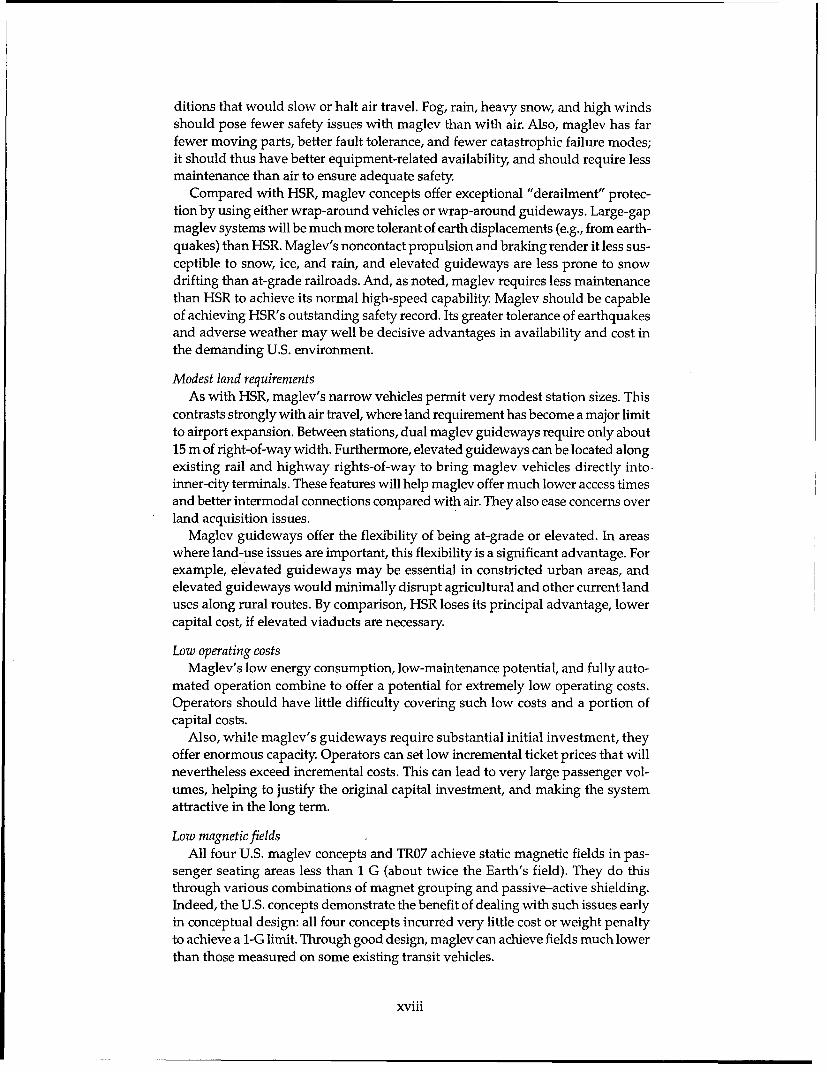
Low magnetic fieldsAll four U.S. maglev concepts and TR07 achieve static magnetic fields in pas-
senger seating areas less than 1 G (about twice the Earth's field). They do thisthrough various combinations of magnet grouping and passive-active shielding.Indeed, the U.S. concepts demonstrate the benefit of dealing with such issues earlyin conceptual design: all four concepts incurred very little cost or weight penaltyto achieve a 1-G limit. Through good design, maglev can achieve fields much lowerthan those measured on some existing transit vehicles.
xviii

Lower noiseUnlike aircraft, maglev and HSR can control their noise emissions near termi-
nals by departing slowly. This is an important advantage that helps permit use ofurban terminals. Furthermore, maglev is quieter than HSR by eliminating wheel-rail contact and pantograph-catenary contact. These noise sources predominateat low speeds, and their absence gives maglev a significant performance advan-tage in urban areas. For example, to meet a noise restriction of 80 dBA, a maglevvehicle should be able to travel at 50 m/s (112 mph) compared with 40 m/s (89mph) for a quiet HSR train. This speed advantage will yield reduced trip timesalong noise-limited routes (i.e., most urban areas).
Even at high speeds, maglev is significantly quieter than HSR. For example, at
83 m/s (185 mph), maglev is 5-7 dBA quieter than HSR. This is a significantreduction in noise emissions that will be beneficial along quiet, rural routes.
Mission flexibilityHSR is best suited to short and intermediate intercity trunk service. TGV's fixed-
consist, nontilting trains, lower cruise speed, and lower overall acceleration-deceleration render it less well suited to meet other missions or transportationneeds. This lack of flexibility ultimately limits the market penetration and profit-ability of HSR.
Besides offering superior intercity trunk service, maglev concepts (particularlyU.S. concepts) show considerable potential for additional uses. This potentialderives from the great performance capability of the technology, although flexibilityto serve other missions should be considered at the design stage.
Mission flexibility helps to reduce the risk that intercity trunk service is notwhere the greatest high-speed ground transportation (HSGT) market lies. Also,by offering other services (regional airport connector, commuter trunk, point-point,long-haul trunk), maglev increases its overall ridership potential as a major trans-portation network. This provides some confidence that an investment in maglevwill fulfill a broad spectrum of U.S. transportation needs.
Opportunities for U.S. maglevThe SCD concepts offer numerous performance improvements over TRO7. Some
of these are concept-specific, while others result from generic improvements thattarget needs of the U.S. market and environment.
Performance efficiencyComparison of TR07 with U.S. maglev concepts revealed two important find-
ings: U.S. maglev can offer slightly better performance than TR07 at much lowercost (especially for at-grade sections), and U.S. maglev can offer much better per-formance than TR07 at similar cost.
For example, the Grumman system offers 9% lower SST trip time and 9% lowerenergy intensity for about 12% lower elevated-guideway cost (or 37% lowerat-grade guideway cost) compared with TRO7. Similarly, the Bechtel conceptoffers a 14% SST trip-time savings for about 2% higher elevated-guideway cost(or 20% lower at-grade guideway cost).
While these are specific SCD concepts, they illustrate the potential performanceand cost advantages likely to result from a U.S. maglev development effort. Theyalso suggest some flexibility in the selection of system characteristics to optimizeperformance and cost for U.S. market conditions.
xix

Suitability to existing rights-of-wayBased on the SCD concepts, a generic U.S. maglev system will be much better
suited than TR07 to deployment along existing rights-of-way (ROW). A U.S. sys-tem will require about half the curve radius of TR07 at 134 m/s (300 mph); it willclimb five-times steeper grades at full speed; and, from a stop, it will reach 134m/s in about half the time. These characteristics mean that a U.S. maglev systemwill achieve much shorter trip times along existing, lower-speed rights-of-way Forexample, 18 minutes of Bechtel's 21-minute SST trip-time advantage over TR07occurs in the first, twisty segment that represents an Interstate Highway ROW.
In principle, Transrapid could upgrade TR07 with a tilting vehicle body and alarger LSM. However, the former would require a major redesign of the vehicle,an increase in roll stiffness of the magnetic suspension, and use of stronger curvedguidewaybeams. Upgrading the LSM may prove more difficult because stator slotwidth limits the diameter (and hence the current capacity) of the stator windings.While these improvements are possible, they would not be possible without sig-nificant R&D (research and development) time, costs, and risks.
Energy efficiencyCompared with TR07, the average energy intensity of the two most efficient U.S.
concepts is 18% lower at steady cruise and 12% lower for the SST. Interestingly,these same two concepts complete the SST in about 11% less time than TR07. Itappears that U.S. maglev may offer superior performance for less energy, animpressive combination.
Several factors account for U.S. maglev's superior trip times and energy effi-ciency. The most important is the provision of vehicle tilting. Tilting allows avehicle to maintain good ride comfort at higher speeds through turns. This reducestrip time directly and reduces the energy needed to accelerate the vehicle to cruisespeed following the turn. The effect is most pronounced along twisty routes (e.g.,typical Interstate ROW). U.S. maglev concepts are also lighter than TR07, whichfurther helps to reduce both trip times and energy consumption.
Another important factor affecting trip time and energy consumption is theaerodynamic drag acting on the vehicle. TR07's aerodynamic drag coefficients arewell established and are comparable to those of high-speed trains. Some SCD con-tractors, however, selected lower drag coefficients that anticipate drag-reductionefforts expected in a U.S. maglev development program. Nevertheless, one of thetwo most energy-efficient concepts (Foster-Miller's) has drag coefficients similarto TR07's. Its aerodynamic drag is a bit lower because of its lower frontal area.Foster-Miller's higher energy efficiency is also attributable in part to its more effi-cient motor. Improvements in aerodynamic drag and motor efficiency are reason-able to expect under a comprehensive U.S. maglev development program. Suchimprovements, combined with lighter, tilting vehicles, would indeed provide U.S.maglev with superior energy efficiency and lower trip times compared with TR07.
High vehicle efficiencyAll SCD vehicles use modern aerospace construction techniques, and two of the
four use advanced composite construction. Superconducting magnets also havegreater lift:magnet-weight ratios than TR07's normal electromagnets and do notrequire heavy back-up batteries to ensure safe hover. Thus, despite their tiltingcapability, U.S. maglev vehicles are lighter than TR07. On average, the SCD vehi-cles are 18% lighter per passenger than TR07, and the composite vehicles average
xx

24% less mass per passenger (values calculated using 0.80 m2 of cabin area as astandard passenger). Composites also offer superior fatigue and corrosion resis-tance relative to aluminum construction.
Lower vehicle mass improves energy efficiency and lowers guideway costs byreducing vehicle loads. Although composite construction currently carries a capital-cost premium, system life-cycle costs may favor its use. Also, further developmentsin the aerospace industry should reduce the cost of composite vehicles. The U.S.aerospace industry leads the world in composite aircraft construction; it is thusreasonable to expect that U.S. maglev vehicles will benefit from this expertise.
Large-gap, active vehicle suspensionsThree of the four SCDs possess active vehicle suspensions. Coupled with a large
gap, an active suspension can maintain a safe, smooth ride over very flexible andrough guideways. This allows use of, respectively, less structural material and lessstringent construction tolerances, reducing guideway costs.
Maglev's large magnetic forces make active control of the primary suspensionan attractive option; Grumman selected this approach. Bechtel and Magneplanechose to use active control of aerodynamic surfaces. All three concepts have suffi-ciently large gaps to realize guideway cost reductions resulting from active sus-pensions. While TR07 also has an active suspension, it must use a small gap andthus requires a very stiff, well aligned, and expensive guideway.
Electromagnetic switchesFoster-Miller and Magneplane proposed electromagnetic (EM) switches as their
high-speed switches, and Betchel investigated an EM switch as an alternate con-cept. Relative to TRO7's bending-beam switch, EM switches offer much shorter cycletimes, no moving structural members, less maintenance, and lower susceptibilityto snow, ice, and dust. Additionally, Foster-Miller's and Magneplane's vehicles bothretain their tilt capability in the turnout direction. This permits higher exit speedsthan is possible with TR07 for a given switch length.
Higher speed potentialGMSA motor and suspension analyses showed that TR07 is near its speed limit
at 134 m/s (300 mph). To meet levitation requirements, TRO7's LSM has a shorterpole pitch than the SCD concepts. It thus operates at a higher frequency (255 Hzcompared with less than 100 Hz for the SCD concepts). This increases performancedemands on converter-station power electronics. As noted, stator slot width alsolimits the LSM current and hence peak thrust. Altering these parameters wouldentail a major redesign of TR07's motor and levitation systems.
Despite very tight guideway tolerances, TRO7's suspension appears to be nearits ride-comfort and safety limits at 134 m/s. Power transfer to the vehicle, satura-tion of the levitation magnets, and the use of a passive secondary suspension pro-vide a second set of limits to the speed potential of TR07.
The U.S. concepts, by comparison, are much farther from their ultimate speedlimits at 134 m/s than is TRO7. They use lower frequency LSMs and have greaterfreedom in stator conductor sizing. They also require much less onboard power.Furthermore, several concepts have adopted active suspensions to maintain ade-quate safety and ride comfort over rougher, more flexible guideways than TRO7's;if these concepts used guideways built to TRO7's tolerances, their suspensions couldhandle much higher speeds.
xxi

Innovations
Large-gap EMSA major concern about TR07's suitability for the U.S. environment is its small,
8-mm suspension gap. To achieve adequate ride comfort and safety margin, TR07'sguideway must be very stiff and well aligned. These requirements increase theguideway's cost and its susceptibility to foundation settlement, earthquake move-ment, thermal expansion, and ice accretion.
Grumman uses iron core, superconducting magnets to increase the suspensiongap of its EDS concept to 40 mm. It actively controls this gap with normal electro-magnets (for high-frequency disturbances) and by slowly varying currents in thesuperconducting magnets. The vehicle requires no secondary suspension, and itmaintains adequate ride comfort and safety over irregularities many times largerthan TR07's limits. This suspension also simplifies hardware requirements byusing the same magnets and reaction rails to provide all lift and guidance forces.Overall, these improvements should simplify guideway design and construction,lower guideway costs, and reduce susceptibility to environmental disturbances.
Locally commutated linear synchronous motor (LCLSM)Foster-Miller's LCLSM energizes discrete guideway coils through individual
inverters to propel a maglev vehicle. A computer controls the current and synthe-sizes a three-phase wave form through each set of coils using pulse-width modu-lation of a DC supply voltage.
The LCLSM could become a very significant innovation in vehicle propulsion.Its advantages include very high overall efficiency (91% as seen at electrical sup-ply), significant capability to operate in a degraded mode, very flexible vehiclecontrol, and use of the same coils for power transfer.
Its principal risk is that the IGBT-based inverters are at present too expensivefor the LCLSM to be economical. Foster-Miller has argued that the large numberof inverters needed (about 2400 per kilometer of dual guideway) will enable massproduction to reduce their cost by a factor of 10. Experience with other semi-conductor products suggests that this cost reduction may be possible.
Spine-girder dual guidewayGrumman has proposed an innovative dual guideway concept called a spine
girder. A central structural "spine" girder carries, on outriggers, a narrow EMSguideway along each side. Government cost estimates confirm that this is a veryefficient structure in terms of performance and cost. Indeed, it is responsible forGrumman's 10% cost advantage over TR07's guideway (also an EMS concept).
Power transferBoth Magneplane and Grumman developed concepts that use the LSM stator
winding as an inductive linear generator to transfer auxiliary power from thewayside to the vehicle. Foster-Miller's concept for power transfer uses its LCLSM.These innovations offer potential for noncontact power transfer to high-speedmaglev vehicles sufficient for all onboard needs.
Cable-in-conduit superconducting magnetsTo date EDS maglev vehicles have used niobium-titanium (NbTi) superconduc-
tors immersed in liquid helium near its boiling point of 4.2 K. This cooling schemeplaces tremendous demands on its refrigerator and can also result in "flashing"or evaporation of the sloshing liquid as the vehicle moves.
xxii

Two of the SCD concepts use cable-in-conduit magnets. This approach offers ahigher operating temperature by using niobium-tin (Nb3Sn) superconductors withsupercritical helium as the coolant. Each cable consists of many wires of Nb3Snconductor contained in a tube that is then wound to form the magnet. Supercriticalhelium is circulated through the tube to cool the superconductor. A coolant tem-perature about 8 K is adequate, resulting in much less refrigeration power. Also,the coolant is a single phase, so there is no danger of flashing. Such magnets appearwell suited for use in maglev vehicles compared with existing NbTi magnets.
Fiber-reinforced plastic (FRP)Bechtel and Foster-Miller have sufficiently high magnetic fields in portions of
their concrete guideway beams that they may not be able to use conventional steelreinforcing rods. Thus, they have both proposed using FRP rods. Bechtel has alsoproposed a bending-beam switch constructed entirely of FRP.
Although well established as an aerospace structural material, FRPs have notsignificantly penetrated civil construction. However, they possess many potentialadvantages over steel reinforcing, including high strength vs. weight, good corro-sion resistance, and high failure stress. Many researchers expect that FRPs willeventually be commonplace in civil structures. Maglev may well prove to be thefirst broad construction use of these materials.
Despite their higher cost, FRPs do not pose a significant overall capital costpenalty on guideways employing them. Because they are new, however, FRPs haveunknown durability for long-life civil structures (typically 50 years). The effectsof long-term, cyclic loading on the attachments for post-tensioning rods are par-ticularly difficult to predict. This durability risk is critical for concepts that mustemploy FRP, and research is currently underway to address it.
High efficiency EDSAt cruise speed, Bechtel's ladder EDS concept achieves a magnetic lift:drag
ratio greater than 100, and Foster-Miller's coil EDS approach has a magneticlift:drag over 170. These are very efficient EDS suspensions. Their benefits includelow energy consumption, high payload:weight ratio, and low liftoff and landingspeeds. Indeed, Bechtel's 10-m/s liftoff speed could allow it to use vertical motorthrust to support its vehicle into and out of stations (it would use air bearings onlyfor emergencies). Essentially, high-efficiency EDS suspensions offer similar low-speed support and low energy consumption to EMS concepts.
CryosystemsTo date, EDS maglev vehicles have used niobium-titanium (NbTi) superconduc-
tors immersed in liquid helium, with cryogenic refrigerators reliquefying thehelium vapor. Such refrigerators consume significant power and are consideredthe least reliable component in the maglev suspension. All four SCD concepts haveavoided using this approach.
The two concepts using liquid-helium baths (Foster-Miller and Grumman)recompress the helium vapor and store it, rather than reliquefying it. They replen-ish the required liquid helium as a daily maintenance operation. This avoids needfor an energy-intensive, unreliable onboard refrigerator; stationary reliquefactionis more efficient and reliable.
The other two SCD concepts, Bechtel and Magneplane, use cable-in-conduitsuperconductors. These Nb3Sn superconductors operate at 6-8 K with supercriticalhelium as the coolant. Bechtel proposes to use an isochoric (constant volume) sys-
xxiii
tem. It accepts daily charges of liquid helium into a sealed reservoir and magnetloop; as the coolant warms up, it pressurizes the loop but retains sufficient heatcapacity for the day's cooling needs. Magneplane uses a cryorefrigerator to keepits supercritical helium in the working temperature range. However, the energyrequired to do so is much less than that needed to reliquefy the helium, and therefrigerator needed is much more reliable.
Air bearingsBechtel and Magneplane proposed using air bearings for low-speed support
rather than wheels. Such bearing have been used for very low speed (less than 5m/s) support of freight pallets. The vehicles are supported by a thin air film trappedbetween the vehicle and the guideway. Relatively low flow rates are needed, soequipment and power requirements are very modest. Air bearings offer a poten-tial for lower weight, cost, and stresses vs. conventional wheels. However, theywill require some development for application at the higher speeds (10-50 m/s[22-112 mph]) needed to support these maglev vehicles.
OVERALL CONCLUSIONS
The GMSA's main goal was to assess the technical viability of maglev in theU.S. We examined in detail the NMI's four contracted SCD concepts and comparedtheir performance potential with that of TGV and TR07.
We found that all maglev concepts studied are potentially technically feasible.As expected, verification of the feasibility and practicality of some features clearlyrequires further work.
All five maglev concepts studied offer much greater performance potential thanTGV. Maglev offers higher speed, better acceleration and performance in curves,and potentially lower maintenance and higher availability for comparable safety.
The four U.S. concepts also offer a performance advantage over TRO7, and theycould do so for similar or lower cost.
Further development will likely improve the performance of both TGV andTRO7. However, such development work will necessarily entail additional time andcost.
xxiv

Technical Assessment of Maglev System ConceptsFinal Report by the Government Maglev System Assessment Team
JAMES H. LEVER, EDITOR
CHAPTER 1. INTRODUCTION
1.1 MAGLEV DEVELOPMENT ment stimulus enabled U.S. investigators to jumpHISTORY to an early lead over their foreign counterparts in
maglev research; for example, Americans pio-Magnetic levitation (or maglev) uses magnetic neered the concept of superconducting magnetic
forces to lift, guide, and propel vehicles. Both levitation and dominated the early experimentalattractive and repulsive magnetic forces may be work in this area.used, and many maglev concepts have been As early as 1963, James Powell (1963) and Gor-developed using various lift, guidance, and pro- don Danby of Brookhaven National Laboratorypulsion schemes. recognized that superconductivity could over-
In the early part of the 20th century, Emile come the power limitations in Bachelet's concept.Bachelet conceived of a magnetic suspension uti- In 1966 the two researchers (Powell and Danbylizing repulsive forces generated by alternating 1966) presented their maglev concept of usingcurrents. Bachelet's concept required impractical superconducting magnets in a vehicle and dis-amounts of power for conventional conductors, crete coils on a guideway. Rapid passage of thehowever. It remained dormant until the 1960s, magnets over the conducting coils generates cur-when superconducting magnets became avail- rents in the coils; these currents in turn establishable. At that point, practical development of magnetic fields of the same polarity as the imposedrepulsive-mode magnetically levitated transpor- fields. The resulting repulsive forces are sufficienttation systems began. to lift and guide passenger-carrying vehicles, pro-
In the early 1920s, work by Hermann Kemper vided powerful (i.e., superconducting) magnetsin Germany pioneered attractive-mode maglev. are used. This technique became known as anKemper pursued this concept through the 1930s electrodynamic suspension (EDS) system. Theirand 40s and established the basic design for prac- subsequent design improvement, known as thetical, attractive-mode maglev in a 1953 paper. "null-flux" system (Powell and Danby 1967), wasDuring the 1970s, German interest in developing eventually adopted by the Japanese for use in thea maglev transportation system eventually only high-speed superconducting maglev systemfocused on an attractive-mode magnetic suspen- in operation today. The presence of powerfulsion. magnets aboard the vehicles also makes practical
Maglev development in the U.S. began in ear- the use of an air-core linear synchronous motornest as a result of the High-Speed Ground Trans- (LSM) for propulsion.portation (HSGT) Act. This act authorized Federal Subsequently, researchers from Stanfordfunding for HSGT research projects, including Research Institute (SRI) (Barbee et al. 1969), Atom-those involving magnetic levitation. This govern- ics International (Guderjahn et al. 1969), and

Sandia Corporation (Guderjahn et al. 1969) devel- The Japanese have pursued two distinct mag-oped a continuous-sheet guideway (CSG) con- lev concepts: one (MLU series) employs an EDScept. This EDS concept also used superconduct- while the other (HSST series [high-speed surfaceing magnets aboard a vehicle. Here, the moving transportation]) employs an EMS. The MLUmagnetic fields of the vehicle magnets induce series full-scale prototypes have achieved speedscurrents in a continuous sheet of conducting of 139 m/s, while HSST series prototypes havematerial such as aluminum. CSG tests involving traveled as fast as 83 m/s. German research, in the"rotating drum" simulations and test guideways meantime, has culminated in the development ofup to 150 m long continued through the early a single EMS concept known as the Transrapid1970s at SRI, at Ford Motor Company (Reitz 1970), system (TR series). The latest full-scale version ofGeneral Motors Corporation (Dukowicz et al. the Transrapid vehicle and guideway (TR07) has1973), and MIT (Kolm and Thornton 1972). Dur- been in operation for several years at a test tracking this period, a locally commutated linear in Emsland, Germany. The TRO7, with a projectedmotor was invented at GM, and the original "Mag- maximum speed of 139 m/s, is the only maglevneplane" was invented at MIT. The latter CGS system in the world that is immediately availableconcept underwent model testing at 1/25th scale, for commercial service. It is currently competingeventually operating at speeds as high as 27 m/s. against high-speed rail systems for ground trans-
Other significant U.S. maglev work during the portation projects in the U.S.early 1970s included development by Rohr Cor- In 1988, owing to a renewed desire for a nationalporation of its ROMAG people-mover demonstra- HSGT capability, the U.S. Congress investigatedtion vehicle. In this system, normally conducting the possibility of reviving maglev research andelectromagnets generated attractive forces development. Studies revealed that maglev wasbetween the vehicle and ferromagnetic material attractive as a means of relieving the congestionin the guideway. This is termed an electromag- and delays in our ground- and air-transport sys-netic suspension (EMS) system. Unlike EDS, an tems (Johnson et al. 1989, Grumman Corp.EMS is statically unstable; a control system must 1989a,b). The transportation "niche" envisionedvary the currents in the electromagnets to main- for maglev was generally 160- to 960-km (100- totain proper clearance between the vehicle and the 600-mile) trips, where the personal car is too slowguideway. This technology was later transferred and uncomfortable, and the commercial airplaneto the Boeing Company and ultimately licensed is too inefficient. A maglev technical advisoryby Carnegie-Mellon University. committee, made up of representatives from a
Maglev research in the U.S. came to a standstill wide range of government and private transpor-in 1975 owing to an abrupt halt in government tation organizations, reviewed the situation andfunding of HSGT research and a slowdown in the reported to Congress in June of 1989. It recom-growth of U.S. transportation demands. mended that the U.S. develop and demonstrate a
Maglev transportation research outside of the second-generation maglev concept utilizing.U.S. has been dominated by the Japanese and Ger- superconducting technology that will be usablemans. The Japanese began on a relatively modest along the Interstate Highway network, and welllevel in the early 1960s. By 1970, Japanese efforts, suited to U.S. weather conditions (Grummanunder the sponsorship of the Japanese National Corp. 1989a, b). Congress responded by authoriz-Railway (JNR), had significantly expanded. At the ing the formation in 1990 of the National Maglevsame time, research in West Germany began and Initiative (NMI) (USACE 1990).quickly grew. The Japanese were successfully levi-tating a demonstration vehicle in 1972 and con- 1.2 ROLE OF THE NATIONALstructing a large-scale test track in 1974. In West MAGLEV INITIATIVEGermany, proof-of-concept test vehicles were op-erating as early as 1970 under two government Maglev makes possible high-speed, high-sponsored maglev research programs. When U.S. capacity travel with potentially low operatingGovernment funding of HSGT ended in 1975, costs and convenient access. Yet, despite thesehigh-speed rail and maglev research in Japan and attributes, U.S. firms have been reluctant to investWest Germany continued to expand. Consider- in the technology. Maglev's development risks,able progress toward commercial maglev trans- large capital cost, and uncertain market responseportation was made by both countries during the are likely reasons for this reluctance.late 1970s and 1980s (Wyczalek 1990). To determine whether it should actively
2

encourage maglev investment, the Federal Gov- * Apply this evaluation process to Transrapidernment organized the National Maglev Initiative 07 (TR07) maglev and to TGV high-speed(NMI). The NMI's principal tasks were to assess rail to establish comparative baselines.the technical and economic viability of maglev in * Apply this process to alternative U.S. maglevthe U.S. and to recommend the most appropriate concepts.Federal role for its development and implemen- e Assess the overall technical viability oftation. maglev generally, and TR07 and alternative
The NMI executed these tasks within a three- U.S. concepts specifically. Where appropri-phase strategic plan: ate, use TGV as a baseline to describe the
"* Phase I-Planning and coordination. performance potential of maglev in the U.S.
"* Phase II-Assessment of technology and Insofar as possible, we sought to integrate oureconomics. process for assessing maglev's technical viability
"* Decision. with that of the NMI's process for assessing eco-"* Phase III-Development and implementa- nomic viability. Note also that our assessment per-
tion. tained to maglev system concepts, not contractor
Phase II culminated with a report summariz- performance. This report describes the results of
ing the NMI's findings (USDOTFRA 1993) and our assessment of maglev's technical viability for
outlining possible implementation strategies. The the U.S.
work described here, technical assessment ofmaglev system concepts, was the primary assess- 1.4 DEFINITIONS OFment of maglev technology conducted in Phase TECHNICAL VIABILITYII. Economic assessments performed in Phase II As noted, the NMI was tasked to assess thearenodescribedNin the Nasksdfinalsreport.are described in the NMI's final reporta technical and economic viability of maglev sys-
The NMI obtained maglev technical data tems for use in the U.S. In effect, this assessmentthrough two sets of procurements. The first was must determine whether maglev can fulfill a sig-a set of contracts exploring specific technological nificant transportation role in a commerciallyissues, so-called Broad Agency Announcements acceptable way. Also, the NMI must consider(BAA). The second consisted of four relatively whether a U.S. maglev system would fulfill thislarger contracts seeking conceptual definitions of role better than existing foreign HSGT systems. Tomaglev systems suitable for the U.S., so-called this end, we may group issues of maglev's tech-System Concept Definitions (SCDs). The resulting nical viability into three broad categories:SCD reports contain quite thorough descriptionsand analyses of the major subsystems, their inter- * Technicalfeasibility-Will a particular systemconnections, and the resulting performance of concept work as intended? This involvespotential maglev systems (Bechtel 1992ab; Foster- assessing the soundness of the physical prin-Miller, Inc. 1992a,b; Grumman Aerospace Corp. ciples and engineering sciences upon which1992a,b; Magneplane International, Inc. 1992ab). the concept is based.
* Mission suitability--Given its performance
1.3 ROLE OF THE GOVERNMENT characteristics, how well will such a system
MAGLEV SYSTEM ASSESSMENT concept fulfill its required mission? Thisinvolves examining the concept's perfor-
The Government Maglev System Assessment mance characteristics and simulating its(GMSA) team consisted of scientists and engi- behavior along realistic routes.neers from the U.S. Army Corps of Engineers * Relative advantage-Do U.S.-developed con-(USACE), the U.S. Department of Transporta- cepts possess superior performance poten-tion (USDOT) and the Department of Energy's tial compared with foreign HSGT alterna-Argonne National Laboratory (ANL), plus con- tives? This requires comparing U.S. conceptstracted transportation specialists. Its overall role to foreign ones, and assessing their poten-was to assist the NMI with its assessment of tial for superior performance and the atten-maglev technology. The GMSA's specific tasks dant development risks.were as follows: We structured our evaluation process to
• Develop a process to evaluate the technical address issues in all three categories of technicalviability of maglev system concepts. viability.
3

1.5 MAGLEV'S TRANSPORTATION appeal in the U.S. Indeed, the French-built TGVMISSION (train 2 grande vitesse) offers a proven, commer-
cially successful 83-m/s service, and this serviceSeveral studies have identified an urgent need is available for the U.S. with essentially no devel-
to improve U.S. intercity transportation. High- opment risk. In addition, its performance limitsSpeed Ground Transportation (HSGT) technolo- appear to be governed more by cost/benefitgies, including maglev, appear well suited to ad- calculation rather than by physical constraints.dress this need. Thus, the NMI targeted this Further development will undoubtedly raise theseintercity role for maglev in its SCD request for pro- limits, albeit with some attendant costs and risks.posals (SCD-RFP, USDOTFRA [1991], sections C - We adopted the view that the lack of develop-2.2 and 2.3): ment costs and risks is critical in the debate over
In soliciting the system concepts, the Na- the merits of HSR and maglev. Thus, we chose a
tional Maglev Initiative views Maglev as an commercially available HSR technology, TGV-intercity transportation system which will Atlantique (TGV-A), as one of our evaluation
supplement and interconnect with existing baselines. We did not try to anticipate further per-
modes... Maglev systems should be safe and formance improvements. Such improvements willreliable. In the 160-km to 1000-km (100- to 600- undoubtedly occur, but their associated costs andmi-) trip range, Maglev should be competitive risks offset TGV-A's critical advantage. On thisin terms of travel times, cost, reliability and basis, we feel that TGV-A serves as a fair baseline
comfort. for comparison with maglev.It should be clean and energy efficient. It For similar reasons, we selected the German
should provide good connections with airports Transrapid 07 (TR07) electromagnetic maglev sys-and major centers. Insofar as possible, it should tern as a second evaluation baseline. Transrapidutilize existing highway, railroad, and utility has extensively tested this technology at itsrights-of-way. Its design should anticipate Emsland test facility. Although it has not yet beenupgrade. It should be economically and finan- integrated into a commercial system, it has been
cially attractive. It should be robust in terms of proposed for use along several corridors in theits susceptibility to adverse weather and its U.S. Again, its critical advantage over possible
requirements for maintenance. It should effi- U.S.-designed systems is the perceived lack ofciently handle passengers and consideration development costs and risks. However, because ofshould be given to its mail and freight handling its lack of system-level integration and commer-capability, cial history, TR07 represents a greater risk than
TGV; it also offers potentially greater performance.We used these statements for our basic evalua- The NMI's four contracted SCD's were by far
tion of the "mission suitability" aspects of techni- the most well defined U.S. maglev concepts avail-cal viability. However, we also recognized that able to us. Each contractor produced a detailedmaglev may address other national transportation report describing the concept's major components,needs, and that adaptability of concepts to those the interconnection between them, analyses ofmissions is also an important viability issue. Thus, component and system performance, and capitalwe developed four additional mission statements and operating cost estimates. We thus chose to(see section 3.4.1) and examined how well each examine in detail these four concepts as represen-HSGT technology fitted those missions. tative U.S. maglev systems. In over-simplified
terms, they represent an updated EMS comparable
1.6 EVALUATION BASELINES AND to TR07 (Grumman), an updated discrete-coil EDS
MAGLEV SYSTEM CONCEPTS comparable to the Japanese MLU002 (Foster-Miller), a well known sheet-guideway EDS (Magne-
HSGT is not yet widely available in the U.S. It plane), and a new ladder-coil EDS (Bechtel).basically provides service in a speed range inter-mediate to automobiles and jet aircraft (say, 50-200 1.7 OVERVIEW OFm/s). Maglev is one possible HSGT technology; EVALUATION PROCESShigh-speed rail (HSR) is another.
Several recently developed HSR systems have To assess the technical viability of maglev con-impressive performance characteristics and could cepts, the GMSA developed an evaluation processmeet many of the requirements for broad market consisting of four main steps:
4

"• Applying the SCD-RFP system criteria as but that were not included in the SCD-RFPassessment criteria. We developed qualita- (USDOTFRA 1991).tive and quantitative cross-checks to deter-mine whether a maglev concept met each These four evaluation steps generated much ofof the criteria defined in the SCD-RFP the input for our overall assessment of the techni-(USDOTFRA 1991). cal viability of maglev for the U.S. As noted, we
* Verifying subsystem performance. We devel- evaluated both TGV-A and TR07 as baseline con-oped numerical models to verify the perfor- cepts and the four SCD concepts as representativemance characteristics of critical subsystems U.S. maglev systems. Insofar as possible, we refer-for each concept. enced our conclusions regarding the viability of
"* Verifying system performance. We developed these concepts to specific evaluation data products.a numerical model to simulate the overall Chapter 2 of this report describes the relevantperformance of each system concept. We also characteristics of the HSGT technologies exam-estimated the main technology-dependent ined. Chapter 3 describes in detail each of the fourcapital costs for the maglev concepts using evaluation steps discussed above, and presentsa standardized procedure. for each concept the resulting evaluation data
"• Applying other criteria. We developed quali- products. Chapter 4 presents our specific conclu-tative and quantitative cross-checks to deter- sions regarding the technical viability of maglevmine whether a maglev concept met perfor- in the U.S. It is structured to reflect the key issuesmance criteria that reflect technical viability in the debate over maglev's technical viability.
5

BLANK
6

CHAPTER 2. CHARACTERISTICS OF SPECIFIC HSGT CONCEPTS
Sections 2.1-2.6 briefly describe each of the mum axle load is limited to 17 tonnes, and theHSGT concepts examined. Section 2.7 summa- maximum unsprung mass to 2.2 tonnes/axle.rizes their general characteristics and lists perfor- Trainset seating capacity ranges between 376mance parameters useful for evaluations. (TGV-R) and 547 (TGV-Bilevel). The trainsets do
not incorporate active or passive tilting.2.1 HIGH-SPEED RAIL-TGV* Propulsion power and hotel power are col-
lected from an overhead catenary through roof-2.1.1 Concept mounted pantographs. The TGV fleet in SNCF
The TGV (train A grande vitesse) uses steel (French National Railways) service carries at leastwheels on steel rails. It is based on essentially con- two pantographs per power car, for 25 kV, 50 Hz,ventional railroad vehicles, tracks, and propul- and 1.5 kV DC. Some trainsets are equipped forsion, power distribution, and signaling and con- operation under three or even four different volt-trol subsystems, albeit very highly developed and ages. A 25-kV roof-mounted trainline is used tomade optimal for high-speed operation (83-m/s permit operation with only one pantographservice speed). Figure 1 shows a typical trainset, raised. Braking on the TGV-A is by means of aits track, and overhead catenary power lines. The combination of rheostatic, axle-mounted discrolling stock is operated in fixed-consist trainsets brakes (four per unpowered axle) and tread(1-8-1 for the first-generation PSE [Paris-Sud-Est], brakes (on powered axles). The TGV-R and later1-10-1 for the second-generation TGV-A [Atlan- versions will eliminate the tread brakes in favortique], 1-8-1 for the third generation TGV-R of disc brakes, even on the powered axles. All[Reseau] and TGV-Bilevel); the trainsets can be axles are equipped with anti-lock braking and theoperated as coupled pairs. powered axles have anti-slip control. Top com-
mercial speed is 83 m/s, though a modified 1-3-1version of the TGV-A set the world wheel-on-railspeed record of 143 m/s. Sustained operation at134 m/s on a 3.5% gradient is not possible.
2.1.3 GuidewayThe basic TGV track structure is that of a con-
ventional standard-gauge railroad, but built on anengineered support structure of granular materi-als selected to ensure free drainage and com-
. ...... pacted to achieve a uniformly high track modu-lus. Minimum ballast depth is 30 cm. The track
. consists of continuously welded rail on twin-Figure 1. TGV-Atlantique. block concrete-steel ties with elastic fasteners and
a 9-mm stiff rubber pad. All viaducts and bridge2.1.2 Vehicles structures are ballast-decked and are built to span-
All TGV trainsets have a power car on each length deflection tolerances. Alignment geometryend, followed by a transition car with one regu- for 83 m/s calls for 6000-m radius horizontallar and one articulated truck; all other cars are ar- curves, although 4000-m radius curves are usedticulated, sharing trucks at either end. The exceptionally. Vertical curve radius at crests andunpowered trucks are equipped with coil-spring troughs is 25,000 m, with 16,000 m used excep-primary and airbag secondary suspensions. The tionally at crests and 14,000 m exceptionally inpowered trucks have coil-spring primary and sec- troughs. Gradients of up to 3.5% are acceptable.ondary suspensions. TGV-Aand later trainsets are Tunnel cross-sections range between 46 m2
propelled by eight body-suspended 1100-kW AC (single-track, 56 m/s) and 71 m 2 (double-track, 75synchronous rotary traction motors. The maxi- m/s).
The high-speed lines are built with full doubletrack having bidirectional signals. Crossovers at
• Written by Christopher J. Boon, Canadian Institute of 25-km intervals are 1:46 units, permitting 44 m/sGuided Ground Transport. in the diverted direction and full line speed in the
7

through direction. High-speed (1:65) swing-nose to interact with propulsion windings mounted inturnouts permit 61 m/s in the diverted direction the stator packs on the guideway. The vehiclecurrently; SNCF expects to increase this to 64 m/s wraps around a T-shaped guideway, with thewhen concrete switch ties replace the wooden ties guidance rails mounted on the outside edges andused in the original switch installations. the levitation and propulsion stator packs
Propulsion and hotel power is supplied mounted underneath the guideway.through a 2- x 25-kV overhead catenary system(OCS) in phase opposition. The OCS contact wire 2.2.2 Vehicleis 150 mm2 at 5.1 m height. Substations have 220- Transrapid 07 uses two or more vehicles in akV single-phase supply feed with 60- to 120-MVA consist, with each designed to carry 100 passen-installed capacity. gers (72 in first-class). Each vehicle is 25.5 m long,
Signaling and control is by means of full CTC 3.92 m high, and 3.7 m wide. It is constructed of(computerized train control), employing coded aluminum frames with sandwich shells of glass-track circuits, track-to train voice and data links, fiber reinforced plastic panels. The reportedand in-cab signals, with an automatic train pro- weight is 106,000 kg per two-vehicle consist. Eachtection system having speed adherence override TR07 vehicle in a consist is capable of indepen-and enforced braking. dent operation and each has 32 levitation and 30
guidance magnets. The stator pack, which is2.1.4 Status
TGV-A has been in regular commercial ser- _._._......_._._...
vice between Paris and west-southwest France .... ....
since 1989. Its predecessor, TGV-Paris-Sud-Est,has been in commercial service since 1981. Bothlines have been extremely popular and have ex-perienced steady ridership increases. TheFrench federal government and SNCF plan ad-ditional lines in France, and the technology hasbeen deployed or proposed for commercial op- . .eration in corridors in Spain, Australia, Korea,Taiwan, Canada, and the U.S. a ...... vie.a. Exterior view.
2.2 TRANSRAPID 07 (TR07)*
2.2.1 Concept MRI-P&:The TR07 has an electromagnetic sus-
pension (EMS) system that uses separate It
sets of conventional iron-core magnetsto generate vehicle lift and guidance bymeans of magnetic attraction (Fig. 2). It iZr
is capable of achieving cruising speeds e sof 134 m/s. Both the levitation andguidance systems have their owndedicated control systems for regulat-ing the air gap between magnet andguideway rail. The control systems SM&NV N,
maintain the air gap at 8 mm nomi-nally. The levitation system operatesat all speeds. Propulsion is providedby a synchronous long-stator linearmotor using the levitation magnets I
b. Cross section showing principal lift, guidance, and propulsion ele-• Written by Richard Armstrong and Rob- ments (INKREF is a displacement sensor).ert Hasse, U.S. Army Engineer Division, Figure 2. TR07 vehicle.Huntsville.
8

mounted on the guideway, is composed of a lami- commercially, although it has been proposed fornated iron core, stator winding, and attachment commercial operation along several Europeanhardware. The stator windings are 300 mm2, soft and U.S. corridors. The GSMA's (1992) Transrapidaluminum, with double shields and an external TR07 Baseline Report contains a more thoroughconductive sheath, in a three-phase configuration. description of this technology.The propulsion force is generated by the interac-tion of the vehicle magnet exciter windings and 2.3 BECHTEL*the guideway stator windings. The primary brak-ing is regenerative, through linear motor current 2.3.1 Conceptreversal in response to phase angle modulation. The Bechtel concept is a novel, flux-cancelingAn eddy-current braking system is used only if electrodynamic suspension (EDS) system. Thethe regenerative braking fails. On board hotel and vehicle contains six sets of eight superconductinglevitation power is provided by Ni-Cd batteries magnets per side. It straddles a concrete box-beamat low speeds (below 28 m/s) and by linear gen- guideway. Interaction between the vehicle mag-erators at increased speeds. The power is trans- nets and a laminated aluminum ladder on eachferred using harmonic frequencies of the LSM guideway sidewall generates lift. Similar interac-fields. The proposed maximum speed for the tion with null-flux coils mounted on the guide-TR07 in a commercial service is 138 m/s (311 way provides guidance. LSM propulsion wind-mph), with a maximum operational speed of 118 ings, also attached to the guideway sidewalls,m/s (265 mph). The top speed that has been interact with these same vehicle magnets to pro-recorded at Emsland is 120 m/s (270 mph). duce thrust. Figure 3 shows the overall layout of
Bechtel's concept.2.2.3 Guideway
The TR07 guideway uses beams supported by 2.3.2 VehicleA-shaped, steel-reinforced concrete piers. The The baseline vehicle consists of a single 106- topiers are supported on either spread or pile foun- 120-passenger car. The 106-passenger vehicle pro-dations, depending on the soil conditions. The vides 90 coach seats with six abreast seating andEmsland test track has both steel and concrete 16 first-class seats with four abreast seating. Thebeams, while Transrapid has proposed only the 120-passenger vehicle has only coach seats. Thesteel beams for commercial service. The concrete Bechtel vehicle uses aerodynamic control surfacesbeam is post-tensioned over a single span and to augment magnetic guidance and dampingsteel reinforced, having a single cell, hollow box forces. When it is not levitating (at low speeds orcross-section, with slanted webs. The steel beam in emergencies), the vehicle operates on air-bear-also has a single cell, hollow box cross-section, ing pads. By incorporating special lift coils in thewith slanted webs, but it is continuous over two guideway, the vehicle may liftoff at zero speed.spans and is welded out of steel plates. Both Two methanol-powered fuel cells provide a totalbeams are constructed and erected to very tight of 186 kW of onboard power.tolerances. The stator packs are bolted to the The vehicle is constructed with an outer alu-beams. Maximum guideway superelevation (tilt minum shell and an inner shell made of compos-or banking) is 120. Switching is accomplished by ite material. The intent of this construction is tobending a special guideway beam section, in enable tilting of the inner shell while maintainingwhich the continuous steel beam is fixed at one a smooth aerodynamic outer surface. The vehicleend and laterally bent to the proper alignment by can tilt to 15'.eight actuators.
Electrical power is distributed along the guide- 2.3.3 Guidewayway at 110 kV, 50 Hz to wayside power condition- The baseline guideway consists of single-span,ing stations. There are two 5-6 MW, variable- post-tensioned concrete box beams supported onfrequency-variable-voltage power conditioning concrete piers with 25-m spacing. The laminatedunits operating in parallel to power the guideway. aluminum suspension ladder, null-flux guidance
coils, and six-phase LSM windings are all com-2.2.4 Status pactly mounted on the upper portion of each
TR07 is a proven technology that is currentlyundergoing performance testing at Transrapid's * Written by Dr. John Potter, U.S. Army Engineer Division,
Emsland test facility. It has yet to be deployed Huntsville.
9

a. Exterior view.
Bins~ar OV Binsod
10M

guideway sidewall; this assembly is then enclosed concept or subsystem tests and none had beenwith a cover plate. The critical gap for this con- conducted prior to this work.cept is the 50-mm horizontal gap between the su-perconducting coils and the cover plate. Because 2.4 FOSTER-MILLER*of high magnetic fields, the concept calls for non-magnetic, FRP reinforcing rods in the upper por- 2.4.1 Concepttion of the box beam. Guideway superelevation The Foster-Miller concept is an EDS generallyof up to 15' is planned. The concept's baseline similar to the Japanese MLU002. Superconduct-switch is a bendable beam constructed of FRP. ing magnets in the vehicle generate lift by inter-
The guideway mounted propulsion coils are acting with null-flux levitation coils located in theconventionally constructed and configured as a sidewalls of a U-shaped guideway; similar inter-six-phase system. DC power is distributed along action with series-coupled propulsion coils pro-the guideway at 24 kV to frequency converters vides null-flux guidance. Its innovative propul-located near the guideway. The typical zone sion scheme is called a locally commutated linearlength for a frequency converter is 4000 m and an synchronous motor (LCLSM). Individual H-LSM blocklength is 2000 m. bridge inverters sequentially energize propulsion
coils as they line up with the vehicle magnets.2.3.4 Status
This concept is one of the four NMI-contracted _i
SCDs. These contracts did not call for proof-of- * Written by Frank L. Raposa, Consulting Engineer.
a. Exterior view.
..... .I------
NULL FLUX LEVITATION I ICOILS AND PROPULSION NULLFLUX GROUND I
COILS I EDS COIL EDS PROPULSION COILS (ACTIVE)
SIDEWALLLOW SPEED AND BEAMEMERGENCY I
SRUNNING SURFACES- LEVITATION/GUIDANCE COILS
b. Cross section. -= -- ---- (PASSIVE)
HIGH-STRENGTHMODULARFIBER CONCRETE,SECTONS +,PRESTRESSED
BEAM
SINON-METALLICOPEN CENTER
Figure 4. Foster-Miller vehicle in (i-shaped guideway.
11

These inverters synthesize a waveform that with the superconducting magnets mounted onmoves down the guideway, synchronously with the bogies. The H-bridge inverters synthesize athe vehicle. Figure 4 shows the overall layout of three-phase waveform that moves down theFoster-Miller's concept. guideway in synchrony with the vehicle.
The LCLSM coils that are located between the2.4.2 Vehicle bogies also operate as the high-frequency primary
The baseline vehicle consists of two 75-passen- of an air-core transformer. This method of opera-ger modules with attached nose and tail sections. tion is also produced by the H-bridge inverters.Smaller or larger vehicles can be made up by The LCLSM coils interact with adjacent coils onincorporating fewer or additional passenger mod- the vehicle to transfer power to the vehicle induc-ules. These modules have magnet bogies at each tively for onboard electrical loads.end, containing four magnets per side, that theyshare with adjacent cars. The port and starboard 2.4.4 Statussuperconducting magnets are series-connected This concept is one of the four NMI-contractedelectrically to provide balanced guidance in the SCDs. Although the contractor conducted noevent of a magnet quench (catastrophic loss of proof-of-concept tests, the Japanese MLU002 issuperconductivity). To reduce exposure to mag- similar (superconducting EDS with U-shapednetic fields, there are no passenger seats over the guideway and vertical null-flux levitation).bogies. Because the Japanese have conducted extensive
The vehicles are made of lightweight compos- tests and development work on the MLU002, itite materials with five across seating. The vehicles must be viewed as a proven concept (although nothave 12' tilting capability, yet a commercial product). However, a significant
departure of the Foster-Miller concept from the2.4.3 Guideway MLU002 is the LCLSM; this propulsion scheme is
The U-shaped guideway consists of two par- as yet unproven.allel, post-tensioned concrete beams joined trans-versely by precast concrete diaphragms. Thebaseline guideway uses two-span assemblies of 2.5 GRUMMAN*such beams supported at 27-m intervals. Each 2.5.1 Conceptbeam has an integral sidewall that carries the null- The Grumman concept is an EMS with simi-flux levitation coils and the propulsion coils. larities to Transrapid 07. However, Grumman'sBecause of high magnetic fields, the upper post- vehicles wrap around a Y-shaped guideway (astensioning rods are FRP. The space between the opposed to the TRO7's T-shaped guideway) andbeams is open to allow direct runoff of rain, snow, use just one set of vehicle magnets and guidewayand debris. Guideway superelevation may be up rails for levitation, guidance, and propulsion (Fig.to 160. The baseline high-speed switch uses 5). The vehicle magnets are superconducting coilsswitched null-flux coils to guide the vehicle around Vanadium-Permendur iron cores thatthrough a vertical turnout. It requires no moving are horseshoe shaped. The horseshoe legs arestructural members. attracted to iron rails on the underside of the
The propulsion coils are located in the sidewall guideway. Normal coils on each iron-core legbehind the levitation coils. Each sidewall coil is modulate levitation and guidance forces to main-electrically connected in series to a corresponding tain a large (40-mm) air gap. Propulsion is by con-coil on the opposite sidewall. The superconduct- ventional LSM embedded in the guideway rail.ing coils on each side of the bogie interact withthe connected sidewall propulsion coils to pro- 2.5.2 Vehiclevide guidance. The design air gap for guidance The baseline consist is a two-vehicle configu-is 100 mm and the system is designed to be very ration for 100 passengers; it can be shortened to astiff. single 50-passenger vehicle or lengthened to a
The sidewall propulsion coils do not overlap 150-passenger, three-vehicle consist. Passengersand are individually switched from H-bridge are seated in two groups of ten rows of two-by-inverters. Each is controlled by its own H-bridgethat is adjacent to its coil. As mentioned the sys-tem is called the LCLSM. The LCLSM will ener- * Written by Dr. John Potter, U.S. Army Engineer Division,
gize the propulsion coils as they become lined up Huntsville.
12

:: ... : : ::.... : : !• ••i•Z !•i:i~ ii i ii!: ii!i- i!i!••!.. ... ' ! .. .... ;• •:... ... .... .. . .. •.:........
a. Exterior view.
VHCE T1.1MODUE, EAHII,AG 02= ON () SUPERCONDUCTING
MAGNET POWERPICKUP
•A,• IRON RAILS C.L -5-1
2 cmOFFSET
CONTROLCOIL -------
2¢m PROPULSION-
LAMINATED (b) OFFSET COILS
IRON CORE -SUPERCONDUCTINGMAGNET IRON RAIL W()
b. Levitation, propulsion, and guidance system.
Figure 5. Grumman vehicle.
three. The vehicles are made of lightweight corn- Onboard power is provided by conventionalposite materials, inductive coils mounted on the ends (or faces) of
The vehicle body is attached to the chassis by the magnet cores. This system provides up to 170tilting mechanisms that provide for up to 9' of kW per car using a combination of slot harmon-body tilt. Each chassis provides the secondary sus- ics and high-frequency current injected into thepension and mounting for two pairs of magnets LSM.on each side and actuators for lateral magnetmovement for guideway clearance in curves. The 2.5.3 Guidewaymagnets are alternately offset 1.5 cm to the left The innovative guideway superstructureand right of the guideway rail to provide roll con- consists of slender Y-shaped guideway sectionstrol. Normal coils on each of the iron-core legs (one for each direction) mounted by outriggersmodulate levitation and guidance forces while every 4.5 m to a 27-m main beam or "spinekeeping the superconducting magnets operating girder." The structural spine girder serves bothat nearly constant current. directions and is in turn supported by conven-
Each magnet consists of 1020 turns of NbTi con- tional piers on piled or spread footings (as foun-ductor carrying 53 A (for 54 kAT) at 4.5 K. The cry- dation conditions dictate). Maximum guidewayostats are mostly aluminum, with reservoirs for superelevation is 15'.both liquid helium and liquid nitrogen. N2 vapor Switching is accomplished with a TR07-styleis vented, while He vapor is compressed and bending guideway beam, except that the Grum-stored for later reliquefaction at a fixed plant. man bending section is complemented by a slid-
13

ing or rotating, elongated frog section that allows vehicle to provide damping (especially in roll) andfor a shorter length of bending guideway. Propul- increased directional stability. Air bearings sup-sion is by conventional, three-phase LSM embed- port the vehicle at speeds below about 40 m/s.ded in the guideway rail in 500-m blocks. Each magnet group consists of six supercon-
ducting propulsion coils along the centerline and2.5.4. Status two superconducting levitation coils on each side.
This concept is one of the four NMI-contracted Each end propulsion coil is designed for 390 kAT,SCDs. Although the contractor conducted no while the mid coils are designed for 780 kAT. Eachproof-of-concept tests, the concept is similar to the levitation coil is sized for 252 kAT. All of the coilswell-tested Transrapid 07 (EDS levitation and are Nb 3Sn cable-in-conduit-conductors, whichguidance, conventional LSM, bending-beam use steel conduit to carry supercritical He for cool-switch). However, Grumman's useof a single set of magnets and reac-tion rails for levitation and guid-ance, and its use of superconduct-ing magnets to achieve a largersuspension gap, are essentially un-proven innovations.
2.6 MAGNEPLANE*
2.6.1 ConceptThe Magneplane concept is a
single-vehicle EDS system using atrough-shaped, 0.2-m-thick alumi-num guideway for sheet levitationand guidance (Fig. 6). Centrifugalforce rotates the vehicle (or "Mag-plane") in the trough for coordi-nated banking in curves. No addi- a. Exterior view.tional tilting suspension is requiredeven for 45' bank angles. Supercon- - -
ducting levitation and propulsion magnets aregrouped at the front and rear of the vehicle The -
centerline magnets interact with conventionalLSM windings and also generate some electro- --- grn "magnetic guidance force (called the keel effect). ,,ooThe magnets on the sides of each group react --
against the aluminum guideway sheets to providelevitation (at a 0.15-m gap).
2.6.2 Vehicle 0-The baseline vehicle is a 140-passenger "Mag- lt s,&.OA,
plane," which can be complemented by a 45-seatversion. The seats are configured in 28 rows of I ... d4u,0 du,19o
two-by-three in a lightweight composite body.The magnets are grouped at each end of the i Pr dl.7
vehicle for cryogenic and magnetic field consid- A ===7 7z
erations; there is no secondary suspension or body ,.,, ° -tilting system. Vertical and horizontal control sur- Ifaces are mounted on the nose and tail of the s Bog6i-,,dI s, S,- - - -
* Written by Dr. John Potter, U.S. Army Engineer b. Vehicle cross-section and bogie coils.
Division, Huntsville. Figure 6. Magneplane vehicle in aluminum guideway trough.
14

ing to between 6 and 8 K. A closed-cycle onboard 2.6.4 Statusrefrigeration system provides the recycled super- This concept is one of the four NMI-contractedcritical He at 6 K. SCDs. Although the contractor conducted no
Onboard power (185 kW) is generated by induc- tests, earlier laboratory work on this concept hastive coupling to high-frequency currents injected essentially proven the levitation, guidance, andinto the LSM. propulsion schemes. No full-scale system or sub-
system tests have yet been conducted. A Magne-2.6.3 Guideway plane consortium has proposed the concept for a
The aluminum levitation sheets in the guide- commercial route in Florida.way trough form the tops of two aluminum boxbeams that support the LSM winding located in 2.7 PHYSICAL CHARACTERISTICSthe center of the trough. These box beams are sup- AND PERFORMANCE PARAMETERS*ported every 9.14 mby columns on piles or spreadfootings, as foundation conditions dictate. It is frequently helpful to compare general
The baseline switch uses switched null-flux physical characteristics of each HSGT system,coils to guide the vehicle through a fork in the such as consist mass, number of passengers perguideway trough. It requires no moving structural consist, etc. Table 1 presents a summary of suchmembers. physical parameters for the concepts studied here.
The centrally mounted LSM is a conventional, Because of rounding, these numbers may differsingle-phase winding with 2000-m blocklengths.Through phase-angle control, the LSM also pro-vides additional vertical damping forces to the *Written by Dr. James Lever, CRREL, and Dr. John Potter, U.S.
vehicle. Army Engineer Division, Huntsville.
Table 1. General physical characteristics of concepts studied.
TGV-Atlantique TR07 Bechtel Foster-Miller Grumman MagneplaneParameter steel woheel- EMS, separate EDS, ladder EDS, sidewall EMS, common EDS, sheet
Basic concept on-rail lift and guidance levitation null-flux lift and guidance levitation
Vehicles/consist 1-10-1 2 1 2 2 1Seats/consist 485 156 106 150 100 140Gross mass (103 kg) 490 106 63 73 61 48Cabin area/seat (in2) 1.2 0.83 0.80 0.74 0.93 0.61Cabin volume/seat (m3) - 2.2 1.7 1.5 1.8 1.1Cruise speed (m/s) 83 134 134 134 134 134Minimum headway (s) 240 57 36 55 30 45Total bank angle (0) 7 12 30 28 24 35Primary suspension passive active passive passive active semi-activeSecondary suspension passive passive active passive none noneCritical air gap (mm) N/A 8 50 75 40 150Low-speed support N/A maglev air bearings wheels maglev air bearingsLiftoff speed (m/s) N/A 0 10 50 0 50Primary braking rheostatic regen. regen. regen. regen. regen.Secondary braking friction eddy aero. wheel, aero. eddy skidsEmergency braking - skids drouge skids friction aero.Normal braking (g) 0.045 0.12 0.20 0.16 0.16 0.16Emergency braking (g) 0.10 0.30 0.25 0.25 0.20 0.50Cryogenic system N/A none isochoric recompress. recompress. refrigeratorOnboard power (kW) 9000 460 190 220 170 190Guideway type ballasted rail T-shaped box beam sidewall Y-shaped troughSpan length, L (m) N/A 25 25 27 27 9.1Static L/deflection - 5600 3500 5000 3000 2400Dynamic L/deflection 4000 4000 2500 2300 2500 2000Switch concept swing-nose bendable bendable vertical bendable horizontal
rails steel beam FRP beam elect.-mag. steel beam elect.-mag.
15

slightly from those in the SCD reports or else- dard passenger (SP) as one occupying 0.80 m2 ofwhere in this report. cabin floor area (including galleys and lavatories).
We also computed several performance param- This value is roughly the average floor area pereters suitable for comparative evaluation of each passenger for the five maglev concepts studied,concept, such as energy efficiency, guideway unit and it approximates business-class airline seating.cost, etc. Table 2 shows these. For these param- This correction prevents indirect penalization ofeters, we attempted to compare concepts equally, concepts with more spacious passenger cabins. Weinsofar as possible. For example, we computed used cabin floor area rather than, say, cabin vol-energy efficiency as energy consumption per ume to define our standard passenger because wepassenger-meter to allow for differing numbers of felt it reflected the spatial measure of greatest rel-passengers per consist. However, each concept evance to paying passengers. Other normalizationalso allotted a different amount of cabin space per approaches may be equally valid, but we feel thispassenger. We corrected for this by defining a stan- one is fair and relevant.
Table 2. Evaluation parameters for each concept. All performance values reflect GMSA
analyses unless noted.
Parameter TGV-A TR07 Bechtel Foster-Miller Grumman Magneplane
Standard passengersper consist (SP) 700 160 110 140 120 110
Gross mass/SP (kg) 700 650 600 520 530 440Max. low-speed accel. (g) 0.044 0.10 0.23 0.16 0.093 0.23Reserve accel. at 134 m/s (g) N/A 0.006 0.12 0.044 0.048 0.0393.5% Grade speed (m/s) 30 110 140 140 140 14010% Grade speed (m/s) N/A 14 140 100 5 900-134 m/s time (s) N/A 320 77 120 180 123Minimum radius* (m) 6000 5800 2600 2800 3300 2200Prop. efficiency t at 134 m/s [0.82) 0.83 0.85 0.91 0.78 0.84Power factort at 134 m/s [0.911 0.74 0.98 0.97 0.98 0.99Aero. drag/SP at 134 m/s (N) 220 360 430 280 240 160Total drag/SP at 134 m/s (N) 240 380 480 350 270 350Energy intensity
at 134 m/s UJ/SP-m) 310 460 560 390 340 400SST energy intensity (J/SP-m) N/A 540 720 450 490 580SST trip time (min.) N/A 140 120 130 130 130
Guideway tolerance limitsRide comfort (mm) 1-3 2 3 12 5 20Safety (mm) 5 6 25 30 50
Consist cost**/SP ($K) 41 58 39 93 71 190Dual elevated cost
SCD** ($M/km) 9.7 15 8.1 9.4 14GMSA ($M/km) 14 12 13 17 11 16
*TGV 83 m/s, 0.05 g unbalanced acceleration, maglev 134 m/s, 0.10 g unbalanced acceleration.tPropulsion efficiency and power factor measured at utility connection for steady cruise [TGV 83 m/s]."**Cost directly from SCD, TGV or TR07 reports; variations compared with GMSA costs are primarily
ascribable to differences in unit costs, subcomponent groupings and guideway heights used (see section3.3.2).
16

CHAPTER 3. APPLICATION OF EVALUATION PROCESS
As noted, the GMSA's main role was to assess guide the SCDs towards performance character-the technical viability of maglev for use in the U.S. istics thought to be important for maglev to ful-This assessment addressed issues concerning the fill its transportation mission. We adopted thesefeasibility of the technical approach, the suitabil- criteria as assessment criteria for this very reason;ity of the concept to a desired transportation mis- measuring a concept against these criteria givession, and the possible advantages of U.S. maglev one indication of how well it fulfills its mission.vs. foreign alternatives. To this end, we developed Furthermore, by checking SCD characteristicsan evaluation process consisting of four main against the TGV and TR07 baselines, we maysteps: assess each U.S. concept's potential for superior
1. Application of the maglev System Concept relative performance. This process thus provided
Definition-Request for Proposals (USDOTFRA us with data on both the mission suitability and,hereafter SCD-RFP) system criteria as the relative advantages of each concept's techni-1991, hratrSDRPsytmcieias cal attributes.
assessment criteria (section 3.1).
2. Verification of subsystem performance (sec- 3.1.2 Applicationtion 3.2). For each SCD-RFP system criterion, we devel-
3. Verification of system performance (section oped both qualitative and quantitative cross-3.3). checks on the stated performance of TR07 and the
4. Application of other criteria (section 3.4). four SCD concepts. Because of its proven commer-
These four steps gave us a common way to cial record, we accepted TGV data as fact. Weassess all aspects of the technical viability of each examined technical data used to derive theseconcept. They also generated the data necessary performance characteristics and cross-checkedto support our conclusions. We evaluated both such data against those of closely related charac-TGV-A and TR07 as baseline concepts and the teristics. For SCD concepts, we also examined thefour SCD concepts as representative U.S. maglev contractors' modeling methods and trade-offsystems. This chapter describes the methodology analyses used to justify each performance char-used for each evaluation step and presents the acteristic.results for each system studied. Chapter 4 pre- As done in the SCD-RFP, those criteria fol-sents our conclusions based on this work. lowed by MR (minimum requirements) are per-
formance specifications that a system must meet
3.1 SYSTEM CRITERIA* to be acceptable. Those that are preceded by DG(design goals) are target performance levels and
3.1.1 Source and rationale are considered important but not essential condi-The NMI's SCD-RFP sought a "system level tions of acceptability. We recognized this distinc-
conceptual definition and analysis effort resulting tion for evaluation by prioritizing the system cri-in a description of all the major subsystems and teria (high, medium, low). We also assigned acomponents of a maglev transportation system ..." numerical weighting to these priorities: high = 3,It provided a mission statement (USDOTFRA medium = 2, low = 1.1991, sections C-2.2 and 2.3) defining how the The following three subsections show our useNMI viewed the role for maglev in the national of the SCD-RFP system criteria list as a technical-transportation network. It also contained a more viability evaluation step. Listed first for each cri-specific set of system criteria (USDOTFRA 1991, terion is its description from section C-3.1 ofsection C-3.1) that described required or desir- USDOTFRA (1991). Next are the cross-checks thatable performance characteristics of a maglev sys- we developed to assess concept performancetem, its vehicles, and guideways. against the criterion. Lastly, for each criterion, we
Participants in a July 1990 workshop at Argonne prepared a table containing the actual assess-
National Laboratory developed these maglev sys- ments for TGV, TR07, and the four SCDs. Eachtem criteria by consensus. They were intended to assessment consists of a descriptive component
and a numerical rating as derived in Table 3. Theproduct of the rating and the priority values forms
* Written by Dr. James Lever, CRREL. the net result for the assessment.
17

Table 3. Numerical rating scheme.
Rating Score
1. Can't evaluate concept against criterion 02. Concept doesn't meet criterion -13. Concept meets criterion 14. Concept exceeds criterion 1.2
Table 4. Actual assessments for speed.
System Evaluation comments Rating
TGV-A 83 m/s service speedTested at 133 m/s sustained speed, 143 m/s downhill -1Operates at full speed through switches (demonstrated 143 m/s), operates at 64 m/s
along turnoutsSpeed through curves limited by nontilting body and 7.15' superelevation of trackInsufficient residual acceleration to achieve 134 m/s in reasonable timeBrakes not designed for 134 m/sSignificant power transfer and maintenance issues must be resolved to achieve 134-m/s
cruising speed in commercial serviceSignificant additional investment needed to meet criterion
TR07 TR07 demonstrated 121 m/s on test trackMotor analyses indicate that concept can achieve 134 m/sThrust capability motor limits operation on 10% grade to very low speeds (about 14 m/s)Structural analyses indicate guideway is capable of supporting 134-m/s loadsVehicle-dynamics model confirms that vehicle can meet ride-comfort criteria and can
safely maintain gap at 134 mIsSwitch through-speed demonstrated at 112 m/s (probably can do 134 m/s), demonstrated
turnout speed of 56 misSpeed through curve limited by nontilting body and 12' guideway tilt (min. radius of 5800 rn
at 134 m/s with 0.10-g unbalanced lateral acceleration)
Bechtel Motor analysis indicates sufficient power and reserve acceleration to exceed 134 m/s 1.2Thrust capability enables 134-m/s sustained speed on 10% gradeStructural analyses show guideway to be strong enough, but FRP reinforcing is unprovenVehicle dynamics not verified owing to insufficient detail on active suspension in final reportPrimary suspension has required lift and guidance forces
Foster-Miller Motor analysis indicates sufficient power and reserve acceleration to exceed 134 m/s 1.2Thrust capability enables 100-m/s sustained speed on 10% gradeLCLSM is unproven and must work as intendedStructural analyses show guideway to be strong enough, but FRP post-tensioning
tendons are unproven and must workVehicle-dynamics model shows need for tuning of passive secondary suspension, but
should not pose problemsPrimary suspension has required lift and guidance forces
Grumman Motor analysis indicates sufficient power and reserve acceleration to exceed 134 Mr/sThrust capability of 60-kN baseline motor limits operation on 10% grade to very low
speeds (about 5 m/s)Structural analyses show guideway to be strong enough, steel reinforcing adequateControl of primary suspension may not capitalize on large gap, but vehicle should
meet ride-comfort and safety requirements at 134 m/sLift, lateral-guidance, and roll forces are adequate
Magneplane Motor analysis indicates sufficient power and reserve acceleration to exceed 134 m/s 1.2Thrust capability enables 90-m/s sustained speed on 10% gradeNeed to correct power factor, conduct cost vs. performance trade-offsStructural analyses show guideway to be strong enoughVehicle suspension relies on active aerodynamic control surfaces-this system requires
significant engineering research for implementation (actuators, control software, etc.)Lift and guidance forces are probably adequate (unable to verify magnetic keel effect,
but it seems reasonable)
18

System Requirements * Cyclic loading capability of power supplySpeed (DG)*. A cruising speed of 134 m/s (300 * System control.
mph) or more is desirable. The cruising speed for * Cycle time on switches, including mechani-a particular system is the result of trade-offs of cal movement, acknowledgment of safe clo-route alignment, power supply capacity, and pas- sure, response time to problems, transitsenger throughput, along with other parameters. speed through switch.The maglev system speed should be sufficient to * Passenger and baggage handling time impli-allow total trip times equal to or better than those cations, dwell time.achieved by current commercial air systems. * Operational strategy, control system charac-
This is a high priority item. We checked the teristics.following: * Effect of power consumption on electric
utility."• Aerodynamic drag, magnetic drag, motor
drag. Table 5 gives the evaluation comments and ratings"* Motor thrust, power consumption. for capacity."* Vehicle structural capability (load trans- Ride comfort. The NMI forwarded new ride-
mission). comfort guidelines to the SCD contractors follow-"* Guideway structural capability, including ing awarding of the contracts. These set design
bending and torsion. goals and minimum requirements for ride vibra-"* Acceleration achievable, including residual tion and motion sickness, and added a seated-
at 134 m/s. belted category for curving performance and jerk."* Reserve thrust in headwinds. See Appendix A for these requirements."• Guidance force available in crosswinds. This is a high priority item. We checked the"* Increased drag in crosswinds. following:"• Aerodynamic consequences of tilting ve- * Suspension system analysis.
hicles. e Guideway tolerances and flexibility."* Considerations given to tunnel design. e Banking, tilt control."• Induced drag from vertical lift, lift in curves."• Control implications from aerodynamic Table 6 gives the evaluation comments and ratings
loads (damping, vortex), for ride comfort."* Dynamics related to vehicle-guideway Noise and vibration (DG). The noise and vibra-
geometry. tion produced by total system operation should"* Speed though switches. be designed to meet existing Federal standards"• Time and distance to achieve 0 to 134 m/s. and industry practices, as appropriate, for sta-
Table 4 gives the evaluation comments and ratings tionary facilities such as maintenance areas andfor speed. stations. Noise and vibration produced by the
Capacity (DG). Capacity should be in the range vehicle traversing the guideway should be mini-ofa4,000to 12,00 Cpassenger sed per in therahe mized. Potential noise and vibration effects and
of 4,000 to 12,000 passenger seats per hour in each possible mitigation methods in urban areasdirection. The lower figure would be appropriate should be given special attention. The Code ofwith a guideway of low cost. T her figure Federal Regulations, Title 40, Chapter I, part 201,would appear to be required to serve the very Noise Emission Standards for Transportation Equip-highest volume markets, possibly with some ment; Interstate Rail Carriers, should be used forincrease in capital cost. guidance but caution must be used in extrapolat-
This is a high priority item. We checked thefollowing: mng such information to high-speed operations ator near grade.
"* Vehicle headway and braking requirements. This has been given a medium priority. We"* Vehicle capacity. checked Transrapid data for comparison and the"* Power system capacity. BAA on this topic. However, this criterion was not"• Cyclic loading capability of motor. (Data or usable for our evaluation. The Federal Code per-
past experience?) mits speed reduction or abatement measures.More useful evaluation would be to compute
• DG means that this item is a design goal, and MR means noise emissions at 134 m/s, but this is beyond ourthat it is a minimum requirement. scope. So, Table 7 contains comments only.
19

Table 5. Actual assessments of capacity.
System Evaluation comments Rating
TGV-A 4-minute headway, large train capacities including bilevel cars 1.2Can now do 14,550 seats/hr at 83 m/s, will do 22,000 seats/hr with bilevel cars
TR07 Can meet 12,000 seats/hr with current concept (no guideway upgrade needed); 1.2e.g., six vehicle-consist every 3 minutes
57-second minimum headwayPower supply and motor can meet demand, but current densities would be
50-100 times higher than standard practice-reduces life of conductor(potentially significant cost issue)
Cannot easily increase conductor diameter because of limited slot width
Bechtel 36-second minimum headway 1Uses 120-passenger (all coach-class) vehicles to meet capacity using 36-second
headwaysGuideway strength O.K. with larger vehicleUnable to analyze vehicle dynamics
Foster-Miller 55-second minimum headway 1.2Six-car consists at 2-minute headways will meet 12,000 seats/hr (headway well
within capability of switch)Could run vehicles very close together (nose-to-tail) if locally commutated
motor could take cycling
Cost analysis accounts for frequent replacement of LCLSM coils due to highcurrent densities
Structural analyses show guideway can handle four-car consists, should alsohandle six-car consists
Vehicle dynamics should be O.K. with six-car consists, provided secondarysuspension is correctly tuned
Grumman 30-second minimum headway 1.2Three-vehicle consists at 45-second headways will meet 12,000 seats/hr, can
add more vehicle modulesGuideway structure O.K.
Magneplane 45-second minimum headway using power leap-frog strategy, 20-second 1.2minimum headway with each block fully powered
42-second headways needed to reach 12,000 seats/hr with single(140-passenger) vehicles
Magnetic fields (DG). Human exposure to steady We reviewed all available models and the BAAand fluctuating magnetic fields must be mini- on this topic. We can analyze static fields, butmized. So, current research findings must be alternating fields are beyond our scope. We calcu-examined. This is a high priority item. We checked lated static stray fields for stationary vehicles forthe following: all EDS concepts examined. These are worst-case
fields-currents induced by vehicle motion gen-"* Approach to field control. erate canceling magnetic fields. At cruise speeds,"* Modeling methods used. stray fields in EDS concepts will be much smaller"* Results with independent calculations (Gov- than values cited here. Table 8 gives the evalua-
ernment models). tion comments and ratings for magnetic fields." Approaches and cost to achieve the follow- Weather (DG). Operation should be compatible
ing levels at floor level where passengers and with all common U.S. weather conditions (e.g.,crew are seated (USDOTFRA 1991, section wind, snow, rain, fog, icing, heat, lightning, etc.)C-3.2.1): 1) maximum 50-G static and with minimal degradation in system performance.1-G alternating fields, 2) maximum 5-G static In the region of operation, maglev should be theand 1-G alternating fields, and 3) maximum transportation mode least affected by adverse1-G static and 0.1-G alternating fields. weather conditions.
20

In addition to the foregoing, some contractors * Guideway configuration for susceptibility torequested and received guidance on wind condi- weather.tions suitable as input to guideway structural * Concept of operations (mitigation, controlanalyses and vehicle dynamics calculations. This system response).guidance is reproduced in Appendix B. * Sensors used for hazard detection, integrity
This item has been given a medium priority, monitoring.We checked the following: * Susceptibility to blown abrasive or magnetic
material.
Table 6. Actual assessments of ride comfort.
System Evaluation Comments Rating
TGV A good ride experienced by team member at 83 m/s 1Ride comfort at 83 m/s is dearly commercially acceptable and it meets or exceeds
design goal of ISO 1-hr reduced-comfort limits
Good ride requires very tight tolerances (i.e., rigorous rail and wheel maintenance) and
stiff rail bed
TR07 Uses a linear, passive secondary suspension between magnet bogies and vehicle body, socan't relax guideway flexibility (as analyses show)
Ride conf-ort (not magnet clashing) governs guideway flexibilityMeets most criteria (Appendix A)Good ride requires very tight tolerances and stiff guideway
Bechtel Requires active aerodynamic control surfaces 0Also uses an active secondary suspension-details not available in final report (although
contractor claims ride comfort is acceptable)Without secondary suspension details, we cannot confirm that vehicle meets ride-comfort
criteria
Foster-Miller Discrete coils cause ripple in lift, guidance, and low-speed thrust forces, but these areprobably smoothed out by suspension
Very stiff guideway required for use with passive secondary suspension (and to lesserextent discrete-bogie vehicles)
Passive secondary suspension needs tuning, but not likely to be a problem
Grumman Single active suspension, large gapHas potential to achieve acceptable ride over rough and flexible guideways, but control
algorithm does not appear to capitalize on this potentialCan be made to meet ride comfort with simple control algorithm, but requires guideway
comparable to TR07
Magneplane Sheet guideway (smoother forces)Single, semi-active suspension (active damping using aerodynamic control surfaces and
LSM phase angle)Hardware to achieve active aerodynamic damping is critical and may push state-of-the-artMust use coordinated turns (reduced speed through turn puts vehicle in wrong place)Nevertheless, expect vehicle to meet ride-comfort criteria
Table 7. Comments on noise and vibration.
System Evaluation comments
TGV Maintenance needed to meet ride quality; also keeps wheel rumble lowNevertheless, wheel-rail contact produces additional noise that can predominate at low speeds
TR07 Noise appears to be acceptable (lower than HSR at low speeds, comparable at high speeds)
Bechtel Wings for aerodynamic control are noise sources
Foster-Miller Diaphragms are potential noise sources
Grumman Outriggers are potential noise sourcesControl of suspension at 70-80 Hz may transfer guideway irregularities to vehicle
Magneplane Wings for roll control are noise sources
21

Table 8. Actual assessments of magnetic fields.
System Evaluation comments Rating
TGV DC fields not an issue 1Dietrich and Feero (1992) and Dietrich et al. (1993) did not measure TGV fieldsCheck fields for Amtrak, which uses 12 kV, 60 Hz (versus 25 kV, 50 Hz for TGV)Catenary fields important, as could be fields from 25-kV trainline in roof of cars used to
transfer power from single catenary to second powered car
TR07 Iron-core magnets inherently confine fields 1Dietrich and Feero (1992) and analyses agreeMeasured static field maximum of 1.5 G at floor levelMean static field at floor below 1 GNot sure how Earth's field of 0.5 G influenced these measurementsMeasured alternating field maximum of 0.25 GMean alternating field below 0.1 G 1
Bechtel Distributed magnets well below passengersAnalysis shows about a 31-G static field at floor without shielding (meets 50-G limit unshielded)5-G level met with active shielding coils (1 kW extra power, 500 kg or 0.8% extra weight,
$55,000 or 1% extra cost for vehicle)1-G level met with active shielding coils (2 kW extra power, 1500 kg or 2% extra weight, $165,000
or 4% extra cost for vehicle)Baseline vehicle weight does not include shielding coils
Foster-Miller Very high fields over bogies (walkway-baggage compartment)Power transfer coils along center of vehicle also of concernPassengers seated away from bogiesAnalysis shows about a 20-G static field at floor without shielding (meets 50-G limit unshielded)5-G limit met with ferromagnetic box (800 kg or 1% extra weight for baseline vehicle)1-G limit met with ferromagnetic box (2000 kg or 3% extra weight for baseline vehicle)Baseline vehicle weight includes 2000 kg shield for 1-G limit
Grumman Iron-core magnets inherently confine fieldsStatic fields about 1 G at a distance of 1 m above magnets and 1.5 m to sideMinimal or no shielding required to meet 1-G level
Magneplane Fields in cabin above bogies very high, passengers seated away from bogies50-G limit met with no shielding (maximum 50 G at floor of first row of seats)5-G level met with active shielding coils (22 kW extra power, 2300 kg or 5% extra weight for
vehicle)1-G level met with active shielding coils (33 kW extra power, 3400 kg or 7% extra weight for
vehicle)Baseline vehicle weight includes 2400 kg shield for 5-G limit
We also reviewed existing DOT guidelines, as This is a high priority item. We checked thewell as the BAA, on sensors. Table 9 presents the following:evaluation comments and the ratings for * Methodology-fault tolerance.weather effects. ° Response to faults.
Controls (MR). All controls must be fully auto- * Results with available tools.mated and fail-safe (DG). A central facility will * Operating strategyoperate the system, receiving and integrating data e Redundancy management, containment ofregarding the status and integrity of all vehicles faults.and guideways, the locations of all vehicles, e Availability and reliability estimates.guideway power requirements, vehicle routingrequests, etc. (MR). The system control software In addition, software design for fault tolerancemust also be fail-safe, equivalent to the level of requires very specific approaches but we were notreliability defined by the Federal Aviation Admin- able to assess quantitative level of reliability. Weistration (FAA) for flight control software for mili- considered the methodology used for fault toler-tary and civilian aircraft.* ance (with guidance). Table 10 provides the evalu-
ation comments and ratings for controls.•See Federal Aviation Regulation 25.1309, Amendment 25-23 and Safety (MR). A system safety plan must beAdvisory Circular 25.1309-1. included that discusses possible failure modes,
22

Table 9. Actual assessments of weather effects.
System Evaluation comments Rating
TGV TGV has experienced some wind-related damage; modified catenary and pantograph as a result 1Train slows down when winds exceed 19 m/s because of catenary dynamicsIcing also affects catenary dynamicsTrain may be slowed at operator's request because of low visibility in fog, heavy rain, or snowReduced adhesion likely in heavy rain, snow, and ice; may reduce braking performance (although
thresholds for reduced performance not known)Dust increases maintenanceMust manage thermal expansion for continuous railsVery well grounded-good lightning protection
TR07 40-GHz communication link examined-may have some attenuation problems in wet snow, sleet,and rain
Redundancy in control system-communication link with vehicle not requiredIcing on guideway a potentially serious problem (small gap)Emergency braking skids may not be as effective when wet or icyGood lightning protection, small LSM gap is preferred path to ground
Bechtel Recesses in guideway may accumulate snow and iceSmallest gap, 50 mm, still quite large but will be reduced by icingTallest vehicle (5.3 vs. 4.1 m for TGV)Active aerodynamic control will be affected by windshear and icingWind-induced yaw moment is design limit for primary suspension (full-speed operation for
lateral winds less than 18 m/s, reduced speed operation for lateral winds to 27 m/s)Vehicle safe on guideway for 54 m/s, bare guideway designed for 89-m/s lateral wind
Foster-Miller Partial trough may collect snow and ice, but relatively large gap (75 mm)Guideway provides partial wind protection, but increases turbulence incident to vehicleNo aerodynamic control surfaces neededVehicle operational wind limit not knownGuideway designed for basic wind speed of 38 m/s with stationary vehicle present
Grumman 40-mm gap under vehicle, largely protected from freezing rain 1.2Bare guideway designed for steady lateral wind of 45 m/sVehicle can operate at full speed with steady cross-wind of 22 m/s and peak gusts of 33 m/s,
significantly higher winds than guidelines above (guideway designed for these added loads)Contractor's specifications call for unaffected vehicle operation with snow accumulations of
up to 50 mm, rain rates up to 50 mm/hr and up to 63 mm of ice on the guidewayHowever, friction-brake performance would likely worsen in rainy or icy conditions
Magneplane Curved guideway may collect snow and ice, although magnetic-drag losses will significantly 1.2heat guideway (for frequent vehicle passings) and reduce or eliminate this concern
Bare guideway designed for 38-m/s basic wind speedVehicle can operate at full speed with steady cross-wind of 13 m/s and peak gusts of 21 m/s
(guideway also designed for these loads)
Guideway provides partial wind protection, but may increase turbulence incident to vehicleActive aerodynamic control will be affected by wind shear (design calls for de-icing and
anti-icing provisions)
All HSGT Visibility affects obstacle detection-may need to reduce speeds in low visibility NA
All maglev No traction problems for acceleration or normal braking NAconcepts Noncontact power transfer
Emergency braking performance using skids will deteriorate in snow, ice, and rain
human operation considerations, evacuation pro- of materials and construction methods, and to thecedures, system restart, equipment and software safety of other users of the ROW. This has a highavailability, safety inspections, consequences of priority We checked the following:vandalism and trespassing, etc. The central con-trol facility will log all operations and communi- * Hazard analysis for reasonableness.cations for subsequent analysis in the event of a * Control system response to hazards.failure. Consideration must be given to safe use * Access to failed components.
23

Table 10. Actual assessments of controls.
System Evaluation comments Rating
TGV Little reliance on micro-processor based controlsFail-safe design with more traditional electromechanical equipmentConsistent with modern European practiceAutomatic supervision, not automatic controlIn-cab signals generated by coded track signalsVoice communication with operatorsControl system can stop train if neededNewest versions use solid-state devices, can provide near automatic control
TR07 FRA safety analysis indicates that control system is adequate for U.S. useControl software does not meet guidelines developed under Broad Agency AnnouncementDon't know and can't evaluate whether TR07 software meets Federal Aviation Administration
regulation reliability levelDoes meet DG (central control), has LSMDesigned to German standards
Bechtel Central control, LSMGood control-system expertise, good approach
Foster-Miller Central control, LSMGood control-system expertise, good approach
Grumman Central control, LSMGood control-system expertise, good approach
Magneplane Central control, LSM 1Good description of hardware, good expertiseMore demanding, flexible vehicle scheduling at very high system capacities, but they have
considered how to do this
Table 11. Actual assessments of safety.
System Evaluation comments Rating
TGV Examined by FRA safety team 1Fundamentally safe as built and used in FranceSome incompatibility with FRA specificationsFRA issuing Rules of Special ApplicabilitySharing of track with freight and other trains could be a problem
TR07 TSC published three safety reports-no serious problems encountered 1
Bechtel Have recognized hazards and developed safety strategy 1
Foster-Miller Have recognized hazards and developed safety strategy 1
Grumman Have recognized hazards and developed safety strategy 1
Magneplane Have recognized hazards and developed safety strategy 1
In addition, we reviewed BAA work, and the is a high priority item. We checked the following:Transrapid hazard analysis. This criterion was not 9 Reliability plan.
very helpful for evaluation (it calls for a safety * Failure mode analysis.plan only-estimates of actual levels of safety * Failure response plans, e.g., removing failedbeyond SCD scope). Table 11 gives the evaluation vehicles.comments and ratings for safety. * Safety assurance plan.
Station operation (DG). Provision should be * Redundancy, modularity.made for convenient and efficient intermodal andintramodal transfer and transport of passengers, * Maintenance plan.baggage, and freight. This has a low priority and *Costs reflecting maintenance, availability.we omitted it as an evaluation parameter.
Availability and reliability (DG). The design should We also reviewed the BAA on diagnostic sensors.have high system availability and subsystem reli- Table 12 gives the evaluation comments and rat-ability, maintainability, and ease of inspection. This ings for system availability and reliability.
24

Table 12. Actual assessments of system availability and reliability.
System Evaluation comments Rating
TGV Good operating experience 193% probability of meeting its schedule within 5 minutes, average delay 40 secondsFleet size dominated by peak demand, small (5%) surplus to ensure high availabilitySurplus may need to change with service patternMust schedule routine maintenance for wheel reprofiling, bearing service, and other operations
associated with wheel-rail systemsNontilting vehicle (less complex)Proven, conventional switch quite reliable
TR07 Potentially significant guideway maintenance owing to tight tolerances (small gap, passive secondary)Needs either adjustments for beams on piers or very conservative foundation design (geotechnical
investigation for every pier)Earthquake sensitivity may seriously affect availability in certain corridorsThree-phase, dual LSM windings and controls can tolerate a winding failure and still operate
(degraded mode)Bending beam switch, reliability unproven
Bechtel Complete fault-tolerant system design 1.2Relatively low takeoff speed (10 m/s)Contactless air cushion for low-speed support (unproven, 10 times higher speed than current
applications of this technology), although they may use active coils instead
Cable-in-conduit superconductor cooling (no sloshing or flashing)Has liquid helium reservoir, no refrigeratorNb3Sn wire has higher transition temperature than NbTi but is more brittleFluctuating loads from ladder will cause eddy current losses in dewars and magnets that will
require cooling beyond that identified in final reportSix-phase, dual LSM windings and controls can tolerate a winding failure and still provide
operational capability (degraded mode)Bending beam switch, reliability unproven
Foster-Miller Landing speed of 20-50 m/s moderately high, requires wheels 1.2Helium bath provides thermal reservoir, no refrigerator but sloshing and flashing possibleNbTi wire has lower transition temperature than Nb3Sn but is less brittleFluctuating loads from discrete coils will cause eddy current losses in dewars and magnets
that will require cooling beyond that identified in final reportLCLSM requires an H-bridge for each coil, so many opportunities for failure of electronic componentsHowever, LCLSM coils are independently controlled, so motor can operate in degrade mode with
individual coils disabled (also, repair or replacement need not shut system down)Electromagnetic switch potentially very reliable
Grumman Zero-speed hover possible, no landing gear needed 1.2Helium bath provides thermal reservoir, no refrigerator but sloshing and flashing possible
(daily recharge-recompress and store helium gas)
Control coils interacting with SC magnets are key to reliable design (unproven concept)Three-phase, dual LSM windings and controls can tolerate a winding failure and still provide
operational capability (degraded mode)Bending beam switch, reliability unproven
Magneplane Concern over reliability of air-bag supports and low-friction landing skidsHigh takeoff speed (50 m/s) places demands on low-friction skidsCable-in-conduit with 30-minute reserve of liquid helium, no sloshing or flashingCryogenic refrigerator least reliable componentNb3 Sn wire has higher transition temperature than NbTi but is more brittleSignificant guideway heating owing to sheet levitation scheme (about 95°C temperature rise for
20-second headways) and ambient air temperature and sun (additional 83°C rise)Continuous-sheet guideway avoids fluctuating forces produced by discrete coils, good for magnetsAluminum and concrete react so attachments may corrode or fatigue (more maintenance)Single three-phase LSM not as reliable as dual LSM concepts (no degraded mode for LSM failure)Nontilting vehicle is more reliableElectromagnetic switch potentially very reliable
All maglev Noncontact for lift, guidance, propulsion, braking, and power transfer. Should allow "on-condition"maintenance, which is preferred to scheduled maintenance (inspections still done during down time)
Repeated transient loads will accelerate settlementIf suspension can smooth out ride (e.g., active control of primary or secondary) then magnet contact
limits allowable guideway irregularities-large gap systems yield big advantage in this case
25

Table 13. Actual assessments of vehicle capacity.
System Evaluation comments Rating
TGV 1.2 m2 cabin-floor area/passenger 1Plenty of headroomOverhead luggage racksCar size variable (standard gauge)Freight car possible
TR07 0.83 m2 cabin-floor area/passenger 1Multiple-vehicle consists possible, width variable
Bechtel 0.80 m2 cabin-floor area/passenger 1Single vehicles, width variableMeets ADA requirements
Foster-Miller 0.74 m2 cabin-floor area/passenger 1Multiple-vehicle consists possible, width fixedMeets ADA requirements
Grumman 0.93 m2 cabin-floor area/passenger 1Multiple-vehicle consists possible, width variableMeets ADA requirements
Magneplane 0.61 m2 cabin-floor area/passenger 1Limited headroomSingle vehicles, length variableMeets ADA requirements
Aesthetics (DG). Attention to aesthetics should mal braking of up to 0.2 g should be considered.be evidenced in the design to increase public This has a high priority. We checked the following:acceptance and ensure consideration of economic * Controls.aspects. This is a low priority item (omitted.) * Levels of redundancy.
Communications (DG). The system will include * For one system independent of waysideprovisions for nonvital voice, data, and video power (minimum),communication capability. This is a low priority * Cabin equipment and procedures (warn-item (omitted.) in equipent anpoe rsw n
Human factors (DG). Human factors should be igs, seat belts, airbags).in the design, including the operator, * Load distribution-vehicle and guideway
considered an maineincludingothe.operator, (especially emergency).passengers, and maintenance personnel. This is a Impacts to power system.low priority item (omitted.) * Use of frictional braking in rain, snow, ice.
Vehicle requirements * Skid design, heat buildup.
Capacity (DG). Vehicles of different sizes, con- * Wheel-guideway traction.
figured to carry passengers or freight, or both, * Asymmetrical magnetic braking.
should be feasible with the same basic design. Table 14 gives the evaluation comments and rat-This item has a medium priority. We checked the ings for the breaking system.following: Structural integrity (MR). Vehicles must safely
"* Ergonomics (seat size, headroom, luggage withstand high-speed collisions with small objects
space, etc.). such as birds, debris, snow, and ice. Vehicles must
"* Dimensions vs. aircraft cabins, also have adequate fatigue life and low-speed
"* Egress times. crash worthiness and should sustain only mini-
"* ADA (Americans with Disabilities Act) mum damage in a 2.2-m/s (5-mph) impact.
requirements. aThis has a low priority and has been omittedas an evaluation parameter.
Table 13 gives the evaluation comments and rat- Onboard power (DG). All power for normalings for capacity. hotel functions, controls, levitation, etc., should be
Braking system (MR). Vehicles must have redun- transferred from the guideway (MR). The vehicledant braking systems that are fail-safe (DG). Nor- must be equipped with emergency power for
26

Table 14. Actual assessments of braking system.
System Evaluation comments Rating
TGV All braking (except aerodynamic drag) traction limited 1Primary service braking via rheostats on powered axlesSecondary braking via disc brakes on unpowered axles and tread brakes on powered axlesAnti-skid control of each wheel set to prevent wheel lockNormal service braking at 0.03-0.06 g, emergency braking at 0.10 gTraction will limit emergency braking
TR07 Aerodynamic braking, eddy current braking and emergency skids are all independent ofwayside power 1.2
Aerodynamic and eddy current braking are independent of onboard powerNormal braking as linear generator-power dissipated in resistors (rather than regenerative)Can also apply reverse thrust by reversing motor directionControl system deflates air bag in secondary suspension for asymmetric magnet loss to
control braking directionNormal braking at 0.12 gEmergency braking at 0.30 g
Bechtel Primary: regenerative 1.2Secondary: aerodynamic-electrodynamicEmergency: drogueNormal braking at 0.20 gEmergency braking at 0.25 g
Foster-Miller Primary: regenerative 1.2Secondary: aerodynamic-wheelsEmergency: skidsNormal braking at 0,16 gEmergency braking at 0.25 g
Grumman Primary: regenerative 1.2Secondary: electrodynamic-eddyEmergency: friction/skidsNormal braking at 0.16 gEmergency braking at 0.20 g
Magneplane Primary: regenerative 1.2Secondary: aerodynamic-sheet dragEmergency: skidsNormal braking at 0.16 gEmergency braking at 0.50 g
operation, as appropriate within the system safety rity of the guideway (presence of debris, snow,plan. This is a high priority item. We checked the and ice, misalignment or deterioration of guide-following: way, etc.) and the status of onboard systems (pro-
"* System safety plan for failure contingencies. pulsion, levitation, guidance, power, safety, etc.).
"* Emergency braking power requirements. Data acquired should be recorded and fully inte-
"* Power to move failed vehicle to off-load grated into vehicle and overall-system controls to
locations, allow appropriate response in emergency andnormal operations. In normal operation, vehicles
Table 15 provides the evaluation comments and will be monitored or controlled from a centralratings for onboard power. facility. However, vehicles will include manual
Emergency systems (MR). Vehicles must include controls for emergencies and maintenance.emergency systems for fire fighting, lighting, Priority is high for this (debris being definedHVAC, evacuation, communication, etc., as appro- as extraneous matter that poses a hazard to thepriate within the system safety plan. This was vehicle). We checked the following:given a low priority and was omitted as an evalu-ation parameter. * Completeness of sensor system.
Instrumentation and controls (MR). The system * Previous experience of contractor.should include instruments that monitor the integ- * Response of sensors to adverse weather.
27

Table 15. Actual assessments of onboard power.
System Evaluation comments Rating
TGV No levitation power needed 1Onboard power (batteries) for commutation to use traction motors for brakingBackup power for anti-lock braking and skid control
TR07 Dual battery systems for emergency hover 1Has rescue strategy to relevitate and move stranded vehicle
Bechtel Onboard methanol-powered fuel cell requires fuel aboard vehicle -1
Foster-Miller LCLSM coils, when not in propulsion mode, function as the primary of an air-core 1transformer for inductive power transfer to vehicle
Power transfer works provided LCLSM worksNot speed dependentEmergency batteries for wheel deployment and braking
Grumman High-frequency, single-phase excitation of LSM windings in conjunction withlinear generator provides inductive power transfer
Speed independent
Magneplane Inductive power transfer by injection of high-frequency, three-phase current into 1LSM windings in direction opposite to LSM propulsion current
Speed dependent
Table 16. Actual assessments of instruments and controls.
System Evaluation comments Rating
TGV Normal daily operation begins with scout train at lower speed 1Have fragile-wire sensors to detect rock slidesExtensive onboard controls and diagnostics (interlocked with central control)
TR07 Gap sensing permits monitoring of guideway degradation 1Good lightning protection
Bechtel 1
Foster-Miller 1
Grumman 1
Magneplane 1
All systems Concern over reliability of forward obstacle detection in bad weather
All maglev Concepts include integrated sensors and control systems (details vary)LSM controls vehicle position well inherently
"* Block and central control hierarchy. Guideway requirements"* Integration of instrumentation into mainte- Structural integrity (AR). Acivil structure (foun-
nance plans. dation and structure supporting the guideway)"* Interface between instrumentation and con- should have a minimum 50-year life. Consider-
trol facility. ation should be given to structural integrity dur-"* State-of-the-art of the sensors being pro- ing earthquakes and in high winds.
posed. The seismic criterion was later updated to
We also reviewed BAA information (Martin- require that the guideway structure be designedMarietta 1992). Table 16 gives the evaluation com- to the specifications for seismic zone 2 of the Uni-ments and ratings for instrumentation and con- form Building Code (International Conference oftrols. Building Officials 1992). Zone 2 covers most of the
Sanitary facilities (MR). Space must be provided continental U.S. except for California, Nevada,for sanitary facilities, including a retention sys- and isolated regions near St. Louis and in thetem. This has been given a low priority (omitted). Rocky Mountains.
28

A common set of wind specifications was also design wind speeds for comparison. Note that thelater provided to the contractors (see Appendix specification for guideway structural integrityB). Not all contractors were instructed to use these called for use of a 38-m/s basic wind speed. Struc-specifications, so we cannot apply them as mini- tural integrity has a high priority. We checked themum requirements. However, Table 17 reports following:
Table 17. Actual assessments of structural integrity.
System Evaluation comments Rating
TGV Viaducts built to L/4000Ballast is relatively easy to realign and maintain
TR07 Designed for L/4000 dynamic deflection ratioAlthough not considered in original design, California-Nevada proposal indicated that guideway
would meet California codes for seismic design (more severe than zone 2 requirement)Low stress levels (all compressive) in concrete owing to deflection-limited design-very good for fatigue
and durability behavior of concreteAttachments would have shorter livesFlorida proposal indicates wind loads not a problem-should easily meet wind-load requirementsSteel beam life comparable to steel bridges in Germany (about 80 years)
California-Nevada proposal indicates that they have considered thermal stresses
Bechtel Simple, conventional superstructure designRequires controversial FRP transverse reinforcing in upper half of girder to prevent magnetic effects.
However, FRP is not used for prestressing (which is more controversial)Numerous attachmentsGirders designed for L/2500 dynamic deflection ratioStructural analyses indicate low deflections and stresses in guideway, promoting good ride quality,
fatigue life and durability. Should meet 50-year life requirement.Thermal stresses not a problem owing to support conditions. Differential thermal deflections not a
problem given large magnet-guideway gapDesigned for seismic zone 2Guideway designed for 38-m/s crosswinds. Vehicle operation allowed at full speed with lateral gusts
to 18 m/s; will reduce speed for 18- to 27-m/s range. These vehicular loadings controlled portions ofguideway design
Foster-Miller Innovative modular superstructure, possibly complex to constructDesign dependent on viability of FRP post-tensioningGirders designed for L/4500 dynamic deflection ratioStructural analyses indicate low deflections and stresses in the guideway, promoting good ride quality,
fatigue life and durability. Should meet 50-year life requirementThermal stresses not a problem owing to support conditions. Differential thermal deflections not a
problem because of the large magnet-guideway gapDesigned for seismic zone 2Guideway designed for 38-m/s winds. Partial enclosure of vehicle by guideway provides some
crosswind protection
Grumman Innovative modular superstructure that has a single (spine girder) substructureEMS design does not require FRP reinforcingStructural analyses indicate total dynamic deflection ratio is L/2400 as input to vehicleStructural analyses indicate low stresses in the guideway, promoting good fatigue life and
durability. Should meet 50-year life requirementThermal stresses not a problem owing to support conditions. Differential thermal deflections not
a problem owing to large magnet-guideway gap.SPC-B seismic design comparable to zone 2 requirementGuideway designed for steady side wind of 44.7 m/s with no vehicles operating, and a steady
22.3-m/s wind with gusts up to 33 m/s while vehicles are traveling at 134 m/s
Magneplane Superstructure requires nationally significant quantities of aluminumStructural analyses indicate very low deflections, well below L/2000 design limitStresses well below allowable fatigue limits for infinite number of cycles. Should meet 50-year
life requirementTemperature differentials of 83°C considered in thermal analysisDesigned for seismic zone 2
Guideway designed for 38-m/s crosswind. Vehicle designed to operate at 134 m/s in steadycrosswinds of 13.4 m/s with 22.3-m/s gusts
29

"* Earthquake analysis-should meet seismic sustain partial service during routine mainte-zone 2 requirements. nance and repair of local failures. The central
"* Design wind loads and structural response. facility will control crossovers and bi-directional"* Use of sensors to forecast winds, earth- traffic.
quakes. This item has a medium priority. We checked"• Discussion of fatigue, degradation. the connection to the operation plan and control"* Measures to meet 50-year minimum life systems. Table 18 gives the evaluation comments
(e.g., cathodic protection). and ratings for guideway configuration."* Effects of thermal stresses. Structure (DG). To facilitate maintenance, repair"* Long-term serviceability, of local failures, and eventual system upgrade,"* Magnetic effects. guideways should be of modular construction"* Methods for calculating vehicle loads, with an independent support structure. This sup-"* Possible aeroelastic loads, port structure (foundations, piers, beams, and
connectors) should be designed to accommodateConfiguration (DG). Guideways will normally growth in traffic (see System Capacity). The design
be elevated and have bi-directional capability, but should also include means for vertical and lateralmust also accommodate near grade and under- adjustment of guiding elements to maintainground situations. Single guideways must include required tolerances.provision for passing vehicles and future expan- This is a high priority item. We checked thesion. Dual guideways must include crossovers to following:
Table 18. Actual assesments of guideway configuration.
System Evaluation comments Rating
TGV Not normally elevated (heavy) -1Fully grade separated on high-speed sectionsNo switching problems
TR07 Normally elevated, can be at near-grade 1Switch proven
Bechtel Normally elevated, can be at near-grade 1
Foster-Miller Normally elevated, can be at near-grade 1
Grumman Normally elevated, can be at near-grade 1
Magneplane Normally elevated, can be at near-grade 1
Table 19. Actual assessments of guideway structure.
System Evaluation comments Rating
TGV Ballast provides modularity, means for alignment 1
TR07 Can replace motor sections 1Guidance elements cannot be adjustedSingle-span beams can be adjusted (with difficulty) on piersFoundation settlement would require lengthy repair
Bechtel Single-span beams can be adjusted (with difficulty) on piers 1Levitation, guidance and propulsion package adjustable on beam using shims
Foster-Miller Levitation, and guidance-propulsion coils separately adjustable on beam 1
Two-span beams can be adjusted on piers, but with more difficulty than single-span beams
Grumman Multiple adjustment points (rails, slab beams, spine girder seats) 1Innovative adjustable post-tensioning can compensate for concrete creepShort-span slab beams easily adjusted
Magneplane Very simple girder layout, easily adjusted 1Two-span beams are short so shouldn't pose extra adjustment problems
30

"* Realignment features. Note that turnout speeds for all switches depend"• Modularity. upon radius of curve and hence length of switch."* Constructiblity. Because switch radius is a design trade-off with"• Integration with maintenance plan (50-year cost, turnout speeds do not generally indicate the
life), relative merits of each switch type. Turnout"* Features for capacity upgrade. speeds in Table 20 are minimum achievable val-
Table 19 provides the evaluation comments and ues for baseline switches.
ratings for guideway structure. Instrumentation and controls (MR). The system
Vehicle entry and exit DG). Entry and exit to off- shall include instruments that monitor guideway
line stations, feeder lines, and other main lines integrity (presence of debris, snow, and ice, mis-should require minimal vehicle headway and alignment or deterioration of guideway, etc.), thesouerald reqtire. mhinitemhal v hic he ty. ad status of its subsystems (propulsion, levitation,overall trip time. This item has high priority. We guidance, power, entries-exits, etc.), and the loca-checked the following: tions and velocities of all vehicles. Data acquired
"* Reasonableness of technique. should be fully integrated into guideway and"* Safety implications, overall system controls to allow response in both"* References to controls, operation plan. emergency and normal operations."* Headway restrictions, implications for capa- This is a high priority item. We checked inte-
city. gration with central control and operation plan,"• Hypothetical route costs for entry-exit. and vehicle control issues (vehicle position and
Table 20. Actual assessments of vehicle entry and exit from the guideway.
System Evaluation comments Rating
TGV No jerk at 61 m/s 1Full speed possible straight through switchTurnout possible at 95 m/sStandard rail switch, reasonably fast and reliableMinimum headway 81 seconds with emergency braking of 0.10 g (actually uses 4 minutes of headway)
TR07 Bendable steel beam is baseline switch (proven at Emsland) 1Has physical interlock to confirm switch statusNo superelevation possible, and vehicle does not tilt so turnout speed limitedLarge jerk (0.5 g/s) also limits turnout speedTurnout possible at 56 m/sMechanical movement and interlock results in relatively slow switch cyde time
Bechtel Baseline bending beam switch is all composite material (FRP) 1No superelevation of bending beam, but vehicle tiltsTurnout possible at 32 m/sMechanical movement and interlock results in relatively slow switch cycle timeElectromagnetic switch studied as an alternative
Foster-Miller Baseline high-speed switch is electromagnetic (vertical, switched null-flux coils with moving safety 1.2floor as interlock)
Turnout possible at 50 m/sVertical orientation for turnout should permit higher speedsRelatively fast cycle time should be possible (except for need to move safety floor)Two lower-speed switches developed: full 20 m/s segmented switch, 20-12 m/s switch for vehicle on
wheels
Grumman Baseline switch consists of a bending-beam section (similar to TR07) and a rotated section to allow 1superelevation
Turnout possible at 65 m/sMechanical movement and interlock results in relatively slow switch cycle time
Magneplane Electromagnetic horizontal switch using null-flux coils 1.2Angling of coils permits banked turnouts for higher turnout speedsTurnout possible at 100 m/sRelatively fast cycle time should be possibleVehicle maintains self-banking capability, so switch on curve possible
31

Table 21. Actual assessments of guideway instrumentation and controls.
System Evaluation comments Rating
TGV Misalignment a less severe issue-regular track and catenary diagnostics 1Can detect rail breakage
TR07 Guideway senses vehicle position and control system uses this information
Bechtel Well-developed control system
Foster-Miller Well-developed control system
Grumman Well-developed control system
Magneplane Well-developed control systemIntelligent vehicle, so no sensors on guideway
All systems Expect that all will probably use Japanese-style earthquake detection and responseSensors needed for forward obstacle detection, reliability in bad weather a concern
Table 22. Actual assessments of guideway power systems.
System Evaluation comments Rating
TGV Can't maintain full speed (83 m/s) up sustained 3.5:100 grade -182% overall efficiency from electrical source, 0.91 power factor
TR07 83% overall efficiency from electrical source, 0.74 power factor -1A lot of redundancy, some fault toleranceLarge land requirement for power systemLarger capacity needed to meet grade and wind requirementsCurrent design has residual acceleration of only 0.006 g at 134 m/s (0.6:100) so cannot maintain full
speed up sustained 3.5:100 grade10% grade climbing capability only at very low speeds (14 m/s)Increased thrust capability limited by stator current density-conductor life trade-offStator slot width limits conductor size so upgrade not easy
Bechtel 85% overall efficiency from electrical source, 0.98 power factor 1.2
High-voltage DC distribution with inverters along wayside provides a continuous guidewaydistribution system
Inverters adjacent to guideway avoids feeder cables but requires real estate for invertersHigh-voltage DC circuit breakers may be difficult and costlyCan climb 10% grade at 134 m/s with some reserve acceleration (0.02 g)-excellent grade
Sclimbing capabilityReserve acceleration at level 134 m/s is 0.12 g
Foster-Miller 91% overall efficiency from electrical source, 0.97 power factorDC distribution to individual H-bridgesLocally commutated LSM-high risk, high benefit itemBlocklengths are a consist length, so LCLSM has potential for very high efficiency (91%)
Can climb 10% grade at 100 m/sReserve acceleration at level 134 m/s is 0.044 g (can maintain full speed up 3.5% grade)
Grumman 78% overall efficiency from electrical source, 0.98 power factorConventional LSM and inverters (as per TR07)Inverters at substations with feeder cablesTypical LSM blocklengths of 500 m, in conjunction with feeder cables for 4-km inverter spacing10% grade climbing capability only at very low speeds (5 m/s) for 60-kN baseline designReserve acceleration at level 134 m/s is 0.048 g (can maintain full speed up 3.5% grade)Replacing aluminum LSM windings with copper enables 100-kN motor thrust (at extra cost)
Magneplane 83% overall efficiency from electrical source, 0.31 power factor if uncorrected
Conventional LSM and inverters (as per TR07)Inverters at substations with feeder cablesTypical LSM blocklengths of 2 km, longer blocks require power-factor correction
84% overall efficiency from electrical source, 0.99 power factor if correctedCan climb 10% grade at 90 m/sReserve acceleration at level 134 m/s is 0.039 g (can maintain full speed up 3.5% grade)
32

velocity may be sensed by the vehicle, not the Superelevation (MR). Superelevated (banked)guideway). Table 21 gives the evaluation corn- guideways must allow safe operation of vehiclesments and ratings for instrum6ntation and con- at all speeds from zero to the maximum designtrols. speed of the curve. Emergency evacuation must
Tunnels (MR). The design of tunnels should be possible from vehicles stopped in a curve. Thisaddress issues of comfort, noise, and safety, with has a medium priority. We checked the following:special attention to vehicle entry and passing e Stopping and restarting in curves.vehicles. This has a low priority (omitted). e Guideway sidewall strength.
Power systems (DG). Power systems should be * Evacuation procedures in curves.sized so that the vehicle can accelerate and brake * Loads from coordinated* vs. non-at all operating conditions, and they should be coordinated turns.capable of meeting requirements for system capac- e Transition designs (shape, cost, length, effectity. Guideway power systems should be capable on modularity).of sustaining vehicles at full cruising speed upsustained grades of 3.5:100, and provide vehicle Table 23 presents evaluation comments and rat-propulsion at reduced speeds up a maximum ings for superelevation.grade of 10:100. This item has a high priority. Wechecked the following: 3.1.3 Results of system-criteria
"* Parametric study. assessment" PReduntrcy, spacig oTable 24 shows a numerical summary of our"• Redundancy, spacing of equipment. use of the SCD system criteria to assess technical• Interface with controls.
"* Cyclic loading response. viability. Essentially, the concepts fall into three
"• Nonlinear currents. groups. The top one consists of the Foster-Miller,
"* Power factor, demand, upgrade potential. Grumman, and Magneplane concepts. They each
"• Diagnostics, maintenance plans. exceed the requirements for five or six criteria and
" Design against existing IEEE (Institute of Elec- meet all other requirements.
trical and Electronics Engineers) standards. The middle group consists of TR07 and the
"tRelationship to single and multiple vehicle Bechtel concept. Despite exceeding the require-cofelations . ments for a few criteria, these systems each fail"configurations, to meet a high-priority criterion: TR07 cannot
"* Nature of transients to grid . climb a 3.5% grade at 134 m/s, and Bechtel's vehi-"• Dynamic vs. regenerative braking. cle includes a methane fuel cell to meet onboard* Total energy analysis. power needs. The Bechtel concept suffers further
Table 22 provides the evaluation comments andratings for power systems. * Means that all loads are normal to the guideway top.
Table 23. Actual assessments of guideway superelevation.
System Evaluation comments Rating
TGV Can evacuate at-grade easily 1
TR07 Beams designed for maximum lateral loads
Guideway can support vehicle stopped in curveCan evacuate vehicle stopped in curves (chutes, walkways)
Can coast to safe-stopping location 1
Bechtel Have considered loads in structural analysisTilting vehicle cabin returns to horizontal if stopped 1
Foster-Miller Has considered loads in structural analysisTilting vehicle body returns to horizontal if stopped 1
Grumman Has central box girder for evacuationTilting vehicle body returns to horizontal if stopped 1
Magneplane Vehicle rolls to horizontal position if stopped in curveWalk on LSM to evacuate
Guideway may be hotHas considered loads in structural analysis 1
33

Table 24. Summary of system criteria assessment.
Parameter Weight TGV-A TR07 Bechtel Foster-Miller Grumman Magneplane
SystemSpeed 3 -1 1 1.2 1.2 1.2 1.2Capacity 3 1.2 1.2 1 1.2 1.2 1.2Ride comfort 3 1 1 0 1 1 1Noise/vibration 0 - - - - - -
Magnetic fields 3 1 1 1 1 1 1Weather 2 1 1 1 1.2 1.2 1.2Controls 3 1 1 1 1 1 1Safety 3 1 1 1 1 1 1Station operation 0 - - - - - -
Availability/reliability 3 1 1 1.2 1.2 1.2 1Aesthetics 0 - - - - - -
Communications 0 .-Human factors 0 .-
Subtotal 23 18 24 21 25 25 25
VehicleCapacity 2 1 1 1 1 1 1Braking 3 1 1.2 1.2 1.2 1.2 1.2Structural integrity 0 - - - - - -Onboard power 3 1 1 -1 1 1 1Emergency syst. 0 - - - - - -
Instr./controls 3 1 1 1 1 1 1Sanitary facilities 0 - - - - - -
Subtotal 11 11 12 6 12 12 12
GuidewayStructural integrity 3 1 1 1 1 1 1Configuration 2 -1 1 1 1 1 1Structure 3 1 1 1 1 1 1Entry/exit 3 1 1 1 1.2 1 1.2Instr./controls 3 1 1 1 1 1 1Tunnels 0 - - - - - -Power systems 3 -1 -1 1.2 1 1 1Superelevation 2 1 1 1 1 1 1
Subtotal 19 9 13 20 20 19 20
Total 53 38 48 46 56 56 56
because the final report did not provide sufficient ments are straightforward and would move theinformation for us to determine whether the Bechtel concept into the upper grouping.vehicle would satisfy ride-comfort requirements. TGV received the lowest assessment resultsThe importance of these shortcomings differ for here. This is not surprising, given that the SCDthe two systems, however, system criteria were established to guide U.S.
As discussed in the text, stator slot width lim- maglev concepts towards performance superior toits the LSM thrust capability of TRO7. While some current high-speed rail systems. In particular,additional thrust is possible with further work, the TGV-A cannot achieve a level cruise speed 134 m/ssystem will not easily provide the thrust needed and cannot climb a 10% grade. It is also not nor-to climb a 3.5% grade at 134 m/s. Conversely, mally an elevated system. Failing to meet theseBechtel's choice of a fuel cell vs. batteries to pro- three criteria produced its low assessment result.vide onboard power reflected a cost-weight trade- Use of the SCD system criteria for assessmentoff. Substitution of batteries for the fuel cell would served as a key step in our evaluation of techni-not be difficult or involve major changes in the cal viability. Essentially, it summarized the perfor-concept. Also, further work would likely yield mance of each concept against requirementsdetails of a suspension that could be shown to thought to be important to maglev's viability inmeet ride-comfort requirements. These improve- the U.S. market. It also provided a focus for our
34

analytical efforts by identifying specific perfor- such, it represents the greatest potential for costmance questions that required data from our savings through good design. The objectives ofmodels to answer. Indeed, we found that we this section were to identify key issues affectingcould not complete this evaluation step until our the viability and economy of the TR07 and SCDmodels had yielded the required data. Overall, guideway designs and to analyze their structuresthis step tells us that U.S. maglev concepts should to address the key issues.perform slightly better than TR07 and substan-tially better than TGV-A. Methodology
It is worth emphasizing that neither TGV nor To evaluate each guideway design, we did theTR07 were designed to meet the SCD system cri- following: reviewed all structural details; identi-teria, and both systems will undoubtedly improve fied key issues that were deemed to have a directwith further development. However, it is beyond effect on the viability and economy of the guide-our scope to assess the likely outcome of such way design; and applied structural analysisdevelopment in terms of the time, costs, and risks "tools" to address the key issues for each design.associated with specific performance improve- The following steps were taken to study thements. We chose TGV-A and TR07 as baselines for guideway structural designs:evaluation because their perceived lack of devel- e Identify the most appropriate and efficientopment costs and risks are critical in the debate analytical tools for the desired structural cal-of whether these systems represent preferred culations.alternatives to developing a U.S.-designed maglev e Test the analytical tools in a baseline evalu-system. Thus, we believe this is a fair assessment. ation of the German TRo7 guideway.
e Use these tools to evaluate the four SCD3.2 SUBSYSTEM VERIFICATION guideway designs.
As noted, one aspect of maglev's technical vi- All analytical work was concentrated on theability is technical feasibility: the soundness of the superstructure (girder) elements since the sub-physical principles and engineering sciences upon structure elements (piers and footings) were allwhich the concept is based. To assess this, the conventional designs with little or no innovationsGMSA identified several critical subsystems that that required special consideration.warranted direct verification. In general, these A vast array of "tools" exists for structuralsubsystems represented high-risk or high-cost analysis and design, ranging from conventionalitems: guideway structure, linear synchronous hand calculations to complex, three-dimensionalmotor, magnetic suspension (including stray finite-element computer programs. For our analy-fields), and vehicle suspension (including guide- ses here, we used a combination of hand calcula-way interactions). We developed our own nu- tions (as discussed in Nilson 1978) and two differ-merical models to assess the technical feasibility ent finite-element programs, ADINA (ADINAof these subsystems for TR07 and the SCD con- R&D, Inc. 1987) and ABAQUS (HKS, Inc. 1988).cepts. Because of the enormous scope of this un- Hand calculations were used for the design anddertaking, we focused most analysis effort on verification of reinforcing requirements within thethose items deemed critical to each concept. concrete cross sections and for a cross-check of the
The following four sections present the results finite-element analytical results. The finite-elementour subsystem verification work. Each section analyses were used for the more complex studiesdescribes specific objectives for the study, meth- involving static and dynamic response and result-odology used, critical issues examined for each ing stress distributions from vehicular loadings.concept, results obtained, and brief conclusionsregarding each concept's technical feasibility. German TR07 guideway
Key Issues. Since the TR07 guideway is cur-3.2.1 Guideway structure* rently in prototype operation and has performedObjectives successfully, the key issues for this design are
The supporting guideway of a Maglev system mainly economic. The only structural questionis generally the most expensive subsystem. As regards their use of pseudo-static loadings for
their designs in place of actual dynamic vehicle-*Written by Dr. James Ray, U.S. ArmyWaterways Experiment guideway interaction analyses. The economics ofStation. the guideway may be addressed by a study of the
35

design to verify that it is as structurally efficient bolically draped Dywidag post-tensioning barsas possible. reinforce each girder as shown in Figure 8. A Ger-
In addition to structural efficiency, the con- man class B45 concrete is used in the girders,struction requirements will also directly affect the which corresponds to a concrete test cube strengthcost of the guideway. The construction tolerance of 45 N/mm2 (approx. 5530-lb/in.2 test cylinderrequirements for this guideway are far greater strength by U.S. standards). The girders have beenthan current construction practice in the U.S. constructed and post-tensioned in such a way asThese tolerances will have a significant effect on to practically eliminate long-term deflectionthe construction time and, thus, cost require- changes attributable to concrete creep.ments. The sloping sides and rounded bottom of Maglev Transit, Inc. (1989) provides a completethe TR07 superstructure girder are very aestheti- set of pseudo-static load cases that reportedlycally pleasing and possibly serve a minimal pur- were used for the design of the guideway in placepose in reducing wind loadings on the structure. of rigorous dynamic analyses. Seismic loadingsHowever, these features also add to the complex- were not considered in the design of these gird-ity and cost of the structure. ers, although it has been reported to the GMSA
Approach. During the initial stages of the GMSA team that the design is sufficient to resist seismicwork, sufficient details for a structural analysis of loadings. The girders were designed for a live loadthe TR07 guideway were sparse. To fill in the deflection ratio of 1:4000, which for the 24.82-minformation gaps, the team members conducted span corresponds to a mid-span downwardan extensive literature search. Most of the useful deflection of approximately 6.2 mm. A permanentdesign information obtained on the TR07 guide- upward camber (under dead load only) of approx-way came initially from five sources (see Bauin- imately 3.6 mm is induced in the beams by thegenieur 1983; City of Las Vegas 1987; L'Industrial post-tensioning to improve the total deflectionItaliana del Cemento 1989; Maglev Transit, Inc. 1989; characteristics under live loading.The Indian Concrete Journal 1991). The initial guide- All of the information discussed above wasway analyses (using the pseudo-static loads) were used for the initial analytical effort, with thebased on this information. Missing details were pseudo-static loads provided in Maglev Transit,filled in as necessary by assuming that the Ger- Inc. (1989). These analyses checked the longitudi-man designs corresponded closely to the U.S. nal post-tensioning steel and the transverse rein-specifications outlined in the design code pub- forcing steel used in the three different TR07lished by the American Concrete Institute (1989). guideway cross sections shown in Figure 7.
The design details used in the analyses are as To verify the German pseudo-static loads andfollows. All girders are single span and simply to validate the finite-element tools, we conductedsupported. Three different span lengths and, thus, a series of dynamic analyses of the TR07 girder. Athree different girder cross-sections are used in the comparative set of analyses, using both a beam-TR07 guideway (see Fig. 7). The 24.82-m span is element and a solid-element model, confirmed thethe most common and is used in all straight por- use of the simpler beam element model for mosttions of the guideway. The other two span lengths, of the vehicle-guideway interaction studies.31.05 and 37.24 m, are used in curved sections of Vehicle speeds ranging from 100 to 500 km/hr (28the guideway. A combination of straight and para- to 139 m/s) were considered. Dynamic vehicle
-------------------------------------------------
24.82m S~m 31.05m, §pan 37.24nm Span
Figure 7. Cross sections of TR07 guideway girders.
36

32mm diameter high strength.... Oo g bars In fRange.
36mm diameter high .= (/strength Oywldag bars \/
in web (6 total).
Mid-Section End Section
- -- - -------- - ---- --- .-- -
24.82m
Side View
Web
-------- ----- ---. - -
I .-.-- ---- .---.------
Top View
Figure 8. Post-tensioned steel arrangements in the TR07 girder.
loads were supplied by the Transportation Sys- cross sections using conventional prestress designtems Center (TSC) of the Department of Transpor- procedures (discussed in Nilson 1978). Thesetation. Their vehicle model, discussed in section requirements were determined using the pseudo-3.2.4, provides load-time functions that represent static loads provided in Maglev Transit, Inc.the dynamic guideway loadings from the vehicle, (1989). For the design of longitudinal post-attributable to both its "sweeping" passage across tensioning, the worst-case loading was for thethe guideway and its mass response (a function of case of the vehicle in a "trough," which producedvehicle mass and bogie suspension characteristics) a maximum downward load of 32.62 kN/m. Theto guideway roughness and deflection. post-tensioning requirements were the same for
Before analyzing the solid-element finite- the both the 1.8- and 2.4-m-deep sections, consist-element model, and after completing the work ing of a combination of 32- and 36-mm-diameterwith the beam-element finite-element model, we high-strength Dywidag bars, as shown for the 1.8-obtained an actual set of design drawings for the m-deep section in Figure 8. The post-tensioningTR07 guideway from the Canadian Institute of for the 3.0-m-deep section was approximately theGuided Ground Transport. These drawings pro- same, except that two additional 36-mm-diametervided more complete and accurate details of the draped bars were required.24.82-m girder. A comparison of the details in these As seen in Table 25, the resulting maximumdrawings with those previously deduced from stresses in the sections were well within the allow-earlier documents revealed that the cross-sectional able limits defined by the American Concretedimensions were slightly different. The new Institute (1989). In fact, the bottom portion of thedetails gave the section a slightly lower moment section only had 1.10 MPa of tensile stress underof inertia than had previously been calculated. its maximum downward loading, which is wellSince the new drawings were considered more below the allowable stress of 3.10 MPa. These lowaccurate, the analyses using the solid-element tensile stresses are very desirable for a concretemodel were made with these drawings. beam, since they will improve its long-term dura-
Results. Longitudinal post-tensioning require- bility (weather resistance) and fatigue life. Becausements were determined for the three different of the low stresses, the post-tensioning designsguideway span lengths and their corresponding discussed above were apparently completely
37

Table 25. Analysis and design results for TR07 girder ing to be transferred through the magnets on one
with 24.82-m span. side of the guideway only, thus inducing a large
Deflections (mm) transverse bending moment into the section.
Load case* Hand calcs. ABAQUS Criteria * The design of reinforcing for the combinedeffects of transverse bending, shear, and torsion is
IPS + DLt -3.6 -3.55 NA very complex. The hand calculation procedureEPS + DL -2.5** - -3.6 (Nilson 1978) is only an approximation and should
PS+DL+LL (trough) 6.1 - 6.2PS*+DL+LL (curve) - 5.25 NA be used with considerable conservatism. For an
Stresses (MPa) important design such as a maglev guideway, athree-dimensional finite-element analysis should
Load case Location Hand calcs. ABAQUS Criteria be used to accurately define the maximum designIPS + DLt Top - -3.20 -22.88 stresses and thus reduce the required design con-
Bottom - -5.20 +1.54 servatism.EPS + DL Top -2.90 - -17.17 The hand calculations showed that the shear
Bottom -3.31 - +3.10 and torsional stresses in the girder were quite lowPS+DL+LL Top -5.52 - -17.17 and could actually be carried by the concrete
(trough) Bottom +1.10 - +3.10 alone, without transverse reinforcing steel. ThePS*+DL+LL Top - -4.5 -17.17 transverse bending stresses from the vehicle roll
(curve) Bottom - -0.80 +3.10 to one side were found to govern the design,
* IPS = initial prestress, DL = dead load, EPS = effective which resulted in a maximum transverse steelprestress, LL = live load, NA = not applicable, requirement of 13-mm-diameter bars at 20 cm on
t Dead load of beam only center. This is fairly close to the more conserva-** Concrete creep neglected; creep increases camber tive TR07 design of 14-mm-diameter bars at 17 cm
on center (considering the approximate nature ofour calculations and the understandable conser-vatism of the TR07 design).
The midspan deflection-time histories result-ing from the beam-element model are comparedin Figure 10. From these plots, we can see that thegirder has a natural frequency of approximately6.0 Hz, which is the same as the hand-calculatedvalue. The maximum deflections increase withvehicle passage speed because of the dynamiceffect, with the largest deflection increase between400 and 500 km/hr. The maximum dynamicdeflection at 500 km/hr was approximately 3.6mm. Note that this value was much less than the
Figure 9. Roll motion of TRO7 vehicle, maximum allowable deflection for the TR07girder (governed by ride quality and magnetic
driven by the strict deflection limitations at the gap) of 6.2 mm. This should be the case since themidspan (previously discussed). loadings used for this model were not the worst
Transverse reinforcing requirements were de- case loadings, which result from the vehicle pass-termined for the 24.82-m span subjected to the ing through a trough.Maglev Transit, Inc. (1989) pseudo-static loadings. The ratio of the maximum dynamic deflectionThe worst-case shear and torsion loadings were and the deflection of the span under the samefor the vehicle in a circular curve, which induced statically applied loading is called the dynamica downward shear force of 31.2 kN/m and a tor- load factor (DLF). This value is used as a staticsional moment of 7.1 kN-m/m. The worst case load amplification factor in the conventional staticloading for transverse bending within the box design of structures. Based upon the 3.6-mmsection was not discussed in Maglev Transit, Inc. dynamic deflection of the girder at a vehicle speed(1989) and was thus assumed to be caused by a of 500 km/hr and the hand-calculated staticvehicle rolling completely to one side of the guide- deflection of 2.3 mm, the DLF for the TR07 girderway, as demonstrated in an exaggerated form in was calculated to be 1.56. This corresponds veryFigure 9. This would cause the total vehicle load- closely to the DLF value of 1.40 reported in
38

4
3- -
7 2-i8 10 KPH
-i•~~~~~ -! -i I/ --- 200 KPH
I /400 KPH
-3-4'
0.0 0,5 1. 1.5 2.0 2.5 3.0
TIME (SEC)
Figure 10. Midspan deflection-time histories for beam-element model ofTR07 girder (KPH = kilometers per hour).
of those drawings, as previouslydiscussed. The stress distributions
>" and magnitudes obtained from thismodel also agreed well with thehand-calculated values.
Conclusions. Our analyses showedthat the superstructure of the TR07guideway is an efficient design andmeets all of the stated requirementsrelating to allowable deflectionsand stresses. The Germans appearto have designed both an aestheti-cally pleasing and economical struc-ture, a combination that is some-times difficult to achieve. However,it should again be emphasized that
Figure,ft. Solid-Ofemert fltite eletmt mhodel af TRO7 girder.
Figure 11. Solid-element model of TR07 girder. the aesthetics add to the construc-tion cost and the benefit to cost ratioof this combination must be care-
Maglev Transit, Inc. (1989), which was used to fully weighed. It should also be reemphasized thatdetermine the pseudo-static loadings reported the required construction tolerances for this guide-therein. way will have a significant effect on its construc-
The solid-element model is shown in Figure 11. tion cost. In addition, continued maintenance ofThe midspan dynamic deflections from this these tolerances on a structure in the U.S. could bemodel are compared to those for the beam- very difficult and costlybecause of the highly var-
element model in Figure 12. We attribute the small ied soil conditions and seismic activity through-differences in stiffnesses and deflections between out the country.the plots to the soild-element model using the The analytical tools provided an effectivemore accurate, less stiff cross section from the means of assessing the TR07 guideway and pro-
Canadian Institute of Guided Ground Transport vided good agreement with the published data ondrawings and the beam-element model using the the TR07. These tools should also prove sufficient
section extracted from literature prior to receipt for evaluating the SCD designs.
39

DEFLECTION OF MIOSPAN NODE - 500 KPH
0.20
. (2,54 ,)
-4 -D SOItq MODELFigur ; 8•AM MODDL I
-0.20
0.0 0.t0 0.20 0.30 0.40 0.50 0.60 0.7Q 0,80 0.90 1.0TIME (SEC)
Figure 12. Comparison of results from beam- and solid-element models of TR07 girder.
Bechtel guideway the guideway (vehicle-guideway interac-General. Bechtel's final SCD guideway concept tion) must be carefully studied to ensure
is shown in Figure 13. It is a single-cell box girder desired ride quality and to give us a com-made of prestressed concrete with both straight plete understanding of the loads applied toand parabolically draped post-tensioned rein- the guideway.forcement in the longitudinal direction. The post- The width of the guideway girder is rela-tensioning details shown in Figure 13 are for tively small. As a result, its torsional stabil-curved sections of guideway. Slightly less post- ity could be insufficient, especially for thetensioning is used in straight guideway sections. guideway sections in curves and the vehicleA combination of conventional steel reinforcing consist in crosswinds.and FRP reinforcing is used in the transverse FRP reinforcing is a very new technology.direction to resist shear and torsional stresses. The Many important factors, such as long-termFRP reinforcing is used in the upper half of the durability and end anchorage, have yet to begirder to prevent magnetic interaction with the studied in sufficient detail. This technologylevitation-guidance system. is very promising as an alternative to steel
The baseline design calls for simply supported reinforcing, but is currently a technologicalspans over the entire guideway. It also shows that risk that must be considered.multiple continuous spans (up to eight-span con- As discussed in Bechtel's final report, thetinuous) can be built in a future design if desired. cost benefits of using a large number of con-In fact, Bechtel's earlier baseline design called for tinuous spans must be carefully weighed.an eight-span continuous guideway with simple The use of continuous spans will allow morespans in the curves when necessary. Because a efficient piers and girders, but the construc-portion of the analytical work reported here was tion complexity, and thus cost, will bedone prior to the completion of the final baseline greater. Maintenance of continuous spandesign, some of it was based on an eight-span girders may also be more difficult.continuous guideway and the final portion was Approach. The dynamic response of the girderbased on a simply supported guideway. This is to vehicle passage was studied using a beam-typedifferentiated throughout the discussion. finite-element model and the ADINA code.
Key issues. Speeds ranging from 100 to 500 km/hr (28 to 139
* As with all guideway designs, the dynamic m/s) were considered. The required properties forinteraction between the passing consist and the beam model (mass, stiffness, and moments
40

0120
12mm Ir U mm M I72 mm 1. / 1722mmm D.C. 1.
I.0 Mj 1.251 2.8 M M .
it~ n0 ~ 12 mmm 0 2mF I 12 1'07Mmmo 200 mmi DoREINF. i OC 0.C D.C. SYMM. 0
I Sm TERP N 270 N
, o • =;,' :i . .............. ":'.......... ............ ."-
, ! • "rJ' •'24 STRAND 1 m O POST TENSIONING TENDONS 1245 KNSk, 1 I i2-9 STRAND 15 mm 0 POST T.NSIONUAG TENDONS 2756 kN
61t065 k
COLUMN
r2 ISfEEL~ L 4l5mREINF. - 14 01251mm
I4 0 125 mm",1.2 M ffyPj 11 *7 125 mmNOTra
ALL. 1OCM M I 1 A~LHRS mOUYE FACt 12rI m O Sw 30 M M. O.C.INNER MEC AS SHOlW
SYrIRRUM 12 ,- . SPACI AS SHOWN11 IN (ELEVATION
- ---- s-T. RNFORMI•CNIT
Figure 13. Bechtel girder design.
of inertia about the principal axes) were deter- duced by the Transportation Services Centermined by conventional hand calculations. These (TSC), as described in section 3.2.4 of this report.calculations were made prior to the final baseline A three-dimensional finite-element modeldesign and were thus based on an eight-span con- using 20-node solid elements is shown in Figuretinuous structure over a flat surface. 14. It was employed along with the ABAQUS
The dynamic loadings were produced by dis-tributing the vehicle weight out to each of thevehicle bogies and over the length of each bogie.Through use of a computer program, these load-ings were then "swept" across an assumedstraight and flat guideway and a load-time his-tory was calculated for each loaded node. Theseloadings were simplified and are by no means a"worst-case" loading scenario. These calculationswere only done to study the DLF associated withthe specific combination of girder stiffness andbogie passage frequency. A more in-depthdynamic analysis would include more accuratevehicle loadings, accounting for vehicle suspen-sion characteristics, guideway irregularity andcurvature, and pre-camber and flexure of theguideway. If time had allowed on this project,these loadings would have been obtained fromthe vehicle-guideway interaction model pro- Figure 14. Solid-element model of Bechtel girder.
41

finite-element program to study the complex shear straight post-tensioning was modeled by apply-and torsional stresses within the girder and to ing axial loads at the appropriate eccentricities atdetermine its dynamic flexural characteristics, the ends of the girder. For expediency, the trans-While reinforcing designs were provided by verse reinforcing was not modeled and the con-Bechtel for both straight and curved guideway crete was assumed to be a linearly elastic isotro-sections, only the reinforcing for curved sections pic material. These assumptions were reasonablewas modeled. The effect of the parabolically since the deflections were known to be small anddraped post-tensioning was modeled by apply- thus stresses would likely be low. More in-depthing an equivalent upward uniform load along the modeling would need a nonlinear concrete modellength of the girder and centered axial loads at the that, upon cracking, would transfer all stresses togirder ends (as discussed in Nilson 1978). The the reinforcing.
2I I -
I'I
-2 -2-
I II
"- NODE 26 - FIRST SPAN-3 -- - - NODE 76 - SECOND SPAN
-4
0 1 2 3 4 a 6 7 9; IM (IITIME (SEC)
a. 100-km/hr vehicle passage.
2- N-- ! 25 - hRST SPAN--- •NODE 76 - SECOND SPAN
0I ,
II
-2
-4
IE .| I I
0 • 2 3 4 5 , 7 a 9 10 11
TINE (SEC)
b. 500-km/hr vehicle passage.
Figure 15. Dynamic analysis results from Bechtel beam-element model.
42

The design loadings for the propulsion-levitation- spans in reducing deflections. The response of spanguidance system defined in section C2 of the 1 is most similar to that which would be expectedBechtel (1992a) SCD report were applied to the from a simply supported span, as called for in thesoild-element model. These loadings result from the final baseline design.vehicle in a curve at full speed and tilt with a 40- The maximum dynamic deflections varied frommph (18 m/s) crosswind, and with the larger frac- approximately 3.8 mm for the 100-km/hr vehicletion of wind force concentrated near the nose of the passage to 4.2 mm for the 500-km/hr passage. If wevehicle. These forces were assumed transferred to assume that the 100-km/hr passage is equivalentthe guideway girder in the form of vertical and hori- to a static loading, this corresponds to a very lowzontal forces (levitation and guidance) at the attach- DLF of 1.10. The Bechtel report indicates that theyment points for the levitation and guidance hard- conservatively used a DLF of 1.4 to design theware. girder. The low DLF shows the value of closely
An eigenvalue analysis was also performed on spaced bogies on the vehicle.the solid-element model using the ABAQUS pro- Please note that the loadings applied to the beamgram. This type of analysis is used to study the var- model were not the worst case and thus the deflec-ied mode shapes and natural frequencies that make tions calculated were less than can be expectedup the total dynamic response of the girder. It is under more severe loadings. In addition, the post-very useful for understanding the manner in which tensioning for the beam element model was baseda structure will respond to actual dynamic loadings, on approximate values, since the Bechtel design
Results. The results of the dynamic analyses with was not complete at the time of these analyses. Thethe beam element model are summarized in Figure results of these calculations should only be used to15 for the 100- and 500-km/hr vehicle passes. Both study the dynamic amplification effects of the bogieplots show deflection-time histories for the maxi- spacing and beam stiffness combination.mum response nodes of both spans 1 and 2 of an The displaced shape of the solid-element modeleight-span continuous structural system. We can resulting from the applied static loads discussedsee that, since span 1 was pinned at one end, its above is shown in Figure 16. Note that the girderresponse to loading was greater than that of span bent about both the x- and y-axes as well as twisted2, which was continuous across both of its supports. about the z-axis. This was expected because of theThis demonstrates the effectiveness of continuous way that the loads were applied. The deflected
Figure 16. Displaced shapefo' Bechtel solid-element model.
43

•~~~~ lký K •6e:fc••'•
z *, vs :
5 • . ...iS
Figure 17. Maximum principal stress contours for Bechtel girder.
shapes are magnified several hundred times to supported by the low stresses discussed in the fol-show more detail. The actual deflections were lowing paragraph.quite small. The maximum (y-axis) deflection was As seen in Figure 17, the principal stressesonly approximately 1 mm downward from its ascribable to the applied loads were low. The maxi-original 7.8-mm upward cambered position. The mum principal tensile stresses were about 18.57.8-mm upward camber may appear extreme at MPa, but these were at the ends where the pre-first. However, Bechtel designed their girder for stressing forces were applied. In reality, thesea dynamic span:deflection ratio of 2500, which stresses would be more spread out owing to themeans they allowed for a 10-mm deflection normal methods of post-tensioning. The otherresponse to a worst-case dynamic loading. Under principal stresses were quite uniform along thethis loading, the guideway would only deflect length and depth of the girder and were in theapproximately 2 mm past its flat position if it had _+0.689-MPa range. Nilson (1978) says that princi-an initial 7.8-mm upward camber. A similar phi- pal tensile stresses in the concrete in the range oflosophy was used by the TR07 designers. 2.5% of compressive strength are acceptable. This
The maximum horizontal displacement (x-axis) limit for a 69-MPa compressive strength concretewas 3 mm. We expect that the load case used for (Bechtel's design) is 1.73 MPa. The applied stressesthis analysis was close to the worst case for hori- (excluding those at the prestress anchor points) arezontal guideway deflections. Therefore, little prob- below this value, without even allowing for thelem should result from a 3-mm horizontal dis- transverse reinforcing. However, the loading com-placement, since the physical lateral gap bination used to produce these stresses was notbetween the magnets in this direction is 50 mm. necessarily a worst-case combination for stress.The maximum difference between x-displace- The first three dynamic bending modes arements at the top and bottom of the girder, repre- shown in Figure 18. These were as expected,senting the degree of twist, was a negligible 0.4 showing the girder being weakest in bendingmm. Therefore, even though the girder originally about the y-axis, and then about the x-axis. Theappeared torsionally weak, we may conclude that frequencies for the first through third bendingit is torsionally sufficient. This statement is also modes were 6.3, 6.7, and 20.0 Hz, respectively.
44

Since the vehicle bogies are closely spaced, thesebeam frequencies should not cause problems byresonance in any direction. This was also shownin the beam element analyses for bending aboutthe x-axis only.
To address the viability of FRP reinforcing, weconducted a literature search to determine thestate-of-the-art in FRP reinforcing. Little informa-tion was found on its use in major structures,especially pertaining to long-term durability andoverall structural performance. However, this typeof reinforcing has captured the interest of manyresearchers and much more information can beexpected in the future. The advent of maglevpromises to spur further interest and developmentin this area. Some basic information on differenttypes of FRP reinforcing was assembled and issummarized in Table 26.
Conclusions. Although a complete range of staticY and dynamic loadings was not considered, the
analyses told us that the girder should performwithin its required limits. The variations of stresses
a. First. (stress cycles) were not studied since a dynamicanalysis was not made with thesolid-element model. However,the low stresses and small deflec-tions observed for the static loadcase show that the fatigue life ofthe structure should not be aproblem.
Further study of this girdershould include dynamic analy-ses with the solid-element model
Y using more realistic and worst-ZA-x case vehicular loadings, as pro-
vided from a dynamic vehicleb. Second. model. These analyses would
allow a study of stress cycleswithin the girder, which wouldgive a better look at of its dura-bility and the amount of trans-verse reinforcement actuallyrequired. Reducing the amountof transverse reinforcing wouldbe beneficial since much of it isFRP reinforcing, the viability ofwhich is yet to be proven.
Insufficient information existsat this time to allow strong con-
L clusions about the viability ofFRP reinforcing. The technologydoes appear to be evolving rap-
c. Third. idly and holds promise. In the
Figure 18. Dynamic flexural modes for Bechtel girder. Bechtel girder, FRP is only used
45

Table 26. Characteristics of fiber-reinforced plastic (FRP) composite reinforcing.
Longitudinaltensile strength Transverse Young's Anchorage Fatigue Chemical
Type (MPa)a tensile strength Modulus Expense Problems" Creep resistance resistance Durability
Prestressing Same assteel 1600-1800 longitude 200 GPa Least No - Susceptable Good Good
to salt
Carbon fiber Up to 2800C Low 129 GPaC Mostc Yes e O.K. Goodg h
Aramid fiber 1200-1400 Low 41-65 MPa Medium Yes __e O.K. Goodg h
Glass fiberb 700-1500 Low 41-65 MPa Least of FRP Yes --e Leastf Goodg h
a Strength increases with smaller diameter fibers because of less surface area for defects. FRP has no yield point prior to failure (straight
line to failure).b Most research data thus far. Most susceptible to surface flaws that affect strength.c Depends upon purity of carbon fibers.d Some successful methods exist but are expensive and difficult to use effectively. Post-tensioning presents most problems because of
localized end anchorage. More research needed.e No data on creep of FRP, except for small amount of conflicting data on GFRP. However, low modulus of FRP means concrete creep
will cause less prestress loss.f Alkali sensitive. Concrete is a strong alkali, so careful protection necessary.S FRP not susceptible to fatigue-producing longitudinal magnetic forces from trainpassage. Fatigue from beam flexure dependent upon
applied stresses, same as steel.h No data on FRP. Research needed to study effects of water, oxygen, heat, light, etc., on creep, strength, polymer solubility, alkali
resistance, etc.
for the top portion of the transverse reinforcing Key issues.and it is not prestressed. This is considerably lessrisky than when it is used as main longitudinal * The Foster-Miller vehicle has bogies onlyreinforcing, especially when prestressed. at its ends, at spacings of 24.7 m. At these
large spacings, the passage frequency of theFoster-Miller guideway bogies is very close to the primary flexural
General. The concept for the Foster-Miller mode frequencies of the guideway, meaningguideway is shown in Figure 19. The guideway that there are potential resonance problems.girder is a unique structure with an open-cell, in- This interaction can greatly increase thetegral sidewall constructed from modular units. dynamic flexural response and resultingTwo symmetrical halves are coupled together by stresses within the guideway.a series of intermittently spaced truss-type dia- * Since the cross section is quite complex andphragms. The modular system is designed to be is loaded horizontally, vertically, and longi-lightweight enough that each half can be built at tudinallythroughits sidewalls, conventionala central off-line facility and easily transported to analytical methods for the prediction of localthe construction site. shear and bending stresses will not apply
The system is held together by post-tensioning * The unique guideway design heavily dependstendons that run horizontally through the section. upon the viability of FRP reinforcing as aIt is reinforced in the longitudinal direction by a nonmagnetic substitute for conventionalcombination of pre- and post-tensioned steel ten- steel reinforcing.dons in the lower half and FRP tendons in the * Bending stresses within the cross sectionupper half. While there is no bonded shear rein- must be kept low enough through use offorcing, a combination of FRP post-tensioning and FRP prestressing and wall thickness adjust-polypropylene-fiber-reinforced concrete is used to ments to alleviatethe need forbonded trans-keep tensile stresses in the concrete within allow- verse shear reinforcing.able limits. The girders will be placed on the pier * The size and construction complexity ofsupports as simple-span units. Then every other this guideway are a concern. The modularsupport will be made continuous through the girders will be easy to transport, but thisapplication of external FRP post-tensioning, mak- approach could have a significant effect oning a two-span continuous system. the complexity of construction.
46

U U*O A UMCU L~
E cc
0 0
000
01
47E

|Z
Y Y
LXFigure 20. Shell-element model for Foster-Miller superstructure.
Approach. We studied the dynamic response of represented a vehicle with its midpoint at thethe girder to vehicle passage in the same way that middle (continuous) support and thus had a bogiewe used for the Bechtel guideway. These calcula- set near the middle of each span. For load case 2,tions were made prior to the final baseline design the horizontal portion of the loadings wereand were thus based on a slightly different cross applied in opposite directions from each other.section than the final recommended design shown Results. The results of the dynamic analysesin Figure 19. However, the differences were small with the beam element model are summarized inand should have little effect on the analytical Figure 21 for the 100- and 500-km/hr (28- and 139-results. m/s) vehicle passes. Both plots are for the maxi-
A three-dimensional finite-element model of mum response nodes of span 1 only. The responsethe Foster-Miller guideway, using eight-node of the second span was always identical to that ofthin-shell elements, is shown in Figure 20. A two- the first, indicating no dynamic coupling betweenspan continuous structure was modeled. The the two spans. The maximum dynamic deflectionsABAQUS code was used with this model to study varied from approximately 0.8 mm for the 100-the complex stress combinations within the girder km/hr vehicle passage to 1.7 mm for the 500-km/and to study its dynamic flexural characteristics. hr passage. If we assume that the 100-km/hr pas-All pre- and post-tensioning bars were modeled sage is equivalent to a static loading, this corre-within the shell elements as rebar elements with sponds to a significant DLF of 2.10. The high DLFinitial stress conditions. The concrete was assumed compared to that of the Bechtel design shows theto be a linearly elastic isotropic material, trade-off associated with larger bogie spacings.
The vertical and horizontal vehicular loadings Again, please note that the loadings applied to thediscussed in section 3.4.4 of the Foster-Miller beam element model were not a worst case and,(1992a) final report were statically applied to the thus, the deflections calculated were less than canmodel. The vertical loadings were 51 kN/m and be expected under more severe loadings.the horizontal loadings were 31 kN/m, both dis- The displaced shape of the shell element modeltributed over the 5-m bogie lengths. The horizon- resulting from load case 2 is shown in Figure 22.tal loads were only applied to one side of the Of the two load cases, this one caused the great-guideway at each bogie location. Since the struc- est deflections and stresses. Bending occurredture is continuous over a support, two different about both the x- and y-axes. The maximumload cases were considered. Load case 1 had only downward (y-axis) deflection was 2.6 mm fromone bogie set in the middle of the first span, rep- its original 0.3-mm upward cambered position,resenting a vehicle halfway across. Load case 2 ending up at 2.3 mm down from a flat position.
48

0.51 2
0.0 .
-0.5 6
2
-I. * "4 v v ________________________________
0 S 2 3 4 a 5 70 1 2 3 4 6 7
TIME =~C TIME (SEC)
a. 100-km/hr vehicle passage. b. 500-km/hr vehicle passage.
Figure 21. Dynamic analysis results from beam-element model of Foster-Miller guideway.
P.,, .. . .,.....
Figure 22. Displaced shape for Foster-Miller shell-element model.
The maximum horizontal (x-axis) displacement mately twice as much if applied as sweepingwas 6.7 mm. The design horizontal gap between dynamic vehicular loadings. The same applies tothe magnets is 75 mm. Obviously, the lateral dis- the stresses discussed below.placements would have been smaller if the lateral Although they resulted from the greatest of theloadings had not been acting in opposite direc- two load cases considered, the principal stressestions from each other. These were all static deflec- for load case 2 (Fig. 23) were low. The majority oftions and, according to the previously discussed the girder experienced compressive stressesdynamic analyses, would have been approxi- below 0.96 MPa. If we neglect stress concentrations
49

a. Top view.
b. Bottom view.
Figure 23. Maximum principal stresses for load case 2, Foster-Miller.
50

a. First. b. Second.
c. Third.
Figure 24. Dynamic flexural mode for Foster-Miller superstructure.
ascribable to prestress anchoring and support con- upon closer study, it is understandable. The con-ditions, the majority of maximum principal tensile necting diaphragms (between the beam units) arestresses were below 0.61 MPa. These tensile parallel to each other and perpendicular to thestresses were well below commonly accepted beam units, and thus add no stiffness in the hori-allowable limits for pre-stressed concrete, which zontal bending direction. The frequencies for theare in the 1.4-MPa range (Nilson 1978). Low first through third bending modes were 4.4, 5.2,stresses are desirable for the static case since the and 5.7 Hz, respectively. These frequencies are ofdynamic case could cause as much as a factor of concern since the bogie passage frequency for the2 increase. vehicle (with 24.7-m bogie spacings and traveling
The first three dynamic bending modes are at 500 km/hr) is very close at 5.4 Hz. A completeshown in Figure 24. These were somewhat sur- set of dynamic analyses considering simultaneousprising, since the first two modes were for bend- vertical and horizontal loadings should be con-ing about the vertical y-axis, indicating the struc- ducted.ture to be weakest in this direction. However, Conclusions. The Foster-Miller guideway is a
51

very innovative design that apparently meets all supported on closely spaced (4.6-m centers)of their stated objectives. However, because of the outrigger elements, which are connected to a cen-complexity of the structure and the limited scope tral simply supported "spine" box girder.of this and the SCD analytical work, much more The slab elements are precast reinforced con-in-depth analyses should be conducted before its crete units, continuous over the outriggers andactual construction. Specifically, a more thorough simply supported only at 27-m centers to matchstudy, possibly with a more refined finite-element the spine girder. To reduce deflections further,grid, should be made of localized shear and bend- part of each levitation rail is designed to act com-ing stresses resulting from worst-case dynamic positely with the slab elements.vehicle passages inducing three-dimensional load- The spine girder is constructed from 4.5-m-longings. Note that these dynamic vehicle loads may precast segments that are post-tensioned together.well result from resonance conditions. This study The post-tensioning has been equally dividedis particularly important since the current design between adjustable and nonadjustable profiles.employs no bonded shear reinforcing in the pre- The adjustable tendons allow periodic changes incompressed zones, mandating that tensile stresses the span deflections to cancel the effects of con-be kept very low for safety and durability. crete creep.
The analyses showed that the principal stresses Key issues.within the structure were low for the load casesconsidered. Principal stresses are useful in visu- on opposite sides of the spine girder, complexalizing the flow of stresses in uncracked beams. deflections and stresses may be induced,They also provide useful information on the both of which will affect the total movementlocation and orientation of diagonal tension crack- and thus ride quality experienced by theing and the load at which these cracks might passing vehicles.occur. However, because small increases in load The combined bending and torsional stressesbeyond this point can cause disproportionate within the central spine girder cannot beincreases in diagonal tensile stresses, principal accurately predicted with conventional ana-stresses do not give us a good indication of the 1yical methods.inherent safety of the structure. A strength analy-sis, based on direct tensile and shear stresses, is Approach. The three-dimensional finite-elementnecessary for this. The shell element model used model used for the analyses of the Grummanhere can provide this information. guideway is shown in Figure 26. The spine girder
The heavy dependence of this guideway on and outriggers were modeled with combinationsnonmagnetic FRP reinforcing is a concern because of four- and eight-node thin shell elements, andthe longevity of this material is not currently well the guideway slab elements were modeled withknown. In particular, the durability of the attach- beam elements. The composite-acting levitationments of post-tensioning rods is an issue requir- hardware on the slab elements was not modeled.ing further study. Also, the consequences of The ABAQUS code calculated both static andusing conventional steel reinforcing in this guide- dynamic responses. We modeled the post-way warrant investigation to determine whether tensioning effect in the spine girder by applyingFRP is enabling technology or enhancing technol- an equivalent upward uniform load along theogy. Despite these issues, FRP appears headed for length of the girder and central axial loads at theuse in high-performance civil structures, so that girder ends (Nilson 1978). We modeled the post-practical experience with it will soon begin to tensioning effect in the outriggers by applyingaccumulate. This experience will undoubtedly axial loads at the anchor points for the tendons.address its durability and hence its desirability for This method did not accurately account for theuse in maglev guideways. draping of the outrigger tendons through the
cross section; future modeling should account forGrumman guideway this. The transverse reinforcing in the spine girder
General. The concept for the Grumman super- was not modeled and the concrete was assumedstructure is shown in Figures 25. The superstruc- to be a linearly elastic isotropic material. Theseture design is very innovative in that it allows for assumptions were reasonable since the deflectionstwo guideways to use the same substructure sys- were known to be small, likely keeping stressestern. The relatively small hat-type slab elements low. More in-depth modeling would employ athat are actually traversed by the vehicles are each nonlinear concrete model that, upon cracking,
52

,.-Tack Slb
Reb
Post Tensioning
a. Detail view.
I. ,•i',o •am (• Girder a
Gi-S)uedirTedon 5 L I __
2,W~ 2.7A ,7~ Q~~Qe
b. Cross-sectional detail.
Figure 25. Grumman's spine-girder superstructure.
would transfer all stresses to the reinforcing. This out to and over the length of each of the vehicle
will be especially important for ultimate strength bogies. Through use of a computer program, these
and earthquake response calculations. loadings were then swept across an assumed
Because of time limitations, only two load cases straight and flat guideway and a load-time his-
were considered. The first was the static applica- tory was calculated for each loaded node. Note
tion of vehicle loads on one side of the guideway that these loadings were simplified and by no
only, and the second was the dynamic application means were a worst-case loading scenario.
of the same vehicle loads moving across the span Results. The magnified displaced shape of the
at 500 km/hr (139 m/s). The dynamic loadings finite-element model resulting from the dynamic
were produced by distributing the vehicle weight load case is shown in Figure 27. The deflected
53

YV
Figure 26. Finite-element model for Grumman superstructure.
Y
Figure 27. Displaced shape of Grumman finite-element model at t = 0.22 s.
shape for the static load case was the same, girder twist and vertical deflection and outriggerexcept that no deflection was seen in the unloaded flexure, was 11 mm. The vehicle bogies shouldslab elements on the opposite side of the guide- respond mainly to the local deflection of 1 mm andway. These elements experienced deflections for thus minimum gap requirements should easily bethe dynamic case because of their inertial response met. However, the vehicle as a whole will beto motion. affected by the total 11-mm movement of the
Figure 28 compares nodal deflections along guideway and ride quality may be affected. Notethe length of the structure for both the static and that the outrigger flexure accounted for much ofdynamic cases. The deflections of both the loaded the total movement. The outriggers could be stiff-and unloaded beam elements (track slab) are ened by a redesign of their shape or of the post-shown, together with both the loaded and tensioning. It is also possible that the way in whichunloaded side of the spine girder. Comparing the outrigger post-tensioning was modeled wasthese deflections shows the amount of torsional too simplified and showed more deflection thantwist experienced by the spine girder and the would actually be the case. Future analytical worklocal and total deflections experienced by the beam should address this possibility.elements. Comparing the static and dynamic deflections
For the dynamic case (Fig. 28b), the maximum in Figure 28 gives a DLF of approximately 1.6 forlocal deflection of the loaded beam elements the slab elements and 1.4 for the spine girder.between outrigger supports was only about 1 mm. These values are a bit higher than the 1.2 valueHowever, the total deflection, accounting for spine that Grumman used in their design calculations.
54

-0.0021 I-r-----
0.00 -
N
Eon-Loaded Side of Spine Girder
O Loaded Side of Spine Girder
-0.006 -- Non-Loaded Beam Elements
"Loaded Beam Elements (Static)
-0.00823
-2.3 10.0 20.0 29.3Distance Along Length (m)
a. Static vehicular loading.
0 .0 i I I I I I I
00
S•[Non-Loadod Side of 'Spine Girder
\-kI
0 Loaded Side of Spine Girder
-0.005 - 41Non-Loaded Beam Elements
"Loaded DesElements
-0 '0112 I 1 1 1 1 1
-2.3. 10.0 20.0 29.3Distance Along Length (W)
b. Dynamic vehicular passage.
Figure 28. Displacement along length of Grumman superstructure.
55

Figure 29. Maximum principal stresses from Grumman analysis at t = 0.22 s.
The reason for the relatively high DLF for the slab The first three dynamic bending modes areelements is not readily clear because the Grum- shown in Figure 30. The first mode had a fre-man vehicle has closely spaced bogies that would quency of 4.4 Hz and represented overall bend-normally load the guideway at a high enough fre- ing of the entire structure. The next two modesquency to avoid large dynamic increase effects. had basically identical frequencies of around 4.9However, the slab elements may be of short Hz and represented flexure of the outrigger ele-enough span and stiff enough that their natural ments.frequencies are close to the loading frequency. Conclusions. The Grumman guideway appearsAlso, the loading frequency that the spine girder to be very efficient-it allows two guideways toactually experiences may be considerably lower use the same substructure. The analyses tell usthan the bogie passage frequency since it is trans- that it will perform this function within allowablemitted to the spine girder through the 4.6-m cen- limits. However, a much more dynamic analysister to center outriggers. Further study should be would be required before it is actually built. Thesemade of the dynamic response of the guideway, analyses should include more accurate vehicleespecially with simultaneous vehicle passages on loadings accounting for vehicle suspensionboth sides. characteristics, guideway irregularity and curva-
The maximum principal stresses for the ture, pre-camber and flexure of the guideway, anddynamic load case at the time of maximum deflec- unbalanced loadings on the vehicle. In addition,tion are shown in Figure 29. Most of the guideway various combinations of simultaneous vehicleexperienced compressive stresses around 1.7 MPa. loadings (i.e., one on each side of the guideway)We saw very little principal tensile stresses must be considered.throughout most of the structure. The exceptionis at the tops of the outriggers, where the princi- Magneplane guidewaypal tensile stresses were approximately 17.9 MPa. General. The Magneplane guideway, called aSuch stresses would likely cause cracking of the "Magway," consists of a trough and its support-concrete and hence could affect its durability. Nev- ing substructure (Fig. 31). The trough is composedertheless, the problem is easily rectified by adjust- of two aluminum levitation plate box beams con-ing the drape or the degree of post-tensioning in nected by an LSM winding. The design varies,these areas or by changing the overall dimensions depending upon the required span length andof the outriggers. We do not see this as a critical guideway curvature-superelevation require-issue. ments. The design discussed here had a 9.14-m
56

a. First.
b. Second.
c. Third.
Figure 30. Dynamic flexural modes for Grumman superstructure.
57

0.02m MN NOW,
13.
Section Through Guide.a I
(9.14 m Span)
004A -0.075
47 .E ON CN
(g.8.1GmoCc.)(iesos r o .14 mn Spans
. .4 .0 5
Longitudina SectionPFiAu BOX K3.M S1ea. PLATE .006s35m
SLOM HOLES AMPAT .en(LUNW ES
(s~0.165T)
()Dimensions are for 9.14 m SpansLongitudinal Section
Figure 31. Magneplane guidewvay superstructure.
span and the levitationbox beams were 0.81 mdeep. the trough and the connections of the alu-These beams are two-span continuous and con- minum trough to its supporting structurenected to adjacent beams, as shown in Figure 31. and LSM winding.
Key Issues. Because of the vehicle's high banking angles
• Aluminum structures are very susceptible to in curves, large tangential and torsionalfatigue failure, and as a result have a short loadings will be applied to both the super-
life expectancy unless the applied cyclic structure and substructure and must be care-
stresses are within durability limits. Because fully considered in the design.
of the structure's complexity, conventional Approach. The three-dimensional finite-elementanalytical methods may not reliably predict model used for the analyses of the guideway isthe actual stress states experienced by the shown in Figure 32. The ABAQUS code was usedstructure. to calculate static response and to study dynamic
* Aluminum also experiences a high degree of flexural characteristics. All parts of the guideway,movement with temperature variations, including the diaphragms, were modeled withThis property will require careful and inno- eight-node thin shell elements. The aluminumvative designs for expansion joints within 6061-T6 material was modeled as an isotropic
58

a. Top view. b. Bottom view.
Figure 32. Shell-element finite-element model for Magway.
linear-elastic material with an elastic modulus of Since the Magway is two-span continuous, two68,950 MPa. The LSM winding between the box different static load cases were considered. Loadbeams was modeled as the same material and was case 1 had only one bogie set in the middle of oneassumed to be continuously connected to each of span, representing a vehicle at the halfway pointthe adjacent box beams. It is actually constructed across the span. Load case 2 represented a vehiclefrom a composite FRP material and is bolted to the with its midpoint at the middle Magway supportbox beams, the details of which could not be and, thus, had a bogie set near the middle of eachfound. The assumption of a continuous connection span.to the box beams may not have been conservative. Results. The magnified displaced shape fromand, therefore, the analytical results should be con- load case 1 is shown in Figure 33a. It had a maxi-sidered with this in mind. mum downward deflection of 2.9 mm in a direc-
a. Load case 1. b. Load case 2.
Figure 33. Displaced Magway shape.
59

tion normal to the vertical axes of the box beams. through the longitudinal stiffeners directlyFigure 33b shows the deflected shaped for load beneath the bogies. Although not required on thecase 2, which produced a maximum displacement basis of these analyses, further stiffness could beof 2.6 mm normal to the box beams. Figure 33a added to the Magway through additional trans-shows that.the deflections were somewhat local- verse diaphragms along its length, which wouldized and transferred to the bottom plate, mainly allow more load sharing between the longitudinal
a. Top view.
9. • $1:.5
b. Bottom view.Figure 34. Maximum principal stresses from Magway dynamic analysis, load case 1.
60
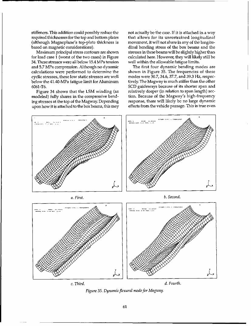
stiffeners. This addition could possibly reduce the not actually be the case. If it is attached in a wayrequired thicknesses for the top and bottom plates that allows for its unrestrained longitudinal(although Magneplane's top-plate thickness is movement, it will not share in any of the longitu-based on magnetic considerations). dinal bending stress of the box beams and the
Maximum principal stress contours are shown stresses in these beams will be slightly higher thanfor load case 1 (worst of the two cases) in Figure calculated here. However, they will likely still be34. These stresses were all below 15.4 MPa tension well within the allowable fatigue limits.and 5.7 MPa compression. Although no dynamic The first four dynamic bending modes arecalculations were performed to determine the shown in Figure 35. The frequencies of thesecyclic stresses, these low static stresses are well modes were 30.7, 34.6, 37.7, and 39.3 Hz, respec-below the 41 .40-MPa fatigue limit for Aluminum tively. The Magway is much stiffer than the other6061-T6. SCD guideways because of its shorter span and
Figure 34 shows that the LSM winding (as relatively deeper (in relation to span length) sec-modeled) fully shares in the compressive bend- tion. Because of the Magway's high-frequencying stresses at the top of the Magway. Depending response, there will likely be no large dynamicupon how it is attached to the box beams, this may effects from the vehicle passage. This is true even
a. First. b. Second.
c. Third. d. Fourth.
Figure 35. Dynamic flexural mode for Magway.
61

though the bogies are spaced far apart, like those * To evaluate, from the performance data, theon the Foster-Miller vehicle, which had a signifi- LSM's thrust capability for vehicle accelera-cant dynamic effect. tion and grade climbing.
Conclusions. The limited analyses tell us that theMagway is a very stiff and well-designed struc- Introductionture. The stresses appear to be low throughout, LSMs consist of two electromagnetic members:which is a primary requirement for an aluminum the armature and the field. In long-stator systems,structure under cyclic loading, the LSM armature, commonly called the stator, is
Further study of this structure should include located on the guideway and the field is locateda series of dynamic analyses with worst-case on the vehicle. Short-stator systems have thesevehicular loadings, including guideway curva- structures reversed.ture. While the stiff Magway will likely prevent Electromagnetic suspension (EMS) systemsmuch of an increase in the dynamic deflections make use of iron structures for both the field andover the static case, a thorough study of the the stator. The saturation of flux density in the irondynamic stress variations within the structure is limits the magnitude of the flux density that cannecessary to ensure its fatigue durability, be obtained in the air gap. This limits an EMS to
small air gaps, typically of the order of 10 mm.3.2.2 Linear synchronous motor* The Grumman SCD's innovative use of super-
conducting coils in conjunction with the iron-coreObjectives stator has the potential for increasing the stator-
All of the maglev concepts investigated use to-field air gap to 40 mm.guideway-mounted linear synchronous motors Electrodynamic suspension (EDS) systems use(LSMs) to propel the vehicles. These motors air-core structures for both the field and stator.present high capital costs, and their power con- Superconducting field windings on the vehicle aresumption creates the system's highest operating required to achieve the large flux densitiescost. For these reasons, the GMSA team required required for operating EDS at large air gaps. Thesean LSM model as a performance-evaluation tool. air gaps typically operate with a 100- to 200-mmAlso, LSM performance data were needed to spacing between the stator and the field.simulate the operational performance of each con- LSMs can be controlled to produce orthogonalcept along specific corridors (see section 3.3.1). forces, for example, forces that act in the longitu-The resulting model (LSMPOWER) is able to dinal direction and in the direction perpendicu-evaluate both iron-core and air-core LSMs and lar to the longitudinal. Almost all maglev systemsfulfills both needs. make use of LSMs to achieve either lift and pro-
The specific objectives of this work are: pulsion, or guidance and propulsion. The LSMused in the TR07, for example, provides both lift
"* To determine the equivalent circuit param- and propulsive forces. The LSM is similar to itseters from the basic size and layout of the rotary counterpart in that a machine of fixedguideway-mounted stator winding and dimensions and materials produces a finite totalvehicle-mounted field windings. force. Trade studies then determine how to appor-
"• To determine the required electrical charac- tion the split of the orthogonal forces. Iron-coreteristics at the terminals of the LSM to meet structures typically produce large vertical forcesthe specified thrust conditions. because of the presence of the iron. On the other
"* To compute the thrust margins required in hand, the operation of air-core structures can beeach concept (i.e., the thrusts required for tailored through their control system to split theacceleration and for operation on a grade). force capability from being all longitudinal to all
"* To compute performance data (power, effi- vertical or a combination of both.ciency, power factor, etc.) at the input to the The power factor, that is the ratio of power con-LSM and at the output of the variable fre- sumed (P) to power applied (S), for LSMs can bequency converters located along the guide- significantly less than unity because of the induc-way. tance of the motor. The inductance causes LSMs
to operate with a lagging power factor. The prin-cipal component of inductance in iron-coremachines is a result of the magnetic circuit of the
• Written by Frank L. Raposa, Consulting Engineer. iron. For air-core machines, the relatively large size
62

of the stator winding, which is required to maxi- Table 27. LSM model description.mize the mutual coupling between stator and Based on classical synchronous motor models
field windings, also results in a large induc- * Two-axis theory model for iron-core LSMs
tance. Air-core machines typically have lower e Magnetic coupling model for air-core LSMs
power factors than iron-core machines. Further, Basic assumptions
the field winding of an iron-core machine can - Linear behavior of the magnetic field
be overexcited and controlled to provide power - Effects of harmonics not critical to performance
factor compensation, with the result that unity Basic modeling equation at the air gap sets the electrical power
or even leading power factors can be achieved, equal to the mechanical power
Methodology Pelectrical = Pmechanical
Table 27 summarizes the pertinent assump- Np• El 1 .Icos(y0) = F, -u,tions and considerations for the model. The key Single LSM model can be used for both iron-core and air-core
to analyzing electromechanical devices is to set LSM modeling equations for maglev performance model.
the electrical power equal to the mechanicalpower at the air gap. Figure 36 identifies thebasic modeling equations used to determine the aggregate length of the LSM field windings forvalues of electrical and magnetic parameters each LSM stator on the guideway. For example,required to meet specific thrust-speed conditions. in a distributed magnet system, such as the TR07,The phasor diagram shown in Figure 37 defines lV is the sum of all field magnets on one side ofthe terminal conditions for determining the com- the vehicle. For a bogie system such as Magne-ponents of electrical power for specific thrust- plane, Iv is the sum of all of the vehicle-mountedspeed conditions of the LSM. propulsion superconducting coils. The remaining
Figure 38 illustrates the joining of the LSM terms of the model are defined on the figure.model to a model of the wayside power distribu- LSMPOWER models from the LSMs to the con-tion system to form the model LSMPOWER. The verter stations used to supply conditioned power.vehicle is shown as a moving wedge of magnetic That is, it does not model the connection of eachlength IV. The magnetic length of the vehicle is the system's converter stations to a utility grid (energy
Air Gap
Pelectrical = Pmechanical P: Power yo: Angle between E, and I1V1: Stator voltage tp: Field winding pole pitch
Np El - • cos(y0) = Fa" us Np: Number of phases D1 : Mechanical losses-Fa: Air gap thrust 1: Stator current
E1U=2•1•p -N •B 5•us Fý: Output thrust R1: Stator resistance
B1 = (n/2) - [./(,rp • 1)] u.: Vehicle velocity XI: Stator reactance
BI: Air gap flux density El: Back EMF
4= Mf • If/p &: Air gap flux fl: Frequency1: Stator width MC: Mutual inductance
=Us/(2 'p) p: Field pole pairs If: Field currentN: Turns/pole/phase (or no. of slots/pole/phase)
Figure 36. LSM equivalent circuit.
63

v1 factors for these converter stations, and wepresent resulting overall values for each systemin the last subsection here.
Model verificationWe used information from Terman (1943),
Fitzgerald et al. (1971), Brown and Hamilton70 E El(1984), Friedrich et al. (1986), Nasar and Boldea
(1987), Miller (1987), and Heinrich and Kretz-Ey schmar (1989) to develop and verify the model.
d• hIn particular, Miller (1987) provided speed-thrust and power data for TR06-II. This earlier
At the terminals of the LSM: VI,=.(RI+jX 1)+E" vehicle has a similar shape to TR07 andThe output power is given by: should closely approximate its performance.
Real power P = V, 1 1 cos(O) We, therefore, used the TR06-II data to verifyLSMPOWER. We also compared the model's
Reactive power Q = Np" V1 ' " sin(•) results to those generated by the SCD contrac-Complex power S = N• V" 1 tors. In general, agreement was excellent, giv-
In terms of the power angle (8): ing us high confidence in our results.Real power P = Np [V1 Id sin(8) + V1 Iq cos(A)]
Where Id and 1. are the component phasors of I Application of LSMPOWERto the TRO7
Figure 37. LSM power output relationships. Published references could not be obtainedthat define the thrust-speed requirement for the
TRO7. However, because of the pend-Rt !xf ] L ,XL ing application of TR07 in Florida, pri-
vate data on several TR07 systemsConverter were given to the Government to aidOutL p in evaluation. TR07 LSM propulsion-
Ž performance data have been releasedto the GMSA team for their inclusion
af -IXf IR, , Ix, R .]X in this report.&-,I We used the configuration of theConverter' Emsland test track power system andoutput --- " V m frequency converter capacity to esti-
1L - mate the thrust-speed capability ofL: LSM block length the TR07. The motor current limit of1,: Magnetic length of vehicle 1200 Aper LSM establishes the maxi-Rr. Feeder cable resistance mum thrust capability and the fre-Lf: Feeder cable inductance (Xf = 2nf1 Lf) quency converter output transformer
RL: LSM block length resistance ratings of 7.2 MVA per LSM limit theLL: LSM block length inductance (XL = 2nfLL) maximum power capability (Hein-rich and Kretzschmar 1989). The
Rt: Rt = RL" [(L-Iv)/L] Transrapid system intended forLt: Lt = LL (L-Iv)/L) (Xt = 21!flLt) Florida is expected to have the sameX: Reactance 1200-A limit per LSM, but the powerf. Frequency capacity of the converter stations is
Figure 38. LSM and power system model. unknown at this time.Using the LSMPOWER model, we
source). We did this to highlight differences attrib- produced performance data for theutable to the LSMs. Thus, most of the results here TR07 operating under the above conditions. Thefor energy consumption and power factor are at baseline vehicle assumed was a two-car consist.the output of the converter stations. Nevertheless, The following parametric data were developedwe separately computed efficiencies and power for the analysis:
64

Blocklength resistance RL: 0.1209 Q power limit, the LSM switches from constantBlocklength inductance LL: 0.0005236 H thrust to constant power at some speed condition.Direct axis inductance Ldm: 0.0002274 H For the data analyzed, constant thrust changed toQuadrature axis inductance Lqm: 0.0000944 H
Vehicle magnetic length 1,: 45 m constant power at approximately 60 m/s. FromLongitudinal length of stator L: 300 m this speed to the maximum speed of 133.3 m/s,Field winding pole pitch tp: 0.258 m the power was held constant at the 7.2 MVA perWidth of LSM stator 1: 0.16 m LSM. Thrust and related power, voltages, andPole pairs per LSM p: 75Slots per pole per phase N: 1 current data are shown in Figure 39 for three loca-
Number of phases NP: 3 tions, namely, the input to the active LSM at theNumber of LSMs per consist Nm: 2 vehicle, the input to the LSM stator blocklength,Resistance of feeder cable Rf: 0.3 n and the output of the frequency converter sta-Inductance of feeder cable Lf: 0.0006 H tions.Air gap flux density BI: 0.959 T The efficiency of the LSM at maximum thrustMaximum stator current per LSM: 1200 AMaximum power per LSM: 7.2 MVA capability varies considerably, depending on the
measurement location. For example, the efficiencyThe above data were obtained from available peaks at 99% at the input to the active LSM and
references (Heinrich and Kretzschmar 1989, is fairly constant over a wide speed range. At theFriedrich et al. 1986, p. 243-249) and, where pos- frequency converter output, the efficiency peakssible, were independently verified through calcu- at 87% at a speed of 133.3 m/s. The efficiency atlation. this point is also quite sensitive to speed because
Figure 39 summarizes the performance capa- of the power losses in the feeder cable and LSMbility of the TR07 LSM. The maximum thrust blocklength. The power factor shows similarcapability of TR07 was determined as 55.1 kN per trends, with it being approximately 90% laggingLSM or 110.2 kN for the consist. Because of the at the active input to the LSM and approximately
I. I I I i I i i
I_ ,I ,1I I I I IS- I I[" l I I
i I I r I I
I I I I
I I I I I I
so -- - -- 1 -- -
30 20 40 - 1040
kIIN 20 . . . r T . . .- -
,0 -, -- _ - -
VehiLe L Speed (m/al
9I)(V) VI (VI (V) t1 (Al (A) P PI ) 5 (KWM) PFIVP)3) Ef 9XLRVI
0.0 55.1 0.0 0 22 1201 08 1.00 0.0010.0 55.1 05 163 193 1201 .063 .69 .91 .8
15 .0 55.1 4.1 244 2 79 1201 .90 1.01 .9 9120 .0 55 .1 4 .5 326 366 1201 1.18 1.32 .990 .9330.0 25.1 5.4 488 539 1201 1.73 1.94 .89 .95
40.0 55.1 6.6 5 2 1201 2.28 2.56 1.19 0.
50.0 55.1 8.1 814 885 1201 2.83 3.19 .9 .9760.0 55.1 4.9 977 1e5 1201 3.38 3.81 .89 .99
60.0 54.9 10.0 985 1066 1196 3.40 3.82 .89 .9470.0 5.7 11. 6 1140 1223 1105 3.62 41.0 .89 .98
80.0 47.0 13.7 1302 1388 1024 3.82 4.26 .90 .99
90.0 435.8 6.2 1465 1552 955 399 4.45 .90 .99
100.0 41.1 19.1 1628 12716 995 4.15 4.61 .90 .9990.04 44. 12 145 15 95 3.9 4 .4 76 0 99
110.0 38.7 22.3 1791 1880 843 4.29 4.76 .90 ,99120.0 36.6 25.9 1954 2044 797 4.42 4.89 .91 .99130.0 34.7 29.8 2116 2208 756 4.54 5.01 .91 .99134.0 34.0 31.5 2182 2274 741 4.59 5.05 .91 .99
a. LSM thrust vs. speed, maximum thrust.
Figure 39. Performance capability of the TR07 LSM.
65

7
P'M
A
0 20 40 s0 s0 100 120 140 I60V.hlcle Speed (m/s. b. LSM power vs. speed,
TRO7 2 CAR-CONSIST: TABLE 1. LSM Electrical Performance at Vehicle
If) ICM A" f lqV I()V I I (&(A PIM M)PP~)ZC
0.0 55.1 0.0 0 22 1201 .08 .08 1.00 0.0010.0 55.1 0.5 163 193 1202. .63 .69 .91 .8815.0 55.1 4.1 244 279 1201 .90 1.01 .90 .9120.0 55.1 4.5 326 366 1201 1.18 1.32 .90 .9330.0 55.1 S.4 488 539 1201 1.73 1.94 .89 .9540.0 55.1 6.6 651 712 1201 2.2B 2.56 .89 .9750.0 55.1 8.1 814 885 1201 2.83 3.19 .89 .9760.0 55.1 9.9 977 1%58 1201 3.38 3.81 .89 .9860.5 54.9 10.0 985 1066 1196 3.40 3.82 .89 .9870.0 50.7 11.6 1140 1223 1105 3.62 4.05 .89 .9880.0 47.0 13.7 1302 1388 1024 3.82 4.26 .90 .9990.0 43.8 16.2 1465 1552 955 3.99 4.45 .90 .99
100.0 41.1 19.1 1628 1716 895 4.15 4.61 .90 .99110.0 38.7 22.3 1791 1880 843 4.29 4.76 .90 .99120.0 36.6 25.9 1954 2044 797 4.42 4.89 .91 .99130.0 34.7 29.8 2116 2208 756 4.54 5.01 .91 .99134.0 34.0 31.5 2182 2274 741 4.59 5.05 .91 .99
7
6 4- . . . --+• - • . . .o. .- - -
S -- - - 7 • 1 _ _ . .•. .4 - - - - -2• -- r - •. . . .• -V 3/ L J - - ,
M 2 . . .- - -• / - - - -- - . . . . . - _
i IIOtI I*II I I I I
WI
0 20 40 60 8o 100 120 140 16O
Vah~ol. Speed (./a) c. BLSMlg input vs poeed,
TR07 2 CAR-CONSIST: TABLE. I. LSK Electrical Performance at LSM Block
Uq(mIA) 1r(W) FXNr41 E..... VLi1Jr M U M) maximum thrust.0.0 55.1 0.0 0 145 1201 .52 .52 1.00 0.00
10.0 55.1 0.5 163 332 1201 1.07 1.20 .90 .5115.0 55.1 4.1 244 434 1201 1.35 1.56 .86 .6120.0 55.1 4.5 326 537 1201 1.62 1.94 .84 .6830.0 55.1 5.4 488 746 1201 2.18 2.69 .81 .7640.0 55.1 6.6 651 956 1201 2.73 3.44 .79 .8150.0 55.1 8.1 814 1167 1201 3.238 4.20 ,78 .460.0 55.1 9.9 977 1378 1201 3.3 4.96 .77 .9860.5 54.9 10.0 985 1396 1196 3.84 4.97 .77 .9870.0 50.7 11.6 1140 158 1105 3.9I 9 5.13 .78 .8980.0 47.0 13.7 1302 1716 1024 4.14 5.27 .79 .9190.0 43.8 16.2 1465 1883 955 4.27 5.39 .79 .92
100.0 41.1 19.1 1628 2049 895 4.40 5.50 .80 .93110.0 38.7 22.3 1791 2214 843 4.51 5.60 .81 .94120.0 36.6 25.9 1954 2379 797 4.62 5.69 .61 .95130.0 34.7 29.8 2116 2543 756 4.72 5.77 .82 .96134.0 34.0 31.5 2182 2609 741 4.75 5.80 .82 .96
Figure 39 (cont'd). Performance capability of the TRO7 LSM.
66
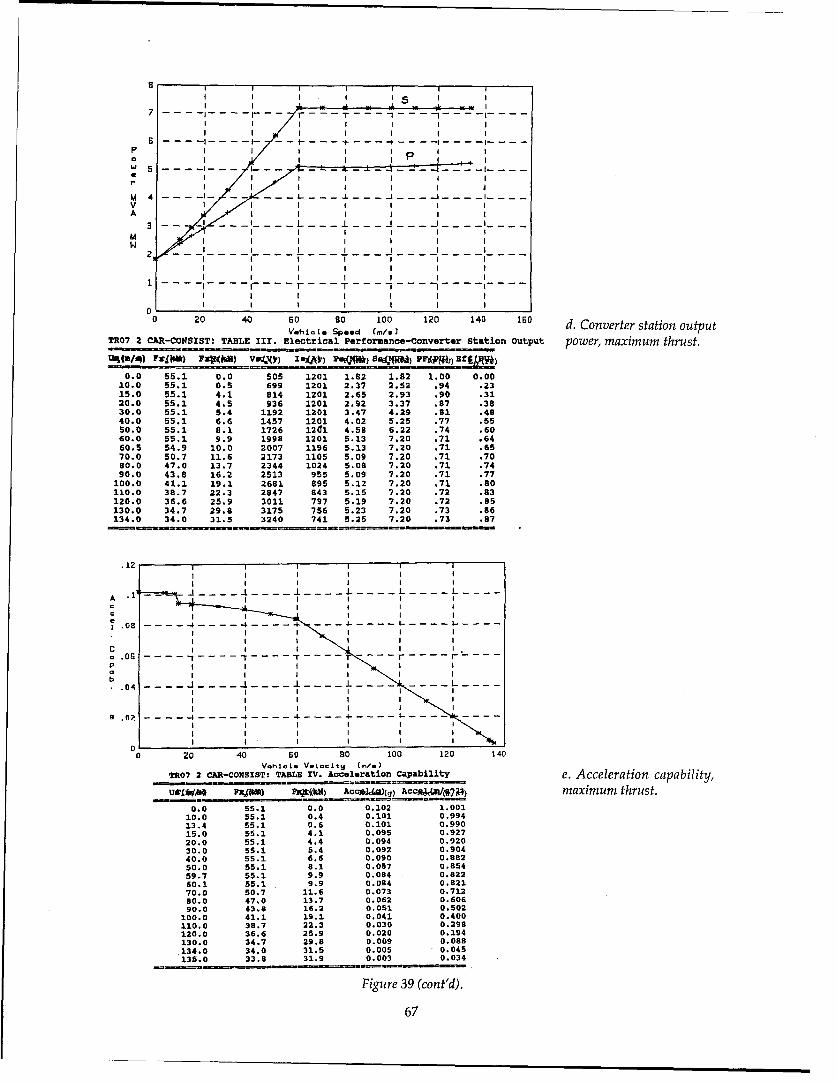
8I I I I I I
I I I I I 5 I II • I-
7-- - .-.- l-- - - -- 7 - - - T • - -1 - - - -
I I- 1 I I-
M 4 - - -- - - -i i
3 L - I J I -
MW2"
I
f r' T 7 - -- ...
0 20 40 so 80 100 120 140 ISO d. Converter station outputVehi~le Spend (m/0
3
TR07 2 CAR-CONSIST! TABLE III. Electrical Performance-Converter Station Output power, maximum thrust.tStM/94) ftla) F3~bR) VSe~) Iu~1?) PaiQWN* S4id.") PF]Wob1 EfIMVJ3
0.0 55.1 0.0 505 1201 1.82 1.82 1.00 0.0010.0 55.1 0.5 699 1201 2.37 2.52 .94 .2315.0 55.1 4.1 814 1201 2.65 2.93 .90 .3120.0 55.1 4.5 936 1201 2.92 3.37 .87 .3830.0 55.1 5.4 1192 1201 3.47 4.29 .91 .4840.0 55.1 6.6 1457 1201 4.02 5.25 .77 .5550.0 55.1 8.1 1726 1261 4.58 6.22 .74 .6060.0 55.1 9.9 1998 1201 5.13 7.20 .71 .6460. 5 54.9 10.0 2007 1196 5.13 7.20 .71 .6570.0 50.7 11.6 2173 1105 5.09 7.20 .71 .7090.0 47.0 13.7 2344 1024 5.09 7.20 .71 .7490.0 43.8 16.2 2513 955 5.09 7.20 .71 .77
100.0 41.1 19.1 2681 895 5.12 7.20 .71 .80110.0 38.7 22.3 2847 943 5.15 7.20 .72 .83120.0 36.6 25.9 3011 797 5.19 7.20 .72 .85130.0 34.7 29.8 3175 756 5.23 7.20 .73 .86134.0 34.0 31.5 3240 741 5.25 7.20 .73 .87
.12ii iii
I I I I I I
i | I I i I
SI - - -
I II I I
. .0 OG - - - - -- - - -- •- - - -
I I I - I• I I
I I I. I I• I04
0 20 40 so 80 100 120 140V~hliýL V.1o-itS (m/.)
TR07 2 CAR-CONSIST: TABLE IV. Acceleration Capability e. Acceleration capability,U9AWLi*V Mom~l) 9FtJ8W) Acc*34(g) AcAac,7 maximum thrust.
0.0 55.1 0.0 0.102 1.00110.0 55.1 0.4 0.101 0.99413.4 55.1 0.6 0.101 0.99015.0 55.1 4.1 0.095 0.92720.0 55.1 4.4 0.094 0.92030.0 55.1 5.4 0.092 0.90440.0 55.1 6.6 0.090 0.88250.0 55.1 8.1 0:087 0.854
59.7 55.1 9.9 0.084 0.82260.1 55.1 9.9 0.084 0.92170.0 50.7 11.6 0.073 0.71280.0 47.0 13.7 0.062 0.606
90.0 43.8 16.2 0.051 0.502
100.0 41.1 19.1 0.041 0.400110.0 38.7 22.3 0.030 0.298120.0 36.6 25.9 0.020 0.194130.0 34.7 29.8 0.009 0.088
134.0 34.0 31.5 0.005 0.045
135.0 33.8 31.9 0.003 0.034
Figure 39 (cont'd).
67

4UI I I I I I
I I I I
II I I I I I
30 -. - .- . I . . .- -- t- - - I- L _L -- --- - 1- --I-- -
I I I I I I II
h- 25 ... - ... -i---- t - --- -+ .- - - - -,, - - - - -
S2 0 . . .- . . .-- . - - , . . - -
0 20 40 60 so 100 120 140 1S0Speed (n,/al f. LSM thrust vs. speed,
TR07 2 CAR-CONSIST: TABLE I. LSM Electrical Performance at Vehicle normal thrust.
tUSXtt~d) FXXJNX() FZP(") VIM8) V101 MUM~) SKW AXV )mSW) ff (PU)
0.0 0.0 0.0 0.0 0:0 0,DOI 40 aa 0O 1,90 1.00
10.0 0.5 162.8 ILSZ.,8 ID,) 1039 ,M1 -a"' ING5 1 0015.0 4.1 244.2 2A4.7 248.7 4 4 ,216 .=7 ..9 .9920.0 4.5 325.6 3=9.6 33•. Z9 980 am9 .BUD .9* .9930.0 5.4 488.4 408.0 423.5 118 .3376 .9W7 l.M 1.0040.0 6.6 651.2 4W2. 057.• 143M4 .26 am 1.90M 1.0050.0 8.1 814.0 634A 8a3Za 11417 .A41 .ae4 3_9W 1.00
60.0 9.9 976.8 MM.& 215..) 21A4 .M0 .954 1.2m 1.00
60.5 10.0 984.9 9".% 21.40 216r AWD .895 1U92 1.0070.0 11.6 1139.6 '11.&L 1i1.2 252380 .1I .887 1.%8 1.0080.0 13.7 1302.4 11330.4 1292.4.ZL 2L1 1Lw IBM19 1.23 1.0090.0 16.2 1465.2 1485.2 14i.M. 3528 21506 IMS 1.9M 1.00
100.0 19.1 1628.0 IE. 166".. 41527 21•n Zan 2- 1.00
110.0 22.3 1790.8 13M.5 1848.3 433 2.5W 2894 .93 .99120.0 25.9 1953.6 2U3.0 2626.7. 6t37 314M LM .93 .99130.0 29.8 2116.4 2•M3.4 21,4 G5043Q 4280 4MB .93 .99134.0 31.5 2181.5 2• .5 2Z".?5 6M057 4WSJ5 45V7 .2 .99
p
I I I II
I I ! i I I
7 - -- I - J -- -- - I
6 -ir - -- - ....
0 Ie I II I / 1
a -- , - - T- - --- T. . . .
M 4 -- i -rT T -1 -- -7- -- I. .
vh.i i Speed I."/m
3 -0 . T -T 01 0- - - - -i.00
200 45 7. 31. 9 T0 -. '•g . "0 -i3 .88 .
2 - - i -I. . T - "- - --- . . .
0 20 48 so 80 100 120 14D IGO g. Converter station outputV6h09 71 speed (./a.
TR07 2 CAR-CONSIST: TABLE III. Electrical P1r6ormanc!-Converter Station output power, normal thrust.
80.0 3.7 .0 1.8 0.000 . .00 01Sao 1890 1.00
10.0 0.52• 80.8 106.V 1019 .81 .11 .. 0 .9715.0 4.1 286.4 280.4 8174 Orb .9W ._3S .86
201 0 4. 5 37420 323 0 9250 . la ,81 .32 .88
30.0 5.4 553.3 264.2 164178 .215 ,3.1 . 9040.0 6.6 739.4 U5~.4 14294 .29 SUL SX .9150. 8. 933:1 9-TJS- i1747 -0 .SW0 _9L .91
600 9:911374 12311t.4 21i5N• .65l SM .6& .9160.•5 10.•0 1147.•4 1 YL15. 21659 .06 M• -- . 91
70.0 11.6 1345.2 1329.0 D 25690 1.2 IBM6 .&2 .9150.0 13.7 1568.2 15M,2 2.9221 2,AD law• S( .91
90.0 16.2 1808.8 18M.81 ISZ29l 1.61 IME _S4) .90
100.0 19.1 2069.6 26".6 •1137 2.52 2• M .8• .90110.0 22.3 2353.6 2MM•J.6 "6 g53 3.10i 3,2M W• .89120.0 25.9 2664.3 26".7 $6417 3-51 IL .10• .89
130.0 29.8 30D5.0 3659-0 i56.13 6-4 53 am% ,.8
134.0 31.5 3150.6 325.6 £8627 4.8) 6349 .3 .88
Figure 39 (cont'd). Performance capability of the TR07 LSM.
68

72% lagging at the frequency converter output. Blocklength resistance RL: 0.17720The low power factor at the converter output loca- Blocklength inductance LL: 0.0012 H
tion is heavily influenced by the reactance of the Direct axis inductance Ldm: 0.00005 HQuadrature axis inductance Lqm: 0.00003 H
feeder cable. Vehicle magnetic length 1,: 18 mThe results of the LSMPOWER analysis for the Longitudinal length of stator L: 500 m
TR07 compare well with the limited published Field winding pole pitch tp: 0.75 m
data and the private data available to the Govern- Width of LSM stator 1: 0.20 m
ment. Pole pairs per LSM p: 12Slots per pole per phase N: 3Number of phases N.: 3
Application of LSMPOWER to the Number of LSMs per consist Nm: 2
SCD linear synchronous motors Resistance of feeder cable Rf: 0.1390Grumman. The Grumman LSM concept pro- Inductance of feeder cable Lf: 0.0012 H
vides integrated levitation, guidance, and propul- Air gap flux density BI: 0.896 TMaximum stator current per LSM: 1343 A
sion with a single machine. It has an iron-core Maximum power per LSM: 7.5 MVALSM with a conventional stator. Like the TR07,there are two LSMs per vehicle. The levitation The above data were obtained from informa-magnets are distributed over the length of the tion provided by Grumman during the in-progressvehicle, and these magnets use superconducting reviews (IPRs) and from the SCD final reportcoils in conjunction with iron cores. Conventional (Grumman 1992a), and, where possible, werecontrol coils on the magnets are used for levita- independently verified through calculation.tion, and the combination of superconducting Figure 40 summarizes the performance capa-coils with conventional control coils achieves an bility of the Grumman SCD LSM. The maximumair gap of 40 mm. thrust capability of Grumman's two-car consist is
The LSM blocklengths are typically 1000 m and 30 kN per LSM or 60 kN for the consist. Theare center-fed in 500-m segments. Converter sta- design provides a constant thrust up to the designtion blocklengths are 4000 m with cables feeding speed of 134 m/s. The charts in these figures showeach 1000-m block. The LSM field current is set thrust and related power, voltages, and currentfor operation at a leading power factor, with the data for two locations, namely, the input to theintent of achieving a power factor that is close to active LSM at the vehicle and the output of theunity at the input to the LSM block, frequency converter stations. Data are shown for
Linear generator coils are set into the field both maximum- and nominal-thrust conditions.winding pole faces in a way similar to the TR07 to The power-limited condition of 7.5 MVA per LSMtransfer power to the vehicle. In addition to these is just reached at 134 m/s.coils, high-frequency power is injected into the Figure 40e shows the acceleration capabilityLSM stator coils and transferred to the vehicle via for the baseline 61,224-kg vehicle. With a totala transformer. These two techniques, when taken thrust of 60 kN, the LSM may maintain a maxi-together, provide all-speed power transfer capa- mum vehicle acceleration of about 0.09 g frombility to the Grumman SCD vehicle; this concept zero speed to 60 m/s; this diminishes to 0.05 gdoes not require the auxiliary batteries of the TRO7. at 134 m/s.
We produced performance data using the Grumman also developed the parameters forLSMPOWER model for the Grumman SCD oper- an LSM with a copper stator winding. This mo-ating as described above. The baseline vehicle was tor has a maximum thrust of 100 kN. It has a low-assumed to be a two-car consist. Grumman's speed acceleration capability of about 0.16 g andbaseline concept also makes use of an aluminum has reserve acceleration of about 0.09 g at 134LSM winding, which produces a maximum thrust m/s. Figure 40f shows the acceleration vs. speedof 30 kN per LSM. This results in a low-speed capability of this 100-kN LSM.acceleration capability of only 0.09 g. For better The efficiency of the LSM at maximum thrustacceleration and grade-climbing capability, the varies considerably, depending on the measure-Grumman LSM would have to be modified by ment location. For example, the efficiency peaksreplacing the aluminum LSM stator winding with at 99% at the input to the active LSM and is fairlya copper winding, constant over a wide speed range. At the fre-
We used the following parametric data, deter- quency converter output, the efficiency peaks atmined from the baseline case of aluminum stator 70% at a speed of 134 m/s. The efficiency at thiswindings, in our analysis: location is also quite sensitive to speed because
69

-- -- • _ _ _- - -,-_ L• -• ) -,L_-- " I. . . . . . . . I i - -, - I " - -
i- -- 1-- --- -- -T - - •T-- ------ -=------ -- _i- -- - .. .
I-- --- I I_ _ L-- 36_ . - - -4- -- --
- - -- - - - - - - : -- -I I-
- - - - - -- - -- - - - - -
, I- - IT - -------- r - - -
S. . . s[ - - I- - , - t - . _- : I • T- -
.- 2 -- I I • I -- -- - I -- -T
- 7 7 -T - -T- 0 - _ r- -
S. .. . . .. . . . .
V . . . . . .
- -d-(•/- • ,• ) • • • (,- - - - _ - ) - T * T - - r • -. a x m m t h u t- 0 - )o - =-05 - -.- . 6.14 0 -. 0 -00 - IqQ -I- 0- -
-10 7 - ._ -J 07 76 -t
SI 30 .. - - -T -- -- T -- = -I- 7I -1 L
- 7 - - 7r.- - r - - -r
_ 3 • •00 -2-7 4 23. 424. 1430 % 3 -1 - • )8• 0 •
0 0 0- 0 403 4 - B - 10 - - - ,4 4 - - 0 ,u -- - -5"2.0-- 0- - 0 4 .y - -80- 1- 0-8 -GCACNIST(Al) . TABLE -1. LSM-Elelctricalr Perffif-- t A~ic: - a LSM thrust vs. speed,
:A(A)~ --~) P9)YY)*ýQqW -wftp Mips , maximum thrust..0. 3-0.0- 2.05- 0-00- .8. 6. 1343.0) -0.03 _-0,93 _- D_..00l-fUa-PoCý0.6
- 10.0G- -0.90 -2.-13 -91.2 -96-73 n42C3 0 -=O33 - 0.39 - -OL.20- 0-.-63- -e.89-115.0 30.0 2.23 f363. j40..7 i341.0 0..-8 -0,57 - -0.29, 0.855 0.9291-20.0 -30.0 2.37 182.'5 185.2 1343.0 " 0.63 20,75: -0.39 0.850 0.94-6
- 05.0 -30.- 2. 
.12
......S
i 0
- 0 .10.2 -
-
- 1--1- .I:94- I
c-~~ 7- 7 Z-i- i
-- -- -""e'k- S-hl-,4- - "-I - - -- -GR 2--eAR-CONSI-ST(A7 ~: TABLE IV. Atceletation Capabilrity __ c. Acceleration capability, maxi-
- -USVWPh9') F)ELWIAT) FUQMN) AcckJ44Xg) Acce]ujj~qxaj~s2
) mum thrust."0.0 30.0 2.05 0.093 0--I ;91 -
-o ----10.0 __-3-- -2.13 - - 0.910 - - 0-- 9 - - -_15.0- 30- 2-23l 0,093 _.907-
- -20.0 - 3 -.. - 2.37 _- - . - -0.90-k--- 25.0 30.0 2.55 0.091 0.89730_0 30.0 . .-2_77- .0i_ - -- 90 - -
.4 40. 30.0 3.33 0.0."89 -- - - --- 71- -- - 0.0 - 4.05 0.086 0,- 848.
-- 60_0 - S0.0 _ 4._93 0,084 0.819.- 70.0 - 30.0 5.75 0.081 6 .792 __-- -8010 30. 6:77 ( 0077 0.75F-- 90.0 30.0 7.99 0.073 _ 0,119-
-- 100,0 -30.----9.40--------0.0,99- 0.673 --- -110.-0 3-0.0 - 10.99 0.0163 0.-621- -
-- -- 120.-0 U. -00 -42.746 -0.0-57 - -0;563 -1-"..-0 - -30.0 -14.-69 --0:051 0.50-- - 3 4.0- - 30.0 1552 4 04 -0.473--
-- 135.0 30.0 15.72 0.048 0.466
_20
- - 4 4 -: -- 4 -i-
L J 09 - 9- -
J I -,
i0-.0 3 . 2. -- r.9 - 1 •.1-
_ - 0 -- -
14.0- -. -- -- J -L
I- T 1 -- 1 1_
-~j -Tu
6ITO -- --- - -- -- -. -- -_-- -- _ -
-- 0- 20- 40 6 70 10 100- -120- -140 18-V100 3i94Sp..;d Tn - ./ - 0 3-
- CR 2.-CARý-CONSIST(A1): -TABtE 6.1, sM Eetil rcl8n6ateicj - d. LSM thrust vs. speed, normalq --10t) '4). thrust.
- 6 470- _.3-- 6-.6 -0.06 0.00 -0.00 -1.000 -0.10-0- 2 3- 91.2- .6 - 05. -. 02 -0•.0- -- Q.-02 0.420 O.Vn
-15;O.- 2:23 -136.9- -137.1 _ 99-.8 _- -03 -- 0-0-4 -020.9--520-.0 1-2.37 f82.5 -182.7 -106.1 0. - 05 - 0,06 - -0.03- 0-.819- 0.995-25.0 2.55 228.j .228..2 114.2 0.06- 0.08- -0.04 0-.619 0.99
- _.0 2.. - .273-7 -273-.7 - 12-4.0- 0.08- 0-.10- - -0.06 6.81§ 0.9i0-4-0.0- -3.3-- -364-9 _-364-.7- 149.37 z0ir v.16 Z 5.819 - 0. "I7-5035 4.05 -46. 2. 455.6 181.3 _.20 -0.25 -0. 14 -0.2-0 -0.99-7-
-60-0 4-493 -547.4. 5.46.3 220-7 -0.3-0 -0.3-6 _-0.11l_-0 8O_-20 r0v2T- 70- - 5-.75- 6-,-8. 63679 257.4 0740 0-,49 -,-.2C 0-821- 0-997S80.0 6.77 729.9 -7273 303 - 0.4 -- 0.66 - 0-38- 0-822- 0,997-"90.0 - 7.99- 821.1 817.5 5- 37.8 72 -0 - 0.88 -0.50 0.-823 0.99--
. "100.0 9 .46 12.i •90,3 - 42,.- 0-94- 1-iS- -0.65 0.824 -0.99110o. 0 10.99T 1003.6 996.9 492.1 .1.21 1.47 -0.83 0.821 -0. 9_U
.- 2- -12.-76 -1091.8- 10-6.7 671.i 1 1.54 - 1.86 -1. •5 -b.a:• - --0.99-.-~3 30 ý_ 14,69 .1186.0 1175.0 657.18 1.92 2.32 -1.30 0.827 0.996-134.0 15.52- 1222.5- 110-4 -694-.6 - 2.09 - 2.52 -i.43_ 0I82& E.996_-135-0 15..72. 12-31.7 1219"2 704.0 2:13 26-.- -1.44. 0.828- 0. 99C
Figure 40 (cont'd).
71

- II: __ i I -- i I i
-- II I I I. I II SI I --- I --- I
P __
- 2 - --- I- I - -I I- -
_ __ __l I _ I __ r •- I -.I I-.- I -- / / - I
"--V-A
W--
__II I - I I
-- -r ,-- 1 "I-- -r
--- I - I -- 1 . _I I II* " - I -'....
-Q-- -- - I - I -I - I
- -- 20 40- 60 - BO- 100 - 120 140 160
- - - Voh1.I Sp.ed (./.)- - -GR 2 CAR=CONSIST-A-ý: TABLE-41-I.Electrie I Performance-Converter Station-- e. Converter station outputu400) F)M• ),_ V(%M U(A) PW) sE&) -QPVAW) PMMM EfANMz L power, normal thrust.
07.0 2.05- 29.0 -91.8 0.0-08 0.008-- 0.000 -- 1.000 0.0001-.0 2.fT 113.1 -95.4 U0."030 0,6032 -0.J12 0.921 0.712
"-I5.0 2723 156.8- 99.8 0.043 0.047 -0.019 0.914 0.780-- 0.0 -2T37 2007.- 106.,1- 0.058 -0.064 -0.027 0.909 0.816
25.U- 2.55 244.8 114.2 0. 076-- 0.084 -0.035 0.908 0.838-30.-0- 2.77 -288.8 128-4.0 0.098 0.107 -- 0.045 0.909 0.8`5-•40.0 3.33 - 376.1 149.1 0.1-54 0.168- -0.067 -t-. 917 07BT5s.0 4.08- 462.4 -181.3 0.-1-34 0.252- -0.093 ---0.929 0807-60.0 4.43 547.3, 220.7 0.342 0.362 -0.120 0.944 0.865- .0 5--75 630 -3-- 257.4 - 0.465 0.487 -0.-743 0.958- 0.865 -80.-0----- 6.77 -7-1-.0 30-. 0.629-- 0.648 -0.158 07970 0.861-90.- 7.99 -- 796.6 35-9.8 0.84-i- 0.855 -0.156 07983 0.85"-
100.4 9.40 - 883.0 4,20.9 1.108 1.115 ý-0.122 0-994 0.84n-110.0 10.99_ 975.0 A92.1 1.4.39 1.439-0.039 -- L. 000 A-120.0 12.76 1076.2 571.1 X-_ 0 1.84.4 0.116_[.998 2.91130.0 14.69 1191.0 657.8 -2.321 2-350 0.3-T3 0.987-- 0.823Y-34.0 15.-52 1241.8- 694.6 2.537 2.588 0.511 0.989 0.820.
-- M.0 1••772 125-.0 704.0-- 2.593_L 2.650 0.549 0.-78 0.819
-18----- ---- -T-
G3 L - - -I -i
.- 20 -- 4 1 - 11
. - -, - -• - -- hi• , . . p.. , -f Aapo
I I--t
II0.-- II - II 2.OS II .60 -- .56 --
0 50_ L T- 16 -
O 1 -. 50 -.- 2 2 -0 - - 0 ---
3. r -20 - 1-T4-
.04 40. 50. 3.3- 0.5j
- -50.0 50.0 4.0 0.3 _ 5
* -- 1 0 517 4.9 I
,o4 _7 -... 50.0 , 5.75 OL4 1.446
-- 100. - 50.0 Io 9.40 1 0 - --
-0 0. 5. 9.6 0.34 - .1
-hI.I.-S d 110.1 4 Acceleration 0 -1220__ GR 2 CAR-CONSISTCCu) : TABLE--IV. Acceleration Capability O-N ,;e;n100kNdesgn maximum---- /• - P(• - •(•,) •:=• •¢=•=~zLthrust.
__ 0 --I So•0- 2-ZS- 0 .•KO0 --- 1.566120.0 SO5 2713 0-159 - 1.56415.0 50.0 2.23 0.159 -1.560
-- 2r. 0 "0. 0 F. 37 0 .159 1 .556-2'6. 0 --5D. 0 --2'.55 -U-1,158 -- 1.550 -
30.0 504.0 2.•77 0.157 1 8 54S--40.0 50.0 3.33 -- 0,155 -- .b525
450.0 50.0 4105 0.153 1.50160 .- 5670 4-.3 0.•i--50 -- 1.•472 --
Fi gue0 S 4.0 t.75 0Pr147 cu1.446-84D-. 0 --50.0 --6.77 -&-.144 -- 1.412
90.0 50.0 7.99 0.140 1.372 -
-- 100.0 -- 50.0 - 9.40 0.135 -- 1.326 -
-- 101.6 50.,0 9.65 0.134 1. 318ll0.-0 48 .- 3 10-.-%9 0.-1-24 1.220
-- 120.0 .46.5 12.76 0,-113 -- 1.104 _-- 130__.0 44.9 J!L. 69 0_i01 -- 0.988
134.0 44.4 15.52 0.096 0.942
Figure 40 (cont'd). Performance capability of the Grumman SCD LSM.
72

of the power losses in the feeder cable and LSM is located under the vehicle and between the two
blocklength. bogies. High-frequency power is injected into the
The power factor shows similar trends: it is LSM stator winding and transferred to the vehicleapproximately 87% leading at the active input to via the air-core transformer.the LSM, is unity as intended at the input the We produced the following performance data
LSM blocklength, and is approximately 80% lag- using the LSMPOWER model for the Magneplane
ging at the frequency converter output location. SCD operating as described above. The baseline
The relatively high power factor at this location is vehicle was a one-car consist.the result of the leading power factor, which partlycompensates for the reactive power requirements Blocklength resistance RL: 0.20 12oftefedrcal.Blocklength inductance LL: 0.0142 H
of the feeder cable. Vehicle magnetic length l1: 2000 mThe LSM parameters used by LSMPOWER for Longitudinal length of stator L: 2000 m
the Grumman concept differ somewhat from Field winding pole pitch t.: 0.75 m
those specified by Grumman, particularly with Width of LSM stator 1: 1.2 m
respect to the internal phase angle of the machine. Pole pairs per LSM p: 2
LSMPOWER derives these parameters, where in Slots per pole per phase N: 4Number of phases N,: 3
the Grumman model they are apparently speci- Number of LSMs per consist Nm: 1
fied. However, the LSMPOWER performance Resistance of feeder cable Rf: 0.1390l
results agree fairly closely with those predicted by Inductance of feeder cable Lf: 0.0012 H
Grumman. The difference in model parameters Back EMF characteristic at aappears to be caused by the different modeling specified speed El: 2326 V at 150 m/s
Maximum stator current per LSM: 3224 Aapproaches taken. Maximum mechanical power output: 7.5 MW for vehicle
Magneplane. The Magneplane LSM is an air-core machine with a conventional meander wind- The above data were obtained from informa-
ing. The concept uses one LSM per vehicle, with tion provided by Magneplane during the IPRs
a propulsion winding air gap of approximately and from their SCD final report (Magneplane
250 mm. Superconducting propulsion coils are 1992a), and where possible were independently
located on bogies at each end of the vehicle. The verified through calculation. These data show the
propulsion coil design is intended to minimize the magnetic length of the vehicle being the same as
stray fields in the passenger compartment. This the LSM blocklength to account for the equivalent
is accomplished by operating the inboard super- circuit parameters as specified by Magneplane.
conducting coils at lower field strengths com- Figure 41 summarizes the performance capa-
pared to the outboard coils. The LSM thrust con- bility of the Magneplane SCD LSM. The Magne-
trol angle is set for zero lift capability for normal plane design requires nearly constant thrust at all
operation. This angle is controlled to provide lift speeds, primarily because of the high magnetic
from the LSM for heave damping. drag at low speeds and the high aerodynamic
The LSM blocklengths are 2000 m for the drag at high speeds. The magnetic drag peaks in
baseline concept and are end-fed from the con- the vicinity of 20-40 m/s. The maximum thrust
verter stations. Converter stations are located at capability of the one-car consist was 150 kN.
every other blocklength and are assumed to be Thrust and related power, voltages, and current
located close enough to the guideway as to not data are shown in the following charts for two
require feeder cables of any significant length. locations, namely, the input to the LSM block-
Here, we include feeder cables in the analysis for length and the output of the frequency converter
comparison with the other concepts. station.The LSM stator winding is a high inductance The thrust-speed breakpoint from constant
winding, and a power factor correction for each thrust to constant power occurs at 50 m/s. The
LSM winding is planned. Magneplane did not very high megavolt-ampere requirement at this
fully develop the details of the power factor cor- point, 94 MVA compared to 14 MW of active
rection; the analysis here considers one prelimi- power, was a result of the very high inductance
nary case of power factor correction to estimate of the stator winding without any capacitive com-
its effect. pensation. The power factor correction planned
For obtaining vehicle power, the LSM windings by Magneplane should take care of this problem.
will be used as the primary of an air-core trans- Figures 41e and f show preliminary estimates
former. The LSM interacts with an 18-mi coil that of the reduced megavolt-ampere requirement
73

__ 16q _ _• -i -- J -- -- -- --- -- - - - - -
120
-T80 4---_------- ---- T -
5-10 --- I _-• _I _ I- - " -
B - -4- --- -1I - - - -- I - I ---
- : 20 -, -._-_ 00 - - ,0 -10 -12- 4- 16-- A N PL2of4P: TA L _- -.-- - --__-, lr--- -, c.... .r . . . . u . . . .~ -- - - ---
--T
-, . -~. 0.o -,.0 .., 44. 3, -4 -6.24 -.2 ,-.0 e-~-e
-2a-40.0---1-5 ----. 1 -5 -8 -.-. -120-- 1400 -0• . JW - I - " - l - I ---
-5- 0 1507•0 24-3-2 32600. 3224. -- 8.4929.0 T.2-- 0.265
20.0 150 -.. 0 .-8 V3h.0.1 . 324./ 9- - 0.---- MANELAE(P) : TA"LE 1-- N Fectrica-l--Performance wt-•Vehioce-3.0.0. 150.0. .-.. ..0..- 3.-- 46. a. LSM thrust vs. speed,u•..•m) F2,10 PXI,() Fri* Sýý) Tý(M) 124) p(ofw, sq*'W pp"eq) Erro maximum thrust.
-30.0 1D50.0 -5.00 5.92.08 520.0 46.9 3224. -6.24 6.94 - J..4 2=00010.0--150.0 - .50 -- 53.18 -- 1-55.1 78.1 --3224. --1.74 2V.10 07385 0-.-415.D 150F-0 2.7 35.324 232.6 3007.7 3224.- 8.49-84.49 0-o20 4.292 0.2
65
2.0 140 3-00 35--50 314-8 395.92-6 9 324+. 91.-24 389.-24 0.147 0.325-30.0 150.0 4-.50 36".04 465.2 5859-.8 32684. 10774 567U._- 0._5M 0.41-32.0 150.0 4.80 57.34 49-6.2 62492.5 32324. 11004 60,39 0.15983 0.4T--35.0 IS50. 0 -5.25 5"4.92 542.7 6a16.9 3Z"24. 11_. 49 65_.94 0,_174 0O15
-80.0 -950.0 -76.00 51.37 1240.53 7E95.3 f204. 1a.24 -5..21 0.163 0.-450.0 -- 8.0 6.75 48034.617.6 974.4 3224. -12.99 -84.49 -o.1540.5
50"'0 150-.0 7.50 47 .905 775.3-9694._2- 32 - 913.7 -- 9437 T r-0-.192 -0-.58-57-.-0 1474-.2 7.-50 4.74--6 8105.3 969-5. 31466a. 13827 90,4 0.10-4 0.563CO.0 115.0 7-50 41387 930.4 970-1.2 268-7. 11.83 78 .-2 0.214 0.634-170.0 107.1 7.50 38.14 1085.5 9713.4 2303. 10;68 67:11 0.1259 0.70'r
-30.0 -93.8 -7.50 35891 12040.5 9729.4 2015. .394 35.82 0.169 0.-755--- 90.0 -- 83.3 -- 7.50 3-S.76 0795.6 978.6 1M94. 8 -. 43 5T-39 0C930 0798--T•0--•----75•-.---7. 50- -1.42-- 1-550. 7-§770. 8 1612. -9.06 -47.26 -o. 39 2 0.2110-0 68•-2 7.50 34.74 1705.7 9795.7 1466. 8.79 43.07 0.204 0.85312-030 6-2.5 T7.50 35--1 186U -7-8 9 82 3----2 13jj"• 8•-58 39.:K 0. 21T 0.874-
S1"0.0 57. 7 -f,-50 36--93 2015i.9 9853.2 1240. 8-42 36.-66 0.2-30 0.899D-1-34.0 _S6.0 1.50 37.58 207_7.9 9865.9 12-03. 8.37 35,;61 0.235 0.896--135.0 --S5.6 --2.50 3-7.76 20-%3.4 98-&9. 1 1194. 8-.36 35";.36 0.236 0-.-9z8-
-4-640.0 -- 53.6 -- 7.50 -39.68 2t"0.9 9&85.6 1-152. 9.30 34.15 0-.243
- ' - . /= X.-' 1- -- -
-0 -2 -4 - 50-- - 0- 1- 2- 1- -
- - - - --- - - - F
0 - 0-0 - 5 -
-1_0.0500--5.8-2---7- 22.4-120;- 24--;- 07515----- --1
:0
-0- -- 20 -4-9 - 80 0 - 4- 100-- 120- 14U I02-2S.. .. Vel- Sp~i.d (m - -
--- •GE•(P}-TALETI-.E•-t~c~ fo o-n(T r -t-~ Ot b. Converter station outputUSOW0 IT•.) "to"•) -V~q) --%(L -E%(•,,--4I¢q.wi- PIK 00*y Emimp power, maximum thrust.
--D.0 -150.00 -- 35.08--1093.1-- 3224.4- 10.574 10.5741 1.-000 07DUUU__10.0---150.00 35.18--2425-7- 3224,4- 12.01A 23.4"65 0";'515 0.2__15.0--150.00 35.32. 338Q-,9- 3224 "4- 12 .-8-2 32.--79-2 -1"391 t7
--20-0 15000 --3-5.50 -4390.3 -- "J24.4--.574---42.469•-- 0. 3"2"0- 0.221"-10.0 15-0.00 -36.04 -6431.6 -- 3224.4--15.074-62.214- 0.2-4-2 0.2"9-32.0 150.00 -57.34 -6843.1 -3224.4- 15.374- 66.195 0.232 0.3+2-'35.0 150.00 54.92 _7461.5 3224.4 15.824 72.17- 0.219 0.232
- 40.0 150.00 - 51.37 8494.5 3224.L 16.574 82.12.0 . 0.-202 0.46-45.0 --150.00- 48.34-9529.7 3224.4 17.12A 92.18-4 .41188 0 9050.6150--0---- 07--10- 6 .4 --- 3=i224.4 -14.074-12 0 .212- 0. 177- 0.415.5__2.0 144.23 _A6.46 10_64.5 3.100.4-17.276--98.263--- 0.1-7& 0.434-60.0 125.00 41.87 10561.7 2687.0 14.843- 85.138- 0.17-4 0.5DS570.0 1O7.14 38.14 10566.1 2303.2 12.895 73.006 0.177 0.582
-80.0 -93.75 - 35.91 10576.4- 2015.3- 11.630 63.942 0.182 0.645- 90.0 -83.33 - 34.76--10591.0-- 1791.1- 10.767 56.91" 0.1-89 0.697
-100.0---75.00--- 34.4-2---10609.--3-- 161272- 10.741 51.-J'13 0-- 9O. 8 0739i 7ITO "718 -34;774 i030..6 9 8 .685 46.742 0.207 0.7741"..0 161-.50 -35.61 120654.8 -1343.5 -- 9.336--42.944- 0.217 0.803-"30.0 -5`7.69 -36.93 1-0681.5 -1240.2 - 9.064- 39.740- 0.228 0.827-134.0 -55.97 .37.58 10692.9 -*1203.1: 8.972: 38.595 0.232 0.S36-
-135.0 55.56 - 37.76-10695.8- 1194.2- 8.950- 38.320 0.1-34 0-.-3&-__140.0 53.57 38.6"0710.7- 1151-f- 8.84-9- 37.003 0--39 0848
Figure 41. Performance capability of the Magneplane SCD LSM.
74

- _ , . ,,-- " -3 - - I- - - i _ 7 7-'• • • . .y - _ - . . . r . . .. . .
25 -4--- 4
- - - _- - - - .
. - - -- - -I A . . . .
. .1 -- --------I- - -------- • . --.
* *.. .. . . ..
. .>... . . .. . .-- .
c " I . . . I I . .I . . . .I . .
0 20 40 60 -100- .120 • .- 10- -I-" . . - I. .. .. . . . . . . . . .. V.. . .oc-- - - - - -,-_ WI-eiaratioii apa i- --- c. Acceleration capability, maxi-
S- ~s)-i . . •. . •- - ~ -- ". " - -g" " , ) . .. .m um thrust.-. 0.0 100 35;0-08 _0.234 --- -2---98 - - - -.. .. 10. - 150.00 35.18-. 0.234 - - - - --2 296- - - -
S.. . .0,,r • ,, . . . .2 ,.. . . . 94 .-
_ -. . . .- - 2. 10 10 . 0 -5 3 . .9 . ." .23 0 - - - 12 - -....- - -.-
2... 6• -d - 5 O -• )- - -. 35. 50 -- -0.234,l . c•,, .... ;.S . .mu th s .
- . ..-. . - . 150.00 36.04 0.232 . . 2.279 _
35.0 150.00 54.92 0.194 1.90--4- 0.,0 - 150.00 - 3 -- - 213, - -- -2,- 29736- - -. ---45.0 150.00 . . . 42.34 ... 0.207 ........ 2.033
.- 50.0 --- 150.00 --- 4. -0 0.208 2.042 ..52Z - - 2.0 - 144.235-0- - -46.463 - . •0.199 - . 1.95"5 ..... . . . . . .0 . ' 125.00 . 41.*7- 0.1 40 -- .. §-
7 40.0 - -107-.14 - - - 38.1A - - - 0:141- -. .1.380- - - -S.. . . 80.0 " 93.75 - 35.91 . . 0.2 ..... . 1.03 - - -
-- _--_--- - 90.0 - 3.33 34.76 0-090 - - -"0.0.977 - -..-100.0 75.00 -.. -14;42 . 0.r083 ... . 1- .63.12
-- -. . . . ..--110 0- - - -068.18 " 34.74 0.068 -- 0.6 . .". ...... 120.0 62.50 35.61 .... 0;055 ......... 4D538 - - -
130.0. . 57.69. 36.93 0.042 0.415- - - - -. . 1.34._0. 55.97 37-.5"8 - - 0.038 -.-.-.-- 0-.3-68 - - -- - - - - -- 135.0 55.56 . " 37;76 " : :0.036 .... ..... 0.3.56 . . .
S- - - --.- )140-0- - - -35-r --57 8368 - - - 0.030 . ..... 90829 ..__ .: - • .0 - f=. . . . f . .
110 I I I I I I
P -- l.
A
__ - - - -- - -
S I -- - I I -- I
50~
-0 20 40 60-- 80 -10-0 120- 140 160- ---- -V• hlýL. SP d --(.//a;) -- -
MAGNEPH-CP): TABLE_..flectrical_-erformance-conyrerter Station d. Converter station outputUs•.lK)- 36CM)kM R(WW VVIWP nL(A)- M(NMW SSONM4 PPXMM EftfMW- ) power with power factor correc-
07-O 150.00 35.08 1336.9 3224.4 10.57..4_12.932 0oA' 0.000 11i2 tion, maximum thrust.- -U-0 150.00__ -. 18 2425.71_:3224.4 12.014 23.465 0.,15 0.124 IP3115.0 -- 1-50.00 35.32 -2902 .5 3224.4 12.824 28.076--V.457 0.175 906020.0--t5"000 35.50 1-8.0 3224.4--13.574 13.620- 0.997 0.221 0v030.0:_--50.00 36.04 .2789.0 3224.4- 15.074 26.979 0.559 0.232.0 150.00 57.34. 2093.4 3224.T 15.374 2Q, 0.759 n.1.n12..35__. 150.00 54.92 1636.6 3224.4 15.824 15.831 1.000 0.332 30004Q-0- 150.00 51-.37 2562.3 -3224.4 16.57V 24.786 0.859 0.362 3000-470 150.00 4•.34 2717.6-3224.4 17.374 26.289 0.659 0.390 f50.0--.-.15000 47.90 -48-73.4 3224.4 ---l-8.074 18.122-0.997 0.415-----15052.0 -144.23 46.46 -2068.6 3100.4 -17.276 19.240 0.898 0.43-4 1:5,00k60.0 -- 125.00 41.87 3754.9 2687.0- 14.843 30.2tt 0.490 0.505 IbOO70.0- 107.14 38.14- 1867.7 2303-.7- 12.895 127.--03 0.999 0.582 7508D:-0 93.75 3a.91 3061.4 .2015.3 11.630-- 18.508 0.628- 0.645 750.- 83.33 -- 34.76 4531.1-1791.3 10.763 24.350 0.442 0.697 750
100.0 75.00 34.42 2101.6 1612.2 10.143 10.165 0.998 0.739 3=110.0 .-- 6.8.18 34.74 --2920.4 1465.6 -- 9.685 12.841. 0.754 0.77 _3 7s5120.0 -- 62.50 35.61 -4009.2 1343.5-. 9.336 16.154 0.578 0.893-37-5130.0-i 57.69 36.93- 2628.7 1240 4- 9.064 9.780 0.927 0.•27 20e134.-0 55.97 37.58 2506.0 1203.1 8.972-_ 9.045 0.992_ 0.836 20013'50 55.56 3T.76 2503.3 1194.2 8.950 8.969 0.088 0.838 200.
S53.57_18•..68 2626. .3-=1151.6 8.5&"9 9.074 0-975 0.848 200
Figure 41 (cont'd).
75

-- _-- 50 - -- - 4 - -- ----, -..... - , ,- - -- - - - -- - -- -
- -. 30 - -r -. ,r - I- r --
-- -o -__ 7_
-__ -4!___ - -
- - -, V 1I ." d t'sl - --
_
normal-t•h rust
-- 0 35.1 I-- 5 155 -- - 54.-- 754-- +-7 - 1.3- 0.I3-- 0-SO--- -7.34-o.- _49 _0 -120. 2o7 .12 " .3o - 06-
05. 0. ._- - 549- 1. 2 ... ... . 7. 4 18. 6.. 2_-- . 76 9-• =-=.1 0. 302 0..LS hr s v .st9e7--4 "51.37 2I:05 T6AB20.3 I.4SM 0ectrica2 2-fo79a-nce- .tVe_0i.o--
" V W rxvpwr- x M,_ ) EUV) I_ L --VT) • P( xW) BM W) PW W) _ VIM Y normal thrust.
40.0 3508F 0.00 _0.0 _150.8_ 754-0 C.U34 -0.34 -- I.00. 0,3-0-5i0.0 -735.1i .035 155.1- 3544.2- 751 3 0, 70 -9.923- 0.563- 0.406-
_15,0 35.42 53 -2-32.6 - 778.-- 759-2 --. 88 ----91.77- 0.349- 0.-6051-- 20..0- 35-.8 2.51-_-31.4I 3399.0- 0763. 2-3 0 2-,33 -0-454 - 0.670 320.0 -- 6.304- 1.-08 4610-2 55•34.2 - 7871.-7- 13.4 a-5.2 -. 409 -0 0.750-
W0.0 -57.34-- .-93 4906.2 2460.7 -1232.- 27-75 9.10 -0.302 - 0.668---35.0 -543947 i-92 54.27 -578.42 8 - 180-.6 2,'76 9.13 :0.302: 0.697--40.0- 5137 2;05 620.3 275844- 1004:_:2 g:79 _7 .14 0.305- 0.-
-45,.0 4- 4, ;F.t•18 7.,8_1925•E 1052 9-1 42-82 _-9,12303 331- 097-_--_150.0 47§6 _. 4-.0 2775.3- 3215.9 1029.8 35.3 9.93 0.305 - 0.790
513.0 -3".546- .2420- 8.3 3-817.6 0-q9 98.-- 3 .9 _3 .,310 - 0.8019135.0 -- , 7 .- 1 20V 93.4 389960- 800-.1 3.,0 91.718 -0.327- 0.839LT-0,0 :-38 .14- 2 .-47 108 B.5 3-634 .8 - 819, 8 3.'07 9.94 :0 .344 : 0 .869--
.800.0 35.91 2-87 1240.5 39293.- 77189 3w23 9.10 -0.355- 0.8-----90.0 34,6 a,13 13-95.6 -4287.8- 747-'-2 3--46 -9.61 -0.360- 0,-r03-
-1-00.0-- 34.4- "4-4 -,7 -- 4717.-g-7 -3.- - -036I- 0,-gy-- iIO__O--_3,-74---3,917 "5--8----4-,--- - 4.1-6- 11--7-1 -5-5 ---. 919--120,0 --35 .61-- 4 .2-7 186 1"m,8 5 V22 .4 -- 765, .4- 4 .W52 13_-737 U-.,346 _ 0 .924 -
1",0 --36.93- 4." 201T.9 6512.9 -- 793- -.- 18 15,51 0.334 ,0927-13I4.0 -37 .58- 5oO4 2077 .9 6817 .6 _ 807 ,9 5,43 jjý,52 _0O.328_* 0 .92 9--
135, 0 -37 .76 5,-10 20 §3.4 1896 .5-- 811--6 "--- 4 .•79 - 0-0327-- 0,9, 24---
-140,0 -- 386 .6 54-41 21-40.9 -- 7307 .49-- 03+-i"4 -5-'8 3 -14- a.2 2 0.- 3 "•- 0, .- --ý
r0- - F r I
-- .I -2 -- 0 - -I - 8-I - -00 - -I0 - | 1 - 0
- - i - -- - - ~ i~ - p~ d ( - - - - , - - i -. -
,- . . • -NAIE1A51P TA L U E .tja- , - - •iiC.- fl- '-- -t- tio -0ut-- t
- -annDIA- -0 -4.-
-- -1.0S-- -- -- I 5.- 5.2 --83 -- 75-. -M _ 2. O 405 I 0 -
* -20.0 -5.51I "-TBI: -i 763. -I 1.-30 - 1-604- station - 0.546-
-- 3.. .. 36.. .. -466-.-6 - -- 77-4-.7 - 1--62- - 3-~-87-- - 0---3-- 0.-3--
'- .- 35. 5i& 25•.• -76- - .- 4 -0.0-15 - -Z0- -0.576-- _- 30.0 87 1 30.7 - 5 - 9.449 - 0-.45 - O_-.
-15.0- 48.32 3894.0 7109.2 - _1 2,071 f .97 .559 0.6475
- 0.0- -3,. 50 _X -3 -7,;- -2 7-. 1 -3 - 2-604- -0.50 0
3-52.0 - -46.346 354071 -1132-5. 3 3-L --3 9199606- 0-338- -a.543-
- 5.0 571-.92- -3696.6 -11900.1 3.337 91.0982 0.334- _0.5753
- 0.- 31.14- 3017.7- 10 . 3.295 999 -- 330 0.62-_- 4.0 48.34 3194.0 71933.1- 3.25 . -9. 7 0.329 0.26s-
- -50.0 -4.76 4640 65 -1747. -3 - 10741 2 -- _.o32 -0.46-
-- 52.e- -46.4-6 J5j0. 4070 - .99W. 3,j3 11.37b& -0.352X - 0.6- -a
10.0 U- 74 669- - 746-97-39ý 0.8 3 .337 9.982-9 0.3347 0.753-70.0- -85.14- 3944.92- -8 - 7 -3.3M - O__3 4 16. ,. 6.79_
M-0 - 3-5.90- 709.1 -- 934. -7 3.49- 7 -6.7-9- 00-35- -0.8826-
9"0 .0" 3 4.76 46 40.6 7 47.23 .609 64 1 044 02 0635 5 : 0 .846-
100.-- 0( •3 4.42E 51 02d _ 7 402 -- i3029 - 1-32 7 &4--5--0, - -- 0 .8 -k
fLO30 . (L-3 4.7- -. "469,- -9 774 67--8 I49--;1 9- 1-.659-- -0, 47• - 0. 8,7T
1- 3 W.0- 5 ,3C93- 27 0•3 9.1- -725 _ ,•0_93--54 -6.7-66 0 -.-3825 0-.8823
1-- 54.0- 37.58- 73-68.9- -807;9 -5.700 -17.5 -" 0.319 -5.8847-135.0 - 37.76- 7454.2 -110-6 - 5.767 8.f59 - 0.318 0.884-
"- 140.0- 1-8.68- 7898.7 -831-.4 - 6.384 - 19-700 _0311 _'0.6a --
- - -0, -- 31- - 394- - -1,- -- ,"" --92 - - 0-346-- ,9
-- - -- Fire41 conf). Ferfna-nce capability of the Magneplane SCD LSM.
76

resulting from power-factor correction. Through cables of any significant length. High-voltagethe speed range below 60 m/s, this correction DC (30,000-V) is obtained from rectifier stationsreduces megavolt-ampere requirements by nearly located at each utility interface and this voltage is"a factor of 3; above 60 m/s, the reduction is about transmitted along the guideway to the frequency"a factor of 2. The maximum megavolt-amperes converter stations.for an uncorrected power factor was in excess of We produced the following performance data100 at 50 m/s. The partial power-factor correction using the LSMPOWER model for the Bechtel LSMapplied here reduced this maximum to 30 MVA concept operating as described above.at the same speed.
The efficiency of the LSM varies considerably Blocklength resistance RL: 0.16 Q
over the vehicle's speed and is a direct result of Blocklength inductance LL: 0.0016 H
the high LSM stator current required to meet the Vehicle magnetic length l1: 2000 mg p Longitudinal length of stator L: 2000 mhigh thrust being produced. The efficiency peaks Field winding pole pitch ty: 1.0 m
at 92% at the design point speed of 150 m/s. Width of LSM stator 1: 0.30 mThe acceleration capability of the Magneplane Pole pairs per LSM p: 12
LSM with a 50,000-kg vehicle exceeds 0.16 g for Slots per pole per phase N: 2
speeds up to 65 m/s. The maximum acceleration Number of phases Np: 6
then falls rapidly with speed to 0.08 g at 100 m/s Number of LSMs per consist Nm: 2and 0.038 g at 134 m/s. Resistance of feeder cable Rf: 0 fn
Inductance of feeder cable Lf: 0 HThe uncorrected power factor is quite low Air gap flux density: 0.90Tacross all speeds, being approximately 26% lag- Maximum stator current per LSM: 1300 A
ging at the design point speed. Power factor cor- Maximum power per LSM: 11 MVA
rection is expected to significantly improve thesituation, and its effects on both efficiency and The above data were obtained from informa-power factor can be considered by the LSMPOWER tion provided by Bechtel and MIT at the IPR andmodel once the implementation details are speci- from the SCD final report; where possible, theyfied. were independently verified through calculation.
The LSM parameters used by LSMPOWER for The above data show the magnetic length of thethe Magneplane concept closely match the corre- vehicle to be equal to the LSM blocklength tosponding parameters reported by Magneplane. account for circuit parameters specified by MIT.The LSMPOWER performance results agree quite Figure 42 summarizes the performance capa-closely with those reported by Magneplane. A bility of the Bechtel LSM. The maximum thrustpreliminary analysis of power-factor correction capability for a one-car consist is 143 kN. This con-tells us that a significant improvement in the cept provides constant thrust from 0 to 112 m/spower factor is possible; this should result in sig- and then operates at a constant power of 22 MVAnificant energy savings. The incremental capital for higher speeds. The acceleration capability forcost to make such a correction must be weighed a 63,300-kg vehicle exceeds 0.16 g for speeds upagainst the potential energy cost savings, to 118 m/s, and it exceeds 0.11 g at 135 m/s.
Bechtel. The Bechtel LSM is an air-core machine The efficiency of the LSM at maximum thrustwith conventional stator windings mounted on varies considerably with speed and reaches 87%the box beam sidewalls. There are two LSMs per at 135 m/s. Under normal thrust conditions, thevehicle, each with a sidewall air gap of approxi- efficiency is relatively constant at about 90-92%mately 0.10 m. Superconducting propulsion coils for speeds above 50 m/s. The power factor isare located on distributed bogies along each side about 90% for maximum thrust conditions at mostof the vehicle. The stator coils are configured as a speeds and about 95% or more at nearly all speedssix-phase system, with one set of stator windings for nominal thrust conditions.located on the upper portion of the box-beam LSMPOWER predicted approximately thesidewall and a second set on the lower portion. same results as those reported by Bechtel.The baseline vehicle is a one-car consist. Bechtel's plan to use power-factor correction
The LSM blocklengths are 2000 m for the base- resulted in the low inductance values input toline concept and are end-fed from the converter LSMPOWER and apparently their own model.stations. Converter stations are located at every However, they didn't describe the specifics of thisother blocklength and are assumed to be located correction, and its relative improvements vs. itsunder the guideway so as to not require feeder costs would need to be examined.
77

* . . ..- VLH-t.L.LL Sf;PLý.U
8 I . - --- -- - -- -- _ L : " 1- -z---_-•L---------------- -----•----------- -'- --- 7=----...-,--
_ -4 i--- ' " -II . -I -I. I I- --
' h , _ _ "I- - I I _ I _ I - I -
" - I I I I I I - -
-. "I: I - 1-.-I - -II I- -- - --
2 --
1- 4--
1 0
L._ L ' -1;. - I- - -I .- pe G.I - - - --
-N L -- _I- - -I- i. - M . - tr-
,- 0- 71- 5-- - -Y -1_- z• = -'"<, .. . . • . . . -- -'.4-•,-' . . .- '. .
I. 0 _1 - -3 - 1 -2. - -i -- 9--" . " . I _ . -- - 1 - - 69 - - 6-
2 0 - i- 1 - i. 183i.3 i.0- . 13T . .. -06- 5.. 26- 0-3-
__ - - _9_- - -- -• I - -3 6 -I- -4.4 - -2"
- - - 70 5 -40- -_ -4 " 8703 " 100 : . . 20" -5. 72 140 -S. .. : : " - V~hl•-le speea r./rn)-
8•H'.E-e•. •AB• i. I;L E~rac t~ic_1 par~r e- -yj±e--l - - a. LSM thrust vs. speed, maximum______,-• -s vy~ • ~m • thrust.
-- 0.0 - 7]•.5 - -0.3 - 0.0 208.0 "1300 "1.62 "1.6-2 1.000--
10.0- 71.5 10.4 91.6 -- 305;8 - 1300 - 2.34 -2.3 0,9-0-15.0_ 71:5_ 21.41 1364j.5 -93571--5 -- 1 A0 -2.9 -2.9 -. 9-6--20.0 71.5- .16.3 7183.3" - 410.0- 1300- 3-.05 3.20- 0.954
30.0 71.5 11.4.3 224.8 - 516.7 1300 3.7T 4.03- 0.935
-- 00-e-. 71.9. - 1f.1- -366-4- 4. -1300 -4.47 -4.87 0.920-50.0 7r-.5 1 9.74. -458.2 - 733.2 "1300 9.20 -5.72 0-.909---2 60.0 71.5 210.7. 549.8 7 142.7- - 1300 -5.91 -6.5-7 C .90.---70.0" 71.5 11.1 641.5 _ 951•6 -- 1100 - 6..63 -- 7.42 -0.897---
S80.0- 71.5 -I2.5- -7733.1_ .1061.1- 1-300- 1-T34-8-2 .887 --90.0- 71.5" 14.3 824.8 1170.7 1300 8.06- 9.13- 0.-882 -
---i070 -- 7175 -- 1.9 1_008_.1 13.90.3 . 1300 .9.49 2.0.84 0.875....-- 11r.8 - 7r.5 - 10.4 - 1024.7 1410.2 1300 9.62 11.00 0_.87L..- 120.0 - 68.3 "21.7: 1099".7 "1476.2 - 1242 -9.68 11.00 0.880
. 110.0- 64.7 - 24.8- -11937.3 - 556-9 - 1178E-9L.5_ i1.00--0..B6
114.0. 63.4- 26.1 1228.0- 1589.3 1154 9.78 11.00_ 0.889 _
3-15. (. 43. 1. -26.4 -1237.2- -1597.4 i148 9.78 11.00_ 0.889-140-.0 -61-- 28-.1 - l830 -163 8.0- -11179 9.8j2 11.00 0.893-
I 2 -I -- L - I- - - I I -
-4 -- -- .. i--"-i--"--i ---- _--I- ---------------
-0. -0 I- < -, 0- ,-0 -100 -i-0 - 14- -E- - i- - V - -, -.. p d (n/n) - - -•i . ,
* -. .71, - 0. - 208-13-0 " '622 1-62 -. 0 0.- 1.0 -.,.-7-.5- 2.1.4 -35 30 - 2.9 -.7 i 0- 6 - .398
- Q.0......71.... .16. - 4i-.0- -1300- 3._52 .__.19_8_ 0,_..54 0.4_
-- V
._3A _- 2.1. - 11.8---517 -130 I6 4-3 0935I - -.6
-- 40. -71 -- 10.1 -65- 13" 4-2- 4.8-7- 0-.2 I ". ---
- 0 .0 71.5/ - 9 - I.3 - 13 -5 --9 -- 5 I4 0-- -I-- 0 6--
- 0 , - -, -- 106 130 7-3 8.7- 0.8 ,-- 79- 90. 71.5 2-.3- _ -171-•- -• .....130 .06-.3 .82-.9-
-- o -- I71.5 I16. - 1280 -- 130 -- 70 -- 9.98 0.7 I- --1..
I 1-- .- __1.5 I _ 18. 130 30 9.8 :10.4 0 I75 -. --2.
- 2.0 6. - . I17 146 24 -- I712dW __.... JL87--
- 0
4- -64.- 24.8 - -5 17 97 10- 000 _ 06 8
- 13.0 -63.4 - 06.1 - 1589- 11540 -,92777 11.000 0•.889 .0.86
-1050-- _ 71.5 20.4 3507 1140 92.84 21.000 0.898 0.871
-140.0- --.5 - 28.2 -638 - 1118 9.-76 -4.000 0.93 - 0.56
_40. -1.5 4a 0. -605 & 0 41482 -M 1472•.2- 0.68--500 7 .-_ 73 V. 1 30 5196- 5.. 7) .0 - .
BECTEL04:T&BE 1I.EcFigur 42 Perform~anceCoe r c tapaioit ofuBecte b. C onere sttinoupuMowr0.0 -71.5 -i0-3 2084 1300 T.622-1.6.22 -r.9006- 0.0-6
1 0-0 --71.5- 0.4- -- 065 1300 2 .337 %2,386 0.980 -0.30615,0-0 _71.5- 12.1. 3i061 1300 - 2.695 7.2788- 0.9-66 -0.3798-
-- •00 -- 71.5 -46.3_- 41.0- -1300 3.0,52 -3-19 8'3 0.-852 -0.468---3•0.0-- U1.5 16.5- 51_ 7 1300 38.767 4. 9.988 0-.935 0.85 ---
4-10.D 7-.5 1- 18 -625 1300 9,485 14.844 0_.920 0.829--11.8 71.5 : 9.74 1473- 1300 5-96-5.7-L900 0,909- 0.6e-610.0 18.5 - 2-17 - 0472_ 12 •5-91 -ii 0 -G90.B0- 0,847
7-1070 -71.5- If.4.8 952 1300 66-6.4 11_.4220_ 0."36 --a.7558T-13.0 716.!r 3.7.1s - 158 1300 7.341 ii.276- 0._88 -0.779
--- W.0- 715•. 1-2. 3- 115-1 -- 134_8-05 -984•.132. 0.882 -0.8799-
--110.5- 71.5 -- 8.9- 11390 1300 9.4513 i000.844 0.87 0.87n--
111.gur 71.5 Perormnc 1410iit 13f 97615e 11. 0LSM.87 .83
1200 683 1ý --47- M r.67 - I OO ý_-UD --748

ýA ALI I Y
-r - -. -
--- - --
T ~iiVI~I~(~. - - - - -
- -4 - - -UuIpj) FFJX) FYCY ccLq cedf*2 u hut
- rro- - T -1.B -. - - -r
P - .20. 1 . 7. - -t - -1; - - -.7 - . 08
S0.0 - 715 -- - 01- -- --- ---- 94------9- - -
I0. L -15 1. --. 19I - - -4.0 - - -
- ~ ~ - -80. 1 5-4 - - -0.8.. 25 *9. 71. 14. 011 .7
S100-----------1. .1 - -1 1 11.06 - - -
p 110. - - 7 - -4aE --606..- -- N30 -MY I -I
-1-0 -. 2.- - - -- - -4 - - - -1.4 -~li .oi~--3G- - --2 E HE -H TBEI . ce48 rt o - Ca-1.-24 - - - -- - - c.A elr to ca bi ty m x -
-- - -~~912 - - -0 0 7 . . .2
- - - - -134.0 --63.4- 0.4 - - -0.2158.......5-
-- -135.0 - - -71-.51- - - 21-.4 - - - -0.71516 1.138 - -
.4D0 b 7 -1.5- - - -28.-1 - - - - 1069- - - - -17.037 _ _
35-. 71_ 10- ..... ._ . L 9 - 41 0-
--- S - - -100- - - - -- 71-1. ,7 - - - - -.0 - -
- -0 - 230 0- - 64 .7 14.180 .100 -20 -240 4
...- EC ELC. 134 A0L. 1. 1.9 63 cria .. ~ ~ 8acaa 4e - d. . thus vs.1 speed, normal
-. 30.0 -0.326-1 0. -0.964 - 6 -. 0 0. .000 -1.000 -
10.0 . a 0.4 -91.6 - 92.9 1 - 0.'005 000 1.000_
30. -J L - - ~ T -l. 14 0.39 f.LO --- 940.0 10.0 __3666 39.5 84 Q37 l.A3 0.96
2500 _97 _ 45. 48. 17 0.1 59 096 __
600 1.4 598 517 14T.4. 064 096__
-70.0-11 4.S 671 -0 .1 .2 .9 _
- 0. -2.2- 73-~ 74. -28-105 105 0A9
is00 43-84- 83. 20-.5135.9k 0~ 4--696. 7. 29 172 1.5 .8N100 t.2 -082 17~ 4 79 72 .8
11.40 .0 -12. 07. 33 229 22 .8
3400 -2-80 4230 - 1405-. 0 100.- 12048 4. 14 0-97 -
V.ý,igur 42 (cont('d) -
BEHTL-K-TBL-Z SHZlctialPefoaceatVail . SM trut s.see,7ora

5 I - I I I I __ I I---- !--- -- I " I I -
I I | ~ I - I I ---
4 I I -- I I I,
P S•--. I 1-i I t-- I I./•
F T_ T -"I -I - I I - I -I --
S - I I -I I I
,V 2, l - - J . I . . . . I _ - _ --_ -_ IL _ _ • _
A I . . .I -. . .1 . .-- I _I •-- _l - I
Mi I. I ._ r - - -
-- is I - Il _ I I _i Iw -- -.. . ..- _-- --. ...--
-- 4
--- -7 -I--i
I --1 - -- I
0- 20 40 - 60 so -- G00 120 140 ISn- V.hlcl. Sp. -.- /a)
8ECUTEL-CM: TABLE IIIzElectrioal Performance-Converter-Station output -
us(aMajs) FtIW~atN) Vstylv) I8(VA•()P8(NlVll) SO (tSWRYA) PF(PNIPu) EfA*!•U)---
0.0 - 0.32 1 1 6 0.000 - 0.000 1.000 0.00010.0 0.45 93 8 0.005 0.005 1.000 0.98615.0- 21.35 20f- 388 0.465 0.469 0.991 0.689209.0 16.35 233 297 0.412 0.415_ 0.993 0.794
-3_070 11.79 311 214 ' 0.398 0.400 0.995 0.889-- 4-07O 10.10 397 184- 0.437 0.43- 0.996 0.92--
50.0 9.73 488 177 0.517 0.519 0.996 079160.0 -10.14 582 - 184 0.641 - 0.644 0.996 u.94•70.0-" 11.11 677- 202 0.817-- 0.821 0.99 o80-.0 12.52 774 228 1.052 1.058 0.994 0.953
-90.0 14.32 -873 260 -1.354 1.365- 0.992 0.952 -.-. 16.46--975 299 - 1.732 1.75( 0.989 0.950-
110.0 -3 .-2 1078 -3 4 2.195 -27226 0.986 0.-948-111.8 -- 9.40 1097 - 353 2.289 -2.323 0.986 0.948-120.0 - 21.69 1184 394 2.752 -2.803 0.98- 0_-9.46130.0. 24.75 1223- 450 3.411-3.493 0-Q77 n -94"A134.0 26.06 _1338 474 -3.708 3.804- 0..975 0.942 -135.0 26.39 1349 480 _ 3.784 3.885- 0.974 0.942-140.0 251 -10 1406 --- 5.U 4.185 -4-"I1 0.971 0.940
e. Converter station output power, normal thrust.
Figure 42 (cont'd). Performance capability of Bechtel SCD LSM.
Foster-Miller. The Foster-Miller LSM is an air- High-voltage DC (2100 V) is obtained from rec-core machine where the LSM coils are located on tifier stations located at approximately every 8000both channel-guideway sidewalls. The sidewall m. This DC power is distributed along the guide-air gap is approximately 100 mm. Superconduct- way to each of the LCLSMs. Each of the oppositeing propulsion coils are located on bogies at each LSM coils in the guideway sidewalls is connectedend of the vehicle and with a shared bogie for each electrically in parallel to the H-bridge. For thecar section. The pole pitch of the propulsion coils baseline two-car consist, this is equivalent to 18mounted on the vehicle is different from the coils individual LSMs powering it. For an eight-carmounted on the sidewall, the ratio being approxi- consist, this is equivalent to 54 individual LSMs.mately 1.5:1 vehicle coil to guideway coil. A key function of the LCLSM control system
The propulsion coils are individually con- is to alternately switch the propulsion coils fromtrolled by adjacent solid-state bridges (H-bridges) a thrust mode to a power transfer mode as theinstalled in the guideway, and the concept is vehicle moves down the guideway. The LCLSMcalled a Locally Commutated Linear Synchronous coils that are located between the bogies are oper-Motor (LCLSM). These LSM coils do not overlap ated as an air-core transformer interacting with aand three-phase operation is obtained electroni- vehicle-mounted coil to transfer power from thecally by control of the H-bridges. The sequence of guideway to the vehicle.control of the propulsion coils is to energize a set We produced performance data using theof LSM coils at the instant a bogie is opposite LSMPOWER model for the Foster-Miller LSMthem. The idea is to synthesize a traveling wave concept operating as described above.down the guideway to propel the vehicle, but Blocklength resistance RL: 0.0049 Q
only those coils adjacent to vehicle magnets are Blocklength inductance LL: 0.000123 H
energized at any time. Vehicle magnetic length L,: 4000 m
80

Longitudinal length of stator L: 4000 m stant thrust to constant power occurs at 83.5 m/s,Field winding pole pitch t.: 1.3 m where the consist power limit is set to 10.6 MW.Width of LSM stator 1: 0.7 m Similar performance exists for an eight-car consist,Pole pairs per LSM p: 1Number of conductors per winding: 11 with the maximum power scaling to 31.9 MW.Number of phases NP: 1 The acceleration capability for a two-car con-Number of LSMs per consist Nm: 18 sist of 72,700 kg exceeds 0.14 g for speeds up toResistance of feeder cable Rf: 0.38 0 83.5 m/s. Above this speed, acceleration capabil-Inductance of feeder cable Lf: 0 HBack EMF characteristics at a ity decreases nearly linearly to 0.05 g at 135 m/s.
specified speed El: 1370 V at 135 m/s The eight-car consist shows similar performance,Maximum stator current per LSM pair: 857 A except that the maximum acceleration is aboutMaximum power per LSM pair: 0.74 MW 0.13 g. This results from a slight reduction in the
allowable maximum current for each LSM.The above data were obtained from informa- The efficiency of the LCLSM is essentially con-
tion provided by Foster-Miller during the IPRs, stant over a wide speed range. It exceeds 99% atfrom the SCD final report, and from supplemen- the output of the H-bridge and is approximatelytal material provided by Foster-Miller. Where pos- 95% at the output of the rectifier station. Thesible the data were independently verified power factor at the output of the H-bridge is ap-through calculation. proximately 80% lagging and is essentially con-
Figure 43 summarizes the performance capabil- stant over the entire speed range.ity of the Foster-Miller SCD LSM. The maximum The current requirement for the H-bridge devicesthrust capability of the LCLSM for the two-car is approximately 860 A per device for maximumconsist was 7 kN per LSM, or a total of 126 kN for thrust. The high switching speeds intended for thethe consist. The thrust-speed breakpoint from con- H-bridge devices will probably require them to be
I~~J -. - - -I
L --- I - -
-0------ - 2 0 - 60-- - 0 r 0 4 -i-S-------
15. 6.9 .. ... 152...2 157. 857. 0.1 ----- 82 --
30 2079 1.40 o 304. A 87 0 0. 12 0.268 0.7 09is
4. 6 I -C2-----ABE5- I. 85. 0.2i 3 0.36 Le....f-
60.0 6.99 0 608. 6.21. 857.0' 70.42 0.004j 1.000 0.0070.0 6.99 0 -7-1014 724.64 857.0 0.049 0.021 H067 0.951
80.0 699 L 15 11. 7.5 857.0 0. n 0 0 0, n 0 1
203.-5---6 9-9 1.0 847.03 863209.5 4 57 .0 0.547 0.740 0.794 0.975-
390~e--6-0 1.24 34 411. 2934 796.3 0.81 0.400' 0-9 3
1000 5.6 9740 10 7 1 0.8 00 3 6 0.7
110.0 5.33 1.1-9-e--11.4 5131. 653.9 0.3589 0.7444 9~
10.0 6.99 0 .5 12179 123.0 857.0 0.042 0.543 1./0U U.39710.0 6.99 5 0---3- 101.3 1.4 857.0 0.0 I .N 84 991
a5,0 3,9 5•7 158,27.57, 8571.108n!• nn•na
134.0 . T47-93 1309. 374. -43857.0 0.590 0.740 0.797 0.994
400 6.9 1.i; 913.3v 9297.4- 579630 0.88 0 7460 ..794 - V .....5,O; 5.69 1,I -8 10 4 18 , 100 5 7180 03588 0,7444 000 5 •,110 0 ,33 1.•-906--1116.3 11314 7 53,0 0.429 0-74 U, 196 0,996
120.0 4:90 2415 81217 81233,5 8700 0.589 0-70.?9- 6 0.•- 997M130 .0--4-. 529 2.43 13193 1334.53 554-.867 .590,8 0.740 0,.14 0,991--
134,0 4,5S9 .55 1359,9 1374, 8 -438. 0.590 0,. •4 0 _67 • 7 97 099
135.0 4.36 2.58 1370.0 1384.-9-- 534.3 0.590 0.740 0.797 0 9O-
a. LSM thrust vs. speed, maximum thrust.
Figure 43. Performance capability of Foster-Miller SCD LSM.
81
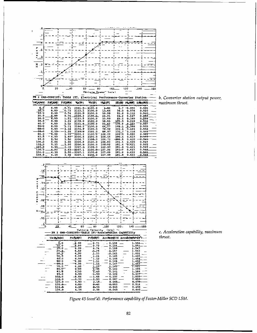
.7 L _L L.8 _ _ I I .- .I I - I I
- -_ -- I-- I"+Ip ~~~ - -I- -
w - I - I I -- - - - -
d_+ - -__ --- - ---
Q - 20 4 0.......0 60 - 8o T 120 ----n ....- ---
FM 2 CA-CONSIST: TABLE III. Electrical Performance-Converter Station b. Converter station output power,Ugj")-*M JF UV UP)VAV ZW kW f~t maximum thrust.
0.0 6.99 _.0.71 2101.0-2100.0 I-- - 2.7 -0-.-&06 0.00616 6.99 ___0.73 2113.7 2100.0 13,66 36.0 -40,076 0.92001,-T 6.99 _0.74 2120.0- 2100.0 19.99 52.6 0.112 0.940
20.0 6.99 0.762126.3 2100-0.- 26.31 69-.2 0.147 0.95026.0 6.99 1.33 2133.9 2100.0 33.90 89.2 0.190 0.95530.0 6.99 1.24 2139.0 2100-.0 38.96 1-0-2.5 0.219 0.95640.0s 6.99 1.12 2151.6 21007.0 51.62 -M3.8 0,2i2 9 9750D-0 6.99 -1.11 2164.3-2100.0 64.27 169.1 0.366 0.955-60-0 6.99 -1.16 2176.9" 2100.0 76.92 202.4 0.441 0.95270..0 6.99-1.25 2189-.-& 2100.0 V9.57 235.7 -0.516 0.948-80.0 -6-.99 1.3--2202.2 21000.-Y- 102.22 265-.0 0.592 0.9"41-483.5- 6.99 1.40- 2206.6 2100.0 106.64 280.6 0.619 0.94-90.0- 6.50 1.50 2206.7 2104- 0 106.72 -280.8 0.620 0. •943100.0 S.86 1.68 2206.8 2100.0 106.83 281.1 0.620 0.944119-0 5.33 1.90 2206.9- 2100.0 106--92 281.4 -0-621 0.945 -120.0 4.90 2.15 2207.0 2100.0 102.00 281.6 -0.621 0.945 -130.0 -- 452 2.43-2207.1 2100.---107.06 281-.-7 0.622 0.946--134.0 -4.39 2.55-- 2207.1 2100.-0 107.09 281.8 0.622 0- CMA135.0 4.36 2.58 2207.1 2100.0 107.09 2,81.8 0.622 0.946
4 - -I _ I_ I I- I
a -- 4 - - I -- I_ I -I -I I = -I
S- f - I A- I --t I 1) I -- Ith .- - 0 .0b6 .99i0-7 1 -. 0 . -L
10.0~ ~ 6.9 0.3 - 0 158 T51-
-o -T - 0.
".02- - -6_ _-- _04 -- 195
- 20 4 .5 6o _ 80 in 126 -- 140 2 7-Vehcl.t VAI..Lts (./.) --- F 2 hR-COSIS-.-TALE V---AcelriionCapal~it c Acceleration caaiiy.maximumUs- Uý8 2 XIW e•-t~szs-W- A"V.- t((QA•v•-o Aceaqq-e d1Y 2. 4-aparust
- 1.d.0 __6.99 -0.71 -0.158 - 1.59-410.0 6.99 -1.9 - 0.0158- - -R91
15.0 - 6.99 - 0.74 0.158 1.547-- J"0.- 629 -76 -0-.-157 - 1.542 -
_ 3426._0 6_99 -1.33 -0-.143 1- .401 -30.0 6.99 1.24 0.145 1 0.425
Fu 4 c.'0 P.99 -i.12 -M0.148 1.454- 0 -6.99 -- 1.11 -- 0.148 -- 1.456
-- 6 0 ----- .99 - 1.16 -- 0.147 - 1-.--•4-•-- 70.0 -- 6.99 - 1.25-- 0. 14U-- 1.7421
-- 80 .0Y- 67--W -Y:15 -T.-.14 2 1. 395 --- 83.5 6.-99 -17.40 76. 14 1 -- 1.384 -
9(0.0 6.50 ý1.50 -'0.126 1. 237 -I_ 10JD0 -S.86 - 1.68 -- 0.105 -- 1.033-11.l..0 ----. 33 -- 1.90G - 0.087 -- 01868
-- 120.0 -- 4.90 -- 2.15-- 0.069---. 6-7-9---- 130 G- 4-62- 2.4-3 -0.053 -- 0.518 --- 134.--0- 4.49 4,55 -0-. 046 -- 0.456 -
135.0 4..36 -2.58 -0.045 0.440 _
Figure 43 (cont'd). Performance capability of Foster-Miller SCD LSM.
82

4 ___ I - I - I
N - I- I - I j i-3.5 -- - -_ -_ - - - - -- -- - --I I I I I _ _- -- - I " I I I I - I -
-- . = -. I-. -- I-=---I-- ------- I-- I
20 -20 -40 &9- s0- 100- 120 -140 1-
.! -- - -. . . . . . . . . . , .I - -
:M 2 CAR NSISTTALE 1. A Electrical Performance at-Vehicle d. LSM thrust vs.speednormrus sped oE ---- , -- t
0.0 0.71 01- 0.5 87.4 0-000 0.000 0.9 9 0.087 -1I:0 0.13 101.5 2.0I 88.9 0.007 0,009 0.804 0.995_13.0 0774 152.T 152.8 90.8 -0.011 0.014 0.804 0.996.-Z-0 -776 20370 203.F 93 0.015 -T.019 0.803 0.99726.0 1.33 -263.9 265.2 163.3 0.035 --0.043 6.803 099630.0 1.24 304.4 30.8a 151.4 0.037- 0 0_4- 6 . 6- .9974070 1.1 405.9 407.4 -137.2 0.045 0.056 0.803 0.99856.0 2.11 507.4 509.1 8136.0 0.056 0.069 0.802 0.9985 -
-6".0 1,06 608.9- 611.0 - 142.7 -0.070 0.087 0.-802 0.999-40.0 -I_65 710,4- 712.9-- 153.4 -- 0.088 0-0-.109 0.802 0.99*9
80.0 1.35 811.9 814.9 166.1 0.109 0.135 0.802 0.59-83.-5-- 1.40 -847.4 50.56 171.8 0.117- 0.146 -- 0.802 0.99990--,0 1.50- 913.3-417.0 -- 04.0 0,0--3-5 0.106 0.802 0.999
100.0 1.68 1014.8-1019.3 -206.5 , 0169 O.-2t0 0.8092 0.998 -110.0 1.90 1116.3 1121.8 - 233.2 0.210 0.-262 0.80-1 0.999120.0 2.15 1217.8 1224.4 263.7 0.258 0-323 0.801 0.999--130.0 2.43 13139.3 1327.3 297.9 0.316 0.395 0,&0- 0.999134.0 SS _1359.9 13•.65 312-5 0.342_ 0.428 _(.800 0-99_135.0 2.58 1370.0 1378.8 316.3 0.349 0.436 0.800 0.999
.5;I I I I I I "
III I I I I
.45 I - - I ....
I I i I I I.4 . . .- . . .-- L -__ -- - --- --' -__ _
I I I I I /
I I I
M .2 - -I - - . .I -- -- -- ---o -3 ---- -------- - ---
. ..i -- . . .- . . . . . .
1.1 I I I II
IwII I
T_ -i . .. --- --- -~ - --"- -- I. .
0 20 40 o0 80 100 120 140 160Voh1.1 IS p..d (./.)
FM 2 CAR-CONSIST: TABLE IUI. Electrical Performance-Converter Station e. Converter station outputUsW o) MOW "IM ,4IQ) V 7) vWP) VsDzxv) ILX) PSWW) UEfpW) power, normal thrust.
0.0 0.71 2100.4 2100.0 0.37 1.0 0.002 0.002
10.0 0.73 2101.7 2100.0 1.68 4.4 0.009 0.78015.0 0.74 2102.4 2100.0 2.38 6.3 0.013 0.844S20.0 - 0.76 2103.1 2100.0 3.13 8.2 0.017 0.88026.0 1.33 2106.7 2100.0 6.65 17.5 0.037 0.93930.0 1.24 2107.1 2100.0 7.09 18.7 0.039 0.943
-40.0 1.12- 2108.5 2100.0 8.48 22.3 0.047 0.95250.0 1.11 2110.4 2100.0 10.41 27.4 0.058 0.95960.0 1.16 2113.0 2100.0 13.02 34.3 0.072 0.96570.0 1.25- 2116-2 21.00.0 16.23 42.7 0.090 0.96980.0 1.35 2120.0 2100.0 20.00 52.6 0.112 0.97183.5 1.40 2121.6 2100.0 21.57 56.8 0.120 0.97290.0 1.50 2124.8 2100.0 24.84 65.4 0.139 0.973
100.0 1.68- 2130.9 2100.0 30.89 81.3 0.173 0.973110.0 1.90 2138.3 2100.0 38.28 100.7 0.215 0.972120.0 2.15 2147.1 2100.0 47.14 124.0 0.266 0.969130.0 - 2.43- 2157:6 2100.0 -57.60 " 151.6 0.327 0.966134.0 2.55 2162.3 2100.0 62.27 163.9 0.354 0.964135.0 2.58 2163.5 2100.0 63.48 167.1 0.361 0.964
Figure 43 (cont'd).
83

0.2B0.24 OW W/a
0.22 010 M/6
02
0.14
01 a. Low speed.0.1
0.02
TROt GRU•MAN MAGNEPLANE FiMI BECHTaEL
MAGLEY SYSTEM CONCEPT
0.13
0.1)
0.09
0.09
00 b. 134 r/s.0.0t4
I).03 I"
0.02 -
0.01
TIOT AJUMMAN MAH4EPLAIE FMI BECHTEL
MACLEY SYSTEM CONCEPT
Figure 44. Comparison of acceleration capabilities.
IGBTs (insulated gate bipolar transistors), since the mental scale model of the LCLSM. Section 4.4 andswitching speeds required are beyond those rec- Appendix C of this report give more detail aboutommended for GTOs (gate turnoff thyristors). the risks and benefits of this innovative propul-Current commercially available IGBTs are limited sion concept.to 600-A ratings with voltage ratings of 1400 V,such as the soon to be introduced Fuji device. Comparative performanceUsing devices of this type in the LCLSM would of the LSM conceptsrequire at least two in series and two in parallel The results of the LSMPOWER runs for each ofper H-bridge leg, or a total of at least 12 devices the SCD concepts and the TR07 were comparedper H-bridge. The continuing evolution of IGBTs for their relative performance in accelerationwill probably reduce this to six devices per and grade climbing capability. The SCD RFPH-bridge within the foreseeable future. (USDOTFRA 1991) required that the system con-
The performance results from LSMPOWER cepts be able to maintain the maximum cruisingcompare well to those reported by Foster-Miller. speed on a +3.5% grade, and that, further, they beHowever, the controllability of the LCLSM is an capable of operating at some speed on a +10%important technical issue that was not addressed grade.in this analysis. It would require additional effort Acceleration capability. Figure 44a gives the low-that would perhaps be best handled with an experi- speed acceleration capability for the five systems
84

150
120
"100_ O90
- 70- a. b.5% grade.
"50"
40
10
20
3IRO7 ORIAN GANEPLANE M FII -3CHIEL
""AI_ EV7 - - - - a.O3.5Ee.
Fiue45%opriogfspessrtieandrds
"150" ---
1 30 --- -_-
at hezeo ifof speed foteTROT 7 GMand MGrum-AN stat BalancEL spesadd otcnie rd
13D
,•100
tSo b. 10% grade.TO
SO
so
TROl iMLIhMAN MAGNEPLANE F IMI
•MAOLEMSYSTEMD ONCIEPT
Figure 45. Comparison of speeds sustained on grades.
analyzed. The maximum acceleration capabilities maintain up a 3.5% grade. These are the steady-at the zero liftoff speed for the TR07 and Grum- state balance speeds and do not consider grademan baseline SCD are 0.102 and 0.093 g, respec- length and inertia to pass over the grade at sometively. Grumman's optional 100-kN LSM increases changing speed. Also, these calculations wereits maximum acceleration to 0.16 g. For the EDS based on the baseline configurations discussedconcepts, the acceleration capabilities at a 20- earlier and do not account for any LSM configu-m/s liftoff speed for the Magneplane and Foster- ration changes at the grade condition. Note thatMiller vehicles are 0.234 and 0.157 g, respectively all SCD concepts are able to maintain maximumThe Bechtel concept can achieve 0.226 g at its cruise speed up a 3.5% grade, as required. The 7.2-liftoff speed of 10 m/s. MVA power limit for the TR07 limits its 3.5°/-
Figure 44b shows that the acceleration capabil- grade-climbing speed to 105 m/s. The LSMPOWERity remaining at the maximum cruise speed of 134 model determined that this power limit wouldm/s is 0.006 g for TR07, 0.05 g for Grumman, 0.04 have to be increased to slightly more than 10 MVAg for Magneplane, 0,05 g for Foster-Miller, and (i.e., by about 4t0%) for the TR07 to maintain 1340.12 g for Bechtel. Grumman's optional 100-kN m/s up a 3.5% grade.LSM raises its value to 0.10 g. Figure 45b shows the maximum speeds that the
Grade climbing capability. Figure 45a shows the SCDs and TR07 may maintain up a 10% grade.maximum speeds that the SCI~s and TR07 may The values vary considerably: about 5 m/s for
85

Grumman's baseline design, 90 m/s for Magne- Not enough is known about the absoluteplane, 100 m/s for Foster-Miller, and 140 m/s for expected lifetime of the LSM stator windings forBechtel. As with the 3.5% grade results, these are the duty cycles possible for these systems. How-the steady-state balance speeds based on the ever, the above comparisons can be used to esti-baseline LSM configurations. For example, the mate the relative stator lifetimes for each of theGrumman concept has aluminum conductors for five concepts. From a thermal stress consider-the LSM stator coil. Changing these conductors to ation, the Magneplane LSM should have the long-copper on the grade portion of the guideway est lifetime, while the Foster-Miller LSM shouldwould enable Grumman's optional 100-kN LSM have the shortest.to maintain 125 m/s up a 10% grade. LSM stator winding construction. All SCD
The TR07 is in a similar situation as the Grum- blocklength LSMs use a stator winding that hasman concept; it cannot maintain much speed overlapping coils, with the coil entrance and exit(about 14 m/s) up a 10% grade. As with Grum- at the same location on the guideway. This tech-man, however, replacing TR07's aluminum stator nique is in contrast with the Transrapid Emslandwindings with copper for the grade section would test facility, where the stator coils enter the guide-substantially increase this speed. way at the beginning of a block and exit at the end
LSM stator winding lifetime. The lifetime of the of the block. The advantages of the SCDs' over-LSM stator winding depends heavily on the ther- lapping approach are that it may simplify electri-mal stresses to which it is exposed. The motors fication construction, and it enables a larger poletypically fail when the winding insulation dete- pitch by having multiple slots (i.e., conductors)riorates, which is accelerated by thermal stresses. per pole. The larger pole pitch in turn lowers theA well known practice in electrical machine operating frequency of the LSM and the controldesign is to assume that insulation lifetime halves inverters. This construction technique shouldfor each 10'C rise in temperature above its design improve both performance and cost over the tech-operating temperature. Industry practice for the nique used at Emsland.design of rotating machinery and bus bars in Efficiency and power factor at electrical source. Thepower installations translates to a current density converter stations connecting each system to anof about 1.7 MA/m 2 of conductor cross section. electrical source differ somewhat. TGV uses AC
Figure 46 shows the current density in millions power directly so that it connects to a sourceof amperes per square meter for each of the five using only a transformer. All other systems con-concepts compared with industry practice. The nect to a source through solid state AC-DC con-Grumman, Bechtel, and TR07 current densities are verters; however, they use the resulting DC powerall about 4 MA/m 2.Magneplane's current density differently.is lowest at about 2 MA/m 2, and Foster-Miller's TR07, Grumman, and Magneplane distributeis highest at about 6 MA/m 2. DC power to widely spaced inverter stations (sev-
eral kilometers apart). They then use7 [feeder cables to power LSM blocks.
Bechtel distributes its high-voltage DC6 to more closely spaced inverter stations
along the guideway. They then powereach LSM block using the stator wind-ings as the feeder cables. Foster-Miller
4 distributes lower-voltage DC directly toI its LCLSM inverters adjacent to each3 coil.
We estimated the efficiency and2 power factor for each system's converter
stations and applied these to the outputI - of LSMPOWER to obtain overall values
as seen at the electrical source. Table 280 shows a summary of these results for
N"TRAN FOSTEý MUMRMAA E Cm TRAMRsA each system. Note that the results for
MAGM'SYsTOA C=VT Magneplane include the power-factorFigure 46. Comparison of the current densities of LSM stator windings. correction discussed in their final report.
86

Table 28. Overall efficiency and power factor for each system at 134 m/s (exceptTGV-A, which is at 83 m/s).
TGV-AParameter (1-10-1) TR07 Bechtel Foster-Miller Grumman Magneplane
Overall efficiency 0.82 0.83 0.85 0.91 0.78 0.84
Power factor 0.91 0.74 0.98 0.97 0.98 0.99
As expected, Foster-Miller's LCLSM yields the * For both iron-core and air-core LSMs, highhighest overall efficiency of the concepts studied. efficiencies are attainable. The LCLSM is
capable of the highest efficiency because itsSummary and conclusions blocklength is always equal to a consist
The linear synchronous motor model, length.LSMPOWER, was developed for two main pur- * The need for feeder cables to energize alter-poses. First, we used it for an assessment tool to nate LSM blocklengths does have someaddress issues of thrust-speed performance, adverse effect on efficiency. It also can signifi-power and energy consumption requirements, cantly reduce the power factor. Both of theseand, to a lesser extent, LSM and related power increase the cost for electrical energy. Feederdistribution, power conversion, and control costs. cable requirements can be traded off withSecond, we used it to provide propulsion data to more closely spaced converter stations; suchsimulate each concept's operational performance trade-off analyses must be part of any route-on corridors (section 3.3.1). The model fulfilled specific studies.both purposes. * The air-core LSMs had the lowest power
An important general finding of this work is factors because of the large coil geometriesthat, in virtually all cases, LSMPOWER predicted required for the air-core stator coils. Most ofperformance similar to that reported by the SCD the SCD studies recognized the potentialstudies. More specifically, the GMSAteam reached need for power factor correction to improvethe following conclusions regarding the LSM con- performance. Power factor correctioncepts studied: requires more detailed study to assess per-
formance improvement and cost trade-offs."* The LSMs considered in all SCD studies, The LSMPOWER model as it currently exists
perhaps with the exception of the locally can assess the effects of power correction oncommutated LSM (LCLSM), appear to be performance.technically feasible and are incremental * Acceleration and grade climbing, asimprovements over contemporary designs. expected, require significantly more LSMHowever, three of the LSM concepts (Foster- thrust capability than the steady-stateMiller, Grumman, and Magneplane) use the thrust-speed requirements. Meeting thesestator as a power transfer component, and two requirements could significantly andthe effect of power transfer on LSM perfor- adversely affect both efficiency and powermance was not assessed here or in the SCD factor. Tailoring the LSM design to meetstudies. acceleration and grade climbing perfor-
"* The LCLSM is potentially a major innova- mance for route-specific conditions wouldtion, but it is unproven and requires addi- result in more optimum LSM designs.tional effort to establish its technical feasibil- * The current density of the LSM is one mea-ity and cost. There are many control issues sure of expected stator-winding lifetime.involved with the LCLSM, and evaluating The SCDs and TR07 all have stator-windingthose issues is beyond the scope of the exist- current densities that exceed industry prac-ing LSMPOWER model. The LCLSM also tice (by factors of 1.3 to 4) for what is con-may require state-of-the art switching sidered to be conservative, long-lifetimedevices as part of the power electronics con- designs. While it is true that, initially, thesetrol; the cost of such devices is extremely dif- LSMs will have duty cycle loadings lowerficult to predict. than industry practice designs, this advan-
87

tage may disappear under the close head- and assessed for both their technical mer-way operation expected for a mature maglev its as well as their total costs. The currentsystem. Upgrading the stator windings may LSMPOWER can model the technical perfor-be appropriate should this take place. mance effects of various power-factor cor-
Recommendations rection strategies. Existing cost models canbe adapted to analyze the total cost.
The LCLSM requires additional study to The scope and schedule of the recentlyestablish its technical feasibility. This con- completed SCD studies limited the choicecept, as envisioned, will make use of com- with linear motors to making incrementalputer control to become energized in the improvements over conventional LSMpropulsion mode at the instant that the super- machines. Several experimental linear mo-conducting field magnets mounted on the tors exist that make use of passive field struc-vehicles' bogies are sensed to be present, to tures. These are attractive because of theirsynthesize the desired waveforms for driv- potential simplicity over conventional iron-ing the LSM coils, and effectively to operate core and air-core LSMs. This could signifi-all LSM coils in parallel with equal current cantly simplify vehicle-carried equipment.sharing. These are control issues that must Each of these concepts has been shownbe addressed. The LCLSM will also function experimentally to produce thrust, levitation,as the power transfer mechanism whenever and guidance forces within a single inte-it is not operating in the propulsion mode; grated structure. These machines warrantcontrol implications for this power-transfer additional R&D work to determine their per-function should also be examined. These formance and costs compared to the moreissues are amenable to scale-model evalua- conventional linear motors.tion, and such tests should be started imme-diately to maintain the LCLSM as a viable 3.2.3 Magnetic fields*option. In addition, trade-off studies shoulddetermine optimum DC supply voltage and Objectivesinverter switching speed; both of these have Forces resulting from magnetic fields gener-effects on efficiency and cost. ated both aboard the vehicle and in the guideway
"• The power transfer methods that make use are essential for the suspension and propulsion ofof the LSM stator as an inductive coupler are maglev vehicles. Magnetic fields incidental tonew ideas at the power levels being consid- these essential functions will exist in the passen-ered. The feasibility of these concepts to ger compartment and in regions surrounding thetransfer the needed power levels effectively vehicle and guideway. The effects of these fieldsand efficiently, without adversely affecting on passengers and the environment are not wellLSM performance, needs to be established, established at this time and so are a matter of con-While many of the questions of feasibility cern. Ways of shielding these fields are available,can be addressed analytically, experimental but including them will inevitably increase thevalidation of the power transfer techniques weight and cost of the vehicle. In this section, theis necessary and could be done at the magnetic forces and stray fields of the TR06/07reduced scale. maglev system and the four SCDs are analyzed
"* The current SCD studies did not quantify and compared with known and proposed values.the benefits of power regeneration. Regen- These calculations were made to assure that theeration was not assessable at this time in values presented to the Government are "reason-LSMPOWER. We recommend that the ana- able." They should not be interpreted as designslytical and modeling work needed to imple- or improvements of the concepts analyzed. Forment regeneration be done initially through expediency, approximate methods have beenan expansion of the LSMPOWER model and used in some cases where they serve to verify thatsubsequently incorporated into the system the values being checked are credible.simulator.
"• Analysis of power-factor correction requiresadditional effort. All concepts need correc-tion. The specific concepts providing power- * Written by Dr. Howard Coffey, Center for Transportation
factor correction should be investigated Research, Argonne National Laboratory.
88

Methodology or in which a field geometry is encountered thatMethods for calculating electromagnetic fields permits a symmetrical boundary condition to be
and forces are well known. However, no single imposed. More complicated geometries require amodel is adequate for the analysis of all the sys- three-dimensional mesh and time-consumingtems proposed by the SCD contractors. Systems computer calculations to obtain reasonable accu-composed of current-carrying coils can be ana- racy. Several commercial computer codes arelyzed using straightforward, but sometimes tedi- available for this purpose.ous, methods, with the accuracy of the results Generally, these codes do not provide for casesbeing limited only by the accuracy with which the involving relative motion between the elementsinput currents and geometries are known. Pru- of the system. Relative motions result in induceddence demanded that simplifications be made in eddy currents in elements of the system that aresome cases. This method of analysis is appropri- exposed to time-varying magnetic fields. Sinceate to some electrodynamic maglev systems these eddy currents can be substantially reducedusing simple or "null-flux" coils in the guideway by using laminated structures, and since all theand superconducting magnets on the vehicle. For ferromagnetic systems analyzed use such struc-iron-cored magnets, electrodynamic systems in tures, this restriction is not believed to be a sub-which the guideway current is induced in contin- stantial limitation to the accuracy of the resultsuous sheets, or inter-connected coils such as lad- presented here.der tracks, however, these methods are insuffi- Solutions for the forces in EDS systems thatcient. induce the reactive current in a continuous con-
A straightforward but complex Dynamic Cir- ducting sheet in the guideway have only beencuit Theory model computer code, developed by obtained for simple geometries in which the sheetHe et al. (1991) of Argonne National Laboratory forms a closed cylinder or is planar and infinite.and verified in part by experiments at ANL Although approximate solutions have been found(Mulcahy et al. 1993), uses numerical techniques for some simple geometries, solutions for sheetsto calculate the time-dependent forces of coil-type forming surfaces of finite dimensions must besuspension systems. This model was used in the analyzed using finite-element computer codesanalysis of the Foster-Miller concept. A similar similar to those used for ferromagnetic materialsmodel was combined with a harmonic analysis but including the motion of the conductor.technique to obtain closed-form formulas to ana- Two-dimensional finite-element calculationslyze the Bechtel concept. Finally, for computing for simple ferromagnetic structures were madethe stray fields from the magnets, He formulated using PE2D, and three-dimensional calculationsa computer code to calculate the magnetic fields were made for more complex ferromagneticfrom finite-element conducting filaments in any structures using TOSCA. All of these are inspatial orientation. The code has been compared commercial use and are regarded as reliable.to results from the three-dimensional computer ELEKTRA*, which includes moving media, iscode TOSCA with good agreement. These codes relatively new. It is the only commercially avail-are discussed below where they were used. able finite-element code of which we are aware
The analysis of electromagnetic systems con- that is capable of these computations. It has beentaining ferromagnetic materials is complicated by used at ANL to calculate the forces on small mag-the nonlinear permeability of ferromagnetic nets mounted close to finite, moving, conductingmaterials. For systems in which the magnetic surfaces of various shapes and dimensionsinduction is well below the saturation values of (Mulcahy et al. 1993). The results are credible forthe materials used, and for geometries in which these small systems. For larger systems, however,the magnetic flux is well confined, the fields and a limitation is encountered in the relationshipforces can be approximated by analytic formulas. between the velocity and the required distanceWhere this approach is inadequate, which for between nodes in the mesh. For realistic sizes andmaglev is generally the case, computer calcula- velocities of maglev magnets, the mesh size be-tions must be made. In making such calculations, comes extremely small and the number of nodesa spatial mesh is designed upon which the fields required becomes prohibitively large for the com-and permeabilities are first approximated andthen iterated until a sufficient degree of accuracyis obtained. We used two-dimensional meshes for * The computer codes PE2D, TOSCA, and ELEKTRA are corn-
geometries in which one dimension is extensive mercial computer codes of Vector Fields, Inc., Aurora, IL.
89

kj•44"o"p LSM
Figure 47. TRO6 levitation and propulsion configuration (dimen- a. Levitation and propul-sions in mm). sion system.
ina
b. Guidance system.
Figure 48. TRO7 guidance configuration (dimensions in Figure 49. TRO6 flux patterns.mm).
puters available in this effort. Consequently, only synchronous motor and is contained in the guide-partial results have been obtained for this case. way. The lower structure or "rotor" is mounted
on the vehicle and interacts with the stator to gen-Application of computational erate both levitation and propulsion forces. Thetechniques to TRO6/07 windings in the stator, shown by the large Xs, are
Data are available for both the TR06 and TR07 the three-phase excitation windings of the LSM.systems, which were developed by Transrapid The Xs in the rotor are the excitation windings ofInternational in Germany (Freidrich et al. 1985, the onboard magnets. The slots in the rotor con-Bohn and Steinmets 1985, Meins et al. 1988, tain additional windings thatpickup power fromHeinrich and Kretzschmar 1989). These data were the LSM for onboard use, as discussed in theused as test cases for the procedures used in the previous section, and are not considered fur-other analyses. ther. Each magnet comprises five poles, each
Magnetic forces, TR06. The TR06 two-car vehicle pole having an excitation current of 6480 AT.is levitated and propelled using 64 magnets, each Associated with each levitation magnet is a1.3 m long, and having five poles with the approxi- guidance magnet of equal length and having themate dimensions shown in Figure 47. Motion of approximate dimensions shown in Figure 48. Inthe vehicle is from the left to the right of the fig- this figure, the motion is into the page; the flature. The upper structure is the stator of the linear plate is the vertical reaction rail in the guideway.
90

The forces in these magnets were modeled Table 29. TR06 levitation forces.using the two-dimensional PE2D computer code. Speciication PE2D TR06
Since the levitation and propulsion forces areinterrelated, and depend on the phase currents in Excitation magnet height 0.190 m 0.190 m
the stator windin the calculations were done Number of magnets 64 64Excitation/magnet 32,400 AT 36,000 AT
with 50% of the maximum phase current in Air gap 0.010 m 0.010 Mphases A and C and 100% in phase B. The result- Pole pitch 0.258 m 0.258 m
ing flux patterns are shown in Figure 49, and the Stator pack
data used and the results of the calculations are width 0.185 m 0.185 mgiven in Tables 29 and 30 and Figure 50. They are height 0.0915 m 0.0915 m
Current 1200 A 1200 A
in reasonable agreement with reported values. Lift force 1284 kN 1196 kN
The results suggest that the 36,000 AT currentreported for TR06 is the maximum rather than Table 30. TR06 guidance forces.the nominal operating excitation current for thesystem. Specification PE2D TR06
Magnetic forces, TRO7. The levitation and guid- Excitation current 15 A 15 A
ance magnets were changed in TR07, reducing the Turns 840 unknown
weight and changing the dimensions. As shown Air gap 0.010 m 0.010 m
in Figure 51, a notch was placed in the Force/magnet 11 kN 9 kN
levitation magnets as part of this effort.Our calculated weight exceeds the 2500 I I It.reported weight by 22%, suggesting - gap-6m _ _
that additional, unknown weight -- o- gap-7m• _ L__reductions were implemented. The 2000 -..-- gap--_levitation magnets were increased in ;5. gap=ni - --- I .- -A--- -length to 3.022 m and the number of ..... L..10 -- T/7 , -F -- -0 I-p• O I
poles per magnet was increased to 10. a100 -- ' -, _i_:L_The pole pitch of 0.258 m was retained 9 --E3- gap-liu- z/.
to maintain compatibility with the LSM 0 - gap-12nun - h-- --,stator. The number of levitation mag- -4-0 - tU•F•,lf..V_ __I __nets was changed to 30. The configura- - • - .tion of the guidance magnets was - - ! L__ i ! T ,-revised to incorporate the double wind- 500
ings shown in Figure 52 rather than the r. - .single windings of Figure 48. In addi- 0
tion, the length of these magnets was 0 20doubled from approximately 1.5 to 3.0 Ampere-Turn/Pole (kA-T)
m. This change reduced the stray fields Figure 50. TR06 levitation forces.from the guidance magnets which, asdiscussed later, are the major source ofexternal fields from the vehicle in this *.\A Guideway LSMsystem. The excitation currents are not .
well known for either type of magnet;we assumed 4500 AT per pole for the
levitation magnets and 8450 AT for the .guidance magnets. The resulting flux ,'patterns are shown in Figure 53, andthe forces are shown in Tables 31 and gi /32. These forces for other currents and K.gaps are shown in Figures 54 and 55.
To good approximations, the lift # • Vehicleforce FL and guidance force FG of TR07can be fitted by the following equa- Figure 51. TR07 levitation and propulsion configuration (dimen-tions: sions in mm).
91

Guideway Vehicle I
b. Guidance system.Figure 52. TRO7 guidance configuration (dimen- Figure 53. TRO7 flux patterns.sions in mm).
1.600 1L.LL1
L
0 4Gap-6mrn L jmJEt1400 --- Gp7i
1200 Gap-8mm
10 -e-Gap-Smmif t V _ z-11:
8004T:L.~i1j Figure 54. TRO7 levitation forces.600 L4_~~,4-~ J4[2L
200 --4-4:~ T:fL 4 .L..L.
000 1 2 3 4 5 6 7
AmpereTurn/Pole (KA-T)
700 i±--±~-~-~~- T
600 - -0--gap-Brmnr ]
500 4 gpirm-'--f-gap-llmmL+ .. I 4
~ 400 -0- gap-nu 4441 Tj'V
200 -1 Omm ~ 4
0
3 0 2.4 1 2 1
g 202

Table 31. TR07 levitation force. FL= 2337. (kAT)'18 76 - 5500. (kAT)4/g5
Spectiication PE2D TR07 FG 180 (kAT) 2 /gI 843
Weight of magnets 14,500 kg 11,800 kgNumber of magnets 30 30 where kAT is the number of kilo-ampere-turns inExcitation/magnet 45,000 AT Unknown the windings and g is the gap dimension inAir gap 0.008 m 0.008 m meters.Stator current 1200 A 1200 APole pitch 0.258 m 0.258 m Since no guidance force is generated when theStator pack vehicle is in the equilibrium position, the guid-
width 0.180 m 0.180 m ance force indicated is that resulting from havingheight 0.0915 m 0.0915 m the guidance magnets energized on one side and
Lift force 917 kN 882 kN de-energized on the other.
Stray magnetic fields, TRO6/07, from levitation-
Table 32. TR07 guidance force. propulsion magnets. The levitation-propulsionmagnets of TR06/07 are arranged along the sides
Specification PE2D TR07 of the vehicle and alternate in polarity as requiredNumber of magnets 30 30 to move the vehicle. The magnetic field at a dis-Weight of magnets 11,600 kg 9,400 kg tance from such an array of magnets is the differ-Excitation current 8,450 AT Unknown ence of the fields from the individual magnets.Air gap 0.010 m 0.010 m The magnitude of the field depends on the dis-Force/magnet 12.39 kN Unknown tance from the magnets relative to their lengths,
the field being lower if the magnets are short rela-- - tive to the distance at which the measurement is
z - -" made. This is illustrated in Figures 56 and 57,- "" where the fields of 20 magnets are calculated at a
Pole 1distance of 1 m above them. From this illustration,Observation Line. I. m • 'b the stray fields around the vehicle from this sourceare expected to be small.
The assumption is better than the figures indi-cate owing to the presence of iron in the system.
Although this analysis would be best if done withY a detailed, three-dimensional magnetic model
cwrut ,rcdow of including iron, it does not appear to be necessaryOn,,5•-pol,,it in light of this approximate analysis and reported... '" aw, magnetic field measurements made on TR07
Figure 56. Row of magnets with alternating polarities. (Electric Research and Management, Inc., no(Magnet length = 19.5 cm; magnet width = 24.4 cm; coil date). At the ends of the array, the fields increase.current = 45 kAT; pole pitch = 25.8 cm; 20 magnets.) It should be noted that the field from the stator
moves with the same velocity as the vehicle and2 ... appears to the vehicle as a constant magnetic
S4,sinfield. A detailed calculation of the fields in the. - .1p Ian,!! cabin directly above the levitation magnets is3- • i jshown in Figure 58.
• __ _ L_....BL..I=1.OE-4G
O' - -
-4 -3 -2 -1 0 1 2 3 4 0.5m B.. = 0.04 GDistanoes ngMagct Bow (i)
Figure 57. Comparison of magnetic fields from a Figure 58. Magnetic fieldsrow of magnets having the same and alternating above TR07 levitation-polarities (magnetic field I m above magnet row). propulsion magnets.
93

4000.0
Y (MM03500.0
300o.0 - O, L STANDING HEAD
2500.0 -
HEADREST2000.0
1500.0 - SEAT
1000.0 - FLOOR LEVEL
500.0 -a
-3000.0 -2000.0 -1000.0 0.0 1000.0 2000.0 3000.0 4000.0
X [MM]Figure 59. Flux density (G) around TR07 guidance magnet.
Stray magnetic fields, TRO6/07,from the guidance the vehicle, and wind gusts, and perhaps aerody-magnets. The major source of stray fields in the namic turbulence on the body of the vehicle, andTR07 system appears to be the guidance magnets. cannot be calculated. The currents in the magnetsThese magnets are 3 m long and therefore do not can be expected to vary by perhaps +10-20% inbenefit as greatly, at close distances, from alter- routine operation, leading to AC fields that arenation of the poles. As noted above, the configura- this percentage of the static fields. The frequen-tion of these magnets was changed in TR07, cies of these AC fields will increase as the speedresulting in better confinement and cancellation of the vehicle increases, as reflected in the ACof fields at large distances. The calculated mag- measurements made at head level by Electricnetic fields (in Gauss) at various positions in and Research and Management, Inc. (no date) duringaround the vehicle are shown in Figure 59. A steel the operation of TR07. Below about 200 km/hrguideway was included in this analysis; an iron- (55 m/s), the major components of the fieldreinforced concrete guideway would alter these were below 100 Hz, while at 400 km/hr (111 m/s)stray fields somewhat. The static field of the Earth they increased to more than 200 Hz. A prominent,is about 500 mG and must be added or subtracted and unexplained, spike of about 15 mG is seen infrom these values to obtain the total static field. the 400-km/hr data at about 10 Hz.The presence, if any, of ferromagnetic materials in In the data presented in Table 34, the valuesthe cabin will alter these values. The fields in Table again peak at floor level, suggesting that most of33 were calculated and are compared with the the fields are generated by the magnets and wir-static fields in the passenger compartment as ing at or below floor level.measured by Electric Research and Management, Wiring to the control system, as well as otherInc. (no date). electrical equipment in the vehicle, can contrib-
These fields are shown as static, but will rarely ute fields of the same magnitude in the cabin ifbe constant since the vehicle is in motion and the they are not adequately shielded. These includecurrents in the guidance magnets vary to correct wiring for hotel power, electronic converters, etc.the guidance forces. These variations reflect mi- A single straight wire carrying 1 A will generatenor perturbations in the guideway, cornering of a field of 2 mG at a radius of 1 m, decreasing
Table 33. Magnetic fields (mG) in the TR07. Table 34. ERM magnetic field data (mG)for all frequencies from 5-2560 Hz.Measured
Calculated Minimum Mean Maximum Minimum Mean Maximum
Floor 700 150 820 1500 Floor 30 100 255Seat 300 50 610 1100 Seat 20 50 140Headrest 150 210 620 1020 Headrest 10 30 75Standing head 75 150 500 950 Standing head 7 20 55
94

inversely with the radius. Since the guidance dimensional analyses using the TOSCA program.magnets operate at a nominal 15 A, the cables to The Magneplane concept uses continuousthese magnets could contribute 30 mG DC at 1 m sheet guideways that cannot be analyzed with sig-and 15 mG DC at 2 m if not shielded, and some nificant accuracy by simple means, requiring thatfraction of these fields will appear as AC fields in the previously mentioned ELEKTRA computerthe same manner as the fields generated by the code be used. Also, as mentioned earlier, the num-guidance magnets. The same is true of currents to ber of mesh elements that could be used wasthe levitation magnets (of unknown magnitude) restricted and limited results were obtained. Theand of the AC currents to onboard equipment. contractor did not present the methods by whichThese cables have apparently been shielded, or their forces were calculated. Stray fields have beenused in pairs for cancellation, since fields of this calculated for the vehicle at rest, which representsmagnitude do not appear in the data. If they have the worst case.not been shielded, doing so is a minor matter.
BechtelApplication to SCD concepts Unique features. The Bechtel concept (see Fig. 3)
As noted earlier, there are considerable differ- is unique in that it uses a ladder type of guide-ences in the designs presented by the four SCD way and an array of onboard magnets with alter-contractors, and no single model suffices to ana- nating polarities to effectively achieve a "null-lyze all of them. The methods of calculation used flux" configuration. When the onboard magnetsand the results are presented in this section. are symmetrically located with respect to the
The Bechtel concept uses no ferromagnetic centerline of the ladder track, no net flux is expe-materials but does have a ladder guideway that rienced by the ladder track, and no currents oris not amenable to direct analysis by the dynamic forces result. The equilibrium operating positioncircuit theory model, PE2D, or TOSCA. The of the magnets is a few centimeters below thisdynamic circuit theory model was modified to centerline.include the LSM waveform as a continuous sine The 96 magnets aboard the vehicle in this sys-wave extending the length of the vehicle. This is tem are contained in six modules on each side ofanalogous to the approach used in conventional the vehicle, the 1-m-long and 0.3-m-wide magnetsmotor theory. It is an approximation in that higher being positioned with their planes in the verticalorder harmonics, eddy currents in the coils, and direction. The modules are spaced 1 m apart alongthe end effects resulting from the finite lengths of the length of the vehicle, each module containingthe magnets are not included. Nevertheless, the eight magnets arranged so that each magnet ismodel approximates the results of the contractor adjacent to other magnets with different polari-and indicates the "reasonableness" of their com- ties. The modules are 4 m long and 0.6 m wide.putations. A separate computer program was Adaptations of model for analysis. The dynamicwritten to analyze the null-flux guidance forces circuit model was used in combination with ain this system. harmonic analysis to evaluate the lift and drag
The Foster-Miller concept uses no ferromag- forces of the Bechtel design. Asteady-state circuitnetic materials or continuous conducting sheets approach was used in the model and providesand can be analyzed with reasonable confidence closed-form analytical solutions that are wellusing the dynamic circuit theory model. This suited for the analysis of coil type EDS systems.model was used to calculate the lift, propulsion, Guidance in this system is derived from interac-and guidance forces resulting from the interac- tions of the onboard magnets with the null-fluxtion of the superconducting magnets aboard the guidance coils, with the levitation ladder, andvehicle with null-flux and propulsion coils in the with the propulsion motor. The interaction withguideway. Stray fields were calculated using the the null-flux coils provides the dominant guid-discrete current-carrying element model. ance force. The octapole magnets on the vehicle
The Grumman concept uses ferromagnetic interact with figure-eight-shaped null-flux coils inmaterials for suspension, guidance, and propul- the guideway that are connected in series withsion and was analyzed as described above for the corresponding coils on opposite sides of theTR06/07 system. Unlike the Transrapid systems, guideway.however, the gap in the ferromagnetic circuit is Modeling results for levitation and guidance. The40 mm rather than 8-10 mm, resulting in more results of the model lift force calculations areflux leakage in the gap and requiring three- shown in Figure 60a, in which the forces are nor-
95

8 • - - .5 -I- r• J i i i i i i ! i
2.5
..I...... i. 1 5.. .(.........7 --• ,. .............. ..i' .............. .i ....... .... .... .. ................ . _ .. L .L .........L .. ._. .... ... .. . .. ..
- - F ... . 7 .•-..•- -••..•...•....i.• a a••8 • F a ...̀... ...... - .- ............
37- . ....... .•.._- ..... ..."....... ... ............• .. . .... ..... V . ......-. ...- i .... -...i...-.. 4 ... .'ý C
2 I/ IVfc Ost&b jgtetr 4A i .....
.....a ......... .'1 . . ........... [.. . ... -. ...... .. 2 ..... ........... 5 ......----;~ ~ ~ ~ ~ ~ ~.. .... 'r -t P--b • 1-i-i...... .
1 I 1 05 i10 0 .... I...I...I .. i 7..
0 0 1(X0 150o 2 0 0 0 1(X) I50 200)
Velocity (mis) Velocity (reb)
a. Model lift force calculations. a. Model lift force calculations
S3.5 ............... ............. .- ,
7.0 3.0
6.0 --- ," "'
2" .~ .-... ,... .. ... .... ..... .....
-. ... :: 2. .... , ... ..
- -. -- "- - - --. -: -- N -
......... .. ..
,., , . . ~ ~.... . ...... . -.. ........
- .. . ...... .--.-. ... ............ ...
39 ,. .... .... , 2- ......... ..
.,.. .. * 3.0....",""... ... ...... ..-.. ........ ................... ..... ........ ....... ... . ..........
.. .. ........ ....... ......... ...........
..... I2
U 0'
0. 0 1.0 .5, .9 2. 0 ,5 .00 1 .W 2.
Speed (m/s) Speed (mis)
b. Bechtel's results. b. Bechtel's results.Figure 60. Normalized lift vs. speed for Bechtel concept, with Figure 61. Normalized drag vs. speed for Bechtel concept,
rung number and vertical offset as parameters. The notation with rung number and vertical offset as parameters.
8,3 etc., refers first to the number of rungs per meter in theladder guideway and second to the displacement in centi-meters of the vehicle-mounted magnets below the centerlineof the ladder.
malized in the same manner as those presented rungs, or vertical members of the ladder, are 0.01
by Bechtel in Figure 60b as part of their paramet- m wide and 0.020 m thick. Bechtel does not giveric studies. These calculations are for an array of details of their calculation or the model used.four coils for comparison with the corresponding In our calculations, the skin effect is ignored,calculations by Bechtel. The upper and lower hori- which is appropriate if the lamination techniquezontal rails of the ladder used in these calculations proposed by Bechtel is successful. Furthermore,are 0.030 m high and 0.020 m thick, while the our calculations consider only the first harmonic
96

of the waveform. Consequently, we adjusted the net modules, one on each side of the vehicle (16effective resistivity in our model to obtain the magnets per bogie), are shown in Figure 62 asagreement shown. The resistivity remains within functions of the vertical offset of the magnetsa factor of two of its expected value, and the from the centerline of the ladder track. The sameadjustment is in the direction that makes the parameters are plotted in Figure 63 as functionsBechtel calculation more conservative than ours. of the vehicle speed.Figure 61 shows the resulting drag forces. At 134 m/s, the vertical offset will be about
The lift and drag forces, lift-to-drag ratio, and 0.030 m to support the 61,000-kg vehicle. The off-the ladder-interaction guidance force resulting set will be greater at lower speeds. The model cal-from one of the six bogies composed of two mag- culates a lift-to-drag ratio of 140 at 134 m/s.
Lift/Drag •
400 200
400 ikee 15
2DO -100
100 -50
0 00 2 4 6 8 10 12
Vfttiale Ofet (am)
Figure 62. Magnetic force vs. vertical displacement for Bechtel concept (8 rungs!m; 0.20-m gap; 400-kAT magnetic current; 16 magnets/bogie).
I-°
200
~Lift
815
60 Lit~rag100k
40
5D
0 1 i00 40 60 8D0o 100 IM 140 16D
Figure 63. Magnetic forces vs. speed for Bechtel concept (8 rungs/m; 0.20-mgap; 400-kAT magnetic current; 16 magnets/bogie).
97

0.8
0.7
0.6
S0.5"
S0.4
0.3 Figure 64. Guidance force vs. lateral dis-
0.2 placement for Bechtel concept. Normalizedguidance force is acting on eight SCMs, withfour on the left and four on the right (solid
0 line shows Argonne results; dashed line
0 2 4 6 8 10 shows Bechtel results).
Bechtel calculated power losses in the coils to Modeling results for stray fields. Stray fields forbe 630 kW at this speed, leading to a lift-to-drag the Bechtel system were computed using the com-ratio of 130 in the absence of eddy current losses puter code, mentioned earlier, that sums the mag-or 110 including such losses. netic fields from each of the finite length current
The primary guidance force from the null- elements of the array of magnets. For simplicity,flux coil interaction is shown in Figure 64 as a we considered the magnets to be arranged in afunction of the lateral displacement (based on continuous line along each side of the vehicle,the dimensions given on page B-35 of the Bechtel whereas each 4-m-long magnet module is actually[1992a] report) and compared with the forces separated from the next by a distance of 1 m. Thereported by Bechtel (1992a) in their Figure D1-6c. effect of considering the magnet modules as con-The forces shown for their calculation are the tinuous rather than spaced apart is to ignore theresult of summing the separate forces on the two ballooning of the magnetic field between adjacentsides of the bogie. The cross-sectional area and modules. This effect will be less than the "endconductivity of the conductor were not reported effect" shown in Figure 57 since in that figure theand have been adjusted within physically permis- magnet array was not continued beyond the end,sible limits to achieve the agreement shown. A while in this case the "end" is followed by anothervalue of 0.1 on the scale shown corresponds to 20 magnet array. The actual "end effect" around thekN for an eight-magnet bogie, resulting in 240 kN vehicle is shown in Figure 65a, where the fieldsof restoring force for the entire vehicle when it are calculated along the centerline of the vehicle.slips to the side by 0.02 m. The fields in the transverse plane of the vehicle
r~l- B r--PC
1.6
0 1 2 3 4 5 6 7. . .
a. Side view. L .Figure 65. Stray fields along centerline of Bechtel vehicle.
98

-2 -1.5 -1 -0.5 0 0.5 1 1.5 2m on the polarities of the magnets on opposite sides4 (m)- of the vehicle. The exact arrangement calculated
3.5 by Bechtel is not known but the magnitudes of thetwo calculations are in good agreement.
Foster-Miller
2.5 1.- Unique features. The Foster-Miller concept (seeFig. 4) uses racetrack-shaped superconducting
2 3. magnets on the vehicle that interact with sidewall-mounted coils for levitation, guidance, and pro-
1.5 pulsion. Levitation, and a portion of the guidanceforce, is achieved using figure-eight-shaped null-
1 56 flux levitation coils that are vertically positioned.The vehicle is propelled and guided by a single
0.5 set of coils that are cross-connected across theguideway and powered in parallel from the way-
•0 side. The propulsion system uses a unique locallycommutated linear synchronous motor, as dis-cussed in section 3.2.2. The baseline 150-passenger,
b. Cross-sectional view along B-B "plane. SCM cur- 73-tonne, 2-car train is levitated and propelled on
rent is 400 kA/coil. three bogies. Each bogie contains eight "race-track" shaped superconducting magnets andmust generate a vertical force of 238 kN to levi-
.2 -1.5 1 -0.5 0 0.5 1 1.5 2(m) tate 24.3 tonnes. Each magnet has a mean wind-) .... ing width of 0.5 m, a mean length of 1.0 m, and
3.5 1800 kAT of current. The magnets interact withnull-flux coils in the guideway that are 0.74 m
3 long, 0.90 m high, and 0.04 x 0.04 m in cross sec--"0.4 0au ss tion.
2.5 Model used for analysis. We used the dynamiccircuit theory model, originally developed to ana-
2 1 lyze null-flux type systems, to directly analyze3.2 -this system.
1.5 Modeling results for levitation and guidance. The24 -magnets aboard the vehicle and the null-flux coils
I_ _ _ in the guideway must be displaced from their.•! symmetrical positions to generate levitation or
guidance forces. The computed levitation forces0. .generated at 134 m/s (300 mph) are shown in
0 Figure 67a as functions of the vertical displace-ment (offset) and in Figure 67b as functions ofthe velocity with a 0.035-m offset. This offset
c. Cross-sectional view along C-C 'plane. SCM cur- achieves the required lift force of 240 kN/bogie
rent is 400 kA/coil. at 134 m/s and results in a lift-to-drag ratio ofabout 180. At 134 m/s, the maximum lift capabil-
Figure 65 (cont'd). ity of the bogie is about 640 kN, and it occurs atan offset of 0.14 m. The lift-to-drag ratio is signifi-
at cuts B-B' and C-C' are shown in Figures 65b cantly lower at this large offset. Foster-Miller'sand c. In making these calculations, we assumed computation of lift vs. deflection (Fig. 68) givesthe currents to be the same as those used in cal- a maximum supportable load of 2.6 times theculating the magnetic forces. Corresponding cal- vehicle weight (essentially the same result asculations from Bechtel are shown in Figure 66. ours). It should be noted that the displacementsThe contours depend on the exact location in at takeoff (50 m/s) and landing (20 m/s) will bethe vehicle at which the calculation is made, and greater than the 0.035 m discussed here, and the
99

3.5 3.5-
3.0' 3.0
~ ...-2-2-0
2.5 2.5 2
1.50. 20. 0 9L.5
-2. . ..~ 9. . I . .8 1- -- r - -••'- -r - ---
Y (.M) Y (in)B B
a. Contours of constant magneticfield magnitude (G) b. Contours of constant magnetic field magnitude (G)along centerline plane. along a plane through the center of the mid-vehicle
magnets.
Figure 66. Cross-sectional view of stray fields of Bechtel vehicle (as calculated by the contractor).
No 50 - -
.~ ' -- i-• L ii' "' -
400i 40~
a. Versus vertical offset. '0 J-VNI L -- t- -J •--!- ..
..... •_.___~ d ..
2W- 0 0 2 4 6 8 10 12 14 160
Lit - . .Vertical Displacement (ej)
~ F~y ~b. Versus speed.
0--
0 30i O9 Ir o'Speed (mi/)
Figure 67. Magnetic suspensionforcefor Foster-Miller concept (27.5-cm gap; 134-mis speed; 1800-hAT SCM current;1 6-cm2 conductor cross-sectional area; eight SCMs-bogie).
100

--3 .. marginal lift will be reduced. Normal takeoff, v-135s ... _and landing will presumably occur in tangent
gm-- t -.• -. -sections of the track and should not requirethe full safety margins provided for high-
" " ------ ------..- speed operation.- Since the coils in this system can be wound
with multiple turns, the conductors can be_. .. ......... thinner than the skin depth. Thus, increases
S ------- -in resistivity induced by skin effects are not aconcern. The calculations assume copperconductors in the guideway with the cross-sectional area indicated.
The primary guidance forces in this systemresult from interaction of the vehicle magnets
4 ... 0.0 with the cross-connected propulsion coils... ..-.-.-..... V--•--- -" Foster-Miller's calculated guidance forces for
Figure 68. Lift force vs. vertical deflection (Foster-Miller). one pair of magnets as functions of lateral dis-
placements of the vehicle are shown in Figure69a. Our calculation of the correspondingforce is shown in Figure 69b and is lower by
200 - about 15%. The total restoring force for a0.030-m lateral displacement is calculated to
ioo be about 400 kN. Smaller, additional guidanceforces result from the propulsion current in
0o the coils and from interactions with the null-flux coils that provide levitation.
Modeling results for stray fields. Magnets0 on opposite sides of the vehicle have been
9 arranged to have the same polarity in this4-200.- design, resulting in lower magnetic fields at
the center of the cabin than would occur if theSI magnets had opposite polarities. Foster-
-. 08 -. 06 *.04 -.02 0 .02 .04 .06 .08 Miller's calculation of the field at floor levelDeviation jzn) is shown in Figure 70a and confirmed by our
a. Foster-Miller's calculations. calculation shown in Figure 70b. Although
this polarization scheme reduces the field in..... . , , , ,the center of the cabin, the field at the side of
the cabin is little affected by the polarization,as can be seen by comparing Figure 70b andFigure 71.
The fields in a vertical plane near the win-OD dows and extending along the length of the
vehicle were calculated for the latter case andare shown in Figure 72. In this figure, the pas-
";0N "" .sengers closest to the magnets would belocated at the 10.5-m position. The fields in thej 100-cross section centered over the bogie array
S.i50 a" (the 6-m point of Fig. 72) are shown in Figure73. (The view is from the front of the vehicle;
. -4 -2 0 2 4 6 a no seats are located in this plane.) ReferringLateral &iplacement (cn to Figure 72, we can see that the field at this
b. Our calculations for various air gaps. symmetrical position between the magnets isactually lower than in other planes along the
Figure 69. Guidance force vs. lateral deflection. axis of the vehicle. A five-sided ferromagnetic
101

1-MI:- fjiT-15 [ -_PAbNE OF CL-OSE-ST RAS-SSN-GEs-l SEA-TING-
a. Foster-Miller's calculations.0-------- --- -12
12=
11 1 GaUs 11
10 . 1 1 0uS
9 9
8 ~387 5 3
6555 5
4 4
33
2.
" I F Igutr e 72S ide vie w
cois) Mile cacein-fu arrngeen (f.. 'loo
0. 70.ur o viewat o fn s or eelno uc gei o f stray fields for coster.
leel n c 4n nearalwidow
Miller aiding-flux arrangement,
0 2 2Foster-Miller vehicle
102

current superconducting magnets to generate the3 -magnetomotive force for the iron poles of the
onboard magnets. The magnetic field is dynami-2.5' cally controlled by separate trim coils near the
pole faces of the magnet. In addition, the gap
2 between the iron poles and the LSM stator is5 increased from the 8-10 mm used in TR07 to 40
1.5 mm. Unlike the TR07 system, which uses separatemagnets for suspension and guidance, this system
1 ]uses one set of magnets acting against a singlereaction plate (the stator of the LSM) that is
0.s mounted at a 350 angle from horizontal in the1 •guideway. This concept, unlike TRO7, requires
that a restoring force be generated when the mag-nets are displaced sideways on the rail. The
..., i ... I .... - 1 ... .II I , 0, 1, , , .. 1 .b. . aseline vehicle carries 100 passengers and
Figure 73. Cross-sectional view of strayfields for Foster- weighs 61.4 tonnes.Miller's vehicle at center of magnet array (6-m point Model used for analysis. We used the three-of Fig. 72). dimensional finite-element code TOSCA to ana-
lyze this system because of our concerns about theshield around the passenger compartment is pro- effects of fringing of the field in the long gap ofposed to lower the fields in this compartment fur- this system.ther. Although the fields of Figures 72 and 73 have Modeling results. The baseline magnetic struc-not been extended outside the vehicle, the exter- ture is shown in Figure 74. The pole faces arenal fields near the magnets will clearly be rather square with sides of 0.200 m and react againstintense and will not be significantly reduced by a square cross-section rail also having sides ofthe use of the ferromagnetic shield. 0.200 m. Inside the superconducting magnet,
the iron core is 0.280 m in diameter (Fig. 74a).Grumman The corresponding motor pole pitch is 0.75 m. The
Uniquefeatures. The Grumman conceptual design superconducting magnet has an inside diameter(see Fig. 5) is an EMS system using constant- of 0.330 m and an outside diameter of 0.380 m
2_so10 L
T 200
I ALL OIMENSiONSl
a. Pole and rail geometry.
Figure 74. Baseline magnetic structure of the Grumman concept.
103

LAMINATEO IRON RAIL
SU ERCONDUCTINGS~COIL
b. Electromagnetic suspension system.
Figure 74 (cont'd). Baseline magnetic structure of the Grumman concept.
2 CM RESTORING FORCEOFFSET-
I•LOFFET RESTORING FORCE
POLES
(A)
LATERAL RESTORING FORCE
FOR DIFFERENT GAPS BUT THE NOMINAL GAP FIELD
Soo0
0J
0 0.5 1 1.6 2 2.5 3 3
OFFSET DISTANCE (cm)
RAIL-U- GAP Scm 5 GAP=3 cm
- GAP. 4cm -B GAP.2cm
(B) (C)
Figure 75. Pole arrangement and resulting lateral forces (Grumman).
(Fig. 74a). These dimensions are inconsistent with magnet. Grumman has chosen to use 48 magnetsthe "coil diameter" of 0.288 m given in the final of this type, 24 on each side of the vehicle. Thereport and the dimensions of the iron pole. This arrangement of the magnets on the rail providesinconsistency has more effect on the mechanical stability as the magnet moves to the side of thestructure than the magnetics. It is possible that the rail (Fig. 75). Each pole extends to the side oflegs of the "C" magnet might have to be length- the rail by 0.020 m. A typical matrix of pointsened to accommodate the cryostat, which has an on which the fields were calculated is shown inextremely limited capacity of helium above the Figure 76.
104

binations of these values, and their con-trol is the major issue addressed in section3.2.4.
The calculated forces normal to thefaces of the poles (referred to as both thenormal force and the total lift force) areshown in Figure 77 as functions of the
R current in the trim coils with the baselinecurrent of 50 kAT in the superconductingmagnet. The trim coil current in the
0 Grumman figure (Fig. 77b) is shown asthat in a single trim coil, while ours is"the sum of the currents in both trim coils,accounting for the factor of two differencein these currents. A more detailed com-
:•parison of the agreement between the two,LX60.' computations is shown in Figure 78. The
X4,.O vertical lift force on the vehicle is the sumZ6 of these normal forces on each magnet,
multiplied by cos350 .At the nominal oper-ating point shown, the vertical force isabout 940 kN, while the vehicle weighsabout 630 kN, so a provision of 50% in lift
Figure 76. Typical matrix array for finite-element analysis of has been made for cornering, wind, andGrumman sus pension. safety factors.
The suspension controller can feed dif-ferent control currents to magnets on op-
The baseline configurations used in the calcu- posite sides of the vehicle. This generates a laterallations are given in Table 35. guidance force equal to the difference between
Model results for levitation and guidance. The forces on opposing sides, multiplied by sin35°.Grumman vehicle magnets interact with a single This requires no verification because the forcesreaction rail (i.e., stator pack) on each side of the derive from the total lift force verified above (seevehicle to generate levitation, guidance, and pro- Fig. 78).pulsion forces, This approach inherently couples The suspension also generates restoring forceslevitation and guidance forces. We calculated the for motion parallel to the face of each rail. The con-magnetic forces in the directions perpendicular to figuration of the magnets that provides this sta-and parallel to the reaction-rail face for compari- bilization force was shown in Figure 75. In thisson with Grumman's computed results. These are configuration, alternate magnets are located 0.020the fundamental suspension forces. The actual m beyond their respective sides of the rail. Therevertical and horizontal guidance forces are com- is no net restoring force in this position. As the
magnets are displaced, one moves onto andTable 35. Baseline configuration used in Grumman's the other off of the rail, resulting in a force thatanalysis and our TOSCA analysiso tends to restore the magnets to their equi-
librium positions. Grumman calculated the
Parameter Units Grumman Tosca restoring force shown in Figure 75 for the case
Pole pitch m 0.75 0.75 where the magnetic field in the gap is con-Number of poles - 48 48 stant. The capability of specifying a constantPole-rail gap m 0.040 0.040 gap field is not contained in TOSCA, so weIron-core diameter m 0.28 0.28 varied the current to approximate this condi-Pole dimensions m 0.20 x 0.20 0.20 x 0.20 tion, and then scaled the forces to the appro-Pole material - Vanadium-Permendur M43Rail width m 0.20 0.20 priate fields using a field-strength squaredRail thickness m 0.20 0.20 (B2 ) scaling to obtain the results shown in Fig-Rail material - M43 M43 ure 79. This approach approximates a condi-Current per pole kA 50 50 tion in which the normal force is constant.
105

2500..... .... ....
1 2000 6 G I26 c
11500W4 :4ja. Our calculations with total current in the trim
A I coils as variable, assuming a constant 50-kAT cur-1100 -- I Irent in the superconducting magnets.
500C
-30 -20 -10 0 10 20 30 40~~ TotmlTrhni4 Cof urret"(
SUPERCONDUCTING COIL CURRENT~ .0 soAT
POINTb. Grumman's calculations with001ý current in a single trim coil as
2_SHORTZ vari.able, assuming a constant41 50-kAT current in the supercon-
OPERTIONducting magnets.
-20 -15 -10 4 0 5 10 I5
TRIM COIL CURRENT (kAT/OOIL)
Figure 77. Total normal force vs. trim current for Grumman suspension.
3 0 0 0 ........ .. .... ... .. .... .... .... ....
2 5 0 0 .......... ... .........
1500.... ....r ...
1000 .... ...... .... .0s a 1ap 3 c
50 0 0 .... .:... .. ... I . .. .. .. ..... ...
J-- .... .. ...... ......
Figure 78 .. Coprio bewe ANL... and a Grm an compuatin0o00 ore (wit tri coil as.. va.. le . s . 50. kA .....
....... .... .106 ..

is00 The restoring force is stabilizing with all.. ... -. - -----. •-....... .....÷ - ... ...
e ANL, gap=-m '-L the gap spacings evaluated, with our. . .I. F results indicating a somewhat greater--e A M ,. g, ,c ... ......... .....
- X ANI, gap4.5cm .--t-.-.-...r..t.... ......-........ . variation with the gap dimension than do-h- a cLm. • -. .. : the Grumman data.
1000 Gwnnf,3c
rmn._ I..... If the current rather than the field ismaintained constant, the results of Figure
P4 . .. .... ...... 80 are obtained, telling us that the restor-...... ... .... . -. . . ... .. . .. . ...
. .. . . ........-...- .... ing force increases as the gap decreases.500. ........... Modeling results for stray fields. The mag-...i .... .. • -. -- h ,-.- ' -•-----'----.'-........... -4 - .+ ..- ..- ..- .- . . ... -..--. r '--• --..... ... -. '
... ... ........ netic fields in both the TR06/TRO7 and the- - 1 i... Grumman system are better confined than
in any of the EDS systems using super-S.... ....
0 , ..- ,-4 conducting magnets. The field in the cabin0 0.5 1 1.5 2 2.5 3 3.5 is more uniformly distributed along the
Figure 79. Comparison between ANL and Grumman computa- length of the vehicle since the magnets aretions of restoring forces for one magnet moved parallel to rail in a row beneath it. The magnetic fieldsface (gap field 0.75 T). around the magnets are shown in Figure
81. The fields external to the vehicle will100 a pbe of the same magnitude.
80L J. .....A. Magneplane... - Unique features. The Magneplane system
. (see Fig. 6) is the only continuous sheet-0p JCM levitation system proposed by the SCD
acontractors. In this setup, eight magnetsS........ ....... ..
.240 L ga 4~maboard the vehicle induce currents inj .. aluminum sheets in the guideway as the
A•1 • t".o I \ - vehicle passes over. These currents in20 .....-. . turn interact with the magnets to produce
-! -1 T-H .... repulsive forces between the vehicle and... ....... the guidew ay. The guidew ay, shaped as a
trough, permits the vehicle to roll in a turn,0 0.5 1 1•5 2 2 5 3 3.5 avoiding the use of a separate tilt mecha-
hspia.e t ftfrom Equfifib Polt (m) nism. Continuous-sheet guideways, unlikeFigure 80. Grumman restoring force for constant current those using discrete coils, provide afor one magnet moved parallel to rail face (I 50 kA). smoother interaction with the supercon-
3m Bma= 0.00024 3m
2.5m Bma:i 0.0021 G 2.5m
2m B., 0.019 G 2m 0.011 G 0.006 G 0.004 G
1.5mn B, = 0.17 G 1.Sm 0.12 G 0.05 G 0.01 G
1m BMax = 1.66 G lm 1.25 G 0.39 G 0.1 G
B.. =-23.22 G 0.5 13 G 2.30 G1G
0,Sin 1M 1.5m
Figure 81. Stray fields around the center of Grumman magnet (I = 50 kA; g = 4 cm).
107

Cut Line for Cross-SectiDnal View
A2.25 m
-- 5 22 _ Cut Line for Side-View BI
-~ - - - - - -H OO
252 kA 1
26.2m I A'
Figure 82. Layout of Magneplane's superconducting coils (A-A' in Fig. 89a).
ducting magnets, simplifying the achievement of Electrodynamic interactions of magnets withride comfort, and reducing the AC losses in the the edges of finite conductors as encountered incryostat and magnet. The system is stabilized in the keel stabilization of the magplane have notthe roll direction by the interaction of the propul- been solved in analytical form and require com-sion coils with the edge of the guideway and by puter computation using finite-element analyses.airfoils. Propulsion of the system is analogous to The ELEKTRA computer code discussed earlierthe other EDS systems, except that the 12 magnets is capable, in principle, of performing this task.used are separate from those used for levitation, In practice, however, the problem could only beand the LSM windings are under the vehicle. The addressed in reduced sizes at very low velocitiesdimensions, currents, and layout of the magnets that are insufficient for evaluating the details ofare shown in Figure 82. this interaction.
Model used for analysis. The stray fields for the Modeling results for levitation and guidance. TheMagneplane system were analyzed in the same lift and drag forces were calculated for two levi-manner as those in the other systems. tation magnets shown in the previous figure and
Analytical models are available for calculating configured for the baseline 45-passenger vehicle.the magnetic lift and drag forces on magnets mov- The lift and drag forces for a bogie composed ofing above an infinitely wide conducting ground two sets of two magnets are shown in Figure 83.plane. Analyses for single magnets have been The variation of the levitation force with the sus-given by Chilton and Coffey (1971), Coffey et al. pension height, with the velocity as a parameter,(1972), Coffee et al. (1973), Reitz (1970), and Davis is shown in Figure 84. This figure shows theand Reitz (1972). A similar analysis has been made effective spring constant of the vehicle. Since theby Lee and Menendez (1974) for multiple mag- baseline force demanded of this bogie is 76 kN,nets. The latter formulation was programmed and we found that sufficient force can be generated byused in the analysis of this system. Values for a the proposed magnets. The vehicle is guided bysingle magnet obtained using this formulation allowing it to rotate in the trough-shaped guide-compare well with a previous program based on way so separate guidance magnets are not used.the above-mentioned references, which has been Modeling results for keel effect. Owing to limita-validated at ANLby numerous experiments. The tions of the program used and the capabilities ofguideway is sufficiently wide that the results are the computers available, the forces resulting fromexpected to be affected only marginally by its the interaction of the propulsion magnets with thefinite width. finite width guideway could be calculated only at
108

300-
250'
z200-
U 15-
0
0.2-0.2
2520
500.7m
z ý
U
a
UELOCITY Crn/s)
b. Drag forces: (2.25 m long, 0.4 m wide, and 0.1 m spacing).
Figure 83. Lift and drag forces: for a single bogie of the 45-passenger Magplane (ANL)
109

1000-
MO M/5
07
140 M/5
300/
, • , 0 m/ 5 20 , ,/s
S- tO m/,S
Z,
I.-
-J
iI I I I I I I I I
I I I I I I
0i
S 0.1 0116 oja 0.2 d.22 0.241 10.26 1 0.2tSUSPENSION HEIGHT (m)
Figure 84. Lift force vs. suspension height for Magplane (ANL).
Unit=cm
Gap between coils and guideway = 1.25cm
Coils Guideway
14.0625
0.625 9 25 9.375
1 125_ _. _ _
9.,,62I 4..875
Figure 85. Layout used in Magneplane's analysis for a reduced-size vehicle (ANL).
very low velocities and in greatly reduced sizes. distribution in the guideway induced by the pro-By arbitrarily reducing the size of the vehicle pulsion magnets alone is shown. In Figure 86b,and the current by a factor of 16 (see Fig. 85), we the eddy current induced by the combination ofobtained the eddy current patterns of Figure 86 the propulsion and levitation magnets is shown.at a velocity of 6 m/s. (The Magneplane system The forces resulting from these interactions areuses six propulsion magnets rather than the four relied upon to provide roll stabilization of themodeled here.) In Figure 86a, the eddy current vehicle. The force tending to restore the vehicle
110

- ---- to its neutral position upon displacement laterally3- :1 fby 0.625 cm is shown in Figure 87. We have notU attempted to extrapolate this force to a full scale
system. That is, although we are able to verify thephysical principle of the keel effect, we are unableat present to verify its magnitude.
S_ _ . Modeling results for stray fields. As in the otherH- : EDS systems, the most intense stray fields occur0 .when the vehicle is at rest and no currents in-
3,= ,duced in the guideway oppose the fields gener-.. . ated by the magnets on the vehicle. Our calculated
fields along the centerline of the vehicle (Fig. 88a)""---'-are comparable to those presented by Magneplane
(Fig. 88b). Magneplane proposes to use activenormally conducting coils to reduce these fields
.-. ', (Fig. 88c). These cancellation coils were not mod-.. ;. ' eled, but are expected to work as proposed. The* .. - computed fields in the cross section A-A' of Fig-
ure 82 (i.e., the centerline of the levitation coils)are shown in Figure 89a, neglecting the effects of
b. [the field cancellation coils. The predicted heightof the 50-G contour is comparable to that foundby Magneplane. Figure 89b shows the fields at this
i . ... same cross section calculated by Magneplane
- active. The active coils substantially reduce fieldstrengths near the vehicle floor. Magneplane didnot present a figure for the case where the coilsare inactive.
Viability issues. To the extent that the suspen-Figure 86. Eddy current patterns from Magneplane's sion systems have been analyzed in this work, weanalysis for a reduced-size vehicle (velocity = 6 m/s). regard all systems as being capable of generatingThe top figure shows the effect offour propulsion mag- the forces presented in their respective reports.nets alone. The bottom figure shows the eddy currents The analysis of the Magneplane system is moreinduced by the four propulsion coils together with the limited than are those for the other systems for thelevitation magnets (ANL). reasons discussed above. No assessment was
0... .... ..... ....Si I D.L . • i _•4•_ ~ ..__.. . I . L ....... .;...
zl 1 7LL -T -----L
"5--T-_--LZ-t -
-........ -- - -- '-.- .. . .
....... ..zv r Figure 87. Restoring.forces from Magne-
0 plane's analysis for a reduced-size vehicle234Velocity 6A') 6 7 (displacement = 0.625 cm) (ANL).
ill

II
S6.1m at 26.2 m
38.4 m
a. Our calculations along the center plane of the vehicle.
50 gauss 50 gauss
b. Magne plane's calculations in a 140-passenger Magplane with no active shielding coils.
b 02USS go Sam gagasu
1.sgauss
J R"g b I ga.uss
bogi bogeo--
1.7 to I gauss
c. Magneplane's calculations in a 140-passenger Magplane with active shielding coils near bogies.
Figure 88. Side view of centerline stray fields in the Magplane.
made of the viability of the superconducting mag- by the ordinary dynamic motions of the vehiclenets or the cryogenics as they are proposed. A during operation, by guideway roughness, and bycomplete assessment will require that these corn- the discontinuous nature of the coils in some ofponents be evaluated in detail, the guideways. Although these interactions were
In particular, the superconducting magnets and not analyzed, they could require that the magnetsthe cryostats containing them will be subjected to be designed with greater margins of safety thaneddy current heating caused by the time-varying proposed by the contractors.fields resulting from interaction of the magnets The use of Nb3Sn magnets in a conduit is anwith the guideway. The time variation is caused innovative approach. More information and
112

5O
Sa. Our calculations of those in plane A-A 'ofFigure 82.
o b. Magneplane's calculationsof those in plane over a bogie.
4.6 m
6.5 m
Figure 89. Cross-sectional view of stray fields.
experimental data on the performance of these 3.2.4 Vehicle-guideway interaction*magnets in this application will be requiredbefore such systems are deployed. Since adjacent Objectivesmagnets are coupled magnetically, the quench of The primary functions of a maglev vehicleone magnet will result in a rapid change in cur- suspension are to follow the guideway and to iso-rent in neighboring magnets and a change in the late passengers from local guideway variations.distribution of the vehicle's load on the guideway. These functions translate, respectively, into safetyThis effect was not evaluated, and ride-comfort requirements. The suspension
The ultimate viability of the various systems is must meet these requirements without imposingdetermined by the use of these magnet systems excessive forces on the guideway and withoutin conjunction with other systems and controls to needing excessive stroke. These requirementssafely levitate and guide the proposed vehicles, influence selection of guideway stiffness, guide-These considerations entail the analysis of the way strength, geometric tolerances, suspensiondynamic performance of the vehicle with the actuators, and controls, and these choices in turnguideway, as discussed in the next section. affect guideway and vehicle costs.
No attempts were made to optimize the sys-tems proposed by the contractors, and furtherimprovements in the systems proposed might ormight not be possible. * Written by David Tyrell, U.S. Department of Transportation.
113

This section summarizes the GMSA's assess- of separate primary and secondary suspensionsment of the dynamic vehicle-guideway interac- into a single suspension.tions of'TR07 and the four SCD concepts. Our Variations in guideway geometry result fromobjectives were to determine the advantageous its design and construction, the service loadsfeatures of each suspension, the features of each imparted by the vehicle, the environment (soilthat might lead to problems, and the areas war- movement, thermal cycling, snow and ice build-ranting further effort. Owing to available time and up, etc.), and maintenance. We may describe theseresources, these analyses focused solely on the geometric variations as the sum of random varia-vertical dynamics of each concept. tions and discrete events. Random variations
result from such things as nonuniformity of mate-Methodology rials, and discrete events result from design char-
The approach used for this effort has been to acteristics such as column spacing.review each concept, evaluate its performance To represent vertical random geometry of acapability, and do a detailed study of potentially rigid guideway, we used a power spectral densitycritical performance limitations. The analyses var- (psd) of the formied for each concept to address specific concernsidentified during preliminary assessments. For G(0w) = AV(TR07 the major concern is a magnet striking the 02guideway because of its small gap. For the Bechtelconcptthemajr cncer istheimpemeta- where G(o)) = psd of the guideway (m2 /[rad/s])concept, the major concern is the implementa- A = amplitude factor (equal to 6.1x10-tion of its active suspension, consisting of both m for high-quality welded rail)active aerodynamic surfaces and active elements V = speed of vehicle (m/s)between the magnet bogies and the vehicle body (o = frequency of interest (rad/s).For the Foster-Miller concept, the major concernis ride quality owing to its use of discrete bogies The discrete perturbations modeled here areand a passive secondary suspension. For the those attributable to guideway precamber andGrumman concept, the major concern is the force- flexibility We modeled the guideway as a simplyrange capability of its levitation control magnets. supported beam, either single span or double span,And for the Magneplane concept, the major con- as shown in Figure 90. We calculated dynamiccern is the physical implementation of its pro- deflection of the guideway for the flexible-posed semi-active suspension. guideway analyses.
Traditionally, ground-based vehicles have used We consider the guideway geometry to be thea primary suspension with a relatively high natu- sum total of the random roughness, the pre-ral frequency (5 to 10 Hz) and low damping (0 to camber, the guideway flexibility, and any irregu-5% of critical damping) to follow the guideway larities owing to environmental influences. Weclosely, and a secondary suspension with a rela- have not modeled the latter here. How well thetively low natural frequency (0.8 to 1.4 Hz) and vehicle behaves on the rigid and flexible guide-relatively high damping (30 to 50% of critical ways indicates the margin that is allowable for thedamping) to isolate the passengers. This tradi- irregularities owing to environmental influences.tional terminology remains helpful in classify- A general difficulty with our modeling is theing suspensions, whether they possess passive or choice of A (psd amplitude factor) in the absenceactive elements or indeed combine the functions of measurements for maglev concepts. As a
-- L - q IL
P1 P1 e 0 Pn P1PI P * 0 Pn
R.t Rt Rot R"t R.t
a. Double-span guideway beam. b. Single-span guideway beam.
Figure 90. Guideway dynamic model.
114

INTER-CAR CONNECTION
,ARBODY2 CARBODY 1
SECONDARYZbSUSPENSION X
IDEAUZE DMAGLEV
16 15 14 13 12 11 10 9 5 7 6 5 4 3 2 1
Figure 91. TR07 vertical dynamics model.
baseline, we selected the value measured for Table 36. TR07 model parameters.U.S. Class 6 railroad track (A = 6.1x1O-8 m). Thisis quite high-quality track suitable for 110-mph Descrptin Value(49-m/s) passenger rail operation. Our dynamic Vehicle
analysis of TR07 suggests that it was designed for Inertia
a random guideway roughness near this value. Hinge mass 1016 kg
We also examined the maximum amplitude tol- Carbody mass 45,711 kg
erated by each maglev system, based on ride com- Carbody pitch inertia 2.48x10⁶ kg m2
fort or safety considerations, and compared this Stiffness
with our baseline value. Such comparisons reveal Primary stiffness 1.45x10 6 N/m
the construction-tolerance requirements for the Secondary stiffness 2.26x10⁵ N/m
maglev systems relative to those of high-speed Intercar vertical stiffness 2.26x10⁷ N/m
rail. Intercar pitch stiffness 0Nm
Damping
Application to TRO7 Primary damping 3.45x10 4 N s/mSecondary damping 2.15x10 4 N s/m
The major concern for TR07 is a magnet strik- Intercar vertical damping ON s/ming the guideway, owing to what appears to be a Intercar pitch damping ON ms
small nominal gap of 8 mm. Gap variations may Geometrybe caused by the guideway flexibility and by Distance between magnets 3.125 m
variations in the guideway geometry. The TR07guideway is generally elevated, and as the vehicle Guideway
traverses the suspended guideway, the guideway Materialdeflects. The suspension of the vehicle responds Modulus of elasticity 21.0x10⁹ N/m 2
to this guideway deflection, and to guideway Density 2.41x10³ kg/m 3
geometry variations such as random roughness, Geometry
precamber, and misalignment between beams. Cross-section area 1.508 m2
Either excessive guideway flexibility or geometry Area moment of inertia 0.682 m4
may cause poor ride quality and potentially may Damping
cause a magnet to strike the guideway. First mode 3%
The vertical dynamics model of TR07 is shown Second mode 3%
in Figure 91. The model used for the flexibleguideway analysis is a two-span guideway. The over a rigid guideway corresponding to highparameters of the model are listed in Table 36. quality welded rail construction (A = 6.1x10- 8 m).Although TR07 uses active control of its levita- Plotted in Figure 92 are the RMS accelerationstion- and guidance-magnet currents, we may ana- at the front of the lead section of the vehicle. Notelyze it as a passive primary suspension with fixed that, at 500 km/hr, the 10-Hz, one-third-octavenatural frequency and damping. We discuss the band response is 0.024 g RMS, whereas the ISOprocedure for determining the equivalent passive 1-hour reduced comfort boundary at 10 Hz issuspension for TR07 in the section dealing with 0.048 g RMS. If the only irregularity was randomGrumman's active suspension. roughness (i.e., a rigid guideway), a guideway
Figure 92 shows, for speeds of 100, 300, and 500 with a roughness coefficient of A = 12.2x10- 8 mkm/hr (28, 83, and 139 m/s), vehicle response could be tolerated, based on ride comfort.
115

0.1
00 0.01'-'"
Y. ... .. ... ...... ................. ..... . ..
C30aO/? " " , 300 kph •'
0_ 0.001
\ 1 I
100 kph.ooo, ///
.00010.1 1 10 100
Frequency (Hz)
Figure 92. TR07 RMS acceleration vs. frequency (front of vehicle,random roughness).
The corresponding RMS gap variation at 500 accommodate an increased range of gap varia-km/hr is 1.05 mm. If we assume that 3crepresents tions would not allow an increase in guidewaythe maximum excursion likely, the magnet gap flexibility, owing to the requirement of acceptablemust be at least 3.2 mm. For TR07's 8-mm gap, the ride quality. The consequences of poor ride qual-maximum permissible roughness coefficient for a ity may include nausea and fatigue of the occu-rigid guideway would be A = 15.3x10- 8 m. This is pants; however, these consequences tend to bea less severe requirement than that for ride com- short-lived. The consequences of one or morefort. Consequently, ride quality dictates the maxi- magnets exceeding its allowable gap variationmum random vertical guideway geometry varia- and potentially striking the guideway may betions that TR07 can tolerate. long-lived and costly.
The vehicle response is influenced by guide- TR07 would benefit in two ways from havingway flexibility. As the guideway becomes more a larger magnet gap. First, it would increase itsflexible, gap variations and carbody accelera- safety margin; second, it would allow the vehicletions tend to increase in magnitude. Figure 93 to maintain acceptable ride quality over a roughershows graphs of gap variation and ride quality as guideway. To realize the second benefit, however,functions of guideway flexibility, both for constant TR07 would need either an active secondary sus-and varying beam natural frequencies. The graph pension or more control authority in its activehas been constructed such that thresholds for both primary suspension. Such improvements wouldthe gap variations and ride quality coincide. Fig- require substantial redesign of TR07's existing sus-ure 93 indicates that both gap variation and ride pension.quality thresholds are reached for essentially thesame guideway flexibility, and that these thresh- Application to SCD conceptsolds are reached for less flexibility if the guide- Bechtel. Our major concern for the Bechtel con-way's natural frequencies are allowed to vary. cept is the achievement of an active suspensionThe graphs also show that, even if a larger mag- consisting of both active aerodynamic surfacesnet gap existed, guideway flexibility would still and active elements between the magnet bogiesneed to be sufficiently small to provide acceptable and the vehicle body. Active suspension controlride quality. can potentially allow acceptable ride quality over
For a TR07-type of vehicle, ride quality dictates rougher, more flexible guideways than is possiblethe flexibility of the guideway. Guideway flexibil- with passive suspensions. Bechtel's final reportity in turn dictates the range of the magnet gap did not describe the control strategy for its activevariation that must be accommodated. For this suspension or the hardware anticipated for itstype of vehicle, a maglev suspension that could actuators and controllers. Without such informa-
116

0.1 21CONSTANT GUIDEWAY 20
0.0o NATURAL FREQUENCY = 5.13 Hz 19
V~.~uk is .5 0.08 171Z1 a" 0.07 M~e QuWlty 15 _
w0.0on 14 z
0.05 1312
0.05 O110*O6GapVuiion 10 >
0.04 -01 ------------- --- --"- a. Constant guideway.IMU ALLOWABL E VAMUTION a
0.0
0.02 -402 3
0.01 2MWfiw SO KPH I
0 00 1/4000 1/00 1/133,333 1/1000
DEFLECTION CRITERIA (m,.miz slef delcloiwVs length)
0.1.- 21VARYING GUIDEWAY / 20
0.0o NATURAL FREQUENCY / 1912
0.06
1714
0.07 0eO~l~ 13
12
10 b. Varying guideway.
0M&YJUJ A.LLWABLLE GAP VARIATION 7
0.03
-0.021 21
0 MWAVOP160 500 KPH 0
0 1/4o 1/-200 1/33.33 1/1000
DEFLECTION CRITERIA
Figure 93. Influence of guideway flexibility on TR07 gap variations and ride quality.
INTER-CAR CONNECTION
SECONDARY Zk,ýxSUSPENSION
SUSPENSION Zo(Xyt)
0 5 4 3 2
Figure 94. Foster-Miller vehicle model.
tion, the vehicle-guideway interaction of Bechtel's cars. The vehicle model is shown in Figure 94, andconcept cannot be analyzed. the parameters of the model are listed in Table 37.
Foster-Miller. Our major concern for the Foster- For the flexible guideway analysis, the Foster-Miller design is ride quality, and the guideway Miller guideway is modeled as a double-spangeometry necessary to provide it. The Foster- beam.Miller vehicle is supported by articulated inter- The vertical secondary suspension is lightlymediate bogies between the cars, and by end damped (about 6%), compared with about 30%bogies supporting the ends of the first and last for most rail passenger vehicles and about 50% for
117

most highway passenger vehicles. This light The acceleration response at the front of thedamping, in combination with the vehicle being Foster-Miller vehicle to random guideway surfacesupported by widely spaced bogies rather than by roughness is shown in Figure 96. This figure alsodistributed bogies (like those used on TRO7, the shows the response for increased secondary sus-Grumman design, and the Bechtel design), tends pension damping. The guideway roughness char-to make the vehicle response to the flexible guide- acteristic used for this analysis is the same as theway sensitive to vehicle speed. characteristic used for the analysis of TR07, the
Figure 95 shows the vehicle response to the flex- results of which are shown in Figure 92. Withible guideway with a 3-mm precamber. With 6% increased damping, the response of the Foster-damping, vertical acceleration at the front of the Miller vehicle to the random roughness is similarvehicle exceeds 0.08 g's at 480 km/hr (133 m/s). to the TR07 response, indicating that the Foster-Increasing the secondary suspension damping to Miller vehicle would require similar tolerances on36% decreases this acceleration to 0.045 g's. the guideway geometry as TR07.
The precamber of the guideway is 3 mm.However, the maximum deflection of the o.1 + Frontof Vehidce,6/%eDtemplng
guideway at low speeds is 1 mm and is 1.8 0.09 w Center of Gravity, 6%'Damping
mm at 500 km/hr. Reducing the pre- "camber to approximately one-half the low *z 0.08 - iz
speed deflection of the guideway would 9 0.07- ±also reduce the maximum carbody accel- Ierations. 00 Front of Vehide +
(3 0.05 - 35% Bounce Damping•> 0.04 -
Table 37. Foster-Miller model parameters. 0 0.0er of Gravity 0
Description Value 0.03 + +
Vehicle 0.02 - t
Inertia 0.01 1 IBogie mass 7,380 kg 0 I
End bogie mass 6,130 kg 0 100 200 300 400 500"A" vehicle mass 22,630 kg SPEED (km/hr.)Carbody pitch inertia 2.48x10 6 kg m2
Stpiftess Figure 95. Foster-Miller maximum carbody acceleration vs. speed.
Primary stiffness 2.651x10⁶ N/m Center of gravity and front of vehicle vertical acceleration on aSecondary stiffness flexible guideway.
End bogie 1.2x10 6 N/mIntermediate bogie 0.6x10 6 N/m 0.1- I
Intercar vertical stiffness 0 N/m . 500 kph 5ý0 (daping ratio = 6%)
intercar pitch stiffness 0 Nmr
Damping .'
Prim ary dam ping 0 N s/m 0.01 . . . . .
Secondary damping 1.0x10⁴ Ns/m " ,:! xIntercar vertical damping 0 N s/mIntercar pitch damping ON ms 0
GeometryDistance between magnets varies (m)
Guideway 3(, kph
Material 0.0001
Modulus of elasticity 30.OxlO9 N/m2
Density 2.40x10³ kg/m3 \100 KPH
Geometry __0"___".
Cross-section area 3.1 m2 0.00001 ,Area moment of inertia 2.16 m4 0.1 1 e 10 100Frequency (Hz)
DampingFirst mode 0% Figure 96. Foster-Miller RMS acceleration vs. frequency (frontSecond mode 8% of vehicle, random roughness, rigid guideway).
118

2 4 0 . 1-i --- -i - - -- -- -
220 -L__ ' _----- . i - !- I
140 -- A-4%L I
120 -...
. 100 - -i-- ] +Iso <. .. , "... - ... .......
S,.... . . .......,• • ... .....: : _....... ]::::::•i ..... _ ...-.... : % Z i ....I I~7± j ..1......40 ...-..-.. .. ....----.... ..... i..... ....... . .. . . . ..... ! ....... ..•....2 0 ...... ..... .........
0 4 6 8 10 12 14
Gap In mm
Figure 97. Force-gap characteristics for a typical EMS suspension.
Increasing damping and reducing of guideway in the attractive force that would accelerate theprecamber are relatively easy to do. We conclude electromagnet into the reaction rail, causing anthat Foster-Miller's vehicle-guideway interac- impact. An increase in gap would similarly causetions would be within allowable ride-comfort and a decrease in the force developed and the forcesafety limits, provided its random guideway would no longer be large enough to support theroughness is similar to TR07's. This will require weight. Because of this behavior, a permanentreasonably close tolerances on its null-flux and magnet or constant current magnet providing levi-propulsion coils, but it appears to be achievable. tation by forces of attraction is said to be unstable.
Grumman. Our major concern with the Grum- To produce stable levitation forces, the currentman vehicle design is the force-range capability in the electromagnet is varied as a function of theof the suspension. The suspension travel must be gap. As the gap becomes smaller, the current isadequate for the range of guideway perturbations reduced, reducing the attractive force. The elec-that the vehicle may encounter. tromagnet is then driven away from the reaction
For EMS suspensions, the forces to support the rail by the force exerted by the weight of thevehicle and to cause it to follow the route align- vehicle. As the gap becomes larger, the current inment are developed by electromagnets interact- the electromagnet is increased, resulting in aning with a ferrous reaction rail. This interaction increase in force produced by the electromagnet,results in a force that attracts the electromagnet which acts to return it to the nominal gap.to the reaction rail. To maintain the stability of the The solid curve in Figure 97 shows the force assystem, a controller varies the current in the elec- a function of gap that would result from a con-tromagnet's coils as a function of the gap between trol strategy where the current was changed bythe electromagnet and the reaction rail and other 20% of the nominal current for each millimetermeasurements of the electromagnet's position of gap change. This force-gap characteristic isand velocity. Figure 97 shows the force generated believed to represent the electromagnets used inby a typical levitation electromagnet designed to the Transrapid TR06 system and the initial mag-operate at a nominal gap of 8 mm. nets used in the TR07 system.
The dashed lines in Figure 97 show the force- In Grumman's concept, the force used to sup-gap relation that would exist if the current in the port the weight of the vehicle is generated byelectromagnets were kept constant. In this situa- superconducting coils. These superconductingtion, a decrease in gap would result in an increase coils maintain the attraction levitation force with-
119

150 -and to isolate passengers from guideway ir-
--- - L--{ Figure 98 shows the force-gap character-130 ----- istic that would be expected for an electro-
120 -- --.-. ~...p------magnetically trimmed superconducting coil
x 10- magnet that is designed to operate at a gap\Jl of 50 mm, with a trim capability to vary the
104 force at the nominal gap 50% either way. The-8 characteristic shown assumes that the con-
80 trol law will maintain an effective stiffnesso 5 ~I-------------Ithat is equivalent to that of a 2-Hz primary70 suspension to accommodate dynamic
I -. loads. Although Grumman revised theirOPRTO -3 IV PRTO suspension to operate at a gap of 40 mm, the
50 "111__'ý Ibasic conclusions presented here remain30 40 50 60 70 valid.
Gap In MM As shown in Figure 98, Grumman's sus-Figure 98. Force-gap characteristics for an electromagneti- pension would be stable in a region of gapscally trimmed superconducting magnet. between 38 and 59 mm (i.e., a range of 21
mm). This would result in a requirement tokeep guideway irregularities at frequencies
out expending energy in the heating losses asso- higher than 2 Hz (or a wavelength of 67 m or lessciated with an electromagnet. Also, the larger at a speed of 134 m/s) to an amplitude of less thanfields generated by the superconducting coils 21 mm peak to peak. Decreasing the system's natu-permit the vehicle to maintain a larger equilib- ral frequency would at most increase the range ofrium gap. Stability is established by a set of aux- stable gaps to 31 mm peak to peak. Increasing theiliary electromagnet coils that adjust the attraction bandwidth of the suspension system has the effectforces by variations in current. The expectation in of reducing the range of gap variation that can bethis approach is that variations in gap and vehicle tolerated.forces will be small and that a limited electromag- Figure 99 shows the block diagram for the forcenetic field variation will be adequate to maintain characteristic of a single magnet module of thecontrol. Grumman maglev vehicle. The guideway's verti-
Interestingly, the Grumman vehicle does not cal geometry is the vertical position of the guide-employ a traditional combination of primary and way at the magnet module, and the vehicle dis-secondary suspensions. Instead, it uses a single placement is also at the magnet module. The blockactive suspension to follow the guideway closely diagram shown in the figure is based on the linear-
Guideway VeIctd Geometry
z120

INTER-CAR CONNECTION
CARBODY 2 CARBODY1
, .. I I I I I I I I I I I IUNEARIZED I_ _MAGLEV iSUSPENSION
Z.T(Xt)
Figure 100. Grumman vehicle model.
ized model developed by Grumman. The model There are two equations of motion that describeimplicitly incorporates the magnet nonlinearities the behavior of the carbody, and six equations thatand the magnet module's own servo control. describe the currents in the magnet modules.
The force from a magnet acting on the vehicle These equations are as follows:mass is given by the constant-coefficient differen-tial equation + 6KaKf z+6KKf-TZM + +KaKaf +
Fn = KaKf -Z n +K i rf'
+(Kfi-K)(zn-ZO)- z f i (2)
- Kf -(i 2 + i+3 + i4 + i5 + i6 )where subscript n refers to the location of the mag-
net module. i/ is the current of the particular mag-net module, and is given by the constant coeffi- Kf K, +zo +Z0 3
cient differential equation: a (J2
in + KaKin+KvKin=Ki (zn-Zon)=0. (3) + z04 + z°5 + z° 6) (4)
(The force produced by each magnet module is ( 35 fI.f 3'52
modeled as a point force here, although its behav-,I I+ 12KaKf I + L•+ lKvKf Of§+ 35Iior is closer to a pressure force. The error from this 2 2i 2
approximation is small owing to the number of ( 3. 1.modules supporting each carbody. There are 12 ,Kf fKj OIKf 11 + 3 1modules with 24 poles supporting each carbody, L, Ki 0-l 2 l + 2 i2 2which were modeled as six forces supporting eachcarbody.) 1. 3. 5
The control system diagrammed in Figure 99 •2 - 2 6i
and described by eq 2 and 3 is divergently unstablewhen more than two modules are used to support (5 3 1a single carbody. The carbody motions Z and 0 are, + 2z 2 +-2zo3stable, while the magnet module currents i1, i2, i3,i4, i5, i6 are divergently unstable. The following 1 3 5paragraphs discuss the stability of a single car- - Z04 - 2-Zo 5 - 2z0 6 ) (5)
body supported by six magnet modules con-trolled using the control loop shown in Figure 99. i5 + 5
Figure 100 shows the model of the baseline ,+ Kai + 21 + KvKi + 21Grumman maglev vehicle, which consists of twocars coupled together. Only one carbody of thismodel is considered in evaluating the stability of + Ki Z+5- = Kizo1 (6)a vehicle supported by multiple magnet modules.
121

• ( 3 N ( 3 ) on the frequency chosen for the magnet moduleI2 + KaKi 2+ 11§ + K.K i + 3 16 servo control, although this frequency is not
2 2 directly related to the magnetic force characteris-
tic. We explain below the rationale for examining+ Ki + = Kizo2 (7) two equivalent suspension frequencies.
Consider the case when the guideway geom-etry consists of an even upward displacement of
13+KKi i+2Ilb)+ KvKi + 1the guideway Z* and the vehicle and control cur-rent have reached steady state, i.e., all their deriva-tives are 0. Since there is no effective pitch input
( 1 ") to the vehicle, the pitch of the vehicle is also 0.+ K z + 10)= Kizo3 (8) These equations then reduce to
+Kiz--le= Kizo 4 (9) =(
"K f5. . 1 1.
i5 +KaKi( i-1._l +KvKi _3 16 l f i-2-1 +2 12+ 13 - -2 4
+Ki (z-31e= Kizo5 (10) 2 (2 )2
Kiz = KiZ*. (14)
+6 +KaKi -5l+KK -_1 Only two equations contain the six unknownk 2) , 2) currents, and consequently the currents are diver-
gently unstable. The currents can be made stable
+ Ki (z- 5lO0)1= Kizo6 (11) in two different ways. One is to add a term in in toS2) eq 6-11, which in effect tries to drive the magnet
module currents to 0 at all times. This approachTable 38 defines and specifies the parameters involves a substantial revision to the control algo-
used in analyses of Grumman's suspension. The rithm. The second approach is to develop a con-displacement, velocity, and current gains depend straint relationship among the currents, such as
Table 38. Grumman vehicle parameters used in analyses.
Description Parameter 9.1-Hz suspension 1-Hz suspension
Carbody mass M 30,639 kg 30,639 kg
Carbody pitch inertia I 8.00x10 5 kg m2 8.00x10⁵ kg m2
Coupling vertical stiffness Kz, 2.26x10 6 N/m 2.26x10⁶ N/m
Distance between magnets 1 2.1 m 2.1 m
Force/gap, open loop K1 4.1x10 6 N/m 4.1x10 6 N/m
Force/current af/ai 3.33x10 3 N/kAT 3.33x10 3 N/kAT
Current gain KI 93 kAT/m s 93 kAT/m s
Magnet servo frequency* (Oc1 60 rad/s 12 rad/s
Acceleration gain Ka 1.75x10- 4 S2 5.75x10⁻⁴ S2
Velocity gain K, 0.02648 s 0.1517 s
Displacement gain Kf 1.49x10⁴ kAT/m 1.29x10 3 kAT/m
* Affects Ka, K,, Kf but does not enter directly into analysis.
122

0.19.1~ ~ ~ ~ IIO K Effacti-9 Wt.W omqure WD PH ' ISodu Cor It.
0.01 1010 100 100
a. 9.1-Hz effective suspension frequency. b. 1.0-Hz effective suspension frequency.
Figure 101. Grumman vehicle response to random roughness (rigid guideway).
in= i + l~i', where i is the average current, In is the passive suspension with a 1.0-Hz natural fre-length from the center of gravity of the car, and quency. The carbody accelerations that are cal-i" is the slope required to meet eq 5. This ap- culated for the 1.0-Hz suspension are shown inproach does not involve any changes to the con- Figure 101; this suspension easily meets the ISOtrol algorithm. However, implementing this ap- criteria.proach would involve a substantial change in the The Grumman guideway is a complex struc-philosophy employed in designing the control ture. However, the results of the GMSA guidewaymodules. Grumman's design philosophy requires analysis (section 3.2.1) indicate that the dynamicthat the magnet modules be independent of each behavior of the guideway can be approximatedother as much as possible, while this approach as a simply supported beam with a natural fre-requires the magnet module currents of a carbody quency of 4.4 Hz and a maximum deflection at theto depend upon each other. Nevertheless, we em- center of the beam of 11 mm when traversed byployed this second approach to analyze the the baseline vehicle at 500 km/hr. We calculatedGrumman suspension. This makes the force the response of the vehicle to the flexible guide-attributable to the currents in the magnet modules way. We chose the stiffness such that 11 mm ofbehave as analogs to springs. The feasibility of guideway displacement was calculated at the cen-physically implementing this approach has not ter of the first guideway beam traversed at 500been evaluated. km/hr by the vehicle with the 1-Hz suspension,
The parameter values used by Grumman result while we chose the mass of the beam such that thein a 9.1-Hz equivalent suspension frequency. first mode frequency of the guideway is 4.4 Hz.Vertically in the steady state, this suspension The baseline Grumman guideway design has abehaves similarly to a passive suspension with a span length of 27 m and does not call for any9.1-Hz natural frequency and a "skyhook" damp- precamber of the guideway beams.ing value of 100% (critical damping). Figure 101 Figure 102 shows the maximum carbody accel-shows the response of the model to random erations at the center of the vehicle and at theroughness in the rigid guideway. As can be seen center of gravity of the first car for both the 9.1-in the figure, the carbody accelerations exceed and 1-Hz suspensions. The acceleration at the cen-the ISO criteria in the front of the vehicle at 500 ter of the vehicle approaches 1 g for the vehiclekmn/hr. with the stiff suspension and reaches 0.12 g for
We wished to determine whether a simple the vehicle with the soft suspension. Althoughparametric change would allow this suspension improved by reducing the effective stiffness, theto meet the ISO criteria. In the steady state, this accelerations of the soft suspension are still highsuspension can be made to behave similarly to a relatively high. This is principally ascribable to the
123

SCenter of guideway less closely, the soft suspension
0. -- 1 _ __ 0 Vehicle is able to provide improved ride quality___._ ___ INeither suspension uses a large portion of
1.8 the 50-mm nominal gap."_ __.7_ ---_ -__Figure 104 shows the range of force
variations as a function of speed that. o.6 - would be expected for the Grumman
-D 0.5 vehicle with the 9.1-Hz suspension trav-First CarG of eling on the flexible guideway. For the
0> 0.4 -_ vehicle with the stiff suspension, the0- 0.3 . analyses tell us that the force between the
__...... guideway and the vehicle would become
0.2 -negative, that is, the magnet modules0.1 would be required to pull the vehicle
down. As the magnet forces cannot001 2W 3D 400 WO become negative, this result says that the
Speed (KPH) magnet modules would become unstable
a. 9.1-Hz effective suspension frequency. traveling on this guideway. Figure 104also shows that the force-range capabil-
0.15 -ity of the magnet modules would also be
0.14 - exceeded for the 1-Hz suspension, eveno.13 - though the force-range is greatly reduced0.12 - . from the 9.1-Hz suspension. The 50%0.11 range of the magnet modules is the maxi-0 0.1 mum range at the nominal gap with the
'r o.0 - vehicle and magnet module control cur-o.o8 rents at steady state. The actual available0.07 / force-range may be somewhat less than
<> 0.06 50%. If the soft suspension were to be
S.5 --- used, it would require a greater force-0o.04 ". range capability.0.03 Subsequent to these analyses, Grum-0.02 man revised its suspension to operate at0.0 a nominal 40-mm gap with a steady force
variation of ±40% and an intermittent100 3M 4- WO force variation of ±80%. These changes
Speed (KPH) address the concerns noted above. How-
b. 1.0-Hz effective suspension frequency. ever, time constraints prevented us from
Figure 102. Grumman carbody acceleration for vehicle traversing analyzing the revised suspension.a flexible guideway. Figure 105 shows the forces support-
ing the vehicle when the vehicle is station-large guideway deflections, in excess of 11 mm. ary on a deflected guideway. The vehicleRide quality could be improved through the is located over the center of a guidewaybeam andintroduction of guideway precamber, use of a guideway deflection is approximated as a recti-stiffer guideway, or improved force control char- fied sine wave with an 11-mm amplitude. Sinceacteristics. the vehicle is stationary, the vertical forces
Figure 103 shows the maximum gap variations between the guideway and vehicle are solely fromfrom nominal for the vehicle traversing the flex- the effective spring of the force-control character-ible guideway with both the 9.1- and 1-Hz suspen- istic, that is, the force-control characteristic acts assions. The stiff suspension follows the guideway a spring under these conditions. For the stiff sus-more closely. The maximum variation from the pension, the magnet modules would exceed theirnominal gap for the stiff suspension is just over 4 force-range capability for the vehicle sitting sta-mm, while the maximum variation from nominal tionary on such a guideway. In this case, the leadis 8 mm for the soft suspension. By following the and trail magnet modules carry a load in excess
124

3 -- _ _ 7.. § -
2 -1 7 __
Z
~~ -2 ~~2 ----
S0 -8
71 --2---04 -3
100 200 300 400 sw -100 - -200 300 400 500
Speed (KOH) Speed (KPH)
a. 9.1-Hz effective suspension frequency. b. 1.0-Hz effective suspension frequency.
Figure 103. Grumman gap variation from nominalfor vehicle traversing aflexible guideway.
4.--- _ _ - _ _
2 1.4
0 0.6
80 0 0
Speed(KPH)Speed(KPH
-2125

of twice their nominal load, while the two mod- guideway geometry and flexibility requirementsules closest to the center carry almost no load. For for acceptable ride quality.the soft suspension, the variation in force is small, The Grumman suspension is fully active andless than 1% from the nominal load. Again, we see its steady-state behavior is similar to a semi-that a 1-Hz suspension is superior for the Grum- active suspension with a skyhook damping. Theman vehicle. The actual guideway deflection is Magneplane suspension is semi-active, ratherless than 11 mm when the vehicle is stationary; than fully active, and the Magneplane vehicle ishowever, it is greater than 11 mm under some suspended only at two locations (essentially aconditions when the vehicle is moving. For the bogie-type vehicle) rather than suspended con-stiff suspension, most of the force variation as the tinuously along its length such as TR07 andvehicle travels along the guideway is attributable Grumman. Because of this, the steady-stateto the effective spring force of the force-control behavior of the Magneplane vehicle will be some-characteristic, in combination with the guideway what worse than the steady-state behavior of thedeflection Grumman vehicle. That is, the comparable
The results of the analyses show that the carbody accelerations shown in Figure 101 for theGrumman suspension can be improved, both in Grumman vehicle will be somewhat greater forterms of the ride quality and in terms of the range the Magneplane vehicle.of force variations, by reducing its effective natu-ral frequency. However, further improvements in Viability issuesperformance may be possible with greater Reduced guideway requirements have becomechanges in the design of the system. The addition a principal issue in developing maglev vehicleof precamber to the guideway would reduce the suspensions. Guideway construction and mainte-effective amplitude of the vertical guideway nance add greatly to the life-cycle cost of a maglevinputs to the suspension, consequently increasing system. Any reduction in these costs could favor-ride quality and reducing the range of force varia- ably influence the decision to build such a system.tions. Revision of the suspension force control This assessment has primarily focused on deter-characteristic could allow stable independence of mining the guideway requirements for proposedthe magnet modules and also improve ride qual- maglev systems.ity over poor guideway geometry by taking Increased gap sizes have been proposed as aadvantage of the large available gap. It appears way of allowing reduced guideway requirements.that a wide range of force-control characteristics However, the analyses of the dynamic perfor-should be possible with the magnet module mance of TR07 and the Foster-Miller vehicle, bothdesigned by Grumman, and that it should be of which use stiff primary and passive secondarycapable of a high level of performance (in terms suspensions, indicate that ride quality dictates theof the ride quality, required guideway geometry minimum level of guideway geometry and stiff-and flexibility, and the required force-range ness. Consequently, increasing the gap betweencapability of the magnet modules). With further the vehicle and the guideway will not reduce thework, this innovative suspension would likely guideway's geometry requirements for systemsachieve its high potential. with stiff primary suspensions and passive sec-
Magneplane. Time constraints prevented a thor- ondary suspensions.ough analysis of the Magneplane vehicle. We dis- To relax guideway geometry and stiffnesscuss its features only qualitatively here. requirements and take advantage of a large gap,
The Magneplane suspension is semi-active; significant improvements in vehicle suspensionsthat is, only the damping in the suspension is con- are required. Specifically, active suspensions aretrolled while the effective spring stiffness of the necessary. The Grumman and Magneplane vehi-magnetic suspension is not controlled. The opti- cles have unconventional suspensions. They com-mum strategy for such a suspension is "skyhook" bine the functions of conventional primary anddamping. Conceptually, this strategy connects one secondary suspensions into one that has activelyend of the damper to a (vertically) fixed reference controlled elements. These suspensions haveand the other end to the vehicle. (Conventional the potential to capitalize on larger magnet gaps;passive damping, in essence, connects one end of however, their implementation details will deter-the damper to the guideway and the other end to mine how well they achieve this potential. Ourthe vehicle.) The potential advantage of active or analysis showed that the Grumman vehicle, assemi-active suspensions is a relaxation of the designed, performs no better than a vehicle
126

equipped with a well-tuned conventional suspen- the contracts. They used this route to estimatesion. Although no detailed analysis was done, it system performance and costs. While the SSTis likely that the Magneplane SCD will not per- does not represent the route characteristics ofform as well as the Grumman SCD, primarily any particular U.S. corridor, average results forbecause the Magneplane vehicle is a bogie-type real U.S. corridors compare well with those for thevehicle and the Grumman vehicle is a distributed- SST (using the simulation method described insupport-type vehicle. Martin-Marietta 1992). Thus, we may view the SST
Clearly, active suspensions warrant further results as representative, on average, of U.S. routes.investigation. Such suspensions hold significant The simulations use as inputs the SST route speci-potential to maintain adequate levels of safety and fications, ride-comfort constraints, and vehicleride comfort over relatively rough and flexible and LSM performance data. Outputs include trip(i.e., less expensive) guideways. Properly done, time, energy usage, and speed profiles.they could be critical to efforts to reduce maglev A primary objective of these simulations wasguideway, and hence system, costs. to compare the performance of the U.S. maglev
Preview control and adaptive control of vehicle systems with TRO7. Transrapid designed TR07 tosuspensions were not explored at all, and feed- be an on-line-station system, connecting closelyback control was not explored thoroughly, by the spaced population centers such as are found inSCD contractors. Research is still needed to make Europe. By comparison, the SCDs focused on sys-optimal maglev vehicle suspensions. tems capable of more frequent service to off-line
stations with smaller population densities. Thus,a system-level comparison between TR07 and the
3.3 SYSTEM-LEVEL VERIFICATION SCDs supports a key focus of the NMI program,namely to assess the capability of U.S. industry
3.3.1 System performance simulation* to improve on available foreign technology. Notethat TGV is unable to climb the steep grades in-
Objectives cluded in the SST; we, therefore, did not simulateComputer simulation of maglev system-level its performance.
performance transforms technological character-istics (vehicle weight, motor thrust, tilting capa- Severe segment test routebility, etc.) into system characteristics that affect The Government developed the SST to permitridership (trip time, ride comfort, service fre- evaluation of each system's performance along aquency, etc.) and costs (fleet size, energy con- common route. Figure 106 shows, in graphicalsumption, etc.). Thus, system simulation offers a form, the 800-km route and its four on-line sta-way to evaluate each concept's ability to serve tions. It consists of three sections. The first 400 kmU.S. markets. It also offers a design tool for devel- between terminal no. 1 (the origin) and terminaloping cost-effective U.S. maglev concepts. no. 2 is a section of guideway with many closely
We simulated the performance of TR07 and the spaced curves. The vehicles must slow downfour SCDs over two hypothetical routes: 1) a 40- through most of these curves to meet the ride-km straight and flat route, and 2) a specially pre- comfort criteria. This section is representative ofpared severe segment test (SST). The performance rugged terrain such as may be found along therequirement for these simulations was to mini- New York State Thruway. Between terminal no.mize trip time within the constraints of ride com- 2 and terminal no. 3 (at 470 km), the curves arefort and a 134-m/s maximum speed. The straight less severe and are separated by greater distances.and flat route allowed easy comparison of thrust This is more representative of terrain with rollingand resistance differences among systems, while hills. The last section (terminal no. 3 to 4) is athe SST highlighted performance differences straight line section that allows a very high aver-along route segments broadly representative of age speed. Compound horizontal and verticalcommon U.S. terrain. curves occur throughout the SST route. Grades
The Government provided the SCD contractors vary over the route from -10% to +10%.with the SST route specifications at the onset of The SST route is described by a horizontal pro-
file and a vertical profile. The horizontal profile
* Written by Dr. James H. Lever, CRREL, Frank L. Raposa, specifies the distance along tangents between
Consulting Engineer, and George Anagnostopoulos, U.S. points of intersection (PI), and specifies the radiusDepartment of Transportation. of curvature (Rh) and the change in azimuth (1) at
127

Ail i... .. "
i i ii i i :::q, 4"".. ...T'-- .... iili: .. ..'•! .... ~
U•ii'iiiii~ i ii i i _ fji
~~~~~.. .... ... . .... ...~ili i ! iil ii ii.... .... .... ...- .... .....I, :. • '
t I.•- i]] liii~
: . ..... L
.. .2222..
. ....... ., -... ,.. .
. . . U ..-. . .. ,.,...... . , ... ...
Z, , P . . . .. .. . 2..
:::: :::::::2::::::::2:::::-::
....... . ... .3 . . . . .. . .
ItIt..................... .... .... 222
I::.,k.:. .:::... ....
a 222:w - **/t I .. ' : :::: ::3''"' '
1.28.....
3I22 .. ,.t:2
AI.~. ~ ,',.'S........
................................28:: :...rr -i- 7- -n T...-i

""a
i i i 1VM * : :i: , 3[
.| !! 1 ! !• ! !- ! ! !: ] !! ! ! •: :: : : : : *'• :::: ::::
~~LA
*1: 1 : ': :* :: :::: ::::I
2.22.. .:.:.. : ..
____L____I a3Nr:ow 2ii l~il~ :::: 3i~i"�":f:::::::: ................................. .... .... ....
.... . r... . .
IL
ilil~ ~ ~ ~ ~~t iiallii!!l!llil
. . .• ....
129

II
. ... . .. .. I .
7 7... ....... .. . .... .... m
:: 22:2: -:::::: :::: :
.. ... . ... ... .
0V US
4% :!TI::I Hi:
,,... .... .... 1. . ... .... .... .. ......
. .... .... :::: . 1
I U
S. . . . . . . . . . . .. i .. .. ..... .i .. ..... . . ..
W ............... .. ...
::: :: : i: : : :i " '. .. . . '9. . . . . . . . .j'! - iii vii UL. iiiiLU.Z.± !L.?LL.± !ii
::: ::: i~ :I: 2:::2:i: 2:::: 222222!!!!i~i !!•!i::* : : : :a:: :: : :, , :: f: :i. .. . .. .. . . . . .. .
130

S... .... .... .... fl ._. ojC _
m C C N 0C. v Z - 0 t
cc 3 - tc - 0C....• flC: C• C...uC
....w, ....n, ...r m .......* , .... ,.... o J• C • = c= >VA c- ~
.... .... ... u...
'.'.:: :::i N,:° -. .::,.: :.
-- ) ,
iii # eii iiiii ll , i . 5a ,z, , i 8•i S C
2? . 0 i> i 0rO& t;U r 2 .2>' i .2's 2
r: EE' m aCC CEC 2S
c > E-g C H
p:!ý~0 r o7M0
... •. o~ l .. | ... . .... ...
.....-. . ... .. ... ;. . . ; :- . ; . - ; ,
- * "-
'-• ,- :,;;I
131

PI PVI
Figure 107. Notation for horizontalHorizontal Curve Vertical Curve and vertical curves for SST route.
each point of intersection. The vertical profile SST because its effects should be small and essen-specifies the distance along tangents between tially independent of which system is used.points of vertical intersection (PVI), and for eachPVI, the elevation, the entering and exiting grades Ride comfort guidelines(G1 and G2), and the length of vertical curve The motion of a maglev vehicle along a practi-(LVC) measured along tangents. Figure 107 shows cal route will subject the passengers to a varietythese curve details. Note that vertical radius of of motions arising from acceleration, curving, andcurvature (RV) approximately equals LVC/ (G1- braking. Ride comfort guidelines describe theG2). The SST consists of 52 PI's and 56 PVI's, of set of maximum rigid-body motions acceptablewhich six are combined horizontal and vertical to passengers under various conditions. On 16curves. The SST instructions did not specify the December 1991, a Ride Quality Workshop wasproportion of total turning angle or grade change held that developed ride comfort guidelines forwithin the transition sections leading to or away the SCD contractors to use in their study of thefrom a curve. However, the vehicle must transit SST. Table 39 summarizes the three sets of guide-at least a portion of the curve at the given curve lines established (see also Appendix A). Designradius. Also, the vehicle must stop at each termi- goal (DG) criteria were based on ride comfortnal before continuing along the route. We did not values known to be acceptable to passengerssimulate the 5-km-long tunnel in segment 3 of the when standing and walking in a moving vehicle.
Minimum requirement (MR) criteriaTable 39. Ride comfort guidelines for curving performance reflect marginally acceptable conditions(maximum values for event, i.e., spiral or curve). for standing and walking passengers.
Minimum Seated-belted (SB) criteria represent
Design goal requirements Seated-belted motions acceptable for passengers thatare seated and belted. We conducted sys-
Bank angle (deg) 24 30 45 tem simulations only for the DG criteria.Roll rate (deg/s) 5 10 These represent the most conservativeLateral (g's) 0.1 0.16 0.2 guidelines in terms of the performanceRoll acceleration (deg/s 2 ) 15 of the vehicle and the comfort of the pas-
Vertical curves sengers.Vertical (up) (g's) 0.05 0.1 0.1Vertical (down) (g's) 0.2 0.3 0.4 System simulator: SSTSIM
Acceleration and braking The simulation software, SSTSIM,Normal (g's) 0.16 0.2 0.6 solves the time-domain equations of
Vector combinations motion for a given vehicle at each point
Lateral/longitudinal (g's) 0.2 0.3 0.6 along the guideway. It uses two sets ofLateral/vertical (g's) 0.2 0.3 0.4 inputs: 1) the SST route characteristicsTotal (g's) 0.24 0.36 0.6 (location of each curve or terminal, enter-
Jerk (g's/sfiltered at 0.3 Hz) or Jolt (peak to peak g's in I s) ing and exiting grades, curve radius, andLateral 0.07 0.25 0.25 maximum allowable speed), and 2) theVertical 0.1 0.3 0.3 vehicle-LSM dynamic characteristicsLongitudinal 0.07 0.25 0.25 (vehicle mass, speed-dependent vehicle
132

Verticalresistance, LSM thrust, and LSM efficiency). VerSeat
Ride comfort criteria restrict the allowable Force Alat
longitudinal acceleration and braking ratesand establish the maximum curve speeds. x
Local coordinates. The ride comfort criteria , mv 2
refer to the local coordinate system of seated hpassengers. Local guideway grade, thus, influ- Lateral Centrifugal Force
Seat Fx from Horizontal Curve, Rhences allowable longitudinal accelerations. For Force
example, the DG longitudinal acceleration Ylimit is 0.16 g. This means that a vehicle canonly accelerate up a 10% grade at 0.06 g toremain within the comfort limit. Conversely,the vehicle can accelerate down a 10% grade __4
at 0.26 g without subjecting the passengers to my2 Avertmore than 0.16 g. The influence is reversed for Centrifugal Force fromvehicle braking on grades. All vehicles simu- Vertical Curve, Rv
lated can brake at the local maximum rate dic- Figure 108. Lateral and vertical acceleration vectors.tated by ride comfort. However, net LSMthrust determines the achievable forwardacceleration unless this value exceeds the local accelerations, roll rates, roll accelerations, andride comfort limit, jerks (changes in accelerations) can be similarly
Ride comfort criteria for lateral and vertical calculated. To minimize trip time, the vehicleaccelerations also refer to the local coordinate sys- should operate on the mathematical surfacetem. The SCDs use a combination of guideway bounding the allowable motions. For the DG ridesuperelevation (or cant) and vehicle tilt to increase comfort level, a few key criteria actually dictatecurving speeds while remaining within these ride allowable vehicle motion, namely: lateral accel-comfort limits. Tilt also gives the system the flex- eration in horizontal or combined curves, verti-ibility of stopping in a curve without exceeding cal acceleration in vertical curves, and longitudi-acceptable ride-quality constraints. nal acceleration-braking and longitudinal jerk
Figure 108 shows a vector diagram for deter- during speed changes.mining the local lateral and vertical accelerations The lateral acceleration criterion establishes ain a compound horizontal and vertical curve. A speed limit v1 at the minimum radius in a horizon-force balance yields tal curve via eq 15. Local vertical acceleration also
occurs in a tilting vehicle on a horizontal curve.
= 1 + (15) However, for DG and MR criteria, the speed limitS=nos1 (15) from this cause is higher than vI. Furthermore,
gRh- gRv 2 transiting the given curve radius at v, ensures that
the vehicle satisfies the limits on combined lateral-
V2 g1v2 vertical and total accelerations for DG and MRAvert= sin 15+ ý1+ a2-JCos 1 (16) criteria.
gRh gl§ )As noted, the SST did not specify the length or
where Alat = local lateral acceleration (g's) shape of curve transition sections (called spirals
Aved = local vertical acceleration (g's) for horizontal curves). Thus, the design of theseAve ve rticale aeledhraio n(gh ) csections can accommodate the secondary rideg = gravitational acceleration comfort criteria (roll rate, roll acceleration, and
Rh = horizontal radius of curvature lateral and vertical jerks). In addition, it shouldRv = vertical radius of curvature (positive be possible to vary radius and turning angle along
for upward curvature or trough) the spiral so that the longitudinal acceleration-fo = vehicle bank angle. braking criterion always dictates the speed pro-
file. A curve offset described by a fourth-degree
Primary ride comfort criteria. Equations 15 and polynomial appears to meet these requirements.16 directly establish the maximum speeds allow- That is, vi, longitudinal acceleration-braking, andable at the minimum radius in horizontal, verti- longitudinal jerk constitute the DG and MR ridecal, and combined curves. Vector combinations of comfort limits for horizontal curves.
133

The upward or downward vertical-acceleration g (modified by local guideway grade) and the Ion-criterion establishes a speed limit vv at the mini- gitudinal jerk limit of 0.07 g/s, establish the kine-mum radius in a vertical curve via eq 16. Because matic constraints for the SST (maximum speed,vehicle tilting yields a negligible performance acceleration, braking rate, and jerk allowed atbenefit in a vertical curve, vv is system indepen- each position or time). We set gravitational accel-dent. For DG ride comfort criteria, vv is less than eration g equal to 9.80 m/s 2, a value appropriate134 m/s for only 23 vertical curves in the SST for most of the U.S.(excluding combined horizontal-vertical curves) Because the performance objective is to mini-and all of these are cresting cases. The local grades mize trip time, all vehicles accelerate at theentering and leaving vertical curves cause negli- system's maximum LSM thrust for that speed,gible reductions in the allowable vertical accelera- and braking and roll-off and roll-on jerks occur attions (applied in local coordinates). The DG and the ride comfort limits. At each time step, the algo-MR criteria for allowable total acceleration are rithm computes the distance required to brakemet for all cresting curves by simply meeting the from the current speed to the next speed gate. Ifcorresponding vertical acceleration limits, this distance is less than the distance available,Because the vehicles can transit all trough curves the vehicle follows the local kinematic constraintsat 134 m/s, they experience no additional longi- (acceleration to, or continued motion at, cruisetudinal accelerations and thus also meet the total speed); otherwise, the vehicle begins to brake foracceleration limits. As with horizontal curves, the speed gate. The algorithm automaticallyentry and exit guideway transitions can accom- handles acceleration through a speed gate bymodate vertical jerk criteria. Therefore, vv, longi- including a roll-off to zero acceleration, one timetudinal acceleration-braking, and longitudinal step at the gate speed, and roll-on back to maxi-jerk constitute the DG and MR ride comfort lim- mum acceleration. For a few cases where a low-its for vertical curves. speed gate closely follows a high-speed gate, the
Equations 15 and 16 can be used to compute braking path to the low-speed gate establishes thethe accelerations experienced in the six combined required brake point. In these cases, the vehiclehorizontal-vertical curves of the SST route. How- brakes continuously through the high-speed gateever, the vertical radii of curvature are all much at a speed typically well below the gate speed.longer than the horizontal radii, so that accelera- Energy consumption during accelerationstion components resulting from the vertical radii (including associated roll-on and roll-off jerks) iscan be neglected. If the vehicle transits the curve calculated at maximum-thrust conditions. Energyat speed v1, computed as if the curve had only a consumption during cruise periods is calculatedhorizontal radius, it easily satisfies the total accel- for normal-thrust conditions (LSM thrust equal toeration criteria. Therefore, vp, longitudinal accel- vehicle resistance); energy consumption is zeroeration-braking, and longitudinal jerk approxi- during braking. Although regenerative braking ismate the DG and MR ride comfort limits for possible with most maglev concepts, we did notcombined curves. include it here. Regenerative braking would lower
SSTSIM algorithm. Use of the aforementioned energy consumption along the SST. SSTSIM cal-set of primary ride comfort criteria simplifies the culates energy consumption for each system at thealgorithm required for the simulations of interest outputs of the converter stations (i.e., the inputshere-vehicles traversing the SST route under DG to the LMSs). For subsequent calculations of sys-ride comfort criteria. For each system, we com- tem energy intensity, based on energy suppliedputed the speed gates (i.e., the set of maximum from an electric utility, we manually appliedvehicle speeds) for the horizontal and combined speed-independent converter station efficienciescurves v1i from eq 15 using the maximum vehicle to the SSTSIM results.bank angle and neglecting the term for vertical Simulation results (speed profile, trip time, andcurvature. We then combined these with the energy consumption) were not sensitive to timespeed gates for the vertical curves Vvi, from eq 16 steps between 0.1-0.01 s, and we used 0.1 s forusing zero bank angle, and the required terminal most runs. Overshoots of speed gates were typi-stops, both of which are system independent. cally less than 0.05 m/s and 10 m, adequate forTable 40 shows the speed gate file for the SST; these simulations. The algorithm reset the vehiclecruise speed (134 m/s) is the target speed between at the gate speed and position to remove anyspeed gates. This speed profile, combined with cumulative advantage of overshoots.the longitudinal acceleration-braking limit of 0.16 SSTSIM does not design guideway curves or
134

Table 40. Speed gate file for the SST route.
Point of Length ofintersection Speed gate (mis) Speed gate (m/s) vertical Entering Exiting(neg. = PVI) Station (i) (12 °bank) SCDs (24 °bank) curve (m) grade, GI grade, G2
Terminal 1 0.0 0.0 0.0 0.0 0.000 0.0351.0000 9,000.0 35.2 46.6 - 0.035 0.035
-1.0000 10,000.0 79.0 79.0 700.0 0.035 -0.0202.0000 16,000.0 39.3 52.1 - -0.020 -0.020
-2.0000 17,000.0 161.7 161.7 600.0 -0.020 0.0253.0000 22,000.0 46.5 61.7 - 0.025 0.025
-3.0000 25,000.0 140.0 140.0 600.0 0.025 0.0104.0000 33,000.0 55.5 73.7 - 0.010 0.010
-4.0000 35,000.0 99.0 99.0 200.0 0.010 0.0005.0000 40,000.0 43.0 57.1 1500.0 0.000 -0.100
-6.0000 44,000.0 171.5 171.5 1500.0 -0.100 0.000-7.0000 50,000.0 99.0 99.0 200.0 0.000 -0.010
6.0000 54,000.0 49.7 65.9 - -0.010 -0.010-8.0000 60,000.0 85.7 85.7 300.0 -0.010 -0.030
7.0000 62,000.0 43.0 57.1 - -0.030 -0.030-9.0000 66,000.0 161.7 161.7 400.0 -0.030 0.000
8.0000 72,000.0 52.7 69.9 - 0.000 0.000-10.000 75,000.0 80.8 80.8 200.0 0.000 -0.015
9.0000 81,000.0 55.5 73.7 500.0 -0.015 0.020-12.000 95,000.0 76.7 76.7 300.0 0.020 -0.005
10.000 96,000.0 43.0 57.1 - -0.005 -0.00511.000 101,000.0 39.3 52.1 - -0.005 -0.005
-13.000 105,000.0 156.5 156.5 500.0 -0.005 0.03512.000 107,000.0 43.0 57.1 - 0.035 0.035
-14.000 114,000.0 83.7 83.7 500.0 0.035 0.00013.000 117,000.0 49.7 65.9 - 0.000 0.00014.000 124,000.0 46.5 61.7 - 0.000 0.000
-15.000 125,000.0 80.8 80.8 200.0 0.000 -0.01515.000 132,000.0 46.4 61.7 100.0 -0.015 -0.020
-17.000 142,000.0 171.5 171.5 300.0 -0.020 0.00016.000 144,000.0 55.5 73.7 - 0.000 0.000
-18.000 147,000.0 198.0 198.0 200.0 0.000 0.01017.000 154,000.0 55.5 73.7 - 0.010 0.010
-19.000 155,000.0 85.7 85.7 300.0 0.010 -0.01018.000 166,000.0 49.7 65.9 - -0.010 -0.010
-20.000 167,000.0 161.7 161.7 200.0 -0.010 0.00519.000 173,000.0 43.0 57.1 - 0.005 0.005
-21.000 180,000.0 88.5 88.5 400.0 0.005 -0.02020.000 182,000.0 55.5 73.7 - -0.020 -0.020
-22.000 187,000.0 167.3 167.3 500.0 -0.020 0.01521.000 188,000.0 52.7 69.9 - 0.015 0.015
-23.000 195,000.0 80.8 80.8 200.0 0.015 0.00022.000 198,000.0 55.5 73.7 - 0.000 0.000
-24.000 205,000.0 171.5 171.5 1500.0 0.000 0.10023.000 206,000.0 39.3 52.1 - 0.100 0.100
-25.000 209,000.0 85.7 85.7 1500.0 0.100 0.00024.000 212,000.0 46.5 61.7 - 0.000 0.000
-26.000 215,000.0 99.0 99.0 200.0 0.000 -0.01025.000 217,000.0 49.7 65.9 - -0.010 -0.01026.000 221,000.0 55.5 73.7 - -0.010 -0.010
-27.000 222,000.0 198.0 198.0 200.0 -0.010 0.000-28.000 230,000.0 88.5 88.5 400.0 0.000 -0.025
27.000 231,000.0 49.7 65.9 - -0.025 -0.025-29.000 236,000.0 313.0 313.0 500.0 -0.025 -0.015
28.000 238,000.0 52.7 69.9 - -0.015 -0.01529.000 243,000.0 43.0 57.1 - -0.015 -0.015
-30.000 245,000.0 161.7 161.7 200.0 -0.015 0.00030.000 256,000.0 55.5 73.7 - 0.000 0.000
-31.000 257,000.0 83.7 83.7 500.0 0.000 -0.03531.000 262,000.0 49.7 65.9 400.0 -0.035 -0.010
-33.000 270,000.0 177.1 177.1 400.0 -0.010 0.01532.000 273,000.0 46.5 61.7 - 0.015 0.015
135

Table 40 (cont'd). Speed gate file for the SST route.
Point of Length ofintersection Speed gate (mis) Speed gate (mis) vertical Entering Exiting(neg. = PVI) Station (i) (12 'bank) SCDs (24 °bank) curve (m) grade, GI grade, G2
-34.000 277,000.0 99.0 99.0 200.0 0.015 0.00533.000 278,000.0 46.5 61.7 - 0.005 0.00534.000 285,000.0 43.0 57.1 100.0 0.005 0.000
-36.000 290,000.0 171.5 171.5 300.0 0.000 0.02035.000 294,000.0 49.7 65.9 - 0.020 0.020
-37.000 300,000.0 82.8 82.8 700.0 0.020 -0.03036.000 304,000.0 55.5 73.7 - -0.030 -0.030
-38.000 307,000.0 161.7 161.7 400.0 -0.030 0.000-39.000 312,000.0 99.0 99.0 200.0 0.000 -0.010
37.000 313,000.0 55.5 73.7 - -0.010 -0.01038.000 324,000.0 55.5 73.7 - -0.010 -0.010
-40.000 325,000.0 198.0 198.0 200.0 -0.010 0.000-41.000 330,000.0 85.7 85.7 300.0 0.000 -0.020
39.000 333,000.0 52.7 69.9 - -0.020 -0.020-42.000 339,000.0 171.5 171.5 300.0 -0.020 0.000
40.000 340,000.0 52.7 69.9 - 0.000 0.000-43.000 345,000.0 161.7 161.7 400.0 0.000 0.030
41.000 350,000.0 55.5 73.7 - 0.030 0.030-44.000 352,000.0 88.5 88.5 400.0 0.030 0.005
42.000 356,000.0 49.7 65.9 - 0.005 0.005-45.000 360,000.0 85.7 85.7 300.0 0.005 -0.015
43.000 365,000.0 52.7 69.9 - -0.015 -0.015-46.000 366,000.0 156.5 156.5 500.0 -0.015 0.02544.000 373,000.0 55.5 73.7 - 0.025 0.025
-47.000 375,000.0 88.5 88.5 400.0 0.025 0.00045.000 380,000.0 46.5 61.7 - 0.000 0.000
-48.000 383,000.0 149.7 149.7 400.0 0.000 0.03546.000 388,000.0 49.7 65.9 - 0.035 0.035
-49.000 393,000.0 76.2 76.2 1600.0 0.035 -0.10047.000 398,000.0 55.5 73.7 1100.0 -0.100 -0.010
Terminal 2 400,000.0 0.0 0.0 - -0.010 -0.01048.000 405,000.0 60.8 80.8 - -0.010 -0.010
-51.000 407,000.0 442.7 442.7 1000.0 -0.010 0.000-52.000 415,000.0 626.1 626.1 2000.0 0.000 0.010
49.000 420,000.0 96.2 127.7 - 0.010 0.010-53.000 430,000.0 571.5 571.5 10,000.0 0.010 -0.005
50.000 434,000.0 124.2 164.9 - -0.005 -0.005-54.000 443,000.0 3067.2 3067.2 12,000.0 -0.005 -0.002
51.000 449,000.0 157.1 208.5 - -0.002 -0.002-55.000 459,000.0 1120.0 1120.0 8000.0 -0.002 0.010
52.000 469,000.0 175.6 233.1 - 0.010 0.010Terminal 3 470,000.0 0.0 0.0 - 0.010 0.010-56.000 475,000.0 989.9 989.9 20,000.0 0.010 0.000Terminal 4 800,000.0 0.0 0.0 - 0.000 0.000
transition spirals because these relate to second- ciency vs. vehicle speed for the two conditions ofary ride comfort criteria neglected in our approxi- interest here: maximum thrust and normal thrust.mations. Consequently, SSTSIM does not calculate SSTSIM uses these data in a series of lookup tablesguideway offsets (i.e., ROW requirements). How- to determine the LSM thrust and efficiency at eachever, these are not strongly system dependent. time step, using linear interpolation between theThe SST requirement of traversing a portion of the speeds tabulated. The tables in section 3.2.2 alsocurve at the specified minimum radius is met by show calculated vehicle resistance (air and mag-establishing the speed gates, as described above. netic drag) vs. speed. For completeness, the resis-
Thrust, efficiency, and resistance. Section 3.2.2 tance lookup tables used in SSTSIM also includepresents our analysis of the linear synchronous drag induced by the linear generators used tomotors used by TR07 and the four SCDs. The transfer hotel power (significant only at speedstables in that section show LSM thrust and effi- below about 50 m/s). Table 41 shows the SSTSIM
136

Table 41. LSM and resistance data used in SSTSIM.
Speed Thrust Resistance Speed Thrust ResistanceCondition (m/s) (kN) Efficiency (kN) Condition (m/s) (kN) Efficiency (kN)
a. TR07. c. Foster-Miller (cont'd).Vehicle mass is 106,000 kg. Vehicle mass is 72,700 kg.
Cruise 134.00 61.800 0.88000 61.800 80.0 125.8 0.944 26.1Maximum thrust 0.0000 110.20 0.0010000 10.300 83.5 125.8 0.943 27.1
1.0000 110.20 0.030000 10.300 90.0 117.0 0.943 29.010.000 110.20 0.23000 10.800 100.0 105.5 0.944 32.415.000 110.20 0.31000 11.300 110.0 95.9 0.945 36.320.000 110.20 0.38000 11.900 120.0 88.2 0.945 40.730.000 110.20 0.48000 13.700 130.0 81.4 0.946 45.840.000 110.20 0.55000 15.800 134.0 79.0 0.946 48.050.000 110.20 0.60000 16.90060.000 110.20 0.64000 19.100 d. Grumman.60.500 109.80 0.65000 19.300 Vehicle mass is 61,200 kg.70.000 101.40 0.70000 22.40080.000 94.000 0.74000 26.700 Cruise 134.0 31.0 0.820 31.090.000 87.600 0.77000 31.800 Maximum thrust 0.0 60.0 0.001 4.1
100.00 82.200 0.80000 37.700 1.0 60.0 0.015 4.1110.00 77.400 0.83000 44.200 10.0 60.0 0.149 4.3120.00 73.200 0.85000 51.200 15.0 60.0 0.208 4.5130.00 69.400 0.86000 58.700 20.0 60.0 0.260 4.7134.00 68.000 0.87000 61.800 25.0 60.0 0.305 5.1
30.0 60.0 0.345 5.5b. Bechtel. 40.0 60.0 0.412 6.7
Vehicle mass is 63,300 kg. 50.0 60.0 0.467 8.1
60.0 60.0 0.513 9.9Cruise 134.0 50.9 0.942 50.9 70.0 60.0 0.551 11.5Maximum thrust 0.0 143.0 0.001 10.5 80.0 60.0 0.584 13.5
1.0 143.0 0.030 10.8 90.0 60.0 0.612 16.010.0 143.0 0.306 13.2 100.0 60.0 0.637 18.815.0 143.0 0.398 14.4 110.0 60.0 0.659 22.020.0 143.0 0.468 15.4 120.0 60.0 0.678 25.530.0 143.0 0.569 17.3 130.0 60.0 0.695 29.440.0 143.0 0.638 18.9 134.0 60.0 0.701 31.050.0 143.0 0.688 20.560.0 143.0 0.726 22.2 e. Magneplane.70.0 143.0 0.755 24.1 Vehicle mass is 48,000 kg.80.0 143.0 0.779 26.490.0 143.0 0.799 29.1 Cruise 134.0 37.6 0.884 37.6
100.0 143.0 0.815 32.5 Maximum thrust 0.0 150.0 0.000 35.1110.0 143.0 0.829 36.7 1.0 150.0 0.012 35.1111.8 143.0 0.831 37.6 10.0 150.0 0.124 35.2120.0 136.6 0.847 41.9 15.0 150.0 0.175 35.3130.0 129.4 0.863 48.1 20.0 150.0 0.221 35.5134.0 126.8 0.869 50.9 30.0 150.0 0.299 36.0
32.0 150.0 0.312 57.3c. Foster-Miller. 35.0 150.0 0.332 54.9
Vehicle mass is 72,700 kg. 40.0 150.0 0.362 51.445.0 150.0 0.390 48.3
Cruise 134.0 48.0 0.964 48.0 50.0 150.0 0.415 47.9Maximum thrust 0.0 125.8 0.006 7.2 52.0 144.2 0.434 46.5
10.0 125.8 0.920 7.6 60.0 125.0 0.505 41.915.0 125.8 0.940 10.3 70.0 107.1 0.582 38.120.0 125.8 0.950 13.7 80.0 93.8 0.645 35.926.0 125.8 0.955 15.4 90.0 83.3 0.697 34.830.0 125.8 0.956 15.7 100.0 75.0 0.739 34.440.0 125.8 0.957 17.4 110.0 68.2 0.774 34.750.0 125.8 0.955 19.2 120.0 62.5 0.803 35.660.0 125.8 0.952 21.3 130.0 57.7 0.827 36.970.0 125.8 0.948 23.5 134.0 56.0 0.836 37.6
137

lookup tables for all systems, and Figure 109 program MPS, previously used by the GMSAshows the corresponding plots for maximum Team for system simulations.thrust conditions. The one-dimensional momentum and energy
Analytical validation. We validated SSTSIM by equations for motion along a straight, flat guide-comparing its results with 1) analytical approxi- way aremations for motion along a straight and flat guide-way, and 2) numerical results generated using the T- R = ma (17)
1 0 r 150 . . . 150 ,• '•i. •.
o Thrust (kN) ---- Efficiency "-a
"- Resistance ( ) Thrust ( kN) ----- rO .-. 0-- Resistance (MN)
-0.8 0.8
------ Efficiencya) 100 100
0.6 0.6 m
a,
0 0.4 0.4 '
" C 50 50
20
•- ~0.2 _..._...--0.2
0 00 .. ., . . ., .. . . . . . . . 0, 0
0 20 40 60 80 100 120 140 0 20 40 60 80 100 120 140
Speed (mis) Speed (m/s)
a. TRO7. b. Bechtel.
150 .............. 1 150........................................'---- Thrust (kN) i. Efficiency
E--o-- Resistance (kN)0.8 0.8
oo c)--- Thrust (W-), 100 o - -Resistance (MN) ,100
C 0.6
to 0. 0
0 0.4 a- a- a S e a, 0
S 50 50
I-.0.20.
0 ....... 00 8010012014.0
0 20 40 60 80 100 120 140 20 40 60 80 100 120 140
Speed (mis) Speed (m/s)
c. Foster-Miller. d. Grumman.
150 .
-.--e--- Thrust (kN) Efficiency---- Resistance (M)A ~0.8
S 10010 0.6 m
"CD e. Magneplane.0 0.4
V; 50
0.2
0 .. 0
0 20 40 60 80 100 120 140
Speed (m/s)
Figure 109. LSM and vehicle resistance vs. speed.
138

Table 42. Electrical energy (kWh) input to each LSM to acceleratethe maglev vehicle from zero to 134 m/s. Normalization by thenumber of standard passengers (SP) corrects for differences inthe space allocated per passenger in each vehicle.
EO_134 TR07 Bechtel Foster-Miller Grumman Magneplane
Equation 21 857 273 293 396 379
SSTSIM 852 278 293 397 382
EO_134 /SP 5.4 2.5 2.1 3.3 3.5
P = Tv (18) is accelerating (a > 0), the second integral can alsobe expressed in terms of the change in velocity,
where T = LSM thrust dv = adt, to yieldR = vehicle resistancem = vehicle mass V 2 1 1a = vehicle acceleration E2 = Im I+ - dv (21)P = mechanical power provided by LSM vITiL %R-1Jv = vehicle velocit. The two terms in the integral retain the same in-
Mechanical power provided by the LSM is related terpretations as in eq 20. For the maglev systemsto the required electrical power Pe via the LSM studied here, these terms are functions of veloc-efficiency TI: ity only. Note that the resistance contribution to
E1_2 is small if thrust is much larger than resis-P = TIPe (19) tance. That is, for a given change in velocity, the
Combining these three equations and integrating LSM will supply less energy to overcome vehicle
yields the electrical energy required to move the resistance if the velocity changes quickly. The
vehicle: LSM efficiency as a function of velocity affectsboth terms in eq 21. To minimize trip time, accel-
2 mv 2 Rv eration occurs at maximum thrust, where effi-E1 -2 =Jf-dv +J---dt (20)
i Ti i Ti "ciency is lowest. Thus, Ti has a strong influence onE1_2.
The first integral is the electrical energy needed Table 42 compares electrical energy required toto accelerate the vehicle and the second is the elec- accelerate each maglev vehicle from zero to 134trical energy needed to overcome vehicle resis- m/s calculated from eq 21 and obtained fromtance (e.g., air and magnetic drag). If the vehicle SSTSIM (for the case of unconstrained accelera-
tion). The deviations are small and attribut-able to numerical integration errors. Evenallowing for differences in standard passen-gers (SP) carried, TR07 requires about twicethe energy to accelerate to cruise speed as theSCD vehicles because its slow acceleration
C results in more time spent at inefficient,S134 ms maximum thrust conditions.
I We may calculate the trip time and energyO\ consumption for a vehicle traveling along a
straight and flat route if the speed profile isknown. Figure 110 shows vehicle speed vs.time for straight and flat travel at the ride
> comfort limits. The Bechtel SCD can approxi-Ti T2 T3 mate this speed profile because it can accel-
Time erate at 0.16 g until it reaches about 120 m/s.Figure 110. Vehicle speed profile along straight and flat route Although its maximum acceleration drops toat ride comfort limits. Jerk limits require acceleration roll-on 0.12 g at 134 m/s, this adds only about 1 s toand roll-off at 0.07 gls. the time required to accelerate the vehicle to
139

Table 43. Incremental time, distance, and energy required for the Bechtelvehicle to traverse a 40-km straight and flat route. Analytical results are formotion at the ride comfort limits.
Time interval (s) Guideway length (W) Energy used (kWh)Phase Analytical SSTSIM Analytical SSTSIM Analytical SSTSIM
Acceleration 87.7 89.0 5,879 6,032 273 278*
Steady cruise 210.8 209.6 28,242 28,100 424 422
Braking 87.7 87.8 5,879 5,872 0 0
Total 386.2 386.4 40,000 40,004 697 700
* SSTSIM energy is for unconstrained acceleration, to compare with analytical value.
cruise speed. Table 43 compares analytical and defined by the ride comfort criteria. This is aSSTSIM results for the Bechtel vehicle to cover a minor shortcoming, and we may compare MPS40-km straight and flat route. Allowing for the results with those from SSTSIM to assess theslightly longer time and distance required for the validity of the latter, particularly the validity ofvehicle to accelerate to cruise speed, the results approximating the ride comfort constraints.show excellent agreement. Because SSTSIM com- SST simulations using the final version of MPSputes a braking path that just crosses each speed were completed only for TRO7. The input LSMgate, the vehicle slightly overshoots the terminal characteristics were slightly different from thosestop. Use of a smaller time step reduces this over- shown in Table 41a, and the total tilt angle (i.e.,shoot. guideway superelevation in TRO7's case) was set
We also compared SSTSIM and analytical at 11.20 rather than the actual value of 120. Usingresults (braking paths, acceleration profiles, energy these modified characteristics, we conducted SSTincrements) for travel between nonzero speed simulations using SSTSIM and compared thegates, including the effects of grade changes. In all results with those from MPS (see Table 44 andcases, SSTSIM results were in excellent agreement Figure 111). Deviations between the MPS andwith analytical values. SSTSIM times and energies are typically within
Validation using Maglev Performance Simulator 0.5% everywhere along the SST route. Because(MPS). The GMSA Team originally used a soft- MPS is entirely independent software, this con-ware package called Maglev Performance Simu- firms the validity of SSTSIM.lator (MPS). Developed by J.E. Anderson Associ-ates, MPS is a suite of eight programs that accepts System comparisons using SSTSIMas inputs the vehicle and LSM technical charac- We used SSTSIM to simulate the performanceteristics, the SST route alignment, and the ride of TR07 and the four SCDs along the 40-kmcomfort constraints. Like SSTSIM, it attemptsto determine the acceleration and speed pro- 9000.. ... . ... . . .. 20000
files that allow a vehicle to traverse the SSTroute in minimum trip time within these con- Time0 MPSstraints. Unlike SSTSIM, however, MPS does x SSTSIM 15000 Enot approximate the ride comfort requirements 6o0o
but rather designs each curve (three-dimen- 0 Energy 2m
sional entry and exit spirals) to ensure that the + MPS 10000vehicle satisfies all ride comfort constraints. ;. 3000
The comprehensive MPS proved difficult to 30005000
validate. In particular, the scheme to optimizecurve designs did not always result in mini-mum trip time (e.g., very small increases in trip 0 ............... 0time could result when a secondary criterion 0 200000 400000 600000 800000
such as lateral jerk was relaxed). That is, the Position along Guideway (m)
vehicle always satisfied the ride comfort crite- Figure 111. Comparison of SST results for TR07 simulatedria through each curve but it didn't necessarily using SSTSIM and MPS with identical LSM and vehiclefollow the bounding mathematical envelop characteristics.
140

Table 44. Comparison of SSTSIM results with MPS results for TR07 using identical LSM andvehicle characteristics.
Position Position Time Time Energy EnergyMPS SSTSIM Deviation MPS SSTSIM Deviation MPS SSTSIM Deviation
Location (W) (i) (%) (s) (s) (%) (kWh) (kWh) (%)
Terminal0 0 0 0 0 0 0(Gate 1)Gate 10 39,900 40,004 0.3 637 641 0.6 1,270 1,268 -0.2
Gate 20 94,731 95,007 0.3 1305 1305 0.0 2,583 2,584 0.0Gate 30 141,179 142,002 0.6 1955 1963 0.4 3,862 3,880 0.5Gate 40 186,082 187,003 0.5 2534 2538 0.2 4,966 4,989 0.5
Gate 50 220,088 221,005 0.4 3070 3066 -0.1 5,994 6,011 0.3Gate 60 260,702 262,005 0.5 3595 3596 0.0 6,949 6,982 0.5Gate 70 306,076 307,002 0.3 4208 4206 0.0 8,207 8,234 0.3Gate 80 348,547 350,005 0.4 4735 4734 0.0 9,180 9,227 0.5Gate 90 386,337 388,005 0.4 5274 5253 -0.4 10,290 10,296 0.1
Terminal 2 398,334 400,000 0.4 5473 5447 -0.5 10,530 10,547 0.2(Gate 93)Gate 100 441,295 443,008 0.4 5925 5905 -0.3 11,680 11,705 0.2Terminal 3 468,294 470,000 0.4 6169 6144 -0.4 12,130 12,146 0.1
(Gate 104)Terminal 4 798,294 800,000 0.2 8779 8758 -0.2 19,000 19,019 0.1
SST TotalSegment 1 398,334 400,000 0.4 5473 5447 -0.5 10,530 10,547 0.2Segment 2 69,960 70,000 0.1 696 697 0.1 1,600 1,599 -0.1
Segment 3 330,000 330,000 0.0 2610 2614 0.2 6,870 6,873 0.0
straight and flat route and along the SST route. Figure 113 shows the speed profiles for theTable 45 summarizes the trip times and LSM TR07 and Bechtel vehicles along the SST route.energy consumption for these cases. Results for the other SCDs are similar to the
Figure 112 shows the speed profiles for each Bechtel results. The SCDs have the largest perfor-system along the 40-km straight and flat route. mance advantage along segment 1 (closely spacedThe SCDs all have much higher thrust/weight curves) where their higher speed gates andratios than TRO7, resulting in shorter distances greater acceleration capabilities result in much(and times) to reach cruise speed (see also Table higher average speeds (see also Table 45). Figure45). 114 shows in more detail the speed profiles for
120
100
80 -- w-TR07
---e-- Bechtel
60 ii Foster-Miller
--- Grumman
40 -- Magneplane
20
0 Figure 112. Speed profiles for TR070 5000 10000 15000 20000 25000 30000 35000 40000 and the four SCDs along a 40-km
Position (m) straight and flat route.
141

TR07 and Bechtel for the first 100 km of the SST. Table 46 compares the performance of the SCDsTR07's lower speed gates and lower maximum against that of TR07 for travel along the 40-kmspeeds between curves show more clearly (note straight and flat and SST routes. Energy intensitythat the speed gates for the two systems are equal (EI) is the electrical energy consumed by a systemonly for vertical curves). As shown in Figure 115, (i.e., the energy supplied by an electrical utility)TR07's longer acceleration periods at peak thrust to move a standard passenger 1 m along the givencause its energy consumption to be higher for the route section. Normalization by standard passen-same distance covered, even though its peak gers (SP = 0.80 m 2 of vehicle floor area) correctspower is much lower than Bechtel's. for differences in vehicle interior space allocated
140
120 <
CL 60
40
20
0.I .I ....I . . . . .
0 100000 200000 300000 400000 500000 600000 700000 800000
Position (m)
a. TRO7.
140
120
V
II
CL 60
40
20
0 . . .. . . . . . . . . . . . . .. i . . ,,,,i, ,,
0 100000 200000 300000 400000 500000 600000 700000 800000
Position (M)
b. Bechtel vehicle.
Figure 113. Speed profiles along SST route.
142

Table 45. SSTSIM results for TR07 and SCDs along 40-km straight and flat and SSTroutes. TR07-24° is TR07 with 240 total bank angle (other characteristics unchanged). SSTsegment 1 is between terminals 1 and 2 (rugged terrain), SST segment 2 is betweenterminals 2 and3 (rolling hills), and SST segment3 is between terminals 3 and 4 (straightand nearly flat).
Item TR07 Bechtel Foster-Miller Grumman Magneplane TR07-24°
Time (s)0-134 m/s straight and flat 318 89 123 182 133 31840 km straight and flat 436 386 392 424 393 436SST segment 1 5,318 4,244 4,359 4,669 4,399 4,762SST segment 2 755 626 634 654 631 671SST segment 3 2,607 2,555 2,558 2,596 2,563 2,607SST total 8,680 7,425 7,551 7,919 7,593 8,040
LSM energy (kWh)0-134 m/s straight and flat 852 314 293 397 426 85240 km straight and flat 930 736 629 614 698 930SST segment 1 10,159 8,938 7,221 7,304 7908 9,492SST segment 2 1,546 1,207 1,060 942 1,067 1,527SST segment 3 6,606 5,095 4,649 3,679 4,138 6,607SST total 18,311 15,240 12,930 11,925 13,113 17,626
140 . . . . . . .
140
20
Z;I?
g o an Bchelveice log irt 00k40
-e-- Bechtel20
--.- TROTFigure 114. Speed profiles for TR07
o and Bechtel vehicle alongfirst 100 km0 200o0 4 0000 6 0000 $0000 100000 of SST route. Sym bols are spaced atPosition (m) l1O0-s intervals.
25 . 3000
SBechtel - Power --a--- Bechtel - Energy
--- TR07 - Power -TR07 - Energ 2500
20
/ 2000
S150
10
1000
500
I •Figure 115. LSM power and energy0 ILL consumption for TR07 and Bechtel
0 20000 40000 60000 8oooo 100000 vehicle alongfirst 100 km of SSTroute.Position (m) Symbols are spaced at 100-s intervals.
143

Table 46. Trip times and energy intensities, normalized by results for TR07. Energy
intensities include losses through the converter stations.
Item TR07 Bechtel Foster-Miller Grumman Magneplane TR07-24°
Standard passengers (SP) 162 106 137 116 108 162
Converter efficiency 0.95 0.90 0.94 0.95 0.95 0.95
Energy intensity (J/SP-m)40 km straight and flat 544 694 440 502 612 544SST segment 1 594 843 505 597 694 555SST segment 2 517 651 423 440 535 510SST segment 3 468 583 394 364 440 468SST total 535 719 452 487 575 515
Time SCD/TR0740 km straight and flat - 0.89 0.90 0.97 0.90 1.00SST segment 1 - 0.80 0.82 0.88 0.83 0.90SST segment 2 - 0.83 0.84 0.87 0.84 0.89SST segment 3 - 0.98 0.98 1.00 0.98 1.00SST total - 0.86 0.87 0.91 0.87 0.93
Energy intensitySCD/TR07
40 km straight and flat - 1.28 0.81 0.92 1.13 1.00SST segment 1 - 1.42 0.85 1.00 1.17 0.93SST segment 2 - 1.26 0.82 0.85 1.04 0.99SST segment 3 - 1.24 0.84 0.78 0.94 1.00SST total - 1.34 0.84 0.91 1.07 0.96
to each passenger. The estimated converter station speeds) of the SCDs. Thus, three of the four con-efficiencies are consistent with those shown in sec- cepts would achieve even greater trip-time advan-tion 3.3.2 and are independent of vehicle speed. tages over TR07 under less conservative ride com-They transform the LSM energy consumption fort criteria (e.g., MR, see Table 106). Bechtelcalculated by SSTSIM into the energy supplied to and, to a lesser extent, Magneplane would furtherthe system by an electrical utility. increase their trip-time advantages with a less
The SCDs develop the largest trip-time advan- restrictive longitudinal acceleration criterion.tages over TR07 along segments 1 and 2 where, The effects of higher average speeds (i.e.,as mentioned, they maintain much higher aver- reduced trip time) on system energy intensity areage speeds. To investigate the relative importance more complicated. The major sources of energyof bank angle vs. acceleration capability, we simu- loss are aerodynamic drag and LSM inefficiencylated TR07 with an increase in its allowable bank at maximum thrust. Aerodynamic losses increaseangle to 240, designated TR07-24°, while keeping by the square of vehicle speed, so they increaseits original LSM and vehicle-resistance character- with increasing average speed. Conversely,istics. This change brings TR07 close to the per- maximum-thrust LSM losses decrease withformance of the Grumman concept (see Table 46), shorter acceleration times, because of eitherthe SCD with the lowest baseline acceleration ca- higher thrust:resistance ratios (see eq 21) or higherpability. For the twisty segment 1, higher bank gate speeds. The 40-km straight and flat route,angles and greater acceleration capabilities of the because it has no turns, reveals the benefit pos-SCDs contribute roughly equally to their trip time sible with higher thrust:resistance ratios-twoadvantages over TR07. Bank angle exerts propor- of the SCDs (Foster-Miller and Grumman) havetionately more influence on trip time along the lower energy intensities than TR07 despite hav-gently curved segment 2, while acceleration capa- ing higher average speeds. The SST results forbility accounts for all of the modest advantage of TR07-24' demonstrate the energy benefit ofthe SCDs on the straight segment 3. Note that, higher gate speeds. Even with the same LSM,except for Grumman, the DG ride comfort crite- reduced acceleration losses from higher gaterion of 240 used in these simulations limits the speeds can more than compensate for increasedmaximum bank angles (and hence the gate aerodynamic losses from higher average speed
144

1.40 Bech contribute to the superior performance of the1,oo Bechtel SCDs, and this combination represents an impor-
S1.30. tant design advantage of a U.S. maglev system
1.20 optimized for typical U.S. routes.
W 1.10 Guideway offset requirements0 Magneplane As noted earlier, SSTSIM does not include fea-TR07S1.00 ................................ .............. tures needed to design guideway spiral transi-c. TR07.24.
uT7 tions for horizontal curves. However, MPS has0.90 0 Grumman this feature, and we used it to determine the off-
0 Foster-Miller set of an actual guideway path (with a transition0.80 ,__________. . . .__ _. . . . se g id wa.p th (w t
0.85 0.90 0.95 1.00 1.05 spiral) to that of a circular curve radius without atransition section.
SST Trip Time (SCD/TR07) Recall that a segment of circular arc at the speci-
Figure 116. SST total trip time vs. energy intensity for fied minimum radius is required for each SSTeach SCD and TR07-24', normalized by the corre- curve. Transition spirals allow for smooth changessponding value for TRO7. between tangent sections (infinite radius) and the
required curve radius, and can be designed to sat-(see Table 113a). Eventually, however, increasing isfy the secondary ride comfort criteria. However,average speed will lead to increased energy inten- transition spirals offset the guideway towards thesity (e.g., Bechtel) because of higher aerodynamic center of curvature and away from the PI (Pointlosses. The exact break-even point depends on the of Intersection), and these offsets alter ROWvehicle and LSM design, and the characteristics of geometries. Figure 117 shows a 400-m-radiusa particular route. curve with change in azimuth of 400. The PI is
Figure 116 summarizes the potential real-world 9000 m from the last PI. The extent of the 400-m-performance advantages of the SCDs compared radius circular arc is indicated by the two radialwith TRO7. Normalized by the values for TR07, lines from the center to the points of tangency ofthe figure shows SST energy intensity vs. trip time the straight tangent sections. The spiral transi-for each SCD. Notice that all SCD systems traverse tion displaces the circular arc about 5 m towardthe SST route much faster than TRO7. In addition, the center of curvature; the transition begins 102two of the SCD's (Foster-Miller and Grumman) m before the circular arc.achieve shorter SST trip times and lower energy Similarly, Figure 118 shows curves of differentintensities than TR07. Increasing the total bank radii, each with a change in azimuth of 200. Byangle of TR07 to 240 (which would require a including spiral transitions, each curve's requiredmajor redesign of the TR07 vehicle and guideway) circular arc moves inward a distance that dependsreduces but does not eliminate the performance on the curve's radius. Thus, the guideway offsetadvantages of the SCDs. That is, larger bank for a 500-m-radius, 200 curve is approximately 2angles and higher thrust:resistance ratios both m. If the radius were increased to 700 m, the off-
400 I I I 1 I I I I I I I
300 --
3000
R =400
200
100
40*0
q-102 m-I I tI Ii i I I i I i I
8700 8800 8900 9000 9100 9200 9300 Figure 117. Offset difference between 400-mDistance (m) radius curve and spiral.
145

S00 increased, with an associated increase in speed.
On the other hand, there may also be instanceswhere planners are so constrained as to require
400 the acquisition of some additional land. Theseresults indicate that land acquisition, if needed,is likely to be on a small scale.
300 - ConclusionsR =500 We developed software, SSTSIM, to simulate
the motion of maglev vehicles along prescribedS200routes to examine how technological characteris-S200
tics translate into system characteristics that affectridership and costs. Inputs to SSTSIM includeroute specifications, ride comfort criteria, and the
100 R = 900 system-dependent vehicle and LSM performance
5=8 m R = 700 data. For the SST route traversed under DG con-=5 m R 500 ditions, the primary ride comfort criteria govern-
0 8=2m t20' ing vehicle motion are lateral acceleration in hori-zontal or combined curves, vertical acceleration
I in vertical curves, and longitudinal acceleration-8800 8900 9000 9100 9200 braking and longitudinal jerk during speed
Distance (m) changes. Comparison of the results of SSTSIM
Figure 118. Offset difference for spiral curves, 500- with the previous GMSA model, MPS, confirmed
900 m. the validity of this approach.We used SSTSIM to compare the performance
of TR07 and the four SCDs along a 40-km straightset would be 5 m. If it were further increased to and flat route and along the SST route. These900 m, the offset would increase to 8 m. The asso- simulations revealed that, compared with TR07,ciated speed through the curve, assuming 24' of the larger bank angles of the SCDs combined withtotal bank angle, is shown in Table 47. The differ- higher LSM thrust-to-vehicle resistance ratios canence in speed in percent from the 500-m case is yield shorter trip times and lower energy intensi-shown as the percent difference from cruise speed ties. This remarkable result occurs because higher(134 m/s). Reasonably large speed increases are gate speeds (larger bank angle) and more efficientpossible for modest offsets (i.e., modest ROW acceleration (higher thrust:resistance ratios) pro-deviations), duce energy savings that more than compensate
Typically, Interstate Highway ROWs are about for the increased aerodynamic losses associated100 m wide and have 11-17 m on either side of with shorter trip times. This combination ofthe roadway. Although details of route alignment shorter trip time and lower energy intensity con-are site specific, there should be sufficient latitude stitutes an important performance advantage thatto accommodate the small offsets resulting from could result by designing the technological char-spiral transitions. Furthermore, there may be acteristics of a U.S. maglev system to satisfy theinstances where the radius of curvature can be requirements of typical U.S. routes.
3.3.2 Guideway cost estimates*
Table 47. Guideway offset and SCD Backgroundvehicle speed for a 200 turn using spiral The guideway, with its critical support, pro-transitions. Offset is measured relative pulsion, and control functions, will be the mostto simple circular curve, expensive part of a maglev system. For this rea-
R Offset V ,V/Vsoom, V/134 m/s son, the GMSA team developed its own guideway(M) (M) (m/s) (%) cost estimates for TR07 and the four SCD con-
500 2 52.1 - 39
700 5 61.7 18 46 * Written by Richard Suever and Dr. John Potter, U.S. Army900 8 69.9 34 52 Engineer Division, Huntsville
146

cepts. We drew heavily on the Corps of Engineers' we focused on the technology-dependent costs ofexperience with costing of civil structures and each guideway concept. The resulting estimatesadvanced military technologies to develop these are only about one-third of the total constructionestimates. cost of each system. Also, we did not estimate
The guideway cost estimates prepared by the vehicle costs for each concept. We did not have theSCD contractors did not allow for easy compari- necessary expertise in aerospace construction, andson among them. The estimating approach var- vehicles do not represent a cost related to theied widely by contractor. Variances resulted from length of the guideway. VNTSC's cost model isdifferent guideway heights, different unit prices specifically designed to estimate total maglevfor similar commodities, nonuniform allocation of system costs, including total construction cost. Forcomponents into subsystems, missing items, and its technology-dependent guideway costs, it usesdifferences in the application of contingencies, the subsystem unit costs developed here.overhead, and profit factors.
The inconsistencies in the estimates, particu- Procedurelarly in the allocation of design components into The guideway cost estimates prepared by thesubsystems, had a significant effect on the cost Government were based on the following:model developed by the Volpe National Transpor- @ It is an 11-m-high, dual guideway.tation Systems Center (VNTSC). To obtain the 0 Consistent unit costs were applied.capital cost of a maglev system for a particular * No site work or fencing was included in thecorridor, the model takes the length along the costs.alignment and multiplies it by the unit cost for * No high voltage power distribution waseach subsystem. The results obtained from the included.model are useful in comparing the different con- * No markups, contingencies, or profits werecepts in terms of total costs. included.
A problem arose when the contractors did notuniformly allocate design components to sub- The unit costs used for each component are ansystems. For example, the guideway beam sub- all-inclusive number that takes into account manu-system may only consist of the structural elements facturing, transportation, and installation, unlessin one contractor's estimate; it may include mag- otherwise noted. The unit costs for the guidewaynetic components that are attached to the guide- structure and the electrical systems are from stan-way in another's; and it may include power dis- dard cost estimating manuals (Walter 1991). Thesetribution in a third. Clearly, each subsystem must unit costs were adjusted on the basis of Corps ofconsist of the same components to compare costs Engineers experience to reflect unusual construc-across concepts. tion techniques or materials.
An effort was undertaken by the Government The components were allocated to subsystemsto rework the guideway cost estimates so that the as follows:different technologies could be equivalently coin- Guideway structure-This subsystem consistspared. The specific objectives of the effort were to: only of the structure itself, i.e., the footings,
"• Compare estimates based on a common set columns, and girders. For Magneplane, theof parameters, such as guideway height. aluminum levitation sheets are included in
"* Provide an independent assessment of the this item because they are also structuralSCD estimates. members. In the case of the TR07, the guide-
"* Develop a standard method of allocating way structure includes the steel sliding sur-
components into subsystems. face used for emergency braking.
"• Develop unit costs for each subsystem in Magnetic components-This subsystem
each concept for use in VNTSC's cost model. includes the motor windings, coils, statorpacks, and guidance rails. In the case of
Note that the total construction cost of a maglev Grumman, we included both the thick andsystem includes many items that are not depen- thin laminated rails in this subsystem, evendent on the technology chosen. Such technology- though the thick rail also serves as a struc-independent items include ROW, site preparation, tural component.fencing, stations, central control facility, mainte- Guideway power distribution-This subsystemnance facilities, etc. The cost of these items may be includes the power components between theestimated reliably using standard practices. Here, rectifier, inverter, or converter station, and
147

the magnetic components on the guideway. The difference in cost between the elevated andThis includes primarily the distribution at- or on-grade systems is in the guideway struc-cable and the grounding system. For the ture itself. We assumed that the other subsystemFoster-Miller concept, the LCLSM switches costs were independent of height. The footings,are included in this item because they are columns, and cross beams were eliminated for thelocated on the guideway. Magneplane, Foster-Miller, and Bechtel designs."Wayside control and communication-This Minimum height columns of 0.92 m (3 ft) wereitem is taken directly from the VNTSC used in the Grumman and TR07 concepts. In addi-model. It includes wayside installations and tion, we decreased the size of the guidewayconnections to the central control facility, beams and the quantity of reinforcing becauseAlthough the uniform application of this an on-grade beam will be uniformly supported byunit cost to all concepts makes it a technol- a soil or stone subgrade, providing much of theogy-independent item, it does represent a required stiffness. In the case of Grumman, thesignificant cost directly related to the guide- spacing of the columns was decreased to 4.6 m (15way. ft) as described in the final SCD report.
" Power stations-This subsystem includes all The TR07 at-grade guideway cost is based onof the components in the rectifier, inverter, the at-grade section shown in the Cal-Nev pro-or converter stations, depending upon the posal. The span length for this section wastechnology. The estimate includes the trans- reduced to 12.34 m (40.50 ft). The higher cost offormer at the end of the high voltage distri- this at-grade guideway compared with the U.S.bution line. The high voltage distribution concepts reflects the tighter construction toler-line is not included. ances required for the TR07.
The cost estimates reflect the baseline designs Uas described in the SCD reports. No attempt was W.. maglev cost estimatemade to optimize the designs provided by the We attempted to estimate te technology-SCD contractors. The quantities of materials in the related costs of a U.S. maglev system that mightguideway structure have been adjusted for the result from further development, despite the dif-
11-m height, depending upon the baseline guide- ficulty that such an estimate poses. This is usefulway height. to efforts by the NMI and others to forecast the
market performance of maglev in the U.S.Results Clearly, significant concept-related differences
The cost estimates prepared by the Govern- exist in the technologies that could be used in ament for each concept are shown in the follow- U.S. maglev system. Despite this, relatively littleing tables. Tables 48-51 show the detailed cost variation exists among subsystem-level costs forbreakdown by component for Magneplane, the SCD concepts. With a couple of importantGrumman, Foster-Miller, and Bechtel. Table 52 exceptions (discussed below), it appears that theshows the cost breakdown for TRO7. The cost broadly defined functions of these subsystemsinformation for the TR07 was taken primarily generally govern their costs. Thus, by excludingfrom the information in the Cal-Nev proposal exceptional cases, we may estimate the cost of a(City of Las Vegas 1987). The quantities shown in U.S. maglev system by averaging the subsystemthe tables are for a 1-km length of guideway. This costs of the SCD concepts. The resulting estimatedinformation has been summarized at the sub- cost of a "U.S. maglev" is shown in Table 53.system level in Table 53a. The two exceptional cases are the Foster-Miller
In addition, the estimated cost of each concept and Magneplane concepts. For both elevated andfor an at- or on-grade guideway was prepared so at-grade U.S. maglev systems, we did not aver-that the SCD concepts and TR07 could be com- age in the cost of the Foster-Miller guideway mag-pared to the TGV in the VNTSC model. The netics, power distribution, and power substationGrumman and TR07 concepts require a near- or costs. The innovative Foster-Miller LCLSM re-at-grade guideway because of the wraparound quires use of components that are very expensiveconfiguration of the vehicle. The guideway for the at present (i.e., the inverters). Foster-Miller couldother concepts can be placed directly on a soil use a more conventional approach and bring theor crushed stone subgrade. The summary of the cost of these subsystems closer to those of theat- or on-grade guideway cost by subsystem is other concepts; alternatively, the cost reductionsshown in Table 53b. Foster-Miller anticipates for mass production of
148

.aZi c.0
00
ze 0
LOtor~-- w0 mNr 0'J2 INJ 0l 0- D0 0(Om Lo CDJa v 00) lW o 9 )mC 0
-j j Co o 0 GP La a co t
I- IO(0 in - 0 J0 CU0 g~ l
.4O -- -o 6& (M - -LO -9 0 - -0* OOOa 0~a 0 O
100ft 4)4 ('10
M00
0 zOmct0*e-m
Uw
ItN Il o; U
c 0 o
CL
* 4j8
. 0 00
E* E
(33
U2d -Z c -ECL FD =E !5
L20 r~l
.2 .3*=. 2
'2 32
149

0
oln 0O0~000 0000000LD00000000 0 0w ClowDvow OCD000WON0.0000000V 0 0LO D 0OO O(O 0O 0O00 00CONO0WNN 0 0
cc ViN ('*. 44C C'J4& W NCM ~ WA toN0, 0
0 0 a ----
U0000000 00000000f00000000 0 0- ~ ~ ~ ~ ~ = wi~ 0 0 !?O O D DO O W O 0
0000000 0000D0WD0OM0;VO W 0~ 0 N * 0 N 000 03 0
MW0~t'~L 0 000010441 00co(hA;LDO 0 00 i C 3;l C. 0c'L' NLf* IV;~ m 6 v
- 64 L W0 m44r- 4A (A- 401401 co r-401 410 (A U) G& 40% 4&
-m - Ix - C- -v -w v v 'T v - -e -v00
0 N( Ify
.4-0
o > W
Uj ICL EE
X wLU~~L -V (7cIqt9
LU _Q Lm' V-0 E .
UccUL
us .5< - Z 0 O49 '113 Je _,
44, R 5 0 8
150

0 C
00~~ 0 jci0 TW y0 0 0~~ ~ ~ .(W0 0 V; -C ,
0i R. 00Lo 0c -- nc l
0-) )W - D m c
o 0 0 0 0 0 CJ t - CMJO
o 000 0 0 CJ0Oin oO 0 0 0 '- W )
N ~ ~ ~ ~ C ON. - -O'C.CýCJ
*2 IN"
O 00 0
o o WOO 0
0 N.-C*E cu* Iz
0-
c 4
-~~~~1 H
15

N 0 0 0r, m 0 cm0 co 000
rl 0 o coto ( W)IR . R . Cý Pt V: lý I
0;0
a LO V 0-L 0 0 in (00 (0 000 0
0Ir CY0 ~ Nr a 0 0 0 q NO4 00 0 0 'to ~ w m go In co to wi too0WO ~ l g ~r- W) -0~ib ~ o-
V)0 0M40 0 0 00 It N 0 000 00 0n 4
ID NO V- N0 0 OD mmn w0 a, 00.0 000
0Y 0M 01kn
Cý R 2 e 0
00ID
Uc
-- -- - ~U)O 00 0 11% I Jca
l N. C in N -i M(U0)
± 4
0 cr 0&
I LI[ J
1521F cc

0 00
0 0
0 Lo0 ,0 0 00 0 0
O~l)0 0 -00 0000 0000000000 0j- 0c (0 Lo( 0000 000000 0000 0
m-0 0 U)(( 000(0 0000000000 0
N R~( Rn R R~ RqRRRRR R R R R.s0*t - -( ~ 0*90 -(l00000 00000 N0u N ~ 000 a0 0 00 0 0 0- 999999**
U 0( 00000 0000000000 0
ornco 0 000 0000000000 0
fa' w*9 000 0 0 0 0 0 0 0
El En I00 gigN 't0 0 >
IL p 099 *ON C J9IN
r 9~9**** 9999 (439
a a9
m C.)
;ýS E E l
00- - - -- - - - . - -I -D
(UA
a-0
40*~ ima CL I
U- LL" ~ 0 0( 0
~ ~ !o&~ a-S S
in~ ~ ~ o o~~153

Ir -l 0
U)C D 0 4
- v 0C
w 06 1 1 1 1 1 H a..I Io o 000 0 0 00a10V ~ 00l0to0 0 000 0 0 0 0- P.(DO~ V tnWW1
.J 0 0 in 00 0 0 -NC ýýa a rU)I0P.-S e; C :) r.:I 0; 0 C-i dCO C.; ci v;0; C ! 0
'm 0 0 0C- - o CO1 M - on 0 t
0 ) as, WS 0 In0N
00 0 000 0 00 W 0 00 0 0
0 0 in00 0 0t Ct 00 *0 00
C) 00. -4 -
CO LO
Eoa E--ES*~J .1 0X
CL0
1UG c-
o1 FS. 0
z U
0 a -.- . 0
15

m2 .0
C! 0
0 0
00
cc CC) =
w 090 0 c ) w
a (0 0 0 m 0 0m 0 0 00 0 Go 0NCD! w rl 0 to 0m I,, o IrNC " ~ 0l
m m w ) c o 0 0 0 CV) (0eCO a -IL)o r-C0)0 Ul N4 0r 0~ w' ~ 0 000 -N o
6sN 0 ' vi (0 0': 6a,- V3 (
Cto
U 0I) 0 0 0 0o 000 NmR0~ . ; 000 R0m)0 m40- 0i 0l Nn 00 c'!.U 6 0;
J fl-~ 4 t 0 64 69 N - C 4tflLOLo *
w ~- 0 v * ccm 0 0 Nw 1 0
CQ 0l 0P.-O Cý t6
oc
OE Ei u
cU LL 0 0 0
C/ 0
a. 0 C 05 10 = .J
V5U-. z C
E ~ - a
r- 0 "-0 caw ZC OC
2.5-.
Vo 0Za~ wLw a:8. R
~ CO~g ~ 155

E
S a
00
X 0
OY >
co co E
.0- ( 00 0 0a.1 0 0~(D O0 0 0 0 w(0 U 0000 0 0
ra coto 0 0 C) m .. C0000 0 0j 0) 0 to 0L 0 0 0 co0 LI)0 0O 0 0a N0O (0 Q0 (0 0 ýC 4C ýI-0~ .- -l N- (0 40CO- ( O 0 )a0) (D m NY 0 4A94& (0 co 4
04.1-
tU 10 0 0 0 Co000 0 0N0 0ý 0ý 0 000 0 0 R C0-.. NCO 0) 0 0 0000 0 a4tco co 0 0 0ý 0000 0 0
S0~ 0 0(0 10 e OO4 0 6 WcoGoe 4& m~C V It
44 O~ wlý co 4
-' a) -C.4-.~ ~ -o -4 - - -M- -
NNDmN
(0Cca0 w(E0
o E
0
0 cmU
R Qo
N- C 0U
I ~ 0 i.
C.H) 0 0I0w II-l2 -~ mCO
156

w
.2 0t R .oC
C3) 0
E m>U E
00 0 00o0 0 0 01 0 0 leii -U)00 0 000 0 0 0 r- C14 00O)C (D fl 1
.. J 00 0 000 0 0 OCm')R O W0fC) 0) V) t
w- O- ND - - - W'C 'In to CO
C,4S
00
00 0 lo00 0 000: 0 Ct 000o 0 0
m~0 "~ *00t0n('CO G* w-'
(')4, Af %29 Y. x
CI 4K 4
0 c
CY 0
a'
(38 1 110 -i j -
S *g~
157

(00
00 0 0 0 co M 00 (0 0 Nt0 (D O U)L~fl 0)v to0 CD 0 qt co 0 NO0 (0 V ti CD 0) a CN 0)a.0 aO 0 4 r-o 'M -N 0 V MCM 0 c00 M (09
(4 -W -ciC - -W to 0 0t o C-M1) V
w V) -) v r 0, 1 3*D ODC4v P.6 4; c.0 400 40
U)00I~ 00 #.0 00 C00 U 0(000~~C R~-0 0f 0i ON (NtfW- U) 0
(U
a~ 0 0o 0o NOc 0coo0 0ý "! -: - w U In
0o Ci Q- -0V*C' 40 0 0CD C
Nq .-- N
0-
(a:
C;c
(0 v -
z M CD CD
0.cc0 -8 l EI I, I I 0 1 z
4 -AN158
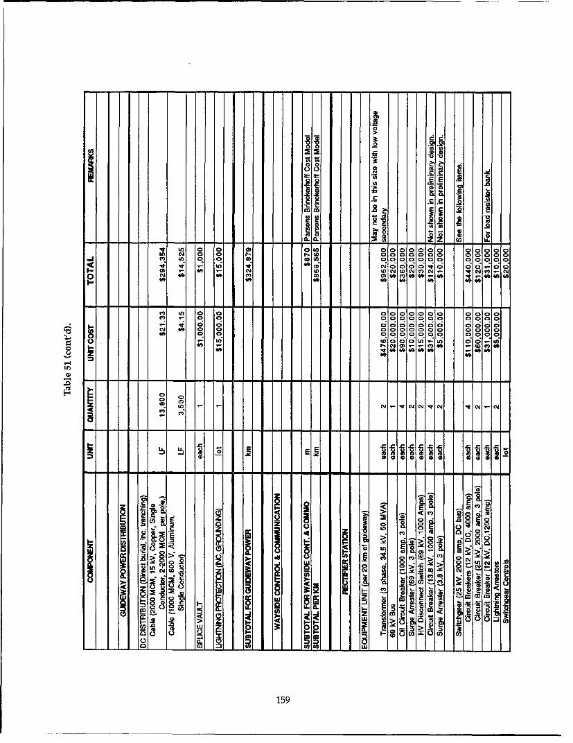
0
.22a~~o.U - U)U
~ -MA -E-SO~~C cm0O ~ o 0 . C
II-L 0 * 1 ki 12 0
0c In 0 0) 0000000 00000in -~ 0 0 r(D0000000 00000
lw V) It 49 0)00000v 00-00
0 0 ~ ~ 000000aaC0. 0n 0.-0-00* 0000
U)woin U 00 i
- - --w #
0IO V. N N- N ' C -~ N.N
E E
5 E EE8
E >-0* 0~
XL NO
2 CJ1 0 0 ~
0 Mý C ". g -a- in~3~3 ~m
N CL
L U0) lo
159

E Ew In L
00 0.Q 0
A Zz
LU ClC
o o 0 000 0 0 OW) 0000 0 0 0000;0 0 0 co0 0 0 ONY 0000 0 0 0000~ ~ 0 0 OO 0 0 UO000 0 0 WIOCU R Ct -q R . . R iO .RC - R
4 0 0 U) W)~t U) 0 CD- to~ (D CY N0 - 41 co 0 CD W)) 0 0
R 0 !qCDW N . 0 C!N0 0 ina 0 0 00000 -m 0 LN 006 - 0 inn -0 0 00 0 O00
0 0 co LO00 0CI- - oM & *C
0m - 0Y
00
U - - -- - - - - - - - - - - - - - - - - - - - - - - -
0~ 0& 0 O 0 0 0n 0 WOO
~0 > 0 DU- -D ~O 0 Ca 0 D)0 0Y 0 00 0 N
0 0c
IV0) 1-
UL m C
01cc wp, _Q i -s (D 1
160

V Ln 0u!VLe) 0) m0o
0J 0 0 NL)(D 0) r- 40 CM W 40
ina 0 ON 4qle -le 'i0 0 ~i.. 403 - U)W z ) Ni DIt( w a;
40), fA i N;*04
On 0
V-4.
E E E EEEE6
id Ne je e I
2 LU s IR5 -
161

* ~ )c l 0) P mwW m nWl
000
0000 0 0 00 0N 0 0 0 0 UC 0 t"LnnQ U- 0 NO) In an (0s 601+, 01ý6 11ý4
t2CO~ v 0o fl- co ( D 0 C 0wN4 ~ ~ ~ 9 C'JI' 0 0 N 0 % N CJCO 0
000a 0 00 0 CM U- 0 000 0 0 0 L
O O A0 o '-I La 0c a 000
C.JNOO 0 0 CD 0D 0n 0 o o-C4 No V; CDO)
0 0 0 0T ItCI CD o
bLO
X Ac
cm CO CO
z E Ec
t.0 flu _ E0 . 0 .
- - -- - .. a*- .. - -.. - .a
CD8
.li 0
= = b CC =
cz ..E .. 0 0 0
80 0' cc~ 0 10 o0-E cc C% 1:
-LL oo 1 1 co -So 00Im
162

.. 2
CIL"
00 in 0 0 W~ 0o10(00) 0) 0 0 it r(D (o0r-s0) co 0 0 D DU) W 0 0
-- c; C oj (7)1 0 0 0 a 0N0;C 10 IN; a0 00~ oo8808'oo
-It c - C.) 0 CO co0 C; c! ci 00't - 44 ~ - 0) co CD 000
40~ 40 0 a AC 4C 0L)t D000
cm co a 0
4v#~ 04 0 !0o0 0 O o060 000 CQ 0
U0 ui 0 0004 o.,
00Rc 0 C
LO0
C)
W)
E 0
R ~ ~ R o4 m I tc o c Y(
Ln >2WLo- .( (
_ C.L
00
M 7 A INS x"
16

U)~~W JCY J'
C
(U
0 00 0 0 0 U) 0 0 101010U0 00 0 0 ONC ý ~ Cl) W sot C l'O000 0 0 W) r. (D N 0'0?q 0 in
0 0N CY - CYCO)L)0 to CYi0)C Cl) 0 6c 61. 403, LO CV ((0 O C C 0
co 4a CY (O. Ql06.01 - T-
000 0 0
% 00 0 0U0
0 L0 '000 (5 dmi- o 6R 4- 09 4
'0
coi
Lu 0
0 _
""9 s4 3
zU. a. c22a _ -J -j-J-E co4
-~~~~C a: --- k -co co M

Table 53. Technology cost summary ($1000 per mile).
Subsystem Magneplane Grumman Foster-Miller Bechtel TR07 U.S. Maglev
a. Elevated.
Guideway structure 18,000 7,900 9,000 9,200 10,700 8,700
Guideway magnetics 3,600 5,800 9,100 6,300 4,200 5,200
Guideway power distribution 700 500 5,200 500 1,500 600
Wayside control andcommunication 1,400 1,400 1,400 1,400 1,400 1,400
Converter station 1,400 - - - - -
Inverter station - 1,900 - 1,900 2,100 2,000
Rectifier station - - 3,200 900 - -
Total 25,100 17,500 27,900 20,200 19,900 17,900
b. At grade.
Guideway structure 4,400 1,500 5,600 3,200 8,500 3,700
Guideway magnetics 3,600 5,800 9,100 6,300 4,200 5,200
Guideway power distribution 700 500 5,200 500 1,500 600
Wayside control andcommunication 1,400 1,400 1,400 1,400 1,400 1,400
Converter station 1,400 - - - - -
Inverter station - 1,900 - 1,900 2,100 2,000
Rectifier station - - 3,200 900 - -
Total 11,500 11,100 24,500 14,200 17,700 12,900
these components could bring the LCLSM cost in erally governs its cost. Thus, for current efforts toline with the other concepts. forecast maglev market performance, the derived
In the case of Magneplane, the guideway struc- U.S. Maglev costs should be meaningful despiteture is complicated and requires an extremely technological differences among concepts.large amount of aluminum. It is not an efficient It is interesting to compare the subsystemstructure for large spans, and, thus, it requires costs for U.S. Maglev with those for TR07. Forclose column spacing. This requirement becomes both elevated and at-grade guideways, essentiallyvery expensive for the standard 11-m elevation the entire cost advantage for U.S. maglev derivesused in this analysis, yet optimizing the beam de- from its lower guideway-structure cost. Indeed,sign for 11-m elevation was beyond our scope. We, TRO7's guideway structure is the most expensivetherefore, did not include the Magneplane guide- of all, except Magneplane's elevated guideway.way cost in our U.S. maglev estimate. The difference is particularly striking for at-grade
With these exceptions removed, subsystem guideways, where TR07's $4,800,000/mile costcosts are quite similar across the U.S. concepts. For disadvantage represents about 40% of the totalexample, excluding the Magneplane guideway, U.S. Maglev technology costs. Apparently, thisthe SCD elevated guideway structure costs vary cost penalty reflects the need to maintain veryless than 10% from the average value. In general, tight construction tolerances for the small-gapsome cost variability naturally exists because of TR07 system.technological differences. Also, some variabilityexists because contractors focused their efforts on Comparison of the Governmentdifferent subsystems and thus did not optimize and SCD cost estimatesall subsystems uniformly. Nevertheless, examina- The cost estimates prepared by the contractorstion of Table 53 supports the conclusion that the were compared to the GMSA estimates above. Thebroadly defined function of each subsystem gen- components in the contractors' estimates were
165

Table 54. Comparison of cost estimates ($1000).
Government ContractorSubsystem estimate estimate Remarks
a. Magneplane International.
Guideway structure 18,000 14,100 Contractor estimate is based on 5.2-m height.Unit costs are different.Reinforcing is not a separate item in contractor estimate.
Guideway magnetics 3,600 4,900 Contractor used higher unit costs.
Guideway power distribution 700 900 Contractor estimate was taken as a percentage (15%) of the totalelectrification costs.
Wayside control andcommunication 1,400 500 Government applied a standard unit cost to all SCD concepts.
Converter station 1,400 1,400
Inverter station - -
Rectifier station - -
Total 25,100 21,800
b. Grumman Aerospace.
Guideway structure 7,900 5,700 Contractor estimate is based on 11.3-m height.Unit costs are different.
Guideway magnetics 5,800 5,300
Guideway power distribution 500 700 Contractor estimate is per meter of dual guideway. It was not insufficient detail to determine differences.
Wayside control andcommunication 1,400 300 Government applied a standard unit cost to all SCD concepts.
Converter station - -
Inverter station 1,900 400 Contractor estimate is per meter of dual guideway. It was not in
sufficient detail to determine differences.
Rectifier station - -
Total 17,500 12,400
c. Foster-Miller.
Guideway structure 9,000 7,600 Contractor estimate is based on 7.6-m height.
Contractor estimate was not in sufficient detail to determinedifferences.
Guideway magnetics 9,100 3,300 Unit costs for magnetic components were too low.
Guideway power distribution 5,200 3,500 Unit costs for inverters were too low.Contractor estimate was not in sufficient detail to determine
differences.
Wayside control andcommunication 1,400 500 Government applied a standard unit cost to all SCD concepts.
Converter station - -
Inverter station - -
Rectifier station 3,200 200 Contractor estimate is for one station; two are required for dualguideway.
Total 27,900 15,100
166

Table 54 (cont'd).
Government ContractorSubsystem estimate estimate Remarks
d. Bechtel.
Guideway structure 9,200 12,700 Unit costs are different.Estimated quantities are different.
Guideway magnetics 6,300 6,800
Guideway power distribution 500 1,100 Contractor estimate was not in sufficient detail to determinedifferences.
Wayside control andcommunication 1,400 1,800 Government applied a standard unit cost to all SCD concepts.
Converter station - -
Inverter station 1,900 2,000
Rectifier station 900 0 Contractor assumed that power utility would provide this station.
Total 20,200 24,400
reallocated to subsystems in accordance with the system criteria and slightly out-performs TR07 onprocedures used in the Government estimate. The the SST. Magneplane and Foster-Miller's baselineresults are shown in Table 54. The reasons for any design have greater banking capability and morediscrepancy greater than 15% in the two estimates powerful motors, and they achieve incrementallyis shown in the remarks column. better performance along the SST. A U.S. maglev
The tables show that there are some substan- system would also fall into this category. Lastly,tial discrepancies between the two estimates. The Bechtel's baseline design possesses the most pow-primary reasons include differences in unit costs, erful motor and the completes the SST is the short-errors in calculated volumes, and items that were est time. On the basis of this rough grouping, weleft out of the contractors' estimates. In many may draw the following conclusions regardingcases, the contractors' estimates were not pro- guideway cost and performance:vided in sufficient detail to determine where thedifferences were. * For elevated guideways, the Grumman con-
Except for Bechtel's concept, our estimates are cept can provide slightly better perfor-higher than those of the contractors. Based on the mance than TR07 at significantly less costinformation available, the government effort rep- ($17,500,000/mile vs. $19,900,000/mile). Inresents a reasonable cost estimate of the technol- addition, the Bechtel concept and U.S.ogy for each guideway concept. maglev can provide enhanced performance
at similar or lower cost ($20,200,000/mile forConclusions Bechtel or $17,900,000/mile for U.S. maglev
Much of our cost-estimating effort focused on vs. $19,900,000/mile for TR07).simple "bookkeeping." We estimated costs based * For at- or on-grade guideways, the Grummanon a common set of guideway parameters and concept is approximately 60% of the cost ofconsistent allocation of components into sub- the TR07 system ($11,100,000/mile as com-systems. More importantly, however, we devel- pared to $17,700,000/mile). Also, the Magne-oped independent guideway cost estimates for all plane and Bechtel concepts and U.S. maglevfour SCDs and TR07 using common procedures would provide enhanced performance atand unit costs. This allows us to draw several gen- significantly lower cost ($11,500,000/mileeral conclusions based on a comparison of these for Magneplane, $14,200,000/mile forcosts and the associated performance character- Bechtel or $12,900,000/mile for U.S. maglevistics of these systems. as compared to $17,700,000/mile for TR07).
To facilitate this comparison, we may first * With two specific exceptions, we found rela-group systems of similar performance character- tively little variability in subsystem costsistics. Grumman's baseline design meets the SCD among U.S. concepts, despite significant dif-
167

ferences in technology. Apparently, the Table 55. Second numericalbroadly defined function of each subsystem rating scheme for each con-
generally governs its cost. This allowed us to cept.
estimate a U.S. maglev cost based on aver- Rating Score
ages of the SCD subsystem costs. This esti- Highly suited to attribute 2
mate should be meaningful for forecasting Capable of attribute 1
market response to maglev in the U.S. and Poorly suited to attribute 0
for comparing maglev with existing foreign Not capable of attribute -1
HSGT systems.For both elevated and at-grade guideways,essentially the entire cost advantage for U.S. the risk that the originally envisioned mission ismaglev relative to TR07 derives from its not where the greatest market response lies. Also,lower guideway-structure cost. The differ- if a maglev network begins to develop, its abilityence is particularly striking for at-grade to serve broader portions of the Nation's travelguideways, where TR07's $4,800,000/mile market will increase ridership and improve eco-cost disadvantage represents about 40% nomic viability. The adaptability of the technol-of the total U.S. maglev technology costs. ogy may also be important for export sales toApparently, this cost penalty reflects the countries with different transportation needs thanneed to maintain very tight construction tol- those of the U.S.erances for the small-gap TR07 system. Given the above rationale, we elaborated sev-
Like all cost estimates, the numbers developed eral mission statements appropriate for maglev;
here contain a degree of uncertainty. In particular, we then listed the primary technological attributes
the U.S. concepts are not fully developed into sys- that a concept should possess to serve these mis-
tem designs, and we had limited access to detailed sions. Note that the mission defined in the SCD-
TR07 data. Nevertheless, because we used a com- RFP is essentially that currently performed byshort-haul aircraft: short-to-medium distancemon procedure and a common set of unit costs for intercity trunk service. Earlier studies of maglev
all systems, these general conclusions are rela- and the NMI's own market and economic studiestively insensitive to this uncertainty. view this as the most promising initial market for
maglev. By using the SCD system criteria as an
3.4 OTHER EVALUATION evaluation step (section 3.1), we have considered
CRITERIA AND ANALYSES in depth the suitability of each HSGT system tointercity trunk service. Thus, we do not repeat that
The SCD-RFP system criteria were intended to evaluation here.guide the contractors in the development of their Given below is a description of four alternativeconcepts. However, other characteristics of maglev HSGT missions, their attributes, and the resultssystems may influence their technical viability in of our evaluation of each concept against thesethe U.S. We, therefore, developed additional evalu- attributes. We adopted the numerical ratingation criteria and applied them as cross-checks on scheme in Table 55 to apply for each technologi-each concept in a similar way to the SCD-RFP sys- cal attribute.tem criteria (section 3.1). The results of this effort This subsection concludes with Table 60, show-follow. ing the rating of each concept for each mission,
and a rating of each concept's overall mission3.4.1 Mission flexibility* flexibility. We view mission flexibility as a high-
The market response to maglev in the U.S. is priority criterion for the success of maglev.not well known or easy to forecast. If a given con-cept can serve a variety of transportation mis- Mission 1-Regional airport connectorsions, it improves its chances of being a commer- Objectives.cial success. Suitability to other missions reduces e To permit multiple airports located within
a relatively small region to serve as sepa-rate terminals of a distributed "mega-
• Written by Christopher J. Boon, Canadian Institute of port."Guided Ground Transportation, and Dr. James H. Lever, * To facilitate transfers between airportsCRREL. and improve network efficiency.
168

Table 56. Rating concepts as regional airport connectors (mission 1).
Attribute TGV TR07 Bechtel Foster-Miller Grumman Magneplane
Efficient at moderate speeds 1 1 1 0* 1 0*
Brisk acceleration/deceleration 0 0 2 2 0 2High peaking capability -1 1 1 1 1 2Transit-style doors,
baggage space, and seating 0 1 2 1 1 -1Tight-radius capability 1 0 0 0 0 0Electromagnetic compatibility 1 1 1 1 1 1
Total 2 4 7 5 4 4
* High liftoff speed.
Table 57. Rating concepts as a regional commuter trunk (mission 2).
Attribute TGV TR07 Bechtel Foster-Miller Grumman Magneplane
Efficient at intermediate speeds 2 2 2 1 2 1High capacity 2 2 2 2 2 2Moderate-high accleration 0 1 2 2 1 2Moderate curving performance 0 1 2 2 2 2
Total 4 6 8 7 7 7
* To improve ground access between pop- Examples.ulation centers and airports. * Long Island-New Jersey-Connecticut-
New York.Examples. * Los Angeles basin.
"* Dulles-Washington National-BWI- e Mor
downtown Baltimore. metropolitan commuter regions
"* LaGuardia-JFK-Newark-Manhattan. (Boston, Chicago, etc.).
"* Midway-downtown Chicago-O'Hare- Service characteristics.Milwaukee. * 60- to 100-km routes, 8- to 16-km station
Service characteristics, spacing.
"* Short distances, moderate speeds (50-60 * Intermediate speeds (70-80 m/s).
mis). e Strongly peaked demand.
"* Frequent service with peaking demands. * Substantial growth in demand.
"* Intermodal passengers and baggage Table 57 presents the numerical ratings of eachtransfers. concept.
"* Substantial growth in demand."• Easy terminal access. Mission 3-Short to medium distance"• Constrained ROW. point-to-point service
Table 56 presents the numerical ratings of each Objectives.
concept. e To improve intercity transportation effi-ciency (similar to SCD mission).
Mission 2-Regional commuter trunk * To improve airport terminal congestion
Objectives. associated with short-haul air.
"* To improve regional transportation effi- 9 To service more diffuse origin-destination
ciency, pairs than is possible with large airports.
"* To reduce pollution associated with con- Examples.gested commuter highways. * Northeast corridor.
"* To reduce or delay investment in high- * California corridor.way capacity to cope with peak com- e Detroit-Chicago-Milwaukee-Minne-muter travel. apolis.
169

Service characteristics. * Long trips, more comfortable cabins,"* 200- to 1000-km routes, 50- to 200-km more amenities.
station spacing. o Larger vehicles (large single or multiple-"* High speed (to 134 m/s). consist vehicles)."* Numerous, convenient station locations. 0 Interconnections to major airports, mag-"* Smaller vehicles, modest peaking. lev hubs."* Good interconnection with other public Table 59 presents the numerical ratings of each
transit. concept.
Table 58 presents the numerical ratings of eachconcept. Summary. Table 60 summarizes the ratings for
each concept against the four missions. The num-Mission 4-Long-haul trunk service ber of attributes (and hence the maximum rating
Objectives. possible) in each mission generally reflects our"* To provide surface interconnections priority of each mission in an overall rating of the
among the three major north-south corri- flexibility of these HSGT concepts to serve mis-dors (Boston-Miami, Chicago-Houston, sions beyond that identified in the SCD-RFPSeattle-San Diego), thereby creating a (intercity trunk service). We applied a final ratingnational HSGT network. to this evaluation using the same rating scheme
"* To supplement long-haul air capacity. as in section 3.1 so that we could add the results"* To reduce pollution generated by aviation together. This criterion is a high-priority one
and motor vehicles. (weighting = 3).This evaluation shows clear separation among
"Examples. the HSGT concepts in overall mission flexibility.Salt Lake City-Seattle TGV is the least flexible. Its fixed-consist, non-
"S Washington-St. Louis-Denver-San tilting trains, lower cruise speed, and lower over-Francisco all acceleration-deceleration render it poorly
"* Miami-Atlanta-New Orleans-Dallas- suited to meet other transportation needs beyond
Phoenix-Los Angeles intercity trunk service. TR07 is an improvementover TGV in this regard, but is limited by its
Service characteristics. nonfilting vehicles, modest acceleration, and lim-* 2000- to 4000-km routes, 500- to 1000-km ited speed potential. By comparison, the SCD
station spacing. maglev concepts show considerable potential too Very high speed (more than 150 m/s). serve additional missions beyond intercity trunk* High traffic density. service. Furthermore, they perform that primary
Table 58. Rating concepts for short to medium distance point-to-point service (mission 3).
Attribute TGV TR07 Bechtel Foster-Miller Grumman Magneplane
High speed 1 2 2 2 2 2High acceleration 0 1 2 2 1 2Good curving performance 0 1 2 2 2 2Small vehicles -1 1 2 2 2 2Short headway, fast switches 1 1 1 2 1 2
Total 1 6 9 10 8 10
Table 59 Rating concepts for long-haul trunk service (mission 4).
Attribute TGV TR07 Bechtel Foster-Miller Grumman Magneplane
Very high speed -1 0 1 1 0 1Low power at high speed -1 0 1 1 1 1Large vehicles, good amenities,
and comfort 1 1 1 1 1 0
Total -1 1 3 3 2 2
170

Table 60. Summary of ratings for all four missions.
Mission TGV TR07 Bechtel Foster-Miller Grumman Magneplane
Regional airport connector 2 4 7 5 4 4Regional commuter trunk line 4 6 8 7 7 7Intercity point-to-point service 1 6 9 10 8 10Long-haul trunk service -1 1 3 3 2 2Total (max. 36) 6 17 27 25 22 23
Mission flexibility rating* -1 1 1.2 1.2 1.2 1.2
*-1 doesn't meet, 1 meets, 1.2 exceeds criterion
Table 61. Assessments of tilting vehicle body.
System Evaluation comments Rating
TGV None -1
TR07 None -1
Bechtel Internal tilting cabin, 150 banking 1Aerodynamically clean, low interior noiseWeight and complexity penalties-redundant structure, doors, and windows
Foster-Miller Simple cabin construction, circular cradles, 12° bankingNo feedback correction for tilt-preprogrammed according to route and speedRequires complex fairing between bogies and tilting cabin 1
Grumman Struts and linkages needed for each bogie, 90 banking 1Complex bogie-body fairing requirements
Magneplane Passive vehicle banking, magnetic keel (i.e., no mechanical tilting mechanism) 350 banking 1May be able to pre-roll and correct tilting actively using aerodynamic control, but control not as
positive as mechanical means
mission, on average, much better than TGV and 3.4.3 Energy efficiency*somewhat better than TRO7. This provides some Energy efficiency is an important performanceconfidence that U.S. maglev concepts will, over- indicator for HSGT, and we rated it as a high-all, fulfill a broader spectrum of U.S. transporta- priority criterion. Here, we summarize energytion needs than either of the two foreign HSGT consumption for all systems and compare thesystems. results to that for short-haul air. We show these
results normalized per seat-meter, a measure3.4.2 Tilting vehicle body known as energy intensity (EI). Our evaluation
A tilting body allows a broader speed range used short-haul air as a baseline: -1 for El higherthrough curves while maintaining ride comfort. It than air, 1 for comparable El to air, 1.2 for EI sub-also provides some flexibility in route alignment stantially lower than air.and speed profile by permitting pre-roll (i.e., initi- We used two measures of energy consump-ating roll in advance of curves). Atilting body also tion-along the SST and at steady cruise. Resultspermits a vehicle to return to a near-horizontal for the SST include energy consumed repeatedlyposition if it is stopped in a curve, thereby easing accelerating a vehicle, particularly in the first,passenger movement and evacuation. Its disad- twisty segment but also for the two intermedi-vantages are basically cost, reliability, mainten- ate stops. However, the SST simulations did notance, and weight. Provisions for tilting should incorporate energy savings from regenerativemaximize the advantages and minimize the dis- braking, the primary braking mode for all maglevadvantages. This is a medium priority item. We concepts. The purpose of regenerative braking ischecked the range of tilt and the complexity and to recover kinetic energy lost during deceleration.weight of the vehicle. Table 61 gives the evalua-tion comments and ratings for tilting vehicle body. * Written by Dr. James H. Lever, CRREL.
171

One way to approximate this benefit is to exam- nection (i.e., at the airport). As reflected in eq 22,ine energy consumption at steady cruise speed on idling, taxiing, and takeoff energy requirementsa level guideway. This value will also approxi- cause the energy intensity for short-haul air travelmate vehicle energy consumption on a fairly to strongly depend on trip length.straight, high-speed guideway. Commonly, energy intensity is calculated on a
We obtained cruise energy consumption values per-passenger basis. Although experience withfor all HSGT concepts by matching vehicle thrust foreign HSGT suggests that maglev would oper-requirements to motor thrust. We then used ate at higher load factors than short-haul air, weLSMPOWER and an estimate of converter station compared energy intensities on a per-seat basis.efficiency (see section 3.3.2) to obtain electrical However, we did correct for differences in cabinenergy consumed from a utility. The SST simula- space allocated per seat for each system. As dis-tor SSTSIM (section 3.3.1) computed energy con- cussed in Chapter 2, we defined a standard pas-sumption along the SST route using the motor and senger (SP) as 0.80 m 2 of cabin space (includingresistance data for each concept. We then applied lavatories and galleys). We then used this defini-a converter station efficiency to obtain total elec- tion to determine the number of seats for each sys-trical energy consumed for one trip along the tem for use in calculating El.route. These values are "base" energy consump- This is an important correction. The 737-300tions-joules of electrical energy consumed at the allocates 0.54 m2 of cabin floor area per seat forsystem connection to an electric utility, its 140-seat arrangement. This is slightly less than
We selected the Boeing 737-300 aircraft to com- the Magneplane vehicle, the least spacious of thepare the energy efficiencies of HSGT and short- HSGT systems studied here. Conversion to stan-haul air. This aircraft is among the most fuel effi- dard passengers gives this airplane 96 seats.cient in the U.S. short-haul fleet, and its energy By using a standard passenger, we acknowl-intensity is about 70-80% that of the fleet, depend- edge that seat spacing is a variable easily altereding on trip length. With about a 30-year replace- by vehicle designers and operators. Provision forment cycle for aircraft, the fleet-averaged energy flexibility in seat pitch or changes from spaciousintensity will likely approach that of the 737-300 five-abreast to compact six-abreast seating is wellby the time maglev becomes a significant alterna- within the technology of the SCD concepts. Thus,tive mode. This is consistent with the estimate by it would be relatively simple for the more spa-Johnson et al. (1989) that fleet-averaged energy cious concepts to increase their number of seatsintensity for intercity air travelwill drop by about and hence improve their energy intensities.75% over this period. Although our choice of 0.80 m 2 per SP is some-
Commercial airlines file data on fuel consump- what arbitrary, use of a different value simplytion with the USDOT for all flights. We used these involves multiplying the El values here by thedata for 737-300 aircraft for the period ending appropriate ratio. Comparisons between systemsJune 1991, and conducted a regression analysis would not change.to obtain average fuel consumption per flight as Table 62 shows the base energy intensities fora function of trip length. By converting jet-fuel each HSGT system at steady cruise, on a levelvolume to its energy equivalent (1 U.S. gal = 1.35x guideway. We show two values for TGV-at its101 BTU = 1.42x101 J Higher Heating Value), we commercial cruise speed of 83 m/s, and projectedobtained a very good fit of the data to the follow- for 134 m/s based on its parameterized drag. Theing equation: latter number demonstrates a benefit in El asso-
ciated with large consists. Also shown in Table 62
Elbas (J/seat-m) = 1.39 X 10⁵+ 4.69 x 10D0 (22) are Elbase values for maglev vehicles making 400-S -D and 800-km trips along the SST (TGV cannot com-
plete the SST). The two values shown for the 400-where Elbase = base energy intensity in J/seat-m km trip are for the first and second halves of the
derived from actual fuel con- route, respectively (from terminal 1 to terminal 2,sumed and from terminal 2 to terminal 4, including a stop
S = the number of seats at terminal 3). The average of these two valuesD = trip length (m). equals that of the full 800-km SST. For routes of
similar geometric alignment, maglev EI is essen-As with maglev electrical energy, this estimate tially independent of trip length.derives from energy consumed at the system con- The Foster-Miller concept has the lowest SST
172

Table 62. Energyintensities for each HSGT system at steady cruise speed, and for 400-and 800-km trips along the SST. These derive frombase energy consumed at the utilityconnection.
Standard 400-km SST 800-km SSTCruise speed passengers Cruise Elbas, EIbs_, Elbas,
System (m/s) (SP) (J/SP-m) (J/SP-m) (J/SP-m)
TGV 83 700 130 - -
134 - 310 - -TR07 134 160 460 590/480 540Bechtel 134 110 560 840/600 720Foster-Miller 134 140 390 510/400 450Grumman 134 120 340 600/380 490Magneplane 134 110 400 690/460 580Average of all SCDs 134 - 420 660/460 560Average of best two SCDs 134 - 370 560/390 470
7000 . drag at cruise speed is comparable to its aerody-namic drag, and this substantially raises its EL.
00 \ 77- CruiseFigure 119 compares these base El values with-...TR07 Cruise
SAve. SCD Cruise that of a 737-300 (eq 22) as a function of trip length.......... Best Two SCD Cruise To represent U.S. maglev, we use the average of
A Ave. SCD SST
d 4000 S Best Two SCD SST all SCD concepts and the average of the two mostefficient ("best") concepts. Based on energy con-
3000 sumed at the system connection (i.e., airport or200 electrical supply), maglev El values range from2000 about 13 to 25% of that of a 737-300 for 200- to 1000-
1000 km trips. The very large difference for short trips.4 highlights maglev's suitability for serving more
0 ,closely spaced stations than is practical with air-0 200 400 600 800 1000 craft.
Distance (kin) Clearly, electricity and jet fuel are different com-Figure 119. Base energy intensity at system connection modities, and their values per joule are different.(airport or electrical supply). Energy cost is one way to compare energy con-
sumption for these different fuels, essentially rely-ing on cost to reflect differences in the value of
EI of the maglev concepts studied. It has the most resources used to produce each fuel. The Depart-efficient motor (the LCLSM), a fairly small fron- ment of Energy produces annual estimates of fueltal area, and low magnetic drag. Interestingly, prices based on forecasts of supply and demandFoster-Miller chose relatively conservative aero- under different sets of overall economicdynamic drag coefficients (see section 3.4.6), assumptions. The baseline or "reference case" fore-based on existing high-speed trains. TR07, cast for the year 2010 (DOE 1993a) predicts a jetGrumman, and Bechtel have vehicles that wrap fuel price of $0.89 /gal. and an electricity price foraround the guideway, resulting in a larger fron- transportation of $0.065/kWh in 1991 dollars. Thattal area. All three concepts have low magnetic is, on a per-joule basis, electricity is expected to bedrag. However, TR07's aerodynamic drag coeffi- about three-times more expensive than jet fuelcients derive from full-scale tests and thus reflect (roughly the same ratio as currently exists). Usingcurrently achievable values. Grumman appears these forecast prices, maglev would realize energy-to have anticipated drag reductions resulting from cost savings compared to air travel of 60 to 30%thorough study of all vehicle drag sources. for the 200- to 1000-km trip range.Because aerodynamic drag predominates at high Another way to reflect the difference in valuespeed, Grumman's low cruise EI results primarily between jet fuel and electricity is to account for thefrom its choice of these lower drag coefficients. energy consumed to produce and deliver eachMagneplane used aerodynamic drag coefficients fuel. Indeed, this approach has been used in pre-similar to Grumman's. However, its magnetic vious comparisons of El between maglev and air
173

7000 gies. Modem natural gas-, oil-, and coal-fired
07plants are much more efficient than this.6000 - 737-300
TR07 Cruise Modem natural gas- and oil-fired combine-5000 ----- Ave. SCD Cruise cycle plants (gas turbine with steam-turbine bot-
. Best Two SCD Cruise toming cycle) commonly achieve base-load effi-S•A Ave. SOD SST0 4000 • Best Two SCD SST ciencies of 47-48%, based on the conservativeSHigher Heating Value of the fuel (Farmer 1992,
Wi 3000 Gas Turbine World 1992, DOE 1993a). Modern200 coal-fired plants are also approaching such effi-2000 ciencies (Bajura and Webb 1991, DOE 1993b).
These power plants have lower capital-cost-per-1000 . . . . . . . . . . : ."--: .• • . . . .
unit capacity than single-cycle plants, and they0 produce very low emissions. Indeed, DOE (1993a)
0 200 400 600 800 1000 forecasts that from 1990 to 2010, combined-cycleDistance (kin) generating capability will grow at about 20 times
Figure 120. Net energy intensity including energy sup- the total growth rate of electrical-generatingply efficiency (90% jet fuel, 45% electricity), capability. Furthermore, utilities will add modem,
efficient equipment to meet additional demandstravel (e.g., Johnson et al. 1989). Essentially, this beyond current forecasts, such as needed to sup-approach identifies possible savings of gross ply a major maglev network. We thus selected anenergy by diverting passengers from air travel to electrical generation efficiency of 47%. Combinedmaglev. We also did this calculation, but it is not with a 95% transmission efficiency, this yields anas straightforward as it seems. electrical supply efficiency of 45% for maglev.
The predominant factor in this second approach Figure 120 shows resulting net El values for airis the net thermal efficiency of electrical power and maglev as functions of trip length. These aregeneration (joules-electrical output/joules-heat the same data as in Figure 119 with the aforemen-input). In effect, applying this factor implies that tioned efficiencies applied. Electrical supply effi-a unit of jet fuel saved in air travel is burned in a ciencies bring the Els closer, but the results stillpower plant to produce electricity for maglev. It overwhelmingly favor maglev. For 200- to 1000-places no direct value on the flexibility of electri- km trips, maglev EI ranges from about 25 to 50%cal power production. Natural gas, coal, hydro, of that of a 737-300. And as noted, this compari-nuclear, solar, wind, and trash are electrical power son ignores the flexibility of power-plant fuelsources that simply cannot be used to fuel com- afforded by maglev's electrical propulsion. Inmercial aircraft. What is the equivalence factor terms of energy consumption and flexibility,between air travel and maglev using hydro power maglev is clearly superior to short-haul air travel.as the energy source? Furthermore, refined petro- TGV also shares these benefits, albeit with at a muchleum powers all commercial aircraft and indeed lower performance level. Thus, all HSGT conceptspractically all U.S. transportation. Maglev can studied here earn a rating of 1.2 for energy con-decouple intercity travel from this dependence on sumption.petroleum, and applying simple efficiency factors To complete this comparison, we examineddoes not capture this distinction. maglev trip times achieved along the SST and
Recognizing that it hides this important dis- compared them to those for air travel. The line-tinction, we nevertheless applied efficiency fac- haul (station-station) trip times for the SST's twotors for energy supplied to aircraft and maglev. 400-km segments average about 64 minutes for allFor jet fuel, Johnson et al. (1989) applied an effi- SCDs. The corresponding value for the full 800-ciency of about 90% to account for transportation, km SST is about 130 minutes. Use of the trip timesrefining, and distribution losses. We adopted this for the two most energy efficient SCDs does notvalue as the only correction applicable for air change these numbers significantly. Airline sched-travel. For electrical power generation and trans- ules indicate line-haul (departure-arrival) tripmission, Johnson et al. used efficiencies of 35 and times of about 60 minutes for a 400-km trip and95%, respectively. We also chose a 95% factor for 100 minutes for an 800-km trip. Thus, line-haultransmission efficiency. However, 35% efficiency trip times are comparable at 400 km, and favor airfor power generation reflects a national average at 800 km (trip times for trips shorter than 400 kmfor fossil-fuel plants of varying ages and technolo- favor maglev). However, access time for maglev
174

should be much less than for air because maglev 3.4.5 Potential for expansionfacilitates smaller, more conveniently located sta- It may be desirable to expand system capacitytions. That is, we would expect maglev and short- beyond 12,000 seats/hour. Here, we rate eachhaul air to yield comparable total trip times for concept's ability to expand capacity easily. Notean 800-km trip; shorter trips should favor maglev. that all the maglev concepts studied are propelled
In summary, maglev can provide intercity by an LSM. This considerable investment ulti-travel at much lower energy usage than aircraft, mately limits motor thrust and, hence, capacity forwith comparable or shorter trip times, and with all systems. Its replacement with a larger LSMflexible choice of power-plant fuel. Average would be very expensive. Fortunately, most con-maglev EI would be about 50% of that of short- cepts can achieve very large capacity using theirhaul air for an 800-km trip, yet offer a comparable current LSM, so that this is not generally a seri-total trip time. As trip length reduces, maglev's ous limit. This has a medium priority. Table 64energy advantage over air increases dramatically, provides the evaluation comments and ratings forand it offers an increasingly significant trip-time expansion potential.advantage. For a 200-km trip, maglev would con-sume about 25% of the energy of a short-haul air- 3.4.6 Aerodynamicscraft and complete the trip in about 25% less time. Aerodynamic drag is the predominant vehicleFrom the view of energy consumption, fuel flex- drag at high speeds for all HSGT systems. It, thus,ibility, and trip time, maglev is clearly superior to is the primary source of energy consumption forair for intercity travel. maglev vehicles along high-speed routes. Both
TGV and TR07 have experience with full-scale3.4.4 Use of existing infrastructure vehicles to determine drag contributions from
Use of existing highway and railroad ROW various sources. To check the reasonableness ofimproves the likelihood of nationwide implemen- the SCD estimates, we cast all aerodynamic dragtation of HSGT. This is a high priority item. We estimates into a common format. We also enlistedchecked the following: the help of Dr. D.M. Bushnell, Fluid Mechanics
"* Minimum curve radii. Division, NASA Langley Research Center. He
" Maximum acceleration and grade capability, based his comments on existing literature for" Maximeutogofrom 0certion 14 g e chigh-speed trains (Hammit 1974; Railway Tech-* Time to go from 0 to 134 m/s. nical Research Institute of Japan 1984, 1989;
Table 63 gives the evaluation comments and rat- Brockie and Baker 1990) and his broad experienceings for using the existing infrastructure. with aerodynamics of aircraft and other vehicles.
Table 63. Assessments of how the concepts can use existing infrastructure.
System Evaluation comments Rating
TGV Can run directly on existing rail lines, although high-speed service requires dedicated lines -1Large, 6000-m minimum curve radius at 83 m/sPoor grade capabilityNot normally elevated (grade crossings, crossing of ROW require elevated structures)
TR07 5800-m minimum curve radius at 134 m/s 10.006-g reserve acceleration (0.6:100) at 134 m/s (present design cannot climb 3.5:100 grade at cruise)320 s to 134 m/s
Bechtel 2600-m minimum curve radius at 134 m/s 1.20.12-g reserve acceleration at 134 m/s89 s to 134 m/s
Foster-Miller 2800-m minimum curve radius at 134 m/s 1.20.044-g reserve acceleration (4.4:100) at 134 m/s120 s to 134 m/s
Grumman 4100-m minimum curve radius at 134 m/s 1.20.048-g reserve acceleration (4.8:100) at 134 m/s180 s to 134 m/s
Magneplane 2200-m minimum curve radius at 134 m/s 1.20.039-g reserve acceleration (3.9:100) at 134 m/s130 s to 134 m/s
175

Table 64. Assessments of potential for system expansion.
System Evaluation comments Rating
TGV Very large consists possible 1.2Bilevel cars now in productionEffort to increase speed to 97 m/s now underwayRail clearance envelope limits vehicle width
TR07 Wrap-around vehicle permits width increase (although beam width fixed-limits strength) 1Stator slot width limits conductor current, hence motor thrustLevitation force limited by stator pack size
Bechtel Slots for extra magnets in vehicle to increase payload capacity 1.2Wrap-around vehicle permits width increase (although beam width fixed-limits strength)Potential for electromagnetic switchPotential for multi-car consists
Foster-Miller LCLSM provides great potential for reduction in headway distance 1.2Eight-car trains at 55-s headways possiblePassive EM switch is very fastChannel guideway easier to strengthen, but harder to increase vehicle width
Grumman Slots for extra magnets in vehicle to increase payload capacity 1.2More powerful motor already considered by using copper LSM winding (although slot width
eventually limits capacity)Wrap-around vehicle permits width increase (although beam width fixed-limits strength)
Magneplane Some flexibility to increase both vehicle and guideway widths 1.2Passive EM switch is very fastVery short headways possible (20 s)
Despite small differences in the methodology P = vehicle wetted perimeter (m)used for each system, we may cast each aerody- Ln = vehicle wetted length (m)namic drag estimate in the following form: n = number of cars per consist (we used
the baseline number)Da/q = Ax Cd + P Ln n Cf (23) Cf = skin friction coefficient.
where: Da = aerodynamic drag (kN)q = dynamic pressure (11 kN/m 2 at Table 65 shows the values for these param-
134 m/s) eters for each HSGT system. Except as noted, weAx = vehicle frontal area (m2) extracted these values directly from TGV andCd = drag coefficient for pressure drag TR07 published literature and reports, and from
(nose, base, protuberances, gaps, the SCD final reports. Also shown is the aerody-etc.) namic drag per standard passenger (Da/SP) for
Table 65. Parameters used for estimating aerodynamic drag for eachconcept.
DA/SP (N)System A• (m2) Cd P (m) Ln (m) n Cf at 134 m/s
TGV-A 11 0.18 13 20 12 0.0039 220TR07 12 0.18 16 27 2 0.0037 360Bechtel 15 0.11 18 36 1 0.0040 430Foster-Miller 9.4 0.21 12 27 2 0.0025 280Grumman 13 0.11 14 18 2 0.0022 240Magneplane 7.1 0.10 10 38 1 0.0016 130Magneplane* 8.0 0.0020 160
"We increased the estimated frontal area for Magneplane based on its revisedvehicle shape; we increased Magneplane's skin friction coefficient because 0.0016appears to be too low for the Reynolds number of the vehicle. We used theserevised values to model Magneplane's performance along the SST.
176

each system at 134 m/s, which is a measure of the -Protuberances.aerodynamic efficiency of the vehicle. For corn- -Gaps between vehicles or components.parison, we have calculated Da/SP for TGV-A at -Wake effects attributable to crosswinds or134 m/s, although its maximum cruise speed is yaw.83 m/s. -Drag ascribable to lift (caused by asym-
Bushnell's literature review suggested that the metrical shapes and boundary conditions).state-of-the-art for high-speed trains justifies use -Magnet bogies.of Cd = 0.15 and Cf = 0.004. These values are quite -Compressibility effects from passingclose to those for TVG and TR07; the Cd value is vehicles.also about midrange for the SCD estimates. How- -Trim drag (of aerodynamic control sur-ever, three of the four SCDs use a much lower skin faces).friction coefficient than that justified by the state- 9 Tunnel drag.of-the-art. According to Bushnell, careful design * Effects of air flow through open channeland detailed attention to drag sources can yield guideways and guideway outriggers.25% (perhaps 50%) reductions in both Cd and Cf. Bushnell suggested that computational fluidIt thus appears that some SCD concepts incorpo- dynamics models or wind tunnel tests with arated such anticipated reductions. While this moving ground plane could yield drag estimatesplaces some concepts at a comparative disadvan- for maglev vehicles within 10-20% of their actualtage, our aim here is to assess technical viability values. Naturally, finer details of vehicle geometryof U.S. concepts generally. Thus, SCD average would be needed. Present SCD estimates based ondrag values appear to be achievable almost im- analogies with high-speed trains and aerody-mediately, and the lower SCD estimates appear namic handbooks are probably within 25-50% ofto be achievable with solid technical effort (as actual values. Given this level of uncertainty andwould likely be part of U.S. maglev develop- lack of detail, we chose not to rate the systems form ent). aero dyna ic perfo s e .
Bushnell also briefly discussed sources of drag aerodynamic performance.and issues affecting drag reduction. Many of these 3.4.7 Criteria summarypoints were also noted in the SCD reports. We list We criteriathem here for consideration as part of further We may combine with the above other criteriawork in this area. our ratings of each concept against the SCD-RFP
Drag minimization requires thorough evalua- criteria (Table 24). This provides an overall evalu-tion of all sources, including: ation of the ability of each concept to meet trans-
portation needs for the U.S. market. That is, this"* Three-dimensional nose-base drag, includ- overall rating assesses the "mission suitability"
ing effects of atmospheric turbulence. aspect of each concept's technical viability. Table"* Frictional drag, including actual surface 66 shows these results.
roughness and guideway channel drag. Interestingly, application of additional evalu-"* Additional pressure drag components, ation criteria did not change the relative ranking
including: of the concepts. However, the gap between TGV
Table 66. Overall assessment of mission suitablity of HSGT concepts studied.
Parameter Weight TGV-A TR07 Bechtel Foster-Miller Grumman Magneplane
RFP systemcriteria subtotal 53 38 48 46 56 56 56
Other CriteriaMission flexibility 3 -1 1 1.2 1.2 1.2 1.2Tilting 2 -1 -1 1 1 1 1Energy efficiency 3 1.2 1.2 1.2 1.2 1.2 1.2Existing infrastructure 3 -1 1 1.2 1.2 1.2 1.2Expansion 2 1.2 1 1.2 1.2 1.2 1.2Aerodynamics 0
Subtotal 13 -2 10 15 15 15 15
Total 66 36 58 61 71 71 71
177

and the maglev concepts widened substantially. ity evaluation process. The mission-flexibility cri-This technology does not meet as extensive a set terion forced us to consider transportation needsof U.S. transportation needs as do the maglev beyond those served by intercity trunk service.technologies. Also, this assessment revealed a Similarly, our aerodynamic assessment placed thesomewhat greater capability of the U.S. maglev concepts in a common format and improved ourconcepts vs. TR07 to meet U.S. transportation understanding of the various procedures used toneeds. TR07 suffered primarily for its lack of a tilt- estimate aerodynamic drag. Perhaps most insight-ing vehicle and its modest motor capability. ful was our energy-efficiency assessment. ThisExcept for Bechtel's selection of a fuel cell for comparison required data from several of ouronboard power supply and its incomplete suspen- analyses (motor and power, system simulation,sion description, all U.S. concepts met or exceeded aerodynamics) and helped to reveal maglev's roleall criteria and yielded essentially identical scores. relative to existing short-haul air service. We
As with the SCD system criteria, evaluation of may now draw upon the insight gained here tothe concepts against the additional criteria in this discuss the overall technical viability of maglevsection was a helpful step in our technical viabil- for the U.S.
178

CHAPTER 4. OVERALL TECHNICAL VIABILITY OF CONCEPTS
The GMSA effort described in chapters 2 and 3 The following sections (4.1.1 to 4.1.9) cQntain theabove concentrated on generating data and exam- technical issues that we feel best reflect the long-ining technical characteristics for each concept. term advantages of maglev vs. HSR. Note that com-Essentially, this provided the input necessary for mercial service speed (or service speed) denotes aevaluating the technical viability of maglev in the speed that is sustainable in commercial operationU.S. In chapter 4, we use this information to address with acceptable margins of safety and life-cyclespecific aspects of technical viability (see Tables 1 costs. We use TGV-A as our primary HSR example,and 3, which list the general performance features although we note differingtechnical characteristicsof each concept). of other HSR systems where appropriate.
4.1.1. Speed4.1 LONG-TERM POTENTIAL OF TGV-A offers 83-m/s commercial service, andMAGLEV COMPARED WITH HSR has demonstrated a sustained speed of 133 m/s
and a peak speed of 143 m/s. Thus, steel-wheel-on-
High-speed rail possesses impressive perfor- rail technology is directionally stable at maglev'smance characteristics and could meet many of the design-goal speed of 134 m/s. Nevertheless, suchrequirements thought to be important for a favor- speeds were not the original design target of thisable market response to maglev. Indeed, TGV offers technology; high-speed stability has been achieveda proven, commercially successful, 83-m/s service, through incremental improvements in aerody-and this service is available for the U.S. with essen- namics, truck design, and rail-bed stiffness andtially no development risk. In addition, its current alignment. For reasons of safety margin or life-performance limits maybe governed more by cost- cycle costs, TGV does not currently operate at 134benefit optimization than by physical constraints, m/s, and it would require further improvements toand further development will undoubtedly raise do so. By their nature, such improvements wouldthese limits. We may then ask whether maglev entail development, capital, and maintenance costspossesses specific attributes that, in the long term, that are even higher than the significant costswill provide it a clear performance advantage over incurred for 83-m/s service.HSR. If it does, this provides some rationale for by- Power transfer by pantograph-catenary contactpassingHSRinfavorofdevelopingmaglev, despite may be HSR's most immediate speed limiter.the latter's significant development cost and risk. Observers noted that arching between the panto-
We discussed several technological issues that graph and catenarywas almost continuous through-appear to favor maglev over HSR. In most cases, out TGV's 143-m/s run. Such arching leads to rapidHSR's shortcomings are not absolute physical con- deterioration of both components. Evenwith steadystraints and could be mitigated with sufficient contact, pantograph-catenary wear will increasedevelopment and maintenance efforts. Indeed, with speed, thereby increasing maintenance costs.HSR's present performance levels have resulted TGV must solve both the contact and wear prob-from just such efforts. While laudable, this process lems to use pantograph-catenary power transfer athas been slow and costly, and future improvements service speeds of 134 m/s and higher.will require proportionately greater investment. SNCF/Gec Alsthom have begun work to develop
By comparison, maglev is a new technology spe- an actively controlled pantograph to enable TGV tocificallyintended to start withperformance capabil- reach higher speeds. They have allocated $120 mil-ity beyond that of current HSR. While its develop- lion for this and other improvements to TGV toment costs and risks are substantial, they maybe no raise its cruise speed to 97 m/ s by 1995. Their effortgreater than those required tobring HSRtoa similar is also supplemented by the general HSR R&Dperformance level. More importantly, future incre- effort worldwide. Such large investments for incre-mental improvements should be much easier for mental speed increases are characteristic of maturemaglev than HSR. This difference in incremental technologies such as steel wheels on rails. Indeed,effort to achieve incremental performance gains both Japan and Germany see 97-m/s service as ais a basis for identifying long-term advantages of goal requiring substantial R&D investment overmaglev over HSR. Other authors have expressed the next 5-10 years.this same argument for maglev (Gran 1990) and for By comparison, high-speed potential is essen-new technologies generally (Foster 1986). tially an inherent characteristic of maglev. Guid-
179

ance and propulsion occur without physical con- compared with 30 m/s for TGV). It also allows fortact. Magnetic elements (coil layout, reaction com- more rapid return to full speed following reduced-ponents, field strengths, etc.) are broadly adjust- speed curves.able to achieve the guidance forces necessary for TGV's trip times along existing ROW also suffervery high speed. Similar flexibility in design exists from lack of vehicle tilting capability. TGV's totalfor guideway structural members. Furthermore, bank angle is only 70 compared with an average ofwithalong-stator LSM, propulsion power does not about 300 for U.S. maglev concepts. Although tilt-need to be transferred to the vehicle. In essence, ing HSR systems exist, none are capable of evenmaglev comes "out-of-the-box" ready for 134-m/s 83-m/s service.service. Higher-speed service is well within the Longer trip times makes HSR less attractive thantechnology, and its associated higher capital and air travel, as well as other transportation modes,operating costs become simply part of the system- resulting in lower ridership and revenues. Relativelevel trade-off with expected market demand for to maglev, such lower revenues can offset HSR'sthe service. If run in evacuated tubes, maglev has capital cost advantage and yield lower profitability.an extremely high ultimate-speed potential.
In principle, HSR could utilize a long-stator LSM 4.1.3. Mission flexibilityforpropulsionto circumvent pantograph-catenary HSR is best suited to short to intermediatepower transfer. However, this would entail high intercity trunk service. TGV's fixed-consist, non-development costs and an enormous infrastructure tilting trains, lower cruise speed, and lower overallinvestment on par with those for a maglev LSM. acceleration-deceleration render itpoorly suited toEssentially, such a system would substitute steel- other transportation needs beyond this. This lack ofwheel-on-rail guidance for magnetic guidance and flexibility ultimately limits the market penetrationwould thus still encounter high incremental devel- and profitability of HSR.opment costs for that element. Besides offering superior intercity trunk service,
Speed, through its influence ontrip time, strongly U.S. maglev concepts show considerable poten-influences forecasts of the U.S. market response to tial to serve additional missions. Such flexibilityHSGT. However, the question of how much speed is derives from the much greater performance capa-enough depends on how much the traveler must bility of the technology. Mission flexibility helps topay for it. It seems likely that maglev will achieve reduce the risk that intercity trunk service is notservice speeds of 134 m/s more easily than will where the greatest HSGT market lies. Also, byHSR; this should translate into lower costs and offering other services (regional airport connector,hence lower ticket prices for the traveler. While commuter trunk, point-point, long-haul trunk),maglev requires development investment just to maglev increases its overall ridership potential in abegin commercial service, HSR will also require sub- major transportation network. This provides somestantial R&D to reach 134 m/s (given that 97 m/s is confidence that an investment in maglev will fulfillviewed as a significant challenge). Even if the'two a broad spectrum of U.S. transportation needs.are comparable in performance and cost at 134 m/s,a desire for future speed increases favors maglev. 4.1.4. Maintenance
HSR relies on wheel-rail contact for lift, guid-4.1.2. Trip time ance, acceleration, and braking, and pantograph-
Trip time strongly influences ridership for trans- catenary contact for power transfer. To achieve lowportation systems. In addition to a much higher rollingresistanceand adequate adhesion, thewheelsspeed potential, maglev possesses other perfor- and rails contact each other over an extremely smallmance characteristics that combine to deliver shorter area; to avoid arching, the pantograph must firmlytrip times than HSR. press against the catenary. In both cases, the result-
TVG's maximum acceleration is 0.04 g from ing contact stresses are high and thus produce0-16 m/s, and this falls to 0.03 g at 50 m/s. By wear. TGV conducts scheduled maintenance tocomparison, maglev's maximum low-speed accel- ensure that wheels are smooth and round, rails areeration is four times TGV's, constrained basically correctly profiled and accurately aligned, and pan-by ride comfort. Additionally, the U.S. maglev con- tograph and catenary wear are within allowablecepts have reserve acceleration in access of 0.04 g at limits. This is costly and time consuming. Because134 m/s. Superior acceleration capability permits wear rates increase with speed, the cost and effortmaglev to maintain higher speeds on grades (e.g., necessary to alleviate them are significant impedi-140 m/s on a 3.5% grade for the U.S. concepts ments to higher service speeds.
180

By its nature, maglev requires no physical con- safe, high-speed operations under more extremetactbetweenvehicles andguideways. Liftandguid- conditions and with less maintenance. That is,ance forces are distributed over large areas, yield- maglev offers the potential for higher system avail-ing much lower stresses than wheel-rail contact. ability and lower cost at safety levels comparable toFurthermore, an LSM offers contactless propulsion HSR.and braking; in long-stator form, it also avoids the Several maglev concepts employ vehicles thatneed to transfer propulsion power to the vehicle, wrap around their guideways. Others have guide-Through good design, attachments securing mag- ways that partially wrap around their vehicles.netic elements to either vehicles or guideways Such approaches can provide more than 1 g ofshould require little maintenance. Overall, maglev "derailment" containment in the event of extremeoffers a potential for very low maintenance costs. environmental disturbances or component failures.
Large-gap maglev systems are much more toler-4.1.5. Adhesion ant of ground displacements caused by earthquakes
Wheel-rail adhesion (or contact friction) poses than is HSR. These displacements can be larger forphysical limits on HSR's propulsion and braking maglev before triggering ride-comfort-, safety-, orforces. In normal operation, adhesion limits HSR's wear-related maintenance. Greater tolerance alsograde-climbing ability and maximum acceleration provides an added margin for bringing high-speedrate. It also limits maximum deceleration during vehicles safely to rest during earthquakes. Suchemergency stopping. This results in increased trip features are extremelyimportant for safety of HSGTtimes for routes with frequent accelerations and in many parts of the U.S.stops. To decouple braking from adhesion limits, Maglev's contactless propulsion and brakingGermany's ICE train uses an eddy current brake; it render it less susceptible to snow, ice, and rain thanis capable of 0.2-0.25 g of deceleration for speeds HSR. Also, maglev concepts with wrap-aroundover about 10 m/s. guideways offer some protection from crosswinds.
TGV's dependence on adhesion forbraking direc- These features offer maglev a potential of highertly affects headway allotments: the maximum no- availability in adverse weather for safety compa-skid deceleration rate (plus safety margin) limits rable to HSR.TGV-A's minimumheadwayto4minutes (expected Maglev should be capable of achieving HSR'sto be reduced to 3 minutes). Because adhesion outstanding safety record. Its greater tolerance todepends strongly on the condition of the wheel/ both earthquakes and adverse weather may wellrail interface, rain, wet leaves, snow, and ice will be decisive advantages in availability and cost intend to worsen HSR performance. TGV-A must the more demanding U.S. environment.reduce speed in heavy rain or snow to maintain itsminimum headway. 4.1.7. Noise
By comparison, there are no physical limits on Maglev avoids a major source of noise generatedmaglev's propulsion and braking forces. Its practi- by HSR-wheel-rail contact. It also generates nocal limits are subject to design trade-offs involving pantograph-catenary noise. These noise sourcesride comfort, motor thrust and power, guideway predominate at low speeds and thus may triggerand vehicle structural strength, etc. Because mag- speed limitations or mitigation measures for HSRnetic fields transmit these forces without contact, sections in urban areas. Maglev at low speeds canadverse weather does not alter them. For emer- be considerably quieter than HSR-it will travelgency stopping, maglev may use skids specifically faster through an area with a set noise limit.designed for generatinghigh frictional forces rather Figure 121 shows peak sound-pressure levelsthan being limited to steel-wheel-on-rail friction. (Lmax) measured at 25-m distance for several HSGTThese characteristics lead to shorter trip times and systems (Hanson et al. 1993). To meet an 80-dBAsubstantially reduced headways (less than 1minute) limit, Shinkansen and Amtrak must stay belowcompared with HSR. about 25 m/s, and ICE must stay below about 40
m/s (data for TGV do not extent to these lower4.1.6. Safety, availability, and cost speeds). By comparison, TR07 may proceed as fast
HSR in both Europe and Japan have exemplary as 50 m/s and still meet an 80-dBA noise limit. Thissafety records. However, the technology requires is a 25% performance advantage. For noise limitsextensive maintenance (inspections and adjust- from 85 to 95 dBA, TR07's speed advantage overments) to achieve such safety. Maglev possesses ICE and TGV is 15-20 m/s. This will yield reducedcharacteristics that should permit it to maintain trip times for routes with noise-limited sections,
181

110 that these technologies have applications in many
EJOE "fields, including military, aerospace, medical, and100 .. .... TG civil infrastructure:
m E AMTRAKN~:
U) 90 Superconductivity* Cryogenics
80 Power electronics"V e0 " Composite vehicle structures
S*e Composite reinforced concrete70 - Smart structures (for integrity monitoring)
0so 100 150 200 250 300 9 Advanced manufacturing and construction60, l I techniques
kW/hr 100 150 200 300 400 500 * Active vehicle suspensionsI I
rTVS 50 83 134 0 Automated system controlsSpeed * Intrusion/obstacle detection
Figure 121. Noise from maglev and high-speed rail sys- * Maglev launchers
tems. (From Hanson et al. 1993.) * EMF shielding* EMF biological effects* Market demand modeling (especially verifi-
such as those along the northeast corridor, cation)Although current high-speed trains cannot achieve * Ride-comfort modelingcruising speeds of 134 m/s, the data indicate that * Public-private joint venturing.maglev would be 5-7 dBA quieter at this speed.Such lower noise emissions will be important alonghigh-speed, rural route sections. 4.2. PERFORMANCE POTENTIAL
OF GENERIC U.S. MAGLEV4.1.8. Use of existing infrastructure COMPARED WITH TR07
Despite being able to run at low speed on exist-ing rail lines and use existing railroad stations, HSR The GMSA team has carefully examined andhas serious shortcomings in its use of existing infra- analyzed the performance of TR07 and four well-structure. HSR vehicles are heavier than maglev defined U.S. maglev concepts. Here, we comparevehicles (700 kg/SP for TGV-Avs. 530 kg/SP for the the potential for a U.S. concept to offer superiorSCD concepts). This increases HSR's expense as an performance to TR07 in the U.S. market. Becauseelevated system, which may be necessary along the four SCD concepts differ in detail, some conclu-existing ROW. HSR also has poorer curving and sions are valid for specific concepts. However, sev-grade-climbing capability than maglev, and it gen- eral performance features are not concept-specific;erates more noise. Collectively, these features place with care, we may aggregate such characteristicsHSR at a serious disadvantage relative to maglev into what may be termed a "generic U.S. maglev"along routes using existing highway and railroad system.ROW. As with our comparison between maglev and
TGV, we recognize that TR07 will undoubtedly4.1.9. Strategic technology benefit from further R&D. Nevertheless, the pre-
Maglev and HSR represent radically different dominant argument in favor of beginning maglevtechnologies. HSR represents the end-product of deployment with TR07 is to avoid developmenttwo centuries of incremental development. By com- costs and risks. This argument assumes that TR07 isparison, maglev encapsulates many of the best basically already in the form needed for rapidtechnologies that the late 20th century has to offer. commercial acceptance in the U.S. We are, thus, freeIt may well drive the refinement and commercial- to compare thepossibleperformance of U.S. maglevization of many strategically important spin-off concepts against the existing characteristics of TR07.technologies. The country that leads maglev R&D Any significant R&D needed to upgrade TR07 off-will also be poised to lead this commercialization sets its principal advantage-the perceived lack ofeffort. development costs and risks.
The following is a list of the most significant We may note here that, unlike TGV, TR07 doesstrategic technologies associated with maglev. Note not offer commercial service anywhere in the world.
182

Indeed, it has not yet entered production. Appar- In principle, Transrapid could upgrade TR07ently, investors have not yet agreed that its perfor- with a tilting vehicle body to improve curvingmance characteristics justify its costs, particularly performance and a larger LSM to increase gradeits high (guideway-dominated) capital costs. climbing ability and peak acceleration. However,Transrapid may need to conduct additional R&D to the former would involve a major redesign of therectify this situation. This requirement may place vehicle, an increase in roll stiffness of the magneticTR07 on a more equal basis with a concerted U.S. suspension, and strengthened curved guidewaymaglev development effort. beams. Upgrading the LSM may prove more diffi-
cult because the slots in the stator pack limit the4.2.1. Performance efficiency diameter (and hence the current capacity) of the
Comparisons of performance and cost of TR07 stator windings. While these improvements areand U.S. maglev concepts revealed two important possible, they would not occur without significantfindings: 1) U.S. maglev can offer slightlybetter per- R&D time, costs, and risks.formance than TR07 at much lower cost (especiallyfor at-grade sections), and 2) U.S. maglev can offer 4.2.3. Gap sizemuch better performance than TR07 at similar cost. By usingnormal electromagnets, TR07 must oper-
For example, the Grumman system offers 9% ate with a small, 8-mm suspension gap. It must,lower SST trip time and 9% lower energy intensity therefore, maintain very tight guideway tolerancesfor about 12% lower elevated-guideway cost (or to avoid magnet contact and ensure adequate rideabout 37% lower at-grade-guideway cost) com- comfort. It achieves these tolerances by precisionpared with TR07. Similarly, the Bechtel concept machining of steel guidewaybeams and using veryoffers a 14% SST trip-time savings for about 2% conservative foundation designs. These measureshigher elevated-guideway cost (or 20% lower at- come with significant cost penalties, including thegrade-guideway cost). inability to use conventional concrete beam con-
While these are specific SCD concepts, they illus- struction. Tighttolerances also imply that even smalltrate the potential performance-cost advantages earthquake deformations may require a costly sys-likely to result from a U.S. maglev development tem shut-down and realignment of beams. Thiseffort. Furthermore, the performance advantages of could render TR07 impractical along several impor-the SCDs increase along twisty routes (e.g., Inter- tant U.S. corridors.state Highway ROW) and for more aggressive ride- By comparison, all U.S. concepts operate withcomfort criteria. These results give designers some much larger suspension gaps (40-150 mm) by usingflexibility in the selection of system characteristics powerful, superconductingmagnets. Suchlarge gapsto make performance cost optimal for U.S. market provide greater design freedom-larger constructionconditions. tolerances are permissible, as are more flexible guide-
ways (provided active suspensions are used). Both4.2.2. Suitability to effects can substantially reduce the cost of guidewayexisting rights-of-way structures (10-40%). Larger gaps also provide much
The SCD concepts indicate that a generic U.S. more leeway in foundation design and much greatermaglev system willbe muchbetter suited than TR07 operational and safety margins in earthquake-proneto deployment along existing ROW. A U.S. system regions. Indeed, earthquake considerations arewill require about half the curve radius of TR07 at thought to be among the reasons that workers in134 m/s (about 3 vs. 6 km). It will climb much Japan elected to develop a large-gap EDS.steeper grades at full speed (more than 4% grade vs. Typically, maglev vehicles may safely transitless than 1%). From a stop, it will reach 134 m/s in step irregularities about half as high as their gapless than half the time (about 130 vs. 320 s). These clearance. For the U.S. systems, with their muchcharacteristics mean that a U.S. maglev system will larger gap, this implies greater tolerance of debris,achieve much shorter trip times along existing, snow, and ice, and guideway misalignment fromlower-speed ROW (e.g., Interstate Highways, con- earthquakes. Also, large-gap systems are less sus-ventional rail). For example, 18 minutes of Bechtel's ceptible to thermal disturbances. As with HSR,21-minute SST trip-time savings take place in the U.S. maglev should be capable of higher avail-first, twisty segment that represents an Interstate ability than TR07 at similar safety levels. To ensureROW. Essentially, greater curving and acceleration adequate ride comfort over very rough or flexiblecapability allows U.S. maglev to have an average guideways, vehicles may require active suspen-trip speed closer to its peak speed than TR07. sions (three of the four SCD concepts incorporate
183

active suspensions). However, improvements in use advanced composite construction. Supercon-availability and reductions in guideway costs more ducting magnets also have greater lift per magnet-than compensate for this added complexity. weight than TR07's normal electromagnets and do
not require heavy backup batteries to ensure safe4.2.4. Energy efficiency hover. Thus, despite including the vehicle tilting
Energy consumption can be the largest variable capability, U.S. maglev vehicles are lighter thancost for high-speed ground transportation systems. TR07. On average, the SCD vehicles are 18% lighterEnergy usage in transportation is also a national per standard passenger than TR07, and the com-strategic concern. Systems with high energy effi- posite vehicles average 24% less mass per standardciency are therefore more desirable, other factors passenger. Composites also better resist fatiguebeing equal, than those of lower energy efficiency. and corrosion than does aluminum construction.
We have used energy intensity, EI (joules/ Lower vehicle mass improves energy efficiencystandard-passenger-meter), as a measure for the and lowers guideway costs by reducing vehicleHSGT systems studied here. Compared with TRO7, loads. Although composite construction currentlythe average energy intensity of the two most effi- carries a cost premium, system life-cycle costs maycientU.S. concepts is 18% lower at steady cruise and favor its use. Also, further developments in the12% lower for the SST. Interestingly, these same aerospace industry should improve the cost effec-two concepts complete the SST in about 11% less tiveness of composite vehicles. The U.S. aerospacetime than TR07. It appears that U.S. maglev may industry leads the world in composite aircraft con-offer superior performance for less energy, an struction; it is thus reasonable to expect that U.S.impressive combination. maglev vehicles will benefit from this expertise.
Several factors account for U.S. maglev's supe-rior trip times and energy efficiency. The most 4.2.6. Switchingimportant is the provision of vehicle tilting. Tilting TR07's switch is a steel guideway section that isallows a vehicle to maintain good ride comfort at bent elastically in the turnout direction. This high-higher speeds through turns. This reduces trip time precision mechanical switchmoves relativelyslowlydirectly and reduces energy needed to accelerate and may be susceptible to adverse weather effectsthe vehicle back to cruise speed following the turn. (ice, blown sand, thermal expansion, etc.). TheseThe effect is most pronounced along twisty routes factors also suggest that TR07's switches will(e.g., typical interstate ROW). U.S. maglev concepts require frequent maintenance (inspections andare also lighter than TRO7, which further helps to requi feent mnsreduce both trip times and energy consumption. adjustments).Anoter mpotan fatoraffctig tip imeandTwo of the SCD concepts (Foster-Miller andAnother important factor affecting trip time and Magneplane) have electromagnetic switches that
energy consumption is the aerodynamic drag act- Mepuane have elema ntic switching on the vehicle. TR07's aerodynamic drag coeffi- require no moving structural elements. Theyoswitchcients are well established and are comparable to null-flux coils to guide their vehicles though turn-those of high-speed trains. Some SCD contractors, outs. A third SCD (Bechtel) explored an electro-however, selected lower drag coefficients that antici- magnetic switch as an alternative totheirbendable-pate drag-reduction efforts expected in a U.S. mag- beam switch. Such electromagnetic switching canlev development program. Nevertheless, one of the be very fast, leading to shorter possible headways.two most energy-efficient concepts (Foster-Miller) Without moving parts, these switches should alsohas similar drag coefficients as TR07. Its aerody- be less susceptible to adverse weather. They shouldnamic drag is lowerbecause of its lower frontal area. thus require less frequent maintenance compared
Foster-Miller's higher energy efficiency also in part to mechanical switches. That is, U.S. maglev offers
comes from its more efficient motor. Improvements a potential for higher-performance, more-reliablein aerodynamic drag and motor efficiency are rea- guideway switches than TRO7.sonable to expect under a comprehensive U.S.maglev developmentprogram. Such improvements, 4.2.7. Higher speed potentialcombined with lighter, tilting vehicles, would in- GMSA motor and suspension analyses showeddeed provide U.S. maglev with superior energy that TR07 is near its speed limit at 134 m/ s. To meetefficiency and lowertrip times compared with TR07. levitation requirements, TR07's LSM has a shorter
pole pitch than the SCD concepts. It thus operates4.2.5. Vehicle efficiency at a higher frequency (255 Hz compared with less
All SCD vehicles will be built with modern aero- than 100 Hz for the SCD concepts), increasing per-space construction techniques, and two of the four formance demands on converter-station power elec-
184

tronics. As noted, stator slot width also limits the * Powerful LSM:LSM current and hence its peak thrust. Altering - High acceleration throughout speed rangethese parameters would entail a major redesign of reduces trip times (0.16-gacceleration main-TR07's motor and levitation systems. tained to 118 m/s).
Despite very tight guideway tolerances, TR07's - Can climb 10% grade at 140 m/s.suspension appears to be near its ride-comfort and * High magnetic lift/drag (magnetic LID > 100safetylimits at 134 m/s. Powertransferto thevehicle, at 134 m/s):saturation of the levitation magnets, and the use of - High payload:weight ratio possible.a passive secondary suspension provide a second - Low-speed liftoff out of stations does notset of limits to the speed potential of TRO7. require auxiliary support (assisted by verti-
The U.S. concepts, by comparison, are much cal motor thrust to about 10 m/s).farther from their ultimate speed limits at 134 m/s * No landing wheels (air bearings used): this pro-than is TRO7. They use lower frequency LSMs and vides weight, reliability, and cost advantages.have greater freedom in stator conductor sizing. * Fault-tolerant headway, suspension, and pro-They also require much less onboard power. Fur- pulsion control:thermore, several concepts have adopted active - Greater safety, reliability, and availability.suspensions to maintain adequate safety and ride - Six-phase LSM offers significant degraded-comfort over rougher, more flexible guideways mode capability.than TR07's; if these concepts had guideways built * Cable-in-conduit superconducting magnets:to TR07's tolerances, their suspensions could handle - Potential for greater stability, lower weight,much higher speeds. and lower thermal losses.
- No external leads needed.
4.3 ADVANTAGES * Sidewall null-flux levitation provides more
AND DISADVANTAGES than 3-g vertical derailment protection.
OF U.S. MAGLEV CONCEPTS * Some flexibility in vehicle outer dimensions.A Tilting inner cabin allows aerodynamicallyAs noted in Chapter 1, the goals of the GMSA clean exterior.
were to assess the technical feasibility of maglev c Door sizes and spacing, and interior dimen-
concepts, to assess their abilities to meet U.S. trans-
portation needs, and to compare their performance sions, permit rapid loading and unloading.
potential with foreign HSGT alternatives. Neither Disadvantagesthe GMSAnorthe National MaglevInitiative sought DiLarge aerodynamic loads (especially sidetopicka "winning" U.S. maglev concept. As reflected loads) from wrap-around vehicle:in sections 4.1 and 4.2, our interest was primarily in - Low crosswinds limit for ride comfort anddetermining the range of technical capability repre- safety (lower weather-related availability).sented by the SCD concepts. aey(oe ete-rltdaalblt)
Nevterbytheless, erchnicap. a- Large aerodynamic drag per standard pas-Nevertheless, every technical approach to HSGT senger (high energy intensity).
carries with it advantages and disadvantages. sengern(hig energy intesiThrough our modeling efforts and comparative * Aerodynamic control surfaces:assessments, these features became apparent. Sec- - Increased control complexity.tions 4.1 and 4.2 discussed the merits of the U.S. - Susceptible to atmospheric turbulence.concepts compared with TGV and TR07. Here, we - Increased aerodynamic drag.discuss the advantages and disadvantages of each * Bending-beam switch:SCD concept. We have made no attempt to rate - Mustbe made of FRP (expensive, unproven
these systems relative to each other. Again, this was durability).
not our goal, and it would not be meaningful at this - Long cycle times.
concept-definition stage. - Moving load-bearing parts (lower reliabil-ity, higher cost).
4.3.1 Bechtel * May require FRP reinforcing rods:Advantages - Expensive compared with conventional
* Octapole magnet configuration: steel rods.- Fields fall rapidly with distance (reduces - Unproven durability of rods and anchorages.
passenger shielding requirements). * Tilting inner cabin increases weight and com-- Transferable to other concepts. plexity.
185

4.3.2 Foster-Miller inverters rated for the required voltagesAdvantages and currents.
" Locally commutated linear synchronous - Unproven concept for vehicle controlmotor (LCLMS): (requires real-time computer control of indi-
- High efficiency (short energized length). vidual H-bridges).- Power transfer possible with same guide- * May require FRP post-tensioning rods:
way coils and switches. - Expensive compared with conventional- Very short headways possible, and it is easy steel rods.
to vary headways operationally. - Unproven durability of rods and anchor-- Can use motor to bring emergency vehicle ages.
to a stationary vehicle. * Bogie design increases dynamic amplification- Transferable to other concepts. factor so that a stiffer guideway is needed to- Individually controlled coils offer signifi- meet ride comfort criteria.
cant degraded-mode capability. o Complex vehicle and bogie fairing needed to" U-shaped guideway: permit tilting.
- Partially protects vehicle from crosswinds o High liftoff speed proposed (50-m/s takeoff,(improves safety and ride comfort). 20-m/s landing). This requires low-speed
- Together with null-flux levitation, provides equipment for normal operation, with asso-more than 3-g vertical derailment protec- ciated weight, reliability, and cost penalties.tion. * Highest magnetic fields to mitigate (although
- Yields low cross-sectional area, hence low the design achieved 1 G at a modest weightaerodynamic drag. penalty).
"* High-speed electromagnetic switch: o Vehicle width fixed by U-shaped guideway.- Load-bearingparts are stationary (lowmain- o At-grade U-shaped guideway susceptible to
tenance, high reliability), snow drifting.- Very fast cycle times possible.
"* Magnets in bogies at ends of vehicles: 4.3.3 Grumman- Reduces suspension weight. Advantages- Reduces frontal area and hence aerodynamic o Large-gap electromagnetic suspension:
drag. - Active primary suspension offers potential- Separation from passengers reduces shield- to meet safety and ride-comfort constraints
ing requirements. over rougher, more flexible (hence cheaper)- Permits simple pivot arrangement for tilt- guideways.
ing. - No secondary suspension needed (saves"* Most well developed EDS levitation and guid- weight, cost, maintenance).
ance configuration, provides low develop- - Integrated lift-guidance-propulsion savesment risk. weight, space, and cost (vehicle and guide-
"* High magnetic lift/drag (magnetic L/D > 140 way).at 134m/s): - Active control of magnetic suspension
- High payload:weight ratio possible. avoids need for aerodynamic control sur-- Low magnetic losses, faces (saves weight, complexity, and cost,
- Low-speed liftoff out of stations possible and there is less influence of turbulence).using vertical motor thrust (although not o Innovative spine-girder dual guideway:proposed by contractor). - Structurally very efficient, yields low cost
"* Series coupled propulsion coils for guidance: for dual guideway.- High lateral stiffness. - At-grade guideway costs also low because- Less complex than independent guidance inexpensive Y-shaped beams can be sup-
configurations. ported directly on piers."• High guideway roll stiffness. * Conventional guideway materials and con-
struction techniques:Disadvantages - No FRP needed.
o High risk with LCLSM: - Close tolerances needed only at Y-shaped- Critically dependent on high-volume cost beams (lowers cost for spine-girder and
reductions (factor of 10) for IGBT-based outriggers).
186

"* Distributed magnets lower guideway stresses - Very fast cycle times possible.and dynamic amplification factors, giving a * Active suspension and very large gap:smoother ride for a given guideway rough- - Permits use of rough, flexible (hence lessness than bogies. costly) guideway.
"* Zero-speed levitation eliminates routine need - Gap of 150-mm provides significant toler-for low-speed support (wheels, etc.). ance to settlement and earthquake displace-
"* Lowstraymagneticfields, solittleorno shield- ments before triggering safety- or ride-ing needed to meet 1-G level, which saves comfort-driven maintenance.weight, and cost. - No secondary suspension needed (lower
"• Simple, conservative superconducting mag- weight, complexity and cost).net design, having a good quench margin. * Simpleguidewaymagnetics (sheetguideway):
"• Recompression of helium vapor avoids lique- - Fewer attachments and adjustmentsneeded.fying refrigerator, giving improved reliabil- - Potentially low maintenance.ity and energy consumption. * Very short headway possible:
"* Small onboard power storage requirements - Electromagnet switch permits fast cyclesince main levitation force derives from times, high turnout speed.superconducting magnets - High braking rate possible.
Disadvantages Disadvantages"* High-risk active primary suspension: * Expensive guideway:
- Demanding active control of electromag- - Nationally significant aluminum content.nets superimposed on superconducting - Most sensitive to energy prices.magnets. * Aerodynamic control surfaces:
- All control modes coupled. - Increased control complexity."• Wrap-around vehicle requires bending-beam - Susceptible to atmospheric turbulence.
switch: - Increased aerodynamic drag.- Longer cycle times. * High magnetic drag:- Mechanically complex, and susceptible to - High, nearly constant thrust requirements
adverse weather. even at low speeds."• Large frontal area from wrap-around vehicle - High liftoff (50 m/s) and landing (30 m/s)
increases aerodynamic drag. speeds increases performance demands on"* Complex outrigger, slab girder (Y-shaped low-speed supports.
beam) and LSM attachments: * Single LSM, no redundancy in phases, which- Some tensile stresses in concrete outriggers, increases the risk of single-point failure.- Tight packaging of LSM. o Unproven low-speed air bearings, which is a
"• Demanding packaging of superconducting substantially higher speed application ofand normal magnets: this technology than current state-of-the-
- Space limits iron-core size (Vanadium- art (about 5 m/s).Permendur near saturation). * Fewer suspension magnets, which means
- Limited liquid helium reservoir. increased consequences of magnet failure.
4.3.4 MagneplaneAdvantages 4.4 KEY INNOVATIONS:
"* Self-banking vehicle, so no tilting mechanism RISKS AND BENEFITSneeded (saves weight, complexity, cost).
"* Very smooth lift and guidance forces from The SCD concepts contain numerous innova-sheet guideway. tions in maglev technology. Many of these offer the
"* Trough guideway: potential for significant performance or cost advan-- Provides some crosswind protection. tage over existing German and Japanese technol-- Permits small vehicle cross-section (low ogy. Naturally, these same innovations carry some
aerodynamic drag). development risk. Here, we summarize the key"• High-speed electromagnetic switch: innovations revealed by the SCDs, describe their
- Load-bearingparts are stationary (lowmain- potential benefits, and indicate the level of risktenance, high reliability), associated with each. The order below is random.
187

4.4.1 LCLSM Vehicle control with an LCLSM is also unproven.Foster-Miller's locally commutated linear syn- Issues include the LCLSM's ability to control
chronous motor (LCLSM) energizes discrete guide- acceleration and speed, and to maintain adequateway coils through individual inverters to propel a lateral stability. Lateral stability may become amaglev vehicle. A computer controls the current concern because the LCLSM, as currently config-and synthesizes a three-phase wave form through ured, also provides the lateral guidance forces.each set of coils using pulse-width modulation of a Real-time computer control of the individual coilsDC supply voltage. Foster-Miller proposes to use is also a demanding technical requirement. How-fast IGBTs as the necessary switches for these ever, reduced-scale testing can address these issuesinverters. The LCLSM could become a very signifi- sufficiently to establish the technical feasibilitycant innovation in vehicle propulsion. of the LCLSM in a reasonably short period.
This motor achieves very high efficiency (99%)because it energizes only that section of the guide- 4.4.2 Fiber-reinforced plasticsway opposite vehicle magnets. By activating indi- Two of the four SCD concepts (Bechtel andvidual coils on a 0.86-m spacing, it provides very Foster-Miller) have sufficiently high magneticflexible thrust and regenerative-braking control of fields in portions of their concrete guidewaythe vehicles, beams that they may not be able to use conven-
Another significant advantage is the ability of tional steel post-tensioning rods. Thus, they havethe LCLSM system to operate in a degraded mode both proposed using FRP rods. Bechtel has alsoin the presence of disabled LSM coils. All coils are proposed a bending-beam switch constructedelectrically connected in parallel with respect to the entirely of FRP.power source and disabled coils can be discon- Although well established as an aerospace struc-nected without adversely affecting the operation of tural material, FRPs have not significantly pene-the remaining LSM coils. This is in contrast to the trated civil construction. However, they possessmore conventional blocklength LSM, where a fail- many potential advantages over steel reinforcing,ure of the LSM could disable the entire block (a few including high strength to weight, high corrosionhundred to a few thousand meters in length) and resistance, and high failure stress. Many researcherseither stop the system or severely curtail its opera- expect that FRPs will eventually be commonplacetion until repaired. in civil structures. Maglev may well prove to be the
The LCLSM also acts as the power-transfer first broad construction use of these materials.mechanism, where the guideway coils form the pri- Despite their higher cost, FRPs do not pose amary of an inductively coupled system. The com- significant overall capital cost penalty on guide-puter switches the guideway coils located between ways employing them. Because they are new, how-vehicle bogies from propulsion mode to power- ever, FRPs have unknown durability for long-lifetransfer mode. Power is then inductively trans- civil structures (typically 50 years). The effects offerred to auxiliary power coils located between long-term, cyclic loading on the attachments forbogies on the vehicle, post-tensioning rods are particularly difficult to
Its principal risk is that the IGBT-based inverters predict. This durability risk is critical for conceptsare at present much too expensive for the LCLSM to that must employ FRP. Indeed, FRP rods becomebe economical. Foster-Miller has argued that the enabling technology for such concepts.large number of inverters needed (about 2400/kmof dual guideway) will enable mass production to 4.4.3 Active vehicle suspensionsreduce their cost by a factor of 10. This will be Three of the four SCDs use some form of activedifficult to prove until there actually is mass pro- vehicle suspension (actuators driven by controlduction. However, any serious commitment to signals to minimize vehicle response to distur-maglev development could become one of the bances). With sufficient control authority and thedevice's major development drivers in much the proper control algorithm, an actively controlledsame way that electrification in transit and rail- vehicle can maintain a smooth ride over very flex-roads has driven the development of the GTO ible and rough guideways. This allows use of,power electronics device. The historical trend in the respectively, less structural material and less strin-costs of electronics, including power devices, has gent construction tolerances than would be the casebeen downward, and there is no reason to think for passively suspended vehicles. Both of thesethat this trend will reverse in foreseeable future. benefits significantly reduce guideway costs.
188

Modem control technology appears sufficient to must deliver adequate control forces to ensureensure that active vehicle suspensions are techni- stability and safety under all possible conditions.cally feasible. Maglev's large magnetic forces make The high currents needed must not induce excessactive control of the primary suspension an attrac- losses in the superconducting magnets. Further-tive option; Grumman selected this approach. more, the control algorithm must take advantage ofActive control of aerodynamic surfaces is also an the hardware's capabilities. These issues may beoption, although unsteady air flow may complicate addressed quickly through laboratory testing of aits implementation. For example, Bechtel's pro- complete magnet-control system. Also, an EMSposed side-mounted ailerons may not see clean air suspension with integrated lift and guidance mag-flow during crosswinds. However, overhead aile- nets is an unproven concept. Its verification mayrons, similar to those proposed by Magneplane, require complete vehicle tests at either full ormay alleviate such concerns. reduced scale.
The main risks with active suspensions are theiradded weight, cost, and reliability penalties com- 4.4.5 Power transferpared with passive suspensions. A reasonable Both the Magneplane and Grumman conceptsR&D effort should minimize these risks. Small- use the LSM stator winding as an inductive linearscale testing of active magnetic suspensions should generator to transfer auxiliary power from the way-quickly demonstrate their feasibility. Similarly, side to the vehicle. Their vehicles have powerpickupwind-tunnel testing and computational fluid- coils directly opposite the LSM stator windings.dynamics maybe used to establish the feasibility of The Grumman concept uses high-frequencyactive aerodynamic control. (600-Hz) single-phase power in conjunction with a
linear generator. The single-phase power is injected4.4.4 Large-gap EMS into the LSM feeder cables, which also supply
A major concern about TR07's suitability for the three-phase propulsion power. This single-phaseU.S. environment is its small, 8-mm suspension current is a control that provides the dominantgap. To achieve adequate ride comfort and safety powertransferatlowvehiclespeeds.Athighspeeds,margin, TR07's guideway must be very stiff and the linear generator, which uses the harmonics ofwell aligned. These requirements increase the the three-phase propulsion current, provides theguideway's cost and its susceptibility to founda- dominant power transfer.tion settlement, earthquake movement, thermal The Magneplane concept uses three-phase aux-expansion, and ice accretion. iliary current in the LSM winding that is connected
Grumman uses iron-core superconducting mag- 1800 out of phase from the main propulsion current.nets to increase the suspension gap of its EDS This connection produces auxiliary-current travel-concept to 40 mm. It actively controls this gap with ing waves in the opposite direction to those of thenormal electromagnets (for high-frequency distur- propulsion currents. The opposite-direction travel-bances such as guideway irregularities) and by ing waves produce a slip frequency that transfersvarying currents in the superconducting magnets power from the from the LSM windings to the(for low-frequency disturbances such as payload pickup coil.changes and curves). With this suspension, the Both concepts have potentially adverse effectsvehicle maintains good ride comfort and a safety on LSM performance, but they reduce onboardmargin over irregularities that are an order of mag- battery requirements and hence save weight. Thesenitude larger than TR07's limits. This suspension concepts warrant reduced-scale investigation toalso uses the same magnets and reaction rails to demonstrate their feasibility and to establish cost toprovide all necessarylift and guidance forces. These weight trade-offs.improvements offer the potential to simplify guide-way design and construction, and increase allow- 4.4.6 High efficiency EDSable guideway tolerances to permit use of standard At cruise speed, Bechtel's ladder EDS conceptconcretebeam construction. This system also incor- achieves a magnetic lift:drag ratio greater than 100,porates desirable active control in the primary sus- and Foster-Miller's coil EDS approach has a mag-pension, eliminating completely the need for a netic lift:drag ratio that is over 170. These are verysecondary suspension. efficient EDSs. Their benefits include lower energy
The main risks with this approach are with the consumption, higher payload to weight ratio, anddetails of the suspension itself. The control coils lower liftoff and landing speeds. Indeed, Bechtel's
189

10-m/s liftoff speed allowed it to propose to use pose swaging the conductors inside the conduit.vertical motor thrust to support its vehicle into and Still, the conductors appear to be susceptible toout of stations (it would use air bearings only for flexing, and any resulting filament breakage wouldemergencies). Essentially, high-efficiency EDSs reduce the critical current of the conductor.offer low-speed support capability and low energy The adequacy of the safety and reliability ofconsumption, similar to EMS concepts. cable-in-conduit conductors used with supercon-
ducting magnets has not been demonstrated, but4.4.7 Cable-in-conduit the benefits appear sufficient to warrant detailedsuperconducting magnets analytical and experimental evaluations.
Superconducting magnets used to date for levitat-ing test or prototype maglev vehicles are made 4.4.8 Electromagnetic switcheswith niobium-titanium (NbTi) superconductors Foster-Miller and Magneplane proposed elec-immersed in liquid helium near its boiling point of tromagnetic (EM) switches as their high-speed4.2 K. Since the refrigeration efficiency increases as switches, and Betchel investigated an EM switch asthe temperature of the refrigerant increases, it is an alternate concept. Relative to TRO7's bending-desirable to operate the magnets at the highest beam switch, EM switches offer much shorter cycletemperature possible. In addition, it may be desir- times, no moving structural members, less mainte-able to avoid the use of liquid helium in transpor- nance, and lower susceptibility to snow, ice, andtation-sloshing of the liquid can result in "flash- dust. Additionally, Foster-Miller's and Magne-ing" or evaporation of the liquid as it comes into plane's vehicles both retain their tilt capability incontact with surfaces at temperatures only margin- the turnout direction. This permits higher exit speedsally higher than it is. than is possible for TR07 for a given switch length.
The cable-in-conduit magnets proposed in someof the concepts offer the opportunity of operating 4.4.9 Spine-girder dual guidewayat higher temperatures without liquid helium by Grumman has proposed an innovative dualusing niobium-tin (Nb3Sn) superconductors with guideway concept called a spine girder. A centralsupercritical helium as the coolant. This approach structural "spine" girder carries a narrowY-shapedis not practical with NbTi, since the transition tern- EMS guideway along either side on outriggers.perature of this material is too close to the tempera- Government cost estimates confirm that this is ature of the coolant (about 8 K). In this approach, very efficient structure in terms of performancemany wires of Nb3Sn conductor (a cable) are con- and cost. Indeed, it is responsible for Grumman'stained in a tube that is then wound to form the 20% cost advantage over TRO7's guideway (also anmagnet. Supercritical helium is circulated through EMS concept).the tube to cool the superconductor. Its risks appear to be limited. Detailed stress
From a refrigeration viewpoint, this approach analysis and design optimization are needed tocould be much superior to the method of using ensure that tensile stresses inthe concrete outriggersNbTi cooled in a helium bath. However, vibratory are within allowable limits for durability. Also,levitation, guidance, and propulsion forces acting adequate alignment of the Y-shaped guideways onon the superconductors are a concern. Most NbTi the outriggers must be achievable and maintain-magnets are completely potted in epoxies to avoid able, although Grumman's large-gap EMS permitsmotion of the conductor, so forces are transmitted fairlyloose alignment tolerances. Lastly, high-speedto the entire body of the magnet through the epoxy. air flow past the outriggers may induce unaccept-This will not be possible in a cable-in-conduit mag- ably large vehicle drag; mitigating this effect willnet, since coolant must circulate through the wind- require detailed aerodynamic modeling (and mayings contained in the tube, and epoxy would block lead to fairing of the outriggers).its flow.
Furthermore, Nb3Sn is abrittleintermetallic com- 4.4.10 Air bearingspound that is much more subject to fracture than Two of the three EDS concepts (Bechtel andNbTi. To mitigate this problem, hundreds or thou- Magneplane) proposed using air bearings for low-sands of filaments of Nb3Sn are often contained in speed support rather than wheels. Such bearings,a copper matrix, so that the overall conductor is which have been used for very low speed (less thanmuch more flexible than a single Nb3Sn conductor 5 m/s) support of freight pallets, use a thin air filmof the same diameter. Also, the SCD designs pro- trapped between the vehicle and the guideway.
190

Relatively low flow rates are needed so equipment terial will not tolerate high cyclic stresses, so thatand power requirements are very modest. They load variations caused by moving vehicles must beoffer a potential for lower weight, cost, and stresses examined. Such testing can also be conducted in arelative to conventional wheels. laboratory but would likely require validation at
Their main risk is that the application here reduced or full scale.requires support at speeds that are 2-10 times higherthan common for existing airbearings. That is, they 4.5 SPECIFIC TECHNICAL ISSUESwill require further work to be applied to maglevvehicles. Also, the mating guideway surface must In conducting its work, the GMSA team hasbe fairly smooth and well aligned to minimize air gathered and analyzed technical data pertaining toflow requirements and ensure adequate support high-speed rail (TGV),acommerciallyreadymaglevpressure. Such issues should be resolvable with system (TR07), and four well-defined U.S. maglevlaboratory and reduced scale tests. concepts. Here, we apply this knowledge to ad-
dress a number of technical issues frequently raised4.4.11 Cryosystems concerning the viability of maglev for the U.S.
To date, EDS maglev vehicles have used nio- market. Where appropriate, we may again judi-bium-titanium (NbTi) superconductors immersed ciously aggregate the performance characteristicsin liquid helium, with cryogenic refrigerators of the four SCD concepts and consider some issuesreliquefying the helium vapor. Such refrigerators as they pertain to a generic U.S. maglev concept.consume significant power and are considered theleast reliable component in the maglev suspension. 4.5.1 What is the feasibilityAll four SCD concepts have avoided using this of routing HSGT along existingapproach. transportation and utility rights-of-way?
The two concepts using liquid-helium baths The routing of maglev along existing ROW was(Foster-Miller and Grumman) recompress the contemplated early in the NMI program. Indeed,helium vapor and store it, rather than reliquefy it. the SCD-RFP reflected this possibility by contain-They replenish the liquid helium as a daily main- ing system criteria appropriate to such routing.tenance operation. This avoids the need for a Thus, we find that all SCD concepts can negotiatereliquefying onboard refrigerator that uses much very tight curves, possess very good performanceenergy and is unreliable; stationary reliquefaction in curves at high speed, climb steep grades, andis more efficient and reliable, accelerate very quickly to full speed. Without ques-
The other two SCD concepts, Bechtel and tion, generic U.S. maglev is significantly betterMagneplane, use cable-in-conduit superconduc- suited to routing along existing ROW than eithertors. These Nb3Sn superconductors operate at 6-8 TGV or TR07 in their present forms.K, with supercritical helium as the coolant. Bechtel TGV is unlikely ever to be well suited to thisproposes to use an isochoric (constant volume) mission. Traction limits its maximum accelerationsystem. The vehicle is charged daily with liquid and grade-climbing ability; its modest 7' super-helium, which resides in a sealed reservoir-magnet elevation and nontilting body limit maximumloop. As the coolant warms up, it pressurizes the speeds in curves. These limitations would requireloop but retains sufficient heat capacity for the very significant R&D investment to overcome.day's cooling needs. Magneplane uses a cryo- Although other HSR systems incorporate tiltingrefrigerator to keep the supercritical helium in the vehicles, none achieve even TGV's 83-m/s service.working temperature range. However, the energy Safetymay limit HSR cornering speeds-the higherrequired to do so is much less than that needed to guidance forces needed for high-speed corneringreliquify the helium, and the refrigerator needed is may be beyond the capability of standard-gaugemuch more reliable, rail.
Provided that they allow adequate liquid he- TR07 could be more easily adapted to this mis-lium storage and minimize sloshing, the Foster- sion. LSM and power system capacity limit itsMiller and Grumman approaches carry little risk. maximum acceleration and grade-climbing ability.Magnets of this type may be tested as an assembly These are subject to design trade-offs, althoughin a laboratory. The two cable-in-conduit magnet ultimately the size of the stator slots limits statorconcepts carry an additional risk associated with current and, hence, maximum thrust. As with U.S.the brittleness of Nb3Sn superconductors. This ma- maglev, wheel-rail contact does not limit TR07's
191

cornering speeds. However, significant R&D improvements in high-strength-low-weight con-investment (for both vehicle and guideway) would crete and the fabrication methods being pursuedbe needed to incorporate vehicle tilting to increase throughout the construction industry.TR07's curving performance. Increased roll stiff- Both TR07's steelbeams and Magneplane's alum-ness of the magnetic suspension would be needed, inum ones also lend themselves to automated pro-as would stronger, curved guideway beams. duction and should drop in price with time. Unfor-
As noted earlier, U.S. maglev vehicles are about tunately, steel and especially aluminum are much20% lighter than TR07 vehicles, despite having more sensitive to energy prices than is concrete.tilting capability. If straight maglev routes become Because maglev is a new technology, guidewaythe norm so that tilting vehicles become unneces- designs incorporate conservatism owing tosary, U.S. maglev vehicles could be made even unknown loads. As these loads become betterlighter. This would reduce both vehicle and guide- established, guideways will become more efficientway costs (lighter vehicles deliver smaller loads to and hence less costly.the guideway). Lastly, near-grade guideways, where applicable,
The superiority of generic U.S. maglev here is an offer the potential for significant cost reductions.example of good engineering practice-define the Maglev offers the potential for normally elevatedproblem you wish to solve, specify the charac- guideways where they are necessary but will ben-teristics that the solution must possess to be accept- efit from lower costs where they are not.able, then develop the product that possesses thesecharacteristics. This process invariably leads to 4.5.4 What advanced constructionbetter results than attempting to use existing prod- materials and techniques are likelyucts to solve problems that they were not specifi- to improve guideway performancecally designed to solve, and reduce costs in the long term?
Several emerging technologies appear likely to4.5.2 Can HSGT be constructed improve guideway performance and reduce costsalong existing rights-of-way? in the long term. By its conservative nature, the
HSR's cost advantage over maglev is for at-grade construction industry has been slow to developconstruction. But this poses problems along exist- and adopt these technologies. However, maglev'sing ROW where numerous grade separations guideways are its most expensive component; anywill be necessary. The structures needed for grade improvements will pay large dividends. Thus,separation of HSR (viaducts and tunnels) are maglev will be a significant driver for innovation inexpensive and hence erode HSR's cost advantage, the entire construction industry. Other sectors of
Maglev vehicles are lighter and more easily ele- the industry will benefit as a result.vated than trains. Only support columns need * All SCD-EDS concepts avoid the use of steelintrude on an existing ROW. Also, maglev con- reinforcing in the vicinity of their powerfulstruction can be highly automated and modular. superconducting magnets. The resultingEssentially, only footings must be constructed at demand for FRP rods to post-tension concretethe site. Piers may be prefabricated and guideway will be by far the most significant construc-beams certainly will be. This type of modular con- tion use of this material. The performance andstruction offers the potential for minimal disrup- cost of the various FRP rods will undoubtedlytion of collocated services. In particular, overhead improve with time.construction permits much lower impact on ROW * In essence, maglev represents a high-tech, high-entry-exit points and existing bridges than does volume application of the most basic of con-at-grade construction. struction materials: concrete. It will thus accel-
erate the development of high-strength-low-4.5.3 What design features or weight concrete, including fiber-reinforcedconstruction methods concrete.will reduce maglev guideway costs? * At present, composite materials have found
Maglev guideways will benefit from several commercial use primarily in the aerospacebasic cost-saving measures. All guideways are industry. Although they are currently muchhighly modular, making them naturals for high- more expensive than concrete and steel asvolume, automated production. Most concepts use structural materials, this could change withconcrete beams. Overtime, such beams will drop in further development. Maglev vehicles willcost or increase in performance because of general likely use advanced composite structures, and
192

guideway switches may also. Maglev's high- * Diamagnetic shielding--Good conductors suchvolume demand will spur development of as copper resist the penetration of AC mag-more efficient, cheaper fabrication methods. netic fields by establishing eddy currents thatBecause they possess tremendous perfor- generate opposing fields. A superconductormance advantages, composite materials could will in fact resist all magnetic field penetra-eventually become the preferred choice for tion (DC and AC) provided the incident fieldsmaglev guideways. are sufficiently small. High-temperature
" New, so-called "smart materials" have superconductors might soon be available forrecently emerged. These materials fall into the task of passenger-compartment shielding.categories according to their properties. Some * Bucking coils-Energized copper coils maybeprovide self-diagnostics for structural integ- placed over magnet bogies or at bulkheads tority; others self-heal small fractures or surface generate opposing DC magnetic fields. Suchdamage; still others vary their mechanical coils provide very effective shielding withproperties such as stiffness and damping in modest weight, cost, and power penalties.response to applied signals. Again, maglev Coils of high-temperature superconductorswill represent a high-volume application for may soon be available that will fully shieldthese materials. 10-G fields at bulkheads. Such coils would
" To avoid disruption along an existing ROW, incur very little penalty by using inexpensivemaglev will likely use cantilever (bridge) con- liquid nitrogen for cooling.struction off the end of the guideway. This * Ferromagnetic shielding-Ferromagnetic mate-construction method will become more effi- rials such as iron and steel may be incorpo-cient and less costly with wide-scale applica- rated into a vehicle's structure to reduce straytion. fields in passenger seating areas. Indeed, Fos-
ter-Miller incorporated a ferromagnetic box4.5.5 What methods exist to minimize shield to meet the 1-G limit with a modestmaglev's stray magnetic fields? weight penalty (2000 kg or 3% of baseline
Stray magnetic fields representperhaps the great- consist mass). Despite this, their vehicle isest uncertainty in eventual public acceptance of 20% lighter per standard passenger than TR07.maglev. However, several design options exist to Ferromagnetic materials may also be incor-minimize these fields: porated into station platforms to shield pas-
sengers entering and exiting vehicles. Here,"* Maglev approach-EMS concepts use iron- the weight penalty is not an important issue,
core magnets that intrinsically concentrate although the magnetic forces attracting themagnetic fields near the magnets. They thus vehicle to the shield will be significant andgenerate much smaller stray fields both inside must be accommodated.and outside of vehicles than do EDS concepts. * Exposure limits-Prudent operation of aHowever, EMS iron-core magnets carry a maglev system may include limits on theweight penalty relative to EDS air-core mag- duration of exposure to very high fields. Fornets. passengers, these would occur during entry
"* Magnet grouping-Grouping magnets so that and exit and will require careful station de-their poles alternate causes stray fields to sign. Consideration of exposure limits for crewdrop very rapidly with distance. This reduces and maintenance personnel will also be nec-field strengths both inside and outside of essary. Design considerations might includevehicles. All three SCD-EDS concepts take extra shielding around galleys, placement ofthis approach, and they require no shielding inspection and service hatches away fromto achieve less than 50-G static fields in pas- magnets, etc.senger seating areas.
"* Distance-Stray fields drop rapidly with dis- 4.5.6 What are the advantagestance. Thus, two of the three SCD-EDS concepts and disadvantages of variouscontain magnets in bogies located at the ends maglev propulsion options?of vehicles, as far as possible from passenger Several options exist to propel maglev vehiclesseating areas. The other SCD-EDS concept along guideways. Here, we discuss only electricmakes the vertical separation of passengers motors using the vehicle and the guideway as theabove distributed magnets as large as possible. two halves of a motor (an active primary and an
193

active or passive secondary). Other propulsion secondary on the guideway (typically iron struc-options, such as jets, turbofans, or electricallydriven tures). The vehicle must pick up propulsion powerfans, generally are less efficient, more noisy, and from the guideway and condition it on board. Suchrequire greater maintenance to overcome mechani- motors are well proven for low speeds, and severalcal wear. Also, use of electric power permits flexibil- people-movers use LIMs for both propulsion andity in selection of the generating source (fossil, levitation.nuclear, hydro, etc.) and control of pollution from Advantages.that source. * Less expensive guideways (assuming costs
As with the construction industry, the electric for power transfer equipment and motor sec-power industry is very conservative. Maglev willbe ondaries are less than long stator windingsa significant driver for the development of low-cost, and additional wayside power supplies).high-power electronics. This will bring down the * Simpler, cheaper wayside power distributioncost of power conditioning over time, which should because all frequency conversion occurs onin turn improve the performance and reduce both vehicles.the capital and operating costs of maglev motors. a Mayincreasepeak capacityby allowing addi-
tional vehicles without the need to change-Long-stator linear synchronous motor (LSM) out guideway power equipment (although
This motor has its primary or stator windings this has not yet been proven for very highimbedded in the guideway; energized magnets on system capacities).the vehicle are the secondary. These magnets may
be ones also used for generating lift or may be Disadvantages.separate propulsion magnets. The wayside power * Highpowertransfertovehicles athighspeedssupply energizes long sections of the stator wind- is an enabling technology. Extensive R&Dings (typically a few kilometers) and generates a would be necessary to develop reliable andtraveling magnetic wave that pulls the vehicle along, cost-effective multi-megawatt power transferThe vehicle remains synchronous with this travel- at 134 m/s. It is unlikely that pantograph-ing wave. TR07 and all four SCD concepts employ catenary power transfer will work satisfacto-a long-stator LSM. rily at such high speeds.
Advantages. * Vehicles are more expensive and heavier"* Avoids the critical need to transfer highpower because of onboard stator and power condi-
for propulsion to vehicles traveling at 134 m/s. tioning equipment."* Vehicles are lighter and less costly because
power conditioning equipment is along the Other LSMswayside. Several experimental linear motors exist that
Disadvantages. use passive secondaries. The secondaries are typi-"* Guideway capital costs are high because of cally made of iron and would mount on the
frequently spaced power supplies, vehicle to avoid the limitations of high-power"* Wayside power supplies occupy significant transfer technology. These motors include the
land areas. homopolar LSM and the transverse flux LSM (in"* Peak capacity of the system is constrained by the European literature sometimes called the
stator current density and, ultimately, stator magnetic river). Each of these concepts have beenslot width; increasing it would require a shown experimentally to provide thrust, levita-change-out of the entire stator pack. tion, and lateral control capabilities. Attractive
because of their simplicity over conventional iron-Short-stator linear induction motor (LIM) and air-core LSMs, these machines warrant R&D
The LIM has its active primary on the vehicle (a to determine their costs and performance com-short length of stator windings) and uses a passive pared with conventional LSMs.
194

LITERATURE CITED Coffey, H.T., J.D. Colton, and K.D. Mahrer (1973)Study of a magnetically levitated vehicle, February,
ACI (1989) Building Code Requirements for Reinforced 1973. National Technical Information Center, Alex-Concrete. Detroit, Michigan: American Concrete andria, Virginia, PB 221696.Institute, ACI 318-89. Davenport, A.G. (1961) The spectrum of horizontalADINA R&D, Inc. (1987) A finite element program gustiness near the ground in high winds. Quarterlyfor automatic dynamic incremental nonlinear analy- Journal of the Royal Meteorological Society, 87: 194-211.sis, Vol. 1. Watertown, Massachusetts, Report ARD Davis, L.C., and J.R. Reitz (1972) Eddy currents in87-1. finite conducting sheets. Journal of Applied Physics,ASCE (1990) Wind loads. In Minimum Design Loads 42: 4119-4127.for Buildings and Other Structures, Section 6. ASCE 7- Department of Energy (1993a) Annual energy out-88. New York: American Society of Civil Engineers. look, 1993, with projections to 2010. Report no.Bajura, R.A., and H.A. Webb (1991) The marriage DOE/EIA-0383(93).of gas turbines and coal. In Mechanical Engineering. Dietrich, F.M., and W.E. Feero (1992) Safety of highAmerican Society of Mechanical Engineers, New speed magnetic levitation transportation systems:York, pp. 58-63. Magnetic field testing of the TR07 maglev vehcileBarbee, T.W., et al. (1968) The hypervelocity rocket and system. U.S. Department of Transportation,sled-A design analysis. SRI Project PMU 7014. Federal Railroad Administration, Office of ResearchBauingenieur (1983) Bauausfuhrung des Betonfahr- and Development, Washington, D.C. DOT/ FRA/weges der Transrapid Versuchsanlage Emsland- ORD-92/09.1, 2.TVE, Spring (in German). Dietrich, F.M., W.E. Feero, and W.L. Jacobs (1993)Bechtel (1992a) Maglev system concept definition. Safety of high speed guided ground transportationFinal report. Prepared forU.S. Department of Trans- systems: Comparison of magnetic and electric fieldsportation, Federal Railroad Administration under of conventional and advanced electrified transpor-contract DTFR 53-92-C-00003. tation systems. U.S. Department of Transportation,Bechtel (1992b) Maglev system concept definition. Federal Railroad Administration, Office of ResearchHypothetical route report. Prepared for U.S. Depart- and Development, Washington, D.C. DOT/FRA/ment of Transportation, Federal Railroad Adminis- ORD-93/ 07.tration under contract DTFR 53-92-C-00003. Department of Energy (1993b) Assumptions for theBohn, G., and G. Steinmets (1985) The electromag- annual energy outlook. Report No. DOE/EIA-netic suspension system of the magnetic train 0527(93).Transrapid. In Proceedings of the International Confer- Dukowicz,J.K., L.O. Hoppie, and T.C. Wang (1973)ence on Maglev Transport '85, pp. 107-114. DC magnetic propulsion and levitation system forBrockie, N.J.W. and C.J. Baker (1990) The aerody- high speed vehicles. U.S. Patent 3,815,511, filed 26namic drag of high-speed trains. Journal of Wind April 1973.Engineering and Industrial Aerodynamics, 34: 273-290. Electric Research and Management, Inc. (no date)Brown, D., and E. Hamilton ( 1984) Electromechani- Measurement and analysis of magnetic and electriccal Energy Conversion. New York: MacMillan. fields for existing and advanced rail transportationChilton, F., and H.T. Coffey (1971) Magnetic levita- systems. Contract DTFR 53-91-C-00047.tion: Tomorrow's transportation. Washington, DC: Farmer, R. (1992) Combined cycle power: Deliver-The Helium Society, p. 288. ing new levels of net plant efficiency. Gas TurbineCity of Las Vegas (1987) Super-speed ground trans- World, Sept.-Oct., pp. 20-34.portation project-Las Vegas/Southern California Fishbein, J., and H. Abramowitz (1992) Hybridcorridor. Submitted to the Federal Railroad Admin- power packaging for automotive applications. IEEEistration, June. Power Electronics in Transportation Workshop, 22-23Coffey, H.T., F. Chilton and W.T. Barbee (1969) October, Deerborn, Michigan, Publication No.Suspension and guidance of vehicles by supercon- 92TH0451-5, pp. 88.ducting magnets. Journal of Applied Physics, 40(5): Fitzgerald, A., C. Kingsley, and A. Kusko (1971)2161. Electric Machinery. Third Edition. New York:Coffey, H.T., F. Chilton, and L.O. Hoppie (1972) McGraw Hill.The feasibility of magnetically levitating high speed Foster, R.N. (1986) Innovation-TheAttacker'sAdvan-ground vehicles, February, 1972. National Techni- tage. New York: Simon & Schuster.cal Information Center, Alexandria, Virginia, PB Foster-Miller, Inc. (1992a) Maglev system concept210505. definition report. U.S. Department of Transporta-
195

tion, Federal Railroad Administration, Office of high speed maglev systems. U.S. Department ofResearch and Development, Washington, D.C. Transportation, Washington DC, Report DOT/Report DOT/FRA/ORD-92/01, October. FRA/NMI-92/18,Foster-Miller, Inc. (1992b) Maglev severe segment He,J.L., D.M. Rote, and H.T. Coffey (1991) Compu-test report. U.S. Department of Transportation, Fed- tation of magnetic suspension of maglev systemseral Railroad Administration, Office of Research using dynamic circuit theory. Argonne Nationaland Development, Washington, D.C. Report DOT/ Laboratory, Argonne, Illinois, Report ANL/CP-FRA/ORD-92/01, November. 72983, August.Freidrich, R.,K.Dreinmann, R.Leistikow, E. Bohm, Heinrich, K., and R. Kretzschmar (Ed.) (1989)and A. Weller (1985) Propulsion and power supply TransrapidMaglev System. Darmstadt: Hestra-verlag.system of the Transrapid 06 Vehicle: Design and HKS Inc. (1988) ABAQUS users manual. Versiontest results. Part 1: Propulsion. In Proceedings of the 4.9. Hibbitt, Karlasson and Sorensen, Inc., Pawtucket,International Conference on Maglev Transport '85, Rhode Island.pp. 75-82. Institute of Electrical and Electronics EngineersFriedrich, R.,V.Dreimann, and R. Leistikow (1986) (1992) Electric vehicles. Special Report, IEEE Spec-The power supply and the propulsion system of the trum, November.Transrapid 06 vehicle, results of trials. In Proceed- International Conference of Building Officialsings of the International Conference on Maglev and (1992) Uniform building code. Whittier, CaliforniaLinear Drives, 14-16 May, pp. 243-249. Johnson, L.R., D.M. Rote, J.R. Hull, H.T. Coffee,Gas Turbine World (1992) The 1992-93 Handbook. J.G. Daly and R.F. Giese (1989) Maglev veljiclesFairfield, Connecticut: Pequot Publishing. and superconductor technology: Integration ofGovernment Maglev System Assessment Team high-speed ground transportation into the airtravel(1992) Transrapid TR-07 baseline report. April. system. Argonne National Laboratory, Energy andGran, R.J. (1990) Benefits of magnetically levitated Environmental Systems Division, Argonne, Illinois,high speed transportation for the United States. In Report ANL/CNSV-67.Magnetic Levitation Technology and Transportation Johnson, L.R., D.M. Rote, J.R. Hull, H.T. Coffey,Strategies. Warrendale, Pennsylvania, SAE Publica- J.G. Daley, and R.F. Giese (1989) Maglev vehiclestion SP-834, pp. 1-9. and superconductortechnology: Integration of high-Grumman Aerospace Corp. (1989a) Benefits of speed ground transportation into the air travel sys-magnetically levitated high-speed transportation tem. Argonne National Laboratory, Argonne, Illi-for the United States. Vol. 1, Executive report. June. nois, Report ANL/CNSV-67.Grumman Aerospace Corp. (1989b) Benefits of Kassakian, J., M. Schlecht, and G. Verghese (1991)magnetically levitated high-speed transportation Principles of Power Electronics. Addison Wesley.for the United States. Vol. 2, Technical report. June. Kolm, H.H., and R.D. Thornton (1972) Magneplane:Grumman Aerospace Corp. (1992a) System con- Guided electromagnetic flight. In Proceedings of thecept definition of a superconducting maglev elec- Applied Superconductivity Conference, IEEE Publica-tromagnetic system. Final report. Prepared for tion No. 72CH0682-5-TABSC.National Maglev Initiative, U.S. Army Corps of L'Industria Italiana del Cemento (1989) Experi-Engineer, Huntsville, under contract DTFR 53-92- mental magnetic levitation railway line (transrapid)C-0004. at Emsland in Western Germany, March, pp. 170-Grumman Aerospace Corp. (1992b) System con- 181.cept definition of a superconducting maglev elec- Lee Shung-Wu and R.C. Menendez (1974) Force ontromagnetic system. SST route report. Prepared for current coils moving over a conducting sheet withNational Maglev Initiative, U.S. Army Corps of application to magnetic levitation. In the Proceed-Engineer, Huntsville, under contract DTFR 53-92- ings of the IEEE, 62: 567-577.C-0004. Maglev Transit, Inc. (1989) Magnetic levitationGuderj ahn, C.A., et al. (1969) Magnetic suspension demonstration project. Vol. 1 and 2. Application toand guidance for high-speed rockets by supercon- Florida Department of Transportation and Floridaducting magnets. Journal of Applied Physics, 40(5): High Speed Rail Committee.2133-2140. Magneplane International, Inc. (1992a) SystemHammit, A.G. (1974) The aerodynamics of high concept definition report for the National Maglevspeed ground transportation. High Speed Ground Initiative. Prepared for National Maglev Initiative,Transportation Journal, 8(2): 93-100. U.S. Army Corps of Engineers, Huntsville, underHanson, C., P. Abbot and I. Dyer (1993) Noise from contract DTFR 53-92-C-0006.
196

Magneplane International, Inc. (1992b) Hypotheti- Railway Technical Research Institute of Japancal route report for the National Maglev Initiative. (1984) Japanese studies of Shinkansen trains. Quar-Prepared for National Maglev Initiative, U.S. Army terly Report, 25(4): 140-143.Corps of Engineers, Huntsville, under contract Railway Technical Research Institute of JapanDTFR 53-92-C-0006. (1989) Japanese studies of Shinkansen trains. Quar-Martin Marietta Corp. (1992a) Maglev guideway terly Report, 30(1): 48-56.and route integrity requirements. Comprehensive Rajashekara, K. (1992) Evaluation of power devicesreport. U.S. Department of Transportation, Federal for electric propulsion systems. IEEE Power Elec-Railroad Administration, Washington, D.C. Report tronics in Transportation Workshop, 22-23 October,DOT/FRA/NMI-92/04; FRA-31-92-0008. Deerborn, Michigan, Publication No. 92TH0451-5,Martin Marietta Corp. (1992b) Maglev guideway pp. 46.route alignment and right-of-way requirements. Reitz, J.R. (1970) Forces on moving magnets dueU.S. Department of Transportation, Federal Rail- to eddy currents. Journal of Applied Physics, 41(5):road Administration, Washington, D.C. Report 2067-2071.DOT/FRA/NMI-92/10; FRA-24-92-0014. Reitz, J.R. (1970) Forces on moving magnets dueMeins, J., L. Miller, and W.J. Mayer (1988) The to eddy currents. Journal of Applied Physics, 41:high-speed MAGLEV transportation system 2067-2071.TRANSRAPID. IEEE Transactions on Magnetics, Simiu, E., and R. H. Scanlan (1978) Wind Effects on24(2). Structures:An Introduction to Wind Engineering. NewMiller, L. (1987) Transrapid 0611, performance and York: Wiley.characteristics. In Proceedings of the International Terman, F. (1943) Radio Engineer's Handbook. FirstConference on Maglev and Linear Drives, 19-24 May, Edition. New York: McGraw Hill.pp. 155-162. The Indian Concrete Journal (1991) ExperimentalMulcahy, T.M., J.L. He, D.M. Rote, and T.D. railway line for high-speed maglev train, WestRossing (1993) Forces on a magnet moving past Germany, May, pp. 205-208.figure-eight coils. Paper presented at the Interna- U.S. Army Corps of Engineers (1990) Preliminarytional Magnetics '93 Conference, 13-16 April, implementation plan. National Maglev Initiative,Stockholm, Sweden. June.Nasar, S., and I. Boldea (1987). Linear Electric U.S. Department of Transportation, Federal Rail-Motors. Englewood Cliffs, N.J.: Prentice Hall. road Administration (1991) Competitive requestNerem, A., et al. (1992) Advanced power condi- for proposal number DTFR 53-91-R-00021. Maglevtioning for maglev systems. U.S. Department of system concept definition. Office of Procurement,Transportation,Washington, DC, DOT/FRA/NMI- Federal Railroad Administration, Washington, D.C.92/14, Final Report, August. U.S. Department of Transportation, Federal Rail-Nilson, A.H. (1978) Design of Prestressed Concrete. road Administration (1993) Final report on theNew York: John Wiley & Sons. National MaglevInitiative (NMI). Washington, D.C.Pepler, R.D., et al. (1978) Development of tech- Report DOT/FRA/NMI-93/03.niques and data for evaluating ride quality, Vol. II. Walter, P.R., Sr. (Ed.) (1991) Means Building Con-U.S. Department of Transportation, Washington, struction Cost Data. 50th Edition. Kingston, Massa-D.C., Report DOT-TSC-RSPD-77-1, II, February. chusetts: R.S. Means Co., Inc., Construction Pub-Powell, J.R. (1963) The magnetic railroad: A new lishers and Consultants.form of transport. In Proceedings of the ASME Rail- Wyczalek, F.A. (1990) A national vision for maglevroad Conference, 23-25 April, Paper 63-RR4. transit in America. In Magnetic Levitation and Trans-Powell, J.R., and G.R. Danby (1966) High-speed portation Strategies: Collection of papers presented attransportby magnetically suspended trains. ASME the SAE Future Transportation Technology ConferencePaper 66-WA/RR-5. and Display, San Diego, California, 13-16 AugustPowell, J.R., and G.R. Danby (1967) A 300-mph 1990. SAE Publication SP-834, Paper 901482.magneticallysuspended train.Mechanical Engineer- Youngwood, P.E. (1991) IGBT Module Applicationing, 89: 30-35. and Technical Data Book. Powerex Inc, pp. 1-17.
197

APPENDIX A: RIDE COMFORT GUIDELINES
This appendix gives the new ride comfort A3. Curving performanceguidelines sent to the contractors after the SCD-RFP was issued. Table Al. Average values for event (i.e., spiral or
curve).Al. Ride vibration regime 1.0-25 Hz Design Min. Req. Seat/Belt
Pepler equation a. Lateral curves" 4-Minute moving window for root mean 30 450
square calculation. Roll rate 5'/s 10°/s
"* Measurements at center of percussion. Lateral 0.1 g's 0.16 0.2"* Pepler equation is the "composite" method Roll accel. 15'/s 2
described in Development of Techniques and Data b. Vertical curves (g)for Evaluating Ride Quality (Pepler et al. 1978). Vertical (up) 0.05 0.1 0.1
"* Calculated only for reference Vertical (down) 0.2 0.3 0.4
c. Acceleration and braking (g)
ISO (International Standard 2631/1,1985, Fig. Al). Normal 0.16 0.2 0.6
"* 50-Second moving window for RMS in 1/3 d. Vector combinations (g)
octave band analysis. Lat./long. 0.2 0.3 0.6
"* Measurements at worst case seat in local Lat./vert. 0.2 0.3 0.4
coordinates. Total 0.24 0.36 0.6
"* Design goal-i-hour reduced comfort."* Minimum requirement-15-minutes reduced Table A2. Jerk (g/s filtered at 0.3 Hz) or
comfort. jolt (peak to peak g's in 1 second).
A2. Motion sickness regime 0.1-1.0 Hz Design Min. Req. Seat/Belt
"* ISO extended (Fig: A2). Lateral 0.07 0.25 0.25"* 4-Minute moving window for RMS in 1/3 Vertical 0.1 0.3 0.3
octave band analysis. Longitudinal 0.07 0.25 0.25
"* Measurements at worst case seat in local co-ordinates.
"* Design goal-l-hour reduced comfort. A4. Other factors"* Minimum requirement-15 minutes reduced * Temperature: 18-23'C
comfort. a Noise: 70-75 dBA
r,o ..--..- -- __ _ _ - _
// I -
0,50. / /"
0,2 _/ 0.2 -,.,.. s /
, I ....... ...
.0 hourl M otian Sick ess
-0.2 " 0.02 -Regime "'u'sShours R Ride VibratiRon ln._g-m-< 0.01 Ride Vibration RegR e.
0.005 0.005
0.002 1-0.0020.001 L , - 0.001 . .. . .. _ -
0.1 0.2 0.5 1 2 5 10 20 50 100 0.1 0.2 0.5 1 2 a 10 20 50 100
Frequency (Hz) Frequency (Hz)
Figure Al. ISO vibration exposure limits for lateral Figure A2. ISO vibration exposure limits for verticalacceleration. acceleration.
199

BLANK
200

APPENDIX B: WIND SPECIFICATIONSFOR MAGLEV SYSTEM CONCEPT DEFINITIONS
To ensure that maglev systems possess supe- Default values are as follows:rior adverse weather performance to alternative = 1.0modes, SCD contractors shall treat wind thresh- I = 1.0olds I and II (defined below) as minimum require- V = 38 m/s (85 mph)ments. Gh = 1.25
B.1 Threshold I-operational Cf = 2.0.
wind threshold These default values represent wind conditionsDuring wind conditions that are less severe over flat, open terrain at a height of 10 m. A basic
than this threshold, a maglev system will oper- wind speed of 38 m/s or less represents a 50-yearate at 100% capability. That is, the system will mean recurrence speed over about 90% of the con-maintain its maximum potential throughput and tinental U.S. An importance factor of 1.10 is suit-acceptable levels of safety and ride comfort dur- able for regions within 160 km of a hurricaneing wind conditions below threshold I. Thresh- coastline (e.g., Northeast corridor).old I wind conditions are as follows: Contractors shall include appropriate analyses
"* A 1-hour average wind speed of 13.4 m/s to demonstrate that their concepts meet wind(30 mph) any direction. thresholds I and II. If they deviate from the val-" Apeak gust of 21 m/s (47 mph) any direction. ues or methodology described above, they shall
include appropriate technical justification.
Gust velocity spectrum is defined below. In addition, contractors shall include support-These conditions occur, on average, six times ing analyses and documentation that establish
per year at Boston, Massachusetts, and 13.4 m/s wind conditions representing thresholds III andrepresents roughly twice the crosswind speed that IV for their concepts (as defined below).disrupts landings of light commercial aircraft. Also,the 1-hour average and 1-second gust specifica- B.3 Threshold III-vehicle safetytions are compatible with the referenced spectrum. wind threshold
During wind conditions that are less severeB.2 Threshold II-structural than this threshold, maglev vehicles may bewind threshold present on the guideway. That is, vehicles may
For wind conditions that are less severe than safely operate at reduced speed or may be safelythis threshold, a maglev system will experience stationary during wind conditions below thresh-no structural failure. That is, the support structure old III. This threshold will be between thresholds(guideway, piers, footings, and all attachments I and II. Contractors must consider safety issuesincluding motor elements), any vehicles on it, and such as vehicle-guideway contact and vehicleall power, communications, command, and con- derailment when determining this threshold.trol equipment will be fully operational follow-ing a wind condition below threshold II. B.4 Threshold IV-ride comfort
Contractors shall use the methodology defined wind thresholdbelow for determining wind loads at threshold II During wind conditions that are less severe(ASCE 1990): than this threshold, a maglev system will main-
F = qz Gh CfAf tain acceptable levels of ride comfort but mayreduce throughput to achieve it. This threshold
where F = wind load (N) will be between thresholds I and III.q, = velocity pressure (0.613 K, [I V]2, Contractors shall specify thresholds III and IV
N/m 2) as a 1-hour average wind speed and direction. ToK, = exposure coefficient analyze dynamic effects, contractors shall use the
I = importance factor gust velocity spectrum described in section B.5 orV = basic wind speed (m/s) provide technical justification for using an alter-
Gh = gust response factor native.Cf = force coefficient Contractors should examine relevant wind
= projected area normal to wind (m2). engineering literature to determine how wind
201

may affect their concepts and to guide their analy- n = gust frequency (Hz)ses. The material presented in Simiu and Scanlan u, = friction velocity (m/s)(1978) constitutes a general survey of this field. x = 1200 n/U 10
U10 = 1-hour average wind speed at aB.5 Wind gust velocity spectrum 10-m height.
This is from Davenport (1961):+ 4/3 Also, the standard deviation u' is assumed tonS(n)/u 2 =4.0 x2 /,(1+ x2) / be
where S(n) = gust velocity spectrum ([m/s] 2 /Hz) u' = 2.5 ut = U10/5.7.
202

APPENDIX C: ASSESSMENT OF THE POWER ELECTRONICS FOR THELOCALLY COMMUTATED LINEAR SYNCHRONOUS MOTOR (LCLSM)*
C.1 LCLSM CONCEPT SUMMARY inverter, operating at a switch modulation fre-
The Foster-Miller, Inc., maglev concept takes a quency of approximately 10 kHz. Foster-Miller
innovative approach to the linear synchronous chose this frequency to reduce the potentially ad-motor (LSM) that is called the locally commutatedLSMlinear synchronous motor (LCLSM). The LCLSM, current, and to control the magnitude of thelinear suprchonous motor, (LCLsM Theivid y cL - H-bridge current during low speed operation,a superconducting motor, has individually con- since the 2-kV DC input voltage bus to the H-nected guideway coils that are connected in par- bridge is not a controlled parameter. The back EMIF
allel to the power source. It requires variable fre- of the LSM is proportional to vehicle speed and,
quency inverters at every LSM coil position on the at low speed operation, the voltage difference
guideway. The guideway coils that are opposite to atweed operation, the voltage
each other are connected in parallel. Each pair of between the back El F and the DC input voltage
coils is then connected to and controlled by one is large. For low speed operation (this would alsoH-bridge inverter. The concept requires LCLSMs include acceleration), each conduction pulse time
to be located at approximately 1-m spacings along of the H-bridge at the 10-kHz rate must be made
the guideway. This is in contrast to conventional as small as possible to limit the peak current that
blocklength LSMs (BLSM), which typically require the H-bridge devices must switch.
the variable frequency inverters along the guide-way to be located with separations of every 2 to C.2 APPLICATION OF10 km. POWER ELECTRONICS DEVICES
The Foster-Miller concept makes use of a DCdistribution system along the guideway. The volt- C.2.1 Review of powerage magnitude is 2 kV and has rectifier substations electronics device technologylocated at approximately 8-km intervals. Feeder Power electronics devices can be grouped intocables connect the rectifier output to the LCLSMs. two categories, depending upon the basic junctionThe feeder cables are sized to limit the voltage structure of the device: the thyristor and the tran-drop from the rectifier to the farthest LCLSM to sistor. Thyristors are generally high-voltage and5% or less. The output of the rectifier substations high-current devices, with ratings that canis not intended to be regulated or controlled in achieve several thousand amperes at several thou-normal operation. sand volts. The commercially available devices in
The inverter power level required for each of the thyristor family include the SCR (silicon con-the individual LCLSM inverters is significantly trolled rectifier), the GTO (the gate turn-off thy-different from the inverter power level for the ristor), and the MCT ([metal oxide semiconduc-BLSM. The inverter power level for the LCLSM tor] MOS-controlled thyristor). The SCR has beenis in the range of 0.5 to 1.0 MVA per inverter, in commercial use for more than 25 years and thewhereas the BLSM inverter power level is in the GTO for about 10 years. The MCT is about to berange of 10 to 20 MVA per inverter. The power introduced in limited quantities and ratings.ratings are further made different from each other Transistors are generally medium voltage andby the on-time portion of each inverter's duty current devices with current ratings that cancycle (this is the time when the inverter is ener- achieve a few hundred amperes at voltage ratingsgized and supplying power to its LSM). The of several hundred volts in the higher current rat-LCLSM's on-time per passing consist is on the ings, and with voltage ratings of about 1000 toorder of 0.5 to 1.5 seconds; the corresponding 1500 V in the lower current ratings. The commer-BLSM's on-time is of the order of 4 to 10 seconds cially available devices in the transistor familyper passing consist. include the BJT (bipolar transistor), the power
The power electronics circuit technology MOSFET (metal oxide field effect transistor), andselected by Foster-Miller for control of the LCLSM the IGBT (insulated gate bipolar transistor). Theis a pulse-width-modulated voltage source BJT has been available for more than 30 years and
the power MOSFET for less than 10 years. TheIGBT has become commercially available only in
* Written by Frank L. Raposa, Consulting Engineer. the last year or so.
203

1OOM - Curret Ptaduet range
I I •° I_----- /I/ J F;-,
HV DC
100M
I M Motor control
Tyristor
>l10K Robot, Welding machine
Welder ... . esIS10K Iron mill.Power supply Tran .sistor
for chemical use Modules CarMSE Switching-mode
1K Power supply
TRIAC er Power supply for audio
I ashing • JI MOSFET10achine -
A ir.. cond ioner L_____M icrow ave oven
10L LV L_ L10 100 1K 10K 1OOK 1M
Operation frequency (Hz)
Figure C1. Typical applications for power electronics devices. (Line art courtesy of Powerex, Inc., and Mitsubishi Elec-tric Company.)
The power module package was introduced nected in series. Devices with these voltage rat-some time ago to achieve higher ratings with tran- ings are available for only lower currents. Typi-sistor assemblies than are possible with discrete cal dual device ratings for higher current units aredevices. With the power module package, several about 2.4 kV where they are connected in series.transistors at the semiconductor die level of fab- Research has been going on for some time torication are connected in parallel on a substrate improve the substrate capability of power mod-to achieve current ratings of several hundred am- ules in both its thermal capacity and dielectricperes. The mounting substrate, which is typically strength (Fishbein and Abramowitz 1992).a copper-clad ceramic, has two major require- Figure C1, published by Powerex Inc. (Young-ments. It must have good heat transfer capability wood 1991) in their IGBT documentation, providesand it must have high dielectric strength. a comprehensive summary of power electronics
The assembly process for dual IGBT device device and module applications as a function ofmodules uses each side of the substrate for the device capacity in volt-amperes and the oper-mounting them. The current material used for the ating frequency that the devices switch in a powersemiconductor die mounting substrate limits the electronics circuit. One of the principal applica-voltage withstanding capability of the completed tions of GTOs is traction drives for rail systems;assembly to only about 3 kV DC. Consequently, this includes equipment installed either in substa-this dielectric strength constraint limits the maxi- tions or vehicles. Other applications for GTOsmum voltage rating for a dual device power mod- include medium voltage (13.8-kV) motor drivesule to a maximum of about 3 kV. The high volt- used in utility systems. One of the major uses ofage IGBT dual device power modules that are both BJT and IGBT modules is for the control ofcurrently available have rating capabilities that motors that have the moderate voltage and cur-are slightly less than 3 kV for the two devices con- rent requirements that are compatible with the
204

available ratings of these devices. The power systems (Nerem et al. 1992). It also concluded thatMOSFET is principally used for nontraction appli- the IGBT is an attractive choice for the lowercations in automobiles and to a lesser extent for power level requirements of vehicle auxiliaryhigh-frequency, low-power motor drives. The power systems.IGBT is likely to become a serious candidate fortraction control in the emerging electric automo- C.2.2 Application of power electronicsbile market. for motor drive inverters
Power electronics devices were recently sum- (after Kassakian et al. 1991)marized at the IEEE Power Electronics in Trans- There are three major considerations in theportation Workshop held in Deerborn, Michigan. choice and application of a solid-state device inTable C1 compares the BJT, MOSFET, IGBT, and power electronics circuits: the required currentMCT for several performance areas, including and voltage ratings of the device and its switch-switching speed, current density, and voltage rat- ing characteristics. The current imposed by theing. The data provided for the MCT in this sum- LSM on the device must be within its thermal rat-mary are conjectural, as this device is just com- ings, since the internal junction temperature of theing out of its development cycle and is about to device must be kept within a specified limit. Thisbe introduced in only limited quantities and with junction temperature is usually set by design tolimited ratings. A 600-V, 75-A device is about to be 125°C or less; this value is somewhat less thanbe introduced by Harris Semiconductor, who are the maximum allowable semiconductor tempera-also evaluating devices with voltage ratings of 2 ture of 150'C and leaves a slight design margin.to 3 kV. Further, the thermal time constant of a power
The recently completed BAA study on power semiconductor is quite small and almost allconditioning for maglev concluded that GTOs are design approaches operate on the assumption thatthe best likely candidates for conventional LSM the junction is always at steady-state temperature.
Table C1. Qualitative characteristics of solid-state switches (after Kajashekara 1992).
Field effect transistor (FET) Bipolar transistor Insulated gate bipolar transistor (IGBT)
O Optimally applied 50 to 200 V 0 Optimally applied 500 to 1400 V + Optimally applied 400 to 120) V
+ Fast turn-on and turn-off + Medium torn-on and turn-off speed + Fast turn-on, medium turn-off speed
O Reverse conducting (equal to forward current rating) 0 Reverse blocking, but only at low voltage 0 Reverse blocking, but to a low voltage
+ Wide safe operating area, no second breakdown; 0 Safe operating area has second breakdown + Wide safe operating area, no second breakdown
rugged 0 Negative temperature coefficient of resistance + Positive temperature coefficient of resistance
O Positive temperature coefficient of resistance makes sharing difficult (parallel sharing)
(parallel sharing) 0 Active device, conductivity modulated via base + Active device, conductivity modulated via base
"+ Active device, cmoductivity modulated via gate 11 Temperature affects switching parameters 0 1-V threshold and then les than a linear
"+ Little temperature effect on switching parameters 0 High on-state voltage drop at high current voltage rise with current
* High on-state resistance at high voltage ratings [ Conduction requires base drive of 10% of + Little temperature effect on switching parameters
forward current 0 High on-state voltage drop at high voltage
Silicon controlled rectifier Gate turn-off thyristor (GTO) MOS controlled thyristor (MCT)
O Optimally applied 50 to 6500 V + Optimally applied 800 to 8000 V + Excellent promise for high voltage, low-loss
+ Highest power device; lowest cost per watt switched + Turns off with a gate counter-pulse-15% of turn-off switcl
"o Only turns off at zero current forward current 03 Not commercially available
"[ Negative temperature coefficient of resistance + Reverse blocking types available 0 Negative temperature coefficient of resistance
makes sharing difficult [0 Negative temperature coefficient of resistance makes sharing difficult
"o Requires recovery time for voltage hold-off after makes sharing difficult 0 Loses turn-off capability above rating, but device
zero current 0 Moderate turn-on time, but low dl/dt will survive if turn-off is attempted
"+ Reverse blocking to full forward voltage + Highest power self-commutated turn-off switch
"+ Moderate turn-on time and dI/dt* available
"+ Low on-state voltage drop + Moderate on-state voltage drop
o] Device destruction if dl/dt rating is exceeded, but 0 Device destruction if turn-off attempted above
otherwise very rugged rating, if dI/dt rating is exceeded, if gate pulse is
inadequate, or if retriggered too soon
+ Advantage
O Typical characteristic
o Disadvantage
dl/dt = rate of current change
205

This is virtually a universally accepted assump- IGBT is shown in Figure C2. For many invertertion and is considered valid, unless a particular applications, the SOA requirement becomes thedesign requirement has the inverter operating at principal application constraint.duty cycles that are significantly less than themicrosecond-duration thermal time constant ofthe device. Heat removal techniques to assure safejunction temperature are a choice for the powerelectronics designer and there are many options 'a
that can be considered. zThe voltage rating of the device is one of its _
most critical, as a solid-state power electronics tdevice cannot withstand an over-voltage condi- 1 U) >o
> 0 0tion. An inadvertent device turn-on because of an • 0
over-voltage almost invariably leads to cata- -
strophic failure either of the device itself or the 0 E E Einverter. Because it is very difficult to accurately 0 _0 I 0 D 10 120
0200 400 600 800 1000 1200specify all voltage conditions that may exist in a VcEssystem (i.e., over-voltage surges resulting from Collector-Emitter Voltage, VCE, (Volts)
transients coupling into the power system), it is Figure C2. Typical turn-off switchingcommon practice in designing power electronics Figur C2. devices.circuits to significantly derate the device with SQAfor IGBT devices.respect to its voltage rating. In cases where a fail-ure could very significantly affect system avail- C.2.3 Comments on the Foster-Millerability, it is not unusual to see deratings of 2.5 concept for the LCLSMto 3 or more applied to the voltage rating of a The concept for the LCLSM is described in thedevice. For example, in a system where the nomi- Foster-Miller final report to the FRA (Foster-Millernal DC voltage is 2 kV, one might see the specifi- 1992a). Figure C3 is the electrical schematic for thecation voltage rating on the solid-state device to drive module for one propulsion coil pair. Thebe 5 kV or more. module consists of a single-phase H-bridge with
The switching characteristics are related to the two IGBT devices connected in series per bridgepower electronics device's current and voltage leg and with regenerative diodes connected acrossratings, but must also consider the nature of the each IGBTB. The regenerative diodes serve a dualload that the inverter drives and the desired function. For operation in the propulsion mode,switching speed of the device. For example, an the diodes provide a path for the phase shift cur-LSM is a highly inductive load and imposes on rent flow caused by the reactive load of the LSMthe inverter conditions of simultaneous high volt- winding. In the braking mode, the diodes formage and high current during the interval when the the path for current to be returned to the DC bus.device is switching from its on state to its off state. Comments on the Foster-Miller concept for sev-This is sometimes referred to as the turn-off eral key areas follow.switching transient state. Transistor manufactur-ers usually provide safe operating area (SOA) C.2.4 Power electronic devicedata as part of a device's specifications. The SOA selection for the LCLSMdescribes the voltage-current area where a device Foster-Miller rejected the use of thecan safely operate during the switching condition. GTO because of its switching speed limitationsFor low voltage devices, where the voltage does The GTO device, as far as its voltage and cur-not exceed a few hundred volts, the SOA is usu- rent ratings are concerned, is more than adequateally a rectangular area with its corners set at the for its use in the LCLSM. Its use would enable thedevice's ratings or at multiples of the device's rat- DC bus voltage to operate at a much higher volt-ings. For almost all transistor devices with volt- age level than the 2 kV, which is currently envi-age ratings approaching 1 kV or more, the SOA sioned by Foster-Miller. However, the GTO switch-is not a rectangle. It has an area that is rectangu- ing speed capability limits its use to an inverterlar only in the low-current-low-voltage region, that operates at switching speeds of only a fewbut the high-voltage-high-current region is trian- kilohertz. This device was dropped from consid-gular. An example of the SOA for a high voltage eration by Foster-Miller because of the switching
206
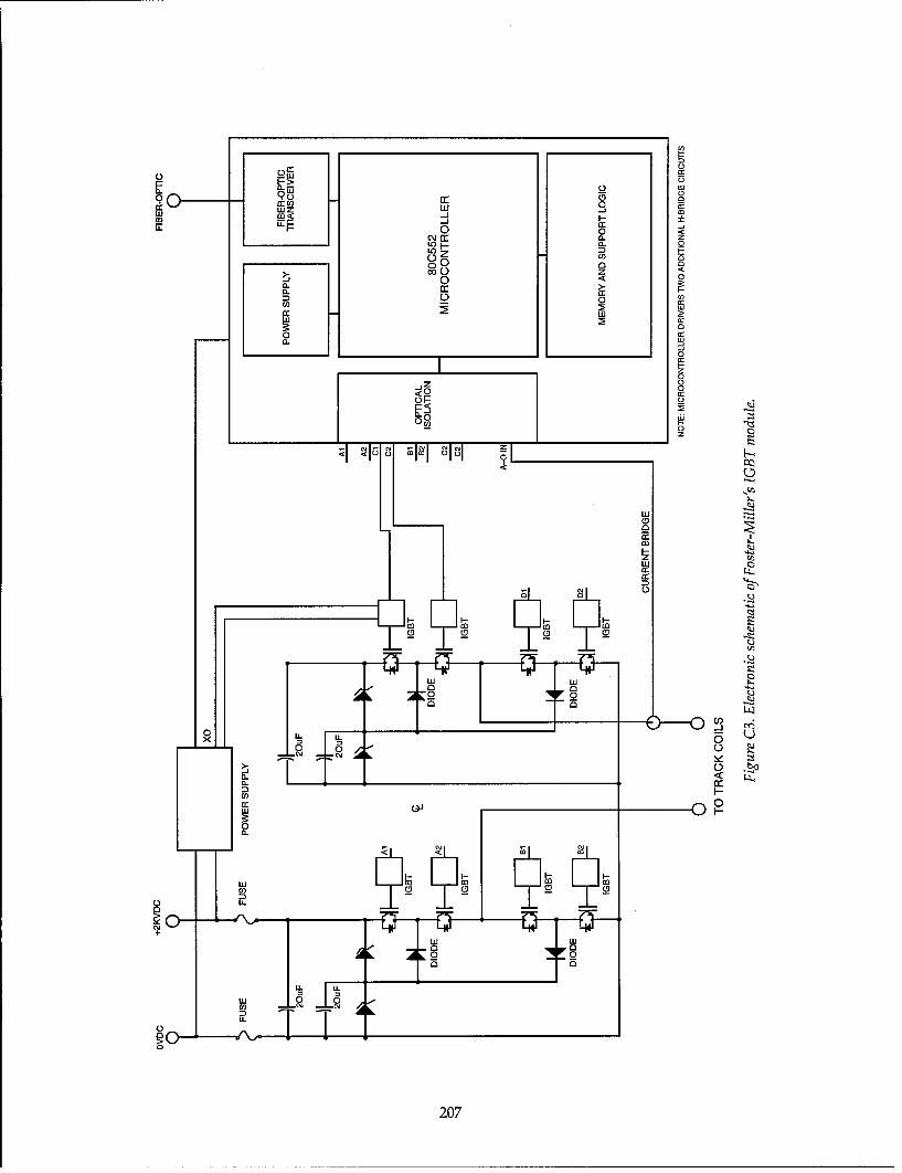
L)
q 0 0wzw cc
0 0 <~
00
a.:3 L) 0 c
U)]
z >
LLI-
:o
_iz
60 0a:
0
0o z
LI-
207

speed limitation and the need envisioned by them C.2.5 DC voltage distribution systemfor operating the H-bridge inverter at a frequency Foster-Miller selected 2 kV DC as the distribu-on the order of 10 kHz. tion voltage to the H-bridge inverters. The selec-
tion of the distribution voltage is somewhat inter-Foster-Miller selected the IGBT dependent with the device technology used in theas the switching device of choice H-bridge inverters. However, the magnitude of
The IGBT is the only available transistor device the power called for is quite large for a 2-kV sup-capable of approaching the LCLSM requirements. ply. For example, Foster-Miller's eight-car consistSince its relatively recent introduction, both its is sized at 30 MW for acceleration performance;voltage and current capability continue to this results in the requirement for large feederincrease. However, present single devices do not cables and relatively close substation spacings.have adequate current and voltage capacity, and The DC distribution voltage level on a power rat-series and parallel strings of devices must be con- ing basis alone should be much higher than the 2sidered. The availability of future devices with kV initially selected and perhaps should be assufficient current capacity to eliminate the need high as 5 to 6 kV. Operation at voltages as high asfor parallel devices is likely. Having sufficient 6 kV is still within the capability of commercialvoltage ratings to eliminate or reduce the num- DC switchgear.ber of series devices is less certain.
A key question is, can we maintain acceptable C.2.6 Estimated costs forsystem operation with failed bridges? An over- the IGBT H-bridge invertervoltage condition that causes a bridge to fail will Foster-Miller estimated the 1994 cost for thealso likely cause several bridges to fail in the inverter at $5181 and the breakdown is given inimmediate area of the surge, unless sufficient volt- Table C2, which is taken from Table 9-18 of theage derating is provided. Foster-Miller (1992a) concept definition report.
The cost of the components listed in the table rep-Foster-Miller has stated that the resent reasonable 1994 cost estimates. However,MCT device may become the future the estimate of $5181 could be understated by asdevice of choice for the LCLSM much as $2300 per inverter. The understated costs
The MCT is just reaching commercial availabil- result from either missing components, or in theity and the initial devices that are now being intro- case of the IGBT, the listing of the incorrect num-duced will have ratings of about 75 A at 600 V. It ber of components required. Missing from the listis unclear at this time what direction the MCT will are the components that are required to completetake with respect to current-voltage capability, the protection and sensing functions for thealthough operating these devices at several kilo- inverter and its control circuits.volts is now being investigated. If a widespreadmarket with needs similar to the current, voltage, C.2.7 IGBT device selectionand switching speed requirements of the LCLSM The need for having sufficient DC voltagematerializes, the MCT could conceivably meet the ratings in conjunction with the estimated 800-LCLSM need. A requirement for the IGBTs would most likely
Table C2. Present-day costs for IGBT discrete component (after Foster-Miller 1992a).
Cost each Total costItem Quantity Description Manufacturer Part no. ($) ($)
1 4 IGBT module Powerex CM200DY-24E 199.93 8002 1 Module heat sink EG&G 510-12-M 58.75 593 4 Clamp diodes IR IRKEL132-14s20 46.15 1854 4 Gate drive modules Custom N/A 295.00 11805 8 Capacitors LCC 2MIFPG66X0105J 50.00 4006 1 Controller Custom N/A 300.00 3007 1 Misc. hardware Custom N/A 250.00 250
8 1 Enclosure Custom N/A 453.30 453Material at 70% of labor 3626Labor at 30% of total 1554
Total 5181
208

require doubling the number of IGBTs per bridge. Table C3. Estimated costs for IGBTThe Foster-Miller concept is based on a series- integrated module (after Foster-Miller
connected dual-device power module component 1992a).
per bridge leg as shown in Figure C3. However, Factor Cost
achieving an adequate voltage margin in conjunc- Item Description (%) ($)tion with the needed current rating is most likely 1 IGBT module 10 80
going to require high-current single-device mod- 2 Module heat sink 50 29ules connected in series. 3 Clamp diodes 25 46
Using a single-device module seems to be more 4 Gate drive modules 3 35
consistent with current developments in the IGBT 5 Capacitors 30 120
6 Controller 5 15than the extension of the dual device component 7 Misc. hardware 10 25
considered by Foster-Miller. For example, both 8 Enclosure 5 23
Powerex and Fuji have recently introduced 600- Labor 10 155
A, 1400-V single device power modules, and Total 529
achieving devices with 800-A capabilities is quitelikely in the near future. The higher current rat-ings are obtained by paralleling more of the lower television set, where they estimated productioncurrent devices at the die level of fabrication. quantities of 5 million sets per year. For an LCLSM
As previously described, a dual-device module maglev application, FMI estimated a requirementis typically made by having the parallel IGBTs for about 1.1 million inverters for a dual guide-mounted on each side of the substrate. Until way of 480 km (300 miles) as the rationale for themounting substrates with higher dielectric production scale similarity.strengths become commercially available, the volt- Historically, semiconductor equipment hasage ratings of the module will continue to be lim- been experiencing about a 15% cost reduction perited. year. This has been based on both market growth
The cost of the IGBT module should be increased as well as improvements in manufacturing pro-from the $800 value cited by Foster-Miller to cesses. Beyond this historical basis, it is very specu-$1600 to account for doubling the number of lative to attempt with any confidence to estimatedevices required. or attempt to verify the anticipated cost reductions
that have been put forth by Foster-Miller for theC.2.8 Missing components H-Bridge inverter in the quantity scale anticipated.for protection and control However, having stated that, we can make the fol-
Not included in the Foster-Miller cost estimate lowing comments about these anticipated costare the components necessary for current and reductions.voltage sensing needed for control and protection, Construction time for a 480-km guideway iscurrent limiting reactances in the DC link-to-limit likely to be 4 years or more. The 1.1 million invert-fault currents, and EMI filters for control of elec- ers estimated by Foster-Miller gives a requirementtromagnetic noise emissions. These components of nearly 275,000 inverters per year. This is aboutare estimated to cost an additional $1500 per 5% of the annual production of TV sets. Further,inverter. the majority of electronics used in TV sets are also
used in other consumer electronics, as well as forC.2.9 Estimated costs for the automotive electronics, thus resulting in compara-IGBT integrated module costs tive production scales that are greatly beyond that
The cost estimated by Foster-Miller for the estimated for the LCLSM.integrated module is $529 and is summarized in The consumer electronics and the automotiveTable C3, which is from Table 9-19 of the Foster- electronics industries are very large and highlyMiller (1992a) concept definition report. Correct- competitive businesses. This allows productioning this table for some of the missing components scales that enable major companies to control and,would probably add an additional $400 to the in many instances, own sources of materiel, manu-estimated cost, making it approximately $930. facturing plants, and integrated manufacturingFoster-Miller's rationale for their estimate was to facilities, and to use other factors that enable low-use the analogy to the cost savings of consumer est cost production. It is unclear the extent toelectronics resulting from very large scale produc- which that situation can be translated to the moretion. The example used by Foster-Miller was the limited mass transportation industry.
209

The principal components of the IGBT each, which has to be added to the other cost ele-inverter-IGBTs, diodes, capacitors, and induc- ments of the inverter. Foster-Miller's estimate fortors-are high voltage or high current units, or the IGBT Integrated Module of $530, corrected toboth, and are not the type of devices that are corn- $930 to account for the missing components,monly found in consumer electronics. Traction would then have to be increased to $1330 perapplications similar to maglev, for example, mass module to allow for the amortization of the incre-transit and railroads, appear to be the only anal- mental capital cost requirements.ogy to the LCLSM inverter. This is true even with Similar capital cost arguments could be madethe emerging electric vehicle market, where the for the other major components of the module.expected operating voltages will only be a few Some of these components, such as inductors andhundred volts (IEEE 1992). Any projections on EMI filters, may have to be uniquely configuredcost savings should be addressing potential to the IGBT module and, as a consequence, alsogrowth in the high power traction market. In fact, require significant one-time costs that would alsomaglev could be one of the major drivers for the have to be amortized.technology for that market. The above assumptions only illustrate some
Current world-wide production of transistor of the factors that would influence cost. A morepower modules is estimated to be about 600,000 detailed study would be necessary to more accu-modules per month.* This includes both BJT and rately determine the cost scaling reductions andIGBT modules and includes devices with current the impact of significant capital cost requirementsratings that vary from 8 to 800 A. The bulk of the to meet production capacity requirements.present demand is for devices of the lower cur- A likely price for the LCLSM power electron-rent ratings rather than those for the higher cur- ics is in the range of $1000 to $1200 per inverter.rent ratings. Of this quantity, only about 20%, or This is for very high production quantities with aabout 120,000 modules per month, are currently significantly sustained production schedule. ThisIGBTs; the rest are conventional BJTs. The IGBT assumes that the economies of scale postulated byportion is expected to grow as time goes on. On Foster-Miller are realized and that the capital coststhe basis of Foster-Miller's quantity estimate of increasing production capacity for the solid-above, and the 4-year production period for the state devices does not have to be carried by the480-km dual guideway, the requirement for maglev project.LCLSM modules would be in excess of 180,000IGBT modules per month. This not only exceeds C.2.10 Estimated number ofcurrent IGBT production, but is also a significant power semiconductors requiredportion of the total monthly production of tran- for LSM blocklength systemssistor modules. GTOs have been identified as the principal
Several semiconductor manufacturers have power semiconductor by the other SCD studiessaid that the capital cost investment needed to that make use of conventional blocklength LSMs.satisfy the LCLSM inverter requirement alone is The following is a preliminary assessment of theof the order of 500 to 800 million dollars. This availability of GTOs to satisfy a major maglevincludes the device fabrication, processing, and construction requirement. It is intended as a pointassembly facilities needed to produce just the of comparison to the IGBT situation for thepower semiconductors for the inverter. Some por- LCLSM.tion of this investment would probably have to be As stated above, the major present use of GTOscarried as a cost by a major maglev construction includes traction applications and utility mediumproject, absent the need for any other major use voltage level (13.8-kV) motor drives. Present pro-of the facilities. duction of GTOs is about 7000 per month and
To arrive at some of idea of the potential includes GTOs in the 4500-V, 2000 to 3000-A rat-impact, assume that 50% of the investment would ings that would be typical of a maglev require-have to be carried by a major maglev construction ment. A representative from Toshiba, a major sup-project and that, further, it is the first 480-km plier of traction type GTOs, stated that currentproject that bears this cost. This assumption leads production rates are well below available manu-to an inverter cost increment of about $300 for facturing capacity. *
* Personal communication with J. Mathis of Collmer Semi-
conductor, Inc., U.S. representative for Fuji Electric Co. * Personal communication with G. Ward, Toshiba Electric Co.
210

Let's use the same 480-km route, 48-month con- In addition, there is a possible stability question.struction example as described above for the IGBT For example, if the degree of current sharing inassessment. Typical inverter station spacings the inverters is such that the most forward bogieswould be about every 4 km, thus requiring about are not conducting as much current as the rear-120 inverter stations for the route. Depending most bogies, how will this influence lateral stabil-upon the particular SCD LSM blocklength con- ity?cept, an inverter station would require from 24 to The LSM coils are individually controlled by48 GTOs per station. Using the 48 GTOs per sta- inverters controlling single coil pairs and willtion as the example requirement results in a operate in a way that is similar to a single-phaserequirement of 120 GTOs per month. This require- motor or perhaps analogously to a DC stepperment is slightly less than 2% of the present motor. This raises the question of potential thrustmonthly production of GTOs. In the next few variations (sometimes referred to as cogging) andyears, the traction market in Europe and in third how this might adversely affect ride comfort.world countries is expected to significantly grow, Another area of concern is the overall effective-thus increasing the production output of GTOs. ness of the power transfer concept. Its effective-Therefore, a maglev requirement for GTOs for the ness depends critically on obtaining a high degreeblocklength concept does not appear to materially of coupling between the guideway primary coilsaffect the availability of GTO devices, and the vehicle secondary coils. A choice of lower
modulation frequencies for the inverter is compat-
C.3 CONCLUSIONS AND ible with the LCLSM operating in the propulsionRECOMMENDATIONS mode, as the LSM frequency is quite low. To what
extent would power transfer capability be com-C.3.1 Technical viability promised with the lower switching frequency?
The LCLSM could become a significantly inno- The choice of the 2-kV DC system for powervative propulsion system. Some of its principal distribution is recognized to be intrinsically con-potential advantages over the more conventional nected to the inverter device technology selected.blocklength LSM are the improved efficiency and However, for the power levels envisioned forpower factor resulting from only the LSM propul- operating multiple car consists, such as the eight-sion coils of a maglev consist length being ener- car consist, the tentative selection of 2-kV DC maygized at any given time. Guideway to vehicle be a too low a voltage to use. Its choice requirespower transfer using those LSM coils between the relatively close DC rectifier station spacingsvehicle bogies as part of an air-core transformer that are similar to those of transit systems andenhances the potential for this concept. Perhaps further requires large feeder cables to minimizethe most significant possible advantage for the voltage drop and energy losses. It is not apparentLCLSM concept is its potential for providing pro- that any trade study was ever conducted on thepulsion when it is degraded, with some of the selection of the DC voltage level.LSM windings inoperative. The degree of degra-dation would of course depend on the number of C.3.2 Economic viabilityLSM windings that are disabled. This is in con- The relative economics of the LCLSM dependtrast to the blocklength LSM, where a failed LSM very heavily on the progress of ongoing develop-winding could disable the entire block and either ments in power electronics devices and the devel-stop the system or severely curtail operation opment of the LCLSM probably won't directlyuntil it is repaired. influence device costs. However, a serious com-
There are many questions that must be mitment to maglev development could be one ofaddressed to establish the technical viability of the the major drivers in the development of powerLCLSM. These include questions of the ability to electronics devices in much the same way thatcontrol acceleration, velocity, and lateral stability, electric traction requirements for both transit andLateral stability may be of concern, as the cur- railroads have pushed the development of GTOs.rently configured LCLSM also provides the lateral The historical trend in the costs of electronics,guidance forces. including power electronics devices, has been
The LCLSM concept operates with all of the downward and there is no reason to think that thisLSM coils electrically connected in parallel and trend will reverse in the foreseeable future. Thethe question of the degree of equal current shar- eventual success of the LCLSM will depend quiteing in the bridge inverters is an important issue. heavily on this trend continuing and eventually
211

pushing inverter costs into the commodity cost provide some direction in the development thatcategory. might lead to an easing of some of the known eco-
nomic constraints.C.3.3 Recommendations We also recommend that further analysis be
We recommend that an experimental develop- done on the selection of the best DC voltage dis-ment program be started on the LCLSM, with the tribution system for the LCLSM. For example,emphasis on the power electronics part of the sys- what would be the potential cost savings for atem and controllability issues. A small-scale 4-kV or a 6-kV DC system or possibly an evenmodel development and evaluation study could higher distribution voltage? What would theaddress almost all of the issues discussed here. It development requirements be, if any, to achievecould also address some of the more subtle issues these expected savings? To what extent, if any,of switching frequencies, waveform synthesis, would this affect the selection and configurationand polyphase vs. single-phase performance, to of the power electronics and the LSM propulsionname a few. Answers to these questions could coils?
212

GLOSSARY
AT Ampere turns.
ANL Argonne National Laboratory.
BAA Broad Agency Announcement. A notice from the Gov-ernment that requests scientific or research proposalsfrom private firms concerning certain areas of interestto the Government. The proposals submitted by privatefirms may lead to contracts.
BJT Bipolar transistor.
bogie Railroad car or locomotive undercarriage.
commutate Reverse the direction of an alternating current each halfcycle to yield a unidirectional current.
consist Composition (number and specific identity) of indi-vidual units of a train.
CGS Continuous sheet guideway.
cryogenics Science of low temperature phenomena.
cryostat Device for maintaining constant low temperature.
DG Design goals.
DOE U.S. Department of Energy.
DLF Dynamic load factor.
USDOT U.S. Department of Transportation.
EDS Electrodynamic suspension.
EMS Electromagnetic suspension.
Emsland Test site of the TR07 in Germany.
El Energy intensity.
EM Electromagnetic.
FHWA U.S. Federal Highway Administration.
FRP Fiber reinforced plastic-polymer-based alternative toferrous reinforcement of concrete and other materials.
FRA U.S. Federal Railroad Administration.
GMSA Government Maglev System Assessment.
guideway Riding surface (including support structure) that physi-cally guides vehicles specially designed to travel on it.
GTO Gate turnoff thyristors.
H-bridge Four-arm, alternating current bridge, the balance ofwhich varies with electrical frequency
headway Interval between the passing of the front ends of suc-cessive vehicles moving in the same direction along thesame lane, track, or other guideway.
HSGT High speed ground transportation.
213

HSR High speed rail.
HSST High speed surface transportation.
ICE Intercity Express (German high-speed train).
IGBT Insulated gate bipolar transistors.
invertor Electrical circuit device that reverses an input to anopposite output in terms of some electrical characteris-tics, such as polarity, voltage, or frequency.
JNR Japanese National Railway.
LCLSM Locally commutated linear synchronous motor.
levitation Rise or cause to rise into air and float in apparent defi-ance of gravity.
levitation, magnetic Support technology that keeps a vehicle separated fromits guideway by riding a surface of magnetic force.
life cycle Useful or total productive life of an asset or system.
life cycle cost Present value total cost for acquisition and operationover the useful life of an asset or system.
IEEE Institute of Electrical and Electronics Engineers.
long-stator Propulsion using an electrically powered linear motorwinding in the guideway.
LSM Linear synchronous motor.
maglev Magnetic levitation.
MOSFET Metal oxide field effect transistor.
magnetic levitation Support technology that keeps a vehicle separated fromits guideway by riding a surface of magnetic force.
MLU Japanese maglev system employing a U-shaped guide-way.
MCT MOS controlled thyristor.
MR Minimum requirements.
NMI National Maglev Initiative.
OCS Overhead catenary system.
pantograph Device for collecting current from an overhead conduc-tor, characterized by a hinged vertical arm operating bysprings or compressed air and a wide, horizontal con-tact surface that glides along the wire.
PI Point of intersection.
PSE Paris-Sud-EST or Paris-Lyon Route on which the TGVhas been in service since 1981 in France.
ROW Right-of-way-A general term denoting land, property,or interest therein, usually in a strip, acquired for ordevoted to transportation.
R&D Research and development.
214

SB Seated and belted criteria.
SCD-FRP System concept definition, request for proposal
SOA Safe operating area (electronics).
SST Severe segment test route.
SRI Stanford Research Institute.
stator Nonrotating part of the magnetic structure in an induc-tion motor.
superconductivity Abrupt and total disappearance of resistance to directcurrent that occurs in some materials at temperaturesnear to or somewhat above absolute zero (such as 90 Kfor some high temperature superconductors).
superelevated curves Banked curves.
TGV Train 2 Grande Vitesse.
Transrapid (TR07) German high speed maglev system. This system isnearest to commercial readiness.
TSC Transportation Services Center.
USACE United States Army Corps of Engineers.
VNTSC Volpe National Transportation Systems Center.
SP Standard passenger.
SSTSIM Severe segment test route simulator.
SCR Silicon controlled rectifier.
SNCF French National Railways.
215

Form ApprovedREPORT DOCUMENTATION PAGE OMB No. 0704-0188
Public reporting burden for this collection of information is estimated to average 1 hour per response, including the time for reviewing instructions, searching existing data sources, gathering andmaintaining the data needed, and completing and reviewing the collection of information. Send comments regarding this burden estimate or any other aspect of this collection of information,including suggestion for reducing this burden, to Washington Headquarters Services, Directorate for Information Operations and Reports, 1215 Jefferson Davis Highway, Suite 1204, Arlington,VA 22202-4302, and to the Office of Management and Budget, Paperwork Reduction Project (0704-0188), Washington, DC 20503.
1. AGENCY USE ONLY (Leave blank) 2. REPORT DATE 3. REPORT TYPE AND DATES COVEREDI October 1998F
4. TITLE AND SUBTITLE 5. FUNDING NUMBERSTechnical Assessment of Maglev System ConceptsFinal Report by the Government Maglev System Assessment Team
6. AUTHORS
James H. Lever, Editor
7. PERFORMING ORGANIZATION NAME(S) AND ADDRESS(ES) 8. PERFORMING ORGANIZATIONREPORT NUMBER
U.S. Army Cold Regions Research and Engineering Laboratory72 Lyme Road Special Report 98-12Hanover, New Hampshire 03755-1290
9. SPONSORING/MONITORING AGENCY NAME(S) AND ADDRESS(ES) 10. SPONSORING/MONITORING
AGENCY REPORT NUMBERNational Maglev Initiative, U.S. Department of Transportation, U.S. ArmyCorps of Engineers, U.S. Department of Energy, and Argonne NationalLaboratory
11. SUPPLEMENTARY NOTESFor conversion of SI units to non-SI units of measurement, consult ASTM Standard E380-93, Standard Practice for Use of theInternational System of Units, published by the American Society for Testing and Materials, 100 Barr Harbor Drive., WestConshohocken, Pennsylvania 19428-2959.
12a. DISTRIBUTION/AVAILABILITY STATEMENT 12b. DISTRIBUTION CODE
Approved for public release; distribution is unlimited.
Available from NTIS, Springfield, Virginia 22161
13. ABSTRACT (Maximum 200 words)
The Government Maglev System Assessment Team operated from 1991 to 1993 as part of the National MaglevInitiative. They assessed the technical viability of four U.S. maglev system concepts, using the French TGV high-speed train and the German TR07 maglev system as assessment baselines. Maglev in general offers advantagesthat include high speed potential, excellent system control, high capacity, low energy consumption, lowmaintenance, modest land requirements, low operating costs, and ability to meet a variety of transportationmissions. Further, the U.S. maglev concepts could provide superior performance to TR07 for similar cost orsimilar performance for less cost. They also could achieve both lower trip times and lower energy consumptionalong typical U.S. routes. These advantages result generally from the use of large-gap magnetic suspensions,more powerful linear synchronous motors and tilting vehicles. Innovative concepts for motors, guideways,suspension, and superconducting magnets all contribute to a potential for superior long-term performance ofU.S. maglev systems compared with TGV and TRO7.
14. SUBJECT TERMS 15. NUMBER OF PAGES241
High-speed ground transportation Maglev 16. PRICE CODEHigh-speed trains Magnetic levitation
17. SECURITY CLASSIFICATION 18. SECURITY CLASSIFICATION 19. SECURITY CLASSIFICATION 20. LIMITATION OF ABSTRACTOF REPORT OF THIS PAGE OF ABSTRACT
UNCLASSIFIED UNCLASSIFIED UNCLASSIFIED ULNSN 7540-01-280-5500 Standard Form 298 (Rev. 2-89)
Prescribed by ANSI Std. Z39-180oal cv,