
PPIS006_2021_Novel method to ensure the reliability of the DC ...
17
PPIS006_2021 NOVEL METHOD TO ENSURE THE RELIABILITY OF THE DC MOTORS CONTROLLED BY AN IGBT / PWM CONVERTER Bernardo Sainz 1 , David Leal 2 , Eric Martínez 3 1 AMI Automation Boulevard Gustavo Diaz Ordaz 402, Nuevo Leon, Mexico, 64650 Phone: +52-81-1001-4050 Email: bernardo.sainz@amiautomation.com 2 AMI Automation Boulevard Gustavo Diaz Ordaz 402, Nuevo Leon, Mexico, 64650 Phone: +52-81-1001-4050 Email: david.leal@amiautomation.com 3 AMI Automation Boulevard Gustavo Diaz Ordaz 402, Nuevo Leon, Mexico, 64650 Phone: +52-81-1001-4050 Email: eric.martinez@amiautomation.com Abstract - For decades, the DC electric motor has been an indispensable element in the transformation of paper, resulting in an important installed base, and therefore a significant fixed asset that is not negligible. Recent advances in drive systems allow the use of PWM IGBT converters for DC motors, that typically had been used in AC motor control. However, IGBT / PWM inverters introduces effects such as voltage spikes caused by sudden changes and common mode voltages. These effects can cause accelerated deterioration of the insulation and bearings of the existing motor. This article presents a novel filter design that achieves optimal performance by mitigating these effects, presenting advantages, such as size, economy, efficiency, versatility, modularity and scalability versus traditional RLC filters. Index Terms – DC motor, IGBT, PWM, dual purpose drive, switching frequency, rise time, voltage spike, bearing currents, common mode voltage, dv/dt filter, RLC filter, LC Clamp filter. INTRODUCTION The direct current motor has been widely used in the paper industry, to drive processes by means of electric power. It offers simplicity for speed control, using straight-forward control circuits and algorithms in comparison with AC motors, and thus it dominated the industry over its AC counterpart during the first decades of use. This has produced a large installed base through the years. This represents a very important asset for paper manufacturers, due to the money invested on it, in equipment and infrastructure, such as gearboxes, motor bases, wiring, cooling systems, etc., and experience in this technology. The advent of new technologies in forced commutation semiconductor devices, such as IGBTs, PWM modulation techniques and increased processing capacity of controllers allowing the execution of more complex algorithms, has enabled the use of AC motors with PWM frequency inverters for applications in which only DC motors were previously used for speed control. However, PWM frequency inverters initially brought with them some challenges for the reliability of AC motors, the voltage waveforms they deliver to the motor are not exactly sinusoidal, and some of their characteristics can affect the integrity of the motor. Over time, methods have been developed to mitigate these effects, producing very reliable AC systems.
-
Upload
khangminh22 -
Category
Documents
-
view
6 -
download
0
Transcript of PPIS006_2021_Novel method to ensure the reliability of the DC ...

PPIS006_2021
NOVEL METHOD TO ENSURE THE RELIABILITY OF THE DC MOTORS CONTROLLED BY AN IGBT / PWM CONVERTER
Bernardo Sainz1, David Leal2, Eric Martínez3
1AMI Automation Boulevard Gustavo Diaz Ordaz 402, Nuevo Leon, Mexico, 64650 Phone: +52-81-1001-4050
Email: [email protected]
2AMI Automation Boulevard Gustavo Diaz Ordaz 402, Nuevo Leon, Mexico, 64650 Phone: +52-81-1001-4050
Email: [email protected]
3AMI Automation Boulevard Gustavo Diaz Ordaz 402, Nuevo Leon, Mexico, 64650 Phone: +52-81-1001-4050
Email: [email protected]
Abstract - For decades, the DC electric motor has been an indispensable element in the transformation of paper, resulting in an important installed base, and therefore a significant fixed asset that is not negligible. Recent advances in drive systems allow the use of PWM IGBT converters for DC motors, that typically had been used in AC motor control. However, IGBT / PWM inverters introduces effects such as voltage spikes caused by sudden changes and common mode voltages. These effects can cause accelerated deterioration of the insulation and bearings of the existing motor. This article presents a novel filter design that achieves optimal performance by mitigating these effects, presenting advantages, such as size, economy, efficiency, versatility, modularity and scalability versus traditional RLC filters.
Index Terms – DC motor, IGBT, PWM, dual purpose drive, switching frequency, rise time, voltage spike, bearing currents, common mode voltage, dv/dt filter, RLC filter, LC Clamp filter.
INTRODUCTION
The direct current motor has been widely used in the paper industry, to drive processes by means of electric power. It offers simplicity for speed control, using straight-forward control circuits and algorithms in comparison with AC motors, and thus it dominated the industry over its AC counterpart during the first decades of use. This has produced a large installed base through the years. This represents a very important asset for paper manufacturers, due to the money invested on it, in equipment and infrastructure, such as gearboxes, motor bases, wiring, cooling systems, etc., and experience in this technology.
The advent of new technologies in forced commutation semiconductor devices, such as IGBTs, PWM modulation techniques and increased processing capacity of controllers allowing the execution of more complex algorithms, has enabled the use of AC motors with PWM frequency inverters for applications in which only DC motors were previously used for speed control.
However, PWM frequency inverters initially brought with them some challenges for the reliability of AC motors, the voltage waveforms they deliver to the motor are not exactly sinusoidal, and some of their characteristics can affect the integrity of the motor. Over time, methods have been developed to mitigate these effects, producing very reliable AC systems.

PPIS006_2021
The improvement of these technologies and the continued development of AC motors have led to more efficient and compact motors, making the AC motor greatly popular for its performance, efficiency, size, and maintainability. In addition, it greatly improved the power factor reducing the requirements upon the electrical power supply system. Today, there is a tendency in industry to use more and more AC systems.
In addition, trends in the paper industry require a technological transformation based on digitalization, mainly focused on increasing the efficiency and sustainability of production, to keep market share and reduce environmental impact. This leads paper manufacturers to invest in modernizing their control and power systems for their drives. However, these projects imply considerable investment and require complex planning.
Solutions have emerged that allow a staggered transition that enables greater flexibility in planning budgets and shutdown times to modernize drive systems and motors, the implementation of dual-purpose drives now allows working with existing DC motors using the same drive technology to control AC motors, IGBT / PWM converters, and eventually replace them with AC motors in the future.
When implementing these technologies in DC motors, it is necessary to evaluate how they specifically affect this type of motor and create techniques to mitigate the adverse effects that may arise. This paper presents a novel method to ensure reliability of DC motors controlled by an IGBT/PWM converter.
BACKGROUND
A. DC MotorA DC motor is an electrical machine that transforms electrical energy into rotational mechanical energy and is composed of two circuits, armature, and field. The armature is in the rotor and generates a variable magnetic field through a commutator, which is connected using carbon brushes. There is also a fixed magnetic field applied by the stator winding.
DC motor speed control is relatively simple, thanks to the fact that speed is directly proportional to the voltage at the armature terminals and inversely proportional to the field current. This allows simple control methods, such as switching resistors fed by a constant voltage source, or more sophisticated methods such as a Motor-Generator set or a thyristor power supply.
In the paper industry, DC motors from 1 to 1,500 KW are used in many different applications such as pumps, fans, extractors, couches, presses, dryers, calenders, coaters, winders, to name just a few.
The NEMA MG-1 [2] standard establishes operating limits that must be observed when working with DC motors and power converters, so as not to affect the integrity of the motor:
1. MG-1 14.63 Current ripple: Current ripple increases heating and decreases the commutating capacity of the motor, reducing the lifetime of the insulation and the commutator. Factors that increase the ripple are low circuit inductance, high ratio of input voltage to converter output voltage, and low switching frequency.2. MG-1 14.65 Current in bearings: Power converters for DC motors can generate currents in motor bearings through capacitive coupling between the rotor windings and the shaft, as a ground discharge path for their return to the transformer secondary, which can damage the bearings.

PPIS006_2021
3. MG-1 14.68 Rate of change in armature current: The standard establishes a limit of 25 for the K factor, defined as the ratio of the nominal current to the time it takes for the change in current to reach it.4. MG 23.17.2 Voltage transients in microseconds: DC motors can withstand repetitive voltage transients lasting microseconds and with magnitude of up to 160% of nominal value. Exceeding these values can stress the motor insulation or damage the switch.Motor manufacturers seek to comply with these standards and tend to complement them by defining their own operating limits, finding some references [4] that indicate a maximum rate of change limit "dv/dt" of 400V/us in the armature voltage, and they also seek to eliminate voltage spikes in the bearings.
We can contrast them with the limits set by the NEMA MG-1 standard [2] for an AC motor when used with frequency inverters.
1. MG-1 31.4.4.1 Leakage current: Leakage currents can occur in motor windings due to high frequency harmonic content. Safe motor grounding practices should be considered.2. MG-1 31.4.4.2 Voltage Spikes: Every time a device is switched in the inverter, a transient is created which, in combination with the inductance and capacitance of the circuit, can generate voltage spikes above the inverter DC bus voltage. The following limits should not be exceeded:
For NV ≤ 600 volts PV < 3.10 NV tr_min ≥ 0.1 µsFor NV ≤ 600 volts PV < 2.04 NV tr_min ≥ 1 µs
3. MG-1 31.4.4.3 Voltages in shafts and bearing insulation: Common mode voltages can be present on motor shafts when using an inverter, since switching takes place at high frequency, and can present voltages up to 10-40 volts between shaft and ground. Therefore, it is necessary to use insulated bearings and/or shaft grounding brushes.4. MG-1 31.4.4.4 Neutral displacement: When an inverter is used with an AC motor, there can be a displacement between the inverter virtual neutral and the motor neutral, creating voltages to ground of up to 3.3 times the nominal line-to-ground voltage. It is necessary to use an isolation transformer at the source to reduce this voltage.
Starting and speed control of a DC motor can be accomplished by several methods, such as the following:a) DC starter with resistors.b) Ward-Leonard Motor - Generator System.c) Thyristor Converterd) PWM Converter
B. Drive with AC-DC Thyristor ConverterThe thyristor-based DC drive is the most widely used method today to control the speed of DC motors, mainly due to its simplicity as it was widely developed and used for this purpose before AC motors and drives were commonly used in variable speed applications.
The thyristor converter consists mainly of a thyristor rectifier bridge, on which a phase control is applied to vary its output.
A converter can be used to control the armature, and another converter for the motor field. There are different rectifier topologies that can be used to power a DC motor; [5] lists the following:

PPIS006_2021
1) Power supply C: Three-phase, Full wave, six pulse, fully controlled, 60 Hz, without additional inductance. 230VAC/240VDC or 460/500VDC.2) Power supply D: Three-phase, Full wave, Six pulse, Semi-controlled, 60 Hz, Freewheeling diode, without additional inductance. 230VAC/240VDC or 460/500VDC. Up to 250 HP.3) Power supply E: Three-phase, Full wave, three pulse, fully controlled, 60 Hz, without additional inductance. 460/500VDC.4) Type K Source: Single phase, Full wave, fully controlled, 60 Hz, without additional inductance. Up to 180V and 7.5 HP.5) Other sources: It is necessary to specify number of pulses per cycle, number of controlled pulses, freewheeling diode, rated voltage, input frequency, series inductance.
As we can see in the above configurations, they have parameters that can affect the output waveform that is applied to the motor. They do not deliver a fully DC waveform, rather they deliver a pulsed waveform, where the output current ripple may vary. From these types of sources, it is possible to obtain waveforms with a high form factor and difficulty in limiting the K factor, due to low switching frequencies. In very demanding applications, it is common to use external reactors to reduce the current ripple and eliminate the problems that it can generate.
In addition, the switching of thyristors may cause voltage spikes and common mode voltages that can affect the motor insulation and generate currents in bearings.
The main characteristics of the thyristor rectifiers used for the control of DC motors are summarized below [7]:
1) Low switching frequency, typically 100 to 720 Hz2) High current ripple3) Natural shutdown, slow shutdown time typically 1200µs4) Slow switching-on times, typically 14 µs
C. Drive with IGBT Converters with PWM DC-AC / DC-DCCurrently, IGBT converters with PWM are widely used in AC drives, which can generate an output voltage similar to a sine wave by forcibly switching a DC bus through semiconductor devices such as IGBTs. The output frequency can be changed by means of PWM techniques. The duty cycle of the IGBTs is changed at a certain switching frequency. This type of converter has been used for AC motors in industry for more than three decades. It is a very mature technology and there are extensive developments and standards on both the converter side and the AC motor, for their joint operation. The use of these converters for the control of DC motors has recently become relevant and has its own challenges.
Due to the fact that, in this type of converter, the voltage rise time during the IGBTs switching represents part of the losses, it is necessary to reduce this time so as to lower the heating of the IGBTs and increase the drive efficiency, with typical rise times in the order of hundreds of nanoseconds. However, very fast rise times generate voltage transitions in the order of 10 to 20 kV/ µs. In addition, there is a compromise between the ripple current and the IGBT losses according to the switching frequency, which should be high within certain limits, typically 1.5k to 6 kHz. A high voltage differential and high switching frequency have adverse effects on the motor insulation, as well as on bearings, such as:

PPIS006_2021
1) Reflected voltage waves off long cables, resulting in voltage spikes of up to twice the terminal voltage2) High leakage ground currents through bearings3) Electromagnetic noise
For use of this type of drive, several improvements have been required in the design of AC motors, such as better insulation materials, grounding techniques, insulated bearings and output filters, allowing operation without jeopardizing the integrity of the motor.
JUSTIFICATION
A. Manufacturers in the paper industry constantly seek to increase their quality, productivity, and performance, in addition to having cleaner processes that allow them to comply with environmental regulations. Therefore, they seek optimal maintenance of their processes and may invest in modernizing them, for the following purposes:
1) Extend the lifetime of the equipment.2) Improve the performance and efficiency of processes.3) Improve configuration, operation, and diagnostic tools.4) Integrate the equipment to modern LAN communication systems.5) Improve maintainability and reduce downtime.
B. In regard to maintenance or modernization of processes involving DC motors, we have the following options:
1) Repair and maintain the DC drive and motor.2) Replace the firing circuit (FCR) of the DC drive and retain of the thyristor converter and motor.3) New DC drive with thyristor converter and retain DC motor.4) New Dual-Purpose drive with IGBT/PWM converter and retain DC motor.5) Fully upgrade to drives with IGBT/PWM converter and AC motors.
The solution presented in this paper revolves around the alternative of using a new Dual-Purpose drive with IGBT/PWM converter, which is capable of controlling either a DC motor or an AC motor. This solution has recently emerged as an alternative that has the advantage of ensuring greater flexibility when planning the modernization of systems, since it adapts to the restrictions generated by current operational demands and budget considerations. It allows implementing a project that initially reuses the existing DC motors with the new Dual-Purpose drives, which reduces the investment but allows future investment in AC motors, using the same drive.
C. The Dual-Purpose drive has the following features and benefits:
1) It can control a DC or an AC motor, since it uses the same hardware as an AC drive, only a software change is needed.2) It can be migrated to AC motor, after having used it first with a DC motor in the same installation.3) It operates in all four quadrants; the regeneration function is integral to the converter topology.4) Nonreversible motor field, Non-Plugging.5) It is powered from a DC source, so it can be directly installed in locations where a DC source already exists.

PPIS006_2021
6) The hardware is based on current, highly developed and supported technology.7) It does not require an external field source.8) Low harmonics level and unity power factor.9) High switching frequency reduces current ripple, resulting in less motor heating and a longer lifetime for the commutator, by reducing its temperature.10) Easy sensorless control of the motor above base speed.11) The current requirement of the input transformer is reduced by improving the power factor of regenerative and non-regenerative loads.
This type of drive is very convenient for updating the drive systems of existing paper machines or other paper processes. However, if only the drive is being modernized and the existing DC motor remains, there is a concern that using a drive with PWM/IGBT technology may have negative effects on a motor that was not designed to be used with them. When AC motors were adapted for operation on this type of converters, the demand for DC motors decreased, investment in their development stopped and they maintained their design that allowed them to operate with thyristor converters. It is still possible to find installations with motors that have been in operation for more than 40 years.
D. Regarding this concern, the effects where the Dual-Purpose drive could exceed some of the standard operating limits for DC motors have been identified, and the challenges that AC drives faced during their first applications on AC motors were taken as a reference. To ensure the reliability of DC motors, the following effects must be considered:
1) High switching frequency, 3-6kHz2) Fast on/off times <1 µs3) Voltage spikes per reflected wave.4) Common mode voltages.5) Bearing currents.
E. Once the possible risk factors of using PWM drives in DC motors have been identified, we look for possible solutions to mitigate these effects. Some of them can be found in the techniques that have been commonly used in AC motors to mitigate voltage spikes and fast rise times; the following options are available:
1) dv/dt filter: It only acts on the transition of PWM pulses2) Sinusoidal filter: It seeks to completely correct the waveform3) Motor terminator: It seeks to compensate for the difference in impedances between the motor and the source, to reduce its effects.4) Insulated bearings and electrostatic shields between stator and rotor.5) Increase the degree of insulation.
F. Bearing this in mind, this paper aims to present an optimal solution to achieve all the benefits of upgrading a DC drive system to modern PWM systems and to ensure the reliability of DC motors, eliminating the adverse effects that could arise when applying this technology, without diminishing the advantages it offers.

PPIS006_2021
Items 4 and 5 are implicit alternatives to the motor, so they are not viable alternatives if it is necessary to maintain the existing DC motor, which is the objective in this type of modernization where we only want to invest in the drive. Thus we will focus on the different types of filters included in points 1, 2 and 3, that we can apply in the external wiring to the motor.
OUTPUT FILTERS
A. Output Filter Circuit ConfigurationThere are basically five types of mitigation techniques that can be applied to the output of a drive to reduce the voltage stress at motor terminals caused by this PWM reflection phenomenon [8]. The filter topologies can either be passive or active filtering. They are as follows:
1) L-Filter (First Order): Load reactors are a common protection unit on motor and drive systems with long motor cables. They increase inductance slowing down the voltage rise time and smoothing the output signal. An additional resistor can damp the overshoot caused by the interaction of the inductance and the cable capacitance.2) RC Snubber (Second Order): This is a common mitigation method used with very large motors. The RC filter at the motor terminals acts as an impedance matching network and reduces the peak of voltage spikes occurring at the motor end due to voltage reflection issues. In its simplest form consists of resistors and capacitors. One advantage of this filter is that there is no series inductance; however, it only reduces voltage spikes, and cannot change the dv/dt of the waveform. Moreover, the value of its components depends on the distance between the motor and the drive as well as the characteristics of the cable. Due to the fact of the difficult access to the motor terminals in many applications as well as difficult maintenance requirements, its acceptance is rather limited.3) RLC-Termination Filter (Third Order): In this type of filter, the LC series circuit, connected in parallel at the motor terminals, forms the dv/dt slope changer and the resistor, across the inductor, helps damp out the oscillations generated by the LC and cable combination.4) RLC-Output Filter (Third Order): This is the conventional LC sine filter at the drive terminal with overshoot damping arrangement. The resistor controls the amount of damping, but it increases the losses in the system.5) LC Clamp Filter (Second Order): Another method of slowing down the voltage rise times (lowering the dv/dt) is to employ a damped second-order LC dv/dt filter at the output of the drive. This filter can increase the rise time and damp out the overshoot. In addition, the filter output is clamped to the DC bus and therefore does not need a damping resistor as in the RLC filter [1]. In comparison to the traditional LC filter, this is possible with a smaller value of inductance, therefore the dimensions of the clamp filter are small. The losses in the clamping circuit are small as well compared to the loses of the damping resistors.
Fig. 1 Filter Configurations: (a) L-Filter; (b) RC Snubber; (c) RLC-Termination Filter; (d) RLC-Output Filter; (e) LC Clamp Filter

PPIS006_2021
B. Field dv/dt filter RLC TypeThe RLC filter design is shown below. The third order filter is composed of the traditional RLC dv/dt filter interposed between the drive and the DC motor field. It is comprised as well of an overvoltage crowbar protection circuit and the field’s current transducer feedback.
C. Armature dv/dt filter LC Clamp TypeThe LC Clamp filter design is shown below. This filter is characterized by a series LC filter with a diode clamping action that clips excessive volts back into the DC bus. Different values of capacitance and inductance can be utilized depending on the drive size.
Fig. 2 Field RLC-Filter Diagram
Fig. 3 Armature LC Clamp Filter Diagram

PPIS006_2021
IMPLEMENTATION
A. For the physical implementation of the filters, first prototypes were developed to evaluate their performance and reliability in the laboratory, using different test equipment including dual-purpose drives and DC motors with varying characteristics, and later a product for different capacities was designed, focusing in the drive sizes offered by a recognized manufacturer of dual-purpose drives, in the range of the most commonly used DC motors in the paper industry. The same product was tested and validated, and it is currently operating in different facilities, with very positive results.
The implementation of these filters has been focused on the size range of DC motors from 5 to 300 kW, since that is the range where Dual Purpose Drives are more competitive against other technologies.
This implementation works with the following voltage systems for DC motors up to 500VDC; these systems are the most common in the paper industry:
So, we have the following relation of drive sizes, power, armature currents and inductance for motors operating at 500VDC within this size range. According to [3], the armature inductance values are estimated as a function of the motor voltage, current, number of poles and base speed.

PPIS006_2021
Motor field current values for motors within this size range vary from a fraction of an amp on the smallest motors to 20 amps, with typical voltages of 150VDC or 300VDC.
The implemented solution consists of the armature filter and field filter; each one is an independent module with its own characteristics, and they are connected to each drive output, as shown in the following scheme:
On the implementation of the filters, the aim was to make the modules on the same component base so that the same part number could be used for different motor sizes, which enables easier maintenance of the filters by having a standard design for all. Since each motor has a different inductance value and the current capacity of the drives is different, the modules allow the selection of different configurations, such as serial or parallel capacitors or number of turns in cores to modify the inductances, in a simple configuration, to achieve optimal performance for each motor.
The inductances are implemented by means of iron cores with defined magnetic characteristics, which enable the generation of inductance by making the conductor pass several turns around its center. This allows us to use a conductor with the same current capacity that the motor requires, which is connected in series to the drive output. The inductance must be set, with the number of turns, to limit the maximum current supported by the IGBT devices for each drive size. It should be considered that increasing the number of turns can saturate the iron cores and reduce their effective inductance, as well as generate higher losses, thus heating the cores; Therefore, an adequate number of iron cores must be selected to avoid saturation and overheating.
The capacitors, clamping diodes and snubber circuit are implemented on a printed circuit board (PCB), seeking an optimal routing of the connections among elements. A heat sink is used to prevent the temperature of the diodes and resistors from rising due to losses during the operation of the filters. The maximum losses have been calculated for each drive size.
Fig. 4 Output Filter Connection

PPIS006_2021
A unique design is available for all drive sizes. This module is connected in parallel with terminals placed after the inductances, in addition to connecting the return to the dual-purpose drive DC link.Both filters have fuses as protection elements. In the case of the field filter, the fuses withstand the total current that is supplied to the motor field, as it uses a serial connection. For the armature filter the fuses serve to protect the filter from a possible overcurrent generated by an internal filter failure, where the clamping diodes can be short-circuited. The modules have blown-fuse detection, to indicate any fault to the drive.
The implemented design allows installation of up to 8 armature filters and 8 field filters in a 600 x 600 x 2100 mm cabinet that can be placed next to the cabinet of the dual-purpose drive. The image below shows four sets of filter modules in the left half of the cabinet.
Fig. 5 (a) Field RLC-Filter Assembly(b) Armature LC Clamp Assembly
Fig. 6 Output Filter Cabinet Layout

PPIS006_2021
The cabinet will accumulate the heat losses generated by all the filters inside, thus, a forced ventilation system is used to expel the heat and keep the temperature within acceptable operating limits.
RESULTS
A. The performance obtained with our implementation of the filter within the range of drive sizes we selected is described below.
The first point to evaluate is the ability of the filter to limit the dv/dt at the motor terminals which, as we saw earlier, is an important variable to maintain the integrity of the insulation and commu-tator. The target value is 400 V/ µs. This was determined by taking the waveform of the voltage pulses at the drive output and the motor terminals and measuring in the second one the increase in voltage during the transition of the pulse and dividing it by the time required to go from 10% to 90% of the voltage.
Fig. 7 Drive and Output Filter Cabinet Layout
Fig. 8 Voltage rise time graph

PPIS006_2021
The results obtained ranged from 30 V/ µs for 10.7 kW drives to 250 V/ µs for 76.5 kW drives, which is fully satisfactory performance in this parameter.
The second point to evaluate is the maximum repetitive voltage spikes per microsecond at the motor terminals, which were measured in the same way by taking the voltage waveform with an oscilloscope. In the case of the 500V motor that powers our test drive, it should not exceed 800 Volts.
The maximum voltage that we found for the different drive sizes within the acceptable filter configurations was 752 Volts, in the case of the 48.5 kW drive. So, we were able to keep the voltage within acceptable limits.
With both previous points, we ensured the reliability of the DC motor by using it with dual-purpose drives and using the armature and field filters.
Next, we must evaluate the behavior of the filter itself and the current that it draws from the drive. We started with the latter, measuring the peak current requested by the filter during each transition, in the same way we used an oscilloscope to measure it directly at the drive output. It must not exceed the maximum current capacity of the IGBT.
Fig. 9 Voltage peak graph
Fig. 10 Current Waveform at the drive output
PPIS006_2021
The current spikes that we found during tests of several sizes of drives ranged from 5% to 94% of the nominal capacity of each drive, with the most critical value being for the 48.5kW drive. In this way, we ensure that the drive can operate in a reliable manner with this type of filter.
Likewise, the heat losses and temperature rise of the filters were evaluated, resulting in maximum heat losses of 200 W and a maximum temperature increase of 30°C, located in the heat sink of the armature filter. If we consider an ambient temperature of 40°C, we get an operating temperature of 70°C, which is below the maximum of 85°C allowed to operate the filter components reliably. Hence, we can also ensure the reliability of the filters.
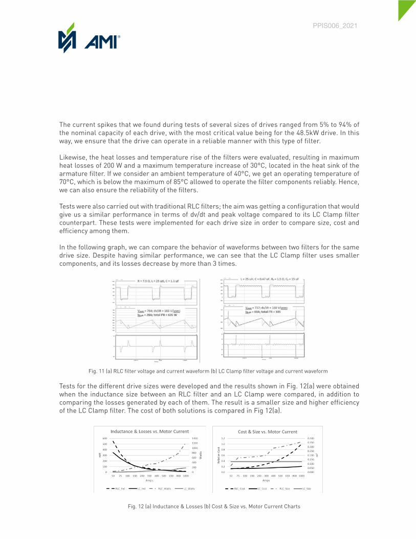
Tests were also carried out with traditional RLC filters; the aim was getting a configuration that would give us a similar performance in terms of dv/dt and peak voltage compared to its LC Clamp filter counterpart. These tests were implemented for each drive size in order to compare size, cost and efficiency among them.
In the following graph, we can compare the behavior of waveforms between two filters for the same drive size. Despite having similar performance, we can see that the LC Clamp filter uses smaller components, and its losses decrease by more than 3 times.
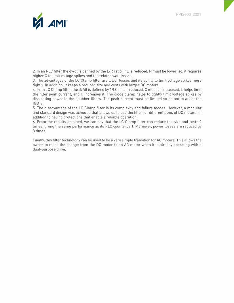
Tests for the different drive sizes were developed and the results shown in Fig. 12(a) were obtained when the inductance size between an RLC filter and an LC Clamp were compared, in addition to comparing the losses generated by each of them. The result is a smaller size and higher efficiency of the LC Clamp filter. The cost of both solutions is compared in Fig 12(a).
Bernardo Sainz1, David Leal2, Eric Martínez3
1AMI Automation Boulevard Gustavo Diaz Ordaz 402, Nuevo Leon, Mexico, 64650 Phone: +52-81-1001-4050
Email: [email protected]
2AMI Automation Boulevard Gustavo Diaz Ordaz 402, Nuevo Leon, Mexico, 64650 Phone: +52-81-1001-4050
Email: [email protected]
3AMI Automation Boulevard Gustavo Diaz Ordaz 402, Nuevo Leon, Mexico, 64650 Phone: +52-81-1001-4050
Email: [email protected]
Abstract - For decades, the DC electric motor has been an indispensable element in the transformation of paper, resulting in an important installed base, and therefore a significant fixed asset that is not negligible. Recent advances in drive systems allow the use of PWM IGBT converters for DC motors, that typically had been used in AC motor control. However, IGBT / PWM inverters introduces effects such as voltage spikes caused by sudden changes and common mode voltages. These effects can cause accelerated deterioration of the insulation and bearings of the existing motor. This article presents a novel filter design that achieves optimal performance by mitigating these effects, presenting advantages, such as size, economy, efficiency, versatility, modularity and scalability versus traditional RLC filters.
Index Terms – DC motor, IGBT, PWM, dual purpose drive, switching frequency, rise time, voltage spike, bearing currents, common mode voltage, dv/dt filter, RLC filter, LC Clamp filter.
INTRODUCTION
The direct current motor has been widely used in the paper industry, to drive processes by means of electric power. It offers simplicity for speed control, using straight-forward control circuits and algorithms in comparison with AC motors, and thus it dominated the industry over its AC counterpart during the first decades of use. This has produced a large installed base through the years. This represents a very important asset for paper manufacturers, due to the money invested on it, in equipment and infrastructure, such as gearboxes, motor bases, wiring, cooling systems, etc., and experience in this technology.
The advent of new technologies in forced commutation semiconductor devices, such as IGBTs, PWM modulation techniques and increased processing capacity of controllers allowing the execution of more complex algorithms, has enabled the use of AC motors with PWM frequency inverters for applications in which only DC motors were previously used for speed control.
However, PWM frequency inverters initially brought with them some challenges for the reliability of AC motors, the voltage waveforms they deliver to the motor are not exactly sinusoidal, and some of their characteristics can affect the integrity of the motor. Over time, methods have been developed to mitigate these effects, producing very reliable AC systems.
Fig. 11 (a) RLC filter voltage and current waveform (b) LC Clamp filter voltage and current waveform
Fig. 12 (a) Inductance & Losses (b) Cost & Size vs. Motor Current Charts

CONCLUSIONS
As discussed in this paper, the DC motor is still widely used in industrial processes. It is a very good option to take advantage of the large base of installed DC motors complemented by a modernization of the drive system, using dual-purpose drives to update the facilities and have more productive, efficient, and higher quality processes. This option also gives us the flexibility to modernize in the future, in a second stage, the DC motors to AC motors if required.
We notice that, in terms of motor reliability, the dual-purpose drive presents a wide advantage as regards ripple and current harmonics, which allow motor components such as the windings and the commutator to operate much cooler than when operated by its counterpart thyristor drive. So, the upgrade to these devices is a very good option and it is not necessary to use any external means to filter the current ripple.
On the other hand, there are certain aspects of the dual-purpose drive that can affect the reliability of the DC motor, which include the following:
1) Voltage spikes2) dv/dt
These can exceed the limits established by the standards due to the speed of IGBT devices and the high switching frequencies present in dual purpose drives and their effects on long cable distances. Therefore, they can degrade the insulation of the motor, flashover commutator and generate currents in bearings. However, it has been possible to implement a set of filters for field and armature: the former uses an RLC filter and the latter an LC Clamp filter. This allows us to mitigate these effects, being a novel method that helps us ensure the reliability of the DC motor when working with dual purpose drives. The advantages of this solution are listed below:
1) Armature filter a) Under 300 volts per microsecond rate of rise. b) Maximum voltage peak of 10% over the DC link. c) Modular design, same structure for all drive frames. d) Modular reactor design based in bulk chokes. e) Up to 75% more efficient compared to a conventional RLC filter. • 1.5% losses for small frames • 0.2% for larger frames 2) Field filter a) Under 300 volts per microsecond rate of rise. b) Under 200 volts per microsecond rate of rise. c) Maximum voltage peak of 10% over the DC link. d) Modular design, same structure for all drive frames. e) Inherent common mode filter.
To which we can add the following, when compared with a traditional RLC filter:
1. The advantage of an RLC filter lies in its simplicity and the current waveform it delivers. Its main disadvantage is the losses. Cost and size increase too much as the size of the DC motor that it powers increases.
PPIS006_2021
2. In an RLC filter the dv/dt is defined by the L/R ratio, if L is reduced, R must be lower; so, it requires higher C to limit voltage spikes and the related watt losses.3. The advantages of the LC Clamp filter are lower losses and its ability to limit voltage spikes more tightly. In addition, it keeps a reduced size and costs with larger DC motors.4. In an LC Clamp filter, the dv/dt is defined by 1/LC; if L is reduced, C must be increased. L helps limit the filter peak current, and C increases it. The diode clamp helps to tightly limit voltage spikes by dissipating power in the snubber filters. The peak current must be limited so as not to affect the IGBTs.5. The disadvantage of the LC Clamp filter is its complexity and failure modes. However, a modular and standard design was achieved that allows us to use the filter for different sizes of DC motors, in addition to having protections that enable a reliable operation.6. From the results obtained, we can say that the LC Clamp filter can reduce the size and costs 2 times, giving the same performance as its RLC counterpart. Moreover, power losses are reduced by 3 times.
Finally, this filter technology can be used to be a very simple transition for AC motors. This allows the owner to make the change from the DC motor to an AC motor when it is already operating with a dual-purpose drive.
PPIS006_2021

NOMENCLATURE
AC Alternate Current.DC Direct Current.C Capacitance.L Inductance.R Resistance.IGBT Insulated Gate Bipolar Transistor.PWM Pulse Width Modulation.
REFERENCES
[1] Acharya B, A., & Vinod, J. (2010, January). Design of output dv/dt filter for motor drives. 2010 5th International Conference on Industrial and Information Systems. Mangalore: Department of Electrical Engineering Indian Institute of Science. [2] ANSI/NEMA. (2019, March 22). MG 1-2016. Motors and Generators.[3] General Electric. (1955). Industrial Power Systems Data Book. Schenectady, NY: General Electric.[4] General Electric. (n.d.). Application Guide. KINAMATIC DIRECT CURRENT MOTORS, 1-4500 HP. GE Motors.[5] IEEE. (1974, January 25). IEEE 444-1973. IEEE Standard Practices and Requirements for Thyristor Converters for Motor Drives Part 1- Converters for DC Motor Armature Supplies. IEEE.[6] IEEE. (2016, December 7). IEEE Std 3004.8™-2016. Recommended Practice for Motor Protection in Industrial and Commercial Power Systems. IEEE Industry Applications Society. [7] Wu, B. (2006). HIGH-POWER CONVERTERS AND AC DRIVES. Hoboken, New Jersey: John Wiley & Sons, Inc.
AUTHORS’ INFORMATION
Bernardo Sainz (1967, Present) was born in Guanajuato, Mexico, on November 27, 1967. He graduated from Monterrey Institute of Technology and Higher Education as Electrical Engineer and studied at the IPADE Business School of Monterrey. 29 Years at AMI Automation. His special fields of interest include automation systems, high-power electronics and Business Management.
David Leal (1985, Present) was born in Monterrey, Mexico, on June 4, 1985. He graduated from the Monterrey Institute of Technology and Higher Education as Mechatronic Engineer. His employment experience includes AMI Automation. His special fields of expertise include hardware design, power electronics and electronic manufacturing.
Eric Martinez (1985, Present) was born in Huatabampo, Mexico, on August 2, 1985. He graduated from the Monterrey Institute of Technology and Higher Education as Mechatronic Engineer.His employment experience includes 13 years at AMI Automation. His special fields of interest include automation systems and high-power converters.
PPIS006_2021