
Computer Reliability
76
WIN A MICROCHIP PICKit 3 DEBUG EXPRESS KIT From valves to chips – New Series! VOX CIRCUIT Computer Reliability VOICE-OPERATED CONTROL SWITCHING MILLIOHM ADAPTOR FOR DMM S Super-sensitive measurement of low resistance PLUS: NET WORK, CIRCUIT SURGERY, TECHNO TALK, READOUT DRIVEWAY SENTRY INTERFACE – TRY SOME RASPBERRY PI Detects moving vehicles via earth’s magnetic field Switches mains-powered equipment Ignores cats, dogs and foxes – no nuisance switching AUGUST 2013 £4.40
-
Upload
khangminh22 -
Category
Documents
-
view
0 -
download
0
Transcript of Computer Reliability

WIN A MICROCHIP PICKit 3 DEBUG EXPRESS KIT
From valves to chips – New Series!
VOX CIRCUIT
Computer Reliability
Voice-operated control switching
MIllIOhM adapTOR FOR dMMs Super-sensitive measurement of low resistance
plus: Net work, CirCuit surgery, teChNo talk, reaDout
dRIVEWaY SENTRY
iNterFaCe – try some raspberry pi
detects moving vehicles via earth’s magnetic field
Switches mains-powered equipment
Ignores cats, dogs and foxes – no nuisance switching
AUGUST 2013 £4.40
AUGUST 13 Cover.indd 1 14/06/2013 16:15:58

MIKROELEKTRONIKA AUGUST 13.indd 1 14/06/2013 11:58:19

Everyday Practical Electronics, August 2013 1
Projects and CircuitsDriveway Sentry 10 by Jim RoweDetect vehicles moving along your driveway using the earth’s magnetic fieldMilliohM Meter aDaPtor for DMMS 26 by Jim RoweMeasure very low resistances accurately, without an expensive benchtop meterBuilD a voX 40 by John ClarkeUse this VOX circuit anywhere you want to switch something with sound SuPerB four-Channel aMPlifier – on the CheaP! 46 by Julian EdgarHigh-quality amplifier using a mix of salvaged parts and prebuilt modules
Series and featuresteChno talk by Mark Nelson 24Scare storiesCoMPuter error: reliaBle Digital ProCeSSing – Part 1 36by William MarshallThe early days of computer reliability – valves and avoiding faultsMaX’S Cool BeanS by Max The Magnificent 52Particles and cosmic rays... Particles, or waves, or particles? interfaCe by Robert Penfold 54Try some Raspberry PiCirCuit Surgery by Ian Bell 57Dataslicing and Manchester codingnet work by Alan Winstanley 66Don’t track me!... Ghostery hunters... Fully compatible... Plus ça change…
regulars and ServiceseDitorial 7Digital: the good, the bad and the ugly…newS – Barry Fox highlights technology’s leading edge 8Plus everyday news from the world of electronicsMiCroChiP reaDer offer iBCEPE Exclusive – Win a Microchip PICkit 3 Debug Express ePe PiC ProjeCtS CD-roM vol. 1 25ePe PiC ProjeCtS CD-roM vol. 2 35ePe BaCk iSSueS Did you miss these? 39SuBSCriBe to ePe and save money 45 reaDout – Matt Pulzer addresses general points arising 50CD-roMS for eleCtroniCS 62A wide range of CD-ROMs for hobbyists, students and engineersDireCt Book ServiCe 68A wide range of technical books available by mail order, plus more CD-ROMsePe PCB ServiCe 70PCBs for EPE projects
aDvertiSerS inDeX 71neXt Month! – Highlights of next month’s EPE 72
INCORPORATING ELECTRONICS TODAY INTERNATIONAL
www.epemag.com
ISSN 0262 3617
ProjeCtS theory newS CoMMent PoPular featureS
vol. 42. no 8 august 2013
Readers’ Services • Editorial and Advertisement Departments 7
© Wimborne Publishing Ltd 2013. Copyright in all drawings, photographs and articles published in EVERYDAY PRACTICAL ELECTRONICS is fully protected, and reproduction or imitations in whole or in part are expressly forbidden.
Our September 2013 issue will be published on Thursday 1 August 2013, see page 72 for details.
Contents Aug 2013.indd 1 17/06/2013 12:39:35

Quasar AUGUST 2012.indd 1 21/06/2012 13:10:22

Quasar AUGUST 2012.indd 2 21/06/2012 13:10:39

FREE CALL ORDERS: 0800 032 7241
Everyday Practical Electronics Magazine has been publishing a series of popular kits by the acclaimedSilicon Chip Magazine Australia. These projects are 'bullet proof' and already tested Down Under. All Jaycar kits are supplied with specified board components, quality fibreglass tinned PCBs and have clear English instructions. Watch this space for future featured kits.
August 2013
For more details on each kit visit our website www.jaycar.co.uk
Featured Kits inEveryday Practical Electronics
Don'
t Jus
t Sit
Ther
e...B
uild
Som
ethi
ng!
Universal Voltage Switch KitA universal module to suit a range of differentapplications. It will trip a relay when a preset voltageis reached. Can be configured to trip with a rising orfalling voltage making it suitable for a wide variety ofvoltage outputting devices eg., throttle positionsensor, air flow sensor, EGO sensor. It also featuresadjustable hysteresis (the difference between triggeron/off voltage), making it extremely versatile. Youcould use it to trigger an extra fuel pump under highboost, anti-lag wastegateshutoff, and muchmore.
• Kit suppliedwith PCB, and electroniccomponents.
• PCB: 105 x 60mm
Cat. KC-5377 £12.00*
3V - 9V DC to DC Converter KitThis great little converter allows you to use regularNi-CD or Ni-MH 1.2V cells, or alkaline 1.5V cells for9V applications. Using low cost, high capacityrechargeable cells, the kit will pay for itself in no-time! You can use any 1.2-1.5V cells you desire.Imagine the extra capacity you would have using two9000mAh D cells in replacement of a low capacity 9Vcell. Kit supplied with PCB, and all electronic components.
• PCB: 59 x 29mm
Cat. KC-5391
£6.00*
12/24VDC 20A Motor SpeedController KitControl the speed of 12 or 24VDC motors fromzero to full power, up to 20A. Features optionalsoft start, adjustable pulse frequency to reducemotor noise, and low battery protection. Thespeed is set using the onboard trimpot, or byusing an external potentiometer (availableseparately, use RP-3510 £0.77).
• Kit supplied with PCB and all onboard electronic components
• Suitable enclosure UB3 case, HB-6013 £1.50 sold separately
• PCB: 106 x 60mm
Cat. KC-5502
£14.50*
A fun first project for a budding electronics enthusiast.Designed to imitate the chirping noise of a cricket or gentlecroaking of a frog (alternates at power up), while keeping itslocation secret to annoy other family members. It activatesin darkness and stops when disturbed by light. Kit suppliedwith PCB, pre-programmed IC, battery and electronic components.
• PCB: 30 x 65mm
Cat. KC-5510£7.25*
Theremin Synthesiser Kit MkIICreate your own eerie science fictionsound effects by simply moving your hand near the antenna. Easy to set up and build. Complete kit contains PCB with overlay, pre-machined case and all specified components.
• PCB: 85 x 145mm
Cat. KC-5475
£27.25*
Ultra-Low Distortion 135WRMSAmplifier ModuleThis ultra low distortionamplifier module usesthe new ThermalTrakpower transistors andis largely based on thehigh performance Class-Aamplifier. This improvedcircuit has no need for aquiescent current adjustment ora Vbe multiplier transistor and has an exceptionallylow distortion figure. Kit supplied with PCB and allelectronic components. Heat sink and power supplynot included.
• Output Power: 135WRMS into 8 ohms and200WRMS into 4 ohms
• Frequency Response at 1W: 4Hz to 50kHz• PCB: 135 x 115mm
Cat. KC-5470
Also available:Power Supply Kit for Ultra-LD Mk2 200W Amplifier KC-5471 £11.00*
£34.50* Garbage and Recycling Reminder KitEasy to build kit that reminds you when to put whichbin out by flashing the corresponding brightlycoloured LED. Up to four bins can be individually setto weekly, fortnightly or alternate week or fortnightcycle. Kit supplied with silk-screened PCB, blackenclosure (83 x 54 x 31mm), pre-programmed PIC,battery and PCB mountcomponents.
• PCB: 75 x 47mm
Cat. KC-5518
£11.00*
Liquid Level Sensor KitWhen two contacts are shorted by liquid, an LED willilluminate. Use in applications such as an overflowalarm and rain detector. Connect Relay Card (KG-9142£3.75) for a relay output to operate lights, sirens or other warning devices.
• Project requires 9VDC• Kit supplied with Kwik
Kit PCB and all electronic components
• PCB: 28 x 17mm
Cat. KG-9138
£3.75*'The Champion' Audio Amplifier Kitwith Pre-AmplifierSuitable for general-purpose audio projects andsupports microphone and electric guitar input. It usesthe AN7511 audio IC to deliver 2W music power into8 ohms from a 9 to 12V supply. Features lowdistortion, two inputs (mixed 1:1), mute and standbycontrol. Power from 4 - 13.5VDC. See website forspecifications. Kit supplied with silk-screened PCB,heatsink and PCB mount components.
• PCB: 101 x 41mm
Cat. KC-5519
£7.25*
FEATUREDTHIS MONTH
Household Kits
Audio Kits
Featured in EPE March 2011
Featured in EPE August 2010
Featured in EPE December 2010
Featured in EPE June 2007
Crazy Cricket and Freaky Frog Kit
Soft Start Kit for Power Tools
USB Port Voltage Checker Kit
Stops that dangerous kick-back when you first power up an electric saw, router or othermains-powered hand tool. This helps prevent damage to the job or yourself when kick-back torque jerks the power tool out of your hand. Kit supplied with PCB, silk screened case, 2m power cord and specified electronic components.
• 240VAC 10A• PCB: 81 x 59mm
Cat. KC-5511£18.25*
An easy way to test a USB port to see if it is dead, faulty or incorrectlywired to help prevent damaging a valuable USB device you plan to connect.Voltage is indicated using three LEDs. Kit supplied with double sided,soldermasked and screen-printed PCB with SMDs pre-soldered, clearheatshrink, USB connectors and components for USB 2.0 & 3.0.
• PCB: 44 x 17mm
Cat. KC-5522
£11.00*
FEATUREDTHIS MONTH
Note: Power cord will need to be replaced by UK equivalent
EPE AUG 13_EPE 13/06/13 4:23 PM Page 1
Jaycar AUGUST 13.indd 1 13/06/2013 09:25:30

ORDER ONLINE: www.jaycar.co.uk
PHONE: 0800 032 7241*FAX: +61 2 8832 3118*EMAIL: [email protected]: P.O Box 7172, Silverwater DC NSW 1811 *Australian Eastern Standard Time (Monday - Friday 6.30am - 5.30pm)*British Summer Time (Monday - Friday 9.30pm - 8.30am)
All prices in Pounds Sterling.Prices valid until 31/08/2013
*ALL PRICES EXCLUDE POSTAGE & PACKING
HOW TO ORDER NOW SHIPPING VIA DHL
• FAST DELIVERY • TRACK SHIPMENT
5 - 10 day working delivery
Test & Measurement Kits Mains Timer Kit for Fans and Lights
ARDUINO Displays
Mixture Display Kit For Fuel Injected CarsThis very simple kit will allow you to monitor the fuel mixtures being run by your car.This type of sensor is also known as an E.G.O.(exhaust, gas, oxygen) monitor. The circuit connects tothe EGO sensor mounted in the exhaust manifold andthe cars battery. PCB, LEDs and components supplied.
• PCB: 74 x 36mm
Cat. KC-5195
£6.25*
Car Battery Monitor KitDon’t get caught with a flat battery! This simpleelectronic voltmeter lets you monitor the condition ofyour car’s battery so you can act before gettingstranded. 10 rectangular LEDs tell you your battery’scondition.
• Kit includes PC board and all components.• PCB: 62 x 39mm
Cat. KA-1683
£8.50*
Voltage Monitor KitThis versatile kit will allow you to monitor the batteryvoltage, the airflow meter or oxygen sensor in yourcar. The kit features 10 LEDs that illuminate inresponse to the measured voltage, preset 9-16V, 0.-5Vor 0-1V ranges. Complete with a fast response time,high input impedance and auto dimming for night timedriving. Kit includes PCB with overlay, LED bar graphand electroniccomponents.
• 12VDC• Recommended
box: UB5 (useHB-6015 £1.25)
• PCB: 74 x 47 mm
Cat. KC-5424 £8.50*
10A 12VDC Motor Speed ControllerIdeal for controlling 12VDC motors in cars such as fuelinjection pumps, water/air intercoolers and waterinjection systems. You can also use it for headlightdimming and for running 12VDC motors in 24Vvehicles. The circuit incorporates a soft start feature toreduce inrush currents, especially on 12Vincandescent lamps. Includes PCB and all electronic components.
• Kit includes PCB plus all electronic components to build the 10A version.
• PCB: 69 x 51mm
Cat. KC-5225 £11.50*
Frequency Switch KitThis is a great module which can be adapted to suit arange of different applications. It uses a standardtacho, road speed, or many other pulse outputs toswitch a relay. The switch frequency can be set to tripwhen it is rising or falling, and it features adjustablehysteresis (the difference between trigger on/offfrequency). You could configure it to trigger waterspray cooling on deceleration, shift light activation,adjustable aerodynamics based on speed, intakemanifold switching and much more. Kit supplied withPCB, and all electronic components.
• PCB: 105 x 60mm
Cat. KC-5378
£14.00*
This simple circuit provides a turn-off delay for a 230VAC light or a fan, such asa bathroom fan set to run for a short period after the switch has been tunedoff. The circuit consumes no stand by power when load is off. Kit suppliedwith PCB, case and electronic components. Includes 100nF capacitor for 1 minto 20 mins. See website for a list of alternate capacitors for different timeperiods between 5 seconds to 1 hour.
• Handles loads up to 5A• PCB: 60 x 76mm
Cat. KC-5512 £14.50*
High Energy Ignition Kit for CarsUse this kit to replace a failed ignition module or toupgrade a mechanical ignition system when restoringa vehicle. Also use with any ignition system that usesa single coil with points, hall effect/lumenition, reluctoror optical sensors (Crane and Piranha) and ECU.Features include adjustable dwell time, output orfollow input option, tachometer output, adjustabledebounce period, dwell compensation for batteryvoltage and coil switch-off with no trigger signal.
• Kit supplied with silk-screened PCB, diecastenclosure (111 x 60 x 30mm), pre-programmed PIC and PCB mount components for fourtrigger/pickup options
Cat. KC-5513
Large Dot Matrix Display Panel - BlueA huge dot matrix LED panel to connect to yourFreetronics Eleven, EtherTen and more! This large,bright 512 LED matrix panel has on-board controllercircuitry designed to make it easy to use straightfrom your board. Clocks, status displays, graphicsreadouts and all kinds of impressive display projectsare ready to create with this display’s features.
• 32 x 16 high brightness Blue LEDs (512 LEDstotal) on a 10mm pitch
• 5V operation• Viewable over 12 metres away• Tough plastic frame• Size: 320(W) x 160(H) x 14(D)mmCat. XC-4251 Also available:Large Dot MatrixDisplay Panel forArduino - Red XC-4250 £14.50
£32.75*
RGB LED Cube Kit for ArduinoThis stunning 3D-matrix of 64 RGB LEDsincorporates an onboard Arduino-compatiblecontroller so you can produce mesmerising lightshows controlled by software. Use it as a moodlight or create your own "ambient device" thatgently notifies you of new email or instantmessages. Some assembly required.
• 4 x 4 x 4 matrix ofindividually addressable8mm RGB LEDs
• Size: 106(W) x 130(H) x106(D)mm (assembled)
Cat. XC-4274
£32.75*
Low Capacitance Adaptor forDMM KitMany modernmultimeterscome withcapacitanceranges, but they'reno good for very small values.This kit is a nifty little adaptor that allows astandard digital multimeter to measure very lowvalues of capacitance from less than onepicofarad to over 10nF. It will allow you tomeasure tiny capacitors or stray capacitances inswitches, connectors and wiring. The kit iscomplete with PCB, components and case. Allyou'll need is a 9V battery and just about anymodern DMM.
• PCB: 51 x 90mm
Cat. KC-5493£12.75*
Digital Multimeter KitLearn everythingthere is to knowabout componentrecognition andbasic electronicswith thiscomprehensive kit.From test leads tosolder, everythingyou need for theconstruction of thismeter is included.
• Size: 67(W) x 123(H) x 25(D)mm
Cat. KG-9250£9.00*
DIY Kits for Electronics Enthusiasts
For more ARDUINO products visitwww.jaycar.co.uk/arduino
ATTENTION KIT BUILDERSCan't find the kit you are looking for?
Try the Jaycar Kit Back Catalogue. Just go to www.jaycar.co.uk/kitbackcatalogue
Don'
t Jus
t Sit
Ther
e...B
uild
Som
ethi
ng!
FEATUREDTHIS MONTH
Automotive Kits
£18.25*
ThousandsSold!
Can only forcomparison
EPE AUG 13_EPE 13/06/13 4:23 PM Page 2
Jaycar AUGUST 13.indd 2 13/06/2013 09:25:42

ESR - JULY2011 - Copy.indd 1 25/05/2011 14:53:24

Editorial Offices:EVERYDAY PRACTICAL ELECTRONICS EDITORIAL Wimborne Publishing Ltd., 113 Lynwood Drive, Merley, Wimborne, Dorset, BH21 1UUPhone: (01202) 880299. Fax: (01202) 843233.Email: [email protected]: www.epemag.comSee notes on Readers’ Technical Enquiries below – we regret technical enquiries cannot be answered over the telephone.
Advertisement Offices:Everyday Practical Electronics Advertisements113 Lynwood Drive, Merley, Wimborne, Dorset, BH21 1UUPhone: 01202 880299 Fax: 01202 843233Email: [email protected]
Editor: MATT PULZERSubscriptions: MARILYN GOLDBERGGeneral Manager: FAY KEARNGraphic Design: RYAN HAWKINSEditorial/Admin: 01202 880299Advertising and Business Manager: STEWART KEARN 01202 880299On-line Editor: ALAN WINSTANLEY
Publisher: MIKE KENWARD
READERS’ TECHNICAL ENQUIRIESEmail: [email protected] are unable to offer any advice on the use, purchase, repair or modification of commercial equipment or the incorporation or modification of designs published in the magazine. We regret that we cannot provide data or answer queries on articles or projects that are more than five years’ old. Letters requiring a personal reply must be accompanied by a stamped self-addressed envelope or a self-addressed envelope and international reply coupons. We are not able to answer technical queries on the phone.
PROJECTS AND CIRCUITSAll reasonable precautions are taken to ensure that the advice and data given to readers is reliable. We cannot, however, guarantee it and we cannot accept legal responsibility for it.
A number of projects and circuits published in EPE employ voltages that can be lethal. You should not build, test, modify or renovate any item of mains-powered equipment unless you fully understand the safety aspects involved and you use an RCD adaptor.
COMPONENT SUPPLIESWe do not supply electronic components or kits for building the projects featured, these can be supplied by advertisers.
We advise readers to check that all parts are still available before commencing any project in a back-dated issue.
ADVERTISEMENTSAlthough the proprietors and staff of EVERYDAY PRACTICAL ELECTRONICS take reasonable precautions to protect the interests of readers by ensuring as far as practicable that advertisements are bona fide, the magazine and its publishers cannot give any undertakings in respect of statements or claims made by advertisers, whether these advertisements are printed as part of the magazine, or in inserts.
The Publishers regret that under no circumstances will the magazine accept liability for non-receipt of goods ordered, or for late delivery, or for faults in manufacture.
TRANSMITTERS/BUGS/TELEPHONEEQUIPMENTWe advise readers that certain items of radio transmitting and telephone equipment which may be advertised in our pages cannot be legally used in the UK. Readers should check the law before buying any transmitting or telephone equipment, as a fine, confiscation of equipment and/or imprisonment can result from illegal use or ownership. The laws vary from country to country; readers should check local laws.
E D I T O R I A L
Digital: the good, the bad and the uglyThe Web seems to have particularly preoccupied my thoughts over the last week or so – even more than usual. And, with apologies to Sergio Leone, there do seem to be more and more downsides to what is otherwise a truly marvelous invention.First the good – well, where do we start? From buying train tickets and eBay ‘bargains’ to enjoying music, up-to-the-minute news and instantaneous contact with distant friends and relatives, there is a whole host of wonderful features that make life easier and more pleasant. Hardly controversial, and I’m sure you could rattle off your own list of positives, but what are the downsides?Recently came the news that software giant Adobe is no longer going to sell its popular Creative Suite (CS) design software as a licensed package. Instead, users will rent it via ‘the Cloud’ on a monthly or yearly basis. The software will still be downloaded, but every so often your computer will talk to Adobe servers and unless you are a registered subscriber your programs won’t work.At Wimborne, we use CS all the time. EPE’s pages are laid out with InDesign, photographs are processed with Photoshop, the circuit diagrams are drawn with Illustrator and the whole thing is proofed and sent to the printers using the professional version of Acrobat. CS is central to the whole production process. Now though, we are caught in a trap: keep subscribing to CS – ‘forever’ – or lose access to files in Adobe’s proprietary formats. The perpetual licence has gone, and with it, perpetual access to our own files. Of course, for any business, reasonable overheads are an accepted fact of life, but where Adobe goes today, other companies will follow tomorrow. The CAD or wordprocessing programs you use may be next, possibly even software that you use to access the Web or play music. I think it is an avaricious move by Adobe, and I hope that other companies will treat their customers more fairly.If that’s the ‘bad’, then what is the ‘ugly’? It seems that GCHQ in the UK and its NSA equivalent in the US have been hoovering up vast amounts of information from leading Internet companies, including information about you, me and just about anyone who uses email, Google, mobile phones, the Web, Facebook, and other Internet-based services. Curiously, now that the usually secretive spy organisations have been caught with their hands in our private data cookie jars, they have more or less admitted they are operating this way. On the other hand, the Internet companies named by leaks have pretty much denied any involvement, except when asked for very specific and limited information on individuals. Someone is being economical with the truth, but when the choice is between spymasters, politicians and billionaire multinational CEOs, it’s not easy knowing who to believe, let alone trust.
7
VOL. 42 No. 08 AUGUST 2013
EPE Editorial_100144WP.indd 7 14/06/2013 09:44:06

Nero promises its software will ‘play back basically any disc type, as well as virtually any video file’, but the option is unhelpfully buried in menus and inside the module Qwik Media, which ironically is slow to open and unintuitive.
But once the user has got lucky and found the correct options, Qwik Me-dia efficiently plays both audio CDs and DVDs.
WinDVD plays DVDs and audio CDs with no problems; so does Pow-erDVD13.
Windows Media Player, which comes free with modern Windows PCs, plays both DVDs and audio CDs. Free-to-download software iTunes/Quicktime plays audio CDs, but not DVDs.
Freeview and EyeTVThere are several Freeview dongle devices that plug into a PC and re-cord TV to a hard disc. I tried the Elgato EyeTV. It comes with Terratec software, which I found sluggish and flaky.
EyeTV/Terratec records TV as an MPG file with 15128kbps data rate, apportioned as 1500kbps with 544 × 576 video and 128kbps/48kHz
A roundup of the latest Everyday News from the world of
electronics
NEWS
8 Everyday Practical Electronics, August 2013
Untangling codecs and DVD playing – report by Barry Fox
Just play the *@%!in’ movie! – as John Dawson, founder of
high-end AV company Arcam, once said. He was summing up viewer frustration over the way DVD and Blu-ray players force viewers to select options, watch copyright notices and then endure advertising trailers before the movie they have paid for starts playing. Only pirated movies start instantly!
A similar situation curses comput-ers and portables. All too often they refuse to play standard audio and video discs and files, because they do not have the correct software co-decs. This is because royalties are payable on most codecs – for exam-ple, MPEG-2 video, H.264 video and AC3 audio, which hikes the price of the software.
Archos, the company that pio-neered the portable player market, keeps the price of its devices low by not including codecs. Screen mes-sages offer users the chance to buy extra software ‘plug-ins’ when files refuse to play.
Play everything?What owners want is one-stop, play-everything software. So I extended last month’s comparison of the ‘Big Three’ multimedia disc-burning software suites (Nero, Cyberlink and Roxio) to find out which will play audio and video discs and files most efficiently.
Note that all three solutions inevi-tably suffer from the same constraint over Blu-ray playback. For copyright reasons, disc play fails unless the PC has a secure digital screen con-nection that prevents easy copying. If the software detects an analogue VGA connector, playback – even of audio – is blocked. PowerDVD 13 now has a helpful error message, which explains this.
audio; digital radio broadcasts are recorded as an MP2 file, with DAB-style MPEG Layer 2 audio, for exam-ple, at 160kbps/48kHz audio.
EyeTV TV MPG recordings play on a PC with Terratec, CyberLink Pow-erDVD 13, Windows Media Player, Nero Kwik Media and WinDVD.
EyeTV MP2 radio recordings play with Terratec, PowerDVD 13, Quick-time, and Windows Media Player. I could find no way to play them with WinDVD and only got Nero to work after I had discovered the need to drag and drop the file into a Kwik Media window.
Top tips!A tip: if a multimedia file will not play, try changing the file extension. For example, Cyberlink PowerDVD 13 refuses to play MPEG-2 digital radio recordings if they have the extension MPG. Changing the exten-sion to MPA, or MP2, fools the soft-ware into playing the recording!
Note that that the free-to-down-load open-source software VLC plays DVDs and audio CDs, and most multimedia audio and video files. VLC comes from VideoLAN, a non-profit group of volunteers which started as a student project at the French École Centrale Paris. Clever programming and quirks of French law avoid the need for codec royalty payments; more details at: www.videolan.org/vlc/index.html
Be warned though, some third-party websites will try to charge for what is intended to be free, so use only the main sites.
A final tip: do try to avoid install-ing more than one brand of multime-dia software on the same computer. They have a tendency to conflict and fight for the default right to play media, which creates confusions and slows performance.
News Aug 2013.indd 8 14/06/2013 09:45:50

Everyday Practical Electronics, August 2013 9
ByPic’s easy-to-use development board
Velleman, the Belgium company famous for its electronic kits
and ready-assembled modules, has unveiled its latest product – the K8200 3D printer kit.
The K8200 is a build-it-yourself 3D printer allowing you to print objects with a maximum size of 200 × 200 × 200mm using PLA or ABS fila-ment (3mm plastic wire). It builds up material to create a real object by melting plastic filament, and then drawing with it in a very fine layer. It then builds another fine layer of plastic on top of the previous one, and then another, and another... building your idea in slices from the bottom up until you have a plastic object ready to hold and use.
The printer has a nominal me-chanical resolution of 0.015 mm in the horizontal X and Y directions,
Parallax has launched its RN-
42 Bluetooth Module (30086)
The module pro-vides a reliable low-cost method for creat-ing a wireless serial communication inter-face between a pair of
ByPic’s development board is a unique concept in
microcontroller development that allows users to ‘program with text’. The ‘intelligence’ is built into the system’s IC. This means that no IDE is necessary, no complex C code, no compiling, and no programmer is required – just a serial interface. Build, connect and it’s ready to go; simply download the text and the IC will take care of the rest.
The concept is ideal for beginners and rapid prototyping because there is no need to learn any complex IDE systems (and a free terminal emula-tor is available). The system is per-fect for ‘what if?’ scenarios and test-ing new ideas.
The IC is a PIC32MX150F128, with 128KB of Flash and 32KB of RAM, operating at 40MHz. Loaded into the Flash is the unique ByPic devel-opment system that gives access to all of the internals of the microcon-troller without having to know how it works. Once connected to a se-rial port, it gives an ‘OK’ prompt to let you know everything is working properly, a handy confidence booster.
A Kickstarter project named RIO (for Raspberry IO) is aiming to
create an intelligent I/O card that stacks over the cheap and powerful Raspberry PI Linux single-board computer. The RIO card includes a rich set of I/O and connectivity features and can be fitted with an optional module that includes 3-axis accelerometer, 3-axis gyroscope, 3-axis magnetometer and a fusion algorithm for precise attitude and heading measure. Project details are found at: http://kck.st/15KlxBm
Roboteq, the industrial partner of this project will manufacture, market and sell the RIO card. RIO combines with Pi to create a powerful embed-ded robot navigation computer.
The RIO card includes a DC-DC power converter, allowing the Rasp-berry Pi to be powered from any DC source up to 40V. Also included are 13 inputs that can be configured as digital inputs, 0-5V analogue inputs with 12-bit resolution, or as pulse inputs capable of pulse width, duty cycle or frequency capture. Eight digital outputs are provided for driv-ing loads up to 1A each at up to 24V.
Researchers at Yo k o h a m a
N a t i o n a l U n i v e r s i t y , Tokyo Institute of Technology have developed a new electrically-conductive shapable resin, which could find uses in custom-formed electrodes for things like fuel cells, batteries, or biosensor interfaces.
The photopolymer resin they de-signed consists of a light-sensitive liquid combined with an epoxy.
To demonstrate just how finely they could shape their resin they created a miniature bunny, which is smaller than the diameter of the finest human hair (typically 20µm).
Velleman launches 3D printer kit
ByPic development system on a chip
Need a Bluetooth module?
RIO: RPi i/o board
Miniature Japanese bunny
and 0.781µm vertically along the Z axis. Wall thicknesses down to 0.5 mm are possible. Layer thicknesses range from 0.20 to 0.25mm
The printer requires a computer (Mac, Win or Linux) and an Internet connection to use the online manual and building instructions.
It will be available in the UK from August 2013; order online from www.velleman.co.uk
devices, such as a microcontroller, PC, mobile phone or another mod-ule. It can pair up with devices sup-porting Bluetooth SPP (serial port profile) to establish a serial inter-face. The RN-42 Bluetooth Module is breadboard friendly and is com-patible with all 5V and 3.3V micro-controller platforms. For further de-tails, visit: www.Parallax.com
Best of Both WorldsThe language will interpret com-mands typed directly into the IC, but will also compile any functions that you write and so you have the interactivity of an interpreted lan-guage and the speed of a compiled language. For example, typing:adc_init(0) sets up ADC channel 0print adc_get(0) gets the channel value
The IC can be purchased on its own to build into projects, or users can build with the BP1, an Arduino-shaped board with a large prototyp-ing area that is supplied in kit form. Further details are available at: www.byvac.com
News Aug 2013.indd 9 14/06/2013 09:46:15

10 Everyday Practical Electronics, August 2013
Constructional Project Constructional Project
Driveway Sentry
By Jim Rowe
Here’s a Driveway Sentry. It detects vehicles like cars, trucks, tractors or other farm machinery moving along a driveway or through a gateway. When movement is detected, it switches on a mains-powered or battery-powered lighting system and activates an optional piezo buzzer alarm for a preset period ranging from 2-25 seconds.
The Driveway Sentry circuit is housed in a plastic jiffy box and switches on lights when a vehicle drives over a driveway detector loop.
Driveway Sentry0812 (FROM MP).indd 10 14/06/2013 10:09:02

Everyday Practical Electronics, August 2013 11
Constructional Project Constructional Project
LPFILTER
SENSORLOOP
LOOPTERMINATION
BOX
HIGH GAINAMPLIFIER
COMPARATOR
IC1,IC2a/d
IC2b+
–
+V
TEST
EXIT DELAYTIMERSTART
EXITDELAY
+V
+V
IC3, IC4, Q1
ALARMONE SHOTHOLDOFF
IC5
TRIGGER
+V +V
PIEZOBUZZER
BUZZERON/OFF
RELAY
Q2
Q3
EXITDELAY
By Jim Rowe
Unlike other motion-sensing systems that use light, heat or
ultrasonic sound waves to detect mo-tion, the Driveway Sentry operates by sensing small changes in the earth’s magnetic field – the same magnetic field that’s sensed by a compass.
Since cars, trucks and similar vehi-cles contain a significant amount of ferrous metal (iron, steel), they inevita-bly produce small temporary changes in the Earth’s magnetic field when they move into or through an area. Detecting that phenomenon is how the Driveway Sentry operates. Despite its sophisticated sensing technique, this project simply uses a loop of sensing cable buried under the driveway to detect passing vehicles.
No interferenceBecause it doesn’t generate any sens-ing fields of its own, the Driveway Sentry produces no electromagnetic interference; it’s quite ‘clean’. Also, because it only senses moving iron and steel objects like vehicles, it’s much more selective than other kinds of sensor. This makes it virtually im-mune to false alarms from birds, dogs, cats, sheep, foxes and other animals, falling tree branches, rain and snow, people walking past (unless they’re Iron Man!) and so on.
At the same time, it can be used to detect the movement of vehicles which contain very little steel – like aluminium trailers, boats and caravans – simply by attaching a strong magnet to the underside of their chassis. The magnet ensures that if they’re moved
past the Driveway Sentry’s remote sen-sor loop, the Earth’s magnetic field will be disturbed locally and the system will activate.
in short, the Driveway Sentry has a multitude of motion-sensing uses around the home or farm. It operates
from 12V DC and draws very little cur-rent – less than 15mA when armed and waiting, and no more than 100mA when it senses movement and is ‘alarmed’ or activated. Thus it can be operated from a 12V battery and/or solar power as an alternative to a DC plugpack supply.
Main features
The Driveway Sentry detects moving vehicles by sensing the small temporary changes in the Earth’s magnetic field caused by this motion. It detects the changes using a rectangular sensor loop which is buried under the driveway, or concealed with two opposite ends of the loop in the expansion gaps in the driveway itself.
Exit Delay: allows the system to be switched to non-sensing ‘sleep mode’ for a period of about five minutes, to allow the owner’s vehicle to exit from the property without activating the Driveway Sentry. At the end of the Exit Delay, the system returns to its movement sensing mode.
Test Button: allows the system to be manually triggered into ‘movement detected’ alarm mode without having to drive a vehicle over the remote sensing loop. This makes system adjustment easier and more convenient.
Piezo Buzzer: produces a high-pitched sound to attract your attention when movement is detected. This sound can be disabled if you prefer the system to respond silently.
Relay Contacts: includes an SPST relay with mains-rated contacts. The relay is activated when the system detects movement, allowing the unit to be connected to control mains lighting or other equipment such as a high-powered siren.
Alarm Duration Control: allows the duration of the system’s ‘movement detected’ alarm mode to be adjusted between a minimum of two seconds and a maximum of about 25 seconds.
Sensitivity Adjustment: allows the sensitivity of the Driveway Sentry to be adjusted over a wide range, so it can be set for reliable vehicle detection without being too sensitive and susceptible to false alarms.
Low Power Consumption: unit operates from 12V DC power (normally a plug-pack), with a low current drain: <25mA in Exit Delay mode (<300mW), <15mA in armed mode (<180mW) and <100mA in alarm (movement detected) mode (<1.2W). This means that the system can also be operated from a 12V SLA bat-tery and/or solar power in rural and other remote situations.
Fig.1: block diagram of the Driveway Sentry. The sensor loop detects a vehicle passing over it and the resulting signal is filtered, amplified and fed to comparator stage IC2b. This then triggers a monostable, which turns on transistors Q2 and Q3 to drive a buzzer and activate a relay to switch on the lights.
Driveway Sentry0812 (FROM MP).indd 11 14/06/2013 10:09:08

12 Everyday Practical Electronics, August 2013
Constructional Project Constructional Project
+5.7 V
+6V
+6V
+6VSENS OR
CO IL
FARADAYSHIELD
10k
10k
100n F
100n F100nF100 nF
100n F
22 nF
22nF
100n F
VR1 500
4. 7k
4. 7k
1k
1k
220k
220k
1k 220 F
470n F
68k
180k
1k
4. 7k
100n F
VR2 500k
TESTS1
IC 57555
IC 57555
84
3
5
1
7
6
2IC 4 4060BIC 4 4060B
IC 3: 4011B
REG1 780 6
IC 2dIC 2dIC 2bIC 2b
100k
100k
100n F
S2
EXITDELAY
10 k
LED2
EXITDELAY
10nF
150n F27k470k
560
47k
VR3500k
47 FRBLL 100n F
PIEZOBUZZER
10k 4. 7k
10 0
BUZZERON /O FF
Q2PN 100
Q3BC 33 7
Q1PN 100
+
– RELAY1
12 VDC IN
D1 1N 5819
1. 5k
LED1PO WE R
100 0 F25 V
47 F16V
100n F
+11 .7 V
+6V +11. 7V
D21N 4004
A
K
5
67
8
9
10
11
12
1314
C
BE
CB
E
CB
E
+6V
A
K
1
2
34
5
6
78
9
10
11
12
1314IC 3aIC 3a
IC 3bIC 3b
IC 3cIC 3c
IC 3dIC 3d
D31N 4148
A
K
3891011
12
16
O1 4Vss
Vdd
MR
RS RT CT
TRIGGE RSENS ITIVITY
4
AK
A
K
+3. 0V +4. 4V
TRIGGE R
LK1
30m SC REEN ED2-CO RE CA BLE
DRIVEWAY SENTRY MK2 KA
1N 4148
IC 2: LM324
ALARMDURATION
CO N2
IC 1AD623 AN
IC 1AD623 AN
1
2
3
45
6
7
8
10 F
1 F
10 0
SENS ITIVITY
GN D
INOU T +
–
E
N
IEC MA IN SIN PUT PLUG
MA IN SOU TLET
N
E
2012SC
KA KA
1N 5819
LEDS
A
K
C E
B
PN 10 0
OU TGN D
GN DIN
7806
1N 4004
WA RN IN G: WI RING IN SIDETHIS AREA OP ERATES AT
230 VA C. CO NTAC T CO ULDBE FATA L!
CE
B
BC 337
1
2
3
IC 2aIC 2a
470
CO N1
SENS ORIN PUT
1
2
3
4
5
1
2
3
4
5
IC 2cIC 2c
FUSE 1
10A
470n F
22k
L
L
How it worksThe heart of the Driveway Sentry is a rectangular loop of shielded multi-conductor cable. This can either be concealed in the expansion joints of a driveway or laid under the driveway or gateway to be monitored. The ends of the loop are fed into a small waterproof box, where the starts and finishes of the various conductors are terminated to form a multi-turn loop.
When tiny, low-frequency AC volt-ages are induced in the loop turns as a result of magnetic field disturbances, they are fed back to the Driveway Sentry’s main box via a twin-shielded cable, amplified and used to trigger the alarm circuit.
Because the sensor loop also tends to pick up a significant amount of electrical noise, it needs to have
a Faraday shield. This job is done by the screening layer of the loop cable which is connected (at one end only) to the shield braid of the output cable. This provides an elec-trostatic shield without also forming a shorted turn.
Fig.1 shows how it works. The tiny voltages induced in the loop are first passed through a fairly drastic low-pass filter to attenuate all noise, hum and spurious signals above about 13Hz. This is possible because the signals we want to detect are of a very low frequency – only a few Hertz. The filtered signals are then fed to a high-gain amplifier (IC1, IC2a and IC2d), where they are amplified by up to 500,000 times. They are also further filtered, giving an overall attenua-tion of about 40dB for any spurious
signals at 50Hz and above that may be picked up.
The amplified signal is then biased to a DC level of 3V and fed to one input of a comparator (IC2b). Here it is compared with a reference DC volt-age of 4.4V at the second comparator input. When the peak value of the amplified sensing loop signal exceeds this reference level, the output of the comparator switches low.
The resulting negative-going pulse is then used to trigger IC5, a monos-table pulse generator (or one-shot). When this happens, the output of the one-shot switches high, turning on transistor Q3 and energising the relay.
The relay contacts can be used to switch power to a siren, turn on secu-rity lights or trigger a security system. At the same time, the high level at the
Fig.2: the circuit uses five low-cost ICs. IC1 (AD623AN) provides most of the signal gain for the loop sensor signals, while 7555 timer IC5 forms the monostable. Counter stage IC4 and its associated circuitry provide an exit delay.
DRIVEWAY SENTRY
Driveway Sentry0812 (FROM MP).indd 12 14/06/2013 10:09:13

Everyday Practical Electronics, August 2013 13
Constructional Project Constructional Project
+5.7 V
+6V
+6V
+6VSENS OR
CO IL
FARADAYSHIELD
10k
10k
100n F
100n F100nF100 nF
100n F
22 nF
22nF
100n F
VR1 500
4. 7k
4. 7k
1k
1k
220k
220k
1k 220 F
470n F
68k
180k
1k
4. 7k
100n F
VR2 500k
TESTS1
IC 57555
IC 57555
84
3
5
1
7
6
2IC 4 4060BIC 4 4060B
IC 3: 4011B
REG1 780 6
IC 2dIC 2dIC 2bIC 2b
100k
100k
100n F
S2
EXITDELAY
10 k
LED2
EXITDELAY
10nF
150n F27k470k
560
47k
VR3500k
47 FRBLL 100n F
PIEZOBUZZER
10k 4. 7k
10 0
BUZZERON /O FF
Q2PN 100
Q3BC 33 7
Q1PN 100
+
– RELAY1
12 VDC IN
D1 1N 5819
1. 5k
LED1PO WE R
100 0 F25 V
47 F16V
100n F
+11 .7 V
+6V +11. 7V
D21N 4004
A
K
5
67
8
9
10
11
12
1314
C
BE
CB
E
CB
E
+6V
A
K
1
2
34
5
6
78
9
10
11
12
1314IC 3aIC 3a
IC 3bIC 3b
IC 3cIC 3c
IC 3dIC 3d
D31N 4148
A
K
3891011
12
16
O1 4Vss
Vdd
MR
RS RT CT
TRIGGE RSENS ITIVITY
4
AK
A
K
+3. 0V +4. 4V
TRIGGE R
LK1
30m SC REEN ED2-CO RE CA BLE
DRIVEWAY SENTRY MK2 KA
1N 4148
IC 2: LM324
ALARMDURATION
CO N2
IC 1AD623 AN
IC 1AD623 AN
1
2
3
45
6
7
8
10 F
1 F
10 0
SENS ITIVITY
GN D
INOU T +
–
E
N
IEC MA IN SIN PUT PLUG
MA IN SOU TLET
N
E
2012SC
KA KA
1N 5819
LEDS
A
K
C E
B
PN 10 0
OU TGN D
GN DIN
7806
1N 4004
WA RN IN G: WI RING IN SIDETHIS AREA OP ERATES AT
230 VA C. CO NTAC T CO ULDBE FATA L!
CE
B
BC 337
1
2
3
IC 2aIC 2a
470
CO N1
SENS ORIN PUT
1
2
3
4
5
1
2
3
4
5
IC 2cIC 2c
FUSE 1
10A
470n F
22k
L
L
output of the one-shot can be used to turn on transistor Q2, which activates a small piezo buzzer mounted in the Driveway Sentry’s control box. How-ever, if you don’t want this internal buzzer to sound, it can be disabled.
The TEST pushbutton switch can be used to temporarily ground the posi-tive input of comparator IC2b. This forces the comparator’s output low, triggering the one-shot in the same way as a signal peak from the high-gain amplifier. So the TEST button allows you to do things like adjust the alarm duration without having to drive a vehicle over the cable loop.
As shown in Fig.1, the rest of the circuitry is used to provide the Drive-way Sentry’s ‘Exit Delay’ function. This operates by holding off the one-shot for a fixed period of about two minutes
after power is first applied to the Drive-way Sentry, or after the ‘START EXIT DELAY’ pushbutton is pressed at any later time. With the one-shot prevented from triggering during that time, you are able to leave in your own vehicle before the Driveway Sentry is re-armed.
Circuit descriptionNow let’s have a look at the full circuit in Fig.2. The sensor loop is at upper left. For clarity, it’s shown with only two turns, although with the recom-mended 9-conductor screened cable there will actually be nine turns.
The loop is connected to the input of the main circuit in the Driveway Sentry via a length of screened 2-core cable. This ends in a 5-pin DIN plug, which mates with input socket CON1, a 5-pin DIN socket.
The very weak signals from the sen-sor loop then pass through the main low-pass filter, formed by two 4.7kΩ resistors, two 22nF capacitors and a 1μF capacitor. They are then fed to the inputs of IC1, an AD623AN instrumen-tation amplifier, which provides most of the signal gain. The 100Ω resistor and 500Ω trimpot (VR1) connected between pins 1 and 8 of IC1 allow its gain to be varied between 168 and 1001, without significantly changing its common-mode rejection.
Note that the sensor loop’s Faraday shield and the input cable’s shield are not connected directly to earth but instead go to the half-supply bias voltage that’s fed to both inputs of IC1. This bias voltage is derived from a voltage divider consisting of two 10kΩ resistors and is bypassed using 100nF
* see note on page 20
*
Driveway Sentry0812 (FROM MP).indd 13 14/06/2013 10:09:19

14 Everyday Practical Electronics, August 2013
Constructional Project Constructional Project
DRIVEWAY SENTRY© 2012 MARK 2
03107121
Q2
PN 100Q1
PN 100
SEN
SO
R IN
180k
68k
1k
470n F
4. 7k
220k
22k
220k
1k
220 F
+
10k
1k
4.7k
1k4.
7k
100
22nF22nF
100n
F
D2
1.5k LED1
PO WE R
100n F
47 F
+
1000 F
D1CO N2
12V
DC
PIEZO BUZZER
100
10k
4.7k
LK1
BUZ
100n F
47k
47 FVR3
500k
LED2
EXIT
100k
10k
560
470
10nF
100n
F
100n
F10
0nF
D3
100n F100n F10 F
1 F
100n F
100n F
S1
TEST
S2
EXIT DELAY
Q3BC 337
150n F
470k
27k
100k
10k
SENS ITIVITY
DELAY
NO BUZ
LL
+
IN
+
TRIG SE NS
+
4455
4148
5819
CO N1CO N1
IC 1IC 1AD623AD623 IC 2IC 2 LM324LM324
IC 5IC 575557555 40
04
IC 3IC 3 4011B4011BIC 4IC 4 4060B4060B
REG1REG178067806
VR1VR1 500500
VR2VR2500k500k
470n F
CO
N3
TO EARTH TERMINAL OF SOCKET
TO RELAY COIL LUGS
and 10µF capacitors. It’s then used to bias IC1’s inputs via the 1kΩ resistors connected between pins 2 and 3 and 2 and 1 of CON1.
This means that there is virtually no DC voltage between the sensor loop conductors and their shielding, which improves the noise performance.
The amplified signals from IC1 emerge from pin 6 and then pass through another low-pass RC filter formed by a 22kΩ resistor and a 470nF capacitor. They then pass through IC2a, one section of an LM324 quad op amp that’s used as a buffer to ensure that this RC filter is very lightly loaded. The buffered signals are then fed to the inverting input of IC2d via a 1kΩ resis-tor and a 220µF coupling capacitor.
IC2d provides the rest of the signal amplification, with its gain adjustable between 5 and 500 via trimpot VR2. It also acts as a low-pass filter due to the 470nF feedback capacitor. Its –3dB point varies with the gain setting so that only signals below 40Hz are amplified.
Note that IC2d only amplifies the AC component of the signals, with their mean value set to +3.0V by a voltage di-vider consisting of two 220kΩ resistors.
From there, the greatly amplified signal from pin 14 of IC2d is fed via a 1kΩ resistor to pin 6 of IC2b, config-ured as a comparator. Here it is com-pared with a +4.4V reference voltage at pin 5, as set by a 68kΩ/180kΩ voltage
divider. When the signal applied to pin 6 of IC2b exceeds this +4.4V reference level, IC2b’s output (pin 7) switches low, providing a trigger pulse for monostable IC5, a 7555 CMOS timer.
The trigger pulse from IC2b is fed to pin 2 of IC5, while pins 6 and 7 are tied together and connected to a timing circuit consisting of a 47kΩ resistor, trimpot VR3 and a 47µF low-leakage capacitor. VR3 allows the one-shot’s ‘alarm time’ duration to be adjusted from about 2 to 25 seconds.
When IC5 is triggered (ie, pin 2 pulled low), its output at pin 3 switch-es high. This turns on Q3, which in turn activates Relay1 to switch power through to the mains outlet. At the same time, Q2 is turned on to activate the piezo buzzer, provided link LK1 is set to its upper position.
Exit delayThe exit delay circuit consists of a sim-ple RS flipflop (IC3b and IC3c) plus IC4, a 4060B 14-stage binary divider with its own clock oscillator. When power is first applied or when S2 is pressed, the flipflop is switched into its reset state (pin 4 low) by the temporary low on pin 8. This low on pin 4 is applied to the reset pin (pin 12) of IC4, and as a result, IC4 starts counting.
At the same time, gates IC3d and IC3a (used here as inverters) apply a logic low to pin 4 of IC5, its reset input.
This prevents IC5 from triggering in response to pulses from IC2b.
The timer’s counting proceeds for a little over two minutes, after which IC4’s O14 (pin 3) output finally goes low. This negative-going pulse is cou-pled via a 10nF capacitor back to pin 6 of IC3b, which switches the flipflop back into its set state.
When this happens, pin 4 goes high and switches IC4 back into its reset state, thus stopping its oscillator and counter. At the same time, gates IC3d and IC3a apply a logic high to the reset pin of IC5, allowing it to be triggered again by any low-going pulses from IC2b. So the Driveway Sentry is armed (or re-armed) after a two-minute delay.
If you want a longer exit delay, simply replace the 150nF capacitor with a higher value (eg, 330nF for about five minutes).
During the exit delay time, there is a logic high on pin 10 of IC3c, the lower flipflop gate. This is used to turn on transistor Q1, which allows current to flow through LED2. This LED is therefore only illuminated during the exit delay period.
Power supplyThe power supply section of the Drive-way Sentry is very straightforward. Power comes from an external 12V DC plugpack, with Schottky diode D1 providing reverse polarity protection.
Fig.3: install the parts on the PCB as shown on this parts layout diagram. Take care to ensure that all polarised parts are correctly oriented, and be sure to make the leads to the relay coil lugs at least 80mm long.
Driveway Sentry0812 (FROM MP).indd 14 14/06/2013 10:09:28

Everyday Practical Electronics, August 2013 15
Constructional Project Constructional Project
The output from D1 is decoupled us-ing a 1000µF electrolytic capacitor and then fed to regulator REG1, which provides a stable +6V supply.
This +6V rail powers all of the circuit except for the relay, which is powered directly from the cathode of D1. Diode D2 across the relay coil protects Q3 from damage by quenching any back-EMF spikes that are gener-ated when the relay turns off.
LED1 provides power-on indication, with the 1.5kΩ resistor limiting the current through the LED to about 7mA.
ConstructionThe assembly is straightforward, with most of the parts mounted on a PCB, coded 03107121, measuring 140mm × 84mm. This PCB is available from the EPE PCB Service. The only parts not on the board are the remote sensor loop, the output relay and the mains input and output connectors.
With the exception of the sensor loop, the parts are all housed in a standard UB2-jiffy box measuring 197mm × 113mm × 63mm. As stated, the remote sensor loop and its associ-ated termination box connect to the main unit via a 2-core shielded cable.
Fig.3 shows the parts layout on the PCB. Begin the assembly by fitting the five wire links (or 0Ω resistors) to the board (note: if you have a double-sided PCB, these links aren’t required). The
resistors can then be installed, taking care to install the correct value at each location. You should also check each resistor using a DMM before installing it.
Follow with the non-polarised capacitors, then fit the polarised (electrolytic) capacitors. Ensure you fit the latter with the correct orienta-tion, as shown on Fig.3. In particular, note that there are two different 47µF electrolytics. One is a low-leakage (RBLL) type and this goes in just be-low IC5. The other is a standard RB type, and this is installed just to the right of REG1.
Now fit the five IC sockets, taking care to orient their notched ends as shown on Fig.3. In particular, note that IC1 and IC2 face in the opposite direction to IC3, IC4 and IC5.
The diodes and transistors can now be installed. Be sure to orient these parts correctly, and take care not to get the transistors mixed up (Q3 is the BC337). Follow these with REG1, which is mounted horizontally at lower left. It’s installed by first bend-ing its leads down through 90° some 6mm from the device body. That done, it must be attached to the PCB using an M3 × 6mm machine screw, star lockwasher and nut before soldering its leads to their respective pads.
Next on the list are the three trim-pots (VR1-VR3) and the piezo buzzer. Note that the PCB provides multiple
mounting holes for the buzzer, to cope with different buzzer pin spacings.
Follow these parts with the 3-way SIL header strip for LK1, then install input socket CON1 and the 2.5mm DC power socket CON2. Make sure these parts are seated flush against the PCB before soldering their pins.
The two LEDs can now be installed. These must be oriented as shown (ie, with the longer anode lead to the top). They must also be stood off the board by 20mm. This can be done by pushing each LED down onto a 20mm-high card-board spacer that’s inserted between its leads before soldering the connections.
You can now complete the PCB as-sembly by plugging the five ICs into their sockets. Be sure to install the correct IC at each location and make sure they are correctly oriented (IC1 and IC2 face in the opposite direction to IC3-IC5). Note also that IC3, IC4 and IC5 are all CMOS types, so take the usual precautions to minimise the risk of electrostatic damage. If possible, earth yourself before picking them up and avoid touching their pins.
The Driveway Sentry’s PCB assem-bly is now ready for testing.
Test and set-upFor the initial testing, there’s no need to connect the remote sensor loop to the PCB assembly. However, you will need to temporarily connect a 27Ω
This view shows the completed PCB, ready for installation in the case. Note that the two LEDs must be stood off the board by 20mm (see text) so that they later protrude through matching holes in the front panel (case lid).
Driveway Sentry0812 (FROM MP).indd 15 14/06/2013 10:09:43

16 Everyday Practical Electronics, August 2013
Constructional Project Constructional Project
resistor between pins 1 and 3 of CON1 as a passive ‘stand in’ (ie, between the two outer pins).
That done, connect a plugpack or another source of 12V DC to the DC input socket (CON2). If all is well, both LEDs should immediately light – LED1 to indicate that power is present and LED2 because the exit delay timing circuit has begun counting.
LED2 should now remain on for about two minutes after power-up. Similarly, it should also light and re-main on for about two minutes after you press button S2.
Next, set trimpot VR3 to about mid-range and check that link LK1 is in the ‘buzzer’ position. Now wait until LED2 goes out, showing that the exit delay circuit has timed out, then press TEST button S1. The piezo buzzer should im-mediately sound for about 10 seconds.
If the buzzer operating time is not to your liking (ie, it’s too short or too long), this can be easily changed by adjusting trimpot VR3. The adjustment range is from about 2s up to about 25s.
The only other adjustment to be made to the Driveway Sentry is to vary the sensitivity of the sensor loop. This is done by adjusting trimpots VR1 and (if necessary) VR2 after the system has been installed and the remote sensor loop connected.
For the present, set VR1 fully anti-clockwise and VR2 to midrange.
Making the sensor loopAs mentioned earlier, the sensor loop consists of a 25m-length of screened 9-conductor ‘computer’ cable, with the individual conductors connected in series to form multiple turns. The free ends of this multi-turn loop are then connected to a length of screened two-core extension cable, which connects to the main unit.
In addition, one end of the loop cable screen (ie, the braid) is connected to the screen of the extension cable, so that the Faraday shield can work correctly.
This is all achieved by bringing both ends of the loop cable and one end of the extension (or output) cable into a small IP65 enclosure, dubbed the ‘loop termination box’. This enclosure measures 115mm × 65mm × 40mm and houses a small blank PCB fitted with a 12-way terminal block to facilitate the various connections.
Fig.4 shows assembly details for the loop termination box. As you can see, it’s really very simple, with the
SHIE
LD
F9, O
2
S9, F
8
S8, F
7
S7, F
6
S6, F
5
S5, F
4
S4, F
3
S3, F
2
S2, F
1
S1, O
1
CABLE GLAND
OUTPUT CABLE TOSENTRY CONTROL BOX
IP65 SEALED ABS ENCLOSURE115 x 65 x 40mm
(SHOWN WITH LID REMOVED)
NYLON CABLE TIE
OUTPUT CABLE SHIELD, PCBCOPPER & LOOP SHIELD AT
FINISH END JOINED ATRH END TERMINAL
'FINISH' END OFSENSOR LOOP
'START' END OFSENSOR LOOP
CABLE GLANDCABLE GLAND
SENSOR LOOP TERMINATION BOARDSENSOR LOOP TERMINATION BOARD
NYLONCABLETIES
NOTE: LOOP CABLESHIELD NOT CONNECTED
AT THIS END
WIRE SOLDERED TO PCBCOPPER UNDERNEATH
Below: inside the loop termination box. Use cable glands and silicone to seal the cable-entry points, to keep moisture out.
Fig.4: here’s how to connect the wires from the sensor loop and the output cable inside the loop termination box. The 12-way terminal block is mounted on a 104mm × 38mm piece of blank PCB material. Note that an earth wire must be soldered to the copper on the underside of the PCB and connected to the earth screw terminal at far right.
Driveway Sentry0812 (FROM MP).indd 16 14/06/2013 10:10:01
Everyday Practical Electronics, August 2013 17
Constructional Project Constructional Project
INSULATEMETAL STRIP
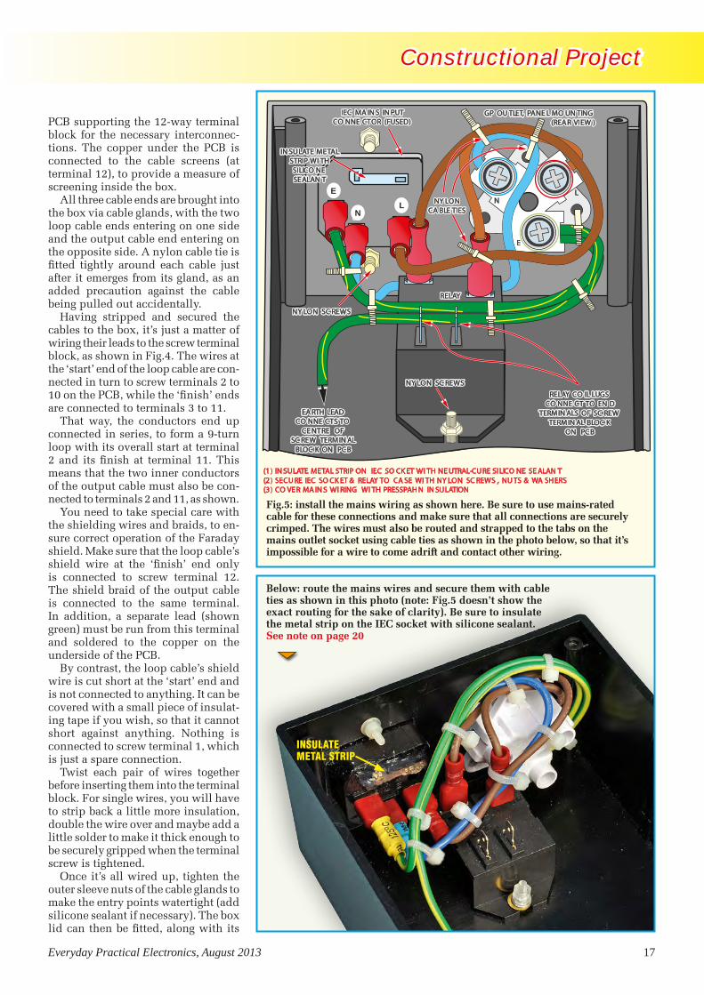
PCB supporting the 12-way terminal block for the necessary interconnec-tions. The copper under the PCB is connected to the cable screens (at terminal 12), to provide a measure of screening inside the box.
All three cable ends are brought into the box via cable glands, with the two loop cable ends entering on one side and the output cable end entering on the opposite side. A nylon cable tie is fitted tightly around each cable just after it emerges from its gland, as an added precaution against the cable being pulled out accidentally.
Having stripped and secured the cables to the box, it’s just a matter of wiring their leads to the screw terminal block, as shown in Fig.4. The wires at the ‘start’ end of the loop cable are con-nected in turn to screw terminals 2 to 10 on the PCB, while the ‘finish’ ends are connected to terminals 3 to 11.
That way, the conductors end up connected in series, to form a 9-turn loop with its overall start at terminal 2 and its finish at terminal 11. This means that the two inner conductors of the output cable must also be con-nected to terminals 2 and 11, as shown.
You need to take special care with the shielding wires and braids, to en-sure correct operation of the Faraday shield. Make sure that the loop cable’s shield wire at the ‘finish’ end only is connected to screw terminal 12. The shield braid of the output cable is connected to the same terminal. In addition, a separate lead (shown green) must be run from this terminal and soldered to the copper on the underside of the PCB.
By contrast, the loop cable’s shield wire is cut short at the ‘start’ end and is not connected to anything. It can be covered with a small piece of insulat-ing tape if you wish, so that it cannot short against anything. Nothing is connected to screw terminal 1, which is just a spare connection.
Twist each pair of wires together before inserting them into the terminal block. For single wires, you will have to strip back a little more insulation, double the wire over and maybe add a little solder to make it thick enough to be securely gripped when the terminal screw is tightened.
Once it’s all wired up, tighten the outer sleeve nuts of the cable glands to make the entry points watertight (add silicone sealant if necessary). The box lid can then be fitted, along with its
E
NNAA
IEC MA IN S IN PUTCO NNE CTOR (FUSED)
GP OU TLET, PANE L MO UN TING(REA R VIEW )
RELAY
EA RTH LEADCO NNE CTS TO
CE NTRE OFSC REW TERMIN AL
BLOC K ON PCB
NY LONCA BLE TIES
RELAY CO IL LUGSCO NNE CT TO EN D
TERMIN ALS OF SC REWTERMIN AL BLOC K
ON PCB
(1 ) IN SULATE METAL STRIP ON IEC SO CK ET WI TH NE UTRAL-CU RE SI LICO NE SE ALAN T(2 ) SECU RE IEC SO CK ET & RELAY TO CA SE WI TH NY LON SC REWS , NU TS & WA SH ERS(3 ) CO VE R MA IN S WI RING WI TH PRESSPAH N IN SULATION
IN SULATE METALSTRIP WI THSILICO NESEALAN T
NY LON SC REWS
NY LON SC REWS
N
E
IN SULATE METALSTRIP WI THSILICO NESEALAN T
IEC MA IN S IN PUTCO NNE CTOR (FUSED)
GP OU TLET, PANE L MO UN TING(REA R VIEW )
NY LONCA BLE TIES
EA RTH LEADCO NNE CTS TO
CE NTRE OFSC REW TERMIN AL
BLOC K ON PCB
RELAY CO IL LUGSCO NNE CT TO EN D
TERMIN ALS OF SC REWTERMIN AL BLOC K
ON PCB
NY LON SC REWS
RELAY
NY LON SC REWS
E L
Fig.5: install the mains wiring as shown here. Be sure to use mains-rated cable for these connections and make sure that all connections are securely crimped. The wires must also be routed and strapped to the tabs on the mains outlet socket using cable ties as shown in the photo below, so that it’s impossible for a wire to come adrift and contact other wiring.
Below: route the mains wires and secure them with cable ties as shown in this photo (note: Fig.5 doesn’t show the exact routing for the sake of clarity). Be sure to insulate the metal strip on the IEC socket with silicone sealant.See note on page 20
E
NL
Driveway Sentry0812 (FROM MP).indd 17 14/06/2013 10:10:16

18 Everyday Practical Electronics, August 2013
Constructional Project Constructional Project
neoprene gasket, and fastened in place using the screws supplied.
The only step remaining is to fit the other end of the output cable with a 5-pin DIN plug, to mate with input socket CON1 on the main Driveway Sentry PCB. Note that the two in-ner conductors must be soldered to pins 1 and 3 of the plug, while the
screening braid goes to pin 2 (ie, the centre pin).
Preparing the caseThe drilling details for the box and its lid are available in PDF format from the EPE website. These should be downloaded and printed out, after which the individual sections can be
cut out and used as drilling templates (they can be temporarily attached to the box/lid using sticky tape).
Most of the holes can be made by simply drilling and (if necessary) reaming them to size. Be sure to always use a small pilot drill to start the larger holes, to ensure drilling accuracy.
The two holes for the mains input and output connectors at the righthand end of the box are inevitably more complex. These are best made by first drilling a series of small holes around the inside perimeter of the area to be removed. The holes can then be joined using a handheld jigsaw, after which the centre pieces can be knocked out and the edges de-burred and filed to a smooth finish using needle files.
Mains wiringThe next step is to mount the relay inside the case, with its switched output lugs nearest the adjacent end and the coil terminals towards the middle.
It should be secured using M3 × 12mm nylon screws, with metal flat and lock washers under nylon nuts on the top of the relay mounting flanges inside (do NOT use metal screws). A second nylon nut at each location is used to lock the first into position.
That done, use neutral-cure silicone sealant to insulate the exposed metal strip on the IEC input connector. That strip links the live input pin and the fuseholder, it runs at mains potential (230V AC) when power is applied. So insulating it is a good idea to prevent accidental contact.
You can now mount the IEC mains input connector and the mains output socket on the righthand end of the case. Use M3 × 12mm nylon screws to hold the IEC connector in place, along with flat washers and two nylon nuts on each screw.
Fig.5 and its accompanying photo show how the mains wiring is installed. Be sure to use mains-rated cable for all this wiring. You will need to crimp 6.3mm fully-insulated female spade connectors to the wires that go to the relay contacts and to the IEC connector.
In each case, it’s a matter of strip-ping back about 5mm of insulation from the wire, then pushing it into the connector and crimping it with the tool. Check each crimp connection as it is made, to make sure it is securely terminated – you must not be able to pull the wire out of the connector.
2023
103
95
9
99
9
3535 33
FOLD DOWN 90 ALONG DOTTED LINEo
13 7
18
PRESSPAHN INSULATION MATERIAL
Fig.6: this diagram shows how to cut out and fold the Presspahn insulation material that’s used to cover the mains wiring. Don’t leave it out – it isolates the mains wiring from the parts on the PCB.
The Presspahn cover has a cut-out to clear the relay and is fitted in position as shown here.
Driveway Sentry0812 (FROM MP).indd 18 14/06/2013 10:10:25

Everyday Practical Electronics, August 2013 19
Constructional Project Constructional Project
Note that you must use a profes-sional ratchet-driven crimping tool for this job. Don’t even think about using a cheap, non-ratchet crimper; they are not up to the job for a project like this, as the pressure applied to the connectors will vary all over the place and this will result in unreliable and unsafe connections.
Note also that some IEC input con-nectors have 4.8mm terminals, in which case you must use 4.8mm spade connectors to suit. These should also be fully-insulated types or, if neces-sary, you can insulate them yourself using heatshrink tubing.
Once all the spade connectors have been fitted, plug the leads into the IEC connector, then connect the neutral lead to the mains socket. The lead from the live terminal on the IEC connector is terminated in a second spade con-nector and this connects to one of the relay output terminals. The other relay output terminal connects to the live terminal on the mains socket.
The two earth leads can now be run to the mains socket. One of these leads is run from the earth terminal on the IEC socket, while the second lead is routed back next to this lead and ultimately connects to the earth track of the PCB. You will need to make this latter lead about 250mm long.
Be sure to route the mains wires as shown in the accompanying photo (note: Fig.5 shows the connections but doesn’t show the exact routing for the sake of clarity). Once all the connec-tions have been made, use cable ties to strap the wires to the tabs on the mains socket (see Fig.5). Five more additional cable ties are also used to strap the wires together and should be installed as shown in Fig.5 and the photo.
Driveway Sentry: Parts List
1 PCB, code 03107121, available from the EPE PCB Service, size, 140mm × 84mm
1 UB2 jiffy box, size 197mm × 113mm × 63mm
1 110 × 100mm piece of Presspahn insulation material
1 PCB-mount mini piezo buzzer2 panel-mount SPST pushbutton
switches1 PCB-mount 5-pin DIN socket
(CON1)1 2.5mm concentric DC input
connector (CON2)1 3-way PCB terminal block (CON3)1 panel-mount fused IEC male
input connector1 M205 10A fuse1 Mains outlet, flush panel
mounting (see note on page 20)1 12V SPST 20A chassis-mount
mains relay (Ocean Controls RLY-008)
2 8-pin DIL IC sockets2 14-pin DIL IC sockets1 16-pin DIL IC socket5 6.3mm fully insulated female
spade connectors (see text)2 fully insulated 4.8mm female
spade connectors1 150mm length of blue insulated
mains-rated wire1 200mm length of brown insulated
mains-rated wire1 400mm length of green/yellow
mains-rated wire2 120mm lengths of insulated
hook-up wire 4 M3 × 25mm tapped spacers9 M3 × 6mm machine screws4 M3 × 12mm nylon screws8 M3 nylon nuts1 M3 hex nut7 M3 star lockwashers4 M3 flat washers1 500Ω multi-turn trimpot (VR1)2 500kΩ horizontal trimpots
(VR2,VR3)12 small nylon cable ties1 150mm length tinned copper wire1 3-way pin header1 shorting link
Semiconductors1 AD623 instrumentation amplifier
(IC1)1 LM324 quad op amp (IC2)1 4011B quad CMOS NAND gate
(IC3)
1 4060B CMOS counter (IC4)1 7555 CMOS timer (IC5)2 PN100 NPN transistors (Q1,Q2)1 BC337 NPN transistor (Q3)1 7806 +6V regulator (REG1)1 5mm LED, green (LED1)1 5mm LED, red (LED2)1 1N5819 Schottky diode (D1)1 1N4004 1A diode (D2)1 1N4148 100mA diode (D3)
Capacitors1 1000µF 25V RB electrolytic1 220µF 16V RB electrolytic1 47µF 16V RB electrolytic1 47µF 25V RBLL low-leakage
electrolytic1 10µF 16V RB electrolytic1 1μF MMC 2 470nF MKT polyester1 220nF MKT polyester1 150nF MKT polyester10 100nF MMC or MKT polyester2 22nF MKT polyester or greencap1 10nF MKT polyester or greencap
Resistors (0.25W 1%)1 470kΩ 4 10kΩ2 220kΩ 4 4.7kΩ1 180kΩ 1 1.5kΩ2 100kΩ 4 1kΩ1 68kΩ 1 560Ω1 47kΩ 1 470Ω1 27kΩ 2 100Ω1 22kΩ
Sensor Loop Assembly1 IP65 sealed ABS enclosure,
115mm × 65mm × 40mm1 blank PCB (ie, copper on one
side), 104mm × 38mm4 M3 × 6mm machine screws1 12-way barrier screw terminal
block, 96mm long2 M3 × 15mm machine screws
and nuts3 cable glands (for 3-6.5mm cable)3 nylon cable ties1 25m length of screened
9-conductor ‘computer cable’ 1 10-30m length (to suit) of
screened 2-conductor heavy duty microphone cable
1 5-pin DIN plug, line type1 50mm-length spaghetti tubing
Use double-crimp spade connectors
Note that the spade connectors used to terminate the mains wiring must be double-crimp types. This means that the metal collar inside each connector extends almost back to the wire entry hole.
That way, both the bared wires and the insulation are crimped by the metal surround, to give better retention. Don’t use single-crimp types, which crimp the copper only, as the wire can more easily come loose.
Reproduced by arrangement with SILICON CHIP
magazine 2013.www.siliconchip.com.au
Driveway Sentry0812 (FROM MP).indd 19 14/06/2013 10:10:23

20 Everyday Practical Electronics, August 2013
Constructional Project Constructional Project
These cable ties are vital to ensure that an individual lead can’t come loose and contact other terminals, even if the box receives a sudden jolt. In particular, be sure to strap the earth wires to the mains socket tab and strap the earth and neu-tral wires together at the IEC connector.
Presspahn coverAs shown in the photos, a Presspahn cover is used to physically isolate the
mains circuitry from the low-voltage circuitry and the PCB. This fits verti-cally over the relay and is folded over the top of the IEC connector and mains socket to form a complete enclosure.
Fig.6 shows the dimensions of the Presspahn cover. It can be cut to shape using a sharp pair of scissors, while the hole for the earth lead that runs to the PCB can be cut out using a sharp hobby knife. The fold line is then lightly
STREET END
HOUSEOR GARAGE
END
GAPS BETWEENDRIVEWAY SLABS
LOOP TERMINATIONBOX
SENSOR LOOP
OUTPUT CABLETO MAIN SENTRY UNIT
scored, after which the top section is folded down through 90°.
Check the mains wiring carefully before installing the Presspahn cover. It’s a good idea to use a multimeter (set to ohms) to check all the con-nections between the IEC connector and the mains socket. The earth lead is critical – use the DMM to confirm continuity between the earth pin of the IEC socket and the earth of the flush-mounting mains socket.
Do the same for the two neutral connections (the two live terminals should be open circuit, since the relay contacts will be open). Check also to ensure there are no shorts between live and neutral on both the IEC connec-tor and the mains socket, or between either of these two terminals and earth.
Once that’s done, feed the earth lead that runs to the PCB through the hole in the Presspahn cover. The cover can then be slipped into position over the relay (see photos) and secured using some hot-melt glue or neutral-cure silicone sealant.
Final assemblyNow for the final assembly. The first step is to download the front panel artwork (in PDF format) from the EPE website. This should be printed out, laminated and attached to the front panel using double-side tape or silicone.
The holes in the panel artwork can then be cut out using a sharp hobby knife.
Once the panel is finished, mount the two pushbutton switches (S1 and S2), then attach four M3 × 25mm tapped spacers to the back of the box lid at the PCB mounting points. Secure
Fig.7: the loop sensor arrangement. The loop can either be buried just under the driveway or installed in the expansion slots of a concrete driveway, with the loop sides buried in a shallow trench. The loop termination box and the output cable should also be buried.
One end of the case carries the IEC input socket and the mains output socket (see note above) while the other end provides access to the loop input socket, the DC connector and the sensitivity trimpot (VR1).
UK MAINS OUTLET SOCKETThis project was originally designed for the Australian market. While it is completely compatible with UK mains voltages, you will notice that the mains outlet socket pictured below is not a type used in the UK. We recommend you use an IEC female socket. However, you must ensure it will fit your chosen enclosure, and most important of all, if you are in any doubt as to the suitability of your choice of socket then you must seek advice from a trusted professional or someone with sufficient experience in wiring mains-related equipment – always be safe!
Driveway Sentry0812 (FROM MP).indd 20 14/06/2013 10:11:00

Everyday Practical Electronics, August 2013 21
Constructional Project Constructional Project
these spacers using four M3 × 6mm machine screws.
That done, cut four 20mm lengths of 0.5mm tinned copper wire and solder these to the switch terminals. These form extension leads, which will later pass down through matching holes in the PCB when the latter is mounted on the spacers.
Next, cut two 80mm lengths of medium-duty hookup wire and crimp one end of each wire to a 4.8mm fully-insulated spade connector. Check that these connections are secure, then connect the opposite ends of these two leads to the terminal block on the PCB – see Fig.3.
The earth lead should also now be connected to the terminal block. Do the screws on the terminal block up nice and tight, then fit a cable tie to the three wires as shown in the photo. Another cable tie can then be used to bind the relay wires about 40mm from the connectors.
The PCB can be mounted on the spacers on the rear of the lid. Basi-cally, it’s just a matter of offering the board up to the lid while making sure that the extension leads from S1 and S2 pass through their corresponding
PCB holes. At the same time, you have to make sure that LED1 and LED2 go through their matching holes in the lid.
Once everything is correct, secure the PCB to the stand-offs using M3 × 6mm screws and star washers. Do the screws up tightly, then solder the extension leads for switches S1 and S2 to their PCB pads.
The assembly can now be completed by connecting the two spade connec-tors to the relay coil terminals, then carefully lowering the PCB/lid assem-bly into the box. Note that it will be necessary to bend the leads from the terminal block straight up from the PCB so that they will clear the Presspahn cover. Make sure that the Presspahn cover is correctly positioned before securing the lid using the four small self-tapping screws supplied.
The Driveway Sentry in now com-plete and ready for installation and sen-sitivity adjustment. Both the sensitivity control (VR1) and the trigger sensitivity control (VR2) can be adjusted after the box is fully assembled, via small access holes (one in the lid and the other in the lefthand end of the case). The same goes for the alarm duration trimpot (VR3).
The PCB is mounted on the lid of the case on four M3 × 25mm spacers. Make sure that the extension wires soldered to the switch terminals pass through their respective holes on the PCB, and don’t forget to solder them.
Switching other devicesIf you don’t wish to switch the mains, then the IEC socket, the flush-mount mains output socket and the mains wiring can all be omitted. You can then simply use the relay output contacts to switch a low voltage or to trigger some other piece of gear, eg, a burglar alarm.
Note, however, that it will still be desirable to earth the Faraday shield of the loop sensor, and this can be done by running a lead from the PCB earth terminal to a metal stake driven into the ground.
Sensitivity adjustmentTo test the unit, the sensor loop must initially be laid on top of the driveway and connected to the main unit. You’re then ready to adjust the sensitivity. It’s simply a matter of setting VR2 to midrange and adjusting trimpot VR1 clockwise to make the Driveway Sentry more sensitive, or anticlockwise to make it less sensitive.
This will have to be done on a trial and error basis, with a vehicle driven over the sensor loop after each ad-justment. The best setting is where it reliably detects the smallest moving vehicle likely to enter or leave the driveway, but don’t make it more sensitive than necessary. If you simply adjust VR1 for maximum sensitivity (ie, fully clockwise), the unit may be prone to giving false alarms due to passing radio transmitters or mobile phones, or during electrical storms.
Note that the loop direction will affect the sensitivity. If you cannot get reliable triggering, reverse the loop by turning it over. This means that you must test the complete unit before burying the loop.
VR2, the trigger sensitivity adjust-ment, is basically a back-up, and is normally left in the midrange position. It need only be moved from this posi-tion if you run out of range with VR1.
Sensor loop installationThe remote sensor loop can either be buried under your driveway (eg, under pavers) or it can be installed in the ex-pansion joints of a concrete driveway.
As shown in Fig.7, two of its op-posite sides lie in the narrow gaps between the concrete driveway slabs, while the other two sides run along-side the enclosed slab on either side. The loop termination box can be located adjacent to one side, with the output cable running away to the main control box inside your house.
Driveway Sentry0812 (FROM MP).indd 21 14/06/2013 10:10:54

22 Everyday Practical Electronics, August 2013
Constructional Project Constructional Project
In practice, the loop termination box can be buried and the output cable run in a shallow trench back to the house, so that it doesn’t get damaged. Make sure that the cable glands have all been properly sealed using silicone before burying the loop termination box, to prevent water damage.
If you are on a rural property, the loop sensor can simply be buried under the driveway in a shallow rec-tangular trench.
Using itWhen the Driveway Sentry is armed and detects movement, it immediately produces an alarm sound from the buzzer and operates the relay. The re-lay contacts can be used to switch on a security floodlight, other lighting or perhaps a siren. The Alarm Duration can be set by adjusting VR3 using a screwdriver through the front-panel access hole.
Finally, note that any fixed mains wiring to lights or other mains-pow-ered items should be installed by a qualified electrician. EPE
This is the completed loop termination box, together with the sensor loop cable (light grey) and the extension cable (black) that runs back to the main unit. Make sure that the box is properly sealed against moisture.
TO ADVERTISE IN EVERYDAY PRACTICAL
ELECTRONICSPLEASE CONTACT
Stewart Kearn on
01202 880299or email
Get the answer you’ve been looking for
Vist the EPE Chat Zonewww.epemag.com
PICs?Can
anyone help me?
I Can help!
General Electronics
chat
Problem sourcing software?
Chat Zone filler advert.indd 1 19/03/2013 14:07:07
Driveway Sentry0812 (FROM MP).indd 22 14/06/2013 10:11:02

The Microchip name and logo, the Microchip logo, dsPIC, MPLAB and PIC are registered trademarks of Microchip Technology Incorporated in the U.S.A. and other countries. All other trademarks are the property of their registered owners.©2012 Microchip Technology Inc. All rights reserved. ME1023BEng/05.13
Microchip offers support for a variety of wired and wireless communication protocols, including peripheral devices and solutions that are integrated with a PIC® Microcontroller (MCU) or dsPIC® Digital Signal Controller (DSC).
Microchip’s Solutions include:
BEFORE YOUR NEXT WIREDOR WIRELESS DESIGN:1. Download free software libraries2. Find a low-cost development tool3. Order samples
www.microchip.com/usbwww.microchip.com/ethernetwww.microchip.com/canwww.microchip.com/linwww.microchip.com/wireless
Adding Connectivity to Your Design
USB8-, 16- and 32-bit USB MCUs for basic, low-cost applications to complex and highly integrated systems along with free license software libraries including support for USB device, host, and On-The-Go.
EthernetPIC MCUs with integrated 10/100 Ethernet MAC, standalone Ethernet controllers and EUI - 48™/EUI - 64™ enabled MAC address chips.
CAN8-, 16- and 32-bit MCUs and 16-bit DSCs with integrated CAN, stand alone CAN controllers, CAN I/O expanders and CAN transceivers.
LINLIN Bus Master Nodes as well as LIN Bus Slave Nodes for 8-, 16- and 32-bit PIC MCUs and 16-bit dsPIC DSCs. The physical layer connection is supported by CAN and LIN transceivers.
Wi-Fi® Innovative wireless chips and modules allowing a wide range of devices to connect to the Internet. Embedded IEEE Std 802.11 Wi-Fi transceiver modules and free TCP/IP stacks.
ZigBee®Certified ZigBee Compliant Platform (ZCP) for the ZigBee PRO, ZigBee RF4CE and ZigBee 2006 protocol stacks. Microchip’s solutions consist of transceiver products, PIC18, PIC24 and PIC32 MCU and dsPIC DSC families, and certified firmware protocol stacks.
MiWiTM
MiWi and MiWi P2P are free proprietary protocol stacks developed by Microchip for short-range wireless networking applications based on the IEEE 802.15.4™ WPAN specification. Wi-Fi G Demo Board
(DV102412)
AUG 2013.indd 1 17/06/2013 12:58:19

24 Everyday Practical Electronics, August 2013
Mark Nelson
Scare stories
When moving, the artificial creature is said to look weirdly alive.
Shut-down scenarioHere’s an interesting everyday electronics challenge, together with a highly practical electronics solution. Chances are that you will never have heard of ENTSO-E, nor of its proposal to turn off your domestic appliances when the power grid is overloaded even though the subject is arousing major concern among consumer organisations and appliance manufacturers. ENTSO-E is the European Network of Transmission System Operators for Electricity, a body that coordinates transmission system operators of electricity at European level. Earlier this year it submitted a controversial proposal to the European Commission requiring makers of appliances such as refrigerators and washing machines to install technology enabling grid operators to switch them off remotely when the power grid is overloaded and thus avoid total blackouts.
But one scenario in a new ‘Demand Connection Code’ proposal drawn up by ENTSO-E, ostensibly in the cause of energy efficiency and renewable energy, requires mandatory participation of all temperature-controlled appliances in frequency-controlled programmes. A response to ENTSO-E, signed by Jill Johnstone, international policy director of Consumer Focus and other European consumer groups states that this plan ‘raises issues around an outside party controlling privately-owned property without the owner’s permission or knowledge.’ Appliance manufacturers are not keen on the idea either, arguing that the extra circuitry required would raise prices. ENTSO-E has stressed that shutting off appliances would be a very last resort, but concedes that it could happen.
Writing in the ERT trade magazine, Graham Knight opined: ‘This European Energy Commission proposal seems like nonsense to me. Imagine what would happen if all the washing machines and fridges closed down at once. Too bad if your dialysis machine switches off. This is just crazy. The National Grid has a legal requirement to meet demand and it should do so. As the signal to switch off devices is to be sent via the power line itself, I think I will start to manufacture a wee filter device to go
in the mains lead and thus guarantee ‘Never a shutdown’. At £25 a go, they should sell like hot cakes.’
Some light reading A while back (October 2008) I mentioned a pilot trial in London using LED luminaires (OK, bulbs) for street lighting. In the meantime, the technology has matured and LED street lamps have become mainstream. Even the lamp standard opposite my home now uses LEDs, giving a rather ghostly glow.
There’s still some way to go, however, and a report issued by The Climate Group (sponsored by Philips Lighting) is calling for all citizens worldwide to have access to energy-efficient outdoor lighting. We can overlook any self-interest on the part of Philips; the call to action makes sound sense. The fact is, lighting is responsible for 19 per cent of electricity use world-wide, and significant savings are possible – on average 40% – simply by switching to energy-efficient lighting technologies such as LED. On a global level these savings amount to £109 billion in reduced electricity cost, 670 million tons of carbon dioxide, or a £1,112 billion saving in reduced need for power infrastructure. In these times of national budget deficits, improving lighting efficiency looks to be virtually an economic necessity, notwithstanding the high up-front costs.
Prices are set to fall significantly nevertheless, according to a new report by market analysis firm DisplaySearch. ‘Demand for LED lighting is growing rapidly thanks to significant expansion in manufacturing capacity, falling prices, environmental concerns, and government incentives,’ states DisplaySearch. ‘This new opportunity for LED lighting applications will double the market, from 16 million units in 2012 to a forecast of 33 million in 2013, and will nearly triple by 2016. As a result, the demand for all LED lighting products will reach 90 million in 2016, increasing the global penetration for LED lighting applications to 26 per cent in 2016, up from only 5% in 2012. This increase is due in large part to continued growth in commercial applications, government incentive programs, and consumer demand for energy-saving technology.’
AutonomouS robot jellyfish for deployment by the US Navy – they sound beyond belief or at
least an April Fool’s joke. But they’re real and a product of Virginia Tech, the state university of the Commonwealth of Virginia in the US. Researchers at Virginia Tech College of Engineering are working on a multi-university, nationwide project for the US Navy that one day will put life-like autonomous robot jellyfish in waters around the world. The robotic creatures are being designed to operate on energy that they generate themselves.
marine mimicsWhat we’re talking about is a life-like, autonomous robotic jellyfish the size and weight of a grown man, 1.7m long and weighing 77kg. The prototype robot, nicknamed Cyro, is a larger model of a robotic jellyfish unveiled last year by the same team. The earlier robot, dubbed RoboJelly, was roughly the size of a man’s hand, and typical of small jellyfish found along beaches. ‘A larger vehicle will allow for greater payload, longer duration, and longer range of operation,’ said Alex Villanueva, a team member. ‘Biological and engineering results show that larger vehicles have a lower cost of transport, which is a metric used to determine how much energy is spent for travelling.’ Both robots are part of a $5 million project funded by the US Naval Undersea Warfare Center and the Office of Naval Research. The goal is to place self-powering, autonomous machines in waters for surveillance and environment monitoring, in addition to other uses such as studying aquatic life, mapping ocean floors, and monitoring ocean currents.
Jellyfish are attractive candidates to mimic because of their ability to consume little energy owing to a lower metabolic rate than other marine species. Their robot clones need to be able to operate on their own for months at a time, as engineers likely won’t be able to capture and repair the robots, or replace their power source (a rechargeable nickel-metal hydride battery). A synthetic rubbery skin conceals the central electronics that control the direct-current electric motors used to control the mechanical arms that agitate the jelly-based pump to create hydrodynamic movement.
Robot jellyfish, ghostly glows and fridges that turn themselves off and ruin your food. nightmare upon nightmare? not really, as mark nelson explains
TechnoTalk new font sizes.indd 24 14/06/2013 10:22:50

Everyday Practical Electronics, August 2013 25
PIC-Based Ultrasonic Tape MeasureYou’ve got it taped if you PIC this ultrasonic distance measuring calculatorEPE Mind PICklerWant seven ways to relax? Try our PIC-controlled mind machine!PIC MIDI Sustain PedalAdd sustain and glissando to your MIDI line-up with this inexpensive PIC-controlled effects unitPIC-based MIDI HandbellsRing out thy bells with merry tolling – plus a MIDI PIC-up, of course!EPE Mood PICkerOh for a good night’s sleep! Insomniacs rejoice – your wakeful nights could soon be over with this mini-micro under the pillow!PIC Micro-ProbeA hardware tool to help debug your PIC softwarePIC Video CleanerImproving video viewing on poorly maintained TVs and VCRsPIC Graphics LCD ScopeA PIC and graphics LCD signal monitor for your workshopPIC to Printer InterfaceHow to use dot-matrix printers as data loggers with PIC microcontrollersPIC PolywhatsitA novel compendium of musical effects to delight the creative musicianPIC Magick MusickConjure music from thin air at the mere untouching gesture of a fingertipPIC Mini-EnigmaShare encrypted messages with your friends — true spymaster entertainmentPIC Virus ZapperCan disease be cured electronically? Investigate this controversial subject for yourselfPIC Controlled Intruder AlarmA sophisticated multi-zone intruder detection system that offers a variety of monitoring facilitiesPIC Big-Digit DisplayControl the giant ex-British Rail platform clock 7-segment digits that are now available on the surplus marketPIC Freezer AlarmHow to prevent your food from defrosting unexpectedlyPIC World ClockGraphically displays world map, calendar, clock and global time-zone dataPICAXE ProjectsA 3-part series using PICAXE devices – PIC microcontrollers that do not need specialist knowledge or programming equipmentPIC-based Tuning Fork and MetronomeThrill everyone by at long last getting your instrument properly tuned!Versatile PIC FlasherAn attractive display to enhance your Christmas decorations or your child’s ceiling
EPE PIC PROJECTS VOLUME 1
MINI CD-ROMA plethora of 20 ‘hand-PICked’ PIC Projects from selected past issues of EPETogether with the PIC programming software for each project plus bonus articlesThe projects are:
EPE PIC PROJECTS CD-ROM ORDER FORM
Please send me ........ (quantity)
EPE PIC PROJECTS VOL 1 CD-ROM
Price £14.75 each – includes postage to anywhere in the world.
Name .............................................................................
Address .........................................................................
........................................................................................
........................................................................................
.................................... Post Code .................................
I enclose cheque/P.O./bank draft to the value of £ ..........
please charge my Visa/Mastercard/Maestro £ ................
Card No. ........................................................................
Card Security Code .......... (The last 3 digits on or just under the signature strip)
Valid From ........................ Expiry Date .........................
Maestro Issue No. .................
SEND TO: Everyday Practical Electronics,
Wimborne Publishing Ltd.,113 Lynwood Drive, Merley, Wimborne,
Dorset BH21 1UU.Tel: 01202 880299. Fax: 01202 843233.Email: [email protected]
Payments must be by card or in £ Sterling – cheque or bank draft drawn on a UK bank.
Normally posted within seven days of receipt of order. Send a copy of this form, or order by letter if you do
not wish to cut your issue.
Order on-line fromwww.epemag.com
or by Phone, Fax, Email or Post.
NOTE: The PDF files on this CD-ROM are suitable to use on any PC with a CD-ROM drive. They require Adobe Acrobat Reader
– included on the CD-ROM
BECOME A PIC PROJECT BUILDER WITH THE HELP OF EPE!
ONLY£14.75INCLUDING
VAT and P&P
PIC Projects.indd 25 14/06/2013 11:19:44

26 Everyday Practical Electronics, August 2013
Constructional Project Constructional Project
Milliohm MeterAdaptor for DMMs
Do you occasionally need to measure very low resistances accurately, but don’t have access to an expensive benchtop milliohm meter or DMM? This low-cost adaptor will let you use almost any DMM to make accurate low-resistance measurements.
By Jim Rowe
Milliohm Adaptor0210 (FROM MP).indd 26 14/06/2013 10:31:15

Everyday Practical Electronics, August 2013 27
Constructional Project Constructional Project
When it comes to measur-ing low resistances (ie, below
about 10Ω) with any significant ac-curacy, very few standard handheld digital multimeters are of much use. only the top-of-the-range models of-fer any real performance in this area.
and when you want to measure even lower resistances – less than one ohm – even some of these drop out of contention. it’s really only the most expensive benchtop models that will provide milliohm-level measurements as a matter of course.
this doesn’t pose much of a prob-lem for most of us, most of the time, because accurate low-value resistance measurements are not needed often.
But sometimes you do need low-ohm accuracy, eg, when matching the
values of low-value resistors used for current sharing in amplifier output stages, or when you need to make up a low resistance current shunt for a panel meter.
that’s when you need this Milliohm Meter Adaptor. it’s self-contained and designed to act as a very low resistance measuring ‘front end’ for almost any standard Dmm.
it works by converting low resist-ance values into a directly proportion-al Dc voltage (nominally 0-1.000V), so the Dmm is simply set for its 1V or 2V Dc voltage range, the range where most Dmms have their highest accuracy.
so when the Adaptor is being used to measure a very low resistance, the resistance value is simply read out on the Dmm in millivolts.
CURRENTSOURCE
CURRENTSOURCE
VOLTMETER
VOLTMETER
Rm (HIGH)
Rm (HIGH)
Rx
Rx
RL1
RL1
RL3
RL2
RL2
+
+
–
–
2–TERMINAL RESISTANCE MEASUREMENT
4–TERMINAL RESISTANCE MEASUREMENT
A
B
ACTUALRESISTOR
TO BEMEASURED
RL4
F+
F–
S+
S–
RESISTANCEOF LEADS
If (FORCE CURRENT)
If (FORCE CURRENT)
With the exception of the terminals and battery, all components mount on a single PC board.
The top diagram (Fig.1a) shows the way resistance is measured in ‘normal’ meters (ie, two-terminal). The lower diagram (Fig.1b) shows how higher accuracy is achieved with four-terminal measurement, especially for low resistances. This is the approach taken in this Milliohm Adaptor.
actually the Adaptor provides two measurement ranges, one is a ‘0-1.0Ω’ range, where it converts milliohms directly into millivolts (so 125mΩ be-comes 125mV, for example). the other is a ‘0-10Ω’ range, where it converts tens of milliohms into millivolts – so 2.2Ω (2200mΩ) becomes 220mV.
so, reading the low-value resist-ances on your Dmm doesn’t require much mental arithmetic.
now at this stage you’re probably thinking this: if a low-cost Adaptor like the one we’re describing here can make this kind of very low resistance measurement relatively easily, why don’t most Dmms provide such ranges?
that’s because there is a catch: in order to measure low resistances accu-rately, you have to use a four-terminal measurement approach, rather than the two-terminal approach used in the majority of Dmms.
so, before we look at the new Adap-tor and the way it works, we’d better explain why it needs to make four-terminal measurements.
Why four terminals?to understand what we’re talking about here, look first at the upper resistance measurement circuit in Fig.1(a). this shows the kind of two-terminal measurement used by most Dmms to measure resistances.
as you can see, it’s quite straightfor-ward: a constant current source forces a current, If, through the resistance to be measured (Rx), which is connected to the meter’s test terminals. the voltme-ter section of the Dmm then measures the voltage drop across the test termi-nals, which is directly proportional to the resistance between the terminals – because according to ohm’s law this voltage is given by e = If × Rx.
note that the voltmeter has a very high multiplier resistance (Rm), so it is assumed to draw virtually no current.
the drawback with this approach is that as shown, our unknown resistance Rx isn’t the only resistance between the two test terminals – there’s also the resistance of the test leads, RL1 and RL2. these are effectively in series with Rx, so the voltage drop across them as a result of If flowing through them will simply be added to the drop across Rx. the resistance measured by the Dmm will therefore be (Rx + RL1 + RL2), rather than just Rx itself.
now, from a practical point of view this doesn’t introduce much error
Milliohm Adaptor0210 (FROM MP).indd 27 14/06/2013 10:31:30

28 Everyday Practical Electronics, August 2013
Constructional Project Constructional Project
when you’re measuring resistances over 10Ω or so (with fairly short test leads). It’s usually not too difficult to keep the test lead resistances down to a few tens of milliohms (which is less than 1% of the value of Rx). But when you’re trying to measure somewhat lower resistances, the errors can be quite significant.
For example, if the resistance you’re measuring is 1Ω, two test leads, each with a resistance of 30mΩ, will in-crease the total resistance across the terminals by 60mΩ or 0.06Ω, giving a measurement error of +6%.
Now consider what happens when we use the four-terminal measurement approach shown in Fig.1(b). Here we still force a known current through the unknown resistor Rx and measure the voltage drop across it as before, using a high-resistance voltmeter. But in this case, the force current If is fed to Rx via one pair of terminals F+ and F–, while the voltmeter is connected across Rx via a second set of ‘sensing’ terminals S+ and S–.
As you can see, the F+ and S+ terminals are connected to one end of Rx via separate leads, while the F– and S– terminals are connected to the other end, also via separate leads. So there are now four test leads, with resistances RL1, RL2, RL3 and RL4.
But how does this extra complex-ity help?
Look carefully and you’ll see that although the force current If still flows through force lead resistances RL1 and RL4, the voltage drops across these resistances now don’t matter because the voltmeter’s sensing leads are con-nected directly across Rx itself – ie, we now only measure the voltage drop across Rx alone.
And the sensing lead resistances RL2 and RL3 don’t cause any problems either, because they’re simply in series with the very high resistance of the voltmeter circuit (and they carry only its tiny measurement current).
So that’s why changing over to four-terminal resistance measurement gives much better accuracy, especially when you’re measuring very low resistances.
Circuit descriptionNow that you understand the basic concept of four-terminal resistance measurement, let’s now take a look at the circuit of the new Milliohm Measuring Adaptor and the way it works in detail.
Fig
.2:
the
com
ple
te s
chem
atic
. T
he
circ
uit
ry a
t u
pp
er l
eft
form
s a
regu
late
d s
ourc
e of
for
ce c
urr
ent,
wh
ile
that
at
low
er r
igh
t is
a D
C a
mp
lifi
er w
ith
a g
ain
of
exac
tly
100.
C
BE
2009SC
A K A K
OU
T TO
DM
M
+ –
680
VR3
5k
CA
LIBRA
TE(G
AIN
)
FORC
E+
FORC
E–
SEN
SE+
SEN
SE–
S1a
S1b
6.2k
Rx
IC1
LM33
6-2.
5V30
0
1k
VR2
5k
SET
1mA
INT/
EXT
SEN
SIN
G
D1
D2
Q1
BC55
9
VR1
10k
+ –
AD
J
ZERO
FORC
EC
URR
ENT
TEM
PCO
9VBA
TTER
Y
S2
POW
ERD
3Vc
c =
+8.4
V
220
F16
V
AK
100n
F
MIL
LIOH
M AD
APTO
R FO
R DM
M'S
68
47nF
47nF
KA
LM33
6-2.
5
AD
J–
+C
E
B
BC55
9
D1,
D2,
D4,
D5:
1N
4148
VR4
500
SET
ZERO
1kIC
2aIC
2a1
2 3
4
5 67
8
IC2b
IC2b
IC3
AD
623A
NIC
3A
D62
3AN
1 23
45
6
7
8
22k
390
10F
6.2k
1k
TP2+
TP2–
IC4
LM33
6Z-2
.5
D4
D5
SET
ZERO
TEM
PCO
VR5
500
A K
AK
+ –A
DJ
(+2.
49V)
TP1+
TP1–
Vcc
– 2.
49V
KA
D3:
1N
4004
IC2:
LM
358
2.7k
27k
1k
VR6
10k
SET
10m
A
0 –
10.0
0
0 –
1.00
0
S3
RAN
GE
MIL
LIO
HM
AD
AP
TOR
FO
R D
MM
s
Milliohm Adaptor0210 (FROM MP).indd 28 14/06/2013 10:31:40

Everyday Practical Electronics, August 2013 29
Constructional Project Constructional Project
a voltage difference of 2.490V between test points TP1+ (the Adaptor’s supply rail) and TP1–. Why 2.490V? Simply because when the LM336-2.5 refer-ence used for IC1 is adjusted to have this voltage drop, the temperature coefficient or ‘tempco’ of its voltage drop is very close to zero – staying constant over a wide temperature range (0-50°C).
IC2a and Q1 are used together with their associated components to gener-ate a constant force current through the adaptor’s force terminals, using the 2.490V voltage drop established by IC1 as its reference. They do this very simply: IC2a increases the base current to Q1 until the voltage level at Q1’s emitter (fed to pin 2 of IC2a) matches the voltage level fed to pin 3 by IC1. The base current is then stabilised at this level, and this in turn stabilises the transistor’s emitter and collector currents as well.
Since the voltage level at the emit-ter of Q1 is set by the current flowing in the resistance between the emitter and the positive supply rail, we can set the force current level by adjusting the emitter resistance.
We provide the adaptor with two measuring ranges by using switch S2 and the various resistors in Q1’s emitter circuit to provide two different preset emitter resistances, correspond-ing to two preset force current levels.
For example, when S2 is in the po-sition shown, the transistor’s emitter resistance consists of the fixed 2.7kΩ, 1kΩ and 27kΩ resistors, together with trimpot VR2. By adjusting VR2, we are thus able to set the total effective emit-ter resistance to 2.490kΩ, which sets the collector current of Q1 (ie, the force current) to a level of 2.49V/2.49kΩ, or exactly 1.000mA.
The schematic diagram (Fig.2) has four measuring terminals just to the left of centre labelled FORCE+, FORCE–, SENSE+ and SENSE–. It will help in understanding the way the circuit operates if you regard all of the circuitry above and to the left of the force terminals as comprising the force current source, while all of the circuitry to the right of the sensing terminals comprises the voltmeter sec-tion. (It’s actually a DC amplifier with its output connecting to the voltmeter section of a DMM.)
Before we get going, you’ve probably noticed already that the two poles of switch S1 are wired so that the two positive terminals and the two negative terminals can be connected together if desired, for ‘internal sensing’.
This switch has been provided purely to allow the adaptor to be used for making ‘quick and dirty’ (ie, less ac-curate) two-terminal measurements on components which can be connected directly to the force terminals, without any test leads as such.
So, for the rest of this discussion, you should regard both poles of S1 as open, just as they are shown in the schematic. This ‘external sensing’ position of S1 is the one used for ac-curate four-terminal measurements, with Rx connected to all four terminals as shown.
Let’s now turn to the circuitry used to provide the force current for our measurements. This is the section at upper left of the schematic involving IC1, IC2a and transistor Q1. Although it may look a bit complex, it’s really quite straightforward if you break it into sections.
IC1, together with D1, D2, the 6.2kΩ resistor and trimpot VR1, form a regu-lated voltage source which establishes
1 PCB, code 04102101, available from the EPE PCB Service, size, 91mm × 57mm
1 UB3 utility box, 130mm × 68mm × 44mm
2 8-pin machined-pin DIL IC sockets
1 DPDT mini toggle switch (S1)2 SPDT mini toggle switches (S2,
S3)2 4mm binding posts, red2 4mm binding posts, black1 4mm banana jack socket, red, 1 4mm banana jack socket, black4 M3 × 15mm tapped spacers8 M3 × 6mm machine screws1 9V battery, alkaline or lithium1 9V battery snap lead4 self-adhesive rubber feet12 1mm-diam. PCB terminal pins1 200mm length red insulated light
duty hook-up wire 1 200mm length black insulated
light duty hook-up wire
Semiconductors2 LM336Z-2.5 +2.5V regulators (IC1,
IC4)1 LM358 dual op amp (IC2)1 AD623AN instrumentation
amplifier (IC3)1 BC559 PNP transistor (Q1)4 1N4148 diodes (D1,D2,D4,D5)1 1N4004 1A diode (D3)
Capacitors1 220μF 16V RB electrolytic1 10μF 16V RB electrolytic1 100nF 100V MKT metallised
polyester2 47nF 100V MKT metallised
polyester
Resistors (0.25W 1% unless specified)1 27kΩ 1 22kΩ 2 6.2kΩ 1 2.7kΩ 4 1kΩ 1 680Ω1 390Ω 1 300Ω 1 68Ω2 10kΩ 25T vertical trimpot
(code 103) (VR1,VR6)2 5kΩ 25T vertical trimpot
(code 502) (VR2,VR3)2 500Ω 25T vertical trimpot
(code 501) (VR4,VR5)
Parts List – Milliohm Adaptor For Digital Multimeters
Fig.3: an instrumentation amplifier consists of three internal op amps, two used as matched input buffers for the third one (AMP3) connected as a difference amplifier.
AMP 1
AMP2
AMP3
NON-INVERTING(+) INPUT
INVERTING(–) INPUT
Rg
R1
R2
R3
R4
R5
R6
OUTPUT
OUTPUTREFERENCE
Alternatively, if S2 is switched to the ‘0-1.000Ω’ position, the 300Ω and 1kΩ fixed resistors plus trimpot VR3 are connected in parallel with the
Milliohm Adaptor0210 (FROM MP).indd 29 14/06/2013 10:31:51

30 Everyday Practical Electronics, August 2013
Constructional Project Constructional Project
existing emitter resistances. By ad-justing VR3, we are now able to set the total effective emitter resistance to 249.0Ω. This sets the collector cur-rent of Q1 to a level of 2.49V/249Ω, or exactly 10.00mA.
So switch S2 allows us to set the adaptor’s force current level to either 1.000mA or 10.00mA, and that’s how we provide its two measuring ranges.
As mentioned earlier, the section of the circuit to the right of the sensing terminals (SENSE+ and SENSE–) acts as a DC amplifier which takes the small voltage drop across our unknown resistor Rx (produced by the force cur-rent flowing through it) and amplifies it before feeding it out to the DMM for measurement.
We use an AD623AN instrumentation amplifier (IC3) for this job, because the requirements are fairly stringent: we need high and stable DC gain (100 times) coupled with high input impedance, very low input offset and high common-mode rejection. These requirements are most easily met by using an instrumen-tation amp like the AD623AN.
By the way, if you’re not familiar with instrumentation amps, a simplified
version of their most common internal configuration is shown in Fig.3.
As you can see, they consist of three conventional op amps, with the third one (AMP3) operating as a difference amplifier.
The other two op amps are config-ured as input buffers, to give each in-put of AMP3 a high input impedance. At the same time, the gain of the two input buffers is carefully matched by laser trimming of their feedback resis-tors R1 and R2. This matching is also done for the resistors around AMP3 and the end result is not only very low input offset, but very high common-mode rejection as well.
Because of the balanced nature of the two input buffers, their gain (and that of the complete instrumentation amp) can be set by varying a single external resistor, Rg.
The 680Ω fixed resistor and trimpot VR4 connected between pins 1 and 8 of IC3 are used to adjust the gain of the amplifier stage to exactly 100 times (ie, they correspond to Rg in Fig.3). As a result, VR4 is used to calibrate the adaptor/DMM combination for the most accurate readings.
As yet, we haven’t mentioned IC4 – which as you have probably noticed already is a second LM336Z-2.5 volt-age reference, just like IC1.
It’s also connected in the same way as IC1, with diodes D4 and D5 plus trimpot VR6 used to allow its voltage drop to be set to 2.490V – providing a near-zero temperature coefficient. So its function is to provide a temperature-stabilised source of +2.490V (with respect to ground in this case), measurable be-tween test points TP2+ and TP2–.
Why do we need another source of stabilised DC voltage? Because al-though the AD623AN instrumentation amp is particularly good in terms of very low input offset, like all compo-nents in the real world, it isn’t perfect.
So in order to set the output to the DMM to exactly 0.000V when IC3 has zero input voltage (ie, when the SENSE+ and SENSE– terminals are shorted together and also connected to ground), we need to vary the DC voltage on the negative output termi-nal over a very small range relative to circuit ground.
That’s the purpose of trimpot VR5, which forms the lower leg (together
100nF
47nF47
nF
IC2
LM35
8
22k
1k
1k
6.2k
680
6.2k
S3POWER
VR4500
VR110k
VR2
5k
D3
D2
D1
Q1
BC559IC1
LM336Z
220 F
+
100
68
1k2.7k
27k
1k
300
S1
INT/EXT–
+
OU
T TO
DM
M
–
+
9V B
ATTE
RY
-2.5
FORCE–
SENSE–
SENSE+
FORCE+
SENSING
4148
4148
OUTPUTJACKS
TO DMM
UPPER(FORCE)BINDING
POSTS
LOWER(SENSE)
BINDINGPOSTS
BATTERYSNAPLEADS
+
– F+
F–
S+
S–IC3
AD
623
4148
4148
VR5500
IC4LM336Z
-2.5
D5
D4
VR610k
+10 F
1
1
TP1+ –
TP2
– +
ZEROFORCE
CURRENTTEMPCO
SET 10.0mA
SETZERO
TEMPCO
CA
LIBRA
TE
SETZERO
4004
VR3
5k
SET 1mA
S2RANGE
Fig.4: follow this component overlay (along with the same-size photo at right) when assembling your Milliohm Adaptor. The two sets of ‘horizontal’ PC pins at the top centre and bottom left of the PC board are test points TP1 and TP2, and are not normally connected.
o No. Value 4-Band Code (1%) 5-Band Code (1%) o 1 27kΩ red violet orange brown red violet black red brown o 1 22kΩ red red orange brown red red black red brown o 2 6.2kΩ blue red red brown blue red black brown brown o 1 2.7kΩ red violet red brown red violet black brown brown o 4 1kΩ brown black red brown brown black black brown brown o 1 680Ω blue grey brown brown blue grey black black brown o 1 390Ω orange white brown brown orange white black black brown o 1 300Ω orange black brown brown orange black black black brown o 1 68Ω blue grey black brown blue grey black gold brown
Resistor Colour Codes
Milliohm Adaptor0210 (FROM MP).indd 30 14/06/2013 10:32:03

Everyday Practical Electronics, August 2013 31
Constructional Project Constructional Project
with the 390Ω resistor across it) of a voltage divider connected across the stabilised 2.490V source provided by IC4. The upper leg of the divider is the 22kΩ resistor, so by adjusting VR5 we are able to vary the voltage level at the negative output terminal between 0V and approximately +25mV. This may seem small, but it’s quite sufficient to allow setting of the Adaptor’s output to zero – within a tiny fraction of a millivolt.
Power supplyThe complete adaptor circuit operates from a single 9V alkaline battery, with switch S3 used to control power, and diode D3 to prevent circuit damage in the event of the battery being con-nected with reversed polarity. This means that all of the adaptor operates
from the unregulated +8.4V (nominal) supply rail. We can do this because IC1 and IC4 stabilise the only critical reference voltages.
Incidentally, the battery drain of the adaptor when operating on the 0-1.000Ω range is around 14mA, drop-ping to around 4mA on the 0-10.00Ω range. The difference is of course due to the change in force current level.
ConstructionAs you can see from the photos, the adaptor is housed with its 9V battery in a standard UB3-size jiffy box (130mm × 68mm × 44mm). Inside the box, all the parts except for the measurement ter-minals and output sockets are mounted directly on a small PCB, coded 04102101 and measuring 91mm × 57mm. The PCB is available from the EPE PCB Service.
The PCB is supported inside the box using four M3 × 15mm tapped spacers. The four measurement terminals are mounted at one end of the box, while the two output sockets are mounted at the other end.
Fig.4 and the accompanying photos show the assembly details. There are no wire links to be fitted, but there are 12 PCB terminal pins – four for the two pairs of test points and the other eight for the off-board connections to the measurement terminals, output sockets and battery snap leads.
Fit these pins first, taking care to fit the test point pins from the component side of the board and the other pins from the copper side. This makes it easier to connect to the latter pins after the board assembly is fitted into the box.
After the terminal pins are fitted and soldered in place, you can fit the sockets for IC2 and IC3. Follow these with the three mini toggle switches and note that you may need to use a small needle file to convert the matching holes in the board into a rectangular shape to accommodate the connection tags on the rear of the switches. The tags of each switch need to pass down through the board holes as far as they’ll go, before soldering to the pads underneath.
With all three switches fitted, the next components to add are the fixed resistors. Make sure you fit these in their correct positions, as shown in the overlay diagram, otherwise your
The completed PC board mounts upside-down in the utility box so that its switches (and trimpot access holes) go through the bottom of the case – which, with the addition of a suitable label, becomes the front panel. The box lid, with adhesive rubber feet, then becomes the base of the project (see also Fig.6, overleaf).
Milliohm Adaptor0210 (FROM MP).indd 31 14/06/2013 10:32:13

32 Everyday Practical Electronics, August 2013
Constructional Project Constructional Project
Adaptor will not work correctly. It’s a good idea to use your DMM to check the value of each resistor before it’s fitted in place and soldered.
Follow the fixed resistors with the five capacitors. Three are unpolarised MKT metallised polyester types, and the remaining two are a polarised electrolytic type. Be sure to fit the latter
with the polarity shown on the parts layout diagram (Fig.4).
Next fit the trimpots, which are all miniature multi-turn types with their adjustment shaft in one top corner. Be careful in fitting these, not only to fit the correct value pot in each position (there are two 10kΩ pots, two 5kΩ pots and two 500Ω pots) but also to make
sure that each pot is oriented the cor-rect way around, as shown on Fig.4.
VR1, VR2 and VR3 are oriented with their adjustment shaft at upper right, while the other three trimpots have the opposite orientation, with the adjust-ment shaft at lower left.
If you don’t mount them this way, you won’t be able to adjust them eas-ily when the board assembly is later mounted inside the box.
SemiconductorsThe final components to fit to the board are the semiconductors, starting with the five diodes. Take care to fit them the correct way around. Note too that D3 is a 1N4004 diode rated at 1A, while the others are smaller 1N4148 diodes.
After the diodes are in place, fit transistor Q1 and the two TO-92 volt-age reference ICs, IC1 and IC4, again watching their orientation. Your board assembly will then be complete, apart from the two plug-in ICs.
We suggest that you only plug in IC2 at this stage. IC3 is best left out until the initial setting-up has been done, because it’s a fairly expensive chip and could possibly be damaged before the force current levels have been set correctly.
For the moment, just place the nearly completed PCB assembly aside while you prepare the box by drilling the various holes that are needed.
There are no holes to be drilled in the box lid; it is used purely as a screw-on project base. All of the ‘works’ are mounted inside the box proper, as you can see from the photos and the side view assembly diagram (Fig.6).
220
F
S1
S2VR6 S1
OUTPUTJACKS
TO DMM
UPPER (FORCE)BINDING POSTS
LOWER (SENSE)BINDING POSTS
VR4
9VBATTERY
&SNAP
S1VR5VR5
ADAPTOR PC BOARD
(ATTACHED TO BOX VIA 4 x 15mmLONG M3 TAPPED SPACERS &8 x 6mm LONG M3 SCREWS)
(BOX LID BECOMES BASE)
S3
Fig.6: this ‘X-ray’ view through the utility box side shows how it all goes together. Not seen here are the two red binding posts which are directly behind the black posts. The 9V battery could be mounted in its own holder or, if you want to save expense, do as we did – simply hold it in place with some duct tape!
CL
A A
A A
19
11
9.5
9.5
9.5
9.5
17
(MEASUREMENT TERMINAL END)
(OUTPUT SOCKET END)
B B
HOLES A: 8mm DIAMHOLES B: 8.5mm DIAM
ALL DIMENSIONSIN MILLIMETRES
Fig.5: drilling detail for the two ends of the UB3 utility box. You will also need to drill nine holes in the ‘bottom’ of the box – use a photocopy or printout of the front panel artwork (Fig.7 overleaf) as a drilling template.
Milliohm Adaptor0210 (FROM MP).indd 32 14/06/2013 10:32:27

Everyday Practical Electronics, August 2013 33
Constructional Project Constructional Project
There are several holes to be drilled in the box bottom, as this becomes the Milliohm Adaptor’s top/front panel. A photocopy of the front panel artwork (or a printout of the panel artwork file from the EPE website) can be used as a template for locating and drilling these holes. The small holes should all be 3.5mm diameter, while the three larger holes (for the switch ferrules) should all be 7mm diameter.
The location and sizes of the holes in the ends of the box are shown in the diagram of Fig.5. Once these holes have been drilled (and if necessary reamed to size), you can fit the meas-urement terminals and the output jack sockets into them, taking care to tighten their nuts firmly so they won’t come loose in use.
Before your Adaptor’s PCB assembly can be fitted into the completed box, it needs to have some of its initial set-up adjustments made. These are done with the PCB assembly on the bench, and powered by either its own 9V battery or some other suitable 9V DC power supply.
Initial setup adjustmentsAll the adjustments can be made using a standard DMM, which can be the one you’ll be using the Milliohm Adaptor with later, if you wish.
The first adjustments to be made are of the two temperature coefficient zero pots, VR1 and VR6. For both of these adjustments you use the DMM set to its 0-4V, 0-10V or 0-20V DC range.
To adjust VR1, you simply connect the DMM test leads to test points TP1+ and TP1– and then adjust VR1 with a small screwdriver until you get a reading of 2.490V (or as close to this figure as you can get). That done, you can transfer the DMM leads to TP2+ and TP2–, and adjust VR6 in the same way to get a reading of 2.490V.
That completes the first two adjust-ments and you are now ready to make the next two. For these, the DMM is switched to a low DC current range and this time its leads are connected to the FORCE+ and FORCE– terminal pins at the right-hand end of the board – with the positive lead connected to FORCE+ and the negative lead to FORCE–.
That done, switch S2 so that its toggle is towards the right (ie, in the 0-10.00Ω position). Your DMM should give a current reading somewhere in the vicinity of 1mA. If necessary, change the DMM’s range to provide the
POWER RANGE SENSING
INT0–1.000 0–10.00 EXT
SILICONCHIP
MILLIOHM ADAPTORFOR DIGITAL MULTIMETERS
CALIBRATE(GAIN)
SET ZEROSET ZEROTEMPCO
SET 10mASET 1mA
FORCE CURRENT
ZERO FORCE
CURRENT TEMPCO
OU
TPU
T TO
DM
M(1
.00V
= 1
.00
/ 10.0
)
+
– ++
– –
FOR
CE
CU
RR
EN
T
SEN
SIN
G
Fig.7: same-size front panel artwork. This can be photocopied (or printed out from the file on the EPE website) and laminated before gluing onto the UB3 box base and drilling the three switch holes and six pot access holes.
best possible resolution, then adjust trimpot VR2 until you get a reading as close as possible to 1.000mA (= 1000μA).
Once this has been achieved, switch S2 to its other position (0-1.0Ω), which should cause the current reading to jump to a higher figure – around 10mA. Again, adjust the DMM range if necessary to get optimum reading resolution and then adjust trimpot VR3 to bring the reading as close as possible to 10.00mA.
That completes the initial setup adjustments, now you’re almost ready to fit the PCB assembly inside the box. Before doing so, turn off the power using S3, remove the 9V battery from its snap lead and attach the four M3 × 15mm tapped spacers to the top of the board using four M3 × 6mm screws passing up from underneath. Tighten the screws firmly to make sure they don’t come loose later.
Now take IC3 from its protective pack-aging and plug it carefully into its socket at lower right on the board, making sure that it’s oriented as shown on Fig.4.
Final assemblyTo begin the final stage of assembly, remove the upper mounting nut from each of the three toggle switches (S1-S3) and then adjust the lower nuts to bring the lockwasher and flat washer on each ferrule up to a level as close to 15mm above the top of the board as you can – that is, level with the tops of the four board mounting spacers. You might find a small steel rule help-ful here.
Now, with the upper nuts still off the switch ferrules, the idea is to hold the PCB assembly upright while you lower the main part of the case down over it (with the correct orientation, of course!) until the switch toggles and then the tops of their threaded ferrules pass up through their matching holes in the box.
They should be protruding by about 1.5-2mm by the time the tops of the mounting spacers are up against the upper inside of the box, allowing you to attach the three remaining switch nuts to each switch ferrule to hold eve-rything together. Then you’ll be able to fit the four remaining M3 × 6mm screws to secure the board mounting spacers to the box.
The screws should be tightened quite firmly, whereas the switch nuts need only be finger tight.
The final step in assembling your Milliohm Adaptor is to upend the box and fit the short connecting wires which connect the measurement binding posts and output sockets to their corresponding terminal pins on the PCB. The connections for each of these wires is shown in the overlay/wiring diagram, so if you follow this methodically you shouldn’t make any mistakes.
By the way, there’s no need to use heavy-gauge wire for any of these wires – ordinary insulated hookup wire is fine, because of the four-terminal measurement system.
Once these wires have all been fitted, you can mount the 9V battery on the inside lid/bottom of the box,
POWER RANGE SENSING
INT0–1.000 0–10.00 EXT
SILICONCHIP
MILLIOHM ADAPTORFOR DIGITAL MULTIMETERS
CALIBRATE(GAIN)
SET ZEROSET ZEROTEMPCO
SET 10mASET 1mA
FORCE CURRENT
ZERO FORCE
CURRENT TEMPCO
OU
TPU
T TO
DM
M(1
.00V
= 1
.00
/ 10.0
)
+
– ++
– –
FOR
CE
CU
RR
EN
T
SEN
SIN
G
Milliohm Adaptor0210 (FROM MP).indd 33 14/06/2013 10:32:37

34 Everyday Practical Electronics, August 2013
Constructional Project Constructional Project
securing it in place with either a small aluminium clamp bracket or a short length of duct tape.
That done, the snap lead can be reconnected to the battery (after first making sure that power switch S3 is in the ‘off’ position) and finally, the lid/base can be attached to the main part of the box using the four self-tapping screws provided.
Final setupYour Milliohm Adaptor is now com-plete and ready for its final set-up adjustments. To prepare for these, connect your DMM’s test leads to the Adaptor’s output jacks, using what-ever lead(s) will ultimately be used to connect the two and with the correct polarity.
Then switch on power to the DMM and switch it to a low DC voltage range – whichever range allows you to read voltage up to a bit over 1.000V with the best possible resolution. This will be the same range you’ll be using when the Milliohm Adaptor is ultimately being used with the DMM.
Before switching on, first connect BOTH of the Adaptor’s S+ and S–binding posts to the F– binding post, using short lengths of tinned copper wire. Next, make sure that switch S1 is in the EXT sensing position (toggle to the right) and also that there is NO connection to the F+ binding post because it must be left unconnected for this next adjustment.
When you switch on power to the Milliohm Adaptor using S3, you’ll very
likely get a very small but significant reading on the DMM – a few millivolts, in all probability.
The idea is to reduce this reading to zero (or as close as you can get) using a small screwdriver to adjust trimpot VR5 via its matching adjustment hole in the top of the box (at lower centre). You’ll find that if you adjust VR5 one way the DMM reading will increase, while if you adjust it the other way it will decrease. So setting the correct zero position is quite easy.
After that, there’s only one further set-up adjustment to make: the cor-rect setting for gain trimpot VR4, so that the Milliohm Adaptor and DMM combination will give accurate low resistance readings.
To prepare for this final adjustment, first switch off the power using S3 and then remove the wires that were previously used to connect the S+ and S– binding posts to the F– binding post for the zero adjustment.
Now take a 1% tolerance (or better) metal-film resistor with a known value of close to 10.00Ω (measured with your own DMM, perhaps, or ideally with another DMM of higher accuracy) and connect the ends of its leads to the upper binding posts of the Milliohm Adaptor (F+ and F–). That done, use a pair of short clip leads to connect the innermost point of each of the resistor’s leads to the corresponding sensing binding post, as shown above in Fig.8.
Now make sure that switch S1 is in the EXT sensing position and also
(FORCE–) (FORCE+)
(SENSE–) (SENSE+)
NOMINAL 10 1% RESISTOROF KNOWN VALUE
SMALLALLIGATOR
CLIP
SMALLALLIGATOR
CLIP
Fig.8: use this test jig to set up your Milliohm Adaptor, as described in the text below
that range switch S2 is in the 0-10.0Ω position (toggle to the right). Then apply power via switch S3.
You should see a reading of around 1.000V on the DMM, corresponding to the resistor’s value converted using the factor 1mV/10mΩ.
All that, you now need to do is adjust trimpot VR4 using a small screwdriver until the DMM reading corresponds to the known value of your nominal 10Ω resistor. Your Mil-liohm Adaptor will then be set up, calibrated and ready for use.
Using itPutting the unit to use is quite easy. It’s simply connected to the DMM as it was for the final set-up adjustments and with the DMM set to the same low-voltage DC range (to give the best meas-urement resolution). You then simply connect the low-value resistor to be measured to all four binding posts, as for the final setting-up adjustment.
You can either connect the resistor as shown in Fig.8, or use four sepa-rate clip leads if the resistor can’t be brought up to the force current bind-ing posts.
To make the measurement, you need to make sure that S1 is in the EXT sens-ing position and that S2 is set for the appropriate measurement range (ie, either 0-1.000Ω or 0-10.00Ω, depend-ing on the resistor’s value).
When the unit is switched on, the DMM reading will show the un-known resistor’s measured value – in millivolts and with a scaling factor of either 1mV/1mΩ or 1mV/10mΩ, depending on the range you’re using. So, using the Milliohm Adaptor to make four-terminal measurements of low value resistors is really quite easy.
As mentioned earlier though, it can also be used to make ‘quick and dirty’ (ie, less accurate) two-terminal measurements, if you’re in a hurry and accuracy isn’t all that important.
To make two-terminal measure-ments, all you need to do is switch S1 to the INT sensing position and connect the resistor to be measured to only the F+ and F– binding posts – ideally with the shortest practical lead lengths.
Then when you turn on the Milli-ohm Adaptor, the DMM will give you a ‘pretty close’ reading of the unknown resistor’s value. EPE
Reproduced by arrangement with SILICON CHIP
magazine 2013.www.siliconchip.com.au
Milliohm Adaptor0210 (FROM MP).indd 34 14/06/2013 10:32:47

Everyday Practical Electronics, August 2013 35
BioPIC Heartbeat MonitorTake a peek at the rhythmic waveforms that keep you tickingEPE MoodloopHave a relaxing ‘field-day’ (or night) with our PIC-based brainwave generator!EPE Morse Code ReaderMulti-function Morse Code translation and learning aid; standalone plus optional PC interface!Freebird Glider ControlAn automatic flight attitude control system for your free-flight model glider!IC TesterLet a PIC and PC check the health of your digital logic chips!Interior Lamp DelayDon’t you just hate being plunged into darkness when the car door shuts? Here’s a solution! Plus lights-on alarm and battery saver!Multi-Channel Transmission SystemAn 8 to 16-channel 2-wire PIC-based signalling link, with optional interface for private phone systems!Musical SundialWhen the sun has got his hat off (hip-hip-hip-hooray) there’s no shadow of doubt you’ll find fun with our PIC-based musical garden gnomon!PIC-A-Colour GamePIC your wits against a colourful code-setting mastermind!PIC-based Brainbot BuggyA low-cost, easy-build buggy that has a mind of its own!PIC-based Fido PedometerKeeping track of how far you’ve walked!PIC-based Intelligent Garden LightsAn easy-to-build lights controller that knows when it’s time to switch off!PIC-based Remote Control IR DecoderAllows PIC programming enthusiasts to remotely control their designs!PIC-based Monitored Dual PSUWorkshop power supply with multiple options and monitoring of voltage and current using a PIC microcontroller plus LCD readout!PIC Pocket BattleshipsBecome a Sea Lord with our interpretation of the age-old pen and paper game!PIC Random LED FlasherEnjoy the fun of an interesting and attractive pattern display!PICronos LED Wall ClockAncient and modern techniques display timely brilliance on a grand scale!PIC Virus Zapper MK.2An alternative method that could keep those bugs at bay!Time and Date GeneratorAdd time and date codes to your CCTV security monitor!Water MonitorHow costly is it to keep your garden watered? Find out and control it!
EPE PIC PROJECTS VOLUME 2 CD-ROM
A plethora of 20 ‘hand-PICked’ PIC projects from selected past issues of EPETogether with the PIC programming software for each project.The projects are:
EPE PIC PROJECTS VOL. 2 CD-ROM ORDER FORM
Please send me ........ (quantity)
EPE PIC PROJECTS VOL 2 CD-ROM
Price £14.75 each – includes postage to anywhere in the world.
Name .............................................................................
Address .........................................................................
........................................................................................
........................................................................................
.................................... Post Code .................................
I enclose cheque/P.O./bank draft to the value of £ ..........
please charge my Visa/Mastercard/Maestro £ ................
Card No. ........................................................................
Card Security Code .......... (The last 3 digits on or just under the signature strip)
Valid From ........................ Expiry Date .........................
Maestro Issue No. .................
SEND TO: Everyday Practical Electronics,
Wimborne Publishing Ltd.,113 Lynwood Drive, Merley, Wimborne,
Dorset BH21 1UU.Tel: 01202 880299. Fax: 01202 843233.Email: [email protected]
Payments must be by card or in £ Sterling – cheque or bank draft drawn on a UK bank.
Normally posted within seven days of receipt of order. Send a copy of this form, or order by letter if you do
not wish to cut your issue.
Order on-line fromwww.epemag.com
or by Phone, Fax, Email or Post.
NOTE: The PDF files on this CD-ROM are suitable to use on any PC with a CD-ROM drive. They require Adobe Acrobat Reader
BECOME A PIC PROJECT BUILDER WITH THE HELP OF EPE!
ONLY£14.75INCLUDING
VAT and P&P
PIC Projects Volume 2.indd 35 14/06/2013 11:20:16

36 Everyday Practical Electronics, August 2013
relays, then valves designed for use in radios were the only choice.
In the 1940s, the calculation-intensive needs of the military drove computer development. In the US, the huge ENIAC was built for gunnery calculations and started work in 1946. Valves burnt out every day, which meant that the machine spent half its time out of action. For many years, ENIAC was called ‘the world’s first programmable digital computer’ because the existence
How often have you heard the excuse for some mistake on your utility bill or failure by an online retailer to deliver some urgently-needed components: ‘Oh it was a computer error’? The implication is that the hardware has developed some kind of fault like a blown fuse or a short-circuit – and more to the point, no human is to blame! In the early days of electronic computers, the most likely reason for computational error was hardware, typically a failed thermionic valve (vacuum tube). The subsequent use of solid-state technology in the form of bipolar transistors, followed by integrated circuits (chips) in computer construction all but eliminated hardware failure as common causes of the dreaded ‘computer error’.
Things continue to go wrong however, but more often than not this is down to ‘bugs’ in the software that have remained undetected – until you encounter them at the most inconvenient moment. Very recently though, hardware faults have returned to plague very large servers and supercomputers; even the latest microcontroller chips are not immune. This couldn’t be happening at a worse time – just as technologists plan to hand over control of currently human-controlled aspects of our lives, for example driving cars using on-board computers. All is not lost though, and in a future article I shall discuss the techniques of fault-tolerant computing.
Early thermionic valve-based computersLet’s start at the beginning and examine the challenges faced by early computer designers. Thermionic valves are definitely not the ideal choice for use in computers; they are bulky, require high voltages and a filament heater is needed to liberate electrons from the cathode. The large number of valves needed results in a lot of waste heat that has to be removed and the heater filament inevitably erodes until it ‘blows’. Still, in those early, pre-silicon days if you wanted high-speed switching to improve upon the low speed of electromechanical
A short history of high-reliability computing by Dr William Marshall
of Colossus, the wartime code-breaking computer at Bletchley Park, was kept secret for decades after the war – see Fig.1. By the time construction of ENIAC had started in 1943, Colossus was already operating.
Often, particularly in war, ‘necessity is the mother of invention’. If it hadn’t been for the desperate need to read the secret coded communications between Hitler and his generals in the field during World War 2 (see Fig.2), would the electronic computer we know today even exist?
The ‘father’ of Colossus, Post Office engineer Tommy Flowers realised that thermionic valves could work reliably enough to replace electromechanical relays in digital computer designs. The trick was to leave the machine powered up: cycling the valves on and off repeatedly shortened their lives considerably. These early computers had no redundancy built in, so one component failing could render the whole machine inoperative. The more valves you need the shorter the MTBF (mean time between failures) for the
Fig.1. The original Colossus computer operated by Royal Navy
Wrens, the world’s first working semi-programmable computer
(image courtesy of Bletchley Park, Crown copyright, GCHQ)
Fig.2. (above) The German Enigma machine, used to encipher messages sent by the German Army, Air Force, Navy and Secret Service, (right) a Lorenz machine, used to encrypt messages sent by Hitler and the high command. Colossus was developed to speed up the breaking of these cipher systems. (Both images courtesy of Bletchley Park, copyright mubsta)
Computer error: reliable digital processing – Part 1
Computer Reliability V4.indd 36 17/06/2013 14:22:03
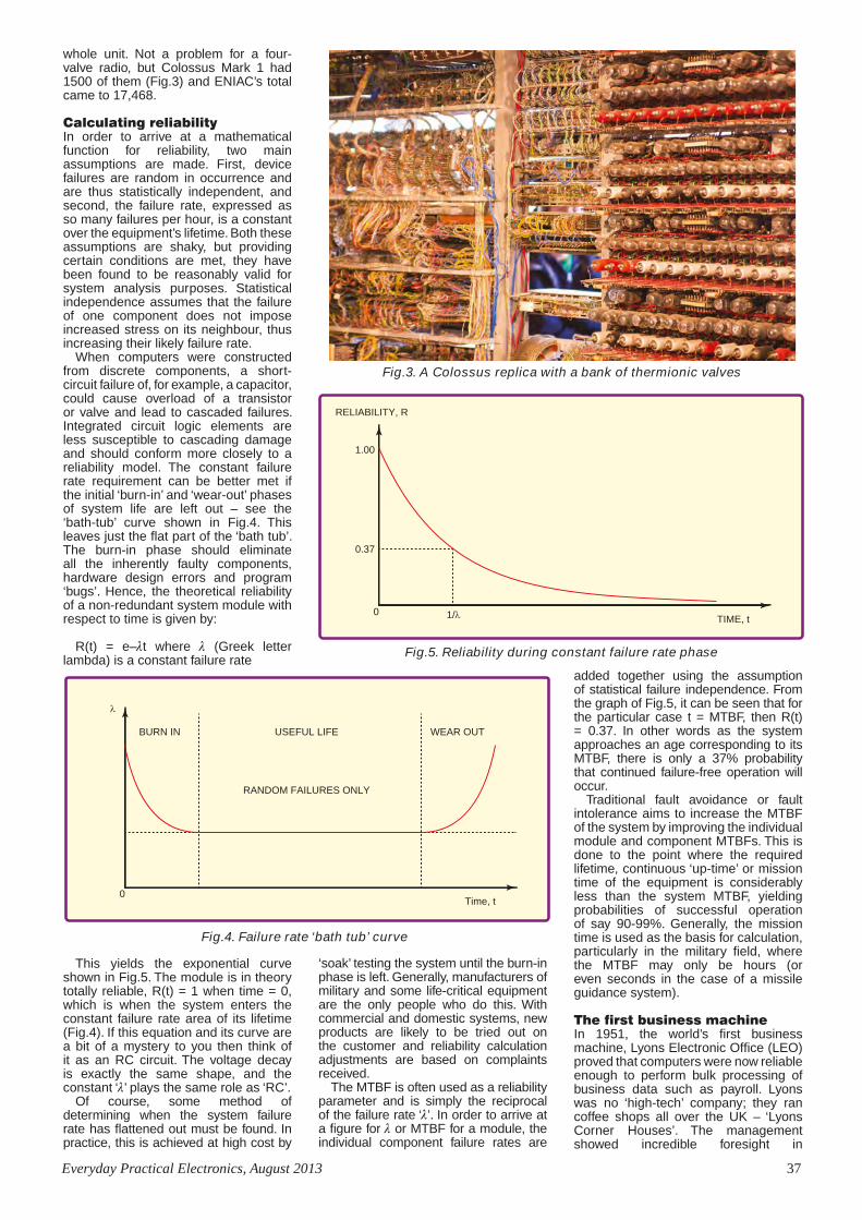
Everyday Practical Electronics, August 2013 37
whole unit. Not a problem for a four-valve radio, but Colossus Mark 1 had 1500 of them (Fig.3) and ENIAC’s total came to 17,468.
Calculating reliabilityIn order to arrive at a mathematical function for reliability, two main assumptions are made. First, device failures are random in occurrence and are thus statistically independent, and second, the failure rate, expressed as so many failures per hour, is a constant over the equipment’s lifetime. Both these assumptions are shaky, but providing certain conditions are met, they have been found to be reasonably valid for system analysis purposes. Statistical independence assumes that the failure of one component does not impose increased stress on its neighbour, thus increasing their likely failure rate.
When computers were constructed from discrete components, a short-circuit failure of, for example, a capacitor, could cause overload of a transistor or valve and lead to cascaded failures. Integrated circuit logic elements are less susceptible to cascading damage and should conform more closely to a reliability model. The constant failure rate requirement can be better met if the initial ‘burn-in’ and ‘wear-out’ phases of system life are left out – see the ‘bath-tub’ curve shown in Fig.4. This leaves just the flat part of the ‘bath tub’. The burn-in phase should eliminate all the inherently faulty components, hardware design errors and program ‘bugs’. Hence, the theoretical reliability of a non-redundant system module with respect to time is given by:
R(t) = e–t where (Greek letter lambda) is a constant failure rate
Fig.3. A Colossus replica with a bank of thermionic valves
FIG4 Reliability43mm x 1.5 COL
λ
Time, t0
BURN IN WEAR OUTUSEFUL LIFE
RANDOM FAILURES ONLY
Fig.4. Failure rate ‘bath tub’ curve
Fig.5. Reliability during constant failure rate phase
FIG5 Reliability43mm x 1.5 COL
RELIABILITY, R
TIME, t
0.37
1/λ
1.00
0
This yields the exponential curve shown in Fig.5. The module is in theory totally reliable, R(t) = 1 when time = 0, which is when the system enters the constant failure rate area of its lifetime (Fig.4). If this equation and its curve are a bit of a mystery to you then think of it as an RC circuit. The voltage decay is exactly the same shape, and the constant ‘’ plays the same role as ‘RC’.
Of course, some method of determining when the system failure rate has flattened out must be found. In practice, this is achieved at high cost by
‘soak’ testing the system until the burn-in phase is left. Generally, manufacturers of military and some life-critical equipment are the only people who do this. With commercial and domestic systems, new products are likely to be tried out on the customer and reliability calculation adjustments are based on complaints received.
The MTBF is often used as a reliability parameter and is simply the reciprocal of the failure rate ‘’. In order to arrive at a figure for or MTBF for a module, the individual component failure rates are
added together using the assumption of statistical failure independence. From the graph of Fig.5, it can be seen that for the particular case t = MTBF, then R(t) = 0.37. In other words as the system approaches an age corresponding to its MTBF, there is only a 37% probability that continued failure-free operation will occur.
Traditional fault avoidance or fault intolerance aims to increase the MTBF of the system by improving the individual module and component MTBFs. This is done to the point where the required lifetime, continuous ‘up-time’ or mission time of the equipment is considerably less than the system MTBF, yielding probabilities of successful operation of say 90-99%. Generally, the mission time is used as the basis for calculation, particularly in the military field, where the MTBF may only be hours (or even seconds in the case of a missile guidance system).
The first business machineIn 1951, the world’s first business machine, Lyons Electronic Office (LEO) proved that computers were now reliable enough to perform bulk processing of business data such as payroll. Lyons was no ‘high-tech’ company; they ran coffee shops all over the UK – ‘Lyons Corner Houses’. The management showed incredible foresight in
Computer Reliability V4.indd 37 17/06/2013 14:22:14

38 Everyday Practical Electronics, August 2013
recognising that the state-of-the-art electronic calculators being developed in Cambridge and Manchester universities could be re-designed as business machines. LEO 1 used 6000 valves with a failure rate at one point of 50 per week. To counter this, the Lyons engineers developed a useful daily procedure for these early machines to ensure that the computer would work all day without breaking down in the middle of an important ‘run’. It was crude, but effective: each morning, the machine was run for an interval with a higher-than-normal supply voltage. All the ‘weak’ valves that had been just about to fail usually did so during this period of increased stress. Duds were replaced, the supply voltage reduced to its normal level and the result was a day’s fault-free operation – most of the time.
Fault avoidant designThe design philosophy of early complex electronic equipment was one of fault
avoidance and this led to some basic rules for minimising the failure rate that still apply today:
• Eliminate redundancy and keep the component count as low as possible (Fewer things to go wrong).
• Use higher-rated components than strictly necessary. For example, when designing a 5V power supply use a 16V or higher decoupling electrolytic capacitor instead of the nominally safe 6.3V version.
• Similarly, use higher-temperature-rated components if available.
• Apply cooling to heat-generating components. Forced draught ventilation on valve-based computers greatly improved reliability. It also improved working conditions for the operators – the female personnel at Bletchley Park allegedly worked the machines in their underwear because of the heat!
A modern hazard is one of counterfeit components. This is becoming a major problem and something that can have a major impact on equipment reliability.
Early machines did break down frequently, but at least no lives were put at risk as a result of ‘computer error’, a term that was to become familiar to most people in the following decades. The transistor brought much improved reliability initially due to another pressing need for computer power, this time mobile in the form of the NASA Apollo rocket guidance and control computer used for the Moon-landing project.
Nowadays, the focus for engineers has moved from ‘fault avoidance’ to ‘fault tolerance’. It is obvious that sooner or later ‘things always go wrong’ – yet disaster must be avoided. In the next part of this series on computer reliability, we’ll look at how improving hardware technology made mobile, ‘real-time’ computing possible.
AGILENT E4407B Spectrum Analyser – 100HZ-26.5GHZ £6,500AGILENT E4402B Spectrum Analyser – 100HZ-3GHZ £3,500HP 3325A Synthesised Function Generator £250HP 3561A Dynamic Signal Analyser £800HP 3581A Wave Analyser – 15HZ-50KHZ £250HP 3585A Spectrum Analyser – 20HZ-40MHZ £995HP 53131A Universal Counter – 3GHZ £600HP 5361B Pulse/Microwave Counter – 26.5GHZ £1,500HP 54502A Digitising Scope 2ch – 400MHZ 400MS/S £295HP 54600B Oscilloscope – 100MHZ 20MS/S from £195HP 54615B Oscilloscope 2ch – 500MHZ 1GS/S £800HP 6030A PSU 0-200V 0-17A – 1000W £895HP 6032A PSU 0-60V 0-50A – 1000W £750HP 6622A PSU 0-20V 4A twice or 0-50v2a twice £350HP 6624A PSU 4 Outputs £350HP 6632B PSU 0-20V 0-5A £195HP 6644A PSU 0-60V 3.5A £400HP 6654A PSU 0-60V 0-9A £500HP 8341A Synthesised Sweep Generator – 10MHZ-20GHZ £2,000HP 8350B with 83592a Generator – 10MHZ-20GHZ £600HP 83731A Synthesised Signal Generator – 1-20GHZ £2,500HP 8484A Power Sensor – 0.01-18GHZ 3nW-10uW £125HP 8560A Spectrum Analyser synthesised – 50HZ -2.9GHZ £2,100HP 8560E Spectrum Analyser synthesised – 30HZ--2.9GHZ £2,500HP 8563A Spectrum Analyser synthesised – 9KHZ-22GHZ £2,995HP 8566A Spectrum Analyser – 100HZ-22GHZ £1,600HP 8662A RF Generator – 10KHZ-1280MHZ £1,000HP 8672A Signal Generator – 2-18GHZ £500HP 8673B Synthesised Signal Generator – 2-26GHZ £1,000HP 8970B Noise Figure Meter £995HP 33120A Function Generator – 100 microHZ-15MHZ £395MARCONI 2022E Synthesised AM/FM Sig Generator – 10KHZ-1.01GHZ £395MARCONI 2024 Synthesised Signal Generator – 9KHZ-2.4GHZ from £800MARCONI 2030 Synthesised Signal Generator – 10KHZ-1.35GHZ £950MARCONI 2305 Modulation Meter £250MARCONI 2440 Counter20GHZ £395MARCONI 2945 Comms Test Set various options £3,000
MARCONI 2955 Radio Comms Test Set £595MARCONI 2955A Radio Comms Test Set £725MARCONI 2955B Radio Comms Test Set £850MARCONI 6200 Microwave Test Set £2,600MARCONI 6200A Microwave Test Set – 10MHZ-20GHZ £3,000MARCONI 6200B Microwave Test Set £3,500IFR 6204B Microwave Test Set – 40GHZ £12,500MARCONI 6210 Reflection Analyser for 6200Test Sets £1,500MARCONI 6960B with 6910 Power Meter £295MARCONI TF2167 RF Amplifier – 50KHZ-80MHZ 10W £125TEKTRONIX TDS3012 Oscilloscope – 2ch 100MHZ 1.25GS/S £1,100TEKTRONIX TDS540 Oscilloscope – 4ch 500MHZ 1GS/S £600TEKTRONIX TDS620B Oscilloscope – 2+2ch 500MHZ 2.5GHZ £600TEKTRONIX TDS684A Oscilloscope – 4ch 1GHZ 5GS/S £2,000TEKTRONIX 2430A Oscilloscope Dual Trace – 150MHZ 100MS/S £350TEKTRONIX 2465B Oscilloscope – 4ch 400MHZ £600TEKTRONIX TFP2A Optical TDR £350R&S APN62 Synthesised Function Generator – 1HZ-260KHZ £225R&S DPSP RF Step Attenuator – 139db £400R&S SME Signal Generator – 5KHZ-1.5GHZ £500R&S SMK Sweep Signal Generator – 10MHZ-140MHZ £175R&S SMR40 Signal Generator – 10MHZ-40GHZ with options £13,000R&S SMT06 Signal Generator – 5KHZ-6GHZ £4,000R&S SW0B5 Polyscope – 0.1-1300MHZ £250CIRRUS CL254 Sound Level Meter with Calibrator £60FARNELL AP60/50 PSU 0-60V 0-50A 1KW Switch Mode £250FARNELL H60/50 PSU 0-60V 0-50A £500FARNELL B30/10 PSU 30V 10A Variable No meters £45FARNELL B30/20 PSU 30V 20A Variable No meters £75FARNELL XA35/2T PSU 0-35V 0-2A twice Digital £75FARNELL LF1 Sine/sq Oscillator – 10HZ-1MHZ £45
FARNELL XA35/2T PSU 0-35V 0-2A twice Digital £75FARNELL LF1 Sine/sq Oscillator 10HZ-1MHZ £45RACAL 1792 Receiver £250RACAL 1991 Counter/Timer 160MHZ 9 digit £150RACAL 2101 Counter20GHZ LED £350
SPECIAL OFFERS for full sales listcheck our website
STEWART OF READING17A King Street, Mortimer, Near Reading, RG7 3RSTelephone: 0118 933 1111• Fax: 0118 933 2375
9am – 5pm, Monday – FridayPlease check availability before ordering or CALLING IN
Used Equipment – GUARANTEEDAll items supplied as tested in our Lab
Prices plus Carriage and VAT
TO ADVERTISE IN EVERYDAY PRACTICAL ELECTRONICS
PLEASE CONTACT
Stewart Kearn on 01202 880299
or email [email protected]
Computer Reliability V4.indd 38 17/06/2013 14:22:27

Everyday Practical Electronics, August 2013 39
We can supply back issues of EPE by post, most issues from the past five years are available. An EPE index for the last five years is also available at www.epemag.com. Where we are unable to provide a back issue a photocopy of any one article (or one part of a series) can be purchased for the same price. Issues from Jan. 99 are available on CD-ROM or DVD-ROM – and back issues from recent years are also available to download from
www.epemag.com. Please make sure all components are still available before commencing any project from a back-dated issue.
BACK ISSUESDID YOU MISS THESE?
BACK ISSUES ONLY £5.00 (each inc. UK p&p.)
Overseas prices £5.80 each surface mail, £6.80 each airmail.We can also supply issues from years: 2006 (except Jan., Feb., Mar., Apr., May, July). 2007 (except June, July, Aug), 2008 (except Aug, Nov, Dec) 2009 (except Jan, Mar, Apr.).
2010 (except May, June, July, August, Oct, Nov, Dec) 2011 (except Jan). Where we do not have an issue a photocopy of any one article or one part of a series can be provided at the same price.
Theft Alarm
Peace of mind while you are on holiday
WIN A MICROCHIP CAN DEVELOPER’S KIT
Practically sPeaking, Pic n’ MiX, net work, circuit surgery, readout, techno talk
Get your monthly slice of Pi!This month’s hands-on project – A Real Time Clock
hard of hearing? let us help!start of a fascinating series on boosting hearing
What are loops?
hearing loop receiverpick up signals from a loop and drive headphones
amplifier designhistory of the telecoil
ultrasonic anti-fouling for boats – part 1save money on dry docking with our electronic barnacle blaster!!
Jump Start
sept 2012 £4.40
SEPTEMBER 2012 Cover.indd 1 16/07/2012 11:13:22
ORDER FORM – BACK ISSUES – PHOTOCOPIES– INDEXES
Send back issues dated. . . . . . . . . . . . . . . . . . . . . . . . . . . . . . . . . . . . . . . . . . . . . . . . . . . . . . . . . . . . . . . . . . . .
Send photocopies of (article title and issue date) . . . . . . . . . . . . . . . . . . . . . . . . . . . . . . . . . . . . . . . . . . . . . . . .
Name . . . . . . . . . . . . . . . . . . . . . . . . . . . . . . . . . . . . . . . . . . . . . . . . . . . . . . . . . . . . . . . . . . . . . . . . . . . . . . . . . . . . .
Address. . . . . . . . . . . . . . . . . . . . . . . . . . . . . . . . . . . . . . . . . . . . . . . . . . . . . . . . . . . . . . . . . . . . . . . . . . . . . . . . . . . .
. . . . . . . . . . . . . . . . . . . . . . . . . . . . . . . . . . . . . . . . . . . . . . Tel: . . . . . . . . . . . . . . . . . . . . . . . . . . . . . . . . . . . . . . . . . .
I enclose cheque/P.O./bank draft to the value of £ . . . . . . . . . . . .
Please charge my Visa/Mastercard/Maestro £ . . . . . . . . . . . . . . .
Card No . . . . . . . . . . . . . . . . . . . . . . . . . . . . . . . . . . . . . . . . . . . . . . . . . . . . Maestro Issue No . . . . . . . . . . . . . . . . . . . . .
Valid From . . . . . . . . . . . . . Card Expiry Date . . . . . . . . . . . . Card Security Code . . . . . . . . . . (The last 3 digits on or just under the signature strip)
SEND TO: Everyday Practical Electronics, Wimborne Publishing Ltd., 113 Lynwood Drive, Merley,
Wimborne, Dorset BH21 1UU.Tel: 01202 880299. Fax: 01202 843233.
E-mail: [email protected] On-line Shop: www.epemag.comPayments must be in £ sterling – cheque or bank draft drawn on a UK bank. Normally posted within seven days of
receipt of order. Send a copy of this form, or order by letter if you do not wish to cut your issue. M08/13
Spooky Circuits
Don’t let electronics scare you!!
WIN A MICROCHIP dsPICDEM SMPS BuCk BOARD
interface, Pic n’ MiX, net work, circuit Surgery, readout, techno talk
digital lighting controller – Start planning the beSt chriStmaS lighting diSplay in your Street!
hearing loop deSign and inStallation – part 2a survey of commercial equipment
ultraSonic anti-fouling for boatS – part 2installing our electronic barnacle blaster!!
• integrate music into your system• up to 32 lighting channels• easy to program, and includes remote control
Jump Start
oct 2012 £4.40
OCTOBER 2012 Cover.indd 1 22/08/2012 15:55:49
PROJECTS • Digital Insulation Meter • Dual Tracking ± 0V To 19V Power Supply – Part 1 • Low-Power Car/Bike USB Charger • Solar-Powered Lighting Controller – Part 2FEATURES • Jump Start – Quiz Machine • Techno Talk • Pico 2205 MSO PC oscilloscope • PIC N’ Mix • Circuit Surgery • Interface • Net Work.
PROJECTS • Lab-Standard 16-Bit Digital Potentiometer • Intelligent 12V Fan Controller • Dual Tracking ±0V To 19V Power Supply – Part 2 FEATURES • Jump Start – Battery Voltage Checker • Techno Talk • PIC N’ Mix • Circuit Surgery • Practically Speaking • Max’s Cool Beans • Net Work.
PROJECTS • Ultrasonic Cleaner • Electrolytic Capacitor Reformer and Tester – Part 1 • High-Performance Microphone Preamplifier • High-Power Reversible DC Motor Speed Controller FEATURES • Jump Start – Solar-Powered Charger • Raspberry Pi Review • Techno Talk • PIC N’ Mix • Circuit Surgery • Interface • Net Work.
PROJECTS • Designing And Installing A Hearing Loop For The Deaf • Hearing Loop Receiver • Ultrasonic Anti-Fouling For Boats – Part 1 • Electrolytic Capacitor Reformer and Tester – Part 2FEATURES • Jump Start – Versatile Theft Alarm • Raspberry Pi – Real-Time Clock • PIC N’ Mix • Circuit Surgery • Practically Speaking • Net Work.
PROJECTS • Two TOSLINK-S/PDIF Audio Converters • Digital Lighting Controller – Part 1 • Ultrasonic Anti-Fouling For Boats – Part 2 • Designing And Installing A Hearing Loop For The Deaf – Part 2 • Ingenuity UnlimitedFEATURES • Jump Start – Spooky Circuits • Techno Talk • Interface • Circuit Surgery • Max’s Cool Beans • Net Work
PROJECTS • Hearing Loop Level Meter – Part 1 • Digital Lighting Controller – Part 2 • RFID Security System • Easy USB plus Telescope Driver Control • Ingenuity UnlimitedFEATURES • Jump Start – Frost Alarm • Techno Talk • Review – Picoscope 3406B • Practically Speaking • Circuit Surgery • Max’s Cool Beans • Net Work
PROJECTS • Universal USB Data Logger – Part 1 • Hot-Wire Cutter • Digital Lighting Controller
– Part 3 • Hearing Loop Level Meter – Part 2 • Ingenuity UnlimitedFEATURES • Jump Start – Mini Christmas Lights • Techno Talk • PIC N’ Mix • Circuit Surgery • Interface • Max’s Cool Beans • Net Work
PROJECTS • 3-Input Stereo Audio Switcher • Stereo Compressor • Low Capacitance Adaptor For DMMs • Universal USB Data Logger – Part 2 FEATURES • Jump Start – iPod Speaker • Techno Talk • PIC N’ Mix • Raspberry Pi – Keypad and LCD Interface • Circuit Surgery • Practically Speaking • Max’s Cool Beans • Net Work
PROJECTS • Semtest – Part 1 • Crystal DAC • 10W LED Floodlight • Built-In Speakers • Universal USB Data Logger – Part 3FEATURES • Jump Start – Logic Probe • Techno Talk • PIC N’ Mix • Raspberry Pi – Software Investigation • Circuit Surgery • Interface • Max’s Cool Beans • Net Work
PROJECTS • Lightning Detector • SemTest – Part 2 • Digital Spirit Level • Interplanetary Voice • Ingenuity UnlimitedFEATURES • Jump Start – DC Motor Controller • Techno Talk • PIC N’ Mix • Raspberry Pi – Further Investigation • Circuit Surgery • Practically Speaking • Max’s Cool Beans • Net Work
PROJECTS • SoftStarter • 6-Decade Resistance Substitution Box • SemTest – Part 3FEATURES • Jump Start – Egg Timer • Techno Talk • PIC N’ Mix • Circuit Surgery • Interface • Max’s Cool Beans • Net Work
PROJECTS • Electronic Stethoscope • PIC/AVR Programming Adaptor Board – Part 1 • Cheap, High-Current Bench Supply • Ingenuity UnlimitedFEATURES • Jump Start – Signal Injector Probe • Techno Talk • Raspberry Pi • PIC N’ Mix • Circuit Surgery • Practically Speaking • Max’s Cool Beans • Net Work
PROJECTS • Mix-It • PIC/AVR Programming Adaptor Board – Part 2 • A Handy USB Breakout Box • Converter For Neon Lamp Experiments • Ingenuity UnlimitedFEATURES • Jump Start – Simple Radio Receiver • Techno Talk • PIC N’ Mix • Circuit Surgery • Interface • Max’s Cool Beans • Net Work
PROJECTS • 6-Decade Capacitance Substitution Box • Soft Starter For Power Tools • High Power Brushless Motors From Old CD/DVD Drives • High-Current Adaptor For Scopes And DMMsFEATURES • Jump Start – Temperature Alarm • Techno Talk • Circuit Surgery • Practically Speaking • Max’s Cool Beans • Net Work
JAN ’13
Digital insulation MeterCheck the safety of your mains equipment!
PLUS
Dual traCking ±0V to 19V Power suPPly – Part 1
interface, Pic n’ MiX, net work, circuit Surgery, readout, techno talk
Quiz Machine
More fun from our exciting new series for newcomers to electronics
solar-PowereD ligHting Controller – Part 2 using free power off grid to run lights
WIN ONE OF FIVE MICROCHIP MICROSTICK II HARDWARE PLATFORMS
• linear power supply delivers up to 1.6a• easy-to-read display of voltage and current • Voltage accuracy better than 1%• excellent load regulation, ripple and noise figures
Jump Start
June 2012 £4.40
JUNE 2012 Cover.indd 1 17/04/2012 16:05:58
PLUS
lab-standard 16-bit digital potentiometer
practically speaking, pic n’ MiX, net work, circuit surgery, readout, techno talk
Battery Voltage Checker
More fun from our exciting new series for newcomers to electronics
dual tracking ±0V to 19V power supply – part 2 assembling our high qualit y bench supply
WIN ONE OF THREE MICROCHIP PICDEM 2 PLUS BOARDS
• works with ac or dc • directly programmable via a keypad• 16-bit resolution, giving 65,535 steps• uses just 4.5w from a 12V supply
Jump Start
intelligent 12V fan controllercool things down this summer!
June 2012 £4.40
JULY 2012 Cover.indd 1 22/05/2012 12:46:46
Solar Powered Charger
More fun from our exciting new series for newcomers to electronics
WIN A MICROCHIP PICDEM PIC18 EXPLORER BOARD
Jump Start
ElEctrolytic capacitor rEformEr and tEstEr – part 1Bring old caps back from the dead!
+ =
HigH-pErformancE micropHonE prEamplifiErget the most from microphones with this low-noise project
Ultrasonic clEanEr• clean complex parts with the ultimate bubble bath • 19-42kHz operation with pic control• High-power ultrasonic transducer• Easy and safe to use
Another energy-saving project for you to build
iNTERFACE, PiC N’ MiX, NET woRk, CiRCuiT SuRgERy, REAdouT, TEChNo TAlk
Raspberry PiSpecial Hands-On Review
What is the Raspberry Pi?
aUgUst 2012 £4.40
AUGUST 2012 Cover.indd 1 19/06/2012 15:46:36
JUNE ’12
NOV ’12
JULY ’12
FEB ’13
AUg ’12
DEC ’12
MAR ’13
SEPT ’12
APR ’13
OCT ’12
MAY ’13
JUNE ’13
JULY ’13
Back Issues Mags.indd 39 17/06/2013 10:31:38

40 Everyday Practical Electronics, August 2013
Constructional Project Constructional Project
Build a VOX
Triggers devices on and off with sound
By JOHN CLARKE
Traditionally, VOX, or Voice-Activated Relay circuits toggle a transmitter on as you speak into a microphone and off again when there is silence. But VOX circuits can be used anywhere you want to turn something on when a sound occurs or you speak into a microphone. You could use it to switch a light, an amplifier or even unlock a door.
stands for Voice-Operated eXchange, and it is also the Lat-in word for ‘Voice’.
A VOX circuit switches on a relay whenever a signal reaches a set thresh-old. The relay switches off once the signal level drops below the threshold and after a short delay.
They are used in communications, public address systems, surveillance, security and also general purpose electronics.
For communications, a VOX switch-es a transceiver from receive to trans-mit whenever the person speaks into the microphone. This frees the opera-tor for other tasks, because a separate switch is not needed to talk. Many intercoms and public address systems are also automated in a similar way.
A VOX circuit can be used to mute any sound until it reaches a set level. That way, a public address system will ignore background noise and remain quiet, until someone intentionally speaks into a microphone. For secu-rity and surveillance, a recorder can be switched on whenever a noise is sensed by a microphone.
But it doesn’t have to be a micro-phone which causes the VOX action. For general-purpose use, any audio signal can be used to switch the relay.
Our designIn line with the above comments, our VOX design has two inputs, both of which will accept the same types of audio input. First is a stereo 3.5mm jack socket, which will handle both mono and stereo signals, while the
second input is for mono inputs only and is via screw terminals.
You can connect an electret or dynamic microphone. Electret micro-phones require a bias voltage, which can be selected with a jumper link (LK1). For stereo signals connected via the 3.5mm socket, a jumper link provides mixing of the left and right channels into a mono signal.
Signal sensitivity can be adjusted to cover a wide range from micro-phone levels up to line levels of 2V RMS. With sufficient signal, the relay switches on and remains on until the signal level drops to below a threshold level. An adjustable delay sets the time taken for the relay to switch off once this threshold is reached.
The relay has two sets of changeover contacts which will suit a variety of
VOX
VOX Relay July11 (FROM MP).indd 40 14/06/2013 10:41:43

Everyday Practical Electronics, August 2013 41
Constructional Project Constructional Project
switching applications. LEDs are in-cluded for visual indication of power and relay switching.
Because of the wide variety of pos-sible uses for a VOX, our module is simply presented as a PCB which you can install to suit your application. Or if you wish, it can be fitted into a plastic ‘UB3’ case measuring 130mm × 68mm × 44mm.
Circuit detailsThe VOX comprises a dual op amp (IC1) that functions as a signal ampli-fier and threshold switch. The relay is driven from the second op amp via a transistor.
Input signals come in via the 3.5mm jack socket (CON1) or via a 2-way screw terminal block (CON2). For the screw terminal input, one termi-nal is connected to ground while the other is applied to the amplifier stage via a 10kΩ resistor.
When an electret microphone is used, bias current is se-lected when link
LK1 is closed. The 10kΩ bias resistor is connected to a supply that is decou-pled from the 11.4V supply via a 1kΩ resistor and a 100μF capacitor. This decoupling prevents supply variations entering the input to the amplifier to cause false triggering.
If the electret microphone is con-nected via the stereo jack socket input, the electret is connected between the ground terminal (sleeve) and the tip of a mono jack plug. Again, link LK1 is inserted for electret power.
If an electret is not used and the signal is applied via the jack socket or screw terminals, the link (LK1) is left disconnected. Stereo signals can be connected via the stereo jack socket and the signal is mixed down to mono
using 10kΩ resistors for each channel. This stereo mixing occurs when link LK2 is inserted.
Dynamic microphones do not re-quire bias current; in fact, they should not be connected to a circuit providing electret bias, hence the reason for LK1.
A 100nF capacitor couples the mono signal to op amp IC1a. Its non-inverting input, pin 3, is biased from the decoupled supply via two 100kΩ resistors. This sets the amplifier output to swing symmetrically about a nomi-nal half-supply voltage. The half sup-ply will vary from about 5.3V to about 5.6V, depending on whether or not an electret microphone is connected.
Diodes D1 and D2 are included to clamp any signal to +0.6V above the
decoupled supply and –0.6V (ie, below the 0V rail). They protect the IC1 in-put if an excessive signal is applied.
IC1a is connected as a non-inverting amplifier with a gain of 2 when VR1 is set to zero ohms, and a gain of about 1000 when VR1 is set to
SpecificationsPower supply: .................. 12VDC at 50mATrigger sensitivity: ............ Adjustable from 2mV (microphone) to 2V (line) Maximum signal input: ..... 50V rmsSignal frequency range: ... 16Hz to >600HzAttack time: ..................... 10 cycles with signal at threshold voltage (faster attack if signal is above threshold)Hysteresis: ...................... 0.44V at the 2.06V thresholdDelay time: ...................... Adjustable from 100ms to 10sElectret bias current: ........ ~320μARelay contacts (DPDT): ..... 5A (maximum of 50V recommended)
Features• 12V operation• Electret or dynamic microphone, or line input• 3.5mm jack socket or screw terminal inputs• Mono or stereo signal• Adjustable sensitivity• Adjustable delay• Hysteresis prevents relay chattering at threshold• DPDT relay• Power and relay LED indication
This VOX is quite a versatile beast! It can be used in practically any application which requires triggering from a sound source – and that sound source can be just about anything, including you!
VOX Relay July11 (FROM MP).indd 41 14/06/2013 10:41:56

42 Everyday Practical Electronics, August 2013
Constructional Project Constructional Project
its maximum. The actual gain when VR1 is set to a high value is depend-ent upon the signal frequency and the open-loop gain of the LM358 op amp.
The 47pF capacitor is included to provide a steep roll-off at high frequen-cies, to ensure IC1 does not oscillate. However, it is the open-loop gain of the amplifier that sets the bandwidth. For example, at a gain setting of 100 (when VR1 is 99kΩ), the roll-off caused by the 47pF capacitor is about 34kHz.
Roll-off due to the open-loop gain is at around 6kHz. With VR1 set for a gain of 1000, the 47pF rolls off frequencies above about 3.4kHz. But the open-loop gain begins to roll off beyond about 600Hz.
Low frequency roll-off is set at about 16Hz. This is due to the 1kΩ resistor and 10μF capacitor connected in series with the inverting input.
The output signal from op amp IC1a is fed to a rectifier involving diodes D3 and D4, to convert the AC signal to a DC voltage. As pin 1 swings above its rest-ing position of 5.7V, the 10μF capacitor discharges via diode D4 into the 100μF capacitor at D4’s cathode. When pin 1 swings below 5.7V, the 10μF capacitor discharges via D3. The 100μF capaci-tor then charges with repetitive pulses provided by the 10μF capacitor.
Op amp IC1b is connected as a Schmitt trigger comparator, with the inverting input at pin 6 tied to a voltage divider comprising a 10kΩ and 2.2kΩ
10k 100 F16V
2 x 10kCON1
CON2
100nF
47pF
1kVR1 1M
10 F
1k
D11N4148
D21N4148
100k
100k
1k
100nF 10 F16V
100 10 F
NP
D31N4148
D4 1N4148
100 F
LED1POWER
4.7k
10k
47k
1M
1k 2.2k 100nF
VR2100k
100 F16V
10k
10k
D5 1N4004
D61N40044.7k
LED2RELAY
RLY1
CON5
CON4Q1
BC337
CON3+12V
0V
A
A
A
A
A
AA
A
K
KK
K
K
KK
K
LK1LK2
3.5mmJACK SOCKET
ALTERNATIVEELECTRET OR
SIGNAL INPUT
+
LK1: ELECTRET BIASLK2: STEREO
+11.4V
CB
E
12
3
4
5
67
8
NC
NC
COM
COM
NO
NO
AMPLIFIER
SENSITIVITY
DELAYAC SIGNAL TO DCCONVERTER (RECTIFIER)
SCHMITT TRIGGER RELAY DRIVER
2011SC VOICE ACTIVATED RELAY
IC1aIC1aIC1bIC1b
IC1: LM358
KAKA
LEDS
A
K
CE
B
BC337
1N4148 1N4004
100 F16V
VOX
01207111
1k10
k
4.7k
D4
D3
CON5
CON4
Q1
D1
D2
D5
D6
10k
10k
100k
100k
1k
1k 100
10k
10k
10k
2.2k
47k
1k
1M
4.7k
100nF
47pF
100n
F
100n
F10 F
10 F
100 F
100 FLED1
LED2
100 F
100 F
10 F
LK2
LK1
4148
4148
4148
4148
4004
4004
CO
N3
CO
N2
VR2100kVR2100k
VR11MVR11M
CON1CON1
RELAY1RELAY1IC1
LM35
8IC
1LM
358
A
K
A
K
NP
+12V
0V
GND
SIG IN
NO
NO
NC
NC
VOX
1k10
k
4.7k
D4
D3
CON5
CON4
Q1
D1
D2
D5
D6
10k
10k
100k
100k
1k
1k 100
10k
10k
10k
2.2k
47k
1k
1M
4.7k
100nF
47pF
100n
F
100n
F10 F
10 F
100 F
100 FLED1
LED2
100 F
100 F
10 F
LK2
LK1
4148
4148
4148
4148
4004
4004
CO
N3
CO
N2
VR2100kVR2100k
VR11MVR11M
CON1CON1
RELAY1RELAY1IC1
LM35
8IC
1LM
358
A
K
A
K
NP
+12V
0V
GND
SIG IN
NO
NO
COM
NC
NC
COM
Fig.1: complete circuit diagram of the VOX, or Voice Activated Relay. It’s all based on one IC, an LM358, which performs the dual function of signal amplifier and comparator/schmitt trigger. A handful of other components completes the circuit.
Fig.2: everything mounts on one PCB, shown here in both diagram and photo form. The only thing ‘missing’ from the PCB is the microphone which must be mounted off the board, otherwise it will ‘hear’ the relay pulling in and releasing, and more than likely trigger in error. It can be mounted on a short pair of wires if you wish, or as far away as necessary using a shielded microphone cable.
VOICE ACTIVATED RELAY
VOX Relay July11 (FROM MP).indd 42 14/06/2013 10:42:19

Everyday Practical Electronics, August 2013 43
Constructional Project Constructional Project
10k 100 F16V
2 x 10kCON1
CON2
100nF
47pF
1kVR1 1M
10 F
1k
D11N4148
D21N4148
100k
100k
1k
100nF 10 F16V
100 10 F
NP
D31N4148
D4 1N4148
100 F
LED1POWER
4.7k
10k
47k
1M
1k 2.2k 100nF
VR2100k
100 F16V
10k
10k
D5 1N4004
D61N40044.7k
LED2RELAY
RLY1
CON5
CON4Q1
BC337
CON3+12V
0V
A
A
A
A
A
AA
A
K
KK
K
K
KK
K
LK1LK2
3.5mmJACK SOCKET
ALTERNATIVEELECTRET OR
SIGNAL INPUT
+
LK1: ELECTRET BIASLK2: STEREO
+11.4V
CB
E
12
3
4
5
67
8
NC
NC
COM
COM
NO
NO
AMPLIFIER
SENSITIVITY
DELAYAC SIGNAL TO DCCONVERTER (RECTIFIER)
SCHMITT TRIGGER RELAY DRIVER
2011SC VOICE ACTIVATED RELAY
IC1aIC1aIC1bIC1b
IC1: LM358
KAKA
LEDS
A
K
CE
B
BC337
1N4148 1N4004
100 F16V
resistor across the 11.4V supply. Pin 6 sits at about 2.06V and is bypassed with a 100nF capacitor.
IC1b’s non-inverting input, pin 5, monitors the voltage across the 100μF capacitor via a 47kΩ resistor. When the 100μF capacitor voltage is below pin 6, IC1b’s output at pin 7 is low; close to 0V. When the capacitor volt-age rises above pin 6, pin 7 will go high to about +10V. So, provided the AC signal fed to the rectifier is enough to produce more than 2V across the 100μF capacitor, pin 7 of IC1b will go high and this will turn on transistor Q1 and the associated relay.
Now, one of the problems with a trigger circuit like IC1b is that it will not switch cleanly from high to low, since a very slight change in the volt-age across the 100μF capacitor could mean that it switches back and forth very rapidly. This would result in the relay chattering, ie, switching on and off very rapidly.
We fix this by adding hysteresis to the circuit, by including the 1MΩ resistor between pin 5 and 7. What now happens is that when the out-put switches high, it also pulls pin 5 slightly higher, 0.35V higher than the 100μF capacitor voltage. This means that the capacitor has to discharge by this amount before IC1b will go low again. This stops the relay chatter.
The 100μF capacitor is continu-ally discharged via VR2 and the 1kΩ
1 PCB, code 01207111, available from the EPE PCB Service, size, 106mm × 61mm
1 DPDT 12V relay, 5A contacts (RLY1)1 3.5mm PCB-mount stereo socket (CON1)2 2-way PCB-mount screw terminals with 5.08mm pin spacing (CON2,CON3)2 3-way PCB-mount screw terminals with 5.08mm pin spacing (CON4,CON5)1 electret microphone insert (MIC1) (if required – see text)11MΩ horizontal mount trimpot (code 105) (VR1)1100kΩ horizontal mount trimpot (code 104) (VR2)2 2-way pin headers with 2.54mm pin spacing (LK1,LK2)2 2.54mm jumper shunts4 M3 tapped spacers (optional)4 M3 × 6mm screws (optional)1 length of hookup wire or single cored shielded cable
Semiconductors1 LM358N dual op amp (IC1)1 BC337 NPN transistor (Q1)4 1N4148 switching diode (D1-D4)2 1N4004 1A diodes (D5,D6)2 3mm red LEDs, 1 red and 1 green (LED1,LED2)
Capacitors3 100μF 16V electrolytic1 10μF Non Polarised (NP) electrolytic2 10μF 16V electrolytic3 100nF MKT polyester1 47pF ceramic
Resistors (0.25W 1%)1 1MΩ 2 100kΩ1 47kΩ 6 10kΩ2 4.7kΩ 1 2.2kΩ4 1kΩ 1 100Ω
Parts List – VOX
resistor. So if the signal from IC1a is not continuously replenishing the 100μF capacitor, the voltage will drop in level. VR2 sets the delay period from when IC1b is triggered high to when its output goes low in the absence of signal from IC1a.
The VOX runs from a 12V supply; diode D5 is included for reverse polar-ity protection. LED1 indicates when power is present.
ConstructionThe VOX is assembled on a PCB, code 01207111 and measuring 106mm × 61mm. This PCB is available from the EPE PCB Service. All of the compo-nents are mounted on the PCB, apart from the microphone, which must not be – it needs to be off the board so that it does not attempt to retrigger
the circuit whenever it ‘hears’ the relay switch off.
The PCB is sized to clip into the integral side slots of a UB3 utility box measuring 130mm × 68mm × 44mm. If you are using this box, make sure the left edge of the PCB is shaped to the correct outline so it fits into the box, clearing the internal corner pillars. That way, the 3.5mm socket can pass through the end of the box. It can be filed to shape if necessary, using the PCB outline shape as a guide.
Begin construction by checking the PCB for breaks in tracks or shorts between tracks or pads. Repair if necessary. Check hole sizes for the components and for the corner mount-ing holes.
Assembly can begin by inserting the resistors. When doing this, use a digi-
Reproduced by arrangement with SILICON CHIP
magazine 2013.www.siliconchip.com.au
VOX Relay July11 (FROM MP).indd 43 14/06/2013 10:42:19

44 Everyday Practical Electronics, August 2013
Constructional Project Constructional Project
tal multimeter to measure each value. Next come the diodes, remembering these must be mounted with the ori-entation shown. There are two types of diodes; D1 to D4 are the smaller 1N4148 types, while D5 and D6 are the larger 1N4004 devices.
IC1 can be soldered directly into the PCB (or you can use a DIP8 socket if you wish). When installing the IC (and socket), take care to orient them correctly. Orientation is with the notch positioned as shown.
Capacitors can be mounted next. The electrolytics must be oriented with the shown polarity except for the NP (non-polarised) type that can mount either way.
Mount the transistors and trimpots VR1 and VR2. VR1 is the 1MΩ trimpot and could be marked with its value or with the coding 105. VR2, the 100kΩ pot could be marked as 104.
LED1 and LED2 are mounted about 5mm above the PCB. The anode is the longer lead and is placed in the uppermost hole.
The 2-way pin headers for LK1 and LK2 can be mounted now, followed by the 3.5mm socket, the relay and the screw terminals. CON1 and CON2 are 2-way terminals that are first attached by sliding the dovetail sections of each together. Similarly for the CON3 and CON4 terminals, these are slid together before being mounted on the PCB. Make sure the wire entry side faces the outside of the PCB.
We mounted the PCB on four 6mm-long tapped spacers, held in place with M3 × 6mm screws, but this is entirely up to you and your application.
If your project is using an electret microphone, this should be mounted so that it does not touch the PCB and is connected via multi-strand hookup wire for short (less than 30mm) leads. Use single-core shielded cable for longer runs. The shield wire connects to the GND terminal (for the 3.5mm jack plug, the GND is the sleeve). Signal connects to the second screw terminal for the screw terminal input or the tip connection of the 3.5mm jack plug.
For a signal input other than a mi-crophone, apply the signal to either the screw terminals or via a 3.5mm jack plug. One channel connects to the tip terminal and the other channel to the ring terminal.
Link selection depends on wheth-er you are using an electret or dynamic microphone, or a mono or stereo signal connection. LK1 should be linked only when the electret microphone is used, and removed for a dynamic mic.
LK2 should have a jumper link for a stereo signal. You wouldn’t normally have both LK1 and LK2 in position at once, but there are stereo electret microphones around, so it is possible you’ll use this combination (although why you’d want to use one in this ap-plication is a bit beyond us!).
Apply 12V power and adjust VR1 so that the relay triggers at the re-quired signal level. Similarly, adjust VR2 so that the relay switches off after the desired time period. The delay should be as short as possible, but not so short that it drops out while speaking.
If the Voice-Activated Relay does not work, first check your soldering to make sure there are no dry joints, solder bridges or dags.
If the visual inspection looks OK, check voltages on the circuit. There should be about 11.4V between pins 4 and 8 of IC1. Pin 3 of IC1 should be around 5.7V to 5.3V. Pin 6 of IC1b should be at about 2V.
Incorrect voltages may be because of incorrect resistor values or a short- or open-circuit connection. Check that LED 1 lights. The output of IC2 at pin 7 should be near 0V when no signal is applied (or when no sound is detected by the microphone).
With sufficient signal applied, the pin 7 output should go to around 10V, the relay should switch on and LED2 should light. The relay should switch off after the preset time period when there is no signal.
Is 9V operation feasible?We know we will be asked this ques-tion! Some constructors may wish to use the VOX as a stand-alone device – so here’s the answer!
‘No’, operation from 9V would be quite unreliable, especially if the bat-tery is a bit flat. And the 50mA current draw would put the battery in that state pretty quickly!
Most of the circuit would be fine at 9V, but the 12V relay would not be at all happy (if indeed it worked at all). Substituting a 5V relay may be an op-tion, with a resistor in series with the coil, but it may not be possible to get one which fits the PCB without modifi-cation. EPE
Another view of the VOX PCB showing in detail the input and power sockets. It can be driven from an electret microphone (as shown here), a dynamic microphone (with bias link LK1 left open) or indeed from virtually any audio source from 2mV (microphone level) right up to 2V (higher than most line levels). The sensitivity pot (closest to the input sockets) can be adjusted to cater for this range. The other pot (closest to the relay) adjusts the length of time the relay stays closed once it is triggered.
VOX Relay July11 (FROM MP).indd 44 14/06/2013 10:42:28

Everyday Practical Electronics, August 2013 45
UK readers you can SAVE 94p on every issue of EPE
How would you like to pay £3.46 instead of £4.40 for your copy of EPE ?
Logic Probe – beginners’ project!
WIN A MICROCHIP mTouch Projected Capacitive Development Kit
Raspberry PiSoftware Investigation
SemTeST – ParT 1• Our best-ever discrete semiconductor tester
• Check diodes, BJTs, MOSFETs and much more• PIC-controlled with an LCD display
Jump Start
crySTaL daceLeganT uPgrade for our STereo dac ProJecT
10W Led fLoodLighTrivaLS incandeScenT SySTemS aT a fracTion of The PoWer LeveLS
FEB 2013 £4.40
FEB 13 Cover.indd 1 17/12/2012 16:18:19
iPod Speaker Easy-to-build, low-cost and portable
WIN A MICROCHIP MPLAB REAL ICE probe kitRRP £315
Raspberry PiDisplay and keypad interface
StEREO COMPRESSORReduces dynamic sound levels for comfortable listening
lOw-CaPaCitanCE adaPtOR fOR dMMs
3-inPut StEREO audiO SwitChERadd extra analogue inputs for your stereo or home theatre
• Measure to sub-picofarad capacitance values• works with standard digital multimeters• Probe for detecting stray capacitance
Jump Start
Jan 2013 £4.40
JAN 13 Cover.indd 1 21/11/2012 14:45:01
Packed with special features for electronics hobbyists everywhere!
Mini Christmas Lights Easy-to-build decorations for the festive period
WIN A MICROCHIP PIC32 USBSTARTER KIT 2
interface, net work, circuit Surgery, readout, techno talk the return of........
unIVerSAL uSB DAtA LoGGer – PArt 1
hot-wIre cutterPrecision, clean-cutting tool for polystyrene
• read from analogue and digital inputs• Store data on SD card• uSB interface• Pc user program supplied
PIc n’ Mix
Jump Start
Dec 2012 £4.40
DECEMBER 2012 Cover.indd 1 17/10/2012 14:56:12
Well you can – just take out a one year subscription and save 94p an issue, or £11.28 over the year.You can even save £1.15 an issue if you subscribe for two years – a total saving of £27.60.
Overseas rates also represent exceptional value.You also: •Avoidanycoverpriceincreaseforthedurationofyoursubscription •Getyourmagazinedeliveredtoyourdooreachmonth •Ensureyourcopy,evenifthenewsagentssellout
Orderbyphoneorfaxwithacreditcardorbypostwithachequeorpostalorder,orbuyonlinefromwww.epemag.com(gototheOnlineShop).
SUBSCRIPTION PRICESSubscriptions for delivery direct to any address in the UK: 6 months £21.95, 12 months £41.50, two years £78.00; Overseas: 6 months £25.00 standard air service or £35.00 express airmail, 12 months £48.00 standard air service or £68.00 express airmail, 24 months £91.00 standard air service or £131.00 express airmail.
Cheques or bank drafts (in £ sterling only) payable to Everyday Practical Electronics and sent to EPE Subs. Dept., Wimborne Publishing Ltd., 113 Lynwood Drive, Merley, Wimborne, Dorset, BH21 1UU. Tel: 01202 880299. Fax: 01202 843233. Email: [email protected]. Also via the Web at: www.epemag.com.
Subscriptions start with the next available issue. We accept MasterCard, Maestro or Visa. (For past issues see the Back Issues page.)
ONLINE SUBSCRIPTIONSOnline subscriptions, for reading the magazine via the Internet, £19.99 for one year, visit www.epemag.com for more details.
SUBSCRIPTION ORDER FORM
6 Months: UK £21.95, Overseas £25.00 (standard air service), £35.00 (express airmail)
1 Year: UK £41.50, Overseas £48.00 (standard air service) £68.00 (express airmail)
2 Years: UK £78.00, Overseas £91.00 (standard air service) £131.00 (express airmail)
To: Everyday Practical Electronics,Wimborne Publishing Ltd., 113 Lynwood Drive, Merley,
Wimborne, Dorset BH21 1UUTel: 01202 880299 Fax: 01202 843233
E-mail: [email protected]
I enclose payment of £ .............. (cheque/PO in £ sterling only), payable to Everyday Practical Electronics
Please charge my Visa/Mastercard/Maestro
My card number is: .......................................................................Please print clearly, and check that you have the number correct
Signature ......................................................................................
Card Security Code .................. Valid From Date........................(The last 3 digits on or just under the signature strip)
Card Ex. Date ...................................Maestro Issue No. ..............
Name ............................................................................................
Address ........................................................................................
Post code .................................. Tel. ...........................................
Subscriptions can only start with the next available issue.
PRICE FREEZE!!
BUY NOW!
Subs page.indd 45 14/06/2013 11:21:48

46 Everyday Practical Electronics, August 2013
A high-quality home amplifier using a mix of salvaged parts and prebuilt modules
By Julian Edgar
In the February 2013 issue of EPE we showed you how to build speakers into your house. In that article, I installed two 15-inch woofers beneath the
floor and two 8-inch two-way speakers in the walls. The question now is, ‘how to drive them?’
I decided to build my own four-channel amplifier to do the job. The end result cost very little (in terms of quality amplifiers, anyway) and was easy to put together. It makes extensive use of low-cost, prebuilt electronics modules now available through online sources such as eBay.
FIG1 EDGAR AMP120mm x 2 COL
BASS SPEAKERS TWO-WAY SPEAKERS
SPEAKERPROTECTION(C)
BASSCROSSOVER(B)
STEREOAMPLIFIERMODULES
RECTIFIER/FILTERMODULE (G)
TOROIDALTRANSFORMER(N)
INPUT
+–
SPEAKERPROTECTION(C)
STEREOAMPLIFIERMODULES
RECTIFIER/FILTERMODULE (G)
TOROIDALTRANSFORMER(N)
INPUT
+–
FAN (H)
TEMPERATURECONTROLLER(M)
TRANSFORMER(I)
INPUTPOWERSOCKETAND FUSE
POWERFILTER (K)
POWERSWITCH(A)
As presented, the design requires that you use it with an input source having its own volume control (for example, an MP3 player) or with a complete standalone pre-amp. I use a pre-amp – a Clarion EQS746 car unit run from a plug-pack. The Clarion is an excellent pre-amp, available at low cost, and makes driving the four inputs from a single stereo audio source very easy.
Note that the amplifier design shown here is not cutting-edge in terms of audiophile, high-end equipment, but it’s easily good enough for most applications.
The main parts are shown in the schematic in Fig.1 and the finished amplifier with the lid off in Fig.2.
Amplifier modulesThe amplifier modules are based around prebuilt LM3886 modules. Each is capable of 68W into 4Ω at a maximum distortion of 0.1 per cent. They have on-board terminal connections for line-level inputs and speaker level outputs. For best results, they require a power supply of at least ±28V at maximum load, while at the same time not exceeding ±42V under no load conditions.
Superb Four-channel Amplifier – on the cheap!
2
1
Fig.1 Block diagram of the amplifier
Julian Edgar - AMP.indd 46 17/06/2013 14:28:25

Everyday Practical Electronics, August 2013 47
• Front panel (eBay – new)• IEC power socket, fuse and filter (salvaged from other
equipment)
I then added:• Digital temp controller displaying heat sink temp (eBay
– new)• Dual cooling fans switched by a temperature controller
(the fans salvaged from other equipment)• Four-channel speaker protection (eBay – two prebuilt
boards)• Internally mounted crossovers for the low frequency
speakers• Blue LED 12V lighting bar
To run the above accessories, I chose to add another power supply comprising a transformer and rectifier/filter board salvaged from other equipment – that kept the power supply for the accessories quite separate to the two powering the audio section.
I chose not to use input sockets, instead using four 30cm-long flying leads terminated in RCA plugs.
ConclusionDriving my underfloor 15-inch bass speakers and 8-inch in-wall two-way speakers, the amp develops plenty of clean power. With these relatively efficient speakers, I’d never want it any louder, and distortion at full noise isn’t audible to my ears.
The amplifier can be driven at maximum listening volume for hour after hour – the design copes with this just fine. Even with 30°C ambient temperature, the cooling fans cycle on and off only about every five minutes, the heatsink temperature never exceeding 43°C. At lower listening levels, or in cooler temperatures, the fans do not operate at all.
To be completely honest with you, I am amazed at how good it sounds.
ComponentsRefer to Fig.3, which details the component parts of the amplifier.
The amplifier modules are available prebuilt on eBay from about £15 to £25 – I used four. Similar modules are available from various advertisers, as are most of the other parts.
Power supplyTo feed the amplifier modules, I used prebuilt power supplies, each comprising a bridge rectifier and 4 × 10,000µF capacitors. Each power supply board can run a pair of amplifier modules.
These power modules are available prebuilt on eBay from about £20 – I used two.
TransformerTwo toroidal transformers were used. Each is rated at 160VA and has a 230V primary and 25V + 25V secondaries. When running the power supply modules (one transformer for each power supply), the measured voltage at the amplifier modules at maximum audio load was ±29V, with ±39V off-load – excellent.
Heat sinkA huge heat sink was sourced second-hand from eBay for just £10. It was cut down a little and then bolted to a thick aluminium plate on which the four amplifier modules were mounted. The plate gave a flat surface on which to mount the ICs.
The buildTo build a working stereo amplifier (two channels), all you need are:
• Two amplifier modules (prebuilt)• Power supply module (prebuilt)• Transformer
You can see that it’s easy to have an amplifier working on a breadboard very shortly after unpacking the parts.
However, in additional to running four channels, I chose to be more elaborate. I added:
• Mains switch (salvaged from other equipment)• Box (a rack-mount, triple-height unit salvaged from
another amplifier)
3
Julian Edgar - AMP.indd 47 17/06/2013 14:28:41

48 Everyday Practical Electronics, August 2013
A – Power switch with inbuilt neon indicator; salvaged from other equipment.B – Crossovers for the underfloor bass speakers. There was room to put them in the amplifier box, so why not? (See Fig.4)
C – Speaker output terminals. These mount directly to the speaker protection modules – available prebuilt on eBay. (See Fig.5 and Fig.9)
L – Second cooling fan, mounted in the clear plastic lid of the enclosure. Both fans are 24V designs run at 12V to slow and quieten them (see Fig.12).M – LED temperature display and programmable controller. This monitors heat sink temperature and operates the fans as required. Controller and remote probe available very cheaply on eBay. (See Fig.11)
I – 12V transformer (see Fig.10) running the speaker protection boards (See Fig.9), temperature monitoring, cooling fans and LED lighting.
7
8
9
10
11
4
5
6
D – Huge heat sink, bolted to a thick aluminium plate. Heat sink sourced second-hand online. (See Fig.6)
E – Four LM3886 prebuilt modules, each developing 68W per channel at low distortion.F – Power supply rectifiers – these were added as the original rectifiers, mounted on the prebuilt boards, were rather small and were not easily connected to heat sinks. (See Fig.7)G – Power supply boards, one per pair of amplifier modules. H – Small cooling fan, mounted on the end of the heat sink. This fan and its enclosure were salvaged from other equipment. (See Fig.8)
J – Rectifier and filter board for 12V transformer. This and the 12V transformer were savaged from other equipment. (See Fig.10)K – Large mains filter, salvaged from other equipment.
N – Two 160VA 25V + 25V transformers, one per power supply module. One transformer was bought new and the other salvaged from an old self-built amplifier.O – Blue LED light bar mounted under front lip. Just a bit of fun! (See Fig.12)
Purchasing adviceThis is not a conventional project, where we can supply a precise list of parts and suppliers. Think of it as inspiration for you to quickly assemble your own amp in a very short space of time with minimum soldering. Most of the parts are available from regular component suppliers (see the advertisements in this issue) or via eBay. The following are eBay suggestions, not absolute instructions to be followed blindly.
Amplifier modules and filter/rectifier boardThis refers to items E and G. Do an eBay search under ‘LM3886’, for example, eBay numbers:
Julian Edgar - AMP.indd 48 17/06/2013 14:28:52

Everyday Practical Electronics, August 2013 49
12
190788648441300679956341280903318494
Speaker protection modulesThis refers to item C. Do an eBay search under ‘UPC1237’, for example eBay number:
251150792983
Temperature controller and displayThis refers to item M. Do an eBay search under ‘digital temperature controller’. Note these are available in either mains or 12V versions. For example, eBay numbers:
171017965477281092800140
Subwoofer filtersThis refers to item B. Do an eBay search under ‘subwoofer filter’, for example, eBay numbers:
190826771244281063054458 EPE
TO ADVERTISE IN EVERYDAY PRACTICAL ELECTRONICS
PLEASE CONTACT
Stewart Kearn on
01202 880299or email [email protected]
Julian Edgar - AMP.indd 49 17/06/2013 14:29:09

50 Everyday Practical Electronics, August 2013
Matt Pulzer addresses some of the general points readers have raised. Have you anything interesting to say?Drop us a line!
WIN AN ATLAS LCR ANALYSER WORTH £79An Atlas LCR Passive Component Analyser, kindly donated by Peak Electronic Design
Ltd, will be awarded to the author of the Letter Of The Month. The Atlas LCR
automatically measures inductance from 1mH to 10H, capacitance from 1pF to 10,000F
and resistance from 1 to 2M with a basic accuracy of 1%. www.peakelec.co.uk
READOUTAll letters quoted here have previously been replied to directly Email: [email protected]
L E T T E R O F T H E M O N T H Organic neons
Dear editorJohn Ellis’ article on neon bulbs as circuit components (June 2013) calls to mind my time as a schoolboy tinkerer in the ‘70s. I was fascinated with the electronic generation of music, and although the enthusiast magazines of the time had designs for synthesisers and the like, making one was beyond my means.
I used to haunt the local organ shop (can you believe there were such things then?) on demonstration evenings, and one day found an old five-octave keyboard being chucked out (I guess it was some kind of part-exchange). I carted it home and checked it over. The circuit board had 12 sections, each comprising a tuneable master oscillator and a chain of octave dividers, all made from neon bulbs! The dividers had to be ‘tuned’ too – they were also based on relaxation oscillators, being pumped from the previous stage and trimmed
to cascade every two input pulses. Filters took the harsh edges off the waveforms, and switches selected the combination of octaves used in the final output (giving some control of the voicing).
There were two mystery components missing from the power supply, but that didn’t seem to matter. I managed to trim and tweak everything into alignment and had a functioning electronic organ, with each key pressing multiple gold-plated spring wires into contact with the output bus bars, although the background bee-hive buzz was a bit obtrusive. It gave me many hours of pleasure, even if it did bite – there was no casing, the chassis stood on corner pillars with the PCB exposed beneath the keyboard assembly (health and safety? what health and safety!). The flickering neon light was clearly visible underneath. One day, a misplaced hand got a shock from the DC HT rail, and left me with a white burn for some time.
Eventually, I got around to looking at the missing PSU components. It turned out they should have been neon regulator tubes, each one presumably about 90V, two in series to produce a 180V rail. I managed to get some from somewhere, and of course when fitted, all the oscillators and dividers had to be recalibrated to the correct HT voltage. This leads me to wonder what voltage the unregulated rail was, and what voltage DC shock I got!
Ken Wood, by email
Matt Pulzer replies:
Great story Ken; it’s remarkable how when we are young – and have the most to loose – we are so cavalier around HT circuits! I remember getting the odd ‘nip’ from uncased circuits that were unfortunate enough to be the object of my enquiring mind. Nevertheless, to all readers young and old – please be careful around anything over 50V. Shocks can hurt, burn and worse.
10 to the power ooops!
Dear editorI think there is an error in the calculations in Jump Start (page 42) of the April 2013 issue. I think that:
R = ton / 1.1 × 470 x 10–6 = ton / 517 × 10–6
is correct.
However, the next line should read:
= 1934 × ton × 10–3 not 1.934 × ton × 10–3
I hope I have made this clear.
Ken Barry, by email
Matt Pulzer replies:
Well spotted Ken! While I basically agree with your analysis, I think the er-ror lies in the index. The line should read:
1.934 × ton × 103… Not 1.934 × ton × 10–3…
Then the rest of the line makes more sense as the erroneous 10–3 is replaced with ‘k’ for kilo.
Electronic issues of EPE
Dear editorI have been a subscriber to EPE for many years now. In fact, I took both the original magazines (Everyday Electronics and Practical Electronics) prior to the introduction of the combined magazine. I used to buy Practical Electronics in my schooldays in the late 1960s and I am now 64!
I have supported you and your predecessors very well during my lifetime, and in return you have provided me with a mine of information to make my hobby as enjoyable as it is. I took most of the other UK electronic journals as well – Electronics Today, Hobby Electronics, Radio & Electronics Constructor and I still have every edition of Elektor here at home – all 434 issues. I have also kept many other titles.
As you can imagine, my attic flooring is beginning to feel the strain and I need to take steps to sort these magazines out before they become totally unmanageable. I am currently only taking EPE and Elektor, and my subscription for the latter gives me an annual CD of all the magazine
contents, but I am also able to download these each month in PDF format for three months after the publishing date at no extra cost. This means that my Elektor magazines do not need to pile up in my den as the months go by; they sit on my hard drive instead. Have you ever thought of offering this service to your own subscribers? I appreciate that we get a discount for paying for a year in advance, but should I wish to buy the electronic version six months down the line I have to pay the same for them as non-subscribers. Would you consider setting up a special deal for subscribers like me to have the electronic format of our printed versions for free or at a much-reduced cost?
I am currently paying for one year’s worth of issues when I renew my subscription but would happily pay for two if you could generate a special deal for the electronic version for subscribers as well.
For your information, my main interest is in all things PIC related. My hero and mentor was the late John Becker, to whom I owe a tremendous debt of gratitude. Thank goodness Mike
Readout - New layout v2.indd 50 14/06/2013 15:14:06

Everyday Practical Electronics, August 2013 51
WIN AN ATLAS LCR ANALYSER WORTH £79An Atlas LCR Passive Component Analyser, kindly donated by Peak Electronic Design
Ltd, will be awarded to the author of the Letter Of The Month. The Atlas LCR
automatically measures inductance from 1mH to 10H, capacitance from 1pF to 10,000F
and resistance from 1 to 2M with a basic accuracy of 1%. www.peakelec.co.uk
Email: [email protected]
Hibbett has taken up the baton with his excellent PIC n’ Mix articles, he has a tough act to follow after JB, but he is succeeding.
I hope that Mike will have me learning the appropriate variant of C in the not too distant future. I am a die-hard assembler programmer with several quite complicated (and working!) projects under my belt, one of which was completed with John Becker’s personal help outside the magazine.
I am now starting to use Microchip’s MPLAB, alongside Mike Hibbett’s current PIC n’ Mix articles. I have a collection of PIC Programmers, some of which are your own designs, as well as PICKit 2 and my newly acquired MPLAB ICD 3 programmer. There have been so many ways of doing things over recent years, but I am now trying to bring myself up-to-date at long last. It will aid my latest specialist project, which I hope to market one day soon.
Keep up the good work at EPE, you are all doing a grand job there and I very much look forward to receiving my copy in the post each month. PICs are still my favourite devices, so do not be coerced by some of those on Chat Zone to go down the road of Arduino and Atmel; your competitors do enough with those devices already.
John Pugh, via email
Matt Pulzer replies:
Thank you very much for such a posi-tive letter. We are constantly review-ing how we sell EPE, and your sug-gestions will definitely be thrown into the mix. Ultimately, this is a decision for Wimborne Publishing, and your suggestions have been passed on to them.
We all miss John Becker and his excellent projects. But you are right, Mike Hibbett is a worthy successor. We will always be a Microchip PIC-based magazine, but might dip the odd toe in Arduino waters from time to time! Plus, for those who are more software oriented, Raspberry Pi is a wonderful (British) platform.
Power-soldering follow up
Dear editorYou may recall that a short while ago I wrote to you requesting information in regards to soldering tips and their suitability for use with my Toolcraft ST80-D Digital Soldering Station, to which Alan Winstanley very kindly sent me a list of Toolcraft Tips that he gathered from the Conrad website.
Unfortunately, there does not appear to be any tips large enough for my needs. Keeping that in mind, I’ve had a go with my son-in-law’s soldering iron which has a bevelled 5mm wide tip. This sized tip appeared to be very suitable for me when soldering switches and contacts within an old popcorn
machine. That is the type of work I want it for, large jobs, not PCB work.
Can I obtain a 4mm or 5mm tip from another manufacturer, and if so, how can I tell if it will fit and be suitable?
Graham Beland, via email
Alan Winstanley replies:
I understand the problem and I’m surprised that a larger bit diameter isn’t available for an 80W iron. 3.2mm is suitable for larger PCB or electronics work, but for large electrical joints containing a lot of metal, you need something probably twice that size or more. Soldering iron stations are really dedicated to precision benchtop electronics or production work rather than larger ‘electrical’ or DIY repairs.
I tried to solder the heavy wires of a lead-acid battery into my PC’s uninterruptible power supplies, and even using a 100W solder gun it was nearly impossible to get sufficient heat to make a proper job of it. There is also the risk of damaging the surrounding materials or PCB substrate due to excess heat.
I would avoid experimenting with other brands of bit though, as the tip must be matched both physically and thermally to the soldering station itself. Being a ‘bit stuck’, I asked John Tomkies of Antex Electronics for advice. Antex manufactures soldering irons and stations in the UK and they agreed that a larger tip having more mass is necessary for larger-scale work. They offer a 6mm bit (Part 1103) for their own stations, but that’s the largest they do. Antex suggested that the best way would be to have a simpler, fixed output higher-power iron.
I have seen 100W irons on sale (ebay, item no. 360651705450) under the Silverline brand with four bits of various shapes including, bent, chisel and screwdriver available. Rarely would an electronics hobbyist need one, but they are cheap and cheerful and probably more suited to general purpose DIY and electrical work. Perhaps you might have better luck with one of those.
…and a helpful reply from a reader:
Dear editorI read about the issues with the Toolcraft ST80-D 80W soldering station from Conrad Electronics.
The accessories you have listed are correct, but what Graham Beland wants to know is what the numbers are. If you visit the following website, www.Soldering-iron-tips.com and look at the top of the page, you will see pull-down tabs and there look for the name ‘Hakko’. These are the 900M solder tips.
I hope this is of help.
Brian Clark, Germany
Imaginethis...
Readout - New layout v2.indd 51 14/06/2013 15:19:44

52 Everyday Practical Electronics, November 2012
In my previous column we introduced the concept of electromagnetic radiation (EM radiation or EMR) and noted that the force carrier for EMR is a massless par-ticle called a photon. We also discussed the fact that if a photon with a frequency less than that of ultraviolet light interacts with an atom, it doesn’t contain suffi-cient energy to strip an electron away from the atom, so this is referred to as ‘non-ionising radiation.’ By comparison, if the photon has a frequency in the range of ultraviolet or higher, it can impart enough energy to strip away an electron from an atom or molecule, thereby leaving a positive ion. Thus, this is referred to as ‘ionising radiation.’
Particles and cosmic raysAnother form of radiation comes in the form of particles – primarily electrons (also known as beta particles, sym-bol = β). Then there ia alpha radiation, consisting of he-lium nuclei (also known as alpha particles, symbol = α).
Max’s Cool Beans
By Max The Magnificent
52 Everyday Practical Electronics, August 2013
The most energetic ultra-high-energy cosmic rays (UHECRs) have been observed to approach ~40 mil-lion times the energy of particles accelerated by the Large Hadron Collider (LHC). The highest-energy cosmic rays observed thus far have energies compa-rable to the kinetic energy of a baseball travelling at 90-kilometers-per-hour (56 mph). When a primary cosmic ray hits the Earth’s atmosphere, it may pro-duce showers of secondary particles that penetrate the atmosphere and sometimes even reach the surface of the planet.
The main point of all this is that if a particle is travel-ling with sufficient speed (has sufficient energy), then when it interacts with another atom or molecule it too can act as ionising radiation and can cause all sorts of undesirable effects. We will discuss these effects – es-pecially in the context of electronic components – in more detail in my next column, but first...
Particles, or waves, or particles?It's easy to get hung up thinking of particles and waves as being two different things, but the world is a very strange place when we get down to the level of indi-vidual atoms. This is something I still find difficult to wrap my own brain around, so let’s see if I can convey just how strange it is.
Suppose we were to drop a pebble in the middle of a pond. We would observe ripples in the form of a se-ries of concentric circles spreading out from the point where the pebble entered the water. Now suppose that we simultaneously dropped two pebbles into the pond a few feet apart from each other. Both would generate ripples, which would boost each other up in some places and cancel each other out in others – the result being referred to as an ‘interference pattern.’
The same effect can be achieved if a single pebble is dropped into a pond close to a wall with two gaps (or slits) in it. The ripples generated by the pebble will pass through both of the gaps and the two new sets of ripples will interfere with each other
The same thing happens if we shine a light source at a "wall" with two slits in it (the slits need to be very close together) – that is, we see an interference pattern on the other side. From this we might deduce that electromagnetic radiation in the form of photons is wavelike in nature (as discussed in my previous column). But wait, there's more...
Now, suppose we control the light source such that we send only individual photons at a time. If we aggregate the results over a large number of these individual photons, we see the same interference patterns. This means that each photon is passing through both slits and interfering with itself!
Now, this is where things start to get really strange, because if we place a detector on the near-side of the "wall" so that we can "watch" the photons as they pass through the slits, then each photon only goes through one of the slits or the other, and the interference patterns disappear. From this we might conclude that photons are actually particles.
Now, we might be tempted to just shake our heads and say something like "Photons, huh? What can you say? They're massless entities so we shouldn’t be too surprised if they behave a little strangely." The problem is that we can perform the same experiment with electrons, which do have mass, and they do the same thing. Even worse, we can do this with entire atoms and even molecules, and we see the same effects – if we don’t use a detector to see which slit they pass through, we see interference patterns, which means (a) they act like waves (which is pretty strange) and (b) they go through both slits and interfere with themselves (which is really strange). If we do use a detector, then they only pass through one slit or the other and they act like particles. My head hurts!
Next Month… In part three of this gripping tale, we will consider how radiation can affect electronic components and systems and the ways in which we can create our designs to mitigate against these effects. Until then – have a good one!
Stew – feel free to accept/reject any of the images shown in this article – your choice – having said this, I might be tempted to go with the ones that accompany the discussions of particles vs. waves in the last section (of course it would be great if we could include small versions of all of them :-)
Maybe this month we could stretch to 1.5 pages? Alternatively, you can chop out the part highlighted in yellow without affecting the flow in any way (although I would prefer to keep it for the "wow" factor).
--------------------------------------------------------------------
Max's Cool Beans
In my previous column we introduced the concept of electromagnetic radiation (EM radiation or EMR) and noted that the force carrier for EMR is a massless particle called a photon. We also discussed the fact that if a photon with a frequency less than that of ultraviolet light interacts with an atom, it doesn’t contain sufficient energy to strip an electron away from the atom, so this is referred to as "non-ionizing radiation." By comparison, if the photon has a frequency in the ultraviolet or higher, it can impart enough energy to strip away an electron from an atom or molecule, thereby leaving a positive ion. Thus, this is referred to as "ionizing radiation."
Particles and Cosmic Rays Another form of radiation comes in the form of particles – primarily electrons (also known as beta particles, symbol = ), protons, neutrons, and atomic nuclei. These atomic nuclei range from helium nuclei (also known as alpha particles, symbol = ) to heavier ions.
It's also common to hear the term "Cosmic Rays." In fact, use of ray in this context is an historical accident, as cosmic rays were at first, and wrongly, thought to be mostly electromagnetic radiation in the form of X-rays and gamma rays. Cosmic rays are, in fact, very high-energy particles, mainly originating outside the Solar System from cosmic events such as supernova.
Of primary cosmic rays, which originate outside of Earth's atmosphere, about 99% are the nuclei (stripped of their electron shells) of well-known atoms, while about 1% are solitary electrons (similar to beta particles). Of the nuclei, about 90% are simple protons (i.e., hydrogen nuclei), 9% are alpha particles, and 1% are the nuclei of heavier elements. (A very small fraction comprises stable particles of antimatter, such as positrons or antiprotons.)
It’s also common to hear the term ‘cosmic rays’. In fact, the use of ‘ray’ in this context is a historical acci-dent, as cosmic rays were at first, and wrongly, thought to be mostly electromagnetic radiation in the form of X-rays and gamma rays. Cosmic rays are, in fact, very high-energy particles, mainly originating outside the solar system from cosmic events such as a supernova.
Of primary cosmic rays, which originate outside of Earth's atmosphere, about 99% are the nuclei (stripped of their electron shells) of well-known atoms, while about 1% are solitary electrons (similar to beta particles). Of the nuclei, about 90% are simple protons (ie, hydrogen nuclei), 9% are alpha particles, and 1% are the nuclei of heavier elements. (A very small fraction comprises stable particles of antimatter, such as positrons or antiprotons.)
Stew – you could include a pic of a supernova [like the one on the left] and/or a depiction of cosmic rays [like the pic on the right])
The most energetic ultra-high-energy cosmic rays (UHECRs) have been observed to approach ~40 million times the energy of particles accelerated by the Large Hadron Collider (LHC). The highest-energy cosmic rays observed thus far have energies comparable to the kinetic energy of a baseball travelling at 90-kilometers-per-hour (56 mph). When a primary cosmic ray hits the Earth's atmosphere, it may produce showers of secondary particles that penetrate the atmosphere and sometimes even reach the surface of the planet.
The main point of all this is that if a particle is travelling with sufficient speed (has sufficient energy), then when it interacts with another atom or molecule it too can act as ionizing radiation and can cause all sorts of undesirable effects. We will discuss these effects – especially in the context of electronic components – in more detail in my next column, but first...
Particles, or Waves, or Particles? It's easy to get hung up thinking of particles and waves as being two different things, but the world is a very strange place when we get down to the level of individual atoms. This is something I still find it difficult to wrap my own brain around, so let's see if I can convey just how strange it is.
Suppose we were to drop a pebble in the middle of a pond. In this case we would observe ripples in the form of a series of concentric circles spreading out from the point where the pebble entered the water. Now suppose that we simultaneously dropped two pebbles into the pond a few feet apart from each other. Both would generate ripples, which would boost each other up in some places and cancel each other out in others – the result being referred to as an "interference pattern."
The same effect can be achieved if a single pebble is dropped into a pond close to a wall with two gaps (or slits) in it. The ripples generated by the pebble stone will pass through both of the gaps and the two new sets of ripples will interfere with each other.
The same thing happens if we shine a light source at a ‘wall’ with two slits in it (the slits need to be very close together) – that is, we see an interference pattern on the
(2 × +ve)
Blog - JULY 2013.indd 52 14/06/2013 15:31:48

other side. From this we might deduce that electromag-netic radiation in the form of photons is wavelike in na-ture (as discussed in my previous column). But wait, there’s more...
Now, suppose we control the light source such that we send only individual photons at a time. If we aggre-gate the results over a large number of these individual photons, we see the same interference patterns. This means that each photon is passing through both slits and interfering with itself!
Now, this is where things start to get really strange, because if we place a detector on the near-side of the ‘wall’ so that we can ‘watch’ the photons as they pass through the slits, then each photon only goes through one of the slits or the other, and the interference patterns disappear. From this we might conclude that photons are actually particles.
Now, we might be tempted to just shake our heads and say something like ‘Photons, huh? What can you say? They're massless entities so we shouldn’t be too surprised if they behave a little strangely.’ The problem is that we can perform the same experiment with elec-trons, which do have mass, and they do the same thing. Even worse, we can do this with entire atoms and even molecules, and we see the same effects – if we don’t use a detector to see which slit they pass through, we see interference patterns, which means (a) they act like waves (which is pretty strange) and (b) they go through
both slits and interfere with themselves (which is really strange). If we do use a detector, then they only pass through one slit or the other and they act like particles. My head hurts!
Next month…In part three of this gripping tale, we will consider how radiation can affect electronic components and systems and the ways in which we can create our de-signs to mitigate against these effects. Until then – have a good one!
Everyday Practical Electronics, August 2013 53
Blog - JULY 2013.indd 53 14/06/2013 15:26:43

54 Everyday Practical Electronics, August 2013
By Robert Penfold
Try some Raspberry Pithat can be used for youngsters and oth-ers to learn about computer program-ming and simple interfacing/electronic projects. It is sold by Farnell and RS, but there are resellers that buy in bulk from these sources and sell on to end users. The resellers often bundle the basic unit with various essential accessories.
The basic Raspberry Pi unit is just a small computer board that has vari-ous ports (Fig.1 and Fig.2). Although it looks a bit like the various microcon-troller development boards that are available, it is not based on a micro-controller. It uses a BCM2835 system on a chip (SoC), which is an ARM pro-cessor, graphics processor, and some memory on a single chip. This chip is used in many mobile phones, but in the current context it is used to pro-vide what could be regarded as a very simple PC motherboard.
There are two versions of the Rasp-berry Pi, called the Model A and Mod-el B. The Model A board is the more basic of the two, and although the Model A is a bit cheaper, the Model B is probably the better choice for most users. Originally there was only 256MB of on-board memory, but the more recent Raspberry Pi boards usu-ally have 512MB. The board I have is a 512MB Model B, and the description that follows is for this version of the board.
The Model B board costs around 30 GB pounds, and I have seen them sell for less than 20 pounds on a certain well-known auction site. This repre-sents very good value for money, but
As explained in many previous articles in this series, interfac-ing your own electronic gadgets
to a PC has become more difficult over the years. PC hardware and program-ming languages are not really pro-duced with this type of thing high up on the list of priorities. In fact, DIY in-terfacing is probably not on the list of priorities at all, and there is no genu-inely simple and straightforward way of using a PC to do something as basic as controlling a few relays or reading data from sensors.
Microcontrollers provide an alterna-tive approach to things, but not eve-ryone is a fan of this method, and it is not really in the same category as using a home computer or PC as the basis for electronic projects. There is nothing currently available that pro-vides facilities that are even vaguely comparable to old favourites such as the BBC Model B or Commodore 64 home computers, or the PCs of yes-teryear with their built-in parallel and serial ports.
Back to basicsWhile there are no current computers that are truly in the BBC Model B or early PC category, there is a computer of sorts that is in some ways comparable. It is rapidly gaining in popularity, and is also acquiring a lot of commercial sup-port. It was designed by the Raspberry Pi Foundation, which is a charity, and they named it ‘Raspberry Pi’. The pri-mary aim of this UK-based organisation is to provide an inexpensive computer
it has to be borne in mind that several other items are required in order to produce a working Raspberry Pi com-puter. Fortunately, these extras are fairly cheap to buy, and you might al-ready have some of them.
Ins and outsThere are two USB ports (one on the Model A board), and these would nor-mally be used with a standard USB keyboard and mouse of the type used with PCs. I had no problems using an old Microsoft mouse from a defunct PC and a new Logitec keyboard that came with a PC, but was never used with it. It is possible to use more than two USB devices, but only with the aid of a USB hub. In some cases a powered hub might be needed in or-der to provide the USB devices with sufficient power.
On the audio/visual side of things there are composite video, stereo sound, and HDMI outputs. The audio signal is obtained via a 3.5mm stereo jack socket, and there is an RCA (pho-no) socket for the composite video output. The composite video signal cannot handle high resolution graph-ics, so where possible it is better to use the digital HDMI output. I found that this worked quite well with a 19-inch portable TV, but text was a bit small and blurred due to the limitations of the TV.
There is no ordinary (analogue) VGA output on the Raspberry Pi board, but the HDMI output can drive the DVI input of a suitable computer monitor
Fig.1. There are two USB ports and an Ethernet port on the right. The miniature USB connector in the bottom left corner of the board is for the 5V power supply and is not a USB port
Fig.2. The board has composite video and audio outputs (the phono and miniature jack sockets). For high quality video the HDMI connector is the better option
Interface.indd 54 14/06/2013 15:49:12

Everyday Practical Electronics, August 2013 55
via the appropriate cable. I found that this gave much better results than a small TV. Although the HDMI output can handle sound and video signals, a monitor will not necessarily imple-ment sound via its DVI input. It might be necessary to couple the sound out-put of the Raspberry Pi to the audio input of the monitor in order to use the monitor’s built-in speakers.
Lacking driveThere is no provision for connecting a hard disc drive. I suppose it would be possible to connect a portable USB hard drive to one of the USB ports, and a USB FLASH drive could also be used. However, it is not possible to boot from any form of USB drive. There is a slot for SD memory cards, and the card fitted here effectively becomes the boot drive. Matters are something less than straightforward here, because it is not possible to in-stall an operating system using con-ventional means, and only a limited range of operating systems are avail-able for the Raspberry Pi.
Some special versions of Linux are compatible, and the most popular one is a version of Debian Linux called Raspian or Raspian Wheezy. A PC or Mac fitted with an SD card reader is needed to make a bootable SD card for the Raspberry Pi. It is not just a matter of downloading the image file onto the SD card. The downloaded image file must first be copied to the computer’s hard disc drive. It is then copied to the SD card using a special program in or-der to produce a bootable card. Like the operating systems themselves, the necessary program is available as a free download. The bootable image is preconfigured to suit the Raspberry Pi board and typical peripherals, but it is necessary to do a certain amount of re-configuring when the unit is used for the first time (Fig.3).
The smallest capacity to take the operating system is 2GB (gigabytes),
but this does not leave much stor-age space for any additional pro-grams or data. With the current low cost of SD cards it is sensi-ble to regard 4GB as the practical minimum size. A 2GB partition is created when the boot image file is installed on the SD card, which will leave any extra storage space unusable. However, the unused storage space can be configured for use once the sys-tem is up and running. It is even pos-sible to expand the 2GB boot partition to use the extra capacity of the card.
Getting connectedIt is possible to download software us-ing another computer, transfer it to the SD card, and then install it. However, this method is a bit cumbersome, and installing software can be more diffi-cult with Linux than with most other operating systems such as Windows. There are built-in facilities for auto-matically downloading and installing software, and for automatically updat-ing software, but obviously it is nec-essary to have the system connected to the Internet in order to use these. Therefore, if at all possible, an Internet connection should be implemented.
Some methods of connecting to the Internet are probably not possible, and my normal method of using a broad-band dongle proved to be impractical with the Raspberry Pi. There is simply no software driver support for special-ised hardware such as this. However, the board is fitted with a standard Eth-ernet socket that can be used to pro-vide an Internet connection via a suit-
able broadband router/modem.
Power struggleThe board has a micro USB port, but this is not for use with USB peripher-als. It is really a power port that is used to provide the unit with a 5V stabi-lised supply. The mains adapters sup-plied with some mobile phones and other electronic gadgets are suitable, but if necessary this type of supply unit can be bought quite cheaply. The Raspberry Pi board requires a maxi-mum of 700mA, but any USB gadgets or other devices that are powered from the unit will obviously boost the cur-rent drain. It is therefore advisable to use a supply that can provide around 1A to 1.5A.
User portAlthough it is not called a user port, the Raspberry Pi has a 26-way con-nector that is effectively a modern version of the user port found on the BBC Model B and some other home PCs of that era. It is termed the GPIO (general-purpose input/output) port, and it provides a number of digital in-puts and outputs plus two supply out-puts. The pin functions for this port are shown in Fig.4.
The +5V output can provide a maxi-mum current that is equal to the cur-rent rating of the mains adapter minus the 700mA drawn by the computer itself, and any current drawn by USB peripherals. A maximum current of 50mA can be drawn from the 3.3V out-put. The board runs from a 3.3V sup-ply, and the practical importance of this is that the input/output pins run at this lower level rather than normal 5V logic levels. This could produce problems when driving some types of 5V logic device. Of more importance, driving GPIO inputs from 5V logic out-puts is not recommended, and could damage the hardware. Where appro-priate, the inputs should be driven via a suitable buffer/level converter.
Up to 16mA can be drawn from outputs, but in practice it may be necessary to use a much lower out-put current. This is simply due to the high total output current if a number of outputs provide the full 16mA. In
Fig.4. A limited but useful range of ports are provided on the Raspberry Pi board. From the DIY interfacing point of view, it is the 26-way GPIO port that is of primary interest
Fig.3. This configuration program runs when Raspian is run for the first time. Having set parameters such as the correct key-board layout, the system is ready for use
Interface.indd 55 14/06/2013 15:49:21

56 Everyday Practical Electronics, August 2013
practical applications it is likely that the output currents will be quite low, but where appropriate, it is advisable to drive loads via buffer stages.
Each GPIO pin can be pro-grammed to operate as an input or an output. This factor, together with the generous number of input/output pins, gives great scope for interfacing your own gadgets to the GPIO port. Many of the input/out-put pins are assigned special func-tions, such as the data input and output lines of a UART (universal asynchronous receiver/transmit-ter) for serial communication, and a PWM (pulse width modulation) output.
Some of these facilities, if pro-vided with suitable support in pro-gramming languages, could be very useful. For most DIY interfacing though, they are not relevant. For-tunately, it seems that these special functions can be ignored and all the GPIO pins are available for use as normal digital inputs or outputs. There are 1kΩ pull-up resistors on pin 3 and pin 5 (GPIO 2 and GPIO 3), but this should not be a signifi-cant hindrance when using these
lines as general-purpose input/output lines. There are further input/output lines available on the 8-way connector next to the GPIO port. However, the board does not come with a connec-tor actually fitted here, and with the GPIO port in use it is likely that any connector that was fitted here would be inaccessible. This additional port is probably of limited practical value.
ProgrammingThere are various ways of program-ming and using the lines of the GPIO port. Python is a popular program-ming language for computers that run under Linux, and there is a Python add-on that provides support for the GPIO port. Both Python and the add-on are free downloads incidentally. As Python is an interpreted program-ming language it is not fast by modern standards. On the other hand, the di-rect mode of an interpreted language is ideal for experimenting with com-puter interfacing, and it can also make it easier to sort out problems when a project does not go according to plan. Anyway, programming the Raspberry Pi GPIO port to do something useful will be covered in a future Interface article.
Fig.5. The GPIO pin functions for a revision 2 board. Although many of the input/output pins have special functions, they can still be used as general purpose input/output (GP10) lines
ELECTRONICS TEACH-IN 4 FREE
CD-ROMWORTH£29.95
BASE MANUAL
www.epemag.co.uk
© Wimborne Publishing Ltd. 2011
This CD-ROM requires
Adobe® Reader™
Downloadable Free from
www.adobe.com
This software should autorun,
if not, open in Windows
Explorer and double-click
index.pd
f
FROM THE PUBLISHERS OF
£8.99
FREE
CD-R
OM
A BROAD-BASED
INTRODuCTION TO ELECTRONICS
i An eleven part tutorial
i uses inexpensive circuit
simulation software
FREE
CD-ROM
THE MODERN ELECTRONICS MANuAL
The essential reference
work for everyone
studying electronics
i Over 800 PDF pages
i In-depth theory
i Extensive data tables
and web links
Teach In 4 Cover.indd 1
14/11/2011 20:33:21
ONLY
£8.99!
The Teach-In 4 book covers three of the most important electronics units that are currently studied in many schools and colleges. These include, Edexcel BTEC level 2
awards and the electronics units of the new Diploma in Engineering, Level 2.
The Free cover-mounted CD-ROM contains the full Modern Electronics Manual, worth £29.95.
The Manual contains over 800 pages of electronics theory, projects, data, assembly instructions and web links.
A package of exceptional value that will appeal to all those interested in learning about electronics or brushing up on their theory, be they hobbyists, students or professionals.
Order from Direct Book Service and get it delivered direct to your door:
Tel: 01202 880299
ELECTRONICSTEACH-IN 4A broad-based Introduction to Electronics plus
FREE CD-ROM
Interface.indd 56 14/06/2013 15:49:31

Everyday Practical Electronics, August 2013 57
Dataslicing and Manchester coding
Circuit SurgeryRegular Clinic by Ian Bell
Recently, EPE Chat Zone cont-ributor lincoln posted a question
about using Manchester coding on a PIC.
I’m trying to implement a wireless link with a master PIC and a few slave PICs, each with its own address. They’ll only be turning on and off various things, not sending more than a byte or two of data plus a header, address and eventually checksum. Also, I’m doing it in assembly and want to understand it fully. Most of the Internet posters of such code don’t explain their code in enough detail that I really get it, so I’m hoping for elaboration here.
I had tried writing a program myself, but have stalled on the following question:
Manchester Encoding’s advantage as an encoding system is that it uses transitions between a hi/lo signal stream to describe a ‘1’ or a ‘0’. A change from low to high (ie, no signal received to signal received) being a ‘1’ and vice versa. If that is the case, what hardware is used to detect a high going or low going pulse? Do you use one of the PIC’s interrupt pins that can be set to recognise such a change or do you, as I suspect, just wait until it’s actually transitioned and then measure the final state at clock cycle intervals?
If the latter is true, then surely the advantage of using the transition is lost?
The question is really about how to write the relevant PIC code, so we will not be addressing it directly here. Another contributor, alexr, posted a link which will hopefully provide lincoln with sufficient coding ideas to progress. Alexr wrote:
Take a look at this app. note from Atmel www.atmel.com/images/doc 9164.pdf. Even though it’s written for AVR chips and gives an example of the coding in C, it does give a clear explanation of the steps needed for both coding and decoding Manchester code and should be easily adapted to your PIC.
The forum discussion also addressed the issue of why Manchester coding might be needed, with zeitghost pointing out the requirement for a
dataslicer when processing signals from a wireless data link, and that Manchester coding might be helpful in this context. Therefore, thought that dataslicing would be an interesting topic for a Circuit Surgery article, as it provides some circuit-orientated background to lincoln’s programming problem and highlights why it might be necessary to use Manchester coding for a wireless data link.
We will look at the idea of dataslicing in general and provide some realistic context in the form of the MAX1471 315MHz/434MHz CMOS data receiver from Maxim Integrated (maximintegrated.com). The MAX1471’s datasheet specifically mentions use of Man-chester coding.
Wireless transmissionAs already indicated, the circumstances we are interested in here is wireless transmission of digital data, which differs significantly from sending data over short-wired connections. Similar issues may occur for data storage and recovery using magnetic media such a tapes, and for transmission via long-wired connections, particularly if capacitors or transformer are used to couple signals to or from the interconnection.
There are a couple of key problems which must be dealt with in such scenarios. First, the transmitter’s clock, which was used to time the data transmission (ie, set the duration of individual bits), is not directly available at the receiver. Thus, the receiver must synchronise its own internal timing to the received data. This is often referred to as clock recovery. The other problem is that the received data is an analogue signal without fixed signal levels. It must be correctly converted to a digital signal, with fixed 0 and 1 levels, to fully recover the transmitted data stream. We will discuss this in more detail shortly.
For the receiver to obtain and maintain synchronisation requires that the data signal changes, otherwise there are no events in the signal to synchronise to. If data is transmitted ‘as is’, then a long sequence of 1’s or 0’s will provide no synchronisation points and the receiver’s timing may drift off.
Manchester coding addresses the clock recovery problem by ensuring that a logic transition occurs during every data bit, at the mid-point of that bit’s time period. For example, a logic 1 in the data is represented as a transition from 0 to 1 in the encoded signal, and a logic 0 in the data is represented as a transition from 1 to 0 in the encoded signal. The opposite encoding can also be used of course, as long as both ends are consistent. Logic transitions occur on the boundary between bits only if required to get signal state to the right level for the next code transition.
Synchronisation can also be addressed by dividing the data into structured packets. This may be particularly useful where data is transmitted intermittently and the receiver has to synchronise after a change from ‘no signal’ to ‘signal present’, rather than just tracking continuous data.
In the simplest case, the data packet starts with a start bit which is always (say) 0 and ends with a stop bit which is always the opposite level (1 in this case). Thus, even if the data bits are all equal, there is always a logic transition at the start of the packet (1 to 0 in this case), which can be used to help receiver synchronisation. More complex approaches are also used; for example, a packet may start with a fixed preamble sequence of 1s and 0s to provide something for the receiver’s synchronisation circuit to lock on to. Use of data packets provides other features, such as the ability to include a recipient address, which may be different in each packet.
Wireless signalThe second issue, mentioned above, with respect to wirelessly received data streams (and related situations) is that the signal is fundamentally analogue in nature and does not have the rigidly fixed levels of a true digital signal. In particular, the signal’s amplitude may change significantly with time, as might its DC level. This is due to the fact that radio signals often vary in strength (eg, due to multipath and shadow fading) and the receiving and demodulating circuits may produce varying offsets at their output. Most readers will have directly experienced
Circuit Surgery.indd 57 17/06/2013 17:02:18

58 Everyday Practical Electronics, August 2013
in Fig.2. The dataslicer is built using an LT1817 high-speed op amp (U1) as a comparator, with C1 and R3 forming the threshold-averaging filter. The output from U1 is our recovered encoded data stream (‘dataout’ on the schematric). The signal-tracking logic threshold is labelled ‘threshold’ on the schematic.
For comparison purposes another LT1817 (U2) is used as a comparator with a fixed reference voltage – this represents what happens if we interpret the received signal directly as a digital signal. The recoverd datastream from this circuit is labelled ‘fixeddataout’. Both op amps are powered using fixed voltage sources V2 and V3.
The received data signal (rxdata) is quite complex and is generated using a ‘behaviour’ voltage source (B1). The arbitrary behavioural voltage (or current) sources in LTSpice allow the voltage (or current) to be set using a mathematical expression. These expressions can use node voltages, node voltage differences, circuit element currents, time (the current time in the simulation) and the constant pi. The expressions can be built using a set of mathematical functions such as +, –, sin(x), max(x,y), sqrt(x) and log(x). For the full list, consult the LTSpice help on BV and BI.
The rxdata signal is generated using the random(x) function:
random(100k*time)
The random(x) function produces a different random value for each integer x, so V=rand(time) will cause the voltage to change every second. Here we set a new voltage every 10µs, multiply time by 100,000 (1 divided by the required update interval). To create a random digital data stream we round the random value using the round (x) function as follows, giving a 1V peak-to-peak signal:
round(random(100k*time))
To create the varying amplitude analogue version of the digital data we multiply this value by a sinewave
derived from a separate voltage source (V5 on the schematic). The V5 sinewave has a DC offset so that the amplitude of the data signal never goes to zero, nor inverts, as a result of the multiplication. It would also have been possible to this using a sine function in the behavioural source equation to obtain the same effect. We now have:
v(amplitude)*round(random(100k*time))
The varying DC offset of the data signal is created in a similar way using the V1 sinewave voltage source. So now we have:
v(offset)+v(amplitude)*round(random(100k*time))
Finally, for this first simulation, we add some random noise to the voltage level using the white(x) function, with a frequency ten times that of the random digital bits.
V=v(offset)+v(amplitude)*round(random(100k*time))+0.15*white(1000k*time)
The generated rxdata waveform does not attempt to replicate the qualities of a Manchester coded signal; however, it is sufficient for our purpose of illustrating basic dataslicer behaviour. Similarly the whole circuit in Fig.2 is not meant to be a realistic design for a dataslicing circuit (eg, op-amps are used instead of dedicated comparators), it was devised to produce illustrative signals. However, it could form the basis of a more realistic simulation with appropriate component and parameter selection.
WaveformsThe waveforms in Fig.3 illustrate the difference between using a fixed threshold and the average level provided by the dataslicer. The top plot plane shows the received analogue datastream (rxdata in green) generated by the behaviour source, as just described. The
fading effects when moving an AM or FM radio around a room to get the best reception, or when searching for a spot where the mobile signal is strong enough to make a call.
Varying radio signal levels will be addressed to some extent by Automatic Gain Control (AGC) in the receiver front-end, but this will still not provide definitely fixed levels which can be interpreted directly as digital data. If the AGC switches gain, the levels may change abruptly.
DataslicerA standard digital circuit has a fixed logic threshold. A voltage above this is a 1 and below it a zero. The threshold for a received data stream has to adapt as the amplitude and DC offset change. This is what the dataslicer, mentioned by zeitghost in the Chat Zone forum does. A basic dataslicer circuit is shown in Fig.1. It comprises a comparator and low-pass RC filter.
CS1AUG1331mm x 1 COL
+
–DATA OUT
INPUT
C1
R1
R2
Fig.1. Basic dataslicer
The principle of operation of the dataslicer in Fig.1 is quite straightforward. R2 and C1 form a low pass filter, which effectively averages the voltage levels of the 1s and 0s in the input data signal. If the values of these components are correctly chosen and the number of 1s and 0s in the data is more or less equal, then the voltage on C1 will settle to about half way between the 0 and 1 voltage. Slow changes in data signal amplitude or offset will result in a corresponding change in the C1 voltage and the ‘half way’ voltage will adapt accordingly. R1 is not particularly critical and may be shorted.
The comparator is comparing the input voltage with the voltage on C1. Thus, if C1 is at the half way point between the 0 and 1 voltage it will correctly output the data at fixed voltage levels. The digital data will have been recovered correctly.
Just like synchronisation, for correct and reliable operation the dataslicer needs frequent logic transistions in the input data stream. If the signal stays at logic 1 or 0 for too long the voltage on C1 will drift towards, and eventually reach, that level. At this point, noise may trigger the comparator randomly. This may be mitigated to some extent by including positive feedback in the comparator circuit (via a feedback resistor from dataout to the op amp’s positive input).
SimulationWe can illustrate dataslicer operation using an LTspice simulation. The schematic used in this example is shown
CS2AUG1366mm x 2 COL
R8
10+
–
LT1817
+
–
Vp
Vn
fixeddataout
fixedthreshold
threshold
+
–
V6
0.5
+
–
+
–
V2
5
V3
5
Vp
Vn
R91k
V=v(offset)+(amplitude*round(random(100k*time))+0.15*white(1000k*time)
.tran 0 10m 0 50n
.ic v(threshold)=0.5
+
–
SINE(1 0.4 300)
amplitude
R61k
V5 +
–
SINE(0 1 70)
offset
R21k
V1
+
–
PULSE(0 1 0 0 0 1.2m 2m)
dataonoff
R11k
V4
R4
10+
–
LT1817
+
–
Vp
Vn
dataout
+
–B1
R51k
C1
200n
R3
1k
U2
U1
rxdata
Fig.2. Circuit for simulating a basic dataslicer using LTSpice
Circuit Surgery.indd 58 14/06/2013 16:36:02

Everyday Practical Electronics, August 2013 59
fixed and variable thresholds are shown on the same graph.
The middle graph in Fig.3 shows the digital data (fixeddata in cyan) recovered using a fixed threshold (fixedthreshold in magenta on the top graph). This clearly fails once the logic 1 level falls below the threshold – the output data simply stops. However the output from the dataslicer (dataout in blue) continues to correctly recover the digital data using the varying threshold (threshold in red on the top graph).
Fig.4 presents a zoom-in view which more clearly shows individual data bits in the received data (rxdata) and dataout signal from the dataslicer. The averaged threshold signal is also shown.
To illustrate what happens if we get a long period without logic transitions we can modify the equation for the behavioural source. We will use a relatively slow pulse waveform from voltage source V4 (the dataonoff signal) to switch the random data on and off. This can be achieved using the if function for the behavioural source. The function if(x,y,z) returns y if x>0.5, otherwise it returns z. Using this, we can switch between the previous data signal and 0 under the control of dataonoff as follows:
if(v(dataonoff),v(amplitude)*round(random(100k*time)),0)
The offset and noise are added as before in the full expression for the source.
Fig.3 (left). The difference between using a fixed and tracking threshold to recover digital data
Fig.4 (below). Zoomed-in view of rxdata, the dataslicer’s threshold and the recov-ered digital signal
The simulation results with a long period of zeros are shown in Fig.5. There is a long period of logic 0 from just after 1.3ms until just after 2ms. At first the data output is OK, but we can see the average level (the threshold) falling. At around 1.7ms the threshold falls into the rxdata noise and the output starts switching randomly. The dataslicer recovers once logic transitions start again, but has poor noise immunity until the threshold fully recovers. Use of Manchester coding will help ensure that this problem does not occur because there will be equal periods of 1 and 0, whatever the original data values were.
Superhet data receiverTo see a real example of dataslicing refer to the schematic of the MAX1471 in Fig.6. The MAX1471 CMOS is a superheterodyne data receiver which is able to demodulate both ASK and FSK signals with data rates as high as 33kbps using Manchester code.
Fig.5. The dataslicer fails after a long sequence of logic zeros in the received data
Modulation is something we have not mentioned so far, but along with coding, and data packet formation is an important part of radio data transmission.
Modulation is the technique by which the coded data is used to manipulate the radio carrier wave employed in the transmission. ASK is ‘amplitude shift keying’, where 1s and 0s are represented by different carrier wave amplitudes at a fixed frequency. FSK is ‘frequency shift keying’, where the carrier frequency is switched between discrete values to represent 1 and 0.
The full receive process is covered by the various blocks which have been highlighted on the MAX1471 schematic in Fig.6. The radio receiver converts the carrier-wave signal into a lower intermediate frequency. This is demodulated using both ASK and FSK demodulators (to provide flexibility to the chip’s user).
The demodulated signals are filtered to reduce noise and passed to the dataslicers, which provide the final digital output. This filters use the first op amp in each filter/dataslicer section, together with the two on-chip 100kΩ resistors and external capacitors to form a second-order Sallen Key low-pass filter.
Basic dataslicerThe MAX1471 can be configured to form a basic dataslicer
Circuit Surgery.indd 59 14/06/2013 16:36:12
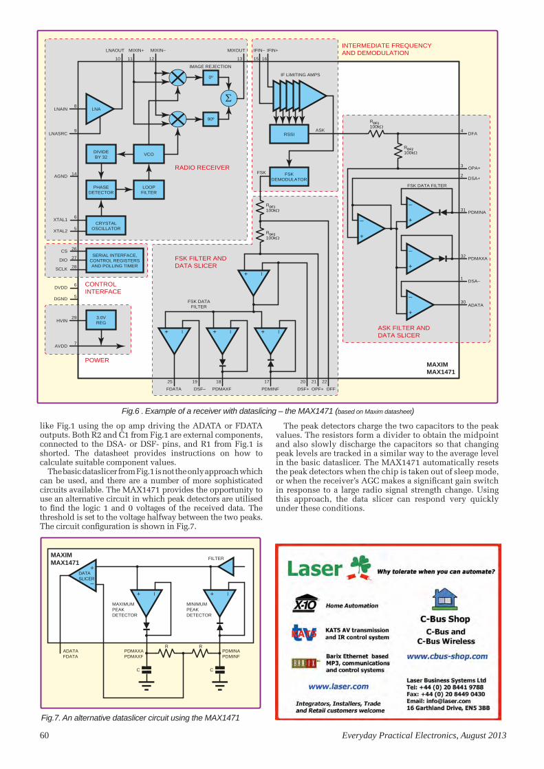
60 Everyday Practical Electronics, August 2013
The peak detectors charge the two capacitors to the peak values. The resistors form a divider to obtain the midpoint and also slowly discharge the capacitors so that changing peak levels are tracked in a similar way to the average level in the basic dataslicer. The MAX1471 automatically resets the peak detectors when the chip is taken out of sleep mode, or when the receiver’s AGC makes a significant gain switch in response to a large radio signal strength change. Using this approach, the data slicer can respond very quickly under these conditions.
CS6AUG13150mm x 3 COL
CRYSTALOSCILLATOR
SERIAL INTERFACE,CONTROL REGISTERSAND POLLING TIMER
FSKDEMODULATOR
DIVIDEBY 32
3.0VREG
RSSIASK
FSK
FSK DATAFILTER
FSK DATA FILTER
0º
90º
VCO
PHASEDETECTOR
LOOPFILTER
+
–
ΣLNA
+
–
+
–
+
–
+ –
+ –
+ –+ –
8
10 11 12 13 15 16
9
6
5
26
27
28
29
7
25 19 18 17 20 21 22
LNAIN
IMAGE REJECTION
IF LIMITING AMPS
4
3
2
31
32
1
30
DFA
OPA+
DSA+
PDMINA
PDMAXA
DSA–
ADATA
LNAOUT MIXIN+ MIXIN– IFIN– IFIN+MIXOUT
LNASRC
XTAL1
XTAL2
6
5
DVDD
DGND
CS
14AGND
DIO
SCLK
HVIN
AVDD
FDATA PDMAXF PDMINFDSF– DSF+ DFFOPF+
RADIO RECEIVER
INTERMEDIATE FREQUENCYAND DEMODULATION
CONTROLINTERFACE
POWER
FSK FILTER ANDDATA SLICER
ASK FILTER ANDDATA SLICER
MAXIMMAX1471
RDF1100kΩ
RDF2100kΩ
RDF2100kΩ
RDF1100kΩ
like Fig.1 using the op amp driving the ADATA or FDATA outputs. Both R2 and C1 from Fig.1 are external components, connected to the DSA- or DSF- pins, and R1 from Fig.1 is shorted. The datasheet provides instructions on how to calculate suitable component values.
The basic dataslicer from Fig.1 is not the only approach which can be used, and there are a number of more sophisticated circuits available. The MAX1471 provides the opportunity to use an alternative circuit in which peak detectors are utilised to find the logic 1 and 0 voltages of the received data. The threshold is set to the voltage halfway between the two peaks. The circuit configuration is shown in Fig.7.
Fig.6 . Example of a receiver with dataslicing – the MAX1471 (based on Maxim datasheet)
CS7AUG1366mm x 1.5 COL
MAXIMUMPEAKDETECTOR
FILTER
R
C C
R
MINIMUMPEAKDETECTOR
PDMINAPDMINF
PDMAXAPDMAXF
ADATAFDATA
+ –+ –
+
–
MAXIMMAX1471
DATASLICER
Fig.7. An alternative dataslicer circuit using the MAX1471
Circuit Surgery.indd 60 14/06/2013 16:36:22

Horoscope 29
EPE Magazine can now be downloaded at
PocketMags.com or download the app for your iPad, iPhone, iPod
Touch or Android phone
• Each individual issue costs only £1.99
• 6 Month Subscription £9.99
• 12 Month Subscription £19.99 (just £1.67 an issue)
The No 1 UK magazine for Electronics Technology &
Computer projects is now available to download worldwide
Download Now and have EPE at your
fingertips
Logic Probe – beginners
project!
WIN A MICROCHIP
mTouch Projected
Capacitive Development KitRaspberry Pi
Software Investigation
SemTeST – ParT 1• Our best-ever discrete semiconductor tester
• Check diodes, BJTs, MOSFETs and much more
• PIC-controlled with an LCD display
Jump Start
crySTaL daceLeganT uPgrade for
our STereo dac ProJecT
10W Led fLoodLighT
rivaLS incandeScenT SySTemS aT
a fracTion of The PoWer LeveLS
$9.99US £4.40UKFEB 2013 PRINTED IN THE UK
FEB 13 Cover.indd 1
17/12/2012 14:37:14
Pocketmags ad.indd 61 14/06/2013 10:46:40

62 Everyday Practical Electronics, August 2013
EPE IS PLEASED TO BE ABLE TO OFFER YOU THESE
ELECTRONICS CD-ROMS
Complex electronic systems in minutes
New features include:• C code views and customisation• Simulation improvements• Search and replace• New variable types• Project auto-documentation• Project explorer• Bookmarks• Improved chip interrupt features• Compilation errors and warning• Interrupts overhaul
Student/home: £49Professional: £199
Professional and FlowKit bundle: £216
The FlowKit can be connected to hard-ware systems to provide a real time debug facility where it is possible to step through the Flowcode program on the PC and step through the program in the hardware at the same time. The FlowKit can be connected to your own hardware to provide In-Circuit Debug to your finished designs.
Hobbyist/Student . . . . . . . . . . . . . . . . . . . . . . . . . . . . . .Professional (Schools/HE/FE/Industry) . . . . . . . . . . . .Flowkit . . . . . . . . . . . . . . . . . . . . . . . . . . . . . . . . . . . . . .
PRICES Prices for each of the items above are: (Order form on third page)
(UK and EU customers add VAT to ‘plus VAT’
prices)
PICMICRO/AVR/DSPIC/PIC24 & ARM Download only
£58 .80 inc . VAT£199 .00 plus VAT£64 .90 plus VAT
Flowcode 5
Please note: Due to popular demand, Flowcode PICmicro, AVR, DSPIC, PIC24 & ARM V5 are now available as a download . Please include your email address and a username (of your choice) on your order . A unique download code will then be emailed to you .
If you require the CDROM as a back-up then please add an extra £14 to the above price .
Flowcode PICmicro V5 is now available as a download
NEWOUT NOW
CD-ROMs Pages.indd 62 14/06/2013 10:47:58

Everyday Practical Electronics, August 2013 63
PICmicro TUTORIALS AND PROGRAMMINGPICmicro Multiprogrammer
Board and Development BoardSuitable for use with the three software packages
listed below
This flexible PICmicro microcontroller programmer board and combination board allows students and professional engineers to learn how to program PICmicro microcontrollers as well as program a range of 8, 18, 28 and 40 pin devices from the 12, 16 and 18 series PICmicro ranges. For experienced programmers all programming software is included in the PPP utility that comes with the multiprogrammer board. For those who want to learn, choose one or all of the packages below to use with the hardware.
• Makes it easier to develop PICmicro projects
• Supports low cost Flash-programmable PICmicro devices
• Fully featured integrated displays – 16 individual LEDs, quad 7-segment display and alphanumeric LCD display
• Supports PICmicro microcontrollers with A/D converters
• Fully protected expansion bus for project work
• USB programmable
• Compatible with the E-blocks range of accessories
ASSEMBLY FOR PICmicro V4
(Formerly PICtutor)Assembly for PICmicro microcontrollers V3.0 (previously known as PICtutor) by John Becker contains a complete course in programming the PIC16F84 PICmicro microcontroller from Arizona Microchip. It starts with fundamental concepts and extends up to complex programs including watchdog timers, interrupts and sleep modes.
The CD makes use of the latest simulation techniques which provide a superb tool for learning: the Virtual PICmicro microcontroller, this is a simulation tool that allows users to write and execute MPASM assembler code for the PIC16F84 microcontroller on-screen. Using this you can actually see what happens inside the PICmicro MCU as each instruction is executed, which enhances understanding.
• Comprehensive instruction through 45 tutorial sections • Includes Vlab, a Virtual PICmicro microcontroller: a fully functioning simulator • Tests, exercises and projects covering a wide range of PICmicro MCU applications • Includes MPLAB assembler • Visual representation of a PICmicro showing architecture and functions • Expert system for code entry helps first time users
• Shows data flow and fetch execute cycle and has challenges (washing machine, lift, crossroads etc.)
• Imports MPASM files.
‘C’ FOR 16 Series PICmicroVersion 4
The C for PICmicro microcontrollers CD-ROM is designed for students and professionals who need to learn how to program embedded microcontrollers in C. The CD-ROM contains a course as well as all the software tools needed to create Hex code for a wide range of PICmicro devices – including a full C compiler for a wide range of PICmicro devices.
Although the course focuses on the use of the PICmicro microcontrollers, this CD-ROM will provide a good grounding in C programming for any microcontroller.
• Complete course in C as well as C programming for PICmicro microcontrollers • Highly interactive course • Virtual C PICmicro improves understanding • Includes a C compiler for a wide range of PICmicro devices • Includes full Integrated Development Environment • Includes MPLAB software • Compatible with most PICmicro programmers • Includes a compiler for all the PICmicro devices.
FLOWCODE FOR PICmicro V5 (see opposite page)
£167 including VAT and postage, supplied with USB cable and programming software
HARDWARE
SOFTWARE
Hobbyist/Student . . . . . . . . . . . . . . . . . . . . . . . . . . . . . . £58 .80 inc VATProfessional (Schools/HE/FE/Industry) . . . . . . . . . . . . £150 plus VATProfessional 10 user (Network Licence) . . . . . . . . . . . £499 plus VATSite Licence . . . . . . . . . . . . . . . . . . . . . . . . . . . . . . . . . . £999 plus VATFlowcode Professional (Schools/HE/FE/Industry) . . . £199 plus VATFlowcode 10 user (Network Licence) . . . . . . . . . . . . . . £599 plus VATFlowcode Site Licence . . . . . . . . . . . . . . . . . . . . . . . . . £999 plus VAT
PRICESPrices for each of the CD-ROMs above are:
(Order form on next page)
(UK and EU customers add VAT to ‘plus VAT’ prices)
Minimum system requirements for these items: Pentium PC running, 2000, ME, XP; CD-ROM drive; 64MB RAM; 10MB
hard disk space.Flowcode will run on XP or later
operating systems
Flowcode is a very high level language programming system based on flowcharts. Flowcode allows you to design and simulate complex systems in a matter of minutes. A powerful language that uses macros to facilitate the control of devices like 7-segment displays, motor controllers and LCDs. The use of macros allows you to control these devices without getting bogged down in understanding the programming. When used in conjunction with the Version 3 development board this provides a seamless solution that allows you to program chips in minutes.
• Requires no programming experience
• Allows complex PICmicro applications to be designed quickly
• Uses international standard flow chart symbols
• Full on-screen simulation allows debugging and speeds up the development process.
• Facilitates learning via a full suite of demonstration tutorials
• Produces ASM code for a range of 18, 28 and 40-pin devices
• 16-bit arithmetic strings and string manipulation
• Pulse width modulation
• I2C.
Features include panel creator, in circuit debug, virtual networks, C code customisation, floating point and new components. The Hobbyist/Student version is limited to 4K of code (8K on 18F devices)
CD-ROMs Pages.indd 63 14/06/2013 10:48:08

64 Everyday Practical Electronics, August 2013
By integrating the entire design process, Circuit Wizard provides you with all the tools necessary to produce an electronics project from start to finish – even including on-screen testing of the PCB prior to construction!
* Circuit diagram design with component library (500 components Standard,1500 components Professional) * Virtual instruments (4 Standard, 7 professional)* On-screen animation * Interactive circuit diagram simulation * True analogue/digital simulation
* Simulation of component destruction * PCB Layout * Interactive PCB layout simulation * Automatic PCB routing * Gerber export
* Multi-level zoom (25% to 1000%) * Multiple undo and redo
* Copy and paste to other software * Multiple document support
CIRCUIT WIZARD
Please send me: CD-ROM ORDER FORM Assembly for PICmicro V4 ‘C’ for 16 Series PICmicro V4 Flowcode for PICmicro V5 (DOWNLOAD + CDROM) Flowcode for PICmicro V5 (DOWNLOAD ONLY) Flowcode for AVR V5 (DOWNLOAD + CDROM) Flowcode for AVR V5 (DOWNLOAD ONLY) Flowcode for ARM V5 (DOWNLOAD + CDROM) Flowcode for ARM V5 (DOWNLOAD ONLY) Flowcode for dsPIC V5 (DOWNLOAD + CDROM) Flowcode for dsPIC V5 (DOWNLOAD ONLY) Flowcode for PIC24 V5 (DOWNLOAD + CDROM) Flowcode for PIC24 V5 (DOWNLOAD ONLY) Flowkit
Email: . . . . . . . . . . . . . . . . . . . . . . . . . . . . . .
Username: . . . . . . . . . . . . . . . . . . . . . . . . . .
PICmicro Multiprogrammer Board and Development Board V4 (hardware)
Circuit Wizard – Standard Circuit Wizard – Professional GCSE Electronics
Full name: . . . . . . . . . . . . . . . . . . . . . . . . . . . . . . . . . . . . . . . . . . . . . . . . . . . . . . . . . . . . . . . . .
Address: . . . . . . . . . . . . . . . . . . . . . . . . . . . . . . . . . . . . . . . . . . . . . . . . . . . . . . . . . . . . . . . . . .
. . . . . . . . . . . . . . . . . . . . . . Post code: . . . . . . . . . . . . . . . . . Tel. No: . . . . . . . . . . . . . . . . . . .
Signature: . . . . . . . . . . . . . . . . . . . . . . . . . . . . . . . . . . . . . . . . .
I enclose cheque/PO in £ sterling payable to WIMBORNE PUBLISHING LTD for £ . . . . . . . . . Please charge my Visa/Mastercard/Maestro: £ . . . . . . . . . . Valid From: . . . . . . . . . . Card expiry date: . . . . . . . . . . . . . Card No: . . . . . . . . . . . . . . . . . . . . . . . . . . . . . . . . . . . . . . . . Maestro Issue No. . . . . . . . . .Card Security Code . . . . . . . . . . (The last 3 digits on or just under the signature strip)
Note: The software on each version is the same, only the licence for use varies.
Minimum system requirements for these CD-ROMs: Pentium PC, CD-ROM drive, 32MB RAM, 10MB hard disk space. Windows 2000/ME/XP, mouse,
sound card, web browser.
ORDERINGALL PRICES INCLUDE UK
POSTAGE
Student/Single User/Standard/Hobbyist Version price includes postage to most
countries in the worldEU residents outside the UK add £5 for
airmail postage per order
Professional, Multiple User and Site License Versions – overseas readers add £5 to the basic price of each order for airmail postage (do not add VAT unless you live in an EU (European Union) country, then add VAT at 20% or provide your official VAT registration number).
Send your order to:Direct Book Service
Wimborne Publishing Ltd113 Lynwood Drive, Merley,
Wimborne, Dorset BH21 1UU
To order by phone ring
01202 880299. Fax: 01202 843233Goods are normally sent within seven days
E-mail: [email protected] shop:
www.epemag.com
Circuit Wizard is a revolutionary software system that combines circuit design, PCB design, simulation and
CAD/CAM manufacture in one complete package. Two versions are available, Standard or Professional.
Version required: Hobbyist/Student Professional Professional 10 user Site licence
This software can be used with the Jump Start and Teach-In 2011 series (and the Teach-In 4 book).
Standard £61.25 inc. VAT Professional £91.90 inc. VAT
Suitable for any student who is serious about studying and who wants to achieve the best grade possible. Each program’s clear, patient and structured delivery will aid understanding of electronics and assist in developing a confident approach to
answering GCSE questions. The CD-ROM will be invaluable to anyone studying electronics, not just GCSE students.
* Contains comprehensive teaching material to cover the National Curriculum syllabus * Regular exercises reinforce the teaching points * Retains student interest with high quality animation and graphics * Stimulates learning through interactive exercises * Provides sample examination ques-tions with model solutions * Authored by practising teachers * Covers all UK examination board syllabuses * Caters for all levels of ability * Useful for self-tuition and revision
GCSE ELECTRONICS
£12.50 inc. VAT and P&P
SUBJECTS COVEREDElectric Circuits – Logic Gates – Capacitors & Inductors – Relays – Transistors – Electric Transducers – Operational Amplifiers – Radio Circuits – Test Instruments
Over 100 different sections under the above headings
CD-ROMs Pages.indd 64 14/06/2013 10:48:19

Everyday Practical Electronics, August 2013 65
SP1 15 x 5mm Red Leds SP2 12 x 5mm Green Leds SP3 12 x 5mm Yellow LedsSP5 20 x 5mm 1 part Led clips SP6 15 x 3mm Red LedsSP7 12 x 3mm Green LedsSP8 10 x 3mm Yellow LedsSP9 20 x 3mm 1 part Led clipsSP10 100 x 1N4148 diodes SP11 30 x 1N4001 diodesSP12 30 x 1N4002 diodesSP18 20 x BC182B transistorsSP20 20 x BC184B transistorsSP23 20 x BC549B transistorsSP24 4 x Cmos 4001SP25 4 x 555 timers SP26 4 x 741 Op-amps SP28 4 x Cmos 4011SP33 4 x Cmos 4081SP34 20 x 1N914 diodesSP36 25 x 10/25V radial elect capsSP37 12 x 100/35V radial elect capsSP38 15 x 47/25V radial elect capsSP39 10 x 470/16V radial elect capsSP40 15 x BC237 transistorsSP41 20 x Mixed transistorsSP42 200 x Mixed 0.25W CF resistorsSP47 5 x Min. PB switchesSP49 4 x 4 metres stranded core wireSP102 20 x 8 pin DIL socketsSP103 15 x 14 pin DIL socketsSP104 15 x 16 pin DIL socketsSP109 15 x BC557B transistorsSP112 4 x Cmos 4093SP115 3 x 10mm Red LedsSP116 3 x 10mm Green LedsSP118 2 x Cmos 4047SP124 20 x Assorted ceramic disc capsSP130 100 x Mixed 0.5W CF resistors
SHERWOOD ELECTRONICSBuy 10 x £1 Special Packs and choose another one FREE
SP131 2 x TL071 Op-ampsSP133 20 x 1N4004 diodesSP134 15 x 1N4007 diodesSP135 5 x Miniature slide switches SP137 4 x W005 1.5A bridge rectifiersSP138 20 x 2.2/63V radial elect capsSP142 2 x Cmos 4017SP143 5 Pairs min. croc.clips (Red+Blk)SP144 5 Pairs min. croc. clips (assorted colours)SP146 10 x 2N3704 transistorsSP151 4 x 8mm Red LedsSP152 4 x 8mm Green LedsSP153 4 x 8mm Yellow LedsSP154 15 x BC548B transistorsSP155 6 x 1000/16V radial elect. capsSP160 10 x 2N3904 transistorsSP161 10 x 2N3906 transistorsSP164 2 x C106D thyristorsSP165 2 x LF351 Op-ampsSP166 20 x 1N4003 diodesSP167 5 x BC107 transistorsSP168 5 x BC108 transistorsSP172 3 x Standard slide switchesSP173 10 x 220/25V radial elect caps SP174 20 x 22/25V radial elect capsSP175 20 x 1/63V radial elect capsSP177 8 x 1A 20mm quick blow fusesSP178 8 x 2A 20mm quick blow fusesSP181 5 x Phono plugs – assorted coloursSP182 20 x 4.7/63V radial elect capsSP183 20 x BC547B transistorsSP186 6 x 1M horizontal trimpotsSP192 3 x Cmos 4066SP195 3 x 10mm Yellow LedsSP197 6 x 20 pin DIL socketsSP198 5 x 24 pin DIL socketsSP199 4 x 2.5mm mono jack plugsSP200 4 x 2.5mm mono jack sockets
RESISTOR PACKS – C.FilmRP3 5 each value - total 365 - 0.25W £3.65RP7 10 each value - total 730 - 0.25W £4.95RP10 1000 popular values - 0.25W £7.00RP4 5 each value – total 305 - 0.5W £4.65RP8 10 each value - total 610 - 0.5W £7.40RP11 1000 popular values - 0.5W £10.15
P&P £2.50 per order. NO VATCheques and Postal Orders to:
Sherwood Electronics,10 NEWSTEAD STREET,
MANSFIELD, NOTTS. NG19 6JJ
AUGUST 2013 x lined up.indd 1 14/06/2013 17:09:48
SPEEDACCURACY?
HAVE IT ALL
WHY COMPROMISE
ALL MODELS INCLUDE PROBES, FULL SOFTWARE AND 5 YEAR WARRANTY. SOFTWARE INCLUDES MEASUREMENTS, SPECTRUM ANALYZER, SDK, ADVANCED TRIGGERS, COLOR
PERSISTENCE, SERIAL DECODING (CAN, LIN, RS232, I²C, I²S, FLEXRAY, SPI), MASKS, MATH CHANNELS, ALL AS STANDARD, WITH FREE UPDATES.
v
www.picotech.com/PS221
FLEXIBLE RESOLUTION OSCILLOSCOPE
2 Channel models also available * Shared between active channels ** Maximum resolution is limited on the lowest voltage ranges: ±10 mV = 8 bits • ±20 mV = 12 bits. All other ranges can use full resolution.
PicoScope PicoScope 5442
PicoScope 5443
PicoScope 5444
Channels 4 4 4
Bandwidth All modes: 60 MHz8 to 15-bit modes:
100 MHz 16-bit mode: 60 MHz
8 to 15-bit modes: 200 MHz
16-bit mode: 60 MHzSampling rate - real time 2.5 GS/s 5 GS/s 10 GS/sBuffer memory (8-bit) * 16 MS 64 MS 256 MSBuffer memory (≥ 12-bit)* 8 MS 32 MS 128 MS
Resolution (enhanced)** 8 bits, 12 bits, 14 bits, 15 bits, 16 bits(Hardware resolution + 4 bits)
Signal Generator Function generator or AWG
CRICKLEWOODELECTRONICS
Visit our shop at:40-42 Cricklewood BroadwayLondon NW2 3ET020 8452 0161
Frustrated with your suppier?Visit our component packed
website for a vast range ofparts - old and new,
many unavailable elsewhere!www.cricklewoodelectronics.com
10001000’s OF PRICES REDUCED!
Alternatively phone us on020 8452 0161 with your
requirements.
Visit our Shop, Call or Buy online at:www.cricklewoodelectronics.com
Established 1981
supplier?
Cricklewood - MAR09.indd 1 28/01/2009 11:08:21
Page 65.indd 65 14/06/2013 17:11:07

66 Everyday Practical Electronics, August 2013
M icrosoft is currently marketing its Internet Explorer web browser on television, and British TV Ad breaks are regularly punctuated by reassuring
voiceovers explaining how a user’s online privacy is important to Microsoft. They’re referring to the Do Not Track feature found in IE10, a privacy feature that is automatically enabled by default in Microsoft’s latest browser, much to the annoyance of online advertisers and marketers.
The Do Not Track feature isn’t new and it’s not unique to Microsoft Internet Explorer 10 either. Do Not Track (DNT) has been a work-in-progress in the US and EU since 2011, and Mozilla started testing the concept of DNT in Firefox some 2½ years ago. DNT is already included in current versions of Firefox for Desktop and Android, which should appeal to mobile users. In Firefox, DNT can be accessed via the Tools/Options/Privacy menu. (Details of DNT found in Internet Explorer were given in last month’s Net Work.)
Microsoft is careful not to over-promise what DNT can offer in Internet Explorer 10, and while DNT can only help protect privacy, in reality it may have negligible impact, at least in the shorter term. The problem is that although a rising number of users are enabling DNT in their browsers, DNT is a voluntary code and is not widely implemented by web servers themselves. Indeed, steps were taken at one point by some systems to deliberately bypass the Do Not Track option, as a protest that DNT should be an opt-in, not an automatically opted-out option.
According to Mozilla (see: https://dnt-dashboard.mozilla.org/) the United Kingdom take-up of Do Not Track in Firefox is the highest in the world at 19.41%, higher than the US or Canada. DNT is not at all guaranteed to be effective, but over time it will gradually have more impact on advertising and I expect the day will come when the EU finally publishes some ill-thought legislation requiring website owners everywhere to adopt it. If the EU cookie laws or anti-spam rules were anything to go by, the implementation of DNT by the UK’s Information Commissioner will be muddled and half-baked at best.
Ghostery huntersMany large blue-chip websites utilise myriad third-party services that track a visitor’s browsing habits for marketing reasons, and an interesting way of seeing what’s going on when you surf them is to try the Ghostery add-on which is available for IE, Firefox, Chrome, Opera, Safari and iOS for mobile browsers. The Ghostery browser add-on reports the presence of any web page trackers, and you can decide to block them from writing data to your browser cache or prevent them from ‘phoning home’. This helps to protect privacy again, and by blocking scripts from running, web pages can load faster as well, or you can whitelist websites which permits all trackers to run when you visit them.
Ghostery pops up with a summary of the total trackers loaded and expands to provide more details of the third-party trackers themselves. As an example, 16 trackers were reported when I visited the website of CBS News and 17 of them were shown on the Daily Telegraph website. The Washington Post home page had nearly 30 trackers, according to Ghostery.
You can visit www.ghostery.com using your preferred browser(s) in order to download
Don’t track me!
Firefox Do Not Track can be enabled via the Tools/Options/Privacy menu
For many users, the feeling of being tracked online is a creepy one, and by enabling the Do Not Track function in a web browser, a user’s privacy can theoretically be protected. The protection on offer is more limited than you might hope: Do Not Track disables the way in which websites gather information about your viewing habits – information which is ultimately used by marketers in order to deliver advertising relating to your recent browsing history. Do Not Track, therefore, mainly strives to disrupt the way that third-party websites can show ‘behavioural advertising’. Even with DNT enabled, you may still be subjected to bland online advertising, but at least it shouldn’t relate to your recent surfing habits.
Using Firefox, the Ghostery add-on reported 16 trackers on this website
Network - New layout.indd 66 14/06/2013 15:42:40

Everyday Practical Electronics, August 2013 67
and install the add-ons directly. Options are available by clicking the ‘Ghost’ button and Ghostery can be uninstalled via the Windows control panel if needed.
Users of AVG Anti Virus might note that AVG Do Not Track is also provided free, and is available in Firefox, IE and Chrome browsers. The AVG ‘eye’ icon on the toolbar shows that the service is running. You have to dig deep to disable AVG Do Not Track: in IE, go Tools/Manage Add-Ons and AVG Do Not Track will be seen in the Toolbars and Extensions section; in Firefox visit Tools/Add-ons/ Extensions. For older Windows XP systems running IE8, the AVG Do Not Track add-on is also available.
A useful tip is to ensure that web browser toolbars are not ‘locked’, as that may hide some add-on buttons from view. Drag the toolbar over to the left to lengthen them and
expose hidden Ghostery or AVG Do Not Track buttons. This is especially true of Internet Explorer.
Fully compatibleWhen users visit a web page, the user’s web browser sends information to web servers that can help the server to respond accordingly. Technically a web browser is termed a ‘user-agent’ and it sends an array of information in an ‘http header’ to the web server, including information such as the visitor’s browser type, screen resolution or operating system. One problem is that the user-agent header can be spoofed or falsified, which results in inaccurate web browser data being exchanged, something
that can make a nonsense of web server logs.Since the earliest days of the web, designers have obsessed
about ensuring that users have a consistent ‘experience’ of a web page, no matter which web browser they were using. The writer’s own view is that, as long as a web browser behaves reasonably well enough in the major browsers (IE, Firefox and Chrome), and that visitors manage to work through the content without any particular obstructions, then that’s good enough. If 100% accuracy is needed then choose a print medium instead! If an incompatible web browser was used, then in principle web pages should be allowed to ‘degrade gracefully’, ie, displaying the content legibly enough without smashing up altogether. Besides, such is the ‘blippy’ nature of web surfers these days, that visitors won’t mind as long as they get the information they seek, and they will soon have surfed onto their next web page anyway.
The problems of browser and web site incompatibility surfaced in the 1990s when designers realised that Netscape Navigator (now Mozilla Firefox) reacted differently to Microsoft’s Internet Explorer when surfing web sites. Buttons
might not work, images might not display or scripts might not run properly, depending on whether NN or IE was used. Designers’ hearts sank when new browsers versions came along and the idea was born that website source code could be launched on the fly that depended on the browser being used. Problems would then arise when the tweaks and tricks used in legacy web pages stopped working because the browsers had moved on, and thus the game of leapfrog would be reversed.
Plus ça change…To offer continuous web page compatibility with every browser is a never-ending and very expensive process which is simply beyond the scope of many web site owners. As an extreme example, even the UK National Lottery website has suffered web browser compatibility issues; following another browser upgrade it was found that part of the website no longer functioned properly. Lottery players were advised to use a different (or older) version of their browser – and that’s from a website where prizes of over £100 million ($150 million) were at stake.
Another example is eBay, a highly complex website whose functionality can occasionally lapse due to browser compatibility problems. eBay’s advice to the writer was to use an older version of Internet Explorer, a completely non-feasible cop-out of a measure that an ordinary-non technical ebayer would find totally impossible to do. Currently, I note that Amazon’s web pages don’t display product images correctly in IE10: the images are misplaced on the web page as the screenshot shows. Firefox seems to handle (parse) the code as the website designers intended.
Detecting the web browser in order to deliver the best online experience remains the holy grail of web designers, but as fast as an answer is found, they change the question. In the late 1990s, I started to receive emails from US readers who – amazingly at the time – were managing to
email me through their TV set using Web TV. Yet more web design rules would be needed to cater for surfers accessing websites from a large TV 3m or 5m away from the user, as opposed to hunching over a 15-inch laptop. ‘Accessibility’ and ‘usability’ became buzzwords, with Web TV users demanding extra-large buttons and small bites of text suitable for viewing on a TV screen instead of a monitor.
Today, with websites accessed by Smart TV web browsers (which are starting to raise questions about online security and LAN protection) and smartphone or tablet mobile access, the trend in web design is towards so-called ‘responsive web design’, which focuses on detecting the user agent accurately and delivering an optimised website suitable for viewing on a QVGA smartphone, or an HD tablet. It is said that the more things change, the more they stay the same, and responsive web design has produced a whole new raft of problems that will keep web designers busy for a long time.
You can email the author at: [email protected].
Shown in Internet Explorer, Ghostery claimed 17 trackers were running on this UK newspaper’s website
In IE10, AVG Do Not Track runs when the eye icon (circled) is visible. Drag toolbars to the left (arrow) to view add-on buttons hidden off to the right.
In the author’s browser, product images on the Amazon website are shown misplaced.
Network - New layout.indd 67 14/06/2013 15:42:52

68 Everyday Practical Electronics, August 2013
DIRECT BOOK SERVICEThe books listed have been selected by Everyday Practical Electronics editorial staff as being of special interest to everyone involved in electronics and computing. They are supplied by mail order direct to your door. Full ordering details are given on the next page.
All prices include UK postage
FOR A FUlLL DESCRIPTION OF THESE BOOKS AND
CD-ROMS SEE THE SHOP ON OUR WEBSITE www.epemag.com
PROJECTCONSTRUCTION
IC 555 PROJECTSE. A. Parr167 pages Order code BP44 £5.49
1
135 pages Order code BP392 £5.99
ELECTRONIC PROJECT BUILDING FOR BEGINNERS R. A. Penfold
AN INTRODUCTION TO RADIO WAVE PROPOGATION J.G. Lee
THEORY AND REFERENCE
ELECTRONICS TEACH-IN BUNDLE –SPECIAL BUNDLE PRICE £14 FOR PARTS 1, 2 & 3
ELECTRONICS TEACH-IN 3
The three sections of this book cover a very wide range of subjects that will
interest everyone involved in electronics, from hobbyists and students to professionals. The first 80-odd pages of Teach-In 3 are dedicated to Circuit Surgery, the regular EPE clinic dealing with readers’ queries on various circuit design and application problems – everything from voltage regulation to using SPICE circuit simulation software.
The second section – Practically Speaking – covers the practical aspects of electronics construction. Again, a whole range of subjects, from soldering to avoiding problems with static electricity and indentifying components, are covered. Finally, our collection of Ingenuity Unlimited circuits provides over 40 circuit designs submitted by the readers of EPE.
The free cover-mounted CD-ROM is the complete Electronics Teach-In 1 book, which provides a broad-based introduction to electronics in PDF form, plus interactive quizzes to test your knowledge, TINA circuit simulation software (a limited version – plus a specially written TINA Tutorial), together with simulations of the circuits in the Teach-In 1 series, plus Flowcode (a limited version) a high level programming system for PIC microcontrollers based on flowcharts.
The Teach-In 1 series covers everything from Electric Current through to Microprocessors and Microcontrollers and each part includes demonstration circuits to build on breadboards or to simulate on your PC. There is also a MW/LW Radio project in the series. The contents of the book and Free CD-ROM have been reprinted from past issues of EPE.
160 pages Order code ETI3 £8.50
FREECD-ROMELECTRONICS TEACH-IN 2 CD-ROM
USING PIC MICROCONTROLLERS A PRACTICAL INTRODUCTIONThis Teach-In series of articles was originally published in EPE in 2008 and, following demand from readers, has now been collected together in the Electronics Teach-In 2 CD-ROM.
The series is aimed at those using PIC microcontrollers for the first time. Each part of the series includes breadboard layouts to aid understanding and a simple programmer project is provided.
Also included are 29 PIC N’ Mix articles, also republished from EPE. These provide a host of practical programming and interfacing information, mainly for those that have already got to grips with using PIC microcontrollers. An extra four part beginners guide to using the C programing language for PIC microcontrollers is also included.
The CD-ROM also contains all of the software for the Teach-In 2 series and PIC N’ Mix articles, plus a range of items from Microchip – the manufacturers of the PIC microcontrollers. The material has been compiled by Wimborne Publishing Ltd. with the assistance of Microchip Technology Inc.
The Microchip items are: MPLAB Integrated Development Environment V8.20; Microchip Advance Parts Selector V2.32; Treelink; Motor Control Solutions; 16-bit Embedded Solutions; 16-bit Tool Solutions; Human Interface Solutions; 8-bit PIC Microcontrollers; PIC24 Micrcontrollers; PIC32 Microcontroller Family with USB On-The-Go; dsPIC Digital Signal Controllers.
Book and CD-ROMs Order code ETI BUNDLE Bundle Price £14.00
ELECTRONICS TEACH-IN 4
ELECTRONICS TEACH-IN 4
A Broad-Based Introduction to Electronics plus FREE CD-ROM
The Teach-In 4 book covers three of the most important electronics units that are currently studied in many schools and colleges. These include, Edexcel BTEC level 2 awards and the electronics units of the new Diploma in Engineering, Level 2.
The Free cover-mounted CD-ROM contains the full Mod-ern Electronics Manual, worth £29.95. The Manual contains over 800 pages of electronics theory, projects, data, assem-bly instructions and web links.
A package of exceptional value that will appeal to all those interested in learning about electronics or brushing up on their theory, be they hobbyists, students or professionals.
FREECD-ROM
144 pages Order code ETI4 £8.99
CD-ROM Order code ETI2 CD-ROM £9.50
RADIO
ELECTRONICS
TEACH-INA BROAD-BASED
INTRODUCTION
TO ELECTRONICS
Find out how circuits
work and what goes
on inside them FREE CD-ROM
i TinaPRO Circuit
Simulation Programme
i Interactive Quizes
To Test Your Knowledge
PLUS SPICE Circuit
Simulation TutorialElectronics Teach-In
i TinaPRO Circuit
Simulation Programme
i Interactive Quizes To Test
Your Knowledge
FROM THE PUBLISHERS OF
£7.95
FREE
CD
-ROM
116 pages Order code BP293 £4.45
BASIC RADIO PRINCIPLES AND TECHNOLOGY Ian Poole
263 pages Order code NE30 £28.99
ELECTRONICS TEACH-IN 3
8 TINA Circuit Simulation Program (Limited version)8 FLOWCODE V3 PIC Programming Software (Limited version)8 Interactive Quizzes to Test Your Knowledge
Ele
ctronics Teach-In 1© Wimborne Publishing Ltd 2010
CD Cover.indd 1
29/04/2010 13:21:42
FROM THE PUBLISHERS OF
£7.99
FREE
CD-ROM
TEACH-IN 1 CD-ROMTWO TEACH-INs FOR THE PRICE OF ONE!
i The free CD-ROM provides
a broad-based introduction
to electronicsi A complete stand-alone
tutorial in 11 parts plus free
software
FREE
CIRCUIT SURGERY i The how and why of circuit design
PRACTICALLY SPEAKING i The techniques of electronic
project constructionINGENUITY UNLIMITED i Over 40 different circuit ideas
Teach In 3 Cover.indd 1
06/05/2010 16:22:29
ELECTRONICS TEACH-IN 4
FREE CD-ROMWORTH£29.95
BASE MANUAL
www.epemag.co.uk
© Wimborne Publishing Ltd. 2011
This CD-ROM requires
Adobe® Reader™
Downloadable Free from
www.adobe.com
This software should autorun,
if not, open in Windows
Explorer and double-click
index.pdf
FROM THE PUBLISHERS OF
£8.99FREE
CD-ROM
A BROAD-BASED INTRODuCTION TO ELECTRONICS i An eleven part tutoriali uses inexpensive circuit simulation software
FREE
CD-ROM
THE MODERN ELECTRONICS MANuALThe essential reference work for everyone studying electronics
i Over 800 PDF pages i In-depth theoryi Extensive data tables
and web links
Teach In 4 Cover.indd 1 14/11/2011 20:33:21
PRACTICAL FIBRE-OPTIC PROJECTS R. A. Penfold
132 pages Order code BP374 £5.45
MICROPROCESSORS
298 pages Order code NE48 £30.99
INTERFACING PIC MICROCONTROLLERSMartin Bates
PROGRAMMING 16-BIT PIC MICROCONTROLLERS IN C– LEARNING TO FLY THE PIC24 Lucio Di Jasio (Application Segments Manager, Microchip, USA)
496 pages +CD-ROM Order code NE45 £38.00
INTRODUCTION TO MICROPROCESSORS AND MICROCONTROLLERS – SECOND EDITIONJohn Crisp
222 pages Order code NE31 £29.99
THE PIC MICROCONTROLLERYOUR PERSONAL INTRODUCTORY COURSE – THIRD EDITION. John Morton
270 pages Order code NE36 £25.00
PIC IN PRACTICE (2nd Edition)David W. Smith
308 pages Order code NE39 £24.99
MICROCONTROLLER COOKBOOKMike James
240 pages Order code NE26 £36.99
BEBOP BYTES BACK (and the Beboputer Computer Simulator) CD-ROMClive (Max) Maxfield and Alvin Brown
Over 800 pages in Adobe Acrobat format
BEBOP TO THE BOOLEAN BOOGIESecond Edition Clive (call me Max) Maxfield
470 pages Order code BEB1 £35.99
440 pages Order code NE21 £32.50
PRACTICAL ELECTRONICS HANDBOOK –Fifth Edition. Ian Sinclair
CD-ROM Order code BEB2 CD-ROM £21.95
STARTING ELECTRONICS – 4th Edition Keith Brindley
296 pages Order code NE100 £18.99
ELECTRONIC CIRCUITS – FUNDAMENTALS & APPLICATIONS – Third Edition Mike Tooley
400 pages Order code NE43 £25.99
FUNDAMENTAL ELECTRICAL AND ELECTRONIC PRINCIPLES – Third Edition C.R. Robertson
368 pages Order code NE47 £21.99
A BEGINNER’S GUIDE TO TTL DIGITAL ICsR.A. Penfold
142 pages Order code BP332 £5.45
UNDERSTANDING ELECTRONIC CONTROL SYSTEMSOwen Bishop
228 pages Order code NE35 £36.99
Order code ETIBUNDLE
Books1.indd 68 14/06/2013 10:47:16

69
COMPUTING AND ROBOTICSFAULT FINDING AND TEST
EQUIPMENT
GETTING THE MOST FROM YOUR MULTIMETERR. A. Penfold
96 pages Order code BP239 £5.49
PRACTICAL ELECTRONIC FAULT FINDING AND TROUBLESHOOTINGRobin Pain
274 pages Order code NE22 £41.99
HOW ELECTRONIC THINGS WORK – AND WHAT TO DO WHEN THEY DON’TRobert Goodman
394 pages Order code MGH3 £21.99
OSCILLOSCOPES – FIFTH EDITIONIan Hickman
288 pages Order code NE37 £36.99
HOW TO USE OSCILLOSCOPES AND OTHER TEST EQUIPMENTR.A. Penfold
104 pages Order code BP267 £5.49
AUDIO & VIDEO
VALVE AMPLIFIERS – Second EditionMorgan Jones
288 pages Order code NE33 £40.99
BUILDING VALVE AMPLIFIERS Morgan Jones
368 pages Order code NE40 £29.00
DIGITAL AUDIO RECORDING Ian Waugh
60 pages Order code PC121 £7.95
MAKING MUSIC WITH YOUR COMPUTER Stephen Bennett
QUICK GUIDE TO MP3 AND DIGITAL MUSICIan Waugh
60 pages Order code PC119 £7.45
92 pages Order code PC120 £10.95
QUICK GUIDE TO DIGITAL AUDIO RECORDING Ian Waugh
208 pages Order code PC121 £7.95
ELECTRONIC PROJECTS FOR VIDEO ENTHUSIASTSR.A. Penfold
109 pages Order code BP356 £5.45
All prices include UK postage. For postage to Europe (air) and the rest of the world (surface) please add £3 per book. Surface mail can take up to 10 weeks to some countries. For the rest of the world airmail add £4 per book. CD-ROM prices include VAT and/or postage to anywhere in the world. Send a PO, cheque, international money order (£ sterling only) made payable to Direct Book Service or card details, Visa, Mastercard or Maestro to: DIRECT BOOK SERVICE, WIMBORNE PUBLISHING LIMITED, 113 LYNWOOD DRIVE, MERLEY, WIMBORNE, DORSET BH21 1UU.
Books are normally sent within seven days of receipt of order, but please allow 28 days for delivery – more for overseas orders. Please check price and availability (see latest issue of Everyday Practical Electronics) before ordering from old lists.
For a full description of these books please see the shop on our website. Tel 01202 880299 Fax 01202 843233. E-mail: [email protected]
Order from our online shop at: www.epemag.com
BOOK ORDERING DETAILS
Full name: .......................................................................................................................................
Address: ..........................................................................................................................................
.........................................................................................................................................................
.........................................................................................................................................................
.............................................. Post code: ........................... Telephone No: ....................................
Signature: ........................................................................................................................................
I enclose cheque/PO payable to DIRECT BOOK SERVICE for £ ..............................................
Please charge my card £ ....................................... Card expiry date.........................................
Card Number ....................................................................... Maestro Issue No..............................
Valid From Date ................ Card Security Code ................ (The last three digits on or just below the signature strip)
Please send book order codes: .......................................................................................................
.......................................................................................................................................................... Please continue on separate sheet of paper if necessary
BOOK ORDER FORM
NEWNES INTERFACING COMPANIONTony Fischer-Cripps
295 pages Order code NE38 £41.00
HOW TO BUILD A COMPUTER MADE EASYR.A. Penfold
120 pages Order code BP707 £8.49
128 pages Order code BP721 £7.99
THE INTERNET – TWEAKS, TIPS AND TRICKSR. A. Penfold
EASY PC CASE MODDINGR.A. Penfold
192 pages + CDROM Order code BP542 £8.99
FREE DOWNLOADS TO PEP-UP AND PROTECT YOUR PCR.A. Penfold
128 pages Order code BP722 £7.99
WINDOWS XP EXPLAINEDN. Kantaris and P.R.M. Oliver
264 pages Order code BP514 £7.99
eBAY – TWEAKS, TIPS AND TRICKSR. A. Penfold
128 pages Order code BP716 £7.50
COMPUTING FOR THE OLDER GENERATIONJim Gatenby
308 pages Order code BP601 £8.99
ANDROIDS, ROBOTS AND ANIMATRONSSecond Edition – John Iovine
224 pages Order code MGH1 £16.99
ROBOT BUILDERS COOKBOOKOwen Bishop
366 pages Order code NE46 £26.00
INTRODUCING ROBOTICS WITH LEGO MINDSTORMSRobert Penfold
288 pages + Order code BP901 £14.99
MORE ADVANCED ROBOTICS WITH LEGOMINDSTORMS – Robert Penfold
298 pages Order code BP902 £14.99
WINDOWS 7 – TWEAKS, TIPS AND TRICKSAndrew Edney
120 pages Order code BP708 £8.49
GETTING STARTED IN COMPUTING FOR THE OLDER GENERATIONJim Gatenby
120 pages Order code BP704 £8.49
HOW TO FIX YOUR PC PROBLEMSR. A. Penfold
128 pages Order code BP705 £8.49
AN INTRODUCTION TO eBAY FOR THE OLDER GENERATIONCherry Nixon
120 pages Order code BP709 £8.49
Books1.indd 69 14/06/2013 10:47:26

70 Everyday Practical Electronics, August 2013
Basic printed circuit boards for most recent EPE constructional projects are available from the PCB Service, see list. These are fabricated in glass fibre, and are drilled and roller tinned, but all holes are a standard size. They are not silk-screened, nor do they have solder resist. Double-sided boards are NOT plated through hole and will require ‘vias’ and some components soldering to both sides. NOTE: PCBs from the July 2013 issue with eight digit codes have silk screen overlays and, where applicable, are double-sided, plated through-hole, with solder masks, they are similar to the photos in the relevent project articles.
All prices include VAT and postage and packing. Add £2 per board for airmail outside of Europe. Remittances should be sent to The PCB Service, Everyday Practical Electronics, Wimborne Publishing Ltd., 113 Lynwood Drive, Merley, Wimborne, Dorset BH21 1UU. Tel: 01202 880299; Fax 01202 843233; Email: [email protected]. On-line Shop: www.epemag.com. Cheques should be crossed and made payable to Everyday Practical Electronics (Payment in £ sterling only).
NOTE: While 95% of our boards are held in stock and are dispatched within seven days of receipt of order, please allow a maximum of 28 days for delivery – overseas readers allow extra if ordered by surface mail.
Back numbers or photocopies of articles are available if required – see the Back Issues page for details. WE DO NOT SUPPLY KITS OR COMPONENTS FOR OUR PROJECTS.
PCB SERVICE CHECK US OUT ON THE WEB
PROJECT TITLE ORDER CODE COST
Interplanetary Voice Jump Start – DC Motor Controller
APRIL ’13Six-Decade Resistance Substitution BoxSoftStarter (single-sided)Jump Start – Egg TimerSemTest HV DC Crowbar
MAY ’13Electronic StethoscopePIC/AVR Programming Adaptor Board (d’ble-sided)Jump Start – Signal Injector Probe
JUNE ’13USB Breakout BoxJump Start – Simple Radio ReceiverMix-It
JULY ’136-Decade Capacitance Substitution Box6-Decade Capacitance Substitution Box Panel/LidSoftStarter For Power ToolsHigh-Current Adaptor For Scopes And DMMsJump Start – Temperature Alarm
AUGUST ’13Driveway SentryBuild A VoxMilliohm Meter Adaptor For DMMs
EPE SOFTWARE All software programs for EPE Projects marked with a star, and others
previously published can be downloaded free from the Library on our website, accessible via our home page at: www.epemag.com
PCB MASTERSPCB masters for boards published from the March ’06 issue onwards can
also be downloaded from our website (www.epemag.com); go to the ‘Library’ section.
EPE PRINTED CIRCUIT BOARD SERVICEOrder Code Project Quantity Price
. . . . . . . . . . . . . . . . . . . . . . . . . . . . . . . . . . . . . . . . . . . . . .
Name . . . . . . . . . . . . . . . . . . . . . . . . . . . . . . . . . . . . . . . .
Address . . . . . . . . . . . . . . . . . . . . . . . . . . . . . . . . . . . . . .
. . . . . . . . . . . . . . . . . . . . . . . . . . . . . . . . . . . . . . . . . . . . . .
Tel. No. . . . . . . . . . . . . . . . . . . . . . . . . . . . . . . . . . . . . . . .
I enclose payment of £ . . . . . . . . . . . . . . (cheque/PO in £ sterling only) to:
Everyday PracticalElectronics
Card No. . . . . . . . . . . . . . . . . . . . . . . . . . . . . . . . . . . . . .
Valid From . . . . . . . . . . . . . Expiry Date . . . . . . . . . . . .
Card Security No. . . . . . . . Maestro Issue No. . . . . . .
Signature . . . . . . . . . . . . . . . . . . . . . . . . . . . . . . . . . . . . .
Note: You can also order PCBs by phone, Fax or Email or via the Shop on our website on a secure server:
http://www.epemag.com
PROJECT TITLE ORDER CODE COST
JULY ’12 16-Bit Digital Potentiometer Intelligent 12V Fan ControllerJump Start – Battery Voltage Checker
AUGUST ’12High Performance Microphone Pre-amplifierJump Start – Solar Powered Charger Electrolytic Capacitor Reformer And Tester Ultrasonic CleanerHigh-power DC Motor Speed Controller – Non-Reversible – Reversible (Both boards double-sided)
SEPTEMBER ’12Hearing Loop Receiver Ultrasonic Anti-Fouling For BoatsJump Start – Versatile Theft Alarm
OCTOBER ’12S/PDIF To TOSLINk ConverterTOSLINk to S/PDIF Converter Digital Lighting Controller – Master Board – Slave BoardJump Start – Crazy Eyes – Ghostly Sounds
NOVEMBER ’12Hearing Loop Level MeterRFID Security SystemJump Start – Frost Alarm
DECEMBER ’12Hot Wire Cutter – Controller Universal USB Data Logger – Part 1 (double-sided)
Jump Start – Mini Christmas Lights
JANUARY ’13Low-Capacitance Adaptor for DMMs 3-Input Stereo Audio Switcher – Main Board – Switch BoardStereo Compressor – Main BoardJump Start – iPod Speaker
FEBRUARY ’1310W LED Floodlight Crystal DAC (double-sided)Jump Start – Logic Probe
MARCH ’13Lightning Detector Digital Spirit Level SemTest – Part 2 – Main/Lower Board – Display/Upper Board
892893
894895896897
898899900
901902903
04106121041061221010712104108121904
031071210120711104102101
£8.75£8.55
£10.10£8.36£8.36£13.61
£9.72£23.33£8.16
£7.97£8.94£11.28
£18.00£18.00£9.00£18.00£7.97
£18.00£22.00£18.00
Please check price and availability in the latest issue. A large number of older boards are listed on, and can be ordered from, our website.
Boards can only be supplied on a payment with order basis.856857858
£13.99£10.10£9.14
859860 861862
863864
£7.58£7.20£16.71£8.75
£6.50£6.75
865866867
£8.55£9.14£9.33
868869
870871872873
874875876
877878
879
£8.16£8.16
£12.05£16.72£7.78£8.16
£9.53£7.75£8.55
£8.55£16.52
£10.69
880
881882883884
£8.55
£12.63£8.16
pair £20.00
See NOTE above left regarding PCBs with eight digit codes
885886887
888889
890891
£6.75£18.46£6.42
£8.75£8.75
£16.52£15.55
PCB Service.indd 70 17/06/2013 12:48:16

Everyday Practical Electronics, August 2013 71
If you want your advertisements to be seen by the largest readership at the most economical price our classified page offers excellent value. The rate for semi-display space is £10 (+VAT) per centimetre high, with a minimum height of 2·5cm. All semi-display adverts have a width of 5.5cm. The prepaid rate for classified adverts is 40p (+VAT) per word (minimum 12 words).All cheques, postal orders, etc., to be made payable to Everyday Practical Electronics. VAT must be added. Advertisements, together with remittance, should be sent to Everyday Practical Electronics Advertisements, 113 Lynwood Drive, Merley, Wimborne, Dorset, BH21 1UU. Phone: 01202 880299. Fax: 01202 843233. Email: [email protected]. For rates and information on display and classified advertising please contact our Advertisement Manager, Stewart Kearn as above.
BETA LAYOUT. . . . . . . . . . . . . . . . . . . . . . . . . . . . . . . . . . . . 72CRICKLEWOOD ELECTRONICS . . . . . . . . . . . . . . . . . . . . . . 65ESR ELECTRONIC COMPONENTS . . . . . . . . . . . . . . . . . . . . . 6JAYCAR ELECTRONICS . . . . . . . . . . . . . . . . . . . . . . . . . . . . . 4/5JPG ELECTRONICS . . . . . . . . . . . . . . . . . . . . . . . . . . . . . . . . 72L-TEK POSCOPE . . . . . . . . . . . . . . . . . . . . . . . . . . . . . . . . . . 51LABCENTER . . . . . . . . . . . . . . . . . . . . . . . . . . . . . . . . Cover (iv)LASER BUSINESS SYSTEMS . . . . . . . . . . . . . . . . . . . . . . . . . . 60MICROCHIP . . . . . . . . . . . . . . . . . . . . . . . . . . . . . . . . . . . . . 23MIKROELEKTRONIKA . . . . . . . . . . . . . . . . . . . . . . . . . Cover (ii)PEAK ELECTRONIC DESIGN . . . . . . . . . . . . . . . . . . . . . . . . . 53PICO TECHNOLOGY . . . . . . . . . . . . . . . . . . . . . . . . . . . . . . 65
QUASAR ELECTRONICS . . . . . . . . . . . . . . . . . . . . . . . . . . . . 2/3SHERWOOD ELECTRONICS. . . . . . . . . . . . . . . . . . . . . . . . . 65STEWART OF READING . . . . . . . . . . . . . . . . . . . . . . . . . . . . 38TRINITY POWER Inc. . . . . . . . . . . . . . . . . . . . . . . . . . . . . . . 49
ADVERTISEMENT OFFICES:113 LYNWOOD DRIVE, MERLEY, WIMBORNE, DORSET BH21 1UUPHONE: 01202 880299 FAX: 01202 843233EMAIL: [email protected] WEB: www.epemag.comFor editorial address and phone numbers see page 7
MISCELLANEOUS
VALVES AND ALLIED COMPONENTS IN STOCK. Phone for free list. Valves, books and magazines wanted. Geoff Davies (Radio), tel. 01788 574774.
ADVERTISE HERE FOR JUST £25 +VAT CALLSTEWART KEARN ON 01202 [email protected]
BTEC ELECTRONICSTECHNICIAN TRAINING
LONDON ELECTRONICS COLLEGE20 PENYWERN ROAD
EARLS COURT, LONDON SW5 9SUTEL: (020) 7373 8721
www.lec.org.uk
NATIONAL ELECTRONICSVCE ADVANCED ICT
HNC AND HND ELECTRONICSFOUNDATION DEGREES
NVQ ENGINEERING AND ITDESIGN AND TECHNOLOGY
BOWOOD ELECTRONICS LTDSuppliers of Electronic Components
Place a secure order on our website or call our sales lineAll major credit cards accepted
Web: www.bowood-electronics.co.ukUnit 10, Boythorpe Business Park, Dock Walk, Chesterfield,
Derbyshire S40 2QR. Sales: 01246 200222Send 60p stamp for catalogue
Bowood - Jan 09.indd 1 17/11/2008 16:12:31
Canterbury WindingsUK manufacturer of toroidal transformers
(10VA to 3kVA)All transformers made to order. No design fees.
No minimum order.www.canterburywindings.co.uk
01227 450810
KITS, TOOLS, COMPONENTS. S.A.E. Catalogue. SIR-KIT ELECTRONICS, 52 Severn Road, Clacton, CO15 3RB, http://sir-kit.webs.com
If you would like to advertise on the Classified page then please
call Stewart Kearn on:01202 880299
or email [email protected]
Everyday Practical Electronics reaches more UK readers than any
other UK monthly hobby electronics magazine, our sales figures prove it.
We have been the leading monthly magazine in this market for the last
twenty-five years.
CAPACITORS WIDE RANGE
including ceramic & polyesterfor full info Visit Section 2
www.partridgeelectronics.co.uk
ASSORTED ELECTRONIC COMPONENTS, available due to retirement. Call Mr Knee on 0191 2520361.
EPE Classifieds_100144WP.indd 71 17/06/2013 11:33:20

Published on approximately the second Thursday of each month by Wimborne Publishing Ltd., 113 Lynwood Drive, Merley, Wimborne, Dorset BH21 1UU. Printed in England by Acorn Web Offset Ltd., Normanton, WF6 1TW. Distributed by Seymour, 86 Newman St., London W1T 3EX. Subscriptions INLAND: £19.95 (6 months); £37.90 (12 months); £70.50 (2 years). OVERSEAS: standard air service, £23.00 (6 months); £44.00 (12 months); £83.00 (2 years). Express airmail, £32.00 (6 months); £62.00 (12 months); £119.00 (2 years). Payments payable to “Everyday Practical Electronics’’, Subs Dept, Wimborne Publishing Ltd. Email: [email protected]. EVERYDAY PRACTICAL ELECTRONICS is sold subject to the following conditions, namely that it shall not, without the written consent of the Publishers first having been given, be lent, resold, hired out or otherwise disposed of by way of Trade at more than the recommended selling price shown on the cover, and that it shall not be lent, resold, hired out or otherwise disposed of in a mutilated condition or in any unauthorised cover by way of Trade or affixed to or as part of any publication or advertising, literary or pictorial matter whatsoever.
ADVERTISERS INDEXBRUNNING. . . . . . . . . . . . . . . . . . . . . . . . . . . . . . . . . . 43
CRICKLEWOOD . . . . . . . . . . . . . . . . . . . . . . . . . . . . . 61
DISPLAY ELECTRONICS . . . . . . . . . . . . . . . . . . . . . . 80
ESR ELECTRONIC COMPONENTS . . . . . . . . . . . . . . . 6
JAYCAR ELECTRONICS . . . . . . . . . . . . . . . . . . . . . . .4/5
JPG ELECTRONICS . . . . . . . . . . . . . . . . . . . . . . . . . . 80
LABCENTER . . . . . . . . . . . . . . . . . . . . . . . . . . Cover (iv)
LASER BUSINESS SYSTEMS . . . . . . . . . . . . . . . . . . 65
MATRIX MULTIMEDIA . . . . . . . . . . . . . . . . . . . . . . . . . 65
MICROCHIP . . . . . . . . . . . . . . . . . . . . . . . . . . . . Cover (ii)
MIKROELEKTRONIKA. . . . . . . . . . . . . . . . . . . . . . . . . 67
MILFORD INSTRUMENTS. . . . . . . . . . . . . . . . . . . . . . 73
PEAK ELECTRONIC DESIGN. . . . . . . . . . . . . Cover (iii)
PICO TECHNOLOGY. . . . . . . . . . . . . . . . . . . . . . . . . . 73
QUASAR ELECTRONICS . . . . . . . . . . . . . . . . . . . . . .2/3
SHERWOOD ELECTRONICS . . . . . . . . . . . . . . . . . . . 73
STEWART OF READING. . . . . . . . . . . . . . . . . Cover (iii)
T2 ENTERPRISES. . . . . . . . . . . . . . . . . . . . . . . . . . . . 59
TECHNOBOTS. . . . . . . . . . . . . . . . . . . . . . . . . . . . . . . 61
ADVERTISEMENT OFFICES:113 Lynwood Drive, Merley, Wimborne, Dorset BH21 1UU
PHONE: 01202 880299 Fax: 01202 843233
EMAIL: [email protected]
For Editorial address and phone numbers see page 7
NEXT MONTHBuild a 6-digit gPS clockLooking for a digital clock that’s always dead accurate? This one derives its time signals from the global positioning satellite (GPS) system, so it never needs setting or adjusting.
digital audio oScillatorIf audio is your thing, then you could use this compact and inexpensive digital audio oscillator. It can produce sine, square, triangle and sawtooth waveforms in the frequency range from 10Hz to 30kHz and features three output ranges: 20mV, 200mV and 1V.
a PreciSion current adaPtor for multimeterSThis may come as a surprise, but many digital multimeters are unable to make accurate current measurements in low-voltage circuits because of their ‘burden voltage’. This precision current adaptor solves that problem and greatly improves the measurement accuracy.
SimPle Voltage Switch for car SenSorSThis Simple Voltage Switch can be used anywhere you want a relay to switch when a voltage reaches a preset level. It has lots of applications in cars, but can be used in any application where you have 12V DC available. Having switched the relay on, it will then switch if off as the voltage being monitored drops below the preset level.
teach-in 2011 – Part 7 Mike and Richard Tooley continue our indispensable back-to-basic series with a look at timers and pulse generators.
MAY ’11 ISSUE – ON SALE 14 APRIL Content may be subject to change
adVertiSerS indeXAREXX ENGINEERING . . . . . . . . . . . . . . . . . . . . . . . . . . . .71AUDON ELECTRONICS . . . . . . . . . . . . . . . . . . . . . . . . . . . .59BETA-LAYOUT . . . . . . . . . . . . . . . . . . . . . . . . . . . . . . . . . . .59CRICKLEWOOD ELECTRONICS . . . . . . . . . . . . . . . . . . . .62DISPLAY ELECTRONICS . . . . . . . . . . . . . . . . . . . . . . . . . 80ESR ELECTRONIC COMPONENTS . . . . . . . . . .6, Cover (iii)JAYCAR ELECTRONICS . . . . . . . . . . . . . . . . . . . . . . . . . . .4/5JPG ELECTRONICS . . . . . . . . . . . . . . . . . . . . . . . . . . . . . .80LABCENTER . . . . . . . . . . . . . . . . . . . . . . . . . . . . . . .Cover (iv)LASER BUSINESS SYSTEMS . . . . . . . . . . . . . . . . . . . . . . .55LEKTRONIX INTERNATIONAL . . . . . . . . . . . . . . . . . . . . . .32MAGENTA ELECTRONICS . . . . . . . . . . . . . . . . . . . . . . . . .59MICROCHIP . . . . . . . . . . . . . . . . . . . . . . . . . . . . . . . .Cover (ii)NURVE NETWORKS LLC . . . . . . . . . . . . . . . . . . . . . . . . . .62PEAK ELECTRONIC DESIGN . . . . . . . . . . . . . . . . . . . . . . .21PICO TECHNOLOGY . . . . . . . . . . . . . . . . . . . . . . . . . . . . . .19QUASAR ELECTRONICS . . . . . . . . . . . . . . . . . . . . . . . . . .2/3SHERWOOD ELECTRONICS . . . . . . . . . . . . . . . . . . . . . . .59STEWART OF READING . . . . . . . . . . . . . . . . . . . . . . . . . . .21THE UNDERWATER CENTRE . . . . . . . . . . . . . . . . . . . . . . .33
adVertiSement officeS:SEQUOIA HOUSE, 398A RINGWOOD ROAD, FERNDOWN, DORSET BH22 9AUPHONE: 01202 873872 FAX: 01202 874562EMAIL: [email protected]
For editorial address and phone numbers see page 7
Published on approximately the second Thursday of each month by Wimborne Publishing Ltd., Sequoia House, 398a Ringwood Road, Ferndown, Dorset BH22 9AU. Printed in England by Apple Web OffsetLtd., Warrington, WA1 4RW. Distributed by Seymour, 86 Newman St., London W1T 3EX. Subscriptions INLAND: £19.95 (6 months); £37.90 (12 months); £70.50 (2 years). OVERSEAS: Standard airservice, £23.00 (6 months); £44.00 (12 months); £83.00 (2 years). Express airmail, £32.00 (6 months); £62.00 (12 months); £119.00 (2 years). Payments payable to “Everyday Practical Electronics’’, Subs Dept,Wimborne Publishing Ltd. Email: [email protected]. EVERYDAY PRACTICAL ELECTRONICS is sold subject to the following conditions, namely that it shall not, without the written consentof the Publishers first having been given, be lent, resold, hired out or otherwise disposed of by way of Trade at more than the recommended selling price shown on the cover, and that it shall not be lent, resold,hired out or otherwise disposed of in a mutilated condition or in any unauthorised cover by way of Trade or affixed to or as part of any publication or advertising, literary or pictorial matter whatsoever.
Everyday Practical Electronics, ISSN 0262 3617 is published monthly (12times per year) by Wimborne Publishing Ltd., USA agent USACAN MediaDist. Srv. Corp. at 26 Power Dam Way Suite S1-S3, Plattsburgh, NY 12901.Periodicals postage paid at Plattsburgh, NY and at additional mailing Offices.
NEXT MONTHNEXT MONTHmainS monitorJohn Becker has done it again – another original and satisfyingproject from the workbench of EPE’s resident design guru!John shows you how to monitor up to 15 mains power outlets(230V or 110V) and keep track of where those increasinglyexpensive electrons are going. A fascinating and useful project,which covers instrumentation, digital design and software.
automotiVe temPerature SwitchA handy thermistor-based circuit for those of us who liketo add genuinely useful systems to our car. You’ll have noexcuse this summer for sitting on the hard shoulder with asteaming radiator!
dc relaY SYStemThis useful circuit does exactly what it says on the tin,enabling you to switch tens of amps with under a milliamp.
a-V channel SelectorNo more scrabbling around behind the TV, pulling onecable out and connecting another every time you want toconnect an extra component. The A-V Channel Selectorsolves the problem with a straightforward, easy-to-builddesign.
AUG ’08 ISSUE ON SALE JULY 10
Europe’s Largest Surplus Store
20,000,000 Items on line NOW !New items added daily
Established for over 25 years, UK companyDisplay Electronics prides itself on offering amassive range of electronic and associatedelectro-mechanical equipment and parts tothe Hobbyist, Educational and Industrialuser. Many current and obsolete hard to getparts are available from our vast stocks,which include:
6,000,000 Semiconductors 5,000 Power Supplies25,000 Electric Motors10,000 Connectors100,000 Relays & Contactors2000 Rack Cabinets & Accessories4000 Items of Test Equipment5000 Hard Disk Drives
www.distel.co.ukDisplay Electronics29 / 35 Osborne RoadThornton HeathSurrey UK CR7 8PD
Telephone [44] 020 8653 3333
Fax [44] 020 8653 8888
We ShipWorldwide
Surplus Wanted
Rechargeable Batteries With Solder Tags
NIMH
AA 2000mAh ......................£2.82C 4Ah ...................................£4.70D 9Ah ...................................£7.60PP3 150mAh ..................... £4.95
Instrument case with edge connector and screw terminals
Size 112mm x 52mm x 105mm tall
This box consists of a cream base with a PCB slot, a cover plate to pro-tect your circuit, a black lid with a 12 way edge connector and 12 screwterminals built in (8mm pitch) and 2 screws to hold the lid on. The creambases have minor marks from dust and handling price £2.00 +VAT(=£2.35) for a sample or £44.00+VAT (=£51.70) for a box of 44.
866 battery pack originally intended to beused with an orbitel mobile telephone itcontains 10 1·6Ah sub C batteries (42 x22 dia. the size usually used in cordlessscrewdrivers etc.) the pack is new andunused and can be broken open quiteeasily £7.46 + VAT = £8.77
Please add £1.66 + VAT = £1.95 postage & packing per order
JPG ElectronicsShaws Row, Old Road, Chesterfield, S40 2RB.
Tel 01246 211202 Fax 01246 550959www.JPGElectronics.com
Mastercard/Visa/Switch Callers welcome 9.30 a.m. to 5.30 p.m. Monday to Saturday
NICAD
AA 650mAh...................... £1.41C 2.5Ah ...............................£3.60D 4Ah ...................................£4.95
Ads Index & Carry over.qxp 29/05/2008 18:19 Page 1
Carry Over.indd 1 24/02/2011 11:26:06
Published on approximately the first Thursday of each month by Wimborne Publishing Ltd., 113 Lynwood Drive, Merley, Wimborne, Dorset BH21 1UU. Printed in England by Acorn Web Offset Ltd., Normanton, WF6 1TW. Distributed by Seymour, 86 Newman St., London W1T 3EX. Subscriptions INLAND: £21.95 (6 months); £41.50 (12 months); £78.00 (2 years). OVERSEAS: standard air service, £25.00 (6 months); £48.00 (12 months); £91.00 (2 years). Express airmail, £35.00 (6 months); £68.00 (12 months); £131.00 (2 years). Payments payable to “Everyday Practical Electronics’’, Subs Dept, Wimborne Publishing Ltd. Email: [email protected]. EVERYDAY PRACTICAL ELECTRONICS is sold subject to the following conditions, namely that it shall not, without the written consent of the Publishers first having been given, be lent, resold, hired out or otherwise disposed of by way of Trade at more than the recommended selling price shown on the cover, and that it shall not be lent, resold, hired out or otherwise disposed of in a mutilated condition or in any unauthorised cover by way of Trade or affixed to or as part of any publication or advertising, literary or pictorial matter whatsoever.
Next Month Content may be subject to change
SEPTEMBER ’13 ISSUE ON SALE 1 AUGUST 2013
USB Instrument InterfaceWith this USB-based project you can turn your desktop or laptop PC into a whole suite of test instruments – a two-channel digital scope, spectrum analyser, AC DMM and frequency counter, plus a two-channel audio signal/function/arbitrary waveform generator.
Digital Sound Effects ModuleAn inexpensive, compact module that can play back up to eight different sound effects, lasting a total of 60 seconds or more. Powered from a lithium cell, it can be used with model railway layouts or any other application requiring sound effects.
MiniReg 1.3-22V Adjustable RegulatorThis compact regulator PCB can be used to produce a fully regulated DC supply ranging from 1.3V to 22V at currents up to 1A.
Vacuum Pump from JunkEvery techie needs a vacuum pump. They rate alongside the air compressor, multimeter and soldering iron as one of the most useful tools in any workshop.
Free Phone UK: 0800 389 [email protected]
FREE Stencilwith every prototype order
www.magic-pcb.com
Embedded RFID authenticate, track & protect your product
NEW!
www.pcb-pool.com
PCB-POOL® is a registered trademark of
CarryOver - AUGUST 2013.indd 72 14/06/2013 15:34:29

Everyday Practical electronics is offering its readers the chance to win one of three PICkit 3 Debug Express Kits from Microchip. The PICkit 3 Debug Express allows debugging and programming of PIC and dsPIC Flash microcontrollers at a low price point using the powerful
graphical user interface of the MPLAB integrated development environment (IDE). The PICkit 3 Debug Express works with 8- and 16-bit PIC MCUs and dsPIC digital signal controllers (DSCs), and will sup-port 32-bit PIC MCUs at a later date.
The PICkit 3 Debug Express kit includes: PICkit 3 debugger and programmer probe, 44-pin demo board populated with a PIC18F45K20 MCU, free MPLAB IDE and free version of the MPLAB C Compiler for PIC18 MCUs. All this is supported by easy-to-understand lessons and tutorials, and a host of other software utilities, examples with source code and full documentation.
Win a EPE
EXCLUSIVE
WORTH$69.99(approx. £45.50)EACH
closinG dateThe closing date for this offer is 31 August 2013
HoW to enterFor your chance to win one of the Microchip PICkit 3 Debug Express Kit, visit: www.microchip-comps.com/epe-pickit3 and enter your details in the online entry form..
Microchip PICkit 3 Debug
Express
Microchip offer.indd 15 14/06/2013 17:26:12

< Board Autoplacement & Gateswap Optimiser.
< Direct CADCAM, ODB++, IDF & PDF Output.
< Integrated 3D Viewer with 3DS and DXF export.
< Mixed Mode SPICE Simulation Engine.
< Co-Simulation of PIC, AVR, 8051 and ARM MCUs.
< Direct Technical Support at no additional cost.
<
<
<
<
<
<
Hardware Accelerated Performance.
Unique Thru-View™ Board Transparency.
Over 35k Schematic & PCB library parts.
Integrated Shape Based Auto-router.
Flexible Design Rule Management.
Polygonal and Split Power Plane Support.
PROTEUS DESIGN SUITE VERSION 8
Labcenter Electronics Ltd. 21 Hardy Grange, Grassington, North Yorks. BD23 5AJ. Registered in England 4692454 Tel: +44 (0)1756 753440, Email: [email protected]
Visit our website or phone 01756 753440
for more details
CAD CONNECTED
Featuring a brand new application framework, common parts database, live netlist and 3D visualisation, a built in debugging environment and a WYSIWYG Bill of Materials module, Proteus 8 is our most integrated and easy to use design system ever. Other features include:
Labcentre JAn 13.indd 1 20/11/2012 13:45:18