
A reconfigurable architecture for continuously variable optical slow-wave delay lines
Upload
teknologimalaysiaCategory
view
4download
0
Jurnal Mekanikal December 2006, No. 22, 89-102
89
POSITION CONTROL FOR PULLEY AXIAL MOVEMENT OF ELECTRO-MECHANICAL DUAL ACTING PULLEY CONTINUOUSLY VARIABLE TRANSMISSION SYSTEM
Bambang Supriyo1
Kamarul Baharin Tawi Hishamuddin Jamaluddin
Sugeng Ariyono
Faculty of Mechanical Engineering Universiti Technologi Malaysia
81310 UTM Skudai, Johor, Malaysia
ABSTRACT Currently a hydraulic system has been used for changing Continuously Variable Transmission (CVT) ratio of metal pushing V-belt with single acting pulley system. This paper introduces an alternative way of changing CVT ratio using an electro-mechanical dual acting pulley (EMDAP) CVT system. This new system introduces two DC servomotors as actuators and power screw mechanisms as a means of shifting the pulleys axially along the transmission shafts. The primary motor is responsible for changing CVT ratio, while the secondary controls the metal belt from slipping. Since the methods of controlling these two motors are similar, this paper only discusses the primary part. The servomotor regulates the axial movement of two movable pulley sheaves to shift the metal belt placed between the sheaves, and change the belt-pulley contact radius. Changing this contact radius means changing the CVT ratio. Fuzzy PID control scheme is proposed for this pulley position control. Computer simulation results are presented to demonstrate the effectiveness of the proposed fuzzy PID controller as compared to that of the conventional fixed gain PID controller. Keywords : Dual acting pulley CVT, position control, fuzzy PID controller. 1.0 INTRODUCTION Most current metal pushing V-belt CVT are hydraulically actuated. Unfortunately, this type of CVT needs continuous hydraulic pressure to maintain the CVT pulleys clamping force on the metal belt to prevent belt slip during operation. This continuous energy consumption becomes the major loss in the hydraulic CVT system that could reduce CVT efficiency [1]. To overcome this energy loss, the electro-mechanical actuated CVT system becomes a viable solution, because this system only operates during changing the CVT ratio. The electro-mechanical actuated CVT with single acting pulley system was introduced in [2]. Slightly different with [2], this paper introduces a new electro-mechanical dual acting
1 Corresponding author: E-mail: [email protected]
Jurnal Mekanikal, December 2006
90
pulley (EMDAP) CVT system, utilizing two DC servomotors as actuators. This system adopts two movable pulley sheaves in both primary and secondary shafts to keep the belt position aligned in the center of shafts, even during the CVT ratio change, hence eliminating the belt misalignment effects. Long term application of this misalignment may damage the belt. The metal belt misalignment has been studied intensively in [3]. A pair of movable sheaves in each shaft is driven by DC servomotor. The primary motor is used for changing the CVT ratio, while the secondary one is used for preventing the belt from slipping. Since the methods of controlling these two motors are similar, this paper only discusses the primary part. PID (Proportional, Integral and Derivative) controller has been the basis in simple linear control systems. It is a well-known and well-established technique for various industrial control applications. This is mainly due to its simple design, straightforward parameters’ tuning and robust performance. As actuators, DC servomotors are extensively used in many automatic controls, including drive for robotic manipulators, machine tools, rolling machines, photocopy machines etc. PID controllers are usually used to control these servomotors. Position controls utilizing PID can be seen in [4, 5, 6, 7]. To design an effective PID controller, three gain parameters, namely, proportional gain, integral gain and derivative gain need to be specified accordingly. The conventional approach to determine the PID parameters is to study the mathematical model of the process and try to come up with a simple tuning law that provides a fixed set of gain parameters. One example of such approach is the Ziegler-Nichols method [8]. Fixed gain PID controller is suitable for fixed parameters processes that could be mathematically modeled using linear first or second order systems. However, an accurate model of a real industrial process is difficult to obtain, since the process itself may have complex characteristics such as nonlinearity, high order, delay-time, dead-time etc. that cannot be easily modeled using a simple linear system. In addition, the process may be affected by parameter variations due to temperature, ageing components, noise and load disturbance. For these complex processes, tuning laws based on these inaccurate models are no longer adequate to attain the controller gains properly. In order to increase the capabilities of the PID controllers in improving their performance for wide range of industrial process applications, new features that retain their basic characteristics should be included, so that industrial practitioners can still take advantages of their knowledge and experiences. For this reason, the use of fuzzy logic controller (FLC) seems to be appropriate, since the FLC presents an algorithm for translating an expert knowledge-based linguistic control strategy into an automatic control strategy [9]. Fuzzy-logic-based PID controllers offer knowledge representation and learning capabilities to tackle a wide range of complex dynamical systems, which may be ill defined or subjected to numerously varying parameters. Auto tuning of PID controller using Takagi-Sugeno type fuzzy logic controller is proposed for performing the pulley axial position control of the EMDAP CVT system.
Jurnal Mekanikal, December 2006
91
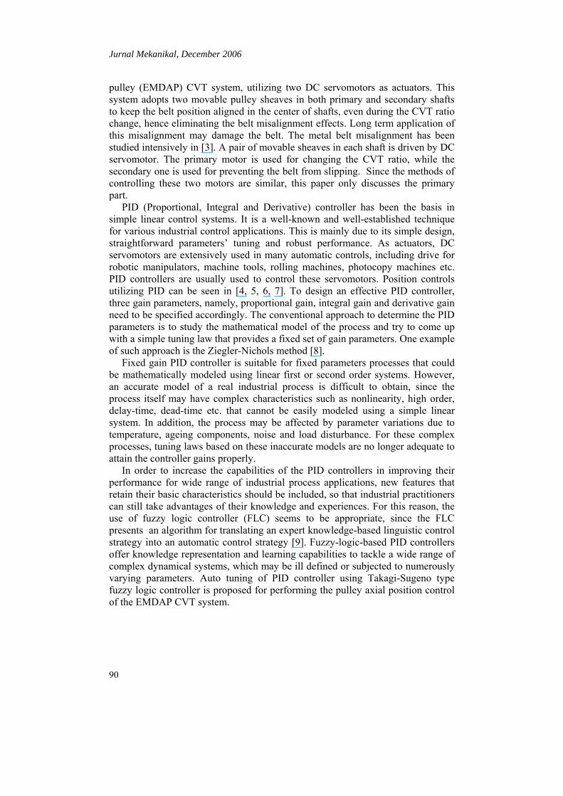
2.0 ELECTRO-MECHANICAL DUAL ACTING PULLEY CVT The electro-mechanical dual acting pulley CVT (EMDAP CVT) system utilizes two DC servomotors as actuators. The system consists of two sets of pulleys, namely primary pulley splined to the input shaft, and secondary pulley splined to the secondary shaft. Both pulleys’ sheaves can slide axially along their respective shaft. Output shaft of the DC servomotor is directly connected to a series of gear reducers and power screw mechanism to initiate the axial pulley sheaves’ movement. Based on this arrangement, the DC servomotor controls the sheaves’ movements directly. A Van Doorne’s metal pushing V-belt is placed on primary and secondary pulley sheaves and runs on these pulley sheaves’ surfaces. This metal belt transmits power and torque from the input shaft to the output shaft by means of contact friction between the belt and the pulleys’ sheaves [10,11]. The contact radius of the belt with primary pulley (Rp) and the contact radius of the belt with secondary pulley (Rs) determines the CVT ratio. The closer the distance between the movable sheaves, the bigger the contact radius will be. The primary and secondary parts of the CVT system have the same components. The components of each part (primary or secondary) consist of a dc servo motor, a gear reducer with ratio of (30:1), a gear reducer with gear ratio of (60:14), power screw mechanism, and two movable metal pulley sheaves for clamping the metal pushing belt. The block diagram of the EMDAP-CVT system can be seen in Figure 1. In laboratory experiments, parameters that can be directly measured are Xp (axial position of primary pulley), Xs (axial position of secondary pulley), ωp (angular speed of primary pulley), ωs (angular speed of secondary pulley), Tp (torque of primary pulley) and Ts (torque of secondary pulley).
PRIMARY DC MOTOR
SECONDARY DC MOTOR
GEAR REDUCER
GEAR REDUCER
Xp
Xs
Rp
Rs
Tp
Ts
ω p
ωs
Vip
Vis
To Wheel Drive
From Engine
Primary Pulley
Secondary Pulley
CVT
Figure 1: The block diagram of the EMDAP-CVT
The primary motor actuates the primary pulley movement for CVT ratio change, while the secondary motor actuates the secondary pulley movement for clamping force. A spring disc is inserted in the back of each secondary pulley sheave to provide continuous clamping force to the belt, and to reduce belt slip

Jurnal Mekanikal, December 2006
92
during CVT ratio change. The primary belt radius is less than the secondary belt radius (Rp < Rs ) during under drive. When ratio change is required, the primary motor will actuate the primary pulley axially to the new value of primary radius and at the same time the secondary motor will actuate the secondary pulley accordingly to provide the optimal clamping force for preventing belt slip. These movements will stop once the desired ratio is achieved. When the CVT is overdrive, the primary belt radius is greater than the secondary belt radius (Rp > Rs). 3.0 SYSTEM MODELING This section describes mathematically how the CVT is being modeled. The model covers the DC servomotor as an actuator, gear reducer as speed reducer and torque multiplier and power screw mechanism as a means of shifting pulley sheaves axially. 3.1 Modeling of DC Servomotor By using Laplace operator s = d/dt, the dynamic model of the DC servomotor is represented as follow:
ωaaaaaa KiRisLV ++= (1)
aaaaaa iRiLsKV .... +=− ω (2) Tm - TL = Jm .s.ω +Bm.s2.ω (3) θ = sω (4)
3.2 Gear Reducer and Power Screw Mechanism A gear reducer serves as a speed reducer and torque multiplier. The gear reducer is coupled with the servomotor shaft. The gear reducer output is connected to the power screw mechanism for shifting the pulley sheaves. There are two gear reducers employed in the EMDAP-CVT system; the first ratio is 30:1, while, the second is 60:14. The total gear ratio of these reducers is 128.57:1. A power screw mechanism is used to move the pulley sheaves axially. It converts every 360° of rotation into 2 millimeters of axial movement. The combination of gear reducers and power screw mechanism is used to help the motor in providing significant torque to turn the power screw mechanism. Torque required by power screw to increase the belt clamping force is given by:
fldlfd
dF21T
m
mmcLu −
+=
ππ
(5)

Jurnal Mekanikal, December 2006
93
Torque required by power screw to reduce the belt clamping force is given by:
fldlfd
dF21T
m
mmcLd +
+=
ππ
(6)
4.0 PROPOSED CONTROLLER This paper proposes a Fuzzy-PID controller to control the DC servomotor system such that the axial-pulley position satisfies the desired set point. The common problem of tuning PID is dealing with specifying three gain parameters to meet a certain requirement of control specifications, such as set-point follower, load disturbance attenuation, robustness due to model uncertainties and noise rejection [12]. Many different techniques have been proposed in the literature to cope with these tuning problems. The use of Ziegler-Nichols formula for tuning PID parameters usually gives good results in load disturbance attenuation, but poor in both lowering the overshoot and reducing the settling time. These two aspects are mainly triggered by the selection of high proportional gain. To cope with this problem, a fuzzy logic controller is proposed to obtain the suitable weight value to adjust the proportional gain with respect to the current value of the system error (e) and its change of error rate (de). The block diagram of the proposed controller scheme is given in Figure 2.
PID
du/dt
FLC
DC SERVOMOTOR
SYSTEM
GEARING SSTEM
Xr Xae
de
Figure 2: Block diagram of the fuzzy-PID controller
4.1 Parameter Tuning for PID Controller The transfer function of a PID controller has the following form:
sKsKKG dipPID ++= / (7)
Another useful equivalent form of the PID controller is given by:
sTsTKG dipPID ++= )/(11( ) (8)
Jurnal Mekanikal, December 2006
94
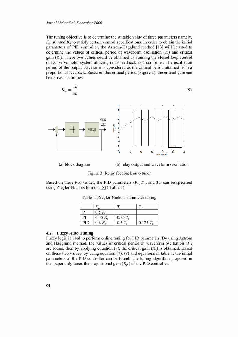
The tuning objective is to determine the suitable value of three parameters namely, Kp, Ki, and Kd to satisfy certain control specifications. In order to obtain the initial parameters of PID controller, the Astrom-Hagglund method [13] will be used to determine the values of critical period of waveform oscillation (Tc) and critical gain (Kc). These two values could be obtained by running the closed loop control of DC servomotor system utilizing relay feedback as a controller. The oscillation period of the output waveform is considered as the critical period attained from a proportional feedback. Based on this critical period (Figure 3), the critical gain can be derived as follow:
adKc π
4= (9)
PROCESS+
-
Process Output
(a) block diagram (b) relay output and waveform oscillation
Figure 3: Relay feedback auto tuner
Based on these two values, the PID parameters (Kp, Ti , and Td) can be specified using Ziegler-Nichols formula [8] ( Table 1).
Table 1: Ziegler-Nichols parameter tuning
Kp Ti Td
P 0.5 Kc PI 0.45 Kc 0.85 Tc PID 0.6 Kc 0.5 Tc 0.125 Tc
4.2 Fuzzy Auto Tuning Fuzzy logic is used to perform online tuning for PID parameters. By using Astrom and Hagglund method, the values of critical period of waveform oscillation (Tc) are found, then by applying equation (9), the critical gain (Kc) is obtained. Based on these two values, by using equation (7), (8) and equations in table 1, the initial parameters of the PID controller can be found. The tuning algorithm proposed in this paper only tunes the proportional gain (Kp ) of the PID controller.

Jurnal Mekanikal, December 2006
95
The fuzzy auto-tuner takes two inputs: the error (e) and the change error rate (de) of the output response. To normalize these inputs into the range of [-1, 1] , these inputs are scaled by two coefficients, Ke and Kde respectively. The fuzzy system can be started to operate at a certain error value by specifying the value of Ke. In this paper authors select Ke=10, meaning that the system will effectively operate when the output error is in the range of [-0.1, 0.1]. The Kde can be set initially to ‘1’. Three triangular membership functions (Figure 4) are defined for each input (N=Negative, Z=Zero and P=Positive), while five constant values of Takagi-Sugeno type in the range of [-1, 1] is defined for the output (NB=Negative Big, NS=Negative Small, Z=Zero, PS=Positive Small and PB=Positive Big).
0 0.5-0.5 1-1
Z PN1
0 0.5-0.5 1-1
Z PN
0
0 1-1 -0.2 0.2
Z PN1
0
(a) error (b) the change of the error
0 1-1 -0.2 0.2
Z PSNS PBNB1
0
(c) output
Figure 4: Membership function of input and output The error e (k) and the error change rate de(k) are defined as follow:
e (k) = xr(k) – xa(k) (10)
de (k) = e(k) – e(k-1) (11)
The fuzzy output (Yf) is the singleton value in the range of [-1, 1] of the Takagi-Sugeno Type. This output value is then multiplied by the proportional gain (Kp) and then summed with other PID gains to give the overall controller gain (Gc ):
Gc= Yf * Kp + Ki + Kd (12)
The fuzzy rules to determine the output fuzzy is determined from the following equation:
Ri: if e(k) is Aj and de(k) is Bj then Yfji (13)
Where i (i=1,…,9) is the number of rules. The rule justification is based on the “scale mapping” method developed by King and Mamdani [9]. This justification is
Jurnal Mekanikal, December 2006
96
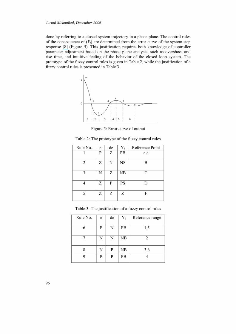
done by referring to a closed system trajectory in a phase plane. The control rules of the consequence of (Yf) are determined from the error curve of the system step response [8] (Figure 5). This justification requires both knowledge of controller parameter adjustment based on the phase plane analysis, such as overshoot and rise time, and intuitive feeling of the behavior of the closed loop system. The prototype of the fuzzy control rules is given in Table 2, while the justification of a fuzzy control rules is presented in Table 3.
a
b
c
de
fg
1 2 3 4 5 6
0
1
Figure 5: Error curve of output
Table 2: The prototype of the fuzzy control rules
Rule No. e de Yf Reference Point 1 P Z PB a,e
2 Z N NS B
3 N Z NB C
4 Z P PS D
5 Z Z Z F
Table 3: The justification of a fuzzy control rules
Rule No. e de Yf Reference range
6 P N PB 1,5
7 N N NB 2
8 N P NB 3,6 9 P P PB 4
Jurnal Mekanikal, December 2006
97
Defuzzification is needed for the fuzzy logic controller to convert its internal fuzzy output variables into crisp values usable for the controlled system. This paper will adopt the weighted average method as following:
∑
∑
=
== n
ii
n
iiji
f
w
cwy
1
1,
(14)
The fitness (wi) is defined as:
))(())(( kdexkew BjAji µµ= (15)
j=1, 2, 3, i=1, 2, 3
This type of defuzzification method is selected due to its simple and fast computation [7]. 5.0 SIMULATION STUDIES Simulation studies of the proposed Fuzzy-PID controller are carried out in order to investigate its effectiveness in this position control application. In these studies, the DC servomotor has the following important parameters as shown in Table 4.
Table 4: DC servomotor parameters
Parameters Values
Motor Voltage 24 V
Armature Resistance 0.03 Ω
Armature Inductance 0.1 mH
Back emf Constant 7 mV/rpm
Torque Constant 0.0674 N/A
Nominal Torque 1.6 Nm
Nominal Speed 3000 rpm
Rotor Inertia 0.1555e-4 N.sec2
Jurnal Mekanikal, December 2006
98
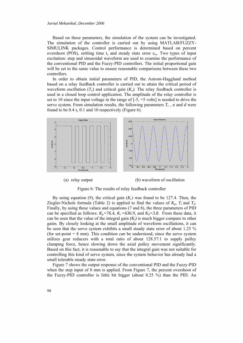
Based on these parameters, the simulation of the system can be investigated. The simulation of the controller is carried out by using MATLAB/FUZZY-SIMULINK packages. Control performance is determined based on percent overshoot (POS), settling time ts and steady state error ess. Two types of input excitation: step and sinusoidal waveform are used to examine the performance of the conventional PID and the Fuzzy-PID controllers. The initial proportional gain will be set to the same value to ensure reasonable comparisons between these two controllers. In order to obtain initial parameters of PID, the Astrom-Hagglund method based on a relay feedback controller is carried out to attain the critical period of waveform oscillation (Tc) and critical gain (Kc). The relay feedback controller is used in a closed loop control application. The amplitude of the relay controller is set to 10 since the input voltage in the range of [-5, +5 volts] is needed to drive the servo system. From simulation results, the following parameters Tc , a and d were found to be 0.4 s, 0.1 and 10 respectively (Figure 6).
(a) relay output (b) waveform of oscillation
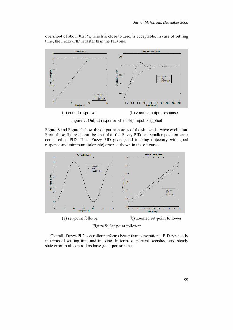
Figure 6: The results of relay feedback controller By using equation (9), the critical gain (Kc) was found to be 127.4. Then, the Ziegler-Nichols formula (Table 2) is applied to find the values of Kp, Ti and Td. Finally, by using these values and equations (7 and 8), the three parameters of PID can be specified as follows: Kp=76.4, Ki =636.9, and Kd=3.8. From these data, it can be seen that the value of the integral gain (Ki) is much bigger compare to other gains. By closely looking at the small amplitude of waveform oscillations, it can be seen that the servo system exhibits a small steady state error of about 1.25 % (for set-point = 8 mm). This condition can be understood, since the servo system utilizes gear reducers with a total ratio of about 128.57:1 to supply pulley clamping force, hence slowing down the axial pulley movement significantly. Based on this fact, it is reasonable to say that the integral gain was not suitable for controlling this kind of servo system, since the system behavior has already had a small tolerable steady state error. Figure 7 shows the output response of the conventional PID and the Fuzzy-PID when the step input of 8 mm is applied. From Figure 7, the percent overshoot of the Fuzzy-PID controller is little bit bigger (about 0.25 %) than the PID. An
Jurnal Mekanikal, December 2006
99
overshoot of about 0.25%, which is close to zero, is acceptable. In case of settling time, the Fuzzy-PID is faster than the PID one.
(a) output response (b) zoomed output response
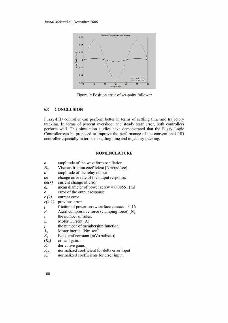
Figure 7: Output response when step input is applied Figure 8 and Figure 9 show the output responses of the sinusoidal wave excitation. From these figures it can be seen that the Fuzzy-PID has smaller position error compared to PID. Thus, Fuzzy PID gives good tracking trajectory with good response and minimum (tolerable) error as shown in these figures.
(a) set-point follower (b) zoomed set-point follower
Figure 8: Set-point follower Overall, Fuzzy-PID controller performs better than conventional PID especially in terms of settling time and tracking. In terms of percent overshoot and steady state error, both controllers have good performance.
Jurnal Mekanikal, December 2006
100
Figure 9: Position error of set-point follower
6.0 CONCLUSION Fuzzy-PID controller can perform better in terms of settling time and trajectory tracking. In terms of percent overshoot and steady state error, both controllers perform well. This simulation studies have demonstrated that the Fuzzy Logic Controller can be proposed to improve the performance of the conventional PID controller especially in terms of settling time and trajectory tracking.
NOMENCLATURE a amplitude of the waveform oscillation. Bm Viscous friction coefficient [Nm/rad/sec] d amplitude of the relay output de change error rate of the output response. de(k) current change of error dm mean diameter of power screw = 0.08551 [m] e error of the output response e (k) current error e(k-1) previous error f friction of power screw surface contact = 0.16 Fc Axial compressive force (clamping force) [N] i the number of rules. ia Motor Current [A] j the number of membership function. Jm Motor Inertia [Nm.sec2] Ka Back emf constant [mV/(rad/sec)] (Kc) critical gain. Kd derivative gains Kde normalized coefficient for delta error input Ke normalized coefficients for error input.
Jurnal Mekanikal, December 2006
101
Ki, integral gain Km Torque Contant [Nm/A] Kp, proportional gain l pitch of power screw = 0.002 [m] La Motor Inductance [H] Ra Motor Resistance [Ω] Tc Critical period of waveform oscillation Td derivative time constant Ti integral time constant TL Load Torque [Nm] TLd Torque for lowering load [Nm] TLu Torque for lifting load [Nm] Tm Motor Torque [Nm] Va Motor Voltage [V] θ motor shaft angular displacement [rad] xr desired output xa actual output. ω motor shaft angular velocity [rad/sec] µAj membership function of error input µBj membership function of change of error input
ACKNOWLEDGEMENT This paper was supported by IRPA vot number 74203.
REFERENCES 1. Akerhurst, S. and Vaughan, N.D., 1999, An Investigation into the Loss
Mechanisms Associated with an Automotive Metal V-belt CVT, European Automotive Congress Vehicle Systems Technology for the Next Century, STA991407, Barcelona.
2. Van de Meerakker, K., Rosielle, P., Bonsen, B. and Klaassen, T., 2004, Design of An Electro-mechanical Ratio and Clamping Force Actuator for a Metal V-Belt Type CVT, 7th International Symposium on Advanced Vehicle Control (AVEC’04), Arhem, Netherland.
3. Tawi, K.B., 1997, Investigation of Belt Misalignment Effects on Metal Pushing V-Belt Continuously Variable Transmission, Ph.D, Thesis, Cranfield University.
4. Jingzhuo, S., Dianguo, X. and Zongpei, W., 2000, Hybrid Stepping Motor Position Servo System Based on DSP, IECON 2000, 20th Annual Conference of the IEEE Industrial Electronics Society IEEE 2000, Vol. 2, pp.1475-1479.
5. Habib, R., Maki, 2001, Designing Fuzzy Logic Controllers for DC Servomotors Supported by Fuzzy Logic Control Development Environment,

Jurnal Mekanikal, December 2006
102
IECON’01: The 27th Annual, Conference of the IEEE Industrial Electronics Society.
6. Yang, Y., Wang, W., Yu, D. and Ding, G., 2002, A Fuzzy Parameters Adaptive PID Controller Design of Digital Positional Servo System, Proc. of The First International Conference on Machine Learning and Cybernetics, Beijing.
7. Bulale, Y.I., Salami, M.J.E., Sulaiman, M., 2003, Design and Development of DSP-Based Hybrid Controller for Servo Driver Applications, Proceeding of 2003 IEEE Conference on Control Applications 2003, Vol. 1, pp. 773-778.
8. Hwang, H., Choi, J.N., Lee, W.H., Kim, J., 1999, A Tuning for the PID Controller Utilizing Fuzzy Theory, IJCNN’99 International Joint Conference on Neural Network 1999, Vol. 4, pp. 2210-2215..
9. Lee, C.C, 1990, Fuzzy Logic in Control Systems: Fuzzy Logic Controller- Part I, IEEE on Trans. on System, Man and Cybernetics, Vol. 20, No. 2.
10. Kanehara, S., Fujii, T. and Oono, S., 1996, A Study of a Metal Pushing V-Belt Type CVT: Macroscopic Consideration for Coefficien of Friction Between Belt and Pulley, SAE Paper, No. 9636277.
11. Fushimi, Y., Fujii, T. and Kanehara, S., 1996, A Numerical Approach to Analyse the Power Transmitting Mechanisms of a Metal Pushing V-Belt Type CVT, SAE Technical Paper Series 960720.
12. Visioli, A., 1999, Fuzzy Logic Based Set-Point Weight Tuning of PID Controllers, IEEE Trans, On Systems, Mans, and Cybernetics-Part A: System and Humans, Vol. 29, No.6.
13. Astrom, K.J. and Hagglund, T., 1984, Automatic Tuning of Simple Regulators with Specifications on Phase and Amplitude Margins, Automatica, 20, pp. 645-651.
Copyright © 2022 FDOKUMEN