
Light-scattering intensity fluctuations in microdroplets containing inclusions
Upload
khangminh22Category
view
1download
0
Control of nonmetallic inclusions incontinuously cast steels in view of macro-
cleanliness, castability, precipitationmodification and grain refinement
von der Fakultät für Werkstoffwissenschaft und Werkstofftechnologieder Technischen Universität Bergakademie Freiberg
genehmigte
DISSERTATION
zur Erlangung des akademischen Grades
Doktor-Ingenieur (Dr.-Ing.)
vorgelegt
von M. Eng. Zhongting Ma
geboren am 04.09.1964 in Anhui, V. R. China
Gutachter: Prof. Dr.-Ing. habil. Dieter Janke, FreibergProf. Dr.-Ing. habil. Heinz-Joachim Spies, FreibergProf. Dr.-Ing. habil. Eberhard Steinmetz, Essen
Tag der Verleihung: 20. April 2001

Contents
PrefaceNomenclature
iiiiv
CHAPTER 1Introduction and research objectives …………………
1.1 Introduction ……………………………………………1.2 Steel quality and nonmetallic inclusions ………………1.3 Research objectives …………………………………
1
123
CHAPTER 2Research scenario and discussions ……………………
2.1 Solidification path of steel ……………………………2.2 Generation of finely dispersed oxide inclusions …………2.3 Precipitation of MnS …………………………………2.4 Formation of intragranular ferrite (IGF) … ……………2.5 Inclusions in view of castability and quality of continuously cast steel ………………2.6 Oxide metallurgy ……………………………………
4
441013
1617
CHAPTER 3Deoxidation techniques used in steelmaking processes ……3.1 Conventional deoxidation technologies …………………3.2 Clean deoxidation technologies ………………………3.3 Alternative deoxidation techniques in view of utilization of oxide inclusions ……………………
242632
36
CHAPTER 4Experimental apparatus and procedures …………………
4.1 Experimental apparatus and investigated steels ……………4.2 Experimental procedures ………………………………4.3 Oxygen sensing and control ……………………………
39
394243

CHAPTER 5Size, composition, distribution and morphology ofoxides in steel ………………………………………………
5.1 Composition of oxide inclusions ……………………………5.2 Size and distribution of oxide inclusions ………………5.3 Shape of oxide inclusions ………………………………
46
465466
CHAPTER 6Effects of oxide inclusions on castability and sulfides …………
6.1 Effect of oxide inclusions on castability …………………6.2 Oxide inclusions acting as nucleation sites for sulfides, nitrides and carbides …………………………………………
70
70
78
CHAPTER 7Effects of oxide inclusions on microstructures andMechanical properties of steel …………………………………
7.1 Effect of oxide inclusions on microstructures ……………7.2 Inclusions serving as nucleation sites for IGF ……………7.3 Relation between microstructure and toughness ……………
86
879094
CHAPTER 8Conclusions …………………………………………………… 100
APPENDIX AThermodynamics of concentrated metallic solutions ………… 103
APPENDIX BInteraction parameters of solutes in liquid iron ………… 110
APPENDIX CCalculation of precipitates in molten steelduring solidification …………………………………………
Acknowledgements ……………………………………………
113
122

Preface
The purpose of this doctorate thesis is to investigate a new technologytermed oxide metallurgy aiming to improve steel service propertieswithout additional secondary metallurgical processing in view of highersteel purity. It is difficult and cost inefficient to produce steel withextremely low contents of inclusions. Moreover, the elimination ofinclusions and impurities can never be fully accomplished. Therefore,oxide metallurgy appears to be a promising additional method to producefuture steels. Steel service properties can be improved and guaranteedthrough minimization of inclusion and grain size without the requirementof ultra clean. This approach can probably to a certain extent reduce theefforts to maintain steel cleanness in refining and tundish metallurgicalprocesses leading to simplified requirements for the conventional slagsand refractories. With the above concept, the controlled inclusions are nolonger harmful to steel service properties in view of macro-cleanness,grain refinement and modification of inclusions. The contents of thepresent study are briefly introduced as follows.
Chapter 1 gives an introduction and outlines the present researchobjectives. The reported research work on oxide metallurgy issummarized and discussed in Chapter 2. Chapter 3 is devoted to discussdeoxidation technologies such as conventional, clean and alternativeones. Alternative deoxidation technology is essential for oxidemetallurgy. The related laboratory-scale experimental equipment andprocedure are covered at length in Chapter 4. Chapter 5 treats inclusionsin steel with the aim to understand the fundamental effects of alternativedeoxidation technology upon inclusions. Effects of inclusions on steelcastability and precipitation of sulfides are considered in Chapter 6.Grain refinement is reached through the control of oxide inclusions andsolidification, eventually contributing an improvement of mechanicalproperties. Chapter 7 gives a clear explanation on this subject.Meanwhile, industrial examples are also presented in this chapter.Several important conclusions obtained from the present study aresummarized in Chapter 8. Finally, Appendices A, B and C deal with thefundamental knowledge related to oxide metallurgy which is directlyused in the present study.

Nomenclature
AV Charpy-V-notch impact toughness (J)Ci Concentration of solute i during solidification from liquidus to
solidus temperature (mass %)CCi
0Coulomb (A⋅s)Concentration of solute i inliquid steel (mass %)
Di Diffusion coefficient of solute i in solid iron (cm2⋅s-1)Di
L Diffusion coefficient of solute i in liquid iron (cm2⋅s-1)E Electromotive force (mV)∆Ei-g Energy change of forming a contact area between inclusion
and gas or vacuum (J)∆Es-g Energy change of forming a contact area between nozzle
refractories and gas or vacuum (J)∆Ep Energy for establishing a cavity (J)∆ET Total energy change (J)∆EV-α Volume free energy change for the formation of α phase (J)∆Eα-γ Surface energy change for the formation of α phase (J)∆Estrain,α Strain energy resulting from the formation of α phase (J)∆Eγ-γ Surface energy change for the diminution of contacted γ phase
(J)∆EV-i Volume free energy change for the formation of inclusion (J)∆Estrain,i Strain energy resulting from the formation of inclusion (J)F Faraday constant (96484.6 C⋅mol-1)
0iG∆ Standard Gibbs free energy of element i dissolved in liquid iron
based on 1 mass% standard (J⋅mol-1)Iion Current of ions across the solid electrolyte (A)
yxOMK Equilibrium constant of formation of oxide MxOy in liquid iron
KxM-yO Equilibrium constant of oxide MxOy dissolved in liquid ironMi Atomic mass of element i (g⋅mol-1)N Number of oxides per unit volume
θP Parameter of partial electronic conductivity at tion=0.5 (bar)'
2OP Oxygen partial pressure in steel melts (bar)
2OP Oxygen partial pressure of reference electrode (bar)
Pa Pressure outside cavity (bar)Pi Pressure inside cavity (bar)

R Universal gas constant (8.314 J⋅K-1⋅mol-1)Rion Resistance of ionic current between two electrodes (Ω)RC Cooling rate (K⋅s-1)T Temperature of steel melts (K)TL Liquidus temperature of steel (K)TS Solidus temperature of steel (K)T0 Melting point of pure iron (K)U External voltage applied to a cell (mV)∆V Volume change (cm3)t Time (s)fS Solid fractionλ Secondary dendrite arm spacing (cm)ki Equilibrium distribution coefficient of solute i between liquid
and solid phases[wt%i](t)
Content of solute i in steel melts at time t during solidification(mass %)
[wt% i]0 Content of solute i in steel melts at time t=0 duringsolidification (mass %)
% [i] Mass percentage of solute i in steel melts (mass %)% [i]max Solubility of solute i in steel melts (mass %)ai Raoultian activity of element i in steel meltshi Henrian activity of element i in steel meltsxi Mole fraction of element i in steel meltsε i
i First-order self-interaction parameter of solute i based onmole fraction
eii First-order self-interaction parameter of solute i based on
mass percentagejiε First-order interaction parameter of solute j upon i based on
mole fractionjie First-order interaction parameter of solute j upon i based on
mass percentage0iγ Raoultian activity coefficient of solute i at infinite dilute
solutionγi Raoultian activity coefficient of solute iγ1 Raoultian activity coefficient of solventfi Henrian activity coefficient of solute iθ Contact angle (degree)θR Observed contact angle with roughness (degree)θS Observed contact angle with perfectly smooth surface (degree)

rτ
Surface roughnessLocal solidification time (s)
δ Misfit between two phases which is calculated for particularplanar parallelisms
σx-y Interfacial tension between x and y phases (J⋅cm-2)ρA Density of phase A (g⋅cm-3)

1
CHAPTER 1Introduction and Research Objectives
1.1 Introduction
Steel is one of the massively used and most important materials in anyindustrialized society. It is regarded as one of the basic materials to thesustainable development of a modern industrial society due to itsversatility and potential of nearly complete recycling. Its applications aremost diverse and widespread in all major branches of industry. Steelindustry is among the most productive, efficient and technologicallysophisticated industries in the world. However, in a global economy that isbecoming steadily more competitive steel industry must continuously findways to stay at the forefront of manufacturing technology. Future steelswill face problems such as quality, price, customer demands andenvironmental and ecological concerns. Steel industry should provide highquality products to its customers in an environmentally friendly, costeffective manner. To achieve this aim, the following three targets(summarized from references [1-2]) are continuously needed to beimproved.- Process efficiency • Improvement of quality, throughput and energy efficiency in cost effective manner • Development of new methods to shorten process chains in cost effective manner • Quantitative modeling of material performance • Process automation- Product development • Development of steel grades for lightweight construction • Increase of steel consumption to key markets by developing new products with new properties • Achievement of maximum flexibility in production capabilities responding to ever-changing markets and customer demands- Environmental and ecological concerns and recycling • Increase of steel recycling and recovery of iron units from plant solid wastes • Ultimate finding of ways to eliminate or at least minimize wastes
2
Therefore, steel industry is going through a technical revolution that willnot only change the conventional steelmaking process but also establish anew industrial structure.
1.2 Steel Quality and Nonmetallic Inclusions
Normally, steel quality is greatly improved by removing impurities andinclusions to very low levels [3]. However, as in any other productionfacility, steelmaking has to find trade-offs between product performanceand price. Extreme pursuance of purity is useless with respect to costeffectiveness and competitiveness on the one hand. On the other hand theelimination of nonmetallic inclusions can never be fully accomplished [4].Moreover, it is a difficult task to produce steel with extremely lowcontents of inclusions. Thus, the performance of steel should be controlledby an advanced technology in view of an appropriate purity level. In fact,the inclusions remaining in steel exert remarkable effects on steel serviceproperties. Control and utilization of nonmetallic inclusions in steel is oneof the essential tasks in steelmaking process directly related to steel qualityand process efficiency and even related to environments by alleviation ofharmful effects of impurities and reduction of effluents.
The prominent characteristics for the forthcoming technologies of thin slabcasting, hot direct rolling and near net shape casting is the reduction ofcasting thickness causing higher cooling rates. It is obvious thatnonmetallic inclusions will exert more remarkable effects on steel serviceproperties and its production processes with regard to advancedsteelmaking technologies in comparison with the conventional ones. It isbelieved that castability, structure and properties of continuously cast steelare closely related to nonmetallic inclusions. In addition to theconventional concept, there exist the following four ways to guarantee theimprovement of castability, structure and properties of continuously caststeel [5]:- removal of nonmetallic inclusions to extremely low levels,- modification of nonmetallic inclusions to alleviate or eliminate their
harmful effects,- control of nonmetallic inclusions for utilization,- grain refiningIt is the main purpose of the present study to investigate the two latterways which are achieved by alternative deoxidation techniques.

3
1.3 Research Objectives
As mentioned above, the present study aims at the control of nonmetallicinclusions and grain size. Thus, the major objectives are focused on thefollowing three aspects:- alternative deoxidation technologies and its consequences for
inclusions in steel and structures and properties of steel,- mechanisms and fundamentals corresponding to alternative
deoxidation technologies at different stages,- knowledge related to these technologies.
References[1] J. Szekely: ISIJ International, 36(1996), 121/132[2] R. J. Fruehan: Metall. Trans. B, 28B(1997), 743/753[3] Z. Ma, D. Peisker and D. Janke: steel research, 70(1999), 178/182[4] Z. Ma and D. Janke: Acta Metallurgica Sinica, 11(1998), 79/86[5] D. Janke, Z. Ma, P. Valentin and A. Heinen: ISIJ International,
40(2000),31/39

4
CHAPTER 2Research Scenario and Discussions
Normally it is unavoidable to admit nonmetallic inclusions in steel, at leastin small quantities, and steel service properties are strongly affected bythem. These inclusions exert harmful effects to steel service propertiesaccording to the conventional experiences. However, Mizoguchi et al.[1-5]
introduced a new concept of utilization of oxide particles. These particlesspontaneously act as nucleation sites for sulfides during cooling andsolidification and, moreover, refine structures after solidification bynucleation of fine intragranular ferrite (IGF). This approach is termed“oxide metallurgy” with a vital interest for direct hot rolling (DHR)processes, thin slab casting and near net shape casting (NNSC), i.e. directstrip casting. Research work on this item is catalogued, summarized anddiscussed as follows.
2.1 Solidification Path of Steel
The solidification path, i.e. micro-segregation of solutes duringsolidification, is important in oxide metallurgy. Extensive studies havebeen done on the assessment of micro-segregation in solidifying alloys.Some analytical micro-segregation models are classified in Table 2.1 andtheir basic equations for these models are listed in Table 2.2. Manynumerical micro-segregation models have also been proposed. However,the discussions on numerical models are out side the scope of the presentstudy.
2.2 Generation of Finely Dispersed Oxides
Composition, size and distribution of precipitated oxides are greatlyinfluenced by the deoxidants, conditions of the molten steel andsolidification process. Al is widely accepted as a deoxidant in steelmakingprocess. Its addition is very convenient and it effectively reduces oxygencontent in liquid steel to low levels. However, vast investigations foundthat most steel problems can be traced to alumina or Al-rich oxides. Solidalumina inclusions in molten steel tend to rapid clustering due to theirdendritic morphology. The alumina clusters hardly float to the top of themolten steel because of their high apparent density in view of oxideclusters plus engulfed liquid steel. They are detrimental to castability and

5
quality of continuously cast steel. Calcium has been frequently employedto treat Al-killed steels since the 1970’s to avoid the formation of solidalumina. Ca treatment effectively improves castability and quality ofcontinuously cast steel, but is limited for all steel products that requireeither high fatigue resistance in service or high cold formability in verythin gauges. This is because of the presence of globular Ca-Al oxides. TheAl, Ca and Ca-Al oxides are normally several to tens of micrometers indiameter. Partial and complete substitution of Ti, Zr and/or rare earthmetals for Al is increasingly pursued recently. This endeavour is toimprove castability and quality of continuously cast steel throughgeneration of finely dispersed oxides which effectively serve asheterogeneous nucleation sites for transformation and precipitation. Thus,control of the amount, size, composition and distribution of nonmetallicinclusions in steel is of importance.
Table 2.1. Classification of models for solute redistribution during solidification
Diffusion in the solid
Diffusion in the liquid
Limited Complete No
Limited
Complete
Himemiya and Umeda [12]
Nastac and Stefanescu [11]
Himemiya and Umeda [12]
Nonsense
Scheil [6]
Brody and Flemings [7]
Clyne and Kurz [8]
Ohnaka [9]
Kobayashi [10]
Himemiya and Umeda [12]
Lever rule
2.2.1 Experimental results
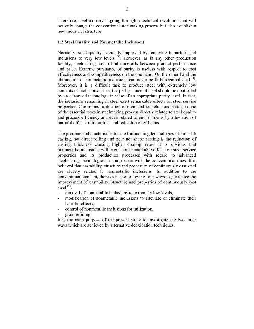
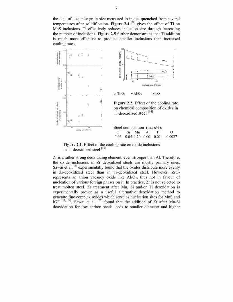
Goto et al.[13-17] experimentally investigated oxide precipitation of Ti-deoxidized low carbon steels. Figures 2.1 and 2.2 demonstrate therelationship between cooling rates and oxide inclusions (number, size,composition and distribution). They further found from experiments that

6
the number of oxides increases with increasing oxygen content, but theaverage size of oxides only slightly increases.
Table 2.2. Equations of analytical micro-segregation models mentioned in Table 2.1
Model Equation
Lever rule
Scheil [6]
Brody and Flemings [7]
Clyne and Kurz [8]
Ohnaka [9]
Kobayashi [10]
Nastac & Stefanescu[11]
Himemiya & Umeda[12]
( )[ ]C kC f kfS S S= − +0 1/
C kC fS Sk= − −
011( )
( )[ ]( ) 2)21/(10 /4,211 λαα α
fSkk
SS tDfkkCC =−−= −−
( )[ ]( )CS kC k f S
k k= −
− −= − −
− −0 1 21 1 2
1 1 12
12
ΩΩ
Ω/ ( )
, exp( ) exp( )αα α
( )[ ]( )C kC k fD t
S Sk k S f= − − =
+=
− −0
1 1 221 1 2
1 28
β β γγ
γλ
β/ ( ), ,
( ) ( )[ ] [ ]
C kC
k f
k k k k
Sk k
S
= + − − − −
= − −
= − + − −
− − − −
− −
01 1 2 1
3 1 3
1 0 5 1 2 1
1 1
1 1 2 4 1
ξ ξ ξ ξ
ξ β
β β γ β
β( )/( ) . ln ,
( ) ,
( ) ( ) ( ) ( )
Γ
Γ
[ ]C k Ck f
m k I If R R
If
nnf
D tR
m for platem for columnarm for equiaxed
I f f
S efef S
ef Sm
Lm S f
m
SS
S
S
fn
L S
= −−
− + +
=
= −
===
= −
+ +
−
+
=
∞
∑
0 1 1
1
1
32 2 1 3
2
21
3 2 3
11
1 1
2 1012
2 1
( )
( ), ( * / )
exp ,,,,
(
( ) ( )
( )/
( ) /
ππ
Sn
n
S
L
fn
n n S
fD tR
f
1 32 1 3
2
21
1 3
11
1
//
/
) exp ,
/ tan( ) .
αα
α α
−−
= −
=
∞
∑
see Ref. [12]
Sawai et al.[18] reported that the oxide inclusions observed in Ti-deoxidizedlow carbon steel are nearly spherical and evenly distributed in the matrixwith small size, and composed of Mn-silicate and (Ti,Mn)O. The elementTi remarkably facilitates grain refinement shown in Figure 2.3 which plots
7
10 1000
50
100
Al2O3
MnO
Ti2O3
cont
ents
of o
xide
(m
ass%
)
cooling rate (K/min)
ο Ti2O3 • Al2O3 MnO
Figure 2.2. Effect of the cooling rateon chemical composition of oxides inTi-deoxidized steel [14]
Figure 2.1. Effect of the cooling rate on oxide inclusions in Ti-deoxidized steel [13]
Steel composition (mass%): C Si Mn Al Ti O 0.06 0.05 1.20 0.001 0.014 0.0027
10 1001000
10000
100000
num
ber o
f oxid
es in
uni
t vol
ume
(num
ber/m
m3 )
cooling rate ( K/min )
10 1000
2
4
aver
age
diam
eter
of
oxi
des
(µ m
)
10 100
0,01
volu
me
fract
ion
of
oxid
es in
ste
el (%
) 0.01
0.001
the data of austenite grain size measured in ingots quenched from severaltemperatures after solidification. Figure 2.4 [20] gives the effect of Ti onMnS inclusions. Ti effectively reduces inclusion size through increasingthe number of inclusions. Figure 2.5 further demonstrates that Ti additionis much more effective to produce smaller inclusions than increasedcooling rates.
Zr is a rather strong deoxidizing element, even stronger than Al. Therefore,the oxide inclusions in Zr deoxidized steels are mostly primary ones.Sawai et al.[18] experimentally found that the oxides distribute more evenlyin Zr-deoxidized steel than in Ti-deoxidized steel. However, ZrO2
represents an anion vacancy oxide like Al2O3, thus not in favour ofnucleation of various foreign phases on it. In practice, Zr is not selected totreat molten steel. Zr treatment after Mn, Si and/or Ti deoxidation isexperimentally proven as a useful alternative deoxidation method togenerate fine complex oxides which serve as nucleation sites for MnS andIGF [23, 24]. Sawai et al. [23] found that the addition of Zr after Mn-Sideoxidation for low carbon steels leads to smaller diameter and higher

8
particle density of oxides. These oxides composed of MnO, SiO2 and ZrO2
are effective nucleation sites for MnS. Wakoh et al. [24] investigated theeffect of Zr on Ti-deoxidized low carbon steels. Their experimental resultssuggest that Zr treatment after Ti deoxidation for low carbon steels favoursuniformly distributed oxide inclusions (MnS precipitation on theirsurfaces) and notably weakens the dependence of oxide distribution oncooling rates in comparison with Ti-deoxidized low carbon steels.
n the size and number density of MnS02S steel [20]
Steel composition (mass%, * in ppm): C Si Mn P* S* Nb N*A: 0.05/8 0.24/26 1.32/1.40 50/80 50/80 0.027/28 50B: 0.06/8 0.25/30 1.36/1.41 50/80 40/80 0.027/30 50
Figure 2.3. Effect of Ticontent on grain growthof as-cast austenite aftersolidification [19]
1000 1100 1200 1300 1400 15000
100
200
300
400
500
600
700
800
9001000
group A: 0.005-0.011 % [Ti]group B: 0.013-0.017% [Ti]
aust
enite
gra
in s
ize
( µm
)
quenching temperature (°C)
0,06 0,08 0,10
0
1
2
MnS
radi
us ( µ
m)
0
10
20
30
40
50
60
70
par
ticle
den
sity
, 104 m
m-3
t (mass%)
Figure 2.4. Effect of Ti content oinclusions in the Fe-0.1C-1Mn-0.
0,00 0,02 0,04Ti conten

9
The People’s Republic of China is rich in resources of rare earth metals(REMs). Therefore, REMs have been widely used in steelmaking sincethree decades for grain refining and inclusion modifying. Extensive andintensive researches were done on their behavior in molten steel and theireffects on steel service properties [25, 26].
2.2.2 Modeling
Many researchers investigated the precipitation behavior of oxides duringsolidification and some of them attempted to simulate this phenomenon.The modeling of inclusion precipitation during solidification is
[27] r, three different modelsitation and growth of4, 27-30]. They are NSC’s
Figure 2.5. Effects of cooling rate and Ti on the size of MnSinclusions in the Fe-0.1C-1Mn-0.02S steel [20]
0 50 100 150 200 250 3000
1
2
3
4
5
6
0.04 wt. [%Ti]
Ti free
Oikawa et. al.[20]
Schwerdtfeger[21]
Takada et al.[22]
Oikawa et. al.[20]
mea
n ra
dius
(µm
)cooling rate (K/min)
summarized in the paper of Wintz et al . So fahave been developed to describe the precipnonmetallic inclusions during solidification [13, 1
(Japan) [29], IRSID’s (France) [27,28] and the present models [30]. Thesemodels are experienced in the same or similar calculation algorithm, i.e.the description of inclusion precipitation is achieved through thecombination of microsegregation models and multiphase equilibrium ones.The calculation tools developed by NSC are based on the juxtaposition oftwo calculation programs, one solving the microsegregation equations ormodels, the other calculating the distribution of elements between liquidmetal and inclusions using a commercial multiphase equilibrium software
10
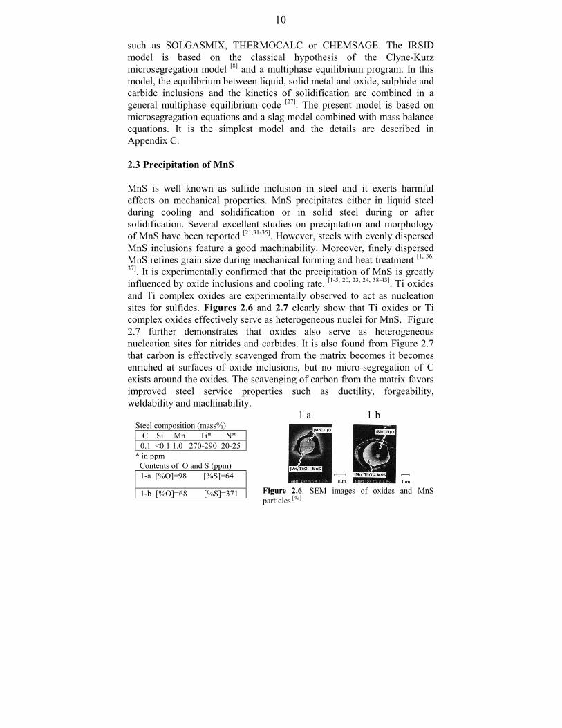
Steel composition (mass%) C Si Mn Ti* N*0.1 <0.1 1.0 270-290 20-25
* in ppm Contents of O and S (ppm)
1-a [%O]=98 [%S]=64
1-b [%O]=68 [%S]=371
such as SOLGASMIX, THERMOCALC or CHEMSAGE. The IRSIDmodel is based on the classical hypothesis of the Clyne-Kurzmicrosegregation model [8] and a multiphase equilibrium program. In thismodel, the equilibrium between liquid, solid metal and oxide, sulphide andcarbide inclusions and the kinetics of solidification are combined in ageneral multiphase equilibrium code [27]. The present model is based onmicrosegregation equations and a slag model combined with mass balanceequations. It is the simplest model and the details are described inAppendix C.
2.3 Precipitation of MnS
MnS is well known as sulfide inclusion in steel and it exerts harmfuleffects on mechanical properties. MnS precipitates either in liquid steelduring cooling and solidification or in solid steel during or aftersolidification. Several excellent studies on precipitation and morphologyof MnS have been reported [21,31-35]. However, steels with evenly dispersedMnS inclusions feature a good machinability. Moreover, finely dispersedMnS refines grain size during mechanical forming and heat treatment [1, 36,
37]. It is experimentally confirmed that the precipitation of MnS is greatlyinfluenced by oxide inclusions and cooling rate. [1-5, 20, 23, 24, 38-43]. Ti oxidesand Ti complex oxides are experimentally observed to act as nucleationsites for sulfides. Figures 2.6 and 2.7 clearly show that Ti oxides or Ticomplex oxides effectively serve as heterogeneous nuclei for MnS. Figure2.7 further demonstrates that oxides also serve as heterogeneousnucleation sites for nitrides and carbides. It is also found from Figure 2.7that carbon is effectively scavenged from the matrix becomes it becomesenriched at surfaces of oxide inclusions, but no micro-segregation of Cexists around the oxides. The scavenging of carbon from the matrix favorsimproved steel service properties such as ductility, forgeability,weldability and machinability.
1-a 1-b
Figure 2.6. SEM images of oxides and MnSparticles [42]

11
Steel composition (mass %) C Si Mn P S Al* Ti* N* O*0.080 0.50 1.47 0.018 0.008 360 43 34 20
* in ppm
The specimen was cut from a continuously cast slab with a thickness of250 mm and a width of 1200 mm at the position of 1/4 width and 125 mmdistance from the lower slab surface in the thickness direction.
Figure 2. 7. Characteristic X-ray images of oxides with sulfide and nitrideprecipitates [44]

12
MnS is significant in oxide metallurgy. The secondary MnS phase whichprecipitates during solidification in the molten steel is much moreimportant than the primary MnS phase because MnS likely precipitatesduring solidification for most produced steels. The contents of Mn and Scontained in these steels hardly reach the solubility product of MnS beforesolidification. It is evident from experiments that most MnS precipitates onthe surfaces of oxides during solidification for the steels deoxidized by Tiand/or Zr[1-5, 20, 23, 24, 36-43]. A small number of globular or near globular MnSprecipitates was found, resulting from homogeneous nucleation based onthe metastable monotectic reaction L1→ Fe(s) + L2, where L1 and L2
present the molten steel and liquid MnS, respectively. The requiredsupersaturation for MnS precipitation is small in the range of 1.0-1.7 [45].As aforementioned, the precipitation and morphology of pure MnS havebeen extensively investigated [21, 31-35]. However, the present interest isfocused on its precipitation on the surfaces of oxides.
Wakoh et al.[42] proposed a mechanism of sulfide precipitation on Mn-silicate inclusions. Oikawa et al.[20] also suggested a mechanism of MnSprecipitation in Ti-killed steels. Wakoh et al.’s mechanism suggests thatMnS crystallization on the surfaces of Mn-silicate is caused by thedecrease of solubility of MnS for Mn-silicate with decreasing temperatureduring solidification. These initial MnS crystals become embryos,contributing to the further growth of MnS precipitates towards the outsideand controlled by the diffusion of Mn and S in the molten steel. Oikawa etal. attributed the nucleation of MnS on the surfaces of oxides in Ti-killedsteels during solidification to the monotectic reactions L1→ Fe(s) + L3 andL1→ Fe(s) + L2 + L3, where L1, L2 and L3 represent the molten steel, liquidMnS and liquid (Ti, Mn)O, respectively. Liquid nuclei of (Ti, Mn)O areprimarily generated at the Fe(s)/Fe(l) interface. After the generation of theliquid (Ti, Mn)O nucleus, liquid MnS droplets (L2) precipitate on thesurfaces of these nuclei. Then, these liquid (Ti, Mn)O nuclei covered withliquid MnS are engulfed by the Fe(s)/Fe(l) interface resulting in finedispersions of MnS and oxides. However, both proposed mechanismscannot completely explain the experimental results and cannot generallydeal with MnS precipitation in industrially produced steels. Furtherinvestigations on MnS precipitation will be discussed in Chapter 6 where anew mechanism is proposed to generally explain MnS precipitation inindustrially produced steels.

13
2.4 Formation of Intragranular Ferrite (IGF)
Proeutectoid ferrite can nucleate at inclusions within austenite grains. Thismakes it possible to obtain a fine ferrite-pearlite microstructure throughcoarse austenite grains. The generation of IGF at inclusions to refine grainstructures effectively improves the toughness of steel to a sufficient levelwithout heat treatment in addition to the conventional austenite grainrefinement techniques. This technology is called IGF technology and is ofgreat interest to welding and structural steels and components ofautomobiles. Obviously, it is the crux of this technology to generate finelydispersed inclusions within austenite grains which effectively act asnucleation sites for IGF. Extensive and intensive researches have beendone on IGF technology [37, 39, 46-69]. However, most of the reported resultsare focused on weld metals and steels at welding thermal cycles. Only in afew cases IGF technology was directly applied to steelmaking processessuch as solidification[37,39] and rolling processes[52]. IGF technology inwelding is quite different from that in steelmaking because of utterdifferent thermal cycles between welding and steelmaking processes.However, the philosophy behind them is similar or consistent no matterhow different the thermal cycles are.
Reported results show that intragranular ferrite can nucleate onprecipitates such as oxides, sulfides and nitrides[37,39,43,46-69]. Figure 2.8gives an example of oxides in a low carbon steel serving as heterogeneousnucleation sites for IGF in the heat affected zone during cooling fromaustenite region after welding. The principles of IGF nucleation on fineoxide inclusions have been extended to sulfides, nitrides and carbides forlow carbon steels at welding thermal cycles [54, 58-60]. An example is shownin Figure 2.9. The nucleation potential for IGF strongly depends oninclusions [49]. Up to now, there exists no uniform theory to clearly explainIGF transformation. Table 2.3 collects various proposed theories toconsider IGF transformation. It is worth mentioning that IGFtransformation may be caused by a combined operation of thesemechanisms. The increase of the driving force for nucleation is also animportant factor.

14
Steel composition (mass %): C Si Mn S Ti O (ppm) N (ppm)0.15 0.24 1.50 <0.007 0.011-0.014 80-120 4-10
Figure 2.8. IGF nucleated on the surface of Ti oxide in the heat effectedzone after a welding thermal cycle (peak temperature of 1400 °C andcooling time of 20 seconds from 800 to 500 °C)[44]
(Note: normally sulfides precipitated on Ti-oxides)
Steel composition (mass %): C Si Mn S Ti Al N (ppm)0.06 0.14 1.48 0.003 0.0011 0.033 40
Figure 2.9. TiN-MnS serving as nucleation sites for IGF in the heataffected zone after a welding thermal cycle (peak temperature of1400 °C, heat input of 20 kJ⋅mm-1 and cooling time of 160 secondsfrom 800 to 500 °C) [60]

15
Table 2.3. Summary of IGF formation mechanism
lar planar
Precipitates, inclusions transformation theory Ref. Epitaxitial growth theory [50]TiO δ = 3.0% [46, 48]TiN δ = 3.8% [46]VN δ = 0.7% [58, 60]Fcc galaxite (Al2O3⋅MnO) δ = 1.8% [46]γAl2O3 δ = 3.2% [46]CuS δ = 2.8% [46] Thermal expansion theory [62](MnO)2(Al2O3)2(SiO2) •Thermal strainAl containing inclusions • Plastic strain Inclusion size theory [67]Inclusion size ≥ 1 µm: GBF [67] ≥0.6 µm: IGF
ry [69]
[62, 65]
[68] [68] [60] [65]
where misfit between two phases, δ, is calculated for particuparallelisms using the following equatio
[ ] [ ]
[ ]∑
=⋅
−==
3
1
)()(
1003
|cos|
2
211
2i uvw
uvwuvwhklhkl
iphase
iphase
iphasephase
phase d
dd θδδ
phaseKhkl)( : low index plane of phase K (K=1 and 2)
[ ]phaseKuvw : low index direction in phaseKhkl)(
[ ]phaseKuvwd : interatomic spacing along [ ]phaseKuvwθ : angle between [ ] 1phaseuvw [ ] 2phaseuvw
Oxide inclusion ≥ 0.4 µm pining γ grain bounda Fine inclusions: ineffective Composition variation such as Mn around inclusions Reducing interfacial energy (Al⋅Si-S-Ti-Mn)O TiN-MnS TiN

16
2.5 Inclusions in view of Castability and Quality of Continuously Cast Steel
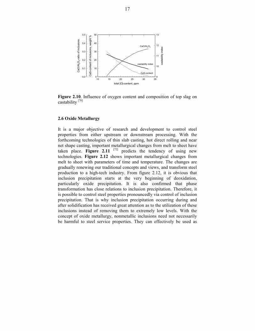
As aforementioned, alumina in steel is easily to form cluster. These clusterinclusions such as Al2O3, Al2O3⋅MgO and Al2O3⋅SiO2 are difficult to beremoved from liquid steel and tend to cause nozzle clogging resulting in abreakdown of the whole casting process. They also exert detrimentaleffects on steel service properties. Ca is introduced to treat Al-killed steelsto avoid the formation of solid alumina. Ca addition transforms solidalumina to liquid Ca-aluminates, reducing nozzle clogging and improvingsteel service properties. Figure 2.10 [70] gives the effect of O content andcomposition of top slag on castability of continuously cast steel. Caaddition effectively modifies alumina inclusions not only in compositionbut also in morphology contributing to improvement of steel serviceproperties. Steel service properties can be guaranteed without therequirement of ultra clean if the maximum particle size is controlled belowa critical level [71]. Of course, finely dispersed inclusions do not tend tocause nozzle clogging. Al deoxidation as well as Ca treated Al deoxidationhardly produce fine inclusions because their corresponding inclusions arenormally several to tens of micrometers in diameter. However, Ti, Zrand/or REMs provide a promising way to generate fine oxide inclusionswith a diameter below 1-2 µm. After adjustment and control, thecorresponding fine oxide inclusions can be evenly dispersed both in themolten steel during cooling and solidification, and in the solid steel matrixafter solidification. These fine oxide inclusions guarantee macro-cleannessand serve as nucleation sites for precipitation and transformation to attaingrain refinement and modification of inclusions. Finally, castability andquality of continuously cast steel are improved by the generation of thesefinely dispersed oxide inclusions. The present investigations show thathigh impact toughness for as-cast stainless, low carbon and low alloyedsteels is obtained through the control and utilization of inclusions.Unfortunately, the author did not find the report on impact toughness ofas-cast deoxidized steels.
17
total [O]-content, ppm
10 15 20 25 30 35C
aO/A
l 2O3-
ratio
of i
nclu
sion
s0,0
0,1
0,2
0,3
0,4
0,5
CaS
-con
tent
of i
nclu
sion
s, w
eigh
t %
0
10
20
30
40
50
cast
abilit
y in
dex
9
10
11
12
13
castability index
CaO/Al2O3
CaS-content
Figure 2.10. Influence of oxygen content and composition of top slag oncastability [70]
2.6 Oxide Metallurgy
It is a major objective of research and development to control steelproperties from either upstream or downstream processing. With theforthcoming technologies of thin slab casting, hot direct rolling and nearnet shape casting, important metallurgical changes from melt to sheet havetaken place. Figure 2.11 [72] predicts the tendency of using newtechnologies. Figure 2.12 shows important metallurgical changes frommelt to sheet with parameters of time and temperature. The changes aregradually renewing our traditional concepts and views, and transform steelproduction to a high-tech industry. From figure 2.12, it is obvious thatinclusion precipitation starts at the very beginning of deoxidation,particularly oxide precipitation. It is also confirmed that phasetransformation has close relations to inclusion precipitation. Therefore, itis possible to control steel properties pronouncedly via control of inclusionprecipitation. That is why inclusion precipitation occurring during andafter solidification has received great attention as to the utilization of theseinclusions instead of removing them to extremely low levels. With theconcept of oxide metallurgy, nonmetallic inclusions need not necessarilybe harmful to steel service properties. They can effectively be used as

18
nucleation sites for precipitation and transformation to improve steelservice properties.
Figure 2.11. Tendencies of producing thin slab and strip casting flat steels [72, 37]
The chart shown in Figure 2.13 clearly indicates that nonmetallicinclusions meeting the requirements are beneficial to steel serviceproperties. This type of nonmetallic inclusion is called “designedinclusion”. Its formation represents the key to oxide metallurgy. Thedesigned inclusions (their composition, size and distribution) should bedecided by the requirements (which can be generally laid down accordingto the demands for steel service properties) and are produced viaalternative deoxidation technology during oxidizing, cooling andsolidification. They will refine grains by generation of intragranular ferrite(IGF) during solidification and rolling processes. Thus, both theaccessibility of determining designed inclusions by demands for steelservice properties and the reliability of producing designed inclusions viaalternative deoxidation technology become the central tasks of oxidemetallurgy.
1985 1990 1995 2000 2005 2010 20150
5
10
15
20
25
30
35
strip casting
thin/mediumslab casting
market implementation strip casting
market implementation thin slab casting
%
of f
lat s
teel
, wor
ldw
ide
year

19
500
1000
1500
molten steel
continuous casting
deoxidation
cementite
ferrite
MnS
oxides
cont
rol o
f ste
el p
rope
rties
CC-DRNNS-CC CC
cold rolling
hot rolling
δ
γ
αtem
pera
ture
, (°C
)
time
CC: Continuous casting, NNS: near net shape casting, DR: direct rolling
Figure 2.12. Temperature-time profile of various steelmaking process [2]
SSP: steel service properties
Figure 2.13. Effect of nonmetallic inclusions on steel service properties[73]
beneficial to SSP
harmful to SSP
positive
negative
inclusionmodification
effe
cts
provision of nucleation sites for IGF
grain refining
surface defects
internal defects
nometallic inclusions

20
References
[1] T. Takamura and S. Mizoguchi: 6th Int. Iron and Steel Congress,Vol.3, Steelmaking I, Oct. 1990, Nagoya, ISIJ, 591/597
[2] S. Mizoguchi and T. Tamamura: 6th Int. Iron and Steel Congress,Vol.3, Steelmaking I, Oct. 1990, Nagoya, ISIJ, 598/604
[3] T. Sawai, M. Wakoh, Y. Ueshima and S. Mizoguchi: 6th Int. Iron andSteel Congress, Vol.3, Steelmaking I, Oct. 1990, Nagoya, ISIJ,605/611
[4] S. Ogibayashi, K. Yamaguchi, M. Hirai and H. Goto: 6th Int. Iron andSteel Congress, Vol.3, Steelmaking I, Oct. 1990, Nagoya, ISIJ,612/17
[5] S. Mizoguchi: “A study on segregation and oxide inclusions for thecontrol of steel properties”, Ph. D. thesis, The University of Tokyo,1996
[6] E. Scheil: Z. Metallkd., 34(1942), 70[7] H. D. Brody, M. C. Flemins: Trans. Metall. Soc. AIME, 236(1966),
615[8] T. W. Clyne and W. Kurz: Metall. Trans. A, 12A(1981), 965[9] I. Ohnaka: Tetsu-to-Hagane, 70(1984), S913 and Trans. Iron Steel
Inst. Jpn., 26(1986), 1045[10] S. Kobayashi: J. Cryst. Growth, 88(1988), 87 and Trans. Iron Steel
Inst. Jpn., 28(1988), 728[11] L. Nastac and D. M. Stefanecu: Metall. Trans. A, 24A(1993), 2107[12] T. Himemiya and T. Umeda: ISIJ International, 38(1998), 730/738[13] H. Goto, K. Miyazawa, K. Yamaguchi, S. Ogibayashi and K. Tanaka:
ISIJ Intern., 34(1994), 414/419[14] H. Goto, K. Miyazawa, W. Yamada and K. Tanaka: ISIJ Intern.,
35(1995), 708/714[15] H. Goto, K. Miyazawa and T. Kadoya: ISIJ Intern., 35(1995),
1477/1482[16] H. Goto, K. Miyazawa and T. Tanaka: ISIJ Intern., 35(1995), 286/291[17] H. Goto, K. Miyazawa and H. Honma: ISIJ Intern., 36(1996),
537/542[18] T. Sawai, M. Wakoh, Y. Ueshima and S. Mizoguchi: ISIJ Intern.,
32(1992), 169/173[19] C. Zhou and R. Priestner: ISIJ Intern., 36(1996), 1397/405

21
[20] K. Oikawa, K. Ishida and T. Nishizawa: ISIJ Intern., 37(1997),332/338
[21] K. Schwerdtfeger: Arch. Eisenhüttenwes., 41(1970), 923[22] H. Takada, I. Bessho and T. Ito: Tetsu-to-Hagane, 62(1976), 1319[23] T. Sawai, M. Wakoh and S. Mizoguchi: Tetsu-to-Hagane, 82(1996),
587/592[24] M. Wakoh, T. Sawai and S. Mizoguchi: Tetsu-to-Hagane, 82(1996),
593/598[25] T. Du, Q. Han and C. Wang: Physical Chemistry of Rare Earth,
Alkaline Earth and Other Elements and Their Applications inMaterials, Academic Press, Beijing, 1995
[26] L. Jia, L. Tang, Q. Lin, G. Shong and L. Liu: private communication,Project “Comprehensive Purification of the Molten Steel by UsingRare Earth and Alkaline Earth Metals” won the fourth class prize of“Development of National Science and Technology of China” 1998
[27] M. Wintz, M. Bobadilla, J. Lehmann and H. Gaye: ISIJ intern.,35(1995), 715/722 or H.Gaye, P. Rocabois, J. Lehmann and M.Bobadilla: steel research, 70(1999), 356/61 or P. Rocabois, J.Lehmann, H.Gaye and M. Wintz: Journal of Crystal Growth,198/199(1999), 838/43
[28] C. Gatellier, H. Gaye, J. Lehmann, J. Bellot and M. Moncel: CIT-Rev. Metall., 4(1992), 361
[29] T. Matsumiya: Metall. Trans. B, 33B(1992), 783[30] Z. Ma and D. Janke: ISIJ Intern., 38(1998), 46/52[31] C. E. Sims and F. B. Dahle: Trans. Am. Foundarymens’s Ass.,
46(1938)[32] W. Dahl, H. Hengstenberg and G. Düren: Stahl und Eisen, 86(1966),
782[33] E. T. Turkdogan and R. A. Grange: J. Iron and Steel Inst., 208(1970),
482[34] Y. Itoh, J. Yonezawa and Y. Matsubara: Tetsu-to-Hagane, 68(1982),
1569[35] K. Oikawa, H. Ohtani, K. Ishida and T. Nishizawa: ISIJ International,
35(1995), 402/408[36] F. Ishikawa, T. Takahashi and T. Ochi: Metall. Trans. A, 25A(1994),
929[37] Z. Ma, D. Peisker and D. Janke: steel research, 70(1999), 178/182

22
[38] Z. Ma and D. Janke: The 3rd CAST (China Association of Scienceand Technology) Conference of Young Scientists, Vol. MaterialsScience and Industrial Technology, August, 1998, Beijing, 46/50
[39] Z. Ma and D. Janke: Technical Report “Improvement of fine grainstructures of 27MnSiVS steel”, Institute of Iron and SteelTechnology, TU Freiberg, November, 1998
[40] K. Yamamoto, T. Hasegawa and J. Takamura: ISIJ International,36(1996), 80/86
[41] see ref. [5][42] M. Wakoh, T. Sawai and S. Mizoguchi: ISIJ International, 36(1996),
1014/1021[43] Z. Ma and D. Janke: Annual Technical Report of ECSC Sponsored
Project under Grant No. ECSC-95-C2.03c, Institute of Iron and SteelTechnology, TU Freiberg, 1998
[44] The picture obtained from Dr. K. S. Oh (POSCO, South Korea):Private Communication, October, 1998
[45] K. Suzuki, A. Ejima and K. Nakanishi: Trans. ISIJ, 15(1985),433/442
[46] R. Mills, G. Thewlis and J. A. Whiteman: Materials Science andTechnology, 3(1987), 1051/1061
[47] R. A. Ricks, P. R. Howell and G. S. Barrotte: J. Mater. Sci., 17(1982),731/740
[48] J. L. Lee and Y. T. Pan: Mater. Sci. Eng., 136A(1991), 109/19,Metall. Trans. A, 22A(1991), 2818/22, 24A(1993), 1399/1408
[49] D. J. Abson: Weld. World, 27(1989), 76/101[50] B. L. Bramfitt: Metall. Trans., 1(1970), 1987/1995[51] F. J. Barbaro, P. Krauklis and K. E. Easterling: Materials Sci. and
Tech., 5(1989), 1057/77[52] T. Funakoshi, T. Tanaka, S. Ueda, M. Ishikawa, N. Koshizuka and K.
Kobayashi: Trans. ISIJ, 17(1997), 419/424[53] D. Yu, F. J. Barbaro, T. Chandra and D. P. Dunne: ISIJ International,
36(1996), 1055/1062[54] H. Homma, S. Ohkita, S. Matsuda and K. Yamamoto: 67th AWS
Convention, Atlanta, USA, 1986[55] Y. Zhu, S. Guo, J. Xu, G. Jiang, D. Yu, L. Pan and Y. Wang: Acta
Metallurgica Sinica, 32(1996), 891/896

23
[56] N. Mori, H. Honma, M. Wakabayashi and S. Ohkita: J. Jpn. Weld.Soc., 50(1981), 786
[57] I. Watanada and K. Kojima: J. Jpn. Weld. Soc., 50(1981), 703[58] F. Ishikawa, T. Takahasi and T. Ochi: Metall. Materials Trans. A,
25A(1994), 929/936[59] T. Ochi, T. Takahashi and H. Takada: Iron & Steelmaker, 16(1989),
21/28[60] Y. Tomita and N. Saito: ISIJ International, 34(1994), 829/835[61] G. M. Evans: Met. Constr., 44(1986), 631/636[62] L. Devillers, D. Kaplan, B. Marandet, A. Ribes and P. V. Riboud: in
Conf. on the effects of residual, impurities and micro-alloyingelements on the weldability and weld properties, The WeldingInstitute, Abington, UK, 1983, 1/12
[63] S. St-Laurent and G. L’Esperance: Mater. Sci. Eng. A, 149A(1992),203/216
[64] Y. Ueshima, H. Yuyama, S. Mizoguchi and H. Kajioka: Tetsu-to-Hagane, 75(1989), 501/08
[65] K. Yamamoto, T. Hasegawa and J. Takamura: ISIJ International,36(1996), 80/86
[66] S. Kanazawa, A. Nakashima, K. Okamoto and K. Kanaya: Trans.ISIJ, 16(1976), 486/495
[67] J. Jang and J. E. Indacochea: J. Mater. Sci., 22(1987), 689/700[68] M. Enomoto and H. I. Aaronson: Metall. Trans. A, 17A(1986),
1381/1384[69] M.Ferrante, K. Akune and M. Odaina: J. Mater. Sci., 22(1987), 351[70] D. Janke, Z. Ma, P. Valentin, A. Heinen: “Improvement of castability,
structure and properties of continuously cast steel”, 10th Japan-Germany Seminar on the Fundamentals of Iron- and Steelmaking,Tokyo, 18-19 May, 1999
[71] H. Kobayashi, T. Kurokawa, T. Shimomura, K. Matsudo and S.Miyahara: Trans. ISIJ, 23(1983), 410/416
[72] K. Schwaha: 1996, cited from the report “Strangiessen undBrammeneinsatz bei der Stahlerzeugung” by M. Wolf, Institute ofIron and Steel Technology, TU Freiberg, July 17, 1997, 44
[73] Z. Ma and D. Janke: Annual Technical Report of ECSC SponsoredProject under Grant No. ECSC-95-C2.03c, Institute of Iron and SteelTechnology, TU Freiberg, 1997

24
CHAPTER 3Deoxidation Techniques Used in Steelmaking Processes
The temperature dependence of oxygen solubility in pure liquid iron isexpressed by Eq. (3-1).
[ ] 765.26380%log max +−=T
O [1] (3-1)
At normal steelmaking temperatures, oxygen solubility is above 0.2 mass%and it is 0.168 mass% at the monotectic temperature (1527 °C) in the Fe-Obinary system. However, oxygen solubility is negligibly small in solid ironshown in Figure 3.1.
Figure 3.1. Iron side of the Fe-O phase diagram [1]
Thus, the dissolved oxygen in liquid steel may react with alloyingelements during cooling and solidification to form oxides. These reactionswill consume alloying elements and carbon resulting in different defects.Moreover, the reaction products may greatly deteriorate steel serviceproperties such as ductility, fracture toughness, machinability, wear
0 20 40 60 80 100800
900
1000
1100
1200
1300
1400
1500
1600
1392 °C
Liquid1527 °C
1537 °C
δ(82)
(54) + liquid oxideδ1390 °C
γ + liquid oxide 1370 °C
+ wustiteγ
γ
(28)
(2)
+ wustiteαα
911.+ °C
tem
pera
ture
, °C
oxygen, ppm

25
resistance and susceptibility to hydrogen induced cracking. Therefore, theoxygen content in steel melts must be reduced to a desired low level. Thisbasic need for steelmaking leads to deoxidation technology. However, it isunavoidable to admit nonmetallic inclusions in steel, at least in smallquantities. These residual inclusions exert strong effects on steel serviceproperties. Attention has been increasingly devoted to control theseresidual inclusions. It is the aim to produce finely dispersed inclusions andto use them to alleviate or diminish their harmful effects and even to exertbeneficial effects on steel service properties.
According to the conventional steel deoxidation, there exist the followingthree categories:- resulphurised and rimming steel deoxidized with ferromanganese to
100-200 ppm oxygen,- semi-killed steel deoxidized with Si-Mn to 50-70 ppm, with Si-Mn-Al
to 40-20 ppm and with Si-Mn-Ca to 20-15 ppm oxygen,- killed steel fully deoxidized with a strong deoxidizer such as Al or Al-
Ca, preventing any reaction between carbon and oxygen duringsolidification.
However, most of the presently produced steels are killed steels. Normally,deoxidation is performed during tapping and refining. With a wideapplication of various types of steel refining processes in recent years, it isnow a common practice to produce steel grades with low levels ofimpurities and inclusions.
As mentioned above, Al is widely used as deoxidant in steelmaking.However, most steel problems can be traced to alumina or Al-rich oxides.To alleviate or eliminate their harmful effects on steel service properties,Ca has been frequently employed to treat Al-killed steels to avoid theformation of solid alumina. However, Ca treatment cannot meet therequirements of either high fatigue resistance in service or high coldformability in very thin gauges. The residual inclusions in steel are ofimportance to steel service properties. Therefore, clean deoxidationtechnology is becoming a topic for discussion which is to prevent steelfrom contamination with deoxidation products through special means toavoid their formation in steel melt. As a matter of fact, the elimination ofimpurities and inclusions from steel can never be fully achieved.Therefore, the composition, size, distribution and number of residualinclusions are the main objectives to the subject of attaining higher steel

26
purity. Partial and/or complete substitution of Ti, Zr and/or rare earthmetals for Al is increasingly pursued aiming at the generation of finelydispersed oxides which can effectively act as nucleation sites for sulfide,nitride and carbide precipitates and intragranular ferrite. In this chapter,the following three deoxidation techniques are discussed and analyzed:- conventional deoxidation technologies,- clean deoxidation technologies,- alternative deoxidation technologies in view of utilization of
inclusions.
3.1 Conventional Deoxidation Technologies
3.1.1 Conventional and Innovative Al Deoxidation PracticeDepending on the particular process route followed at a plant, thedeoxidation process is carried out by the addition of solid lump Al into themolten steel during tapping. The added Al, Aladd, is generally consumed bythe following reactions [2,3]:- Al oxidized by furnace slag, Alslag,- Al oxidized due to air entrainment, Alair,- Al dissolved in steel, Aldiss,- Al reacted with dissolved oxygen, Alreact-O.Alreact-O is simply composed of two parts. One is the reaction product Al2O3
retained in steel as inclusions and the other floated up as a part of the slag.According to material balance, the following Eq. (3-2) is obtained
Aladd = Alslag + Alair + Aldiss + Alreact-O (3-2)
The loss of aluminum due to reaction with oxygen picked up by the metalthrough the entrainment of air is usually less than 20 ppm. Thus, this lossis negligible compared with the other terms mentioned above. Normally,this deoxidation process is easy to complete, but the products hardly floatup and become inclusions entrained in the molten steel. To improve steelcleanliness, exchange treatments with non-oxidizing synthetic slag andwith conditioned slag normally enhanced by stirring and degassing areproposed. Exchange treatment with non-oxidizing synthetic slag aims toachieve deoxidation, desulphurization and inclusion modification.Exchange treatment with conditioned slag can be reached by adding pureCaO or a mixture of limestone (CaCO3) and aluminum to the top slag in

27
order to lower the activity of FeO in the slag. Stirring and degassing areused to improve the kinetics of reactions.
Besides the methods mentioned above, innovative Al deoxidationtechniques are pursued to more effectively reach higher purity of steel.Treatments such as injection of powered agents like Al, Ca-Al, rare earthmetals and Al + CaO-Al2O3 into the molten steel with the help of an inertcarrier gas or by submerged cored-wire injection are practically adopted[3].Most recently, the addition of aluminum in liquid state with or withoutother co-additives is proposed and a higher cleanliness is obtained.However, this technique is just in primary stage and further investigationsare necessary [4].
3.1.2 Ca Treatment of Al-Deoxidized Steel
Al effectively reduces the dissolved oxygen of the molten steel by theformation of solid alumina. However, the solid alumina particles in themolten steel are easily clustering due to their dendritic morphology. Theyhardly float to the top of the molten steel becoming inclusions detrimentalto steel service properties. Ca treatment has been employed to treat Al-killed steels to avoid the formation of solid alumina mainly for longproducts, i.e. bloom/billet casting, but also in standard practice for slabcasting, and is 100% in use for thin slab casting.
The benefits from Ca addition are briefly summarized as follows:
(1) Ca addition conventionally aims to transfer solid alumina inclusionsinto liquid Ca-aluminates. These liquid particles, in contrast to solidalumina, can grow in size and float up from the liquid steel to beabsorbed by the top slag and resulting in cleaner steel with low oxidecontents. The results are solidly confirmed by the fact that the totaloxygen content in the molten steel is greatly decreased by Ca treatmentafter Al deoxidation compared to the molten steel deoxidized by Al.Finally, both castability and quality of continuously cast steel areimproved by Ca treatment.
(2) In addition to the formation of liquid Ca aluminates, another importantaspect of Ca treatment is to modify inclusion morphology,schematically shown in Figures 3.2 and 3.3.

28
Low S (S≤50 ppm):
MnS CaS >> MnS Ca treatment
Rolling Rolling
(Figure 3.2a)
High S (S≥300 ppm):
MnS CaS > MnS Ca treatment CaO + Al2O3
Rolling Rolling
(Figure 3.2b)
Figure 3.2. Schematic images of sulfides in steel after casting and rolling Note: Dimensions of inclusions are not in scale
29
Low S (S≤50 ppm)
Al2O3 Ca treatment CaO+Al2O3
rolling rolling
High S (S≥300 ppm)
Al2O3 Ca treatment CaO+Al2O3
rolling rolling
(CaO+Al2O3)+(CaS+MnS)
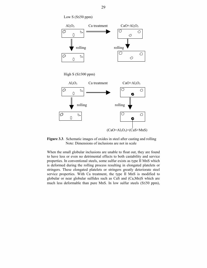
Figure 3.3. Schematic images of oxides in steel after casting and rolling Note: Dimensions of inclusions are not in scale
When the small globular inclusions are unable to float out, they are foundto have less or even no detrimental effects to both castability and serviceproperties. In conventional steels, some sulfur exists as type II MnS whichis deformed during the rolling process resulting in elongated platelets orstringers. These elongated platelets or stringers greatly deteriorate steelservice properties. With Ca treatment, the type II MnS is modified toglobular or near globular sulfides such as CaS and (Ca,Mn)S which aremuch less deformable than pure MnS. In low sulfur steels (S≤50 ppm),

30
most of sulfur combines Ca as Ca rich sulfides and only a small amount ofsulfur exists as MnS in complex sulfides. However, Ca hardly combines allsulfur as CaS rich sulfides in high sulfur steels (S≥300 ppm). In fact, alarger amount of MnS rich sulfides is formed during and/or after casting.Therefore, increasing attention has been drawn to develop new methods tonucleate sulfides on the surfaces of oxides. The formation of these lessdeformed sulfides makes a great contribution to the improvement of steelservice properties.
The added Ca gradually converts solid dendritic alumina inclusions toglobular or near globular C-A inclusions (C: CaO and A: Al2O3). This kindof modification is greatly beneficial to steel castability and serviceproperties. It is worth mentioning that the reaction between Ca and oxidescontinuously occurs from tapping to casting. The continuous change ofinclusion composition clearly confirms this result shown in Figures 3.4and 3.5 [5].
Figure 3.4. Inclusion path of the heats without RH treatment in thepseudo-ternary system CaO´-MgO´-Al2O3´ [5]

31
Figure 3.5. Inclusion path of the heats with RH treatment in the pseudo-ternary CaO´-MgO´-Al2O3´ [5]
Normally, Ca is added to molten steel through the following five methods[6].- Conventional Method: Ca containing agents are thrown into the melt
stream during teeming or into the ladle or tundish. A second popularmethod is to place the Ca containing agents into the ladle and tundishbefore pouring the steel melt.
- Injection Method: Ca containing agents are injected into the moltensteel with the help of an inert carrier gas.
- Cored-Wire Injection: This is similar to the technology of introducingAl wire into steel melts, but the wire consists of a steel sheath which istightly wrapped around a core of Ca containing agents.
- Bullet Shooting Method: Ca containing bullets, as an Al shell in whichcompressed Ca-Si powder is enclosed, are shot into the molten steel bya shooter powered by gas pressure.

32
- Wire Lance Injection: This method combines features of the InjectionMethod and the Cored-Wire Injection. The calcium wire is fed into themolten steel through a ceramic lance, which is submerged into themolten steel. Before feeding, the lance is purged with an inert gas andthe gas flow continues during the whole wire feeding operation.
The injection of Ca and its alloys into the molten steel is important forcontrol of sulfur, oxygen and inclusions and the production of qualitysteels with improved service properties. After the injection of Ca into themolten steel, Ca melts, vaporizes and then partially dissolves into theliquid steel, Ca (s) → Ca (l) → Ca (g) → [Ca] (in liquid steel). Thedissolved Ca reacts not only with the dissolved oxygen and oxideinclusions such as Al2O3, but also with the dissolved sulfur or sulfideinclusions such as MnS in the light of the following reactions
[Ca] + [O] = (CaO) , (3-3)
[Ca] + (x+1/3) (Al2O3) = (CaO⋅xAl2O3) + 2/3 [Al], (3-4)
[Ca] + [S] = (CaS), (3-5)
[Ca] + (MnS) = [Mn] + (CaS). (3-6)
Calcium aluminates may form in the following sequence depending on thecontents of Ca, Al, O in the molten steel and Al2O3, CaO in inclusions:
A→ CA6 → CA2 → CA → C12A7
Thermodynamic considerations on Ca treatment are discussed in detail inRef. [5, 7-9]. Detailed studies of the effect of inclusions on the physicaland mechanical properties of steel are available in Ref. [10-12].
3.2 Clean Deoxidation Technologies
In view of the fact that several steel problems can be traced back tononmetallic inclusions, a deoxidation technology is wanted that caneffectively remove oxygen from steel melts with prevention ofcontamination by deoxidation products. Clean deoxidation technologyhas increasingly received attention from both metallurgists and

33
metallurgical engineers. It is time to deeply and systematically investigatethe new technology. The available research work related to this technologyis summarized and discussed as follows.
3.2.1. Electrolytic Deoxidation
Electrochemical cells based on oxygen ion-conducting ceramicselectrolytes have been used to determine the dissolved oxygen in metalmelts since the 1960’s. In such a cell, the measured EMF, E , is closelyrelated to the oxygen partial pressure in the melt, )(
2MpO , and that of the
reference electrode, )(2
RpO as shown in Eq. (3-7). The used symbols arelisted and explained in the “nomenclature”.
)()(
ln 4/14/1
4/14/1
2
2
MppRpp
FRTE
Oe
Oe
++
=′
′ (3-7)
It is obvious from Eq. (3-7) that the oxygen partial pressure in the melt,)(
2MpO , is obtained from the measurement of E when )(
2RpO and T are
known. The Henrian activity of oxygen, Oh , is deduced from the followingequation
)(exp 2/10
2Mp
RTGh O
OO
∆−= (3-8)
where 0OG∆ represents the Gibbs free energy change of the dissolution
reaction of oxygen in pure liquid iron.
When an external voltage, U , is applied to the cell, the solid electrolytecell mentioned above can be used to adjust the dissolved oxygen content inmetal melts achieving deoxidation or oxidation. The following equation isconsidering this process [13]:
ionionOe
Oeionion RI
MppRpp
FRTRIEU ⋅+
++
=⋅+=′
′
)()(
ln 4/14/1
4/14/1
2
2 (3-9)

34
% [O
], m
ass%
where ionI and ionR represent the ion current across and the ion currentresistance of the ceramic electrolyte.
A continuous deoxidation can be achieved when a negative polarity isattributed to molten metal electrode. Laboratory scale tests were performedon the applicability of this method to remove oxygen from liquid Fe, Co,Ni, Cu and Ag [13, 14]. Figure 3.6 gives an example of electrolyticdeoxidation of an iron melt [13].
Faraday’s line
time, min
1: measuring cell ZrO2 (CaO) 2: electrolysis cell ZrO2 (CaO)(anodic current density 0.37A⋅h-1; melt weight 460 g; meltcontinuously stirred; Al2O3
crucible; argon stream 100l⋅cm-3)
Figure 3.6. Change of oxygen content during electrolytic deoxidation ofan iron melt at 1873 K and electrolysis cells after electrolytic deoxidation[13]
A B
Electrolysis immersion cells withcopper/gra-phite anode in longitu-dinal section after ele-ctrolyticdeoxidation of iron melts
A: porous ZrO2 (CaO)B: porous ThO2 (Y2O3)

35
The prominent advantage of this technology is that it successfully reachesdeoxidation of metal melts without generation of oxidation products in themelts. This advantage is wanted for the production of clean steel.However, this technology faces some problems for its industrializationsuch as efficiency, reliability and costs. Most recently, Li and hisco-workers [15,16] improved and modified this technology. Theysuccessfully developed a “deoxidation unit” in which solid electrolyteZrO2, short-circuited materials and deoxidizer are integrated into one unit.When this deoxidation unit is immersed into a liquid metal, the dissolvedoxygen is forced to pass through the solid electrolyte into the deoxidationunit. The diffused oxygen reacts with the deoxidizer contained in thedeoxidation unit. Therefore, deoxidation products are present inside thedeoxidation unit rather than in the liquid metal. Figure 3.7 indicates thatthe oxygen content in liquid steel is reduced from hundreds to several ppmin one or two minutes after the immersion of the deoxidation unit. It isfound that the experimental data are located above the theoreticallycalculated results after 2 minutes of deoxidation. This is caused during thechange of oxygen sensors because this action allows a little air to enter theatmosphere above the melt resulting in its reoxidation.
Figure 3.7. Change ofoxygen content in steelmelts after immersion ofdeoxidation units into themelts (melt weight of 200g; the volume of thedeoxidation unitrepresents about fivepercent of the meltvolume)[15]
0 2 4 6 8
0
20
40
60
80
100
1840 K experimetal data theoretical calculation
[O],
ppm
time, min
0 1 2 3 4 5 6 7 80
200
400
600
800
experimetal data theoretical calculation
1818 K
[O],
ppm
time, min

36
3.2.2. Deoxidation with Carbon-bearing Oxide Materials
Mixtures of oxides with graphite such as MgO+C and dolomite+C havebeen recently employed as refractory materials in refining of steel becausethese refractory materials demonstrate a superior resistance to steel meltsand slags [17-20]. Janke and the present author [20] proposed a reactionmechanism between the refractory materials and steel melts revealing thefact of its superior resistance to steel melts. According to this mechanism,these refractory materials can also be employed to remove the oxygendissolved in steel melts. Najafabadi et al. [21] experimentally confirmed thatMgO+C porous tubes can be used to remove the oxygen in steel melts tolow levels. Clean deoxidation (without or less deoxidation productspresent in steel melts) is easily reached by using this deoxidationtechnique. Reducing the internal pressure of the MgO+C porous tubefavors the deoxidation process. Further investigations are needed forimproving this new technology.
3.3 Alternative Deoxidation Techniques in view of Utilization of Inclusions
The improvement of steel cleanness is a key task in conventionalsteelmaking processes. Steel castability and quality have been greatlyimproved by adoption of advanced steelmaking technologies, particularlysecondary refining metallurgy, which effectively removes impurities andinclusions to very low levels. Numerous investigators found that most steelproblems can be traced to nonmetallic inclusions. It is a commonlyaccepted view that nonmetallic inclusions are harmful to both steelmakingprocesses and steel service properties. However, the potential to furtherimprove steel cleanliness based on the addition of Al and Ca seems to belimited. Moreover, low levels of impurities and inclusions need notnecessarily guarantee excellent steel service properties because these aregreatly influenced by the remaining inclusions. It has to be recognized thatsteel service properties can be guaranteed without the requirement of ultracleanness under the following conditions- the maximum size of inclusions is controlled below a critical level [22],- the inclusions possess acceptable properties for the hot-linked
processes such as DHR (direct hot rolling), DSC (direct strip casting)and welding [22, 23].

37
Thus, generation of finely dispersed inclusions with favorable propertiesrelated to the hot- linked processes is of importance to produce qualitysteel. This approach provides a radical change in future cleannessassurance, i.e. inclusions have to be controlled below a critical level indiameter despite a higher total oxygen content resulting in lesser demandsin view of refining and tundish metallurgical process. These simplify therequirements for conventional slags and refractories in view of theproduction of clean steel. Since Ti, Zr and rare earth metals are strongoxide formers, they can be used to remove oxygen from molten steel.Steels deoxidized by Ti, Zr and rare earth metals have increasingly beenpursued more recently because their deoxidation products are finelydispersed in steel in globular or nearly globular shape with a low tendencyto collision growth in molten steel. These finely dispersed oxides not onlyguarantee good castability but also further improve steel service propertiesthrough effectively acting as nucleation sites for precipitates such as MnSand for phase transformation with respect to IGF. With this approach, thecontrolled nonmetallic inclusions are no longer harmful to steel serviceproperties in view of insuring macro-cleanness, grain refinement andmodification of inclusions. This approach terms Oxide Metallurgy as aforemost tool of “Inclusion Engineering”. The following chapters willdiscuss it in detail.
References:
[1] E. T. Turkdogan: Fundamentals of Steelmaking, The University Press,Cambridge, 1996
[2] E. T. Turkdogan: Ironmaking and Steelmaking, 15(1988), 311/17[3] B. Deo and R. Boom: Fundamentals of Steelmaking Metallurgy,
Prentice Hall International, New York, 1993, 216/253[4] J. Whitbread, A. Cubero and L. Zampetti: Draft Final Report
“Improved Deoxidation Practices for Ultra Clean Steel Production”,ECSC sponsored project, Jan. 1999, British Steel plc, Sidenor I & Dand Centro Sviluppo Materiali.
[5] D. Janke, Z. Ma, P. Valentin and A. Heinen: ISIJ International,40(2000), 31/39
[6] T. Ototani: Calcium Clean Steel, Springer-Verlag, Berlin, 1986, 20/28

38
[7] H. Gaye, D. C. Gatellier, M. Nadif, P. V. Riboud, J. Saleil and J. Faral:Congress “Clean Steel 3”, Balatonfüred, 1986, 433/439
[8] K. Larsen and R. J. Fruehan: Trans. ISS, I&SM, 1990, July, 45[9] O. Wijk: “Inclusion Engineering”, ScanJect VII. 7th International
Conference on Refining Process, Ludea, June 7-8, 1995, 35/67[10] L. E. K. Holappa: Int. Mater. Rev., 27(1982), 53/76[11] K. W. Lange: Int. Mater. Rev., 33(1988), 53/89[12] L. E. Holappa and R. V. Väinölä: “Inclusion Control – Key to
Mastering Properties of High Performance Steels”, XLVIII Berg- undHüttenmännischer Tag, 20-21 June, 1996, Freiberg, Paper 3
[13] D. Janke: Arch. Eisenhüttenwes., 49(1978), 217/24[14] D. Janke: Z. Metallkde., 69(1978), 302/307[15] F. Li et al: unpublished paper[16] K.-C. Chou and F. Li: China Patent, No. 97116954.3, 1997[17] V. Brabie: steel research, 68(1997), 54/60[18] S. Miglani and J. J. Uchno: Veitsch-Radex Rundschau, 1998, No. 2,
3/12[19] W. Meyer, A. Franchi, G. Buchebner and M. Willingshofer: Veitsch-
Radex Rundschau, 1998, No. 2, 32/44[20] D. Janke and Z. Ma: Veitsch-Radex Rundschau, 1999, No.2, 61/83[21] M. A. Najafabadi, M. Hirasawa and M. Sano: ISIJ International,
36(1996), 1366/1372[22] H. Kobayashi, T. Kurokawa, T. Shimomura, K. Matsudo and S.
Miyahara: Trans. ISIJ, 23(1983), 410/416[23] Z. Ma, D. Peisker and D. Janke: steel research, 70(1999), 178/82

39
CHAPTER 4Experimental Apparatus and Procedures
The present experiments aim to generate finely dispersed oxides serving asnucleation sites for intergranular ferrite (IGF) and sulfides, nitrides andcarbides through alternative deoxidation technology and control ofsolidification. These aims are supposed to be reached by partial and/orcomplete substitution of Ti and Zr for Al and increased cooling rates.Commercial steels such as low carbon steel, Cr-Ni based austeniticstainless steel and 27MnSiVS steel are investigated objectives. In thischapter, the presently employed experimental equipment and procedure aresystematically given and explained. The experimental investigations arecarried out for determining the optimum conditions of generating finelydispersed oxides. Different factors to influence oxides’ composition, sizeand distribution and their capability to act as nucleation sites for IGF andsulfides, nitrides and carbides are investigated.
4.1 Experimental Unit and Investigated Steels
A vacuum induction furnace is used in the present experimentsschematically shown in Figure 4.1. Figure 4.2 illustrates the interior ofthe furnace and Figure 4.3 indicates the sizes of the presently used castingmoulds.
The compositions of the investigated steels are given in Table 4.1 and thepurities of the metallic materials and the argon gas used in the presentexperiments are summarized in Table 4.2.

40
Figure 4.2. Internal view of thevacuum induction furnace
1
2
3 8 4 9 10
5 6 7 11
1 sampling and adding 2 viewing window 3 steel melt4 wire 5 oxygen sensor 1 + thermocouple 6 oxygen sensor 2+ thermocouple7 Mo rod 8 thermocouple 9 crucible10 vacuum pumping 11 measuring equipment
Figure 4.1. Schematic vacuum induction furnace

41
height: 350 mm
thermocouple 47 m
m
water outletwater inlet
refractory
refractory: 70% SiO2 + 30% Al2O3
480 mm
Cu, 15 mm thickness
Cu, 15 mm thickness
steel, 28 mm thickness
steel, 28 mm thickness
A B height: 400 mm
thermocouple
material GGG (125×125 mm)
Figure 4.3. Size of casting moulds (casting mould 3-B only used for somestainless steels)
Table 4.1. Compositions of the investigated steels
Fe-Cr-Ni austenitic stainless steel C Si Mn P S Cr Ni Mo V Co Cu Nb* N*0.024 0.48 1.45 0.033 0.010 17.95 9.10 0.30 0.045 0.090 0.19 70 4500.035 0.44 1.55 0.025 0.015 18.19 9.20 0.33 0.048 0.095 0.22 180 500
Low carbon steel C Si Mn P S Cr Ni Cu Nb N*0.020 0.035 0.40 0.010 0.002 0.030 0.15 0.020 0.010 280.030 0.080 1.50 0.030 0.012 0.140 0.25 0.030 0.012 40
Ultra-low carbon steel
C* Si Mn P S Cr Ni Cu Nb 8 0.005 0.40 0.010 0.009 0.03 0.09 0.020 0.00910 0.028 1.20 0.015 0.011 0.08 0.14 0.030 0.012
27 MnSiVS steel C Si Mn P S Cr Ni Mo V Cu Nb* N*0.022 0.60 1.45 0.010 0.017 0.15 0.15 0 0 0 0 200.027 0.70 1.55 0.015 0.033 0.20 0.20 0.050 0.13 0.15 55 200* ppm the contents of Al, Ti, Zr and O are controlled variables
45×45 mm2

42
Table 4.2. Purities of metallic materials and argon gas used in the experiments
Materials Ti Al Zr argon gasPurity 99.9% 99.9% 99.9% 99.996%
4.2 Experimental Procedures
About 20 kg of the charge material (the investigated steel used to bedeoxidized by designed deoxidants) were placed into an alumina crucible(90% Al2O3+10% SiO2) and the size of which is shown in Figure 4.4.After heating the furnace under vacuum (3-5×10⁻¹ mbar) until completemelting of the charge materials, argon gas was introduced into the furnaceup to 200 mbar. This pressure was maintained in the furnace till the end ofeach experiment. The detailed experimental procedure is shown in theflow chart below which only represents three intervals of casting, but theintervals and weights were different in practice. Each casting weight isroughly the same. The temperature of the ingot was measured duringcooling and solidification using a thermocouple as shown in Figure 4.3.Thus, the cooling rate of ingot could be estimated according to themeasured temperatures.
end of the experiment
third casting (7 kg)< 2 min
measurement of temperature< 1 min
third addition of deoxidants< 10 min
< 2 min< 1 minsecond casting (7 Kg)
measurement of temperature
second addition of deoxidants< 5 min
first casting (7 kg)< 2 min
measurement oftemperature< 1 min
first addition of deoxidants< 3 min
200 mbar20-30 min
introduce Ar measurement oftemperature andsampling
complete meltingof the charge materials
3-5x10⁻¹ mbar 25-30 min
under vacuumstart melting

43
150 mm
175 mm
270
mm
3
00 m
m
Figure 4.4. Size of the used crucible
The dissolved o the molten steel was measured using an oxygensensor (see belodifferent investigSEM micro-anamechanical propCamera-microscEPMA. The surfmm. Charpy-V-was also determi
SEM: scanning eEMPA: electronEDX: energy-dis
4.3 Oxygen Sen
Oxygen in molchemically bounoxygen contentsubsequent chemdetermined by othe sensor. Onemetal and the op
xygen in
w) and the solid steel samples were taken from ingots foruch as metallography with optical microscope andth EPMA and SEM-EDX, microstructures and
ations slysis wi
erties. Metallographic investigations were carried out by aope Neophot 21 with software Image C, SEM-EDX andace size of the metallographic specimens was about 15×15notch impact toughness of the investigated as-cast steelsned.lectron microscope microprobe analysispersive X-ray micro-analysis
sing and Control
ten steel occurs in different forms either dissolved ord in the form of oxide particles suspended in it. The total can be determined by conventional sampling withical analysis while the dissolved oxygen can be directly
xygen sensor measurement of the EMF generated across surface of the electrolyte is in contact with the moltenposite surface in contact with a reference electrode which

44
inner diameter: 4 mm outer diameter: 6 mm length: 40-50 mmlength ofelectrolyte plug: 8-10 mm
consists of equilibrated mixture of another metal with its oxideschematically shown in Figure 4.5. The electrochemical potential dropacross the electrolyte is given by:
4/14/1
4/14/1'
2
2ln4RTE
θ
θ
PP
PPF O
O
+
+= (4-1)
where R, F and T are gas constant, Faraday constant and absolutetemperature, respectively; PO2
' and PO2 are the oxygen partial pressures in
the reference electrode and the molten steel, respectively.
Mo wire
Al2O3 tube
alumina powder
Cr/Cr2O3
Solid electrolyte (ZrO2 + 7 mass % Y2O3)
Figure 4.5. Schematic diagram of the electrochemical probe
The basic formula to determine oxygen activity in the molten melt isexpressed as
( )a expG
RTP P exp
EFRT
POO0
1/4O
1/4 1/42
= −
+ ⋅ −
−
∆θ θ
2
(4-2)
In the present experiments, Y2O3 (7 mole %) stabilized zirconia was used

45
as the ceramic electrolyte and a mixture of chromium and chromium oxideCr2O3 (9:1 wt %) for the reference electrode. The values of the relevantparameters are given as follows:
+−=
RTT162.170747583expP'
O 2 ref. [1] (4-3)
logP58,600
T15.9θ = − + ref. [2] (4-4)
∆ G 115, . TO0 = − −750 4 63 J, at 1 mass % O ref. [3] (4-5)
where the units for 2
'Op , θp and 0OG∆ are bar, bar and J⋅mol-1,
respectively.
References
[1] S. Dimitrov, H. Wenz, K. Koch and D. Janke: steel research,66(1995), 39/43
[2] D. A. J. Swinkels: J. Electrochem. Soc., 117(1970), 1267[3] E. T. Turkdogan: Ironmaking and Steelmaking, 29(1993), 469

46
CHAPTER 5Size, Composition, Distribution and Shape of Oxides in Steel
One of the major concerns for steelmaking is to improve castability andquality of continuously cast steel in an economical and environmentallyfriendly way. Castability and quality standards have been greatly improvedby adoption of advanced steelmaking technologies, particularly ofsecondary refining metallurgy which can remove impurities and inclusionsto extremely low levels. It is generally accepted that the improvement ofsteel cleanness is an effective way to improve castability and quality ofsteel since conventional experiences indicate that most steel problems arein close relation to inclusion behaviour. However, the elimination ofinclusions is never fully accomplished. Moreover, it is difficult and costlyto produce steel with extremely low contents of inclusions. The residualinclusions exert a remarkable influence on both steelmaking processes andsteel service properties. As mentioned in the first three chapters, controland utilization of these inclusions guarantee good castability and highquality of steel. Therefore, alternative deoxidation technology ismeaningful to improve steel quality and castability. The generation of fineoxide inclusions is characterised by the following items:- even distribution in globular or nearly globular shape;- formation of nucleation sites for precipitation and phase transformation;- modification including morphology, structure, composition, size and other properties;- low tendency to collision growth in molten steel;- favorable properties with respect to hot-linked processes.
Among them, morphology, size, composition and distribution are basicproperties which are needed to be well controlled. Fundamentals behindthem are focused on an accurate understanding of the influencing factors.However, little has been reported in this field. This chapter concentrateson Ti and/or Zr deoxidized steels which are particularly attractive in oxidemetallurgy.
5.1 Composition of Oxide Inclusions
Normally, oxides start to precipitate directly after deoxidation of themolten steel and continue to precipitate and grow during cooling and

47
solidification. The composition of oxide precipitates is an importantparameter for control and utilization of inclusions. Oxidation reactions insteel melts follow the general reaction
x [M] + y [O] = (MxOy) (5-1)
yO
xM
OMOM hh
aK yx
yx ⋅= (5-2a)
yO
xMOMyOxM hhKK
yx⋅==− /1 (
yxOMa =1) (5-2b)
The temperature dependence of the equilibrium constants for Al, Mn, Si,Ti and Zr has been determined and compiled by several researchers [1-7].The selected values are listed in Table 5.1. These values were frequentlyused and recommended by experts for allowing accurate evaluations.
Table 5.1. Temperature dependence of yOxMK − from different sources
Oxide Year Authors log yOxMK − -T function Ref.
Al2O3 (s)MnO (l)MnO (s)SiO2 (s)ZrO2 (s)Ti2O3 (s)Ti3O5 (s)TiO2 (s)
19711988198819881986198119861979
Rohde et al.Sakaoand FujisawaSakao and FujisawaSakao and FujisawaGhosh and MurthyISIJGhosh and MurthyGatellier and Olette
20.57-64000/T5.53-12590/T6.67-14880/T11.40-30110/T11.86-41258/T18.08-56060/T29.34-91304/TKTi-2O=5.0⋅10-7 at 1873 K
[6,8,9][6][6][6][7,10][11][7,10][3]
It is obvious from Eqs. (5-1) and (5-2) that KxM-yO and the Henrianactivities of elements M and O in the molten steel determine thecomposition of oxide inclusions under equilibrium conditions. In otherwords, the composition and temperature of the molten steel determinethe composition of oxide inclusions. In order to predict the composition ofoxide inclusions, component activities of the molten steel and oxides areneeded.

48
Relations between component activities and compositions of oxides havenot been completely revealed. However, some valuable models have beenproposed since the 1960’s. Outstanding summaries on these models weregiven in Refs. [12-14]. Further studies on this subject are needed. Moredetailed discussions are beyond the scope of the present study.
The interpretation of thermodynamic properties of multicomponentsystems represents a permanent matter of interest because it is significantfor the fundamental understanding of metal and non-metal solutions. Quitea number of researchers have tried to develop formalisms to describe thethermodynamic properties of multicomponent systems. Unfortunately,none of them is applicable for all ranges of composition. The interactionparameter formalism which is expressed in terms of a MacLaurin seriesexpansion of partial excess free energy was first developed by Wagner [15,
16]. It is frequently used to express the thermodynamic properties of dilutesolutions particularly of metals. However, any truncated MacLaurin seriesexpansion weakens the exactness of the expression for the activitycoefficient of a solute in a multicomponent system and at higher soluteconcentrations the thermodynamic inconsistency may result in significanterrors [17-21]. In view of this, several other approaches to overcome thethermodynamic inconsistency of Wagner’s ε formalism have beendeveloped trying to extend them to concentrated solutions. The merits anddemerits of the different formalisms are summarized in Table 5.2. Table5.3 gives the mathematical expressions of the different approaches. Thepresent author developed an useful modified ε formalism featuringthermodynamic consistency at both dilute and concentrated levels with theadoption of only the first-order interaction parameters [21]. This formalismwas successful-ly applied to evaluate element activities in metallicsolutions [21-28] yielding a higher accuracy in comparison with thetraditionally used Wagner’s ε formalism and the other availableformalisms. It is composed of two equations which represent analyticalexpressions of the activity coefficients of solvent and solutes. Eq. (5-3) isused to calculate the activity coeffi-cient of solvent 1 and Eq. (5-4) isapplied to calculate the activity coefficient of the solute i. Appendix Agives the details on the deduction of Eqs. (5-3) and (5-4). A computerprogram-me was subsequently developed on the basis of the modified εformalism to perform thermo-dynamic calculations. The presentevaluations of element activities in metallic solutions have been performed

49
QF: quadratic formalism MIS: MacLaurin infinite series
Table 5.2. Merits and demerits of the different formalismsFormalism Advantages Disadvantages Comments1st and 2nd
orderparameterinteractionformalism[15, 16]
(Wagner &Lupis)
MacLaurininfiniteseries[16]
(Lupis &Elliott)
the Unifiedε formalism[19]
(Pelton andBale)
QFFormalismand itsextension tomulti-component Solutions[17,
29]
(Darken,Srikanth& Jacob)
Quasi-chemicality[30]
(Lupis)
ModifiedMIS [31]
(Hajra &Frohberg)
Modified ε formalism(the presentstudy)
Simplicity in expressionExtensive compilation of ε parameters available2nd order formalism applicable to larger concentration range than the 1st order one
Thermodynamically consistent and mathematically exact
Thermodynamically consistentValid for wider range of com- positionUsing available ε parameters
Thermodynamically consistentValid for wider range of com- position than ε formalism in simple systemsValues of αij can be derived from ε formalism
Thermodynamically consistentVery similar to QF
Thermodynamically consistentdepending on the experimental accuracyUsing available ε parameters
ibid
Thermodynamically inconsistent at finite levelsPath dependent integralA limited number of 2nd order interaction parameters available
Interaction parameters beyond 2nd order not available
No rigorous definition of para- meters such as εijA mathematical fitting treatment
Not yet very popularNot applicable to strongly interacting systems
Different relation with ε formalism than QF with itNo rigorous definition of lnγj
o
Not popularComplex in expressionUsed in binary and ternary systems
Not popularComplex inexpression
An extensively used formalism with reasonable accuracyApplied special relations, the 2nd
order formalism is identical to Darken’s QF and to equation suggested by Schuhmann
Lacking practical utility
Unification of standard ε formalism, quadratic formalism and polynomial expression of Marglues[41]
Identical to 2nd order ε formalism incorporating special relations (formalism of Pelton and Bale, and that of Schumann)
Lacking experimental investigationsNot applicable to strongly interacting systems
Questioning applicability to multicomponent systemsLacking practical utility
Giving more accurate resultsin comparison to ε formalism

50
Table 5.3. Analytical expressions of the different formalisms
Formalism Analytical expression1st and 2nd
ε formalism(WagnerandLupis)
Modified εformalism(Bale and Pelton)
MacLaurininfiniteseries(Lupis andElliott)
Quadraticformalism(Darken,Srikanth andJacob)
Quasi-chemicality(Lupis)
ModifiedMacLaurininfiniteseriesexpansion(Hajra andFrohberg)
ln lnγ γ ε ρ ρi i ij
j ij
j ijk
j kk j
n
j
n
j
n
j
n
x x x x= + + +>===
∑∑∑∑0 2
222
ln ln ln
ln
, ,,
, ,, , , ,
γ γ γ ε ε ε
γ ε ε ε
i i ij j ijk j ijkl j k lj k l
n
j k
n
j
n
jk j k jkl j k lj k l
n
j k
n
jklm j k l mj k l m
n
x x x x x
x x x x x x x x x
= + + + + + ⋅ ⋅ ⋅
= − − − − ⋅ ⋅ ⋅
===
== =
∑∑∑
∑∑ ∑
01
2
222
111 1
12
23
34
ln lnγ γ ε ρ ρi i ij
j ij
j ijk
j kk j
n
j
n
j
n
j
n
x x x x= + + + + ⋅ ⋅ ⋅>===
∑∑∑∑0 2
222
log ( )
log log log ( )( )
γ α α α α
γ γ γ α α α α
1 1 1 12
22
01 1 1 1
22
= + − +
= + − + − −
> ==
= ≠
∑ ∑∑
∑
j k jk j kk j
n
j jj
n
j
n
i i i j ij j i ij i
n
x x x
x x
lnln ln ln( )
γγ γ
1 2 22
3 32
1 2 3
1 1
5 5 105 1 10 10
= − − −= + − + +
L x L x L x xL L x L xi i i i j
for ternary 1-i-j system
for ternary 1-i-j system
ln ln( )γ ε ε ε ε1
2
2
3
11
= − + −−
−
+
=∑ x x
x xx
x x Zi ii
i ii i j
iij
i j ij
i
where Z represents the infinite series which includes x x2 3 terms.

51
Modified εformalism(the presentstudy)
* i is soluteand 1 issolvent. Themeanings ofthe symbolslisted in thistable can befound in thecorrespond-ingreferences.
[ ]ln ln( )ln( ) ln( )
ln( )
( )
γ ε ε
ε ε
12 12
1
22
2 2
1 11 1
11 1
112
11
11
1
= + − − +−
+−
+ +−
−−
+
−+
−−
= = +=
−
=≠
= = +
∑ ∑∑
∑∑
ii
i ii
m
jk
j kj
j
k
kk j
m
j
m
ik
i kk
k ikk i
m
i
m
jk
j kj kk j
x x x xx
xx
x
x xx
x xx x
x x12
1
2 22
22
11
11 2 1
1
m
j
m
ik
i ki k
i
ikk i
m
i
mx x
x xx
x
∑∑
∑∑
=
−
=≠
=−
−+
−+
−−
ε
( )( )
ln ln ln ln( )
ln( )
( )
( )
( )
γ γ γ ε
ε
ε
i io
ii
i
ik
kk
k ikk i
m
ik
k ikk i
m
i k
i
i
x
xx
x x
x xx x
xx
= + − −
− +−
−−
+−
+−
+−
−
=≠
=≠
∑
∑
1
2
2
22
1
11 1
1
11
11 2 1
1
(5-3)
(5-4)
[ ]
∑ ∑
∑ ∑∑ ∑
∑ ∑∑
=≠
=
−
= +==≠
=
−
= +==
−
−+
−+
−−
−
−+
−+
−
−−++
−+−
+−−+=
m
i
m
ikk i
i
kiki
ki
m
j
m
jk kjkj
kj
m
i
m
ikk ik
kki
ki
m
j
m
jk k
k
j
jkj
kj
m
iii
ii
xx
xxxx
xxxx
xxxxx
xx
xx
xxxx
2)(
22
22
1
2 1
22
2)(
2
1
2 121
1)1(21
11
1
11
11
121
11)1ln(1
)1ln()1ln(1)1ln(ln
ε
εε
εεγ
−
−+
−+
−+
−
−−+−−−+=
∑
∑
≠=
≠=
1)1(21
11
1
11)1ln(1)1ln(lnlnln
2
)(2
2
)(2
1
i
i
ki
m
ikk
ikki
m
ikk ik
kk
kii
ii
oii
xx
xxxx
xxxxx
ε
εεγγγ

52
using the thermodynamic data of 0iγ and j
ie which are listed in Appendix
B. Since the temperature dependence of jie is not known, all calculations
are referred to a typical melt temperature of 1873 K.
In theory, it is possible to predict the required contents of deoxidants andoxygen in the molten steel to produce oxides with the expectedcomposition. For example, relations between the activities of Al, Ti and Oin the molten steel deoxidized by Ti and/or Al can be calculated as shownin Figure 5.1. The curves in planes such as plane A, B, C and D indicatethe relations between activities of Al, Ti and O at different assumedactivities of the oxides Al2O3 and Ti2O3. It is evident that the curves shiftin the direction shown in figure 5.1 as the ratio of
3232/ OAlOTi aa increases.
Ti2O3, TiO2 and Ti3O5 are possible deoxidation products in the moltensteel deoxidized by Ti. The present author and Janke canvassed thisproblem. Detailed information can be found in Refs. [26, 32]. Goto et al.[33,
34] experimentally found that oxide inclusions with above 50% Ti2O3 andless 20% Al2O3 favour the generation of finely dispersed oxides. Therequired contents of Al and O for the investigated steels can be calculatedaccording to the mentioned conditions. The experimental and calculatedresults are listed in Table 5.4. It is obvious that the present modelcalculation can accurately predict the required conditions for the moltensteel if the composition of the oxide inclusions are set. That is, therequired conditions for the molten steel can be predicted according to thedesigned oxides under the assumption of reactions in the molten steelreaching equilibrium state. This assumption is reasonable for steel melts athigh temperatures. However, factors such as kinetics of reactions andcooling rates influence oxide inclusions including their composition,distribution and size. Therefore, it is very useful and important in practiceto predict the composition of oxide inclusions according to the existingconditions of the molten steel. The present author and Janke[32] developeda model to predict the composition of oxide inclusions. The detaileddeduction is given in Appendix C. The predicted and experimental resultsare listed in Table 5.5. It is obvious that the presently proposed modelevaluates the composition of oxides for Ti- and Zr-killed steels.

53
0246810
0,02,0
4,06,0
8,0
0
20
40
60
80
100
120
140
aAl 2O3=0
aTi2O3=1.0
aAl 2O3=0.1
aTi2O3=0.7
aAl 2O3=0.2
aTi2O3=0.5
aAl 2O3=1.0
aTi2O3=0
D
C
B
A
h Ox1
04
hTix102
hAl x10 3
1873 K
Figure 5.1. Relations between the activities of Al, Ti and O in molten steelat given activities of Al2O3 and Ti2O3 in the oxide phase (The lines in thehorizontal plane are projective lines of the corresponding curves)
Table 5.4. Comparison of experimental with calculated results for steeland oxide phase
No.Required contents Al* O*
Composition of oxidesTi2O3 Al2O3 MnO SiO2 CaO MgO
1
2
<10 21 Cal. 10 27 Ref. [33]
<3-9 21-40 Cal.n.d. 17-39 Ref. [34]
assumed 32OTia =0.5 and
32OAla =0.2
61.1 19.1 10.3 0.5 3.4 1.4assumed
32OTia =0.6 and 32OAla =0.2
78.2 12.9 4.7 1.1 0.8 0.9
* in ppm n.d.: not determined
Compositions of the molten steels (mass%): C Si Mn Ti No.1 0.06 0.05 1.2 0.014 No.2 0.06-0.11 0.05-0.26 1.20-1.54 0.006-0.016
All calculations are for 1600 °C. The experimental data are chemically analyzedresults and the temperature of the molten steels is in the range from 1560 to 1600 °C.The data for oxides are referred to solidified specimens.

54
Table 5.5. Experimental and calculated composition of oxides
composition of molten steel (wt%) C Si Mn P S N* O* Ti* Al*
Composition of oxides (wt%) Ti2O3 Al2O3 SiO2 MnO CaO MgO
Remarks
0.06 0.05 1.20 0.025 0.025 60 27 140 <30.06 0.05 1.20 n.d. n.d. n.d. 27 140 n.d0.06 0.05 1.20 n.d. n.d. n.d. 17 60 n.d. | | | | |0.11 0.26 1.54 n.d. n.d. n.d. 39 160
0.042 0.84 1.53 0.019 0.018 28 15 208 10
0.042 0.84 1.53 0.019 0.018 28 15 208 10
0.079 0.50 1.45 0.017 0.009 36 20 43 30
0.079 0.50 1.45 0.017 0.009 36 20 43 30
55~75 ~20 ~0.2 ~2.5 / / **
61.1 19.1 0.5 10.3 3.4 1.4***
78.2 12.9 1.1 4.7 0.8 0.9***
60~85 10~40 ~2.5 ~3.5 / / **
35~86 13-60 <5 <5 1.3~5.0 1.7~5.0 ***
~3.5 >90 ~1.5 ~3.5 / / **
1.0~6.0 >80 ~3.0 <20 <0.5 <10 ***
Cal.Ref. [33]Ref. [34]
Cal.
Exp.+
Cal.
Exp.+
* in ppm. n.d.: not determined
** Without considering the formation of CaO and MgO; calculations
based on the temperature range from liquidus to solidus
temperature.
*** Chemical analysis results from specimens which were cut from
continuously cast slabs in the thickness direction.
+ K. S. Oh: private communication, POSCO, South Korea, 1998
5.2 Size and Distribution of Oxide Inclusions
Size and distribution of inclusions play a key role in Ti and Zr deoxidizedsteels. It is experimentally confirmed that Ti and Zr oxides have a lowtendency to collision growth and the average particle size is much smallerthan that of alumina in the case of Al-killed steels [33, 35-39]. Figure 5.2clearly indicates that the average size of oxides in Ti- and Mn-killed steelsis smaller in comparison with that in Al-killed steels. This differencebecomes prominent at the surfaces of slab where have higher cooling rates.The remarkable change of the average size of alumina suggests the factthat alumina in liquid steel easily forms clusters. Recently, Sawai et al. [37,
38] experimentally found that Zr treatment of Ti-killed and Mn-Si-killedsteels leads to an improvement of oxide distribution and weakens thesensitivity of oxide distribution to the cooling rate.

55
According to their investigations, deoxidants and cooling rates greatlyinfluence the size and distribution of oxides. Systematic understanding ofthe effects of deoxidants and cooling rates upon size, composition anddistribution of oxides is required. However, this understanding is at thevery beginning. In the present investigation important results are obtainedon this subject which are valuable to practice.
(mass%) C Si Mn Al TiTi deoxidation 0.06 0.05 1.20 0.001 0.014Mn deoxidation 0.003 0.003 0.34 0.001Al deodidation 0.17 0.09 0.35 0.008
Note: the areas betweendot, dash and solid linesrepresent the limits ofscatter for Mn, Ti andAl deoxidized steels,respectively
0 40 80 120
num
ber o
f oxi
des
(num
ber/m
m2 )
centersurfacedistance from slab surface (mm)
10
100
1000
Mn
Ti
Al
0 40 80 1200
1
2
3
4
5
centersurface
aver
age
diam
eter
of o
xide
s (µ
m)
distance from slab surface (mm)
Mn
Ti
AlFigure 5.2. The numberand size of oxides alongslab thickness directionfor various deoxidations[35]

56
5.2.1. Effect of Al on Size and Distribution of Oxide Inclusions
Figure 5.3 shows the effect of Al on oxide inclusions. It is widelyaccepted that Al deoxidation products such as alumina easily form clustersin molten steel and the cooling rate weakly affects the formation ofclusters. This tendency is also clearly demonstrated in figure 5.3.However, it is obvious that a higher addition of Al is in favour of reducingthe size of oxide inclusions and improving their distribution although itadvances the formation of oxide clusters. Therefore, it is hard to avoid theformation of oxide clusters for steels deoxidized only by Al. Here theindex of formed oxide clusters is defined as the ratio of the number offormed oxide clusters to that of total oxide inclusions. Its value is in therange between zero and one.
Figure 5.3. Effect of Al content on oxide inclusions in as-cast Fe-Cr-Nistainless steel
5.2.2. Effect of Ti on Size and Distribution of Oxide Inclusions
The addition of Ti tends to improve the distribution of oxides and toreduce their size as shown in Figure 5.4. A further addition of Ti tends to
0.03 0.04 0.05 0.06 0.07 0.080
1
2
3
4
5uneven good satisfactory
< 0.005% [Ti] cooling rate: 20-50 K/min
aver
age
diam
eter
of o
xide
s (µ
m)
% [Al]
0.0
0.2
0.4
0.6
0.8
1.0
Oxide distribution
inde
x of
form
ed o
xide
clu
ster
s

57
form clusters although the tendency of forming clusters is low at both highand low contents of Ti. However, high cooling rates effectively reduce thistendency. For example, Figures 5.5 clearly indicates that an increasingcooling rate strongly reduces the tendency of forming oxide clusters andtheir size. Figure 5.6 demonstrates the comprehensive influence of coolingrate and Ti and Al contents on oxide inclusions in as-cast low carbon steel.For low carbon steel, Al exerts a great influence on oxide inclusions whenTi content is below 50 ppm. It is more favorable to control Al contentbelow 30 ppm for generating finely dispersed oxides in low carbon steel.Distributions of oxides in the investigated steels are demonstrated inFigures 5.7-5.9 as a further explanation to figures 5.4-5.6.
Figure 5.4. Effect of Ti content on oxide inclusions in as-cast Fe-Cr-Nistainless steel
0,00 0,02 0,04 0,06 0,080
1
2
3
4direction of improvement
Distribution of oxide inclusions
0.009-0.012% [Al]cooling rate: 20-50 K/min
aver
age
diam
eter
of o
xide
s (µ
m)
% [Ti]
0,0
0,2
0,4
0,6
0,8
1,0
inde
x of
form
ed o
xide
clu
ster
s

58
Figure 5.5. Effects of Ti content and cooling rate on oxide inclusions inas-cast Fe-Cr-Ni stainless steel
Figure 5.6. Effect of Ti content on oxide inclusions in as-cast low carbonsteel
0,00 0,02 0,04 0,06 0,080
1
2
3
4
0.030-0.036% [Al]
aver
age
diam
eter
of o
xide
s (µ
m)
% [Ti]
0,0
0,2
0,4
0,6
0,8
1,0 cooling rate: 20-50 K/min
cooling rate: 100-150 K/min
inde
x of
form
ed o
xide
clu
ster
s
0 50 100 1500
1
2
3
4
aver
age
diam
eter
of o
xide
s (µ
m)
[Ti], ppm
0.0
0.2
0.4
0.6
0.8
1.0
inde
x of
form
ed o
xide
clu
ster
s
<30 ppm [Al] 50-70 ppm [Al]
% [Zr] < 25 ppm, cooling rate: 100-150 K/min

59
0.030% [Ti], 0.011% [Al], RC =20-50 K/min
0.075% [Ti], 0.012%
Figure 5.7. Effect of Ti contestainless steel
20µm
[Al], RC =20-50 K/min
nt on oxide inclusions in as-cast Fe-Cr-Ni
10µm

60
0.063% [Ti], 0.034% [Al], RC =20-50 K/min
0.066% [Ti], 0.032% [Al], RC =100-150 K/min
Figure 5.8. Effect of cooling rate on oxide inclusions in as-cast Fe-Cr-Nistainless steel
10µm
10µm

61
0.041% [Ti], <0.001% [Al] RC =100-150 K/min
0.048% [Ti], 0.007% [Al] RC =100-150 K/min
Figure 5.9. Effect of Al content on oxide inclusions in as-cast low carbonsteel
5.2.3. Effect of Mn on Size and Distribution of Oxide Inclusions
The element Mn has a strong impact on oxide inclusions in Ti-killedcarbon steels. This effect has not been brought to a great attention so far.However, the present investigation indicates that it must be taken seriousfor employing oxide metallurgy to low and ultra low carbon steels. Figure5.10 demonstrates the effect of Mn on oxide inclusions. It is obvious that
10µm
10µm

62
Mn favors the generation of finely dispersed oxides and alleviates thetendency of forming oxide clusters. It is possible to generate finelydispersed oxides in low and ultra low carbon steels by partial and completesubstitution of Ti for Al. The allowable contents of Ti and Al forgenerating finely dispersed oxides are influenced by Mn. The main reasonfor the presence of MnO in the oxide phase perhaps is the formation ofliquid oxide inclusions in the molten steel at high temperatures. MnOgreatly reduces the melting point of the oxides. At higher temperatures theliquid inclusions tend to evenly disperse in the steel matrix and to becomenucleation sites for sulfides, carbides and nitrides during cooling andsolidification. These phenomena will be discussed in section 6.2.
Figure 5.10. Effect of Mn content on oxide inclusions in as-cast low andultra low carbon steels
0.0 0.5 1.0 1.5 2.00
1
2
3
aver
age
diam
eter
of o
xide
s (µ
m)
% [Mn]
0.0
0.2
0.4
0.6
0.8
1.0
inde
x of
form
ed o
xide
clu
ster
s
direction of improvementDistribution of oxide inclusions
low carbon steel (<10 ppm [Al]) ultra low carbon steel (130-140 ppm [Al])
0.011-0.014% [Ti], cooling rate: 100-150 K/min

63
5.2.4. Effect of Zr on Size and Distribution of Oxide Inclusions
Zr is a rather strong deoxidant and even more effective than Al. Therefore,oxide inclusions in Zr-killed steels are mostly primary ones. In addition tothat ZrO2 represents an anion vacancy type oxide like Al2O3 which doesnot promote preferential nucleation of various foreign phases on it.However, it is experimentally found that a more even distribution andsmaller size of oxides in Zr-killed or Zr-treated steels were obtained incomparison to Ti-killed steels [36-38]. It is also found that distribution andsize of oxide inclusions in Zr-killed and Zr-treated steels are not sensitiveto the cooling rate [36-38]. Thus, in practice, Zr alone is not selected to treatthe molten steel, but Zr-based deoxidants are used. In the presentexperiments it was found that Mn content hardly influences the oxideinclusions in Zr-base-killed steels. However, oxygen content has a strongimpact on the size of oxide inclusions as shown in Figure 5.11. Ti+Zr-killed steels feature the same characteristics as Zr-killed steels, i.e. oxideinclusions are finely dispersed in the steel matrix and are hardly influencedby Mn content and cooling rate. For the following two reasons, thecontents of Ti, Zr and O should be well controlled in view of the formationof finely dispersed oxides- strong additions of Ti may promote the formation of oxide clusters- high oxygen contents favour the formation of large oxides.
5.2.5. Effect of Cooling Rate on Oxide Inclusions
For Ti-killed low carbon steels, the cooling rate has a great impact on thenumber of oxide inclusions in a unit volume. Figure 5.12 numericallyshows this effect by plotting the experimental data of Goto et al. [33]. It isobvious that a higher number of oxides per unit volume is obtained at ahigher cooling rate. Similar results were obtained as discussed above forlow carbon steel and Cr-Ni-based stainless steel shown in Figures 5.2 and5.5. It is obvious that higher cooling rates favour the generation of fine andevenly distributed oxides in Ti-killed steels. The present investigationfurther confirms this result as shown in Figures 5.13 and 5.14.

64
A B
C 20 µm
Figure 5.11. Effect of oxygen content on oxide inclusions in as-cast Zr treated low and ultra low carbon steel
O* Zr* MnA 204 14 0.42B 138 24 1.05C 129 19 0.81
* ppm
8
9
10
11 lnN=6.034+0.817lnRC
ln N
, (nu
mbe
r per
cm
3 )
Figure 5.12. Relationeen number of oxidesnit volume and coolingn low carbon steel [33]
7
betwper urate i
1 2 3 4 5 6 7ln Rc, (K/min)

65
Figure 5.13. Influence of cooling rate on the average diameter of oxide inclusions in Ti-killed 20% Cr-10% Ni stainless steel
Figure 5.14. Influence of cooling rate on average diameter of oxideinclusions in Ti-killed 27MnSiVS steel
1.0
1.5
2.0
2.5
3.0
3.5
20% Cr- 10% Ni stainless steel
0.030-0.033% [Al] 0.045-0.055% [Ti] 130-150 ppm [O]total
5-20 40-60 100-150
aver
age
diam
eter
of o
xide
s (µ
m)
cooling rate, K/min
1,0
1,5
2,0
2,5
3,0 27MnSiVS steel
5-20 40-60 100-150
aver
age
diam
eter
of o
xide
s (µ
m)
cooling rate, K/min

66
Oxide radii are also influenced by the cooling rate in Ti-killed low carbonsteels. Figure 5.15 illustrates the changes of oxide radii duringsolidification. The calculated results are based on the presently proposedmodel as aforementioned (details see Appendix A). It is obvious that thecooling rate greatly influences the radii of secondary oxides, but hardlyaffects the radii of primary ones, particularly in the case of larger primaryoxides at higher cooling rates. This may lead to a useful method ofdistinguishing the secondary from primary oxides according to their size.
5.3 Shape of Oxide Inclusions
The shape of oxide inclusions is influenced by many factors such ascomposition of oxides and steel melts, cooling rate and type of deoxidants.For example, Ti oxides in Ti-killed steels are normally globular, but astrong addition of Ti makes Ti oxides forming clusters as discussed above.However, the composition of oxide inclusions is decisive for theirmorphology. In general, liquid inclusions in molten steel easily formglobular ones finely dispersed in solid steel. The reported results on theshape of pure or nearly pure oxide inclusions are summarized in Table 5.6.
Figure 5.15. Calculated radii ofoxides during solidification of Ti-deoxidized low carbon steel at threedifferent cooling rates (cooling fromliquidus to solidus temperature)
0,0 0,2 0,4 0,6 0,8 1,00,0
1,0
2,0
3,0
4,0
5,0
6,0
7,0
Rad
ius
of o
xide
, r (µ
m)
Rc=500 K/min
Solid fraction, fs
0,0 0,2 0,4 0,6 0,8 1,00,0
1,0
2,0
3,0
4,0
5,0
6,0
7,0
Rc=100 K/min
Solid fraction, fs
0,0 0,2 0,4 0,6 0,8 1,00,0
1,0
2,0
3,0
4,0
5,0
6,0
7,0
Rc=6 K/min
Rad
ius
of o
xide
, r( µ
m)
Solid fraction, fs

67
Table 5.6. Shapes of pure or near pure oxides in steel
Oxides Shape CollisionAl2O3
SiO2
Ti2O3
MgOCaOZrO2
Irregular with tipsNearly globular with hard surfaceGlobular or nearly globularPolyhedron or nearly globularGlobular or nearly globularGlobular or nearly globular with facetedsurface
Loose clusterCoarse clusterNo collisionDense clusterNo collisionNo collision
Oxide inclusions in steel are normally complex oxides rather than pureones. It is found from the reported results that a complex oxide in steeltends to take the shape of the main component and the others contribute amodifying effect to this shape. For example, Al2O3 is irregular with tipseasily forming loose clusters. The shape of the inclusions containing Al2O3
gradually changes away from the shape of Al2O3 depending on thecontents of the other components as shown in Table 5.7 [40]. It is found thatthe liquid oxides in molten steel easily take globular shapes finally presentin solid steel.
Table 5.7. Shapes of oxides in steel dependent on composition [40]
Oxides and compositionAl2O3 SiO2 CaO (%) Shape Collision 100 0 0>80 <20 075-90 10-20 <10~60 <10 >3040-60 20-30 20-30
>80 0 <2060-65 0 30-2540-60 0 40-60
Irregular with tipsIrregular with smooth surfaceIrregular with smooth surfaceGlobularGlobular
Irregular with coarse tipsIrregular to globularGlobular
Loose clusterDense clusterDense clusterNo collisionNo collision
Coarse clusterDense clusterNo collision

68
Reference:
[1] D. Janke and W. A. Fischer: Arch. Eisenhüttenwes., 47(1976),195/198; 589/594
[2] D. Janke and W. A. Fischer: Stahl u. Eisen, 96(1976), 398/401[3] C. Gatellier and M. Olette: Rev. Met., 76(1979), 377/386[4] E. T. Turkdogan: Arch. Eisenhüttenwes., 54(1983), 1/10[5] F. Oeters: “Metallurgy of steelmaking”, Verlag Stahleisen mbH,
Düsseldorf, 1994, 3/102[6] Steelmaking Data Sourcebook, Revised ed. The Japan Soc. For
Promotion of Science, 19th Committee on Steelmaking, Gordon andBreach Science Publ., New York, 1988, 278/93.
[7] B. Deo and R. Room: Fundamentals of steelmaking metallurgy,Prentice Hall Int., New York, 1993, 53
[8] L. E. Rohde, A. Choudhury and M. Wahlster: Arch. Eisenhüttenwes.,42(1971), 165/174
[9] D. Janke, Z. Ma, P. Valentin and A. Heinen: ISIJ International,40(2000), 31/39
[10] A. Ghosh and G. V. R. Murthy: Trans. ISIJ, 26(1986), 629/637[11] Iron and Steel Handbook, 3rd ed., Vol.1, ed. by ISIJ, Maruzen Co.
Ltd., Tokyo, 1981, 15[12] Slag Atlas, edited by Verein Deutscher Eisenhüttenleute (VDEh), 2nd
edition, Verlag Stahleisen GmbH, Düsseldorf, 1995, 25/29, 105[13] Y. Waseda and J. M. Toguri: The structure and properties of oxide
melts, Word Scientific Publishing Co. Pte. Ltd., Singapore, 67/106[14] G. Jiang, K. Xu and S. Wei: ISIJ International, 33(1993), 20/25[15] C. Wagner: Thermodynamics of alloys, Addison-Wesley, reading,
Massachusetts, 1952[16] C. H. P. Lupis and J. F. Elliott: Acta Met., 1(1966), 529/538[17] L. S. Darken: TMS-AIME, 239(1967), 80/89[18] R. Schuhmann, Jr.: Metall. Trans. B, 16B(1985), 807/813[19] A. D. Pelton, C. W. Bale: Metall. Trans. A, 17A(1986), 1211/1215;
Metall. Trans. A, 21A(1990), 1997/2002[20] S. Srikanth and K. T. Jacob: Metall. Trans. B, 19B(1988), 269/275[21] Z. Ma, J. Ohser and D. Janke: Acta Met. Sinica, 10(1997), 375/385[22] Z. Ma and D. Janke: Acta Met. Sinica, 11(1998), 235/240[23] Z. Ma and D. Janke: Acta Met. Sinica, 12(1999), 127/136[24] Z. Ma, L. Savov and D. Janke: Metall, 53(1999), 61/67[25] Z. Ma and D. Janke.: Metall, 53(1999), 334/338
69
[26] Z. Ma and D. Janke: steel research, 71(1999), 395/401[27] Z. Ma and D. Janke: steel research, 71(1999), No.12[28] D. Janke and Z. Ma: Veitsch-Radex Rundschau, 1999, No. 2, 61/83[29] S. Srikanth and K. T. Jacob: Trans. ISIJ, 29(1989), 171/174[30] C. H. P. Lupis: Chemical thermodynamics of materials, North
Holland, Amsterdam, 1983[31] J. P. Hajra and M. G. Frohberg: steel research, 60(1989), 479/484;
Metall. Trans. B, 23B(1992), 23/28[32] Z. Ma and D. Janke: ISIJ International, 38(1998), 46/52[33] H. Goto, K. Miyazawa, K. Yamamuchi, S. Ogibayashi and T. Tanaka:
ISIJ International, 34(1994), 414/419[34] H. Goto, K. Miyazawa and T. Tanaka: ISIJ International, 35(1995),
286/291[35] H. Goto, K. Yamamuchi, S. Ogibayashi, T. Tanaka and S. Nishimori:
CAMP-ISIJ, 4(1991), 284[36] T. Sawai, M. Wakoh, Y. Ueshima and S. Mizuguchi: ISIJ
International, 32(1992), 169/173[37] T. Sawai, M. Wakoh and S. Mizoguchi: Tetsu-to-Hagane, 82(1996),
587/592[38] M. Wakoh, T. Sawai and S. Mizoguchi: Tetsu-to-Hagane, 82(1996),
593/598[39] Z. Ma and D. Janke: Technical report “Improvement of nonmetallic
inclusions and fine grain structures of continuously cast steel by oxidemetallurgy”, European Coal and Steel Community (ECSC) sponsoredproject under grant No. 7210.CC/115, 1997; 1998.
[40] H. Yin, H. Shibata, T. Emi and M. Suzuki: ISIJ International,37(1997), 946/955
[41] M. Margules: Situngsber Wiend Akad., 104(1895), 1243

70
CHAPTER 6Effects of Oxide Inclusions on Castability and Precipitation of Sulfide
It is experimentally found that oxide precipitates exert a strong effect onsteel castability and the precipitation of sulfides, nitrides and carbides.Steel castability directly influences production efficiency and productquality. One of the important tasks in steelmaking is to guarantee goodcastability of the molten steel during the continuous casting process. Animportant aspect of steel castability concerns nozzle clogging whichshould be eliminated. Therefore, the effect of oxide inclusions on steelcastability is important from both practical and theoretical views,particularly regarding the application of oxide metallurgy.
It is commonly accepted that sulfides in steel strongly influence its serviceproperties. Finely dispersed sulfide improves steel machinability andrefines grain size during heat treatment and mechanical forming on the onehand. On the other hand, larger sulfides with dendritic or irregular shapeexert harmful effects on service properties. A close control of sulfides insteel becomes an important measure to produce high quality steel.
6.1 Effect of Oxide Inclusions on Castability
Castability is closely related to fluidity, chilling tendency and shrinkagecharacteristics. Unfortunately, there exists no clear definition forcastability. Thus, castability is a relative feature depending on variousfactors such as the kind of metal and its making process. Here our interestsare focused only on the steelmaking process. In continuous castingprocesses, castability concerns fluidity of steel melts and nozzle cloggingtendency. It is accepted that temperature determines fluidity of steel melts,and inclusions present in steel melts influence nozzle clogging. Thepresent objective is to discuss the effect of inclusions on nozzle clogging.According to the author’s knowledge, the present understanding on thiseffect is empirical, i.e. directly referred to the practical results. It is ofsignificance to fundamentally understand this phenomenon from both thepractical and theoretical point of view.

71
6.1.1 Basic Principles on Nozzle Clogging
In a continuous casting process, it is normally hard to avoid theaccumulation of inclusions at the nozzle wall responsible for clogging.Nozzle clogging is conventionally regarded as a symptom of cleanliness.However, it can be avoided if the inclusions in the steel melt are wellcontrolled. Therefore, the basic principles for the accumulation ofinclusions on nozzle refractories need to be discovered. The researchresults on interactions between solids in molten steel supply sources toreveal the aforementioned phenomena, although little information on it isavailable.
The attachment of an inclusion toward the inside nozzle wall is achievedby three main steps. First, the inclusion transports to the nozzle wall and itis then adhered to the wall or rejected by the wall. After adhesion, theinclusion sinters with the nozzle refractories through physical andchemical reactions at high temperatures. Figure 6.1 schematicallyillustrates the mechanism of attachment process of an inclusion to thenozzle wall. As aforementioned, the inclusion will be pushed away from orattached to the nozzle wall after it reaches the nozzle wall. Some of thesteel melts between the nozzle wall and the inclusion have to withdraw ifthe inclusion is attached to the nozzle wall. Thus, a small vacuum or gasspace is produced between the wall and the inclusion as shown in figure6.1. At higher temperatures (>1673 K), the attached inclusions easily sinterwith the nozzle refractories and with themselves and then they are firmlyadhered or attached to the nozzle wall.
The present study attempts to give a quantitative description of adhesionbehavior of an inclusion to the nozzle wall. The critical point for theadhesion behavior of inclusions to the nozzle wall is the determination ofdetermining factors of adhesion and rejection. The following two basicassumptions are proposed to be the determining factors.
Assumption 1. Attachment of an inclusion occurs results from the reduc- tion of total energy change in the local area or system, ∆ET.Assumption 2. If the kinetic energy of the inclusion in liquid metal flow is smaller than |∆ET|, the attachment of the inclusion will occur.

72
θs
θi
σs-l
σs-gσl-g
σl-g σi-g
σi-l
Figure 6.1. Approach and adhesion of an inclusion to the nozzlewall
inclusion gas or vacuum
steel melt nozzle refractory
θs
θi
σs-l
σs-g
σl-g
σl-g
σi-g
σi-l

73
Where i, l, s, g and σx-y represent inclusion, steel melt, nozzle refractory,gas/vacuum and interfacial tension between x and y (x and y represent i, l,s or g ), respectively.
The total local energy change, ∆ET, is expressed as
pgsgiT EEEE ∆+∆+∆=∆ −− (6-1)
where ∆Ei-g and ∆Es-g represent the change of energy by forming a contactarea ∆A1 between the inclusion and the gas or vacuum cavity and byforming a contact area ∆A2 between the nozzle wall and the gas or vacuumcavity, respectively. ∆Ep is the needed energy to establish the cavity.
∆Ei-g, ∆Es-g and ∆Ep are given as follows
11 cos)( AAE iglligigi ∆⋅⋅=∆−=∆ −−−− θσσσ (6-2)
22 cos)( AAE sgllsgsgs ∆⋅⋅=∆−=∆ −−−− θσσσ (6-3)
)( iap ppVE −⋅∆=∆ (6-4)
The contact angles, θi and θs, are determined by interfacial tensionsexpressed by the Young equations:
gl
ligii
−
−− −=
σσσ
θcos (6-5)
gl
lsgss
−
−− −=
σσσ
θcos (6-6)
Eq. (6-1) can be rewritten as
)()cos(cos 21 iasiglT ppVAAE −∆+∆⋅+∆⋅=∆ − θθσ (6-7)

74
If the velocity of the inclusion is taken as vi, its kinetic energy is ½ 2ivim
where mi represents the mass of the inclusion. According to theassumptions, the following inequality represents the condition for theinclusion to be attached to the nozzle wall.
)()cos(cosv21
212
iasiglii ppVAAm −∆+∆⋅+∆⋅< − θθσ (6-8)
It is obvious that all influential factors rendering ∆ET more negative for aninclusion favour its attachment to the nozzle wall. The following sectionswill discuss these influential factors in detail based on this mechanism.
6.1.2 Inclusion Morphology
Derivation of the Young equations (6-5) and (6-6), is based on theassumption that the investigated surfaces are perfectly smooth. In apractical situation, however, the surfaces are rough and consequently thesurface energy differs from the apparent surface energy based on theassumption of a smooth surface. The change of surface energy due tosurface roughness was considered by Wenzel [1] giving a simple relationbetween the observed contact angle θRough on a rough surface and the angleθSmooth measured at a perfectly smooth surface:
SmoothRough r θθ coscos ⋅= (6-9)
where r, the surface roughness factor, is defined as the ratio of the truesurface area to the geometric area based on the assumption of a smoothsurface. The Wenzel relation was proven by experimental work of Ogino[2] as shown in Figure 6.2. It is evident from this relation that the observedcontact angle θRough for a wetted system decreases with increasing r, andθRough for a non-wetted system increases with increasing r. It is concludedthat rough non-wetting inclusions in liquid steel tend to be easier attachedto the nozzle wall, but wetting inclusions are likely to be rejected by thenozzle wall. Table 6. 1 gives the contact angles between various oxidesand liquid iron. It is obvious that TiO2 represents wetting inclusions inliquid steel. If the assumption of Ti-oxides being fairly wetted by liquid

75
steel is valid, the Ti-oxides are unlikely to be attached to the nozzle wall.Therefore, the alternative deoxidation technology, suggesting partial orcomplete substitution of Ti for Al, is an effective method to improvecastability of continuously cast steel. Al2O3 represent non-wettinginclusions in liquid steel. Vast experimental results indicated that aluminain liquid steel easily form clusters. Figure 6.3 gives typical topographiesof alumina in steel [4]. Therefore, alumina in molten steel is easy to causenozzle clogging from a theoretical point of view, and this conclusion wasconfirmed by experimental results. In order to avoid this harmful effect ofalumina, the topography of alumina should be modified. Ca treatment hasconvincingly proven as an effective way in practice to transform aluminaclusters to individual globular CaO-Al2O3 inclusions as schematicallyshown in Figure 6.4 [5]. Thus, the castability of Al-killed steels isimproved by Ca treatment. It is suggested that liquid inclusions in liquidsteel are easy to form globular ones fairly wetted by the liquid steelresulting in even dispersion in solid steel. This means that steel castabilitycan be improved through generation of liquid inclusions. In the presentinvestigation, it was found that steel castability is improved withincreasing the ratio of CaO/Al2O3 in inclusions [4]. However, it is not theunique requirement to liquefy alumina inclusions for the improvement ofcastability. It is found from the present mechanism that steel castabilitycan also be improved through generation of wetting solid inclusions ornon-wetting solid inclusions with smooth surfaces and improvedwettablility. It is also obvious that an increase of roughness of the nozzlewall favours the entrapment of inclusions.
Table 6.1. Contact angles between various oxides and liquid iron at 1823-1873 K [3]
Oxides Al2O3 MgO CaO MnO SiO2 ZrO2 Cr2O3 TiO2
θSmooth * 126 118 116 113 112 111 95 79* average values from different sources

76
Figure 6.2. Experimental data verifying the Wenzel relation betweenθRough and R for the Fe-Al2O3 system at 1873 K [2]
Figure 6.3. A typical topography of Al2O3 inclusions in steel [5]
Figure 6.4. A typical partialmodified Al2O3 inclusion inCa treated Al-killed steels [6]
(spherical calcium aluminateinclusion)
1.0 1.2 1.4 1.6-1.0
-0.9
-0.8
-0.7
-0.6
-0.5
cosθ
Rou
gh
surface roughness factor, r

77
6.1.3 Size, Composition and Porosity
Inclusion size directly influences the parameters of ∆A1, ∆A2 and ∆V inEq. (6-7). In general, larger inclusions lead to greater values of ∆A1, ∆A2
and ∆V. Thus, the value of |∆ET| for smaller inclusions is lower than thatfor larger inclusions. Therefore, larger inclusions are easier to be attachedby the nozzle wall in comparison with smaller ones at the same mass. It isconcluded that generation of smaller inclusions in liquid steel favoursimprovement of steel castability.
It is experimentally found that composition of oxides has a weak impact onthe contact angles between the oxides and liquid metal [3]. Therefore, thechange of size and topography caused by the change of oxides’composition is the main source to contribute to the change of ∆ET. Catreated Al-killed steels as discussed before are a good example.
The porosity of inclusions is another factor to influence the contact anglesbetween liquid metal and the inclusions. It is experimentally found thatporosity greatly reduces the contact angles for the wetting systems, but ithas no significant effect on the contact angles for the non-wetting systems.However, high porosity leads to an increase of size which is harmful tosteel castability.
6.1.4 Density, Velocity and Chemical Forces
It is a fact that density and velocity of inclusions directly influence theirkinetic energy. High density and velocity increase the kinetic energy ofinclusions which are beneficial to reduce nozzle clogging.
If chemical reactions occur when the contact is formed between inclusions,liquid steel and nozzle refractory, the initial system is in non-equilibriumstate. This phenomenon is out of the scope of the present study. However,it is also important to continuous casting processes. Chemical reactions orsintering between inclusions and nozzle refractories are easy to occurbecause of high temperature and high chemical activities of inclusions.This forms a part of future work.

78
6.1.5 Ways to Reduce Nozzle Clogging
It is obvious that the improvement of steel cleanliness is a fundamentalcountermeasure to reduce nozzle clogging. Steel cleanliness has beengreatly improved during the last decades through the employment ofadvanced metallurgical technologies such as ladle and tundish metallurgyand refining.
The occurrence of nozzle clogging is connected to the use of the SEN(submerged entry nozzle). Therefore, materials and structures of the SENare important factors to influence nozzle clogging which were discussed indetail elsewhere [7]. It is worth mentioning that the control of steel flowpattern is significant to reduce clogging through modification of nozzlegeometry and adoption of an electromagnetic force.
Two factors directly influence nozzle clogging. One is the type of SEN asmentioned above and the other is related with the nonmetallic inclusions inliquid steel. The present study suggests that the size, morphology, densityand contact angle of inclusions are important factors to influence theadhesion behaviour of inclusions toward the nozzle wall. These propertiesare directly related to the inclusion composition. Therefore, compositioncontrol of inclusions is significant to reduce nozzle clogging. This controlis closely related to deoxidation technologies and inclusion modification.Finely dispersed globular inclusions with a smooth surface, high densityand small contact angle are beneficial to reduce nozzle clogging. Ofcourse, high speed of steel flow is also beneficial to reduce nozzleclogging. Therefore, a possible maximum casting speed is expected inpractice.
6.2 Oxide inclusions Acting as Nucleation Sites for Sulfides, Nitrides and Carbides
One of the aims of oxide metallurgy is to control oxide inclusions servingas nuclei for the formation of highly dispersed sulfides, nitrides andcarbides. Figure 6.5 shows that oxides with a certain solubility for sulfideeffectively serve as nucleation sites for MnS. This result was confirmed byvarious reports [8-24]. Figure 2.7 (page 11) further shows that oxides alsoserve as nucleation sites for nitrides and carbides. It clearly indicates thatcarbon is effectively scavenged from the matrix because of precipitation of
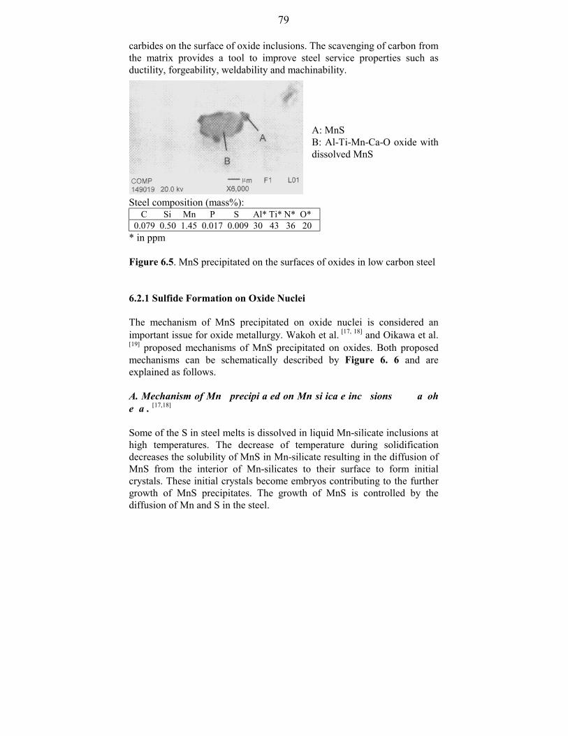
79
carbides on the surface of oxide inclusions. The scavenging of carbon fromthe matrix provides a tool to improve steel service properties such asductility, forgeability, weldability and machinability.
A: MnSB: Al-Ti-Mn-Ca-O oxide withdissolved MnS
Steel composition (mass%): C Si Mn P S Al* Ti* N* O*0.079 0.50 1.45 0.017 0.009 30 43 36 20
* in ppm
Figure 6.5. MnS precipitated on the surfaces of oxides in low carbon steel
6.2.1 Sulfide Formation on Oxide Nuclei
The mechanism of MnS precipitated on oxide nuclei is considered animportant issue for oxide metallurgy. Wakoh et al. [17, 18] and Oikawa et al.[19] proposed mechanisms of MnS precipitated on oxides. Both proposedmechanisms can be schematically described by Figure 6. 6 and areexplained as follows.
A. Mechanism of MnS precipitated on Mn-silicate inclusions by Wakohet al. [17,18]
Some of the S in steel melts is dissolved in liquid Mn-silicate inclusions athigh temperatures. The decrease of temperature during solidificationdecreases the solubility of MnS in Mn-silicate resulting in the diffusion ofMnS from the interior of Mn-silicates to their surface to form initialcrystals. These initial crystals become embryos contributing to the furthergrowth of MnS precipitates. The growth of MnS is controlled by thediffusion of Mn and S in the steel.
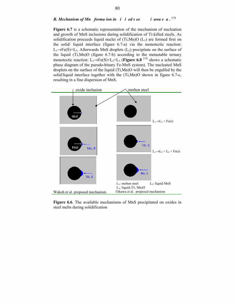
80
B. Mechanism of MnS formation in Ti-killed steel by Oikawa et al. [18]
Figure 6.7 is a schematic representation of the mechanism of nucleationand growth of MnS inclusions during solidification of Ti-killed steels. Assolidification proceeds liquid nuclei of (Ti,Mn)O (L3) are formed first onthe solid/ liquid interface (figure 6.7-a) via the monotectic reaction:L1→Fe(S)+L3. Afterwards MnS droplets (L2) precipitate on the surface ofthe liquid (Ti,Mn)O (figure 6.7-b) according to the metastable ternarymonotectic reaction: L1→Fe(S)+L2+L3 (Figure 6.8 [18] shows a schematicphase diagram of the pseudo-binary Fe-MnS system). The nucleated MnSdroplets on the surface of the liquid (Ti,Mn)O will then be engulfed by thesolid/liquid interface together with the (Ti,Mn)O shown in figure 6.7-c,resulting in a fine dispersion of MnS.
oxide inclusion molten steel
Wakoh et al. proposed mechanism
L1→L3 + Fe(s)
L1→L3 + L2 + Fe(s)
L1: molten steel L2: liquid MnS L3: liquid (Ti, Mn)O Oikawa et al. proposed mechanism
Figure 6.6. The available mechanisms of MnS precipitated on oxides insteel melts during solidification

81
direction of decreasing temperature
Figure 6.7. Schematic illustration of MnS formation during solidification ofTi-killed steel [18]
Figure 6.8. Schematic stable and metastable phase diagramof the pseudo-binary Fe-MnS system [18]
Dire
ctio
n of
adv
ance
men
t supersaturation of sulfide
MnSFe
stablemetastable
Fe(S) + MnS(S)
L2
Fe(S)
M1(1.7%)
1480 °C
1483 °C
~ 3 °C
L1 + MnS(S)
L1 + L2
(1.5%)E
L1
Tem
pera
ture
, °C
Content of S, mass%

82
C. New proposed mechanism of MnS precipitated on oxides in steel
Oikawa et al. [19] reported that the metastable liquid MnS inclusions in Ti-free steel are formed during solidification when the degree ofsupersaturation of MnS reaches a high level. Since the metastable liquidMnS features low wettability with respect to the advancing solid/liquidinterface of iron, MnS droplets are rejected by the interface to the iron-richliquid where they grow by collision and coalescence. This result is directlyopposed to Wakoh et al.’s reported results [18] which indicate that theprecipitation ratio of MnS in Mn-Si deoxidized steel is higher than that inTi-killed steel at lower S contents. The precipitation ratio of MnS isdefined as the ratio of the number of oxide particles bearing MnSprecipitates to the total number of oxides. Moreover, both of themechanisms proposed by Wakoh et al. and Oikawa et al. do not explainwhy high MnS precipitation ratios are obtained for all deoxidized steels athigh S content independent of the deoxidants as shown in Figure 6.9.From figure 6.6, it is easy to find the shortcomings contained in bothmechanisms. The following new mechanism is proposed to overcome theproblem by effectively combining both mechanisms.
Figure 6.9. Precipitation ratio of MnS depending on S content anddeoxidants [17]
10 100
0
20
40
60
80
100
Wakoh et al. [17]
Low carbon steel (0.1% C, 1.0% Mn)
Mn-Zr
Mn-Ti
Mn-Al
10 20 50 100 200 400 800
Ueshima et al. [23]
10 kg ingot
Wakoh et al. [17]
Wakoh et al. [17]
Wakoh et al. [17]
Wakoh et al. [17]
Mn-Si
Prec
ipita
tion
ratio
of M
nS (%
)
S, ppm

83
In molten steel, S is distributed over oxides and the molten steel. As thetemperature decreases, a small amount of MnS crystallizes on the surfaceof oxides acting as embryos for MnS precipitates. These small MnScrystals on the surface of oxides are produced in the following ways- In the low S region, MnS crystallizes at lower temperatures due to the
decrease of the solubility of MnS in oxides. Micro-segregation ofsolutes hardly allows the contents of Mn and S to reach the requiredsupersaturation of MnS.
- In the high S region, microsegregation of solutes easily renders thecontents of Mn and S to reach the required supersaturation of MnS.Thus, MnS crystallizes on the surface of oxides due to either themicrosegregation of solutes or the decrease of the solubility of MnS inoxides. Moreover, the higher the content of S, the higher is the amountof crystallized MnS inclusions on the surface of oxides depending onmicrosegregation.
Further growth of MnS is controlled by the diffusion of Mn and S in steel.It is worth mentioning that the level of S content depends on the sulfidecapacity of oxide inclusion and its sensitivity to temperature. Thedemarcation line between the low and the high S level varies with theoxides.
The present proposed mechanism fully explains the above experimentalresults [16]. At low S content, the formation of embryo MnS depends on thesulfide capacities of oxides. Therefore, there obviously exist different MnSprecipitation ratios for different oxides. However, MnS precipitation ratiosare small for all oxides. At high S content, the formation of embryo MnSdepends on micro-segregation and oxide structure. MnS precipitationratios are high for almost all tested oxides shown in figure 6.9. Thedifference of MnS precipitation ratios between different oxides is largelydecided by the structures of oxides. Normally, oxides and oxidecompounds such as Ti2O3, MnO, FeO, (Fe,Mn)O, MnO⋅SiO2 andMnO⋅TiO2 contain cation vacancies which contribute greatly topreferential nucleation of various foreign phases on them. On the otherhand, oxides such as SiO2, Al2O3 and ZrO2 contain anion vacancies whichcan exchange oxygen ions with the matrix. Thus, MnS precipiattion ratiosfor cation vacancy oxides are higher than those for anion vacancy typeoxides. This is confirmed by the reported experimental results shown infigure 6.9.

84
References:
[1] R. N. Wenzel: Ind. Eng. Chem., 28(1936), 988[2] K. Ogino: Taikabutsu Overseas, 2(1982), 80/84[3] Slag Atlas, edited by Verein Deutscher Eisenhüttenleute (VDEh), 2nd
edition, Verlag Stahleisen GmbH, Düsseldorf, 1995, 513/539[4] D. Janke, Z. Ma, P. Valentin and A. Heinen: ISIJ International,
40(2000), 31/39[5] E. Steinmetz, H. -U. Lindenberg, W. Mörsdorf and P. Hammerschmid:
Stahl u. Eisen, 97(1977), 1154/1159[6] C. E. Cicutti, J. Madias and J. C. Gonzalez: Ironmaking and
Steelmaking, 24(1997), 155/159[7] D. Janke and Z. Ma: Veitsch-Radex Rundschau, accepted[8] H. Goto, K. Miyazawa and T. Tanaka: ISIJ International, 35(1995),
286/291[9] H. Goto, K. Yamamuchi, S. Ogibayashi, T. Tanaka and S. Nishimori:
CAMP-ISIJ, 4(1991), 284[10] T. Sawai, M. Wakoh, Y. Ueshima and S. Mizoguchi: ISIJ
International, 32(1992), 169/173[11] T. Sawai, M. Wakoh and S. Mizoguchi: Tetsu-to-Hagane, 82(1996),
587/592[12] M. Wakoh, T. Sawai and S. Mizoguchi: Tetsu-to-Hagane, 82(1996),
593/598[13] Z. Ma and D. Janke: Technical report “Improvement of nonmetallic
inclusions and fine grain structures of continuously cast steel by oxidemetallurgy”, European Coal and Steel Community (ECSC) sponsoredproject under grant No. 7210.CC/115, 1997; 1998.
[14] H. Goto, K. Miyazawa and T. Kadoya: ISIJ International, 35(1995),1477/82
[15] H. Goto, K. Miyazawa and H. Honma: ISIJ International, 36(1996),537/42
[16] K. Yamamoto, T. Hasegawa and J. Takamura: ISIJ International,36(1996), 80/86
[17] M. Wakoh, T. Sawai and S. Mizoguchi: ISIJ International, 36(1996),1014/21
[18] M. Wakoh, T Sawai, and S. Mizoguchi: Tetsu-to-Hagane, 78(1992),1697
[19] K. Oikawa, K. Ishida and T. Nishizawa: ISIJ International, 37(1997),332/38

85
[20] Z. Ma and D. Janke: “Oxide precipitation and its precipitates acting asnucleation sites for sulfide in steel melts”, the 3rd CAST (ChinaAssociation for Science and Technology) Conference of YoungScientists, Vol. Materials Science and Industrial Technology, ChinaPress of Science and Technology, August 20-23, 1998, 46/50
[21] J. Tamamura and S. Mizoguchi: Proc. 6th Int. Iron and Steel Cong.,Vol. 1, ISIJ, Nagoya, (1990), 591/97 and 598/604
[22] T.Sawai, M. Wakoh, Y. Ueshima, and S. Mizoguchi: 6th Int. Iron andSteel Cong., Vol. 1, ISIJ, Nagoya, (1990), 605/11
[23] Y. Ueshima, H. Yuyama, S. Mizoguchi and H. Kajioka: Tetsu-to-Hagane, 75(1989), 501
[24] S. Ogibayashi, K. Yamaguchi, M. Hirai, H. Goto, H. Yamaguchi, K.Tanaka: 6th Int. Iron and Steel Cong., Vol. 1, ISIJ, Nagoya, (1990),612/17

86
CHAPTER 7Effects of Inclusions on Microstructures and Mechanical Properties ofSteel
With the concept of oxide metallurgy, nonmetallic inclusions need notnecessarily be harmful to steel service properties. These inclusions caneffectively serve as nucleation sites for precipitation and phasetransformation resulting in an improvement of steel service properties. Thegeneration of finely dispersed oxide inclusions and their function of actingas nucleation sites for precipitation such as MnS were discussed in thepreceding chapters. These finely dispersed oxides also serve as nucleationsites for phase transformation such as of fine ferrite causing a refinementof steel microstructures.
Proeutectoid ferrite can nucleate at inclusions within austenite grains. Thisenables to obtain a fine ferrite-pearlite microstructure despite coarseaustenite grains. This method is termed IGF (intragranular ferrite)technology [1-30]. With IGF technology, a fine grain structure is obtainedthrough coarse austenite grains resulting in an improvement of steelservice properties such as toughness and strength. It is of great interest towelded structural steels and components of automobiles. It is obvious thatthe crux of this technology is to generate finely dispersed inclusions withinaustenite grains which effectively serve as nucleation sites for IGF.Extensive and intensive researches have been undertaken on IGFtechnology [6-30]. However, most of the researches are focused on weldmetals and steels in welding thermal cycles. Only a few studies directlyapplied IGF technology to steelmaking processes such as solidifica- tion[1-4] and rolling processes [5]. IGF technology in welding processes is quitedifferent from that in casting processes because of different thermal cycles.In the present study it was further found that the ideal of IGF technologycan be extended to refine grain structures (not only ferrite, but also otherphases) and to modify precipitates through finely dispersed oxideinclusions.
Mechanical properties of the as-cast investigated steels are tested.Generation of finely dispersed oxide inclusions in steel prominentlyimproves notch impact toughness.
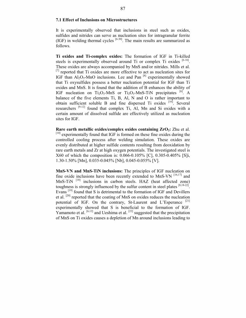
87
7.1 Effect of Inclusions on Microstructures
It is experimentally observed that inclusions in steel such as oxides,sulfides and nitrides can serve as nucleation sites for intragranular ferrite(IGF) in welding thermal cycles [6-30]. The main results are summarized asfollows.
Ti oxides and Ti-complex oxides: The formation of IGF in Ti-killedsteels is experimentally observed around Ti or complex Ti oxides [6-16].These oxides are always accompanied by MnS and/or nitrides. Mills et al.[7] reported that Ti oxides are more effective to act as nucleation sites forIGF than Al2O3-MnO inclusions. Lee and Pan [8] experimentally showedthat Ti oxysulfides possess a better nucleation potential for IGF than Tioxides and MnS. It is found that the addition of B enhances the ability ofIGF nucleation on Ti2O3-MnS or Ti2O3-MnS-TiN precipitates [6]. Abalance of the five elements Ti, B, Al, N and O is rather important toobtain sufficient soluble B and fine dispersed Ti oxides [16]. Severalresearchers [9-12] found that complex Ti, Al, Mn and Si oxides with acertain amount of dissolved sulfide are effectively utilized as nucleationsites for IGF.
Rare earth metallic oxides/complex oxides containing ZrO2: Zhu et al.[10] experimentally found that IGF is formed on these fine oxides during thecontrolled cooling process after welding simulation. These oxides areevenly distributed at higher sulfide contents resulting from deoxidation byrare earth metals and Zr at high oxygen potentials. The investigated steel isX60 of which the composition is: 0.066-0.105% [C], 0.305-0.405% [S]i,1.30-1.50% [Mn], 0.035-0.045% [Nb], 0.045-0.055% [V].
MnS-VN and MnS-TiN inclusions: The principles of IGF nucleation onfine oxide inclusions have been recently extended to MnS-VN [16,17] andMnS-TiN [18] inclusions in carbon steels. HAZ (heat affected zone)toughness is strongly influenced by the sulfur content in steel plates [8,18-22].Evans [19] found that S is detrimental to the formation of IGF and Devillerset al. [20] reported that the coating of MnS on oxides reduces the nucleationpotential of IGF. On the contrary, St-Laurent and L’Esperance [21]
experimentally showed that S is beneficial to the formation of IGF.Yamamoto et al. [6,12] and Ueshima et al. [22] suggested that the precipitationof MnS on Ti oxides causes a depletion of Mn around inclusions leading to

88
S content, mass%
an increase in transformation temperature, thereby promoting theformation of IGF. Lee and Pan [8] reported that there exists an optimaladdition of S for Ti-killed carbon steel to promote the formation of IGF.Both strong and small additions of S are detrimental to the formation ofIGF. This result was further confirmed by Tomita et al. [18] shown inFigure 7.1 which quantitatively yields an optimal S content correspondingto a maximum HAZ toughness. It seems that S strongly influences HAZmicrostructure and precipitates.
steel composition (mass%): C Si Mn Cu Ni Nb Ti Al N S0.05 0.11 1.57 0.30 0.30 0.008 0.009 0.031 0.0037 0.001-0.008
Figure 7.1. Effects of S content on HAZ toughness in one-side single passsubmerged arc welded joints with a heat input of 20 kJ/mm [18]
In the present investigation it was found that titanium or complex titaniumoxides, sulfides and nitrides serve as nucleation sites for IGF during steelcasting and rolling which is clearly demonstrated in Figures 7.2-7.4. Thisfact makes it possible to refine grain structures directly through control ofdeoxidation and solidification. It suggests the new idea that steelmicrostructures have a close relation to deoxidation technology.
Abs
orbe
d en
ergy
at –
60 °C
, J

89
Conventionally it is thought that steel microstructures are the matter duringand after casting. The changes according to the new idea may bring abouta great challenge to the current steelmaking practice. We may simplify orabandon some conventional grain refining measures through the adoptionof feasible deoxidation techniques and controlled solidification processes.The present study further demonstrates that finely dispersed oxideinclusions generally refine the as-cast steel structure because theseinclusions serve as nucleation sites for phase transformation. Therefore,this technology is a promising way to produce future steels which featurenot only efficient and cost effective but also environment friendly benefits.
Ti-oxide
ZrO2
Ferrite Pearlite
As-cast structures (low carbon steel) Figure 7.2. Oxides serving as nucleation sites for IGF
Pearlite Ferrite
MnS
VN+TiN
As-cast structures (27MnSiVS steel)Figure 7.3. Sulfides and nitrides serving as nucleation sites for IGF
20 µm
20 µm

90
after rolling, 27MnSiVS steel Figure 7.4. Sulfides and nitrides serving as nucleation sites for IGF
7.2 Mechanism of Inclusions Serving as Nucleation Sites for IGF
Mechanisms of nucleation of IGF at inclusions were discussed andsummarized in chapter 2. Here the available mechanisms are listed inTable 7.1 again in which the references are omitted (details see Table 2.3).
The energy change caused by phase transformation, for example theprecipitation of α phase from austenite, can be generally expressed by thefollowing equations according to different conditions:
Nucleation of ferrite inside austenite (generation of IGF):
istrainiVstrainiV EEEEEEE ,,,, ∆−∆−∆+∆+∆+∆=∆ −− ααγαα (7-1)
Nucleation of ferrite at austenite grain boundary (generation of GBF):
istrainiVstrainiV EEEEEEEE ,,,, ∆−∆−∆−∆+∆+∆+∆=∆ −−− γγααγαα (7-2)
∆EV,i and ∆Estrain,i become zero if IGF and GBF (grain boundary ferrite) donot nucleate at the surfaces of inclusions.
The meanings of the symbols used in Eqs. (7-1) and (7-2) are as follows
20 µm

91
∆EV-α: Volume free energy change for the formation of α phase∆Eα-γ: Surface energy change for the formation of α phase∆Estrain,α: Strain energy resulting from the formation of α phase∆Eγ-γ: Surface energy change for the diminution of contacted γ phase∆EV-i: Volume free energy change for the formation of an inclusion∆Estrain,i: Strain energy resulting from the formation of an inclusion
Table 7.1. Summary of IGF formation mechanism
Precipitates and/or inclusions Transformation theory
TiO
TiN
VN
FCC galaxite (Al2O3⋅MnO)
γAl2O3
CuS
Epitaxitial growth theory
(minimum misfit, δ )
δ = 3.0%
δ = 3.8%
δ = 0.7%
δ = 1.8%
δ = 3.2%
δ = 2.8%
(MnO)2(Al2O3)2(SiO2)
Al containing inclusions
Thermal expansion theory
•Thermal strain
• Plastic strain
Inclusion size
Oxide inclusion
Fine inclusions
Inclusion size theory
≥ 1 µm: GBF; ≥0.6 µm: IGF
≥ 0.4 µm pining γ grain
boundary
ineffective
Composition variation
such as Mn depletion around
inclusions
(Al⋅Si-S-Ti-Mn)O, TiN-MnS, TiN Reduction of interfacial energy
* IGF: intragranular ferrite GBF: grain boundary ferrite

92
The different energy changes are interpreted by the following equations
VV GVE ∆⋅=∆ αα,
γαγαγα σ −−− ⋅=∆ AE)( γααα σσ −−−− −−=∆ iiii AE
γααα ε −⋅=∆ VEstrain ,
γγγγγ σ⋅=∆ −− AE)( ,,, γαα −−− −=∆ iViViiV GGVE
)(, γαα εε −−− −=∆ iiiistrain VE
Where Vα: volume α phaseVk-t: volume of k phase in t phaseσ: surface or interface tensionε: strainAk-t: surface area of k phase contacting t phase
Subscript: α:i:γ:V:
α phaseinclusionγ phasevolume factor
The term ∆EV,α is negative indicating the driving force of forming α phase.It is reasonable to assume that all factors causing reduction of ∆E favourthe formation of α phase both inside austenite and at the austenite grainboundary as shown in Eqs.(7-10) and (7-11). It is obvious that IGF is toprecipitate prior to GBF if conditions satisfy the inequality Eq. (7-12).
Maximum of - α,VE∆ (7-10)
Minimum of istrainiVstraini EEEEE ,,, ∆−∆−∆+∆+∆ −− ααγα (7-11)
GBFistrainiVstraini
IGFistrainiVstraini
EEEEEEEEEEEE
)()(
,,,
,,,
∆−∆−∆−∆+∆+∆<
∆−∆−∆−∆+∆+∆
−−−
−−−
γγααγα
γγααγα (7-12)

93
Unfortunately it is impossible till now to calculate all terms because of thelack of parameters. However, these inequalities give a general criterion forthe formation of IGF which can reasonably explain the availablemechanisms. The proposed mechanisms are quite different from and evencontradictory to different sources. According to the inequality Eqs. (7-10)-(7-11), these mechanisms are no longer different and contradictory butonly reflect the contribution of different influencing factors to theinequalities. Here general discussions are given. The favourable conditionsfor forming IGF are listed and explained in Table 7.2. It is obvious that theavailable mechanisms are only partial contributions to the present unifiedformulae. These formulae can be treated as a general condition todetermine the precipitation of IGF and GBF. Figure 7.5 demonstrates thatGBF and IGF simultaneously precipitate during and after solidification.The favorable conditions for prior IGF are clearly demonstrated in table7.2.
The above discussions are focused on the thermodynamic point of view.However, the kinetic factors are also important. For example, a highdiffusivity of carbon atoms in austenite greatly favours ferrite nucleation.However, the discussion on the kinetics of ferrite nucleation is out side thescope of the present study.
Table 7.2. Favourable conditions for forming IGF
Favorable conditions Contribution to formIGF
Available mechanism
Minimum misfit betweeninclusion (inside austenite)and IGF
Increase of ∆EV,i Epitaxial growth theory
Thermal strain and plasticstrain between inclusionsand IGF
Increase of ∆Estrain,I Thermal expansion theory
Coarse inclusions andlarge inclusions
Increase of ∆Estrain,i
and ∆EV,I
Inclusion size theory
Reduction of interfacialenergy between inclusionsand IGF
Decrease of ∆EI-α Reduction of interfacialenergy
Composition of steel Influencing ∆Eα-γ
and ∆Eγ-γ

94
Figure 7.5. Competition of nucleation between GBF and IGF for as-cast27MnSiVS steel ([V] <100 ppm)
7.3 Relation between Microstructure and Toughness
Figures 7.6-7.8 show the experimental results of charpy-V-notch impacttoughness AV of the investigated steels. It is found that notch impacttoughness of the investigated steels is greatly improved by the addition ofTi at S contents below 0.012%. However, it seems that notch impacttoughness is influenced by Ti and S contents at high S levels and that anoptimal range for Ti and S contents exists to reach high AV values. Highnotch impact toughness for Fe-Cr-Ni austenitic stainless steels is alsoobtained using alternative deoxidation technology. The notch impacttoughness of as-cast Fe-Cr-Ni austenite stainless steels meets the standardrequirements for the final product. Moreover, the correspondingmicrostructures for the investigated steels are investigated. It is found thatsteels with fine grain structure demonstrate a high toughness. For example,Figures 7.9-7.11 indicate that the steels featuring fine as-castmicrostructure and finely dispersed inclusions demonstrate high notchimpact toughness. It is concluded that steels produced by oxide metallurgy
10 µm
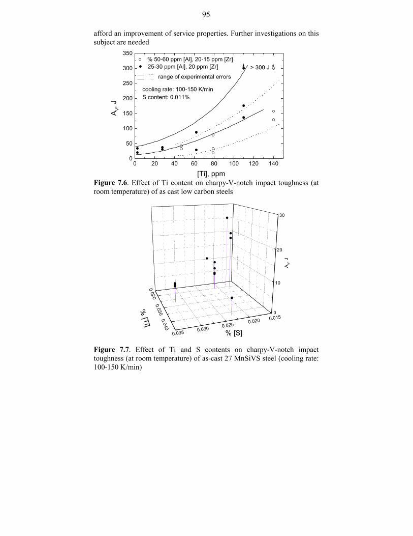
95
afford an improvement of service properties. Further investigations on thissubject are needed
Figure 7.6. Effect of Ti content on charpy-V-notch impact toughness (atroom temperature) of as cast low carbon steels
Figure 7.7. Effect of Ti and S contents on charpy-V-notch impacttoughness (at room temperature) of as-cast 27 MnSiVS steel (cooling rate:100-150 K/min)
A V, J
0
10
20
30
0.035 0.030 0.025 0.020 0.015
0.020 0.030 0.040
% [S]
% [Ti]
0 20 40 60 80 100 120 1400
50
100
150
200
250
300
350
> 300 J25-30 ppm [Al], 20 ppm [Zr]
A V, J
[Ti], ppm
range of experimental errors
cooling rate: 100-150 K/minS content: 0.011%
% 50-60 ppm [Al], 20-15 ppm [Zr]

96
Photo of a sample after the testof Charpy-V-notch impacttoughness
Figure 7.8. Achievement of high Charpy-V-notch impact toughness (atroom temperature) of as-cast Cr-Ni based stainless steel throughalternative deoxidation technology
××××100
××××500
Figure 7.9. As-cast structures of low carbon steel (25-30 ppm [Al],0.011% [Ti])
100 µm
20 µm
0.04 0.05 0.06 0.07 0.0850
100
150
200
250
300
standard requirement for the final steel product > 100 J
A V, J
[Ti], ppm
X5 CrNi18 10 cooling rate: 100-150 K/minAl content: 0.027-0.032%

97
Photo of a sample after thetest of Charpy-V-notchimpact toughness
Photo of a sample after thetest of Charpy-V-notchimpact toughness
××××100
××××500
Figure 7.10. As-cast structures of low carbon steel (50-60 ppm [Al],0.014% [Ti])
×××× 500
Figure 7.11. As-cast structure of low carbon steel (25-30 ppm [Al],0.008% [Ti])
100 µm
20 µm
20 µm

98
References
[1] Z. Ma, D. Peisker and D. Janke: steel research, 70(1999), 178/82[2] Z. Ma and D. Janke: Technical Report “Improvement of fine grain
structures of 27MnSiVS steel”, Institute of Iron and SteelTechnology, TU Freiberg, November, 1998
[3] S. Mizoguchi: “A study on segregation and oxide inclusions for thecontrol of steel properties” , PhD thesis, The University of Tokyo,1996
[4] Z. Ma and D. Janke: Annual Technical Report of ECSC SponsoredProject under Grant No. ECSC-95-C2.03c, Institute of Iron and SteelTechnology, TU Freiberg, 1998
[5] T. Funakoshi, T. Tanaka, S. Ueda, M. Ishikawa, N. Koshizuka and K.Kobayashi: Trans. ISIJ, 17(1997), 419/24
[6] K. Yamamoto, T. Hasegawa and J. Takamura: ISIJ International,36(1996), 80/86
[7] R. Mills, G. Thewlis and J. A. Whiteman: Materials Sci. and Tech.,3(1987), 1051/61
[8] J. L. Lee and Y. T. Pan: Mater. Sci. Eng., 136A(1991), 109/19,Metall. Trans. A, 22A(1991), 2818/22, 24A(1993), 1399/1408
[9] D. Yu, F. J. Barbaro, T. Chandra and D. P. Dunne: ISIJ International,36(1996), 1055/62
[10] Y. Zhu, S. Guo, J. Xu, G. Jiang, D. Yu, L. Pan and Y. Wang: ActaMetallurgica Sinica, 32(1996), 891/6
[11] H. Honma, S. Ohkita, S. Matsuda and K. Yamamoto: 67th AWSConvention, Atlanta, USA, 1986
[12] K. Yamamoto, S. Matsuda, T. Hase, R. Chijiiwa and H. Mimura: “Anewly developed Ti-oxide bearing steel having high HAZ toughness”,Symp. on Residual & Unspecified Elements in Steel, ASTM-STP,1989, 264/284
[13] N. Mori, H. Honma, M. Wakabayashi and S. Ohkita: J. Jpn. Weld.Soc., 50(1981), 786
[14] I. Watanada and K. Kojima: J. Jpn. Weld. Soc., 50(1981), 703[15] T. Yamaguchi, H. Terashima and N. Nishiyama: Proc. of the Symp.
on TMCP Steel by Weld. Metall. Comm. of J.W.S., Paper 23, 1990[16] F. Ishikawa, T. Takahashi and T. Ochi: Metall. Materials Trans.,
25A(1994), 929/36

99
[17] T. Ochi, T. Takahashi and H. Takada: Iron Steelmaker, 16(1989),21/28
[18] Y. Tomita and N. Saito: ISIJ International, 34(1994), 829/35[19] G. M. Evans: Met. Constr., 44(1986), 631/36[20] L. Devillers, D. Kaplan, B. Marandet, A. Ribes and P. V. Riboud: in
Conf. on the effects of residual, impurities and micro-alloyingelements on the weldability and weld properties, The WeldingInstitute, Abington, UK, 1983, 1/12
[21] S. St-Laurent and G. L’Esperance: Mater. Sci. Eng., 149A(1992),203/16
[22] Y. Ueshima, H. Yuyama, S. Mizoguchi and H. Kajioka: Tetsu-to-Hagane, 75(1989), 501/08
[23] R. A. Ricks, P. R. Howell and G. S. Barrotte: J. Mater. Sci., 17(1982),731/740
[24] D. J. Abson: Weld. World, 27(1989), 76/101[25] B. L. Bramfitt: Metall. Trans., 1(1970), 1987/1995[26] F. J. Barbaro, P. Krauklis and K. E. Easterling: Materials Sci. and
Tech., 5(1989), 1057/1077[27] S. Kanazawa, A. Nakashima, K. Okamoto and K. Kanaya: Trans.
ISIJ, 1681976), 486/495[28] J. Jang and J. E. Indacochea: J. Mater. Sci., 22(1987), 689/700[29] M. Enomoto and H. I. Aaronson: Metall. Trans., 17A(1986),
1381/1384[30] M. Ferrante, K. Akune and M. Odaina: J. Mater. Sci., 22(1987), 351
100
CHAPTER 8Conclusions
It is one of the most important tasks in steelmaking to improve castabilityand quality of continuously cast steel. Oxide metallurgy offers an effectiveadditional method to alleviate or eliminate nozzle clogging duringcontinuous casting processes and to improve steel service propertiesthrough control of inclusions and grain refinement. The fineunagglomerated inclusions in liquid steel give rise to the improvement ofcastability. The generation of the finely dispersed oxides which easilybecome nucleation sites for precipitates such as sulfides, nitrides andcarbides and for phase transformation with respect to IGF plays a key rolein oxide metallurgy. Alternative deoxidation techniques with partial orcomplete substitution of Ti and Zr for Al are presently investigated. Themain conclusions and results are summarized as follows:
• Thermodynamic analysis of metallic solutions (appendices A and B)A modified ε formalism was developed to perform thermodynamicanalysis for both dilute and concentrated metallic solutions. Thisformalism features thermodynamic consistency and higher accuracy incomparison with Wagner’s ε formalism. The interaction parametersbetween solutes in liquid iron at 1873 K were given.
•
•
Calculation model for size and composition of oxide inclusions(appendix C)A calculation model was proposed to evaluate the size and compositionof oxide precipitates in molten steel during solidification. So far, threedifferent models have been developed to describe the precipitation andgrowth of nonmetallic inclusions during solidification. They wereestablished at IRSID (France), NSC (Japan) and IEST, TU Freiberg(Germany). The present model is the simplest one and accuratelypredicts the oxide behaviour in molten steel during solidification.
The state-of-the-art of research work on oxide metallurgy (chapters1 and 2)The reported work on oxide metallurgy was summarized and discussed.The present research objectives were outlined.

101
• Deoxidation technologies used in steelmaking processes (chapter 3)The available deoxidation technologies are summarized and discussed.Clean deoxidation technology is presently applied in view of theproduction of clean steel. Alternative deoxidation techniques aiming atthe utilization of inclusions in steel are being discussed.
• Generation of finely dispersed oxide inclusions (chapter 5)Oxide precipitation is important in oxide metallurgy and is affected bymany factors. However, deep understanding of the effects of theseinfluencing factors is not available. The present study gives asystematic and profound investigation on this subject. It isexperimentally found that the size, distribution and number of oxides insteels are greatly influenced by factors such as the cooling rate and thecontents of Ti, Al, Zr, Mn and O. Their influence on size, composition,distribution and shape of oxides is investigated and discussed in thepresent work. The main results are given in chapter 5.
• Effect of oxide inclusions on nozzle clogging (chapter 6)Basic principles of nozzle clogging are theoretically discussed. Aformula was developed to explain nozzle clogging. This formulasuccessfully interpretes different experimental results from thetheoretical point of view. It may help to develop new processes andimprove the available processes to avoid nozzle clogging.
• Effect of oxide inclusions on sulfide precipitation (chapter 6)Oxide inclusions serving as nucleation sites for sulfides are importantto guarantee the generation of evenly dispersed sulfides in steel. It isexperimentally found that Ti oxides effectively serve as nucleation sitesfor sulfides in steel. A new mechanism of MnS precipitation on oxideswas proposed. This mechanism reasonably explains the availableexperimental results.
• Generation of IGF (chapter 7)IGF technology was successfully applied to steel casting and rollingprocesses. Meanwhile, it has been experimentally confirmed that finelydispersed oxides in steel generally refine grain structures duringsolidification processes. This technology is most useful for theforthcoming technologies of hot direct rolling, thin slab casting anddirect strip casting.

102
A mechanism of producing IGF was proposed which reasonably unifiesthe available mechanisms appearing different and even contradictory.
• Effect of oxide inclusions on mechanical properties of steel (chapter7)Fine grain structures can be obtained using oxide metallurgy andresulting in an improvement of steel service properties. High charpy-V-notch impact toughness for stainless, low carbon and low alloyed steelsis obtained through the control and utilization of inclusions.
Oxide metallurgy is beneficial for various casting and hot workingprocesses, particularly in the case of fast cooling and hot direct rolling.This technology features efficient, cost effective and environment friendlymeasures. It improves castability and the quality of continuously cast steelwithout additional metallurgical treatment and without enhancing theeffects to increase steel cleanness in conventional refining processes. Newsteel grades based on fine or ultra fine grain structures can be producedusing oxide metallurgy in conventional and new steelmaking processessuch as thin slab and direct strip casting.
103
APPENDIX AThermodynamics of Concentrated Metallic Solutions
1. Introduction
The interaction parameter formalism expressed in terms of a MacLaurinseries expansion for the partial excess free energy is frequently used toexpress the thermodynamic properties of dilute solutions, particularly ofmetals. However, the experimental determination of interaction parametersbeyond second-order is almost impossible in practice due to therequirement of an extremely high accuracy. Activity coefficients of solutesat high solute contents have so far been calculated by the first-orderinteraction parameters, that is, based on the simplest case of a truncatedMacLaurin series. Any truncated MacLaurin series expansion weakens theexactness of the expression for the activity coefficient of a solute in amulticomponent system, and at high solute contents the thermodynamicinconsistency can result in significant errors [1-4]. In view of this, manyattempts have been made to extend the approach to concentrated solutions.
Darken [1,5] proposed a quadratic formalism which is thermodynamicallyconsistent, but this formalism has never enjoyed much popularity since thepublished experimental data are mainly presented in terms of the interactionparameter formalism, and the validity of Darken's formalism for ternary andhigher order systems with strong interactions needs further proof. Theequations based on the quasi-chemical model for dilute ternary andmulticomponent systems first solved by Lupis [6] with a formidablemathematical procedure are very similar to Darken's formalism. Bale andPelton [3,7] have more recently proposed a unified interaction parameterformalism which is thermodynamically consistent by simply adding a termof ln γsolvent in the expression of ln γi where i represents the solute. Thededuced procedure is based on the integral molar excess Gibbs energy of amulticomponent solution at constant temperature expressed by the generalMargules-type polynomial expansion in the mole fractions [7]. Srikanth andJacob [4] derived the same expression of ln γsolvent by solving the Gibbs-Duhem equation and they also indicated that the expression is valid only fordilute solutions. Furthermore, Srikanth and Jacob [4] have shown that atruncated MacLaurin series being inaccurate at finite contents may beintegrated along a constant composition path without significant loss of

104
accuracy. However, the introduction of this path-depending integral isgenerally considered to reduce the degree of compositional freedom. Thethermodynamic inconsistency retained in this method. Hajra and Frohberg[8,9] proposed suitable expressions involving interaction parameters forpresenting thermodynamic properties of the solvent in a ternary system.These expressions were obtained by integration of several series whichemerge from the MacLaurin infinite series based on the integral property ofthe system and subjected to appropriate boundary conditions. But theexpression of ln γi where i is the solute has not been given by the authors.
A new method is proposed in the present work to describe thethermodynamic properties of multicomponent systems. It isthermodynamically consistent and independent of integration paths.
2. Establishment of the Formalism
For the system 1−2−⋅⋅⋅−i−⋅⋅⋅−m with m components, the excess Gibbs freeenergy of the system can be expressed as an infinite MacLaurin series interms of the integral function of the system. Eq. (1) gives this approach. Letxk denote the mole fraction of the k-th component (k=1,2, 3, ⋅⋅⋅, m). Theseries is subjected to the following general and boundary conditions:
(a) general condition: x1→1, xj→0 (j=2, 3, ⋅⋅⋅, m) for the system with mcomponents, ∆EG →0,
(b) boundary conditions: xi→1, xj→0 (i≠1 and j=2, 3, ⋅⋅⋅, i-1, i+1, ⋅⋅⋅, m) forthe marginal systems with m-1 components, ∆EG→0.
(1)
When inserting the boundary conditions as mentioned above into the series(1), the following equation is obtained:
⋅⋅⋅+
∆+
∂∆∂
∆∆
∑ ∑ ∑ ∑
∑∑
−
= +=
∞
=
∞
=→
+
→
∞
→
1
2 1 1 11211 2
21
1
21
21
!!1m
i
m
ij n n
nj
ni
x
nj
ni
Enn
nin
i
En
1x11=n
m
2=i1x
EE
xxxx
Gnn
xx
G!n
1+)G(=G 1
1
1
111
∂∂∂

105
(2)
Substituting Eq. (2) into Eq. (1) yields
(3)
Then the interaction parameters defined in Table 1 are introduced. Theexcess Gibbs free energy can be written as Eq. (4) with neglect of theimpact terms which are listed in Table 2. The neglect takes into accountthat higher-order interaction parameters are not available and the accuracyof results from high temperature experimental techniques is limited
(4)
With progression functions the above equation can be rewritten as
(5)
0=x
Gn!1
nj
En
1x1=n1
.
∂∆∂
→
∞
∑
∆∂
∂∆∂
−→
∞
→=∑∑∑ k
j
Ek
1x
1+n
=1k
nj
=1nj
E
1xjj
m
2j xG
k!1
xx
Gxx=
11
+∂
)1(
+xxxx
G!n!n
1+ m
ij
nj
nin
jni
En+n
1x211=n1=n
m
2=i
21
21
21
121
⋅⋅⋅
∂∂∆∂∑ ∑∑∑
+= →
∞∞−
1
1
∑ ∑ ∑∑ ∑∑∑
∑∑∑
−
= +=
∞
=+=
∞∞
=
−
∞
=
∞
=
+−+
+
+−++−∆
1
2 1 1
22
1 1
1
11
)(12
111)1(ln)1(
m
j
m
jk n
nk
njkj
kj
m
jk
nj
1=n
kj
n
nkk
jkjkj
m
2=j
n
nj
jj
n
nj
ojjj
m
2=j
E
xxxx1+n
x+1+n
x+xx
xn
xxx=RT
G
εεεε
εγ
∑=
−+
−+
−−∆ m
j j
j
j
jj
oj
jjj x
xxx
xx=RT
GE
2
)1ln(1
1ln1
1)1( εγ
xx
xx+x
xx
xxx
m
jk kjkj
kj
m
2j=
m
jk k
k
j
jkjkj
m
2j=∑∑∑∑
+=
−
+=
−
−
−+
−
−+−
+−1
221
1
1
11
11
121)1ln()1ln(
1 εε
⋅⋅⋅
∂∂∆∂
∂∆∂∆ ∑ ∑∑∑∑∑
+= →
∞
=
∞
=
−
=→
∞
==
+xxxxG
!n!n1+
xG)x-(1-=G
m
ij
nj
nin
jni
En+n
1x21n1n
m
2inj
En
1x
nj
1n
m
2j
E 21
21
21
11
1
1
1
1
1 1 1
1
2

106
Table 1. Relation between derivatives of the excess Gibbs free energy andthe conventional interaction parameters
No.
1
2
3
4
5
Here ε and ρ are first and second-order activity interactionparameters, respectively, and their subscripts and superscripts arethe same as designed by Lupis and Elliott [6]. The J denotes higher-order interaction parameters.
+=xG
RT1 j
jjj3
j
xs3
1x1
,2 ρε
∂∆∂
→
,3, >
∂
∆∂
∂∆∂
→→
nJ+x
G2)-(n=xG
RT1 1)-(n
jj,1-nj
xs1-n
1xnj
xsn
1x 11
,ρε kj,k
jk
j2k
xs3
1x
+=xx
GRT1
1
∂∂
∆∂
→
nJ+xx
G2)-(n=xx
GRT1 1)-(n
kj,j
2-nk
xs1-n
1xj1-n
k
xsn
1x 11
,3, >
∂∂
∆∂
∂∂
∆∂
→→
.3,, 21 >
∂∂∆∂
∂∂∆∂
→→
nnJ+
xxG2)-n+n(=
xxG
RT1
1)-n+n(kj,
nk
1-nj
xs1-n+n
1x
21nk
nj
xsn+n
1x
21
21
21
1
21
21
1

107
[ ]
,1)1(21
11
1
11
11
121
11)1ln(1
)1ln()1ln(1)1ln(
1ln
2)(
22
22
1
2 1
22
2)(
2
1
2 12
21
∑ ∑
∑ ∑∑ ∑
∑ ∑∑
∑
=≠
=
−
= +==≠
=
−
= +==
=
−
−+
−+
−−
−
−+
−+
−
−−++
−+−
+−−+
∆−∆=
m
i
m
ikk i
i
kiki
ki
m
j
m
jk kjkj
kj
m
i
m
ikk ik
kki
ki
m
j
m
jk k
k
j
jkj
kj
m
iii
ii
m
i i
E
i
E
xx
xxxx
xxxx
xxxxx
xx
xx
xxxx=
xGx
RTRTG
ε
εε
εε
∂∂γ
Table 2. With neglect of the impact terms in Eq. (3)
No. Terms1
2
3
Higher than second-order interaction parameters
∂∂ ∂ ∂
n n n E
in
jn
kn
x
Gx x x
1 2 3
1 2 3
1 1
+ +
→
∆ and analogous derivations wit
more components
∂∂ ∂
n n E
in
jn
x
Gx x
1 2
1 2
1 1
+
→
∆ for n1≥3 and n2≥3
The partial excess Gibbs free energy can be written as
(6)
where δij is the Kronecker delta, i.e. δij = 01
jiji
≠=
According to Eq. (6) and ln γi=∆EGi/RT, the expression for ln γ1 of thesolvent can be derived from Eq. (4) as
(7)
x
G)x-(RT
+RT
G=RT
Gj
E
jij
m
2=j
Ei
E
∂∆∂∆∆ ∑ δ
1

108
[ ] [ ]
−
−+
−+
−+
−−
−
−−
−+−++−+=
3)1()1(1
31
32
11
111)1ln()1ln(ln
23
32
2
2
32
23
22
32
3232
3233
3322
221
xx
xx
xxxx
xxxxxxxx
ε
εεεγ
If the component i is a solute then
(8)
Eqs. (7) and (8) express the activity coefficients of solvent and solutes,respectively, in multicomponent systems in terms of first-order interactionparameters and mole fractions of solutes. These expressions arethermodynamically consistent with the Gibbs-Duhem equation and theygive more accurate results in comparison with the classical Wagnerapproach. The expressions are complex, but they can simply be handled incomputer calculation. The application of the formulae (7) and (8) isdemonstrated in the special case of ternary systems
(9)
−
−−+−−−+=
∆+=
ik
kk
kii
ii
oi
i
E
i
xxxxx
xG
RT
11)1ln(1)1ln(lnln
1lnln
1
1
εεγγ
∂∂γγ
−
−+
−+
−+ 1
)1(211
11
22
i
i
kiik
ki x
xxx
xxε (10)
.1)1(21
11
1
11)1ln(1)1ln(lnln
1lnln
2
)(2
2
)(2
1
1
−
−+
−+
−+
−
−−+−−−+=
∆+=
∑
∑
≠=
≠=
i
i
ki
m
ikk
ikki
m
ikk ik
kk
kii
ii
oi
i
E
i
xx
xxxx
xxxxx
xG
RT
ε
εεγγ
∂∂γγ

109
for i, k=2, 3 and k≠i. In this case the index k of the right-hand side of Eq.(10) is determined by the index i, i.e. k=3 for i=2, and k=2 otherwise.
References
[1] L. S. Darken: TMS-AIME, 239(1967), 80-89[2] R. Schuhmann, Jr.: Metall. Trans., 16B(1985), 807-13[3] A. D. Pelton and C. W. Bale: Metall. Trans. A, 17A(1986), 1211-15[4] S. Srikanth and K. T. Jacob: Metall. Trans. B, 19B(1988), 269-75[5] L. S. Darken: TMS-AIME, 239(1967), 90-96[6] C. H. P. Lupis and J. F. Elliott: Acta Metall., 14(1966), 529-38; 1019-
32[7] C. W. Bale and A. D. Pelton: Metall. Trans. A, 21A(1990), 1997-2002[8] J. P. Hajra and M. G. Frohberg: Metall. Trans. B, 23B(1992), 23-28[9] J. P. Hajra and M. G. Frohberg: steel research, 60(1989), 479-84

110
APPENDIX B
Table 1. Interaction parameters in liquid iron at 1873 K [1-9]
(1-A) j C Si Mn P S Cr Ni Cu Co
jCe 0.19 0.08 -0.012 0.051 0.044 -0.023 0.01 0.016 0.0075
jSie 0.103 -0.0146 0.09 0.066 -0.0003 0.005 0.0144 0.006
jMne -0.0026 0.06 -0.048 0.0039 -0.0072 -0.012 -0.0036
jPe 0.054 0.034 -0.018 0.003 -0.035 0.004
jSe -0.046 -0.0105 0 -0.0084 0.0026
jCre -0.00067 0.0002 0.016 -0.019
jNie 0.0007 0.009 0.012
jCue -0.02 -0.0060
jCoe 0.0051
0jγ 0.599 0.0013 1.44 1.18 0.66 9.11 1.05
continued on the next page

111
(1-b) continued from the above page
j Mo Ti V Al Nb N Oj
Ce -0.0137 -0.07 -0.03 0.043 -0.059 0.11 -0.32j
Sie 2.36 1.23 0.025 0.058 0 0.092 -0.119j
Mne 0.0046 -0.05 0.0057 0.027 0.0073 -0.091 -0.083j
Pe 0.001 -0.04 -0.024 0.037 -0.012 0.13 0.13j
Se 0.0027 -0.18 -0.019 0.041 -6.013 0.01 -0.27j
Cre 0.0018 0.059 0.012 0.019 0.0091 -0.182 -0.12jNie -0.011 -0.60 -0.12 0.0097 -0.066 0.015 0.01j
Cue 0.0059 -0.0058 0 -0.025 0.0067 0.025 -0.065j
Coe 0 -0.017 -0.0085 -0.023 -0.0048 0.037 0.018 j
Moe 0.0121 0.021 0.011 0.016 0.011 -0.1 0.0083j
Tie 0.042 0.029 -0.0029 0.027 -2.06 -3.40j
Ve 0.031 -0.0001 0.018 -0.4 -0.46jAle 0.043 0.0093 0.015 -1.98jNbe 0 -0.475 -0.72jNe 0 -0.12j
Oe -0.170jγ 1.0 0.017 0.08 0.058 0.2
+−= 1)1230(
2301
1MM
ee jji
ij , 1)1230(
1
+−= ji
jji e
MM
ε
[ ]CrCrN %10989.084.9 +−=ε [4]
The values in italics were estimated based on the calculatedresults [9]

112
References:
[1] Steelmaking data sourcebook, revised by the Japan Society for thePromotion of Science, The 19th committee on steelmaking, Gordon andBreach Science Publ., New York, 1988, 278/293
[2] E. T. Turkdogan: Fundamentals of steelmaking, The University Press,Cambridge, 1996, 92/94
[3] Z. Ma, J. Ohser and D. Janke: Acta Metallurgica Sinica, 10(1997),375/385
[4] Z. Ma and D. Janke: Acta Metallurgica Sinica, 11(1998), 235/240[5] Z. Ma and D. Janke: Acta Metallurgica Sinica, 12(1999), 127/138[6] Z. Ma and D. Janke: ISIJ International, 38(1998), 46/52[7] C. Bodsworth: Physical Chemistry of Iron and Steel Manufacture,
Langmans, Gree and Co. Ltd., 1963, 462/475[8] Selected equilibrium values for steelmaking reactions, The 19th
Committee on steelmaking, The Japan Society for the Promotion ofscience, Rep. No. 19-10588 (Nov. 1984)
[9] Q. Han: Rare earth, alkaline earth and other elements in metallurgy,JATIS, Ohmsha Ltd. And IOS Press, Tokyo, 1998, 254/260

113
APPENDIX CCalculation of Precipitates in Molten Steel during Solidification
Oxide precipitation and growth in molten steel during solidification areimportant to control steel quality. The present study is an attempt totheoretically predict composition and size of oxide precipitates duringsolidification with the help of a thermodynamic analysis and amicrosegregation model.
1. Calculation Model
The present calculation model is based on the following assumptions(1) the equilibrium at the interfaces between oxides and the molten steel is
attained,(2) growth of oxides is controlled by the diffusion of oxygen in the molten
steel,(3) secondary precipitates are all retained in steel,(4) the molten steel is always completely mixed and of constant density
during solidification.
For the purpose of mass balance, oxygen in a volume element at any timeis equal to the initial total oxygen in the molten steel on the basis of theabove third assumption. It is assumed that the oxides are uniformlydispersed in steel. Then the following equation is obtained to calculate thechange of radii and composition of the oxides during solidification basedon the fourth assumption. If the oxides are not assumed as uniformlydispersed in steel, the terms concerning the number of oxides in the solidand liquid steel will be replaced by the corresponding new terms that takethe distribution of oxides into account
(1)
[ ]
( ) [ ]
( ) )()())(1()(34
)(%)(1))((34)(1
)()())((34))()((
%)341(
34
3
3
0
3
33
ttWttttfNttr
ttOwtttfNtrttf
tWtNtrtfttf
OwtNrWNr
Oss
mss
tt
tOsss
mooo
Ooso
∆+∆+∆+−∆++
∆+
∆+−−∆+−+
−∆+=
−+
∑=
=
ρπ
ρπ
ρπ
ρπρπ

114
where ro
ρso
WOo
N ρm r(t) WO(t) ρs(t)
::::::::
initial radius of oxide equals to r(0) (cm)initial density of oxides equals to ρs(0) (g⋅cm-3)initial mass percentage of oxygen in oxides equals toWO(0)number of the oxides per unit volume (cm-3)density of molten steel (g⋅cm-3)radius of oxide during solidification (cm)mass percentage of oxygen in oxides during solidificationdensity of oxides during solidification (g⋅cm-3)
The left hand side of the above equation represents the initial total oxygencontent in molten steel and the first term of the right hand side in Eq. (1) isthe sum of oxygen content in oxides which exist in solid steel. The secondterm represents the remaining amount of oxygen in molten steel at the timet+∆t and the third term is the amount of oxygen contained in the oxidespresented in molten steel.
Microsegregation of solutes in molten steel can be calculated usingOhnaka's equation [1,2]:
(2)
[wt%i](t): content of solute i at time t during solidification (mass%) [wt%i] o: initial concentration of solute i (mass%) ki: equilibrium distribution coefficient of solute i betweenliquid and δ phase fs: solid fraction Di: diffusion coefficient of solute i in solid (cm2⋅s-1) λ: secondary dendrite arm spacing (cm) τ: local solidification time (s)
The secondary dendrite arm spacing (µm) can be empirically expressed byregression as Eq. (3)
2iD4= where
λτβ •
[ ] [ ]))1/(1()1(
)(1
11%)(%ββ
ββ
+−−
+
−−=ii kk
si
o tfkiwttiwt

115
bCRa ⋅=λ (3)
a, b: constantRC: cooling rate (K⋅min-1)
For low carbon steel a and b are determined as 688 and -0.36, respectively[3].
It is considered that the solidification or δ/l transformation in a given areais completed when the actual temperature of steel reaches the δ/γtransformation temperature and the liquidus and solidus temperature canbe calculated using the following relationships [4]
TL=1809-78[wt%C]-7.6[wt%Si]-4.9[wt%Mn]-34.4[wt%P]-38[wt%S] (4)
Ts=Tδ/γ
=1665+1122[wt%C]-60[wt%Si]+12[wt%Mn]-140[wt%P]-160[wt%] (5)
In a region where solid and liquid coexist in a dendrite cell, thetemperature at the solid-liquid interface, T, is given by Eq. (6) [5]. Thisestimated temperature is assumed to be the temperature of liquid steelduring solidification according to the assumption of local equilibrium atthe interface between oxide and molten steel attained
(6)
where To, TL and TS represent the melting point of pure iron (1809 K),liquidus and solidus temperature of alloy steel studied, respectively.
The local solidification time is simply equal to (TL-TS)/Rc (min) and theequilibrium distribution coefficients of solutes and diffusion coefficientsof solutes in the solid are given in Table 1. Then the segregation of solutesin molten steel during solidification can be calculated by the abovementioned method.
T-TT-Tf-1
T-T-T=T
So
SLS
Loo

116
Table 1. Equilibrium distribution coefficients and diffusion coefficients ofsolutes in iron [4]
Element kδ/L Diδ (cm2⋅s-1)
TiCSiMnPSAlON
0.4 [6]
0.190.770.760.230.050.60 [7]
0.022 [8]
0.32 [6]
68exp(-62400/RT) [9]
0.0127exp(-19450/RT)8.0exp(-59500/RT) 0.76exp(-53640/RT)2.9exp(-55000/RT)4.56exp(-51300/RT)n.d.0.0371exp(-23050/RT) [9] DO
L=1.2×10⁻⁴ [10]
10-2405/T-2.97 [11]
The number of the oxides per unit volume is an important parameter forthe calculation of oxide precipitation and growth during solidification. It isassumed that the relation between the number of oxides per unit volumeand cooling rates can be expressed as following equation:
bCRmN ⋅= i.e. CRbaN lnln += (7)
where m, b and a are constants and ma ln= .
This empirical formula was confirmed by many experimental results. Forexample, Goto et al's experimental results [3] for Ti-killed low carbon steelare replotted in Figure 1. It is obvious that the relation between N and RC
satisfies the empirical formula. However, further investigations on therelationship between N and RC are needed. More considerations such astemperature, energy and structure should be involved in this relation.

117
Figure 1. Relationship of the number of oxides per unit volume as afunction of the cooling rate for low carbon steel [3] (cooling from about1580°C; specimens were cut from continuous cast slabs in the thicknessdirection)
2. Examples
The steel studied by Goto et al. [3] was taken as an example having acomposition of 0.06% [C], 0.05% [Si], 1.20% [Mn], 0.001% [Al],0.014% [Ti], 0.0027% [O] where the main deoxidizers are Ti, Si and Mn.The contents of P, S and N are not given and are assumed to be 0.025%[P], 0.025% [S] and 0.006% [N].
2.1 Results of Calculation and Discussion
The equilibrium at the interface between oxide and molten steel isassumed to be attained, that is, the following oxidation reactions reachequilibrium
2Ti +3 O = (Ti2O3)2Al +3 O = (Al2O3)Si +2 O = (SiO2)Mn + O = (MnO)
logK2Ti-3O=56,060/T-18.08logK2Al-3O=64,000/T-20.57logKSi-2O=30,110/T-11.40logKMn-O=11,749/T-4.666
[12] (8)[13] (9)[13] (10)[14] (11)
1 2 3 4 5 6 77
8
9
10
11 lnN=6.034+0.817lnRC
lnN
, (nu
mbe
r per
cm
3 )
ln RC, (K/min)

118
Figure 2 illustrates the change of the oxide radius during solidification. Itis obvious that the radius of secondary oxides is greatly affected by thecooling rate. On the other hand, the radii of primary oxides are hardlyinfluenced by the cooling rate during solidification, particularly in the caseof larger primary oxides and at higher cooling rates. At a low cooling rateof 6K/min, the oxide radius will reach 3 to 3.5 µm at the end ofsolidification as shown in figure 2 whereas the initial radius ro amounts toseveral Angstrom units (the critical radius for an oxide nucleus is normallyin the order of 1 to 10 Å). At 100K/min and 500K/min, secondary oxideradii reach less than 2µm and 1µm, respectively. This result may lead to auseful method of distinguishing the secondary oxides from primary oxidesaccording to their size. For instance, in the presently studied Ti-deoxidizedlow carbon steel, the oxides with radii below approximately 1µm areconsidered as secondary oxides which precipitate and grow duringsolidification, and those above 1µm are considered as primary deoxidationproducts which exist before solidification at a cooling rate of 500K/min.
Figure 2. Calculated radii of oxides during solidification of Ti-deoxidizedlow carbon steel at three different cooling rates (cooling from liquidus tosolidus temperature)
Figure 3 reflects the change of oxide composition during solidification.The content of Al2O3 tends to increase and Ti2O3 has the tendency fordecrease during solidification. Comparisons of calculated withexperimental results were made in chapter 5. A good agreement betweencalculated and experimental results is reached.
0,0 0,2 0,4 0,6 0,8 1,0
Rc=500 K/min
Solid fraction, fs
0,0 0,2 0,4 0,6 0,8 1,0
Rc=100 K/min
Solid fraction, fs
0,0 0,2 0,4 0,6 0,8 1,00,0
1,0
2,0
3,0
4,0
5,0
6,0
7,0
Rc=6 K/min
Rad
ius
of o
xide
, r(µ
m)
Solid fraction, fs

119
Figure 3. Change of composition of oxides during solidification of Tideoxidized steel (temperature range from liquidus to solidus)
According to the calculated results for the above mentioned Ti-deoxidizedsteel, TiN and MnS are apart from oxides possible nonmetallic inclusionsto precipitate during solidification. Figures 4 and 5 show the precipitationbehaviour of TiN and MnS, respectively. The calculated results indicatethat Ti reacts with N in molten steel to form TiN which possiblyprecipitates at the surface of oxides for suppression of AlN precipitation.This was verified by Ouchi et al [15], Coleman et al [16] and Suzuki et al's [17]
experimental results. The precipitation of MnS occurs possibly at the endof solidification, but MnS is not precipitated as pure MnS, but only incomplex sulfides (supersaturation of MnS, S<0.5 shown in figure 5) and itis highly probable to precipitate at the surface of the oxides.
0,0 0,2 0,4 0,6 0,8 1,00
20
40
60
80
SiO2MnO
Al2O3
Ti2O3
com
posi
tion
of in
clus
ions
, mas
s%
Solid fraction, fs

120
*supersaturation of MnS:S = actual activity product of MnS/equilibrium activity product of MnS
REFERENCES
[1] Ohnaka: Tetsu-to-Hagane, 70(1984), S913[2] Ohnaka: Trans. Iron Steel Inst. Jpn., 26(1986), 1045/1051[3] H. Goto, K. Miyazawa, K. Yamaguchi, S. Ogibayashi and K. Tanaka:
ISIJ Intern., 34(1994), 414/419[4] Y. Ueshima, S. Mizoguchi, T. Matsumiya and H. Kajioka: Metall.
Trans. B, 17B(1986), 845/859[5] J. Matsuno: Proc. Symp. Solidification Phenomena, Solidification
Comm., ISIJ, Tokyo, (1976), 2[6] E. T. Turkdogan: Proc. 70th AIME Steelmaking Conf., (1987) cited
from K. Suzuki, S. Miyagawa, Y. Saito and K. Shiotani: ISIJ Intern.,35(1995), 34/41
[7] Y. Kawashita and H. Suito: ISIJ Intern., 35(1995), 1468/1476[8] W. A. Fischer, H. Spitzer and M. Nishinuma: Arch. Eisen., 31(1960),
365
Figure 5. Precipitation of MnS inlow carbon molten steel duringsolidification (Temperature rangefrom liquidus to solidus)
Figure 4. Precipitation of TiN inmolten low carbon steel duringsolidification (Temperature rangefrom liquidus to solidus)
0.0 0.2 0.4 0.6 0.8 1.0
10
20
30
40
50
60
.
10-19800/T+7.78 [18]
(actual activity product of aTi aN)
T=1753.87 K
aTi aN
equilibrium values of TiN:
Solu
bilit
y pr
oduc
t, x1
0 5
Solid fraction, fs
0.0 0.2 0.4 0.6 0.8 1.00.0
0.2
0.4
0.6
0.8
S=
..
.
actual activity product equilibrium activity product
Supersaturation *
(actual activity product of aMn aS)aMn aS
equilibrium activity product of MnS:
102955/T-1.8 [19]
Solu
bilit
y pr
oduc
t
Solid fraction, fs
0.0
0.1
0.2
0.3
0.4
0.5
Supe
rsat
urat
ion,
S

121
[9] H. Besteand K. W. Lange: Arch. Eisenhuttenwes., 43(1972), 20[10] Solidification of Steel, Suppl., Solidification Committe, ISIJ,
Tokyo, (1977), 1[11] G. S. Ershov and A. M. Kovalenko: Metallurgy, (1972), 60
[12] Iron and Steel Handbook, 3rd ed., Vol. 1, ed. by ISIJ, Maruzen Co.Ltd., Tokyo, (1981), 15
[13] Steelmaking data sourcebook, Revised edition by The Japan Societyfor the Promotion of Science The 19th Committee on Steelmaking,Gordon and Breach Science Publishers, (1988), 235/242, 45/53
[14] S. Dimitov, A. Weyl and D. Janke: steel research, 66(1995), 87/92[15] C Ouchi, T. Sanpei and K. Matsumoto: Tetsu-to-Hagane, 69(1979),
A293[16] T. H. Coleman and J. R. Wilcox: Mat. Sci. Tec., 1(1985), 80[17] K. Suzuki, S. Miyagawa, Y. Saito and K. Shiotani: ISIJ Intern.,
35(1995), 34/41[18] E. T. Turkdogan: Physical Chemistry of High Temperature
Technology, Academic Press, (1980), 8[19] Y. Ito, N. Yonezawa and K. Matsubara: Trans. Iron Steel Inst. Jpn.,
20(1980), 19

122
Acknowledgements
Sincere appreciation is due to Professor Dr.-Ing. habil. Dieter Janke, Headof the IIST, for his general supervision. I am also grateful for his interestand active role in my doctoral work as well as his valuable suggestions anddiscussions.
The author acknowledges with gratitude the helps received from manypersons during my doctoral work. Particular thanks are due to Prof. Dr.-Ing. habil. Gerd Neuhof for his kind help and useful discussions; Dr.-Ing.Hans-Peter Heller for his help and cooperation in my experimental work;Dr.-Ing. B. Luft, Dr.-Ing. A. Franke, Dr.-Ing. A. Weiß, Dr.-Ing. H. Baum(Institut für Metallkunde), Mr. P. Neuhold, Mr. M. Uhlmann, Mr. D.Reinhardt, Mr. E. Fischer and Ms. I. Grahl for their helps on preparingsamples and doing chemical and physical analyses; Dr. K. S. Oh (POSCO,South Korea) and Dr. P. Valentin (Saarstahl AG) for their discussions; Ms.K. Brock, secretary of the Institute of Iron and Steel Technology, for herkind help in different aspects with respect to daily life. Many others insideand outside the Institute of Iron and Steel Technology have directly andindirectly given me different helps. They are unfortunately too numerousfor me to mention them all here.
Sincere thanks are due to Prof. Dr.-Ing. habil. Heinz-Joachim Speis(Institut für Werkstofftechnik, TU Bergakademie Freiberg) and Prof. Dr.-Ing. habil. Eberhard Steinmetz (Haus der Technik e.v., Essen) forreviewing my dissertation as appraisers.
Finally, it is a pleasure for me to express my gratitude to the Institute ofIron and Steel Technology, TU Freiberg, for assistance of this study.Financial support from ECSC (European Coal and Steel Community)under grant No. 7210.cc/115 is also gratefully acknowledged.
This dissertation is dedicated to my wife Lixin Ma and my daughter XiyuMa. Their strong support and encouragement during the extended periodof research are gratefully recognized. The dedication of this work to themis indeed a small compensation for their many sacrifices.
October 2000Zhongting Ma Freiberg, Germany
Copyright © 2022 FDOKUMEN