Investigation into Cracking in Reinforced Concrete Water ...
Upload
independentCategory
view
1download
0
Construction and Building Materials 25 (2011) 4250–4262
Contents lists available at ScienceDirect
Construction and Building Materials
journal homepage: www.elsevier .com/locate /conbui ldmat
Horizontal cracking of continuously reinforced concrete pavementunder environmental loadings
Seongcheol Choi a,⇑, Soojun Ha b, Moon C. Won c
a Department of Civil Engineering, The University of Texas at El Paso, 500 West University Avenue, El Paso, TX 79968, USAb Center for Transportation Research, The University of Texas at Austin, 300 West 21st Street, Austin, TX 78712, USAc Department of Civil and Environmental Engineering, Texas Tech. University 10th and Akron, Lubbock, TX 79409, USA
a r t i c l e i n f o
Article history:Received 19 November 2010Received in revised form 25 April 2011Accepted 25 April 2011Available online 19 May 2011
Keywords:Continuously reinforced concrete pavementEnvironmental loadingsHorizontal cracking
0950-0618/$ - see front matter � 2011 Elsevier Ltd. Adoi:10.1016/j.conbuildmat.2011.04.069
⇑ Corresponding author. Tel.: +1 915 747 8478; faxE-mail addresses: [email protected] (S. Choi), so
[email protected] (M.C. Won).
a b s t r a c t
The objective of this study is to identify the mechanisms and associated variables of horizontal crackingin continuously reinforced concrete pavement (CRCP) and to develop mitigation methodologies. To thisend, the laboratory and field testing were carried out. The behavior of CRCP at relatively early ages underenvironmental loadings was measured and compared with numerical analysis. The effect of factorsrelated to design, materials, and construction on the horizontal cracking potential was evaluated throughthe comprehensive numerical analysis. It is expected that this study could help develop or improvedesign standards and/or material or construction specifications to prevent distress from horizontal crack-ing in CRCP.
� 2011 Elsevier Ltd. All rights reserved.
1. Introduction
Punchouts are forms of structural distress in continuously rein-forced concrete pavement (CRCP). They occur at the edge of thepavement, where a slab segment containing two transverse cracksconnected by a longitudinal crack is pushed down by wheel loads[1]. It has long been accepted by researchers and practitioners thatpunchouts take place either from subbase erosion and/or from fa-tigue damage in concrete due to environmental and wheel loadapplications. This well-accepted punchouts theory [1] assumesthat the distress is caused by structural deficiencies of the pave-ment system, resulting in full-depth punchouts. To address punch-outs problems, Texas Department of Transportation made severalchanges, in the mid-1980s, in pavement design and construction,which included the use of thicker slabs, stabilized bases, and tiedconcrete shoulders.
However, during the repair of punchouts in Texas and else-where, it was observed that usually what appeared to be full-depthpunchouts were not actually the typical punchouts; rather, it waspartial depth failure with horizontal cracking at approximatelymid-depth of the slab as shown in Fig. 1 [2–5]. This type of failurewas observed also in CRCP that had the structural improvementsmentioned above (i.e., thicker slabs, stabilized bases, and tied con-crete shoulders). Based on the field observations [2–4], it wasknown that horizontal cracking usually took place at relatively
ll rights reserved.
: +1 915 747 [email protected] (S. Ha),
early ages. Horizontal cracking is believed to be affected by con-crete material properties, environmental conditions, and longitudi-nal steel placement layouts. Even though wheel loading may alsocontribute to horizontal cracking of CRCP, this study focused onthe mechanism of horizontal cracking due to environmental load-ings based on the field observations [2–4].
The purpose of this study was to identify the mechanism of hor-izontal cracking in CRCP. To this end, a comprehensive numericalmodel was developed to represent the behavior of CRCP underenvironmental loadings. The stress distribution of concrete at thedepth of steel, where the horizontal crack generally occurs, wasanalyzed using the model. The mechanism of horizontal crackingwas identified through the numerical model. Laboratory and fieldtesting was also performed, in which the developed numericalmodel was validated with measured data from testing. The varia-tion of strain in concrete during temperature changes was mea-sured and compared with the result predicted by numericalanalysis. The development of vertical stress in concrete elementnear steel was also evaluated. Based on experimental and numer-ical study results, a comprehensive factorial experiment was devel-oped, and the horizontal cracking potential was assessed for thefactors related to the materials, design, and construction of CRCP.
2. Horizontal cracking mechanism
2.1. Numerical model
Cracking in concrete takes place when the stress exceeds thestrength. In order to identify the appropriate horizontal cracking
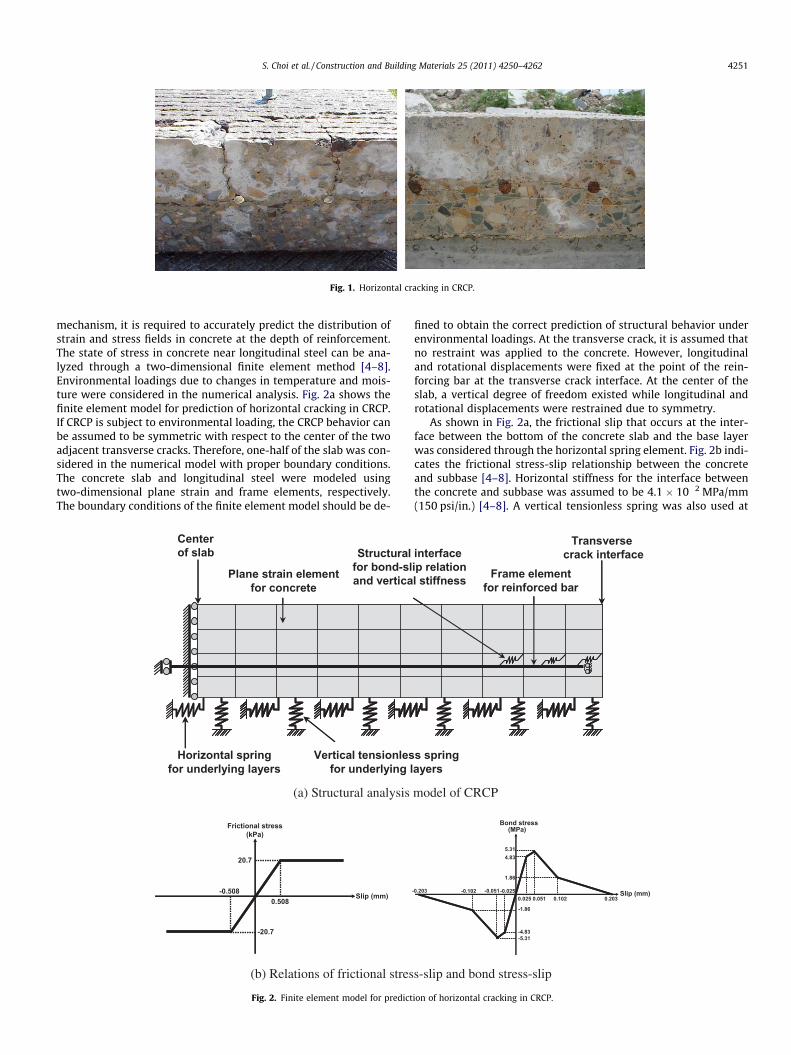
Fig. 1. Horizontal cracking in CRCP.
S. Choi et al. / Construction and Building Materials 25 (2011) 4250–4262 4251
mechanism, it is required to accurately predict the distribution ofstrain and stress fields in concrete at the depth of reinforcement.The state of stress in concrete near longitudinal steel can be ana-lyzed through a two-dimensional finite element method [4–8].Environmental loadings due to changes in temperature and mois-ture were considered in the numerical analysis. Fig. 2a shows thefinite element model for prediction of horizontal cracking in CRCP.If CRCP is subject to environmental loading, the CRCP behavior canbe assumed to be symmetric with respect to the center of the twoadjacent transverse cracks. Therefore, one-half of the slab was con-sidered in the numerical model with proper boundary conditions.The concrete slab and longitudinal steel were modeled usingtwo-dimensional plane strain and frame elements, respectively.The boundary conditions of the finite element model should be de-
Plane strain elementfor concrete
Horizontal springfor underlying layers
Vertical tensionlesfor underlying l
Structuralfor bond-sland vertica
Center of slab
(a) Structural analysis
Slip (mm)
Frictional stress(kPa)
0.508-0.508
20.7
-20.7
(b) Relations of frictional stres
Fig. 2. Finite element model for predict
fined to obtain the correct prediction of structural behavior underenvironmental loadings. At the transverse crack, it is assumed thatno restraint was applied to the concrete. However, longitudinaland rotational displacements were fixed at the point of the rein-forcing bar at the transverse crack interface. At the center of theslab, a vertical degree of freedom existed while longitudinal androtational displacements were restrained due to symmetry.
As shown in Fig. 2a, the frictional slip that occurs at the inter-face between the bottom of the concrete slab and the base layerwas considered through the horizontal spring element. Fig. 2b indi-cates the frictional stress-slip relationship between the concreteand subbase [4–8]. Horizontal stiffness for the interface betweenthe concrete and subbase was assumed to be 4.1 � 10�2 MPa/mm(150 psi/in.) [4–8]. A vertical tensionless spring was also used at
Transverse crack interface
s springayers
Frame elementfor reinforced bar
interfaceip relationl stiffness
model of CRCP
Slip (mm)
Bond stress(MPa)
0.025 0.051 0.102 0.203-0.203 -0.102 -0.025-0.051
5.314.83
1.86
-1.86
-4.83-5.31
s-slip and bond stress-slip
ion of horizontal cracking in CRCP.
4252 S. Choi et al. / Construction and Building Materials 25 (2011) 4250–4262
the bottom interface of concrete in order to properly consider thecurling-up movement. The stiffness of vertical tensionless springwas assumed to be 8.1 � 10�2 MPa/mm (300 psi/in.) [4–8]. Thebond-slip behavior between concrete and longitudinal steel barswas considered through the interface element with horizontalsprings (see Fig. 2a). Fig. 2b shows the relationship of bondstress-slip used in the modeling [4–8]. The stiffness of verticalspring of the structural interface between concrete and longitudi-nal steel bars, which governs the development of vertical stressin concrete near the steel bar, was 2.7 � 103 MPa/mm(1 � 107 psi/in.). The vertical stiffness value will be discussed laterwith experimental data. The finite element program DIANA [9] wasused in the numerical analysis.
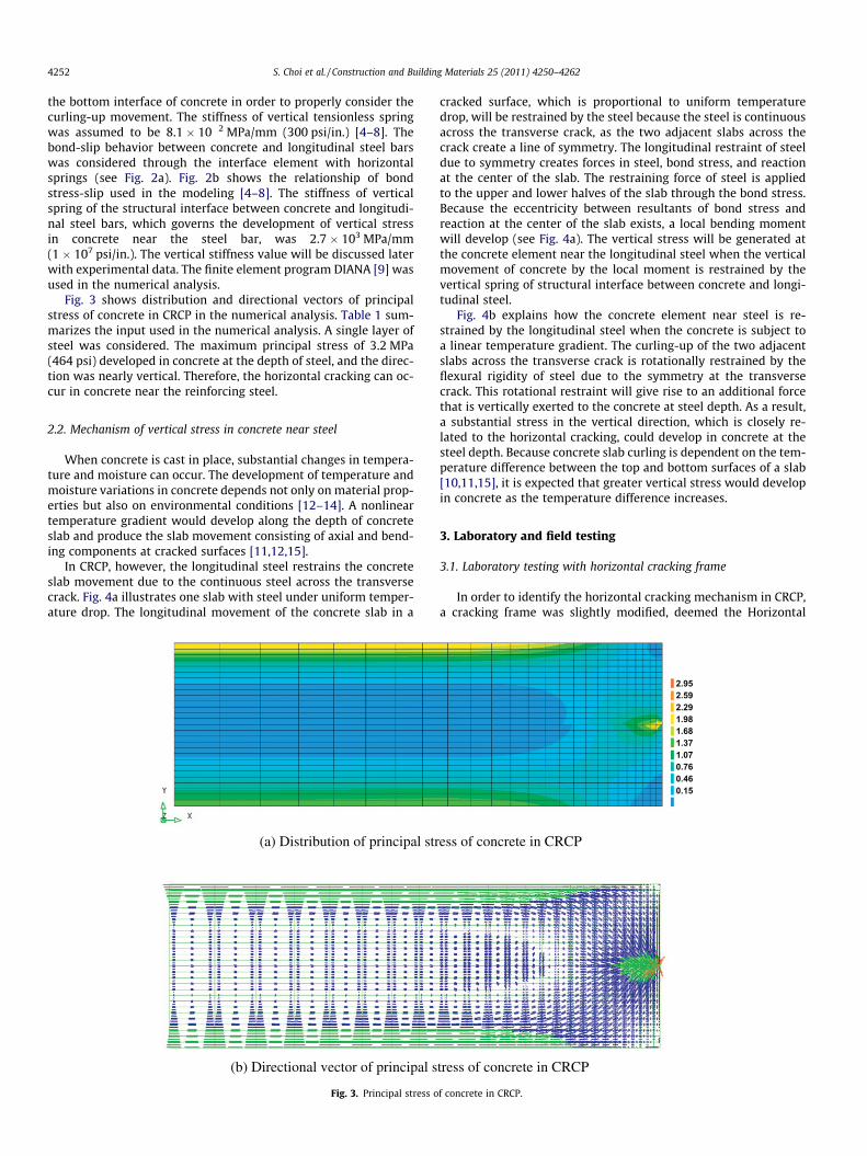
Fig. 3 shows distribution and directional vectors of principalstress of concrete in CRCP in the numerical analysis. Table 1 sum-marizes the input used in the numerical analysis. A single layer ofsteel was considered. The maximum principal stress of 3.2 MPa(464 psi) developed in concrete at the depth of steel, and the direc-tion was nearly vertical. Therefore, the horizontal cracking can oc-cur in concrete near the reinforcing steel.
2.2. Mechanism of vertical stress in concrete near steel
When concrete is cast in place, substantial changes in tempera-ture and moisture can occur. The development of temperature andmoisture variations in concrete depends not only on material prop-erties but also on environmental conditions [12–14]. A nonlineartemperature gradient would develop along the depth of concreteslab and produce the slab movement consisting of axial and bend-ing components at cracked surfaces [11,12,15].
In CRCP, however, the longitudinal steel restrains the concreteslab movement due to the continuous steel across the transversecrack. Fig. 4a illustrates one slab with steel under uniform temper-ature drop. The longitudinal movement of the concrete slab in a
(a) Distribution of principal str
(b) Directional vector of principal s
Fig. 3. Principal stress o
cracked surface, which is proportional to uniform temperaturedrop, will be restrained by the steel because the steel is continuousacross the transverse crack, as the two adjacent slabs across thecrack create a line of symmetry. The longitudinal restraint of steeldue to symmetry creates forces in steel, bond stress, and reactionat the center of the slab. The restraining force of steel is appliedto the upper and lower halves of the slab through the bond stress.Because the eccentricity between resultants of bond stress andreaction at the center of the slab exists, a local bending momentwill develop (see Fig. 4a). The vertical stress will be generated atthe concrete element near the longitudinal steel when the verticalmovement of concrete by the local moment is restrained by thevertical spring of structural interface between concrete and longi-tudinal steel.
Fig. 4b explains how the concrete element near steel is re-strained by the longitudinal steel when the concrete is subject toa linear temperature gradient. The curling-up of the two adjacentslabs across the transverse crack is rotationally restrained by theflexural rigidity of steel due to the symmetry at the transversecrack. This rotational restraint will give rise to an additional forcethat is vertically exerted to the concrete at steel depth. As a result,a substantial stress in the vertical direction, which is closely re-lated to the horizontal cracking, could develop in concrete at thesteel depth. Because concrete slab curling is dependent on the tem-perature difference between the top and bottom surfaces of a slab[10,11,15], it is expected that greater vertical stress would developin concrete as the temperature difference increases.
3. Laboratory and field testing
3.1. Laboratory testing with horizontal cracking frame
In order to identify the horizontal cracking mechanism in CRCP,a cracking frame was slightly modified, deemed the Horizontal
2.952.592.291.981.681.371.070.760.460.15
ess of concrete in CRCP
tress of concrete in CRCP
f concrete in CRCP.
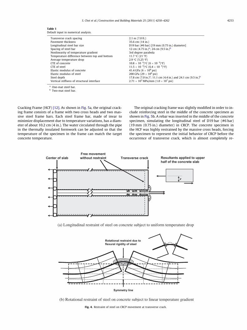
Table 1Default input in numerical analysis.
Transverse crack spacing 2.1 m (7.0 ft.)Pavement thickness 35.6 cm (14 in.)Longitudinal steel bar size D19 bar (#6 bar) [19 mm (0.75 in.) diameter]Spacing of steel bar 12 cm (4.75 in.)a; 24 cm (9.5 in.)b
Nonlinearity of temperature gradient 3rd degree parabolaTemperature difference between top and bottom 11.7 �C (21 �F)Average temperature drop 2.9 �C (5.25 �F)CTE of concrete 10.8 � 10�6/�C (6 � 10�6/�F)CTE of steel 11.5 � 10�6/�C (6.4 � 10�6/�F)Elastic modulus of concrete 41.4 GPa (6 � 106 psi)Elastic modulus of steel 200 GPa (29 � 106 psi)Steel depth 17.8 cm (7.0 in.)a; 11.1 cm (4.4 in.) and 24.1 cm (9.5 in.)b
Vertical stiffness of structural interface 2.71 � 103 MPa/mm (1.0 � 107 psi)
a One-mat steel bar.b Two-mat steel bar.
S. Choi et al. / Construction and Building Materials 25 (2011) 4250–4262 4253
Cracking Frame (HCF) [12]. As shown in Fig. 5a, the original crack-ing frame consists of a frame with two cross heads and two mas-sive steel frame bars. Each steel frame bar, made of invar tominimize displacement due to temperature variations, has a diam-eter of about 10.2 cm (4 in.). The water circulated through the pipein the thermally insulated formwork can be adjusted so that thetemperature of the specimen in the frame can match the targetconcrete temperature.
Center of slab TransFree movementwithout restraint
(a) Longitudinal restraint of steel on concre
Symmetry l
Rotational restraiflexural rigidity of
(b) Rotational restraint of steel on concret
Fig. 4. Restraint of steel on CRCP m
The original cracking frame was slightly modified in order to in-clude reinforcing steel in the middle of the concrete specimen asshown in Fig. 5b. A rebar was inserted in the middle of the concretespecimen, simulating the longitudinal steel of D19 bar (#6 bar)(19 mm (0.75 in.) diameter) in CRCP. The concrete specimen inthe HCF was highly restrained by the massive cross heads, forcingthe specimen to represent the initial behavior of CRCP before theoccurrence of transverse crack, which is almost completely re-
verse crack Resultants applied to upperhalf of the concrete slab
ee
te subject to uniform temperature drop
ine
nt due to steel
e subject to linear temperature gradient
ovement at transverse crack.

4254 S. Choi et al. / Construction and Building Materials 25 (2011) 4250–4262
strained by the continuous placement of concrete. HCF can alsosimulate the behavior of CRCP after a transverse crack occurs be-cause, after a crack in the specimen, each end and cracked surfacesof a specimen are restrained by the cross head and the longitudinalsteel, respectively.
Vibrating wire strain gages (VWSGs) were installed to measurethe temperature and strain in concrete specimens. Three EM-5VWSGs were installed in the longitudinal direction at differentdepths [2.5 cm (1.0 in.), 7.6 cm (3.0 in.), and 12.7 cm (5.0 in.)] fromthe top surface. These gages measured the longitudinal strain andit is expected that a sudden increase in concrete strain will be ob-served if a transverse crack occurs in the specimen. In order to in-duce a crack at the center of the specimen, two acrylic plates[15.2 cm (6.0 in.) high, 2.5 cm (1.0 in.) wide, and 12.7 mm(0.5 in.) thick] were placed at the center of the specimen (seeFig. 5b). In order to measure the vertical movement of concrete ele-ment near the reinforcing steel, two EM-2 VWSGs were also in-stalled vertically at the mid-depth [7.6 cm (3.0 in.)] in the centerof the specimen. Type I/II cement was used in the concrete mix,and the water-to-cement ratio was 0.45.
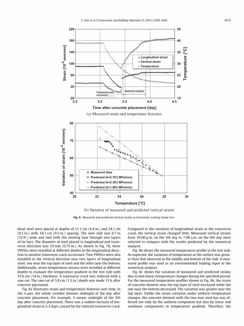
Fig. 6a shows the measured temperature and strain histories inthe horizontal cracking frame test. The temperature was main-tained at 40.6 �C (105 �F) for a concrete age of 3.1 days. During thisperiod, concrete was being hardened. In order to simulate thetransverse cracking in CRCP due to temperature drop, the specimenwas cooled down to 21.1 �C (70 �F). Because the volume change ofthe specimen was restrained by the frame, the tensile stress in-creased in the specimen during cooling stages. At the age of3.4 days, the longitudinal strain suddenly increased and it was be-lieved that this sudden increase was due to the transverse crack
(a) Crac
Embedded concrete strain gageLongitudinal steel Crack inducer
LCLC
(b) Instrumentation of gages in
Fig. 5. Horizontal cra
occurrence. The vertical strain also suddenly increased. After thetransverse crack occurred, the vertical strain was still increasingeven though the temperature was decreasing. This indicates thatthe significant tensile stress in the vertical direction developed atthe concrete element near the reinforcing steel. HCF testing wasanalyzed with the numerical model described previously, in whichthe measured temperature along with mechanical and materialproperties was incorporated. The concrete behavior from 3.4 daysto 3.8 days was analyzed in the numerical analysis. The measuredelastic modulus [16] and CTE [17] were 24.8 GPa (3.6 � 106 psi)and 7.6 � 10�6/�C (4.24 � 10�6/�F), respectively.
Fig. 6b presents variations of measured and predicted verticalstrains during the specified period. The concrete element near steelin the HCF specimen slowly expanded under a uniform tempera-ture drop. This result agreed with the mechanism introduced inthe previous section. Fig. 6b also indicates that the predicted strainvaried with different vertical stiffness values of the structuralinterface between steel and concrete. Among the three verticalstiffness values evaluated, 2.3 � 103 MPa/mm (8.5 � 106 psi/in.)provided the closest prediction to the measured data. This valuecan be used in accurately evaluating the horizontal cracking poten-tial. The validity of this value was examined again with a fieldexperiment, which is shown in next section.
3.2. Field testing
In order to investigate realistic behavior of CRCP under environ-mental loadings, field testing was conducted. The test slab con-sisted of new 35.6 cm (14.0 in.) CRCP over a 10.2 cm (4.0 in.)asphalt stabilized base. As shown in Fig. 7a, two layers of longitu-
king frame
horizontal cracking frame
cking frame test.
-20
20
60
100
140
180
220
2.5 3.0 3.5 4.0 4.5
Time after concrete placement [day]
Stra
in [1
0-6 m
m/m
m]
15
20
25
30
35
40
45
Tem
pera
ture
[°C
]
Longitudinal strainVertical strainTemperature
Numerical analysisTransverse crackoccurrence
(a) Measured strain and temperature histories
40
50
60
70
80
20 22 24 26 28 30
Temperature [°C]
Varia
tion
of s
trai
n [1
0-6 m
m/m
m]
Measured dataPredicted (k=2.7E3 MPa/mm)Predicted (k=2.3E3 MPa/mm)Predicted (k=1.9E3 MPa/mm)
(b) Variation of measured and predicted vertical strains
Fig. 6. Measured and predicted vertical strains in horizontal cracking frame test.
S. Choi et al. / Construction and Building Materials 25 (2011) 4250–4262 4255
dinal steel were placed at depths of 11.1 cm (4.4 in.) and 24.1 cm(9.5 in.) with 24.1 cm (9.5 in.) spacing. The new slab was 6.7 m(22 ft.) wide and tied with the existing lane through two layersof tie bars. The diameter of steel placed in longitudinal and trans-verse direction was 19 mm (0.75 in.). As shown in Fig. 7b, threeVWSGs were installed at different depths in the longitudinal direc-tion to monitor transverse crack occurrence. Two VWSGs were alsoinstalled in the vertical direction near two layers of longitudinalsteel: one near the top layer of steel and the other near the bottom.Additionally, seven temperature sensors were installed at differentdepths to evaluate the temperature gradient in the test slab with35.6 cm (14 in.) thickness. A transverse crack was induced with asaw cut. The saw cut of 3.8 cm (1.5 in.) depth was made 15 h afterconcrete placement.
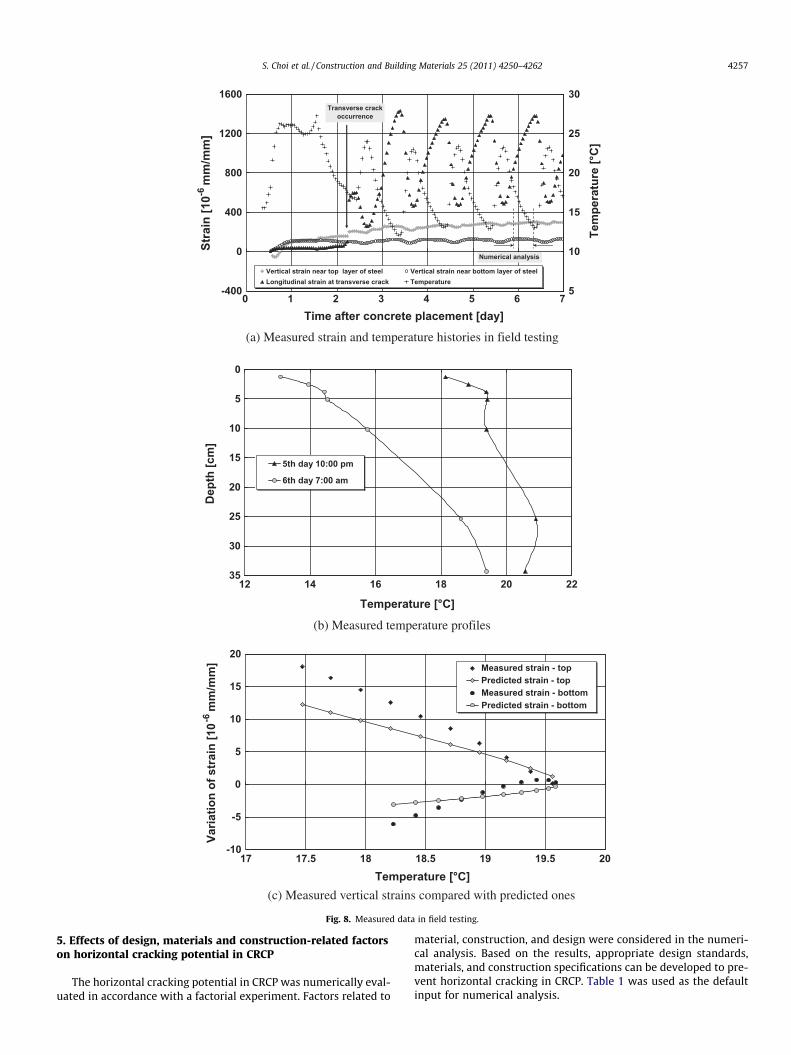
Fig. 8a illustrates strain and temperature histories over time. Inthe x-axis, the whole number denotes midnight of the day afterconcrete placement. For example, 5 means midnight of the 5thday after concrete placement. There was a sudden increase of lon-gitudinal strain at 2.3 days, caused by the induced transverse crack.
Compared to the variation of longitudinal strain at the transversecrack, the vertical strain changed little. Measured vertical strainsfrom 10:00 p.m. on the 5th day to 7:00 a.m. on the 6th day wereselected to compare with the results predicted by the numericalanalysis.
Fig. 8b shows the measured temperature profile in the test slab.As expected, the variation of temperature at the surface was great-er than that observed at the middle and bottom of the slab. A mea-sured profile was used as an environmental loading input in thenumerical analysis.
Fig. 8c shows the variation of measured and predicted strainsdue to non-linear temperature changes during the specified period.For the measured temperature profiles shown in Fig. 8b, the strainof concrete element near the top layer of steel increased while theone near the bottom decreased. The variation was greater near thetop layer. Unlike the strain variation under uniform temperaturechanges, the concrete element with the two-mat steel bar was af-fected not only by the uniform component but also by linear andnonlinear components in temperature gradient. Therefore, the
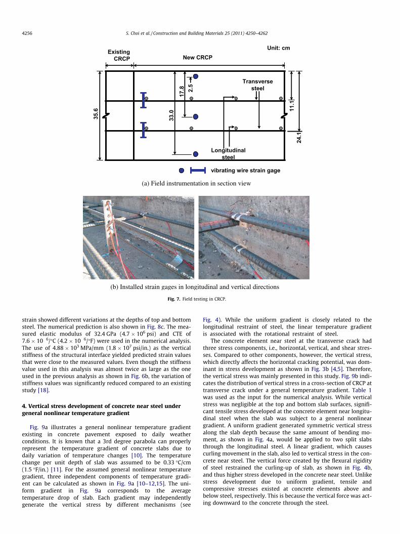
35.6
ExistingCRCP New CRCP
Transversesteel
Longitudinalsteel
vibrating wire strain gage
11.1
24.1
2.5
17.8
33.0
Unit: cm
(a) Field instrumentation in section view
(b) Installed strain gages in longitudinal and vertical directions
Fig. 7. Field testing in CRCP.
4256 S. Choi et al. / Construction and Building Materials 25 (2011) 4250–4262
strain showed different variations at the depths of top and bottomsteel. The numerical prediction is also shown in Fig. 8c. The mea-sured elastic modulus of 32.4 GPa (4.7 � 106 psi) and CTE of7.6 � 10�6/�C (4.2 � 10�6/�F) were used in the numerical analysis.The use of 4.88 � 103 MPa/mm (1.8 � 107 psi/in.) as the verticalstiffness of the structural interface yielded predicted strain valuesthat were close to the measured values. Even though the stiffnessvalue used in this analysis was almost twice as large as the oneused in the previous analysis as shown in Fig. 6b, the variation ofstiffness values was significantly reduced compared to an existingstudy [18].
4. Vertical stress development of concrete near steel undergeneral nonlinear temperature gradient
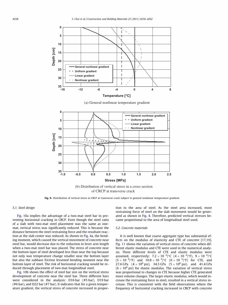
Fig. 9a illustrates a general nonlinear temperature gradientexisting in concrete pavement exposed to daily weatherconditions. It is known that a 3rd degree parabola can properlyrepresent the temperature gradient of concrete slabs due todaily variation of temperature changes [10]. The temperaturechange per unit depth of slab was assumed to be 0.33 �C/cm(1.5 �F/in.) [11]. For the assumed general nonlinear temperaturegradient, three independent components of temperature gradi-ent can be calculated as shown in Fig. 9a [10–12,15]. The uni-form gradient in Fig. 9a corresponds to the averagetemperature drop of slab. Each gradient may independentlygenerate the vertical stress by different mechanisms (see
Fig. 4). While the uniform gradient is closely related to thelongitudinal restraint of steel, the linear temperature gradientis associated with the rotational restraint of steel.
The concrete element near steel at the transverse crack hadthree stress components, i.e., horizontal, vertical, and shear stres-ses. Compared to other components, however, the vertical stress,which directly affects the horizontal cracking potential, was dom-inant in stress development as shown in Fig. 3b [4,5]. Therefore,the vertical stress was mainly presented in this study. Fig. 9b indi-cates the distribution of vertical stress in a cross-section of CRCP attransverse crack under a general temperature gradient. Table 1was used as the input for the numerical analysis. While verticalstress was negligible at the top and bottom slab surfaces, signifi-cant tensile stress developed at the concrete element near longitu-dinal steel when the slab was subject to a general nonlineargradient. A uniform gradient generated symmetric vertical stressalong the slab depth because the same amount of bending mo-ment, as shown in Fig. 4a, would be applied to two split slabsthrough the longitudinal steel. A linear gradient, which causescurling movement in the slab, also led to vertical stress in the con-crete near steel. The vertical force created by the flexural rigidityof steel restrained the curling-up of slab, as shown in Fig. 4b,and thus higher stress developed in the concrete near steel. Unlikestress development due to uniform gradient, tensile andcompressive stresses existed at concrete elements above andbelow steel, respectively. This is because the vertical force was act-ing downward to the concrete through the steel.
-400
0
400
800
1200
1600
0 1 2 3 4 5 6 7Time after concrete placement [day]
Stra
in [1
0-6 m
m/m
m]
5
10
15
20
25
30
Tem
pera
ture
[°C
]
Vertical strain near top layer of steel Vertical strain near bottom layer of steelLongitudinal strain at transverse crack Temperature
Transverse crackoccurrence
Numerical analysis
(a) Measured strain and temperature histories in field testing
0
5
10
15
20
25
30
3512 14 16 18 20 22
Temperature [°C]
Dep
th [c
m]
5th day 10:00 pm
6th day 7:00 am
(b) Measured temperature profiles
-10
-5
0
5
10
15
20
17 17.5 18 18.5 19 19.5 20Temperature [°C]
Varia
tion
of s
trai
n [1
0-6 m
m/m
m] Measured strain - top
Predicted strain - topMeasured strain - bottomPredicted strain - bottom
(c) Measured vertical strains compared with predicted ones
Fig. 8. Measured data in field testing.
S. Choi et al. / Construction and Building Materials 25 (2011) 4250–4262 4257
5. Effects of design, materials and construction-related factorson horizontal cracking potential in CRCP
The horizontal cracking potential in CRCP was numerically eval-uated in accordance with a factorial experiment. Factors related to
material, construction, and design were considered in the numeri-cal analysis. Based on the results, appropriate design standards,materials, and construction specifications can be developed to pre-vent horizontal cracking in CRCP. Table 1 was used as the defaultinput for numerical analysis.
0
5
10
15
20
25
30
35-16 -12 -8 -4 0 4 8
Temperature [°C]
Dep
th [c
m]
General nonlinear gradientUniform gradientLinear gradientNonlinear gradient
(a) General nonlinear temperature gradient
0
5
10
15
20
25
30
35-1.0 -0.5 0.0 0.5 1.0 1.5 2.0 2.5
Stress [MPa]
Dep
th [c
m]
General nonlinear gradientUniform gradientLinear gradientNonlinear gradient
(b) Distribution of vertical stress in a cross-section of CRCP at transverse crack
Fig. 9. Distribution of vertical stress in CRCP at transverse crack subject to general nonlinear temperature gradient.
4258 S. Choi et al. / Construction and Building Materials 25 (2011) 4250–4262
5.1. Steel design
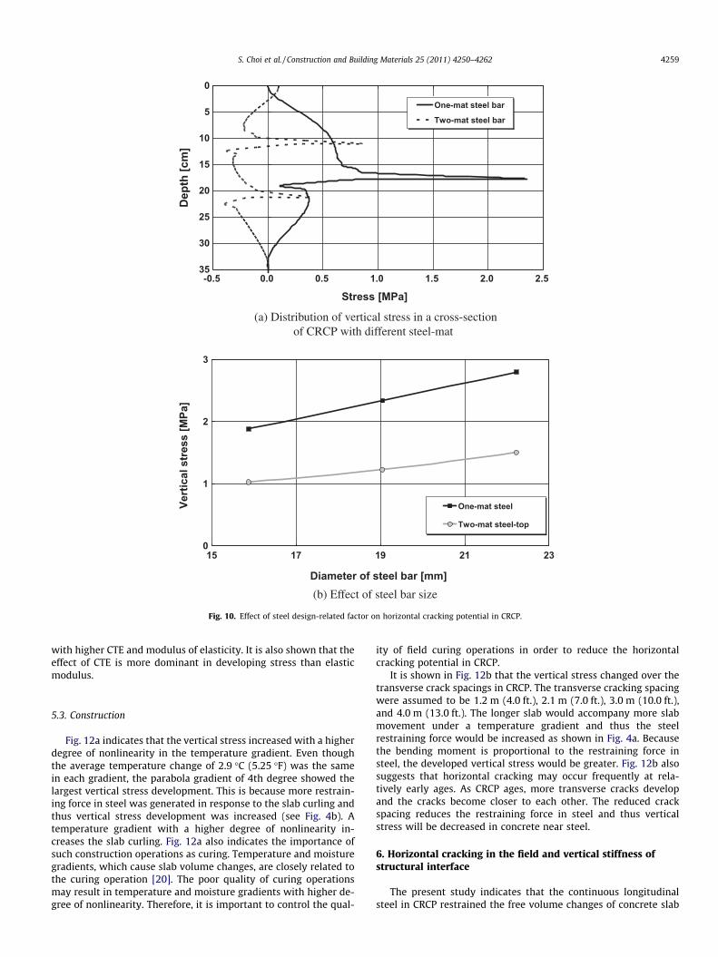
Fig. 10a implies the advantage of a two-mat steel bar in pre-venting horizontal cracking in CRCP. Even though the steel ratioof a slab with two-mat steel placement was the same as one-mat, vertical stress was significantly reduced. This is because thedistance between the steel restraining force and the resultant reac-tion at the slab center was reduced. As shown in Fig. 4a, the bend-ing moment, which caused the vertical movement of concrete nearsteel bar, would decrease due to the reduction in lever arm lengthwhen a two-mat steel bar was placed. The stress of concrete nearthe bottom layer of steel developed less than near the top becausenot only was temperature change smaller near the bottom layerbut also the subbase friction lessened bending moment near thebottom layer of steel. The risk of horizontal cracking would be re-duced through placement of two-mat longitudinal steel.
Fig. 10b shows the effect of steel bar size on the vertical stressdevelopment of concrete near the steel bar. Three different barswere considered in the analysis: D16 bar (#5 bar), D19 bar(#6 bar), and D22 bar (#7 bar). It indicates that for a given temper-ature gradient, the vertical stress of concrete increased in propor-
tion to the area of steel. As the steel area increased, morerestraining force of steel on the slab movement would be gener-ated as shown in Fig. 4. Therefore, predicted vertical stresses be-came proportional to the area of longitudinal steel used.
5.2. Concrete materials
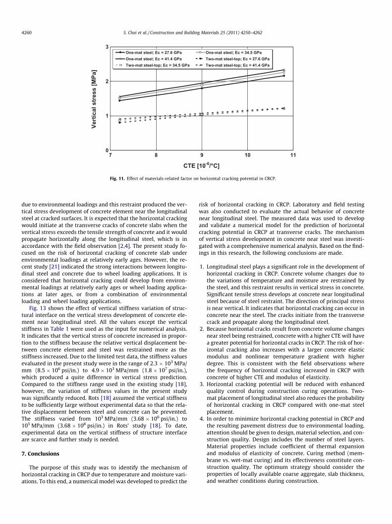
It is well known that coarse aggregate type has substantial ef-fects on the modulus of elasticity and CTE of concrete [17,19].Fig. 11 shows the variation of vertical stress of concrete when dif-ferent elastic modulus and CTE were used in the numerical analy-sis. Three different levels of CTE and elastic modulus wereassumed, respectively: 7.2 � 10�6/�C (4 � 10�6/�F), 9 � 10�6/�C(5 � 10�6/�F) and 10.8 � 10�6/�C (6 � 10�6/�F) for CTE, and27.6 GPa (4 � 106 psi), 34.5 GPa (5 � 106 psi), and 41.4 GPa(6 � 106 psi) for elastic modulus. The variation of vertical stresswas proportional to changes in CTE because higher CTE generatedmore volume changes. The larger elastic modulus, which would in-crease the restraining force in steel, resulted in a vertical stress in-crease. This is consistent with the field observations where thefrequency of horizontal cracking increased in CRCP with concrete
0
5
10
15
20
25
30
35-0.5 0.0 0.5 1.0 1.5 2.0 2.5
Stress [MPa]
Dep
th [c
m]
One-mat steel bar
Two-mat steel bar
(a) Distribution of vertical stress in a cross-section of CRCP with different steel-mat
0
1
2
3
15 17 19 21 23
Diameter of steel bar [mm]
Vert
ical
str
ess
[MPa
]
One-mat steel
Two-mat steel-top
(b) Effect of steel bar size
Fig. 10. Effect of steel design-related factor on horizontal cracking potential in CRCP.
S. Choi et al. / Construction and Building Materials 25 (2011) 4250–4262 4259
with higher CTE and modulus of elasticity. It is also shown that theeffect of CTE is more dominant in developing stress than elasticmodulus.
5.3. Construction
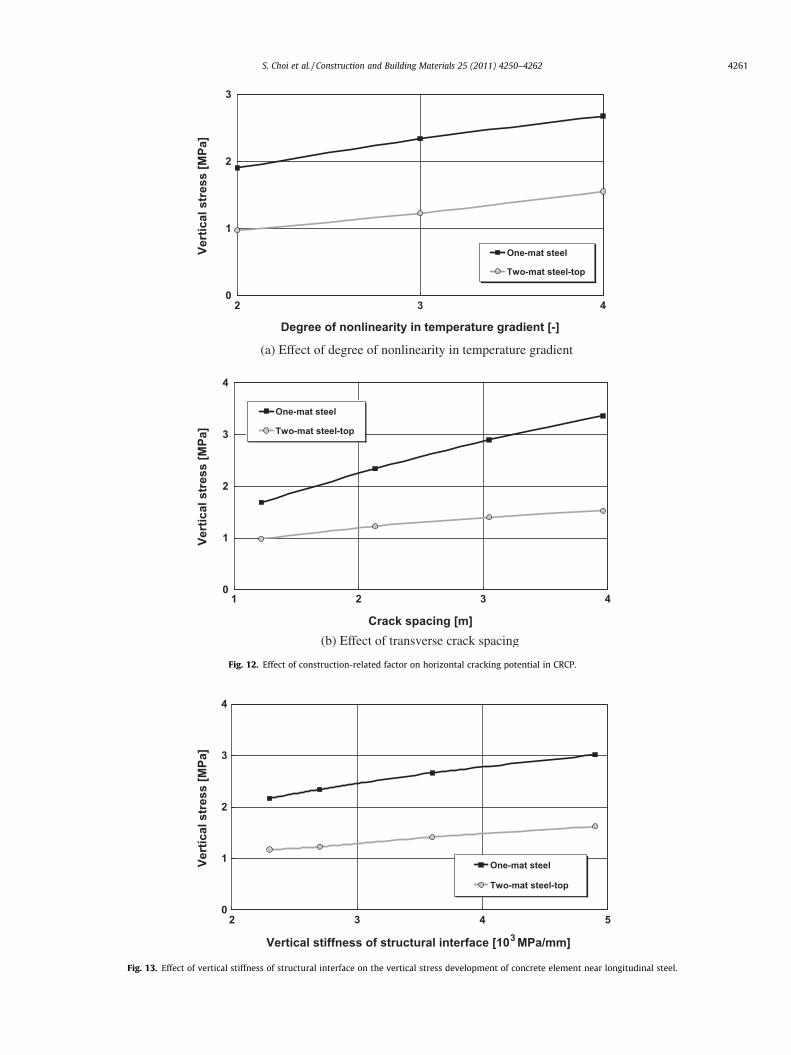
Fig. 12a indicates that the vertical stress increased with a higherdegree of nonlinearity in the temperature gradient. Even thoughthe average temperature change of 2.9 �C (5.25 �F) was the samein each gradient, the parabola gradient of 4th degree showed thelargest vertical stress development. This is because more restrain-ing force in steel was generated in response to the slab curling andthus vertical stress development was increased (see Fig. 4b). Atemperature gradient with a higher degree of nonlinearity in-creases the slab curling. Fig. 12a also indicates the importance ofsuch construction operations as curing. Temperature and moisturegradients, which cause slab volume changes, are closely related tothe curing operation [20]. The poor quality of curing operationsmay result in temperature and moisture gradients with higher de-gree of nonlinearity. Therefore, it is important to control the qual-
ity of field curing operations in order to reduce the horizontalcracking potential in CRCP.
It is shown in Fig. 12b that the vertical stress changed over thetransverse crack spacings in CRCP. The transverse cracking spacingwere assumed to be 1.2 m (4.0 ft.), 2.1 m (7.0 ft.), 3.0 m (10.0 ft.),and 4.0 m (13.0 ft.). The longer slab would accompany more slabmovement under a temperature gradient and thus the steelrestraining force would be increased as shown in Fig. 4a. Becausethe bending moment is proportional to the restraining force insteel, the developed vertical stress would be greater. Fig. 12b alsosuggests that horizontal cracking may occur frequently at rela-tively early ages. As CRCP ages, more transverse cracks developand the cracks become closer to each other. The reduced crackspacing reduces the restraining force in steel and thus verticalstress will be decreased in concrete near steel.
6. Horizontal cracking in the field and vertical stiffness ofstructural interface
The present study indicates that the continuous longitudinalsteel in CRCP restrained the free volume changes of concrete slab
0
1
2
3
7 8 9 10 11
CTE [10-6/°C]
Vert
ical
str
ess
[MPa
]
One-mat steel; Ec = 27.6 GPa One-mat steel; Ec = 34.5 GPaOne-mat steel; Ec = 41.4 GPa Two-mat steel-top; Ec = 27.6 GPaTwo-mat steel-top; Ec = 34.5 GPa Two-mat steel-top; Ec = 41.4 GPa
Fig. 11. Effect of materials-related factor on horizontal cracking potential in CRCP.
4260 S. Choi et al. / Construction and Building Materials 25 (2011) 4250–4262
due to environmental loadings and this restraint produced the ver-tical stress development of concrete element near the longitudinalsteel at cracked surfaces. It is expected that the horizontal crackingwould initiate at the transverse cracks of concrete slabs when thevertical stress exceeds the tensile strength of concrete and it wouldpropagate horizontally along the longitudinal steel, which is inaccordance with the field observation [2,4]. The present study fo-cused on the risk of horizontal cracking of concrete slab underenvironmental loadings at relatively early ages. However, the re-cent study [21] indicated the strong interactions between longitu-dinal steel and concrete due to wheel loading applications. It isconsidered that horizontal cracking could develop from environ-mental loadings at relatively early ages or wheel loading applica-tions at later ages, or from a combination of environmentalloading and wheel loading applications.
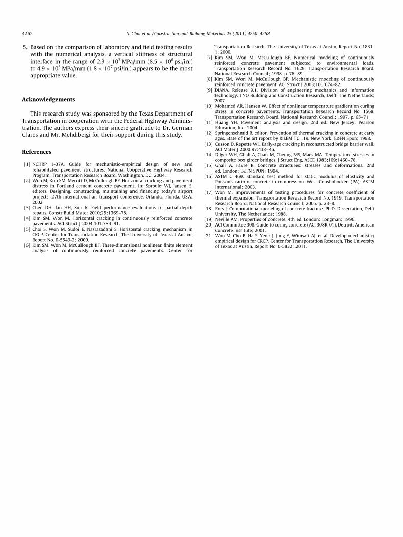
Fig. 13 shows the effect of vertical stiffness variation of struc-tural interface on the vertical stress development of concrete ele-ment near longitudinal steel. All the values except the verticalstiffness in Table 1 were used as the input for numerical analysis.It indicates that the vertical stress of concrete increased in propor-tion to the stiffness because the relative vertical displacement be-tween concrete element and steel was restrained more as thestiffness increased. Due to the limited test data, the stiffness valuesevaluated in the present study were in the range of 2.3 � 103 MPa/mm (8.5 � 106 psi/in.) to 4.9 � 103 MPa/mm (1.8 � 107 psi/in.),which produced a quite difference in vertical stress prediction.Compared to the stiffness range used in the existing study [18],however, the variation of stiffness values in the present studywas significantly reduced. Rots [18] assumed the vertical stiffnessto be sufficiently large without experimental data so that the rela-tive displacement between steel and concrete can be prevented.The stiffness varied from 103 MPa/mm (3.68 � 106 psi/in.) to105 MPa/mm (3.68 � 108 psi/in.) in Rots’ study [18]. To date,experimental data on the vertical stiffness of structure interfaceare scarce and further study is needed.
7. Conclusions
The purpose of this study was to identify the mechanism ofhorizontal cracking in CRCP due to temperature and moisture vari-ations. To this end, a numerical model was developed to predict the
risk of horizontal cracking in CRCP. Laboratory and field testingwas also conducted to evaluate the actual behavior of concretenear longitudinal steel. The measured data was used to developand validate a numerical model for the prediction of horizontalcracking potential in CRCP at transverse cracks. The mechanismof vertical stress development in concrete near steel was investi-gated with a comprehensive numerical analysis. Based on the find-ings in this research, the following conclusions are made.
1. Longitudinal steel plays a significant role in the development ofhorizontal cracking in CRCP. Concrete volume changes due tothe variations of temperature and moisture are restrained bythe steel, and this restraint results in vertical stress in concrete.Significant tensile stress develops at concrete near longitudinalsteel because of steel restraint. The direction of principal stressis near vertical. It indicates that horizontal cracking can occur inconcrete near the steel. The cracks initiate from the transversecrack and propagate along the longitudinal steel.
2. Because horizontal cracks result from concrete volume changesnear steel being restrained, concrete with a higher CTE will havea greater potential for horizontal cracks in CRCP. The risk of hor-izontal cracking also increases with a larger concrete elasticmodulus and nonlinear temperature gradient with higherdegree. This is consistent with the field observations wherethe frequency of horizontal cracking increased in CRCP withconcrete of higher CTE and modulus of elasticity.
3. Horizontal cracking potential will be reduced with enhancedquality control during construction curing operations. Two-mat placement of longitudinal steel also reduces the probabilityof horizontal cracking in CRCP compared with one-mat steelplacement.
4. In order to minimize horizontal cracking potential in CRCP andthe resulting pavement distress due to environmental loading,attention should be given to design, material selection, and con-struction quality. Design includes the number of steel layers.Material properties include coefficient of thermal expansionand modulus of elasticity of concrete. Curing method (mem-brane vs. wet-mat curing) and its effectiveness constitute con-struction quality. The optimum strategy should consider theproperties of locally available coarse aggregate, slab thickness,and weather conditions during construction.
0
1
2
3
432
Degree of nonlinearity in temperature gradient [-]
Vert
ical
str
ess
[MPa
]
One-mat steel
Two-mat steel-top
(a) Effect of degree of nonlinearity in temperature gradient
0
1
2
3
4
4321
Crack spacing [m]
Vert
ical
str
ess
[MPa
]
One-mat steel
Two-mat steel-top
(b) Effect of transverse crack spacing
Fig. 12. Effect of construction-related factor on horizontal cracking potential in CRCP.
0
1
2
3
4
5432
Vertical stiffness of structural interface [103 MPa/mm]
Vert
ical
str
ess
[MPa
]
One-mat steel
Two-mat steel-top
Fig. 13. Effect of vertical stiffness of structural interface on the vertical stress development of concrete element near longitudinal steel.
S. Choi et al. / Construction and Building Materials 25 (2011) 4250–4262 4261
4262 S. Choi et al. / Construction and Building Materials 25 (2011) 4250–4262
5. Based on the comparison of laboratory and field testing resultswith the numerical analysis, a vertical stiffness of structuralinterface in the range of 2.3 � 103 MPa/mm (8.5 � 106 psi/in.)to 4.9 � 103 MPa/mm (1.8 � 107 psi/in.) appears to be the mostappropriate value.
Acknowledgements
This research study was sponsored by the Texas Department ofTransportation in cooperation with the Federal Highway Adminis-tration. The authors express their sincere gratitude to Dr. GermanClaros and Mr. Mehdibeigi for their support during this study.
References
[1] NCHRP 1-37A. Guide for mechanistic-empirical design of new andrehabilitated pavement structures. National Cooperative Highway ResearchProgram, Transportation Research Board. Washington, DC; 2004.
[2] Won M, Kim SM, Merritt D, McCullough BF. Horizontal cracking and pavementdistress in Portland cement concrete pavement. In: Sproule WJ, Jansen S,editors. Designing, constructing, maintaining and financing today’s airportprojects, 27th international air transport conference, Orlando, Florida, USA;2002.
[3] Chen DH, Lin HH, Sun R. Field performance evaluations of partial-depthrepairs. Constr Build Mater 2010;25:1369–78.
[4] Kim SM, Won M. Horizontal cracking in continuously reinforced concretepavements. ACI Struct J 2004;101:784–91.
[5] Choi S, Won M, Sudoi E, Nasrazadani S. Horizontal cracking mechanism inCRCP. Center for Transportation Research, The University of Texas at Austin,Report No. 0-5549-2; 2009.
[6] Kim SM, Won M, McCullough BF. Three-dimensional nonlinear finite elementanalysis of continuously reinforced concrete pavements. Center for
Transportation Research, The University of Texas at Austin, Report No. 1831-1; 2000.
[7] Kim SM, Won M, McCullough BF. Numerical modeling of continuouslyreinforced concrete pavement subjected to environmental loads.Transportation Research Record No. 1629, Transportation Research Board,National Research Council; 1998. p. 76–89.
[8] Kim SM, Won M, McCullough BF. Mechanistic modeling of continuouslyreinforced concrete pavement. ACI Struct J 2003;100:674–82.
[9] DIANA, Release 9.1. Division of engineering mechanics and informationtechnology. TNO Building and Construction Research, Delft, The Netherlands;2007.
[10] Mohamed AR, Hansen W. Effect of nonlinear temperature gradient on curlingstress in concrete pavements. Transportation Research Record No. 1568,Transportation Research Board, National Research Council; 1997. p. 65–71.
[11] Huang YH. Pavement analysis and design. 2nd ed. New Jersey: PearsonEducation, Inc; 2004.
[12] Springenschmid R, editor. Prevention of thermal cracking in concrete at earlyages. State of the art report by RILEM TC 119. New York: E&FN Spon; 1998.
[13] Cusson D, Repette WL. Early-age cracking in reconstructed bridge barrier wall.ACI Mater J 2000;97:438–46.
[14] Dilger WH, Ghali A, Chan M, Cheung MS, Maes MA. Temperature stresses incomposite box girder bridges. J Struct Eng, ASCE 1983;109:1460–78.
[15] Ghali A, Favre R. Concrete structures: stresses and deformations. 2nded. London: E&FN SPON; 1994.
[16] ASTM C 469. Standard test method for static modulus of elasticity andPoisson’s ratio of concrete in compression. West Conshohocken (PA): ASTMInternational; 2003.
[17] Won M. Improvements of testing procedures for concrete coefficient ofthermal expansion. Transportation Research Record No. 1919, TransportationResearch Board, National Research Council; 2005. p. 23–8.
[18] Rots J. Computational modeling of concrete fracture. Ph.D. Dissertation, DelftUniversity, The Netherlands; 1988.
[19] Neville AM. Properties of concrete. 4th ed. London: Longman; 1996.[20] ACI Committee 308. Guide to curing concrete (ACI 308R-01). Detroit: American
Concrete Institute; 2001.[21] Won M, Cho B, Ha S, Yeon J, Jung Y, Wimsatt AJ, et al. Develop mechanistic/
empirical design for CRCP. Center for Transportation Research, The Universityof Texas at Austin, Report No. 0-5832; 2011.
Copyright © 2022 FDOKUMEN