Maintenance Actions to Address Fatigue Cracking in Steel ...
203
i Maintenance Actions to Address Fatigue Cracking in Steel Bridge Structures PROPOSED GUIDELINES AND COMMENTARY Prepared for: NCHRP Transportation Research Board of The National Academies Prepared by: Robert J. Connor and Jason B. Lloyd Purdue University West Lafayette, Indiana March, 2017 The information contained in this report was prepared as part of NCHRP Project 20-07, Task 387, National Cooperative Highway Research Program. SPECIAL NOTE: This report IS NOT an official publication of the National Cooperative Highway Research Program, Transportation Research Board, National Research Council, or The National Academies.
-
Upload
khangminh22 -
Category
Documents
-
view
1 -
download
0
Transcript of Maintenance Actions to Address Fatigue Cracking in Steel ...
i
Maintenance Actions to Address Fatigue Cracking in Steel Bridge Structures
PROPOSED GUIDELINES AND COMMENTARY
Prepared for:
NCHRP Transportation Research Board of The National Academies
Prepared by: Robert J. Connor and Jason B. Lloyd
Purdue University West Lafayette, Indiana
March, 2017
The information contained in this report was prepared as part of NCHRP Project 20-07, Task 387, National Cooperative Highway Research Program.
SPECIAL NOTE: This report IS NOT an official publication of the National Cooperative Highway Research Program, Transportation Research Board, National Research Council, or The National Academies.

ii
Acknowledgements This study was conducted for the [cite requesting organization/committee], with funding
provided through the National Cooperative Highway Research Program (NCHRP) Project 20-07 Task 387, Maintenance Actions to Address Fatigue Cracking in Steel Bridge Structures. The NCHRP is supported by annual voluntary contributions from the state Departments of Transportation. Project 20-07 is intended to fund quick response studies on behalf of the AASHTO Subcommittee on Bridges and Structures (SCOBS). The report was prepared by Dr. Robert J. Connor, Professor of Civil Engineering at Purdue University (Principal Investigator) and Mr. Jason B. Lloyd, P.E. Research Engineer at Purdue University, with excellent computer drafting support provided by Mr. Jonathan Hui, Graduate Research Assistant at Purdue University. The work was guided by a technical working group. The project was managed by Dr. Waseem Dekelbab, NCHRP Senior Program Officer.
Disclaimer The opinions and conclusions expressed or implied are those of the research agency that
performed the research and are not necessarily those of the Transportation Research Board or its sponsoring agencies. This report has not been reviewed or accepted by the Transportation Research Board Executive Committee or the Governing Board of the National Research Council.
iii
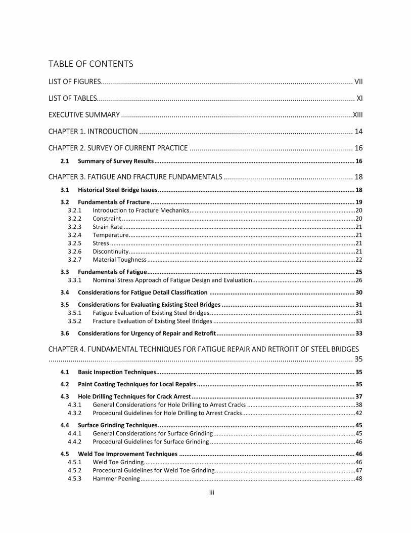
TABLE OF CONTENTS
LIST OF FIGURES ............................................................................................................................. VII
LIST OF TABLES................................................................................................................................ XI
EXECUTIVE SUMMARY ...................................................................................................................XIII
CHAPTER 1. INTRODUCTION .......................................................................................................... 14
CHAPTER 2. SURVEY OF CURRENT PRACTICE ................................................................................. 16
2.1 Summary of Survey Results ................................................................................................................. 16
CHAPTER 3. FATIGUE AND FRACTURE FUNDAMENTALS ................................................................ 18
3.1 Historical Steel Bridge Issues ............................................................................................................... 18
3.2 Fundamentals of Fracture ................................................................................................................... 19 3.2.1 Introduction to Fracture Mechanics .................................................................................................. 20 3.2.2 Constraint .......................................................................................................................................... 20 3.2.3 Strain Rate ......................................................................................................................................... 21 3.2.4 Temperature ...................................................................................................................................... 21 3.2.5 Stress ................................................................................................................................................. 21 3.2.6 Discontinuity ...................................................................................................................................... 21 3.2.7 Material Toughness ........................................................................................................................... 22
3.3 Fundamentals of Fatigue ..................................................................................................................... 25 3.3.1 Nominal Stress Approach of Fatigue Design and Evaluation ............................................................. 26
3.4 Considerations for Fatigue Detail Classification .................................................................................. 30
3.5 Considerations for Evaluating Existing Steel Bridges ........................................................................... 31 3.5.1 Fatigue Evaluation of Existing Steel Bridges ...................................................................................... 31 3.5.2 Fracture Evaluation of Existing Steel Bridges .................................................................................... 33
3.6 Considerations for Urgency of Repair and Retrofit .............................................................................. 33
CHAPTER 4. FUNDAMENTAL TECHNIQUES FOR FATIGUE REPAIR AND RETROFIT OF STEEL BRIDGES....................................................................................................................................................... 35
4.1 Basic Inspection Techniques ................................................................................................................ 35
4.2 Paint Coating Techniques for Local Repairs ......................................................................................... 35
4.3 Hole Drilling Techniques for Crack Arrest ............................................................................................ 37 4.3.1 General Considerations for Hole Drilling to Arrest Cracks ................................................................ 38 4.3.2 Procedural Guidelines for Hole Drilling to Arrest Cracks ................................................................... 42
4.4 Surface Grinding Techniques ............................................................................................................... 45 4.4.1 General Considerations for Surface Grinding .................................................................................... 45 4.4.2 Procedural Guidelines for Surface Grinding ...................................................................................... 46
4.5 Weld Toe Improvement Techniques ................................................................................................... 46 4.5.1 Weld Toe Grinding ............................................................................................................................. 46 4.5.2 Procedural Guidelines for Weld Toe Grinding ................................................................................... 47 4.5.3 Hammer Peening ............................................................................................................................... 48
iv
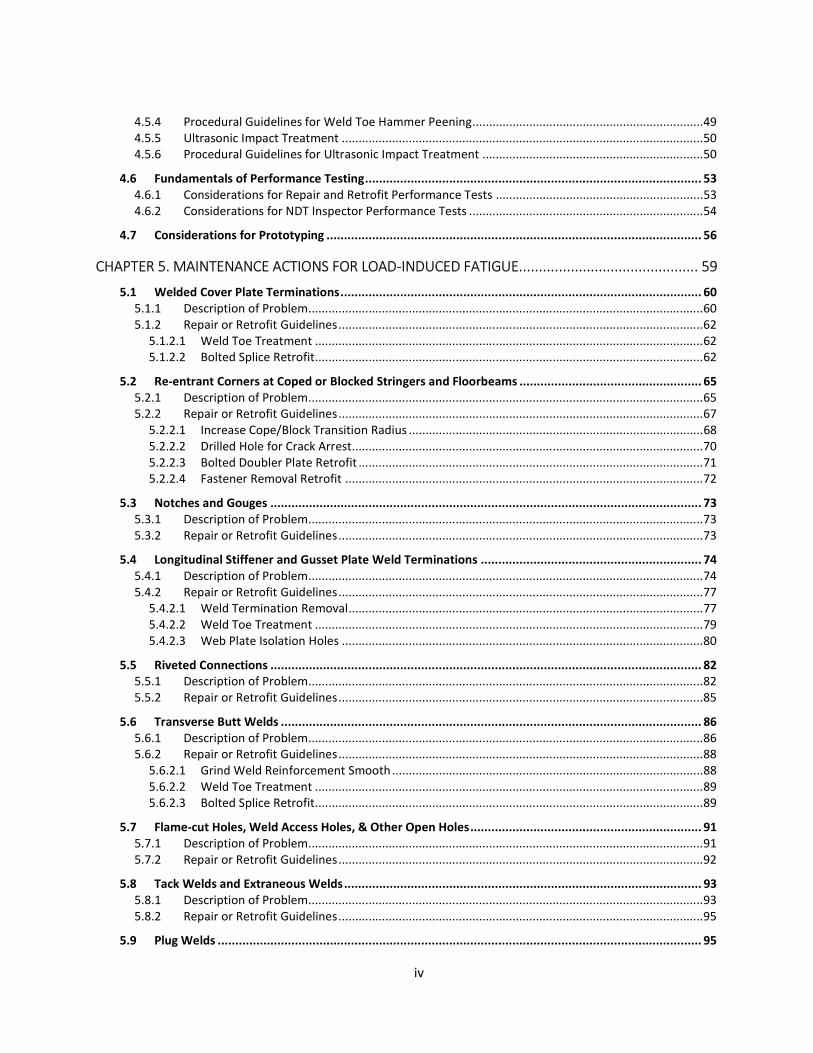
4.5.4 Procedural Guidelines for Weld Toe Hammer Peening ..................................................................... 49 4.5.5 Ultrasonic Impact Treatment ............................................................................................................ 50 4.5.6 Procedural Guidelines for Ultrasonic Impact Treatment .................................................................. 50
4.6 Fundamentals of Performance Testing ................................................................................................ 53 4.6.1 Considerations for Repair and Retrofit Performance Tests .............................................................. 53 4.6.2 Considerations for NDT Inspector Performance Tests ...................................................................... 54
4.7 Considerations for Prototyping ........................................................................................................... 56
CHAPTER 5. MAINTENANCE ACTIONS FOR LOAD-INDUCED FATIGUE ............................................. 59
5.1 Welded Cover Plate Terminations ....................................................................................................... 60 5.1.1 Description of Problem ...................................................................................................................... 60 5.1.2 Repair or Retrofit Guidelines ............................................................................................................. 62
5.1.2.1 Weld Toe Treatment .................................................................................................................... 62 5.1.2.2 Bolted Splice Retrofit .................................................................................................................... 62
5.2 Re-entrant Corners at Coped or Blocked Stringers and Floorbeams .................................................... 65 5.2.1 Description of Problem ...................................................................................................................... 65 5.2.2 Repair or Retrofit Guidelines ............................................................................................................. 67
5.2.2.1 Increase Cope/Block Transition Radius ........................................................................................ 68 5.2.2.2 Drilled Hole for Crack Arrest......................................................................................................... 70 5.2.2.3 Bolted Doubler Plate Retrofit ....................................................................................................... 71 5.2.2.4 Fastener Removal Retrofit ........................................................................................................... 72
5.3 Notches and Gouges ........................................................................................................................... 73 5.3.1 Description of Problem ...................................................................................................................... 73 5.3.2 Repair or Retrofit Guidelines ............................................................................................................. 73
5.4 Longitudinal Stiffener and Gusset Plate Weld Terminations ............................................................... 74 5.4.1 Description of Problem ...................................................................................................................... 74 5.4.2 Repair or Retrofit Guidelines ............................................................................................................. 77
5.4.2.1 Weld Termination Removal .......................................................................................................... 77 5.4.2.2 Weld Toe Treatment .................................................................................................................... 79 5.4.2.3 Web Plate Isolation Holes ............................................................................................................ 80
5.5 Riveted Connections ........................................................................................................................... 82 5.5.1 Description of Problem ...................................................................................................................... 82 5.5.2 Repair or Retrofit Guidelines ............................................................................................................. 85
5.6 Transverse Butt Welds ........................................................................................................................ 86 5.6.1 Description of Problem ...................................................................................................................... 86 5.6.2 Repair or Retrofit Guidelines ............................................................................................................. 88
5.6.2.1 Grind Weld Reinforcement Smooth ............................................................................................. 88 5.6.2.2 Weld Toe Treatment .................................................................................................................... 89 5.6.2.3 Bolted Splice Retrofit .................................................................................................................... 89
5.7 Flame-cut Holes, Weld Access Holes, & Other Open Holes .................................................................. 91 5.7.1 Description of Problem ...................................................................................................................... 91 5.7.2 Repair or Retrofit Guidelines ............................................................................................................. 92
5.8 Tack Welds and Extraneous Welds ...................................................................................................... 93 5.8.1 Description of Problem ...................................................................................................................... 93 5.8.2 Repair or Retrofit Guidelines ............................................................................................................. 95
5.9 Plug Welds .......................................................................................................................................... 95

v
5.9.1 Description of Problem ...................................................................................................................... 95 5.9.2 Repair or Retrofit Guidelines ............................................................................................................. 97
5.10 Gusset Plates Welded to Flanges .................................................................................................... 98 5.10.1 Description of Problem ...................................................................................................................... 98 5.10.2 Repair or Retrofit Guidelines ............................................................................................................. 99
5.10.2.1 Weld Toe Treatment .................................................................................................................. 99 5.10.2.2 Conversion to Bolted Connection ............................................................................................ 100
5.11 Discontinuous Backing Bars .......................................................................................................... 102 5.11.1 Description of Problem .................................................................................................................... 102 5.11.2 Repair or Retrofit Guidelines ........................................................................................................... 102
5.12 Impact Damaged Zones ................................................................................................................. 104 5.12.1 Description of Problem .................................................................................................................... 104 5.12.2 Repair or Retrofit Guidelines ........................................................................................................... 106
CHAPTER 6. MAINTENANCE ACTIONS FOR DISTORTION-INDUCED FATIGUE ................................ 108
6.1 Connection Plate Web Gaps on Girder, Girder-Floorbeam, and Box Girder Bridges .......................... 109 6.1.1 Description of Problem .................................................................................................................... 109 6.1.2 Repair or Retrofit Guidelines ........................................................................................................... 111
6.1.2.1 Drilled Hole for Crack Arrest....................................................................................................... 111 6.1.2.2 Web-gap Stiffening: Welded Splice Retrofit ............................................................................... 112 6.1.2.3 Web-gap Stiffening: Bolted Splice Retrofit ................................................................................. 114 6.1.2.4 Web-gap Softening: Large-Hole Retrofit .................................................................................... 119 6.1.2.5 Web-gap Softening: Connection Plate Cutback Retrofit ............................................................ 120 6.1.2.6 Diaphragm or Cross Frame Removal Retrofit ............................................................................. 122 6.1.2.7 Bolt Loosening Retrofit ............................................................................................................... 123
6.2 Floorbeam Web Gaps on Tied-Arch Bridges, Trusses, and Plate Girder Bridges ................................. 124 6.2.1 Description of Problem .................................................................................................................... 124 6.2.2 Repair or Retrofit Guidelines ........................................................................................................... 126
6.2.2.1 Drilled Hole for Crack Arrest....................................................................................................... 126 6.2.2.2 Floorbeam Cutback Retrofit ....................................................................................................... 128
6.3 Cantilever Bracket Connections ........................................................................................................ 130 6.3.1 Description of Problem .................................................................................................................... 130 6.3.2 Repair or Retrofit Guidelines ........................................................................................................... 131
6.4 Cantilever Bracket Tie Plates ............................................................................................................. 132 6.4.1 Description of Problem .................................................................................................................... 132 6.4.2 Repair or Retrofit Guidelines ........................................................................................................... 134
6.5 Riveted and Bolted Connections Using Angles .................................................................................. 137 6.5.1 Description of Problem .................................................................................................................... 137 6.5.2 Repair or Retrofit Guidelines ........................................................................................................... 139
6.5.2.1 Bearing Seats Retrofit ................................................................................................................. 139 6.5.2.2 Diaphragm Removal Retrofit ...................................................................................................... 139 6.5.2.3 Connection Angle Replacement Retrofit .................................................................................... 140 6.5.2.4 Fastener Removal Retrofit ......................................................................................................... 141
6.6 Web Penetrations in Cross Girders .................................................................................................... 142 6.6.1 Description of Problem .................................................................................................................... 142 6.6.2 Repair or Retrofit Guidelines ........................................................................................................... 144

vi
CHAPTER 7. MAINTENANCE ACTIONS FOR DETAILS AT RISK OF CONSTRAINT-INDUCED FRACTURE..................................................................................................................................................... 147
7.1 Intersecting Welds at Gusset Plates (Hoan Details) ........................................................................... 151 7.1.1 Description of Problem .................................................................................................................... 151 7.1.2 Retrofit Guidelines .......................................................................................................................... 152
7.1.2.1 Gusset Plate Cope Retrofit ......................................................................................................... 152 7.1.2.2 Web Plate Isolation Holes Retrofit ............................................................................................. 156 7.1.2.3 Ball End Mill Retrofit .................................................................................................................. 158
7.2 Intersecting Welds at Longitudinal Stiffener Plates ........................................................................... 161 7.2.1 Description of Problem .................................................................................................................... 161 7.2.2 Retrofit Guidelines .......................................................................................................................... 162
7.3 Poor Quality Longitudinal Stiffener Splices ....................................................................................... 165 7.3.1 Description of Problem .................................................................................................................... 165 7.3.2 Retrofit Guidelines .......................................................................................................................... 167
7.3.2.1 Longitudinal Stiffener Core Retrofit ........................................................................................... 167 7.3.2.2 Web Plate Core Retrofit ............................................................................................................. 170
7.4 Web Gaps at Bearing Stiffeners in Negative Moment Regions .......................................................... 175 7.4.1 Description of Problem .................................................................................................................... 175 7.4.2 Retrofit Guidelines .......................................................................................................................... 175
CHAPTER 8. VARIOUS METHODS WITH UNDETERMINED PERFORMANCE ................................... 178
8.1 Doubler plate-angle retrofit for web gap stiffening ........................................................................... 178
8.2 Fusion welded threaded stud for web gap stiffening ........................................................................ 180
8.3 Carbon Fiber Reinforced Polymer (CFRP) .......................................................................................... 181
8.4 Drilled hole with cold expansion sleeve ............................................................................................ 184
REFERENCES ................................................................................................................................ 186
APPENDIX A ................................................................................................................................. 192
A.1 Load-Induced Fatigue Quick Reference Tables .......................................................................................... 192
A.2 Distortion-Induced Fatigue Quick Reference Tables .................................................................................. 198
A.3 Constraint-Induced Fracture Quick Reference Table ................................................................................. 202

vii
LIST OF FIGURES Figure 3.1 Stress concentration at a finite element model flange thickness transition -------------------------------------- 22 Figure 3.2. Material toughness curves (NDT Resource Center, 2014) ------------------------------------------------------------- 23 Figure 3.3 Charpy impact test machine --------------------------------------------------------------------------------------------------- 24 Figure 3.4 Sample of Charpy Impact Test data showing transitions --------------------------------------------------------------- 25 Figure 3.5 Modern S-N curve showing all AASHTO fatigue categories ------------------------------------------------------------ 27 Figure 3.6 Sample variable amplitude load spectrum from field monitoring --------------------------------------------------- 28 Figure 3.7 Category C S-N curve illustrating the regions of the plot --------------------------------------------------------------- 29 Figure 3.8 FEM illustrating differing stress concentrations for length and thickness effects ------------------------------- 30 Figure 4.1 (Left) Example of magnetic-based drill, (Right) Annular cutter used for hole drilling -------------------------- 37 Figure 4.2 Crack tip tunneling contributing to a missed crack tip that later fractured --------------------------------------- 39 Figure 4.3 Crack length appears different on each side of a plate as it transitions to through-thickness --------------- 39 Figure 4.4 Improper and proper drilled hole placements for crack arrest ------------------------------------------------------- 40 Figure 4.5 Example of chasing the crack tip with repeated drilling ---------------------------------------------------------------- 41 Figure 4.6 Drilled hole showing rough edges and burrs------------------------------------------------------------------------------- 42 Figure 4.7 Magnetic Particle Test performed before drilling crack arrest hole in order to locate the crack tip ------- 43 Figure 4.8 Shows annular cutter breaking the surface on the opposite side of the plate, positioned correctly to
intercept the crack tip ------------------------------------------------------------------------------------------------------------------ 44 Figure 4.9 Example of finished crack arrest hole prior to painting ----------------------------------------------------------------- 44 Figure 4.10 Typical angle grinder with flap wheel -------------------------------------------------------------------------------------- 45 Figure 4.11 Typical die grinder with burr bit --------------------------------------------------------------------------------------------- 45 Figure 4.12 Correct tool position for angle grinding of weld toe (Gregory et al., 1989) ------------------------------------- 47 Figure 4.13 Correct tool position for die grinding with burr bit at weld toe (Gregory et al., 1989) ----------------------- 48 Figure 4.14 Typical peening bits ------------------------------------------------------------------------------------------------------------- 49 Figure 4.15 Examples of UIT tools ---------------------------------------------------------------------------------------------------------- 50 Figure 4.16 Sketch demonstrating the path of the handheld tool during UNP application --------------------------------- 51 Figure 4.17 Appearance of properly treated weld toe using UNP method ------------------------------------------------------ 52 Figure 4.18 Recommended peening locations for cover plate details with (Left) and without (Right) the transverse
weld ------------------------------------------------------------------------------------------------------------------------------------------ 52 Figure 4.19 (Left) Example of used mockup, (Right) Performance testing of a contractor prior to implementation of
a repair project --------------------------------------------------------------------------------------------------------------------------- 54 Figure 4.20 (Left) Welded steel test specimen hung on a bridge, (Right) Performance testing of an inspector prior to
beginning NDT on bridge welds ------------------------------------------------------------------------------------------------------ 54 Figure 4.21 Sample of UT Performance Testing results (Washer et al., 2014a) ------------------------------------------------ 55 Figure 4.22 Distortion-induced fatigue crack growing out of the throat of the weld ----------------------------------------- 57 Figure 4.23 Example of prototype “two-hole” retrofit installed -------------------------------------------------------------------- 58 Figure 4.24 Example of prototype “one-hole” retrofit installed -------------------------------------------------------------------- 58 Figure 5.1 Example of load-induced fatigue crack located on a railroad through-truss hanger---------------------------- 59 Figure 5.2 16-inch long fracture resulting from fatigue crack at cover plate weld toe (Bowers, 1973) ------------------ 60 Figure 5.3 Example of cover plate fatigue crack at detail without transverse weld (Fisher et al., 1979) ---------------- 61 Figure 5.4 Example of fatigue crack at a cover plate with transverse weld ----------------------------------------------------- 61 Figure 5.5 Crack arrest hole preventing crack from propagating into the web plate ----------------------------------------- 63 Figure 5.6 Rendering of full flange splice at cover plate detail ---------------------------------------------------------------------- 63 Figure 5.7 Rendering of partial flange splice at a bottom flange cover plate detail with weld toe peening ------------ 64 Figure 5.8 Sample re-entrant corner details with no transition radius ----------------------------------------------------------- 66 Figure 5.9 Example of load-induced crack at floorbeam cope (Photograph courtesy of Oklahoma DOT) -------------- 67 Figure 5.10 Example of floorbeam cope crack (Photograph courtesy of Kansas DOT) --------------------------------------- 67 Figure 5.11 Examples of typical acceptable copes-------------------------------------------------------------------------------------- 68 Figure 5.12 Drilled hole used to increase cope transition and reduce stress concentration -------------------------------- 69 Figure 5.13 Before (A) and after (B) pictures of cope transition retrofit --------------------------------------------------------- 70

viii
Figure 5.14 Drilled hole retrofit for cracked cope details using high strength bolt assembly ------------------------------ 71 Figure 5.15 Bolted doubler plate retrofit with drilled hole for crack arrest ----------------------------------------------------- 72 Figure 5.16 Example of 5:1 taper ratio markings --------------------------------------------------------------------------------------- 74 Figure 5.17 Example of edge flaw removed with 5:1 fairing ratio ----------------------------------------------------------------- 74 Figure 5.18 Example of fatigue crack at gusset plate weld termination ---------------------------------------------------------- 75 Figure 5.19 Example of fatigue crack at longitudinal stiffener weld termination ---------------------------------------------- 76 Figure 5.20 Example of longitudinal stiffeners located in tension and compression zones --------------------------------- 77 Figure 5.21 Weld termination removal using burr bit and die grinder (Photograph courtesy of Iowa DOT) ----------- 78 Figure 5.22 Retrofit for plate termination using drill and annular cutter -------------------------------------------------------- 79 Figure 5.23 Weld toe peening at gusset plate termination (Photograph courtesy of Iowa DOT)-------------------------- 80 Figure 5.24 Example of dog-bone retrofit (left) and web isolation holes (right) ----------------------------------------------- 81 Figure 5.25 Example of web isolation hole placement at weld termination of a gusset plate ----------------------------- 82 Figure 5.26 Example of punched and drilled hole quality ---------------------------------------------------------------------------- 83 Figure 5.27 Perspective with rivet removed revealing appearance of punched (a) vs. drilled (b) hole ------------------ 84 Figure 5.28 Test specimen showing fractured cover plate with fatigue crack propagating from rivet hole in the
flange angle (Hebdon, 2015) ---------------------------------------------------------------------------------------------------------- 84 Figure 5.29 Rivet removal using blunt tip and pneumatic rivet buster hammer ----------------------------------------------- 86 Figure 5.30 Transverse groove weld with reinforcement left in place (Category C) ------------------------------------------ 87 Figure 5.31 Category C transverse groove weld----------------------------------------------------------------------------------------- 88 Figure 5.32 Example of bolted splice installed on a tie girder ----------------------------------------------------------------------- 89 Figure 5.33 Top view showing dog bone retrofit on a tie girder butt weld ------------------------------------------------------ 90 Figure 5.34 Poor quality flame-cut hole that is prone to fatigue and fracture ------------------------------------------------- 92 Figure 5.35 Repair of cracked weld access hole showing before (Left) and after (Right) (Photographs courtesy of
Kansas DOT) ------------------------------------------------------------------------------------------------------------------------------- 93 Figure 5.36 Examples of tack welds used in fabrication ------------------------------------------------------------------------------ 94 Figure 5.37 Common crack location at tack weld (Bowman et al., 2012) -------------------------------------------------------- 95 Figure 5.38 I-57 Farina Overpass fracture at plug weld (Steel Fatigue Knowledge Base, 2008)---------------------------- 96 Figure 5.39 Magnetic particle test results at a plug weld showing lack of fusion defects (Photograph courtesy of Phil
Fish) ------------------------------------------------------------------------------------------------------------------------------------------ 97 Figure 5.40 Example of gusset plate welded to the flange with only transverse welds -------------------------------------- 99 Figure 5.41 Weld toe peening for gusset plates attached to flanges ------------------------------------------------------------ 100 Figure 5.42 Completed retrofit showing removal of welds and bolted connection ----------------------------------------- 101 Figure 5.43 Example of backing bar discontinuity found in Fort Duquesne approach spans ----------------------------- 102 Figure 5.44 Example of backing bar termination removed inside the tie girder of the Hoan Bridge ------------------- 103 Figure 5.45 Discontinuous backing bar retrofit showing fairing of weld terminations ------------------------------------- 104 Figure 5.46 (a) Example of micro-crack resulting from impact (b) Example of brittle fracture resulting from impact
at another location (Taken from Connor et al., 2008). ----------------------------------------------------------------------- 105 Figure 5.47 Fractures on the same girder resulting from a singled impact event ------------------------------------------- 106 Figure 6.1 Example of floorbeam web gap cracking --------------------------------------------------------------------------------- 108 Figure 6.2 Exaggerated illustration depicting bending in a web gap caused by uneven loading of the plate girders
---------------------------------------------------------------------------------------------------------------------------------------------- 110 Figure 6.3 Example of web gap cracking resulting from distortion -------------------------------------------------------------- 111 Figure 6.4 Welded splice at connection plate and top flange (Koob et al., 1989) ------------------------------------------- 113 Figure 6.5 Completed welded splice retrofit showing filler plate option to close gap -------------------------------------- 114 Figure 6.6 Insufficiently stiff splice angle shown installed on gusset-connection plate web gap ------------------------ 115 Figure 6.7 Completed bolted splice retrofit showing double angle stiffening elements ----------------------------------- 117 Figure 6.8 Completed bolted splice retrofit showing WT stiffening element ------------------------------------------------- 118 Figure 6.9 WT stiffening retrofit implemented on the Hoan Bridge ------------------------------------------------------------- 118 Figure 6.10 Drilled hole prototype installed at bearing stiffeners (Reproduced from Koob et al., 1985) ------------- 119 Figure 6.11 Large-hole retrofit – note interception of horizontal and vertical weld toes (Photograph courtesy of
Iowa DOT) -------------------------------------------------------------------------------------------------------------------------------- 120 Figure 6.12 Lexington Ave Bridge cutback retrofit (Photograph courtesy of MNDOT) ------------------------------------- 121

ix
Figure 6.13 Cutback retrofit installed on Polk County Bridge (Photograph courtesy of Iowa DOT) --------------------- 122 Figure 6.14 Illustration highlighting in red the area of a floorbeam web prone to web gap cracks --------------------- 125 Figure 6.15 Cross section illustrating driving stresses for the floorbeam web gap cracking ------------------------------ 126 Figure 6.16 Example of distortion-induced cracking in web gab of floorbeam connected to tie girder --------------- 126 Figure 6.17 Floorbeam web gap crack --------------------------------------------------------------------------------------------------- 127 Figure 6.18 Results of PT revealing extent of crack ---------------------------------------------------------------------------------- 127 Figure 6.19 Drilled hole prior to sanding edges --------------------------------------------------------------------------------------- 128 Figure 6.20 Finished repair with zinc-rich paint --------------------------------------------------------------------------------------- 128 Figure 6.21 Birmingham Bridge before retrofit showing web gap cracking --------------------------------------------------- 129 Figure 6.22 Birmingham Bridge softening retrofit that cut back the floorbeam --------------------------------------------- 129 Figure 6.23 Sketch illustrating mechanism driving fatigue cracking of bracket connection plates ---------------------- 130 Figure 6.24 Cantilever floorbeam web gap and connection plate cracks ------------------------------------------------------ 131 Figure 6.25 Softening retrofit on floor bracket connection plates showing removal of bolts and plate (Demers &
Fisher, 1990) ----------------------------------------------------------------------------------------------------------------------------- 132 Figure 6.26 Close up showing softening detail with crack arrest hole (Demers & Fisher, 1990) ------------------------- 132 Figure 6.27 Illustration of cantilever tie plate distortion --------------------------------------------------------------------------- 133 Figure 6.28 Fatigue crack emanating from tack weld on a tie plate (Photo courtesy of John Fisher) ------------------ 134 Figure 6.29 Typical tie plate detail prior to retrofit with common crack location highlighted --------------------------- 136 Figure 6.30 Tie plate retrofit showing reduced plate width and decoupling from girder ---------------------------------- 136 Figure 6.31 Common locations for fatigue cracks in connection angles -------------------------------------------------------- 137 Figure 6.32 Cracked connection angle fillet (Photograph courtesy of John Fisher) ----------------------------------------- 138 Figure 6.33 Example of fatigue crack located at the bend of a connection angle (Photograph courtesy of Utah DOT)
---------------------------------------------------------------------------------------------------------------------------------------------- 138 Figure 6.34 Rendering of connection angles used by Cousins et al. (1998)---------------------------------------------------- 141 Figure 6.35 Dan Ryan Expressway with fractured cross girder -------------------------------------------------------------------- 143 Figure 6.36 Fatigue crack enhanced with PT at girder flange tip and cross girder web ------------------------------------ 143 Figure 6.37 Cross girder structure with dog bone retrofit at the web penetration (deck removed for clarity) ------ 144 Figure 6.38 Completed dog-bone retrofit on a web penetration detail -------------------------------------------------------- 146 Figure 7.1 US 422 Bridge fracture discovered in 2003 during retrofitting ----------------------------------------------------- 147 Figure 7.2 US 422 Bridge fracture that arrested in the web ----------------------------------------------------------------------- 148 Figure 7.3 Defining characteristics of CIF details -------------------------------------------------------------------------------------- 149 Figure 7.4 Illustration of effect of web gap size and constraint on the stress condition at the weld termination with
the web gap (Connor et al., 2007) ------------------------------------------------------------------------------------------------- 149 Figure 7.5 Illustration of effect of a sufficient web gap that removes constraint at the weld termination (Connor et
al., 2007)---------------------------------------------------------------------------------------------------------------------------------- 151 Figure 7.6 Hoan Bridge fracture showing the gusset detail of the interior girder ------------------------------------------- 152 Figure 7.7 CIF detail located at the intersection of transverse and horizontal welds on the Hoan Bridge ------------ 152 Figure 7.8 Gusset plate cope retrofit (secondary members removed for clarity) -------------------------------------------- 153 Figure 7.9 Burr grinder being used to remove leftover gusset plate and weld ----------------------------------------------- 154 Figure 7.10 Completed gusset plate cope retrofit with ¾” web gap ------------------------------------------------------------ 155 Figure 7.11 CIF arrested in one of the Hoan Bridge web isolation holes shortly after installation (Photograph
courtesy of Phil Fish) ------------------------------------------------------------------------------------------------------------------ 156 Figure 7.12 Web plate isolation holes retrofit for CIF details---------------------------------------------------------------------- 157 Figure 7.13 Web isolation holes retrofit on the Hoan Bridge (A) beneath the gusset, (B) opposite side of gusset
(Photographs courtesy of Phil Fish) ----------------------------------------------------------------------------------------------- 158 Figure 7.14 Diefenbaker Bridge fracture originated at CIF detail ----------------------------------------------------------------- 159 Figure 7.15 Ball end mill retrofit on Diefenbaker Bridge---------------------------------------------------------------------------- 159 Figure 7.16 Matthew E. Welsh Bridge CIF ball end mill retrofit (Photograph courtesy of Indiana DOT) -------------- 161 Figure 7.17 CIF at a longitudinal stiffener ----------------------------------------------------------------------------------------------- 162 Figure 7.18 Example of CIF retrofit on longitudinal stiffener providing necessary ¼-inch web gap -------------------- 162 Figure 7.19 Hoan Bridge longitudinal stiffener CIF retrofit------------------------------------------------------------------------- 163 Figure 7.20 CIF retrofit at a longitudinal stiffener (Photograph courtesy of Iowa DOT) ----------------------------------- 165

x
Figure 7.21 Example of poor quality longitudinal stiffener butt splice weld -------------------------------------------------- 166 Figure 7.22 Poor quality longitudinal stiffener splice (shown before retrofit) ------------------------------------------------ 166 Figure 7.23 I-95 Bridge over Brandywine River in Delaware with fracture initiated at the longitudinal stiffener butt
splice (Chajes et al., 2005) ----------------------------------------------------------------------------------------------------------- 167 Figure 7.24 Illustration of the longitudinal stiffener core retrofit ---------------------------------------------------------------- 168 Figure 7.25 Alternate version of the longitudinal stiffener core retrofit with the stiffeners plates cut back in
addition to the drilled hole ---------------------------------------------------------------------------------------------------------- 170 Figure 7.26 Longitudinal stiffener core retrofit showing drilled holes in the web plate for crack arrest (Photograph
courtesy of Kansas DOT) ------------------------------------------------------------------------------------------------------------- 170 Figure 7.27 Hole drilled in web for web core retrofit -------------------------------------------------------------------------------- 171 Figure 7.28 Removal of butt weld and drilled core for web core retrofit ------------------------------------------------------ 172 Figure 7.29 Finished retrofit with drilled holes for optional bolted splice ----------------------------------------------------- 173 Figure 7.30 Illustration of the web plate core retrofit for longitudinal stiffener splices ----------------------------------- 174 Figure 7.31 Alternate version of the web plate core retrofit (Chajes et al., 2005) ------------------------------------------ 174 Figure 7.32 Fracture initiated at stiffener in negative moment region (Photograph courtesy of Y. Edward Zhou) - 175 Figure 7.33 Illustration of Large-hole retrofit at bearing stiffener (shown with transparent stiffener to show second
drilled hole) ------------------------------------------------------------------------------------------------------------------------------ 177 Figure 8.1 Example details of doubler plate stiffening for distortion-induced fatigue (Source anonymous) --------- 178 Figure 8.2 Stiffened-angles-with-plate retrofit (Taken from Bennet et al., 2014) ------------------------------------------- 179 Figure 8.3 Example of fusion welded threaded stud retrofit shown blast cleaned in preparation for painting
(Photograph courtesy of Kansas DOT) -------------------------------------------------------------------------------------------- 180 Figure 8.4 Torque testing arrangement (AWS D1.5, 2015) ------------------------------------------------------------------------- 181 Figure 8.5 Components of the PUR system (Taken from Ghafoori et al., 2015) ---------------------------------------------- 183 Figure 8.6 Strengthened floorbeam using PUR system (Ghafoori et al., 2015) ----------------------------------------------- 184 Figure 8.7 Cold expansion of crack arrest holes (a) floorbeam cope cracking, (b) drilled hole at the crack tip, (c) &
(d) finished repairs with expansion sleeve (Photographs courtesy of Oklahoma DOT) ----------------------------- 185

xi
LIST OF TABLES
Table 1.1 Description of ideograms used in repair and retrofit tables for success of performance ---------------------- 15 Table 1.2 Description of ideograms used in repair and retrofit tables for ease of installation ----------------------------- 15 Table A. 1 Strategies for welded attachments subject to primary stresses ---------------------------------------------------- 193 Table A. 2 Strategies for miscellaneous details subjected to primary stresses ----------------------------------------------- 194 Table A. 3 Strategies for miscellaneous details subjected to primary stresses, continued -------------------------------- 195 Table A. 4 Strategies for riveted and damaged details ------------------------------------------------------------------------------ 196 Table A. 5 Strategies for web gaps on primary members subject to secondary stresses ---------------------------------- 199 Table A. 6 Strategies for web gaps on secondary members subject to secondary stresses ------------------------------- 200 Table A. 7 Strategies for connections using angles subjected to secondary stresses --------------------------------------- 201 Table A. 8 Strategies for constraint-induced fracture (CIF) details --------------------------------------------------------------- 203
xii
ABSTRACT This document provides guidelines for the maintenance actions to address fatigue cracking and details
at risk of constraint-induced fracture (CIF) in steel bridges. It is a synthesis of best practices from published literature, project reports, past and on-going research projects, as well as input from industry professionals gathered through a web-based survey. Intended to be a very practical reference text, it is written with everyone in mind from a maintenance contractor to an asset manager and design engineer, providing detailed descriptions of the driving causes of fatigue cracking and CIF in steel bridges and accepted methods for repair or retrofit. A number of case studies are discussed giving context for the different detail susceptibilities and utilizing a mixture of real-world and rendered images to illustrate the problems and solutions. For each case, a suggested sequence of steps is also provided as a “how-to”.
xiii
EXECUTIVE SUMMARY Nearly thirty percent of the U.S. national bridge inventory (highway bridges) is made up of bridges
having steel superstructures with an average age of about 48 years. Fortunately, steel bridge superstructures lend themselves well to repair and retrofit methods that can improve and even eliminate fatigue and constraint-induced fracture (CIF) concerns, extending the service life for many years or even decades. Unfortunately, fatigue and fracture tend to be the least understood by engineers of the limit states affecting steel bridges. In some cases this has led to repair or retrofit strategies that rendered a worse condition than was intended to be fixed.
This document provides simple-to-follow guidelines for the maintenance actions to address fatigue cracking as well as details at risk of constraint-induced fracture (CIF) in steel bridges. It is a synthesis of best practices from published literature, project reports, past and on-going research projects, as well as input from industry professionals gathered through a web-based survey. Intended to be a very practical reference text, it is written with everyone in mind from a maintenance contractor to an asset manager and design engineer, providing detailed descriptions of the driving causes of fatigue cracking and CIF in steel bridges and accepted methods for repair or retrofit. A number of case studies are discussed giving context for the different detail susceptibilities and utilizing a mixture of real-world and rendered images to illustrate the problems and solutions. For each case, a suggested sequence of steps is also provided as a “how-to”.
Appendix A contains quick reference tables with Harvey Ball ideograms that help users qualitatively identify appropriate repair or retrofit approaches for a type of detail. Some steel bridge details have multiple strategies that can be implemented and the tables are intended to give the reader a snapshot view of the benefits of each one, the degree of success it has had historically, and the level of ease (which translates to cost) with which the strategies can be implemented. Chapter 1 explains the ideogram tables in more detail.
Chapter 2 summarizes the results of a web-based survey that gathered industry experience with fatigue and fracture repairs and retrofits. Chapter 3 reviews several important general topics such as a brief history of steel bridge issues, the basics of fracture mechanics, as well as the basics of fatigue and fatigue evaluation. In addition, Chapter 3 also includes a section on the urgency of repairs, helping to ensure the reader considers factors that contribute to how urgently a repair or retrofit should be treated. Chapter 4 delves into some fundamental repair and retrofit techniques, such as grinding and hole drilling. These techniques are referred back to many times throughout the rest of the guideline. Chapter 5 introduces details commonly susceptible to load-induced fatigue, giving repair and retrofit strategies specific to those details. Load-induced fatigue is that caused by primary stresses and includes many of the details contained in the AASHTO fatigue detail tables (AASHTO, 2017). Chapter 6 transitions into distortion-induced fatigue caused by secondary stresses in steel structures. These are the most common types of fatigue cracks found in the steel bridge inventory. Chapter 7 covers the mechanics of constraint-induced fracture and details a number of effective retrofits that can be implemented to reduce or eliminate risk of fracture. And finally, Chapter 8 discusses several retrofit or repair concepts that may be in use, or being considered for use, that need additional research and development before being recommended.
14
CHAPTER 1. INTRODUCTION The following is a synthesis of best practices from published literature, on-going research activities,
as well as input from industry professionals with the objective to provide guidelines for maintenance actions to address fatigue cracking in steel bridges. The findings are primarily intended for highway bridges, but are conceptually equally applicable to railroad bridges. In addition to fatigue, preemptive maintenance actions related to constraint-induced fracture (CIF) are also presented. These guidelines cover repair procedures, detailing techniques, maintenance recommendations, inspection recommendations and preservation actions to repair and retrofit steel bridges in order to mitigate initiation of fatigue cracks on details known to have low fatigue resistance, control further growth of existing fatigue cracks, and reduce or eliminate the risk of CIF in steel bridges.
Fatigue and fracture tend to be the two limit states of steel bridges least understood when it comes to design, inspection, and especially for repair and retrofit. Although a wealth of research and case studies of fatigue damage and other failures related to steel bridge cracking exist in the literature, few university civil engineering programs offer courses on these topics. Only a limited number of professional short courses are offered which specialize in these topics and even fewer reference manuals are available to practitioners. As a result, bridge owners and their consultants are often left to develop their own strategies. Unfortunately, experience has shown that some implemented repairs or retrofits have actually made the conditions worse due to the lack of understanding of what drives the development of fatigue cracks and how best to address it.
Detailed discussion is included regarding the cause or driving force behind various fatigue cracks observed in the field. As expected, the mitigation approaches have widely varied throughout the inventory with some being more effective than others. In some cases, the retrofit actually may have made the situation worse requiring additional repair and retrofit. During the literature review, which included a survey and conversations with industry leaders, the most effective retrofit strategies were identified for a giving type of cracking. While the reader is encouraged to study this document to become fully familiar with the associated recommended retrofit strategy, ideograms were developed to assist the user in quickly selecting the most effective retrofit(s) for a given type of cracking. The approach follows that which is often used in publications that are used for rating and comparing cars or appliances. The concept is illustrated and explained in Table 1.1.
It is noted that there are often several “acceptable” retrofit strategies for a given type of cracking. Thus, assuming multiple approaches are known to be effective, other criteria, such as the required skills of the workforce or ease of installation, which generally translates into cost, should also be considered. Hence, the ideogram shown in Table 1.2 was prepared to provide a simple summary of these other factors which should be considered with each approach. While these tables explain the meaning of the ideograms, Appendix A contains the quick reference tables that help users qualitatively identify appropriate repair or retrofit approaches for a type of detail. Some steel bridge details have multiple strategies that can be implemented and the tables are intended to provide a snapshot view of the benefits of each one, the degree of success it has had historically, and the level of ease (which translates to cost) with which the strategies can be implemented.
While the quick reference tables provided in Appendix A should not be used without reviewing the content of this guideline, they do provide a useful, quick reference guide. Further, it is noted that some retrofits are inherently more challenging to install than others. For example, simple grinding is useful in removing a shallow nick or gouge while retrofit and repair of a detail susceptible to CIF will require considerably more effort and possibly engineering analysis.

15
Table 1.1 Description of ideograms used in repair and retrofit tables for success of performance
Success of Repair
● Well-documented successful performance in the laboratory and in the field. Significant increase in fatigue resistance or significant reduction of risk of fracture.
◑ Documented successful performance in the laboratory or in the field showing moderate fatigue resistance enhancement or reduction of risk of fracture.
○ Unknown or unproven long-term success or documented poor performance Table 1.2 Description of ideograms used in repair and retrofit tables for ease of installation
Ease of Installation
● Relatively easy to install with common hand tools (e.g., grinder, mag-drill, etc.) and minimal experience with iron work required.
◕ Decreased ease of installation, but still manageable with most common hand tools and beginner skill level in iron work.
◑ Some ease, requiring average working knowledge of repairing steel and/or specialized tools or training (e.g., ultrasonic impact machine, turn-of-nut wrench, etc.).
◔ Moderate effort required. Specialized training and tools required. Sound engineering judgement needed.
○ Significant effort required. Difficult to install generally requiring expert knowledge. May also require engineering analysis.

16
CHAPTER 2. SURVEY OF CURRENT PRACTICE Wide distribution of a web-based survey to Class 1 North American railroads, the U.S. Army Corps of
Engineers (USACE), and all state departments of transportation resulted in the submission of 27 completed surveys. Twenty-five surveys were submitted from state department of transportation officials representing 23 states, one submission by USACE, and one response was tendered by a Class 1 railroad company.
2.1 Summary of Survey Results The results of the survey can be summarized as follows:
1. Forty-four percent responded that their agency has had at least one load-induced fatigue crack that resulted in fracture of the member. Examples of details where the cracks originated included plug welds, gusset plate terminations (Category E detail), a riveted built-up tie girder, and fractures due to impact on fascia girders.
2. Twenty-seven percent replied that a distortion-induced fatigue crack has resulted in fracture of the member. Examples of details where the cracks originated from included web gaps between horizontal connection plates and transverse stiffeners, transverse connection plate web gaps, grid decks on lift spans, stringer connections, diaphragm connections, stringer copes, and floorbeam copes.
3. Thirty-two percent of respondents indicated that their agency possesses a fatigue repair guideline or manual. Among the guidelines listed were the FHWA Manual for Repair and Retrofit of Fatigue Cracks (Dexter & Ocel, 2013), Fatigue and Fracture Library for the Inspection, Evaluation, and Repair of Vehicular Steel Bridges (Fish et al., 2015), and one state-specific guideline.
4. Only 13 percent replied that their agency currently has a policy for preemptive retrofitting of fatigue-prone details, such as during a more comprehensive rehabilitation project, even when no sign of cracking has been observed. All of the 13 percent replied that the details included in their policy were AASHTO Category E and E’. One state replied that they have found through previous field testing that the actual live load stress range at E’ fatigue details in their inventory was lower than calculated resulting in sufficient remaining fatigue life. The respondent concluded that additional field testing (and presumably retrofitting) was deemed unnecessary for their inventory.
5. Forty-one percent of replies indicated that their agency never uses the AASHTO Manual for Bridge Evaluation (MBE) in order to estimate remaining fatigue life and determine a need for retrofit. The majority of the remaining 59 percent indicated that they “sometimes” do. Of those who do use the MBE for evaluating fatigue life, 18 percent said they only use Mean Life, 24 percent said they only use Evaluation Life, and 18 percent answered that in addition to Evaluation and Mean, their agency also uses Minimum Life.
6. The survey revealed that field testing/instrumentation is “sometimes” used by about 48 percent of those who replied, and “never” used by 43 percent. Of those who replied “sometimes”, only one stated that they “never” use field testing to measure live load stress ranges for fatigue analysis.
7. Retrofit and repair “prototypes” are those installed in a few select locations on a bridge so that performance monitoring, typically through instrumentation and field testing, can be used to ensure the retrofit or repair will perform adequately. This generally is done only when

17
there is some uncertainty about the effect of the intended repair or retrofit, especially when it will be implemented at many locations on a bridge. This survey revealed that only 17 percent of agencies who responded “sometimes” use prototypes in the field when designing a fatigue or fracture retrofit.
8. Finite element analysis (FEA) is used to aid in design of retrofits for fatigue damage “always” or “sometimes” by 39 percent of survey participants. Interestingly, one state who uses FEA, reported that they “never” use field testing/instrumentation to calibrate the FEA. Field measurements are recommended for calibration of finite element models whenever possible.
9. As much as 52 percent of survey participants knew of a fatigue repair that failed to repair the damage, meaning that the detail continued to fatigue following a repair implementation. Of that 52 percent, 67 percent said it was drilled holes intended to blunt crack tips and arrest crack propagation and 75 percent of the agencies were able to successfully correct the ineffective repair with rework.
10. Thirty-five percent reported having a constraint-induced fracture (CIF) occur in their inventory, while only 13 percent said that their agency currently has a policy for preemptive retrofitting of CIF-prone details. This suggests that a vast majority of owners either do not have CIF-prone details in their inventory, or are comfortable with, or unaware of, the assumed risk of not retrofitting them. Only one agency reported having a guideline for retrofitting CIF details.
11. Performance testing is a method wherein mock-ups similar to a detail to be repaired/retrofit on a bridge are fabricated and the same people intended to work on the bridge perform the repair/retrofit on the mock-up until the agency in charge is satisfied with performance. Twenty-two percent of survey participants said that their agency “sometimes” uses performance testing as part of repair/retrofit projects.
18
CHAPTER 3. FATIGUE AND FRACTURE FUNDAMENTALS
3.1 Historical Steel Bridge Issues Early steel bridges were fabricated using mechanical fasteners. The first fastener, of course, was the
rivet, which was later followed by the high strength bolt in the 1950’s. This type of fabrication resulted in internally redundant members that have been shown to be quite reliable in service. This combined with smaller loads and lesser loading frequencies by today’s standards, meant that these early structures less commonly experienced fatigue cracking. Welding became more popular in the 1950’s where it quickly rose to the most common method for steel bridge fabrication. This had two principal effects relative to fatigue, (1) welding introduced high residual stresses and more severe and common initial crack-like defects than did riveting or bolting, and (2) the continuity between elements of welded construction meant that a crack could propagate across element boundaries (Fisher, Kulak, & Smith, 1997).
Prior to 1965, the AASHO (now known as AASHTO) Specifications for Highway Bridges contained no guidance for fatigue design. For the following decade, only limited provisions were included, until in 1974 the modern fatigue design provisions that use the nominal stress approach developed by John Fisher were incorporated (Connor et al., 2005). The current AASHTO LRFD specifications utilize essentially the same fatigue design approach established in 1974 along with some improvements over the years (AASHTO, 2017).
One of the most effective improvements to the design specifications was that which addressed distortion-induced fatigue. Although the provisions introduced in 1974 effectively corrected fatigue issues resulting from primary stresses, they were silent regarding the potential for cracking caused by secondary stress ranges. Secondary stress ranges are those unanticipated stress ranges which are not accounted for in the design process, but which occur in bridges due to the interconnectivity of structural elements into a structural system. The most common is out-of-plane distortion cracking observed within a web gap where cross frames or floorbeams connect to the primary structural girders at transverse connection plates. In 1985 provisions were added to the AASHTO specifications guiding improved detailing techniques to avoid this phenomenon. This was a significant advancement for the industry because of the proliferation of this type of cracking, which was estimated to be about 90% of all fatigue cracks (Connor & Fisher, 2006).
The 1970’s also brought the topic of redundancy to the forefront. This was primarily triggered by the collapse of the Silver Bridge near Point Pleasant, West Virginia, in 1967. Years following the Silver Bridge collapse, a few other fractures in non-load path redundant bridges, not resulting in collapse, also heightened the interest of industry leaders resulting in more stringent requirements for bridges containing non-redundant “fracture critical” members (FCM). The 1978 AASHTO Fracture Control Plan (FCP) included reduced allowable fatigue stress ranges, more rigorous Charpy V-Notch (CVN) testing requirements, more thorough shop inspection, and the federal requirement for arms-length visual inspection of FCM’s every 24 months (AASHTO, 1978; Fish et al., 2015).
Prior to 1970 there were no minimum toughness requirements for bridge steels, leaving the fracture toughness of bridge steel basically unknown. It wasn’t until the 1974 AASHTO Specifications (later refined in 1978) that bridge steels were required to meet certain minimum CVN values in the “Guide Specifications for Fracture Critical Non-Redundant Steel Bridge Members” (AASHTO, 1978). Interestingly, as the steel bridge industry progressed over the following years; higher strength steels such as A514 “T-1” steel became more common, which were designed for higher service stresses, but unfortunately the higher strength steels often had lower fracture toughness. Higher service stresses combined with lower fracture toughness meant that smaller flaws and cracks were more likely to lead to brittle fracture. Further, welding of such steels was also rather challenging. It was recognized that the critical flaw sizes for these

19
structural members could be very difficult to locate during an in-service inspection, even an arms-length inspection. The AASHTO Fracture Control Plan attempted to address this, as well as reduce risk of fracture in non-redundant steel members. These many industry improvements over the years have combined to forge a generation of steel bridges that are perceived to have a lower risk of fracture, as compared to those bridges built prior to the 1978 FCP criteria (Fish et al., 2015).
Current fatigue provisions, the FCP, tougher steels, better developed inspection programs, and improved welding processes have made the fatigue and fracture limit states as well-controlled as any other design limit state. This is evidenced by that fact that brittle fractures and fatigue cracking in bridges built after 1985 are extremely rare. In addition, ongoing research in areas such as fracture mechanics, damage tolerant design (DTD) in built-up members, and fracture toughness will continue to aid the steel bridge industry moving forward to take advantage of superior steels like High Performance Steel (HPS) and improved design and construction methods. Nevertheless, due to funding constraints, highway and railway bridge owners must maintain their existing inventory of steel bridges. Many of these bridges have exceeded their design fatigue life, were never even designed for the fatigue limit state, or have CIF prone details that will need to be addressed by engineers who understand proper and effective retrofitting or repair techniques. Finally, research efforts focused on developing an integrated fracture control plan that recognizes the link between superior material properties, fabrication standards and reliability-based inspection intervals, for example, continues to advance with the objective of reliably and economically managing new and aging bridges.
3.2 Fundamentals of Fracture Fracture refers to an unstable and rapid extension of a crack causing a member to partially break or
completely break into two parts. Fracture is only possible in the presence of tensile stress and occurs when a crack becomes unstable in a material under certain conditions, such as constraint, temperature, and stress. Fracture can be a ductile failure mode that requires slower and extensive expenditure of energy, but can also happen suddenly and without any warning. The latter is referred to as “brittle” fracture and can be a dangerous mode of failure due to the lack of warning. The fracture resistance of a material is called its fracture “toughness”. Fracture toughness is a material property and is influenced by temperature, load or strain rate, and constraint (related to material thickness or equivalent material thickness). The maximum crack size that can be resisted by a structural member within those conditions is referred to as the critical crack size and can be estimated using fracture mechanics.
Fractures are generally grouped into three types; ductile, brittle, or transitional fracture. 1. Brittle Fracture: Instantaneous crack growth characterized by little or no ductile “necking”
of the material resulting in little dissipation of energy per unit crack growth. The fracture surface will appear straight, or flat, as if cut by saw, and rough to the touch, with little or no disturbance to the coating. A video showing brittle fracture in a laboratory setting can be viewed here: http://dx.doi.org/10.4231/R78K7710.
2. Transitional Fracture: generally has aspects of both brittle and ductile fractures. 3. Ductile Fracture: Occurs by formation, growth and coalescence of voids and micro-cracks
and results in a slow, stable crack growth. This fracture mode is relatively insensitive to temperature and loading rate (Zhu & Joyce, 2012) and results in large dissipation of energy per unit crack extension. The fracture is characterized by a very jagged surface and extensive plastic deformation, particularly at the edges of the plate where “necking” usually can be observed. Necking will precede this type of fracture providing some initial warning prior to failure, but on very large steel bridge members it is most likely not going to be noticed. Some fractures will propagate in a brittle mode and then once enough

20
energy is dissipated, may begin to slow and transition from brittle to ductile fractures, finally arresting. This will often be distinguished by the yield marks and flaking of the coating at the crack termination.
3.2.1 Introduction to Fracture Mechanics Fracture mechanics is the field of study related to the response of solids in the presence of a defect
or crack. Originally developed to explain the rupture of glass specimens, its transition into the field of structural engineering started in the 1940’s to help derive the cause of catastrophic failure of welded ship hulls (Fisher, Kulak, & Smith, 1997). The method uses analytical solid mechanics to predict the driving force of crack growth as well as the resistance to crack growth by a material. This “growth” can be due to stable fatigue crack extensions or sudden brittle fracture.
Two primary approaches to fracture mechanics are linear elastic fracture mechanics (LEFM) and elastic-plastic fracture mechanics (EPFM). For ductile fracture, plastic deformations surround the crack tip and the material fracture resistance increases as the crack grows. This mode of fracture is best estimated using the J-integral or Crack Tip Opening Displacement (CTOD), which estimate the energy release rate. The linear elastic fracture mechanics (LEFM) method is most often used in fitness-for-service (FFS) evaluations of steel bridges because it conservatively simplifies the analysis for most practical applications while providing sufficient accuracy, but is only valid for the brittle fracture mode. Instances of brittle fracture have elastic deformation that dominates the crack tip and initiation toughness is governed by the material fracture resistance. The stress intensity factor, K, was proposed by Irwin in 1957 to describe the intensity of the stress state immediately ahead of a sharp crack tip as part of LEFM (Zhu & Joyce, 2012). K has the unusual units of stress x length1/2 (e.g. Mpa∙√m = 0.9102 ksi∙√in). This should not be confused with the more familiar stress concentration factor, Kt, which is a dimensionless term that describes the local increase in stress due to changes in geometry (e.g. at a hole, Kt = local stress/nominal stress). LEFM applications are limited to nominally elastic behavior, but small amounts of crack tip plasticity are allowed (Grandt, 2004). The stress intensity factor is the LEFM parameter that relates remote stress, crack size, and structural geometry. In its general form, the stress intensity factor is defined as:
= √ ∙ (1)
where σ is the remotely applied stress (nominal stress), a is the crack length, and β is a dimensionless factor that depends on crack length and component geometry. Stress intensity factors are important because they provide a means for estimating when fracture will take place, which occurs when the stress intensity factor equals or exceeds the critical stress intensity factor, or fracture toughness, of a material, KC. Several factors influence the stress intensity factor and fracture toughness. These are discussed in greater detail in the following sections.
3.2.2 Constraint Crack tip constraint caused by thickness, size, and configuration can have a large effect on fracture
toughness. In general, high constraint results in higher crack tip stresses with reduced crack tip yielding, which promotes a more brittle mode of fracture. The overall effect is a lower ductile fracture resistance that pushes the mode of failure toward brittle fracture. Low constraint, on the other hand, has the opposite effect resulting in lower crack tip stresses with more crack tip yielding and tends to reduce the possibility of brittle fracture (Zhu & Joyce, 2012). Thicker members are more constrained, behaving in a plain strain mode where deformation or yielding (Poisson effect) is limited, or even prevented. This
21
behavior can allow local stresses to increase beyond the yield strength, which decreases resistance to brittle fracture.
Brittle fracture in welded joints where tensile residual stresses are high and which are highly constrained is known as Constraint-Induced Fracture (CIF). Such details can “lose” apparent fracture toughness and result in brittle fracture under service loads where ductile behavior would otherwise be expected. Highly constrained welded details should be avoided in new design and retrofit in existing structures in order to minimize the risk of CIF. Several techniques and effective retrofits can be utilized in these cases, such as drilled copes to eliminate intersecting welds, fracture isolation holes, minimizing weld sizes as appropriate, using bolted connections or reconfiguring the detail. These strategies are discussed in greater detail in CHAPTER 7.
3.2.3 Strain Rate The plain strain fracture toughness of some materials is affected by the strain rate, or loading rate,
where a decreased fracture toughness will be observed as the strain rate increases (Zhu & Joyce, 2012). For typical bridges, the loading rate from traffic in primary elements is relatively low (0.2 to 1.0 strain cycles per sec). As a result, these structures are generally considered quasi-statically loaded. However, high strain rate events can occur on bridges, such as impact loading from an over-height vehicle. The effect of loading rate is usually considered as an adjustment to the minimum specified fracture resistance of a material instead of explicitly considering the loading rate in an analysis (Fish et al., 2015).
3.2.4 Temperature Steel can exhibit stable, ductile fracture response at elevated temperatures, but transitions to
unstable, brittle fracture at lower temperatures. This direct relationship between toughness and temperature means that as the temperature decreases, so does the toughness. Table 6.6.2.1-2 in AASHTO addresses this relationship in new design by dividing the United States into three zones and using the minimum service temperature expected for the area in which the bridge will be built (AASHTO, 2017).
3.2.5 Stress Applied stress does not affect fracture toughness of the material, but as can be seen in Eqn. (1), the
stress intensity factor is a direct function of stress – the higher the stress, the higher the potential for fracture. Typically, the stress referred to in terms of a fracture analysis, refers to the nominal, maximum stress (measured or calculated) in a member, disregarding local stress concentrations. This is referred to as the far-field, or remote, stress. Stress can be controlled through member sizing, detailing, load distribution, or load restriction. It should be kept in mind that risk of fracture (a brittle limit) or net section yielding (a ductile limit) increases as a fatigue crack grows through a member effectively increasing the stress by decreasing the cross-sectional area. This effect, however, is not directly calculated during fracture analysis because it is accounted for in the stress intensity factor for a given crack.
3.2.6 Discontinuity A discontinuity refers to any interruption to uniform stress flow through a given detail. These can
come in the form of drilled or punched holes, copes, thickness transitions, or attachment terminations, such as is illustrated in Figure 3.1 in the red area. However, they can also be introduced into a member through material imperfections and manufacturing processes, such as weld inclusions. Abrupt changes in the stress flow result in stress concentrations, which increase the risk for fracture. Discontinuities can be controlled through appropriate material specification, fabrication processes that utilize extensive quality control measures, and detailing practices that reduce concentrations and promote uninterrupted stress flow. These concepts do not only apply to new design, but also the design and installation of effective

22
retrofits and repairs. In some cases, discontinuities have been introduced into bridges during fatigue or fracture retrofit and repair projects, not only by the design of the repair or retrofit itself, but also by ignorance or negligence.
Figure 3.1 Stress concentration at a finite element model flange thickness transition
3.2.7 Material Toughness Although some material properties, such as yield strength, ductility, and corrosion damage have some
effect on the fracture resistance of a member, by far the greatest effect is due to the fracture toughness. That said, the toughest materials are usually very ductile.
In simplest terms, crack propagation is a release of stored strain energy. If the release of the energy exceeds the ability of a material to absorb energy, then the crack will continue to grow. Toughness is the material property that quantifies the ability of a material to absorb energy, or resist fracture. The amount of energy that can be absorbed relates to the local plastic deformation at the crack tip prior to fracture initiation and throughout fracture propagation. This can be graphically represented by the area under the stress-strain curve. Figure 3.2 qualitatively illustrates this concept with three different types of steel. The first, High Carbon Steel, possesses high strength and low ductility and the lowest toughness. The Low Carbon Steel possesses a lesser strength, higher ductility and a higher toughness than the High Carbon Steel. The final example is the Medium Carbon Steel that fall between the previous types, possessing a compromise of ductility and strength while having the highest level of toughness. In this example, the High Carbon Steel would be expected to behave in a brittle manner. The Medium Carbon Steel better represents a typical High Performance Steel (HPS) where the optimal combination of strength and toughness is retained in the same material providing the best possible structural performance for steel bridge applications.

23
Figure 3.2. Material toughness curves (NDT Resource Center, 2014)
The most widely used method of estimating the toughness of steel is the Charpy V-Notch (CVN) Impact
Test. This procedure was developed over 90 years ago, but remains a primary method of estimation (Fisher, Kulak, & Smith, 1997) due to feasibility and economics.
CVN testing is a standardized high-strain rate impact test used to determine how much energy a small bar containing a machined notch can absorb before fracture occurs. This test is not a direct measurement of fracture toughness, but rather qualitatively infers fracture toughness. Using some type of accepted relationship or correlation between measured energy absorption and toughness, the fracture toughness can be estimated. Guidance for the test is provided in ASTM E23 where requirements can be found for the test specimen dimension and orientation, impact test machine maintenance and calibration, as well as how to perform the test itself.
During the test, a Charpy specimen is cooled to the desired temperature and maintained at that temperature for at least 5 minutes. Tongs, which are also cooled and maintained at the test temperature, are used to extract the specimen from the cooling bath and place it in the test machine within a specified time limit, so as to minimize any warming of the specimen. Once the specimen is placed, a lever is pulled on the test machine and the hammer swings from a high position impacting the specimen opposite the notch, as shown in Figure 3.3. The energy absorbed by the specimen is measured by knowing the hammer weight, the height of the hammer in the start position (h1) and the height at the end of the swing (h2). The difference between these two potential energies is the energy absorbed by the specimen, which is indicated on the calibrated scale. Videos showing CVN Impact testing can be seen here: http://dx.doi.org/10.4231/R7H41PC8 and http://dx.doi.org/10.4231/R74T6G98.

24
Figure 3.3 Charpy impact test machine
The effect of temperature on the energy absorbed is often examined by repeating the test using
identical specimens that have been cooled to various temperatures. A variety of tests at varying temperatures can establish the relationship between the measured absorbed energy and temperature. Figure 3.4 shows a sample of actual CVN test data from steel from a circa 1900 railroad truss. The general regions of the transition curve have been highlighted for emphasis. This figure illustrates that as the temperature is increased, the steel undergoes a brittle-to-ductile transition in terms of fracture toughness. The three regions often referred to are lower shelf, transition, and upper shelf. The lower shelf is associated with brittle fracture and is the region of fracture mechanics where LEFM is valid. The upper shelf is associated with ductile fracture, or tearing, where significant inelastic deformations form shear lips on the fracture surface. Between the lower and upper shelves is called the transition region, associated with the brittle-ductile, or transitional, fracture behavior. Fractures in this region are characterized by a mix of brittle and ductile and often has larger scatter in the data. The temperature range for the transition region will differ for different steels, some being only a few degrees, while others might be spread over tens of degrees, such as is shown in Figure 3.4. It is noted that not all steels follow such an ideal curve, as shown in Figure 3.4, with some not exhibiting clear upper and lower shelves.
In present day AASHTO specifications the toughness requirements are enforced by requiring steels to meet minimum CVN values at specific temperatures, rather than actual fracture toughness values. The temperature requirements depend on the minimum service temperature anticipated for the bridge. As stated, correlations can be used to estimate the material fracture toughness, KIC, at the requisite temperature from the CVN data. The most commonly used correlation is the Master Curve Method, which is valid for the lower shelf and transition regions. The AASHTO fracture control approach is to ensure that the material possesses sufficient toughness at the minimum service temperature of a bridge in order to prevent lower shelf, brittle fracture. The CVN requirements for fracture-critical members are slightly higher in order to provide additional resistance to fracture.
Scale
Hammer
Start of swing
End of swing
Specimen

25
Figure 3.4 Sample of Charpy Impact Test data showing transitions
3.3 Fundamentals of Fatigue Fatigue is the initiation and propagation of cracks by repeated, or cyclic, stress ranges. Two different
modes of fatigue damage occur in steel bridges, known as Load-induced and Distortion-induced fatigue. Load-induced fatigue is that due to the in-plane live load stress ranges typically calculated by engineers during design or evaluation. Maintenance actions designed to address this type of cracking in steel bridges are provided in CHAPTER 5. Distortion-induced fatigue is caused by differential displacement of connected elements causing secondary stresses unaccounted for in typical design and evaluation. Details prone to distortion-induced fatigue are not categorized in AASHTO (2017) fatigue category tables, instead the design specification provides detailing rules that address this for new design. Maintenance actions aimed at repairing or retrofitting distortion-induced fatigue cracking in steel bridges is provided in CHAPTER 6.
All elements of steel bridges contain metallurgical or fabrication-related discontinuities, as well as stress concentrators (e.g., weld toes, holes, etc.). These locations are the most prone to fatigue cracking. The stresses that drive fatigue cracks can be far below the static yield strength of steel. There are three general stages of a fatigue crack; nucleation, crack growth, and final fracture. A time-lapse video shows the accelerated timeline of a distortion-induced fatigue crack generated in a laboratory setting at Purdue University: http://dx.doi.org/10.4231/R7W9573Z. In the video, the first two states, nucleation and crack growth, are shown.
The nucleation phase of fatigue comprises the vast majority of the overall fatigue life of a given detail, estimated to consume as much as 90%, and is largely unaffected by material properties (Fish et al, 2015). However, the nucleation stage is highly dependent on pre-existing imperfections in the member. Early
0
10
20
30
40
50
60
-60 -40 -20 0 20 40 60 80 100 120 140 160 180 200 220 240
CVN
Ene
rgy
(ft-
lbs)
Temperature (Deg F)
Actual Mean
Lower Shelf
Transition
Upper Shelf

26
NCHRP laboratory testing of typical welded bridge details examined only full- or large-scale specimens. This aspect of the research was important because fatigue nucleation follows the “weakest link” concept, meaning that a larger volume of material will have a greater probability of containing imperfections that promote fatigue crack initiation. Weld inclusions, construction quality (i.e. nicks and gouges), material process inclusions, or other stress flow discontinuities will help to accelerate fatigue crack initiation.
The next stage is crack growth. The onset of this stage is not well defined and most often will begin before visual inspection or nondestructive testing (NDT) methods will be effective in locating the crack. This stage is influenced by many factors, such as material composition and heat treatment, microstructure, type of product (e.g. plate, extrusion, forging), residual stresses, variations in material processing, and toughness. However, for steel bridge applications the primary variables are the type of detail and the stress range, Sr (Fisher, 1973). The reason for this is the local tensile residual stress at weld toes resulting from the constraint put upon the heat affected zone (HAZ) by surrounding base metal as the weld cools and attempts to shrink. The resulting tensile residual stress approaches the yield strength of the base material. Most of the fatigue life occurs within this region of high tensile residual stress. This means that under cyclic loading, the entire stress range, Sr, irrespective of being nominally compressive or tensile, expends fatigue life. Consequently, Smax is usually at the yield point and Sr becomes the only stress parameter affecting fatigue life, while Smin essentially has no effect. This is no longer valid, however, for weld toes that have undergone post-weld impact treatment introducing plastic deformations that replace tensile residual stresses with compressive stresses. The effective stress range resulting from the superposition of the applied and residual stresses can be either tensile or compressive, depending upon their relative magnitudes. Accordingly, the propagation stage of a crack at the treated detail becomes dependent upon Smin, as well (Roy & Fisher, 2003).
The final stage of a fatigue crack is fracture. Fracture was discussed in greater detail in Section 3.2 and the reader is referred there for more on this topic. A load-induced fatigue crack that is left to grow to a critical size will eventually result in either fracture or net section yielding of the structural member. Sometimes distortion-induced fatigue cracks will stop growing once a cracked detail becomes more flexible as a result of the cracking. Although this is possible, it is not recommended that distortion-induced fatigue cracks be left unmonitored or unrepaired. Repair and retrofit strategies for these and other details are presented below.
3.3.1 Nominal Stress Approach of Fatigue Design and Evaluation Fatigue damage is cumulative over the life of a bridge detail. Determining the number of cycles at a
given stress range is critical in evaluating or designing for fatigue. The AASHTO LRFD Specification uses a nominal stress form of the stress-life approach in the design and evaluation of fatigue details. The stress-life approach was originally developed by German engineer, August Wohler, in the mid to late 1800’s to analyze failures of railroad components. The key to this approach was the S-N curve, which is very similar to what is used today. An example of a modern S-N curve is shown in Figure 3.5, discussed more below, where S is the nominal stress range and N is the number of cycles until significant cracking is detected. Using the stress-life method, extensive experimental fatigue testing developed the modern fatigue categories for typical steel bridge details, which were based on nominal stresses (Fisher et al., 1974; Schilling et al., 1978; Keating & Fisher, 1986). The current fatigue details are summarized in Section 3.4.

27
Figure 3.5 Modern S-N curve showing all AASHTO fatigue categories
The three most influential factors on fatigue life are stress range, number of cycles, and the detail
type (referring to the orientation and configuration relative to the applied stress range). The stress range that drives fatigue cracking is that produced by live loads. The range is the difference between the maximum and minimum stress in a given load cycle. Although other sources of live load, such as wind and temperature change, produce stress ranges in a bridge, their contribution to the overall fatigue life is minimal in most cases when compared to traffic loads and is typically negligible. However, there have been reported cases of aeroelastic instability due to wind loading resulting in excessive vibration of truss hangers for example, leading to fatigue cracking.
Only tensile stress ranges promote crack initiation and growth. As a result, any element of the bridge that is subjected to net tensile stress ranges after accounting for compressive and tensile dead load stresses, must be designed or evaluated for fatigue. The design/evaluation does not directly take into account the tensile residual stresses from welding (hot spot stresses), though, as this is already accounted for in the fatigue category obtained from laboratory testing. This means that nominal stress ranges calculated using conventional axial and bending stress equations (i.e. P/A or Mc/I) are used to determine the stress range. The same is also true for non-welded details possessing discontinuities that generate stress concentrations (e.g., rivet holes, etc.). The stress concentration effect on the live load stress range is already accounted for in the applicable fatigue category. This greatly simplifies the analysis while providing an accurate and consistent method for practicing engineers.
Fatigue test data used to develop modern fatigue categories were primarily obtained from constant amplitude laboratory testing. However, later testing by Fisher et al. (1983) verified the S-N curve developed for details under constant amplitude loading can be used for predicting the fatigue life of details subjected to variable amplitude loading. Fluctuating traffic volumes, configurations, and axle weights provide for highly variable fatigue load spectrums on actual bridges. These are referred to as
1
10
100
1.E+05 1.E+06 1.E+07 1.E+08
STRE
SS R
ANG
E -K
SI
N - NUMBER OF CYCLES
S-N Curve
B'C & C'
CC' & B'
AB
DE
A
B
D
E
E’
E’

28
variable amplitude spectrums, such as that shown in Figure 3.6. Each cycle accumulates and contributes to fatigue damage, however, the larger the stress range, the greater the damage it causes. In design for fatigue, a single stress range (i.e., single truck) is used and represents the effective loading condition that accounts for the equivalent damage produced by the variable loading. Commonly known as the “fatigue truck”, the HS15 with a fixed rear axle spacing of 30 feet is the AASHTO loading model used for this purpose. The 2015 AASHTO LRFD specifications actually uses the HS20 truck with a fatigue load factor of 0.75 to effectively achieve the stress range produced by the HS15, but without adding another load design truck. (It is noted that in 2016, the AASHTO Sub-committee on Bridges and Structures voted to increase the load factors from 0.75 to 0.8 for finite life design and from 1.5 to 1.75 for infinite life design.) When field measurements are recorded for variable amplitude load spectrums on existing bridges, a conversion to an equivalent constant amplitude fatigue loading spectrum is performed. This must be done in order to compare the fatigue demand on the detail to the constant amplitude fatigue categories in AASHTO.
Figure 3.6 Sample variable amplitude load spectrum from field monitoring
A fatigue cycle constitutes a complete peak-to-peak stress-range oscillation. This should not be confused with reversals, which are only half of a complete cycle. Depending on the element of the bridge being evaluated or designed, a single truck may cause one or many fatigue load cycles. For example, the bottom chord of a simple-span through-truss will experience only one fatigue cycle for a single truck, while a hanger in that same bridge might see two or more fatigue cycles from the same truck. Secondary members, such as floorbeams, stringers, or attachments may also be subjected to multiple cycles for a single truck. This is addressed in the AASHTO bridge design specifications.
Steel bridge details possessing similar fatigue resistance have been grouped into categories and assigned letters A through E’. There are eight categories in total, listed here in descending order of fatigue resistance: A, B, B’, C’, C, D, E, and E’. An AASHTO design curve, such as that seen in Figure 3.7, represents the fatigue resistance for each respective category. The sloped portion of the curve represents the number of cycles at a given stress range that can be expected for a detail before significant cracking will occur. The region of the plot below the sloped line is referred to as the “finite life” region. The horizontal
-1
-0.5
0
0.5
1
1.5
2
0 10 20 30 40 50 60
Stre
ss (k
si)
Time (sec)

29
section of the curves are called the Constant Amplitude Fatigue Limits (CAFL) or Constant Amplitude Fatigue Thresholds (CAFT). These terms are synonymous and used interchangeably in the literature. If the maximum stress range is less than the CAFL for a given detail category, it can be expected that an infinite number of cycles can be resisted without incurring fatigue damage. The region of the curve below the CAFL is referred to as the “infinite life” region.
Figure 3.7 Category C S-N curve illustrating the regions of the plot
The S-N curves can be represented by a power law relationship:
=
(1)
where N is the number of stress cycles, S is the nominal stress range, and A is a detail constant (the y-intercept). Notice that the stress range is cubed in Eqn. (1), implying that small changes in the stress range can have significant impact on the fatigue life estimation. This should be remembered for two reasons. First, from a design/evaluation perspective it means that accuracy in the estimation of the stress range is very important and where estimated remaining fatigue life is found to be unacceptable, more sophisticated analysis or field measurement may result in a lower stress range input and therefore an increase in the calculated fatigue life. Second, from a retrofit or repair perspective it means that implementing a modification to a detail that will reduce the stress range and/or concentration will have the greatest impact on the fatigue resistance improvement.
1
10
100
1.E+05 1.E+06 1.E+07 1.E+08
STRE
SS R
ANG
E -K
SI
N - NUMBER OF CYCLES
S-N Curve: Category C
C
INFINITE LIFE REGION
CAFL
DESIGN/EVALUATION FAILS: DESIGN FATIGUE LIFE
CONSUMED FINITE LIFE
REGION
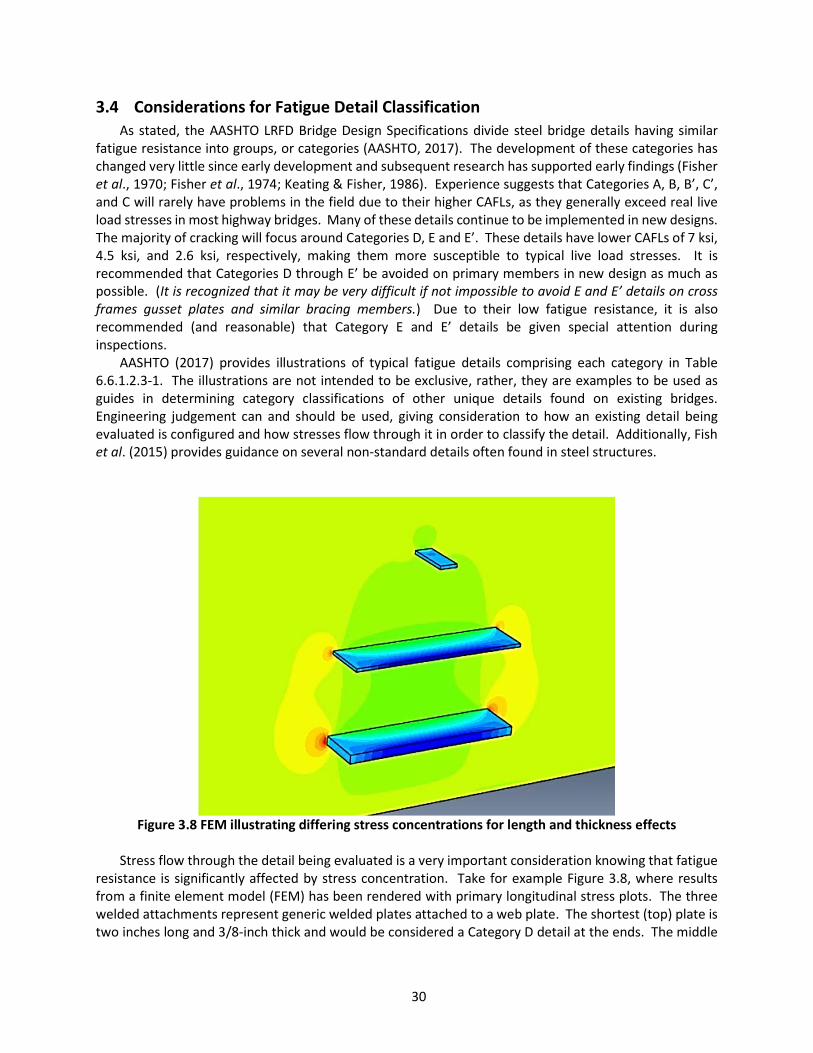
30
3.4 Considerations for Fatigue Detail Classification As stated, the AASHTO LRFD Bridge Design Specifications divide steel bridge details having similar
fatigue resistance into groups, or categories (AASHTO, 2017). The development of these categories has changed very little since early development and subsequent research has supported early findings (Fisher et al., 1970; Fisher et al., 1974; Keating & Fisher, 1986). Experience suggests that Categories A, B, B’, C’, and C will rarely have problems in the field due to their higher CAFLs, as they generally exceed real live load stresses in most highway bridges. Many of these details continue to be implemented in new designs. The majority of cracking will focus around Categories D, E and E’. These details have lower CAFLs of 7 ksi, 4.5 ksi, and 2.6 ksi, respectively, making them more susceptible to typical live load stresses. It is recommended that Categories D through E’ be avoided on primary members in new design as much as possible. (It is recognized that it may be very difficult if not impossible to avoid E and E’ details on cross frames gusset plates and similar bracing members.) Due to their low fatigue resistance, it is also recommended (and reasonable) that Category E and E’ details be given special attention during inspections.
AASHTO (2017) provides illustrations of typical fatigue details comprising each category in Table 6.6.1.2.3-1. The illustrations are not intended to be exclusive, rather, they are examples to be used as guides in determining category classifications of other unique details found on existing bridges. Engineering judgement can and should be used, giving consideration to how an existing detail being evaluated is configured and how stresses flow through it in order to classify the detail. Additionally, Fish et al. (2015) provides guidance on several non-standard details often found in steel structures.
Figure 3.8 FEM illustrating differing stress concentrations for length and thickness effects
Stress flow through the detail being evaluated is a very important consideration knowing that fatigue
resistance is significantly affected by stress concentration. Take for example Figure 3.8, where results from a finite element model (FEM) has been rendered with primary longitudinal stress plots. The three welded attachments represent generic welded plates attached to a web plate. The shortest (top) plate is two inches long and 3/8-inch thick and would be considered a Category D detail at the ends. The middle

31
plate is twenty inches long and also 3/8-inch thick and would be considered a Category E detail at the ends. The bottom plate is also twenty inches long, but is one-inch thick and would be considered a Category E’ detail at the ends. Notice how the stress concentration changes from the top plate to the bottom plate, as seen by the increasing accrual of orange and red contours near the ends of the attachments. This FEM nominally illustrates how a longer attachment “collects” more stress than a shorter one of equivalent thickness and how similarly a thicker attachment “collects” more stress than a thinner one of equivalent length. Stresses flow from the web plate into each of the attachments and back out again, concentrating at the ends of each. A similar comparison could be shown where with increasing radii at the ends of the attachments the stress concentration is reduced.
There are many details and conditions that remain unclassified, such as pins, forged welds, rolling flaws, extraneous welds, and very importantly, details which are cracked. The AASHTO fatigue categories only apply to uncracked details. Once a detail has cracked, a fracture mechanics analysis must be employed to determine remaining life and/or fitness-for-service. Finally, details susceptible to distortion-induced fatigue are also not classified by the AASHTO specifications (AASHTO, 2017). However, Connor & Fisher (2006) reported that several tests have been conducted supporting classification as Category C, as long as the stress range is calculated in a manner consistent with how it was measured during the testing. Distortion-induced fatigue is discussed in greater detail in CHAPTER 6.
3.5 Considerations for Evaluating Existing Steel Bridges When evaluating an existing steel bridge, the year it was built will provide some indication of whether
fatigue and fracture would expected to be a concern. Bridges built before 1974 will most likely have fatigue prone details because they would not have benefited from implementation of the 1974 fatigue design specifications. Bridges built before 1978 would not have benefited from detailing rules and CVN requirements implemented in the Fracture Control Plan. Bridges built prior to the mid-1980’s would not have benefited from research into distortion-induced fatigue and may likely be prone to web gap fatigue cracking. Additionally, bridges built prior to 2009 may not have benefited from modern understanding of the web gap between perpendicular attachment welds that will help to resist onset of constraint-induced fracture. Although these dates help provide a general guide, it should also be considered that some owners are slower to adopt new specifications and so bridges built some years after these dates could also possess critical details.
3.5.1 Fatigue Evaluation of Existing Steel Bridges As stated, there are two types of fatigue cracks that can occur in steel bridges. They are distinguished
by the fundamental differences of what drives the nucleation and propagation. Load-induced fatigue is driven by live load stress ranges in primary members and causes cracks more prone to fracture of primary load carrying members. Distortion-induced fatigue is driven by unanticipated relative movement between connected elements. Typically this is caused by relative displacement of the adjoined members (e.g. adjacent primary girders connected by cross bracing) due to disproportionate traffic loads. Fisher (1984) also documented a few rare cases where distortion-induced fatigue occurred during shipping and handling of girders prior to being put into service. These instances are extremely rare, however, and typically this type of cracking occurs under in-service live loading and takes many years, even decades, to develop detectable cracks.
Due to a random distribution of defects in steel bridge members, there is considerable scatter in the experimentally derived fatigue life estimations. For this reason, the AASHTO Manual for Bridge Evaluation (MBE) (2016) establishes three levels of finite fatigue life estimation, each progressively less conservative (increasing risk):
32
Minimum expected fatigue life (equivalent to the AASHTO (2017) design life – two standard deviations below mean life)
Evaluation fatigue life (considered a conservative fatigue life for evaluation purposes – one standard deviation below mean life)
Mean fatigue life (considered the least conservative, but statistically the most likely fatigue life)
The difference between the three levels of finite fatigue life is defined by the resistance factor, RR, which was updated in research conducted by Bowman et al. (2012). Using the resistance factors, it is apparent that mean life can be as much as 1.6 to 2.1 times larger than minimum life for typical steel bridge details prone to fatigue. AASHTO MBE (2016) offers two strategies when estimated remaining fatigue life is deemed unacceptable, recognizing that limiting the useful fatigue life of bridges to the Minimum (design) life may be overly conservative and uneconomical. The first strategy is the recalculation of fatigue life using the Evaluation life or Mean life. The Mean life simply has a higher probability of cracking. The MBE clearly states, however, that this is only done if the evaluator is willing to accept greater risk of fatigue cracking, suggesting the following possible reasons to justify acceptance of higher risk:
Long satisfactory fatigue life of the detail to date A high degree of redundancy (considering load path, structural, and/or member level
redundancies) Increased inspection effort (shorter inspection interval) Or some combination of the above
The second strategy suggested is usually preferred, which is recalculating fatigue life using more accurate stress range data. Generally a more accurate model or data obtained from field measurements reveals actual in-service stresses or numbers of cycles to be less than using simplified approaches. Some sources of data improvement, which generally result in a lower stress range at the detail of interest include:
Using field instrumentation to obtain actual effective stress ranges and numbers of cycles. Using weigh in motion (WIM) data to determine the effective truck weight, which can improve
accuracy. Improved average daily truck traffic (ADTT) counts, which would improve the accuracy of the
number of cycles a given fatigue detail is submitted to each day. (These data are also collected while using field instrumentation.)
Better count of the number of cycles per truck passage on a given detail. (This data is also collected while using field instrumentation.)
Equation (1) shows that stress range is a cubed variable in the fatigue life calculation. Hence, obtaining more accurate stress range data will have the largest impact on the estimated fatigue life. Field testing and monitoring is a very effective way to obtain more accurate live load stress range data at a detail in question. Normally a measured stress range will be less than a theoretical one, improving fatigue life. In addition, the data related to the number of cycles per day is also measured through the same instrumentation. However, to ensure an accurate assessment, it is critical that monitoring include uncontrolled, or random, traffic for a sufficient period of time. Connor & Fisher (2006) suggest that a monitoring period between two and four weeks is generally sufficient to establish the stress range histograms used in fatigue evaluations. However, any unique or seasonally-driven fluctuations in truck (axle) weights should also be considered so that an accurate sampling of extreme overloads or permit loads are captured.
33
3.5.2 Fracture Evaluation of Existing Steel Bridges Evaluation for fracture is more commonly focused around bridge members identified as fracture
critical. Fracture critical members are subjected to more rigorous inspection, however, inspection of FCMs only serves to detect fatigue cracks or identify CIF prone details that contribute to the risk of fracture. Due to the rapid propagation of fracture, it is not something that can be inspected for in the same way that fatigue cracks are inspected and monitored. Also, in terms of fracture, the age of the bridge provides no indication of the risk of fracture where known fracture-prone details exist. Even though a bridge may be decades old while possessing CIF details does not mean that it is at lower risk for constraint-induced fracture. It is very important to recognize that leaving a CIF detail unretrofit is actually accepting the risk of fracture no matter how many successful years of service the bridge has provided.
Fitness-for-service (FFS) evaluations can be used to determine acceptability of existing fatigue cracks in steel bridges. FFS is based in fracture mechanics and can be quite complex requiring accurate knowledge of the material fracture toughness, flaw size, live load, dead load, and residual stresses. Due to the complexity of an FFS, it is generally reserved for bridges of higher importance. Where bridges are known to have CIF prone details, FFS is not applicable since there is no known initial flaw which can be input into the fracture mechanics calculations (Connor et al., 2007). Rather preemptive retrofit is recommended using one of the strategies presented in this guide specification.
3.6 Considerations for Urgency of Repair and Retrofit The urgency for retrofit of a fatigue prone or fracture prone detail, or repair of a cracked detail is
ultimately determined by the bridge owner. Each situation will be unique, whether it is the bridge design, the feature carried, the feature intersected, and the material from which the bridge is built, or some combination of all of these and other factors. The risk associated with each case needs to be considered carefully. The following is not meant to be a comprehensive list of considerations for this topic, nor is it intended to provide a prescribed method for determining urgency. These cannot practically be accomplished this way. Determining the urgency of repair or retrofit of a steel bridge is founded upon structural analysis, personal, agency, and industry experience (documented and otherwise), research, and engineering judgement. The topic of urgency involves the balance of economics and public safety. Typically, this is referred to as a risk analysis which accounts for both likelihood of the event happening and consequence of the event presuming it occurs. Obviously, public perception, government policy, and political sway are also often a large part of the decision making, but these factors will not be discussed here.
Topics to consider when determining urgency of repair or retrofit:
Is the structure redundant? A non-redundant structure would likely have greater consequence of unstable crack propagation, than a redundant one. Hence, a non-redundant bridge should be given higher urgency than a redundant one. There are three types of redundancy, namely load path redundancy, structural redundancy, and internal member redundancy. Load path redundancy refers to the number of primary load carrying members between points of support. Typically a state will consider a two-girder bridge to be non-load path redundant, whereas a three or four-girder bridge (or more) would be considered load path redundant. Structural redundancy refers to continuity of the primary members over supports, or other three-dimensional aspects such as transverse member spacing. Internal member redundancy refers to built-up members where mechanical connections isolate member components against fracture propagation through the entire cross section. This type of redundancy is also known as a “fail-safe design” and is often utilized by the aviation industry. The assumption is that the surrounding components are designed to pick up the

34
load of the fractured component and that inspection will identify the fractured component in time to have it repaired without another component also failing.
Is there cracking already present? If so, does it appear to be rapid growth or slow growth? And what is the orientation of the crack relative to primary stresses? As discussed previously, the presence of cracks at a detail means that the fatigue life has already been consumed and the detail is no longer categorized by AASHTO. The follow-up questions help to identify the level of urgency that could be necessary for known cracks on a steel bridge. Rapid growth cracks typically are given a higher repair urgency because they indicate that a fracture has occurred (typically four or more inches growth between inspections, as a rule of thumb). Whereas, fatigue cracks are considered to have slow growth (approximately three or less inches growth between inspections, as a rule of thumb). Cracks oriented perpendicular to primary stresses are more prone to fracture and propagation is driven by the primary stresses in the member. Higher urgency should be given to cracks that are oriented this way. Distortion-induced cracks which start out parallel to primary stresses, but if left to propagate, can turn under the increasing influence of primary stresses if left unchecked. Recall that twenty-seven percent of survey respondents indicated that their agency has had a member fracture preceded by distortion-induced fatigue.
Is the live load stress range known? If so, is it greater than the CAFL? Thirteen percent of survey respondents reported that their agency has a policy to preemptively retrofit Category E and E’ fatigue details. For these agencies the urgency is already decided. However, knowing that a poor fatigue detail, such as E or E’, exists on a steel bridge may not always be enough to determine urgency for repair where policy has not already determined that. Lower urgency can be given to poor fatigue details where no cracking is present and so long as the stress range can be confidently determined to be less than the CAFL. This could be determined through field monitoring projects that typically would cost far less than a bridge-wide retrofit project.
Is the detail of concern in a location subject to net tension or net compression? Cracks can initiate at welded details in compression members due to the high residual tensile stresses. However, once the crack grows out of the localized residual stress zone it will no longer propagate under net compressive stress cycles. Higher urgency should be given to members in net tensile zones, particularly if they are known to have cracks.
Are the material properties known? Where the material properties are not known, conservative assumptions would need to be made in order to ensure reliable operation. At the same time, higher urgency should be given to details where material properties are known to have low fracture toughness.
What are the consequences of potential failure? What is the feature carried and what is the feature intersected? What is the importance of the structure? Clearly an interstate, either carried or intersected, where high volumes of traffic traveling at high speeds would be at much greater risk in the event of failure than would a bridge intersecting an unnavigable waterway. Bridges that provide exclusive access to hospitals, or where if closed would cause large detours with safety and economic consequences should be given higher urgency. All of these consequences of the worst-case scenario should be considered when determining the urgency of repair or retrofit for a bridge.
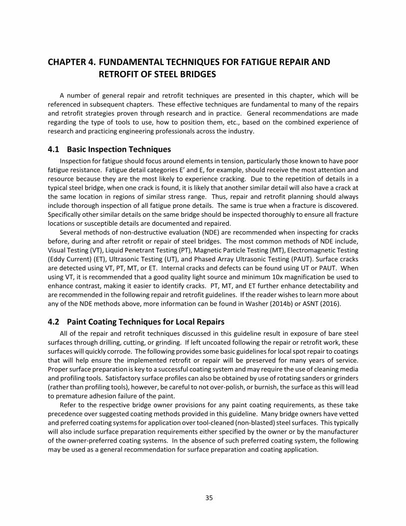
35
CHAPTER 4. FUNDAMENTAL TECHNIQUES FOR FATIGUE REPAIR AND RETROFIT OF STEEL BRIDGES
A number of general repair and retrofit techniques are presented in this chapter, which will be
referenced in subsequent chapters. These effective techniques are fundamental to many of the repairs and retrofit strategies proven through research and in practice. General recommendations are made regarding the type of tools to use, how to position them, etc., based on the combined experience of research and practicing engineering professionals across the industry.
4.1 Basic Inspection Techniques Inspection for fatigue should focus around elements in tension, particularly those known to have poor
fatigue resistance. Fatigue detail categories E’ and E, for example, should receive the most attention and resource because they are the most likely to experience cracking. Due to the repetition of details in a typical steel bridge, when one crack is found, it is likely that another similar detail will also have a crack at the same location in regions of similar stress range. Thus, repair and retrofit planning should always include thorough inspection of all fatigue prone details. The same is true when a fracture is discovered. Specifically other similar details on the same bridge should be inspected thoroughly to ensure all fracture locations or susceptible details are documented and repaired.
Several methods of non-destructive evaluation (NDE) are recommended when inspecting for cracks before, during and after retrofit or repair of steel bridges. The most common methods of NDE include, Visual Testing (VT), Liquid Penetrant Testing (PT), Magnetic Particle Testing (MT), Electromagnetic Testing (Eddy Current) (ET), Ultrasonic Testing (UT), and Phased Array Ultrasonic Testing (PAUT). Surface cracks are detected using VT, PT, MT, or ET. Internal cracks and defects can be found using UT or PAUT. When using VT, it is recommended that a good quality light source and minimum 10x magnification be used to enhance contrast, making it easier to identify cracks. PT, MT, and ET further enhance detectability and are recommended in the following repair and retrofit guidelines. If the reader wishes to learn more about any of the NDE methods above, more information can be found in Washer (2014b) or ASNT (2016).
4.2 Paint Coating Techniques for Local Repairs All of the repair and retrofit techniques discussed in this guideline result in exposure of bare steel
surfaces through drilling, cutting, or grinding. If left uncoated following the repair or retrofit work, these surfaces will quickly corrode. The following provides some basic guidelines for local spot repair to coatings that will help ensure the implemented retrofit or repair will be preserved for many years of service. Proper surface preparation is key to a successful coating system and may require the use of cleaning media and profiling tools. Satisfactory surface profiles can also be obtained by use of rotating sanders or grinders (rather than profiling tools), however, be careful to not over-polish, or burnish, the surface as this will lead to premature adhesion failure of the paint.
Refer to the respective bridge owner provisions for any paint coating requirements, as these take precedence over suggested coating methods provided in this guideline. Many bridge owners have vetted and preferred coating systems for application over tool-cleaned (non-blasted) steel surfaces. This typically will also include surface preparation requirements either specified by the owner or by the manufacturer of the owner-preferred coating systems. In the absence of such preferred coating system, the following may be used as a general recommendation for surface preparation and coating application.

36
WARNING! If you scrape, sand or remove old paint from any surface coated with lead-based paint, you may release lead paint dust. LEAD IS TOXIC. EXPOSURE TO LEAD DUST CAN CAUSE SERIOUS ILLNESS. Wear a NIOSH approved respirator to control lead exposure when working with lead-based paint. Carefully clean up with a wet mop or HEPA vacuum.
Surface profile: During retrofit and repair procedures outlined in this guideline, bare steel surfaces will be exposed
and smoothed. Suggested grits for sanding wheels, etc., are recommended to obtain a surface free of stress risers that help ensure the highest level of fatigue resistance. However, in order for a quality paint coating system to adhere to the repaired area, a proper surface profile must also be made. The Society for Protective Coatings (2015b) recommends a minimum 25 micrometer (1.0 mil) surface profile for bare steel surface preparation. This standard is suitable where roughened, clean bare metal is required, but where abrasive blasting is not feasible, which will be the case for many of the localized repair and retrofit procedures outlined herein. However, if abrasive blast cleaning is required by the bridge owner, this can also be used following completion of the repair or retrofit without compromising the fatigue resistance of the repaired area. The following steps and recommendations are provided for cases where blast cleaning is not feasible or economical and hand tool cleaning and surface profiling methods are needed.
1. With the bare steel surface exposed, feather the remaining, intact surrounding coating with
light sanding so as to remove any “step” from bare steel to remaining paint at the edge of the repair area. This will help ensure a more uniform appearance once completed.
2. Use a profile-producing power tool to roughen the surface slightly, such as a roto-peening tool or a bristle blaster tool. Be sure that the roughening tool does not produce burrs and gouges.
Note that many profiling tools may not be able to access the interior of drilled holes and copes, etc., created as part of many of the retrofit and repair procedures. Sanding grits of 80 to 100 grit flap wheels may provide a properly roughened surface for painting. However, ensure the flap wheels used for the final surface roughening are not worn and that finish sanding does not burnish (mirror finish) the surface.
Surface cleaning:
3. Remove foreign material such as rust, drilling shards, and sanding dust, using a brush, scraper, cloth, dry compressed air, or vacuum.
4. Perform solvent cleaning to remove grease, oil, dust, and debris, etc., from the repair area. Ensure solvent is compatible with the repair paint. Direct spray and scrub, wetted rag scrubbing, steam cleaning, or vapor degreasing methods can be used. Use clean solvent and clean rags or brushes for the final wiping (SSPC, 2015a).
Painting: 5. Apply one of the following coating systems to the profiled and cleaned surface:
a. Organic zinc rich primer followed by compatible top coat. These paints can typically be sprayed, rolled, or brushed on. Follow manufacturer recommendations.
b. Aluminum pigmented epoxy. These paints are typically two-part mixes that are mixed one-to-one, which can be sprayed, rolled or brushed on. Follow manufacturer recommendations.

37
4.3 Hole Drilling Techniques for Crack Arrest Stop-holes, or crack arrest holes, are holes drilled at the tip of a crack intended to blunt the tip and
slow or completely prevent growth. Note that the stress concentration effect for a notch is found to be inversely proportional to the radius of the notch (Anderson, 2005). Mathematically this means that as the radius of the notch approaches zero (infinitely sharp crack), the stress concentration at the tip of the crack approaches infinity. Obviously, no material is capable of resisting infinite stress. The infinitely sharp crack, in reality, is a purely theoretical concept. Plastic deformation at the crack tip in ductile materials such as steel helps to somewhat blunt the tip and prevent an actual infinite stress concentration. For most steels, however, relying on the crack tip plasticity to sufficiently blunt the tip to prevent growth is not enough, especially as temperatures decrease. Drilled holes have proven to be an economic and highly effective method for repair and retrofit of steel bridge fatigue. Drilling a large radius hole at the tip of the crack increases the blunting effect of the crack tip significantly, dropping the stress concentration to approximately 3 (depending on the hole radius) – far from the theoretically calculated infinite stress. The effectiveness of drilled holes has been proven in the field over many decades of use. In addition to blunting existing crack tips, drilled holes have also been effectively used to prevent fatigue cracking by isolating details, as well as for providing an effective means to arrest a running fracture. For example, the large-hole retrofit discussed in section 6.1.2.4 uses drilled holes to increase detail flexibility, thereby reducing the driving stress condition of distortion-induced fatigue, while also isolating it from crack propagation beyond the immediate weld toe.
Drilled holes have been shown to be effective for load-induced fatigue applications as well as for distortion-induced fatigue. Although often considered a temporary repair, it can also be a very effective strategy for long-term repair or retrofit when properly sized and installed. The aspects of proper installation have been detailed below, which includes tactics for hole placement, hole diameter, and hole edge condition. Another benefit of hole drilling is that it is relatively inexpensive to execute, requiring lower skilled labor and portable and affordable equipment. Often the drilled hole should be the first measure taken upon discovery of a crack in a steel bridge and generally is recommended as part of any repair project where known cracks exist.
The equipment recommended for hole drilling includes a magnetic-based drill and annular cutter, such as that seen in Figure 4.1. Although, hand drills have been shown to be effective, even for larger diameter holes, when operated by trained and experienced crews, magnetic-based drills offer superb control and precision for a wide range of hole sizes. The greatest challenge can be positioning the drill in tight spaces where intersecting elements of a detail leave little room for the drill to seat properly.
Figure 4.1 (Left) Example of magnetic-based drill, (Right) Annular cutter used for hole drilling

38
AASHTO (2017) conservatively categorizes an open hole in a member as a Category D fatigue detail. Fisher et al. (1987) found that plates with open holes yielded fatigue strengths that exceeded the Category C resistance curve. This conclusion was also supported by research carried out by Brown et al. (2007). Hence, drilled holes installed according to recommendations provided in this guideline can be expected to have a fatigue resistance of Category C. Any deviation from the recommended procedures for drilled holes may provide a fatigue resistance of less than Category C, but not less than Category D. In most cases Category C resistance would satisfy fatigue life requirements, particularly when considering that the day the hole is drilled is day “one” for the fatigue life of the hole, even if the bridge itself is decades old, and may well provide sufficient fatigue resistance for the remaining service life of the bridge. This depends on the future stress ranges and number of cycles. By installing a fully-tensioned high strength bolt (F3125 Grade A325 or A490) with F436 hardened washers on both sides of the plate, however, the fatigue category can be improved further to Category B. This approach is recommended for load-induced fatigue cases. In circumstances where the additional flexibility offered by the drilled hole improves the performance of the cracked detail, such as for distortion-induced fatigue cracks (web gap fatigue cracks), it is not desirable to add the pretensioned bolt because of the added stiffness.
4.3.1 General Considerations for Hole Drilling to Arrest Cracks Although not difficult to perform hole drilling to arrest cracks, if certain important steps are neglected
or carelessly performed it could lead to an ineffective repair or retrofit. These types of mistakes are common and often attributed to a lack of training. Over 52 percent of the survey respondents for this research indicated that at some point a fatigue repair implemented in their inventory had failed to repair a fatigue crack. Approximately 67 percent of those failed fatigue repairs were directly the result of missed crack tips during hole drilling repairs. The importance of catching the crack tip within the drilled hole cannot be over emphasized. If the tip is missed, the repair attempt will have no effect and the crack will most likely continue to grow. At a minimum this results in the cost and possible service disruption of repeated repair attempts in the future, as well as additional material removed from the steel member when another drilled hole has to be made to arrest the crack. It could also leave the member vulnerable to fracture if the crack is left to grow to a critical length.
Crack tunneling can also contribute to missed crack tips if the engineer or technician is unaware of this phenomenon. Crack tunneling is the term used to describe the preferential advance of the crack tip at the center of a plate with the edges lagging behind. Additional triaxial restraint through the thickness of the plate can promote slightly quicker growth rates with a hidden leading edge, particularly in thicker plates. An extreme example of crack tunneling is shown in Figure 4.2 where a drilled hole was installed to attempt to arrest a crack caused during an impact event. The corroded surface indicates the extent of the previous crack and the bright silver surface indicates the new fracture that propagated instantaneously during another impact event some months later. Notice that the previous crack tunneled ahead of where it breaks the surface of the plate. Furthermore, surface inspection methods such as MT or PT could not have detected the leading crack tip toward the middle of the plate thickness; UT could have been used to detect it, however.
A similar effect has been observed for penny-shaped fatigue cracks that will be one length on a given side of a plate and appear to be shorter on another as the crack transitions to a through-thickness crack. For this reason NDE should be performed on both sides of the cracked plate to ensure the longest dimension is characterized and the leading edge is arrested with the drilled hole. A sketch illustrating an extreme example of this concept is provided in Figure 4.3, which shows the cross section view of a typical interior plate girder with welded gusset plates. The hatched section indicates the uncracked section. Notice that if inspection only occurred on the left side of the web plate, the crack length would be severely mischaracterized and it would be possible that the crack tip would not be removed during hole drilling.
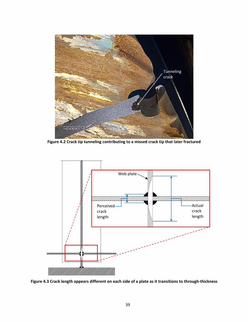
39
Figure 4.2 Crack tip tunneling contributing to a missed crack tip that later fractured
Figure 4.3 Crack length appears different on each side of a plate as it transitions to through-thickness
Web plate
Perceived crack length
Actual crack length
Tunnelingcrack
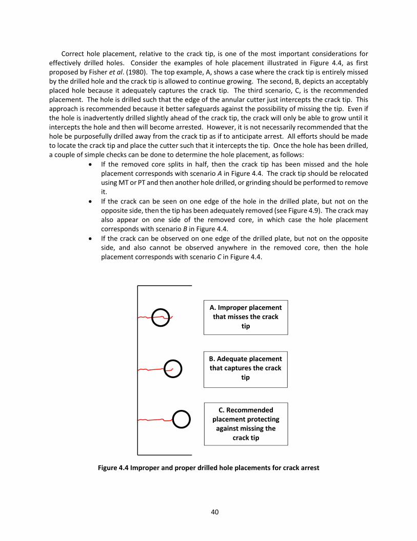
40
Correct hole placement, relative to the crack tip, is one of the most important considerations for effectively drilled holes. Consider the examples of hole placement illustrated in Figure 4.4, as first proposed by Fisher et al. (1980). The top example, A, shows a case where the crack tip is entirely missed by the drilled hole and the crack tip is allowed to continue growing. The second, B, depicts an acceptably placed hole because it adequately captures the crack tip. The third scenario, C, is the recommended placement. The hole is drilled such that the edge of the annular cutter just intercepts the crack tip. This approach is recommended because it better safeguards against the possibility of missing the tip. Even if the hole is inadvertently drilled slightly ahead of the crack tip, the crack will only be able to grow until it intercepts the hole and then will become arrested. However, it is not necessarily recommended that the hole be purposefully drilled away from the crack tip as if to anticipate arrest. All efforts should be made to locate the crack tip and place the cutter such that it intercepts the tip. Once the hole has been drilled, a couple of simple checks can be done to determine the hole placement, as follows:
If the removed core splits in half, then the crack tip has been missed and the hole placement corresponds with scenario A in Figure 4.4. The crack tip should be relocated using MT or PT and then another hole drilled, or grinding should be performed to remove it.
If the crack can be seen on one edge of the hole in the drilled plate, but not on the opposite side, then the tip has been adequately removed (see Figure 4.9). The crack may also appear on one side of the removed core, in which case the hole placement corresponds with scenario B in Figure 4.4.
If the crack can be observed on one edge of the drilled plate, but not on the opposite side, and also cannot be observed anywhere in the removed core, then the hole placement corresponds with scenario C in Figure 4.4.
Figure 4.4 Improper and proper drilled hole placements for crack arrest
A. Improper placement that misses the crack
tip
B. Adequate placement that captures the crack
tip
C. Recommended placement protecting
against missing the crack tip

41
The diameter of the drilled hole can also impact the effectiveness of the repair or retrofit. Larger diameter holes will further reduce stress concentrations while also lowering the odds of missing the crack tip should it be tunneling. A review of literature and case studies shows that different diameter drilled holes have been implemented with varying levels of success. Figure 4.5 shows an example of the “swiss cheese” effect that can occur when insufficient hole size is used (often combined with insufficient edge conditions discussed below) or when the crack tip is missed. Fisher et al. (1980) suggested an engineering calculation that can be used to estimate the minimum hole size, which may estimate a hole size that is less than 1 inch for typical highway bridges. However, experience has shown that enforcing a minimum hole diameter of at least 1 inch will help ensure sound performance (Dexter & Ocel, 2013), while increasing the size to between 2 and 4 inches when possible, may provide even better results (Fish et al., 2015), in particular when trying to mitigate cracking due to out-of-plane distortion. Net section yielding could become a concern and should be considered, particularly when the crack is located in a tension flange of a long-span bridge versus a short-span bridge web plate, for example. In all cases, however, a drilled hole at the end of the crack tip will always be better than leaving a crack tip “as is”. Typically, when a drilled hole is used to repair load-induced fatigue cracks the hole will also be filled with a fully tensioned high-strength bolt. This practice further improves fatigue resistance of the hole by instating a compressive stress field around the hole perimeter. Larger holes, such as 2 to 4 inch holes are normally used in distortion-induced fatigue repairs and retrofits where increased connection flexibility improves the fatigue resistance.
Figure 4.5 Example of chasing the crack tip with repeated drilling
Gouging marks from drill slip

42
Figure 4.6 Drilled hole showing rough edges and burrs
Another important consideration is the edge condition of the hole. The edge condition of the hole
may very well impact fatigue life of the repair or retrofit more than the diameter of the hole. Even the quality of the drill bit used can have an effect on the fatigue life. Brown et al. (2007) found that holes drilled with dull bits often resulted in fatigue life similar to punched holes, or about Category C. They reference other research which reportedly has shown that these differences can drop the fatigue resistance of the hole to as low as Category D. Figure 4.6 shows an example of the edge conditions following drilling and before sanding. The cutting process naturally leaves rough edges and burrs that can generate stress concentrations that over time can become initiation sites for fatigue cracks. A recommended sanding procedure includes using an 80 to 100 grit flap wheel with an angle grinder around the outer edges of the hole on both sides of the plate. Then the inside of the hole should be sanded using an 80 to 100 grit flap wheel with a die grinder. The result is a smooth-to-the touch surface free of burrs and rough and gouged edges, while being careful not to burnish the surface, as discussed for painting in Section 4.2. Also, sometimes when drilling begins, the magnetic base may shift as the annular cutter digs into the plate. This can happen when the magnetic connection to the plate is insufficient due to a number of possible reasons, such as excessive moisture, oil, or corrosion, plate curvature, or on very thin plates. When this happens, gouges can result that are capable of initiating cracks over time. This condition can be observed in Figure 4.5 above the third drilled hole from the left. The gouges should be removed using the surface grinding techniques discussed in Section 4.4.
A final general consideration for box girder bridges is to plug the drilled hole with a bolt, wood, metal screen or rubber stopper. This will help to prevent birds or other animals from nesting inside the structure, which could lead to accelerated corrosion pockets where fecal matter or nesting materials accumulate (Dexter & Ocel, 2013).
4.3.2 Procedural Guidelines for Hole Drilling to Arrest Cracks The following guideline outlines proper procedure for repairs and retrofits utilizing drilled holes for
crack arrest.
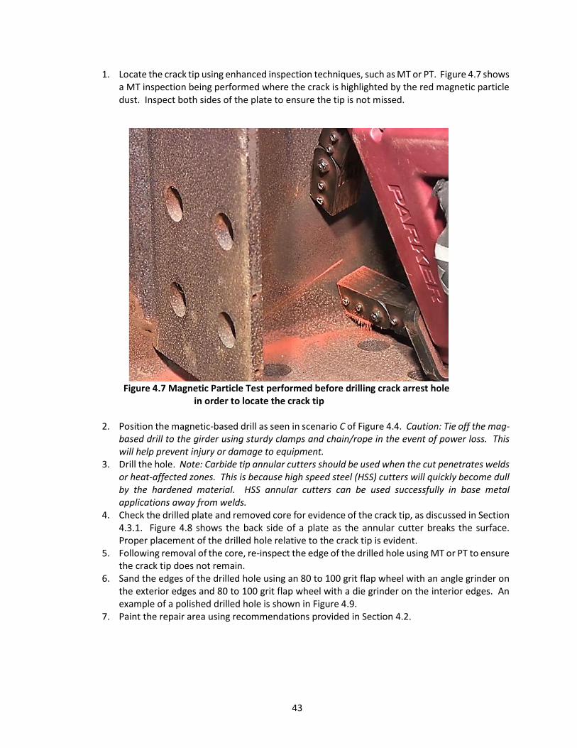
43
1. Locate the crack tip using enhanced inspection techniques, such as MT or PT. Figure 4.7 shows a MT inspection being performed where the crack is highlighted by the red magnetic particle dust. Inspect both sides of the plate to ensure the tip is not missed.
Figure 4.7 Magnetic Particle Test performed before drilling crack arrest hole
in order to locate the crack tip
2. Position the magnetic-based drill as seen in scenario C of Figure 4.4. Caution: Tie off the mag-based drill to the girder using sturdy clamps and chain/rope in the event of power loss. This will help prevent injury or damage to equipment.
3. Drill the hole. Note: Carbide tip annular cutters should be used when the cut penetrates welds or heat-affected zones. This is because high speed steel (HSS) cutters will quickly become dull by the hardened material. HSS annular cutters can be used successfully in base metal applications away from welds.
4. Check the drilled plate and removed core for evidence of the crack tip, as discussed in Section 4.3.1. Figure 4.8 shows the back side of a plate as the annular cutter breaks the surface. Proper placement of the drilled hole relative to the crack tip is evident.
5. Following removal of the core, re-inspect the edge of the drilled hole using MT or PT to ensure the crack tip does not remain.
6. Sand the edges of the drilled hole using an 80 to 100 grit flap wheel with an angle grinder on the exterior edges and 80 to 100 grit flap wheel with a die grinder on the interior edges. An example of a polished drilled hole is shown in Figure 4.9.
7. Paint the repair area using recommendations provided in Section 4.2.

44
Figure 4.8 Shows annular cutter breaking the surface on the opposite side of the plate, positioned correctly to intercept the crack tip
Figure 4.9 Example of finished crack arrest hole prior to painting
Drilled hole
Crack

45
4.4 Surface Grinding Techniques Surface grinding techniques can be used for removing shallow defects, improving geometry to provide
smooth stress flow thereby reducing stress concentrations, and repairing nicks and gouges. These types of defects, if left unrepaired, can become initiation sites for fatigue cracks, effectively reducing the fatigue resistance of the member or detail. Typical causes of these surface discontinuities includes vehicle impacts, flame cutting, grinders, pneumatic hammers (e.g. peening or rivet busters), weld spatter, arc strikes, lifting chains, and other maintenance operations (Fish et al., 2015). Surface grinding is only recommended for the following types of repairs:
Notches, nicks, or gouges Shallow surface crack removal (generally ≤ 3/16” deep) Removal of tack welds and other extraneous welds Finish work on drilled holes
Figure 4.10 Typical angle grinder with flap wheel
Figure 4.11 Typical die grinder with burr bit
There are two main types of handheld grinders, angle and die. Grinding wheels for the angle grinder
typically come in either 4.5 inch or 9 inch diameter and a wide range of types and grits. Also called a disc grinder, the angle grinder can also be used to quickly cut steel when using a cutting wheel. An example of an angle grinder is shown in Figure 4.10 paired with a flap wheel for sanding. A typical die grinder is shown in Figure 4.11 fitted with a rotary burr bit for rough grinding. The die grinder typically uses much smaller abrasive wheels and cutting wheels than the angle grinder, as well as carbide rotary burrs, allowing for access to smaller spaces. The angle grinder, although more difficult to get into tight spaces, has the advantage of faster material removal.
4.4.1 General Considerations for Surface Grinding Although grinding is effective and requires little training or skill, careless handling can cause new
problems or leave the original problem unresolved. Discontinuities must be completely removed in order to be effectively repaired, but without removing too much material or losing control of tools and leaving new nicks and gouges. The following provides some general considerations for surface grinding:
Although visual inspection can be very effective for locating and evaluating surface defects such as notches or gouges, enhanced NDT, such as PT or MT are highly recommended to help identify the limits of a crack before beginning grinding.
Once grinding has been completed, NDT should again be used to ensure the crack has been completely removed. Grinding can “smear” a crack, or partially fill the visual opening with metal shavings effectively hiding the crack from view. Note that if the crack is smeared enough, PT may also be made ineffective.
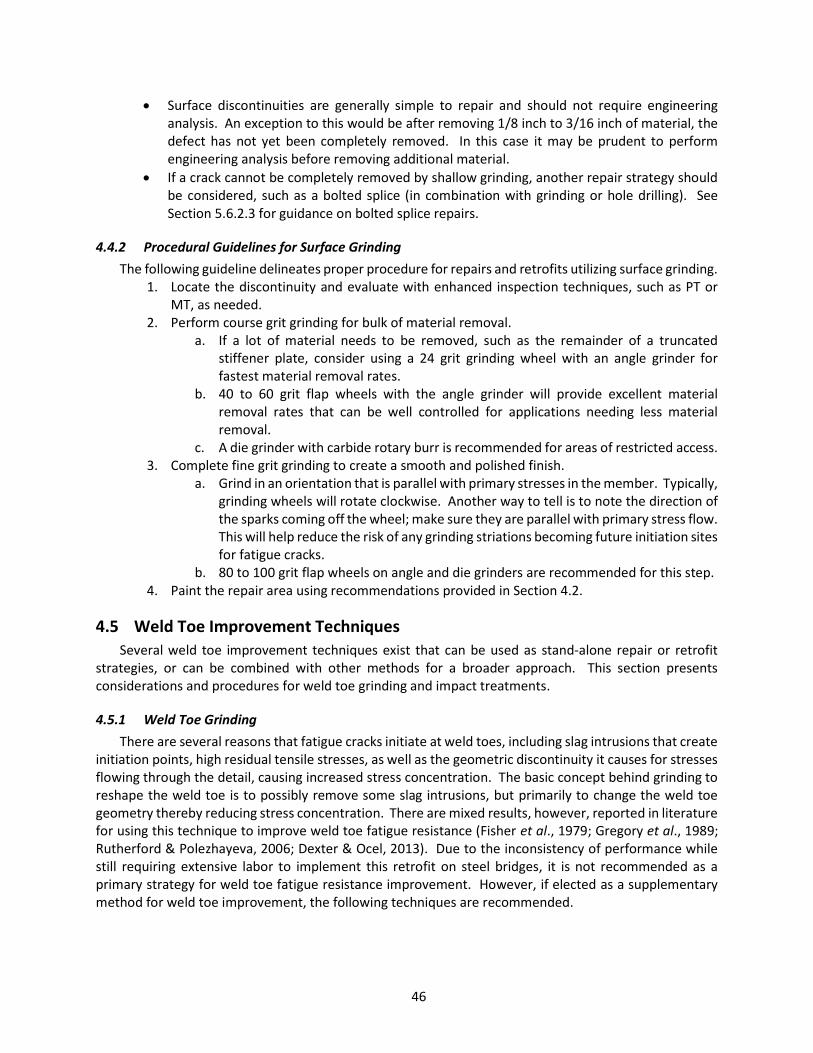
46
Surface discontinuities are generally simple to repair and should not require engineering analysis. An exception to this would be after removing 1/8 inch to 3/16 inch of material, the defect has not yet been completely removed. In this case it may be prudent to perform engineering analysis before removing additional material.
If a crack cannot be completely removed by shallow grinding, another repair strategy should be considered, such as a bolted splice (in combination with grinding or hole drilling). See Section 5.6.2.3 for guidance on bolted splice repairs.
4.4.2 Procedural Guidelines for Surface Grinding The following guideline delineates proper procedure for repairs and retrofits utilizing surface grinding.
1. Locate the discontinuity and evaluate with enhanced inspection techniques, such as PT or MT, as needed.
2. Perform course grit grinding for bulk of material removal. a. If a lot of material needs to be removed, such as the remainder of a truncated
stiffener plate, consider using a 24 grit grinding wheel with an angle grinder for fastest material removal rates.
b. 40 to 60 grit flap wheels with the angle grinder will provide excellent material removal rates that can be well controlled for applications needing less material removal.
c. A die grinder with carbide rotary burr is recommended for areas of restricted access. 3. Complete fine grit grinding to create a smooth and polished finish.
a. Grind in an orientation that is parallel with primary stresses in the member. Typically, grinding wheels will rotate clockwise. Another way to tell is to note the direction of the sparks coming off the wheel; make sure they are parallel with primary stress flow. This will help reduce the risk of any grinding striations becoming future initiation sites for fatigue cracks.
b. 80 to 100 grit flap wheels on angle and die grinders are recommended for this step. 4. Paint the repair area using recommendations provided in Section 4.2.
4.5 Weld Toe Improvement Techniques Several weld toe improvement techniques exist that can be used as stand-alone repair or retrofit
strategies, or can be combined with other methods for a broader approach. This section presents considerations and procedures for weld toe grinding and impact treatments.
4.5.1 Weld Toe Grinding There are several reasons that fatigue cracks initiate at weld toes, including slag intrusions that create
initiation points, high residual tensile stresses, as well as the geometric discontinuity it causes for stresses flowing through the detail, causing increased stress concentration. The basic concept behind grinding to reshape the weld toe is to possibly remove some slag intrusions, but primarily to change the weld toe geometry thereby reducing stress concentration. There are mixed results, however, reported in literature for using this technique to improve weld toe fatigue resistance (Fisher et al., 1979; Gregory et al., 1989; Rutherford & Polezhayeva, 2006; Dexter & Ocel, 2013). Due to the inconsistency of performance while still requiring extensive labor to implement this retrofit on steel bridges, it is not recommended as a primary strategy for weld toe fatigue resistance improvement. However, if elected as a supplementary method for weld toe improvement, the following techniques are recommended.
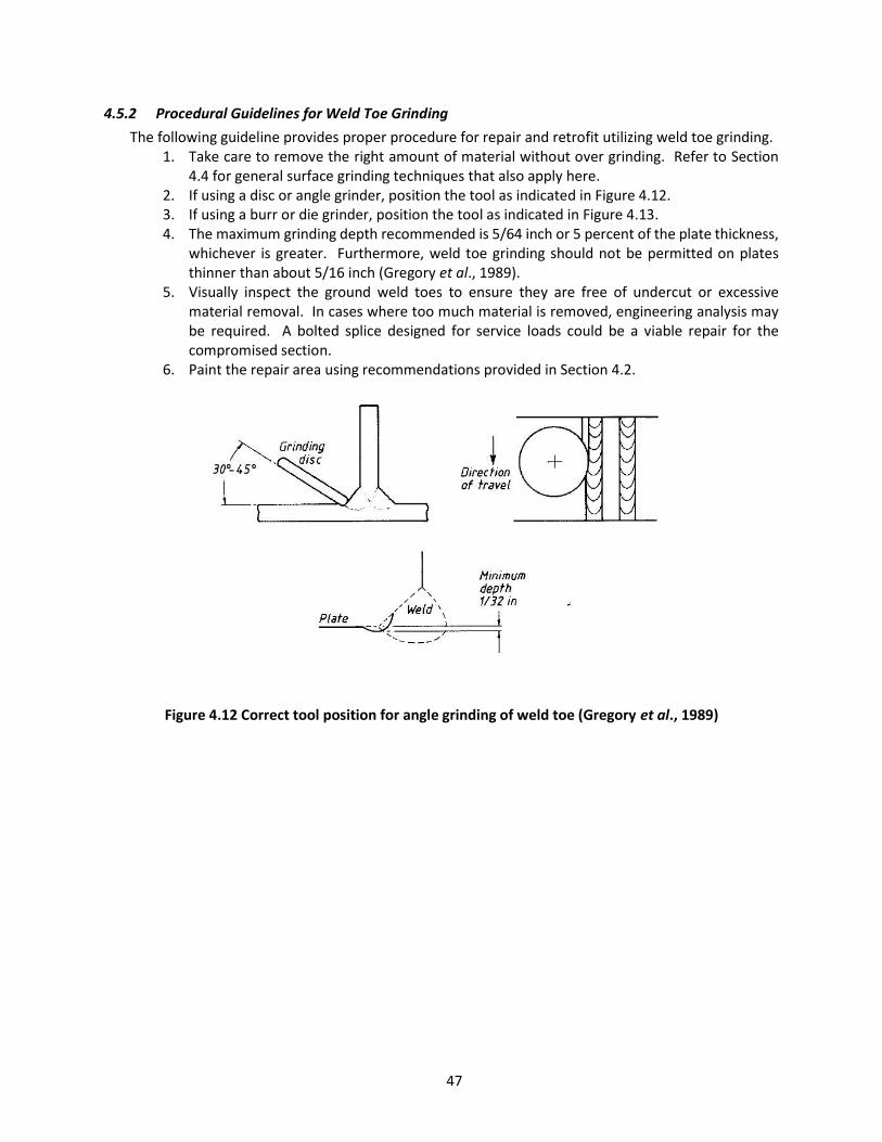
47
4.5.2 Procedural Guidelines for Weld Toe Grinding The following guideline provides proper procedure for repair and retrofit utilizing weld toe grinding.
1. Take care to remove the right amount of material without over grinding. Refer to Section 4.4 for general surface grinding techniques that also apply here.
2. If using a disc or angle grinder, position the tool as indicated in Figure 4.12. 3. If using a burr or die grinder, position the tool as indicated in Figure 4.13. 4. The maximum grinding depth recommended is 5/64 inch or 5 percent of the plate thickness,
whichever is greater. Furthermore, weld toe grinding should not be permitted on plates thinner than about 5/16 inch (Gregory et al., 1989).
5. Visually inspect the ground weld toes to ensure they are free of undercut or excessive material removal. In cases where too much material is removed, engineering analysis may be required. A bolted splice designed for service loads could be a viable repair for the compromised section.
6. Paint the repair area using recommendations provided in Section 4.2.
Figure 4.12 Correct tool position for angle grinding of weld toe (Gregory et al., 1989)

48
Figure 4.13 Correct tool position for die grinding with burr bit at weld toe (Gregory et al., 1989)
4.5.3 Hammer Peening Hammer peening is a process of repeated dynamic impacts inducing severe, localized plastic
deformations at the weld toe. Hammer peening has been shown to blunt crack-like slag intrusions and introduce compressive residual stresses that slow crack initiation and growth (Fisher et al., 1979). In addition to introducing compressive residual stresses and blunting slag intrusions, deformations from peening also reshape the weld toe, improving geometry. Lap-type defects were also observed by Fisher et al. (1979) at depths similar to the blunted slag intrusions and behaved similarly to the intrusions providing discontinuities for fatigue crack initiation. Fisher et al. referenced research conducted by Harrison (1966) who showed that when welds were peened and then stress relieved, they provided the same fatigue resistance as the untreated weld toe. This behavior was consistent with findings from Fisher et al. (1979) where it was observed that when peening preceded dead load, much or all of the fatigue strength benefit from the compressive residual stresses was removed upon application of dead load and the fatigue resistance was similar to untreated welds. This suggests that the primary benefit of weld toe peening is gained from the induction of compressive residual stresses. Any blunting of weld slag intrusions gained from the peening process is offset by the introduction of lap-type discontinuities and the weld toe reshaping is not significant enough to promote superior fatigue resistance over typical untreated welds. However, weld toes peened under dead load were found to improve at least one fatigue category. This means that hammer peening of weld toes is ideally suited for retrofit and repair applications where steel bridge members are already under dead load. Weld toes with shallow surface cracks of less than 1/8 inch deep also benefited from peening where the propagation of the crack was appreciably slowed or arrested, even without removing the crack (Fisher et al., 1979; Haussammann et al., 1983; Hassan & Bowman, 1995; Fisher & Roy, 2015). Fisher & Roy (2015) added that this is only reliable if the stress range does not exceed approximately 6 ksi. This means that the benefit of peening can be had even in the presence of shallow, undetected cracks for the majority of steel bridge details. Furthermore, in cases where no fatigue cracks are present, the fatigue life is effectively “reset” upon peening, even if the bridge is decades old. In other words, even if the peened weld remains in finite life (based on the new CAFL and percentage exceedance of the variable stress range), the fatigue cycle accumulation starts over for that detail. Assuming the

49
fatigue loading doesn’t change, then the fatigue life of the peened weld would be at least the current age of the bridge, into the future.
However, it is recommended that NDT is used to inspect the weld toe and removal of any shallow cracks take place prior to impact treatment. If cracks deeper than 1/8 inch are identified, another repair method should be considered, such as a bolted splice combined with a technique to remove the crack, such as grinding. The depth of residual compressive stresses from hammer peening have been found to extend from two to four times the depth of the deformation, or about 0.04 to 0.08 inches (Roy et al., 2003; Dexter & Ocel, 2013). The introduction of compressive residual stresses through the thickness of a steel plate means that tensile residual stresses are introduced away from the weld toe in order for the plate to maintain equilibrium. Thus, if deep cracks are peened, it is possible that the equilibrium tensile stress field could surround the deep crack tip and exacerbate fatigue growth. Careful inspection of the weld toe will help ensure the benefits of hammer peening are realized.
4.5.4 Procedural Guidelines for Weld Toe Hammer Peening The following steps outline the proper procedure for repair and retrofit utilizing weld toe hammer
peening. 1. Remove corrosion, paint or other coating from the area to be peened. 2. Inspect the area using proven NDT methods such as MT or PT. 3. Use grinding techniques discussed in Section 4.4 and 4.5.1 to remove shallow cracks of not
more than about 1/8 inch deep. If the crack is determined to be deeper, either by use of UT or after initial grinding, another repair method of that area should be considered, such as a bolted splice. In some cases a crack indication will be revealed as only weld overlap after grinding, in which case proceed to Step 4.
4. Once the weld toe has been determined free of cracks, apply the hammer peening treatment using the following recommendations, as reported by Dexter & Ocel (2013) with reference to Haussammann et al. (1983).
a. Adjust the pressure regulator to 40 psi when using a needle tip. When using a wider chisel-type tip, a higher pressure of up to 60 psi has been found to improve indentation at the weld toe.
Figure 4.14 Typical peening bits
b. Place the chisel or bit on the weld toe and hold the tool at a 45° angle, applying firm
pressure to improve control. Excessive chatter or loss of control of the tool can result in gouges in the surrounding base metal and weldment. Surface grinding
Needle Tip Chisel Tip

50
techniques should be used following peening treatment to remove any gouges and nicks (see Section 4.4).
c. Move the peening hammer along the weld toe at a rate of about 3 inches/minute, making a total of about 6 passes. The depth of indentation should be about 1/32 inch.
5. For improved results, very lightly grind (or wire brush) the peened weld toe with a 100 grit flap wheel to remove any lap-type discontinuities without removing base material.
6. Paint the repair area using recommendations provided in Section 4.2.
4.5.5 Ultrasonic Impact Treatment Ultrasonic impact treatment (UIT), or ultrasonic needle peening (UNP), is conceptually very similar to
hammer peening in that very small and rapid localized impacts are used to plastically deform the weld toe. Weld toe reshaping, slag intrusion blunting, and compressive residual stresses all result from UIT, just as they do for hammer peening. Discussion from Section 4.5.3 applies to UIT, as well. Also similar to hammer peening, UIT has been shown to improve fatigue resistance by one fatigue category at higher minimum stresses (dead load effect), but diverged from hammer peening where improvement was as much as three fatigue categories at lower minimum stresses for cover plate details (Roy et al., 2003). The research has shown that a category E’ cover plate detail treated under dead load, such as would be the case for existing bridges, could see an improvement to as much as category C.
The primary difference between these two forms of post-weld impact treatment is in the equipment itself. The UIT equipment impacts at extreme rates of 20 to 27 kHz, whereas the peening hammer impacts at only 100 to 200 Hz. The extreme impact rate of UIT affords faster application and minimized areas of missed treatment. UIT is far more precise with computerized, automated controls providing reproducible results. The UIT tools include a handheld tool connected to a generator unit or central unit where controls and monitoring are housed (see Figure 4.15). The equipment is designed to be ergonomic, minimizing vibration discomfort, noise, and worker fatigue for the operator.
Figure 4.15 Examples of UIT tools
4.5.6 Procedural Guidelines for Ultrasonic Impact Treatment The following steps outline the proper procedure for repair and retrofit utilizing ultrasonic impact
treatment (UIT). Typically, manufacturers will require proprietary training on their equipment, but the following steps are a general guideline that is consistent with this type of training.
1. Prepare the weld toe for UIT by cleaning it of any paint coatings, corrosion, or scale. 2. Inspect the weld toe using proven NDT methods, such as PT or MT.

51
3. Use grinding techniques discussed in Section 4.4 and 4.5.1 to remove shallow cracks of not more than about 1/8 inch deep. If the crack is determined to be deeper, either by use of UT or after initial grinding, another repair method of that area should be considered, such as a bolted splice. In some cases a crack indication will be revealed as only weld overlap after grinding, in which case proceed to Step 4.
4. Set the control unit settings to the appropriate intensity level, according to manufacturer recommendations. Peening intensity is a combination of parameters, such as vibration frequency and amplitude of vibration (monitored and controlled by the central unit), together with the needle and sonotrode characteristics. The manufacturer’s scheduled maintenance of the needles and sonotrode is required to ensure desired peening intensity is sustained.
5. Position the handheld tool with the needle on the weld toe at a 45° angle and perpendicular to the line of the weld toe.
6. Continuously run the tool along a path parallel to the direction of the weld, maintaining the handheld tool perpendicular to the weld toe. Repeat the same path of treatment two more times, each time rotating the handheld tool to a position that is ±15° from the original 45° angle, as shown in Figure 4.16. Avoid leaving the needle at a single location to avoid “digging” the material.
Figure 4.16 Sketch demonstrating the path of the handheld tool during UNP application
7. Inspect the groove, looking for uniform, shiny appearance, such as that shown in Figure 4.17.
A 3/32 welding rod or a peening needle can also be lightly dragged through the groove. A well-formed groove will allow the rod/needle to slide without catching. If gaps in treatment are located, repeat treatment in those areas and inspect again.
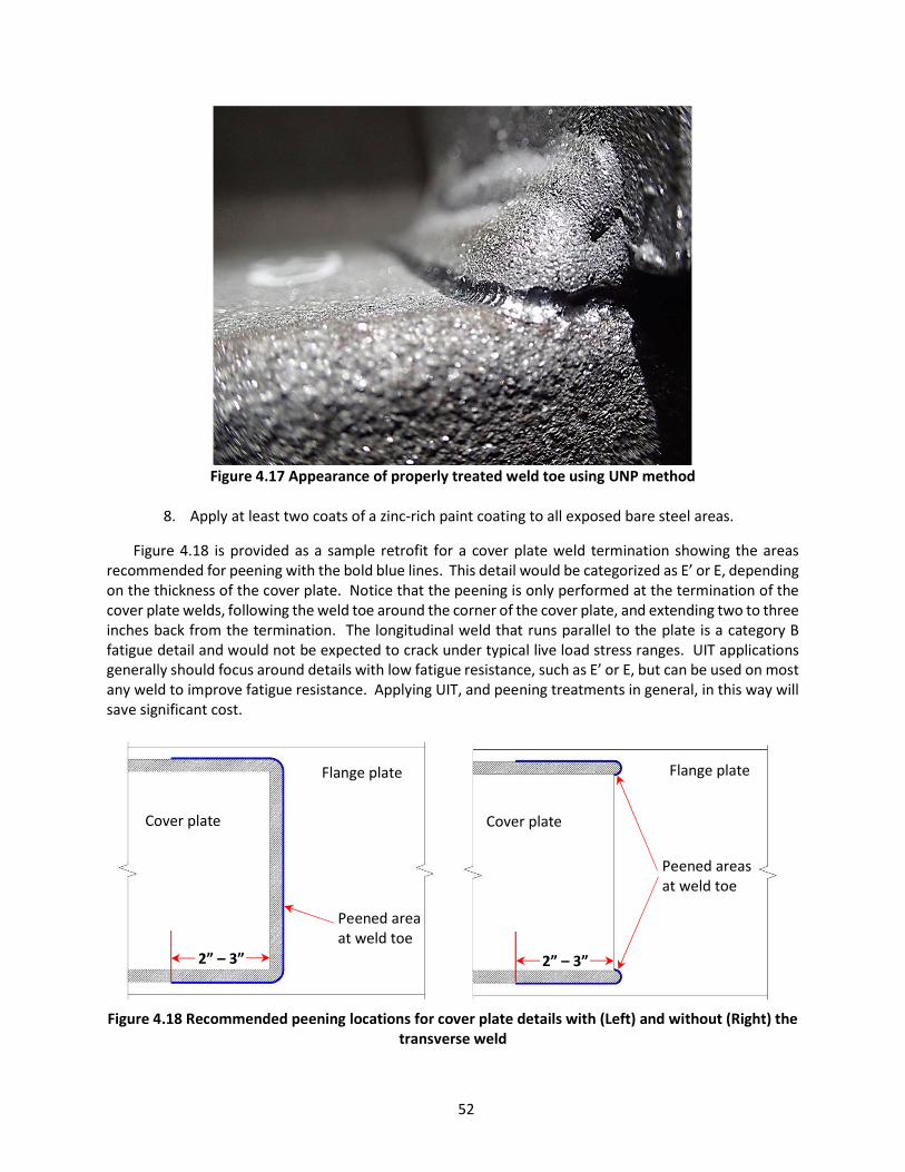
52
Figure 4.17 Appearance of properly treated weld toe using UNP method
8. Apply at least two coats of a zinc-rich paint coating to all exposed bare steel areas.
Figure 4.18 is provided as a sample retrofit for a cover plate weld termination showing the areas recommended for peening with the bold blue lines. This detail would be categorized as E’ or E, depending on the thickness of the cover plate. Notice that the peening is only performed at the termination of the cover plate welds, following the weld toe around the corner of the cover plate, and extending two to three inches back from the termination. The longitudinal weld that runs parallel to the plate is a category B fatigue detail and would not be expected to crack under typical live load stress ranges. UIT applications generally should focus around details with low fatigue resistance, such as E’ or E, but can be used on most any weld to improve fatigue resistance. Applying UIT, and peening treatments in general, in this way will save significant cost.
Figure 4.18 Recommended peening locations for cover plate details with (Left) and without (Right) the
transverse weld
Flange plate
Cover plate
Peened area at weld toe
Peened areas at weld toe
Cover plate
2” – 3”
Flange plate
2” – 3”
53
4.6 Fundamentals of Performance Testing Performance testing has been shown to be a very effective method of ensuring the desired quality of
work is achieved. For example, performance testing can be used to qualify workers who will install the retrofits on the bridge, by requiring they first demonstrate competency by performing the work on a mockup. Obviously, the mock-ups must be reasonably similar to those on the bridge detail(s) to be repaired or retrofit. Similar performance testing can also be conducted to ensure NDT technicians demonstrate a desired level of competency by requiring them to inspect components with known flaws or defects and comparing their results to the known results. Performance testing helps to ensure that the end product, whether data from a non-destructive inspection, or installation of a fatigue crack repair, is within required standards. This can serve as a very effective method of quality assurance for the owner. Surprisingly, however, only 22 percent of the industry survey respondents replied that their agency employs performance testing, and only “sometimes”.
4.6.1 Considerations for Repair and Retrofit Performance Tests Experience has shown that even the most experienced contractors and maintenance crews can
underestimate the challenges of executing repairs on steel bridges. Unfortunately, in some cases it is not until they actually begin work that those challenges surface. This type of situation can cause costly delays for the owner and the contractor, or worse, actually cause damage to the structure. Figure 4.19 shows an example of a used mockup specimen (left) and ironworkers performing repairs as part of a performance test (right). This type of testing can be successfully included in rehabilitation contracts where the scope of work requires the fabrication of mockups and satisfactory completion of the test before work can begin on the bridge. The performance test provides two primary functions, (1) to ensure the work can be completed as intended by the contractor, and (2) to establish the level of quality that is expected on the project to all parties. Typically, mockups can be fabricated for only a few thousand dollars, depending on the complexity of the detail. The fidelity of the mockup to the actual detail is very important. Size, quality, condition, and geometry should be replicated as much as possible. Economy is achieved by duplicating the detail like shown in Figure 4.19, without compromising authenticity. Difficult-to-access areas, such as corners of intersecting plates and connection elements should not be overlooked because often it is these details that make the actual repair or retrofit challenging and where the real benefit of the mockup will be gained.

54
Figure 4.19 (Left) Example of used mockup, (Right) Performance testing of a contractor prior to implementation of a repair project
4.6.2 Considerations for NDT Inspector Performance Tests NDT inspection relies on trained inspectors who follow established procedures and correctly interpret
the test results. High variability in nondestructive test results has been shown to occur among certified inspectors where variances in thoroughness, care with which NDT procedures are followed, and interpretation of results differed. Washer et al. (2014a) conducted performance testing of ASNT Level II and III certified UT and MT inspectors to establish inspector qualifications prior to inspection work beginning on the Sherman-Minton Bridge over the Ohio River near Louisville, KY. Before inspecting the tied arch structure, inspectors were first evaluated in a performance test program. The welded-steel specimens used for performance testing were fabricated plates with known flaws of various sizes. Figure 4.20 shows similar test specimens hung on a bridge (left) and an inspector completing a performance test (right).
Figure 4.20 (Left) Welded steel test specimen hung on a bridge, (Right) Performance testing of an
inspector prior to beginning NDT on bridge welds Installing the test specimens on the bridge helps to make the test authentic, ensuring ambient factors
present in actual inspection are also at play during testing (i.e., wind, temperature, access, bucket sway, lighting, etc.). A sample of the test results is provided in Figure 4.21 (Washer et al., 2014a). The horizontal axis is the actual flaw length and the vertical axis is the measured flaw length as reported by each inspector. The diagonal line passing through the plot represents the correct flaw length and the solid circles are the average measured lengths. The results of the performance tests identified inspectors whose performance was substandard and provided quantitative measures of the variations in the NDT results (Washer et al., 2014a). The variations can be seen in the plot where it shows that scatter among inspectors was as much as the defect length, meaning that some inspectors were over or underestimating crack sizes by as much or more than 100%. At the same time a few inspectors were able to report very accurate results.
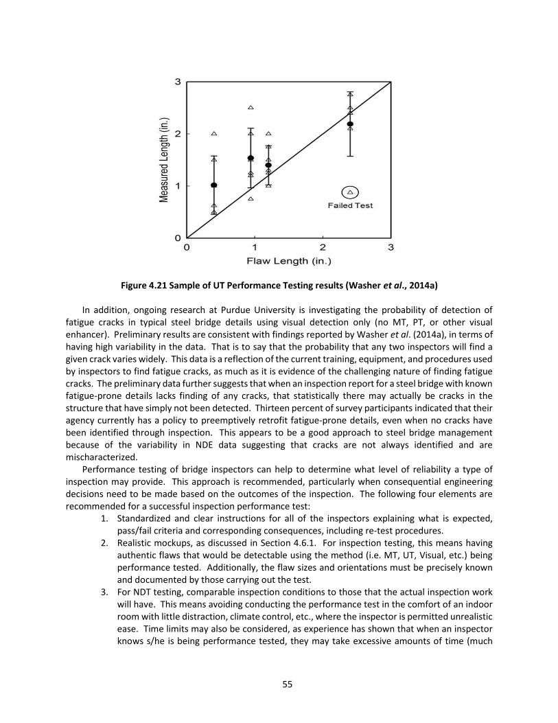
55
Figure 4.21 Sample of UT Performance Testing results (Washer et al., 2014a) In addition, ongoing research at Purdue University is investigating the probability of detection of
fatigue cracks in typical steel bridge details using visual detection only (no MT, PT, or other visual enhancer). Preliminary results are consistent with findings reported by Washer et al. (2014a), in terms of having high variability in the data. That is to say that the probability that any two inspectors will find a given crack varies widely. This data is a reflection of the current training, equipment, and procedures used by inspectors to find fatigue cracks, as much as it is evidence of the challenging nature of finding fatigue cracks. The preliminary data further suggests that when an inspection report for a steel bridge with known fatigue-prone details lacks finding of any cracks, that statistically there may actually be cracks in the structure that have simply not been detected. Thirteen percent of survey participants indicated that their agency currently has a policy to preemptively retrofit fatigue-prone details, even when no cracks have been identified through inspection. This appears to be a good approach to steel bridge management because of the variability in NDE data suggesting that cracks are not always identified and are mischaracterized.
Performance testing of bridge inspectors can help to determine what level of reliability a type of inspection may provide. This approach is recommended, particularly when consequential engineering decisions need to be made based on the outcomes of the inspection. The following four elements are recommended for a successful inspection performance test:
1. Standardized and clear instructions for all of the inspectors explaining what is expected, pass/fail criteria and corresponding consequences, including re-test procedures.
2. Realistic mockups, as discussed in Section 4.6.1. For inspection testing, this means having authentic flaws that would be detectable using the method (i.e. MT, UT, Visual, etc.) being performance tested. Additionally, the flaw sizes and orientations must be precisely known and documented by those carrying out the test.
3. For NDT testing, comparable inspection conditions to those that the actual inspection work will have. This means avoiding conducting the performance test in the comfort of an indoor room with little distraction, climate control, etc., where the inspector is permitted unrealistic ease. Time limits may also be considered, as experience has shown that when an inspector knows s/he is being performance tested, they may take excessive amounts of time (much

56
more than would be spent on a typical inspection) while trying to do well on the evaluation. If implemented, time limits should be reasonable and explained as part of the instructions.
4. Pass/Fail criteria (for example, no more than 1/4 inch under sizing or 1 inch over sizing) with consequences for failed tests. (It is noted that while no standard criteria presently exist in the US bridge industry, criteria were developed in Washer et al., 2014a). An example of consequence for failure might be that the inspector would not be allowed to inspect the bridge or could obtain refresher training for the NDT method being used and re-test. If the inspector passes the second time s/he could be allowed to inspect, but if not, the inspector might be permanently removed from that particular project. As stated, these criteria must be fully agreed upon by all parties prior to performance testing.
4.7 Considerations for Prototyping Repair and retrofit prototypes are an effective way of ensuring a repair or retrofit will perform as
intended. Prototypes can be investigated in a formal research laboratory, but often, useful prototypes can simply be implemented on the bridge. Typically, when a prototype is implemented on a bridge, it would be done at one or two locations and then be instrumented for evaluation of important performance criteria, such as the stress range and number of cycles. Sometimes, however, it may be prudent to instrument the structure at a few locations prior to a prototype in order to characterize what might be causing existing damage. Then a repair prototype can be designed to address the known cause and be compared back to results obtained from the unrepaired detail. Prototypes can be especially useful in situations where a large number of the repairs or retrofits are necessary for a bridge where it is not entirely known how well the repair will function. This will help ensure that a repair or retrofit project will be successful, prior to bridge-wide implementation, and won’t require rework later on.
Fatigue repair and retrofit prototypes generally involve instrumenting the detail in question because simply waiting to see if cracks reinitiate is not realistic. Knowing the fatigue category of the modified detail, the stress range, and the number of cycles, however, one can calculate the new fatigue life of the detail and thereby determine the effectiveness of the retrofit or repair. See Section 3.5.1 for recommendations on field monitoring for fatigue evaluation. Finite element modeling can also be a powerful tool in determining the effectiveness of retrofits or repairs. The finite element model (FEM) can and should be calibrated with data obtained from field monitoring. An example of the prototype process is provided in the following.
A simple “two-hole” retrofit for distortion-induced fatigue cracking on twin, 6-girder interstate bridges was evaluated using a prototype. The superstructure of the bridge included 30 skewed spans made up of six-48 inch deep, continuous plate girders with a fully composite reinforced concrete deck. Bridge inspectors discovered distortion-induced fatigue cracks that initiated at the bottom of several transverse connection plates and grew into the web plates. This prompted a more thorough arms-length inspection of the bridge resulting in 30 locations identified with fatigue cracks grown into the web plate and approximately 1,900 locations that appeared to have some distortion-induced cracking at the weld termination (as seen in Figure 4.22) that had not yet grown out into the web plate. The unique aspect about this distortion-induced fatigue cracking was that it was occurring despite the relatively large 5-inch web gap, which can also be seen in Figure 4.22. Most often distortion-induced cracking occurs where there are much smaller web gaps, however, larger web gaps can also crack if sufficient displacement occurs and particularly when weld quality is lacking.

57
Figure 4.22 Distortion-induced fatigue crack growing out of the throat of the weld
The owner in this case was considering a stiffening retrofit that would have cost hundreds of
thousands of dollars to implement bridge-wide because there were so many locations to repair and due to the extent of work and material it would require. This begged the question, could something simpler be implemented, saving cost without sacrificing long-term performance? It was decided that drilling a large hole to each side of the connection plate weld termination, slightly intercepting the weld toe, may perform well by increasing web flexibility further and providing crack arrest for any existing or future fatigue cracks. To make sure it would do the job, a few locations were identified to install a prototype. One example of the prototype can be seen in Figure 4.23. A 3-inch diameter hole was drilled on each side of the connection plate, surrounding the weld termination and isolating it against web crack propagation. Another prototype was also evaluated at a location on the bridge that was a single drilled hole centered on the connection plate at the weld termination. This required removing part of the lower edge of the connection plate in order to remove the transverse weld terminations. This prototype is shown in Figure 4.24. Following installation of the prototypes, the areas were instrumented, along with a couple benchmark locations where no repairs were made. Field monitoring of live load stresses in the primary members, in the web gap areas, as well as out-of-plane displacements of the web plate was conducted with random traffic loading. The data acquisition was then left in place for two weeks collecting triggered stress time-history data for fatigue evaluation of the prototype. The data was used to calibrate a finite element model where different diameter holes were evaluated for the two different prototypes. The FE parametric study concluded that the “two-hole” repair would conservatively provide infinite fatigue life with drilled holes of 2 inches diameter or greater. However, for the “one-hole” repair prototype, the hole would need to be 3 inches diameter or greater in order to provide the same fatigue life.

58
Figure 4.23 Example of prototype “two-hole” retrofit installed
Figure 4.24 Example of prototype “one-hole” retrofit installed
Web X-brace

59
CHAPTER 5. MAINTENANCE ACTIONS FOR LOAD-INDUCED FATIGUE Load-induced fatigue is caused by the in-plane stresses in the primary structural members that make
up the structure cross section. Load-induced fatigue stresses are directly correlated to the live load stresses that can be calculated using conventional axial and bending analysis at the location of the detail in question, or nominal stresses. This is approach is valid because of the way the fatigue categories were initially developed by correlating large-scale fatigue test results with the nominal stress ranges. The detail category itself implies inclusion of the characteristic stress concentrations, residual stresses, and defect distribution inherent in that detail or group of details. An example of load-induced fatigue cracking is shown in Figure 5.1. This example shows a fatigue crack that has grown from the first rivet hole on a railroad truss hanger. This is a relatively common location for fatigue cracks to occur.
Figure 5.1 Example of load-induced fatigue crack located on a railroad through-truss hanger
The sections that follow include common steel bridge details where load-induced fatigue cracks have
been documented to occur relatively often. Discussion includes the driving forces behind the cracking, how to repair or retrofit the details, and inspection recommendations pertinent to the repair or retrofit itself, as well as follow-up, long-term inspection recommendations to ensure performance. Fundamentally, all of the following recommended procedures operate around one of two common concepts, (1) improving stress flow by removing discontinuities and increasing radii where stress flows are disrupted and stress concentrations drive down fatigue resistance, or (2) reducing the effect of tensile stress ranges by introducing residual compressive stresses.

60
5.1 Welded Cover Plate Terminations
5.1.1 Description of Problem Fatigue cracks have been known to form in the weld toes of cover plate terminations since the 1960s
when several such details cracked as part of the AASHO Road Test. Relatively large stress ranges (~12 ksi) under controlled truck traffic developed fatigue cracks on multiple-beam bridges (Fisher, 1984). In 1970 a cover plate termination fatigue crack located on the Yellow Mill Pond Bridge in Bridgeport, Connecticut, resulted in the partial fracture of an internal cover plated beam (Bowers, 1973). Figure 5.2 shows an elevation view of the resulting fracture, which reached 16 inches into the web plate before it arrested and was later repaired. Subsequent inspections of other cover plated beams along I-95, prompted by the discovery of the crack on the Yellow Mill Pond Bridge, revealed many other small (less than one inch) fatigue cracks in cover plate weld toes (Bowers, 1973). These details, as well as that shown in Figure 5.2, were repaired with bolted splices or treated with hammer peening.
Figure 5.2 16-inch long fracture resulting from fatigue crack at cover plate weld toe (Bowers, 1973)
In 1975, The New Jersey Department of Transportation identified a fatigue crack in the transverse
weld of a bottom flange cover plate of the Route 21 Ramp Bridge near Clifton, New Jersey. The crack propagated through the web and about ½ inch into the top flange before arresting. A bolted field splice was used to repair the bridge and put it back into service (Steel Bridge Fatigue Knowledge Base, 2008).
Many research projects over the last several decades have investigated the fatigue resistance of welded cover plate terminations on steel bridge beams (Schilling et al., 1978; Fisher et al., 1979; Fisher et al., 1983; Keating & Fisher, 1986; Hassan & Bowman, 1995). The research is conclusive in that the fatigue resistance is poor, with slight variations between differing cover plate geometries, which are reflected in the current AASHTO detail categories for load-induced fatigue (AASHTO, 2017). Cover plate terminations are categorized as either E or E’ details. High residual tensile stresses resulting from the welding process combine with stress concentrations as the live load stresses exit the cover plate at its termination and enter the flange plate. Cracks typically will develop along the weld toe at the termination of the plate,
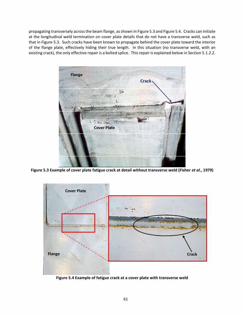
61
propagating transversely across the beam flange, as shown in Figure 5.3 and Figure 5.4. Cracks can initiate at the longitudinal weld termination on cover plate details that do not have a transverse weld, such as that in Figure 5.3. Such cracks have been known to propagate behind the cover plate toward the interior of the flange plate, effectively hiding their true length. In this situation (no transverse weld, with an existing crack), the only effective repair is a bolted splice. This repair is explained below in Section 5.1.2.2.
Figure 5.3 Example of cover plate fatigue crack at detail without transverse weld (Fisher et al., 1979)
Figure 5.4 Example of fatigue crack at a cover plate with transverse weld
Crack
Crack
Flange
Cover Plate
Cover Plate
Flange

62
Despite the poor fatigue resistance of the cover plate detail, it is not uncommon for these details to satisfy their service life without developing any detectable fatigue cracks. This is possible because cover plates are often continued into the low-moment regions of the beams, subjecting the terminations to relatively small live load stress ranges. Inspect carefully for cracks in the flange plate at the toe of the transverse weld and at the termination of the longitudinal welds. It is known that cover plate toe cracks are very difficult to find using unassisted visual inspection. A 10x magnifying glass was recommended by Fisher et al. (1979) based on his original research into the fatigue performance of cover plates. When the cover plate is wider than the flange plate, inspect at the intersection of the flange edge and cover plate weld termination. If cracks are suspected, conduct NDT using either MT or PT to confirm the presence of a crack and establish its length.
5.1.2 Repair or Retrofit Guidelines Two primary tactics can be used to repair or retrofit cover plate details. These are weld toe
treatments, such as hammer peening or ultrasonic impact treatment (UIT), and bolted splices. If desired, these approaches could also be combined. Field monitoring may also be practical in cases where the fatigue stress range is unknown and when many locations on the structure will require repair or retrofit. For example, consider a multi-girder bridge with Category E cover plate details. If field monitoring determines that the effective stress range is less than 7 ksi (the CAFL for Category D fatigue detail) and that any existing cracks are small enough to be effectively removed using surface grinding techniques, it could save the owner significant cost to hammer peen the cover plate weld toes versus installing a bolted splice. Hammer peening has shown to improve fatigue resistance at least one fatigue category, making a Category E cover plate detail, a Category D. UIT offers many benefits over hammer peening, but is also more costly than hammer peening. However, research has shown that UIT under dead load stress increases the fatigue resistance of cover plate details by as much as two categories, or from Category E to C. Although costs for UIT equipment are more than for hammer peening, the process itself is very quick. A single cover plate detail could be treated in just a few minutes (ignoring setup and take down time). Enhancing the fatigue resistance to Category C raises the CAFL to 10 ksi, which would be sufficient for most cover plated beams. For instances where this is still insufficient, or when fatigue cracks are larger than can be feasibly removed, then a bolted splice could be used to increase it to a Category B (CAFL of 16 ksi).
5.1.2.1 Weld Toe Treatment Weld toe treatment is described in detail in Section 4 (see Sections 4.5.3 and 4.5.5) of this guideline.
Refer to this section for a complete description of weld toe grinding to remove existing cracks or apply post weld peening treatment. Refer to 4.5.6 for recommended areas to treat at the cover plate weld termination detail.
5.1.2.2 Bolted Splice Retrofit A slip-critical bolted splice is the most reliable retrofit that can be installed at a cover plate detail.
Where cracks are not found or where cracks are found to be within the flange plate only, the splice can simply be designed to carry the flange moment only. If an existing fatigue crack has propagated into the web plate, then a web plate and flange splice is recommended, sufficiently designed to carry the full moment of the girder at that location. It would also be highly recommended to drill a hole at the crack tip(s) to arrest the crack, as research has shown that a bolted splice installed after fatigue cracking has initiated may not prevent subsequent crack growth (Hassan & Bowman, 1995). See Section 4.2 for hole drilling techniques. Adding a 2 to 4 inch diameter drilled hole in the web directly above (or below in cases where the cover plate is on a top flange) the cover plate weld toe could also be done to ensure that any
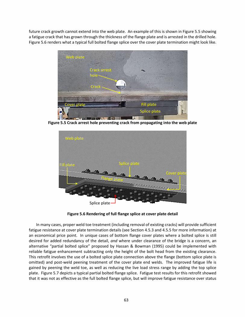
63
future crack growth cannot extend into the web plate. An example of this is shown in Figure 5.5 showing a fatigue crack that has grown through the thickness of the flange plate and is arrested in the drilled hole. Figure 5.6 renders what a typical full bolted flange splice over the cover plate termination might look like.
Figure 5.5 Crack arrest hole preventing crack from propagating into the web plate
Figure 5.6 Rendering of full flange splice at cover plate detail
In many cases, proper weld toe treatment (including removal of existing cracks) will provide sufficient
fatigue resistance at cover plate termination details (see Section 4.5.3 and 4.5.5 for more information) at an economical price point. In unique cases of bottom flange cover plates where a bolted splice is still desired for added redundancy of the detail, and where under clearance of the bridge is a concern, an alternative “partial bolted splice” proposed by Hassan & Bowman (1995) could be implemented with reliable fatigue enhancement subtracting only the height of the bolt head from the existing clearance. This retrofit involves the use of a bolted splice plate connection above the flange (bottom splice plate is omitted) and post-weld peening treatment of the cover plate end welds. The improved fatigue life is gained by peening the weld toe, as well as reducing the live load stress range by adding the top splice plate. Figure 5.7 depicts a typical partial bolted flange splice. Fatigue test results for this retrofit showed that it was not as effective as the full bolted flange splice, but will improve fatigue resistance over status
Web plate
Cover plate Splice plate
Crack
Web plate
Splice plate
Fill plate
Cover plate
Fill plate
Splice plate
Crack arrest hole

64
quo when under clearance is a limiting parameter. Detailed procedures and example details for these bolted splice repairs and retrofits are provided below.
Figure 5.7 Rendering of partial flange splice at a bottom flange cover plate detail with weld toe
peening The following steps outline the proper procedure for installation of a typical full bolted flange splice.
Before installation can begin, a qualified engineer must design the splice. The term “qualified” is used several times throughout the guideline and refers to a person deemed competent by the owner to perform the required task.
1. Clean the weld toe to be repaired or retrofit near the end of the cover plate. For cover plates
wider than the flange, the cleaned weld toe should include the weld ends at the intersection of the cover plate with the girder flange edge.
2. Inspect the weld toe(s) using NDT methods such as MT or PT. 3. Use grinding techniques discussed in Section 4.4 and 4.5.1 to remove shallow cracks, if found.
Refer to Section 4.2 for hole drilling techniques to arrest cracks, as necessary. 4. Drill a 2 to 4-inch diameter hole through the web plate directly above (or below in cases where
the cover plate is on a top flange) the cover plate weld toe, as shown in Figure 5.5 to prevent further crack propagation. Refer to Section 4.4 for drilling techniques and hole edge finishing.
5. Use the bottom splice plate as a template for the holes in the flange plate. Clamp the splice plate and filler plate in place and use a transfer punch to mark the locations of the drilled holes.
6. Remove the splice plate and clamps. Using a mag-based drill with annular cutter and pilot pin, drill the bolt holes in the flange 1/16 inch larger than the diameter of the specified bolt, using the transfer punch indentations as guides. Caution: tie off the mag-based drill to the girder using sturdy clamps and chain/rope in the event of power loss. This will help prevent injury or damage to equipment.
7. Clean and degrease all surfaces within the area of the splice. Include three to six inches outside the footprint of the bolted splice. Ensure dirt, corrosion, cutting oil, hole drilling shards and other debris are removed from the area.
8. Apply an appropriate primer to the cleaned area. 9. Once the primer coating has dried, install the splice plates and hand tighten the bolts.
Peened area

65
10. Starting from the center of the splice and moving methodically outward, snug tighten and then fully tension the bolts according to current RCSC specifications for slip-critical connections.
11. Paint the entire repair area using recommendations provided in Section 4.2. 12. Follow up with typical visual inspections scheduled as part of the regular inspection cycle for
the bridge.
The following steps outline the proper procedure for installation of a typical partial bolted flange splice at a bottom flange cover plate detail. Before installation can begin, a licensed engineer must design the splice.
1. Clean the weld toe to be repaired or retrofit near the end of the cover plate. For cover plates
wider than the flange, the cleaned weld toe should include the weld ends at the intersection of the cover plate with the girder flange edge.
2. Inspect the weld toes using NDT methods such as MT or PT. 3. Use grinding techniques discussed in section 4.4 and 4.5.1 to remove shallow cracks, if found.
If cracks are identified that are too deep for peening over or removing with a grinder, as recommended in Section 4, a full bolted splice should be considered instead.
4. Peen or apply UIT to the weld toes. The area treated should include all transverse welds at the end of the cover plate and at least 2 to 3 inches of weld back from the end of the cover plate (see Figure 5.7). Refer to Section 4.5.3 and Section 4.5.5 for peening techniques.
5. Use the splice plates as a template for the holes in the flange plate. Clamp the splice plates in place on top of the bottom girder flange and use a transfer punch to mark the locations of the drilled holes.
6. Remove the splice plates and clamps. Using a mag-based drill with annular cutter and pilot pin, drill the bolt holes in the flange, using the transfer punch indentations as guides. Caution: tie off the mag-based drill to the girder using sturdy clamps and chain/rope in the event of power loss. This will help prevent injury or damage to equipment.
7. Clean and degrease all surfaces within the area of the splice. Include three to six inches outside the footprint of the bolted splice. Ensure dirt, corrosion, cutting oil, hole drilling shards and other debris are removed from the area.
8. Apply an appropriate primer to the cleaned area. 9. Once the primer has dried, install the splice plates and hand tighten the bolts. Install the bolts
with the nut on top of the flange (to reduce under clearance as much as possible). 10. Starting from the center of the splice and moving methodically outward, snug tighten and
then fully tension the bolts according to current RCSC specifications for slip-critical connections.
11. Paint the entire repair area using recommendations provided in Section 4.2. 12. Follow up with typical visual inspections scheduled with the regular inspection cycle for the
bridge. Check edges of holes drilled to arrest existing cracks to ensure the crack has not reinitiated.
5.2 Re-entrant Corners at Coped or Blocked Stringers and Floorbeams
5.2.1 Description of Problem Coped and blocked stringers and floorbeams have been commonly used to frame members together
on steel bridges for decades. A typical design detail is shown in Figure 5.8. Variations of this detail have
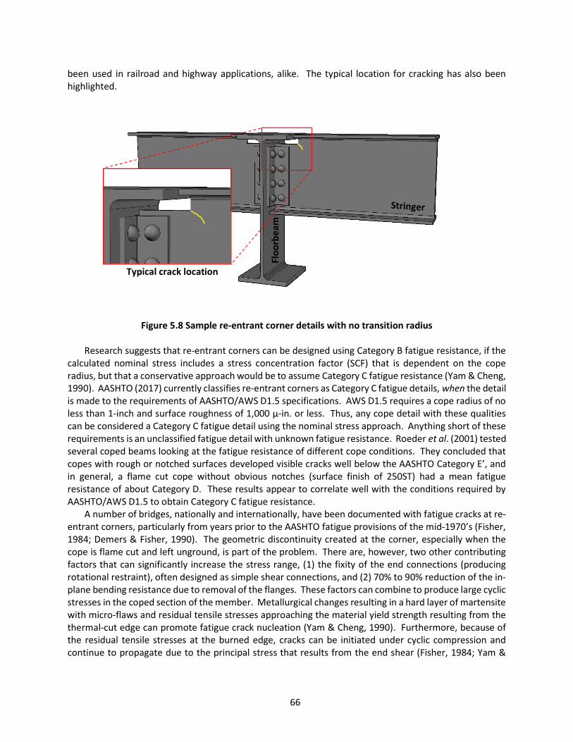
66
been used in railroad and highway applications, alike. The typical location for cracking has also been highlighted.
Figure 5.8 Sample re-entrant corner details with no transition radius
Research suggests that re-entrant corners can be designed using Category B fatigue resistance, if the
calculated nominal stress includes a stress concentration factor (SCF) that is dependent on the cope radius, but that a conservative approach would be to assume Category C fatigue resistance (Yam & Cheng, 1990). AASHTO (2017) currently classifies re-entrant corners as Category C fatigue details, when the detail is made to the requirements of AASHTO/AWS D1.5 specifications. AWS D1.5 requires a cope radius of no less than 1-inch and surface roughness of 1,000 µ-in. or less. Thus, any cope detail with these qualities can be considered a Category C fatigue detail using the nominal stress approach. Anything short of these requirements is an unclassified fatigue detail with unknown fatigue resistance. Roeder et al. (2001) tested several coped beams looking at the fatigue resistance of different cope conditions. They concluded that copes with rough or notched surfaces developed visible cracks well below the AASHTO Category E’, and in general, a flame cut cope without obvious notches (surface finish of 250ST) had a mean fatigue resistance of about Category D. These results appear to correlate well with the conditions required by AASHTO/AWS D1.5 to obtain Category C fatigue resistance.
A number of bridges, nationally and internationally, have been documented with fatigue cracks at re-entrant corners, particularly from years prior to the AASHTO fatigue provisions of the mid-1970’s (Fisher, 1984; Demers & Fisher, 1990). The geometric discontinuity created at the corner, especially when the cope is flame cut and left unground, is part of the problem. There are, however, two other contributing factors that can significantly increase the stress range, (1) the fixity of the end connections (producing rotational restraint), often designed as simple shear connections, and (2) 70% to 90% reduction of the in-plane bending resistance due to removal of the flanges. These factors can combine to produce large cyclic stresses in the coped section of the member. Metallurgical changes resulting in a hard layer of martensite with micro-flaws and residual tensile stresses approaching the material yield strength resulting from the thermal-cut edge can promote fatigue crack nucleation (Yam & Cheng, 1990). Furthermore, because of the residual tensile stresses at the burned edge, cracks can be initiated under cyclic compression and continue to propagate due to the principal stress that results from the end shear (Fisher, 1984; Yam &
Floo
rbea
m
Typical crack location
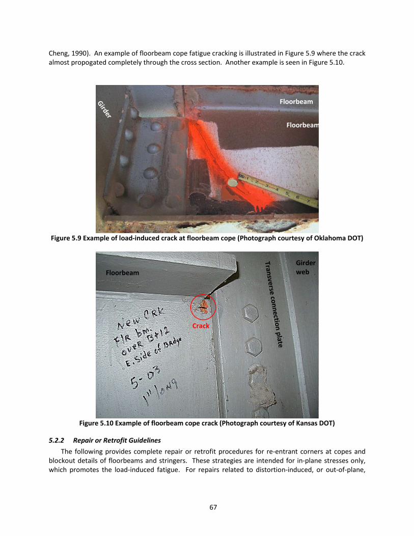
67
Cheng, 1990). An example of floorbeam cope fatigue cracking is illustrated in Figure 5.9 where the crack almost propogated completely through the cross section. Another example is seen in Figure 5.10.
Figure 5.9 Example of load-induced crack at floorbeam cope (Photograph courtesy of Oklahoma DOT)
Figure 5.10 Example of floorbeam cope crack (Photograph courtesy of Kansas DOT)
5.2.2 Repair or Retrofit Guidelines The following provides complete repair or retrofit procedures for re-entrant corners at copes and
blockout details of floorbeams and stringers. These strategies are intended for in-plane stresses only, which promotes the load-induced fatigue. For repairs related to distortion-induced, or out-of-plane,
Floorbeam
Floorbeam
Floorbeam Girder web
Crack
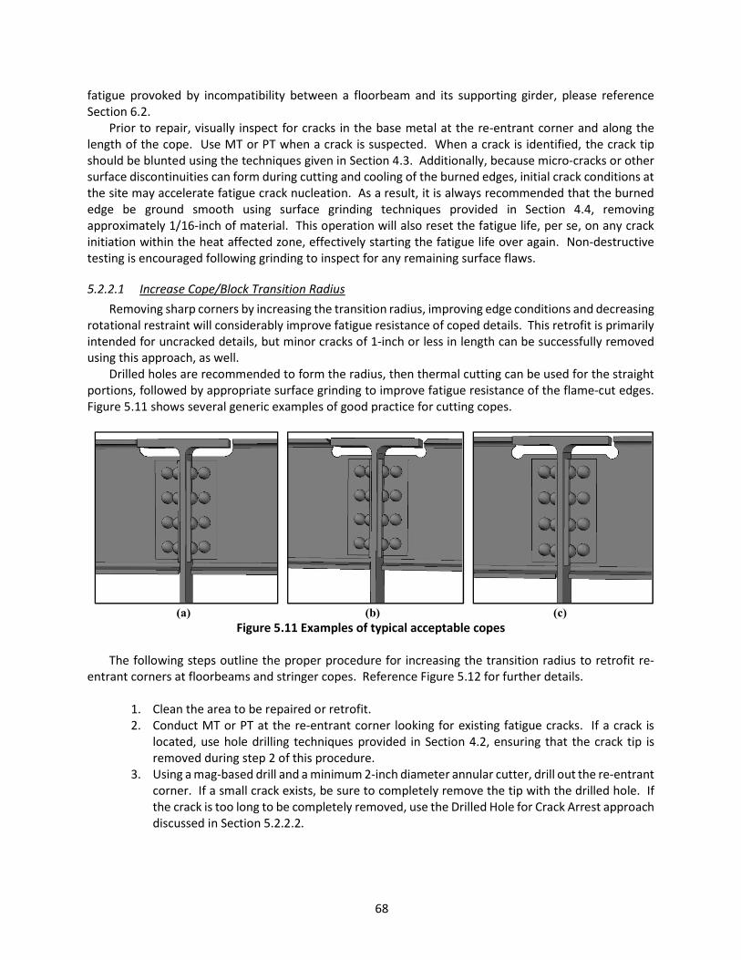
68
fatigue provoked by incompatibility between a floorbeam and its supporting girder, please reference Section 6.2.
Prior to repair, visually inspect for cracks in the base metal at the re-entrant corner and along the length of the cope. Use MT or PT when a crack is suspected. When a crack is identified, the crack tip should be blunted using the techniques given in Section 4.3. Additionally, because micro-cracks or other surface discontinuities can form during cutting and cooling of the burned edges, initial crack conditions at the site may accelerate fatigue crack nucleation. As a result, it is always recommended that the burned edge be ground smooth using surface grinding techniques provided in Section 4.4, removing approximately 1/16-inch of material. This operation will also reset the fatigue life, per se, on any crack initiation within the heat affected zone, effectively starting the fatigue life over again. Non-destructive testing is encouraged following grinding to inspect for any remaining surface flaws.
5.2.2.1 Increase Cope/Block Transition Radius Removing sharp corners by increasing the transition radius, improving edge conditions and decreasing
rotational restraint will considerably improve fatigue resistance of coped details. This retrofit is primarily intended for uncracked details, but minor cracks of 1-inch or less in length can be successfully removed using this approach, as well.
Drilled holes are recommended to form the radius, then thermal cutting can be used for the straight portions, followed by appropriate surface grinding to improve fatigue resistance of the flame-cut edges. Figure 5.11 shows several generic examples of good practice for cutting copes.
(a)
(b)
(c)
Figure 5.11 Examples of typical acceptable copes
The following steps outline the proper procedure for increasing the transition radius to retrofit re-entrant corners at floorbeams and stringer copes. Reference Figure 5.12 for further details.
1. Clean the area to be repaired or retrofit. 2. Conduct MT or PT at the re-entrant corner looking for existing fatigue cracks. If a crack is
located, use hole drilling techniques provided in Section 4.2, ensuring that the crack tip is removed during step 2 of this procedure.
3. Using a mag-based drill and a minimum 2-inch diameter annular cutter, drill out the re-entrant corner. If a small crack exists, be sure to completely remove the tip with the drilled hole. If the crack is too long to be completely removed, use the Drilled Hole for Crack Arrest approach discussed in Section 5.2.2.2.
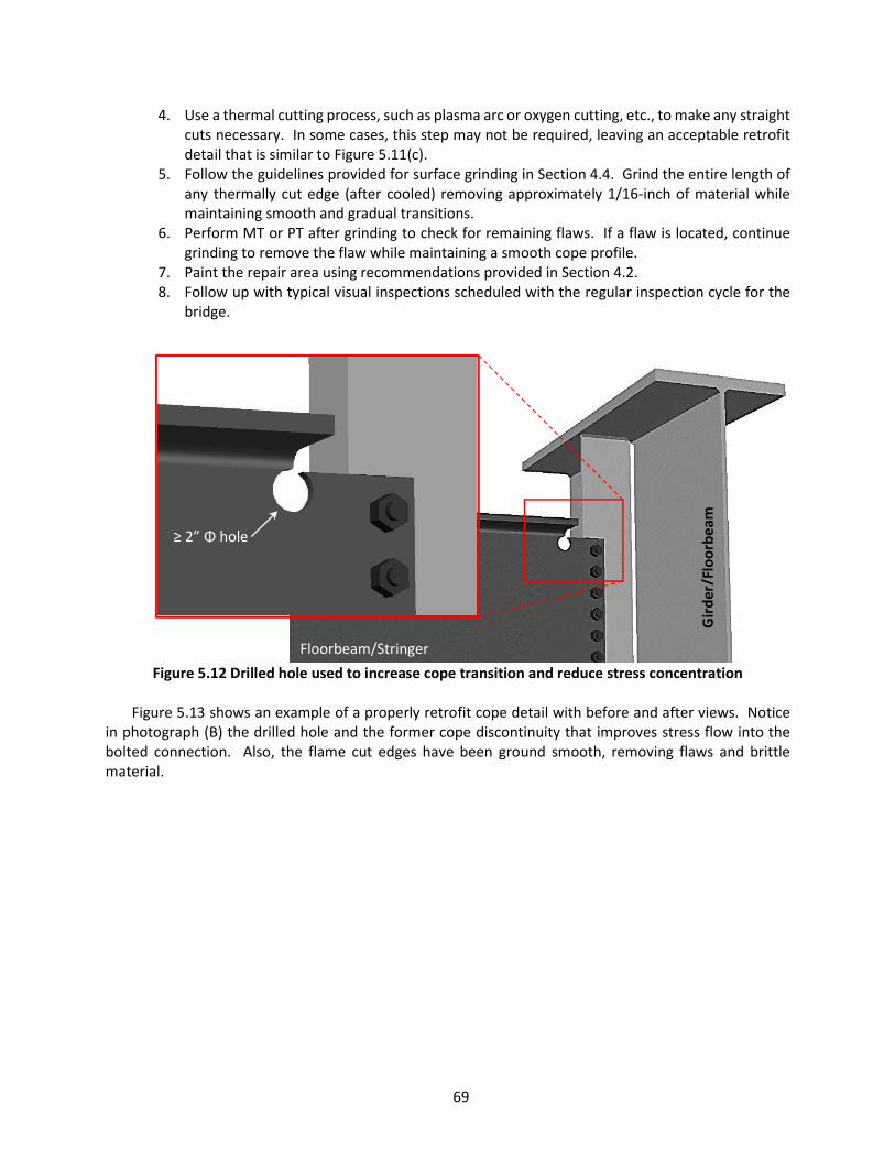
69
4. Use a thermal cutting process, such as plasma arc or oxygen cutting, etc., to make any straight cuts necessary. In some cases, this step may not be required, leaving an acceptable retrofit detail that is similar to Figure 5.11(c).
5. Follow the guidelines provided for surface grinding in Section 4.4. Grind the entire length of any thermally cut edge (after cooled) removing approximately 1/16-inch of material while maintaining smooth and gradual transitions.
6. Perform MT or PT after grinding to check for remaining flaws. If a flaw is located, continue grinding to remove the flaw while maintaining a smooth cope profile.
7. Paint the repair area using recommendations provided in Section 4.2. 8. Follow up with typical visual inspections scheduled with the regular inspection cycle for the
bridge.
Figure 5.12 Drilled hole used to increase cope transition and reduce stress concentration
Figure 5.13 shows an example of a properly retrofit cope detail with before and after views. Notice
in photograph (B) the drilled hole and the former cope discontinuity that improves stress flow into the bolted connection. Also, the flame cut edges have been ground smooth, removing flaws and brittle material.
Floorbeam/Stringer
≥ 2” Φ hole
Gir
der/
Floo
rbea
m
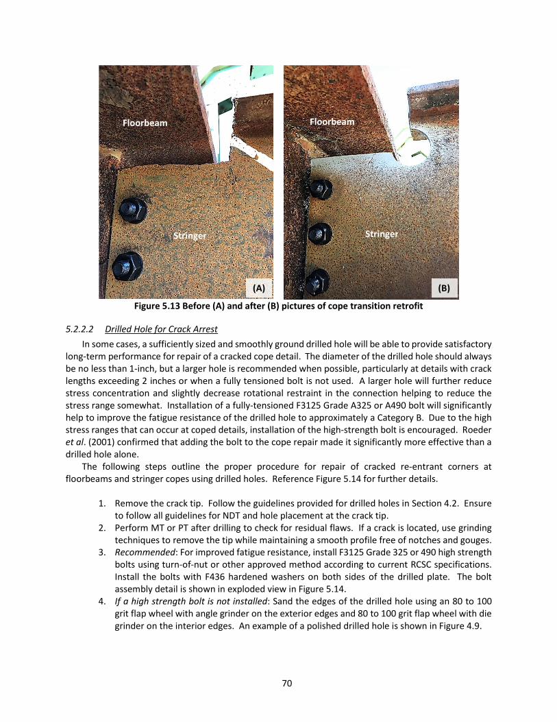
70
Figure 5.13 Before (A) and after (B) pictures of cope transition retrofit
5.2.2.2 Drilled Hole for Crack Arrest In some cases, a sufficiently sized and smoothly ground drilled hole will be able to provide satisfactory
long-term performance for repair of a cracked cope detail. The diameter of the drilled hole should always be no less than 1-inch, but a larger hole is recommended when possible, particularly at details with crack lengths exceeding 2 inches or when a fully tensioned bolt is not used. A larger hole will further reduce stress concentration and slightly decrease rotational restraint in the connection helping to reduce the stress range somewhat. Installation of a fully-tensioned F3125 Grade A325 or A490 bolt will significantly help to improve the fatigue resistance of the drilled hole to approximately a Category B. Due to the high stress ranges that can occur at coped details, installation of the high-strength bolt is encouraged. Roeder et al. (2001) confirmed that adding the bolt to the cope repair made it significantly more effective than a drilled hole alone.
The following steps outline the proper procedure for repair of cracked re-entrant corners at floorbeams and stringer copes using drilled holes. Reference Figure 5.14 for further details.
1. Remove the crack tip. Follow the guidelines provided for drilled holes in Section 4.2. Ensure
to follow all guidelines for NDT and hole placement at the crack tip. 2. Perform MT or PT after drilling to check for residual flaws. If a crack is located, use grinding
techniques to remove the tip while maintaining a smooth profile free of notches and gouges. 3. Recommended: For improved fatigue resistance, install F3125 Grade 325 or 490 high strength
bolts using turn-of-nut or other approved method according to current RCSC specifications. Install the bolts with F436 hardened washers on both sides of the drilled plate. The bolt assembly detail is shown in exploded view in Figure 5.14.
4. If a high strength bolt is not installed: Sand the edges of the drilled hole using an 80 to 100 grit flap wheel with angle grinder on the exterior edges and 80 to 100 grit flap wheel with die grinder on the interior edges. An example of a polished drilled hole is shown in Figure 4.9.
(A) (B)
Floorbeam/Stringer
Stringer Stringer
Floorbeam Floorbeam
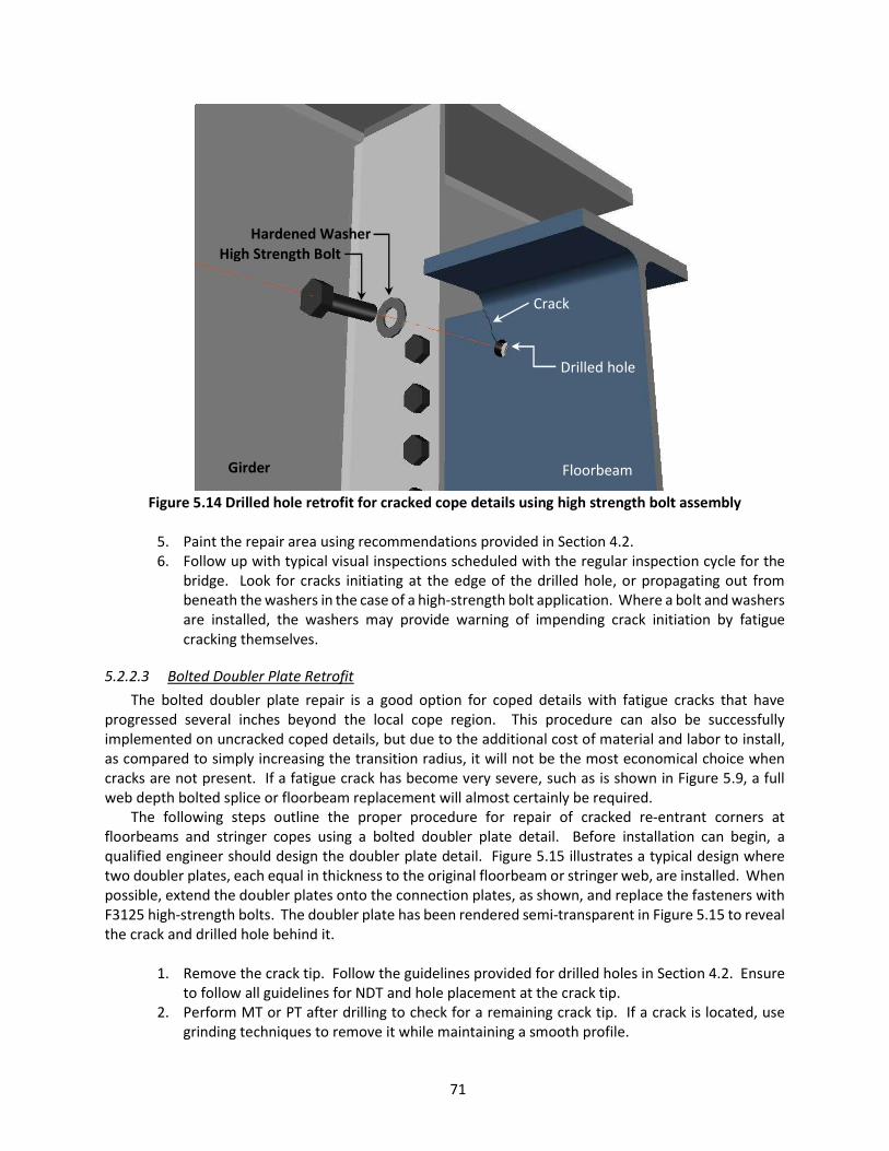
71
Figure 5.14 Drilled hole retrofit for cracked cope details using high strength bolt assembly
5. Paint the repair area using recommendations provided in Section 4.2. 6. Follow up with typical visual inspections scheduled with the regular inspection cycle for the
bridge. Look for cracks initiating at the edge of the drilled hole, or propagating out from beneath the washers in the case of a high-strength bolt application. Where a bolt and washers are installed, the washers may provide warning of impending crack initiation by fatigue cracking themselves.
5.2.2.3 Bolted Doubler Plate Retrofit The bolted doubler plate repair is a good option for coped details with fatigue cracks that have
progressed several inches beyond the local cope region. This procedure can also be successfully implemented on uncracked coped details, but due to the additional cost of material and labor to install, as compared to simply increasing the transition radius, it will not be the most economical choice when cracks are not present. If a fatigue crack has become very severe, such as is shown in Figure 5.9, a full web depth bolted splice or floorbeam replacement will almost certainly be required.
The following steps outline the proper procedure for repair of cracked re-entrant corners at floorbeams and stringer copes using a bolted doubler plate detail. Before installation can begin, a qualified engineer should design the doubler plate detail. Figure 5.15 illustrates a typical design where two doubler plates, each equal in thickness to the original floorbeam or stringer web, are installed. When possible, extend the doubler plates onto the connection plates, as shown, and replace the fasteners with F3125 high-strength bolts. The doubler plate has been rendered semi-transparent in Figure 5.15 to reveal the crack and drilled hole behind it.
1. Remove the crack tip. Follow the guidelines provided for drilled holes in Section 4.2. Ensure
to follow all guidelines for NDT and hole placement at the crack tip. 2. Perform MT or PT after drilling to check for a remaining crack tip. If a crack is located, use
grinding techniques to remove it while maintaining a smooth profile.
Floorbeam Girder
Crack rack
Hardened Washer
Drilled hole
High Strength Bolt
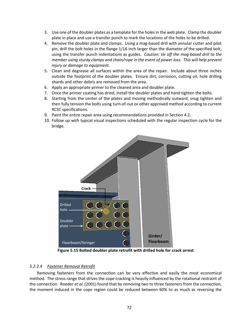
72
3. Use one of the doubler plates as a template for the holes in the web plate. Clamp the doubler plate in place and use a transfer punch to mark the locations of the holes to be drilled.
4. Remove the doubler plate and clamps. Using a mag-based drill with annular cutter and pilot pin, drill the bolt holes in the flange 1/16 inch larger than the diameter of the specified bolt, using the transfer punch indentations as guides. Caution: tie off the mag-based drill to the member using sturdy clamps and chain/rope in the event of power loss. This will help prevent injury or damage to equipment.
5. Clean and degrease all surfaces within the area of the repair. Include about three inches outside the footprint of the doubler plates. Ensure dirt, corrosion, cutting oil, hole drilling shards and other debris are removed from the area.
6. Apply an appropriate primer to the cleaned area and doubler plate. 7. Once the primer coating has dried, install the doubler plates and hand tighten the bolts. 8. Starting from the center of the plates and moving methodically outward, snug tighten and
then fully tension the bolts using turn-of-nut or other approved method according to current RCSC specifications.
9. Paint the entire repair area using recommendations provided in Section 4.2. 10. Follow up with typical visual inspections scheduled with the regular inspection cycle for the
bridge.
Figure 5.15 Bolted doubler plate retrofit with drilled hole for crack arrest
5.2.2.4 Fastener Removal Retrofit Removing fasteners from the connection can be very effective and easily the most economical
method. The stress range that drives the cope cracking is heavily influenced by the rotational restraint of the connection. Roeder et al. (2001) found that by removing two to three fasteners from the connection, the moment induced in the cope region could be reduced between 60% to as much as reversing the
Girder/ Floorbeam Floorbeam/Stringer
Crack
Doubler plate
Drilled hole
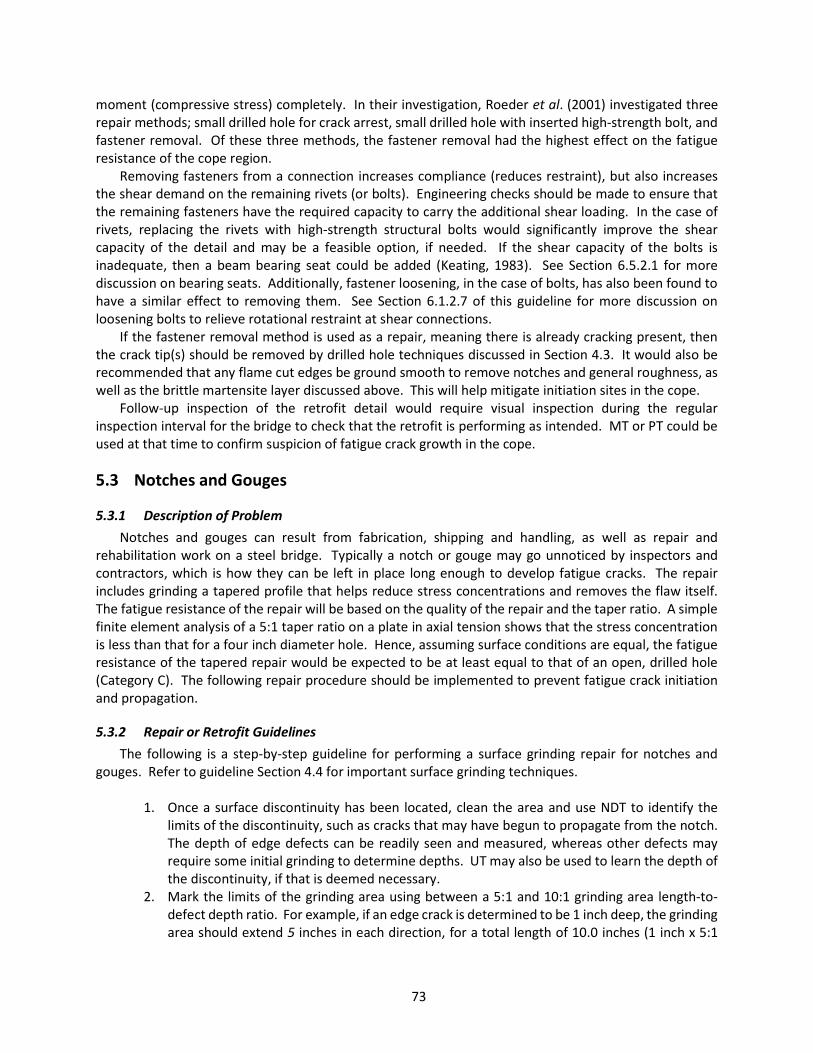
73
moment (compressive stress) completely. In their investigation, Roeder et al. (2001) investigated three repair methods; small drilled hole for crack arrest, small drilled hole with inserted high-strength bolt, and fastener removal. Of these three methods, the fastener removal had the highest effect on the fatigue resistance of the cope region.
Removing fasteners from a connection increases compliance (reduces restraint), but also increases the shear demand on the remaining rivets (or bolts). Engineering checks should be made to ensure that the remaining fasteners have the required capacity to carry the additional shear loading. In the case of rivets, replacing the rivets with high-strength structural bolts would significantly improve the shear capacity of the detail and may be a feasible option, if needed. If the shear capacity of the bolts is inadequate, then a beam bearing seat could be added (Keating, 1983). See Section 6.5.2.1 for more discussion on bearing seats. Additionally, fastener loosening, in the case of bolts, has also been found to have a similar effect to removing them. See Section 6.1.2.7 of this guideline for more discussion on loosening bolts to relieve rotational restraint at shear connections.
If the fastener removal method is used as a repair, meaning there is already cracking present, then the crack tip(s) should be removed by drilled hole techniques discussed in Section 4.3. It would also be recommended that any flame cut edges be ground smooth to remove notches and general roughness, as well as the brittle martensite layer discussed above. This will help mitigate initiation sites in the cope.
Follow-up inspection of the retrofit detail would require visual inspection during the regular inspection interval for the bridge to check that the retrofit is performing as intended. MT or PT could be used at that time to confirm suspicion of fatigue crack growth in the cope.
5.3 Notches and Gouges
5.3.1 Description of Problem Notches and gouges can result from fabrication, shipping and handling, as well as repair and
rehabilitation work on a steel bridge. Typically a notch or gouge may go unnoticed by inspectors and contractors, which is how they can be left in place long enough to develop fatigue cracks. The repair includes grinding a tapered profile that helps reduce stress concentrations and removes the flaw itself. The fatigue resistance of the repair will be based on the quality of the repair and the taper ratio. A simple finite element analysis of a 5:1 taper ratio on a plate in axial tension shows that the stress concentration is less than that for a four inch diameter hole. Hence, assuming surface conditions are equal, the fatigue resistance of the tapered repair would be expected to be at least equal to that of an open, drilled hole (Category C). The following repair procedure should be implemented to prevent fatigue crack initiation and propagation.
5.3.2 Repair or Retrofit Guidelines The following is a step-by-step guideline for performing a surface grinding repair for notches and
gouges. Refer to guideline Section 4.4 for important surface grinding techniques.
1. Once a surface discontinuity has been located, clean the area and use NDT to identify the limits of the discontinuity, such as cracks that may have begun to propagate from the notch. The depth of edge defects can be readily seen and measured, whereas other defects may require some initial grinding to determine depths. UT may also be used to learn the depth of the discontinuity, if that is deemed necessary.
2. Mark the limits of the grinding area using between a 5:1 and 10:1 grinding area length-to-defect depth ratio. For example, if an edge crack is determined to be 1 inch deep, the grinding area should extend 5 inches in each direction, for a total length of 10.0 inches (1 inch x 5:1

74
ratio x 2 sides). Figure 5.16 shows an example of a 5:1 taper ratio marking before grinding. The dashed red lines indicates the area that would be ground smooth.
Figure 5.16 Example of 5:1 taper ratio markings
3. Perform rough grinding to remove the bulk of the material using 40 to 60 grit flap wheels
while being careful to follow the tapered markings. 4. Complete the fine grit grinding step using 80 to 100 grit flap wheels. Figure 5.17 shows an
example of a 5:1 taper following removal of an edge gouge on a flange. Notice the smooth and gradual surface of the repair.
5. Inspect using MT or PT to ensure no crack tips were left behind. If a crack is located, complete steps 2 – 5 again.
6. Paint the repair area using recommendations provided in Section 4.2. 7. Document the section reduction for load rating analysis purposes. Follow up with typical
visual inspections scheduled with the regular inspection cycle for the bridge.
Figure 5.17 Example of edge flaw removed with 5:1 fairing ratio
5.4 Longitudinal Stiffener and Gusset Plate Weld Terminations
5.4.1 Description of Problem Research has identified the fatigue resistance of welded web attachments of varying lengths and
thicknesses, such as stiffening elements and connection plates, including those subjected to variable amplitude fatigue loading (Fisher et al, 1980; Tilly & Nunn, 1980; Keating & Fisher, 1986). Components longer than 4 inches are currently characterized as Category E when less than 1 inch thick and Category E’ when equal to or more than 1 inch thick (AASHTO, 2017). Hence, the weld terminations for web gusset plates (also referred to as lateral connection plates or shelf plates) and longitudinal stiffener plates have
d
5 x d
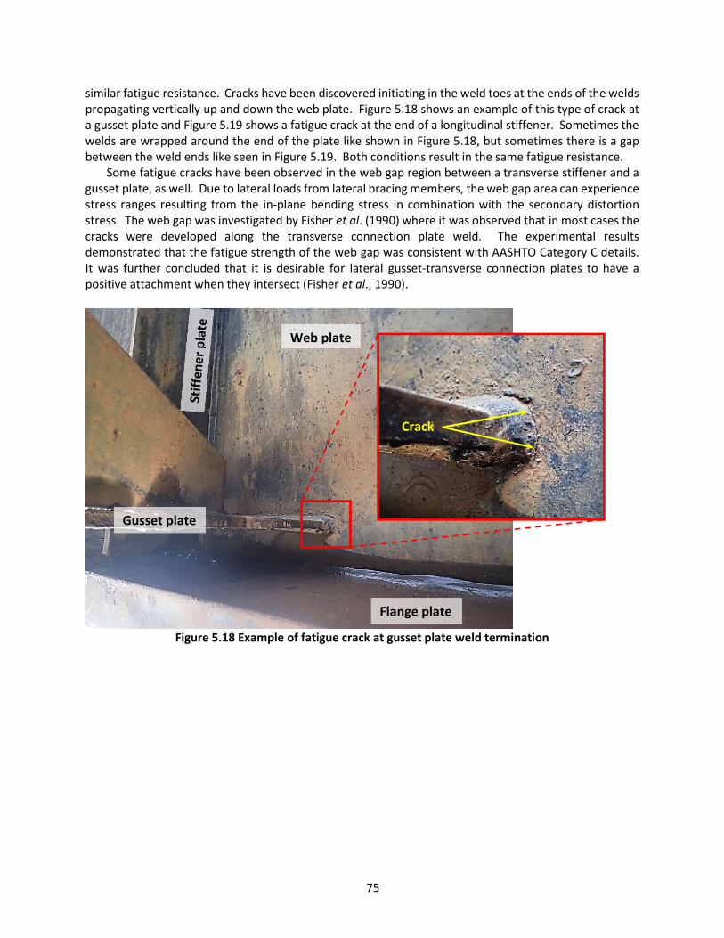
75
similar fatigue resistance. Cracks have been discovered initiating in the weld toes at the ends of the welds propagating vertically up and down the web plate. Figure 5.18 shows an example of this type of crack at a gusset plate and Figure 5.19 shows a fatigue crack at the end of a longitudinal stiffener. Sometimes the welds are wrapped around the end of the plate like shown in Figure 5.18, but sometimes there is a gap between the weld ends like seen in Figure 5.19. Both conditions result in the same fatigue resistance.
Some fatigue cracks have been observed in the web gap region between a transverse stiffener and a gusset plate, as well. Due to lateral loads from lateral bracing members, the web gap area can experience stress ranges resulting from the in-plane bending stress in combination with the secondary distortion stress. The web gap was investigated by Fisher et al. (1990) where it was observed that in most cases the cracks were developed along the transverse connection plate weld. The experimental results demonstrated that the fatigue strength of the web gap was consistent with AASHTO Category C details. It was further concluded that it is desirable for lateral gusset-transverse connection plates to have a positive attachment when they intersect (Fisher et al., 1990).
Figure 5.18 Example of fatigue crack at gusset plate weld termination
Crack
Web plate
Flange plate
Gusset plate

76
Figure 5.19 Example of fatigue crack at longitudinal stiffener weld termination
Longitudinal stiffener plates are typically placed in compression zones in order to stiffen the web
plates against bend buckling out of plane. The purely compression regions of a bridge generally are not a concern for fatigue cracking because even though fatigue cracks can initiate at weld toes in a compression zone, they will not propagate beyond the tensile residual stress of the weld toe. Outside the tensile stresses of the weld toe the compressive live load stresses will not advance the crack further and it dies off. However, longitudinal stiffeners are often continued into stress reversal zones that are subject to tensile stresses. In some cases, they have also been used as architectural features, such as that shown in Figure 5.20, where they are subjected to full tensile dead load stress and live load stress ranges. In such cases the weld terminations, as well as the butt weld splice locations, can become prone to fatigue cracks. These regions of the stiffener plate can also be prone to constraint-induced fracture where poor groove weld quality at the butt splices or insufficiently sized web gap regions at intersections with transverse stiffener plates has caused brittle fracture. Performing the retrofits discussed in Section 7.2 will address both fatigue and fracture concerns for details intersecting transverse plates and performing retrofits discussed in Section 7.3 will address both fatigue and fracture concerns for the groove welded butt splice details. Retrofits presented in this section apply to weld terminations of both longitudinal stiffener and gusset plates and may not remove risk of constraint-induced fracture. Rather, the following retrofits are intended for fatigue only.
Crack

77
Figure 5.20 Example of longitudinal stiffeners located in tension and compression zones
5.4.2 Repair or Retrofit Guidelines
5.4.2.1 Weld Termination Removal This retrofit is intended for uncracked details. If a fatigue crack has already initiated, use the Web
Plate Isolation Holes Retrofit described in Section 5.4.2.3 instead. Removing the end of the weld, either by grinding or by first drilling and then grinding, is an effective
way to “reset” the fatigue life at the detail. The most fatigue prone part of the weld is at the termination. Thus, by removing the termination the retrofit essentially creates a new weld termination with the fatigue life starting anew. An example of this type of retrofit is shown in Figure 5.21 where a carbide rotary burr bit was used to grind off the end of the weld and slightly improve the transition to the web plate. This same type of retrofit could also be accomplished using a mag-based drill and annular cutter where the cutter would be lined up flush with the web plate and a hole is drilled through the gusset plate. Any remaining weld could be removed by grinding. If a 4-inch diameter cutter is used, this would create a 2-inch radius transition and improve the fatigue resistance of the termination from Category E to Category D, as well. Larger radii could also be installed using thermal cutting and grinding processes, but the additional work may not be worth the effort and expense. Field testing to determine the effective stress range at the detail would be recommended prior to increasing the radius beyond 2 inches. Most likely the 7 ksi CAFL of a Category D detail at the gusset plate termination will be sufficient for infinite life for a typical highway bridge. Moreover, Fisher et al. (1980) determined that fillet-welded gusset plates with radius transitions cannot achieve fatigue resistance improvement over a Category D (based on the radius and not some other retrofit approach, such as peening), even when the transition exceeds 6 inches. They concluded that this is due to the subsurface discontinuities in the transition region, which are more likely at the fillet weld root and which limit the fatigue resistance.
The following is a step-by-step guideline for performing the weld termination removal retrofit.

78
1. Inspect the area carefully using NDE methods such as PT or MT to identify any cracks that may exist. If a crack is identified, it is recommended that Section 5.4.2.3, Web Plate Isolation Holes, be used instead.
2. Using a carbide rotary burr bit and die grinder, gradually grind away the gusset plate and weld creating a gradual and gentle transition to the web plate. Remove between ¼” to ½” of the end of the welds (both above and below the gusset plate). Follow techniques and recommendations discussed in Section 4.4 being careful to not remove web plate material. Option: Remove the bulk of the material and weld from the plate using a mag-based drill. Align the annular cutter such that it is flush with the web plate at a point approximately ¼” to ½” back from the end of the weld. This will result in a partial circle cut at the edge of the gusset or longitudinal stiffener plate with some weld remaining attached to the web. Grind off the residual weld flush with the web plate. Figure 5.22A shows what a typical plate termination will look like after drilling a 4-inch diameter hole. Notice the small weld material that was missed by the drilling, which needs to be ground smooth in Figure 5.22A. Figure 5.22B shows the retrofit as it should be completed, with the weld ground smooth to the web. Although Figure 5.22 is drawn for a gusset plate termination, the same detail can be used on a longitudinal stiffener plate termination.
Figure 5.21 Weld termination removal using burr bit and die grinder (Photograph courtesy of Iowa
DOT) 3. Once the gusset or longitudinal stiffener plate weld terminations have been removed and the
transition to the web is smooth and free of gouges, inspect the area again using NDE methods to see if grinding exposed any cracks in the web plate. If a crack is located, drill out the tips using Section 4.2.
4. Paint the repair area using recommendations provided in Section 4.2. 5. Follow up with typical visual inspections scheduled with the regular inspection cycle for the
bridge.

79
Figure 5.22 Retrofit for plate termination using drill and annular cutter
5.4.2.2 Weld Toe Treatment Weld toe treatment is described in detail in Section 4.5 of this guideline. Refer to this section for a
complete description of weld toe grinding for removing existing cracks, as necessary, and to apply post weld peening treatment. Peening should be applied to the last two to three inches of the gusset or longitudinal stiffener plate weld, following the weld toe in contact with the web plate. If the weld wraps around the end, ensure that the peening treatment follows the weld toe around and continues for two to three inches along the underside of the plate, as seen in Figure 5.23. It is not clear from this figure whether or not the paint coating was removed prior to peening. This is an important step to ensure quality peening treatment. Tool access between the attachment plate and adjacent flange plate should also be considered before choosing this retrofit approach.
Girder web
Gusset plate
A B
Residual weld missed during drilling: grind smooth Properly
finished retrofit
2- 4” Φ hole
¼ - ½ inch

80
Figure 5.23 Weld toe peening at gusset plate termination (Photograph courtesy of Iowa DOT)
5.4.2.3 Web Plate Isolation Holes Web plate isolation holes are intended to prevent a fatigue crack that develops from propagating into
the web plate. Effectively replacing the weld termination with a drilled hole, however, also improves the fatigue resistance of the detail from an AASHTO Category E to about a Category C. This retrofit is one of the simplest and most economical to install because it is only two holes drilled through the web plate. A similar retrofit, referred to as a “dog-bone” retrofit, has also been used with success on these details. The dog-bone retrofit uses drilled holes like the web plate isolation holes retrofit, and then connects them with a sawcut. The sawcut between the drilled holes could also be effectively done using a controlled thermal cut. The dog-bone retrofit releases the weld termination from the live load stresses that drive fatigue cracking. However, it may be equally effective and more economical to simply drill the isolation holes and allow the weld termination area to fatigue into the drilled holes. If a crack forms, it will simply grow into the holes and stop. In terms of stress flow through the detail, the two holes connected by a fatigue crack would perform equally to the dog-bone type retrofit.
Two to four-inch diameter drilled holes are recommended. Larger holes improve fatigue resistance by further reducing stress concentration at the edge of the holes. Figure 5.24 shows an example of the dog-bone retrofit on the left and the web isolation holes retrofit on the right.
Gusset plate
Ultrasonic needle peening
Web plate
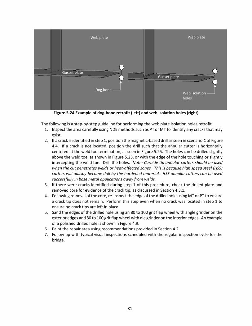
81
Figure 5.24 Example of dog-bone retrofit (left) and web isolation holes (right)
The following is a step-by-step guideline for performing the web plate isolation holes retrofit.
1. Inspect the area carefully using NDE methods such as PT or MT to identify any cracks that may exist.
2. If a crack is identified in step 1, position the magnetic-based drill as seen in scenario C of Figure 4.4. If a crack is not located, position the drill such that the annular cutter is horizontally centered at the weld toe termination, as seen in Figure 5.25. The holes can be drilled slightly above the weld toe, as shown in Figure 5.25, or with the edge of the hole touching or slightly intercepting the weld toe. Drill the holes. Note: Carbide tip annular cutters should be used when the cut penetrates welds or heat-affected zones. This is because high speed steel (HSS) cutters will quickly become dull by the hardened material. HSS annular cutters can be used successfully in base metal applications away from welds.
3. If there were cracks identified during step 1 of this procedure, check the drilled plate and removed core for evidence of the crack tip, as discussed in Section 4.3.1.
4. Following removal of the core, re-inspect the edge of the drilled hole using MT or PT to ensure a crack tip does not remain. Perform this step even when no crack was located in step 1 to ensure no crack tips are left in place.
5. Sand the edges of the drilled hole using an 80 to 100 grit flap wheel with angle grinder on the exterior edges and 80 to 100 grit flap wheel with die grinder on the interior edges. An example of a polished drilled hole is shown in Figure 4.9.
6. Paint the repair area using recommendations provided in Section 4.2. 7. Follow up with typical visual inspections scheduled with the regular inspection cycle for the
bridge.
Gusset plate Gusset plate
Web plate Web plate
Dog bone Web isolation holes
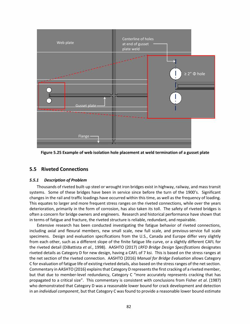
82
Figure 5.25 Example of web isolation hole placement at weld termination of a gusset plate
5.5 Riveted Connections
5.5.1 Description of Problem Thousands of riveted built-up steel or wrought iron bridges exist in highway, railway, and mass transit
systems. Some of these bridges have been in service since before the turn of the 1900’s. Significant changes in the rail and traffic loadings have occurred within this time, as well as the frequency of loading. This equates to larger and more frequent stress ranges on the riveted connections, while over the years deterioration, primarily in the form of corrosion, has also taken its toll. The safety of riveted bridges is often a concern for bridge owners and engineers. Research and historical performance have shown that in terms of fatigue and fracture, the riveted structure is reliable, redundant, and repairable.
Extensive research has been conducted investigating the fatigue behavior of riveted connections, including axial and flexural members, new small scale, new full scale, and previous-service full scale specimens. Design and evaluation specifications from the U.S., Canada and Europe differ very slightly from each other, such as a different slope of the finite fatigue life curve, or a slightly different CAFL for the riveted detail (DiBattista et al., 1998). AASHTO (2017) LRFD Bridge Design Specifications designates riveted details as Category D for new design, having a CAFL of 7 ksi. This is based on the stress ranges at the net section of the riveted connection. AASHTO (2016) Manual for Bridge Evaluation allows Category C for evaluation of fatigue life of existing riveted details, also based on the stress ranges of the net section. Commentary in AASHTO (2016) explains that Category D represents the first cracking of a riveted member, but that due to member-level redundancy, Category C “more accurately represents cracking that has propagated to a critical size”. This commentary is consistent with conclusions from Fisher et al. (1987) who demonstrated that Category D was a reasonable lower bound for crack development and detection in an individual component, but that Category C was found to provide a reasonable lower bound estimate
Gusset plate
Web plate
Flange
Centerline of holes at end of gusset plate weld
≥ 2” Φ hole

83
for riveted members. The commentary of the MBE indicates that Category C was selected for evaluation since the inherent internal redundancy associated with riveted built-up members better represents the actual fatigue life, rather than first cracking as characterized by Category D. Again, note that this is for steel members, however. For a wrought iron riveted detail, the lower bound fatigue limit is Category E (Fisher et al., 1987).
Hebdon (2015) took this a step further by determining the fatigue resistance of riveted built-up full scale girders after a single component (i.e. cover plate or flange angle) was completely failed (either due to fatigue or fracture). An example of these test specimens is shown in Figure 5.28 where it shows the severed cover plate and a fatigue crack propagating out from underneath the rivet head. Results from this research indicated that the AASHTO Category D was a reasonable lower bound for girders with drilled holes, based on an amplified net-section stress range that incorporates localized stress redistribution.
The quality of the rivet hole is also a factor in the fatigue resistance of riveted connections. Several methods of hole preparation exist, including drilled holes, punched holes, subpunched and reamed holes, and subdrilled and reamed holes. Fisher et al. (1987) reported that the different methods of hole preparation did not result in major differences in fatigue strength, adding the caveat that limited test data was available on punched holes, which may have a wide variety of quality due to punch wear, plate thickness, and material. They added that reamed holes seemed to provide better performance than drilled holes. Hebdon (2015) tested 12 full scale beams, some with drilled holes and some with punched holes. He concluded that Category E’ was a reasonable lower bound fatigue resistance for girders with punched holes; this was for girders with a single component already failed.
Figure 5.26 shows a punched hole and a drilled hole side-by-side. Notice that the punched hole has shear lap defects where it appears as if the material was smeared. Drilled holes will not always appear as smooth as Figure 5.26 appears, this will be a product of the drilling rate and bit sharpness. Another look at a drilled hole is shown in Figure 5.27(a) where it reveals the drilling striations. Figure 5.27(b) also shows a similar perspective for a punched hole. This is the view that a worker would have in the field when trying to determine whether the holes are punched or drilled.
Figure 5.26 Example of punched and drilled hole quality
Punched hole
Drilled hole

84
(a)
(b)
Figure 5.27 Perspective with rivet removed revealing appearance of punched (a) vs. drilled (b) hole Experience with field testing has shown that maximum stress ranges for highway bridges will rarely
exceed the 7 ksi fatigue limit of Category D, much less the 10 ksi fatigue limit of Category C. This means that fatigue damage, due to primary stresses, will not likely occur in most highway bridges. This does not go without exception, however, and also does not include secondary effects at riveted connections, such as that discussed in Section 6.5.
Figure 5.28 Test specimen showing fractured cover plate with fatigue crack propagating from rivet
hole in the flange angle (Hebdon, 2015)
Inspection of riveted connections is challenging due to the number of rivets typically involved.
Thousands of rivets means thousands of locations on a single bridge where a crack could initiate and propagate. Efforts should be focused around areas of maximum bending stress for flexural members (e.g. floorbeams, girders), and at the first two rows and last two rows of rivets in axial members (e.g. truss chord gusset plates and hanger connections). Fatigue cracks initiate at the edge of the rivet hole, which
Crack
Severed cover plate
Flange Angle

85
means that at the earliest stage of detectability, the crack has already grown from under the edge dimension of the rivet head, or about 3/8-inch, typically. At this length the crack still has a very low probability of detection, particularly outside of a laboratory setting. The critical size of a crack in a built-up riveted member, however, is typically much larger than for a welded members.
The risk of fatigue cracks growing to a critical size in riveted built-up members is low. Research has shown that riveted built-up members possess significant member-level redundancy and that as a component begins to crack, the member redistributes load into adjoining components thereby reducing the stress range in the cracked component. Fisher et al. (1987) concluded that if cracks develop in a single component, they are likely to be detected before the section can no longer carry load. Hebdon (2015) concluded that fracture of an individual component in a riveted built-up member is highly unlikely due to several factors, including load redistribution into adjacent components, and constraint created by adjacent fasteners. He found that for most traditionally proportioned built-up members, fracture of any component was unlikely. In cases where failure of a single component occurred (either through fatigue or fracture), traditional linear elastic fracture mechanics calculations did not accurately predict the critical crack length, meaning that the girders could tolerate much longer cracks than fracture mechanics estimated they could. This behavior favors inspection such that finding a 1-inch or smaller crack is not critical, rather finding the severed component should be the real aim of the inspection of riveted built-up members.
5.5.2 Repair or Retrofit Guidelines Replacing rivets with F3125 high-strength bolts increases fatigue resistance of a steel riveted
connection to Category B. This is, however, only if no cracks are present and gouges are not left in place during the replacement operation. The following steps outline the proper procedure for this retrofit.
1. Rivet removal. If groups of rivets will be removed from a connection prior to replacing them
with bolts, a qualified engineer should evaluate the connections to determine how many rivets can safely be removed at one time, or in what pattern they should be removed. Consideration should be given to whether or not the bridge will remain open to traffic. Rivet removal can be done using a pneumatic rivet hammer with chisel bit to rapidly impact the rivet head, shearing it off and then popping the remainder of the rivet out using a rounded, blunt bit. Figure 5.29 shows workers removing a rivet head using a rivet hammer. Other methods can also be used such as drilling out or torching out the center of the rivet and then shearing the head off with a rivet hammer, or using a scarfing tip and torch to burn off the rivet head and then pop out the remainder of the rivet with a rivet hammer and a rounded, blunt tip. In all cases, care should be taken to protect the base material from gouging. Gouging the base material can weaken sections or create future fatigue crack locations. If gouges are created during rivet removal, follow techniques discussed in Section 4.4 and 5.3 to remove the defects.
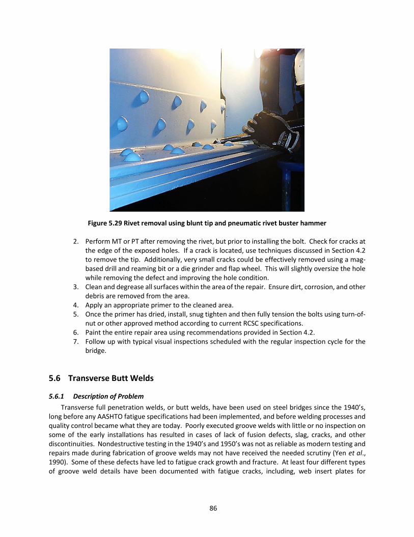
86
Figure 5.29 Rivet removal using blunt tip and pneumatic rivet buster hammer
2. Perform MT or PT after removing the rivet, but prior to installing the bolt. Check for cracks at the edge of the exposed holes. If a crack is located, use techniques discussed in Section 4.2 to remove the tip. Additionally, very small cracks could be effectively removed using a mag-based drill and reaming bit or a die grinder and flap wheel. This will slightly oversize the hole while removing the defect and improving the hole condition.
3. Clean and degrease all surfaces within the area of the repair. Ensure dirt, corrosion, and other debris are removed from the area.
4. Apply an appropriate primer to the cleaned area. 5. Once the primer has dried, install, snug tighten and then fully tension the bolts using turn-of-
nut or other approved method according to current RCSC specifications. 6. Paint the entire repair area using recommendations provided in Section 4.2. 7. Follow up with typical visual inspections scheduled with the regular inspection cycle for the
bridge.
5.6 Transverse Butt Welds
5.6.1 Description of Problem Transverse full penetration welds, or butt welds, have been used on steel bridges since the 1940’s,
long before any AASHTO fatigue specifications had been implemented, and before welding processes and quality control became what they are today. Poorly executed groove welds with little or no inspection on some of the early installations has resulted in cases of lack of fusion defects, slag, cracks, and other discontinuities. Nondestructive testing in the 1940’s and 1950’s was not as reliable as modern testing and repairs made during fabrication of groove welds may not have received the needed scrutiny (Yen et al., 1990). Some of these defects have led to fatigue crack growth and fracture. At least four different types of groove weld details have been documented with fatigue cracks, including, web insert plates for
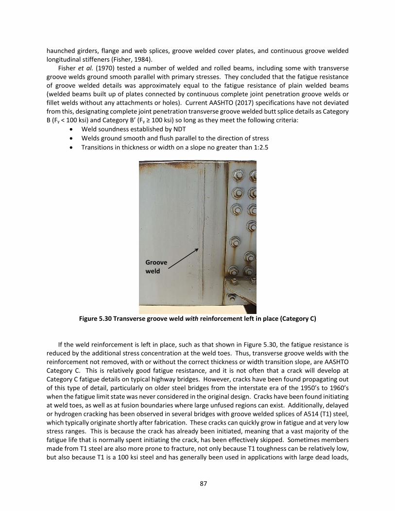
87
haunched girders, flange and web splices, groove welded cover plates, and continuous groove welded longitudinal stiffeners (Fisher, 1984).
Fisher et al. (1970) tested a number of welded and rolled beams, including some with transverse groove welds ground smooth parallel with primary stresses. They concluded that the fatigue resistance of groove welded details was approximately equal to the fatigue resistance of plain welded beams (welded beams built up of plates connected by continuous complete joint penetration groove welds or fillet welds without any attachments or holes). Current AASHTO (2017) specifications have not deviated from this, designating complete joint penetration transverse groove welded butt splice details as Category B (Fy < 100 ksi) and Category B’ (Fy ≥ 100 ksi) so long as they meet the following criteria:
Weld soundness established by NDT Welds ground smooth and flush parallel to the direction of stress Transitions in thickness or width on a slope no greater than 1:2.5
Figure 5.30 Transverse groove weld with reinforcement left in place (Category C)
If the weld reinforcement is left in place, such as that shown in Figure 5.30, the fatigue resistance is reduced by the additional stress concentration at the weld toes. Thus, transverse groove welds with the reinforcement not removed, with or without the correct thickness or width transition slope, are AASHTO Category C. This is relatively good fatigue resistance, and it is not often that a crack will develop at Category C fatigue details on typical highway bridges. However, cracks have been found propagating out of this type of detail, particularly on older steel bridges from the interstate era of the 1950’s to 1960’s when the fatigue limit state was never considered in the original design. Cracks have been found initiating at weld toes, as well as at fusion boundaries where large unfused regions can exist. Additionally, delayed or hydrogen cracking has been observed in several bridges with groove welded splices of A514 (T1) steel, which typically originate shortly after fabrication. These cracks can quickly grow in fatigue and at very low stress ranges. This is because the crack has already been initiated, meaning that a vast majority of the fatigue life that is normally spent initiating the crack, has been effectively skipped. Sometimes members made from T1 steel are also more prone to fracture, not only because T1 toughness can be relatively low, but also because T1 is a 100 ksi steel and has generally been used in applications with large dead loads,
Groove weld
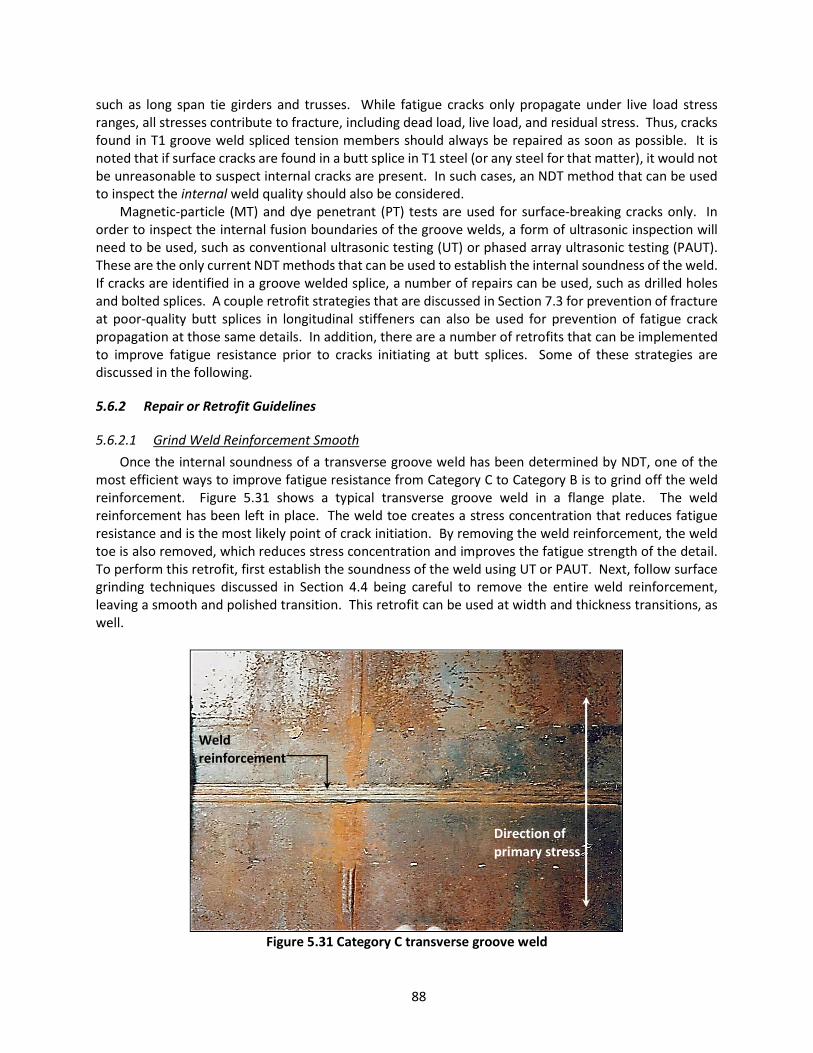
88
such as long span tie girders and trusses. While fatigue cracks only propagate under live load stress ranges, all stresses contribute to fracture, including dead load, live load, and residual stress. Thus, cracks found in T1 groove weld spliced tension members should always be repaired as soon as possible. It is noted that if surface cracks are found in a butt splice in T1 steel (or any steel for that matter), it would not be unreasonable to suspect internal cracks are present. In such cases, an NDT method that can be used to inspect the internal weld quality should also be considered.
Magnetic-particle (MT) and dye penetrant (PT) tests are used for surface-breaking cracks only. In order to inspect the internal fusion boundaries of the groove welds, a form of ultrasonic inspection will need to be used, such as conventional ultrasonic testing (UT) or phased array ultrasonic testing (PAUT). These are the only current NDT methods that can be used to establish the internal soundness of the weld. If cracks are identified in a groove welded splice, a number of repairs can be used, such as drilled holes and bolted splices. A couple retrofit strategies that are discussed in Section 7.3 for prevention of fracture at poor-quality butt splices in longitudinal stiffeners can also be used for prevention of fatigue crack propagation at those same details. In addition, there are a number of retrofits that can be implemented to improve fatigue resistance prior to cracks initiating at butt splices. Some of these strategies are discussed in the following.
5.6.2 Repair or Retrofit Guidelines
5.6.2.1 Grind Weld Reinforcement Smooth Once the internal soundness of a transverse groove weld has been determined by NDT, one of the
most efficient ways to improve fatigue resistance from Category C to Category B is to grind off the weld reinforcement. Figure 5.31 shows a typical transverse groove weld in a flange plate. The weld reinforcement has been left in place. The weld toe creates a stress concentration that reduces fatigue resistance and is the most likely point of crack initiation. By removing the weld reinforcement, the weld toe is also removed, which reduces stress concentration and improves the fatigue strength of the detail. To perform this retrofit, first establish the soundness of the weld using UT or PAUT. Next, follow surface grinding techniques discussed in Section 4.4 being careful to remove the entire weld reinforcement, leaving a smooth and polished transition. This retrofit can be used at width and thickness transitions, as well.
Figure 5.31 Category C transverse groove weld
Direction of primary stress
Weld reinforcement
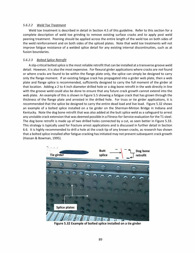
89
5.6.2.2 Weld Toe Treatment Weld toe treatment is described in detail in Section 4.5 of this guideline. Refer to this section for a
complete description of weld toe grinding to remove existing surface cracks and to apply post weld peening treatment. Peening should be applied across the entire length of the weld toe on both sides of the weld reinforcement and on both sides of the spliced plates. Note that weld toe treatments will not improve fatigue resistance of a welded splice detail for any existing internal discontinuities, such as at fusion boundaries.
5.6.2.3 Bolted Splice Retrofit A slip-critical bolted splice is the most reliable retrofit that can be installed at a transverse groove weld
detail. However, it is also the most expensive. For flexural girder applications where cracks are not found or where cracks are found to be within the flange plate only, the splice can simply be designed to carry only the flange moment. If an existing fatigue crack has propagated into a girder web plate, then a web plate and flange splice is recommended, sufficiently designed to carry the full moment of the girder at that location. Adding a 2 to 4 inch diameter drilled hole or a dog bone retrofit in the web directly in line with the groove weld could also be done to ensure that any future crack growth cannot extend into the web plate. An example of this is shown in Figure 5.5 showing a fatigue crack that has grown through the thickness of the flange plate and arrested in the drilled hole. For truss or tie girder applications, it is recommended that the splice be designed to carry the entire dead load and live load. Figure 5.32 shows an example of a bolted splice installed on a tie girder on the Sherman-Minton Bridge in Indiana and Kentucky. Note the dog bone retrofit that was also added at the butt splice weld as a safeguard to arrest any unstable crack extension that was deemed possible in a Fitness-for-Service evaluation for the T1 steel. The dog bone retrofit is made up of two drilled holes connected by a cut, as seen better in Figure 5.33. This strategy is typically used for fracture arrest applications and is discussed in further detail in Section 6.6. It is highly recommended to drill a hole at the crack tip of any known cracks, as research has shown that a bolted splice installed after fatigue cracking has initiated may not prevent subsequent crack growth (Hassan & Bowman, 1995).
Figure 5.32 Example of bolted splice installed on a tie girder
Splice plates
Tie girder Dog bone retrofit
Butt splice

90
Figure 5.33 Top view showing dog bone retrofit on a tie girder butt weld
The following steps outline the proper procedure for installation of a typical bolted splice retrofit of a
transverse butt weld. Before installation can begin, a qualified engineer must design the splice.
1. Prepare the weld for inspection by cleaning and removing all coatings. 2. Establish the soundness of the groove weld using UT or PAUT methods. 3. Visually inspect the weld toes with enhanced NDT methods such as MT or PT looking for
surface cracks. 4. Use grinding techniques discussed in Section 4.4 and 4.5.1 to remove shallow cracks, if found.
Refer to Section 4.3 for hole drilling techniques to arrest cracks, as necessary. 5. Drill a 2 to 4-inch diameter hole through the web plate directly above the cover plate weld
toe, as shown in Figure 5.5. Refer to Section 4.3 for hole edge finishing techniques. Option: Install a dog bone detail in the web plate directly in line with the groove weld. This retrofit is discussed in Section 6.6 in greater detail. It involves drilling two 2 to 4-inch diameter holes connected by a cut. The cut between drilled holes can be made using a cutting wheel and angle grinder or with a controlled thermal cutting process such as plasma.
6. Use a splice plate as a template for the holes in the plates to be spliced. Clamp the splice plate and filler plate in place and use a transfer punch to mark the locations of the drilled holes. Filler plates will only be required if the weld reinforcement is left in place.
7. Remove the splice plate and clamps. Using a mag-based drill with annular cutter and pilot pin, drill the bolt holes in the flange 1/16 inch larger than the diameter of the specified bolt, using the transfer punch indentations as guides. Caution: tie off the mag-based drill to the girder using sturdy clamps and chain/rope in the event of power loss. This will help prevent injury or damage to equipment.
8. Clean and degrease all surfaces within the area of the splice. Include three to six inches outside the footprint of the bolted splice. Ensure dirt, corrosion, cutting oil, hole drilling shards and other debris are removed from the area.
9. Apply an appropriate primer to the cleaned area. 10. Once the primer has dried, install the splice plates and hand tighten the bolts.
Tie girder
Butt splice
Dog bone retrofit

91
11. Starting from the center of the splice and moving methodically outward, snug tighten and then fully tension the bolts according to current RCSC specifications for slip-critical connections.
12. Paint the entire repair area using recommendations provided in Section 4.2. 13. Follow up with typical visual inspections scheduled with the regular inspection cycle for the
bridge.
5.7 Flame-cut Holes, Weld Access Holes, & Other Open Holes
5.7.1 Description of Problem Research has shown that open holes in plates and connections have a reduced fatigue resistance from
base metal (Fisher et al., 1987, Brown et al., 2007). The reduction is due in part to the stress concentration at the edge of the hole, which is inversely proportional to the radius. However, Brown et al. (2007) also concluded that the fatigue resistance of a hole is dependent upon the edge conditions, showing that holes drilled with new bits or subpunched and reamed holes performed better than holes drilled with worn bits or holes punched full size. Weld access holes in rolled cross sections are classified as Category C by AASHTO (2017) when the detail is made to the requirements of AASHTO/AWS D1.5, Article 3.2.4. If that same weld access hole is made in a built-up welded plate girder, it is classified as Category D at the end of the termination of the longitudinal welds in the access hole. In both cases, AWS D1.5 requires a radius of no less than 1-inch and surface roughness of 1,000 µ-in. or less. Thus, any weld access hole short of these requirements is an unclassified fatigue detail with unspecified fatigue resistance. The two primary characteristics of the classification are the radius of the hole and the surface roughness, which is consistent with findings from Fisher et al. (1987) and Brown et al. (2007). This means increasing the size of an open hole or weld access hole and/or improving the hole edge conditions are two ways to improve the fatigue resistance. Figure 5.34 shows a retrofit hole that was made using a torch with very poor quality. Sometimes holes are added to steel bridges using thermal cut processes. It is important to note that metallurgical changes along the burn line result in a hard layer of martensite with micro-cracks and residual tensile stresses approaching the material yield strength, which can promote fatigue crack nucleation (Yam & Cheng, 1990).

92
Figure 5.34 Poor quality flame-cut hole that is prone to fatigue and fracture
5.7.2 Repair or Retrofit Guidelines Using thermal cutting makes sense for some retrofit applications, but it is important that the hole not
be left in conditions anything like seen in Figure 5.34. Further, plasma cutting is strongly encouraged over traditional oxy-acetylene thermal cutting whenever possible. Drilling the hole is also highly recommended whenever possible and will produce a much higher quality edge finish with minimal sanding at the edges. If a thermal cut is used to make a weld access hole or a retrofit hole, it is recommended that a carbide rotary burr bit and die grinder be used to remove the hardened and brittle martensite layer at the burned edge, grinding down to bright metal and removing gouges. Additional grinding and sanding is recommended following the burr bit, as listed below. This will not only remove discontinuities at the edge of the hole related to roughness of the cut, but also any micro-flaws that may have formed in the brittle layer during cooling. Figure 5.35 shows a before and after repair of a cracked weld access hole. Notice the increased and improved radius, smooth and polished edges, and gradual transitions into the flange plate. This particular repair also included peening treatment around the edge of the hole and at the termination of the flange-to-web welds to further improve fatigue resistance. Grinding the transverse groove weld smooth would have likely resulted in an overall Category B fatigue detail. Leaving the weld reinforcement in place made this a Category C detail. See Section 5.6 for retrofit techniques for transverse groove welds.
The following steps outline the proper procedure for repairing existing weld access holes, flame-cut holes, or other open holes.
1. Prepare the edge of the hole for inspection by cleaning and removing all coatings. 2. Visually inspect the edge of the hole on both sides of the plate with enhanced NDT methods
such as MT or PT looking for surface cracks. 3. If a crack is found, consider increasing the size of the hole to remove the entire crack. If this
would require a hole size that is not feasible, use grinding techniques discussed in Section 4.4 and 4.5.1 to extend portions of the hole to remove the crack. Drilling a hole at the crack tip may also be necessary if the crack has extended several inches away from the open or weld access hole. Refer to Section 4.2 for hole drilling techniques, as necessary.

93
4. If possible, increase the radius of the hole to between 1 and 2 inches (2 to 4-inch diameter hole). For weld access holes, this may require a thermal cutting process with free-hand cutting. Care should be taken to ensure a smooth and clean cut.
5. Follow up with grinding to improve the hole edge conditions: a. Drilled hole: Sand the edges of the drilled hole using an 80 to 100 grit flap wheel with
angle grinder on the exterior edges and 80 to 100 grit flap wheel with die grinder on the interior edges. An example of a polished drilled hole is shown in Figure 4.9.
b. Flame-cut hole: Grind the burned edge using a carbide rotary burr bit down to bright metal, removing all gouges and maintaining a gradual and rounded profile. Next, sand the edges of the hole using an 80 to 100 grit flap wheel with angle grinder on the exterior edges and 80 to 100 grit flap wheel with die grinder on the interior edges.
6. Paint the repair area using recommendations provided in Section 4.2. 7. Follow-up should include careful visual inspection during regularly scheduled bridge
inspections. MT or PT may also be used to check for initiation of fatigue cracks.
Figure 5.35 Repair of cracked weld access hole showing before (Left) and after (Right) (Photographs courtesy of Kansas DOT)
5.8 Tack Welds and Extraneous Welds
5.8.1 Description of Problem Tack welds are welds made to hold parts of a weldment in proper alignment until the final welds are
made (AWS, 2015). Tack welds have also been used for many decades to align geometry for bolted and riveted members together for drilling, punching, and fastening. Often the tack welds were left in place following fabrication and construction leaving details like what are shown in Figure 5.36.
Web plate
Weld access hole Crack
Web plate
Retrofit weld access hole
Groove weld

94
Figure 5.36 Examples of tack welds used in fabrication
Tack welds are not currently classified for fatigue in Chapter 6 of the AASHTO LRFD Bridge Design
Specifications. They are mentioned in Chapter 9 when used for holding horizontal concrete forms in place on grid decks where it is specified that the tack weld is a Category E’. The AASHTO Standard Specification designated tack welds oriented parallel with primary stress as a Category E. When evaluating an existing structure for fatigue, a Category E or E’ fatigue detail can have a significant impact on service life and can even result in negative life. Consider, for example, a riveted built-up steel bridge with tack welds left in place. The riveted details qualify as Category C according to the AASHTO Manual for Bridge Evaluation for purposes of evaluation. However, using guidance from the Standard Specifications would suggest that the fatigue service life of the bridge be governed by the Category E tack weld detail resulting in a significant reduction in life. It is not common to find tack welds cracked, and when they do, they generally crack in a relatively benign throat failure or simply become unfused to the base metal. However, in rare cases, they can also crack into the base metal in which case the problem can become more serious. In these cases, the crack typically grows out of the end of the weld, as can be seen in Figure 5.37.
Bowman et al. (2012) investigated the fatigue resistance of tack welds looking at stress range, number of tack welds, tack weld length, tack weld orientation (transverse to primary stress vs. parallel), and fastener clamping force (fully tensioned bolt in the detail the tack welds were used to align vs. a simulated rivet connection). The research concluded that tack weld fatigue resistance was congruent with AASHTO Category C design life. They also found that fully tensioned bolted connections with tack welds did not tend to crack, likely due the load transfer of the connection through friction that drew stress away from the tack weld detail. Conclusions from this research would suggest that the fatigue resistance attributed to tack welds by current specifications is overly conservative and that Category C may be a more accurate classification. As such, unless fatigue cracks in tack welds have been identified on a bridge, retrofit may not be necessary. However, should cracking be identified or should an owner want to retrofit tack and other extraneous welded details of unknown quality, the following provides a recommended retrofit procedure.
Tack weld
Tack weld

95
Figure 5.37 Common crack location at tack weld (Bowman et al., 2012)
5.8.2 Repair or Retrofit Guidelines When retrofit is elected for tack or other extraneous weld details or when repairs may be required
for instances of cracked tack welds, the following retrofit or repair procedure is recommended. 1. Prepare the weld for inspection by cleaning and removing all coatings. 2. Visually inspect the weld terminations with enhanced NDT methods such as MT or PT looking
for surface cracks. 3. If a crack is found, use surface grinding techniques discussed in Section 4.4 and 4.5.1 to
remove the weld entirely. 4. Once the weld has been removed, visually inspect the area once again using NDT methods as
necessary to ensure any cracks that extend into the base metal are removed or arrested. 5. If the crack extends into the base metal, attempt to remove it using the surface grinding
techniques. Alternatively, drill a hole at the crack tip to blunt crack growth and arrest the crack. Refer to Section 4.2 for hole drilling techniques, as necessary.
6. Paint the repair area using recommendations provided in Section 4.2. 7. Follow-up should include careful visual inspection during regularly scheduled bridge
inspections. MT or PT may also be used to check for initiation of fatigue cracks.
5.9 Plug Welds
5.9.1 Description of Problem Plug welds have been used in the past to correct fabrication errors, such as bolt holes drilled in the
wrong location. Rather than scrapping the entire girder or floorbeam, the fabricator would simply fill the holes with weldment, grind them smooth, and drill new holes. Due to a lack of proper weld process and limited access inside the holes, particularly for thick plates, the quality of these welds was typically not very good. A number of fatigue cracks and fractures have resulted from plug welds used in this way.
Plug weld failures have been observed in several bridges, including the I-57 Farina Overpass. An interior girder of this bridge fractured during the winter of 1976-1977 resulting from fatigue cracks
Crack

96
initiated at plug weld sites in the tension side of the web to correct for miss-drilled bolt holes during fabrication (Steel Fatigue Knowledge Base, 2008). Figure 5.38 shows the fracture and plug welds. Figure 5.39 shows a magnetic particle test result for a plug weld detail on a tied arch bridge in Sault Ste. Marie, Michigan. The results highlight the lack of fusion around the original hole that is not uncommon for these often poorly-executed welds. In addition to the risk of fracture, a plug weld is not currently classified in any existing AASHTO fatigue category, and therefore has unknown fatigue resistance.
Figure 5.38 I-57 Farina Overpass fracture at plug weld (Steel Fatigue Knowledge Base, 2008)
Fracture
Plug welds
Girder

97
Figure 5.39 Magnetic particle test results at a plug weld showing lack of fusion defects (Photograph
courtesy of Phil Fish)
5.9.2 Repair or Retrofit Guidelines AWS (2015), Article 3.7.7 specifies for new fabrication that unless there is a structural reason for repair
welding mislocated holes, the holes may be left open or may be filled with a bolt. This approach is also recommended for repair or retrofit of existing structures. Drilling a hole to completely remove the plug weld will create a detail that has Category C fatigue resistance (Fisher et al., 1987, Brown et al., 2007). Adding an F3125 high-strength bolt with hardened F436 washers on both sides of the drilled plate will improve it to a Category B fatigue resistance. Adding fully tensioned bolts is highly recommended.
The following steps outline the recommended procedure for repairing existing plug welds used to fill mislocated holes.
1. Prepare the weld for inspection by cleaning and removing all coatings. 2. Visually inspect the weld perimeter and adjacent areas with enhanced NDT methods such as
MT or PT looking for surface cracks. 3. If a crack is found, locate the crack tip and estimate whether or not it can be completely
removed during the hole drilling operation in step 4. If the crack has extended beyond the diameter of the intended repair hole, use techniques provided in Section 4.2 to drill a hole at the crack tip as well to arrest further crack extension.
4. Using a mag-based drill with annular cutter, drill out the plug weld using a cutter who’s inside diameter is larger than the existing plug weld. Caution: tie off the mag-based drill to the girder using sturdy clamps and chain/rope in the event of power loss. This will help prevent injury or damage to equipment.
5. Following removal of the core, re-inspect around the edge of the drilled hole using MT or PT to ensure no cracks were missed. If a crack is identified, use a die grinder with carbide rotary burr bit to remove the crack tip while maintaining a smooth hole profile.
6. Recommended: For improved fatigue resistance, install F3125 Grade 325 or 490 high strength bolts using turn-of-nut or other approved method according to current RCSC specifications. Install the bolts with F436 hardened washers on both sides of the drilled plate.
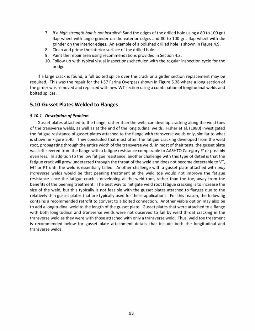
98
7. If a high strength bolt is not installed: Sand the edges of the drilled hole using a 80 to 100 grit flap wheel with angle grinder on the exterior edges and 80 to 100 grit flap wheel with die grinder on the interior edges. An example of a polished drilled hole is shown in Figure 4.9.
8. Clean and prime the interior surface of the drilled hole. 9. Paint the repair area using recommendations provided in Section 4.2. 10. Follow up with typical visual inspections scheduled with the regular inspection cycle for the
bridge.
If a large crack is found, a full bolted splice over the crack or a girder section replacement may be required. This was the repair for the I-57 Farina Overpass shown in Figure 5.38 where a long section of the girder was removed and replaced with new WT section using a combination of longitudinal welds and bolted splices.
5.10 Gusset Plates Welded to Flanges
5.10.1 Description of Problem Gusset plates attached to the flange, rather than the web, can develop cracking along the weld toes
of the transverse welds, as well as at the end of the longitudinal welds. Fisher et al. (1980) investigated the fatigue resistance of gusset plates attached to the flange with transverse welds only, similar to what is shown in Figure 5.40. They concluded that most often the fatigue cracking developed from the weld root, propagating through the entire width of the transverse weld. In most of their tests, the gusset plate was left severed from the flange with a fatigue resistance comparable to AASHTO Category E’ or possibly even less. In addition to the low fatigue resistance, another challenge with this type of detail is that the fatigue crack will grow undetected through the throat of the weld and does not become detectable to VT, MT or PT until the weld is essentially failed. Another challenge with a gusset plate attached with only transverse welds would be that peening treatment at the weld toe would not improve the fatigue resistance since the fatigue crack is developing at the weld root, rather than the toe, away from the benefits of the peening treatment. The best way to mitigate weld root fatigue cracking is to increase the size of the weld, but this typically is not feasible with the gusset plates attached to flanges due to the relatively thin gusset plates that are typically used for these applications. For this reason, the following contains a recommended retrofit to convert to a bolted connection. Another viable option may also be to add a longitudinal weld to the length of the gusset plate. Gusset plates that were attached to a flange with both longitudinal and transverse welds were not observed to fail by weld throat cracking in the transverse weld as they were with those attached with only a transverse weld. Thus, weld toe treatment is recommended below for gusset plate attachment details that include both the longitudinal and transverse welds.

99
Figure 5.40 Example of gusset plate welded to the flange with only transverse welds
5.10.2 Repair or Retrofit Guidelines
5.10.2.1 Weld Toe Treatment When the gusset plate is welded to the flange with both longitudinal and transverse welds, weld toe
treatment has been found to be a very effective retrofit. Weld toe treatment is described in detail in Section 4 of this guideline. Refer to this section for a complete description of weld toe grinding to remove existing surface cracks and to apply post weld peening treatment. Peening should be applied across the entire length of the transverse weld toes, wrap around the corner and continue down the longitudinal weld 2 to 3 inches, as highlighted on Figure 5.41 with yellow lines. For cases where the gusset is attached to the flange by transverse welds only, weld toe treatment is not recommended unless longitudinal weld can be added. This is because treating the toe, in this particular case, may push the fatigue initiation to the weld root where it will not be detectible.
Also, before selecting this retrofit, consideration should be given to the specific detail in question to ensure that the peening tools can access the backside of the gusset plate along the longitudinal weld. In some cases the distance between the web plate and the longitudinal weld toe may not allow sufficient access to properly peen at all recommended angles while maintaining the tool perpendicular to the weld toe longitudinal axis. In such cases, as well as when transverse welds are the only welds attaching the gusset plate to the flange, a conversion to bolted connection outlined in the following section is recommended.
Web
Flange
Gusset

100
Figure 5.41 Weld toe peening for gusset plates attached to flanges
5.10.2.2 Conversion to Bolted Connection Gusset plates attached to flanges are sometimes welded and sometimes riveted or bolted. A riveted
connection provides at least Category D fatigue resistance, which is many cases will be sufficient for infinite fatigue life for typical highway bridges. Careful inspection of the areas surrounding the rivet heads (at the top surface of the gusset plate and on the bottom surface of the flange plate) should be performed to ensure no cracking can be detected. Any fatigue damage that is detected should be repaired by removing the rivet, grinding or reaming out the hole to remove the crack tip and then replacing the rivet with a F3125 high strength bolt tensioned according to current RCSC specifications.
For the case where the gusset plate is welded to the flange with transverse welds only, the following procedure is recommended. Prior to installing the bolted connection, a qualified engineer must evaluate the detail to check the new net section of the flange plate and gusset plate with drilled bolt holes. Figure 5.42 shows the completed retrofit.
1. Clean the area to be retrofit removing all coating and debris. 2. Mark the bolt hole center locations on the to surface of the gusset plate. Punch the centers
of the holes using a center punch and hammer. 3. Using a mag-based drill with annular cutter and pilot pin, drill the bolt holes in the flange 1/16
inch larger than the diameter of the specified bolt, using the center punch indentations as guides. Caution: tie off the mag-based drill to the girder using sturdy clamps and chain/rope in the event of power loss. This will help prevent injury or damage to equipment.
4. Clean and degrease all surfaces within the area of the drilled holes. Ensure dirt, corrosion, cutting oil, hole drilling shards and other debris are removed from the area.
5. Prime or paint the bare steel surfaces of the drilled holes. 6. Insert the bolt assemblies and hand tighten. Then, starting from one end of the connection
and moving across the length of the gusset plate, snug tighten and then fully tension the bolts according to current RCSC specifications for slip-critical connections.
Top flange
Bottom flange Gusset plate
Peened areas
Fillet weld
101
7. After the bolts are fully tensioned, clean the weld toes of the transverse welds and prepare for NDT evaluation looking for any existing fatigue cracks. Note any cracks and continue to the next step.
8. Using techniques described in Section 4.4 for surface grinding, remove the entire transverse fillet weld from both ends of the gusset plate. Take care to not grind into the flange plate. A course 24 grit grinding wheel and angle grinder may work best in the beginning to remove the most material, grinding at a nearly horizontal position such that the grinding wheel does not dig into the flange. Continue gradually removing weld material, switching to 40 to 60 grit flap wheels and eventually to 80 to 100 grit wheels as the grinding approaches the flange. The end result should expose the gusset plate edge and top of the flange plate, leaving no remaining fillet weld material.
9. With the fillet welds removed, inspect the areas where the fillet welds were located. Use PT or MT to enhance visual inspection if an indication of cracking is identified. If a crack is located, follow techniques outlined in Section 4.3 (drilled holes for crack arrest), 4.4 (surface grinding), and 5.3 (repair of notches and gouges) to remove or arrest cracks that have propagated into the flange plate.
10. Once the welds are removed and any existing cracks are removed or arrested, paint the repair area using recommendations provided in Section 4.2.
Figure 5.42 Completed retrofit showing removal of welds and bolted connection
A bolted connection is a very reliable and fatigue resistant detail and typically would not warrant special follow-up inspections. However, due to the removed fillet weld and possibility for cracks in the flange, follow up with typical visual inspections scheduled with the regular inspection cycle for the bridge. Inspect the areas where the fillet welds were removed looking for indications that cracking has initiated or grown into the flange plate.
Gusset plate
Web
Removed fillet welds

102
5.11 Discontinuous Backing Bars
5.11.1 Description of Problem Backing, or backing bars, are auxiliary material used to retain molten weld metal for complete joint
penetration (CJP) groove welds performed from one side. The use of backing bars allows for welding of joints with variable root openings. Often times, the backing bar is held in place using temporary external welds, such as tack welds. AWD D1.5, Article C-3.3.7.6 states that the temporary welds attaching backing bars are to be made continuous full length or be removed. This is because they can serve as locations for fatigue and fracture initiation. Additionally, during the welding process the backing usually becomes fused to the welded joint. When this happens, the backing bar becomes part of the structure and will carry loads just as any welded attachment does. Typically the bars are used in box girders in which they are laid end-to-end in long strips because they are not long enough to extend the full length of the welded joint without using multiple bars. In some older structures, where the ends of the backing bars met, they were not welded together, creating terminations perpendicular to primary stresses between each individual bar. The terminations create an abrupt discontinuity in the backing that creates a crack-like condition. Thus, backing bars with this type of splice left in place may cause unanticipated and unacceptable stress risers. Careful inspection of these details in areas of greatest positive moment should be performed to determine if any of the backing bar ends have cracked into the web or flange plates.
Figure 5.43 Example of backing bar discontinuity found in Fort Duquesne approach spans
5.11.2 Repair or Retrofit Guidelines Two primary repair or retrofit strategies are recommended for left-in-place backing bars. The first is
removal of the entire backing bar. This may prove to be very difficult, if feasible at all, due to the fusing of the bar to the joint during welding and is not recommended or justified. The second strategy is to remove the terminations of the backing bars, replacing them with gradual transitions back to base metal. This approach is much more feasible, economical, and will provide sufficient resistance to fatigue and significantly reduce risk of fracture. Figure 5.44 shows an example of this method used in the tie girder
Flange
Backing bar
Web Discontinuity

103
of the Hoan Bridge in Milwaukee, WI. Notice that the backing terminations were removed down to the base metal of the web and flange plates leaving no residual weld material behind.
Figure 5.44 Example of backing bar termination removed inside the tie girder of the Hoan Bridge Along the length of the welded joint, the fatigue resistance is equal to AASHTO Category B’ with
a CAFL of 12 ksi. This is a very good fatigue detail and fatigue cracking would not be expected. However, at the termination of the backing bar where there is an abrupt disruption to stress flow and significant stress concentration, the fatigue resistance drops considerably to around E or E’ (Fish et al., 2015). Figure 5.44 shows a retrofit gradual transition back to base metal that removes the stress concentration and improves the fatigue resistance to approximately Category C, depending on the radius of transition. Two slightly different approaches can be used to remove the termination and create a gradual transition. One is by using a mag-based drill and 4-inch diameter annular cutter; this is the method used for the retrofit shown in Figure 5.44. The other approach is to grind down the backing bar using carbide rotary burr bits and die grinders. Both methods pose risk of gouging the flange and web plates during installation, so care should be had to ensure this is mitigated as much as possible. Gouges in the base metal should never be left in place as they create stress risers which can accelerate fatigue crack nucleation. Both methods are included in the recommended procedure below.
The following steps outline the recommended procedure for repairing or retrofitting backing bar terminations.
1. Prepare the area for inspection by cleaning and removing all coatings. 2. Visually inspect the termination, looking for signs of cracking parallel with the termination,
which would be perpendicular to primary stress (transverse to the web and flange plates). Use MT or PT methods to enhance visual inspection if any indications of cracking are identified.
3. Begin removing backing bar material using one of the following methods: a. Mag-based drill: Using a mag-based drill and 4-inch diameter annular cutter with
carbide tip, drill out the backing bar termination. Align the cutter edge such that it drills flush with the web plate traveling vertically down through the backing bar
Web plate
Flange plate
Backing bar
Retrofit termination
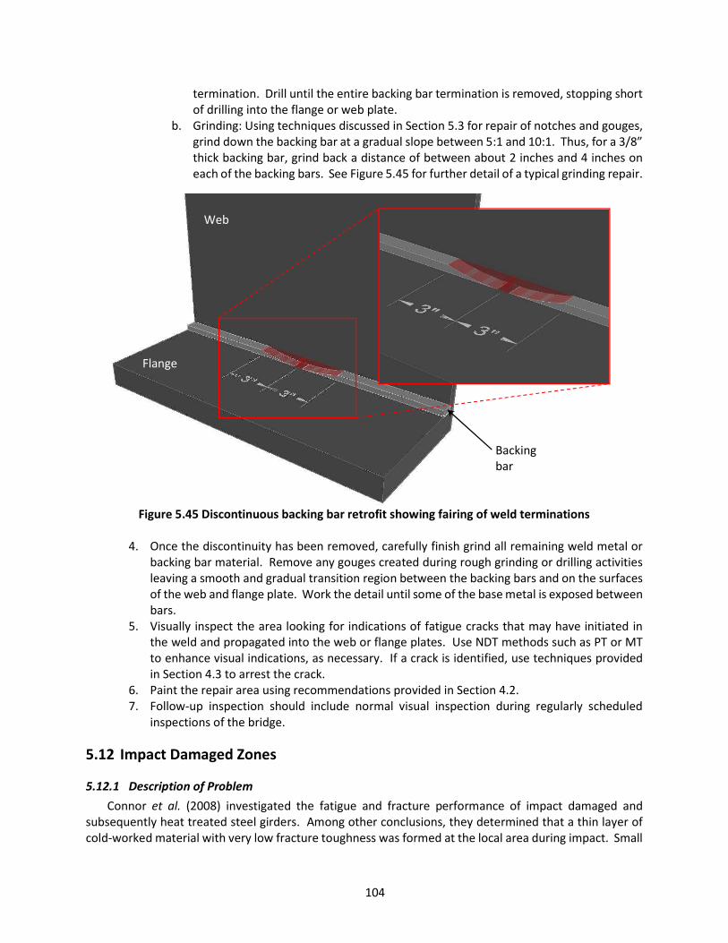
104
termination. Drill until the entire backing bar termination is removed, stopping short of drilling into the flange or web plate.
b. Grinding: Using techniques discussed in Section 5.3 for repair of notches and gouges, grind down the backing bar at a gradual slope between 5:1 and 10:1. Thus, for a 3/8” thick backing bar, grind back a distance of between about 2 inches and 4 inches on each of the backing bars. See Figure 5.45 for further detail of a typical grinding repair.
Figure 5.45 Discontinuous backing bar retrofit showing fairing of weld terminations
4. Once the discontinuity has been removed, carefully finish grind all remaining weld metal or
backing bar material. Remove any gouges created during rough grinding or drilling activities leaving a smooth and gradual transition region between the backing bars and on the surfaces of the web and flange plate. Work the detail until some of the base metal is exposed between bars.
5. Visually inspect the area looking for indications of fatigue cracks that may have initiated in the weld and propagated into the web or flange plates. Use NDT methods such as PT or MT to enhance visual indications, as necessary. If a crack is identified, use techniques provided in Section 4.3 to arrest the crack.
6. Paint the repair area using recommendations provided in Section 4.2. 7. Follow-up inspection should include normal visual inspection during regularly scheduled
inspections of the bridge.
5.12 Impact Damaged Zones
5.12.1 Description of Problem Connor et al. (2008) investigated the fatigue and fracture performance of impact damaged and
subsequently heat treated steel girders. Among other conclusions, they determined that a thin layer of cold-worked material with very low fracture toughness was formed at the local area during impact. Small
Flange
Web
Backing bar

105
cracks, as seen in Figure 5.46(a), resulting from severe strain, as well as rolling and bunching of the material, was observed at the exact point of impact on tested steel girder flanges. These defects, if left untreated, resulted in brittle fracture during subsequent impacts at different locations on the girders, as seen in Figure 5.46(b).
(a)
(b)
Figure 5.46 (a) Example of micro-crack resulting from impact (b) Example of brittle fracture resulting from impact at another location (Taken from Connor et al., 2008).
This same phenomenon has also been observed outside of the laboratory. One example is the Virginia
Ave Bridge over the I65-/I-70 northbound lanes near downtown Indianapolis. In 2013, the fascia girder was impacted by the boom of an aerial lift being hauled on a flatbed trailer. The non-composite girder instantly fractured at two locations, one on either side of the point of impact, just beyond the adjacent cross frames. The fractures are shown in Figure 5.47. The fractures both initiated at locations of previous impacts in the hardened, cold worked zones where small cracks existed. Fortunately, the fractures both arrested in the web plate just inches from the top flange keeping the nearly 40-foot girder section from falling into traffic. For bridges like the Virginia Ave. Bridge that span over interstate traffic and are frequently impacted, proper inspection and maintenance following an impact event can be very difficult. Often the impacts are not reported and are challenging to distinguish from past impacts documented during regular inspections. As a result, the damaged areas can easily go unrepaired. However, the repair is relatively quick and simple, requiring only common hand tools and a few minutes.
Follow-up inspections of the area impacted and repaired should be performed during the regularly scheduled bridge inspection. Careful visual inspection of cross frames and welded details near an impact location should be performed. VI may also need to be supplemented with PT or MT to ensure no small cracks go undetected in the localized impact zone.
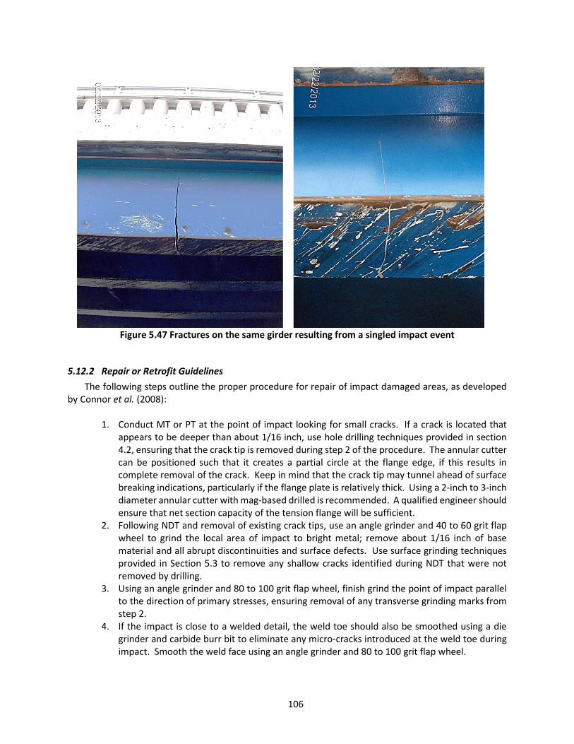
106
Figure 5.47 Fractures on the same girder resulting from a singled impact event
5.12.2 Repair or Retrofit Guidelines The following steps outline the proper procedure for repair of impact damaged areas, as developed
by Connor et al. (2008):
1. Conduct MT or PT at the point of impact looking for small cracks. If a crack is located that appears to be deeper than about 1/16 inch, use hole drilling techniques provided in section 4.2, ensuring that the crack tip is removed during step 2 of the procedure. The annular cutter can be positioned such that it creates a partial circle at the flange edge, if this results in complete removal of the crack. Keep in mind that the crack tip may tunnel ahead of surface breaking indications, particularly if the flange plate is relatively thick. Using a 2-inch to 3-inch diameter annular cutter with mag-based drilled is recommended. A qualified engineer should ensure that net section capacity of the tension flange will be sufficient.
2. Following NDT and removal of existing crack tips, use an angle grinder and 40 to 60 grit flap wheel to grind the local area of impact to bright metal; remove about 1/16 inch of base material and all abrupt discontinuities and surface defects. Use surface grinding techniques provided in Section 5.3 to remove any shallow cracks identified during NDT that were not removed by drilling.
3. Using an angle grinder and 80 to 100 grit flap wheel, finish grind the point of impact parallel to the direction of primary stresses, ensuring removal of any transverse grinding marks from step 2.
4. If the impact is close to a welded detail, the weld toe should also be smoothed using a die grinder and carbide burr bit to eliminate any micro-cracks introduced at the weld toe during impact. Smooth the weld face using an angle grinder and 80 to 100 grit flap wheel.

107
5. Thoroughly inspect the area of impact following grinding and drilling, including any weld toes in the vicinity. Use MT or PT, as necessary.
6. Paint the repair area using recommendations provided in Section 4.2. 7. Follow-up should include careful visual inspection during regularly scheduled bridge
inspections. MT or PT may also be used to check for initiation of fatigue cracks.

108
CHAPTER 6. MAINTENANCE ACTIONS FOR DISTORTION-INDUCED FATIGUE Distortion-induced fatigue, also sometimes called “out-of-plane fatigue” or “web gap cracking”, is the
most prevalent type of fatigue cracking in steel bridges. Connor and Fisher (2006) have estimated that as much as 90% of fatigue cracks in steel bridges are caused by secondary stresses. Since this type of cracking usually forms in planes parallel with primary stresses, they do not affect performance of the structure as long as they are discovered and repaired before turning perpendicular to the primary stresses and entering a flange. Distortion-induced fatigue is generated by secondary stresses, which are typically caused by out-of-plane forces unaccounted for in conventional design. These secondary stresses can only be calculated by refined analysis or measured with strain gages. The localized, out-of-plane deformations that produce this type of cracking are very small, generally on the order of a few thousandths of an inch. Figure 6.1 shows an example of distortion-induced fatigue cracking on the end floorbeam of a simple-span through-truss bridge in Indiana. Notice that the crack grew out of the small web gap just above the connection angle tying the floorbeam into the truss lower chord. The cause of this specific type of web gap crack is discussed in detail in Section 6.2.
Figure 6.1 Example of floorbeam web gap cracking
Distortion-induced fatigue cracking has developed in many types of bridges, such as trusses,
suspension bridges, girder floorbeam bridges, multi-beam bridges, tied arch bridges, and box girder bridges. Common locations include web gaps at cross frames, diaphragms, and floorbeams, bearing stiffeners, floorbeam copes and connections, riveted or bolted connections using angles, and cantilever brackets. Two general approaches to repairing and retrofitting these details includes softening (increasing connection flexibility) and stiffening (increasing connection rigidity). If stiffening the connection is considered, an engineer must check the complete load path to make sure that a problem is not simply moved to a new location or that a new problem is provoked by implementing the stiffening retrofit. Unlike softening, which dissipates load and reduces stresses, stiffening may cause additional load transfer
Gus
set P
late
Floor Beam
Stringer

109
through a connection that must be analyzed in the structure. Distortion-induced fatigue results from displacement. Softening a detail allows for the displacement to occur over a longer distance, thereby reducing its effect. Stiffening, on the other hand, aims to eliminate the displacement. Hence, stiffening retrofits should be designed based on very high stiffness requirements, rather than load or strength requirements.
Retrofit and repair strategies for these details are presented in the following sections. However, because the circumstances behind each individual bridge involving distortion-induced secondary effects can be unique, sometimes these retrofits will require field testing combined with instrumentation to ensure that the implemented repair or retrofit will perform as intended. The complex calculation of stresses combined with the unique interactions of the coupled elements of a particular bridge make prescribing one way of performing many of these retrofits nearly impossible. Specific guidelines are provided when appropriate, and when not possible, general guidelines are recommended.
6.1 Connection Plate Web Gaps on Girder, Girder-Floorbeam, and Box Girder Bridges
6.1.1 Description of Problem The AASHTO LRFD Bridge Design Specifications do not typically classify details susceptible to
distortion-induced fatigue. However, the Detail Category Table 6.6.1.2.3-1 contains a note in Case 5.3 (which is Category C) stating that cracking in the flange of a ‘T’ section may occur due to out-of-plane bending stresses induced by the stem. This loading case is consistent with web gap cracking in a web plate. Connor & Fisher (2006) reported that several tests have been conducted wherein the data supported classification of the transverse connection plate weld termination as AASHTO Category C with references to Fisher et al. (1980, 1990) and Mueller & Yen (1968). AASHTO has addressed this fatigue problem using prescriptive detailing rules that have been around since the mid-1980s to prevent the driving mechanism of web gap cracking– relative movement between connected elements.
Standard practice for many years previous to about the mid-1980s was to leave transverse stiffeners short of the tension flange for fear of creating a fatigue problem with placing a transverse weld on the tension flange. This practice creates a “web gap” between the end of the connection plate weld and the flange plate. The web gap region can be vulnerable to large strains if adjacent, connected bridge components differentially deflect pulling or pushing the web plate out of plane. There is principally one driving mechanism for web gap cracking – the relative movement of connected elements within a localized web gap – which occurs in primary and secondary members alike. Fatigue cracking in the web plate of primary members, such as plate girders, at transverse connection plates, is the focus of this section of the guidelines. Fatigue cracking in the web plate of secondary members, such as floorbeams, is the focus of Section 6.2. In a number of bridges, cracks have also formed at gusset plate web gaps with an orientation perpendicular to primary stresses. This makes them more susceptible to propagation from traffic loading and in areas of high restraint, small cracks have grown and led to unstable brittle fracture (Fisher, 1977).
The driving mechanism for distortion-induced fatigue in the web plate of primary members is illustrated in Figure 6.2. Uneven loading of bridge girders can cause differential vertical deflections. Lateral loads are transferred through the connecting elements into the web plate, which is very flexible out of plane, resulting in web plate reverse bending immediately adjacent to the flange. The inset of Figure 6.2 shows a red portion of the web located in the web gap region between the connection plate and the top flange with a yellow dashed line accenting the web gap distortion. This is the problematic area where cracking can occur. The flange restrains the web plate at the concrete deck similar to the fixed

110
end of a cantilevered beam, generating bending stresses. However, this type of cracking can also occur at the bottom of the connection plate, even in positive moment regions, due to the out-of-plane flexibility of the web plate as compared to the relatively stiff flange plate. Bridges that experience relatively large differential displacements of adjoining members are more prone to this phenomenon, such as skewed bridges, curved bridges, or bridges with large girder spacing. An example of distortion-induced cracking in a girder web gap is shown in Figure 6.3. Note in this image that the cracking has occurred at the transverse weld termination as well as the web-to-flange weld. The dual cracks are common for distortion-induced fatigue due to the reverse curvature of the web plate imposing tensile stresses at the top and bottom of the web gap (which has been illustrated in Figure 6.2, as well).
Although this is most often caused by traffic loading while in service, Fisher (1984) reported that this type of fatigue cracking has also occurred as a result of cyclic out-of-plane bending stresses introduced during handling and shipping. In some cases these cracks have been found before the bridge was put into service. The stress ranges within the web gaps can be quite high, depending on the geometry and loading of the structure. This is why even though the connection plate weld terminations have been found to perform equivalent to the AASHTO Category C details, these locations have been known to crack frequently and relatively early in the service life of many bridges.
Figure 6.2 Exaggerated illustration depicting bending in a web gap caused by uneven loading of the plate girders
∆ Out-of-plane distortion
Web centerline
Web gap
Flange Deck
Tension
Tension
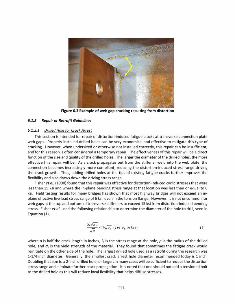
111
Figure 6.3 Example of web gap cracking resulting from distortion
6.1.2 Repair or Retrofit Guidelines
6.1.2.1 Drilled Hole for Crack Arrest This section is intended for repair of distortion-induced fatigue cracks at transverse connection plate
web gaps. Properly installed drilled holes can be very economical and effective to mitigate this type of cracking. However, when undersized or otherwise not installed correctly, this repair can be insufficient, and for this reason is often considered a temporary repair. The effectiveness of this repair will be a direct function of the size and quality of the drilled holes. The larger the diameter of the drilled holes, the more effective this repair will be. As a crack propagates out from the stiffener weld into the web plate, the connection becomes increasingly more compliant, reducing the distortion-induced stress range driving the crack growth. Thus, adding drilled holes at the tips of existing fatigue cracks further improves the flexibility and also draws down the driving stress range.
Fisher et al. (1990) found that this repair was effective for distortion-induced cyclic stresses that were less than 15 ksi and where the in-plane bending stress range at that location was less than or equal to 6 ksi. Field testing results for many bridges has shown that most highway bridges will not exceed an in-plane effective live load stress range of 6 ksi, even in the tension flange. However, it is not uncommon for web gaps at the top and bottom of transverse stiffeners to exceed 15 ksi from distortion-induced bending stress. Fisher et al. used the following relationship to determine the diameter of the hole to drill, seen in Equation (1),
√4 (1)
where a is half the crack length in inches, Sr is the stress range at the hole, ρ is the radius of the drilled hole, and σy is the yield strength of the material. They found that sometimes the fatigue crack would reinitiate on the other side of the hole. The largest drilled hole used as a retrofit during the research was 1-1/4 inch diameter. Generally, the smallest crack arrest hole diameter recommended today is 1 inch. Doubling that size to a 2-inch drilled hole, or larger, in many cases will be sufficient to reduce the distortion stress range and eliminate further crack propagation. It is noted that one should not add a tensioned bolt to the drilled hole as this will reduce local flexibility that helps diffuse stresses.

112
When a distortion-induced crack is located, the first response should always be to drill a hole to blunt the crack tip, even when a drill bit of less than one inch is all that is available at the time. A larger hole can always be drilled later. At a minimum this will slow crack growth until further repairs can be implemented. Continued inspection of the drilled holes during regular inspections for the bridge is recommended to watch for crack reinitiation. Sometimes the distortion is large enough that cracks will reinitiate at the opposite edge of the drilled holes, even when the crack tip was completely removed (Koob et al., 1989). This can be due to under sizing the drilled holes, leaving poor hole edge conditions, or simply because the distortion causes large enough stress ranges to exceed the fatigue resistance of the drilled holes. However, adding a larger diameter hole may prove to be an effective, very economical and permanent repair for the transverse connection plate detail. Refer to Section 4.3 for guidelines and tips for drilling effective crack arrest holes. Refer to Section 6.1.2.4 for a retrofit method that uses 3 to 4-inch diameter holes.
6.1.2.2 Web-gap Stiffening: Welded Splice Retrofit Eliminating the relative displacement between connection plate and flange will eliminate the
distortion-induced fatigue. The displacements are so small that designing a splice between these plates is governed by stiffness rather than strength. The stiffest type of splice that can be made is a welded splice. AASHTO (2017) currently requires transverse welds on the tension (as well as compression) flange for positive attachment of the connection plate. This is in part due to recognizing how effective a welded attachment to the flange is at eliminating distortion-induced fatigue. However, on existing bridges where the welding must be made in the field, some challenges come with a welded splice retrofit. For example, if the bridge is made from A514 “T1” steel, it would not be advisable to weld as the weldability of the material could be poor. Preheat and interpass temperatures may be difficult to maintain when attempting to weld on a flange plate in contact with the concrete deck. Overhead welding quality in the field may be a concern. And a final difficulty to consider for this retrofit is that displacements caused by live loads at the detail is what is causing the cracking, thus, if a welded retrofit is attempted, the bridge may need to be temporarily closed to minimize movement so that a quality weld can be made. Gregory et al. (1989) recommended that lanes be closed at least long enough to make the initial root pass, after which lanes can be opened to traffic while the welding is completed. Koob et al. (1989) closed lanes to traffic during the welding of their prototype welded splice on the Poplar Street Bridge, which is shown in Figure 6.4. Field testing of the pictured retrofit resulted in complete elimination of the distortion. Regardless, welding should not be performed until the steel properties are known and a reliable weld procedure is developed.
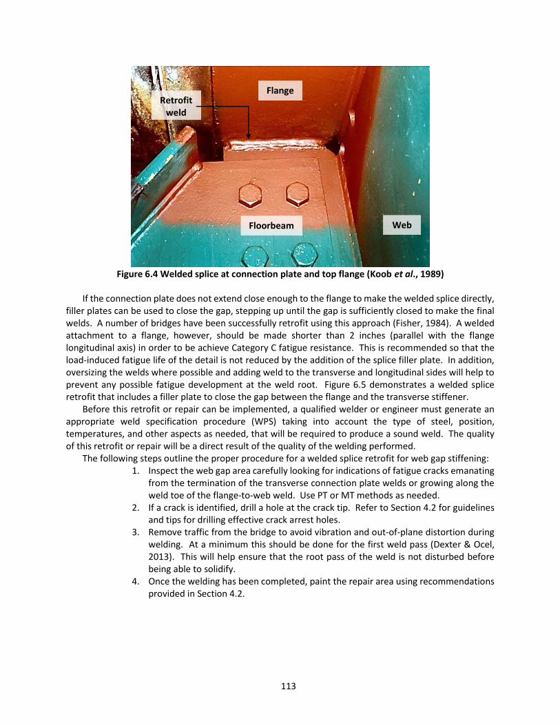
113
Figure 6.4 Welded splice at connection plate and top flange (Koob et al., 1989)
If the connection plate does not extend close enough to the flange to make the welded splice directly,
filler plates can be used to close the gap, stepping up until the gap is sufficiently closed to make the final welds. A number of bridges have been successfully retrofit using this approach (Fisher, 1984). A welded attachment to a flange, however, should be made shorter than 2 inches (parallel with the flange longitudinal axis) in order to be achieve Category C fatigue resistance. This is recommended so that the load-induced fatigue life of the detail is not reduced by the addition of the splice filler plate. In addition, oversizing the welds where possible and adding weld to the transverse and longitudinal sides will help to prevent any possible fatigue development at the weld root. Figure 6.5 demonstrates a welded splice retrofit that includes a filler plate to close the gap between the flange and the transverse stiffener.
Before this retrofit or repair can be implemented, a qualified welder or engineer must generate an appropriate weld specification procedure (WPS) taking into account the type of steel, position, temperatures, and other aspects as needed, that will be required to produce a sound weld. The quality of this retrofit or repair will be a direct result of the quality of the welding performed.
The following steps outline the proper procedure for a welded splice retrofit for web gap stiffening: 1. Inspect the web gap area carefully looking for indications of fatigue cracks emanating
from the termination of the transverse connection plate welds or growing along the weld toe of the flange-to-web weld. Use PT or MT methods as needed.
2. If a crack is identified, drill a hole at the crack tip. Refer to Section 4.2 for guidelines and tips for drilling effective crack arrest holes.
3. Remove traffic from the bridge to avoid vibration and out-of-plane distortion during welding. At a minimum this should be done for the first weld pass (Dexter & Ocel, 2013). This will help ensure that the root pass of the weld is not disturbed before being able to solidify.
4. Once the welding has been completed, paint the repair area using recommendations provided in Section 4.2.
Flange
Floorbeam Web
Retrofit weld
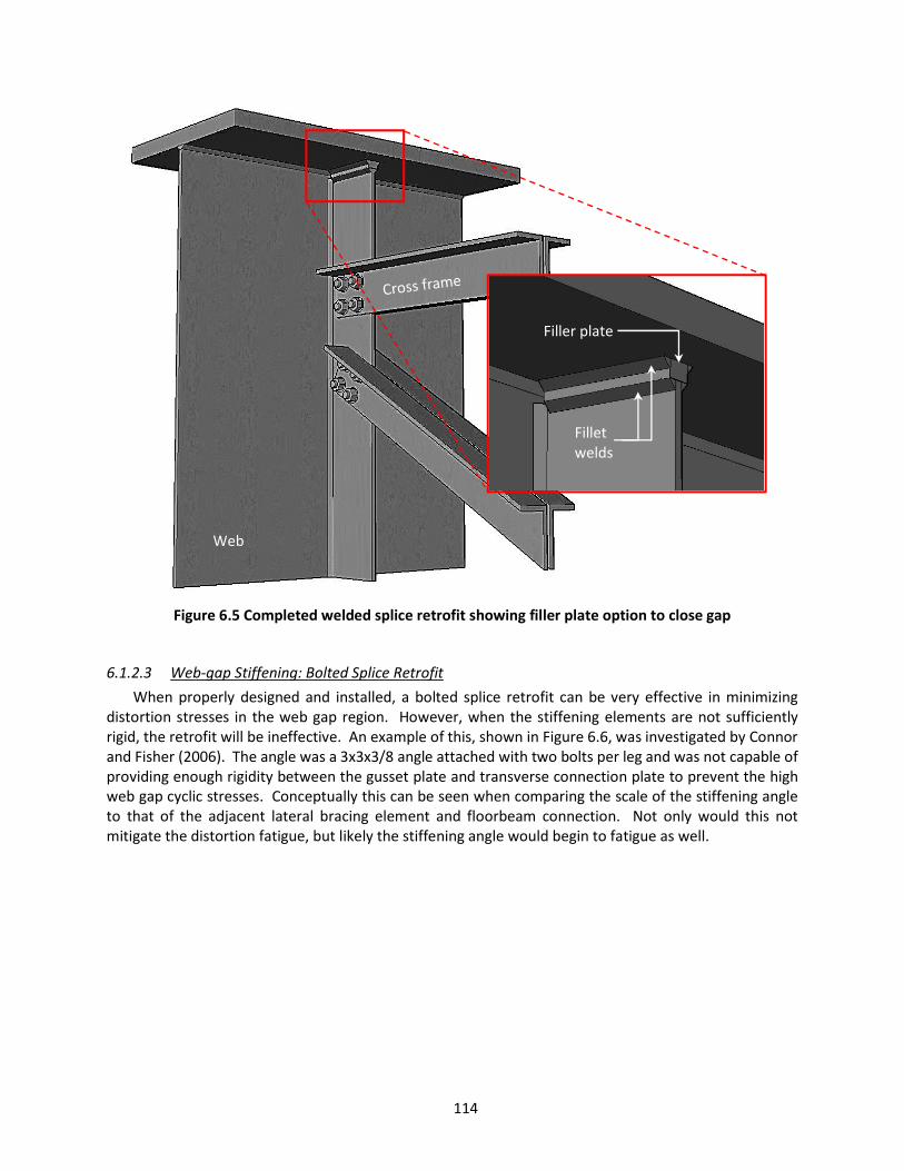
114
Figure 6.5 Completed welded splice retrofit showing filler plate option to close gap
6.1.2.3 Web-gap Stiffening: Bolted Splice Retrofit When properly designed and installed, a bolted splice retrofit can be very effective in minimizing
distortion stresses in the web gap region. However, when the stiffening elements are not sufficiently rigid, the retrofit will be ineffective. An example of this, shown in Figure 6.6, was investigated by Connor and Fisher (2006). The angle was a 3x3x3/8 angle attached with two bolts per leg and was not capable of providing enough rigidity between the gusset plate and transverse connection plate to prevent the high web gap cyclic stresses. Conceptually this can be seen when comparing the scale of the stiffening angle to that of the adjacent lateral bracing element and floorbeam connection. Not only would this not mitigate the distortion fatigue, but likely the stiffening angle would begin to fatigue as well.
Web
Filler plate
Fillet welds

115
Figure 6.6 Insufficiently stiff splice angle shown installed on gusset-connection plate web gap
Koob et al. (1989) applied a prototype slip-critical bolted splice retrofit to the Poplar Street Bridge
web gap between a transverse connection plate and top flange. They used 8x6x3/4 inch angles on both sides of the connection plate attached with two 1-inch diameter Grade A325 high strength bolts or studs. The holes in the top flange (in the negative moment region) were drilled and tapped with a stud embedment depth that was 1-1/4-inch. Consideration for this type of drilled and tapped connection should be given to the fact that the flange plate is a softer and weaker material than the bolt and can easily be stripped out when tensioning the bolt if insufficient embedment depth is used. A rule of thumb is to embed the bolt approximately 1.5 times its nominal diameter. Based on embedment tests of 1-inch Grade A325 bolts in A36 steel by Koob et al. (1989), the minimum embedment depth needed to be 1.25 inches in order to avoid thread slippage. If a flange plate is not thick enough to provide at least 1.25 times the bolt diameter, then a drill and tap approach would not be recommended and instead a through-bolted connection requiring excavation of the deck should be used. Following installation of the retrofit, field measurements before and after showed that it reduced out-of-plane displacements by as much as 46 percent (Koob et al., 1989). Strain measurements adjacent to the transverse connection plate weld toes revealed strains that corresponded to stress ranges of 11.7 ksi and 9.9 ksi for each of the two prototypes. This may have been improved by using a stiffer connecting element, such as a WT section.
Bowman et al. (2012) investigated bolted retrofits for distortion-induced fatigue combining analytical
and experimental observations. Finite element analysis was used to study the forces developed in the cross frame members, such as typical K-type or X-type bracing elements. It was found that the cross frame forces increased twofold or more for a given girder displacement after applying the stiffening retrofit to the web gap. Bennett et al. (2014) found that stiffening the web gap pushed the fatigue failure to the cross frame connection instead. As is for all stiffening retrofits, load paths must be considered since the loads are no longer dissipated through a flexible connection, but rigidly transferred from element to element. Bowman et al. (2012) concluded the following for bolted splice retrofits for distortion-induced fatigue:
Connections to the flange should be made with four preloaded F3125 high strength bolts in each shear plane; two bolts on each flange leg of the stiffening element and four bolts at the transverse connection plate. Bolt diameters should be no less than 7/8-inch.
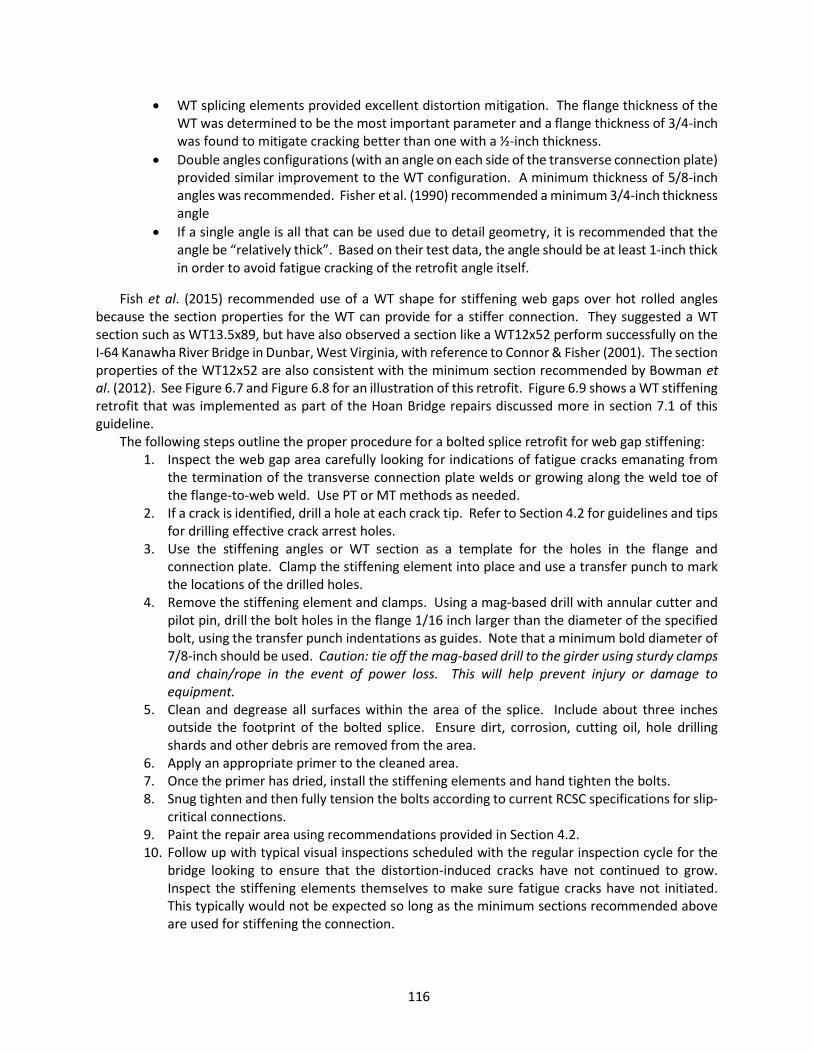
116
WT splicing elements provided excellent distortion mitigation. The flange thickness of the WT was determined to be the most important parameter and a flange thickness of 3/4-inch was found to mitigate cracking better than one with a ½-inch thickness.
Double angles configurations (with an angle on each side of the transverse connection plate) provided similar improvement to the WT configuration. A minimum thickness of 5/8-inch angles was recommended. Fisher et al. (1990) recommended a minimum 3/4-inch thickness angle
If a single angle is all that can be used due to detail geometry, it is recommended that the angle be “relatively thick”. Based on their test data, the angle should be at least 1-inch thick in order to avoid fatigue cracking of the retrofit angle itself.
Fish et al. (2015) recommended use of a WT shape for stiffening web gaps over hot rolled angles because the section properties for the WT can provide for a stiffer connection. They suggested a WT section such as WT13.5x89, but have also observed a section like a WT12x52 perform successfully on the I-64 Kanawha River Bridge in Dunbar, West Virginia, with reference to Connor & Fisher (2001). The section properties of the WT12x52 are also consistent with the minimum section recommended by Bowman et al. (2012). See Figure 6.7 and Figure 6.8 for an illustration of this retrofit. Figure 6.9 shows a WT stiffening retrofit that was implemented as part of the Hoan Bridge repairs discussed more in section 7.1 of this guideline.
The following steps outline the proper procedure for a bolted splice retrofit for web gap stiffening: 1. Inspect the web gap area carefully looking for indications of fatigue cracks emanating from
the termination of the transverse connection plate welds or growing along the weld toe of the flange-to-web weld. Use PT or MT methods as needed.
2. If a crack is identified, drill a hole at each crack tip. Refer to Section 4.2 for guidelines and tips for drilling effective crack arrest holes.
3. Use the stiffening angles or WT section as a template for the holes in the flange and connection plate. Clamp the stiffening element into place and use a transfer punch to mark the locations of the drilled holes.
4. Remove the stiffening element and clamps. Using a mag-based drill with annular cutter and pilot pin, drill the bolt holes in the flange 1/16 inch larger than the diameter of the specified bolt, using the transfer punch indentations as guides. Note that a minimum bold diameter of 7/8-inch should be used. Caution: tie off the mag-based drill to the girder using sturdy clamps and chain/rope in the event of power loss. This will help prevent injury or damage to equipment.
5. Clean and degrease all surfaces within the area of the splice. Include about three inches outside the footprint of the bolted splice. Ensure dirt, corrosion, cutting oil, hole drilling shards and other debris are removed from the area.
6. Apply an appropriate primer to the cleaned area. 7. Once the primer has dried, install the stiffening elements and hand tighten the bolts. 8. Snug tighten and then fully tension the bolts according to current RCSC specifications for slip-
critical connections. 9. Paint the repair area using recommendations provided in Section 4.2. 10. Follow up with typical visual inspections scheduled with the regular inspection cycle for the
bridge looking to ensure that the distortion-induced cracks have not continued to grow. Inspect the stiffening elements themselves to make sure fatigue cracks have not initiated. This typically would not be expected so long as the minimum sections recommended above are used for stiffening the connection.

117
Figure 6.7 Completed bolted splice retrofit showing double angle stiffening elements
Web
Stiffening angles
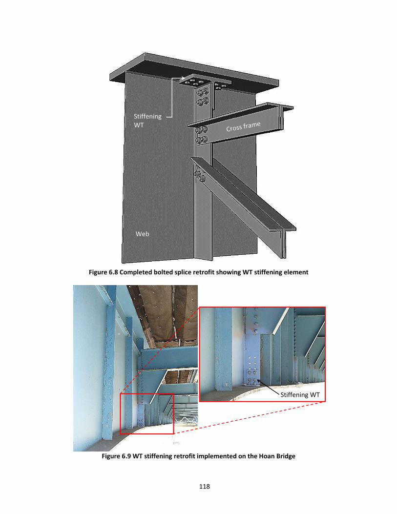
118
Figure 6.8 Completed bolted splice retrofit showing WT stiffening element
Figure 6.9 WT stiffening retrofit implemented on the Hoan Bridge
Stiffening WT
Web
Stiffening WT

119
6.1.2.4 Web-gap Softening: Large-Hole Retrofit Koob et al. (1985) investigated a large-hole retrofit as an economical way to remove or intercept any
existing cracks near the top flange at bearing stiffener-to-floorbeam connections. The prototype retrofit was installed in three locations on the Poplar Street Bridge Approaches, near St. Louis, to determine if the out-of-plane stiffness of the connection would change and to measure the stress range along the weld toes adjacent to the drilled holes. Figure 6.10 shows the basic detail used. They drilled 2-inch diameter holes on either side of the stiffener connection plate, intercepting the flange-to-web weld toe and bearing stiffener-to-web weld toes by 1/8 inch. Intercepting the weld toes in this way prevents a fatigue crack from propagating along the weld toe without being arrested in the retrofit holes. Results from the field test showed that the retrofit was effective in reducing the distortion-induced stress ranges to 6.6 ksi or less, which less than the Category C CAFL determined for a typical quality drilled hole (Fisher et al., 1987; Brown et al., 2007). The actual fatigue resistance will depend on the quality of the finished hole. A larger diameter hole would further reduce the stress range by increasing the connection compliance.
Figure 6.10 Drilled hole prototype installed at bearing stiffeners (Reproduced from Koob et al., 1985)
This retrofit should be installed using techniques discussed in Section 4.3. The drilled holes are
recommended to be at least 3 to 4 inches in diameter and each hole should intersect the horizontal and transverse welds approximately 1/8 inch. If a hole misses either of the welds, use a die grinder and carbide rotary burr bit to grind from the inside of the drilled hole toward the missed weld until the hole is extended sufficiently to intercept it. Maintain a round and gradual profile as best as possible. In the case that there is an existing crack at the detail, the hole should be drilled to either completely remove the crack, or if the crack is too long to be completely removed, the hole should be drilled such that it removes the crack tip. See Figure 4.4 for recommendations on hole placement. This may require that the drilled hole be placed such that the horizontal flange-to-web weld is missed. If this is the case, it is recommended that grinding or an additional hole be used to ensure the horizontal weld toe is intercepted to isolate the web plate from crack propagation.
Parapet
Bearing stiffener
2” Φ drilled holes (removed cracks in red)

120
This is estimated to be the most economical retrofit method for this kind of distortion-induced fatigue due to the simplicity of installation, standard tools and not requiring engineering analysis or highly skilled labor.
Follow-up inspections should include typical visual inspection enhanced with PT or MT as needed during regularly scheduled bridge inspections.
Figure 6.11 Large-hole retrofit – note interception of horizontal and vertical weld toes (Photograph
courtesy of Iowa DOT)
6.1.2.5 Web-gap Softening: Connection Plate Cutback Retrofit Cutting the connection plate short reduces rotational restraint at the transverse connection plate
detail, which reduces the out-of-plane bending stress in the web gap. A prototype of this retrofit was installed on the Poplar Street Bridge and field tested by Koob et al. (1989). They removed approximately 14 inches of the connection plate. The softening retrofit was observed to reduce web gap out-of-plane bending stresses to only five ksi. This would be far less than the CAFL of 10 ksi for this AASHTO Category C detail, inferring that infinite fatigue life could be expected. Fisher et al. (1990) concluded similarly on the amount of material that should be removed suggesting that the improved web gap be no less than 20t, where t is the web plate thickness.
In order for this retrofit to perform well, ensure that the transverse connection plate welds are ground down smooth to the web plate leaving no weldment behind. The Lexington Avenue Bridge (I-35E over the Mississippi River) demonstrated the importance of this quality. Dexter & Ocel (2013) report that the retrofitting contractor complained about the amount of work involved in grinding the leftover weld flush with the web and it was decided that it could be left in place. Shortly after the retrofits were completed, fatigue cracks were found initiating at the end of the remaining weld. The bridge owner had a drilled hole added to the details later to remove the weld terminations and cracks, as see in Figure 6.12.
Thermal cutting processes can be utilized for making the cuts on the connection plate. However, this should be done with caution to avoid gouging and overheating the web plate. This will require some grinding following the cuts to remove the remaining weld down to the web plate. The cuts can also be

121
made with angle grinders and cutting wheels. An example of a high-quality retrofit can be seen in Figure 6.13. Notice the generous new web gap, drilled holes to arrest cracks initiated in the flange-to-web weld, the web plate that shows no sign of the former transverse fillet welds, and a smooth 2-inch radius transition from the transverse connection plate to the web. The radius can be made using a mag-based drill and annular cutter.
Figure 6.12 Lexington Ave Bridge cutback retrofit (Photograph courtesy of MNDOT)
The following steps outline the proper procedure for the connection plate cutback retrofit for
transverse connection plate web gap cracking: 1. Inspect the web gap area carefully looking for indications of fatigue cracks emanating from
the termination of the transverse connection plate welds or growing along the weld toe of the flange-to-web weld. Use PT or MT methods as needed.
2. If a crack is identified, drill a hole at each crack tip. Refer to Section 4.3 for guidelines and tips for drilling effective crack arrest holes.
3. Mark on the connection plate the depth of the cutback to be made using either the 20t or web plate depth/6 rules of thumb. For example, a girder with a 5/8-inch web plate might be cut back to make a 12- inch gap (20 x 5/8 = 12.5). This means that the new web gap is 12 inches, which is to say that the exposed web plate between the horizontal and vertical weld toes is 12 inches.
4. Cut back the connection plate using either a thermal cut process or a mag-based drill and angle grinder with cutoff wheel. Use caution to not cut into the web plate causing gouges that can later develop fatigue cracks. If the web is gouged, refer to Section 4.4 for surface grinding techniques used to fair in the gouge and reduce the stress concentration.
a. If using a thermal cutting process, the horizontal and vertical cuts in the connection plate can be made. It is recommended that the vertical cut follow the transverse weld profile keeping safely away from the web plate.
b. If using a drill and grinder, place the annular cutter so that it drills a hole that creates the transition radius from the connection plate to the web plate. Once the hole is drilled, use the angle grinder and cutoff wheel to cut off the desired section of the connection plate.
Web plate Connection WT
Drilled hole for crack arrest

122
5. Once the connection plate is cut back, use an angle grinder with 24 grit grinding wheel or a die grinder with carbide rotary burr bit to begin grinding off the remaining transverse weld and connection plate. Carefully grind down toward the web plate using caution to not over grind and gouge into the web. Be sure to remove all of the transverse weld from the web plate.
6. Finish sand the web gap area using an 80 to 100 grit flap wheel. Create a smooth and gradual transition from the connection plate to the web.
7. Paint the repair area using recommendations provided in Section 4.2. 8. Follow up with typical visual inspections scheduled with the regular inspection cycle for the
bridge looking to ensure that the distortion-induced cracks have not continued to grow.
Figure 6.13 Cutback retrofit installed on Polk County Bridge (Photograph courtesy of Iowa DOT)
6.1.2.6 Diaphragm or Cross Frame Removal Retrofit When considering that distortion-induced fatigue cracking is driven by load transfer through lateral
supporting elements resulting from differential displacement of primary members, the most obvious solution might be to remove the load transferring elements—the cross frames or diaphragms. Stallings et al. (1996) investigated this retrofit method. Following structural evaluation of each bridge for load rating, wind load analysis, and lateral-torsional buckling, field tests were conducted on two bridges using controlled loads looking at before and after diaphragms were removed. The field testing was used to validate finite element analysis (FEA) with which they were able to evaluate effects of cross member removal on eight additional bridges. They concluded that in many cases, structural integrity of the bridge was not notably affected by the removal of the cross framing members. The following conclusion resulted from this study:
Web plate
Floorbeam
Crack arrest holes
New web gap
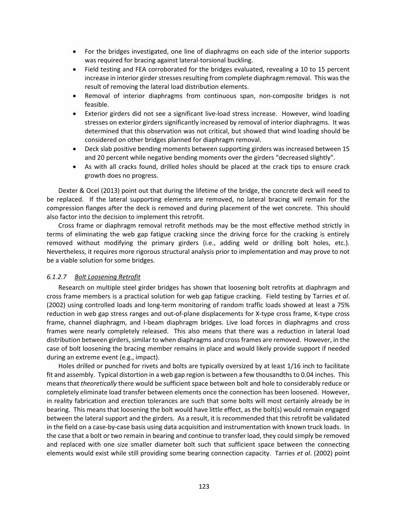
123
For the bridges investigated, one line of diaphragms on each side of the interior supports was required for bracing against lateral-torsional buckling.
Field testing and FEA corroborated for the bridges evaluated, revealing a 10 to 15 percent increase in interior girder stresses resulting from complete diaphragm removal. This was the result of removing the lateral load distribution elements.
Removal of interior diaphragms from continuous span, non-composite bridges is not feasible.
Exterior girders did not see a significant live-load stress increase. However, wind loading stresses on exterior girders significantly increased by removal of interior diaphragms. It was determined that this observation was not critical, but showed that wind loading should be considered on other bridges planned for diaphragm removal.
Deck slab positive bending moments between supporting girders was increased between 15 and 20 percent while negative bending moments over the girders “decreased slightly”.
As with all cracks found, drilled holes should be placed at the crack tips to ensure crack growth does no progress.
Dexter & Ocel (2013) point out that during the lifetime of the bridge, the concrete deck will need to be replaced. If the lateral supporting elements are removed, no lateral bracing will remain for the compression flanges after the deck is removed and during placement of the wet concrete. This should also factor into the decision to implement this retrofit.
Cross frame or diaphragm removal retrofit methods may be the most effective method strictly in terms of eliminating the web gap fatigue cracking since the driving force for the cracking is entirely removed without modifying the primary girders (i.e., adding weld or drilling bolt holes, etc.). Nevertheless, it requires more rigorous structural analysis prior to implementation and may prove to not be a viable solution for some bridges.
6.1.2.7 Bolt Loosening Retrofit Research on multiple steel girder bridges has shown that loosening bolt retrofits at diaphragm and
cross frame members is a practical solution for web gap fatigue cracking. Field testing by Tarries et al. (2002) using controlled loads and long-term monitoring of random traffic loads showed at least a 75% reduction in web gap stress ranges and out-of-plane displacements for X-type cross frame, K-type cross frame, channel diaphragm, and I-beam diaphragm bridges. Live load forces in diaphragms and cross frames were nearly completely released. This also means that there was a reduction in lateral load distribution between girders, similar to when diaphragms and cross frames are removed. However, in the case of bolt loosening the bracing member remains in place and would likely provide support if needed during an extreme event (e.g., impact).
Holes drilled or punched for rivets and bolts are typically oversized by at least 1/16 inch to facilitate fit and assembly. Typical distortion in a web gap region is between a few thousandths to 0.04 inches. This means that theoretically there would be sufficient space between bolt and hole to considerably reduce or completely eliminate load transfer between elements once the connection has been loosened. However, in reality fabrication and erection tolerances are such that some bolts will most certainly already be in bearing. This means that loosening the bolt would have little effect, as the bolt(s) would remain engaged between the lateral support and the girders. As a result, it is recommended that this retrofit be validated in the field on a case-by-case basis using data acquisition and instrumentation with known truck loads. In the case that a bolt or two remain in bearing and continue to transfer load, they could simply be removed and replaced with one size smaller diameter bolt such that sufficient space between the connecting elements would exist while still providing some bearing connection capacity. Tarries et al. (2002) point
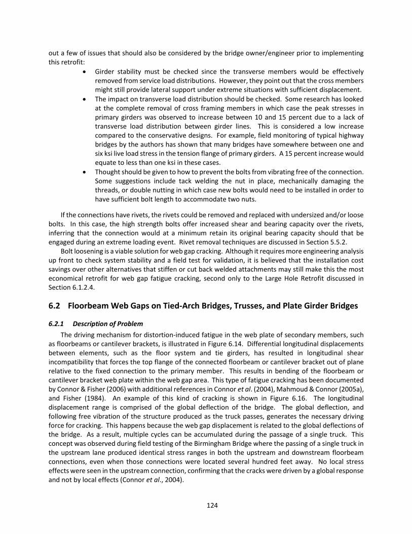
124
out a few of issues that should also be considered by the bridge owner/engineer prior to implementing this retrofit:
Girder stability must be checked since the transverse members would be effectively removed from service load distributions. However, they point out that the cross members might still provide lateral support under extreme situations with sufficient displacement.
The impact on transverse load distribution should be checked. Some research has looked at the complete removal of cross framing members in which case the peak stresses in primary girders was observed to increase between 10 and 15 percent due to a lack of transverse load distribution between girder lines. This is considered a low increase compared to the conservative designs. For example, field monitoring of typical highway bridges by the authors has shown that many bridges have somewhere between one and six ksi live load stress in the tension flange of primary girders. A 15 percent increase would equate to less than one ksi in these cases.
Thought should be given to how to prevent the bolts from vibrating free of the connection. Some suggestions include tack welding the nut in place, mechanically damaging the threads, or double nutting in which case new bolts would need to be installed in order to have sufficient bolt length to accommodate two nuts.
If the connections have rivets, the rivets could be removed and replaced with undersized and/or loose bolts. In this case, the high strength bolts offer increased shear and bearing capacity over the rivets, inferring that the connection would at a minimum retain its original bearing capacity should that be engaged during an extreme loading event. Rivet removal techniques are discussed in Section 5.5.2.
Bolt loosening is a viable solution for web gap cracking. Although it requires more engineering analysis up front to check system stability and a field test for validation, it is believed that the installation cost savings over other alternatives that stiffen or cut back welded attachments may still make this the most economical retrofit for web gap fatigue cracking, second only to the Large Hole Retrofit discussed in Section 6.1.2.4.
6.2 Floorbeam Web Gaps on Tied-Arch Bridges, Trusses, and Plate Girder Bridges
6.2.1 Description of Problem The driving mechanism for distortion-induced fatigue in the web plate of secondary members, such
as floorbeams or cantilever brackets, is illustrated in Figure 6.14. Differential longitudinal displacements between elements, such as the floor system and tie girders, has resulted in longitudinal shear incompatibility that forces the top flange of the connected floorbeam or cantilever bracket out of plane relative to the fixed connection to the primary member. This results in bending of the floorbeam or cantilever bracket web plate within the web gap area. This type of fatigue cracking has been documented by Connor & Fisher (2006) with additional references in Connor et al. (2004), Mahmoud & Connor (2005a), and Fisher (1984). An example of this kind of cracking is shown in Figure 6.16. The longitudinal displacement range is comprised of the global deflection of the bridge. The global deflection, and following free vibration of the structure produced as the truck passes, generates the necessary driving force for cracking. This happens because the web gap displacement is related to the global deflections of the bridge. As a result, multiple cycles can be accumulated during the passage of a single truck. This concept was observed during field testing of the Birmingham Bridge where the passing of a single truck in the upstream lane produced identical stress ranges in both the upstream and downstream floorbeam connections, even when those connections were located several hundred feet away. No local stress effects were seen in the upstream connection, confirming that the cracks were driven by a global response and not by local effects (Connor et al., 2004).

125
Figure 6.14 Illustration highlighting in red the area of a floorbeam web prone to web gap cracks The red area highlighted on the floorbeam at the top of the connection to the tie girder is the location
where the cracking is most often seen. Note, however, that distortion-induced fatigue cracks have also been observed at the web gap that sometimes exists between the transverse stiffeners on the floorbeam directly beneath the stringers when the stiffener is not attached to the floorbeam flange (Albrecht & Wright, 2000). Use Section 6.1 for retrofit and repair of these areas.
A cross section of the floorbeam-tie girder connection is shown in Figure 6.15. A relative displacement between the floorbeam top flange (which is connected to the stringers) and the connection plates (which are connected to the tie or primary girder) occurs. This results in a bending of the floorbeam web plate within the small web gap area, similar to that shown in Figure 6.2 for transverse connection plates (within the web gap region, the two modes of fatigue cracking are identical). Very large tensile stresses result at the top and bottom of the web gap often causing cracks at both of these locations. Typically, this type of fatigue crack will be most prevalent in locations of largest global shear stress where the incompatibility between the floor system and tie girders will be the highest. An example of the fatigue cracks are shown in Figure 6.16 on the Birmingham tied-arch bridge over the Monongahela River in Pittsburgh, PA.
Floorbeam
Stringer
Tie Girder

126
Figure 6.15 Cross section illustrating driving stresses for the floorbeam web gap cracking
Figure 6.16 Example of distortion-induced cracking in web gab of floorbeam connected to tie girder
6.2.2 Repair or Retrofit Guidelines
6.2.2.1 Drilled Hole for Crack Arrest The simplest and most economical repair is a large drilled hole for crack arrest. The reader is referred
to Section 6.1.2.1 on use of drilled holes for repair and retrofit of web gap regions for transverse connection plates. An example of this repair method is shown in Figure 6.17 through Figure 6.20. These images are from the SR 119 through-truss bridge in Indiana. The end floorbeams of the simple span truss were experiencing distortion-induced fatigue cracks in the web gap region between the floorbeam top
Crack Floor Beam
Tie Girder
Relative displacement
Floorbeam
Connection plate
Tension
Tension
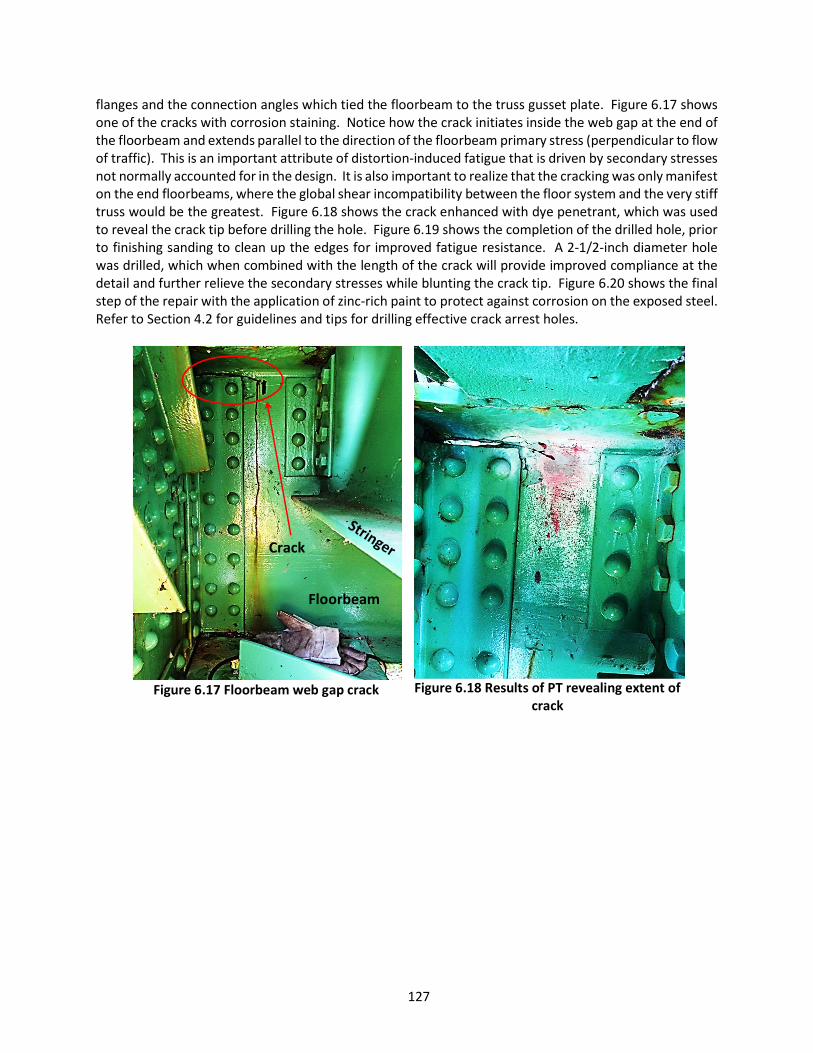
127
flanges and the connection angles which tied the floorbeam to the truss gusset plate. Figure 6.17 shows one of the cracks with corrosion staining. Notice how the crack initiates inside the web gap at the end of the floorbeam and extends parallel to the direction of the floorbeam primary stress (perpendicular to flow of traffic). This is an important attribute of distortion-induced fatigue that is driven by secondary stresses not normally accounted for in the design. It is also important to realize that the cracking was only manifest on the end floorbeams, where the global shear incompatibility between the floor system and the very stiff truss would be the greatest. Figure 6.18 shows the crack enhanced with dye penetrant, which was used to reveal the crack tip before drilling the hole. Figure 6.19 shows the completion of the drilled hole, prior to finishing sanding to clean up the edges for improved fatigue resistance. A 2-1/2-inch diameter hole was drilled, which when combined with the length of the crack will provide improved compliance at the detail and further relieve the secondary stresses while blunting the crack tip. Figure 6.20 shows the final step of the repair with the application of zinc-rich paint to protect against corrosion on the exposed steel. Refer to Section 4.2 for guidelines and tips for drilling effective crack arrest holes.
Figure 6.17 Floorbeam web gap crack
Figure 6.18 Results of PT revealing extent of
crack
Crack
Floorbeam

128
Figure 6.19 Drilled hole prior to sanding
edges
Figure 6.20 Finished repair with zinc-rich
paint Adding a large diameter hole may prove to be an effective, very economical and permanent repair for
the distortion-induced cracking of floorbeam web gap details. However, this may not provide sufficient softening for some applications. Follow-up inspection should be performed with the regularly scheduled inspections of the bridge looking for signs of crack reinitiation at the edges of the drilled hole. For cases where the crack reinitiates, or where field testing determines that the drilled hole will not be sufficient due to large secondary stresses, the Floorbeam Cutback Retrofit discussed in the following section is recommended.
6.2.2.2 Floorbeam Cutback Retrofit There are two primary approaches to repairing or retrofitting these details, which is to stiffen or
soften. Both approaches have been successfully implemented, along with large drilled holes for some applications. Fisher (1984) reports a stiffening retrofit that was implemented on the Prairie Du Chien Bridge, a tied-arch main span bridge. In order to rigidly connect the flanges of the floorbeam to the tie girder, an extremely stiff connection was required. They bolted heavy structural “T” sections to the floorbeam top flange and to the web of the tie girder. In order to prevent out-of-plane displacements of the tie girder web, heavy structural “T” and channel sections were bolted to the interior of the tie girder opposite the new “T” section on the outside. This is a very expensive retrofit, which only becomes more expensive as the span length increases and the forces required to stiffen the connection increase. Hence, most often the economical option will be to soften the connection.
Cutting back the floorbeam connection to the primary girder has been demonstrated through prototyping (including field testing and finite element analysis) to be a very effective retrofit method and would be much less costly than a stiffening approach. Pennsylvania DOT and Lehigh University carried out a study of a prototype retrofit on the Birmingham tied-arch bridge over the Monongahela River near Pittsburgh, PA. Fatigue cracks were located on a number of the floorbeam webs near the connection to the tie girder. Field monitoring revealed that the top flanges of the floorbeams were moving out-of-plane (parallel to traffic) during traffic loading. Figure 6.21 shows the detail before retrofitting. Notice the crack

129
extending from the floorbeam web gap above the connection angles (highlighted by corrosion staining) and positive attachment of the stringer to the floorbeam. The attachment to the stringer facilitates the out-of-plane movement of the floorbeam top flange as the floor system deflects independently of the tie girder. After removing the top six bolts in the connection angles and cutting out the floorbeam flange, web material, and connection angles seen removed in Figure 6.22, vertical stress ranges in the floorbeam web (those which drive the cracking) were reduced to less than the constant amplitude fatigue limit, meaning infinite fatigue life for the detail.
Figure 6.21 Birmingham Bridge before retrofit showing web gap cracking
Figure 6.22 Birmingham Bridge softening retrofit that cut back the floorbeam
Floorbeam
Tie Girder Stringer
Floorbeam
Deck
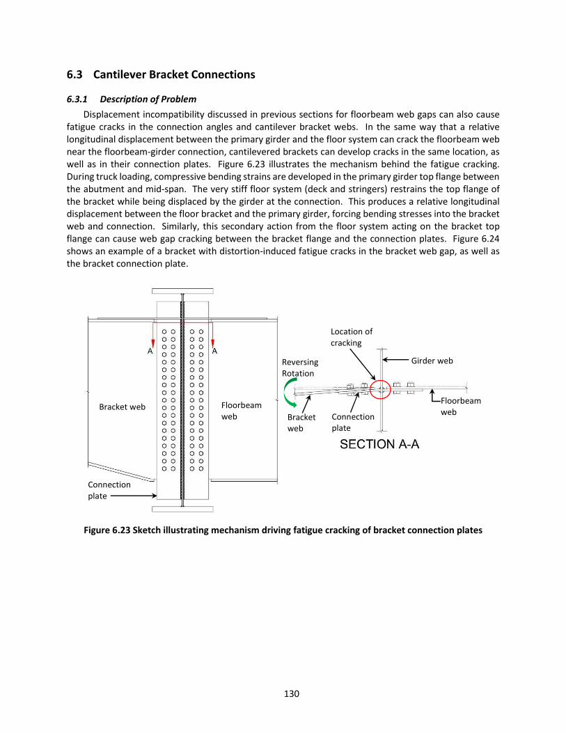
130
6.3 Cantilever Bracket Connections
6.3.1 Description of Problem Displacement incompatibility discussed in previous sections for floorbeam web gaps can also cause
fatigue cracks in the connection angles and cantilever bracket webs. In the same way that a relative longitudinal displacement between the primary girder and the floor system can crack the floorbeam web near the floorbeam-girder connection, cantilevered brackets can develop cracks in the same location, as well as in their connection plates. Figure 6.23 illustrates the mechanism behind the fatigue cracking. During truck loading, compressive bending strains are developed in the primary girder top flange between the abutment and mid-span. The very stiff floor system (deck and stringers) restrains the top flange of the bracket while being displaced by the girder at the connection. This produces a relative longitudinal displacement between the floor bracket and the primary girder, forcing bending stresses into the bracket web and connection. Similarly, this secondary action from the floor system acting on the bracket top flange can cause web gap cracking between the bracket flange and the connection plates. Figure 6.24 shows an example of a bracket with distortion-induced fatigue cracks in the bracket web gap, as well as the bracket connection plate.
Figure 6.23 Sketch illustrating mechanism driving fatigue cracking of bracket connection plates
Floorbeam web Bracket
web Connection plate
Bracket web Floorbeam web
Connection plate
Girder web Reversing Rotation
Location of cracking
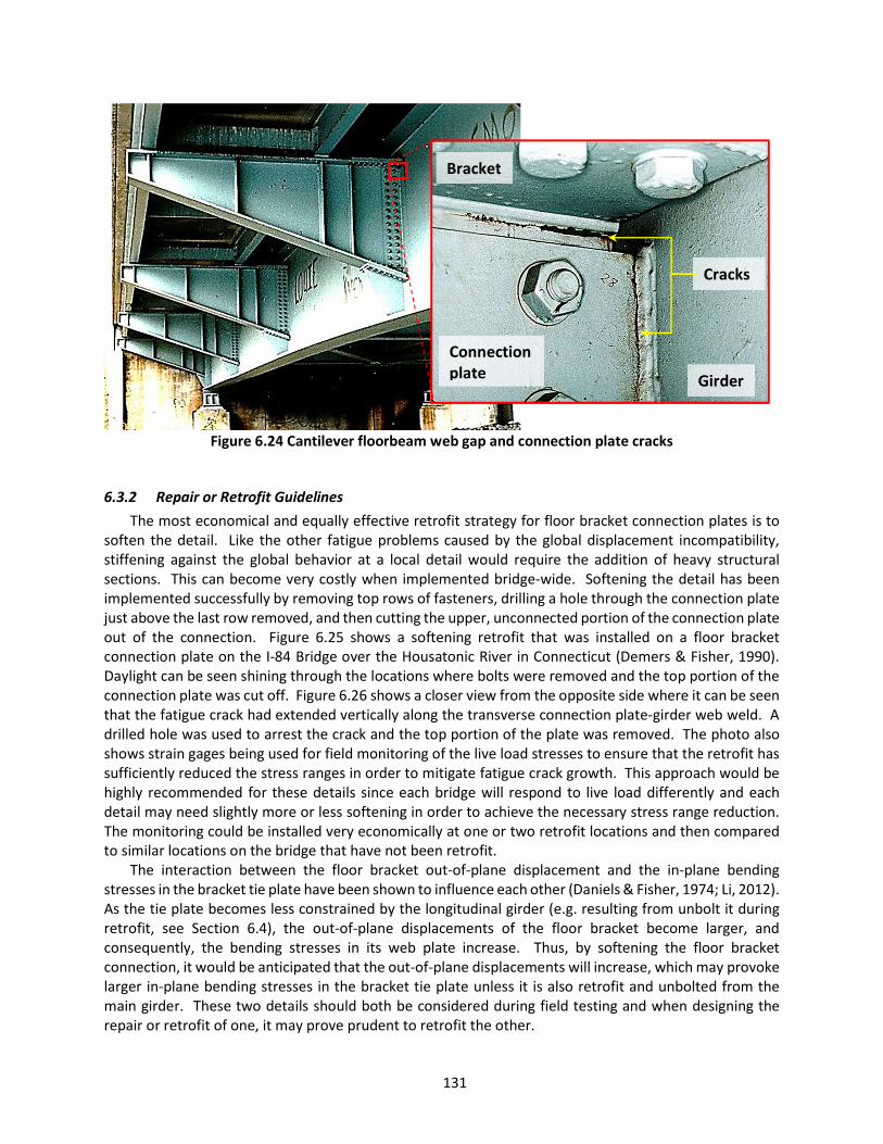
131
Figure 6.24 Cantilever floorbeam web gap and connection plate cracks
6.3.2 Repair or Retrofit Guidelines The most economical and equally effective retrofit strategy for floor bracket connection plates is to
soften the detail. Like the other fatigue problems caused by the global displacement incompatibility, stiffening against the global behavior at a local detail would require the addition of heavy structural sections. This can become very costly when implemented bridge-wide. Softening the detail has been implemented successfully by removing top rows of fasteners, drilling a hole through the connection plate just above the last row removed, and then cutting the upper, unconnected portion of the connection plate out of the connection. Figure 6.25 shows a softening retrofit that was installed on a floor bracket connection plate on the I-84 Bridge over the Housatonic River in Connecticut (Demers & Fisher, 1990). Daylight can be seen shining through the locations where bolts were removed and the top portion of the connection plate was cut off. Figure 6.26 shows a closer view from the opposite side where it can be seen that the fatigue crack had extended vertically along the transverse connection plate-girder web weld. A drilled hole was used to arrest the crack and the top portion of the plate was removed. The photo also shows strain gages being used for field monitoring of the live load stresses to ensure that the retrofit has sufficiently reduced the stress ranges in order to mitigate fatigue crack growth. This approach would be highly recommended for these details since each bridge will respond to live load differently and each detail may need slightly more or less softening in order to achieve the necessary stress range reduction. The monitoring could be installed very economically at one or two retrofit locations and then compared to similar locations on the bridge that have not been retrofit.
The interaction between the floor bracket out-of-plane displacement and the in-plane bending stresses in the bracket tie plate have been shown to influence each other (Daniels & Fisher, 1974; Li, 2012). As the tie plate becomes less constrained by the longitudinal girder (e.g. resulting from unbolt it during retrofit, see Section 6.4), the out-of-plane displacements of the floor bracket become larger, and consequently, the bending stresses in its web plate increase. Thus, by softening the floor bracket connection, it would be anticipated that the out-of-plane displacements will increase, which may provoke larger in-plane bending stresses in the bracket tie plate unless it is also retrofit and unbolted from the main girder. These two details should both be considered during field testing and when designing the repair or retrofit of one, it may prove prudent to retrofit the other.
Cracks
Bracket
Connection plate Girder

132
Figure 6.25 Softening retrofit on floor bracket connection plates showing removal of bolts and plate
(Demers & Fisher, 1990)
Figure 6.26 Close up showing softening detail with crack arrest hole (Demers & Fisher, 1990)
6.4 Cantilever Bracket Tie Plates
6.4.1 Description of Problem Cantilever bracket tie plates have been used for continuity across intersecting girders for floorbeam
and cantilever bracket moment transfer. In design the tie plate is thought to carry only tensile forces as it restrains rotation of the top flanges of the floorbeam and floor bracket. However, secondary stresses
Bracket
Stringer
Girder
Bolts and connection plate removed
Girder
Connection plate
Drilled hole for crack arrest
Removed bolts
Strain gage

133
have been measured in some tie plates where global displacement incompatibility exists between the bridge floor system and primary girders. The mechanism that drives this problem is related directly to that which drives the floorbeam web gap fatigue crack and the cantilever bracket connection plate fatigue crack discussed in previous sections. The primary girders move longitudinally relative to the very stiff deck and stringer system during truck loading. If the tie plate has any kind of connection to the girder top flange (e.g. rivets, bolts, tack welds, corrosion, etc.), then it becomes displaced by the girder while being restrained by the floor system. This concept is exaggerated in Figure 6.27, which shows a plan view of a generic superstructure and an out-of-plane bending of the tie plate.
Figure 6.27 Illustration of cantilever tie plate distortion
The Lehigh River and Canal Bridges are two examples of bridges where this type of fatigue problem
has been documented. The twin bridges are built-up riveted construction, erected in 1953. In 1972, Pennsylvania DOT inspectors discovered fatigue cracks in the tie plates initiating at tack welds that had been used during fabrication to temporarily hold the tie plate to the bracket and floorbeam flanges. Figure 6.28 shows one of the fatigue cracks in the tie plate with a strain gage installed for field monitoring purposes. Daniels & Fisher (1974) conducted research looking at different tie plate thicknesses, widths, as well as releasing the tie plate from the main girder for these two bridges. They concluded the following:
Stress ranges in the tie plate when bolted to the main girder, under normal traffic, were large enough to result in fatigue crack growth from bolt holes.
Releasing (unbolting or removing rivets) the tie plates from the main girders resulted in a substantial decrease in the in-plane bending stress of the tie plate (about a 30% decrease).
The decrease in bending stress was further reduced by replacing the 10-inch wide tie plate with a 6-inch wide plate (about an additional 50% decrease) of equal thickness.
Variations in the plate thickness did not significantly alter the stress range. Approximately the same stress was observed for a ½-inch thick plate and a 1-inch thick plate of common widths, confirming the fact that the secondary stresses in the tie plate are a result of displacement.
Releasing the tie plate from the main girder increased the relative displacement slightly, which increased the out-of-plane bending stress in the bracket web plate by 4 ksi, a value which would result in no fatigue damage in the bracket on these two bridges.
∆
Tie plate Bracket
Girder
Stringer Stringer Stringer
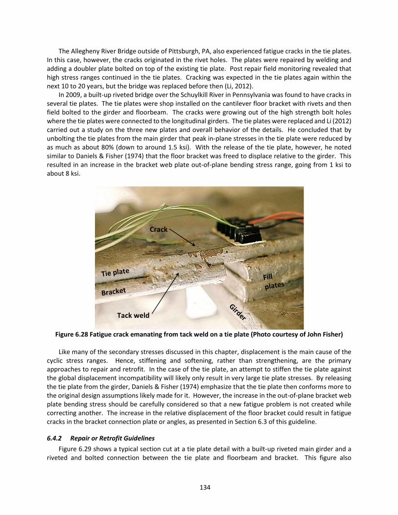
134
The Allegheny River Bridge outside of Pittsburgh, PA, also experienced fatigue cracks in the tie plates. In this case, however, the cracks originated in the rivet holes. The plates were repaired by welding and adding a doubler plate bolted on top of the existing tie plate. Post repair field monitoring revealed that high stress ranges continued in the tie plates. Cracking was expected in the tie plates again within the next 10 to 20 years, but the bridge was replaced before then (Li, 2012).
In 2009, a built-up riveted bridge over the Schuylkill River in Pennsylvania was found to have cracks in several tie plates. The tie plates were shop installed on the cantilever floor bracket with rivets and then field bolted to the girder and floorbeam. The cracks were growing out of the high strength bolt holes where the tie plates were connected to the longitudinal girders. The tie plates were replaced and Li (2012) carried out a study on the three new plates and overall behavior of the details. He concluded that by unbolting the tie plates from the main girder that peak in-plane stresses in the tie plate were reduced by as much as about 80% (down to around 1.5 ksi). With the release of the tie plate, however, he noted similar to Daniels & Fisher (1974) that the floor bracket was freed to displace relative to the girder. This resulted in an increase in the bracket web plate out-of-plane bending stress range, going from 1 ksi to about 8 ksi.
Figure 6.28 Fatigue crack emanating from tack weld on a tie plate (Photo courtesy of John Fisher)
Like many of the secondary stresses discussed in this chapter, displacement is the main cause of the
cyclic stress ranges. Hence, stiffening and softening, rather than strengthening, are the primary approaches to repair and retrofit. In the case of the tie plate, an attempt to stiffen the tie plate against the global displacement incompatibility will likely only result in very large tie plate stresses. By releasing the tie plate from the girder, Daniels & Fisher (1974) emphasize that the tie plate then conforms more to the original design assumptions likely made for it. However, the increase in the out-of-plane bracket web plate bending stress should be carefully considered so that a new fatigue problem is not created while correcting another. The increase in the relative displacement of the floor bracket could result in fatigue cracks in the bracket connection plate or angles, as presented in Section 6.3 of this guideline.
6.4.2 Repair or Retrofit Guidelines Figure 6.29 shows a typical section cut at a tie plate detail with a built-up riveted main girder and a
riveted and bolted connection between the tie plate and floorbeam and bracket. This figure also
Crack
Tack weld
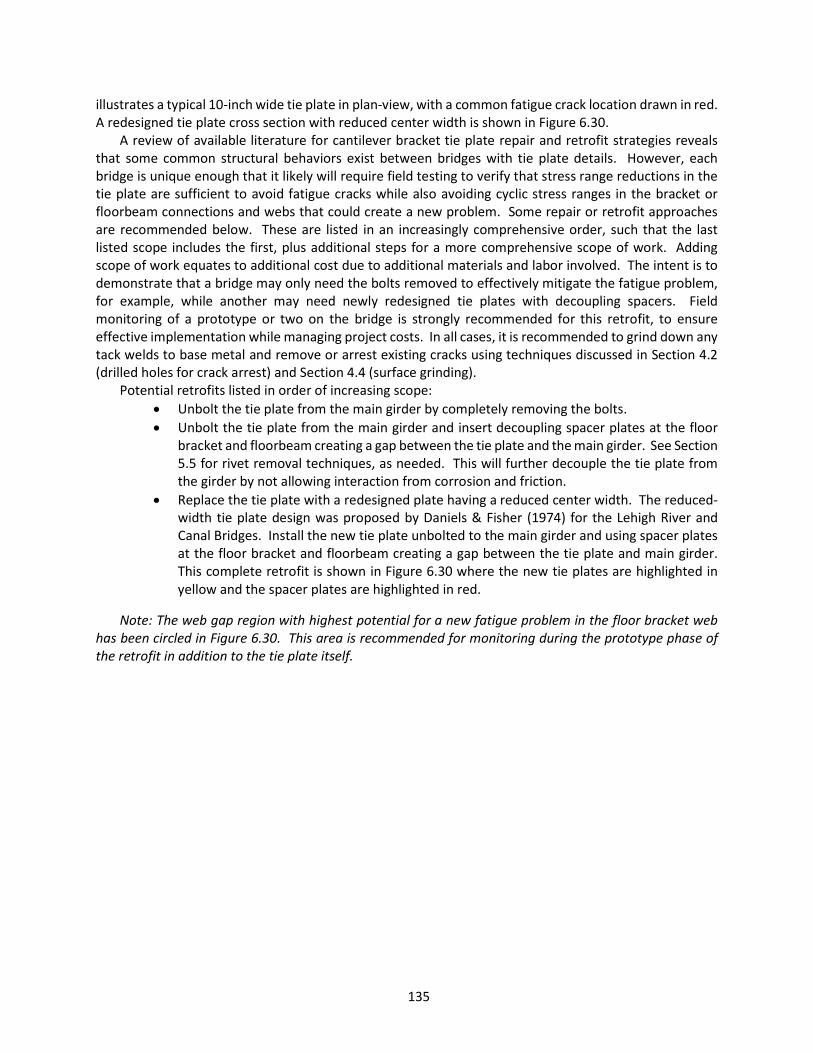
135
illustrates a typical 10-inch wide tie plate in plan-view, with a common fatigue crack location drawn in red. A redesigned tie plate cross section with reduced center width is shown in Figure 6.30.
A review of available literature for cantilever bracket tie plate repair and retrofit strategies reveals that some common structural behaviors exist between bridges with tie plate details. However, each bridge is unique enough that it likely will require field testing to verify that stress range reductions in the tie plate are sufficient to avoid fatigue cracks while also avoiding cyclic stress ranges in the bracket or floorbeam connections and webs that could create a new problem. Some repair or retrofit approaches are recommended below. These are listed in an increasingly comprehensive order, such that the last listed scope includes the first, plus additional steps for a more comprehensive scope of work. Adding scope of work equates to additional cost due to additional materials and labor involved. The intent is to demonstrate that a bridge may only need the bolts removed to effectively mitigate the fatigue problem, for example, while another may need newly redesigned tie plates with decoupling spacers. Field monitoring of a prototype or two on the bridge is strongly recommended for this retrofit, to ensure effective implementation while managing project costs. In all cases, it is recommended to grind down any tack welds to base metal and remove or arrest existing cracks using techniques discussed in Section 4.2 (drilled holes for crack arrest) and Section 4.4 (surface grinding).
Potential retrofits listed in order of increasing scope: Unbolt the tie plate from the main girder by completely removing the bolts. Unbolt the tie plate from the main girder and insert decoupling spacer plates at the floor
bracket and floorbeam creating a gap between the tie plate and the main girder. See Section 5.5 for rivet removal techniques, as needed. This will further decouple the tie plate from the girder by not allowing interaction from corrosion and friction.
Replace the tie plate with a redesigned plate having a reduced center width. The reduced-width tie plate design was proposed by Daniels & Fisher (1974) for the Lehigh River and Canal Bridges. Install the new tie plate unbolted to the main girder and using spacer plates at the floor bracket and floorbeam creating a gap between the tie plate and main girder. This complete retrofit is shown in Figure 6.30 where the new tie plates are highlighted in yellow and the spacer plates are highlighted in red.
Note: The web gap region with highest potential for a new fatigue problem in the floor bracket web has been circled in Figure 6.30. This area is recommended for monitoring during the prototype phase of the retrofit in addition to the tie plate itself.
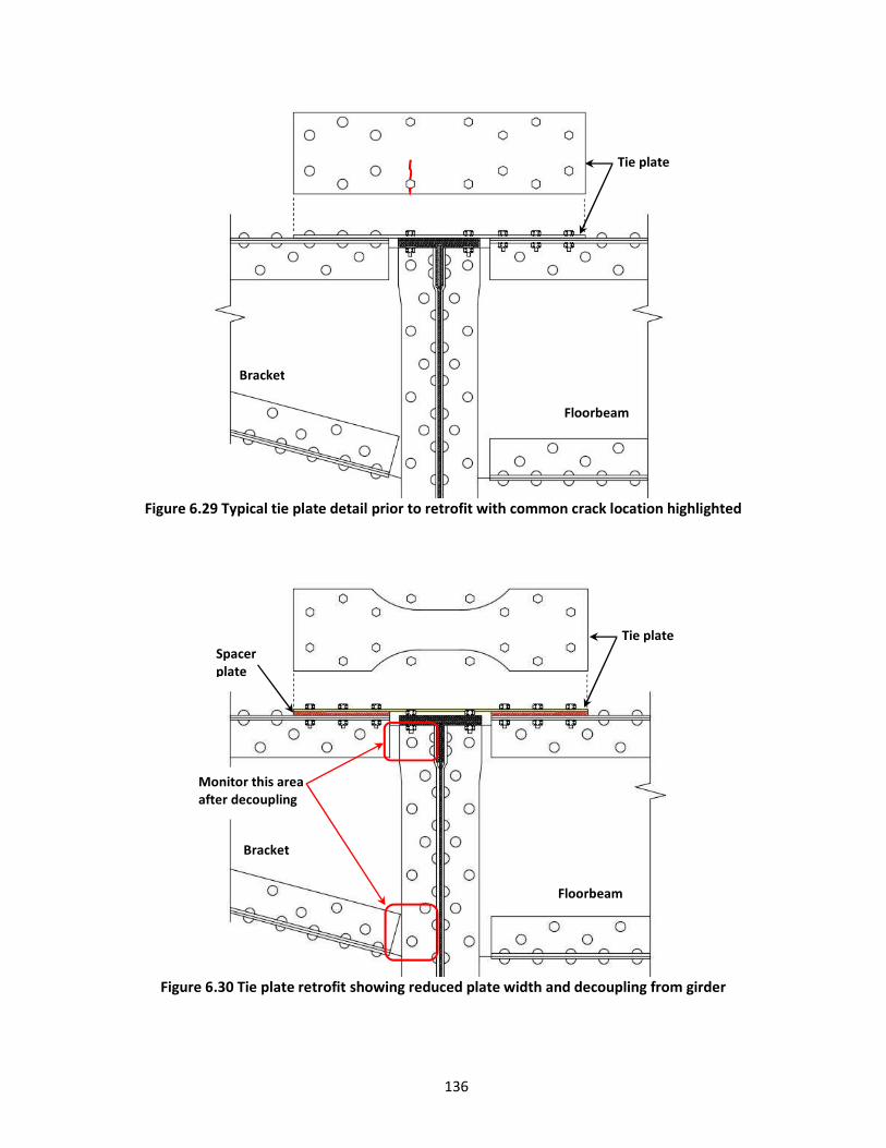
136
Figure 6.29 Typical tie plate detail prior to retrofit with common crack location highlighted
Figure 6.30 Tie plate retrofit showing reduced plate width and decoupling from girder
Tie plate
Floorbeam
Bracket
Bracket
Floorbeam
Tie plate
Monitor this area after decoupling
Spacer plate

137
6.5 Riveted and Bolted Connections Using Angles
6.5.1 Description of Problem Riveted and bolted connections using single and double angles have been widely implemented in
highway and railway bridges alike for stringer-to-floorbeam connections, floorbeam-to-girder connections, diaphragm-to-girder connections, etc. These connections are normally designed for shear forces alone, assuming that they only transfer reactions to supporting members as a simply-supported type connection. However, inherent stiffness of the connections combined with secondary effects from distortion of primary members and longitudinal incompatibilities between secondary and primary elements can result in large stress ranges in the connection angles (Stallings et al., 1996; Cousins et al., 1998; Dexter & Ocel, 2013). Prying action in the angles has also been known to remove rivet and bolt heads. Some of the reported stresses measured in the field exceeded the yield strength of the material resulting in a permanent gap, as seen in Figure 6.31 (Cousins et al., 1998). Pumping action of the connected element can generate large stress ranges at the angle fillet or near the edge of the fastener commonly initiating fatigue cracks at these two locations. Figure 6.32 shows a stringer connection angle removed from the Burlington Northern Railroad Bridge 196.0 in Bismarck, North Dakota. Several such connection angles were found by inspectors with cracks ranging from 4 to 27 inches in length. Fractographic examination revealed fatigue and fracture surfaces (Steel Bridge Fatigue Knowledge Base, 2008). Another example of connection angle cracking is shown in Figure 6.33 taken from the Mexican Hat Bridge in Utah. These are two of many bridges where connection angles have experienced fatigue cracking.
Figure 6.31 Common locations for fatigue cracks in connection angles
Girder/Floorbeam web
Conn
ectio
n an
gle
Gap
Crack
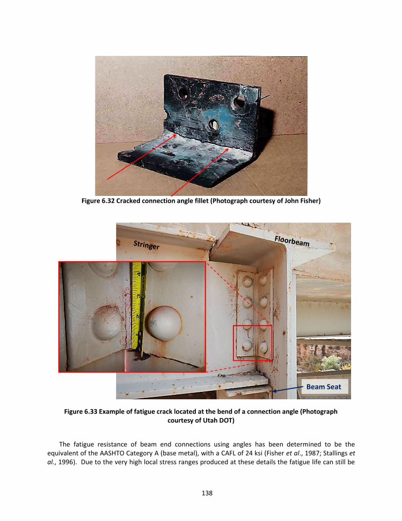
138
Figure 6.32 Cracked connection angle fillet (Photograph courtesy of John Fisher)
Figure 6.33 Example of fatigue crack located at the bend of a connection angle (Photograph courtesy of Utah DOT)
The fatigue resistance of beam end connections using angles has been determined to be the equivalent of the AASHTO Category A (base metal), with a CAFL of 24 ksi (Fisher et al., 1987; Stallings et al., 1996). Due to the very high local stress ranges produced at these details the fatigue life can still be
Beam Seat

139
relatively short. In one case, replacement angles connected with bolts resulted in a fatigue life of only 1 to 2 years (Cousins et al., 1998).
Inspection of connections using angles should focus at the top or bottom of the angles in the fillet and at the edge of the fasteners, as indicated in Figure 6.31. Diaphragm connection angles prone to fatigue cracking could be located anywhere on the structure, but may be focused between interior and exterior girder lines. For stringer end connections, the most likely cases will be located at the interior stringers and at exterior floorbeams (stringers located toward the ends of spans). These locations typically experience the largest secondary effects from relative global displacements.
6.5.2 Repair or Retrofit Guidelines Several possible retrofits exist for fatigue cracking of connection angles. Each will need to be
considered with regard to the specific circumstances of the bridge experiencing the problem. Unfortunately, there is not a single retrofit that can be recommended for all situations with specific step to perform the retrofit. Instead, each of them will be briefly discussed with general guidelines for each.
The four most common retrofits are: 1. Bearing Seats Retrofit (with option of removing connection angles) 2. Diaphragm Removal Retrofit 3. Connection Angle Replacement Retrofit 4. Fastener Removal Retrofit
6.5.2.1 Bearing Seats Retrofit Keating (1983) suggested one possible approach to repairing stringer end connections subject to large
rotational stresses would be to redesign the connection so that it no longer transmits the moment through the joint. He proposed adding a bearing, or beam, seat below each stringer end, either releasing the original shear connection or allowing it to eventually fail in fatigue or fracture. An example of a beam seat can be seen in Figure 6.33. The bearing seat would provide full support to the stringer bottom flange resulting in a true simply-supported connection. The stringer would need to be connected through its bottom flange to the bearing seat to avoid becoming unseated. The biggest benefit to this retrofit approach is that it could be performed without closing the bridge to traffic since the original connection angles would likely not need to be removed. Special consideration should also be given to cases where the stringer has been coped at the connection, removing its bottom flange.
There are two engineering aspects of this retrofit to consider before implementation. First is to determine if the stringer web needs to be stiffened for the new bearing. It is likely that the existing connection angles will sufficiently stiffen the stringer web for this purpose. The second is releasing end restraint at the connection could slightly increase deflection of the stringer under traffic loading. Keating (1983) points out that the original design of the deck makes the assumption that the stringer is simply-supported, so this typically should not be a problem either.
Inspection of the retrofit detail would only be visual inspection on the regular inspection interval for the bridge to check that the retrofit is performing as intended.
6.5.2.2 Diaphragm Removal Retrofit Removal of diaphragms may not always be feasible and requires engineering analysis to ensure
stability of the structure is not compromised by doing so. Stallings et al. (1996) investigated removal of interior diaphragms to eliminate damaged diaphragm-girder connections in simple span and continuous bridges. They performed structural analysis for five “typical” bridges, including load rating, wind load analysis, and lateral-torsional buckling analysis for continuous span bridges. These analyses were compared to field testing conducted on a long simple span and a three-span continuous bridge, before
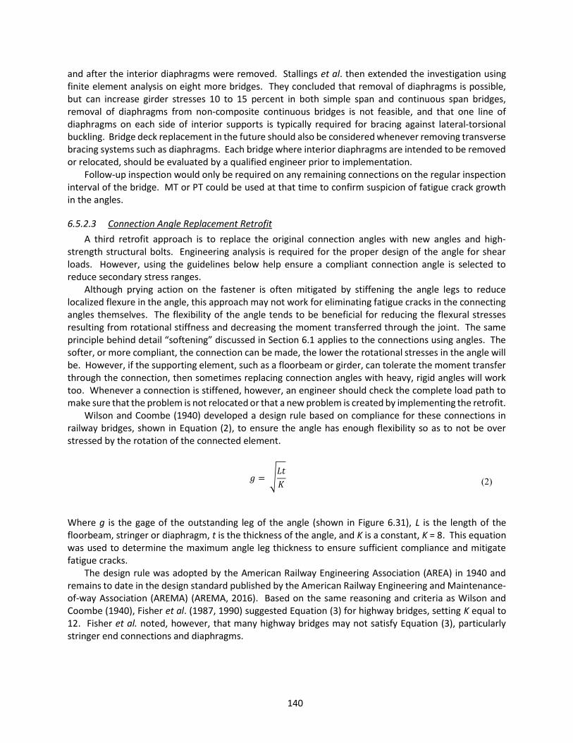
140
and after the interior diaphragms were removed. Stallings et al. then extended the investigation using finite element analysis on eight more bridges. They concluded that removal of diaphragms is possible, but can increase girder stresses 10 to 15 percent in both simple span and continuous span bridges, removal of diaphragms from non-composite continuous bridges is not feasible, and that one line of diaphragms on each side of interior supports is typically required for bracing against lateral-torsional buckling. Bridge deck replacement in the future should also be considered whenever removing transverse bracing systems such as diaphragms. Each bridge where interior diaphragms are intended to be removed or relocated, should be evaluated by a qualified engineer prior to implementation.
Follow-up inspection would only be required on any remaining connections on the regular inspection interval of the bridge. MT or PT could be used at that time to confirm suspicion of fatigue crack growth in the angles.
6.5.2.3 Connection Angle Replacement Retrofit A third retrofit approach is to replace the original connection angles with new angles and high-
strength structural bolts. Engineering analysis is required for the proper design of the angle for shear loads. However, using the guidelines below help ensure a compliant connection angle is selected to reduce secondary stress ranges.
Although prying action on the fastener is often mitigated by stiffening the angle legs to reduce localized flexure in the angle, this approach may not work for eliminating fatigue cracks in the connecting angles themselves. The flexibility of the angle tends to be beneficial for reducing the flexural stresses resulting from rotational stiffness and decreasing the moment transferred through the joint. The same principle behind detail “softening” discussed in Section 6.1 applies to the connections using angles. The softer, or more compliant, the connection can be made, the lower the rotational stresses in the angle will be. However, if the supporting element, such as a floorbeam or girder, can tolerate the moment transfer through the connection, then sometimes replacing connection angles with heavy, rigid angles will work too. Whenever a connection is stiffened, however, an engineer should check the complete load path to make sure that the problem is not relocated or that a new problem is created by implementing the retrofit.
Wilson and Coombe (1940) developed a design rule based on compliance for these connections in railway bridges, shown in Equation (2), to ensure the angle has enough flexibility so as to not be over stressed by the rotation of the connected element.
=
(2)
Where g is the gage of the outstanding leg of the angle (shown in Figure 6.31), L is the length of the floorbeam, stringer or diaphragm, t is the thickness of the angle, and K is a constant, K = 8. This equation was used to determine the maximum angle leg thickness to ensure sufficient compliance and mitigate fatigue cracks.
The design rule was adopted by the American Railway Engineering Association (AREA) in 1940 and remains to date in the design standard published by the American Railway Engineering and Maintenance-of-way Association (AREMA) (AREMA, 2016). Based on the same reasoning and criteria as Wilson and Coombe (1940), Fisher et al. (1987, 1990) suggested Equation (3) for highway bridges, setting K equal to 12. Fisher et al. noted, however, that many highway bridges may not satisfy Equation (3), particularly stringer end connections and diaphragms.

141
= 12
(3)
Cousins et al. (1998) found that by increasing the length of the angle leg, the fatigue performance of
connection angles could be improved. This approach enhances the joint compliance. Interestingly, however, two different angles were implemented by Cousins as replacement angles and monitored, revealing that the thinner angle (Type D) was more susceptible to fatigue cracking than the thicker angle (Type G) with the longer leg dimension. Figure 6.34 shows the two angles used. The Type D angle was a L6 x 6 x 3/8 inch and the Type G was a L8 x 6 x 1/2 inch. This suggests that when increasing the leg dimensions is possible, it may improve performance more than simply replacing with a thinner angle. However, it may not be feasible to replace angles with ones having longer leg dimensions since it would require new holes, or a slight side shift of the connected element to reuse existing fastener holes, in the floorbeam or girder web plates. Typically, new holes would not be a problem, but this should be checked by a qualified engineer. Paasch and DePiero (1999) found that increasing the angle leg from 4 inches to 6 inches (i.e., increasing the gage length on the outstanding angle leg), reduced the stress range in the angle by 40%.
Figure 6.34 Rendering of connection angles used by Cousins et al. (1998)
Follow-up inspection of the retrofit detail would only require visual inspection on the regular inspection interval for the bridge to check that the retrofit is performing as intended. MT or PT could be used at that time to confirm suspected fatigue crack growth in the angles.
6.5.2.4 Fastener Removal Retrofit Another method of softening a connection detail is to remove fasteners. This has been shown to be
effective for many details prone to secondary stress-induced fatigue and may be the most economical option. Paasch and DePiero (1999) analyzed connections from the Winchester Bridge on I-5 in Oregon. Using finite element analysis calibrated with field test data of known loads, they performed a parametric study that removed the top row and top two rows of fasteners in the riveted angle connections. They
Type D Type G

142
reported that by removing the top row of rivets, the stress range in the angle was reduced 32% and by removing the top two rows of rivets (leaving 3 intact), the bending stress range in the angles was reduced by as much as 70%. The results of removing fasteners from connections on other bridges may not be equal to what Paasch & DePiero (1999) found for the Winchester Bridge. However, their results provide insight into about what could be expected. Note that secondary effects on the concrete deck resulting from the increased connection flexibility were not quantified.
Removing the rivets from the connection increases compliance, but also increases the shear demand on the remaining rivets (or bolts). Engineering checks should be made to ensure that the remaining fasteners have the required capacity to carry the additional shear loading. In the case of rivets, replacing the rivets with high-strength structural bolts would significantly improve the shear capacity of the detail and may be a feasible option, if needed. Removing rivets or bolts from the connection would require the least amount of labor, material and design work of all the recommended options.
Follow-up inspection of the retrofit detail would only require visual inspection on the regular inspection interval for the bridge to check that the retrofit is performing as intended. MT or PT could be used at that time to confirm suspected fatigue crack growth in the angles.
6.6 Web Penetrations in Cross Girders
6.6.1 Description of Problem Steel box cross girders have been constructed as mid-span supports, or bents, for some steel bridges,
including highway and rail applications. The bents typically were constructed with two column legs, a horizontal built-up welded box member spanning between them, and having the bottom flanges of the longitudinal girders intersecting the box member web plates. Usually, the bents were fabricated with portions of the longitudinal girders integrally welded into the boxes with girder stubs projecting out from the web plate on either side of the box. The stubs projected three to four feet and were spliced to the longitudinal girders with bolted connections. The integral girder sections were normally passed through the bent box web via slots cut into the lower portion and then welded from one side. Today these details are known to perform very poorly in fatigue due to the high stress concentrations, residual stresses at the flange-web intersection, often poor weld quality due to the geometry of the detail, and out-of-plane distortion caused by the longitudinal girders. However, in the later 1950’s and 1960’s when the structures were designed this was not well understood.
In 1978 two bridges were found to have fatigue cracks and brittle fractures emanating from some of the cross girder web penetrations. The first was the Dan Ryan Expressway in Chicago, IL. Three bents were found to have fatigue cracks that led to brittle fracture. Figure 6.35 shows a picture of one of the fractured bents. Fractographic analysis revealed that the cracks initiated as fatigue at the partially welded junction of the plate girder flange tips to the cross girder (bent) side plates. Paint was also observed on the interior surface near the crack, suggesting poor fabrication of the detail that left built-in defects. The investigation confirmed that the combination of severe stress concentrations at the junction of the girder flange and bent side plates, fatigue cracking, and cold temperatures was sufficient to cause the fractures.
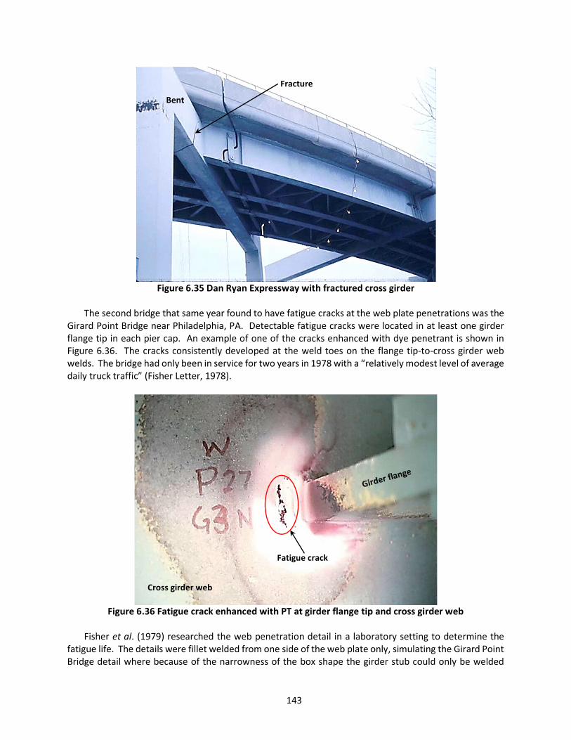
143
Figure 6.35 Dan Ryan Expressway with fractured cross girder
The second bridge that same year found to have fatigue cracks at the web plate penetrations was the
Girard Point Bridge near Philadelphia, PA. Detectable fatigue cracks were located in at least one girder flange tip in each pier cap. An example of one of the cracks enhanced with dye penetrant is shown in Figure 6.36. The cracks consistently developed at the weld toes on the flange tip-to-cross girder web welds. The bridge had only been in service for two years in 1978 with a “relatively modest level of average daily truck traffic” (Fisher Letter, 1978).
Figure 6.36 Fatigue crack enhanced with PT at girder flange tip and cross girder web
Fisher et al. (1979) researched the web penetration detail in a laboratory setting to determine the
fatigue life. The details were fillet welded from one side of the web plate only, simulating the Girard Point Bridge detail where because of the narrowness of the box shape the girder stub could only be welded
Fracture
Bent
Cross girder web
Fatigue crack

144
from the outside. They concluded that the fatigue life was roughly half that of a full-sized cover plated beam, that is to say much worse than the AASHTO Category E’. They estimated that the CAFL for the web penetration detail was around one ksi. Fisher et al. (1980) investigated web penetration details further, focusing on the fatigue life when the detail is fillet welded on both sides of the web. They found that these details performed around an AASHTO Category E’. They also noted a web plate thickness effect whereby they observed that when a ¾-inch thick flange was fillet welded to a ¼-inch web plate, the fatigue resistance was closer to a Category E. The bottom line is that the web penetration is a poor fatigue detail. Since the fatigue resistance is very low and the potential for cracking to initiate from the weld root (i.e., it is undetectable) it may be prudent to preemptively retrofit these details, especially when redundancy is questionable.
6.6.2 Repair or Retrofit Guidelines The recommended retrofit or repair for these details is referred to as a “dumb bell” or “dog bone”
detail. The nicknames come from the shape made by drilling two holes and connecting them with a saw cut. The sawcut between the drilled holes could also be effectively done using a controlled thermal cut, (plasma cutting is recommended over oxy-acetylene). The dog bone detail provides two benefits to the fatigue-prone web penetration detail. First, it helps to significantly lower the tensile residual stress field acting at the weld toe where the cracks have developed. Secondly, it isolates the cross girder web plate from subsequent fatigue crack growth or even fracture. Figure 6.37 illustrates a typical dog bone retrofit installed at a web penetration detail. Notice the two drilled holes highlighted in red that isolate the girder stub flange tip, which are connected by a vertical cut in the cross girder web plate. The alignment of the drilled holes should be such that the cut is approximately centered at the holes while cutting through the weld toe at the very tip of the flange. This retrofit should be installed at any web penetration detail located within a tension or reversal stress range area.
Figure 6.37 Cross girder structure with dog bone retrofit at the web penetration (deck removed for
clarity)
Girder stub web
Cross girder web
Dog bone

145
The following steps outline the proper procedure for a dog bone retrofit for cross girder web
penetration details: 1. Carefully inspect the flange weld terminations at the web penetration for fatigue cracks. Use
PT or MT methods to enhance visual indications. 2. Hole placement for the dog bone retrofit will be dependent on the location of an existing
crack tip. a. If no cracks are identified, the drilled holes should be centered over the flange tip
weld toes. b. If a crack is located at the flange tip weld toe that has not extended into the web plate
yet (like in Figure 6.36), then center the drilled holes over the weld toe and proceed to saw cut between them, as described in step 3.
c. If a crack is located that is grown into the penetrated web, the drilled holes should be placed at the crack tip as indicated in Figure 4.4. If cracks have grown out of the flange tip weld toes, vertically extending up and down the web plate, then the drilled holes can be placed at the crack tips and the sawcut is not necessary since the crack is effectively doing the same thing that a sawcut is intended to do.
3. Drill the 3-inch to 4-inch diameter holes. Use hole finish sanding techniques described in Section 4.3 to ensure a quality, fatigue-resistant edge conditions for long-term performance.
4. Connect the centers of the two drilled holes by cutting vertically up/down the web plate using an angle grinder with cutoff wheel or a controlled thermal cutting process such as plasma cutting. If possible, make the vertical cut between the two holes pass through the flange tip weld toes. This will remove any existing cracks, as well as relieve the detail of locked-in welding residual stresses. Refer to Figure 6.37 for illustration of this detail. See Figure 6.38 for an example of the dog bone retrofit installed on the Girard Point Bridge.
5. Paint the repair area using recommendations provided in Section 4.2. 6. Repeat steps 1 through 5 for all flange tips on both sides of the girder stubs and on both sides
of the cross girder. 7. Follow up with typical visual inspections scheduled with the regular inspection cycle for the
bridge. If the repair or retrofit were to fatigue, the cracks would initiate at the top edge of the top hole or bottom edge of the bottom hole extending vertically up and down the penetrated web plate.

146
Figure 6.38 Completed dog-bone retrofit on a web penetration detail

147
CHAPTER 7. MAINTENANCE ACTIONS FOR DETAILS AT RISK OF CONSTRAINT-INDUCED FRACTURE
Fatigue life and the likelihood of fatigue cracking can be estimated with calculations and/or using field instrumentation and monitoring. In contrast, constraint-induced fracture (CIF) has been observed to occur suddenly without warning and without fatigue cracks preceding it. Thirty-five percent of survey participants indicated that their agency has experienced at least one fracture from a CIF detail in their inventory. It is unknown how many bridges have experienced CIF events since many probably go undocumented and are simply repaired, in some cases being misidentified as fatigue cracks. There is no time in service at which point the risk of CIF has been reduced or can be assumed to have been eliminated. Several case studies of CIF show that multiple decades of service can go by before a fracture occurs. This means that past performance is not an indicator of future results. Additionally, the inspection is not a viable method to address CIF nor can instrumentation provide meaningful data for evaluation. Once a detail is identified as being susceptible, the details must either be retrofit or one must accept the consequence of a possible fracture. This is to say that the retrofit approach for CIF details must be a preemptive one. The role of inspection is simply to recognize a CIF detail so that appropriate retrofit plans can be put in place.
The best-known case study for CIF is the Hoan Bridge in Milwaukee, WI, which carries I-794 over the Milwaukee River. This case study is discussed more in the following section. Other bridges have also had similar fractures originate at CIF details, such as the Shenango River Bridge and the US 422 Bridge over the Schuylkill River. Interestingly, the US 422 Bridge fracture was discovered while retrofits to its lateral gusset plates were being performed in 2003. Figure 7.1 shows the fracture in the tension flange of the fracture-critical girder. The fracture severed the tension flange and traveled 9 inches into the web before arresting at discontinuities in the web plate (Kaufmann et al., 2004). Figure 7.2 shows the inside and outside vantage points of the fracture revealing the ductile yielding of the web plate indicated by the yield lines in the paint and the separation of the tension flange. The deflection of the fracture-critical girder was so slight that it went unnoticed by motorists for an unknown amount of time.
Figure 7.1 US 422 Bridge fracture discovered in 2003 during retrofitting
Fracture
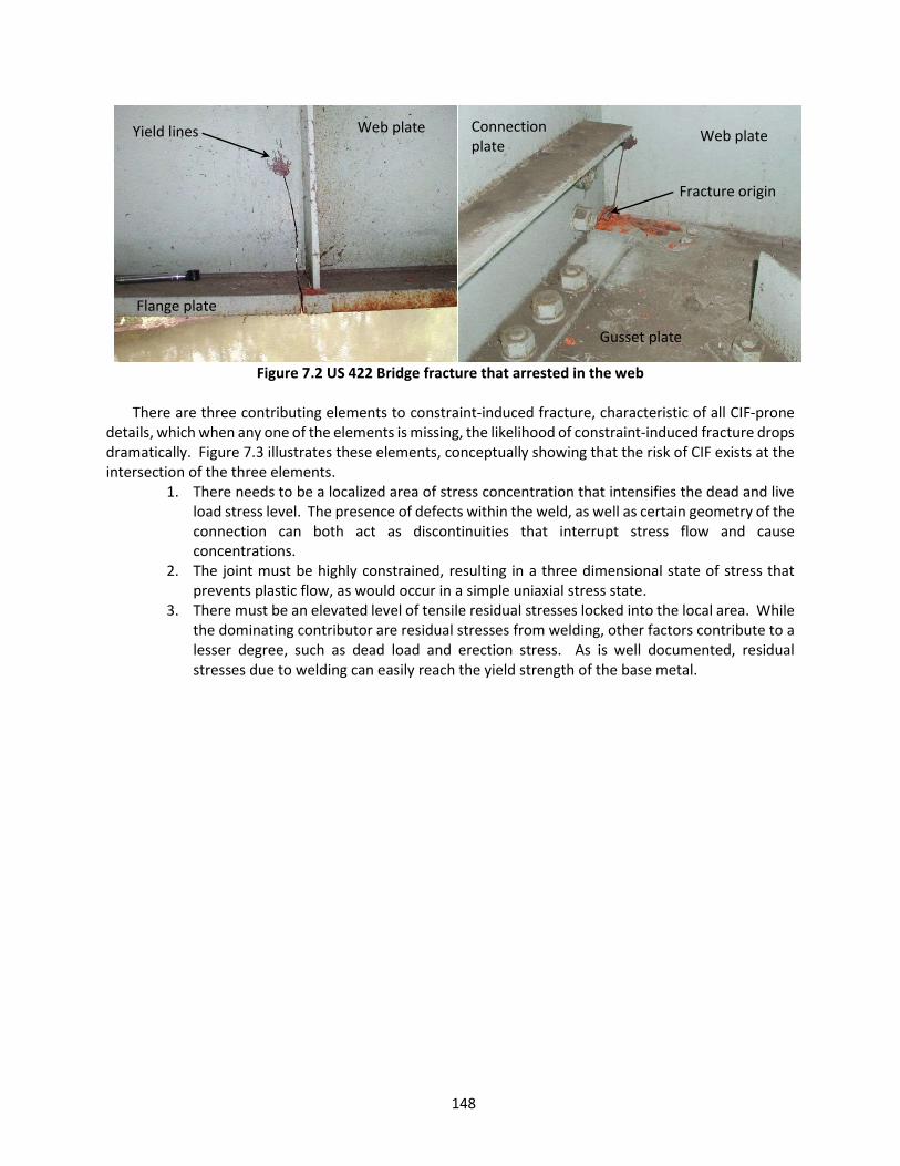
148
Figure 7.2 US 422 Bridge fracture that arrested in the web There are three contributing elements to constraint-induced fracture, characteristic of all CIF-prone
details, which when any one of the elements is missing, the likelihood of constraint-induced fracture drops dramatically. Figure 7.3 illustrates these elements, conceptually showing that the risk of CIF exists at the intersection of the three elements.
1. There needs to be a localized area of stress concentration that intensifies the dead and live load stress level. The presence of defects within the weld, as well as certain geometry of the connection can both act as discontinuities that interrupt stress flow and cause concentrations.
2. The joint must be highly constrained, resulting in a three dimensional state of stress that prevents plastic flow, as would occur in a simple uniaxial stress state.
3. There must be an elevated level of tensile residual stresses locked into the local area. While the dominating contributor are residual stresses from welding, other factors contribute to a lesser degree, such as dead load and erection stress. As is well documented, residual stresses due to welding can easily reach the yield strength of the base metal.
Yield lines
Fracture origin
Flange plate
Web plate
Gusset plate
Connection plate
Web plate

149
Figure 7.3 Defining characteristics of CIF details
Figure 7.4 Illustration of effect of web gap size and constraint on the stress condition at the weld
termination with the web gap (Connor et al., 2007)
Residual stresses(welded details)
Presence of defect or crack-like geometry
(stress concentration)
Constrained material(little or no web gap)
CIF

150
Figure 7.4 provides an illustration of the mechanics behind the three contributing elements for CIF. This figure shows a plan view and elevation view of a welded detail where the longitudinal attachment to the web plate intersects with the transverse plate. Little or no web plate gap exists between the weld intersections. Due to the welded construction, high residual tensile stresses are present. Crack-like geometry amplifies stress concentrations by disrupting stress flow between the longitudinal and transverse plates forcing those stresses back into the web plate through the small area of intersecting weld. With the stress condition at the yield strength of the web plate, the material would attempt to contract in the through-thickness direction under live loading in order to disperse stress (i.e., Poisson’s effect). However, the longitudinal attachments constrain the plastic flow of the web material subjecting it to what is called a triaxial state of stress, or plain strain condition, illustrated by the cube that represents an infinitesimal section of the web plate. The triaxial state of stress strain-hardens the material increasing its strength while decreasing its ductility. Once the localized stress condition exceeds the material tensile (ultimate) strength, brittle fracture ensues. This situation can be made more vulnerable when fracture toughness of the web material is reduced during cold temperatures.
Figure 7.5 shows another illustration of the same detail, except that in this case there is a web gap between the transverse and longitudinal weld toes that removes constraint from the plate at that localized region. As the gap becomes larger, the effect of the residual stresses from the welds and the local stress concentrations at the termination of the longitudinal plate are reduced. This creates a much different stress condition at the web gap (plain stress), which allows the web plate to strain. This concept is demonstrated with the necking of the web plate in the plan view and the stress state of the infinitesimal cube in the elevation view. The third axis of stress, σ3, is diffused through necking of the material while stresses along the σ1 and σ2 axes have been shown to reduce by 26% and 36%, respectively, with a web gap size of ¼-inch (Mahmoud et al., 2005b; Connor et al., 2007).
With the constraint removed from the web gap, the improved detail shown in Figure 7.5 is no longer at risk of constraint-induced fracture. Fracture has never been observed at the end of the longitudinal attachment away from the transverse attachment despite the fact that the weld termination would possess similar residual tensile stresses from the welding and similar stress concentrations from dead and live loads as is the case at the CIF detail. However, the constraint does not exist because just beyond the longitudinal attachment, the web plate is unconstrained and allowed to yield as needed. Thus, the third element is missing and the risk of fracture is significantly reduced. This is the basis of some of the retrofit approaches discussed in detail in the following sections. Thus, removal of the constraint through removal of the intersection of welds and opening of the web gap between weld toes has proven to be a very effective retrofit strategy.

151
Figure 7.5 Illustration of effect of a sufficient web gap that removes constraint at the weld termination
(Connor et al., 2007)
7.1 Intersecting Welds at Gusset Plates (Hoan Details)
7.1.1 Description of Problem CIF details located at gusset (or shelf) plate details are often also referred to as “Hoan Details” in
practice. This stems from a fracture of all three girders on one of the south approach spans of the Hoan Bridge in Milwaukee, Wisconsin, on December 13, 2000. The approach spans for the steel tied arch bridge are continuous plate girder construction with CIF details at the lateral gusset plates. There are three girders in the cross section. Following the fracture, the northbound span sagged about four feet, but incredibly did not collapse, though two of the three girders completely fractured and significant cracking was observed in the web of the third. Detailed analysis indicated that brittle fractures developed at the intersection of the shelf plate and transverse connection plate without any detectable fatigue crack extension or ductile tearing at the crack origin (Fisher et al., 2001). The photograph in Figure 7.6 was taken shortly after the discovery of the fracture and shows the interior girder CIF detail. The brittle nature of the fracture is evident from the lack of yield lines in the paint and the straight, sawcut-like appearance of the fracture surface. Figure 7.7 shows the Hoan detail removed from the bridge for evaluation with the characteristic intersecting welds and crack-like geometry rendered by the lack of weld between the gusset plate and the transverse connection plate. Although this crack-like geometry increases risk of CIF, brittle fracture can still initiate at a CIF detail that has a weld connecting the gusset plate to the transverse plate. This was the case for the US 422 Bridge fracture discussed previously.
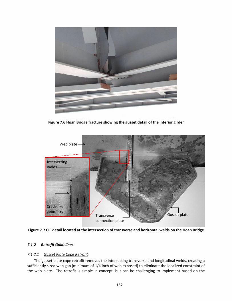
152
Figure 7.6 Hoan Bridge fracture showing the gusset detail of the interior girder
Figure 7.7 CIF detail located at the intersection of transverse and horizontal welds on the Hoan Bridge
7.1.2 Retrofit Guidelines
7.1.2.1 Gusset Plate Cope Retrofit The gusset plate cope retrofit removes the intersecting transverse and longitudinal welds, creating a
sufficiently sized web gap (minimum of 1/4 inch of web exposed) to eliminate the localized constraint of the web plate. The retrofit is simple in concept, but can be challenging to implement based on the
Gusset plate
Web plate
Transverse connection plate
Crack-like geometry
Intersecting welds

153
geometry of a detail. Figure 7.8 illustrates the simplest form of this detail with the secondary members removed for clarity, demonstrating the location of the copes adjacent to the transverse connection or stiffening plate.
The tighter into the corner a drill can be placed, the more efficiently the retrofit can be installed. This is because it cuts down on the amount of grinding that is required after drilling to remove any leftover longitudinal weld and expose the web plate. After-market modifications to magnetic-based drills performed by some help to better fit the tool into the corner of the intersecting plates, as well as fabricated jigs to allow the drill to approach the intersection from a slight angle. Sometimes this retrofit will require removal of bolts or rivets from nearby secondary elements that are in the way of tool placement, or sometimes it will require drilling upside down. All of these nuances can add up to longer-than-anticipated installation times if they are not worked out in the beginning. Performance testing of contractors can help with this, particularly when the contractor has not performed this retrofit before or if there is a unique aspect to the bridge detail in question that may add another level of difficulty. Prequalifying on authentic details that are not part of the bridge can be helpful in working out the installation plan. Performance testing is discussed more in Section 4.6.
There are certain characteristics that are desirable for this retrofit to be effective: 1. First and foremost, the web gap, or exposed web plate between weld toes (not the distance
between the welds) must be a minimum of ¼-inch. It is recommended that the target gap be twice that much or more to help ensure that the minimum is met.
2. Complete removal of the longitudinal weld material from the web plate without gouging the web plate and while preserving the transverse weld profile
3. A smooth and gradual transition from the gusset plate to the web plate
Figure 7.8 Gusset plate cope retrofit (secondary members removed for clarity)
The following steps outline the proper procedure for a gusset plate cope retrofit for details susceptible
to CIF:
Web plate
Web gaps

154
1. Place the annular cutter into the corner created by the web and transverse plates. Adjust the drill such that the cutter is as close to the web plate and transverse plate as possible. The larger the diameter of the cutter, generally the easier this will be, but this also depends on the size and shape of the drill being used.
2. Drill the hole. Caution: tie off the mag-based drill to the girder using sturdy clamps and chain/rope in the event of power loss. This will help prevent injury or damage to equipment. Note: Carbide-tip annular cutters are recommended when the cut penetrates welds or heat-affected zones due to increased hardness of the material.
3. Once the core is removed, use a die grinder with rotary carbide burr bit to remove any leftover gusset plate and longitudinal weld that could not be reached by drilling (see Figure 7.9). Slowly and carefully carve away the material while sculpting a smooth and gradual transition back into the web plate. Be careful to not gouge the web plate. If gouging does occur, use flap wheels to smooth out and taper the gouges to avoid stress concentration.
Figure 7.9 Burr grinder being used to remove leftover gusset plate and weld
4. With the web plate exposed, check the new web gap dimension between the longitudinal and
transverse weld toes (see Figure 7.10). This gap must be a minimum of 1/4-inch, but more is better. If the gap is less than 1/4 inch, additional grinding with the carbide rotary burr bit and die grinder will be necessary.
5. Once the cope is formed and sufficient web gap has been established, change the burr bit for a 60 to 80 grit flap wheel to begin polishing and smoothing the drilled hole and exposed web plate.
6. Next, sand the edges of the drilled hole and exposed web plate using an 80 to 100 grit flap wheel with angle grinder on the exterior edges and 80 to 100 grit flap wheel with die grinder on the interior edges. Sand until the surfaces are smooth and free of cutting marks and gouges. If the gusset plate is fillet welded to the web, be sure to blunt the transition slightly. Smooth tapering of fillet welds can result in hair-thin cross sections of weld that can become vulnerable to fatigue cracking (Connor et al., 2007). Thus, the tip should be blunted by slightly rounding it off with the flap wheel as it tapers back into the web plate.
Web plate
Gusset plate
Leftover plate to be removed

155
7. Paint the repair area using recommendations provided in Section 4.2.
Figure 7.10 shows an example of the completed retrofit on one side of the transverse plate. This same procedure must be repeated on the other side of the transverse plate for a completed retrofit. Notice the smooth and gradual transition from the gusset plate to the web plate that helps to minimize stress concentrations at the weld termination, the preserved transverse weld, and the smooth 3/4-inch web gap exposed between weld toes.
Making a cope at the intersection of the lateral gusset plate and the transverse connection or stiffener plate creates a web gap, as labeled in Figure 7.10. This is desirable for mitigation of CIF, however, it is worth mentioning that the detail is still susceptible to distortion-induced fatigue if the gusset plate and transverse plate are not positively connected. Fisher et al. (1990) found that structures with lateral bracing attached to the girder webs by gusset plates, along with transverse connection plates for floorbeams or diaphragms, were susceptible to web distortions in the gaps between the gusset plate and transverse connection plate. They found that the lateral gusset plate web gaps demonstrated a fatigue resistance equivalent to an AASHTO Category C. During the experimental laboratory research, cracking only occurred along the web at the weld toe of the transverse connection plate. As a result, it is recommended that future inspections of the CIF retrofit detail (that does not connect the gusset plate to the transverse connection plate) include careful observation at the transverse weld toe inside the newly created web gap region. Field testing of this area could also be performed at a few locations on the bridge following retrofitting to determine if stress ranges in the gap are large enough to cause fatigue cracking at the Category C detail under random or controlled live loads. The stress ranges that would be monitored in this case, would be those caused by the out-of-plane push and/or pull of the lateral bracing on the gusset plate, not the primary stresses in the girder.
Figure 7.10 Completed gusset plate cope retrofit with ¾” web gap
Web plate
Gusset plate
Web gap ≥ 1/4”

156
7.1.2.2 Web Plate Isolation Holes Retrofit Unlike the gusset plate cope retrofit that removes one of the contributing factors for constraint-
induced fracture, namely the constraint, the web plate isolation hole retrofit simply installs a mechanism to arrest a fracture immediately after it initiates, isolating the web plate and flanges from further fracture propagation. The local conditions of the detail that make it susceptible to CIF are not altered, leaving the potential for fracture unchanged. However, the risk of the fracture is essentially eliminated by arresting it before it can cause damage to the girder. This retrofit was the first retrofit put in place on the Hoan Bridge following the brittle fracture of the three approach span girders. During retrofitting operations, workers completed a CIF retrofit and had moved to the next location when they heard a loud noise. Returning to the previously retrofit detail to investigate they discovered that the CIF detail had fractured and the retrofit performed as designed immediately arresting the crack in the newly installed isolation holes. Figure 7.11 is a photograph of that fracture showing that it arrested into the retrofit hole.
Figure 7.11 CIF arrested in one of the Hoan Bridge web isolation holes shortly after installation
(Photograph courtesy of Phil Fish) The web isolation holes retrofit can be implemented anywhere that access to the CIF detail allows for
all four holes to be properly drilled. When conditions are suitable for it, this retrofit can be one of the simplest CIF retrofits to perform, generally making it the most economical, as well. The diameter of the hole is not as important as its placement, but generally a two-inch to four-inch diameter hole would be recommended. This is not only to reduce stress concentrations at the hole edge, but also because it makes the key aspect of this retrofit more achievable, which is to intersect the vertical weld toe with the drilled hole. Once the fracture initiates, it will travel vertically up and down the web plate. The most likely path for the fracture will be along the vertical weld toe or in the web plate following a mostly vertical trajectory. By placing the hole such that both of these paths (and ideally the longitudinal gusset-to-web weld toe also), the fracture will not have an uninterrupted path into the rest of the girder web and flange. Hence, the retrofit is referred to as “web isolation holes” since its purpose is to isolate the girder from the potential fracture. Figure 7.12 illustrates this retrofit showing the four holes surrounding the CIF detail. Notice that the holes intercept the vertical and horizontal welds toes.
Web
Gusset
Connection plate
Fracture

157
Figure 7.12 Web plate isolation holes retrofit for CIF details
The following steps outline the proper procedure for the web plate isolation holes retrofit for CIF
details: Note: Begin this retrofit by drilling the holes between the CIF detail and the tension flange first. This
is recommended because as the holes are drilled, locked in stresses can redistribute and could possibly trigger a fracture. Thus, the first priority should be to isolate the tension flange.
1. Determine the correct placement for the annular cutter ensuring that the drilled hole will intercept the vertical weld toe about 1/8-inch, as illustrated in Figure 7.12. If possible, also place the drilled hole so that it intercepts the horizontal weld toe, but if both cannot be achieved, the vertical weld toe is far more critical. In order to ensure a correct placement from the backside of the web plate (opposite the gusset plate or longitudinal stiffener), a small 1/4-inch to 3/8-inch pilot hole using a hand drill can be helpful. Drill the pilot hole at the assumed center of the eventual isolation hole (this simplifies locating the position and also ensure that the small pilot hole will be removed during drilling of the isolation hole). Then absolute measurements can be made relative to the pilot hole on both sides of the web plate to establish the correct position for the annular cutter.
2. Drill the hole. Caution: tie off the mag-based drill to the girder using sturdy clamps and chain/rope in the event of power loss. This will help prevent injury or damage to equipment. Note: Carbide-tip annular cutters are recommended when the cut penetrates welds or heat-affected zones due to increased hardness of the material.
3. Inspect the hole placement to confirm that it intercepts the vertical weld at least 1/8-inch. If the hole misses the vertical weld toe, use a carbide rotary burr bit with a die grinder to widen the hole toward the vertical weld toe. Grind until the weld toe has been sufficiently disconnected and there is no longer a continuous path for a fracture to bypass the isolation hole. Figure 7.13 shows this retrofit on the Hoan Bridge. Notice in photograph (A) that the transverse stiffener weld toe has been drilled out. Photograph (B) shows the entire retrofit from the opposite side of the web plate revealing the four holes that surround the CIF detail.
4. Repeat Steps 2 and 3 until all four holes have been completed. 5. Next, sand the exterior edges of the drilled holes using an 80 to 100 grit flap wheel with angle
grinder and 80 to 100 grit flap wheel with die grinder on the interior surfaces. Sand until the surfaces are smooth and free of cutting marks and gouges.
Web
Gusset plate
Flange
~1/8-inch
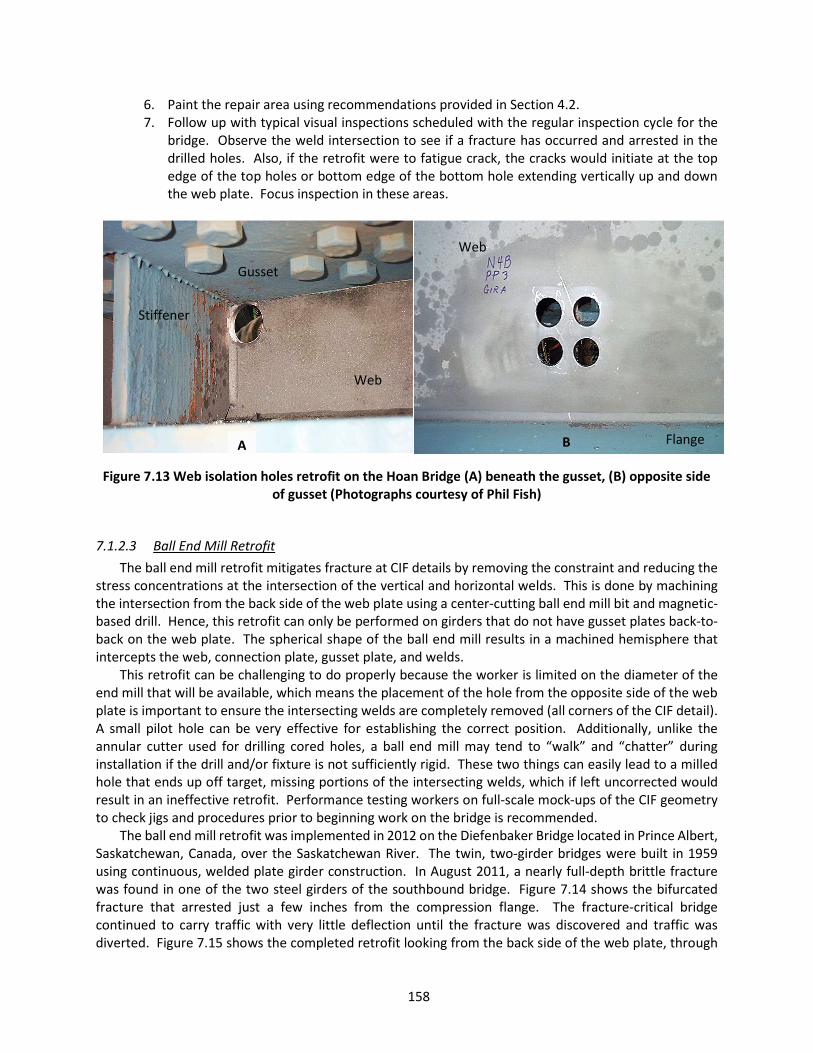
158
6. Paint the repair area using recommendations provided in Section 4.2. 7. Follow up with typical visual inspections scheduled with the regular inspection cycle for the
bridge. Observe the weld intersection to see if a fracture has occurred and arrested in the drilled holes. Also, if the retrofit were to fatigue crack, the cracks would initiate at the top edge of the top holes or bottom edge of the bottom hole extending vertically up and down the web plate. Focus inspection in these areas.
Figure 7.13 Web isolation holes retrofit on the Hoan Bridge (A) beneath the gusset, (B) opposite side of gusset (Photographs courtesy of Phil Fish)
7.1.2.3 Ball End Mill Retrofit The ball end mill retrofit mitigates fracture at CIF details by removing the constraint and reducing the
stress concentrations at the intersection of the vertical and horizontal welds. This is done by machining the intersection from the back side of the web plate using a center-cutting ball end mill bit and magnetic-based drill. Hence, this retrofit can only be performed on girders that do not have gusset plates back-to-back on the web plate. The spherical shape of the ball end mill results in a machined hemisphere that intercepts the web, connection plate, gusset plate, and welds.
This retrofit can be challenging to do properly because the worker is limited on the diameter of the end mill that will be available, which means the placement of the hole from the opposite side of the web plate is important to ensure the intersecting welds are completely removed (all corners of the CIF detail). A small pilot hole can be very effective for establishing the correct position. Additionally, unlike the annular cutter used for drilling cored holes, a ball end mill may tend to “walk” and “chatter” during installation if the drill and/or fixture is not sufficiently rigid. These two things can easily lead to a milled hole that ends up off target, missing portions of the intersecting welds, which if left uncorrected would result in an ineffective retrofit. Performance testing workers on full-scale mock-ups of the CIF geometry to check jigs and procedures prior to beginning work on the bridge is recommended.
The ball end mill retrofit was implemented in 2012 on the Diefenbaker Bridge located in Prince Albert, Saskatchewan, Canada, over the Saskatchewan River. The twin, two-girder bridges were built in 1959 using continuous, welded plate girder construction. In August 2011, a nearly full-depth brittle fracture was found in one of the two steel girders of the southbound bridge. Figure 7.14 shows the bifurcated fracture that arrested just a few inches from the compression flange. The fracture-critical bridge continued to carry traffic with very little deflection until the fracture was discovered and traffic was diverted. Figure 7.15 shows the completed retrofit looking from the back side of the web plate, through
A B
Web
Flange
Web
Gusset
Stiffener
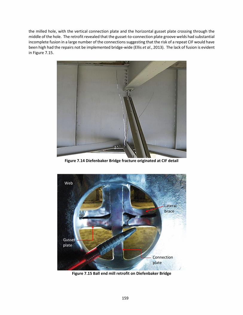
159
the milled hole, with the vertical connection plate and the horizontal gusset plate crossing through the middle of the hole. The retrofit revealed that the gusset-to-connection plate groove welds had substantial incomplete fusion in a large number of the connections suggesting that the risk of a repeat CIF would have been high had the repairs not be implemented bridge-wide (Ellis et al., 2013). The lack of fusion is evident in Figure 7.15.
Figure 7.14 Diefenbaker Bridge fracture originated at CIF detail
Figure 7.15 Ball end mill retrofit on Diefenbaker Bridge
Web
Gusset plate
Connection plate
Lateral brace
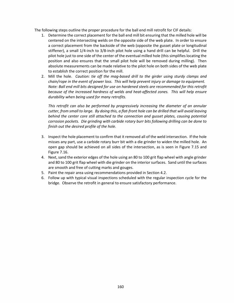
160
The following steps outline the proper procedure for the ball end mill retrofit for CIF details: 1. Determine the correct placement for the ball end mill bit ensuring that the milled hole will be
centered on the intersecting welds on the opposite side of the web plate. In order to ensure a correct placement from the backside of the web (opposite the gusset plate or longitudinal stiffener), a small 1/4-inch to 3/8-inch pilot hole using a hand drill can be helpful. Drill the pilot hole just to one side of the center of the eventual milled hole (this simplifies locating the position and also ensures that the small pilot hole will be removed during milling). Then absolute measurements can be made relative to the pilot hole on both sides of the web plate to establish the correct position for the mill.
2. Mill the hole. Caution: tie off the mag-based drill to the girder using sturdy clamps and chain/rope in the event of power loss. This will help prevent injury or damage to equipment. Note: Ball end mill bits designed for use on hardened steels are recommended for this retrofit because of the increased hardness of welds and heat-affected zones. This will help ensure durability when being used for many retrofits.
This retrofit can also be performed by progressively increasing the diameter of an annular cutter, from small to large. By doing this, a flat-front hole can be drilled that will avoid leaving behind the center core still attached to the connection and gusset plates, causing potential corrosion pockets. Die grinding with carbide rotary burr bits following drilling can be done to finish out the desired profile of the hole.
3. Inspect the hole placement to confirm that it removed all of the weld intersection. If the hole misses any part, use a carbide rotary burr bit with a die grinder to widen the milled hole. An open gap should be achieved on all sides of the intersection, as is seen in Figure 7.15 and Figure 7.16.
4. Next, sand the exterior edges of the hole using an 80 to 100 grit flap wheel with angle grinder and 80 to 100 grit flap wheel with die grinder on the interior surfaces. Sand until the surfaces are smooth and free of cutting marks and gouges.
5. Paint the repair area using recommendations provided in Section 4.2. 6. Follow up with typical visual inspections scheduled with the regular inspection cycle for the
bridge. Observe the retrofit in general to ensure satisfactory performance.

161
Figure 7.16 Matthew E. Welsh Bridge CIF ball end mill retrofit (Photograph courtesy of Indiana DOT)
7.2 Intersecting Welds at Longitudinal Stiffener Plates
7.2.1 Description of Problem Longitudinal stiffener plates with welds that intersect with transverse connection and stiffener plate
welds are also prone to constraint-induced fracture when located in a tensile or stress reversal zone. A few documented cases exist, such as a bridge along I-90 near Bozeman, MT, that suffered a near full-depth fracture that initiated at the intersection of the longitudinal and transverse stiffening elements. A couple photographs show this fracture from the interior and exterior perspectives in Figure 7.17. The same retrofit approaches discussed for the gusset plate intersecting welds can also be effectively implemented for this detail, since the same driving mechanisms and similar detailing are behind the cause of the fracture risk. First, coping the stiffener plate back away from the transverse plate to open the 1/4-inch gap and remove constraint, will be discussed below with a case study and example. Second, isolation holes drilled into the web plate above and below the CIF location on both sides of the transverse plate could be used. Observing the crack propagation path in Figure 7.17, it becomes apparent that correctly placed isolation holes would have interrupted the crack path and arrested the fracture. And although it has not been used for this particular detail, the ball end mill retrofit could also succeed presuming the entire intersection (both sides of the transverse plate) could be removed by the milling process.
Also, sometimes the longitudinal and transverse plates are spaced far enough apart that the requisite 1/4-inch web gap between weld toes could be established by simply grinding down the longitudinal weld termination. It is not uncommon that by removing some of the longitudinal weld that wraps around the end of the stiffener, the web gap can be established (see Figure 7.18). The grinding can be challenging, however, because of the limited access between the longitudinal and transverse plates and in many cases the geometry will prohibit this method. However, if the geometry is favorable for this simplified retrofit, it is the most economical way to reduce CIF risk at this detail. When performing the retrofit, ensure the
View from exterior of girder web
Web
Gusset plate
Connection plate

162
quality of the grinding does not suffer as a consequence of the limited access resulting in fatigue initiation sites at web plate gouges, etc.
Figure 7.17 CIF at a longitudinal stiffener
Figure 7.18 Example of CIF retrofit on longitudinal stiffener providing necessary ¼-inch web gap
7.2.2 Retrofit Guidelines Since this detail and the gusset detail discussed in Section 7.1 are very similar, it is recommended to
consult with Section 7.1.2 for additional guidance on retrofit approaches for the longitudinal stiffener CIF detail. This includes the isolation holes and ball end mill retrofit methods. The remainder of the present
Longitudinal stiffener
≥ 1/4” gap
Web
Longitudinal stiffener
Web
Fracture
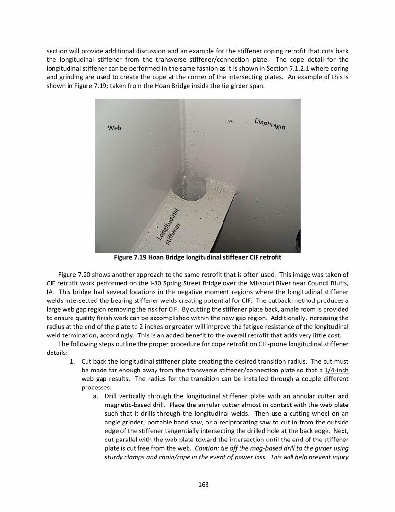
163
section will provide additional discussion and an example for the stiffener coping retrofit that cuts back the longitudinal stiffener from the transverse stiffener/connection plate. The cope detail for the longitudinal stiffener can be performed in the same fashion as it is shown in Section 7.1.2.1 where coring and grinding are used to create the cope at the corner of the intersecting plates. An example of this is shown in Figure 7.19; taken from the Hoan Bridge inside the tie girder span.
Figure 7.19 Hoan Bridge longitudinal stiffener CIF retrofit
Figure 7.20 shows another approach to the same retrofit that is often used. This image was taken of
CIF retrofit work performed on the I-80 Spring Street Bridge over the Missouri River near Council Bluffs, IA. This bridge had several locations in the negative moment regions where the longitudinal stiffener welds intersected the bearing stiffener welds creating potential for CIF. The cutback method produces a large web gap region removing the risk for CIF. By cutting the stiffener plate back, ample room is provided to ensure quality finish work can be accomplished within the new gap region. Additionally, increasing the radius at the end of the plate to 2 inches or greater will improve the fatigue resistance of the longitudinal weld termination, accordingly. This is an added benefit to the overall retrofit that adds very little cost.
The following steps outline the proper procedure for cope retrofit on CIF-prone longitudinal stiffener details:
1. Cut back the longitudinal stiffener plate creating the desired transition radius. The cut must be made far enough away from the transverse stiffener/connection plate so that a 1/4-inch web gap results. The radius for the transition can be installed through a couple different processes:
a. Drill vertically through the longitudinal stiffener plate with an annular cutter and magnetic-based drill. Place the annular cutter almost in contact with the web plate such that it drills through the longitudinal welds. Then use a cutting wheel on an angle grinder, portable band saw, or a reciprocating saw to cut in from the outside edge of the stiffener tangentially intersecting the drilled hole at the back edge. Next, cut parallel with the web plate toward the intersection until the end of the stiffener plate is cut free from the web. Caution: tie off the mag-based drill to the girder using sturdy clamps and chain/rope in the event of power loss. This will help prevent injury
Web
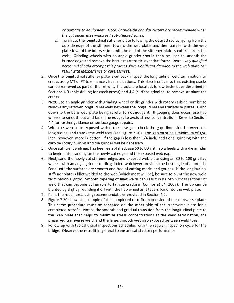
164
or damage to equipment. Note: Carbide-tip annular cutters are recommended when the cut penetrates welds or heat-affected zones.
b. Torch cut the longitudinal stiffener plate following the desired radius, going from the outside edge of the stiffener toward the web plate, and then parallel with the web plate toward the intersection until the end of the stiffener plate is cut free from the web. Grinding wheels with an angle grinder should then be used to smooth the burned edge and remove the brittle martensitic layer that forms. Note: Only qualified personnel should attempt this process since significant damage to the web plate can result with inexperience or carelessness.
2. Once the longitudinal stiffener plate is cut back, inspect the longitudinal weld termination for cracks using MT or PT to enhance visual indications. This step is critical so that existing cracks can be removed as part of the retrofit. If cracks are located, follow techniques described in Sections 4.3 (hole drilling for crack arrest) and 4.4 (surface grinding) to remove or blunt the cracks.
3. Next, use an angle grinder with grinding wheel or die grinder with rotary carbide burr bit to remove any leftover longitudinal weld between the longitudinal and transverse plates. Grind down to the bare web plate being careful to not gouge it. If gouging does occur, use flap wheels to smooth out and taper the gouges to avoid stress concentration. Refer to Section 4.4 for further guidance on surface gouge repairs.
4. With the web plate exposed within the new gap, check the gap dimension between the longitudinal and transverse weld toes (see Figure 7.20). This gap must be a minimum of 1/4-inch, however, more is better. If the gap is less than 1/4 inch, additional grinding with the carbide rotary burr bit and die grinder will be necessary.
5. Once sufficient web gap has been established, use 60 to 80 grit flap wheels with a die grinder to begin finish sanding on the newly cut edge and the exposed web gap.
6. Next, sand the newly cut stiffener edges and exposed web plate using an 80 to 100 grit flap wheels with an angle grinder or die grinder, whichever provides the best angle of approach. Sand until the surfaces are smooth and free of cutting marks and gouges. If the longitudinal stiffener plate is fillet welded to the web (which most will be), be sure to blunt the new weld termination slightly. Smooth tapering of fillet welds can result in hair-thin cross sections of weld that can become vulnerable to fatigue cracking (Connor et al., 2007). The tip can be blunted by slightly rounding it off with the flap wheel as it tapers back into the web plate.
7. Paint the repair area using recommendations provided in Section 4.2. 8. Figure 7.20 shows an example of the completed retrofit on one side of the transverse plate.
This same procedure must be repeated on the other side of the transverse plate for a completed retrofit. Notice the smooth and gradual transition from the longitudinal plate to the web plate that helps to minimize stress concentrations at the weld termination, the preserved transverse weld, and the large, smooth web gap exposed between weld toes.
9. Follow up with typical visual inspections scheduled with the regular inspection cycle for the bridge. Observe the retrofit in general to ensure satisfactory performance.
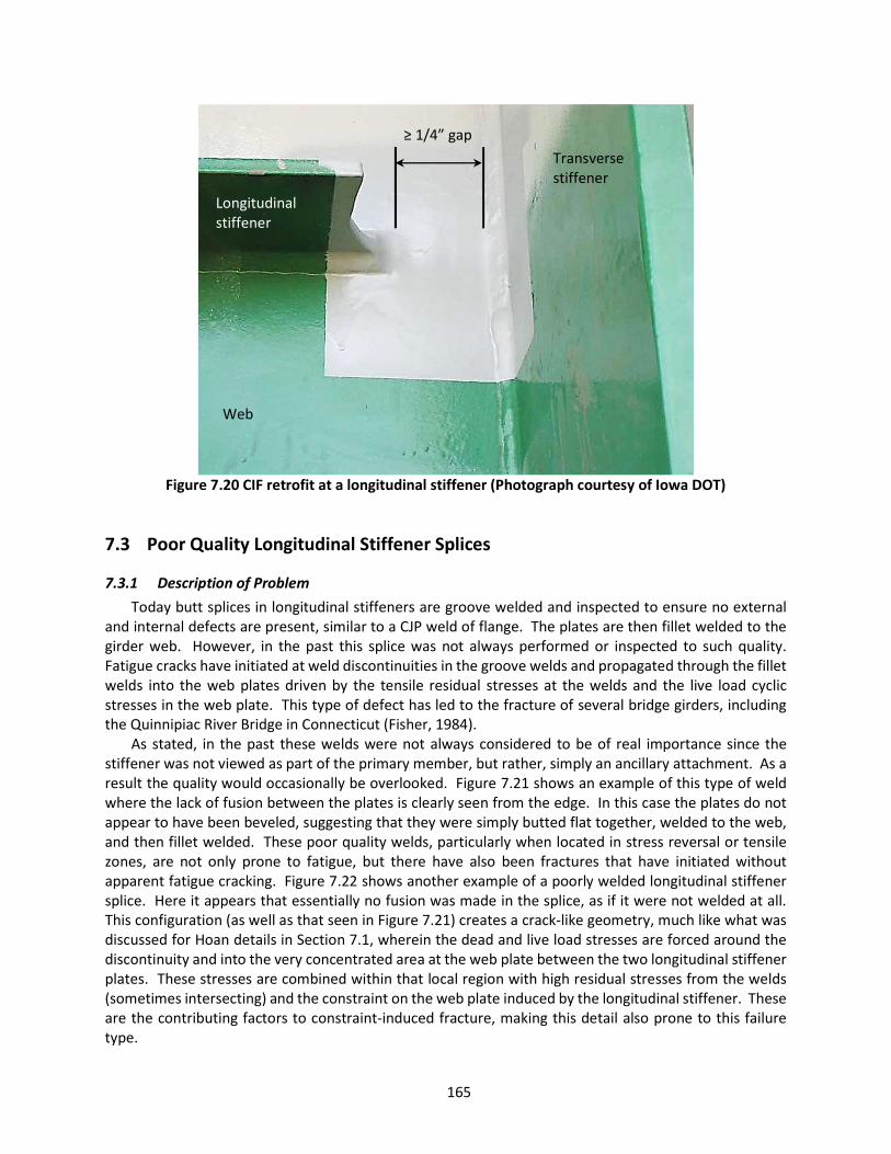
165
Figure 7.20 CIF retrofit at a longitudinal stiffener (Photograph courtesy of Iowa DOT)
7.3 Poor Quality Longitudinal Stiffener Splices
7.3.1 Description of Problem Today butt splices in longitudinal stiffeners are groove welded and inspected to ensure no external
and internal defects are present, similar to a CJP weld of flange. The plates are then fillet welded to the girder web. However, in the past this splice was not always performed or inspected to such quality. Fatigue cracks have initiated at weld discontinuities in the groove welds and propagated through the fillet welds into the web plates driven by the tensile residual stresses at the welds and the live load cyclic stresses in the web plate. This type of defect has led to the fracture of several bridge girders, including the Quinnipiac River Bridge in Connecticut (Fisher, 1984).
As stated, in the past these welds were not always considered to be of real importance since the stiffener was not viewed as part of the primary member, but rather, simply an ancillary attachment. As a result the quality would occasionally be overlooked. Figure 7.21 shows an example of this type of weld where the lack of fusion between the plates is clearly seen from the edge. In this case the plates do not appear to have been beveled, suggesting that they were simply butted flat together, welded to the web, and then fillet welded. These poor quality welds, particularly when located in stress reversal or tensile zones, are not only prone to fatigue, but there have also been fractures that have initiated without apparent fatigue cracking. Figure 7.22 shows another example of a poorly welded longitudinal stiffener splice. Here it appears that essentially no fusion was made in the splice, as if it were not welded at all. This configuration (as well as that seen in Figure 7.21) creates a crack-like geometry, much like what was discussed for Hoan details in Section 7.1, wherein the dead and live load stresses are forced around the discontinuity and into the very concentrated area at the web plate between the two longitudinal stiffener plates. These stresses are combined within that local region with high residual stresses from the welds (sometimes intersecting) and the constraint on the web plate induced by the longitudinal stiffener. These are the contributing factors to constraint-induced fracture, making this detail also prone to this failure type.
Web
Longitudinal stiffener
Transverse stiffener
≥ 1/4” gap

166
Figure 7.21 Example of poor quality longitudinal stiffener butt splice weld
Figure 7.22 Poor quality longitudinal stiffener splice (shown before retrofit)
The I-95 Bridge over the Brandywine River is a continuous, three-span, twin structure with six plate
girders each, built in 1963. In April of 2003, a bird watcher observed a large crack on one of the fascia girders. Officials were called on scene and found that the northbound bridge had a near full-depth fracture that originated in a welded butt splice of the longitudinal stiffener in the tension zone. It was determined by the investigation team that a combination of cool temperatures (near freezing), increased live loads on the shoulder of the bridge due to on-going maintenance, and a lack of fusion zone at the butt splice contributed to the fracture. Evidence collected by investigators suggested that the fracture was relatively recent and that the crack progressed rapidly due to brittle fracture and not due to fatigue (Chajes et al., 2005). Figure 7.23 shows a couple of pictures where the fracture can be seen running
Web
Stress flow around the lack of fusion and concentrated at the web weld
Web
Longitudinal stiffener
Lack of fusion

167
through the tension flange, stiffener, and most of the web. A bolted splice was installed at the location of the fracture. Thorough inspection of similar details on the Brandywine River Bridge revealed a wide range of weld quality and workmanship, as well as a few more cracks in the butt splices. All of the longitudinal butt splice details were retrofit as part of preemptive measures to avoid further girder fractures. The team used a hole saw isolation technique that was reported by Fisher (1984) for the I-95 Bridge over Rappahannock River in Virginia. This method uses an annular cutter and magnetic-based drill to drill in from the back side of the web with a 3-inch diameter hole centered at the longitudinal butt splice. The core of the hole is not removed, leaving a circular cut through the web plate and partial depth linear cuts in the longitudinal stiffener. This method is effective at isolating the girder from crack propagation out of the butt splice. It is similar to the retrofit method discussed in Section 7.3.2.2, except that the stiffener plate cuts are not completed in order to remove the core. Removal of the core will not necessarily make the retrofit more successful at preventing fracture propagation. However, removing the core will provide access to polish the edges and interior surface of the drilled hole for improved fatigue resistance and could also be easier to maintain in terms of corrosion control.
Figure 7.23 I-95 Bridge over Brandywine River in Delaware with fracture initiated at the longitudinal
stiffener butt splice (Chajes et al., 2005)
7.3.2 Retrofit Guidelines
7.3.2.1 Longitudinal Stiffener Core Retrofit The longitudinal stiffener core retrofit is designed to remove constraint on the web plate at the
location of the longitudinal splice weld, reduce stress concentration, and isolate the girder from possible crack propagation. Note that even though this retrofit is included in the CIF retrofit chapter of the guideline, this retrofit method may also be successfully used for prevention of fatigue propagation at the longitudinal butt splice detail.
Web
Flange
Stiffener
Fracture

168
There are several varieties of this retrofit that have been implemented by DOT’s throughout the country. Some remove more of the longitudinal plate than others, which won’t make the retrofit more successful at its primary objective, fracture isolation, but may provide a particular aesthetic look that the owner prefers. The method that is presented here is a method that is relatively feasible to implement (i.e., minimal labor and skill involved) while providing effective and low-maintenance performance. Figure 7.24 shows the longitudinal stiffener core retrofit as described in the following procedure. An example of one implemented by a DOT is shown in Figure 7.25. Notice that at the main difference between the two is that the stiffener plate in Figure 7.25 was cut back from the drilled hole at a taper. Due to the tapered cut, the original drilled hole in the stiffener is no longer visible in this version of the retrofit.
Figure 7.24 Illustration of the longitudinal stiffener core retrofit
The following steps outline the proper procedure for the longitudinal stiffener core retrofit on CIF-
prone longitudinal stiffener butt splices: 1. Due to the susceptibility of this detail to fatigue as well as fracture, begin by preparing the
weld splice area for inspection by cleaning and removing all coatings, including a small area on the girder web adjacent to the stiffener splice.
2. Visually inspect the web area above and below the stiffener splice. Use enhanced NDT methods such as MT or PT to confirm visual indications, as necessary.
3. If a crack is found in the web plate, locate the crack tip. Use techniques provided in Section 4.3 to drill a hole at the crack tip(s) to prevent further crack extension.
4. Using a mag-based drill with annular cutter, drill a hole vertically through the longitudinal stiffener plate, as shown in the detail of Figure 7.24. Position the annular cutter so that it is centered on the splice weld and almost in contact with the web plate such that it drills through the longitudinal welds.
If a cutter with diameter of at least four inches is used, the transition radius at the end of the stiffener plate will be at least two inches, making this an AASHTO Category D detail with CAFL of 7 ksi. Anything smaller will result in a Category E detail with CAFL of 4.5 ksi. Keeping in mind that the fatigue life is starting from zero at the point of retrofit, and that for typical highway bridges the stress ranges will be relatively low at the longitudinal stiffener, the two to three inch hole will most likely provide an excellent retrofit. Going to the 4-inch hole,
Web
2” - 4” Φ hole
≥ 1/4” gap
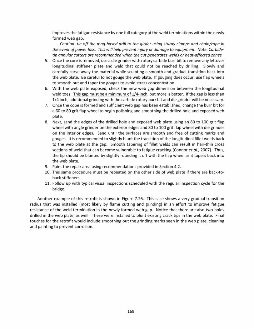
169
improves the fatigue resistance by one full category at the weld terminations within the newly formed web gap.
Caution: tie off the mag-based drill to the girder using sturdy clamps and chain/rope in the event of power loss. This will help prevent injury or damage to equipment. Note: Carbide-tip annular cutters are recommended when the cut penetrates welds or heat-affected zones.
5. Once the core is removed, use a die grinder with rotary carbide burr bit to remove any leftover longitudinal stiffener plate and weld that could not be reached by drilling. Slowly and carefully carve away the material while sculpting a smooth and gradual transition back into the web plate. Be careful to not gouge the web plate. If gouging does occur, use flap wheels to smooth out and taper the gouges to avoid stress concentration.
6. With the web plate exposed, check the new web gap dimension between the longitudinal weld toes. This gap must be a minimum of 1/4-inch, but more is better. If the gap is less than 1/4 inch, additional grinding with the carbide rotary burr bit and die grinder will be necessary.
7. Once the cope is formed and sufficient web gap has been established, change the burr bit for a 60 to 80 grit flap wheel to begin polishing and smoothing the drilled hole and exposed web plate.
8. Next, sand the edges of the drilled hole and exposed web plate using an 80 to 100 grit flap wheel with angle grinder on the exterior edges and 80 to 100 grit flap wheel with die grinder on the interior edges. Sand until the surfaces are smooth and free of cutting marks and gouges. It is recommended to slightly blunt the transition of the longitudinal fillet welds back to the web plate at the gap. Smooth tapering of fillet welds can result in hair-thin cross sections of weld that can become vulnerable to fatigue cracking (Connor et al., 2007). Thus, the tip should be blunted by slightly rounding it off with the flap wheel as it tapers back into the web plate.
9. Paint the repair area using recommendations provided in Section 4.2. 10. This same procedure must be repeated on the other side of web plate if there are back-to-
back stiffeners. 11. Follow up with typical visual inspections scheduled with the regular inspection cycle for the
bridge.
Another example of this retrofit is shown in Figure 7.26. This case shows a very gradual transition radius that was installed (most likely by flame cutting and grinding) in an effort to improve fatigue resistance of the weld termination in the newly formed web gap. Notice that there are also two holes drilled in the web plate, as well. These were installed to blunt existing crack tips in the web plate. Final touches for the retrofit would include smoothing out the grinding marks seen in the web plate, cleaning and painting to prevent corrosion.

170
Figure 7.25 Alternate version of the longitudinal stiffener core retrofit with the stiffeners plates cut
back in addition to the drilled hole
Figure 7.26 Longitudinal stiffener core retrofit showing drilled holes in the web plate for crack arrest
(Photograph courtesy of Kansas DOT)
7.3.2.2 Web Plate Core Retrofit The web plate core retrofit is very similar to the longitudinal stiffener core retrofit. Instead of drilling
a hole in the stiffener plate, however, a hole is drilled in the web plate from the opposite side of the stiffener splice and then the entire butt splice is removed. It is designed to remove constraint, reduce stress concentration, and isolate the girder from possible crack propagation. Even though this retrofit is

171
included in the CIF retrofit chapter of the guideline, this retrofit method could also be successfully used for prevention of fatigue propagation at the longitudinal butt splice detail.
The following steps outline the proper procedure for the web plate core retrofit on CIF-prone longitudinal stiffener butt splices:
1. Due to the susceptibility of this detail to fatigue as well as fracture, begin by preparing the area for inspection by cleaning and removing all coatings, including a small area on the girder web adjacent to the stiffener splice.
2. Visually inspect the web area above and below the stiffener splice. Use enhanced NDT methods such as MT or PT to confirm visual indications, as necessary.
3. If a crack is found in the web plate, locate the crack tip. If the crack tip will be removed during Step 5, then no drilling would be required in addition to Step 5. Otherwise, use techniques provided in Section 4.3 to drill a hole at the crack tip(s) to prevent further crack extension into the web.
4. Determine the correct placement for the drilled hole ensuring that it will be centered on the longitudinal butt splice. In order to ensure a correct placement from the backside of the web (opposite the longitudinal stiffener), a small 1/4-inch to 3/8-inch pilot hole using a hand drill can be helpful. Drill the pilot hole just above (or below) the estimated center of the eventual drilled hole (this simplifies locating the position and also ensures that the small pilot hole will be removed during the main drilling). Then absolute measurements can be made relative to the pilot hole on both sides of the web plate to establish the correct position for the annular cutter.
5. Using a mag-based drill with annular cutter, drill a hole through the web plate and partially into the longitudinal stiffener plate, as shown in Figure 7.27. It is recommended to use a two to four-inch diameter cutter to help reduce stress concentration and improve finish work.
Figure 7.27 Hole drilled in web for web core retrofit
Web
Longitudinal stiffener
Drilled hole

172
Caution: tie off the mag-based drill to the girder using sturdy clamps and chain/rope in the event of power loss. This will help prevent injury or damage to equipment. Note: Carbide-tip annular cutters are recommended when the cut penetrates welds or heat-affected zones.
6. Once the hole is drilled, use a cutting wheel on an angle grinder, portable band saw, or a reciprocating saw to cut in from the outside edge of the stiffener intersecting the cut lines in the stiffener made from the annular cutter in Step 5. Figure 7.28 shows this step using a portable band saw.
Figure 7.28 Removal of butt weld and drilled core for web core retrofit
7. Next, sand the edges of the drilled hole and exposed web plate using an 80 to 100 grit flap
wheel with angle grinder on the exterior edges and 80 to 100 grit flap wheel with die grinder on the interior edges. Sand until the surfaces are smooth and free of cutting marks and gouges. If it is desired to restore the section of the stiffener plate, a bolted splice may be used, as seen being prepared in Figure 7.29.
Bolted splice option: a. Use a splice plate as a template for the holes in the stiffener plate. Securely clamp
the splice plate in place and use a transfer punch to mark the locations of the holes to be drilled.
b. Remove the splice plate and clamps. Using a mag-based drill with annular cutter and pilot pin, drill the bolt holes in the stiffener 1/16 inch larger than the diameter of the specified bolt, using the transfer punch indentations as guides. Caution: tie off the mag-based drill to the member using sturdy clamps and chain/rope in the event of power loss. This will help prevent injury or damage to equipment.
c. Clean and degrease all surfaces within the area of the splice. Include about three inches outside the footprint of the splice plates. Ensure dirt, corrosion, cutting oil, hole drilling shards and other debris are removed from the area.
Drilled hole
Cut line from drilling

173
d. Apply an appropriate primer to the cleaned area. e. Once the primer coating has dried, install the splice plate and hand tighten the bolts. f. Starting from the center of the plate and moving methodically outward, snug tighten
and then fully tension the bolts according to current RCSC specifications for slip-critical connections using turn-of-nut or other approved method.
Figure 7.29 Finished retrofit with drilled holes for optional bolted splice
8. Paint the entire splice and retrofit location repair area using recommendations provided in
Section 4.2. Option: apply silicon caulk to the edges of the splice plate prior to painting to further prevent water intrusion.
9. Follow up with typical visual inspections scheduled with the regular inspection cycle for the bridge. If fatigue cracks were to initiate, the most likely location for them would be vertically from the top or bottom edge of the drilled hole.
Figure 7.30 shows the completed web plate core retrofit (minus the bolted splice) for poor longitudinal stiffener butt splice details. The fatigue resistance of the new detail is governed by the drilled hole since the longitudinal welds terminate at the edge of the hole. The hole is at a minimum an AASHTO Category D detail, but may likely perform better if high quality edge conditions are put in place. Adding a bolted splice on the longitudinal stiffener would further relieve stress concentrations at the drilled hole by providing continuity in the stiffener load path and also fully restores the stiffener to perform as originally intended. The bolted splice is typically recommended, but increases retrofit costs significantly. Engineering calculations could be made to check stability of the web plate for cases where it is desired to leave the longitudinal stiffeners disconnected (not spliced back together) at the retrofit.
Additionally, Figure 7.31 demonstrates a very simple alternative. This method uses isolation holes drilled in the web plate directly above and directly below the longitudinal stiffener splice to arrest fracture

174
if it occurs. The same sanding finishes would be recommended once the two holes are drilled. Although this retrofit may not be as aesthetic, it would effectively perform the intended function, is very economical, and could be installed even at locations with stiffeners on both sides of the web plate.
Figure 7.30 Illustration of the web plate core retrofit for longitudinal stiffener splices
Figure 7.31 Alternate version of the web plate core retrofit (Chajes et al., 2005)
Web
Web
Longitudinal stiffener
Butt splice center line

175
7.4 Web Gaps at Bearing Stiffeners in Negative Moment Regions
7.4.1 Description of Problem Several cases of brittle fracture initiating at the top of a bearing stiffener (or sometimes from
connection plates) in a negative moment region of continuous spans have been observed. Figure 7.32 shows one such example from a bridge carrying I-495. This type of fracture, however, is much less common and there may be a number of undocumented cases. The actual cause of the fracture, meaning the characteristics that make one detail more prone than another, have not been well quantified by research or field studies. It is believed that some contributing factors are those that would contribute to a triaxial stress state at a subsurface microscopic flaw, such as the thickness of the stiffener element, the size of the longitudinal and vertical welds, the quality of the welds, and the size of the web gap. It is worth noting that no such fracture is known to have occurred when the stiffener/connection plate or bearing stiffener was welded to the flange.
Figure 7.32 Fracture initiated at stiffener in negative moment region (Photograph courtesy of Y.
Edward Zhou)
7.4.2 Retrofit Guidelines A very effective and economic retrofit to prevent fracture at bearing stiffeners and transverse
connection plates in negative moment regions is the large-hole retrofit. This retrofit was discussed and also recommended for use in retrofitting details susceptible to distortion induced fatigue. The same retrofit can be implemented and effectively mitigate cause and risk for both damage modes. The retrofit

176
functions by disconnecting the propagation path of a crack from the web gap region into the rest of the girder. As detailed in Section 6.1.2.4, this retrofit is also efficient at reducing out-of-plane stresses.
The following steps outline the proper procedure for the large-hole retrofit at bearing stiffeners in negative moment regions:
1. Due to the susceptibility of this detail to distortion-induced fatigue as well as fracture, begin by preparing the area for inspection by cleaning a small area on the girder web adjacent to the stiffener weld.
2. Visually inspect the web area. Use enhanced NDT methods such as MT or PT to confirm visual indications, as necessary. Mark any crack tips identified and determine whether or not they will be removed during the drilling operation in Step 4. If the tips will be removed during the drilling, then no additional crack arrest holes will be required at the crack tips. If a crack has extended beyond the reach of the intended large-hole retrofit, follow suggested practices for crack tip blunting provided in Section 4.3 of this guideline.
3. Determine the correct placement for the annular cutter ensuring that the drilled hole will intercept the bearing stiffener-to-web (vertical) weld toe and the flange-to-web (horizontal) weld toe about 1/8-inch, as illustrated in Figure 7.33. It is recommended that the cutter used be at least 3-inch to 4-inch in diameter.
4. Drill the hole. Caution: tie off the mag-based drill to the girder using sturdy clamps and chain/rope in the event of power loss. This will help prevent injury or damage to equipment. Note: Carbide-tip annular cutters are recommended when the cut penetrates welds or heat-affected zones due to increased hardness of the material.
5. Inspect the hole placement to confirm that it intercepts the vertical and horizontal welds about 1/8-inch. If the hole misses either weld toe, use a carbide rotary burr bit with a die grinder to widen the hole toward the missed weld toe. Grind until the weld toe has been sufficiently disconnected and there is no longer a continuous path for a fracture to bypass the hole and continue through the girder web.
6. Repeat Steps 3 through 5 on the other side of the bearing stiffener plate. 7. Next, sand the exterior edges of the drilled holes using an 80 to 100 grit flap wheel with angle
grinder and 80 to 100 grit flap wheel with die grinder on the interior surfaces. Sand until the surfaces are smooth and free of cutting marks and gouges.
8. Paint the repair area using recommendations provided in Section 4.2. 9. Follow up with typical visual inspections scheduled with the regular inspection cycle for the
bridge. Observe the web gap area to see if a fracture has occurred and arrested in the drilled holes. Also, observe the bottom edges of the drilled holes for any indications of fatigue cracking.
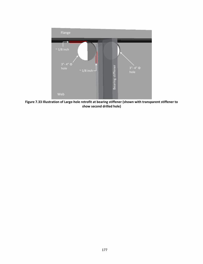
177
Figure 7.33 Illustration of Large-hole retrofit at bearing stiffener (shown with transparent stiffener to
show second drilled hole)
Web
Bear
ing
stiff
ener
Flange
3”- 4” Φ hole
3”- 4” Φ hole
~ 1/8 inch
~ 1/8 inch

178
CHAPTER 8. VARIOUS METHODS WITH UNDETERMINED PERFORMANCE The following section introduces some additional repair or retrofit concepts that have been presented
in published papers, research reports, or in response to the survey for this guideline. While some of the concepts, and in some cases the research, may show promise, their individual long-term success overall has not yet been sufficiently established for steel bridges to make a recommendation for implementation. This section is intended simply to provide enough detail to make the reader aware of the methods, but does not provide implementation procedures or other related recommendations.
8.1 Doubler plate-angle retrofit for web gap stiffening A doubler plate-angle retrofit consists of stiffening angles attached to both sides of the transverse
connection plate and then the addition of a plate (or sometimes another angle) on the back side of the web (opposite of the connection plate). The stiffening components would be bolted together through the web plate. The doubler plate stiffening of web gaps has been used by some bridge owners because of the ease of installation as compared to some other stiffening methods, particularly those that would require excavation of the deck for bolt tightening. This is one of the greatest advantages of the doubler plate-angle method; the retrofit can be installed at the top web gap without needing access to the top surface of the girder top flange. This can save a lot of installation cost and allows the retrofit to be performed while the bridge remains open to traffic. However, it has its inherent setbacks too. Figure 8.1 shows an example of two doubler plate-angle stiffening details used by a bridge owner to repair and retrofit web gap fatigue cracking at the top and bottom web gaps on a multi-plate girder bridge. The detail on the left is for the bottom web gap and the detail on the right is for the top web gap. The bolt (3/4-inch diameter), angle (1/2-inch thick), and plate (1/2-inch thick) sizes seen in Figure 8.1 are smaller than recommended by NCHRP Report 721 (Bowman et al., 2012). It would be expected, therefore, to continue to crack. Another challenge with this retrofit is that it would be very difficult to inspect because the doubler plates and angles cover portions of the locations where cracking could be expected in the future. Thus, if the detail shown in Figure 8.1 did continue to crack, it would not be known by inspectors until the cracks were relatively long and emerged from behind the plates/angles.
Figure 8.1 Example details of doubler plate stiffening for distortion-induced fatigue (Source anonymous)
Nuances between different applications of the doubler plate-angle retrofit exist, such as the structural
shapes used (i.e., WT’s, angles, plates), the sizes of the fasteners (i.e., 3/4-inch, 7/8-inch, or 1-inch

179
diameter), and the thickness/stiffness of the shapes and plates, as well. All of these factors affect the overall stiffness of the finished retrofit, which is the most critical performance criterion. If the connection is not sufficiently stiff, it will not correct the problem. (Section 6.1.2 of this guideline discusses detailed recommendations for stiffening retrofits.) However, even with very stiff components like that seen in Figure 8.2, the doubler plate-angle type retrofit does not provide a positive connection to the flange; meaning that the loads are still being transferred through the web plate into the flange. This aspect is important to the performance of the retrofit because the cause of the distortion-induced fatigue is a relative displacement between the flange and web plates. By positively connecting the connection plate to the flange plate, the relative displacement (or at least most of it) is eliminated by transferring loads through the stiffening elements directly into the flanges (bypassing the web gap). In some cases, irregularities in the longitudinal weld profiles could keep the stiffening component from fitting up tightly against the weld toe creating small gaps between the end of the stiffening component and the web-to-flange weld toe. Depending on this geometry and the quality of the fit-up during installation, the web gap could become reduced (rather than bypassed), which could aggravate the problem while also adding the difficulty of inspection. This means that if cracking continues, the cracks could possibly grow at a faster rate and go undetected until they appear from behind the plates or angles.
The doubler plate-angle type retrofit has potential to work well in some applications when meticulously designed and installed. Bennett et al. (2014) found some positive results with highly stiffened angles and backer plates (see Figure 8.2). However, they also concluded that it was not as effective at mitigating crack initiation and propagation at the flange-to-web welds as connecting the stiffening component directly to the flange. This is because as mentioned above, the loads are still transferred through the web into the flange. Although the cost benefit of this type of retrofit is that the deck does not require excavation at top web gaps, a cost drawback is that it needs very stiff structural components with a reasonable susceptibility to aggravating the web gap demands in cases of moderate to low-quality fit-up.
Figure 8.2 Stiffened-angles-with-plate retrofit (Taken from Bennet et al., 2014)
Flange
Web
Stiffening angle

180
8.2 Fusion welded threaded stud for web gap stiffening Fusion welded threaded studs have been used on a limited basis in place of high strength structural
bolts for web gap stiffening against distortion-induced fatigue. A disadvantage of the bolted retrofit for web gap cracking discussed in Section 6.1.2.3 is that it requires excavation of the concrete deck for web gaps at the top of the girder in order to bolt through the flange. One way to avoid having to remove concrete deck would be to use a partially threaded stud that can be fusion welded to the bottom surface of the top flange in the same way that a fusion welded shear connector is welded to steel girders for composite decks. The fatigue resistance of the welded stud on the top flange (if located in a tension or reversal zone) is the same as a stud-type shear connector, AASHTO Category C.
Figure 8.3 Example of fusion welded threaded stud retrofit shown blast cleaned in preparation for
painting (Photograph courtesy of Kansas DOT) Figure 8.3 shows an example of this type of retrofit that has been blast cleaned in preparation for
painting. The threaded studs look like bolts from one side. In this example, the owner correctly drilled holes at the crack tips to arrest propagation and welded the stiffening angles to the connection plate providing a very stiff connection. The threaded stud connection to the flange, however, would not provide comparable stiffness, particularly because only two studs were used per angle. The threaded studs can be found commercially produced up to 1-inch diameter. However, the studs are not of comparable yield strength to the high strength structural bolts used for slip critical connections. Currently, the highest tensile (ultimate) strength available for the threaded stud is 61 ksi, about half that of the 120 ksi tensile strength for the 1-inch diameter F3125-325 high strength bolts. This means that a fully tensioned fusion welded stud will only provide roughly half of the pretension load for a slip-critical connection. Hence, in order to obtain similar slip-critical connection stiffness to the high strength bolts, twice as many threaded studs would be required. This is important because the stiffness of the connection is central to the effectiveness of the retrofit. Bearing and shear capacities of the fasteners cannot be relied upon for most applications because the web gap distortion that causes the cracking is typically much less than the gap between the threaded stud and a standard sized hole. This means that the displacement in the web gap must be resisted entirely by the clamping force of the connection.
Flange
Web
Threaded stud
Stiffening angle

181
The welding of studs during bridge fabrication is governed by AWS D1.5 where the qualification requirements for welding the studs can be found. It would be prudent to follow these fabrication requirements for the retrofitting process in order to ensure a quality retrofit. AWS D1.5 (2015) calls for a welding procedure specification (WPS) for each base metal, stud type, and position. Ten specimens in each process, base metal, and position are required to be tested by one of the following: bend, torque, or tension testing for each operator. A passing test qualifies both the process and the operator. AWS D1.5 (2015) provides a table of testing torques, which for a 1-8 UNC threaded stud it calls for 318 ft-lbs of torque. The suggested test configuration is shown in Figure 8.4. This setup could also be used to test a required turn-of-nut application in order to qualify that type of pretensioning method for the installation of the retrofit.
Figure 8.4 Torque testing arrangement (AWS D1.5, 2015)
If this retrofit method is implemented, the following items are recommended to secure an effective
repair or retrofit using the fusion welded threaded studs: The number of high-strength bolts recommended in NCHRP Report 721 for each stiffening
element face, should be doubled for the number of threaded, 1-inch diameter welded studs used. NCHRP Report 721 recommends at least four high-strength bolts (≥ 7/8-inch diameter) on each shear plane to connect the retrofit to the web and to the flange.
The stiffening component sizes (i.e., angle or WT sizes) recommended in NCHRP Report 721 (discussed in Section 6.1.2.3 of this guideline) should be used.
A qualified person should develop a welding procedure specification (WPS) that requires testing of the welded studs and operator. The test should be done in the same position (overhead), welded to the base metal, and using the tensioning method intended to be used to tighten the retrofit connections.
A few retrofit locations should be field tested measuring web gap displacements and stresses to confirm that the retrofit is providing sufficient resistance to the out-of-plane distortion.
8.3 Carbon Fiber Reinforced Polymer (CFRP) There are many types of Carbon Fiber Reinforced Polymers (CRFP), but typically they are a cross-ply,
epoxy laminated composite material, with relatively high strength-to-weight ratio (about 5 times that of steel) and moderate stiffness (slightly less than steel). The CFRP structure consists of a polymer resin (called the matrix), typically an epoxy, reinforced by carbon fibers. Several variations of the polymer resin, as well as the fibrous reinforcement material, exist and have been studied by the aviation, automotive,
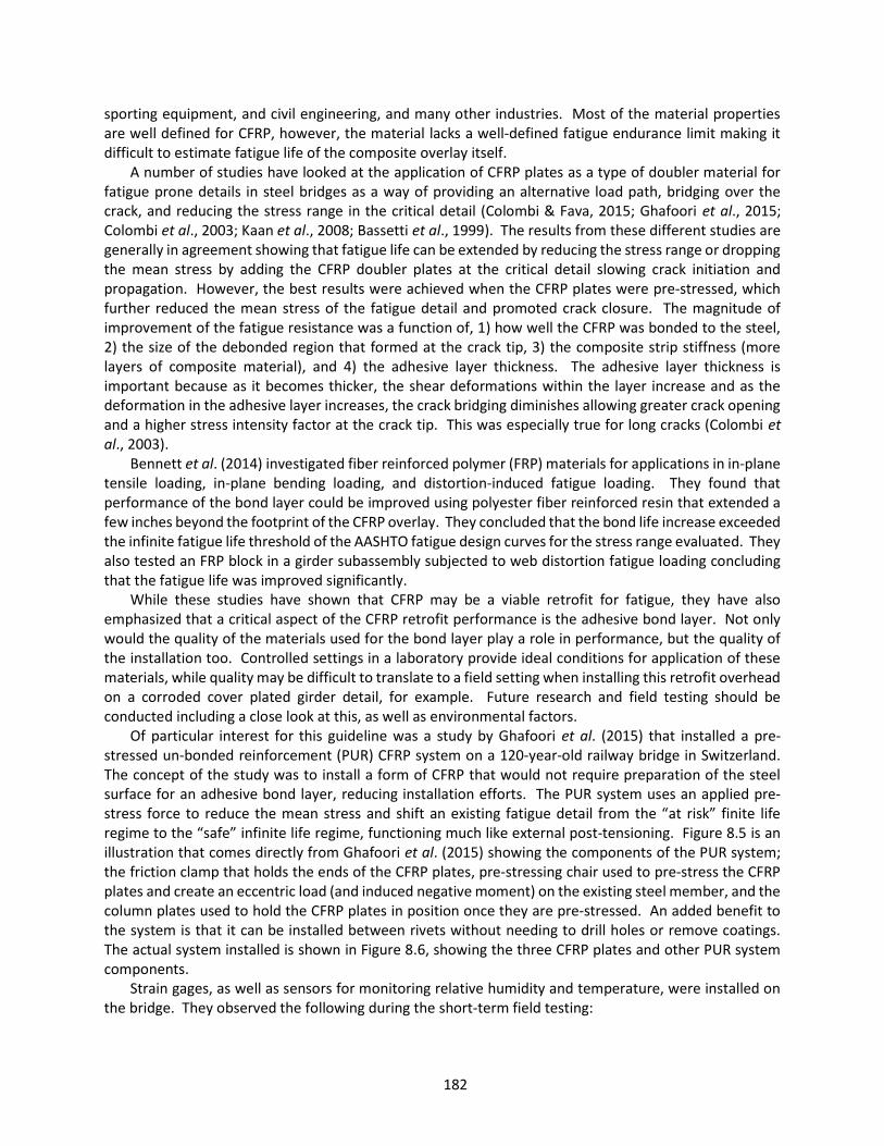
182
sporting equipment, and civil engineering, and many other industries. Most of the material properties are well defined for CFRP, however, the material lacks a well-defined fatigue endurance limit making it difficult to estimate fatigue life of the composite overlay itself.
A number of studies have looked at the application of CFRP plates as a type of doubler material for fatigue prone details in steel bridges as a way of providing an alternative load path, bridging over the crack, and reducing the stress range in the critical detail (Colombi & Fava, 2015; Ghafoori et al., 2015; Colombi et al., 2003; Kaan et al., 2008; Bassetti et al., 1999). The results from these different studies are generally in agreement showing that fatigue life can be extended by reducing the stress range or dropping the mean stress by adding the CFRP doubler plates at the critical detail slowing crack initiation and propagation. However, the best results were achieved when the CFRP plates were pre-stressed, which further reduced the mean stress of the fatigue detail and promoted crack closure. The magnitude of improvement of the fatigue resistance was a function of, 1) how well the CFRP was bonded to the steel, 2) the size of the debonded region that formed at the crack tip, 3) the composite strip stiffness (more layers of composite material), and 4) the adhesive layer thickness. The adhesive layer thickness is important because as it becomes thicker, the shear deformations within the layer increase and as the deformation in the adhesive layer increases, the crack bridging diminishes allowing greater crack opening and a higher stress intensity factor at the crack tip. This was especially true for long cracks (Colombi et al., 2003).
Bennett et al. (2014) investigated fiber reinforced polymer (FRP) materials for applications in in-plane tensile loading, in-plane bending loading, and distortion-induced fatigue loading. They found that performance of the bond layer could be improved using polyester fiber reinforced resin that extended a few inches beyond the footprint of the CFRP overlay. They concluded that the bond life increase exceeded the infinite fatigue life threshold of the AASHTO fatigue design curves for the stress range evaluated. They also tested an FRP block in a girder subassembly subjected to web distortion fatigue loading concluding that the fatigue life was improved significantly.
While these studies have shown that CFRP may be a viable retrofit for fatigue, they have also emphasized that a critical aspect of the CFRP retrofit performance is the adhesive bond layer. Not only would the quality of the materials used for the bond layer play a role in performance, but the quality of the installation too. Controlled settings in a laboratory provide ideal conditions for application of these materials, while quality may be difficult to translate to a field setting when installing this retrofit overhead on a corroded cover plated girder detail, for example. Future research and field testing should be conducted including a close look at this, as well as environmental factors.
Of particular interest for this guideline was a study by Ghafoori et al. (2015) that installed a pre-stressed un-bonded reinforcement (PUR) CFRP system on a 120-year-old railway bridge in Switzerland. The concept of the study was to install a form of CFRP that would not require preparation of the steel surface for an adhesive bond layer, reducing installation efforts. The PUR system uses an applied pre-stress force to reduce the mean stress and shift an existing fatigue detail from the “at risk” finite life regime to the “safe” infinite life regime, functioning much like external post-tensioning. Figure 8.5 is an illustration that comes directly from Ghafoori et al. (2015) showing the components of the PUR system; the friction clamp that holds the ends of the CFRP plates, pre-stressing chair used to pre-stress the CFRP plates and create an eccentric load (and induced negative moment) on the existing steel member, and the column plates used to hold the CFRP plates in position once they are pre-stressed. An added benefit to the system is that it can be installed between rivets without needing to drill holes or remove coatings. The actual system installed is shown in Figure 8.6, showing the three CFRP plates and other PUR system components.
Strain gages, as well as sensors for monitoring relative humidity and temperature, were installed on the bridge. They observed the following during the short-term field testing:
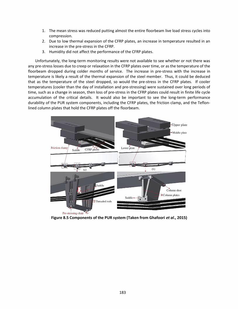
183
1. The mean stress was reduced putting almost the entire floorbeam live load stress cycles into compression.
2. Due to low thermal expansion of the CFRP plates, an increase in temperature resulted in an increase in the pre-stress in the CFRP.
3. Humidity did not affect the performance of the CFRP plates.
Unfortunately, the long-term monitoring results were not available to see whether or not there was any pre-stress losses due to creep or relaxation in the CFRP plates over time, or as the temperature of the floorbeam dropped during colder months of service. The increase in pre-stress with the increase in temperature is likely a result of the thermal expansion of the steel member. Thus, it could be deduced that as the temperature of the steel dropped, so would the pre-stress in the CFRP plates. If cooler temperatures (cooler than the day of installation and pre-stressing) were sustained over long periods of time, such as a change in season, then loss of pre-stress in the CFRP plates could result in finite life cycle accumulation of the critical details. It would also be important to see the long-term performance durability of the PUR system components, including the CFRP plates, the friction clamp, and the Teflon-lined column plates that hold the CFRP plates off the floorbeam.
Figure 8.5 Components of the PUR system (Taken from Ghafoori et al., 2015)
184
Figure 8.6 Strengthened floorbeam using PUR system (Ghafoori et al., 2015)
8.4 Drilled hole with cold expansion sleeve Cold expansion of holes to mitigate fatigue cracking was developed for the aerospace industry and
has been used by that industry for decades. While this method has proven itself very effective for aerospace applications, questions remain as to whether that success could translate to bridge applications where the base material is steel rather than aluminum, plate thicknesses are significantly different, and residual and secondary stress fields differ from aerospace structures.
The concept of cold expansion of holes is that it improves the fatigue life by creating a zone of compressive residual stress around the circumference of the hole, even for a hole with a crack entering one side (Heller et al., 1991). The compressive stress is produced through plastic deformation of the material by mechanical expansion of the hole, typically 4 – 6% residual expansion is targeted. In general, this is accomplished by forcing an oversized expansion mandrel with a lubricated sleeve through the hole, locally yielding the surrounding material (Reid, 2011). Material beyond the plastic zone is elastically deformed, providing an elastic rebound upon removal of the mandrel, creating a locked-in residual compressive stress equal to about 2/3 the yield stress of the material radiating out from the edge of the hole about one hole diameter (Reid, 2012). In order to maintain internal equilibrium, the compressive zone is surrounded by a small field of tensile residual stress equal to about 10 – 15% of the yield strength (Crain et al., 2010). This combined with a lack of data for bridge applications have also caused some to wonder how well this method would work adjacent to welds where the residual stresses are already at or near the yield strength of the base material.
Another cold expansion technique was also investigated where a similar compressive residual hoop stress was produced using a piezoelectric tool called the Piezoelectric Impact Compressive Kinetics (PICK) device that used ultrasonic vibration to expand an aluminum plug through Poisson’s effect, which cold-worked the steel hole by repeated impact against the hole surface (Crain et al., 2010; Bennett et al., 2014). The test results showed a sizeable improvement in fatigue life of the thin-plate specimens, however, they also concluded that some tensile residual stresses were imparted in the treated hole at the outer faces (due to non-uniform deformation of the aluminum plug), which could cause unwanted cracking. Additionally, the bench-mounted tool would not be practical in the field and for these reasons will require further development. An important conclusion from this research was that the 4 – 6% expansion generally used by the aerospace industry produced a similar effect on the steel plate specimens tested. This

185
conclusion was based on the similarity of normalized tangential residual stress in the steel, as for aluminum found in literature (Bennett et al., 2014).
(a) (b)
(c) (d)
Figure 8.7 Cold expansion of crack arrest holes (a) floorbeam cope cracking, (b) drilled hole at the crack tip, (c) & (d) finished repairs with expansion sleeve (Photographs courtesy of Oklahoma DOT)
Figure 8.7 shows the progressive steps of installing one of the cold expansion sleeves at floorbeam
cope details that have fatigue cracked. Notice that the expansion sleeve is left behind providing a direct interception as the base material attempts to rebound, or spring back, helping to lock in the residual compressive stress at the edge of the hole. Although this method shows promise for bridge repair applications and is being implemented by a few states, the repair has not yet been in service long enough to determine its long-term effectiveness.
Floorbeam Web
Floorbeam Web
Floorbeam Web
Floorbeam Web
Cold expansion repair
Cold expansion repair
Drilled hole
Crack
Crack
Crack
Crack
186
REFERENCES
Albrecht, P., and Wright, W. (2000). Fracture Mechanics: Applications and Challenges. 13th European Conference on Fracture, Vol. 26, pp. 211-234. European Structural Integrity Society.
American Association of State Highway and Transportation Officials (AASHTO). (1978). Guide Specifications for Fracture-Critical Non-Redundant Steel Bridge Members. Washington, D.C.
American Association of State Highway and Transportation Officials (AASHTO). (2016). AASHTO Manual for Bridge Evaluation. Washington, D.C.
American Association of State Highway and Transportation Officials (AASHTO). (2017). AASHTO LRFD Bridge Design Specifications. Washington, D.C.
American Railway Engineering and Maintenance-of-way Association (AREMA) (2016). Manual for Railway Engineering. American Railway Engineering and Maintenance-of-way Association. Lanham, Maryland.
American Society for Nondestructive Testing (ASNT) (2016). Introduction to Nondestructive Testing [online]. Available from: <https://www.asnt.org/MinorSiteSections/AboutASNT/Intro-to-NDT>. [Accessed November 2016]
American Welding Society (AWS). (2015). AWS D1.5:2015 Bridge Welding Code. Miami, FL.
Anderson, T. L. (2005). Fracture Mechanics: Fundamentals and Applications. Third Edition. Boca Raton, Florida: CRC Press.
Bassetti, A., Liechti, P., & Nussbaumer, A. (1999). Fatigue Resistance and Repairs of Riveted Bridge Members. European Structural Integrity Society, Vol. 23, pp. 207-218. Available from: http://dx.doi.org/10.1016/S1566-1369(99)80043-0
Bennet, C., Matamoros, A., Barrett-Gonzalez, R., & Rolfe, S. (2014). Enhancement of Welded Steel Bridge Girders Susceptible to Distortion-Induced Fatigue. Report No. FHWA-KS-14-03. The University of Kansas Center for Research, Inc. Lawrence, KS.
Bowman, M. D., Fu, G., Zhou, Y. E., Connor, R. J., & Godbole, A. A. (2012). Fatigue Evaluation of Steel Bridges. NCHRP Report 721. Transportation Research Board. Washington, D.C.
Bowers, D. G. (1973). Summary Report: Loading History Span No. 10, Yellow Mill Pond Bridge I-95, Bridgeport, Connecticut. Connecticut DOT, Wethersfield, CT. Available from: http://rebar.ecn.purdue.edu/fatigue/search1.aspx?dir=003&type=No&type1=Yes&type2=No&type3=No&type4=No&many=%27yes%27. [Accessed October 2016]
Brown, J. D., Lubitz, D. J., Cekov, Y. C., and Frank, K. H. (2007). Evaluation of Influence of Hole Making Upon the Performance of Structural Steel Plates and Connections. Report No. FHWA/TX-07/0-4624-1. University of Texas at Austin. Austin, TX.
187
Crain, J. S., Simmon, G. G., Bennett, C. R., Barrett-Gonzalez, R., Matamoros, A. B., & Rolfe, S. T. (2010). Development of a Technique to Improve Fatigue Lives of Crack-Stop Holes in Steel Bridges. Transportation Research Record: Journal of the Transportation Research Board, No. 2200, pp. 69-77. Transportation Research Board of the National Academies, Washington, D.C. DOI: 10.3141/2200-09
Chajes, M. J., Mertz, D. R., Quiel, S., Roecker, H., and Milius, J. (2005). Steel Girder Fracture on Deleware’s I-95 Bridge Over the Brandywine River. Structures Congress 2005: pp. 1-10. DOI: 10.1061/40753(171)36
Colombi, P., Bassetti, A., & Nussbaumer, A. (2003). Analysis of Cracked Steel Members Reinforced by Pre-Stress Composite Patch. Fatigue Fract. Engng. Mater. Struct., Vol. 26, pp. 59-66. Blackwell Publishing Ltd.
Colombi, P. and Giulia, F. (2015). Experimental Study on the Fatigue Behaviour of Cracked Steel Beams Repaired with CFRP Plates. Elsevier, Engineering Fracture Mechanics 145, pp. 128-142.
Connor, R. J., and Fisher, J. W. (2001). Report on Field Measurements and Assessment of the I-64 Kanawha River Bridge at Dunbar, West Virginia. ATLSS Report 01-14. Center for Advanced Technology for Large Structural Systems. Lehigh University. Bethlehem, PA.
Connor, R. J., Fisher, J. W., Hodgson, I. C., & Bowman, C. (2004). Results of field Monitoring Prototype Floorbeam Connection Retrofit Details on the Birmingham Bridge – Final Report. ATLSS Report No. 04-04, Center for Advanced Technology for Large Structural Systems, Lehigh University. Bethlehem, PA.
Connor, R. J., Dexter, R. J., & Mahmoud, H. (2005). Inspection and management of bridges with fracture-critical details (NCHRP Report 354). Washington, DC: Transportation Research Board.
Connor, R. J., & Fisher, J. W. (2006). Identifying Effective and Ineffective Retrofits for Distortion Fatigue Cracking in Steel Bridges Using Field Instrumentation. Journal of Bridge Engineering. 11(6), pp. 745-752
Connor, R. J., Kaufmann, E. J., Fisher, J. W., and Wright, W. J. (2007). Prevention and Mitigation Strategies to Address Recent Brittle Fractures in Steel Bridges. Journal of Bridge Engineering. Vol. 12, p. 164-173. DOI: 10.1061/(ASCE)1084-0702(2007)12:2(164)
Connor, R. J., Urban, M. J., & Kaufmann, E. J. (2008). Heat-Straightening Repair of Damaged Steel Bridge Girders: Fatigue and Fracture Performance. NCHRP Report 604. Transportation Research Board. Washington, D.C.
Cousins, T. E., Stallings, J. M., Lower, D. A., and Stafford, T. E. (1998). Field Evaluation of Fatigue Cracking in Diaphragm-Girder Connections. Journal of Performance of Constructed Facilities, Vol. 12, No. 1. American Society of Civil Engineers (ASCE).
Daniels, J. H., and Fisher, J. W. (1974). Field Evaluation of Tie Plate Geometry, Nov. 1974. Fritz Laboratory Reports. Paper 455. Lehigh University. Bethlehem, PA.

188
Demers, C. E. and Fisher, J. W. (1990). Fatigue Cracking of Steel Bridge Structures: Vol. I: A Survey of Localized Cracking in Steel Bridges – 1981 to 1988. Publication No. FHWA-RD-89-166. Federal Highway Administration. McLean, VA.
Dexter, R. J., & Ocel, J. M. (2013). Manual for Repair and Retrofit of Fatigue Cracks in Steel Bridges. FHWA Publication No. FHWA-IF-13-020. Federal Highway Administration. McLean, VA.
DiBattista, J. Adamson, D., and Kulak, G. (1998). Fatigue Strength of Riveted Connections. Journal of Structural Engineering, 10.1061/(ASCE)0733-9445(1998)124:7(792), pp. 792-797.
Ellis, R. M., Connor, R. J., Medhekar, M., MacLaggan, D., and Bialowas, M. (2013). Investigation and Repair of the Diefenbaker Bridge Fracture. In: Conference and Exhibition of the Transportation Association of Canada, Winnipeg, Manitoba, Canada. pp. 17.
Fish, P., Schroeder, C., Connor, R. J., & Sauser, P. (2015). Fatigue and Fracture Library for the Inspection, Evaluation, and Repair of Vehicular Steel Bridges. Purdue University. West Lafayette, Indiana. Available from: http://dx.doi.org/10.5703/1288284315520
Fisher, J. W., Frank, K. H., Hirt, M. A., & McNamee, B. M. (1970). Effect of Weldments on the Fatigue Strength of Steel Beams. NCHRP Report 102. Transportation Research Board. Washington, D.C.
Fisher, J. W. (1973). Evaluation of Typical Welded Bridge Details for Fatigue Design. NCHRP Project 12-15. Transportation Research Board. Washington, D.C.
Fisher, J. W., Albrecht, P.A., Yen, B. T., Klingerman, D. J., & McNamee, B. M. (1974). Fatigue Strength of Steel Beam with Welded Stiffeners and Attachments. NCHRP Report 147. Transportation Research Board. Washington, D.C.
Fisher, J.W. (1977). Evaluation of Fracture of Lafayette Street Bridge. ASCE J. Struct. Div., 103(7), 1339-1357.
Fisher, J. W., Hausammann, H., Sullivan, M. D., & Pense, A. W. (1979). Detection and Repair of Fatigue Damage in Welded Highway Bridges. NCHRP Report 206. Transportation Research Board. Washington, D.C.
Fisher, J. W., Barthelemy, B. M., Mertz, D. R., & Edinger, J. A. (1980). Fatigue Behavior of Full-Scale Welded Bridge Attachments. NCHRP Report 227. Transportation Research Board. Washington, D.C.
Fisher, J. W., Mertz, D. R., & Zhong, A. (1983). Steel Bridge Members under Constant Amplitude Fatigue Loading. NCHRP Report 267. Transportation Research Board. Washington, D.C.
Fisher, J. W. (1984). Fatigue and Fracture in Steel Bridges. New York: John Wiley & Sons, Inc.
Fisher, J. W., Yen, B. T., and Wang, D. (1987). Fatigue and Fracture Evaluation For Rating Riveted Bridges. NCHRP 302. Transportation Research Board. Washington, D.C.

189
Fisher, J. W., Jim, J., Wagner, D. C., & Yen, B. T. (1990). Distortion Induced Fatigue Cracking in Steel Bridges. NCHRP Report 336. Transportation Research Board. Washington, D.C.
Fisher, J. W., Kulak, G. L., & Smith, I. F. C. (1997, October). A Fatigue Primer for Structural Engineers. (97-11). Lehigh University, Bethlehem, PA.
Fisher, J. W., Kaufmann, E. J., Wright, W., Xi, Z., Tjiang, H., Sivakumar, B., and Edberg, W. (2001). Hoan Bridge Forensic Investigation Failure Analysis Final Report. Web. October 2016. http://wwwcourses.sens.buffalo.edu/cie500d/other_classes/Hoan-Failure-Investigation.pdf
Fisher, J. W., & Roy, S. (2015). Fatigue Damage in Steel Bridges and Extending Their Life. Advanced Steel Construction, Vol. 11, No. 3, pp. 250-268.
Fisher, J. W. “Girard Point Bridge Fatigue Cracks.” Letter to Mr. B. F. Kotalik. 17 July 1978. N.p.: n.p., n.d. N. pag. Steel Bridge Fatigue Knowledge Base. Purdue University. Web. 04 June 2016. http://rebar.ecn.purdue.edu/Fatigue/Fisher_Files/040-Girard_Point_Bridge/Additional_Information/Publications//John%20Fisher%20letter.pdf.
Ghafoori, E., Motavalli, M., Nussbaumber, A., Herwig, A., Prinz, G.S., & Fontana, M. (2015). Design Criterion for Fatigue Strengthening of Riveted Beams in a 120-year-old Railway Metallic Bridge Using Pre-Stressed CFRP Plates. Elsevier, Composites: Part B 68, pp. 1-13.
Grandt, A. F. Jr. (2004). Fundamentals of Structural Integrity: Damage Tolerant Design and Nondestructive Evaluation. Hoboken, New Jersey: John Wiley & Sons, Inc.
Gregory, E., Slater, G., & Woodley, C. (1989). Welded Repair of Cracks in Steel Bridge Members. NCHRP Report 321. Transportation Research Board. Washington, D.C.
Harrison, J. D. (1966). Further Techniques for Improving the Fatigue Strength of Welded Joints. Brit Welding J., Vol. 13, No. 11: pp 642-647.
Hassan, A. F., and Bowman, M. D. (1995). Fatigue Strength of Girders with Tapered Covered Plates. Publication FHWA/IN/JHRP-94/13. Joint Highway Research Project, Indiana Department of Transportation and Purdue University, West Lafayette, Indiana. http://dx.doi.org/10.5703/1288284313225
Hausammann, H., Fisher, J. W., & Yen, B. T. (1983). Effect of Peening on Fatigue Life of Welded Details. American Society of Civil Engineers Proceedings, W. H. Munse Symposium on Behavior of Metal Structures – Research and Practice.
Hebdon, M. H. (2015). Member-Level Redundancy of Built-up Steel Girders. Dissertation. Purdue University. West Lafayette, Indiana.
Heller, M., Jones, R., & Williams, J. F. (1991). Analysis of Cold-Expansion for Cracked and Uncracked Fastener Holes. Engineering Fracture Mechanics, Vol. 39, No. 2, pp. 195-212.
190
Kaan, B., Barrett, R., Bennett, C., Matamoros, A., & Rolfe, S. (2008). Fatigue Enhancement of Welded Coverplates Using Carbon-Fiber Composites. Structures Congress, American Society of Civil Engineers.
Kaufmann, E. J., Connor, R. J., & Fisher, J. W. (2004). Analysis of the US 422 Bridge Fracture. ATLSS Reports. Paper 53. Leigh University. Bethlehem, PA.
Keating, P. B. (1983). Fatigue Analysis of Stringer Connection Angles in a Deck-Truss Bridge. Theses and Dissertations. Paper 1917. Lehigh University. Bethlehem, PA.
Keating, P. B., & Fisher, J. W. (1986). Evaluation of Fatigue Tests and Design Criteria on Welded Details. NCHRP Report 286. Transportation Research Board. Washington, D.C.
Koob, M. J., Frey, P. D., and Hanson, J. M. (1985). Evaluation of Web Cracking at Floor Beam to Stiffener Connections of the Poplar Street Approaches, FAI Route 70, East St. Louis, St. Clair County, Illinois. Wiss, Janney, Elstner Associates for the Illinois Department of Transportation.
Li, X. (2012). Fatigue Failure Evaluation of Tie Plates due to Secondary Deformations on Steel Plate Girder Bridges. Theses and Dissertations. Paper 1052. Lehigh University. Bethlehem, PA
Mahmoud, H. N., & Connor, R. J. (2005a). Field Monitoring Prototype Retrofits of Floorbeam Connections on the I-95 Girard Point Bridge – Final Report. ATLSS Report No. 05-01. Center for Advanced Technology for Large Structural Systems, Lehigh University. Bethlehem, PA.
Mahmoud, H.N., Connor, R.J., and Fisher, J. W. (2005b). Finite-element Investigation of the Fracture Potential of Highly Constrained Details. Computer Aided Civil Infrastructure Engineering. Vol. 20, p. 383-392.
NDT Resource Center [online]. (2014). Available from: https://www.nde-ed.org. [Accessed May 2016]
Paasch, R. K., and DePiero, A. H. (1999). Fatigue Crack Modeling in Bridge Deck Connection Details. Report No. FHWA-OR-RD-00-08. Oregon State University. Corvallis, OR.
Reid, L. (2012). Repairing and Preserving Bridge Structure by Innovative Crack Arrest Repair System. International Bridge Conference. Pittsburgh, PA.
Research Council on Structural Connections (RCSC)(2014). Specifications for Structural Joints Using High-Strength Bolts. American Institute of Steel Construction. Chicago, IL.
Roeder, C. W., MacRae, G. A, Kalogiros, A. Y., & Leland, A. (2001). Fatigue Cracking of Riveted, Coped, Stringer-to-Floorbeam Connections. Washington State Transportation Center (TRAC), University of Washington. Seattle, WA.
Roy, S., & Fisher, J. W. (2003). Enhancing Fatigue Strength by Ultrasonic Impact Treatment. Lehigh University. Bethlehem, PA.

191
Roy, S., Fisher, J. W., & Yen, B. T. (2003). Fatigue Resistance of Welded Details Enhanced by Ultrasonic Impact Treatment (UIT). International Journal of Fatigue, Vol. 25, pp. 1239-1247.
Rutherford, S. E., and Polezhayeva, H. (2006). Effect of Burr Grinding on the Fatigue Strength of Angled Welded Connections. Lloyd’s Register Technical Papers. London, England.
Schilling, C. G., Klippstein, K. H., Barson, J. M., and Blake, G. T. (1978). Fatigue of Welded Steel Bridge Members under Variable-Amplitude Loading. NCHRP Report 188. Transportation Research Board. Washington, D.C.
Society for Protective Coatings (SSPC) (2015a). SSPC-SP 1. Surface Preparation Specification No. 1 Solvent Cleaning. Pittsburg, PA.
Society for Protective Coatings (SSPC) (2015b). SSPC-SP 11. Surface Preparation Specification No. 11 Power Tool Cleaning to Bare Metal. Pittsburg, PA.
Stallings, J. M., Cousins, T. E., and Tedesco, J. W. (1996). Fatigue of Diaphragm-Girder Connections. Report No. RP930-307. Auburn University. Auburn, Alabama.
Steel Bridge Fatigue Knowledge Base. (2008). Available from: http://rebar.ecn.purdue.edu/fatigue/default.aspx [Accessed July 2016].
Tarries, D. J., Phares, B. M., Wipf, T. J., Griemann, L., and Wood, D. L. (2002). Bolt Loosening Retrofit to Inhibit Fatigue Cracking in Steel Girder Bridges. Transportation Research Board. Washington, D.C.
Tilly, G. P. and Nunn, D. E. (1980). Variable Amplitude Fatigue in Relation to Highway Bridges. The Institution of Mechanical Engineers, Proceedings, Vol. 194, No. 27.
Washer, G., Connor, R. J., & Looten, D. (2014a). Performance Testing of Inspectors to Improve the Quality of Nondestructive Testing. Transportation Research Record: Journal of the Transportation Research Board, Vol. 2408, pp. 107-116.
Washer, G. (2014b). Nondestructive Evaluation of Bridge Elements. Bridge Engineering Handbook, ISBN 9781439852057, Taylor and Francis, Boca Raton, FL, eds. Duan L., Chen, W.
Wilson, W. M. and Coombe, J. W. (1940). Design of Connection Angles for Stringers of Railway Bridges. Proc., AREA, Vol. 41, pp. 889-903.
Yam, M. and Cheng, J. (1990). Fatigue Strength of Coped Steel Beams. Journal of Structural Engineering, 10.1061/(ASCE)0733-9445(1990)116:9(2447), Vol. 116, pp. 2447-2463.
Yen, B. T., Huang, T., Lai, L., and Fisher, J. W. (1990). Manual for Inspecting Bridges for Fatigue Damage Conditions. Department of Civil Engineering Report No. 511-1, Lehigh University; Publication No. FHWA-PA-89-022 + 85-02. Federal Highway Administration. McLean, VA.
Zhu, X., and Joyce, J. A. (2012). Review of Fracture Toughness (G, K, J, CTOD, CTOA) Testing and Standardization. U. S. Navy Research. Paper 49.

192
APPENDIX A QUICK REFERENCE TABLES
A.1 Load-Induced Fatigue Quick Reference Tables

193
Table A. 1 Strategies for welded attachments subject to primary stresses P
ropo
sed
G
uid
elin
e S
ecti
on
5.2.
2.2
5.2.
2.1
5.4.
2.1
5.4.
2.2
5.4.
2.3
5.10
.2.1
5.10
.2.2
Insp
ecti
on
Rec
omm
end
atio
n
ND
E b
efor
e re
pair
. F
ollo
w u
p w
ith
visu
al
insp
ecti
on o
n no
rmal
in
spec
tion
cyc
le.
ND
E b
efor
e re
trof
it on
ly.
No
spec
ial f
ollo
w-u
p in
spec
tion
is n
eces
sary
.
ND
E b
efor
e an
d af
ter
retr
ofit.
Fol
low
up
with
vi
sual
insp
ectio
n on
no
rmal
insp
ectio
n cy
cle.
ND
E b
efor
e re
pair
. F
ollo
w u
p w
ith
visu
al
insp
ecti
on o
n no
rmal
in
spec
tion
cyc
le.
ND
E b
efor
e re
trof
it.
Fol
low
up
wit
h vi
sual
in
spec
tion
on
norm
al
insp
ecti
on c
ycle
.
ND
E b
efor
e re
pair
. F
ollo
w u
p w
ith
visu
al
insp
ecti
on o
n no
rmal
in
spec
tion
cyc
le.
ND
E b
efor
e re
trof
it. N
o sp
ecia
l fol
low
-up
insp
ecti
on is
nec
essa
ry.
Eas
e of
In
stal
lati
on
◑
◔
◕
◑
◕
◑
◔
Suc
cess
of
Rep
air
●
●
●
●
●
●
●
New
F
atig
ue
Cat
egor
y
D to
B
B
Dep
ends
on
rad
ius
D to
B
C
D to
B
B
Rep
air
Bes
t P
ract
ice
Wel
d to
e tr
eatm
ent
(cra
ck r
emov
al a
nd
peen
ing)
Bol
ted
splic
e
Wel
d te
rmin
atio
n re
mov
al
Wel
d to
e tr
eatm
ent
Web
pla
te is
olat
ion
hole
s
Wel
d to
e tr
eatm
ent
Con
vers
ion
to
bolt
ed c
onne
ctio
n
Det
ail T
ype
Wel
ded
Cov
er P
late
T
erm
inat
ion
s (G
uid
elin
e Se
ctio
n 5.
1)
Lon
gitu
din
al S
tiff
ener
an
d G
usse
t P
late
Wel
d T
erm
inat
ion
s (G
uid
elin
e Se
ctio
n 5.
4)
Gu
sset
Pla
te W
eld
ed
to F
lang
e (G
uid
elin
e Se
ctio
n 5.
10)
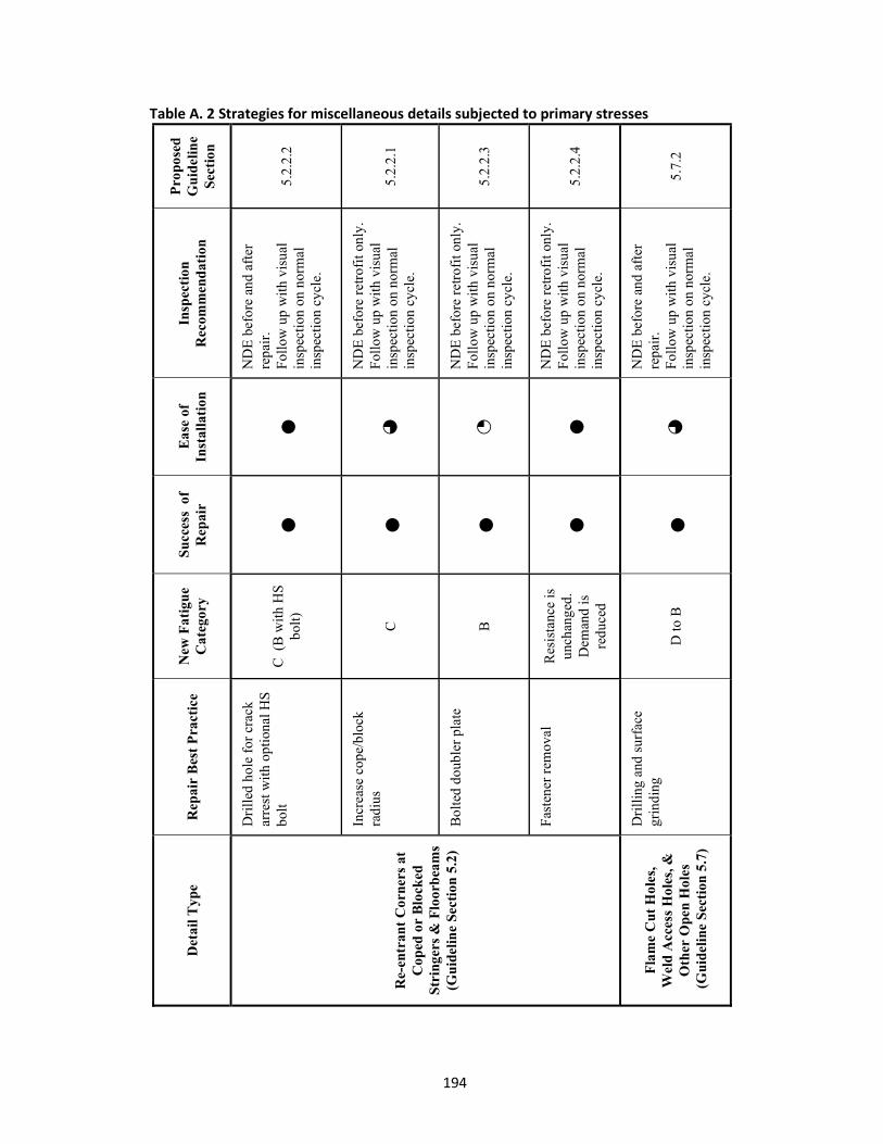
194
Table A. 2 Strategies for miscellaneous details subjected to primary stresses
Pro
pose
d
Gu
idel
ine
Sec
tion
5.2.
2.2
5.2.
2.1
5.2.
2.3
5.2.
2.4
5.7.
2
Insp
ecti
on
Rec
omm
end
atio
n
ND
E b
efor
e an
d af
ter
repa
ir.
Fol
low
up
wit
h vi
sual
in
spec
tion
on
norm
al
insp
ecti
on c
ycle
.
ND
E b
efor
e re
trof
it on
ly.
Fol
low
up
wit
h vi
sual
in
spec
tion
on
norm
al
insp
ecti
on c
ycle
.
ND
E b
efor
e re
trof
it on
ly.
Fol
low
up
wit
h vi
sual
in
spec
tion
on
norm
al
insp
ecti
on c
ycle
.
ND
E b
efor
e re
trof
it on
ly.
Fol
low
up
wit
h vi
sual
in
spec
tion
on
norm
al
insp
ecti
on c
ycle
.
ND
E b
efor
e an
d af
ter
repa
ir.
Fol
low
up
wit
h vi
sual
in
spec
tion
on
norm
al
insp
ecti
on c
ycle
.
Eas
e of
In
stal
lati
on
●
◕
◔ ●
◕
Suc
cess
of
Rep
air
●
●
●
●
●
New
Fat
igu
e C
ateg
ory
C (
B w
ith
HS
bo
lt)
C
B
Res
ista
nce
is
unch
ange
d.
Dem
and
is
redu
ced
D to
B
Rep
air
Bes
t P
ract
ice
Dri
lled
hol
e fo
r cr
ack
arre
st w
ith
opti
onal
HS
bo
lt
Incr
ease
cop
e/bl
ock
radi
us
Bol
ted
doub
ler
plat
e
Fas
tene
r re
mov
al
Dri
llin
g an
d su
rfac
e gr
indi
ng
Det
ail T
ype
Re-
entr
ant
Cor
ners
at
Cop
ed o
r B
lock
ed
Str
inge
rs &
Flo
orb
eam
s (G
uid
elin
e Se
ctio
n 5.
2)
Fla
me
Cut
Hol
es,
Wel
d A
cces
s H
oles
, &
Oth
er O
pen
Hol
es
(G
uide
line
Sec
tion
5.7
)

195
Table A. 3 Strategies for miscellaneous details subjected to primary stresses, continued
Pro
pose
d
Gu
idel
ine
Sec
tion
5.6.
2.1
5.6.
2.2
5.6.
2.3
5.9.
2
5.11
.2
Insp
ecti
on R
ecom
men
dat
ion
ND
E b
efor
e an
d af
ter
repa
ir.
UT
insp
ecti
on to
est
abli
sh
soun
dnes
s (A
WS
D1.
5).
Fol
low
up
wit
h vi
sual
insp
ectio
n on
nor
mal
insp
ecti
on c
ycle
.
ND
E b
efor
e re
trof
it. F
ollo
w u
p w
ith
visu
al in
spec
tion
on n
orm
al
insp
ecti
on c
ycle
.
ND
E b
efor
e re
trof
it on
ly.
No
spec
ial f
ollo
w-u
p in
spec
tion
is
nec
essa
ry.
ND
E b
efor
e an
d af
ter
repa
ir.
Fol
low
up
wit
h vi
sual
insp
ectio
n on
nor
mal
insp
ecti
on c
ycle
.
ND
E b
efor
e an
d af
ter
repa
ir.
Fol
low
up
wit
h vi
sual
insp
ectio
n on
nor
mal
insp
ecti
on c
ycle
.
Eas
e of
In
stal
lati
on
◑
◑
◔
◔
◑
Suc
cess
of
R
epai
r
●
●
●
◑
◑
New
F
atig
ue
Cat
egor
y B
B
B
C (
B
wit
h H
S
bolt
)
Dep
ends
on
rad
ius
Rep
air
Bes
t P
ract
ice
Gri
nd s
moo
th
Wel
d to
e tr
eatm
ent
Bol
ted
splic
e re
trof
it
Wel
d re
mov
al w
ith
opti
onal
hig
h st
reng
th
bolt
Bac
king
bar
rem
oval
or
fair
ing
of te
rmin
atio
n w
ith
grin
ding
Det
ail T
ype
Tra
nsve
rse
Bu
tt W
eld
s (G
uid
elin
e Se
ctio
n 5.
6)
Plu
g W
elds
(G
uid
elin
e Se
ctio
n 5.
9)
Dis
con
tin
uou
s B
acki
ng
Bar
s (G
uid
elin
e Se
ctio
n 5.
11)
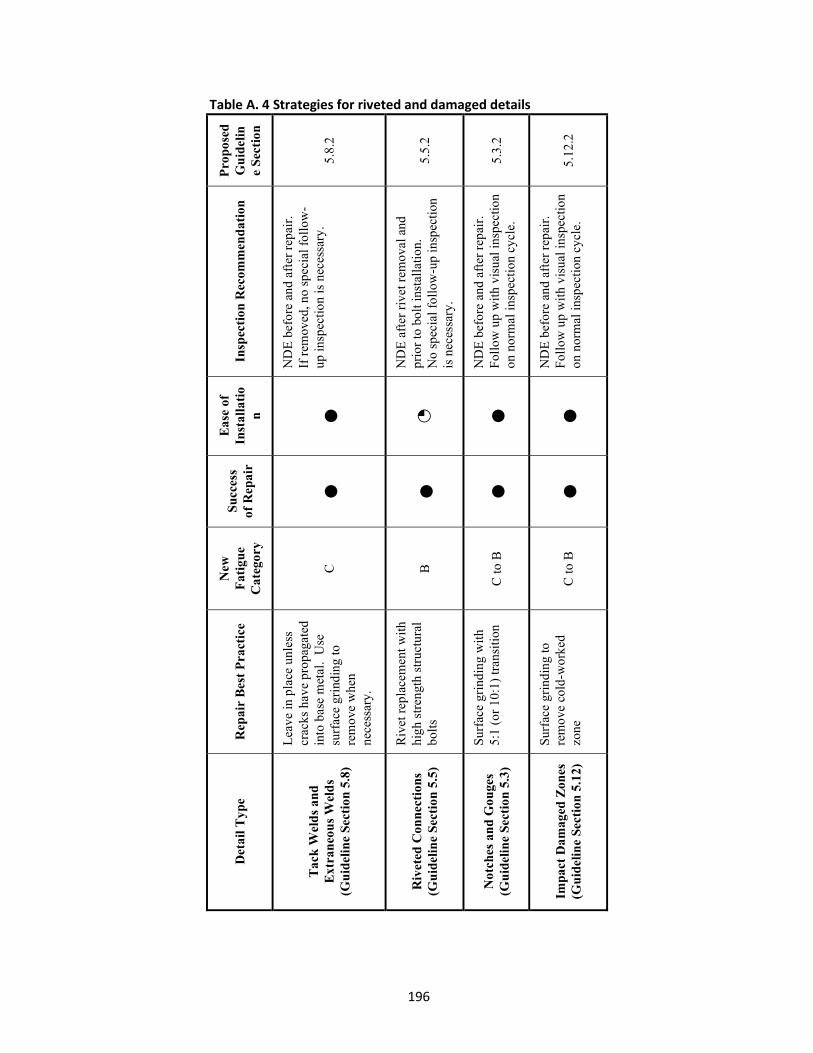
196
Table A. 4 Strategies for riveted and damaged details
Pro
pose
d
Gu
idel
ine
Sec
tion
5.8.
2
5.5.
2
5.3.
2
5.12
.2
Insp
ecti
on R
ecom
men
dat
ion
ND
E b
efor
e an
d af
ter
repa
ir.
If r
emov
ed, n
o sp
ecia
l fol
low
-up
insp
ectio
n is
nec
essa
ry.
ND
E a
fter
riv
et r
emov
al a
nd
prio
r to
bol
t ins
tall
atio
n.
No
spec
ial f
ollo
w-u
p in
spec
tion
is
nec
essa
ry.
ND
E b
efor
e an
d af
ter
repa
ir.
Fol
low
up
wit
h vi
sual
insp
ectio
n on
nor
mal
insp
ecti
on c
ycle
.
ND
E b
efor
e an
d af
ter
repa
ir.
Fol
low
up
wit
h vi
sual
insp
ectio
n on
nor
mal
insp
ecti
on c
ycle
.
Eas
e of
In
stal
lati
on
●
◔ ●
●
Suc
cess
of
Rep
air
●
●
●
●
New
F
atig
ue
Cat
egor
y
C
B
C to
B
C to
B
Rep
air
Bes
t P
ract
ice
Lea
ve in
pla
ce u
nles
s cr
acks
hav
e pr
opag
ated
in
to b
ase
met
al.
Use
su
rfac
e gr
indi
ng to
re
mov
e w
hen
nece
ssar
y.
Riv
et r
epla
cem
ent w
ith
high
str
engt
h st
ruct
ural
bo
lts
Sur
face
gri
ndin
g w
ith
5:1
(or
10:1
) tr
ansi
tion
Sur
face
gri
ndin
g to
re
mov
e co
ld-w
orke
d zo
ne
Det
ail T
ype
Tac
k W
eld
s an
d
Ext
ran
eou
s W
eld
s (G
uid
elin
e Se
ctio
n 5.
8)
Riv
eted
Con
nect
ions
(G
uid
elin
e Se
ctio
n 5.
5)
Not
ches
an
d G
ouge
s (G
uid
elin
e Se
ctio
n 5.
3)
Impa
ct D
amag
ed Z
ones
(G
uid
elin
e Se
ctio
n 5.
12)

197

198
A.2 Distortion-Induced Fatigue Quick Reference Tables

199
Table A. 5 Strategies for web gaps on primary members subject to secondary stresses P
ropo
sed
G
uid
elin
e S
ecti
on
6.1.
2.1
6.1.
2.2
6.1.
2.3
6.1.
2.4
6.1.
2.5
6.1.
2.6
6.1.
2.7
Insp
ecti
on
Rec
omm
end
atio
n
ND
E b
efor
e an
d af
ter
repa
ir.
Fol
low
up
wit
h vi
sual
in
spec
tion
on
norm
al
insp
ecti
on c
ycle
.
ND
E b
efor
e an
d af
ter
repa
ir.
Fol
low
up
wit
h vi
sual
in
spec
tion
on
norm
al
insp
ecti
on c
ycle
.
ND
E b
efor
e an
d af
ter
repa
ir.
Fol
low
up
wit
h vi
sual
in
spec
tion
on
norm
al
insp
ecti
on c
ycle
.
ND
E b
efor
e an
d af
ter
repa
ir.
Fol
low
up
wit
h vi
sual
in
spec
tion
on
norm
al
insp
ecti
on c
ycle
.
ND
E b
efor
e an
d af
ter
repa
ir.
Fol
low
up
wit
h vi
sual
in
spec
tion
on
norm
al
insp
ecti
on c
ycle
.
ND
E b
efor
e re
pair
. F
ollo
w u
p w
ith
visu
al
insp
ecti
on o
n no
rmal
in
spec
tion
cyc
le.
ND
E b
efor
e re
pair
. F
ollo
w u
p w
ith
visu
al
insp
ecti
on o
n no
rmal
in
spec
tion
cyc
le.
Eas
e of
In
stal
lati
on
●
◔
◔
◕
◑
○
◑
Suc
cess
of
Rep
air
●
●
●
●
●
●
●
Rep
air
Bes
t P
ract
ice
Dri
lled
hol
e fo
r cr
ack
arre
st
Web
gap
stif
feni
ng:
Wel
ded
spli
ce r
etro
fit
Web
gap
stif
feni
ng:
Bol
ted
splic
e re
trof
it
Web
gap
sof
teni
ng:
Lar
ge-h
ole
retr
ofit
Web
gap
sof
teni
ng:
Con
nect
ion
plat
e cu
tbac
k re
trof
it
Dia
phra
gm o
r cr
oss
fram
e re
mov
al
retr
ofit
Bol
t loo
seni
ng
retr
ofit
Det
ail T
ype
Gir
der
Web
Gap
s at
C
onne
ctio
n P
late
s on
G
irde
r, G
ird
er F
loor
beam
, an
d B
ox G
ird
er B
rid
ges
(Gu
idel
ine
Sect
ion
6.1)

200
Table A. 6 Strategies for web gaps on secondary members subject to secondary stresses
Pro
pose
d
Gu
idel
ine
Sec
tion
6.2.
2.1
6.2.
2.2
6.3.
2
6.4.
2
6.6.
2
Insp
ecti
on
Rec
omm
end
atio
n
ND
E b
efor
e an
d af
ter
repa
ir.
Fol
low
up
wit
h vi
sual
in
spec
tion
on
norm
al
insp
ecti
on c
ycle
.
ND
E b
efor
e re
pair
. F
ollo
w u
p w
ith
visu
al
insp
ecti
on o
n no
rmal
in
spec
tion
cyc
le.
ND
E b
efor
e re
pair
. F
ollo
w u
p w
ith
visu
al
insp
ecti
on o
n no
rmal
in
spec
tion
cyc
le.
ND
E b
efor
e re
pair
. N
o sp
ecia
l fol
low
-up
insp
ecti
on is
nec
essa
ry a
fter
re
pair
.
ND
E b
efor
e re
trof
it. F
ollo
w
up w
ith
visu
al in
spec
tion
on
norm
al in
spec
tion
cycl
e.
Eas
e of
In
stal
lati
on
●
◔
◑
◔
◑
Suc
cess
of
Rep
air
●
●
●
●
●
Rep
air
Bes
t P
ract
ice
Dri
lled
hol
e fo
r cr
ack
arre
st
Flo
orbe
am c
utba
ck
retr
ofit
Bra
cket
con
nect
ion
plat
e cu
tbac
k re
trof
it
Dec
oupl
e tie
pla
te
from
gir
der
Web
pla
te is
olat
ion
hole
s (D
og b
one)
Det
ail T
ype
Flo
orb
eam
Web
Gap
s on
Tie
d A
rche
s, T
russ
es, a
nd
Pla
te
Gir
ders
(G
uid
elin
e Se
ctio
n 6.
2)
Can
tile
ver
Bra
cket
C
onne
ctio
ns
(Gu
idel
ine
Sect
ion
6.3)
Can
tile
ver
Bra
cket
Tie
Pla
tes
(Gu
idel
ine
Sect
ion
6.4)
Web
Pen
etra
tion
s in
Cro
ss
Gir
ders
(G
uid
elin
e Se
ctio
n 6.
6)

201
Table A. 7 Strategies for connections using angles subjected to secondary stresses
Pro
pose
d
Gu
idel
ine
Sec
tion
6.5.
2.1
6.5.
2.2
6.5.
2.3
6.5.
2.4
Insp
ecti
on
Rec
omm
end
atio
n
Fol
low
up
wit
h vi
sual
in
spec
tion
on
norm
al
insp
ecti
on c
ycle
.
Fol
low
up
wit
h vi
sual
in
spec
tion
on
norm
al
insp
ecti
on c
ycle
on
rem
aini
ng d
iaph
ragm
s on
ly.
Fol
low
up
wit
h vi
sual
in
spec
tion
on
norm
al
insp
ecti
on c
ycle
.
Fol
low
up
wit
h vi
sual
in
spec
tion
on
norm
al
insp
ecti
on c
ycle
.
Eas
e of
In
stal
lati
on
◑
○
◑
●
Suc
cess
of
Rep
air
●
●
●
●
Rep
air
Bes
t P
ract
ice
Bea
ring
sea
ts r
etro
fit
Dia
phra
gm r
emov
al
retr
ofit
Con
nect
ion
angl
e re
plac
emen
t ret
rofi
t
Fas
tene
r re
mov
al
retr
ofit
Det
ail T
ype
Riv
eted
and
Bol
ted
C
onne
ctio
ns U
sin
g A
ngl
es
(Gu
idel
ine
Sect
ion
6.5)

202
A.3 Constraint-Induced Fracture Quick Reference Table

203
Table A. 8 Strategies for constraint-induced fracture (CIF) details P
ropo
sed
G
uid
elin
e S
ecti
on
7.1.
2.1
7.1.
2.2
7.1.
2.3
7.2.
2
7.3.
2.1
7.3.
2.2
7.4.
2
Insp
ecti
on
Rec
omm
end
atio
n
No
spec
ial f
ollo
w-u
p in
spec
tion
is n
eces
sary
No
spec
ial f
ollo
w-u
p in
spec
tion
is n
eces
sary
No
spec
ial f
ollo
w-u
p in
spec
tion
is n
eces
sary
No
spec
ial f
ollo
w-u
p in
spec
tion
is n
eces
sary
No
spec
ial f
ollo
w-u
p in
spec
tion
is n
eces
sary
No
spec
ial f
ollo
w-u
p in
spec
tion
is n
eces
sary
No
spec
ial f
ollo
w-u
p in
spec
tion
is n
eces
sary
Eas
e of
In
stal
lati
on
◔
◑
◔
◑
◑
◑
◑
Suc
cess
of
Rep
air
●
●
●
●
●
●
●
Rep
air
Bes
t P
ract
ice
Gus
set p
late
cop
e re
trof
it
Web
pla
te is
olat
ion
hole
s re
trof
it
Bal
l end
mill
ret
rofi
t
Lon
gitu
dina
l st
iffe
ner
cutb
ack
retr
ofit
Lon
gitu
dina
l st
iffe
ner
core
re
trof
it
Web
pla
te c
ore
retr
ofit
Web
pla
te is
olat
ion
hole
s re
trof
it
Det
ail T
ype
Inte
rsec
ting
wel
ds
at g
uss
et
pla
tes
(i.e
., H
oan
deta
ils)
(G
uid
elin
e Se
ctio
n 7.
1)
Inte
rsec
ting
wel
ds
at
lon
gitu
din
al s
tiff
ener
pla
tes
(Gu
idel
ine
Sect
ion
7.2)
Poo
r qu
alit
y lo
ngit
udi
nal
st
iffe
ner
sp
lices
(G
uid
elin
e Se
ctio
n 7.
3)
Web
gap
s at
bea
ring
st
iffe
ner
s in
neg
ativ
e m
omen
t re
gion
s (G
uid
elin
e Se
ctio
n 7.
4)