Inducing hydrogen assisted cold cracking in high strength ...
196
University of Wollongong Research Online University of Wollongong Thesis Collection University of Wollongong Thesis Collections 2009 Inducing hydrogen assisted cold cracking in high strength steel weld metal Rian Holdstock University of Wollongong Research Online is the open access institutional repository for the University of Wollongong. For further information contact Manager Repository Services: [email protected]. Recommended Citation Holdstock, Rian, Inducing hydrogen assisted cold cracking in high strength steel weld metal, Doctor of Philosophy thesis, School of Mechanical, Materials and Mechatronics Engineering - Faculty of Engineering, University of Wollongong, 2009. http://ro.uow.edu.au/theses/3182
-
Upload
khangminh22 -
Category
Documents
-
view
0 -
download
0
Transcript of Inducing hydrogen assisted cold cracking in high strength ...
University of WollongongResearch Online
University of Wollongong Thesis Collection University of Wollongong Thesis Collections
2009
Inducing hydrogen assisted cold cracking in highstrength steel weld metalRian HoldstockUniversity of Wollongong
Research Online is the open access institutional repository for theUniversity of Wollongong. For further information contact ManagerRepository Services: [email protected].
Recommended CitationHoldstock, Rian, Inducing hydrogen assisted cold cracking in high strength steel weld metal, Doctor of Philosophy thesis, School ofMechanical, Materials and Mechatronics Engineering - Faculty of Engineering, University of Wollongong, 2009.http://ro.uow.edu.au/theses/3182
INDUCING HYDROGEN ASSISTED COLD CRACKING IN HIGH STRENGTH STEEL WELD METAL
A THESIS SUBMITTED IN FULFILMENT OF
THE REQUIREMENTS FOR THE AWARD OF THE DEGREE
DOCTOR OF PHILOSOPHY
FROM
THE UNIVERSITY OF WOLLONGONG
BY
RIAN HOLDSTOCK
SCHOOL OF MECHANICAL, MATERIALS AND MECHATRONICS ENGINEERING
2009
ii
DECLARATION This is to certify that the work presented in this thesis has been conducted by the candidate
while enrolled as a full-time postgraduate student in the Department of Materials
Engineering, University of Wollongong. The results obtained in this study and the
conclusions drawn are those of the candidate. The work has not been submitted in total or in
partial fulfilment of the requirements of any other university or educational institution.
Rian Holdstock
iii
ACKNOWLEDGEMENTS
I would like to thank The Cooperative Research Centre for Welded Structures (CRC-WS),
which provided financial support for the program. I would also like to acknowledge the effort
and guidance given by Dr. David Nolan. Without his efforts my studies at The University of
Wollongong, under the auspices of CRC-WS, would not have eventuated.
To my colleagues at BMT Fleet Technology, thanks for the freedom, your advice and a
supportive working environment.
To Dr. Zoran Sterjovski, you gave both friendship and academic stimulus, thanks mate!
To the wonderful staff of the engineering faculty, who were always prepared to accommodate
my needs. particularly: Ron, Stuart, Bob (x3), Ian, Alan, Greg, Jose, Nick, Lorelle and Joy,
thank you immensely.
To, Professors John Norrish and Professor Rian Dippenaar, whose mentoring, patience and
support provided much of the inspiration I needed to complete this thesis.
To my mother, Bettie, and my brother Louis. I share this achievement with you.
Finally to my patient wife, Lillian, who most likely had to endure more than I had to. You
were my foundation during this momentous task. Muito obrigado minha queridinha.

iv
ABSTRACT
The thesis explores the hydrogen assisted cold cracking in high strength steel weld metal
during flux cored arc welding (FCAW) using a technique involving the deliberate
introduction of hydrogen into the CO2 shielding gas. A specific objective was to investigate
weld metal cold cracking susceptibility by development of a research tool which permitted
control over both the weld metal diffusible hydrogen content and the stress applied during
mechanical testing of single bead on plate weld deposits.
The basis for this undertaking is twofold, and stems from the fact that crack mitigating
measures traditionally address cracking in the heat affected zone, although it has been shown
that weld metal hydrogen assisted cold cracking is more likely when strength matching weld
metals are used to join high strength low alloy steels. As a result existing weldability test
methods have a limited ability to simulate weld metal hydrogen assisted cold cracking.
The literature relevant to hydrogen assisted cold cracking (HACC) has been reviewed, and
the current understanding and assertions relating to HACC have been detailed. The primary
findings are that this form of cracking in high strength steel weld metal occurs by localised
plastic deformation, which eventually results in fracture through bands of intense shear. The
increase in alloying elements and the as-cast nature of the weld metal are also recognised as
two key reasons why cracking has migrated from the heat affected zone into the weld metal.
Current welding standards and recognised weldability test methods have also been reviewed
to establish the techniques and engineering guidance available. This review indicates that the
majority of test methods and all of the welding standards are heat affected zone specific A
further revelation is that weldability test methods typically function as a ranking tool and
offer limited scope to serve as a research tool.
The initial experimental investigation of multipass welds in thick plate revealed that the
majority of weld metal cold cracking occurred within 48 hours of weld completion. Crack
detection was also recorded several days after welding had ceased, indicating that the

v
diffusion, trapping and stress-strain conditions of solute hydrogen contribute significantly to
crack initiation and propagation.
Self restraint multipass weld techniques were then considered as a means of generating weld
metal hydrogen assisted cold cracking test data. Subsequent research also evaluated tensile
and bend testing to develop cracking in single bead on plate weld deposits. The analysis of
the requirements to generate cracking in both single and multipass welds was then used to
produce a single bead, applied stress test which preferentially targeted the weld metal. The
test methods developed during the experimental phase subsequently allowed manipulation of
the diffusible hydrogen content and the magnitude of the applied stress, which in turn
facilitated weld metal cold cracking under controlled conditions.
The test specimens were produced by depositing high strength ferritic weld metal onto a
strength matched martensitic base material via an automated flux cored arc welding process.
In order to increase the susceptibility to cracking, 2% and 5%H2 was deliberately added to the
CO2 shielding gas.
Both tensile and 4-point bend testing of single pass weld deposits were evaluated, although 4-
point bending was ultimately selected as the most suitable test method providing preferential
targeting of the weld metal. Standard bead on plate and geometrically modified bead on plate
specimen geometries were employed during testing. These were assessed according to their
functionality, machinability and reproducibility of the results generated.
Rising load and stress controlled test configurations were applied to observe the behaviour of
the weld metal mechanical properties. Although the test configurations permitted close
control over the test variables (hydrogen, stress, microstructure and time), the results
indicated that variations in cold cracking delay times will occur under near identical test
conditions. The variations observed are explained in terms of differences in the transport and
trapping behaviour of hydrogen in the heterogeneous structure of the weld metal.
The inability to generate closely matching cold cracking delay times under matching
conditions suggests that a single time to fracture cannot be realised for the test conditions
employed. It is therefore proposed that a maximum delay time after which fracture will not
vi
occur be used as a research outcome, instead of defining specific or closely matching delay
times.
Metallographic analysis of the test specimens was also conducted to determine the effect of
hydrogen on the evolution of the microstructure and to establish the fracture morphology.
Image analysis revealed that a reduction of non-metallic inclusions occurred during welding
with hydrogen-rich shielding gas. The introduction of hydrogen into the shielding gas also
resulted in a coarsening of the general microstructure, believed to be the product of reduced
acicular ferrite nucleation, allowing individual grains to coarsen without being impeded by
the growth of nearby nucleated grains.
The morphology of the fractures observed under microscopy and their reliance on the
introduction of hydrogen in the shielding gas indicated that the fractures were typical of those
produced under weld metal hydrogen assisted cold cracking conditions. Ductile tearing,
microvoid coalescence, quasi cleavage and cleavage fracture facets were observed along the
fracture path. The cracks were observed to have propagated along both the columnar
solidification structure and along the prior austenite grain boundaries. Microcracks were also
observed on the fracture faces, which are believed to have contributed to the final fracture by
means of crack-linkage. Higher concentrations of impurity elements were also observed on
the boundary along which the cracks had propagated. The typical region from which cracking
would originate was associated with second phase constituents and low grain boundary ferrite
content.
Whilst it was not possible to develop a quantitative test for hydrogen cracking susceptibility;
the reasons for the test variability have been explored and show that the interaction of
hydrogen with microstructural development may play a significant role in WM HACC
susceptibility.
vii
ABBREVIATIONS
AE Acoustic Emission Monitoring
AF Acicular Ferrite
AS/NZS Australia/New Zealand Standard
AWS American Welding Society
B Bainite
CEIIW International Institute of Welding Carbon Equivalent
CEN Carbon Equivalent Number
EDS Energy Dispersive Spectrometer (EDS)
FCAW Flux Cored Arc Welding
GB Grain Boundary
GBOP Gapped Bead on Plate
HACC Hydrogen Assisted Cold Cracking
HD Diffusible Hydrogen
HEDE Hydrogen Enhanced Decohesion
HELP Hydrogen Enhanced Localised Plasticity
HSLA High Strength Low Alloy
IG Intergranular
LB-TRC Longitudinal Bead – Tensile Restraint
MMAW Manual Metal Arc Welding

viii
Ms Martensite Start Temperature
MT Magnetic Particle Testing
MVC Microvoid Coalescence
NDT Nondestructuve Testing
Pcm Ito and Bessyo Carbon Equivalent
PM Parent Metal
QC Quasi Cleavage
Q&T Quenched and Tempered
RT Radiography
SEM Scanning Electron Microscopy
TEM Transmission Electron Microscopy
TRC tensile Restraint Cracking
UT Ultrasonic Testing
W Widmanstätten Ferrite
WM Weld Metal
YS Yield Strength
Z Confidence Interval
α Allotriomorphic Ferrite
δ Delta-Ferrite or Deflection
γ Austenite
σeff Effective Stress

ix
σmax Maximum Stress in Outer Fibre
εmax Maximum Strain in Outer Fibre

x
TABLE OF CONTENTS
DECLARATION ...................................................................................................................... ii
ACKNOWLEDGEMENTS ....................................................................................................iii
ABSTRACT ............................................................................................................................. iv
ABBREVIATIONS ................................................................................................................ vii
TABLE OF CONTENTS ........................................................................................................ x
CHAPTER 1: ........................................................................................................................... 1
INTRODUCTION ................................................................................................................... 1
CHAPTER 2 ............................................................................................................................. 8
LITERATURE SURVEY ......................................................................................................... 8
2.1.1 Hydrogen Entry Due to Welding ................................................................................................. 8
2.1.2 Hydrogen Trapping ......................................................................................................................... 11
2.1.3 Hydrogen Transport ....................................................................................................................... 17
2.1.4 Hydrogen – Dislocation Interactions ....................................................................................... 18
2.1.5 Hydrogen Diffusion ......................................................................................................................... 22
2.2 HIGH STRENGTH STEEL WELD METAL MICROSTRUCTURE .......................................... 26
2.2.1 Solid State Transformation ......................................................................................................... 26
2.2.2 Austenite Grain Size ...................................................................................................................... 28
2.2.3 Allotriomorphic Ferrite (Polygonal or Grain Boundary Ferrite) .................................... 30
2.2.4 Widmanstätten Ferrite .................................................................................................................. 31
2.2.5 Acicular Ferrite ................................................................................................................................. 32
2.2.6 Weld Metal Inclusions ................................................................................................................... 35
2.2.7 Austenite Grain Size and Martensite Start Temperature ............................................... 39
2.2.8 Acicular Ferrite and Hardenability ............................................................................................ 42
2.3 HYDROGEN ASSISTED COLD CRACKING .............................................................................. 44
2.3.1 Hardness ............................................................................................................................................. 45

xi
2.3.2 Incubation Time ............................................................................................................................... 47
2.3.3 Hydrogen – Stress Relationship ................................................................................................ 48
2.3.4 Inclusion Assisted Fracture ......................................................................................................... 51
2.4 HYDROGEN ASSISTED COLD CRACKING MECHANISMS ................................................ 54
2.4.1 Planar Pressure Theory ................................................................................................................. 54
2.4.2 Adsorption Theory .......................................................................................................................... 54
2.4.3 Hydrogen Enhanced Decohesion .............................................................................................. 55
2.4.4 Hydride Induced Embrittlement ................................................................................................ 55
2.4.5 Microplasticity Theory ................................................................................................................... 56
2.4.6 Adsorption Induced Localised Slip Model .............................................................................. 56
2.4.7 Hydrogen Enhanced Localised Plasticity (HELP Model)................................................... 57
2.4.8 Comment on HAC Mechanisms ................................................................................................. 58
2.5 WELD METAL HACC TEST METHODS ...................................................................................... 60
2.5.1 Longitudinal Bead Tensile Restraint Cracking Test (LB-TRC) ...................................... 62
2.5.2 Gapped Bead on Plate Test ......................................................................................................... 63
2.5.3 Bend Testing ..................................................................................................................................... 64
2.5.4 Comment on Weld metal Cold Cracking Test Methods ................................................... 65
CHAPTER 3 ........................................................................................................................... 69
HYDROGEN CRACKING IN MULTIPASS HIGH STRENGTH WELD METAL -
INVESTIGATION ................................................................................................................ 69
3.1.0 Introduction ....................................................................................................................................... 71
3.1.1 Method: Welding High Restraint Test Plate ......................................................................... 72
3.1.2 Method: Diffusible Hydrogen Levels ....................................................................................... 74
3.1.3 Method: Nondestructive Testing (NDT) ................................................................................. 74
3.2.1 Results: Cooling Times and Interpass Temperature ........................................................ 75
3.2.2 Results: Diffusible Hydrogen Levels ....................................................................................... 78
3.2.3 Results: Nondestructive Testing (NDT) ................................................................................. 78
CHAPTER 4 ........................................................................................................................... 83
EVALUATING DIFFUSIBLE HYDROGEN TESTING .................................................. 83

xii
4.1.0 Introduction ....................................................................................................................................... 83
4.1.1 Materials ............................................................................................................................................. 83
4.1.2 Welding Power Source .................................................................................................................. 84
4.1.3 Welding Consumables ................................................................................................................... 85
4.2.1 Method: Hydrogen Test Assembly ........................................................................................... 85
4.2.2 Method: Welding of Hydrogen Test Samples ...................................................................... 87
4.2.3 Method: Quenching of Welded Samples ............................................................................... 88
4.2.4 Method: Diffusible Hydrogen Analysis ................................................................................... 89
4.3.1 Results: Diffusible Hydrogen Analysis – Test Configurations ...................................... 90
4.3.2 Results: The Addition of H2 to the CO2 Shielding Gas ..................................................... 90
4.3.3 Results: Relative Humidity .......................................................................................................... 91
4.3.4 Results: Hydrogen Weld Test Assembly ................................................................................ 92
CHAPTER 5 ........................................................................................................................... 94
DEVELOPMENT OF MECHANICAL TEST SPECIMENS............................................ 94
5.1.0 Introduction ....................................................................................................................................... 94
5.1.1 Method: Tensile Specimen .......................................................................................................... 95
5.1.2 Method: 4-Point Bend Specimen .............................................................................................. 96
5.1.3 Method: Statistical Analysis of Weld Bead Geometry ..................................................... 98
5.1.4 Method: Stress Determination – Narrow Specimen ....................................................... 99
5.1.5 Method: Stress Determination – Wide Specimen ........................................................... 100
5.1.6 Method: ANSYS Bend Specimen Comparison ................................................................... 100
5.2.1 Result: ANSYS 0.5mm Roller Displacement ...................................................................... 102
5.2.2 Result: ANSYS 1.0mm Roller Displacement ...................................................................... 103
5.2.3 Result: ANSYS 2.0mm Roller Displacement ...................................................................... 104
CHAPTER 6 ......................................................................................................................... 105
TESTING SINGLE PASS HIGH STRENGTH WELD METAL ................................. 105
6.1.0 Introduction ................................................................................................................................... 105
6.1.1 Method: Baseline Conditions .................................................................................................... 106
6.1.2 Method: HACC in Single Pass High Strength Weld Metal............................................. 107

xiii
6.1.3 Result: Baseline Conditions – Tensile Testing .................................................................. 108
6.1.4 Results: 4-Point Bending Baseline Conditions ................................................................. 110
6.1.5 Results: HACC – Tensile Testing ............................................................................................ 112
6.1.6 Results: HACC – Bend Testing ................................................................................................ 114
CHAPTER 7 ......................................................................................................................... 117
MICROSTRUCTURAL AND FRACTOGRAPHIC ANALYSIS ................................... 117
7.1.0 Introduction ..................................................................................................................................... 117
7.1.1 Method: Chemical Composition .............................................................................................. 117
7.1.2 Results: Chemical Composition ............................................................................................... 118
7.1.5 Method: Cellular Dendritic Spacing ....................................................................................... 123
7.1.6 Results: Cellular Dendritic Spacing ....................................................................................... 124
7.1.7 Method: Microscopic Analysis of fractured specimens .................................................. 126
7.1.8 Method: General Microstructure ............................................................................................. 126
7.1.9 Results: Microstructure .............................................................................................................. 127
7.1.10 Results: Fracture Surface Microscopy ................................................................................. 132
CHAPTER 8 ......................................................................................................................... 141
DISCUSION ........................................................................................................................ 141
8.1 Deliberate Generation of Multipass Weld Metal Cold Cracking .................................. 141
8.2 Diffusible Hydrogen Testing ..................................................................................................... 145
8.4 Mechanical Testing ....................................................................................................................... 153
8.5 Microstructure and Fractography ........................................................................................... 158
8.6 Conclusions – Inducing HACC in High Strength Steel Weld Metal ........................... 165
8.7 Limitations of Study ..................................................................................................................... 166
8.8 Future Work: ................................................................................................................................... 166
APPENDIX A ....................................................................................................................... 180
CALCULATING STRESSES - WIDE BEAD ON PLATE SPECIMEN .................... 180
APPENDIX B ....................................................................................................................... 181
PUBLICATIONS ................................................................................................................................................. 181

1
CHAPTER 1: INTRODUCTION
Hydrogen assisted cold cracking (HACC) has historically been associated with the heat
affected zone (HAZ) of welds in ferritic steel, but improved steel making processes have
enabled high parent metal strength to be obtained with low alloy levels and reduced
susceptibility to HACC. In contrast, the as-cast nature of the weld metal does not provide the
same opportunity to control the transformation processes, and therefore the microstructure as
precisely as high strength low alloy (HSLA) steels. Therefore in situations where the weld
metal strength needs to match the strength of the parent material the hydrogen assisted cold
cracking problem is been transferred from the heat affected zone to the high strength steel weld
metal (Davidson, 1995; Adonyi, 2000).
This thesis aimed to contribute to the understanding and control of hydrogen assisted cold
cracking (HACC) of high strength ferritic steel weld metal and to develop a test method that
preferentially targets the weld metal, as opposed to the heat affected zone (HAZ). Ideally such
a test method should be capable of quantifying weld metal HACC suceptibility under various
conditions.
Current test methods are limited in their ability to exercise close control over the factors that
govern weld metal HACC, and in particular the inability to control and measure the level of
applied stress (Law et al, 2007). The proposed applied stress test technique was designed to
allow the evaluation of HACC under more precise conditions and lead to a greater
understanding of the mechanisms that cause this dangerous and costly weld metal cracking
phenomenon. Standardisation of the test method should furthermore provide an opportunity to
develop a recognised weld metal specific HACC standard and provide data for ‘safe’ procedure
development.
A specific challenge faced during the welding of ferritic steel is that hydrogen decomposes in
the welding arc, producing hydrogen ions that are easily absorbed into the molten weld pool.
During subsequent solidification, the monatomic diffusible hydrogen is retained in the weld
2
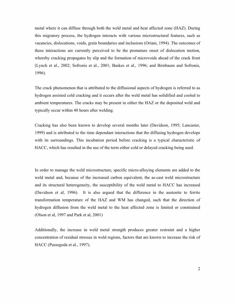
metal where it can diffuse through both the weld metal and heat affected zone (HAZ). During
this migratory process, the hydrogen interacts with various microstructural features, such as
vacancies, dislocations, voids, grain boundaries and inclusions (Oriani, 1994). The outcomes of
these interactions are currently perceived to be the premature onset of dislocation motion,
whereby cracking propagates by slip and the formation of microvoids ahead of the crack front
(Lynch et al., 2002; Sofronis et al., 2001; Baskes et al., 1996; and Birnbaum and Sofronis,
1996).
The crack phenomenon that is attributed to the diffusional aspects of hydrogen is referred to as
hydrogen assisted cold cracking and it occurs after the weld metal has solidified and cooled to
ambient temperatures. The cracks may be present in either the HAZ or the deposited weld and
typically occur within 48 hours after welding.
Cracking has also been known to develop several months later (Davidson, 1995; Lancaster,
1999) and is attributed to the time dependant interactions that the diffusing hydrogen develops
with its surroundings. This incubation period before cracking is a typical characteristic of
HACC, which has resulted in the use of the term either cold or delayed cracking being used.
In order to manage the weld microstructure, specific micro-alloying elements are added to the
weld metal and, because of the increased carbon equivalent, the as-cast weld microstructure
and its structural heterogeneity, the susceptibility of the weld metal to HACC has increased
(Davidson et al, 1996). It is also argued that the difference in the austenite to ferrite
transformation temperature of the HAZ and WM has changed, such that the direction of
hydrogen diffusion from the weld metal to the heat affected zone is limited or constrained
(Olson et al, 1997 and Park et al, 2001)
Additionally, the increase in weld metal strength produces greater restraint and a higher
concentration of residual stresses in weld regions, factors that are known to increase the risk of
HACC (Pussegoda et al., 1997).

3
The susceptibility of a weldment to defects is evaluated through weldability tests, which have
been produced for both the heat affected zone and the weld metal (see Chapter 2, Table 2.3).
Reviews of these test methods have been produced, although they focus predominantly on the
heat affected zone (Yurioka and Suzuki, 1990; Davidson, 1995; Graville, 1995). In addition, a
survey of the literature indicates that the majority of the weldability tests and all current
international standards derived from these tests relate to cracking in the parent HAZ and not to
cracking in the weld metal.
This omission has further been highlighted by a report on the comparison of standardised
methods for the avoidance of cold cracking (ISO/TR 17844:2004) in which weld metal cold
cracking received minimal attention. A result of this disparity is that the weld metal is now
subject to the same procedures developed for the HAZ, and in many instances these procedures
may be over-zealous, thereby increasing the economic cost of welding high strength steels.
According to Law et al., (2007), current weld metal specific tests are constrained in their ability
to isolate and manipulate individual aspects that cause weld metal hydrogen assisted cold
cracking. As an example, the Gapped Bead on Plate (GBOP) test is typically used as a ranking
tool and relies on a groove or a notch to induce artificial stress concentrations in the weld. The
results from this test are analysed on a percentage cracking basis and the stresses required to
produce the cracking cannot readily be determined. The general requirement for a notch or a
groove in the weldability tests further complicates the calculation of stress and also forces
crack initiation and crack growth in predetermined regions.
This reliance on artificial stress concentrations (notches and grooves) may alter the natural path
of the diffusing hydrogen, forcing hydrogen to concentrate in specific regions of the test
material, instead of allowing the constraints of the microstructure being evaluated to dictate the
diffusion path. If close control is required in these tests, variations in placement and the
geometry of the groove will moreover increase the potential to derive non-standardised results.
The underlying theme of this thesis is therefore the development of an un-notched test
specimen that can subsequently be used to quantify cold cracking delay times under controlled

4
conditions. The proposed test relies on a load being applied to a welded specimen, which
contains a known quantity of diffusible hydrogen in the weld metal. The hydrogen is
introduced via the shielding gas and the specimen stored in liquid nitrogen to arrest diffusion.
Prior to testing, the specimen is brought to room temperature and mechanical testing
commences with the application of an applied load.
Hydrogen assisted cold cracking should occur in the specimen after the required incubation
time has been met. The incubation time will be dependent on the microstructural features
within the weld metal, the applied load and the speed at which hydrogen diffuses to regions of
elevated stress. Data, such as load, stress, diffusible hydrogen and time, may be collected and
analysed to facilitate quantitative predictions. The conditions required for the onset of HACC
in the high strength ferritic weld metal may subsequently be evaluated.
Quantification of the stress at the crack tip was not sought, but the relationships between the
applied loading conditions and controllable quantities of diffusible hydrogen were investigated.
A single bead on plate welded specimen is produced to serve as a basis for the applied stress
testing. It was required that the test specimen should be notch-free and contain a controlled
level of diffusible hydrogen,. The original proposed test matrix is described and shown
diagramatically below.

5
Phase 1:
Nondestructive techniques were used to monitor hydrogen assisted cold cracking activity in a
multipass V-groove flux cored weld deposits. The crack activity was evaluated using magnetic
particle inspection, ultrasonic inspection, radiography and the monitoring of acoustic
emissions. The results and experiences gained from this phase provide a background for the
development of a smaller single pass applied stress test.
Phase 2:
This phase investigated the influence of diffusible hydrogen with time on high strength ferritic
weld metal. The research established the degree to which weld metal diffusible hydrogen levels
could be controlled when introduced via the shielding gas. The purpose was to approximate the
diffusible hydrogen (HD) present in the weld during mechanical testing.
Phase 3:
This phase focused on defining the specimen geometries and the test procedures that may be
used during the applied stress testing. A specific objective was to produce notch-free
geometries that permit preferential targeting of the weld metal. The outcome of this work
provided welded samples that were used to study either the combined effects or individual
aspects that are held responsible for weld metal hydrogen assisted cold cracking.
Phase 4:
This phase included the applied stress testing. Variations in mechanical response and the
cracking delay times were produced by means of deliberately altering the test variables. The
aim was to establish the sensitivity of the proposed test methodology and to establish whether
reproducible and standardised test outcomes can be achieved by monitoring cold cracking
delay times.
Phase 5:
Investigated fracture surfaces, nonmetallic inclusions, austenite grain sizes, chemical
composition and the microstructure of the welds produced under different hydrogen conditions.

6
Phase 6:
The final phase was to present a summary of the significant findings and discuss limitations of
the test procedures.
To summarise, the main objectives were to:
i. Produce un-notched welded specimens that allow preferential targeting
of the weld metal during mechanical testing.
ii. Generate weld metal hydrogen assisted cold cracking through controlled
injection of hydrogen during the welding process and the application of
a stress.
iii. Determine the predictability of hydrogen assisted cold cracking delay
times in the test configurations utilised.
iv. Provide results related to how the introduction of hydrogen into the
shielding gas alters the as deposited high strength ferritic steel weld
metal microstructure
v. Provide results related to typical and preferential hydrogen crack
initiation and propagation aspects of high strength steel weld metal

7
These steps are illustrated diagrammatically below:

8
CHAPTER 2 LITERATURE SURVEY
2.1.1 Hydrogen Entry Due to Welding
The introduction of hydrogen into steel weld metal is attributed to absorption of monatomic
(H) or diatomic (H2) hydrogen that has been liberated from hydrogenous compounds in the
vicinity of the welding arc. Under normal ambient conditions, the diatomic molecule of
hydrogen is too large to diffuse into the metal lattice (Carter and Cornish, 2001). The diatomic
hydrogen molecule must first dissociate into single atoms (H-H) before entry into the metal
lattice , a viewpoint supported by Oriani (1994).
Hydrogenous compounds in the vicinity of the welding arc are numerous and include paint,
corrosion, moisture and grease. Dissociation of these hydrocarbons will therefore occur during
welding, when the extremely high temperature of the arc (in excess of 3000°C) dissociates
molecular hydrogen (H2) into monatomic hydrogen (H). The monatomic hydrogen is then
introduced into the weld pool, where it is eventually retained as a monatomic solute on
solidification (see Figure 2.1). In addition, when hydrogen does enter and diffuse into metals, it
does so as a neutral atom, as the positive nuclear charge will have been neutralised (screened)
by free electrons in the metal (Sasse and Gadgill, 1996).
Due to the thermodynamic driving force required to attain equilibrium, hydrogen will be
attracted to, and driven towards energetically favourable areas within the microstructure.
During this process it will interact with other microstructural features, and it is this migratory
process of the monatomic hydrogen through the matrix (termed hydrogen diffusion), which is
believed to form the basis for HACC (Oriani, 1994). These microstructural features, such as
second phase particles and dislocations, have attractive and repulsive energies associated with
each and in turn produce compressive, shear and tensile stress fields. Oriani also writes that
dissolved hydrogen is believed to change the global and electronic structure of the host metal,
with the expectation that it therefore changes the cohesive forces between the metal atoms.
The consequence is that a decreased effort is then required to cause brittle cracking.
9
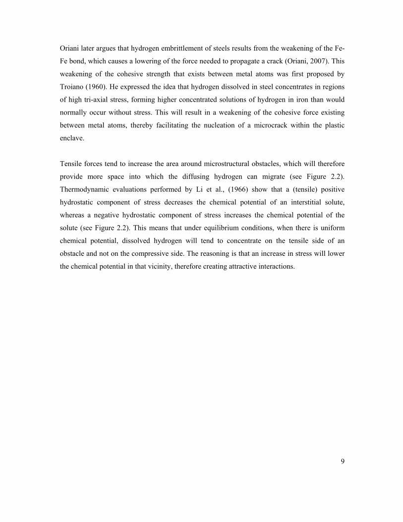
Oriani later argues that hydrogen embrittlement of steels results from the weakening of the Fe-
Fe bond, which causes a lowering of the force needed to propagate a crack (Oriani, 2007). This
weakening of the cohesive strength that exists between metal atoms was first proposed by
Troiano (1960). He expressed the idea that hydrogen dissolved in steel concentrates in regions
of high tri-axial stress, forming higher concentrated solutions of hydrogen in iron than would
normally occur without stress. This will result in a weakening of the cohesive force existing
between metal atoms, thereby facilitating the nucleation of a microcrack within the plastic
enclave.
Tensile forces tend to increase the area around microstructural obstacles, which will therefore
provide more space into which the diffusing hydrogen can migrate (see Figure 2.2).
Thermodynamic evaluations performed by Li et al., (1966) show that a (tensile) positive
hydrostatic component of stress decreases the chemical potential of an interstitial solute,
whereas a negative hydrostatic component of stress increases the chemical potential of the
solute (see Figure 2.2). This means that under equilibrium conditions, when there is uniform
chemical potential, dissolved hydrogen will tend to concentrate on the tensile side of an
obstacle and not on the compressive side. The reasoning is that an increase in stress will lower
the chemical potential in that vicinity, therefore creating attractive interactions.

10
Figure 2.1:
At A, molecular hydrogen is drawn to the surface.
At B, the molecular hydrogen dissociates into atomic
hydrogen.
At C, the atomic hydrogen resides as an interstitial.
Figure 2.2 Tensile forces around an obstacle will attract atomic hydrogen.
The “driving force” behind the net movement of dissolved hydrogen down its concentration
gradient is the difference in chemical potential between two areas. The chemical potential of a
system is a form of potential energy related to the structural arrangement of atoms. It describes
how the energy will change when a number of particles are added or removed from a specific
system. Tensile stress will normally decrease the chemical potential, as there already is a force
trying to remove the atomic hydrogen from the system.

11
The process in which molecules move from a region of higher concentration to one of lower
concentration is called diffusion. Fick’s Law of diffusion (see Chapter 2.1.5) requires that
particles move from regions of higher chemical potential (higher concentration) to regions of
lower chemical potential. Therefore, in order to achieve equilibrium, atomic hydrogen will
diffuse to areas of high stress, as these areas have lower chemical energy states, i.e., areas of
tensile stress. This demonstrates the implications as far as stressed members are concerned, as
it shows that hydrogen will diffuse to regions associated with increased state of tensile stress or
regions of lower chemical potential. In other words, the diffusing hydrogen will want to
migrate from areas of high concentration to areas of lower concentration.
Lower Stress Higher Stress
Higher Chemical Potential Lower Chemical Potential
Higher Hydrogen Concentration Lower Hydrogen Concentration
Plastic strain fields around discontinuities (i.e. voids, nonmetallic inclusions and grain
boundaries) will also provide areas of reduced chemical potential, favourable to the migrating
hydrogen atom. Under certain circumstances, the hydrogen atom will become trapped around
these discontinuities, which can either ensure a more even distribution of hydrogen or, more
detrimentally, provide a source of hydrogen in regions of high stress. The region in which
hydrogen is trapped will have a lower potential energy than the atoms it traps.
2.1.2 Hydrogen Trapping
At long ranges relative to the atomic spacing, hydrogen atoms will interact with defects in the
crystal lattice through its elastic strain field. At short ranges these interactions become
chemical in nature due to the bonding of hydrogen atoms with other atoms that define the
defect in that locality (Maroef et al., 2002). The distinctions between the various chemical
interactions are complex and local interactions are therefore described in terms of how the
hydrogen atoms bind to the defect – termed its binding energy. The effect of trapping on
hydrogen diffusion will depend strongly on the trap binding energy and the trap density.
The distribution of hydrogen in a steel weld deposit is not homogeneous due to attractive and
repulsive energies exerted upon the mobile hydrogen atom. Hydrogen will not only occupy

12
interstitial lattice sites, but also reside at atomic and microstructural imperfections such as
vacancies, solute atoms, dislocations, grain boundaries, second-phase particles and voids. The
generic term for this phenomenon is hydrogen trapping. The diffusion of H through the lattice
is not believed to follow a constant concentration gradient, meaning that internal lattice
features may act as hydrogen traps, thereby influencing how much of the absorbed hydrogen
eventually effuses out from the metal.
Absorbed hydrogen in the weld metal is characterised by its mobility and classed as either
diffusible hydrogen or residual hydrogen (Maroef et al, 2002). Trapping sites are referred to as
reversible traps and can act as either hydrogen sinks, which capture the hydrogen atoms from
weaker traps, or as hydrogen sources, which deposit hydrogen atoms to stronger traps, if the
binding energy is small. On the other hand, large binding energies give rise to irreversible
(“strong”) traps, which normally will not release hydrogen easily (Eliezer et al, 2006).
The process of trapping and releasing monatomic hydrogen is strongly dependent on the binding
energy involved, and traps are therefore generally classified according to the reversibility of that
specific hydrogen trap site. See Table 2.1. A schematic diagram illustrates the energies relevant to
a hydrogen trap site in Figure 2.3.
Depending on the trap energy, hydrogen residing at traps may either increase or decrease the
solubility and thereby also the apparent diffusivity of hydrogen (Davidson et al, 1996). Traps
will be classified as “irreversible” if they only act as hydrogen sinks and “reversible”, if the
hydrogen can be released from the trap under certain conditions. The characterisation of
“reversible” and “irreversible” hydrogen traps indicates that specific binding/activation
energies and release temperatures are associated with the different types of hydrogen traps.
A trapped hydrogen atom must therefore acquire a substantially larger energy than the normal
lattice migration energy to escape the trap. The mean residence period for a migratory atom
will also be longer in a trap site than in a normal lattice site and the apparent diffusivity is
likely to be less than the lattice diffusivity. Two prominent effects of hydrogen trapping are
therefore to (i) increase the apparent hydrogen solubility and to (ii) decrease the apparent
diffusivity (Krom and Bakker, 2000).

13
GL = Lattice Site Energy
GT = Trap Site Energy
ES = Saddle Energy (energy that influences path of migrating H
atom, activation energy for diffusion)
EB = Binding Energy (amount of energy that holds atom in trap)
ET = Trap Energy (energy to release H from trap site)
Figure 2.3 Energy levels for normal lattice sites (GL) and trapping sites (GT). The trap energy, ET is the sum of the saddle energy (ES) and the binding energy (EB).
Hydrogen trap sites are typically categorised according to their binding energies, as provided in
Table 2.1. The foundations of hydrogen trap sites and their associated activation energies were
prepared by researchers such as Oriani (1970), Pressouyre and Bernstein, (1979) and Kumnick
and Johnson, (1980).
The role of alloying additions to either delay or advance HACC was presented by Pressouyre
and Bernstein (1979) who pointed out that a high density of fine (TiC) particles with activation
energies greater than 60 kJ/mol can delay hydrogen induced cracking. A low density of
heterogeneously distributed coarse particles conversely accelerated hydrogen-induced
cracking. This suggests that reversible and irreversible hydrogen trapping principles were in
operation in the samples they studied.
The reversible nature of a trap site is also associated with temperature, as an increase in
temperature will potentially transform an irreversible trap into a reversible trap (Pressouyre,
1979). Ultimately the hydrogen atoms are either diffusible hydrogen, hydrogen accumulated
around stress concentrations or trapped hydrogen. The density of hydrogen trapping sites will
further decide the maximum trapped-hydrogen content, and saturation of these traps will imply
that a steady state has been achieved (Asahi et al, 2003). A saturated trap is not therefore

14
expected to accommodate more atomic hydrogen, which then allows a certain amount of
hydrogen to diffuse further through the microstructure. Hydrogen trap sites can in effect be
engineered to limit the local accumulation of hydrogen at crack initiation sites (Davidson,
1995; Widgery et al, 2002). These researchers maintain that the increase or decrease in
resistance to HACC will depend on the nature and distribution of these traps.
Through the use of both modern welding techniques and enhanced weld metal metallurgy,
current achievements in high strength steel have reduced the amount of absorbed hydrogen to a
low level. The key focus has been on preventing saturation of hydrogen traps (Olson, 1999).
The focus on correct design and use of hydrogen traps will therefore be capable of suppressing
the diffusion of hydrogen in weld metal, and also promote a more balanced distribution of
hydrogen. Earlier, Olson et al., (1997) argued that the use of efficient trap sites would lead to
the capture of a large portion of hydrogen in the weld metal, thereby immobilising diffusible
hydrogen and preventing it from reaching and accumulating at sites that are more susceptible to
hydrogen cracking.
Oriani (1970) was one of the pioneers to measure the amount and density of traps in metal. He
used this information to determine the extent to which traps inhibit the diffusion of hydrogen
through the matrix and demonstrated that an increase in the density of trap sites will decrease
the amount of hydrogen available for diffusion. The influence of trap types and volume density
of traps have also been examined by Choo et al., (1981), and Lee and Lee (1983). Their
findings agree with Oriani in that an increased volume of traps decreases the amount of
hydrogen available for diffusion.
Pressouyre (1980), however, suggests that an excessive number of trap sites can itself speed up
the process of hydrogen cracking. Research conducted into high strength Cr-Mo steel by
Katano et al., (2001) also provided evidence that hydrogen traps can act as a significant source
of diffusible hydrogen. Their work concluded that trap sites supplied most of the diffusible
hydrogen when the steel was heated to 100°C, although this is typically above the in-service
temperature of ferritic weldments. The diffusible hydrogen content of weld metal will therefore
be affected by the individual binding energies associated with each trap, and the argument has
been advanced that hydrogen traps with binding energies in excess of 60 kJ/mol can potentially
reduce the amount of diffusible hydrogen (Pitrun, 2004). Trap types have been grouped by a

15
number of researchers, Pitrun, (2004), Olsen et al., (1997) and Davidson et al., (1996)
according to their binding energies and release temperatures. The traps were categorised into
“irreversible”, “reversible” and “very reversible” (Table 2.1).
Table 2.1 Hydrogen trap types: relevant binding energies and release temperatures.
HYDROGEN TRAP Binding Energy
[kJ/mol]
Release Temperature
[ °C ] Very reversible: (Interstitial lattice sites, elastic stress field, dislocations)
7.7 ‐
Reversible: (substitutional atoms, grain boundaries, dislocations, ferrite / carbide and ferrite / cementite interfaces, tempered martensite)
17 – 36 112 – 270
Irreversible: (Microvoids, Fe2O3, Fe3O4, MnS, Al2O3, or SiO2, TiC, Ce203)
35 – 112 305 – 750
The research shows that hydrogen trapping plays an important role in HACC, although a
detailed understanding is complicated by the low hydrogen concentrations involved and by the
lack of knowledge concerning the exact distribution of the hydrogen in the weld metal (Gao et
al., 1994). Experimental data provided by Krom et al., (2000) suggest that plastic deformation
increases the trap density. They report, however, that it was difficult to quantify the number of
traps as a function of plastic strain. The assessment of accurate values of binding energies at
different trap sites is further complicated by limitations in experimental methods, especially
when different trap sites are contained within the sample.
The distribution of trap sites around stress concentrations is expected to contribute extensively to
HACC. Gangloff (2003) argued that the trapping of hydrogen combined with a high stress
concentration at a crack tip constitutes sufficient conditions to promote hydrogen embrittlement
through brittle crack propagation. It was also stressed that a high tensile strength and strong
hydrogen trapping frequently accompany each other, because features that strengthen an alloy
often provide effective sites for hydrogen segregation and accumulation.

16
Indications of how trapping relates to strained regions have been provided by Sun et al., (1995).
Their work showed two peaks of hydrogen distribution ahead of a crack and they maintain that the
peak nearest to the crack corresponded to the region of maximum strain and the peak further away
corresponded to maximum hydrostatic stress (see Figure 2.4).
It was concluded that the distribution of dissolved hydrogen with two peaks around the crack tip
correspond to the distribution of stress and strain fields, i.e. a stress peak and a strain peak. These
peaks were argued to have been produced due to the interaction of hydrogen with hydrostatic
stress and dislocations respectively. Each of these regions would have presented unique trapping
potentials and may provide a reason why cracks typically propagate from one region of high
hydrogen concentration to another in the vicinity of the crack tip. The latter where voids are likely
situated (Liang et al., 2004).
Figure 2.4 Research by Sun et al., (1995) showed hydrogen distribution occurs at two peaks in the vicinity of a crack notch. One peak occurs in the region of maximum strain and one peak occurs in the region of maximum hydrostatic stress.
The development of high strength steel weld metal inherently contains nonmetallic inclusions and
other features that will act as potential hydrogen trap sites. Recent developments and current
understanding of hydrogen weld metal behaviour are attempting to strike a balance between the
negative and beneficial effects of hydrogen trap sites. The design and use of hydrogen traps to
both suppress the diffusion of hydrogen in weld metal and also to promote a more uniform
distribution of hydrogen in the weld metal is a common goal.

17
2.1.3 Hydrogen Transport
Some argue that hydrogen facilitates dislocation motion and crack growth through slip and the
formation of microvoids. This has been shown through microscopic analysis techniques
(Sofronis and Robertson, 2002), which was a continuation of the research performed by
Beachem (1972), Birnbaum and Sofronis (1994), and Lynch (1988). Their results and analyses
have contributed to what is seen as hydrogen enhanced localised plastic deformation. The
belief is that hydrogen induced localised ductile rupture results in the traditional macroscopic
observations of brittle behaviour.
The relationship between hydrogen and localised plastic deformation around the crack tip has
primarily been approached by considering the lattice diffusion of hydrogen and also the role of
dislocation transport of hydrogen (Johnson and Hirth, 1976; Toribio, 1992).
These two main types of hydrogen transport in metals have therefore been investigated and
seek to clarify whether hydrogen transport occurs by random walk lattice diffusion or by
dislocation movement. Two major modes of hydrogen transport are known, and whether they
act independently or in conjunction is still to be established. Literature is available that
supports both the lattice diffusion and the dislocation movement approach (Toribio, 1992; Tien
et al, 1976; Johnson and Hirth, 1976; Toribio and Kharin, 2006). Mechanical testing of welded
specimens should therefore consider how hydrogen influences plastic deformation and how the
subsequent deformation affects diffusion. It will be introduced, in Chapter 2.1.4, that hydrogen
facilitates the creation and the easing of dislocation mobility through the promotion of slip
band formation or strain localisation. The question then remains whether the transport of
hydrogen via dislocation movement can lead to sufficient accumulation of hydrogen to cause
hydrogen assisted cracking.
It is assumed that the speed at which dislocations carry hydrogen is related to the average speed
of the plastic strain rate (Toribio and Kharin, 2006). Tien et al., (1976) reported that dislocation
dragging of hydrogen (where hydrogen atmospheres inhibit dislocation motion) could result in
a significant build-up of hydrogen. The accumulation of hydrogen results from the stripping of
hydrogen from moving dislocations due to the presence of a stronger trap in the immediate
vicinity. Investigations performed by Johnson and Hirth (1976) also confirmed that hydrogen
18
could be transported to deposition sites by dislocation dragging. They maintain that hydrogen
can be released from trap sites via normal diffusion or may be released when dislocations
annihilate each other.
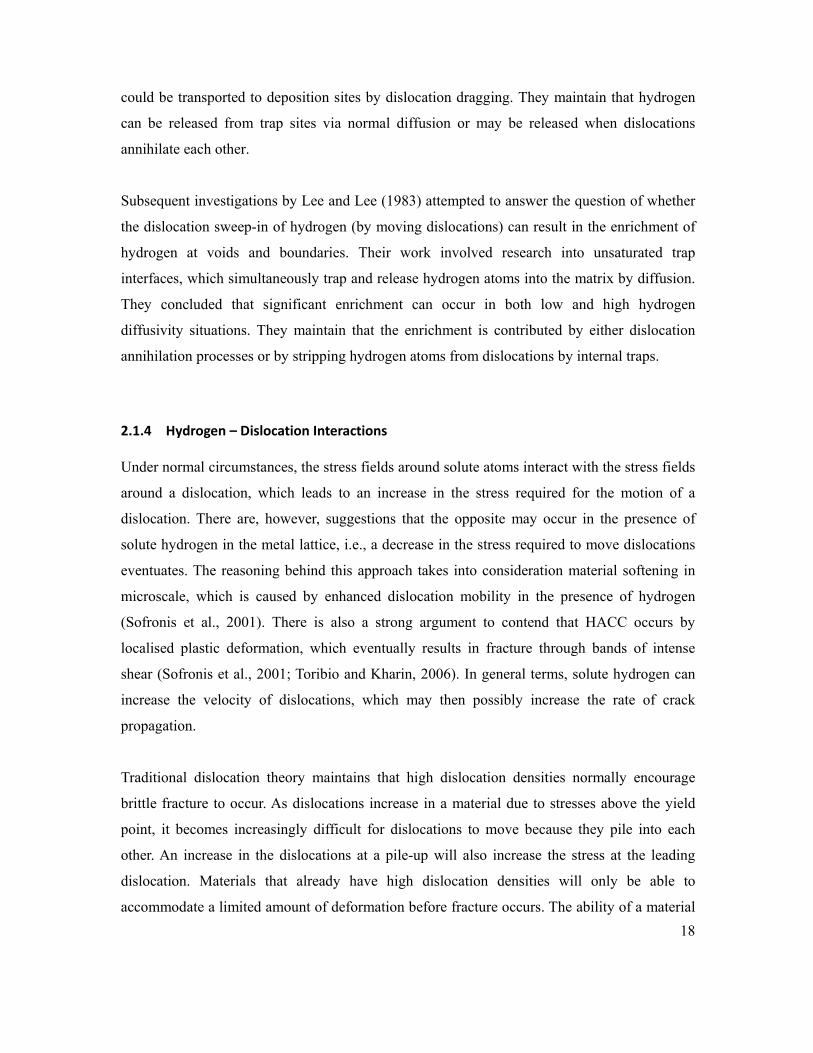
Subsequent investigations by Lee and Lee (1983) attempted to answer the question of whether
the dislocation sweep-in of hydrogen (by moving dislocations) can result in the enrichment of
hydrogen at voids and boundaries. Their work involved research into unsaturated trap
interfaces, which simultaneously trap and release hydrogen atoms into the matrix by diffusion.
They concluded that significant enrichment can occur in both low and high hydrogen
diffusivity situations. They maintain that the enrichment is contributed by either dislocation
annihilation processes or by stripping hydrogen atoms from dislocations by internal traps.
2.1.4 Hydrogen – Dislocation Interactions
Under normal circumstances, the stress fields around solute atoms interact with the stress fields
around a dislocation, which leads to an increase in the stress required for the motion of a
dislocation. There are, however, suggestions that the opposite may occur in the presence of
solute hydrogen in the metal lattice, i.e., a decrease in the stress required to move dislocations
eventuates. The reasoning behind this approach takes into consideration material softening in
microscale, which is caused by enhanced dislocation mobility in the presence of hydrogen
(Sofronis et al., 2001). There is also a strong argument to contend that HACC occurs by
localised plastic deformation, which eventually results in fracture through bands of intense
shear (Sofronis et al., 2001; Toribio and Kharin, 2006). In general terms, solute hydrogen can
increase the velocity of dislocations, which may then possibly increase the rate of crack
propagation.
Traditional dislocation theory maintains that high dislocation densities normally encourage
brittle fracture to occur. As dislocations increase in a material due to stresses above the yield
point, it becomes increasingly difficult for dislocations to move because they pile into each
other. An increase in the dislocations at a pile-up will also increase the stress at the leading
dislocation. Materials that already have high dislocation densities will only be able to
accommodate a limited amount of deformation before fracture occurs. The ability of a material

19
to deform plastically therefore relies on the freedom of the dislocations to move with little
energy. However, a decrease in the distance that dislocations can travel before pile-up (such as
during strain hardening) will counteract the plastic deformation, reducing deformation, and
encourage the hastening of the fracture process.
Evidence for strain hardening was presented by Dollar and Bernstein (1998) who reported slip
localisation accompanied by an increase in the flow stress. It is also probable that the attributed
increase in flow stress was due to the solid solution strengthening by hydrogen during plastic
deformation. Nibur et al., (2006) used nano-indentation to study the effect of dissolved
hydrogen on the deformation of small volumes of steel. They observed that hydrogen reduced
the energy required to nucleate dislocations, likely due to hydrogen reducing the shear
modulus.
Nibur et al., (2006) found that hydrogen increases slip planarity, which they attribute as the
cause of the increase in the measured hardness (or strain hardening) of the hydrogenated
samples. A conclusion reached was that hydrogen lowers the stress necessary for dislocations
to glide, which agrees with the hydrogen enhanced localised plasticity proposed by Beachem
(1972), Lynch (1979) and Birnbaum and Sofronis (1994).
Slip localisation along with a decrease in the flow stress has also been reported by Zeides
(1986). It is believed that the strain rate used may, however, indicate whether the samples will
either increase or decrease the flow stress, as proposed by Wu and Kim (2003) and Birnbaum
and Sofronis (1994). High strain rates are likely to show a higher macroscopic hardening effect
that arises from dislocation dragging, whereas a smaller extent of hydrogen induced hardening
exists at lower strain rates when the rate of hydrogen diffusion matches that of the moving
dislocations. In other words higher strain rates will not provide sufficient time for hydrogen to
be transported along with the moving dislocations, possibly also reducing the local
concentration of hydrogen in the crack vicinity. According to Birnbaum and Sofronis (1994),
the dislocation velocity is related to the stress by a power law relationship (see Equation 2.1),
and an increase in velocity will be accompanied by an increase in the flow stress.

20
..............................................................................................Equation 2.1
Flow stress during slip localisation
Flow stress during homogeneous deformation
Fraction of gauge length where slip is localised
m material dependent term
Usui and Asano (1996) reported an increase in the Young’s modulus in Fe-Cr-Mn austenitic
steels due to the presence of solute hydrogen. They argued that the increase resulted from an
increase in the elastic forces between dislocations, i.e., the increase in flow stress was due to
the anchoring of the dislocations.
It is also possible that the increase in elastic forces between dislocations may have increased
the separation distances during pile-up, but this is in contrast to the work done by Birnbaum
and Sofronis (1996) and Sofronis and Robertson (2002), who showed a decrease in separation
distances between the dislocations at pile-up. These authors are strongly convinced that
hydrogen atmospheres around dislocations change the stress fields around the dislocations.
They believe that hydrogen induces a change in the interaction energy between a dislocation
and other elastic obstacles.
Work by Sirois and Birnbaum (1992) and Birnbaum and Sofronis (1994) proposed a hydrogen
shielding mechanism where hydrogen diminishes the local stress fields from dislocations and
solutes that act as barriers to the dislocation motion. This occurs when the hydrogen atoms
forming Cottrell atmospheres along a dislocation interact with the elastic fields of neighbouring
dislocations. As an example, the shielding will then lead to a reduced repulsion of two edge
dislocations with equal Burgers vectors due to the common Cottrell atmosphere of hydrogen.
Hydrogen shielding of the dislocation strain field therefore reduces the activation energy,
which decreases the stress required to move the dislocation.

21
Consequently, hydrogen increases the mobility of dislocations, which will be localised to
regions of high hydrogen concentration and will result in microscale softening. This
microscopic hydrogen induced softening can lead to macroscopic shear localisation and the
fracture surfaces may exhibit a brittle appearance. Closer examination will, however, show
plastic deformation on hydrogen induced fracture surfaces. This was proposed by Beachem
(1972), who was the first to propose that failure occurred by a ductile process, and that
hydrogen enhanced – not retarded – the mobility of dislocations.
Related research has suggested that the presence of dissolved hydrogen decreases both the
Peierls stress and the stacking fault energy (Lu et al 2001). This decrease in Peierls stress is
conceivably due to weakening of the atomic bond strength, as proposed by Lynch (1979,
1988). Evidence suggests that hydrogen atoms diffuse and segregate around and into
dislocation cores, where they find atomic sites that can accommodate their radii. Hydrogen is
attracted to the dislocation cores (Oriani, 1993) where it becomes trapped and subsequently
lowers the core energy (Gao et al., 1994). A strong bond also exists between the dissolved
hydrogen and the dislocation cores.
Experimental observations (Wen et al., 2005; and Sofronis et al., 2005) show that hydrogen
atoms inhibit cross-slip due to this strong binding energy, which is believed to be the result of
the stabilising (hydrogen shielding) effect that hydrogen has on the edge component of mixed
dislocations, therefore inhibiting cross-slip.
The current literature therefore argues for HACC to occur by localised plastic deformation,
which eventually results in fracture through bands of intense shear (Sofronis et al., 2001;
Toribio and Kharin, 2006). In general terms, solute hydrogen can increase the velocity of
dislocations, thereby increasing both hydrogen diffusion to specific trap sites and the rate of
crack propagation.

22
2.1.5 Hydrogen Diffusion
The movement of the matter through the material is termed diffusion and is represented by
Fick’s Law (Equation 2.2), which helps to establish the movement of matter from one point to
another in a given time.
......................................................................................... Equation 2.2
Fick’s first law assumes a steady state and the concentration of hydrogen within the diffusion
volume can therefore not change with respect to time. It does not consider trapping effects
and the fact that the gradient and local concentration of the diffusing substance in a material
decreases with an increase in time.
The flux of diffusing hydrogen entering a section with a specific concentration gradient will
be different from the flux of diffusible hydrogen that exits that same section. This difference
must result in a change in the concentration of hydrogen within the section, assuming that no
further hydrogen is produced or consumed in the section. Fick’s Law addresses the change in
concentration gradient and states that the change in the concentration over time is equal to the
change in the flux, so the diffusion (flux) will vary with time.
Equation 2.2 (Fick’s second law) will provide an acceptable approximation only if small
concentrations of the diffusing element are considered, and it is also dependent on the method
by which the diffusing medium is supplied to the substrate (Plecas and Dimovic, 2005). The
as-cast structure of a steel weld is not homogeneous and the diffusion of hydrogen is strongly
influenced by this non-uniform structure. Hydrogen diffusion in welds is not only affected by
the differences of microstructures and dislocation densities, but also by stress and strain fields
within the weldment.
At moderate pressures, the concentration of hydrogen dissolved in solid metals is more
accurately described by Sievert’s Law, which states that the concentration of gas is
proportional to the square root of the partial pressure at any given temperature. In other
words, the amount of dissolved hydrogen in the matrix can be reduced by reducing the partial
pressure of hydrogen. The general assumption is that the approximate equilibrium

23
concentration of hydrogen in metals will follow Sievert’s Law. It therefore shows why
hydrogen gas (H2) dissociates into monatomic hydrogen and then passes through the steel
where it recombines to become a diatomic atom again. For equilibrium conditions, Equation
2.3 (below) applies, were [H] is the concentration hydrogen dissolved in steel, C is the atomic
hydrogen concentration on the steel surface, Keq is Sievert’s equilibrium constant and PH2 is
the hydrogen partial pressure. Both Keq and C are temperature dependent.
2 [H] H2 and
and
.................. Equation 2.3
There is the conjecture that a linear relationship exists between the solubility of hydrogen in
liquid iron and the square root of the partial pressure of hydrogen in contact with the liquid
metal. This implies that increasing the partial pressure of the diatomic gas above the melt can
raise the hydrogen in iron alloys. Although Sievert’s Law has been used extensively in
hydrogen permeation experiments, it may not be suited to the conditions created during arc
welding (Gedeon and Eagar, 1990; Mundra and Debroy, 1995; Du Toit, 2001; Al Raisi and
Gardner, 2007). Applying Sievert’s Law under normal welding conditions implies that the
addition of hydrogen to the shielding gas will increase the concentration of hydrogen in the
weld pool. However, at a given temperature only a certain amount of hydrogen can be
absorbed.
The immense energy released by the welding arc and the fact that a plasma is generated will
also influence the way in which hydrogen is introduced into the metal (Gedeon and Eagar,
1990; Mundra and Debroy, 1995; Du Toit, 2001). The conditions pertaining to a welding arc
are very different than those used in equilibrium studies, and uncertainty therefore exists with
regards to Sievert’s constant. Current research is re-evaluating the use of Sievert’s Law, but it
seems that dissolution kinetics may override thermodynamic considerations (Gedeon and
Eagar, 1990; Du Toit, 2001; Kokawa, 2004).
24
The absorption of monatomic hydrogen at the liquid/metal interface appears to dominate the
overall transfer of hydrogen from the arc plasma to the liquid metal (McKeown, 1985). On the
other hand, the absorption of hydrogen into the weld pool is dependent on the dissociation of
hydrogen gas, as suggested by Gedeon and Eagar (1990). These researchers redeveloped a
model for the absorption of hydrogen in iron weld metal and proposed that Sievert’s Law
cannot be applied to approximate the concentration of hydrogen in metals during welding. This
is not surprising, as Sievert’s Law only tells us how much hydrogen will dissolve in the liquid
metal. The argument is therefore that during welding, standard equilibrium conditions do not
prevail.
In most welding processes, the weld metal is exposed to a plasma environment, which first
decomposes hydrogenous compounds into molecular hydrogen gas. The gas phase contains
neutral atoms and ions, excited molecules and atoms, and electrons.
Under these conditions, the concentrations of these species in the metal are significantly higher
than those calculated from Sievert’s Law (Gedeon and Eagar, 1990; Al Raisi and Gardner,
2007). The transformation of ordinary molecular species into excited neutral atoms and ions in
the gas phase therefore leads to enhanced solution of the species in the metal (Gedeon and
Eagar, 1990).
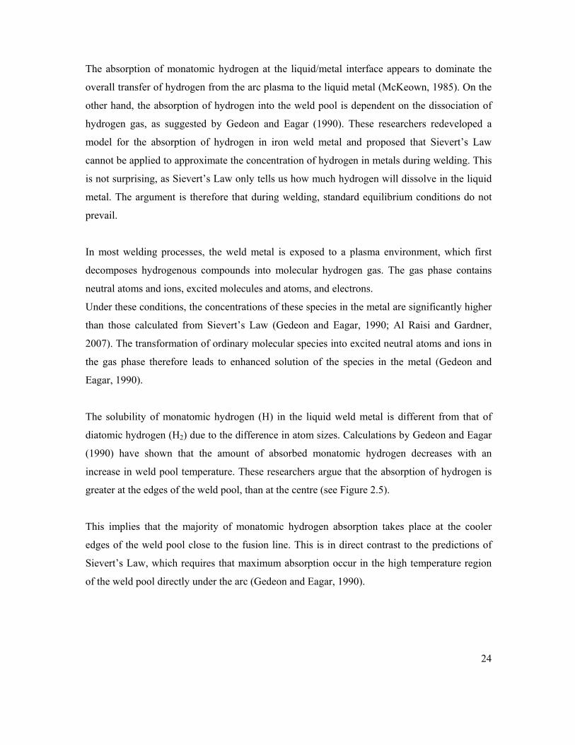
The solubility of monatomic hydrogen (H) in the liquid weld metal is different from that of
diatomic hydrogen (H2) due to the difference in atom sizes. Calculations by Gedeon and Eagar
(1990) have shown that the amount of absorbed monatomic hydrogen decreases with an
increase in weld pool temperature. These researchers argue that the absorption of hydrogen is
greater at the edges of the weld pool, than at the centre (see Figure 2.5).
This implies that the majority of monatomic hydrogen absorption takes place at the cooler
edges of the weld pool close to the fusion line. This is in direct contrast to the predictions of
Sievert’s Law, which requires that maximum absorption occur in the high temperature region
of the weld pool directly under the arc (Gedeon and Eagar, 1990).

25
Figure 2.5 Theoretical hydrogen absorption of monatomic and diatomic hydrogen as a function across the weld pool. Absorption of monatomic H is greater at the edges of the weld pool, assuming dissociation at 2500°C (Gedeon and Eagar, 1990).
The literature reviewed therefore indicates that hydrogen absorption into the weld metal is
complex, and hydrogen diffusion will be a function of several factors. Variations in
temperature and hydrogen distribution across the welding arc are highly likely to influence the
distribution of hydrogen in the weld pool (Li and North, 1992). Stress gradients produced by
nonuniform aspects within the microstructure will also provide a greater driving force in the
form of stress assisted diffusion (Oriani, 1993).
A further important consideration will point towards the role that the specific microstructure
plays in diffusion. The next chapter will therefore review the microstructure of high strength
ferritic weld metal.
26
2.2 HIGH STRENGTH STEEL WELD METAL MICROSTRUCTURE
The aim of the following chapter is to discuss the evolution of typical ferritic weld metal
microstructure and to describe the competing processes involved in the formation of acicular
ferrite (AF), which is now regarded as the optimum microstructure for high strength ferritic
steel weld metal. The underlying competing nucleation paths involve competition between
bainite, which nucleates on the austenite grain surfaces, and acicular ferrite, which nucleates
intragranularly on nonmetallic inclusions. The nucleation of these two products is largely
dependent on the size of the austenite grains and the availability of nonmetallic inclusion
around which the acicular ferrite can nucleate. The relationship between crack
initiation/propagation and specific microstructure will be mentioned in this chapter, but further
analysis will be supplied in the next chapter.
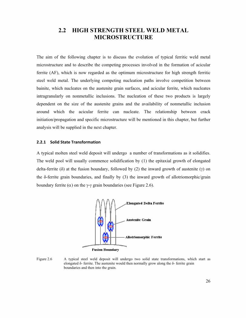
2.2.1 Solid State Transformation
A typical molten steel weld deposit will undergo a number of transformations as it solidifies.
The weld pool will usually commence solidification by (1) the epitaxial growth of elongated
delta-ferrite (δ) at the fusion boundary, followed by (2) the inward growth of austenite (γ) on
the δ-ferrite grain boundaries, and finally by (3) the inward growth of allotriomorphic/grain
boundary ferrite (α) on the γ-γ grain boundaries (see Figure 2.6).
Figure 2.6 A typical steel weld deposit will undergo two solid state transformations, which start as elongated δ- ferrite. The austenite would then normally grow along the δ- ferrite grain boundaries and then into the grain.

27
Inducing the molten weld pool to solidify directly to austenite by faster cooling has been
proposed (Lord, 1999; Edvardson et al., 1976), but this is deemed undesirable for two reasons.
First, large inclusions tend to become trapped at the advancing solid/liquid interface and they
end up at the columnar grain boundaries, in the part of the weld metal microstructure that
corresponds to relatively brittle allotriomorphic ferrite (Bhadeshia and Svensson, 1993).
According to these authors, the nucleation of δ-ferrite before the nucleation of austenite will,
however, reduce the amount of large inclusions at the columnar grain boundaries. The
reasoning is that since the austenite grains grow across the δ/δ grain boundaries, the large
inclusions will eventually reside within the austenite grains, where they are believed to be less
harmful and may even stimulate the nucleation of acicular ferrite. A second reason given by
Bhadeshia and Svensson (1993) to avoid the direct solidification into austenite relates to the
unwanted segregation of substitutional elements, such as manganese. These elements are
deliberately included in the weld pool to contribute to the strength and toughness of the weld
deposit. Apart from the formation of delta-ferrite and austenite, the three other main ferritic
constituents (Figures 2.7 and 2.8) that subsequently form in the solidified weld metal are
allotriomorphic ferrite, Widmanstätten ferrite and acicular ferrite. Of the three, acicular ferrite
(AF) is favoured in high strength steel weld metal, as it provides optimum weld metal
mechanical properties due to its small plate size, interlocking microstructure and high angle
grain boundaries (Grong and Matlock, 1986; Jin et al., 2003; Thewlis, 2004; Lee et al., 2000.
Figure 2.7 Typical high strength weld metal microstructure containing three variants of ferrite.

28
Figure 2.8 Schematic diagram of microstructural evolution in steel welds. Modified from Bhadeshia and Svensson (1993).
2.2.2 Austenite Grain Size
It is not disputed that both the shape and size of the austenite grains (which develop upon
cooling) are of significant importance in the evolution of the final microstructure. The
influencing factor attributed to the austenite grains is primarily due to the manner in which the
final weld metal microstructure grows from the underlying austenite grains.
The presence of acicular ferrite (AF) is known to correlate with improved toughness (Lee et al.,
2000). It will be covered in more detail further on, although mention has to be made of its
dependence on the presence of nonmetallic inclusions within the austenite grains, from which it
nucleates. Besides the requirement for nonmetallic inclusions, the prior austenite grain size is
argued to be the most critical factor responsible for obtaining a given level of AF content in the
weld microstructure (Basu and Raman, 2002). The understanding is that a minimum and
maximum prior austenite grain size is likely to exist, below and above which formation of
acicular ferrite is not favoured. Although the distribution of fine inclusion particles in the weld
metal refines both the austenite grain size and the final weld metal microstructure (Suito et al.,
2006), finer austenite grain sizes also favour the nucleation of bainite above acicular ferrite
(Bhadeshia and Svensson, 1993; Babu and Bhadeshia, 1991).

29
It is therefore argued that smaller austenite grains will increase the number of nucleating sites
for bainite. This increase in nucleation sites stems from the increase in grain boundary surfaces
produced by the smaller austenite grains. An increase in grain boundary surfaces will therefore
increase the opportunities for bainite to nucleate (Figure 2.9).
During welding, coarsening of the austenite grains in the heat affected zone will occur, which
is dependent on the magnitude of the heat input. Increasing the heat input will also increase the
weld metal austenite grain size, which in turn will foster the development of acicular ferrite at
the expense of bainite. However, at very large heat inputs, the cooling rate decreases
sufficiently so that greater amounts of more equilibrium forms of ferrite are obtained with a
corresponding reduction in the amount of acicular ferrite. Higher heat input decreases the
cooling rate of the solidifying weld metal and the weld will therefore spend a longer time at
higher temperatures, leading to a larger austenite grain size. At too high a heat input, there will
also be greater opportunity for inclusions to be absorbed by the slag leading to a drop in the
volume fraction of inclusions.
The austenite grain size and the distribution of the inclusions are both closely associated with
the final acicular ferrite content. In order to nucleate bainite, the austenite grain boundary has
to dominate the transformation of austenite to ferrite, rapidly swamping the interiors of the γ
grains with bainite laths. It is the view of Bhadeshia and Svensson (1993) that smaller austenite
grains will not only result in an increase in the number density of grain boundary nucleation
sites for bainite; but they will also amount to a decrease in hardenability, implying a reduction
in alloying content. Intragranular nucleation of ferrite around inclusions is more likely at
larger γ grain sizes, which in turn provides favourable conditions for the formation of acicular
ferrite (Figure 2.9).
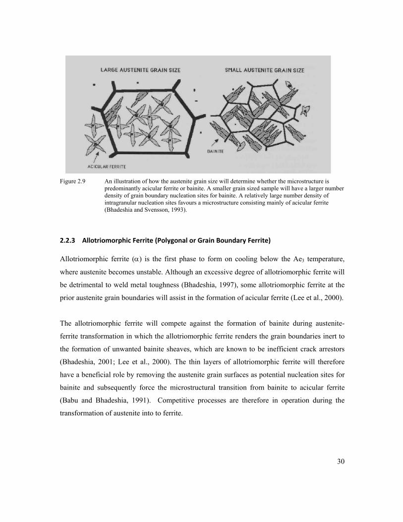
30
Figure 2.9 An illustration of how the austenite grain size will determine whether the microstructure is predominantly acicular ferrite or bainite. A smaller grain sized sample will have a larger number density of grain boundary nucleation sites for bainite. A relatively large number density of intragranular nucleation sites favours a microstructure consisting mainly of acicular ferrite (Bhadeshia and Svensson, 1993).
2.2.3 Allotriomorphic Ferrite (Polygonal or Grain Boundary Ferrite)
Allotriomorphic ferrite (α) is the first phase to form on cooling below the Ae3 temperature,
where austenite becomes unstable. Although an excessive degree of allotriomorphic ferrite will
be detrimental to weld metal toughness (Bhadeshia, 1997), some allotriomorphic ferrite at the
prior austenite grain boundaries will assist in the formation of acicular ferrite (Lee et al., 2000).
The allotriomorphic ferrite will compete against the formation of bainite during austenite-
ferrite transformation in which the allotriomorphic ferrite renders the grain boundaries inert to
the formation of unwanted bainite sheaves, which are known to be inefficient crack arrestors
(Bhadeshia, 2001; Lee et al., 2000). The thin layers of allotriomorphic ferrite will therefore
have a beneficial role by removing the austenite grain surfaces as potential nucleation sites for
bainite and subsequently force the microstructural transition from bainite to acicular ferrite
(Babu and Bhadeshia, 1991). Competitive processes are therefore in operation during the
transformation of austenite into to ferrite.

31
2.2.4 Widmanstätten Ferrite
There are two types of Widmanstätten ferrite, primary and secondary. Primary Widmanstätten
ferrite grows directly from the austenite grain surfaces and Secondary Widmanstätten ferrite
develops from any allotriomorphic ferrite that may be present in the microstructure (see
Figures 2.10 and 2.13). Although Widmanstätten ferrite can nucleate directly from the
austenite grains, it usually grows from allotriomorphic ferrite.
Figure 2.10 Morphology of Primary and Secondary Widmanstätten Ferrite, the latter requiring
allotriomorphic ferrite, which nucleated from the austenite grain boundary.
The formation of Widmanstätten ferrite does not involve the diffusion of substitutional solutes.
It forms by a displacive transformation, usually preceded by a reconstructive transformation
(Jones and Bhadeshia, 1998). Reconstructive transformations are slow; they involve the
breaking of chemical bonds and recombining the atoms into a different crystal structure.
Displacive transformations are fast and involve small adjustments to the crystal structure where
the angles between the atoms may change slightly, thereby deforming the original crystal
structure.
During continuous cooling transformations, excessive pre-emptive formation of Widmanstätten
ferrite prevents the formation of acicular ferrite as illustrated in Fig. 3b. In particular, the
growth rate of Widmanstätten ferrite increases drastically as the carbon concentration is
reduced (Fig. 2a). At low carbon concentrations, Widmanstätten ferrite plates can grow across
austenite grains in a fraction of a second, and stifle the subsequent formation of acicular ferrite.

32
2.2.5 Acicular Ferrite
Acicular ferrite is now a common microstructure observed during the cooling of low alloy steel
weld deposits (Bhadeshia and Svensson, 1993). It is also the preferred microstructure because
it improves cleavage toughness due to the ferrite plates pointing in many different directions,
providing effective crack deflection capabilities (Bhadeshia, 1997). Further beneficial crack
arresting properties are gained due to small grain sizes (typically 1 – 3μm) and high angle grain
boundaries (Grong and Matlock, 1986).
According to Bhadeshia (2004), acicular ferrite is intragranularly nucleated bainite and it
therefore forms at a lower temperature when compared with Widmanstätten ferrite. It is current
understanding that acicular ferrite nucleates at the interface of inclusions (Strangwood and
Bhadeshia, 1987, Lee et al., 2000 and Babu, 2004). This intragranular nucleation and growth of
acicular ferrite on or around inclusions (see Figures 2.11 and 2.12) will occur until they are
impinged by neighbouring grains. Due to the geometric randomness of the acicular ferrite
grains and the fact that other AF grains impinge their growth; the final grain size may
potentially be determined by the average spacing between the inclusions from which they
nucleated.
As mentioned previously, a decrease in nonmetallic inclusions density will generally decrease
the austenite grain size and, according to Bhadeshia and Svensson (1993), a reduction in
austenite grain size will often lead to a replacement of acicular ferrite with bainite. Smaller
austenite grains will provide an increase in austenite grain boundaries upon which the bainite
can nucleate. Although there are resemblances with bainite, the major difference between
acicular ferrite and bainite stems from the understanding that acicular ferrite nucleates on
inclusions inside the austenite grains in the form of isolated plates radiating from a point, rather
than the sheaf morphology of classical bainite, which nucleates at the austenite grain surface.

33
A number of parameters therefore favour the formation of acicular ferrite over ordinary bainite.
These are: the presence of nonmetallic inclusions; large austenite grain size; and the decoration
of austenite grain boundaries with uniform layers of allotriomorphic ferrite (Lee et al., 2000;
Bhadeshia and Svensson, 1993). There are also two pathways available for the decomposing
austenite:
(i) Fine platelets of ferrite can nucleate along the austenite grain boundaries to form
bainite, or
(ii) The ferrite can grow on/around inclusions inside the austenite grain to form acicular
ferrite.
Figure 2.11 The arrows point towards acicular ferrite nucleated on nonmetallic inclusions.
Figure 2.12 A typical microstructure of acicular ferrite observed under TEM. In figure 2.12 The acicular ferrite constituent consists of fine ferrite laths or plates and the individual lath contains a relatively high density of dislocations (Lee et al., 2000).
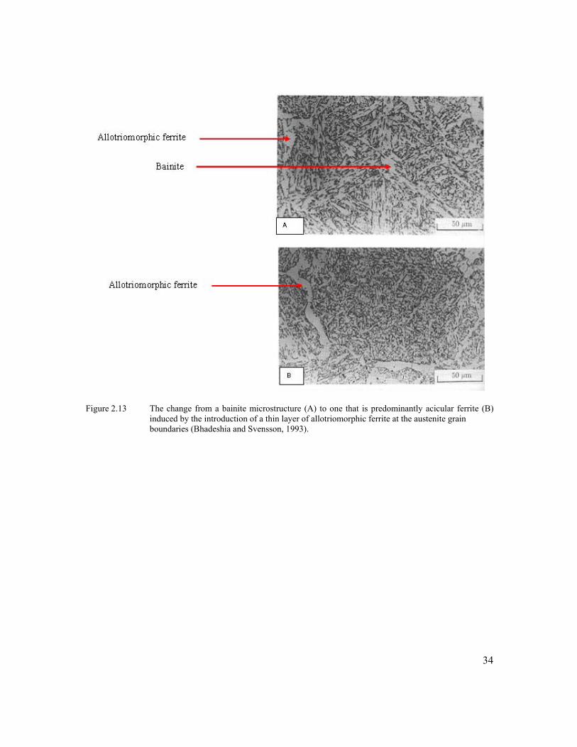
34
Figure 2.13 The change from a bainite microstructure (A) to one that is predominantly acicular ferrite (B) induced by the introduction of a thin layer of allotriomorphic ferrite at the austenite grain boundaries (Bhadeshia and Svensson, 1993).

35
2.2.6 Weld Metal Inclusions
The eventual transformation from austenite to acicular ferrite is largely controlled by the size of
the austenite grains and favourable nucleating sites for ferrite, especially acicular ferrite, which, as
mentioned previously, nucleates inside the austenite grains on nonmetallic inclusions.
During solidification, solute atoms are rejected into the liquid, which then changes the
composition of the liquid as it solidifies. This difference in composition (segregation) may under
certain circumstances also inhibit the nucleation of acicular ferrite, since segregation stabilizes the
austenite (Kang et al., 2007). The optimum conditions required for the nucleation of acicular
ferrite appear to point towards the inclusion type and size distribution, which is perceived to be
more potent AF nucleating agents than the total volume fraction of inclusions. This notion was
expressed by Greg and Bhadeshia (1997), as they observed that titanium oxides were particularly
effective in promoting the intragranular nucleation of acicular ferrite.
Attempts to control the content of acicular ferrite in the weld metal have led to the introduction
of welding consumables containing complex deoxidizing alloys (Si, Mn, Al, Ti) and balanced
additions of other alloying elements such as Nb, V, Cu, Ni, Cr, Mo and B. The formation of the
nonmetallic inclusions will typically require a certain amount of oxygen (Harrison and Farrar,
1981; Fleck et al., 1986), although an excess of oxygen will create conditions that will oxidise
the alloying elements into the slag of the weld metal (Bailey, 1994).
Lee et al., (2000) prepared low-carbon steel welds that contained a high density of oxide
inclusions in order to study the effect of inclusion size on the formation of acicular ferrite. A
total of 282 inclusions were observed under TEM and they classified these into two groups, i.e.
non-nucleant and the nucleant (Figure 2.14). Their experimental results showed that the group
of inclusions from which acicular ferrite nucleated was appreciably larger in size compared
with the non-nucleating inclusions, even though the chemical and structural natures appeared
to be the same. A further observation by these authors was that although approximately a third
of the total inclusions contributed to AF nucleation, the inclusions were capable of generating a
weld microstructure that predominantly consisted of acicular ferrite.

36
Figure 2.14 Lee et al (2000) classified nonmetallic inclusions into two groups with regards to acicular ferrite; those that nucleate AF and those that do not. Earlier work by Ricks et al., (1982) proposed that the energy barrier to AF nucleation at
inclusions will decrease as the size of the inclusion increases to approximately 1µm. The
research by Barbaro et al., (1989) demonstrated that a minimum particle size of 0.4 – 0.6µm
was required, while Lee et al., (2000) provided evidence to show that inclusion sizes in the
region of 1 – 1.4µm maximised the probability of acicular ferrite formation (Figure 2.15).
They showed that when the inclusion size is less than 0.2µm, the probability for AF nucleation
is nearly zero.
Figure 2.15 Work produced by Lee et al., (2000) indicates that inclusion sizes in the region of 1–1.4µm maximised the probability of acicular ferrite formation.

37
Lee et al., (2000) further proposed that even if nucleating inclusions were of the same size,
each inclusion will have a different chemistry and therefore a different surface energy. This
local variation in chemistry between the inclusions can subsequently result in varying
nucleation potential, which most likely explains why only 36% of the nucleating type
inclusions contributed to the nucleation of 80% acicular ferrite.
The inclusions studied by Lee et al., (2000) were mostly spherical and had a maximum size of
approximately 3µm. Their examination with SEM-EDS has indicated that the inclusions were
rich in O, Si, Mn and Al with a small amount of Ti and S (Figure 2.16). They assumed that the
major metallic elements were combined with oxygen to give a single phase oxide within the
MnO–SiO2–Al2O3. Their analysis showed that all the inclusions, regardless of the size, were
chemically homogeneous and were absent from any chemical segregation.
Figure 2.16 The chemistry of the inclusions studied by Lee et al., (2000) was rich in oxygen, silicon, manganese and aluminium with a small amount of titanium and sulphur.
The influence of weld metal inclusions however stem further than just providing nucleation
sites for acicular ferrite. Inclusions can also refine the weld metal microstructure by pinning the
austenite grains and preventing grain growth, known as Zener pinning (Koseki and Thewlis,
2005, Suito et al., 2006). It occurs when small particles hinder the motion of the moving
boundaries (or applying a dragging force) by exerting a pinning pressure. This pinning pressure
will subsequently counteract the driving force attempting to enlarge the austenite grain
boundary.

38
The austenite grains form by the transformation of δ-ferrite and Zener pinning hinders the path
along which the austenite grains are growing. Zener pinning will not necessarily control the
size of the austenite grains, but will to a certain extent control their morphology. Bhadeshia and
Svensson (1993) maintain that the shape of the pinned austenite grains will give an indication
of how effective the Zener pinning is.
The direct effect of alloying elements on the austenite grain size is also evident, as can be
demonstrated by Equation 2.4 which suggests that a decrease in certain alloying elements will
refine the prior austenite grain size (Bhadeshia and Svensson, 1993).
..………….............. Equation 2.4
L = predicted columnar austenite grain size
Wt% C = weight percent carbon
Wt% Si = weight percent silicon
Wt% Mn = weight percent manganese
HI = heat input, in kilo Joules per millimetre
If the above equation holds true, then slight reductions in the alloy chemistry may alter the size
of the austenite grains, perhaps also influencing the manner in which the δ→γ transformation
occurs. Excessive alloying may, however, prevent the formation of allotriomorphic ferrite and
therefore expose the remainder of the austenite grain boundaries to impurity segregation, which
could then lead to intergranular fracture at the columnar austenite grain boundaries (Bhadeshia
and Svensson, 1993).
The intricate relationships between the variables that contribute to the nucleation of AF have
been researched for more than 25 years. Although generalised assertions can be made, subtle
changes (like a variation in shielding gas oxygen content) may significantly alter the AF
content. The nucleation of acicular ferrite is therefore dependent on its ability to compete and
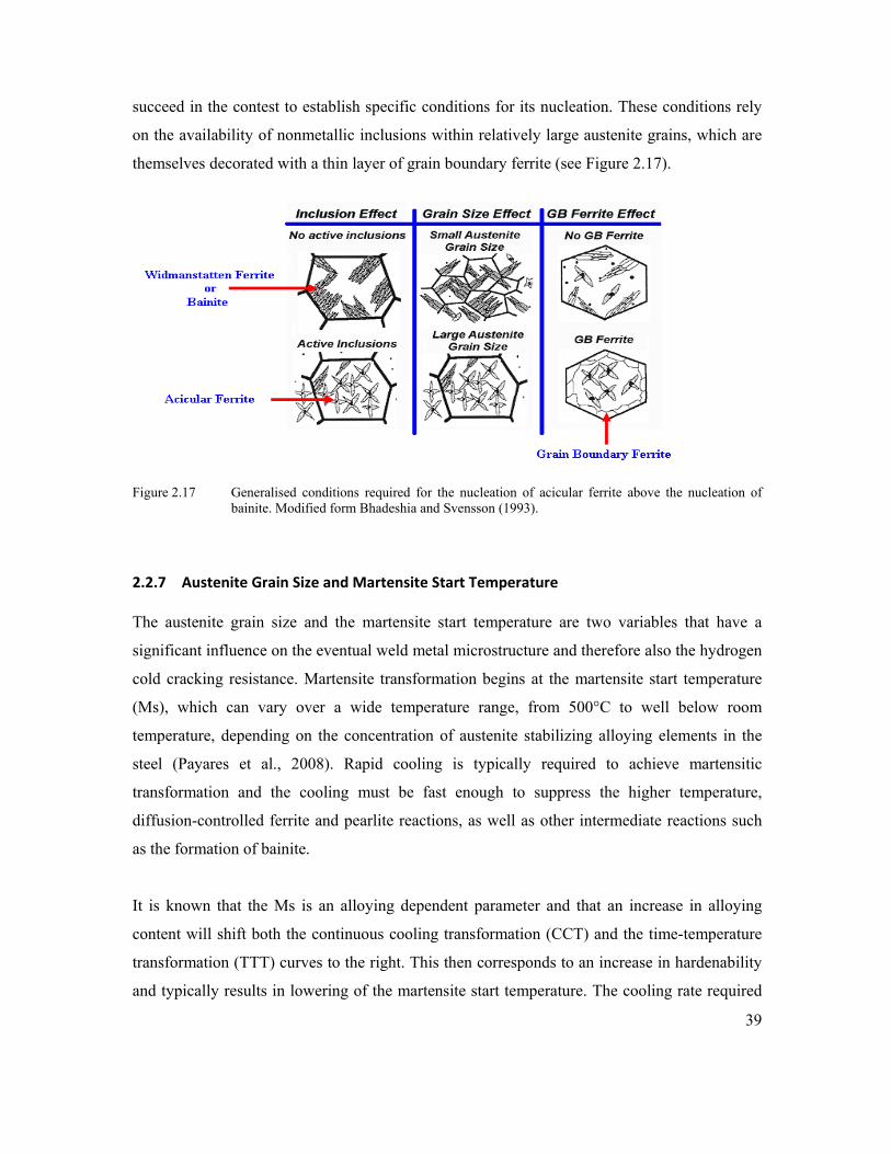
39
succeed in the contest to establish specific conditions for its nucleation. These conditions rely
on the availability of nonmetallic inclusions within relatively large austenite grains, which are
themselves decorated with a thin layer of grain boundary ferrite (see Figure 2.17).
Figure 2.17 Generalised conditions required for the nucleation of acicular ferrite above the nucleation of
bainite. Modified form Bhadeshia and Svensson (1993).
2.2.7 Austenite Grain Size and Martensite Start Temperature
The austenite grain size and the martensite start temperature are two variables that have a
significant influence on the eventual weld metal microstructure and therefore also the hydrogen
cold cracking resistance. Martensite transformation begins at the martensite start temperature
(Ms), which can vary over a wide temperature range, from 500°C to well below room
temperature, depending on the concentration of austenite stabilizing alloying elements in the
steel (Payares et al., 2008). Rapid cooling is typically required to achieve martensitic
transformation and the cooling must be fast enough to suppress the higher temperature,
diffusion-controlled ferrite and pearlite reactions, as well as other intermediate reactions such
as the formation of bainite.
It is known that the Ms is an alloying dependent parameter and that an increase in alloying
content will shift both the continuous cooling transformation (CCT) and the time-temperature
transformation (TTT) curves to the right. This then corresponds to an increase in hardenability
and typically results in lowering of the martensite start temperature. The cooling rate required
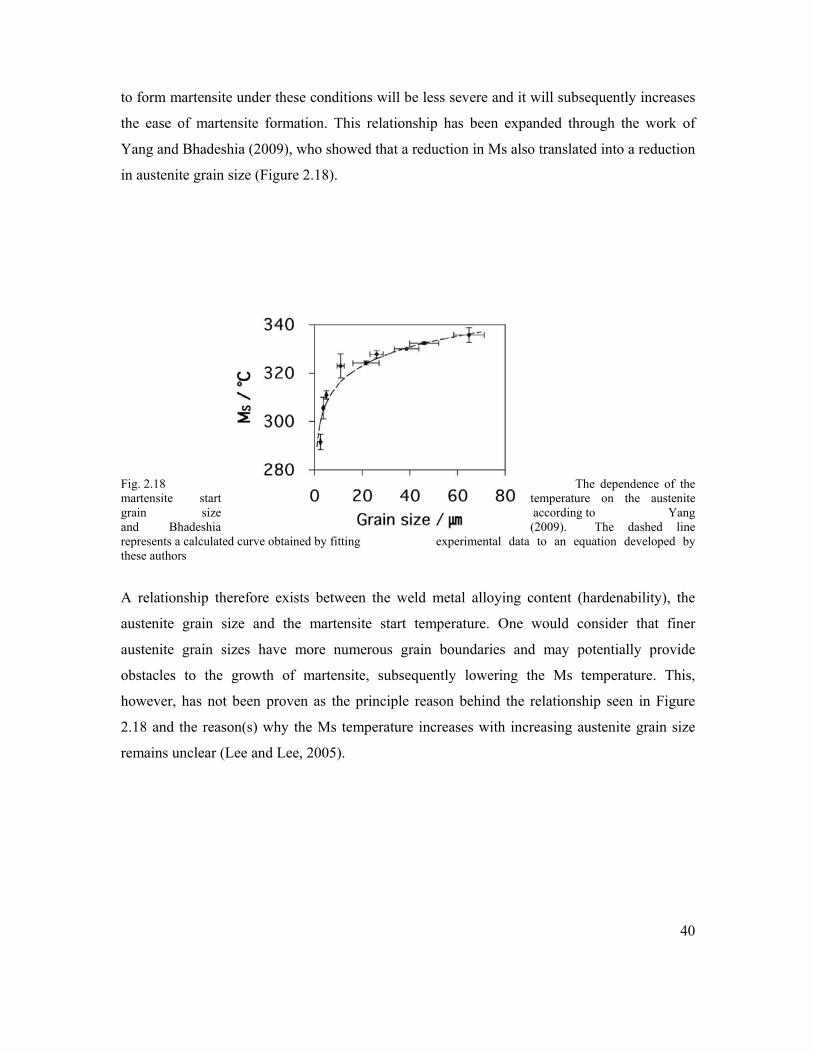
40
to form martensite under these conditions will be less severe and it will subsequently increases
the ease of martensite formation. This relationship has been expanded through the work of
Yang and Bhadeshia (2009), who showed that a reduction in Ms also translated into a reduction
in austenite grain size (Figure 2.18).
Fig. 2.18 The dependence of the martensite start temperature on the austenite grain size according to Yang and Bhadeshia (2009). The dashed line represents a calculated curve obtained by fitting experimental data to an equation developed by these authors
A relationship therefore exists between the weld metal alloying content (hardenability), the
austenite grain size and the martensite start temperature. One would consider that finer
austenite grain sizes have more numerous grain boundaries and may potentially provide
obstacles to the growth of martensite, subsequently lowering the Ms temperature. This,
however, has not been proven as the principle reason behind the relationship seen in Figure
2.18 and the reason(s) why the Ms temperature increases with increasing austenite grain size
remains unclear (Lee and Lee, 2005).
41
Hydrogen atoms have to migrate across austenite, ferrite and martensite during typical cooling
of ferritic weld metal. Austenite is a faced centered cubic structure (FCC) and has high
hydrogen solubility, but a low hydrogen diffusion rate. This is in contrast to ferrite and
martensite, which have orders of magnitude higher hydrogen diffusion coefficients and low
solubility than the austenite (Bollinghaus et al., 1996). Due to these differences in hydrogen
diffusivity, a non-uniform distribution of hydrogen can result across the weldment, depending
on the decomposition behaviour of austenite (Graville, 1990). It has also been believed that a
shift in alloy design of the base metal has reduced the carbon equivalent, which would then
alter the transformation temperatures of both the HAZ and the weld metal, thereby influencing
whether HACC occurs in the HAZ or the weld metal.
The location of cracks in either the HAZ or the weld metal will depend on factors such as the
direction of the principle weld joint restraint forces, hardenability and alloy content of the weld
and parent metals. The martensite start temperature is considered to be an alloying dependent
parameter. According to Park et al., (2001), the transport and trapping characteristics provided
by the weld metal alloy content can then (by means of the Ms) be used as an indicator for
effective transport of hydrogen away from the weld metal. Because the Ms is a measure of the
microstructural evolution of the weld metal, it will also indicate the suitability of the
microstructure for hydrogen transport either into, or away from the weld metal (Park et al,
2001).
This relationship between the global diffusion and distribution of hydrogen in low alloy steel
weld metal during phase transformation was described by Granjon (1971) and Olson et al.,
(1996). When the austenite-martensite transformation in the weld metal occurs at a higher
temperature than the heat affected zone, diffusible hydrogen will segregate in the heat affected
zone, just under the fusion line. This is seen as underbead cracking in high strength steel
weldments. Conversely, when the martensite transformation in the heat affected zone occurs at
a higher temperature than in the weld metal, excessive hydrogen may accumulate in the weld
metal, promoting weld metal cold cracking. This concept is given in Equation 2.5.

42
...................................................................Equation 2. 51:
where: ΔMS = change in martensite start temperature [ °C ]
MWM = martensite start temperature of weld metal [ °C ]
MHAZ = martensite start temperature of parent metal HAZ [ °C ]
Case (a): if ΔMS > 0, hydrogen will accumulate in the parent metal HAZ
Case (b): if ΔMS < 0, hydrogen will accumulate in the weld metal
The lower the MWM temperature, the more time will be available for hydrogen to reside in the
weld metal. This also means that the available temperature range for effective hydrogen diffusion
and trapping in the martensitic/ferritic phase becomes narrower and the suppression of diffusible
hydrogen content becomes less effective.
As an example, overmatched weld metal (with respect to the base metal) will typically have a
higher alloying content, resulting in a lower martensite start temperature of the base metal. It is
then expected that the austenite phase will retain a higher level of hydrogen, implying that an
enhanced source of hydrogen will be available when the austenite transforms into
ferrite/martensite.
The relationship between austenite grain size, martensite start temperature and the transport
and trapping characteristics of the weld metal, which in turn are also related to the weld metal
alloying content, is therefore expected to be a critical function of the weld metal’s
susceptibility to hydrogen assisted cold cracking.
2.2.8 Acicular Ferrite and Hardenability
It has been proposed that AF is dependent on weld cooling rate, austenite grain size and
hardenability (Abson and Pargeter, 1986; Farrar and Harrison, 1987; Grong and Matlock, 1986
and Kanjilal et al., 2005). The influence of weld metal chemical composition on the formation
of AF has also been established (Farrar and Harrison, 1987 & Liu et al., 1994). Elements such
as C, Mn and Ni increase hardenability and moves austenite transformation start curves to
ΔMS = MWM - MHAZ
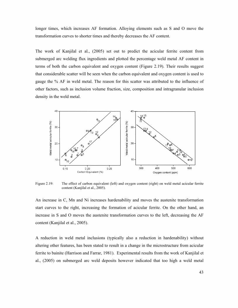
43
longer times, which increases AF formation. Alloying elements such as S and O move the
transformation curves to shorter times and thereby decreases the AF content.
The work of Kanjilal et al., (2005) set out to predict the acicular ferrite content from
submerged arc welding flux ingredients and plotted the percentage weld metal AF content in
terms of both the carbon equivalent and oxygen content (Figure 2.19). Their results suggest
that considerable scatter will be seen when the carbon equivalent and oxygen content is used to
gauge the % AF in weld metal. The reason for this scatter was attributed to the influence of
other factors, such as inclusion volume fraction, size, composition and intragranular inclusion
density in the weld metal.
Figure 2.19: The effect of carbon equivalent (left) and oxygen content (right) on weld metal acicular ferrite content (Kanjilal et al., 2005).
An increase in C, Mn and Ni increases hardenability and moves the austenite transformation
start curves to the right, increasing the formation of acicular ferrite. On the other hand, an
increase in S and O moves the austenite transformation curves to the left, decreasing the AF
content (Kanjilal et al., 2005).
A reduction in weld metal inclusions (typically also a reduction in hardenability) without
altering other features, has been stated to result in a change in the microstructure from acicular
ferrite to bainite (Harrison and Farrar, 1981). Experimental results from the work of Kanjilal et
al., (2005) on submerged arc weld deposits however indicated that too high a weld metal
44
inclusion content can also reduce the % AF. The inclusions within the γ grains will provide
nucleation sites for AF and an adequate inclusion density is required to obtain the acicular
ferrite laths. The toughness of the weld metal will be dependent on overcoming the tendency to
form bainite, or other competing microstructural constituents. This detrimental impact can then
be minimised by alloy design and selecting alloying additions which preferentially promote the
formation of acicular ferrite. These alloying additions will typically be associated with an
increase in hardenability, although it can be argued that sufficient hardenability, rather than
high hardenability will be what is required to optimise the AF content.
2.3 HYDROGEN ASSISTED COLD CRACKING
The entry of hydrogen into metals, the subsequent redistribution of it through the metal lattice
and the importance of stressed regions within the microstructure have been discussed in
previous chapters. This chapter will focus on crack initiation and crack propagation aspects
related to hydrogen assisted cold cracking in high strength ferritic steel weld metal. When
compared with austenitic steels, ferritic steels are characterised by their increased susceptibility
to hydrogen cracking and their faster crack growth rates (Vigilante et al., 1996). This is
attributed to the closely packed body-centred cubic ferritic lattice structure, which allows
greater mobility (lower solubility) of hydrogen atoms when compared with austenitic steels
(higher solubility) of hydrogen.
The welding of modern high strength steels has been approached with great caution since
matching strength weld metal became widely available during the 1980s (Karlson et al., 2004).
One critical issue associated with the increase in weld metal strength is the phenomenon known
as hydrogen assisted cold cracking (HACC). It traditionally occurred in the heat affected zone,
but improved steel making processes and a subsequent reduction in steel hardenability have
resulted in a tendency for HACC to occur in the weld metal, rather than in the HAZ (Trevisan
and Fals, 1999; Davidson, 1995; Vuick, 1993). The increased risk of HACC occurring in the
weld metal component of structural sections is also believed to be a consequence of its as-cast
microstructure, increased alloy content and considerable structural heterogeneity, which arises
from the prominence of nonmetallic inclusions and segregation effects (Davidson, 1995;
Adonyi, 2000).

45
Higher strength levels have also resulted in greater restraint and higher levels of residual
stresses being concentrated in weld regions. Weld metal hydrogen assisted cold cracks
commonly run transverse to the welding direction (see Figure 2.20). It is a specific case of
weldment cracking that occurs after the weld metal has solidified and cooled to ambient
temperatures. This is a characteristic feature of HACC as failure generally occurs some time
after completion of the weld. It is therefore also referred to as cold- or delayed cracking. One
very challenging aspect attributed to its delayed nature is that cracking may not be detected
during initial testing procedures, which could result in unsafe operating loads being applied
and/or the initiation of costly in-service repair procedures.
Figure 2.20 Photographs showing typical transverse cracking in high strength multipass flux cored weld deposits.
2.3.1 Hardness
Even though experience tends to suggest that weld metal (WM) hydrogen cracking also increases
with increasing hardness, it is generally accepted that it is more complex than just using a
hardness indicator to avoid HACC in WM. Research by McParlan and Graville (1976), and
Davidson et al., (1996) has shown that the role of high hardenability is diminished with respect to
cracking in high strength steel weld metal. A general correlation between WM hardness and

46
HACC can be useful in providing a rough estimate, though it should be recognised that this
correlation is of lesser significance when compared to HAZ HACC.
Davidson et al., (1996) conclude that hardness per se is not a reliable indicator of HACC
susceptibility, but rather the particular microstructure used to achieve a specific hardness or
strength. Their argument was derived from work performed on high strength steel, using the same
consumable to produce two weld beads with hardness values of 320Hv and 360Hv. The results
revealed that the cracking only occurred in the lower hardness weld deposit (see Figure 2.21).
It is likely that the much higher heat input used to produce the 320Hv weld also produced a less
susceptible tougher microstructure due to the lower cooling rate and possibly larger weld deposit.
The specific influence of hydrogen could not be established, as references to the hydrogen content
in the weld metal studied at various heat input values and preheat values were not disclosed by
these authors
Figure 2.21 Investigation by Davidson et al., (1996) indicating that higher hardness does not necessarily equate to cracking. Sample A (320Hv) cracked, while sample B (360Hv) did not crack.
Earlier work by McParlan and Graville (1976) also hinted that hardness can only be used as an
approximate indicator for crack susceptibility. They, however, noted that the correlation was less

47
useful for weld deposits that have diffusible hydrogen content less than 10ml/100g of deposited
weld metal, common for current high strength steel weld deposits. Oriani (1994) is of the
viewpoint that on a microscale, a clearer relationship between hardness and crack initiation will
exist. He argues that a local concentration of hydrogen can produce large shear stresses, which
ultimately generate dislocations. Some of these dislocations form entangled arrays that locally
increase the hardness and decrease the diffusion of the hydrogen atoms by trapping. The increased
hardness and an increased concentration of hydrogen locally are then capable of increasing the
likelihood of initiating microcracks.
2.3.2 Incubation Time
Several years ago, Beachem (1961) demonstrated that cracking during Lehigh restraint tests
could be delayed if pre-cracked samples were stored at very low temperatures. This strongly
suggested that the diffusion of hydrogen contributes to the delayed nature of hydrogen
cracking, since the mobility of hydrogen is significantly reduced at low temperatures. The
diffusional behaviour of hydrogen in steel results in an incubation period before the initiation
of cracks. This is primarily due to HACC depending on the atomic transport of hydrogen to the
crack tip. Fracture initiation is therefore regarded as time dependent and a discontinuous
stepped process.
According to Pargeter (2003), the discontinuous process of HACC in part arises from the stress
dependent diffusion characteristics of hydrogen. As the crack propagates, it enters regions of
lower hydrogen concentration and an incubation time is then required for the hydrogen
concentration to increase locally. Lynch (1996) postulates that it occurs due to crack arrests and
propagation. Cracks would propagate when a critical concentration of hydrogen is reached at a
specific distance ahead of the crack tip, and would arrest when the crack runs into regions of
lower hydrogen concentration.
The research carried out by Pargeter (2003) demonstrated that HY-100 (690 MPa YS) steel
showed many instances of measurable delays in both the initiation and growth of WM HAC.
He investigated HACC delay times using conventional carbon manganese and low-alloyed
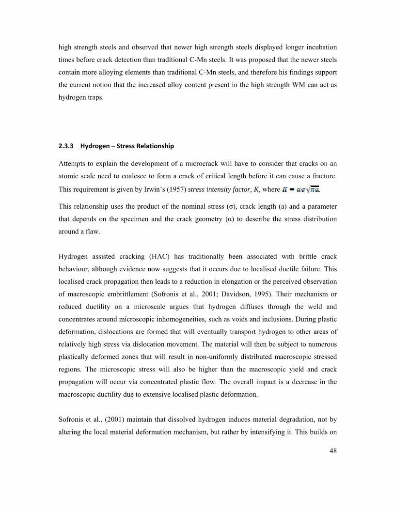
48
high strength steels and observed that newer high strength steels displayed longer incubation
times before crack detection than traditional C-Mn steels. It was proposed that the newer steels
contain more alloying elements than traditional C-Mn steels, and therefore his findings support
the current notion that the increased alloy content present in the high strength WM can act as
hydrogen traps.
2.3.3 Hydrogen – Stress Relationship
Attempts to explain the development of a microcrack will have to consider that cracks on an
atomic scale need to coalesce to form a crack of critical length before it can cause a fracture.
This requirement is given by Irwin’s (1957) stress intensity factor, K, where .
This relationship uses the product of the nominal stress (σ), crack length (a) and a parameter
that depends on the specimen and the crack geometry (α) to describe the stress distribution
around a flaw.
Hydrogen assisted cracking (HAC) has traditionally been associated with brittle crack
behaviour, although evidence now suggests that it occurs due to localised ductile failure. This
localised crack propagation then leads to a reduction in elongation or the perceived observation
of macroscopic embrittlement (Sofronis et al., 2001; Davidson, 1995). Their mechanism or
reduced ductility on a microscale argues that hydrogen diffuses through the weld and
concentrates around microscopic inhomogeneities, such as voids and inclusions. During plastic
deformation, dislocations are formed that will eventually transport hydrogen to other areas of
relatively high stress via dislocation movement. The material will then be subject to numerous
plastically deformed zones that will result in non-uniformly distributed macroscopic stressed
regions. The microscopic stress will also be higher than the macroscopic yield and crack
propagation will occur via concentrated plastic flow. The overall impact is a decrease in the
macroscopic ductility due to extensive localised plastic deformation.
Sofronis et al., (2001) maintain that dissolved hydrogen induces material degradation, not by
altering the local material deformation mechanism, but rather by intensifying it. This builds on

49
the work done several years ago by Beachem (1972), who argued that the essential action of
hydrogen is to diffuse into the lattice ahead of the crack tip and to aid whatever plastic
deformation process the system displays. His work has now become topical, as current
understanding points towards the coupling of crack propagation with hydrogen diffusion
(Toribio and Kharin, 2006) and localisation of macroscopic deformation into bands of intense
shear (Sofronis et al., 2001).
Sofronis et al., (2001) suggest that shear localisation can occur under high hydrogen
concentrations, which arguably leads to the material failing by yielding on a microscale. This
microscale yielding is postulated not to be an indication of the process that occurs
macroscopically. These arguments put forward are thereby linking the decrease in macroscopic
ductility with an increase in localised plastic deformation.
The fracture processes responsible for both HAZ and WM cracking are dependent on the
strength of the steel, the stress state near a crack tip (stress intensity factor) and the
concentration of hydrogen at the crack tip (Yurioka and Suzuki, 1990). Investigations into the
relationship between stress-strain fields and fracture surfaces produced in hydrogen
environments show that non-uniformity of microstructure and subsequent stress-strain
localisation may be important in determining the fracture mode (Gao and Cao, 1998). These
authors investigated the effects of stress-strain fields on fracture surfaces produced in hydrogen
environments. They concluded that the plastic deformation in the vicinity of the crack tip plays
an important role in hydrogen transportation.
Measurements of hydrogen concentrations taken at different locations towards the crack tip
displayed two hydrogen concentration peaks in the vicinity of the crack tip. One hydrogen
concentration peak was attributed to a hydrostatic stress-induced hydrogen accumulation peak
and the other peak was attributed to an accumulation of hydrogen at the crack tip, caused by
the trapping effect of dislocations. Gao and Cao (1998) postulated that these peaks therefore
show the redistribution of hydrogen under the influence of applied loads. Their work showed
that during constant loading tests, crack initiation sites always correspond to the point of
maximum hydrostatic stress, which is located some distance ahead of the notch tip. However,

50
for slow strain rate tests, cracking originated at the notch tip, which corresponds to the point of
maximum equivalent plastic strain. The relationship between the critical stress intensity factor
was therefore shown to be different for the two test configurations.
Early research carried out by Beachem (1972) demonstrated that an increase in the stress
intensity factor (due to an applied load) can result in a change of the fracture mode from
intergranular, to quasi cleavage and finally to transgranular microvoid coalescence (MVC).
Beachem explains that the stress intensity is therefore critical in determining which mode of
fracture results and that a very high stress intensity factor can result in a ductile fracture mode.
Vasudevan et al., (1981), Yurioka (1990) and Gedeon and Eagar (1990) have since then
produced experimental evidence to support Beachem’s viewpoint.
Sterjovski (2003) further notes that both transgranular and intergranular fracture can occur by
microvoid coalescence. The voids are formed at regions of localised strain, such as at
inclusions or dislocation pile-ups (Liang et al., 2004) and provide regions for significant
enhancement of hydrogen concentration. The reason for this is believed to be due to the
elevation of both hydrostatic stress and plastic strain in the vicinity of the precipitate, induced
by the lattice misfit strain (Sofronis and Ritchie, 2003).
Modern high strength steel weld metal is characterised by increased strength and toughness,
derived in part from an increase in secondary particles, such as inclusions. These particles act
as hydrogen traps and will increase the stress intensity locally. Lynch et al., (2002) noted that
the main embrittling site is often in the vicinity (a few atomic distances) of the crack tip, during
which crack growth usually occurs predominantly by localised slip. Baskes et al., (1994)
observed hydrogen damage far ahead of the main crack, indicating that a rapid mode of
hydrogen transport was in operation, such as transport by moving dislocations and diffusion
along dislocation cores.
Baskes et al., (1996) mention that the effect of hydrogen degradation was not observable unless
both plastic deformation and hydrogen charging occurred simultaneously, further indicating that
the transport of hydrogen is a key influencing factor. The authors also contend that hydrogen
51
enhances the void nucleation rate, which in turn increases the overall crack growth rate. Their
results show that hydrogen induced decohesion takes place at the internal interfaces and that
hydrogen accelerates the fracture process. A close relationship therefore exists between the local
stress field in a metal lattice and the hydrogen concentration at a crack tip. The hydrostatic stress
field at the tip of a crack has also been considered by some to be a major component, if not the
controlling parameter in the hydrogen embrittlement process (Sasse and Gadgill, 1996; Oriani and
Josephic, 1974).
2.3.4 Inclusion Assisted Fracture
WM inclusions are normally smaller than the inclusions in the parent plate, although the weld
metal generally has a larger concentration of inclusions. WM inclusions range from a diameter
of 0.1 μm to 3 μm and they influence the microstructural transformation products by aiding
nucleation of acicular ferrite, reducing the grain size and suppressing formation of a brittle
microstructure (Koseki and Thewlis, 2005). However, inclusions can unfortunately also have a
detrimental effect on the toughness of weld metal by providing areas for void nucleation and
subsequent trap sites.
Tweed and Knott (1987) observed cracks, which initiated at inclusions, finding that some
inclusions were themselves cracked. They proposed a model for brittle fracture in weld metal
which argues that deformation is localised within the grain boundary and that dislocation pile-
up and the crack tip stress field then further induce cracking of the inclusions. This process
subsequently leads to crack growth. They also proposed that the size of the inclusion is more of
a problem than the chemistry of the inclusion. Davidson et al., (1996) agrees with this
viewpoint and maintain that the probability of cleavage fracture increases if the inclusions are
larger than 1μm. Cleavage fracture that initiates through the cracking of brittle second phase
particles (such as inclusions and carbides) is illustrated in Figure 2.22.
The above paragraph pertains to brittle fracture, although other fractographic examinations
indicate that crack propagation occurs to a large extent by the linkage of the main crack to
microcracks, which have formed by void coalescence in the plastic zone (Baskes et al., 1994).

52
Studies have also shown that hydrogen assisted cracking initiates at second phase particles by
hydrogen induced decohesion, followed by shear localisation (Sofronis et al., 2006). It is now
common to find HACC fracture surfaces in high strength weld metal that display a significant
level of (MVC) microvoid coalescence (Sofronis et al., 2006). This observation is not unusual,
as modern weld metal has high strength and toughness values, directly increasing the stress
intensity factor required to initiate fracture.
The literature indicates that the fracture toughness of high strength steel weld metal is strongly
dependent on the distribution, size and density of inclusions and the fine-scale microstructure
(Maroef et al., 2002). If the inclusions are equi-axed and nucleate voids at low strains, the
volume fraction and spacing of the inclusion distributions will significantly influence
toughness (Garrison and Wojcieszynski, 1998). Other work by Blackburn et al., (1999) focused
on grain refinement and showed that a large volume fraction of inclusions is responsible for
limiting the extent of toughness that can be achieved in modern weld metal. They argue that an
increase in the number and size of the voids surrounding the inclusions will have the potential
to provide sources for crack formation. Furthermore, these voids have a beneficial effect due to
their ability to attract hydrogen, acting as hydrogen trap sites.
Nagumo and Matsuda (2002) agree that the constraint of plastic deformation at voids and
inclusions is likely to determine the susceptibility to hydrogen-related failure induced by strain
concentration, as much of the localisation of the strain is expected to occur around voids and
inclusions. It is understood that the hydrostatic stress around inhomogeneities (voids and
inclusions) lowers the chemical potential and attracts the hydrogen atoms. The hydrogen atoms
then take up residence in the vicinity of these features, increasing the onset of further localised
yielding and possible fracture.

53
As pointed out previously, the presence of hydrogen in solid solution also decreases the
barriers to dislocation motion, therefore increasing the amount of deformation that occurs in a
localised region adjacent to the fracture surface. Ductile crack growth is then further promoted
by an increase in dislocations and by decreasing the volume fraction of inclusions, i.e.,
decreasing the distance between the inclusions. Both factors facilitating the linkage of voids.
Fine second-phase particles, such as inclusions, can therefore initiate voids ahead of the
advancing crack tip and the crack will then propagate by the linkage of these voids as
illustrated in Figure 2.22(a).
Figure 2.22 Diagram showing an advancing fracture through the stress field generated by a crack tip (a) void formation and void linkage at small particles, such as inclusions,(b) cleavage of particles and (c) intergranular fracture (adapted from Sterjovski, 2003).
54
2.4 HYDROGEN ASSISTED COLD CRACKING MECHANISMS
No single, concrete, mechanistic explanation of hydrogen cracking is available, even though
several HACC mechanisms (and their variants) have been proposed (Sofronis and Robertson,
2002; Baskes et al., 1996). What follows is therefore a summary of the most widely used
theories, together with a brief synopsis on their suitability for high strength ferritic weld metal.
Concluding remarks in relation to WM HACC will be made in Chapter 2.4.8.
2.4.1 Planar Pressure Theory
The planar pressure theory (Zapfe and Sims, 1941) suggests that high pressure is created by
hydrogen gas in the voids, thereby causing fracture. This theory is based on the decrease in
solubility of hydrogen as the temperature is lowered and it is postulated that atomic hydrogen
re-associates into diatomic hydrogen in pores and microvoids. This then increases the pressure
to very high values and adds to the externally applied stress.
2.4.2 Adsorption Theory
This mechanism is attributed to Petch and Stables (1952) and argues that hydrogen acts like an
acid and lowers the free surface energy, which holds the atoms together. It proposes that
hydrogen adsorbed onto the internal surfaces of cracks or voids will decrease the surface
energy and allow a crack to grow under a lower applied stress. Adsorption of hydrogen atoms
at the crack tip leads to the weakening of interatomic bonds, which in turn facilitates
dislocation injection from the crack tip. The crack subsequently grows by slip and formation of
microvoids.

55
2.4.3 Hydrogen Enhanced Decohesion
Bastein and Azou (1952) proposed that the movement of dislocations carries along hydrogen
atoms during plastic deformation, where dislocation pile-ups at structural defects produce an
over-saturation of hydrogen. Troiano (1962) added to this and argued that hydrogen interacts
with dislocation pile-ups in areas of tri-axial stress, thereby lowering the cohesive strength. The
interaction of hydrogen with the dislocations ahead of the stress concentration is postulated to
be sufficient to cause fracture if the concentration of hydrogen reaches a certain level.
Oriani (1972) added to Troiano’s initial theory and proposed that hydrogen damage occurs
when the tensile stress at the crack tip exceeds the maximum local atomic cohesion strength,
which has been lowered by the presence of hydrogen. In the hydrogen enhanced decohesion
(HEDE) scenario, hydrogen accumulates at trapping sites, such as voids, cracks and interfaces
where it subsequently reduces the bond strength. The regions where damage occurs are located
ahead of the crack tip surface where tensile stresses are maximized. This theory therefore
considers that there is a critical hydrogen concentration for the occurrence of brittle fracture
and that dissolved hydrogen decreases the cohesion forces that exist between atoms.
2.4.4 Hydride Induced Embrittlement
Brittle cleavage-like fracture associated with stress-induced hydride formation is one of the
established hydrogen embrittlement mechanisms. Hydrogen accumulation is believed to
promote a local concentration of hydrides, assisting the generation of stacking faults and also
an increase in stress. Subsequently under increased stress, crack propagation will occur by the
successive formation of crack fronts (Torres et al., 2002).
The nucleation and growth of a hydride field ahead of a crack has been dynamically observed
by several researchers (Varias and Feng, 2004; Teter et al., 2001). Their investigations revealed
that the hydrides first nucleated in the stress field associated with a crack. The crack then
propagated, not by the growth of individual hydrides, but by the nucleation and growth of new
hydrides in the stress field of others cracks, demonstrating that the small hydrides coalesced to
form larger hydrides. The metal hydrides are not only brittle and less dense than the metal
matrix, but precipitate at dislocations, grain boundaries and other defects (Louthan, 1987).

56
2.4.5 Microplasticity Theory
Beachem (1972) reasoned that the absorption of hydrogen will enhance the ease of dislocation
motion and/or dislocation generation. The belief is that the distribution of hydrogen will be
non-uniform and may over-concentrate in certain regions. During an applied stress, the flow
stress in these regions (on a microscopic level) will be reduced, resulting in localised
deformation which leads to a highly localised ductile failure, therefore leading one to believe
that the fracture is brittle by nature.
Beachem proposed that microplasticity governs what happens at the crack tip, rather than an
embrittlement process. His mechanism allows for hydrogen ahead of the crack tip to assist
whatever microscopic deformation the microstructure will allow. He reasons that intergranular,
quasi cleavage and microvoid coalescence are all possible fracture modes, which can be
associated with HACC. The different fracture modes will further be a function of the
microstructure, crack tip stress intensity and the hydrogen concentration.
Other researchers have also experimentally validated the argument that several types of
fracture mode can be associated with HACC (Vasudevan et al., 1981; Yurioka and Suzuki,
1990). Beachem’s model therefore unifies several theories and the basic hydrogen-steel
interaction appears to point to an easing of dislocation motion or dislocation generation, or a
combination of both. This postulation is supported by observations that atomic hydrogen
decreases the friction between dislocation movement on slip planes and therefore causes
movement within the lattice. The crack formation mechanism in this case is thought to be
microvoid coalescence or simply a dislocation avalanche (Gedeon and Eagar, 1990).
2.4.6 Adsorption Induced Localised Slip Model
Lynch (1988) also proposes a localised plastic deformation mechanism but supports the
injection of dislocations from the crack tip, thereby promoting the coalescence of cracks with
voids ahead of an existing crack front. The overall result is also a process of plastic flow,
similar to what was proposed by Beachem (1972) and Birnbaum and Sofronis (1996), but one
governed by the injection of dislocations from the crack tip. The adsorption of hydrogen atoms
at the crack tip will result in weakening of the interatomic bonds, thereby facilitating
dislocation injection from a crack tip. The crack subsequently grows by slip and the formation

57
of microvoids. Lynch (1988) states that segregation of impurities, such as phosphorus, to prior-
austenite grain boundaries will most likely increase the susceptibility to HACC by promoting
intergranular fracture. The impurities can weaken interatomic bonds at the crack tip, facilitating
decohesion or the creation/movement of dislocations. Lynch (1988), however, warns that the
explanations for the observed effects of microstructure on the susceptibility to HACC are
generally speculative, as he believes that microstructures and fracture paths are not
characterised in sufficient detail. He also states that it is often difficult to compare the results of
different researchers due to different measures used in assessing the susceptibility to HACC.
2.4.7 Hydrogen Enhanced Localised Plasticity (HELP Model)
This theory also assumes that hydrogen facilitates dislocation motion and crack growth by slip
and the formation of microvoids. Using modern high image microscope analysis techniques
(Sofronis 2001) and the work of Beachem (1972), Birnbaum and Sofronis (1994) and Lynch
(1988) have contributed to what many current researchers refer to as the Hydrogen Enhanced
Localised Plasticity (HELP) Model. It argues for a hydrogen induced localised ductile rupture
process, which results in the traditional macroscopic observations of brittle behaviour. As with
the decohesion model, the HELP model requires the accumulation of hydrogen in a stress field,
i.e., in the vicinity of the crack tip or in the vicinity of a dislocation.
During dislocation movement (induced by an external stress), the atomic hydrogen eases the
dislocation movement by shielding the stress fields of the dislocations against each other, as
well as against other imperfections. The shielding will lower the local yield stress, resulting in
the dislocation movement occurring at low levels of shear stress. This will lead to microcracks
that were caused by the formation of microvoids and the shearing action of dislocation
movement. The macroscopic ductility is therefore limited due to the onset of extensive
localised plastic deformation, a viewpoint that may be counter intuitive.

58
2.4.8 Comment on HAC Mechanisms
Of the several suggestions for hydrogen cracking, Barnoush and Vehoff (2008) suggest that the
three mechanisms listed in Table 2.2 dominate the observed effect of hydrogen on steels.
Table 2.2 Dominating hydrogen embrittlement mechanisms
No. MECHANISM
1 Hydride Induced Embrittlement (Second Phase Mechanism)
2 Hydrogen Enhanced Decohesion (Brittle Fracture)
3 Hydrogen Enhanced Localised Plasticity ( Ductile Fracture)
The definition of HACC operating as a “brittle fracture” is historically based on the observed
loss of macroscopic ductility (e.g., decrease of reduction in area and elongation). Beachem’s
theory on microplasticity (1972) was therefore one of the pioneers to argue for plastic
behaviour at the crack tip, prior to the observed loss of macroscopic ductility. This idea has
since then received more credence primarily due to research performed on hydrogen-
dislocation interactions.
Baskes et al., (1996) pointed out that hydrogen carried along by moving dislocations enhances
both the dislocation mobility and the tendency for further dislocations to form. They proposed
that the creation of new dislocations will then in itself create a path for additional rapid
hydrogen transport.
The research of Sofronis et al., (2001, 2002, 2003) provided evidence that solute hydrogen
certainly enhances the mobility of all dislocation types (edge, screw, mixed and partial
dislocations), which occurred in a wide range of metals and alloys with different crystal
structures. Their work using an in-situ transmission electron microscope to observe
deformation and fracture of samples in an environmental cell supported the HELP model as a

59
failure mechanism for a large number of pure metals and alloys. The investigation they
performed on the effect of hydrogen on crack growth proved that adding hydrogen gas to the
environmental cell gave rise to the spawning and increase of dislocations velocities. Removal
of hydrogen from the cell resulted in the converse being observed as dislocation motion ceased
to occur. This research subsequently validated the arguments put forward by Baskes et al.,
(1996).
Lynch et al., (2002) provided a comprehensive overview of the different mechanisms attributed
to hydrogen assisted cracking in non-hydride forming materials. The overall conclusion
reached is that the HACC process is often a combination of the various mechanisms. In the
systems where synergistic interactions between mobile dislocations and trapped or transported
hydrogen occur, hydrogen directly modifies the dislocation character and behaviour,
introducing or excluding specific slip systems (slip plane and direction). This in turn promotes
shear localisation (Sofronis et al., 2001). The localised plastic deformation therefore enhances
localised fracture and also has the ability to mimic apparent brittle cleavage fracture.
Synergistic interactions of various processes therefore have to be assumed to explain the
observed effects of hydrogen. The generality of this effect is explained through the presence of
hydrogen atmospheres around dislocations and elastic obstacles, which decreases the
interaction energy between them. The effect manifests itself as a reduction in the applied stress
required to move dislocations in the presence of solute hydrogen, which subsequently causes
localised deformation. This in turn results in localised failure through plastic processes.
60
2.5 WELD METAL HACC TEST METHODS
There are a wide variety of test techniques that have been used to characterize the susceptibility
of materials to hydrogen assisted cold cracking. The tests generally determine a critical heat
input, preheat or interpass temperature at which HACC will potentially be avoided. Several
reviews of these test techniques have been performed and they are mostly geared towards both
older steel types the heat affected zone (Viyanit and Boellinghaus, 2004; Yurioka and Suzuki,
1990; Davidson, 1995 and Graville, 1995). A few tests have been developed to include weld
metal cold cracking and a list of commonly applied HAZ and WM tests are presented in Table
2.3 below. The highlighted rows emphasize the tests which were specifically produced for the
WM and these are described in more detail further in the text.
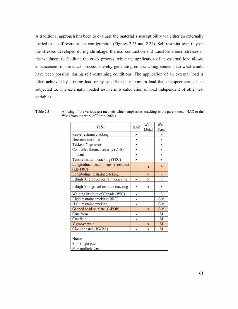
61
TEST HAZ Weld Metal
Weld Pass
Reeve restraint cracking x S Non-restraint fillet x S Tekken (Y groove) x S Controlled thermal severity (CTS) x S Implant x S Tensile restraint cracking (TRC) x S Longitudinal bead - tensile restraint (LB-TRC) x S
Longitudinal restraint cracking x S Lehigh (U groove) restraint cracking x x S
Lehigh (slot grove) restraint cracking x x S
Welding Institute of Canada (WIC) x S Rigid restraint cracking (RRC) x S/M H slit restraint cracking x S/M Gapped bead on plate (G-BOP) x S/M Cruciform x M Cranfield x M V groove weld x M Circular patch (BWRA) x x M Notes: S = single pass M = multiple pass
A traditional approach has been to evaluate the material’s susceptibility via either an externally
loaded or a self restraint test configuration (Figures 2.23 and 2.24). Self restraint tests rely on
the stresses developed during shrinkage, thermal contraction and transformational stresses in
the weldment to facilitate the crack process, while the application of an external load allows
enhancement of the crack process, thereby generating cold cracking sooner than what would
have been possible during self restraining conditions. The application of an external load is
often achieved by a rising load or by specifying a maximum load that the specimen can be
subjected to. The externally loaded test permits calculation of load independent of other test
variables.
Table 2.3 A listing of the various test methods which emphasises cracking in the parent metal HAZ or the
WM (from the work of Pitrun, 2004).
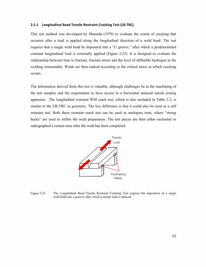
62
2.5.1 Longitudinal Bead Tensile Restraint Cracking Test (LB‐TRC)
This test method was developed by Matsuda (1979) to evaluate the extent of cracking that
occurres after a load is applied along the longitudinal direction of a weld bead. The test
requires that a single weld bead be deposited into a “U groove,” after which a predetermined
constant longitudinal load is externally applied (Figure 2.23). It is designed to evaluate the
relationship between time to fracture, fracture stress and the level of diffusible hydrogen in the
welding consumable. Welds are then ranked according to the critical stress at which cracking
occurs.
The information derived from this test is valuable, although challenges lie in the machining of
the test samples and the requirement to have access to a horizontal uniaxial tensile testing
apparatus. The longitudinal restraint WM crack test, which is also included in Table 2.3, is
similar to the LB-TRC in geometry. The key difference is that it could also be used as a self
restraint test. Both these restraint crack test can be used as multipass tests, where “strong
backs” are used to stiffen the weld preparation. The test pieces are then either sectioned or
radiographed a certain time after the weld has been completed.
Figure 2.23 The Longitudinal Bead Tensile Restraint Cracking Test requires the deposition of a single weld bead into a groove, after which a tensile load is induced.

63
2.5.2 Gapped Bead on Plate Test
According to Graville and McParlan (1974), the G-BOP test method (Figure 2.24) was
primarily used to assess the welding consumable’s susceptibility to cold cracking. It differs
from the LB-TRC and the longitudinal restraint WM crack test because a single weld bead is
deposited on top of 50mm thick base material, and not in a groove. The deposited weld bead
traverses a gap of specified width and the subsequent stress is created by contraction of the
weld. No external load is applied. After 48 hours, the weld is heat tinted and forcibly fractured.
The fractured surfaces prior to heat tinting will be then be discoloured, provided that a surface
breaking crack was present. The fractured welds are then investigated and ranked according to
the incidences, size and density of cracking.
Figure 2.24 A typical G-BOP configuration used to test for weld metal hydrogen assisted cold cracking. In this image, a weld is deposited over a 0.75mm gap which acts as a large stress concentration, assisting initiation of transverse weld metal (Pitrun, 2004).
The GBOP test is a self restraint test and is reliant on a gap at the root to increase the stress
intensity. Disadvantages of self restraint tests are that they do not have the capacity to readily
determine the stress at which cracking occurs, and that incubation periods ranging from 12-48
hours is typically required before sectioning or investigation via nondestructive means is
performed. The GBOP tests is also known to be unconservative if low hydrogen levels are
present in the deposited weld metal (Olson, 1999). This factor may limit their effectiveness if

64
used on modern high strength weld metals, which commonly have low diffusible hydrogen
designations. The GBOP nevertheless remains a popular test method to rank welding
consumables.
2.5.3 Bend Testing
Bend testing has primarily been reserved for single pass specimens due to the requirement for
large capacity test frames if multipass welded specimens are to be tested. The results from bend
testing are also not typically used to provide welding specifications that will preclude WM cold
cracking. Pussegoda et al., (2004), Graville (1995) and Satoh et al., (1977) have however used
bend testing as a platform from which they investigated weld metal’s susceptibility to cold
cracking. Their methods incorporated a notch in a pre-selected area of the deposited weld metal
(similar to fracture toughness testing) and then imposed either 3 or 4-point bending strains on
the specimens. The applied load introduced localised straining at the sharp pre-notches, thereby
initiating hydrogen induced cracking at the pre-notch.
An advantage of a 4-point bend above the 3-point bend test is that the 4-point bend test will
evaluate a larger region of weld metal. The typical 4-point bend test arrangement results in two
rollers on the load span pushing against two rollers on the support span (see Figure 2.25). The
support span (S) will be positioned on the deposited weld bead and the load span (L) will be
positioned behind the weld on the base material. This orientation induces a tensile stress in the
weld bead and a compressive stress on the base material. The shorter load span will be
subjected to a uniform bending moment and would produce uniform surface stresses across the
weld metal (excluding variations related to weld surface profile). This test arrangement focuses
the test on the weld metal and not on the base material, making it suitable for WM HACC
investigations.
Figure 2.25 Illustration of loading conditions in a 4-point bend test. The load span (L) pushes down on the support span (S) to induce uniform surface stresses across the load span.

65
2.5.4 Comment on Weld metal Cold Cracking Test Methods
The current measures employed to combat WM HACC include costly applications of preheat,
interpass temperatures and postweld heat treatment, which have been inherited from an era
when cracking in the HAZ was a greater concern than cracking in the WM. Hydrogen cracking
in the heat affected zone has therefore received preferential attention due to it previously
having the most susceptible microstructure (Graville, 1975; Yurioka et al, 1983; Bailey et al,
1995 and ISO/TR 17844:2004).
The test methods given in Table 2.3 to assess weld metal hydrogen cold cracking have seen
both industrial and academic use and according to Graville (1995), the existing procedures
available to avoid HACC are prescriptive towards the welding conditions, such as specifying
elevated preheat or interpass temperatures and specifying specific edge preparations. This
generalised approach is most likely given due to our incomplete understanding of weld metal
cold cracking. According to Wongpanya et al., (2008), the guidelines might be successful for
low and medium strength steels, but they are limited when applied to the welding of newer
high strength steels with yield strengths above 690 MPa.
The challenge with more recent higher strength steels and the associated weld metal is that
such materials have different weld microstructures, producing different metallurgical and
mechanical behaviour when compared to traditional lower strength steels. Significant benefits
can consequently be gained by producing test methods aimed preferentially at higher strength
weld metal and which also provide close control over the influencing factors that lead to the
occurrence of cold cracking in the higher alloyed weld metal.
Ideally, such a test must be capable of determining the dominant variables that affect weld
metal cold cracking of the target materials. More specifically, Davidson (1995) maintained that
a test which focuses on the weld metal should serve one or more of the following three
functions:

66
1. Enable the development of welding procedures to guarantee freedom from HACC
2. Provide ranking of consumables with regards to resistance to HACC
3. Provide a research tool that permits independent control of the key variables held
responsible for HACC.
These three functions given by Davidson thereby illustrate that the outcomes from crack tests
can be used for a variety of purposes, which in general is to either prevent or study cold
cracking. The determination of the required process variables to prevent HACC is often
derived from test configurations which mimic the production weld in terms of restraint, i.e. a
self restraining test. The option to function as a research tool will then see combinations of
stress, hydrogen concentration and microstructure as necessary variables. Such a test
configuration will typically lean towards being externally loaded.
In order to develop practical recommendations, a test which does not force cracking to
originate or propagate in a specific region is desirable. It should furthermore permit the crack
initiation site to be determined by influences similar to those conditions experienced in
practice. Graville (1975) delivered a fundamental challenge when he wrote that a crack test
does not necessarily show whether a particular welding procedure will be successful in
avoiding cold cracking. He argues that the weldability tests are used to provide comparative
information, which requires correlation with practice, either by previous experience or by
performing joint simulation tests that exactly simulate the real joint in all essential details. This
is a daunting task, which has been addressed by producing small scale test configurations
which maximise restraint and provide stress concentrations to which the hydrogen will diffuse
or concentrate around.
The requirement for a notch in a test configuration provides a challenge in terms of calculating
the stress needed to produce cracking. It may alter the natural path of the diffusing hydrogen,
forcing it to concentrate in specific regions of the test material, instead of allowing the
constraints of the microstructure being evaluated to dictate the diffusion. If close control is
required in these tests, variations in placement and the geometry of the groove or notch will
moreover increase the potential to derive non-standardised results. This has been referred to by

67
0 10 20 30 40
0
10
20
30
40
50
Plat
e Th
ickn
ess
Crack Density (cracks/m2)
Weld metal hydrogen concentration curve. ( Takahashi et al. 1979)
Yurioka (1999), who is of the viewpoint that a notched or a grooved test specimen may not
necessarily produce transverse cracking, as the cracking will typically originate from the
induced geometric stress concentration.
The requirement for artificial stress concentrations in multipass welds can further be
questioned if one considers the work of Kuebler et al. (2000) and Takahashi et al. (1979).
These authors showed that weld longitudinal residual tensile stresses, hydrogen concentration
and crack density maximizes towards the upper layers of a multipass weldments (Figure 2.26),
which implies that WM HACC is a feature of the upper region of the deposited weld, not the
root.
Figure 2.26 Generalised plot of crack density in the weld metal through a 50 mm thick plate (X-Y plane) at preheat and inter-pass temperature of 140 °C (from Kuebler et al. 2000).
Although hydrogen assisted cold cracking is generally influenced by the local microstructure,
the mechanical loads and hydrogen concentration, the crack susceptibility can potentially be
evaluated from a mechanical aspect. Wongpanya et al., (2008) believe that this approach
requires determination of the critical strains at which a specific microstructure will produce
crack behaviour at a given hydrogen concentration. Of the potential crack test methods
discussed previously, the bend test is deemed a suitable mechanism for this to occur.

68
The bend test will provide a means of altering and measuring the load, independent of the other
variables. The strain rate (via deflection) can be adjusted to influence the rate at which
hydrogen diffuses through the microstructure to vicinity of naturally developed crack tip. The
additional introduction of hydrogen into the shielding gas (if needed) will then provide the
hydrogen concentration required for cracking, in conjunction with the critical strains imposed
during bending. A successful test outcome will determine whether, and to what extent, the test
variables (bending stress and diffusible hydrogen) produce cracking.

69
CHAPTER 3
HYDROGEN CRACKING IN MULTIPASS HIGH STRENGTH WELD METAL - INVESTIGATION
The literature survey indicated that there are several factors which influence the weld metal’s
susceptibility to HACC. It has been noted that key to this is the diffusion and trapping of
hydrogen, the other primary variables are elevated stress, susceptible microstructure and an
adequate incubation time. These variables are interrelated and a comprehensive understanding
of their interrelationship is not fully understood.
This following work will present a series of coordinated experiments that were conducted to
achieve a common goal. This goal was to further the understanding of HACC in high strength
steel weld metal by providing a test platform from which individual aspects that contribute to
HACC could be isolated and researched. The motivation to proceed via a series of
experimental tests was to establish the likelihood of initiating HACC in the test materials and
to determine the level of control that could be xercised over the associated test variables
(diffusible hydrogen, stress, microstructure, time) in a laboratory setting.
The test materials chosen for this body of work were quenched and tempered BIS80 and a high
strength (E110) very low (H4) hydrogen flux cored arc welding wire. In an attempt to
reproduce HACC, the prescribed CO2 shielding gas was supplemented by adding a known
percentage of laboratory grade hydrogen. The details of each coordinated experiment are
presented at the beginning of each test phase discussed later on. Experiments were conducted
on both single and multipass welds, although the ultimate aim was to explore un-notched single
bead on plate configurations that could be subjected to applied stress testing. The presentation
of the results and the analysis has been separated into Phases 1-6 to illustrate the research
performed. For clarity, the following work is based on the following:
70
1. Initiating and detecting HACC
2. Controlling the weld metal diffusible hydrogen content
3. Generating test specimen geometry
4. Conducting applied stress testing
5. Conducting microstructural, chemical and fractographic analysis
6. Summary of significant findings
Phase 1: Chapter 3
This phase will generate cold cracking in a 40mm thick multipass weld deposit. The
motivation is to determine whether HACC can readily be initiated in the target materials and to
establish which nondestrtuctive testing methods will constitute the most reliable for its
detection. Experimental data to aid the study of delay times in high strength ferritic weld metal
will also be produced.
Phase 2: Chapter 4
This phase will establish the accuracy to which levels of weld metal diffusible hydrogen can be
controlled when introduced into CO2shielding gas. The purpose is to approximate the quantity
of diffusible hydrogen present in the weld in relation to the percentage hydrogen in the
shielding gas.
Phase 3: Chapter 5
This phase will define specimen geometries and test procedures that will be used during
applied stress testing. A specific objective is to produce notch-free geometries that allow
preferential targeting of the weld metal. The outcome of this chapter will provide welded
samples that can be used to study either the combined effects, or individual aspects held
responsible for weld metal hydrogen assisted cold cracking.
Phase 4: Chapter 6
This phase will document the results obtained from 4-point bend testing. Variations in
mechanical response and the delayed times will be produced by means of purposefully altering
the test variables. The sensitivity of the proposed test methodology will be established and cold
cracking delay times under varying conditions will be produced.

71
Phase 5: Chapter 7
This phase will produce microstructural and fractographic analysis of the specimens that will
be tested under conditions related to the introduction of hydrogen into the CO2 shielding gas.
The focus will be to interpret the preferred fracture path produced during the applied bend
testing and to establish what general effects the deliberate introduction of hydrogen will have
on the microstructure.
Phase 6: Chapter 8
The final phase will discuss the significant findings and offer limitations of the research
conducted in this thesis. Suggestions regarding further research into weld metal hydrogen
assisted cold cracking will also be provided.
3.1.0 Introduction
This phase of the research being presented relates to the deliberate generation of cold cracking
in a 40mm thick multipass high strength steel weld deposit. The motivation is to determine
whether HACC could be readily initiated in the target materials and to establish which
nondestructive testing methods would constitute the most reliable for its detection. A further
aim was to produce experimental data to aid the study of delay times in high strength ferritic
weld metal.
High strength steel weld metal cold cracking activity was monitored in two 1600mm x 500mm
x 40mm Bis80 plates, welded together by an E110 manual flux cored arc welding (FCAW)
process. The intentional generation of WM HACC was therefore required and this was
produced by:

72
• Increasing diffusible hydrogen levels in the weld by the introduction of 2% hydrogen
into CO2 shielding gas
• Minimizing the interpass temperatures (below 70°C) and minimizing interpass times
• Increasing the cracking susceptibility of the microstructure by increasing the cooling rate
• Increasing residual stress through the use of plate stiffeners
3.1.1 Method: Welding High Restraint Test Plate
High restraint in the test plate was achieved by welding 36mm mild steel stiffeners onto the
40mm thick, 700 grade Q&T base plate (Figure 3.1). The stiffeners were intermittently welded
(3 run fillet weld) to the base material with 4mm AWS A5.5 electrodes using a minimum
preheat temperature of 100°C.
Figure 3.1 Reverse side of the high restraint test plate indicating (A) the heating pads which were used for
the preheat treatment for the welding of the stiffeners, (B) the location of the root bead and (C) the transverse and longitudinal stiffeners. The intermittent 3 pass fillet welds can also be seen adjacent to the stiffeners.
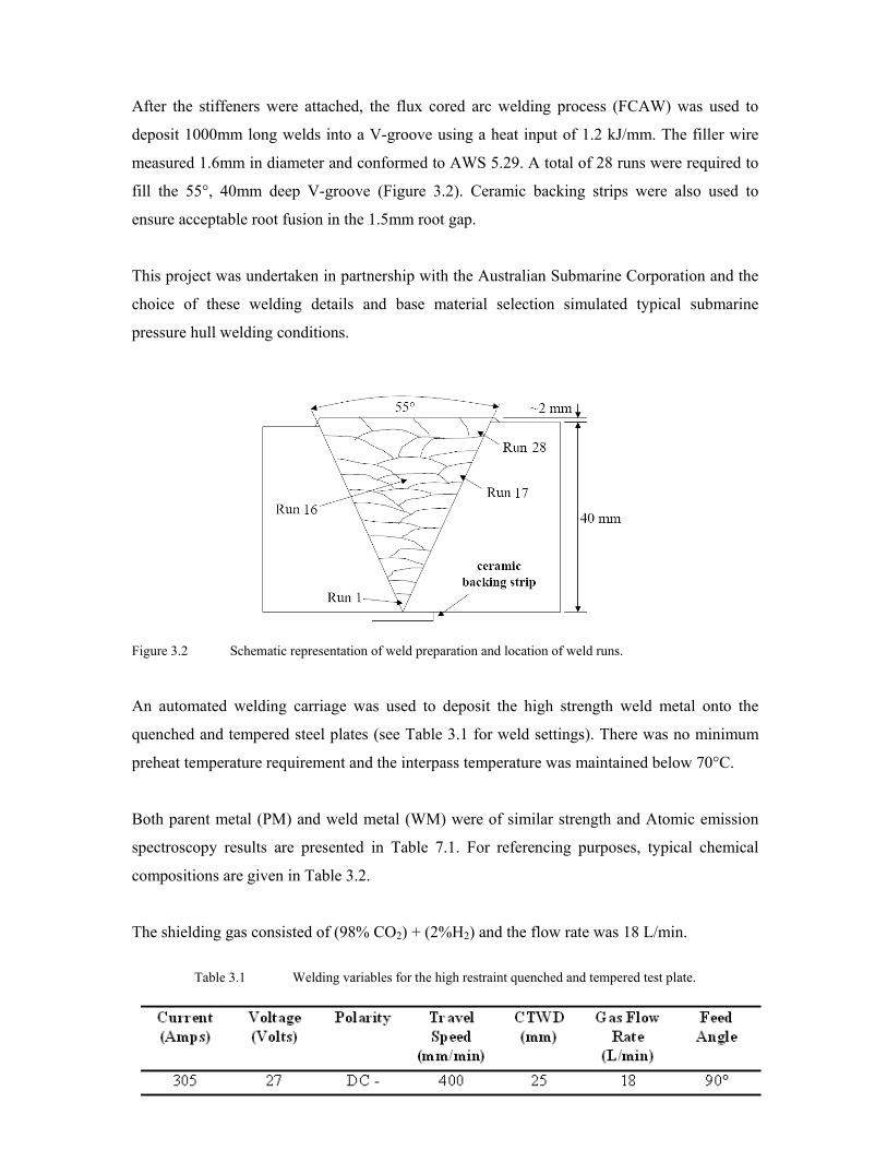
73
After the stiffeners were attached, the flux cored arc welding process (FCAW) was used to
deposit 1000mm long welds into a V-groove using a heat input of 1.2 kJ/mm. The filler wire
measured 1.6mm in diameter and conformed to AWS 5.29. A total of 28 runs were required to
fill the 55°, 40mm deep V-groove (Figure 3.2). Ceramic backing strips were also used to
ensure acceptable root fusion in the 1.5mm root gap.
This project was undertaken in partnership with the Australian Submarine Corporation and the
choice of these welding details and base material selection simulated typical submarine
pressure hull welding conditions.
Figure 3.2 Schematic representation of weld preparation and location of weld runs. An automated welding carriage was used to deposit the high strength weld metal onto the
quenched and tempered steel plates (see Table 3.1 for weld settings). There was no minimum
preheat temperature requirement and the interpass temperature was maintained below 70°C.
Both parent metal (PM) and weld metal (WM) were of similar strength and Atomic emission
spectroscopy results are presented in Table 7.1. For referencing purposes, typical chemical
compositions are given in Table 3.2.
The shielding gas consisted of (98% CO2) + (2%H2) and the flow rate was 18 L/min.
Table 3.1 Welding variables for the high restraint quenched and tempered test plate.

74
Table 3.2 Typical WM and 700 GRADE PM chemical compositions (wt %).
3.1.2 Method: Diffusible Hydrogen Levels
The average diffusible hydrogen levels were taken from three samples, plotted as a function of
%H2 in CO2. The samples were prepared and tested, as specified in AS/NZS 3752:1996,
“Welding – Methods for determination of the diffusible hydrogen content of ferritic weld metal
produced by arc welding”. The diffusible hydrogen tests were carried out on single bead on
plate samples and gave an indication of the level of diffusible hydrogen (ml/100g) for a single
run. This test does not represent the diffusible hydrogen for the total weld, but represents the
level of diffusible hydrogen for each individual weld deposit.
3.1.3 Method: Nondestructive Testing (NDT)
Magnetic particle testing (MT) was performed in accordance with AS1171-1998: “Non-
destructive testing – Magnetic particle testing of ferromagnetic products, components and
structures”. The testing was carried out on both sides of the weld (root and cap) to determine
the extent of longitudinal and transverse surface defects.
Radiography (RT) of the weldment was performed in accordance with AS2177.1-1004:
“Radiography of welded butt joints in metal”. The test weld was radiographed in 250mm weld
length intervals. Ultrasonic testing (UT) was carried out in accordance with AS2207-1994:
“Nondestructive testing – Ultrasonic testing of fusion welded joints in ferritic steel”. Scanning
for HACC defects occurred every 24 hours for one week and then every 72 hours for three
weeks. It was predominantly carried out with a 70° probe, to ensure that the ultrasonic waves
detected planar defects during transverse scanning of the weld.

75
Acoustic emission monitoring (AE) was utilized to establish the effectiveness of this technique
in determining crack locations (see Figures 3.3, 3.8 and 3.11 to 3.14). The highly restrained
welded test plate was monitored for 14 days after the completion of welding. Data such as
waveform, time, amplitude, rise time, duration, average frequency, peak frequency, energy,
counts and XY location were logged. The XY coordinates of the acoustic events were
determined by triangulation between four 300 kHz resonant piezo-electric sensors using the
known velocity of sound in the material and non-linear regression to refine the results. The
velocity of sound was determined experimentally by pulsing/listening sensors from known
locations, and this was confirmed by test signals on the weld centre line prior to monitoring.
Figure 3.3 Representation of the acoustic emission process used. When the AE transducer senses a signal over the threshold, an AE event is captured. Four sensors were positioned on the test plate, and all four had to record a signal before an event was logged.
3.2.1 Results: Cooling Times and Interpass Temperature
This high restraint welded plate was designed to produce high levels of residual stress and
cooling rates typically associated with larger structures. The elevated stresses and the addition
of 2% hydrogen into the shielding gas were sufficient to induce cracking in the weld metal (see
Figures 3.9 and 3.10).
Relatively fast cooling rates of t8/5 and reduced interpass temperatures (at or below 70°C) were
used to limit effusion of hydrogen from the weld metal, as the interpass time and interpass
temperature affect the distribution of hydrogen in the weld (Pussegoda et al., 2004). The t8/5
cooling time was approximately five seconds (see Figure 3.5) which produced a relatively fast
cooling rate. It is believed that this cooling rate also increased the hardness of the
microstructure, making it more susceptible to HACC.

76
Plots of interpass temperatures vs. interpass times are presented in Figures 3.6a and 3.6b. The
test welds were also deposited without preheat, as preheat is known to assist the effusion of
hydrogen from the weld. A typical temperature-time profile measured from a weld deposited
near the top surface is shown in Figure 3.4. The fluctuations seen here during the cooling cycle
are due to the commencement of preparation for the next weld run, which includes slag
removal, grinding and air cleaning.
Figure 3.4 Temperature from the base plate adjacent to the weld preparation for run 16, 800mm from the
datum and face side of the plate.
Figure 3.5 Illustration of a typical cooling rate experienced by the molten weld pool with an interpass
temperature of ~60°C. The cooling rate was establish by placing a thermocouple into the solidifying weld metal.

77
Figure 3.6(a) Plot of interpass temperature versus interpass times. Note that lower interpass
temperatures correspond to longer interpass times.
Figure. 3.6(b) The interpass temperatures were kept below 70°C to avoid the rapid effusion of hydrogen from the weld. The total welding time was completed in approximately 550 minutes (~9 hours).
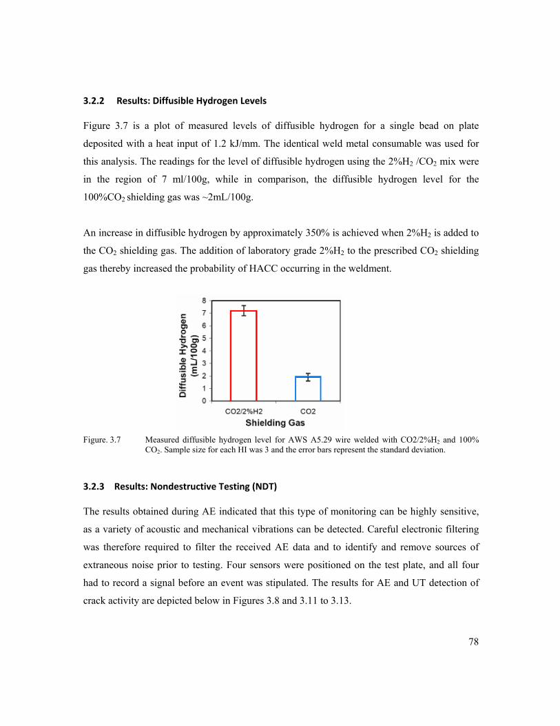
78
3.2.2 Results: Diffusible Hydrogen Levels
Figure 3.7 is a plot of measured levels of diffusible hydrogen for a single bead on plate
deposited with a heat input of 1.2 kJ/mm. The identical weld metal consumable was used for
this analysis. The readings for the level of diffusible hydrogen using the 2%H2 /CO2 mix were
in the region of 7 ml/100g, while in comparison, the diffusible hydrogen level for the
100%CO2 shielding gas was ~2mL/100g.
An increase in diffusible hydrogen by approximately 350% is achieved when 2%H2 is added to
the CO2 shielding gas. The addition of laboratory grade 2%H2 to the prescribed CO2 shielding
gas thereby increased the probability of HACC occurring in the weldment.
Figure. 3.7 Measured diffusible hydrogen level for AWS A5.29 wire welded with CO2/2%H2 and 100%
CO2. Sample size for each HI was 3 and the error bars represent the standard deviation.
3.2.3 Results: Nondestructive Testing (NDT)
The results obtained during AE indicated that this type of monitoring can be highly sensitive,
as a variety of acoustic and mechanical vibrations can be detected. Careful electronic filtering
was therefore required to filter the received AE data and to identify and remove sources of
extraneous noise prior to testing. Four sensors were positioned on the test plate, and all four
had to record a signal before an event was stipulated. The results for AE and UT detection of
crack activity are depicted below in Figures 3.8 and 3.11 to 3.13.

79
Figure 3.8 Schematic representation of the HACC locations detected by conventional UT and acoustic
emission monitoring. The arrow represents the direction of weld and the position of the AE boundary is represented by the dashed line. The majority of events were recorded along the weld. Surface breaking cracks (blue lines) were in the vicinity of the stiffeners.
Two of the five significant UT cracks were surface-breaking and were detected visually and by
magnetic particle inspection (Figure 3.9). The same two surface-breaking cracks were also
detected by radiography. All significant HACC incidents and also the majority of transverse
HACC (UT data points in Figure 3.8 were located to the left and right of the weld centre. They
were also distributed relatively evenly along the length of the weld. Figure 3.9 shows
photographs of two surface-breaking hydrogen cracks and Figure 3.10(a) is a radiograph of one
surface-breaking crack, which indicates that the crack, although transverse, branches into
multiple paths. Radiography detected only two deep surface-breaking cold cracks, lack of
sidewall fusion and group porosity (Figure 3.10(b)), but not the numerous fine cracks that were
detected by conventional UT and AE.

80
Figure 3.9 Photograph of HACC detected by MPI (a) 300mm from the datum, and (b) 1280mm from
datum. These cracks were located close to the stiffener plates.
Figure 3.10 Photograph of (a) HACC detected by radiography 1280mm from the datum, and (b) group
porosity 675mm from the datum, which was not detected by UT.
Figures 3.11 to 3.14 provide insight into the time-dependent nature of HACC as they indicate
that some cracks propagated over a period of a month, while others remained dormant. Figure
3.13 shows that the majority of acoustic emission activity (attributed to HACC) in the vicinity
of the weld occurred during the first 48 hours. There appears to be no acoustic emissions
detected after ~3 days, which is misleading, as crack propagation was detected beyond this
time by conventional UT (Figure 3.12).

81
Figure 3.11 Crack size depth measurements at various days after completion of welding, as measured by
UT. One example shows that crack propagation occurred between 15 and 27 days.
Fig. 3.12 Overall acoustic emission activity in the vicinity of the weld plotted against days after
completion of welding.
Figure 3.13 Derived energy (AE) versus time for significant HACC
(a) 1035mm and (b) 535mm from the datum.

82
Figure 3.14 below is a plot of the acoustic emissions in the range of 0.20-1.20 MHz associated
with HACC and shows that there were two typical emissions types. The first was a relatively
low frequency emission at ~250 HZ and is attributed to crack propagation. The second type of
emission detected was a combination of low frequency (~250Hz) and high frequency (~500Hz)
emission, most likely a combination of crack propagation and plastic flow ahead of a crack tip.
Figure 3.14(a) A typical HACC acoustic emission from weld at a frequency of ~250 Hz indicating
crack propagation.
Figure 3.14(b) A typical HACC acoustic emission of approximately 250 Hz, which contains a high
frequency component in the region of 500Hz. Most likely due to plastic deformation at a crack tip (Graham and Alers, 1975).

83
CHAPTER 4
EVALUATING DIFFUSIBLE HYDROGEN TESTING
4.1.0 Introduction
This phase established the accuracy to which weld metal diffusible hydrogen levels could be
controlled when introduced via the shielding gas. The purpose was to approximate the quantity
of diffusible hydrogen (HD) present in the weld metal before the application of the proposed
mechanical testing. This tied in with the general aim to quantify the levels of diffusible
hydrogen that will result in specific hydrogen assisted cold cracking delay times.
4.1.1 Materials
All further welding was produced by depositing a high strength ferritic weld bead onto 12mm
thick quenched and tempered (martensitic) base material (Bis80), via an automated flux cored
arc welding (FCAW) process. The automation of the test welds maintained consistency of
welding parameters, such as CTWD, travel speed and torch angle. The nominal properties and
compositions of both parent and weld metal are presented in Tables 4.1 and 4.3. Weld
parameters are presented in Table 4.2.
Table 4.1 Base material properties used during this research.
PROPERTIES SPECIFICATION TYPICAL
0.2% Proof Stress 690 MPa (Min) 750 MPa
Tensile Strength 790-930 MPa (Min) 830 MPa
Elongation 18% (Min) 26%
Charpy Impact at -20◦C 40 J (Min) 160 J
Hardness 255 HB 250 HB
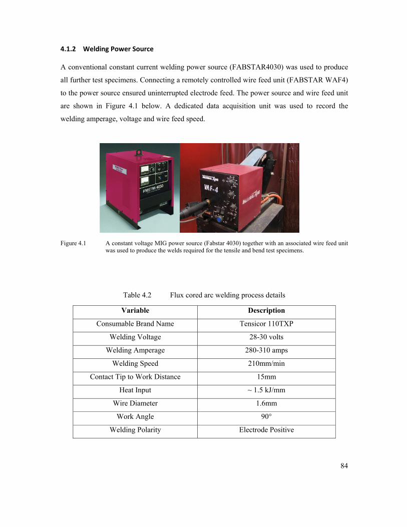
84
4.1.2 Welding Power Source
A conventional constant current welding power source (FABSTAR4030) was used to produce
all further test specimens. Connecting a remotely controlled wire feed unit (FABSTAR WAF4)
to the power source ensured uninterrupted electrode feed. The power source and wire feed unit
are shown in Figure 4.1 below. A dedicated data acquisition unit was used to record the
welding amperage, voltage and wire feed speed.
Figure 4.1 A constant voltage MIG power source (Fabstar 4030) together with an associated wire feed unit
was used to produce the welds required for the tensile and bend test specimens.
Table 4.2 Flux cored arc welding process details
Variable Description
Consumable Brand Name Tensicor 110TXP
Welding Voltage 28-30 volts
Welding Amperage 280-310 amps
Welding Speed 210mm/min
Contact Tip to Work Distance 15mm
Heat Input ~ 1.5 kJ/mm
Wire Diameter 1.6mm
Work Angle 90°
Welding Polarity Electrode Positive
85
4.1.3 Welding Consumables
The welding consumable used during this current work was Tensicor 110TXP and is classified
in Australia to AS/NZS 2203:1 and as E110T5-K4 for AWS A5.29. It is a fully basic,
commercially available High Strength, low alloy steel flux cored wire, which was formulated
to be used with CO2 shielding gas. It has a low hydrogen (H5) hydrogen status, which typifies
it as having less than 5ml diffusible hydrogen per 100g of deposited weld metal. It is primarily
used to weld Bisalloy and similar Quenched and Tempered steels. Unused reels of welding
wire were replaced in their original packaging and stored in a dry environment.
Table 4.3 Supplier specified weld metal properties
4.2.1 Method: Hydrogen Test Assembly
In the current work, the hydrogen test pieces were prepared, welded and analysed for levels of
diffusible hydrogen content in accordance with International Standard ISO 3690(E)-2000:
“Welding and allied processes – Determination of hydrogen content in ferritic steel arc weld
metal”.
Prior to welding, the hydrogen sample was machined to size, individually marked and weighed,
cleaned in alcohol, dried with compressed nitrogen and then heat treated for an hour in a
vacuum chamber at 650°C. An inert gas (argon) was used to ensure that no surface
contamination occurred. Once the samples had cooled in the vacuum chamber, they were
removed and stored in a desiccator.
Typical All Weld Metal Mechanical
Properties Using CO2
Using Welding Grade CO2 Shielding Gas
Yield Strength 720 MPa
Tensile Strength 800 MPa
Elongation 22%
CVN Impact Values 50J @ -50ºC

86
The standard diffusible hydrogen test sample consists of three pieces, namely a run-on tab; a
hydrogen sample and a run-off tab. This is shown in Figure 4.2. All three pieces (referred to as
the test assembly) were made from BIS80 quenched and tempered, grade 700 steel. The
dimensions of the test assembly for heat inputs below 2kJ/mm are typically 50mm x 15mm x
10mm. The FCAW process and the associated 1.6mm welding wire, however, produced a weld
deposit that encroached on the edge of the hydrogen test assembly. This required that the
hydrogen sample be rotated transverse to the welding direction, as shown in Figure 4.3.
Figure 4.2 A typical illustration of the test assembly required for diffusible hydrogen analysis. The
assembly is quenched in iced water and then placed into liquid nitrogen. The liquid nitrogen prohibits effusion of hydrogen and also facilitates the removal of the run on/off tabs.
Figure 4.3 Rotation of the test assembly was required (bottom image) to accommodate the broader weld deposit produced by the 1.6mm FCAW consumable. The hydrogen sample was analysed for a 15mm long weld deposit, as opposed to a 30mm weld deposit typically used for narrower welds.

87
4.2.2 Method: Welding of Hydrogen Test Samples
Immediately before welding, the samples were removed from the desiccator, degreased with
acetone and dried with compressed nitrogen. They were then aligned inside a copper welding
fixture in preparation for welding (Figure 4.4).
Figure 4.4 The copper welding fixture in which the diffusible hydrogen test assemblies were welded.
Prior to arc ignition, the CTWD, voltage, travel speed, torch alignment, wire feed speed and
welding current was checked to ensure consistency with the required settings. The arc was then
ignited after movement of the travel arm had commenced and was extinguished once the
desired weld length had been deposited. The welding torch was secured on an automated
travelling device, which allowed a predetermined welding travel speed, torch angle and CTWD
to be used. This automated procedure therefore ensured strict control of the heat input by
maintaining the prescribed CTWD and travel speed. A dedicated data acquisition unit was also
employed to assist with capturing the welding amperage, voltage and wire feed speed.
Reproducibility of welding conditions could accordingly be achieved.

88
4.2.3 Method: Quenching of Welded Samples
Hydrogen is extremely mobile and will rapidly effuse out of the welded specimen. Quenching
of the hydrogen test specimen immediately after welding was therefore required to retain the
diffusible hydrogen for analysis. The welded samples were first quenched in a bucket of iced
water within 10 seconds after extinction of the arc. This initial quenching lasted five seconds,
thereafter the specimens were placed in a dewar of liquid nitrogen. The welded test assembly
could be stored and retrieved from the dewar by securing a length of welding wire to a hole
drilled into the run off piece prior to welding (see Figure 4.5).
The samples were removed from the liquid nitrogen five minutes after being submerged and
the welding slag was removed with the help of a chipping hammer and a wire brush. The
exposure to room temperature was limited to two minutes. Once the welding slag was removed
and the samples had been re-immersed in the liquid nitrogen, they were clamped in a vice and
the run on and run off tabs were removed by tapping them with a hammer. The individual
hydrogen samples were then stored inside a flask containing liquid nitrogen and analysed for
their diffusible hydrogen content the next day.
Figure 4.5 Positioning of the hole in a trial MMAW hydrogen test assembly through which a piece of wire was attached. This facilitated storage and removal of the sample in liquid nitrogen

89
4.2.4 Method: Diffusible Hydrogen Analysis
The hydrogen samples were transported from Wollongong University to BlueScope Steel (in
liquid nitrogen) for vacuum hot extraction (HE) analysis. This method has the ability to
quantify the diffusible hydrogen in the weld metal within minutes, as opposed to several hours
or days (Pitrun, 2004). The analysis required that a single welded hydrogen sample be removed
from the liquid nitrogen, thawed in a beaker of warm acetone and dried with a hair dryer.
This process lasted approximately 40 seconds, after which the dry and thawed sample was
placed in a vacuum furnace connected to an ELTRA ONH-2000 hydrogen analyser (Figure
4.6). The vacuum furnace was heated to 400°C and a stream of argon gas was used as a carrier
gas. The argon transported the hydrogen to the analyser, which converted the carrier and
hydrogen gas mixture into a measurable volume of hydrogen. Calibration was achieved by
injecting a known volume of hydrogen into the carrier gas and comparing that with the
readings obtained from the analyser.
Figure 4.6 Photograph showing the equipment required for vacuum hot extraction of the diffusible
hydrogen content. The individual components are (A) furnace, (B) Eltra ONH-2000 analyser unit and (C) data collection computer.
A
B
C
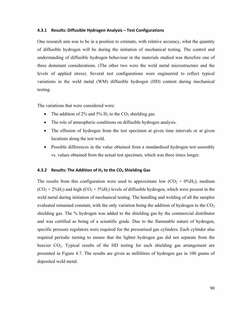
90
4.3.1 Results: Diffusible Hydrogen Analysis – Test Configurations
One research aim was to be in a position to estimate, with relative accuracy, what the quantity
of diffusible hydrogen will be during the initiation of mechanical testing. The control and
understanding of diffusible hydrogen behaviour in the materials studied was therefore one of
three dominant considerations. (The other two were the weld metal microstructure and the
levels of applied stress). Several test configurations were engineered to reflect typical
variations in the weld metal (WM) diffusible hydrogen (HD) content during mechanical
testing.
The variations that were considered were:
• The addition of 2% and 5% H2 to the CO2 shielding gas.
• The role of atmospheric conditions on diffusible hydrogen analysis.
• The effusion of hydrogen from the test specimen at given time intervals or at given
locations along the test weld.
• Possible differences in the value obtained from a standardised hydrogen test assembly
vs. values obtained from the actual test specimen, which was three times longer.
4.3.2 Results: The Addition of H2 to the CO2 Shielding Gas
The results from this configuration were used to approximate low (CO2 + 0%H2), medium
(CO2 + 2%H2) and high (CO2 + 5%H2) levels of diffusible hydrogen, which were present in the
weld metal during initiation of mechanical testing. The handling and welding of all the samples
evaluated remained constant, with the only variation being the addition of hydrogen to the CO2
shielding gas. The % hydrogen was added to the shielding gas by the commercial distributor
and was certified as being of a scientific grade. Due to the flammable nature of hydrogen,
specific pressure regulators were required for the pressurised gas cylinders. Each cylinder also
required periodic turning to ensure that the lighter hydrogen gas did not separate from the
heavier CO2. Typical results of the HD testing for each shielding gas arrangement are
presented in Figure 4.7. The results are given as millilitres of hydrogen gas in 100 grams of
deposited weld metal.
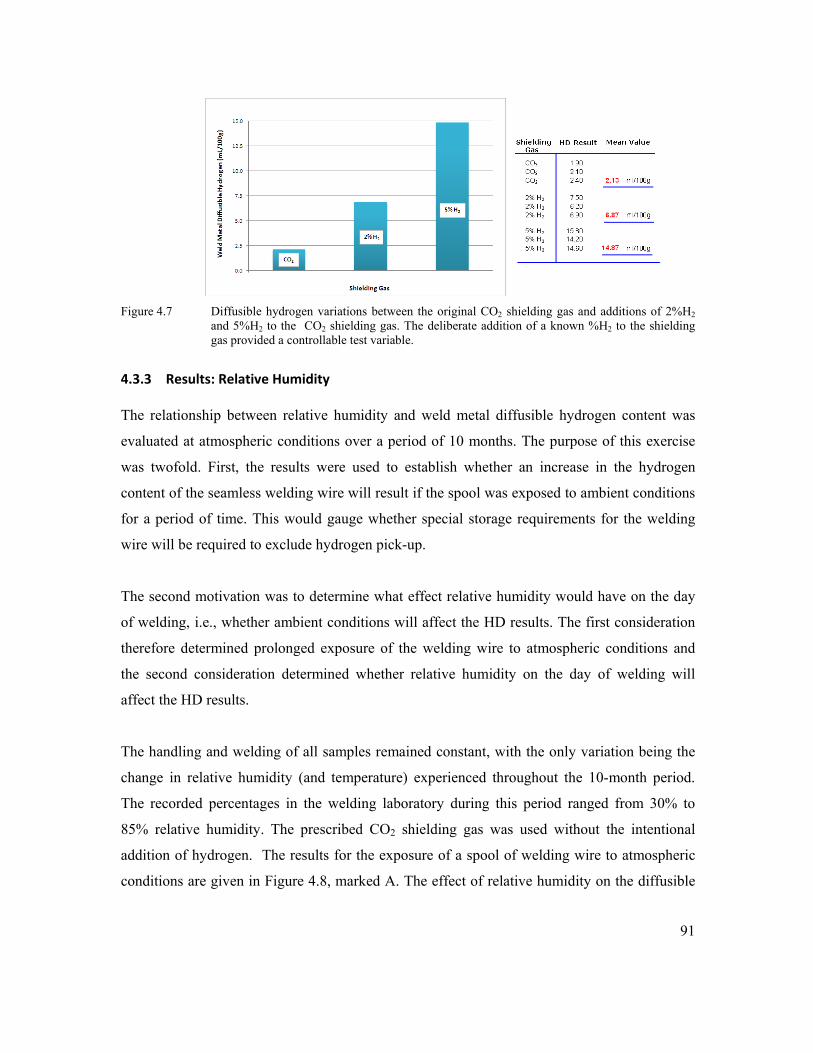
91
Figure 4.7 Diffusible hydrogen variations between the original CO2 shielding gas and additions of 2%H2
and 5%H2 to the CO2 shielding gas. The deliberate addition of a known %H2 to the shielding gas provided a controllable test variable.
4.3.3 Results: Relative Humidity
The relationship between relative humidity and weld metal diffusible hydrogen content was
evaluated at atmospheric conditions over a period of 10 months. The purpose of this exercise
was twofold. First, the results were used to establish whether an increase in the hydrogen
content of the seamless welding wire will result if the spool was exposed to ambient conditions
for a period of time. This would gauge whether special storage requirements for the welding
wire will be required to exclude hydrogen pick-up.
The second motivation was to determine what effect relative humidity would have on the day
of welding, i.e., whether ambient conditions will affect the HD results. The first consideration
therefore determined prolonged exposure of the welding wire to atmospheric conditions and
the second consideration determined whether relative humidity on the day of welding will
affect the HD results.
The handling and welding of all samples remained constant, with the only variation being the
change in relative humidity (and temperature) experienced throughout the 10-month period.
The recorded percentages in the welding laboratory during this period ranged from 30% to
85% relative humidity. The prescribed CO2 shielding gas was used without the intentional
addition of hydrogen. The results for the exposure of a spool of welding wire to atmospheric
conditions are given in Figure 4.8, marked A. The effect of relative humidity on the diffusible

92
hydrogen content of the sealed and dry-stored welding consumable is also presented in Figure
4.8, marked B.
Figure 4.8 Diffusible hydrogen variations when using a spool of welding wire exposed to atmospheric
conditions (marked A) and a spool that has been stored in dry conditions (marked B) for 10 months.
4.3.4 Results: Hydrogen Weld Test Assembly
The standard hydrogen weld test assembly measures approximately 115mm long, while the
weld deposited on the test specimen used during mechanical testing was three times longer
than this. It was probable that the results obtained from the standard hydrogen weld test
assembly may not be indicative of the diffusible hydrogen content for the longer weld used
during applied stress testing. The distribution of diffusible hydrogen across the length of the
mechanical test weld was consequently approximated by extending the test assembly to contain
two further hydrogen samples, evenly distributed along the length of the weld deposit (Figures
4.9A and 4.9B). The sample was extended to a total length of 330mm.
This extension of the test assembly would reveal whether thermal effects of a longer weld
deposit influenced the WM diffusible hydrogen result and what part of the test weld may have
lost diffusible hydrogen due to delay times before quenching. The results of the tests are
presented below in Figure 4.9 (B). Each hydrogen sample in the extended test assembly would
consequently indicate what the WM diffusible hydrogen content was for quench delay times of
five, 45 and 90 seconds.
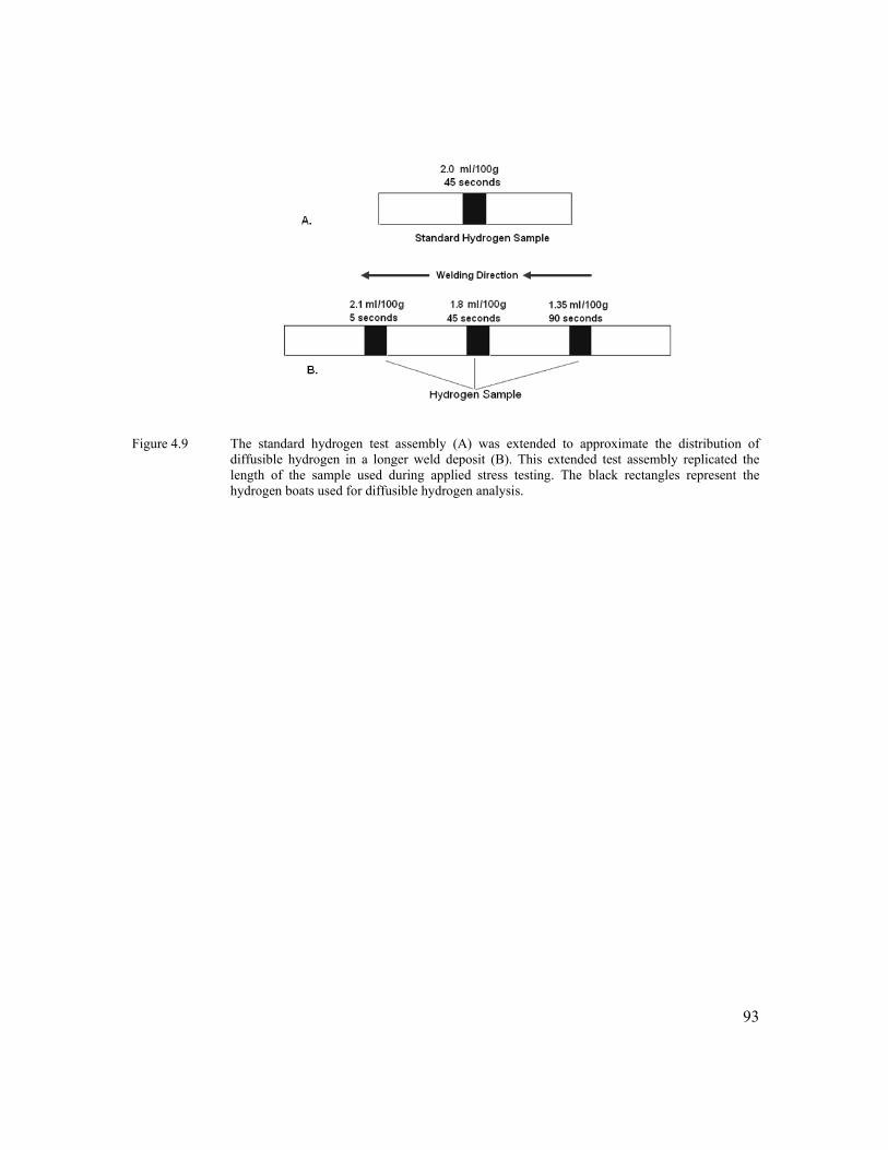
93
Figure 4.9 The standard hydrogen test assembly (A) was extended to approximate the distribution of
diffusible hydrogen in a longer weld deposit (B). This extended test assembly replicated the length of the sample used during applied stress testing. The black rectangles represent the hydrogen boats used for diffusible hydrogen analysis.

94
CHAPTER 5
DEVELOPMENT OF MECHANICAL TEST SPECIMENS
5.1.0 Introduction
This chapter focused on defining mechanical test specimen geometries that were used during
mechanical testing of weld metal containing a controlled level of diffusible hydrogen. The
techniques to determine the applied stress were also established.
The welded samples could then be used to study either the combined effects or individual
aspects that are held responsible for weld metal hydrogen assisted cold cracking. A specific
objective was to produce specimens that permitted the preferential evaluation of the weld
metal, as opposed to evaluating the heat affected zone or the base material. Other general
requirements were that it:
1. Must contain a high strength weld deposit.
2. Must not contain artificial stress raisers (notch or groove).
3. Must allow natural stress assisted and dislocation assisted diffusion.
4. Must be relatively easy to machine.
5. Must be relatively easy to manage.
Tensile testing, 4-point bend testing (4-pb) and numeric modelling were used to facilitate the
above requirements.
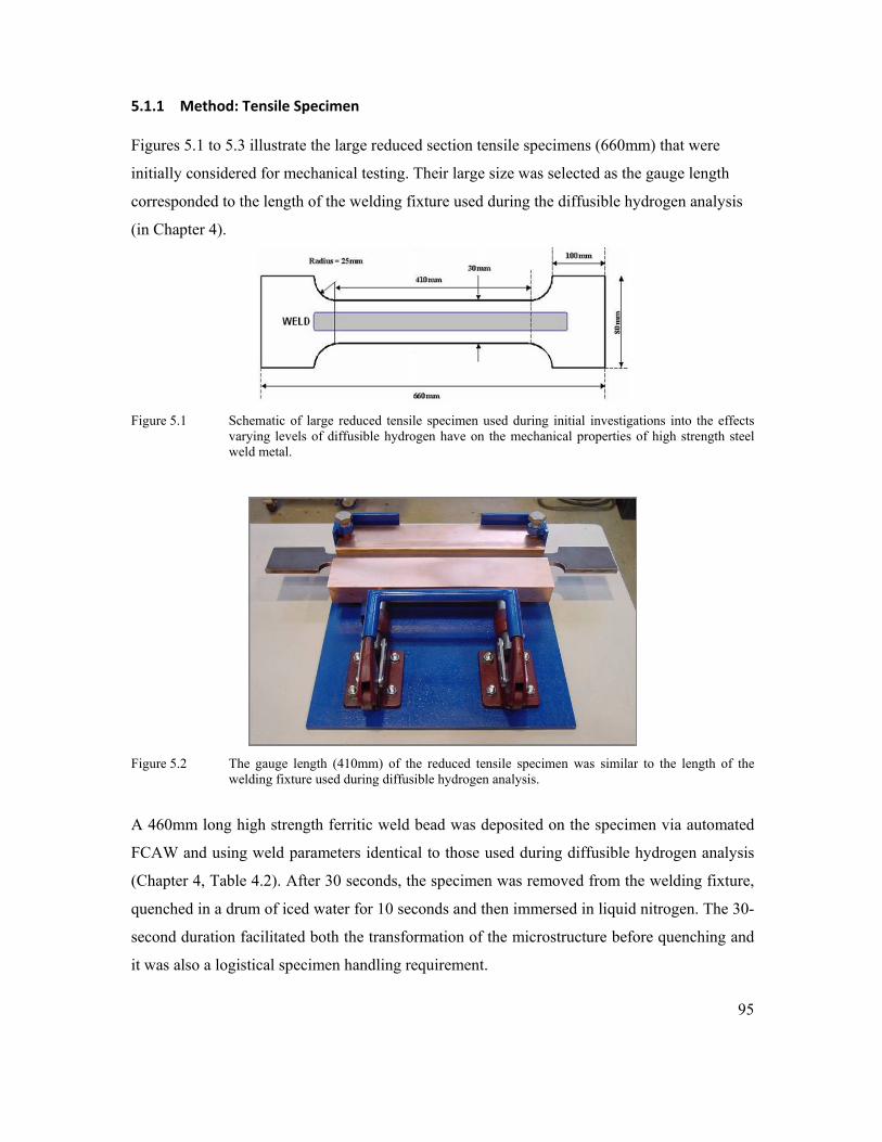
95
5.1.1 Method: Tensile Specimen
Figures 5.1 to 5.3 illustrate the large reduced section tensile specimens (660mm) that were
initially considered for mechanical testing. Their large size was selected as the gauge length
corresponded to the length of the welding fixture used during the diffusible hydrogen analysis
(in Chapter 4).
Figure 5.1 Schematic of large reduced tensile specimen used during initial investigations into the effects
varying levels of diffusible hydrogen have on the mechanical properties of high strength steel weld metal.
Figure 5.2 The gauge length (410mm) of the reduced tensile specimen was similar to the length of the
welding fixture used during diffusible hydrogen analysis.
A 460mm long high strength ferritic weld bead was deposited on the specimen via automated
FCAW and using weld parameters identical to those used during diffusible hydrogen analysis
(Chapter 4, Table 4.2). After 30 seconds, the specimen was removed from the welding fixture,
quenched in a drum of iced water for 10 seconds and then immersed in liquid nitrogen. The 30-
second duration facilitated both the transformation of the microstructure before quenching and
it was also a logistical specimen handling requirement.

96
Prior to tensile testing, the specimen was brought to room temperature by thawing it in a large
container of water. The time it took to remove the specimen from the liquid nitrogen to
initiation of tensile testing was approximately three and a half minutes.
Figure 5.3 A 460mm long weld bead was deposited on a 660mm reduced tensile specimen. Here the specimen is being prepared for x-ray analysis.
5.1.2 Method: 4‐Point Bend Specimen
Two specimen types were developed in this work. The first (narrow specimen) was developed
to reduce the test frame loading requirements and to eliminate any possible influences that the
weld toes and the HAZ may have on the behaviour of the specimen under elevated hydrogen
conditions (H2 in the shielding gas). The specimen is shown in Figure 5.4 and was produced by
machining three rectangular bars measuring 10mm x 14mm x 300mm. The three bars were then
clamped together in the welding fixture shown in Figure 5.2, thereby providing a 42mm wide
surface upon which to weld. The same welding parameters were used as described in Chapter 4,
Table 4.2.
A single pass of weld metal measuring 150mm long was deposited on the centre bar of the 42mm
wide surface. This resulted in all three bars being fused together by the weld bead, which was kept
in the fixture for 30 seconds to allow microstructural transformations to occur. Once 30 seconds
had elapsed, each specimen (three bars welded together) was quenched in iced water for 10
seconds and then immediately placed in liquid nitrogen. Once the welded bars were cooled to
approximately -196°C, they were removed from the liquid nitrogen and the outside bars were
broken off. Any protruding weld fibres were removed with the aid of a metal file and light
grinding, while still under cryogenic conditions.

97
The use of liquid nitrogen was required for machining and storage due to the high mobility of
hydrogen in weld metal at ambient temperatures.
The second specimen (wide specimen) was a standard bead on plate arrangement and contained
the same length of weld as the narrow specimen. The only difference was that the width of the
wide specimen base plate was specified to be 30mm. Identical quenching and storage
conditions to those for narrow specimens were also maintained. The wide specimen is
illustrated in Figure 5.4, below the narrow specimen.
Figure 5.4 Single bead on plate arrangement for all bend specimens. The narrow specimen is at the top of
the image and the dotted line (top right) represents the cross section of the narrow bend specimen.
A few minutes before testing, the samples were removed from the liquid nitrogen and thawed
in a bath of room temperature water. The surface temperatures of the thawed samples were
then approximately 15°C. After removing the samples from the water, they were dried with a
cloth, marked to indicate positioning in the test fixture and then placed in the 4-pb test
apparatus. The marking ensured that the orientation of the sample and positioning of the rollers
remained constant.
The actual 4-point bending of the samples commenced three and a half minutes after the
samples had been removed from the liquid nitrogen and the testing progressed until advanced
plasticity or fracture had taken place. The mechanical test data were captured via the load
frame’s built-in data acquisition software and then imported into an Excel worksheet.

98
The above established two methods (tensile and 4-pb) that can be applied during the testing of
high strength steel weldments. A method was now required to standardise the weld metal
geometry to facilitate later calculations.
5.1.3 Method: Statistical Analysis of Weld Bead Geometry
One aim during the proposed mechanical applied test is to subject the welded samples to a
predetermined level of stress. This requires information relating to the cross sectional area.
Even though the welding process was automated, the nature of the FCAW welding process, the
CO2 shielding gas and the nature of the basic wire electrode would introduce a certain level of
variability into the weld bead geometry.
Statistical analysis of several cross sectional areas was therefore used to standardise the
geometric variables. After producing several test welds, a confidence interval of 95% was
selected to determine the geometric variables required to calculate the stresses and strains
during mechanical testing. The principle variables needed (see Equations 5.2 and 5.3) were
weld width and weld height. These were then standardised via Equation 5.1.
………………………………………………Equation (5.1)
Where:
x = sample mean
Z @ 95% confidence = 1.96 (determined from normal distribution tables)
S.D = standard deviation
n = sample population
( )n. DSzx ±
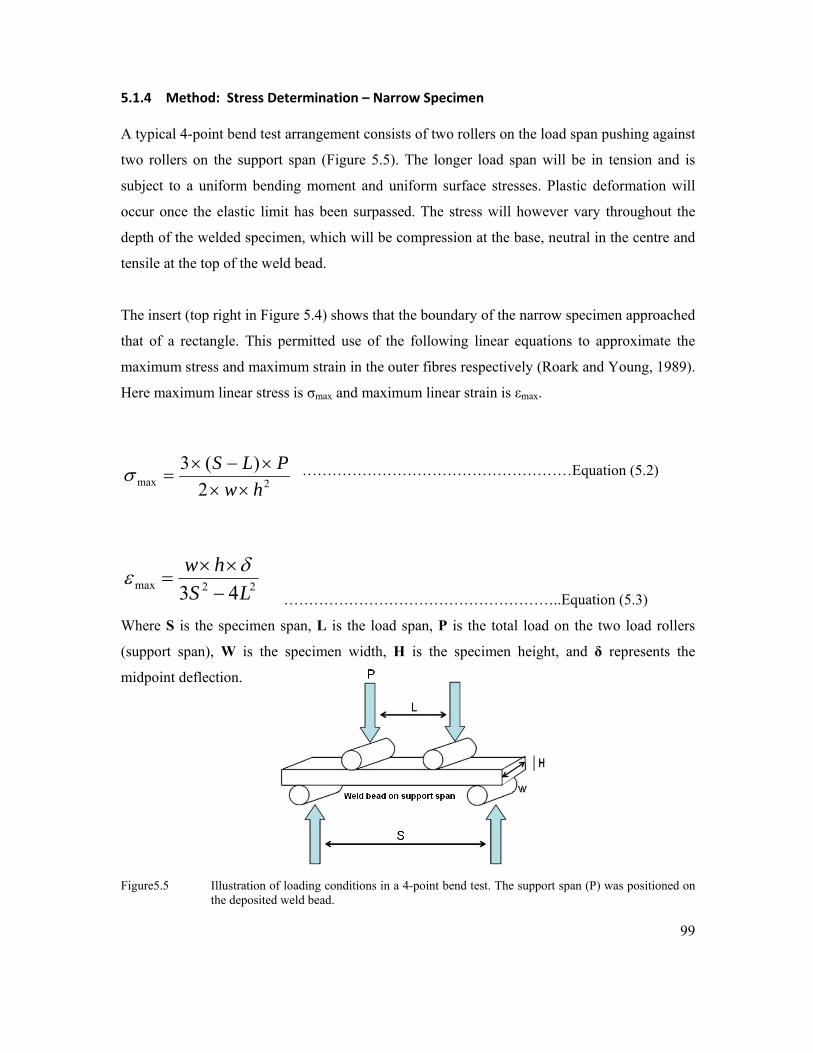
99
5.1.4 Method: Stress Determination – Narrow Specimen
A typical 4-point bend test arrangement consists of two rollers on the load span pushing against
two rollers on the support span (Figure 5.5). The longer load span will be in tension and is
subject to a uniform bending moment and uniform surface stresses. Plastic deformation will
occur once the elastic limit has been surpassed. The stress will however vary throughout the
depth of the welded specimen, which will be compression at the base, neutral in the centre and
tensile at the top of the weld bead.
The insert (top right in Figure 5.4) shows that the boundary of the narrow specimen approached
that of a rectangle. This permitted use of the following linear equations to approximate the
maximum stress and maximum strain in the outer fibres respectively (Roark and Young, 1989).
Here maximum linear stress is σmax and maximum linear strain is εmax.
………………………………………………Equation (5.2)
………………………………………………..Equation (5.3)
Where S is the specimen span, L is the load span, P is the total load on the two load rollers
(support span), W is the specimen width, H is the specimen height, and δ represents the
midpoint deflection.
Figure5.5 Illustration of loading conditions in a 4-point bend test. The support span (P) was positioned on
the deposited weld bead.
2max 2)(3hw
PLS××
×−×=σ
22max 43 LShw−××
=δε

100
5.1.5 Method: Stress Determination – Wide Specimen
The elastic stresses and elastic strains imposed on a rectangular specimen during bend testing
can be defined by analysing the cross sectional behaviour of the loaded beam. The calculations
required to define the stresses in the wide specimen necessitated determination of the second
moment of area. For this the weld bead was assumed to approximate an ellipse, which was
positioned on top of a rectangular bar, as shown in Figure 5.6.
This configuration created an opportunity to determine the moments of inertia, together with
the neutral axis and the centroid positions of both the weld and the base material. Factoring this
into the global bending moment allowed the linear stress and strain to be determined at the top
of the wide specimen’s weld bead. The precise detail of this method is provided in Appendix
A.
Figure 5.6 Image relating to the calculation of stresses and strains on a bead on plate specimen where the
weld bead is assumed to approximate an ellipse. The second moment of area allows the elastic stresses and elastic strains to be calculated.
5.1.6 Method: ANSYS Bend Specimen Comparison
The standardisation of the geometry and the automated welding procedures employed allowed
numeric models to be created from data that were specific to both the narrow and wide bend
specimens. The models were created in ANSYS using results from the baseline conditions and
also by using the actual weld bead dimensions (Chapter 6.1.1). Both the weld metal and the
base material were assumed to have uniform characteristics and the models therefore only
show geometric effects.

101
For the ANSYS FEA Models, the weld bead height, measured from the top of the base material
to the top of the weld bead was 3.5mm. The width of the weld was 7.5mm for the wide
specimen and 7mm for the narrow specimen. The width measurements were half their actual
sizes to accelerate computational time. The length of both models was 165mm and the height
of the base material was 12mm. The element sizes were also standardised to control potential
variations in the results due to variance in mesh density. The models represent specimens
which are equally divided in two along the weld centreline, where the mesh size is 1.0mm
vertical and 0.5mm horizontal. For the purpose of comparison, the stresses at a roller
displacement of 0.5mm, 1.0mm and 2.0mm are presented. In the finite element plots, the
maximum stresses are shown in red or grey, while the minimum stresses are represented in
blue. All stresses shown are in MPa. The image below in Figure 5.7 illustrates the FEA models
generated for the wide and narrow 4-point bend specimens.
Figure 5.7 The model on the left (a) represents the narrow bead on plate bend specimen and the model on
the right (b) represents the wide bead on plate bend specimen. Half symmetry shown.
(a) (b)

102
5.2.1 Result: ANSYS 0.5mm Roller Displacement
Figure 5.8(a) shows the von Misses stresses in the narrow model and Figure 5.8(b) shows the
von Misses stresses in the wide model. At a roller displacement of 0.5mm, the maximum stress
contour for these models was set at 720MPa, which was the assumed yield stress. At the roller
displacement of 0.5mm, no plastic deformation has occurred, as the maximum stresses in the
narrow and wide models are approximately 462MPa and 446MPa, respectively.
The models therefore show that the stresses in the weld cap at a roller displacement of 0.5mm
are generally well below yield, and are similar between the narrow and wide models.
Figure 5.8 Transverse von Misses stresses at 0.5mm roller displacement. The maximum stress in the narrow specimen (a) is approximately 462 MPa, while the wide specimen (b) produces a maximum stress of approximately 446 MPa. No yielding is observed in either specimen.
(a) (b)

103
5.2.2 Result: ANSYS 1.0mm Roller Displacement
Figure 5.9(a) and 5.9(b) show the von Misses stresses in both models at a roller displacement
of 1mm. Both models indicate (grey contours) that the stresses in the weld cap are beyond
yield at this displacement. In the specimen body, the stress contours differ slightly, with the
base of the narrow model experiencing larger (compressive) plastic deformation than the wide
model. Post-yield activity has occurred at the base of the narrow model, while the stresses at
the base of the wide model approach yield.
Figure 5.9 Transverse von Misses stresses (MPa) at 1.0mm Roller Displacement. The contours above yield are shown in grey. The maximum stress attained in the narrow specimen (a) was 732.5 MPa, while the wide specimen (b) recorded a maximum stress of 737 MPa.
(a) (b)

104
5.2.3 Result: ANSYS 2.0mm Roller Displacement
Figures 5.10(a) and 5.10(b) show the von Misses stresses in both models at a roller
displacement of 2mm. Both models indicate (red contours) that the stresses in the weld cap are
beyond yield at this displacement. During construction of the model, the height of the weld
bead above the base material was set at 3.5mm. In both models, the outer fibres of this region
(from 2.5mm) were subject to stress levels of approximately 759MPa, indicating stresses
beyond yield. Both specimens therefore have near-identical von Misses stresses, although the
narrow specimen displays a greater distribution of post-yield stresses than the wide specimen.
Figure 5.10 Transverse von Misses stresses (MPa) at 2.0mm Roller Displacement. The contours above yield are shown in red. A maximum stress of 759 MPa was attained in the narrow specimen (a), which is similar to the 758 MPa recorded for the wide specimen (b).
(a) (b)
105
CHAPTER 6
TESTING SINGLE PASS HIGH STRENGTH WELD METAL
6.1.0 Introduction
This phase will present and analyse the results from applied stress testing of both the tensile
and bend specimens defined in the previous chapter. During this present phase, baseline
conditions will be established, after which hydrogen will be introduced into the shielding gas to
either 2% or 5% volume.
The load applied during this phase will equate to values that represent conditions of 80%,
100% and 120% yield stress, as determined during baseline conditions. The specimens will
then either be; (A) Strained to fracture through rising load conditions or (B) Held at a particular
level of applied stress until an event occurs.
The primary aims of this phase will be to (1) induce cold cracking in the weld metal and to (2)
produce quantifiable cold cracking delay times under different applied loading and diffusible
hydrogen conditions.
A specific requirement from the test outcomes will be that only the existing microstructure; the
applied load; the level of diffusible hydrogen and the incubation time should produce hydrogen
assisted crack initiation and propagation. No artificial stress raisers, such as notches or pre-
cracks will therefore be introduced into the test specimens, as these may potentially steer the
crack initiation and propagation to regions where HACC may not occurred otherwise.

106
6.1.1 Method: Baseline Conditions
Specifying a predetermined level of applied stress (80%, 100% and 120% yield stress) required
an understanding of how the specimens behaved under normal conditions. These normal
conditions represent baseline conditions, i.e. as welded and under low WM diffusible hydrogen
conditions. No hydrogen was therefore added to the shielding gas.
The loading applied to both the tensile and bend specimens was converted into stress by using
a 95% confidence interval to predict the weld bead cross sectional area (Equation 5.1). To
achieve this statistical average, numerous welds produced under matching test conditions were
examined. The statistical prediction thereby standardised the test weld profile and this was then
used to determine the percentage of yield stress being applied. The calculations to determine
yield stress were presented in Chapter 5.
All welds were deposited on top of 12mm BIS80 plate, under similar conditions, in the same
weld fixture using the same welding parameters and the same welding wire. These weld details
were previously presented in Chapter 4, Tables 4.1 and 4.2. Details specific to the tensile and
bend specimen geometries can be located in Chapters 5.1.1 and 5.1.2.
The loading of the specimens was achieved by using A 500 kN servo-hydraulic testing
apparatus. The loading rate for all specimens, (unless otherwise stated) was 5m/min. The
results were recorded using commercial data acquisition software packages available from the
load frame manufacturer.
Both bend and tensile testing baseline conditions were established. The results from the tensile
tests baseline conditions are presented in Chapter 6.2.1, while the results from the baseline
bend tests are presented in Chapter 6.2.2. The combined analysis of these results is provided in
Chapter 6.3.1.

107
6.1.2 Method: HACC in Single Pass High Strength Weld Metal
Preliminary testing revealed that HACC could not readily be generated in the sample materials
without the addition of hydrogen into the shielding gas. A common procedure during all further
testing was therefore to enrich the specimens with hydrogen.
The welded specimens contained three levels of diffusible hydrogen, achieved by introducing
2%H2 and 5% H2 to the prescribed CO2 shielding gas. For simplification, this infers that 0%,
2% and 5% hydrogen conditions existed (referring to the addition of hydrogen to the shielding
gas). Diffusible hydrogen variations between the original CO2 shielding gas and the additions
of 2%H2 and 5%H2 to the CO2 shielding gas were presented in Figure 4.7. The deliberate
addition of a known %H2 to the shielding gas thereby provided a controllable test variable.
To arrested loss of hydrogen from the weld, storage of the specimens in liquid nitrogen prior to
testing was conducted using a standardised procedure. The subsequent mechanical testing was
performed once the samples were brought back to room temperature by means of placing them
in a large reservoir of room temperature water. Care was taken to ensure the thawing
conditions were also standardised.
Testing consisted of clamping the specimens in the test-frame and then moving the crosshead
until either failure or a required load (equating to the desired stress) was reached. Both rising
load and load limit test conditions were therefore utilised. Load limit testing involved
displacing the specimen to a certain applied stress and then maintaining the load at that
crosshead position, as illustrated in Figure 6.6. The ramp speed (5mm/min) was derived from
the baseline conditions. This ensured a constant effective strain rate for all specimens.
The results from tensile testing under hydrogen conditions are presented in Chapter 6.2.3 and
the subsequent analysis is provided in Chapter 8.4
The results from the bend test under hydrogen conditions are presented in Chapter 6.2.4, while
the subsequent analysis is provided in Chapter 8.4.
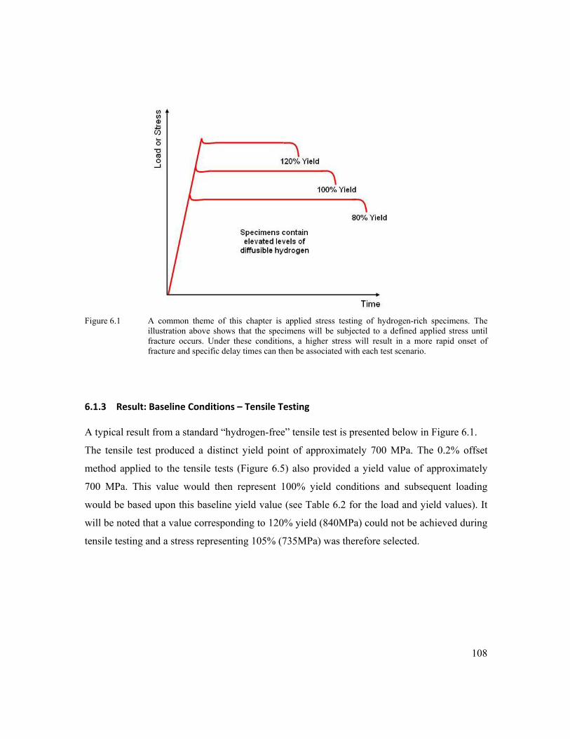
108
Figure 6.1 A common theme of this chapter is applied stress testing of hydrogen-rich specimens. The
illustration above shows that the specimens will be subjected to a defined applied stress until fracture occurs. Under these conditions, a higher stress will result in a more rapid onset of fracture and specific delay times can then be associated with each test scenario.
6.1.3 Result: Baseline Conditions – Tensile Testing
A typical result from a standard “hydrogen-free” tensile test is presented below in Figure 6.1.
The tensile test produced a distinct yield point of approximately 700 MPa. The 0.2% offset
method applied to the tensile tests (Figure 6.5) also provided a yield value of approximately
700 MPa. This value would then represent 100% yield conditions and subsequent loading
would be based upon this baseline yield value (see Table 6.2 for the load and yield values). It
will be noted that a value corresponding to 120% yield (840MPa) could not be achieved during
tensile testing and a stress representing 105% (735MPa) was therefore selected.

109
Figure 6.2 Initial (large) tensile tests were conducted without the addition of hydrogen to the shielding gas.
The results would provide a baseline foundation (100% yield value) for subsequent testing.
Figure 6.3 The 0.2% offset yield was used to establish 100% yield criteria. The other yield percentages
were then established as a ratio of the offset yield, i.e., 80% yield equated to 0.8 x 698MPa.

110
6.1.4 Results: 4‐Point Bending Baseline Conditions
Figure 6.4 displays the results from bend test baseline conditions. For comparison, the results
for tensile testing are also included. The work shows that the narrow bend specimen (which
had the smallest cross sectional area) required the lowest applied load to reach yield and
fracture. Even though the tensile specimen had an identical cross section to that of the wide
bend specimen, the difference in mechanical behaviour between the two is significant. It can be
seen that the tensile specimen required greater loads to produce similar strength.
Figure 6.5 shows differences in mechanical behaviour between the narrow and the wide bend
specimens. There are differences in the elastic response of the specimens to loading and
although the time to yield for both is similar, they are not identical.
Figure 6.6 compares the stress versus time for all three specimens. It can be seen that the
specimens with greater restraint require a reduced stress for yield, UTS and fracture. An overall
observation is that the inclusion of the base material either side of the weld will result in an
increase in the load required reach yielding, but it will also decrease the stress required to attain
yield conditions.
Figure 6.4 Rising load baseline test comparison of three test configurations. The rising load was based on a
crosshead displacement of 5mm/min. It is observed that yield conditions occur sooner in the bend specimens.

111
Figure 6.5 Rising load comparison between the wide and the narrow 4-point bend specimens. The
difference in mechanical behaviour is due to differences in the respective cross sectional areas.
Figure 6.6 Stress versus time comparison of the three test configurations. The bend specimens display
similar times to yield, even though the stresses at yield are different. The tensile specimens required the lowest applied stress for yielding.

112
6.1.5 Results: HACC – Tensile Testing
The generation of HACC was achieved by adding hydrogen to the shielding gas and by
straining the test specimens in the tensile test frame. The rising load tensile tests results
contained additions of both 2% and 5% hydrogen in the shielding gas, while the load-limit
specimens were welded with only 2%H2 in the shielding gas.
The results from the rising load, hydrogen rich specimens (Figure 6.7) display an expected
decrease in ductility (or time to fracture) with each increase in the %H2 in the shielding gas. Of
special interest is the observed increase in yield strength, associated with the increase in
shielding gas hydrogen.
A total of three tensile specimens were evaluated at each (load limit) yield percentage, but only
one specimen produced evidence of hydrogen cracking. This specimen was tested at 105%
yield stress and the delay time was 12 hours. See Tables 6.1 and 6.2 for details. No further
tensile testing was conducted under hydrogen rich conditions.
Figure 6.7 Tensile test data showing the mechanical behaviour during the application of a rising load for
each hydrogen condition. Note the increase in yield strength (hardening) of the specimen with each increase in hydrogen.
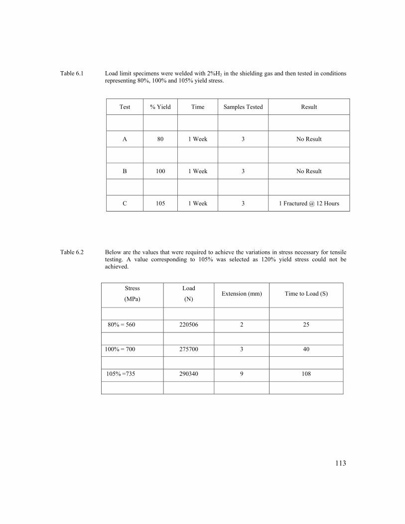
113
Table 6.1 Load limit specimens were welded with 2%H2 in the shielding gas and then tested in conditions
representing 80%, 100% and 105% yield stress.
Table 6.2 Below are the values that were required to achieve the variations in stress necessary for tensile
testing. A value corresponding to 105% was selected as 120% yield stress could not be achieved.
Stress
(MPa)
Load
(N) Extension (mm) Time to Load (S)
80% = 560 220506 2 25
100% = 700 275700 3 40
105% =735 290340 9 108
Test % Yield Time Samples Tested Result
A 80 1 Week 3 No Result
B 100 1 Week 3 No Result
C 105 1 Week 3 1 Fractured @ 12 Hours
114
6.1.6 Results: HACC – Bend Testing
Typical results from rising load bend testing further illustrate the effect that hydrogen has on
the mechanical behaviour of the specimens. Again an increase in shielding gas hydrogen
content equated to a loss of macroscopic ductility. This can be seen in Figures 6.8 and 6.9.
There was also evidence that an increase in hydrogen translated into an increase in yield
strength. This time the increase in yield strength was observed at both the 2% and 5%
conditions, as seen in Figures 6.8 and 6.9 below. Similar behaviour was previously noted
during tensile testing results of hydrogen-rich specimens (see Figure 6.7). The bend testing
results revealed that this phenomenon was more apparent in behaviour of the wide specimen,
which also generally produced cracking sooner than the narrow specimen.
Figure 6.10 also illustrates a load limit bend testing procedure for 5% hydrogen conditions.
This procedure is similar to what has been described for tensile testing in Chapter 6.2.3. Loads
corresponding to 700, 800 and 900MPa were used for these tests.
These tests were intended to provide indications of hydrogen cracking delay times and it can be
seen that for each specimen type, a higher applied stress under similar levels of diffusible
hydrogen will result in quicker times to fracture. However, two requirements were generally
needed to reproduce cracking in these specimens. The first was that 5%H2 shielding gas
conditions were needed and the second was that stresses above yield were necessary. Cracking
did not occur at stresses below yield when subjected to load limit testing.
Chronographically similar delay times could also not be produced under near identical test
conditions. A range of delay times associated with a single test condition would be more
appropriate to describe the outcomes of the testing. As an example, a load limit test with 5%
hydrogen in the shielding gas and an applied stress of 900 MPa produced delay times which
ranged from 100 to 400 seconds. The 300 second range will then represents the timeframe in
which HACC is expected to occur. It is also observed that closer delay times were achieved
during rising load tests, when compared to load limit (applied stress) tests.

115
Figure 6.8 Narrow specimen 4-point bend mechanical behaviour (rising load). All specimens were welded
and tested in near identical conditions. Note both the increase in yield strength of the 5%H2 specimens and the range of delay times associated with each test conditions.
Figure 6.9 Wide specimen test data showing the mechanical behaviour during the application of a rising
load for each hydrogen condition. Note the increase in yield strength as the % hydrogen in the shielding gas increases. Similarly, an increase in hydrogen decreases the ductility.

116
Figure 6.10 Example behaviour of load limit (stress controlled) testing relating to specimens containing
5%H2 in the shielding gas. An increase in applied stress translated to a decrease in delay times. Note also the variations in this time to fracture for matching conditions.
117
CHAPTER 7
MICROSTRUCTURAL AND FRACTOGRAPHIC ANALYSIS
7.1.0 Introduction
This chapter is associated with microstructural and fractographic analysis of specimens that
were tested under conditions related to the introduction of hydrogen into the CO2 shielding gas.
The focus was to interpret the preferred fracture path produced during the applied bend testing
and to establish what general effects the deliberate introduction of hydrogen will have on the
microstructure. The research focused on the following:
1. The chemistry and microstructure produced.
2. The distribution of nonmetallic inclusions.
3. The fracture initiation and propagation characteristics.
7.1.1 Method: Chemical Composition
The changes in composition that resulted from the introduction of H2 in the shielding gas were
determined by BlueScope Steel Central Laboratories. The nitrogen and oxygen contents were
determined via Inert Gas Fusion, while all other elements listed (besides H) were determined
by Atomic Emission Spectroscopy. Samples were welded under near identical conditions and
on the same day, using the same base material and welding wire consumable. The only
difference between samples being the addition of hydrogen into the shielding gas.
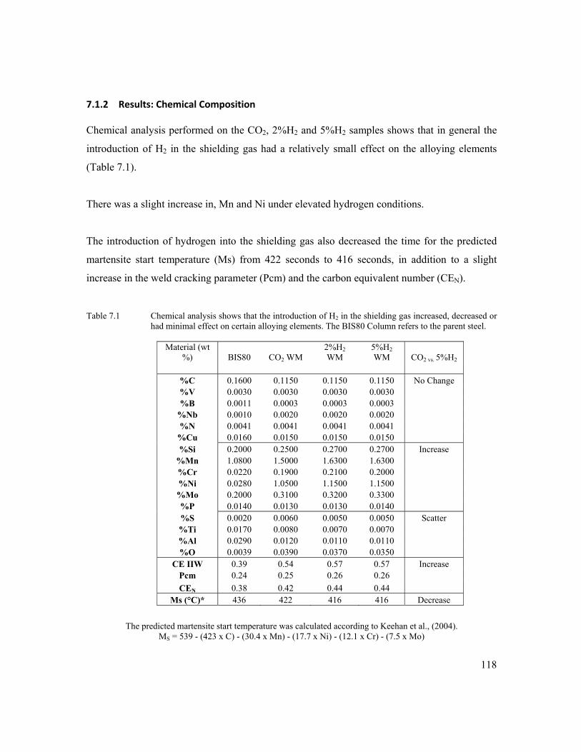
118
7.1.2 Results: Chemical Composition
Chemical analysis performed on the CO2, 2%H2 and 5%H2 samples shows that in general the
introduction of H2 in the shielding gas had a relatively small effect on the alloying elements
(Table 7.1).
There was a slight increase in, Mn and Ni under elevated hydrogen conditions.
The introduction of hydrogen into the shielding gas also decreased the time for the predicted
martensite start temperature (Ms) from 422 seconds to 416 seconds, in addition to a slight
increase in the weld cracking parameter (Pcm) and the carbon equivalent number (CEN). Table 7.1 Chemical analysis shows that the introduction of H2 in the shielding gas increased, decreased or
had minimal effect on certain alloying elements. The BIS80 Column refers to the parent steel.
Material (wt %) BIS80 CO2 WM
2%H2 WM
5%H2 WM CO2 vs. 5%H2
%C 0.1600 0.1150 0.1150 0.1150 No Change %V 0.0030 0.0030 0.0030 0.0030 %B 0.0011 0.0003 0.0003 0.0003
%Nb 0.0010 0.0020 0.0020 0.0020 %N 0.0041 0.0041 0.0041 0.0041
%Cu 0.0160 0.0150 0.0150 0.0150 %Si 0.2000 0.2500 0.2700 0.2700 Increase
%Mn 1.0800 1.5000 1.6300 1.6300 %Cr 0.0220 0.1900 0.2100 0.2000 %Ni 0.0280 1.0500 1.1500 1.1500 %Mo 0.2000 0.3100 0.3200 0.3300 %P 0.0140 0.0130 0.0130 0.0140 %S 0.0020 0.0060 0.0050 0.0050 Scatter %Ti 0.0170 0.0080 0.0070 0.0070 %Al 0.0290 0.0120 0.0110 0.0110 %O 0.0039 0.0390 0.0370 0.0350
CE IIW 0.39 0.54 0.57 0.57 Increase Pcm 0.24 0.25 0.26 0.26 CEN 0.38 0.42 0.44 0.44
Ms (°C)* 436 422 416 416 Decrease
The predicted martensite start temperature was calculated according to Keehan et al., (2004). MS = 539 - (423 x C) - (30.4 x Mn) - (17.7 x Ni) - (12.1 x Cr) - (7.5 x Mo)
119
7.1.3 Method: Nonmetallic Inclusion Analysis
Optical microscopy was employed to measure changes in the size and distribution of
nonmetalic inclusions > 1 µm. The samples used were those produced under matching
conditions, with the only change being the introduction of hydrogen into the shielding gas. The
sample welds were sectioned to reveal a cross section of the weld and then polished to 0.5 μm
on a napless cloth in preparation for examination using an optical microscope up to a
magnification of 500X. No etchant was applied. A total of 10 micrographs per location were
produced at 1mm, 3mm and 6mm below the weld cap. This would amount to 30 images per
test condition (CO2, 2%H2 and 5%H2).
Further analysis was also made possible by using a statistical 2D image evaluation tool
developed at BlueScope Steel. The optical analysis tool was primarily used to reveal the
distribution and size of inclusions smaller than 1 µm (although this is limited by the resolution
of optical microscopy, as discussed later) . Two specimens representing the 0%H2 and 5%H2
(CO2-5%H2) conditions were sectioned parallel to the direction of welding. The sectioned
samples were then ground, polished and finished with a polishing step on 1/4 μm diamond
cloth. A total of 30 micrographs at 1 500x magnification were taken of each sample, at
locations of 1mm, 3mm and 6mm below the weld cap. No etchant was used to reveal these non-
metallic features.
7.1.4 Results: Non‐metallic Inclusion Analysis
Optical microscope images to compare the inclusion size (>1 µm) distribution between the
varying test conditions are presented in Figure 7.1. for the CO2 and 5%H2 conditions are
presented in Figures 7.2 and 7.3 respectively.
The results from 0%H2 and 5%H2 conditions (<1 µm) that were analysed by the 2D image
evaluation tool developed at BlueScope Steel are presented in Figures 7.4 to 7.6. It must be
noted that not all data is presented as the measurements have a minimum value of 0.20μm.
Particle diameter measurement below 0.20μm were considered to be unreliable due to
blurring effects of light diffraction (forming in the microscopes optics) and feature sizes are
incorrect below this value.
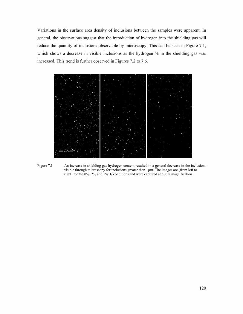
120
Variations in the surface area density of inclusions between the samples were apparent. In
general, the observations suggest that the introduction of hydrogen into the shielding gas will
reduce the quantity of inclusions observable by microscopy. This can be seen in Figure 7.1,
which shows a decrease in visible inclusions as the hydrogen % in the shielding gas was
increased. This trend is further observed in Figures 7.2 to 7.6.
Figure 7.1 An increase in shielding gas hydrogen content resulted in a general decrease in the inclusions visible through microscopy for inclusions greater than 1µm. The images are (from left to right) for the 0%, 2% and 5%H2 conditions and were captured at 500 × magnification.
20µm

121
20 micron
20 micron
Figure 7.2 Optical microscope image of inclusions for CO2 (0%H2) condition. No etchant was used.
Figure 7.3 Optical microscope image of less numerous inclusions for the 5%H2 condition. The large
inclusion was not specific to the elevated hydrogen conditions and was also observed in similar quantities at lower levels of hydrogen. No etchant was used.
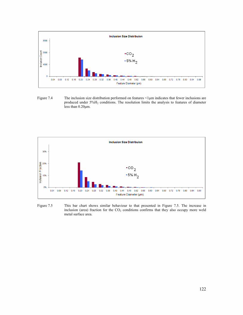
122
Figure 7.4 The inclusion size distribution performed on features <1µm indicates that fewer inclusions are
produced under 5%H2 conditions. The resolution limits the analysis to features of diameter less than 0.20μm.
Figure 7.5 This bar chart shows similar behaviour to that presented in Figure 7.5. The increase in inclusion (area) fraction for the CO2 conditions confirms that they also occupy more weld metal surface area.

123
Figure 7.6 A comparison between the inclusion count (left) and the inclusion area fraction (right) reveal
that the inclusions produced under 5%H2 conditions were generally of a slightly smaller size than those produced under CO2 conditions.
7.1.5 Method: Cellular Dendritic Spacing
The prior austenite grain boundaries of ferritic steel weld metal are not readily observed
following transformation especially using the standard Nital etchant. It is however possible
to reveal the prior austenite grain boundaries by etching in specific solutions that highlight
the elemental segregates that remain after final transformation. This is also possible for
identification of the original delta ferrite boundaries. The technique can be difficult but with
careful adjustments of etching time and solution temperature an accurate assessment of prior
grain structures can be obtained. This was achieved in the current investigation using a
saturated acqueous solution of picric acid with a small addition of teepol as a wetting agent.
(Samuels, 1999). Although this method does not reveal which elements have segregated, it
can be used to provide an indication of the solidification morphology of the weld metal.
Test samples produced under CO2 /0%H2 and 5%H2 conditions were sectioned transverse to
weld direction, polished to 0.5µm and etched with the solution of saturated aqueous Picric
acid mixed with Teepol. The samples were then submerged in the solution at 60°C for five
minutes and had to be swabbed continuously to avoid severe pitting.
Micrographs were taken at distances of 1mm, 3mm and 6mm below the weld cap, from
which a total of 75 measurements per condition were made to size the cellular dendrite cells
or the widths of the previous delta ferrite grains. The delta ferrite grain size was

124
quantitatively determined using a linear intercept method . The aim of this investigation was
to compare observations along three regions of each weld to identical regions in the other
weld. Care was also taken to size the cells situated in the typical as-deposited microstructure
of that region in the weld.
7.1.6 Results: Cellular Dendritic Spacing
The dark regions in Figure 7.7 below indicate areas of higher alloying element
concentrations. The darkening observed is due to intercellular dendritic microsegregation,
which occurs during the primary solidification mode of the weld metal. Linear measurements
across the cells revealed that the introduction of H2 into the shielding gas reduced the width
of these intercellular dendritic cells (Table 7.2 and Figure 7.7). The grains in Figure 7.7 are
columnar and follow the solidification from bottom to top in the figure. Sectioning was done
transverse to the direction of the weld.
Table 7.2 A linear measurement of the cellular dendritic cells revealed that the introduction of H2 into
the shielding gas reduced the width of the cells.
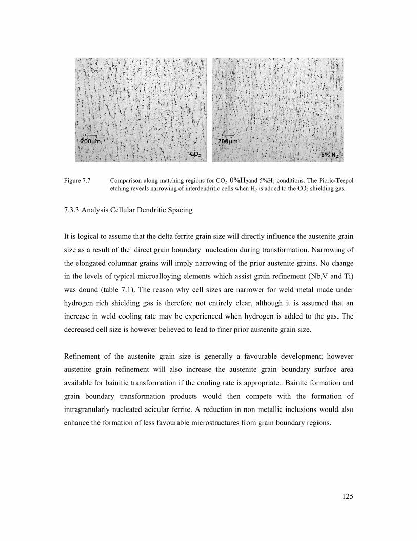
125
Figure 7.7 Comparison along matching regions for CO2 0%H2and 5%H2 conditions. The Picric/Teepol etching reveals narrowing of interdendritic cells when H2 is added to the CO2 shielding gas.
7.3.3 Analysis Cellular Dendritic Spacing
It is logical to assume that the delta ferrite grain size will directly influence the austenite grain
size as a result of the direct grain boundary nucleation during transformation. Narrowing of
the elongated columnar grains will imply narrowing of the prior austenite grains. No change
in the levels of typical microalloying elements which assist grain refinement (Nb,V and Ti)
was dound (table 7.1). The reason why cell sizes are narrower for weld metal made under
hydrogen rich shielding gas is therefore not entirely clear, although it is assumed that an
increase in weld cooling rate may be experienced when hydrogen is added to the gas. The
decreased cell size is however believed to lead to finer prior austenite grain size.
Refinement of the austenite grain size is generally a favourable development; however
austenite grain refinement will also increase the austenite grain boundary surface area
available for bainitic transformation if the cooling rate is appropriate.. Bainite formation and
grain boundary transformation products would then compete with the formation of
intragranularly nucleated acicular ferrite. A reduction in non metallic inclusions would also
enhance the formation of less favourable microstructures from grain boundary regions.

126
7.1.7 Method: Microscopic Analysis of fractured specimens
The tested specimens were fractured in liquid nitrogen, sectioned, rinsed in alcohol, dried
with compressed nitrogen and then stored in a desiccator. This process allowed the failed
regions to be analysed using optical and scanning electron microscopy. Use of these two
resources permitted both specific and generalised observations to be made.
Scanning electron microscopy (SEM) was conducted from 500 to 15000 magnification, while
light microscopy was performed up to a magnification of 1000×. For SEM analysis, the
samples were mounted on a stub with double sided carbon tape and characterised using a
Leica Stereoscan 440 scanning electron microscope.
The ferritic steel surfaces were imaged with secondary electrons using an accelerating voltage
of 20k eV and the working distance for the secondary electron imaging was approximately
25mm. Light microscopy was performed using a Leica DMRM microscope. This operated in
bright-field reflectance mode and was equipped with lenses that allowed imaging up to 500×
magnification. The sample images were observed in real time via a computer connected to a
Panasonic CCD camera. Image capturing was by Video Pro 32 software.
7.1.8 Method: General Microstructure
In an attempt to make general observations, the weld metal microstructures produced under
CO2-0%H2 and 5%H2 conditions were investigated using the guidelines produced by IIW
Doc.No.IX-1533-88, Guide to the Light Microscope Examination of Ferritic Steel Weld
Metals (1988).
The sample welds were sectioned transverse to the direction of welding, mounted and then
polished to 1μm on a diamond cloth. They were then etched with a 5% Nital solution, after
which scribe marks were centrally positioned at depths of 1mm, 2mm, 3mm, 4mm and 6mm
below the weld cap. These scribe marks would indicate a standardised location from which
micrographs could be produced.

127
7.1.9 Results: Microstructure
The complexity of high strength ferritic steel microstructure required that numerous
micrographs be produced for light microscopy. Magnification below 200× did not provide
images from which clear distinctions could be made of the microstructures and the optimum
magnifications required to adequately discriminate microstructural differences was at 400×
and 1000×.
All micrographs typically show a chaotic and mixed arrangement, containing ferrite with
second phase (FS), acicular ferrite (AF) and bainite F(B). Other major constituents such as
grain boundary ferrite PF(G), ferrite with aligned second phase F(SA) and ferrite with non-
aligned second phase FS(NA) are also observed (Figure 7.8). Comparisons between typical
microstructures produced under CO2 shielding conditions with those produced under CO2-
5% H2 shielding gas conditions are presented in Figures 7.9 and 7.10.
Four micrographs taken from four different samples to focus on the ferrite content is
presented in Figure 7.11. These images represent typical CO2-0%H2 and CO2-5%H2
microstructures. Once 5%H2 is added to the CO2 shielding gas, the top 2 photographs of
figure 7.11 indicate less numerous ferrite laths occur, in addition to coarsening of the general
microstructure.

128
Figure 7.8 Typical mixed and chaotic high strength ferritic weld metal microstructure produced during this research. A 5% Nital etchant was applied..
F(B)
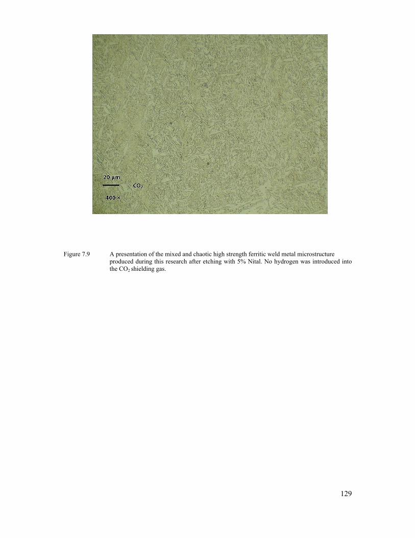
129
Figure 7.9 A presentation of the mixed and chaotic high strength ferritic weld metal microstructure produced during this research after etching with 5% Nital. No hydrogen was introduced into the CO2 shielding gas.
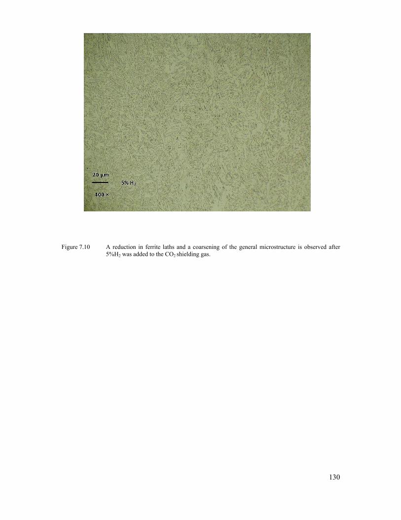
130
Figure 7.10 A reduction in ferrite laths and a coarsening of the general microstructure is observed after
5%H2 was added to the CO2 shielding gas.
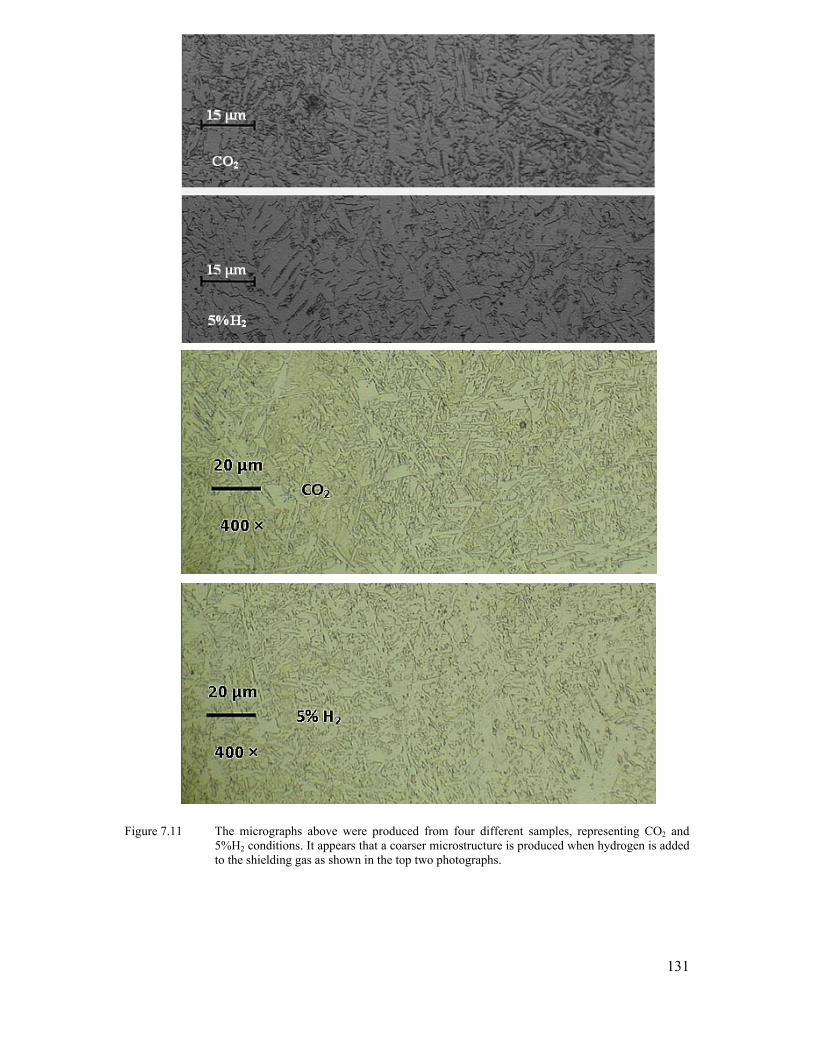
131
Figure 7.11 The micrographs above were produced from four different samples, representing CO2 and
5%H2 conditions. It appears that a coarser microstructure is produced when hydrogen is added to the shielding gas as shown in the top two photographs.
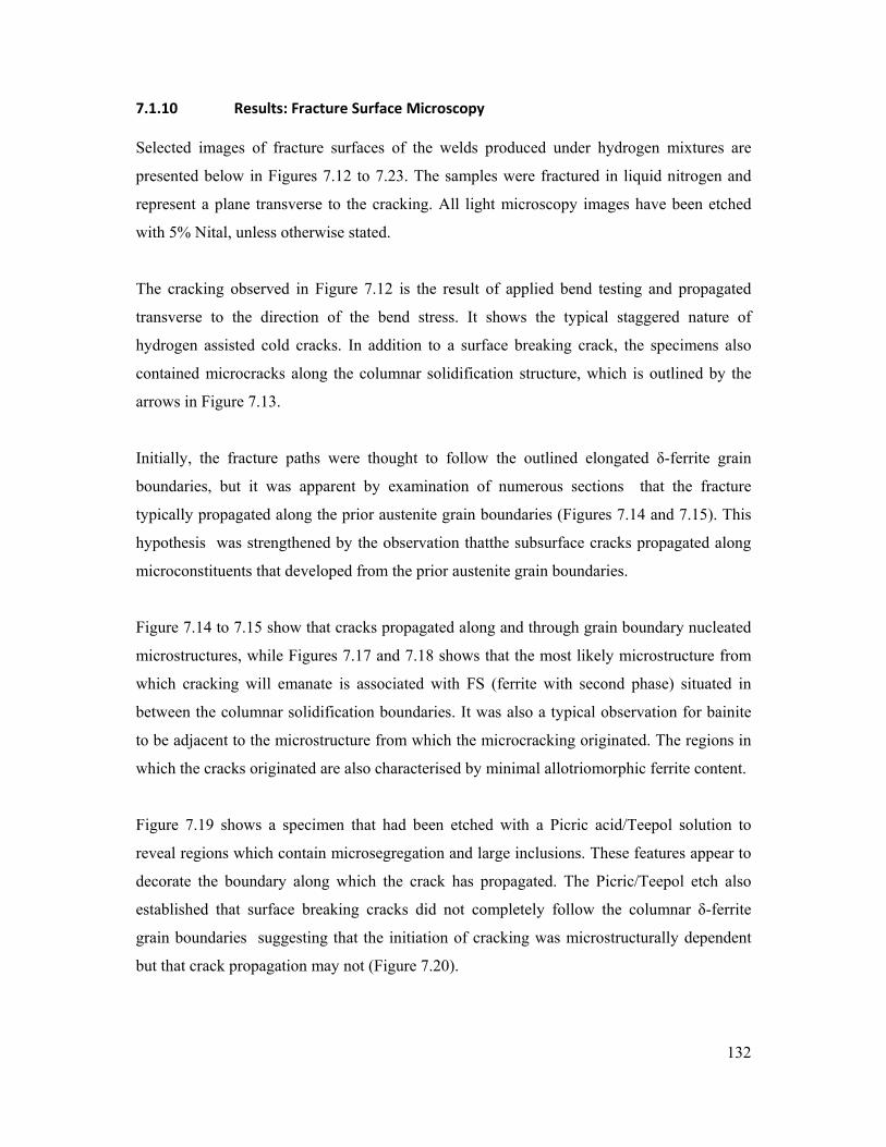
132
7.1.10 Results: Fracture Surface Microscopy
Selected images of fracture surfaces of the welds produced under hydrogen mixtures are
presented below in Figures 7.12 to 7.23. The samples were fractured in liquid nitrogen and
represent a plane transverse to the cracking. All light microscopy images have been etched
with 5% Nital, unless otherwise stated.
The cracking observed in Figure 7.12 is the result of applied bend testing and propagated
transverse to the direction of the bend stress. It shows the typical staggered nature of
hydrogen assisted cold cracks. In addition to a surface breaking crack, the specimens also
contained microcracks along the columnar solidification structure, which is outlined by the
arrows in Figure 7.13.
Initially, the fracture paths were thought to follow the outlined elongated δ-ferrite grain
boundaries, but it was apparent by examination of numerous sections that the fracture
typically propagated along the prior austenite grain boundaries (Figures 7.14 and 7.15). This
hypothesis was strengthened by the observation thatthe subsurface cracks propagated along
microconstituents that developed from the prior austenite grain boundaries.
Figure 7.14 to 7.15 show that cracks propagated along and through grain boundary nucleated
microstructures, while Figures 7.17 and 7.18 shows that the most likely microstructure from
which cracking will emanate is associated with FS (ferrite with second phase) situated in
between the columnar solidification boundaries. It was also a typical observation for bainite
to be adjacent to the microstructure from which the microcracking originated. The regions in
which the cracks originated are also characterised by minimal allotriomorphic ferrite content.
Figure 7.19 shows a specimen that had been etched with a Picric acid/Teepol solution to
reveal regions which contain microsegregation and large inclusions. These features appear to
decorate the boundary along which the crack has propagated. The Picric/Teepol etch also
established that surface breaking cracks did not completely follow the columnar δ-ferrite
grain boundaries suggesting that the initiation of cracking was microstructurally dependent
but that crack propagation may not (Figure 7.20).

133
A scanning electron microscope image (Figure 7.21) shows that subsurface cracking was
observed to be inter-columnar, following the path of solidification. A ductile tearing
mechanism is also at the top end of the crack in Figure 7.22, in addition to quasi cleavage
features related to brittle fracture (Figure 7.23) (ie a mixed fracture mode)
Figure 7.12 Typical fracture profiles produced during bend testing. The specimen on the left has not been etched, while a light 5% Nital etch was used for the specimen on the right. The 900MPa and 800Mpa represent the loads at which the specimens were held until surface breaking cracking occurred. The scale bars represent 300μm.

134
Figure 7.13 Cross sectioning of a failed specimen indicates that in addition to a surface breaking crack, the
specimens also contained microcracks along the columnar solidification structure, outlined by the arrows.

135
Figure 7.14 Image of a microcrack through PF(A), indicating that the fracture propagated along and
through microconstituents that grow from the prior austenite grain boundaries.
Figure 7.15 Image of a microcrack in a region sparse in PF(G) The faint black line arrowed at the top of the crack indicates a prior austenite grain boundary.
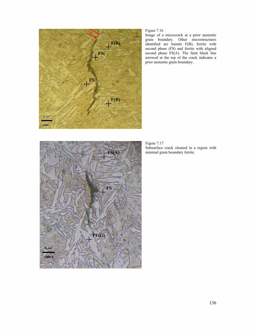
136
Figure 7.16 Image of a microcrack at a prior austenite grain boundary. Other microstructures identified are bainite F(B), ferrite with second phase (FS) and ferrite with aligned second phase FS(A). The faint black line arrowed at the top of the crack indicates a prior austenite grain boundary.
Figure 7.17 Subsurface crack situated in a region with minimal grain boundary ferrite.
FS +
F(B) +
F(B) +
FS(+
FS(A) +
PF(G)+
FS +

137
Figure 7.18 Microstructure identified as bainite F(B) is typically adjacent to the ferrite with second phase
from which cracking originates. Note also the lack of grain boundary ferrite where the cracking is situated.
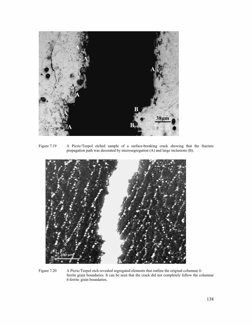
138
Figure 7.19 A Picric/Teepol etched sample of a surface-breaking crack showing that the fracture
propagation path was decorated by microsegregation (A) and large inclusions (B).
Figure 7.20 A Picric/Teepol etch revealed segregated elements that outline the original columnar δ- ferrite grain boundaries. It can be seen that the crack did not completely follow the columnar δ-ferrite grain boundaries.
38μm A
A
A
A
A
B
B
A

139
Figure 7.21 SEM image of a weld that failed during bend testing. The specimen was fractured in liquid
nitrogen and occurred by intercolumnar fracture. Figure 7.22 SEM image at top end of the crack shown in Figure 7.21. A ductile tearing mechanism is seen
to be in operation. This is due to the propagating crack front escaping the hydrogen atmosphere and requiring an increase in energy to continue fracture.
IG QC MVC
IG
IG
DUCTILE TEARING
MVC

140
Figure 7.23 In addition to the ductile tearing observed in Figure 7.22, quasi cleavage facets were also
noticed adjacent to subsurface cracks.
MVC
QC

141
CHAPTER 8
DISCUSION
The investigation was carried out in several stages with each phase informing the conduct of
the next. For this reason the following chapter discusses the outcomes of each phase in
sequence followed by the final conclusions of the work.
8.1 Deliberate Generation of Multipass Weld Metal Cold Cracking
The motivation of this part of the work was to determine whether HACC could readily be
initiated in the target materials and to establish which nondestructive testing methods would
constitute the most reliable for its detection. Cold cracking was deliberately generated in a
40mm thick multipass weld deposits .Experimental data to aid the study of delay times in
high strength ferritic weld metal was also produced.
Modern high strength ferritic weld metals are designed to exhibit good strength and
toughness properties and it is therefore unlikely that standard welding practices would have
initiated cracking in the test plate used. Olson (1999) Hydrogen assisted cold cracking was
deliberately generated by (i) adding hydrogen to the shielding gas, (ii) not applying preheat,
(iii) maximizing the weld cooling rate, (iv) maintaining low interpass temperatures and (v)
increasing welding restraint.
For the welding of the high restraint test plate under the given conditions, transverse HACC
was found throughout the entire weld, although a trend was observed which pointed towards
the upper third region of the multipass weld being where the highest concentration of cracks
were situated. The majority of cracks were transverse and were located by conventional UT,
either left or right of the weld centreline. This has also been reported by Kuebler et al., (2000)
and Takahashi et al. (1979), who indicated that this region of the deposited weld is where
both maximum longitudinal residual tensile stresses and the maximum hydrogen
accumulation occurs
142
Cracking was hydrogen assisted cold cracking because of the staggered or stepped
appearance and the delay times involved. Certain cracks were still propagating after a month,
while others remained stable. The largest cracks were located near the transverse stiffeners
and the longitudinal restraint end welds, which would have experienced the greatest restraint
and possibly the fastest cooling rates. The faster cooling rate being produced by a heat sink
effect of the stiffener plates and longitudinal end welds.
Radiographic testing (RT) of the weldment did not detect all cracks and planar defects
because of the limitations of this technique with certain crack orientations. For example,
radiography was only successful in detecting two significant surface-breaking cracks, which
were almost through-thickness. Similarly, magnetic particle inspection was only successful in
detecting the same two surface-breaking cracks that were detected by RT.
Acoustic emissions (AE) was capable of identifying both the initiation and propagation of
hydrogen cracking, as also reported by Trevisan and Fals (1999). It was shown in this work
that AE correlated well with conventional UT, which was the most accurate method for
detecting transverse cracking in the deposited weld. Due to the excessive number of
transverse cracks generated in the test plate, it was impractical to size and locate all cracks
via UT. Defects such as lack of sidewall fusion and group porosity did not appear to initiate
cracking in this multipass configuration.
The majority of acoustic emission activity in the vicinity of the weld occurs in the first two
days, after which relative acoustic silence was detected. There appears to be no acoustic
emissions detected after three days, which is misleading, as crack propagation was detected
beyond this time by conventional UT. The reason for the lack of AE crack detection after
three days is believed to be due to the decrease in acoustic emission intensity with time, as
hydrogen will have diffused away from the weldments, relaxing the stresses and emitting
fewer signals. It is also probable that the cracking was occurring via a different method, one
which may not be detectable by the AE method employed in this study.
Another possible reason for the lack of AE detection after three days is that in order for
acoustic emissions to be accepted by the test software, it had to be detected by all four

143
sensors. The acceptance criteria can be set at various sensitivities to overcome this
inadequacy, such as accepting emissions that are detected by any three of the four sensors.
It is important to note that an increase in test sensitivity will not only increase the number of
cracks detected, but also lead to more noise (or “phantom”) emissions, which will make data
analysis more cumbersome and time consuming.
Figure 3.14 shows a plot of acoustic emissions in the range of 0.20-1.20 MHz associated with
HACC and reveals two typical emissions types. The first is a relatively low frequency
emission at ~250 HZ and is attributed to crack propagation. The second is a combination of a
low frequency (~250Hz) and high frequency (~500Hz) emission, which is most likely a
combination of crack propagation and plastic flow ahead of a crack tip (Graham and Alers,
1975).
Figure 3.13 and 3.14 further support an established principle of HACC, which maintains that
the growth of HACC occurs in stages. Other possible reasons for the two distinct types of
emissions may also be ascribed to the varying nature of WM HACC. The fracture path can
either be transgranular or intergranular,.
These varying fracture paths will understandably emit differing acoustic signatures and will
be dependent upon the stress intensity at the crack tip and the local hydrogen concentration
Beachem (1972). Multiple frequency detections have also been referred to by Yurioka and
Suzuki (1990), who showed that acoustic emission signals detected during hydrogen crack
process were operating in a discontinuous and staggered manner.
An acknowledged limitation of the AE work undertaken was that crack initiation times were
not specifically researched. The volume and close proximity of the emissions impeded closer
scrutiny of the signals that constituted crack initiation. This resulted in the two stages
(initiation and propagation) being bound together and treated as one, namely as “crack
activity”. No conclusion can therefore be made with regards to when the crack initiation
occurred. Although it is outside the scope of this study, further work is required to
investigate the relationship between specific acoustic emission frequencies associated with
crack initiation in high strength weld metal and so assist in the accurate prediction of HACC
delay times.

144
From the emissions that could be recognized as crack initiation, AE monitoring revealed that
the majority (but not all) of emissions occurred within 48 hours of the completion of welding.
These delay times are a typical trademark of HACC and may reveal certain deficiencies in
Engineering Standards, with regards to the timing of the final inspection and the requirement
to perform final NDT inspection immediately after the weld has cooled. For example,
AS4037 and AS4041 do not address the importance of delaying the final non-destructive
evaluation, and AS4041 only stipulates that when an alternative for radiography and
ultrasonic testing is applied, the weldment must be allowed to cool for the final inspection.
There is fortunately an accepted understanding that non-destructive testing or evaluation of
weldments should be delayed for several hours, particularly for critical applications (such as
for fatigue and pressure vessel applications). This requirement is evident based on the results
shown in Figures 3.11, 3.12 and 3.13, where cracks propagated well after 48 hours. Crack
propagation is shown to occur between 15 and 27 days in Figure 3.11 and acoustic emission
activity was detected at three days. Investigations by Pargeter (2003) on similar strength
material (HY100) also revealed that crack initiation occurred as long as 65 hours after
welding.
HACC delay times are expected to be influenced by the diffusivity of hydrogen in the weld
metal, the tendency for hydrogen to migrate to or remain at sites of high tri-axial stress, and
by the physical distance hydrogen is required to diffuse before it can concentrate around
inhomogeneous features (i.e. inclusions, grain boundaries and dislocation pileups) to cause
cracking. The above requires that hydrogen must maintain a certain level of mobility within
the microstructure, and the delayed nature of hydrogen cracking is often based on the
assumption that cracking must be diffusion controlled.
For the multipass weld investigated, higher levels of diffusible hydrogen were introduced into
the weld metal by adding 2%H to the prescribed CO2 shielding gas. This was sufficient to
generate HACC and increased the expected diffusible hydrogen levels from ~2ml/100g to ~7
ml/100g (see Figure 3.7). It must be emphasized that this value does not represent the
diffusible hydrogen for the total weld, but for each individual weld deposit.

145
The diffusible hydrogen tests were carried out on single bead on plate samples and gave an
indication of the level of diffusible hydrogen (ml/100g) of a single run. It is expected that the
total diffusible hydrogen content may have accumulated to some degree with the deposition
of each pass. This will however depend on the relative transformation temperatures of the
weld metal and the heat affected parent material.
The primary aim was to generate HACC in high strength steel weld metal, and to determine
which NDT methods were the most reliable. The work formed a foundation for further
investigations into cold cracking delay times.
In summary it was found that:
• Hydrogen assisted cold cracking can intentionally be generated in multipass high strength ferritic steel weld metal by the introduction of hydrogen into the shielding gas and by imposing high restraint conditions upon the weld. The diffusible hydrogen levels and stresses imposed were however not significantly higher than the possible conditions experienced in poorly controlled field welding practice.
• Transverse cold cracks were noted throughout the entire weld using conventional and acoustic emission testing equipment. The majority of crack activity was situated towards the upper region of the multipass weld.
• Ultrasonic inspection provided the most reliable method to detect HACC
• The majority of crack activity detected by AE occurred within 48 hours, although some crack activity exceeded 30 days.
8.2 Diffusible Hydrogen Testing
The ability to measure the diffusible hydrogen content provides a means of determining the
degree to which a given welding consumable, the associated welding process and the
environmental conditions are likely to introduce hydrogen into the weld metal. The diffusible
hydrogen testing in this body of work was undertaken to determine the hydrogen levels
obtained when H2 was added to the shielding gas.

146
The accuracy of the hot extraction method (HE) used was considered in a previous study by
Nolan and Pitrun (2003). The results of their study showed that the HE method typically
removes more hydrogen as “diffusible hydrogen” than the commonly used mercury and gas
chromatography test methods, giving higher readings. The difference of 0.2 - 0.3 ml/100g was
however considered insignificant and within the accepted accuracy level of ±1 ml/100g of
deposited weld metal.
The hydrogen test assembly requires single bead on plate arrangements, although multipass
weld deposits have been used if the specimen can fit into the testing apparatus. This is
achieved by depositing the weld metal into a groove to produce an “as fused” hydrogen test
assembly (Pussegoda et al., 2004). The constraints of the general test methods, however, limit
the testing to only a few passes and may therefore not be indicative of thick welded sections.
The reheated weld metal microstructure of multipass welds may possibly also create different
trap densities when compared to single pass welds. The delay time to fracture in thick
sections will be expected to increase as a result of the greater hydrogen diffusion distances
and the thermal effects of multipass welds will also have to be accounted for. It is therefore
understood that a single pass weld metal diffusible hydrogen test will differ from a multipass
weld. The aim to control the weld metal hydrogen content for research purposes was thereby
easier to achieve when utilising single bead weld deposits.
To quantify the diffusible hydrogen content in this thesis, modification of the typical
hydrogen test assembly was required because preliminary welding trials indicated that the
weld deposits were wider than the 15mm typically recommended for the hydrogen test
samples. This issue was resolved by rotating the hydrogen sample by 90º so that its width
was transverse to the welding direction (Figure 4.3).
It was also impractical to use the smaller copper welding fixture as prescribed by the relevant
standard because the energy released by the 1.6mm welding consumable and the width of the
weld bead necessitated the use of the larger welding fixture. This method has previously been
used with success by White et al., (1992) and Pitrun (2004).
Using a larger test specimen and a larger diffusible hydrogen test assembly indicated that an
uneven distribution of hydrogen will occur along a fixed length of deposited weld metal. For
baseline conditions (no hydrogen added to the shielding gas), a gradual decrease in diffusible
147
hydrogen along the length of the weld was recorded. At 50mm from the end of the weld, the
hydrogen sample typically contained 2.1ml H2 per 100g of deposited weld metal, while at
250mm, the result was 1.35ml/100g.
Each hydrogen sample in the extended test assembly would consequently also indicate what
the WM diffusible hydrogen content was for quench delay times of 5, 45 and 90 seconds.
These times relate to the time it took for the travelling arc to move away from deposit weld
metal and a longer time equated to a decrease in diffusible hydrogen content. It is expected
that the extended time before quenching of each sample was the principal reason for the
decrease in diffusible hydrogen.
The addition of H2 to the shielding gas provided a mechanism whereby a certain degree of
control could be exercised over the quantity of diffusible hydrogen present in the welded
sample. The addition of 2% hydrogen to the CO2 shielding gas increased the level of
diffusible hydrogen from ~2ml/100g to ~7ml/100g. This was an increase of 350%. The
addition of 5% H2 to the shielding gas increased the diffusible hydrogen to ~15ml/100g, an
approximate increase of 750% (see Figure 4.7). Although the values for the H2 addition may
appear to be extreme, they assisted in representing low, mean and high values of diffusible
hydrogen, which were then subsequently used during mechanical testing
The susceptibility of the FCAW consumable used during the present investigation to
hydrogen pick-up was also evaluated. This was undertaken to determine whether it will
influence the test specimens. Two reels of welding wire were compared during a 10-month
atmospheric exposure trial period. The test relied on ambient conditions and the period
selected ensured that a range of atmospheric humidity levels could be accounted for.
A dry-stored and an exposed reel of welding wire were compared. The results show that there
was a marginal increase in diffusible hydrogen content for both reels of wire consumable
with respect to the increase in relative humidity. The difference between the minimum and
maximum values was, however, less than 1ml/100g and one could argue that the accuracy of
the laboratory apparatus decreases at such low levels of diffusible hydrogen (from
approximately 1.8ml/100g to 2.4ml/100g).

148
The results from this exercise specified the degree to which the welding wire consumable
needed to be shielded from atmospheric exposure for prolonged periods. Overall, the
susceptibility to increased hydrogen content from atmospheric exposure appears to be a
function of the electrode flux, the electrode manufacturer method (seamed or seamless), the
packaging method, the consumable storage time and possibly the wire diameter (Harwig et
al., 1999). The seamless, fully basic consumable used during this research was therefore not
considered to be susceptible to a level of hydrogen pick-up that warranted concern. It must
however be mentioned that mechanical testing was not performed on this exposed FCAW
consumable and even though negligible results have been seen in terms of hydrogen pickup,
the effect due to exposure on mechanical properties is not known. The exposed reel of
welding wire was therefore not used during the applied stress testing.
This part of the investigation indicated that with care an acceptable amount of control of
diffusible hydrogen content can be achieved by introducing hydrogen into the shielding gas.
In summary:

149
• The location of the hydrogen sample along the weld path is an important consideration when conducting weld metal diffusible hydrogen measurements. A gradual decrease in diffusible hydrogen readings was recorded the further the hydrogen sample was positioned from the weld start point. This demonstrated hydrogen effusion from the weld prior to the sample being quenched in liquid nitrogen.
• The addition of 2% hydrogen to the CO2 shielding gas increased the level of diffusible hydrogen from ˜2ml/100g to ˜7ml/100g.
• The addition of 5%H2 to the shielding gas increased the diffusible hydrogen to ˜15ml/100g. The variation between each data point for one hydrogen condition was typically less than 1.5 ml/100g.
• The consumable used did not appear to be particularly susceptible to hydrogen pickup from either storage or from ambient conditions.
• The addition of H2 to the shielding gas provides a means whereby an acceptable degree of control can be exercised over the quantity of diffusible hydrogen in the welded sample during testing.
8.3 Development of WM HACC Test Specimens
Large reduced section tensile specimens were initially considered for mechanical testing,
primarily as their gauge length matched the length of the welding fixture used to determine
the diffusible hydrogen content. The suitability of tensile testing as an ultimate test medium
was however not justified, due to the cross sectional stress distribution in the composite
material (bead on plate) and the large size of the specimen. These large specimens required
significant machining, large test plates and subsequent post-weld storage in a custom-built
liquid nitrogen container. The deposition of a weld bead on top of the base material created a
composite tensile specimen that would have produced variable strains across the thickness,
complicating the determination of stress.

150
During tensile strains, the elastic response from the weld metal may have been different to
that of the base material. It would therefore not have been possible to readily determine with
reasonable accuracy what percentage of the weld metal was being evaluated. Although some
mechanical testing was conducted with these large tensile specimens, a different approach
was required, one that specifically targeted the weld metal and minimised the influence of the
base material. The alternative test configuration was found to be in the form of bend testing.
The numeric modelling showed that bend testing will focus the stresses on the weld bead.
There was, however, an initial suspicion that bend testing may induce high stresses in the
HAZ and the weld toes, thereby leading to premature test endpoints. A narrow specimen was
designed and experimented with, which did not contain the original weld toes. Numeric
modelling subsequently demonstrated that the stresses in the HAZ and the weld toes remain
relatively low. Further justification for the narrow bend test specimen lay in its ability to
reduce the load requirement of the test frame.
There was also the understanding that the narrow specimen would produce a faster internal
strain rate, which would affect the hydrogen-dislocation interactions. Inclusion of the narrow
specimen thereby facilitated a clearer understanding of the impact that geometric variations
could have on test outcomes. Both the wide and the narrow specimens were therefore
regarded as suitable test specimen geometries.
The research undertaken in Phase 1 showed that the region in which HACC occurs falls
within the upper third of the weld deposit. Related research demonstrated that the local
hydrogen concentration reaches its maximum value in this region, typically 0.75–0.90 of the
weld thickness (Kinsey, 1998). From this it was concluded that even though the stress from
bending would reach a maximum in the outer fibres, HACC is not expected to originate from
the outer fibres.
Numeric modelling was employed to observe the nonlinear behaviour of the test specimens
under bending. Load-displacement values derived from baseline conditions (no H2 in the
shielding gas) were incorporated into ANSYS models to simulate the nonlinear behaviour of
both the wide and the narrow specimens. The key variable used to evaluate the behaviour of

151
the two different specimen geometries was deflection, which was set at 0.5mm, 1.0mm and
2.0mm. These values were covered a range that included both elastic and plastic behaviour.
Applying a von Misses criterion calculated whether the stress combinations at a given point
would cause failure based on the mechanical properties of the material, i.e., when the sum of
all principal stresses exceed yield. A surprising result from the ANSYS models was that at
the displacements studied, the von Misses stresses acting in both geometries revealed similar
plastic responses to the applied loading.
Although these stresses were similar, variations in the magnitudes of each principal stress
(between the different geometries) was however expected. To illustrate this, the relative stress
in both a rectangular specimen and an un-machined specimen is compared below in Figure
8.1. The weld bead geometry was assumed to be identical for both. During loading, it will not
be the total stress applied to the specimen that causes yielding, but rather the effective stress,
which in this work was influenced by the width of the base plate during testing. To explain
this, one has to consider that the increased width of the wide specimen will decrease the
height of the centroid and it will also lower the effective stress (average stress) in the
specimen.
The stress required for yielding of a wide bend specimen will subsequently be lower when
compared to the narrow specimen. It is therefore expected that during mechanical testing,
differences in delayed cracking times between the two specimens will be observed. A faster
internal strain rate will be experienced by the narrow bend specimen, which will result in a
decrease in the effects of dislocation dragging.
Figure 8.1 Schematic showing the variation in effective stress (σweld/σplate) when comparing the narrow
and wide bend specimens.
It is recognised that one limitation of the FEA study was the reliance on “displacement”
instead of “time”. As the narrow specimen had a lesser cross sectional area, a defined roller

152
displacement would have had a greater effect. However, in defence of the original choice,
one may propose that even though the load required for each respective roller displacement
was different, the results indicate that the von Misses stress at these deflections are
comparable.
The use of an applied strain (or roller displacement) thereby enabled direct comparisons to be
drawn between the two specimen geometries. This result further illustrates that both bend test
geometries ultimately satisfy the criteria to concentrated the loading in the weld metal,
especially as no artificial stress raisers (such as notches or pre-cracks) were introduced. The
decision to use the 4-point bend test also subjected a larger amount of weld metal to the
applied stress, enabling the study of crack initiation at existing microstructural features or
defects over a greater region.
The test configurations developed in Phases 2 and 3 allow the manipulation of factors held
responsible for hydrogen assisted cold cracking. It does this by introducing a controllable
quantity of diffusible hydrogen into an un-notched welded specimen. Variables such as time,
load, and applied stress and strain can then be manipulated to produce HACC under bend
testing. Individual or joint manipulation of these variables will allow the study of individual
aspects that influence hydrogen assisted cold cracking. The following conclusions can be
drawn from these investigations:
• Tensile testing as a test medium is unsuitable for WM HACC testing when the tensile stresses are applied to a composite structure in which each component has different yield and tensile strengths.
• Numeric modelling showed that bend testing will focus the stresses in the weld bead and that both the narrow and the wide bend specimen will be subjected to similar von Misses stresses.
• Compared to the narrow bend specimen, the higher restraint imposed on the wide bend specimen (due to the increase in base plate width) will reduce the (effective) stress required for yielding.
• Due to the reduced cross section, the narrow bend specimen can be used where a smaller load-frame is available.

153
• It is believed that a faster internal strain rate will be experienced by the narrow bend
specimen, when compared to the wide specimen. This faster internal straining will decrease the effects of dislocation dragging.
• The narrow and the wide specimens will produce dissimilar hydrogen-dislocation interactions and ultimately different hydrogen cracking delay times.
8.4 Mechanical Testing
The mechanical behaviour of the tensile, narrow and wide bend specimens was different
during mechanical loading (Figures 6.4 to 6.6). Each produced different results in regards to
delay times. Under similar applied strain rates, the bend specimens achieved yield conditions
sooner than the tensile test, while the wide bend specimens appear to reach yielding slightly
sooner than the narrow specimens. What was also observed is that the tensile specimens
produce yielding conditions at lower applied stresses, followed by the wide bend specimen
and then the narrow bend specimen.
From this behaviour it can be seen that an increase in restraint (wide bend specimen) will
decrease the applied stress required for yielding, but this increased restraint will however also
increase the load required for yielding. The effect of restraint was arguably also key in
producing sufficiently high stresses to generate HACC in Phase 1. Here the stiffener plates
enhanced the multipass weld’s susceptibility to HACC by effectively maintaining elevated
restraint stresses in the multipass weld.
The gauge length of the tensile specimens was very similar to the length of the wide bend
specimen, which may imply that comparable results can be expected. The outer fibres of the
wide bend test specimen was however subjected to a higher magnitude of applied stress,
which resulted in a significant decrease in load required to fracture the wide bend specimen,
when compared to the tensile test specimen. A further reason for the difference in the results
between the tensile and bend specimen is that the gauge length of the tensile specimen was
much greater than the region in between the rollers where the stresses were concentrated
during the 4-point bend testing. The difference in stiffness observed between the tensile
154
specimen and the wide bend specimen is therefore expected (see Figures 6.5 and 6.6). One
can subsequently not equate the results under one test condition to those of another.
Due to the variations in mechanical response, all three test regimes (tensile, narrow and wide)
was expected to generate variations in hydrogen/dislocation interactions, produced by the
differences in the geometric restraint of each specimen. This complicates any attempt to
standardise the behaviour (or compare delay times) of the three specimens tested.
Both constant load (position controlled) and rising load (slow strain rate) tests were
conducted to generate cold cracking delay times. Experimental work by Goa et al., (1994)
showed that during constant loading tests, crack initiation sites always correspond to the point
of maximum hydrostatic stress, which is located some distance ahead of the notch tip. For
slow strain rate tests, cracking originated at the notch tip, which corresponds to the point of
maximum equivalent plastic strain.
When comparing the two bend specimens, one can observe that slight differences in delay
times were generated at 5%H2 conditions, while a greater spread in delay times were
observed under the 2%H2 conditions. It is believed that the reason for this can be attributed to
the overriding dominance that the diffusible hydrogen had at 5% and this large volume of
diffusible hydrogen produced conditions that were sufficient to deliver closer matching delay
times. At greater quantities, hydrogen will therefore have a significant impact on its own,
although this impact becomes obscured at lower quantities and a greater emphasis should be
placed on the combined factors that result in weld metal cold cracking.
Variations in delay times were not exclusive to differences in the % H2 in the shielding gas,
as differences were also noted for near-identical test conditions. An example of this is the 200
second difference in delay time produced between similar specimens that were tested at
900MPa (Figure 6.10). It must however be noted that the delay times generated in Phase 4
were first recorded when a load drop was observed in the testing apparatus. The speed of the
propagating crack also resulted in the appearance of a surface breaking crack, before the test
was manually terminated. It is therefore proposed that one reason for the differences in delay
times can be associated with the distances that the propagating cracks had to travel before
they broke the surface. Longer crack path before fracture of the outer fibres would therefore

155
result in longer delay times. A more tortuous path in one specimen will then equate to an
increase in time before surface-breaking fracture occurred.
During mechanical testing under hydrogen-rich conditions a progressive decrease in
elongation (ductility) was observed with each increase in the level of diffusible hydrogen.
There were also clear indications that an increase in the shielding gas hydrogen content will
result in an increase in yield strength, which may be interpreted as macroscopic hardening.
As an example, the Yield/UTS ratios (strain hardening behaviour) of the tensile specimens
were in the order of 0.85. The addition of hydrogen to the shielding gas increased these ratios
to 0.90 and higher, which subsequently led to a reduction in elongation. The data further
reveals that severe plastic collapse is expected at ratios of 0.95 and higher. This result is in
agreement with the belief that the threshold stress intensity at the onset of hydrogen cracking
decreases with an increase in yield strength, i.e., an increase in yield will reduce the stress
required to initiate HACC (Ferreira et al., 1998; Nedelcu and Kizler, 2002).
The hypothesis that macroscopic hardening (increase in yield strength) was observed under
hydrogen-rich conditions centres on dislocation drag or dislocation pinning effects. Because
hydrogen is an interstitial atom, it finds its way into the small voids in the vicinity of
dislocations, which then increases the density of the structure and effectively results in
dislocation pinning. This behaviour will subsequently also inhibit deformation and
dislocation mobility, impacting the yield strength (Gedeon and Eagar, 1990; Karlson et al.,
2004). The increase in yield strength under hydrogen-rich was therefore most likely caused
by hydrogen retarding dislocation movement. In other words, the dislocations were unable to
break away from the hydrogen atmosphere, effectively anchoring (or pinning) the
dislocations and causing a drag effect.
The more apparent increase in hardness observed for the wide specimen under hydrogen
conditions will then be due to a stronger dislocation dragging process, which was produced
under slower internal straining. Dislocation dragging is ascribed to a viscous effect, produced
by the relation that hydrogen in the lattice has with Cottrell atmospheres. These atmospheres
occur when interstitial atoms distort the lattice, increasing the residual stress field
surrounding the interstitial atom. The subsequent quest for a condition of equilibrium will
156
then require that interstitial (hydrogen) atoms diffuse into vacant dislocation cores. Here the
hydrogen atoms will remain as a result of the binding energies involved.
The net result of these interstitial-lattice-hydrogen interactions is the pinning of dislocations.
Any further movement of dislocations will require an increase in applied force. The increase
in applied load without the required increase in plastic behaviour therefore translated into a
strengthening (or hardening) mechanism.
The results from positional control testing (Figure 6.10) proposes that the opposite - hydrogen
enhanced dislocation mobility - is observed. During these tests, the applied strain was fixed
via position control and the dislocations mobility of the hydrogen-rich specimens continued
without the application of further load. This is observed as the plot shows a decrease in
gradient with time, i.e., a reduction in stress with time. This mechanism ultimately resulted in
macroscopic fracture. Here it is believed that the hydrogen swept along by the moving
dislocations now facilitated the spawning and further mobility of dislocations, a hydrogen
induced softening effect. The newly generated hydrogen induced dislocation movement
would trap increasing amount hydrogen and then transport it to new deposition sites,
enhancing the fracture process. This has previously been echoed by Sofronis and Robertson
(2002), who maintain that the transport of hydrogen by dislocations will ultimately lead to
accelerated fracture.
Even though both a decrease and an increase in dislocation motion is proposed, which is
believed to primarily be dependent on the strain rate, a common feature in both mechanical
test scenarios involved the transport of hydrogen to regions where it altered the effect that
inhomogeneous features within the lattice had on the crack behaviour. It is also likely that the
accumulated hydrogen also influenced void initiation and void growth during this transport
and trapping process. The overall crack initiation and propagation activity will then arguably
have a probabilistic dependency, which will be a function of hydrogen trapping and transport,
hydrogen-dislocation interactions, void initiation and void growth and finally the general
microstructure in which the crack activity operates. The interrelationship between these
factors will also affect cold cracking delay times due to the inhomogeneous structure of the
weld metal.

157
If one analyses the results in terms of hydrogen transport by dislocation movement, then
faster internal straining (narrow specimen) will translate into a higher level of diffusible
hydrogen being transported away from the stress centres through the enhanced dislocation
movement. Cracking will then most occur by dislocation pileup. Conversely, the slower
internal straining (higher restraint) experienced by the wide specimens will have permitted a
greater quantity of hydrogen to diffuse to critical regions. The impact of dislocation pileup is
then postulated to be less severe for the wide bend specimens where stress assisted diffusion
of hydrogen dominates. Due to the straining of the specimens and the observation that plastic
deformation is required to induce WM HACC, the diffusion of hydrogen by dislocations for
all specimens has to be considered. The following conclusions can be drawn from Phase 4:
• Two bend specimen configurations (narrow and wide) are applicable for the investigation of weld metal hydrogen assisted cold cracking.
• Hydrogen assisted cold cracking was generated in these single pass high strength weld metal specimens without the requirement for notches or pre-cracking.
• The deliberate introduction of hydrogen into the shielding gas and the subsequent bend testing initiated hydrogen cracking in the weld metal and not in the HAZ.
• The results suggest that both hydrogen transport by dislocation movement and normal lattice diffusion of hydrogen operates in both types of specimens.
• Both macroscopic hardening (increase in yield strength) and macroscopic softening (decrease in material resistance to applied stress) was observed.
• Variations in time to fracture under near identical conditions were observed
• The reasons for the variation in delay times between near identical specimens are attributed to the inhomogeneous structure of the as-cast high strength weld metal. The delay times of each specimen are primarily a function of hydrogen transport and trapping, hydrogen-dislocation interactions and differences in crack initiation sites.
• Defining a single delay time for one test configuration of high strength steel weld metal is not feasible. A maximum delay time before cracking, or a specified time-range is therefore proposed, rather than a unique cold cracking delay time.
158
8.5 Microstructure and Fractography
This final phase involved the microstructural and fractographic analysis of the specimens
containing controlled levels of hydrogen. The focus was on the interpretation of the preferred
fracture path. It was also aimed to determine the general effects that the introduction of
hydrogen in the shielding gas (and subsequent weld metal hydrogen content) had on the weld
metal microstructure.
The chemical analysis performed shows that the introduction of H2 into the shielding gas will
have varying effects on the alloying elements. The increase in Mn and Ni under elevated
hydrogen conditions suggests that there is likely to be a reduction in nonmetallic inclusions
containing Sulphur and oxygen.
Although it appears that the major inclusion formers required for the initiation of acicular ferrite
(Ti and O) decreased when H2 was added to the shielding gas, any quantitative assessment
must take into account the potential errors and variations in the analytical methods.
The general trend however shows that the addition of hydrogen to the shielding gas will
result in an increase in detectable alloying elements, the most notable being increases of Mn,
and Ni,. The net effect is a decrease of the calculated martensite start temperature (Table
7.1). An additional impact of an increase in Ni and Mn is the potential to elevate the
impurity segregation at the prior austenite grain boundaries, reducing the cohesive strength
of the matrix.
There are however minimal differences between the samples in terms of their calculated
carbon equivalents (Pcm and CEN), shown at the bottom of Table 7.1 The calculated results
therefore suggest that the hardenability of the samples were similar, if one ignores the
relevance of the austenite grain size. It is known that smaller austenite grain sizes typify a
reduction in hardenability, which is however not illustrated in the calculated carbon
equivalents. It is therefore believed that the Pcm and CEN equations are more suited to the
prediction of hardenability in the heat affected zone of the low alloy parent material and
only give approximations if applied to ferritic high strength steel weld metal.
159
8.5.1 Nonmetallic Inclusions
The influence of H2 on the inclusion size distribution can be seen in Figures 7.1 and 7.6,
where the introduction of hydrogen into the shielding gas typically decreases the size and
number of weld metal inclusions.
The chemical compositions (Table 7.1) indicated that , Mn and Ni may be more efficiently
transferred during welding under elevated hydrogen conditions. A greater number of
inclusions are expected to preferentially nucleate acicular ferrite. The addition of hydrogen to the
shielding gas and reduction in the number of inclusions would favour the formation of ferrite
at the austenite grain boundaries and so reduce the probability of acicular ferrite formation.
Smaller austenite grain sizes will also increase the potential nucleation of grain boundary
nucleated bainite. Larger austenite grain sizes will favour intragranular nucleation of acicular
ferrite on inclusions (Babu and Bhadeshia, 1991) and the prior austenite grain size is then a
controlling feature for acicular ferrite formation, as it will determine the balance of the
competitive reactions that occur at the grain boundaries or those occurring intragranularly
(Farrar and Harrison, 1987).
The analysis indicates that a greater abundance of acicular ferrite plates are present in the
microstructure produced with the prescribed CO2 (Figure 7.9), as opposed to a general
coarsening of the general microstructure (Figures 7.10 &7.11) visible in the hydrogen rich
microstructure. These observations were typical in all the samples analysed. The coarsening
observed is believed to primarily be the result of neighbouring grains being unable to impede
expansion, i.e., they were not sufficiently numerous. This reduction of neighbouring grains
will be associated with the general decrease of nonmetallic inclusions around which acicular
ferrite would have nucleated, suggesting a decrease in hardenability. A reduction of
intragranular nucleated ferrite grains thereby reduces the capacity to impede grain growth,
whereas finer general grain sizes are expected in the presence of sufficient intragranular
nucleated ferrite grains.
A reduction in both the martensite start temperature (Table 7.1) and narrowing of the cellular
dendritic cells (Table 7.2) under hydrogen-rich conditions were noted, suggests that a refining
of the subsequent austenite grain size will occur. The refining of the austenite grain size is
generally a favourable development; however, austenite grain refinement will also increase

160
the austenite grain boundary surface area available for the nucleation of other undesirable
constituents, such as bainite and possibly even martensite if the alloying chemistry is
sufficient.
As the austenite grains develop from the delta ferrite, one can assume that the geometric
effects imposed on the delta ferrite grains will carry through to the austenite grains, i.e., a
narrowing of the elongated columnar grain will imply a narrowing of the prior austenite
grain. Typical microalloying elements which assist grain refinement (Nb, V and Ti) show
either no change or a decrease in Table 7.1. The reason why lateral cell growth was
constrained is therefore not clear, but is assumed to be related to the weld cooling rate and to
the ability of segregated particles hindering cell growth.
The subsequent microstructural classification of the weld metal microstructure produced
during this thesis was based on what could be observed with light microscopy, using a guide
produced by the IIW (1988). The ferrite with second phase (FS) referred to in Figure 7.8 is
assumed to be ferrite with martensite–austenite-carbides (MAC). This assumption is made
because of its abundance in the micrographs analysed and also because it is regarded as the
predominant microstructural constituent in C-Mn welds (Van der Voort, 1984).
It is however understood that the magnification available during light microscopy limits a
more detailed analysis of what microstructural constituents would be present in the ferrite
with second phase identified. This challenge subsequently only allows for broad and
generalised observations to be made, such as referring to the microstructure as ferrite with
second phase, or ferrite with aligned martensite-austenite-carbides (MAC). It is believed that
a high degree of martensite inhibits the ferrite with second phase, which is assumed to be the
reason for its enhanced susceptibility to the cracking observed.
In addition, retained austenite present in a second phase has been shown by Park (2002) to be
a significant hydrogen trap site in HSLA steel weld deposits. He also believes that some
retained austenite in the weld will experience stress-induced phase transformation into
martensite when subjected to deformation strains. These strains would have been present
during bend testing in all specimens, thereby transforming some of the retained austenite into

161
martensite, releasing hydrogen into the matrix during the process. The release of hydrogen
will be due to low hydrogen diffusivity and high hydrogen solubility of austenite, and this
release of hydrogen (if present) would have been standard in all test specimens.
8.5.2 Fracture Microscopy
It is understood that the magnification available during light microscopy limits a
more detailed analysis of what microstructural constituents would be present in the
ferrite with second phase identified. This challenge subsequently only allows for broad
and generalised observations to be made, such as referring to the microstructure as
ferrite with second phase, or ferrite with aligned martensite-austenite-carbide (MAC).
It is believed that a high degree of martensite inhibits this ferrite with second phase, which
is assumed to be the reason for its enhanced susceptibility to cracking.
In addition, retained austenite present in a second phase has been shown by Park (2002) to be a
significant hydrogen trap site in HSLA steel weld deposits. He also believes that some retained
austenite in the weld will experience stress-induced phase transformation into martensite when
subjected to deformation strains.
These strains would have been present during bend testing in all specimens, thereby transforming
some of the retained austenite into martensite, releasing hydrogen into the matrix during the
process. The release of hydrogen will be due to low hydrogen diffusivity and high hydrogen
solubility of austenite, and this release of hydrogen (if present) would have been standard in all
test specimens. The lack of recorded cracking in the CO2 baseline welds therefore illustrates the
significance of adding hydrogen into the shielding gas, as the reversible hydrogen trap sites (i.e.,
martensite) would not have provided a sufficient quantity of diffusible hydrogen required to
allow for cracking to occur.
Figure 7.19 and 7.20 show samples that have been etched with a Picric acid/Teepol solution. This
etchant revealed the microsegregation which occurred due to elemental partitioning of the solid
and liquid during solidification. It subsequently also outlined the original columnar δ -ferrite
grain boundaries. Comparing the crack path with the pattern created by elemental partitioning
showed a directional relationship between the segregated particles and the crack path. The

162
comparison however did not confirm that cracking in the weld metal followed the δ ferrite grain
boundaries. The reason why cracking would then preferentially follow the prior austenite grain
boundaries is visible in Figure 7.19, where it is believed that enhanced impurity concentrations in
the vicinity of large inclusions facilitated the crack process.
Only specimens containing hydrogen in the shielding gas failed during bend testing. This
reason, in addition to the staggered nature of the fracture paths demonstrates that hydrogen
assisted cold cracking was the predominant fracture process. Both subsurface and surface
breaking cracks were observed, where the overall surface-breaking crack mechanism will
have resulted from linking of the microcracks. According to a model proposed by Beachem
(1972) for hydrogen-assisted cracking, intergranular (IG), quasi-cleavage (QC), or microvoid
coalescence (MVC) fracture modes will operate depending upon the microstructure, the
crack-tip stress intensity and the concentration of hydrogen. The subsurface crack seen in
Figure 7.23 was most likely caused by a high local hydrogen concentration, in addition to a
high stress intensity at a quasi cleavage crack tip. The ductile tearing observed in Figure 7.22
is believed to have occurred due to the propagating crack front escaping the hydrogen
atmosphere, and then requiring an increase in energy to continue fracture. Beachem further
proposed that an increase in the stress intensity can result in the fracture mode changing from
intergranular, to quasi cleavage and finally to transgranular microvoid coalescence.
The importance of hydrogen in the cracking process cannot be discounted, as the “hydrogen
free” specimens did not display surface breaking cracks, nor were results recorded in the test
data to suggest that internal cracks were propagating in these specimens. A further factor to
consider is that all specimens displayed similar ferrite with second phase microstructures,
which was identified as the microstructure in which cracking would originate. This
susceptible microstructure was thereby present in all the specimens subjected to bend testing,
although cracking was only observed in the hydrogen-rich specimens. This provides further
support for the argument that hydrogen could be released into the matrix as the retained
austenite transforms into martensite.
Figure 7.19 and 7.20 show samples that have been etched with a Picric acid/Teepol solution.
This enchant revealed the microsegregation which occurred due to elemental partitioning of
the solid and liquid during solidification. It also outlined the original columnar δ-ferrite grain
163
boundaries. Although the crack path and the pattern created by the elemental partitioning
displayed a directional relationship, the crack did not always follow the δ-ferrite grain
boundaries in the weld metal. A closer relationship between crack path and prior austenite
grain boundaries were however observed and it is likely that in certain regions, the crack may
have propagated along a shared δ-ferrite and austenite grain boundary.
The reason why cracking would follow the prior austenite grain boundaries will be attributed
to enhanced impurity concentrations and the lack of grain boundary ferrite. The work of
Bhadeshia and Svensson (1993) postulated that a reduction in the capacity to form
allotriomorphic ferrite could expose the prior austenite grain boundaries to impurity
segregation, which could then lead to intergranular fracture at the columnar austenite grain
boundaries. It is understood that it is not the reduction in allotriomorphic ferrite content per
se which worsens the properties; the important factor is believed to be the degree of coverage
that this type of ferrite provides along the prior austenite grain boundaries.
The work of Brown et al., (2002) proposed that that intercellular dendritic microsegregation
was associated with regions richer in alloying elements, effectively increasing the
hardenability and thereby facilitating cracking. Support for these arguments is visually
attainable in Figures 7.13 to 7.18. The cracks indicate that the fractures propagated along the
columnar solidification structure and along the prior austenite grain boundaries, regions in
which impurity segregation is known to occur. The higher magnification images however
show that cracking followed and traversed microconstituents that grow from the prior
austenite grain boundaries. These regions are also typified by reduced allotriomorphic ferrite
content per surface area, subsequently exposing the prior austenite grain boundaries to
impurity segregation. Hydrogen would segregate to these regions of high lattice expansion
(increasing hardness) and a fracture that developed would have been a result of the local
stress exceeding the cohesive strength of the matrix. More specifically, the cohesive strength
of the intercrystalline boundaries would have decreased with the increase in segregated
impurity concentrations and the increase in the local hydrogen concentration.

164
The following is a summary of section 8.5
• Only specimens containing hydrogen in the shielding gas failed during bend testing.
• Both subsurface and surface breaking cracks were observed in these specimens.
• Scanning electron microscopy revealed the occurrence of ductile tearing and quasi cleavage in the vicinity of a crack tip.
• Regions containing higher levels of microsegregation and large inclusions decorate the crack propagation boundaries.
• A Picric acid and Teepol etch indicated intercellular dendritic microsegregation.
• Revealing this microsegregation subsequently outlined the original δ-ferrite grain boundaries.
• A narrowing of the columnar dendritic cells (original δ-ferrite grains) in hydrogen-rich welds was observed. It is believed that this would produce subsequent refining of the prior austenite grain size.
• The introduction of hydrogen into the shielding gas typically also decreased the size, distribution and number of weld metal inclusions.
• A coarser general microstructure evolved when hydrogen was added to the shielding gas. The reason for this is attributed to fewer intragranular nucleated ferrite grains, which would not have been sufficient to provide obstacles that would restrict grain growth
• The high strength ferritic weld metal analysed contained a chaotic and mixed arrangement of ferrite with second phase (FS), acicular ferrite (AF) and bainite F (B). Other notable microconstituents were grain boundary ferrite PF (G), ferrite with aligned second phase F (SA) and ferrite with non-aligned second phase FS (NA).
• The microstructure in which cracking would originate from has been termed ferrite with second phase. It is believed that a high degree of martensite inhabits this phase.
• Cracking produced by bend testing was observed to occur along the columnar solidification structure.
• Cracking followed and traversed microconstituents that grow from the prior austenite grain boundaries. The regions of crack initiation were typified by having both a low toughness microstructure in addition to reduced allotriomorphic ferrite content per surface area.
165
8.6 Conclusions – Inducing HACC in High Strength Steel Weld Metal
• The aim of this work was to develop a method of evaluating the susceptibility of high
strength ferritic weld metals to hydrogen assisted cold cracking.
• A technique involving controlled introduction of hydrogen into the weld metal
followed by an applied stress test was developed in an attempt to quantify cold
cracking delay times.
• Considerable effort was devoted to standardisation of test procedures, aimed at
fostering representative test outcomes when specific test variables are altered.
• The cold cracking delay times generated under near identical test conditions revealed
that variations in time to fracture will occur, even if the hydrogen level, loading,
specimen configuration and welding specifications remained unchanged.
• It was however found that the introduction of H2 in the shielding gas had varying
effects on the alloying elements. The level of elemental inclusions formers (Ti, S, and
O) that assist with the nucleation of acicular ferrite decreased when H2 was added to
the shielding gas. There was a subsequent reduction in non-metallic inclusion content.
• The hydrogen addition also resulted in a coarser general grain structure, which is
likely to have occurred due to insufficient impingement effects.
• The reduction of acicular ferrite content is believed to have accompanied by
microstructural expansion and also increased the propensity for bainite formation, a
microstructure not generally associated with crack resistance in high strength steel
weld metal.
• Whilst it was not possible to develop a quantitative test for hydrogen cracking
susceptibility; the reasons for the test variability have been explored and show that the
interaction of hydrogen with microstructural development may play a significant role

166
in WM HACC susceptibility in addition to its conventional role in promoting crack
propagation.
8.7 Limitations of Study
The dislocation and hydrogen trapping dynamics of high strength weld metal plays an
important role in WM HACC suceptibility. This results from complex dislocation-hydrogen
interactions, and microstructural changes which are believed to have contributed to
differences in delay times for the chosen test technique. The delay times were also influenced
by varying amounts of hydrogen in the welded specimens, even when a controlled quantity
was introduced into the welding arc.
This test configuration required that a single weld bead be deposited on top of a rectangular
base plate. It therefore only serves as a single pass test and the restraint produced under these
conditions can not equate to production welds. Machining a groove into the base plate would
increase restraint and in terms of a single bead arrangement, may also allow for simpler
specimen geometry. However the introduction of a ‘notch’ may mask the more subtle factors
referred to above its practical relevance is questionable.
The mechanical test behaviour observed for the hydrogen-rich specimens were associated
with significant crack propagation. Subsurface microcracks were also observed, which may
not have been detected with the instrumentation used. The mechanical test configurations
may be limited in its ability to detect crack initiation.
8.8 Future Work:
The limitation with regards to the test weld not reproducing production welds can be
investigated by machining a groove in the base plate, in which the target weld metal is
deposited. Groove geometry can be altered in an attempt to replicate the restraint produced in
production welds.

167
Addressing the limitation in terms of crack initiation can be remedied by the application of
acoustic emission testing. The effectiveness of this technique was demonstrated in Chapter 3
during testing on multipass welds in a static environment. It is however suggested that
considerable calibration will be required to differentiate between crack initiation and other
acoustic interferences produced in the test environment.
Coarsening of the acicular ferrite grain size when hydrogen is deliberately introduced into the
weld metal was principally attributed to a decrease in non-metallic inclusion content. The
Ferrite with second phase (FS) referred to in Figure 7.8 is assumed to be ferrite with
martensite–austenite-carbides (MAC), potentially also lower bainite. It is however
understood the MAC is a very general term used to group together those structures which
have an unfavourable impact on mechanical properties of the material. A more detailed
analysis of modern high strength weld metal microstructure and the influence of hydrogen is
proposed to aid analyses by light optical microscopy.
Finally, it is proposed that the test methodology developed in this thesis be further
investigated as a test platform to investigate the relevance of maximum cracking delay times
in high strength steel weld metal.

168
REFERENCES 1. Abson, D. J. and Pargeter, R. J. 1986. Factors influencing as-deposited strength,
microstructure, and toughness of manual metal arc welds suitable for C-Mn steel fabrications. International Metals Reviews, 31(4): 141-194
2. Adonyi, Y. 2000. Weldability of high performance steels. Invited Paper, Conference on Steel Bridge Design and Construction for the New Millennium with Emphasis on High Performance Steel, Baltimore, MD, November 30 – December 1, 2000.
3. Alam et al., 1999. First International Conference on Weld Metal Hydrogen Cracking in Pipeline Girth Welds in Pipeline Girth Welds, Wollongong, Australia 1-2 March, 1999.
4. Al Raisi, A.Y. and Gardner, T. 2007. Hydrogen permeation through Pd and Pd/Ag membranes from mixture feeds – deviation from Sievert’s' law. Presented at the annual meeting of the American Institute of Chemical Engineers, Salt Lake City, UT, November 4–9, 2007.
5. AS1171-1998: Non-destructive testing – Magnetic particle testing of ferromagnetic products,
components and structures. Australian Standard.
6. AS2177-1994: Non-destructive testing – Radiography of welded butt joints in metal. Australian Standard.
7. AS 2203.1-1990: Cored electrodes for arc welding - Ferritic steel electrodes. Australian Standard.
8. AS2207-1994: Nondestructive testing – Ultrasonic testing of fusion welded joints in ferritic steel. Australian Standard.
9. AS4037-1999: Pressure equipment - Examination and testing. Australian Standard.
10. AS4041-1992: Pressure piping. Australian Standard.
11. Asahi, H., Hirakami, D. and Yamasaki, S. 2003. Hydrogen trapping behavior in vanadium-
added steel. ISIJ International, 43(4): 527–533.
12. AS/NZS 3752-1996: Welding – Methods for determination of the diffusible hydrogen content of ferritic weld metal produced by arc welding. Joint Australian and New Zealand Standard.
13. AWS A5.5-1996: Specification for Low Alloy Steel Electrodes for Shielded Metal Arc Welding. American Welding Society.
14. AWS 5.29-1998: Specification of Low Alloy Steel Electrodes for Flux Cored Arc Welding.
American Welding Society.
15. Babu, S.S. 2002. The mechanism of acicular ferrite in weld deposits. Current Opinion in Solid State & Materials Science, 8(3-4): 267-278

169
16. Babu, S.S. 2002. Inclusion formation and microstructure evolution in low alloy steel welds. Invited lecture at the International Conference on Advanced Structural Steels (ICASS 2002), Tsukuba, Japan, May 22–24, 2002.
17. Babu, S.S. and Bhadeshia, H.K.D.H. 1991. Mechanism of the transition from bainite to acicular ferrite materials. Materials Transactions, 32(8): 679–688.
18. Bailey, N. 1994. Weldability of ferritic steels. Woodhead Publishing Ltd, Abignton, UK.
19. Bailey, N., Coe, F.R., Gooch, T.G., Hart, T.H.M., Jenkins, N. and Pargeter, R.J. 1995.
Welding without hydrogen cracking, TWI, Abington Publishing, Cambridge, 2nd edition. 20. Barbaro, F.J., Krauklis, P. and Easterling, K.E. 1989. Formation of acicular ferrite at oxide
particles in steels. Materials Science and Technology, 5(11): 1057–1068.
21. Barnoush, H. and Vehoff, H. 2008. In situ electrochemical nanoindentation: a nanomechanical approach to rank hydrogen embrittlement in extremely small specimens. Presented at the 2008 International Hydrogen Conference, Effects of Hydrogen on Materials, Moran, WY, September 7–10, 2008.
22. Baskes, M.I., Angelo, J.E. and Moody, N.R. 1996. Atomistic calculations of hydrogen interactions with Ni3Al grain boundaries and Ni/Ni3Al interfaces. In Hydrogen effects in materials. Edited by A.W. Thompson and N.R. Moody. Proceedings of the 5th International Conference on the Effect of Hydrogen on the Behavior of Materials, Moran, WY, September 11–14, 1994. TMS, Warrendale, PA, pp. 77–90.
23. Bastein, P. and Azou, P. 1952. Effect of hydrogen on the deformation and fracture on iron and
steel in simple tension, In Proceedings of the first World Metallurgical Congress: under the Auspices of the American Society for Metals, Detroit, MI, October, 1951. Edited by W.M. Baldwin. American Society for Metals, Cleveland, OH, pp. 532–552.
24. Basu, B. and Raman, R. 2002. Microstructural variations in a high-strength structural steel
weld under isoheat input conditions. Welding Research Supplement, 81(11): 239–248.
25. Beacham, E.P., Johnson, H.H. and Stout, R.D. 1961. Hydrogen and delayed cracking in steel weldments. Welding Research Supplement, 40(4): 155–159.
26. Beachem, C.D. 1972. A new model for hydrogen-assisted cracking (hydrogen
“embrittlement”). Metallurgical Transactions, 3(2): 441–455. 27. Bhadeshia, H.K.D.H. 1997. Models for the elementary mechanical properties of steel welds.
In Mathematical modelling of weld phenomena III. Edited by H. Cerjak and H.K.D.H. Bhadeshia. Institute of Materials, London, UK, pp. 229–284.
28. Bhadeshia, H.K.D.H. 2001. Bainite in steels. 2nd ed. Institute of Materials, London, UK.
29. Bhadeshia, H.K.D.H. 2004. Reliability of Weld Microstructure and Property Calculations, Welding Journal, 83(9): 237-243.
30. Bhadeshia, H.K.D.H. and Svensson, L.E. 1993. Modelling the evolution of microstructure in steel weld metal. In Mathematical modelling of weld phenomena. Edited by H. Cerjak and K.E. Easterling. Institute of Materials, London, UK, pp. 109–182.

170
31. Birnbaum, H.K.D.H and Sofronis, P. 1994. Hydrogen-enhanced localized plasticity—a mechanism for hydrogen-related fracture. Materials Science & Engineering: A, 176(1–2): 191–202.
32. Birnbaum, H.K. and Sofronis, P. 1996. Hydrogen–dislocation interactions. In Hydrogen
effects in materials. Edited by A.W. Thompson and N.R. Moody. Proceedings of the Fifth International Conference on the Effect of Hydrogen on the Behavior of Materials, Moran, WY, September 11–14, 1994. TMS, Warrendale, PA, pp. 15–34.
33. Blackburn, J.M., Brandenmart, A. and Fox, A.G. 1999. Effects of inclusions and austenite grain size on the impact behavior of a newly developed low-carbon steel weld metal. Naval Surface Warfare Center, West Bethesda, MD. Carderock Division Report No. TR-61-TR-1999/02.
34. Bollinghaus, T., Hoffmeister, H., and Middel, C. 1996. Scatterbands for hydrogen diffusion coefficients in steels having a ferritic or martensitic microstructure and steels having an austenitic microstructure at room temperature. Welding in the World 37(1): 16–23.
35. Brown, I.H., Daka, B., Powell, G. L. And Linton, V. M. 2002. The role of microsegregation
in centreline cold cracking of high strength low alloy steel weldments. Proceedings of The 50th WTIA Annual Conference and the 12th International TWI Computer Technology in Welding and Manufacturing Conference. Sydney, Australia.
36. Carter, T.J. and Cornish, L.A. 2001. Hydrogen in metals. Engineering Failure Analysis, 8(2): 113–121.
37. Choo, W.Y., Lee, J.Y., Cho, C.G. and Hwang, S.H. 1981. Hydrogen solubility in pure iron and effects of alloying elements on the solubility in the temperature range 20 to 500° C. Journal of Materials Science, 16(5): 1285–1292.
38. Davidson, J.L. 1995. Hydrogen induced cracking of low carbon – low alloy steel weldments.
Materials Forum, 19: 35–51.
39. Davidson, J.L., Lynch, S.P. and Majumdar, A. 1996. The relationship between hydrogen-induced cracking resistance, microstructure and toughness in high strength weld metal. In Proceedings of the Joint Seminar of Defence Science and Technology Organisation/Welding Technology Institute of Australia, Melbourne, October 1996. Edited by J.L. Davidson and D.L. Olson, pp. 21–34.
40. Dollar, M. and Bernstein, I.M. 1998. The effect of hydrogen on deformation substructure,
flow and fracture in a nickel-base single crystal superalloy. Acta Metallurgica, 36(8): 2369–2376.
41. du Plessis, J. and du Toit, M. 2008. Reducing diffusible hydrogen contents of shielded metal
arc welds through addition of flux-oxidizing ingredients. Journal of Materials Engineering and Performance, 17(1): 50–56.
42. du Toit, M. 2001. The behaviour of nitrogen during the autogenous arc welding of stainless
steel. PhD dissertation, University of Pretoria, Pretoria, South Africa.
43. Edvardson, T., Fredriksson, H. and Svensson, I. 1976. A study of the solidification process of low carbon manganese Steels. Metal Science Journal, 10: 297-306. [Cited in Keehan 2005.]

171
44. Eliezer, D., Tal-Gutelmacher, E., Cross, C.E. and Boellinghaus, Th. 2006. Hydrogen trapping in β-21S titanium alloy. Materials Science & Engineering: A, 421(1–2): 200–207.
45. Farrar, R.A. and Harrison, P.L. 1987. Acicular ferrite in carbon–manganese weld metals: an
overview. Journal of Materials Science, 22(11): 3812–3820. 46. Ferreira, P.J., Robertson, I.M. and Birnbaum, H.K. 1998. Hydrogen effects on the interaction
between dislocations. Acta Materialia, 46(5): 1749–1757.
47. Fleck, N.A., Grong, Ø., Edwards, G.R. and Matlock, D.K. 1986. The role of filler metal wire and flux composition in submerged arc weld metal transformation kinetics. Welding Research Supplement, 65: 113s–121s. [Cited in Bhadeshia and Svensson 1993.]
48. Gangloff, R.P. 2003. Hydrogen assisted cracking of high strength alloys. In Comprehensive structural integrity, I. Vol. 6. Edited by J. Petit and P. Scott. Elsevier Science, New York, NY, pp. 31–101.
49. Gao, H. and Cao, W. 1998. Effects of stress–strain conditions on hydrogen-induced fracture.
Fatigue & Fracture of Engineering Materials & Structures, 21(11): 1351–1360.
50. Gao, H., Cao, W., Fang, C. and de los Rios, E.R. 1994. Analysis of crack tip hydrogen distribution under I/II mixed mode loads. Fatigue & Fracture of Engineering Materials & Structures, 17(10): 1213–1220.
51. Garrison, W, M. and Wojcieszynski, A, L. 1998. Fine scale microstructure - Inclusion interactions and the toughness of ultra high strength steels. Defense Technical Information Center OAI-PMH Repository. Dumfries, United States.
52. Gedeon, S.A. and Eagar, T.W. 1990. Thermochemical analysis of hydrogen absorption in
welding. Welding Research Supplement, 69(7): 264–271.
53. Graham, L.J. and Alers, G.A. 1975. Acoustic emission in the frequency domain. In Monitoring structural integrity by acoustic emission. Edited by J.C. Spanner and J.W. McElroy JW. Proceedings of the symposium on monitoring structural integrity by acoustic emission, Fort Lauderdale, FL, January 17–18, 1974. American Society for Testing and Materials, Philadelphia, PA, A75-37542 17-38, pp. 11–39.
54. Graville, B.A. 1995. Interpretive report on weldability tests for hydrogen cracking of higher
strength steels and their potential for standardization. Welding Research Council, New York, Bulletin 400.
55. Graville, B.A. 1990. Hydrogen cracking sensitivity of HSLA steels. Proceedings of the conference on The Metallurgy, Welding and Qualification of Microalloyed (HSLA) Steel Weldments, Miami, ,Florida, November 6-8, 1990.
56. Graville, B.A. 1975. The Principles of Cold Cracking Control in Welds. Dominion Bridge Company, Ltd., Quebec, Canada.
57. Graville, B.A. and McParlan, M. 1974. Weld metal cold cracking. Metal Construction and British Welding Journal, 62(2): 62-63.
58. Gregg, J.M. and Bhadeshia, H.K.D.H. 1997. Solid-state nucleation of acicular ferrite on minerals added to molten steel. Acta Materialia, 45(2): 739–748.

172
59. Grong, Ø. and Matlock, D.K. 1986. Microstructural development in mild and low-alloy steel weld metals. International Materials Review, 31(1): 27–48.
60. Harrison, P.L. and Farrar, R.A. 1981. Influence of oxygen-rich inclusions on the γ→α phase
transformation in high strength low alloy (HSLA) steel weld metals. Journal of Materials Science, 16(8): 2218–2226. [Cited in Bhadeshia and Svensson 1993.]
61. Harwig, D. D., Longenecker, D. P. and Cruz J. H. 1999. Effects of welding parameters and electrode atmospheric exposure on the diffusible hydrogen content of gas shielded flux cored arc welds, Welding Journal, 78(9): 314-321.
62. Hirth, J.P. 1980. Effects of hydrogen on the properties of iron and steel. Metallurgical and
Materials Transactions A, 11(6): 861–890.
63. IIW Doc.No.IX-1533-88, Guide to the Light Microscope Examination of Ferritic Steel Weld Metals (1988).
64. Irwin, G.R. 1957. Analysis of stresses and strains near the end of a crack traversing a plate.
Journal of Applied Mechanics, 24: 361–364.
65. ISO 3690(E)-2000: Welding and allied processes – Determination of hydrogen content in ferritic steel arc weld metal. International Organization for Standardisation.
66. ISO/TR 17844-2004: Welding, Comparison of standardised methods for the avoidance of cold cracks. International Organization for Standardisation.
67. Jin, H.H., Shim, J.H., Cho, Y.W. and Lee, H.C. 2003. Formation of intragranular acicular
ferrite grains in a Ti-containing low carbon steel. ISIJ International, 43(7): 1111–1113.
68. Johnson, H.H. and Hirth, J.P. 1976. Internal hydrogen supersaturation produced by dislocation transport. Metallurgical and Materials Transactions A, 7(9): 1543–1548
69. Jones, S.J. and Bhadeshia, H.K.D.H. 1998. Kinetics of the Widmanstätten ferrite transformation in steels. In Displacive phase transformations and their applications in materials engineering. Edited by K. Inoue, K. Mukherjee, K. Otsuka, and H. Chen. TMS, Warrendale, PA, pp. 419–426.
70. Kang, J.S., Lee, C.W., Ahn, S.S., Yoo, C.Y. and Park, C.G. 2007. Effects of Ni content on continuous cooling transformation behaviours and mechanical properties in low carbon HSLA steels. In Proceedings of TMS 2007 Annual Meeting & Exhibition, Orlando, FL, February 25 – March 1, 2007. TMS, Warrendale, PA, pp. 9–17.
71. Kanjilal, P., Majumdar, S.K. and Pal, T.K., 2005. Prediction of acicular ferrite from flux ingredients in submerged arc weld metal of C-Mn Steel. ISIJ International, 4(6):876-885.
72. Karlsson, L., Keehan, E., Andrén, H. and Bhadeshia, H.K.D.H. 2004. Development of high strength steel weld metal. In Proceedings, Eurojoin 5, Vienna, May 13–14, 2004. Published by The European Welding Federation.
73. Katano, G., Ueyama, K. and Mori, M. 2001. Observation of hydrogen distribution in high-strength steel. Journal of Materials Science, 36(9): 2277–2286.
74. Keehan, E., Karlsson, L., Andrén, H.O. and Bhadeshia, H.K.D.H. 2006. Understanding
mechanical properties of novel high strength steel weld metals through high-resolution microstructural investigations. In Proceedings of the 7th International Conference on Trends

173
in Welding Research, Pine Mountain, GA, May 16–20, 2005. Edited by David, T DebRoy, J Lippold, H Smart, J Vitek, ASM International, Materials Park, OH, pp. 969–974.
75. Kinsey, A.J. 1998. Weld metal hydrogen cracking during welding 450 N/mm2 yield strength
using tubular cored electrodes. TWI Industrial Members Report 655/198.
76. Kokawa, H. 2004. Nitrogen absorption and desorption by steels during arc and laser welding. Welding International, 18(4): 277–287.
77. Koseki, T. and Thewlis, G. 2005. Inclusion assisted microstructure control in C–Mn and low alloy steel welds. Materials Science and Technology, 21(8): 867–879.
78. Kotecki, D. J. 1992. Hydrogen reconsidered. Welding Journal 71(8):35-43.
79. Krom, A.H.M. and Bakker, A. 2000. Hydrogen trapping models in steel. Metallurgical and Materials Transactions B, 31(6): 1475–1482.
80. Kuebler, R., Pitrun, M. and Pitrun, I. 2000. The effect of welding parameters and hydrogen
levels on the weldability of high strength Q&T steel welded with FCAW consumables. Australasian Welding Journal, 45 (1st quarter): 38–47.
81. Kumnick, A.J. and Johnson, H.H. 1980. Deep trapping states for hydrogen in deformed iron.
Acta Metallurgica, 28(1): 33–39.
82. Lancaster, J.F. 1999. Metallurgy of welding. 6th ed. Woodhead Publishing, Abington, UK.
83. Law, M., Holdstock, R. and Nolan, D. 2008. Method for the quantitative assessment of transverse weld metal hydrogen cracking. Materials Characterization, 59(8): 991–997.
84. Lee, J.L. and Lee, J.Y. 1983. Hydrogen trapping in AISI 4340 steel. Metal Science, 17(9):
426–432.
85. Lee, T.K., Kim, H.J., Kang, B.Y. and Hwang, S.K. 2000. Effect of inclusion size on the nucleation of acicular ferrite in welds. ISIJ International, 40(12): 1260–1268.
86. Lee, S. J. Lee, Y. K. 2005. Effect of austenite grain size on martensitic transformation of a low alloy steel. Materials Science Forum Vols. 475(2005): 3169-3172.
87. Li, H. and North, T.H. 1992. Hydrogen absorption and hydrogen cracking in high strength
weld metal. Key Engineering Materials, 69–70: 95–112.
88. Li, J.C.M., Oriani, R.A. and Darken, L.S. 1966. The thermodynamics of stressed solids. Zeitschrift für Physikalische Chemie Neue Folge, 49: 271–290. [Cited in Oriani 1994.]
89. Liang, Y., Sofronis, P. and Dodds, R.H., Jr. 2004. Interaction of hydrogen with crack-tip
plasticity: effects of constraint on void growth. Materials Science & Engineering: A, 366(2): 397–411.
90. Liu, S. 2000. Hydrogen management in high strength steel welding. Invited paper at the IIW
Asian–Pacific Welding Conference and WTIA Conference, Melbourne, Australia, October 29–November 3, 2000.
174
91. Liu, S., Ibarra, S. and Olson, D.L. 1994. Assessment of microstructural and property prediction equations in structural welding. Proceedings of The Offshore Technology Conference, 2 May-5 May 1994, Houston, Texas
92. Lord, M. 1999. Design and modelling of ultra – high strength steel weld deposits. PhD thesis, University of Cambridge, UK. [Cited in Keehan 2005.]
93. Louthan, M.R. 1987. The effect of hydrogen on metals. In Corrosion mechanisms. Edited by
F. Mansfeld. Marcel Dekker, New York, NY, pp. 339–340. 94. Lu, G., Zhang, Q. and Kioussis, N. 2001. Interactions between hydrogen and dislocations in
aluminium: an ab initio study. Physical review Letters, 87(9): March 12–16, 2001. 95. Lynch, S.P. 1979. Mechanisms of hydrogen assisted cracking. Metals Forum, 2(3): 189–200.
96. Lynch, S.P. 1988. Environmentally assisted cracking: overview of evidence for an adsorption-
induced localised slip process. Acta Metallurgica, 36(10): 2639–2661.
97. Lynch, S.P., Muddle, B.C. and Pasang, T. 2002. Mechanisms of brittle intergranular fracture in Al–Li alloys and comparison with other alloys. Philosophical Magazine A, 82(17–18): 3361–3373.
98. Maroef, I., Olson, D.L., Eberhart, M. and Edwards, G.R. 2002. Hydrogen trapping in ferritic
steel weld metal. International Materials Reviews, 47(4): 191–223.
99. Matsuda, F., Nakagawa, H. and Shinozaki, K. 1979. The LB–TRC test for cold crack susceptibility of weld metal for high-strength steels. Transactions of the JWRI, 8(1): 113–119.
100. McKeown, D. 1985. Hydrogen and its control in weld metal. Metal Construction, 17(10):
655–661. 101. McParlan, M. and Graville, B.A. 1976. Hydrogen cracking in weld metals. Welding Research
Supplement, 55(4): 95–102.
102. Mundra, K. and Debroy, T. 1995. A general model for partitioning of gases between a metal and its plasma environment. Metallurgical and Materials Transactions B, 26(1): 149–157.
103. Nagumo, M. and Matsuda, H. 2002. Function of hydrogen in intergranular fracture of
martensitic steels. Philosophical Magazine A, 82(17–18): 3415–3425.
104. Nedelcu, S. and Kizler, P. 2002. Molecular dynamics simulation of hydrogen-edge dislocation interaction in BCC iron. Physica Status Solidi (A), 193(1): 26–34.
105. Nibur, K.A., Bahr, D.F. and Somerday, B.P. 2006. Hydrogen effects on dislocation activity in
austenitic stainless steel. Acta Materialia, 54(10): 2677–2684.
106. Nolan, D. and Pitrun, M. 2003. A comparative study of diffusible hydrogen test methods. Australasian Welding Journal, 48(4): 36-41.
107. Olson, D.L. 2001. High strength steel weldment reliability. Final report submitted to US
Army Research Office, Research Triangle Park, NC, November 14, 2001. CSM Report No. MT-CWJCR-001-022.

175
108. Olson, D.L. 1999. Hydrogen and preheat management in welded high strength steel for defence applications. Final Report, Project MAT-TP1-0-13, US Army Research Office.
109. Olson, D.L., Maroef, I., Lensing, C., Smith, R.D., Wang, W.W., Liu, S., Wildeman, T. and Eberhart, M. 1997. Hydrogen management in high strength steel weldments. In Hydrogen management in steel weldments. Edited by J.L. Davidson and D.L. Olson. Proceedings of a joint seminar held in Melbourne, Victoria, October 23, 1996. Defence Science and Technology Association (Australia), Welding Technology Institute of Australia, and US Army Research Office, Melbourne, Victoria, pp. 1–19.
110. Oriani, R.A. 1970. The diffusion and trapping of hydrogen in steel. Acta Metallurgica, 18(1): 147–157.
111. Oriani, R.A. 1972. A mechanistic theory of hydrogen embrittlement of steels. Berichte der
Bunsen-Gesellschaft für Physikalische Chemie, 76(8): 848–856.
112. Oriani, R.A. 1993. The physical and metallurgical aspects of hydrogen in metals. In Proceedings, 4th International Conference on Cold Fusion, Lahaina, Maui, HI, December 6–9, 1993. Edited by T.O. Passell and M.C.H. McKubre. Electric Power Research Institute, Palo Alto, CA. pp. 235–266. Also: Transactions of Fusion Technology, 26(4T): 235–266.
113. Oriani, R.A. 1994. A brief survey of useful information about hydrogen in metals. In
International Symposium on Cold Fusion and Advanced Energy Sources, Minsk, Belarus, May 24–26, 1994. Edited by H. Fox. Fusion Information Centre, Salt Lake City, UT, pp. 125–128.
114. Oriani, R.A. 2007. Email correspondence on 24.07.07.
115. Oriani, R.A. and Josephic, P.H. 1974. Equilibrium aspects of hydrogen-induced cracking of steels. Acta Metallurgica, 22(9): 1065–1074.
116. Pargeter, R. 2003. Evaluation of necessary delay before inspection for hydrogen cracks.
Welding Research Supplement, 82(11): 321–329.
117. Park, Y., Landau, Y., Edwards, G.R. and Olson, D.L. 1999. The role of retained austenite in the hydrogen management of high strength steel welds", Proceedings of The International Conference on Trends in Welding Research, Pine Mountain, Ohio, June 1998, pp. 31-36.
118. Payares, M., Katsumoto, H., and Liu, S. 2008. Effect of Martensite Start and Finish Temperature on Residual Stress Development in Structural Steel Welds. Welding Journal, 87: 279-289.
119. Petch, N.J. and Stables, P. 1952. A decohesion theory for hydrogen-induced crack propagation. Nature (London), 169: 842-843.
120. Pitrun, M. 2004. Hydrogen cracking in ferritic steels. PhD thesis, University of Wollongong,
Wollongong, NSW, Australia.
121. Plecas, I. and Dimovic, S. 2005. Immobilization of 137Cs and 60Co in concrete matrix. Part 2: Mathematical modelling of transport phenomena. Annals of Nuclear Energy, 32(13): 1509–1515.
122. Pressouyre, G.M. 1979. A classification of hydrogen traps in steel. Metallurgical Transactions
A, 10(10): 1571–1573.
176
123. Pressouyre, G.M. 1980. Trap theory of hydrogen embrittlement. Acta Metallurgica, 28(7):
895–911. 124. Pressouyre, G.M. and Bernstein, I.M. 1979. Kinetic trapping model for hydrogen-induced
cracking. Acta Metall. 27, 89, pp.89-100.
125. Pussegoda, L.N., Granville, B.A. and Malik, L. 1997. Delayed cracking in naval structures steels. Department of National Defence Canada, Ottawa, ON. Unclassified Report No. CR97/420.
126. Pussegoda, L.N., Dinovitzer, A. and Horsley, D. 2004. Determination of critical hydrogen curves from slow bend tests. In International Pipeline Conference. Proceedings of the 5th Biennial International Pipeline Conference, Calgary, AB, October 4–8, 2004. American Society of Mechanical Engineers, New York, NY. IPC04-0414, pp. 1459-1464.
127. Roark, R.J. and Young, C. 1989. Roark's formulas for stress and strain. 6th ed. McGraw Hill
Book Company, New York, NY.
128. Roberts, C.G. 2007. Grain growth and the Zener pinning phenomenon: a computational and experimental investigation. PhD thesis, Carnegie Mellon University, Pittsburgh, PA.
129. Ricks, R.A., Howell, P.R. and Barritte, G.S. 1982. The nature of acicular ferrite in HSLA
steel weld metals. Journal of Materials Science, 17(3): 732–740.
130. Samuels, L., E. 1999. Light Microscopy of Carbon Steels. ASM International, Materials Park, Ohio, 1999, p.332.
131. Sasse, A.G.B.M. and Gadgil, V.J. 1996. The kinetics of hydrogen assisted cracking of metals.
In Hydrogen effects in materials. Edited by A.W. Thompson and N.R. Moody. Proceedings of the 5th International Conference on the Effect of Hydrogen on the Behavior of Materials, Moran, WY, September 11–14, 1994. TMS, Warrendale, PA, pp. 497–506.
132. Satoh, K., Matsui, S., Nishimura, I., Hyama, H. and Chiba, N. 1977. Effect of intensity of
bending restraint on weld cracking in multipass weld. Transactions of the Japan Welding Society 8(1): 42–49.
133. Sirois, E. and Birnbaum, H.K. 1992. Effects of hydrogen and carbon on thermally activated
deformation in nickel. Acta Metallurgica, 40(6):1377–1385. 134. Sofronis, P. and Ritchie, R. 2003. Hydrogen-induced material degradation: brittle decohesion
versus plastic flow localization. University of Illinois at Urbana–Champaign, National Science Foundation Award Abstract No. 0302470.
135. Sofronis, P. and Robertson, I.M. 2002. Transmission electron microscopy observations and
micromechanical/continuum models for the effect of hydrogen on the mechanical behaviour of metals. Philosophical Magazine A, 82(17–18): 3405–3413.
136. Sofronis, P., Liang, Y. and Aravas, N. 2001. Hydrogen induced shear localization of plastic
flow in metals and alloys. European Journal of Mechanics—A/Solids, 20(6): 857–872.
137. Sofronis, P., Robertson, I.M., Liang, Y., Teter, D.F. and Aravas, N. 2003. Recent advances in the study of hydrogen embrittlement at the University of Illinois. In Hydrogen effects on material behavior and corrosion deformation interactions. Edited by N.R. Moody, A.W.

177
Thompson, R.E. Ricker, G.W. Was and R.H. Jones. Proceedings of a conference held in Moran, WY, September 22–26, 2002. TMS, Warrendale, PA, pp. 537–548.
138. Sofronis, P., Robertson, I.M. and Johnson, D.D. 2005. Hydrogen embrittlement of pipeline
steels: causes and remediation. US Department of Energy, Report DE-FG36-05GO15045.
139. Sofronis, P., Robertson, I.M. and Johnson, D.D. 2006. Hydrogen embrittlement of pipeline steels: causes and remediation. 2005 DOE Hydrogen Program Review.
140. Sterjovski, Z. 2003. Investigation of postweld heat treatment of quenched and tempered pressure vessel steels. PhD thesis, University of Wollongong, Wollongong, NSW, Australia.
141. Strangwood, M. and Bhadeshia, H.K.D.H. 1987. The Mechanism of Acicular Ferrite Formation in Steel Weld Deposits. Proceedings of Advances in Welding Technology and Science, ASM, Metals Park, Ohio, pp. 187-191.
142. Suito, H., Ohta, H. and Morioka, S. 2006. Refinement of solidification microstructure and
austenite grain by fine inclusion particles. ISIJ International, 46(6): 840–846.
143. Sun, S., Shiozawa, K., Gu, J. and Chen, N. 1995. Investigation of deformation field and hydrogen partition around crack tip in fcc single crystal. Metallurgical and Materials Transactions A, 26(3): 731–739.
144. Takahashi, E., Iwai, K. and Horitsuji, T. 1979. Relationship between occurrence of the transverse cracking. Journal of Japan Welding Society, 48(10):865-872.
145. Teter, D.F., Robertson, I.M. and Birnbaum, H.K. 2001. The effects of hydrogen on the deformation and fracture of β-titanium. Acta Materialia, 49(20): 4313–4323.
146. Thewlis, G. 2004. Classification and quantification of microstructures in steels. Materials
Science and Technology, 20(2): 143–160. 147. Tien, J., Thompson, A.W., Bernstein, I.M. and Richards, R.J. 1976. Hydrogen transport by
dislocations. Metallurgical Transactions A, 7(5): 821–829.
148. Toribio, J. 1992. Fractographic evidence of hydrogen transport by diffusion in pearlitic steel. Journal of Materials Science Letters, 11(17): 1151–1153.
149. Toribio, J. and Kharin, V. 2006. Fractographic and numerical study of hydrogen–plasticity
interactions near a crack tip. Journal of Materials Science, 41(18): 6015–6025.
150. Torres, P., Aoyagi, K., Suda, T., Watanabe, S. and Ohnuki, S. 2002. Hydride formation and fracture of vanadium alloys. Journal of Nuclear Materials, 307–311(Part 1): 625–629.
151. Trevisan, R.E. and Fals, H.C. 1999. Fracture modes and acoustic emission characteristics of
hydrogen-assisted cracking in high-strength low-alloy steel weldment. Journal of the Brazilian Society of Mechanical Sciences, 21(4): 685–682.
152. Troiano, A.R. 1960. The role of hydrogen and other interstitials in the mechanical behavior of
metals. Transactions of the American Society for Metals, 52(1): 54–80.
153. Troiano, A.R. 1962. The influence of hydrogen on the mechanical behaviour of steel. Iron and Steel Institute, Report No. 73.

178
154. Tweed, J.H. and Knott, J.F. 1987. Micromechanisms of failure in C–Mn weld metals. Acta Metallurgica, 35(7): 1401–1414.
155. Usui, M. and Asano, S. 1996. An internal friction peak caused by hydrogen in maraging steel.
Scripta Materiala, 34(1): 97–101.
156. Van der Voort, G. 1984. Metallography of Welds in Carbon - Manganese Steels, 1st ed. The welding Institute, Abington Cambridge, United Kingdom, 1984.
157. Varias, A.G. and Feng, J.L. 2004. Simulation of hydride-induced steady-state crack growth in metals. Part I: Growth near hydrogen chemical equilibrium. Computational Mechanics, 34(5): 339–356.
158. Vasudevan, R., Stout, R.D. and Pense, A.W. 1981. Hydrogen-assisted cracking in HSLA
pipeline steels. Welding Research Supplement, 60(9): 155–168.
159. Vigilante, G.N., Underwood, J.H., Crayon, D., Tauscher, S., Sage, T. and Troiano, E. 1996. Hydrogen induced cracking tests of high strength steels and nickel–iron base alloys using the bolt-loaded specimen. In Proceedings of the Seminar, Melbourne, Victoria, October 1996, pp. 61–73.
160. Viyanit, E. and Boellinghaus, Th. 2004. Cold Cracking Tests, IIW-Doc. No. II-A-111-04
161. Vuik, J. 1993. An update of the state-of-the-art of weld metal hydrogen cracking. Welding in the World, 31(5): 23–32.
162. Wen, M., Fukuyama, S. and Yokogawa, K. 2005. Atomistic simulations of hydrogen effect on
dissociation of screw dislocations in nickel. Scripta Materialia, 52(10): 959–962.
163. White, D., Pollard, G. and Gee, R. 1992. The effect of welding parameters on diffusible hydrogen levels in cored wire welding. Welding and Metal Fabrication, 60(7): 209–216.
164. Widgery, D.J., Karlson, L., Murugananth, M. and Keehan, E. 2002. Approaches to the
development of high strength steel weld metals. Presented at the 2nd International Symposium on High Strength Steel, Verdal, Norway, April 23–24, 2002.
165. Wongpanya, P., Boellinghaus, Th., Lothongkum, G. 2008. Heat treatment procedures for hydrogen assisted cold cracking avoidance in S 1100 QL steel root welds. Welding in the World 52, 2008, pp. 671-678.
166. Wu, X.Q. and Kim, I.S. 2003. Effects of strain rate and temperature on tensile behavior of hydrogen-charged SA508 Cl.3 pressure vessel steel. Materials Science & Engineering: A, 348(1–2): 309–318.
167. Yang, H. S. and Bhadeshia, H. 2009. Austenite grain size and the martensite-start temperature, Scripta Materialia, Vol. 60, pp. 493-495.
168. Yurioka, N. Predictive methods for prevention and control of hydrogen assisted cold
cracking. First International Conference on Weld Metal Hydrogen Cracking in Pipeline Girth Welds, March 1999, Wollongong, Australia.
169. Yurioka, N. Weldability of modem high strength steels. In 1st US–Japan Symposium on Advances in Welding Metallurgy, AWS/JWS/JWES, San Francisco, CA, June6-24, 1990, pp. 79–100.

179
170. Yurioka, N. and Suzuki, H. 1990. Hydrogen assisted cracking in C–Mn and low alloy steel
weldments. International Materials Reviews, 35(4): 217–249. 171. Yurioka, N., Suzuki, H., Ohshita, S. and Saito, S. 183. Determination of necessary preheat
temperature in steel welding, Welding Journal, Vol. 62(6), 1983:147-153.
172. Zapfe, C.A. and Sims, G. 1941. Hydrogen embrittlement in engineering materials, internal stress, and defects in steel. Transactions of the ASME, 145: 225–259.
173. Zeides, F. 1986. Effect of hydrogen on the mechanical properties and fracture behavior of
high purity aluminium. PhD thesis, University of Illinois at Urbana–Champagne, IL. [Cited in Ferreira et al., 1998.]

180
APPENDIX A
CALCULATING STRESSES - WIDE BEAD ON PLATE SPECIMEN
Displacement of load point = d Let: −X = (S − L)/2; Y = d/2 Rectangle properties Moment of inertia, Ir = wh^3/12 Centroid, Cr = h/2 Area, Ar = wh Half-ellipse properties Moment of inertia, Ie = π (ab) ^3/8 Centroid, Ce = 4b/3π Area, Ae = πab/4 Composite bead on plate properties Total area, At = Ar + Ae Height of centroid for composite, Cc = (Ae (Ce + h) + ArCr)/At Moment of inertia for composite, Ic = Ir + Ae (h − Cc) ^2 + Ie Radius of curvature of specimen, R = sqrt ((−x/y × (L/2 − x) + y) ^2 + (L/2) ^2) Test results Bending moment in test, M = P (S − L)/4 Distance from neutral axis to bead, y = (b + h − Cc) Maximum stress in weld bead surface, σ = My/ Ic Maximum strain, ε = y/R, where R is the radius of curvature of the specimen Where S is the specimen span, L is the load span, P is the total load on the 2 load rollers, w is the specimen width, h is the specimen height, and d is the midpoint deflection. These equations ignore plastic straining
Image above indicates position of neutral axis in relation to both narrow and wide specimen geometries

181
APPENDIX B
PUBLICATIONS
1. Holdstock, R., Pussegoda, N., Semiga, V., and Begg, D. 2009. Cold cracking delay times for single pass weld metal. 12th International Conference on Fracture, Ottawa, Canada, July 12-17, 2009.
2. Law, M., Holdstock, R. and Nolan, D. 2008. Method for the quantitative assessment of transverse weld metal hydrogen cracking, Materials Characterization, 59(8): 991-997
3. Holdstock, R., Nolan, D., Law, M., Sterjovski, Z. and Bendeich, P. 2007. Hydrogen
embrittlement of high strength steel weldments. Presented at Pacific Structural Steel Conference, March 13-16, 2007, Taupu, New Zealand.
4. Nicholson, A., Norrish, J. and Holdstock, R. 2007. Feasibility of robotic weld repair of live pipelines. Presented at the WTIA 55th Annual Conference 2007 and 5th Asian Pacific IIW International Congress held in Sydney, March 7-9, 2007. - "Received A. Ramsey Moon Award" for best published Industry Paper.
5. Sterjovski, Z., Holdstock, R., Carr, D., Nolan, D. & Norrish, J. 2007. A non-destructive evaluation of transverse hydrogen cracking in high strength flux-cored weld metal. Australasian Welding Journal, 52 (1), 40-48.
6. Holdstock, R., Nolan, D. & Sterjovski, Z. 2006. The effect of diffusible hydrogen on tensile
properties of high strength steel bead-on-plate weldments. Proceeding of the 19th Australasian Conference on Mechanics of Structures and Materials, November, 2006 (pp. 867-872). The Netherlands: Taylor & Francis/Balkema.
7. Sterjovski Z., Norrish J., Holdstock R., Sloan G. and Nolan D. 2005. Evaluation of calculated arc energy heat input in MMAW processes, Australasian Welding Journal Welding Research Supplement, vol. 50, third quarter 2005, pp 42-48