Experimental determination of axial compressive strength of crimped cold-formed channels
Upload
khangminh22Category
view
5download
0
1
COLD FORMED STEEL SECTIONS

2
INTRODUCTION –
––
–
–––
extensively used in building industrymanufactured by forming thin steel sheets in cold statealso called Light Gauge Steel Sections or Cold RolledSteel Sectionsnumber of pairs of rolls (called stages) depends on thecomplexity of the cross sectional shapealternative method of forming is press – brakinggalvanising provides protection against corrosionnormally, yield strength is at least 280 N/mm2

Light Gauge is a termUsed In comparison tohot rolled steel to formstructural shapes forframing buildings. Hot
rolled steel is formed at temperatures just below melting point.
Cold Formed means that the members are formedfrom a specific thickness and finish of sheet steel, then
pressed with a form to make the shape desired. Coldrolled steel is formed at room temperature

•
A single sheet of paper is very weak when laidflat across two supports . . .

•
But may be made much stronger when foldedto a different configuration . . .

Cold rolled studs and joists are formed in “C”shapes, which provides lateral strength for studs
and vertical strength for joists and rafters.

Strength & Stiffness depends on Configuration,Depth, & Thickness of material
Thickness -Gauge
Depth

Studs are manufactured in standard sizes Standard widths are 1 ½”, 3 5/8”, 6”, and 8”Standard thickness of material is 26 gage, but thicker
material is available for structural conditions.Standard Length lengths are 2’ foot increments, but
custom lengths are available. Joists are made in standard depths, 6”, 8”, 10”, and 12”
, and a variety of gauge thicknesses are available.Span and loading tables are provided by themanufacturers.
Gage compared to thickness:
26 gage = .0179 inch thick1/64 inch = .0156 inch thick

••
•
Punched for:WiringPiping
Bracing
2’0” oc

ANCHORAGE
Steel studs fastened tobottom track with Self-
Tapping Screws

• Light Gage steel joists are similar to Light Wood Framingand just as the same for wood joists, bridging between
members within spans and end blocking is required toprevent the tendency to buckle or twist under load.
Reinforcing the webOf joist ends addsStrength to joists underBearing walls

••
•
COMMON USES OF STEEL STUDSInterior Partition Framing,
either load bearing or nonload bearing Exterior Framing
Heavier gage studsare required forframing of walls thatSupport floor and roofloads.

Interior Partition Framing

Brick Veneer “Mockup” showingMetal Stud Backup Wall

Metal Studs as Support Structure for Exterior GypsumSheathing
ChannelBracing

MetalHeaders
EXTERIOR WALL FRAMING
TemporaryBracing

Multi story building framed with exterior steelstuds
f

Metal Studs used at the “GrillArea” in a restaurant kitchen

•
•
•
•
•
STEEL ROOF AND FLOOR FRAMING Sections of steel sections to be used as joists, rafters,and trusses are similar in shape to steel studs, in that thecross section assumes a “C” shape, which is structurallyoriented. Units are made in standard sizes of 6”, 8”, 10”, and 12”. Methods of attachment are the same as for wall framing,and assembly, bracing, and bridging is similar totechniques used in wood framing. Structural load tables are available from manufacturer ofsteel joist products.

20
ADVANTAGES•
•
•
•
••
Cross sectional shapes formed to close tolerancesand can be consistently repeated for as long asrequired.Any desired shape of any desired length can beproduced.Pre-galvanised or pre-coated metals have highresistance to corrosion, besides having an attractivesurface finish.All conventional jointing methods, (i.e. riveting,bolting, welding and adhesives) can be employed.High strength to weight ratio.light and easy to transport and erect.

21
Typical Cold Formed Steel Profiles

22
- stiffened element - an element which is supported by
webs along both its longitudinal edges.- unstiffened element - supported along one longitudinal
edge only with the other parallel edge being free todisplace
- intermittently stiffened element - made of a very widethin element divided into two or more narrow subelements by the introduction of intermediate stiffeners,formed during rolling.
Stiffened and Unstiffened Elements

23
Stiffened and Unstiffened Elements - 2
Stiffened and Unstiffened Elements
Stiffenedelement
Unstiffenedelement
Intermediatestiffener
Intermittently stiffenedelement Edge stiffened
element
Lips

24
LOCAL BUCKLING
•
Elastic Buckling of Thin Plates A flat plate simply supported on all edges and loaded
in compression will buckle at an elastic critical stress
given by
2
b
t
)21(12
E2Kcrp
25
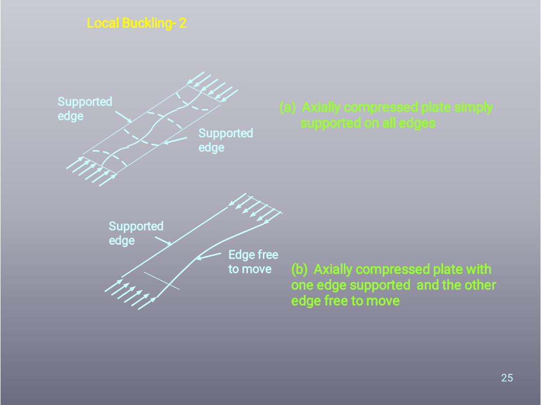
Local Buckling- 2
Supportededge
Supportededge
(a) Axially compressed plate simply supported on all edges
(b) Axially compressed plate with one edge supported and the other edge free to move
Supportededge
Edge freeto move

26
Local Buckling - 3
The technique of stiffening the element
Unstiffenedelement withan edge free tomove
Internalelement
Section with unstiffenedelement
Edges stiffened to preventfree movement
Internal element withsupported edges
The same section withstiffened outstands
Edge stiffenedelement

27
Local Buckling - 4
• Post - Critical Behaviour
2
effb
(c) Effective width
M
M
(a) Buckled Shape
(b) Stress Distribution
b
Local Buckling Effects

28
Local Buckling - 7
•
•
•
•
Effective Width Concept Lightly stressed regions at the centre are leasteffective.
Regions near the supports are far more effective. The effective width, (beff ) multiplied by the edge stress(e) is the same as the mean stress across the sectionmultiplied by the total width (b ) of the compressionmember.

29
Local Buckling - 13
•
•
•
•
Maximum width to thickness ratios (IS: 801 and BS5950, Part 5 )
Stiffened elements with one longitudinal edgeconnected to a flange or web element and the otherstiffened by a simple lip: 60 Stiffened elements with both longitudinal edgesconnected to other stiffened elements: 500 Unstiffened compression elements: 60

30
Local Buckling - 14
•
•
Treatment of Elements with Stiffeners Edge Stiffeners
Elements having b/t 60 and provided with simple liphaving one fifth of the element width may be regardedas a stiffened element If b/t > 60 , then the lip itself may have stabilityproblems. Therefore “compound” lips are designed.

31
Local Buckling - 15
• Intermediate stiffeners
The required minimum moment of inertia of the stiffener aboutthe axis 0-0
280
f
t
w.t0.2I
y2
4m i n
w
t
o o
Intermediatestiffener
Intermediate stiffeners is used to transform a wide andineffective element into highly effective element

32
Local Buckling - 17
•
–
Proportioning of Stiffeners
Performance of unstiffened elements can besubstantially improved by
introducing stiffeners such as lip.introducing intermediate stiffeners.According to BS 5950, an unstiffened element canbe regarded as a stiffened element, when the lipor the edge stiffener has a moment of inertiaabout an axis through the plate middle surfaceequal to or greater than
375
tbI
3
m i n

33
Local Buckling - 18
• The Indian standard IS: 801-1975 prescribes a minimum moment of inertia for the lip given by
y
24
F281200
twt1.83I m i n
Imin should not be less than 9.2 t4 .
6y
2
m i n F281200
twt2.8d
•For a simple lip bent at right angles to the stiffened element, the required overall depth dmin is given by
dmin should be less than 4.8 t

34
Beams•
•
•
Laterally stable beams - Beams, which do notbuckle laterally .Designs may be carried out using simple beamtheory, making modifications for local buckling ofthe webs.This is done by imposing a maximum compressivestress,(which may be considered to act on thebending element ) given by
yyy
fp280
f
t
D0019.013.1p O

35
Beams - 3
•1.
Other Beam Failure CriteriaWeb Crushing
Generally occurs under concentrated load or atsupport point when deep slender webs are employed.
(a) Web crushing
Space between bottom flangeand supporting beam
Web cleat used to avoidweb crushing
(b) Cleats to avoid web crushing
Web crushing and how to avoid it

36
Beams - 3
Shear Buckling
W
Web buckling
•
•
••
Thin webs subjected to predominant shear willbuckle. The maximum shear in a beam web is invariably
limited to 0.7 times yield stress in shear. In deep webs, where shear buckling can occur, theaverage shear stress (pv) must be less than
2
vD
t1000p

37
Beams - 4
•
Lateral Buckling The great majority of cold formed beams are (by
design) restrained against lateral deflections.Lateral buckling will not occur if the beam under
loading bends only about the minor axis.Lateral buckling occurs only in "long" beams and is
characterised by the beam moving laterally and twisting when a transverse load is applied

38
Beams - 5
Lateral Buckling
Bending andtwisting

39
Beams - 7
Single and Double Curvature Bending
M MSingle Curvature
M M Double Curvature

40
Design of Column

41
Design of Column

42
Design of Column (IS 5384:1969)

43

44
THANK YOU
Copyright © 2022 FDOKUMEN