Evaluation of the slenderness ratio in built-up cold-formed box sections
7
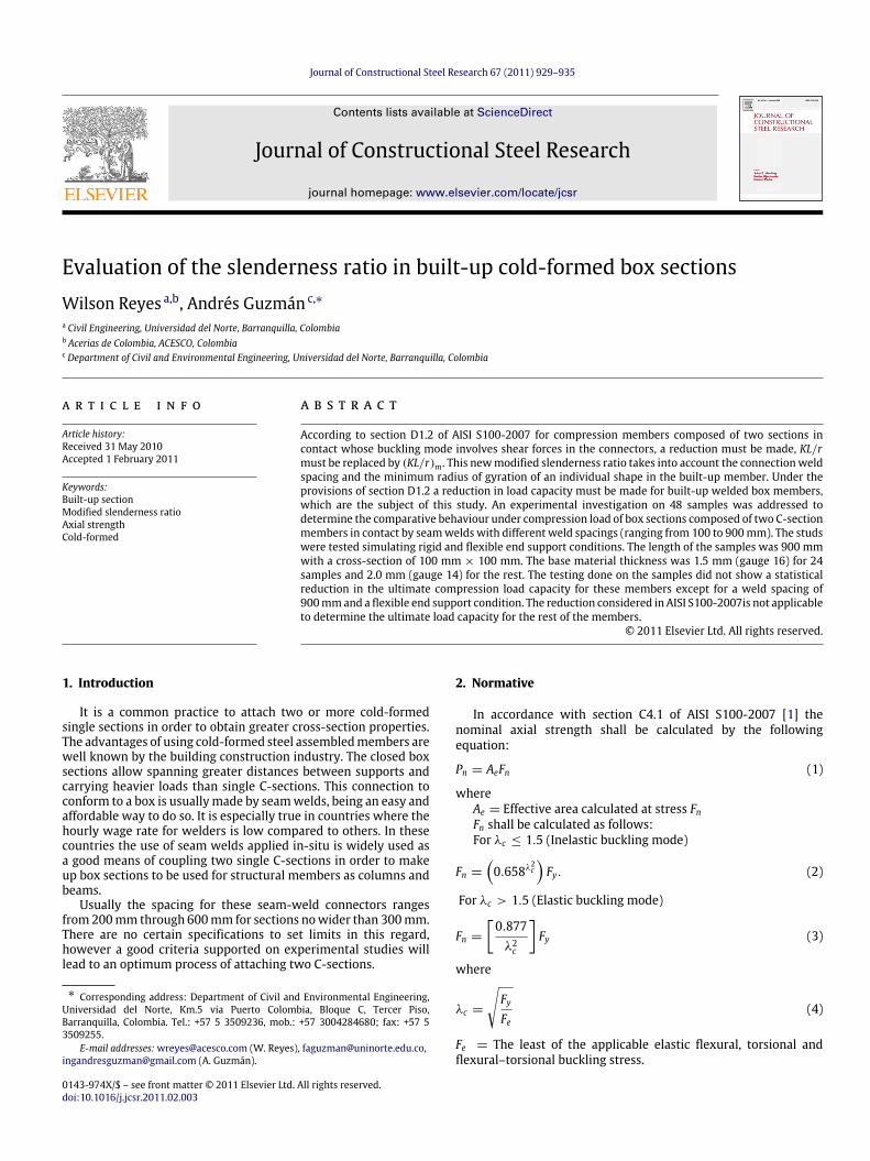
Journal of Constructional Steel Research 67 (2011) 929–935 Contents lists available at ScienceDirect Journal of Constructional Steel Research journal homepage: www.elsevier.com/locate/jcsr Evaluation of the slenderness ratio in built-up cold-formed box sections Wilson Reyes a,b , Andrés Guzmán c,∗ a Civil Engineering, Universidad del Norte, Barranquilla, Colombia b Acerias de Colombia, ACESCO, Colombia c Department of Civil and Environmental Engineering, Universidad del Norte, Barranquilla, Colombia article info Article history: Received 31 May 2010 Accepted 1 February 2011 Keywords: Built-up section Modified slenderness ratio Axial strength Cold-formed abstract According to section D1.2 of AISI S100-2007 for compression members composed of two sections in contact whose buckling mode involves shear forces in the connectors, a reduction must be made, KL/r must be replaced by (KL/r ) m . This new modified slenderness ratio takes into account the connection weld spacing and the minimum radius of gyration of an individual shape in the built-up member. Under the provisions of section D1.2 a reduction in load capacity must be made for built-up welded box members, which are the subject of this study. An experimental investigation on 48 samples was addressed to determine the comparative behaviour under compression load of box sections composed of two C-section members in contact by seam welds with different weld spacings (ranging from 100 to 900 mm). The studs were tested simulating rigid and flexible end support conditions. The length of the samples was 900 mm with a cross-section of 100 mm × 100 mm. The base material thickness was 1.5 mm (gauge 16) for 24 samples and 2.0 mm (gauge 14) for the rest. The testing done on the samples did not show a statistical reduction in the ultimate compression load capacity for these members except for a weld spacing of 900 mm and a flexible end support condition. The reduction considered in AISI S100-2007is not applicable to determine the ultimate load capacity for the rest of the members. © 2011 Elsevier Ltd. All rights reserved. 1. Introduction It is a common practice to attach two or more cold-formed single sections in order to obtain greater cross-section properties. The advantages of using cold-formed steel assembled members are well known by the building construction industry. The closed box sections allow spanning greater distances between supports and carrying heavier loads than single C-sections. This connection to conform to a box is usually made by seam welds, being an easy and affordable way to do so. It is especially true in countries where the hourly wage rate for welders is low compared to others. In these countries the use of seam welds applied in-situ is widely used as a good means of coupling two single C-sections in order to make up box sections to be used for structural members as columns and beams. Usually the spacing for these seam-weld connectors ranges from 200 mm through 600 mm for sections no wider than 300 mm. There are no certain specifications to set limits in this regard, however a good criteria supported on experimental studies will lead to an optimum process of attaching two C-sections. ∗ Corresponding address: Department of Civil and Environmental Engineering, Universidad del Norte, Km.5 via Puerto Colombia, Bloque C, Tercer Piso, Barranquilla, Colombia. Tel.: +57 5 3509236, mob.: +57 3004284680; fax: +57 5 3509255. E-mail addresses: [email protected] (W. Reyes), [email protected], [email protected] (A. Guzmán). 2. Normative In accordance with section C4.1 of AISI S100-2007 [1] the nominal axial strength shall be calculated by the following equation: P n = A e F n (1) where A e = Effective area calculated at stress F n F n shall be calculated as follows: For λ c ≤ 1.5 (Inelastic buckling mode) F n = 0.658 λ 2 c F y . (2) For λ c > 1.5 (Elastic buckling mode) F n = [ 0.877 λ 2 c ] F y (3) where λ c = F y F e (4) F e = The least of the applicable elastic flexural, torsional and flexural–torsional buckling stress. 0143-974X/$ – see front matter © 2011 Elsevier Ltd. All rights reserved. doi:10.1016/j.jcsr.2011.02.003
-
Upload
independent -
Category
Documents
-
view
1 -
download
0
Transcript of Evaluation of the slenderness ratio in built-up cold-formed box sections
Journal of Constructional Steel Research 67 (2011) 929–935
Contents lists available at ScienceDirect
Journal of Constructional Steel Research
journal homepage: www.elsevier.com/locate/jcsr
Evaluation of the slenderness ratio in built-up cold-formed box sectionsWilson Reyes a,b, Andrés Guzmán c,∗
a Civil Engineering, Universidad del Norte, Barranquilla, Colombiab Acerias de Colombia, ACESCO, Colombiac Department of Civil and Environmental Engineering, Universidad del Norte, Barranquilla, Colombia
a r t i c l e i n f o
Article history:Received 31 May 2010Accepted 1 February 2011
Keywords:Built-up sectionModified slenderness ratioAxial strengthCold-formed
a b s t r a c t
According to section D1.2 of AISI S100-2007 for compression members composed of two sections incontact whose buckling mode involves shear forces in the connectors, a reduction must be made, KL/rmust be replaced by (KL/r)m. This newmodified slenderness ratio takes into account the connectionweldspacing and the minimum radius of gyration of an individual shape in the built-up member. Under theprovisions of section D1.2 a reduction in load capacity must be made for built-up welded box members,which are the subject of this study. An experimental investigation on 48 samples was addressed todetermine the comparative behaviour under compression load of box sections composed of two C-sectionmembers in contact by seamwelds with different weld spacings (ranging from 100 to 900mm). The studswere tested simulating rigid and flexible end support conditions. The length of the samples was 900 mmwith a cross-section of 100 mm × 100 mm. The base material thickness was 1.5 mm (gauge 16) for 24samples and 2.0 mm (gauge 14) for the rest. The testing done on the samples did not show a statisticalreduction in the ultimate compression load capacity for these members except for a weld spacing of900mmand a flexible end support condition. The reduction considered in AISI S100-2007is not applicableto determine the ultimate load capacity for the rest of the members.
© 2011 Elsevier Ltd. All rights reserved.
1. Introduction
It is a common practice to attach two or more cold-formedsingle sections in order to obtain greater cross-section properties.The advantages of using cold-formed steel assembledmembers arewell known by the building construction industry. The closed boxsections allow spanning greater distances between supports andcarrying heavier loads than single C-sections. This connection toconform to a box is usuallymade by seamwelds, being an easy andaffordable way to do so. It is especially true in countries where thehourly wage rate for welders is low compared to others. In thesecountries the use of seam welds applied in-situ is widely used asa good means of coupling two single C-sections in order to makeup box sections to be used for structural members as columns andbeams.
Usually the spacing for these seam-weld connectors rangesfrom200mm through 600mm for sections nowider than 300mm.There are no certain specifications to set limits in this regard,however a good criteria supported on experimental studies willlead to an optimum process of attaching two C-sections.
∗ Corresponding address: Department of Civil and Environmental Engineering,Universidad del Norte, Km.5 via Puerto Colombia, Bloque C, Tercer Piso,Barranquilla, Colombia. Tel.: +57 5 3509236, mob.: +57 3004284680; fax: +57 53509255.
E-mail addresses:[email protected] (W. Reyes), [email protected],[email protected] (A. Guzmán).
0143-974X/$ – see front matter© 2011 Elsevier Ltd. All rights reserved.doi:10.1016/j.jcsr.2011.02.003
2. Normative
In accordance with section C4.1 of AISI S100-2007 [1] thenominal axial strength shall be calculated by the followingequation:
Pn = AeFn (1)
whereAe = Effective area calculated at stress FnFn shall be calculated as follows:For λc ≤ 1.5 (Inelastic buckling mode)
Fn =
0.658λ2c
Fy. (2)
For λc > 1.5 (Elastic buckling mode)
Fn =
[0.877λ2c
]Fy (3)
where
λc =
FyFe
(4)
Fe = The least of the applicable elastic flexural, torsional andflexural–torsional buckling stress.

930 W. Reyes, A. Guzmán / Journal of Constructional Steel Research 67 (2011) 929–935
Fig. 1. Typical tested sample for rigid end supports (left) and for flexible end supports (right).
For sections not subject to torsional or flexural–torsionalbuckling as doubly-symmetric sections or closed cross-sections:
Fe =π2E
(KL/r)2(5)
whereE= Modulus of ElasticityK= Effective Length factorL= Laterally unbraced length of memberr= Radius of gyration of full unreduced cross section about axis
of buckling.The design specifications for assembled members under
compression loads described in the section D1.2 of the AISI S100-2007 [1] modify the overall slenderness ratio of the built-upmember according to the spacing between connection seamweldsin individual shapes. If shear forces are present in the weldconnector due to deformations related to the buckling mode of themember, KL/r , in Eq. (5), shall be replaced by (KL/r)m as follows:
KLr
m
=
KLr
2
o+
ari
2
o(6)
where(KL/r)o= Overall slenderness of the entire section about built-
up member axisa= Seam weld spacingri= Minimum radius of gyration of full unreduced cross-
sectional area of an individual shape in a built-up member.Other studies take a different approach to determine the
modified slenderness ratio of a built-up member [2,3]. The AISCSpecification for Structural Steel Buildings [4] presents a differentexpression based on the work of Zahn and Haaijer [5] to predictthe behaviour of built-up sections with welded connectors:
For a/ri > 50KLr
m
=
KLr
2
o+
ari
− 502
. (7)
For a/ri ≤ 50KLr
m
=
KLr
o. (8)
The work of Zahn and Haaijer concludes that reduction shall beapplicable when the value of a/ri is greater than 50.
3. Experimental investigation
The study performed by Stone and LaBoube [6] provided thebasic guidance to develop all the research on assembled boxmembers.
Fig. 1 presents both the typical stud sample for the first setrigidly supported (left) and the typical sample for the second setunder a flexible end supporting condition (right). For the flexiblesupport neoprene plates 15 mm thick at each end were used(Fig. 5). The experimentation focused on ultimate axial strengthwas performed at Universidad del Norte, Barranquilla (Colombia).
The purpose of this research is to determine the variation ofthe ultimate load capacity for the built-up member evaluatinghow it is affected by the variability in the weld spacing (distance‘‘a’’ in Fig. 1) taking into consideration different end supportingconditions and also shedding light on determining whethercurrent AISI provisions are applicable for cold-formed box sectionmembers.
The statistical methods used to analyse the data from testsare the standard for numerical data: ANOVA and descriptivestatistics. Several statistical tests were performed: Normality tests,Homoscedasticity test, Barlett’s test, and Residual Analysis. Thestatistical software used for analysis is Minitab 16 (Minitab Inc.,Pennsylvania, US, 2010).
The Fig. 2 shows the dimensions of the cross-section.
3.1. Section and material parameters
The parameters of the typical section are shown in Fig. 2 andtheir magnitudes are shown in Table 1.
All the samples were 900 mm long and the tracks were madeof material 1.5 mm thick. An elastic buckling mode was expectedduring the test.
The material properties were obtained through tensile coupontests (3 per eachmaterial) also performed at Universidad del Norte,Barranquilla (Colombia).
The 1.5 mm thick member complies with (exceeds) the ASTMA1008 Grade 40 Structural Steel requirements: E = 203467 MPa,

W. Reyes, A. Guzmán / Journal of Constructional Steel Research 67 (2011) 929–935 931
Fig. 2. Typical box section.
Table 1Parameter magnitudes of the cross-section.
Parameter Magnitude (mm)
Stud thickness, t 1.5, 2.0Depth, D 100Flange, bf 50Edge stiffener, df 15Weld seam spacing, a 100, 300, 600, 900
Yield Strength Fy = 312.39 MPa, Tensile Strength Fu = 353.87MPa.
The 2.0 mm thick member complies with (exceeds) the ASTMA1011 Grade 50 Structural Steel requirements: E = 216401 MPa,Yield Strength Fy = 411.78 MPa, Tensile Strength Fu = 463.67MPa.
3.2. Test setup
The single C-sections were attached by seam welds of 50 mmlong except for the seam welds on the member ends; there theywere 25 mm long. These seam welds at the ends were used as25mm to consider a continuous support and to consider a constantvalue for a/ri to predict the theoretical response of the built-upmember. The weld spacing of 300 mm is the one commonly usedto attach two single C-sections. The welding work was done usingelectrodes E6011 meeting the specifications of the AWS (Americanwelding society). A complete penetration of the seam welds was
guaranteed. Fig. 3 shows the work of attaching the two singleC-sections.
The first set of 24 samples was directly supported on the platesof the Universal Testing Machine. This condition simulates a rigidsupport for the structural members. No additional plates wereused to test the samples during the first set. The second set of 24samples was similar to the first but the end support conditionswere changed. In this case neoprene plates 15mm thick were usedto simulate a flexible supporting condition (Fig. 5). Short trackswere fixed by self-drilling screws to the member ends to considerthe real support handled in construction.
According to quality control of ACESCO products, the dimen-sions of the section are known in advance. Nevertheless, thesedimensionswere confirmed after the sectionwaswelded andwerechecked against maximum tolerances. The cross-section of thebuilt-up members was symmetric. The load was applied througha load disk; the centroid of the load disk was settled to matchup as best as possible the estimated effective centroid of the steelsection.
All the specimens were tested under compression load inthe Universal Testing Machine. The criterion to stop the testingwas determined by the point where failure load was reached(ultimate load capacity). The test was stopped shortly afterreaching that point, at which point the force–displacement curvestarted decreasing. The values for displacement come from theactuator head displacement.
3.3. Test procedure
The failure load, Ptest, is the largest load that a built-up membersustained during a test. The load application was done through thecentroid of the section after adjusting the samples on the bearingsupports of the machine according to Figs. 4 and 5. All the sampleswere tested under compression loads [7].
4. Test results
Almost all the specimens with rigid support showed localbuckling near the connection welds during the test. Neverthelessthey were still able to continue carrying load. The set of samplessupported on the neoprene plate mainly showed local buckling atthe member ends and several of them showed local buckling nearthe connection seamwelds. Most of the specimens reached failureload after presenting prominent lateral deformations on the wallsof the cross-section. At the end of the testing for the first set all thespecimens presented a smooth curvature as shown in Fig. 6.
Some of the rigidly supported specimens showed a curvaturedifferent from Fig. 6 before reaching the failure load. Each singleC-section curved smoothly in opposite directions one fromanotherfollowing the pattern shown in Fig. 7. It was mainly presented insamples with weld spacing of 600 and 900 mm.
Fig. 3. Attachment of two single sections.

932 W. Reyes, A. Guzmán / Journal of Constructional Steel Research 67 (2011) 929–935
Fig. 4. Test setup for the rigid support condition.
Fig. 5. Test setup for the flexible support condition.
Fig. 6. Typical failure mode for rigidly supported specimens.
On the other hand the second set of specimens on flexiblesupports showed a local buckling at the ends. The typical curvatureis described in Fig. 8.
The specimens with seam weld spacing of 900 mm on flexiblesupports presented a deformation as shown in Fig. 9. EachC-section member curved in a direction opposite from anotherlimiting the maximum load capacity of the member. There was asignificant statistical reduction in the maximum load capacity forthese samples.
Tables 2 and 3 summarise the failure loads for each specimen.These tables collect all themaximum loads obtained from the testsfor rigid and flexible supports. The results of the first set of samples,under a rigid support condition, are summarised in Table 2
(Ptest1). Table 3 presents the results obtained from the second setof samples according to a flexible support condition (Ptest2). InFigs. 12 and 13 several load–displacement curves obtained fromtests present combined results from both sets of samples as acomparison of the top loads sustained during tests.
Figs. 12 and 13 shows the difference presented between theresults for samples under flexible versus rigid support conditions.These curves describe the behaviour presented during the testfor specimens with weld spacing of 900 mm before reachingthe failure load (maximum load capacity). For this spacing therewas a significant statistical difference between the failure loadobtained from rigid and flexible supports for both 1.5 and 2.0 mmthicknesses.

W. Reyes, A. Guzmán / Journal of Constructional Steel Research 67 (2011) 929–935 933
Fig. 7. Other failure modes for rigidly supported specimens.
Fig. 8. Local buckling at ends for samples with flexible supports (left) and buckling close to seam welds along the specimen (right).
Fig. 9. Typical failure curvature mode on samples with flexible supports and welds spaced 900 mm (there was a reduction in the maximum load capacity under thisconfiguration).
5. Data analysis
In Fig. 10 the predicted failure loads are shown for the built-up section C 100 × 50–1.5 mm according to AISI formulations.Each curve represents a capacity curve for a different value for theconnection weld spacing ‘‘a’’ in a range of effective length from0 to 2000 mm. The top and bottom curves represent the totally
welded and non-welded box (predicted failure load for a C-sectionmultiplied by 2), respectively. Increasing the value for ‘‘a’’, thecapacity curve diminishes. Fig. 11 evidences a similar behaviourfor the C100 × 50–2.0 mm.
The results of failure load from the first set, Ptest1, and thesecond test, Ptest2, were compared one to another. Figs. 12 and13 shows separately the difference presented due to the different

934 W. Reyes, A. Guzmán / Journal of Constructional Steel Research 67 (2011) 929–935
Table 2Built-up compression-member test results for rigid supports.
Reference Weld spacing (mm) Ptest1 , Failure load (kN)1st test 2nd test 3rd test
Box 100 × 100–1.5 mm 100 131.4 141.6 133.2Box 100 × 100–1.5 mm 300 133.1 134.0 129.8Box 100 × 100–1.5 mm 600 131.0 123.6 121.1Box 100 × 100–1.5 mm 900 141.9 130.2 144.3Box 100 × 100–2.0 mm 100 240.1 265.4 256.9Box 100 × 100–2.0 mm 300 264.0 267.9 264.1Box 100 × 100–2.0 mm 600 263.8 246.2 263.9Box 100 × 100–2.0 mm 900 257.5 269.6 263.9
Table 3Built-up compression-member test results for flexible supports.
Reference Weld spacing (mm) Ptest2 , Failure load (kN)1st test 2nd test 3rd test
Box 100 × 100–1.5 mm 100 131.2 125.8 129.7Box 100 × 100–1.5 mm 300 120.9 128.2 121.4Box 100 × 100–1.5 mm 600 124.8 121.8 129.7Box 100 × 100–1.5 mm 900a 115.8 119.5 118.2Box 100 × 100–2.0 mm 100 239.4 247.8 251.8Box 100 × 100–2.0 mm 300 250.8 262.9 259.5Box 100 × 100–2.0 mm 600 243.6 253.3 254.9Box 100 × 100–2.0 mm 900a 238.3 235.8 240.0a These samples presented a significant statistical reduction in the average of the
maximum load capacity.
Fig. 10. Capacity curves for box members 100 × 100–1.5 mm.
seam weld spacing in the cold-formed samples from material 1.5and 2.0 mm thick. The Ptest2/Ptest1 ratio establishes the variation ofthe maximum load capacity between the second and the first test.
According to the values presented in Figs. 14 and 15 andaccording to a statistical analysis, it could not be stated as ageneralised behaviour a noticeable reduction in themaximum loadcapacity due to the greater spacing between the seam welds. Forboth end support conditions the statistical values of failure loadare about the same magnitude except for the 900 mm spacingwith a flexible end support. This latter spacing showed a reducedcapacity with a flexible support compared to that with an end rigidsupport. The reduction considered in section D1.2 of the NorthAmerican Specification (AISI S100-2007) due to the weld spacingwould not be applicable to predict the failure load up to a weldspacing of 600 mm no matter the type of support. In other words,the actual overall slenderness ratio of the entire section might notbe modified due to the weld spacing as it is less than or equal to600 mm.
Fig. 11. Capacity curves for box members 100 × 100–2.0 mm.
Fig. 12. Comparative behaviour of samples under Rigid versus Flexible supportconditions for box members 100 × 100–1.5 mm and weld spacing of 900 mm.

W. Reyes, A. Guzmán / Journal of Constructional Steel Research 67 (2011) 929–935 935
Fig. 13. Comparative behaviour of samples under Rigid versus Flexible supportconditions for box members 100 × 100–2.0 mm and weld spacing of 900 mm.
Fig. 14. Comparison between the maximum load capacity (failure load) under aflexible and a rigid support condition. Cold-formedbox section of 100mm×100mmand thickness material 1.5 mm.
For the seamweld spacing of 900mm the results obtained fromthe second set of samples with flexible supports are, by an averageof 15% and 10%, below the values obtained with rigid supportsfor the material 2.0 and 1.5 mm thick, respectively. This indicatesthat it may be necessary to use a reduction in the load capacity,using the same weld spacing or greater, following the provisionsof section D1.2 of the American Specification.
6. Conclusions
The analysis of the results obtained from the 48 specimensshows that the modified slenderness ratio is not always necessaryfor material 1.5 and 2.0 mm thick and therefore the actualslenderness ratio could be used to compute the ultimate loadcapacity for these structural members if the seam weld spacingis less than or equal to 600 mm since there is not a significantstatistical reduction in the failure load in laboratory tests.
Fig. 15. Comparison between the maximum load capacity (failure load) under aflexible and a rigid support condition. Cold-formedbox section of 100mm×100mmand thickness material 2.0 mm.
The values were slightly affected by the type of support butthis reduction did not represent a significant statistical differenceexcept for the samples on flexible supports with a seam weldspacing of 900mm.Disregarding this latter spacing there is noneedto use the modified slenderness ratio to determine the maximumload capacity of the members under consideration no matterthe type of support. This observation concurs and expands theapplication of the AISC approach for built-up members conformedfrom two C-section members in contact by seam welds [4].
Acknowledgements
ACERIASDECOLOMBIA, ACESCO&CIA S.C.A., PIMSAParque Ind-ustrialMalambo,Malambo, Atlántico, Colombia,www.acesco.com.
Garza, Luis, M.Sc., Associated Professor of the Department ofCivil Engineering, Universidad Nacional de Medellín, Colombia,[email protected].
LaBoube, Roger, Ph.D, Department of Civil Engineering, Univer-sity of Missouri-Rolla, Rolla, MO, USA. [email protected].
Tests and Materials Laboratory of the Universidad del Norte,Department of Mechanical Engineering, Barranquilla, Colombia,www.uninorte.edu.co.
References
[1] American Iron and Steel Institute, AISI. North American specification for thedesign of cold-formed steel structural members. Washington, DC; 2007.
[2] Duan L, Reno M, Uang CM. Effect of compound buckling on compressionstrength of built-up members. Engineering Journal 2002;(1/4):30–7.
[3] Sato A, Uang CM.Modified slenderness ratio for built-upmembers. EngineeringJournal 2007;(3/4):269–80.
[4] American Institute of Steel Construction, Inc., AISC. Manual of Steel Construc-tion, Load and Resistance Factor Design. Chicago; 2005.
[5] Zahn CJ, Haaijer G. Effect of connector spacing and flexural–torsional bucklingon double-angle compressive strength. Engineering Journal 1988;25:109–18.
[6] Stone TA, LaBoube RA. Behavior of cold-formed steel built-up I-sections. Thin-Walled Structures 2005;43(12):1805–17.
[7] ASTM International. A370: Standard test methods and definitions for mechan-ical testing of steel products. West Conshohocken; 2002.