
How wooden ships are built
124
-
Upload
khangminh22 -
Category
Documents
-
view
2 -
download
0
Transcript of How wooden ships are built


How \Vooden Ships
Are Built
A Practical Treatise onModern American WoodenShip Construction with a
Supplement on LayingOif Wooden Vessels
By H. COLE ESTEPEditor of The Marine Review
THE PENTON PUBLISHING COMPANYPublisher of The Marine Review
Cleveland, Ohio
1918
Copyright in The United States and Canada
and
Entered at Stationers' Hall, London
1918
By The Penton Publishing Company
Cleveland, Ohio
All Rights Reserved
A77
Prefreiace
^^^7HE revival of wooden shipbuilding in the United States dates from the latter part of
a ^J 1915. In April, 1917, at the time we declared war against Germany, over ISO large
^^^^/ wooden vessels were under construction along our coasts, principally in New England,
the South and the Pacific Northwest. With America's entry into the war, the tonnage
requirements of the entente allies were tremendously increased. It soon became evident that
the United States would be called upon to construct an enormous armada of steel cargo carriers
and in addition as many wooden vessels as could possibly be turned out. Subsequent events up
to the spring of 1918 have served only to emphasize the problem. The universal cry is ships,
ships—and yet more ships ! The necessity, under these conditions, for a large fleet of wooden
vessels is no longer disputed, and wooden shipbuilding flourishes all around our far-flung coast
line from Maine to Washington.
This revival of the art of wooden shipbuilding has brought with it an insistent demand for
information on how wooden ships are built. Compared with the needs of today, the number
of expert wooden shipbuilders in the United States at the outbreak of our war with Germanyconstituted scarcely more than a corporal's guard. Thousands of new men have been inducted
into the business. These men must be trained. They must be taught the "know how".
It is to assist in this important work of training that this book is offered. In other words,
the book has been prepared to meet a war emergency and it is hoped the information it contains
is of practical value.
Most of the material appeared originally in a series of articles published in The MarineReview between June, 1917, and March, 1918. The entire text, however, has been carefully revised
and brought down to date.
The illustrations, which the publisher believes form perhaps the most valuable feature of
the volume, have been carefully selected. Over 150 of the original photographs were madepersonally by the author expressly for this work. They were taken with the sole purpose of
showing clearly and accurately how modern wooden ships actually are constructed. The aim in
every case was to present important details of construction rather than general views. To obtain
the photographs and collect the material for this work the author traveled extensively and visited
nearly all of the important wooden shipyards in the United States.
An effort has been made to produce a book that is practical and illustrative and one that
also reflects current American practice accurately.
The mathematical theory of ship design and other details which come more within the
province of the naval architect than the shipbuilder have been omitted. As a supplement,
however, two chapters on laying down wooden ships from the treatise of the late Samuel J. P.
Thearle have been added. Acknowledgment is made to John W. Perrin, librarian, Case Library,
Cleveland, for the opportunity to reprint portions of this rare work published originally by
William Collins Sons & Co., London. While Professor Thearle deals with laying down British
ships of the line, the underlying principles of which he treats are unchangeable and it is doubtful
if any present-day author could present the subject more lucidly.
The publisher and author wish to express their appreciation of the generous assistance they
received from the leading wooden shipbuilders of the country, without whose aid this work would
have been impossible. By permitting full access to their plants and by whole-hearted co-operation
in furnishing valuable data, detailed drawings, etc., they have set an example of patriotism and
broadmindedness that many lines of business could emulate.
For particular services, advice and assistance the author wishes specially to acknowledge
his indebtedness to Capt. James Griffiths and Stanley A. Griffiths, Winslow Marine Railway &Shipbuilding Co., Seattle ; S. H. Hedges, Washington Shipping Corp., Seattle ; M. R. Ward,Grays Harbor Shipbuilding Co., Aberdeen, Wash. ; F. A. Ballin, Supple-Ballin Shipbuilding Corp.,
Portland, Oreg. ; O. P. M. Goss, West Coast Lumberman's association, Seattle; Frank M. Stetson,
Stetson Machine Works, Seattle ; Martin C. Erismann, naval architect, Houston, Texas ; R.
Lawrence Smith, New York, and G. W. Hinckley, Brunswick Marine Construction Co.,
Brunswick, Ga.

Contents
Chapter I— Typical Methods of Construction 1
Chapter II— Strength and Characteristics of Ship Timbers 7
Chapter III— Layout and Equipment of Wooden Shipbuilding Plants 15
Chapter IV— Details of Different Types of Wooden Vessels 23
Chapter V— Details of Frame and Keel Construction 33
Chapter VI — Methods of Framing Forward End of Ship 47
Chapter VII— Framing the After End of the Ship 54
Chapter VIII— Planking, Keelson and Ceiling Construction 64
Chapter IX— Construction of Hold Bracing and Deck Elements 73
Chapter X— Spars, Rudders, Shaft Logs and Engine Beds 83
Supplement
Chapter I— Fundamental Propositions"7
Chapter II— Fairing the Lines"^

LIST OF ILLUSTRATIONSPAGE
Fig. 1
—
Launching a large wooden steamer at a shipyard near New Orleans 1
Fig. 2
—
Detail of keel construction of English ship 2
Fig. 3
—
Midship section of a typical nineteenth century English ship 2
Fig. 4
—
Midship section of a wooden ship designed by a modern Pacific Coast Naval Architect 3
Fig. 5
—
Midship section of a modern American wooden ship of the conventional type 3
Fig. 6
—
Typical construction views in a southern wooden shipbuilding yard 4
Fig. 7
—
Cross section showing method of reinforcement patented by Frank E. Kirby 5
Fig. 8
—
Fashioning curved and irregular timbers on a band saw 7
Fig. 9
—
Special machines have been designed for beveling and edging timbers 7
Fig. 10
—
Timbers long enough to require two cars frequently are needed in wooden shipbuilding 8
Fig. 1 1
—
Boring holes with an air drill 8
Fig. 12
—
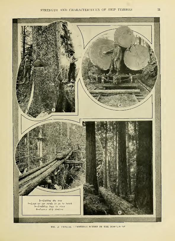
Typical lumbering scenes in the northwest 11
Fig. 13
—
West Coast lumbering requires special heavy duty equipment 12
Fig. 14
—
Division of stringer into volumes for consideration of positions of knots 13
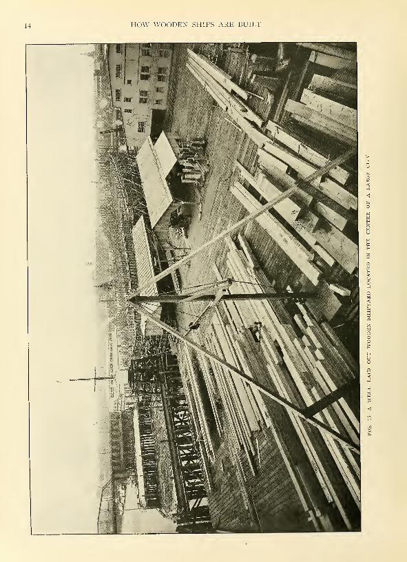
Fig. 15—A well laid out wooden shipyard located in the center of a large city 14
Fig. 16
—
Electrically-driven traveling derrick setting frames in a wooden shipyard 15
Fig. 17
—
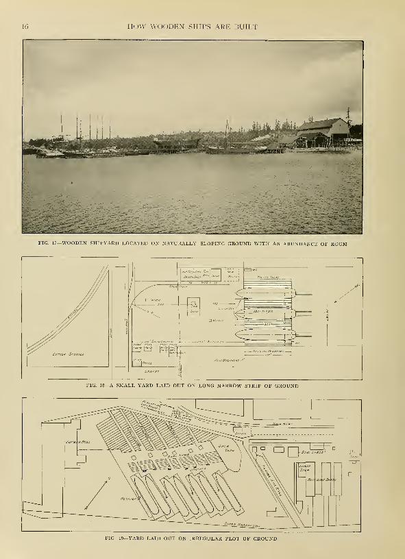
Wooden shipyard located on naturally sloping ground with an abundance of room 16
Fig. 18—A small yard laid out on long narrow strip of ground 16
Fig. 19
—
Yard laid out on irregular plot of ground 16
Fig. 20
—
Yard with four building slips compactly arranged on city property 17
Fig. 21—A steel framed revolving crane for wooden shipyard 17
Fig. 22
—
Mill containing saws and woodworking machinery 18
Fig. 23
—
Cut-off and band saw sheds in a western shipyard 18
Fig. 24
—
General view of a Seattle shipyard showing beveling machine, arrangement of derricks, building slips, etc. 19
Fig. 25
—
Woodworking machinery in a Puget sound shipyard 20
Fig. 26
—
Bandsawing bevels in a south Atlantic shipyard 20
Fig. 27
—
Derricks and hoisting engine in a southern yard 20
Fig. 28
—
Timber hauling engines in a Grays Harbor shipyard 20
Fig. 29
—
Driving piles for building ways in a Georgia shipyard 20
Fig. 30
—
General arrangement of building ways showing vessels in various stages of construction 21
Fig. 31
—
Portable electrically driven planer 21
Fig. 32
—
Band sawing equipment in a Pacific coast yard 21
Fig. 33
—
Traveling table for handling timber around machines 21
Fig. 34—A building shed protects the work from the weather 21
Fig. 35—A 5-masted, topmast wooden auxiliary schooner built at a prominent Pacific coast shipyard 23
Fig. 36—Midship section and construction details of a 290-foot, 5-masted topmast auxiliary schooner 24
Fig. 37
—
Midship section and construction details of 4000-ton wooden steamer designed for construction on the
Pacific coast • 25
Fig. 38—A 5-masted wooden auxiliary schooner undergoing her trial trip 26
Fig. 39
—
Three-thousand-ton, 4-masted schooner built at Seattle, Wash 26
Fig. 40
—
Midship section and construction details of a 4000-ton motor ship with diagonal planking 27
Fig. 41
—
Outboard profile and deck plan of a typical 4000-ton wooden steamship 28
Fig. 42
—
Outboard profile and deck plan of 4500-ton wooden steamship with propelling machinery aft 28
Fig. 43
—
Outboard profile and deck plan of 4000-ton motor ship designed for overseas service 29
Fig. 44
—
Inboard profile of 5-masted, topmast auxiliary schooner showing arrangement of center girder-keelson... 30
Fig. 45—A typical 4-masted wooden auxiliary schooner under construction on Puget sound 31
Fig. 46
—
Frame of a typical wooden vessel nearly ready for planking 33
Fig. 47
—
La\'ing-down the lines of a ship on the mold-loft floor 34
Fig. 48
—
Laying the keel of a 4000-ton motor ship 34
viii

LIST OF ILLUSTRATIONS
PAGE
Fig. 49
—
Finishing the framing of a large wooden ship on the Pacific coast 34
Fig. SO
—
Framing stage laid alongside keel—the frames are hoisted into position by means of a simple tackle 35
Fig. 51
—
Assembling frame futtocks on framing stage 35
Fig. 52
—
Resawing frame joints to a proper fit 35
Fig. 53
—
Setting keel blocks to the proper height 36
Fig. 54
—
Setting keel blocks on sand 36
Fig. 55
—
Keel wedged in place on keel blocks 36
Fig. 56
—
Laying the keel in a southern shipyard 36
Fig. 57
—
Scaffolding arranged alongside keel blocks 36
Fig. 58
—
Keel near stern 36
Fig. 59
—
Frame timbers and molds 37
Fig. 60
—
Marking frame timbers 37
Fig. 61
—
Cut-off saw for frame timbers 37
Fig. 62
—
Band saw for shaping frame timbers 37
Fig. 63—A frame buttock after leaving the band saw 37
Fig. 64
—
General arrangement of framing stage 37
Fig. 65
—
Setting frames by means of a traveling crane 38
Fig. 66
—
Raising frames by means of block and tackle 38
Fig. 67
—
Frames raised, ready for plumbing and horning 38
Fig. 68
—
Hand-winch for hauling timbers through band saw 39
Fig. 69
—
Detail of bolted frame joints 39
Fig. 70
—
Another view of bolted frame construction 39
Fig. 71
—
Ribbands in place and shoring under frame 39
Fig. 72
—
Framing stage in a Georgia shipyard 40
Fig. 73—Frame of a vessel in a Georgia shipyard 40
Fig. 74—Two sets of cross spalls sometimes are used to hold the frame sections together 40
Fig. 75
—
Upper part of arch strapping 41
Fig. 76
—
Lower part of arch strapping showing method of fastening the butts 41
Fig. 77—Detail of standard frame construction 42
Fig. 78
—
Detail of bolted frame construction 42
Fig. 79
—
Frame near bow using natural crooks 42
Fig. 80
—
Framing a ship in a southern yard 42
Fig. 81
—
Sometimes the floors are laid first and the frame pieces raised afterward 42
Fig. 82
—
Detail of frames heeling to deadwood 42
Fig. 83—Bow construction of a large Pacific coast motor schooner 46
Fig. 84
—
Details of stem showing large natural knee 47
Fig. 85
—
Stem reinforced without use of a knee 48
Fig. 86
—
Detailed drawing of stem of a steamer the general arrangement of which is shown in Fig. 84 48
Fig. 87
—
Interior of bow construction of a 290-foot motor schooner 49
Fig. 88
—
Detail of stem construction of the schooner shown in Fig. 87 illustrating method of fastening forwardends of keelson timbers to stem 49
Fig. 89
—
Arrangement of stem and knighthead at upper end near main deck 49
Fig. 90
—
Staging surrounding a clipper-type bow under construction 49
Fig. 91
—
Details of forefoot showing use of natural knee and angle blocks 51
Fig. 92
—
Another view of the same stem 51
Fig. 93
—
Same stem from the opposite side 51
Fig. 94
—
Steamer type bow under construction partly planked 51
Fig. 95
—
Steamer type bow finished with staging still in place 51
Fig. 96
—
Forward cant frames heeling to deadwood 51
Fig. 97
—
Detail of forefoot of clipper type stem showing na ural knee lock-scarfed to keel 52
Fig. 98
—
Arrangement of floors, keelson and stem of a vessel under construction at a gulf shipyard 52
Fig. 99
—
Details of stem and forward frame construction of a motor schooner under construction on the gulf.... 52
Fig. 100
—
Detail of stern frame of ship being built for United States government 54
Fig. 101
—
Finished transom stern on a 5-masted motor schooner 54
Fig. 102
—
Detail of rudder and rudderpost assembly 54
Fig. 103
—
Detail of upper part of stern framing shown in Fig. 102 55
Fig. 104
—
General view of stern frames and rudder assembly 55
Fig. 105
—
Erecting fore and aft post timbers for a stern of unusually strong construction 55
Fig. 106
—
Detail of transom stern framing of a ship under construction in a southern yard 56

HOW WOODEN SHIPS ARE BUILT
PAGE
Fig. 107
—
Transom type stern in early stages of construction 56
Fig. 108
—
The next step in the construction of a transom stern 56
Fig. 109
—
Interior of a transom stern before transom timbers are in place 56
Fig. 110—A closer view of the interior of the same stern 56
Fig. Ill
—
Fitting transom timbers to fashion timber 56
Fig. 112
—
Stern frame assembly being hoisted into place : 57
Fig. 113
—
Detail of framing of transom type stern 57
Fig. 114
—
Inside of framing of the stern shown in Fig. 113 57
Fig. 115
—
Detail of stern framing from the inside of a ship 58
Fig. 116
—
Another view of the framing of the same ship 58
Fig. 117
—
Lower part of stern framing of the same ship showing sternpost, deadwood, etc 58
Fig. 118
—
Same stern planked up and nearly finished 58
Fig. 119
—
Details of the elliptical or fantail stern shown in Figs. 105 and 125 59
Fig. 120
—
Timber from which quarter-block is hewed 60
Fig. 121
—
Hewing out the quarter-block 60
Fig. 122—A pair of quarter-blocks finished 60
Fig. 123
—
Stern framing showing holes left for reception of qltarter-blocks 60
Fig. 124
—
Quarter-block in place 60
Fig. 125
—
General view of elliptical or fantail stern 60
Fig. 126
—
x\nother view of the stern shown in Fig. 125 61
Fig. 127
—
Natural knee used to connect sternpost to other stern elements 61
Fig. 128
—
Shaft log in twin-screw motor ship 61
Fig. 129
—
Detail of fantail stern construction at knuckle line 62
Fig. 130
—
Arrangement of timbers inside the same stern at the point shown in Fig. 129 62
Fig. 131
—
Timber chute for hauling ceiling strakes and keelsons inside the ship 64
Fig. 132
—
Interior of a wooden ship under construction showing timber chute and scaffolding—bilge ceiling in
PLACE 64
Fig. 133
—
Steam box for softening planks 65
Fig. 134
—
Side of ship with plank in place 65
Fig. 135
—
Dubbing-off and raising lines on ship's side for planking 65
Fig. 136
—
Clamping plank in place prior to spiking 65
Fig. 137
—
Clamping ceiling strakes in place prior to bolting 65
Fig. 138
—
Lower ends of stern frame and deadwood rased for planking 66
Fig. 139
—
Ceiling a ship in a gulf coast yard 66
Fig. 140
—
Bolting down keelson timbers with pneumatic hammers 66
Fig. 141
—
Port side of a completely ceiled wooden motor ship 67
Fig. 142
—
Beveling keelson timbers by hand 68
Fig. 143
—
Making a scarf in a keelson timber 68
Fig. 144
—
The first step in building up a center girder-keelson 68
Fig. 145
—
Clamps used for temporarily securing keelson pieces 68
Fig. 146
—
Boring driftbolt holes in center girder-keelson 68
Fig. 147
—
Center girder-keelson nearly completed 68
Fig. 148
—
Ceiling strakes on a table of automatic beveling machine—note batten along top which indicates theamount of bevel 69
Fig. 149
—
In some yards the ceiling is laid in parallel strakes between the keelsons and the bilge 69
Fig. 150
—
Dubbing-off the inside preparatory to ceiling 69
Fig. 151
—
Keelson construction of a small motor schooner 69
Fig. 152
—
Clamping and bolting upper ceiling strakes in place 70
Fig. 153
—
Ceiling a ship in the way of the stern, showing the use of clamps 70
Fig. 154
—
Detail of stanchion footings in a large wooden ship 73
Fig. 155
—
General view of stanchions in the same ship 73
Fig. 156
—
Stanchions between main and lower deck beams 74
Fig. 157
—
General view of hold framing 74
Fig. 158
—
Safety ladder inside ship 74
Fig. 159
—
Dubbing-off stern bulwarks 74
Fig. 160
—
Arrangement of deck beams near stern 75
Fig. 161
—
Deck of wooden motor schooner nearly completed 75
Fig. 162
—
Deck beams resting on shelf, bolted construction 75

LIST OF ILLUSTRATIONS
PAGE
Fig. 163
—
Details of fastenings of shelf and clamp 75
Fig. 164
—
Main-deck beams with hanging knees in place 76
Fig. 165—Main deck beams fitted to shelf 76
Fig. 166
—
Spiking down deck planking 76
Fig. 167
—
Clamping deck planking in place 76
Fig. 168
—
General view of hold beams showing lumber chute 77
Fig. 169
—
Detail of cast steel knees 77
Fig. 170
—
Hold beams in the way of a hatch 77
Fig. 171
—
Lodging knees in the way of a hatch 77
Fig. 172
—
Detail of hatch beam construction 77
Fig. 173
—
Crane used for setting deck beams 77
Fig. 174
—
Surfacing knees on a special planing machine—knees also are fayed on this machine in lots of 10 or
12, the operation requiring only 15 minutes 78
Fig. 175
—
Section of deck framing of large wooden ship showing method of reinforcing with steel plates and straps 78
Fig. 176
—
Deck of large wooden motor schooner • 79
Fig. 177
—
Caulking deck using heavy maul 79
Fig. 178
—
Finish caulking 79
Fig. 179
—
Inserting pine plugs over spikeheads in deck 79
Fig. 180
—
Rudder details of a 4000-ton wooden vessel 82
Fig. 181
—
Foundation details for a twin-screw oil-engine driven ship fitted with 500-horsepower, 6-cylinder engines 83
Fig. 182
—
Iron-bark rudder stock set up on traveling table of beveling machine 84
Fig. 183
—
Angle chocks used for trimming rudder stock on beveling machine 84
Fig. 184
—
Complete iron-bark rudder for wooden ship 84
Fig. 185
—
Roughing out a spar with an axe 85
Fig. 186
—
Steam-driven cargo winch installed on wooden ship 85
Fig. 187
—
Finishing a spar with a hand plane 85
Fig. 188
—
Steam-driven anchor winch built on Pacific coast 85
Midship section standard wooden steamer for government 6
New wooden vessels vie with steel 72
Supplement
How Wooden Ships Are Laid Onpage
Fig. 1
—
Projecting a point on a plane 88
Fig. 2
—
Determining a point in space 88
Fig. 3
—
Rabatting a line 88
Fig. 4
—
Sheer draft of a sloop of war 88
Fig. 5
—
Waterlines and diagonals 92
Fig. 6
—
Diagram showing method of ending level lines 93
Fig. 7
—
Correct method of drawing bearding line 93
Fig. 8
—
Diagram showing method of drawing a horizontal ribband line 94
Fig. 9
—
Buttock lines and bow lines 94
Fig. 10
—
Contracted method of fairing 95
Fig. 11
—
Accounting for swell for screw shaft 95
Fig. 12
—
Diagram showing method of drawing diagonals in sheer plan 97

Uliiiiiii mi mini nmiiiii iiiliiiiinii i miiiiiiiiii inuiiiiiiiiiiiiiiiiiiiii niuiiiiiiiiiuiiii iiiiiiiiiii iiiiiiiiiiniiiiiiiiii niiiiiiiiiiiniiiii iiiiiiiiiiiiiiiiiiiiiiiiiiiiiiiiiiiiiiiiiiiiiiiiiiiiiiiiiiiiiiiiiiiiiiiiiiiiiiiiiiiiiiiiiiiiiini miming
I H©w Wo©den Skips Are Buaili I
lllllllll^
CHAPTER I
Typical Methods of Construction
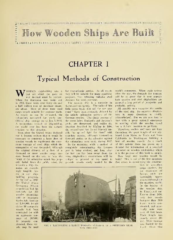
WOODEN shipbuilding was a
lost art which the gods of
war decreed must be revived.
When the European war broke out
in 1914, there were over forty-six and
a half million tons of merchant steam-
ers afloat. Most of them were steel
cargo vessels suitable for overseas trade.
As nearly as can be estimated, the
submarines accounted for nearly one-
fifth of this tonnage up to Jan. 1, 1918.
A tremendous revival of shipbuilding
the world over has been the natural
reaction to this situation.
Soon after the United States declared
war it became evident that it would be
necessary to construct a large fleet of
wooden vessels to supplement the enor-
mous tonnage of steel ships which the
emergencies of war demanded. Although
the original chimera of a fleet of a
thousand or more wooden cargo car-
riers loosed on the seas to bear the
brunt of the submarine attack has prop-
erly faded from the public mind, the
wooden ship re-
mains an exceed-
ingly tangible fac-
tor in our ship-
building program.
At the end of 1917
the United States
Emergency Fleetcorporation had let
contracts for 379
wooden steamships
with an aggregate
deadweight tonnage
of 1,344,900. In ad-
dition 58 composite
vessels had been
contracted for with
an aggregate ton-
nage of 207,000.
If properly con-
structed, these ves-
sels may be used
for transatlantic service. At all events
they will be suitable for many coastwise
purposes, thus releasing valuable steel
steamers for work overseas.
The wooden ship is a necessity in
the present emergency. The ranks of "the
little cargo boats that sail the wet seas
roun' " have been seriously thinned by
the unholy submarine warfare of the
German empire. The dingy tramps of
the ocean lanes, England's and America's
pride, are threatened, and unlike the
situation described by Kipling in 1894,
the man-o'-war has found himself un-
able "to up an' fight for them" with
complete success, although tremendous
forward strides in the offensive against
the submarines were made during 1917.
In the meantime, while a method of
completely exterminating" the German
pest is being evolved, and long after
the last one has been swept from the
seas, shipbuilders everywhere will be
obliged to proceed at top speed to
provide vessels sorely needed by the
FIG. 1—LAUNCHING A LARGE WOODEN STEAMER AT A SHIPYARD NEARNEW ORLEANS
world's commerce. When trade revives
after the war, the demands for tonnage
will be so great that it now appears
both wooden and steel shipbuilders are
assured a long period of prosperity and
profitable activity.
All sensible men recognize the merits
of the steel ship. Its superior effective-
ness in many directions is readily
acknowledged. But we are now face to
face with a great national emergency
in meeting which the wooden vessel
has a definite function to perform.
Therefore, mallets and saws are busy
throughout the great length of our sea-
board, from Maine to Texas and from
California to Washington building a
host of wooden vessels. As a result
of this activity there has grown up a
demand for information of a practical
character on wooden shipbuilding which
it is the purpose of this book to supply.
How large may wooden vessels be
built? This is one of the first questions
that arises in considering the construc-
tion of woodencargo carriers, for
the economies of
large units are
thoroughly appre-
ciate d throughout
the maritime world.
In the heydey of
the wooden ship,
in England and
Europe about 1850,
very few vessels
larger than 2000
tons were con-
structed, and prac-
tically none were
over 40 feet beam.
Their length was
usually about 200
feet. Their tonnage
was limited by the
fact that the

HOW WOODEN SHIPS ARE BUILT
^Middle LineKeblson rLiMBER Board
LuiberStrai
False keel
FIG. -DETAIL OF KEEL CONSTRUCTION OF ENGLISH SHIP
naturally crooked oak timbers used for
the frames grew only in limited sizes.
The same limitations existed in regard
to long timbers, such as keels,, keelsons,
strakes, clamps, shelves and planks,
which had to be built up and well
scarfed, locked, hooked and bolted to
make up for lack of large size material.
It remained for the Pacific coast of the
United States with its boundless supply
of timbers of the largest sizes, to
finally demonstrate that wooden vessels
of 3000 to 3500 or oven 4000 tons dead-
weight capacity are practicable. There
is, however, a difference of opinion
among architects as to the extent to
which the largest hulls should be rein-
forced with steel. In 1917, two wooden
vessels, 308 feet long, 28S feet keel,
with a deadweight capacity of 4300
tons, not including 2500 barrels of oil
fuel for diesel engines, were built on
the north Pacific coast. These vessels,
which are so reinforced with steel as
to fall almost in the composite classifi-
cation, have been given the highest
rating by both American and British
classification societies. Conservative
opinion leans to the view that vessels
without steel reinforcement should not
be built over 260 or 270 feet in length.
For any vessels over 200 feet arch
strapping, at least, seems desirable.
As far as the supply of lumber for
wooden ship construction is concerned,
there is little to fear. The estimated
total supply of merchantable timber in
the United States is placed at the
stupendous figure 2,500,000,000,000 feet
board measure—over two-thousand bil-
lion feet. Canada, in addition has
80,000,000,000 feet. Russia has even
more timber reserves than the United
States. A large portion of the ship-
building timber in this country is in the
Pacific northwest, the state of Washing-
ton alone having over 11,700 square
miles of standing timber, exclusive of
national forest reserves. In the south,
along the gulf and southern Atlantic
coasts, there are almost equally im-
portant timber reserves, and on account
of its superior strength, southern pine is
prized for shipbuilding, although it does
not grow as large as western
fir. Also, in spite of 300 years of
exploitation, the forests of New Eng-
land still contain vast quantities of
ship timber of unusually satisfactory
character.
In fact, New England is one of
the two sections of the country in
which wooden ship building main-
tained a continuous existence through
the lean years, 1880 to 1916. The north
Pacific coast is the only other region
where the art of building woodenvessels failed of complete extinction
during the period just mentioned. It
is from the traditions of both of these
important sections, separated by 3,000
miles of continent, that the revived
art and the new literature of woodenship building must be drawn.
Power for Wooden Ships
Wooden hulls are best adapted to
sail power, but for obvious reasons
such a method of propulsion cannot
be depended upon in modern times,
except for certain special trades. In
the war zones, sailing ships are under
a severe handicap because of their
high visibility. Some form of me-chanical propulsion, therefore, is de-
sirable for practically all of the wood-en vessels now under construction or
to be built during the next 24 months.
Virtually only three types of powerpresent themselves, oil engines of the
TopTiriBEf? Sioeo 6-jr"^
Port d" 7i"to8"
4 #M°{„ol.0Ef6j"
*
iBfirfdfj'OED 7"to 7{"J " \7l0lDED 6%"
?tu>uc/[o-iDtro6"to?"~ " \MoLoeo7i
SS S KHud (Sided 9" to II"" \r~ioLDEo eg'
7-e- S K
\J10LDEO &1
-MIDSHIP SECTION OF A TYPICAL NINETEENTHENGLISH SHIP
TYPICAL METHODS OF CONSTRUCTION
pure or semi-diesel type, reciprocat-
ing steam engines and steam turbines.
The advantages of the oil engine in
fuel economy, increased cargo space,
low visibility, etc., are well known,
and for these reasons a large numberof the wooden vessels built in
1916-17 were fitted with internal com-
bustion motors, usually working twin
screws. Undoubtedly, this arrange-
ment is one of the most satisfactory
that could be devised for large wood-en merchant ships. But it has been
shown there are not enough skilled
oil engine builders in the country to
supply the demand at the present
time. Therefore recourse is had to
steam. The question of obtaining
enough skilled engineers also enters
into this problem.
For a full-powered ship, the con-
census of opinion seems to be
that about 1,500 horsepower is neces-
sary for propelling a 3,000-ton vessel.
In spite of the advantages of the
oil engine, steam is not without its
advocates, especially among those whopoint out the space saving possibilities
of the turbine.
Types of Hull Construction
Compared with steel vessels, wood-en ships are weak in both longi-
-MIDSHIP SECTION OF A MODERN AMERICAN WOODEN SHIP OFTHE CONVENTIONAL TYPE
tudinal and transverse directions, al-
though their greatest structural fail-
ings appear to be in longitudinal
planes. Large wooden hulls are sus-
ceptible to both hogging and sagging.
In the former case, the deck bends con-
vexly, the ends becoming lower than
the midship section; in the case of
sagging, the deck bends concavely
and the sheer is exaggerated. Also,
/rfxiri"
-MIDSHIP SECTION OF A WOODEN SHIP DESIGNED BY A MODERNPACIFIC COAST NAVAL ARCHITECT
in a seaway, some wooden hulls are
sprung up from the bottom, causingthe decks to bulge. These weaknessesare largely due to the rectangularconstruction of wooden ships, in
which the fastenings are depended up-on almost exclusively for stiffness.
In the nature of things, it is impos-sible to fasten the members of a
wooden vessel together as stiffly as
those of a steel ship, but by properdesign and construction a great deal
of the weakness inherent in woodenhulls may be overcome. If we con-sider a ship as a beam and resort to
the language of the engineer for a
moment, we find that the greatesl
strength should be concentrated as
far from the neutral axis (approxi-mately the center of the load water-line plane) as possible; also, the
sides of the vessel should be designeeto withstand permanent vertical andlongitudinal stresses; and the connec-tions between the flange and webmembers (decks and sides) should beas rigid as possible.
Typical Wooden Vessels
The accompanying cross sections of
typical wooden ships show how de-signers in various parts of the worldand at different times have attemptedto meet these conditions.
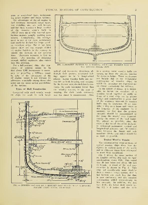
Fig. 3 shows the cross section of
an English sailing ship built to rigid
specifications about 1850. This vessel
was 30 feet beam and about 180 feet
in length. A detail of the keel con-struction is shown in Fig. 2. Thisship had considerably more deadrisethan a modern cargo carrier, that is
her bottom was much less flat thanis now customary, and this roundedconstruction added tremendously to
her strength. In addition, she hadtwo decks, the lower deck beams be-ing 6y2 x 8 inches and the main
HOW WOODEN SHIPS ARE BUILT
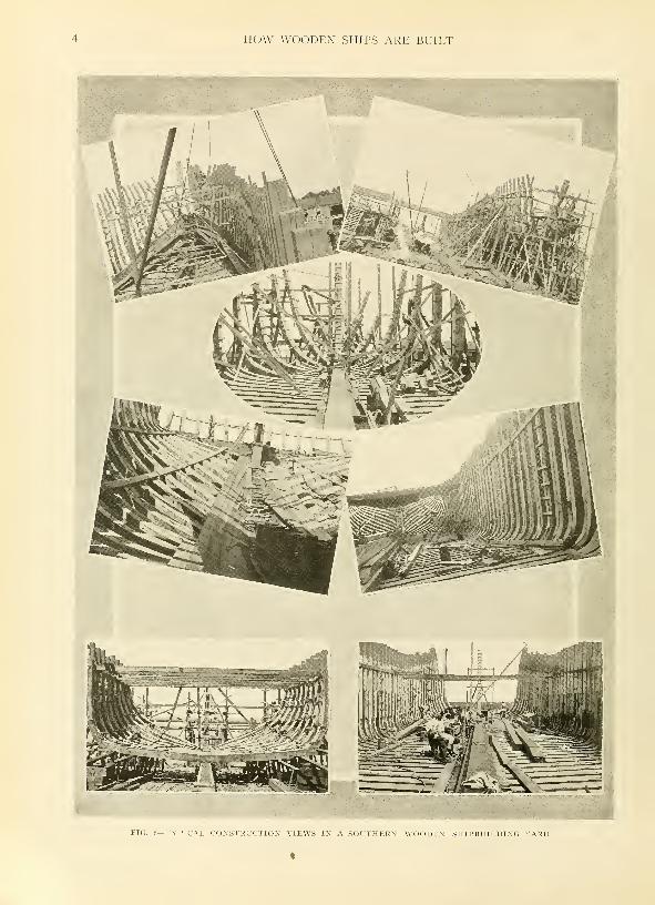
FIG. 6—TYPICAL CONSTRUCTION VIEWS IN A SOUTHERN WOODEN SHIPBUILDING YARD

TYPICAL METHODS OF CONSTRUCTION
deck beams 9 x 10 inches. Finally,
she was very carefully and painstak-
ingly fitted together in order to give
the utmost stiffness and permanencyto the hull structure.
Fig. 5 shows a cross section of a
modern Pacific coast lumber vessel
of the conventional type. It forms
an interesting comparison with Fig. 3.
This ship is 48 feet beam and about
275 feet in length. Her floors are 18
inches deep, compared with 9yi inches
in the English ship shown in Fig. 3.
But in the latter case, natural bent
oak was used for the frames and in
the modern Pacific coast boat, sawnfir. Some architects think that the
depth of the frames in the vessel
shown in Fig. S is too small. This
illustration, however, shows very
clearly the characteristics of cus-
tomary American construction. Thefeature of the design is the large
number of keelsons, nine in all, run-
ning from stem to stern like a small
mountain range. Fig. 5 also indi-
cates the large size of the planking
and ceiling timbers.
A more advanced form of construc-
tion, designed by Fred A. Ballin,
naval architect, Portland, Ore., is
shown in Fig. 4. In this case the
necessity for a large number of keel-
sons is obviated, in the designer's
opinion, by the use of deep floors
FIG. 7 — CROSS SECTION SHOWINGMETHOD OF REINFORCEMENT
PATENTED BY FRANK E.
KIRBY
and deck beams. Care also is taken
in the disposal of the knees, ceiling
and planking.
One of the most successful forms
of steel reinforcement for wood ves-
sels is shown in Fig. 7, illustrating
a method of construction patented by
Frank E. Kirby, of Detroit, one of
the most famous naval architects on
the Great Lakes, where a large num-
ber of unusually staunch wooden ves-
sels were built in the era before the
steel freighter. According to Mr.
Kirby's patent, the topsides are
strengthened by means of a steel
sheer plate, to which a deck stringer
plate is connected with a strong angle.
The deck stringer rests directly on
the top of the top timbers of the
frames and the iron straps running
diagonally around the hull are fast-
ened to the sheer plate. This is
somewhat similar to the method of
reinforcement adopted for the newwooden steamers being built for the
government under the auspices of the
United States Shipping Board Emerg-ency Fleet Corporation, except that
in the case of the government boats
the deck stringer construction is
lighter.

HOW WOODEN SHIPS ARE BUILT

CHAPTER II
Strength and Characteristics of Snip Timbers
BEFORE any attempt is made to
lay down or build a wooden
ship, the architect, yard super-
intendent and others responsible for the
success of the proposed vessel, should
acquire a fundamental knowledge of
the physical characteristics and strength
of the timbers that will be used in
the construction of the hull. An in-
vestigation also should be made into the
different methods of fastening timbers
together in shipbuilding and of the
efficiency of such fastenings. In other
words, a little knowledge of the ele-
ments of structural engineering is as
essential to the shipbuilder as it is to
the building contractor or bridge
erector.
For an intelligent and thorough
grasp of the subject it is necessary, in
fact, to start with the lumber industry,
which bears the same relation to
wooden shipbuilding as iron-ore mining
does to the manufacture of steel. In
this chapter, therefore, a few facts will
be presented regarding the production
of lumber in the United States, to-
gether with data on the physical char-
acteristics and strength of various
species of ship timbers.
In the preceding chapter, figures cov-
ering the supply of merchantable timber
in the United States and Canada were
presented. To give an idea of the
ability of lumber manufacturers to fur-
nish ship timbers in quantity, it may be
stated that the United States forest ser-
vice has estimated the lumber produc-
tion of the United States in 1915, the
latest year for which figures are avail-
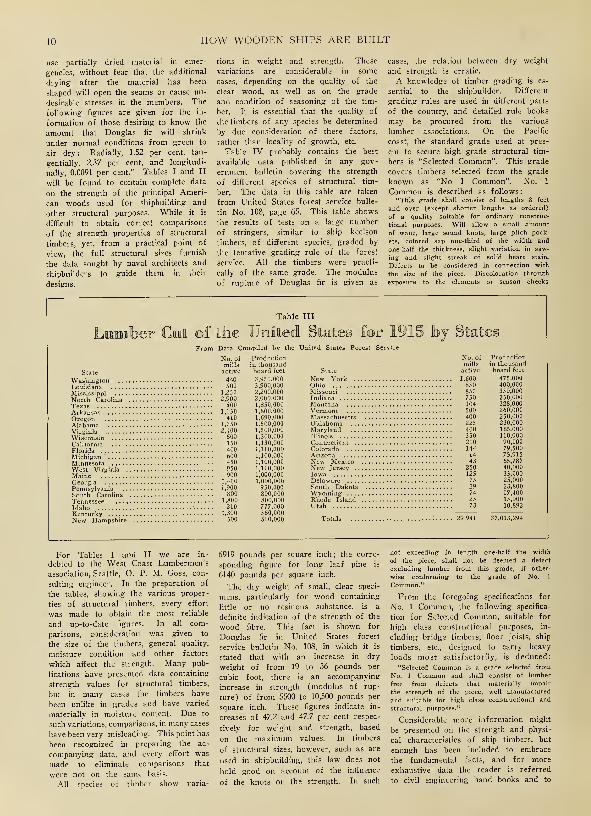
able, at 37,013,294,000 board feet. Dur-
ing 1915 there were 29,941 mills in ope-
ration. The details of the lumber cut
of 1915, showing the number of mills
and production of each state are given in
Table III. By an inspection of this
table, it is possible to estimate the pro-
duction of the two principal kinds of
ship lumber, namely, Douglas fir and
southern yellow pine. The pine grow-
ing states turned out 17,010,000,000 feet
and the fir states, 5,640,000,000 feet in
1915. In 1916, the production of the fir
states was approximately 7,000,000,000
feet. About 10 per cent of the Pacific
coast cut is available for ship work. In
other words, as far as lumber supply
is concerned, the Pacific coast mills
alone can turn out sufficient material
for 400 3000-ton ships in a year and
the southern mills, because of the
smaller size of pine timbers, enough for
500 to 600 more, provided satisfactory
labor supply and mill conditions can
be obtained.
Southern yellow pine is the most
abundant of all ship materials, and on
account of its wide geographical dis-
tribution, comparatively close to the
great eastern centers of population, it is
extensively employed in building
wooden vessel of all kinds. It comes in
sufficiently large sizes so that the prin-
cipal elements of the ship's structure
can be worked up in a compara-tively few pieces, without the necessity
of resorting to an abnormal number of
butts and scarfs. Yellow pine is an
even grained, easily worked, dense woodDetailed figures on the strength of pine
timbers are given in Tables I, II andIV.
Pine is an unusually durable wood,even when subjected to long continued
stresses in a ship's structure. In the
tables just referred to, the modulus of
rupture, or breaking strength, of south-
ern pine is given as varying from 6437
to 5948 pounds per square inch for the
green material and 7033 to 5957 poundsfor air-seasoned timber. The weight
per cubic foot varies from 38.6 to 31.4
pounds. Ships constructed of southern
pine along the Atlantic and gulf coasts
have a special strength advantage, in
that, when possible, natural crooks have
been used for the curved frame mem-bers in nearly all cases. Such timbers
are appreciably stronger than the sawed
frame construction. As a material
which is suitable for ship construction,
Douglas fir, grown on the Pacific coast,
is fully as important as yellow pine, and
on account of the exceptionally large
size of the trees, and the relative light-
-FASHIONING SHIP TIMBERS ON ABAND SAW
FIG. 9—SPECIAL MACHINES HAVE BEEN DESIGNED FORBEVELING AND EDGING TIMBERS

HOW WOODEN SHIPS ARE BUILT
-TIMBERS LONG ENOUGH TO REQUIRE TWO CARS FREQUENTLYARE NEEDED IN WOODEN SHIPBUILDING
ness of the wood, this timber has pe-
culiar advantages of its own. Concern-
ing this wood, the United States forest
service, in Bulletin No. 88, has put
itself on record as follows
:
"Douglas fir may perhaps be con-
sidered the most important of American
woods. Though in point of production
it ranks second to southern yellow pine,
its rapid growth in the Pacific coast
forests, its comparatively wide distribu-
tion and the great variety of uses to
which its wood may be put, place it
first. As a structural timber it is not
surpassed and probably it is most
widely used and known in this ca-
pacity."
Fir an Important Wood
Douglas fir comprises more than 25
per cent of the standing timber supply
of the United States, including both
hard and soft woods. The timber
stand of Washington and Oregon is
such as to insure a permanent source
of supply of the highest class of lumber
for shipbuilding. Also, the winter cli-
mate in this vast, western timber-belt
is mild, enabling the lumber camps and
mills to operate continuously, thereby
producing a steady supply of manu-
factured products.
Practically all log transportation is by
water and many of the mills are lo-
cated on tidewater, in close proximity
to shipbuilding plants. These conditions
make it possible to produce lumber for
ship construction at a minimum operat-
ing cost.
Pacific coast logging operators are
provided with equipment specially
adapted for handling large logs. Underthe ordinary methods of procedure, the
logs are hauled out from the places
where the trees are felled by steel
cables operated by powerful hoisting
engines. This operation is termed
yarding. The yarded logs are usually
rolled onto flat cars or specially con-
structed trucks, on which they are
hauled to the water, either a river or
tidewater. Here they are made up into
rafts and towed to the mills. To some
mills, of course, the logs are delivered
direct by rail.
Big Timbers are Cut
The mills on the Pacific coast are
equipped with extra heavy facilities for
handling big logs and getting out big
timbers and heavy planks specially
suited to ship construction. Both large
circular and band saws are used to
work up the logs, while heavy planing
mills are provided to dress the timbers.
The modern mills are also completely
provided with power-driven roller tables
and transfers for handling the lumber
during the process of manufacture. Theaccompanying illustrations show the es-
sentials of the logging and lumbering
operations on the Pacific coast.
Douglas fir trees grow commonlyfrom 3 to S feet in diameter and from
175 to 250 feet high. Tremendous tim-
bers, particularly suited to shipbuilding,
therefore are available in quantity.
Structural timbers of Douglas fir, 18
x 18 inches in section and 120 to 140 feet
long, may be obtained from mills at
any time, and timbers 36 inches square
and 80 or 90 feet long are equally avail-
able. By the use of such timbers, the
largest boats can be constructed with a
minimum of splicing and scarfing,
which not only reduces labor costs but
materially increases the strength or
seaworthiness of the vessel.
Douglas fir has an average specific
gravity of 0.53 based on its oven dry
volume. The specific gravity based on
green volume, before shrinkage, is 0.46
;
based on air-dry volume it is 0.48. Thegreen wood weighs 38 pounds per cubic
foot, or 3.166 pounds per board foot
and the air-dry wood 34 pounds per
cubic foot or 2.836 pounds per board
foot. These weights vary in fir as in
other woods but the foregoing figures
are reliable averages. A knowledge of
these figures is indispensable to the
naval architect or shipbuilder, in com-
puting the weights, trim and displace-
ment of his vessel. The method of
figuring these weights will be brought
out later in this book. Too manywooden ships at the present time are
constructed and trimmed by guesswork,
resulting in some exceedingly costly ex-
periences for the shipowner.
Preservatives are Recommended
Douglas fir and southern pine are
on a par as to durability, although like
other woods when used for shipbuild-
ing, precautions should be taken at the
time the boat is constructed' to see that
preservatives are effectively applied and
that the necessary amount of ventilation
is supplied to prevent the collection of
moist, stagnant air in any part of the
vessel. For preserving the timber, com-
mon salt is frequently introduced be-
tween the frame joints and between the
frame members and the planking and
ceiling. Most modern shipbuilders,
however, prefer creosote, carbolineum,
or some similar compound applied with
a brush or old broom to the joints dur-
ing the process of construction.
On account of differences of opinion
recently voiced regarding the advisabil-
ity of building wooden boats of green
timber to meet the present submarine
emergency, the following data on the
shrinkage of Douglas fir, from a
pamphlet by Howard B. Oakleaf,
United States forest service, Portland,
Ore., are presented
:
"Douglas fir does not shrink much,
and for this reason it is possible to
FIG. 11—BORING HOLES WITH ANAIR DRILL
STRENGTH AND CHARACTERISTICS OF SHIP TIMBERS
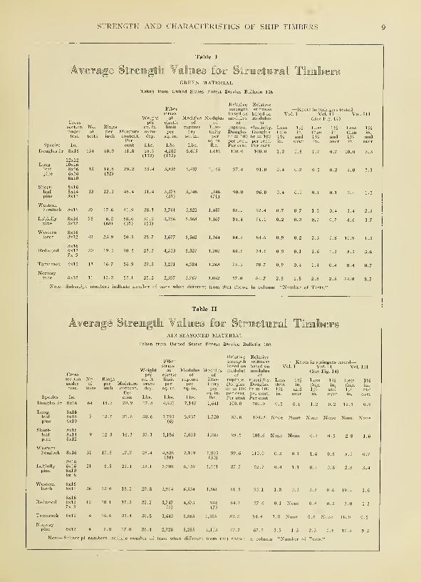
Table I
Average Sttirengllh Valines for Sttraetaral TGREEN MATERIAL
Taken from United States Forest Service Bulletin 10
Weight at Modulu
10 HOW WOODEN SHIPS ARE BUILT
use partially dried material in emer-
gencies, without fear that the additional
drying after the material has been
shaped will open the seams or cause un-
desirable stresses in the members. The
following figures are given for the in-
formation of those desiring to know the
amount that Douglas fir will shrink
under normal conditions from green to
air dry: Radially, 1.52 per cent, tan-
gentially, 2.37 per cent, and longitudi-
nally, 0.0091 per cent." Tables I and II
will be found to contain complete data
on the strength of the principal Ameri-
can woods used for shipbuilding and
other structural purposes. While it is
difficult to obtain correct comparisons
of the strength properties of structural
timbers, yet, from a practical point of
view, the full structural sizes furnish
the data sought by naval architects and
shipbuilders to guide them in their
designs.
tions in weight and strength. These
variations are considerable in some
cases, depending on the quality of the
clear wood, as well as on the grade
and condition of seasoning of the tim-
ber. It is essential that the quality of
the timbers of any species be determined
by due consideration of these factors,
rather than locality of growth, etc.
Table IV probably contains the best
available data published in any gov-
ernment bulletin covering the strength
of different species of structural tim-
ber, The data in this table are taken
from United States forest service bulle-
tin No. 108, page 65. This table shows
the results of tests on a large number
of stringers, similar to ship keelson
timbers, of different species, graded by
the tentative grading rule of the forest
service. All the timbers were practi-
cally of the same grade. The modulus
of rupture of Douglas fir is given as
cases, the relation between dry weight
and strength is erratic.
A knowledge of timber grading is es-
sential to the shipbuilder. Different
grading rules are used in different parts
of the country, and detailed rule books
may be procured from the various
lumber associations. On the Pacific
coast, the standard grade used at pres-
ent to secure high grade structural tim-
bers is "Selected Common". This grade
covers timbers selected from the grade
known as "No 1 Common". No. 1
Common is described as follows
:
"This grade shall consist of lengths 8 feet
and over (except shorter lengths as ordered)
of a quality suitable for ordinary construc-
tional purposes. Will allow a small amount
of wane, large sound knots, large pitch pock-
ets, colored sap one-third of the width and
one-half the thickness, slight variation in saw-
ing and slight streak of solid heart stain.
Defects to be considered in connection with
the size of the piece. Discoloration through
exposure to the elements or season checks
Table III
Lumber U 1915 bjData Compiled by the United States Forest Se
No. of Production No
State
WashingtonLouisiana
millsactive
440500
Mississippi 1,250
North CarolinaTexas
OregonAlabamaVirginiaWisconsinCalifornia
2,900500
1,150410
1,3502,400600150400600450950900
Georgia 1,400
Pennsylvania 1,900
South Carolina .800Tennessee
FloridaMichigan . .
.
MinnesotaWest Virgini;Maine
Kentucky210
1,300500
l thousaboard feet
3,950,0003,900,0002,200,0002,000,0001,850,0001,800,0001,690,0001,500,0001,500,0001,300,0001,130,0001,110,0001,100,0001,100,0001,100,0001,000,0001.000,000950,000800,000800,000777,000560,000500,000
lills
State active
New York 1,600Ohio 850Missouri 850Indiana 750Montana 104Vermont 500Massachusetts 400Oklahoma 225Maryland 400Illinois 350Connecticut 200Colorado 144
New MexicoNew Jersey . .
IowaDelawareSouth DakotaWyomingRhode IslandUtah
Totals
Productionin thousandboard feet
475,000400,000350,000350,000328,000260,000250,000230,000165,000110,00090,00079,50075,91565,78740,00035,00025,00023,80017,40015,00010,892
29,941 37,013,294
For Tables I and II we are in-
debted to the West Coast Lumbermen's
association, Seattle, O. P. M. Goss, con-
sulting engineer. In the preparation of
the tables, showing the various proper-
ties of structural timbers, every effort
was made to obtain the most reliable
and up-to-date figures. In all com-
parisons, consideration was given to
the size of the timbers, general quality,
moisture condition and other factors
which affect the strength. Many pub-
lications have presented data containing
strength values for structural timbers,
but in many cases the timbers have
been unlike in grades and have varied
materially in moisture content. Due to
such variations, comparisons, in many cases
have been very misleading. This point has
been recognized in preparing the ac-
companying data, and every effort was
made to eliminate comparisons that
were not on the same basis.
All species of timber show varia-
6919 pounds per square inch ; the corre-
sponding figure for long leaf pine is
6140 pounds per square inch.
The dry weight of small, clear speci-
mens, particularly for wood containing
little or no resinous substance, is a
definite indication of the strength of the
wood fibre. This fact is shown for
Douglas fir in United States forest
service bulletin No. 108, in which it is
stated that with an increase in dry
weight of from 19 to 36 pounds per
cubic foot, there is an accompanying
increase in strength (modulus of rup-
ture) of from 5500 to 10,500 pounds per
square inch. These figures indicate in-
creases of 47.2 and 47.7 per cent respec-
tively for weight and strength, based
on the maximum values. In timbers
of structural sizes, however, such as are
used in shipbuilding, this law does not
hold good on account of the influence
of the knots on the strength. In such
not exceeding in length one-half the width
of the piece, shall not be deemed a defect
excluding lumber from this grade, if other-
wise conforming to the grade of No. 1
Common."
From the foregoing specifications for
No. 1 Common, the following specifica-
tion for Selected Common, suitable for
high class constructional purposes, in-
cluding bridge timbers, floor joists, ship
timbers, etc., designed to carry heavy
loads most satisfactorily, is deduced:
"Selected Common is a grade selected from
No. 1 Common and shall consist of lumber
free from defects that materially impair
the strength of the piece, well manufactured
and suitable for high class constructional and
structural purposes."
Considerable more information might
be presented on the strength and physi-
cal characteristics of ship timbers, but
enough has been included to embrace
the fundamental facts, and for more
exhaustive data the reader is referred
to civil engineering hand books and to
STRENGTH AND CHARACTERISTICS OF SHIP TIMBERS 11
FIG. 12—TYPICAL LUMBERING SCENES IN THE NORTHWEST

12 HOW WOODEN SHIPS ARE BUILT
—
1

STRENGTH AND CHARACTERISTICS OF SHIP TIMBERS 13
the various special booklets on struc-
tural timber, such as that issued by the
West Coast Lumbermen's association.
It might be added, however, that a safe
fibre stress for fir or pine, is considered
to be from 1600 to 1800 pounds per
square inch in tension, 1600 pounds for
compression parallel to the grain, and
400 pounds for compression across the
grain. The weaknesses introduced by
the practice of sawing out the bilge
turns in the frame timbers of large
ships are indicated by the great varia-
tion in the last two sets of figures.
How Timbers are Shaped
Before going on into the design and
construction of ships in detail, it is
advisable briefly to consider the methods
of shaping and fashioning timbers for
ship construction and also the principal
methods of fastening the various ele-
ments together. The data about to be
presented is of a purely general char-
acter. More detailed methods of work-
ing up timbers and fastenings will be
considered later.
Generally speaking, timbers are shaped
by sawing, chopping, planing and bor-
ing. As far as possible, in modern
wooden shipyards, machines are sup-
planting hand labor for all of these
operations. Band saws or jig saws,
together with common circular saws are
used for a great variety of operations.
Air-driven boring augers are used and
special machines have been developed
for beveling timbers and performing
other operations peculiar to shipbuild-
ing. In many cases, however, hand
tools must be used, as for instance in
dubbing-off the inside of the hull pre-
paratory to laying the ceiling. For
many operations such as this, the adz
is indispensable. For rough hewing,
axes are employed, while hand planes,
bits, chisels, and all the tools found in
the carpenter's kit also are utilized.
For fastenings, dowels, treenails, drift
bolts, spikes and screw bolts are em-
ployed. The various pieces may also be
and clenched on steel rings in the in-
side.
For "sticking" the planking to the
frames and other preliminary fastenings,
treenail is driven home with an air
hammer. After it is in place, it is cut
off, split on the end, and wedged to a
tight fit. The subsequent action of the
water is supposed to swell the treenail
and make it fit tighter.
Although treenails are used exten-
sively in modern shipbuilding, there is
doubt as to their efficiency after the
possible such bolts are driven through
as well as for securing the deck planks,
galvanized standard ship spikes are
used. Usually they are J^-inch square
and 8 or 10 inches long. Screw bolts
also are used for some forms of fasten-
ings, as well as bolts fitted with wash-
ers and nuts. The latter may be taken
up from time to time as required.
Tests of Spikes
Some tests of spikes were made at
the Seattle testing laboratory of the
Table IV
Average Stoems(Grade 1, Tentative Grading Ruli
GREEN MATERIAL<en from United States Forest Service B
S. Forest Se
Page 65, Table 8
Species
Douglas fir ..
Longleaf pineLoblolly pineShortleaf pineWestern hemlO'Western larch
Redwood
14 HOW WOODEN SHIPS ARE BUILT

CHAPTER III
Layout ana Equipment of WoodenShipbuilding Plants
INTHE two previous chapters in this book, the
general possibilities and limitations of wooden ships
were discussed and the structural characteristics of
ship timber were studied in detail. Before the actual
work of building the ship can commence, there is still
another problem to be disposed of—the shipyard must
be planned and equipped. If the prospective builder is
going into the construction of wooden ships on a per-
manent basis, this problem is perhaps the most important
one he will be called upon to solve. Mistakes in the
design or method of building a given hull can be rectified
when the next ship is laid down; blunders in the layout
or equipment of the shipyard can seldom be corrected,
except at prohibitive expense. Like most other old saws,
the adage about the poor workman always blaming his
tools is only a half truth; good workmanship demands
the use of the best tools and is intolerant of slipshod
equipment. Therefore, the shipbuilder who starts out
with a half-baked, poorly laid out, pinched and skimped
plant, is saddling himself with a handicap that may later
spell ruin. The impression is all too prevalent that a
well planned, thoroughly equipped plant,
carefully arranged and organized, is
relatively unnecessary for building wood-en ships. Quite the reverse is true, and
a study of the plants that have built
ships continuously for a generation or
more, through good times and bad, re-
veals the fact that they are all as com-pletely equipped for their task as anysteel shipyard. In fact, one of the un-
fortunate results of the present boom is
the multiplication of hay-wire yards onboth eastern and western coasts. If
wooden shipbuilding is to establish itself permanently,
the idea that anybody's back lot will do for a building
site and a chest of carpenter's tools for equipment, mustbe definitely abandoned. Wooden shipbuilding is no longer
a haven for irresponsible promoters. Success in this field
demands money, brains, skill and experience—the more the
better.
The location of the yard is the first phase of the
problem to be considered. Four factors govern the
selection of the site: The supply of labor, the cost of
the land, the contour of the ground and the depth of
the water. Labor supply and real estate prices are com-plementary; where labor is abundant, property is ex-
pensive, and where land is cheap the supply of labor is
dubious. The builder must compromise these conflicting
elements to the best of his judgment and ability, remem-bering that a busy yard may carry a high overhead, but
no plant can be run without men. It is significant that
the most successful of the modern wooden shipbuilding
plants on the Pacific coast are located in or near large
cities. This would indicate that labor supply is the
controlling factor.
In selecting a site for wooden shipbuilding, the slope
and contour of the ground is important. Preferably, the ships
should be built on dry land that has just sufficient natural
slope to permit the laying of the keel blocks conveniently.
There also must be level property for the construc-
tion of buildings and the storage of lumber.
These conditions are not always easily ful-
filled, although they are found in manyof the oldest and most successful
yards. In some cases, where long
tide flats are encountered,
filling has been resorted
to, and although it is
an expensive proc-
ess, an ideal
site can be
created in
this man-ner. Anexample
FIG. 16—ELECTRICALLY-DRIVEN, TRAVELING DERRICK SETTING FRAMES IN A WOODEN SHIPYARD
15
16 HOW WOODEN SHIPS ARE BUILT
FIG. ir—WOODEN SHIPYARD LOCATED ON NATURALLY SLOPING GROUND WITH AN ABUNDANCE OF ROOM
FIG. 18—A SMALL YARD LAID OUT ON LONG NARROW STRIP OF GROUND
FIG. 19—YARD LAID OUT ON IRREGULAR PLOT OF GROUND

LAYOUT AND EQUIPMENT OF PLANT 17
of the relativeimportance o f
properly prepar-
ing the site is
found in the es-
timates for a
small California
yard, in which
the cost of
buildings is giv-
en as $9280 and
the yard workat $16,520, in-
cluding $4720 for
filling. In somePacific coastyards where nat-
ural groundconditions areunfavorable, the
building ways,framing stages
and even thefoundations for
buildings andlumber storage
have been placed
on piles. Onfresh -water riv-
ers, safe fromthe ravages of
the toredo, this
procedure is not
so objectionable
as on salt water,
circumstances it is
icism on account
porary and a source
pense for renewals,
be defended only in
-YARD WITH FOUR BUILDING SLIPS COMPACTLY ARRANGED ONCITY PROPERTY
but under all builder feels his business is so purely
subject to crit- transient that the expense of filling-in
of being tern- permanent foundations or paying
of continual ex- enough for a suitable natural site, is
This practice can unjustified,
cases where the In many wooden shipyards too lit-
tle consideration
has been given
the influence of
the shape of the
property on the
progress of the
material through
the plant. Manyyards, especially
some of thenewer ones, are
laid out with nothought what-
ever, apparently,
to the labor that
might be saved
by properly and
thoughtfully rout-
ing the work. Theprinciples of
straight - line
progress that are
so ingrained in
the metalworking
industries andmost other pro-
ductive establish-
ments, have beencompletely over-
looked. The re-
sult is chaos anda tremend ous
waste of money.This comes from
the practice of throwing the yards to-
gether rather than having them de-
signed by a competent, experienced
engineer.
If routing alone is to be consid-
ered, a long, narrow yard, in which
FIG. 21—A STEEL FRAMED REVOLVING CRANE FOR WOODEN SHIPYARD

18 HOW WOODEN SHIPS ARE BUILT
FIG. 22—MILL CONTAINING SAWS AND WOODWORKING MACHINERY
the raw material comes in at one
end and proceeds in a straight line
to the building ways at the other, is
ideal. This arrangement can seldom
be realized, and the next choice is a
rectangular yard in which the ma-
terial flows around only one corner
and does not double back at any
point. Regardless of the shape of the
plot, however, and the limitations of
property lines, a skilled designer can
so arrange the equipment as to get
the most out of the situation at hand
and avoid waste in handling materials.
The accompanying illustrations, Figs.
18, 19 and 20, illustrate some of the
principles of yard arrangement. Fig.
18 shows a small yard for three ships
designed by Martin C. Erismann,
engineer. In this case, a long, narrow
piece of ground was available and a
straight-line plant was the result.
Fig. 19, detailing the yard of the
Grays Harbor Motorship Corp., Aber-
deen, Wash., shows what can be done
with a comparatively shallow, irreg-
ular plot on which a large numberof building slips must be placed. In
this case, extra room and proper
routing is obtained by placing the
slips at an acute angle with the har-
bor line. The advantages of angular
layouts of this general character havelong been understood by industrial
engineers.
Getting the Most Out of City
Property
Fig. 20 shows what can be done on
comparatively restricted ground area in
the heart of a city. In this case,
four building slips for ships of the
largest size are provided, together
with ample room for shops of a moreelaborate character than are usually
found around wooden shipbuilding
plants, yet the plant is not over-
crowded. The lumber moves across
the yard from south to north and is
properly distributed by means of the
traveling cranes between the first and
second and third and fourth slips.
The steel fittings, which are made-up
in the plate shop, move in the op-
posite direction. This plant is oper-
ated by Supple & Ballin, Portland,
Oreg. How the arrangement works
out in actual practice is shown clearly
in Fig. IS, which gives a good gen-
eral view of the yard under operating
conditions.
The patent advantages of an almost
perfect natural site, with unlimited
room, are shown in Fig. 17, which
illustrates the yard of the WinslowMarine Railway & Shipbuilding Co.,
Winslow, Wash. In this case, piling
or filling are unnecessary, for the
ground has the correct natural slope
for laying keel blocks and the water
deepens rapidly from the shore. Theways are laid out along the shore and
covered by sheds, with the shops,
mill, etc., immediately in the rear.
The cost of wooden shipyards varies,
of course, within wide limits, depend-
ing on the locality, price of the
ground, number of building slips and
the completeness of the shop and
yard equipment. In altogether too
many cases the latter item is danger-
ously slighted. Probably $45,000 rep-
resents the minimum for three slips,
and in this case the margin is hardly
comfortable. From this figure, the
investment ranges up to $500,000.
While no definite suggestions can be
given where so many variables are
to be considered, it is safe to say
that a reasonable sum invested in the
plant and its equipment makes for
permanent success.
Proper Design and Layout
This chapter is concerned with the
general phases of yard design and
layout. Details, such as the construc-
tion, slope and arrangement of the
keel blocks and the foundations of
the building slips will be treated later
in the chapters devoted to construc-
tion procedure. Various methods of
laying out the building slips are sug-
gested by the drawings, Figs. 18, 19
and 20, previously mentioned.
In the north Pacific coast region,
on Puget sound and the Columbia
river, the question of protecting the
building slips with sheds is a mootone. There is no doubt the protec-
tion of the work from the weather
during construction tends to add to
the life of the vessel, and that from
the standpoint of the comfort of the
workmen and their efficiency, espe-
cially in the winter time when rain
is frequent, sheds are desirable. Onthe other hand, they add greatly to
the cost of the yard, and this is
the principal reason why so much
X A WESTERN SHIPYARD
LAYOUT AND EQUIPMENT OF PLANT 19
Table V
Costt of Buiildliirigg, ettCo, for Small
Yard Shown in Figo ISThree Building Slips
Mold loft, 2-story, 45 x 100 feet, bottom floor contain-
ing joiner shop, 45 x 80; tool room, 45 x 30 and
store room, 45 x 40 $4,500
Office, 18 x 35 feet 1,000
Blacksmith shop, 20 x 25 feet 350
Oakum store, 20 x 30 feet 400
Boiler house and compressor room, 30 x 40 feet 800
Steel storage racks 150
Paint shop, 18 x 25 feet 150
Saw sheds, 45 x 70 feet 250
Steam boxes, two 3 x 3 x 50 feet 180
Piping for water and air 1,500
Spur track 800
Filling and bulkheading 4,720
Ways, piling and flooring 10,000
Miscellaneous 1,000
Total $25,800
Table VI
Eqmipinnieett for Small Sitim
Sliowm imi Figo 18One 48-inch band saw $2,600One 20-horsepower motor for band saw 421Two 30-inch saws for loft and joiner shop 330Two motors for 30-inch saws 200One circular table saw 425One buzz knee planer or 24-inch jointer 700One bolt cutter 350Grindstones and emery wheels 200Mauls, dogs, chains, rope, peavys 2,000Forty jacks 320Clamps, screws, Nelson iron 1,000Two anvils 150Two forges 200Two steam winches 3,000One drill press 450One air compressor 2,696Six 90-lb. air hammers 300One extra heavy hammer 175Six wood boring machines : 450Air hose 300Motors 1,000Boiler, pumps, etc 1,500Miscellaneous . . . 1,000
Total $19,767
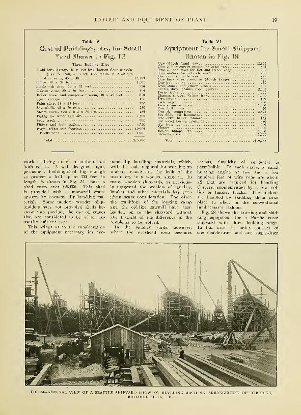
work is being done out-of-doors on
both coasts. A well designed, light,
permanent building-shed big enough
to protect a hull up to 300 feet in
length, is shown in Fig. 34. Such a
shed costs over $20,000. This shed
is provided with a monorail crane
system for economically handling ma-terials. Some modern wooden ship-
builders have not provided sheds be-
cause they preclude the use of cranes
that are considered to be of an un-
usually efficient type.
This brings us to the consideration
of the equipment necessary for eco-
nomically handling materials, which,
with the tools required for working-uptimbers, constitutes the bulk of the
machinery in a wooden shipyard. In
many wooden shipyards, as previous-
ly suggested, the problem of handling
lumber and other materials has beengiven scant consideration. Too often
the traditions of the logging campand the old-line sawmill have beenhanded on to the shipyard withoutany thought of the difference in the
problems to be solved.
In the smaller yards, however,where the overhead soon becomes
serious, simplicity of equipment is
permissible. In such cases, a small
hoisting engine or two and a fewhundred feet of wire rope are aboutall that are required for handlingtimbers, supplemented by a few dol-
lies or lumber trucks. The timbersare handled by skidding them fromplace to place in the conventional
lumberman's fashion.
Fig. 28 shows the hoisting and skid-
ding equipment for a Pacific coast
shipyard with three building ways.In this case the outfit consists of
one double-drum and one single-drum
FIG. 24—GENERAL VIEW OF A SEATTLE SHIPYARD SHOWING BEVELING MACHINE, ARRANGEMENT OF DERRICKS,BUILDING SLIPS, ETC.

20 HOW WOODEN SHIPS ARE BUILT
FIG. 25—WOODWORKING MACHINERY IN A PUGET SOUND SHIPYARD
FIG. 26—BANDSAWING BEVELS IN A SOUTH ATLANTIC SHIPYARD. FIG. 27—DERRICKS AND HOISTING ENGINEIN A SOUTHERN YARD
FIG. 28—TIMBER HAULING ENGINES IN A GRAYS HARBOR SHIPYARD. FIG. 29—DRIVING PILES FOR BUILDINGWAYS IN A GEORGIA SHIPYARD

LAYOUT AND EQUIPMENT OF PLANT
FIG. 30—GENERAL ARRANGEMENT OF BUILDING WAYS SHOWING VESSELS IN VARIOUS STAGES OF CONSTRUCTION.FIG. 31—PORTABLE ELECTRICALLY DRIVEN PLANER. FIG. 32—BAND SAWING EQUIPMENT IN A PACIFIC COAST
YARD. FIG. 33—TRAVELING TABLE FOR HANDLING TIMBER AROUND MACHINES. FIG. 34—A BUILDINGSHED PROTECTS THE WORK FROM THE WEATHER

22 HOW WOODEN SHIPS ARE BUILT
hoisting engine with a vertical nigger-
head for handling the manila haul-
back line. The steam is supplied by
a vertical donkey boiler 5 feet in
diameter and 8 feet high. It carries
about 80 pounds pressure and burns
wood refuse from the yard that other-
wise would go to waste. Almost the
whole expense of operating this rig,
therefore, is the wages of the engi-
neer, $4.50 per day. A J^-inch wire
rope is used for hauling the timbers.
This equipment serves three hulls
handling all the timbers for frames,
keelsons, ceiling, etc. The cost of
such an outfit should not exceed
$1500. Frequently second-hand con-
tractor's equipment is purchased at
low prices. The services of the don-
key engine are usually supplemented
by a few rough timber derricks, as
shown in Fig. 27.
In more elaborately equipped yards,
and in most cases where thoroughly
satisfactory results are desired, someform of crane equipment is provided.
In cases where there are building
sheds, rope or electrically driven
I-beam monorail hoists running the
full length of the shed have been
found to fill the bill. Where the
work is out in the open, traveling
cranes of the types shown in Figs. 16
and 21 are most frequently employed.
Two Types of Cranes
Both of these cranes were designed
specially to meet conditions in woodenshipbuilding yards. The main fram-
ing of the crane shown in Fig. 16 is
wood; the one illustrated in Fig. 21
has a steel frame. Both cranes are
simply variations of the traveling
derrick.
The timber-framed derrick shown in
Fig. 16, sometimes called a "monstros-
ity", has a boom 72 feet in length,
set on a base 30 feet above the
ground. It will handle 7 tons, andmight be termed a shear legs onwheels. It is electrically operated,
the power being supplied through a
looped, insulated cable that slides on
a wire stretched alongside the run-
way. To give the machine stability,
the hoisting machinery is placed on
the lower of the two platforms shownin Fig. 16. A 50-horsepower motorgeared to a 3-drum hoist is provided.
The hoist also is equipped with a
small niggerhead for skidding light
timbers. The operator's cab is on
the upper platform, at the foot of
the derrick. The foot-spread, or gage
of track on which the crane runs, is
35 feet. One such crane will serve
two building slips.
The crane shown in Fig. 21 is
mounted on a turntable that permits
the boom to swing through 360 de-
grees, an advantage the timber-framed
traveler just described does not
possess. The boom in the case of
the revolving crane shown in Fig. 21
has a reach of 50 feet.
For handling light timbers in single
pieces, ordinary lumber dollies andwide-tired four-wheel trucks are used
in great profusion in wooden ship-
yards. These vehicles usually are of
the simplest character, consisting of
nothing more than a timber frame to
which the wheels and axles are bolt-
ed. They may be moved by manpower, although horses are usually
employed. In some of the moreprogressive yards, small gasoline-
driven tractors have been introduced,
making it possible to handle the lum-
ber trucks in trains.
Woodworking Machinery
The equipment required for work-
ing-up timbers, including the band
saws, cut-off saws, jig saws, planing
machines, automatic beveling ma-
chines, etc., must be carefully ar-
ranged so the work can be gotten
out expeditiously with a minimum of
rehandling. There are two general
methods of arranging this equipment.
In some yards it is grouped together
in a mill located, usually, at a con-
venient point in front of the building
ways. In other yards, the apparatus
is scattered among a number of small
saw sheds, on the unit principle. In
the latter case, each building slip is
provided with an individual saw out-
fit, located, generally, at the head of
the ways. A mill in which all the
sawing equipment is grouped to-
gether is shown in Fig. 22. A pair
of individual saw sheds of the unit
type is shown in Fig. 23. In this
illustration, the cut-off saw, with der-
rick and hoisting engine for handling-
timbers, is in the background, with
the band-saw shed, in which the
curved frame sections are shaped, in
the right foreground. The simple andinexpensive character of the equip-
ment is clearly shown. A searchlight
for night work is mounted on the
band-saw shed.
In order to give a concrete idea
of the equipment required for woodenshipbuilding and its cost, Tables Vand VI are presented, giving the cost
of buildings and equipment for the
3-way yard shown in Fig. 18. Theprices are based on quotations in
April, 1917. The equipment listed
may be considered a minimum for
the work to be done, and if moremoney were available considerable
apparatus could be added, such as
cranes, automatic beveling machines,
etc. The total cost of the three
major items is as follows: Buildings,
$9280; yard work, $16,520; machinery
and tools, $19,767; total, $45,567, ex-
clusive of real estate, supplies or
working capital.
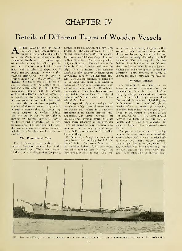
CHAPTER IV
Details of Different Types of Wooden Vessels
AFTER providing for the layout,
equipment and organization of
his plant, the wooden shipbuilder
turns naturally to a consideration of the
structural details of the various types
of vessels he may be called upon to
turn out. The successful builder is fa-
milar with all kinds of ships, and is
broad minded enough to realize that
valuable suggestions may be obtained
from a study of even the so-called freak
designs. He knows also that before he
can go ahead with the details of his
building operations, he must become
thoroughly familiar with the general
outlines of a large number of boats. It
is logical, therefore, to insert a chapter
at this point in our book which will
set forth the salient facts regarding a
number of different wooden ship models
in such a manner that the reader mayreadily compare the various designs.
This can best be done by presenting a
number of detailed drawings, supple-
mented by such descriptive text as maybe necessary. The drawings and repro-
ductions of photographs, however, really
tell the story and they should be studied
carefully.
The Conventional Type
Fig. 5 shows a cross section of a
modern American wooden ship of the
conventional type. The salient features
of this type were discussed in Chapter I.
Details of an old English ship also werepresented. The ship shown in Fig. 5 is
48 feet beam and about 27S feet in length.
Her floors are 18 inches deep. The keel
is 18 x 20 inches. The bottom planking
is 4z/2 x 14 inches. The ceiling over the
floors is 10 x 16 inches and over the
bilges 12 x 12 inches. The backbone
consists of nine keelsons 20 inches square
surmounted by a 20 x 24-inch rider keel-
son. The keelson assembly is connected
to the lower and upper deck beams by
means of 14 x 14-inch stanchions. Both
sets of deck beams are 14 x 16 inches in
cross section. These few dimensions are
presented to give an idea of the size of
timbers used in the construction of ves-
sels of this class.
This type of ship was developed and
brought to a high state of perfection on
the Pacific coast where it is employed
principally in the lumber carrying trade.
Experience has shown, however, that
vessels of this general design—they are
called steam schooners on the west coast
—are not suited to long off-shore voy-
ages or for carrying general cargo.
Their hull construction is too shallow
for one thing.
Furthermore, although the builders of
these boats are exceedingly lavish in the
use of timber, their strength is not all
that could be desired. It has been found
that when running light in heavy seas
they have a tendency to hog. As a mat-
ter of fact, what really happens is that
owing to their transverse weakness, the
floors are bulged up from the bottom,
sometimes seriously distorting the hull
structure. The only way the old line
builders have found to correct this ten-
dency to hog or bulge is to use heavier
ceiling and add more lumber to the hull
structure. This, however, is hardly a
logical method of attacking the problem.
Weakness Studied
The problem of overcoming the in-
herent weaknesses of wooden ship con-
struction has been the object of close
study by a large number of naval archi-
tects for a couple of years—ever since
the revival in wooden shipbuilding set
in in earnest. As a result of this in-
tensive effort, a number of somewhatmodified designs have been evolved, cov-
ering the construction of wooden vessels
for deep sea service. The latest designs
provide for boats up to 308 feet in
length and of 4000 tons capacity. In
some of them steel is employed exten-
sively.
The question of using steel reinforcing
in some form to counteract some of the
characteristic weaknesses of wooden hulls
is a moot one. Some builders, particu-
larly of the older generation, claim it is
not practicable to fasten wood and steel
members together in a satisfactory man-ner. It is interesting to observe, how-
FIG. 35—A 5-MASTED, TOPMAST WOODEN AUXILIARY SCHOONER BUILT AT A PROMINENT PACIFIC COAST SHIPYARD

24 HOW WOODEN SKIPS ARE BUILT

DETAILS OF TYPES OF WOODEN VESSELS 25
^ kJ *O I- 5"
to j~ y^ i 5
o o.1 -I
^<£
^£i- ^ kj
O ft ^^ n! h-•» ^ kl
5
k.
q;
5 <
CQQ
<
Q «J
^^o.<o £ ^^ r-i * ?
i
H ,^ "Q ^
^ y CL
?« ^ *o ^ ? <k-i .i a. <t 5 £
CQ
w^

26 HOW WOODEN SHIPS ARE BUILT
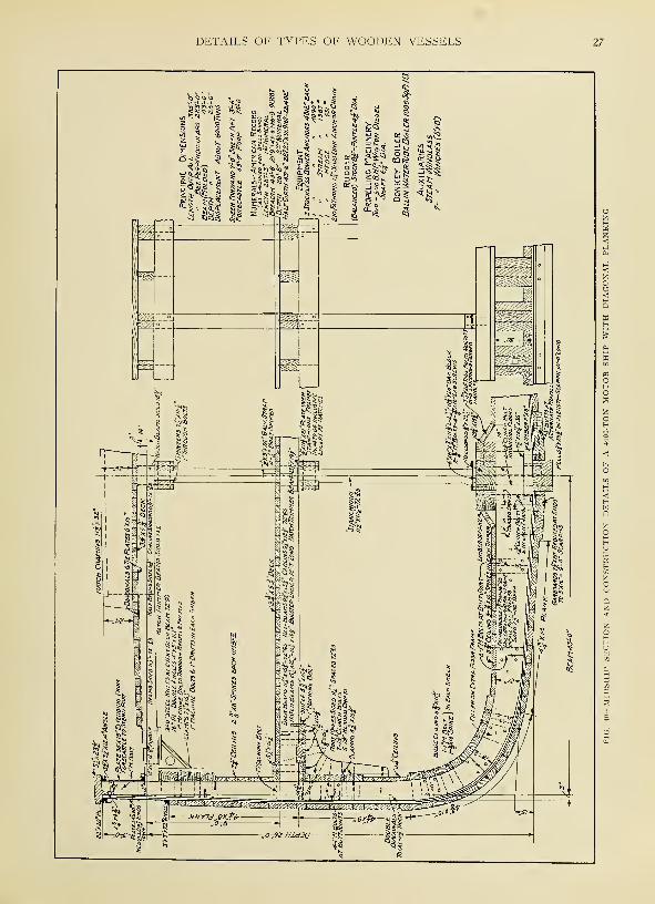
DETAILS OF TYPES OF WOODEN VESSELS 27

28 HOW WOODEN SHIPS ARE BUILT
Main Deck
FIG. 41—OUTBOARD PROFILE AND DECK PLAN OF ATYPICAL 4000-TON WOODEN STEAMSHIP
Principal Dimensions joo'x4S'xe7'
FIG. 42—OUTBOARD PROFILE AND DECK PLAN OF 4500-TON WOODEN STEAMSHIP WITH PROPELLING MACHINERY AFT
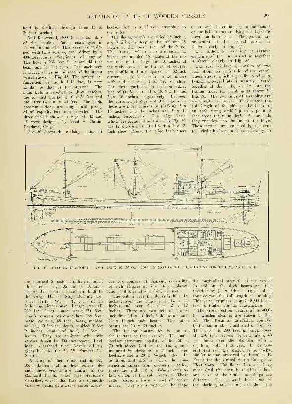
DETAILS OF TYPES OF WOODEN VESSELS 29
hold is obtained through three 16 x
24-foot hatches.
A full-powered, 4000-ton motor ship
of the standard Pacific coast type is
shown in Fig. 43. This vessel is equip-
ped with twin screws, each driven by a
400-horsepower, 6-cylinder oil engine.
The boat is 265 feet in length, 43 feet
beam and 26 feet deep. The machinery
is placed aft as in the case of the steam
vessel shown in Fig. 42. The general ar-
rangement of the hull in fact, is very
similar to that of the steamer. The
main hold is reached by three hatches,
the forward one being 16 x 23 feet and
the after two 16 x 26 feet. The cabin
accommodations are ample and plenty
of oil capacity has been provided. The
three vessels shown in Figs. 41, 42 and
43 were designed by Fred A. Ballin,
Portland, Oreg.
Fig. 36 shows the midship section of
keelson and by steel arch strapping on
the sides.
The floors, which are sided 12 inches,
are 26Yz inches deep at the keel and 19
inches at the lower turn of the bilge.
The frames, which also are sided 12
inches, are molded 16 inches at the up-
per turn of the bilge and 10 inches at
the main deck. The frames, of course,
are double and are spaced on 32-inch
centers. The keel is 20 x 24 inches
with a 4 x 20-inch false keel or shoe.
The three garboard strakes on either
side of the keel are 11 x 18, 9 x 18 and
7 x 16 inches, respectively. Between
the garboard strakes and the bilge keels
there are three courses of planking, S x
16 inches, S x 14 inches and 5 x 12
inches, respectively. The bilge keels,
which are arranged as shown in Fig. 36,
are 12 x 16 inches, fitted with a 4 x 12-
inch shoe. Above the bilge keels there
of an arch, extending up to the height
of the hold beams amidship and tapering
down on both ends. The general ar-
rangement of this central girder is
shown clearly in Fig. 44.
The method of fastening the various
elements of the hull structure together
is shown clearly in Fig. 36.
The steel reinforcing consists of two
arch straps on each side of the vessel.
These straps, which are built up of M x
14-inch universal plates securely riveted
together at the ends, are let into the
frames under the planking as shown in
Fig. 36. The two lines of strapping are
about eight feet apart. They extend the
full length of the ship in the form of
an arch rising amidship to a point 3
feet above the main deck. At the ends
they run down to the line of the bilge.
These straps, supplemented by the cen-
ter girder-keelson, add considerably to
Forecastle Deck
FIG. 43—OUTBOARD PROFILE AND DECK PLAN OF 4000-TON MOTOR SHIP DESIGNED FOR OVERSEAS SERVICE
the standard S-masted auxiliary schooner
illustrated in Figs. 35 and 44. A num-
ber of these vessels have been built by
the Grays Harbor Ship Building Co.,
Grays Harbor, Wash. They are of the
following dimensions : Length over all,
290 feet; length under deck, 274 feet;
length between perpendiculars, 268 feet
;
beam, extreme, 48 feet; beam, molded,
46 feet, 10 inches ; depth, molded, 26 feet
9 inches ; depth of hold, 24 feet 6
inches. They are equipped with twin
screws driven by 400-horsepower, 4-cyl-
inder, crosshead type, 2-cycle oil en-
gines built by the H. W. Sumner Co.,
Seattle.
A study of their cross section, Fig.
36, indicates that in their general de-
sign these vessels are similar to the
standard Pacific coast type previously
described, except that they are strength-
ened by means of a heavy center girder-
are two courses of planking consisting
of eight strakes of 6 x 10-inch planks
and 22 strakes of 7 x 8-inch planks.
The ceiling over the floors is 10 x 16
inches ; over the bilges it is 14 x 14
inches and over the sides 12 x 12
inches. There are two sets of beams
including 14 x 16-inch hold beams and
16 x 16-inch main beams. The hatch
beams are 16 x 20 inches.
The keelson construction is one of
the features of these vessels. The main
keelson structure consists of five 20 x
20-inch pieces laid on the floors, sur-
mounted by three 20 x 20-inch sister
keelsons and a 20 x 24-inch rider. In
addition, and this is where the con-
struction differs from ordinary practice,
there are eight 12 x 18-inch keelsons
laid on top of the rider keelson. These
latter keelsons form a sort of center
girder. They are arranged in the shape
the longitudinal strength of the vessel
In addition, the deck beams are tied
together by M x 4-inch straps laid in
four courses the full length of the ship.
This vessel requires about 1,350,000 board
feet of timber for its construction.
The cross section details of a 4000-
ton wooden steamer are shown in Fig.
37. They form an interesting contrast
to the motor ship illustrated in Fig. 36.
This vessel is 290 feet in length over
all, 270 feet between perpendiculars, 49
feet beam over the planking, with a
depth of hold of 26 feet. In its gen-
eral features, the design is somewhat
similar to that prepared by Theodore E.
Ferris for the United States Emergency
Fleet Corp. The floors, however, have
more dead rise than in the Ferris boat
and some of the timber scantlings are
different. The general dimensions of
the planking and ceiling are about the

30 HOW WOODEN SHIPS ARE BUILT
same as those in the motor ship shown
in Fig. 36. A similar system of arch
strapping also is employed. The straps
extend for three-quarters the length of
the vessel.
The keelson construction in this case
consists of five 20 x 20-inch keelsons
laid on the floors surmounted by three
20 x 20-inch sister keelsons and a 14 x
14-inch continuous rider. On either
side of the rider are 6 x 14-inch string-
ers. Instead of the center girder-keel-
son illustrated in Fig. 36, a central
longitudinal bulkhead is employed. It
consists of stanchions at alternate beams
connected by a bulkhead built up of 6 x
12-inch timbers. These timbers are
further strengthened by 4 x 10-inch
diagonals on both sides. The details of
this bulkhead construction are clearly-
shown in Fig. 37.
The lower deck beams are sided 16
inches and molded 14 inches. They are
spaced on 3-foot centers. The hatch
end beams are sided 20 inches and
molded 14 inches. The main deck
beams are 16 inches x 14 inches. The
ings. Each hatch is divided into two
parts by a filler consisting of two 14 x
16-inch pieces surmounted by a 14 x 20-
inch continuous stringer. The overall
dimensions of the hatches are 12 x 22
feet, except the forward hatch, which
is 12 x 18 feet.
A Novel Design
Fig. 40 shows th'e cross section de-
tails of a 4000-ton motor ship designed
by Fred A. Ballin, Supple & Ballin,
Portland, Oreg. The construction
adopted by Mr. Ballin presents several
novel features, the object of the de-
signer being to produce a boat which
will have strength equivalent to that of
a steel hull without using excessive
amounts of timber. To accomplish this
purpose, unusually deep floors are em-
ployed, together with a double diagonal
inner skin of planking and specially de-
signed steel topsides. The details of
the design are shown clearly in Fig. 40.
The boat, which has a displacement of
about 6000 tons and a capacity of about
4000 tons is 308 feet in length over all
to the lower deck and 4J4 x 8 inches
above that point. It will be understood,
of course, that under this outer layer of
ordinary planking are two thicknesses
of 1/4-inch diagonal planking. This
inner skin of double diagonals adds im-
mensely to the strength of the hull. It
also makes it possible to reduce the
thickness of the ceiling very materially.
Furthermore, the large number of keel-
sons commonly employed in Pacific
coast ships are done away with. Thekeelsons in this vessel consist simply of
one 15^ x 23J^ inch main keelson with
a 15^-inch square sister keelson on
each side. The ceiling over the floor is
354 inches thick. The bilge ceiling is
554 x 11J4 inches. The ceiling on the
sides is i% inches. The clamps under
the lower deck beams are 5?4 x 15^2
inches. Three are provided. Three
7}4 x 15^-inch clamps likewise are
provided under the main deck beams.
The lower deck beams are braced by
steel knees spaced on 72-inch centers.
The upper deck beams are similarly
supported by 3-foot steel knees also
FIG. 44—INBOARD PROFILE OF -MASTED, TOPMAST AUXILIARY SCHOONER SHOWING ARRANGEMENT OFCENTER GIRDER-KEELSON
frames which are spaced 36 inches are
sided 12 inches and molded 26^ inches
over the keel. They also are molded 19
inches at the lower turn of the
bilge, 17 inches at the center of
the bilge, 16 inches at the top of
the bilge, 10 inches at the deck and 9
inches at the rail. The frames, of
course, are double up to the rail, which
is 6 x 30 inches in section.
It will be noted that the use of knees
for holding the beams in place has been
obviated by the employment of a clamp
and shelf type of construction. Theclamp consists of three 12 x 12-inch
pieces surmounted by the shelf which is
built up of 12 x 14-inch, 12 x 12-inch
and 16 x 16-inch stringers as shown in
Fig. 37. This shelf construction is used
for supporting both the lower and up-
per deck beams.
Hatch Construction
The hatch construction also is inter-
esting. On the lower deck it consists
of a 16 x 18-inch trimmer surmounted
by a 16 x 16-inch coaming. The upper
deck hatches consist of 16 x 18-inch
carlins surmounted by 16 x 18-inch con-
tinuous stringers and 16 x 16-inch coam-
and 285 feet between perpendiculars.
The molded beam is 43 feet and the
molded depth 26 feet. The sheer for-
ward is 7 feet; aft, 3 feet 6 inches.
This vessel is driven by two SOO-horse-
power 6-cylinder Winton engines, built
by the Winton Gas Engine Works,
Cleveland. These engines are connected
to twin screws.
The frames, which it will be noted
are spaced on 36-inch centers, are sided
7^4 inches and are molded as follows
:
21 inches at the lower turn of the bilge,
18 inches at the middle of the bilge,
X6Y2 inches at the upper turn of the
bilge ; 14^2 inches at the lower deck
and 12 inches at the upper deck. Thefloors, which also are sided 754 inches,
are 30 inches deep over the keel. There
is one extra floor at each frame on all
full frames. The keel is 15^2 x 25^2
inches arranged in three lengths with
10-foot scarfs. On either side of the
keel are two garboard strakes IVi x 20
inches reduced at the ends to 5 x 16
inches. They are provided with 9-foot
scarfs. Outside of the garboards the
bottom planking is 454 x 14 inches. Theouter bilge planking is 454 x 10 inches
and the side planking is A TA x 9 inches
spaced on 72-inch centers. These knees
are of plate and angle construction, their
general arrangement being clearly indi-
cated in Fig. 40.
This illustration also shows the de-
tails of the steel plate topside. This
reinforcement consists of a 54-inch x
20-pound girder plate on the outside of
the frames, a 36-inch x 15-pound gir-
der plate on the inside of the frame
and a 48-inch x 20-pound deck stringer
plate. The two girder plates are tied
together by a 22-inch x 20-pound rail
plate, the connection being made 3 1/? x
3yi x 12.4 pound angles. The girder
plates, also, are tied to the -deck
stringer plate by angles. The whole
forms a very rigid topside construc-
tion, the details of which should be
studied by referring to Fig. 40.
An Opinion From England
The merits of the double diagonal
planking system adopted by Mr. Ballin,
are interestingly set forth by W. H.
White, late chief constructor of the
royal navy, Great Britain, in his "Man-
ual of Naval Architecture." In this
book Mr. White says
:
"Other composite ships have been con-

DETAILS OF TYPES OF WOODEN VESSELS 31
FIG. 45—A TYPICAL FOUR-MASTED WOODEN AUXILIARY SCHOONER UNDER CONSTRUCTION ON PUGET SOUND
32 HOW WOODEN SHIPS ARE BUILT
structed with the skin planking in two
thicknesses, one or both of which had
the planks worked diagonally; it was
then unnecessary to fit diagonal rider
plates to assist the skin against rack-
ing strains.
The Diagonal System of Planking
"This diagonal system of planking has
also been adopted in some special classes
of wooden ships with great success.
The royal yachts are examples of this
system of construction. Three thick-
nesses of planking are employed, the
two inside being worked diagonally and
the outer one longitudinally. The two
diagonal layers are inclined in oppo-
site directions and the skin thus formed
possesses such superior strength to the
skin of an ordinary wooden ship that
there need be comparatively little trans-
verse framing above the bilges. Direct
experiments with models and the ex-
perience gained with ships built on this
plan, have demonstrated its great com-
bination of strength and lightness. The
royal yacht Victoria and Albert, built
on this plan, with her unusually pow-
erful engines and high speed, is sub-
jected to excessively great sagging mo-
ments, but has continued in service for
nearly 40 years with complete ex-
emption from signs of weakness. Like
many other improved systems of con-
struction, this is found rather more ex-
pensive than the common plan, but if
wood had not been so largely super-
seded by iron and steel, probably muchmore extensive use would have been
made of the diagonal system."
It is necessary when building a
wooden ship to work out the weights
of the various items in the structure
carefully. The following table will give
an idea of what these figures come to
in the case of an actual ship. The fig-
ures given below are the hull weights
of a motor schooner built by the Aber-
deen Shipbuilding Co., Aberdeen, Wash.,
for the French-American Shipping Co.,
New York. These boats are 252 feet
in length over all and 221 feet between
perpendiculars. The length of the keel
is 220 feet. The extreme beam is 43
feet, the molded beam 40 feet 2 inches
and the depth of hold is 21 feet. Thehull weights are as follows
:
Item PoundsOakum 8,000Auxiliaries 8,000Anchors and chains 38,350Boats 2,000Cabin and forecastle fittings 10,000Davits 2,000Deck piping and pumps 3,000Donkey boiler 8,000Engine room piping, air bottles, lead
sleeve 4,000Exhaust piping 2,200Fastenings 266,000Fresh water , 58,156Lumber 3,166,350Main engines 56,000Oil 270,000Propellers 4,000Rigging 20,000Spars 49,200Shafting : 10,000Steering gear 1 ,000Strut 4,000Tanks 26,000Windlass 16,000Winches, 3 30,000Spikes 40,000Clinch rings 2,500Iron bark 30,000Paint 70,000
Total 4,206,756
An interesting formula for estimating
the carrying capacity of wooden ships
of the standard Pacific coast type with
heavy center keelsons has been workedout by western engineers. This formula
is as follows
:
C = 1.15 L W.Where C is the carrying capacity in poundsL is the number of board feet of lumber
required to build ship.YV is the weight of the timber per board
foot.
If actual experience is any guide, it
requires from seven to nine months to
build a wooden vessel on the Pacific
coast under existing conditions. Claims
have been made that 3500-ton boats could
be built in four months, but in no case
under the writer's observation, has this
been substantiated, even approximately.
It is the writer's judgment that with
the proper yard organization and care
in assembling materials promptly, these
boats might be constructed in five or
six months at the minimum.
While it is possible to crowd the con-
struction by adding more men to the
job, the point is soon reached where
additional men do not result in propor-
tionately increased progress. One ofthe oldest practical ship builders onthe Pacific coast claims that it is noteconomical to work over 50 to 60 menon one hull. About 25 per cent of these
men should be skilled.
It is believed a study of the draw-ings, reproductions of photographs anddata included in this chapter will givethe reader a clear idea of the generalfeatures of modern wooden ship con-struction. It is not intended in this
series to go into the theoretical side ofthe problem. The purpose of this workis simply to present practical facts re-
garding actual construction operations.
Theory is Complicated
If the reader is interested in' becom-ing familiar with the methods of de-signing and laying down ships, includ-ing the preparation of the lines, the
calculation of the displacements, trim,
etc., he should refer to standard works-on naval architecture dealing with this
subject. It might be stated, however,that the theoretical side of ship designis exceedingly complicated. Even the
comparatively simple problem of pre-paring the sheer draft or lines of awooden vessel involves a knowledge ofthe principles of descriptive geometrynot possessed by persons who have not
made a special study of this branch ofmathematics.
One great trouble, however, with the
product of many modern wooden ship
building yards, lies in the fact that in
a large number of cases the boats are
not designed by competent architects,
but are simply built by rule of thumbmethods. In this day and age, such
procedure is hardly acceptable in any
department of the mechanical world.
On the other hand, it must be thor-
oughly understood that the scientific
principles of ship designing cannot be
learned in a few months, particularly
by persons who have not had the bene-
fit of general technical and mathemat-
ical training.
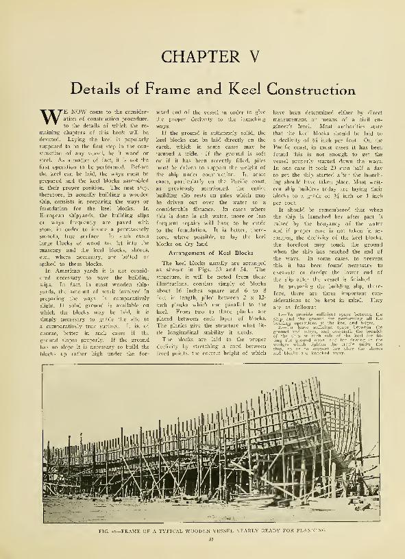
CHAPTER V
Details of Frame and Keel Construction
WE NOW come to the consider-
ation of construction procedure,
to the details of which the re-
maining chapters of this book will be
devoted. Laying the keel is popularly
supposed to be the first step in the con-
struction of any vessel, be it wood or
steel. As a matter of fact, it is not the
first operation to be performed. Before
the keel can be laid, the ways must be
prepared and the keel blocks assembled
in their proper position. The first step,
therefore, in actually building a wooden
ship, consists in preparing the ways or
foundation for the keel blocks. In
European shipyards, the building slips
or ways frequently are paved with
stone in order to insure a permanently
smooth, true surface. In such cases
large blocks of wood are let into the
masonry and the keel blocks, shores,
etc., where necessary, are bolted or
spiked to these blocks.
In American yards it is not consid-
ered necessary to pave the building
slips. In fact, in most wooden ship-
yards, the amount of work involved in
preparing the ways is comparatively
slight. If solid ground is available on
which the blocks may be laid, it is
simply necessary to grade the site to
a comparatively true surface. It is, of
course, better in such cases if the
ground slopes properly. If the ground
has no slope it is necessary to build the
blocks up rather high under the for-
ward end of the vessel in order to give
the proper declivity to the launching
ways.
If the ground is sufficiently solid, the
keel blocks can be laid directly on the
earth, which in some cases may be
tamped a trifle. If the ground is soft
or if it has been recently filled, piles
must be driven to support the weight of
the ship under construction. In some
cases, particularly on the Pacific coast,
as previously mentioned, the entire
building slip rests on piles which maybe driven out over the water to a
considerable distance. In cases where
this is done in salt water, more or less
frequent repairs will have to be made
to the foundation. It is better, there-
fore, where possible, to lay the keel
blocks on dry land.
Arrangement of Keel Blocks
The keel blocks usually are arranged
as shown in Figs. 53 and 54. Thestructure, it will be noted from these
illustrations, consists simply of blocks
about 16 inches square and 6 to 8
feet in length, piled between 2 x 12-
inch planks which run parallel to the
keel. From two to three planks are
placed between each layer of blocks.
The planks give the structure what lit-
tle longitudinal stability it needs.
The blocks are laid to the proper
declivity by stretching a cord between
fixed points, the correct height of which
have been determined either by direct
measurement or means of a civil en-
gineer's level. Most authorities state
that the keel blocks should be laid to
a declivity of % inch per foot. On the
Pacific coast, in most cases it has been
found this is not enough to get the
vessel properly started down the ways.
In one case it took 20 men half a day
to get the ship started after the launch-
ing should have taken place. Most west-
ern ship builders today are laying their
blocks to a grade of 54 inch or 1 inch
per foot.
It should be remembered that whenthe ship is launched her after part is
raised by the bouyancy of the water
and if proper care is not taken in ar-
ranging the declivity of the keel blocks,
the forefoot may touch the ground
when the ship has reached the end of
the ways. In some cases, to prevent
this it has been found necessary to
excavate or dredge the lower end of
the slip after the vessel is finished.
In preparing the building slip, there-
fore, there are three important con-
siderations to be kept in mind. They
are as follows
:
betv the1.—To provide sufficient spacship and the ground for performing all the
building operations at the keel and bilges.
2.—To leave sufficient space between the
ground and bilges, and one-sixth the breadthof the ship at each side of the keel for fit-
ting the ground ways, and for driving in the
wedges which tighten the cradle under theship, so as to support her after the shoresand blocks are knocked away.
FIG. 46—FRAME OF A TYPICAL WOODEN VESSEL NEARLY READY FOR PLANKING

34 HOW WOODEN SHIPS ARE BUILT
FIG. 47—LAYING-DOWN THE LINES OF A SHIP ON THE MOLD-LOFT FLOOR
FIG. 48—LAVING THE KEEL OF A 4000-TON MOTOR SHIP
FIG. 49—FINISHING THE FRAMING OF A LARGE WOODEN SHIP ON THE PACIFIC COAST
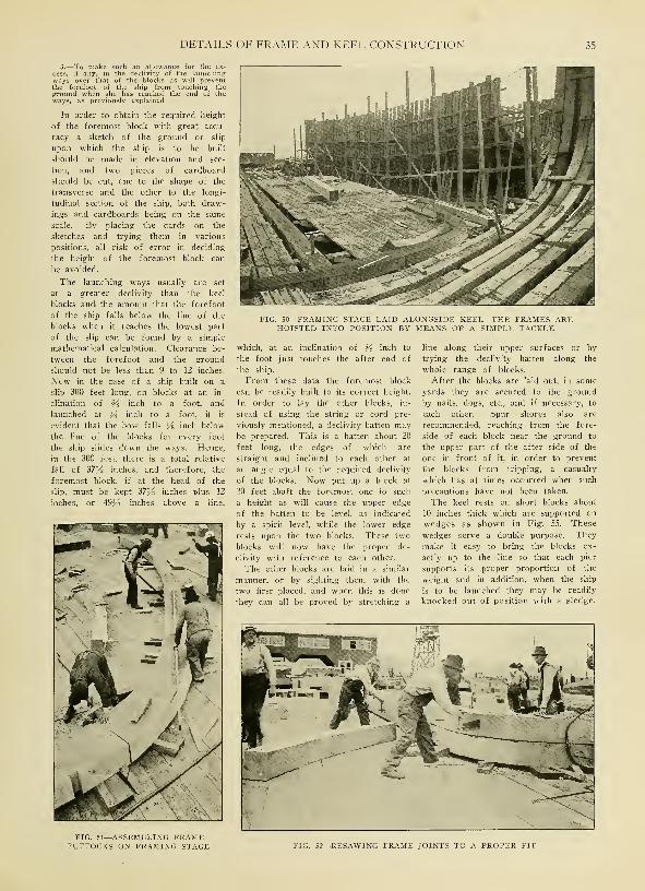
DETAILS OF FRAME AND KEEL CONSTRUCTION 35
3.—To make such an allowance for the ex-
cess, if any, in the declivity of the launchingways over that of the blocks as will preventthe forefoot of the ship from touching theground when she has reached the end of theways, as previously explained.
In order to obtain the required height
of the foremost block with great accu-
racy a sketch of the ground or slip
upon which the ship is to be built
should be made in elevation and sec-
tion, and two pieces of cardboard
should be cut, one to the shape of the
transverse and the other to the longi-
tudinal section of the ship, both draw-
ings and cardboards being on the same
scale. By placing the cards on the
sketches and trying them in various
positions, all risk of error in deciding
the height of the foremost block can
be avoided.
The launching ways usually are set
at a greater declivity than the keel
blocks and the amount that the forefoot
of the ship falls below the line of the
blocks when it reaches the lowest part
of the slip can be found by a simple
mathematical calculation. Clearance be-
tween the forefoot and the ground
should not be less than 9 to 12 inches.
Now in the case of a ship built on a
slip 300 feet long, on blocks at an in-
clination of Y% inch to a foot, and
launched at 54 inch to a foot, it is
evident that the bow falls Ys inch below
the line of the blocks for every foot
the ship slides down the ways. Hence,
in the 300 feet, there is a total relative
fall of 37J/2 inches, and therefore, the
foremost block, if at the head of the
slip, must be kept 37^2 inches plus 12
inches, or 49yi inches above a line,
FIG. 50—FRAMING STAGE LAID ALONGSIDE KEEL—THE FRAMES AREHOISTED INTO POSITION BY MEANS OF A SIMPLE TACKLE
which, at an inclination of Ys inch to
the foot just touches the after end of
the ship.
From these data the foremost block
can be readily built to its correct height.
In order to lay the other blocks, in-
stead of using the string or cord pre-
viously mentioned, a declivity batten maybe prepared. This is a batten about 20
feet long, the edges of which are
straight and inclined to each other at
an angle equal to the required declivity
of the blocks. Now put up a block at
20 feet abaft the foremost one to such
a height as will cause the upper edge
of the batten to be level, as indicated
by a spirit level, while the lower edge
rests upon the two blocks. These two
blocks will now have the proper de-
clivity with reference to each other.
The other blocks are laid in a similar
manner, or by sighting them with the
two first placed, and when this is done
they can all be proved by stretching a
line along their upper surfaces or by
trying the declivity batten along the
whole range of blocks.
After the blocks are laid out, in some
yards they are secured to the ground
by nails, dogs, etc., and if necessary, to
each other. Spur shores also are
recommended, reaching from the fore-
side of each block near the ground to
the upper part of the after side of the
one in front of it, in order to prevent
the blocks from tripping, a casualty
which has at times occurred when such
precautions have not been taken.
The keel rests on short blocks about
10 inches thick which are supported on
wedges as shown in Fig. SS. These
wedges serve a double purpose. They
make it easy to bring the blocks ex-
actly up to the line so that each pier
supports its proper proportion of the
weight and in addition, when the ship
is to be launched they may be readily
knocked out of position with a sledge.
FIG. 51—ASSEMBLING FRAMEFUTTOCKS ON FRAMING STAGE FIG. 52—RESAWING FRAME JOINTS TO A PROPER FIT

36 HOW WOODEN SHIPS ARE BUILT

DETAILS OF FRAME AND KEEL CONSTRUCTION 37
fe >
««0fa ^ £o w M
fa p Ofa
« 2 fc
w * w*H Oi ,1
fa <
w « £« fa w< H OSg
I
1 w urj Sw < fa
fa P4fa
ogJ Mo a.
O en
5«cfi fa
fa £m <gen
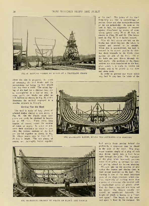
38 HOW WOODEN SHIPS ARE BUILT
FIG. 65—SETTING FRAMES BY MEANS OF A TRAVELING CRANE
After the site is prepared, the work
of arranging the keel blocks and the
preparations for laying the keel should
take less than a week. The actual lay-
ing of the keel for a 300-foot boat can
be accomplished in a day or two. In
some yards, the blocks are piled up
crib fashion as shown in Fig. 56, which
illustrates the method employed in a
wooden shipyard in Georgia.
Getting Out the Keel
The keel is made of long pieces of
selected timber similar to that shown in
Fig. 48. On the Pacific coast these
pieces can easily be obtained in lengths
up to 100 feet. These extra long
lengths, of course, reduce the number
of joints or scarfs. In order to pre-
serve their continuity as much as pos-
sible, the various sections of the keel
are scarfed together as shown in Fig.
55. These scarfs may be from 10 to
20 feet in length. The two pieces, of
course, are thoroughly bolted together
at the scarf. The joints of the scarf
frequently are laid in carbolineum to
prevent decay and also to resist the action
of the sea animalculae. As soon as the
keel is laid, its alignment is secured
against disturbance by means of sway
braces spaced every 30 or 40 feet, as
shown in Figs. 55 and 56. The brace
used in Fig. 55 is 6 inches square.
After the keel pieces are laid on the
blocks and fitted together, the whole is
sighted and proved to be straight.
When this is accomplished, the keel is
secured in the correct position by driv-
ing short treenails in the blocks close
against the side of the keel. All of
the bolts are now driven through the
keel scarfs. The positions of the frame
stations are next transferred' to the keel,
after which it is ready to receive the
frames and to be joined to the stem
and stern posts.
In order to prevent any water which
may find its way into the joints of the
FIG. 66—RAISING FRAMES BY MEANS OF BLOCK AND TACKLE
FIG. 67—FRAMES RAISED, READY FOR PLUMBING AND HORNING
keel scarfs from getting behind the
garboards, a stopwater may be placed
in the joint of the scarf. This stop-
water consists simply of a plug of soft
pine driven tightly into a hole bored
right through the joint. The expansion
of the plug, when immersed, prevents
water from going up through the scarf
and getting behind the bottom planking.
We now take up the question of pre-
paring the frames and placing them in
their proper positions on the keel. Theframing is one of the most important
parts of the ship's structure, which con-
sists, essentially of nothing more than
a series of transverse ribs covered with
a longitudinal series of planks which
bind the frames together and keep out
the water. The frames usually are
spaced at equidistant intervals, the
length of which is known as a "room
and space." The length of the room
and space is fixed by the designer. On

DETAILS OF FRAME AND KEEL CONSTRUCTION 39
68
FIG. 68—HAND-WINCH FOR HAULING TIMBERS THROUGH BAND SAW FIG. 69—DETAIL OF BOLTED FRAME JOINTSFIG. 70—ANOTHER VIEW OF BOLTED FRAME CONSTRUCTION FIG. 71—RIBBANDS IN PLACE AND SHORING
UNDER FRAME

40 HOW WOODEN SHIPS ARE BUILT
FIG. 72—FRAMING STAGE IN A GEORGIA SHIPYARD
FIG. 73—FRAME OF A VESSEL IN A GEORGIA SHIPYARD
FIG. 74—TWO SETS OF CROSS SPALLS SOMETIMES ARE USED TO HOLD THE FRAME SECTIONS TOGETHER

DETAILS OF FRAME AND KEEL CONSTRUCTION 41
FIG. 75—UPPER PART OF ARCH STRAPPING
account of the great curvature of the
transverse sections of the vessel, es-
pecially amidships, it is necessary to
build the frames of a number of pieces
and in order that these may be united
as rigidly as possible, they are disposed
in two sets, the butts of which give
shift to each other, the whole being so
combined that its elements will yield
mutual support in the most efficient
manner obtainable.
Preparing the Molds
The proper curves or molds for the
frame sections are provided by the
mold loft, where the sheer-draft or
lines of the vessel are laid down full
size. Fig. 47 shows a view of a mold
loft, indicating how the lines are laid
down for the preparation of the molds.
The mold loft should be big enough so
the longitudinal or sheer-plan of the
vessel can be laid down in at least two
sections. In many cases, however, it is
necessary to lay down the ship in three
sections.
A sheer-draft, as the lines of the ves-
sel frequently are called, usually is pre-
pared in the drawing room to a scale of
Va inch to the foot. When this is copied
to full size on the mold-loft floor, it maybe found that errors, almost inappre-
ciable in the quarter scale drawings are
very apparent when magnified 48 times.
It is usually found, therefore, that the
three sets of ' lines, namely, the sheer-
plan, body-plan, and half-breadth plan,
disagree sufficiently to prevent the vari-
ous problems of laying off from being
solved with that degree of accuracy
which is necessary in order to obtain
a fair surface to the vessel. Hence a
fairing or correcting process has to be
performed before the molds can be
prepared.
As every draftsman knows, the pro-
jections of the lines of the vessel upon
the three plans, sheer, body and half-
breadth, are mutually interdependent
and this property is utilized in perform-
ing the fairing operation. The pro-
jections of each of the sets of lines
used in this process, that is the water-
lines or level lines, cross sections or
square sections, bow lines and diagonal
lines, appear straight in one or two
of the three plans, so that by the aid
of a straightedge they can be drawn
fair easily in such plans. Now the
property which a wooden or metallic
batten has of bending in a fair curve
is brought into play in drawing the
lines fairly in the plans where they
appeared curved. Since the intersec-
tions of lines with each other are
points, the points of intersection of two
sets of lines in one plan are transferred
to their relative positions in the others,
so that points which appear straight in
one plan form a curved line in another.
Battens are penned or bent to pass
through as many of the points as is
consistent with absolute fairness and
the line is drawn. Thus, by a series of
interchanges between the three plans, or
projections of the lines, the various lines
are copied from one plan into another
until at length all the plans coincide
and the lines composing them are con-
tinuous curves. The fact that the
curves are continuous proves that the
body is fair.
It is a great advantage if the seams
of the boards forming the floor of the
mold loft are perfectly straight and
parallel, as they thus afford consider-
able assistance in the several processes
of squaring and drawing parallel lines
which are involved in the practice of
laying-off.
Transferring Lines to the Floor
The first thing to be done in copying
the lines onto the mold loft floor is to
strike a base-line. If the edges of the
boards are arranged as suggested, it
will be necessary to place the base-line
either parallel or perpendicular to the
lines of seams. Should the floor be
rectangular, about two feet from the
wall or other boundary of the floor is a
convenient position for a base-line.
After the base-line is drawn, the depth
of the keel, the lower edge of planking,
and the upper side of the keel are set
off from it at distances measured from
the sheer-plan. Also the fore and after-
edges of the stem together with the
fore-edge of rabbet of stem, which is,
of course, a continuation of the lower
edge of planking on the keel, are laid
off. The sternpost is next copied with
the after-edge of its rabbet and the
various square stations, or frame sta-
tions in the sheer-plan are laid out on
the floor. These, with the line of the
upper deck beams at the middle, are
termed the fixed lines of the sheer-
plan, being unalterable except insofar
as drawing them true is concerned.
To economize space, the half-breadth
plan is generally drawn on the same
part of the mold loft floor as the sheer-
plan. The base-line of the former, or a
line parallel thereto serving as the middle
FIG. 76—LOWER PART OF ARCHFASTENING
STRAPPING SHOWING METHOD OFTHE BUTTS
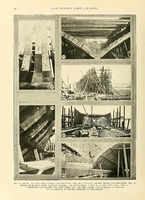
42 HOW WOODEN SHIPS ARE BUILT
7—DETAIL OF STANDARD FRAME CONSTRUCTION FIG. 78—DETAIL OF BOLTED FRAME CONSTRUCTIONFRAME NEAR BOW USING NATURAL CROOKS FIG. 80—FRAMING A SHIP IN A SOUTHERN YARD FIG. 8
SOMETIMES THE FLOORS ARE LAID FIRST AND THE SIDE FRAME PIECES RAISED AFTERWARDFIG. 82—DETAIL OF FRAMES HEELING TO DEADWOOD

DETAILS OF FRAME AND KEEL CONSTRUCTION 43
line of the latter, and in this way the
same square stations will do for the
two plans.
Now, having copied the sheer-plan,
the body-plan is next copied full size as
nearly as possibly to the sheer-plan. In
some cases where the' mold loft floor
is smaller than it should be, two plans
overlap. On a very small floor, the
same base-line may as well serve for
three plans, one of the square stations
in the midship being taken as the mid-
dle line of the body-plan.
Copying the Body Plan
The body-plan is copied or drawn on
the floor by measuring the distances
along the several water and diagonal
lines from the middle line to where
they cut the square stations, setting
these distances off to full size on the
corresponding lines on the floor. Bat-
tens are then penned or bent as in Fig.
47 so as to approximate as closely to
these points as is consistent with ab-
solute fairness or continuity. The lines
then are marked in, usually with thin
slices of chalk. At some yards it
is customary to measure the ordinates,
etc., and record them on paper in tabu-
lated form before proceeding to draw
the body full size on the floor. In this
case, the latter operation is performed
without direct reference to the drawing
when working on the floor.
The half-breadth plan is next to be
drawn on the floor and here we again
note that the lines which are curved in
the body plan are straight in the half-
breadth plan and vice versa.
Having already drawn the middle
line of the half-breadth plan on the
floor and the projections of the square
stations in that plan, we proceed to
copy the level or water lines from the
body plan into the half-breadth plan.
For this purpose straightedged battens
are set to the middle lines of the body
and half-breadth plans on the drawings.
Now measure on a staff whose end is
kept against the batten set to the middle
line of the body-plan, the distance fromthis line to where a level line cuts each
square station or frame station in the
body-plan. Transfer these distances to
the corresponding square stations in the
half-breadth plan on the floor by setting
the end of the staff against the middle-
line batten of that plan, marking the
distances out from the respective square
stations. A batten is then bent so it
can pass fairly through as many as
possible of these points, thus trans-
ferring the water lines to the half-
breadth plan.
The diagonal lines and bow and but-
tock lines from the sheer-draft are also
transferred full size to the mold loft
floor in much the same manner as just
described. In fact, this process of
transferring the lines to the floor is
comparatively simple if the principles
of projection which underlie all draft-
ing work are thoroughly understood.
To be completely successful, the moldloft man also should have a goodknowledge of descriptive geometry,
which covers the details of the science
of projection.
As the various plans are copied onthe floor it is found that there are
discrepancies, as previously pointed out.
These must be corrected by mutual ad-
justment until the three plans coincide
accurately.
When discrepancies occur, the waterand diagonal lines in the neighborhood
must be examined to see if the points
within the section were correctly taken,
and if a modification of these lines,
consistent with fairness, will give such
points as the batten will spring to. Thebow and buttock lines are a great help
to both the designer and the drafts-
man in judging the character of the
surface at the extremities of the ship.
No rules, however, can be laid downfor guidance in dealing with them, ex-
perience being required in order that
they may afford a vivid conception of
the form of the vessel.
In practically performing all of the
operations connected with laying downthe lines on the mold loft floor, a great
deal must be left to the judgment of
the man in charge. A practiced eye will
save much labor. When a batten does
not spring well to the point, it is bent
to pass outside some and inside others.
As a rule the batten should pass on
the outside more frequently than on
the inside of the points in order that
the volume of the ship may not be
less than that given by the design. In
copying and drawing the body-plan, it
is advisable to draw the midship sec-
tion first and then the others in rotation
as the draftsman is thus better enabled
to see what he is doing and exercise
his judgment.
Time Required for Framing
Mold loft floors usually are painted.
Generally a gray color is chosen. Whena new set of lines is to be laid down, it
usually is advisable to repaint the floor
in order to completely obliterate all of
the old lines. In some cases, however,
the floors are not painted, but are left
in a natural color. In these yards
when new lines are to be laid down, the
whole floor is gone over with a cabinet
scraper, thus removing the old drawing.
The finished molds are similar to those
shown on the pile of timber in Fig. 59.
White pine, cedar, or other easily
worked scrips are used for makingmolds.
As soon as the molds are ready, the
process of framing the ship actually
may be begun. This process may be
divided into three steps as follows:
Sawing the frame sections; assembling
the sections, or futtocks; and raising
the frame.
The time required to frame a ship
seems to vary widely in different yards.
In one case the writer has been in-
formed that 46 days were required to
frame a 250-foot, 4-masted schooner.
In this yard the frames were skidded
into position and raised by tackle, no
cranes being available. In another yard
only 15 days were "required to frame
the square body of a 290-foot ship,
using the same method of raising the
frames. To this should be added 10
days for the forward and stern cant
frames. A gang of about eight to 10
men is required, not including those
working on the framing stage where
a dozen more are necessary. After the
main frames are up the smaller pieces
of the stern frame, including the tran-
som, etc., can be framed with a gang of
four or five men.
Specifications of Timber Needed
The frames of modern wooden ves-
sels are sawed from timbers similar to
those shown in Fig. 59. The sizes of
timbers necessary and the quantity re-
quired for framing a 300-foot vessel
are indicated by the following quotation
from the timber schedule for standard
Pacific coast type wooden steamship, de-
signed by Mr. Ferris for the United
States Emergency Fleet Corp. Thestandard government boat, it will be
recalled is 281 feet 6 inches in length
overall and 46 feet beam. It has a
cargo capacity of about 3500 tons on a
draft of 23J/2 feet. The frame timber
specifications are as follows
:
Net

44 HOW WOODEN SHIPS ARE BUILT
13 pieces 12 x 22 — 22
13 pieces 12 x 25 — 34
20 pieces 12 x 22 — 36
16 pieces 12 x 18— 40
10 pieces 12 x 18— 42
Forward Cant Frame No. 92
1 piece 12 x 26 — 241 piece 12 x 28 — 36
1 piece 12x24—221 piece 12x20— 28
1 piece 12x28— 24
1 piece 12 x 16 — 28
One method of marking the frame
timbers with the molds is shown clearly
in Fig. 60. A man of some experience
is necessary for this operation and a
good workman can save considerable
lumber at this point. After the frame
timbers have been properly marked, they
are ready to be sawed and for this
purpose sawing equipment such as that
illustrated in Figs. 61 and 62 may be
employed. The equipment shown in
Fig. 61 consists of a 48-inch swinging-
cut-off saw and a steam-driven derrick
with a 45-foot boom. As soon as the
timbers are marked, as shown in Fig.
60, they are picked up by the derrick
and swung around to the cut-off saw
table as indicated in Fig. 61. After
being sawed to the proper length, they
are skidded out onto the horses shown
at the extreme left in the background
in Fig. 61. They are then transferred
from the horses to dollies or timber
trucks similar to those shown in Fig.
62. These dollies are used to shift the
timbers to the band-saw.
Roughing Out the Timber
A 40-inch bandsaw is provided. The
frames are sawed to the proper curved
outlines in the band-saw, the finished
sections or futtocks appearing as in Fig.
63. This also shows the type of truck
used for transferring the finished frame
sections from the band-saw to the fram-
ing stage where the frames are as-
sembled. In some yards, in order to
assist the work of sawing, small hand
winches, such as that shown in Fig. 68,
are employed. This apparatus saves
considerable labor. It is particularly
useful in sawing bevels on long straight
pieces. For sawing out the frames of
a 300-foot vessel, a gang of seven to
nine men, using the equipment just de-
scribed, is employed. It takes such a
gang about nine weeks to saw out the
100 frames in the ship. If the gang
turns out four complete single frames
in an 8-hour shift, a good day's work
has been accomplished. If greater speed
is desired, more men and equipment
must be employed.
After the frame sections are sawed
out, they must be assembled. This
operation is shown in Figs. 51, 52 and
64. The framing stage of a southern
shipyard also is shown in Fig. 72. The
framing stage, on which the various
sections are assembled, is located usu-
ally at the head of the building slip.
Sometimes, as in Fig. 50, it is built
right alongside the keel so that the
assembled frames do not have to be
moved before they are rolled up into
place. Preferably, however, the framing
stage should be level. At all events it
should have a plane surface. As shown
in Fig. 51, wedges are used to bring
the various sections or futtocks to
proper alignment. The joints, it will
be noted, do not fit exactly. They,
therefore, are resawed using cross-cut
saws as shown in Fig. 52. This illus-
tration shows the frame after the doub-
ling frame is in place. The several
futtocks must be fastened together be-
fore the frame is hoisted into place.
Usually wooden treenails, such as those
shown at the left in Fig. 64, are utilized
for this purpose. The tops of the
frames also are tied together by means
of cross spalls. Single pieces of 2 x 6-
inch timber usually are employed for
this purpose.
After the frame has been assembled
as shown in Fig. 64 it must be raised
into position. Various methods are em-
ployed. Perhaps the most rapid and
efficient is that illustrated in Fig. 65,
using the traveling derrick described in
Chapter III, and described in detail on
page 22.
As this illustration indicates, the der-
rick readily picks up the frame and takes
it down to its proper position on the keel.
The derrick also is of advantage in the
plumbing and horning operations. As
soon as the frame is secured in place,
it is fastened to its neighbor by means
of light tie pieces and small bolts as
shown in Fig. 50. Groups of frames
. when they are erected, are later tied
together by ribbands as shown in Figs.
71 and 78. The derrick shown in Fig.
65 is at the plant of the Sloan Ship-
yards Corp., Olympia, Wash.
When the services of a derrick or
crane are not available, the simpler
method of rolling the frame into posi-
tion by means of tackle as shown in
Fig. 66 may be employed. This method
of raising frames is employed in the
yard shown in Fig. 50. This illustra-
tion shows clearly how the frame is
hoisted into position using tackle fast-
ened to the upper ends of frames al-
ready raised.
Southern Practice
A good view of a set of frames after
hoisting is shown in Fig. 74. This
illustrates the practice of a Georgia
yard. It will be noted that two sets
of ties are used to hold the frames
together. Another view of the frame
construction of a wooden motor
schooner built in the same yard is
shown in Fig. 79. This shows hownatural crooks are employed to
strengthen the frame members near the
bow. It must be admitted that these
frames are stronger than those which
are merely sawed out. There is not,
however, enough timber of suitable
character available to permit any large
number of ships being built in this
country in the manner shown in Fig. 79.
Detailed views of modern methods
of fastening sawed frame futtocks to-
gether are shown in Figs, 69, 70, 77,
and 78. The standard Pacific coast and
Gulf construction is shown in Fig. 77.
These frames are sawed out as previ-
ously described and as the illustration
just' mentioned indicates, the futtocks
are fastened together by wooden tree-
nails and drift bolts. Other shipbuild-
ers, notably Fred A. Ballin, Portland,
Oreg., use the bolted construction illus-
trated in Figs. 69, 70, and 78. Two bolts
are carried through each end of the
futtock forming a solid joint.
Further Construction Details
Further details of methods of shoring
up frames after they are erected may be
obtained from a study of Fig. 71. These
shores are 6 inches square and it will
be noted they are wedged to a bearing.
The ribbands which hold the frames to-
gether temporarily are about 4 inches
square and are spiked once to each
frame. They are, of course, removed
when the planking goes on. Wedgesdriven by hand mauls usually are em-
ployed for this purpose. In some cases,
6 x 6-inch ribbands are used. As a
matter of fact, their exact dimensions
are of no consequence. Neither is it
necessary that they follow the diagonal
lines as some old-line shipbuilders stipu-
late. Their sole purpose is simply to
hold the frames together temporarily.
In setting frames, it is customary to
start at the after end of the boat as
shown in Fig. 65. Sometimes, how-ever, the after cant frames are omitted,
the square body being framed up first.
In other yards, particularly in the
south, the floors are first laid, and some
of the keelsons bolted down, after
which the side futtocks of the frames
are set in place as shown in Fig. 81.
The frames, of course, cannot be se-
cured by ribbands until the builder is
sure they are set square with the keel
and with each other. The following
method may be employed to determine
whether or not the frame is vertically
square to the keel. Drop a plumb from
the middle of the cross spall to the
floor. Then measure the thickness of
the cross spall from the joint of the
frame, and set off this distance from
the joint on the floor. The plumb should
fall as much abaft this point as is
given by the product of the declivity of
the keel blocks per foot by the number
of feet in the height of the cross spall
above the floor. Of course, this is on
the supposition that the frames are to
be square to the keel which is true al-

DETAILS OF FRAME AND KEEL CONSTRUCTION 45
most universally at the present time.
In some old ships the frames are
square to the load waterline instead of
to the keel. In such cases, the neces-
sary allowance must be made.
To determine whether or not the
frame is horizontally square to the keel,
the following procedure may be adopted
:
A point is selected on the middle line
of the keel at some distance from the
frame to be horned, as it is termed,
and two other points are marked at
equal heights on each side of the frame,
say at a frame head. The distance
from these latter points to the point on
the middle line of keel will be equal
if the frame is horizontally square to
the keel. It is not necessary to horn
every frame in this way nor to check
its vertical inclination, since by the aid
of ribband battens, when one frame is
set correctly a number of others can
be set by reference to it. It is, how-ever, advisable to institute checks at
intervals. The breadth of the ship at
the different frame heads also should be
checked from time to time, so that by
plumbing and horning, the frames of
the ship can be so shored and secured
as to insure her external surface being
of the designed form.
Putting on Arch Straps
The general method of reinforcing
the frames of a wooden ship with
steel strapping have been discussed in
a previous chapter. When arch strap-
ping, using 14-inch universal plates of
the type shown in Figs. 75 and 76 is
employed, the frames must be mortised
out properly to let in the straps, so
the planks will rest on a fair surface.
The method of doing this is clearly
indicated in Fig. 76, which also shows
how the butts of the straps are fastened
together and how the straps are bolted
to the frames. The upper part of the
steel arch where it rises to a point
above the main deck is shown in Fig.
75. This form of strapping costs about
$3000, including about $1500 for labor
and fastenings.
Near the stern of the ship, the frames
must be carefully heeled to the dead-
wood. Fig. 82 shows how this is done.
It also shows how the deadwood is
clamped together by means of chains
and wedges before it is edgebolted.
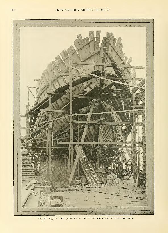
46 HOW WOODEN SHIPS ARE BUILT
FIG. 83—BOW CONSTRUCTION OF A LARGE PACIFIC COAST MOTOR SCHOONER

CHAPTER VI
Methods of Framing Forward End of Snip
INFRAMING the ends of a ship
special problems are encountered.
The stem, at the forward end and
the sternpost at the rear, must be set
in place and the surrounding timbers
properly arranged before the planking
operations can be commenced. Of the
two ends of the vessel, the framing of
the bow is much the simpler.
Today wooden ships usually are built
with either clipper bows or steamer
bows. Vessels with auxiliary power
usually are provided with clipper bows
while full-powered motor vessels or
steamships have steamer bows with the
customary straight stem. The chief char-
acteristics of these two types of bows
are generally understood. The steamer
bow is perhaps the less artistic of the
two, although easier to frame. In the
steamer bow the stem is set perpendicu-
lar to the keel ; in the clipper type bow,
the stem has a rake forward and is set
at an acute angle to the keel. A typical
clipper bow, with the framing in place
ready for planking, is shown in Fig. 83.
A steamer bow, in a similar stage of
completion is shown in Fig. 94.
The bow construction of modern
wooden ships has been greatly simplified
by the large timbers now available in
all sections of the United States, par-
ticularly on the Pacific coast. In the
old days in England it was necessary
to build up the
stem, deadwood,
apron, knighthead.
etc.. out of a
great many pieces,
all of which had
to be carefully
locked, scar fed,
hooked and bolted
together. In some
old English ships
of the line, a s
many as 34 pieces
were used in the
stem construction.
The stem proper
of modern wood-
en ships can be
easily fashioned
from one piece.
The apron like-
wise can be madeof one piece, and
the knightheads
may be similarly
gotten out. Asshown in Figs. 84
and 96, the frames near the stem
must be swung or canted forward,
out of square with the line of
the keel. This is done in order
to avoid excessive molding dimensions.
Frames which are so swung are termed
cant frames, whether they are located
in the forward or after part of the ves-
sel. The remaining frames, usually, are
known as square frames. On the Pacific
coast at the present time, however, the
term cant frame is more loosely con-
strued to mean any frame which heels
against the deadwood as in Fig. 96, in-
stead of against the keel.
On account of the tapering of the
ship toward the forward end. it is
necessary to fill up the thin portion
with blocks of timber termed deadwood
in order to form a suitable footing for
the frames. In the case of clipper type
ships, such as that shown in Fig. 83, it
is not possible, even, to heel all of the
frames against the deadwood, and some
of the shorter ones near the upper part
of the stem are heeled against the apron,
which is a piece fitted immediately be-
hind the stem. This construction is
clearly shown in Figs. 83 and 89. The
short timbers in the latter illustration,
parallel to the stem, are known as
knightheads. They are utilized to fill
out the framing where the bows are
comparatively blunt. Some years ago
FIG. 84—DETAILS OF STEM SHOWING LARGE NATURAL KNEE
old-line English wooden shipbuilders
thought it absolutely necessary to use
oak for the stems of wooden ships.
Modern experience, has indicated, how-
ever, that this is not necessary at all,
and at the present time fir, yellow pine
and other woods are employed with
equal success. In fact, the latter woods
are preferable on account of the large
sizes in which the timbers may be
obtained. The advantage of using
larger timbers already has been dis-
cussed.
If, however, it is necessary to build
up the stem of more than one piece,
the sections should be connected by
scarfs similar to those used to connect
the pieces of keel together. These
scarfs should be so disposed as to
give a good shift to the pieces of the
apron, in case the latter also is com-
posed of more than one piece. On ac-
count of the strain to which they are
subjected, it is not a bad idea to dowel
scarfs of this character.
Prior to 1850 it was customary to
join the stem to the fore piece of keel
by means of a curved scarf. It was
necessary, therefore, to convert the
stem from a timber which already had
the necessary natural curvature so as
to avoid shortness of grain at the thin
lip of the scarf. In such cases, also,
to aid in the conversion of the timbers,
a portion cf the
curvature of the
fore- foot was in-
cluded in the fore-
piece of' keel by
placing the scarf
a little higher up
the stem. At the
present time,
however, a verti-
cal scarf similai
to that shown in
Figs. 84 and 97
usually i s e m -
ployed and thejoint is rein-forced by insert-
ing a naturalknee. Sometimes
this knee goes in
over the dead-
wood as in Fig. 84.
In other cases, it
constitutes thelowest piece of
deadwood as in
Fig. 97. Inthelat-
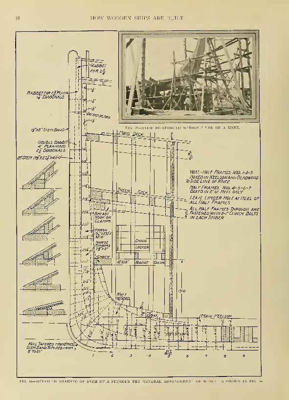
48 HOW WOODEN SHIPS ARE BUILT
FIG. 86—DETAILED DRAWING OF STEM OF A STEAMER THE GENERAL ARRANGEMENT OF WHICH IS SHOWN IN FIG

FRAMING THE FORWARD END OF THE SHIP 49
FIG. 87—INTERIOR OF BOW CONSTRUCTION OF A 290-FOOT MOTOR SCHOONER. FIG. 88—DETAIL OF STEM CONSTRUC-TION OF THE SCHOONER SHOWN IN FIG. 87 ILLUSTRATING METHOD OF FASTENING FORWARD ENDS OF
KEELSON TIMBERS TO STEM. FIG. 89—ARRANGEMENT OF STEM AND KNIGHTHEAD AT UPPEREND NEAR MAIN DECK. FIG. 90—STAGING SURROUNDING 4 CLIPPER-TYPE BOW
UNDER CONSTRUCTION

50 HOW WOODEN SHIPS ARE BUILT
ter case, the knee usually is lock-
scarfed, to the keel as shown.
The stem is trimmed to the proper
curvature by means of molds sent from
the mold-loft floor. These molds are
made from the lines of the stem laid
down on the floor when the sheer draft
is prepared If the stem, or its coun-
terpart, consists of more than one piece,
a separate mold is made for each piece.
In this case, it is a good idea to mark
the waterlines on the mold, together
with the two edges of rabbet and a
vertical line by which to set the stem
in its correct position. As many as a
dozen separate molds were required
for the clipper-type bows of some old
English ships. At the present time,
this has been reduced to two or three
molds of the simplest character.
The stem usually has a tapered siding
increasing uniformly from the fore end
of the keel. In some cases, the taper
extends to the top of the stem, while
in others, when a particularly fine job
is desired, three sidings are fixed,
namely, at the head, midway down and
at the keel.
After the stem piece is trimmed, in a
manner to be described later, the several
waterlines, fore edge of rabbet, bearding
line and the vertical line for setting it
in position, if it is of the clipper type,
all are transferred to it from the molds.
The rabbet is sometimes roughly cut
before the stem is raised. It is advis-
able not to cut the rabbet to the exact
depth but to leave enough wood to
allow its being faired when the outside
of the frame timbers are dubbed-off.
Raising the Stem
The stem, apron and knightheads are
usually treenailed and bolted together
before lifting them into place. For
raising the stem a crane such as that
employed for handling frames may be
employed, or, if it is not available, a
simple derrick or even nothing more
than a gin pole may be used. After
the stem is hoisted in place, if it is of
the clipper type, its rake is proved by
means of the vertical line marked upon
it from the mold. It is set vertically by
projecting the middle line of the keel
sufficiently far forward to be below the
most projecting part of the stem. Then
if a plumb line, held against the middle
line of stem at different heights, touches
the line so produced, it is proof that
the stem is vertical and free from any-
bulging or lateral curvature. After this
fact is determined, the stem is securely
shored into position. Where the stem
is of the steamer type, its correct
position in a transverse plane can
readily be determined simply by drop-
ping a plumb line from the upper end.
The apron is really a portion of the
stem, although it is distinguished from
the stem proper by a separate name.
Its chief function is to back-up the
stem, giving it additional strength and
solidity.
Deadwood, as previously mentioned,
is the name given to those pieces of
timber which form the lean or acute
portions of the bow and stern of the
ship between the extremities and the
cutting-down line, or line of the inside
of timbers. This line generally bounds
the upper side of the deadwood, the
latter thus giving just the necessary
amount of heeling for the cant tim-
bers. But in very fine ships, the cut-
ting-down line is sometimes on the
keelsons, in order to save the great
weight of timber at the extremities
caused by making the deadwood deep
enough of itself to receive the abut-
ments of the cants.
Butts Should Give Good Shift
The pieces of which the deadwood
is composed are arranged in such a
manner that their butts give a good
shift to each other and to those of the
keel. When a floor crosses the dead-
wood, the lip of the deadwood scarf
is so situated as to receive a through
bolt, and in all cases the butts and
scarfs are so placed as to be in the
most favorable position to receive the
fastenings. In both screw and sailing
ships, the pieces of deadwood ought to
be tenoned into the pieces of stern post
that they abut against, and the former
also should be doweled and bolted to-
gether, the dowels being spaced about a
room and space apart.
In some cases, a mold for the dead-
wood is sent from the mold-loft floor.
It is made of battens upon which the
joints of the several pieces composing
the deadwood are marked, together with
the upper edge of rabbet or bearding
line, the cutting-down line of the tim-
bers and the positions of the heels of
the cants and square frames. Half-
section molds of the deadwood at sev-
eral square stations also may be given.
These can be tacked to the main mold
so as to form a part of it, in such a
position that the middle line of the
half-section mold coincides with the
line on the mold at which the section is
given. The section molds generally
give the form of the rabbet and the
taper, if any, of the deadwood. The
deadwood may be trimmed to the taper
of the keel, stem or sternpost, although
usually at the present time it has par-
allel siding. Its siding corresponds to
that of the greatest siding of that por-
tion of the keel upon which it rests.
In any case, the marks on the mold, to-
gether with the sections, give the neces-
sary data for trimming the several
pieces.
The cant frames, Fig. 96, may be
secured to the keel and deadwood with
bolts which pass through and secure
the heels of the cants on the opposite
side of the ship. These bolts usually
are placed alternately high and low so
as to avoid the weakness caused by a
line of bolt holes. Sometimes the
heels of all cants are scored into the
deadwood, the line of the underside of
the score being termed the stepping
line. This has been done in the case of
the cant shown in Fig. 96. Most mod-ern shipbuilders, however, believe this
labor is unnecessary, the cants being
simply heeled against the keel and dead-
wood, without any such stepping. In
such cases, however, the thin sliver
edges of the foremost cant may be cut
away and a piece of batten fitted in a
score cut beneath. The batten can be
fastened with short spikes and. lightly
caulked.
It would not be out of place to insert
at this point a few remarks regarding
methods of trimming ship timbers. At
the present time, of course, the lumber
is purchased from the mill cut as nearly
to size as possible. Furthermore, the
shipyard usually is equipped with plan-
ing, sawing and beveling machines
which are adapted to perform a great
number of operations rapidly and with
mechanical accuracy. In many of the
smaller yards, however, the mechanical
equipment is limited, and skilled menwho can do the work by hand are nec-
essary. Also, around any shipyard there
should be a few men who know how to
trim a timber with an axe or adz and
it will be found that the services of
men of this character can always be
made use of.
Operation Relatively Simple
No particular skill is required in trim-
ming timbers in a machine, other than a
knowledge of the principles on which
the machine is operated and of the
method of setting it for the work to
be performed.
In practice, the trimming of timbers
by hand includes the process of "lining
the log" as well as the more mechanical
operation of removing the superfluous
wood with axe, adz, plane, etc. It is
in the former sense only that we will
consider the subject, as it is this por-
tion of the work which involves thought
and ingenuity.
Nearly all of the timbers from which
a ship is built are so shaped that their
cross sections are quadrilaterals, gener-
ally parallelograms. Also, the majority
of the timbers have their opposite sides
parallel, at least two of these generally
being plane surfaces. As a result of
these conditions, the process of trimming
the several timbers of a ship is com-
paratively simple, consisting of the four
following principal operations:
1.—Obtaining a fair surface, generally plane,
upon one side of the timber.2.—Molding the piece by applying the molds
and then marking or setting off the curva-
ture.
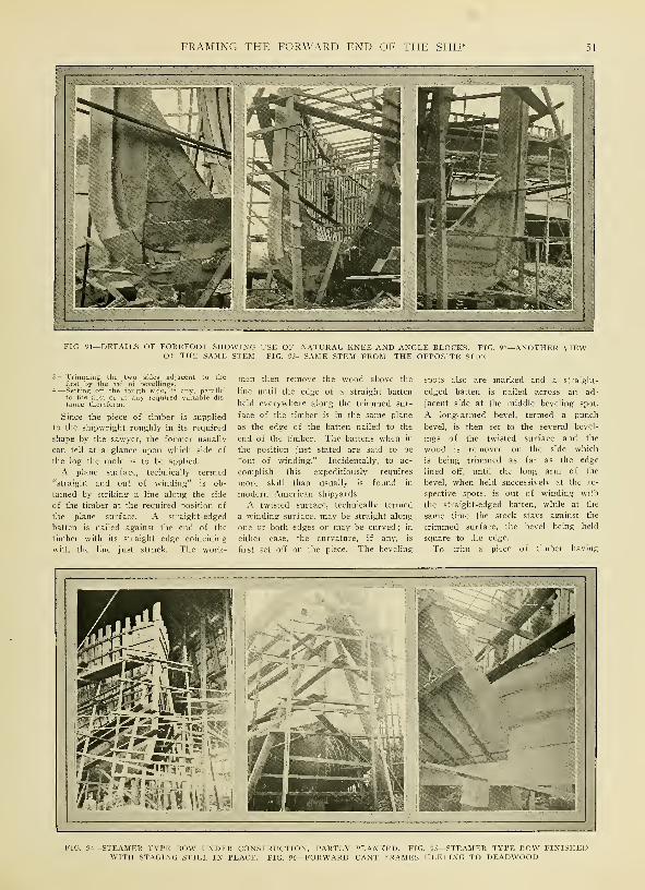
FRAMING THE FORWARD END OF THE SHIP 51
FIG. 91—DETAILS OF FOREFOOT SHOWING USE OF NATURAL KNEE AND ANGLE BLOCKS. FIG.OF THE SAME STEM. FIG. 93—SAME STEM FROM THE OPPOSITE SIDE
-ANOTHER VIEW
3.—Trimming the two sides adjacent to thefirst by the aid of bevellings.
4.—Setting off the fourth side, if any, parallelto the first -or at any required variable dis-
tance thereform.
Since the piece of timber is supplied
to the shipwright roughly in its required
shape by the sawyer, the former usually
can tell at a glance upon which side of
the log the mold is to be applied.
A plane surface, technically termed
"straight and out of winding" is ob-
tained by striking a line along the side
of the timber at the required position of
the plane surface. A straight-edged
batten is nailed against the end of the
timber with its straight edge coinciding
with the line just struck. The work-
men then remove the wood above the
line until the edge of a straight batten
held everywhere along the trimmed sur-
face of the timber is in the same plane
as the edge of the batten nailed to the
end of the timber. The battens when in
the position just stated are said to be
"out of winding." Incidentally, to ac-
complish this expeditiously requires
more skill than usually is found in
modern American shipyards.
A twisted surface, technically termed
a winding surface, may be straight along
one or both edges or may be curved ; in
either case, the curvature, if any, is
first set off on the piece. The beveling
spots also are marked and a straight-
edged batten is nailed across an ad-
jacent side at the middle beveling spot.
A long-armed bevel, termed a punch
bevel, is then set to the several bevel-
ings of the twisted surface and the
wood is removed on the side which
is being trimmed as far as the edge
lined off, until the long arm of the
bevel, when held successively at the re-
spective spots, is out of winding with
the straight-edged batten, while at the
same time the stock stays against the
trimmed surface, the bevel being held
square to the edge.
To trim a piece of timber having
FIG. 94—STEAMER TYPE BOW UNDER CONSTRUCTION, PARTLY PLANKED. FIG. 95—STEAMER TYPE BOW FINISHEDWITH STAGING STILL IN PLACE. FIG. 96—FORWARD CANT FRAMES HEELING TO DEADWOOD

?2 HOW WOODEN SHIPS ARE BUILT
FIG. 97—DETAIL OF FOREFOOT OF CLIPPER TYPE STEM SHOWINGNATURAL KNEE LOCK-SCARFED TO KEEL
the points. This line will be one edgeof the plane surface. Set off the siding
of the timber from this line square to
the edges of the batten and strike a
line joining the siding spots; chamferthe edges away to these lines, to removethe surplus wood, with an axe or adz.
Siding the Timber
Now turn the timber over, havingpreviously rased the positions of the
battens over the ends. Repeat the
operation of looking in points andlining the side, also of setting off the
siding. Trim the two sides down fromthese lines to the chamfered edges. Wethus have two plane sides to the timber,
and if the sidings are uniform, the sides
are also parallel. In its present state
the timber is said to be sided.
This is one method of performing the
operation. Others will occur to the ex-
perienced man. In modern wooden
straight siding and curved moldings,
such as the stem or a beam, secure the
piece upon blocks at a convenient height
for trimming with the convex side
nearest the ground. We may nowproceed as follows:
Method of Procedure
Hold a straight-edged batten vertically
against each end as near as possible to
the side upon which the mold is to be
made, so that lines joining the outer
edges of the two battens, both above
and below, may be everywhere within
the log or timber. Adjust the battens
so their edges are out of winding.
Then, still looking these edges out of
winding, determine points along the up-
per side of the timber which are in a
line with the edges of the batten. Strike
a line (this necessarily must be done in
short lengths owing to the curvature of
the side) along the upper side joining FIG 99—DETAILS OF STEM AND FORWARD FRAME CONSTRUCTION OF AMOTOR SCHOONER UNDER CONSTRUCTION ON THE GULF
-ARRANGEMENT OF FLOORS, KEELSON AND STEM OF A VESSELUNDER CONSTRUCTION AT A GULF SHIPYARD
shipyards, however, it is seldom neces-
sary to resort to this rather elaborate
process of siding a timber, machinery
usually being available. However, as
previously stated, it is well to know howthe operation may be performed by
hand.
For molding the curved shape of the
timber, a mold is furnished from the
mold loft. It is laid on the molding or
joint side of the timber, being kept
sufficiently on the surface to allow woodfor obtaining the necessary beveling.
Also due regard is had for the re-
quired length of the timber. In some
cases, when concave curvature is given
for convex timbers, as cant molds, for
instance, the mold is held off the timber
and the curvature is then copied by
spiling. When the curvature is rased in
and the positions of the beveling spots
transferred, the mold is removed, the
moldings of the timbers are set off, a

FRAMING THE FORWARD END OF THE SHIP 53
thin batten is set so it can pass fairly-
through the spots and the line so found
is rased in.
Now set a bevel to each of the suc-
cessive bevelings of the piece and ap-
ply the bevel to the molded edge, square
to the curve and to the edge of the
timber at the respective beveling spots.
Hold the bevel so its tongue just
touches the timber ; measure with a
pair of compasses the distance between
the tongue and the molded edge and set
this distance in upon the timber on
the opposite side, measuring from the
tongue. Bend the thin batten so as to
pass through all of the points so ob-
tained on the side opposite to the
molded side, and rase in the line.
Trim the Curved Side
Now trim down the curved side of
the timber straight from line to line,
and the outer surface of the timber will
be to its required state. The inside
surface is trimmed parallel to the outer
through the line obtained by setting off
the molded scantlings. Frame timbers,
beams, stem, apron, deadwood, stern-
posts of screw ships, etc., may be
trimmed in this way if no machinery is
available. A band-saw, however, as de-
scribed in the previous chapter, is the
proper tool to use for operations of this
character. A knowledge of the method
of marking, however, is just as neces-
sary as if the work were to be done by
hand.
A timber with straight siding and
molding is trimmed by a simple and
obvious modification of the methods just
described. It is evident that the only
difference consists in striking straight
lines upon the plane surface instead of
marking with a curved mold.
Fig. 83, in addition to illustrating the
method of framing the bow and work-ing up the stem of a clipper-type ship,
also shows the staging which must be
erected to give access to the sides of
the ship during construction. This
staging is similar to that used in house
construction. The posts or stanchions
usually are provided with holes bored
about every foot so that the joists
upon which the staging rests may be set
at convenient heights. These holes also
make it easy to take the staging downor to move it.
Figs. 87 and 88 show how the for-
ward ends of the keelson are fastened
to the stem, particularly in ships pro-
vided with heavy center girder-keelsons.
It will be noted that the keelson tim-
bers are securely bolted to the stem.
These illustrations also show how the
ceiling fays against the forward end of
the center girder keelson.
A method of fastening the stem of a
vessel to the keel without the use of
a natural knee is shown in Fig. 85, il-
lustrating the practice of a Gulf coast
shipyard. It will be noted that in this
case straight pieces of timber, suitably
beveled at the ends, are inserted in place
of the knee usually set in the corner
formed by the keel and stem. This type
of construction should be contrasted
with that in which a knee is used, as
illustrated in Fig. 97.
A well known method of working out
the stem-to-keel connection in the case
of a steamer type bow is illustrated in
Figs. 91, 92 and 93. It will be noted
that a natural knee is used to form
the nose or forefoot of the ship andthat the deadwood is reinforced byangle-blocking placed in the corner be-
tween the stem and the upper part of
the deadwood. These illustrations also
show clearly how the rabbet must be
cut in the stem to receive the forwardends of the planking. More general
views of a stem of this type in finished
and semifinished states are shown re-
spectively in Figs. 94 and 95.
Still another form of stem, using a
very large natural knee in the angle,
is illustrated in Fig. 84. A detailed
drawing of this stem is presented in
Fig. 86. This drawing shows the na-
ture and disposition of the fastenings
together with the arrangement of the
stem, keel, apron, deadwood, knee, etc.
The drawing should be studied care-
fully. Cross sections of the stem,
apron, knighthead and forward framesat various waterline elevations are
shown on the drawing. It will be noted
that two rabbets are provided, this ship
being triple planked with an inner skin
of double diagonals and an outer skin
of ordinary horizontal planking. Thelarge wooden knee set in the angle of
the stem is sided \9 l/2 inches. Thehorizontal leg of this knee is 11 feet in
length, the vertical leg being 8 feet.
Half frames Nos. 1, 2 and 3, Fig. 86,
are boxed in the keelson and deadwoodto the sidelines of the knee. Half
frames Nos. 4, 5, 6 and 7 are boxed in 2
inches at the heel only. Limber holes
are left at the heels of all the half
frames. The half frames are screw
fastened with two 1-inch clinch bolts in
each timber.

CHAPTER VII
Framing trie After End of the Ship
£>j TERN framing involves many
^^ problems, not only on account^""^ of the large number of pieces
necessary to build up the stern of a
wooden vessel, but also because of
the number of different types of
sterns in use. In fact, it is the stern
which gives character to the entire
vessel and here we find the mostdistinctive lines. This has been true
of naval architecture in every age.
The old Spanish galleons were not
specially different in many of their
elements from modern wooden ships.
They are famous, however, for their
exceedingly bizarre, high awkwardsterns. The same remarks apply to
the Chinese luggers that infest the
Yellow sea.
In fact, just as different periods
have produced their particular forms
of land architecture, so there has been
a succession of styles in naval archi-
tecture, each of which has grown out
of that preceding it. And, as in the
case of land architecture, the latest
style is preferred for a period as
being more beautiful and useful; it
gives way, however, in time to other
styles which are considered superior to
it. In no part of a wooden ship have
these differences in style been moremarked than at the stern and the
problems of construction have been

FRAMING THE AFTER END OF THE SHIP 55
^-^^X^^:;^': /.-v>
:^^^^-
-DETAIL OF UPPER PART OF STERN FRAMING SHOWN IN FIG. 102. FIG. 104—GENERAL VIEW OF STERNFRAMES AND RUDDER ASSEMBLY
it. As previously stated, this type of
stern is sometimes called the square
stern. Abaft the fashion timber it maybe composed of two sets of timbers as
follows:
-Horizontal timbers, extendingtimber to fashion timber andthe stern post. These are
from fashio
/ertical timbers, extendinger transom to the rail,
vhich are termed stern tin
n Fig. 108.
from the up-These pieces,
Hers, are shown
The farthest of these stern timbers
from the middle line, the one whichpartakes of the rake of the stern and
also of that of the topside, is termed
the side-counter timber. It is shownin Fig. 107. It heels against the upper
transom and fays against the fashion
timbers.
In some ships, the transom timbers
situated at certain positions are
distinguished by particular names. Theone which forms the base of the
stern, that is the transom upon whichthe stern timbers step and to whichthey may be tenoned, is termed the
wing transom. Boxen wood is left
on the edge of this timber in order
to house the planks of the bottomand to receive the fastenings of their
hooding ends. The line at which the
planks end is called the margin; anda rail called the tuck rail is fitted
over the boxen left above the margin,
thus giving a finished appearance at
the ends of the planking. This methodof finishing the planking, slightly
modified, is shown in Fig. 101.
In some large ships, the principal
transom is called the deck transom.
It is situated at the height of the
deck and its upper surface conforms
FIG. 105—ERECTING FORE AND AFT POST TIMBERS FOR A STERN OF UNUSUALLY STRONG CONSTRUCTION

56 HOW WOODEN SHIPS ARE BUILT

FRAMING THE AFTER END OF THE SHIP 57
All except the deck and wing tran-
soms have their upper and lower sur-
faces in a plane which is either hori-
zontal, or square to the after side of
the stern post. The deck and wingtransoms, however, have their sides
trimmed to a surface which partakes
of the round of the beam and the
sheer of the topsides and deck re-
spectively.
A Trim, Neat Stern
Although certain English writers on
naval architecture seem to take pleas-
ure in sneering at the transom stern
on the ground that it is ungainly
and unworkmanlike in appearance, it
can, nevertheless, be made very trim
and neat, as Fig. 101 clearly indicates.
Also it is relatively simple to con-
struct, cheap, and easily repaired in
case of damage. In addition, it offers
good resistance to a heavy following
FIG. 112—STERN FRAME ASSEMBLY BEING HOISTED INTO PLACE
to the round up of the beams, being
made sufficiently wide to receive the
fastenings of the deck planks which
stop at a rabbet or score in it. Be-
tween the wing and deck transoms
certain others are fitted, the numberbeing regulated by the distance be-
tween the two main beams. These
usually are called filling transoms.
Below the deck transom a series
of other transoms may be fitted, suffi-
cient in number to extend from the
deck transom to a short distance above
the heel of the fashion timber, the
space between the lowest and the
bearding line being filled in by short
canted timbers which are tenoned to
the under-side of the lowest transom.
In ships of this character, the tran-
soms below the deck transom are dis-
tinguished by number, according to
the order of their position below it.
FIG. 114—INSIDE OF FRAMING OF THE STERN SHOWN IN FIG. 113
sea. When not hampered by too manyrestrictions, a good naval architect
likes to give earnest consideration to
the beauty of his vessel. To accom-plish this, special attention is paid to
the form of the stern and as already
indicated, some architects prefer the
elliptical type to the transom type
just discussed. Its framing is similar
to the transom stern up to the fashion
timber. Beyond this point, the fram-
ing differs radically.
The upper aftermost portion of the
continuation of the contour of the
ship's bottom is termed the buttock.
It is usually so flat and nearly hori-
zontal that the only planes which give
a definite intersection with it on the
drafting board are the vertical longi-
tudinal or buttock planes. Therefore,
the buttock lines are of considerable
service and are largely employed in
FIG. 113—DETAIL OF FRAMING OF TRANSOM TYPE STERN
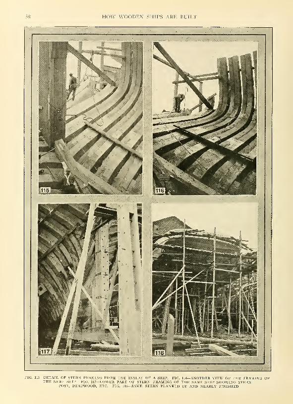
58 HOW WOODEN SHIPS ARE BUILT
FIG. 115—DETAIL OF STERN FRAMING FROM THE INSIDE OF A SHIP. FIG. 116—ANOTHER VIEW OF THE FRAMING OFTHE SAME SHIP. FIG. 117—LOWER PART OF STERN FRAMING OF THE SAME SHIP SHOWING STERN-
POST, DEADWOOD, ETC. FIG. 118—SAME STERN PLANKED UP AND NEARLY FINISHED
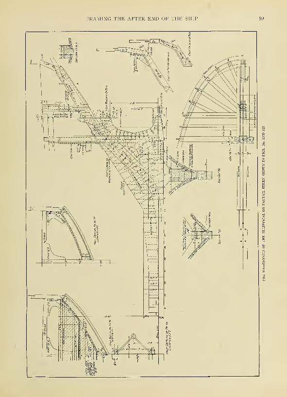
FRAMING THE AFTER END OF THE SHIP 59
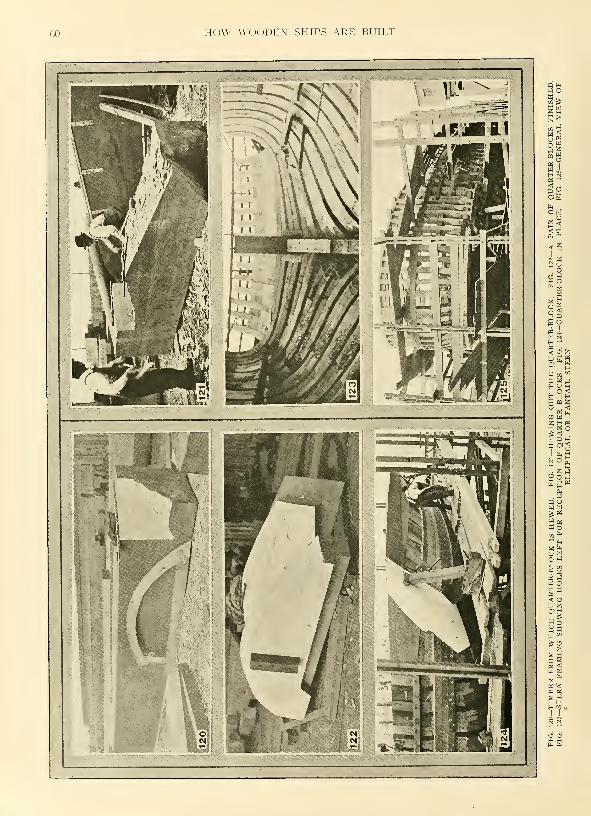
60 HOW WOODEN SHIPS ARE BUILT
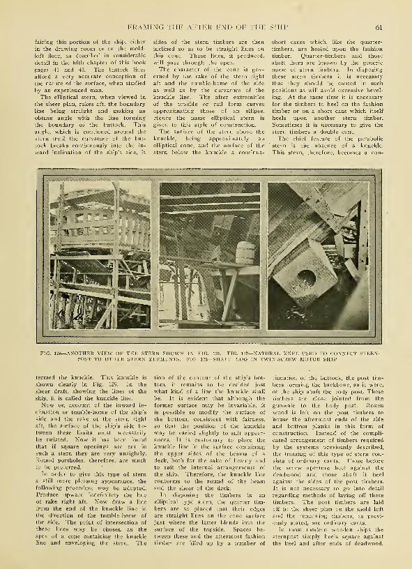
FRAMING THE AFTER END OF THE SHIP 61
fairing this portion of the ship, either
in the drawing room or on the mold-
loft floor, as described in considerable
detail in the fifth chapter of this book
pages 41 and 43. The buttock lines
afford a very accurate conception of
the nature of the surface, when studied
by an experienced man.
The elliptical stern, when viewed in
the sheer plan, rakes aft, the boundaryline being straight and making an
obtuse angle with the line forming
the boundary of the buttock. This
angle, which is continued around the
stern until the curvature of the but-
tock breaks continuously into the in-
ward inclination of the ship's side, is
sides of the stern timbers are then
inclined so as to be straight lines on
this cone. These lines, if produced,
will pass through the apex.
The character of the cone is gov-
erned by the rake of the stern right
aft and the tumble-home of the side
as well as by the curvature of the
knuckle line. The after extremities
of the topside or rail form curves
approximating those of an ellipse.
Hence the name elliptical stern is
given to this style of construction.
The surface of the stern above the
knuckle, being approximately an
elliptical cone, and the surface of the
stern below the knuckle a continua-
short cants which, like the quarter-
timbers, are heeled upon the fashion
timber. Quarter-timbers and those
abaft them are known by the generic
name of stern timbers. In disposing
these stern timbers it is necessary
that they should be canted in such
positions as will avoid excessive bevel-
ing. At the same time it is necessary
for the timbers to heel on the fashion
timber or on a short cant which itself
heels upon another stern timber.
Sometimes it is necessary to give the
stern timbers a double cant.
The chief feature of the parabolic
stern is the absence of a knuckle.
This stern, therefore, becomes a con-
-ANOTHER VIEW OF THE STERN SHOWN IN FIG.POST TO OTHER STERN ELEMENTS. FIG. 128-
125. FIG. 127—NATURAL KNEE USED TO CONNECT STERN--SHAFT LOG IN TWIN-SCREW MOTOR SHIP
termed the knuckle. This knuckle is
shown clearly in Fig. 129. In the
sheer draft, showing the lines of the
ship, it is called the knuckle line.
Now on account of the inward in-
clination or tumble-home of the ship's
side and the rake of the stern right
aft, the surface of the ship's side be-
tween these limits must necessarily
be twisted. Now it has been foundthat if square openings are cut in
such a stern they are very unsightly.
Round portholes, therefore, are muchto be preferred.
In order to give this type of stern
a still more pleasing appearance, the
following procedure may be adopted.
Produce upward indefinitely the line
of rake right aft. Now draw a line
from the end of the knuckle line in
the direction of the tumble-home of
the side. The point of intersection of
these lines may be chosen as the
apex of a cone containing the knuckleline and enveloping the stern. The
tion of the contour of the ship's bot-
tom, it remains to be decided just
what kind of a line the knuckle shall
be. It is evident that although the
former surface may be invariable, it
is possible to modify the surface of
the bottom, consistent with fairness,
so that the position of the knuckle
may be varied slightly to suit appear-
ances. It is customary to place the
knuckle line in the surface containing
the upper sides of the beams of a
deck, both for the sake of beauty andto suit the internal arrangements of
the ship. Therefore, the knuckle line
conforms to the round of the beamand the sheer of the deck.
In disposing the timbers in an
elliptical type stern, the quarter tim-
bers are so placed that their edgesare straight lines on the cone surface
just where the latter blends into the
surface of the topside. Spaces be-
tween these and the aftermost fashion
timber are filled up by a number of
tinuation of the buttock, the post tim-
bers forming the backbone, as it were,
of the ship abaft the body post. Thesetimbers are close jointed from the
gunwale to the body post. Boxenwood is left on the post timbers to
house the aftermost ends of the side
and bottom planks in this form of
construction. Instead of the compli-
cated arrangement of timbers required
by the systems previously described,
the framing of this type of stern con-
sists of ordinary cants. Those before
the screw aperture heel against the
deadwood and those abaft it heel
against the sides of the post timbers.
It is not necessary to go into detail
regarding methods of laying off these
timbers. The post timbers are laid
off in the sheer plan on the mold loft
and the remaining timbers, as previ-
ously stated, are ordinary cants.
In most modern wooden ships the
sternpost simply heels square against
the keel and after ends of deadwood.
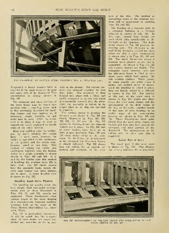
62 HOW WOODEN SHIPS ARE BUILT
FIG. 129—DETAIL OF FANTAIL STERN CONSTRUCTION AT KNUCKLE LINE
Frequently a heavy wooden knee is
inserted in the angle between the post
and upper side of the deadwood. This
construction is clearly shown in
Fig. 119.
The sternpost and other sections of
the stern frame may be raised into
position with a traveling crane such
as that previously described for hand-
ling frames and bow timbers, or, if
necessary, simple derricks, or gin
poles may be used. After the stern-
post is in place it may be used to
support the tackle employed to handle
some of the other timbers.
Most ship builders raise the rudder-
post by itself, hanging the rudder
later. In some cases, however, the
rudder is assembled to the rudderpost
on the ground and the whole com-bination raised at one time. This
method of raising the rudder and
rudderpost, together with the fashion
timber in a single assembly is shownclearly in Figs. 102 and 104. It is
said by the builder that this methodof handling the problem saves $50 in
labor cost. Fig. 104 shows clearly
how the assembly looks before the
after cant frames and stern timbers
are in place. A more detailed view
is shown in Fig. 102.
Handling Small Stern Timbers
For handling the smaller stern tim-
bers, simple block and tackle arrange-
ments such as those illustrated in
Figs. 110, 111 and 112, usually are
employed. These illustrations showvarious stages of the stern framing
of a transom-stern, S-masted auxiliary
schooner built at the plant of the
Grays Harbor Shipbuilding Co., Aber-
deen, Wash.
Fig. 112 is particularly instructive.
It will be noted that the irregular
pieces of stern timber are hewed out,
beveled and assembled as far as pos-
sible on the ground. The various sec-
tions are fastened together by iron
drift bolts. The assembly is then
hoisted into place with a block andtackle connected to an eye bolt whichis temporarily screwed into the piece.
After the assembly is bolted in its
proper place in the ship, the eye bolt
is removed.
The various stages in framing the
transom stern shown in Fig. 101 are
clearly illustrated by Figs. 107, 108,
109, 110, 111, 112 and 118. Fig. 107
shows the framing before the transomtimbers are in place. In Fig. 108 part
of these timbers have been set in
their proper positions, Figs. 109 and110 show inside views of the samestern. In the latter, the arrangementof the sternpost and aftermost frames
is clearly indicated. Fig. 109 showshow the ceiling fits up against the
keelson and sternpost in the after
part of the ship. The method of
assembling some of the transom sec-
tions will be understood by studying
Figs. Ill and 112.
The framing of a transom stern in
a schooner building in a Georgia
shipyard is shown in Fig. 106. In
this case, natural bent crooks are
used which adds considerably to the
strength of the structure. The deck-
house shown in Fig. 101 protects the
steering gear. The character of the
scaffolding necessary around the stern
when the ship is under construction
is shown clearly in Figs. 107, 108 and118. The latter illustration shows a
transom stern planked up and nearly
completed. As shown in Fig. 113, the
side counter timbers are double. Thetriangular space between them andthe aftermost frame is filled in with
short cants which heel against the
side counter timbers. These pieces,
or cants usually are sided about 8
inches and molded about 10 inches.
Until the planking is bolted in place,
they are lightly spiked to a ribband,
as shown in Fig. 113. The interior
of this part of the same stern is
shown in Fig. 114, which also illus-
trates the after main frames and the
arrangement of the deck beams in
the way of the stern. Further details
of this type of stern framing, in an
earlier stage of the construction
process, are shown in Figs. 115 and116. These illustrations show quite
clearly how the after stern frames are
formed and how they heel against the
sternpost and after portion of the
deadwood. The arrangement of the
ceiling near the stern post also is
suggested.
Lower Part of Stern
The lower part of this same stern
is shown in Fig. 117. This illustra-
tion clearly indicates the arrangement
-ARRANGEMENT OF TIMBERS INSIDE THE SAME STERN AT THEPOINT SHOWN IN FIG. 129
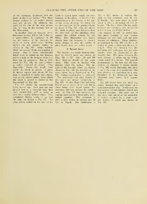
FRAMING THE AFTER END OF THE SHIP 63
of the sternpost, deadwood and the
heels of the after frames. The three
bronze sockets for the rudder pintles
also are shown. In addition, the
shaft log for one of the twin screws
may be seen at the extreme left of
the illustration.
In another form of transom stern,
illustrated in Figs. 120 to 124, inclusive,
a quarter-block is employed to fill
©ut the corners of the transom, in-
stead of using short cants heeling
against the side counter timber, as
shown in Fig. 113. Some builders
think the quarter-block construction is
neater. Also it saves considerable
detail work in fitting up the framing
and is a help to the designer if he is a
little shy on geometry. But as indi-
cated by Fig. 120, the quarter-block
is rather wasteful of timber. This
illustration shows the baulk from
which the block is hewed. A piece
36 inches square and about 10 feet
long is required to make each block.
One of the curved molds from whichthe block is hewed is shown in the
foreground of Fig. 120.
Fig. 121 shows the quarter-block
being hewed out. Two men are em-ployed and it is essential that they
have considerable skill in order to
turn out a neatly finished block. Twocompleted blocks, ready to go into
the ship, are shown in Fig. 122. Thestrip shown nailed on the side of the
block is placed there simply for con-
venience in handling. A detail of the
arrangement of the frames in the wayof the stern, showing the holes left
for the reception of the quarter-blocks
is shown in Fig. 123. Fig. 124 showsthe block in place, and indicates howthe after-ends of the planking close
against the rabbet formed by the
block. This illustration also showsclearly how the transom is framed,
using clamps to hold the planks in
place before they are spiked down.
A Fantail Stern
The details of a neatly formed ellip-
tical or fantail stern are shown in
Figs. 125 to 127. Figs. 129 and 130
show close-up details of the samestern. This stern is framed with
timbers sided 7J4 inches. The de-
tails of the knuckle joints are clearly
shown in Fig. 129, the interior of the
same joints being illustrated by Fig.
130. Bolted construction is employed.
The fastenings and other details of
this stern are shown completely in
Fig. 119. As this illustration indicates,
liberal use is made of natural knees,
there being three fayed against the
sternpost and one against the rudder-
post. As Fig. 119 also indicates, the
various parts are very thoroughly drift-
bolted together. The sternpost is
22>V2 x \9 J/2 inches in section and 30
feet in length. The rudderpost is
19j/£ x 23J/2 inches in section, the
same as the sternpost, and 18 feet
in length. The main piece of dead-
wood is 23 l/2 x 30 inches, 38 feet in
length. The knee which fills the angle
between the sternpost and deadwoodis 6 x 6 feet, sided 23^2 inches.
In general, it will be noted that
this stern consists of cant frames
stepping on two fore and aft post
timbers or whiskers. These timbers,
as indicated by Fig. 119, are 9]/2 x 26
inches in cross section and 44 feet in
length. They are notched into the
sternpost and rudderpost and are con-
tinuous from the deadwood to the
knuckle line. The space between the
post timbers is taken up by filling
blocks sided \7 l/2 inches. The general
arrangement of the fore and aft post
timbers or whiskers is shown clearly
in Fig. 10S, which illustrates this stern
in an early stage of construction. Thepost timbers are equivalent to a con-
tinuation of the deadwood and the
aftermost cant frames heel against
them.
Fig. 128 shows how the shaft log
comes through the stern frame on a
twin-screw motor ship. In this case, the
log consists of two timbers bolted anddoweled together. The outer end of
the shaft, just ahead of the propeller,
is further steadied by a steel truss,
the details of which are shown in
Fig. 119.

CHAPTER VIII
Planking, Keelson and Ceiling Construction
AFTER the frames, stem, stern-
post, etc., are all set in place,
L the ship is ready to be planked
on the outside and ceiled on the in-
side. The keelson construction on the
inside also can be finished. Next to
the frames, the exterior planking
probably is the most important part
of the ship's structure. In the old
days, the planking of large ships was
divided into a number of distinct
assemblies each with a special designa-
tion. Old-line wooden ship builders
accordingly were familiar with such
terms as sheer strakes, channel and
middle wales, black strakes, main
wales, diminishing planks, plank of
bottom, and garboard- strakes. These
names are given in the order of the
respective assemblages, beginning at
the topside. In the old warships, the
sheer strakes were situated between
the planksheer or covering plank and
the ports of the main deck. Below
the latter, as far as the ports of the
middle deck, the external planks were
termed channel wales, as they received
the fastenings of the chain plate and
preventer bolts of the channels. The
FIG. 131—TIMBER CHUTE FOR HAUL-ING CEILING STRAKES AND KEEL-
SONS INSIDE THE SHIP
middle wales were situated between
the ports of the middle and lower
decks, while the planks immediately
below the lower deck ports were
termed black strakes, owing to the
fact that their upper edges formed
the boundary line of the portion of
the ship below the fighting decks,
which was painted black. From the
main wales, the planks gradually
diminished in thickness to that of the
plank-of-bottom strakes. The strakes
in which taper was worked were
known as diminishing plank. The
plank-of-bottom extended from the
diminishing plank to the garboard
strake, the lower edge of the latter
rabbeting to the keel. The planks
between the ports were termed short
stuff, being specially designated ac-
cording to their situation as short stuff
'tween decks, etc.
Modern ship builders have forgotten
all about these terms and at the
present time about all we hear of are
garboards, bottom plank and topside
planking. In some cases bilge plank-
ing is mentioned. The planking usual-
ly is arranged in a series of strakes
of diminishing thickness, the garboard
strakes adjoining keel being thickest.
Before starting in to plank a ship,
a disposition of the edges and butts
-INTERIOR OF A WOODEN SHIP UNDER CONSTRUCTION SHOWING TIMBER CHUTE AND SCAFFOLDING—BILGECEILING IN PLACE

PLANKING, KEELSON AND CEILING CONSTRUCTION 65
FIG. 133—STEAM BOX FOR SOFTENING PLANKS. FIG. 134— SIDE OF SHIP WITH PLANK IN PLACE. FIG. 135—DUBBING-OFF AND RASING LINES ON SHIP'S SIDE FOR PLANKING. FIG. 136—CLAMPING PLANK IN PLACE PRIOR TO
SPIKING. FIG. 137—CLAMPING CEILING STRAKES IN PLACE PRIOR TO BOLTING .

66 HOW WOODEN SHIPS ARE BUILT
FIG 138—LOWER ENDS OF STERN FRAME AND DEADWOOD RASED FORPLANKING
case may be, is termed a stealer.
The lengths of the planks should
be as great as can be obtained. In
England three strakes are placed be-
tween consecutive butts on the sameframe. This practice is not followed
in the United States, where one
strake in many cases is considered
sufficient. Two, however, is better
practice. The butts also should be
disposed so as to avoid the succession
suggested by the name ladder step.
Lloyd's rules do not permit the
butts to be nearer than 5 feet from
each other, unless there is a strake
wrought between them and then a
distance of 4 feet is allowed. Nobutts are permitted on the same tim-
ber unless there are three strakes
between them. In ships with extreme
proportions the figures six and five
are substituted for five and four, re-
spectively.
In most yards in the United States,
should be prepared and set off on an
expansion drawing. If care is taken
in arranging disposition of the planks,
considerable work can be avoided.
Planks between the main deck and the
keel should be filled up in such a wayas to give the least possible twist or
curvature, thus simplifying the con-
version of the material and work of
securing the planks in place.
In a full-bodied ship it will be
found impossible to continue the samenumber of planks right fore and aft,
owing to the difference between the
girth amidships and at the extremities.
In every case, in fact, there is a con-
siderable reduction in the breadths of
the planks before they terminate at
the stem or stern. When it is neces-
sary to reduce the number of planks
for the reason just mentioned, the
last plank of the strake which does
not extend right fore and aft, as the FIG. 140—BOLTING DOWN KEELSON TIMBERS WITH PNEUMATIC HAMMERS
FIG. 139—CEILING A SHIP IN A GULF COAST YARD
the vessel is planked from the keel
upward. Sometimes, however, the
garboard strakes and the wales at the
top are first put on and the planking
then proceeds from both top and bot-
tom toward the bilges.
Before working the planks, the lines
of their edges are rased in on the
frames by means of battens bent in
the position indicated by the expan-
sion drawings. Fig. 138 shows howthese lines are rased on the keel and
lower ends of the frames and after
deadwood. Fig. 135 shows how the
lines are rased on the frames amid-
ship. The latter illustration also
shows how the frames are dubbed-off
to a fair surface before the planks
are spiked in place. The dubbing-off
operation is performed by skilled
workmen using an adz. It is a rather
expensive process and recently someinteresting experiments have been

PLANKING, KEELSON AND CEILING CONSTRUCTION 67
made with a machine designed to per-
form this operation. This machine, a
portable electrically driven planer,
with circular knives, works something
on the principle of a lawn-mower.
It is said to save a tremendous amountof time in dubbing-off the outer sur-
face of the ship.
A True Sheer Necessary
Care must be taken in rasing in the
lines shown in Figs. 135 and 138 that
the front or sight-edge of the plank
is the line drawn, as at the bow andbuttock where there is a considerable
twist in the surface, a very unsightly
edge and not the true sheer would
ness of the plank, the diminution be-
ing, however, only about Y% inch in
12 inches.
For the extremities of the ship and
on the bilges it is necessary to soften
the planks by steaming them in a
steam box provided for that purpose.
A box of this character is shown in
Fig. 133. It is 90 feet in length and
about 6 feet square, built of large
timbers edge-bolted together andcaulked. The necessary steam is sup-
plied at low pressure by an ordinary
donkey boiler fired with refuse woodfrom the shipyard. In many yards
the hot plank is often transferred fromthe steam box to the ship by hand.
ner shown in Fig. 136. Before the
plank is clamped in place, the bottomsof the holes which are to receive the
spikes are reamed out with a handauger so the spikes may be set easily.
The plank is first tacked or stuck in
position with 10-inch galvanized boat
spikes which are driven by hand. Twospikes are driven at the ends and one
in between on every frame. After
these spikes are driven, the shores
and wedges may be removed. Thering bolts also can be taken out, leav-
ing the planking as it appears in Fig.
134. It is now ready to receive the
final fastenings which usually consist
of locust treenails and iron drift-bolts.
FIG. 141—PORT SIDE OF A COMPLETELY CEILED WOODEN MOTOR SHIP
be obtained if this precaution werenot observed.
The edges of the planks are trimmedsquare to the surface of the timbers,
this being expressed in technical
language by saying that the "closest
edges stand between two squares".
A little deduction is made from this
angle to allow for the caulking seams.Usually it amounts to 1/16 inch to
every inch of plank thickness, whenthe plank does not exceed 6 inches
in thickness, which is rare in modernshipbuilding. One method of deter-
mining the seam adopted by workmenis to set the two arms of a 2-foot
rule Y% inch apart at their extremities.
This gives rather less than 1/16 inchof seam for every inch in the thick-
In most Pacific coast shipyards a
gang of 12 men is employed for plank-
ing the ship. A gang of this sort,
with some additional labor, should be
able to plank up one strake a dayclear around a 275-foot ship from the
keel to the bilges. From this point
up to the rail the planking should
proceed at the rate of two strakes per
day, allowing 35 days altogether to
plank the ship.
Putting on the Plank
The necessary holes for the fasten-
ings are bored in the plank before it
is brought out to the ship. After be-
ing lifted into place, the plank is
tightened into position by means of
chains, shores and wedges in the man-
The treenails, which are about 26
inches long and \% inches in diam-
eter, are driven into holes bored a
scant \% inches. After they are
driven home, they are wedged on the
ends and in some cases caulked. Spe-
cial care is required in driving tree-
nails in order to avoid crippling them,
as in this case it is impossible to
drive them any further and they musteither be driven or bored out andtheir places supplied by others whichgenerally are less efficient than if
driven through in the first place. Tree-
nails should be of well-seasoned soundlocust or oak cut with the grain.
There is a considerable difference
of opinion regarding the comparativevalue of treenail and drift-bolt fasten-

68 HOW WOODEN SHIPS ARE BUILT
<4l[
:_,
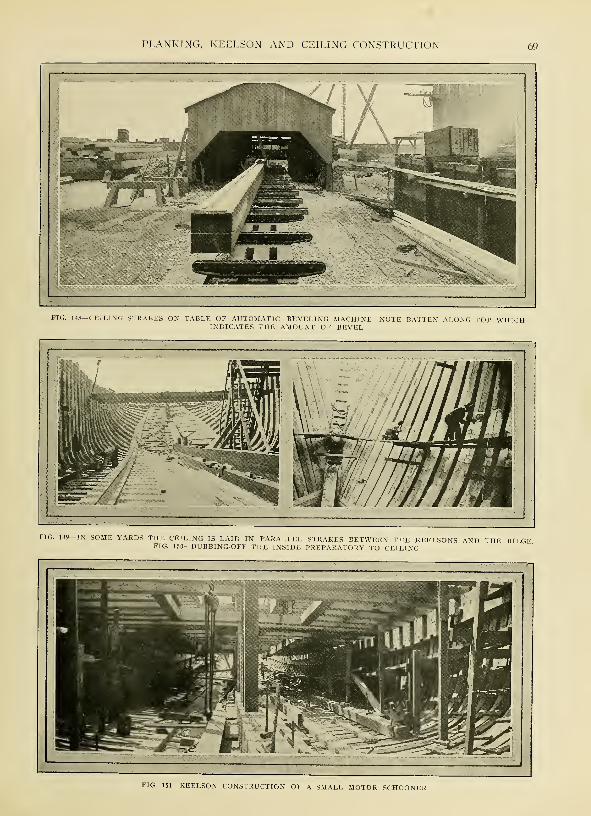
PLANKING, KEELSON AND CEILING CONSTRUCTION
FIG. 148—CEILING STRAKES ON TABLE OF AUTOMATIC BEVELING MACHINE—NOTE BATTEN ALONG TOP WHICHINDICATES THE AMOUNT OF BEVEL
FIG. 149—IN SOME YARDS THE CEILING IS LAID IN PARALLEL STRAKES BETWEEN THE KEELSONS AND THE BILGEFIG. 150—DUBBING-OFF THE INSIDE PREPARATORY TO CEILING
FIG. 151—KEELSON CONSTRUCTION OF A SMALL MOTOR SCHOONER
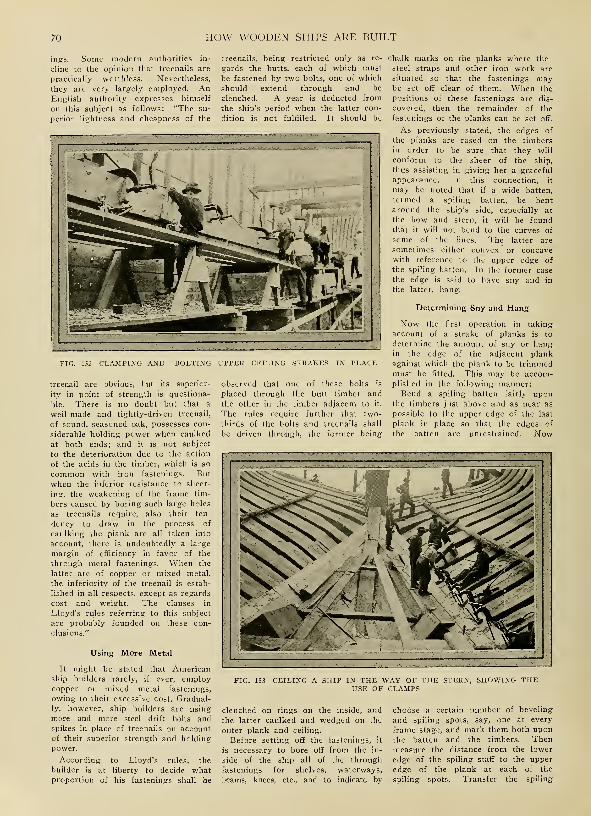
70 HOW WOODEN SHIPS ARE BUILT
ings. Some modern authorities in-
cline to the opinion that treenails are
practically worthless. Nevertheless,
they are very largely employed. AnEnglish authority expresses himself
on this subject as follows: "The su-
perior lightness and cheapness of the
treenails, being restricted only as re-
gards the butts, each of which must
be fastened by two bolts, one of which
should extend through and be
clenched. A year is deducted from
the ship's period when the latter con-
dition is not fulfilled. It should be
FIG. 152—CLAMPING AND BOLTING UPPER CEILING STRAKES IN PLACE
treenail are obvious, but its superior-
ity in point of strength is questiona-
ble. There is no doubt but that a
well-made and tightly-driven treenail,
of sound, seasoned oak, possesses con-
siderable holding power when caulked
at both ends; and it is not subject
to the deterioration due to the action
of the acids in the timber, which is so
common with iron fastenings. But
when the inferior resistance to sheer-
ing, the weakening of the frame tim-
bers caused by boring such large holes
as treenails require, also their ten-
dency to draw in the process of
caulking the plank are all taken into
account, there is undoubtedly a large
margin of efficiency in favor of the
through metal fastenings. When the
latter are of copper or mixed metal,
the inferiority of the treenail is estab-
lished in all respects, except as regards
cost and weight. The clauses in
Lloyd's rules referring to this subject
are probably founded on these con-
clusions."
Using More Metal
It might be stated that Americanship builders rarely, if ever, employcopper or mixed metal fastenings,
owing to their excessive cost. Gradual-
ly, however, ship builders are using
more and more steel drift bolts andspikes in place of treenails on accountof their superior strength and holding
power.
According to Lloyd's rules, the
builder is at liberty to decide whatproportion of his fastenings shall be
observed that one of these bolts is
placed through the butt timber and
the other in the timber adjacent to it.
The rules require further that two-
thirds of the bolts and treenails shall
be driven through, the former being
chalk marks on the planks where the
steel straps and other iron work are
situated so that the fastenings maybe set off clear of them. When the
positions of these fastenings are dis-
covered, then the remainder of the
fastenings of the planks can be set off.
As previously stated, the edges of
the planks are rased on the timbers
in order to be sure that they will
conform to the sheer of the ship,
thus assisting in giving her a graceful
appearance. In this connection, it
may be noted that if a wide batten,
termed a spiling batten, be bent
around the ship's side, especially at
the bow and stern, it will be foundthat it will not bend to the curves of
some of the lines. The latter are
sometimes either convex or concavewith reference to the upper edge of
the spiling batten. In the former case
the edge is said to have sny and in
the latter, hang.
Determining Sny and Hang
Now the first operation in taking
account of a strake of planks is to
determine the amount of sny or hangin the edge of the adjacent plank
against which the plank to be trimmedmust be fitted. This may be accom-plished in the following manner:Bend a spiling batten fairly upon
the timbers just above and as near as
possible to the upper edge of the last
plank in place so that the edges of
the batten are unrestrained. Now
FIG. 153—CEILING A SHIP IN THE WAY OF THE STERN, SHOWING THEUSE OF CLAMPS
clenched on rings on the inside, and
the latter caulked and wedged on the
outer plank and ceiling.
Before setting off the fastenings, it
is necessary to bore off from the in-
side of the ship all of the through
fastenings for shelves, waterways,
beams, knees, etc., and to indicate by
choose a certain number of beveling
and spiling spots, say, one at every
frame stage, and mark them both upon
the batten and the timbers. Thenmeasure the distance from the lower
edge of the spiling staff to the upper
edge of the plank at each of the
spiling spots. Transfer the spiling
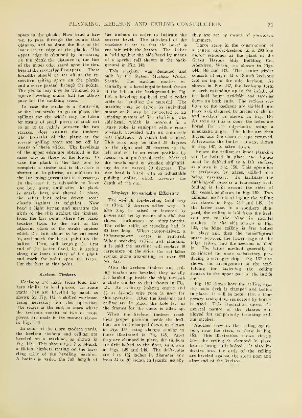
PLANKING, KEELSON AND CEILING CONSTRUCTION 71
spots to the plank. Now bend a bat-
ten to pass through the points thus
obtained and so draw the line of the
inner lower edge of the plank. The
upper edge is obtained by measuring
on the plank the distance to the line
of the upper edge rased upon the tim-
bers at the several spiling spots. These
breadths should be set off at the re-
spective spiling spots on the planks
and a curve passed through the points.
The planks may now be trimmed to a
square beveling minus half the allow-
ance for the caulking seam.
In case the strake is a shutter-in,
or the last strake to go in place, the
spilings for the width may be taken
by means of small pieces of stick cut
so as to fit tightly between the two
strakes, close against the timbers.
The breadths of the plank at the
several spiling spots are set off bymeans of these sticks. The bevelings
of the upper edge are obtained in the
same way as those of the lower. In
case the plank is the last one to
complete a strake and is therefore a
shutter in lengthwise, an addition to
the foregoing precaution is necessary.
In this case it is advisable to leave
one butt uncut until after the plank
is nearly bent and shored in place,
the other butt being driven homeclosely against its neighbor. Nowbend a light batten and measure the
girth of the ship against the timbers,
from the last point where the plank
touches them to the butt of the
adjacent plank of the strake against
which the butt about to be cut mustfit, and mark the latter point on the
batten. Then, still keeping the first
end of the batten fixed, let it spring
along the inner surface of the plank
and mark the point upon the latter.
Cut the butt at this point.
Keelson Timbers
Keelsons are made from long tim-
bers similar to keel pieces. In someyards they are bevelled by hand, as
shown by Fig. 142, a skilled workmanbeing necessary for this operation.
The scarfs at the end, in cases wherethe keelsons consist of two or morepieces, are made in the manner shownin Fig. 143.
In some of the more modern yards,
the keelson timbers and ceiling are
beveled on a machine, as shown in
Fig. 148. This shows two 7 x 14-inch
x 80-foot timbers resting on the trav-
eling table of the beveling machine.A batten is nailed the full length of
the timbers in order to indicate the
correct bevel. The side-head of the
machine is set so that the bevel is
cut fair with the batten. The timberis held against the side-head by meansof a special roll shown in the back-
ground in Fig. 148.
This machine was designed andbuilt by the Stetson Machine Works,Seattle. The machine consists es-
sentially of a beveling side-head, shownat the left in the background in Fig.
148, a beveling top-head and a roller
table for handling the material. Themachine may be driven by individual
motor or it may be connected to anexisting system of line shafting. Theside-head, which is mounted in a
heavy yoke, is equipped with a coun-ter-shaft provided with an automaticbelt tightener. A 7-inch belt is used.
This head may be tilted 30 degreesto the right and 20 degrees to the
left and set in an exact position bymeans of a graduated scale. Most of
the bevels used in wooden shipbuild-
ing do not exceed 10 degrees. Theside head is fitted with an adjustable
guiding collar, which governs the
depth of the cut.
Displays Remarkable Efficiency
The 48-inch top-beveling head maybe tilted IS degrees either way. It
also may be raised or lowered bypower and set by means of a dial that
shows thicknesses to sixty-fourths.
The roller table, or traveling bed, is
80 feet long. When motor-driven, a
50-horsepower motor is required.
When working ceiling and planking,
it is said the machine will replace 18
carpenters on the skids, the net laborsaving alone amounting to over $85per day.
After the keelson timbers and ceil-
ing strakes are beveled, they usually
are hauled up inside the ship througha chute similar to that shown in Fig.
131. An ordinary hoisting engine and
y2 or 5^-inch wire rope is used for
this operation. After the keelsons andceiling are in place, the hole left in
the frames for the chute is filled up.
When the keelson timbers reach
their proper position inside the hull,
they are first clamped down, as shownin Fig. 137, using clamps similar to
those illustrated in Fig. 145. After
they are clamped in place, the timbersare drift-bolted to the floor, as shownin Figs. 139 and 140. The drift-bolts
are 1 to 1J4 inches in diameter andfrom 24 to 30 inches in length; usually
they are set by means of pneumatichammers.Three steps in the construction of
a center girder-keelson in a 290-foot
motor schooner at the plant of the
Grays Harbor Ship Building Co.,
Aberdeen, Wash., are shown in Figs.
144, 146 and 147. This center girder
consists of eight 12 x 18-inch keelsons
laid on top of the rider keelson. Asshown in Fig. 147, the keelsons forman arch extending up to the height of
the hold beams amidship and tapering
down on both ends. The various sec-
tions of the keelsons are skidded into
place and clamped by means of chains
and wedges, as shown in Fig. 146.
As soon as this is done, the holes are
bored for the edge-bolts, using a
pneumatic auger. The bolts are thendriven and the chain clamps removed.Afterwards the timber runway, shownin Fig. 147, is taken down.Before the ceiling or inner planking
can be bolted in place, the framesmust be dubbed-off to a fair surface,
as shown in Fig. 150. This operationis performed by adzes, skilled menbeing necessary. To facilitate the
dubbing-off process a temporary scaf-
folding is built around the sides of
the vessel, as shown in Fig. 150. Twodifferent methods of laying the ceiling
are shown in Figs. 132 and 149. Inthe latter case, in a southern ship-
yard, the ceiling is laid from the keel-
son out to the bilge in parallel
strakes. In the ship shown in Fig.
132, the bilge ceiling is first boltedin place and then the semielliptical
space between the lower edge of thebilge ceiling and the keelson is filled
in. The latter method generally is
considered the more satisfactory, pro-
ducing a stronger ship. Fig. 132 also
shows the arrangement of the scaf-
folding for fastening the ceiling
strakes to the upper part of the inside
ship.
Fig. 152 shows how the ceiling nearthe main deck is clamped and boltedin place. It will be noted that a tem-porary scaffolding supported by horsesis used. This illustration shows thegeneral nature of the clamps em-ployed for temporarily fastening ceil-
ing strakes.
Another view of the ceiling opera-tion, near the stern, is show in Fig.
153. This illustration shows clearly
how the ceiling is clamped in place
before being drift-bolted. It also in-
dicates how the ends of the ceiling
are beveled against the stern post andafter-end of the keelson.

HOW WOODEN SHIPS ARE BUILT
»lll!lllll!llll!llllllllllll!f!!»in«li[||lll!lll!l!ll]|l!!l!!llllllllllllll!lll!l!IIH^
New WdDodeB Vessels Vie With §te<
\\ 1 1.
\\
,r===«
v
! \\ I
SI 'Jlliinliii h\
In all corners of the
country, the carpenterand the riveter arematching their skill
against the German.The steel tanker abovewas built at Camden,N. J., the steel bulkfreighter below atDetroit. The larger
wooden boats werebuilt at Portland,Oreg., the one in thesmall inset, at Mill-bridge, Me.
rat* % mi
HUBS?
lllllllllllllllllllllll ..'
:..

CHAPTER IX
Construction of Hold Bracmgf and Deck Elements
WOODEN ships are held to-
gether internally by various
combinations of timbers, the
most important of which are the
beams which connect the upper ends
of the frames. These beams are cov-
ered by deck planking and usually
they are supported in the middle by
posts or stanchions. In large ships,
two rows of beams are inserted,
known respectively as hold beams and
main deck beams. The ends of the
beams are secured either by woodenor steel knees or by a shelf and clamp
construction, the details of which will
be described later. There is somedoubt among modern shipbuilders of
the efficiency of beams for tying the
upper parts of the ship together andresisting twisting strains. It is point-
ed out that the nature of the connec-
tion between the beam's ends and the
sides of the vessel is such that the
beams should be considered as sup-
ported and not fixed. In order to
give the deck construction morestrength, therefore, most modern ship
builders resort to the use of longi-
tudinal or diagonal steel straps. Theformer usually extend right fore andaft under the waterways and along-
side the hatches. Where diagonal
straps also are employed, they are
arranged in the shape of a lattice or
simple truss between the hatchways.
The necessity for hold stanchions
or posts is evident from a considera-
tion of the strains to which the ship
is subjected when empty. In such a
case, the bottom must resist the enor-
mous upward push of the water and
as stated in one of the earlier chap-
ters in this book, many wooden ves-
sels have been found insufficiently
strong to resist these forces, with the
result that the bottom has caved up-
ward. This has occurred even wherehold stanchions are provided in the
ordinary manner. In such cases, how-ever, the bulging is not nearly as
great as it would be if there were no
stanchions. When, on account of
weak floors, such bulging occurs with
the stanchions in place, the deck
beams are lifted up at the center and
the round of beams is exaggerated.
Contrasting Methods
Two contrasting methods of fram-
ing hold stanchions are shown in
Figs. 154 and 1SS, and 156 and 157,
respectively. In the former case, the
stanchions, which are of relatively
light cross-section, are arranged in
pairs. These pairs face athwartship
in the way of the hatches and longi-
tudinally between the hatches. A de-
tail of the stanchion footings is shownin Fig. 154, which indicates how the
lower ends of the stanchions fit onto
the wide, flat keelsons. It will be
noted that a hardwood block is pro-
vided to take the thrust and that the
footing is further reinforced by short
sections of angle iron. The details
and dimensions of this framing are
given in Fig. 40, page 27, in the
fourth chapter of this book.
A more conventional type of hold
framing is shown in Figs. 156 and 157.
This illustrates the framing of a 290-
foot, 5-masted auxiliary schooner which
is provided with both hold and main
deck beams. It is readily apparent
that there is a more lavish use of
timber than in the design shown in
Figs. 154 and 155. The stanchions
shown in Fig. 157 are divided into two
section by the hold beams. The lower
section foots on the center girder-keel-
son. The stringers, or caps, carrying
the deck beams are shown clearly in
-DETAIL OF STANCHION FOOTINGS IN A LARGE WOODEN SHIP.IN THE SAME SHIP
FIG. 155—GENERAL VIEW OF STANCHIONS

74 HOW WOODEN SHIPS ARE BUILT
-STANCHIONS BETWEEN MAIN AND LOWER DECK BEAMS. FIG. 157—GENERAL VIEW OF HOLD FRAMINGFIG. 158—SAFETY LADDER INSIDE SHIP. FIG. 159—DUBBING-OFF STERN BULWARKS

CONSTRUCTION OF HOLD BRACING AND DECK ELEMENTS
-ARRANGEMENT OF DECK BEAMS NEAR STERN. FIG. 161—DECK OF WOODEN MOTOR SCHOONER NEARLYCOMPLETED
Fig. 156. Further details and dimen-
sions of this framing may be obtained
by referring to Fig. 36, page 24, pub-
lished in the fourth chapter of this
book.
Incidentally, it might be stated that
many wooder. ship builders fail to
appreciate the necessity for providing
safe entrances and exits to their ves-
sels during construction. Scaffolding
and ladders of the flimsiest character
are often considered sufficient. As a
result, accidents have been abnormallyhigh in wooden shipyards. The re-
sulting loss may be readily avoided
by giving a little thought to the sub-
ject of safety. Fig. 158 shows howone ship builder in Portland, Oreg.,
solved the problem of providing a
safe entrance to the hold by building
a cheap, strong plank stairway whichwas properly protected by rope rails.
Two different forms of deck beamconstruction are shown in Figs. 164
and 165, and 162 and 163, respectively.
In either case, the ends of the deck
beams rest on a line of timbers se-
cured to the inside surface of the
frames. This combination of timbers
is termed a shelf. In some cases,
however, the topmost timber only,
which carries the direct weight of the
beams, is called the shelf, the timbers
immediately underneath being knownas clamps. The shelf is fastened with
bolts, as shown in Fig. 164; ordirary
drift bolts clenched on the inside
usually are employed, although in .ome
cases, as in Fig. 162, through bolts
provided with nuts and washers are
used instead.
In the construction shown in Fig.
164, which is the more usual type,
the ends of the shelf or clamp timbers
are simply butted together. In the
vessel shown in Fig. 162, these tim-
bers are scarfed at the joints. Con-siderable difference of opinion exists
with reference to the utility of scarf-
ing the various lengths of timber com-posing the shelf. Some builders ad-
vocate the necessity of so doing onthe ground that the greater the num-ber of plain butts in the length of
the ship, the less the resistance
offered to such changes of form as
sagging and hogging. It is claimed
that by preserving as far as possible
continuity of strength in the shelf,
the ship is materially aided in resist-
ing strains. This has been urgedmore especially in the case of large
ships. On the other hand, it has
been maintained that the scarfing of
a single course or so of longitudinal
timbers can afford but little additional
FIG. 162—DECK BEAMS RESTING ON SHELF, BOLTED CONSTRUCTION. FIG. 163—DETAILS OF FASTENINGS OF SHELFAND CLAMP
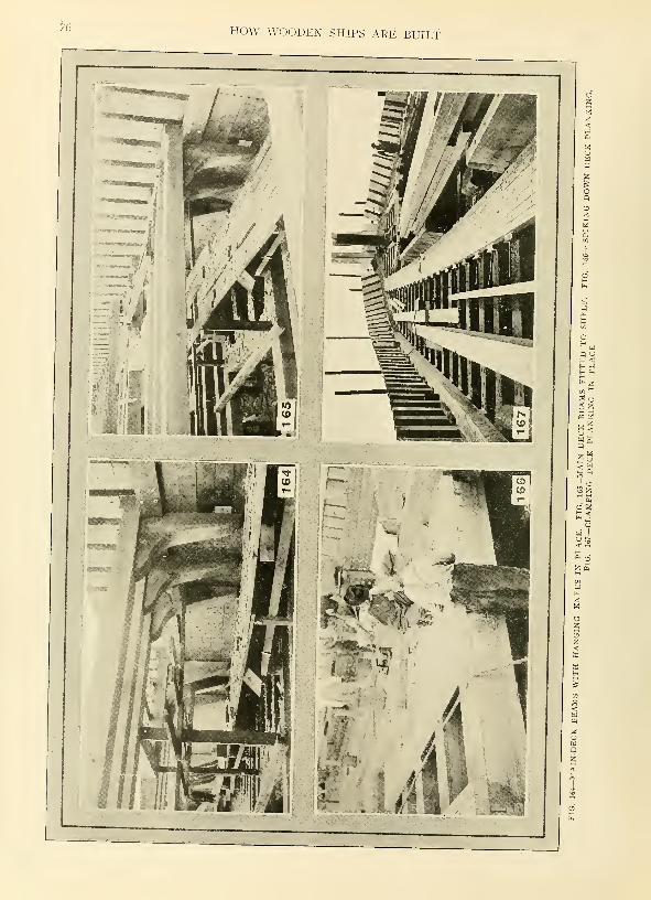
76 HOW WOODEN SHIPS ARE BUILT
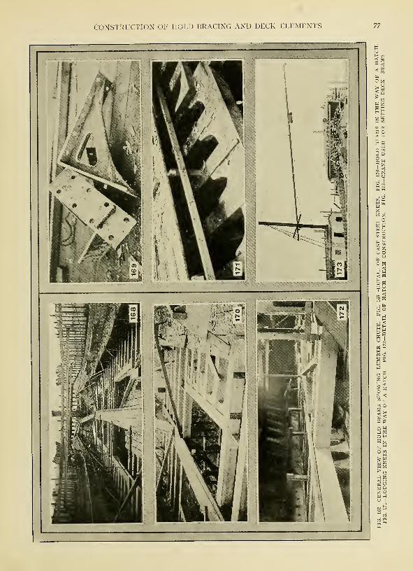
CONSTRUCTION OF HOLD BRACING AND DECK ELEMENTS 77

78 HOW WOODEN SHIPS ARE BUILT
-SURFACING KXEES ON A SPECIAL PLANING MACHINE—KNEES ALSO ARE FAYED ON THIS MACHINEIN LOTS OF 10 OR 12, THE OPERATION REOUIRING ONLY 15 MINUTES
support and that the benefits derived
are not proportionate to the expense
involved. There is no doubt, however,
that the scarfed joint is the stronger
of the two.
As soon as the shelf is in place,
the exterior planks opposite it maybe trimmed and fitted. When this is
done, the whole constitutes a very
rigid ribband which preserves the
form of the ship while the remainder
of the plank is put on. Usually the
beam knees are not fitted until someconsiderable time after the shelf is
put in place.
Lloyd's rules require that for ships
whose length is five times their
breadth, and between eight and nine ;
times their depth, the sectional areas
of shelves and waterways shall not be
less than that of the beams, the
latter being determined by a table
giving the scantlings according to
the breadth of the ship amidships. Therules also require that the breadths
of the faying surfaces of such shelves
shall not be less than the siding given
for the beam. When the fastenings
are of iron, they need not go through
the exterior planks, but may be
clenched either on the inside of the
shelf or' outside of the timbers. If
copper or yellow metal fastenings are
used for any purpose, they must be
clenched on the outer planks.
Beams Perform Two-Fold Service
As previously suggested, the beamsperform the two-fold service of con-
necting the sides of the ship and of
forming the foundation for the decks
which carry out the internal economyof the vessel. Besides this, the beams,
in combination with the deck planks
form a continuation of the frames
and planking, it being evident that
when the ship is rolling and workingheavily in a seaway, the deck andbeams at intervals are subjected to
the same strains as the frames andthe outside planking.
Usually, the framing of a woodendeck consists of beams, half beamsand carlings. The beams are those
which extend continuously from one
side to the other. Half beams are
short beams of reduced scantling
which extend from the side to fore
and aft pieces of deck framing termedcarlings. The latter are fitted between
FIG. 175—SECTION OF DECK FRAMING OF LARGE WOODEN SHIP SHOWING METHOD OF REINFORCING WITH STEELPLATES AND STRAPS
CONSTRUCTION OF HOLD BRACING AND DECK ELEMENTS
the beams. The arrangement of the
deck framing is given in the design
of the ship and is adapted to the
required position of the hatchways,
companionways, etc. The beams are
cut with parallel siding and molding,
the upper surface being formed to the
curvature of a circular arch. Theversed sine of this arch is termed the
round-up of the beam. This curvature
prevents the water from lodging on
the deck and adds to the bearing-
power of the beam when its ends are
fixed.
In modern yards ihe beams usually
are trimmed on a band saw or edging
machine. For this purpose, beammolds or tables of dimensions are
provided. The molds may be prepared
in the mold loft in the following man-ner:
The line of the beam at middle is
rased or scratched in on the floor in
the body plan, being copied into that
plan from the sheer plan by measur-
ing square to the base line the height
at which the beam at middle line in
sheer cuts each square station, trans-
ferring these heights to the body plan
square to the base line. The midship
beam itself also is drawn in the bodyplan, being copied from the midship
section. The distance between the
beam end and the beam middle lines
at any square station in the sheer
plan is evidently the round-up in the
length of the beam. Therefore, hav-ing given the latter line, together with
the curve of the longest beam and
the length of the beams in the deck
under consideration, the former line
is at once determined by setting the
FIG. 176—DECK OF LARGE WOODENMOTOR SCHOONER
amount of round-up for the beam at
each square station below the latter,
passing a curve through the points
so obtained. The curve of' the beamitself is that of an arc of a circle.
Since this circle is necessarily of verylarge radius, the portion of it that is
required may be most conveniently
constructed by certain simple methodsexplained in most works on plane
geometry or mechanical drawing.
After the inside of the ship has
been dubbed-out fair, it is a good idea
to rase in the line for the beams on
the ship's side. The first operation in
getting in a line of a tier of beamsis that of marking a straight line onthe ship's side at or near the height
of the beam at middle line amidships.
The straight line is drawn first onthe sheer draft and its height is meas-ured from the keel. Three boardsare then put across from side to side,
one being near each extremity of the
ship and one at the middle. Theseboards should be set perfectly hori-
zontal by means of a spirit level andthey are so placed that the upperedges of the two extreme boards are
at the height of the straight line, andout of winding with the lower edgeof the middle board. This is done bylooking across the edges or sighting
as it is termed. Battens then are
fixed along the inside of the ship.
The end batten is so placed that its
upper edge coincides with the upperedges of the two extreme base boardsand the lower edge of the middleboard. The intermediate portions of
the upper edges of the battens are
looked level with the three edges of
the baseboards, and the straight line
FIG. 177—CAULKING DECK USING HEAVY MAUL. FIG. 178— FINISH CAULKING. FIG. 179—INSERTING PINE PLUGS OVERSPIKEHEADS IN DECK

80 HOW WOODEN SHIPS ARE BUILT
is thus sighted on the inside surface
of the frames. This line is then rased
in on the timbers, after which it may
be painted so as to be readily dis-
tinguishable. In this way a straight
line may be put in on both sides of
the ship at the same height above the
keel.
Next, the perpendicular distance be-
tween the straight line and the beam
at middle line in the sheer draft is
measured at every square station or
frame station. A small cord is now
set to cross the ship at each square
station, being kept to the straight
lines already drawn on each side of
the ship. In this position a spirit level
is sometimes applied to the cord to
prove the agreement of the straight
lines on the ship's side. The distances
measured from the drawing are then
set up from the cord, square to the
base line, at the respective square
stations, and the points so found are
marked on the inside surface of the
timbers on both sides of the ship. Aline drawn to all the points by aid of
sheering battens, gives the sheer of
the deck or the projection of the
beams at middle upon the sides of
the timbers.
Marking in the Lines
The beams at side line, that is the
line of the upper side of the beam
ends, is then found by measuring
from the beam mold the round down
of the beam in the breadth of the
ship at each square station, and this
distance is set down square from the
line of the beams at middle. The
spots so found are marked on the
timbers. A line drawn through all
such points, by the aid of sheering
battens, is the line of the beams at
side. It is evident that by setting
beneath this line, the molding of the
beam, minus the snaping of the end,
we obtain points in the line of the
upper edge of the shelf, which line
can then be drawn by the aid of
sheering battens.
For trimming the shelf, molds maybe made to the curvature of the side
and the amount of sheer determined
by spilings taken from a straight line
drawn on the inside of the timbers,
adjacent to the line of shelf, for the
length of the piece to be trimmed.
These spilings are set off from a cor-
responding straight line drawn on the
timber when trimming it.
The correct section of the shelf
amidships is given in the design and
the shelf is kept the same siding
and molding throughout its entire
length. The upper side usually slopes
slightly inward and the under side is
more frequently parallel to the under
side of the beam than square to the
surface of the timbers. At the ex-
tremities of the ship, the shelf usually
is tapered away to the thickness of
the clamps or ceiling.
Two types of knees, wood and steel,
respectively, are shown in Figs. 164
and 169. Knees may be either hang-
ing or lodging, that is, vertical or
horizontal, as shown respectively in
Figs. 165 and 170. The chief function
of knees at beam ends is to preserve
a constant angle between the beamand the ship's side, it being evident
that the working of a ship in a seaway
tends to alter that angle. Considera-
ble difference of opinion exists re-
garding the relative efficiency of natural-
bent wood knees, such as shown in
Fig. 16S and the cast steel knees illus-
trated in Fig. 169. The latter are
about 4 feet 6 inches on a side and
Yi inch in section. They are, of
course, much stiffer than the woodknees; they also are lighter and less
unsightly. It is claimed by somebuilders, however, that their very stiff-
ness is undesirable, it being the con-
tention of these shipwrights that all
parts of the ship's structure should
work together. On the Pacific coast,
natural wood knees can be obtained
in almost any size, with arms up to
8 or 10 feet length and thicknesses
up to 24 inches. In some cases, the
clamp and shelf construction is so
arranged that the use of hanging
knees under the beams is obviated.
The length of a wooden beam usual-
ly is measured at the tip. This can
be done either by measuring the
breadth of the ship straight across, at
the level of the upper ed°-e of the
beam, then applying this length to
the beam mold, and measuring the
length of the curved edge of the moldin the straight distance, or it can be
done by putting the beam mold in
place and marking-off the length on
it. By the latter method the beveling
of the beam ends, if any, can be
marked on the mold at the same time.
To Take the Snape of a Beam
In order to take account of the
snape of the beam end, also of the
beveling and length at one time,
whether the beam is at its correct
round or not, the following is an
ordinary method:
A batten is placed across the ship
at the position of the beam to be
fitted, and the upper edge is kept in
touch with a cord stretched tightly
across the ship and secured to the
beam end line at each extremity. Apiece of mold is then made to the
shape of each of the beam ends.
These molds are nailed to the ends
of the batten, while the latter is in
the position already named. The bat-
tens with the end molds are then
laid upon the beam to be cut. Theends may now be marked by the
molds and in order to be sure that
the beam fits closely against the tim-
bers, it is customary to allow an
extra length of say Y\ to % inch, in
proportion to the length of the beam,
the exact amount being regulated by
a slip of wood kept by the workmanwho thereby makes it certain that all
of the beams are wedged in equally.
The fore and aft bevelings of the
beam ends, if any, are taken with a
bevel held against an athwartship line
and the inside of the timbers. It is
of the utmost importance that the
beams should fit closely against the
frame timbers. A close joint is pop-
ularly said to be half the fastening
and nowhere is this more true than
in the case of beams.
Steel Tape May Be Used
In a good many American shipyards
where speed is the chief considera-
tion, these precautions to insure cor-
rectly fitted beams frequently are
omitted, simple measurements with a
steel tape taking their place. Veryoften this does quite well, but if a
well-built ship is desired, too muchcare cannot be taken in fitting its
parts together.
After the beams are laid and prior
to planking the deck, it is necessary
to arrange for the deck furnishings.
These fittings consist of hatchways,
scuttles, match partners, bitts, bol-
lards, capstans, etc. The sides of the
hatchways are formed with carlings
which are scored into the beams.
Coamings and headledges are bolted
above the carlings, the former being
placed in a fore and aft, the latter
in a transverse or athwartship direc-
tion. They are referred to by the
general name of coamings, and ex-
tend to a sufficient height above the
deck plank to prevent water from get-
ting through the hatchway under or-
dinary conditions.
The mast holes of a ship with woodbeams are framed with a series of
carlings termed fore-and-aft partners,
cross-partners and angle-chocks, the
whole forming a hole the diameter of
which exceeds that of the section of
the mast usually by twice the thick-
ness of the mast wedges. The latter
vary from about 3 inches to 6 inches,
according to the size of the ship. Theframings for capstans, bollards, riding
bitts, etc., are built up simply of
carlings fitted so as to form a solid
resting place or bearing for the fit-
ing in question.
The deck planking for Americanwooden ships of normal size usually
consists of 5-inch square, edge-grain
fir or yellow pine timbers laid longi-
tudinally, as shown in Figs. 166 and
167. The latter illustration shows howthe deck planks are clamped and
wedged into place before being spiked
down. Fig. 166 shows the method of

CONSTRUCTION OF HOLD BRACING AND DECK ELEMENTS 81
spiking down the short lengths of
plank between hatchways. Ten-inch
galvanized boat spikes usually are em-ployed. They may be driven with
an air hammer instead of by hand.
Great care should be taken in lay-
ing the deck plank as it presents a
very unsightly appearance when ir-
regularly or carelessly put down. Theedges should be fair, but not neces-
sarily straight, as it sometimes is
considered advisable to taper the
strakes toward the bow in a curvi-
linear manner in order to neutralize
the optical illusion of curved deck
edges which is produced by parallel
straight seams approaching a side of
considerable curvature. In mostAmerican ships, the deck planks are
straight and parallel. Whether straight
or curved, it is absolutely necessary
that the edges be fair. If the practice
shown in Fig. 167 of laying several
strakes together is followed very fair
and even seams may be obtained.
The heads of the deck spikes are
countersunk and the holes are filled
with soft, white-pine plugs laid in
white lead. The method of perform-ing this operation is shown clearly
in Fig. 179. After the spike heads are
plugged, the deck is caulked. Thepreliminary caulking is performed bytwo men, as shown in Fig. 177. Oneholds the caulking iron and the otherswings the maul. The final caulkingis performed by one man who sits
on a campstool and uses a light mal-let. This operation is shown in Fig.
178. Fig. 176 shows the finished deckof a S-masted wooden auxiliary
schooner.

82 HOW WOODEN SHIPS ARE BUILT

CHAPTER X
Spars, Rudders, Shaft Logs and Engine Beds
SOME wooden shipbuilders maketheir own spars; others purchase
them from spar specialists. Mostof the timber for spars comes fromthe Pacific northwest on account of
the abundance of tall, straight trees
free from limbs close to the ground,
obtainable in that section of the coun-
try. Up-to-date machinery has been
employed very little in working-up
spars. Skilled men, therefore, are
necessary. Figs. 185 and 187 showthe essential operations in preparing
a spar or mast. For convenience in
handling, the rough logs usually are
laid on timbers which raise themabout 2 feet from the ground. Whenthe shipyard works up its own spars,
the logs are purchased peeled. In
order to obtain the proper taper, it
is first necessary to rough-out the
spar with an adz or axe, as shown in
Fig. 185. This is a rather laborious
and tiresome operation which at the
same time must be carefully conduct-
ed. After the spar is roughed-out it
is planed to a true surface by meansof hand planes of various sizes as
shown in Fig. 187. Sometimes spars
are scraped and sandpapered. Gener-
ally, also, they are varnished before
being set in place.
Some wooden shipbuilders are now
using steel masts which are lighter
than wood, and in somo sections of
the .country more readily obtainable.
In the case of an auxiliary vessel, the
steel mast also has an advantage, in
that it may be employed as an exhaust
pipe for the engine.
It hardly need be stated that a rud-
der is necessary to govern the direc-
tion of the ship's motion through the
water, the operation involved being
termed steering. The rudder, there-
fore, is a very important part of the
ship. Fig. 184 shows a wood rudder
of standard type for a large woodenauxiliary vessel. Another type of
rudder also used on wooden ships is
shown in Fig. 180. This rudder is of
the composite type with a cast steel
frame and wood filling.
How the Rudder Stock is Coned
Referring now to Fig. 184, it will
be seen that a line drawn through the
center of a rudder pintles coincides with
the center line of the rudder stock.
Fig. 184 shows clearly how this re-
sult is obtained in the case of a
wooden rudder, the lower end of
the rudder stock, known as the con-
ing, being trimmed or coned to fit
a corresponding cavity in the rudder.
Formerly, the fore-side of the
rudder was straight, and therefore
the center line of pintles, about whichthe rudder revolves, was at a dis-
tance about equal to the radius of
the pintles from the fore-side of the
rudder stock. It is evident that a
large hole' was necessary under these
circumstances to permit the rudder
to turn through the required angle.
The difficulty of making this hole
watertight, leather being usually em-ployed, led to the construction shownin Fig. 184.
The rudder itself is built of pieces
of timber rigidly edge-bolted together.
The after side is protected by an
iron strap or forging. Hardwoodinvariably is employed, iron bark, a
dense hard wood obtained from Aus-tralia usually being used in the Unit-
ed States. The rudder pintles, usually
four in number, are generally bronze
castings. They fit into bronze sockets
bolted to the rudder post. Complete
details of this construction are shownin Fig. 117, in the seventh chapter.
Further details of wooden rudder con-
struction may be obtained by leferring
to Figs. 102 and 104 in the same chapter.
As Figs. 102 and 117 clearly indi-
cate, the after portion of the rudder-
post or sternpost, as the case may
FIG. 181—FOUNDATION DETAILS FOR A TWIN-SCREW OIL-ENGINE DRIVEN SHIP FITTED WITH 500-HORSEPOWER,6-CYLINDER ENGINES
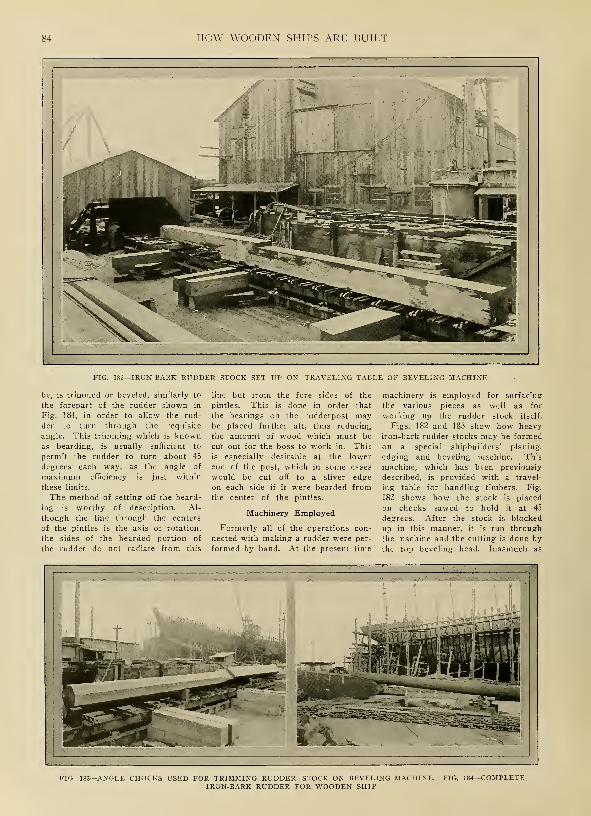
84 HOW WOODEN SHIPS ARE BUILT
FIG. 182—IRON-BARK RUDDER STOCK SET UP ON TRAVELING TABLE OF BEVELING MACHINE
be, is trimmed or beveled, similarly to
the forepart of the rudder shown in
Fig. 184, in order to allow the rud-
der to turn through the requisite
angle. This trimming which is knownas bearding, is usually sufficient to
permit the rudder to turn about 45
degrees each way, as the angle of
maximum efficiency is just within
these limits.
The method of setting-off the beard-
ing is worthy of description. Al-
though the line through the centers
of the pintles is the axis of rotation,
the sides of the bearded portion of
the rudder do not radiate from this
line but from the fore sides of the
pintles. This is done in order that
the bearings on the rudderpost maybe placed further aft, thus reducing
the amount of wood which must be
cu't out for the boss to work in. This
is especially desirable at the lower
end of the post, which in some cases
would be cut off to a sliver edge
on each side if it were bearded fromthe center of the pintles.
Machinery Employed
Formerly all of the operations con-
nected with making a rudder were per-
formed by hand. At the present time
machinery is employed for surfacing
the various pieces as well as for
working up the rudder stock itself.
Figs. 182 and 183 show how heavy
iron-bark rudder stocks may be formedon a special shipbuilders' planing,
edging and beveling machine. This
machine, which has been previously
described, is provided with a travel-
ing table for handling timbers. Fig.
183 shows how the stock is placed
on chocks sawed to hold it at 45
degrees. After the stock is blocked
up in this manner, it is run through
the machine and the cutting is done by
the top beveling head. Inasmuch as
FIG. 183—ANGLE CHOCKS USED FOR TRIMMING RUDDER STOCK ON BEVELING MACHINE. FIG. 184—COMPLETEIRON-BARK RUDDER FOR WOODEN SHIP

SPARS, RUDDERS, SHAFT LOGS AND ENGINE BEDS 85
the wood is especially hard, com-
paratively light cuts are taken and
each time the carriage is reversed the
top beveling head is lowered slightly
-ROUGHING OUTWITH AN AXE
by power. This head is provided with
a dial indicator which shows its exact
position. This operation is continued
until the cut is brought down to the
desired depth. The rudder stock is
then turned so that another corner can
be cut down to the same depth in the
same manner. By continuing this
operation, the stock can be reduced
in the machine from the rough to
practically a finished condition.
The rudder shown in Fig. 180 is
of the balanced type. It extends 6
feet abaft the pintles and 2 feet
in front of them. This rudder has
an overall height of 16 feet 4 inches.
It is supported at the lower end bya cast steel shoe. The rudder stock
is a forged steel shaft turned to a
diameter of 8 inches. The pintle
bearing at the lower end is turned
to a diameter of- 4% inches. The
rudder sleeve is lin-ed with lead. Theinside diameter of the sleeve is 10
inches and the walls are 5 inches
in thickness.
In preparing the engine foundations
for wooden ships, the methods vary
considerably among different ship'
yards. The object of the builder in
each case is to furnish a firm founda-
tion which will hold the engine se-
curely and keep the shaft in align-
ment. In wooden vessels, particularly
where the machinery is amidships, this
question of shaft alignment is a seri-
ous one owing to the twisting of the
hull in service. In order to avoid
the troubles which result from this
displacement of the hull, some builders
of oil engines recommend the use
of flexible couplings of the usual
pin and leather-ring type. Some of
these builders also place the engines
parallel to the propeller shaft, in the
case of twin screw boats, transmitting
the power through a herringbone
gear. This is said to permit the en-
gine to run at a more economical
speed.
Solid Foundation
Some builders of motor ships pre-
fer to place their engines on a foun-
dation built of solid 12 x 12-inch
timbers. They believe this is neces-
sary in order to fortify the structure
against the shocks of pre-ignition.
Experience has shown, however, that
in the case of well designed engines
this is not necessary. A type of
foundation for a 6-cylinder 500-horse-
power oil engine, which is muchmore economical of timber than the
solid block type is illustrated in Fig.
181. This drawing shows very clearly
the various details of the foundation.
In this case, the engine is carried on
two 12 x 24-inch continuous founda-
tion timbers. The engine is approxi-
mately 26 feet in length over all.
FIG. 187—FINISHING A SPAR WITH AHAND PLANE
Fig. 181 also shows one arrange-
ment of shaft log and stern tube. Twotypes of stern tubes are in general
use. In one design, for twin-screw
motor vessels, the propeller shaft is
carried through a built-up wood shaft
log about 28 inches square on the
outside. Sometimes the log is built
out of two pieces with a single longi-
tudinal parting. In other cases, four
pieces thoroughly edge-bolted to-
gether are employed. The log is
rabbeted into the planking and ceil-
ing, and caulked tight. It is pro-
vided with a lead sleeve and with
cast iron caps on each end.
The other design involves the use
of a cast-steel sleeve or stern tube
FIG. 186—STEAM-DRIVEN CARGO WINCH INSTALLED ON WOODEN SHIP. FIG. 188—STEAM-DRIVEN ANCHOR WINCHBUILT ON PACIFIC COAST

86 HOW WOODEN SHIPS ARE BUILT
with bronze liners at each end carry-
ing lignum vitae bushings. The shaft
between the bushings is served with
marlin. The shaft bearings are bored
out to their proper alignment after
the log is in place, using a portable
electric-driven boring machine. Theboring machine usually is driven by
a 7j4-horsepower motor connected to
the boring-bar through a worm gear.
The cost of installing an oil engine
in a modern motor ship varies con-
siderably depending on the size of
the vessel and the skill of the in-
stalling foreman. Generally speaking,
it ought not to cost over $3000 to
install two 350-horsepower semideisel
outfits complete with tanks. Thejob should be accomplished in from13 to 20 days. Some shipbuilders,
however, have spent as much as $7000
installing two engines, and in onecase, at least, fully two months'
time was required.
The deck fittings for wooden ships
do not differ materially from those
employed on steel vessels. Fig. 186
shows a typical cargo hoist and Fig.
188 an anchor winch installed on a
5-masted auxiliary- schooner. Both of
these machines are steam driven.
Electrically driven winches also are
used to a considerable extent, par-
ticularly on power driven vessels
where it may not be convenient to
provide steam. On motor ships, hori-
zontal oil or coal fired donkey boilers
with some 480 to 700 square feet of
heating surface usually are provided.
In some cases, larger boilers have
been found advisable, with up to
1000 square feet of heating surface.
Wood vessels are launched in the
same manner as steel ships. Onthe coast or wherever end launching
is employed, a cradle is built under
both ends of the vessel. This cradle,
of course, rests on the standing ways.
When the ship is ready for launching,
it is raised off the keel blocks bywedges. Then the shores and keel
blocks are knocked out transferring
the weight of the ship to the cradle.
In some cases the sliding ways are
spiked to the standing ways to hold
the ship prior to launching. In this
case, the ways are sawed apart bytwo men at the moment of launching.
In other cases the usual trigger gear
is employed. On the Great Lakes,
vessels are launched sideways. Thegeneral principles are similar, the waysrunning athwartship instead of longi-
tudinally.
Vessels usually are painted above
the waterline as well as below before
launching. In some yards the paint
is sprayed on by a pneumatic, atom-
izer. This device saves considerable
time and makes it easy for an un-
skilled man to produce a smoothcoat. A large ship will require from
70,000 to 100,000 pounds of paint.
In some yards sailing vessels are
launched with the masts and most
of the rigging in place. In other
establishments the hull is sent into
the water without any rigging.
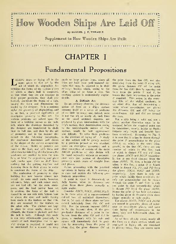
i Illlllllllillffll .iiiiiii
1 :' 1
:
;.: :
r :-
©w ipg Are Laid OffBy SAMUEL J. P. THEARLE
it tto How Wooden Ships Are Built
llll!llllll!lllllllllllll!Illlll!IIIIIIIIIIIIIIIIIIinttlllll!l!l!llllllllll[
CHAPTER I
Fundamental Propositions
LAYING down or laying off is the
. name given to that art by the
aid of which the shipbuilder de-
termines the forms of the various pieces
of which a ship's hull is composed,
so that when they are put together in
their proper positions, they shall col-
lectively constitute the frame of a ship,
having the form and dimensions in-
tended by the designer. It is sometimes
styled the geometry of shipbuilding, and
is, in fact, a practical application of
descriptive geometry to that art. Its
various problems are solved upon the
floor of a building known as the mold
loTt, where the drawings furnished by
the designer are transferred in chalk
lines in full size, and then by the aid
of geometry, and in the manner dis-
cussed in the following paragraphs,,
the draftsman determines and draws
in the shapes of the various components
of the frame. Molds or patterns are
made to the lines, and with them and
other data furnished by the draftsman, the
workmen are enabled to trim the tim-
bers, or bend the angle-irons, and place
such marks upon them as shall leave
nothing but the putting together and
fastening them in their places in order
to construct the frame of the ship.
The application of geometry to ship-
building has now become almost uni-
versal. In some small yards, however,
schooners, brigs, and such minor craft,
are not laid off ; but the stem, stern-
posts, and the keel having been set
in position, the form of the hull is
shaped in on one side with battens bent
to please the eye ; and molds having
been made to the timbers on that side,
they are reversed for the timbers on
the other side. The timbers are kept
in place by cross spalls, shores, and
ribbands, the frame is planked, and thus
the hull is built. Although this modeis not very objectionable practically in
vessels of such description that no spe-
cial design is required, it could notbe entertained for a moment in navy
yards or large private firms, where all
ships are built from well matured de-
signs that must be adhered to in their
entirety; besides which, owing to the
ships being of so large a size, this
mocking system is economically imprac-
ticable.
A Difficult ArtTo an ordinary observer, the determi-
nation of lines on a ship's surface
presents itself as a series of problems
of no little intricacy; and, indeed, wereit not that all, or nearly all, such lines
as the naval architect requires, are
produced by plane intersections with the
ship's surface, their determination, owingto the undevelopable nature of that
surface, would be both approximate
and difficult. To solve these problems
is the province of laying off. A study
of this subject will be greatly assisted
by a previous perusal of any standard
work on descriptive geometry ; and a
clear conception of certain of the moredifficult problems of ship design will
be found impossible without an acquaint-
ance with that portion of descriptive
geometry which treats of straight lines
and planes.
Before proceeding with the practical
operations in laying off, it is necessary
to state and explain the following pre-
liminary proposition
:
A point in space is determined, or
fully known, when its distances are
given from three planes mutually at
right angles.
Consider AOCD, BOCF, AOBE, Fig. 1,
to be three sides of a square-cornered
cubical box of unlimited dimensions;
that is, let each of these plane surfaces
extend indefinitely from OB, OC and('.-J. For the present, suppose OBEAto be the bottom ; then, if the per-
pendicular distances of a point in the
bottom from the sides OB and OA be
given, a mechanic with his rule andsquare will immediately find its posi-
tion by measuring from the point Oalong OA, the given distance OX of
87
the point from the line OB, and also
measuring from the point O along OB,the given distance OY of the point
from the line OA; then by squaring outlines from the points X and Y, heknows that their intersection is the point
P required. This action in the every-
day life, of the skilled mechanic, is
no other than that of determining a
point whose co-ordinates, are given;
the distances OX and OY being the
co-ordinates. OB and OA are termedthe axes.
But a ship being a solid and not a
plane, another dimension must be in-
troduced before the required point canbe determined, namely, height or depth
;
hitherto only length and breadth havebeen considered. Returning to Fig. 1,
it is seen that if a line be drawn throughthe point P perpendicular to the plane
OBEA, or, which is the same thing,
parallel to the line OC, there are anynumber of points in this line, each
of which is distant PX and PY fromthe planes AOCD and -BOCF respective-
ly, but at any fixed distance from the
plane AOBE. If, then, a height PQ be
taken in this line, a point Q is found,
which is distant PX, PY, and PQ fromthe planes AOCD, BOCF and AOBE,respectively. Now there is only onepoint which fulfills these conditions, for
only one perpendicular can be drawnthrough the point P, and there is only
one point in that perpendicular whichis distant PQ from the plane AOBE.Hence the point Q has been determined
by having given its distances from three
planes mutually at right angles.
The planes AOCD, BOCF and AOBEare termed in geometry planes of refer-
ence or co-ordinate planes, and havetheir laying off counterparts in the
sheer, body and half-breadth plans, re-
spectively.
As we have already stated, nearly all
the lines on a ship's surface which are
employed in laying off, are contained
in planes ; hence, they are drawn upon

HOW WOODEN SHIPS ARE LAID OFF
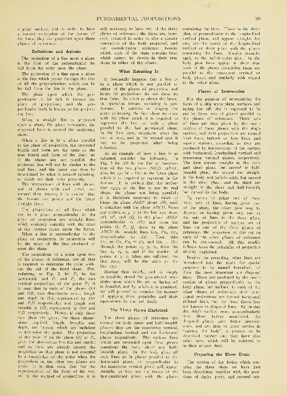
FUNDAMENTAL PROPOSITIONS 89
a plane surface, and in order to have
a correct conception of the forms of
the lines, they are projected upon three
planes of reference.
Definitions and Axioms
The projection of a line upon a plane
is the foot of the perpendicular let
fall from the point upon the plane.
The projection of a line upon a plane
is the line which passes through the feet
of all the perpendiculars which can he
let fall from the line to the plane.
The plane upon which the per-
pendicular is let fall, is termed the
plane of projection; and the per-
pendicular itself is known as the project-
ing line.
When a straight line is projected
upon a plane, the plane containing the
projected lines is termed the projecting
plane.
When a line is in a plane parallel
to the plane of projection, the projected
length and form are the same as the
true length and form of the line ; but
if the planes are not parallel, the
projected line will not be similar to the
real line ; and the latter can then be
determined by what is termed rabatting,
to which we shall refer presently.
The intersections of lines with planes,
and of planes with each other, are
termed their traces ; it is evident that
the former are points and the latter
straight lines.
The projections of all lines which
are in a plane perpendicular to the
plane of projection are straight lines,
which evidently coincide with the trace
of the former plane upon the latter.
When a line is perpendicular to the
plane of projection, its projection will
be the trace of the line produced to
meet the plane.
The projections of a point upon twoof the planes of reference, are all that
is required to determine the point with-
out the aid of the third plane. For,
referring to Fig. 2, let P t be the
horizontal, and P2 and P 3 the twovertical projections of the point P; it
is seen that in each of the planes OAand OB, two dimensions enter, length
and depth in OA, represented by ODand P,D respectively; and length and
breadth in OB, represented by OD and
PJD respectively. Hence, if only these
two plans are given, the three dimen-
sions required, length, breadth and
depth, are known, which are sufficient
to determine the point. The projection
of the point P on the plane OC at P,„
gives the dimensions breadth and depth
;
and as these are already known, the
projection on that plane is not essential
to a knowledge of the point when the
projections on the other two planes are
given. It is thus seen, that for the
representation of the form of the ves-
sel by the method of projections, it is
only necessary to have two of the three
planes of reference ; the three are, how-ever, retained in order to give a clearer
conception of the body projected, and
for corroborative evidence ; besides
which, each of the plans contains lines
which cannot be shown • in their true
shape in either of the others.
What Rabatting Is
It frequently happens that a line is
in a plane which is not parallel to
either of the planes of projection, and
hence its projections do not show its
true form. In order to obtain the latter,
an operation termed rabatting is per-
formed. It consists in hinging the
plane containing the line about its trace
with the plane which it is required to
represent the line, or with a plane
parallel to the last mentioned plane.
In the first case, rabatment gives the
line at once, and in the second case it
has to be projected after being
rabatted.
As an example of how a line is so
rabatted, consider the following. In
Fig. 3 let AB be the line of intersec-
tion of the two planes ABCD, ABEF,also, let xyz be a line in the latter plane
which it is required to represent in the
former. It is evident that the projec-
tion x1y1z1 of the line is not its real
shape, the planes not being parallel
;
it is therefore necessary to rabat or
hinge the plane ABEF about AB, until
it coincides with the plane ABCD. Fromany points, x, y, z, in the line xyz, drawxO, yP, and zQ, in the plane ABEFperpendicular to AB ; and from the
points O, P, O, draw in the plane
ABCD the straight lines Ox.,, Py 2, Qz2 ,
perpendicular to AB. Then take
Ox. = Ox, Py, = Py. and Qz2 — Qz;through the points x2 , y 2, z2, draw the
line x2 , y 2, z2 , and if the number of
points x, y, z, taken are sufficient, the
iine x2y 2z2 will be the same as the
iine xyz.
Having thus briefly, and as simply
as possible, stated the geometrical prin-
ciples upon which the art of laying off
is founded, and by which it is practiced,
we will proceed to examine the mannerof applying these principles and their
equivalents in the art itself.
The Three Planes Explained
The three planes of reference are
termed the body sheer, and half-breadth
planes ; they are the transverse vertical,
longitudinal vertical and the horizontal
planes respectively. The various lines
which are projected upon these planes
constitute the body, sheer and half-
breadth plans. In the body plan, all
such lines as in planes parallel to the
horizontal plane, or perpendicular to
the transverse vertical plane, will appeal-
straight, as they are the traces of the
last-mentioned plane with the planes
containing the lines. Those in the sheer
plan, or perpendicular to the longitudinal
vertical plane, will appear straight, for
they are the traces of the longitudinal
vertical or sheer plane with the planes
containing the lines. Similar remarks
apply to the half-breadth plan. In the
body plan lines appear in their true
form if the planes containing them are
parallel to the transverse vertical or
body plane; and similarly with regard
to the other plans.
Planes of Intersection
For the purpose of representing the
form of a ship upon plane surfaces and
laying her off, she is supposed to be
cut by three sets of planes parallel to
the planes of reference. Three sets
of lines are thus given by the inter-
section of these planes with the ship's
surface, and their projections are termed
level lines, buttock or bow lines, and
square stations, according as they are
produced by intersections of the surface
with horizontal, longitudinal vertical and
transverse vertical planes, respectively.
The first appear straight in the body
and sheer plans, but curved in half-
breadth plan; the second are straight
in the body and half-breadth, but curved
in the sheer plan; and the third are
straight in the sheer and half-breadth,
but curved in the body.
By means of either two of these
three sets of lines, having given twoof the plans, the other pian may be
drawn; or having given only one of
the sets of lines in the three plans,
and the projection of another set of
lines on one of the three planes of
reference, the projection of this set on
each of the other planes of reference
can be determined. All this readily
follows from the principles of projection
already explained.
Besides the preceding, other lines are
introduced into the plans for special
purposes to be named hereafter ; of
these the most important are diagonal
lines. These are produced by the inter-
section of planes perpendicular to the
body plane, but inclined to each of the
other planes of reference; their hori-
zontal projections are termed horizontal
ribband lines, but the lines themselves
are known as diagonal lines. By cutting
the ship's surface more perpendicularly
than those before mentioned. the
diagonal planes give better intersec-
tions, and are thus of great service in
"fairing the body", a process to be
described further on ; they have also
other uses, which will be referred to
in their proper place.
Preparing the Sheer Draft
The portion of the design which con-
tains the three plans we have just
been describing, together with the posi-
tions of decks, port?, and general out-
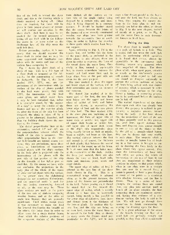
90 HOW WOODEN SHIPS ARE LAID OFF
line of the hull, is termed the sheer
draft, and this is the drawing which is
chiefly required in laying off. Other
data are required, but these will be
given in their proper places; at present,
we will confine our attention to the
sheer draft. And here it may be re-
marked that the several processes of
laying off are dealt with in the follow-
ing pages in the same order as the
draftsman lays off his ship upon the
inold-loft floor.
Before proceeding further, it is nec-
essary that we should examine the
sheer draft in order that we may be-
come acquainted and familiarize our-
selves with the names and uses of the
various lines composing it.
Fig. 4 shows the sheer draft of a
sloop of war. This is a fair type of
a sheer draft as prepared at the Ad-
miralty for the construction of vessels
in dockyards. In Fig. 4, the lines
marked 2WL. 3WL, etc., are the
projections of the intersections with the
surface of the ship of planes parallel
to the load water plane; they with
LWL, the intersection of the load
water plane, are called water lines.
It may be here remarked that, unless
it is otherwise stated, by "the surface
of a ship" is meant the outside of the
frames and not of the exterior plank,
as, after the form of the ship has been
designed, the plank is taken off by a
process to be afterward described, and
thus the building draft shows the sur-
face of the frames.
The dotted perpendicular lines at the
extremities, marked FP and AP, are
the perpendiculars between which the
length of the ship is measured. The
other perpendicular lines in the sheer
and half-breadth are termed square sta-
tions; they are projections, upon these
plans, of intersections of transverse
vertical planes with the ship's surface.
In the body plan is projected only the
intersections of the planes with the
port side of that portion of the ship
on the foreside of her fullest part or
dead flat. By this means we have, with-
out confusion, the projections in the
body plan of the whole of the traces
of these vertical planes with the surface.
At the present time the alphabetical
designations are sometimes discontinued,
and the numerical mode is used for
the two bodies, commencing forward
or aft, as the case may be. These
plane sections are made at the joints
of the two sets of timbers composing-
wooden frames, and at the sides of
angle iron frames ; they are generally
equidistant. Until within recent years
it was customary to make the dead
flat interval five-fourths the breadth of
the others, this being done in order to
allow room for a single timber frame,
about which the relative positions of
the component timbers of the frames
were shifted, all the timbers on the
fore side of the single timber being
disposed by a certain rule, and those
abaft it being disposed in a contrary
manner. It should be further stated
that the spaces between the joints of
the frames of some recently constructed
wooden war ships have been greater
towards the extremities than at amid-
ships, in order to lighten the framing
at those parts which receive least buoy-
ant support.
Again, referring to Fig. 4, TS is the
topside line, and besides this the form
of the upper deck, as projected in the
three plans, is also shown ; these are
given in order to represent the form of
the vessel above the water lines. Gen-
erally, a line, termed a top-breadth
line, is drawn somewhere between the
topside and load water line ; and, in
large ships, lines at the port sills are
given for the same purpose.
The lines marked K show the upper
and lower edges of the keelson, and at
their extremities are shown the stemson
and sternson.
The doited line marked A is the
upper part of the keel, the two lines
next below are the upper and lower
edges of rabbet of keel ; and below
these are shown, in succession, the
lower edge of keel and the two pieces
of false keel. The lines marked UDLin the sheer plan are, beginning at the
uppermost, the lines of upper side of
upper deck at middle line, upper side
of upper deck beams at middle line,
and upper side of upper deck beams
at the ship's side respectively ; these
being usually known as deck at middle,
beam at middle, and beam at side lines.
The vertical distance between the first
and second is, of course, the thickness
of deck plank; that between the second
and third is the round up of the beam.
It is at once seen that the latter meet
at the extremities of the deck. Besides
the lines just noticed, there are also
shown the knee of head, head rails,
stern and munions. ports, masts and
other details.
The upper edge of rabbet of keel is
selected as the base line of the sheer
draft shown in Fig. 4. This is a
conventional usage which is adopted
when, as in the present instance, the
joints of the frames are perpendicular
to the keel. Before passing on, it should
be stated that the line termed the
upper edge of rabbet, which is usually
chosen as a base line, is incorrectly
named, being merely a line parallel to
the lower edge of rabbet—a fixed line
—
and distant from it the thickness of
the bottom plank. By making this the
base line, and the ship not being on
an even keel, causes the water lines to
be curved in the body plan, as shown.
In many cases the frames stand per-
pendicular to the LWL, and in such
cases a line drawn parallel to the latter,
and near the keel, has been chosen as
a base, thus causing the square sta-
tions in the body plan to end suc-
cessively one below the other, as shownby Fig. 5 in the next chapter, instead
of mostly at a point, as in Fig. 4,
and the water lines in such drawings
are known as level lines.
Fairing the Ship
The sheer draft is usually prepared
on a scale of J^-inch to a foot. This
is copied full size upon the mold loft
floor, in performing which operation
it is found that errors, almost in-
appreciable in the one-quarttr scale
drawing, become very apparent whenthus magnified 48 times. The three
plans which, when upon' paper, coincide
as nearly as the draftsman's powerswill permit, when copied to full size
are found to disagree sufficiently to
prevent the various problems of laying
off from being solved with that degree
of accuracy which is necessary in order
to obtain a fair surface to the ship.
Hence a fairing, or correcting process,
has to be performed before the timbers
can be laid off.
The mutual dependence of the three
plans upon each other has already been
shown ; this property is utilized in per-
forming a tentative process, termedfairing the body. It has been shownthat the projections of each .of the sets
of lines generally used in this process,
viz., level lines, square stations, bowlines, and diagonal lines, appear straight
in one or two of the plans; so that,
by the aid of a straight-edged batten,
they can be drawn fair very readily
in such plans. The property which a
wooden or metallic batten has of bend-
ing in a fair curve, is brought to our
aid in drawing the lines fairly in the
plans where they appear curved. For,
since the intersections of lines with
each other are points, the points of
intersection of two sets of lines in one
plan are transferred to their relative
positions in others, so that points which,
when in one plan, were in a straight
line, are now in a curved line; a
batten is penned, or bent to pass through
as many of the points as is consistent
with absolute fairness, and the line is
drawn. Thus, by a series of inter-
changes, the various lines are copied
from one plan into another, until at
length all the plans coincide, the lines
composing them are continuous curves
;
and, having thus evidence of a con-
tinuous surface, the body is said to be
fair. We will now go through these
operations in detail, commencing by
copying the drawing upon the floor.
It is a great advantage if the seams
of the boards forming the floor of a
mold loft are perfectly straight and
parallel, as they thus afford considerable

FUNDAMENTAL PROPOSITIONS 91
assistance in the several processes of
squaring and drawing parallel lines
which are involved in the practice of
laying off.
The first thing to be done is to
strike a base line on the floor ; if the
board edges are arranged as just stated,
it will be necessary to place the base
line either parallel or perpendicular to
the lines of the seams. Should the
floor be rectangular, about two feet fromthe wall or other boundary of the floor
is a very convenient position for a base
line. As before stated, a line parallel
to the lower edge of rabbet is usually
taken as the base, except in the case
already cited. Whichever line, however,
is chosen, the depth of the keel, the
lower edge of rabbet, and the upper
side of keel, are set off from it, at
distances measured from the sheer
draft; also, the fore and after edges
of stem, together with the fore edge
of rabbet of stem, which latter is, of
course, a continuation of the lower edge
of rabbet of keel. The post is next
copied with the after edge of its
rabbet, also the margin of stern andthe various square stations in the sheer
plan, including" the fore and after per-
pendiculars. These, with the beam at
middle lines, are termed the fixed lines
of the sheer plan, being indeed un-
alterable, except insofar as drawing
them fair is concerned. To economize
space, the half-breadth plan is generally
drawn upon the same part of the floor
as the sheer plan, the base line of the
former, or a line parallel thereto, serv-
ing as the middle line of the latter,
and in this way the same square sta-
tions will do for the two plans. Thereare few mold-loft floors upon which
vessels of more than 100 feet long can
be drawn in one length to full size
;
hence it is necessary to lay them off
in two, three, and, in some cases, even
more parts. The usual practice, with
a wooden ship, is to set off the two
perpendiculars at such distances from
the ends of the floor, as will permit
of the head rails and stern timbers be-
ing laid oft" ; whereas with an iron ship,
the perpendiculars can be so placed as
to just give room for drawing the
contour of the stem and the rake of
the counter.
When the positions of the per-
pendiculars are fixed, as much of the
fore and after bodies are drawn as
the length of the floor will allow, and
if there still remains an amidship part,
it is laid off separately; so that there
are two, or even three, sets of lines
overlapping each other. However, since
these bodies are not both laid off
simultaneously, no confusion occurs.
We will presume that there is roomupon our floor to lay off our ship in
two parts, and will consider first the
fore body, i. e., that portion of the
ship on the fore side of dead flat.
To Copy the Body Plan
Having already copied the sheer plan,
we will now copy the body plan, doing
so as near as possible to the former,
at the same time not allowing the lines
to cross if it can be avoided. How-ever, this is a mere question of roomand convenience. On a small floor
the same base line may well serve for
the three plans, one of the square sta-
tions at amidships being taken as the
middle line of the body plan.
A base and middle line for the body
plan having been drawn upon the floor,
before copying that plan it will be
necessary to put certain additional lines
in the body plan of the sheet draft,
in order to assist the draftsman in
copying, and subsequently fairing it.
By reference to the sheer draft shownin Fig. 4, it will be seen that the
water lines are curved on the body
plan. Now the process of fairing is
materially assisted if lines which are
curved in one plan are straight in an-
other. We have already explained the
cause of the curvature of these water
lines when projected upon the body
plane ; we will now draw a series of
lines parallel to the base line of the
sheer plan, and equidistant from each
other. These lines, being produced by
the intersections of the surface with
planes parallel to the horizontal or half-
breadth plane, will appear straight in
the body plan, and will, in fact, be
drawn similarly to those in the sheer
plan. We will therefore draw in the
body and sheer plans about as manyof those level lines as there were water
lines, and copy the lines upon the floor
;
besides which we will put in level lines
near the top side line, top breadth line,
and at other intermediate positions, ac-
cording to the height of the ship above
the load water line.
Besides these, in order to obtain
more numerous and better intersections,
a number of diagonal lines are drawnin the body plan. The positions of
these lines will be given hereafter
;
suffice it to say, for the present, that
they are the lines of the heads andheels of the timbers, and therefore of
the harpins and sirmarks.
Having transferred these lines to the
floor, we proceed to copy the body plan
by measuring, with a scale, the dis-
tances, along the several level and
diagonal lines, from the middle line to
where they cut the square stations, andthen setting off these distances to full
size on the corresponding lines uponthe floor. Battens are then penned or
bent, so as to approximate as closely
to these points as is consistent with
absolute fairness or continuity, and the
lines are marked in with thin slices
of chalk.
Table of Ordinates
At some yards it is customary to
measure these ordinates, etc., and record
them upon paper in a tabulated formbefore proceeding to draw the body to
full size on the floor; and thus the
latter operation is performed without
direct reference to the drawing whenworking on the floor. The square sta-
tions thus drawn upon the floor are
ended as follows: The lines of the
half sidings of keel, stem, and stern-
post, are drawn in the body and half-
breadth plans from dimensions fur-
nished by the specifications or schemeof scantlings, which also states the
taper, if any, which these parts of the
ship should have. Next, the distance
from the base line of sheer at which
each square station cuts the lower or
fore edge of rabbet, is set off from
the base line of body upon the middle
line of that plan, and from this point
a line is squared out to the half siding
of keel, stem, or sternpost. A circle is
then swept with the point thus obtained
as a center, and a radius equal to the
thickness of the bottom plank, and the
square station is ended as a tangent
to this circle upon the side of the
latter, which is nearest to the middle
line of body. It should be noticed that
this ending is approximate.

CHAPTER II
Fairing the Lines
THE half-breadth plan has next
to be drawn upon the floor ; and
here we may again note that
lines now being used, which are curved
in the body plan, will be straight in
the half-breadth plan, and vice versa.
Before proceeding to copy the half-
breadth plan from the body plan, it
should be noticed that, owing to the
new level lines which have been penciled
on the sheer drawing, the half-breadth
pian to be drawn upon the floor will be
totally dissimilar in appearance to that
given in the design. But if the base
line of the sheer draft is parallel to
the water lines, and the body is there-
fore given in that drawing as shown in
Fig. 5, the additional work of copying
the body by new lines, and then trans-
ferring the latter to the half-breadth
plan, will be unnecessary.
Having already drawn on the floor
the middle line of the half-breadth plan,
and the projections of the square sta-
tions in that plan we proceed to copy
the level lines from the body into the
half-breadth plan (see Fig. 6).
Straight-edged battens are set to the
middle lines of body and half-breadth.
Then measure on a staff, whose end
is kept against the former batten, the
distance from the middle line to where
a level line ab cuts each square station
1, 2, 3, etc., in the body plan, and
transfer these distances to the cor-
responding square stations in the half-
breadth plan, by setting the end of the
staff against the middle line batten of
that plan, and marking the distances
out on the respective square stations.
A batten is then bent so as to pass
fairly through as many as possible of
these points, and the line a26» is chalked
in, this process being per-
formed for each level line.
Still referring to Fig. 6,
square down from the sheer
plan to the middle line of
the half-breadth plan, the
point of intersection at of
the level line with the
fore edge of rabbet of
s t e m, and set off on
this perpendicular line the
half siding of stem at this
height as measured from the
body plan. Then end the level
line by making it a tangent
to a circle whose center is the
point thus found, and whose
radius is equal to the thick-
ness of the bottom plank, tak-
ing care to do so on that side
of the circle nearest to the
middle line of body. We must again re-
mark that this ending is only approxi-
mate unless the stem is square
to the level line. For the fore
edge of the rabbet is assumed to
be the axis of a curved cylinder,
the radius of which is the thickness
of the bottom plank; and the surface
of the timbers is supposed to be in
contact with this cylinder along the
line of the center of rabbet. It is
evident, then, that unless the section
of the cylinder is made square to the
axis it will be elliptical. Another error
is, however, introduced owing to the
tapered siding" of the stem below the
lower cheek.
A more correct ending is, therefore,
obtained by making the level line end
as a tangent to an ellipse of great or
less eccentricity in proportion as the
stem deviates much or little from the
condition mentioned. However, practi-
cally, these endings are sufficiently cor-
rect, being within the limits of error
to which work is carried out upon the
mold-loft floor.
The Bearding Line
It is necessary at this stage of the
work to get in the bearding line, i. e.,
the true line of the after edge of
rabbet of stem or upper edge of rabbet
of keel, that given in the sheer draft
being not sufficiently correct to be
copied from thence to the floor. The
bearding line is the line of the inter-
section of the surface of keel, dead-
wood, stem, and stern post, with the
outer surface of the frame timbers
;
hence a rough, and, indeed, a commonway of finding this line, is by measur-
ing in the body plan the half siding of
stem at each level line, and drawing,
I.H. £S. FH. F6 FS. F.H. /.S. /.H 4 S
FIG. 5—WATERLINES AND DIAGONALS
in the half-breadth plan, a line parallel
to the middle line of that plan at a
distance equal to the half siding thus
found. The intersection of this parallel
line with the corresponding level line
in the half-breadth plan will be, approxi-
mately, a point in the bearding line;
and if this point be squared into the
sheer plan to the corresponding level
line, we shall have an approximation
to a point in the bearding line in that
plan. Other points in the' bearding line
below the level lines in the sheer are
obtained by measuring in the half-
breadth plan, the half siding of keel at
each square station, and drawing a line
in the body parallel to the middle line
of that plan, and distant from it the
half siding thus found ; the intersection
of this parallel line with the correspond-
ing square station, when transferred to
the respective square station in the sheer
plan, will be an approximation to a
point in the bearding line in that plan.
There is an error in this method of
obtaining the bearding line due to the
same causes as the incorrectness of the
endings of the level lines already re-
ferred to. However, it is usually suffi-
ciently correct for all practical purposes,
and if slight allowances be made in
ending the lines by substituting ellipses
for circles according to the discretion
of the draftsman, no error worthy of
notice will occur.
More Correct Mode of Drawing the
Bearding Line
At some yards it is usual to obtain
the bearding line and middle of rab-
bet by the following method, whichis obviously more accurate than the
preceding, although even this is not
theoretically correct, as the taper of
the stem is not taken into
account. At any se-
lected points A and Con the fore edge of stem,
Fig. 7, in the sheer plan,
about the same distance from
each other as the level lines,
draw lines AB and CD per-
pendicular to the stem ; these
will be the vertical traces of
planes which are perpendicular
to the stem and to the sheer
plane. Where either of these
lines, say CD, cuts the square
stations 1, 2, 3, etc., draw lines
EG, FH, and DK perpendicu-
lar to CD. Then measure the
heights of these intersections
E, F and D above the base
line of sheer, and set them up

FAIRING THE LINES 93
Body Plan Sheer Plan
from the base line of body upon the mid-
dle line of that plan at Eh F, and Di. Next
measure the perpendicular distances of
these points Elt F„ D± from the re-
spective square stations in the body,
and set them off from the perpendicular
line CD in the sheer upon the cor-
responding lines EG, FH, DK. Pass a
curve through these points G, H and K,
and we have the form of a section of
the bow made by a plane which is
perpendicular to the stem and to the
sheer plane, the section being rabatted
upon this latter plane.
To end this section, measure the
height of the point L (where the line
CD cuts the fore edge of rabbet) above
the base line of the sheer plan, and
set it up on the middle line of body,
measuring from the base line of that
plan. Then take the half siding of
stem at that height, and set it out
from the point L perpendicular to CD;with the point 5, so found, as center,
and with a radius equal to the thick-
ness of the bottom plank, sweep a
circle, and end the curve KHG as a
tangent to this circle upon the side of
it nearest . to CD. A line SM drawnthrough the center 5" of the circle
parallel to CD, will intersect the curve
H/dole Line
-DIAGRAM SHOWING METHOD OF ENDING LEVEL LINES
KHGT in a point M, from which a
line MP perpendicular to CD will de-
termine a point P on the latter which
will be a point in the bearding line.
A perpendicular TO from the point of
contact T of the curve with the circle
upon the line CD, will give a point Oin the middle of rabbet. By following
a similar course with the other per-
pendicular lines AB, etc., points are
obtained by which the bearding line
and middle of rabbet may be drawn.
Both body and half-breadth plans are
now upon the floor, the latter having
been obtained from the former.
In drawing the lines of the half-
breadth plan, it will be found that they
do not pass through all the points de-
termined for them from the body plan,
hence, as yet, these plans do not quite
agree with each other. We may nowproceed to correct the body plan from
the half-breadth plan by reversing the
preceding process, and thus draw newsquare stations in the former plan, hav-
ing previously rubbed out those original-
ly drawn.
Further Test of Fairness
But it is found advisable, before do-
ing this, to institute a greater check
upon the square stations in the body
plan, than can be made with level lines
only. This is done by projecting and
5 Sheer Plan
FIG. 7—CORRECT METHOD OF DRAWING HEARING LINE

94 HOW WOODEN SHIPS ARE LAID OFF
Body Plan Sheer Plan
rabatting upon the half-breadth plane
the intersections of the diagonal planes,
already drawn, with the surface; and
by projecting upon the sheer plane the
intersections, with the surface, of planes
parallel to that plane. The two sets of
lines obtained by treating the diagonal
planes as described, are termed diagonal
lines and horizontal ribband lines re-
spectively; while the lines obtained by
the intersections of the planes parallel
to the sheer plane, are known as bowlines when in the fore body, and but-
tock lines when in the after body.
The diagonal lines and horizontal rib-
band lines are valuable as checks uponthe fairness of the ship, inasmuch as,
being in planes which are nearly per-
pendicular to her surface, they give
more determinate intersections ; besides
which, they afford an excellent criterion
of the nature of that surface.
The bow and buttock lines are valua-
ble only at the extremities of the ship
;
and, there, more as a criterion by which
the experienced draftsman can decide
A-hether or not the character of the
surface is such as it should be, than as
a means of fairing the body, owing to
ff/DDLE L/NE
-DIAGRAM SHOWING METHOD OF DRAWING A HORIZONTALRIBBAND LINE
the general indeterminateness of their
intersections.
Hence, some draftsmen test the fore
and after ends of the ship by bow andbuttock lines, before proceeding to fair
the body ; as it sometimes happens whenthe body has been carefully faired by
level lines, by "running in" a few bowand buttock lines, a radical defect in
the character of the surface is discov-
ered, which necessitates a repetition of
the whole fairing process.
Before proceeding to fair the bodyby means of the diagonals, or lines of
heads and heels of timbers, it must beremarked, that as neither of the planes
of projection is parallel to the diagonal
plane, in order to obtain the true formof intersection of the diagonal plane
must be rabatted upon either the half-
breadth or sheer planes. The formeris that generally chosen, and, as before
stated, the line so obtained is termed a
diagonal line.
To Draw a Horizontal Ribband LineMeasure the distance, Fig. 8, square
to the middle line of the body plan
at which a diagonal line ah cuts each
Body Plan Sheer Plan
Half Breadth Plan
Middle Line
FIG. 9—BUTTOCK LINES AND BOW LINES

FAIRING THE LINES 95
square station 1, 2, 3, etc., and set off
these distances from the middle line of
the half-hreadth plan upon the cor-
responding square stations. A line ajj^
drawn through these points is the hori-
zontal ribband line.
Measure the perpendicular distance
from the base line of body, to wherethe diagonal ab cuts the half siding
of stem, and set that distance up square
to the base line of the sheer plan, to
where it intersects the bearding line at
elt from which point square a line e^e^
to the middle line of half-breadth, and
measure from the base line upon the
line e tes , a distance cm-^ equal to half
siding of stem ef at the height of the
point e. The point a-, thus found is
the ending of the horizontal ribband
line.
In fairing the bodies of wall-sided
ships, the horizontal ribband lines fre-
ribband line—a point A is thus deter-
mined at which the diagonal is to be
ended.
Bow and Buttock Lines
We will now turn our attention to
the bow and buttock lines. Since the
sheer and half-breadth plans overlap
each other on the floor, and have the
base and middle line of these plans,
respectively, coincident; as a matter of
convenience, the level lines in the former
plan may be used as bow and buttock
lines for the latter. In the body plan,
these lines will be drawn parallel to
the middle line, and at the same distance
from it as they are from the middle
line of the half-breadth plan. The bowand buttock lines are drawn only as
lai from the extremities toward amid-
ships, as curvature of a peculiar char-
acter may extend.
Where the bow line ab, Fig. 9, in
the bow line as the batten will spring
to. As we have already stated bowand buttock lines are of great service
to both designer and draftsman in
judging the character of the surface
at the extremities of the ship. No rules
can be laid down for guidance in deal-
ing with them, experience being required
in order that they may afford a vivid
conception of the form of the vessel.
The body plan may now be re-
copied, and the new square stations
drawn in and ended as before. If
these do not pass through all the
points obtained for them, the half-
breadth plan must again be checkedby it, and so on, alternately, these
operations must be repeated until the
body and half-breadth plans exactly
coincide, and both plans have fair or
continuous lines in them.
In practically performing these
Portion of Body Plan
FIG. 10—CONTRACTED METHOD OF FAIRING. FIG. 11— ACCOUNTING FOR SWELL FOR SCREW SHAFT
quently coincide, or are so near each
other as to be indistinguishable. In such
a case it is advisable to use the rabatted
instead of the projected intersection of
the diagonal plane, i.e., to fair by
diagonals. Indeed, in any case it is
advantageous to draw these lines in
fairing, as they must be laid off at
some time or another in order that the
molds may be made for the harpins.
In Fig. 8, measure along the direc-
tion of the diagonal line ab in the bodyplan, the distance from the middle line
of that plan to where the diagonal cuts
each square station, 1, 2, 3, etc., andset off these distances in the half-
breadth plan upon the corresponding-
square stations, measuring from the mid-
dle line. A curve AB passed through
these points is the diagonal required.
To end the diagonal line, measure the
half siding of stem ae in the body plan
along the direction of the diagonal line,
and set up this distance on the per-
pendicular line e2e1 already drawnthrough the ending of the horizontal
the halfbreadth plan intersects with each
level line, square up to the correspond-
ing level line in the sheer plan, andthe points thus determined are in the
bow line. Next, take the heights abovethe base line of the body plan, at which
the bow line cuts each square station,
and set up these heights in the sheer
plan upon the corresponding square sta-
tions, measuring from the base line
;
the points thus obtained will also be
in the bow line. Generally, a curve
will not pass through all these points,
owing to the indeterminateness of the
intersections at some parts, as well as
to an unfairness of the surface. Hence,
bow and buttock lines require morejudgment and discretion in their treat-
ment than either of the other lines by
which the body is faired. When discre-
pancies occur, the level and diagonal
lines in the neighborhood must be
examined to see if the points of inter-
section were correctly taken, and if a
modification of these lines, consistent
with fairness, will give such points for
operations, a great deal must be left
to the judgment of the draftsman;a practical eye will save much labor
When a batten does not spring wellto the points, it is best to pass it
outside some and inside others, andthus prevent great deviation fromthe design in either direction; observ-ing that, as a rule, the batten shouldpass on the outside more frequentlythan on the inside of the points, in
order that the volume of the ship maynot be less than that given by thedesign. In copying and drawing thebody plan, it is advisable to drawthe midship section first, and thenthe others in rotation, as the drafts-
man is thus better enabled to see
what he is doing, and exercise his
judgment.
Fairing the After Body
Should the preceding operationshave been carefully carried out, thefore body will be fair, and work,v^hich will be treated of subsequently,
HOW WOODEN SHIPS ARE LAID OFF
can be proceeded with at once. Before
entering upon this, we will, however,
first consider the after body. All that
has been said of the fore body is
true of this; a slight variation is,
however, made with reference to the
bearding lines. Owing to the swell
allowed to house the screw shaft,
and the general fineness of the after
body, which would cause the heels of
the timbers to run off to a thin
wedge, a somewhat irregular stepping
line is cut in the stern post and dead-
wood for the endings of the timbers
(See Fig. 4). Greater care is re-
quired in getting in buttock than bowlines, as owing to the great curvature
at the counter, which is in a direc-
tion perpendicular to the buttock
planes, the intersections are more trust-
worthy than by any other plans, and,
hence, they are almost the only
criterion of the fairness at that part.
It is well, in fairing the body, to
scarf or overlap the lines in the half-
breadth plan, that is, to fair a few
feet of the midship portion of the ship
in both bodies. Perhaps, however, the
best way to ensure the ship being
fair when the fore and after bodies
are joined amidships, is to set off in
the half-breadth plan lines parallel to
the middle line of that plan, and
distant from it the greatest breadths
at the several level lines; and take
care, when penning the battens to
the respective lines, to prevent themfrom extending beyond the parallel
lines.
A Contracted Method of Fairing
The body being fair, we might nowproceed to lay off the cants, etc., by
it; but, before doing so, we will first
show how to fair the body by what
is known as the contracted method.
The extremities of a ship are the
parts which require the most care
in fairing, this being due, not only
to the greater curvature at those
parts, but also to the fact that most
of the problems in laying off occur at
the bow and stern.
As we shall see further on, the
midship portion of the ship, although
by far the largest, is yet that most
easily disposed of by the draftsman,
and owing to its being so straight,
very little fairing is required for it.
To save time and labor, as well
as for the advantage derived from
being able to do in a small space
that which would otherwise occupy
a large part of the floor, the body is
often faired by the contracted method
shown in Fig. 10.
First determine by an examination
of the body plan how much of it
shall be faired by this method, ob-
serving that it is well to leave such
portions of the two bodies as mayhave great curvature to be faired bythe method already given. It mustbe observed, that in the figure, morethan the usual portion of the bodyis shown as being faired by this
method.
Draw upon the floor, perpendicular
to any chosen base line, as manyequidistant straight lines as there are
sections to be faired, and numberthese perpendiculars to represent the
square stations. These lines need not
be spaced more than a sixth or a
seventh of the spacing of the stations
apart. Next, produce each level anddiagonal line (diagonal line usually)
in the body plan to any point chosen
at a few feet beyond the midship
section, the reason for this will be
seen presently. Then measure along
each level and diagonal line from the
termination outside the body plan
just fixed upon, to where is intersects
with each of the square stations to
be faired; set these distances uponthe corresponding perpendicular lines
just drawn, measuring, of course, fromthe base line; and draw lines, by a
batten, through these points. Treat
all the level and diagonal lines in a
similar manner; and at the top sides
use level lines drawn in the sameplaces as when fairing that part okthe ship by the ordinary method.
Fair these lines in the same manneras if the spacing of the perpendiculars
were the correct room and space.
Alternate the processes by recopying
the body from these curved lines,
and vice versa, until the curves pass
fairly through all the points obtained
for them, after which this fictitious
half-breadth plan may be rubbed out,
the midship portion of the body being
faired. Assume the two endmost of
the stations so faired to be absolute
and invariable; and in fairing the
extremities of the ship by the ordinary
method, let the batten pass through
al! the spots in these stations in the
same manner as if it mere the mid-
ship section, taking care, however, to
let the batten pass through points
obtained from the adjacent stations,
so that there may be no discontinuity
in the surface of the ship where the
portion of the body faired by the
contracted method joins to that faired
by the ordinary method.
One of the chief advantages of the
method of fairing which we have just
been describing, consists in the facility
with which the molds of the square
body can be sent out, and the timbers
converted before the fairing of the
extremities of the ship is completed.
It may be remarked, that when the
square stations are not equidistant, it
will be necessary to space the per-
pendicular lines, by which the curvesare set off, at distances from eachother proportional to the spacing of
the square stations. There is no nec-
essity for using the level and diagonal
lines already in the body, as any lines
may be used for the purpose of
fairing.
It will be readily seen that not onlyis the contracted method correct in
principle, but owing to the ordinates
of the curve being placed closer to-
gether, the curvature is increased,
and, therefore, the battens are morelikely to spring fairly than when the
curves are nearly straight.
Projections of Diagonals on the
Sheer Plan
We will now get in a set of lines,
which, although seldom used for the
purpose of fairing, yet serve to prove
that fairness, when drawing uponpaper. The lines referred to are the
projections of the diagonal lines on
the sheer plane. The chief use" of
these lines is to give the positions
of the heads and heels of the timbers
when disposed in the sheer plan, uponboards which are given to the work-men for their guidance in fairing the
ship.
It has been already remarked, that
diagonals are used as harpin lines ; of
these diagonals there are two sets, viz.,
heads or harpins, and filling heads or
sirmarks. The former give the lines
of the heads of frame timbers, and
the latter of filling or doubling frames.
An arrangement of diagonals in the
body plan is shown by Fig. S ; those
marked FH, \H, 2H, etc., being the
floor head, first head, second head, etc.,
harpins, respectively ; while those marked
FS, 1st S, 2nd S, etc., are the floor
sirmark, first sirmark, second sirmark,
etc., respectively. The same names are
given to the corresponding diagonals
in the half-breadth and sheer plans. At
some yards a different nomenclature is
adopted ; the sirmarks FS, 1st S, 2nd S,
etc., being known as S.F.H., F.F.H.,
F. 1st H, etc.. or short floor head,
filling floor head, filling first head, etc.,
while the same names, as before stated,
are given to the heads of the frame
timbers.
The diagonals in the sheer plan are
generally copied upon paper to a
'4-inch scale, being laid off from
the sheer draft without reference to
the floor. When the frames are dis-
posed, the drawing is copied upon a
board and given to the workmen for
their guidance, as before stated.
Measure the height, Fig. 12, square
from the base line of the body plan,
at which a diagonal line ab cuts each
square station, 1, 2, 3, etc., and set
these distances upon the corresponding
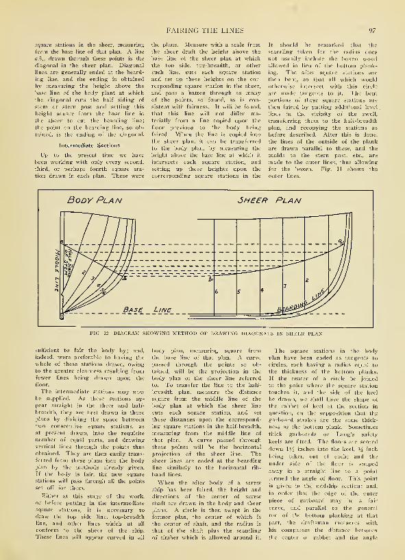
FAIRING THE LINES 97
square stations in the sheer, measuring
from the base line of that plan. A line
aj>i, drawn through these points is the
diagonal in the sheer plan. Diagonal
lines are generally ended at the beard-
ing line, and the ending is obtained
by measuring the height above the
base line of the body plant at whichthe diagonal cuts the half siding of
stem or stern post and setting this
height square from the base line in
1he sheer to cut the bearding line;
the point on the bearding line, so ob-
tained, is the ending of the diagonal.
Intermediate Sections
Up to the present time we have
been working with only every second,
third, or perhaps fourth square sta-
tion drawn in each plan. These were
the plans. Measure with a scale fromthe sheer draft the height above the
base line of the sheer plan at which
the top side, top-breadth, or other
such line, cuts each square station
and set up these heights on the cor-
responding square station in the sheer,
and pass a batten through as manyof the points, so found, as is con-
sistent with fairness. It will be found,
that this line will not differ ma-terially from a line copied upon the
floor previous to the body being
faired. When the line is copied into
the sheer plan, it can be transferred
to the body plan, by measuring the
height above the base line at which it
intersects each square station, and
setting up these heights upon the
corresponding square stations in the
It should be remarked that the
scantling taken for the radius does
not usually include the boxen woodallowed in lieu of the bottom plank-
ing. The after square stations are
then bent, so that all which wouldotherwise intersect with this circle
are made tangents to it. The bent
portions of these square stations are
then faired by putting additional level
,
lines in the vicinity of the swell,
transferring them to the half-breadth
plan, and recopying the stations as
before described. After this is done,
the lines of the outside of the plank
are drawn parallel to these, and the
molds to the stern post, etc., are
made to the outer lines, thus allowing
for the boxen. Fig. 11 shows the
outer lines.
r~
HOW WOODEN SHIPS ARE LAID OFF
of floor in the midship section; and
with the former point as a center,
sweeps a circular arc in the body
plan to cut the square stations at
points, each of which will be the angle
of floor for that section. The shape
of the floor for each section is then
obtained, by joining a point V/2 inches
below the upper part of keel with the
angle of floor at that section. It will
be observed that, as the stations get
more perpendicular forward and aft,
the lines of the underside of floors,
as thus drawn merge into the curves
of the frames until the angle dis-
appears. Sometimes only the square
body frames have been treated in this
way; the timbers of what is termed
the cant body, which we shall con-
sider in a future chapter, being made
to heel against the bearding line.
Hence, below the angle of floor, these
timbers have projected beyond those
ot the square body. Of course, this
has only been the case when the cant
body has commenced nearer amid-
ships, than where the angle of floor
has merged into the curvature of the
frames. A fair surface has been given
to the ship's bottom in such a case,
either by scoring the garboard plank
over this projection, or by putting the
garboards in two thicknesses, the inner
of which has flushed the surface be-
fore the outer was put on.
The cutting down line is the line
of the upper side of the floors at the
middle line in the square body, and
of the upper side of the heels of the
timbers in the cant body. It should
now be drawn.
The position of this line is governed
by the shape of the body and the
molding of the timbers. It is usually
obtained by setting in square to the
surface at each square station in the
body plan, the molding of the timber
at its ending, to where that distance
cuts the half siding of either stem
deadwood or stern post, according
to the situation of the ending. Such
a point will be the height of cutting
down at that square station, that is,
the minimum height to which the
deadwood need come in order
to completely house the heel
of the timber in the cant body; it
is also the top of the floors, at middle
line, in the square body. Points such
as these are obtained for each square
station in the body plan, then these
heights are transferred to the cor-
responding stations in the sheer plan;
and a line drawn through the points
so obtained gives the cutting downline.
We have just stated that the mold-
ings of the timbers are set in square
to the surface of the ship. Now, at
amidships, it will be sufficient if wemerely set the molding of the timber
in a direction square to the curve
of the station; but at the extremities,
especially in a bluff ship, it is evi-
dent that the distance thus set in
would be considerably less than the
actual thickness of the timber; wehave therefore to obtain the accurate
molding of the timber in the plane
of the square station, before we can
draw in a correct cutting down line
at the extremities. Such moldings,
from a practical point of view, are
difficult to obtain perfectly accurate.
Just as the bearding line is the
line of the endings of the outer sides
of the timbers, so the cutting downline is that of their inner sides. Theyare, in fact, respectively, the traces
of the planes of the side of stem,
stern post, and deadwood with the
outer and inner surfaces of the frame
timbers. In proportion, then, as the
ship is full or sharp at her extremi-
ties, so will these lines be near to
each other or far apart. Now, as a
sufficient molded width of stem,
apron, stern post, deadwood, etc., is
required to provide heeling and se-
curity to the cant, frames, il is evident
that the cutting down line will reg-
ulate the dimensions of the fore and
after ends of the backbone of the
ship. The deadwood usually projects
about 1 inch beyond the cutting
down line, but in some instances,
\\ hen the ships have been very sharp,
it has been found necessary to re-
duce the molded width of the dead-
wood in order to save weight, by
allowing the cutting down line to run
along the keelson, and thus partially
heeling the cants against the latter;
this, however, should be avoided whenpossible, as the keelson is considerably
weakened by receiving the bolts from
the heels of the timbers.
Even before we have arrived at
this stage of the work, the drawing
on the floor is sufficiently advanced
for molds to be made for the frames
o? the square body, and other in-
formation to be supplied from it, by
means of which the workmen can
begin to prepare many of the timbers
of the ship.
IndexPage
Accidents, Methods of Avoiding, During Vessel
Construction 75
After Body, Drawing the, on the Mold-Loft Floor 41, 91
After End of the Ship, Framing of the 54
Air Seasoned Material, Average Strength Values for
Structural Timbers 9
Apron, Definition of 47, 50
Arch Strapping, Employment of 45
Assembling the Frame Sections 44
Axioms and Definitions 89
Page
Carrying Capacity of Wooden Ships of Standard
Pacific Coast Type 32
Caulking the Deck 81
Ceiling, Laying the 71
Cost of Equipment and Buildings for Small Shipyard 19
Cranes Used in Shipyard Work 22
Cross Section of Typical Wooden Ship 3
Cutting-Down Line, Drawing in the 98
Ballin, Fred A., Advanced Form of Construction,
Designed by 5
Ballin, Fred A., Design of Steel Strapping WorkedOut by 26
Ballin, Fred A., Description of 4000-Ton Motor Ship,
Designed by 30
Batten, Use of, in Preparing the Molds 41
Battens, Use of, in Trimming the Timbers 51
Beam, Taking the Snape of a 80
Beams, Efficiency of Hold and Main Deck 73
Beams, Marking in the Line of the 80
Beams, Rasing in the Line for the 79
Beams, Two-Fold Service of, in Deck Construction.. 78
Bearding Line, Drawing in the 92
Bearding of the Rudder Post 83
Beveling Machine, Designed by Stetson Machine
Works, Description of 71
Beveling of Rudder Stocks 84
Beveling the Timbers 53
Body Plans, Copying the 91
Body Plan of a Vessel, Copying the, onto the Mold-
Loft Floor 46
Bow Construction of Modern Wooden Ships 47
Box for Softening Planks 67
British Architect on the Double Diagonal Planking
System 30
Building Slips, Preparing the 33
Buildings Necessary for Shipyard 18
Buttock Lines, Importance of 57
Butts, Disposition of, in Planking 66
Deadwood, Arrangement of the
Deadwood, Heeling to the 45,
Deck Beams, Two Different Forms of Construction...
Deck Elements, Construction of
Deck Finishing, Arranging for the
Deck Fittings for Wooden Ship
Deck Planks, Laying the
Definitions and Axioms
Derricks Used in Shipyard WorkDesign and Layout of Shipyard
Design for Typical Wooden Vessel
Design of a 4000-ton Motor Ship, Built by Supple &Ballin
Diagonal System of Planking
Diagonals, Projection of, on the Sheer Plan
Dollies for Use in Shipyard WorkDouglas Fir, Average Strength Value for...:
Drift-Bolts as Fastenings
Dubbing-Off the Outer Surface of the Ship
Edge Bolting as a Means of Fastening Elements
Together 13
Elliptical Stern, Construction of 61
Engine Foundations in Wooden Ships, Preparation of 85
Engines, Cost of Installing Oil, in Modern Motor Ship 86
Entrance to Vessel During Construction 75
Equipment Necessary for Shipyard 19
Exit to Vessel During Construction 75
Fairing, a Contracted Method of 96
Cant Frames, Securing the, to the Keel and Deadwood 50 Fairing the Line 92
Carlings, Definition of 78 Fairing the Ship 41, 90
99
100 HOW WOODEN SHIPS ARE BUILT
Page
Fantail Stern, Construction of 61
Fastening for Planking 67
Fastening Sawed Frame Futtocks Together 44
Fastenings in Ship Construction 13
Fastenings, Use of Metal 67
Ferris, Theodore E., Steel Strapping, as Designed by 26
Fibre Stress for Fir or Pine 10
Fir, Preparing Douglas, for Use 8
Fir, Production of Douglas, in the United States
in 1915 7
Fir, Typical Properties of Douglas 8
Fore Body, Drawing the, on the Mold-Loft Floor.. 41, 91
Formula for Estimating Carrying Capacity of
Wooden Ships 32
Forward End of Ship, Methods of Framing 47
Frame, Assembling the 44
Frame of Modern Wooden Vessel, Specifications of
Timbers Needed for 43
Frame Timbers, Marking and Sawing the 44
Frame, Raising the, into Position 44
Framing the After End of the Ship 54
Framing the Ship, Time Required for 43
Framing the Vessel 38
Futtocks, Assembling the 44
Geometry, Application of, to Shipbuilding 87
Grays Harbor Shipbuilding Co., Description of Stand-
ard 5-Masted Auxiliary Schooner, Built by 29
Great Lakes Type of Wooden Vessel, Description of 26
Green Lumber, Average Strength Value for Structural
Timbers 9
Half-Breadth Plan, Copying the, on the Mold-Loft
Floor 43, 91, 92
Hang, Determining the Amount of 70
Hatch Construction in a 4000-ton Wooden Steamer... 30
Hatchways, Formation of the 80
Head Frames, Definition of 47
Heeling to the Deadwood 45, 47
Hoisting Equipment Necessary in Shipyard 19
Hold Bracing, Construction of 73
Hold for the Frame Sections, Preparing the 41
Hold Stanchions, Methods for Framing 73
H orning the Frame 45
Hulls, Weaknesses of Wooden 3
Hull Weights of a Motor Schooner 32
Page
Keelson Construction in a 4000-ton Wooden Steamer 30
Keelson, Construction of 71
Keelson Construction on a Typical Pacific CoastVessel 29
Kirby, Frank E., Method of Construction, Patented by 5
Knees, Types of 80
Knightheads, Definition of 47
Knuckle of an Elliptical Stern 61
Labor Necessary on Planking Job 67
Labor on the Job, Economy of not Overcrowding. . . 32
Launching of Wooden Ships 86
Launching Ways, Preparing the, for the Construction
of the Ship : 33
Laying Off the Ship 41, 87
Layout of Shipyard 18
Loblolly Pine, Average Strength Values for 9
Logging Operations on the Pacific Coast 8
Long-Leaf Pine, Average Strength Value for 9
Lumber Cut in the United States for 1915 by States 10
Lumber, No. 1 Common, Specifications for Standard
Grade 10
Lumber Production for 1915 in the United States 7
Lumber Supply in Canada 2
Lumber Supply in the United States 2
Lumbering Operations on the Pacific Coast 8
Mast Pole, Framing of 80
Masts, Advantages of Using Steel 83
Men Necessary on Planking Job, Number of 67
Men on the Job,, Economy of not Overcrowding.... 32
Mold-Loft, Laying Off the Ship on the 91
Molding the Curved Shape of the Timbers 52
Motor Ship, Description of a Full-Powered 4000-ton,
of Standard Pacific Coast Type 29
Motor Ship, Description of 4000-ton, Designed by
Fred A. Ballin 30
Motive Power Necessary for Propulsion 3
Oil Engines, Advantages of, in Fuel Economy 2
Oil Engines, Cost of Installing, in Modern Motor
Ships 86
Ordinates, Use of Table of 91
Internal Combustion Motors, Advantages of, in Fuel Pacific Coast Type of Wooden Vessel, Description
Economy 3 of Standard 29
Painting of Wooden Ships 86
Parabolic Stern, Construction of 61
Pine, Production of Southern Yellow in the United
Keel Blocks, Laying the 33 States in 1915 7
Keel, Laying the 38 Pine, Typical Properties of Southern Yellow 7

INDEX 101
Page
Pintles, Placing of the Rudder 83
Planking of the Ship 64
Planking System, Double Diagonal 30
Planks, Putting on the 67
Power for Wooden Ships 2
Preservatives, Application of 8
Quarter-Block in Stern Construction. 63
Rabatting, Definition of 89
Rabbet, Determining the Base by the Lower Edge of 91
Rectangular Construction of Wooden Ships, Weak-
nesses in 3
Reinforcement of Wooden Vessels 5
Ribbands for Holding the Frame Together 44
Roughing Out the Timber 44
Routing Material Through Shipyards 18
Rudder and Rudder Post, Raising of the 62
Rudder Stock, Coning of the 83
Saw Outfit for Shipyard Use 22
Scarfing of the Shelf Timers 75
Scarfing Together Section of the Keel 38
Schooner, Description of Standard Type Wooden.... 29
Selected Common, Specifications for 10
Shaft Logs, Arrangement of 85
Shaping Timbers for Ship Construction 13
Sheer-Draft, Preparation of the 41
Sheer Plan, Copying the 91
Sheer Plan, Projection of Diagonals on the 96
Shelf, Construction of 75
Ship Timbers, Grades and Characteristics of 7
Shipyard, Cost of Equipment for Small 19
Shipyard, Design and Layout of 18
Shipyards, Cost of Building for Small 19
Shipyards, Factors Governing Selection of the Site.. 15
Shrinkage of Douglas Fir 8
Siding the Timber 52
Site for Shipyard, Factors Governing the Selection of... 15
Skidding Equipment Necessary in Shipyard 19
Slips, Preparing the Building 33
Snape of a Beam, Taking the 80
Sny, Determining the Amount of 70
Southern Practice in Framing 44
Spars, Preparation of 83
Specifications for No. 1 Common and Selected
Common 10
Spikes, Use of, as Fastenings 13
Spiling Batten, for Determining Sny and Hang 70
Square Stern, Timbering of the 54
Steamer, Cross Section Details of 4000-ton Wooden 29
Steel Reinforcement for Wooden Vessels 5, 23
Steel Reinforcing on a Typical Pacific Coast Vessel 29
Pace
Steel Strapping for Wooden Ships 26
Stem, Building Up the 47
Stem, Fastening of the, to the Keel 53
Stern, Different Types of 54
Stern Framing, Details of 54
Stern Post, Raising the, into Place 62
.Stern Tube, Arrangement of 85
Stetson Machine Works, Description of Beveling
Machine, Designed by 71
Strake of Planks, Determining the Amount of Sny or
Hang in a 70
Strakes, Arrangement of the Planking in 64
Strapping, Steel, for Wooden Ships 26
Strength Values for Structural Timbers, Average.... 9
Stress, Fibre, for Fir or Pine 10
Structural Timbers, Average Strength Values for.... 9
Supple & Ballin, Arrangements for Routing at the
Plant of 18
Timber in the United States and Canada, Total Supply
of Merchantable 2
Timbers, Trimming the 50
Tools for Shipyard Work 22
Tools Used in Shaping Timbers 13
Transom Stern, Timbering of the 54
Treenails and Fastenings for Planking 67
Treenails, Use and Efficiency of 13
Trimming of Timbers 50
Types of Wooden Vessels, Details of Different 23
Typical Properties of Southern Pine and Douglas Fir 7
Typical Wooden Vessel Stern 3
United States Emergency Fleet Corporation, Descrip-
tion of Vessels Similar to Those Designed for.... 26
Ward, M. R., System of Steel Strapping as Designed
by 26
Ways, Preparing the, for the Construction of WoodenShips 33
Weights of Timber 8
Weights of Various Items in a Wooden Ship 32
Western Hemlock, Average Strength Values for 9
White, W. A., On the Merit of the Double Diagonal
Planking System 30
Wooden Hulls, Weaknesses Inherent in 3
Wooden Ships, Description of Three Typical 26
Wooden Ships, the Outboard Profiles and Deck Plans
of Standard Type of 27
Wooden Vessels, Details of Different Types of 23
Woodworking Machinery for Shipyard Use 22
Yard, Cost of Building for Small Ship 19
Yard, Cost of Equipment for Small Ship 19
Yards, Factors Governing the Selection of the Site of... 15


11 Wr^^o
lY^rtfc &^uv


SMITHSONIAN INSTITUTION LIBRARIES
3 9088 00797 6509
vi-i;illfll§
SflilS