Experimental determination of axial compressive strength of crimped cold-formed channels
10
Experimental determination of axial compressive strength of crimped cold-formed channels Anjan Kanti Bhowmick, Cindy Kumalasari, Anant Varkekar, Murty K.S. Madugula * Department of Civil and Environmental Engineering, University of Windsor, Windsor, Ont., Canada N9B 3P4 Received 7 July 2004; received in revised form 29 July 2004; accepted 14 October 2004 Available online 8 December 2004 Abstract This paper presents experimental axial compressive failure loads of 33 cold-formed regular channels and 51 cold-formed crimped channels varying in sizes, lengths, and end conditions. Strain gauges and mechanical dial gauges were used during the centering of the specimens in the test frame. For some specimens, the failure loads of regular channels were greater than those of the crimped channels. In other cases, the crimped channels were stronger. Therefore, statistical analysis (Student’s t-test) was carried out and the null hypothesis that there is no difference between the compressive strength of regular and crimped channels was accepted at 0.01 significance level. Thus, the compressive strength of crimped channels can be calculated using the formulas applicable for regular channels. q 2004 Elsevier Ltd. All rights reserved. Keywords: Axial compressive strength; Cold-formed; Crimped channel; Open web steel joist; Regular channel 1. Introduction Cold-formed structural members are used increasingly in a wide range of lightweight construction, including steel-framed residential houses and low-rise office buildings. Cold-formed open web steel joists are generally fabricated using double angles as chord members and channels as diagonal members. To facilitate the connection of the channel to 0263-8231/$ - see front matter q 2004 Elsevier Ltd. All rights reserved. doi:10.1016/j.tws.2004.10.004 Thin-Walled Structures 43 (2005) 543–552 www.elsevier.com/locate/tws * Corresponding author. Tel.: C1 519 253 3000x2559, fax: C1 519 971 3686. E-mail address: [email protected] (M.K.S. Madugula).
-
Upload
independent -
Category
Documents
-
view
0 -
download
0
Transcript of Experimental determination of axial compressive strength of crimped cold-formed channels
Experimental determination of axial compressive
strength of crimped cold-formed channels
Anjan Kanti Bhowmick, Cindy Kumalasari, Anant Varkekar,Murty K.S. Madugula*
Department of Civil and Environmental Engineering, University of Windsor, Windsor, Ont., Canada N9B 3P4
Received 7 July 2004; received in revised form 29 July 2004; accepted 14 October 2004
Available online 8 December 2004
Abstract
This paper presents experimental axial compressive failure loads of 33 cold-formed regular
channels and 51 cold-formed crimped channels varying in sizes, lengths, and end conditions. Strain
gauges and mechanical dial gauges were used during the centering of the specimens in the test frame.
For some specimens, the failure loads of regular channels were greater than those of the crimped
channels. In other cases, the crimped channels were stronger. Therefore, statistical analysis
(Student’s t-test) was carried out and the null hypothesis that there is no difference between the
compressive strength of regular and crimped channels was accepted at 0.01 significance level. Thus,
the compressive strength of crimped channels can be calculated using the formulas applicable for
regular channels.
q 2004 Elsevier Ltd. All rights reserved.
Keywords: Axial compressive strength; Cold-formed; Crimped channel; Open web steel joist; Regular channel
1. Introduction
Cold-formed structural members are used increasingly in a wide range of lightweight
construction, including steel-framed residential houses and low-rise office buildings.
Cold-formed open web steel joists are generally fabricated using double angles as chord
members and channels as diagonal members. To facilitate the connection of the channel to
Thin-Walled Structures 43 (2005) 543–552
www.elsevier.com/locate/tws
0263-8231/$ - see front matter q 2004 Elsevier Ltd. All rights reserved.
doi:10.1016/j.tws.2004.10.004
* Corresponding author. Tel.: C1 519 253 3000x2559, fax: C1 519 971 3686.
E-mail address: [email protected] (M.K.S. Madugula).
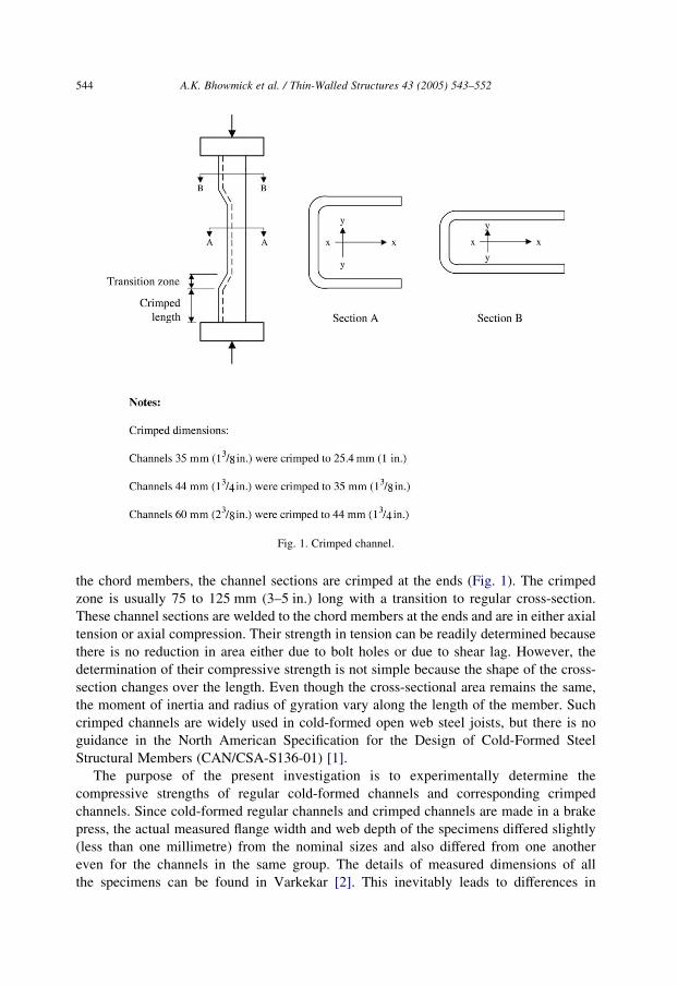
Fig. 1. Crimped channel.
A.K. Bhowmick et al. / Thin-Walled Structures 43 (2005) 543–552544
the chord members, the channel sections are crimped at the ends (Fig. 1). The crimped
zone is usually 75 to 125 mm (3–5 in.) long with a transition to regular cross-section.
These channel sections are welded to the chord members at the ends and are in either axial
tension or axial compression. Their strength in tension can be readily determined because
there is no reduction in area either due to bolt holes or due to shear lag. However, the
determination of their compressive strength is not simple because the shape of the cross-
section changes over the length. Even though the cross-sectional area remains the same,
the moment of inertia and radius of gyration vary along the length of the member. Such
crimped channels are widely used in cold-formed open web steel joists, but there is no
guidance in the North American Specification for the Design of Cold-Formed Steel
Structural Members (CAN/CSA-S136-01) [1].
The purpose of the present investigation is to experimentally determine the
compressive strengths of regular cold-formed channels and corresponding crimped
channels. Since cold-formed regular channels and crimped channels are made in a brake
press, the actual measured flange width and web depth of the specimens differed slightly
(less than one millimetre) from the nominal sizes and also differed from one another
even for the channels in the same group. The details of measured dimensions of all
the specimens can be found in Varkekar [2]. This inevitably leads to differences in

A.K. Bhowmick et al. / Thin-Walled Structures 43 (2005) 543–552 545
the ultimate compressive strength. A total of 84 specimens were included in the
investigation and statistical analysis was used to determine whether there is any significant
difference in the compressive strength between regular and corresponding crimped
channels.
2. Experimental investigation
Axial compressive tests were conducted on 84 regular and crimped channels with
five different sizes C 35!3, C 35!4, C 44!38!4, C 44!5, and C 60!51!5 mm
(C 13/8!0.118, C 13/8!0.157, C 13/4!11/2!0.157, C 13/4!0.197, C 23/8!2!0.197 in.). The lengths of the specimens varied from 762 to 2438 mm (30 to 96 in.). The
slenderness ratios L/r (where ‘L’ is the length of the specimen and ‘r’ is the minimum
radius of gyration based on the nominal dimensions) varied from 68 to 182. The details of
the specimens are given in Tables 1(a)–(c). Three end conditions (pinned-end, flat-end,
and welded-end) were included in the investigation. Since the specimens were fabricated
by shearing, each specimen was milled at both ends by a milling machine to an accuracy of
0.01 mm to ensure full contact between the specimen and the end bearing.
Table 1(a)
Experimental failure loads of regular and crimped channels with pinned-end condition
No. Section (mm
(in.))
Specimen
length (mm
(in.))
Regular channels Crimped channels
Specimen ID Failure load
kN (kips)
Specimen ID Failure load
kN (kips)
1 C 35!3 (C
13/8!0.118)
762 c14 41 cr2 36*
(30) (9.2) cr21 (8.1)
1981 c16a 13 cr4 15
(78) (2.9) (3.4)
2 C 35!4 (C
13/8!0.157)
762 c18 51 cr6 60*
(30) (11.5) cr23 (13.5)
1372 c19 26 cr7 28*
(54) (5.8) cr24 (6.3)
1981 c20 19 cr8 20
(78) (4.3) (4.5)
3 C 44!38!
4 (C 13/4!
11/2!0.157)
1676 c23 32 cr11 35*
(66) (7.2) cr26 (7.9)
4 C 44!5 (C
13/4!0.197)
1118 c26 99 cr14 106*
(44) (22.3) cr27 (23.8)
1676 c27 71 cr15 67*
(66) (16.0) cr28 (15.1)
5 C 60!51!
5 (C 23/8!
2!0.197)
1981 c31 68 cr19 75*
(78) (15.3) cr30 (16.9)
Total number of specimens 9 16
*Average for two specimens.

Table 1(b)
Experimental failure loads of regular and crimped channels with flat-end condition
No. Section
(mm (in.))
Specimen
length
(mm (in.))
Regular channels Crimped channels
Specimen ID Failure load
kN (kips)
Specimen ID Failure load
kN (kips)
1 C 35!3 (C
13/8!0.118)
762 c14 75 cr2 73*
(30) (16.9) cr21 (16.4)
1372 c15 53 cr3 48*
(54) (11.9) cr22 (10.8)
1981 c16 39 cr4 38
(78) (8.8) (8.5)
2 C 35!4 (C
13/8!0.157)
762 c18 117 cr6 131
(30) (26.3) (29.5)
1372 c19 82 cr7 73*
(54) (18.4) cr24 (16.4)
3 C 44!38!
4 (C 13/4!11/2!0.157)
1676 c23 102 cr11 93*
(66) (22.9) cr26 (20.9)
2235 c24a 79* cr12a 68*
4 C 44!5 (C
13/4!0.197)
(88) c24b (17.8) cr12b (15.3)
1676 c27 150 cr15 148*
(66) (33.7) cr28 (33.3)
2235 c28a 112* cr16a 100*
(88) c28b (25.2) cr16b (22.5)
5 C 60!51!
5 (C 23/8!2!0.197)
1524 c30 201 cr18 190*
(60) (45.2) cr29 (42.7)
1981 c31 185 cr19 164*
(78) (41.6) cr30 (36.9)
2438 c32a 138* cr20a 141*
(96) c32b (31.0) cr20b (31.7)
Total number of specimens 15 22
*Average for two specimens.
A.K. Bhowmick et al. / Thin-Walled Structures 43 (2005) 543–552546
2.1. Details of specimens
The specimen identification number, the size, and length are given in Tables 1(a)–(c)
for pinned-end, flat-end and welded-end conditions respectively. Regular channel
specimens had the prefix ‘c’, whereas crimped specimens had the prefix ‘cr’.
2.2. Test set-up
As mentioned earlier, the specimens were tested under three different end conditions—
pinned-end condition, flat-end condition, and welded-end condition. In the first case, the
pinned-end condition was achieved using an assembly of plates and knife-edges. Each end
was made up of an assembly consisting of three plates separated by two knife-edges. The
middle plate contained two 1208 V-grooves, one on the top face and the other on
the bottom face. These grooves were made perpendicular to each other in order to make
the buckling length of the specimen the same in the two orthogonal directions. The top and
bottom plates contained 900 V-grooves on the side facing the middle plate. The top and
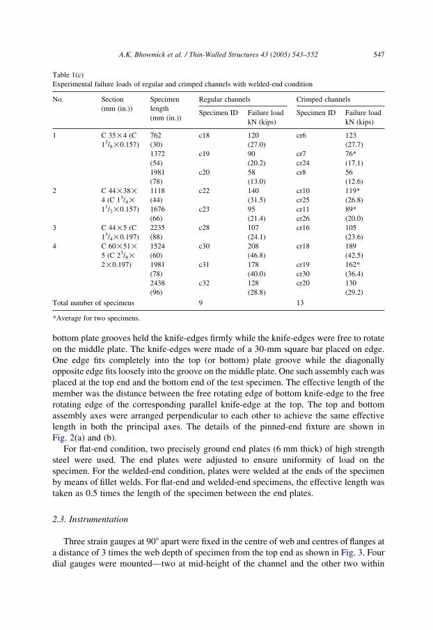
Table 1(c)
Experimental failure loads of regular and crimped channels with welded-end condition
No. Section
(mm (in.))
Specimen
length
(mm (in.))
Regular channels Crimped channels
Specimen ID Failure load
kN (kips)
Specimen ID Failure load
kN (kips)
1 C 35!4 (C
13/8!0.157)
762 c18 120 cr6 123
(30) (27.0) (27.7)
1372 c19 90 cr7 76*
(54) (20.2) cr24 (17.1)
1981 c20 58 cr8 56
(78) (13.0) (12.6)
2 C 44!38!
4 (C 13/4!
11/2!0.157)
1118 c22 140 cr10 119*
(44) (31.5) cr25 (26.8)
1676 c23 95 cr11 89*
(66) (21.4) cr26 (20.0)
3 C 44!5 (C
13/4!0.197)
2235 c28 107 cr16 105
(88) (24.1) (23.6)
4 C 60!51!
5 (C 23/8!
2!0.197)
1524 c30 208 cr18 189
(60) (46.8) (42.5)
1981 c31 178 cr19 162*
(78) (40.0) cr30 (36.4)
2438 c32 128 cr20 130
(96) (28.8) (29.2)
Total number of specimens 9 13
*Average for two specimens.
A.K. Bhowmick et al. / Thin-Walled Structures 43 (2005) 543–552 547
bottom plate grooves held the knife-edges firmly while the knife-edges were free to rotate
on the middle plate. The knife-edges were made of a 30-mm square bar placed on edge.
One edge fits completely into the top (or bottom) plate groove while the diagonally
opposite edge fits loosely into the groove on the middle plate. One such assembly each was
placed at the top end and the bottom end of the test specimen. The effective length of the
member was the distance between the free rotating edge of bottom knife-edge to the free
rotating edge of the corresponding parallel knife-edge at the top. The top and bottom
assembly axes were arranged perpendicular to each other to achieve the same effective
length in both the principal axes. The details of the pinned-end fixture are shown in
Fig. 2(a) and (b).
For flat-end condition, two precisely ground end plates (6 mm thick) of high strength
steel were used. The end plates were adjusted to ensure uniformity of load on the
specimen. For the welded-end condition, plates were welded at the ends of the specimen
by means of fillet welds. For flat-end and welded-end specimens, the effective length was
taken as 0.5 times the length of the specimen between the end plates.
2.3. Instrumentation
Three strain gauges at 908 apart were fixed in the centre of web and centres of flanges at
a distance of 3 times the web depth of specimen from the top end as shown in Fig. 3. Four
dial gauges were mounted—two at mid-height of the channel and the other two within

Fig. 2. (a) Sketch of end fixture for pinned-end condition. (b) Photograph of end fixture for pinned-end condition.
A.K. Bhowmick et al. / Thin-Walled Structures 43 (2005) 543–552548

Fig. 3. Schematic of test set-up.
A.K. Bhowmick et al. / Thin-Walled Structures 43 (2005) 543–552 549
3 mm (1/8 in.) of the strain gauge locations (one each at the centre of web and centre of
flange). With the help of the strain gauge and dial gauge readings, it was possible to verify
whether the loading was concentric axial or not.
2.4. Testing
The alignment of the specimen was the important step to be carried out before testing a
centrally loaded specimen. The condition of alignment was judged from the readings
obtained from the strain gauges applied to the specimen. Due to the unavoidable
dimensional imperfections and the practical difficulty of precise alignment, concentric
axial loading could not be achieved. This had the effect of reducing the experimental
failure load from the theoretical failure load based on perfectly straight concentrically
loaded column. A 222 kN (50 kips) calibrated load cell was used to measure the load. The
axial load was applied slowly with an increment of about one-twentieth of the expected
ultimate capacity of the specimen. Smaller increments were used near the failure load of
the specimen. Figs. 4 and 5 show the flat-end and welded-end specimens during testing.
2.5. Experimental failure loads
The failure loads of the test specimens are presented in columns 5 and 7 of Tables 1(a)–
(c) for pinned-end, flat-end and welded-end conditions respectively. When there are two
specimens in one group, the average failure load for the two specimens is given. To
illustrate the crimping effect, regular and crimped channels of same size and length are
paired together. All specimens failed in the torsional-flexural buckling mode.
2.6. Test on tensile coupons
Tension tests were carried out according to standard ASTM procedures on 39
tensile coupons taken from the webs of the test specimens. Yield strength, tensile

Fig. 4. Flat-end specimen under testing.
A.K. Bhowmick et al. / Thin-Walled Structures 43 (2005) 543–552550
strength, and percent elongation of the material used in the investigation were
determined. The average yield strength was determined to be 461 MPa, while the
average tensile strength was 537 MPa, and the average percent elongation over 50 mm
(2 in.) gauge length was 28%. The details of the tension tests on coupons are given in
Varkekar [2].
3. Statistical analysis
A study of failure loads in Tables 1(a)–(c) shows that regular channels were stronger
than crimped channels in some cases. In other cases, crimped channels were stronger.
There is no definite trend that can be observed in the test data. Therefore, it is hypothesized
that there is no significant difference between the compressive strengths of regular
channels and crimped channels. To test the validity of this null hypothesis, Student’s t-test
was performed. The level of significance alpha was chosen as 0.01, so that there is a 1%
probability of Type I error if it is assumed that the compressive strengths of regular and
corresponding crimped channels are the same. There are 30 paired data of failure loads
(nine paired data each for pinned-end condition and welded-end condition, and 12 paired
data for flat-end condition), giving the degrees of freedom of system of 29. The t-value for
the experimental data was 2.502 against the tabulated t-value of 2.756 for an alpha of 0.01
and degrees of freedom of 29. Since experimental t-value is less than the tabulated t-value,
the null hypothesis is accepted. The failure loads of regular channels can be calculated
using the classical elastic and inelastic buckling formulas and since there is no statistical
difference in the failure loads of regular channels and crimped channels, it is concluded

Fig. 5. Welded-end specimen under testing.
A.K. Bhowmick et al. / Thin-Walled Structures 43 (2005) 543–552 551
that classical elastic and inelastic buckling formulas are also applicable to calculate the
failure loads of crimped channels.
4. Conclusion
From tests on 33 regular channels and 51 crimped channels with three different end
conditions described in the paper, it can be concluded that crimping has no significant
effect on the compressive strength of channels at 0.01 significance level and the formulas
applicable to regular channels can also be used to determine the strength of crimped
channels with 1% probability of making Type I error.

A.K. Bhowmick et al. / Thin-Walled Structures 43 (2005) 543–552552
Acknowledgements
The authors wish to acknowledge CANAM MANAC GROUP, Montreal, Que., for
donating the test specimens to the University of Windsor. Financial support provided by
the Natural Sciences and Engineering Research Council Canada is gratefully
acknowledged.
References
[1] Canadian Standards Association. North American Specification for the Design of Cold-Formed Steel
Structural Members: CAN/CSA-S136-01. Mississauga, Ont., Canada; 2002.
[2] Varkekar A. Compressive resistance of crimped channels. MASc Thesis. Department of Civil and
Environmental Engineering, University of Windsor. Windsor, Ont., Canada; 1999.