Behaviour of Cold Formed Light Gauge Steel Angle Columns ...
13
International Journal of Engineering and Advanced Technology (IJEAT) ISSN: 2249 – 8958, Volume-8 Issue-6, August 2019 384 Published By: Blue Eyes Intelligence Engineering & Sciences Publication Retrieval Number E7733068519 /2019©BEIESP DOI: 10.35940/ijeat.E7733.088619 Behaviour of Cold Formed Light Gauge Steel Angle Columns Subjected To Eccentric Loading Busanaboyina Jagadish Chakravarti, Bhamidipati Sai Krishna Abstract: Coldformed steel is an exceptional engineering material for residential and commercial applications because of its inherent structural efficiency obtained by hot and cold bending and its wide range of prefabricated geometries.A lot of research has been done to study the structuralbehaviour of light gauge axially loaded steel angle columns. The study of cold formed light gauge steel angle columns subjected to eccentric load is to be required to know its performance in the place of hot rolled steel columns. The load is varying from shear centre to centre of gravity of angle section. The study of such columns can be done experimentally with varying thickness and b/t ratios by taking fixed-hinged end condition and the same can be validated in the finite element model by using ABAQUS / CAE 6.14 finite element softwareto find the buckling behaviour of different columns Keywords: Cold formed steel, Angle columns, eccentric loading, buckling behaviour, finite element analysis, ABAQUS etc. I. INTRODUCTION Light gauge steel individuals are cold-framed from steel sheets or strips. The thickness for surrounding individuals, for example, shafts, studs, joists, and so on by and large changes from 1.2 to 4.0mm.for floor divider boards and, for long range rooftop deck thickness shifts from 1.2 to 2.5mm, and for standard rooftop deck and divider claddings extending from 0.8 to 1.2mm. These limits compares to typical structure practice, yet ought not be comprehended to confine the utilization of material of littler or bigger thickness. In India cold shaped steel individuals are broadly utilized in transport body development, railroad mentors, and so forth and the thickness of such individuals fluctuates from 1.0 to 3.2mm Shaping is done in press brakes or by cool rolling. Light check individuals can be either cool framed in rolls or by press brake from level steel commonly not thicker than 12.5mm.For tedious large scale manufacturing they are framed most financially by chilly rolling while little amounts of extraordinary shapes are most monetarily delivered on press brakes. The last procedure with its incredible flexibility of shape variety makes this kind of development as versatile to uncommon prerequisites as strengthened cement is in its field use. By and by light measure individuals are created in India both by press stopping mechanism (for little amounts) and by cold- framing (for huge quantities).These individuals are fortified together for the most part by spot welds, cold riveting and by special fasteners Revised Manuscript Received on August 05, 2019. BusanaboyinaJagadishChakravarti, Assistant professor, Department of Civil Engineering, V R Siddhartha Engineering CollegeVijayawada BhamidipatiSai Krishna – Structural Engineer, Vijayawada The cold formed angle sections areutilized for basic surrounding in transmission line towers, Steel supports and low ascent structures. II. ADVANTAGES OF COLD FORMED STEEL SECTIONS Cold forming results in an increase in the yield stress of the steel, which results from cold work in the hardening zone. These altitudes prevail in areas where the metal is bent by bending. Cold working has the effect of increasing the average yield stress from 15 to 30% for design purposes, the yield stress can then be considered increased to a minimum of 15%. Here are some of the main advantages of cold-rolled steel sections over their hot-rolled counterparts. a) The transverse shapes are framed to close resiliences and these can be rehashed always during the fundamental time b) Cold rolling can produce almost any shape and any length A high strength-to-weight ratio is achieved with cold-rolled products c) All regular holding techniques, for example, riveting, screws, welds and glues might be utilized d) They are generally lightweight, facilitating easy transportation and assembly III. NON – LINEARITY Non-linear auxiliary issues incorporate the variety of solidness of the structure with the adjustment in twisting and the materials stress-strain conduct. By and large all physical structures display non-straight conduct. Direct investigation is a proper methodology that is regularly appropriate for configuration purposes. It is clearly inadmissible for some, auxiliary re-enactments, including assembling forms, for example, fashioning or stepping; mishap examination; and investigation of elastic parts, for example, tires or motor mounts. When the reaction of the structure to a connected outside burden isn't straight, the heap versus avoidance bend won't be direct The force and displacement relation for a spring withnon-straight solidifying reaction is demonstrated as follows Figure 1: linear and nonlinear spring characteristics
-
Upload
khangminh22 -
Category
Documents
-
view
0 -
download
0
Transcript of Behaviour of Cold Formed Light Gauge Steel Angle Columns ...

International Journal of Engineering and Advanced Technology (IJEAT)
ISSN: 2249 – 8958, Volume-8 Issue-6, August 2019
384
Published By:
Blue Eyes Intelligence Engineering
& Sciences Publication
Retrieval Number E7733068519 /2019©BEIESP
DOI: 10.35940/ijeat.E7733.088619
Behaviour of Cold Formed Light Gauge Steel
Angle Columns Subjected To Eccentric Loading
Busanaboyina Jagadish Chakravarti, Bhamidipati Sai Krishna
Abstract: Coldformed steel is an exceptional engineering
material for residential and commercial applications because of
its inherent structural efficiency obtained by hot and cold
bending and its wide range of prefabricated geometries.A lot of
research has been done to study the structuralbehaviour of light
gauge axially loaded steel angle columns. The study of cold
formed light gauge steel angle columns subjected to eccentric
load is to be required to know its performance in the place of hot
rolled steel columns. The load is varying from shear centre to
centre of gravity of angle section. The study of such columns can
be done experimentally with varying thickness and b/t ratios by
taking fixed-hinged end condition and the same can be validated
in the finite element model by using ABAQUS / CAE 6.14 finite
element softwareto find the buckling behaviour of different
columns
Keywords: Cold formed steel, Angle columns, eccentric
loading, buckling behaviour, finite element analysis, ABAQUS
etc.
I. INTRODUCTION
Light gauge steel individuals are cold-framed from steel
sheets or strips. The thickness for surrounding individuals,
for example, shafts, studs, joists, and so on by and large
changes from 1.2 to 4.0mm.for floor divider boards and, for
long range rooftop deck thickness shifts from 1.2 to 2.5mm,
and for standard rooftop deck and divider claddings
extending from 0.8 to 1.2mm. These limits compares to
typical structure practice, yet ought not be comprehended to
confine the utilization of material of littler or bigger
thickness. In India cold shaped steel individuals are broadly
utilized in transport body development, railroad mentors,
and so forth and the thickness of such individuals fluctuates
from 1.0 to 3.2mm
Shaping is done in press brakes or by cool rolling. Light
check individuals can be either cool framed in rolls or by
press brake from level steel commonly not thicker than
12.5mm.For tedious large scale manufacturing they are
framed most financially by chilly rolling while little
amounts of extraordinary shapes are most monetarily
delivered on press brakes. The last procedure with its
incredible flexibility of shape variety makes this kind of
development as versatile to uncommon prerequisites as
strengthened cement is in its field use. By and by light
measure individuals are created in India both by press
stopping mechanism (for little amounts) and by cold-
framing (for huge quantities).These individuals are fortified
together for the most part by spot welds, cold riveting and
by special fasteners
Revised Manuscript Received on August 05, 2019.
BusanaboyinaJagadishChakravarti, Assistant professor,
Department of Civil Engineering, V R Siddhartha Engineering
CollegeVijayawada
BhamidipatiSai Krishna – Structural Engineer, Vijayawada
The cold formed angle sections areutilized for basic
surrounding in transmission line towers, Steel supports and
low ascent structures.
II. ADVANTAGES OF COLD FORMED STEEL
SECTIONS
Cold forming results in an increase in the yield stress of the
steel, which results from cold work in the hardening zone.
These altitudes prevail in areas where the metal is bent by
bending. Cold working has the effect of increasing the
average yield stress from 15 to 30% for design purposes, the
yield stress can then be considered increased to a minimum
of 15%.
Here are some of the main advantages of cold-rolled steel
sections over their hot-rolled counterparts.
a) The transverse shapes are framed to close resiliences and
these can be rehashed always during the fundamental time
b) Cold rolling can produce almost any shape and any length
A high strength-to-weight ratio is achieved with cold-rolled
products
c) All regular holding techniques, for example, riveting,
screws, welds and glues might be utilized
d) They are generally lightweight, facilitating easy
transportation and assembly
III. NON – LINEARITY
Non-linear auxiliary issues incorporate the variety of
solidness of the structure with the adjustment in twisting and
the materials stress-strain conduct. By and large all physical
structures display non-straight conduct. Direct investigation
is a proper methodology that is regularly appropriate for
configuration purposes. It is clearly inadmissible for some,
auxiliary re-enactments, including assembling forms, for
example, fashioning or stepping; mishap examination; and
investigation of elastic parts, for example, tires or motor
mounts. When the reaction of the structure to a connected
outside burden isn't straight, the heap versus avoidance bend
won't be direct The force and displacement relation for a
spring withnon-straight solidifying reaction is demonstrated
as follows
Figure 1: linear and nonlinear spring characteristics

Behaviour of Cold Formed Light Gauge Steel Angle Columns Subjected To Eccentric Loading
385
Published By: Blue Eyes Intelligence Engineering
& Sciences Publication
Retrieval Number E7733068519 /2019©BEIESP
DOI: 10.35940/ijeat.E7733.088619
A. Types of Nonlinearity:
Previously examining the numerical techniques, the
wellsprings of nonlinearity have been written beneath
There are three sorts of nonlinearities.
1. Geometric Non-linearity
2. Material Non-linearity
3. Boundary Non-linearity
i. Geometric Nonlinearity:
This kind of nonlinearity emerges when huge
redirection influences the reaction of the structure.
Figure 2: Large deflection of cantilever beam
Geometric nonlinearity can be three types:
a) Huge relocation and little strain conduct: this arrangement
with the diminutiveness of one of the worldwide directions
of a body exposed to stack.
b) Enormous dislodging and huge strain conduct: when
changes to all the worldwide directions of the body are
tantamount, the stress appropriation toward any path can't be
disregarded.
c) Linear stability analysis:on the off chance that because of
outer burden the body is very nearly stable balance and any
further burden will cause a flimsy harmony in the
framework, the conduct of framework can be considered as
a straight capacity of connected burden.
ii. Material non-linearity:
Material non-linearity is caused because of the nonlinear
connection among anxiety past as far as possible. Past this
point of confinement some part of the part will begin
yielding and dependent on materials, nonlinear constitutive
connection begin to react in-flexibly. This causes changes in
the firmness of the part which relies upon the material
conduct called Elasto-plastic conduct
The present work included just Elasto-Plastic
conduct.Expansion of the yield stress is alluded to as
solidifying and its reduction is called softening. Ordinarily,
numerous materials at first solidify and later mollify as
appeared in Fig.4. A plot of a stress - strain bend
characterizes material conduct.
Figure 3: Strain Hardening behaviour
In view of stress-strain graph material conduct can be
delegated
a) Perfectly plastic
b) Elasto-Plastic strain hardening
c) Elasto-plastic strain softening
B.Perfectly plastic It is the property of material for which the stress, strain
bend of the material ends up parallel to strain hub, for
example there is a huge increment in strain for constant
yield stress esteem
Figure 4: Perfectly plastic behaviour
B. Elasto-plastic strain hardening:
Materials display a trademark called work or strain
solidifying, which is fortifying of metal by plastic twisting.
The yield surface for such materials will when all is said in
done increment in size with further straining. It can likewise
be ordered into two kinds.
(i) Isotropic hardening
(ii) Kinematic hardening
i. Isotropic hardening: It is described by the growing
yield surface of same shape with expanding stress
Figure 5: Isotropic hardening behaviour
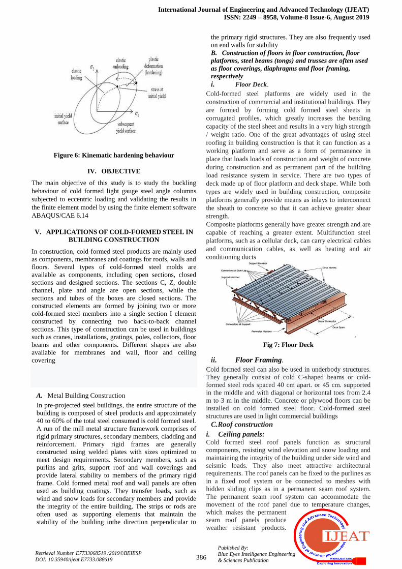
ii. Kinematic Hardening: It is described by the yield
surface of same shape and size interpreting in
stress space
International Journal of Engineering and Advanced Technology (IJEAT)
ISSN: 2249 – 8958, Volume-8 Issue-6, August 2019
386
Published By:
Blue Eyes Intelligence Engineering
& Sciences Publication
Retrieval Number E7733068519 /2019©BEIESP
DOI: 10.35940/ijeat.E7733.088619
Figure 6: Kinematic hardening behaviour
IV. OBJECTIVE
The main objective of this study is to study the buckling
behaviour of cold formed light gauge steel angle columns
subjected to eccentric loading and validating the results in
the finite element model by using the finite element software
ABAQUS/CAE 6.14
V. APPLICATIONS OF COLD-FORMED STEEL IN
BUILDING CONSTRUCTION
In construction, cold-formed steel products are mainly used
as components, membranes and coatings for roofs, walls and
floors. Several types of cold-formed steel molds are
available as components, including open sections, closed
sections and designed sections. The sections C, Z, double
channel, plate and angle are open sections, while the
sections and tubes of the boxes are closed sections. The
constructed elements are formed by joining two or more
cold-formed steel members into a single section I element
constructed by connecting two back-to-back channel
sections. This type of construction can be used in buildings
such as cranes, installations, gratings, poles, collectors, floor
beams and other components. Different shapes are also
available for membranes and wall, floor and ceiling
covering
A. Metal Building Construction
In pre-projected steel buildings, the entire structure of the
building is composed of steel products and approximately
40 to 60% of the total steel consumed is cold formed steel.
A run of the mill metal structure framework comprises of
rigid primary structures, secondary members, cladding and
reinforcement. Primary rigid frames are generally
constructed using welded plates with sizes optimized to
meet design requirements. Secondary members, such as
purlins and grits, support roof and wall coverings and
provide lateral stability to members of the primary rigid
frame. Cold formed metal roof and wall panels are often
used as building coatings. They transfer loads, such as
wind and snow loads for secondary members and provide
the integrity of the entire building. The strips or rods are
often used as supporting elements that maintain the
stability of the building inthe direction perpendicular to
the primary rigid structures. They are also frequently used
on end walls for stability
B. Construction of floors in floor construction, floor
platforms, steel beams (tongs) and trusses are often used
as floor coverings, diaphragms and floor framing,
respectively
i. Floor Deck.
Cold-formed steel platforms are widely used in the
construction of commercial and institutional buildings. They
are formed by forming cold formed steel sheets in
corrugated profiles, which greatly increases the bending
capacity of the steel sheet and results in a very high strength
/ weight ratio. One of the great advantages of using steel
roofing in building construction is that it can function as a
working platform and serve as a form of permanence in
place that loads loads of construction and weight of concrete
during construction and as permanent part of the building
load resistance system in service. There are two types of
deck made up of floor platform and deck shape. While both
types are widely used in building construction, composite
platforms generally provide means as inlays to interconnect
the sheath to concrete so that it can achieve greater shear
strength.
Composite platforms generally have greater strength and are
capable of reaching a greater extent. Multifunction steel
platforms, such as a cellular deck, can carry electrical cables
and communication cables, as well as heating and air
conditioning ducts
.
Fig 7: Floor Deck
ii. Floor Framing.
Cold formed steel can also be used in underbody structures.
They generally consist of cold C-shaped beams or cold-
formed steel rods spaced 40 cm apart. or 45 cm. supported
in the middle and with diagonal or horizontal toes from 2.4
m to 3 m in the middle. Concrete or plywood floors can be
installed on cold formed steel floor. Cold-formed steel
structures are used in light commercial buildings
C.Roof construction
i. Ceiling panels: Cold formed steel roof panels function as structural
components, resisting wind elevation and snow loading and
maintaining the integrity of the building under side wind and
seismic loads. They also meet attractive architectural
requirements. The roof panels can be fixed to the purlines as
in a fixed roof system or be connected to meshes with
hidden sliding clips as in a permanent seam roof system.
The permanent seam roof system can accommodate the
movement of the roof panel due to temperature changes,
which makes the permanent
seam roof panels produce
weather resistant products.

Behaviour of Cold Formed Light Gauge Steel Angle Columns Subjected To Eccentric Loading
387
Published By: Blue Eyes Intelligence Engineering
& Sciences Publication
Retrieval Number E7733068519 /2019©BEIESP
DOI: 10.35940/ijeat.E7733.088619
Permanent mounting roof panels are not only used in new
buildings, but are also widely used in the restoration and
renovation of existing buildings. Cold-formed steel roof
platforms can serve as part of the roof substructure, resisting
the forces of the roof diaphragm and supporting roofs with
insulation and waterproofing membrane. Steel roof
platforms are generally 3.8 cm or 7.5 cm deep,
depending on the extension requirement.
ii. Roof Framing: Cold-formed steel can also serve as a roof substructure in
the manner of roof panels or roof trusses. In a steel building,
Z-shaped and C-shaped roof panels are generally used to
support roof panels and to transfer roof loads, such as wind
and snow loads to the primary frames, providing the same
time the lateral stability to the primary elements of the
frame. Cold-formed steel trains are used in residential and
light commercial buildings. They can be made of regular
screws of section C or other proprietary forms. Cold formed
steel trains provide the same extension capabilities and
design flexibilities as wood trusses, but are lighter and more
dimensionally stable than wood beams. Most cold formed
steel roof trains are pre-engineered and pre-fabricated with
the help of computer software, allowing you to
accommodate various roof configurations and designs. This
design flexibility makes cold formed steel beams ideal for
almost all types of buildings, including residential,
commercial, institutional, educational and industrial
structures.
Fig 8: Roof trusses
VI. EXPERIMENTAL STUDY
The experimental study was performed considering the cold-
formed steel angle columns of 30 × 30 × 1.6 mm, 50 × 50 ×
1.6 mm and 50 × 50 × 2 mm. IS 801-1975 specifies the
distance between the shear and the center of gravity of the
respective angular sections. In order to determine the
buckling behavior of inclined columns exposed to an
eccentric load, the load shall be applied at the center of the
shear and with an eccentricity of the center of shear at the
center of gravity, the length of the column being 1.5 m.The
details of columns and load positions are shown in the table
Table1: Column test program
COLUMN
NO
B/T
RATIO
COLUMN
DIMENSIONS
LOAD
POSITION
1 18.75
50x50x1.6mm
At shear centre
2 At 5mm
from S C
3 At centre of gravity
4
25.0
50x50x2.0mm
At shear
centre
5 At 10mm from S C
6 At centre of
gravity
7 31.25
50x50x1.6mm
At shear centre
8 At 10mm
from S C
9 At centre of gravity
A. Column setup:
The point sections with one end fixed i.e., base end fixed
and opposite end pivoted i.e., top end is pivoted. is taken
and compacted by applying the offbeat stacking at top of
the segment. So as to move the heap to edge segment a
M.S plate of 4mm thick is weldedto the point section both
at top and base to move the heap. Though it is eccentric
loading a rod of 12mm diameter and 30mmlength is
welded on the top of the plate where we want to apply the
load. the top plate with groove is welded on the top of the
angle columns to attain the hinge action. On the top of the
groove another ms plate of 4mmthick and dimensions as
similar to the plate below 12mm rod is welded on the top
of the groove. In order to place the loading cell properly as
shown in fig
Fig 9: COLUMN SETUP
The centre of the rod should be coinciding with the middle
of the top plate. The groove shall be located at the point
where we want to apply the load the clear section is shown
in fig. The bottom of the angle section is also connected to
the MS plate of 4mm thick by providing groove to the plate
in that groove the angle section is placed and welded. it will
restrain the rotation when the load is applied i.e. to attain
fixed condition. The bottom plate is connected to the base
plate through welding as shown in fig
B. TEST SET UP:
The linear variable displacement transducer (LVDT)
ispositioned at the middle height of the column in the
horizontal direction the corresponding displacement is
measured through the LVDT.The LVDT setup is shown in
the fig:

International Journal of Engineering and Advanced Technology (IJEAT)
ISSN: 2249 – 8958, Volume-8 Issue-6, August 2019
388
Published By:
Blue Eyes Intelligence Engineering
& Sciences Publication
Retrieval Number E7733068519 /2019©BEIESP
DOI: 10.35940/ijeat.E7733.088619
Fig 10: ELEVATION
Fig 11: SECTION A-A
The heap is connected between shear focus and focuses of
gravity of point area. The situation of focus of gravity and
shear focal point of edge area is appeared beneath:
Fig 12: Shear centre and Centre of gravity of Angle
section
Cold-shaped point segment of 1.5m stature put in the
stacking casing of 50 tons limit, with LVDT are associated
with the information procurement framework appeared in
the Experimental arrangement as underneath
Fig 13: TEST SETUP
The load cell, LVDT, strain gauges were connected to the
system consisting of prosaf software through the channel
slots present in the system. After the load cell, LVDT, strain
gauges were connected we have enable the channel slots and
the auto balancing is to be done. After auto balancing the
system the load is applied gradually by the manually
operated hydraulic loading machine the load is applied until
the failure of column takes place the corresponding values
are saved in the data acquisition system. The corresponding
buckling modes are shown below

Behaviour of Cold Formed Light Gauge Steel Angle Columns Subjected To Eccentric Loading
389
Published By: Blue Eyes Intelligence Engineering
& Sciences Publication
Retrieval Number E7733068519 /2019©BEIESP
DOI: 10.35940/ijeat.E7733.088619
Fig 14: Failure of columns
VII. FINITE ELEMENT ANALYSIS
Finite Element Nonlinear Analysis of Cold-formed
Steel Angular Columnsare done by theStatic Risk procedure
available in the finite element package ABAQUS/CAE 6.14
which is followed by Eigen value buckling analysis done by
linear perturbation step available in ABAQUS. FromEigen
value buckling analysis buckling modes and loads are
obtained
A. ABAQUS Modeling and analysis In ABAQUS displaying and examination incorporate after
three stages:
1. Pre-processing
2. Simulation
3. Post processing
i.Pre-processing
It is the fundamental development to analyze the physical
issue. In this movement model of the physical issue is
portrayed and an ABAQUS info record (job.inp) in
delivered. Basic key centers like material properties, part
type, limit condition, load, contact, work is described here
ii.Simulation
Simulation is usually done as a basic method. This
ABAQUS information document created previously deals
with the numerical problem characterized in the model. For
example, print inspection performance contains the problem
of displacement and stress sensitivity and is stored in
parallel records in the simulation to be used for post-
processing. The output file is created as a job
During the simulation,
ABAQUS uses Newton

International Journal of Engineering and Advanced Technology (IJEAT)
ISSN: 2249 – 8958, Volume-8 Issue-6, August 2019
390
Published By:
Blue Eyes Intelligence Engineering
& Sciences Publication
Retrieval Number E7733068519 /2019©BEIESP
DOI: 10.35940/ijeat.E7733.088619
Raphson's techniqueto tackle the non-linear sort issues. In
contrast to linear investigation, load application to the
framework is gradual in non-linear case. ABAQUS breaks
the simulation arrange into number of burden increases and
toward the finish of each heap increase it finds a rough
harmony setup. At times ABAQUS takes various emphasess
to locate a satisfactory arrangement relies upon resilience
indicated, for a specific burden increase. At last the
aggregate summation of all heap gradual reactions is the
inexact answer for that non-linear issue. Thusly ABAQUS
utilizes both steady and iterative techniques to take care of
non-linear issues.
There are three stages in simulation
Analysis step
Load increase
Iteration
Analysis step which for the most part comprises of stacking
alternative, yield demand. Yield solicitation portrays the
estimations of required parameters like uprooting, stress,
strain, response power, bowing minute and so on.
In Load Increase step, first weight expansion is to be
described by the customer and the resulting growths will be
picked by ABAQUS normally
Iteration proceeds till ABAQUS enhance the remaining
powers to the given resilience esteem. Henceforth, after
each heap increase the structure fulfills the harmony
conditions and relating yield solicitation esteems are to be
kept in touch with the yield database record.
iii.Post processing
Once the simulation is complete, the calculated quantities
such as stresses, displacements, deformations, reaction
forces, etc. can be displayed via the ABAQUS visualization
module. The visualization engine includes various options
for displaying results, such as: Animation, color contour
plots, distorted shapes, and X-Y traces
B. Finite Element Modelling and Assembly:
The angle column is modelled as a solid element by using
solid extrusion option in ABAQUS and the plates
connecting angle column are modelled as a rigid element to
transfer the load to the column. The properties of cold
shaped steel are assigned to the angle section modulus of
elasticity E=203.4Gpa, poisons ratio v=0.3.The angle
column section is assembled with the rigid plates at top and
base of the column in such a way that centroid of the plate
will coincide with the shear centre of the angle section. The
assembly is meshed with a mesh size of 10x10.
C. Boundary conditions and load:The cold shaped steel
angle columns were compressed under fixed bonding
conditions. The lower end of the column is fixed and
the upper end can rotate. The point charge
concentration is applied to the angle column between
the shear and the centre of gravity. D. Validation of model:The model was approved by
utilizing the trial results on the fixed-pivoted finishes
equivalent plain edge section examples, exposed to
offbeat burdens. Limited component displaying was
finished utilizing the ABAQUS programming and the
information parameters were likewise given.
E. Elastic Buckling Analysis:The analysis of the elastic
buckling of 9 cold formed steel columns was carried
out using the “BUCKLE “option available in the
ABAQUS software during a linear perturbation step,
and the buckling and buckling modes were obtained
from the eigenvalue buckling analysis.
The elastic buckling loads obtained from the ABAQUS
software are tabulated below.

Behaviour of Cold Formed Light Gauge Steel Angle Columns Subjected To Eccentric Loading
391
Published By: Blue Eyes Intelligence Engineering
& Sciences Publication
Retrieval Number E7733068519 /2019©BEIESP
DOI: 10.35940/ijeat.E7733.088619
Table 2: Elastic Buckling loads
COLUMN
NO
B/T RATIO COLUMN
DIMENSIONS
LOAD
POSITION
ELASTIC
BUCKLING
LOADS (KN)
1
18.75
50x50x1.6mm
At shear centre 26.0
2 At 5mm from S C 25.5
3 At centre of
gravity
27.0
4
25.0
50x50x2.0mm
At shear centre 30.34
5 At 10mm from S C 30.20
6 At centre of
gravity
30.10
7
31.25
50x50x1.6mm
At shear centre 24.50
8 At 10mm from S C 22.80
9 At centre of
gravity
24.35
F. Buckling modes
Fig 15: Buckling modes
G. Non-linear analysis:The Non-linear finite element
analysis was done by using the static risk procedure
available in ABAQUS by taking geometric non-linearity
into consideration it is added by enabling the “NLGEOM”
option during the step. The material non-linearity is also
taken into consideration by taking elasto-plastic
properties. The non-linear analysis will give the load
versus displacement graph from that graph the ultimate
load can be obtained

International Journal of Engineering and Advanced Technology (IJEAT)
ISSN: 2249 – 8958, Volume-8 Issue-6, August 2019
392
Published By:
Blue Eyes Intelligence Engineering
& Sciences Publication
Retrieval Number E7733068519 /2019©BEIESP
DOI: 10.35940/ijeat.E7733.088619
Fig 16: Failure of columns
VIII. RESULTS
The graphs are plotted between b/t ratio and ultimate load
obtained from the experiment for various load positions
Graph 1: load vs. b/t ratio at Shear centre Graph2: load
vs. b/t ratio at centre gravity
Graph 3: load vs. b/t ratio between shear centre and
centre of gravity
The load versus deflection graphs are plotted for all the
columns tested with different b/t ratios
0
5
10
15
20
25
30
0 20 40
LOA
D K
N
b/t ratio
load KN
0
5
10
15
20
25
0 20 40
LOA
D K
N
b/t ratio
load
load
20
21
22
23
24
0 20 40
load
KN
b/t ratio
load
0
5
10
15
20
25
30
0 20 40
load
KN
Displacement mm
EXPERIMENT
LOAD

Behaviour of Cold Formed Light Gauge Steel Angle Columns Subjected To Eccentric Loading
393
Published By: Blue Eyes Intelligence Engineering
& Sciences Publication
Retrieval Number E7733068519 /2019©BEIESP
DOI: 10.35940/ijeat.E7733.088619
Graph 4: Load vs. Displacement for column 1
Graph 5: Load vs. Displacement for column 2
Graph 6: Load vs. Displacement for column 3
0
5
10
15
20
25
30
0 20 40 60
load
KN
Displacement mm
ABAQUS
load
0
5
10
15
20
25
30
0 20 40
load
KN
Displacement mm
EXPERIMENT
LOAD
0
5
10
15
20
25
30
0 20 40 60
load
KN
Displacement mm
ABAQUS
load
0
5
10
15
20
25
0 20 40 60
load
KN
Displacement mm
EXPERIMENT
LOAD
0
5
10
15
20
25
30
0 20 40 60
load
KN
Displacement mm
ABAQUS
load
0
5
10
15
20
25
0 20 40 60
load
KN
Displacement mm
EXPERIMENT
LOAD
International Journal of Engineering and Advanced Technology (IJEAT)
ISSN: 2249 – 8958, Volume-8 Issue-6, August 2019
394
Published By:
Blue Eyes Intelligence Engineering
& Sciences Publication
Retrieval Number E7733068519 /2019©BEIESP
DOI: 10.35940/ijeat.E7733.088619
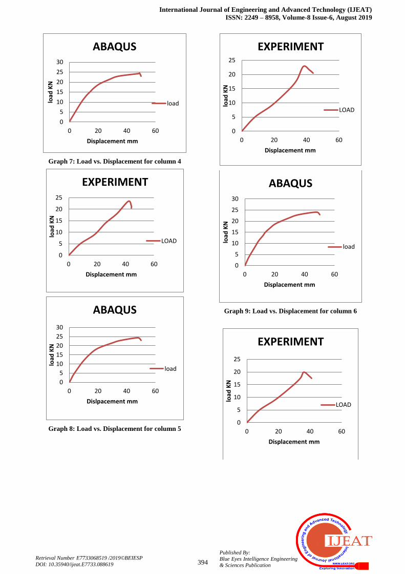
Graph 7: Load vs. Displacement for column 4
Graph 8: Load vs. Displacement for column 5
Graph 9: Load vs. Displacement for column 6
0
5
10
15
20
25
30
0 20 40 60
load
KN
Displacement mm
ABAQUS
load
0
5
10
15
20
25
0 20 40 60
load
KN
Displacement mm
EXPERIMENT
LOAD
0
5
10
15
20
25
30
0 20 40 60
load
KN
Dislpacement mm
ABAQUS
load
0
5
10
15
20
25
0 20 40 60
load
KN
Displacement mm
EXPERIMENT
LOAD
0
5
10
15
20
25
30
0 20 40 60
load
KN
Displacement mm
ABAQUS
load
0
5
10
15
20
25
0 20 40 60
load
KN
Displacement mm
EXPERIMENT
LOAD

Behaviour of Cold Formed Light Gauge Steel Angle Columns Subjected To Eccentric Loading
395
Published By: Blue Eyes Intelligence Engineering
& Sciences Publication
Retrieval Number E7733068519 /2019©BEIESP
DOI: 10.35940/ijeat.E7733.088619
Graph 10: Load vs. Displacement for column 7
Graph 11: Load vs. Displacement for column 8
Graph 12: Load vs. Displacement for column 9
0
5
10
15
20
25
0 20 40 60
load
KN
Displacement mm
ABAQUS
load
0
5
10
15
20
25
0 20 40 60
load
KN
Displacement mm
EXPERIMENT
load
0
5
10
15
20
25
0 20 40 60
load
KN
Dislpacement mm
ABAQUS
load
0
5
10
15
20
0 20 40 60
load
KN
Displacement mm
EXPERIMENT
LOAD
0
5
10
15
20
25
0 20 40 60
load
KN
Displacement mm
ABAQUS
load
International Journal of Engineering and Advanced Technology (IJEAT)
ISSN: 2249 – 8958, Volume-8 Issue-6, August 2019
396
Published By:
Blue Eyes Intelligence Engineering
& Sciences Publication
Retrieval Number E7733068519 /2019©BEIESP
DOI: 10.35940/ijeat.E7733.088619
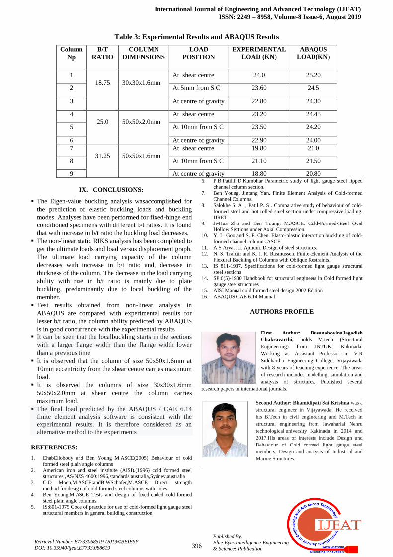
Table 3: Experimental Results and ABAQUS Results
Column
Np
B/T
RATIO
COLUMN
DIMENSIONS
LOAD
POSITION
EXPERIMENTAL
LOAD (KN) ABAQUS
LOAD(KN)
1
18.75
30x30x1.6mm
At shear centre 24.0 25.20
2 At 5mm from S C 23.60 24.5
3 At centre of gravity 22.80 24.30
4
25.0
50x50x2.0mm
At shear centre 23.20 24.45
5 At 10mm from S C 23.50 24.20
6 At centre of gravity 22.90 24.00
7
31.25
50x50x1.6mm
At shear centre 19.80 21.0
8 At 10mm from S C 21.10 21.50
9 At centre of gravity 18.80 20.80
IX. CONCLUSIONS:
The Eigen-value buckling analysis wasaccomplished for
the prediction of elastic buckling loads and buckling
modes. Analyses have been performed for fixed-hinge end
conditioned specimens with different b/t ratios. It is found
that with increase in b/t ratio the buckling load decreases.
The non-linear static RIKS analysis has been completed to
get the ultimate loads and load versus displacement graph.
The ultimate load carrying capacity of the column
decreases with increase in b/t ratio and, decrease in
thickness of the column. The decrease in the load carrying
ability with rise in b/t ratio is mainly due to plate
buckling, predominantly due to local buckling of the
member.
Test results obtained from non-linear analysis in
ABAQUS are compared with experimental results for
lesser b/t ratio, the column ability predicted by ABAQUS
is in good concurrence with the experimental results
It can be seen that the localbuckling starts in the sections
with a larger flange width than the flange width lower
than a previous time
It is observed that the column of size 50x50x1.6mm at
10mm eccentricity from the shear centre carries maximum
load.
It is observed the columns of size 30x30x1.6mm
50x50x2.0mm at shear centre the column carries
maximum load.
The final load predicted by the ABAQUS / CAE 6.14
finite element analysis software is consistent with the
experimental results. It is therefore considered as an
alternative method to the experiments
REFERENCES: 1. EhabEllobody and Ben Young M.ASCE(2005) Behaviour of cold
formed steel plain angle columns
2. American iron and steel institute (AISI).(1996) cold formed steel structures ,AS/NZS 4600:1996,standards australia,Sydney,australia
3. C.D Moen,M.ASCE:andB.WSchafer,M.ASCE Direct strength
method for design of cold formed steel columns with holes 4. Ben Young,M.ASCE Tests and design of fixed-ended cold-formed
steel plain angle columns.
5. IS:801-1975 Code of practice for use of cold-formed light gauge steel structural members in general building construction
6. P.B.Patil,P.D.Kumbhar Parametric study of light gauge steel lipped
channel column section.
7. Ben Young, Jintang Yan. Finite Element Analysis of Cold-formed Channel Columns.
8. Salokhe S. A , Patil P. S . Comparative study of behaviour of cold-
formed steel and hot rolled steel section under compressive loading. IJRET.
9. Ji-Hua Zhu and Ben Young, M.ASCE. Cold-Formed-Steel Oval
Hollow Sections under Axial Compression. 10. Y. L. Goo and S. F. Chen. Elasto-plastic interaction buckling of cold-
formed channel columns.ASCE.
11. A.S Arya, J.L.Ajmuni. Design of steel structures. 12. N. S. Trahair and K. J. R. Rasmussen. Finite-Element Analysis of the
Flexural Buckling of Columns with Oblique Restraints.
13. IS 811-1987. Specifications for cold-formed light gauge structural steel sections
14. SP:6(5)-1980 Handbook for structural engineers in Cold formed light gauge steel structures
15. AISI Manual cold formed steel design 2002 Edition
16. ABAQUS CAE 6.14 Manual
AUTHORS PROFILE
First Author: BusanaboyinaJagadish
Chakravarthi, holds M.tech (Structural
Engineering) from JNTUK, Kakinada.
Working as Assistant Professor in V.R
Siddhartha Engineering College, Vijayawada
with 8 years of teaching experience. The areas
of research includes modelling, simulation and
analysis of structures. Published several
research papers in international journals.
Second Author: Bhamidipati Sai Krishna was a
structural engineer in Vijayawada. He received
his B.Tech in civil engineering and M.Tech in
structural engineering from Jawaharlal Nehru
technological university Kakinada in 2014 and
2017.His areas of interests include Design and
Behaviour of Cold formed light gauge steel
members, Design and analysis of Industrial and
Marine Structures.
.