Pirani Gauge Enhanced - PGE500 - INFICON
80
tinb60e1 (2020-07) 1 Pirani Gauge Enhanced PGE500 With DeviceNet Operating Manual Incl. EU Declaration of Conformity
-
Upload
khangminh22 -
Category
Documents
-
view
4 -
download
0
Transcript of Pirani Gauge Enhanced - PGE500 - INFICON
tinb60e1 (2020-07) 1
Pirani Gauge Enhanced PGE500 With DeviceNet
Operating Manual Incl. EU Declaration of Conformity

2 tinb60e1 (2020-07)
Product Identification In all communications with INFICON, please specify the infor-mation given on the product nameplate. For convenient refer-ence copy that information into the space provided below.

tinb60e1 (2020-07) 3
Validity This document applies to products with part numbers:
The part number (PN) can be taken from the product nameplate.
This User Manual is applicable to the INFICON® model PGE500 product with Device Net interface manufactured with firmware number FW 2998-101 and higher (last three digits of 101 or higher). See STATUS menu described in section 4.6.4 of this manual to determine the firmware version of your PGE500 We reserve the right to make technical changes without prior notice.
4 tinb60e1 (2020-07)
Important User Information There are operational characteristic differences between solid state equipment and electromechanical equipment. Because of these differences, and because there are a variety of uses for solid state equipment, all persons that apply this equipment must take every precaution and satisfy themselves that the intended application of this equipment is safe and used in an acceptable manner. In no event will INFICON be responsible or liable for indirect or consequential damages that result from the use or application of this equipment. Any examples or diagrams included in this manual are provided solely for illustrative purposes. Because of the many variables and requirements imposed on any particular installation, INFICON cannot assume responsibility or liability for any actual use based on the examples and diagrams. No patent liability is assumed by INFICON with respect to use of information circuits, equipment, or software described in this manual. Throughout this manual we use notes, notices and apply inter-nationally recognized symbols and safety messages to make you aware of safety considerations.
tinb60e1 (2020-07) 5
Identifies information about practices or circumstances that can cause electrical or physical hazards which, if precautions are not taken, could result in death or serious injury, property damage, or economic loss.
Identifies information about practices or circumstances that can cause electrical or physical hazards which, if precautions are not taken, could result in minor or moderate injury, property damage, or economic loss.
Identifies information that is critical for successful application and understanding of the product.
Labels may be located on or inside the device to alert people that dangerous voltages may be present.
CAUTION
NOTICE
SHOCK HAZARD
6 tinb60e1 (2020-07)
General Safety Instructions • Adhere to the applicable regulations and take the necessary
precautions for the process media used. Consider possible reactions with the product materials. Consider possible reactions (e.g. explosion) of the process media due to the heat generated by the product.
• Adhere to the applicable regulations and take the necessary precautions for all work you are going to do and consider the safety instructions in this document.
• Before beginning to work, find out whether any vacuum com-ponents are contaminated. Adhere to the relevant regulations and take the necessary precautions when handling contamin-ated parts.
Communicate the safety instructions to all other users.
Liability and Warranty INFICON assumes no liability and the warranty becomes null and void if the end-user or third parties • disregard the information in this document • use the product in a non-conforming manner • make any kind of interventions (modifications, alterations etc.)
on the product • use the product with accessories not listed in the product
documentation.
The end-user assumes the responsibility in conjunction with the process media used. Gauge failures due to contamination or wear and tear, as well as expendable parts (e.g. Pirani filament), are not covered by the warranty.
tinb60e1 (2020-07) 7
Contents
Product Identification 2 Validity 3 Important User Information 4 General Safety Instructions 6 Liability and Warranty 6 1 Introduction / General Information 9 1.1 Description 9 1.2 Specifications 10 1.3 Dimensions 12 2 Important Safety Information 13 2.1 Safety Precautions - General 13 2.2 Safety Precautions - Service and Operation 14 2.3 Electrical Conditions 15 2.3.1 Proper Equipment Grounding 16 2.3.2 Electrical Interface and Control 16 2.4 Overpressure and use with hazardous gases 17 2.5 Gases other than Nitrogen / air 18 3 Installation 18 3.1 Mechanical Installation 18 3.2 Electrical Installation 21 3.2.1 Grounding 21 3.2.2 Electrical Connections 22 4 Setup and Operation 23 4.1 User Interface Basics 23 4.2 DeviceNet and Module Status LEDs 24 4.3 DeviceNet Setup Switches 25 4.3.1 Data Rate Switch Setting 26 4.3.2 Node Address Switch Setting 26 4.4 Initial Setup 27 4.5 Factory-Set Default Parameters 28 4.6 Programming 30 4.6.1 DISPLAY 30 4.6.2 STATUS 32 4.6.3 DEFAULTS 32 4.6.4 CALIBRATION 33 4.6.5 RELAYS 34

8 tinb60e1 (2020-07)
5 Using the gauge with different gases 37 6 Display 40 6.1 Display - Torr 40 6.2 Display - mBAR 44 7 DeviceNet Operation 48 7.1 Supported DeviceNet Objects for ODVA compliance 48 7.2 Supported DeviceNet Objects compliant with Semi
Guidelines 49 7.3 Other supported DeviceNet Objects 49 7.4 Configuring the DeviceNet switches 49 7.5 Allocating DeviceNet connections to the PGE500 50 7.6 Configuring Expected Packet Rate 50 7.7 Configuring Polled I/O data format 51 7.8 UINT 2 byte integer pressure 52 7.9 DeviceNet Protocol for PGE500 52 7.9.1 Standard Objects 54 7.9.1.1 Identity Object 54 7.9.1.2 DeviceNet Object 55 7.9.1.3 Connection Object - Explicit Message Connection 56 7.9.1.4 Connection Object - Polled I/O Data 57 7.9.1.5 Discrete Output Point Object 58 7.9.1.6 S-Device Supervisor Object 59 7.9.1.7 S-Analog Sensor Object 60 7.9.1.8 S-Gas Calibration Object 61 7.9.1.9 Trip Point Object 62 8 Service 63 8.1 Calibration 63 8.2 Maintenance 63 8.3 Troubleshooting 64 8.4 Contamination 66 8.5 Module and sensor replacement 68 9 Factory Service and Support 74 10 Returning the Product 75 11 Disposal 75 12 Spare Parts 77 EU Declaration of Conformity 78
For cross-references within this document, the symbol (→ XY) is used.
tinb60e1 (2020-07) 9
1 Introduction / General Information
1.1 Description Thermal conductivity gauges measure pressure indirectly by sensing the loss of heat from a sensor to the surrounding gases. The higher the pressure of the surrounding gas, the more heat is conducted away from the sensor. Pirani thermal conductivity gauges maintain a sensor (usually a wire) at some constant tem-perature, and measure the current or power required to maintain that temperature. A standard Pirani gauge has a useful measur-ing range of about 10-4 Torr to 10 Torr. By taking advantage of convection currents that are generated above 1 Torr, convection-enhanced Pirani gauges increase the measuring range to just above atmosphere.
The INFICON® PGE500 module provides the basic signal condi-tioning required to turn a convection vacuum gauge into a com-plete measuring instrument. This version of the PGE500 pro-vides a DeviceNet interface as well as two process control set-point relays. Additionally a built-in OLED digital display provides the measured pressure values and provides for a convenient user interface for setup and operation of the vacuum gauge. The INFICON PGE500 module will also directly replace the DeviceNet version of the Granville-Phillips® / MKS Mini-Convec-tron® vacuum gauge as the electrical connector pin-out and DeviceNet commands are identical to the corresponding Mini-Convectron®.
10 tinb60e1 (2020-07)
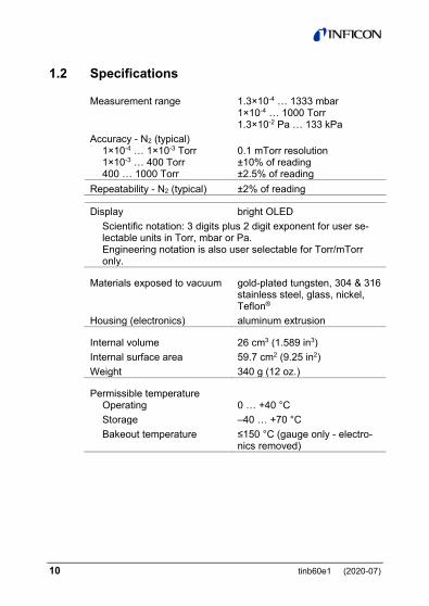
1.2 Specifications Measurement range 1.3×10⁻⁴ … 1333 mbar
1×10⁻⁴ … 1000 Torr 1.3×10⁻² Pa … 133 kPa
Accuracy - N2 (typical) 1×10⁻⁴ … 1×10⁻³ Torr 1×10⁻³ … 400 Torr 400 … 1000 Torr
0.1 mTorr resolution ±10% of reading ±2.5% of reading
Repeatability - N2 (typical) ±2% of reading
Display bright OLED Scientific notation: 3 digits plus 2 digit exponent for user se-lectable units in Torr, mbar or Pa. Engineering notation is also user selectable for Torr/mTorr only.
Materials exposed to vacuum gold-plated tungsten, 304 & 316 stainless steel, glass, nickel, Teflon®
Housing (electronics) aluminum extrusion
Internal volume 26 cm3 (1.589 in3) Internal surface area 59.7 cm2 (9.25 in2) Weight 340 g (12 oz.)
Permissible temperature Operating
0 … +40 °C
Storage –40 … +70 °C Bakeout temperature ≤150 °C (gauge only - electro-
nics removed)
tinb60e1 (2020-07) 11
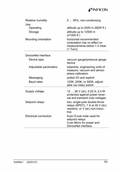
Relative humidity 0 … 95%, non-condensing Use
Operating altitude up to 2500 m (8200 ft.)
Storage altitude up to 12500 m (41000 ft.)
Mounting orientation horizontal recommended (orientation has no effect on measurements below 1.3 mbar (1 Torr))
DeviceNet Interface Device type vacuum gauge/pressure gauge
device Adjustable parameters setpoints, engineering units of
measure, vacuum and atmos-phere calibration
Messaging polled I/O and explicit Baud rates 125K, 250K, or 500K, adjust-
able via rotary switch
Supply voltage 12 … 26 V (dc), 0.22 A, 2.4 W protected against power rever-sal and transient over-voltages
Setpoint relays two, single-pole double-throw relays (SPDT), 1 A at 30 V (dc) resistive, or V (ac) non-induc-tive
Electrical connection 9-pin D-sub male used for setpoint relays 5-pin Micro for power and DeviceNet interface

12 tinb60e1 (2020-07)
1.3 Dimensions
Fitting Dimension A mm (inch) DN 16 ISO-KF 29.5 (1.16) DN 25 ISO-KF 29.5 (1.16) DN 40 ISO-KF 29.5 (1.16) DN 16 CF-R 34 (1.34) DN 40 CF-R 34 (1.34) 4 VCR female 43.7 (1.72) 8 VCR female 40.9 (1.61) 1/8" NPT male 21.8 (0.86)

tinb60e1 (2020-07) 13
2 Important Safety Information
INFICON has designed and tested this product to provide safe and reliable service, provided it is installed and operated within the strict safety guidelines provided in this manual. Please read and follow all warnings and instructions.
To avoid serious injury or death, follow the safety informa-tion in this document. Failure to comply with these safety procedures could result in serious bodily harm, including death, and or property damage. Failure to comply with these warnings violates the safety stand-ards of installation and intended use of this instrument. INFICON disclaims all liability for the customer’s failure to comply with these instructions. Although every attempt has been made to consider most possi-ble installations, INFICON cannot anticipate every contingency that arises from various installations, operation, or maintenance of the module. If you have any questions about the safe installa-tion and use of this product, please contact INFICON.
2.1 Safety Precautions - General The product should never be operated with the enclosure re-moved.
WARNING! There are no operator serviceable parts or adjustments inside the product enclosure. However, the sensor inside the product enclosure is replaceable. Refer servicing to service trained personnel.
WARNING
14 tinb60e1 (2020-07)
Do not modify this product or substitute any parts without au-thorization of qualified INFICON service trained personnel. Re-turn the product to an INFICON qualified service and repair cen-ter to ensure that all safety features are maintained. Do not use this product if unauthorized modifications have been made.
WARNING! Source power must be removed from the product prior to performing any servicing.
After servicing this product, ensure that all safety checks are made by a qualified service person. When replacement parts are required, ensure that the parts are specified by INFICON Sub-stitutions of non-qualified parts may result in fire, electric shock or other hazards. Use of unauthorized parts or modifications made to this product will void the warranty. To reduce the risk of fire or electric shock, do not expose this product to rain or moisture. These products are not waterproof and careful attention must be paid to not spill any type of liquid onto these products. Do not use these products if they have been damaged. Immediately contact INFICON to arrange return of the product if it is damaged. Due to the possibility of corrosion when used in certain environ-mental conditions, it is possible that the product’s safety could be compromised over time. It is important that the product be peri-odically inspected for sound electrical connections and equip-ment grounding. Do not use if the equipment grounding or elec-trical insulation has been compromised.
2.2 Safety Precautions - Service and Operation Ensure that the vacuum port on which the PGE500 vacuum gauge is mounted is electrically grounded. Use an appropriate power source of 12 … 26 V (dc), 0.22 A, 2.4 W. Turn off power to the unit before attempting to service the module.
tinb60e1 (2020-07) 15
Turn off power to the unit if a cable or plug is damaged or the product is not operating normally according to this operating manual. Contact qualified INFICON service personnel for any service or troubleshooting condition that may not be covered by this operating manual. It is important that the product be periodically inspected for sound electrical connections and equipment grounding. Do not use if the equipment grounding or electrical insulation has been compromised. Do not use if the unit has been dropped or the enclosure has been damaged. Contact INFICON for return authorization and instructions for returning the product to INFICON for evaluation.
2.3 Electrical Conditions
WARNING! When high voltage is present in any vacuum system, a life threatening electrical shock hazard may exist un-less all exposed electrical conductors are maintained at earth ground potential. This applies to all products that come in con-tact with the gas contained in vacuum chambers. An electrical discharge within a gaseous environment may couple dangerous high voltage directly to any ungrounded conductor of electricity. A person could be seriously injured or killed by coming in contact with an exposed, ungrounded electrical conductor at high volt-age potential. This condition applies to all products that may come in contact with the gas inside the vacuum chamber (vacuum / pressure containment vessel).

16 tinb60e1 (2020-07)
2.3.1 Proper Equipment Grounding
WARNING! Hazardous voltages that could seriously in-jure or cause death are present in many vacuum processes. Verify that the vacuum port on which the PGE500 vacuum gauge module is mounted is electrically grounded. Consult a qualified Electrician if you are in doubt about your equipment grounding. Proper grounding of your equipment is essential for safety as well as intended operation of the equipment. The PGE500 mo-dule vacuum gauge must be connected directly to a good quality earth ground. Use a ground lug on the PGE500 gauge vacuum connection / flange if necessary.
WARNING! In order to protect personnel from electric shock and bodily harm, shield all conductors which are subject to potential high voltage electrical discharges in or around the vacuum system.
2.3.2 Electrical Interface and Control It is the user’s responsibility to ensure that the electrical signals from this product and any connections made to external devices, for example, relays and solenoids, are used in a safe manner. Always double check the system set-up before using any signals to automate your process. Perform a hazardous operation analy-sis of your system design and ensure safeguards and personnel safety measures are taken to prevent injury and property dam-age.
tinb60e1 (2020-07) 17
2.4 Overpressure and use with hazardous gases
WARNING! Install suitable protective devices that will limit the level of pressure inside your vacuum chamber to less than what the vacuum chamber system components are capable of withstanding. INFICON gauges should not be used at pres-sures exceeding 1000 Torr absolute pressure.
In cases where an equipment failure could cause a hazardous condition, always implement fail-safe system operation. For ex-ample, use a pressure relief device in an automatic backfill op-eration where a malfunction could result in high internal pres-sures if the pressure relief device was not installed on the chamber. The PGE500 vacuum gauge module is not intended for use at pressures above 20 psia (1000 Torr); DO NOT exceed 35 psig (<2½ bars) pressure inside the sensor. If your chamber goes to higher pressures, you should install an isolation valve or pres-sure relief device to protect the gauge tube from overpressure conditions. With some fittings, actual safe overpressure condi-tions may be lower; for example, a quick-connect, O-ring com-pression fitting may forcibly release the gauge tube from the vacuum chamber fitting with only a few psi over local uncor-rected barometric (atmospheric) pressure.
CAUTION! If the internal pressure of a vacuum gauge device is allowed to increase above local uncorrected baro-metric pressure (atmospheric pressure side), vacuum fit-tings may release and possible overpressure conditions may cause leaks that would allow the gas inside the gauge tube to release into the atmosphere of the surrounding en-vironment. Toxic, pyrophoric and flammable gases are ex-amples of hazardous gases that if allowed to leak out of the vacuum/pressure containment vessel into the atmospheric environment, could cause bodily injury and possible dam-age to equipment. Never expose the gauge tube internal volume to pressure above local atmospheric pressure when using hazardous gases.

18 tinb60e1 (2020-07)
2.5 Gases other than Nitrogen / air
WARNING! Do not attempt to use with gases other than nitrogen (N2) or air without referring to correction factor data tables. INFICON gauges and modules are calibrated for direct readout of nitrogen or air. Do not attempt to use with other gases such as argon (Ar) or carbon dioxide (CO2) unless accurate conversion data for N2 to other gas is properly used. Refer to sections titled "Using the gauge with different gases", "Display" and "Analog Output" for a more complete discussion.
WARNING! Do not use this device in an explosive atmos-phere or in the presence of flammable gases, vapors or fumes. Do not use this device to measure the pressure of explosive or combustible gases or gas mixtures. The sensor wire in the gauge normally operates at 125 °C, but if malfunction should occur, the wire temperature could exceed the ignition tempera-ture of certain combustible gases and gas mixture. This could cause an explosion which could result in serious injury or death.
3 Installation
3.1 Mechanical Installation Mount the PGE500 as close as possible to the pressure you want to measure. Long or restricted, small diameter tubing will create a pressure difference between your process chamber and the gauge. This may cause a delay in response to pressure changes.
tinb60e1 (2020-07) 19
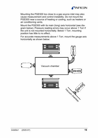
Mounting the PGE500 too close to a gas source inlet may also cause measurement and control instability. Do not mount the PGE500 near a source of heating or cooling, such as heaters or air conditioning vents. Mount the PGE500 with its main (long) axis horizontal (see dia-gram below). Pressure reading errors may occur above 1 Torr if the unit is not mounted horizontally. Below 1 Torr, mounting position has little to no effect. For accurate measurements above 1 Torr, mount the gauge axis horizontally as shown below:
Vacuum chamber
20 tinb60e1 (2020-07)
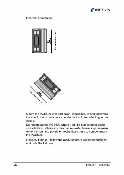
Incorrect Orientation:
Mount the PGE500 with port down, if possible, to help minimize the effect of any particles or condensation from collecting in the gauge. Do not mount the PGE500 where it will be subjected to exces-sive vibration. Vibrations may cause unstable readings, measu-rement errors and possible mechanical stress to components in the PGE500.
Flanges/ Fittings - follow the manufacturer's recommendations and note the following:
tinb60e1 (2020-07) 21
- NPT fittings: When connecting the device using a NPT fitting, apply a thread sealant or wrap the threaded portion of the tubing with one-and-a-half to two wraps of pipe thread seal tape such as PTFE (Teflon®) tape and hand tighten the gauge into the gauge port. Do not use a wrench or other tool which may dam-age the gauge.
3.2 Electrical Installation
3.2.1 Grounding
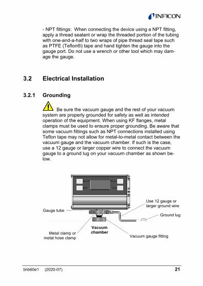
Be sure the vacuum gauge and the rest of your vacuum system are properly grounded for safety as well as intended operation of the equipment. When using KF flanges, metal clamps must be used to ensure proper grounding. Be aware that some vacuum fittings such as NPT connections installed using Teflon tape may not allow for metal-to-metal contact between the vacuum gauge and the vacuum chamber. If such is the case, use a 12 gauge or larger copper wire to connect the vacuum gauge to a ground lug on your vacuum chamber as shown be-low.
Use 12 gauge or larger ground wire
Ground lug
Vacuum gauge fitting
Gauge tube
Metal clamp or metal hose clamp
Vacuum chamber

22 tinb60e1 (2020-07)
3.2.2 Electrical Connections A good recommended practice is to remove power from any cable prior to connecting or disconnecting it.
9-pin D-sub Connector pinout
Pin no. Pin description 1 Relay 2 Normally Open 2 Relay 2 Common 3 Relay 2 Normally Closed 4 No Connection 5 Relay 1 Common 6 Relay 1 Normally Closed 7 Relay 1 Normally Open 8 No Connection 9 No Connection
5-pin DeviceNet Micro Connector
1 Shield
4 CAN_H (–) Ground 3
+24 V (dc) 2
CAN_L 5

tinb60e1 (2020-07) 23
4 Setup and Operation
4.1 User Interface Basics The setup and programming is done via the four programming-keys located on the front panel of the PGE500. During program-ming of the gauge, the display will identify what function each key represents.
To begin programming, press the MENU key. Press the UP and DOWN key to select the desired menu or change values. Press the ENTER key to access the parameters and save the new set-tings. Press the MENU Key to return to the previous menu or press repeatedly to return to the main pressure measurement display screen. To continue setting additional parameters, scroll with the UP { ↑ } and DOWN { ↓ } keys until you reach the de-sired parameter then press ENTER.
Scroll DOWN ↓ key
Relay status indicators for relays 1 and 2 Filled circle = Relay energized Unfilled circle = Relay not energized
Gas Symbol N2
ENTER key
Scroll UP ↑ key
DeviceNet Network Status LED
Gauge Module Status LED
MENU key

24 tinb60e1 (2020-07)
4.2 DeviceNet and Module Status LEDs In addition to a built-in display the PGE500 is provided with two status LED indictors as shown below. The LED indicator marked NET represents the DeviceNet network status. The LED indica-tor marked MOD represents the gauge module (PGE500) status.
MOD Status LED:
LED Meaning off no power to the gauge red an error condition/fault exits with the gauge
flashing red-green
gauge is in self test. Review Identity Object in ODVA DeviceNet specifications
green gauge is functioning normally
DeviceNet Network Status LED
Gauge Module Status LED
tinb60e1 (2020-07) 25
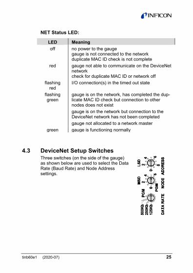
NET Status LED:
LED Meaning off no power to the gauge
gauge is not connected to the network duplicate MAC ID check is not complete
red gauge not able to communicate on the DeviceNet network check for duplicate MAC ID or network off
flashing red
I/O connection(s) in the timed out state
flashing green
gauge is on the network, has completed the dup-licate MAC ID check but connection to other nodes does not exist
gauge is on the network but connection to the DeviceNet network has not been completed
gauge not allocated to a network master green gauge is functioning normally
4.3 DeviceNet Setup Switches Three switches (on the side of the gauge) as shown below are used to select the Data Rate (Baud Rate) and Node Address settings.
26 tinb60e1 (2020-07)
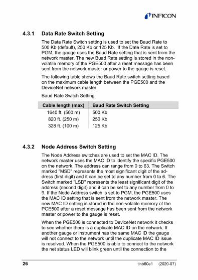
4.3.1 Data Rate Switch Setting The Data Rate Switch setting is used to set the Baud Rate to 500 Kb (default), 250 Kb or 125 Kb. If the Date Rate is set to PGM, the gauge uses the Baud Rate setting that is sent from the network master. The new Buad Rate setting is stored in the non-volatile memory of the PGE500 after a reset message has been sent from the network master or power to the gauge is reset.
The following table shows the Baud Rate switch setting based on the maximum cable length between the PGE500 and the DeviceNet network master.
Baud Rate Switch Setting
Cable length (max) Baud Rate Switch Setting 1640 ft. (500 m) 500 Kb 820 ft. (250 m) 250 Kb 328 ft. (100 m) 125 Kb
4.3.2 Node Address Switch Setting The Node Address switches are used to set the MAC ID. The network master uses the MAC ID to identify the specific PGE500 on the network. The address can range from 0 to 63. The Switch marked "MSD" represents the most significant digit of the ad-dress (first digit) and it can be set to any number from 0 to 6. The Switch marked "LSD" represents the least significant digit of the address (second digit) and it can be set to any number from 0 to 9. If the Node Address switch is set to PGM, the PGE500 uses the MAC ID setting that is sent from the network master. The new MAC ID setting is stored in the non-volatile memory of the PGE500 after a reset message has been sent from the network master or power to the gauge is reset.
When the PGE500 is connected to DeviceNet network it checks to see whether there is a duplicate MAC ID on the network. If another gauge or instrument has the same MAC ID the gauge will not connect to the network until the duplicate MAC ID issue is resolved. When the PGE500 is able to connect to the network the net status LED will blink green until the connection to the
tinb60e1 (2020-07) 27
network master is achieved. The NET status LED will then become solid green indicating the connection is complete.
4.4 Initial Setup Two of the most important steps for the initial setup of the gauge are to set atmosphere (SET ATM) set zero (SET VAC) and as described in the Programming section 4.6.4 below. This will ensure proper operation of the gauge and accurate pressure measurements. The gauge is calibrated at the factory using nitrogen. Furthermore, the gauge is also installed in a certain orientation when calibrated at the factory. Without setting zero and atmosphere after the gauge is installed in your system, the gauge may not display the expected and correct pressures. This could be caused by the fact that you may be using a different gas than Nitrogen such as air to setup and calibrate the gauge (most commonly the case) and the gauge orientation is different than the orientation used at the factory. As such, it is very important to perform your own initial setup and calibration by setting zero and atmosphere with the gauge installed in your actual system. Please note the following:
Setting Atmosphere (SET ATM) Setting atmosphere is the most important step for a newly in-stalled gauge. If you prefer to use air to set atmosphere, vent your vacuum system chamber to expose the gauge to the local atmospheric pressure (air) and set atmosphere to match your known local uncorrected barometric pressure (air). This is the reading of ambient air pressure you will expect if you were to vent and open your vacuum chamber to the atmosphere sur-rounding the outside of your chamber. At sea level, this pressure is usually near 760 Torr. At elevations above sea level, the pres-sure decreases. Check your local aviation authority or airport web sites or your current local weather conditions online to help find your local uncorrected barometric pressure if you do not have this information. See "SET ATM" in section 4.6.4.
28 tinb60e1 (2020-07)
Setting zero (SET VAC) Setting zero optimizes performance of the gauge when operating at a low pressure range of 1.00×10⁻⁴ Torr to 1.00×10⁻³ Torr. If your minimum operating pressure is higher than 1.00×10⁻³ Torr, it is not normally necessary to set zero and thus setting atmos-phere should be adequate. If you are able to evacuate your system to below 1.00×10⁻⁴ Torr, it is always a good practice to check and set zero if necessary. See "SET VAC" in section 4.6.4.
Note - Setting zero and atmosphere is normally required only once during the initial setup and maybe checked by the user periodically. After power has been applied to the gauge during the initial setup, allow five minutes for the gauge to stabilize (warm-up) before setting zero and atmosphere. If you set factory defaults you would need to repeat the initial setup procedure in-cluding setting ATM and VAC and reprogram other parameters as required.
4.5 Factory-Set Default Parameters The following is a summary of all factory-set default values in the PGE500 display menu.
DISPLAY • UNITS: [Factory default = TORR] • CNTRAST: [Factory default = 6] • SCRN SVR: [Factory default = ON • FLIP SCR: [Factory default = OFF] • NOTATN: [Factory default = SCI]
STATUS • STATUS: [Factory default = OK]

tinb60e1 (2020-07) 29
• GAUGE INFO [Factory default MSN: Actual Module Serial Number GSN: Actual Gauge Serial Number FW: Firmware version of device
CALIBRATION • SET ATM [Factory default = SET TO 760] • SET VAC [Factory default = SET TO ZERO]
DFAULTS • DEFAULTS [Factory default = NO]
(Gauge shipped with factory defaults but user must select YES to set factory defaults again)
RELAYS • RELAY 1
RLY: [Factory default = DISABLED] LO TRIP [Factory default = 7.00 E+02 TORR] HI TRIP [Factory default = 7.50 E+02 TORR]
• RELAY 2 RLY: [Factory default = DISABLED] LO TRIP [Factory default = 7.00 E+02 TORR] HI TRIP [Factory default = 7.50 E+02 TORR]
• TEST RELAYS ①: [Factory default = OFF] ②: TRIP [Factory default = OFF]
30 tinb60e1 (2020-07)
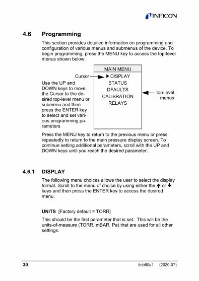
4.6 Programming This section provides detailed information on programming and configuration of various menus and submenus of the device. To begin programming, press the MENU key to access the top-level menus shown below:
MAIN MENU Cursor Use the UP and DOWN keys to move the Cursor to the de-sired top-level menu or submenu and then press the ENTER key to select and set vari-ous programming pa-rameters
▶ DISPLAY STATUS
DFAULTS CALIBRATION
RELAYS
top-level menus
Press the MENU key to return to the previous menu or press repeatedly to return to the main pressure display screen. To continue setting additional parameters, scroll with the UP and DOWN keys until you reach the desired parameter.
4.6.1 DISPLAY The following menu choices allows the user to select the display format. Scroll to the menu of choice by using either the or keys and then press the ENTER key to access the desired menu.
UNITS [Factory default = TORR] This should be the first parameter that is set. This will be the units-of-measure (TORR, mBAR, Pa) that are used for all other settings.
tinb60e1 (2020-07) 31
CNTRAST [Factory default = 6] This function sets the display contrast. Access the CNTRST menu and use select a number between 1 and 10. The contrast setting of 10 provides the highest contrast (brightest) and 1 the lowest. Note - Factory default setting of 6 optimizes display life.
SCRN SVR [Factory default = ON] The PGE500 uses an OLED type display which over an exten-ded period of time can start to show divergence between pixels that are on at all times verses pixels that are not. This could result in pixels exhibiting a burned-in effect. To minimize the burned-in effect, a screen saver function can be activated by programming the SCRN SVR menu selection to ON. With the screen saver function turned on, the display appearance chan-ges every 12 hours. The display will appear in the normal mode with a dark background color for the first 12 hours and will then switch to a back-lit background color for the next 12 hours. If you like to have the 12 hour period for the normal display mode to start at a specific time of the day, simply access the SCRN SVR menu and change setting to OFF and then ON again. This initi-ates the screen saver function immediately.
FLIP SCREEN [Factory default = OFF] This allows the user to select a normal display or have the dis-played data inverted. When the gauge is mounted in an inverted position, this selection is used to invert the displayed date 180 degrees for user convenience.
NOTATN [Factory default = SCI] This allows the user to select the pressure measurement display format. Select SCI for scientific notation (Torr, mBAR and Pa) and ENG for engineering notation (Torr only). For example, when scientific notation (SCI) is selected, the pressure measure-ment format will be displayed as 7.60E+02 Torr while the same pressure value will be displayed as 760 Torr when the engineer-ing notation (ENG) is selected. ENG notation is only available when units of measure is Torr. With ENG notation selected any

32 tinb60e1 (2020-07)
measured pressure value from 1000 to 1 Torr will be displayed in units of measure in Torr and any pressure values below 1 Torr will be displayed in mTorr.
4.6.2 STATUS The following menu choices allows the user to see any pending error conditions as well as gauge identification information.
STATUS [Factory default = OK] Access this menu to determine whether the gauge is functioning normally or an error condition(s) exists.
GAUGE INFO Factory default = MSN: Actual Module Serial Number
GSN: Actual Gauge Serial Number FW: Firmware version of device
4.6.3 DEFAULTS The following menu allows the user to return all values to the original factory default setting.
DEFAULTS [Factory default = NO] Gauge shipped with factory defaults but user must select YES to set factory defaults again. If desired, you can reset all values to the original factory default settings. Access the DEFAULTS menu, then press YES or NO to set factory defaults. If YES is selected the FAC SET. submenu will be displayed indicating the device has been returned to the original factory default setting. Press the menu key to return to the previous menu(s). Note that if you set factory defaults you would need to repeat the initial setup procedure including setting ATM and VAC and reprogram other parameters as required.

tinb60e1 (2020-07) 33
4.6.4 CALIBRATION As described in section 4.4 above, two of the most important steps for the initial setup of the gauge is to set atmosphere (SET ATM) and set zero (SET VAC) as described below:
SET ATM Select SET ATM to set atmosphere and the following two sub-menu choices will appear: • SET TO 760 • ENTER VALUE
1) To set the atmospheric pressure reading (also known as the "spa" adjustment), flow nitrogen gas or air into your closed vacuum chamber to allow the pressure to rise to a known value above 400 Torr. Alternatively, if your local uncorrected barometric pressure (air) is known, simply vent your vacuum system chamber to expose the gauge to the local atmos-pheric pressure.
2) If you are at sea level you may simply select "SET TO 760" if the units of measure selected is in Torr (SET TO 1.01E+03 if using mbar or SET TO 1.01E+05 if using Pa). PGE500 re-sponds with message ATM SET confirming atmosphere has been successfully set. Press the menu key to return to the previous menu(s). If you are at an elevation other than sea level you may select "ENTER VALUE" to enter your actual known local uncorrected barometric pressure. Minimum ATM value that can be set is 400 Torr.
SET VAC Select SET VAC to set zero and the following two submenu choices will appear: • SET TO VAC • ENTER VALUE
34 tinb60e1 (2020-07)
INFICON advises that you first determine if the "span" (SET ATM) adjustment of your measurement device is set properly before setting the "zero" (SET VAC) adjustment. It is good prac-tice to perform the sequence of checking and adjusting ATM (span) then VAC (zero) and then, finally re-checking the ATM setting to ensure the instrument has been properly set.
1) To properly set the vacuum reading ("zero" point), with the gauge installed on your vacuum system, the gauge should be evacuated to a pressure below 1.00×10⁻⁴ Torr.
2) When the known vacuum system pressure is below 1.00×10⁻⁴ Torr, press SET TO ZERO and the number 0.00E+0 Torr will be displayed. PGE500 responds with message VAC SET confirming zero has been successfully set. Press the menu key to return to the previous menu(s).
If for a specific reason you want to set the "zero" pressure reading to a number higher than 0.00E+0, then select the "ENTER VALUE" menu instead of "SET TO VAC" to enter the value. Maximum VAC value that can be set is 1.00E-01 Torr.
Due to the nature of circuit operation and transducer electri-cal control that cover a full range of measurement by a con-vection gauge, it is advised that one first check and adjust, if necessary, the "span" and "zero" to ensure that all measure-ments made between these two, adjusted settings are as accurate as possible.
4.6.5 RELAYS Select RELAYS to access the following relay menus for configur-ing the setpoint relays:
RELAY 1 Select RELAY 1 to configure setpoints for relay 1 and the follow-ing submenus will appear:

tinb60e1 (2020-07) 35
RLY: [Factory default = DISABLED] The factory default setting for the relay 1 is disabled. Select this menu to change the state of relay 1 to ENABLED.
LO TRIP [Factory default = 7.00 E+02 TORR] This setpoint corresponds to the turn on point for Relay 1. Relay 1 will turn on when the pressure drops below this setting. If you are unable to increase the value of LO TRIP (PGE500 respond-ing with message "LO MORE THAN HI"), you must first access the HI TRIP menu below and increase that value to a number higher than the value of the LO TRIP you are trying to set. Note that at the bottom of the screen the HI TRIP value is also dis-played (but cannot be changed) while in this menu selection.
HI TRIP [Factory default = 7.50 E+02 TORR] This setpoint corresponds to the turn off point for Relay 1. Relay 1 will turn off when the pressure rises above this setting. If you are unable to decrease the value of HI TRIP (PGE500 respond-ing with message "LO MORE THAN HI"), you must first access the LO TRIP menu above and decrease that value to a number lower than the value of the HI TRIP you are trying to set. Note that at the bottom of the screen the LO TRIP value is also dis-played (but cannot be changed) while in this menu selection.
RELAY 2 Select RELAY 2 to configure setpoints for relay 2 and the follow-ing submenus will appear:
RLY: [Factory default = DISABLED] Same instructions as relay 1 RLY above.
LO TRIP [Factory default = 7.00 E+02 TORR] Same instructions as relay 1 LO TRIP above.

36 tinb60e1 (2020-07)
HI TRIP [Factory default = 7.50 E+02 TORR] Same instructions as relay 1 HI TRIP above.
TEST RELAYS This allows the user to manually toggle the relays on and off to test for correct external circuit wiring and ensure polarity is as desired. Select the TEST RELAYS menu and the following two submenus will appear:
①: [Factory default = OFF] Press the ENTER key to turn on and energize relay 1. Press the ENTER key again to turn off and deenergize relay 1.
②: [Factory default = OFF] Press the ENTER key to turn on and energize relay 2. Press the ENTER key again to turn off and deenergize relay 2.
Relays will return to the previous state after exiting the TEST RELAYS menu.
tinb60e1 (2020-07) 37
5 Using the gauge with different gases
A thermal conductivity gauge senses heat loss which depends on the thermal conductivity of the gas surrounding the sensor. Since different gases, and mixtures, have different thermal con-ductivities, the indicated pressure readings and outputs will also be different. INFICON convection gauges (and most other ther-mal conductivity gauges) are calibrated using nitrogen (N2). When a gas other than N2 / air is used, correction must be made for the difference in thermal conductivity between nitrogen (N2) and the gas in use. The charts and tables on the following pages indicate how different gases affect the display and output from an INFICON convection gauge.
WARNING! Using a thermal conductivity gauge with gases other than that for which it is calibrated could result in death or serious injury. Be sure to use gas correction data in this manual when measuring pressures of gases other than N2 / air.
For N2 the calibration shows excellent agreement between in-dicated and true pressure throughout the range from 10-4 to 1000 Torr. At pressures below 1 Torr, the calibration curves for the different gases are similar. The difference in readings at these low pressures is a constant, a function of the difference between thermal conductivities of the gases.
At pressures above 1 Torr, indicated pressure readings may diverge significantly. At these higher pressures convection currents in the gauge become the predominant cause of heat loss from the sensor and calibration depends on gauge tube geometry and mounting position as well as gas properties.
Generally, air and N2 are considered the same with respect to thermal conductivity, but even N2 and air will exhibit slight differ-ences in readings at higher pressures. For example, when vent-ing a system to atmosphere using N2, you may see readings change by 30 to 40 Torr after the chamber is opened and air gradually displaces the N2 in the gauge. For most other gases the effect is much more significant and may result in a hazard-ous condition as described below.
38 tinb60e1 (2020-07)
Other considerations when using gases other than N2 / air Flammable or explosive gases
WARNING! INFICON convection gauges are neither in-trinsically safe nor explosion proof and are not intended for use in the presence of flammable or explosive gases or vapors.
Under normal conditions the voltages and currents in INFICON convection gauges are too low to cause ignition of flammable gases. However, under certain failure conditions, sufficient en-ergy could be generated to cause flammable vapors or gases to ignite or explode. Thermal conductivity gauges like the INFICON convection gauges are not recommended for use with flammable or explosive gases.
Moisture / water vapor In some processes (lyophilization, for example) the gas composi-tion may not change significantly, except for moisture content. Water vapor can significantly change the response of a thermal gauge and correction should be made, as you would for any other gas.
Other contaminants If your gases condense, coat, or corrode the sensor, the gauge calibration and response to different gases will change. Gener-ally, if the gauge can be "calibrated" ("zero" and "span" settings), these changes are small enough to be ignored. If you can’t set zero and span, the gauge should be replaced or return to factory for evaluation and possible cleaning.

tinb60e1 (2020-07) 39
Indicated vs. true total pressure (test gases N2, Ar, He)
Gas Correction Chart The Y- axis of the above chart is actual pressure as measured by a capacitance manometer, a diaphragm gauge that measures true total pressure independent of gas composition. The X-axis is the pressure reading indicated by the convection gauge under test. This chart shows readings for an INFICON convection gauge (CVG) and Granville-Phillips® Convectron® gauge to illustrate that the difference in the response for both of these types of gauges is virtually indistinguishable.
CAUTION! Do not assume this data applies to other convection gauges which may or may not be the same. Refer to the table in section 6.1 and note the following examples: Example A: If the gas is nitrogen (N2), when the true total pres-sure is 500 Torr, the gauge will read 500 Torr. Example B: If the gas is argon (Ar), when the true pressure is 100 Torr, the gauge will read about 9 Torr. If you are backfilling your vacuum system with Ar, when your system reaches a pressure of 760 Torr true pressure your gauge will be reading about 23 Torr. Continuing to backfill your system,
40 tinb60e1 (2020-07)
attempting to increase the reading up to 760 Torr, you will over pressurize your chamber which may present a hazard. Example C: If the gas is helium (He), the gauge will over pres-sure (OP) when pressure reaches about 10 Torr true pressure and opening the chamber to atmosphere prematurely may pre-sent other hazards for both people and product.
CAUTION! What these examples illustrate is that using gases other than nitrogen (N2) without using accurate gas conversion data and other proper precautions could result in injury to per-sonnel and/or damage to equipment.
Suggested precautions when using gases other than nitrogen (N2): Install a pressure relief valve or burst disk on your chamber, to protect it from overpressure. Post a warning label on your gauge readout that states "Do Not Exceed ____ Torr Indicated Pres-sure" (fill in the blank for maximum indicated pressure for the gas you use) so that an operator using the gauge will not exceed a safe pressure.
6 Display
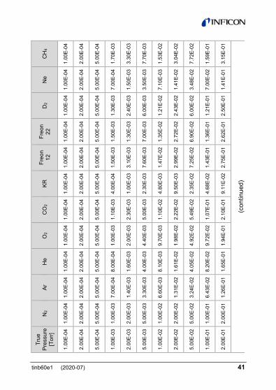
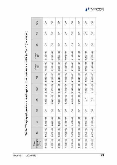
6.1 Display - Torr The table below shows the displayed readings at various pres-sures for selected gases when engineering units selected is in Torr.
tinb60e1 (2020-07) 41
C
H4
1.00
E-04
2.00
E-04
5.00
E-04
1.70
E-03
3.30
E-03
7.70
E-03
1.53
E-02
3.04
E-02
7.72
E-02
1.59
E-01
3.15
E-01
(con
tinue
d)
Ne
1.00
E-04
2.00
E-04
5.00
E-04
7.00
E-04
1.50
E-03
3.50
E-03
7.10
E-03
1.41
E-02
3.48
E-02
7.00
E-02
1.41
E-01
D2
1.00
E-04
2.00
E-04
5.00
E-04
1.30
E-03
2.40
E-03
6.00
E-03
1.21
E-02
2.43
E-02
6.00
E-02
1.21
E-01
2.50
E-01
Freo
n 22
1.00
E-04
2.00
E-04
5.00
E-04
1.50
E-03
1.30
E-03
7.00
E-03
1.35
E-02
2.72
E-02
6.90
E-02
1.36
E-01
2.62
E-01
Freo
n 12
1.00
E-04
2.00
E-04
5.00
E-04
1.50
E-03
3.10
E-03
7.60
E-03
1.47
E-02
2.99
E-02
7.25
E-02
1.43
E-01
2.75
E-01
KR
1.00
E-04
2.00
E-04
5.00
E-04
4.00
E-04
1.00
E-03
2.30
E-03
4.80
E-03
9.50
E-03
2.35
E-02
4.68
E-02
9.11
E-02
CO
2
1.00
E-04
2.00
E-04
5.00
E-04
1.10
E-03
2.30
E-03
5.00
E-03
1.10
E-02
2.22
E-02
5.49
E-02
1.07
E-01
2.10
E-01
O2
1.00
E-04
2.00
E-04
5.00
E-04
1.00
E-03
2.00
E-03
4.40
E-03
9.70
E-03
1.98
E-02
4.92
E-02
9.72
E-02
1.94
E-01
He
1.00
E-04
2.00
E-04
5.00
E-04
8.00
E-04
1.60
E-03
4.00
E-03
8.10
E-03
1.61
E-02
4.05
E-02
8.20
E-02
1.65
E-01
Ar
1.00
E-04
2.00
E-04
5.00
E-04
7.00
E-04
1.40
E-03
3.30
E-03
6.60
E-03
1.31
E-02
3.24
E-02
6.43
E-02
1.26
E-01
N2
1.00
E-04
2.00
E-04
5.00
E-04
1.00
E-03
2.00
E-03
5.00
E-03
1.00
E-02
2.00
E-02
5.00
E-02
1.00
E-01
2.00
E-01
True
Pr
essu
re
[Tor
r]
1.00
E-04
2.00
E-04
5.00
E-04
1.00
E-03
2.00
E-03
5.00
E-03
1.00
E-02
2.00
E-02
5.00
E-02
1.00
E-01
2.00
E-01

42 tinb60e1 (2020-07)
Ta
ble
"Dis
play
ed p
ress
ure
read
ings
vs.
true
pre
ssur
e - u
nits
in T
orr"
(con
tinue
d)
CH
4
7.81
E-01
1.60
E+00
3.33
E+00
7.53
E+00
2.79
E+01
3.55
E+02
8.42
E+02
OP
OP
OP
(con
tinue
d)
Ne
3.59
E-01
7.45
E-01
1.59
E+00
5.24
E+00
2.15
E+01
5.84
E+02
OP
OP
OP
OP
D2
6.87
E-01
1.55
E+00
4.13
E+00
2.46
E+02
OP
OP
OP
OP
OP
OP
Freo
n 22
5.94
E-01
1.04
E+00
1.66
E+00
2.62
E+00
3.39
E+00
3.72
E+00
4.14
E+00
4.91
E+00
6.42
E+00
7.52
E+00
Freo
n 12
6.11
E-01
1.05
E+00
1.62
E+00
2.45
E+00
2.96
E+00
3.32
E+00
3.79
E+00
4.68
E+00
5.99
E+00
6.89
E+00
KR
2.17
E-01
4.00
E-01
7.00
E-01
1.28
E+00
1.78
E+00
2.29
E+00
2.57
E+00
2.74
E+00
3.32
E+00
3.59
E+00
CO
2
4.89
E-01
9.50
E-01
1.71
E+00
3.34
E+00
4.97
E+00
6.59
E+00
8.22
E+00
9.25
E+00
1.23
E+01
1.69
E+01
O2
4.86
E-01
9.70
E-01
1.94
E+00
4.98
E+00
1.03
E+01
2.23
E+01
7.76
E+01
2.09
E+02
2.95
E+02
3.80
E+02
He
4.35
E-01
9.40
E-01
2.22
E+00
1.35
E+01
OP
OP
OP
OP
OP
OP
Ar
3.12
E-01
6.00
E-01
1.14
E+00
2.45
E+00
4.00
E+00
5.80
E+00
7.85
E+00
8.83
E+00
9.79
E+00
1.13
E+01
N2
5.00
E-01
1.00
E+00
2.00
E+00
5.00
E+00
1.00
E+01
2.00
E+01
5.00
E+01
1.00
E+02
2.00
E+02
3.00
E+02
True
Pr
essu
re
[Tor
r]
5.00
E-01
1.00
E+00
2.00
E+00
5.00
E+00
1.00
E+01
2.00
E+01
5.00
E+01
1.00
E+02
2.00
E+02
3.00
E+02
tinb60e1 (2020-07) 43
Tabl
e "D
ispl
ayed
pre
ssur
e re
adin
gs v
s. tr
ue p
ress
ure
- uni
ts in
Tor
r" (c
oncl
uded
)
CH
4
OP
OP
OP
OP
OP
OP
OP
OP
Ne
OP
OP
OP
OP
OP
OP
OP
OP
D2
OP
OP
OP
OP
OP
OP
OP
OP
Freo
n 22
8.42
E+00
9.21
E+00
9.95
E+00
1.07
E+01
1.11
E+01
1.14
E+01
1.20
E+01
1.27
E+01
Freo
n 12
7.63
E+00
8.28
E+00
8.86
E+00
9.42
E+00
9.76
E+00
9.95
E+00
1.05
E+01
1.11
E+01
KR
3.94
E+00
4.21
E+00
4.44
E+00
4.65
E+00
4.75
E+00
4.84
E+00
4.99
E+00
5.08
E+00
CO
2
2.24
E+01
2.87
E+01
3.64
E+01
4.61
E+01
5.39
E+01
5.94
E+01
7.95
E+01
1.11
E+02
O2
4.85
E+02
6.04
E+02
7.30
E+02
8.59
E+02
9.41
E+02
9.97
E+02
OP
OP
He
OP
OP
OP
OP
OP
OP
OP
OP
Ar
1.35
E+01
1.61
E+01
1.88
E+01
2.18
E+01
2.37
E+01
2.51
E+01
2.85
E+01
3.25
E+01
N2
4.00
E+02
5.00
E+02
6.00
E+02
7.00
E+02
7.60
E+02
8.00
E+02
9.00
E+02
1.00
E+03
True
Pr
essu
re
[Tor
r]
4.00
E+02
5.00
E+02
6.00
E+02
7.00
E+02
7.60
E+02
8.00
E+02
9.00
E+02
1.00
E+03
44 tinb60e1 (2020-07)
Notes: OP = Overpressure (Display shows PR OVER PRS)
Examples:
1) Using nitrogen (N2), pressure display shows 1.00E+01 Torr. True pressure of nitrogen is 1.00E+01 Torr.
2) Using argon (Ar), pressure display shows 8.83E+0 Torr. True pressure of argon is 1.00E+02 Torr.
3) Using oxygen (O2), pressure display shows 4.86E-01 mTorr. True pressure of oxygen is 5.00E-01 Torr.
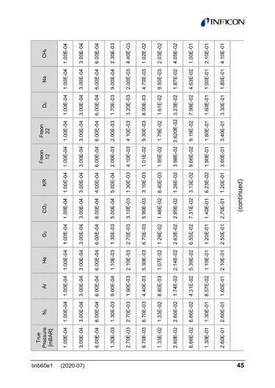
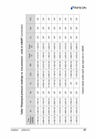
6.2 Display - mBAR The table below shows the displayed readings at various pres-sures for selected gases when engineering units selected is in mbar.
tinb60e1 (2020-07) 45
C
H4
1.00
E-04
3.00
E-04
6.00
E-04
2.30
E-03
4.40
E-03
1.02
E-02
2.03
E-02
4.05
E-02
1.00
E-01
2.10
E-01
4.10
E-01
(con
tinue
d)
Ne
1.00
E-04
3.00
E-04
6.00
E-04
9.00
E-04
2.00
E-03
4.70
E-03
9.50
E-03
1.87
E-02
4.63
E-02
1.00
E-01
1.80
E-01
D2
1.00
E-04
3.00
E-04
6.00
E-04
1.70
E-03
3.20
E-03
8.00
E-03
1.61
E-02
3.23
E-02
7.99
E-02
1.60
E-01
3.30
E-01
Freo
n 22
1.00
E-04
3.00
E-04
6.00
E-04
2.00
E-03
4.10
E-03
9.30
E-03
1.79
E-02
3.62
0E-0
2
9.19
E-02
1.80
E-01
3.40
E-01
Freo
n 12
1.00
E-04
3.00
E-04
6.00
E-04
2.00
E-03
4.10
E-03
1.01
E-02
1.95
E-02
3.98
E-02
9.66
E-02
1.90
E-01
3.60
E-01
KR
1.00
E-04
3.00
E-04
4.00
E-04
5.00
E-04
1.30
E-03
3.10
E-03
6.40
E-03
1.26
E-02
3.13
E-02
6.23
E-02
1.20
E-01
CO
2
1.00
E-04
3.00
E-04
6.00
E-04
5.00
E-04
3.10
E-03
5.90
E-03
1.46
E-02
2.95
E-02
7.31
E-02
1.40
E-01
2.70
E-01
O2
1.00
E-04
3.00
E-04
6.00
E-04
1.30
E-03
2.70
E-03
6.70
E-03
1.29
E-02
2.63
E-02
6.55
E-02
1.20
E-01
2.50
E-01
He
1.00
E-04
3.00
E-04
6.00
E-04
1.10
E-03
2.10
E-03
5.30
E-03
1.07
E-02
2.14
E-02
5.39
E-02
1.10
E-01
2.10
E-01
Ar
1.00
E-04
3.00
E-04
6.00
E-04
9.00
E-04
1.90
E-03
4.40
E-03
8.80
E-03
1.74
E-02
4.31
E-02
8.57
E-02
1.60
E-01
N2
1.00
E-04
3.00
E-04
6.00
E-04
1.30
E-03
2.70
E-03
6.70
E-03
1.33
E-02
2.60
E-02
6.66
E-02
1.30
E-01
2.60
E-01
True
Pr
essu
re
[mBA
R]
1.00
E-04
3.00
E-04
6.00
E-04
1.30
E-03
2.70
E-03
6.70
E-03
1.33
E-02
2.60
E-02
6.66
E-02
1.30
E-01
2.60
E-01

46 tinb60e1 (2020-07)
Ta
ble
"Dis
play
ed p
ress
ure
read
ings
vs.
true
pre
ssur
e - u
nits
in m
BA
R"
(con
tinue
d)
CH
4
1.04
E+00
2.13
E+00
4.43
E+00
1.00
E+01
3.71
E+01
4.73
E+02
1.01
E+03
OP
OP
OP
(con
tinue
d)
Ne
4.70
E-01
9.90
E-01
2.11
E+00
6.98
E+00
2.86
E+01
7.78
E+02
OP
OP
OP
OP
D2
9.10
E-01
2.06
E+00
5.50
E+00
3.27
E+02
OP
OP
OP
OP
OP
OP
Freo
n 22
7.90
E-01
1.38
E+00
2.21
E+00
3.49
E+00
4.51
E+00
4.95
E+00
5.51
E+00
6.54
E+00
8.55
E+00
1.00
E+01
Freo
n 12
8.10
E-01
1.39
E+00
2.15
E+00
3.26
E+00
3.94
E+00
4.42
E+00
5.05
E+00
6.23
E+00
7.98
E+00
9.18
E+00
KR
2.80
E-01
5.30
E-01
9.30
E-01
1.70
E+00
2.37
E+00
3.05
E+00
3.42
E+00
3.65
E+00
4.42
E+00
4.78
E+00
CO
2
6.50
E-01
1.26
E+00
2.27
E+00
4.45
E+00
6.62
E+00
8.78
E+01
1.09
E+01
1.23
E+01
1.63
E+01
2.25
E+01
O2
6.40
E-01
1.29
E+00
2.58
E+00
6.63
E+00
1.37
E+01
2.97
E+01
1.03
E+02
2.78
E+02
3.93
E+02
5.06
E+02
He
5.70
E-01
1.25
E+00
2.95
E+00
1.79
E+01
OP
OP
OP
OP
OP
OP
Ar
4.10
E-01
7.90
E-01
1.51
E+00
3.26
E+00
5.33
E+00
7.73
E+00
1.04
E+01
1.17
E+01
1.30
E+01
1.50
E+01
N2
6.66
E-01
1.33
E+00
2.66
E+00
6.66
E+00
1.33
E+01
2.66
E+01
6.66
E+01
1.33
E+02
2.66
E+02
4.00
E+02
True
Pr
essu
re
[mBA
R]
6.66
E-01
1.33
E+00
2.66
E+00
6.66
E+00
1.33
E+01
2.66
E+01
6.66
E+01
1.33
E+02
2.66
E+02
4.00
E+02
tinb60e1 (2020-07) 47
Tabl
e "D
ispl
ayed
pre
ssur
e re
adin
gs v
s. tr
ue p
ress
ure
- uni
ts in
mB
AR
" (c
oncl
uded
)
CH
4
OP
OP
OP
OP
OP
OP
OP
OP
Valu
es li
sted
und
er e
ach
gas
type
are
in m
BAR
.
Ne
OP
OP
OP
OP
OP
OP
OP
OP
D2
OP
OP
OP
OP
OP
OP
OP
OP
Freo
n 22
1.12
E+01
1.22
E+01
1.32
E+01
1.42
E+01
1.47
E+01
1.51
E+01
1.60
E+01
1.69
E+01
Freo
n 12
1.01
E+01
1.10
E+01
1.18
E+01
1.25
E+01
1.30
E+01
1.32
E+01
1.39
E+01
1.47
E+01
KR
5.25
E+00
5.61
E+00
5.91
E+00
6.19
E+00
6.33
E+00
6.45
E+00
6.65
E+00
6.77
E+00
CO
2
2.98
E+01
3.82
E+01
4.85
E+01
6.14
E+01
7.18
E+01
7.91
E+01
1.05
E+02
1.47
E+02
O2
6.46
E+02
8.05
E+02
9.73
E+02
1.14
E+03
1.25
E+03
1.32
E+03
OP
OP
He
OP
OP
OP
OP
OP
OP
OP
OP
Ar
1.79
E+01
2.14
E+01
2.50
E+01
2.90
E+01
3.15
E+01
3.34
E+01
3.79
E+01
4.33
E+01
N2
5.33
E+02
6.66
E+02
8.00
E+02
9.33
E+02
1.01
E+03
1.06
E+03
1.19
E+03
1.33
E+03
True
Pr
essu
re
[mBA
R]
5.33
E+02
6.66
E+02
8.00
E+02
9.33
E+02
1.01
E+03
1.06
E+03
1.19
E+03
1.33
E+03

48 tinb60e1 (2020-07)
Notes: OP = Overpressure (Display shows PR OVER PRS)
Examples:
1) Using nitrogen (N2), pressure display shows pressure measurement of 1.33E+01 mBAR. True pressure of nitrogen is 1.33E+01 mBAR.
2) Using argon (Ar), pressure display shows pressure measurement of 1.17E+01 mBAR. True pressure of argon is 1.33E+02 mBAR.
3) Using oxygen (O2), pressure display shows pressure measurement of 1.29E-02 mBAR. True pressure of O2 is 1.33E-02 mBAR.
7 DeviceNet Operation
7.1 Supported DeviceNet Objects for ODVA compliance The PGE500 supports all standard DeviceNet objects, attributes and services required for ODVA certification.
Class Object 1 Identity 2 Message Router 3 DeviceNet Object 4 Assembly 5 Connection
tinb60e1 (2020-07) 49
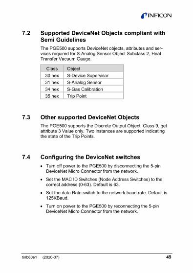
7.2 Supported DeviceNet Objects compliant with Semi Guidelines The PGE500 supports DeviceNet objects, attributes and ser-vices required for S-Analog Sensor Object Subclass 2, Heat Transfer Vacuum Gauge.
Class Object 30 hex S-Device Supervisor 31 hex S-Analog Sensor 34 hex S-Gas Calibration 35 hex Trip Point
7.3 Other supported DeviceNet Objects The PGE500 supports the Discrete Output Object, Class 9, get attribute 3 Value only. Two instances are supported indicating the state of the Trip Points.
7.4 Configuring the DeviceNet switches • Turn off power to the PGE500 by disconnecting the 5-pin
DeviceNet Micro Connector from the network.
• Set the MAC ID Switches (Node Address Switches) to the correct address (0-63). Default is 63.
• Set the data Rate switch to the network baud rate. Default is 125KBaud.
• Turn on power to the PGE500 by reconnecting the 5-pin DeviceNet Micro Connector from the network.
50 tinb60e1 (2020-07)
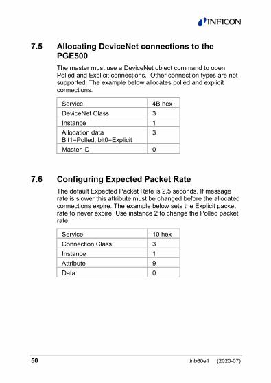
7.5 Allocating DeviceNet connections to the PGE500 The master must use a DeviceNet object command to open Polled and Explicit connections. Other connection types are not supported. The example below allocates polled and explicit connections.
Service 4B hex DeviceNet Class 3 Instance 1 Allocation data Bit1=Polled, bit0=Explicit
3
Master ID 0
7.6 Configuring Expected Packet Rate The default Expected Packet Rate is 2.5 seconds. If message rate is slower this attribute must be changed before the allocated connections expire. The example below sets the Explicit packet rate to never expire. Use instance 2 to change the Polled packet rate.
Service 10 hex Connection Class 3 Instance 1 Attribute 9 Data 0
tinb60e1 (2020-07) 51
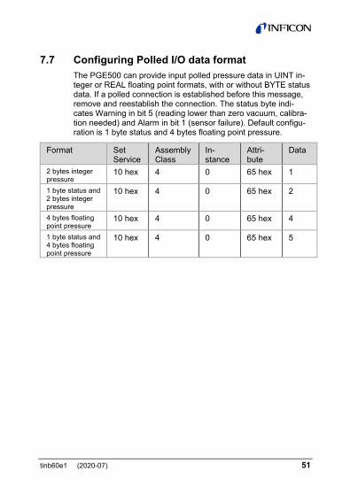
7.7 Configuring Polled I/O data format The PGE500 can provide input polled pressure data in UINT in-teger or REAL floating point formats, with or without BYTE status data. If a polled connection is established before this message, remove and reestablish the connection. The status byte indi-cates Warning in bit 5 (reading lower than zero vacuum, calibra-tion needed) and Alarm in bit 1 (sensor failure). Default configu-ration is 1 byte status and 4 bytes floating point pressure.
Format Set Service
Assembly Class
In-stance
Attri-bute
Data
2 bytes integer pressure
10 hex 4 0 65 hex 1
1 byte status and 2 bytes integer pressure
10 hex 4 0 65 hex 2
4 bytes floating point pressure
10 hex 4 0 65 hex 4
1 byte status and 4 bytes floating point pressure
10 hex 4 0 65 hex 5
52 tinb60e1 (2020-07)
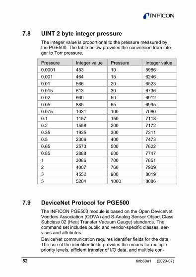
7.8 UINT 2 byte integer pressure The integer value is proportional to the pressure measured by the PGE500. The table below provides the conversion from inte-ger to Torr pressure.
Pressure Integer value Pressure Integer value 0.0001 453 10 5986 0.001 464 15 6246 0.01 566 20 6523 0.015 613 30 6736 0.02 660 50 6912 0.05 885 65 6995 0.075 1031 100 7060 0.1 1157 150 7118 0.2 1558 200 7172 0.35 1935 300 7311 0.5 2306 400 7473 0.65 2573 500 7622 0.85 2888 600 7747 1 3086 700 7851 2 4007 760 7909 3 4552 900 8019 5 5204 1000 8086
7.9 DeviceNet Protocol for PGE500 The INFICON PGE500 module is based on the Open DeviceNet Vendors Association (ODVA) and S-Analog Sensor Object Class Subclass 02 (Heat Transfer Vacuum Gauge) standards. The command set includes public and vendor-specific classes, ser-vices and attributes. DeviceNet communication requires identifier fields for the data. The use of the identifier fields provides the means for multiple priority levels, efficient transfer of I/O data, and multiple con-
tinb60e1 (2020-07) 53
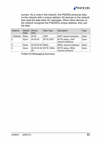
sumers. As a node in the network, the PGE500 produces data on the network with a unique address. All devices on the network that need the data listen for messages. When other devices on the network recognize the PGE500's unique address, they use the data
Instance Master Data
Device Data
Data Type Description Type
1 (default) None 00 00 UINT UINT vacuum pressure Open 2 None 00 00 00 BYTE,UINT BYTE status, UINT
vacuum pressure Open
4 None 00 00 00 00 REAL REAL vacuum pressure Open 5 None 00 00 00 00
00 BYTE, REAL BYTE status, REAL
vacuum pressure Open
Polled I/O Messaging Summary

54 tinb60e1 (2020-07)
7.9.1 Standard Objects There is a single instance of the Identity Object for the PGE500. No class attributes are supported. All of the instance attributes are contained in ROM or EEPROM.
7.9.1.1 Identity Object
Serv
ice
Cla
ss
Inst
ance
Attri
bute
Mas
ter
Dat
a
Dev
ice
Dat
a
Dat
a Ty
pe
De-
scrip
tion
Type
0Ehex 1 1 1 None 633 UINT Vendor Identification
Open
0Ehex 1 1 2 None 28 UINT Product Type Open 0Ehex 1 1 3 None 100 UINT Product ID Open 0Ehex 1 1 4 None 1.01 STRUCT Firmware
Revision Open
0Ehex 1 1 5 None 00 00 WORD Status and Fault Information
Open
0Ehex 1 1 6 None 00 00 00 00 UDINT Serial Number Open 0Ehex 1 1 7 None PGE500 S-STRING Identification Open 05hex 1 1 None None None Reset module to
Power-Up State Open
Explicit Message Summary - Identity Object
tinb60e1 (2020-07) 55
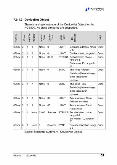
7.9.1.2 DeviceNet Object There is a single instance of the DeviceNet Object for the PGE500. No class attributes are supported.
Serv
ice
Cla
ss
Inst
ance
Attri
bute
Mas
ter
Dat
a
Dev
ice
Dat
a
Dat
a Ty
pe
De-
scrip
tion
Type
0Ehex 3 1 1 None 0 USINT Get node address, range 0-63
Open
0Ehex 3 1 2 None 0 USINT Get baud rate, range 0-2 Open 0Ehex 3 1 5 None 00 00 STRUCT Get allocation choice,
range 0-3 Get master ID, range 0-63
Open
0Ehex 3 1 6 None 0 BOOL The Node Address Switch(es) have changed since last power– up/reset.
Open
0Ehex 3 1 7 None 0 BOOL The Baud Rate Switch(es) have changed since last power– up/reset.
Open
0Ehex 3 1 8 None 00 USINT Actual value of Node Address switches
Open
0Ehex 3 1 9 None 00 USINT Actual value of Baud Rate switch
Open
4Bhex 3 1 None 03 00 Success STRUCT Set allocation choice, range 0-3 Set master ID, range 0-63
Open
4Chex 3 1 None 3 Success BYTE Release allocation, range 0-3
Open
Explicit Message Summary - DeviceNet Object
56 tinb60e1 (2020-07)
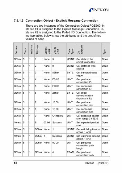
7.9.1.3 Connection Object - Explicit Message Connection There are two instances of the Connection Object PGE500. In-stance #1 is assigned to the Explicit Message Connection. In-stance #2 is assigned to the Polled I/O Connection. The follow-ing two tables below show the attributes and the predefined values of each.
Serv
ice
Cla
ss
Inst
ance
Attri
bute
Mas
ter
Dat
a
Dev
ice
Dat
a
Dat
a Ty
pe
De-
scrip
tion
Type
0Ehex 5 1 1 None 3 USINT Get state of the object, range 0-5
Open
0Ehex 5 1 2 None 0 USINT Get instance type, explicit
Open
0Ehex 5 1 3 None 83hex BYTE Get transport class trigger
Open
0Ehex 5 1 4 None FB 05 UINT Get produced connection ID
Open
0Ehex 5 1 5 None FC 05 UINT Get consumed connection ID
Open
0Ehex 5 1 6 None 21hex BYTE Get initial communication characteristics
Open
0Ehex 5 1 7 None 18 00 UINT Get produced connection size
Open
0Ehex 5 1 8 None 18 00 UINT Get consumed connection size
Open
0Ehex 5 1 9 None C4hex 09 UINT Get expected packet rate, range 0-65535
Open
10hex 5 1 9 00 00 Success UINT Set expected packet rate
Open
0Ehex 5 1 0Chex None 1 USINT Get watchdog timeout action, 1 or 3
Open
10hex 5 1 0Chex 1 Success USINT Set watchdog timeout action, 1 or 3
Open
0Ehex 5 1 0Dhex None 00 00 UINT Get produced connection path length
Open
0Ehex 5 1 0Ehex None 4 EPATH Get produced connection path
Open
tinb60e1 (2020-07) 57
Serv
ice
Cla
ss
Inst
ance
Attri
bute
Mas
ter
Dat
a
Dev
ice
Dat
a
Dat
a Ty
pe
De-
scrip
tion
Type
0Ehex 5 1 0Fhex None 00 00 UINT Get consumed connection path length
Open
0Ehex 5 1 10hex None 4 EPATH Get consumed connection path
Open
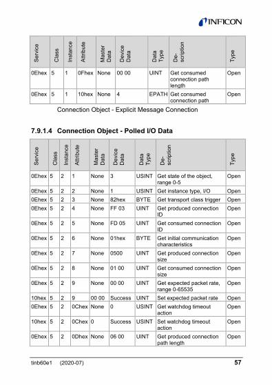
Connection Object - Explicit Message Connection
7.9.1.4 Connection Object - Polled I/O Data
Serv
ice
Cla
ss
Inst
ance
Attri
bute
Mas
ter
Dat
a
Dev
ice
Dat
a
Dat
a Ty
pe
De-
scrip
tion
Type
0Ehex 5 2 1 None 3 USINT Get state of the object, range 0-5
Open
0Ehex 5 2 2 None 1 USINT Get instance type, I/O Open 0Ehex 5 2 3 None 82hex BYTE Get transport class trigger Open 0Ehex 5 2 4 None FF 03 UINT Get produced connection
ID Open
0Ehex 5 2 5 None FD 05 UINT Get consumed connection ID
Open
0Ehex 5 2 6 None 01hex BYTE Get initial communication characteristics
Open
0Ehex 5 2 7 None 0500 UINT Get produced connection size
Open
0Ehex 5 2 8 None 01 00 UINT Get consumed connection size
Open
0Ehex 5 2 9 None 00 00 UINT Get expected packet rate, range 0-65535
Open
10hex 5 2 9 00 00 Success UINT Set expected packet rate Open 0Ehex 5 2 0Chex None 0 USINT Get watchdog timeout
action Open
10hex 5 2 0Chex 0 Success USINT Set watchdog timeout action
Open
0Ehex 5 2 0Dhex None 06 00 UINT Get produced connection path length
Open
58 tinb60e1 (2020-07)
10hex 5 2 0Dhex 06 00 Success UINT Set produced connection path length
Open
0Ehex 5 2 0Ehex None 01 EPATH Get produced connection path
Open
10hex 5 2 0Ehex 01 Success EPATH set produced connection path
Open
0Ehex 5 2 0Fhex None 06 00 UINT Get consumed connection path length
Open
0Ehex 5 2 10hex None 00 EPATH Get consumed connection path
Open
10hex 5 2 10hex 00 Success EPATH Set consumed connection path
Open
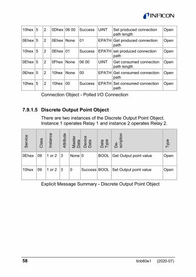
Connection Object - Polled I/O Connection
7.9.1.5 Discrete Output Point Object There are two instances of the Discrete Output Point Object. Instance 1 operates Relay 1 and instance 2 operates Relay 2.
Serv
ice
Cla
ss
Inst
ance
Attri
bute
Mas
ter
Dat
a D
evic
e D
ata
Dat
a Ty
pe
De-
scrip
tion
Type
0Ehex 09 1 or 2 3 None 0 BOOL Get Output point value Open
10hex 09 1 or 2 3 0 Success BOOL Set Output point value Open
Explicit Message Summary - Discrete Output Point Object

tinb60e1 (2020-07) 59
7.9.1.6 S-Device Supervisor Object This object models the interface, functions and behavior associ-ated with the management of application objects for devices within the "Hierarchy of Semiconductor Equipment Devices".
Serv
ice
Cla
ss
Inst
ance
Attri
bute
Mas
ter
Dat
a
Dev
ice
Dat
a
Dat
a Ty
pe
De-
scrip
tion
Type
0Ehex 30hex 1 3 None VG SHORT STRING
Device Type Open
0Ehex 30hex 1 4 None E54-0997 SHORT STRING
SEMI Standard Revision Level
Open
0Ehex 30hex 1 5 None INFICON AG
SHORT STRING
Manufacturer's Name
Open
0Ehex 30hex 1 6 None PGE500 SHORT STRING
Manufacturer's Model Number
Open
0Ehex 30hex 1 7 None V1.01 SHORT STRING
Software Revision Level
Open
0Ehex 30hex 1 8 None 100 SHORT STRING
Hardware Revision Level
Open
0Ehex 30hex 1 9 None 50005384 SHORT STRING
Manufacturer's Serial Number
Open
0Ehex 30hex 1 0Bhex None 02 USINT Device Status Open 0Ehex 30hex 1 0Chex None 00 BYTE Exception Status Open 0Ehex 30hex 1 0Fhex None 01 BOOL Alarm Enable Open 10hex 30hex 1 0Fhex 01 Success BOOL Alarm Enable Open 0Ehex 30hex 1 10hex None 01 BOOL Warning Enable Open 10hex 30hex 1 10hex 01 Success BOOL Warning Enable Open
Explicit Message Summary - S-Device Supervisor Object
60 tinb60e1 (2020-07)
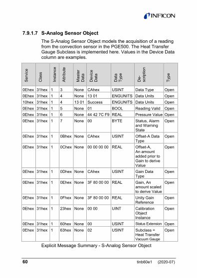
7.9.1.7 S-Analog Sensor Object The S-Analog Sensor Object models the acquisition of a reading from the convection sensor in the PGE500. The Heat Transfer Gauge Subclass is implemented here. Values in the Device Data column are examples.
Serv
ice
Cla
ss
Inst
ance
Attri
bute
Mas
ter
Dat
a
Dev
ice
Dat
a
Dat
a Ty
pe
De-
scrip
tion
Type
0Ehex 31hex 1 3 None CAhex USINT Data Type Open 0Ehex 31hex 1 4 None 13 01 ENGUNITS Data Units Open 10hex 31hex 1 4 13 01 Success ENGUNITS Data Units Open 0Ehex 31hex 1 5 None 01 BOOL Reading Valid Open 0Ehex 31hex 1 6 None 44 42 7C F9 REAL Pressure Value Open 0Ehex 31hex 1 7 None 00 BYTE Status, Alarm
and Warning State
Open
0Ehex 31hex 1 0Bhex None CAhex USINT Offset-A Data Type
Open
0Ehex 31hex 1 0Chex None 00 00 00 00 REAL Offset-A, An amount added prior to Gain to derive Value
Open
0Ehex 31hex 1 0Dhex None CAhex USINT Gain Data Type
Open
0Ehex 31hex 1 0Ehex None 3F 80 00 00 REAL Gain, An amount scaled to derive Value
Open
0Ehex 31hex 1 0Fhex None 3F 80 00 00 REAL Unity Gain Reference
Open
0Ehex 31hex 1 23hex None 00 00 UINT Calibration Object Instance
Open
0Ehex 31hex 1 60hex None 00 USINT Status Extension Open 0Ehex 31hex 1 63hex None 02 USINT Subclass =
Heat Transfer Vacuum Gauge
Open
Explicit Message Summary - S-Analog Sensor Object
tinb60e1 (2020-07) 61
7.9.1.8 S-Gas Calibration Object The S-Gas Calibration Object affects the behavior of an asso-ciated S-Analog Sensor object instance; a device profile will show a relationship between these two objects where an S-Gas Calibration Object is used.
Serv
ice
Cla
ss
Inst
ance
Attri
bute
Mas
ter
Dat
a
Dev
ice
Dat
a
Dat
a Ty
pe
Des
crip
tio
n
Type
0Ehex 34hex 1 3 None 0D 00 UINT Gas Standard Number = Nitrogen
Open
0Ehex 34hex 1 4 None 01 00 UINT Valid Sensor Instance Open
Explicit Message Summary - S-Gas Calibration Object
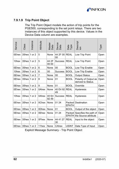
62 tinb60e1 (2020-07)
7.9.1.9 Trip Point Object The Trip Point Object models the action of trip points for the PGE500, corresponding to the set point relays. There are two instances of this object supported by this device. Values in the Device Data column are examples.
Serv
ice
Cla
ss
Inst
ance
Attri
bute
Mas
ter
Dat
a
Dev
ice
Dat
a
Dat
a Ty
pe
Des
crip
tio
n
Type
0Ehex 35hex 1 or 2 5 None 44 2F 00 00
REAL Low Trip Point Open
10hex 35hex 1 or 2 5 44 2F 00 00
Success REAL Low Trip Point Open
0Ehex 35hex 1 or 2 6 None 00 BOOL Low Trip Enable Open 10hex 35hex 1 or 2 6 00 Success BOOL Low Trip Enable Open 0Ehex 35hex 1 or 2 7 None 00 BOOL Output Status Open 0Ehex 35hex 1 or 2 8 None 01 BOOL Polarity of Output as
derived to Status. Open
0Ehex 35hex 1 or 2 9 None 01 BOOL Override Open 0Ehex 35hex 1 or 2 0Ahex None 40 E4 92
49 REAL Hysteresis Open
10hex 35hex 1 or 2 0Ahex 40 E4 92 49
Success REAL Hysteresis Open
0Ehex 35hex 1 or 2 0Chex None 01 24 Packed EPATH
Destination Open
0Ehex 35hex 1 or 2 0Dhex None 01 BOOL Output of the object Open 0Ehex 35hex 1 or 2 0Ehex None 01 24 Packed
EPATH Specifies the path of the Source attribute
Open
0Ehex 35hex 1 or 2 0Fhex None 44 41 27 30
REAL Input to the object Open
0Ehex 35hex 1 or 2 11hex None CAhex USINT Data Type of Input Open
Explicit Message Summary - Trip Point Object

tinb60e1 (2020-07) 63
8 Service
8.1 Calibration Every INFICON module is calibrated prior to shipment using ni-trogen (N2). However, you can calibrate the instrument by adjust-ing zero (vacuum) and span (atmosphere) using the procedure described previously in section 4.6.4 titled "Calibration". Zero and span (atmosphere) calibration affect the displayed value and the output signal. Zero calibration optimizes performance of the gauge when operating at a low pressure range of 1.00×10⁻⁴ Torr to 1.00×10⁻³ Torr. If your minimum operating pressure is higher than 1.00×10⁻³ Torr, it is not normally necessary to perform cali-bration at zero and thus span calibration should be adequate. If you are able to evacuate your system to below 1.00×10⁻⁴ Torr, it is always a good practice to check and set zero if necessary. This will also improve performance in cases where gauge con-tamination is causing higher readings than 1.00×10⁻⁴ Torr even though the system has been evacuated to below 1.00×10⁻⁴ Torr. Care should be exercised when using gases other than nitrogen (N2).
8.2 Maintenance In general, maintenance is not required for your INFICON mod-ule. Periodic performance checks may be done by comparing the gauge to a known reference standard.
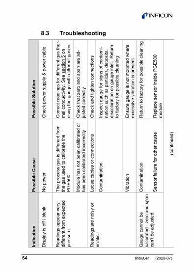
64 tinb60e1 (2020-07)
8.3 Troubleshooting
Poss
ible
Sol
utio
n
Che
ck p
ower
sup
ply
& po
wer
cab
le
Cor
rect
read
ings
for d
iffer
ent g
as th
er-
mal
con
duct
ivity
. See
sec
tion
5 on
us
ing
the
gaug
e w
ith d
iffer
ent g
ases
Che
ck th
at z
ero
and
span
are
ad-
just
ed c
orre
ctly
Che
ck a
nd ti
ghte
n co
nnec
tions
Insp
ect g
auge
for s
igns
of c
onta
mi-
natio
n su
ch a
s pa
rticl
es, d
epos
its,
disc
olor
atio
n on
gau
ge in
let.
Ret
urn
to fa
ctor
y fo
r pos
sibl
e cl
eani
ng
Ensu
re g
auge
is n
ot m
ount
ed w
here
ex
cess
ive
vibr
atio
n is
pre
sent
Ret
urn
to fa
ctor
y fo
r pos
sibl
e cl
eani
ng
Rep
lace
sen
sor i
nsid
e PG
E500
m
odul
e
(con
tinue
d)
Poss
ible
Cau
se
No
pow
er
The
proc
ess
gas
is d
iffer
ent f
rom
th
e ga
s us
ed to
cal
ibra
te th
e PG
E500
Mod
ule
has
not b
een
calib
rate
d or
ha
s be
en c
alib
rate
d in
corre
ctly
Loos
e ca
bles
or c
onne
ctio
ns
Con
tam
inat
ion
Vibr
atio
n
Con
tam
inat
ion
Sens
or fa
ilure
for o
ther
cau
se
Indi
catio
n
Dis
play
is o
ff / b
lank
Rea
ding
s ap
pear
ver
y di
ffere
nt fr
om e
xpec
ted
pres
sure
Rea
ding
s ar
e no
isy
or
erra
tic
Gau
ge c
anno
t be
calib
rate
d - z
ero
and
span
ca
n’t b
e ad
just
ed
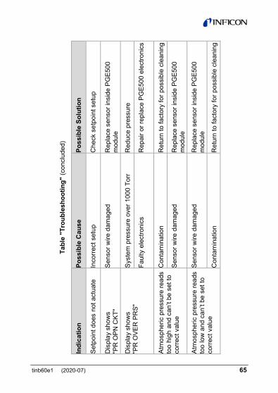
tinb60e1 (2020-07) 65
Tabl
e "T
roub
lesh
ootin
g" (c
oncl
uded
)
Poss
ible
Sol
utio
n
Che
ck s
etpo
int s
etup
Rep
lace
sen
sor i
nsid
e PG
E500
m
odul
e
Red
uce
pres
sure
Rep
air o
r rep
lace
PG
E500
ele
ctro
nics
Ret
urn
to fa
ctor
y fo
r pos
sibl
e cl
eani
ng
Rep
lace
sen
sor i
nsid
e PG
E500
m
odul
e
Rep
lace
sen
sor i
nsid
e PG
E500
m
odul
e
Ret
urn
to fa
ctor
y fo
r pos
sibl
e cl
eani
ng
Poss
ible
Cau
se
Inco
rrect
set
up
Sens
or w
ire d
amag
ed
Syst
em p
ress
ure
over
100
0 To
rr
Faul
ty e
lect
roni
cs
Con
tam
inat
ion
Sens
or w
ire d
amag
ed
Sens
or w
ire d
amag
ed
Con
tam
inat
ion
Indi
catio
n
Setp
oint
doe
s no
t act
uate
Dis
play
sho
ws
"PR
OPN
CKT
"
Dis
play
sho
ws
"PR
OVE
R P
RS"
Atm
osph
eric
pre
ssur
e re
ads
too
high
and
can
’t be
set
to
corre
ct v
alue
Atm
osph
eric
pre
ssur
e re
ads
too
low
and
can
’t be
set
to
corre
ct v
alue
66 tinb60e1 (2020-07)
8.4 Contamination The most common cause of all vacuum gauge failures is conta-mination of the sensor. Noisy or erratic readings, the inability to set zero or atmosphere and total gauge failure, are all possible indications of gauge contamination.
Contamination can be generally characterized as either: A) a reaction of process gases with sensor elements, or B) an accumulation of material on the sensor elements. Sen-
sors that fail due to chemical reaction are generally not salvageable. Sensors that fail due to condensation, coatings, or particles may possibly be restored by cleaning.
A) Reactive Gases If process gases react with the materials of construction of the sensor, the result is corrosion and disintegration of the sensor over time. The chemistry of the gases used for plasma etching and other reactive semiconductor processes are examples where this failure mode is possible. In this case, cleaning can’t solve the problem because the sensor has been destroyed. The sensor or module must be replaced.
If you experience this failure mode quickly or frequently, you should consider a different vacuum gauge for your application. Thermal vacuum gauges may be available with different sensor materials that are not as reactive with your particular process gases. The standard gold plated tungsten sensor used in the INFICON convection gauge is offered for use with air and inert gases such as N2, argon, etc. INFICON also offers platinum sen-sors for applications not compatible with gold plated tungsten.
There is no material that is universally chemical resistant; your choice of vacuum gauge (as well as all other vacuum compo-nents) should take into consideration the potential reactions between your process gases and the materials of construction. Consider what effect water vapor will have when combined with your process gases because a finite amount of water will enter the chamber during venting to atmosphere with air.

tinb60e1 (2020-07) 67
B) Oil, Condensation, Coatings, and Particles If the failure is due to an accumulation of material in the gauge, we may be able to restore your gauge or module by cleaning. Contamination may be as simple as condensed water, or as difficult as solid particles.
Oils and hydrocarbons: Exposure of the gauge internal surfaces to oils and hydrocarbons can result in sensor contamination. Some of these types of contamination may be removed by cleaning the gauge. If there is the possibility of oil back stream-ing from wet vacuum pumps, it is recommended that a filter or trap be installed to prevent contamination of components of your vacuum system.
Condensation: Some gases (such as water vapor) can con-dense on sensor surfaces, forming a liquid coating that changes the rate at which heat is removed from the sensor (which chang-es the calibration). The sensor can often be restored simply by pumping on the gauge between process cycles. A dry N2 purge will help speed up drying, or the gauge may be gently heated provided temperature doesn't exceed the specified limit of 40 °C, operating.
Coatings: Some gases can condense on sensor surfaces, form-ing a solid coating, which changes the rate at which heat is re-moved from the sensor. Some of these coatings may be re-moved by cleaning the gauge.
Particles: Particles generated by the process may enter the gauge during the process cycle or during the venting cycle. The result is interference with heat removal from the sensor. In this case, cleaning may be able to remove particles from the gauge. However, particulate contamination is the most difficult to re-move as particles can become stubbornly trapped inside the gauge. In some processes, solid particles are created during the process throughout the chamber including inside the gauge. Par-ticles tend to form on cooler surfaces such as in a gauge at room temperature. You may slow down the build-up of particles in the gauge by keeping the gauge warm (within specified limits) during the process cycle.

68 tinb60e1 (2020-07)
Particles in the process chamber may be swept into the gauge during the vent cycle. The PGE500 has a screen built into the gauge port to help keep the largest particles out of the gauge. In very dirty applications, or where particles are small enough to get through the screen, an additional filter installed on the inlet may help prolong the gauge life.
In some vacuum processes, desorbed and sputtered materials from the process may enter vacuum components connected to the process vacuum chamber by line-of-sight transport, espe-cially under high vacuum conditions, i.e., in the molecular flow regime. To prevent materials that may be transported via line-of-sight momentum from entering your vacuum gauge or other components, it is advisable to install some form of apparatus that will block the line-of-sight. In many cases a simple 90° elbow may help prevent or reduce the transport of particles from enter-ing your vacuum gauge.
In the event of gauge contamination please contact the factory to return the gauge for possible cleaning if the gauge has not been exposed to hazardous materials.
8.5 Module and sensor replacement The sensor in the PGE500 can be replaced in the field. Once a new sensor is installed the procedure described in section 4.6.4 must be followed to set atmosphere and zero.
To replace the sensor, disconnect the cable from the gauge and remove the gauge from the vacuum system. Use the following procedure to replace sensor:

tinb60e1 (2020-07) 69
Remove all 8 Torx screws from both side panels of the enclosure.
Remove the back panel by lifting it off from the enclosure.
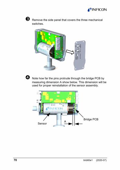
70 tinb60e1 (2020-07)
Remove the side panel that covers the three mechanical switches.
Note how far the pins protrude through the bridge PCB by measuring dimension A show below. This dimension will be used for proper reinstallation of the sensor assembly.
Sensor
Bridge PCB A

tinb60e1 (2020-07) 71
Remove the bridge PCB from the assembly.
Remove the sensor from the assembly by pulling it up and out of the enclosure assembly.

72 tinb60e1 (2020-07)
Push pins of new sensor through the holes in the Bridge PCB. Set Dimension A as previously measured in step 4.
GENTLY lift the CPU PCB and install the bridge PCB / sen-sor assembly into the CPU PCB.
A
Lift CPU PCB

tinb60e1 (2020-07) 73
After reinstalling the bridge PCB / sensor into the CPU PCB reinstall the side panel.
Reinstall the back panel …

74 tinb60e1 (2020-07)
… and reattach all 8 Torx screws on both side panels of the enclosure. Reinstall in vacuum system. Set atm. and zero again.
9 Factory Service and Support If you need help setting up, operating, troubleshooting, or obtaining a return materials authorization number (RMA number) to return the module for diagnosis, please contact us during normal business hours Monday through Friday, at +423 / 388 3111. Or e-mail us at [email protected].
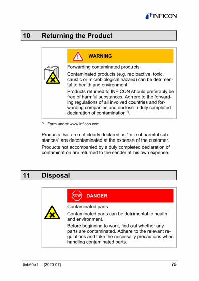
tinb60e1 (2020-07) 75
10 Returning the Product
WARNING
Forwarding contaminated products Contaminated products (e.g. radioactive, toxic, caustic or microbiological hazard) can be detrimen-tal to health and environment. Products returned to INFICON should preferably be free of harmful substances. Adhere to the forward-ing regulations of all involved countries and for-warding companies and enclose a duly completed declaration of contamination *).
*) Form under www.inficon.com
Products that are not clearly declared as "free of harmful sub-stances" are decontaminated at the expense of the customer. Products not accompanied by a duly completed declaration of contamination are returned to the sender at his own expense.
11 Disposal
DANGER
Contaminated parts Contaminated parts can be detrimental to health and environment. Before beginning to work, find out whether any parts are contaminated. Adhere to the relevant re-gulations and take the necessary precautions when handling contaminated parts.
76 tinb60e1 (2020-07)
WARNING
Substances detrimental to the environment Products or parts thereof (mechanical and electric components, operating fluids etc.) can be detrimen-tal to the environment. Dispose of such substances in accordance with the relevant local regulations.
Separating the components After disassembling the product, separate its components ac-cording to the following criteria: • Non-electronic components
Such components must be separated according to their materials and recycled.
• Electronic components Such components must be separated according to their ma-terials and recycled.
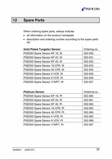
tinb60e1 (2020-07) 77
12 Spare Parts
When ordering spare parts, always indicate • all information on the product nameplate • description and ordering number according to the spare parts
list Gold Plated Tungsten Sensor Ordering no. PGE500 Spare Sensor KF 16, W 352-550 PGE500 Spare Sensor KF 25, W 352-551 PGE500 Spare Sensor KF 40, W 352-552 PGE500 Spare Sensor 16 CFR, W 352-553 PGE500 Spare Sensor 40 CFR, W 352-554 PGE500 Spare Sensor 4 VCR, W 352-555 PGE500 Spare Sensor 8 VCR, W 352-556 PGE500 Spare Sensor ⅛"NPT, W 352-557 Platinum Sensor Ordering no. PGE500 Spare Sensor KF 16, Pt 352-560 PGE500 Spare Sensor KF 25, Pt 352-561 PGE500 Spare Sensor KF 40, Pt 352-562 PGE500 Spare Sensor 16 CFR, Pt 352-563 PGE500 Spare Sensor 40 CFR, Pt 352-564 PGE500 Spare Sensor 4 VCR, Pt 352-565 PGE500 Spare Sensor 8 VCR, Pt 352-566 PGE500 Spare Sensor ⅛"NPT, Pt 352-567
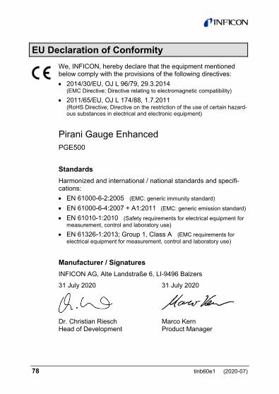
78 tinb60e1 (2020-07)
EU Declaration of Conformity We, INFICON, hereby declare that the equipment mentioned below comply with the provisions of the following directives: • 2014/30/EU, OJ L 96/79, 29.3.2014
(EMC Directive; Directive relating to electromagnetic compatibility) • 2011/65/EU, OJ L 174/88, 1.7.2011
(RoHS Directive; Directive on the restriction of the use of certain hazard-ous substances in electrical and electronic equipment)
Pirani Gauge Enhanced PGE500
Standards Harmonized and international / national standards and specifi-cations: • EN 61000-6-2:2005 (EMC: generic immunity standard) • EN 61000-6-4:2007 + A1:2011 (EMC: generic emission standard) • EN 61010-1:2010 (Safety requirements for electrical equipment for
measurement, control and laboratory use) • EN 61326-1:2013; Group 1, Class A (EMC requirements for
electrical equipment for measurement, control and laboratory use)
Manufacturer / Signatures INFICON AG, Alte Landstraße 6, LI-9496 Balzers
31 July 2020 31 July 2020
Dr. Christian Riesch Head of Development
Marco Kern Product Manager

tinb60e1 (2020-07) 79
Notes

LI–9496 Balzers
Liechtenstein Tel +423 / 388 3111 Fax +423 / 388 3700 [email protected]
www.inficon.com
Original: English