EJX510B and EJX530B Absolute and Gauge Pressure ...
86
User’s Manual Yokogawa Electric Corporation EJX510B and EJX530B Absolute and Gauge Pressure Transmitters IM 01C27F01-01EN IM 01C27F01-01EN 10th Edition
-
Upload
khangminh22 -
Category
Documents
-
view
1 -
download
0
Transcript of EJX510B and EJX530B Absolute and Gauge Pressure ...

User’sManual
Yokogawa Electric Corporation
EJX510B and EJX530BAbsolute and Gauge PressureTransmitters
IM 01C27F01-01EN
IM 01C27F01-01EN10th Edition

Toc-1
IM 01C27F01-01EN
EJX510B and EJX530BAbsolute and Gauge Pressure Transmitters
IM 01C27F01-01EN 10th Edition
10th Edition: May 2017 (KP)All Rights Reserved, Copyright © 2010, Yokogawa Electric Corporation
Contents1. Introduction ............................................................................................... 1-1
1.1 Safe Use of This Product .................................................................................1-21.2 Radio Wave ........................................................................................................1-31.3 Warranty .............................................................................................................1-41.4 Trademarks ........................................................................................................1-41.5 ATEX Documentation .......................................................................................1-51.6 Control of Pollution Caused by the Product ..................................................1-6
2. Handling Cautions .................................................................................... 2-12.1 ModelandSpecificationsCheck .....................................................................2-12.2 Unpacking ..........................................................................................................2-12.3 Storage ...............................................................................................................2-12.4 Selecting the Installation Location ................................................................2-22.5 Pressure Connection ........................................................................................2-32.6 Restrictions on Use of Radio Transceivers ...................................................2-32.7 Insulation Resistance and Dielectric Strength Test ...................................... 2-32.8 Installation of an Explosion-Protected Instrument ....................................... 2-4
2.8.1 FM Approval .......................................................................................2-4
2.8.2 CSACertification ................................................................................2-5
2.8.3 ATEXCertification ..............................................................................2-6
2.8.4 IECExCertification .............................................................................2-7
2.9 EMC Conformity Standards .............................................................................2-82.10 Pressure Equipment Directive (PED) ..................................................2-82.11 Low Voltage Directive .......................................................................................2-92.12 Regulatory Compliance for Radio and Telecommunication ........................ 2-9
2.12.1 Radio and Telecommunications Terminal Equipment Directive (R&TTE) ....................................................................................2-9
2.12.2 FCC compliance ................................................................................2-9
2.12.3 Industry Canada (IC) compliance ....................................................2-10
2.13 RoHS .................................................................................................................2-10
3. Component Names .................................................................................. 3-14. Installation ................................................................................................. 4-1
4.1 Precautions .......................................................................................................4-14.2 Mounting ............................................................................................................4-14.3 Rotating Transmitter Section ...........................................................................4-2

Toc-2
IM 01C27F01-01EN
4.4 Changing the Direction of Integral Indicator .................................................4-24.5 Changing the direction of the antenna ...........................................................4-3
5. Installing Impulse Piping ......................................................................... 5-15.1 Impulse Piping Installation Precautions ........................................................5-1
5.1.1 Connecting Impulse Piping to a Transmitter ...................................... 5-1
5.1.2 Routing the Impulse Piping ................................................................5-1
5.2 Impulse Piping Connection Examples ...........................................................5-2
6. Wiring ......................................................................................................... 6-16.1 Mounting Antenna and Wiring .........................................................................6-1
6.1.1 Mounting the antenna ........................................................................6-1
6.1.2 Mounting External Antenna and Wiring Antenna Extension Cable ... 6-2
6.1.2.1 Mounting of External Antenna ............................................................6-2
6.1.2.2 Wiring of Antenna Extension Cable ...................................................6-2
6.1.2.3 Mounting of Arrester and Wiring ........................................................6-4
6.2 Grounding ..........................................................................................................6-4
7. Operation ................................................................................................... 7-17.1 Preparation for Starting Operation .................................................................7-17.2 Zero Point Adjustment .....................................................................................7-27.3 Starting Operation ............................................................................................7-27.4 Connecting to the Field Wireless Network .....................................................7-37.5 Shutting Down the Transmitter .......................................................................7-5
8. Setting Parameters ................................................................................... 8-18.1 Environment for parameter setting .................................................................8-18.2 Preparing Software ...........................................................................................8-1
8.2.1 SoftwaresfortheFieldWirelessConfigurationToolandtheDeviceConfigurationTool ..............................................................................8-1
8.2.2 Software Download ............................................................................8-1
8.3 Setting Parameters ...........................................................................................8-18.3.1 Parameter Usage and Selection ........................................................8-1
8.3.2 Function Block and Menu Tree ..........................................................8-2
8.3.3 Parameters for Wireless Communication ........................................8-10
8.3.4 Tag and Device Information .............................................................8-10
8.3.5 Unit ................................................................................................... 8-11
8.3.6 Range Change ................................................................................. 8-11
8.3.7 Output Signal Low Cut Mode Setup ................................................ 8-11
8.3.8 Integral Indicator Scale Setup ..........................................................8-12
8.3.9 Unit for Displayed Temperature .......................................................8-12
8.3.10 Zero Point Adjustment and Span Adjustment ..................................8-12
8.3.11 Software Write Protect .....................................................................8-14
8.3.12 Switching to Deep Sleep Mode ........................................................8-15
8.3.13 Switching to Silence Mode ...............................................................8-15

Toc-3
IM 01C27F01-01EN
8.4 Self-Diagnostics ..............................................................................................8-168.4.1 IdentifyProblemsbyUsingtheDeviceConfigurationTool ..............8-16
8.4.2 Alert Report ......................................................................................8-17
8.4.3 Checking with Integral Indicator .......................................................8-19
9. Maintenance .............................................................................................. 9-19.1 Overview ............................................................................................................9-19.2 Calibration Instruments Selection ..................................................................9-19.3 Calibration .........................................................................................................9-19.4 Disassembly and Reassembly ........................................................................9-3
9.4.1 Replacing the Integral Indicator .........................................................9-4
9.4.2 Replacing the RF Assembly ...............................................................9-4
9.4.3 Replacing the CPU Assembly ............................................................9-4
9.4.4 Cleaning and Replacing the Capsule Assembly ............................... 9-5
9.4.5 Replacing the Battery Pack ...............................................................9-6
9.4.6 Replacing the Batteries ......................................................................9-6
9.4.7 Handling Batteries ..............................................................................9-7
9.5 Troubleshooting ................................................................................................9-89.5.1 Basic Troubleshooting .......................................................................9-8
9.5.2 Troubleshooting Flowcharts ...............................................................9-9
9.5.3 Errors and Countermeasures .......................................................... 9-11
10. Parameter Summary .............................................................................. 10-111. GeneralSpecifications .......................................................................... 11-1
11.1 StandardSpecifications ................................................................................. 11-111.2 ModelandSuffixCodes ................................................................................. 11-311.3 OptionalSpecifications .................................................................................. 11-311.4 Dimensions ...................................................................................................... 11-5
Revision Information

<1. Introduction> 1-1
IM 01C27F01-01EN
1. IntroductionThank you for purchasing the DPharp EJX Pressure transmitter.
Your EJX Pressure Transmitter was precisely calibrated at the factory before shipment. To ensure bothsafetyandefficiency,pleasereadthismanualcarefully before you operate the instrument.
NOTEThis manual covers the EJX510B absolute pressure transmitter and EJX530B gauge pressure transmitter, and describes how to use for the detachable antenna type transmitters (Amplifierhousingcode8or9). Unless otherwise stated, the illustrations in this manual are of the EJX530B gauge pressure transmitter with a detachable antenna type. Usersoftheothermodelsandspecificationsshould bear in mind that certain features of their instrument will differ from those shown in the illustrations of the EJX530B.
MODEL SUFFIXEJX510B --8*
--9*EJX530B
Regarding This Manual
• Thismanualshouldbeprovidedtotheenduser.
• Thismanualandtheidentificationtagattachedon packing box are essential parts of the product; keep them in a safe place for future reference.
• Thecontentsofthismanualaresubjecttochange without prior notice.
• Allrightsreserved.Nopartofthismanualmaybe reproduced in any form without Yokogawa’s written permission.
• Yokogawamakesnowarrantyofanykindwithregard to this manual, including, but not limited to, implied warranty of merchantability and fitnessforaparticularpurpose.
• Ifanyquestionarisesorerrorsarefound,orifany information is missing from this manual, please inform the nearest Yokogawa sales office.
• Thespecificationscoveredbythismanualarelimited to those for the standard type under the specifiedmodelnumberbreak-downanddonot cover custom-made instruments. When productswhosesuffixcodeoroptionalcodescontain code “Z” and an exclusive document is attached, please read it along with this manual.
• Pleasenotethatchangesinthespecifications,construction, or component parts of the instrumentmaynotimmediatelybereflectedin this manual at the time of change, provided that postponement of revisions will not cause difficultytotheuserfromafunctionalorperformance standpoint.
• Yokogawaassumesnoresponsibilitiesforthisproduct except as stated in the warranty.
• Ifthecustomeroranythirdpartyisharmedbythe use of this product, Yokogawa assumes no responsibility for any such harm owing to any defects in the product which were not predictable, or for any indirect damages.
• Thefollowingsafetysymbolsareusedinthismanual and on the product:
WARNING
Indicates a potentially hazardous situation which, if not avoided, could result in death or serious injury.
CAUTIONIndicates a potentially hazardous situation which, if not avoided, may result in minor or moderate injury or physical damage. It may also be used to alert against unsafe practices.
IMPORTANTIndicates that operating the hardware or software in this manner may damage it or lead to system failure.
<1. Introduction> 1-2
IM 01C27F01-01EN
NOTEDraws attention to information essential for understanding the operation and features.
Functional grounding terminal
CautionThis symbol indicates that the operator must refer to an explanation in the user’s manual in order to avoid the risk of injury or death of personnel or damage to the instrument.
Notice
NO RIGHTS OR LICENSES, EXPRESS OR IMPLIED, ARE GRANTED TO USE THIRD-PARTY DEVICES IN COMBINATION WITH THESE PRODUCTS IN A WIRELESS MESH NETWORK, OR TO USE THIRD-PARTY SERVICES TO ACCESS, MONITOR OR CONTROL THESE PRODUCTS IN A WIRELESS MESH NEWORK VIA THE INTERNET OR ANOTHER EXTERNAL WIDE AREA NETWORK.
Patent Marking
Covered by one or more claims of patents: http://sipcollc.com/patent-list/ and http://intusiq.com/patent-list/.
1.1 Safe Use of This Product This product is designed to be used by a person with specialized knowledge. For the safety of the operator and to protect the instrument and the system, please be sure to follow this manual’s safety instructions when handling this instrument. If these instructions are not heeded, the protection provided by this instrument may be impaired. In this case, Yokogawa cannot guarantee that the instrument can be safely operated. Please pay special attention to the following points:
(a) Installation
• Thisinstrumentmayonlybeinstalledbyanengineer or technician who has an expert knowledge of this device. Operators are not allowed to carry out installation unless they meet this condition.
• Withhighprocesstemperatures,caremustbe taken not to burn yourself by touching the instrument or its casing.
• Neverloosentheprocessconnectornutswhenthe instrument is installed in a process. This can lead to a sudden, explosive release of process fluids.
• Whendrainingcondensatefromthepressuredetector section, take appropriate precautions to prevent the inhalation of harmful vapors and thecontactoftoxicprocessfluidswiththeskinor eyes.
• Whenremovingtheinstrumentfromahazardousprocess,avoidcontactwiththefluidand the interior of the meter.
• Allinstallationshallcomplywithlocalinstallationrequirements and the local electrical code.
(b) Wiring
• Theinstrumentmustbeinstalledbyanengineer or technician who has an expert knowledge of this instrument. Operators are not permitted to carry out wiring unless they meet this condition.
<1. Introduction> 1-3
IM 01C27F01-01EN
(c) Maintenance
• Pleasecarryoutonlythemaintenanceprocedures described in this manual. If you require further assistance, please contact the nearestYokogawaoffice.
• Careshouldbetakentopreventthebuildupofdust or other materials on the display glass and the name plate. To clean these surfaces, use a soft, dry cloth.
(d) Explosion Protected Type Instrument
• UsersofexplosionproofinstrumentsshouldreferfirsttoSection2.8(InstallationofanExplosion-Protected Instrument) of this manual.
• Theuseofthisinstrumentisrestrictedtothosewho have received appropriate training in the device.
• Takecarenottocreatesparkswhenaccessingthe instrument or peripheral devices in a hazardous location.
• Repairormodificationtothisinstrumentbycustomer will cause malfunction of explosion protect function and hazardous situation. If you needtorepairormodification,pleasecontactthenearestYokogawaoffice.
(e) Modification
• Yokogawawillnotbeliableformalfunctionsordamageresultingfromanymodificationmadeto this instrument by the customer.
(f) Product Disposal
• Theinstrumentshouldbedisposedofinaccordance with local and national legislation/regulations.
(g) Authorized Representative in EEA
• InrelationtotheCEMarking,Theauthorizedrepresentative for this product in the EEA (European Economic Area) is:
Yokogawa Europe B.V. Euroweg 2, 3825 HD Amersfoort,
The Netherlands
1.2 Radio Wave
IMPORTANT- This instrument is equipped with a wireless
modulewhichisdesignatedasacertificationof construction type as a wireless facility for 2.4 GHz band low-power data communication system of the Radio Act. Refer to 2.12 “Regulatory Compliance for Radio and Telecommunication” for detail.
- Duetothedesignatedcertificationofconstruction type, users may be subject to legal punishment in case of:- Disassembling or modifying the wireless
module or antenna in this instrument- Peelingoffthecertificationlabelattached
to the wireless module in this instrument- Preventing interference with other wireless
stations The operating frequency bandwidth of this
instrument may overlap the same range asindustrialdevices,scientificdevices,medical devices, microwave ovens, licensed premises radio stations and non-licensed specifiedlow-powerradiostationsformobileobjectidentificationsystemsusedinfactoryproduction lines.
Before using this instrument, ensure that neitherapremisesradiostationnorspecifiedlow power radio station for mobile object identificationsystemsisinusenearby.
If this instrument causes radio wave interference to a wireless station for mobile objectidentificationsystems,promptlychange the frequency being used or turn off the source of radio wave emissions. Then,contactaYokogawaofficeregardingcountermeasures to prevent interference, such as setting up partitions.
<1. Introduction> 1-4
IM 01C27F01-01EN
1.3 Warranty• Thewarrantyshallcovertheperiodnotedon
the quotation presented to the purchaser at the time of purchase. Problems occurring during the warranty period shall basically be repaired free of charge.
• Ifanyproblemsareexperiencedwiththisinstrument, the customer should contact the Yokogawa representative from which this instrument was purchased or the nearest Yokogawaoffice.
• Ifaproblemariseswiththisinstrument,please inform us of the nature of the problem and the circumstances under which it developed,includingthemodelspecificationand serial number. Any diagrams, data and other information you can include in your communication will also be helpful.
• Thepartyresponsibleforthecostoffixingtheproblem shall be determined by Yokogawa following an investigation conducted by Yokogawa.
• Thepurchasershallbeartheresponsibilityforrepair costs, even during the warranty period, if the malfunction is due to:
- Improper and/or inadequate maintenance by the purchaser.
- Malfunction or damage due to a failure to handle, use, or store the instrument in accordancewiththedesignspecifications.
- Use of the product in question in a location notconformingtothestandardsspecifiedbyYokogawa, or due to improper maintenance of the installation location.
- Failureordamageduetomodificationorrepair by any party except Yokogawa or an approved representative of Yokogawa.
- Malfunction or damage from improper relocation of the product in question after delivery.
- Reasonofforcemajeuresuchasfires,earthquakes,storms/floods,thunder/lightening, or other natural disasters, or disturbances, riots, warfare, or radioactive contamination.
1.4 TrademarksIn this document, trademarks or registered trademarks are not marked with “™” or “®”.Product names and company names in this document are trademarks or registered trademarks of the respective companies.

<1. Introduction> 1-5
IM 01C27F01-01EN
1.5 ATEX DocumentationThis is only applicable to the countries in European Union.
GB
DK
I
E
NL
SF
P
F
D
S
LT
LV
PL
EST
SLO
H
BG
RO
M
CZ
SK
GR

<1. Introduction> 1-6
IM 01C27F01-01EN
1.6 Control of Pollution Caused by the ProductThis is an explanation for the product based on “Control of Pollution caused by Electronic Information Products” in the People’s Republic of China.
電子情報製品汚染制御管理弁法(中国版RoHS) 产品中有害物质或元素的名称及含量
产品中有害物质或元素的名称及含量
型号 部件名称有害物质
铅(Pb)
汞(Hg)
镉(Cd)
六价铬(Cr(VI))
多溴联苯(PBB)
多溴二苯醚(PBDE)
EJX-B series无线差压 / 压力变送器
YTA510无线温度变送器
壳体 × ○ ○ ○ ○ ○
膜盒组件 × ○ ○ ○ ○ ○
基板组件 × ○ ○ × ○ ○
电源连接线 × ○ ○ ○ ○ ○
天线组件 × ○ ○ ○ ○ ○
电池组件 × ○ ○ ○ ○ ○
○ :表示该部件的所有均质材料中的有害物质的含量均在 GB/T26572 标准中所规定的限量以下。× :表示至少该部件的某些均质材料中的有害物质的含量均在 GB/T26572 标准中所规定的限量以上。
环保使用期限 :
该标识适用于 SJ /T11364 中所述,在中华人民共和国销售的电子电气产品的环保使用期限。
注)该年数为“环保使用期限”,并非产品的质量保证期。

<2. Handling Cautions> 2-1
IM 01C27F01-01EN
2. Handling CautionsThis chapter provides important information on how to handle the transmitter. Read this carefully before using the transmitter.
EJX Series transmitters are thoroughly tested at the factory before shipment. When taking delivery of an instrument, visually check them to make sure that no damage occurred during shipment.
Also check that all transmitter mounting hardware showninfigure2.1isincluded.Ifthetransmitteris ordered without the mounting bracket and the process connector, the transmitter mounting hardware will not be included. After checking the transmitter, carefully repack it in its box and keep it there until you are ready to install it.
U-bolt Nut (L type)
Mounting bracket
U-bolt (L type)U-bolt (S type)
U-bolt Nut (S type)
F0201.ai
No antenna is provided for Amplifierhousing code 9.
Antenna
Figure 2.1 Transmitter Mounting Hardware
2.1 ModelandSpecificationsCheck
Themodelnameandspecificationsarewrittenonthe name plate attached to the case.
: Refer to USER'S MANUAL.Made in JapanTOKYO 180-8750 JAPAN
MODELSUFFIX
SUPPLYOUTPUTMWP
mA DCV DC
STYLE
CALRNG
NO.
F0202.ai
Figure 2.2 Name Plate
2.2 UnpackingKeep the transmitter in its original packaging to prevent it from being damaged during shipment. Do not unpack the transmitter until it reaches the installation site.
2.3 StorageThe following precautions must be observed when storing the instrument, especially for a long period.
(a) Select a storage area which meets the following conditions:• Itisnotexposedtorainorsubjecttowater
seepage/leaks.• Vibrationandshockarekepttoaminimum.• Ithasanambienttemperatureandrelative
humidity within the following ranges.
Ambient temperature: –40 to 85°C –30 to 80°C LCD visible rangeRelative humidity: 0% to 100% R.H. Preferred temperature and humidity: approx. 25°C and 65% R.H.
(b) When storing the transmitter, repack it carefully in the packaging that it was originally shipped with.
(c) If the transmitter has been used, thoroughly cleanthechambersinsidethecoverflanges,sothatthereisnoprocessfluidremaininginside.Before placing it in storage, also make sure that the pressure-detector is securely connected to the transmitter section.
(d) Preferably remove the batteries for storage. For maximum battery life, the storage temperature should not exceed 30°C.
NOTEWhen storing the instrument with a battery pack, it is recommended to put the instrument in Deep Sleep mode to conserve the batteries. For details on how to switch to Deep Sleep mode, refer to subsection 8.3.12 “Switching to Deep Sleep Mode”.

<2. Handling Cautions> 2-2
IM 01C27F01-01EN
2.4 Selecting the Installation Location
The transmitter is designed to withstand severe environmental conditions. However, to ensure that it will provide years of stable and accurate performance, take the following precautions when selecting the installation location.
(a) Wireless Communication
NOTEThe installation location of this transmitter must meet the following conditions:
- Adjust the direction of the antenna to be in the upright position regardless of the orientation of this transmitter. See section 4 for adjusting the antenna.
- Install the transmitter at least 1.5m above the groundorfloor.
F0203.ai
1.5m or more
- Ensure that there are no obstacles such as walls or pipes within a 30-cm radius of each antenna.
- Confirmthateachfieldwirelessequipmentcompliant with ISA100.11a can see the antenna of other devices which locate within its own communication range. In the star topology network, the visibility to the antenna of gateway is a mandatory clause.
(b) Ambient TemperatureAvoid locations subject to wide temperature variationsorasignificanttemperaturegradient.If the location is exposed to radiant heat from plant equipment, provide adequate thermal insulation and/or ventilation.
(c) Ambient AtmosphereDo not install the transmitter in a corrosive atmosphere. If this cannot be avoided, there must be adequate ventilation.
(d) Shock and VibrationAlthough the transmitter is designed to be relatively resistant to shock and vibration, an installation site should be selected where this is kept to a minimum.
(e) Installation of Explosion-protected TransmittersAn explosion-protected transmitters is certifiedforinstallationinahazardousareacontainingspecificgastypes.Seesubsection2.8 “Installation of an Explosion-Protected Transmitters.”

<2. Handling Cautions> 2-3
IM 01C27F01-01EN
2.5 Pressure Connection
WARNING
• Neverloosentheprocessconnectorboltswhen an instrument is installed in a process. The device is under pressure, and a loss of seal can result in a sudden and uncontrolled releaseofprocessfluid.
• Whendrainingtoxicprocessfluidsthathavecondensed inside the pressure detector, take appropriate steps to prevent the contact ofsuchfluidswiththeskinoreyesandtheinhalationofvaporsfromthesefluids.
The following precautions must be observed in order to safely operate the transmitter under pressure.
(a) Make sure that all the process connector bolts aretightenedfirmly.
(b) Make sure that there are no leaks in the impulse piping.
(c) Never apply a pressure higher than the specifiedmaximumworkingpressure.
2.6 Restrictions on Use of Radio Transceivers
IMPORTANTAlthough the transmitter has been designed to resist high frequency electrical noise, if a radio transceiver is used near the transmitter or its external wiring, the transmitter may be affected by high frequency noise pickup. To test this, start out from a distance of several meters and slowly approach the transmitter with the transceiver while observing the measurement loop for noise effects. Thereafter use the transceiver outside therangewherethenoiseeffectswerefirstobserved.
2.7 Insulation Resistance and Dielectric Strength Test
Since the transmitter has undergone insulation resistance and dielectric strength tests at the factory before shipment, normally these tests are not required. If the need arises to conduct these tests, heed the following:
(a) Do not perform such tests more frequently than is absolutely necessary. Even test voltages that do not cause visible damage to the insulation may degrade the insulation and reduce safety margins.
(b) Never apply a voltage exceeding 500 V DC (100 V DC with an internal lightning protector) for the insulation resistance test, nor a voltage exceeding 500 V AC (100 V AC with an internal lightning protector) for the dielectric strength test.
(c) The procedure for conducting these tests is as follows:
• InsulationResistanceTest
1) Remove the battery pack. See subsection 9.4.5 for details on how to remove it.
2) Short-circuit the battery connection terminals in the terminal box.
3) Turn OFF the insulation tester. Then connect the insulation tester plus (+) lead wire to the shorted battery connection terminals and the minus (–) leadwire to the grounding terminal.
4) Turn ON the insulation tester power and measure the insulation resistance. The voltage shouldbeappliedasbrieflyaspossibletoverifythattheinsulationresistanceisatleast20MΩ.
5) After completing the test and being very careful not to touch exposed conductors disconnect the insulationtesterandconnecta100kΩresistorbetween the grounding terminal and the short-circuiting battery connection terminals. Leave this resistor connected at least one second to discharge any static potential. Do not touch the terminals while it is discharging.

<2. Handling Cautions> 2-4
IM 01C27F01-01EN
NOTEWhen storing the instrument with a battery pack, it is recommended to put the instrument in Deep Sleep mode to conserve the batteries. For details on how to switch to Deep Sleep mode, refer to subsection 8.3.12 “Switching to Deep Sleep Mode”.
• DielectricStrengthTest
1) Remove the battery pack. See subsection 9.4.5 for details on how to remove it.
2) Short-circuit the battery connection terminals in the terminal box.
3) Turn OFF the dielectric strength tester. Then connect the tester between the shorted battery connection terminals and the grounding terminal. Be sure to connect the grounding lead of the dielectric strength tester to the ground terminal.
4) Set the current limit on the dielectric strength tester to 0.1 mA, then turn ON the power and gradually increase the test voltage from ‘0’ to thespecifiedvoltage.
5)Whenthespecifiedvoltageisreached,holditfor one minute.
6) After completing this test, slowly decrease the voltage to avoid any voltage surges.
NOTEWhen storing the instrument with a battery pack, it is recommended to put the instrument in Deep Sleep mode to conserve the batteries. For details on how to switch to Deep Sleep mode, refer to subsection 8.3.12 “Switching to Deep Sleep Mode”.
2.8 Installation of an Explosion-Protected Instrument
Ifacustomermakesarepairormodificationtoanintrinsically safe instrument and the instrument is not restored to its original condition, its intrinsically safe construction may be compromised and the instrument may be hazardous to operate. Please contact Yokogawa before making any repair or modificationtoaninstrument.
CAUTIONThisinstrumenthasbeentestedandcertifiedas being intrinsically safe. Please note that severe restrictions apply to this instrument’s construction, installation, external wiring, maintenance and repair. A failure to abide by these restrictions could make the instrument a hazard to operate.
WARNING
The battery pack may be replaced in a hazardous area. The battery pack has surface resistivity greater than 1G ohm and must be properly installed in the enclosure of the transmitter. Care must be taken during transportation to and from the point of installation to prevent electrostatic charge build-up.
2.8.1 FM ApprovalCaution for FM intrinsically safe type. (Following contents refer “DOC. No. IFM037-A20”)
Note 1. Model EJX Series Differential, gauge and absolute pressure transmitters with optional code /FS17 are applicable for use in hazardous locations.
• ApplicableStandard:Class3600,Class3610, Class 3611, Class 3810, NEMA 250, ANSI/ISA-60079-0, ANSI/ISA-60079-11
• IntrinsicallySafeforClassI,Division1,Groups A, B, C & D, Class II, Division 1, Groups E, F & G and Class III, Division 1, Class I, Zone 0, in Hazardous Locations, AEx ia IIC
• NonincendiveforClassI,Division2,GroupsA, B, C & D, Class II, Division 2, Groups F & G and Class III, Division 1, Class I, Zone 2, Groups IIC, in Hazardous Locations.
• Enclosure:NEMA4X(Indoorsandoutdoors).• TemperatureClass:T4• Ambienttemperature:-50to70°C

<2. Handling Cautions> 2-5
IM 01C27F01-01EN
Note 2. Installation• Installationshouldbeinaccordancewith
ANSI/ISA-RP12.06.01 and the National Electric Code (NFPA 70).
• Dust-tightconduitsealmustbeusedwheninstalled in a Class II, III, Group E, F and G environments.
• Noteawarninglabelworded“SUBSTITUTION OF COMPONENTS MAY IMPAIR INTRINSIC SAFETY,” and “INSTALL IN ACCORDANCE WITH DOC. NO. IFM037-A20”.
[Installation Diagram]
F0204.ai
Transmitter
[Intrinsically Safe]Class I, II, III, Division 1,Groups A,B,C,D,E,F,GClass I, Zone 0in Hazardous (Classified)LocationsAEx ia IIC
[Nonincendive]Class I, II, Division 2,Groups A,B,C,D,F,GClass III, Division 1.Class I, Zone 2, Group IIC,in Hazardous (Classified)Locations
Antenna(*1)
Arrester(*1, *2)
*1: These apparatus are simple apparatus.*2: Arrester may not be connected.
Antenna Connector
Battery Pack
Hazardous Location
Note 3. Maintenance and Repair• Theinstrumentmodificationorparts
replacement by other than authorized representative of Yokogawa Electric Corporation is prohibited and will void FM Approvals approval.
Note 4. Battery Pack USE ONLY BATTERY PACK YOKOGAWA
F9915MA OR F9915NS.
Note 5. Special Conditions for safe use POTENTIAL ELECTROSTATIC CHARGING
HAZARD-SECURE DISTANCE OF 100MM FROM ANTENNA.
DO NOT OPEN WHEN CL II, III, DIV 1,2 ATMOSPHERE IS PRESENT.
2.8.2 CSACertificationCaution for CSA Intrinsically safe type. (Following contents refer to “DOC No. ICS030”)
Note 1. Model EJX Series differential, gauge, and absolute pressure transmitters with optional code /CS17 are applicable for use in hazardous locations
Certificate:2325443• Applicablestandard:CAN/CSA-C22.2No.0,
CAN/CSA-C22.2 No.0.4, C22.2 No.25, CAN/CSA-C22.2 No.94, CAN/CSA-C22.2 No.157, C22.2 No.213, CAN/CSA-C22.2 No.61010-1, CAN/CSA- C22.2 No.60079-0, CAN/CSA-E60079-11, IEC60529
• ExiaIICT4• IntrinsicallySafeforClassI,Division1,
Groups A, B, C & D, Class II, Division 1, Groups E, F & G, Class III, Division 1
• NonincendiveforClassI,Division2, Groups A, B, C & D, Class II, Division2, Groups F & G, Class III, Division1
• Enclosure:IP66/IP67andType4X• TemperatureCode:T4• AmbientTemperature:–50 to 70°C• Max.ProcessTemp.:120°C
Note 2. Installation• Installationshouldbeinaccordancewith
Canadian Electrical Code Part I and Local Electrical Code.
• Donotalterdrawingwithoutauthorizationfrom CSA.
• Theinstrumentmodificationorpartsreplacement by other than authorized representative of Yokogawa Electric Corporation is prohibited and will void Canadian Standards Intrinsically safe and nonincendiveCertification.
[Installation Diagram]
F0205.ai
Transmitter
[Intrinsically Safe]Group IIC, Zone 0Class I, II, III, Division 1,Groups A,B,C,D,E,F,G
[Nonincendive]Class I, II, Division 2,Groups A,B,C,D,F,GClass III, Division 1
Antenna(*1)
Arrester(*1, *2)
*1: These apparatus are simple apparatus.*2: Arrester may not be connected.
Antenna Connector
Battery Pack
Hazardous Area

<2. Handling Cautions> 2-6
IM 01C27F01-01EN
Note 3. Battery Pack• UseonlyYOKOGAWAbatterypack
F9915MA or F9915NS.
Note 4. Special Conditions for safe use• Potentialelectrostaticcharginghazard-
secure distance of 100mm from antenna.
2.8.3 ATEXCertification
(1) Technical Data
Caution for ATEX Intrinsically safe type.
Note 1. Model EJX Series pressure transmitters with optional code /KS27 for potentially explosive atmospheres:
• No.KEMA10ATEX0164X• ApplicableStandard:
EN60079-0:2012+A11:2013 EN 60079-11:2012
• TypeofProtectionandMarkingcode: Ex ia IIC T4 Ga
• Group:II• Category:1G• AmbientTemperature:–50°Cto70°C• ProcessTemperature(Tp.):120°Cmax.• Enclosure:IP66/IP67
Note 2. Installation• Installationshouldbeinaccordancewith
local installation requirements. (Refer to the Control Drawing)
[Control Drawing]
F0206.ai
Hazardous Area
*1: These apparatus are simple apparatus.*2: Arrester may not be connected.
Transmitter
Battery Pack
Arrester(*1, *2)
Antenna(*1)
Antenna connector
Note 3. Battery Pack• UseonlyYOKOGAWAbatterypack
F9915MA or F9915NS.
Note 4. Special conditions for Safe Use• IncasetheenclosureofthePressure
Transmitter is made of aluminum, if it is mounted in an area where the use of category 1 G apparatus is required, it must be installed such, that, even in the event of rare incidents, ignition sources due to impact and friction sparks are excluded.
• Forapplicationsinexplosiveatmospherescaused by gases, vapors or mists and where category 1 G apparatus is required, electrostatic charges on the non-metallic parts of the Pressure Transmitter shall be avoided.
WARNING
Potential electrostatic charging hazard - secure distance of 100mm from antenna.
(2) Operation
WARNING
Take care not to generate mechanical sparking when access to the instrument and peripheral devices in a hazardous location.
(3) Maintenance and repair
WARNING
Theinstrumentmodificationorpartsreplacementby other than an authorized Representative of Yokogawa Electric Corporation is prohibited and willvoidthecertification.

<2. Handling Cautions> 2-7
IM 01C27F01-01EN
(4) Name Plate
• NamePlate
: Refer to USER'S MANUAL.Made in JapanTOKYO 180-8750 JAPAN
MODELSUFFIX
SUPPLYOUTPUTMWP
mA DCV DC
STYLE
CALRNG
NO.
F0207.ai
• Tagplateforintrinsicallysafetype
F0208.ai
KS27
No. KEMA 10ATEX0164 X Ex ia IIC T4 GaENCLOSURE: IP66/IP67Tamb.: -50 TO 70°C MAX PROCESS TEMP.: 120°C
POTENTIAL ELECTROSTATIC CHARGING HAZARD - SECURE DISTANCE OF 100MM FROM ANTENNA.USE ONLY BATTERY PACK YOKOGAWA F9915MA OR F9915NS.POTENTIAL ELECTROSTATIC CHARGING HAZARD - SEE USER'S MANUAL.
WARNING
*3
MODEL:Specifiedmodelcode. STYLE: Style code. SUFFIX:Specifiedsuffixcode. SUPPLY: Supply voltage. OUTPUT: Output signal. MWP: Maximum working pressure. CALRNG:Specifiedcalibrationrange. NO.: Serial number and year of production *1. TOKYO 180-8750 JAPAN: The manufacturer name and the address *2.
*1: Thefirstdigitinthefinalthreenumbersoftheserialnumber appearing after “NO.” on the nameplate indicates the year of production. The following is an example of a serial number for a product that was produced in 2010:
91K819857 032 ↑ The year 2010
*2: “180-8750” is a zip code which represents the following address.
2-9-32 Nakacho, Musashino-shi, Tokyo Japan*3: TheidentificationnumberofNotifiedBody.
2.8.4 IECExCertificationCaution for IECEx Intrinsically safe type.
Note 1. Model EJX Series pressure transmitters with optional code /SS27 for potentially explosive atmospheres:
• No.IECExKEM10.0074X• ApplicableStandard:
IEC 60079-0:2011, IEC 60079-11:2011, IEC 60079-26:2006
• TypeofProtectionandMarkingcode: Ex ia IIC T4 Ga
• AmbientTemperature:–50°Cto70°C• ProcessTemperature(Tp.):120°Cmax.• Enclosure:IP66/IP67
Note 2. Installation• Installationshouldbeinaccordancewith
local installation requirements. (Refer to the Control Drawing)
[Control Drawing]
F0209.ai
Hazardous Area
*1: These apparatus are simple apparatus.*2: Arrester may not be connected.
Transmitter
Battery Pack
Arrester(*1, *2)
Antenna(*1)
Antenna connector
Note 3. Maintenance and Repair• Theinstrumentmodificationorparts
replacement by other than authorized representative of Yokogawa Electric Corporation is prohibited and will void IECEx IntrinsicallysafeCertification.
WARNING
Theinstrumentmodificationorpartsreplacementby other than an authorized Representative of Yokogawa Electric Corporation is prohibited and willvoidthecertification.

<2. Handling Cautions> 2-8
IM 01C27F01-01EN
Note 4. Battery Pack• UseonlyYOKOGAWAbatterypack
F9915MA or F9915NS.
Note 5. Special conditions for Safe Use• IncasetheenclosureofthePressure
Transmitter is made of aluminum, if it is mounted in an area where the use of apparatus of equipment protection level Ga is required, it must be installed such, that, even in the event of rare incidents, ignition sources due to impact and friction sparks are excluded.
• Forapplicationsinexplosiveatmospherescaused by gases, vapors or mists and mounted in an area where the use of apparatus of equipment protection level Ga is required, electrostatic charges on the non-metallic parts of the Pressure Transmitter shall be avoided.
WARNING
• Potentialelectrostaticcharginghazard-secure distance of 100mm from antenna.
• Takecarenottogeneratemechanicalsparking when access to the instrument and peripheral devices in a hazardous location.
2.9 EMC Conformity StandardsEN61326-1 Class A, Table 2 (For use in industrial locations), EN61326-2-3
CAUTIONThis instrument is a Class A product, and it is designed for use in the industrial environment. Please use this instrument in the industrial environment only.
2.10 Pressure Equipment Directive (PED)
(1) General
• EJXSeriespressuretransmittersarecategorized as pressure accessories under the vessel section of directive 2014/68/EU, which corresponds to Article 4, Paragraph 3 of PED, denoted as Sound Engineering Practice (SEP).
• EJX110B-MS, EJX110B-HS, EJX110B-VS, EJX510B-D, and EJX530B-D can be used above 200 bar and therefore considered as a part of a pressure retaining vessel where category III, Module H applies. These models with option code /PE3 conform to that category.
(2) Technical Data
• Modelswithout/PE3 Article 4, Paragraph 3 of PED, denoted as Sound Engineering Practice (SEP).
• Modelswith/PE3 Module: H Type of Equipment: Pressure Accessory-Vessel Typeoffluid:LiquidandGas Groupoffluid:1and2
Model Capsulecode
PS(bar)*1 V(L) PS·V
(bar·L) Category*2
EJX110BF, L 160 0.01 1.6 Article 4,
Paragraph 3(SEP)M, H, V 250 0.01 2.5
EJX110Bwith code /
PE3M, H, V 250 0.01 2.5 III
EJX310B L, M, A, B 160 0.01 1.6Article 4,
Paragraph 3(SEP)
EJX430B H, A, B 160 0.01 1.6Article 4,
Paragraph 3(SEP)
EJX510BA, B, C 100 0.1 10 Article 4,
Paragraph 3(SEP)D 700 0.1 70
EJX510Bwith code /
PE3D 700 0.1 70 III
EJX530BA, B, C 100 0.1 10 Article 4,
Paragraph 3(SEP)D 700 0.1 70
EJX530Bwith code /
PE3D 700 0.1 70 III
*1: PS is maximum allowable pressure for vessel itself. *2: Referred to Table 1 covered by ANNEX II of EC Directive
on Pressure Equipment Directive 2014/68/EU

<2. Handling Cautions> 2-9
IM 01C27F01-01EN
(3) Operation
CAUTION• Thetemperatureandpressureoffluidshould
be maintained at levels that are consistent with normal operating conditions.
• Theambienttemperatureshouldbemaintained at a level that is consistent with normal operating conditions.
• Pleasetakecaretopreventwaterhammerand the like from inducing excessive pressures in pipes and valves. If phenomena are likely, install a safety valve or take some other appropriate measure to prevent pressure from exceeding PS.
• Takeappropriatemeasuresatthedeviceorsystem level to protect transmitters if they are to be operated near an external heat source.
2.11 Low Voltage DirectiveApplicable standard: EN61010-1, EN61010-2-030
(1) Pollution Degree 2
"Pollution degree" describes the degree to which a solid, liquid, or gas which deteriorates dielectric strength or surface resistivity is adhering. " 2 " applies to normal indoor atmosphere. Normally, only non-conductive pollution occurs. Occasionally, however, temporary conductivity caused by condensation must be expected.
(2) Installation Category I (Anticipated transient overvoltage 330 V)
"Overvoltage category (Installation category)" describesanumberwhichdefinesatransientovervoltage condition. It implies the regulation for impulse withstand voltage. " I " applies to electrical equipment which is supplied from the circuit when appropriate transient overvoltage control means (interfaces) are provided.
2.12 Regulatory Compliance for Radio and Telecommunication
Pleaseconfirmthatainstallationregionfulfillsastandards, require additional regulatory information and approvals, contact to Yokogawa Electric Corporation.
2.12.1 Radio and Telecommunications Terminal Equipment Directive (R&TTE)
We, Yokogawa Electric Corporation hereby declare that this equipment, model EJX-L series is in compliance with the essential requirements and other relevant provisions of Directive 1999/5/EC.The CE declaration of conformity for R&TTE for this product can be found at http://www.yokogawa.com/fld/
2.12.2 FCC complianceThis equipment contains transmitter module FCC ID: SGJ-WFC001. This device complies with Part 15 of FCC Rules. Operation is subject to the following two conditions: (1) this device may not cause interference, and (2) this device must accept any interference, including interference that may cause undesired operation of this device.
Co-located:
This transmitter must not be co-located or operated in conjunction with any other antenna or transmitter.
FCC WARNING:
Changesormodificationsnotexpresslyapprovedby the party responsible for compliance could void the user’s authority to operate the equipment.

<2. Handling Cautions> 2-10
IM 01C27F01-01EN
NOTEThis equipment has been tested and found to comply with the limits for a Class A digital device, pursuant to part 15 of he FCC Rules. These limits are designed to provide reasonable protection against harmful interference when the equipment is operated in a commercial environment.This equipment generates, uses, and can radiate radio frequency energy and, if not installed and used in accordance with the instruction manual,may cause harmful interference to radio communications. Operation of this equipment in a residential area is likely to cause harmful interference in which case the user will be required to correct the interference at his own expense.
2.12.3 Industry Canada (IC) complianceThis equipment contains transmitter module IC: 8999A-WIC001.
This Class A digital apparatus complies with Canadian ICES-003.
This device complies with Industry Canada license-exempt RSS standard(s). Operation is subject to the following two conditions: (1) this device may not cause interference, and (2) this device must accept any interference, including interference that may cause undesired, operation of the device.
Under Industry Canada regulations, this radio transmitter may only operate using an antenna of a type and maximum (or lesser) gain approved for the transmitter by Industry Canada. To reduce potential radio interference to other users, the antenna type and its gain should be so chosen that the equivalent isotropically radiated power (e.i.r.p.) is not more than that necessary for successful communication.
This radio transmitter IC Number 8999A-WIC001 has been approved by Industry Canada to operate with the antenna types listed below with the maximum permissible gain and required antenna impedance for each antenna type indicated. Antenna types not included in this list, having a gain greater than the maximum gain indicated for that type, are strictly prohibited for use with this device.
Antenna type: Gain: COLLINEAR 9dBi,50ΩSleeve 2.14dBi,50Ω
French:Cet appareil numérique de la classe A est conforme à la norme NMB-003 du Canada.
Le présent appareil est conforme aux CNR d’Industrie Canada applicables aux appareils radio exempts de licence. L’exploitation est autorisée aux deux conditions suivantes : (1) l’appareil ne doit pas produire de brouillage, et (2) l’utilisateur de l’appareil doit accepter tout brouillage radioélectrique subi, même si le brouillage est susceptible d’en compromettre le fonctionnement.
Conformément à la réglementation d’Industrie Canada, le présent émetteur radio peut fonctionner avec une antenne d’un type et d’un gain maximal (ou inférieur) approuvé pour l’émetteur par Industrie Canada. Dans le but de réduire les risques de brouillage radioélectrique à l’intention des autres utilisateurs, il faut choisir le type d’antenne et son gain de sorte que la puissance isotrope rayonnée équivalente (p.i.r.e.) ne dépasse pas l’intensité nécessaire à l’établissement d’une communication satisfaisante.
Le présent émetteur radio IC Number 8999A-WIC001 a été approuvé par Industrie Canada pour fonctionner avec les types d’antenne énumérés ci-dessous et ayant un gain admissible maximal et l’impédance requise pour chaque type d’antenne. Les types d’antenne non inclus dans cette liste, ou dont le gain est supérieur au gain maximal indiqué, sont strictement interdits pour l’exploitation de l’émetteur.
Antenne type: Gain: COLLINEAR 9dBi,50ΩSleeve 2.14dBi,50Ω
2.13 RoHSApplicable standard: EN50581(For the products delivered after July 1st, 2017)

<3. Component Names> 3-1
IM 01C27F01-01EN
3. Component Names
F0301.ai
YES (Note 2)
(Write disabled)NO
(Write enabled)
Zero-adjustmentscrew
Ground terminal
RF assembly
CPU assembly
Transmitter section
Amplifier Cover
Mounting screw
Integralindicator
Hardware write protection switch (WR)
Write Protection
Write ProtectionSwitch Position
(Note 1)
Pressure-detector section
Slideswitch
E WRD
Not in use
Write protection switch
HL
ED
HL
ED
Antenna
Note1: Settheswitchasshowninthefigureabovetosetthewriteprotection.ThehardwarewriteprotectionswitchissettoEside.Setto H side for the switch of not-in-use.
Note 2: When the switch is D side (write protection setting), provisioning is acceptable. For details of provisioning, refer to section 7.4 “ Connecting to the Field Wireless Network “.
Figure 3.1 Component Names
Table 3.1 Display Symbol
Display Symbol Meaning of Display Symbol▲ The output signal being zero-adjusted is increasing.▼ The output signal being zero-adjusted is decreasing.
Write protect function is enabled.

<4. Installation> 4-1
IM 01C27F01-01EN
4. Installation4.1 Precautions Before installing the transmitter, read the cautionary notes in section 2.4, “Selecting the Installation Location.” For additional information on the ambient conditions allowed at the installation location, refer tosection11.1“StandardSpecifications.”
NOTETo connect this transmitter to the Field Wireless Network,informationforconnectingtothefieldwireless devices needs to be set beforehand. Refer to 7.4 “Connecting to the Field Wireless Network.”
IMPORTANT• Whenweldingpipingduringconstruction,
take care not to allow welding currents to flowthroughthetransmitter.
• Donotsteponthisinstrumentafterinstallation.
• FortheEJX530BwhosecapsulecodeisA,B or C, the pipe of the atmospheric opening is located on the pressure detecting section. The opening must not face upward. See subsection 5.1.1.
• DcapsuleofEJX530Bisofsealedgaugereference and the change in atmospheric pressure may affect the measurement.
4.2 Mounting■ Theimpulsepipingconnectionportofthe
transmitter is covered with a plastic cap to protect against dust. This cap must be removed before connecting the piping. (Be careful not to damage the threads when removing these caps. Do not insert a screw driver or other tool between the cap and the port threads to remove the cap.)
■ The transmitter can be mounted on a nominal 50 mm (2-inch) pipe using the mounting bracket supplied, as shown in Figure 4.1.
■ The user should prepare the mating gasket for the transmitters with Process connection code 8 and 9. See Figure 4.2.
Horizontal pipe mounting
F0401.ai
Vertical pipe mounting
50 mm (2-inch) pipe
U-bolt (L)
U-bolt (S)
Mounting bracket
U-bolt nut (S)
U-bolt nut (L)
U-bolt nut (L)
Mounting bracket
50 mm (2-inch) pipe
U-bolt (L)
U-bolt (S)
U-bolt nut (S)
Figure 4.1 Transmitter Mounting
GasketF0402.ai
Figure 4.2 Gasketing
<4. Installation> 4-2
IM 01C27F01-01EN
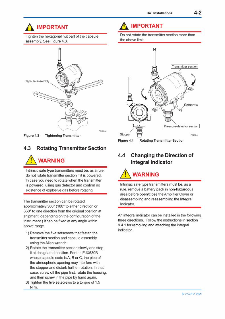
IMPORTANTTighten the hexagonal nut part of the capsule assembly. See Figure 4.3.
F0403.ai
Capsule assembly
Figure 4.3 Tightening Transmitter
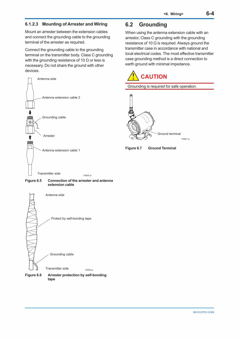
4.3 Rotating Transmitter Section
WARNING
Intrinsic safe type transmitters must be, as a rule, do not rotate transmitter section if it is powered.In case you need to rotate when the transmitter ispowered,usinggasdetectorandconfirmnoexistence of explosive gas before rotating.
The transmitter section can be rotated approximately 360° (180° to either direction or 360° to one direction from the original position at shipment,dependingontheconfigurationoftheinstrument.)Itcanbefixedatanyanglewithinabove range.
1)Removethefivesetscrewsthatfastenthetransmitter section and capsule assembly, using the Allen wrench.
2) Rotate the transmitter section slowly and stop it at designated position. For the EJX530B whose capsule code is A, B or C, the pipe of the atmospheric opening may interfere with the stopper and disturb further rotation. In that case,screwoffthepipefirst,rotatethehousing,and then screw in the pipe by hand again.
3)Tightenthefivesetscrewstoatorqueof1.5N·m.
IMPORTANTDo not rotate the transmitter section more than the above limit.
Stopper
Setscrew
Transmitter section
Pressure-detector section
F0404.ai
Figure 4.4 Rotating Transmitter Section
4.4 Changing the Direction of Integral Indicator
WARNING
Intrinsic safe type transmitters must be, as a rule, remove a battery pack in non-hazardous areabeforeopen/closetheAmplifierCoverordisassembling and reassembling the Integral Indicator.
An integral indicator can be installed in the following three directions. Follow the instructions in section 9.4.1 for removing and attaching the integral indicator.

<4. Installation> 4-3
IM 01C27F01-01EN
4.5 Changing the direction of the antenna
Adjust the direction of the antenna to be in the upright position. Figure 4.5 show factory setup antenna position. If the transmitter is installed to horizontal impulse piping, follow the procedure below and change the antenna position.
1) Loosen the two mounting screws at the bottom of the antenna by using a 2.5mm Allen wrench (see Figure 4.5). The screws might come off and be lost if loosened too much; loosen the screws by about three rotations.
2) Press forward and down 90 degrees by rotating the axis at the bottom of the antenna.
3) Tighten the two screws to a torque of 1.5 N·m by using a torque wrench. When doing this, be careful not leave a gap between the antenna and housing.
F0405.ai
Figure 4.5 Mounting Screw Position
F0406.ai
Figure 4.6 Adjusting Antenna Position

<5. Installing Impulse Piping> 5-1
IM 01C27F01-01EN
5. Installing Impulse Piping5.1 Impulse Piping Installation
PrecautionsThe impulse piping that connects the process outputs to the transmitter must convey the process pressure accurately. If, for example, gas collects in aliquidfilledimpulseline,orthedrainforagas-filledimpulse line becomes plugged, it will not convey the pressure accurately. Since this will cause errors in the measurement output, select the proper piping methodfortheprocessfluid(gas,liquid,orsteam).Pay careful attention to the following points when routing the impulse piping and connecting the impulse piping to a transmitter.
5.1.1 Connecting Impulse Piping to a Transmitter
IMPORTANTThe transmitter can be installed in horizontal impulsepipingconfiguration,tiltingthetransmitter's position up to 90°. When tilting, observe that the pipe (for Model EJX530B with measurement span code A, B, and C) is positioned horizontal downwards, or any place between them, as shown in Figure 5.1 The zero-adjustment screw must be positioned downwards for all the models.
F0501.ai
Zero-adjustment screw Pipe(backside of the instrument)
The pipe (open to atmosphere) is positioned horizontal.
If the zero-adjustment screw is positioned other than downwards after installation, rotate the housing until it is positioned downwards.
Figure 5.1 Horizontal Impulse Piping Connection
5.1.2 Routing the Impulse Piping
(1) Process Pressure Tap Angles
If condensate, gas, sediment or other extraneous material in the process piping gets into the impulse piping, pressure measurement errors may result. To prevent such problems, the process pressure taps mustbeangledasshowninfigure5.2accordingtothekindoffluidbeingmeasured.
NOTE• Iftheprocessfluidisagas,thetapsmustbe
vertical or within 45° either side of vertical.• Iftheprocessfluidisaliquid,thetapsmust
be horizontal or below horizontal, but not more than 45° below horizontal.
• Iftheprocessfluidissteamorothercondensing vapor, the taps must be horizontal or above horizontal, but not more than 45° above horizontal.
[Gas]
Pressuretaps
Processpiping
[Steam][Liquid]
45°
45°
45° 45°
45°
45°
F0502.ai
Figure 5.2 Process Pressure Tap Angle (For Horizontal Piping)
(2) Position of Process Pressure Taps and Transmitter
If condensate (or gas) accumulates in the impulse piping, it should be removed periodically by opening the drain (or vent) plugs. However, this will generate a transient disturbance in the pressure measurement, and therefore it is necessary to position the taps and route the impulse piping so that any extraneous liquid or gas generated in the leadlines returns naturally to the process piping.
• Iftheprocessfluidisagas,thenasarulethetransmitter must be located higher than the process pressure taps.
• Iftheprocessfluidisaliquidorsteam,thenasarule the transmitter must be located lower than the process pressure taps.

<5. Installing Impulse Piping> 5-2
IM 01C27F01-01EN
(3) Impulse Piping Slope
The impulse piping must be routed with only an upward or downward slope. Even for horizontal routing, the impulse piping should have a slope of at least 1/10 to prevent condensate (or gases) from accumulating in the pipes.
(4) Preventing Freezing
Ifthereisanyriskthattheprocessfluidintheimpulse piping or transmitter could freeze, use a steam jacket or heater to maintain the temperature ofthefluid.
NOTEAfter completing the connections, close the valves on the process pressure taps (main valves), the valves at the transmitter (stop valves), and the impulse piping drain valves, so that condensate, sediment, dust and other extraneous material cannot enter the impulse piping.
5.2 Impulse Piping Connection Examples
Figure 5.3 shows examples of typical impulse piping connections. Before connecting the transmitter to the process, study the transmitter installation location, the process piping layout, andthecharacteristicsoftheprocessfluid(corrosiveness,toxicity,flammability,etc.),inorderto make appropriate changes and additions to the connectionconfigurations.
Note the following points when referring to these piping examples.
• Iftheimpulselineislong,bracingorsupportsshould be provided to prevent vibration.
• Theimpulsepipingmaterialusedmustbe compatible with the process pressure, temperature, and other conditions.
• Avarietyofprocesspressuretapvalves(mainvalves) are available according to the type ofconnection(flanged,screwed,welded),construction (globe, gate, or ball valve), temperature and pressure. Select the type of valve most appropriate for the application.
F0503.ai
Tee
Stopvalve
Stopvalve
Drain valve
Drain plug
Union or
flange
Union or
flange
Tap valve
Figure 5.3 Impulse Piping Connection Examples

<6. Wiring> 6-1
IM 01C27F01-01EN
6. Wiring6.1 Mounting Antenna and
WiringAn antenna is not attached to the transmitter. The following provides the instructions for mounting the antenna and installing the remote antenna and wiring using antenna extension cable.
IMPORTANTThe antenna connector is covered with a cap at the time of delivery. Keep the cap attached until the installation of the antenna or antenna cables to protect the inside connection part. The unscrewed cap should be stored in order to replace it immediately after the antenna or antenna cables are removed.
CAUTIONTo maintain the ultimate conditions of radio-frequency signal, protect the connectors of antenna, extension antenna cable, and arrester from the corrosive atmosphere by the following treatment.1. Clean the connection to be protected.2. Wind the butyl rubber self-bonding tape
around the connection. See the manual of the tape about the winding.
3. To protect the butyl rubber self-bonding tape from the environment such as ultraviolet rays and so on, wind vinyl tape (or a vinyl type self-bonding tape) on it.
6.1.1 Mounting the antennaScrew the provided antenna into the antenna connector of the transmitter. The antenna may be sold as available accessories and supplied separately.
1. Unscrew the antenna connector cap on the antenna connector.
2. Screw the provided antenna into the antenna connector. Tighten the antenna connector with a torque of 2 to 3 N·m.
Antenna connector
F0601.ai
Figure 6.1 Mounting the antenna
CAUTIONWhen installing the antenna, screw the antenna by tightening the lower nut part. Screwing the antenna by holding the antenna body may cause failure such as cable disconnection. The same manner should be taken when unscrewing the antenna.
Antenna body
F0602.ai
Nut part
Figure 6.2 Antenna

<6. Wiring> 6-2
IM 01C27F01-01EN
6.1.2 Mounting External Antenna and Wiring Antenna Extension Cable
6.1.2.1 Mounting of External AntennaMount the external antenna at the proper location according to the wireless environment described in 2.4 Selecting the Installation Location. The mounting to the pipe such as 50 mm (2-inch) pipe needs to secure the enough strength to endure a strong wind, vibration and so on. The antenna must be mounted vertically.
Fixing of External AntennaFix an external antenna appropriately using the bracket provided as the external antenna option to 50 mm (2-inch) pipe.
Bracket
Antenna
Vertical pipe mounting
Horizontal pipe mounting
Nut
2-inch pipe
U Bolt
Nut
AntennaExtension Cable
F0603.ai
Figure 6.3 Fixing the remote antenna
Mounting Procedure of External Antenna
1. Fix the bracket by U-bolt and nut to 50 mm (2-inch) pipe.
2. Fix the antenna extension cable to the bracket 1 using the provided nut with a torque of 6 to 7 N·m as shown in the Figure 6.3 above. Use the nut which is attached to the antenna extension cable.
3. Screw the antenna into the antenna connector of the antenna extension cable on the bracket 1.
Tighten the antenna connector with a torque of 2 to 3 N·m.
4. Protect the connection as necessary. For details of the protection, see “6.1 Mounting Antenna and Wiring.”
6.1.2.2 Wiring of Antenna Extension Cable1. Use the provided antenna extension cable
to connect the antenna connector with the external antenna. Tighten the connector of the antenna extension cable with a torque of 2 to 3 N·m. The minimum bending radius while checking the wiring position should be more than 200 mm.
2. When using two extension cables, the provided arrester should be inserted between these cables.
3.Beforethewiringwork,confirmthepolarities(male/female) of the connectors of antenna, extension antenna cable, and arrester. Tighten the connector of the antenna extension cable with a torque of 2 to 3 N·m.
4. Protect the connectors of antenna, extension antenna cable, and arrester as necessary. See “6.1 Mounting Antenna and Wiring.”
5. Fix the extension antenna cable to the appropriate structure to protect the cable from the vibration, wind, and so on. The minimum bendingradiusforfixinginthestatemaintainedfor a long period should be more than 80 mm.

<6. Wiring> 6-3
IM 01C27F01-01EN
Transmitter body
Grounding cable
Protect by self-bonding tape
F0604.ai
Antenna extension cable 2: 10 m
Antenna
Antenna
Antenna extension cable 1: 3 mAntenna extension cable 1: 3 m
Protect by self-bonding tape
Transmitter body
Arrester
Figure 6.4 Wiring the antenna extension cable
CAUTIONUse the dedicated antenna extension cable provided by Yokogawa as accessories for the transmitters.
<6. Wiring> 6-4
IM 01C27F01-01EN
6.1.2.3 Mounting of Arrester and WiringMount an arrester between the extension cables and connect the grounding cable to the grounding terminal of the arrester as required.
Connect the grounding cable to the grounding terminal on the transmitter body. Class C grounding withthegroundingresistanceof10Ωorlessisnecessary. Do not share the ground with other devices.
F0605.aiTransmitter side
Grounding cable
Antenna side
Antenna extension cable 2
Antenna extension cable 1
Arrester
Figure 6.5 Connection of the arrester and antenna extension cable
F0606.aiTransmitter side
Grounding cable
Antenna side
Protect by self-bonding tape
Figure 6.6 Arrester protection by self-bonding tape
6.2 GroundingWhen using the antenna extension cable with an arrestor, Class C grounding with the grounding resistanceof10Ωisrequired.Alwaysgroundthetransmitter case in accordance with national and local electrical codes. The most effective transmitter case grounding method is a direct connection to earth ground with minimal impedance.
CAUTIONGrounding is required for safe operation.
F0607.ai
Ground terminal
Figure 6.7 Ground Terminal

<7. Operation> 7-1
IM 01C27F01-01EN
7. Operation7.1 Preparation for Starting
OperationThis section describes the operation procedure for theEJX530Basshowninfigure7.1.
NOTEIt is required to set security and network information to enable the transmitter to be connected to the Field Wireless Network. For more details, refer to section 7.4 “Connecting to the Field Wireless Network”.
NOTECheck that the process pressure tap valves, drain valves, and stop valves are closed.
(a) Follow the procedures below to introduce process pressure into the impulse piping and transmitter.
1)Openthetapvalve(mainvalve)tofilltheimpulsepipingwithprocessfluid.
2) Gradually open the stop valve to introduce processfluidintothetransmitterpressure-detector section.
3)Confirmthatthereisnopressureleakinthe impulse piping, transmitter, or other components.
(b) Insert batteries into the battery case, and install to the transmitter. To insert batteries into the battery case, be careful to polarity of batteries and battery case. For details of Installation of battery, refer to section 9.4.6 and 9.4.7.
Battery case is installed in the transmitter when shipped from the factory, however, batteries are sold separately and not included.
(c) Usingthedeviceconfigurationtool,confirmthat the transmitter is operating properly. Check parameter values or change the setpoints as necessary.
Integral Indicator’s indication can be used toconfirmthatthetransmitterisoperatingproperly.Fordetailsonhowtoconfirmrefertosubsection 8.4 “Self-Diagnostics”.
ISA100 devices display self-diagnostic information in an easy-to-understand manner
using four categories (Check function, Maintenance required, Failure, and Off specification)accordingtoNAMURNE107*
* NAMUR NE107 “Self-Monitoring and Diagnosis of Field Devices”
F0701.ai
Union or flange
Vent plug (Fill plug)
Tap valve
Stop valve
Tee
Drain valve
Drain plug
Union or flange
Figure 7.1 Liquid Pressure Measurement (Gauge Pressure Transmitters)
■ Confirmthattransmitterisoperatingproperly by Integral Indicator
If the transmitter is faulty, an error code is displayed.
F0702.ai
Self-diagnostic error on the integral indicator (Faulty transmitter)
Figure 7.2 Integral Indicator with Error Code
NOTEIf any of the above errors are indicated on the display of the integral indicator or the device configurationtool,refertosubsection9.5.3forthe corrective action.
<7. Operation> 7-2
IM 01C27F01-01EN
Verify and Change Transmitter Parameter Setting and Values
The parameters related to the following items are minimum required to be set for operation, and set at factoryasspecifiedinorder.Confirmorchangetheparameters if needed.• Measurement range (measurement lower/
upper limit, unit)
7.2 Zero Point AdjustmentAfter completing preparations for operating the transmitter, adjust the zero point. There are two zero point adjusting ways.
IMPORTANTDo not turn off the power to the transmitter immediately after performing a zero point adjustment. Powering off within 30 seconds of performing this procedure will return the zero point to its previous setting.
(1) When you can obtain the Low Range Value from the actual measured value of 0% (0kPa, atmospheric pressure);
Using the transmitter’s zero-adjustment screw
Before adjusting zero point, make sure followings.
• That the External zero trim parameter (External Zero Trim) is “Trim on”. For details, refer to section 8 “Setting Parameters”.
• Use a slotted screwdriver to turn the zero-adjustment screw. Turn the screw clockwise to increase the output or counterclockwise to decrease the output.
The zero point adjustment can be made with a resolution of 0.01% of the setting range. The degree of zero adjustments varies with the screw turningspeedturnthescrewslowlytomakeafineadjustment, quickly to make a rough adjustment.
UsingtheDeviceConfigurationTool
Refer to subsection 8.3.10 “Zero Point Adjustment and Span Adjustment”.
(2) When you cannot obtain the Low Range Value from the actual measured value of 0%;
Adjust the transmitter output value matches to the actual measured value obtained by precise pressure measurement equipment.
[Example]
The measuring range of 50 to 250 kPa : the actual measured value of 130kPa.
130–50250–50
Actual measured value= x100=40.0%
Using the transmitter’s zero-adjustment screw
Turn the zero adjustment screw to match the output signal to the actual measured value.
UsingtheDeviceConfigurationTool
Refer to subsection 8.3.10 “Zero Point Adjustment and Span Adjustment”.
7.3 Starting OperationAfter the zero point adjustment is completed, the transmitter is already the operating status. Follow the procedure below.
1) Confirmtheoperatingstatus.2) Afterconfirmingtheoperatingstatus,perform
the following.
IMPORTANT• Closetheterminalboxcoverandtheamplifiercover.Screweachcoverintightlyuntil it will not turn further.
• Tightenthezero-adjustmentcovermountingscrew to secure the cover.
<7. Operation> 7-3
IM 01C27F01-01EN
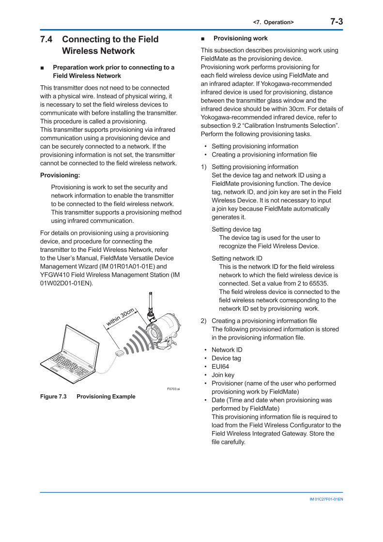
7.4 Connecting to the Field Wireless Network
■ PreparationworkpriortoconnectingtoaField Wireless Network
This transmitter does not need to be connected with a physical wire. Instead of physical wiring, it isnecessarytosetthefieldwirelessdevicestocommunicate with before installing the transmitter. This procedure is called a provisioning.This transmitter supports provisioning via infrared communication using a provisioning device and can be securely connected to a network. If the provisioning information is not set, the transmitter cannotbeconnectedtothefieldwirelessnetwork.
Provisioning:
Provisioning is work to set the security and network information to enable the transmitter tobeconnectedtothefieldwirelessnetwork.This transmitter supports a provisioning method using infrared communication.
For details on provisioning using a provisioning device, and procedure for connecting the transmitter to the Field Wireless Network, refer to the User’s Manual, FieldMate Versatile Device Management Wizard (IM 01R01A01-01E) and YFGW410 Field Wireless Management Station (IM 01W02D01-01EN).
F0703.ai
within 30cm
Figure 7.3 Provisioning Example
■ Provisioningwork
This subsection describes provisioning work using FieldMate as the provisioning device.Provisioning work performs provisioning for eachfieldwirelessdeviceusingFieldMateandan infrared adapter. If Yokogawa-recommended infrared device is used for provisioning, distance between the transmitter glass window and the infrared device should be within 30cm. For details of Yokogawa-recommended infrared device, refer to subsection 9.2 “Calibration Instruments Selection”. Perform the following provisioning tasks.
• Settingprovisioninginformation• Creatingaprovisioninginformationfile
1) Setting provisioning information Set the device tag and network ID using a
FieldMate provisioning function. The device tag, network ID, and join key are set in the Field Wireless Device. It is not necessary to input a join key because FieldMate automatically generates it.
Setting device tag The device tag is used for the user to
recognize the Field Wireless Device.
Setting network ID ThisisthenetworkIDforthefieldwirelessnetworktowhichthefieldwirelessdeviceisconnected. Set a value from 2 to 65535.
Thefieldwirelessdeviceisconnectedtothefieldwirelessnetworkcorrespondingtothenetwork ID set by provisioning work.
2) Creatingaprovisioninginformationfile The following provisioned information is stored
intheprovisioninginformationfile.
• NetworkID• Devicetag• EUI64• Joinkey• Provisioner(nameoftheuserwhoperformed
provisioning work by FieldMate)• Date(Timeanddatewhenprovisioningwas
performed by FieldMate) ThisprovisioninginformationfileisrequiredtoloadfromtheFieldWirelessConfiguratortotheField Wireless Integrated Gateway. Store the filecarefully.

<7. Operation> 7-4
IM 01C27F01-01EN
■ Connectingtoafieldwirelessnetwork
The action after installing the battery pack varies depending on the silence setting. Mounting the battery pack automatically starts a searchforthefieldwirelessnetwork.WhentheField Wireless Integrated Gateway is found, the instrument enters the join status.When the Field Wireless Integrated Gateway is not foundandaspecifiedtimehaselapsed,acycleofaone-hour pause and six-minutes search is repeated untiltheinstrumentcanjointhefieldwirelessnetwork. For details on the procedure to switch to silence mode, refer to subsection 8.3.13 “Switching to Silence Mode.”
F0704.ai
Mounting battery pack
Boot
Infrared communication
Pause (b)Search failure for the specified time
Infrared communication 1 hour
passedSearch failure for 6 minutes
Ready 2: Searching (b)
(Connect)(Connect)
Confirm connecting status: Join (c)
(Publish)Operation (d)
Deep sleep setting
(Disconnect)(Disconnect)
Ready 1: Searching (b)
Deep sleep (a)Infrared communication
Figure 7.4 Wireless Connection Process
(a) Deep sleep
F0705.ai
(b) Ready and pause
F0706.ai
(c)Confirmconnectingstatus
F0707.ai
(d) Join
F0708.ai

<7. Operation> 7-5
IM 01C27F01-01EN
NOTEIf the transmitter searches the Field Wireless Network for long time at low ambient temperature condition, sometimes error “AL.70 LOWBAT” is displayed on the Integral Indicator. Even though using new batteries, it can occur. It occurs because of battery characteristics. After joining to the Field Wireless Network, this error will be cleared within one hour if battery has no failure.
7.5 Shutting Down the Transmitter
Shut down the transmitter as follows.
1) Remove the battery pack or set the transmitter todeepsleepmodebythedeviceconfigurationtool.
2) Close the stop valve.3) Close the tap valves.
NOTE• Whenevershuttingdownthetransmitterfora
long period, remove the transmitter from the process line.
• Refertosubsection9.4.5“ReplacingtheBattery Pack” for the battery pack removing.
• Whenstoringtheinstrumentwithabatterypack inserted, it is recommended to put the instrument into deep sleep mode to conserve battery power. For details on how to switch to deep sleep mode, refer to subsection 8.3.12 “Switching to the Deep Sleep Mode.”

<8. Setting Parameters> 8-1
IM 01C27F01-01EN
8. Setting ParametersThis transmitter can remotely handle range changes, Tag No. setup, monitoring of self-diagnostic results, and Zero Point Adjustment, etc. accordingtocommunicationwiththefieldwirelessconfigurationtoolorthedeviceconfigurationtool.
8.1 Environment for parameter setting
After installing the battery pack, perform provisioningandhavethetransmitterjointhefieldwireless network.
This transmitter supports the OOB(out-of-band) method using the infrared communication as a provisioning method. Refer to Subsection 7.4 “Connecting to the Field Wireless Network” for details of the provisioning.
F0801.ai
Infrared port
Figure 8.1 Infrared port of the transmitter
8.2 Preparing Software
8.2.1 Softwares for the Field Wireless ConfigurationToolandtheDeviceConfigurationTool
Beforeusingthedeviceconfigurationtool,confirmthatCF/DDandDeviceDTMforyourtransmitter (wireless EJX) are installed in the device configurationtool.
Refer to the following website for the latest information on CF/DD and DeviceDTM. <http://www.yokogawa.com/>
CF (Capabilities File)/DD (Device Description)
ACFfilecontainsinformation,suchasthevendorofthefielddevice,itsmodelandrevision,availabletypesofprocessdata(flowrate, temperature, pressure, etc.), and number ofdataitems.ADDfilecontainstheinformationon parameters, such as data structures and attributes.
DeviceDTM
DeviceDTM (Device Type Manager) is driver softwareforfielddevicesprovidedbasedontheFDT (Field Device Tool) technology.
Thefieldwirelessconfigurationtoolorthedeviceconfigurationtoolallowsconfirmingthedeviceinformation. Refer to subsection 9.2 “calibration Instruments Section”forthefieldwirelessconfigurationtoolorthedeviceconfigurationtoolofourrecommendation.
8.2.2 Software DownloadSoftware download function permits to update wirelessfielddevicesoftwareviaISA100.11awireless communication. For details, refer to YFGW410 Field Wireless Management Station (IM 01W02D01-01EN).
8.3 Setting Parameters
8.3.1 Parameter Usage and SelectionBefore setting a parameter, please see the following table for a summary of how and when each parameter is used.
IMPORTANTAftersettingandsendingdatawiththefieldwirelessconfigurationtoolorthedeviceconfigurationtool,wait30secondsbeforeturning off the transmitter. If it is turned off too soon, the settings will not be stored in the transmitter.

<8. Setting Parameters> 8-2
IM 01C27F01-01EN
Table 8.1 Parameter Usage and Selection
Item DescriptionTag No Sets the tag No. as Device Tag (Software Tag). Sixteen characters
(alphanumericcharacters,including-and•)canbeset.Output The process variable and the diagnostic result can be output.
Either or all of differential pressure (AI1:Process Value), static pressure (AI2:Process Value), temperature(AI3:Process Value) of capsule or amplifierandself-diagnosticinformation(UAPMO:DiagnosticStatus)canbe set to the output
Range Adjust the range corresponding for 0% to 100%.
The unit of the range, input value at 0% (LRV) and input value at 100% (URV) is set.
Note: LRV and URV can be set within the range of -32000 to 32000.Damping time constant Dampingtimeconstantisusedtoreducethelargefluctuationofpressure
signal and given by each Process Value Filter Time parameter for differential Pressure/pressure (AI1) and Static pressure (AI2).
Output signal low cut mode Used mainly to stabilize output near 0 if output signal is the square root mode. Two modes are available: forcing output to 0% for input below a specificvalue,orchangingtoproportionaloutputforinputbelowaspecificvalue.
Integral indicator range of scale and unit Sets one of pressure value, or temperature value for the integral indicator scale.
Note: LRV and URV can be set within the range of -32000 to 32000.Unit for displayed temperature Sets a temperature unit to be displayed.Range with actual input applied Range corresponding for 0% to 100% signal is set with actual input
applied.
The output setting can be done just 100% to user’s reference pressure output.
However, when shipping it, the calibration is done in high accuracy as for DPharp. Please do the span setting by a usual range setting.
Zero Point Adjustment and Span Adjustment Handle Zero Point Adjustment and Span Adjustment.
There are two methods of Zero Point Adjustment, using external zero-adjustmentscrewandusingdeviceconfigurationtool.
Reset adjustment The amount of the adjustment set by user can be cleared.Software write protect Prohibit writing the setting data.Operational mode Set the operational mode of the sensor and integral indicator, etc.
Note: Someoftheparametersettingsareinadialogueformcalledmethod,theon-lineinstructionsyoucanconfiguretheparameterseasily.
8.3.2 Function Block and Menu Tree
(1) Function Block
The function of this transmitter is shown below. Aspecificfunctionmightnotbeabletobeusedaccordingtothefieldwirelessconfigurationtoolused.Whenthefieldwirelessconfigurationtoolof our recommendation is used, the software attached to the Field Wireless Integrated Gateway is necessary for setting the dotted line part. Refer to Subsection 9.2 “Calibration Instruments Selection”forthefieldwirelessconfigurationtoolof our recommendation. The setting of differential pressure(Al2 block) is invalid in this instrument. The output value of Al2 object and the output status are “0.0”(zero), “Uncertain” respectively.

<8. Setting Parameters> 8-3
IM 01C27F01-01EN
• Configuration• Diagnostics• Alerts• Power Status• Identification
(UAPMO)
• APP Download
(UDO)
• Configuration• Others
(CO)
• Block Info• Configuration/ Calibration
(TRANSDUCER)
• UAPMO• UDO• CO• TRANSDUCER• AI1 DP• AI2 SP• AI3 Temp
Online Menu
• UAP Option• Hardware Write Protect• Static Revision• Reset Energy Left• Radio Silence• Energy Harvest Type
(Configuration)
• Diagnostic Status• Diagnostic Status Detail.1• Diagnostic Status Detail.2• Diagnostic Switch• Diagnostic Configuration
(Diagnostics)
• Version Revision• CTS Version• ITS Version• Identification Number
(Identification)
• DESCRIPTION• STATE• MAX_BLOCK_SIZE• LAST_BLOCK_DOWNLOADED• ERROR_CODE
(APP Download)
• COMM_ENDPOINT• COMM_CONTRACT• PUB_ITEM_MAX• PUB_ITEM_NUM• PUB_ITEM
(Configuration)
• REVISION(Others)
• Network address of remote endpoint• Transport layer port at remote endpoint• Object ID at remote endpoint• Stale data limit• Data publication period• Ideal publication phase• PublishAutoRetransmit• Configuration status
(COMM_ENDPOINT)
• ContractID• Contract_Status• Actual_Phase
(COMM_CONTRACT)
• ObjectID• AttributeID• AttributeIndex• Size
(PUB_ITEM)
• Tag Description(Block Info)
• Auto Recovery• Model• Sensor Serial Number• Measurement Rate• Measurement Mode• Wireless Status• Display Selection
(Configuration/Calibration)
F0802-1.ai
• Energy Left• Power Supply Status• Power Supply Voltage
(Power Status)
• Others
• Display Unit1
• EJX Key
• Test Key 2• Test Key 1
• Test Key 3
• Unit Sel1
• XD Filter• LCD Intermittent Time
• Special Order ID• LCD Mode
• Special Cmd(Others)
• Other Faults Alert• Faults Non-compliance Alert• Faults Process Influence Alert• Simulation Active Alert• Soft Update Incomplete Alert• Power Low Alert• Power Critical Low Alert• Fault Prediction Alert• Environmental Conditions Alert• Outside Sensor Limits Alert• Out of Service Alert• Calibration Problem Alert• Faults Sensor or Actuator Alert• Faults Electronics Alert
(Alerts)

<8. Setting Parameters> 8-4
IM 01C27F01-01EN
• Block Info• Block Mode• Dynamic Variables• Configuration• Calibration• Others
(AI1 DP)• Tag Description
(Block Info)
• Mode.Target• Mode.Actual• Mode.Permitted• Mode.Normal
(Block Mode )
• Process Value• Simulation
(Dynamic Variables)
• Simulate Switch• Transducer Value• Simulate Value
(Simulation)
• Process Value.Status• Process Value.Value **
(Process Value)
• Block Mode• Concentrator OID• Scale *• Process Value Filter Time
(Configuration) (Block Mode)
• Mode.Target• Mode.Actual• Mode.Permitted• Mode.Normal
(Scale)
• Scale.EU at 100% *• Scale.EU at 0% *• Scale.Units Index *• Scale.Decimal *
• Upper Limit• Lower Limit• PV Range *• Linerization Type *• Flow Constant *• Lower Cutoff• Low Cut Mode *• H/L Swap *• T Zero Cmp *• Temp Zero *• Temp Select *
(Others) (PV Range)
• PV Range.EU at 100% *• PV Range.EU at 0% *• PV Range.Units Index *• PV Range.Decimal *
F0802-2.ai
• Block Mode• Cal Cmd *• Cal Status• Calibration Highest Point *• Calibration Lowest Point *• Calibration Minimum Span• External Zero Trim *
(Calibration) (Block Mode)
• Mode.Target• Mode.Actual• Mode.Permitted• Mode.Normal
• Transducer Value. Status• Transducer Value. Value
(Transducer Value)
• Simulate Value. Status• Simulate Value. Value
(Simulate Value)
Online Menu (continued)
*: When the data of these parameters is rewritten, it is necessary to set the operational mode of the block to O/S (Out of Service). **: When the data of these parameters is rewritten, it is necessary to set the operational mode of the block to Manual.

<8. Setting Parameters> 8-5
IM 01C27F01-01EN
• Block Info• Block Mode• Dynamic Variables• Configuration• Others
(AI2 SP)• Tag Description(Block Info)
• Mode.Target• Mode.Actual• Mode.Permitted• Mode.Normal
(Block Mode )
• Process Value• Simulation
(Dynamic Variables)
• Simulate Switch• Transducer Value• Simulate Value
(Simulation)
• Process Value.Status• Process Value.Value **
(Process Value)
• Block Mode• Concentrator OID• Scale *• Process Value Filter Time
(Configuration) (Block Mode)
• Mode.Target• Mode.Actual• Mode.Permitted• Mode.Normal
(Scale)
• Scale.EU at 100% *• Scale.EU at 0% *• Scale.Units Index *• Scale.Decimal *
• Upper Limit• Lower Limit• PV Range *• Linerization Type *• Flow Constant *• Lower Cutoff• Cal Cmd *• Cal Status• Calibration Highest Point *• Calibration Lowest Point *• Calibration Minimum Span• Static Pres Type *• SP Select *
(Others) (PV Range)
• PV Range.EU at 100% *• PV Range.EU at 0% *• PV Range.Units Index *• PV Range.Decimal *
F0802-3.ai
• Transducer Value. Status• Transducer Value. Value
(Transducer Value)
• Simulate Value. Status• Simulate Value. Value
(Simulate Value)
Online Menu (continued)
*: When the data of these parameters is rewritten, it is necessary to set the operational mode of the block to O/S (Out of Service). **: When the data of these parameters is rewritten, it is necessary to set the operational mode of the block to Manual.

<8. Setting Parameters> 8-6
IM 01C27F01-01EN
• Block Info• Block Mode• Dynamic Variables• Configuration• Others
(AI3 Temp)• Tag Description(Block Info)
• Mode.Target• Mode.Actual• Mode.Permitted• Mode.Normal
(Block Mode )
• Process Value• Simulation
(Dynamic Variables)
• Simulate Switch• Transducer Value• Simulate Value
(Simulation)
• Process Value.Status• Process Value.Value **
(Process Value)
• Block Mode• Concentrator OID• Scale *• Process Value Filter Time
(Configuration) (Block Mode)
• Mode.Target• Mode.Actual• Mode.Permitted• Mode.Normal
(Scale)
• Scale.EU at 100% *• Scale.EU at 0% *• Scale.Units Index *• Scale.Decimal *
• Sensor Range• Tertiary Value Sel *
(Others) (Sensor Range)• Sensor Range.EU at 100%• Sensor Range.EU at 0%• Sensor Range.Units Index **• Sensor Range.Decimal **
F0802-4.ai
• Transducer Value. Status• Transducer Value. Value
(Transducer Value)
• Simulate Value. Status• Simulate Value. Value
(Simulate Value)
Online Menu (continued)
*: When the data of these parameters is rewritten, it is necessary to set the operational mode of the block to O/S (Out of Service). **: When the data of these parameters is rewritten, it is necessary to set the operational mode of the block to Manual.
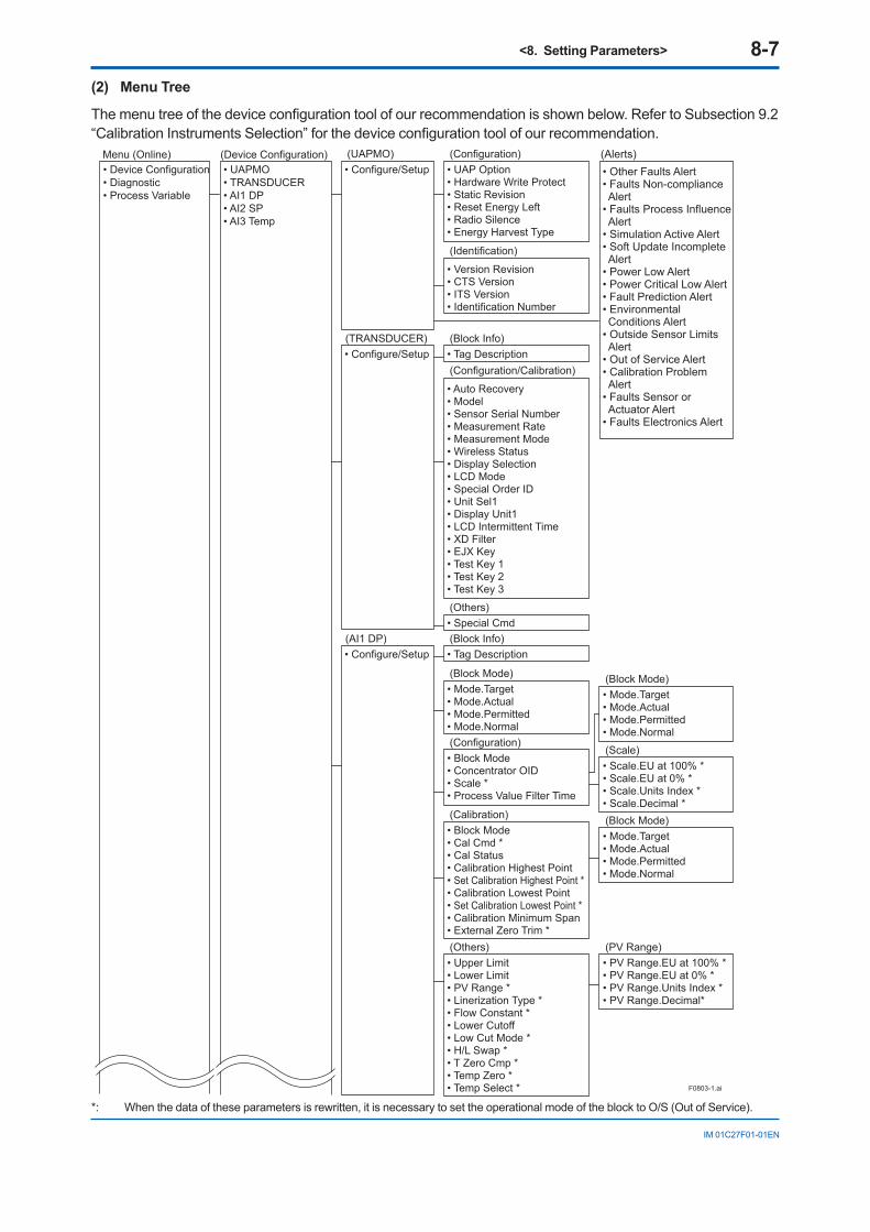
<8. Setting Parameters> 8-7
IM 01C27F01-01EN
(2) Menu Tree
Themenutreeofthedeviceconfigurationtoolofourrecommendationisshownbelow.RefertoSubsection9.2“CalibrationInstrumentsSelection”forthedeviceconfigurationtoolofourrecommendation.
• UAPMO• TRANSDUCER• AI1 DP• AI2 SP• AI3 Temp
• Device Configuration• Diagnostic• Process Variable
(Device Configuration)Menu (Online)
F0803-1.ai
• Configure/Setup(UAPMO)
• UAP Option• Hardware Write Protect• Static Revision• Reset Energy Left• Radio Silence• Energy Harvest Type
(Configuration)
• Version Revision• CTS Version• ITS Version• Identification Number
(Identification)
• Configure/Setup(AI1 DP)
• Block Mode• Cal Cmd *• Cal Status• Calibration Highest Point• Set Calibration Highest Point *• Calibration Lowest Point• Set Calibration Lowest Point *• Calibration Minimum Span• External Zero Trim *
(Calibration)
• Mode.Target• Mode.Actual• Mode.Permitted• Mode.Normal
(Block Mode)
• Upper Limit• Lower Limit• PV Range *• Linerization Type *• Flow Constant *• Lower Cutoff• Low Cut Mode *• H/L Swap *• T Zero Cmp *• Temp Zero *• Temp Select *
(Others)• PV Range.EU at 100% *• PV Range.EU at 0% *• PV Range.Units Index *• PV Range.Decimal*
(PV Range)
• Configure/Setup(TRANSDUCER)
• Auto Recovery• Model• Sensor Serial Number• Measurement Rate• Measurement Mode• Wireless Status• Display Selection• LCD Mode• Special Order ID• Unit Sel1• Display Unit1• LCD Intermittent Time• XD Filter• EJX Key• Test Key 1• Test Key 2• Test Key 3
(Configuration/Calibration)• Tag Description(Block Info)
• Special Cmd(Others)
• Mode.Target• Mode.Actual• Mode.Permitted• Mode.Normal
(Block Mode)
• Block Mode• Concentrator OID• Scale *• Process Value Filter Time
(Configuration)
• Mode.Target• Mode.Actual• Mode.Permitted• Mode.Normal
(Block Mode)
• Scale.EU at 100% *• Scale.EU at 0% *• Scale.Units Index *• Scale.Decimal *
(Scale)
• Tag Description(Block Info)
• Other Faults Alert• Faults Non-compliance Alert
• Faults Process Influence Alert
• Simulation Active Alert• Soft Update Incomplete Alert
• Power Low Alert• Power Critical Low Alert• Fault Prediction Alert• Environmental Conditions Alert
• Outside Sensor Limits Alert
• Out of Service Alert• Calibration Problem Alert
• Faults Sensor or Actuator Alert
• Faults Electronics Alert
(Alerts)
*: When the data of these parameters is rewritten, it is necessary to set the operational mode of the block to O/S (Out of Service).

<8. Setting Parameters> 8-8
IM 01C27F01-01EN
• Configure/Setup(AI2 SP)
F0803-2.ai
• Tag Description
(Block Info)
• Upper Limit• Lower Limit• PV Range *• Linerization Type *• Flow Constant *• Lower Cutoff• Cal Cmd *• Cal Status• Calibration Highest Point• Set Calibration Highest Point *• Calibration Lowest Point • Set Calibration Lowest Point *• Calibration Minimum Span• Static Pres Type *• SP Select *
(Others)
• Mode.Target• Mode.Actual• Mode.Permitted• Mode.Normal
(Block Mode)
• Sensor Range.EU at 100%• Sensor Range.EU at 0%• Sensor Range.Units Index *• Sensor Range. Decimal *
(Sensor Range)
(Block Mode)
• Mode.Target• Mode.Actual• Mode.Permitted• Mode.Normal
(AI3 Temp) (Block Info)• Tag Description
• Sensor Range• Tertiary Value Sel *
(Others)
• Block Mode• Concentrator OID• Scale *• Process Value Filter Time
(Configuration)
• Mode.Target• Mode.Actual• Mode.Permitted• Mode.Normal
(Block Mode)
• Scale.EU at 100% *• Scale.EU at 0% *• Scale.Units Index *• Scale.Decimal *
(Scale)
• PV Range.EU at 100% *• PV Range.EU at 0% *• PV Range.Units Index *• PV Range. Decimal *
(PV Range)
• Configure/Setup
• Block Mode• Concentrator OID• Scale *• Process Value Filter Time
(Configuration)
• Mode.Target• Mode.Actual• Mode.Permitted• Mode.Normal
(Block Mode)
• Scale.EU at 100% *• Scale.EU at 0% *• Scale.Units Index *• Scale.Decimal *
(Scale)
Menu (Online) (continued)
Device Configuration(continued)
*: When the data of these parameters is rewritten, it is necessary to set the operational mode of the block to O/S (Out of Service).

<8. Setting Parameters> 8-9
IM 01C27F01-01EN
• Transducer Value. Status• Transducer Value. Value
• UAPMO
Menu (Online)(continued)
(Diagnostic)
F0803-3.ai
• Device Diagnostics
(UAPMO)
• Diagnostic Status• Diagnostic Status Detail.1• Diagnostic Status Detail.2• Diagnostic Switch• Diagnostic Configuration
(Diagnostics)
• Energy Left• Power Supply Status• Power Supply Voltage
(Power Status)
• AI1 DP• AI2 SP• AI3 Temp
(Process Variable)
• Process Variable
(AI1 DP)
• Process Value• Simulation
(Dynamic Variables)
• Process Value.Status• Process Value.Value **
(Process Value)
• Simulate Switch• Transducer Value• Simulate Value
(Simulation)(Transducer Value)
• Simulate Value. Status• Simulate Value. Value
(Simulate Value)
• Process Variable
(AI2 SP)
• Process Value• Simulation
(Dynamic Variables)
• Process Value.Status• Process Value.Value **
(Process Value)
• Simulate Switch• Transducer Value• Simulate Value
(Simulation)
• Process Variable
(AI3 Temp)
• Process Value• Simulation
(Dynamic Variables)
• Process Value.Status• Process Value.Value **
(Process Value)
• Simulate Switch• Transducer Value• Simulate Value
(Simulation)
• Transducer Value. Status• Transducer Value. Value
(Transducer Value)
• Simulate Value. Status• Simulate Value. Value
(Simulate Value)
• Transducer Value. Status• Transducer Value. Value
(Transducer Value)
• Simulate Value. Status• Simulate Value. Value
(Simulate Value)
• Diagnostic.Other Faults• Diagnostic.Faults Non-Compliance• Diagnostic.Faults Process Influence• Diagnostic.Simulation Active• Diagnostic.Soft Update Incomplete• Diagnostic.Power Low• Diagnostic.Power Critical Low• Diagnostic.Fault Prediction• Diagnostic.Environmental Conditions• Diagnostic.Outside Sensor Limits• Diagnostic.Out of Service• Diagnostic.Calibration Problem• Diagnostic.Faults Sensor or Actuator• Diagnostic.Faults Electronics
(Diagnostic Configuration)
*: When the data of these parameters is rewritten, it is necessary to set the operational mode of the block to O/S (Out of Service).

<8. Setting Parameters> 8-10
IM 01C27F01-01EN
8.3.3 Parameters for Wireless Communication
(1) Network Information
Concentratorobjectblock:Configuration
Allowsconfirmingthenetworkinformation.
(2) Update Time
CO block: Data publication period
Sets the update time value to 0.5 to 3,600 seconds. The setting affects the battery life. When update time is set 0 seconds, the transmitter is stopped to update process variables by way ofthefieldwirelessnetwork.Andthetransmittercontinues to measure process variables with special interval time internally.
(3) Measurement Mode
TRANSDUCER block: Measurement Mode
The setting affects the battery life; it becomes shorter in the continuous mode.When the update period is set to 1 second or less in intermittent mode, the mode is continuous mode, regardless of the measurement mode and the display.
(4) Measurement Rate
TRANSDUCER block: Measurement Rate
Reads the measurement rate value from 0.5 to 3600 seconds. The shorter the measurement period, the shorter the battery life.
(5) Remaining battery life
UAPMO block: Energy Left
The number of days of remaining battery life is indicated assuming ambient temperature condition as 23 degrees Celsius. It takes several days for the indicated value to be stabiilzed after the power on and initialization of the remaining battery life.
UAPMO block: Reset Energy Left
When changing batteries, the remaining battery life is initialized by Reset Energy Left parameter.
(6) LCD display
The following steps describe how to set LCD display.
1. On/Off of display When “Enable” in LCD Mode is selected, the
LCD displays a set of screens to be shown and turnsoffforthespecifiedtimebasedonLCDIntermittent Time, and the display keeps the cycle repeatedly. Not selecting this parameter turns the LCD off.
2. On/Off of continuous display mode When “Enable” is set to LCD Mode and zero is
set to LCD Intermittent Time, the LCD displays continuously.
3. On/Off of bar graph Select “LCD Bargraph ON” in LCD Mode when
the bar graph is required.
When the wireless connection process is in the status of “ready,” “pause,” or “join,” the LCD display stays on regardless of the status in LCD Mode.
NOTEWhen the device detects AL01 and AL02, the LCD display stays on regardless of the status in LCD mode. See Table 9.3 and 9.4 Alarm Message for details.
8.3.4 Tag and Device InformationIfthesearespecifiedwhenordering,thedesignatedTag No. and device information are set and shipped. Tag No. and device information can be checked as follows.
• ProceduretocallupthetagNo.anddeviceinformation
- Device Tag ( Software Tag ) Thisisspecifiedwhenwritingcharacters(upto16characters)ofamplifiersTAGthatdifferfromcharactersspecifiedinTagNo.
Refer to section 7.4 “Connection to the Field WirelessNetwork”forconfirmation.
- Tag Description This is a universal parameter to store the
comment that describes the content of the tag located in the TRANSDUCER and AI blocks.
The AI1 and AI3 blocks of the AI blocks correspond to the pressure and temperature, respectively.

<8. Setting Parameters> 8-11
IM 01C27F01-01EN
• Whenchangingthedeviceinformation,inputthe information based on the following limitation on the number of characters.
- Message function (up to 32 characters) TRANSDUCER block : Tag Description AI1, AI3 block : Tag Description
8.3.5 UnitThe unit parameter is set at the factory before shipmentifspecifiedatthetimeoforder.Followtheprocedure below to change the unit parameter.
• ProceduretocalluptheUnitdisplay(UnitsIndex) Al1, Al3 block : Scale.Units Index
To change the Unit display, choose desired unit among the list of displayed unit selecting AI1 block as for the pressure, and AI3 block as for temperature in the AI blocks.
8.3.6 Range ChangeTherangevaluesarefactory-setasspecifiedbythe customer. To change the range, follow the steps below.
The measurement span is determined by the upper and lower range values. In this method, the upper and lower range values can be set independently, and the span changes according to the range limit values sent to the transmitter.
• ProceduretocallupthePVRangedisplay. AI1 block : PV Range
Select the AI1 block for the pressure, then select “EU at 0%” and “EU at 100%” displayed in the PV Range parameters. And input the lower range and upper range values for the range.
8.3.7 Output Signal Low Cut Mode SetupLow cut mode can be used to stabilize the output signal near the zero point.( There is 10% of hysteresis at only point of transition from low to high)
[Setup Low Cut Value]
• ProceduretocalluptheLowCutoff*display AI1 block : Low Cutoff*
Example: setup LOW_CUT of output to 15%
*Low Cutoff= (“Eu at 100%” - “Eu at 0%”) × 0.15 + “Eu at 0%”
[Setup Low Cut Mode]
• ProceduretocalluptheLowCutModedisplay AI1 block : Low Cut Mode
F0804.ai
(%)50
20
0 50 (%)
For low cut in Linear mode For low cut in Zero mode
Example:Low cut 20%
Input
(%)50
20
0 50 (%)
Example:Low cut 20%
Input
Out
put
Out
put
Figure 8.3 Low Cut Mode
The low cut point has hysterisis so that the output aroundthepointisbehavedasbelowfigure.
<Example>Output mode: LinearLow cut mode: ZeroLow cut: 20.00%
Output
Setting range:0 to 20%
Input0%
(20%)
2%
Low cutpoint
Hystrersis fixed at 10%of the cut point
F0805.ai

<8. Setting Parameters> 8-12
IM 01C27F01-01EN
8.3.8 Integral Indicator Scale SetupThe following two displays are available for the integral indictor: pressure and temperature. The following two variables can be displayed on the integral indicator: % of pressure range, and % of temperature range.
Available displays Descriptionand related parameters
% of range(PRES %)
Indicates input pressure in –10 to 110% range depending on the set range (LRV and URV).
PRES % 45.6 %
Follow the procedure described in (1) to (2) below to set the integral indicator.
(1) Display Selection
Display set to Display Selection is displayed on the integral indicator.
• ProceduretocalluptheDisplaySelectiondisplay TRANSDUCER block: Display Selection
The Display Selection parameter enables the pressure (AI1 block), and, temperature (AI3 block) to be displayed on the LCD. Select whether or not to enable each block to be displayed.
(2) Cyclic Display
Information in the AI1, AI3 blocks can be displayed cyclically according to the display On/Off setting for the pressure (AI1 block), and temperature (AI3 block) selected in the Display Selection parameter.
8.3.9 Unit for Displayed TemperatureWhen the instrument is shipped, the temperature units are set to C (Centigrade). Follow the procedure below to change this setting.
• ProceduretocalluptheSensorRange.UnitsIndex display AI3 Block: Sensor Range.Units Index
ConfirmthatºC(degC)isselectedintheUnitsIndex parameter for the temperature(AI3 block).
Note: When the unit is changed by Sensor Range.Units Index parameter in temperature (AI3 block), units of capsule temperature is also changed.
8.3.10 Zero Point Adjustment and Span Adjustment
Each EJX-B series transmitter is characterized by factory. But there are some errors caused by environment and installed posture.
ThereareZeroandSpanAdjustmentstofine-tunethose errors.Zero Adjustment is adjustment for one point to adjust the bottom value of the measurement range as 0% of output.
TheSpanAdjustmentdefinesinputandoutputcharacteristic between two points that’s one side assumed as standard.This is used when there is doubt of span drift or when it is impossible to make zero at absolute pressure with adjustment for user’s pressure standard.

<8. Setting Parameters> 8-13
IM 01C27F01-01EN
(1) Zero Point Adjustment
a. To set 0% at current input, perform following procedure.
This method is used only when the pressure at bottom of measurement range is zero.
• Proceduretocallupthelowerlimitadjustmentparameter (Calibration Lowest Point).
AI1 block : Calibration Lowest Point
Set 0 to Calibration Lowest Point parameter for pressure (AI1 block).
• Proceduretocallupthecalibrationadjustmentparameter (Cal Cmd).
AI1 block : Cal Cmd : CAL_LOW
Lower limit is changed by using Cal Cmd parameter for puressure (AI1 block).
• Proceduretocallupthecalibrationadjustmentparameter (Cal Status) AI1 block: Cal Status
ConfirmthecalibrationstatusofCAL_SUCCESS (1) using the Cal Status parameter.
b. To match current input and output value, follow procedure
Like the measurement that is impossible to set process pressure to 0kPa, output value is adjustment to actual level by other measurement using glassgage.
Example: Pressure Transmitter’s span is 0 to 25.00kPa,
current level is 13.50kPa, current output is 13.83kPa.
• Proceduretocallupthelowerlimitadjustmentparameter (Calibration Lowest Point). AI1 Block: Calibration Lowest Point
Set the actual level value of 13.50 kPa to the Calibration Lowest Point parameter for the pressure (AI1 block). Apply an actual input andconfirmthevaluespecifiedinCalibrationLowest Point as the output value.
• Proceduretocallupthecalibrationadjustmentparameter (Cal Cmd). AI1 block: Cal Cmd: CAL_LOW
The present output is changed from 13.83kPa to 13.50 kPa in CAL_LOW of the pressure (AI1 block) Cal Cmd parameter.
• Proceduretocallupthecalibrationstatusparameter (Cal Status). AI1 block: Cal Status
ConfirmthecalibrationstatusofCalStatus(1)using the Cal Status parameter.
c. Using External Zero adjustment Screw
External Zero-adjustment parameter (External Zero Trim) can set permission or prohibition to adjustment by External Zero-adjustment Screw.
Set “Trim on” to use the External Zero-adjustment Screw. (“Trim on” at shipment)
Use a slotted screwdriver to turn the zero-adjustment screw. Equalize the transmitter, then turn the screw clockwise to increase the output or counterclockwise to decrease the output. The zero point adjustment can be made with a resolution of 0.01% of the setting range. The degree of zero adjustments varies with the screw turning speed; turnthescrewslowlytomakeafineadjustment,quickly to make a rough adjustment.
Zero-adjustment Screw
F0806.ai
Figure 8.3 Zero-adjustment Screw

<8. Setting Parameters> 8-14
IM 01C27F01-01EN
(2) Span Adjustment
Span Adjustment is function to change the input and output characteristic that assumed the bottom value (zero point) of measurement range a standard.
Therefore, perform span adjustment (adjustment of the upper limit value) after zero adjustment (adjustment of bottom limit value).
After adding the pressure at point of adjustment and setting pressure value as parameter, the transmitter calculates quantity of adjustment and performs adjustment automatically.
• Proceduretocallupthelowerlimitvalueparameter (Calibration Lowest Point) AI1 block: Calibration Lowest Point
Set the lower limit adjustment value on the pressure (AI1 block) Calibration Lowest Point parameter screen. Apply a reference pressure corresponding to the lower limit of the measurement range to the pressure transmitter andconfirmthepressurewhenitstabilized.
• Proceduretocallupthecalibrationadjustmentparameter (Cal Cmd) AI1 block: Cal Cmd: CAL_LOW
Confirmthelowerlimitofthemeasurementrange in CAL_LOW of the pressure (AI1 block) Cal Cmd parameter.
• Proceduretocallupthecalibrationstatusparameter (Cal Status) AI1 block: Cal Status
ConfirmthecalibrationstatusofCAL_SUCCESS (1) using the Cal Status parameter.
• Proceduretocalluptheupperlimitadjustmentparameter (Calibration Highest Point). AI1 block: Calibration Highest Point
Set the upper limit adjustment value for the pressure (AI1 block) Calibration Highest Point parameter. Apply a reference pressure corresponding to the upper limit of the measurement range to the pressure transmitter andconfirmthewhenithasstabilized.
• Proceduretocallupthecalibrationadjustmentparameter (Cal Cmd). AI1 block: Cal Cmd: CAL_HIGH
Confirmtheupperlimitofthemeasurementrange in CAL_HIGH of the pressure (AI1 block) Cal Cmd parameter.
• Proceduretocallupthecalibrationstatusparameter (Cal Status) AI1 block: Cal Status
ConfirmthecalibrationstatusofCalStatus(1)using the Cal Status parameter.
(3) Reset Adjustments
Reset Adjustment clear the amount of adjustment. Reset Adjustment can be performed using CAL_CLEAR of the pressure (AI1 block) Cal Cmd parameter for the input pressure. After calibration, confirmstatusbyusingthepressure(AI1block)CalStatus.
The amount of adjustment made by the external zero-adjustment screw can be reset to the initial setting as well.
• Proceduretocallupthecalibrationadjustmentparameter (Cal Cmd). AI1 block: Cal Cmd: CAL_CLEAR
8.3.11 Software Write ProtectHardware write protection and software write protection functions are available for this transmitter
• Proceduretocalluptheprotectionsettingparameter (UAP Option) UAPMO block: UAP Option
ThefollowingsettingscanbeconfiguredintheUAP Option parameter.
- Setting to enable or disable software write protection.
- Setting to enable or disable the hardware write protection switch.
- Setting to enable or disable changing the setting to the Diagnostic Switch and DiagnosticConfigurationparameters.
• Proceduretocalluptheprotectionsettingdisplay parameter (Hardware Write Protect) UAPMO block: Hardware Write Protect
The Hardware Write Protect parameter enables the switch status of hardware write protection to be displayed.
For the relationship between hardware write protection and software write protection, refer section 10. “Parameter Summary”.

<8. Setting Parameters> 8-15
IM 01C27F01-01EN
8.3.12 Switching to Deep Sleep ModeWhen the instrument will not be used for a long time, switch the instrument to deep sleep mode to conserve battery power. To switch to deep sleep mode, follow the procedure below.• Proceduretocalluptheswitch-to-deep-sleep
parameter TRANSDUCER block: Special Cmd
Set Deep Sleep mode (Standby) to the Special Cmd parameter for the TRANSDUCER block. To start from deep sleep mode, either remove and insert the battery pack, or use the provisioning device tool or the device configurationtoolviainfraredcommunication.
CAUTIONAfter setting the deep sleep mode by infrared deviceconfigurationtool,keeptheinfraredportof device away from any other infrared signals.
NOTE• Transmitterbecomesthestopstateafter
setting deep sleep mode and cannot reply anyrequestfromthedeviceconfigurationtool via wireless communication.
• Forthisreason,thereisthecasethatanerrorisdisplayonthedeviceconfigurationtool via wireless communication.
• Towakeupfromdeepsleepmode,pleasepull battery pack, and wait more than 30 seconds before attaching battery back.
8.3.13 Switching to Silence ModeThis is a function to pause the instrument when itcannotjointhefieldwirelessnetworkafteraspecifiedtimehaselapsed.Thisfunctioniseffectivein conserving battery power when, for example, the installationofthefieldwirelessintegratedgatewayisdelayedcomparedtothatoffieldwirelessdevices. The default value is 28800 seconds (8 hours). Thereafter, a cycle of a one-hour pause and six-minute search is repeated until the instrument canjointhefieldwirelessnetwork.
• Proceduretocalluptheswitch-to-silenceparameter (Radio Silence) UAPMO block: Radio Silence
Set 0 to 231 seconds for the Radio Silence parameter of the UAPMO block. If 0 is set, the Radio Silence parameter is invalid. To start from silence mode, either remove and insert the battery pack, or use the provisioning device toolorthedeviceconfigurationtoolviainfraredcommunication.

<8. Setting Parameters> 8-16
IM 01C27F01-01EN
8.4 Self-Diagnostics
8.4.1 Identify Problems by Using the DeviceConfigurationTool
First, check Diagnostic Status of the self-diagnostic result.
UAPMO block: Diagnostic Status
Any of the four categories (Check function, Maintenance required, Failure, and Off specification)accordingtoNAMURNE107*issupplied to Diagnostic Status of each diagnostic result.
Table 8.2 Diagnostic Status
Bits ContentsExample
NAMUR NE107Categorization
Bit31 (MSB) F: Failure status ---Bit30 C: Function check status ---Bit29 O:Outofspecificationstatus ---Bit28 M: Maintenance required status ---Bit27 Faults in electronics FBit26 Faults in sensor or actuator element FBit25 Installation, calibration problem CBit24 Out of service CBit23 Outside sensor limits OBit22 Environmentalconditionsoutofdevicespecification OBit21 Fault prediction: Maintenance required MBit20 Power is critical low: maintenance need short-term MBit19 Power is low: maintenance need mid-term MBit18 Software update incomplete CBit17 Simulation is active CBit16 Faultsduetoprocessinfluence FBit15 Faultsduetonon-compliancewithspecifiedoperatingconditions FBit14 Other faults FBit13-Bit08 reserved by WCI ---Bit07-Bit01 vendorspecificarea ---Bit00 Detail information available
1: available0: no available
---
Checking the Diagnostic Status category allows taking the proper action. The Diagnostic Status contents are common for all ISA devices, and the setting for the Diagnostic Status category can be changed. For further details, refer to Diagnostic Status Detail. In Diagnostic Status Contents that can be diagnosed by the EJX, the alert category set in Out of Service can be changed to Check function. To do so, follow one of the procedures below.
a) UAPMO block: UAP Option, select enable.b)UAPMOblock:DiagnosticConfiguration,
change Out of Service from Failure to Check function.
c) UAPMO block: UAP Option, select disable.
Thecontentsofdiagnosticstatusaredefinedeithervalid or invalid at Diagnostic Switch parameter. Follow the example below to change “Out of Service” to invalid.
a) UAPMO block: UAP Option, select enable.b) UAPMO block: Diagnostic Switch, turn ON
Turn off “Out of Service”. Out of Service. c) UAPMO block: UAP Option, select disable.
Note: Be careful when changing the alert category and turning detection on and off as described above. Be sure to set UAP OPTION to disable again to prevent setting errors.
*: NAMUR NE107 “Self-Monitoring and Diagnosis of Field Devices”
InDiagnosticConfigurationsetting,selectonefromthefollowings; F: Failure status, C: Function check status, O:Outofspecificationstatus,orM:Maintenancerequired status.

<8. Setting Parameters> 8-17
IM 01C27F01-01EN
8.4.2 Alert ReportEJX generates alert information related to DiagnosticStatusandautomaticallysendstoafieldwireless gateway. To use this function, the following alert setting is necessary. When “Out of Service” for Diagnostic Status alert is required, choose “FALSE” for [Out of Service.Alert Disable] in the UAPMO block.RefertothefieldwirelessgatewayUser’sManual for the setting procedure to obtain the alert information from the gateway.The alert report consists of the list of parameter names as shown Table 8.3 below.
Table 8.3 Contents of Alert Report
Parameter name DescriptionDetectObjectTLPort Alert detection port UAP (0xF0B2)
fixedDetectObject Alert detection block UAPMO (1)
fixedDetectTime Time stampAlertDirection 1: generated, 0: clearAlertPriority Alert priorities set by usersAlertType Alert types, see 8.4 Self-
DiagnosticsAlertValue NAMUR107 category
0:Failure, 1:checkFunction, 2:OffSpec, 3:MaintenaceRequired
CAUTIONFor a wireless gateway which does not support the alert report function, the alert setting in UAPMO block for the transmitter must be set to“Disable.”NotethatYFGW710fieldwirelessintegrated gateway does not have the alert report function.

<8. Setting Parameters> 8-18
IM 01C27F01-01EN
Table 8.4 Diagnostic Results Summary
Diagnostic Status Contents
AlertType
NAMUR NE107
CategoryDiagnostic Status Detail Description
Faults in electronics 78 F
AMP_EEPROM_FAIL AmplifierEEPROMfailureAMP_EEP_IRREGULAR AMP EEPROM version not correctG_A_COMM_FAIL G/A failureFC_DELTA_T_FAIL C-side delta T circuit failureFR_DELTA_T_FAIL R-side delta T circuit failure
WL_AD_FAIL Battery voltage not detected (AMP failure)
Faults in sensor or actuator element 77 F
FC_SENSOR_FAIL C sensor frequency failureFR_SENSOR_FAIL R sensor frequency failureCAP_T_SENSOR_FAIL Capsule temperature sensor failureCAP_EEPROM_FAIL Capsule EEPROM failureCAP_EEP_IRREGULAR CAP EEPROM version not correctFC_UNOSC_FAIL C sensor oscillation stop failureFR_UNOSC_FAIL R sensor oscillation stop failure
Installation, calibration problem 76 C
DP_TRIM_SPAN_OUTSIDE "Pressure span adjustment variable outside of range"
DP_TRIM_ZERO_OUTSIDE "Pressure zero adjustment variable outside of range"
SP_TRIM_SPAN_OUTSIDE "Static pressure span adjustment variable outside of range"
SP_TRIM_ZERO_OUTSIDE "Static pressure zero adjustment variable outside of range"
LCD_OUTSIDE_LIMIT LCD display outside of limits
Out of service 75 CAI1_OUT_OF_SERVICE AI1 O/S modeAI2_OUT_OF_SERVICE AI2 O/S modeAI3_OUT_OF_SERVICE AI3 O/S mode
Outside sensor limits 74 O
DP_OUTSIDE_LIMIT Pressure outside of rangeSP_OUTSIDE_LIMIT Static pressure outside of rangeCAPT_OUTSIDE_LIMIT Capsule temperature outside of rangeAMPT_OUTSIDE_LIMIT Amplifiertemperatureoutsideofrange
Environmental conditions outofdevicespecification. 73 O
DP_OUTSIDE_RANGE Pressure setting outside of range
SP_OUTSIDE_RANGE Static pressure setting outside of range
Power is critical low: maintenance need short-term.
71 M CRITICAL_LOWBAT Detection of an extreme decrease in the battery voltage
Power is low: maintenance need mid-term 70 M WL_LOWBAT_ALM Detection of a decrease in the battery
voltage
Simulation is active 68 CAI1_SIMULATION_ACTIVE AI1 Simulation modeAI2_SIMULATION_ACTIVE AI2 Simulation modeAI3_SIMULATION_ACTIVE AI3 Simulation mode
Not applicable for the diagnostic regarding AI2 object and static pressure measurement.

<8. Setting Parameters> 8-19
IM 01C27F01-01EN
8.4.3 Checking with Integral Indicator
NOTEIf an error is detected by running self-diagnostics, an error number is displayed on the integral indicator. If there is more than one error, the error number changes at three-second intervals. See Table 9.4 regarding the error codes.
F0807.ai
Figure 8.4 Integral Indicator

<9. Maintenance> 9-1
IM 01C27F01-01EN
9. Maintenance9.1 Overview
WARNING
Sincetheaccumulatedprocessfluidmaybetoxic or otherwise harmful, take appropriate care to avoid contact with the body or inhalation of vapors when draining condensate or venting gas from the transmitter pressure-detector section and even after dismounting the instrument from the process line for maintenance.
Maintenance of the transmitter is easy due to its modular construction. This chapter describes the procedures for calibration, adjustment, and the disassembly and reassembly procedures required for component replacement.
Transmitters are precision instruments. Please carefully and thoroughly read the following sections for information on how to properly handle them while performing maintenance.
IMPORTANT• Asarule,maintenanceofthistransmitter
should be done in a maintenance room that has all the necessary tools.
• TheCPUassembly,RFassemblyandintegral indicator contain sensitive parts that can be damaged by static electricity.
Take precautions such as using a grounded wrist strap when handling electronic parts or touching the board circuit patterns. Also be sure to place the removed CPU assembly, RF assembly and integral indicator into a bag with an antistatic coating.
9.2 Calibration Instruments Selection
Table 9.1 lists the instruments that can be used to calibrate a transmitter. When selecting an instrument, consider the required accuracy level. Exercise care when handling these instruments to ensuretheymaintainthespecifiedaccuracy.
9.3 CalibrationUse the procedure below to check instrument operation and accuracy during periodic maintenance or troubleshooting.
1) Insert the battery pack and then perform provisioning to have the transmitter join the Field Wireless Network or preparing the infrared communication for calibration.
2) Set measurement mode to continuous using thefielddeviceconfigurationtoolandtheupdateperiodto1secondusingthefieldwirelessconfigurationtool.
3) Connect the devices as shown in Figure 9.1 and allow the transmitter to warm up for at least 5 minutes.
IMPORTANTIf the measurement range 0% point is 0 kPa or shifted in the positive direction (suppressed zero), the reference pressure should be applied asshowninthefigure. If the measurement range 0% point is shifted in the negative direction (elevated zero), the reference pressure should be applied using a vacuum pump.
4) Apply reference pressures of 0%, 50%, and 100% of the measurement range to the transmitter. Calculate the errors (differences betweenthedeviceconfigurationtoolreadingsand reference pressures) as the pressure is increased from 0% to 100% and is decreased from100%to0%,andconfirmthattheerrorsare within the required accuracy.
5) Whenthetestisfinished,resetmeasurementmode and update time to the initial value using thefielddeviceconfigurationtoolandthefieldwirelessconfigurationtool.
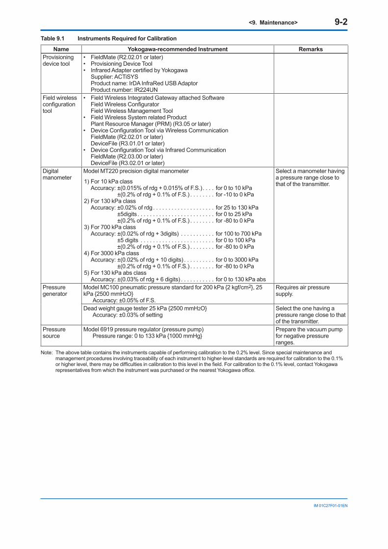
<9. Maintenance> 9-2
IM 01C27F01-01EN
Table 9.1 Instruments Required for Calibration
Name Yokogawa-recommended Instrument RemarksProvisioning device tool
• FieldMate(R2.02.01orlater)• ProvisioningDeviceTool• InfraredAdaptercertifiedbyYokogawa Supplier: ACTiSYS Product name: IrDA InfraRed USB Adaptor Product number: IR224UN
Field wireless configurationtool
• FieldWirelessIntegratedGatewayattachedSoftware FieldWirelessConfigurator Field Wireless Management Tool• FieldWirelessSystemrelatedProduct Plant Resource Manager (PRM) (R3.05 or later)• DeviceConfigurationToolviaWirelessCommunication FieldMate (R2.02.01 or later) DeviceFile (R3.01.01 or later)• DeviceConfigurationToolviaInfraredCommunication FieldMate (R2.03.00 or later) DeviceFile (R3.02.01 or later)
Digital manometer
Model MT220 precision digital manometer
1) For 10 kPa class Accuracy: ±(0.015% of rdg + 0.015% of F.S.). . . . for 0 to 10 kPa
±(0.2% of rdg + 0.1% of F.S.) . . . . . . . . for -10 to 0 kPa2) For 130 kPa class Accuracy: ±0.02% of rdg. . . . . . . . . . . . . . . . . . . . for 25 to 130 kPa ±5digits . . . . . . . . . . . . . . . . . . . . . . . . . for 0 to 25 kPa ±(0.2% of rdg + 0.1% of F.S.) . . . . . . . . for -80 to 0 kPa3) For 700 kPa class Accuracy: ±(0.02% of rdg + 3digits) . . . . . . . . . . . for 100 to 700 kPa ±5 digits . . . . . . . . . . . . . . . . . . . . . . . . for 0 to 100 kPa ±(0.2% of rdg + 0.1% of F.S.) . . . . . . . . for -80 to 0 kPa4) For 3000 kPa class Accuracy: ±(0.02% of rdg + 10 digits) . . . . . . . . . . for 0 to 3000 kPa ±(0.2% of rdg + 0.1% of F.S.) . . . . . . . . for -80 to 0 kPa5) For 130 kPa abs class Accuracy: ±(0.03% of rdg + 6 digits) . . . . . . . . . . . for 0 to 130 kPa abs
Select a manometer having a pressure range close to that of the transmitter.
Pressure generator
Model MC100 pneumatic pressure standard for 200 kPa {2 kgf/cm2}, 25 kPa {2500 mmH2O}
Accuracy: ±0.05% of F.S.
Requires air pressure supply.
Dead weight gauge tester 25 kPa {2500 mmH2O}Accuracy: ±0.03% of setting
Select the one having a pressure range close to that of the transmitter.
Pressure source
Model 6919 pressure regulator (pressure pump)Pressure range: 0 to 133 kPa {1000 mmHg}
Prepare the vacuum pump for negative pressure ranges.
Note: The above table contains the instruments capable of performing calibration to the 0.2% level. Since special maintenance and management procedures involving traceability of each instrument to higher-level standards are required for calibration to the 0.1% orhigherlevel,theremaybedifficultiesincalibrationtothislevelinthefield.Forcalibrationtothe0.1%level,contactYokogawarepresentativesfromwhichtheinstrumentwaspurchasedorthenearestYokogawaoffice.

<9. Maintenance> 9-3
IM 01C27F01-01EN
P
Reference pressure
Pressure generator
Supply pressure
P
Reference pressure
Precision digital manometer
Pressure source
Using pressure generator
Using pressure source with manometer
F0901.ai
Figure 9.1 Instrument Connections
9.4 Disassembly and Reassembly
CAUTIONPrecautions for the intrinsic safety explosion prevention type instrument
Intrinsic safe type transmitters must be, as a rule, removed to a non-hazardous area for maintenance and be disassembled and reassembled to the original state. Check and confirmtheinsulationwhenitisreassembledtothe original state.Checkandconfirmtheinsulationwhenitisreassembled to the original state.Refer to section 2.7 “Insulation Resistance and Dielectric Strength Test” for details of Resistance Test.
IMPORTANT• Performtheprovisioningwhenreplacingthe
RF assembly. Refer to 7.4 Connecting to the Field Wireless Network for details.
• Replacethebatteriesandperformtheparameter settings when replacing the CPU assembly. Refer to 9.4.6 Replacing the Batteries.
This section describes procedures for disassembly and reassembly for maintenance and component replacement.
CAUTIONAlways remove Battery pack and shut off pressures before disassembly and assembly. Use proper tools for all operations.
Table 9.2 shows the tools required.
Table 9.2 Tools for Disassembly and Reassembly
Tool Quantity RemarksPhillips screwdriver
1 JIS B4633, No. 2
Slotted screwdriver
1
Allen wrenches 3 JIS B4648 One each, nominal 3, 4 and 2.5 mm Allen wrenches
Wrench 1 Widthacrossflats,17mmTorque wrench 1Adjustable wrench
1
Socket wrench 1 Widthacrossflats,16mmSocket driver 1 Widthacrossflats,5.5mmTweezers 1

<9. Maintenance> 9-4
IM 01C27F01-01EN
9.4.1 Replacing the Integral IndicatorThis subsection describes the procedure for replacinganintegralindicator.(Seefigure9.2)
■ RemovingtheIntegralIndicator
1) Remove the cover.2) While supporting the integral indicator with one
hand, loosen its two mounting screws.3) Dismount the integral indicator from the RF
assembly. When doing this, carefully pull the integral
indicator straight forward so as not to damage the connector pins between it and the RF assembly.
■ Attaching the Integral Indicator
1) Align both the integral indicator and RF assembly connectors and engage them.
2) Insert and tighten the two mounting screws.3) Replace the cover.
Zero-adjustmentscrew
RF assembly
CPU assembly
Amplifier cover
Mounting screw
Integralindicator Boss
Stud
F0902.ai
Pressforward
Power cable
Zero-adjustmentscrew pin
Figure 9.2 Removing and Attaching Integral indicator, RF assembly and CPU Assembly
9.4.2 Replacing the RF AssemblyThis subsection describes how to replace the RF assembly (see Figure 9.2).
■ RemovingtheRFassembly
1) Remove the cover.2) Remove the integral indicator (refer to
subsection 9.4.1).3) Remove the two stud bolts by using a socket
driver(widthacrossflats:5.5mm).4) Disconnect the RF assembly from the CPU
assembly. When doing this, carefully pull the RF assembly straight forward so as not to damage the connector pins between it and the CPU assembly.
5) Disconnect the antenna cable that connects the RF assembly and the antenna.
NOTEBe careful not to apply excessive force to the RF assembly and the connector of the antenna cable when removing it.
■ MountingtheRFassembly
1) Connect the antenna cable between the RF assembly and the antenna.
2) Align both the RF assembly and CPU assembly connectors and engage them.
3) Tighten the two stud bolts.4) Mount the integral indicator (refer to subsection
9.4.1).5) Replace the cover.
9.4.3 Replacing the CPU AssemblyThis subsection describes how to replace the CPU assembly (see Figure 9.2).
■ RemovingtheCPUassembly
1) Remove the cover. Remove the integral indicator and the RF assembly (refer to subsections 9.4.1 and 9.4.2).
2) Turn the zero-adjustment screw to the position as shown in Figure 9.2.
3) Disconnect the power cable (cable with brown connector at the end). When doing this, lightly press the side of the CPU assembly connector and pull the cable connector to disengage (see the upper left of Figure 9.2).

<9. Maintenance> 9-5
IM 01C27F01-01EN
4) Useasocketdriver(widthacrossflats,5.5mm)to loosen the two bosses.
5) Carefully pull the CPU assembly straight forward to remove it.
6) Disconnecttheflatcable(cablewithwhiteconnector at the end) that connects the CPU assembly and the capsule.
NOTEBe careful not to apply excessive force to the CPU assembly when removing it.
■ MountingtheCPUassembly
1) Connecttheflatcable(withwhiteconnector)between the CPU assembly and the capsule.
2) Connect the power cable (with brown connector) to the CPU assembly.
NOTEMake certain that the cables do not get pinched between the case and the edge of the CPU assembly.
3) Align and engage the zero-adjustment screw pin with the groove on the bracket on the CPU assembly. Then insert the CPU assembly straightontothepostintheamplifiercase.
4) Tighten the two bosses. Mount the RF assembly, and the integral indicator (refer to subsections 9.4.1 and 9.4.2).
IMPORTANTConfirmthatthezero-adjustmentscrewpinisplaced properly in the groove on the bracket prior to tightening the two bosses. If it is not, the zero-adjustment mechanism will be damaged.
5) Replace the cover.
9.4.4 Cleaning and Replacing the Capsule Assembly
CAUTIONPrecautions for the intrinsic safety explosion prevention type instrumentModificationisnotpermittedbytheuserforintrinsic safety explosion prevention type transmitter. If you wish to replace the capsule assembly with one of a different measurement range, contact Yokogawa. The user is permitted, however, to replace a capsule assembly with another of the same specificationandmeasurementrange.Aftercompleting maintenance, be sure to securely tighten the setscrews that fasten the transmitter section and pressure-detector section together.
This subsection describes the procedures for cleaning and replacing the capsule assembly. (See figure9.3.)
■ Removing the Capsule Assembly
IMPORTANTExercise care as follows when cleaning the capsule assembly.• Handlethecapsuleassemblywithcare,and
be especially careful not to damage or distort the diaphragms that contact the process fluid.
• Donotuseachlorinatedoracidicsolutionforcleaning.
• Rinsewithcleanwateraftercleaning,pleasedry until completely dry.
1) Remove the CPU assembly as shown in subsection 9.4.3.
2) Removethefivesetscrews,thestopperbolt,and the stopper that connect the transmitter section and pressure-detector section.
3) Remove the hexagon-head screw and the stopper.
4) Separate the transmitter section and pressure-detector section.
5) Clean the capsule assembly or replace with a new one.

<9. Maintenance> 9-6
IM 01C27F01-01EN
■ Reassembling the Capsule Assembly
1) Reattach the transmitter section to the pressure-detector section.
Reattach the stopper with the hexagon-head screw.
2) Tightenthefivesetscrews.(Tightenthescrewsto a torque of 1.5 N·m)
3) Install the CPU assembly according to subsection 9.4.3.
4) After completing reassembly, adjust the zero point and recheck the parameters.
StopperStopper bolt
Transmitter section
Setscrew
Pressure-detector section
Pipe
F0903.ai
Figure 9.3 Removing and Mounting the Pressure-detector Section
9.4.5 Replacing the Battery PackRegarding the transmitter with intrinsically safe approval, the battery pack can be replaced without removing the device in hazardous area.
■ Preparation
Initialize the remaining battery life by using the parameter of Reset Energy Left in UAPMO block.When the battery power is burned and emptied, initialize the remaining battery after prompt replacement of the battery pack.
■ Removing
1) Remove the terminal box cover.2) Loosen the two battery pack mounting screws
(see Figure 9.5).3) Pull out the Battery pack.
F0904.ai
The battery pack mounting screws cannot be separated from the battery pack so as to prevent drop-off.
Figure 9.4 Removing the Battery Pack
■ Remounting
1) Insert the new battery pack lightly.2) Push the center of the battery pack and insert it
securely.3) Tighten the two battery pack mounting screws
to a torque of approximately 0.7 N·m.4) Replace the terminal box cover.
9.4.6 Replacing the BatteriesThe batteries in the battery pack can be replaced.Batteries are not installed when shipped from the factory. Assemble the battery pack as follows.
WARNING
Be sure to replace the batteries or disassemble and assemble the battery pack in a safe location. Doing so in an explosive area could cause an explosion.
CAUTIONWhen replacing the batteries, be sure to replace the two batteries at the same time and do not use an old and a new battery together.
■ Disassembling
1) Loosen the two battery case mounting screws (Figure 9.5).
2) Separate the battery case into two parts.3) Remove the old batteries.

<9. Maintenance> 9-7
IM 01C27F01-01EN
■ Assembling
1) Insert new batteries into the battery case. Be careful of the orientation of the batteries.
2) Attach the two parts of the battery case to each other.
3) Tighten the two battery case mounting screws to a torque of approximately 0.7 N·m.
F0905.ai
The battery pack mounting screws cannot be separated from battery pack so as to prevent drop-off.
Figure 9.5 Removing the Battery Pack
9.4.7 Handling BatteriesThis battery pack uses two primary lithium/thionyl chloride batteries. Each battery contains approximately 5 grams of lithium, for a total of 10 grams in each pack. Under normal conditions, the battery materials are self-contained and are not reactive as long as the batteries and the pack integrity are maintained. Care should be taken to prevent thermal, electrical or mechanical damage. Protect the electrode of the battery pack to avoid rapid electrical discharge. Discharged a battery may leadtofluidleakageandexcessiveheat.Batteriesshould be stored in a clean and dry area. For maximum battery life, storage temperature should not exceed 30°C.
WARNING
Handling the battery packThe following precautions must be observed in order to safely and effectively use a battery pack.Improperusemayleadtofluidleakage,excessive heat, ignition, or explosion.• Neverchargeit.• Donotshort-circuitit.• Donotdisassemble,transform,ormodifyit.• Donotheatitorthrowitintoafire.• Donotsoakitinfreshwaterorseawater.
CAUTIONObserve the following precautions for the safe disposal of batteries.• Donotincineratethebattery,anddonot
expose it to a high temperature of 100°C ormore.Thismayleadtofluidleakageorexplosion.
• Disposeofthebatteryaccordingtolawsandregulations.
Use the following dedicated parts for the battery pack and batteries.
■ BatteryPack Part number: F9915NQ (with batteries) Part number: F9915NK (without batteries)
■ Batteries Part number: F9915NR Alternatively, Tadiran TL-5930/S batteries may
be purchased and used.
■ Transportationofproductscontaininglithium batteries:
Batteries used for this transmitter contain lithium. Primary lithium batteries are regulated in transportation by the U.S. Department of Transportation, and are also covered by the International Air Transport Association (IATA), the International Civil Aviation Organization (ICAO), and the European Ground Transportation of Dangerous Goods (ARD). It is the responsibility of the shipper to ensure compliance with these or any other local requirements. Consult current regulations and requirements before shipping. When transporting this transmitter with the battery pack inserted, keep it in deep sleep mode in order to conserve battery power. For details on how to switch to deep sleep mode, refer to subsection 8.3.12 “Switching to Deep Sleep Mode.”

<9. Maintenance> 9-8
IM 01C27F01-01EN
■ Howtoreplaceanddisposeofthebatteries:
This is an explanation about the new EU Battery Directive (DIRECTIVE 2006/66/EC). This directive is only valid in the EU.Batteries are used for this product.When you remove batteries from this product and dispose them, discard them in accordance with domestic law concerning disposal.Take a right action on waste batteries because the collection system in the EU on waste batteries are regulated.Battery type: Primary lithium-thionyl chloride battery
CAUTIONThe symbol (see above), which is marked on the batteries, means they shall be sorted out and collected as ordained in ANNEX II in DIRECTIVE 2006/66/EC.
■ Proceduretoremovethebatteriessafely:
Refer to subsection 9.4.5 “Replacing the Battery Pack” and subsection 9.4.6 “Replacing the Batteries.”
9.5 TroubleshootingIf any abnormality appears in the measured values, usethetroubleshootingflowchartbelowtoisolateand remedy the problem. Since some problems havecomplexcauses,theseflowchartsmaynotidentifyall.Ifyouhavedifficultyisolatingorcorrecting a problem, contact Yokogawa service personnel.
9.5.1 Basic TroubleshootingFirst determine whether the process variable is actually abnormal or a problem exists in the measurement system.
If the problem is in the measurement system, isolate the problem and decide what corrective action to take.
This transmitter is equipped with a self-diagnostic function which will be useful in troubleshooting, and the transmitter equipped with an integral indicator will show an alarm code as a result of self-diagnosis. See subsection 9.5.3 for the list of alarms.
Abnormalities appear in measurement.
: Areas where self-diagnostic offers support
Is process variableitself abnormal?
Inspect theprocess system.
Isolate problem inmeasurement system.
Does problem exist inreceiving instrument?
Check/correctenvironmental conditions.
Inspect receiver.
Check transmitter.
Check/correct operatingconditions.
Measurement system problem
F0906.ai
YES
NO
NO
YES
Environmental conditions
Operating conditions
Transmitter itself
Figure 9.6 Basic Flow and Self-Diagnostics

<9. Maintenance> 9-9
IM 01C27F01-01EN
9.5.2 Troubleshooting Flowcharts
Check display of the error code.Check self-diagnostics by the device configuration tool.
Does the self-diagnosticindicate problem location?
Contact Yokogawa service personnel.
F0907.ai
The following sorts of symptoms indicate that transmitter may not be operating properly.Example : • There is no output signal. • Output signal does not change even though process variable is known to be varying. • Output value is inconsistent with value inferred for process variable.
Fix pressure leaks, paying particularattention to connections for impulsepiping,pressure-detector section, etc.
Fully open valve.
Are valves opened orclosed correctly?
Is there any pressure leak?
YES
NO
YES
NO
NO
YES
Refer to Alarm Message Summary in Subsection 9.5.3.
Is theField Wireless Network
setting correct?
NO
YES Reconnect to the Field Wireless Network.
Connect the device configuration tool and check self-diagnostics.
Does the self-diagnostic indicate problem
location?
Contact Yokogawa service personnel.F0908.ai
Are valves opened or closed correctly?
Refer to Alarm Message Summary in Subsection 9.5.3.
YES
NO
Fix pressure leaks, paying particularattention to connections for impulsepiping, pressure-detector section, etc.
Fully open valve.
NO
YES
YES
NO
Adjust the zero point.
NO
YES
Is there any pressure leak?
Is zero point adjusted correctly?
Output travels beyond 0% or 100%.

<9. Maintenance> 9-10
IM 01C27F01-01EN
Connect the device configuration tool and check self-diagnostics.
Contact Yokogawa service personnel.
F0909.ai
Are valves opened orclosed correctly?
Is impulse pipingconnected correctly?
Refer to Alarm Message Summary in Subsection 9.5.3.
Provide lagging and/or cooling, or allowadequate ventilation.
Refer to subsection 9.2 "Calibration Instruments Selection".
Fully open valve.
Refer to individual model user manualsand connect piping as appropriate for the measurement purpose.
Adjust the output.
Is transmitterinstalled where there is
marked variation intemperature?
Is output adjusted correctly?
Large output error.
Does the self-diagnostic indicate problem
location?
Were appropriateinstruments used for
calibration?
YES
NO
YES
NO
NO
YES
NO
YES
NO
YES
NO
YES
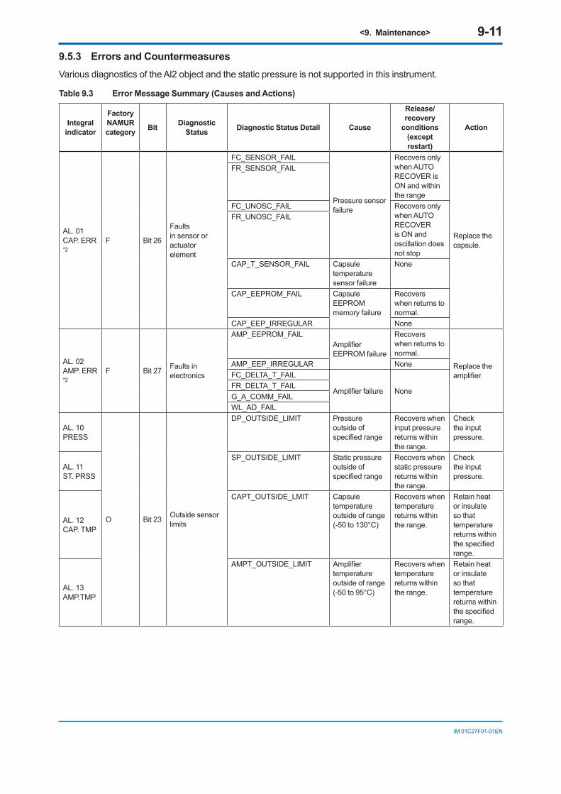
<9. Maintenance> 9-11
IM 01C27F01-01EN
9.5.3 Errors and CountermeasuresVarious diagnostics of the Al2 object and the static pressure is not supported in this instrument.
Table 9.3 Error Message Summary (Causes and Actions)
Integral indicator
Factory NAMUR category Bit Diagnostic
Status Diagnostic Status Detail Cause
Release/recovery
conditions (except restart)
Action
AL. 01CAP. ERR *2
F Bit 26
Faults in sensor or actuator element
FC_SENSOR_FAIL
Pressure sensor failure
Recovers only when AUTO RECOVER is ON and within the range
Replace the capsule.
FR_SENSOR_FAIL
FC_UNOSC_FAIL Recovers only when AUTO RECOVER is ON and oscillation does not stop
FR_UNOSC_FAIL
CAP_T_SENSOR_FAIL Capsule temperature sensor failure
None
CAP_EEPROM_FAIL Capsule EEPROM memory failure
Recovers when returns to normal.
CAP_EEP_IRREGULAR None
AL. 02AMP. ERR *2
F Bit 27 Faults in electronics
AMP_EEPROM_FAILAmplifierEEPROM failure
Recovers when returns to normal.
Replace the amplifier.
AMP_EEP_IRREGULAR NoneFC_DELTA_T_FAIL
Amplifierfailure NoneFR_DELTA_T_FAILG_A_COMM_FAILWL_AD_FAIL
AL. 10 PRESS
O Bit 23 Outside sensor limits
DP_OUTSIDE_LIMIT Pressure outside of specifiedrange
Recovers when input pressure returns within the range.
Check the input pressure.
AL. 11ST. PRSS
SP_OUTSIDE_LIMIT Static pressure outside of specifiedrange
Recovers when static pressure returns within the range.
Check the input pressure.
AL. 12CAP. TMP
CAPT_OUTSIDE_LMIT Capsule temperature outside of range (-50 to 130°C)
Recovers when temperature returns within the range.
Retain heat or insulate so that temperature returns within thespecifiedrange.
AL. 13AMP. TMP
AMPT_OUTSIDE_LIMIT Amplifiertemperature outside of range (-50 to 95°C)
Recovers when temperature returns within the range.
Retain heat or insulate so that temperature returns within thespecifiedrange.

<9. Maintenance> 9-12
IM 01C27F01-01EN
Integral indicator
Factory NAMUR category Bit Diagnostic
Status Diagnostic Status Detail Cause
Release/recovery
conditions (except restart)
Action
AL.53P. ADJ
C Bit 25Installation, calibration problem
DP_TRIM_SPAN_OUTSIDE Pressure span adjustment variable outside of range
Recovers when span adjustment variable/point returns within the range.
Check the span adjustment variable for the Pressure.
AL.53P. ADJ
DP_TRIM_ZERO_OUTSIDE Pressure zero adjustment variable outside of range
Recovers when zero adjustment variable/point returns within the range.
Check the zero adjustment variable for the Pressure.
AL. 55SP. ADJ
C Bit 25Installation, calibration problem
SP_TRIM_SPAN_OUTSIDE Static pressure span adjustment variable outside of range
Recovers when span adjustment variable /point returns within the range.
Check the static pressure span adjustment variable.
AL. 55SP. ADJ
SP_TRIM_ZERO_OUTSIDE Static pressure zero adjustment variable outside of range
Recovers when zero adjustment variable/point returns within the range.
Check the static pressure zero adjustment variable.
AL. 79OV. DISP
LCD_OUTSIDE_LIMIT LCD display outside of specifiedrange
Recovers when display value returns within the range.
Check the display setting.
AL. 30RANGE
O Bit 22
Environmental conditions out of device specification
DP_OUTSIDE_RANGE Input pressure setting outside of range
Recovers when setting returns within the range.
Check the input pressure setting.
AL. 31SP. RNG
SP_OUTSIDE_RANGE Static pressure setting outside of range
Recovers when setting returns within the range.
Check the static pressure setting.
AL. 70LOWBAT
M
Bit 20
Power is critical low: maintenance need short - term
CRITICAL_LOWBAT Battery voltage is the lowest.
None Replace the batteries.
AL. 70LOWBAT Bit 19
Power is low: maintenance need mid - term
WL_LOWBAT_ALM Low remaining battery voltage None Replace the
batteries.
AL. 60AI OOS
C Bit 24 O/S
AI1_OUT_OF_SERVICE AI1 block is O/S mode.
Returns when the mode target of AI1 block is other than O/S.
Set the mode target to AUTO.
AL. 61AI OOS
AI2_OUT_OF_SERVICE AI2 block is O/S mode.
Returns when the mode target of AI2 block is other than O/S.
Set the mode target to AUTO.
AL. 62AI OOS
AI3_OUT_OF_SERVICE AI3 block is O/S mode.
Returns when the mode target of AI3 block is other than O/S.
Set the mode target to AUTO.

<9. Maintenance> 9-13
IM 01C27F01-01EN
Integral indicator
Factory NAMUR category Bit Diagnostic
Status Diagnostic Status Detail Cause
Release/recovery
conditions (except restart)
Action
AL. 63AI SIM
C Bit 17 Simulation is active
SimulationActive(AI1)
AI1 block is simulate mode.
Returns when the simulate mode of AI1 block is set to disable. 1 (Disable)
Check the simulate mode of AI1 block.
AL. 64AI SIM
SimulationActive(AI2)
AI2 block is simulate mode.
Returns when the simulate mode of AI2 block is set to disable. 1 (Disable)
Check the simulate mode of AI2 block.
AL. 65AI SIM C Bit 17 Simulation is
active
SimulationActive(AI3)
AI3 block is simulate mode.
Returns when the simulate mode of AI3 block is set to disable. 1 (Disable)
Check the simulate mode of AI3 block.
*1: "Factory NAMUR category” refers to the four categories (C: Check function, M: Maintenance required, F: Failure, and O: Off specification)accordingtoNAMURNE107*.
* NAMUR NE107 “Self-Monitoring and Diagnosis of Field Devices”*2: When the device detects “AL01 CAP.ERR” and “AL02 AMP.ERR”, the LCD display stays on regardless of the status in LCD mode.

<9. Maintenance> 9-14
IM 01C27F01-01EN
Table 9.4 Error Message Summary (Output Actions)
Integral Indicator
Factory NAMUR category
Bit Diagnostic Status Diagnostic Status Detail
Output actions
Pressure Static Pressure
CapsuleTempValue
AmpTempValue
AL. 01CAP. ERR *2
F Bit 26
Faults in sensor or actuator element
FC_SENSOR_FAIL Output value (hold value)Output status (BAD: Sensor Failure)
Output value(hold value) Output status (BAD: Sensor Failure)
Normal action
Normal action
FR_SENSOR_FAILFC_UNOSC_FAILFR_UNOSC_FAIL
CAP_T_SENSOR_FAIL Normal action Normal action Output value (calculated in a normal way)Output status (BAD: Sensor Failure)
CAP_EEPROM_FAIL Output value (hold value) Output status (BAD: Device Failure)
Output value(hold value) Output status (BAD: Device Failure)
Output value (calculated in a normal way)Output status (BAD: Device Failure)
Output value (calculated in a normal way) Output status (BAD: Device Failure)
CAP_EEP_IRREGULAR
AL. 02AMP.ERR *2
F Bit 27 Faults in electronics
AMP_EEPROM_FAIL Output value (hold value) Output status (BAD: Device Failure)
Output value (hold value) Output status (BAD: Device Failure)
Output value (calculated in a normal way) Output status (BAD: Device Failure)
Output value(calculated in a normal way) Output status (BAD: Device Failure)
AMP_EEP_IRREGULAR
FC_DELTA_T_FAIL Output value (hold value) output status (BAD: Device Failure)
Output value (calculated in a normal way) Output status (BAD: Device Failure)
Output value (hold value) Output status (BAD: Device Failure)
Normal action
Output value(calculated in a normal way) Output status (BAD: Device Failure)
FR_DELTA_T_FAIL
G_A_COMM_FAIL Output value (calculated in a normal way) Output status (BAD: Device Failure)
Output value (calculated in a normal way) Output status (BAD: Device Failure)
WL_AD_FAIL

<9. Maintenance> 9-15
IM 01C27F01-01EN
Integral Indicator
Factory NAMUR category
Bit Diagnostic Status Diagnostic Status Detail
Output actions
Pressure Static Pressure
CapsuleTempValue
AmpTempValue
AL. 10 PRESS
O Bit 23 Outside sensor limits
DP_OUTSIDE_LIMIT Output value (calculated in a normal way) Output status (UNCERTAIN: Sensor Conversion not Accurate)
Output value (calculated in a normal way) Output status (UNCERTAIN: NonSpecific)
Normal action Normal action
AL. 11ST. PRSS
SP_OUTSIDE_LIMIT Output value (calculated in a normal way) Output status (UNCERTAIN: NonSpecific)
Output value (calculated in a normal way) Output status (UNCERTAIN: Sensor Conversion not Accurate)
Normal action Normal action
AL. 12CAP. TMP
CAPT_OUTSIDE_LIMIT Output value (calculated in a normal way) Output status (UNCERTAIN: NonSpecific)
Output value (calculated in a normal way) Output status (UNCERTAIN: NonSpecific)
Output value (calculated in a normal way) Output status (UNCERTAIN: Sensor Conversion not Accurate)
Normal action
AL. 13AMP. TMP
AMPT_OUTSIDE_LIMIT
Normal action Normal action Normal action
Output value (calculated in a normal way) Output status (UNCERTAIN: Sensor Conversion not Accurate)
AL. 53P. ADJ
C Bit 25Installation, calibration problem
DP_TRIM_SPAN_OUTSIDE
Output value (calculated in a normal way) Output status (UNCERTAIN: Range Limits Exceeded)
Normal action Normal action Normal action
AL. 53P. ADJ
DP_TRIM_ZERO_OUTSIDE
Output value (calculated in a normal way) Output status (UNCERTAIN: Range Limits Exceeded)
Normal action Normal action Normal action
AL. 55SP. ADJ
SP_TRIM_SPAN_OUTSIDE
Normal action
Output value (calculated in a normal way) Output status (UNCERTAIN: Range Limits Exceeded)
Normal action Normal action
AL. 55SP.ADJ
SP_TRIM_ZERO_OUTSIDE
Normal action
Output value (calculated in a normal way) Output status (UNCERTAIN: Range Limits Exceeded)
Normal action Normal action
AL. 79OV. DISP
LCD_OUTSIDE_LIMITNormal action Normal action Normal action Normal action

<9. Maintenance> 9-16
IM 01C27F01-01EN
Integral Indicator
Factory NAMUR category
Bit Diagnostic Status Diagnostic Status Detail
Output actions
Pressure Static Pressure
CapsuleTempValue
AmpTempValue
AL. 30RANGE
O Bit 22
Environmental conditions out of device specification
DP_OUTSIDE_RANGE Normal action Normal action Normal action Normal action
AL. 31SP. RNG
SP_OUTSIDE_RANGENormal action Normal action Normal action Normal action
AL. 70*3
LOWBAT
M
Bit 20
Power is critical low: maintenance need short - term
CRITICAL_LOWBAT
Normal action Normal action Normal action Normal action
AL. 70*3
LOWBAT Bit 19
Power is low: maintenance need mid - term
WL_LOWBAT_ALM
Normal action Normal action Normal action Normal action
AL. 60AI OOS
C Bit 24 O/S
AI1_OUT_OF_SERVICE Output value(hold value)Output status(BAD: Out of Service)
Normal action Normal action Normal action
AL. 61AI OOS
AI2_OUT_OF_SERVICE
Normal action
Output value(hold value)Output status(BAD: Out of Service)
Normal action Normal action
AL. 62AI OOS
AI3_OUT_OF_SERVICE
Normal action Normal action
Output value(hold value)Output status(BAD: Out of Service)
Output value(hold value)Output status(BAD: Out of Service)
AL. 63AI SIM
C Bit 17 Simulation is active
SimulationActive(AI1) Normal action Normal action Normal action Normal action
AL. 64AI SIM
SimulationActive(AI2) Normal action Normal action Normal action Normal action
AL. 65AI SIM
SimulationActive(AI3) Normal action Normal action Normal action Normal action
*1: “Factory NAMUR category” refers to the four categories (C: Check function, M: Maintenance required, F: Failure, and O: Off *1: “Factory NAMUR category” refers to the four categories (C: Check function, M: Maintenance required, F: Failure, and O: Off specification)accordingtoNAMURNE107*.
* NAMUR NE107 “Self-Monitoring and Diagnosis of Field Devices”*2: When the device detects “AL01 CAP.ERR” and “AL02 AMP.ERR”, the LCD display stays on regardless of the status in LCD mode. *3: Whentheambienttemperatureishigherthan60°C,AL.70maybegenerateddespitetheindicationofEnergyLeftshowssufficiently
remained. However, it does not affect the device operation. This is caused by the change of battery inner status with extremely low power consumption under high temperature environment. It is recommended to set the data updating period to 15 seconds or shorter.

<10. Parameter Summary> 10-1
IM 01C27F01-01EN
10. Parameter SummaryThe setting of differential pressure (Al2 block) is invalid in this instrument. The output value of Al2 object and the output status are “0.0”(zero) and “Uncertain” respectively.Various diagnostics of the Al2 object and the static pressure is not supported in this instrument.Table 10.1 Parameter
ObjectID
Attribute ID Label Description Default
value Handling
1.UAPMOblock
1 Version Revision Indicates the application revision of EJX This revision when the application software is downloaded.
--- R
10 Static Revision IndicatestherevisionlevelofthefixedparametersofUAP Used, for example, to check whether parameters have been change.
0 R
64 IdentificationNumber
Indicates the vender ID, model ID, and revision of the device.
--- R
65 CTS Version Indicates the version of the communication stack test system (CTS).
0 R
66 ITS Version Indicates the version of the inter operability test system (ITS).
0 R
67 Diagnostic Status Indicates the diagnostic results of the device based on the NAMUR NE107*1 model.SettingEnablediagnosticstatusconfigurationinUAPOption to Enable allows turning OFF and ON the display of the diagnostic results for each summary, and changing Categorize For Categorize at the time of shipment, refer to tables 8.3 and 10.2.
--- R
68 UAP Option Allows setting the Diagnostic Status and write protection of UAP.
Software write protect1: On, 0: Off
Enable hardware write protect1: Enable, 0: Disable (default)
Enablediagnosticstatusconfiguration1: Enable, 0: Disable (default)
The following table shows the relationship between the hardware write protection and software write protection.
Enable hardware
write protect
Hardware write
protect
Software write
protect
Write protect
Disable Off or On Off No(Writable)
Disable Off or On On Yes(Unwritable)
Enable Off Off or On No(Writable)
Enable On Off or On Yes(Unwritable)
0 W
69 DiagnosticSwitch
Allows setting On/Off for each summary of Diagnostic StatuswhenEnablediagnosticstatusconfigurationinUAP Option is set to Enable.
On W
70 DiagnosticConfiguration
Allows Categorize for each summary of Diagnostic StatuswhenEnablediagnosticstatusconfigurationinUAP Option is set to Enable.
Refer to Table 10.2.
W
102 Diagnostic Status Detail[2]
Detailed information on Diagnostic Status. For Categorize at the time of shipment, refer to Table 10.2.
Refer to Table 10.2.
R
103 Energy Left Indicates the number of days of remaining battery life assuming ambient temperature condition as 23 degrees Celsius.The unit is day.
--- R
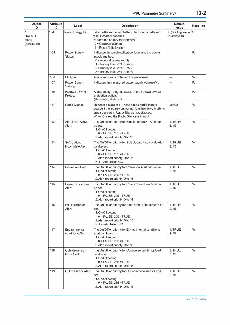
<10. Parameter Summary> 10-2
IM 01C27F01-01EN
ObjectID
Attribute ID Label Description Default
value Handling
1.UAPMO block(continued)
104 Reset Energy Left Initialize the remaining battery life (Energy Left) and reset it as new batteries.Perform the battery replacement.0 = Continue (Cancel)1 = Reset (Initialization)
0 (reading value is always 0)
W
105 Power Supply Status
Indicates the predicted battery level and the power supply method.0 = external power supply1 = battery level 75% or more2 = battery level 25% ~ 75%3 = battery level 25% or less
R
106 EHType Available to write note into this parameter. --- W
107 Power Supply Voltage
Indicates the measured power supply voltage (V). --- R
110 Hardware Write Protect
Allows recognizing the status of the hardware write protection switch.(Switch Off, Switch On)
R
111 Radio Silence Repeats a cycle of a 1-hour pause and 6-minute search if the instrument cannot join the network after a timespecifiedinRadioSilencehaselapsed.When 0 is set, the Radio Silence is invalid.
28800 W
112 Simulation Active Alert
The On/Off or priority for Simulation Active Alert can be set.1. On/Off setting
0 = FALSE, 255 =TRUE2. Alert report priority: 0 to 15
1. TRUE 2. 15
W
113 Soft Update incomplete Alert
The On/Off or priority for Soft Update incomplete Alert can be set.1. On/Off setting
0 = FALSE, 255 =TRUE2. Alert report priority: 0 to 15Not available for EJX.
1. TRUE 2. 15
W
114 Power low Alert The On/Off or priority for Power low Alert can be set.1. On/Off setting
0 = FALSE, 255 =TRUE2. Alert report priority: 0 to 15
1. TRUE 2. 15
W
115 Power Critical low Alert
The On/Off or priority for Power Critical low Alert can be set.1. On/Off setting
0 = FALSE, 255 =TRUE2. Alert report priority: 0 to 15
1. TRUE 2. 15
W
116 Fault prediction Alert
The On/Off or priority for Fault prediction Alert can be set.1. On/Off setting
0 = FALSE, 255 =TRUE2. Alert report priority: 0 to 15Not available for EJX.
1. TRUE 2. 15
W
117 Environmental conditions Alert
The On/Off or priority for Environmental conditions Alert can be set.1. On/Off setting
0 = FALSE, 255 =TRUE2. Alert report priority: 0 to 15
1. TRUE 2. 15
W
118 Outside sensor limits Alert
The On/Off or priority for Outside sensor limits Alert can be set.1. On/Off setting
0 = FALSE, 255 =TRUE2. Alert report priority: 0 to 15
1. TRUE 2. 15
W
119 Out of service Alert The On/Off or priority for Out of service Alert can be set.1. On/Off setting
0 = FALSE, 255 =TRUE2. Alert report priority: 0 to 15
1. TRUE 2. 15
W

<10. Parameter Summary> 10-3
IM 01C27F01-01EN
ObjectID
Attribute ID Label Description Default
value Handling
1.UAPMO block(continued)
120 Callibration problem Alert
The On/Off or priority for callibration problem Alert can be set.1. On/Off setting
0 = FALSE, 255 =TRUE2. Alert report priority: 0 to 15
1. TRUE 2. 15
W
121 Faults Sensor or actuator Alert
The On/Off or priority for Faults Sensor or actuator Alert can be set.1. On/Off setting
0 = FALSE, 255 =TRUE2. Alert report priority: 0 to 15
1. TRUE 2. 15
W
122 Faults Electronics Alert
The On/Off or priority for Faults Electronics Alert can be set.1. On/Off setting
0 = FALSE, 255 =TRUE2. Alert report priority: 0 to 1
1. TRUE 2. 15
W
123 Faults process influenceAlert
TheOn/OfforpriorityforFaultsprocessinfluenceAlertcan be set.1. On/Off setting
0 = FALSE, 255 =TRUE2. Alert report priority: 0 to 15Not available for EJX.
1. TRUE 2. 15
W
124 Faults non-compliance Alert
The On/Off or priority for Faults non-compliance Alert can be set.1. On/Off setting 0 = FALSE, 255 =TRUE2. Alert report priority: 0 to 15Not available for EJX.
1. TRUE 2. 15
W
125 Other faults Alert The On/Off or priority for Other faults Alert can be set.1. On/Off setting 0 = FALSE, 255 =TRUE2. Alert report priority: 0 to 15Not available for EJX.
1. TRUE 2. 15
W
2.UDOblock
2 DESCRIPTION Indicates the version and model information of the downloaded data.
--- R
3 STATE Indicates the status of UAP block.0 Idle1 Downloading3 Applying4 DLComplete6 DLError
--- R
5 MAX_BLOCK_SIZE
Maximum block size. This value is smaller than the maximum data size of APDU.
--- R
14 LAST_BLOCK_DOWNLOADED
Indicates the last downloaded block number. 0 means that no block has been downloaded.
--- R
16 ERROR_CODE Indicates the error codes for DLError.0 = noError1 = Timeout2 = ClientAbort64 = Apply failure
--- R
3.COblock
1 REVISION Indicates the revision number such as COMM_ENDPOINT, etc.
--- R
2 COMM_ENDPOINT
Indicates the Endpoint information. The following shows the components.1. Network address of remote endpoint2. Transport layer port at remote endpoint3. Object ID at remote endpoint4. Stale data limit5. Data publication period6. Ideal publication phase7. PublishAutoRetransmit8.Configurationstatus
--- W

<10. Parameter Summary> 10-4
IM 01C27F01-01EN
ObjectID
Attribute ID Label Description Default
value Handling
3.COblock(continued)
3 COMM_CONTRACT
Indicates the Contract information. The following shows the components.1. ContractID2. Contract_Status3. Actual_Phase
--- R
4 PUB_ITEM_MAX Maximum PUB_ITEM value --- R
5 PUB_ITEM_NUM PUB_ITEM number --- R
6 PUB_ITEM Indicates the PUB_ITEM information. The following shows the components1. ObjectID2. AttributeID3. AttributeIndex4. Size
--- W
4.TRANSDUCERblock
1 Tag Description Memofieldavailabletowriteanything. Transducer W
2 Auto Recovery Allows specifying the action when the cause of a sensor failure is removed.OFF (=0): AL continues to be indicated
even after the cause of the sensor error is removed, and the BURN OUT state is not released.
ON (=1): The AL indication for sensor failure disappears and normal action is resumed when the cause of the sensor failure is removed.
ON W
3 Model Indicates the model name of the transmitter. --- R
4 Sensor Serial Number
Indicates the device number of the transmitter. --- R
6 Measurement Mode
Measurement mode selects continuous mode or intermittent mode.When the update time is set to 0.5 second in intermittent mode, the mode is automatically switched to continuous mode.When the update time is set to 0.5 second, the computation process is in continuous mode, regardless of the measurement mode.When 0 is set, measurement period is set to 30 seconds regardless of measurement setting.
intermittent mode
W
7 Wireless Status Indicate the communication status.1. Indicates the initial idle status or join status. (idle status, join status)2. Indicates whether Contract(Pub) is established. (not establishment, establishment) 3. Indicates whether Contract(R/W) is
established. (not establishment, establishment)
1. idle status2. not estabilishment3. not esabilishment
R
8 Display Selection Select PV Value displaying on the LCD indicator.1. Indicates display status of PV Value of AI1 (displayed, not displayed)2. Indicates display status of PV Value of AI2 (displayed, not displayed)3. Indicates display status of PV Value of AI3 (displayed, not displayed)
1. displayed2. not displayed3. not displayed
W
9 LCD Mode Select the display mode on the LCD indicator.1. Indicates the ON mode. (OFF, ON)2. Indicates the bar graph display. (bar graph not displayed, bar graph displayed)
1. OFF2. bar graph not displayed
W
<10. Parameter Summary> 10-5
IM 01C27F01-01EN
ObjectID
Attribute ID Label Description Default
value Handling
4.TRANSDUCERblock(continued)
10 Special Cmd Special function parameter.0 = initialize value at READ (None)1 = Squawk status2 = deep sleep status
To start from deep sleep mode, either remove and insert the battery pack, or use the provisioning device toolorthedeviceconfigurationtoolviainfraredcommunication.
0 W
11 Special Order ID Displays the special order number, if applicable. --- R
12 Unit Sel1 Selects whether to automatically apply the unit to the word for the parameter for which the unit display is selected, or apply the characters that are written to Display Unit1. (Auto, Custom)
Auto W
13 Display Unit11 When Custom is selected in Unit Sel1, set the display unit using 6 characters or less.
NULL W
14 LCD Intermittetnt Time
Set the time to turn off display on the LCD indicator.When 0 is set, it is diplayed in continuous mode.Unit: second
60 seconds W
15 XD Filter Set the damping time to Tranceducer value in the AI1 ans AI2 blocks. Unit: second
When Measurement mode is set to continuous mode, it is valid.
2 seconds W
16 Measurement Rate
Indicates the cycle to publish the measurement value and status
0 R
5.AI1 block
1 Process Value AL1 is a pressure output object.Indicates the primary analog value (or corresponding process value) and status used to execute this function.Allows updating data by specifying this for the Concentrator object.1. Value: output value of Al object2. Status: Specify output status of Al object.
1. Value = ---2. Status = ---
W
2 Block Mode A universal parameter to indicate the block’s operation status. Each O/S, Auto, and Man can select from.1. Target : Specify Al object mode.2. Actual : Indicates current mode of Al object.3. Permitted : Indicates the mode selected by
Target of Al object.4. Normal : Indicate normal status mode of Al
object.
1.Target=Auto2.Actual=Auto3.Permitted=Auto4.Normal=Auto
W
3 Concentrator OID Indicates the Concentrator object value that corresponds to the data update of the PV value.
3 R
4 Scale Allows specifying the upper or lower limit for the PV scaling, unit code, etc.1. EU at 100% : Indicate the upper limit of the PV
value.2. EU at 0% : Indicate the lower limit of the PV value.3. Units Index : Indicate the setting unit used for the
PV value.4. Decimal : Indicate the digit number below the
decimal point displayed in the LCD indicator.
1. EU at 100% = 1002. EU at 0% = 03. Units Index = %4. Decimal = 2
W
26 Tag Description A universal parameter to store the comment that describes the tag
Al1:DifferentialPressure
W
27 Process Value Filter Time
AllowsadjustingthetimeconstantforfilteringthePVvalue. Setting unit: Second. This is enabled for the Continuous mode.*2
0 second W
28 Simulate Switch A simulation function switch for the AI object test (Disable, Enable)
1 (Disable) W

<10. Parameter Summary> 10-6
IM 01C27F01-01EN
ObjectID
Attribute ID Label Description Default
value Handling
5.AI1 block (continued)
29 Transducer Value When Simulate Switch is set to Disable, this value is used as the input value for the AI object. Refer to Figure 10.1.
Disable R
30 Simulate Value When Simulate Switch is set to Enable, this value is used as the input value for the AI object.The input value can be changed.
--- W
51 Upper Limit Indicates the upper limit (URL) for the pressure. --- R
52 Lower Limit Indicates the lower limit (LRL) for the pressure. --- R
53 PV Range Sets the measurement range.1. EU at 100% : Indicates input value of the upper
limit.2. EU at 0% : Indicates input value of the lower limit.3. Units Index : Indicates the units of the
measurement range.4. Decimal : Indicates the digit number below the
decimal point.
EU at 100% = 100EU at 0% = 0Units Index = kPa (1133)Decimal = 2
W
54 Linearization Type Select either No Linearization or Square root as a setting of the output range.0 = No Linearization : Provides an output value scaled according to the
PV Range and Scale range settings. (To use Direct with FF, set the same value for PV
Range and Scale.)10 = Square root : Provides a square root output computed for the
value scaled according to the PV Range and Scale range settings.
0 W
55 Flow Constant Indicatestheflowcoefficient,whichshowsthecorrelationbetweentheflowratevalueandsquarerootvalue of the differential pressure.
1.0 W
56 Lower Cutoff Specifiesthelowcutvalue.TheunitissubjecttoScale.Units Index.
10 W
57 Cal Cmd Specifiesthecalibrationmethod.0 = CAL_NONE : Initial state in which calibration is
not performed1 = CAL_LOW : Applies an actual input and adjusts thelowerlimitusingthevaluespecifiedinCalibration Lowest Point.
2 = CAL_HIGH : Applies an actual input and adjusts thehigherlimitusingthevaluespecifiedinCalibration Highest Point.
5 = CAL_CLEAR : Clears the adjustment variable.
0 (reading value is always 0)
W
58 Cal Status Indicates the calibration status.0 = CAL_NONE : Start-up and default value1 = CAL_SUCCESS : Indicates that calibration was
successful.7 = CAL_BAD_TRIM_POINT : Indicates this status
when the adjustment variable is outside of range.
--- R
59 Calibration Highest Point
Specifiesthehigherlimitadjustmentvariableforadjustment between two points.
--- W
60 Calibration Lowest Point
Specifiesthelowerlimitadjustmentvariablefortheadjustment between two points.
--- W
61 Calibration Minimum Span
Indicates the minimum span of the adjustment variable.
--- R
104 External Zero Trim Allows performing external zero adjustment.(Trim on, Trim off)
Trim on W
105 Low Cut Mode Specifiesthelowcutmode.(Linear, Zero)
Linear W
<10. Parameter Summary> 10-7
IM 01C27F01-01EN
ObjectID
Attribute ID Label Description Default
value Handling
5.AI1 block (continued)
106 H/L Swap Allows performing reverse connection of the impulse line.(NORMAL, REVERSE : reverse connection)Used when the lower pressure side and higher pressure side of the impulse line were connected wrongly when installing the pressure transmitter.
Normal W
107 T Zero Cmp Parameter to select the temperature zero shift compensation mode0 = OFF : Does not perform temperature zero shift
compensation.1 = ON : Performs temperature zero shift
compensation.
Off w
108 Temp Zero Parameter to set the temperature gradient value for the temperature zero shift compensation
0 w
109 Temp Select Parametertoselectthetemperature(amplifier-side/ capsule-side) used for the temperature zero shift compensation.0=AMPTEMP:thevalueoftheamplifier-side
temperature sensor is used.1 = CAP TEMP : the value of the capsule-side
temperature sensor is used.
1 w
6.AI2block
1 Process Value AI2 is a static pressure output object.Indicates the primary analog value (or corresponding process value) and status used to execute this function.Allows updating data by specifying this for the Concentrator object. 1. Value: output value of Al object2. Status: Specify output status of Al object.
--- W
2 Block Mode A universal parameter to indicate the block’s operation status. O/S, Auto, and Man can be selected.1. Target : Specify Al object mode.2. Actual : Indicates current mode of Al object.3. Permitted : Indicates the mode selected by Target
of Al object.4. Normal : Indicate normal status mode of Al object.
1.Target = O/S2.Actual = O/S3.Permitted = O/S4.Normal = O/S
W
3 Concentrator OID Indicates the Concentrator object value that corresponds to the data update of the PV value.
3 R
4 Scale Allows specifying the upper or lower limit for the PV scaling, unit code, etc.1. EU at 100% : Indicate the upper limit of the PV
value.2. EU at 0% : Indicate the lower limit of the PV value.3. Units Index : Indicate the setting unit used for the
PV value.4. Decimal : Indicate the digit number below the
decimal point displayed in the LCD indicator.
1. EU at 100% = 1002. EU at 0% = 03. Units Index = %4. Decimal = 2
W
26 Tag Description A universal parameter to store the comment that describes the tag.
AI2: Static Pressure
W
27 Process Value Filter Time
AllowsadjustingthetimeconstantforfilteringthePVvalue. Setting unit: Second. This is enabled for the Continuous mode.*2
0 second W
28 Simulate Switch A simulation function switch for the AI object test(Disable, Enable)
Disable W
29 Transducer Value When Simulate Switch is set to Disable, this value is used as the input value for the AI object.
--- R
30 Simulate Value When Simulate Switch is set to Enable, this value is used as the input value for the AI object.The input value can be changed.
--- W

<10. Parameter Summary> 10-8
IM 01C27F01-01EN
ObjectID
Attribute ID Label Description Default
value Handling
6.AI2 block (continued)
51 Upper Limit Indicates the upper limit (URL) for the pressure. --- R
52 Lower Limit Indicates the lower limit (LRL) for the pressure. --- R
53 PV Range Sets the measurement range.1. EU at 100% : Indicates input value of the upper
limit.2. EU at 0% : Indicates input value of the lower limit.3. Units Index : Indicates the units of the
measurement range.4. Decimal : Indicates the digit number below the
decimal point.
1. EU at 100% = 25000.000000EU at 0% = 0Units Index = kPaDecimal = 2
W
54 Linearization Type Select either No Linearization or Square root as a setting of the output range.0 = No Linearization : Provides an output value scaled according to the
PV Range and Scale range settings. (To use Direct with FF, set the same value for PV
Range and Scale.)
0 W
55 Flow Constant Indicatestheflowcoefficient,whichshowsthecorrelationbetweentheflowratevalueandsquarerootvalue of the pressure.
1.0 W
56 Lower Cutoff Specifiesthelowcutvalue.TheunitissubjecttoScale.Units Index.
10 W
57 Cal Cmd Specifiesthecalibrationmethod.0 = CAL_NONE : Initial state in which calibration is
not performed1 = CAL_LOW : Applies an actual input and adjusts thelowerlimitusingthevaluespecifiedinCalibration Lowest Point.
2 = CAL_HIGH : Applies an actual input and adjusts thehigherlimitusingthevaluespecifiedinCalibration Highest Point.
5 = CAL_CLEAR : Clears the adjustment variable.
0 (reading value is always 0)
W
58 Cal Status Indicates the calibration status.0 = CAL_NONE : Start-up and default value1 = CAL_SUCCESS : Indicates that calibration was
successful.7 = CAL_BAD_TRIM_POINT : Indicates this status
when the adjustment variable is outside of range.
R
59 Calibration Highest Point
Specifiesthehigherlimitadjustmentvariableforadjustment between two points.
--- W
60 Calibration Lowest Point
Specifiesthelowerlimitadjustmentvariablefortheadjustment between two points.
--- W
61 Calibration Minimum Span
Indicates the minimum span of the adjustment variable.108 = Gauge pressure109 = Absolute pressure
--- R
102 Static Process Type
Selects the gauge pressure or the absolute pressure. Abs W
103 SP Select Parameter to select the High-side pressure or the Low-side pressure as the static pressure output.0 = High : Displays the H-side pressure as the static
pressure1 = Low : Displays the L-side pressure as the static
pressure
High W

<10. Parameter Summary> 10-9
IM 01C27F01-01EN
ObjectID
Attribute ID Label Description Default
value Handling
7.AI3 block
1 Process Value Al3 is a temperature pressure output object.Indicates the primary analog value (or corresponding process value) and status used to execute this function.Allows updating data by specifying this for the Concentrator object. 1. Value: output value of Al object2. Status: Specify output status of Al object.
1. Value = ---2. Status = ---
W
2 Block Mode A universal parameter to indicate the block’s operation status. O/S, Auto, and Man can be selected.1. Target : Specify Al object mode.2. Actual : Indicates current mode of Al object.3. Permitted : Indicates the mode selected by Target
of Al object.4. Normal : Indicate normal status mode of Al object.
1. Target = Auto2. Actual = Auto3. Permitted = O/S+Auto +Man4. Normal = Auto
W
3 Concentrator OID Indicates the Concentrator object value that corresponds to the data update of the PV value.
3 R
4 Scale Allows specifying the upper or lower limit for the PV scaling, unit code, etc.1. EU at 100% : Indicate the upper limit of the PV
value.2. EU at 0% : Indicate the lower limit of the PV value.3. Units Index : Indicate the setting unit used for the
PV value.4. Decimal : Indicate the digit number below the
decimal point displayed in the LCD indicator.
1. EU at 100% = 1002. EU at 0% = 03. Units Index = %4. Decimal = 2
W
26 Tag Description A universal parameter to store the comment that describes the tag
AI3: Capsule temperature
W
27 Process Value Filter Time
AllowsadjustingthetimeconstantforfilteringthePVvalue. Setting unit: Second. This is enabled for the Continuous mode.
0 second W
28 Simulate Switch A simulation function switch for the AI object test(Disable, Enable)
Disable W
29 Transducer Value When Simulate Switch is set to Disable, this value is used as the input value for the AI object.
--- R
30 Simulate Value When Simulate Switch is set to Enable, this value is used as the input value for the AI object.The input value can be changed.
--- W
53 Sensor Range Parameter to nondimensionalize the sensor output value. K and deg C are selectable for the temperature unit. 1. EU at 100% : Indicates input value of the upper
limit.2. EU at 0% : Indicates input value of the lower limit.3. Units Index : Indicates the units of the
measurement range.4. Decimal : Indicates the digit number below the
decimal point.
1. EU at 100% = 1302. EU at 0% = -503. Units Index = deg C4. Decimal = 0
W
102 Tertiary Value Select
Specifieseitherthecapsuletemperatureoramplifiertemperature as the output value.(CAP, AMP)
CAP W
(Note) Handling: R=Read only, W=Read & Write(Note) “Factory NAMUR category” refers to the four categories (C: Check function, M: Maintenance required, F: Failure, and O: Off
specification)accordingtoNAMURNE107*.
*1: NAMUR NE107 “Self-Monitoring and Diagnosis of Field Devices”*2: It is valid for not only continuous mode but also intermittent mode.

<10. Parameter Summary> 10-10
IM 01C27F01-01EN
Table 10.2 Diagnostic Status Detail [0]
Bit Diagnostic Status Detail Description Diagnostic Status assignment bit NAMUR
DiagnosticDetail_131 FC_SENSOR_FAIL C sensor frequency error Bit26 F30 FR_SENSOR_FAIL R sensor frequency error Bit26 F29 CAP_T_SENSOR_FAIL Capsule temperature sensor failure Bit26 F28 CAP_EEPROM_FAIL Capsule EEPROM failure Bit26 F27 CAP_EEP_IRREGULAR CAP EEPROM version not correct Bit26 F25 AMP_EEPROM_FAIL AmplifierEEPROMfailure Bit27 F24 AMP_EEP_IRREGULAR AMP EEPROM version not correct Bit27 F22 G_A_COMM_FAIL G/A failure Bit27 F21 FC_UNOSC_FAIL C sensor oscillation stop failure Bit26 F20 FC_DELTA_T_FAIL C-side deltaT circuit failure Bit27 F19 FR_DELTA_T_FAIL R-side deltaT circuit failure Bit27 F18 WL_AD_FAIL Battery voltage not detected (AMP failure) Bit27 F17 FR_UNOSC_FAIL R sensor oscillation stop failure Bit26 F15 DP_OUTSIDE_LIMIT Pressureoutsideofspecifiedrange Bit23 O14 SP_OUTSIDE_LIMIT Staticpressureoutsideofspecifiedrange Bit23 O13 CAPT_OUTSIDE_LIMIT Capsuletemperatureoutsideofspecifiedrange Bit23 O12 AMPT_OUTSIDE_LIMIT Amplifiertemperatureoutsideofspecifiedrange Bit23 O7 DP_OUTSIDE_RANGE Input pressure setting outside of range Bit22 O6 SP_OUTSIDE_RANGE Static pressure setting outside of range Bit22 ODiagnosticDetail_231 AI1_OUT_OF_SERVICE AI1 O/S mode Bit24 C30 AI2_OUT_OF_SERVICE AI2 O/S mode Bit24 C29 AI3_OUT_OF_SERVICE AI3 O/S mode Bit24 C28 AI1_SIMULATION_ACTIVE AI1 simulation mode Bit17 C27 AI2_SIMULATION_ACTIVE AI2 simulation mode Bit17 C26 AI3_SIMULATION_ACTIVE AI3 simulation mode Bit17 C20 DP_TRIM_SPAN_OUTSIDE Pressure span adjustment variable outside of range Bit25 C19 DP_TRIM_ZERO_OUTSIDE Pressure zero adjustment variable outside of range Bit25 C15 SP_TRIM_SPAN_OUTSIDE Static pressure span adjustment variable outside of
rangeBit25 C
14 SP_TRIM_ZERO_OUTSIDE Static pressure zero adjustment variable outside of range
Bit25 C
13 WL_LOWBAT_ALM Detection of a decrease in the battery voltage Bit19 M12 CRITICAL_LOWBAT Detection of an extreme decrease in the battery
voltageBit20 M
8 LCD_OUTSIDE_LIMIT LCDdisplayoutsideofspecifiedrange Bit25 C
F1001.ai
AI algoritm
MODE Targetfrom operator
from operator
from operator
from transducer
SIMULATE
On
Off
AIalgorithm
Linearizationscaling,
filter
Alertreport
HiHi etc
PV
Auto
O/S
Man
PublishValue
& StatusPV
PV
Value& Status
Value& Status
Value& Status
Mode andPV.Status handling
SWITCHSIMULATE
_VALUE
Figure 10.1 Example schema of analog input object

<11.GeneralSpecifications> 11-1
IM 01C27F01-01EN
11. GeneralSpecifications11.1 StandardSpecifications
Communication protocol:
ISA100.11a protocol
Data rate:
250 kbps
Frequency:
2400 - 2483.5 MHz license free ISM band
Radio security:
AES128bitcodified
RF Transmitter power:
Max.11.6dBm(fixed)
Antenna:
+2 dBi Omni directional monopole type
Span and range limits:
(For EJX510B, values are in absolute and lower range limits are 0.)
T01E.ai
Span
SpanRange
Range
Range
RangeSpan
–1 to 20
1 to 50
–1 to 1002 to 100
0.4 to 20
145 to 7200 10 to 500
8 to 200 kPa
–0.1 to 10
–0.1 to 20.04 to 2
–100 to 200 kPa
–14.5 to 14500.2 to 10
1.16 to 29–14.5 to 295.8 to 290
–14.5 to 29029 to 1450
Span–1 to 2
10 to 500–1 to 500–14.5 to 7200–0.1 to 50 –1 to 500
2 to 100
–1 to 20.08 to 2
0.4 to 20–1 to 20
–1 to 100
A
D
0.08 to 2
C
B
kgf/cm2 (/D4)MPaMeasurementSpan/Range
psi (/D1) bar (/D3)
Performancespecifications:Refer to GS 01C27F01-01EN.
Update TimeMeasurement
modeDifferentialpressure Pressure
Continuous 100 ms 100 ms
Intermittent 0.5 to 3600 sselectable
0.5 to 3600 sselectable
The transmitter shifts to the countinuous mode when the update time is set to 0.5 second.
PowerSupplySpecificationsBattery:
Use the dedicated battery pack.Rated voltage: 7.2 VRated capacity: 19 Ah
Output:Wireless (ISA100.11a protocol) 2.4GHz signal
Zero Adjustment Limits:Zero can be fully elevated or suppressed, within the lower and upper range limits of the capsule.
External Zero Adjustment:External zero is continuously adjustable with 0.01% incremental resolution of span. Re-range can be done locally using the digital indicator with range-setting switch.
Integral Indicator (LCD display):5-digit numerical display, 6-digit unit display andbargraph.Theindicatorisconfigurableto display one or up to two of the following variables periodically.; Pressure and temperature.
Burst Pressure:A, B and C capsule: 30MPaD capsule: 132MPa
Self Diagnostics:Capsulefailure,amplifierfailure,configurationerror,batteryalarm,wireless communication alarm, and over-range error for process variables.
Ambient Temperature Limits:-40to85ºC(-40to185°F)-30to80ºC(-22to176°F)LCDvisiblerange
Process Temperature Limits:-40to120ºC(-40to248°F)
Ambient Humidity Limits:0 to 100% RH

<11.GeneralSpecifications> 11-2
IM 01C27F01-01EN
Working Pressure Limits (Silicone oil):
Maximum Pressure LimitsPressure
Capsule EJX510B EJX530BA 200 kPa abs (29 psia) 200 kPa (29 psig)B 2 MPa abs (290 psia) 2 MPa (290 psig)C 10 MPa abs (1450 psia) 10 MPa (1450 psig)D 50 MPa abs (7200 psia) 50 MPa (7200 psig)
Minimum Pressure LimitSee graph below
-40(-40)
0(32)
40(104)
80(176)
120 (248)
0.1(0.75) 0.13(1)
1(7.5)
100(750)
10(75)
2.7(20)
0.01(0.075) 0.013(0.1)
85 (185)
(mmHg abs)
WorkingpressurekPa abs
Applicable range
Process temperature °C ( °F)F1101.ai
Atmosphericpressure
-40(-40)
0(32)
40(104)
80(176)
120(248)
1(0.14)
2.7(0.38)
10(1.4)
(psia)
100(14.5)
Process temperature °C ( °F)
WorkingpressurekPa abs
Applicable range
F1102.ai
Maximum Over PressurePressure
Capsule EJX510B EJX530BA and B 4 MPa abs (580 psia) 4 MPa (580 psig)
C 20 MPa abs (2900 psia) 20 MPa (2900 psig)
D 75 MPa abs (10800 psia)
75 MPa (10800 psig)
EMC Conformity StandardsEN61326-1 Class A, Table 2 (For use in industrial locations), EN61326-2-3Immunityinfluenceduringthetest
Differential pressure/ pressure: Output shift is specifiedwithin±1%of1/10Maxspan.Staticpressure:Outputshiftisspecifiedwithin ±5% of 1 MPa span.
R&TTE Conformity Standards ETSI EN 300 328, ETSI EN 301 489-1, ETSI EN 301 489-17, EN61010-1, EN61010-2-030, EN62311•Indoor/Outdooruse
Regulation Conformity of the Wireless Module•FCCApproval•ICApproval
Safety Requirement StandardsEN61010-1, EN61010-2-030•Altitudeofinstallationsite:
Max. 2,000 m above sea level•Installationcategory:I
(Anticipated transient overvoltage 330 V)•Pollutiondegree:2•Indoor/Outdooruse
Connections:Referto“ModelAndSuffixCodes.”
Wetted Parts Materials:Diaphragm, Process ConnectorReferto“ModelAndSuffixCodes.”
Non-wetted Parts Materials:Housing
Low copper cast aluminum alloy with polyurethane, mint-green paint (Munsell 5.6BG 3.3/2.9 or its equivalent)
Degrees of ProtectionIP66/IP67, NEMA4X
PipePolypropylene
Cover O-ringsBuna-N
Name plate and tag316 SST tag plate wired onto transmitter
Fill FluidSilicone,fluorinatedoil(optional)
Weight:Capsule A, B and C: 3.2kg (7.1 lb) *Capsule D: 3.4kg (7.4 lb) *
*: Without battery pack and mounting bracket.

<11.GeneralSpecifications> 11-3
IM 01C27F01-01EN
11.2 ModelandSuffixCodesModel SuffixCodes Description
EJX510BEJX530B
. . . . . . . . . . . . . . . . . . . . . . . . . . . . . . . . . . . . . . . . . . . .
Absolute pressure transmitterGauge pressure transmitter
Output signal
-L . . . . . . . . . . . . . . . . . . . . Wireless communication (ISA100.11a protocol)
Measurementspan (capsule)
A. . . . . . . . . . . . . . . . . . .B. . . . . . . . . . . . . . . . . . .C. . . . . . . . . . . . . . . . . . .D. . . . . . . . . . . . . . . . . . .
8 to 200 kPa (1.16 to 29 psi)0.04 to 2 MPa (5.8 to 290 psi)0.2 to 10 MPa (29 to 1450 psi)1 to 50 MPa (145 to 7200 psi)
Wetted partsmaterial *3 S. . . . . . . . . . . . . . . . . .
H. . . . . . . . . . . . . . . . . .
Process connection Diaphragm Others316L SST Hastelloy C-276 *1 316L SSTHastelloy C-276 *1 Hastelloy C-276 *1 Hastelloy C-276 *1
Process connections
4 . . . . . . . . . . . . . . . .7 . . . . . . . . . . . . . . . .8 . . . . . . . . . . . . . . . .9 . . . . . . . . . . . . . . . .
1/2 NPT female1/2 NPT maleG1/2 male *2M20×1.5 male *2
─ N. . . . . . . . . . . . . . Always N─ -0 . . . . . . . . . . . Always 0Amplifierhousing 8 . . . . . . . . . .
9 . . . . . . . . . .Cast aluminum alloy with detachable antenna (2 dBi) *5Cast aluminum alloy without antenna (N connector) *4*5
Electrical connection J . . . . . . . . . No electrical connection, battery-powered type (battery case only; battery cells not included)
Integral indicator D. . . . . . . Digital indicatorMounting bracket ►
F . . . . .N. . . . .
304 SST 2-inch pipe mountingNone
Optional Codes / Optionalspecification
The “►”marksindicatesthemosttypicalselectionforeachspecification.Example:EJX530B-LAS4N-08JNN/o.*1: Hastelloy C-276 or ASTM N10276.*2: Not applicable for combination of capsule code D and wetted parts material code H.*3: Usersmustconsiderthecharacteristicsofselectedwettedpartsmaterialandtheinfluenceofprocessfluids.Theuseof
inappropriatematerialscanresultintheleakageofcorrosiveprocessfluidsandcauseinjurytopersonneland/ordamagetoplantfacilities.Itisalsopossiblethatthediaphragmitselfcanbedamagedandthatmaterialfromthebrokendiaphragmandthefillfluidcancontaminatetheuser’sprocessfluids.
Beverycarefulwithhighlycorrosiveprocessfluidssuchashydrochloricacid,sulfuricacid,hydrogensulfide,sodiumhypochlorite,and high-temperature steam (150°C [302°F] or above). Contact Yokogawa for detailed information of the wetted parts material.
*4: Order the antenna separately from accessary option.*5: Remote antenna cables can be attached. Order separately from accessary option.
11.3 OptionalSpecifications
OPTIONAL SPECIFICATIONS (For Explosion Protected type)
Item Description CodeFactory Mutual (FM) FM Intrinsically safe Approval FS17ATEX ATEX Intrinsically safe Approval KS27Canadian Standards Association (CSA) CSA Intrinsically safe Approval CS17IECEx IECEx Intrinsically safe Approval SS27

<11.GeneralSpecifications> 11-4
IM 01C27F01-01EN
OPTIONAL SPECIFICATIONS
Item Description Code
PaintingColor change Amplifiercoveronly PCoating change Anti-corrosion coating *1 X2
Oil-prohibited use*10Degrease cleansing treatment K1Degreasecleansingtreatmentwithfluorinatedoilfilledcapsule.Operating temperature -20 to 80°C ( -4 to 176°F) K2
Capsulefillfluid FluorinatedoilfilledincapsuleOperating temperature -20 to 80°C ( -4 to 176°F) K3
Calibration units*2P calibration (psi unit)
(See Table for Span and Range Limits.)D1
bar calibration (bar unit) D3M calibration (kgf/cm2 unit) D4
Gold-plated diaphragm*10 Surface of isolating diaphragms are gold plated, effective for hydrogen permeation. A1
European Pressure Equipment Directive *11
PED 2014/68/EUCategory III, Module H, Type of Equipment: Pressure Accessory-Vessel,Type of Fluid: Liquid and Gas, Group of Fluid: 1 and 2.
PE3
Materialcertificate*3 Process Connector M15
Pressure test/Leaktestcertificate*9
Test Pressure: 200 kPa (29 psi)*4
Nitrogen(N2) Gas or Water*8Retention time: one minute
T05Test Pressure: 2 MPa (290 psi)*5 T06Test Pressure: 10 MPa (1450 psi)*6 T07Test Pressure: 50 MPa (7200 psi)*7 T08
*1: Not applicable with color change option.*2: TheunitofMWP(Max.workingpressure)onthenameplateofahousingisthesameunitasspecifiedbyoptioncodesD1, D3, and
D4.*3: Materialtraceabilitycertification,perEN102043.1B.*4: Applicable for capsule code A.*5: Applicable for capsule code B.*6: Applicable for capsule code C.*7: Applicable for capsule code D.*8: Pure nitrogen gas or pure water is used for oil-prohibited use (option codes K1 and K2).*9: TheunitonthecertificateisalwayskPa/MParegardlessofselectionofoptioncodeD1, D3 and D4. *10: Applicable for wetted parts material code S. *11: Applicable for measurement span code D. If compliance with category III is needed, specify this option code.
OPTIONAL ACCESSORIES
Product Part number SpecificationBattery pack assembly F9915NQ*1 Battery case, Lithium-thionyl chloride batteries 2 piecesBatteries*2 F9915NR Lithium-thionyl chloride batteries, 2 piecesBattery case F9915NK*3 Battery case onlyRemote antenna cable F9915KU 3 m with mounting bracket
F9915KV 13 m (3 m+10 m), with arrester and mounting bracketAntenna F9915KW 2 dBi standard antenna
F9915KY 6 dBi high gain antenna*4
*1: If you need F9915MA, please purchase F9915NQ. F9915NQ is a set of F9915MA and instruction manual.*2: Alternatively, Tadiran SL-2780/S or TL-5930/S batteries can be purchased from your local distributor.*3: If you need F9915NS, please purchase F9915NK. F9915NK is a set of F9915NS and instruction manual.*4: Use of high gain antenna is limited by local regulation of radio and telecommunication law. Consult Yokogawa for details.

<11.GeneralSpecifications> 11-5
IM 01C27F01-01EN
11.4 Dimensions
Unit: mm (approx. inch) Process connections code 7 (Amplifier housing code 8)
*1: Applicable for EJX530B Measurement span code A, B, and C.*2: 91 mm (3.58 inch) for Measurement span code D.*3: 11 mm (0.43 inch) for Measurement span code D. *4: 80 mm (3.15 inch) for Measurement span code D.*5: When amplifier housing code 9 is selected, the value is 221 mm (8.70 inch). In this case, the figure is shown as A.
Process connections code 4
193
(7.6
0)
F1103.ai
Process connections code 8 and 9
5(0.
20)
24(0
.94)
ø6(0.24)
209
(8.2
3)
For electricalconnection code5, 9, A, and D
76(2.99)
6(0.24)
A*5
93 (3.66)
341*
5 (1
3.43
)
72(2
.83)16
2 (6
.38)
202
(7.9
5)
40(1
.57)
140 (5.51)
82*4
(3.23)
12*3
(0.47)
64(2.52)
191 (7.52)
199 (7.83)
39(1.54)
24(0.94)
Ø11
0 (4
.33)
Open toatmosphere*1
Mounting bracket(Optional)
Integral indicator
2-inch pipe(O. D. 60 mm)
Zero adjustment
Ground terminal
Infrared Configuration
F1104.aiInfrared port

i
IM 01C27F01-01EN
Revision Information Title : EJX510B and EJX530B Absolute and Gauge Pressure Transmitters Manual No. : IM 01C27F01-01EN
Edition Date Page Revised Item2nd Aug. 2010 — Release of ISA100.11a protocol3rd Apr. 2011 — • Adaptedtodeviceconfigurationtoolwithinfraredcommunicationfunction.
• Partnumberchange Battery pack: F9915MA → F9915NQ Delete F9915MX Battery: A1133EB → F9915NR Delete battery case part number
4th Dec. 2011 9-7 9.4.7 Add battery case part number of F9915NK.5th Aug. 2012 — Releaseofamplifierhousingcode8and9.6th Oct. 2012 — ReleaseofATEX/IECExintrinsicsafeforamplifierhousingcode8and9.
2-5 to 2-7 2.8.3, 2.8.4 Change the descriptions and the installation diagram.11-2 11.1 Delete the limitation use for France.
7th June 2013 — ReleaseofCSAintrinsicsafeforamplifierhousingcode8and9.8th Jan. 2014 — ReleaseofFMintrinsicsafeforamplifierhousingcode8and9.9th July 2015 11-2
11-4Revise descriptions for EMC conformity standards.Add notes to the table of optional accessories.
10th May 2017 ——
1-1, 1-2, 2-101-21-21-5
2-8,11-42-611-4
Change due to YFGW710 discontinuationChangedueto“AmplifierCode7”discontinuationChange due to RoHSAddition of Patent MakingAddition of Product Disposal informationAddition of China RoHSRevision of PED descriptions Revision of the applicable standard for ATEXDeletion of F9915KX due to RoHS