HILO-pcatalog_1016.pdf - Absolute EMC
24
Elektrische Prüf- und Messtechnik GmbH Product catalogue Technique from HILO-TEST More than 38 years’ experience Your advantage in competition Impulses for your development We develop and produce Generators and test equipment according to IEC, VDE, ISO, IEEE, DIN Our equipment is user friendly reliable, durable stand-alone programmable with light guide computer controllable Made in Germany HILO-TEST Am Hasenbiel 42 D-76297 Stutensee/ Karlsruhe +49 7244 20 500-0 +49 7244 20 500-39 [email protected] www.hilo-test.de
-
Upload
khangminh22 -
Category
Documents
-
view
4 -
download
0
Transcript of HILO-pcatalog_1016.pdf - Absolute EMC

Elektrische Prüf- und Messtechnik GmbH
Product catalogue
Technique from HILO-TEST
More than 38 years’ experience Your advantage in competition Impulses for your development
We develop and produce
Generators and test equipment according to IEC, VDE, ISO, IEEE, DIN
Our equipment is
user friendly reliable, durable stand-alone programmable with light guide computer controllable
Made in Germany
HILO-TEST Am Hasenbiel 42 D-76297 Stutensee/ Karlsruhe +49 7244 20 500-0 +49 7244 20 500-39 [email protected] www.hilo-test.de

Technical specifications subject to change, HILO-pcatalog_1016.docx, 10/16 Page 1 of 22
HILO-TEST GmbH, Am Hasenbiel 42, D-76297 Stutensee-Karlsruhe, Tel. 07244/20500-0, www.hilo-test.de
1. PRODUCT OVERVIEW
1. PRODUCT OVERVIEW .................................................................................. 1
2. GENERAL CONTROL DISCRIPTION ............................................................ 3
Control unit .................................................................................................................. 3 2.1
PC Software: HILO Remote Control ........................................................................... 4 2.2
3. EMC TEST EQUIPMENT ................................................................................ 5
AUTOMOTIVE EMC EQUIPMENT ................................................................................ 5 3.1
3.1.1 CAR TEST SYSTEM .............................................................................................. 5
3.1.2 CAR ACCESSORIES ............................................................................................. 6
INDUSTRIAL EMC EQUIPMENT .................................................................................. 7 3.2
3.2.1 Multi-CE5 ................................................................................................................ 7
3.2.2 Multi-CE5 sub-units ................................................................................................ 7
3.2.3 Multi-CE5 Accessories ........................................................................................... 8
3.2.4 Combination Wave Generators .............................................................................. 9
3.2.5 Coupling- / Decoupling Networks for CWG............................................................. 9
3.2.6 Oscillatory Wave ( Ring Wave ) Generators ......................................................... 10
TELECOM TEST EQUIPMENT ................................................................................... 11 3.3
3.3.1 High-Voltage Test Generator ................................................................................ 11
3.3.2 Special Generators ............................................................................................... 12
4. COMPONENT TEST GENERATORS ........................................................... 13
HIGH VOLTAGE PULSE GENERATORS .................................................................. 13 4.1
HIGH CURRENT PULSE GENERATORS .................................................................. 14 4.2
5. HIGH-VOLTAGE TEST AND MEASUREMENT EQUIPMENT ..................... 16
AC- / DC TEST EQUIPMENT ...................................................................................... 16 5.1
SAVETY TEST COVERS ............................................................................................ 18 5.2
CALIBRATION EQUIPMENT ...................................................................................... 18 5.3
HIGH-VOLTAGE MEASUREMENT EQUIPMENT ...................................................... 19 5.4
HIGH-VOLTAGE DIVIDERS ....................................................................................... 20 5.5
CURRENT VIEWING RESISTORS ............................................................................. 21 5.6
MISCELLANOS ........................................................................................................... 21 5.7

Technical specifications subject to change, HILO-pcatalog_1016.docx, 10/16 Page 2 of 22
HILO-TEST GmbH, Am Hasenbiel 42, D-76297 Stutensee-Karlsruhe, Tel. 07244/20500-0, www.hilo-test.de
You can download all data sheets of our equipment from our web site:
www.hilo-test.de Notes: ___________________________________________________________________________ ___________________________________________________________________________ ___________________________________________________________________________ ___________________________________________________________________________ ___________________________________________________________________________ ___________________________________________________________________________ ___________________________________________________________________________ ___________________________________________________________________________ ___________________________________________________________________________ ___________________________________________________________________________ ___________________________________________________________________________ ___________________________________________________________________________ ___________________________________________________________________________ ___________________________________________________________________________ ___________________________________________________________________________ ___________________________________________________________________________ ___________________________________________________________________________ ___________________________________________________________________________ ___________________________________________________________________________ ___________________________________________________________________________ ___________________________________________________________________________ ___________________________________________________________________________ ___________________________________________________________________________ ___________________________________________________________________________ ___________________________________________________________________________ ___________________________________________________________________________ ___________________________________________________________________________ ___________________________________________________________________________ ___________________________________________________________________________ ___________________________________________________________________________ ___________________________________________________________________________
Technical specifications subject to change, HILO-pcatalog_1016.docx, 10/16 Page 3 of 22
HILO-TEST GmbH, Am Hasenbiel 42, D-76297 Stutensee-Karlsruhe, Tel. 07244/20500-0, www.hilo-test.de
2. GENERAL CONTROL DISCRIPTION
Control unit 2.1
The HILO-TEST Control unit is the centre of each generator, over which the user interacts with the device. At multi-testers, like the ‘Multi-CE5’, a user can choose a subunit and change per 1-click-methode all testing parameters. As well, he can create and edit own test procedures, or choose one of predefined standard test sequences. While testing he gets live visualized the state of testing as well as the D.U.T. monitoring. Furthermore are changes in the parameters possible, while the test is running. The documented results, which include test parameters and results as well as in the set-up menu defined information, can be stored on an USB stick. ‘Autotest’ allows running predefined or own sequences of different subunits after each other, while leaving the D.U.T. at one output. Highlights:
5”/ 7” touch screen display unit Intuitive control and pictures help to explain parameters as well as test setups
One-click change of test parameters Manual operation or creation of own test procedures Select out of predefined standard procedures Status and D.U.T. monitoring Printout of test documentation to an USB stick Additional: Remote PC control via optically isolated Ethernet interface with Impulse
Recording Function (IRF)
Figure 1: Main menu of Multi-CE5
Figure 2: 1-click Parameter changes
Figure 3: Autotest
Figure 4: Impulse Test
Figure 5: Live variation of parameters
Figure 6. Test results
Technical specifications subject to change, HILO-pcatalog_1016.docx, 10/16 Page 4 of 22
HILO-TEST GmbH, Am Hasenbiel 42, D-76297 Stutensee-Karlsruhe, Tel. 07244/20500-0, www.hilo-test.de
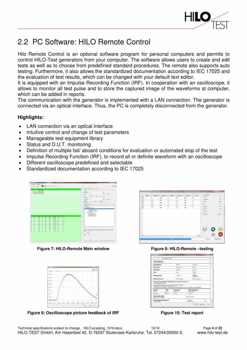
PC Software: HILO Remote Control 2.2
Hilo Remote Control is an optional software program for personal computers and permits to control HILO-Test generators from your computer. The software allows users to create and edit tests as well as to choose from predefined standard procedures. The remote also supports auto testing. Furthermore, it also allows the standardized documentation according to IEC 17025 and the evaluation of test results, which can be changed with your default text editor. It is equipped with an Impulse Recording Function (IRF). In cooperation with an oscilloscope, it allows to monitor all test pulse and to store the captured image of the waveforms at computer, which can be added in reports. The communication with the generator is implemented with a LAN connection. The generator is connected via an optical interface. Thus, the PC is completely disconnected from the generator. Highlights:
LAN connection via an optical interface
Intuitive control and change of test parameters
Manageable test equipment library Status and D.U.T. monitoring Definition of multiple fail/ aboard conditions for evaluation or automated stop of the test Impulse Recording Function (IRF), to record all or definite waveform with an oscilloscope Different oscilloscope predefined and selectable Standardized documentation according to IEC 17025
Figure 7: HILO-Remote Main window
Figure 8: HILO-Remote –testing
Figure 9: Oscilloscope picture feedback of IRF
Figure 10: Test report

Technical specifications subject to change, HILO-pcatalog_1016.docx, 10/16 Page 5 of 22
HILO-TEST GmbH, Am Hasenbiel 42, D-76297 Stutensee-Karlsruhe, Tel. 07244/20500-0, www.hilo-test.de
3. EMC TEST EQUIPMENT
AUTOMOTIVE EMC EQUIPMENT 3.1 The specific EMC requirements in automotive tests take continuously, so that the test waveforms are becoming increasingly complex. As a manufacturer of EMC test simulators and due to the participation in international standardization bodies, HILO-TEST knows exactly the current and future requirements of the automotive industry. The following automotive products are especially geared to the EMC requirements in modern automobile and according to current standards:
3.1.1 CAR TEST SYSTEM The CAR TEST SYSTEM includes a set of pulse generators which supply different test pulses.
CAR TEST SYSTEM 14
According to
ISO 7637-2: 2011
ISO 16750-2: 2012
Highlights:
Suitable for 12V, 24V, 42V systems up to 70V Different battery currents 50/100/200 A Electronic sense for battery voltage Front ground connections For 19” rack, build in Modular and extendable
Standard System
Included Pulse Waveform Voltage Standard Ri
Pulse 1 1-5/2000µs 1-5/1000µs
600 V 600 V
ISO ISO / SAE
Pulse 2a 1 / 50µs 600 V ISO 2/4/10/20/30/50/90/150 Pulse 3 5/100 ns 800 V ISO 50
Extended for following Pulses
Pulse Required additional equipment
Pulse 2b Power supply PS xx-xx Pulse 4 Power supply PS xx-xx Test A+B (Pulse 5) Load Dump: PG 2804 / CAR-LD (3xPS 66-55) Superimposed alternating voltage
CAR-SS-A1250-16E: AC voltage generator, 75Vp, 30Ap, DC-1MHz
Figure 11: CAR TEST SYSTEM with option PS 66-55 to extend by Pulse 2b and Pulse 4.
Technical specifications subject to change, HILO-pcatalog_1016.docx, 10/16 Page 6 of 22
HILO-TEST GmbH, Am Hasenbiel 42, D-76297 Stutensee-Karlsruhe, Tel. 07244/20500-0, www.hilo-test.de
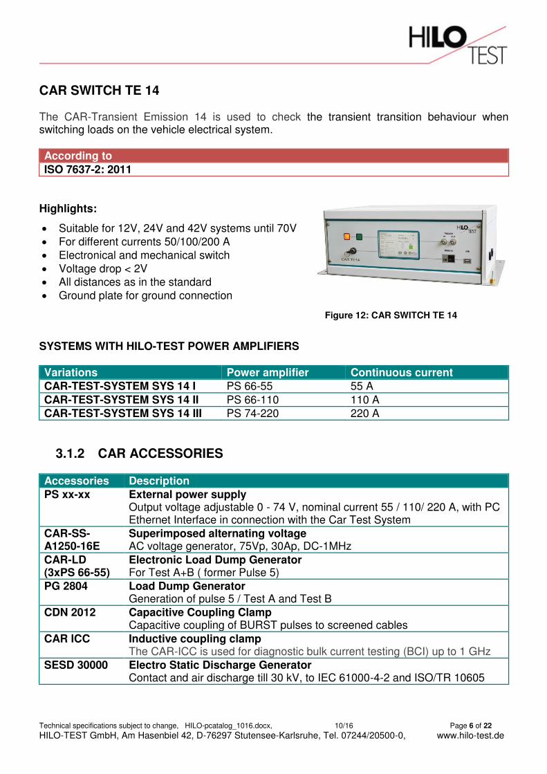
CAR SWITCH TE 14 The CAR-Transient Emission 14 is used to check the transient transition behaviour when switching loads on the vehicle electrical system.
According to
ISO 7637-2: 2011
Highlights:
Suitable for 12V, 24V and 42V systems until 70V For different currents 50/100/200 A Electronical and mechanical switch Voltage drop < 2V All distances as in the standard Ground plate for ground connection
SYSTEMS WITH HILO-TEST POWER AMPLIFIERS Variations Power amplifier Continuous current
CAR-TEST-SYSTEM SYS 14 I PS 66-55 55 A CAR-TEST-SYSTEM SYS 14 II PS 66-110 110 A CAR-TEST-SYSTEM SYS 14 III PS 74-220 220 A
3.1.2 CAR ACCESSORIES Accessories Description
PS xx-xx External power supply Output voltage adjustable 0 - 74 V, nominal current 55 / 110/ 220 A, with PC Ethernet Interface in connection with the Car Test System
CAR-SS-A1250-16E
Superimposed alternating voltage AC voltage generator, 75Vp, 30Ap, DC-1MHz
CAR-LD (3xPS 66-55)
Electronic Load Dump Generator For Test A+B ( former Pulse 5)
PG 2804 Load Dump Generator Generation of pulse 5 / Test A and Test B
CDN 2012 Capacitive Coupling Clamp Capacitive coupling of BURST pulses to screened cables
CAR ICC Inductive coupling clamp The CAR-ICC is used for diagnostic bulk current testing (BCI) up to 1 GHz
SESD 30000 Electro Static Discharge Generator Contact and air discharge till 30 kV, to IEC 61000-4-2 and ISO/TR 10605
Figure 12: CAR SWITCH TE 14
Technical specifications subject to change, HILO-pcatalog_1016.docx, 10/16 Page 7 of 22
HILO-TEST GmbH, Am Hasenbiel 42, D-76297 Stutensee-Karlsruhe, Tel. 07244/20500-0, www.hilo-test.de
INDUSTRIAL EMC EQUIPMENT 3.2 The EMC Test Equipment is designed for testing electromagnetic immunity of the electrical and electronic equipment for industrial applications.
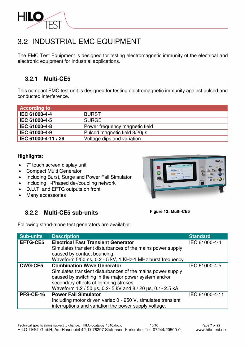
3.2.1 Multi-CE5 This compact EMC test unit is designed for testing electromagnetic immunity against pulsed and conducted interference. According to
IEC 61000-4-4 BURST
IEC 61000-4-5 SURGE
IEC 61000-4-8 Power frequency magnetic field
IEC 61000-4-9 Pulsed magnetic field 8/20µs
IEC 61000-4-11 / 29 Voltage dips and variation
Highlights:
7” touch screen display unit Compact Multi Generator Including Burst, Surge and Power Fail Simulator Including 1-Phased de-/coupling network D.U.T. and EFTG outputs on front Many accessories
3.2.2 Multi-CE5 sub-units Following stand-alone test generators are available: Sub-units Description Standard
EFTG-CE5 Electrical Fast Transient Generator Simulates transient disturbances of the mains power supply caused by contact bouncing. Waveform 5/50 ns, 0.2 - 5 kV, 1 KHz-1 MHz burst frequency
IEC 61000-4-4
CWG-CE5 Combination Wave Generator Simulates transient disturbances of the mains power supply caused by switching in the major power system and/or secondary effects of lightning strokes. Waveform 1.2 / 50 µs, 0.2- 5 kV and 8 / 20 µs, 0.1- 2.5 kA.
IEC 61000-4-5
PFS-CE-16 Power Fail Simulator Including motor driven variac 0 - 250 V, simulates transient interruptions and variation the power supply voltage.
IEC 61000-4-11
Figure 13: Multi-CE5

Technical specifications subject to change, HILO-pcatalog_1016.docx, 10/16 Page 8 of 22
HILO-TEST GmbH, Am Hasenbiel 42, D-76297 Stutensee-Karlsruhe, Tel. 07244/20500-0, www.hilo-test.de
3.2.3 Multi-CE5 Accessories
Accessories Description
VPS 250-16 Variable Power Source Motor driven variac, control by Multi-CE5, generation of voltage variation according to IEC 61000-4-11
HI200-CE Helmholtz Coil Air coil for generation of magnetic fields according to IEC 61000-4-8 / -9
EFTC 2012 Capacitive Coupling Clamp For capacitive coupling of BURST pulses to screened cables according to IEC 61000-4-4
SCK 105 Surge Calibration Kit Including impulse voltage divider and current viewing resistor For calibration of surge generators
BCK 400F Burst Calibration Kit
Including impulse voltage divider 200:1 and 400:1, input impedance 50 For calibration of burst generators
SESD 216 Electric Static Discharge Generator Contact discharge up to 10 kV, air discharge up to 16, 5 kV As specified IEC 61000-4-2
Compatible Coupling- / Decoupling Networks For SURGE and/or BURST pulses Coupling display on the front panel Control by Mulit-CE5.
Variations Burst/Surge coupling to Supply voltage Maximal test voltage
CDN 5416 power supply lines 3 * 400V, 16A 5kV, 1.2/50µs CDN 5432 power supply lines 3 * 400V, 32A 5kV, 1.2/50µs CDN 5463 power supply lines 3 * 400V, 63A 5kV, 1.2/50µs CDN 3402 4 data lines 4 * 48V, 2A 3 kV, 1.2/50µs CDN 3410 4 data lines 4 * 240V, 10A 3 kV, 1.2/50µs CDN 3802 8 data lines 8 * 48V, 2A 3 kV, 1.2/50µs
Figure 15: EFTC 2012 Figure 14: Multi-CE5 + CDN combination

Technical specifications subject to change, HILO-pcatalog_1016.docx, 10/16 Page 9 of 22
HILO-TEST GmbH, Am Hasenbiel 42, D-76297 Stutensee-Karlsruhe, Tel. 07244/20500-0, www.hilo-test.de
3.2.4 Combination Wave Generators Surge pulses occur due to direct or indirect lightning strikes in a circuit or by switching transients caused by switching inductive loads or short circuits. This leads to currents or electromagnetic fields cause high voltage or current transients. Surge voltages and currents can reach several thousands of volts and thousands of amperes. Our following Surge generators simulate these disturbances for all the necessary level: According to
IEC 61000-4-5
IEC 60060
Highlights:
Standardised voltage and current waveforms Voltage: 1,2/50 µs; Current: 8/20 µs
Up to 24 kV and 12 kA 1- or 3-phase and data line CDNs available
Variations CWG Pulse voltage 1.2/50µs CWG Pulse current 8/20µs
PG 7-250 7 kV 3.5 kA PG 10-504 10 kV 5.0 kA PG 12-804 12 kV 6.0 kA PG 24-2500 24 kV 12 kA
3.2.5 Coupling- / Decoupling Networks for CWG Allow superposition of the disturbances to the mains voltage or to signal lines of the device under test. As specified in
IEC 61000-4-5
IEC 60060
Variations Burst/Surge coupling to Supply voltage Maximal test voltage
CDN 5416 power supply lines 3 * 400 V, 16 A 5 kV, 1.2/50µs CDN 5432 power supply lines 3 * 400 V, 32 A 5 kV, 1.2/50µs CDN 5463 power supply lines 3 * 400 V, 63 A 5 kV, 1.2/50µs CDN 7416 power supply lines 3 * 400 V, 16 A 7 kV, 1.2/50µs CDN 7463 power supply lines 3 * 400 V, 63 A 7 kV, 1.2/50µs CDN 10416 power supply lines 3 * 400 V, 16 A 10 kV, 1.2/50µs CDN 10463 power supply lines 3 * 400 V, 63 A 10 kV, 1.2/50µs CDN 10216 power supply lines 1 * 240 V, 16 A 10 kV, 1.2/50µs CDN 12216 power supply lines 1 * 240 V, 16 A 12 kV, 1.2/50µs CDN 12416* power supply lines 3 * 400 V, 16 A 12 kV, 1.2/50µs CDN 3402 4 data lines 4 * 48 V, 2 A 3 kV, 1.2/50µs CDN 3410 4 data lines 4 * 240 V, 10 A 3 kV, 1.2/50µs CDN 3802 8 data lines 4 * 48 V, 2 A 3 kV, 1.2/50µs
* CDN 12216: special for usage of differential mode and common mode
Figure 16: Combination wave generator

Technical specifications subject to change, HILO-pcatalog_1016.docx, 10/16 Page 10 of 22
HILO-TEST GmbH, Am Hasenbiel 42, D-76297 Stutensee-Karlsruhe, Tel. 07244/20500-0, www.hilo-test.de
3.2.6 Oscillatory Wave ( Ring Wave ) Generators According to Generator Description
IEC 61000-4-10 IEC 1008-1
IPG 612T Ring-wave generator RCCB´s testing
IEC 61000-4-12 IPG 2553 High-frequency magnetic field test generator IEC 61000-4-18 IPG 2554 Oscillatory wave generator
Highlights:
Versatile and upgradable Different configurations possible External data line CDN available Internal 3-phased coupling/decoupling network (IPG2554) Common and differential mode
Variations Description IPG 612T Ring-wave generator
Simulates high-voltage transients of the mains power supply caused by switching in the major power system, mains synchronous triggering Waveform 0.5µs/100 kHz, 0 - 6 kV Specified in IEC 61000-4-12 Coupling-/decoupling network for power supply lines , as option Modification for testing RCCB´s according to IEC 1008-1, as option
IPG 2553 High-frequency magnetic field test generator Simulates high-frequency magnetic fields caused by switching in gas Isolated substations of the power system Specified in IEC 61000-4-10 Including Helmholtz-Coil, 1*1 m Damped magnetic field 100 kHz, 10/30/100 A/m, repetition rate 40 Hz Damped magnetic field 1.0 MHz, 10/30/100 A/m, repetition rate 400 Hz
IPG 2554 Oscillatory wave generator Simulates high-voltage transients of the mains power supply caused by switching in gas isolated substations of the power system Specified in IEC 61000-4-18 Slow damped oscillatory wave: 100 kHz, 0.25 - 3 kV, repetition rate 400 Hz 1.0 MHz, 0.25 - 3 kV, repetition rate 400 Hz Fast damped oscillatory wave: 3 / 10 / 30 / MHz, 0.25 - 4 kV, repetition rate 5000 Hz The IPG is to obtain in the following different configurations: IPG 2554 (fast, slow) IPG 2554 fast IPG 2554 slow
Figure 17: IPG2554

Technical specifications subject to change, HILO-pcatalog_1016.docx, 10/16 Page 11 of 22
HILO-TEST GmbH, Am Hasenbiel 42, D-76297 Stutensee-Karlsruhe, Tel. 07244/20500-0, www.hilo-test.de
TELECOM TEST EQUIPMENT 3.3
3.3.1 High-Voltage Test Generator Telecommunication networks are exposed to particularly natural disasters such as lightning and its effects. Therefore all connected telecommunications systems require reliable protection. Our subsequent Surge Simulators are specifically designed for EMC testing of telecommunications systems in accordance with ITU-T: Devices, specified in
ITU-T K12, K17
Highlights:
Multiple variations
Different output impedances
Different safety test cover mounted on the top of the equipment I*t Limit monitoring and evaluation
High-voltage pulse generator
Variations Pulse type Waveform Voltage Energy
IPG 620 Lightning surge 1.2/50 µs 6 kV 20 J IPG 1050 Lightning surge 1.2/50 µs 10 kV 50 J IPG 1272 Lightning surge 1.2/50 µs 12 kV 72 J
Generators with multiple Waveforms:
Devices, specified in
ITU-T K12, K17, K20
Variations Pulse type Waveform Voltage Energy
PG 5-200-1/2 Lightning surge Switching surge
1.2/50 µs 10/700 µs
5 kV 5 kV
10 J 200 J
PG 6-364 Lightning surge Switching surge Option:
1.2/50 µs 10/700 µs 100/700 µs 0.5/700 µs 1/1000 µs
6 kV 6 kV
20 J 360 J
PG 10-1000 Lightning surge Switching surge
1.2/50 µs 10/700 µs
10 kV 10 kV
50 J 1000 J
PG 12-1400 Lightning surge Switching surge
1.2/50 µs 10/700 µs
12 kV 12 kV
70 J 1400 J
PG 14-1960 Switching surge Switching surge
10/700 µs 0.5/700 µs
14 kV 14 kV
1960 J 1960 J
PG 20-4000 Switching surge 10/700 µs 20 kV 4000 J
Figure 18: IPG1050

Technical specifications subject to change, HILO-pcatalog_1016.docx, 10/16 Page 12 of 22
HILO-TEST GmbH, Am Hasenbiel 42, D-76297 Stutensee-Karlsruhe, Tel. 07244/20500-0, www.hilo-test.de
3.3.2 Special Generators According to
ITU-T K12, K17, K20
ITU-T 12 TR 1 GR-1089-CORE
FCC Part 68, TIA - 968
Variations Description IPG 255 Insulation test with impulse voltage according to IEC 255
Impulse voltage: 0.8/1.0/1.5/2.5/4.0/5.0/6.0/8.0 kV, We = 0.5 J, Rs = 500 Ohm
IPG 506 Front chopped wave generator Designed for measurement of dc spark-over voltage and Impulse spark-over voltage 5 kV impulse, dU/dt = 100V/µs - 5000 V/µs Insulation resistance 0,5 -5 G According to ITU-T, K12
IPG 506-SYM Symmetric Front chopped wave generator Test system for two stage SPDs 2 x Impulse spark-over voltage 2 x 5 kV impulse, dU/dt = 100V/µs - 5000 V/µs Insulation resistance 0,5 -5 G
PIG 1500 Power induction generator Designed for testing telecommunication ports Open circuit output voltage 30 - 1500 V Series resistor 200 / 600 Coupling impedance, optional 100 +0, 5µF +1.0µF According to ITU-T K20
PG 6-432 Impulse life test generator Life time test of SPDs Switching Surge 10/700 µs, 2*100 A, 430 J Switching Surge 10/1000 µs, 2*100 A, 430 J According to ITU-T 12 TR 1, K17, K20
PG 6-500 Surge current generator, 2/4* 5 kV, or 100/500 A, 2/10 µs Designed for testing 2-wire or 4-wire telecom ports First-Level Lightning Surge ± 2500 V, 500 A, 2/10 µs Second-Level Lightning Surge ± 5000 V, 500 A, 2/10 µs Intra-Building Lightning Surge ± 800 V, 100 A, 2/10 µs Intra-Building Lightning Surge ± 1500 V, 100 A, 2/10 µs According to Fig. 4.2 of GR-1089-CORE standard FCC Part 68, TIA - 968
PG 2-750 Surge current generator 1.6kV, 10/160µs, 4*100A or 800V, 10/560µs, 2*100A Optional 1kV, 10/1000µs, 2*100A according to GR-1089-CORE According to FCC Part 68, TIA – 968
PG 4-641 Surge current generator 3.6kV, 10/160µs, 480A According to FCC Part 68, TIA – 968
Technical specifications subject to change, HILO-pcatalog_1016.docx, 10/16 Page 13 of 22
HILO-TEST GmbH, Am Hasenbiel 42, D-76297 Stutensee-Karlsruhe, Tel. 07244/20500-0, www.hilo-test.de
4. COMPONENT TEST GENERATORS
Designed for testing passive and active components and devices:
Meets testing recommendation of many product standards Surge voltage test of transformers, optical couplers and electrical installations Surge voltage test of over-voltage protection devices and circuits Dielectric testing of X/Y-capacitors Spark over detection on the test sample with adjustable current sensor
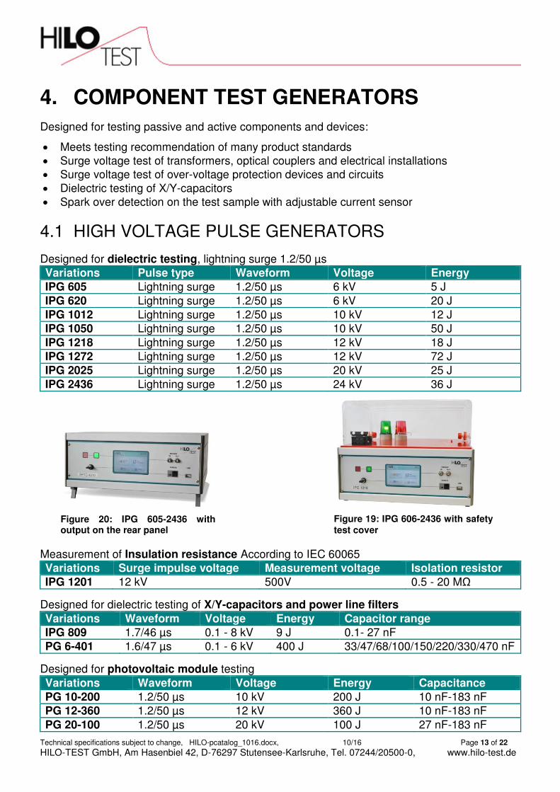
HIGH VOLTAGE PULSE GENERATORS 4.1
Designed for dielectric testing, lightning surge 1.2/50 µs Variations Pulse type Waveform Voltage Energy
IPG 605 Lightning surge 1.2/50 µs 6 kV 5 J IPG 620 Lightning surge 1.2/50 µs 6 kV 20 J IPG 1012 Lightning surge 1.2/50 µs 10 kV 12 J IPG 1050 Lightning surge 1.2/50 µs 10 kV 50 J IPG 1218 Lightning surge 1.2/50 µs 12 kV 18 J IPG 1272 Lightning surge 1.2/50 µs 12 kV 72 J IPG 2025 Lightning surge 1.2/50 µs 20 kV 25 J IPG 2436 Lightning surge 1.2/50 µs 24 kV 36 J
Measurement of Insulation resistance According to IEC 60065
Variations Surge impulse voltage Measurement voltage Isolation resistor
IPG 1201 12 kV 500V 0.5 - 20 MΩ
Designed for dielectric testing of X/Y-capacitors and power line filters Variations Waveform Voltage Energy Capacitor range
IPG 809 1.7/46 µs 0.1 - 8 kV 9 J 0.1- 27 nF PG 6-401 1.6/47 µs 0.1 - 6 kV 400 J 33/47/68/100/150/220/330/470 nF
Designed for photovoltaic module testing Variations Waveform Voltage Energy Capacitance
PG 10-200 1.2/50 µs 10 kV 200 J 10 nF-183 nF PG 12-360 1.2/50 µs 12 kV 360 J 10 nF-183 nF PG 20-100 1.2/50 µs 20 kV 100 J 27 nF-183 nF
Figure 20: IPG 605-2436 with output on the rear panel
Figure 19: IPG 606-2436 with safety test cover

Technical specifications subject to change, HILO-pcatalog_1016.docx, 10/16 Page 14 of 22
HILO-TEST GmbH, Am Hasenbiel 42, D-76297 Stutensee-Karlsruhe, Tel. 07244/20500-0, www.hilo-test.de
HIGH CURRENT PULSE GENERATORS 4.2HILO-TEST manufactures power generators for surge current material and safety tests, in particular for the examination of diverting elements such as gas discharge tubes, varistors, SPDs, and components in which such protective elements are installed.
According to
IEC / EN 61643-11
Highlights: Compact tester as table usage
Cabinet tester optional with testing room Safety test cover mounted on the top of the equipment Plug in for different wave shapes
Compact tester:
Variations Type Pulse current Waveform Energy
PG 6-250 Varistor tester 10A - 2.5 kA 8/20µs 250 J PG 6-200 Surge Current Generator 5 kA 8/20µs 200 J PG 6-400 Surge Current Generator 10 kA 8/20µs 400 J EMC 2015 Pulse Generator System
Current standard plug-in Current plug-in Current plug-in Current plug-in Current plug-in Combination wave plug-in Varistor test plug-in Voltage plug-in
25 kA 5 kA 600 A 300 A 200 A 2 * 10 kV 2 * 10 kA 3 kA 10kV
8 / 20 µs 10 / 50 µs 10 / 350 µs 10 / 700 µs 10/1000 µs 1.2 / 50 µs 8 / 20 µs 8 / 20 µs 10/700 µs
1500 J 1500 J 1500 J 1500 J 1500 J 1500 J 1500 J 250 J
Figure 22: PG 6-200/400 Figure 21: EMC 2015
Technical specifications subject to change, HILO-pcatalog_1016.docx, 10/16 Page 15 of 22
HILO-TEST GmbH, Am Hasenbiel 42, D-76297 Stutensee-Karlsruhe, Tel. 07244/20500-0, www.hilo-test.de
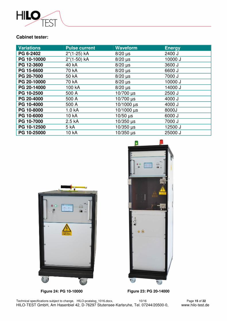
Cabinet tester:
Variations Pulse current Waveform Energy
PG 6-2402 2*(1-25) kA 8/20 µs 2400 J PG 10-10000 2*(1-50) kA 8/20 µs 10000 J PG 12-3600 40 kA 8/20 µs 3600 J PG 15-6600 70 kA 8/20 µs 6600 J PG 20-7000 50 kA 8/20 µs 7000 J PG 20-10000 70 kA 8/20 µs 10000 J PG 20-14000 100 kA 8/20 µs 14000 J PG 10-2500 500 A 10/700 µs 2500 J PG 20-4000 500 A 10/700 µs 4000 J PG 10-4000 500 A 10/1000 µs 4000 J PG 10-8000 1.0 kA 10/1000 µs 8000J PG 10-6000 10 kA 10/50 µs 6000 J PG 10-7000 2.5 kA 10/350 µs 7000 J PG 10-12500 5 kA 10/350 µs 12500 J PG 10-25000 10 kA 10/350 µs 25000 J
Figure 24: PG 10-10000 Figure 23: PG 20-14000

Technical specifications subject to change, HILO-pcatalog_1016.docx, 10/16 Page 16 of 22
HILO-TEST GmbH, Am Hasenbiel 42, D-76297 Stutensee-Karlsruhe, Tel. 07244/20500-0, www.hilo-test.de
5. HIGH-VOLTAGE TEST AND MEASUREMENT EQUIPMENT
HILO-TEST produce several devises and components, the range of these products includes: High-voltage test of isolations with ac- dc or impulse voltage Measuring equipment for ac-, dc- or impulse voltage High-voltage dividers for ac-, dc- or impulse voltage Current viewing resistors for ac-, dc- or impulse current
AC- / DC TEST EQUIPMENT 5.1
Highlights:
Massive safety test cover mounted on the top of the equipment Ground rod inside the safety test cover Burn and Turn-off modus Current limitation and shutdown Step function
Variations Description Voltage, current
AC-TESTER Measurement of protective earth resistance, insulation resistance and supply current
5 kV, 100 mA
AC-TESTER 6 Testing of electrical isolations Security test cover on top of the Device, Test mode burning and over current With security test cover on top
10 kV, 100 mA
Figure 25: AC Tester

Technical specifications subject to change, HILO-pcatalog_1016.docx, 10/16 Page 17 of 22
HILO-TEST GmbH, Am Hasenbiel 42, D-76297 Stutensee-Karlsruhe, Tel. 07244/20500-0, www.hilo-test.de
Figure 26: HVTS as 19"cabinet with test room
AC test set-up Designed for AC isolation test
Highlights:
Security glass front door with safety switch Grounding rod Red and green warning lamps With 4 wheels, 2 statable Integration of HV-impulse generators possible,
for example IPG 2025 / 2436. This provides a compact and versatile testing facility available.
Variations Voltage Current
HVTS 30-20* 30 kV 20 mA
HVTS 30-40* 30 kV 40 mA
HVTS 50-10* 50 kV 10 mA
* Also available in 19” cabinet with test room:
High voltage DC Tests
Compact DC high voltage test device, developed for DC isolations tests: Highlights:
Adjustable rise time Test time adjustable Current limit adjustable Error message when over current
DC test set-up
Variations Voltage Current
HVS 20-5 20 kV 5 mA
HVS 20-10 20 kV 10 mA
Figure 27: HVS 20-10

Technical specifications subject to change, HILO-pcatalog_1016.docx, 10/16 Page 18 of 22
HILO-TEST GmbH, Am Hasenbiel 42, D-76297 Stutensee-Karlsruhe, Tel. 07244/20500-0, www.hilo-test.de
SAVETY TEST COVERS 5.2
Highlights:
For High-voltage testing of components Prevents accidental contact with live
parts of test objects With ground rod Security door switch with Interlock Different test sample connections Red / green lights
Variations Description Test space (WxHxD)
PA 503 Safety test cabinet Test voltage until 10 kV
400 x 140 x 300
PA 504 PA 505
Safety test cabinet Test voltage until 12 kV
490 x 300 x 300 400 x 250 x 400
PU Test device switch unit High-voltage testing of components Switch unit for 8 test samples Optionally build in with impulse voltage divider and current shunt
-
CALIBRATION EQUIPMENT 5.3 Highlights:
Pulse generator Measuring the step response Different operational modes
Variations Usage Impulse riste time
IPG 250 Impulse generators for calibration purposes/ step response measurement
< 3 ns
Calibration Kits Variations Usage
SCK 105 Surge Calibration Kit BCK 400F Burst Calibration Kit
Figure 28: PA 504

Technical specifications subject to change, HILO-pcatalog_1016.docx, 10/16 Page 19 of 22
HILO-TEST GmbH, Am Hasenbiel 42, D-76297 Stutensee-Karlsruhe, Tel. 07244/20500-0, www.hilo-test.de
HIGH-VOLTAGE MEASUREMENT EQUIPMENT 5.4 All HILO-TEST voltage divider HVT – RCR are included in the HVM2015 firmware. The user connects the voltage divider, set it in the device menu and can start with the measurements immediately. Highlights:
High voltage measurement equipment Measuring up to 10 kV
Optional up to 20 KV
With ext. HVT: up to 300 kV
Firmware set up for all Hilo-Test dividers implemented
Remote Ethernet interface with fibre optic Variations Usage Extern input Direct input
HVM 2015 Measurement device for high ac, dc and pulse voltage
0 - 100 V
10KV Optional: 20kV
Figure 29: HVM 2015

Technical specifications subject to change, HILO-pcatalog_1016.docx, 10/16 Page 20 of 22
HILO-TEST GmbH, Am Hasenbiel 42, D-76297 Stutensee-Karlsruhe, Tel. 07244/20500-0, www.hilo-test.de
HIGH-VOLTAGE DIVIDERS 5.5 The High voltage divider types HVT - RCR possess from DC up to their cut-off frequencies in the MHz range uniformly excellent transmission characteristics. The voltage divider consists of a resistive branch, which is constructed of high-grade resistance, and a capacitive branch with series damping.
Highlights:
Broadband high voltage divider for AC, DC and impulse voltage
Very good accuracy, high bandwidth, low rise time
Manual operation or creation of test procedures with HVM2015
Variations Description PVD *** Impulse voltage divider HVT***RCR Wide band voltage dividers
HVT variations 10 20 40 80 120 160 240 300
DC voltage 11 kV 22 kV 40 kV 80 kV 120 kV 160 kV 240 kV 300 kV
AC voltage eff. 8 kV 15 kV 30 kV 60 kV 90 kV 120 kV 180 kV 230 kV
Pulse voltage 20 kV 40 kV 100 kV 160 kV 200 kV 250 kV 360 kV 480 kV
Divider ratio 1000:1 2000:1 2500:1 5000:1 5000:1 5000:1 5000:1 5000:1
Figure 30:
HVT 240/300 RCR
Figure 31:
HVT 80/120/160 RCR
Figure 32:
HVT 40 RCR
Figure 33:
HVT 2.5/10/20 RCR

Technical specifications subject to change, HILO-pcatalog_1016.docx, 10/16 Page 21 of 22
HILO-TEST GmbH, Am Hasenbiel 42, D-76297 Stutensee-Karlsruhe, Tel. 07244/20500-0, www.hilo-test.de
CURRENT VIEWING RESISTORS 5.6 Variations Usage Series ISM*** Current measuring resistors for high pulse currents
Series WSM*** Current measuring resistors for high ac currents
MISCELLANOS 5.7 HCC: High voltage Capacitor Charging unit
HCC variations Max Voltage/ kV 4 10 20 30 40 50 60 Max Current/ mA 400 120 60 40 30 24 20
Miscellaneous Description MCT 5002 Multi-channel trigger unit MCT 5004 Multi-channel trigger unit IT 5413 Trigger transformer for spark gaps IT 5425 Trigger transformer for spark gaps HS 10 High voltage ground switch HS 50 High voltage ground switch USD 3801 Ultrasonic detector for partial discharge USD 3802 Ultrasonic detector for partial discharge TEM 2000 TEM-test cell
Figure 34: WSM/ ISM

Technical specifications subject to change, HILO-pcatalog_1016.docx, 10/16 Page 22 of 22
HILO-TEST GmbH, Am Hasenbiel 42, D-76297 Stutensee-Karlsruhe, Tel. 07244/20500-0, www.hilo-test.de
Notes: ___________________________________________________________________________ ___________________________________________________________________________ ___________________________________________________________________________ ___________________________________________________________________________ ___________________________________________________________________________ ___________________________________________________________________________ ___________________________________________________________________________ ___________________________________________________________________________ ___________________________________________________________________________ ___________________________________________________________________________ ___________________________________________________________________________ ___________________________________________________________________________ ___________________________________________________________________________ ___________________________________________________________________________ ___________________________________________________________________________ ___________________________________________________________________________ ___________________________________________________________________________ ___________________________________________________________________________ ___________________________________________________________________________ ___________________________________________________________________________ ___________________________________________________________________________ ___________________________________________________________________________ ___________________________________________________________________________ ___________________________________________________________________________ ___________________________________________________________________________ ___________________________________________________________________________ ___________________________________________________________________________ ___________________________________________________________________________ ___________________________________________________________________________ ___________________________________________________________________________ ___________________________________________________________________________ ___________________________________________________________________________ ___________________________________________________________________________ ___________________________________________________________________________ ___________________________________________________________________________ ___________________________________________________________________________ ___________________________________________________________________________ ___________________________________________________________________________ ___________________________________________________________________________ ___________________________________________________________________________ ___________________________________________________________________________ ___________________________________________________________________________ ___________________________________________________________________________ ___________________________________________________________________________ ___________________________________________________________________________ ___________________________________________________________________________ ___________________________________________________________________________ ___________________________________________________________________________ ___________________________________________________________________________
Elektrische Prüf- und Messtechnik GmbH
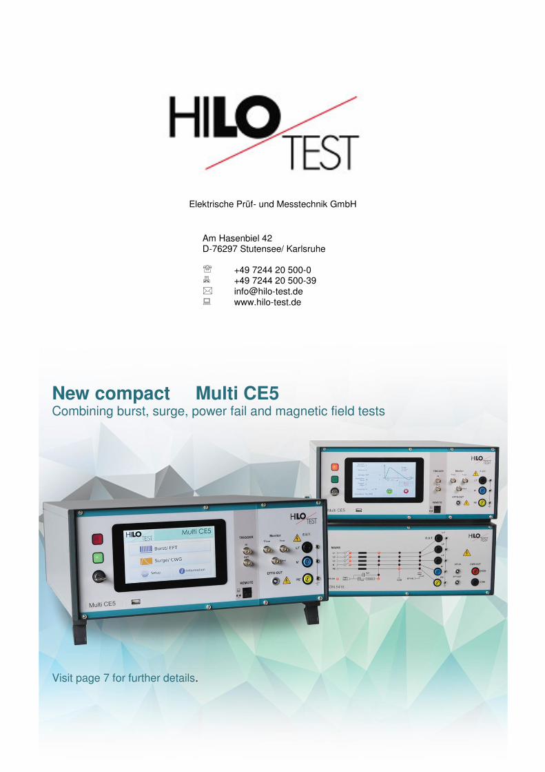
New compact Multi CE5 Combining burst, surge, power fail and magnetic field tests Visit page 7 for further details.
Am Hasenbiel 42 D-76297 Stutensee/ Karlsruhe +49 7244 20 500-0 +49 7244 20 500-39 [email protected] www.hilo-test.de