ABSOLUTE OZONE
25
ABSOLUTE OZONE OZONE GENERATOR Models ATLAS/TITAN/MAGNUM 25-200 OPERATOR’S MANUAL Absolute Ozone 10712 - 181 Street, Edmonton, Alberta, T5S 1K8, Canada 780-486-3761
-
Upload
khangminh22 -
Category
Documents
-
view
0 -
download
0
Transcript of ABSOLUTE OZONE

ABSOLUTE OZONE
OZONE GENERATOR Models ATLAS/TITAN/MAGNUM 25-200
OPERATOR’S MANUAL
Absolute Ozone
10712 - 181 Street, Edmonton, Alberta, T5S 1K8, Canada
780-486-3761

1
TABLE OF CONTENTS
SECTION 1 – General Information .....................................................................2
1A. Description ............................................................................................... 3
1B. Specifications (Ozone Output) ..................................................................... 3
1C. Layout & Accessories ................................................................................. 3
1C.1 Ozone Generation................................................................................ 3
1C.2 Required Accessories ........................................................................... 4
SECTION 2 - Installation ....................................................................................5
2A. Location ................................................................................................... 5
2B. Electrical .................................................................................................. 6
2C. Plumbing ................................................................................................... 6
2D. Remote Control ......................................................................................... 6
SECTION 3 - Operation ......................................................................................9
3A. Control Panel Overview .............................................................................. 9
3B. System Startup ....................................................................................... 10
3C. System Shutdown ................................................................................... 10
3D. Standard Operating Procedures ................................................................. 10
SECTION 4 – Maintenance and Service ........................................................... 11
4A. Preventative Maintenance ......................................................................... 11
4B. Troubleshooting ...................................................................................... 11
SECTION 5 – Replacement Parts ...................................................................... 13
SECTION 6 – Ozone Overview and Safety Procedures ...................................... 13
6A. Ozone Use and Technology Overview ......................................................... 13
6A.1 Relative Strength of Ozone ................................................................. 13
6A.2 Micro-Flocculation and Oxidation ......................................................... 13
6B. General Safety Information .................................................................. 13
6B.1 Ozone Properties ............................................................................... 13
6B.2 Ozone Uses ...................................................................................... 14
6C. Hazards ................................................................................................ 14
6C.1 Health Hazards – Detection Levels ....................................................... 14
6C.2 Health Hazards – Effects on Humans .................................................... 14
6C.3 Electrical Hazards .............................................................................. 15
6C.4 Fire Hazards ..................................................................................... 15
6C.5 Chemical Action ................................................................................ 15
6D. Precautions for Safe Handling and Use ................................................ 15
6D.1 Ozone Monitors ................................................................................. 16

2
6D.2 Ventilation ....................................................................................... 15
6D.3 Emergency Procedure........................................................................ 16
6D.4 Respiratory Protection ....................................................................... 16
6D.5 Education and Training ...................................................................... 16
6E. System Operation and Maintenance ...................................................... 17
6E.1 Safety Precautions and Equipment ...................................................... 17
6E.2 Maintenance Requirements................................................................. 17
6F. Monitoring ........................................................................................... 17
6F.1 Location of Monitors .......................................................................... 17
6F.2 Monitoring Equipment ........................................................................ 17
6G. First Aid Procedures ............................................................................ 17
6G.1 General Information .......................................................................... 17
6G.2 Inhalation ........................................................................................ 16
6G.3 Eye Contact ..................................................................................... 18
6G.4 Precautions ...................................................................................... 17
6G.5 Emergency Information Form ............................................................. 18
Absolute Ozone Five Years Limited Warranty .................................................. 19
7 Ozone Generator Dimensions and Mounting Dimensions… .......................... 20
8 Typical Ozone Injection System Diagram …………… .............................…..21
SECTION 1 – General Information
IMPORTANT SAFETY INSTRUCTIONS. PLEASE READ AND FOLLOW ALL INSTRUCTIONS.
• Read this manual completely before operation of ATLAS/TITAN/MAGNUM
25-200 Ozone Generator Equipment. Warning - High Voltage is present inside the enclosure
USE EXTREME CAUTION
• Operate the ATLAS/TITAN/MAGNUM 25-200 with safe access to electrical
power. • Connect to a GFCI type receptacle.
• Follow all applicable electrical codes. • Do not bury cord.
WARNING: To reduce the risk of electrical shock, replace damaged cord
immediately.
ELECTRICAL SHOCK HAZARD: Turn OFF all power switches and disconnect power cord from power source receptacle before performing any service work. Failure to do so could result in serious injury or death.

3
1A. Description
The ATLAS/TITAN/MAGNUM 25-200 are Ozone Generators that produce from 1 to 160
grams of ozone per hour respectively, with ozone concentration up to 14% by weight or
as specified in attached test report.
The ATLAS/TITAN/MAGNUM 25-200 are designed to produce ozone for variety of applications such as:
• Water Disinfection for Bottled Water Plants, Medical & Pharmaceutical Facilities,
Swimming Pools, etc. • Industrial Processes, Chemical Production and Laboratories, Electronic
Production, Mining • Aquatic Life Support Systems for Marine Mammals, Fish Hatcheries, Large
Aquariums…
• Food Processing, Food Processing Facilities Disinfection, Food Preservation • Soil Remediation, Ground Water Remediation
• Wineries Facilities Disinfection, Barrel Disinfection
• Cooling Towers Water Treatment, Technological Processes Water Treatment • Potable Water Disinfection for Small Communities
• Waste Water Treatment for Industrial Plants, Technological Production Processes, Commercial Facilities Waste Water Treatment, Dangerous Chemical and Bacteria
Treatment, etc.
1B. Specifications :
• Ozone Output as specified in supplied performance chart, g/h.
• Gas Flow Rate (min): 0.05 SLPM
• Gas Flow Rate (max): as specified in supplied performance chart, SLPM • % By Weight 03: 5 – 12% (6 – 14% for ATLAS/ TITAN 25-100C/ MAGNUM 200C)
• Working Pressure: 20-120 PSIG according to supplied performance chart. • Feed Gas – Oxygen 90%-95% concentration for best performance. When bottle
oxygen or LOX is used, Nitrogen 0.5%-5% has to be added to the feed gas for
best performance. • Power Requirements:
o Domestic: ATLAS/TITAN/MAGNUM 25-200– 115 V AC, 60 Hz, 5.0-18.0 A (25 Amp Service)
o International: ATLAS/TITAN/MAGNUM 25-200E – 220/240 V AC, 50/60
Hz, 2.5-9.5 A (15 Amp Service)
1C. Accessories The ATLAS/TITAN/MAGNUM 25-200 could be used with several accessories and safety
devices to assure long service life of the Generator.
1C.1 Ozone Generation
• Air Compressor: air compressor pumps ambient air into the oxygen concentrator • Oxygen Concentrator separates oxygen from Nitrogen and supplies it to ozone
generating cell.
• Ozone Generating Cell design is based on proprietary Microfluidic Platform Technology, constructed from ozone resistant materials and offers extremely high
performance and reliability. Ozone Cell is designed to be absolutely maintenance and service free. Anticipated service life 15-20 years.

4
1C.2 Required Equipment & Accessories
• Oxygen Concentrator: The oxygen concentrator uses a PSA (pressure swing
adsorption) molecular sieve to remove dirt, moisture, nitrogen and other trace
gases, producing oxygen at greater than 90% purity and less than –60°C dew-
point. The air compressor pumps ambient air into the oxygen concentrator. Concentrated oxygen feed-gas enables ozone concentration up to 14% by
weight. In our experience, Oxygen Concentrators made by AirSep work well with all Absolute Ozone generators.
• To protect Absolute Ozone Generator from sieve particles in case of oxygen concentrator failure we recommend installing Oxygen Filter Upstream from the
generator.
• Ozone Flow Control Valve: Downstream from ozone generator to maintain
working pressure across ozone cell as specified 20-120 PSIG for the unit.
• Automatic Ozone Compatible ALD2000 Water Drain system to prevent Ozone
Generator flooding. Please note – Non return valves (check valves) do not provide 100%
protection to ozone generator!
We do not recommend installing ozone generator, without this device.
• Ozone Injector for Water Treatment Applications: Inlet water flows through the
pump and through the ozone injector, creating vacuum that pulls ozone gas from the ozone generation module and injects the ozone into the water flow. The
injector should be sized to dissolve a minimum of 90% of the ozone gas into the
water flow continuously.
• Ozone Degas Chamber: Ozone-enriched water from the ozone injector flows into
the degas chamber where the counter-current design forces any undissolved ozone gas through the float valve-protected top vent to the Ozone Destructor.
• Ozone Destructor: Undissolved ozone gas passes through the heated catalytic
ozone destructor that is made of non-consumable manganese dioxide (heat
protected from moisture fouling). The manganese dioxide and heat offer redundant ozone destruct capabilities.
Liquid Trap
To Ozone Generator
From Ventury
Check Valve
To Drain

5
SECTION 2 - Installation
2A. Location
The ATLAS/TITAN/MAGNUM 25-200 Ozone Generators are designed to be installed on
the wall, on the rack or stack up system in convenient location mobile cart or skied. Allow for access to protected electrical power and required gas connections and cooling
air to the Ozone Generator. Do not obstruct cooling air vents of the Generator!
Unit could be installed indoors & outdoors if protected from weather element. Ambient
working temperature from –10°C to +30°C.
TITAN 25-100 Standard 19” x 7”h Rack Mount Enclosure offers retrofit replacement for most popular rackmount ozone generators on the market providing superior performance and reliability.

6
2B. Electrical
Main Power Supply Circuit: The ATLAS/TITAN/MAGNUM 25-200 are supplied with 3-5 feet power cord. Connect the power cord to a standard grounded 15
Amp (10 Amp International) power source, according to a local electrical code only.
2C. Plumbing
When injecting Ozone in to water all measures should be taking to protect the Generator Cell from water exposure, which may cause internal cell damage. A
small tank with/or an automatic water drain system is recommended.
2D. Gas Connections
The Ozone Generator should be connected by tubing made from material appropriate for ozone and oxygen applications. Connect the Ozone Generator
according to indications on input and output bulkheads. All efforts should be made to protect the generator from exposure to excessive pressure fluctuations,
which may lead to the damage of electronic circuitry and Ozone Cell. For applications where pressure fluctuations are possible we strongly recommend
installation of a buffer tank with an appropriate hi-low pressure switch. It is VERY IMPORTANT to protect the Generator from any possible contamination
from the Oxygen Concentrator or from water injection device, by installing oxygen monitor and filter upstream from the Generator and automatic water
drain device in combination with check valve. Concentration of feed oxygen should not be below 90%.

7
2E. Remote Control
All Absolute Ozone Generators are equipped with standard “On/Off” remote
control terminals to enabling operator, ambient ozone monitor or PLC to remotely switch the Ozone Generator On or Off.
This contacts have to be connected to dry contact only (not connected to the ground on any kind or to any voltage source AC or DC)
Standard Remote Control Schematic
Remote On/Off Switch

8
Full (Optional) 4-20mA Remote Control Description and Schematic
Full remote control features: • Remote control of ozone production level by 4-20mA or 0-10 VDC signal,
no special switching for both of these signals required • Remote On/Off. Remote Switch must be normally open for the generator
to be “On” and closed to stop the Ozone production. • That switch has to be connected to dry contacts only (not connected to
the ground on any kind or to any voltage source AC or DC) • Remote Ozone Generator status indicator.
a. During Normal Ozone generator operation pin 5 –normally open, pin 6 – common, pin 7 – normally closed.
b. If Remote Control Switch is off or safety shutoff is activated the circuit
will be closed between pins 5 & 6.

9
Full Remote Control Connection Schematic
Use Shielded Cable Only!
Ground Shield Only on
One Side! To switch from manual control operation to remote control please switch jumper
in the middle PCB from pins 1-2 to 2-3
Manual Remote Control Control
SECTION 3 - Operation
3A. Control Panel Overview
1. Green LED – Power “On” 2. Red LED - Safety Shutoff/Remote Control Off
3. Power On/Off Switch 4. Ozone Production Adjustment Dial
1A, 120-240VAC/24VDC
Remote Status
Indicator Dry
Relay Contacts
+
-
4
6
5
7
1
2
3
4
3
2
1
COM
NC
NO
Remote On/Off
WHITE
ORANGE
BROWN
BLUE
GREEN
RED
BLACK
7
5
6
Remote Control Cables of required length are available as a special order option
4-20mA /0-10VDC Input Connection

10
3B. System Startup
5. Make sure the Ozone Generator enclosure is securely attached to an appropriate frame or wall Ozone Generators Stack.
6. Make sure all connections to the generator, power and gas are made according to local codes and regulations.
7. Purge the generator with 90% or higher concentration oxygen and assure free flow of oxygen through the system and removal of contaminants.
Conduct system leak test applying working pressure +/-10% using oxygen only. Adjust gas pressure across the cell according to
specifications using downstream Control Valve and pressure gage (supplied by the installer).
8. Turn the potentiometer on the front panel fully counterclockwise. 9. Plug the system into a specified receptacle.
10.Flip the Power Switch in to “ON” position. 11.Turn the Ozone Production Potentiometer clockwise slowly, to reach
optimum power setting according to supplied “Ozone Generator Performance Test” chart. Now the generator is in optimum production
mode, and ozone should be flowing though the system.
3C. System Shutdown
1. Turn the potentiometer fully counterclockwise.
2. Turn the Ozone Production switch in to “OFF” position. (No ozone is produced at this time.)
3. Unplug the system from the power source if required. 4. Close the Control Valve off (optional, supplied by installer) to protect unit
from accidental flooding. 5. Turn the oxygen source off.
3D. Standard Operating Procedures
NOTE: To assure a long trouble-free service life of the ATLAS/TITAN/MAGNUM 25-200 Ozone Generators, provide following operating conditions:
• Make sure that the oxygen concentrator is maintained properly and is
producing oxygen at greater than 90% purity and less than -60°C dew point. Check sieve conditions and replace it as often as recommended by
manufacturer
• Install oxygen filter and oxygen dryer between oxygen concentrator and
the Ozone Generator, check condition and replace a cartridge as to protect Ozone Generator from sieve particles in case of oxygen generator
failure and moisture.

11
• Make sure to maintain working pressure across ozone cell as specified for the generator protection and most efficient ozone production.
• When injecting ozone in to water make sure to protect the generator from
flooding by installing device capable of preventing water backup. Check valves usually start leaking after few days of operation in ozone and
cause serious damage to the ozone cell. We recommend using devices, which could automatically drain water out of ozone line and stop it from
entering the ozone cell.
• Protect internal components of the Ozone Generator from water, snow, excessive dust and humidity, vibration, mechanical shock; make sure that
there is a sufficient amount of clean air available for the unit cooling air and inlet and outlet are not obstructed by other equipment or elements.
• Check that electrical power fluctuations are within +/- 10% of the
specified AC Voltage and install power-conditioning devices if necessary.
SECTION 4 – Maintenance and Service
4A. Preventative Maintenance
Generally the ATLAS/TITAN/MAGNUM 25-200 are maintenance-free although it
is useful to check the Ozone Generator for proper operation: a. Make sure green indicator light is lit during operation.
b. Red light or Amber light for Magnum is off c. Make sure that all air vents are clear of any obstruction.
On a monthly basis:
1. Make sure that all system equipment (oxygen concentrator, air compressor, etc.) is maintained according to the manufacturer
recommendations. 2. Remove and replace or clean filter cartridges and other devices if installed
and required. 3. Perform general cleaning of cabinet exterior after disconnecting the
equipment from electrical source.
4. Using clean/dry compressed air, blow out the interior of cabinet, taking special care around electronic components and wiring.
4B. Troubleshooting
Knowledge of electrical applications is required for troubleshooting. Contact a certified electrician if you are unsure of your ability to service the equipment. If

12
any problem persists, please call 780-486-3761. We will have one of our system engineers discuss your situation with you over the phone.
Symptom: Green, Red or Amber indicator lights “OFF”, POWER Switch is in the
“ON” position and the cooling fan is not running. 1. Check if the power coming to the generator.
2. Check the Power fuse located on exterior of the Ozone Generator and if the fuse is “OK” check power cord for breaks in insulation or loose
connections or contact the Service Department
3. If the fuse is not “OK” please contact Service Department
Symptom: Green indicator light is “ON”, Red or Amber indicator light are “ON”, Internal Safety Shutoff;
1. Please check the following;
a. Presence of moisture inside the tubing and the generator. If moisture is present, dry it out by running oxygen though the
generator without power (that could take from a few hours to several days). Do not power the generator unless absolutely sure that it is dry. Running the generator with moisture inside will cause
serious damage to the internal components and costly repair.
b. Red or Amber light can be “ON” also in case of Remote “Off” condition
c. Oxygen pressure and adjust the pressure according to the
specifications.
2. If the above conditions are not present, please turn the Ozone Production Potentiometer on the Control Panel ½ of a turn down and switch the
Power Switch “ON” again. If the Red indicator light is still “ON” – Please contact our Service Department
If the above conditions are no longer present, please turn the power to “OFF”
position, turn the potentiometer to 0 position, wait 10 seconds and turn the power switch “ON”. Adjust the potentiometer according to the instructions.
Should the problem persist, please contact our service department.
13
SECTION 5 – Replacement Parts
ATLAS/TITAN/MAGNUM 25-200 Ozone Generators are repaired at
Absolute Ozone facilities only. On a rare occasion (must be authorized by Absolute Ozone technicians only), if any of the parts have to be replaced in the
field Absolute Ozone will provide those parts to the customer. Please contact our service department.
SECTION 6 – Ozone Overview and Safety Procedures
6A. Ozone Use and Technology Overview
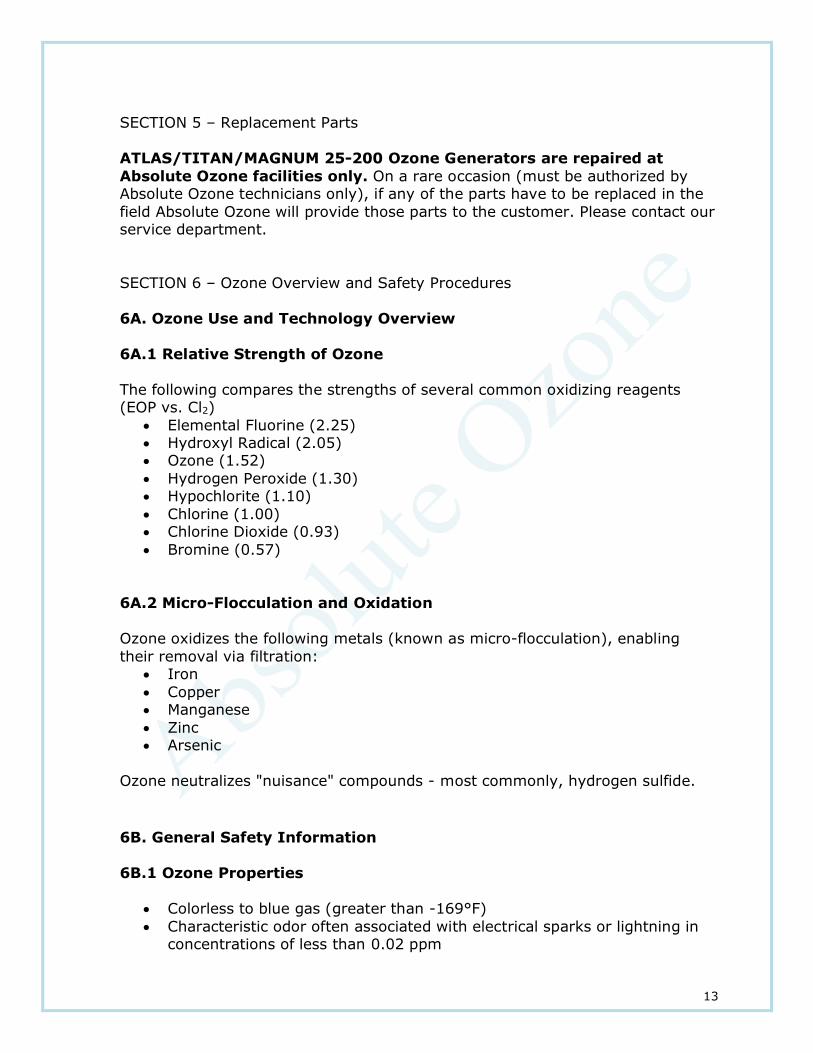
6A.1 Relative Strength of Ozone
The following compares the strengths of several common oxidizing reagents (EOP vs. Cl2)
• Elemental Fluorine (2.25) • Hydroxyl Radical (2.05) • Ozone (1.52)
• Hydrogen Peroxide (1.30) • Hypochlorite (1.10)
• Chlorine (1.00) • Chlorine Dioxide (0.93)
• Bromine (0.57)
6A.2 Micro-Flocculation and Oxidation
Ozone oxidizes the following metals (known as micro-flocculation), enabling
their removal via filtration: • Iron
• Copper • Manganese
• Zinc • Arsenic
Ozone neutralizes "nuisance" compounds - most commonly, hydrogen sulfide.
6B. General Safety Information
6B.1 Ozone Properties
• Colorless to blue gas (greater than -169°F)
• Characteristic odor often associated with electrical sparks or lightning in concentrations of less than 0.02 ppm

14
• Highly chemically reactive • Non-flammable, non-carcinogenic
• Hazardous polymerization can occur in some rear materials • Spontaneously decomposes to oxygen gas
6B.2 Ozone Uses
• Air and water disinfection • Surface sanitation
• Water treatment plants • Bottled water, irrigation, community water supplies, swimming
pools/spas, etc. • Aquariums/life support
• Agricultural wash water • Wastewater treatment
• Mold and bacteria control in cold storage
6C. Hazards
6C.1 Health Hazards – Detection Levels
Gaseous ozone can be detected in air by its distinctive odor at concentrations of about 0.02 ppm. Although each nose varies, olfactory fatigue occurs quickly.
Initial small exposure may reduce cell sensitivity and/or increase mucous thickness producing a resistance to low gaseous ozone levels.
DO NOT RELY ON ODOR AS A WARNING OF HIGH OZONE
CONCENTRATIONS. The Permissible Exposure Level (PEL) or time-weighted concentration for gaseous ozone to which workers may be exposed is 0.1 ppm
averaged over 8 hours, 5 days a week (OSHA). The short-term exposure limit is 0.3 ppm averaged over 15 minutes. The concentration of 5.0 ppm ozone in air is
generally accepted as Immediately Dangerous to Life or Health (IDLH).
6C.2 Health Hazards – Effects on Humans
Gaseous ozone acts as a primary irritant, affecting mainly the eyes, upper respiratory tract and the lungs. Inhalation produces various degrees of
respiratory effects from irritation to pulmonary edema (fluid in lungs). Short exposure to 1-2 ppm concentrations causes headache as well as irritation to the
respiratory system but symptoms subside when exposure ends. High concentrations of ozone produce severe irritation to the eyes and respiratory system. Exposure above the ACGIH/OSHA limits may produce nausea, chest
pain, coughing, fatigue, reduced visual acuity and pulmonary edema. Symptoms of edema from excessive exposure can be delayed one or more hours. There is
no threshold limit and so no exposure (regardless of how small) is theoretically without effect from ozone’s strong oxidative ability.

15
6C.3 Electrical Hazards
Turn OFF all power switches and disconnect power cord from power source receptacle before performing service work. Failure to do so could result in
serious injury or death. Operate the ATLAS/TITAN/MAGNUM 25-200 with safe access to electrical power. Connect the ATLAS/TITAN/MAGNUM 25-200 to a
G.F.C.I. type receptacle or as required by local electrical code & regulations. Do not bury the electrical cord. To reduce risk of electrical shock, replace damaged
cord immediately.
6C.4 Fire Hazards
Ozone is nonflammable. Decomposition of ozone into oxygen gas (O2) can increase strength of fire. Ozone is unstable at room temperature and
spontaneously decomposes to oxygen gas. Avoid ignition sources such as heat, sparks, and open flame. Keep away from strong combustible materials such as
grease, oils, and fats.
6C.5 Chemical Action
Ozone is chemically incompatible with all oxidizable materials, both organic and inorganic.
6D. Precautions for Safe Handling and Use

16
6D.1 Ozone Monitors
Ambient ozone monitoring equipment should be installed in the areas where ozone is being generated or applied. (See Monitoring section 6F.) Self-adhesive
ozone monitor badges, such as the Chromair® System by K&M Environmental (Virginia Beach, VA, www.kandmenvironmental.com), may be used for personal
or area monitoring for exposure times ranging from 5 minutes to 10 hours.
6D.2 Ventilation
It is mandatory that general and local exhaust ventilation be provided to dilute and disperse small amounts of ozone into the outside atmosphere. Federal,
state, and local regulations must be followed.
6D.3 Emergency Procedure
Due to the short life of ozone, evacuation and ventilation is all that is generally required in the event of a high ambient ozone alarm. All ozone generating and
delivery equipment should be shut down (manually or automatically by alarm) and a high-speed fan activated to dilute and disperse ozone in to the atmosphere. Personnel should leave the affected area until levels are returned
to below 0.1ppm.
6D.4 Respiratory Protection
A disposable respirator (3M #N95 8214/8514 - Minneapolis, MN, www.3m.com) is recommended for relief against ozone levels up to 10 times the OSHA PEL or
applicable government occupational exposure limits, whichever is lower.
6D.5 Education and Training
The education and training of workers is the responsibility of the employer. An effective training program must be practical, based on written work procedures
and be specific to both the job-site and the tasks to be performed. Training shall also include the responsibilities and responses of workers in an emergency. The
employer shall ensure through the education and training program that all workers are able to work without risk to themselves or others around them.
All workers must clearly understand their responsibilities with regard to not only
specific work procedures, but also the need to report all hazards, accidents or incidents and injuries. Management and employees shall review all routine work and emergency procedures jointly at least once annually.

17
6E. System Operation and Maintenance
6E.1 Safety Precautions and Equipment
Repair and maintenance of the ozone system shall be done under the direction
of qualified personnel. Qualification shall consist of instruction and training by the equipment supplier in the safeguards and procedures necessary for safe
performance of the work. A certificate of completion of such training shall be provided. Repair of Ozone Generator could be performed only at Absolute Ozone
facilities unless authorized and instructed otherwise by Absolute Ozone personal.
All equipment in an ozone plant (ozone generator, piping, pumps, tanks…) coming in contact with gases containing ozone must be maintained free of oil
and grease. Monitoring equipment and alarm system shall be tested and serviced according
to the manufacturer’s instructions. The planned maintenance of all safety equipment is essential to worker safety.
6E.2 Maintenance Requirements
It is the joint responsibility of the manufacturer, supplier and installer of the Ozone Generating and handling equipment to determine whether or not the
system is working properly. The operation and maintenance manual provided with the equipment outlines the operating procedures and maintenance
requirements.
6F. Monitoring
6F.1 Location of Monitors
Ambient ozone detection monitors shall be located to monitor ozone room air
and production/plant room air for indoor applications.
6F.2 Monitoring Equipment
Proper Ozone Monitoring equipment should be use to protect personnel from dangerous levels of ozone exposure. Absolute Ozone could provide suitable
ozone monitoring at customer request.
6G. First Aid Procedures
6G.1 General Information
1. DO NOT PANIC. If exposure to gaseous ozone causes headaches or shortness of breath, immediately remove the worker to a fresh-air

18
environment.
2. Ensure there is no more danger to yourself or the worker.
3. Workers who have been exposed to low concentrations of ozone should be given oxygen to breathe while under the observation of trained personnel.
4. If exposure is severe, send for medical assistance immediately.
5.
6G.2 Inhalation
1. Assess worker’s breathing.
2. All unconscious workers must be placed in the drainage position (on their sides); so that fluids can drain from the airways once breathing has been
restored.
3. Check pulse.
4. If breathing has ceased, start artificial respiration (rescue breathing is the
most effective method) until breathing has been restored.
5. Send for medical assistance immediately.
6. If absent, begin cardiopulmonary resuscitation (CPR).
6G.3 Eye Contact
1. Effective irrigation should start immediately. Eyes should be irritated for 30 minutes by the clock with running tap water or preferably normal
saline.
2. Effective irrigation must be continued while en-route to hospital.
6G.4 Precautions
Workers with a previous cardiopulmonary (heart and lung) condition must consult their physician prior to working in an area in which they may be exposed
to ozone. Significant alterations in cardiopulmonary functions have been documented when such workers have been exposed to low concentrations of ozone.
6G.5 Emergency Information Form
An emergency information form (see below) should be filled out prior to
operating the Ozone Generator.

19
Absolute Ozone Five Years Limited Warranty The limited warranty set forth below applies to products manufactured by Absolute Ozone 10712 - 181 Street, Edmonton, AB., T5S 1K8, Canada, and sold by Absolute
Ozone and its authorized dealers. This limited warranty is given only to the first retail purchaser of such products and is not transferable to any subsequent owners or
purchasers of such products.
Absolute Ozone warrants that Absolute Ozone will repair or replace, at Absolute Ozone’s
option, any part of such products proven to be defective in materials or workmanship within Five (5) years from data of original purchase. Parts are covered under the Five
(5) year warranty when and only when required operating conditions and procedures as
described in this manual are performed and provided. This Warranty specifically excludes any components not manufactured by Absolute Ozone that are external to the
products covered, such as pumps, air compressors, monitors, tanks, or related
components. Absolute Ozone will assist with warranty claims for such components purchased through Absolute Ozone; limited to the extent of the manufacturer’s standard
warranty. ANY REPAIR OR REPLACEMENT WILL BE WARRANTED ONLY FOR THE BALANCE OF THE ORIGINAL FIVE (5) YEAR WARRANTY PERIOD.

20
THIS LIMITED WARRANTY DOES NOT INCLUDE ANY OF THE FOLLOWING:
(a) Any labor charges for troubleshooting, removal, or installation of such parts;
(b) Any repair or replacement of such parts necessitated by faulty installation, or improper operating procedures and conditions, misuse, abuse, negligence, accident, fire,
flood, repair materials, and/or unauthorized accessories; (c) Any such products installed without regard to required local codes and accepted
trade practices;
(d) Damage caused by water passing through unit; (e) Damage caused by operating bellow or above specified working pressure;
(f) ANY IMPLIED WARRANTY OF MERCHANTABILITY OR IMPLIED WARRANTY OF FITNESS FOR PARTICULAR PURPOSE, AND SUCH WARRANTIES ARE HEREBY
DISCLAIMED; AND
(g) ABSOLUTE OZONE SHALL NOT BE LIABLE UNDER ANY CIRCUMSTANCES FOR LOSS OF USE OF SUCH PRODUCTS, LOST PROFITS, DIRECT DAMAGES, INDIRECT DAMAGES,
CONSEQUENTIAL DAMAGES AND/OR INCIDENTAL DAMAGES.
TO OBTAIN WARRANTY SERVICE:
Absolute Ozone
10712 – 181 Street, Edmonton, Alberta,
T5S 1K8, Canada
Customer Service: 780-486-3761 Fax: 780-486-3763
Web: www.absoluteozone.com
Email: [email protected]
THE OZONE CELL CONTAINS TAMPER PROOF DEVICE. ANY ATTEMPT
TO OPEN THE CELL WILL NOT ONLY VOID THE WARRANTY, BUT WILL VOID A POSSIBILITY OF OBTAINING ANY SERVICE BY
ABSOLUTE OZONE.
NOTE: ANY WORK PERFORMED ON ABSOLUTE OZONE PRODUCTS WITHOUT
PRIOR AUTHORIZATION FROM ABSOLUTE OZONE WILL AUTOMATICALLY VOID THIS WARRANTY. ANY ABSOLUTE OZONE PRODUCT MUST BE
RETURNED TO ABSOLUTE OZONE PREPAID, FOR WARRANTY EVALUATION.

21
Please provide the following information:
1. Project, contact name, mailing address and telephone
2. Installer/Mechanical Contractor 3. Serial # and date of purchase
4. The date of failure 5. A description of the failure
6. All shipping documents should clearly state “Warranty Repair” and indicated RMA number. Absolute Ozone is not
responsible for double taxes or duties resulted from improper shipping documentation.

22
MAGNUM 160-200 Ozone Generator dimensions and mounting hole dimensions.
Dimensions: 14” x 26.5” x 7” Mounting holes dimensions: W12” x H27-7/8”
7 ATLAS 25-100 Ozone Generator dimensions and mounting hole dimensions.
Dimensions: 14” x 15” x 7” Mounting holes dimensions: W12” x H16-5/16”

23
Comment: All System Components and Materials have to be Ozone Compatible.
8. Typical Ozone Injection System Diagrams for Water Treatment

24
Comment: All System Components and Materials have to be Ozone Compatible.
9. Notes: