testo 338 · Density gauge
36
testo 338 · Density gauge Instruction manual
-
Upload
khangminh22 -
Category
Documents
-
view
0 -
download
0
Transcript of testo 338 · Density gauge

testo 338 · Density gauge
Instruction manual

2

1 Contents
3
Pos: 1 /TD/Überschriften/1. Inhalt @ 0\mod_1177587817070_79.docx @ 1243 @ 1 @ 1
1 Contents 1 Contents ................................................................................................... 3 2 Safety and the environment .................................................................... 5
2.1. About this document ........................................................................ 5 2.2. Ensure safety ................................................................................... 6 2.3. Protecting the environment .............................................................. 7
3 Specifications .......................................................................................... 8 3.1. Use .................................................................................................. 8 3.2. Technical data ................................................................................. 8 3.3. Measuring principle ......................................................................... 9
3.3.1. Sensors ........................................................................................................... 9 3.3.2. Paper blackening (PB) ................................................................................... 10 3.3.3. Filter loading (FL) ........................................................................................... 11
3.4. Measurement units ........................................................................ 11 3.4.1. Filter smoke number [FSN] ............................................................................ 11 3.4.2. Bosch number [Bosch] ................................................................................... 13 3.4.3. Soot concentration [mg/m3] ............................................................................ 13
4 Product description ............................................................................... 14 5 First steps .............................................................................................. 17
5.1. Charging the battery ...................................................................... 17 5.2. Connecting the mains unit ............................................................. 17 5.3. Switching the instrument on/off ...................................................... 18
6 Using the product .................................................................................. 20 6.1. Performing the leakage test ........................................................... 20 6.2. Performing settings ........................................................................ 20
6.2.1. Date/time ....................................................................................................... 20 6.2.2. Configuration menu........................................................................................ 21
6.3. Preparing measurements .............................................................. 22 6.4. Measuring ...................................................................................... 22 6.5. Viewing, printing and deleting saved measurement results ........... 24 6.6. Data transfer to testo easyEmission software ................................ 24
1 Contents
4
7 Maintaining the product ....................................................................... 25 7.1. Removing TopSafe from the testo 338 ......................................... 25 7.2. Emptying the condensate trap ...................................................... 26 7.3. Changing the rechargeable battery ............................................... 27 7.4. Changing the filter paper ............................................................... 28 7.5. Replacing the particle filter ............................................................ 31 7.6. Cleaning the instrument and TopSafe ........................................... 32 7.7. Calibration ..................................................................................... 32
8 Tips and assistance .............................................................................. 33 8.1. Questions and answers ................................................................ 33 8.2. Accessories and spare parts ......................................................... 34
Pos: 2 /TD/--- Seitenwechsel --- @ 0\mod_1173774430601_0.docx @ 283 @ @ 1
2 Safety and the environment
5
Pos: 3 /TD/Überschriften/2. Sicherheit und Umwelt @ 0\mod_1173774719351_79.docx @ 292 @ 1 @ 1
2 Safety and the environment Pos: 4 /TD/Überschriften/2.1 Zu diesem Dokument @ 0\mod_1173775252351_79.docx @ 346 @ 2 @ 1
2.1. About this document Pos: 5 /TD/Sicherheit und Umwelt/Zu diesem Dokument/Verwendung/Verwendung (Standard) @ 0\mod_1173775068554_79.docx @ 337 @ 5 @ 1
Use > Please read this documentation through carefully and
familiarize yourself with the product before putting it to use. Pay particular attention to the safety instructions and warning advice in order to prevent injuries and damage to the products.
> Keep this document to hand so that you can refer to it when necessary.
> Hand this documentation on to any subsequent users of the product.
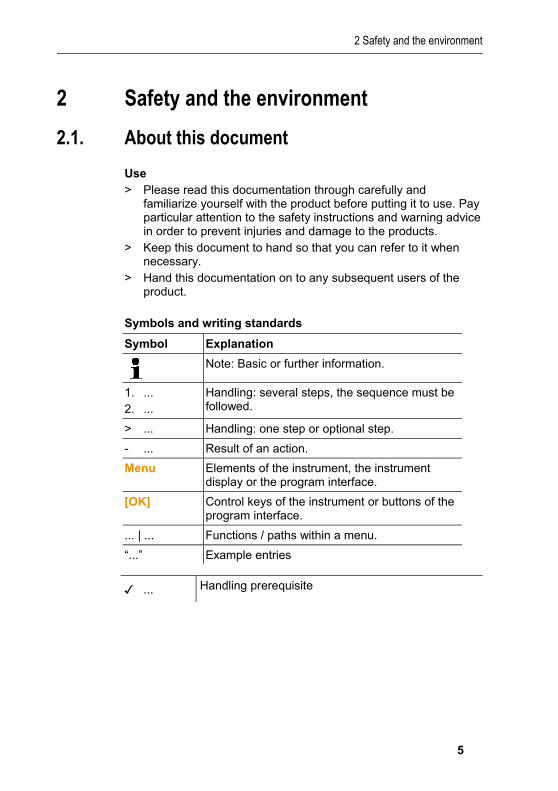
Pos: 6 /TD/Sicherheit und Umwelt/Zu diesem Dokument/Symbole und Schreibkonventionen/Symbole und Schreibkonv. [testo 338] @ 12\mod_1332405496527_79.docx @ 113753 @ 5 @ 1
Symbols and writing standards
Symbol Explanation
Note: Basic or further information.
1. ... 2. ...
Handling: several steps, the sequence must be followed.
> ... Handling: one step or optional step.
- ... Result of an action.
Menu Elements of the instrument, the instrument display or the program interface.
[OK] Control keys of the instrument or buttons of the program interface.
... | ... Functions / paths within a menu.
“...” Example entries Pos: 7 /TD/Sicherheit und Umwelt/Zu diesem Dokument/Symbole und Schreibkonventionen/Schreibkonv. Handlungsvorrausetzung @ 10\mod_1320321351105_79.docx @ 96443 @ @ 1
✓ ... Handling prerequisite Pos: 8 /TD/Sicherheit und Umwelt/Zu diesem Dokument/Symbole und Schreibkonventionen/Tabellenkopf Warnhinweise @ 2\mod_1207645198296_79.docx @ 14334 @ 5 @ 1

2 Safety and the environment
6
Warnings Always pay attention to information that is marked by the following warnings with warning pictograms. Implement the specified precautionary measures.
Representation Explanation Pos: 9 /TD/Sicherheit und Umwelt/Zu diesem Dokument/Symbole und Schreibkonventionen/Warnhinweis VORSICHT @ 2\mod_1207651416515_79.docx @ 14416 @ @ 1
CAUTION indicates potential minor injuries Pos: 10 /TD/Sicherheit und Umwelt/Zu diesem Dokument/Symbole und Schreibkonventionen/Warnhinweis ACHTUNG (Produktschaden) @ 2\mod_1207651536812_79.docx @ 14434 @ @ 1
NOTICE indicates circumstances that may lead to damage to the products
Pos: 11 /TD/Überschriften/2.2 Sicherheit gewährleisten @ 0\mod_1173780783960_79.docx @ 366 @ 2 @ 1
2.2. Ensure safety Pos: 12 /TD/Sicherheit und Umwelt/Sicherheit gewährleisten/Produkt bestimmungsgemäß verwenden @ 0\mod_1173781261848_79.docx @ 386 @ @ 1
> Only operate the product properly, for its intended purpose and within the parameters specified in the technical data. Do not use any force.
Pos: 13 /TD/Sicherheit und Umwelt/Sicherheit gewährleisten/Nicht mit Lösungsmitteln lagern @ 0\mod_1175692375179_79.docx @ 583 @ @ 1
> Do not store the product together with solvents. Do not use any desiccants.
Pos: 14 /TD/Sicherheit und Umwelt/Sicherheit gewährleisten/Nur beschriebene Wartungsarbeiten durchführen @ 0\mod_1175692705195_79.docx @ 601 @ @ 1
> Carry out only the maintenance and repair work on this instrument that is described in the documentation. Follow the prescribed steps exactly. Use only original spare parts from Testo.
Pos: 15 /TD/Sicherheit und Umwelt/Sicherheit gewährleisten/Akku-Sicherheitshinweise (LiIon) @ 0\mod_1187184666109_79.docx @ 2363 @ @ 1
> Improper use of rechargeable batteries can lead to destruction or injuries by means of current surges, fire or escaping chemicals. The following instructions must be observed to avoid such hazards: • Only use in accordance with the directions in the instruction
manual. • Do not short, take apart or modify. • Do not expose to heavy impacts, water, fire or temperatures
above 60 °C. • Do not store in the proximity of metal objects. • Do not use leaky or damaged rechargeable batteries. In the
event of contact with battery acid: Thoroughly wash affected area with water and consult a doctor, if necessary.
2 Safety and the environment
7
• Only charge in the instrument or the recommended charging station.
• Immediately stop the charging process if this is not completed in the given time.
• In the event of improper function or signs of overheating, immediately remove the rechargeable battery from the measuring instrument/charging station. Caution: Rechargeable battery may be hot!
Pos: 16 /TD/Sicherheit und Umwelt/Sicherheit gewährleisten/Option Bluetooth [testo 338] @ 12\mod_1332407047041_79.docx @ 113787 @ 5 @ 1
For products with Bluetooth® (optional) Changes or modifications that have been made without the explicit consent of the responsible approval authority, may cause the retraction of the type approval. Data transfer may be disturbed by equipment that uses the same ISM-band, e.g. WLAN, microwave ovens, ZigBee. The use of radio communication links is not permitted in aeroplanes and hospitals, among others. For this reason the following points must be ensured before entering: The data transfer function must not be active.
Pos: 17 /TD/Überschriften/2.3 Umwelt schützen @ 0\mod_1173780843645_79.docx @ 375 @ 2 @ 1
2.3. Protecting the environment Pos: 18.1 /TD/Sicherheit und Umwelt/Umwelt schützen/Akkus/Batterien entsorgen @ 0\mod_1175693637007_79.docx @ 619 @ @ 1
> Dispose of faulty rechargeable batteries/spent batteries in accordance with the valid legal specifications.
Pos: 18.2 /TD/Sicherheit und Umwelt/Umwelt schützen/Produkt entsorgen @ 0\mod_1173780307072_79.docx @ 357 @ @ 1
> At the end of its useful life, send the product to the separate collection for electric and electronic devices (observe local regulations) or return the product to Testo for disposal.
Pos: 19 /TD/--- Seitenwechsel --- @ 0\mod_1173774430601_0.docx @ 283 @ @ 1

3 Specifications
8
Pos: 20 /TD/Überschriften/3. Leistungsbeschreibung @ 0\mod_1173774791554_79.docx @ 301 @ 1 @ 1
3 Specifications Pos: 21 /TD/Überschriften/3.1 Verwendung @ 0\mod_1176211016437_79.docx @ 695 @ 2 @ 1
3.1. Use Pos: 22 /TD/Leistungsbeschreibung/Verwendung/testo 338 @ 9\mod_1314086265823_79.docx @ 93513 @ 5 @ 1
Functions and use The density gauge is a handheld instrument for determining the filter smoke number (FSN), the Bosch number and the soot concentration of diesel engines.
The Bluetooth® option may only be operated in countries in which it is type approved.
Pos: 23 /TD/Überschriften/3.2 Technische Daten @ 0\mod_1176211088437_79.docx @ 704 @ 2 @ 1
3.2. Technical data Pos: 24 /TD/Leistungsbeschreibung/Technische Daten/testo 338/testo 338-Technische Daten @ 11\mod_1329727600578_79.docx @ 110714 @ @ 1
Feature Values
Sensor Photodiode
Measurement range FSN/Bosch no.1: 0 to 2 Soot concentration: 0 to 50 mg/m3
Resolution FSN/Bosch no.1: 0.01 Soot concentration: 0.01 mg/m3
Repeatability FSN/Bosch no.1: ±0.03 or 6% of meas. val. Soot concentration: ±0.5 mg/m3 or ±9% of meas. val.
Measuring probe volume
Hi: 0.2 l (range: 0.2 to 2.0 FSN) Lo: 0.4 l (range: 0 to 0.3 FSN)
Storage/transportation temperature
-20 to 50°C
Operating temperature
5 to 45°C
Rech. batt. Lithium-ion, 2600 mAh / 3.7 V
Rech. batt. life >45 individual measurements
Protection class IP 40
Interfaces Printer: IR, IRDA Software: Bluetooth (only 0632 3382)
Dimensions 270 x 92 x 127mm
Weight 770g (including battery)

3 Specifications
9
Feature Values
Warranty 2 years, warranty conditions: see www.testo.com/warranty
EU Directive 2004/108/EC
1 Under reference conditions of 25°C and 1000 hPa Pos: 25 /TD/Leistungsbeschreibung/Technische Daten/testo 338/Zulassungen testo 338 @ 12\mod_1332407855428_79.docx @ 113891 @ 3 @ 1
Bluetooth® module (option)
• Bluetooth® type: BlueNiceCom IV • Bluetooth® product note: BNC4_HW2x_SW2xx • Bluetooth® identification: B013784 • Bluetooth® company: 10274 • Coverage: < 10 m • Certification: Belgium (BE), Bulgaria (BG), Denmark (DK),
Germany (DE), Estonia (EE), Finland (FI), France (FR), Greece (GR), Ireland (IE), Italy (IT), Latvia (LV), Lithuania (LT), Luxembourg (LU), Malta (MT), Netherlands (NL), Austria (AT), Poland (PL), Portugal (PT), Romania (RO), Sweden (SE), Slovakia (SK), Slovenia (SI), Spain (ES), Czech Republic (CZ), Hungary (HU), United Kingdom (GB), Republic of Cyprus (CY). Iceland, Liechtenstein, Norway and Switzerland. Turkey, El Salvador, Columbia
Pos: 26 /TD/Leistungsbeschreibung/Technische Daten/testo 338/testo 338-Messprinzip @ 11\mod_1329727736886_79.docx @ 110748 @ 23323333 @ 1
3.3. Measuring principle
3.3.1. Sensors
1 White LED 2 Light 3 Loaded filter paper

3 Specifications
10
4 Reflected light 5 Optical sensor (photodiode)
Component Process
Optical sensor (photodiode and white LED)
The white LED radiates light with a defined intensity on to the blackening mark. The photodiode calculates the paper blackening based on the reflected light intensity. The more soot is deposited on the filter paper, the less light is reflected.
Differential pressure sensor/temperature sensor
The sensor for differential pressure determines the probe volume under ambient conditions.
The ambient pressure depends on the height above sea level and weather (high/low-pressure region). With the testo 338, the current height above sea level must be entered manually. The probe volume determined by the differential pressure sensor is used to calculate the probe volume under reference conditions with the input height and the temperature measured by the instrument.
This probe volume and the measured paper blackening are then used to calculate the FSN (filter smoke number), soot concentration (mg/m3) or Bosch number.
Measurements are assessed optically and are therefore dependent on the optical property of the soot. The optical properties of the soot vary depending on the engine and fuel, which can lead to inaccuracies during the calculation of the mass.
3.3.2. Paper blackening (PB) The optical sensor detects the reflection capacity of filter paper blackened by flue gas. This means that 100% reflection corresponds to PB = 0 (white paper) and complete absorption = 0% reflection (completely blackened paper) corresponds to PB = 10. = 10 ∙ −
PB: Paper blackening
RB: Measuring value
RW: Reflection of the white filter paper

3 Specifications
11
3.3.3. Filter loading (FL) Filter loading describes the level of soot on the paper and is specified in milligrams per square metre. The filter loading increases exponentially with the paper blackening. = ∙ ∙ ∙ FL = filter loading
α: empirical, fixed value
PB: Paper blackening
β: empirical, fixed value
Filt
er lo
adi
ng
Filter smoke number/paper blackening
3.4. Measurement units
3.4.1. Filter smoke number [FSN] The filter smoke number (FSN) is a standardised unit. It corresponds to paper blackening caused by the intake of a flue gas column from a reference length of 405 mm (under reference conditions: 1000 mbar, 25 °C) on the filter paper. With the testo 338, a longer flue gas column is drawn through the filter paper to increase sensitivity. After the measurement, this is converted to a reference length. During the measurement, the flue gas volume taken in by the testo 338 is adjusted to the current ambient conditions (pressure, temperature) so that it corresponds to the volume under reference conditions. This gives a measuring value irrespective of local conditions.

3 Specifications
12
Filt
er lo
adi
ng
Filter smoke number/paper blackening
The calculation of the FSN from the directly measured filter blacking PB is carried out in three steps: 1 With the measured paper blackening (at reference pressure and
temperature), the effective filter loading (FLeff) is calculated. 2 The filter loading with a reference length (FLref) is determined. 3 The FSN is determined according to the calculated reference
filter loading. The reference conditions (pressure, temperature) for calculating the volume are 1000 mbar and 25 °C. This means that, irrespective of where and under what conditions a measurement is carried out, the measurement results remain comparable.

3 Specifications
13
3.4.2. Bosch number [Bosch] The main difference between the Bosch number and the FSN is its dependency on the current ambient pressure and -temperature.
Filt
er lo
adi
ng
Filter smoke number/paper blackening
The Bosch number is calculated in the testo 338 as follows: 1 With the measured paper blackening (at reference pressure and
temperature), the effective filter loading (FLeff) is calculated. 2 The filter loading with a reference length (FLref) is determined. 3 The Bosch number is determined according to the calculated
reference filter loading (under current ambient conditions).
3.4.3. Soot concentration [mg/m3] With the filter loading, via the volume that causes the blackening, it is possible to infer the soot concentration (SC = soot concentration) of the flue gas. This unit is calculated via the measured filter loading and the effective length, which are understood in the following context. SC= FLeffLeff SC: soot concentration
FLeff: effective filter loading
Leff: effective length Pos: 27 /TD/--- Seitenwechsel --- @ 0\mod_1173774430601_0.docx @ 283 @ @ 1

4 Product description
14
Pos: 28 /TD/Überschriften/4. Produktbeschreibung @ 0\mod_1173774846679_79.docx @ 310 @ 1 @ 1
4 Product description Pos: 29 /TD/Produktbeschreibung/Übersicht/testo 338 Übersicht @ 9\mod_1314086534410_79.docx @ 93579 @ @ 1
1 IR- / IrDA interface 2 Display:
Instrument status icons:
Icon Meaning
Error message
Pump running
Printing
Memory menu open
Query: Clear data?
Data transfer (printer or memory)
Note: Feed probe into flue gas duct
Note: Remove probe from flue gas duct.
Configuration menu opened
+ percentage
Engine operating point
Battery capacity: >75% / >50% / >25% / <10%
+ two-digit number
Engine number

4 Product description
15
Icon Meaning
Hi, Lo Probe volume mode (set automatically by the instrument irrespective of the FSN value of the last measurement): • Hi: high soot concentration –
measurement period 20 s • Lo: low soot concentration –
measurement period 40 s
Test Leakage test running
3 Control keys:
Button Function
Switch the instrument on/off Cancel (takes the display back one operating step)
Left function key:
Function changes depending on the instrument status:
[Start] Begin smoke measurement
[OK] Apply setting/measuring value
[ ] Toggle position display
[ ] Open date/time menu
[ ] Start printout
Right function key:
Function changes depending on the instrument status:
[test ] Begin leakage test
[set] Open configuration menu
[ ] Change selection
[ ] Save measuring values
[ ] Delete measuring values
[NO] Apply setting/measuring value
4 Mains socket 5 Condensate outlet

4 Product description
16
6 Gas inlet 7 Service lid: access to filter paper, battery 8 Eyelet for wrist strap 9 Condensate trap 10 Probe shaft 11 Cone 12 Connecting hose to the gas inlet 13 Bypass with hose clamps (not shown)
Pos: 30 /TD/--- Seitenwechsel --- @ 0\mod_1173774430601_0.docx @ 283 @ @ 1

5 First steps
17
Pos: 31 /TD/Überschriften/5. Erste Schritte @ 0\mod_1173774895039_79.docx @ 319 @ 1 @ 1
5 First steps Pos: 32 /TD/Erste Schritte/testo 308/Akku laden @ 0\mod_1177413427960_79.docx @ 1210 @ 2 @ 1
5.1. Charging the battery Fully charge the rechargeable battery before using the instrument. The rechargeable battery can only be charged at an ambient temperature of 0 to 35°C / 32 to 95°F. If the rechargeable battery pack has discharged completely, the charging time at room temperature is approx. 8-9 hrs.
Rechargeable battery care: • If possible, always discharge the rechargeable
battery and recharge it fully. • Do not store a discharged battery for an extended
period, fully charge before renewed use. • Best storage conditions: 50-80 % residual capacity,
10 to 20°C / 50 to 68°F ambient temperature.
It is not possible to charge batteries in the instrument when switched on. > Switch the instrument off before charging the battery. 1. Insert the instrument plug of the mains unit into the mains
socket on the instrument. 2. Insert the mains plug of the mains unit into a mains socket. - The charging process will start. The battery symbol illuminates
with a variable number of segments. The charging process
stops automatically and illuminates when the battery is charged.
Alternatively, the battery can be charged in a charger (accessory, 0554 1103). > Refer to the documentation that comes with the charger for this.
Pos: 33 /TD/Erste Schritte/testo 338/testo 338 Netzteil anschließen @ 12\mod_1331546077811_79.docx @ 112603 @ 2 @ 1
5.2. Connecting the mains unit If the mains unit is connected, the instrument is powered automatically via the mains unit. It is not possible to charge the battery in the instrument during operation. 1. Insert the instrument plug of the mains unit 0554 1096 into the
mains socket on the instrument. 2. Insert the mains plug of the mains unit into a mains socket. - If the instrument is switched off, the battery charging process
begins automatically. By switching the instrument on, the battery charging process is stopped and the instrument is then powered via the mains unit.

5 First steps
18
Pos: 34 /TD/Erste Schritte/testo 338/testo 338 Gerät ein-/ausschalten @ 10\mod_1314172155251_79.docx @ 93829 @ 255 @ 1
5.3. Switching the instrument on/off
Switching the instrument on
If the service lid is not secured, incorrect measurements will result: > Check that the service lid is secured before
switching on the instrument.
Testo recommends performing a leakage test before every series of measurements: > Seal off the probe shaft before switching on the instrument and
close the hose clamp on the bypass.
1. Press and hold down [ ] until something appears on the display.
- A segment test is carried out: all display segments light up for 2 s.
- The firmware version is then displayed for 2 s. [test ] is
assigned to the right function key and [ ] is assigned to the left function key.
During this time, you have the following options:
> Set date/time: press [ ]. - The date/time menu is opened, see Date/time, page 20.
During first commissioning, this menu is opened automatically.
> Start leakage test: press [test ]. - The leakage test is started, see Performing the leakage test,
page 20. - [set] is then assigned to the right function key for 2 s. During this time, you have the following option: > Open configuration menu: press [set].
- The configuration menu is opened, see Configuration menu, page 21.
During first commissioning, this menu is opened automatically.
> Carry out the basic settings, see Performing settings, page 20.
- If no function key is pressed, the instrument switches to the measurement view, see Measuring, page 22.

5 First steps
19
- The stability time is started: lights up and a 60 s countdown runs down.
During the stability time, the ambient temperature is measured, which is required for calculating the Bosch number. To ensure correct Bosch number calculation: > Only start the measurement once the stability time
has elapsed.
Switching the instrument off
While the instrument is switched on, filter paper heating is activated automatically. This reduces the operating time of the rechargeable battery. > Switch the instrument off if you are not performing a
measurement.
- The measurement view is opened.
> Press and hold down [ ] until the display goes out. - The instrument switches itself off.
Pos: 35 /TD/--- Seitenwechsel --- @ 0\mod_1173774430601_0.docx @ 283 @ @ 1

6 Using the product
20
Pos: 36 /TD/Überschriften/6. Produkt verwenden @ 0\mod_1173774928554_79.docx @ 328 @ 1 @ 1
6 Using the product Pos: 37 /TD/Produkt verwenden/testo 338/testo 338 Dichtigkeitstest durchführen @ 10\mod_1314175237037_79.docx @ 93863 @ 2 @ 1
6.1. Performing the leakage test
The hose clamp must be closed before the leakage test can be carried out. When opening, make sure that the hose is not sticking.
- The leakage test has been started, see Switching the instrument on/off, page 18.
- Test lights up and the flue gas pump runs. Air is sucked in for max. 20 seconds. During this time, the probe shaft must remain sealed off and the hose clamp on the bypass hose must be closed.
- If the instrument is leak-tight, Test OK lights up before 20 seconds have elapsed. > Press [OK] to switch to the measurement view.
- If the instrument leaks, lights up: > Check whether the service lid is secured correctly. > Check whether the condensate trap is inserted and closed
correctly. > Repeat the leakage test: press [Start]. > Contact your dealer or Testo Customer Service if you
receive another error message. > After the test, open the clamp on the bypass hose again and
ensure that the hose is not squashed. If necessary, move the hose clamp slightly.
Pos: 38 /TD/Überschriften/6.1 Einstellungen vornehmen @ 0\mod_1184584321421_79.docx @ 1863 @ 2 @ 1
6.2. Performing settings Pos: 39 /TD/Produkt verwenden/testo 338/testo 338 Einstellungen vornehmen @ 10\mod_1314176450342_79.docx @ 93896 @ 33 @ 1
6.2.1. Date/time ✓ The date/time menu has been opened, see Switching the
instrument on/off, page 18. - The date and time are displayed alternately. 1. Press [set] while the date is displayed.
2. Set the date with [ ] (increase value) and [ ] (switch to the next value).
3. Press [OK]. 4. Press [set] while the time is displayed.

6 Using the product
21
5. Set the time with [ ] (increase value) and [ ] (switch to the next value).
6. Press [OK] twice. - The instrument switches to the measurement view.
6.2.2. Configuration menu ✓ The configuration menu has been opened, see Switching the
instrument on/off, page 18.
- lights up and the engine operating point value flashes.
1. Switch to the next engine operating point: press [ ].
The engine operating point can be set in 5% increments between 0% and 110%.
2. Press [OK].
- lights up and the engine number flashes.
3. Set the engine number: press [ ].
Ten engine numbers between 01 and 10 can be set.
4. Press [OK].
- lights up and the printer number flashes.
5. Select the printer used: press [ ]. • 0545: Testo report printer (IR) 0554 0545 • 0547: Testo report printer (IrDA) 0554 0547 • 0549: Testo report printer (IrDA) 0544 0549
6. Press [OK]. - Bosch or FSN flashes.
7. Set measurement unit: press [ ]. 8. Press [OK]. - Alt lights up and the height value flashes.
9. Set height above sea level: press [ ].
The height can be set in 100 m increments between 0 and 3500 m.
10. Press [OK]. - The measurement view is opened (duration approx. 5 s).

6 Using the product
22
Pos: 40 /TD/Produkt verwenden/testo 338/testo 338 Messungen vorbereiten @ 10\mod_1315295671036_79.docx @ 94263 @ 2555 @ 1
6.3. Preparing measurements
Safety
CAUTIONHot probe shaft may cause burns! > Wear safety gloves. > Allow the probe shaft to cool down after a measurement.
Preventing product damage > Check the fill level of the condensate trap. Empty it if the level is
past the max. mark, see Emptying the condensate trap, page 26.
> Check the particle filter for signs of contamination. Change the filter if it is contaminated, see Replacing the particle filter, page 31.
> Check that there is enough filter paper in the instrument (service lid window). Replace the filter paper when it has been used up, see Changing the filter paper, page 28.
Ensuring measuring accuracy > Recommendation: Carry out a leakage test prior to every series
of measurements, see Switching the instrument on/off, page 18. > Adjust the height entry after changing the measuring location,
see Configuration menu, page 21. > Ensure that the hose clamp on the bypass is used correctly:
• Measurements when there is overpressure in the flue gas duct (normal): hose clamp open.
• Measurements when there is underpressure in the flue gas duct: hose clamp closed.
Pos: 41 /TD/Überschriften/6.3 Messungen durchführen @ 0\mod_1184584650078_79.docx @ 1872 @ 2 @ 1
6.4. Measuring Pos: 42 /TD/Produkt verwenden/testo 338/testo 338 Messungen durchführen @ 12\mod_1333611701734_79.docx @ 115483 @ @ 1
✓ The flue gas probe is located outside the flue gas duct.
1. Press [OK]. - Rinse phase (pump running, duration 10 s). - A 20 s countdown runs down. During this time, the probe shaft
must be fed into the flue gas duct and the measurement must be started. If this is not done, the rinse phase must be started again.
2. Position the probe shaft in the flue gas duct.

6 Using the product
23
3. Press [Start]. - The measurement begins (pump running). - The measurement is stopped automatically after 20 s (Hi) or 40
s (Lo). 4. Remove probe from flue gas duct.
CAUTION
The instrument may become damaged by condensate!
> Only leave the probe shaft in the flue gas duct for the duration of the measurement.
- The evaluation of the blackening mark created on the filter paper is performed as soon as the instrument is unpressurised. The determined soot concentration, as well as the Bosch number or FSN (depending on the setting), is displayed.
5. Press [OK] to apply the value or [NO] to delete the value. > To remove the output filter paper strip: Hold the paper just
above the paper outlet and pull sideways.
CAUTION
The instrument may become damaged!
> While the service lid is closed, do no pull the filter paper out of the instrument.
> Only pull the filter paper sideways to remove it.
> Press [ ].
- The data is transferred to the report printer ( flashes).
6. Press [ ]. - The data is stored. - [set] is shown for approx. 2 s. You can call up the configuration
menu to select another operating point or another engine number.
- The measurement view is opened. Pos: 43 /TD/Produkt verwenden/testo 338/testo 338 Messergebnisse ansehen, drucken, loeschen @ 10\mod_1314194363677_79.docx @ 93929 @ 2 @ 1

6 Using the product
24
6.5. Viewing, printing and deleting saved measurement results ✓ The measurement view is open and the measurement data has
been saved.
1. Press [ ].
2. Select engine number (only possible if measuring values have
been stored under multiple engine numbers): press [ ] and confirm with [OK].
Viewing measurement results
3. Press [ ] and then [OK]. 4. Select engine operating point (only possible if measuring values
have been stored under multiple engine operating points): press
[ ] and confirm with [OK]. - Measurement results are displayed.
> Display date/time of measurement: press [ ]. Back to the soot
concentration display: [ ]. Deleting measurement results
5. Press [ ] and then [ ]. 6. Delete a measurement result: [OK]. Printing measurement results
3. Press [ ] and then [OK].
- The data is transferred to the report printer ( flashes). Pos: 44 /TD/Produkt verwenden/testo 338/testo 338 Datenübertragung @ 12\mod_1332420114612_79.docx @ 113925 @ 2 @ 1
6.6. Data transfer to testo easyEmission software A data transfer to the testo easyEmission software is only possible for instruments with Bluetooth® (article no. 0632 3382). Please read the instruction manual for the testo easyEmission software (0970 0360).
Pos: 45 /TD/--- Seitenwechsel --- @ 0\mod_1173774430601_0.docx @ 283 @ @ 1

7 Maintaining the product
25
Pos: 46 /TD/Überschriften/7. Produkt instand halten @ 0\mod_1173789831362_79.docx @ 397 @ 1 @ 1
7 Maintaining the product Pos: 47 /TD/Produkt instand halten/testo 338/testo 338 TopSafe @ 12\mod_1331729638069_79.docx @ 113075 @ 2 @ 1
7.1. Removing TopSafe from the testo 338 1. Unplug the instrument from the mains and switch it off before
opening the TopSafe. 2. Push down the locking clip (1) to release the guard. 3. Open guard (2).
4. Open the TopSafe cover (3).
5. Remove the testo 338 from the TopSafe (4).

7 Maintaining the product
26
Pos: 48 /TD/Produkt instand halten/testo 338 Kondensatfalle leeren @ 9\mod_1314098836072_79.docx @ 93721 @ 2 @ 1
7.2. Emptying the condensate trap
CAUTION
The flue gas pump may become damaged as a result of condensate entering the gas path!
> Do not empty the condensate trap while the flue gas pump is running.
The condensate consists of a weak mix of acids: > Avoid contact with the skin. > Make sure that the condensate does not run over the
housing.
1. Hold the instrument in such a way that the condensate outlet points upwards.
2. Pull the sealing plug out of the condensate outlet approx. 5 mm up to the stop.
3. Empty the condensate into a sink. 4. Wipe off any remaining drops at the condensate outlet using a
cloth. 5. Close the condensate outlet with the sealing plug.
> Ensure that the condensate outlet is fully closed,
otherwise incorrect measurements may occur due to external air entering.
Pos: 49 /TD/Produkt instand halten/testo 338/testo 338 Akku wechseln @ 12\mod_1331719363015_79.docx @ 113037 @ 2 @ 1

7 Maintaining the product
27
7.3. Changing the rechargeable battery 1. Unplug the instrument from the mains and switch it off before
changing the rechargeable battery. 2. Remove TopSafe from the instrument, see Removing TopSafe
from the testo 338, page 25. 3. Open the lock of the service lid (1). 4. Open the service lid and remove it from the instrument (2).
5. Open the battery lock by pressing the grey button and simultaneously pushing in the direction of the arrow (3).
6. Remove the rechargeable battery from the instrument and insert a new battery. Only use the Testo rechargeable battery 0515 0107!
7. Close the battery lock by pressing the grey button and simultaneously pushing opposite the direction of the arrow until the battery engages.
8. Insert the service lid in the retaining hinge and close it. 9. Close the lock of the service lid.
After changing the battery, you have to set the date and time again.

7 Maintaining the product
28
Pos: 50 /TD/Produkt instand halten/testo 338/testo 338 Filterpapier wechseln @ 12\mod_1331632400364_79.docx @ 112922 @ 2 @ 1
7.4. Changing the filter paper
CAUTION
The measuring lens may become damaged or contaminated!
> Keep the paper rolls free of contamination, as this could potentially be transmitted to the measuring lens.
> Do not touch the protective glass of the measuring lens.
Do not crinkle the filter paper to ensure that the paper is fed through smoothly.
1. Isolate the instrument from the mains and switch it off before changing the filter paper (1).
2. Remove TopSafe, see Removing TopSafe from the testo 338, page 25.
3. Open the lock of the service lid (2). 4. Open the service lid (3) and remove it from the instrument. 5. Pull the winder out of the bracket (4). 6. Remove the plastic sleeve of the spent paper roll from the
winder and dispose of this (5).
Off1
2
3
4
5
(3)

7 Maintaining the product
29
7. Slide a new paper roll onto the winder (6). 8. Align the paper roll as shown (6) and fasten the winder in the
bracket (7). 9. Unwind approx. 10 cm of paper from the roll (8). 10. Cut off the unwound paper and dispose of this (9). Then cut the
start of the paper roll into a point.
CAUTION
The gear wheel and the draw roll for paper transport may become damaged!
> Do not turn the gear wheel and the draw roll for paper transport.
click
7
6 click

7 Maintaining the product
30
11. Slide the end of the paper strip through under the guide tabs on the side and under the draw roll (10). Carefully pull the paper strip approx. 3 cm out of the guide (11).
12. Insert the service lid in the retaining hinge (12) and close it (13). 13. Close the lock of the service lid (14).
CAUTION
The instrument may become damaged!
> While the service lid is closed, do no pull the filter paper out of the instrument.
> Only pull the filter paper sideways to remove it.
Pos: 51 /TD/Produkt instand halten/testo 338/testo 338Partikelfilter wechseln @ 12\mod_1331737767653_79.docx @ 113451 @ 2 @ 1

7 Maintaining the product
31
7.5. Replacing the particle filter 1. Unplug the instrument from the mains and switch it off before
changing the particle filter. 2. Remove TopSafe from the testo 338, see Removing TopSafe
from the testo 338, page 25. 3. Remove the condensate trap from the instrument (1).
4. Remove the spent particle filter from the plastic sleeve (2) and insert a new filter.
5. Place the condensate trap on the instrument again (3).
Pos: 52 /TD/Produkt instand halten/testo 338/testo 338 Gerät reinigen @ 12\mod_1331737887031_79.docx @ 113485 @ 255 @ 1

7 Maintaining the product
32
7.6. Cleaning the instrument and TopSafe
Housing and TopSafe > If the instrument housing and TopSafe is contaminated, clean it
with a damp cloth. Do not use any aggressive cleaning agents or solvents! Mild household cleaning agents and soap suds may be used.
Protecting glass of the measuring lens
CAUTION
There is a risk of the protective glass of the measuring lens breaking!
> When cleaning, only exert light pressure on the protective glass.
> If contaminated, clean the protective glass of the measuring lens with a damp cloth that is not too wet.
Do not use any aggressive cleaning agents or solvents! Mild household cleaning agents and soap suds may be used.
Pos: 53 /TD/Produkt instand halten/testo 308/Kalibrierung @ 2\mod_1207921490093_79.docx @ 14584 @ 2 @ 1
7.7. Calibration In order to guarantee measurement accuracy, we recommend having the instrument calibrated once a year. Please contact your dealer or Testo customer service. For contact data, see back of this document or web page www.testo.com/service-contact
Pos: 54 /TD/--- Seitenwechsel --- @ 0\mod_1173774430601_0.docx @ 283 @ @ 1

8 Tips and assistance
33
Pos: 55 /TD/Überschriften/8. Tipps und Hilfe @ 0\mod_1173789887985_79.docx @ 406 @ 1 @ 1
8 Tips and assistance Pos: 56 /TD/Überschriften/8.1 Fragen und Antworten @ 0\mod_1177402017078_79.docx @ 1093 @ 2 @ 1
8.1. Questions and answers Pos: 57 /TD/Tipps und Hilfe/Fragen und Antworten/testo 338 @ 12\mod_1331718411663_79.docx @ 113003 @ @ 1 v
Question Possible causes/solutions
E02 lights up The drawn volume is too low after the end of the max. permissible measuring period.
> Instrument may be blocked.
E03 lights up Soot pump leaks, the drawn volume is too high after expiry of the min. permissible measuring period. > Carry out a leakage test, eliminate leaks,
e.g. lock lid.
E04 lights up Instrument temperature is outside the specified range > (Allow it to) cool down or warm up.
E07 lights up Basic position was not reached, gas path leaks.
> Press End to carry out positioning again.
OPEn b.P., E30 lights up
The overpressure is too high > Open bypass
E31 lights up The evaluated smoke number does not correspond to the set measuring range, the measuring range is changed automatically > Repeat measurement
E41 lights up Checksum error in Eeprom (over configuration range) > In the case of critical errors, contact Testo
Service.
E42 lights up Checksum error in Eeprom (over calibration data range) > In the case of critical errors, contact Testo
Service.
E43 lights up The ADC counts from the optical (smoke number) evaluation are outside the permissible range. > In the case of a hardware defect or critical
error, contact Testo Service.

8 Tips and assistance
34
Question Possible causes/solutions
E49 lights up Unknown error
and flash Battery charging not possible. > Plug in battery
flashes Battery charging <10% > Connect mains unit
If we could not answer your question or the solutions given during troubleshooting did not help: please contact your dealer or Testo Customer Service. Contact data see back of this document or website www.testo.com/service-contact.
Pos: 58 /TD/Überschriften/8.2 Zubehör und Ersatzteile @ 0\mod_1177402058734_79.docx @ 1102 @ 2 @ 1
8.2. Accessories and spare parts Pos: 59 /TD/Tipps und Hilfe/Zubehör und Ersatzteile/testo 338 @ 9\mod_1314097212957_79.docx @ 93645 @ @ 1
Description Article no.
Mains unit 0554 1096
Spare rech. battery 0515 0107
Spare filter paper (8 rolls) 0554 0146
Spare particle filter 0554 1101
Instrument bag 0516 0002
Printer 0554 0549 === Ende der Liste für Textmarke Inhalt ===

8 Tips and assistance
35

0970 3380 en 01 V01.00