LIGHT GAUGE METAL FRAMING ACCESSORIES
9
ACCESSORIES 09200 LIGHT GAUGE METAL FRAMING ACCESSORIES
-
Upload
khangminh22 -
Category
Documents
-
view
2 -
download
0
Transcript of LIGHT GAUGE METAL FRAMING ACCESSORIES

ACCESSORIES
09200109200
LIGHT GAUGE METAL FRAMING ACCESSORIES

BUILDSTRONG
www.BUILDSTRONG.com2
DRYWALL FRAMING ACCESSORIES
Physical/Structural Properties for Drywall Furring Channels (DWFC)
Drywall Furring Channel (DWFC) Allowable Ceiling Spans - L/240
Drywall Furring Channel (DWFC) Allowable Ceiling Spans - L/360
Gross Properties Effective Properties
SectionFy
(ksi)
DesignThickness
(in)Area(in2)
Weight(lb/ft)
Ix(in4)
Rx(in)
Iy(in4)
Ry(in)
Ix(in4)
Sx(in3)
Ma(Ft-lb)
DWFC088-18 33 0.0188 0.070 0.239 0.009 0.356 0.035 0.710 0.009 0.016 26.4DWFC088-30 33 0.0312 0.115 0.391 0.014 0.353 0.058 0.710 0.014 0.031 50.5DWFC088-43 33 0.0451 0.162 0.550 0.020 0.348 0.082 0.711 0.020 0.042 69.2DWFC088-54 50 0.0566 0.197 0.669 0.023 0.345 0.099 0.711 0.023 0.050 124.9DWFC150-18 33 0.0188 0.094 0.320 0.031 0.575 0.047 0.705 0.030 0.034 56.6DWFC150-30 33 0.0312 0.154 0.525 0.050 0.571 0.077 0.705 0.050 0.064 105.3DWFC150-43 33 0.0451 0.219 0.745 0.070 0.565 0.109 0.705 0.070 0.089 146.3DWFC150-54 50 0.0566 0.269 0.914 0.084 0.561 0.134 0.705 0.084 0.107 267.2
Uniform Load 4 psf 6 psf 13 psf
SectionFy
(ksi) SpansSpacing (in) oc Spacing (in) oc Spacing (in) oc
12 16 24 12 16 24 12 16 24
DWFC088-18 33Single 5’-2” 4’-9” 4’-1” 4’-6” 4’-1” 3’-7” 3’-6” 3’-2” 2’-9”
Multiple 6’-5” 5’-10” 5’-1” 5’-7” 5’-1” 4’-2” 4’-0” 3’-6” 2’-9”
DWFC088-30 33 Single 6’-2” 5’-7” 4’-11” 5’-5” 4’-11” 4’-3” 4’-2” 3’-9” 3’-4”Multiple 7’-7” 6’-11” 6’-1” 6’-8” 6’-1” 5’-3” 5’-2” 4’-8” 3’-11”
DWFC088-43 33 Single 6’-10” 6’-3” 5’-5” 6’- 0” 5’-5” 4’-9” 4’-7” 4’-2” 3’-8”Multiple 8’-6” 7’-8” 6’-9” 7’-5” 6’-9” 5’-10” 5’-9” 5’-2” 4’-6”
DWFC088-54 50 Single 7’-3” 6’-7” 5’-9” 6’-4” 5’-9” 5’-0” 4’-11” 4’-5” 3’-11”Multiple 9’- 0” 8’-2” 7’-2” 7’-10” 7’-2” 6’-3” 6’-1” 5’-6” 4’-10”
DWFC150-18 33 Single 7’-11” 7’-2” 6’-3” 6’-11” 6’-3” 5’-6” 5’-4” 4’-10” 4’-2”Multiple 9’-9” 8’-10” 7’-5” 8’-6” 7’-5” 5’-11” 5’-7” 4’-9” 3’-8”
DWFC150-30 33 Single 9’-5” 8’-6” 7’-5” 8’-2” 7’-5” 6’-6” 6’-4” 5’-9” 5’-0”Multiple 11’-7” 10’-6” 9’-2” 10’-2” 9’-2” 8’-0” 7’-10” 7’- 0” 5’-8”
DWFC150-43 33 Single 10’-6” 9’-6” 8’-4” 9’-2” 8’-4” 7’-3” 7’-1” 6’-5” 5’-7”Multiple 12’-11” 11’-9” 10’-3” 11’-4” 10’-3” 9’- 0” 8’-9” 7’-11” 6’-8”
DWFC150-54 50 Single 11’-2” 10’-1” 8’-10” 9’-9” 8’-10” 7’-9” 7’-6” 6’-10” 6’- 0”13’-9” 12’-6” 10’-11” 12’-0” 10’-11” 9’-7” 9’-4” 8’-5” 7’-5”
Notes: 1. Properties based on the 2007 NASPEC 2. Design thickness used for determination of properties. Minimum delivered thickness must be no less than 95% of design thickness. 3. For deflection calculations, use effective Ixx. Effective Ixx is based on Procedure 1 of the NASPEC 4. Effective properties are given as the minimum value for positive or negative bending.
Notes: 1. Single spans taken as the minimum span based on moment, shear, web crippling or deflection 2. Multiple spans indicate two or more equal, continuous spans with span length measured support to support. 3. Multiple spans taken as the minimum span based on moment, shear, web crippling, deflection combined bending and shear or combined and web crippling 4. Web crippling values based on 1” bearing at end and interior supports.
Uniform Load 4 psf 6 psf 13 psf
Fy Spacing (in) oc Spacing (in) oc Spacing (in) ocSection (ksi) Spans 12 16 24 12 16 24 12 16 24
DFWC088-18 33 Single 4’-6” 4’-1” 3’-7” 4’- 0” 3’-7” 3’-2” 3’-1” 2’-9” 2’-5”Multiple 5’-7” 5’-1” 4’-5” 4’-11” 4’-5” 3’-11” 3’-9” 3’-5” 2’-9”
DWFC088-30 33 Single 5’-5” 4’-11” 4’-3” 4’-8” 4’-3” 3’-9” 3’-8” 3’-4” 2’-11”Multiple 6’-8” 6’-1” 5’-3” 5’-10” 5’-3” 4’-7” 4’-6” 4’-1” 3’-7”
DWFC088-43 33 Single 6’- 0” 5’-5” 4’-9” 5’-3” 4’-9” 4’-2” 4’-0” 3’-8” 3’-2”Multiple 7’-5” 6’-9” 5’-10” 6’-6” 5’-10” 5’-2” 5’- 0” 4’-6” 4’- 0”
DWFC088-54 50 Single 6’-4” 5’-9” 5’-0” 5’-7” 5’-0” 4’-5” 4’-3” 3’-11” 3’-5”Multiple 7’-10” 7’-2” 6’-3” 6’-10” 6’-3” 5’-5” 5’-4” 4’-10” 4’-2”
DWFC150-18 33 Single 6’-11” 6’-3” 5’-6” 6’-0” 5’-6” 4’-9” 4’-8” 4’-3” 3’-8”Multiple 8’-6” 7’-9” 6’-9” 7’-5” 6’-9” 5’-11” 5’-7” 4’-9” 3’-8”
DWFC150-30 33 Single 8’-2” 7’-5” 6’-6” 7’-2” 6’-6” 5’-8” 5’-6” 5’-0” 4’-5”Multiple 10’-2” 9’-2” 8’-0” 8’-10” 8’-0” 7’-0” 6’-10” 6’-3” 5’-5”
DFWC150-43 33 Single 9’-2” 8’-4” 7’-3” 8’- 0” 7’-3” 6’-4” 6’-2” 5’-7” 4’-11”Multiple 11’-4” 10’-3” 9’- 0” 9’-11” 9’- 0” 7’-10” 7’-8” 6’-11” 6’-1”
DFWC150-54 50 Single 9’-9” 8’-10” 7’-9” 8’-6” 7’-9” 6’-9” 6’-7” 6’- 0” 5’-3”12’-0” 10’-11” 9’-7” 10’-6” 9’-7” 8’-4” 8’-2” 7’-5” 6’-5”
Product Data:• Available in 7/8” and 1-1/2” sizes.• Gauge: Standard 25 through 16 gauges.• Lengths: 12’ 0” Stock Length, (other lengths available).• Consult Telling Industries’ Light Gage Structural Framing & Accessories brochure for structural properties and span tablesUses:• Convenient accessory components for use in furring out ceilings and masonry walls. Knurled face prevents screw “ride” when attaching gypsum wallboard.• 1-1/2” DWFC is economical with respect to furring walls with electrical boxes, (no need to set into concrete).

ACCESSORIES
092003
Product Data:• Available in galvanized steel meeting ASTM A-1003 or hot-dipped galvanized steel meeting ASTM A-653, G60.• Lengths: 16’ stock length. (Other lengths available)Uses:• Bridging, (lateral support) in walls carrying axial and/or wind loads.• Bracing studs at door bucks and furring for ceilings.• Used in conjunction with metal lath and plaster in partitions, ceilings, column and beam enclosures, etc.
Notes: 1 Minimum deliverable base metal thickness is 95% of design thickness. 2 Inside bend radius taken as 3/32”. 3 Effective properties based on Fy = 33 ksi. 4 For deflection calculations, use the effective moment of inertia.
Notes: 1 Multiple span indicates two or more equal spans with channel continuous over interior supports. 2 End and interior bearing length = 0.75”. Web stiffeners are not required. 3 Listed spans are based on unbraced compression flanges. 4 Moment of inertia for deflection is calculated at the maximum service level stress for the span and load listed. Note that this value may be higher than the effective Ixx listed in section property tables.
Design Gross Effective Properties 33 ksiThickness Area Weight Ix Rx Iy Ry Ix Sx Ma Va
Section (in) (in2) (lb/ft) (in4) (in) (in4) (in) (in4) (in3) (in-k) (lb)CRC-075 0.0566 0.087 0.30 0.007 0.288 0.002 0.155 0.007 0.019 0.45 315CRC-150 0.0566 0.129 0.44 0.039 0.547 0.003 0.144 0.039 0.052 1.22 840CRC-200 0.0566 0.157 0.54 0.079 0.709 0.003 0.136 0.079 0.079 1.87 1190CRC-250 0.0566 0.186 0.63 0.139 0.866 0.003 0.128 0.139 0.111 2.64 1540
Allowable U-Channel (CRC) Ceiling Spans - L/240
Allowable U-Channel (CRC) Ceiling Spans - L/360
U-Channel (CRC) Properties and Spans
4 psf 6 psf 13 psf
15 psf
Channel Spacing (in) o.c. Channel Spacing (in) o.c. Channel Spacing (in) o.c. Channel Spacing (in) o.c.Section Spans 24 36 48 60 72 24 36 48 60 72 24 36 48 60 72 24 36 48 60 72
CRC-075 Single 3’ 11” 3’ 5” 3’ 1” 2’ 10” 2’ 8” 3’ 5” 3’ 0” 2’ 8” 2’ 6” 2’ 4” 2’ 7” 2’ 4” 2’ 1” 1’ 11” 1’ 9” 2’ 6” 2’ 2” 2’ 0” 1’ 10” 1’ 8”Multiple 4’ 10” 4’ 2” 3’ 10” 3’ 7” 3’ 4” 4’ 2” 3’ 8” 3’ 4” 3’ 1” 2’ 10” 3’ 3” 2’ 9” 2’ 4” 2’ 1” 1’ 11” 3’ 1” 2’ 7” 2’ 2” 2’ 0” 1’ 9”
CRC-150 Single 5’ 6” 4’ 10” 4’ 5” 4’ 1” 3’ 10” 4’ 10” 4’ 3” 3’ 10” 3’ 7” 3’ 5” 3’ 9” 3’ 3” 3’ 0” 2’ 9” 2’ 7” 3’ 7” 3’ 2” 2’ 10” 2’ 7” 2’ 5”Multiple 7’ 1” 6’ 2” 5’ 8” 5’ 3” 4’ 11” 6’ 2” 5’ 5” 4’ 11” 4’ 7” 4’ 4” 4’ 10” 4’ 2” 3’ 9” 3’ 4” 3’ 0” 4’ 7” 4’ 0” 3’ 6” 3’ 1” 2’ 9”
CRC-200 Single 5’ 10” 5’ 1” 4’ 8” 4’ 4” 4’ 1” 5’ 1” 4’ 6” 4’ 1” 3’ 10” 3’ 7” 4’ 0” 3’ 6” 3’ 2” 3’ 0” 2’ 10” 3’ 10” 3’ 4” 3’ 1” 2’ 10” 2’ 8”Multiple 7’ 5” 6’ 6” 5’ 11” 5’ 6” 5’ 2” 6’ 6” 5’ 8” 5’ 2” 4’ 10” 4’ 7” 5’ 1” 4’ 5” 4’ 0” 3’ 9” 3’ 6” 4’ 10” 4’ 3” 3’ 10” 3’ 7” 3’ 2”
CRC-250 Single 6’ 1” 5’ 4” 4’ 10” 4’ 6” 4’ 3” 5’ 4” 4’ 8” 4’ 3” 4’ 0” 3’ 9” 4’ 2” 3’ 8” 3’ 4” 3’ 1” 2’ 11” 4’ 0” 3’ 6” 3’ 2” 3’ 0” 2’ 10” 7’ 9” 6’ 9” 6’ 2” 5’ 9” 5’ 5” 6’ 9” 5’ 11” 5’ 5” 5’ 0” 4’ 9” 5’ 3” 4’ 7” 4’ 3” 3’ 11” 3’ 9” 5’ 0” 4’ 5” 4’ 0” 3’ 9” 3’ 7”
4 psf 6 psf 13 psf 15 psfChannel Spacing (in) o.c. Channel Spacing (in) o.c. Channel Spacing (in) o.c. Channel Spacing (in) o.c.
Section Spans 24 36 48 60 72 24 36 48 60 72 24 36 48 60 72 24 36 48 60 72
CRC-075 Single 3’ 5” 3’ 0” 2’ 8” 2’ 6” 2’ 4” 3’ 0” 2’ 7” 2’ 4” 2’ 2” 2’ 1” 2’ 4” 2’ 0” 1’ 10” 1’ 8” 1’ 7” 2’ 2” 1’ 11” 1’ 9” 1’ 7” 1’ 6”Multiple 4’ 2” 3’ 8” 3’ 4” 3’ 1” 2’ 11” 3’ 8” 3’ 2” 2’ 11” 2’ 8” 2’ 7” 2’ 10” 2’ 6” 2’ 3” 2’ 1” 1’ 11” 2’ 8” 2’ 4” 2’ 2” 2’ 0” 1’ 9”
CRC-150 Single 5’ 6” 4’ 10” 4’ 5” 4’ 1” 3’ 10” 4’ 10” 4’ 3” 3’ 10” 3’ 7” 3’ 5” 3’ 9” 3’ 3” 3’ 0” 2’ 9” 2’ 7” 3’ 7” 3’ 2” 2’ 10” 2’ 7” 2’ 5”Multiple 7’ 1” 6’ 2” 5’ 8” 5’ 3” 4’ 11” 6’ 2” 5’ 5” 4’ 11” 4’ 7” 4’ 4” 4’ 10” 4’ 2” 3’ 9” 3’ 4” 3’ 0” 4’ 7” 4’ 0” 3’ 6” 3’ 1” 2’ 9”
CRC-200 Single 5’ 10” 5’ 1” 4’ 8” 4’ 4” 4’ 1” 5’ 1” 4’ 6” 4’ 1” 3’ 10” 3’ 7” 4’ 0” 3’ 6” 3’ 2” 3’ 0” 2’ 10” 3’ 10” 3’ 4” 3’ 1” 2’ 10” 2’ 8”Multiple 7’ 5” 6’ 6” 5’ 11” 5’ 6” 5’ 2” 6’ 6” 5’ 8” 5’ 2” 4’ 10” 4’ 7” 5’ 1” 4’ 5” 4’ 0” 3’ 9” 3’ 6” 4’ 10” 4’ 3” 3’ 10” 3’ 7” 3’ 2”
CRC-250 Single 6’ 1” 5’ 4” 4’ 10” 4’ 6” 4’ 3” 5’ 4” 4’ 8” 4’ 3” 4’ 0” 3’ 9” 4’ 2” 3’ 8” 3’ 4” 3’ 1” 2’ 11” 4’ 0” 3’ 6” 3’ 2” 3’ 0” 2’ 10” 7’ 9” 6’ 9” 6’ 2” 5’ 9” 5’ 5” 6’ 9” 5’ 11” 5’ 5” 5’ 0” 4’ 9” 5’ 3” 4’ 7” 4’ 3” 3’ 11” 3’ 9” 5’ 0” 4’ 5” 4’ 0” 3’ 9” 3’ 7”
Product Data:• RC-1: Single Leg • RC-2: Double Leg• Gauge: Standard 25 gage conforming to ASTM A-653 and C-645.• Lengths: 12’ 0” stock length• RC-1: Screw attachment, one side only.• RC-2: Screw attachment, both sides.Uses:• Used as cross furring members for resilient attachment ofgypsum wallboard or lath on ceilings and partitions.• Decreases sound transmission through wall partitions and ceilings.
Product Length Wt./Ft. Pcs./Ctn. Ft./Ctn.RC-1 12’ 0.20 40 480RC-2 12’ 0.24 40 480

BUILDSTRONG
www.BUILDSTRONG.com4
DRYWALL FRAMING ACCESSORIESProduct Data:• Available in hot-dipped galvanized steel conforming to ASTM A-653 and C-645.• Gauges: Standard 25 gauge, (available in 20, 18, and 16 gauge upon request).• Lengths: Standard 10’ 0” and 8’ 6” lengths, (other lengths available upon request).Uses:• Designed to accommodate the installation of rigid insulation board while pro viding an attachment for drywall or other facing materials to the interior side of masonry or monolithic concrete walls.
Product (A) in. Size 25 Ga. Wt./Ft.Z-100 1.00 0.195Z-150 1.50 0.225Z-200 2.00 0.260
Product Data:• Designation: FS width and gauge.• Widths: 2, 4 and 6” (custom widths and coil available).Uses:• Provides tension force resistance in shear wall assemblies.• Resists racking of prefabricated wall assemblies while handling, transporting, and erecting.
Product Width (in.) Gauges LengthFS 2”, 4”, 6” 25, 22, 20, 18, 16 10’
Product Data:• Made of galvanized steel.• Joint cement adheres easily to knurled flanges and keys into the perforations.• Exposed nose provides a straight, clean corner definition and guards against damage through impact .Uses:• Provides durable protection for drywall external corners.• Specify hot-dipped for moist or humid conditions.
(RA) Rolled Angles
(CA) Clip Angles
Product Data:• Available in most sizes, lengths, and gauges.
Uses:• For 90 degree corner enclosures at lapped framing location; provides in-plane stability of framework.
Product Data:• Designation: SA Length (L) x gauge.• Designed for 3-5/8, 4, 6, 7-1/4, 8, 9-1/4, 10 and 12 inch studs.• Gauges: 18 ga (3-5/8, 4, or 6 inch only), 14 ga (all lengths), 12 ga (6, 7-1/4, 8, 9-1/4, 10 and 12 inch only)• W and F dimensions per request. Standard 2” x 2”
Uses:• For miscellaneous attachments of intersecting framing components.• For attachment of joist framing components to flush mounted headers.• For attachment of solid blocking sections to adjacent studs of joists.• For alternate screw attachment of CRC briding to stud webs in lieu direct weld

ACCESSORIES
092005
Product Data:• Sturdy, channel-type steel casing.• Joint cement applied to front side.• L Bead available in both regular and long-leg flange.• Easily installs to framing or jamb.Uses:• Provides maximum protection.• Adds a finished edge to wallboard at window and door jambs
Product Size Depth Length(ft.) Pcs./Ctn. Ft./Ctn.L-50, J-50 1/2” or 5/8” 8’, 10’ 63, 50 5 04, 500L-62, J-62 “ “ “ “
Custom lengths and UPC labeling available upon request.
Product Data:• An economical steel channel.• No joint cement required.Uses:• Provides edge protection around doors and windows or any partition junction openings.
Product Size Depth Length(ft.) Pcs./Ctn. Ft./Ctn.RT-50, RT-62 1/2” & 5/8” 8’, 10’ 63, 50 504, 500
Custom lengths and UPC labeling available upon request.
Product Data:• Manufactured from the highest quality pure zinc coil stock for superior corrosion resistance.• Fits standard 1⁄4” openings.Uses:• Product is excellent for interior or exterior applications.
Product Length(ft.) Pcs./Ctn. Ft./Ctn.093 10’ 25 250

BUILDSTRONG
www.BUILDSTRONG.com6
ACCESSORIES (CLT) Custom Leg Track
(FS) Flat Strapping
(WS) Web Stiffeners
Bridge Clip
(BC) Bridge Clip
Product Data:• Designation: Width-FS- Gauge. o Ex 2” FS- 20Ga• Stock widths: 2”, 4”, 6”• Custom Widths are available in increments of even inches. o Examples:1.5, 2, 3, 4, 5, 6, 7, 8, 9, 10, 11, 12, 13, 14 15, 16, 17, 18, 19, 20, 21, 22, 23, 24, 25, 26, 27, 28, 29, 30, 31, 32, 33, 34, 35, 36, 37, 38, 39, 40, 41,42, 43, 44, 45, 46, 47, 48”• Length: 10’ Standard (Alt. Lengths Available, ie. 8‘)• Gauges: o 33KSI: 25, 22, 20, 20S& 18 gauge. o 50KSI: 20S, 22, 16, 14 &12 gauge.• Coating: o Drywall: Standard G-40 Hot Dipped Galvanized. Also Available in G-60 and G-90. o Structural: G-60 Hot Dipped Galvanized. Also Available in G-60 and G-90• Meets applicable ASTM’s for Structural and Drywall applications: o ASTM- A1003, A-653, A924, C-645, C754, C955, C1007
UsesProvides tension force resistance in shear wall assemblies.
• Backing plates for fixtures, railings and where ever additional pullout strength is required.
• Resists racking of prefabricated wall assemblies while handling, transporting, and erecting.
Product Data:• Designation: CLT or VST Width x Gauge• Widths: Multiple Sizes and Gauges available.• Gauge: Multiple Sizes available.• Lengths: Standard 10’
Uses:• CLT used for standard stick built construction with channel or bracing attached within 2’ of track member to each stud.• For attachment at top of infill curtain wall systems to primary frame; allows for one half inch of live load deflection or settlement of the primary frame without transferring the load to the exterior wall while bracing the wall against lateral forces.• Variable width and height for track-in-track applications such as panel construction
Product Data:• Designation: WS W x F x gauge.• Length: 4, 6, 7-1/4, 8, 9-1/4, 10, 12 inch.• Galvanized finish.• For axial capacities contact Telling Industries Engineering
Product Data:• Designation: BC Length x Gauge• Leg Dimensions: F-1-1/2”, W-1-1/2”• Standard Gauge: 16 ga. galvanized steel.• Standard Length: L-2-1/2”, 3-3/8” and 5-1/4”
Uses:• For alternate screw attachement of CRC bridging to stud webs in place of direct weld.
Uses:• For web reinforcement of C shaped framing members• Allow transfer of axial loads through joists at bearing conditions of platform frames.
ACCESSORIES
092007
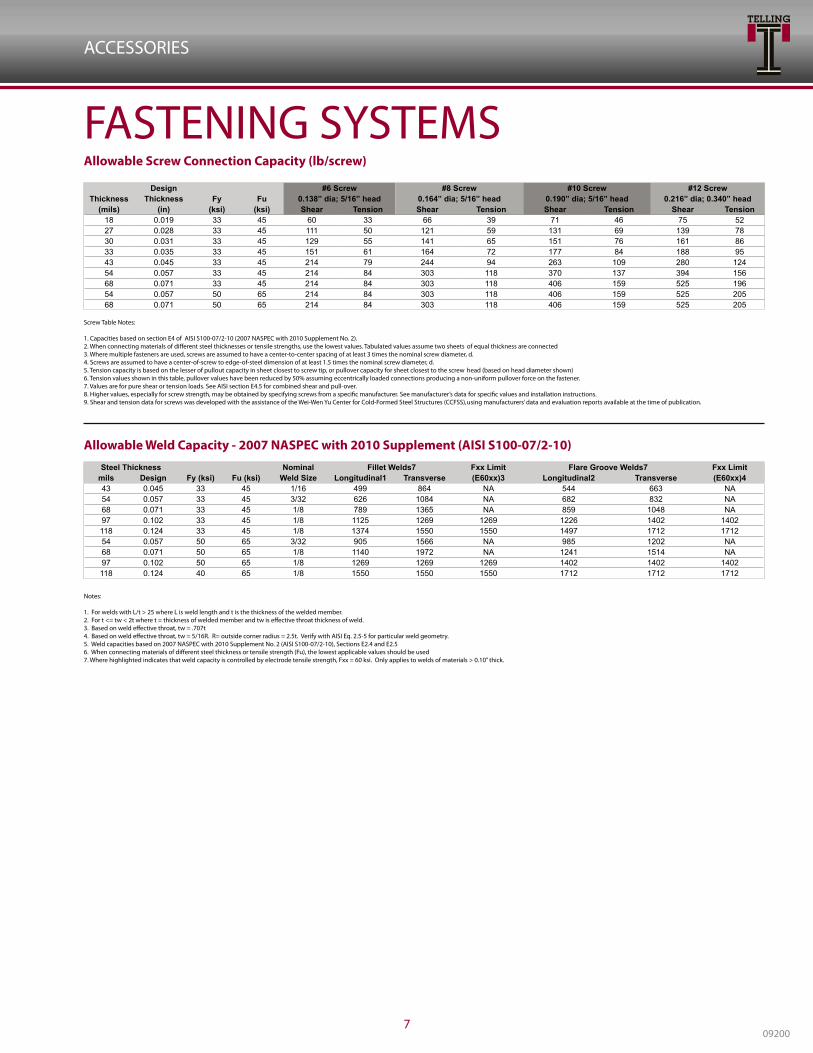
FASTENING SYSTEMSAllowable Screw Connection Capacity (lb/screw)
Allowable Weld Capacity - 2007 NASPEC with 2010 Supplement (AISI S100-07/2-10)
Design #6 Screw #8 Screw #10 Screw #12 ScrewThickness Thickness Fy Fu 0.138” dia; 5/16” head 0.164” dia; 5/16” head 0.190” dia; 5/16” head 0.216” dia; 0.340” head
(mils) (in) (ksi) (ksi) Shear Tension Shear Tension Shear Tension Shear Tension18 0.019 33 45 60 33 66 39 71 46 75 5227 0.028 33 45 111 50 121 59 131 69 139 7830 0.031 33 45 129 55 141 65 151 76 161 8633 0.035 33 45 151 61 164 72 177 84 188 9543 0.045 33 45 214 79 244 94 263 109 280 12454 0.057 33 45 214 84 303 118 370 137 394 15668 0.071 33 45 214 84 303 118 406 159 525 19654 0.057 50 65 214 84 303 118 406 159 525 20568 0.071 50 65 214 84 303 118 406 159 525 205
Screw Table Notes: 1. Capacities based on section E4 of AISI S100-07/2-10 (2007 NASPEC with 2010 Supplement No. 2). 2. When connecting materials of different steel thicknesses or tensile strengths, use the lowest values. Tabulated values assume two sheets of equal thickness are connected 3. Where multiple fasteners are used, screws are assumed to have a center-to-center spacing of at least 3 times the nominal screw diameter, d.4. Screws are assumed to have a center-of-screw to edge-of-steel dimension of at least 1.5 times the nominal screw diameter, d.5. Tension capacity is based on the lesser of pullout capacity in sheet closest to screw tip, or pullover capacity for sheet closest to the screw head (based on head diameter shown)6. Tension values shown in this table, pullover values have been reduced by 50% assuming eccentrically loaded connections producing a non-uniform pullover force on the fastener.7. Values are for pure shear or tension loads. See AISI section E4.5 for combined shear and pull-over.8. Higher values, especially for screw strength, may be obtained by specifying screws from a specific manufacturer. See manufacturer’s data for specific values and installation instructions.9. Shear and tension data for screws was developed with the assistance of the Wei-Wen Yu Center for Cold-Formed Steel Structures (CCFSS), using manufacturers’ data and evaluation reports available at the time of publication.
Notes: 1. For welds with L/t > 25 where L is weld length and t is the thickness of the welded member.2. For t <= tw < 2t where t = thickness of welded member and tw is effective throat thickness of weld.3. Based on weld effective throat, tw = .707t4. Based on weld effective throat, tw = 5/16R. R= outside corner radius = 2.5t. Verify with AISI Eq. 2.5-5 for particular weld geometry.5. Weld capacities based on 2007 NASPEC with 2010 Supplement No. 2 (AISI S100-07/2-10), Sections E2.4 and E2.56. When connecting materials of different steel thickness or tensile strength (Fu), the lowest applicable values should be used7. Where highlighted indicates that weld capacity is controlled by electrode tensile strength, Fxx = 60 ksi. Only applies to welds of materials > 0.10” thick.
Steel Thickness Nominal Fillet Welds7 Fxx Limit Flare Groove Welds7 Fxx Limitmils Design Fy (ksi) Fu (ksi) Weld Size Longitudinal1 Transverse (E60xx)3 Longitudinal2 Transverse (E60xx)443 0.045 33 45 1/16 499 864 NA 544 663 NA54 0.057 33 45 3/32 626 1084 NA 682 832 NA68 0.071 33 45 1/8 789 1365 NA 859 1048 NA97 0.102 33 45 1/8 1125 1269 1269 1226 1402 1402118 0.124 33 45 1/8 1374 1550 1550 1497 1712 171254 0.057 50 65 3/32 905 1566 NA 985 1202 NA68 0.071 50 65 1/8 1140 1972 NA 1241 1514 NA97 0.102 50 65 1/8 1269 1269 1269 1402 1402 1402118 0.124 40 65 1/8 1550 1550 1550 1712 1712 1712

BUILDSTRONG
www.BUILDSTRONG.com8
ALLOWABLE WORKING VALUES FOR LOW VELOCITY FASTENERS INTO STEEL (POUNDS)
1. Holding values shown are for fastenings that have the entire pointed end of the fastener driven through the steel plate.2. Holding values shown incorporate a 10 to 1 safety factor for tension and a 5 to 1 safety factor for shear. Wood or steel connecting members must be investigated separately.
Values are suggested only. In structural or load bearing applications, always consult a professional design engineer for proper use of fasteners
1. Except as noted, values shown reflect an 8 to 1 safety factor2. Values shown are for concrete at the designated strength and are for the fastener or clip system only. Wood, Steel, etc. connected members must be investigated separately.3. Cyclic, fatigue or shock loads and other design criteria may require a different safety factor.4. Job-site testing may be required to determine actual job-site values.* 10 to 1 safety factor used due to shallow embedment.** Interpolated values.
CatalogNumberSeries
ShankDiameter(inches
Typeof
Shank
Min.Edge
Distance
Min.Spacing
Base Steel Thickness ( inches )
3/16 1/4 3/8
Tension Shear Tension Shear Tension Shear
1500, 1600& 1900
Series Shank Drive Pins
.140 Smooth 1/2 1 130 665 270 700 370 840
Ladd ceilingSystem
Drive Pins.152 Smooth 3/4 1-1/2 137 NA 133 NA 132 NA
3300 SeriesDrive Pins
.170 Smooth 5/8 1-1/8 85 820 180 895 330 900
9140KThreaded Stud
.205 Knurled 3/4 1-3/8 NA NA 480 1565 550 1950
CatalogNumber
Serie
ShankDiameter(inches
PenetrationMin.Edge
Distance
Min.Spacing
Concrete Compressive Strength (psi)
2000 3000 4000
Tension Shear Tension Shear Tension Shear
1506SM1508SM
Step Shank Drive Pin
.1303/41
1-1/4
333
333
55*112200
60*87
118
49**87**134**
45**99**152**
44*6268
30*112187
1500, 1600& 1900 SeriesStraight Shank
Drive Pins
.140
3/41
1-1/41-1/2
3333
3333
45*110130187
80*165190200
70*175180
227**
115*185215
223**
90*235230268
145*205240247
1524, 1524SDDrive Pins
.1521
1-1/433
33
105115
150170
150162
215225
197220
262280
3300 SeriesDrive Pins
.1701-1/41-1/2
33
44
165220
225330
185225
225315
210225
280300
9100 SeriesThreaded
Studs.205
13/161-1/161-1/41-1/2
3333
5555
80115165300
125265315375
90150230310
145250330420
105190295320
170230350460
9100 SeriesThreaded
Studs.140 1-1/8 3 NA - - 96 180 98 193
ALLOWABLE WORKING VALUES FOR LOW VELOCITY FASTENERS INTO STONE AGGREGATE CONCRETE (POUNDS)

Telling® IndustriesCorporate Headquarters4420 Sherwin RoadWilloughby, OH 44094Phone: 440-974-3370Toll Free: 866-FRAME-TI(372-6384)FFax: 440-974-3408 E-mail: [email protected]
Telling® IndustriesMidwest Facility2105 Larrick RoadCambridge, OH 43725Phone: 740-435-8900Toll Free: 866-35STUDS (357-8837)FFax: 740-435-8915E-mail: [email protected]
Telling® IndustriesMidsouth Facility1400 Southwire DriveOsceola, AR 72370Phone: 870-563-6065Toll Free: 888-711-3124FFax: 870-563-2471 E-mail: [email protected]
This technical information reflects the most current information available and supersedes any and all previous publicationseffective January 1, 2016.
Telling® IndustriesNortheast Facility1050 Kennedy RoadWindsor, CT 06095Toll Free: 866-372-6384Fax: 440-974-3408 E-mail:E-mail: [email protected]