Acute health effects after exposure to chlorine gas released after a train derailment
Upload
khangminh22Category
view
1download
0
539
LOW
NOx
Gas train accessoriesSeal control kit
To test the valve seals on the gas train, a special “seal control kit” is available. The valve seal control device is compulsory (EN 676) on gas trains to burners with a maxi-mum output over 1200 kW. The seal control is type VPS 504.
GAS TRAIN KIT CODE
for 50 Hz operation KIT CODE
for 60 Hz operation
u M C 1 t e 3010367 20029057
u C 1 t e 3010367 20029057
RLS 500÷1200/M SERIESLow NOx Modulating Dual Fuel Burners


541
LOW
NOx
The RLS/E-EV MX series of burners covers a firing range from 350 to 1840 kW, and they have been designed for use in low or medium temperature hot water boilers, hot air or steam boilers, diathermic oil boilers.They are equipped with Siemens LMV26, which is able to manage the air-fuel ratio by independent servomotors in order to obtain a perfect output control and to assure a correct combustion and safe operation on all modulation range. Operation can be “two stage progressive” or, alternatively, “modulating” with the installation of a PID logic regulator and respective probes. RLS/E-EV MX burners series guarantees high efficiency levels in all the various applications, thus reducing fuel consumption and running costs. The RLS/E-EV MX models, are available to operate with aria le S ee ri e technolog base on the control of a
Frequency Inverter that modifies the air flow through the motor speed variation.Optimisation of sound emissions is guaranteed by the special design of the air suction circuit and by incor orate soun roo ing aterial.
S M 200/350 ÷ 860 kWS 120 M 300/600 ÷ 1200 kWS 1 0 M 300/930 ÷ 1840 kW
FIRING RATES
Low NOx Modulating Dual Fuel Burners
RLS/E-EV MX SERIES
Useful working fieldfor choosing theburner
Modulation range
Test conditionsconforming to EN267- EN676 Temperature: 20°CPressure: 1013,5 mbarAltitude: 0 m a.s.l.
S
S 120S 1 0

542
A
D
B C
F - F(1)E
O - O(1)
L
N
V
M
I
H
G*-G(1)*
(1) Length with extended combustion head.* Maximum depth of the boiler door including the depth of the burner flange insulating gasket.
BURNER - BOILER MOUNTING FLANGE
MODEL A B C D E F - F(1) G* - G(1)* H I L M N O - O (1) V
u S M 691 296 395 555 840 260 - 395 200 - 335 189 430 214 2” 134 1161 - 1300 221
u S 120 M 733 338 395 555 840 260 - 395 200 - 335 189 430 214 2” 134 1161 - 1300 221
u S 1 0 M 843 366 477 555 863 373 - 503 272 - 402 221 430 237 2” 141 1442 - 1589 186
MODEL D1 D2 Ø
u S 120 M 195 275 - 325 M12
u S 1 0 M 230 325 - 368 M16
(1) Length with standard and extended combustion head.
MODEL X (1) Y Z kg
u S M 1400 975 645 70
u S 120 M 1400 975 645 76
u S 1 0 M 1400 975 645 95
PACKAGING
Z
XY
RLS/E-EV MX SERIES
BURNER
Overall dimensions (mm)
Low NOx Modulating Dual Fuel Burners

543
LOW
NOx
EXTENDED DESIGNATION
S 1 0 M TC S1 3 230 00 0 230 0
Series : R
Fuel : S Natural gas
L Light oil
LS Light oil / Natural gas
N Heavy oil
Size
Operation : /1 One stage
... Two stage
/M Modulating
/E Electronic cam
/P Proportioning air/gas valve
/EV Electronic cam predisposed for variable speed (with inverter)
Emission : ... Class 1 EN267 - EN676
MZ Class 2 EN267 - EN676
BLU Class 3 EN267 - EN676
MX
Class 2 EN267
Class 3 EN676
Head : TC Standard head
TL Extended head
Flame control system :
FS1 Standard (1 stop every 24 h)
FS2 Continuous working (1 stop every 72 h)
Electrical supply to the system :
1/230/50 1/230V/50Hz
3/230/50 3/230V/50Hz
3/400/50 3N/400V/50Hz
3/230-400/50 3/230V/50Hz - 3N/400V/50Hz
3/220/60 3/220V/60Hz
3/380/60 3N/380V/60Hz
3/220-380/60 3/220V/60Hz - 3N/380V/60Hz
Auxiliary voltage :
230/50-60 230V/50-60Hz
110/50-60 110V/50-60Hz
ID : Differential switch
BASIC DESIGNATION
RLS/E-EV MX SERIES
DESIGNATION OF SERIES
Specification
Low NOx Modulating Dual Fuel Burners

544
STATE OF SUPPLY
Specification
Monoblock forced draught Low NOx dual fuel burner with two stage progressive or modulating operation at the gas and oil side, with a specific kit, fully automatic, made up of:- Microprocessor-based Digital Burner Management System (Electronic Cam) - Display Interface operating unit to adjust the system- air suction circuit lined with sound-proofing material- centrifugal fan with high performance and low sound emissions- air damper for air flow setting, butterfly valve for regulating gas output and oil modulator for oil output controlled by
a servomotors- starting motor at 2800 rpm, three-phase 400V with neutral, 50Hz - low emission combustion head, that can be set on the basis of required output, fitted with: - stainless steel end cone, resistant to corrosion and high temperatures - ignition electrodes - gas distributor - flame stability disk- maximum gas pressure switch to stop the burner in the case of excess pressure on the fuel supply line- minimum air pressure switch stops the burner in case of insufficient air quantity at the combustion head- gears pump for high pressure fuel supply - pump starting motor- Valve unit with a double oil safety valve on the output circuit and a double safety valve on the return circuit- Safety oil pressure switch- burner safety control box- UV photocell for flame detection- burner on/off selection switch- manual or automatic output increase/decrease selection switch- Oil/Gas selector- flame inspection window- slide bars for easier installation and maintenance- protection filter against radio interference- IP 44 electric protection level.
Stan ar e ui ent- 1 gas train flange- 1 flange gasket- 4 screws for fixing the flange- 1 thermal screen- 4 screws for fixing the burner flange to the boiler- 2 flexible pipes for connection to the oil supply network- 2 nipples for connection to the pump with gaskets- Instruction handbook for installation, use and maintenance- Spare parts catalogue.
RLS/E-EV MX SERIESLow NOx Modulating Dual Fuel Burners

545
LOW
NOx
SpecificationBurners
Available models
Net calorific value light oil: 11,8 kWh/kg; 10.200 kcal/kg - Viscosity at 20°C: 4-6 mm2/s (cSt).Net calorific value G20 gas: 10 kWh/Nm3; 8.600 kcal/Nm3 - Density: 0,71 kg/Nm3.The burners of RLS/E-EV MX series are in according to 2009/142 - 2004/108 - 2006/95 - EC Directive and EN 267 - 676 Norm.
CODE MODEL HEAT OUTPUT TOTALELECTRICAL POWER
CERTIFICATION NOTE
LIGHT OIL NATURAL GAS
(kW) (kg/h) (Nm3/h) (kW)
on demand RLS 68/E MX TC FS1 3/230-400/50 230/50-60 200/350-860 17/30-73 27/40-100 2,2 in progress
on demand RLS 68/EV MX TL FS1 3/230-400/50 230/50-60 200/350-860 17/30-73 27/40-100 2,2 in progress
on demand RLS 68/E MX TC FS2 3/230-400/50 230/50-60 200/350-860 17/30-73 27/40-100 2,2 in progress
on demand RLS 68/EV MX TL FS2 3/230-400/50 230/50-60 200/350-860 17/30-73 27/40-100 2,2 in progress
on demand RLS 120/E MX TC FS1 3/230-400/50 230/50-60 300/600-1200 25/50-101 37/70-140 3,0 in progress
on demand RLS 120/EV MX TL FS1 3/230-400/50 230/50-60 300/600-1200 25/50-101 37/70-140 3,0 in progress
on demand RLS 120/E MX TC FS2 3/230-400/50 230/50-60 300/600-1200 25/50-101 37/70-140 3,0 in progress
on demand RLS 120/EV MX TL FS2 3/230-400/50 230/50-60 300/600-1200 25/50-101 37/70-140 3,0 in progress
on demand RLS 160/E MX TC FS1 3/400/50 230/50-60 300/930-1840 25/78-155 30/93-184 6,0 in progress
on demand RLS 160/EV MX TC FS1 3/230/50 230/50-60 300/930-1840 25/78-155 30/93-184 6,0 in progress
on demand RLS 160/E MX TL FS1 3/400/50 230/50-60 300/930-1840 25/78-155 30/93-184 6,0 in progress
on demand RLS 160/EV MX TL FS1 3/230/50 230/50-60 300/930-1840 25/78-155 30/93-184 6,0 in progress
on demand RLS 160/E MX TC FS2 3/400/50 230/50-60 300/930-1840 25/78-155 30/93-184 6,0 in progress
on demand RLS 160/EV MX TC FS2 3/230/50 230/50-60 300/930-1840 25/78-155 30/93-184 6,0 in progress
on demand RLS 160/E MX TL FS2 3/400/50 230/50-60 300/930-1840 25/78-155 30/93-184 6,0 in progress
on demand RLS 160/EV MX TL FS2 3/230/50 230/50-60 300/930-1840 25/78-155 30/93-184 6,0 in progress
RLS/E-EV MX SERIESLow NOx Modulating Dual Fuel Burners

546
Gas Trains
RLS/E-EV MX SERIESLow NOx Modulating Dual Fuel Burners
Available models
Please see designation of Gas Train Series in the page before the Catalogue index.* 230V/50Hz -220V/60Hz electrical supply.** 230V/50Hz electrical supply.The valve seal control device is compulsory (conforming to EN 676) on gas trains to burners with a maximum output over 1200 kW.To select the gas train please refer to the technical data leaflet and/or instruction manual.C.T. Gas valve leak detection control device: - gas train not equipped with leak detection control device; this device can be ordered separately - see VPS column - and installed later.VPS Valve leak detection control device. Supplied separately from the gas train (please see Gas train accessories paragraph for both 50 Hz and 60 Hz codes).l Not available.
GAS TRAIN ADAPTER CODE
CODE MODEL Ø RLS 68 RLS 120 RLS 160
3970599* MB 407/1 - RT 52 Rp ¾”
3000824+ 3000843
l l
3970553* MB 407/1 - RT 20 Rp ¾” l l
3970229* MB 407/1 - RSM 20 Rp ¾” l l
3970258* MB 410/1 - RT 52 Rp 1” ¼ 3010126 l
3970554* MB 410/1 - RT 20 Rp ¾”
3000824+ 3000843
l
3970600* MB 410/1 - RT 52 Rp ¾” l
3970230* MB 410/1 - RSM 20 Rp ¾” l
3970256* MB 412/1 - RT 52 Rp 1” ½
3000843
3970144* MB 412/1 - RT 20 Rp 1” ½3970197** MB 412/1 CT RT 20 Rp 1” ½3970231* MB 412/1 - RSM 20 Rp 1” ½3970180* MB 415/1 - RT 30 Rp 1” ½3970198** MB 415/1 CT RT 30 Rp 1” ½3970250* MB 415/1 - RT 52 Rp 1” ½3970253** MB 415/1 CT RT 52 Rp 1” ½3970232* MB 415/1 - RSM 30 Rp 1” ½3970181* MB 420/1 - RT 30 Rp 2” - - -3970182** MB 420/1 CT RT 30 Rp 2” - - -3970257* MB 420/1 - RT 52 Rp 2” - - -3970252** MB 420/1 CT RT 52 Rp 2” - - -3970233* MB 420/1 - RSM 30 Rp 2” - - -3970234** MB 420/1 CT RSM 30 Rp 2” - - -3970221* MBC 1200/1 - RSM 60 Rp 2” - - -
3970225** MBC 1200/1 CT RSM 60 Rp 2” - - -3970222* MBC 1900/1 - FSM 40 DN 65
30008253970226** MBC 1900/1 CT FSM 40 DN 653970223* MBC 3100/1 - FSM 40 DN 80
30008263970227** MBC 3100/1 CT FSM 40 DN 803970145* CB 512/1 - RSM 30 Rp 1” ½
300084320045589** CB 512/1 CT RSM 30 Rp 1” ½
3970146* CB 520/1 - RSM 30 Rp 2” - - -3970160** CB 520/1 CT RSM 30 Rp 2” - - -20044659* CB 525/1 - RSM 30 Rp 2” - - -20044660** CB 525/1 CT RSM 30 Rp 2” - - -
3970147* CB 5065/1 - FSM 30 DN 653000825
3970161** CB 5065/1 CT FSM 30 DN 653970148* CB 5080/1 - FSM 30 DN 80
30008263970162** CB 5080/1 CT FSM 30 DN 803970148* CB 50100/1 - FSM 30 DN 100
3010370 + 30008263970162** CB 50100/1 CT FSM 30 DN 100
3970148* CB 50125/1 - FSM 30 DN 125 l3010224 + 3000826
3970162** CB 50125/1 CT FSM 30 DN 125 l

547
LOW
NOx
Nozzles type 60° BThe nozzles must be ordered separately. The following table shows the features and codes on the basis of the maximum required fuel output.
NOTE: each burner needs N° 1 nozzle.
Burner accessories
RLS/E-EV MX SERIESLow NOx Modulating Dual Fuel Burners
BURNER RATED OUTPUT kg/h A3 NOZZLE CODE A4 NOZZLE CODE
u S M 40 3009853 20067277
u S M 50 3009854 20067279
u S M 60 3009855 20067281
u S M 70 3009856 20067283
u S M 80 3009857 20067284
u S M 90 3009858 20067285
u S M 100 3009859 20067286
u S M 110 3009860 20067287
u S M 120 3009861 20067288
u S M 130 3009862 20067289
u S M 140 3009863 20067290
u S M 150 20059496* 20067290
u S M 160 3009864 20067293
u S M 180 3009865 20067295
u S M 200 3009866 20067297
* 60° Angle

548
If burner head penetration into the combustion chamber needs reducing, varying thickness spacers are available, as given in the following table:
Spacer kit
BURNER
SPACER THICKNESS S (mm)
KIT CODE
u S M 102 3000722
Continuous ventilation kit
BURNER KIT CODE
u S M 3010094
If the burner requires continuous ventilation in the stages without flame, a special kit is available as given in the following table.
C
If noise emission needs reducing even further, sound-proofing boxes are available.In case of generator heights, where a lower dimension “B” is required, ask for the Box Support Kit code 20065135.
Sound proofing box
BURNER
BOX TYPE
A(mm)
B (mm)min-max
C(mm)
[dB(A)] (*)
BOX CODE
u S 120 1 0 M C4/5 850 160 - 980 110 10 3010404
(*) Average noise reduction according to EN 15036-1 standard
Extended head kit“Standard head” burners can be transformed into “extended head” versions, by using the special kit. The kits available for the various burners, giving the original and the extended lengths, are listed below.
BURNER STANDARD HEADLENGTH (mm)
EXTENDED HEADLENGTH (mm)
KIT CODE
u S 120 M 260 395 3010360
u S 1 0 M 373 503 3010441 *
* Kit to be used on burners recognizable by a serial number that is over or equal to 02426XXXXXX, for burners with a serial number that is under or equal to 02416XXXXXX please use the Kit coded 3010340
Burner accessories
RLS/E-EV MX SERIESLow NOx Modulating Dual Fuel Burners
Variable Speed Drive (VSD) for RLS/EV series onlyThe motor speed variation for the RLS/EV BLU burners series is obtained thanks to a frequency converter: variable speed drive (VSD).
BURNER MAX POWER (kW) KIT CODE
u S 1,5 20063532
u S 120 3,0 20063533
u S 1 0 200 5,5 20062679

549
LOW
NOx
Burner accessoriesAccessories for modulating operation
To obtain modulating operation, the RLS/E-EV MX series of burners requires a regulator with three point outlet controls. The following table lists the accessories for modulat-ing operation with their application range.
BURNER
REGULATOR TYPE
REGULATOR CODE
u S M RWF 40 3010414
The relative temperature or pressure probes fitted to the regulator must be chosen on the basis of the application.
BURNER PROBE TYPE RANGE (°C) (bar) PROBE CODE
u S M Temperature PT 100 -100 ÷ 500°C 3010110
u S M Pressure 4 ÷ 20 mA 0 ÷ 2,5 bar 3010213
u S M Pressure 4 ÷ 20 mA 0 ÷ 16 bar 3010214
u S M Pressure 4 ÷ 20 mA 0 ÷ 25 bar 3090873
Head kit for “reverse flame chamber”
In certain cases, the use of the burner on reverse flame boilers can be improved by using an additional Pipes Kit.
BURNER KIT CODE
u S M 20006401
u S 120 M 20006402
u S 1 0 M 3010249
RLS/E-EV MX SERIESLow NOx Modulating Dual Fuel Burners
OCI412 interface kitInterface kit between the LMV 26 and a Modbus system, such as a building automation and control system (BACS).The Modbus interface is based on the RS-485 standard.
BURNER KIT CODE
u ll o els 3010437
OCI410 interface for ACS410 software kitInterface kit between burner management system and PC. It facilitates viewing, han-dling and recording setting parameters on site.
BURNER KIT CODE
u ll o els 3010436

550
Gas train accessories
RLS/E-EV MX SERIESLow NOx Modulating Dual Fuel Burners
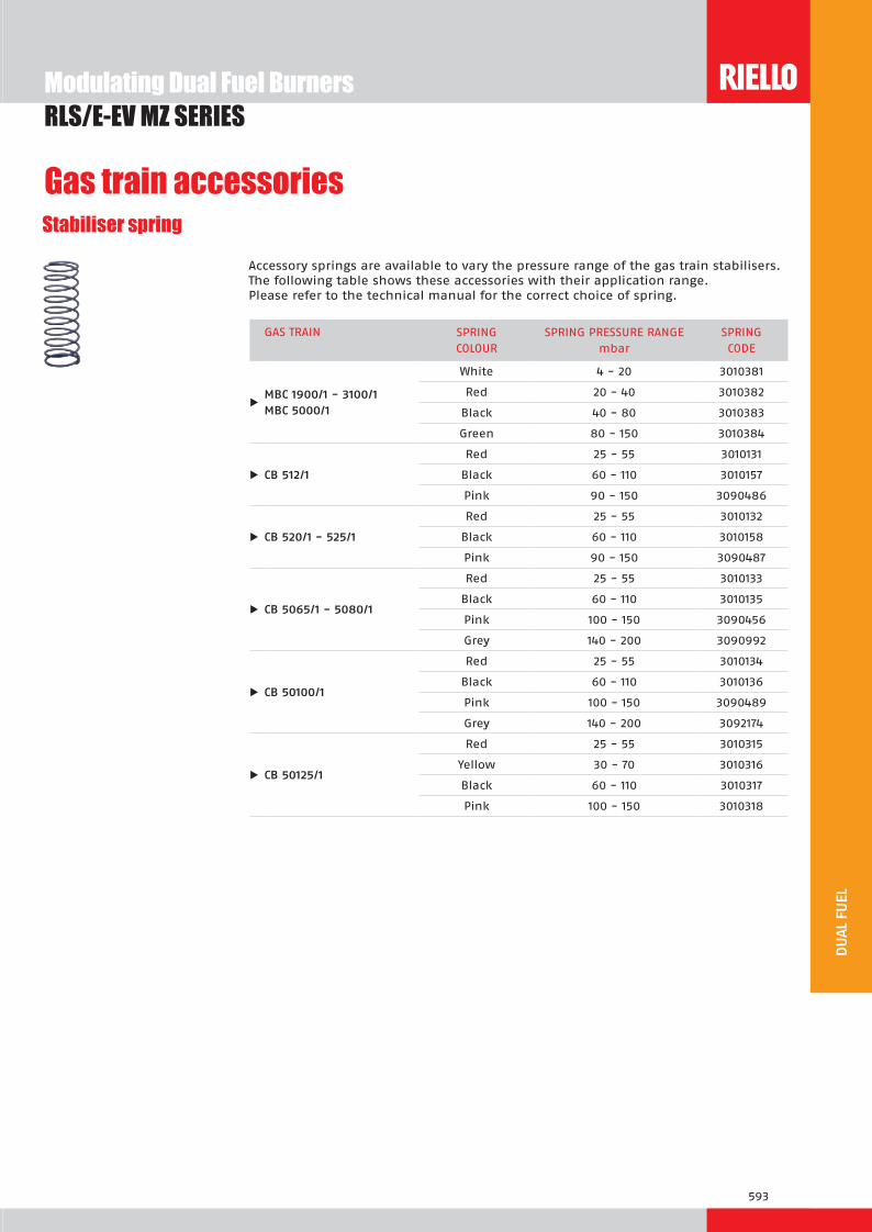
Stabiliser springAccessory springs are available to vary the pressure range of the gas train stabilisers. The following table shows these accessories with their application range.Please refer to the technical manual for the correct choice of spring.
GAS TRAIN SPRINGCOLOUR
SPRING PRESSURE RANGE mbar
SPRINGCODE
u M C 1 00 1 3100 1
White 4 - 20 3010381
Red 20 - 40 3010382Black 40 - 80 3010383Green 80 - 150 3010384
u C 12 1Red 25 - 55 3010131
Black 60 - 110 3010157Pink 90 - 150 3090486
u C 20 1 2 1Red 25 - 55 3010132
Black 60 - 110 3010158Pink 90 - 150 3090487
u C 0 1 0 0 1
Red 25 - 55 3010133
Black 60 - 110 3010135Pink 100 - 150 3090456Grey 140 - 200 3090992
AdaptersWhen the diameter of the gas train is different from the set diameter of the burners, an adapter must be fitted between the gas train and the burner.Below are given the available adapters; please see on the Gas Train list the correct adapter codes to select.
ADAPTER LENGTH mm
ADAPTER CODE
1” 1/23/4” 31 3000824
2” 1/2
DN 65
1” 1/2
2”
2” 1/2
300 3000825
2” 1/2DN 80 2” 300 3000826
2”1” 1/2 35 3000843
2”1” 1/4 35 3010126

551
LOW
NOx
RLS 300÷1200/E-EV SERIESRLS/E-EV series burners are characterised by a modular monoblock structure that means all necessary components can be combined in a single unit thus making installation easier, faster and, above all, more flexible.The series covers a firing range from 1250 to 11500 kW, and they have been designed for use in hot water boilers, overheated water boilers as well as steam boilers. Operation can be “two stage progressive” or alternatively “modulating” for both fuels, ligth oil and gas, with the installation of a PID logic regulator on the RLS 300÷800/E series burners while RLS/EV and RLS 1000-1200/E series is fully “modulating”. The burner can, therefore, supply with precision the demanded power, guaranteeing an high efficiency system level and the stability setting, obtaining fuel consumption and operating costs reduction.The innovative combustion head, adjustment system ensures perfect movement during modulation as well as reducing noise and pollutants.
S 300 M 600/1250 ÷ 3550 kWS 00 M 800/1800 ÷ 4300 kWS 00 M 1120/2500 ÷ 5050 kWS 0 M 1430/3000 ÷ 6550 kWS 00 M 1750/3500 ÷ 8000 kWS 300 M 600/1250 ÷ 3550 kWS 00 M 800/1800 ÷ 4300 kWS 00 M 1120/2500 ÷ 5050 kWS 0 M 1430/3000 ÷ 6550 kWS 00 M 1750/3500 ÷ 8000 kWS 1000 C13 1200/3750 ÷ 10600 kWS 1200 C13 1500/5500 ÷ 11500 kWS 1000 C13 1200/3750 ÷ 10600 kWS 1200 C13 1500/5500 ÷ 11500 kW
Low NOx Modulating Dual Fuel Burners

552
FIRING RATES
Useful working fieldfor choosing theburner
Modulation range
Test conditionsconforming to EN267- EN676 Temperature: 20°CPressure: 1013,5 mbarAltitude: 0 m a.s.l.
RLS 500/E-EV MX
RLS 800/E-EV MX
RLS 650/E-EV MX
RLS 300-1200/E-EV SERIESLow NOx Modulating Dual Fuel Burners
RLS 1000/E-EVRLS 1200/E-EV

553
LOW
NOx
BURNER
Overall dimensions (mm)
BURNER - BOILER MOUNTING FLANGE
MODEL A D E F G* H I M N O P Q S
u S 300 M 720 890 1325 508 365 313 605 DN80 164 1055 342 320 1175
u S 00 M 775 890 1325 508 365 313 605 DN80 164 1055 342 320 1175
u S 00 M 815 890 1325 544 390 370 605 DN80 164 1055 342 320 1175
u S 0 M 880 950 1325 549 397 410 630 DN80 164 1055 427 320 1190
u S 00 M 940 937 1325 558 382 428 630 DN80 164 1055 427 320 1190
MODEL D1 D2 Ø
u S 300 M 350 452 M18
u S 00 M 350 452 M18
u S 00 M 390 452 M18
u S 0 M 440 495 M18
u S 00 M 440 495 M18
MODEL X Y Z kg
u S 300 M 1960 970 1100 280
u S 00 M 1960 970 1100 290
u S 00 M 1960 970 1100 300
u S 0 M 2190 1110 1450 320
u S 00 M 2190 1110 1450 320
PACKAGING
Z
XY
RLS 300-1200/E-EV SERIES
M
S
O
M
O
S
Q
Q
A
D
E
I
F
H
N
P
G*
Low NOx Modulating Dual Fuel Burners
* Maximum depth of the boiler door including the depth of the burner flange insulating gasket.

554
BURNER
Overall dimensions (mm)
RLS 300-1200/E-EV SERIESLow NOx Modulating Dual Fuel Burners
PACKAGING
BURNER - BOILER MOUNTING FLANGE
MODEL D1 D2 Ø
u S 1000 C13 460 608 M20
u S 1200 C13 500 608 M20
MODEL X Y Z kg
u S 1000 C13 2400 1400 1595 550
u S 1200 C13 2400 1400 1595 600
BURNER - BOILER MOUNTING FLANGE
Z
XY
* Maximum depth of the boiler door including the depth of the burner flange insulating gasket.
G*
H
IM
N
E F
A
D
S
O
O
MODEL A D E F G* H I M N O S
u S 1000 C13 1206 1338 1637 674 484 413 885 DN80 200 1350 1425
u S 1200 C13 1250 1338 1637 658 465 456 885 DN80 200 1350 1425

555
LOW
NOx
RLS 300-1200/E-EV SERIESLow NOx Modulating Dual Fuel Burners
DESIGNATION OF SERIES
Specification
BASIC DESIGNATION
EXTENDED DESIGNATION
S 1200 C13 TC S1 3 00 0 230 0 0
Series: R Fuel: S Natural Gas L Light oil LS Light oil/Natural Gas N Heavy oil
Size Setting: /1 Single stage /B Two stage /M Modulating - Mechanical cam /P Proportioning air/gas valve /E Electronic cam /EV Electronic cam predisposed for variable speed (with inverter) Emission: C11 or … Class 1 EN267 - EN676 C22 or MZ Class 2 EN267 - EN676 C33 or BLU Class 3 EN267 - EN676 C23 or MX Class 2 EN267 - Class 3 EN676 C13 Class 1 EN267 - Class 3 EN676 Head length: TC standard head TL extended head Flame control system: FS1 Standard (1 stop every 24 h) FS2 Continuous working (1 stop every 72 h) Electrical supply to the system: 1/230/50 1/230V/50Hz 3/230/50 3/230V/50Hz 3/400/50 3N/400V/50Hz 3/230-400/50 3/230V/50Hz - 3N/400V/50Hz 3/220/60 3/220V/60Hz 3/380/60 3N/380V/60Hz 3/220-380/60 3/220/60Hz - 3N/380V/60Hz
Auxiliary voltage: 230/50-60 230V/50-60Hz 110/50-60 110V/50-60Hz

556
STATE OF SUPPLY
Specification
Monoblock forced draught gas burner with modulating operation, fully automatic, made up of:- High performance fan with low sound emissions, reverse curve blades for RLS 300-400-1000-1200/E-EV, forward curve
blades for RLS 500-650-800/E-EV MX- Air suction circuit lined with sound-proofing material- Air damper for air setting controlled by a high precision servomotor- Air pressure switch- Fan starting motor at 2800 rpm, three-phase 230/400 - 400/690 V with neutral, 50Hz- Separate light oil pump - Low emission combustion head, that can be set on the basis of required output, fitted with: - stainless steel end cone, resistant to corrosion and high temperatures - ignition electrodes - ignition by gas pilot with gas train for RLS 650 and RLS 800-1000-1200 models - flame stability disk- Maximum gas pressure switch, with pressure test point, for halting the burner in the case of over pressure on the fuel
supply line- Digital Burner management system for air/fuel setting; with output PID modulation control included on RLS/EV models,
and RLS 1000-1200/E as accessory on RLS 300÷800/E MX models- AZL Display Interface, for combustion system commissioning and monitoring, included in RLS/EV and RLS 1000-1200/E
models (Available as accessory for RLS 300÷800/E BLU models)- Electronic cam for controlling the system safety- Infrared flame detector- Star/triangle starter for the fan motor (burners with motor electrical power ≥ 7,5 kW - RLS/E versions)- Main electrical supply terminal board- Burner on/off switch - Auxiliary voltage led signal- Burner working led signal- Contacts motor and thermal relay with release button- Motor internal thermal protection- Motor failure led signal - Burner failure led signal and lighted release button- Emergency button- Coded connection plugs-sockets- Burner opening hinge- Lifting rings- IP 54 electric protection level- Gears pump for high pressure fuel supply - Pump starting motor- Oil safety valves- Valve unit with double oil safety valve on the output circuit and double safety valve on the return circuit- Oil/Gas selector- Flame inspection window- The gas train can only enter from the right side of the burner- The RLS 1000-1200/E-/EV dual fuel burners are equipped with as spray lance for light oil, activated by compressed air.
Stan ar e ui ent- 1 flange gasket- 4 screws for fixing the flange- 1 thermal screen- 4 screws for fixing the burner flange to the boiler- 2 flexible pipes for connection to the oil supply network- 2 nipples for connection to the pump with gaskets- Seal control pressure switch (for installation on gas train)- Instruction handbook for installation, use and maintenance- Spare parts catalogue.
Low NOx Modulating Dual Fuel BurnersRLS 300-1200/E-EV SERIES

557
LOW
NOx
SpecificationBurners
Available models
Net calorific value light oil: 11,8 kWh/kg; 10.200 kcal/kg - Viscosity at 20°C: 4-6 mm2/s (cSt).Net calorific value G20 gas: 10 kWh/Nm3; 8.600 kcal/Nm3 - Density: 0,71 kg/Nm3.(1) according to 2009/142 - 2004/108 - 2006/95 - EC Directive and EN 267 - 676 Norm.(2) the burners are factory set for FS1 operation (1 stop every 24 h) but they can be switched to FS2 operation (continuous - 1 stop every 72 h) by changing the parameters
through the AZL unit menu.(3) according to 2009/142 EC - 2006/95 - 2004/108 - EC Directive and EN 267 - 676 Norm.
CODE MODEL HEAT OUTPUT TOTALELECTRICAL POWER
CERTIFICATION NOTE
LIGHT OIL NATURAL GAS
(kW) (kg/h) (Nm3/h) (kW)
3898530 RLS 300/E MX TC FS1 3/400/50 230/50-60 600/1250-3550 50/105-300 60/125-355 7,5 CE 0085BR0471 (1)(2)
3898632 RLS 400/E MX TC FS1 3/400/50 230/50-60 800/1800-4300 67/152-363 80/180-430 11,5 CE 0085BR0472 (1)(2)
3899632 RLS 500/E MX TC FS1 3/400/50 230/50-60 1120/2500-5050 95/211-426 112/250-505 15 (oil)13 (gas)
CE 0085CL0207 (1)(2)
20026857 RLS 650/E MX TC FS1 3/400/50 230/50-60 1430/3000-6550 121/253-552 143/300-655 23,5 (oil)19,5 (gas)
CE 0085CL0422 (2)(3)
3911132 RLS 800/E MX TC FS1 3/400/50 230/50-60 1750/3500-8000 148/295-675 175/350-800 26 (oil)24 (gas)
CE 0085CL0422 (1)(2)
20057529 RLS 1000/E C13 TC FS1 3/400/50 230/50-60 1200/3750-10600 110/320-793 130/380-940 26 (oil)23 (gas)
CE 0085CN0119 (1)
20057530 RLS 1200/E C13 TC FS1 3/400/50 230/50-60 1500/5500-11500 126/464-970 150/550-1150 31 (oil)27 (gas)
CE 0085CN0120 (1)
20022571 RLS 300/EV MX TC FS1 3/400/50 230/50-60 600/1250-3550 50/105-300 60/125-355 7,5 CE 0085BR0471 (1)(2)
20022570 RLS 400/EV MX TC FS1 3/400/50 230/50-60 800/1800-4300 67/152-363 80/180-430 11,5 CE 0085BR0472 (1)(2)
20005681 RLS 500/EV MX TC FS1 3/400/50 230/50-60 1120/2500-5050 95/211-426 112/250-505 15 (oil)13 (gas)
CE 0085CL0207 (1)(2)
20026959 RLS 650/EV MX TC FS1 3/400/50 230/50-60 1430/3000-6550 121/253-552 143/300-655 23,5 (oil)19,5 (gas)
CE 0085CL0422 (2)(3)
20011318 RLS 800/EV MX TC FS1 3/400/50 230/50-60 1750/3500-8000 148/295-675 175/350-800 26 (oil)24 (gas)
CE 0085CL0422 (1)(2)
20051416 RLS 1000/EV C13 TC FS1 3/400/50 230/50-60 1200/3750-10600 110/320-793 130/380-940 26 (oil)23 (gas)
CE 0085CN0119 (1)
20047475 RLS 1200/EV C13 TC FS1 3/400/50 230/50-60 1500/5500-11500 126/464-970 150/550-1150 31 (oil)27 (gas)
CE 0085CN0120 (1)
Low NOx Modulating Dual Fuel BurnersRLS 300-1200/E-EV SERIES

558
Gas Trains
Please see designation of Gas Train Series in the page before the Catalogue index.* gas train are 230V/50Hz - 220V/60Hz electrical supply. The valve seal control device is compulsory (conforming to EN 676) on gas trains to burners with a maximum output over 1200 kW.The seal control function is managed by LMV control box, by installation on gas train of pressure switch supplied, as standard equipment, with the burner.To select the gas train please refer to the technical data leaflet and/or instruction manual.l Not available.(1) To use if it is necessary to space out the gas train from the burner.
Available models
Low NOx Modulating Dual Fuel BurnersRLS 300-1200/E-EV SERIES
GAS TRAIN ADAPTER CODE
CODE* MODEL Ø RLS 300 RLS 400 RLS 500 RLS 650 RLS 800 RLS 1000 RLS 1200
3970250 MB 415/1 - RT 52 Rp 1” ½3000843 + 3000826 + 20064220
l l l l l l
3970257 MB 420/1 - RT 52 Rp 2”3000826 + 20042324
l l l l l l
3970221 MBC 1200/1 - RSM 60 Rp 2” 3000826 + 200423243970222 MBC 1900/1 - FSM 40 DN 65 3010221 - 30103693970223 MBC 3100/1 - FSM 40 DN 80 3010222 (1)3970224 MBC 5000/1 - FSM 80 DN 100 3010223 - 3010370
3970145 CB 512/1 - RSM 30 Rp 1” ½3000843 + 3000826 +
20064220l l l l l
3970146 CB 520/1 - RSM 30 Rp 2” 3000826 + 20042324 l l l l
20044659 CB 525/1 - RSM 30 Rp 2” 3000826 + 20042324 l l
3970147 CB 5065/1 - FSM 30 DN 65 3010221 - 3010369 l
3970148 CB 5080/1 - FSM 30 DN 80 3010222 (1)3970149 CB 50100/1 - FSM 30 DN 100 3010223 - 301037020015871 CB 50125/1 - FSM 30 DN 125 3010224

559
LOW
NOx
RLS 300-1200/E-EV SERIES
NozzlesThe nozzles must be ordered separately. The following table shows the features and codes on the basis of the maximum required fuel output.
Burner accessories
BURNER RATED DELIVERY (kg/h) NOZZLE CODE
u S 300 00 M 150 3009363
u S 300 00 M 200 3009364
u S 300 00 M 225 3009365
u S 300 00 M 250 3009366
u S 300 00 M 275 3009367
u S 300 00 M 300 3009368
u S 00 M 325 3009369
u S 00 M 350 3009370
u S 00 M 375 3009371
u S 00 M 400 3009372
u S 00 M 425 3009373
u S 00 M 350 3045495
u S 00 M 400 3045499
u S 00 M 450 3045501
u S 00 M 500 3045503
u S 0 M 350 3045495
u S 0 M 450 3045501
u S 0 M 550 3045505
u S 0 M 600 3045507
u S 00 M 375 3009332
u S 00 M 550 3009346
u S 00 M 650 3009352
u S 00 M 750 3009356
u S 1000 M 350 20047954
u S 1000 M 600 20047978
u S 1000 M 750 20047985
u S 1000 M 900 20047994
u S 1200 M 700 20006479
u S 1200 M 700 20006479
u S 1200 M 900 20006482
u S 1200 M 1100 20006484
Low NOx Modulating Dual Fuel BurnersRLS 300-1200/E-EV SERIES
For more information please contact Riello Burners Commercial and Technical Depart-ment, our Application Engineers will be pleased to help you.

560
Accessories for modulating operationTo obtain modulating operation, the RLS/E MX series of burners requires a regulator.In RLS/EV models PID regulator is integrated inside LMV 52 control box.
BURNER
REGULATOR TYPE REGULATOR CODE
uS 300 00 00 0
00 M RWF 40 Basic version with 3 position output 3010356
uS 300 00 00 0
00 MRWF 40 High version with additional modulating output and RS 485 Interface
3010357
The relative temperature or pressure probes fitted to the regulator, must be chosen on the basis of the application.
BURNER PROBE TYPE RANGE (°C) (bar) PROBE CODE
u ll o els
Temperature PT 100 -100 ÷ 500°C 3010110
Pressure 4 ÷ 20 mA 0 ÷ 2,5 bar 3010213
Pressure 4 ÷ 20 mA 0 ÷ 16 bar 3010214
Pressure 4 ÷ 20 mA 0 ÷ 25 bar 3090873
The QGO2 is an oxygen analizer with relevant probe which controls and supervises the residual oxygen content in exhaust gases.
Oxygen Control kit (QGO2)
BURNER KIT CODE
u ll o els 3010378
u ll o els 20045187 *
Low NOx Modulating Dual Fuel Burners
Variable Speed Drive (VSD) for RLS/EV series only
The motor speed variation for the RLS/EV burners series is obtained thanks to a fre-quency converter: variable speed drive (VSD). It always must be ordered with RLS/EV series.
BURNER MAX POWER (kW) KIT CODE
u S 300 00 7.5 20028307
u S 00 15 3090960
u S 0 18.5 3091174
u S 00 1000 22 3090913
u S 1200 30 20030338
Burner accessories
RLS 300-1200/E-EV SERIES
* Installation outside the burner cover

561
LOW
NOx
Burner accessories
Low NOx Modulating Dual Fuel BurnersRLS 300-1200/E-EV SERIES
This tool is needed for combustion system commissioning and monitoring. The AZL, Display and Operating Unit, is included in RLS 1000-1200/E and RLS/EV models.
Display and Operating Unit (AZL)
BURNER KIT CODE
u S 300 00 00 0 00 M 3010355
u ll o els 3010469
* for Russian language only
Kit efficiency with oxygen control kit (for RLS/EV only)
The kit includes two temperature sensors: one for air and one for exhaust gas detec-tion. They must be wired to oxygen control kit interface to allow the LMV 52 efficiency calculation. The value is showed on AZL display.
BURNER KIT CODE
u S 300 00 00 0 00 3010377 (*)
u S 1000 1200 20041584
LPG kitFor burning LPG gas, a special kit is available to be fitted to the combustion head on the burner.
BURNER KIT CODE
u S 300 M 20039863 (*)
u S 00 M in progress
u S 00 0 00 M in progress
u S 1000 1200 C13 in progress
(*) Certification in progress, CE approval on field is required.
PC tool for convenient programming and burner settings, process visualization, data recording, selection of AZL language, software update AZL.
PC Interface Software (ACS 450)
BURNER KIT CODE
u ll o els 3010388
(*) Probe type PT 1000 - range -80°C + 600°C

562
BURNER SPACER THICKNESS S (mm)
KIT CODE
u S 300 00 00 0 00 180 20008903
Spacer kitIf burner head penetration into the combustion chamber needs reducing, varying thickness spacers are available, as given in the following table:
Low NOx Modulating Dual Fuel Burners
Gas train accessories
RLS 300-1200/E-EV SERIES
C
If noise emission needs reducing even further, sound-proofing boxes are available.In case of generator heights, where a lower dimension “B” is required, ask for the Box Support Kit code 20065135.
Sound proofing box
BURNER
BOX TYPE
A(mm)
B (mm)min-max
C(mm)
[dB(A)] (*)
BOX CODE
u S 300 00 00 0 00 C7 1255 160 - 980 110 10 3010376
u S 1000 1200 C8 1425 285 - 1000 110 10 3010401
(*) Average noise reduction according to EN 15036-1 standard
AdaptersIn certain cases, an adapter must be fitted between the gas train and the burner, when the diameter of the gas train is different from the set diameter of the burner.Below are given the available adapters; please see on the Gas Train list the correct adapter codes to select.
ADAPTER DIMENSIONS ADAPTER CODE
ØiDN
ØODN
Amm
Bmm
Cmm
Ø2Ø1
65 80 400 - - 301022180 80 400 - - 3010222100 80 400 - - 3010223125 80 320 - - 301022465 80 10 - - 3010369100 80 50 - - 3010370
2”1” 1/2 - - 35 - - 3000843
2” 1/2DN 80 2” - - 300 - - 3000826
2”1” 1/2 - - 65 - - 20064220
2”2” - - 65 - - 20042324
Burner accessories

563
LOW
NOx
Gas train accessoriesStabiliser spring
To vary the pressure range of the gas train stabilisers, accessory springs are available. The following table shows these accessories with their application range. Please refer to the technical manual for the correct choice of spring.
GAS TRAIN SPRINGCOLOUR
SPRING PRESSURE RANGE mbar
SPRINGCODE
uM C 1 00 1 3100 1M C 000 1
White 4 - 20 3010381
Red 20 - 40 3010382
Black 40 - 80 3010383
Green 80 - 150 3010384
u C 12 1
Red 25 - 55 3010131
Black 60 - 110 3010157
Pink 90 - 150 3090486
u C 20 1 2 1
Red 25 - 55 3010132
Black 60 - 110 3010158
Pink 90 - 150 3090487
u C 0 1 0 0 1
Red 25 - 55 3010133
Black 60 - 110 3010135
Pink 100 - 150 3090456
Grey 140 - 200 3090992
u C 0100 1
Red 25 - 55 3010134
Black 60 - 110 3010136
Pink 100 - 150 3090489
Grey 140 - 200 3092174
u C 012 1
Red 25 - 55 3010315
Yellow 30 - 70 3010316
Black 60 - 110 3010317
Pink 100 - 150 3010318
Low NOx Modulating Dual Fuel BurnersRLS 300-1200/E-EV SERIES


Two Stage Dual Fuel Burners
565
RLS SERIES
S 2 100/163 ÷ 325 kWS 3 116/232 ÷ 442 kWS 0 145/290 ÷ 581 kWS 0 232/465 ÷ 814 kWS 100 349/698 ÷ 1163 kWS 130 465/930 ÷ 1395 kW
The RLS series of burners covers a firing range from 163 to 1395 kW, and it has been designed for use in low or medium temperature hot water boilers, hot air or steam generators, diathermic oil boilers.Operation is “two stage”; the burners are fitted with an electronic device LED PANEL, which supplies a diagnostic of burner status. Optimisation of sound emissions is guaranteed by the use of fans with reverse curve blades and sound deadening material incorporated in the air suction circuit. The elevated performance of the fans and combustion head guarantee flexibility of use and excellent working at all firing rates.The exclusive design ensures reduced dimensions, simple use and maintenance. A wide range of accessories guarantees elevated working flexibility.
FIRING RATES
Useful working fieldfor choosing theburner
Modulation range
Test conditionsconforming to EN267- EN676 Temperature: 20°CPressure: 1013,5 mbarAltitude: 0 m a.s.l.

566
RLS 28 - 38 - 50 RLS 70 - 100 - 130
Model X Y Z kg
u S 2 1190 492 510 43
u S 3 1190 492 510 45
u S 0 1190 492 510 46
u S 0 1405 1000 660 70
u S 100 1405 1000 660 73
u S 130 1405 1000 660 76
Model D1 D2 Ø
u S 2 160 224 M8
u S 3 160 224 M8
u S 0 160 224 M8
u S 0 185 275-325 M12
u S 100 195 275-325 M12
u S 130 195 275-325 M12
BURNER - BOILER MOUNTING FLANGE
Z
XY
Model A B C D E F - F(1) H I L M N O - O(1) S V
u S 2 476 - - 474 580 191 - 326 140 352 164 1”1/2 108 810 - 810 367 168
u S 3 476 - - 474 580 201 - 336 152 352 164 1”1/2 108 810 - 810 367 168
u S 0 476 - - 474 580 216 - 351 152 352 164 1”1/2 108 810 - 810 367 168
u S 0 691 296 395 555 840 250 - 385 179 430 214 2” 134 1161 - 1361 - 221
u S 100 707 312 395 555 840 250 - 385 189 430 214 2” 134 1161 - 1361 - 221
u S 130 733 338 395 555 840 250 - 385 189 430 214 2” 134 1161 - 1361 - 221
(1) Length with extended combustion head
PACKAGING
RLS SERIES
BURNER
Overall dimensions (mm)
Two Stage Dual Fuel Burners

567
EXTENDED DESIGNATION
S 2 TC S1 3 230 00 0 230 0
Series : R
Fuel : S Natural gas
L Light oil
LS Light oil / Natural gas
N Heavy oil
Size
Operation : /1 One stage
... Two stage
/M Modulating
/E Electronic cam
/P Proportioning air/gas valve
/EV Electronic cam predisposed for variable speed (with inverter)
Emission : ... Class 1 EN267 - EN676
MZ Class 2 EN267 - EN676
BLU Class 3 EN267 - EN676
MX
Class 2 EN267
Class 3 EN676
Head : TC Standard head
TL Extended head
Diagnostic : LP Led panel
ST Status panel
Flame control system :
FS1 Standard (1 stop every 24 h)
FS2 Continuous working (1 stop every 72 h)
Electrical supply to the system :
1/230/50 1/230V/50Hz
3/230/50 3/230V/50Hz
3/400/50 3N/400V/50Hz
3/230-400/50 3/230V/50Hz - 3N/400V/50Hz
3/220/60 3/220V/60Hz
3/380/60 3N/380V/60Hz
3/220-380/60 3/220V/60Hz - 3N/380V/60Hz
Auxiliary voltage :
230/50-60 230V/50-60Hz
110/50-60 110V/50-60Hz
ID : Differential switch
BASIC DESIGNATION
RLS SERIES
DESIGNATION OF SERIES
Specification
Two Stage Dual Fuel Burners

568
RLS SERIESTwo Stage Dual Fuel Burners
SpecificationSTATE OF SUPPLY
Monobloc forced draught dual fuel burner, two stage operation, made up of:- Air suction circuit lined with sound-proofing material- Fan with reverse curve blades- Fan starting motor- Air damper for air setting controlled by a servomotor- Minimum air pressure switch- Combustion head, that can be set on the basis of required output - Gears pump for high pressure fuel supply - Pump starting motor- Oil safety valves- Two oil valves (1st and 2nd stage)- Burner safety control box - Electronic device to check all burners operational modes (Led Panel)- UV photocell for flame detection- Burner on/off switch- Oil/Gas selector- Manual 1st and 2nd stage switch- Plugs for electrical connections (RLS 28-38-50)- Flame inspection window- Slide bars for easier installation and maintenance- Protection filter against radio interference- IP 44 electric protection level.
Stan ar e ui ent- 1 gas train flange- 1 flange gasket- 4 screws for fixing the flange- 1 thermal screen- 4 screws for fixing the burner flange to the boiler- 2 flexible pipes for connection to the oil supply network- 2 nipples for connection to the pump with gaskets- Kit for transformation to LPG- Fairleads for electrical connections (for RLS 28-38-50 model)- Instruction handbook for installation, use and maintenance- Spare parts catalogue.
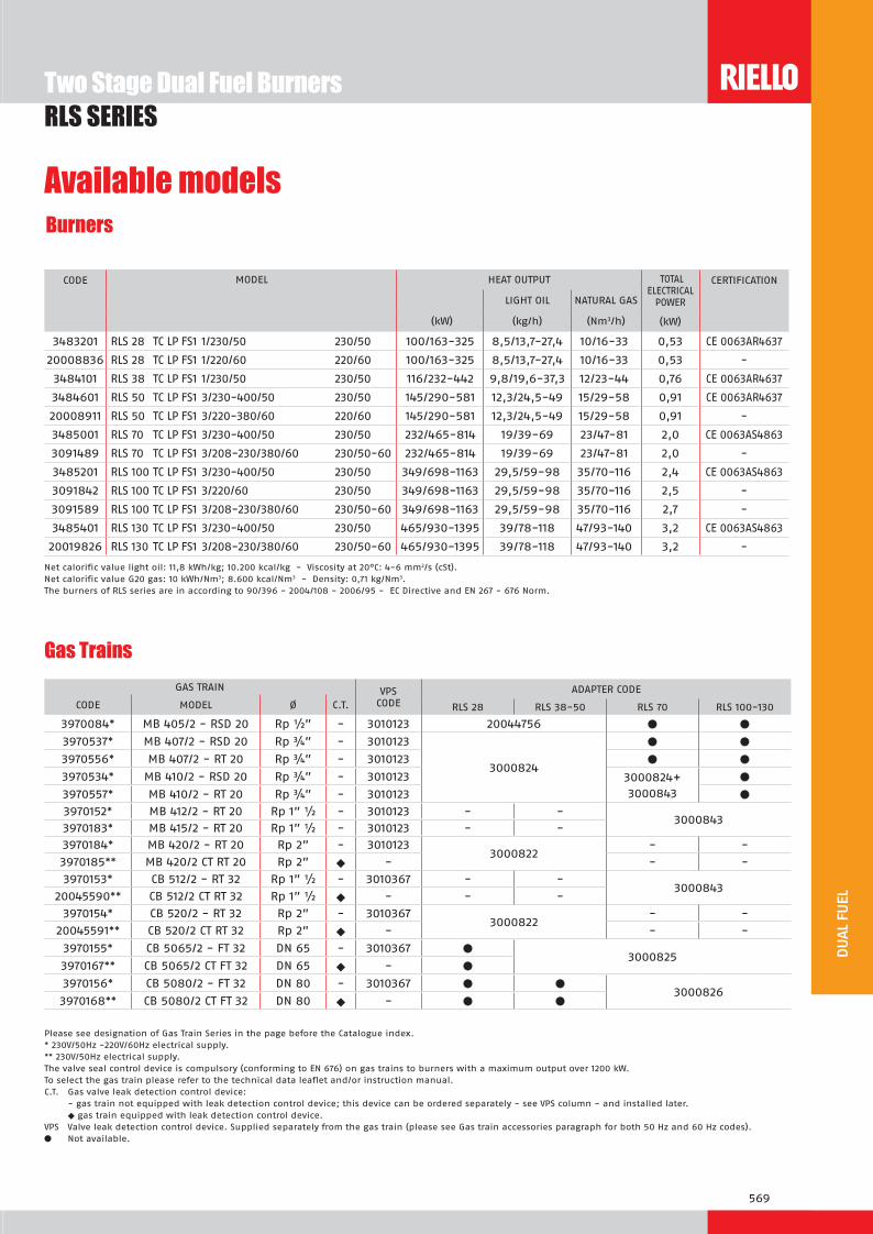
569
Burners
Available models
CODE MODEL
HEAT OUTPUT TOTAL ELECTRICAL
POWER
CERTIFICATION
LIGHT OIL NATURAL GAS
(kW) (kg/h) (Nm3/h) (kW)
3483201 RLS 28 TC LP FS1 1/230/50 230/50 100/163-325 8,5/13,7-27,4 10/16-33 0,53 CE 0063AR4637
20008836 RLS 28 TC LP FS1 1/220/60 220/60 100/163-325 8,5/13,7-27,4 10/16-33 0,53 -
3484101 RLS 38 TC LP FS1 1/230/50 230/50 116/232-442 9,8/19,6-37,3 12/23-44 0,76 CE 0063AR4637
3484601 RLS 50 TC LP FS1 3/230-400/50 230/50 145/290-581 12,3/24,5-49 15/29-58 0,91 CE 0063AR4637
20008911 RLS 50 TC LP FS1 3/220-380/60 220/60 145/290-581 12,3/24,5-49 15/29-58 0,91 -
3485001 RLS 70 TC LP FS1 3/230-400/50 230/50 232/465-814 19/39-69 23/47-81 2,0 CE 0063AS4863
3091489 RLS 70 TC LP FS1 3/208-230/380/60 230/50-60 232/465-814 19/39-69 23/47-81 2,0 -
3485201 RLS 100 TC LP FS1 3/230-400/50 230/50 349/698-1163 29,5/59-98 35/70-116 2,4 CE 0063AS4863
3091842 RLS 100 TC LP FS1 3/220/60 230/50 349/698-1163 29,5/59-98 35/70-116 2,5 -
3091589 RLS 100 TC LP FS1 3/208-230/380/60 230/50-60 349/698-1163 29,5/59-98 35/70-116 2,7 -
3485401 RLS 130 TC LP FS1 3/230-400/50 230/50 465/930-1395 39/78-118 47/93-140 3,2 CE 0063AS4863
20019826 RLS 130 TC LP FS1 3/208-230/380/60 230/50-60 465/930-1395 39/78-118 47/93-140 3,2 -
Net calorific value light oil: 11,8 kWh/kg; 10.200 kcal/kg - Viscosity at 20°C: 4-6 mm2/s (cSt).Net calorific value G20 gas: 10 kWh/Nm3; 8.600 kcal/Nm3 - Density: 0,71 kg/Nm3.The burners of RLS series are in according to 90/396 - 2004/108 - 2006/95 - EC Directive and EN 267 - 676 Norm.
Gas Trains
Please see designation of Gas Train Series in the page before the Catalogue index.* 230V/50Hz -220V/60Hz electrical supply.** 230V/50Hz electrical supply.The valve seal control device is compulsory (conforming to EN 676) on gas trains to burners with a maximum output over 1200 kW.To select the gas train please refer to the technical data leaflet and/or instruction manual.C.T. Gas valve leak detection control device: - gas train not equipped with leak detection control device; this device can be ordered separately - see VPS column - and installed later. u gas train equipped with leak detection control device.VPS Valve leak detection control device. Supplied separately from the gas train (please see Gas train accessories paragraph for both 50 Hz and 60 Hz codes).l Not available.
RLS SERIESTwo Stage Dual Fuel Burners
GAS TRAIN VPSCODE
ADAPTER CODE
CODE MODEL Ø C.T. RLS 28 RLS 38-50 RLS 70 RLS 100-130
3970084* MB 405/2 - RSD 20 Rp ½” - 3010123 20044756 l l
3970537* MB 407/2 - RSD 20 Rp ¾” - 3010123
3000824
l l
3970556* MB 407/2 - RT 20 Rp ¾” - 3010123 l l
3970534* MB 410/2 - RSD 20 Rp ¾” - 3010123 3000824+ 3000843
l
3970557* MB 410/2 - RT 20 Rp ¾” - 3010123 l
3970152* MB 412/2 - RT 20 Rp 1” ½ - 3010123 - -3000843
3970183* MB 415/2 - RT 20 Rp 1” ½ - 3010123 - -3970184* MB 420/2 - RT 20 Rp 2” - 3010123
3000822- -
3970185** MB 420/2 CT RT 20 Rp 2” u - - -
3970153* CB 512/2 - RT 32 Rp 1” ½ - 3010367 - -3000843
20045590** CB 512/2 CT RT 32 Rp 1” ½ u - - -
3970154* CB 520/2 - RT 32 Rp 2” - 30103673000822
- -
20045591** CB 520/2 CT RT 32 Rp 2” u - - -
3970155* CB 5065/2 - FT 32 DN 65 - 3010367 l3000825
3970167** CB 5065/2 CT FT 32 DN 65 u - l
3970156* CB 5080/2 - FT 32 DN 80 - 3010367 l l3000826
3970168** CB 5080/2 CT FT 32 DN 80 u - l l

570
Burner accessories
Connection flange kitA kit is available for use where the burner opening on the boiler is of excessive diam-eter.
BURNER KIT CODE
u S 2 3 0 3010138
Degasing unit
To solve problem of air in the oil sucked, two versions of degassing unit are available.
BURNER FILTER FILTERING
DEGREE (mm) DEGASING UNIT
CODE (*)
uS 2 3 0 S 0 100
With filter 50 - 75 3010055
uS 2 3 0S 0 100
Without filter - 3010054
(*) Max capability 80 kg/h (more filters are needed for higher flow).
For burning LPG gas, a dedicated kit is available with RLS dual fuel burners as standard equipment, if necessary it is available also as accessory as given in the following table:
LPG kit
BURNER
KIT CODE FOR“STANDARD HEAD”
KIT CODE FOR“EXTENDED HEAD”
u S 2 3 0 3010304 3010304
u S 0 100 130 3010305 3010305
Gas max pressure switch kitIf necessary a Gas max pressure Switch kit is available.
BURNER KIT CODE
u S 2 3 0 0 100 130 3010493
�� ��
��
�
����
����
��
��
���
C
If noise emission needs reducing even further, sound-proofing boxes are available.In case of generator heights, where a lower dimension “B” is required, ask for the Box Support Kit code 20065135.
Sound proofing box
BURNER
BOX TYPE
A(mm)
B (mm)min-max
C(mm)
[dB(A)] (*)
BOX CODE
u S 2 3 0 C1/3 650 372 - 980 110 10 3010403
u S 0 100 130 C4/5 850 160 - 980 110 10 3010404
(*) Average noise reduction according to EN 15036-1 standard
RLS SERIESTwo Stage Dual Fuel Burners

571
BURNER RATED DELIVERY (kg/h)at 12 bar
GPH NOZZLECODE
u S 2 8,5 2,00 3042126
u S 2 3 10,6 2,50 3042140
u S 2 3 0 12,7 3,00 3042158
u S 2 3 0 14,8 3,50 3042162
u S 3 0 17 4,00 3042172
u S 3 0 19,1 4,50 3042182
u S 3 0 0 21,2 5,00 3042192
u S 0 0 23,3 5,50 3042202
u S 0 0 25,5 6,00 3042212
u S 0 0 27,6 6,50 3042222
u S 0 100 29,7 7,00 3042232
u S 0 100 31,8 7,50 3042242
u S 0 100 33,9 8,00 3042252
u S 0 100 36,1 8,50 3042262
u S 0 100 130 40,3 9,50 3042282
u S 0 100 130 42,4 10,00 3042292
u S 0 100 130 46,7 11,00 3042312
u S 100 130 50,9 12,00 3042322
u S 100 130 55,1 13,00 3042332
u S 100 130 59,4 14,00 3042352
u S 100 130 63,6 15,00 3042362
u S 100 130 67,9 16,00 3042382
u S 130 72,1 17,00 3042392
The nozzles must be ordered separately. The following table shows the features and codes on the basis of the maximum required fuel output.
NOTE: each burner needs N° 2 nozzles.
Nozzles type 60° B
Extended head kit“Standard head” burners can be transformed into “extended head” versions, by using the special kit. The kits available for the various burners, giving the original and the extended lengths, are listed below.
BURNER STANDARD HEADLENGTH (mm)
EXTENDED HEADLENGTH (mm)
KIT CODE
u S 2 191 326 3010264
u S 3 201 336 3010265
u S 0 216 351 3010266
u S 0 250 385 3010345
u S 100 250 385 3010346
u S 130 250 385 3010347
Burner accessories
RLS SERIESTwo Stage Dual Fuel Burners

572
Gas train accessories
BURNER GAS TRAIN KIT CODE for 50 Hz operation
KIT CODE for 60 Hz operation
u S 2 MB 407/2 - MB 410/2 MB 412/2 - MB 415/2 - MB 420/2
3010123 20050030
CB 512/2 - CB 520/2 3010125 20050033
u S 3 MB 410/2 - MB 412/2 MB 415/2 - MB 420/2
3010123 20050030
CB 512/2 - CB 520/2 3010125 20050033
u S 0 MB 410/2 - MB 412/2 MB 415/2 - MB 420/2
3010123 20050030
CB 512/2 - CB 520/2 3010125 20050033
u S 0 MB 415/2 - MB 420/2 3010123 20050030
CB 512/2 - CB 520/2 - CB 5065/2 - CB 5080/2 3010125 20050033
u S 100MB 415/2 - MB 420/2 3010123 20050030
CB 512/2 - CB 520/2 - CB 5065/2 - CB 5080/2 3010125 20050033
u S 130MB 415/2 - MB 420/2 3010123 20050030
CB 512/2 - CB 520/2 - CB 5065/2 - CB 5080/2 3010125 20050033
Seal control kitTo test the valve seals on the gas train, a special “seal control kit” is available.
RLS SERIESTwo Stage Dual Fuel Burners
Continuous ventilation kit
BURNER KIT CODE
u S 1 0 M 2 0 M M 3010094
If the burner requires continuous ventilation in the stages without flame, a special kit is available as given in the following table.

573
Adapters
ADAPTER LENGTH mm
ADAPTER CODE
1” 1/22” 70 3000822
1” 1/23/4” 31 3000824
2” 1/2
DN 65
1” 1/2
2”
2” 1/2
300 3000825
2” 1/2DN 80 2” 300 3000826
2”1” 1/2 35 3000843
1” 1/21/2” 31 20044756
In certain cases, an adapter must be fitted between the gas train and the burner, when the diameter of the gas train is different from the set diameter of the burner.Below are given the available adapters; please see on the Gas Train list the correct adapter codes to select.
Gas train accessories
RLS SERIESTwo Stage Dual Fuel Burners
Stabiliser springAccessory springs are available to vary the pressure range of the gas train stabilisers.
GAS TRAIN SPRINGCOLOUR
SPRING PRESSURE RANGE mbar
SPRINGCODE
u C 12 2
Red 25 - 55 3010131
Black 60 - 110 3010157
Pink 90 - 150 3090486
u C 20 2
Red 25 - 55 3010132
Black 60 - 110 3010158
Pink 90 - 150 3090487
u C 0 2 0 0 2
Red 25 - 55 3010133
Black 60 - 110 3010135
Pink 100 - 150 3090456
Grey 140 - 200 3090992


575
Modulating Dual Fuel Burners
RLS/M MZ SERIESThe RLS/M MZ series of burners covers a firing range from 550 to 2460 kW, and they have been designed for use in hot or superheated water boilers, hot air or steam generators, diathermic oil boilers.Operation is “two stage” at the oil side and “modulating” at the gas side with the installation of a PID logic regulator and respective probes.RLS/M MZ series burners guarantees high efficiency levels in all the various applications, thus reducing fuel consumption and running costs.Optimisation of sound emissions is guaranteed by the special design of air suction circuit and the use of sound proofing material.The exclusive design ensures reduced dimensions, simple use and maintenance. A wide range of accessories guarantees elevated working flexibility.
S 1 0 M M 550/1100 ÷ 2150 kWS 2 0 M M 550/1230 ÷ 2460 kW
FIRING RATES
Useful working fieldfor choosing theburner
Modulation range
Test conditionsconforming to EN267- EN676 Temperature: 20°CPressure: 1013,5 mbarAltitude: 0 m a.s.l.

576
RLS/M MZ SERIESModulating Dual Fuel Burners
PACKAGING
Z
XY
MODEL A B C D E F - F (1) H I L M N O - O (1) V
u S 1 0 M M 843 366 477 555 863 412 - 542 222 430 237 Rp2 141 1442 - 1587 186
u S 2 0 M M 904 427 477 555 863 412 - 542 222 435 237 Rp2 141 1442 - 1587 186
(1) Length with extended combustion head.
Model D1 D2 Ø
u S 1 0 M M 230 325 - 368 M16
u S 2 0 M M 230 325 - 368 M16
Model X Y Z kg
u S 1 0 M M 1400 975 645 95
u S 2 0 M M 1400 1000 765 100
BURNER - BOILER MOUNTING FLANGE
BURNER
Overall dimensions (mm)

577
Modulating Dual Fuel BurnersRLS/M MZ SERIES
EXTENDED DESIGNATION
S 1 0 M M TC S1 3 230 00 0 230 0
Series : R
Fuel : S Natural gas
L Light oil
LS Light oil / Natural gas
N Heavy oil
Size
Operation : /1 One stage
... Two stage
/M Modulating
/E Electronic cam
/P Proportioning air/gas valve
/EV Electronic cam predisposed for variable speed (with inverter)
Emission : ... Class 1 EN267 - EN676
MZ Class 2 EN267 - EN676
BLU Class 3 EN267 - EN676
MX
Class 2 EN267
Class 3 EN676
Head : TC Standard head
TL Extended head
Flame control system :
FS1 Standard (1 stop every 24 h)
FS2 Continuous working (1 stop every 72 h)
Electrical supply to the system :
1/230/50 1/230V/50Hz
3/230/50 3/230V/50Hz
3/400/50 3N/400V/50Hz
3/230-400/50 3/230V/50Hz - 3N/400V/50Hz
3/220/60 3/220V/60Hz
3/380/60 3N/380V/60Hz
3/220-380/60 3/220V/60Hz - 3N/380V/60Hz
Auxiliary voltage :
230/50-60 230V/50-60Hz
110/50-60 110V/50-60Hz
ID : Differential switch
BASIC DESIGNATION
DESIGNATION OF SERIES
Specification
MODEL A B C D E F - F (1) H I L M N O - O (1) V
u S 1 0 M M 843 366 477 555 863 412 - 542 222 430 237 Rp2 141 1442 - 1587 186
u S 2 0 M M 904 427 477 555 863 412 - 542 222 435 237 Rp2 141 1442 - 1587 186

578
RLS/M MZ SERIESModulating Dual Fuel Burners
SpecificationSTATE OF SUPPLY
Monoblock forced draught dual fuel burner with two stage operation at the oil side and two stage progressive or modulating operation at the gas side, with a specific kit, fully automatic, made up of:- air suction circuit lined with sound-proofing material- centrifugal fan with high performance and low sound emissions- air damper for air flow setting and butterfly valve for regulating gas output controlled by a servomotor with variable
cam- starting motor at 2800 rpm, three-phase 400V with neutral, 50Hz - low emission combustion head, that can be set on the basis of required output, fitted with: - stainless steel end cone, resistant to corrosion and high temperatures - ignition electrodes - gas distributor - flame stability disk- maximum gas pressure switch to stop the burner in the case of excess pressure on the fuel supply line- minimum air pressure switch stops the burner in case of insufficient air quantity at the combustion head- gears pump for high pressure fuel supply - pump starting motor- oil safety valves- two oil valves (1st and 2nd stage)- burner safety control box- UV photocell for flame detection- burner on/off selection switch- manual or automatic output increase/decrease selection switch- Oil/Gas selector- flame inspection window- slide bars for easier installation and maintenance- protection filter against radio interference- IP 44 electric protection level.
Stan ar e ui ent- 1 gas train flange- 1 flange gasket- 4 screws for fixing the flange- 1 thermal screen- 4 screws for fixing the burner flange to the boiler- 2 flexible pipes for connection to the oil supply network- 2 nipples for connection to the pump with gaskets- Instruction handbook for installation, use and maintenance- Spare parts catalogue.

579
Modulating Dual Fuel BurnersRLS/M MZ SERIES
Burners
Available models
CODE MODEL
HEAT OUTPUT TOTAL ELECTRICAL
POWER
CERTIFICATION NOTE
LIGHT OIL NATURAL GAS
(kW) (kg/h) (Nm3/h) (kW)
3488110 RLS 190/M MZ TC FS1 3/400/50 230/50-60 550/1100-2150 46/93-181 55/110-215 6,0 CE 0085BP0439
20011625 RLS 190/M MZ TC FS1 3/230/50 230/50-60 550/1100-2150 46/93-181 55/110-215 6,0 CE 0085BP0439
3482810 RLS 250/M MZ TC FS1 3/400/50 230/50-60 550/1230-2460 46/104-208 55/123-246 7,5 (oil)6,0 (gas) CE 0085CM0153
20004704 RLS 250/M MZ TC FS1 3/230/50 230/50-60 550/1100-2150 46/93-181 55/110-215 7,5 (oil)6,0 (gas) CE 0085CM0153
Net calorific value light oil: 11,8 kWh/kg; 10.200 kcal/kg - Viscosity at 20°C: 4-6 mm2/s (cSt).Net calorific value G20 gas: 10 kWh/Nm3; 8.600 kcal/Nm3 - Density: 0,71 kg/Nm3.The burners of RLS/M MZ series are in according to 90/396 - 2004/108 - 2006/95 - EC Directive and EN 267 - 676 Norm.
580
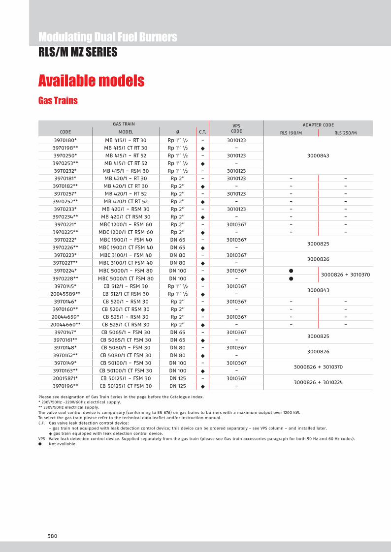
Gas Trains
Please see designation of Gas Train Series in the page before the Catalogue index.* 230V/50Hz -220V/60Hz electrical supply.** 230V/50Hz electrical supply.The valve seal control device is compulsory (conforming to EN 676) on gas trains to burners with a maximum output over 1200 kW.To select the gas train please refer to the technical data leaflet and/or instruction manual.C.T. Gas valve leak detection control device: - gas train not equipped with leak detection control device; this device can be ordered separately - see VPS column - and installed later. u gas train equipped with leak detection control device.VPS Valve leak detection control device. Supplied separately from the gas train (please see Gas train accessories paragraph for both 50 Hz and 60 Hz codes).l Not available.
RLS/M MZ SERIESModulating Dual Fuel Burners
Available models
GAS TRAIN VPSCODE
ADAPTER CODE
CODE MODEL Ø C.T. RLS 190/M RLS 250/M
3970180* MB 415/1 - RT 30 Rp 1” ½ - 3010123
3000843
3970198** MB 415/1 CT RT 30 Rp 1” ½ u -
3970250* MB 415/1 - RT 52 Rp 1” ½ - 3010123
3970253** MB 415/1 CT RT 52 Rp 1” ½ u -
3970232* MB 415/1 - RSM 30 Rp 1” ½ - 30101233970181* MB 420/1 - RT 30 Rp 2” - 3010123 - -
3970182** MB 420/1 CT RT 30 Rp 2” u - - -
3970257* MB 420/1 - RT 52 Rp 2” - 3010123 - -
3970252** MB 420/1 CT RT 52 Rp 2” u - - -
3970233* MB 420/1 - RSM 30 Rp 2” - 3010123 - -
3970234** MB 420/1 CT RSM 30 Rp 2” u - - -
3970221* MBC 1200/1 - RSM 60 Rp 2” - 3010367 - -
3970225** MBC 1200/1 CT RSM 60 Rp 2” u - - -
3970222* MBC 1900/1 - FSM 40 DN 65 - 30103673000825
3970226** MBC 1900/1 CT FSM 40 DN 65 u -
3970223* MBC 3100/1 - FSM 40 DN 80 - 30103673000826
3970227** MBC 3100/1 CT FSM 40 DN 80 u -
3970224* MBC 5000/1 - FSM 80 DN 100 - 3010367 l3000826 + 3010370
3970228** MBC 5000/1 CT FSM 80 DN 100 u - l
3970145* CB 512/1 - RSM 30 Rp 1” ½ - 30103673000843
20045589** CB 512/1 CT RSM 30 Rp 1” ½ u -
3970146* CB 520/1 - RSM 30 Rp 2” - 3010367 - -
3970160** CB 520/1 CT RSM 30 Rp 2” u - - -
20044659* CB 525/1 - RSM 30 Rp 2” - 3010367 - -
20044660** CB 525/1 CT RSM 30 Rp 2” u - - -
3970147* CB 5065/1 - FSM 30 DN 65 - 30103673000825
3970161** CB 5065/1 CT FSM 30 DN 65 u -
3970148* CB 5080/1 - FSM 30 DN 80 - 30103673000826
3970162** CB 5080/1 CT FSM 30 DN 80 u -
3970149* CB 50100/1 - FSM 30 DN 100 - 30103673000826 + 3010370
3970163** CB 50100/1 CT FSM 30 DN 100 u -
20015871* CB 50125/1 - FSM 30 DN 125 - 30103673000826 + 3010224
3970196** CB 50125/1 CT FSM 30 DN 125 u -

581
RLS/M MZ SERIESModulating Dual Fuel Burners
Nozzles type 60° B
Burner accessories
Extended head kit“Standard head” burners can be transformed into “extended head” versions, by using the special kit. The kits available for the various burners, giving the original and the extended lengths, are listed below.
The nozzles must be ordered separately. The following table shows the features and codes on the basis of the maximum required fuel output.
NOTE: each burner needs N° 2 nozzles.
(*) Nozzle rated delivery is reffered to atomized pressure
BURNER RATED DELIVERY kg/h (*) GPH NOZZLE
u S 1 0 M M 42,4 10,00 3042292
46,7 11,00 3042312
uS 1 0 M MS 2 0 M M
48,37 12,00 3042322
52,79 13,00 3042332
56,86 14,00 3042352
60,92 15,00 3042362
64,98 16,00 3042382
69,04 17,00 3042392
73,10 18,00 3042412
77,16 19,00 3042422
81,22 20,00 3042442
89,34 22,00 3042462
97,47 24,00 3042472
101,53 26,00 3042482
105,59 28,00 20018051
u S 2 0 M M
122 30,00 3042502
130,1 32,00 3042512
142,1 35,00 3042522
BURNER STANDARD HEADLENGTH (mm)
EXTENDED HEADLENGTH (mm)
KIT CODE
u S 1 0 M M 412 542 3010440 *
u S 2 0 M M 412 542 20029376
For burning LPG gas, a special kit is available to be fitted to the combustion head on the burner, as given in the following table:
LPG kit
BURNER
KIT CODE FOR“STANDARD HEAD” (*)
KIT CODE FOR“EXTENDED HEAD” (*)
u S 1 0 M M 3091796 3091796
u S 2 0 M M in progress in progress
(*) Without CE certification
* Kit to be used on burners recognizable by a serial number that is over or equal to 02426XXXXXX, for burners with a serial number that is under or equal to 02416XXXXXX please use the Kit coded 3010366

582
Modulating Dual Fuel BurnersRLS/M MZ SERIES
If burner head penetration into the combustion chamber needs reducing, varying thickness spacers are available, as given in the following table.
Spacer kit
BURNER
SPACER THICKNESS S (mm)
KIT CODE
u S 1 0 M 2 0 M M 102 3000722
Continuous ventilation kit
BURNER KIT CODE
u S 1 0 M 2 0 M M 3010094
If the burner requires continuous ventilation in the stages without flame, a special kit is available as given in the following table.
Accessories for modulating operationTo obtain modulating operation, the RLS/M MZ series of burners requires a regulator with three point outlet controls. The following table lists the accessories for modulat-ing operation with their application range.
BURNER TYPE CODE
u S 1 0 M 2 0 M M RWF 40 3010414
TYPE RANGE (°C) (bar) CODE
Temperature PT 100 -100 ÷ 500°C 3010110
Pressure 4 ÷ 20 mA 0 ÷ 2,5 bar 3010213
Pressure 4 ÷ 20 mA 0 ÷ 16 bar 3010214
Pressure 4 ÷ 20 mA 0 ÷ 25 bar 3090873
The relative temperature or pressure probes fitted to the regulator must be chosen on the basis of the application.
REGULATOR
PROBE
BURNER TYPE (INPUT SIGNAL) CODE
u S 1 0 M 2 0 M M0/2 - 10 V (impedance 200 KW) 0/4 - 20 mA (impedance 250 W)
3010415
ANALOG CONTROL SIGNAL CONVERTER
BURNER KIT CODE
u S 1 0 M 2 0 M M 3010416
POTENTIOMETER KIT Depending on the servomotor fitted to the burner, a three-pole potentiometer (1000 W) can be installed to check the position of the servomotor. The KITS available for the various burners are listed below.
Burner accessories

583
C
RLS/M MZ SERIESModulating Dual Fuel Burners
Adapters
Gas train accessories
Burner accessories
If noise emission needs reducing even further, sound-proofing boxes are available.In case of generator heights, where a lower dimension “B” is required, ask for the Box Support Kit code 20065135.
Sound proofing box
BURNER
BOX TYPE
A(mm)
B (mm)min-max
C(mm)
[dB(A)] (*)
BOX CODE
u S 1 0 2 0 M M C4/5 850 160 - 980 110 10 3010404
(*) Average noise reduction according to EN 15036-1 standard
In certain cases, an adapter must be fitted between the gas train and the burner, when the diameter of the gas train is different from the set diameter of the burner.Below are given the available adapters; please see on the Gas Train list the correct adapter codes to select.
ADAPTER LENGTH mm
ADAPTER CODE
2” 1/2
DN 65
1” 1/2
2”
2” 1/2
300 3000825
2” 1/2DN 80 2” 300 3000826
2”1” 1/2 35 3000843
DN 80DN 100 50 3010370
320 3010224
RLS/M MZ SERIES

584
Gas train accessories
Stabiliser springAccessory springs are available to vary the pressure range of the gas train stabilisers. The following table shows these accessories with their application range.Please refer to the technical manual for the correct choice of spring.
Modulating Dual Fuel BurnersRLS/M MZ SERIES
GAS TRAIN SPRINGCOLOUR
SPRING PRESSURE RANGE mbar
SPRINGCODE
uM C 1 00 1 3100 1M C 000 1
White 4 - 20 3010381
Red 20 - 40 3010382
Black 40 - 80 3010383
Green 80 - 150 3010384
u C 12 1
Red 25 - 55 3010131
Black 60 - 110 3010157
Pink 90 - 150 3090486
u C 20 1 2 1
Red 25 - 55 3010132
Black 60 - 110 3010158
Pink 90 - 150 3090487
u C 0 1 0 0 1
Red 25 - 55 3010133
Black 60 - 110 3010135
Pink 100 - 150 3090456
Grey 140 - 200 3090992
u C 0100 1
Red 25 - 55 3010134
Black 60 - 110 3010136
Pink 100 - 150 3090489
Grey 140 - 200 3092174
u C 012 1
Red 25 - 55 3010315
Yellow 30 - 70 3010316
Black 60 - 110 3010317
Pink 100 - 150 3010318
Seal control kitTo test the valve seals on the gas train, a special “seal control kit” is available. The valve seal control device is compulsory (EN 676) on gas trains to burners with a maxi-mum output over 1200 kW. The seal control is type VPS 504.
GAS TRAIN KIT CODE
for 50 Hz operation KIT CODE
for 60 Hz operation
u M 1 t e 3010123 20050030
u M C 1 t e 3010367 20029057
u C 1 t e 3010367 20029057

585
Modulating Dual Fuel Burners
RLS/E-EV MZ SERIESThe RLS/E-EV MZ series of burners covers a firing range from 550 to 2460 kW, and they have been designed for use in hot or superheated water boilers, hot air or steam generators, diathermic oil boilers.They are equipped with Siemens LMV26, which is able to manage the air-fuel ratio by independent servomotors in order to obtain a perfect output control and to assure a correct combustion and safe operation on all modulation range. Operation can be “two stage progressive” or, alternatively, “modulating” with the installation of a PID logic regulator and respective probes. RLS/E-EV MZ burners series guarantees high efficiency levels in all the various applications, thus reducing fuel consumption and running costs. The RLS/E-EV MZ models, are available to operate with aria le S ee ri e technolog base on the control of a
Frequency Inverter that modifies the air flow through the motor speed variation.Optimisation of sound emissions is guaranteed by the special design of the air suction circuit and by incor orate soun roo ing aterial.
S 2 0 M 550/1230 ÷ 2460 kW
FIRING RATES
Useful working fieldfor choosing theburner
Modulation range
Test conditionsconforming to EN267- EN676 Temperature: 20°CPressure: 1013,5 mbarAltitude: 0 m a.s.l.
RLS 250/E-EV MZ
RLS/M MZ SERIES

586
RLS/E-EV MZ SERIESModulating Dual Fuel Burners
PACKAGING
Z
XY
MODEL A B C D E F - F (1) H I L M N O - O (1) V
u S 2 0 M 904 427 477 555 863 412 - 542 222 435 237 Rp2 141 1442 - 1587 186
(1) Length with extended combustion head.
Model D1 D2 Ø
u S 2 0 M 230 325 - 368 M16
Model X Y Z kg
u S 2 0 M 1400 1000 765 100
BURNER - BOILER MOUNTING FLANGE
BURNER
Overall dimensions (mm)

587
Modulating Dual Fuel BurnersRLS/E-EV MZ SERIES
EXTENDED DESIGNATION
S 2 0 M TC S1 3 230 00 0 230 0
Series : R
Fuel : S Natural gas
L Light oil
LS Light oil / Natural gas
N Heavy oil
Size
Operation : /1 One stage
... Two stage
/M Modulating
/E Electronic cam
/P Proportioning air/gas valve
/EV Electronic cam predisposed for variable speed (with inverter)
Emission : ... Class 1 EN267 - EN676
MZ Class 2 EN267 - EN676
BLU Class 3 EN267 - EN676
MX
Class 2 EN267
Class 3 EN676
Head : TC Standard head
TL Extended head
Flame control system :
FS1 Standard (1 stop every 24 h)
FS2 Continuous working (1 stop every 72 h)
Electrical supply to the system :
1/230/50 1/230V/50Hz
3/230/50 3/230V/50Hz
3/400/50 3N/400V/50Hz
3/230-400/50 3/230V/50Hz - 3N/400V/50Hz
3/220/60 3/220V/60Hz
3/380/60 3N/380V/60Hz
3/220-380/60 3/220V/60Hz - 3N/380V/60Hz
Auxiliary voltage :
230/50-60 230V/50-60Hz
110/50-60 110V/50-60Hz
ID : Differential switch
BASIC DESIGNATION
DESIGNATION OF SERIES
Specification
MODEL A B C D E F - F (1) H I L M N O - O (1) V
u S 2 0 M 904 427 477 555 863 412 - 542 222 435 237 Rp2 141 1442 - 1587 186
588
RLS/E-EV MZ SERIESModulating Dual Fuel Burners
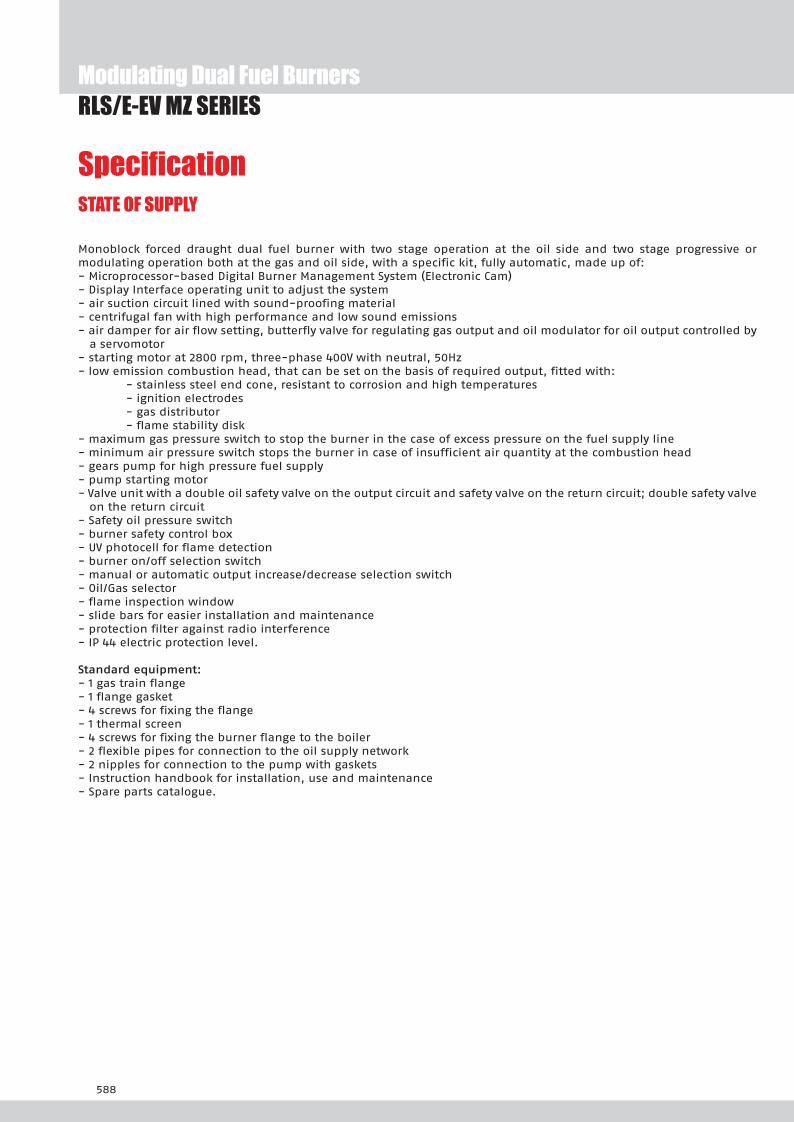
SpecificationSTATE OF SUPPLY
Monoblock forced draught dual fuel burner with two stage operation at the oil side and two stage progressive or modulating operation both at the gas and oil side, with a specific kit, fully automatic, made up of:- Microprocessor-based Digital Burner Management System (Electronic Cam) - Display Interface operating unit to adjust the system- air suction circuit lined with sound-proofing material- centrifugal fan with high performance and low sound emissions- air damper for air flow setting, butterfly valve for regulating gas output and oil modulator for oil output controlled by
a servomotor- starting motor at 2800 rpm, three-phase 400V with neutral, 50Hz - low emission combustion head, that can be set on the basis of required output, fitted with: - stainless steel end cone, resistant to corrosion and high temperatures - ignition electrodes - gas distributor - flame stability disk- maximum gas pressure switch to stop the burner in the case of excess pressure on the fuel supply line- minimum air pressure switch stops the burner in case of insufficient air quantity at the combustion head- gears pump for high pressure fuel supply - pump starting motor- Valve unit with a double oil safety valve on the output circuit and safety valve on the return circuit; double safety valve
on the return circuit- Safety oil pressure switch- burner safety control box- UV photocell for flame detection- burner on/off selection switch- manual or automatic output increase/decrease selection switch- Oil/Gas selector- flame inspection window- slide bars for easier installation and maintenance- protection filter against radio interference- IP 44 electric protection level.
Stan ar e ui ent- 1 gas train flange- 1 flange gasket- 4 screws for fixing the flange- 1 thermal screen- 4 screws for fixing the burner flange to the boiler- 2 flexible pipes for connection to the oil supply network- 2 nipples for connection to the pump with gaskets- Instruction handbook for installation, use and maintenance- Spare parts catalogue.

589
Modulating Dual Fuel BurnersRLS/E-EV MZ SERIES
Burners
Available models
CODE MODEL
HEAT OUTPUT TOTAL ELECTRICAL
POWER
CERTIFICATION NOTE
LIGHT OIL NATURAL GAS
(kW) (kg/h) (Nm3/h) (kW)
on demand RLS 250/E-EV MZ TC FS1 3/400/50 230/50-60 550/1230-2460 46/104-208 55/123-246 7,5 (oil)6,0 (gas) inprogress
on demand RLS 250/E-EV MZ TC FS1 3/230/50 230/50-60 550/1100-2150 46/93-181 55/110-215 7,5 (oil)6,0 (gas) in progress
Net calorific value light oil: 11,8 kWh/kg; 10.200 kcal/kg - Viscosity at 20°C: 4-6 mm2/s (cSt).Net calorific value G20 gas: 10 kWh/Nm3; 8.600 kcal/Nm3 - Density: 0,71 kg/Nm3.The burners of RLS/E-EV MZ series are in according to 90/396 - 2004/108 - 2006/95 - EC Directive and EN 267 - 676 Norm.
Gas Trains
Please see designation of Gas Train Series in the page before the Catalogue index.* 230V/50Hz -220V/60Hz electrical supply.The valve seal control device is compulsory (conforming to EN 676) on gas trains to burners with a maximum output over 1200 kW.To select the gas train please refer to the technical data leaflet and/or instruction manual.l Not available.
GAS TRAIN ADAPTER CODE
CODE MODEL Ø RLS 250/E-EV
3970250* MB 415/1 - RT 52 Rp 1” ½ 30008433970257* MB 420/1 - RT 52 Rp 2” -3970221* MBC 1200/1 - RSM 60 Rp 2” -3970222* MBC 1900/1 - FSM 40 DN 65 30008253970223* MBC 3100/1 - FSM 40 DN 80 30008263970224* MBC 5000/1 - FSM 80 DN 100 3000826 + 30103703970145* CB 512/1 - RSM 30 Rp 1” ½ 30008433970146* CB 520/1 - RSM 30 Rp 2” -
20044659* CB 525/1 - RSM 30 Rp 2” -3970147* CB 5065/1 - FSM 30 DN 65 30008253970148* CB 5080/1 - FSM 30 DN 80 30008263970149* CB 50100/1 - FSM 30 DN 100 3000826 + 301037020015871* CB 50125/1 - FSM 30 DN 125 3000826 + 3010224

590
Nozzles type 60° B
Burner accessories
Extended head kit“Standard head” burners can be transformed into “extended head” versions, by using the special kit. The kits available for the various burners, giving the original and the extended lengths, are listed below.
The nozzles must be ordered separately. The following table shows the features and codes on the basis of the maximum required fuel output.
NOTE: each burner needs N° 1 nozzle
BURNER STANDARD HEADLENGTH (mm)
EXTENDED HEADLENGTH (mm)
KIT CODE
u S 2 0 M 412 542 20029376
For burning LPG gas, a special kit is available to be fitted to the combustion head on the burner, as given in the following table:
LPG kit
BURNER
KIT CODE FOR“STANDARD HEAD” (*)
KIT CODE FOR“EXTENDED HEAD” (*)
u S 2 0 M in progress in progress
* Kit to be used on burners recognizable by a serial number that is over or equal to 02426XXXXXX, for burners with a serial number that is under or equal to 02416XXXXXX please use the Kit coded 3010366
RLS/E-EV MZ SERIESModulating Dual Fuel Burners
BURNER RATED OUTPUT kg/h A3 NOZZLE CODE A4 NOZZLE CODE
u S 2 0 M 140 3009863 20067290
u S 2 0 M 150 20059496* 20067290
u S 2 0 M 160 3009864 20067293
u S 2 0 M 180 3009865 20067295
u S 2 0 M 200 3009866 20067297
* 60° Angle.Please ask for specific code.

591
RLS/E-EV MZ SERIESModulating Dual Fuel Burners
C
If noise emission needs reducing even further, sound-proofing boxes are available.In case of generator heights, where a lower dimension “B” is required, ask for the Box Support Kit code 20065135.
Sound proofing box
BURNER
BOX TYPE
A(mm)
B (mm)min-max
C(mm)
[dB(A)] (*)
BOX CODE
u S 2 0 M C4/5 850 160 - 980 110 10 3010404
(*) Average noise reduction according to EN 15036-1 standard
If burner head penetration into the combustion chamber needs reducing, varying thickness spacers are available, as given in the following table.
Spacer kit
BURNER
SPACER THICKNESS S (mm)
KIT CODE
u S 2 0 M 102 3000722
Continuous ventilation kit
BURNER KIT CODE
u S 2 0 M 3010094
If the burner requires continuous ventilation in the stages without flame, a special kit is available as given in the following table.
Accessories for modulating operationTo obtain modulating operation, the RLS/E-EV MZ series of burners requires a regulator with three point outlet controls. The following table lists the accessories for modulat-ing operation with their application range.
BURNER TYPE CODE
u S 2 0 M RWF 40 3010414
TYPE RANGE (°C) (bar) CODE
Temperature PT 100 -100 ÷ 500°C 3010110
Pressure 4 ÷ 20 mA 0 ÷ 2,5 bar 3010213
Pressure 4 ÷ 20 mA 0 ÷ 16 bar 3010214
Pressure 4 ÷ 20 mA 0 ÷ 25 bar 3090873
The relative temperature or pressure probes fitted to the regulator must be chosen on the basis of the application.
REGULATOR
PROBE
Burner accessories
592
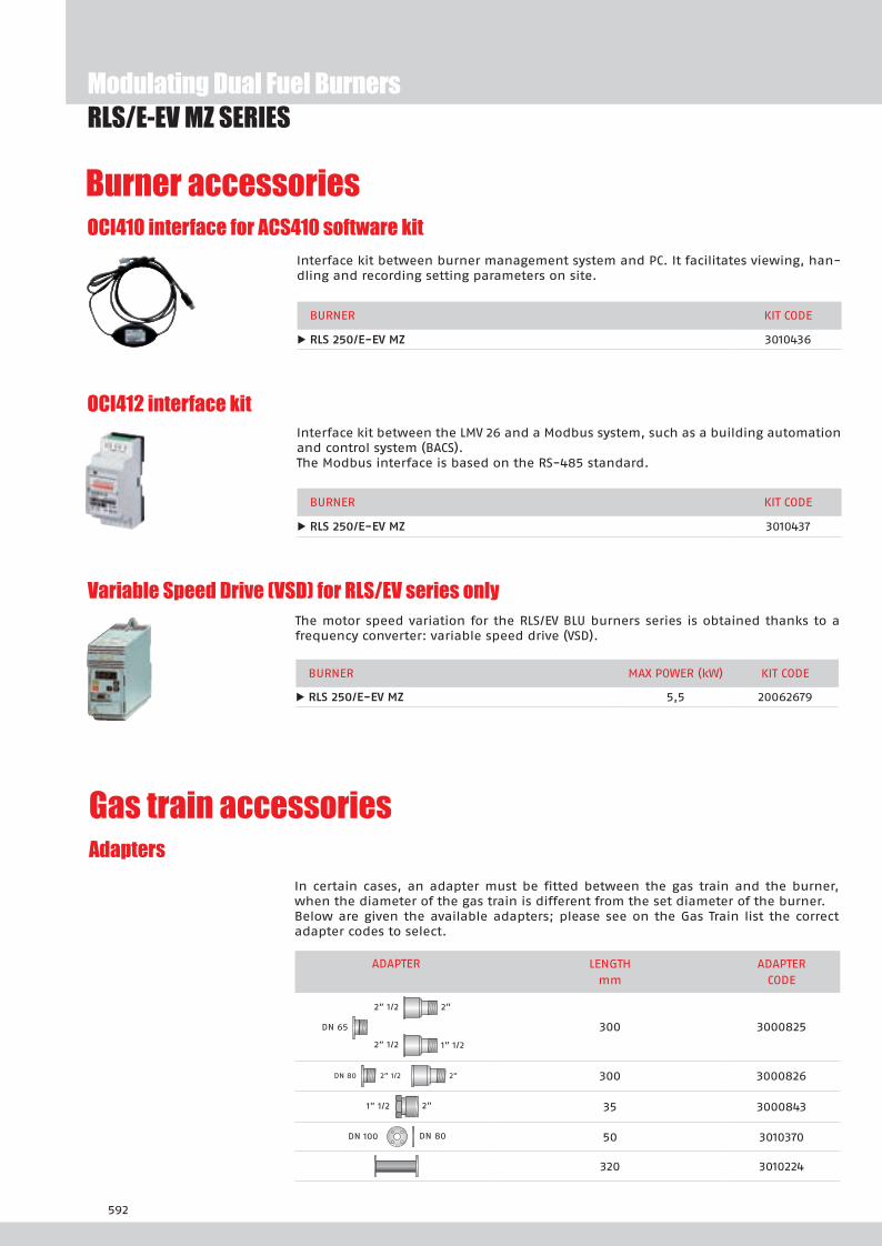
OCI412 interface kitInterface kit between the LMV 26 and a Modbus system, such as a building automation and control system (BACS).The Modbus interface is based on the RS-485 standard.
BURNER KIT CODE
u S 2 0 M 3010437
OCI410 interface for ACS410 software kitInterface kit between burner management system and PC. It facilitates viewing, han-dling and recording setting parameters on site.
BURNER KIT CODE
u S 2 0 M 3010436
Variable Speed Drive (VSD) for RLS/EV series onlyThe motor speed variation for the RLS/EV BLU burners series is obtained thanks to a frequency converter: variable speed drive (VSD).
BURNER MAX POWER (kW) KIT CODE
u S 2 0 M 5,5 20062679
Modulating Dual Fuel BurnersRLS/E-EV MZ SERIES
Burner accessories
Gas train accessoriesAdapters
In certain cases, an adapter must be fitted between the gas train and the burner, when the diameter of the gas train is different from the set diameter of the burner.Below are given the available adapters; please see on the Gas Train list the correct adapter codes to select.
ADAPTER LENGTH mm
ADAPTER CODE
2” 1/2
DN 65
1” 1/2
2”
2” 1/2
300 3000825
2” 1/2DN 80 2” 300 3000826
2”1” 1/2 35 3000843
DN 80DN 100 50 3010370
320 3010224
593
RLS/E-EV MZ SERIESModulating Dual Fuel Burners
Gas train accessoriesStabiliser spring
Accessory springs are available to vary the pressure range of the gas train stabilisers. The following table shows these accessories with their application range.Please refer to the technical manual for the correct choice of spring.
GAS TRAIN SPRINGCOLOUR
SPRING PRESSURE RANGE mbar
SPRINGCODE
uM C 1 00 1 3100 1M C 000 1
White 4 - 20 3010381
Red 20 - 40 3010382
Black 40 - 80 3010383
Green 80 - 150 3010384
u C 12 1
Red 25 - 55 3010131
Black 60 - 110 3010157
Pink 90 - 150 3090486
u C 20 1 2 1
Red 25 - 55 3010132
Black 60 - 110 3010158
Pink 90 - 150 3090487
u C 0 1 0 0 1
Red 25 - 55 3010133
Black 60 - 110 3010135
Pink 100 - 150 3090456
Grey 140 - 200 3090992
u C 0100 1
Red 25 - 55 3010134
Black 60 - 110 3010136
Pink 100 - 150 3090489
Grey 140 - 200 3092174
u C 012 1
Red 25 - 55 3010315
Yellow 30 - 70 3010316
Black 60 - 110 3010317
Pink 100 - 150 3010318
RLS/E-EV MZ SERIES


Two Stage Dual Fuel Burners
595
FIRING RATES
GI/EMME 300÷900 SERIESThe GI/EMME 300-900 series of burners covers a firing range from 175 to 922 kW.They have been designed for middle and high output users and they are in particular suitable for matching with pressurized boilers.Their use allow to have an high safety in operation, guaranteed from the double fuel supply. Two options of operation are available: only gas and only light oil, thus settable by a selector and a terminal board. Light oil circuit is fitted with his own electric motor: this permits pump stop during gas operation preventing danger of pumping seizure. A wide range of accessories and gas trains suitable to the burners guarantee an elevated working flexibility.
MM 300 107/175 ÷ 332 kWMM 00 116/232 ÷ 465 kWMM 00 174/348 ÷ 665 kWMM 00 250/525 ÷ 922 kW
Useful working fieldfor choosing theburner
Test conditionsconforming to EN267- EN676 Temperature: 20°CPressure: 1013,5 mbarAltitude: 0 m a.s.l.

596
GI/EMME 300÷900 SERIES
MODEL A D E F -F(1) H I M N O V
u MM 300 410 397 610 185 - 320 140 292 1”1/2 97 978 165
u MM 00 410 397 610 187 - 320 150 292 1”1/2 97 1018 165
u MM 00 410 437 645 187 - 320 155 332 1”1/2 97 1063 165
u MM 00 410 485 770 227 - 360 175 370 2” 131 1260 195
(1) Length with extended combustion head
MODEL X Y Z kg
u MM 300 1000 790 550 42
u MM 00 1000 790 550 49
u MM 00 1400 850 650 64
u MM 00 1200 790 650 88
MODEL L M N
u MM 300 160 155 M10
u MM 00 160 165 M10
u MM 00 160 165 M10
u MM 00 195 185 M12
BURNER - BOILER MOUNTING FLANGE
PACKAGING
Z
XY
BURNER
Overall dimensions (mm)
Two Stage Dual Fuel Burners

597
GI/EMME 300÷900 SERIES
MM 00 TC S1 3 230 00 0 230 0
BASIC DESIGNATION
EXTENDED DESIGNATION
Series : GI/EMME
Size
Emission : Class 1 EN267 - EN676
Head : TC Standard head
TL Extended head
Flame control system : FS1 Standard (1 stop every 24 h)
Electrical supply to the system : 1/230/50 1/230V/50Hz
1/210/60 1/210V/60Hz
1/220/60 1/220V/60Hz
3/230-400/50 3/230V/50Hz - 3N/400V/50Hz
3/210/60 3/210V/60Hz
3/400/50 3N/400V/50Hz
3/220/60 3/220V/60Hz
3/380/60 3N/380V/60Hz
3/230/50 3/230V/50Hz
3/220-380/60 3/220/60Hz - 3N/380V/60Hz
Auxiliary voltage : 230/50-60 230V/50-60Hz
110/50-60 110V/50-60Hz
DESIGNATION OF SERIES
Specification
Two Stage Dual Fuel Burners

598
Two Stage Dual Fuel Burners
SpecificationSTATE OF SUPPLY
Monoblock forced draught dual fuel burner, two stage operation, made up of:- Air suction circuit- Fan with forward curved blades- Air damper for setting controlled by a servomotor- Combustion head, that can be set on the basis of required output- Minimum air pressure switch- Fan electrical motor- Pump electrical motor- Gears pump for high pressure fuel supply, fitted with: - filter - pressure regulator - connections for installing a pressure gauge and a a vacuometer - internal by-pass for single pipe installation- Valve unit with a double oil safety valve on the output circuit- UV photocell for flame detection- Flame inspection window- Slide bars for easier installation and maintenance- Protection filter against radio interference- IP X0D (IP 40) protection level.
Stan ar e ui ent- 1 gas train flange- 1 flange gasket- 1 insulating screen- 2 flexible hoses for connection to the oil supply circuit- 2 nipples for connection to the pump- 3 wiring looms fittings for electrical connections- 8 screws for fixing the burner flange to the boiler- 1 LPG kit- Instruction manual for installation, use and maintenance- Spare parts catalogue.
GI/EMME 300÷900 SERIES

599
Two Stage Dual Fuel Burners
Available models
GI/EMME 300÷900 SERIES
Burners
CODE MODEL HEAT OUTPUT TOTALELECTRICAL
POWER
CERTIFICATION NOTE
LIGHT OIL NATURAL GAS
(kW) (kg/h) (Nm3/h) (kW)
3483681 GI/EMME 300 TC FS1 1/220/60 220/60 107/175-340 9/15-29 11/17,5-34 0,5 -
3483621 GI/EMME 300 TC FS1 1/230/50 230/50 107/175-332 9/15-28 11/17,5-33 0,5 CE-0085AQ0711
3484271 GI/EMME 400 TC FS1 1/210/60 120/60 116/232-465 10/20-39 12/23-46,5 0,62 -
3484221 GI/EMME 400 TC FS1 1/230/50 230/50 116/232-465 10/20-39 12/23-46,5 0,62 CE-0085AQ0711
3484281 GI/EMME 400 TC FS1 3/220-380/60 220/60 116/232-465 10/20-39 12/23-46,5 0,62 -
3484871 GI/EMME 600 TC FS1 3/210/60 120/60 174/348-697 15/30-60 17/35-70 1,1 -
3484881 GI/EMME 600 TC FS1 3/220-380/60 220/60 174/348-697 15/30-60 17/35-70 1,1 -
3484821 GI/EMME 600 TC FS1 3/230-400/50 230/50 174/348-665 15/30-56 17/35-66,5 1,1 CE-0085AQ0711
3485971 GI/EMME 900 TC FS1 3/210/60 120/60 262/523-1045 22/44-88 26/52-105 2 -
3485981 GI/EMME 900 TC FS1 3/220-380/60 220/60 262/523-1045 22/44-88 26/52-105 2 -
3485921 GI/EMME 900 TC FS1 3/230-400/50 230/50 250/525-922 21/44-78 25/52,5-92 2 CE-0085AQ0711
Net calorific value light oil: 11,8 kWh/kg; 10.200 kcal/kg - Viscosity at 20°C: 4-6 mm2/s (cSt).Net calorific value G20 gas: 10 kWh/Nm3; 8.600 kcal/Nm3 - Density: 0,71 kg/Nm3.The burners of GI/EMME series are in according to 2004/108, 2006/95 Directive and EN 267, EN 676 Norm.
Gas Trains
Please see designation of Gas Train Series in the page before the Catalogue index.* 230V/50Hz -220V/60Hz electrical supply.** 230V/50Hz electrical supply.The valve seal control device is compulsory (conforming to EN 676) on gas trains to burners with a maximum output over 1200 kW.To select the gas train please refer to the technical data leaflet and/or instruction manual.C.T. Gas valve leak detection control device: - gas train not equipped with leak detection control device; this device can be ordered separately - see VPS column - and installed later. u gas train equipped with leak detection control device.VPS Valve leak detection control device. Supplied separately from the gas train (please see Gas train accessories paragraph for both 50 Hz and 60 Hz codes).l Not available.
GAS TRAIN VPSCODE
ADAPTER CODE
CODE MODEL Ø C.T. G/M 300 G/M 400 G/M 600 G/M 900
3970084* MB 405/2 - RSD 20 Rp ½” - 3010123 3000842+3000824 l l
3970537* MB 407/2 - RSD 20 Rp ¾” - 3010123
3000824
l
3970556* MB 407/2 - RT 20 Rp ¾” - 3010123 l
3970534* MB 410/2 - RSD 20 Rp ¾” - 30101233000824+ 3000843
3970557* MB 410/2 - RT 20 Rp ¾” - 30101233970152* MB 412/2 - RT 20 Rp 1” ¼ - 3010123 3010124 30101263970183* MB 415/2 - RT 20 Rp 1” ½ - 3010123 - - - 30008433970184* MB 420/2 - RT 20 Rp 2” - 3010123
3000822-
3970185** MB 420/2 CT RT 20 Rp 2” u - -
3970153* CB 512/2 - RT 32 Rp 1” ½ - 3010367 - - -3000843
20045590** CB 512/2 CT RT 32 Rp 1” ½ u - - - -
3970154* CB 520/2 - RT 32 Rp 2” - 30103673000822
-
20045591** CB 520/2 CT RT 32 Rp 2” u - -
3970155* CB 5065/2 - FT 32 DN 65 - 3010367 l3000825
3970167** CB 5065/2 CT FT 32 DN 65 u - l
3970156* CB 5080/2 - FT 32 DN 80 - 3010367 l l l3000826
3970168** CB 5080/2 CT FT 32 DN 80 u - l l l

600
Nozzles type 60° B
The nozzles must be ordered separately. The following table shows the features and codes on the basis of the maximum required fuel output.
NOTE: each burner needs N° 2 nozzles.
BURNER RATED DELIVERY (kg/h)AT 12 bar
GPH NOZZLECODE
u MM 300 6,8 1,75 3042110
u MM 300 7,8 2,00 3042126
u MM 300 8,7 2,25 3042127
u MM 300 00 9,7 2,50 3042140
u MM 300 00 11,6 3,00 3042158
u MM 300 00 13,6 3,50 3042162
u MM 300 00 00 15,6 4,00 3042172
u MM 00 00 17,5 4,50 3042182
u MM 00 00 19,4 5,00 3042192
u MM 00 00 21,3 5,50 3042202
u MM 00 00 23,3 6,00 3042212
u MM 00 00 27,1 7,00 3042232
u MM 00 00 29,1 7,50 3042242
u MM 00 33 8,50 3042262
u MM 00 36,8 9,50 3042282
u MM 00 38,8 10,00 3042292
u MM 00 42,3 11,00 3042312
u MM 00 46,5 12,00 3042322
Extended head kit“Standard head” burners can be transformed into “extended head” versions, by using the special kit. The kits available for the various burners, giving the original and the extended lengths, are listed below.
BURNER STANDARD HEADLENGTH (mm)
EXTENDED HEADLENGTH (mm)
KIT CODE
u MM 300 185 320 3000836
u MM 00 187 320 3010001
u MM 00 187 320 3010002
u MM 00 227 360 3010003
GI/EMME 300÷900 SERIES
Burner accessories
Two Stage Dual Fuel Burners

601
C
GI/EMME 300÷900 SERIES
If noise emission needs reducing even further, sound-proofing boxes are available.In case of generator heights, where a lower dimension “B” is required, ask for the Box Support Kit code 20065135.
Sound proofing box
BURNER
BOX TYPE
A(mm)
B (mm)min-max
C(mm)
[dB(A)] (*)
BOX CODE
u MM 300 00 00 00 C1/3 650 372 - 980 110 10 3010403
(*) Average noise reduction according to EN 15036-1 standard
AdaptersIn certain cases, an adapter must be fitted between the gas train and the burner, when the diameter of the gas train is different from the set diameter of the burner.Below are given the available adapters; please see on the Gas Train list the correct adapter codes to select.
ADAPTER LENGTH mm
ADAPTER CODE
1” 1/22” 70 3000822
1” 1/23/4” 31 3000824
2” 1/2
DN 65
1” 1/2
2”
2” 1/2
300 3000825
2” 1/2DN 80 2” 300 3000826
3/4”1/2” 26 3000842
2”1” 1/2 35 3000843
1” 1/21/2” 31 20044756
1” 1/21” 1/4 31 3010124
2”1” 1/4 35 3010126
Burner accessories
Two Stage Dual Fuel Burners
Gas train accessories

602
Two Stage Dual Fuel Burners
Gas train accessories
GI/EMME 300÷900 SERIES
BURNER GAS TRAIN KIT CODE for 50 Hz operation
KIT CODE for 60 Hz operation
u MM 300 MB 407/2 - MB 410/2 MB 412/2 - MB 415/2
3010123 20050030
CB 512/2 3010125 20050033
u MM 00 MB 410/2 - MB 412/2 MB 415/2 - MB 420/2
3010123 20050030
CB 512/2 - CB 520/2 3010125 20050033
u MM 00 MB 410/2 - MB 412/2 MB 415/2 - MB 420/2
3010123 20050030
CB 512/2 - CB 520/2 3010125 20050033
u MM 00 MB 412/2 - MB 415/2 MB 420/2
3010123 20050030
CB 512/2 - CB 520/2 - CB 5065/2 3010125 20050033
Seal control kitTo test the valve seals on the gas train, a special “seal control kit” is available.
Stabiliser springAccessory springs are available to vary the pressure range of the gas train stabilisers.
GAS TRAIN SPRINGCOLOUR
SPRING PRESSURE RANGE mbar
SPRINGCODE
u C 12 2
Red 25 - 55 3010131
Black 60 - 110 3010157
Pink 90 - 150 3090486
u C 20 2
Red 25 - 55 3010132
Black 60 - 110 3010158
Pink 90 - 150 3090487
u C 0 2 0 0 2
Red 25 - 55 3010133
Black 60 - 110 3010135
Pink 100 - 150 3090456
Grey 140 - 200 3090992

603
Useful working fieldfor choosing theburner
Modulation range
Test conditionsconforming to EN267- EN676 Temperature: 20°CPressure: 1013,5 mbarAltitude: 0 m a.s.l.
Modulating Dual Fuel Burners
GI/EMME 1400÷4500 SERIESThe GI/EMME 1400-4500 series of burners covers a firing range from 820 to 4650 kW. They ave been designed for high output users and they are suitable for matching with every kind of boilers, with normal or pressurized combustion chamber.Operation can be “two stage progressive” or, alternatively, “modulating” with the installation of a PID logic regulator and respective probes. Two options of operation are available: only gas and only light oil, thus settable by a manual switch. Light oil circuit is fitted with his own electric motor: this permits pump stop during gas operation preventing danger of pumping seizure and avoiding oil circulation. A wide range of accessories and gas trains suitable to the burners guarantee an elevated working flexibility.
MM 1 00 407/820 ÷ 1540 kWMM 2000 581/1163 ÷ 2325 kWMM 3000 872/1744 ÷ 3488 kWMM 00 1163/2350 ÷ 4650 kW
FIRING RATES

604
GI/EMME 1400÷4500 SERIES
(1) Length with extended combustion head
MODEL A B C E F - F(1) H I M O - O(1)
MM 1 00 858 376 482 1090 385 - 495 250 467 2” 1407 - 1585
MM 2000 878 396 482 1090 385 - 495 260 467 DN 80 1407 - 1585
MM 3000 985 447 538 1320 476 - 606 336 525 DN 80 1796 - 2000
MM 00 1046 508 538 1320 476 - 606 336 525 DN 80 1796 - 1926
MODEL X Y Z kg
u MM 1 00 1740 990 950 190
u MM 2000 1740 990 950 200
u MM 3000 2040 1180 1125 280
u MM 00 2040 1180 1125 500
MODEL D1 D2 Ø
u MM 1 00 255 368 M16
u MM 2000 265 368 M16
u MM 3000 340 438 M20
u MM 00 340 438 M20
BURNER - BOILER MOUNTING FLANGE
PACKAGING
Z
XY
Modulating Dual Fuel Burners
BURNER
Overall dimensions (mm)

605
GI/EMME 1400÷4500 SERIES
BASIC DESIGNATION
EXTENDED DESIGNATION
Series : GI/EMME
Size
Emission : Class 1 EN267 - EN676
Head : TC Standard head
TL Extended head
Flame control system : FS1 Standard (1 stop every 24 h)
Electrical supply to the system : 1/230/50 1/230V/50Hz
1/210/60 1/210V/60Hz
1/220/60 1/220V/60Hz
3/230-400/50 3/230V/50Hz - 3N/400V/50Hz
3/210/60 3/210V/60Hz
3/400/50 3N/400V/50Hz
3/220/60 3/220V/60Hz
3/380/60 3N/380V/60Hz
3/230/50 3/230V/50Hz
3/220-380/60 3/220/60Hz - 3N/380V/60Hz
Auxiliary voltage : 230/50 230V/50Hz
120/60 120V/60Hz
220/60 220V/60Hz
Modulating Dual Fuel Burners
MM 1 00 TC S1 3 230 00 0 230 0
DESIGNATION OF SERIES
Specification

606
SpecificationSTATE OF SUPPLY
Monoblock forced draught dual fuel burner, two stage progressive or modulating operation with a kit, made up of:- Air suction circuit- Fan with forward curved blades- Air damper for setting and butterfly valve for regulating fuel output controlled by a servomotor- Combustion head, that can be set on the basis of required output- Maximum gas pressure switch- Minimum air pressure switch- Fan electrical motor- Pump electrical motor- Gears pump for high pressure fuel supply, fitted with: - filter - pressure regulator - connections for installing a pressure gauge and a a vacuometer - internal by-pass for single pipe installation- Valve unit with a double oil safety valve on the output circuit and safety valve on the return circuit- UV photocell for flame detection- Flame inspection window- Slide bars for easier installation and maintenance- Protection filter against radio interference- IP X0D (IP 40) protection level.
Stan ar e ui ent- 1 flange (for GI/EMME 1400)- 1 gas train flange- 8 screws for fixing the burner flange to the boiler (for GI/EMME 1400)- 12 screws for fixing the burner flange to the boiler- 1 insulating screen- 2 flexible hoses for connection to the oil supply circuit- 2 nipples for connection to the pump- 4 wiring looms fittings for electrical connections- 2 pin extensions- 8 washers (for GI/EMME 1400)- 12 washers- Instruction handbook for installation, use and maintenance- Spare parts catalogue.
GI/EMME 1400÷4500 SERIESModulating Dual Fuel Burners

607
Available models
GI/EMME 1400÷4500 SERIES
Burners
(1) CE 0085AQ0712. (2) CE 0085AQ0712. (3) CE 0085AQ0712. (4) CE 0085AQ0712.* Star delta starter.Net calorific value light oil: 11,8 kWh/kg; 10.200 kcal/kg - Viscosity at 20°C: 4-6 mm2/s (cSt).Net calorific value G20 gas: 10 kWh/Nm3; 8.600 kcal/Nm3 - Density: 0,71 kg/Nm3.The burners of GI/EMME series are in according to 90/396 - 2004/108 - 2006/95 EC Directive and EN 267-676 Norm.
Modulating Dual Fuel Burners
CODE MODEL HEAT OUTPUT MOTORSELECTRICAL
POWER
CERTIFICATION NOTE
LIGHT OIL NATURAL GAS
(kW) (kg/h) (Nm3/h) (kW)
3486683 GI/EMME 1400 TC FS1 3/220-380/60 220/60 415/814-1660 35/69-140 41/81-166 3 + 1,1 -
3486655 GI/EMME 1400 TC FS1 3/230-400/50 230/50 407/820-1540 34/69-130 41/82-154 3 + 1,1 (1)
3486684 GI/EMME 1400 TL FS1 3/220-380/60 220/60 415/814-1660 35/69-140 41/81-166 3 + 1,1 -
3486656 GI/EMME 1400 TL FS1 3/230-400/50 230/50 407/820-1540 34/69-130 41/82-154 3 + 1,1 (1)
3487683 GI/EMME 2000 TC FS1 3/220-380/60 220/60 590/1163-2370 50/98-200 59/116-237 4 + 1,1 -
3487657 GI/EMME 2000 TC FS1 3/230-400/50 230/50 581/1163-2325 49/98-196 58/116-233 4 + 1,1 (2)
3487659 GI/EMME 2000 TC FS1 3/400/50 230/50 581/1163-2325 49/98-196 58/116-233 4 + 1,1 (2) *
3487684 GI/EMME 2000 TL FS1 3/220-380/60 220/60 590/1163-2370 50/98-200 59/116-237 4 + 1,1 -
3487658 GI/EMME 2000 TL FS1 3/230-400/50 230/50 581/1163-2325 49/98-196 58/116-233 4 + 1,1 (2)
3487660 GI/EMME 2000 TL FS1 3/400/50 230/50 581/1163-2325 49/98-196 58/116-233 4 + 1,1 (2) *
3488783 GI/EMME 3000 TC FS1 3/220-380/60 220/60 890/1744-3560 75/147-300 89/174-356 9 + 1,5 -
3488757 GI/EMME 3000 TC FS1 3/230-400/50 230/50 872/1744-3488 74/147-294 87/174-349 9 + 1,5 (3)
3488759 GI/EMME 3000 TC FS1 3/400/50 230/50 872/1744-3488 74/147-294 87/174-349 9 + 1,5 (3) *
3488784 GI/EMME 3000 TL FS1 3/220-380/60 220/60 890/1744-3560 75/147-300 89/174-356 9 + 1,5 -
3488758 GI/EMME 3000 TL FS1 3/230-400/50 230/50 872/1744-3488 74/147-294 87/174-349 9 + 1,5 (3)
3488760 GI/EMME 3000 TL FS1 3/400/50 230/50 872/1744-3488 74/147-294 87/174-349 9 + 1,5 (3) *
3489085 GI/EMME 4500 TC FS1 3/220/60 220/60 1190/2325-5100 100/196-430 119/233-510 15 + 1,5 - *
3489063 GI/EMME 4500 TC FS1 3/230/50 230/50 1163/2350-4650 98/198-392 116/235-465 15 + 1,5 (4) *
3489087 GI/EMME 4500 TC FS1 3/380/60 220/60 1190/2325-5100 100/196-430 119/233-510 15 + 1,5 - *
3489065 GI/EMME 4500 TC FS1 3/400/50 230/50 1163/2350-4650 98/198-392 116/235-465 15 + 1,5 (4) *
3489086 GI/EMME 4500 TL FS1 3/220/60 220/60 1190/2325-5100 100/196-430 119/233-510 15 + 1,5 - *
3489064 GI/EMME 4500 TL FS1 3/230/50 230/50 1163/2350-4650 98/198-392 116/235-465 15 + 1,5 (4) *
3489088 GI/EMME 4500 TL FS1 3/380/60 220/60 1190/2325-5100 100/196-430 119/233-510 15 + 1,5 - *
3489066 GI/EMME 4500 TL FS1 3/400/50 230/50 1163/2350-4650 98/198-392 116/235-465 15 + 1,5 (4) *

608
Available modelsGas Trains
GI/EMME 1400÷4500 SERIESModulating Dual Fuel Burners
Please see designation of Gas Train Series in the page before the Catalogue index.* 230V/50Hz -220V/60Hz electrical supply.** 230V/50Hz electrical supply.The valve seal control device is compulsory (conforming to EN 676) on gas trains to burners with a maximum output over 1200 kW.To select the gas train please refer to the technical data leaflet and/or instruction manual.C.T. Gas valve leak detection control device: - gas train not equipped with leak detection control device; this device can be ordered separately - see VPS column - and installed later. u gas train equipped with leak detection control device.VPS Valve leak detection control device. Supplied separately from the gas train (please see Gas train accessories paragraph for both 50 Hz and 60 Hz codes).l Not available.
GAS TRAINVPS CODE
ADAPTER CODE
CODE MODEL Ø C.T. G/M 1400 G/M 2000 G/M 3000 G/M 4500
3970256* MB 412/1 - RT 52 Rp 1” ¼ - 3010123
3010126
l l l
3970144* MB 412/1 - RT 20 Rp 1” ¼ - 3010123 l l l
3970197** MB 412/1 CT RT 20 Rp 1” ¼ u - l l l
3970231* MB 412/1 - RSM 20 Rp 1” ¼ - 3010123 l l l
3970180* MB 415/1 - RT 30 Rp 1” ½ - 3010123
30008433000843 + 20064220 +
3010128
l
3970198** MB 415/1 CT RT 30 Rp 1” ½ u - l
3970250* MB 415/1 - RT 52 Rp 1” ½ - 3010123 l
3970253** MB 415/1 CT RT 52 Rp 1” ½ u - l
3970232* MB 415/1 - RSM 30 Rp 1” ½ - 3010123 l
3970181* MB 420/1 - RT 30 Rp 2” - 3010123 -
20064220 + 3010128
l
3970182** MB 420/1 CT RT 30 Rp 2” u - - l
3970257* MB 420/1 - RT 52 Rp 2” - 3010123 - l
3970252** MB 420/1 CT RT 52 Rp 2” u - - l
3970233* MB 420/1 - RSM 30 Rp 2” - 3010123 - l
3970234** MB 420/1 CT RSM 30 Rp 2” u - - l
3970221* MBC 1200/1 - RSM 60 Rp 2” - 3010367 -20064220 + 3010128
3970225** MBC 1200/1 CT RSM 60 Rp 2” u - -
3970222* MBC 1900/1 - FSM 40 DN 65 - 30103673000825 3000831
3970226** MBC 1900/1 CT FSM 40 DN 65 u -
3970223* MBC 3100/1 - FSM 40 DN 80 - 30103673000826 3000832
3970227** MBC 3100/1 CT FSM 40 DN 80 u -
3970224* MBC 5000/1 - FSM 80 DN 100 - 3010367 l l3010127
3970228** MBC 5000/1 CT FSM 80 DN 100 u - l l
3970145* CB 512/1 - RSM 30 Rp 1” ½ - 30103673000843
3000843 + 20064220 + 3010128
l
20045589** CB 512/1 CT RSM 30 Rp 1” ½ u - l
3970146* CB 520/1 - RSM 30 Rp 2” - 3010367 -
20064220 + 30101283970160** CB 520/1 CT RSM 30 Rp 2” u - -
20044659* CB 525/1 - RSM 30 Rp 2” - 3010367 -
20044660** CB 525/1 CT RSM 30 Rp 2” u - -
3970147* CB 5065/1 - FSM 30 DN 65 - 30103673000825 3000831
3970161** CB 5065/1 CT FSM 30 DN 65 u -
3970148* CB 5080/1 - FSM 30 DN 80 - 30103673000826 3000832
3970162** CB 5080/1 CT FSM 30 DN 80 u -
3970149* CB 50100/1 - FSM 30 DN 100 - 3010367 3010370 + 3000826
30101273970163** CB 50100/1 CT FSM 30 DN 100 u -
20015871* CB 50125/1 - FSM 30 DN 125 - 3010367 3010224 + 3000826
30909403970196** CB 50125/1 CT FSM 30 DN 125 u -

609
Burner accessories
GI/EMME 1400÷4500 SERIESModulating Dual Fuel Burners
Nozzles type B5-SA 45°
The nozzles must be ordered separately. The following table shows the features and codes on the basis of the maximum required fuel output.
NOTE: each burner needs N° 1 nozzle.
BURNER RATED DELIVERY (kg/h)
NOZZLECODE (1)
NOZZLECODE (2)
u MM 1 00 70 3009303 3045471
u MM 1 00 80 3009305 3045472
u MM 1 00 90 3009307 3045473
u MM 1 00 2000 100 3009310 3045475
u MM 1 00 2000 125 3009312 3045477
u MM 2000 3000 150 3009314 3045479
u MM 2000 3000 175 3009316 3045481
u MM 2000 3000 00 200 3009318 3045483
u MM 3000 00 225 3009320 3045485
u MM 3000 00 250 3009322 3045487
u MM 3000 00 275 3009324 3045489
u MM 3000 00 300 3009326 3045491
u MM 00 325 3009328 3045493
u MM 00 350 3009330 3045495
u MM 00 375 3009332 3045497
u MM 00 400 3009334 3045499
(1) Nozzles Bergonzo B5 45° - without “SA” needle code. (2) Nozzles Fluidics N2 45° - without needle code.
If burner head penetration into the combustion chamber needs reducing, varying thickness spacers are available, as given in the following list.
Spacer kit
BURNER
SPACER THICKNESS S (mm)
KIT CODE
u MM 1 00 2000 102 3000722
u MM 3000 00 130 3000751
C
If noise emission needs reducing even further, sound-proofing boxes are available.In case of generator heights, where a lower dimension “B” is required, ask for the Box Support Kit code 20065135.
Sound proofing box
BURNER
BOX TYPE A
(mm)B (mm)
min-maxC
(mm)[dB(A)]
(*) BOX CODE
u MM 1 00 2000 3000 00 C7 1255 160 - 980 110 10 3010376
(*) Average noise reduction according to EN 15036-1 standard

610
Modulating Dual Fuel BurnersGI/EMME 1400÷4500 SERIES
Burner accessoriesAccessories for modulating operation
To obtain modulating operation, the GI/EMME series of burners requires a regulator.
BURNER
REGULATOR TYPE
REGULATOR CODE
u MM 1 00 2000 3000 00 RWF 40 3010211
Depending on the servomotor fitted to the burner, a three-pole potentiometer (1000 W) can be installed to check the position of the servomotor.
BURNER
POTENTIOMETER KIT CODE
u MM 1 00 2000 3000 00 3010021
The relative temperature or pressure probes fitted to the regulator, must be chosen on the basis of the application.
BURNER PROBE TYPE RANGE (°C) (bar) PROBE CODE
uMM 1 00 2000MM 3000 00
Temperature PT 100 -100 ÷ 500°C 3010110
Pressure 4 ÷ 20 mA 0 ÷ 2,5 bar 3010213
Pressure 4 ÷ 20 mA 0 ÷ 16 bar 3010214
Pressure 4 ÷ 20 mA 0 ÷ 25 bar 3090873
For easier maintenance, a mobile burner support has been designed, which means the burner can be dismantled without the need of forklift trucks.
Burner support
BURNER SUPPORT CODE
u MM 1 00 2000 3000 00 3000731
LPG kitFor burning LPG gas, a special kit is available to be fitted to the combustion head on the burner, as given in the following table.
BURNER KIT CODE FOR‘STANDARD HEAD’ (*)
KIT CODE FOR‘EXTENDED HEAD’ (*)
u MM 1 00 2000 3010063 3010063
u MM 3000 3090223 3090223
u MM 00 3090937 3090937
(*) Without CE certification

611
Modulating Dual Fuel BurnersGI/EMME 1400÷4500 SERIES
Gas train accessoriesAdapters
In certain cases, an adapter must be fitted between the gas train and the burner, when the diameter of the gas train is different from the set diameter of the burner.Below are given the available adapters; please see on the Gas Train list the correct adapter codes to select.
ADAPTER LENGTH mm
ADAPTER CODE
2” 1/2
DN 65
1” 1/2
2”
2” 1/2
300 3000825
2” 1/2DN 80 2” 300 3000826
2”1” 1/2 35 3000843
2”1” 1/4 35 3010126
DN 80DN 100 50 3010370
2”1” 1/2 65 20064220
DN 65
DN 80
320 3000831
DN 80
DN 80
320 3000832
DN 100
DN 80
320 3010127
2” 1/2 2”
DN 80
DN 65 540 3010128

612
Modulating Dual Fuel BurnersGI/EMME 1400÷4500 SERIES
Gas train accessories
Seal control kitTo test the valve seals on the gas train, a special “seal control kit” is available. The valve seal control device is compulsory (EN 676) on gas trains to burners with a maxi-mum output over 1200 kW. The seal control is type VPS 504.
GAS TRAIN KIT CODE
for 50 Hz operation KIT CODE
for 60 Hz operation
u M 1 t e 3010123 20050030
u M C 1 t e 3010367 20029057
u C 1 t e 3010367 20029057
Stabiliser springTo vary the pressure range of the gas train stabilisers, accessory springs are available. The following table shows these accessories with their application range. Please refer to the technical manual for the correct choice of spring.
GAS TRAIN SPRINGCOLOUR
SPRING PRESSURE RANGE mbar
SPRINGCODE
uM C 1 00 1 3100 1M C 000 1
White 4 - 20 3010381
Red 20 - 40 3010382
Black 40 - 80 3010383
Green 80 - 150 3010384
u C 12 1
Red 25 - 55 3010131
Black 60 - 110 3010157
Pink 90 - 150 3090486
u C 20 1 2 1
Red 25 - 55 3010132
Black 60 - 110 3010158
Pink 90 - 150 3090487
u C 0 1 0 0 1
Red 25 - 55 3010133
Black 60 - 110 3010135
Pink 100 - 150 3090456
Grey 140 - 200 3090992
u C 0100 1
Red 25 - 55 3010134
Black 60 - 110 3010136
Pink 100 - 150 3090489
Grey 140 - 200 3092174
u C 012 1
Red 25 - 55 3010315
Yellow 30 - 70 3010316
Black 60 - 110 3010317
Pink 100 - 150 3010318

613
Useful working fieldfor choosing theburner
Modulation range
Test conditionsconforming to EN267- EN676 Temperature: 20°CPressure: 1013,5 mbarAltitude: 0 m a.s.l.
ENNE/EMME SERIESThe ENNE/EMME 1400-4500 series of burners covers a firing range from 814 to 5000 kW. They They have been designed for high output users and they are suitable for matching with every kind of boilers, with normal or pressurized combustion chamber.Operation can be “two stage progressive” or, alternatively, “modulating” with the installation of a PID logic regulator and respective probes. Two fuel options are available: only gas and only heavy oil, thus settable by a manual switch. Heavy oil circuit is fitted with his own electric motor: this permits pump stop during gas operation preventing danger of pumping seizure and avoiding oil circulation. A wide range of accessories and gas trains suitable to the burners guarantee an elevated working flexibility.
MM 1 00 407/814 ÷ 1628 kWMM 2000 581/1163 ÷ 2325 kWMM 3000 872/1744 ÷ 3488 kWMM 00 1163/2325 ÷ 5000 kW
Modulating Dual Fuel Burners
FIRING RATES

614
ENNE/EMME SERIES
(1) Length with extended combustion head
PACKAGING
Z
X - X(1)Y
MODEL D1 D2 Ø
u MM 1 00 255 368 M16
u MM 2000 265 368 M16
u MM 3000 340 438 M20
u MM 00 340 438 M20
BURNER - BOILER MOUNTING FLANGE
Modulating Dual Fuel Burners
MODEL A B C E F - F(1) H I M O - O(1)
u MM 1 00 892 376 516 1090 385 - 495 250 467 2” 1475 - 1585
u MM 2000 912 396 516 1090 385 - 495 260 467 DN80 1475 - 1585
u MM 3000 1000 447 553 1320 476 - 606 336 525 DN80 1796 - 1926
u MM 00 1061 508 553 1320 476 - 606 336 525 DN80 1796 - 1926
MODEL X - X(1) Y Z Kg
u MM 1 00 1740 - 1740 990 950 265
u MM 2000 1740 - 1740 990 950 265
u MM 3000 2040 - 2040 1180 1125 280
u MM 00 2040 - 2040 1180 1125 500
(1) Length with extended combustion head
BURNER
Overall dimensions (mm)

615
ENNE/EMME SERIES
BASIC DESIGNATION
EXTENDED DESIGNATION
Series : ENNE/EMME
Size
Emission : Class 1 EN267 - EN676
Head : TC Standard head
TL Extended head
Flame control system : FS1 Standard (1 stop every 24 h)
Electrical supply to the system : 3/220/50 3/220V/50Hz
3/380/50 3N/380V/50Hz
3/220-380/50 3/220/50Hz - 3N/380V/50Hz
Auxiliary voltage : 220/50 220V/50Hz
Modulating Dual Fuel Burners
MM 1 00 TC S1 3 220 3 0 0 220 0
DESIGNATION OF SERIES
Specification
616
SpecificationSTATE OF SUPPLY
Monoblock forced draught dual fuel burner, two stage progressive or modulating operation with a kit, made up of:- Air suction circuit- Fan with forward curved blades- Air damper for setting and butterfly valve for regulating fuel output controlled by a servomotor- Combustion head, that can be set on the basis of required output- Maximum gas pressure switch- Minimum air pressure switch- Fan electrical motor- Dedicated 1400 rpm low speed pump motor- Gears pump for high pressure fuel supply, fitted with: -filter -pressure regulator -connections for installing a pressure gauge and a a vacuometer -internal by-pass for single pipe installation- Preheater unit- Valve unit with a double oil safety valve on the output circuit and safety valve on the return circuit- Heavy oil heating cartridges factory installed on pump and valves group- UV photocell for flame detection- Flame inspection window- Slide bars for easier installation and maintenance- Protection filter against radio interference- IP X0D (IP 40) protection level.
Stan ar e ui ent- 1 gas train flange- 12 screws for fixing the burner flange to the boiler- 1 insulating screen- 2 flexible hoses for connection to the oil supply circuit- 2 nipples for connection to the pump- 4 wiring looms fittings for electrical connections- 2 pin extensions- 8 washers- Instruction handbook for installation, use and maintenance- Spare parts catalogue.
Modulating Dual Fuel BurnersENNE/EMME SERIES

617
Available modelsBurners
(1) Star delta starter.Net calorific value light oil: 11,8 kWh/kg; 10.200 kcal/kg - Viscosity up to 20°E (150 mm2/s, cSt), Type BUNKER B / USA n° 5 (with separate 1400 rpm low speed pump, heavy oil heating cartridges factory installed on pump and valves group).Net calorific value G20 gas: 10 kWh/Nm3; 8.600 kcal/Nm3 - Density: 0,71 kg/Nm3.The burners of ENNE/EMME series are in according to 90/396 - 2004/108 - 2006/95 EC Directive and EN 267-676 Norm.
Modulating Dual Fuel BurnersENNE/EMME SERIES
CODE MODEL HEAT OUTPUT TOTALELECTRICAL
POWER
CERTIFICATION NOTE
LIGHT OIL NATURAL GAS
(kW) (kg/h) (Nm3/h) (kW)
3486701 ENNE/EMME 1400 TC FS1 3/230-400/50 230/50 407/814-1628 35/70-140 41/81-163 3 + 1,1
3486702 ENNE/EMME 1400 TL FS1 3/230-400/50 230/50 407/814-1628 35/70-140 41/81-163 3 + 1,1
3487801 ENNE/EMME 2000 TC FS1 3/230-400/50 230/50 581/1163-2325 50/100-200 58/116-233 4 + 1,1
3487802 ENNE/EMME 2000 TL FS1 3/230-400/50 230/50 581/1163-2325 50/100-200 58/116-233 4 + 1,1
3488801 ENNE/EMME 3000 TC FS1 3/230-400/50 230/50 872/1744-3488 75/150-300 87/174-349 9 + 2,2
3488802 ENNE/EMME 3000 TL FS1 3/230-400/50 230/50 872/1744-3488 75/150-300 87/174-349 9 + 2,2
3489201 ENNE/EMME 4500 TC FS1 3/230/50 230/50 1163/2325-5000 100/200-430 116/233-500 12 + 2,2 (1)
3489202 ENNE/EMME 4500 TL FS1 3/230/50 230/50 1163/2325-5000 100/200-430 116/233-500 12 + 2,2 (1)
3489203 ENNE/EMME 4500 TC FS1 3/400/50 230/50 1163/2325-5000 100/200-430 116/233-500 12 + 2,2 (1)
3489204 ENNE/EMME 4500 TL FS1 3/400/50 230/50 1163/2325-5000 100/200-430 116/233-500 12 + 2,2 (1)

618
Available modelsGas Trains
Modulating Dual Fuel BurnersENNE/EMME SERIES
Please see designation of Gas Train Series in the page before the Catalogue index.* 230V/50Hz -220V/60Hz electrical supply.** 230V/50Hz electrical supply.The valve seal control device is compulsory (conforming to EN 676) on gas trains to burners with a maximum output over 1200 kW.To select the gas train please refer to the technical data leaflet and/or instruction manual.C.T. Gas valve leak detection control device: - gas train not equipped with leak detection control device; this device can be ordered separately - see VPS column - and installed later. u gas train equipped with leak detection control device.VPS Valve leak detection control device. Supplied separately from the gas train (please see Gas train accessories paragraph for both 50 Hz and 60 Hz codes).l Not available.
GAS TRAINVPS CODE
ADAPTER CODE
CODE MODEL Ø C.T. N/M 1400 N/M 2000 N/M 3000 N/M 4500
3970256* MB 412/1 - RT 52 Rp 1” ¼ - 3010123
3010126
l l l
3970144* MB 412/1 - RT 20 Rp 1” ¼ - 3010123 l l l
3970197** MB 412/1 CT RT 20 Rp 1” ¼ u - l l l
3970231* MB 412/1 - RSM 20 Rp 1” ¼ - 3010123 l l l
3970180* MB 415/1 - RT 30 Rp 1” ½ - 3010123
30008433000843 + 20064220 +
3010128
l
3970198** MB 415/1 CT RT 30 Rp 1” ½ u - l
3970250* MB 415/1 - RT 52 Rp 1” ½ - 3010123 l
3970253** MB 415/1 CT RT 52 Rp 1” ½ u - l
3970232* MB 415/1 - RSM 30 Rp 1” ½ - 3010123 l
3970181* MB 420/1 - RT 30 Rp 2” - 3010123 -
20064220 + 3010128
l
3970182** MB 420/1 CT RT 30 Rp 2” u - - l
3970257* MB 420/1 - RT 52 Rp 2” - 3010123 - l
3970252** MB 420/1 CT RT 52 Rp 2” u - - l
3970233* MB 420/1 - RSM 30 Rp 2” - 3010123 - l
3970234** MB 420/1 CT RSM 30 Rp 2” u - - l
3970221* MBC 1200/1 - RSM 60 Rp 2” - 3010367 -20064220 + 3010128
3970225** MBC 1200/1 CT RSM 60 Rp 2” u - -
3970222* MBC 1900/1 - FSM 40 DN 65 - 30103673000825 3000831
3970226** MBC 1900/1 CT FSM 40 DN 65 u -
3970223* MBC 3100/1 - FSM 40 DN 80 - 30103673000826 3000832
3970227** MBC 3100/1 CT FSM 40 DN 80 u -
3970224* MBC 5000/1 - FSM 80 DN 100 - 3010367 l l3010127
3970228** MBC 5000/1 CT FSM 80 DN 100 u - l l
3970145* CB 512/1 - RSM 30 Rp 1” ½ - 30103673000843
3000843 + 20064220 + 3010128
l
20045589** CB 512/1 CT RSM 30 Rp 1” ½ u - l
3970146* CB 520/1 - RSM 30 Rp 2” - 3010367 -
20064220 + 30101283970160** CB 520/1 CT RSM 30 Rp 2” u - -
20044659* CB 525/1 - RSM 30 Rp 2” - 3010367 -
20044660** CB 525/1 CT RSM 30 Rp 2” u - -
3970147* CB 5065/1 - FSM 30 DN 65 - 30103673000825 3000831
3970161** CB 5065/1 CT FSM 30 DN 65 u -
3970148* CB 5080/1 - FSM 30 DN 80 - 30103673000826 3000832
3970162** CB 5080/1 CT FSM 30 DN 80 u -
3970149* CB 50100/1 - FSM 30 DN 100 - 3010367 3010370 + 3000826
30101273970163** CB 50100/1 CT FSM 30 DN 100 u -
20015871* CB 50125/1 - FSM 30 DN 125 - 3010367 3010224 + 3000826
30909403970196** CB 50125/1 CT FSM 30 DN 125 u -

619
Burner accessories
Modulating Dual Fuel Burners
If burner head penetration into the combustion chamber needs reducing, varying thickness spacers are available, as given in the following list.
Spacer kit
BURNER
SPACER THICKNESS S (mm)
KIT CODE
u MM 1 00 2000 102 3000722
u MM 3000 00 130 3000751
ENNE/EMME SERIES
Nozzles type B5-AA 45°
The nozzles must be ordered separately. The following table shows the features and codes on the basis of the maximum required fuel output.
NOTE: each burner needs N° 1 nozzle.
BURNER RATED DELIVERY (kg/h)
NOZZLECODE (1)
NOZZLECODE (2)
u MM 1 00 70 3009203 3045426
u MM 1 00 80 3009205 3045427
u MM 1 00 90 3009207 3045428
u MM 1 00 2000 100 3009209 3045430
u MM 1 00 2000 125 3009211 3045432
u MM 1 00 2000 3000 150 3009213 3045434
u MM 2000 3000 175 3009215 3045436
u MM 2000 3000 00 200 3009800 3045438
u MM 3000 00 225 3009801 3045440
u MM 3000 00 250 3009802 3045442
u MM 3000 00 275 3009803 3045444
u MM 3000 00 300 3009804 3045446
u MM 00 325 3009805 3045448
u MM 00 350 3009806 3045450
u MM 00 375 3009807 3045452
u MM 00 400 3009808 3045454
u MM 00 425 3009809 3045455
u MM 00 450 3009810 3045456
(1) Nozzles Bergonzo B5 45° - with “AA” needle code. (2) Nozzles Fluidics W2 45° - with “AA” needle code.
C
If noise emission needs reducing even further, sound-proofing boxes are available.In case of generator heights, where a lower dimension “B” is required, ask for the Box Support Kit code 20065135.
Sound proofing box
BURNER
BOX TYPE A
(mm)B (mm)
min-maxC
(mm)[dB(A)]
(*) BOX CODE
u MM 1 00 2000 3000 00 C7 1255 160 - 980 110 10 3010376
(*) Average noise reduction according to EN 15036-1 standard

620
Modulating Dual Fuel Burners
Burner accessoriesAccessories for modulating operation
To obtain modulating operation, the ENNE/EMME series of burners requires a regulator.
BURNER
REGULATOR TYPE
REGULATOR CODE
u MM 1 00 2000 3000 00 RWF 40 3010211
Depending on the servomotor fitted to the burner, a three-pole potentiometer (1000 W) can be installed to check the position of the servomotor.
BURNER
POTENTIOMETER KIT CODE
u MM 1 00 2000 3000 00 3010021
The relative temperature or pressure probes fitted to the regulator, must be chosen on the basis of the application.
BURNER PROBE TYPE RANGE (°C) (bar) PROBE CODE
uMM 1 00 2000MM 3000 00
Temperature PT 100 -100 ÷ 500°C 3010110
Pressure 4 ÷ 20 mA 0 ÷ 2,5 bar 3010213
Pressure 4 ÷ 20 mA 0 ÷ 16 bar 3010214
Pressure 4 ÷ 20 mA 0 ÷ 25 bar 3090873
LPG kitFor burning LPG gas, a special kit is available to be fitted to the combustion head on the burner, as given in the following table.
BURNER KIT CODE FOR STANDARD HEAD
KIT CODE FOR EXTENDED HEAD
u MM 1 00 2000 3010063 3010063
u MM 3000 3090223 3090223
u MM 00 3090937 3090937
ENNE/EMME SERIES

621
Modulating Dual Fuel Burners
Burner accessories
ENNE/EMME SERIES
Self-cleaning filter
FILTER TYPE FILTERING DEGREE (µm)
FILTER CODE
u 1 1 2 0 at 0 C 300 3010022
For cleaning heavy oil from dirty particles and impurities, it is equipped with a ther-mostatic heater for oil with 60°E viscosity at 50°C.
HEATER / THERMOSTAT TYPE HEATER / THERMOSTAT CODE
u Ther ostatic heater ith 3010060
u eater 3010061
u Ther ostat t o stage regula le 3010062
In modulating burner, gas separator bottle connects the burner circuit to the main ring circuit. It allows to recover heat in excess by discharge of the gas from the return circuit.
Degasing unit
BURNER DEGASING UNIT CODE
u MM 1 00 2000 3000748
u MM 3000 00 3010012

622
Gas train accessories
Modulating Dual Fuel BurnersENNE/EMME SERIES
AdaptersIn certain cases, an adapter must be fitted between the gas train and the burner, when the diameter of the gas train is different from the set diameter of the burner.Below are given the available adapters; please see on the Gas Train list the correct adapter codes to select.
ADAPTER LENGTH mm
ADAPTER CODE
2” 1/2
DN 65
1” 1/2
2”
2” 1/2
300 3000825
2” 1/2DN 80 2” 300 3000826
2”1” 1/2 35 3000843
2”1” 1/4 35 3010126
DN 80DN 100 50 3010370
2”1” 1/2 65 20064220
DN 65
DN 80
320 3000831
DN 80
DN 80
320 3000832
DN 100
DN 80
320 3010127
2” 1/2 2”
DN 80
DN 65 540 3010128
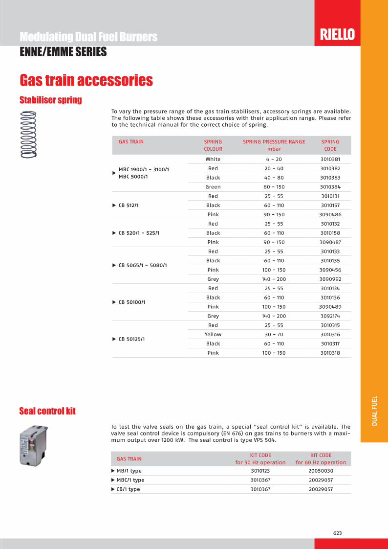
623
Gas train accessories
Modulating Dual Fuel BurnersENNE/EMME SERIES
Seal control kitTo test the valve seals on the gas train, a special “seal control kit” is available. The valve seal control device is compulsory (EN 676) on gas trains to burners with a maxi-mum output over 1200 kW. The seal control is type VPS 504.
GAS TRAIN KIT CODE
for 50 Hz operation KIT CODE
for 60 Hz operation
u M 1 t e 3010123 20050030
u M C 1 t e 3010367 20029057
u C 1 t e 3010367 20029057
Stabiliser springTo vary the pressure range of the gas train stabilisers, accessory springs are available. The following table shows these accessories with their application range. Please refer to the technical manual for the correct choice of spring.
GAS TRAIN SPRINGCOLOUR
SPRING PRESSURE RANGE mbar
SPRINGCODE
uM C 1 00 1 3100 1M C 000 1
White 4 - 20 3010381
Red 20 - 40 3010382
Black 40 - 80 3010383
Green 80 - 150 3010384
u C 12 1
Red 25 - 55 3010131
Black 60 - 110 3010157
Pink 90 - 150 3090486
u C 20 1 2 1
Red 25 - 55 3010132
Black 60 - 110 3010158
Pink 90 - 150 3090487
u C 0 1 0 0 1
Red 25 - 55 3010133
Black 60 - 110 3010135
Pink 100 - 150 3090456
Grey 140 - 200 3090992
u C 0100 1
Red 25 - 55 3010134
Black 60 - 110 3010136
Pink 100 - 150 3090489
Grey 140 - 200 3092174
u C 012 1
Red 25 - 55 3010315
Yellow 30 - 70 3010316
Black 60 - 110 3010317
Pink 100 - 150 3010318


625
ST
INDUSTRIAL BURNERS
SYSTEM COMPONENTS
Industrial combustion system data sheets section
HEATING PUMPING UNITS
PRESSURE REGULATING / REDUCING UNITSSAFETY / REGULATING GAS TRAINSSAFETY / REGULATING PROPORTIONAL GAS TRAINS
CENTRIFUGAL AIR FANS
BURNER CONTROL PANELS
pag 627
pag 649
pag 649
pag 657
pag 671
pag 685

We are here energizing your working environment and processes
www.rielloburners.com

627
ST
DB SERIES
Industrial Dual Block Oil, Gas and Dual Fuel Burners
The new DB burners platform represents the evolution in Riello Burners industrial product range.They are dual block burners for application in big plants (district heating, hospitals) as well as in food, chemicals, textile industry for matching with hot water boilers, steam and thermal oil generators.DB series burners can be supplied with electronic or mechanical air-fuel ratio control according to customer specification.DB 9-12-16-20 are equipped with pilot ignition, while for DB 4-6 models it can be supplied on demand. DB series can work with pre-heated air up to 150°C as standard, up to 250°C with special construction. New variable geometry combustion head allows to reach < 80 mg/kWh NOx emission on natural gas operations.An hinge system for easier combustion head maintenance is available on all models.As part of the offer, various accessories (air fan, control panels, high pressure gas train, etc) are available.
1000/2500 ÷ 5000 kW 1400/4000 ÷ 7800 kW 1500/5000 ÷ 9500 kW 12 1700/7000 ÷ 12500 kW 1 2500/8000 ÷ 16000 kW 20 3000/10000 ÷ 20000 kW

628
Industrial Dual Block Oil, Gas and Dual Fuel BurnersDB SERIES
FIRING RATES
Modulation range Working field
Test conditions conforming to EN 267- EN676 Temperature: 20°CPressure: 1013.5 mbarAltitude: 100 m a.s.l.

629
ST
Industrial Dual Block Oil, Gas and Dual Fuel BurnersDB SERIES
Overall dimensions (mm)
BURNER
A
L
P
O B C (*)
D
N
F E
M
b2 a2
GAS CONNECTIONS
All dimensions are approximate and mentioned just as an indication. Please refer to Riello Burners Technical Department for further detailed information.
MODEL A B C D E F L (L*) M N O P
u 1577 700 536 313 385 375 1033 (1217) 450 760 341 183
u 1577 700 536 363 385 375 1033 (1217) 450 760 341 183
u 1857 851 662 413 420 333 1195 (1539) 550 753 344 208
u 12 1857 851 662 456 420 333 1195 (1539) 550 753 344 208
u 1 2080 852 797 544 486 448 1283 (1600) 761 934 431 258
u 20 2080 852 797 590 486 448 1283 (1600) 761 934 431 258
L = gas versionL* = oil and dual fuel versionsa2 - b2 = see “Burner-boiler mounting flange” dimensions table(*) Instructions about how to realize the fettling are reported in the manual of the burner in the chapter “Fixing to the boiler”.
DN 65 gas connection from belowElbow adapter DN 65 requiredDN 80 gas connection from below (for gas versions). Elbow adapter DN 80 required.
DB 9 - 12 DB 16 - 20
DN 80 gas connection from below (for gas versions). Elbow adapter DN 80 required.
DN 100 gas connection from the sideElbow 100/100 adapter already included as standard equipment
DB 4: DN 65DB 6: DN 80

630
Industrial Dual Block Oil, Gas and Dual Fuel BurnersDB SERIES
BURNER - BOILER MOUNTING FLANGE
PACKAGING
Z
XY
AIR DUCT CONNECTION FIXING TO THE BOILER GAS SUPPLY
DB 4 - 6 - 9 - 12 DB 16 - 20
Ø2
D3b1
b2
t
b
a1a2 at
t1 t1
Ø3
D2
Ø1
D1
45°
45°
D2
Ø1
D1
45°
22,5°
Overall dimensions and weights to estimate the delivery.
MODEL X Y Z kg
u 2100 1000 1200 200
u 2040 1180 1125 200
u 2040 1180 1125 270
u 12 2040 1180 1125 250
u 1 2200 1000 1300 530
u 20 2200 1000 1300 550
MODEL a a1 a2 b b1 b2 D1 D2 D3 t t1 Ø1 Ø2 Ø3
u 329 370 400 308 370 409 350 452 145 - DN 65 130 130 M18 4x45°M16 13
u 329 370 400 308 370 409 380 495 160 - DN80 130 130 M18 M16 13
u 436 476 506 400 440 470 420 608 160 - DN 80 200 180 M20 M18 11
u 12 436 476 506 400 440 470 465 608 160 - DN 80 200 180 M20 18 11
u 1 562 620 652 452 510 542 560 700 180 - DN 100 260 205 M16 18 11
u 20 562 620 652 452 510 542 600 700 160 - DN 100 260 205 M16 18 11
Overall dimensions (mm)

631
ST
Industrial Dual Block Oil, Gas and Dual Fuel BurnersDB SERIES
BASIC DESIGNATION
EXTENDED DESIGNATION
S C03 TC S1 0 T 0 230 0 0
Series: DB
Size: 4 - 6 - 9 - 12 - 16 - 20
Fuel: S = natural gas NS = heavy oil/natural gas
L = light oil NAS = heavy oil assisted atomizing/natural gas
N = heavy oil LS = light oil/natural gas
NA = heavy oil assisted atomizing LP = light oil/LPG
P = LPG NAP = heavy oil assisted atomizing/LPG
Operation: M = mechanical cam EV = electronic cam predisposed for variable speed
E = electronic cam
Emissions*: C11 = class 1 oil - class 1 gas
C23 = class 2 oil - class 3 gas
C03 = No oil - class 3 gas
C01 = No oil - class 1 gas
C10 = class 1 oil - No gas
C20 = class 2 oil - No gas
Head length: TC = standard head
TL = extended head
Flame safeguard: FS1 = standard checking (1 stop/24 h)
FS2 = continuous self checking
Fuel supply: FR = from right
FL = from left
Air supply: A0 = from the bottom
A180 = from the top
Air max temperature: T50 = 50°C
T150 = 150°C
T250 = 250°C
Auxiliary voltage: 230V/50-60Hz
110V/50-60Hz
* Estimated, emissions values, considering a hot water boiler with thermal load of 1,1 MW/m3 Guaranteed values to be confirmed after the verification of the combustion chamber charachteristics
DESIGNATION OF SERIES
Specification
Overall dimensions and weights to estimate the delivery.

632
Industrial Dual Block Oil, Gas and Dual Fuel BurnersDB SERIES
SpecificationDB SERIES - STATE OF SUPPLY
ll urnersDual block forced draught burner, two stages progressive or modulating operation (with a kit), separate supply, fully automatic, made up of:- Air damper for air setting with variable profile cam controlled by a servomotor (version /M – mechanical cam)- Air damper for air setting with air servomotor managed by microprocessor (version /E – electronic cam)- Variable geometry combustion head that can be set according the required output- Combustion head servomotor managed by microprocessor (version /E – electronic cam DB16-20 only)- Pilot burner with two gas valves and pressure regulator (as standard on DB9-12-16-20 only)- Minimum air pressure switch- Flame inspection window- Electrical interface box with ignition transformer inside- Opening hinge to have easier combustion head inspection and maintenance- IP54 protection level.
il urner- Phototcell for flame detection- Nozzle pipe- Safety nozzle valve- Oil lance without nozzle (nozzle must be ordered separately) - Valves group with safety oil valves- Oil capacity regulator controlled by air servomotor linkage (version /M – mechanical cam)- Oil capacity regulator with servomotor managed by microprocessor (version /E – electronic cam)- Maximum oil pressure switch on the return circuit- Pressure gauge on delivery and return circuit.
Standard equipment: - screws for fixing the burner flange to the boiler- thermal screen- instruction handbook for installation, use and maintenance- spare parts catalogue.
as urner- Photocell for flame detection- Maximum gas pressure switch- Butterfly gas valve controlled by air servomotor linkage (version /M – mechanical cam)- Butterfly gas valve with servomotor managed by microprocessor (version /E – electronic cam)- Gas pressure test point to the combustion head.
Standard equipment:- screws for fixing the burner flange to the boiler - thermal screen- screws for fixing the gas train flange to the burner- gas train gasket- high voltage burner ignition for DB 4÷6- pilot burner ignition for DB 9÷20 (for DB 4÷6 on demand)- instruction handbook for installation, use and maintenance- spare parts catalogue.
ual uel urner il as- Phototcell for flame detection- Nozzle pipe- Safety nozzle valve

633
ST
Industrial Dual Block Oil, Gas and Dual Fuel BurnersDB SERIES
- Oil lance without nozzle (nozzle must be ordered separately) - Valves group with safety oil valves- Oil capacity regulator controlled by air servomotor linkage (version /M – mechanical cam)- Oil capacity regulator with servomotor managed by microprocessor (version /E – electronic cam)- Maximum oil pressure switch on the return circuit- Pressure gauge on delivery and return circuit- Maximum gas pressure switch- Butterfly gas valve controlled by air servomotor linkage (version /M – mechanical cam)- Gas/oil servomotor managed by microprocessor (version /E – electronic cam) for butterfly gas valve / oil capacity
regulator control- Gas pressure test point to the combustion head.
Standard equipment: - screws for fixing the burner flange to the boiler- thermal screen- screws for fixing the gas train flange to the burner - gas train gasket- high voltage burner ignition for DB 4÷6- pilot burner ignition for DB 9÷20 (for DB 4÷6 on demand)- instruction handbook for installation, use and maintenance- spare parts catalogue.
SpecificationDB SERIES - STATE OF SUPPLY
Specification

634
Industrial Dual Block Oil, Gas and Dual Fuel BurnersDB SERIES
Burners
Models available
* Max capacity is referred to: Light oil net calorific value 11,8 kWh/kh - 10200 kcal/kg - Viscosity at 20°C 4-6 mm2/s (cSt) Heavy oil net calorific value 11,1-11,3 kWh/kg - 9545-9720 kcal/kg - Viscosity at 20°C 500 mm2/s (cSt) G20 net calorific value 10 kWh/Nm3 - Density 0,71 kg/Nm3
G25 net calorific value 8,6 kWh/Nm3 - Density 0,78 kg/Nm3
LPG net calorific value 25,8 kWh/Nm3 - Density 2,02 kg/Nm3
** FS1 operation as standard. FS2 on demand.
MODEL ** FUEL HEAT OUTPUT *
OIL GAS(kW) (kg/h) (Nm3/h)
LOW
NOX
MO
DEL
S DB 4 SE TC A 0 FS1 230/50-60 Hz Natural gas1000/2500-5000
- 500
DB 4 SE TC A 180 FS1 230/50-60 Hz Natural gas - 500
DB 6 SE TC A 0 FS1 230/50-60 Hz Natural gas1400/4000-7800
- 780
DB 6 SE TC A 180 FS1 230/50-60 Hz Natural gas - 780
DB 9 SE TC A 0 FS1 230/50-60 Hz Natural gas1500/5000-9500
- 950
DB 9 SE TC A 180 FS1 230/50-60 Hz Natural gas - 950
DB 12 SE TC A 0 FS1 230/50-60 Hz Natural gas1700/7000-12500
- 1250
DB 12 SE TC A 180 FS1 230/50-60 Hz Natural gas - 1250
DB 16 SE TC A 0 FS1 230/50-60 Hz Natural gas2500/8000-16000
- 1600
DB 16 SE TC A 180 FS1 230/50-60 Hz Natural gas - 1600
DB 20 SE TC A 0 FS1 230/50-60 Hz Natural gas3000/10000-20000
- 2000
DB 20 SE TC A 180 FS1 230/50-60 Hz Natural gas - 2000
OTH
ER M
OD
ELS
AVA
ILAB
LE DB 4 SM TC A 0 FS1 230/50-60 Hz Natural gas
1000/2500-5000
- 500
DB 4 SM TC A 180 FS1 230/50-60 Hz Natural gas - 500
DB 4 LE TC A 0 FS1 230/50-60 Hz Light oil 422 -
DB 4 LE TC A 180 FS1 230/50-60 Hz Light oil 422 -
DB 4 LSE TC A 0 FS1 230/50-60 Hz Light oil / Natural gas 422 500
DB 4 LSE TC A 180 FS1 230/50-60 Hz Light oil / Natural gas 422 500
DB 4 LSM TC A 0 FS1 230/50-60 Hz Light oil / Natural gas 422 500
DB 4 LSM TC A 180 FS1 230/50-60 Hz Light oil / Natural gas 422 500
DB 4 NM TC A 0 FS1 230/50-60 Hz Heavy oil 450 -
DB 4 NM TC A 180 FS1 230/50-60 Hz Heavy oil 450 -
DB 4 NSM TC A 0 FS1 230/50-60 Hz Heavy oil / Natural gas 450 500
DB 4 NSM TC A 180 FS1 230/50-60 Hz Heavy oil / Natural gas 450 500
DB 6 SM TC A 0 FS1 230/50-60 Hz Natural gas
1400/4000-7800
- 780
DB 6 SM TC A 180 FS1 230/50-60 Hz Natural gas - 780
DB 6 LE TC A 0 FS1 230/50-60 Hz Light oil 658 -
DB 6 LE TC A 180 FS1 230/50-60 Hz Light oil 658 -
DB 6 LSE TC A 0 FS1 230/50-60 Hz Light oil / Natural gas 658 780
DB 6 LSE TC A 180 FS1 230/50-60 Hz Light oil / Natural gas 658 780
DB 6 LSM TC A 0 FS1 230/50-60 Hz Light oil / Natural gas 658 780
DB 6 LSM TC A 180 FS1 230/50-60 Hz Light oil / Natural gas 658 780
DB 6 NM TC A 0 FS1 230/50-60 Hz Heavy oil 703 -
DB 6 NM TC A 180 FS1 230/50-60 Hz Heavy oil 703 -
DB 6 NSM TC A 0 FS1 230/50-60 Hz Heavy oil / Natural gas 703 780
DB 6 NSM TC A 180 FS1 230/50-60 Hz Heavy oil / Natural gas 703 780
DB 9 SM TC A 0 FS1 230/50-60 Hz Natural gas
1500/5000-9500
- 950
DB 9 SM TC A 180 FS1 230/50-60 Hz Natural gas - 950
DB 9 LE TC A 0 FS1 230/50-60 Hz Light oil 801 -
DB 9 LE TC A 180 FS1 230/50-60 Hz Light oil 801 -
DB 9 LSE TC A 0 FS1 230/50-60 Hz Light oil / Natural gas 801 950
DB 9 LSE TC A 180 FS1 230/50-60 Hz Light oil / Natural gas 801 950
DB 9 LSM TC A 0 FS1 230/50-60 Hz Light oil / Natural gas 801 950

635
ST
Industrial Dual Block Oil, Gas and Dual Fuel BurnersDB SERIES
Other versions are available on request.
Burners
Models available
MODEL ** FUEL HEAT OUTPUT *
OIL GAS
(kW) (kg/h) (Nm3/h)
OTH
ER M
OD
ELS
AVA
ILAB
LE DB 9 LSM TC A 180 FS1 230/50-60 Hz Light oil / Natural gas
1500/5000-9500
801 950
DB 9 NM TC A 0 FS1 230/50-60 Hz Heavy oil 856 -
DB 9 NM TC A 180 FS1 230/50-60 Hz Heavy oil 856 -
DB 9 NSM TC A 0 FS1 230/50-60 Hz Heavy oil / Natural gas 856 950
DB 9 NSM TC A 180 FS1 230/50-60 Hz Heavy oil / Natural gas 856 950
DB 12 SM TC A 0 FS1 230/50-60 Hz Natural gas
1700/7000-12500
- 1250
DB 12 SM TC A 180 FS1 230/50-60 Hz Natural gas - 1250
DB 12 LE TC A 0 FS1 230/50-60 Hz Light oil 1054 -
DB 12 LE TC A 180 FS1 230/50-60 Hz Light oil 1054 -
DB 12 LSE TC A 0 FS1 230/50-60 Hz Light oil / Natural gas 1054 1250
DB 12 LSE TC A 180 FS1 230/50-60 Hz Light oil / Natural gas 1054 1250
DB 12 LSM TC A 0 FS1 230/50-60 Hz Light oil / Natural gas 1054 1250
DB 12 LSM TC A 180 FS1 230/50-60 Hz Light oil / Natural gas 1054 1250
DB 12 NM TC A 0 FS1 230/50-60 Hz Heavy oil 1126 -
DB 12 NM TC A 180 FS1 230/50-60 Hz Heavy oil 1126 -
DB 12 NSM TC A 0 FS1 230/50-60 Hz Heavy oil / Natural gas 1126 1250
DB 12 NSM TC A 180 FS1 230/50-60 Hz Heavy oil / Natural gas 1126 1250
DB 16 SM TC A 0 FS1 230/50-60 Hz Natural gas
2500/8000-16000
- 1600
DB 16 SM TC A 180 FS1 230/50-60 Hz Natural gas - 1600
DB 16 LE TC A 0 FS1 230/50-60 Hz Light oil 1349 -
DB 16 LE TC A 180 FS1 230/50-60 Hz Light oil 1349 -
DB 16 LSE TC A 0 FS1 230/50-60 Hz Light oil / Natural gas 1349 1600
DB 16 LSE TC A 180 FS1 230/50-60 Hz Light oil / Natural gas 1349 1600
DB 16 LSM TC A 0 FS1 230/50-60 Hz Light oil / Natural gas 1349 1600
DB 16 LSM TC A 180 FS1 230/50-60 Hz Light oil / Natural gas 1349 1600
DB 16 NM TC A 0 FS1 230/50-60 Hz Heavy oil 1441 -
DB 16 NM TC A 180 FS1 230/50-60 Hz Heavy oil 1441 -
DB 16 NSM TC A 0 FS1 230/50-60 Hz Heavy oil / Natural gas 1441 1600
DB 16 NSM TC A 180 FS1 230/50-60 Hz Heavy oil / Natural gas 1441 1600
DB 20 SM TC A 0 FS1 230/50-60 Hz Natural gas
3000/10000-20000
- 2000
DB 20 SM TC A 180 FS1 230/50-60 Hz Natural gas - 2000
DB 20 LE TC A 0 FS1 230/50-60 Hz Light oil 1686 -
DB 20 LE TC A 180 FS1 230/50-60 Hz Light oil 1686 -
DB 20 LSE TC A 0 FS1 230/50-60 Hz Light oil / Natural gas 1686 2000
DB 20 LSE TC A 180 FS1 230/50-60 Hz Light oil / Natural gas 1686 2000
DB 20 LSM TC A 0 FS1 230/50-60 Hz Light oil / Natural gas 1686 2000
DB 20 LSM TC A 180 FS1 230/50-60 Hz Light oil / Natural gas 1686 2000
DB 20 NM TC A 0 FS1 230/50-60 Hz Heavy oil 1802 -
DB 20 NM TC A 180 FS1 230/50-60 Hz Heavy oil 1802 -
DB 20 NSM TC A 0 FS1 230/50-60 Hz Heavy oil / Natural gas 1802 2000
DB 20 NSM TC A 180 FS1 230/50-60 Hz Heavy oil / Natural gas 1802 2000
* Max capacity is referred to: Light oil net calorific value 11,8 kWh/kh - 10200 kcal/kg - Viscosity at 20°C 4-6 mm2/s (cSt) Heavy oil net calorific value 11,1-11,3 kWh/kg - 9545-9720 kcal/kg - Viscosity at 20°C 500 mm2/s (cSt) G20 net calorific value 10 kWh/Nm3 - Density 0,71 kg/Nm3
G25 net calorific value 8,6 kWh/Nm3 - Density 0,78 kg/Nm3
LPG net calorific value 25,8 kWh/Nm3 - Density 2,02 kg/Nm3
** FS1 operation as standard. FS2 on demand.

636
Burner accessories
Industrial Dual Block Oil, Gas and Dual Fuel BurnersDB SERIES
Nozzles for DB 4 - 6 - 9 - 12 - 16 - 20The nozzles must be ordered separately. The following table shows the features and codes on the basis of the maximum required fuel output. One nozzle required for each burner, able to guarantee the calculated oil delivery.
Nozzles:W2 maximum modulating ratio 1:4 (interchangeable with B5)B5 maximum modulating ratio 1:5 (interchangeable with W2)CT5 maximum modulating ratio 1:5 bigger shape
*steam boiler size according to: N.C.V. heavy oil = 11,16 kWh/kg combustion air = 50°C 1 ton/h = 775 kW (eff = 90%)
For steam/air assisted atomizing, special nozzles available on demand.
BURNER
ton/h*
RATED DELIVERY
kg/h
NOZZLES TYPEW2 - 45°
CODE
RATED DELIVERY
kg/h
NOZZLES TYPEB5 - 45° - AA
CODE
RATED DELIVERY
kg/h
NOZZLES TYPECT5 - 45°
CODE
u
3 200 3045438 200 3009800
225 3045440 225 3009801
250 3045442 250 3009802
4 275 3045444 275 3009803
300 3045446 300 3009804
325 3045448 325 3009805
5 350 3045450 350 3009806
375 3045452 375 3009807
6 400 3045454 400 3009808
425 3045455 425 3009809
450 3045456 450 3009810
u
475 3045457 475 3009811
500 3045458 500 3009812
525 3045459 525 3009813
8 550 3045460 550 3009814
575 3045461 575 3009815
600 3045462 600 3009816
650 3045463 650 3009817
10 700 3045464 700 3009818
u
750 3045465 750 3009819
800 3009820
12 850 3009821
u 12 700 20006462
u 12 1 800 20006465
u 12 1
20
900 20006468
15 1000 20006469
16 1100 20006470
u 1 20
1200 20006471
18 1300 20006472
20 1400 20006473
1500 20006474
u 20
22 1600 20006475
1700 20006476
25 1800 20006477

637
ST
Burner accessories
Industrial Dual Block Oil, Gas and Dual Fuel BurnersDB SERIES
High pressure flexible tubesIn order to facilitate the connection of the burner to the fuel line adduction there are flexible tubes available according to the following table.
BURNER TUBE DIAMETER
TUBE LENGTH (mm)
MAXIMUM WORKING PRESSURE (bar)
TUBE CODE
u 1/2” 1500 40 3094227
u 12 1 20 3/4” 2000 40 3094226
Depending on the servomotor fitted to the burner, a three-pole potentiometer (1000 W) can be installed to check the position of the servomotor. The KITS available for the various burners are listed below.
BURNER
POTENTIOMETER KIT CODE
u 12 1 20 3010021
Potentiometer kit
Check valveIn order to avoid fuel return, that could damage the hydraulic circuit, “check valve” are available.
BURNER VALVE DIAMETER
VALVE CODE
u 1/2” in progress
u 12 1 20 3/4” 3012660
Circulation group (by-pass valve)
If the burner is far away from the pumping group it is possible to install a circulation group that allows the circulates of the heated fuel during the stand-by phase.
BURNER GROUP DIAMETER
GROUP CODE
u 1/2” in progress
u 12 1 20 3/4” in progress
High pressure oil filter
In order to protect the hydraulic circuit of the burner from the possible presence of particles in the combustion line, these following filters are available.
BURNER FILTER DIAMETER
FILTERING DEGREE (µm)
FILTER CODE
u 1/2” 500 3091881
u 12 1 20 3/4” 500 in progress


639
ST
The industrial burners ER series are designed especially for water tube boilers used in big civil installations and industrial processes with a remarkable thermal demand.These burners allow to realise a modular and flexible combustion system adding a preparation fuel unit (regulation pressure group set, preheating/pumping oil station), a gas train, a control panel and a fan.Preheated air can also be used as in the oil diathermic generators and other heat recovery systems.The modulating regulation always allows to reach a wide modulation ratio and optimal fluid-dynamics conditions for a good combustion.
540/2500 ÷ 4000 kW 840/4000 ÷ 6000 kW 1250/6000 ÷ 9000 kW 12 1750/9000 ÷ 12000 kW 1 2350/12000 ÷ 16000 kW 20 3000/16000 ÷ 20000 kW 2 3500/20000 ÷ 25000 kW 32 4000/25000 ÷ 32000 kW
Industrial Oil, Gas and Dual Fuel Air Register Burners
ER SERIES

640
FIRING RATES
Test conditions conforming to EN 267 - EN 676:Temperature: 20°C - Pressure: 1013,5 mbar - Altitude: 0 m a.s.l.
Modulation range Working field
ER SERIESIndustrial Oil, Gas and Dual Fuel Air Register Burners

641
ST
BURNER
Overall dimensions (mm)ER 4 - 6 - 9 - 12
ER 16 - 20 - 25 - 32
MODEL A B C D E F H I M N P Y V
u 855 455 400 835 1160 330 370 530 DN65 605 380 307 542
u 855 455 400 835 1160 330 430 530 DN65 605 380 307 542
u 1150 600 550 1170 1345 350 520 720 DN80 765 457 345 588
u 12 1150 600 550 1170 1345 350 600 720 DN80 765 457 345 588
u 1 1623 903 720 1570 1670 372 690 970 DN100 1122 716 423 600
u 20 1623 903 720 1570 1670 372 770 970 DN100 1122 716 423 600
u 2 1835 1007 828 1758 1952 472 870 1050 DN125 1294 794 487 708
u 32 1835 1007 828 1758 1952 472 980 1050 DN125 1294 794 487 708
A
CB
I
V
E
Y
F
P
H
N
D
M
I
V
A
CB
H
F P
N
E
M
Y
D
ER SERIESIndustrial Oil, Gas and Dual Fuel Air Register Burners

642
AIR DUCT CONNECTION
b
t
b2
t
t
t
t
b1
a1a2 a
FIXING TO THE BOILER
D2
45°
D1
Ø1
22,5
GAS SUPPLY
Ø2
D3DN
Ø2
D3
Z
XY
BURNER - BOILER MOUNTING FLANGE
PACKAGING
MODEL X Y Z kg
u 2090 1460 1680 200
u 2090 1460 1680 200
u 2300 1750 1900 300
u 12 2300 1750 1900 300
u 1 2450 1850 2000 500
u 20 2450 1850 2000 500
u 2 3000 2500 2300 800
u 32 3000 2500 2300 1550
MODEL a a1 a2 b b1 b2 D1 D2 D3 t Ø1 Ø2
u 400 444 480 324 280 360 380 552 145 148 M18 18
u 400 444 480 324 280 360 440 552 145 148 M18 18
u 500 551 580 405 355 435 530 800 160 125 M18 18
u 12 500 551 580 405 355 435 620 800 160 125 M18 18
u 1 710 775 810 567 500 600 710 970 180 160 M20 18
u 20 710 775 810 567 500 600 790 970 180 160 M20 18
u 2 900 968 1018 708 640 758 930 1200 210 200 M20 18
u 32 900 968 1018 708 640 758 1050 1200 210 200 M20 18
ER 9÷32ER 4-6
Industrial Oil, Gas and Dual Fuel Air Register Burners
Overall dimensions (mm)

643
ST
DESIGNATION OF SERIES
BASIC DESIGNATION
EXTENDED DESIGNATION
S C03 TC S1 0 T 0 230 0 0
Series: ER
Size: 4 - 6 - 9 - 12 - 16 - 20 - 25 - 32
Fuel: S Natural gas NS Heavy oil/natural gas
L Light oil NAS Heavy oil assisted atomizing/Natural gas
N Heavy oil LS Light oil/Natural gas
NA Heavy oil assisted atomizing LP Light oil/LPG
P LPG NAP Heavy oil assisted atomizing/LPG
Operation: E electronic cam
M mechanic cam
Emissions *: C11 = class 1 oil - class 1 oil
C23 = class 2 oil - class 3 gas
C03 = No oil - class 3 gas
C01 = No oil - class 1 gas
C10 = class 1 oil - No gas
C20 = class 2 oil - No gas
Head length: TC standard head
TL extended head
Flame safeguard: FS1 = standard checking (1 stop/24 h)
FS2 = continuous self checking
Fuel supply: FR = from right
FL = from left
Air supply: A0 = from the bottom
A180 = from the top
Air max temperature: T50 = 50 °C
T150 = 150 °C
T250 = 250 °C
Auxiliary voltage: 230/50-60 230V/50-60Hz
110/50-60 110V/50-60Hz
* Estimated, not garanteed emissions values, considering a hot water boiler with thermal load of 1,1 MW/m3
ER SERIESIndustrial Oil, Gas and Dual Fuel Air Register Burners
Specification

644
SpecificationSTATE OF SUPPLY
il urnerForced draught oil burner with modulating operation and separate supplies, fully automatic, made up of:- Sheet-steel airlock painted with a front cover for access to the internal elements- Air dampers for air setting controlled by two indipendent high precision servomotors - Combustion head fitted with:
- stainless steel end cone, resistant to corrosion and high temperatures- pilot burner with gas train and ignition electrodes- flame stability disk made up of axial swirlers
- Flame shape regulation device- Photocell for flame detection- Minimum air pressure switch- Nozzle pipe- Safety nozzle valve- Valves group with safety oil valves- Automatic regulator of oil delivery controlled by a high precision servomotor- Maximum oil pressure switch on the return circuit- Pressure gauge on the delivery circuit- Pressure gauge on the return circuit- Electrical box with ignition transformer- IP 54 electric protection level.
Standard equipment: - Screws for fixing the burner flange to the boiler- Thermal screen- Instruction handbook for installation, use and maintenance- Spare parts catalogue.
as urnerForced draught gas burner with modulating operation and separate supplies, fully automatic, made up of:- Sheet-steel airlock painted with a front cover for access to the internal elements- Air dampers for air setting controlled by two indipendent high precision servomotors - Combustion head fitted with:
- stainless steel end cone, resistant to corrosion and high temperatures- gas distributor with multiple pipes- pilot burner with gas train and ignition electrodes- uv photocell- flame stability disk made up of axial swirler
- Flame shape regulation device- Minimum air pressure switch- Maximum gas pressure switch- Automatic regulator for gas delivery, controlled by a high precision servomotor- Gas pressure test point to the combustion head- Electrical box with ignition transformer- IP 54 electric protection level.
Standard equipment:- Screws for fixing the burner flange to the boiler - Thermal screen- Screws for fixing the gas train flange to the burner- Gas train gasket- Instruction handbook for installation, use and maintenance- Spare parts catalogue.
ual uel urner oil gasForced draught dual fuel burner with modulating operation and separate supplies, fully automatic, made up of:- Sheet-steel airlock painted with a front cover for access to the internal elements- Air dampers for air setting controlled by two indipendent high precision servomotors
ER SERIESIndustrial Oil, Gas and Dual Fuel Air Register Burners

645
ST
SpecificationSTATE OF SUPPLY
- Combustion head fitted with:- stainless steel end cone, resistant to corrosion and high temperatures- gas distributor with multiple pipes- pilot burner with gas train and ignition electrodes- flame stability disk made up of axial swirler
- Flame shape regulation device- UV photocell for flame detection- Nozzle pipe - Safety nozzle valve- Valves group with safety oil valves- Automatic regulator of oil and gas delivery controlled by a high precision servomotor- Maximum oil pressure switch on the return circuit- Pressure gauge on the delivery circuit- Pressure gauge on the return circuit- Minimum air pressure switch- Maximum gas pressure switch- Gas pressure test point to the combustion head- Electrical box with ignition transformer- IP 54 electric protection level.
Standard equipment: - Screws for fixing the burner flange to the boiler- Thermal screen- Screws for fixing the gas train flange to the burner - Gas train gasket- Instruction handbook for installation, use and maintenance- Spare parts catalogue.
ER SERIESIndustrial Oil, Gas and Dual Fuel Air Register Burners

646
Further version available on request* Max capacity is referred to: Light oil net calorific value 11,86 kWh/kh - 10200 kcal/kg - Viscosity at 20°C 4-6 mm2/s (cSt) Heavy oil net calorific value 11,1-11,3 kWh/kg - 9545-9720 kcal/kg - Viscosity at 20°C 500 mm2/s (cSt) G20 net calorific value 10 kWh/Nm3 - Density 0,71 kg/Nm3
G25 net calorific value 8,6 kWh/Nm3 - Density 0,78 kg/Nm3
LPG net calorific value 25,8 kWh/Nm3 - Density 2,02 kg/Nm3
MODEL
FUEL HEAT OUTPUT *
OIL GAS
(kW) (kg/h) max (Nm3/h) max
ER 4 S E … Natural gas 540/2500-4000 --- 400
ER 4 L E … Light oil 820/2500-4000 337 ---
ER 4 N E … Heavy oil 1100/2500-4000 357 ---
ER 4 P E … LPG 540/2500-4000 --- 155
ER 4 NP E … Heavy oil/LPG 1100/2500-4000 357 155
ER 4 NS E … Heavy oil/Natural gas 1100/2500-4000 357 400
ER 4 LS E … Light oil/Natural gas 820/2500-4000 337 400
ER 4 LP E … Light oil/LPG 820/2500-4000 337 155
ER 4 NA E … Heavy oil steam atomising 1100/2500-4000 357 ---
ER 4 NAS E … Natural gas / heavy oil steam atomising 1100/2500-4000 357 400
ER 6 S E … Natural gas 840/4000-6000 --- 600
ER 6 L E … Light oil 1250/4000-6000 506 ---
ER 6 N E … Heavy oil 1700/4000-6000 536 ---
ER 6 P E … LPG 840/4000-6000 --- 233
ER 6 NP E … Heavy oil/LPG 1700/4000-6000 536 233
ER 6 NS E … Heavy oil/Natural gas 1700/4000-6000 536 600
ER 6 LS E … Light oil/Natural gas 1250/4000-6000 506 600
ER 6 LP E … Light oil/LPG 1250/4000-6000 506 233
ER 6 NA E … Heavy oil steam atomising 1700/4000-6000 536 ---
ER 6 NAS E … Natural gas / heavy oil steam atomising 1700/4000-6000 536 600
ER 9 S E … Natural gas 1250/6000-9000 --- 900
ER 9 L E … Light oil 1870/6000-9000 759 ---
ER 9 N E … Heavy oil 2500/6000-9000 804 ---
ER 9 P E … LPG 1250/6000-9000 --- 349
ER 9 NP E … Heavy oil/LPG 2500/6000-9000 804 349
ER 9 NS E … Heavy oil/Natural gas 2500/6000-9000 804 900
ER 9 LS E … Light oil/Natural gas 1870/6000-9000 759 900
ER 9 LP E … Light oil/LPG 1870/6000-9000 759 349
ER 9 NA E … Heavy oil steam atomising 2500/6000-9000 804 ---
ER 9 NAS E … Natural gas / heavy oil steam atomising 2500/6000-9000 804 900
ER 12 S E … Natural gas 1750/9000-12000 --- 1200
ER 12 L E … Light oil 2600/9000-12000 1012 ---
ER 12 N E … Heavy oil 3500/9000-12000 1071 ---
ER 12 P E … LPG 2100/9000-12000 --- 465
ER 12 NP E … Heavy oil/LPG 3500/9000-12000 1071 465
ER 12 NS E … Heavy oil/Natural gas 3500/9000-12000 1071 1200
ER 12 LS E … Light oil/Natural gas 2600/9000-12000 1012 1200
ER 12 LP E … Light oil/LPG 2600/9000-12000 1012 465
ER 12 NA E … Heavy oil steam atomising 3500/9000-12000 1071 ---
ER 12 NAS E … Natural gas / heavy oil steam atomising 3500/9000-12000 1071 1200
Burners
ER SERIES
Models available
Industrial Oil, Gas and Dual Fuel Air Register Burners

647
ST
Other versions are available on request.
MODEL
FUEL HEAT OUTPUT *
OIL GAS
(kW) (kg/h) max (Nm3/h) max
ER 16 S E … Natural gas 2350/12000-16000 --- 1600
ER 16 L E … Light oil 3500/12000-16000 1349 ---
ER 16 N E … Heavy oil 4700/12000-16000 1428 ---
ER 16 P E … LPG 2800/12000-16000 --- 620
ER 16 NP E … Heavy oil/LPG 4700/12000-16000 1428 620
ER 16 NS E … Heavy oil/Natural gas 4700/12000-16000 1428 1600
ER 16 LS E … Light oil/Natural gas 3500/12000-16000 1349 1600
ER 16 LP E … Light oil/LPG 3500/12000-16000 1349 620
ER 16 NA E … Heavy oil steam atomising 4700/12000-16000 1428 ---
ER 16 NAS E … Natural gas / heavy oil steam atomising 4700/12000-16000 1428 1600
ER 20 S E … Natural gas 3000/16000-20000 --- 2000
ER 20 L E … Light oil 4500/16000-20000 1686 ---
ER 20 N E … Heavy oil 6000/16000-20000 1786 ---
ER 20 P E … LPG 3600/16000-20000 --- 775
ER 20 NP E … Heavy oil/LPG 6000/16000-20000 1786 775
ER 20 NS E … Heavy oil/Natural gas 6000/16000-20000 1786 2000
ER 20 LS E … Light oil/Natural gas 4500/16000-20000 1686 2000
ER 20 LP E … Light oil/LPG 4500/16000-20000 1686 775
ER 20 NA E … Heavy oil steam atomising 6000/16000-20000 1786 ---
ER 20 NAS E … Natural gas / heavy oil steam atomising 6000/16000-20000 1786 2000
ER 25 S E … Natural gas 3500/20000-25000 --- 2500
ER 25 L E … Light oil 3500/20000-25000 2107 ---
ER 25 N E … Heavy oil 3500/20000-25000 2232 ---
ER 25 P E … LPG 3500/20000-25000 --- 968
ER 25 NP E … Heavy oil/LPG 3500/20000-25000 2232 968
ER 25 NS E … Heavy oil/natural gas 3500/20000-25000 2232 2500
ER 25 LS E … Light oil/natural gas 3500/20000-25000 2107 2500
ER 25 LP E … Light oil/LPG 3500/20000-25000 2107 968
ER 25 NA E … Heavy oil steam atomising 3500/20000-25000 2232 ---
ER 25 NAS E … Natural gas / heavy oil steam atomising 3500/20000-25000 2232 2500
ER 32 S E … Natural gas 4000/25000-32000 --- 3200
ER 32 L E … Light oil 4000/25000-32000 2711 ---
ER 32 N E … Heavy oil 4000/25000-32000 2857 ---
ER 32 P E … LPG 4000/25000-32000 --- 1240
ER 32 NP E … Heavy oil/LPG 4000/25000-32000 2857 1240
ER 32 NS E … Heavy oil/natural gas 4000/25000-32000 2857 3200
ER 32 LS E … Light oil/natural gas 4000/25000-32000 2711 3200
ER 32 LP E … Light oil/LPG 4000/25000-32000 2711 1240
ER 32 NA E … Heavy oil steam atomising 4000/25000-32000 2857 ---
ER 32 NAS E … Natural gas / heavy oil steam atomising 4000/25000-32000 2857 3200
Further version available on request* Max capacity is referred to: Light oil net calorific value 11,86 kWh/kh - 10200 kcal/kg - Viscosity at 20°C 4-6 mm2/s (cSt) Heavy oil net calorific value 11,1-11,3 kWh/kg - 9545-9720 kcal/kg - Viscosity at 20°C 500 mm2/s (cSt) G20 net calorific value 10 kWh/Nm3 - Density 0,71 kg/Nm3
G25 net calorific value 8,6 kWh/Nm3 - Density 0,78 kg/Nm3
LPG net calorific value 25,8 kWh/Nm3 - Density 2,02 kg/Nm3
Burners
Models available
ER SERIESIndustrial Oil, Gas and Dual Fuel Air Register Burners
MODEL
FUEL HEAT OUTPUT *
OIL GAS
(kW) (kg/h) max (Nm3/h) max
ER 4 S E … Natural gas 540/2500-4000 --- 400
ER 4 L E … Light oil 820/2500-4000 337 ---
ER 4 N E … Heavy oil 1100/2500-4000 357 ---
ER 4 P E … LPG 540/2500-4000 --- 155
ER 4 NP E … Heavy oil/LPG 1100/2500-4000 357 155
ER 4 NS E … Heavy oil/Natural gas 1100/2500-4000 357 400
ER 4 LS E … Light oil/Natural gas 820/2500-4000 337 400
ER 4 LP E … Light oil/LPG 820/2500-4000 337 155
ER 4 NA E … Heavy oil steam atomising 1100/2500-4000 357 ---
ER 4 NAS E … Natural gas / heavy oil steam atomising 1100/2500-4000 357 400
ER 6 S E … Natural gas 840/4000-6000 --- 600
ER 6 L E … Light oil 1250/4000-6000 506 ---
ER 6 N E … Heavy oil 1700/4000-6000 536 ---
ER 6 P E … LPG 840/4000-6000 --- 233
ER 6 NP E … Heavy oil/LPG 1700/4000-6000 536 233
ER 6 NS E … Heavy oil/Natural gas 1700/4000-6000 536 600
ER 6 LS E … Light oil/Natural gas 1250/4000-6000 506 600
ER 6 LP E … Light oil/LPG 1250/4000-6000 506 233
ER 6 NA E … Heavy oil steam atomising 1700/4000-6000 536 ---
ER 6 NAS E … Natural gas / heavy oil steam atomising 1700/4000-6000 536 600
ER 9 S E … Natural gas 1250/6000-9000 --- 900
ER 9 L E … Light oil 1870/6000-9000 759 ---
ER 9 N E … Heavy oil 2500/6000-9000 804 ---
ER 9 P E … LPG 1250/6000-9000 --- 349
ER 9 NP E … Heavy oil/LPG 2500/6000-9000 804 349
ER 9 NS E … Heavy oil/Natural gas 2500/6000-9000 804 900
ER 9 LS E … Light oil/Natural gas 1870/6000-9000 759 900
ER 9 LP E … Light oil/LPG 1870/6000-9000 759 349
ER 9 NA E … Heavy oil steam atomising 2500/6000-9000 804 ---
ER 9 NAS E … Natural gas / heavy oil steam atomising 2500/6000-9000 804 900
ER 12 S E … Natural gas 1750/9000-12000 --- 1200
ER 12 L E … Light oil 2600/9000-12000 1012 ---
ER 12 N E … Heavy oil 3500/9000-12000 1071 ---
ER 12 P E … LPG 2100/9000-12000 --- 465
ER 12 NP E … Heavy oil/LPG 3500/9000-12000 1071 465
ER 12 NS E … Heavy oil/Natural gas 3500/9000-12000 1071 1200
ER 12 LS E … Light oil/Natural gas 2600/9000-12000 1012 1200
ER 12 LP E … Light oil/LPG 2600/9000-12000 1012 465
ER 12 NA E … Heavy oil steam atomising 3500/9000-12000 1071 ---
ER 12 NAS E … Natural gas / heavy oil steam atomising 3500/9000-12000 1071 1200


649
SST
M C
MTS
The unit skids of SG, DG, SN and DN series to treat and prepare fuel are an integral part of the industrial burners. The system, designed for oil fuel with max viscosity 65°E at 50°C, consists mainly of a filter, a heater, a pump and a vent valve. Electric or steam/electric heaters may be used and a double system with backup filter and pump is also available.The unit skids come ready assembled and tested for fast installation and the wide range of models available makes the system suitable for many different application.
S an series 380 ÷ 3600 l/h pre-set at 28 bar
S an series 540 ÷ 3600 l/h pre-set at 30 bar
Light Oil Pumping Unit Skids - Heavy Oil Heating and Pumping Unit Skids for Industrial Burners
SG and DG SERIESSN and DN SERIES

650
SG and DG SERIES - SN and DN SERIES
PUMPING UNIT
LIGHT OIL
Overall dimensions (mm)
MODEL A B C
u S 1 0 1000 400 600
u S 2 0 1000 400 600
u S 320 1000 400 600
u S 00 1000 400 600
u S 00 1000 400 600
u S 00 1000 400 600
u S 1000 1300 400 650
u S 1 00 1300 400 650
u 1 0 1000 600 600
u 2 0 1000 600 600
u 320 1000 600 600
u 00 1000 600 600
u 00 1000 600 600
u 00 1000 600 600
u 1000 1300 800 650
u 1 00 1300 800 650
Light Oil Pumping Unit Skids - Heavy Oil Heating and Pumping Unit Skids for Industrial Burners

651
SST
M C
MTS
HEAVY OIL
Electrical heater
PUMPING UNIT
Overall dimensions (mm)
Electrical/steam heater
MODEL A B C
u S 2 0 1400 400 985
u S 320 1400 400 985
u S 00 1500 400 1100
u S 0 1500 400 1100
u S 00 1500 400 1100
u S 1000 1500 600 1100
u S 1 00 1500 600 1100
u 2 0 1400 700 985
u 320 1400 700 985
u 00 1500 700 1100
u 0 1500 700 1100
u 00 1500 700 1100
u 1000 1500 900 1100
u 1 00 1500 900 1100
MODEL A B C
u S 2 0 1700 400 1105
u S 320 1700 400 1200
u S 00 1700 400 1200
u S 00 1700 400 1200
u S 0 1700 400 1200
u S 00 1700 400 1200
u S 1000 1900 600 1300
u S 1 00 1900 600 1300
u S 2000 1900 600 1300
u 2 0 1700 700 1105
u 320 1700 700 1200
u 00 1700 700 1200
u 00 1700 700 1200
u 0 1700 700 1200
u 00 1700 700 1200
u 1000 1900 900 1300
u 1 00 1900 900 1300
u 2000 1900 900 1300
Light Oil Pumping Unit Skids - Heavy Oil Heating and Pumping Unit Skids for Industrial BurnersSG and DG SERIES - SN and DN SERIES

652
Overall dimensions (mm)PACKAGING
SG and DG SERIES - SN and DN SERIES
Z
XY
MODEL X Y Z
u S 1 0 1260 640 840
u S 2 0 1260 640 840
u S 320 1260 640 840
u S 00 1260 640 840
u S 00 1260 640 840
u S 00 1260 640 840
u S 1000 1560 640 890
u S 1 00 1560 640 890
u 1 0 1260 840 840
u 2 0 1260 840 840
u 320 1260 840 840
u 00 1260 840 840
u 00 1260 840 840
u 00 1260 840 840
u 1000 1560 1040 890
u 1 00 1560 1040 890
MODEL X Y Z
u S 2 0 1660 640 1450
u S 320 1660 640 1450
u S 00 1660 640 1450
u S 0 1660 640 1450
u S 00 1660 640 1450
u S 1000 1660 840 1450
u S 1 00 1660 840 1450
u 2 0 1660 940 1450
u 320 1660 940 1450
u 00 1660 940 1450
u 0 1660 940 1450
u 00 1660 940 1450
u 1000 1660 1140 1450
u 1 00 1660 1140 1450
MODEL X Y Z
u S 2 0 1860 640 1450
u S 320 1860 640 1450
u S 00 1860 640 1450
u S 00 1860 640 1450
u S 0 1860 640 1450
u S 00 1860 640 1450
u S 1000 1995 840 1550
u S 1 00 1995 840 1550
u S 2000 1995 840 1550
u 2 0 1860 940 1450
u 320 1860 940 1450
u 00 1860 940 1450
u 00 1860 940 1450
u 0 1860 940 1450
u 00 1860 940 1450
u 1000 1995 1140 1550
u 1 00 1995 1140 1550
u 2000 1995 1140 1550
Light Oil Pumping Unit Skids - Heavy Oil Heating and Pumping Unit Skids for Industrial Burners
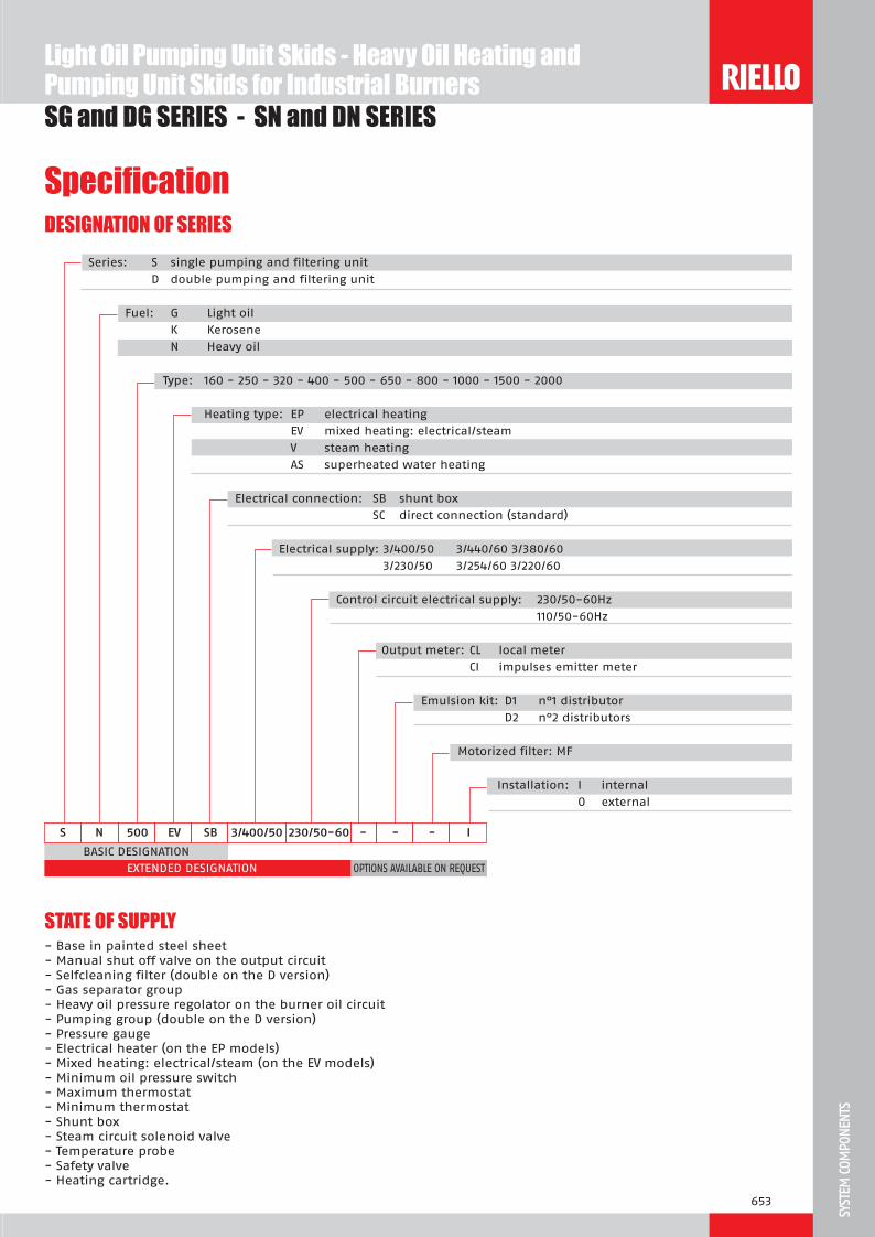
653
SST
M C
MTS
BASIC DESIGNATION
EXTENDED DESIGNATION
S 00 S 3 00 0 230 0 0
OPTIONS AVAILABLE ON REQUEST
Series: S single pumping and filtering unit
D double pumping and filtering unit
Fuel: G Light oil
K Kerosene
N Heavy oil
Type: 160 - 250 - 320 - 400 - 500 - 650 - 800 - 1000 - 1500 - 2000
Heating type: EP electrical heating
EV mixed heating: electrical/steam
V steam heating
AS superheated water heating
Electrical connection: SB shunt box
SC direct connection (standard)
Electrical supply: 3/400/50 3/440/60 3/380/60
3/230/50 3/254/60 3/220/60
Control circuit electrical supply: 230/50-60Hz
110/50-60Hz
Output meter: CL local meter
CI impulses emitter meter
Emulsion kit: D1 n°1 distributor
D2 n°2 distributors
Motorized filter: MF
Installation: I internal
O external
SpecificationDESIGNATION OF SERIES
SG and DG SERIES - SN and DN SERIES
- Base in painted steel sheet- Manual shut off valve on the output circuit- Selfcleaning filter (double on the D version)- Gas separator group- Heavy oil pressure regolator on the burner oil circuit- Pumping group (double on the D version)- Pressure gauge- Electrical heater (on the EP models)- Mixed heating: electrical/steam (on the EV models)- Minimum oil pressure switch- Maximum thermostat- Minimum thermostat- Shunt box- Steam circuit solenoid valve- Temperature probe- Safety valve- Heating cartridge.
STATE OF SUPPLY
Light Oil Pumping Unit Skids - Heavy Oil Heating and Pumping Unit Skids for Industrial Burners

654
SG and DG SERIES - SN and DN SERIES
Other models are available on request.
Available modelsCODE MODELS FUEL PORT DELIVERY DELIVERY MOTOR
SIZE at 15 bar at 28 bar POWER
(l/h) (l/h) (kW)
on demand SG 250 SC 3/380/60 230/50-60 I Light oil 1/2” 900 780 1,5
3090820 SG 320 SC 3/400/50-3/440/60 230/50-60 I Light oil 1/2” 910* 810* 1,1*
3090545 SG 400 SC 3/400/50-3/440/60 230/50-60 I Light oil 1/2” 1270* 1140* 2,2*
3090549 SG 800 SC 3/400/50-3/440/60 230/50-60 I Light oil 3/4” 1960* 1700* 3,0*
3090657 DG 1000 SC 3/400/50-3/440/60 230/50-60 I Light oil 1” 2800* 2200* 4,0*
* these data are referred to 50 Hz supply
* these data are referred to 50 Hz supply - oil viscosity max 65°E at 50°C
* these data are referred to 50 Hz supply - oil viscosity max 65°E at 50°C ** percentage of output with electrical heater only
CODE MODELS FUEL PORT DELIVERY DELIVERY MOTOR HEATING ELECTRICAL
POWER
MAX
SIZE at 15 bar at 30 bar POWER DELIVERY
(l/h) (l/h) (kW) (kW) (kg/h)
on demand SN 250 EP SC 3/400/50-3/440/60 230/50-60 I Heavy oil 1/2” 580* 540* 1,1* 14* 265*
on demand SN 320 EP SC 3/400/50-3/440/60 230/50-60 I Heavy oil 3/4” 950* 700* 1,5* 20* 350*
on demand SN 650 EP SC 3/400/50-3/440/60 230/50-60 I Heavy oil 3/4” 1400* 1200* 2,2* 40* 590*
on demand SN 800 EP SC 3/400/50-3/440/60 230/50-60 I Heavy oil 3/4” 1900* 1700* 3* 30* 800*
on demand DN 800 EP SC 3/400/50-3/440/60 230/50-60 I Heavy oil 3/4” 1900* 1700* 3+3* 40* 775*
CODE MODELS FUEL PORT DELIVERY DELIVERY MOTOR ELECTRICAL HEATED
OUTPUT **
MAX
SIZE at 15 bar at 30 bar POWER DELIVERY
(l/h) (l/h) (kW) (%) (kg/h)
on demand SN 250 EV SC 3/400/50-3/440/60 230/50-60 I Heavy oil 1/2” 580* 540* 1,1* 100 265*
on demand SN 400 EV SC 3/400/50-3/440/60 230/50-60 I Heavy oil 3/4” 1400* 1200* 2,2* 70 415*
on demand SN 400 EV SC 3/380/60 230/50-60 I Heavy oil 3/4” 1680 1440 2,2 70 415
on demand SN 500 EV SC 3/400/50-3/440/60 230/50-60 I Heavy oil 3/4” 1400* 1200* 2,2* 65 590*
on demand SN 650 EV SC 3/400/50-3/440/60 230/50-60 I Heavy oil 3/4” 1900* 1700* 3,0* 70 700*
on demand SN 800 EV SC 3/400/50-3/440/60 230/50-60 I Heavy oil 3/4” 1900* 1700* 3,0* 70 800*
on demand SN 1000 EV SC 3/400/50-3/440/60 230/50-60 I Heavy oil 1” 2700* 2200* 5,5* 70 1083*
Light Oil Pumping Unit Skids - Heavy Oil Heating and Pumping Unit Skids for Industrial Burners

655
SST
M C
MTS
SG and DG SERIES - SN and DN SERIES
Available accessoriesPumping unit for main ring
MODEL ELECTRICAL SUPPLY Ph/V/Hz
CONNECTION IN/OUT
DELIVERY at 9 bar [l/h]
ELECTRIC MOTOR POWER [kW]
MOTOR SPEED [rpm]
CODE
Ma iscosit 12 at 0 C
u 00 3/400/50 3/440/60
Rp 1/2 600 720
0,37 0,43
1400 1700
3093220
u 1000 3/400/50 3/440/60
Rp 3/4 1000 1200
0,55 0,65
1400 1700
3093221
u 1 00 3/400/50 3/440/60
Rp 3/4 1500 1800
0,75 0,88
1400 1700
3093222
u 2000 3/400/50 3/440/60
Rp 3/4 2000 2400
1,1 1,27
1400 1700
3093223
u 3000 3/400/50 3/440/60
Rp 1 3000 3600
1,5 1,8
1400 1700
3093224
u 00 3/400/50 3/440/60
Rp 1 4500 5400
2,2 2,5
1400 1700
on demand
u 000 3/400/50 3/440/60
Rp 1 6000 7200
3 3,5
1400 1700
3093226
Ma iscosit at 0 C
u S 0 3/400/50 3/440/60
Rp 1 670 800
0,75 0,88
950 1100
3093232
u S 1000 3/400/50 3/440/60
Rp 1 1000 1200
1,1 1,27
950 1100
3093227
u S 1330 3/400/50 3/440/60
Rp 1 1330 1600
1,5 1,8
950 1100
3093228
u S 2000 3/400/50 3/440/60
Rp 1 1/4 2000 2400
2,2 2,5
950 1100
on demand
u S 3000 3/400/50 3/440/60
Rp 1 1/4 3000 3600
3 3,5
950 1100
on demand
u S 000 3/400/50 3/440/60
Rp 1 1/4 4000 4800
4 4,8
950 1100
3093231
Pumping group with pressure regulator
MODEL ELECTRICAL SUPPLY Ph/V/Hz
CONNECTION IN/OUT
DELIVERY at 28 bar [l/h]
ELECTRIC MOTOR POWER [kW]
MOTOR SPEED [rpm]
CODE
Ma iscosit at 0 C
u 00 3/400/50 3/440/60
Rp 3/4 700 840
1,5 1400 1700
3093211
u 1200 3/400/50 3/440/60
Rp 3/4 1200 1440
2,2 1400 1700
3093212
u 1 00 3/400/50 3/440/60
Rp 3/4 1700 2040
3,0 1400 1700
3093213
u 2200 3/400/50 3/440/60
Rp 1 2200 2640
4,0 1400 1700
3093217
Light Oil Pumping Unit Skids - Heavy Oil Heating and Pumping Unit Skids for Industrial Burners
SG and DG SERIES - SN and DN SERIES

656
SG and DG SERIES - SN and DN SERIES
Available accessoriesAutomatic gas separator
TYPE CONNECTION IN/OUT MAX WORKING DELIVERY [l/h] CODE
u S 1 0 1”1/2 - 1” 1000 3000748
u S 2 0 1”1/2 - 1”1/2 2000 3010012
Heating cartridge
TYPE ELECTRICAL POWER [W] CODE
u C 100 100 on demand
u C 1 0 160 3090621
u C 2 0 280 3090622
Line filter
TYPE ELECTRICAL POWER [W] CONNECTION IN/OUT MAX DELIVERY [l/h] CODE
Cartri ge ilter 100 m light oil
u C 3 00 - Rp 1 3800 3090236
Sel cleaning ilter 300 m
u SC 2000 80 Rp 1 1/2 2000 3000790
u SC 000 80 - 300 Rp 1 1/2 4000 3010022
Pressure regolator
TYPE SETTING RANGE [bar] CONNECTION IN/OUT MAX DELIVERY [l/h] CODE
u 3 1 - 4 Rp 3/4 2000 3090569
u 1 1 - 4 Rp 1 6000 3090316
u 1 1 1 - 4 Rp 1 1/4 10000 on demand
Light Oil Pumping Unit Skids - Heavy Oil Heating and Pumping Unit Skids for Industrial Burners

657
SST
M C
MTS
HPRT SERIESLPRT SERIESCB SERIESMBC SERIESVGD SERIESDMV SERIESPressure reduction and regulation units allow to bring gas pressure available in the line to values suited to the specific application.Gas trains include a series of safety and control devices for gas feeding to the burner.They are constructed and supplied with two different selection options (separated or assembled units). The selection has to be made on the specific application (available pressure, installation chances,…).This permits to reach the best flexibilty using pre-assembled units, which are also tested in the factory according with existing norms and designed for a easy installation.
T Pin = 0,5 ÷ 4 barT Pin <= 0,5 bar
C Pin <= 0,5 barM C Pin <= 0,5 bar (<= 0,36 threaded)
Pin <= 0,5 bar M Pin <= 0,5 bar
Gas TrainsSG and DG SERIES - SN and DN SERIES

658
Overall dimensions (mm)
HPRT - LPRT - CB - MBC - VGD - DMV SERIES
SAFETY / REGULATING GAS TRAINS (CB series)
LOW PRESSURE REGULATING / REDUCING UNITS (LPRT series)
MODEL X Y Z Ø IN Ø OUT
u T 0 532 130 245 Rp 3/4 R 3/4
u T 0 600 145 310 Rp 1 R 1
u T 1 0 710 195 365 Rp 1 1/2 R 1 1/2
u T 2 0 880 250 450 Rp 2 R 2
u T 00 880 285 590 DN 65 DN 65
u T 0 955 285 590 DN 80 DN 80
u T 1000 1070 350 760 DN 100 DN 100
u T 1 00 1146 400 1000 DN 125 DN 125
u T 2000 1275 480 1180 DN 150 DN 150
HIGH PRESSURE REGULATING / REDUCING UNITS (HPRT series)
MODEL X Y Z Ø IN Ø OUT
u T 0 1223 180 400 Rp 1 1/2 R 1 1/2
u T 1 0 1275 180 410 Rp 1 1/2 R 2
u T 2 0 1200 280 560 Rp 2 DN 65
u T 00 1750 280 563 DN 65 DN 65
u T 0 1890 280 563 DN 80 DN 80
u T 1000 2070 380 725 DN 100 DN 100
u T 1 00 2120 500 810 DN 100 DN 100
u T 2000 2150 500 810 DN 125 DN 125
MODEL X Y Z Ø IN Ø OUT
u C 12 1 SM 30 891 245 261 Rp 1 1/2 Rp 1 1/2
u C 20 1 SM 30 986 255 328 Rp 2 Rp 2
u C 2 1 SM 30 1025 285 356 Rp 2 Rp 2
u C 0 1 SM 30 906 285 356 DN 65 DN 65
u C 0 0 1 SM 30 934 285 416 DN 80 DN 80
u C 0100 1 SM 30 1054 350 501 DN 100 DN 100
u C 012 1 SM 30 1164 400 780 DN 125 DN 125
u C 12 1 CT SM 30 891 245 261 Rp 1 1/2 Rp 1 1/2
u C 20 1 CT SM 30 986 255 328 Rp 2 Rp 2
u C 2 1 CT SM 30 1026 285 356 Rp 2 Rp 2
u C 0 1 CT SM 30 906 285 356 DN 65 DN 65
u C 0 0 1 CT SM 30 934 285 416 DN 80 DN 80
u C 0100 1 CT SM 30 1054 350 501 DN 100 DN 100
u C 012 1 CT SM 30 1164 400 780 DN 125 DN 125
Gas Trains

659
SST
M C
MTS
Overall dimensions (mm)SAFETY / REGULATING GAS TRAINS (MBC series)
MODEL X Y Z Ø IN Ø OUT
u M C 1200 1 SM 0 573 425 161 2” 2”
u M C 1 00 1 SM 0 583 430 237 DN 65 DN 65
u M C 3100 1 SM 0 633 500 240 DN 80 DN 80
u M C 000 1 SM 0 733 576 350 DN 100 DN 100
u M C 1200 1 CT SM 0 573 425 290 2” 2”
u M C 1 00 1 CT SM 0 583 430 300 DN 65 DN 65
u M C 3100 1 CT SM 0 633 500 320 DN 80 DN 80
u M C 000 1 CT SM 0 733 576 350 DN 100 DN 100
Example of gas train “MULTIBLOC” type without seal control
Example of gas train “COMPOSED” type without seal control
HPRT - LPRT - CB - MBC - VGD - DMV SERIES
SAFETY / REGULATING PROPORTIONAL GAS TRAINS (VGD series)
MODEL A B C Ø IN Ø OUT
u 0 615 245 495 2” DN 80
u 600 245 520 DN 65 DN 80
u 0 625 245 545 DN 80 DN 80
u 100 755 245 575 DN 100 DN 80
Gas Trains

660
Overall dimensions (mm)
HPRT - LPRT - CB - MBC - VGD - DMV SERIESGas Trains
DOUBLE SOLENOID VALVE (DMV series)
MODEL X Y Z Ø IN Ø OUT
u M 12 1 SM 0 490 245 292 Rp 1 1/2 Rp 1 1/2
u M 12 1 CT SM 0 490 245 292 Rp 1 1/2 Rp 1 1/2
u M 12 1 C SM 2 490 245 292 Rp 1 1/2 Rp 1 1/2
u M 20 1 SM 0 490 255 292 Rp 2 Rp 2
u M 20 1 CT SM 0 490 255 292 Rp 2 Rp 2
u M 20 1 C SM 2 490 255 292 Rp 2 Rp 2
u M 2 1 SM 0 530 270 338 Rp 2 Rp 2
u M 2 1 CT SM 0 530 270 338 Rp 2 Rp 2
u M 2 1 C SM 2 530 270 338 Rp 2 Rp 2
u M 0 1 SM 0 290 270 338 DN 65 DN 65
u M 0 1 CT SM 0 290 270 338 DN 65 DN 65
u M 0 1 C SM 2 290 270 338 DN 65 DN 65
u M 0 0 1 SM 0 310 290 397 DN 80 DN 80
u M 0 0 1 CT SM 0 310 290 397 DN 80 DN 80
u M 0 0 1 C SM 2 310 290 397 DN 80 DN 80
u M 0100 1 SM 0 350 307 449 DN 100 DN 100
u M 0100 1 CT SM 0 350 307 449 DN 100 DN 100
u M 0100 1 C SM 2 350 307 449 DN 100 DN 100
u M 012 1 SM 0 400 333 554 DN 125 DN 125
u M 012 1 CT SM 0 400 333 554 DN 125 DN 125
u M 012 1 C SM 2 400 333 554 DN 125 DN 125
X
Y
Z
ØinØout

661
SST
M C
MTS
HPRT - LPRT - CB - MBC - VGD - DMV SERIES
Overall dimensions (mm)PACKAGING (HPRT - LPRT - CB - MBC - VGD - DMV series)
Z
XY
Model X Y Z
u T 0 1230 460 560
u T 1 0 1230 460 560
u T 2 0 1230 460 560
u T 00 1300 530 590
u T 0 1300 530 590
u T 1000 1300 530 590
u T 1 00 1390 710 795
u T 2000 1390 710 795
u T 0 532 245 292
u T 0 310 290 397
u T 1 0 350 307 449
u T 2 0 400 333 554
u T 00 532 150 292
u T 0 535 165 292
u T 1000 290 185 338
u T 1 00 310 200 397
u T 2000 350 220 449
u C 12 1 1050 370 320
u C 20 1 1050 370 320
u C 0 1 940 480 530
u C 0 0 1 1120 570 580
u C 0100 1 1120 570 580
u C 012 1 1390 710 795
u M C 1200 1 650 490 350
u M C 1 00 1 690 410 490
u M C 3100 1 750 460 570
u M C 000 1 850 510 660
u 0 860 360 620
u 860 360 620
u 0 860 360 620
u 100 860 360 620
u M 12 1 940 480 530
u M 20 1 940 480 530
u M 2 1 940 480 530
u M 0 1 940 480 530
u M 0 0 1 940 480 530
u M 0100 1 940 480 530
u M 012 1 940 480 530
Gas Trains

662
DESIGNATION OF SERIES
Specification
HPRT - LPRT - CB - MBC - VGD - DMV SERIES
T 1 0
Series: LPRT low pressure regulating / reducing unit
HPRT high pressure regulating / reducing unit
Size: 40 - 80 - 160 - 250 - 500 - 750 - 1000 - 1500 - 2000
Gas Trains
C 0 1 CT SM 3 0
Series: MB MBC VGD CB DMV CG Size: 405 407 410 412 415 420 - 65 1200 1900 3100 5000 50 65 80 100 - - - 512 520 525 5065 5080 50100 50125 512 520 525 5065 5080 50100 50125 120 220 - - - - - Operating mode: /S = only ON-OFF function /1 = 1 step opening /2 = 2 steps opening /P = 1 step opening with air/gas proportioning regulator
Valves proving system: - = non installed CT = Valves proving system installed CQ = Pressure Switch installed for valves proving system function Outlet port: R = threaded F = ISO standard flange F1 = BS1 square flange F2 = BS2 square flange F3 = BS3 - BS4 square flange Electrical connecton: T = Terminal board SD = Domestic Plug SM = Medium Power Plug
Standard outlet pressure range: - = without pressure regulator 0 = with regulator and air/gas proportioned pressure 2 = with regulator and outlet pressure up to 20 mbar 3 = with regulator and outlet pressure up to 30 mbar 4 = with regulator and outlet pressure up to 40 mbar 5 = with regulator and outlet pressure up to 50 mbar 6 = with regulator and outlet pressure up to 60 mbar 8 = with regulator and outlet pressure up to 80 mbar 15 = with regulator and outlet pressure up to 150 mbar
Valve driving: 0 = Common 2 = Separate

663
SST
M C
MTS
HPRT - LPRT - CB - MBC - VGD - DMV SERIES
SpecificationSTATE OF SUPPLY
T seriesHigh pressure regulating/reducing unit, for gas of 1st - 2nd - 3rd family, with max. inlet pressure of 4 bar made up of:- 1 manual shut-off valve (ball valve)- 1 gas filter with filtering degree lower than 50 µm- 1 gas pressure gauge, with shut-off push-button cock, located upstream to the regulator- 2 connection stubs- 1 pressure regulator-stabilizer- 1 slam-shut valve- 1 gas pressure gauge, with shut-off push-button cock, located downstrem to the regulator- 2 pipelines for sensing line- 1 vent valve- 1 antivibrating joint- Nipples (in threaded version)- Gaskets (in flanged version)- Fixing screws (in flanged version).
T seriesLow pressure regulating/reducing unit, for gas of 1st - 2nd - 3rd family, with max. inlet pressure of 500 mbar made up of:- 1 manual shut-off valve (ball valve)- 1 gas filter with filtering degree lower than 50 µm- 1 gas pressure gauge, with shut-off push-button cock, located upstraem to the regulator- 1 pressure regulator-stabilizer- 1 anti-vibrating joint- Nipples (in threaded version)- Gaskets (in flanged version)- Fixing screws (in flanged version).
Stan ar e ui ent- Instruction handbook for installation, use and maintenance- Gaskets (in flanged version)- Fixing screws (in flanged version)- Terminals for electrical connection.
C seriesSafety/regulating gas train for gas of 1st - 2nd - 3rd family, with MAX supply pressure of 500 mbar made up of:- 1 gas filter with filtering degree lower than 50 µm- 1 pressure regulator-stabilizer, for stabilizing gas inlet pressure to the burner with a ±5% max. tolerance respect the
fixed value- 1 valves unit composed from two automatic closing valves EN 161, class A, group 2, realized with double diaphragm
technology, comprised in a single body and featured by:- fast closing and slow opening with adjustable fast stroke for initial gas volume- adjustable main delivery- anti-dust filter with net- 1 minimum gas pressure switch that allows system working only with a suited pressure in the gas distribution line- 1 automatic seal control with a release time of 10÷26 seconds (when equipped)- Nipples (in threaded version)- Gaskets (in flanged version)- Fixing screws (in flanged version).
Gas Trains
Specification
Series: MB MBC VGD CB DMV CG Size: 405 407 410 412 415 420 - 65 1200 1900 3100 5000 50 65 80 100 - - - 512 520 525 5065 5080 50100 50125 512 520 525 5065 5080 50100 50125 120 220 - - - - - Operating mode: /S = only ON-OFF function /1 = 1 step opening /2 = 2 steps opening /P = 1 step opening with air/gas proportioning regulator
Valves proving system: - = non installed CT = Valves proving system installed CQ = Pressure Switch installed for valves proving system function Outlet port: R = threaded F = ISO standard flange F1 = BS1 square flange F2 = BS2 square flange F3 = BS3 - BS4 square flange Electrical connecton: T = Terminal board SD = Domestic Plug SM = Medium Power Plug
Standard outlet pressure range: - = without pressure regulator 0 = with regulator and air/gas proportioned pressure 2 = with regulator and outlet pressure up to 20 mbar 3 = with regulator and outlet pressure up to 30 mbar 4 = with regulator and outlet pressure up to 40 mbar 5 = with regulator and outlet pressure up to 50 mbar 6 = with regulator and outlet pressure up to 60 mbar 8 = with regulator and outlet pressure up to 80 mbar 15 = with regulator and outlet pressure up to 150 mbar
Valve driving: 0 = Common 2 = Separate

664
HPRT - LPRT - CB - MBC - VGD - DMV SERIES
STATE OF SUPPLY
M C seriesSafety shut-off valve for gas of 1st - 2nd - 3rd family, with MAX supply pressure of 360 mbar for threaded version and 500 mbar for flanged version.Gas train are composed of:- 1 gas filter with filtering degree lower than 50 µm (inside for the threaded valve)- 1 valves unit composed from two automatic closing valves EN 161, class A, group 2, realized with double diaphragm
technology, comprised in a single body and featured by:- ant-dust filter with net- fast closing and slow opening- servo pressure regulator unit as per DIN EN 88 Class A Group 2- 1 automatic seal control with a release time of 10÷26 seconds (when equipped)- Gaskets (in flanged version)- Fixing screws (in flanged version).
Stan ar e ui ent- Instruction handbook for installation, use and maintenance- Gaskets (in flanged version)- Fixing screws (in flanged version)- Electrical connection terminals whit plug.
seriesSafety shut-off valve for gas of 1st - 2nd - 3rd family, with MAX supply pressure of 500 mbar composed from:- 1 valves unit composed from two automatic closing valves EN 161, class A, group 2, realized with double diaphragm
technology, comprised in a single body and featured by: - fast closing and slow opening with adjustable fast stroke for initial gas volume - adjustable main delivery and proportional regulation - ant-dust filter with net- 1 automatic seal control with a release time of 10÷26 seconds (when equipped)- nipples (in threaded version)- gaskets (in flanged version)- fixing screws (in flanged version).
Stan ar e ui ent- instruction handbook for installation, use and maintenance- gaskets (in flanged version)- fixing screws (in flanged version)- electrical connection terminals.
M seriesSafety shut-off valve for gas of 1st - 2nd - 3rd family, with MAX supply pressure of 500 mbar composed from:- 1 valves unit composed from two automatic closing valves EN 161, class A, group 2, realized with double diaphragm
technology, comprised in a single body and featured by: - fast closing and slow opening with adjustable fast stroke for initial gas volume - adjustable main delivery and proportional regulation - anti-dust filter with net- 1 automatic seal control with a release time of 10÷26 seconds (when equipped)- nipples (in threaded version)- gaskets (in flanged version)- fixing screws (in flanged version).
Stan ar e ui ent- instruction handbook for installation, use and maintenance- gaskets (in flanged version)- fixing screws (in flanged version)- electrical connection terminals.
Gas Trains
Specification

665
SST
M C
MTS
Available models
HPRT - LPRT - CB - MBC - VGD - DMV SERIES
CODE MODEL Ø PRESSURE RANGES (mbar) NOTE
IN OUT MAX INLET OUTLET (4)
3090650 HPRT 80 Rp 1”1/2 Rp 1”1/2 4000 27-60 -
3090843 HPRT 160 Rp 1”1/2 Rp 2” 4000 27-60 -
3090844 HPRT 250 Rp 2” DN 65 4000 65-120 -
3090768 HPRT 500 DN 65 DN 65 4000 100-200 -
3090857 HPRT 750 DN 80 DN 80 4000 100-200 -
3090870 HPRT 1000 DN 100 DN 100 4000 155-230 -
In progress HPRT 1500 DN 100 DN 100 4000 150-220 -
3091033 HPRT 2000 DN 125 DN 125 4000 150-220 -
In progress LPRT 40 Rp 3/4” Rp 3/4” 500 10-30 -
In progress LPRT 80 Rp 1” Rp 1” 500 10-30 -
3090664 LPRT 160 Rp 1”1/2 Rp 1”1/2 500 10-30 -
In progress LPRT 250 Rp 2” Rp 2” 500 10-30 -
3090455 LPRT 500 DN 65 DN 65 500 10-30 -
3090604 LPRT 750 DN 80 DN 80 500 10-30 -
3090546 LPRT 1000 DN 100 DN 100 500 10-30 -
In progress LPRT 1500 DN 125 DN 125 500 10-30 -
In progress LPRT 2000 DN 150 DN 150 500 10-30 -3970145 * CB 512/1 - RSM 30 Rp 1”1/2 Rp 1”1/2 500 10 - 30 (1)
3970146 * CB 520/1 - RSM 30 Rp 2” Rp 2” 500 10 - 30 (1)
20044659 * CB 525/1 - RSM 30 Rp 2” Rp 2” 500 10 - 30 (1)
3970147 * CB 5065/1 - FSM 30 DN 65 DN 65 500 10 - 30 (1)
3970148 * CB 5080/1 - FSM 30 DN 80 DN 80 500 10 - 30 (1)
3970149 * CB 50100/1 - FSM 30 DN 100 DN 100 500 10 - 30 (1)
20015871 * CB 50125/1 - FSM 30 DN 125 DN 125 500 10 - 30 (1)
20045589 ** CB 512/1 CT RSM 30 Rp 1”1/2 Rp 1”1/2 500 10 - 30 (2)
3970160 ** CB 520/1 CT RSM 30 Rp 2” Rp 2” 500 10 - 30 (2)
20044660 ** CB 525/1 CT RSM 30 Rp 2” Rp 2” 500 10 - 30 (2)
3970161 ** CB 5065/1 CT FSM 30 DN 65 DN 65 500 10 - 30 (2)
3970162 ** CB 5080/1 CT FSM 30 DN 80 DN 80 500 10 - 30 (2)
3970163 ** CB 50100/1 CT FSM 30 DN 100 DN 100 500 10 - 30 (2)
3970196 ** CB 50125/1 CT FSM 30 DN 125 DN 125 500 10 - 30 (2)
3090436 * CB 5080/1 CQ FSM 30 DN 80 DN 80 500 10 - 30 (3)
3090327 * CB 50100/1 CQ FSM 30 DN 100 DN 100 500 10 - 30 (3)
20010671 * CB 50125/1 CQ FSM 30 DN 125 DN 125 500 10 - 30 (3)
3970221 * MBC 1200/1 - RSM 60 Rp 2” Rp 2” 360 4-60 (1)
3970222 * MBC 1900/1 - FSM 40 DN 65 DN 65 500 20-40 (1)
3970223 * MBC 3100/1 - FSM 40 DN 80 DN 80 500 20-40 (1)
3970224 * MBC 5000/1 - FSM 80 DN 100 DN 100 500 40-80 (1)
3970225 ** MBC 1200/1 CT RSM 60 Rp 2” Rp 2” 360 4-60 (2)
3970226 ** MBC 1900/1 CT FSM 40 DN 65 DN 65 500 20-40 (2)
3970227 ** MBC 3100/1 CT FSM 40 DN 80 DN 80 500 20-40 (2)
3970228 ** MBC 5000/1 CT FSM 80 DN 100 DN 100 500 40-80 (2)
* 230V/50Hz -220V/60Hz electrical supply.** 230V/50Hz electrical supply.(1) Seal control accessory (2) Seal control incorporated (3) Seal control on control panel (4) For CB, LPRT and MBC units, for different outlet pressure ranges, it is possible to match the correct springs selecting them from accessories section(5) gas trains suitable to RS/P BLU burners only.
Gas TrainsHPRT - LPRT - CB - MBC - VGD - DMV SERIES
Specification

666
Available models
HPRT - LPRT - CB - MBC - VGD - DMV SERIES
* 230V/50Hz -220V/60Hz electrical supply.** 230V/50Hz electrical supply.(1) Seal control accessory (2) Seal control incorporated (3) Seal control on control panel (4) For CB, LPRT and MBC units, for different outlet pressure ranges, it is possible to match the correct springs selecting them from accessories section(5) gas trains suitable to RS/P BLU burners only.
Gas Trains
CODE MODEL Ø PRESSURE RANGES (mbar) NOTE
IN OUT MAX INLET OUTLET (4)
3970215 * VGD 50/P - FT 02 Rp 2” DN 80 500 proportional (5)
3970212 * VGD 65/P - FT 02 Rp 2” DN 80 500 proportional (5)
3970213 * VGD 80/P - FT 02 DN 65 DN 80 500 proportional (5)
3970214 * VGD 100/P - FT 02 DN 65 DN 80 500 proportional (5)
20043035 * DMV 512/1 - RSM -0 Rp 1” ½ Rp 1” ½ 500 - -
20043036 ** DMV 512/1 CT RSM -0 Rp 1” ½ Rp 1” ½ 500 - -
20043037 * DMV 512/1 CQ RSM -2 Rp 1” ½ Rp 1” ½ 500 - -
20043038 * DMV 520/1 - RSM -0 Rp 2” Rp 2” 500 - -
20043039 ** DMV 520/1 CT RSM -0 Rp 2” Rp 2” 500 - -
20043040 * DMV 520/1 CQ RSM -2 Rp 2” Rp 2” 500 - -
20043053 * DMV 525/1 - RSM -0 Rp 2” Rp 2” 500 - -
20043054 ** DMV 525/1 CT RSM -0 Rp 2” Rp 2” 500 - -
20043055 * DMV 525/1 CQ RSM -2 Rp 2” Rp 2” 500 - -
20043041 * DMV 5065/1 - FSM -0 DN 65 DN 65 500 - -
20043042 ** DMV 5065/1 CT FSM -0 DN 65 DN 65 500 - -
20043043 * DMV 5065/1 CQ FSM -2 DN 65 DN 65 500 - -
20043044 * DMV 5080/1 - FSM -0 DN 80 DN 80 500 - -
20043045 ** DMV 5080/1 CT FSM -0 DN 80 DN 80 500 - -
20043046 * DMV 5080/1 CQ FSM -2 DN 80 DN 80 500 - -
20043047 * DMV 50100/1 - FSM -0 DN 100 DN 100 500 - -
20043048 ** DMV 50100/1 CT FSM -0 DN 100 DN 100 500 - -
20043049 * DMV 50100/1 CQ FSM -2 DN 100 DN 100 500 - -
20043050 * DMV 50125/1 - FSM -0 DN 125 DN 125 500 - -
20043051 ** DMV 50125/1 CT FSM -0 DN 125 DN 125 500 - -
20043052 * DMV 50125/1 CQ FSM -2 DN 125 DN 125 500 - -

667
SST
M C
MTS
HPRT - LPRT - CB - MBC - VGD - DMV SERIES
AccessoriesSprings for pressure regulators
Accessories springs are available for varying pressure range of the regulator-stabilizer included in the regulating/reducing unit or in MBC train.In the following table, the springs are listed with their application range.
TYPE SPRING PORT OUTLET PRESSURE
(mbar) CODE
u T 0 red Rp 3/4” 25÷55 in progress
u T 0 yellow Rp 3/4” 30÷70 in progress
u T 0 black Rp 3/4” 60÷110 in progress
u T 0 pink Rp 3/4” 90÷150 in progress
u T 0 red Rp 1” 25÷55 in progress
u T 0 yellow Rp 1” 30÷70 in progress
u T 0 black Rp 1” 60÷110 in progress
u T 0 pink Rp 1” 90÷150 in progress
u T 1 0 C M 12 red Rp 1”1/2 25÷55 3010131
u T 1 0 C M 12 yellow Rp 1”1/2 30÷70 in progress
u T 1 0 C M 12 black Rp 1”1/2 60÷110 3010157
u T 1 0 C M 12 pink Rp 1”1/2 90÷150 3090486
u T 2 0 C M 20 2 red Rp 2” 25÷55 3010132
u T 2 0 C M 20 2 yellow Rp 2” 30÷70 20008549
u T 2 0 C M 20 2 black Rp 2” 60÷110 3010158
u T 2 0 C M 20 2 pink Rp 2” 90÷150 3090487
u T 00 0 C M 0 0 0 red DN 65/80 25÷55 3010133
u T 00 0 C M 0 0 0 yellow DN 65/80 30÷70 20008549
u T 00 0 C M 0 0 0 black DN 65/80 60÷110 3010135
u T 00 0 C M 0 0 0 pink DN 65/80 100÷150 3090456
u T 00 0 C M 0 0 0 grey DN 65/80 140÷200 3090992
u T 1000 C M 0100 red DN 100 25÷55 3010134
u T 1000 C M 0100 yellow DN 100 30÷70 in progress
u T 1000 C M 0100 black DN 100 60÷110 3010136
u T 1000 C M 0100 pink DN 100 100÷150 3090489
u T 1000 C M 0100 grey DN 100 140÷200 3092174
u T 1 00 C M 012 red DN 125 25÷55 3010315
u T 1 00 C M 012 yellow DN 125 30÷70 3010316
u T 1 00 C M 012 black DN 125 60÷110 3010317
u T 1 00 C M 012 pink DN 125 100÷150 3010318
u T 2000 red DN 150 25÷55 in progress
u T 2000 yellow DN 150 30÷70 in progress
u T 2000 black DN 150 60÷110 in progress
u T 2000 pink DN 150 90÷150 in progress
u M C series neutral DN 68÷100 0÷20 3010381
u M C series red DN 68÷100 20÷40 3010382
u M C series black DN 68÷100 40÷80 3010383
u M C series green DN 68÷100 80÷150 3010384
Gas TrainsHPRT - LPRT - CB - MBC - VGD - DMV SERIES

668
HPRT - LPRT - CB - MBC - VGD - DMV SERIES
AccessoriesConnection adapters
In some cases, an adapter must be fitted between the gas train and the burner, when the diameter of the gas train is different from the set diameter of the burner.Below the available adapters that can be fitted are listed.
TYPE Ø 1 Ø 2 A B CODE
u 0 320 DN 65 DN 80 320 174 3000831
u 320 DN 65 DN 65 320 129 20025934
u 0 0 320 DN 80 DN 80 320 174 3000832
u 0 00 DN 80 DN 65 400 174 3010352
u 100 0 320 DN 100 DN 80 320 174 3010127
u 2 0 2” DN 80 540 174 3010128
u 100 100 DN 100 DN 100 320 174 3090680
u 12 100 320 DN 125 DN 100 320 174 3090679
u 12 0 320 DN 125 DN 80 320 174 3090940
u 100 DN 100 DN 65 320 174 3010353
TYPE Ø 1 Ø 2 A B C CODE
u 0 320 DN 65 DN 80 400 - - 3010221
u 0 0 320 DN 80 DN 80 400 - - 3010222
u 100 0 320 DN 100 DN 80 400 - - 3010223
u 12 0 320 DN 125 DN 80 320 - - 3010224
u 12 100 320 DN 125 DN 100 320 - - 3091093
u 0 00 0 22 DN 65 DN 80 400 480 225 3010225
u 0 0 00 0 22 DN 80 DN 80 400 480 225 3010226
u 100 0 00 0 22 DN 100 DN 80 400 480 225 3010227
u 12 0 00 0 300 DN 125 DN 80 500 480 300 3010228
Manual valvesBall shut-off manual valves are available in different sizes and listed in the following table.
MODEL MAX OPERATING PRESSURE (bar) PORT CODE
u 1 2 5 1/2” in progress
u 3 5 3/4” 3090097
u 1 5 1” 3090967
u 1 1 2 5 1”1/2 3090143
u 2 5 2” 3090968
u 16 DN65 3090947
u 0 16 DN80 3090969
u 100 16 DN100 3090962
u 12 16 DN125 3091065
u 1 0 16 DN150 in progress
Gas Trains

669
SST
M C
MTS
HPRT - LPRT - CB - MBC - VGD - DMV SERIES
AccessoriesAnti-vibrating joints
Anti-vibrating joints to damp vibrations and facilitate application of the gas train to the gas distribution line are available in different sizes listed in the table below.
TYPE PORT SIZE INLET MAX PRESSURE (bar) CODE
u 20 3/4” 6 3891033
u 2 1” 6 3891034
u 0 1”1/2 6 3891043
u 0 2” 6 3891053
u DN65 6 3891013
u 0 DN80 6 3891003
u 100 DN100 6 3891023
u 12 DN125 6 3091092
FiltersA series of gas filters of different sizes are avilable and listed in the following table.
TYPE PORT IN/OUT INLET MAX PRESSURE (bar) CODE
u 1 1 1”1/2 0,5 3012198
u 20 1 2” 0,5 3012199
u 00 3 DN 65 4 3012200
u 00 0 3 DN 80 4 3012201
u 0100 3 DN 100 4 3012202
u 012 DN 125 4 3013141
Pressure regulatorsA series of pressure regulators of different sizes are avilable and listed in the follow-ing table.
TYPE PORT IN/OUT INLET MAX PRESSURE (bar) CODE
u S 1 1”1/2 0,5 3012203
u S 20 2” 0,5 3012204
u S 0 DN 65 0,5 3012205
u S 0 0 DN 80 0,5 3012206
u S 100 DN 100 0,5 3012207
u S 12 DN 125 0,5 on demand
Gas TrainsHPRT - LPRT - CB - MBC - VGD - DMV SERIES

670
HPRT - LPRT - CB - MBC - VGD - DMV SERIES
AccessoriesPressure gauge kit + push-button cock
A kit composed from a pressure gauge and a push-button cock for measuring gas pressure is available in different sizes following the table.
MODEL MAX PRESSURE (mbar) CODE
u 1 60 3090062
u 2 160 3091805
u 3 300 3091491
u 500 3090099
u 1000 in progress
u 2000 in progress
u 3000 in progress
u 4000 in progress
Gas pressure switch for seal control installed on the control panel
A gas pressure switch is available as seal control accessory to be installed on the con-trol panel.
MODEL SETTING RANGE ∆P (mbar) CODE
u 1 00 300 ÷ 1500 in progress
u 000 1000 ÷ 6000 in progress
Seal control kitTo test the valve seals on the gas train, a special “seal control kit” is available. The valve seal control device is compulsory (EN 676) on gas trains to burners with a maxi-mum output over 1200 kW. The seal control is type VPS 504.
GAS TRAIN KIT CODE
for 50 Hz operation KIT CODE
for 60 Hz operation
u M C 1 t e 3010367 20029057
u C 1 t e 3010367 20029057
u M 1 t e 3010367 20029057
u t e 3010367 20029057
Gas Trains

671
SST
M C
MTS
Centrifugal Air Fans for Industrial Burners
GCH SERIESGCM SERIESGBJ SERIESAir supply fans allow to bring comburent air through the adduction channel to the combustion head in pressure and delivery conditions required from the application.The air delivery processed from the fan is in a correct proportion to the fuel to guarantee the required burner output with a safe combustion. Performance tables help the fan selection among the available models.All the models are pre-assembled and tested in factory in the respect of existing normatives so to permit the maximum installation facility.
C S S 800 ÷ 5000 m3/h 1800 ÷ 4800 PaCM S S 4000 ÷ 9500 m3/h 1800 ÷ 4400 Pa
S S 3500 ÷ 20000 m3/h 2800 ÷ 10000 Pa
HPRT - LPRT - CB - MBC - VGD - DMV SERIES

672
Overall dimensions (mm)
Centrifugal Air Fans for Industrial BurnersGCH - GCM - GBJ SERIES
GCH SERIES
OUTLET FLANGE
Fan and basement
MODEL A B C D E F G H I L M N O P
u C 0 020 660 580 400 230 280 80 375 67 215 270 245 137 60 18
u C 0 020 800 735 570 290 355 100 450 85 320 392 360 250 45 25
u C 0 0 0 800 735 570 290 355 100 450 85 320 392 360 250 45 25
MODEL a b c d e f g
u C 0 020 180 219 250 125 167 195 112
u C 0 020 224 265 294 160 200 230 112
u C 0 0 0 224 265 294 160 200 230 112

673
SST
M C
MTS
Centrifugal Air Fans for Industrial BurnersGCH - GCM - GBJ SERIES
GCM SERIES
OUTLET FLANGE
Fan and basement
Overall dimensions (mm)
MODEL A B C D E F G H I L M N O P
u CM 0 0 930 750 720 328 335 140 560 132 320 392 360 250 45 25
u CM 0 020 1010 840 750 365 355 160 630 148 320 392 360 250 45 25
u CM 0 0 0 1010 840 820 365 355 160 630 148 425 440 400 340 55 30
MODEL a b c d e f g
u CM 0 0 355 405 435 250 300 330 125
u CM 0 020 400 448 480 280 332 360 125
u CM 0 0 0 400 448 480 280 332 360 125

674
Overall dimensions (mm)
Centrifugal Air Fans for Industrial BurnersGCH - GCM - GBJ SERIES
GBJ SERIES
OUTLET FLANGE
Fan and basement
MODEL A B C D E F G H I L M N O P
u 0 30 900 825 680 310 400 120 500 110 425 440 360 250 45 30
u 0 320 1000 930 700 342 425 135 560 120 425 440 400 340 55 30
u 0 330 1000 930 750 342 425 135 560 120 425 440 400 340 55 30
u 0 3 0 1000 930 775 342 425 135 560 120 470 500 450 340 55 35
u 0 12 1120 1000 825 382 475 145 630 135 500 570 510 385 75 40
u 0 1 1120 1000 825 382 475 145 630 135 500 570 510 385 75 40
u 0 310 1000 930 820 322 425 145 560 135 425 440 400 340 55 30
u 0 320 1000 930 820 322 425 145 560 135 425 440 400 340 55 35
u 0 3 0 1000 930 820 322 425 145 560 135 470 500 450 370 65 35
u 0 10 1120 1000 1000 360 475 160 630 150 550 626 565 425 85 40
u 0 12 1120 1000 710 360 475 160 630 150 320 392 360 250 45 25
u 0 00 1250 1120 750 405 530 180 710 170 320 320 392 360 45 25
MODEL a b c d e f g
u 0 30 280 332 260 200 249 280 125
u 0 320 315 366 395 224 273 304 125
u 0 330 315 366 395 224 273 304 125
u 0 3 0 315 366 395 224 273 304 125
u 0 12 355 405 435 250 300 330 125
u 0 1 355 405 435 250 300 330 125
u 0 310 355 405 435 250 300 330 125
u 0 320 355 405 435 250 300 330 125
u 0 3 0 355 405 435 250 300 330 125
u 0 10 400 448 480 280 332 360 125
u 0 12 400 448 480 280 332 360 125
u 0 00 450 497 530 315 366 395 125

675
SST
M C
MTS
DESIGNATION OF SERIES
Specification
Centrifugal Air Fans for Industrial BurnersGCH - GCM - GBJ SERIES
STATE OF SUPPLYAir fan models of GBJ, GCM and GCH series are provided, already assembled and tested in the factory, packaged on pallets with protective plastic films.The issue includes:- centrifugal fan made up of a spiral-box which contains the fan wheel fitted on drive shaft- three phases electrical motor- intake protection grid- vibration damping coupling outflow-end- terminals for electrical connection- handbook for installation, use and maintenance.
EXTENDED DESIGNATION
0 30 0 3 3 0 ∆ 0 C
Series: GCH, GCM, GBJ
Model: 04020 ........................................................................ I0800A
Discharge position: RD 0 45 90 135 180 225 270 315 (clockwise rotation)
LG 0 45 90 135 180 225 270 315 (counterclockwise rotation)
Electrical supply: 3 / 380 V∆ / 60 Hz
3 / 400 V∆ / 50 Hz
3 / 440 V∆ / 60 Hz
3 / 220 V∆ / 60 Hz
3 / 230 V∆ / 50 Hz
Installation: I Indoor
O Outdoor
Motor certification: CE
EEX PROOF
RINA (Naval approval)
...
BASIC DESIGNATION

676
Technical data delivery and static pressure
Centrifugal Air Fans for Industrial BurnersGCH - GCM - GBJ SERIES
The features listed are referred to air at the temperature of +15°C and at the barometrical pressure of 760 mmHg with specific gravity 1,226 kg/m3
Capacity tolerance: ± 5 %

677
SST
M C
MTS
Available models
Centrifugal Air Fans for Industrial BurnersGCH - GCM - GBJ SERIES
CODE MODELS TOTAL ELECTRICAL POWER SOUND PRESSURE NOTE
INSTALLED ABSORBED
(kW) (kW) dB(A)
In progress GCH 04020 RD 270 3/400 V∆/50 Hz 1,5 1,4 72
In progress GCH 04020 LG 270 3/400 V∆/50 Hz 1,5 1,4 72
In progress GCH 04020 RD 0 3/400 V∆/50 Hz 1,5 1,4 72
In progress GCH 04020 LG 0 3/400 V∆/50 Hz 1,5 1,4 72
In progress GCH 04020 RD 270 3/380 V∆/60 Hz 1,5 1,4 72
In progress GCH 04020 LG 270 3/380 V∆/60 Hz 1,5 1,4 72
In progress GCH 04020 RD 0 3/380 V∆/60 Hz 1,5 1,4 72
In progress GCH 04020 LG 0 3/380 V∆/60 Hz 1,5 1,4 72
In progress GCH 05020 RD 270 3/400 V∆/50 Hz 5,5 5,2 78
In progress GCH 05020 LG 270 3/400 V∆/50 Hz 5,5 5,2 78
In progress GCH 05020 RD 0 3/400 V∆/50 Hz 5,5 5,2 78
In progress GCH 05020 LG 0 3/400 V∆/50 Hz 5,5 5,2 78
In progress GCH 05020 RD 270 3/380 V∆/60 Hz 5,5 5,2 78
In progress GCH 05020 LG 270 3/380 V∆/60 Hz 5,5 5,2 78
In progress GCH 05020 RD 0 3/380 V∆/60 Hz 5,5 5,2 78
In progress GCH 05020 LG 0 3/380 V∆/60 Hz 5,5 5,2 78
In progress GCH 05040 RD 270 3/400 V∆/50 Hz 7,5 7 80
In progress GCH 05040 LG 270 3/400 V∆/50 Hz 7,5 7 80
In progress GCH 05040 RD 0 3/400 V∆/50 Hz 7,5 7 80
In progress GCH 05040 LG 0 3/400 V∆/50 Hz 7,5 7 80
In progress GCH 05040 RD 270 3/380 V∆/60 Hz 7,5 7 80
In progress GCH 05040 LG 270 3/380 V∆/60 Hz 7,5 7 80
In progress GCH 05040 RD 0 3/380 V∆/60 Hz 7,5 7 80
In progress GCH 05040 LG 0 3/380 V∆/60 Hz 7,5 7 80
3891100 GCM 04540 RD 270 3/400 V∆/50 Hz 7,5 7,1 82
3891101 GCM 04540 LG 270 3/400 V∆/50 Hz 7,5 7,1 82
3891102 GCM 04540 RD 0 3/400 V∆/50 Hz 7,5 7,1 82
3891103 GCM 04540 LG 0 3/400 V∆/50 Hz 7,5 7,1 82
3891104 GCM 04540 RD 270 3/440 V∆/60 Hz 7,5 7,1 82
3891105 GCM 04540 LG 270 3/440 V∆/60 Hz 7,5 7,1 82
3891106 GCM 04540 RD 0 3/440 V∆/60 Hz 7,5 7,1 82
3891107 GCM 04540 LG 0 3/440 V∆/60 Hz 7,5 7,1 82
3891108 GCM 04540 RD 270 3/380 V∆/60 Hz 7,5 7,1 82
3891109 GCM 04540 LG 270 3/380 V∆/60 Hz 7,5 7,1 82
3891110 GCM 04540 RD 0 3/380 V∆/60 Hz 7,5 7,1 82
3891111 GCM 04540 LG 0 3/380 V∆/60 Hz 7,5 7,1 82
3891112 GCM 05020 RD 270 3/400 V∆/50 Hz 9 8,7 83
3891113 GCM 05020 LG 270 3/400 V∆/50 Hz 9 8,7 83
3891114 GCM 05020 RD 0 3/400 V∆/50 Hz 9 8,7 83
3891115 GCM 05020 LG 0 3/400 V∆/50 Hz 9 8,7 83
3891116 GCM 05020 RD 270 3/440 V∆/60 Hz 9 8,7 83
3891117 GCM 05020 LG 270 3/440 V∆/60 Hz 9 8,7 83

678
Available models
Centrifugal Air Fans for Industrial BurnersGCH - GCM - GBJ SERIES
CODE MODELS TOTAL ELECTRICAL POWER SOUND PRESSURE NOTE
INSTALLED ABSORBED
(kW) (kW) dB(A)
3891118 GCM 05020 RD 0 3/440 V∆/60 Hz 9 8,7 83
3891119 GCM 05020 LG 0 3/440 V∆/60 Hz 9 8,7 83
3891120 GCM 05020 RD 270 3/380 V∆/60 Hz 9 8,7 83
3891121 GCM 05020 LG 270 3/380 V∆/60 Hz 9 8,7 83
3891122 GCM 05020 RD 0 3/380 V∆/60 Hz 9 8,7 83
3891123 GCM 05020 LG 0 3/380 V∆/60 Hz 9 8,7 83
3891124 GCM 05040 RD 270 3/400 V∆/50 Hz 11 10,5 84
3891125 GCM 05040 LG 270 3/400 V∆/ 50 Hz 11 10,5 84
3891126 GCM 05040 RD 0 3/400 V∆/ 50 Hz 11 10,5 84
3891127 GCM 05040 LG 0 3/400 V∆/ 50 Hz 11 10,5 84
3891128 GCM 05040 RD 270 3/440 V∆/ 60 Hz 11 10,5 84
3891129 GCM 05040 LG 270 3/440 V∆/ 60 Hz 11 10,5 84
3891130 GCM 05040 RD 0 3/440 V∆/ 60 Hz 11 10,5 84
3891131 GCM 05040 LG 0 3/440 V∆/ 60 Hz 11 10,5 84
3891132 GCM 05040 RD 270 3/380 V∆/ 60 Hz 11 10,5 84
3891133 GCM 05040 LG 270 3/380 V∆/ 60 Hz 11 10,5 84
3891134 GCM 05040 RD 0 3/380 V∆/ 60 Hz 11 10,5 84
3891135 GCM 05040 LG 0 3/380 V∆/ 60 Hz 11 10,5 84
3891136 GBJ H05630 RD 270 3/400 V∆/ 50 Hz 11 10,5 88
3891137 GBJ H05630 LG 270 3/400 V∆/ 50 Hz 11 10,5 88
3891138 GBJ H05630 RD 0 3/400 V∆/ 50 Hz 11 10,5 88
3891139 GBJ H05630 LG 0 3/400 V∆/ 50 Hz 11 10,5 88
3891140 GBJ H05630 RD 270 3/440 V∆/ 60 Hz 11 10,5 88
3891141 GBJ H05630 LG 270 3/440 V∆/ 60 Hz 11 10,5 88
3891142 GBJ H05630 RD 0 3/440 V∆/ 60 Hz 11 10,5 88
3891143 GBJ H05630 LG 0 3/440 V∆/ 60 Hz 11 10,5 88
3891144 GBJ H05630 RD 270 3/380 V∆/ 60 Hz 11 10,5 88
3891145 GBJ H05630 LG 270 3/380 V∆/ 60 Hz 11 10,5 88
3891146 GBJ H05630 RD 0 3/380 V∆/ 60 Hz 11 10,5 88
3891147 GBJ H05630 LG 0 3/380 V∆/ 60 Hz 11 10,5 88
3891148 GBJ H06320 RD 270 3/400 V∆/ 50 Hz 15 14,5 91
3891149 GBJ H06320 LG 270 3/400 V∆/ 50 Hz 15 14,5 91
3891150 GBJ H06320 RD 0 3/400 V∆/ 50 Hz 15 14,5 91
3891151 GBJ H06320 LG 0 3/400 V∆/ 50 Hz 15 14,5 91
3891152 GBJ H06320 RD 270 3/440 V∆/ 60 Hz 15 14,5 91
3891153 GBJ H06320 LG 270 3/440 V∆/ 60 Hz 15 14,5 91
3891154 GBJ H06320 RD 0 3/440 V∆/ 60 Hz 15 14,5 91
3891155 GBJ H06320 LG 0 3/440 V∆/ 60 Hz 15 14,5 91
3891156 GBJ H06320 RD 270 3/380 V∆/ 60 Hz 15 14,5 91
3891157 GBJ H06320 LG 270 3/380 V∆/ 60 Hz 15 14,5 91
3891158 GBJ H06320 RD 0 3/380 V∆/ 60 Hz 15 14,5 91
3891159 GBJ H06320 LG 0 3/380 V∆/ 60 Hz 15 14,5 91

679
SST
M C
MTS
Centrifugal Air Fans for Industrial BurnersGCH - GCM - GBJ SERIES
CODE MODELS TOTAL ELECTRICAL POWER SOUND PRESSURE NOTE
INSTALLED ABSORBED
(kW) (kW) dB(A)
3891160 GBJ I06310 RD 270 3/400 V∆/ 50 Hz 15 14,5 90
3891161 GBJ I06310 LG 270 3/400 V∆/ 50 Hz 15 14,5 90
3891162 GBJ I06310 RD 0 3/400 V∆/ 50 Hz 15 14,5 90
3891163 GBJ I06310 LG 0 3/400 V∆/ 50 Hz 15 14,5 90
3891164 GBJ I06310 RD 270 3/440 V∆/ 60 Hz 15 14,5 90
3891165 GBJ I06310 LG 270 3/440 V∆/ 60 Hz 15 14,5 90
3891166 GBJ I06310 RD 0 3/440 V∆/ 60 Hz 15 14,5 90
3891167 GBJ I06310 LG 0 3/440 V∆/ 60 Hz 15 14,5 90
3891168 GBJ I06310 RD 270 3/380 V∆/ 60 Hz 15 14,5 90
3891169 GBJ I06310 LG 270 3/380 V∆/ 60 Hz 15 14,5 90
3891170 GBJ I06310 RD 0 3/380 V∆/ 60 Hz 15 14,5 90
3891171 GBJ I06310 LG 0 3/380 V∆/ 60 Hz 15 14,5 90
3891172 GBJ H06330 RD 270 3/400 V∆/ 50 Hz 18,5 18 92
3891173 GBJ H06330 LG 270 3/400 V∆/ 50 Hz 18,5 18 92
3891174 GBJ H06330 RD 0 3/400 V∆/ 50 Hz 18,5 18 92
3891175 GBJ H06330 LG 0 3/400 V∆/ 50 Hz 18,5 18 92
3891176 GBJ H06330 RD 270 3/440 V∆/ 60 Hz 18,5 18 92
3891177 GBJ H06330 LG 270 3/440 V∆/ 60 Hz 18,5 18 92
3891178 GBJ H06330 RD 0 3/440 V∆/ 60 Hz 18,5 18 92
3891179 GBJ H06330 LG 0 3/440 V∆/ 60 Hz 18,5 18 92
3891180 GBJ H06330 RD 270 3/380 V∆/ 60 Hz 18,5 18 92
3891181 GBJ H06330 LG 270 3/380 V∆/ 60 Hz 18,5 18 92
3891182 GBJ H06330RD 0 3/380 V∆/ 60 Hz 18,5 18 92
3891183 GBJ H06330 LG 0 3/380 V∆/ 60 Hz 18,5 18 92
3891184 GBJ I06320 RD 270 3/400 V∆/ 50 Hz 18,5 18 90
3891185 GBJ I06320 LG 270 3/400 V∆/ 50 Hz 18,5 18 90
3891186 GBJ I06320 RD 0 3/400 V∆/ 50 Hz 18,5 18 90
3891187 GBJ I06320 LG 0 3/400 V∆/ 50 Hz 18,5 18 90
3891188 GBJ I06320 RD 270 3/440 V∆/ 60 Hz 18,5 18 90
3891189 GBJ I06320 LG 270 3/440 V∆/ 60 Hz 18,5 18 90
3891190 GBJ I06320 RD 0 3/440 V∆/ 60 Hz 18,5 18 90
3891191 GBJ I06320 LG 0 3/440 V∆/ 60 Hz 18,5 18 90
3891192 GBJ I06320 RD 270 3/380 V∆/ 60 Hz 18,5 18 90
3891193 GBJ I06320 LG 270 3/380 V∆/ 60 Hz 18,5 18 90
3891194 GBJ I06320 RD 0 3/380 V∆/ 60 Hz 18,5 18 90
3891195 GBJ I06320 LG 0 3/380 V∆/ 60 Hz 18,5 18 90
3891196 GBJ I06360 RD 270 3/400 V∆/ 50 Hz 22 21 92
3891197 GBJ I06360 LG 270 3/400 V∆/ 50 Hz 22 21 92
3891198 GBJ I06360 RD 0 3/400 V∆/ 50 Hz 22 21 92
3891199 GBJ I06360 LG 0 3/400 V∆/ 50 Hz 22 21 92
3891200 GBJ I06360 RD 270 3/440 V∆/ 60 Hz 22 21 92
3891201 GBJ I06360 LG 270 3/440 V∆/ 60 Hz 22 21 92
Available models

680
Available models
Centrifugal Air Fans for Industrial BurnersGCH - GCM - GBJ SERIES
CODE MODELS TOTAL ELECTRICAL POWER SOUND PRESSURE NOTE
INSTALLED ABSORBED
(kW) (kW) dB(A)
3891202 GBJ I06360 RD 0 3/440 V∆/ 60 Hz 22 21 92
3891203 GBJ I06360 LG 0 3/440 V∆/ 60 Hz 22 21 92
3891204 GBJ I06360 RD 270 3/380 V∆/ 60 Hz 22 21 92
3891205 GBJ I06360 LG 270 3/380 V∆/ 60 Hz 22 21 92
3891206 GBJ I06360 RD 0 3/380 V∆/ 60 Hz 22 21 92
3891207 GBJ I06360 LG 0 3/380 V∆/ 60 Hz 22 21 92
3891208 GBJ H06380 RD 270 3/400 V∆/ 50 Hz 22 21 93
3891209 GBJ H06380 LG 270 3/400 V∆/ 50 Hz 22 21 93
3891210 GBJ H06380 RD 0 3/400 V∆/ 50 Hz 22 21 93
3891211 GBJ H06380 LG 0 3/400 V∆/ 50 Hz 22 21 93
3891212 GBJ H06380 RD 270 3/440 V∆/ 60 Hz 22 21 93
3891213 GBJ H06380 LG 270 3/440 V∆/ 60 Hz 22 21 93
3891214 GBJ H06380 RD 0 3/440 V∆/ 60 Hz 22 21 93
3891215 GBJ H06380 LG 0 3/440 V∆/ 60 Hz 22 21 93
3891216 GBJ H06380 RD 270 3/380 V∆/ 60 Hz 22 21 93
3891217 GBJ H06380 LG 270 3/380 V∆/ 60 Hz 22 21 93
3891218 GBJ H06380 RD 0 3/380 V∆/ 60 Hz 22 21 93
3891219 GBJ H06380 LG 0 3/380 V∆/ 60 Hz 22 21 93
3891220 GBJ H0712 RD 270 3/400 V∆/ 50 Hz 30 28 95
3891221 GBJ H0712 LG 270 3/400 V∆/ 50 Hz 30 28 95
3891222 GBJ H0712 RD 0 3/400 V∆/ 50 Hz 30 28 95
3891223 GBJ H0712 LG 0 3/400 V∆/ 50 Hz 30 28 95
3891224 GBJ H0712 RD 270 3/440 V∆/ 60 Hz 30 28 95
3891225 GBJ H0712 LG 270 3/440 V∆/ 60 Hz 30 28 95
3891226 GBJ H0712 RD 0 3/440 V∆/ 60 Hz 30 28 95
3891227 GBJ H0712 LG 0 3/440 V∆/ 60 Hz 30 28 95
3891228 GBJ H0712 RD 270 3/380 V∆/ 60 Hz 30 28 95
3891229 GBJ H0712 LG 270 3/380 V∆/ 60 Hz 30 28 95
3891230 GBJ H0712 RD 0 3/380 V∆/ 60 Hz 30 28 95
3891231 GBJ H0712 LG 0 3/380 V∆/ 60 Hz 30 28 95
3891232 GBJ H0717 RD 270 3/400 V∆/ 50 Hz 37 35 95
3891233 GBJ H0717 LG 270 3/400 V∆/ 50 Hz 37 35 95
3891234 GBJ H0717 RD 0 3/400 V∆/ 50 Hz 37 35 95
3891235 GBJ H0717 LG 0 3/400 V∆/ 50 Hz 37 35 95
3891236 GBJ H0717 RD 270 3/440 V∆/ 60 Hz 37 35 95
3891237 GBJ H0717 LG 270 3/440 V∆/ 60 Hz 37 35 95
3891238 GBJ H0717 RD 0 3/440 V∆/ 60 Hz 37 35 95
3891239 GBJ H0717 LG 0 3/440 V∆/ 60 Hz 37 35 95
3891240 GBJ H0717 RD 270 3/380 V∆/ 60 Hz 37 35 95
3891241 GBJ H0717 LG 270 3/380 V∆/ 60 Hz 37 35 95
3891242 GBJ H0717 RD 0 3/380 V∆/ 60 Hz 37 35 95
3891243 GBJ H0717 LG 0 3/380 V∆/ 60 Hz 37 35 95

681
SST
M C
MTS
Centrifugal Air Fans for Industrial BurnersGCH - GCM - GBJ SERIES
CODE MODELS TOTAL ELECTRICAL POWER SOUND PRESSURE NOTE
INSTALLED ABSORBED
(kW) (kW) dB(A)
3891244 GBJ I0710 RD 270 3/400 V∆/ 50 Hz 37 35 94
3891245 GBJ I0710 LG 270 3/400 V∆/ 50 Hz 37 35 94
3891246 GBJ I0710 RD 0 3/400 V∆/ 50 Hz 37 35 94
3891247 GBJ I0710 LG 0 3/400 V∆/ 50 Hz 37 35 94
3891248 GBJ I0710 RD 270 3/440 V∆/ 60 Hz 37 35 94
3891249 GBJ I0710 LG 270 3/440 V∆/ 60 Hz 37 35 94
3891250 GBJ I0710 RD 0 3/440 V∆/ 60 Hz 37 35 94
3891251 GBJ I0710 LG 0 3/440 V∆/ 60 Hz 37 35 94
3891252 GBJ I0710 RD 270 3/380 V∆/ 60 Hz 37 35 94
3891253 GBJ I0710 LG 270 3/380 V∆/ 60 Hz 37 35 94
3891254 GBJ I0710 RD 0 3/380 V∆/ 60 Hz 37 35 94
3891255 GBJ I0710 LG 0 3/380 V∆/ 60 Hz 37 35 94
3891256 GBJ I0712 RD 270 3/400 V∆/ 50 Hz 45 42 94
3891257 GBJ I0712 LG 270 3/400 V∆/ 50 Hz 45 42 94
3891258 GBJ I0712 RD 0 3/400 V∆/ 50 Hz 45 42 94
3891259 GBJ I0712 LG 0 3/400 V∆/ 50 Hz 45 42 94
3891260 GBJ I0712 RD 270 3/440 V∆/ 60 Hz 45 42 94
3891261 GBJ I0712 LG 270 3/440 V∆/ 60 Hz 45 42 94
3891262 GBJ I0712 RD 0 3/440 V∆/ 60 Hz 45 42 94
3891263 GBJ I0712 LG 0 3/440 V∆/ 60 Hz 45 42 94
3891264 GBJ I0712* RD 270 3/380 V∆/ 60 Hz 45 42 94
3891265 GBJ I0712* LG 270 3/380 V∆/ 60 Hz 45 42 94
3891266 GBJ I0712* RD 0 3/380 V∆/ 60 Hz 45 42 94
3891267 GBJ I0712* LG 0 3/380 V∆/ 60 Hz 45 42 94
3891268 GBJ I0800A RD 270 3/400 V∆/ 50 Hz 55 50 95
3891269 GBJ I0800A LG 270 3/400 V∆/ 50 Hz 55 50 95
3891270 GBJ I0800A RD 0 3/400 V∆/ 50 Hz 55 50 95
3891271 GBJ I0800A LG 0 3/400 V∆/ 50 Hz 55 50 95
3891272 GBJ I0800A RD 270 3/440 V∆/ 60 Hz 55 50 95
3891273 GBJ I0800A LG 270 3/440 V∆/ 60 Hz 55 50 95
3891274 GBJ I0800A RD 0 3/440 V∆/ 60 Hz 55 50 95
3891275 GBJ I0800A LG 0 3/440 V∆/ 60 Hz 55 50 95
3891276 GBJ I0800A* RD 270 3/380 V∆/ 60 Hz 55 50 95
3891277 GBJ I0800A* LG 270 3/380 V∆/ 60 Hz 55 50 95
3891278 GBJ I0800A* RD 0 3/380 V∆/ 60 Hz 55 50 95
3891279 GBJ I0800A* LG 0 3/380 V∆/ 60 Hz 55 50 95
Available models
* Motor size 45-55 kW voltage supply 3/380 V/60 Hz are rewinded. Other electrical supply are available on request.
Noise level tolerance: + 3 dB

682
Fan accessoriesFan silencers for GCM and GBJ models
Cylindrical/rectangular silencers in zinc sheet full of circular flange for mounting on the fans aspiration mouths.
Centrifugal Air Fans for Industrial BurnersGCH - GCM - GBJ SERIES
an silencers or CM o els
SILENCER SUCTION FLANGE
OUTLET FLANGE
FAN MODELS
LENGHT
(m)
NOISE REDUCTION
(dBA)
CODE
u S 1032 GXS B32 GWA 0321L GCM 04540 1 3-4 In progress
u S 103 GXS B35 GWA 0361L GCM 05020 1 3-4 In progress
u S 103 GXS B35 GWA 0361L GCM 05040 1 3-4 In progress
an silencers or o els
SILENCER SUCTION FLANGE (mm)
OUTLET FLANGE (mm)
FAN MODELS
LENGHT
(m)
NOISE REDUCTION
(dBA)
CODE
u S 1 400x800 350 GBJ H06320 GBJ I06310
2 3-4 In progress
u S 2 800x600 350 GBJ H05630 GBJ H06330
2 3-4 In progress
u
S 3
800x750 400
GBJ H06380GBJ I06320 GBJ I0710 GBJ I07120
2 3-4 In progress
u S 800x900 400 GBJ I06360 GBJ H07120
2 3-4 In progress
u S 800x1050 500 GBJ H07170 2 3-4 In progress
u S 1200x800 560 GBJ I0800A 2 3-4 In progress

683
SST
M C
MTS
Fan accessoriesCircular DAPO’ flow regulators for GCM and GBJ models
Flow rate regulators are used to vary the fan flow rate, so as to keep the efficiency high even during the operation. Available with manual and motor-driven operation.
Centrifugal Air Fans for Industrial BurnersGCH - GCM - GBJ SERIES
Circular lo regulators or CM o els
TYPE BORES (n°) WEIGHT (kg) FAN MODELS CODE
u 031 8 19 GCM 04540 In progress
u 03 8 21 GCM 05020 In progress
u 03 8 21 GCM 05040 In progress
Circular lo regulators or o els
TYPE BORES (n°) WEIGHT (kg) FAN MODELS CODE
u 02 0 8 17 GBJ H05630 In progress
u 031 8 19 GBJ H06320 In progress
u 031 8 19 GBJ H06330 In progress
u 031 8 19 GBJ H06380 In progress
u 03 8 21 GBJ H0712 In progress
u 03 8 21 GBJ H0717 In progress
u 03 8 21 GBJ I06310 In progress
u 03 8 21 GBJ I06320 In progress
u 03 8 21 GBJ I06360 In progress
u 0 00 12 23 GBJ I0710 In progress
u 0 00 12 23 GBJ I0712 In progress
u 0 0 12 26 GBJ I0800A In progress

684
Fan accessories
Centrifugal Air Fans for Industrial BurnersGCH - GCM - GBJ SERIES
Sound proofing boxUsed to dampen the fan noise during operation. In the standard version they are pro-vided with: - Vibration-damping joints between the fan panels and the suction and delivery flanges - Flexible supports between the fan and the base - Silenced circulation air intakes - Lifting eyebolts - Self-bearing chassis - Removable inspection panels.
or all the an o els it is ossi le to re is ose electrical otor or the a lication o in erter so to ha e aria le an rotation s ee ar ing re uenc
TYPE DIMENSIONS (mm) NOISE REDUCTION FAN MODELS CODE
u 1150x1110x1120 10-15 dB(A) at 2 m GBJ H05630 In progress
u 1250x1250x1220 10-15 dB(A) at 2 m GBJ H06320 In progress
u 1250x1250x1220 10-15 dB(A) at 2 m GBJ H06330 In progress
u 1250x1250x1220 10-15 dB(A) at 2 m GBJ H06380 In progress
u 1250x1250x1220 10-15 dB(A) at 2 m GBJ I06310 In progress
u 1250x1250x1220 10-15 dB(A) at 2 m GBJ I06320 In progress
u 1250x1250x1220 10-15 dB(A) at 2 m GBJ I06360 In progress
u 1320x1250x1340 10-15 dB(A) at 2 m GBJ H0712 In progress
u 1320x1250x1340 10-15 dB(A) at 2 m GBJ H0717 In progress
u 1320x1430x1340 10-15 dB(A) at 2 m GBJ I0710 In progress
u 1320x1430x1340 10-15 dB(A) at 2 m GBJ I0712 In progress
u 1440x1500x1470 10-15 dB(A) at 2 m GBJ I0800A In progress

685
SST
M C
MTS
Control Panels for Industrial Burners
QA SERIESBurner control panels are available in different structural versions, such as wall-mounted and desk tpye (on request).The automatic control system makes the logical integration of whole combustion system.The customisation of this logic is carried out with the different type of combustion process and in compliance with the main safety norms.Basic operation can be increased by the addition of more sophisticated control systems such as continuos regulation of combustion (oxygene trim), fan speed control (with inverter), electronic cam and others.The standard control panels are designed and realized according to the norm EN 60439-1. They are suitable for indoor application (IP 54), on request, suitable for outdoor applications.
M Natural GasLight OilHeavy Oil
M Natural Gas and Light OilM Natural Gas and heavy Oil

686
Control Panels for Industrial Burners QA SERIES
DESIGNATION OF SERIES
Specification
EXTENDED DESIGNATION
11 1 3 230 0 230 0 0
Series: QA
Size: 10…14
Operation : P/ progressive (mechanic cam)
E/ electronic cam
Fuel: M Natural gas
G Light oil
N Heavy oil
GM Natural gas and Light oil
NM Natural gas and Heavy oil
ID number of max burner output: … 1 - 2 - 3
Heating system: A electrical
B steam/electrical
Power supply to the system: 3/230/50 3/230V/50Hz
3/400/50 3/400V/50Hz
3/208/60 3/208V/60Hz
3/220/60 3/220V/60Hz
3/254/60 3/254V/60Hz
3/265/60 3/265V/60Hz
3/380/60 3/380V/60Hz
3/440/60 3/440V/60Hz
3/460/60 3/460V/60Hz
Auxiliary and control supply: 110/50-60 110V (+10%/-15%) /50-60Hz
230/50-60 230V (+10%/-15%) /50-60Hz
BASIC DESIGNATION

687
SST
M C
MTS
Specification
QA SERIESControl Panels for Industrial Burners
STATE OF SUPPLYWall-mounted burner control panels for logical integration of a whole combustion system, made up of some basic components and different devices depending on applications requirments following the list and the table below.
- General switch with door interlock- Control box for ingition cycle and flame safeguard- Power controller (RWF 40) for modulating operation- Terminal strip with bearings- Carpentery metal structure for support and assembly of all components- Fuse block- Thermal relay- Auxilary relay and socket- Lamps.
(1) Only electrical heating type(2) Steam/electrical heating type(*) Only for burners with micromodulation system
Specification

688
Available models
QA SERIESControl Panels for Industrial Burners
MODEL MAX. BURNER POWER (kW)
QA 10 PM - 1A 3/230/50 3900
QA 10 PM - 2A 3/230/50 4600
QA 11 PM - 1A 3/230/50 5400
QA 11 PM - 2A 3/230/50 6200
QA 11 PM - 3A 3/230/50 7000
QA 12 PM - 1A 3/230/50 7700
QA 12 PM - 2A 3/230/50 8500
QA 13 PM - 1A 3/230/50 9500
QA 13 PM - 2A 3/230/50 10800
QA 14 PM - 1A 3/230/50 11600
QA 14 PM - 2A 3/230/50 12400
QA 10 PG - 1A 3/230/50 3900
QA 10 PG - 2A 3/230/50 4600
QA 11 PG - 1A 3/230/50 5400
QA 11 PG - 2A 3/230/50 6200
QA 11 PG - 3A 3/230/50 7000
QA 12 PG - 1A 3/230/50 7700
QA 12 PG - 2A 3/230/50 8500
QA 13 PG - 1A 3/230/50 9300
QA 13 PG - 2A 3/230/50 10800
QA 14 PG - 1A 3/230/50 11600
QA 14 PG - 2A 3/230/50 12400
QA 10 PN - 1A 3/230/50 3900
QA 10 PN - 2A 3/230/50 4600
QA 11 PN - 1A 3/230/50 5400
QA 11 PN - 2A 3/230/50 6200
QA 11 PN - 3A 3/230/50 7000
QA 12 PN - 1A 3/230/50 7700
QA 12 PN - 2A 3/230/50 8500
QA 13 PN - 1A 3/230/50 9300
QA 13 PN - 2A 3/230/50 10800
QA 14 PN - 1A 3/230/50 11600
QA 14 PN - 2A 3/230/50 12400
QA 10 PN - 1B 3/230/50 3900
QA 10 PN - 2B 3/230/50 5000
QA 11 PN - 1B 3/230/50 5400
QA 11 PN - 2B 3/230/50 6200
QA 11 PN - 3B 3/230/50 7000
QA 12 PN - 1B 3/230/50 7700
QA 12 PN - 2B 3/230/50 8500
QA 13 PN - 1B 3/230/50 9300
QA 13 PN - 2B 3/230/50 10800
QA 14 PN - 1B 3/230/50 11600
QA 14 PN - 2B 3/230/50 12400
MODEL MAX. BURNER POWER (kW)
QA 10 PGM - 1A 3/230/50 3900
QA 10 PGM - 2A 3/230/50 4600
QA 11 PGM - 1A 3/230/50 5400
QA 11 PGM - 2A 3/230/50 6200
QA 11 PGM - 3A 3/230/50 7000
QA 12 PGM - 1A 3/230/50 7700
QA 12 PGM - 2A 3/230/50 8500
QA 13 PGM - 1A 3/230/50 9300
QA 13 PGM - 2A 3/230/50 10800
QA 14 PGM - 1A 3/230/50 11600
QA 14 PGM - 2A 3/230/50 12400
QA 10 PNM - 1A 3/230/50 3900
QA 10 PNM - 2A 3/230/50 4600
QA 11 PNM - 1A 3/230/50 5400
QA 11 PNM - 2A 3/230/50 6200
QA 11 PNM - 3A 3/230/50 7000
QA 12 PNM - 1A 3/230/50 7700
QA 12 PNM - 2A 3/230/50 8500
QA 13 PNM - 1A 3/230/50 9300
QA 13 PNM - 2A 3/230/50 10800
QA 14 PNM - 1A 3/230/50 11600
QA 14 PNM - 2A 3/230/50 12400
QA 10 PNM - 1B 3/230/50 3900
QA 10 PNM - 2B 3/230/50 5000
QA 11 PNM - 1B 3/230/50 5400
QA 11 PNM - 2B 3/230/50 6200
QA 11 PNM - 3B 3/230/50 7000
QA 12 PNM - 1B 3/230/50 7700
QA 12 PNM - 2B 3/230/50 8500
QA 13 PNM - 1B 3/230/50 9300
QA 13 PNM - 2B 3/230/50 10800
QA 14 PNM - 1B 3/230/50 11600
QA 14 PNM - 2B 3/230/50 12400

689
SST
M C
MTS
TESTO primo accessorio
QA SERIESControl Panels for Industrial Burners
Available accessoriesThe following options or accessories are available on request:
OPTION OR ACCESSORY
ee ater u le el control u to
ee ater u le el control u to 1
es t e control anel o er rice res ect all ounte ersion
rotection egree o er rice res ect ersion
ea age control 11 ounte on control anel


691
Special burners on demandFor some models Riello Burners is able to offer technical variants which allow the burner to be used in case of special applications different from the standard in terms of:- special National or Regional Directives- local requirements in terms of plant design and installation- special requirements in terms of interface/integration with the plant system.These burner variants can be developed upon request and after a technical-commercial evaluation. The availability of this kind of products is planned within 60 days after receipt of order. In the following table you can find the variants available: further special variants can be evaluated upon request.
RL
BLU
RL/
M B
LU
GU
LLIV
ER R
G
GU
LLIV
ER
RG
D
GU
LLIV
ER
RG
F
GU
LLIV
ER
RG
DF
RIE
LLO
40 G
RIE
LLO
40 G
I
RIE
LLO
40 F
RD
B
PRES
S G
Painted cover • • • • • • • • • •Strip version (no CE) - (only for under cover application) • • • • • • • •Air damper open in stand-by • •Installed extended head kit • • • • • • •MO550 digital control box • •553SE/H control box with hourcounter signal • • • •With electrical supply cable * • • • • • • •Always on 25W electrical heater • • • • • • • •Kerosene fuel version • • • • • • •Biodiesel 5% blended fuel version • • • • •With gas train *
LPG version
Town Gas version (no CE)
MO556 digital control box • • •Ceramic electrodes • • • •Continuosly ventilation version (no CE) • • • • • • • • • •Post ventilation version (no CE) • • • • • • • • •Remoted control box version (no CE) • •Reduced combustion head diameter version • •BF Balanced Flue version • • •RMG digital control box
Hot air generator version (no CE)
Short flame version (end cone with turbulator disk)
Kitchen version
Continuous operation / Steam boilers • •Version with external controls (terminal strip interface) • • •Remote status and alarm signals (voltage free) • • •AISI 310 combustion head blast tube • • •Extended pre-ventilation (5 minutes max) • • •Voltage - frequency variants • • •Marine burner version (compliance to Marine standards) • •Various combustion head length • • • • • •Remote modulation from analogic signal •Burner control cycle for combustor and incinerator • • •Quick start cycle (short pre-ventilation) • • •Bio Gas version
Plug and Socket interface
Manual modulating operation
IP 55 version without control panel (with terminal strip interface) •Dual fuel Light oil / Heavy oil version
MO 535 digital control box •* Supplied as standard equipment. Available as standard • Available on demand Not available

692692
PRES
S T/
G
PRES
S P/G
RL/
1 -
RL
RL/
M
PRES
S N
PRES
S T/
N
PRES
S P/N
GU
LLIV
ER B
S
GU
LLIV
ER
BSD
GU
LLIV
ER
BSF
GU
LLIV
ER
BSD
F
Painted cover • • • • • •Strip version (no CE) - (only for under cover application) • • • •Air damper open in stand-by • • •Installed extended head kit • • • •MG569 digital control box
553SE/H control box with hourcounter signal
With electrical supply cable * • • • •Always on 25W electrical heater
Kerosene fuel version
Biodiesel 5% blended fuel version
With gas train * • • • •LPG version • • • •Town Gas version (no CE) • • • •MO556 digital control box
Ceramic electrodes
Continuosly ventilation version (no CE) • • • • • • • • • • •Post ventilation version (no CE) •Remoted control box version (no CE)
Reduced combustion head diameter version
BF Balanced Flue version
RMG digital control box
Hot air generator version (no CE)
Short flame version (end cone with turbulator disk)
Kitchen version
Continuous operation / Steam boilers • • •Version with external controls (terminal strip interface) • • • • • • •Remote status and alarm signals (voltage free) • • • • • • •AISI 310 combustion head blast tube • • • • • • •Extended pre-ventilation (5 minutes max) • • • • • • •Voltage - frequency variants • • • • • • •Marine burner version (compliance to Marine standards) • •Various combustion head length • • • • • • • • • • •Remote modulation from analogic signal • • •Burner control cycle for combustor and incinerator • • • • • •Quick start cycle (short pre-ventilation) • • • • • • • • • •Bio Gas version • • • •Plug and Socket interface
Manual modulating operation • •IP 55 version without control panel (with terminal strip interface) • •Dual fuel Light oil / Heavy oil version •MO 535 digital control box
Special burners on demand
* Supplied as standard equipment. Available as standard • Available on demand Not available

693
RS/
M B
LU
RS/
E B
LU
RIE
LLO
40
GS
RIE
LLO
40
GSD
RIE
LLO
40 F
S
RIE
LLO
40
FSD
GU
LLIV
ER R
S
GU
LLIV
ER
RSD
GU
LLIV
ER
RSF
GU
LLIV
ER
RSD
F
GAS
Painted cover • • • • • • • • • •Strip version (no CE) - (only for under cover application) • • • • • • • •Air damper open in stand-by • •Installed extended head kit • • • • • • • •MG569 digital control box
553SE/H control box with hourcounter signal
With electrical supply cable * • • • • • • • •Always on 25W electrical heater
Kerosene fuel version
Biodiesel 5% blended fuel version
With gas train * • • • • • • • •LPG version • • • • • • • • • • •Town Gas version (no CE) • • • • • • • • •MG557 digital control box
Ceramic electrodes
Continuosly ventilation version (no CE) • • • • • • • • • •Post ventilation version (no CE) • • • • • •Remoted control box version (no CE)
Reduced combustion head diameter version
BF Balanced Flue version • •RMG digital control box • • • •Hot air generator version (no CE) • •Short flame version (end cone with turbulator disk) • • •Kitchen version •Continuous operation / Steam boilers • •Version with external controls (terminal strip interface) • • •Remote status and alarm signals (voltage free) • • •AISI 310 combustion head blast tube • • •Extended pre-ventilation (5 minutes max) • • •Voltage - frequency variants • • •Marine burner version (compliance to Marine standards)
Various combustion head length • • • • • • • • • • •Remote modulation from analogic signal • •Burner control cycle for combustor and incinerator • •Quick start cycle (short pre-ventilation) • • • • • • •Bio Gas version • • • • • • • • •Plug and Socket interface
Manual modulating operation
IP 55 version without control panel (with terminal strip interface)
Dual fuel Light oil / Heavy oil version
MO 535 digital control box
Special burners on demand
* Supplied as standard equipment. Available as standard • Available on demand Not available * Supplied as standard equipment. Available as standard • Available on demand Not available

694694
GAS/
2
GAS
P/M
RS/
1 -
RS
RS/
M
RS/
E M
Z
RLS
/M M
X
RLS
RLS
/M M
Z
GI/
EMM
ETw
o S
tage
GI/
EMM
EM
od
ula
tin
g
ENN
E/EM
ME
Painted cover • • • • • •Strip version (no CE) - (only for under cover application)
Air damper open in stand-by
Installed extended head kit • • • • •MO550 digital control box
553SE/H control box with hourcounter signal
With electrical supply cable *
Always on 25W electrical heater
Kerosene fuel version
Biodiesel 5% blended fuel version
With gas train *
LPG version • • • • • • • • • • •Town Gas version (no CE) • • • • •MO556 digital control box
Ceramic electrodes
Continuosly ventilation version (no CE) • • • • • • • • • • •Post ventilation version (no CE) • • • • • • • •Remoted control box version (no CE)
Reduced combustion head diameter version
BF Balanced Flue version
RMG digital control box
Hot air generator version (no CE)
Short flame version (end cone with turbulator disk)
Kitchen version
Continuous operation / Steam boilers • • • • • • • • •Version with external controls (terminal strip interface) • • • • • • • • • • •Remote status and alarm signals (voltage free) • • • • • • • • • • •AISI 310 combustion head blast tube • • • • • •Extended pre-ventilation (5 minutes max) • • • • • • • • • • •Voltage - frequency variants • • • • • • • • • • •Marine burner version (compliance to Marine standards)
Various combustion head length • • • • • • • • • • •Remote modulation from analogic signal • • • • • • •Burner control cycle for combustor and incinerator • • • • • • • • • •Quick start cycle (short pre-ventilation) • • • • • • • • • • •Bio Gas version • • • • • • • • • • •Plug and Socket interface • •Manual modulating operation • •IP 55 version without control panel (with terminal strip interface)
Dual fuel Light oil / Heavy oil version
MO 535 digital control box
Special burners on demand
* Supplied as standard equipment. Available as standard • Available on demand Not available

695
Request for informationIf you did not find the product for your application in this catalogue, please fill in the following form and send it to RIELLO BURNERS APPLICATION ENGINEERING DEPT. (fax +39 0442 630 375 - [email protected])
��������� ��������������� ���������� ���������
����������� ������������� �����
������������ ��������
���������
������������� ������ ������� ������ �
������ ������� ������
����������������������
��������� ������� ���������� ���� ���
����
���������� ��� ��������� ����� ������ �������
��� ������ �������� ���� ���
����������������������� ������� ����
���������������������
������������������ �������������
���������
������
�������� �����
���������������������������
�
����� � ���������
� ���� ��������� ���
��� ����� ������� ��������������� ���
�������������������������
������������������
�������������
��� �����
���� �������� �����
����������� �����
��� �������� �����
������� ���
����������� �����
��� ������ �������� ��� ��� ������ ����������� � ����� �����
���� �������� ���� ������������ ������
������ ������������ ������
��������� ������
�����
������ ��
�������� ��
���� ��
����� ��
�� ���
��� ������ ���� ���������� ��
������� ���
����� ���
���
����� ���
���� ���
��������
���������� ����������
����� ��������� ������
���������� ��� ����� ������ ��� ����� ������ �������
������� ��������� � ���� � ��� ����� �������� ��������� �� ���� �� ���
������ ����
������ ���� ������ ������
������ ������ ���������
� ���� ��������
������������� ������ ������� � ������� ������� � ����������
���������� ���������� �¡��¡����� ���������� ���������� � ������
�������� � ������ ����������� �¢����� ������
� ��� �� ��� �� �� ��� ��� �� ��� ��� �� ��� ��� �� ���
��� ���������
* Supplied as standard equipment. Available as standard • Available on demand Not available


697
Sales & Service Network
WEST EUROPE RESIDENTIALBURNERS
COMMERCIALBURNERS
INDUSTRIALBURNERS
COUNTRY COMPANY REFERENCES FOR CONTACT
ALBANIA Name: Klevis&RjelloAddress: Rruga Don Bosko, Pallati 139/3City: Tirane
Office Phone:00355 683032965e-mail: [email protected]
Name: Ergeda VulcanoAddress: Brigada 8 str. 8/1 Build.City: Tirana
Office Phone:355 4 237273Office Fax:355 4 237273e-mail: [email protected]
AUSTRIA Name: Eibisberger GerhardAddress: Südbahnstraße 34 - 36City: A- 8700 Leoben
Office Phone:+43 0 3842/44749Office Fax:+43 0 3842/44749-1e-mail: [email protected]: www.riello.at
BELGIUM Name: Riello S.A./N.V.Address: Waverstraat 15City: B-9310 Aalst-Moorsel
Office Phone: 0032 53 769030Office Fax: 0032 53 789440e-mail: [email protected]
Name: Geveke Climate TechnologyAddress: Leuvenseweg 250 ACity: B-1800 Vilvoorde
Office Phone: +32 2 257 10 03Office Fax: +32 2 257 10 08e-mail: [email protected]
BOSNIA Name: Vokel D.O.O. Address: Vinjani B.B.City: 88240 Posusje
Office Phone:0039 739693Office Fax:0039 739693199e-mail: [email protected]
CROATIA Name: RielloAddress: Gaje Alage 1City: 10000 Zagreb
Office Phone:00385914578808website: www.riello.hr

698698
Sales & Service Network
WEST EUROPE RESIDENTIALBURNERS
COMMERCIALBURNERS
INDUSTRIALBURNERS
COUNTRY COMPANY REFERENCES FOR CONTACT
CYPRUS Name: Royal Engineering Co. Ltd.Address: 1, Prodicou Str. P.O. Box 20689City: 1662 Nicosia
Office Phone: +357-2-344985 / 347782Office Fax: +357 - 2 - 348436Mobile Phone: +35-09-657192e-mail: [email protected]
DENMARK Name: Milton Megatherm A/SAddress: Formervangen 12-16City: DK-2600 Glostrup
Office Phone: +45 46970000Office Fax: +45 46970001e-mail: [email protected]
Name: Vagn Hansen A/SAddress: Thulevej 4City: DK 5210 Odense NV
Office Phone:+45 66156151Office Fax:+45 66156947e-mail: vh@vh-as-dkwebsite: www.vh-as.dk
FRANCE Name: Riello FranceBrûleurs FranceAddress: Espace Vinci - Balthus 3A - 24/28 Avenue Graham BellCity: 77600 Bussy Saint Georges
Office Phone: +33 1 80 66 99 66 Office Fax: +33 1 80 66 99 55e-mail: [email protected]:www.rielloburners-france.com
GERMANY Name: Riello S.p.A. Zweigniederlassung DeutschlandAddress: Josef-Baumann-Str. 19aCity: 44805 Bochum
Office Phone: +49 234 8901412Office Fax: +49 234 8901419e-mail: [email protected]
GREECE Name: Caloria S.A.Address: 57 Ifestou str.City: 19400 Koropi - Athens
Office Phone: 0030-210-6628068/69/70/71/72/73Office Fax: 0030-210-6623784Mobile Phone:0030-6944841974e-mail: [email protected]
HOLLAND Name: Geveke KlimaattechniekAddress: Barajasweg 60City: 1043 CP Amsterdam
Office Phone: +31 20 5829111Office Fax: +31 20 6861604e-mail: [email protected]

699
Sales & Service Network
WEST EUROPE RESIDENTIALBURNERS
COMMERCIALBURNERS
INDUSTRIALBURNERS
COUNTRY COMPANY REFERENCES FOR CONTACT
ITALY Name: Riello S.p.A.Address: Via Ing. Pilade Riello, 7City: 37045 Legnago (VR)
Office Phone: +39 0442 630111Office Fax: +39 0442 631527e-mail: [email protected]:www.riello.it
MALTA Name: Anthony Falzon Energy ProjectsAddress: 12, Triq il-ParroccaCity: St. Venera HMR 18
Office Phone: +356 21470265Office Fax: +356 21470264e-mail: [email protected]
NORWAY Name: VV Parts ASAddress: Larkollveien 10City: N-1570 Dilling
Office Phone: +47 69 26 46 50Office Fax: +47 69 26 46 99e-mail: [email protected]: www.vvparts.no
PORTUGAL Name: Euroma 21, Lda.Address: Tv. Sá e Melo, 161 - Fracção LBCity: 4470-116 Maia
Office Phone: +351 229421058Office Fax: +351 229489456e-mail:[email protected]
Name:GaleciaAddress:Rua dos Combatentes, 681City:4485 - 093 FajozesVila Do Conde
Office Phone:+351 252 660500Office Fax: +351 252 660501e-mail: [email protected]
PORTUGAL Name: Sanitop Material Sanitario, LdaAddress: Zona Industrial 2° Fase, Apartado 538City: 4935-232 Neiva - Viano do Castelo
Office Phone: +351 258350010Office Fax: +351 258350011e-mail:[email protected]
SERBIA Name: Doming D.O.O.Address: Vodovodska 164ECity: 11250 Belgrado
Office Phone:0038 1112589666Office Fax:0038 1112577161website: www.doming.rs
700700
Sales & Service Network
WEST EUROPE RESIDENTIALBURNERS
COMMERCIALBURNERS
INDUSTRIALBURNERS
COUNTRY COMPANY REFERENCES FOR CONTACT
SLOVENIA Name: RielloAddress: Gaje Alage 1City: 10000 Zagreb
Office Phone:0038 5914578808website: www.riello.si
SPAIN Name: Eclipse Combustion S.A.Address: Santander, 71City: 08020 Barcelona
Office Phone: +34 93 4980400Office Fax: +34 93 4980410website:www.eclipsenet.com
SWITZERLAND Name: Riello Suisse S.A.Address: Via IndustriaCity: CH-6814 Lamone
Office Phone: +41/91/6045022Office Fax: +41/91/6045024Mobile Phone:+41/79/2070551e-mail: [email protected]
SWEDEN Name: Milton Sverige ABAddress: Lastgatan 13City: 254 64 Helsingborg
Office Phone: +46 042252840Office Fax: +46 042158621e-mail: [email protected]:www.milton.se
UK Name: Riello Ltd.Address: The Ermine Centre Ermine Business ParkCity: Huntingdon Cambridgeshire PE29 6WX
Office Phone: +44 1480432144Office Fax: +44 1480432191e-mail: [email protected]

701
Sales & Service Network
EAST EUROPE RESIDENTIALBURNERS
COMMERCIALBURNERS
INDUSTRIALBURNERS
COUNTRY COMPANY REFERENCES FOR CONTACT
BULGARIA Name: Caloria Ltd.Address: 202 Street, no. 8City: 1220 Sofia
Office Phone: +359 2 83111-30/33Office Fax: +359 2 83111-34Mobile Phone: +359 89845150 +395 888233284e-mail: [email protected]: www.caloria.bg
CZECHREPUBLIC
Name: Riello Palniki Sp. z o.o.Address: ul. Pólnocna 15-19City: 54-105 Wroclaw
Office Phone: +48 71 326 53 80Office Fax: +48 71 326 53 90e-mail: [email protected]
ESTONIA Name: Riello Palniki Sp. z o.o.Address: ul. Pólnocna 15-19City: 54-105 Wroclaw
Office Phone: +48 71 326 53 80Office Fax: +48 71 326 53 90e-mail: [email protected]
HUNGARY Name: Riello S.p.A. Magyarorszàgi FiòktelepeAddress: Lomb Utca 37-39City: H-1139 Budapest
Office Phone: +36 1 3399069Office Fax: +36 1 3200578e-mail: [email protected]
LATVIA Name: Riello Palniki Sp. z o.o.Address: ul. Pólnocna 15-19City: 54-105 Wroclaw
Office Phone: +48 71 326 53 80Office Fax: +48 71 326 53 90e-mail: [email protected]
LITHUANIA Name: Riello Palniki Sp. z o.o.Address: ul. Pólnocna 15-19City: 54-105 Wroclaw
Office Phone: +48 71 326 53 80Office Fax: +48 71 326 53 90e-mail: [email protected]
POLAND Name: Riello Palniki Sp. z o.o.Address: ul. Pólnocna 15-19City: 54-105 Wroclaw
Office Phone: +48 71 326 53 80Office Fax: +48 71 326 53 90e-mail: [email protected]

702702
EAST EUROPE RESIDENTIALBURNERS
COMMERCIALBURNERS
INDUSTRIALBURNERS
COUNTRY COMPANY REFERENCES FOR CONTACT
ROMANIA Name:Riello RO S.r.l.Address:Str. Copilului Nr. 20Sector 1City:012178 Bucuresti
Office Phone: +40 21 2246648 Office Fax: +40 21 2029287e-mail: [email protected]
RUSSIA Name: Riello S.p.A.Representative Office in CISAddress: Malaya Kaluzhskaya StreetCity: 117927 Moscow
Office Phone: +7-495-7851485Office Fax: +7-495-7851486e-mail: [email protected]
SLOVAKREPUBLIC
Name: Riello Palniki Sp. z o.o.Address: ul. Pólnocna 15-19City: 54-105 Wroclaw
Office Phone: +48 71 326 53 80Office Fax: +48 71 326 53 90e-mail: [email protected]
UKRAINE Name: Riello S.p.A.Representative Office in CISAddress: Nikolay Krasnov, 50City: 03115, Kiev
Office Phone: +38 044 495-60-50Office Fax: +38 044 495-60-51e-mail:[email protected]
Sales & Service Network

703
MIDDLE EAST AND AFRICA RESIDENTIALBURNERS
COMMERCIALBURNERS
INDUSTRIALBURNERS
COUNTRY COMPANY REFERENCES FOR CONTACT
ALGERIA Name: Eurl Maroua ImpexAddress: 4em km Route de Batna, 47City: Constantine
Office Phone: +213 31 625 733Office Fax: +213 31 625 734-5e-mail:[email protected]
EGYPT Name: Mohamed Ahmed OmerAddress: 11 Darb ShaikhFaraq St.City: Block Ela - Cairo
Office Phone: +2 02 5762898-5797176Office Fax: +2 02 5779503e-mail:[email protected]
IRAN Name: Ramesh Trading Co.Address: 465 Taleghani st.City: Teheran
Office Phone: +98 5118405619Office Fax: +98 5118411627e-mail:[email protected]
JORDAN Name: Matco - Mazzawi Trading Co.Address: P.O. Box 9151City: Amman 11191
Office Phone: +962 6 5513462 - 5513463Office Fax: +962 6 5524127e-mail: [email protected]
LEBANON Name: Hage GroupAddress: Rue Monot, Imm. Tabet11-4991City: 9312 Beirouth
Office Phone: +961 1 329209Office Fax: +961 1 329209Mobile Phone: +961 3 618558e-mail: [email protected]
MOROCCO Name: Aqua FlammeAddress: Rue de l’Aisne Belvedere 22-24City: Casablanca
Office Phone: +212 22 305 350Office Fax: +212 22 305 289e-mail: [email protected]
Name: Hierro SarlAddress: N° 56, rue El FouratRésidence SanaaCity: Casablanca
Office Phone: +212 22 98 59 17/18Office Fax: +212 22 98 59 19
MOROCCO Name: SogetubAddress: 21 Bis, Bd de la GirondeCity: Casablanca
Office Phone:0021 2522442424Office Fax:0021 2522443060e-mail: [email protected]
Sales & Service Network

704704
Sales & Service Network
MIDDLE EAST AND AFRICA RESIDENTIALBURNERS
COMMERCIALBURNERS
INDUSTRIALBURNERS
COUNTRY COMPANY REFERENCES FOR CONTACT
NAMIBIA Name: RentechAddress:Rentech Building, no. 5, 12th street, Industrial AreaCity: Walvis Bay
Office Phone: +264 64 204327Office Fax: +264 64 204328e-mail:[email protected]:www.rentech.bz
SOUTHAFRICA
Name: Combustion Technology (Pty) Ltd.Postal Address: P.O. BOX 30047, Tokai, 7966, Cape TownPremises Address:Unit 28E, 60 White Road, Retreat, 7945, Cape Town
Office Phone: +27 (21) 7153171Office Fax: +27 (21) 7156297Mobile Phone:+27 82 568 4012e-mail:[email protected]
SYRIA Name: Tahmaz Co.Address: P.O. Box 316City: Damascus
Office Phone: +963 11 2121533Office Fax: +963 11 2121294e-mail:[email protected]
TUNISIA Name: Sotucep S.A.Address: 8, Rue Abou El Hassen GabsiCity: Citè El Khadra - 1003 Tunis
Office Phone: +216 1 772506Office Fax: +216 1 770476Mobile Phone: +21609342132e-mail:[email protected]
TURKEY Name:E-GazAddress:Perpa Ticaret Merkezi B Blok Kat: 11 n° 1651City:80270 Sisli / Istanbul
Office Phone: +90 (0) 212 3205201-02Office Fax: +90 (0) 212 3207924-25e-mail:[email protected]
UNITED ARAB EMIRATES
Name: Alitaliya Trading Est.Address: P.O. Box 28095City: Sharjah
Office Phone: +971 6 5671265Office Fax: +971 6 5670260e-mail:[email protected]
Name: Value AdditionAddress: P.O. Box 8153 - A3/77 Saif ZoneCity: Sharjah
Office Phone: +971 6 5571699Office Fax: +971 6 5571678e-mail:[email protected]

705
Sales & Service Network
FAR EAST AND OCEANIA RESIDENTIALBURNERS
COMMERCIALBURNERS
INDUSTRIALBURNERS
COUNTRY COMPANY REFERENCES FOR CONTACT
AUSTRALIA Name: AccuthermAddress: Unit 1/5 Samantha CourtCity: Knoxfield 3180 Victoria
Office Phone: +61 3 97636335Office Fax: +61 3 97638003e-mail:[email protected]
Name: System Control Engineering PTY. LTD.Address: 5 Alfred Street, Blackburn, Victoria 3130 City: Melbourne
Office Phone: +61 3 9877 3211 Office Fax: +61 3 9878 5337 e-mails: [email protected] [email protected]: www.systemcontrol.com.au
CHINA Name: Riello Beijing Representative OfficeAddress: Rm. 1915, Gemdale Plaza Tower B, No. 91 Jianguo Road Chaoyang DistrictCity: 100022 Beijing
Office Phone: +86 10 6563 0131Office Fax: +86 10 6566 2772e-mail:[email protected]
INDIA Name: Suntec Energy SystemsAddress: “Sambhaav House”Bodakdev, VastrapurCity: 380015 Ahmedabad
Office Phone: +91 79 26871911Office Fax: +91 79 26871990e-mail: [email protected]
INDONESIA Name: PT. Unitek Standarindo EngineeringAddress: Jl. Pangeran Jayakarta 44/29City: 10730 Jakarta
Office Phone: +62 21 6289456 - 6264806Office Fax: +62 21 6264807 e-mail:[email protected]
JAPAN Name: Riello Japan Inc.Address: c/o NFK 1-53,2-Chome, ShitteTsurumi-ku, P.O. Box 230-0003 City: Yokohama
Office Phone: +81 455758097Office Fax: +81 455758099e-mail:[email protected]

706706
Sales & Service Network
FAR EAST AND OCEANIA RESIDENTIALBURNERS
COMMERCIALBURNERS
INDUSTRIALBURNERS
COUNTRY COMPANY REFERENCES FOR CONTACT
KOREA Name: Chungwoo Gnt. Co. Ltd.Address: 1Ma – 715Ho 1695, Jeongwang-dong, Kyunggi-do, 429-915City: Shihung-city
Office Phone: +82 31 4972041Office Fax: +82 31 4972048e-mail: [email protected]: http:www.cwgnt.co.kr
MALAYSIA Name: Unimech Eng. Sdn Bhd.Address: No. 4934, Jalan Chain FerryCity: 12100 Butterworth, Penang
Office Phone: +60 4 33288821/2/3Office Fax: +60 4 3325491e-mail: [email protected]
NEWZEALAND
Name:Cowley Refrigeration EngineeringAddress:101 Port Road Seaview 5010 City:Wellington
Office Phones: +64 4 576 2423 Office Fax:+64 4 232 5101 e-mail:[email protected]: www.hastieservices.co.nz
Name: System Control Engineering NZ Ltd.Address: 274 Church Street, Onehunga, 1006City: Auckland
Office Phone: + 64 9 636 1401Office Fax: + 64 9 636 1525e-mail: [email protected]: www.systemcontrol.co.nz
PHILIPPINES Name:Seacom INC.Address:721 Aurora Blvd., New Manila City:Quezon City
Office Phone:+63 2 7222661 +63 2 5841870Office Fax:+63 2 7235854e-mail:[email protected] [email protected] website:www.seacominc.com.ph
SINGAPORE Name: Riello S.p.A. Rep. Off.Address: 300, Beach Road #40-08, The ConcourseCity: 199555 Singapore
Office Phone: +65 63415580Office Fax: +65 63980314e-mail: [email protected]
Name: Combustion Solution Pte Ltd.Address: No. 395 Jalan Besar, 03-02City: Singapore 209006
Office Phone: +65 97719354Office Fax: +65 64874740e-mail: [email protected]

707
Sales & Service Network
FAR EAST AND OCEANIA RESIDENTIALBURNERS
COMMERCIALBURNERS
INDUSTRIALBURNERS
COUNTRY COMPANY REFERENCES FOR CONTACT
SRI LANKA Name: Ess Kaye EnterpriseAddress: 6/1B, Tyre Corporation Road, Dalugama City:Kelaniya
Office phone: +94 11 4815918 Office fax: +94 11 5511351 e-mail:[email protected]
TAIWAN Name: Ching Ye Co. Ltd.Address: 8F-11, No.16, Lane. 609, Sec. 5, Chung Hsin Rd., Sanchung Dist.City: New Taipei City 24159
Office Phone: +886 2 29990456Office Fax: +886 2 29990455e-mail: [email protected]:www.ching-ye.com.tw
THAILAND Name: R.L. Burner (Thailand) Co., Ltd.Address: 24, 26 Soi Chan 18/7 Yak 3Thungwatdon, SathornCity: 10120 Bangkok
Office Phone: +66 2 6732772Office Fax: +66 2 6731881e-mail: [email protected]
Name:Unimech Engineering Group (Thailand) Co., Ltd.Address:68/60 Moo 5 Kingkaew Road., T.Rachatewa A.Bangplee City: Samutprakam
Office Phone:+66 2 738 8640 - 6Office Fax: +66 2 7388647e-mail:[email protected]
VIETNAM Name: Dinh Hai Equipment Co. Ltd.-DHEAddress: 1C Street No 10, Tan binh Industrial ParkCity: Ho Chi Minh
Office Phone: +84 8 38155195Office Fax: + 84 8 38155196Mobile Phone: +84 90701 289e-mail: [email protected]

708708
AMERICA RESIDENTIALBURNERS
COMMERCIALBURNERS
INDUSTRIALBURNERS
COUNTRY COMPANY REFERENCES FOR CONTACT
ARGENTINA Name: EQA S.A.I.C.Address: 26 de Abril 3836City: 1714 Ituzaingo
Office Phone:+54 11 44819950 y rotativasOffice Fax:+54 11 44819288e-mail: [email protected]:www.equa.com.ar
BRAZIL Name: Auto-Ferr Ind. e Com. de Queimadores Ltda.Address: Av. Álvaro Guimarães, 322 09890-001 Bairro Planalto City: São Bernardo do Campo
Office Phone: +55 11 4341-4894Office Fax: +55 11 4341-6501e-mail:[email protected]:www.riello.com.br
CANADA Name: Riello Burners North AmericaAddress: 2165 Meadowpine Blvd.City: L5N 6H6 Mississauga (Ontario)
Office Phone: +1-800-4-RIELLO+1-800-474-3556Office Fax: +1-866-2-RIELLOe-mail:[email protected]
CHILE Name: Commercial Anwo Ltda Av.Address: Eduardo Frei Montalva17.001City: Colina Santiago
Office Phone: +56 2 29890000Office Fax: +56 2 2730404website:www.anwo.cl
COLOMBIA Name:Equisol Commercial Division of INDISA S.A.Address: Carrera. 75 no. 48A-07City: 55812 Medellin
Office Phone: +57 4 4446169Office Fax: +57 4 2308388e-mail: [email protected]:www.equisol.com.co
CUBA Name:Finauto International Ltd.Address:Calle 1ra. N° 2606 esq. A 28, Miramar, PlayaC. de la HabanaCity:Cuba
Office Phone:+53 7 2049160/61e-mail:[email protected]:www.finautointernational.com
Sales & Service Network

709
Sales & Service Network
AMERICA RESIDENTIALBURNERS
COMMERCIALBURNERS
INDUSTRIALBURNERS
COUNTRY COMPANY REFERENCES FOR CONTACT
ECUADOR Name: Calser Calderas y Servicios del Ecuador S.A.Address: Av. de la Prensa n 58-111 y Vaca de CastroCity: Quito
Office Phone:+593 2 2530443 +593 2 2291792 +593 2 2297046e-mail: [email protected] [email protected]: www.calser.com.ec
Name: GuayaquilAddress: Av. Carlos Julio Arosemena km. 2-1/2City: Antigua Planta Equidor
Office Phone:+593 4 2221840 +593 4 2221856e-mail: [email protected]
GUATEMALA Name:Comercial Fema, S. A.Address:6ta. Avenida 13-53 Zona 9
Office Phone:+502 2361-2825 +502 2361-9039+502 2361-5337 +502 2360-5899e-mail:[email protected]:www.comercialfema.com
MEXICO Name: Thermal Combustion S. de R.L. de C.V.Address: Calle 37 poniente 2520-B Col. Benito JuárezCity: C.P. 72410 Puebla
Office Phone: +52 222 462 9659+52 222 279 6643+52 55 1167 8259e-mail: [email protected]:www.thermalcombustion.com
Name:Controles y Quemadores deMexico, S.A. de C.V.Address:Blvd. Hermanos Serdan, 41Col. AmorCity:Puebla
Office Phone:+52 22 480817Office Fax:+52 22 480817e-mail: [email protected]:www.cqmexico.com.mx
PANAMA Name: Autoproducts Panama Inc.Address: PH Bahía Marbella 2, Ph 15 City: Ciudad de Panamá
Office Phone: +507 398 2500 +507 398 250e-mail: [email protected]:www.autoproductspanama.com

710710
Sales & Service Network
AMERICA RESIDENTIALBURNERS
COMMERCIALBURNERS
INDUSTRIALBURNERS
COUNTRY COMPANY REFERENCES FOR CONTACT
Name: Servipan S.A.Address: Calle Principal Altos de Bethania 3C - Apartado 6 City: 2680 El Dorado Panama
Office Phone: +507 2600748Office Fax: +507 2606342e-mail: [email protected]
PERÙ Name: Energy Technologies S.A.C. Grupo ITSAAddress office: Av. 28 de Julio N° 359City: Lima
Office Phone:+511 4239471+511 7149550NEXTEL: +511 99419*2875e-mail: [email protected]: www.energy.com.pe
Address production: Av. Mariscal Oscar R. Benavides N° 4747-4751-4755City: La Colonial-Callao
URUGUAY Name: Tecnosolar S.A.Address: Calle Paraguay 1968/76City: 11800 Montevideo
Office Phone: +59829240738-42Office Fax: +59829248423e-mail: [email protected]:www.tecnosolar.com.uy
USA Name: Riello Burners North AmericaAddress: 35 Pond Park RoadCity: 02043 Hingham (Massachusetts)
Office Phone: +1-800-4-RIELLO+1-800-474-3556Office Fax: +1-866-2-RIELLOe-mail:[email protected]
VENEZUELA Name: Riello VenezuelaAddress: Calle 13, edf Yamato PB Local 6-E - La Urbina City: Caracas
Office Phone: +58 212 2416748Office Fax: +58 414 3268480e-mail:[email protected]

The new Riello Burners RS VA series of duct burners has been designed for the installation in direct heating systems with medium-low temperature levels, as the ones adopted in spray booths.This burner is particularly suitable for situation of elevated re-circulation and high air delivery variability, thanks to the dedicated fan. Moreover, the protection of the combustion head from the primary air flow avoids the settlement of impurities on the combustion module, guaranteeing long-lasting operation efficiency.
Riello RS VA seriesAir Duct BurnersDirect heating applications with low temperature
S 1 0 20 100 1 0 S 2 22 30 1 0 2 0 S 3 300 30 2 0 3 0 S 0 0 110 3 0 30
S 0 00 120 30 00 S 100 00 200 00 10 0 S 130 13 0 2 0 10 0 1 00
l Complete combustion at every output level thanks to a pre-adjusted air delivery system
l Excellent flame stability and uniform combustion
l Simple use
l Reduced flame length
l Operation with natural gas and LPG without installing accessory kits
l “Ready-to-install” package
l Thermal exchange efficiency near to 100%
l 8:1 modulation ratio (optional version)
l “Package” configuration “L” or “T” shape to suit to different types of applications
l Suitable for 50-60 Hz

l Excellent Turn-Down Modulation ratio (up to 7:1).
l Ideal solution for condensing applications.
l Compact flame geometry allowing reduction of combustion chamber dimensions.
l Very Low Noise Emissions at the chimney and the boiler room or any other installation place.
l Combustion Head with fibre manufactured in seamless knitted wire: removal of any critical situation caused by thermal stress.
l Values of CO and NOx Emissions lower than the more restrictive European Standards.
RIELLO RX Premix Gas Burners are designed to satisfy different demands in all HVAC and process applications (Boilers, Air Heaters, Furnaces, Ab-sorption Chillers, Bakery Ovens, Grain Dryers, Spray Paint Booths, etc.). For further information contact Riello Burners Technical Department.
Riello RX seriesPremix Low NOx Gas Burners
2 0
00 30 1000

In addition to the solutions already available as standard, Riello Burners is able to supply on demand other burners, in the commercial and industrial range, equipped with continuous control of O2, CO and smoke temperature.These devices, integrated into the burners, guarantee an excellent operation with a very low air excess, granting remarkable fuel savings and less waste gases production, all within total safety during the operation.
Combustion control systems
l Easy installation
l Small overall dimensions
l Indipendence from external air thanks to CO control
l Easy setting of lowest air excess with constant value on all firing rates thanks to the exhaust gas analyser
l Energy saving
l Noise reduction
l Polluting emissions reduction
l Total safety during operation
1000


715
Notes..............................................................................................................................................................................................................................................................................................................................................................................................................................................................................................................................................................................................................................................................................................................................................................................................................................................................................................................................................................................................................................................................................................................................................................................................................................................................................................................................................................................................................................................................................................................................................................................................................................................................................................................................................................................................................................................................................................................................................................................................................................................................................................................................................................................................................................................................................................................................................................................................................................................................................................................................................................................................................................................................................................................................................................................................................................................................................................................................................................................................................................................................................................................................................................................................................................................................................................................................................................................................................................................................................................................................................................................................................................................................................................................................................................................................................................................................................................................................................................................

716716
..................................................................................................
..................................................................................................
..................................................................................................
..................................................................................................
..................................................................................................
..................................................................................................
..................................................................................................
..................................................................................................
..................................................................................................
..................................................................................................
..................................................................................................
..................................................................................................
..................................................................................................
..................................................................................................
..................................................................................................
..................................................................................................
..................................................................................................
..................................................................................................
..................................................................................................
..................................................................................................
..................................................................................................
..................................................................................................
..................................................................................................
..................................................................................................
..................................................................................................
..................................................................................................
..................................................................................................
..................................................................................................
..................................................................................................
..................................................................................................
..................................................................................................
..................................................................................................
..................................................................................................
..................................................................................................
..................................................................................................
..................................................................................................
..................................................................................................
..................................................................................................
..................................................................................................
Notes
717
Notes..............................................................................................................................................................................................................................................................................................................................................................................................................................................................................................................................................................................................................................................................................................................................................................................................................................................................................................................................................................................................................................................................................................................................................................................................................................................................................................................................................................................................................................................................................................................................................................................................................................................................................................................................................................................................................................................................................................................................................................................................................................................................................................................................................................................................................................................................................................................................................................................................................................................................................................................................................................................................................................................................................................................................................................................................................................................................................................................................................................................................................................................................................................................................................................................................................................................................................................................................................................................................................................................................................................................................................................................................................................................................................................................................................................................................................................................................................................................................................................................

718718
..................................................................................................
..................................................................................................
..................................................................................................
..................................................................................................
..................................................................................................
..................................................................................................
..................................................................................................
..................................................................................................
..................................................................................................
..................................................................................................
..................................................................................................
..................................................................................................
..................................................................................................
..................................................................................................
..................................................................................................
..................................................................................................
..................................................................................................
..................................................................................................
..................................................................................................
..................................................................................................
..................................................................................................
..................................................................................................
..................................................................................................
..................................................................................................
..................................................................................................
..................................................................................................
..................................................................................................
..................................................................................................
..................................................................................................
..................................................................................................
..................................................................................................
..................................................................................................
..................................................................................................
..................................................................................................
..................................................................................................
..................................................................................................
..................................................................................................
..................................................................................................
..................................................................................................
Notes
Copyright © 2022 FDOKUMEN