XactGauge™ Convection-Enhanced Pirani Gauge Sensor
32
Doc. Ref. XGC-321-100119 1 V00 (2019-11) XactGauge™ Convection-Enhanced Pirani Gauge Sensor XGC-321 Operating Manual Incl. EU Declaration of Conformity
-
Upload
khangminh22 -
Category
Documents
-
view
5 -
download
0
Transcript of XactGauge™ Convection-Enhanced Pirani Gauge Sensor
Doc. Ref. XGC-321-100119 1 V00 (2019-11)
XactGauge™ Convection-Enhanced Pirani Gauge Sensor XGC-321
Operating Manual Incl. EU Declaration of Conformity
2 Doc. Ref. XGC-321-100119 V00 (2019-11)
Product Identification
In all communications with Ideal Vacuum Products, please spe- cify the information given on the product nameplate. For conven- ient reference copy that information into the space provided below.
Validity
This document applies to products with part numbers:
P1010261 (ISO-KF-16) P1010260 (ISO-KF-25) P1010259 (ISO-KF-40) P1010258 (CF 1.33”) P1010257 (CF 2.75”) P1010256 (4 VCR female) P1010255 (8 VCR female) P1010245 (1/8" MNPT)
The part number (PN) can be taken from the product nameplate.
If not indicated otherwise in the legends, the illustrations in this document correspond to the product with vacuum connection DN 25 ISO-KF. They apply to the other products by analogy.
We reserve the right to make technical changes without prior notice.
Doc. Ref. XGC-321-100119 3 V00 (2019-11)
Important User Information
There are operational characteristic differences between solid state equipment and electromechanical equipment. Because of these differences, and because there are a variety of uses for solid state equipment, all persons that apply this equipment must take every precaution and satisfy themselves that the intended application of this equipment is safe and used in an acceptable manner.
In no event will Ideal Vacuum Products be responsible or liable for indirect or consequential damages that result from the use or application of this equipment.
Any examples or diagrams included in this manual are provided solely for illustrative purposes. Because of the many variables and requirements imposed on any particular installation, Ideal Vacuum Products cannot assume responsibility or liability for any actual use based on the examples and diagrams.
No patent liability is assumed by Ideal Vacuum Products with respect to use of information circuits, equipment, or software described in this manual.
Throughout this manual we use notes, notices and apply inter- nationally recognized symbols and safety messages to make you aware of safety considerations.
Identifies information about practices or circumstances that can cause electrical or physical hazards which, if precautions are not taken, could result in death or serious injury, property damage, or economic loss.
4 Doc. Ref. XGC-321-100119 V00 (2019-11)
CAUTION
Identifies information about practices or circumstances that can cause electrical or physical hazards which, if precautions are not taken, could result in minor or moderate injury, property damage, or economic loss.
NOTICE
Identifies information that is critical for successful application and understanding of the product.
SHOCK HAZARD
Labels may be located on or inside the device to alert people that dangerous voltages may be present.
Doc. Ref. XGC-321-100119 5 V00 (2019-11)
General Safety Instructions
• Adhere to the applicable regulations and take the necessary precautions for the process media used.
Consider possible reactions with the product materials.
Consider possible reactions (e.g. explosion) of the process media due to the heat generated by the product.
• Adhere to the applicable regulations and take the necessary precautions for all work you are going to do and consider the safety instructions in this document.
• Before beginning to work, find out whether any vacuum com- ponents are contaminated. Adhere to the relevant regulations and take the necessary precautions when handling contamin- ated parts.
Communicate the safety instructions to all other users.
Liability and Warranty
Ideal Vacuum Products assumes no liability and the warranty becomes null and void if the end-user or third parties
• disregard the information in this document
• use the product in a non-conforming manner
• make any kind of interventions (modifications, alterations etc.) on the product
• use the product with accessories not listed in the product documentation.
The end-user assumes the responsibility in conjunction with the process media used.
Gauge failures due to contamination or wear and tear, as well as expendable parts (e.g. Pirani filament), are not covered by the warranty.

6 Doc. Ref. XGC-321-100119 V00 (2019-11)
Contents
Product Identification 2 Validity 2 Important User Information 3 General Safety Instructions 5 Liability and Warranty 5
1 Introduction / General Information 7 1.1 Description 7 1.2 Specifications 8 1.3 Dimensions 9
2 Important Safety Information 10 2.1 Safety Precautions - General 10 2.2 Safety Precautions - Service and Operation 11 2.3 Electrical Conditions 12 2.3.1 Proper Equipment Grounding 12 2.3.2 Electrical Interface and Control 13 2.4 Overpressure and use with hazardous gases 13 2.5 Gases other than Nitrogen / air 14
3 Installation 15 3.1 Mechanical Installation 15 3.2 Electrical Installation 17 3.2.1 Grounding 17
4 Using the gauge with different gases 19
5 Service 23 5.1 Calibration 23 5.2 Maintenance 23 5.3 Troubleshooting 24 5.4 Contamination 26 5.5 Gauge replacement 28
6 Factory Service and Support 29
7 Returning the Product 29
8 Disposal 30
EU Declaration of Conformity 31
For cross-references within this document, the symbol (→ XY) is used,
Doc. Ref. XGC-321-100119 7 V00 (2019-11)
1 Introduction / General Information
1.1 Description
Thermal conductivity gauges measure pressure indirectly by sensing the loss of heat from a sensor to the surrounding gases. The higher the pressure of the surrounding gas, the more heat is conducted away from the sensor. Pirani thermal conductivity gauges maintain a sensor (usually a wire) at some constant tem- perature, and measure the current or power required to maintain that temperature. A standard Pirani gauge has a useful measur- ing range of about 10-4 Torr to 10 Torr. By taking advantage of convection currents that are generated above 1 Torr, convection- enhanced Pirani gauges increase the measuring range to just above atmosphere.
The Ideal Vacuum Products XactGaugeTM XGC-321 Convection- Enhanced Pirani Gauge Sensor is a convection-enhanced Pirani vacuum gauge sensor that interfaces with external controllers such as the Ideal Vacuum Products XactGaugeTM XGC-320 controller. The XGC-321 is also a direct drop-in replacement pin- pin compatible gauge for the MKS Instruments / Granville- Phillips® 275 Convectron® gauge. The sensor connector has the same pinouts and signal as the corresponding Convectron®. It is directly interchangeable with your existing Convectron® control- lers and cables, so you don't need to change any wiring, hardware, or process recipes.
8 Doc. Ref. XGC-321-100119 V00 (2019-11)
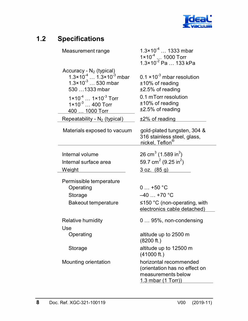
1.2 Specifications
Measurement range 1.3×10⁻⁴ … 1333 mbar 1×10⁻⁴ … 1000 Torr 1.3×10⁻² Pa … 133 kPa
Accuracy - N2 (typical) 1.3×10⁻⁴ … 1.3×10⁻³ mbar 1.3×10⁻³ … 530 mbar 530 …1333 mbar
0.1 ×10⁻³ mbar resolution ±10% of reading ±2.5% of reading
1×10⁻⁴ … 1×10⁻³ Torr 1×10⁻³ … 400 Torr
400 … 1000 Torr
0.1 mTorr resolution ±10% of reading ±2.5% of reading
Repeatability - N2 (typical) ±2% of reading
Materials exposed to vacuum gold-plated tungsten, 304 & 316 stainless steel, glass,
nickel, Teflon®
Internal volume 26 cm3 (1.589 in3)
Internal surface area 59.7 cm2 (9.25 in2)
Weight 3 oz. (85 g)
Permissible temperature Operating
0 … +50 °C
Storage –40 … +70 °C
Bakeout temperature ≤150 °C (non-operating, with electronics cable detached)
Relative humidity 0 … 95%, non-condensing
Use Operating
altitude up to 2500 m (8200 ft.)
Storage altitude up to 12500 m (41000 ft.)
Mounting orientation horizontal recommended (orientation has no effect on measurements below 1.3 mbar (1 Torr))
Doc. Ref. XGC-321-100119 9 V00 (2019-11)
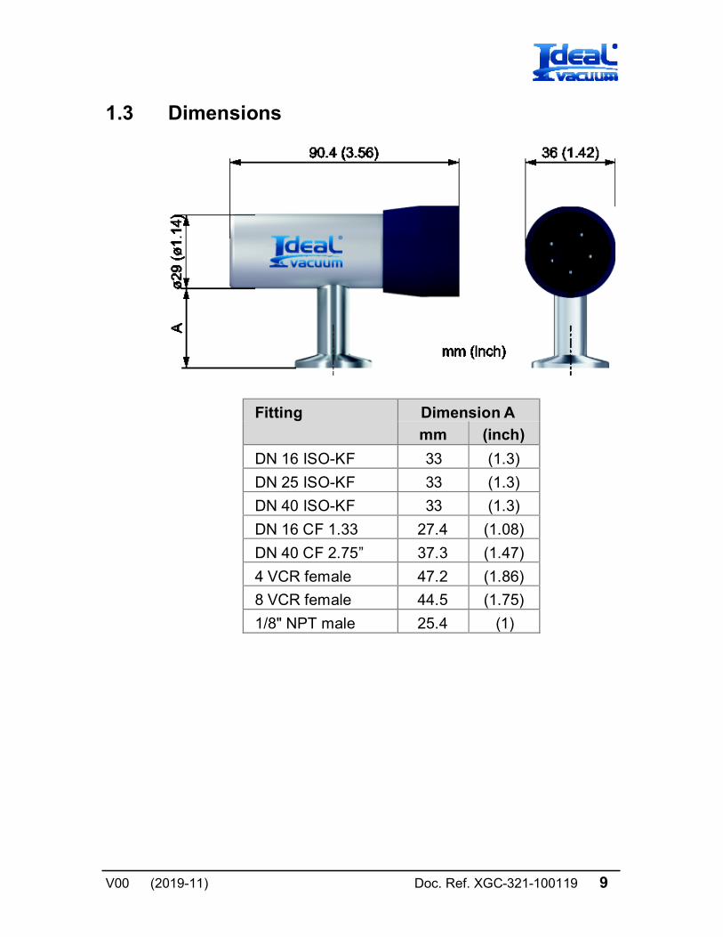
1.3 Dimensions
Fitting Dimension A
mm (inch)
DN 16 ISO-KF 33 (1.3)
DN 25 ISO-KF 33 (1.3)
DN 40 ISO-KF 33 (1.3)
DN 16 CF 1.33 27.4 (1.08)
DN 40 CF 2.75” 37.3 (1.47)
4 VCR female 47.2 (1.86)
8 VCR female 44.5 (1.75)
1/8" NPT male 25.4 (1)
10 Doc. Ref. XGC-321-100119 V00 (2019-11)
2 Important Safety Information
Ideal Vacuum Products has designed and tested this product to provide safe and reliable service, provided it is installed and operated within the strict safety guidelines provided in this man- ual. Please read and follow all warnings and instructions.
WARNING
To avoid serious injury or death, follow the safety informa- tion in this document. Failure to comply with these safety procedures could result in serious bodily harm, including death, and or property damage.
Failure to comply with these warnings violates the safety stand- ards of installation and intended use of this instrument. Ideal Vacuum Products disclaims all liability for the customer’s failure to comply with these instructions.
Although every attempt has been made to consider most possi- ble installations, Ideal Vacuum Products cannot anticipate every contingency that arises from various installations, operation, or maintenance of the module. If you have any questions about the safe installation and use of this product, please contact Ideal Vacuum Products.
2.1 Safety Precautions - General
WARNING! There are no operator serviceable parts or adjustments inside the gauge sensor.
Doc. Ref. XGC-321-100119 11 V00 (2019-11)
Do not modify this product or substitute any parts without au- thorization of qualified Ideal Vacuum Products service trained personnel. Return the product to an Ideal Vacuum Products qualified service and repair center to ensure that all safety features are maintained. Do not use this product if unauthorized modifications have been made.
WARNING! Source power must be removed from the product prior to performing any servicing.
Prior to installing the XGC-321, ensure that all safety checks are made by a qualified service person. When a replacement gauge is required, ensure that the gauge is specified by Ideal Vacuum Products Substitutions of non-qualified parts may result in fire, electric shock or other hazards. Use of unauthorized parts or modifications made to this product will void the warranty.
To reduce the risk of fire or electric shock, do not expose this product to rain or moisture. These products are not waterproof and careful attention must be paid to not spill any type of liquid onto these products. Do not use these products if they have been damaged. Immediately contact Ideal Vacuum Products to arrange return of the product if it is damaged.
Due to the possibility of corrosion when used in certain environ- mental conditions, it is possible that the product’s safety could be compromised over time. It is important that the product be peri- odically inspected for sound electrical connections and equip- ment grounding. Do not use if the equipment grounding or elec- trical insulation has been compromised.
2.2 Safety Precautions - Service and Operation
Ensure that the vacuum port on which the XGC-321 vacuum gauge is mounted is electrically grounded.
Remove cable to the unit before attempting to service the gauge.
Remove cable to the unit if a cable or plug is damaged or the product is not operating normally according to this Operating Manual. Contact qualified Ideal Vacuum Products service personnel for any service or troubleshooting condition that may not be covered by this Operating Manual.
12 Doc. Ref. XGC-321-100119 V00 (2019-11)
It is important that the product be periodically inspected for sound electrical connections and equipment grounding. Do not use if the equipment grounding or electrical insulation has been compromised.
Do not use if the unit has been dropped. Contact Ideal Vacuum Products for further instructions regarding evaluation of the damaged sensor.
2.3 Electrical Conditions
WARNING! When high voltage is present in any vacuum system, a life threatening electrical shock hazard may exist un- less all exposed electrical conductors are maintained at earth ground potential. This applies to all products that come in con- tact with the gas contained in vacuum chambers. An electrical discharge within a gaseous environment may couple dangerous high voltage directly to any ungrounded conductor of electricity. A person could be seriously injured or killed by coming in contact with an exposed, ungrounded electrical conductor at high volt- age potential. This condition applies to all products that may come in contact with the gas inside the vacuum chamber (vacuum / pressure containment vessel).
2.3.1 Proper Equipment Grounding
WARNING! Hazardous voltages that could seriously in-
jure or cause death are present in many vacuum processes. Verify that the vacuum port on which the XGC-321 vacuum gauge module is mounted is electrically grounded. Consult a qualified Electrician if you are in doubt about your equipment grounding. Proper grounding of your equipment is essential for safety as well as intended operation of the equipment. The XGC-321 module vacuum gauge must be connected directly to a good quality earth ground. Use a ground lug on the XGC-321 gauge vacuum connection / flange if necessary.
Doc. Ref. XGC-321-100119 13 V00 (2019-11)
WARNING! In order to protect personnel from electric
shock and bodily harm, shield all conductors which are subject to potential high voltage electrical discharges in or around the vacuum system.
2.3.2 Electrical Interface and Control
It is the user’s responsibility to ensure that the electrical signals from this product and any connections made to external devices, for example, relays and solenoids, are used in a safe manner. Always double check the system set-up before using any signals to automate your process. Perform a hazardous operation analy- sis of your system design and ensure safeguards and personnel safety measures are taken to prevent injury and property dam- age.
2.4 Overpressure and use with hazardous gases
WARNING! Install suitable protective devices that will limit the level of pressure inside your vacuum chamber to less than what the vacuum chamber system components are capable of withstanding. Ideal Vacuum Products gauges should not be used at pressures exceeding 1000 Torr absolute pressure.
In cases where an equipment failure could cause a hazardous condition, always implement fail-safe system operation. For ex- ample, use a pressure relief device in an automatic backfill op- eration where a malfunction could result in high internal pres- sures if the pressure relief device was not installed on the cham- ber.
14 Doc. Ref. XGC-321-100119 V00 (2019-11)
The XGC-321 vacuum gauge module is not intended for use at pressures above 20 psia (1000 Torr); DO NOT exceed 35 psig (<2½ bars) pressure inside the sensor. If your chamber goes to higher pressures, you should install an isolation valve or pres- sure relief device to protect the gauge tube from overpressure conditions. With some fittings, actual safe overpressure condi- tions may be lower; for example, a quick-connect, O-ring com- pression fitting may forcibly release the gauge tube from the vacuum chamber fitting with only a few psi over local uncor- rected barometric (atmospheric) pressure.
CAUTION! If the internal pressure of a vacuum gauge device is allowed to increase above local uncorrected baro- metric pressure (atmospheric pressure side), vacuum fit- tings may release and possible overpressure conditions may cause leaks that would allow the gas inside the gauge tube to release into the atmosphere of the surrounding en- vironment. Toxic, pyrophoric and flammable gases are ex- amples of hazardous gases that if allowed to leak out of the vacuum/pressure containment vessel into the atmospheric environment, could cause bodily injury and possible dam- age to equipment. Never expose the gauge tube internal volume to pressure above local atmospheric pressure when using hazardous gases.
2.5 Gases other than Nitrogen / air
WARNING! Do not attempt to use with gases other than nitrogen (N2) or air without referring to correction factor data tables.
Doc. Ref. XGC-321-100119 15 V00 (2019-11)
Ideal Vacuum Products gauges are calibrated for direct readout of nitrogen or air. Do not attempt to use with other gases such as argon (Ar) or carbon dioxide (CO2) unless accurate conversion data for N2 to other gas is properly used. Refer to the correction factor data listed in the controller Operating Manual operating this device. The Ideal Vacuum Products XGC-320 controller Operating Manual provides a more complete discussion of using correction factors when using the gauge on gases other than Nitrogen.
WARNING! Do not use this device in an explosive atmos-
phere or in the presence of flammable gases, vapors or fumes. Do not use this device to measure the pressure of explosive or combustible gases or gas mixtures. The sensor wire in the gauge normally operates at 125 °C, but if malfunction should occur, the wire temperature could exceed the ignition tempera- ture of certain combustible gases and gas mixture. This could cause an explosion which could result in serious injury or death.
3 Installation
3.1 Mechanical Installation
Mount the XGC-321 as close as possible to the pressure you want to measure. Long or restricted, small diameter tubing will create a pressure difference between your process chamber and the gauge. This may cause a delay in response to pressure changes.
Mounting the XGC-321 too close to a gas source inlet may also cause measurement and control instability. Do not mount the XGC-321 near a source of heating or cooling, such as heaters or air conditioning vents.
16 Doc. Ref. XGC-321-100119 V00 (2019-11)
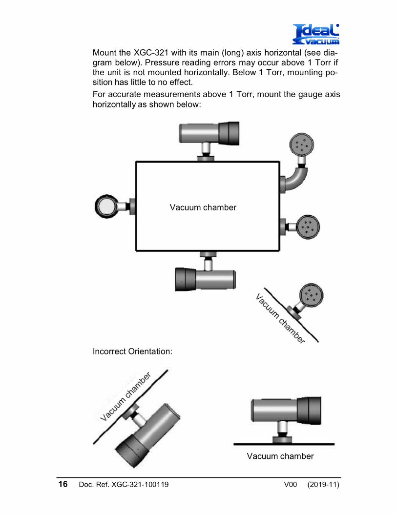
Mount the XGC-321 with its main (long) axis horizontal (see dia- gram below). Pressure reading errors may occur above 1 Torr if the unit is not mounted horizontally. Below 1 Torr, mounting po- sition has little to no effect.
For accurate measurements above 1 Torr, mount the gauge axis horizontally as shown below:
Vacuum chamber
Incorrect Orientation:
Vacuum chamber
Doc. Ref. XGC-321-100119 17 V00 (2019-11)
Mount the XGC-321 with port down, if possible, to help minimize the effect of any particles or condensation from collecting in the gauge.
Do not mount the XGC-321 where it will be subjected to exces- sive vibration. Vibrations may cause unstable readings, measu- rement errors and possible mechanical stress to components in the XGC-321.
Flanges/ Fittings - follow the manufacturer's recommendations and note the following:
- NPT fittings: When connecting the device using a NPT fitting, apply a thread sealant compound or wrap the threaded portion of the tubing with one-and-a-half to two wraps of pipe thread seal tape such as PTFE (Teflon®) tape and hand tighten the gauge into the gauge port. Do not use a wrench or other tool which may damage the gauge.
3.2 Electrical Installation
3.2.1 Grounding
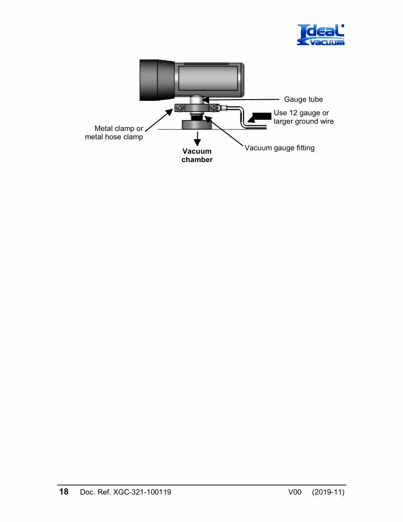
Be sure the vacuum gauge and the rest of your vacuum system are properly grounded for safety as well as intended operation of the equipment. When using KF flanges, metal clamps must be used to ensure proper grounding. Be aware that some vacuum fittings such as NPT connections installed using Teflon tape may not allow for metal-to-metal contact between the vacuum gauge and the vacuum chamber. If such is the case, use a 12 gauge or larger copper wire to connect the vacuum gauge to a ground lug on your vacuum chamber as shown be- low.
18 Doc. Ref. XGC-321-100119 V00 (2019-11)
Metal clamp or metal hose clamp
Vacuum chamber
Gauge tube
Use 12 gauge or larger ground wire
Vacuum gauge fitting
Doc. Ref. XGC-321-100119 19 V00 (2019-11)
4 Using the gauge with different gases
A thermal conductivity gauge senses heat loss which depends on the thermal conductivity of the gas surrounding the sensor. Since different gases, and mixtures, have different thermal con- ductivities, the indicated pressure readings and outputs will also be different. Ideal Vacuum Products convection gauges (and most other thermal conductivity gauges) are calibrated using nitrogen (N2). When a gas other than N2 / air is used, correction must be made for the difference in thermal conductivity between nitrogen (N2) and the gas in use. The gas correction data, charts and tables listed in your controller (such as the Ideal Vacuum Products XGC-320 controller) Operating Manual indicates how different gases affect the display and output from an Ideal Vacuum Products convection gauge.
WARNING! Using a thermal conductivity gauge with gases other than that for which it is calibrated could result in death or serious injury. Be sure to use the correction factor data listed in the controller Operating Manual operating this device.
For N2 the calibration shows excellent agreement between indi- cated and true pressure throughout the range from 1×10⁻⁴ to 1000 Torr. At pressures below 1 Torr, the calibration curves for the different gases are similar. The difference in readings at these low pressures is a constant, a function of the difference between thermal conductivities of the gases.
At pressures above 1 Torr, indicated pressure readings may diverge significantly. At these higher pressures convection currents in the gauge become the predominant cause of heat loss from the sensor and calibration depends on gauge tube geometry and mounting position as well as gas properties.
20 Doc. Ref. XGC-321-100119 V00 (2019-11)
Generally, air and N2 are considered the same with respect to thermal conductivity, but even N2 and air will exhibit slight diffe- rences in readings at higher pressures. For example, when venting a system to atmosphere using N2, you may see readings change by 40 to 55 Torr after the chamber is opened and air gradually displaces the N2 in the gauge. For most other gases the effect is much more significant and may result in a ha- zardous condition as described below.
Other considerations when using gases other than N2 / air
Flammable or explosive gases
WARNING! Ideal Vacuum Products convection gauges are neither intrinsically safe nor explosion proof and are not intended for use in the presence of flammable or explosive gases or vapors.
Under normal conditions the voltages and currents in Ideal Vacuum Products convection gauges are too low to cause igni- tion of flammable gases. However, under certain failure condi- tions, sufficient energy could be generated to cause flammable vapors or gases to ignite or explode. Thermal conductivity gauges like the Ideal Vacuum Products convection gauges are not recommended for use with flammable or explosive gases.
Moisture / water vapor
In some processes (lyophilization, for example) the gas composi- tion may not change significantly, except for moisture content. Water vapor can significantly change the response of a thermal gauge and correction should be made, as you would for any other gas.
Other contaminants
If your gases condense, coat, or corrode the sensor, the gauge calibration and response to different gases will change. Gener- ally, if the gauge can be "calibrated" ("zero" and "span" settings), these changes are small enough to be ignored. If you can’t set zero and span, the gauge should be replaced or return to factory for evaluation and possible cleaning.
Doc. Ref. XGC-321-100119 21 V00 (2019-11)
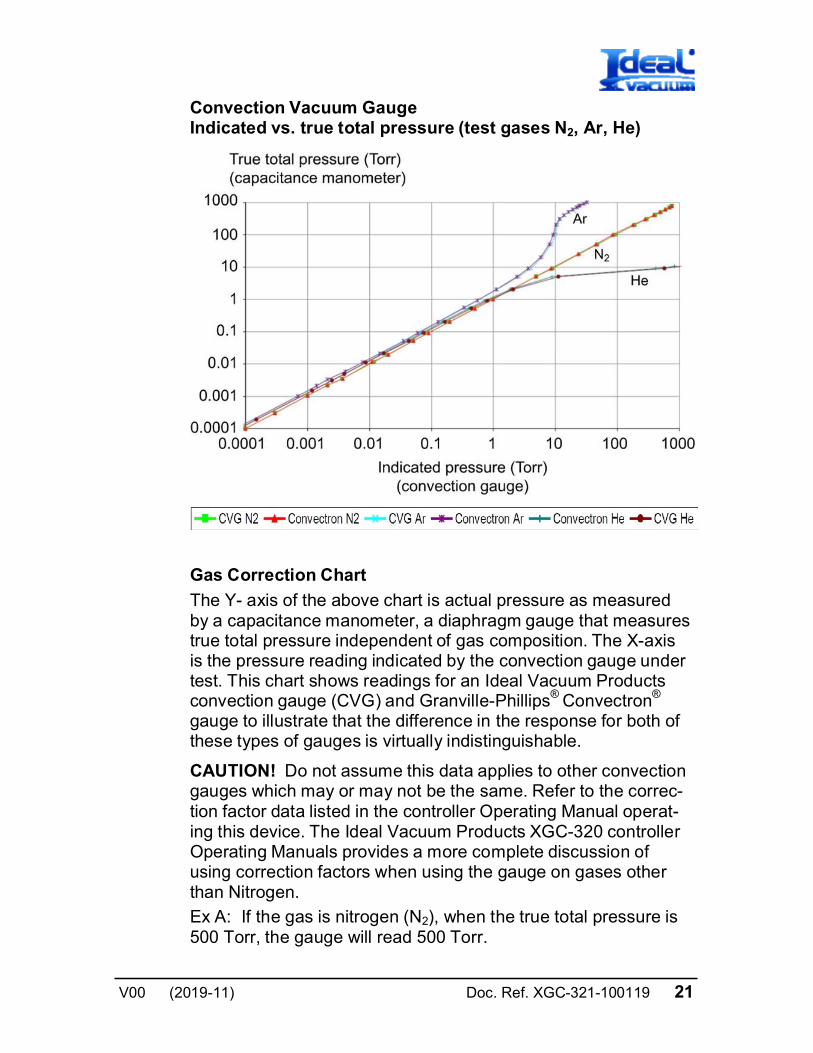
Convection Vacuum Gauge Indicated vs. true total pressure (test gases N2, Ar, He)
Gas Correction Chart
The Y- axis of the above chart is actual pressure as measured by a capacitance manometer, a diaphragm gauge that measures true total pressure independent of gas composition. The X-axis is the pressure reading indicated by the convection gauge under test. This chart shows readings for an Ideal Vacuum Products convection gauge (CVG) and Granville-Phillips® Convectron®
gauge to illustrate that the difference in the response for both of these types of gauges is virtually indistinguishable.
CAUTION! Do not assume this data applies to other convection gauges which may or may not be the same. Refer to the correc- tion factor data listed in the controller Operating Manual operat- ing this device. The Ideal Vacuum Products XGC-320 controller Operating Manuals provides a more complete discussion of using correction factors when using the gauge on gases other than Nitrogen.
Ex A: If the gas is nitrogen (N2), when the true total pressure is 500 Torr, the gauge will read 500 Torr.
22 Doc. Ref. XGC-321-100119 V00 (2019-11)
Ex B: If the gas is argon (Ar), when the true pressure is 100 Torr, the gauge will read about 9 Torr. If you are backfilling your vacuum system with Ar, when your system reaches a pressure of 760 Torr true pressure your gauge will be reading about 23 Torr. Continuing to backfill your system, attempting to increase the reading up to 760 Torr, you will over pressurize your chamber which may present a hazard.
Ex C: If the gas is helium (He), the controller will read over pres- sure (OP) when pressure reaches about 10 Torr true pressure and opening the chamber to atmosphere prematurely may pre- sent other hazards for both people and product.
CAUTION! What these examples illustrate is that using gases other than nitrogen (N2) without using accurate gas conversion data and other proper precautions could result in injury to per- sonnel and/or damage to equipment.
Suggested precautions when using gases other than nitrogen (N2):
Install a pressure relief valve or burst disk on your chamber, to protect it from overpressure. Post a warning label on your gauge readout that states "Do Not Exceed Torr Indicated Pres- sure" (fill in the blank for maximum indicated pressure for the gas you use) so that an operator using the gauge will not exceed a safe pressure.
Doc. Ref. XGC-321-100119 23 V00 (2019-11)
5 Service
5.1 Calibration
Every Ideal Vacuum Products XGC-321 gauge is calibrated prior to shipment using nitrogen (N2). However, you can calibrate the instrument by adjusting zero and span (atmosphere), using the controller which is operating the gauge.
Zero and span (atmosphere) calibration affect the displayed value and the output signal. Zero calibration optimizes perfor- mance of the gauge when operating at a low pressure range of 1.00×10⁻⁴ Torr to 1.00×10⁻³ Torr. If your minimum operating pres- sure is higher than 1.00×10⁻³ Torr, it is not normally necessary to perform calibration at zero and thus span calibration should be adequate. If you are able to evacuate your system to below 1.00×10⁻⁴ Torr, it is always a good practice to check and set zero if necessary. This will also improve performance in cases where gauge contamination is causing higher readings than 1.00×10⁻⁴ Torr, even though the system has been evacuated to below 1.00×10⁻⁴ Torr. Care should be exercised when using gases other than nitrogen (N2) / air.
5.2 Maintenance
In general, maintenance is not required for your Ideal Vacuum Products gauge. Periodic performance checks may be done by comparing the gauge to a known reference standard.

5.3 Troubleshooting
24 Doc. Ref. XGC-321-100119 V00 (2019-11)
Ind
icat
ion
P
oss
ible
Ca
use
P
oss
ible
So
luti
on
Rea
ding
s a
ppe
ar v
ery
diffe
rent
from
exp
ect
ed
pres
sure
Th
e p
roce
ss g
as is
diff
ere
nt f
rom
th
e ga
s us
ed to
cal
ibra
te th
e X
GC
-32
1
Cor
rect
re
adin
gs
for
diff
eren
t gas
th
erm
al c
ond
uctiv
ity. S
ee
cont
rolle
r O
pera
ting
Man
ual
Mod
ule
ha
s n
ot b
een
cal
ibra
ted
or
has
been
cal
ibra
ted
inco
rrec
tly
Che
ck th
at z
ero
and
spa
n ar
e ad
just
ed
corr
ect
ly. S
ee c
ont
rolle
r O
pera
ting
Man
ual
Rea
ding
s a
re n
oisy
or
erra
tic
Loo
se c
able
s or
co
nne
ctio
ns
Che
ck a
nd
tight
en
conn
ect
ions
Con
tam
inat
ion
Insp
ect g
aug
e fo
r si
gns
of
cont
amin
atio
n su
ch a
s p
artic
les,
de
pos
its, d
isco
lora
tion
on g
aug
e in
let.
R
etu
rn t
o fa
ctor
y fo
r p
ossi
ble
cle
anin
g
Vib
ratio
n
Ens
ure
gau
ge is
not
mo
unte
d w
here
ex
cess
ive
vib
ratio
n is
pre
sent
Gau
ge
cann
ot b
e ca
libra
t-
ed -
ze
ro a
nd
span
ca
n't
be a
djus
ted
R
etu
rn t
o fa
ctor
y fo
r p
ossi
ble
cle
anin
g
Sen
sor
failu
re fo
r ot
her
cau
se
Ret
urn
to
fact
ory
for
eval
uat
ion
or
repl
ace
(c
ontin
ued
)
Doc. Ref. XGC-321-100119 25 V00 (2019-11)
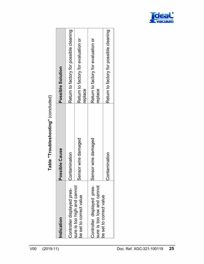
T
ab
le "
Tro
ub
les
ho
oti
ng
" (c
onc
lude
d)
Ind
icat
ion
P
oss
ible
Ca
use
P
oss
ible
So
luti
on
Con
trol
ler
disp
laye
d pr
es-
sure
is to
o hi
gh
an
d ca
nno
t be
set
to c
orre
ct v
alue
Con
tam
inat
ion
Ret
urn
to f
acto
ry fo
r p
ossi
ble
cle
anin
g
Sen
sor
wir
e da
ma
ged
Ret
urn
to fa
ctor
y fo
r ev
alua
tion
or
repl
ace
Con
trol
ler
disp
laye
d p
res-
su
re i
s to
o lo
w a
nd
cann
ot
be s
et to
cor
rect
val
ue
Sen
sor
wir
e da
ma
ged
Ret
urn
to f
acto
ry fo
r ev
alua
tion
or
repl
ace
Con
tam
inat
ion
Ret
urn
to f
acto
ry fo
r p
ossi
ble
cle
anin
g
26 Doc. Ref. XGC-321-100119 V00 (2019-11)
5.4 Contamination
The most common cause of all vacuum gauge failures is conta- mination of the sensor. Noisy or erratic readings, the inability to set zero or atmosphere and total gauge failure, are all possible indications of gauge contamination.
Contamination can be generally characterized as either:
A) a reaction of process gases with sensor elements, or
B) an accumulation of material on the sensor elements. Sen- sors that fail due to chemical reaction are generally not sal- vageable. Sensors that fail due to condensation, coatings, or particles may possibly be restored by cleaning.
A) Reactive Gases
If process gases react with the materials of construction of the sensor, the result is corrosion and disintegration of the sensor over time. The chemistry of the gases used for plasma etching and other reactive semiconductor processes are examples where this failure mode is possible. In this case, cleaning can’t solve the problem because the sensor has been destroyed. The sensor or module must be replaced.
If you experience this failure mode quickly or frequently, you should consider a different vacuum gauge for your application. Thermal vacuum gauges may be available with different sensor materials that are not as reactive with your particular process gases. The standard gold plated tungsten sensor used in the Ideal Vacuum Products convection gauge is offered for use with air and inert gases such as N2, argon, etc. Ideal Vacuum Products also offers modules with platinum sensors for applica- tions not compatible with gold plated tungsten.
There is no material that is universally chemical resistant; your choice of vacuum gauge (as well as all other vacuum compo- nents) should take into consideration the potential reactions between your process gases and the materials of construction. Consider what effect water vapor will have when combined with your process gases because a finite amount of water will enter the chamber during venting to atmosphere with air.
Doc. Ref. XGC-321-100119 27 V00 (2019-11)
B) Oil, Condensation, Coatings, and Particles
If the failure is due to an accumulation of material in the gauge, we may be able to restore your gauge or module by cleaning. Contamination may be as simple as condensed water, or as difficult as solid particles.
Oils and hydrocarbons: Exposure of the gauge internal surfaces to oils and hydrocarbons can result in sensor contamination. Some of these types of contamination may be removed by cleaning the gauge. If there is the possibility of oil back stream- ing from wet vacuum pumps, it is recommended that a filter or trap be installed to prevent contamination of components of your vacuum system.
Condensation: Some gases (such as water vapor) can con- dense on sensor surfaces, forming a liquid coating that changes the rate at which heat is removed from the sensor (which changes the calibration). The sensor can often be restored simply by pumping on the gauge between process cycles. A dry N2 purge will help speed up drying, or the gauge may be gently heated provided temperature doesn't exceed the specified limit of 40 °C, operating.
Coatings: Some gases can condense on sensor surfaces, for- ming a solid coating, which changes the rate at which heat is removed from the sensor. Some of these coatings may be re- moved by cleaning the gauge.
Particles: Particles generated by the process may enter the gauge during the process cycle or during the venting cycle. The result is interference with heat removal from the sensor. In this case, cleaning may be able to remove particles from the gauge. However, particulate contamination is the most difficult to re- move as particles can become stubbornly trapped inside the gauge. In some processes, solid particles are created during the process throughout the chamber including inside the gauge. Par- ticles tend to form on cooler surfaces such as in a gauge at room temperature. You may slow down the build-up of particles in the gauge by keeping the gauge warm (within specified limits) during the process cycle.
28 Doc. Ref. XGC-321-100119 V00 (2019-11)
Particles in the process chamber may be swept into the gauge during the vent cycle. The XGC-321 has a screen built into the gauge port to help keep the largest particles out of the gauge. In very dirty applications, or where particles are small enough to get through the screen, an additional filter installed on the inlet may help prolong the gauge life.
In some vacuum processes, desorbed and sputtered materials from the process may enter vacuum components connected to the process vacuum chamber by line-of-sight transport, espe- cially under high vacuum conditions, i.e., in the molecular flow regime. To prevent materials that may be transported via line-of- sight momentum from entering your vacuum gauge or other components, it is advisable to install some form of apparatus that will block the line-of-sight. In many cases a simple 90° elbow may help prevent or reduce the transport of particles from enter- ing your vacuum gauge.
In the event of gauge contamination please contact the factory to return the gauge for possible cleaning if the gauge has not been exposed to hazardous materials.
5.5 Gauge replacement
If the XGC-321 gauge fails for any reason, and cleaning does not resolve the issue, the XGC-321 gauge should be replaced.
Doc. Ref. XGC-321-100119 29 V00 (2019-11)
6 Factory Service and Support
If you need help setting up, operating, troubleshooting, or obtaining a return materials authorization number (RMA number) to return the module for diagnosis, please contact us during normal business hours (8:00 am to 5:00 pm Mountain time) Monday through Friday, at (505) 872-0037. Or e-mail us at [email protected].
7 Returning the Product
WARNING
Forwarding contaminated products
Contaminated products (e.g. radioactive, toxic, caustic or microbiological hazard) can be detrimen- tal to health and environment.
Products returned to Ideal Vacuum Products should preferably be free of harmful substances. Adhere to the forwarding regulations of all involved countries and forwarding companies and enclose a duly completed declaration of contamination *).
*) Please contact Ideal Vacuum Products
Products that are not clearly declared as "free of harmful sub- stances" are decontaminated at the expense of the customer.
Products not accompanied by a duly completed declaration of contamination are returned to the sender at his own expense.
30 Doc. Ref. XGC-321-100119 V00 (2019-11)
8 Disposal
DANGER
Contaminated parts
Contaminated parts can be detrimental to health and environment.
Before beginning to work, find out whether any parts are contaminated. Adhere to the relevant re- gulations and take the necessary precautions when handling contaminated parts.
WARNING
Substances detrimental to the environment
Products or parts thereof (mechanical and electric components, operating fluids etc.) can be detrimen- tal to the environment.
Dispose of such substances in accordance with the relevant local regulations.
Separating the components
After disassembling the product, separate its components ac- cording to the following criteria:
• Contaminated components
Contaminated components (radioactive, toxic, caustic or bio- logical hazard etc.) must be decontaminated in accordance with the relevant national regulations, separated according to their materials, and disposed of.
• Other components
Such components must be separated according to their ma- terials and recycled.
Doc. Ref. XGC-321-100119 31 V00 (2019-11)
EU Declaration of Conformity
We, Ideal Vacuum Products, hereby declare that the equipment mentioned below complies with the provisions of the following Directives:
• 2014/30/EU, OJ L 96/79, 29.3.2014 (EMC Directive; Directive relating to electromagnetic compatibility)
• 2011/65/EU, OJ L 174/88, 1.7.2011 (RoHS Directive; Directive on the restriction of the use of certain hazard- ous substances in electrical and electronic equipment)
XactGauge™ Convection-Enhanced Pirani Gauge Sensor XGC-321 (operation with XGC-320)
Standards
Harmonized and international / national standards and specifi- cations:
• EN 61000-6-2:2005 (EMC: generic immunity standard)
• EN 61000-6-4:2007 + A1:2011 (EMC: generic emission standard)
• EN 61010-1:2010 (Safety requirements for electrical equipment for measurement, control and laboratory use)
• EN 61326-1:2013; Group 1, Class A (EMC requirements for electrical equipment for measurement, control and laboratory use)
Manufacturer / Signatures
Ideal Vacuum Products, LLC, 87109 New Mexico
Tony C. Smith General manager
www.ideafvac.com
New Mexico 87109
Phone: (505) 872-0037 Fax: (505) 872-9001
Original: English [email protected]
11111111111111111111111111111111111111111111111111111111111111111111111111111111
xas·321-100119