Thermosolutal convection and macrosegregation
9
Thermosolutal Convection and Macrosegregation Caused by Solute Rejection at Cell/Dendrite Tips S.N. TEWARI, RAJESH SHAH, and M.A. CHOPRA Thermosolutal convection caused by the solute build up ahead of growing arrays of cells and dendrites results in macrosegregation along the length of Pb-Sn alloy (10 to 58 wt pct Sn) specimens when they are directionally solidified in a positive thermal gradient (melt on top, solid below, and gravity pointing down). At a constant thermal gradient, the extent of macro- segregation increases with decreasing growth speed as the microstructure changes from dendritic to cellular and to planar. An empirical parameter, effective partition coefficient (k~rf), obtained from the dependence of the longitudinal macrosegregation on fraction distance solidified can be used to represent the extent of macrosegregation. The extent of macrosegregation appears to be related to a parameter, [g(C, - Co) DJRCo] ~/2, where Co is the tin content of the alloy, Ct is the tin content of melt at the array tips, R is the growth speed, D~ is the diffusivity of tin in the melt, and g is the acceleration due to gravity. I. INTRODUCTION TEMPERATURE and composition profiles in the melt near the tips of the primary dendrite array, both in the interdendritic mushy region and in the bulk melt ahead, for directional solidification of a Pb-10 wt pct Sn alloy at a thermal gradient (G~) of 110 K cm -~ are shown in Figure 1. As shown schematically, the location of the tips corresponds to the distance marked zero. The inter- dendritic solutal profiles in this figure were obtained from the experimentally determined I~l thermal profiles during steady-state directional solidification of the alloy by as- suming local equilibrium. Tip compositions, C,, are es- timated from a theoretical model. [2] The solute content of the bulk liquid is assumed to decrease exponentially from C, to the melt composition, C0, over a characteristic distance equal to D~/R, where D~ is the solutal diffusivity in the melt and R is the growth speed. The temperature and composition dependence of the Pb-Sn binary alloy melt density reported by Poirier t3] has been used in cal- culating the density profiles in the melt shown in Figure I. For directional solidification with the melt on top and solid below, with gravity pointing down, the density profile in the interdendritic melt and in the melt imme- diately ahead of the tips promotes natural convection (higher density melt on top of that with lower density). For dendritic arrays growing with small solute build up at the tips, the interdendritic density profile plays a cru- cial role in determining the extent of natural convection. In a recent article, 141 we described the influence of thermosolutal convection in the interdendritic melt on the longitudinal macrosegregation for dendritic arrays and its relationship with the formation of channel segregates. However, the solute buildup at the tip is much larger for the cellular arrays which form at lower growth speeds, S.N. TEWARI, Professor, and RAJESH SHAH, Graduate Student, are with the Chemical Engineering Department, Cleveland State University, Cleveland, OH 44115. M.A. CHOPRA, formerly Research Associate, NASA-Lewis Research Center, Cleveland, OH, is Development Engineer with IBM, Austin, TX 78758. Manuscript submitted June 22, 1992. for example, 2 /xm s ~ for cells vs 10 /xm s -1 for den- drites (compare C~ with C) in Figure 1). This not only produces a larger density inversion in the melt ahead of the tips at lower growth speeds (density of the melt ahead of the tip increases by Apz before beginning to decrease, compared with an increase of only Apj), but the inver- sion also exists over larger distance (compare Dt/Rz with D~/Rj in Figure 1). Thermosolutal convection in the bulk melt will therefore be very important for the cellular morphologies. Convection near the tips can also pene- trate into the mushy region. This will result in longitu- dinal (parallel to the growth direction) and transverse macrosegregations, solutal inhomogeneities over length scales much larger than the primary arm spacings, dur- ing directional solidification. In this article, we will ex- amine the longitudinal macrosegregation resulting from thermosolutal convection in the melt driven by the re- jection of low density solute at the tips during directional solidification of Pb-Sn alloys. II. EXPERIMENTAL About 30-cm-long Pb-Sn samples were obtained by induction melting a charge (lead and tin, 99.99 pct pu- rity) in an argon atmosphere in a quartz crucible and pushing the melt into evacuated quartz tubes (0.7-cm ID) with the help of argon pressure. The quartz tubes con- tained two chromel-alumel thermocouples (0.01-cm- diameter wires kept within one end closed quartz capillaries, 0.06-cm OD) located along the sample length with a separation distance of about 2 cm. After sealing at one end, the quartz tubes containing these samples were evacuated and the top 20-cm length of the cast specimen was remelted. Directional solidification was carried out by raising the furnace assembly at various growth speeds with respect to the stationary sample, thus avoiding any convection due to the crucible motion. The furnace and experimental details were presented ear- lierJ t4] Growth conditions were thermally stable, melt on the top and solid below with gravity pointing down. A steady-state thermal profile was maintained during di- rectional solidification, as evidenced by identical ther- mal profiles indicated by the two thermocouples kept in METALLURGICAL TRANSACTIONS A VOLUME 24A, JULY 1993--1661
-
Upload
independent -
Category
Documents
-
view
1 -
download
0
Transcript of Thermosolutal convection and macrosegregation

Thermosolutal Convection and Macrosegregation Caused by Solute Rejection at Cell/Dendrite Tips
S.N. TEWARI, RAJESH SHAH, and M.A. CHOPRA
Thermosolutal convection caused by the solute build up ahead of growing arrays of cells and dendrites results in macrosegregation along the length of Pb-Sn alloy (10 to 58 wt pct Sn) specimens when they are directionally solidified in a positive thermal gradient (melt on top, solid below, and gravity pointing down). At a constant thermal gradient, the extent of macro- segregation increases with decreasing growth speed as the microstructure changes from dendritic to cellular and to planar. An empirical parameter, effective partition coefficient (k~rf), obtained from the dependence of the longitudinal macrosegregation on fraction distance solidified can be used to represent the extent of macrosegregation. The extent of macrosegregation appears to be related to a parameter, [g(C, - Co) DJRCo] ~/2, where Co is the tin content of the alloy, Ct is the tin content of melt at the array tips, R is the growth speed, D~ is the diffusivity of tin in the melt, and g is the acceleration due to gravity.
I. INTRODUCTION
TEMPERATURE and composition profiles in the melt near the tips of the primary dendrite array, both in the interdendritic mushy region and in the bulk melt ahead, for directional solidification of a Pb-10 wt pct Sn alloy at a thermal gradient (G~) of 110 K cm -~ are shown in Figure 1. As shown schematically, the location of the tips corresponds to the distance marked zero. The inter- dendritic solutal profiles in this figure were obtained from the experimentally determined I~l thermal profiles during steady-state directional solidification of the alloy by as- suming local equilibrium. Tip compositions, C,, are es- timated from a theoretical model. [2] The solute content of the bulk liquid is assumed to decrease exponentially from C, to the melt composition, C0, over a characteristic distance equal to D~/R, where D~ is the solutal diffusivity in the melt and R is the growth speed. The temperature and composition dependence of the Pb-Sn binary alloy melt density reported by Poirier t3] has been used in cal- culating the density profiles in the melt shown in Figure I.
For directional solidification with the melt on top and solid below, with gravity pointing down, the density profile in the interdendritic melt and in the melt imme- diately ahead of the tips promotes natural convection (higher density melt on top of that with lower density). For dendritic arrays growing with small solute build up at the tips, the interdendritic density profile plays a cru- cial role in determining the extent of natural convection. In a recent article, 141 we described the influence of thermosolutal convection in the interdendritic melt on the longitudinal macrosegregation for dendritic arrays and its relationship with the formation of channel segregates. However, the solute buildup at the tip is much larger for the cellular arrays which form at lower growth speeds,
S.N. TEWARI, Professor, and RAJESH SHAH, Graduate Student, are with the Chemical Engineering Department, Cleveland State University, Cleveland, OH 44115. M.A. CHOPRA, formerly Research Associate, NASA-Lewis Research Center, Cleveland, OH, is Development Engineer with IBM, Austin, TX 78758.
Manuscript submitted June 22, 1992.
for example, 2 /xm s ~ for cells vs 10 /xm s -1 for den- drites (compare C~ with C) in Figure 1). This not only produces a larger density inversion in the melt ahead of the tips at lower growth speeds (density of the melt ahead of the tip increases by Apz before beginning to decrease, compared with an increase of only Apj), but the inver- sion also exists over larger distance (compare Dt/Rz with D~/Rj in Figure 1). Thermosolutal convection in the bulk melt will therefore be very important for the cellular morphologies. Convection near the tips can also pene- trate into the mushy region. This will result in longitu- dinal (parallel to the growth direction) and transverse macrosegregations, solutal inhomogeneities over length scales much larger than the primary arm spacings, dur- ing directional solidification. In this article, we will ex- amine the longitudinal macrosegregation resulting from thermosolutal convection in the melt driven by the re- jection of low density solute at the tips during directional solidification of Pb-Sn alloys.
II. EXP ERIMENTAL
About 30-cm-long Pb-Sn samples were obtained by induction melting a charge (lead and tin, 99.99 pct pu- rity) in an argon atmosphere in a quartz crucible and pushing the melt into evacuated quartz tubes (0.7-cm ID) with the help of argon pressure. The quartz tubes con- tained two chromel-alumel thermocouples (0.01-cm- diameter wires kept within one end closed quartz capillaries, 0.06-cm OD) located along the sample length with a separation distance of about 2 cm. After sealing at one end, the quartz tubes containing these samples were evacuated and the top 20-cm length of the cast specimen was remelted. Directional solidification was carried out by raising the furnace assembly at various growth speeds with respect to the stationary sample, thus avoiding any convection due to the crucible motion. The furnace and experimental details were presented ear- lierJ t4] Growth conditions were thermally stable, melt on the top and solid below with gravity pointing down. A steady-state thermal profile was maintained during di- rectional solidification, as evidenced by identical ther- mal profiles indicated by the two thermocouples kept in
METALLURGICAL TRANSACTIONS A VOLUME 24A, JULY 1993--1661

670
i 620
570
52C -.25
;- Tip--\ / • "
_ ~ . S ' * "
I I I I I I 0 .25 .50 .75
Distance, cm
#
t- O
E 8
2 5 - -
2 0 -
15 -
10 -
-.25
\ \ Sn o01 (10 ixms -1)
\ Sn 004 (2 Fins -1) \ \
\ \ ' , 4
I , Co I I i I I I 0 .25 .50 .75
Distance, cm
10.00
9.75
i ~ 9.50 "0 m Q
9.25
o
I Dr/R1
- T T , - - -
/ /
/ /
/ /
/ 9 .00 I I I -.25 0 .25 .50 .75
Distance, cm
Fig. 1 --Thermal, solutal, and density profiles of the melt in the in- terdendritic region and ahead of the dendritic array for directional so- lidification of Pb-10 wt pct Sn in a positive thermal gradient of 110 K cm -~ at 10 and 2/.tm s -~.
the sample. Ill After 12 to 14 cm of directional growth, the specimens were quenched by directing a jet of he- lium gas, cooled by liquid nitrogen, to the surface of the quartz crucibles. For these experiments, the mushy zone length during directional solidification was less than 10 pct of the length of the initial melt column. The furnace and crucible arrangements were such that the furnace translation rate was equal to the directional solidification speed. This was verified by correlating the longitudinal (parallel to the growth direction) microstructure of the directionally solidified specimen with the furnace trans- lation distance.
The longitudinal (parallel to growth direction) and transverse microstructures were examined in the unetched condition by standard optical metallography techniques. Atomic absorption spectrometry was used to determine macrosegregation along the length of the directionally solidified bars. The tin contents of thin slices (~3-mm wide), cut along the length of the directionally solidified and quenched portion of the specimen, were determined to a reported accuracy of +0.5 wt pct for Co = 10 wt pct, -+0.6 wt pct for Co = 17 wt pct, and -+ 1.2 wt pct for Co = 57 wt pct. The distance from the tip of the mushy zone at the onset of directional solidification to its tip at the time of quench, as observed from the lon- gitudinal microstructure, was taken as the total solidi- fication distance. The ratio of the distance solidified, as measured from the tip of the mushy zone at the onset of directional solidification, to the total length of the initial melt column was taken as the fraction solid (fs). Trans- verse macrosegregation, as a function of the radial dis- tance from the specimen outer surface, was examined for some samples by analyzing the filings obtained by ma- chining the sample at one f~ by a lathe. Table I lists the growth parameters for all the specimens examined in this study.
I lL RESULTS
Figure 2 shows the typical microstructures in direc- tionally solidified Pb-10 wt pct Sn alloy. The longitu- dinal microstructures are at the quenched liquid-solid interface. The transverse microstructures are from the quenched mushy region of the specimens, at a distance of about 0.5 mm from the quenched dendrite tips. With increasing growth speed, the microstructure changed from planar (Figure 2(a), 1 ftm s -~) to cellular (Figure 2(b), 2 /xm s -1) and finally to dendritic (Figure 2(c), 4 /zm s-l). Figure 2 shows that the cells and dendrites were aligned parallel to the alloy growth direction. Exami- nation of the longitudinal sections near the quenched array tips showed that the mushy zone length was constant across the entire specimen cross section. This indicates the absence of any significant transverse temperature gradient in the melt.
Typical growth speed dependence of the longitudinal macrosegregation for the directionally solidified Pb-Sn alloys is shown in Figure 3, which plots Cs/Co vs frac- tion distance solidified (fs), Cs being the composition at f~. The open symbols correspond to the directionally so- lidified portion, and the closed symbols correspond to the quenched liquid portion of the specimens. Here, Co,
1 6 6 2 - - V O L U M E 24A, JULY 1993 M E T A L L U R G I C A L TRANSACTIONS A

Table I. Macrosegregation and Growth Parameters for Directionally Solidified Pb-Sn Alloys
Sample Co R Gt C,* [g(Ct - Co)DJRCo] 1/2 Number (Wt Pct Sn) (/zm s -I) (K cm 1) (Wt Pct Sn) kerr** (cm s -I) Morphology
SN015 10.1 20.0 110.0 10.6 1.0 0.85 SN001 10.1 10.0 110.0 11.0 0.98 -+ 0 . 0 1 / 0 . 9 7 1.63 SN004 9.07 2.0 102.0 13.1 0.85 -+ 0 . 0 3 / 0 . 7 7 8.09 SN27 5.64 6 .0 98.0 6.95 0.87 • 0 . 0 5 / 0 . 8 8 3.38 SN002 10.1 1.0 97.3 17.8 0 .76 • 0 . 0 4 / 0 . 6 8 14.98 SN19B2 10.1 1.0 110.0 17.9 0.58 • 0 . 0 5 / 0 . 6 4 15.00 SN1A 16.5 4 .0 101.0 18.9 0.85 • 0 . 0 4 / 0 . 8 6 3.27 SN1B 17.9 1.0 101.0 27.5 0 .74 +- 0 . 0 2 / 0 . 7 0 12.56 SN1D 17.0 0.35 101.0 40.4 0 .44 -+ 0 .01 /0 .51 34.02 MVTI* 20.0 1.7 114 26.4 0 .70 7.4 MVT2 t 20.0 0 .4 125 47.6 0 .32 31.9 MVT3* 40.0 2.0 100.0 44.8 0.71 4.2 MVT4* 40.0 4.5 102.0 42.2 0.81 1.9 MVT5* 40 .0 4.5 356.0 47.6 0.85 3.5 MVT6* 40 .0 20.0 350.0 41.8 0 .99 0.8 MVT7* 40 .0 202.0 346.0 40.6 1.0 0.15
dendritic dendritic cellular cellular planar planar
dendritic cellular cellular
*C, values have been estimated from Ref. 2 for the effective thermal gradient (G), where G = [(2K~G~ + RL,.)/(K~ + K~). Thermal conductivities of liquid (K~) and of solid (K3, heat of fusion per unit volume (L,), and other physical properties listed in Ref. 4 have been used here.
**First number indicates ko,f obtained from slope, -+ number its standard deviation, and third number ke, obtained from intercept. *K~rf data have been extracted from Ref. 12.
Longitudinal
T N
Fig. 2--Typical microstructures of directionally solidified Pb-10 wt pct Sn near the quenched liquid-solid interface: (a) planar, 1 tzm s ~; (b) cellular, 2 /xm s-~: (i) longitudinal (parallel to the growth direction) and (ii) transverse; and (c) dendritic, 4 /xm s ~: (i) longitudinal and (ii) transverse.
METALLURGICAL TRANSACTIONS A VOLUME 24A, JULY 1993--1663

1o4
1.2
~ 1 . 0
.8
i I I H i �9 �9 �9 i i
4)~4,~o~, 04l ' 'IFIm o4o " O 0 0 0 0 0 ^ 00 - - 0 O0 oo<>ood6oo "0 o
.6 0
~ 1 7 6 ~ I ! 20 i~ns -1 denddtlc ~OOOn 0 0 0 ~ vv v v 10 ~ s -1 dendritic
2 p.ms -1 cellular v v v 1 p.ms -1 planar
V V v v
(a) t I I [ I .2 .4 .6 .8 1.0
Fraction distance solidified
1.4
1 . 2 w
1.0
.8
.4 (/9) I 0 .2
[]
oOOoOOO 0 o ~ 1 7 6 1 7 6 1 7 6 1 7 6 _
B o o cl
I .4
n ~ []
4.0 p.ms -1 dendritic 1.0 btms -1 cellular
.35 lares -1 cellular
I I .6 .8 1.0
Fraction distance solidified
Fig. 3 - - G r o w t h speed dependence of the longitudinal macrosegre- gation in directionally solidified Pb-Sn alloys (G/ = 1 l0 K cm ~). Open symbols correspond to the directionally solidified portion and closed symbols to the quenched melt portion of the specimen: (a) Pb- 10 wt pct Sn and (b) Pb-17 wt pct Sn.
the original tin content of the sample for each direction- ally solidified specimen, was obtained by measuring the area under the Cs vs f~ plots, which included both the directionally solidified and quenched melt portions, as shown in Figure 3(a). It was found to be within +5 pct of the analysis obtained from the specimens cut from the precast feed stock bars. Figure 3(a) shows that for the Pb-10 wt pct Sn alloy, the Cs/Co value is nearly unity along the entire length of the dendritic specimen solid- ified at 20 ~m s -1, indicating absence of longitudinal macrosegregation. Data for one precast sample, which was similarly analyzed along the specimen length and did not show any longitudinal macrosegregation, have not been included in this figure for the sake of clarity. In the absence of convection, a uniform solute content will be expected along the length of the directionally so- lidified dendritic/cellular specimens, except for the ini- tial and final transients (length about the size of the mushy
zone length). The dendritic specimen grown at 10 ~m s -l shows some macrosegregation, as indicated by the CJCo values being slightly higher than unity in the quenched liquid portion of this specimen. Macro- segregation is much larger for the specimen with the cel- lular morphology, grown at 2 /z ms -l. The specimen with planar morphology, obtained at 1 /x ms 1, showed the largest macrosegregation.
Similar behavior was observed for the Pb-17 wt pct Sn alloy (Figure 3(b)). The composition data from the quenched melt portion have not been included in this figure for the sake of clarity. The multiple data corre- sponding to a constantf~ in this figure correspond to the tin contents measured in the radial direction, transverse to the alloy growth direction. The array morphology was dendritic for the growth speed of 4 /xm s -~. It was cel- lular for both 1 and 0.35 /zm s -1. The extent of longi- tudinal macrosegregation increased as the growth speed decreased from 4 to 0.35 /zm s -1. The specimen grown at 0.35 /zm s -1 showed more longitudinal macro- segregation than the one grown at 1/~m s -l , even though they both had cellular morphology. Generally, the radial macrosegregation was observed to be minimal as com- pared to the longitudinal macrosegregation.
IV. DISCUSSION
A. Effective Partition Coefficient
Macrosegregation in the presence of convection dur- ing directional solidification with a planar liquid-solid interface is described by Cs = keCo(1 - f s ) kE-~, where kE is the effective solute partition coefficient corresponding to a solute boundary layer thickness 6 in the meltJ 51 As the extent of convection increases from purely diffusive mass transport toward complete mixing in the melt, the effective partition coefficient decreases from nearly unity to k, the equilibrium partition coefficient from the phase diagram. Because of the lack of a similar rigorous anal- ysis, it has been assumed t61 that the above relations are also valid for the cellular/dendritic morphologies. This approach visualizes the mushy zone as a closed volume having no solute exchange with the rest of the melt and a solutal boundary layer thickness 6 ahead of the cell tips through which the solute is transported by diffusion. The melt distant from the cell tips is assumed to be well mixed. Sharp and Hellawell {71 observed that for AI-2 wt pct Cu, the thickness of the solutal boundary layer ahead of the dendrite tips decreases in the presence of forced convection.
The experimentally observed macrosegregations in the directionally solidified Pb-10 wt pct Sn and Pb-17 wt pct Sn alloys are plotted in Figure 4 as logto(Cs/Co) vs logt0(1 - f~). The lines represent the linear least-squared best fit to the experimental data. The data appear to show a good fit to the relationship Cs = keffC 0 (1 -- fs) k~f'-l. A rea- sonable agreement is seen (Table I) in the kefe values ob- tained from the slope of the lines and the intercept. Table I also lists the standard deviation in keff as obtained from the slope. As the thermosolutal convection be- comes more intense, the longitudinal macrosegregation is expected to increase. The effective partition coeffi- cient will therefore decrease from unity.
1664-- VOLUME 24A, JULY 1993 METALLURGICAL TRANSACTIONS A

0 -
~ - . 0 8 -
..~ --.12 - -
--.16 -
(a) - - ,20
0
o [] 0
6 lares -1 (5.64%Sn) cellular 2 lares -1 (9.1%Sn) cellular 1 lares -1 (10.1%Sn) planar 1 I~ms -1 (10.1%Sn) planar
" ~'<>" ~"o--o.,~ o
[]
"O" 1:] "" ".- ...D. 43
L I I I I I
.2 .4 .6 .8 1.0 log (1-f=)
.15 - -
0 -
-.15 -
(b) - - .30
--.8
I o 4.0p.ms -1 dendritic 0 1.0 isms -1 cellular
~ 1 ~ % [] 0.35 p.ms -1 cellular
~%n o
%'a %
I I I ~ t - .6 -.4 -.2 0
log (1 -t,)
Fig. 4 - - L i n e a r least-squared fit plots of log (CJCo) vs log (1 - fs) to obtain the effective partition coefficient (k,~0 for directionally so- lidified Pb-Sn alloys: (a) Pb-10 wt pct Sn and (b) Pb-17 wt pct Sn.
However, as shown in Figure 5(a), the electron micro- probe analysis of the quenched melt immediately ahead of the liquid-solid interface shows no evidence of a solute- rich boundary layer. This figure plots CJCo (tin content in the quenched melt/original alloy composition) for Pb- 10 wt pct Sn alloy as a function of distance from the quenched liquid-solid interface for three typical micro- structures, dendritic, cellular, and planar. Each Ct point represents an average of about 8 to 10 analyses carried out in 30 x 30/zm adjoining squares at a given distance from the interface. There is a large scatter in the data because of the large tin precipitates formed in the quenched melt region, for example, Figure 5(b). Figure 5(a) shows only the earlier described increase in tin content of the bulk melt with decreasing growth velocity. However, the typical solute-rich boundary layer (6), observed in the directionally solidified A1-Cu t71 and Pb-Au 181 alloys, was not observed in Pb-Sn alloys. This is because of the very
1.6
(a)
1 . 4
A
1.2
1.0"
.8 10
l I l!hhl 100
O 1 p.ms -1 planar 2 i~ms -1 cellular
J [ ] 10 ~tms -1 dendritic
7-
I! ~1 hhl I 1171111] 1000 10 000 100 000
Distance from quenched interface, ttm
(b)
Fig. 5 - - A b s e n c e of the solutal boundary layer ahead of the liquid- solid interface in directionaUy solidified Pb-Sn alloys. (a) Ratio of the tin content of the quenched melt (C~) and the original alloy com- position (Co) vs distance ahead of the liquid-solid interface. No solute-rich boundary layer is observed for dendritic, cellular, or planar liquid-solid interface. (b) Typical tin precipitates in the quenched melt responsible for the large scatter in Fig. 5(a) (planar liquid-solid inter- face).
different nature of the fluid flow due to the natural con- vection during directional solidification of Pb-Sn alloys. Unlike the aluminum-rich A1-Cu and lead-rich Pb-Au al- loys, where rejection of solute ahead of the liquid-solid interface increases the melt density, the rejection of sol- ute in Pb-Sn alloys (with tin content less than the eu- tectic composition) decreases the melt density. The resulting convection consists of solute-rich, low-density fluid fingers (plumes) emerging at the interface and ris- ing into the melt column ahead, as has been experimen- tally observed in the transparent model alloys, tg'l~ This type of fluid flow is expected to destroy by mixing any solute-rich boundary layer ahead of the quenched liquid- solid interface. Therefore, the solutal boundary layer thickness (6) values, which can be calculated from the keff vs k relationship (as used by Verhoevent6J), do not have any physical significance for our directionally so- lidified alloys. Here, we use the effective partition coef- ficient values strictly as an empirical parameter to
METALLURGICAL TRANSACTIONS A VOLUME 24A, JULY 1993-- 1665

quantitatively represent the extent of the longitudinal macrosegregation.
B. Longitudinal Macrosegregation and Thermosolutal Convection
A dimensionless parameter, the Grashoff number (Gr = g(t~p/p)(n3/t~)), has been used in the literature to de- scribe the relative influence of the buoyancy and vis- cosity in natural convection, ml Here, g is the gravitational acceleration, ~, is the kinematic viscosity, and (6p/p) is the relative fluid density change over the characteristic distance, H. For G~ >> 1, the fluid velocity (V) has been estimated to be equal to [g(6p/p)H]J/2. IHJ There is con- troversy in the literature about the dimension which best represents the characteristic distance: the crucible di- ameter, primary arm spacing, mushy zone length, or D J R. The characteristic distance for this study is best rep- resented by Dt/R , because the thermosolutal convection is primarily caused by the solute build up at the array tips. The fluid velocity is therefore expected to be pro- portional to [ g ( C , - Co)DJRCo] I/2. Higher fluid veloc- ities (more intense convection) will result in larger longitudinal macrosegregation indicated by smaller keff.
Figure 6 plots the experimentally observed keff vs [g(G - Co)DJRCo] 1/2. Here, kcff values represent the average of those obtained from the slope and from the intercept of the log~0 (Cs/Co) vs log~0 (1 - fs) plots. This figure also includes data from Reference 12 (closed symbols) where the tin contents of the quenched melt (Cq) and that of the solid behind the eutectic isotherm (C~av) have been reported. In an analogous manner to the treatment of the planar liquid-solid interface, I51 the ratio, Csav/Cq, is taken to be equal to keff. The Ct values (listed in Table I) used in this figure are the ones predicted from an analytical model t21 (which does not include convection in its anal- ysis) for the given growth parameters and the alloy phys- ical properties. Figure 6 shows that the larger fluid
c
O
Q.
>
=
1 . 1 m
I I Mason et al. (82)
. 9 - -
�9 O
. 7 - - �9 �9
. 5
.3 0
O � 9
O
O
I I I � 9 I 10 20 30 40
[g (ct-Co)(D~R)] 1/2, cm s -1
Fig. 6 - - Inc reas ing fluid velocity represented by [g(C, - Co)D d RCo] w2 results in more intense longitudinal macrosegregation, as in- dicated by lower k~ff values. Filled symbols are the data extracted from Ref. 12.
velocities, expected with increasing [g(C, - Co)DJ RCo] 1/2, also result in increased longitudinal macrose- gregation, as indicated by the k~ff values decreasing from unity.
However, the fluid flow rates in plumes in aqueous alloys have been observed to be of the order of 0.1 cm S-I. [9'101 In metals, these flow rates would be expected to be even higher because of their higher Prandtl num- ber. This would allow sufficient time for a complete mixing in the liquid for our growth conditions, because the growth speeds (<25 /xm s -1) are much smaller than the expected plume velocities. Therefore, it can be ar- gued that the above-described correlation between the macrosegregation and the fluid flow velocity, due to the solutal build up at the tips, is probably fortuitous and that these results are only demonstrating that the fraction of solute rejected normal to the plane of the growth front, as opposed to laterally (interdendritically), is different for different interfacial morphologies. In order to ex- amine this possibility, Figure 7 plots the extent of the macrosegregation, represented by kcff, vs the extent of the normal solute rejection, represented by (C, - Co)/ ((Co~k) - Co). The solute flux, rejected normal to the cell/dendrite tips, is equal to R(C, - Co). The maximum normal flux expected to occur for growth with a planar liquid-solid interface would be R((Co/k) - Co). The ratio of these two fluxes, (Ct - Co)/((Co/k) - Co), is ex- pected to vary from zero to one with the increasing amount of solute rejected normal to the growth front. A com- parison of Figures 6 and 7 shows that the extent of the longitudinal macrosegregation con'elates much better with the fluid velocities due to the solutal build up at the inter- face (Figure 6) than with the amount of solute rejected normal to the growth front (Figure 7).
C. Macrosegregation in Lead-Rich Near-Eutectic Alloys
Boettinger et al. 1~3~ examined the longitudinal macro- segregation in directionally solidified near-eutectic al- loys. The lead-rich alloys, directionally solidified with
1.1
v , ~ .9
E
O .7
m
1::
.> 12; .5
B
O
I, ~ "'sw~ ] Mason et al. (82)
O
O
O
O
O
.3 I I I I a 0 .2 .4 .6 .8 1.0
(Ct-Co)/((Co/k)-Co))
Fig. 7- -Corre la t ion between the longitudinal macrosegregation (keff) and the fraction of solute rejected normal to the solidification front.
1666--VOLUME 24A, JULY 1993 METALLURGICAL TRANSACTIONS A

the melt on top, the solid below, and gravity pointing down, invariably showed longitudinal macro- segregation. The macrosegregation consisted of two re- gions, as shown in Figure 8 (0.5 /zm s -~, 57 pct Sn). The initial region consisted of large macrosegregation along the specimen length. It was followed by the sec- ond region of nearly constant tin content. The slight macrosegregation in the second region was attributed to the thermal diffusion effects. (~31 The initial portion of the specimens with the large macrosegregation invariably showed primary dendrites in the microstructure. The second region with little macrosegregation did not con- tain primary dendrites and showed only a two-phase in situ composite microstructure. Our data (Figure 8) in- dicate that the alloys with similar tin content do not show any longitudinal macrosegregation when directionally solidified at very low G JR values.
Let us examine Figure 9 which schematically shows
1.2 m
1.1- - 0
1.o - - 0 0 0
"-6 .9--
/ I- . 7 - / [ (p.ms -1) (wt%"Sn)(Kcm -1)
i / I 0 10 57.9 105
54.7 360 {Boettinge, .6 0.5 et al.}
.5 I I I 0 .2 .4 .6 .8
Fraction distance solidified
Fig. 8--Influence of increasing Gt/R on the longitudinal macro- segregation in Pb-Sn alloy. The 57 wt pct Sn data are from Boettinger et a/. 1131
Uquid Liquid Uquid
R 3 < R 2 < R 1 / i
/ i
CE Ct 2 Ct I Co
Composition
=o R3 __ r
Fig. 9 - - A schematic diagram showing the influence of changing growth speed on the solutal profile in the melt during directional solidification of Pb-Sn alloys with tin content slightly less than eutectic.
the influence of decreasing Gt/R on the solute profiles in the melt during directional solidification of near-eutectic lead-tin alloy. For these alloys, the tin content is slightly less than eutectic (61.9 wt pct tin). The microstructure, during directional solidification, consists of lead-rich primary cells/dendrites with a two-phase aligned in situ composite in the interdendritic region. The tin content of the interdendritic melt decreases from Ce, the eutectic composition, at the base of mushy zone to C, at the tips and finally to Co in the bulk melt. At high growth rate, Rl (low Gt/R), the solute build up at the tips will be too small to cause convection in the bulk melt ahead of the dendrites. The slight density inversion in the inter- dendritic melt (caused by Ce - C,) is too small and the interdendritic region too constrained (typical primary arm spacings are about 180 to 250/xm) for significant con- vection to occur. Growth under such conditions will therefore produce little macrosegregation, as is observed in the present study (Figure 8). Growth at higher G JR (represented by lower speed R2 in Figure 9) will produce large density inversion in the bulk melt ahead of the den- drite tips (significant solute build up at the tips) where flow is constrained only by the crucible walls (typically 3-to 7-mm-ID crucibles). This will produce extensive convection in the melt resulting in significant macro- segregation, as indicated by the data from Boettinger et al. tl31 (Figure 8).
On the other hand, when the microstructure is an aligned two-phase in situ composite (planar liquid-solid interface with no primary dendrites), as will be the case at large Gt/g (represented by small growth speed R 3 in Figure 9), there will be no solute build up ahead of the liquid-solid interface and therefore no convection in the melt. These specimens will not have longitudinal ma- crosegregation, which was observed by Boettinger et al. in the second region of Pb-57 wt pct Sn sample (Figure 8, 0.5 /zms -~) where the microstructure was an aligned two-phase in situ composite.
D. Cellular Morphology and Need for Low-Gravity Experiments
Models, both analytical t2,~4-2~1 and numerical, t22,23,24J have been proposed in the literature to describe the cel- lular array morphology (cellular spacing, A~, tip radius, r,, composition of liquid at the tip, and the temperature at the tip, 7",) in terms of the alloy growth parameters (Co, R, and G~). All these are based on the solution of the solute diffusion equation and on some sort of a se- lection criterion for the tip radius. Let us examine the experimental requirements for conducting the steady-state growth of a three-dimensional (3-D) cellular array in a positive thermal gradient for any meaningful comparison with theoretical models. First of all, we have to ensure purely diffusive solutal and thermal transports during di- rectional solidification of a well-characterized binary alloy. For a diffusive transport, the transverse or longitudinal macrosegregation in the directionally solidified speci- mens would be absent. We need to accurately control Gt and R and measure r, and C, or 7",. The shape selection criteria proposed in the literature require the determi- nation of solute gradient at the interface (G'c). One can select either metallic alloys or their organic analogues,
METALLURGICAL TRANSACTIONS A VOLUME 24A, JULY 1993--1667
such as succinonitrile-acetone. The metallic alloys could be of two types, producing either an increase in the melt density from the solute rejected during solidification (Pb- Au,AI-Cu) or a decrease in the melt density (Pb-Sn). Attempts can be made to reduce the transverse thermal gradients (normal to the direction of gravity) and direc- tionally solidify in a thermally stable configuration (pos- itive thermal gradient in the melt antiparallel to the direction of gravity) to avoid temperature-induced con- vection. The specimen size (thickness) can be signifi- cantly reduced to avoid convection, as has been done for the succinonitrile-acetone experiments. However, as shown subsequently, it appears that no matter what alloy system is selected and how much care is taken, the purely diffusive experimental data for 3-D cellular array growth (within the above-mentioned constraints) cannot be ob- tained from the ground-based experiments. It is nontri- vial to include convective effects in the theoretical cell growth models.
1. (al) Solutally unstable and thermally stable growth As shown earlier, directional solidification of these
alloys (for example, Pb-10 wt pct Sn) produces micro- structures which appear uniform across the specimen cross section. Accurate measurements of the tip radius can therefore be made from the longitudinal sections through the quenched mushy zone of a directionally solidified specimen (by superimposing cell tip morphologies from several successive sections, typically shown in Figure 2(b)). However, as discussed earlier, these alloys produce extensive macrosegregation along the length of the directionally solidified specimens due to the thermo- solutal convection. The convection is maximum pre- cisely for the growth conditions where the cellular morphology is obtained, at high GJR.
2. (a2) Transparent organic alloys Convection has been eliminated during directional so-
lidification of succinonitrile-acetone alloys by using thin slab shaped (alloy sample thickness ~150 txm) trans- parent glass crucibles. 12s'261 This technique allows precise measurements of tip radius and tip temperature. How- ever, typical experiments near the cellular growth re- gime produce primary arm spacings about twice and the tip radius about half the crucible thickness (if the cru- cible thickness is adjusted to correspond to the primary spacing, convection effects become importand271). Measurements in thin crucibles do not represent a 3-D cellular array, because large distortion of the solutal field is caused from the "wall effects." Cheveigne et al. t281 have found experimentally that the thickness of the am- poule affects the threshold velocity for cellular growth for thin-film organic analogues. In addition, the surface tension effects between glass walls and succinonitrile (solid preferentially wets glass) become predominant in determining the tip shape for small amplitude cells.
3. (a3) Solutally and thermally stable growth In order to avoid convection during directional solid-
ification, the experiments are conducted in a thermally stable mode: positive thermal gradient in the melt anti- parallel to the gravity orientation. In addition, the alloy compositions are such that the solute rejected during so- lidification results in increased melt density (AI-Cu,
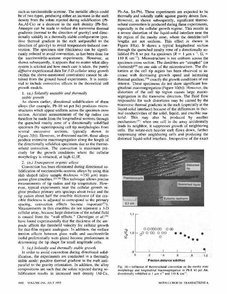
Pb-Au, Sn-Pb). These experiments are expected to be thermally and solutally stable against gravity driven flow. However, as shown subsequently, significant thermo- solutal convection is produced during these experiments, especially in the cellular growth regime. This results in a severe distortion of the liquid-solid interface near the tip region of the mushy zone, where the dendrite/cell lengths are not uniform. This effect is shown in Figure 10(a). It shows a typical longitudinal section through the quenched mushy zone of a directionally so- lidified Pb-8 wt pct Au specimen (R = 1 /~m s - l , Gt = 110 K cm-~). Microstructure is not uniform across the specimen cross section. The dendrites are "steepled" (or clustered) 129~ on one side of the microstructure. The dis- tortion at the cell tip region has been observed to in- crease with decreasing growth speed and increasing thermal gradient, 13~ exactly the growth conditions of our interest. These specimens do not show significant lon- gitudinal macrosegregation (Figure 10(b)). However, the distortion of the cell tip region causes large macro- segregation in the transverse direction. The fluid flow responsible for such distortions may be caused by the transverse thermal gradients in the melt (especially at the liquid-solid interface) because of the differences in ther- mal conductivities of the solid, liquid, and crucible ma- terial. This may also be produced by another mechanism: t3~] when one cell in the array accidentally leads its neighbor, it suppresses growth of neighboring cells. The solute-rich heavier melt flows down, further suppressing other neighboring cells and producing the distorted liquid-solid interface. Irrespective of the exact
1.1 - -
"6 0
o 1.0
0 0 0 0 0 C O 0 GD -- O0 0 O0 0 0 0
0
�9 �9 �9
o o
.9 I I I I 0 .2 .4 .6 .8 1.0
Fract ion d i s t a n c e sol idi f ied
Fig. 1 0 - - I n f l u e n c e of thermosolutal convection on the mushy zone morphology and longitudinal macrosegregat ion in Pb-8 wt pct Au, directionally solidified at 1 ,u.m s -t and 110 K cm t.
1668-- VOLUME 24A, JULY 1993 METALLURGICAL TRANSACTIONS A

mechanism for the formation of dendrite steepling, a re- cent low-gravity experiment 132~ established that this ef- fect is gravity induced. It was observed that under identical growth conditions, the A1-Cu alloy sample solidified in microgravity did not show steepling.
The preceding discussion shows that there will be ex- tensive thermosolutal convection during directional so- lidification of binary alloys at decreased gradients of constitutional supercoolings (high G/R), where the cell to dendrite transitions occur and cellular morphologies are observed. Therefore, the morphological information generated from the terrestrial experiments in this growth regime does not represent the diffusive solutal transports in the melt generally assumed by the theoretical models. Low-gravity directional solidification and quenching ex- periments, where convection related macrosegregation may be eliminated or significantly reduced, are expected to provide the valid diffusive growth data required by the 3-D cellular array models.
V. CONCLUSIONS
The following conclusions can be drawn from this study on the longitudinal macrosegregation in Pb-Sn alloys di- rectionally solidified with steady-state arrayed growth of cells or dendrites.
1. Thermosolutal convection caused by the build up of low-density solute ahead of growing arrays of cells and dendrites results in significant macrosegregation along the solidified length. The extent of macro- segregation can be quantitatively represented by an empirical parameter, k~ff (the effective partition coef- ficient), which is about unity in the absence of con- vection and is observed to decrease with the increasing convection.
2. A parameter, [g(C,- Co)Dt/RCo] ~/2, indicating the convective fluid velocity, can be used to predict the intensity of the above thermosolutal convection, where Co is the solute content of the alloy, C, is the melt composition at the array tip, DI is the solute diffu- sivity, and R is the growth speed. The macro- segregation increases with the increasing value of this parameter.
3. Convection effects become more important at low growth speeds. Therefore, recourse must be made to the low-gravity environment to obtain morphological data for cellular arrays undisturbed by natural convection.
A C K N O W L E D G M E N T S
Appreciation is expressed to the Microgravity Science and Applications Division for the use of the Microgravity Materials Science Laboratory at the NASA-Lewis
Research Center for this research. Continuous encour- agement from Thomas K. Glasgow, Chief Processing Science and Technology Branch, and help from John Sedlock (deceased), Jerry Loveland, Frank Terepka, and Dr. M. Vijayakumar are gratefully acknowledged.
REFERENCES
1. M.A. Chopra and S.N. Tewari: Metall. Trans. A, 1991, vol. 22A, pp. 2467-74.
2. V. Laxmanan: J. Cryst. Growth, 1986, vol. 75, pp. 573-80. 3. D.R. Poirier: Metall. Trans. A., 1988, vol. 19A, pp. 2349-54. 4. S.N. Tewari and Rajesh Shah: Metall. Trans. A, 1992, vol. 23A,
pp. 3383-92. 5. J.A. Burton, R.C. Prim, and W.P. Slichter: J. Chem. Phys., 1953,
vol. 21, pp. 1987-91. 6. J. Verhoeven: Metall. Trans., 1971, vol. 2, pp. 2673-80. 7. R.M. Sharp and A. Hellawell: J. Cryst. Growth, 1970, vol. 8,
pp. 29-32. 8. S.N. Tewari: Metall. Trans. A, 1988, vol. 19A, pp. 1351-64. 9. A.K. Sample and A. Hellawell: Metall. Trans. A, 1984, vol. 15A,
pp. 2163-73. 10. R.S. Steube and A. Hellawell: Micro/Macro Scale Phenomena
in Solidification, C. Beckermann, L.A. Bertram, S.J. Pien, and R.E. Smelser, eds., ASME, Fairfield, NJ, 1992, ASME-HTD- vol. 218, pp. 73-84.
11. S.M. Pimputkar and S. Ostrach: J. Cryst. Growth, 1981, vol. 55, pp. 614-46.
12. J.T. Mason, J.D. Verhoeven, and R. Trivedi: J. Cryst. Growth, 1982, vol. 59, pp. 516-24.
13. W.J. Boettinger, F.S. Biancaniello, and S.R. Coriell: Metall. Trans. A, 1981, vol. 12A, pp. 321-27.
14. H.D. Brody and M.C. Flemings: Trans. Am. Inst. Min. Eng., 1966, vol. 236, pp. 615-24.
15. M.H. Burden and J.D. Hunt: J. Cryst. Growth, 1974, vol. 22, pp. 109-16.
16. J.D. Hunt: Solidification and Casting of Metals, The Metals Society, London, 1979, Book 192, p. 3.
17. I. Jin and G.R. Purdy: J. Cryst. Growth, 1974, vol. 23, pp. 29-44. 18. J.S. Kirkaldy: Scripta Metall., 1980, vol. 14, pp. 739-44. 19. A. Karma and P. Pelce: Phys. Rev. A, 1989, vol. 39, pp. 4162-69. 20. P, Pelce and A. Pumir: J. Cryst. Growth, 1985, vol. 73,
pp. 337-42. 21. B. Billia, M. Jamgotchian, and L. Capella: J. Cryst. Growth,
1987, vol. 82, pp. 747-56. 22. L,H. Unger, M.J. Bennett, and R.A. Brown: Phys. Rev. B., 1985,
vol. 31, pp. 5923-30. 23. J.D. Hunt and D.G. McCartney: Acta Metall., 1987, vol. 35,
pp. 89-99. 24. G.B. McFadden, R.F. Boisvert, and S.R. Coriell: J. Cryst.
Growth, 1987, vol. 84, pp. 371-89. 25. K. Somboonsuk, J.T. Mason, and R. Trivedi: Metall. Trans. A,
1984, vol. 15A, pp. 967-75. 26. H. Esaka and W. Kurz: J. Cryst. Growth, 1985, vol. 72,
pp. 578-84. 27. R.J. Schaefer and S.R. Coriell: Metall. Trans. A, 1984, vol. 15A,
pp. 2109-15. 28. S. de Cheveigne, C. Guthmann, and M. Lebrun: J. Phys., 1986,
vol. 47 (12), pp. 2095-103. 29. J.D. Verhoeven, J,T. Mason, and R. Trivedi: Metall. Trans. A,
1986, vol. 17A, pp. 991-1000. 30. S.N. Tewari and M.A. Chopra: Microgravity Sci. Technol., 1990,
vol. 3 (2), pp. 99-106. 31. M.H. Burden, D.J. Hebditch, and J.D. Hunt: J. Cryst. Growth,
1973, vol. 20, pp. 121-24. 32. M.D. Dupouy, D. Camel, and J.J. Favier: Acta Metall., 1989,
vol. 37, pp. 1143-47.
METALLURGICAL TRANSACTIONS A VOLUME 24A, JULY 1993-- 1669