Mantle convection with internal heating and pressure-dependent thermal expansivity
Upload
independentCategory
view
1download
0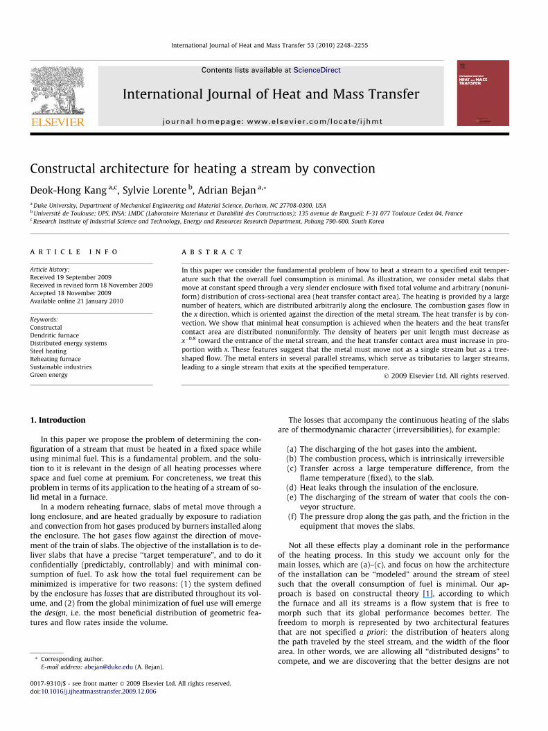
International Journal of Heat and Mass Transfer 53 (2010) 2248–2255
Contents lists available at ScienceDirect
International Journal of Heat and Mass Transfer
journal homepage: www.elsevier .com/locate / i jhmt
Constructal architecture for heating a stream by convection
Deok-Hong Kang a,c, Sylvie Lorente b, Adrian Bejan a,*
a Duke University, Department of Mechanical Engineering and Material Science, Durham, NC 27708-0300, USAb Université de Toulouse; UPS, INSA; LMDC (Laboratoire Materiaux et Durabilité des Constructions); 135 avenue de Rangueil; F-31 077 Toulouse Cedex 04, Francec Research Institute of Industrial Science and Technology, Energy and Resources Research Department, Pohang 790-600, South Korea
a r t i c l e i n f o
Article history:Received 19 September 2009Received in revised form 18 November 2009Accepted 18 November 2009Available online 21 January 2010
Keywords:ConstructalDendritic furnaceDistributed energy systemsSteel heatingReheating furnaceSustainable industriesGreen energy
0017-9310/$ - see front matter � 2009 Elsevier Ltd. Adoi:10.1016/j.ijheatmasstransfer.2009.12.006
* Corresponding author.E-mail address: [email protected] (A. Bejan).
a b s t r a c t
In this paper we consider the fundamental problem of how to heat a stream to a specified exit temper-ature such that the overall fuel consumption is minimal. As illustration, we consider metal slabs thatmove at constant speed through a very slender enclosure with fixed total volume and arbitrary (nonuni-form) distribution of cross-sectional area (heat transfer contact area). The heating is provided by a largenumber of heaters, which are distributed arbitrarily along the enclosure. The combustion gases flow inthe x direction, which is oriented against the direction of the metal stream. The heat transfer is by con-vection. We show that minimal heat consumption is achieved when the heaters and the heat transfercontact area are distributed nonuniformly. The density of heaters per unit length must decrease asx�0.8 toward the entrance of the metal stream, and the heat transfer contact area must increase in pro-portion with x. These features suggest that the metal must move not as a single stream but as a tree-shaped flow. The metal enters in several parallel streams, which serve as tributaries to larger streams,leading to a single stream that exits at the specified temperature.
� 2009 Elsevier Ltd. All rights reserved.
1. Introduction
In this paper we propose the problem of determining the con-figuration of a stream that must be heated in a fixed space whileusing minimal fuel. This is a fundamental problem, and the solu-tion to it is relevant in the design of all heating processes wherespace and fuel come at premium. For concreteness, we treat thisproblem in terms of its application to the heating of a stream of so-lid metal in a furnace.
In a modern reheating furnace, slabs of metal move through along enclosure, and are heated gradually by exposure to radiationand convection from hot gases produced by burners installed alongthe enclosure. The hot gases flow against the direction of move-ment of the train of slabs. The objective of the installation is to de-liver slabs that have a precise ‘‘target temperature”, and to do itconfidentially (predictably, controllably) and with minimal con-sumption of fuel. To ask how the total fuel requirement can beminimized is imperative for two reasons: (1) the system definedby the enclosure has losses that are distributed throughout its vol-ume, and (2) from the global minimization of fuel use will emergethe design, i.e. the most beneficial distribution of geometric fea-tures and flow rates inside the volume.
ll rights reserved.
The losses that accompany the continuous heating of the slabsare of thermodynamic character (irreversibilities), for example:
(a) The discharging of the hot gases into the ambient.(b) The combustion process, which is intrinsically irreversible(c) Transfer across a large temperature difference, from the
flame temperature (fixed), to the slab.(d) Heat leaks through the insulation of the enclosure.(e) The discharging of the stream of water that cools the con-
veyor structure.(f) The pressure drop along the gas path, and the friction in the
equipment that moves the slabs.
Not all these effects play a dominant role in the performanceof the heating process. In this study we account only for themain losses, which are (a)–(c), and focus on how the architectureof the installation can be ‘‘modeled” around the stream of steelsuch that the overall consumption of fuel is minimal. Our ap-proach is based on constructal theory [1], according to whichthe furnace and all its streams is a flow system that is free tomorph such that its global performance becomes better. Thefreedom to morph is represented by two architectural featuresthat are not specified a priori: the distribution of heaters alongthe path traveled by the steel stream, and the width of the floorarea. In other words, we are allowing all ‘‘distributed designs” tocompete, and we are discovering that the better designs are not
Nomenclature
a proportionality factor, Eq. (2)A total heat transfer area, m2
cp specific heat at constant pressure of combustion prod-uct gas, J kg�1 K�1
cs specific heat at constant pressure of steel,J kg�1 K�1
h heat transfer coefficient, Wm�2 K�1
HV heating value of the fuel, J Kg�1
L length of the furnace, mmfuel fuel mass flow rate, kg s�1
mp combustion product gas mass flow rate,kg s�1
ms steel mass flow rate, kg s�1
n number, Eq. (18)p heat transfer area per unit of furnace length, mq heat transfer rate, WT temperature, KTaf adiabatic flame temperature, KTp combustion product gas temperature, KTp,out exhaust combustion product gas temperature, KTs steel temperature, KTout exit steel temperature, KX coordinate along length, m
Greek symbolsa dimensionless factor, Eq. (14)b taper of furnace heat transfer area, Eq. (21)Dm mass flow rate within a control volume, kg s�1
Dma combustion air mass flow rate, kg s�1
Dmf fuel mass flow rate, kg s�1
Dmp combustion product gas mass flow rate, kg s�1
Dq heat transfer rate, WDT temperature difference, KDx infinitesimal length, me number, Eq. (18)l number, Eq. (18)n dimensionless coordinate along length
Subscripts0 represents ambient conditionmin minimumopt optimumscale nondimensional factor
Superscripts� dimensionless
´ derivative
D.-H. Kang et al. / International Journal of Heat and Mass Transfer 53 (2010) 2248–2255 2249
the traditional designs with uniformly placed heaters and con-stant width.
2. Model
The research literature on furnace design and optimization isconcerned mainly with the optimal control to improve energy con-sumption and to meet quality requirements for the slab heatingprocess of a reheating furnace in a hot strip mill [2–13]. Fullnumerical simulations of heat transfer and fluid flow in reheatingfurnaces are also being reported [14–21]. The feature that thesestudies have in common is that each study focuses on a specifiedconfiguration of reheating furnace and combustion.
In the model used in this study, the configuration is not speci-fied. The configuration is the unknown. The furnace consists of astream of moving steel slabs of mass flow rate, ms [kg/s], whichare exposed to heating all along the length of the enclosure, L.The enclosure is very slender. The steel enters at x = L and exitsat x = 0 .
The heating is provided by a large number of gas burners dis-tributed arbitrarily along the furnace. We model this distributionas a string of infinitesimal burners of length Dx, as shown inFig. 1. The Dx burner receives Dmf [kg/s] of fuel and Dma [kg/s]of oxidant such as air, and discharges Dmp [kg/s] of gaseous prod-ucts of combustion. Mass conservation (Dmf + Dma = Dmp) andstoichiometry (Dma/Dmf = constant) indicate that Dmp is propor-tional to Dmf, and can be used as a measure of the rate of fuel thatis being burned. In other words, the ratio Dmp/Dmf is a known con-stant. To minimize the total rate of fuel consumption is the same asminimizing the total stream of gaseous products issuing from thefurnace.
The fuel and oxidant enter the Dx burner at ambient conditions(T0, P0). The pressure changes in the combustion chamber are neg-ligible. If the chamber functions adiabatically, then the productsexit at the adiabatic flame temperature Taf, which is a constantknown for each combination of fuel and oxidant [21]. The limitof adiabatic operation is sketched in Fig. 1.
The actual combustor is not adiabatic. It generates the heattransfer rate Dq and, as a consequence, the stream Dmp is at a tem-perature (Tp) lower than Taf. This situation is sketched in the lowerpart of Fig. 1. The conservation of energy requires ([22], p. 101)
Dq ¼ DmpcpðTaf � TpÞ ð1Þ
where the cp is the specific heat at constant pressure of the prod-ucts. Here we make the approximation that Taf is considerablygreater than Tp, such that (Taf�Tp) may be regarded as relativelyconstant. This leads to the conclusion that the heat released Dq isproportional to the fuel consumption rate (or gas generation rateDmp), which can be written per unit length as
q0ðxÞ ¼ am0p ð2Þ
This equation comes from writing q0=Dq/Dx and m0p ¼ Dmp=Dx,
where a is a proportionality factor proportional to the heating valueof the fuel HV, in other words
mfuelHV ¼ amp ð3Þ
where the ratio mp/mfuel is dictated by stoichiometry. In currentindustrial furnace design, mp/mfuel is of order 6, HV = 1.67 � 107 J/kg, and consequently a = 2.75 � 106 J/kg, all in an order of magni-tude sense.
The steel is a steady stream of temperature Ts(x) and mass flowrate ms [kg/s], entering at Ts = T0 at x = L, and exiting at Ts = Tout atx = 0. The end temperatures are fixed: T0 is the ambient tempera-ture, and Tout is the design (target) temperature of the steel heatingprocess.
The steel runs in counterflow with the stream of hot gases ofcombustion, mp(x). The spatial distribution of combustion ½m0pðxÞ�is the chief degree of freedom of the design, however, if m0p isknown then the mass flow rate of the gas stream can be calculated
mpðxÞ ¼ mpð0Þ þZ L
0m0pdx ð4Þ
The gas temperature is Tp(x). The local heat transfer rate from gas tosteel is
fmΔ amΔ
0 x x x+ Δ L
0T 0T
afT
Adiabatic
0T 0T
pmΔ
Non-adiabatic
qΔ
pT
pmΔ
Fig. 1. Model of a large number of gas heaters distributed along the furnace.
s
s
m
T
p
p
m
T
s
s s
m
T dT+
p p
p p
m dm
T dT
+
+
q dx′ 0pm dx T′
s s sm c T ( )s s s sm c T dT+
iq dx′
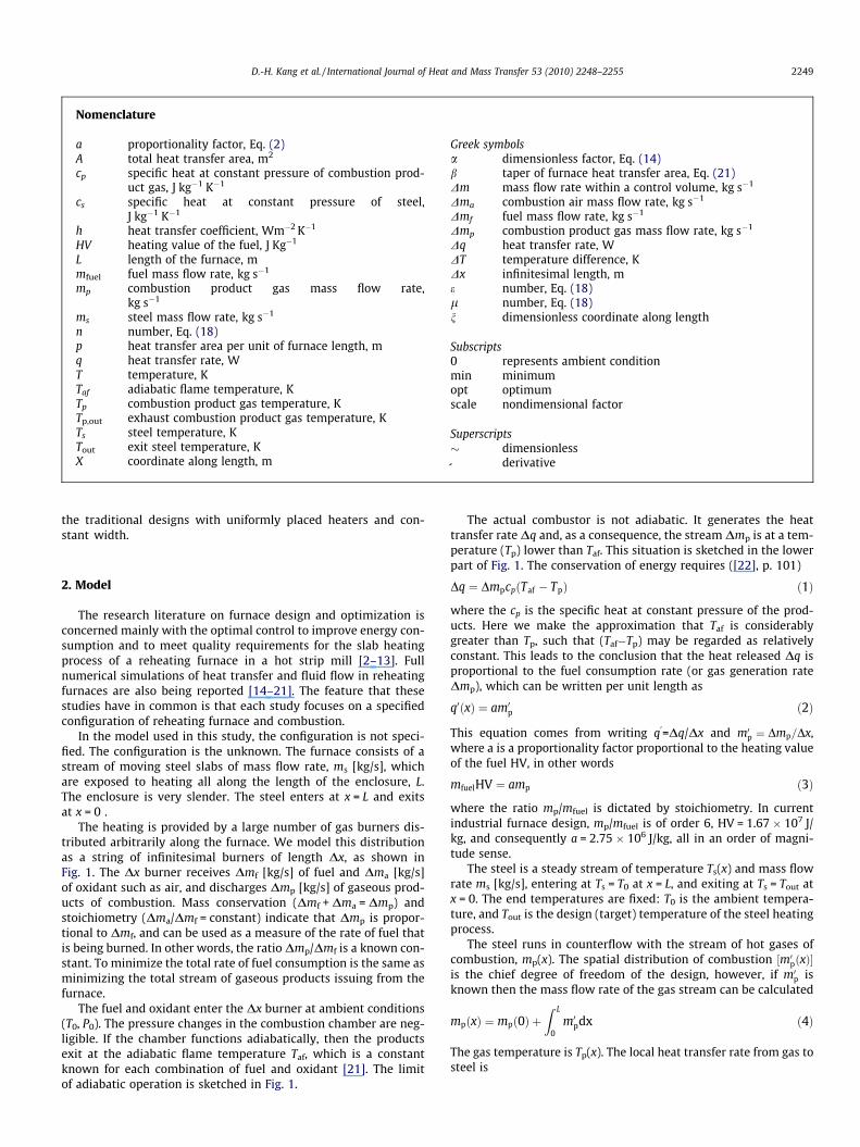
Fig. 2. The streams of hot gas, steel and energy for an elemental length of thefurnace.
2250 D.-H. Kang et al. / International Journal of Heat and Mass Transfer 53 (2010) 2248–2255
q0i ¼ hpðxÞðTp � TsÞ ð5Þ
where the heating is by convection with constant heat transfer coef-ficient h.
For simplicity in this first treatment of the distributed heatingconfiguration, we assumed that the gas–steel heat transfer is dom-inated by convection, not radiation. This assumption is valid in thelimit where the combustion in every burner is conducted with suf-ficient excess air such that the adiabatic flame temperature wouldbe sufficiently lower than in the case of theoretical combustion.The regime of heat transfer by radiation will be valid in the oppo-site limit.
The heat transfer area per unit of furnace length p(x) is anotherdegree of freedom of the design. The total heat transfer area isfixed,
Z L
0pdx ¼ A ð6Þ
If the cross-section of the furnace is flat (like a slit), and if the heightof the ceiling is uniform, then p(x) is a function that varies in thesame way as the shape of the floor. This is why in the following dis-cussion the designs with p = constant and p/x = constant are de-scribed as floors with constant width and triangular (tapered)floors, respectively.
According to the upper part of Fig. 2, the first law of thermody-namics for the furnace element of length dx requires
am0p ¼ cpðTp � T0Þm0p �mscsdðTs � T0Þ
dxþmpcp
dðTp � T0Þdx
ð7Þ
Written for the steel stream alone (Fig. 2, bottom), the first lawrequires
hpðxÞðTp � TsÞdx ¼ �mscsdðTs � T0Þ ð8Þ
The scale analysis of Eqs. (2)–(8) reveals the scales
pscale ¼AL; xscale ¼ L; mscale ¼
hAcs
ðT � T0Þscale ¼ Tout � T0 ¼ DTð9Þ

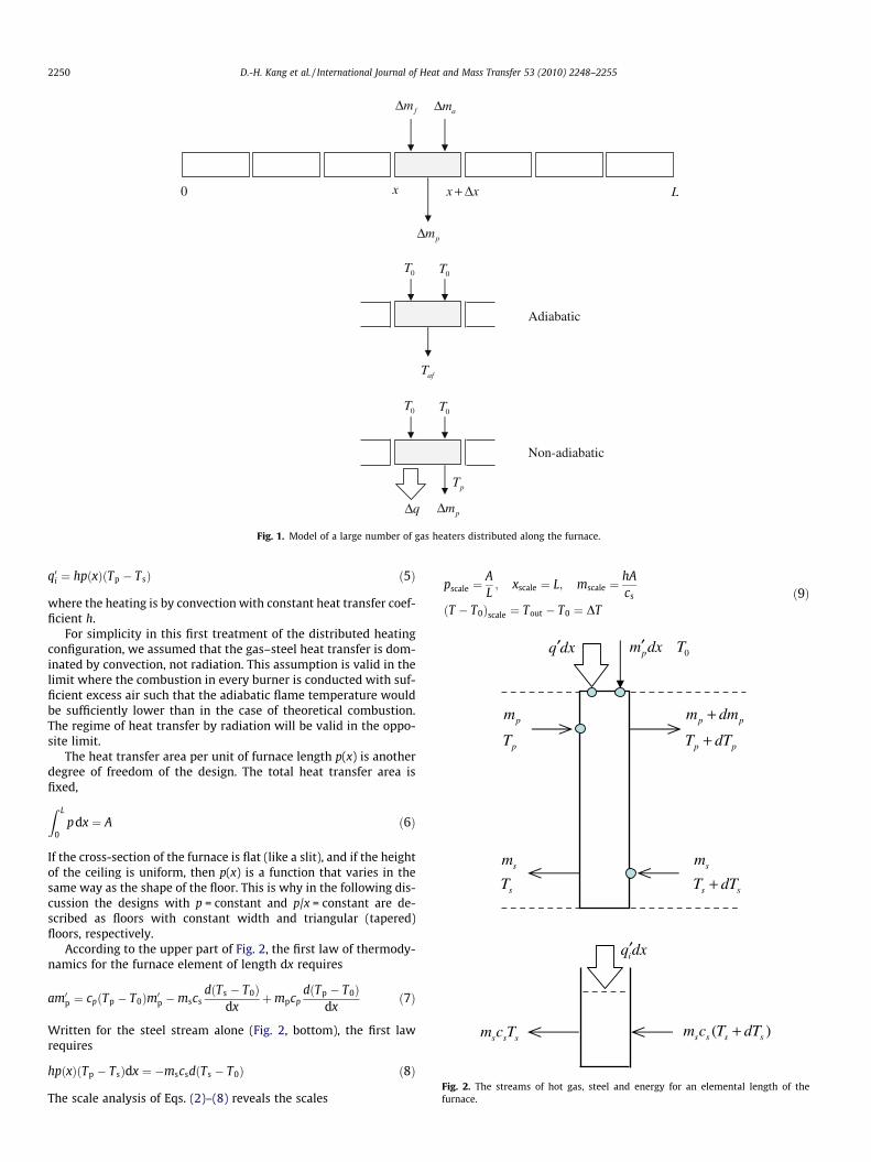
Fig. 3. The overall control volume of the furnace.
D.-H. Kang et al. / International Journal of Heat and Mass Transfer 53 (2010) 2248–2255 2251
which recommend the dimensionless variables
~p0 ¼p
A=L; n ¼ x
L; eT 0 ¼
T � T0
DT; ~m0 ¼
mmscale
ð10Þ
Eqs. (6)–(8) becomeZ 1
0~pdn ¼ 1 ð11Þ
a ~m0p ¼ ~m0p~Tp �cs
cp~mseT 0s þ ~mp
eT 0p ð12Þ
~pðeT p � eT sÞ ¼ � ~msdeT s
dnð13Þ
where
~ms ¼ms
mscale; ~mp ¼
mp
mscale; a ¼ a
cpDTð14Þ
The two boundary conditions necessary for integrating equations(12) and (13) are
eT sð0Þ ¼ 1 and eT sð1Þ ¼ 0: ð15Þ
Fig. 4. The temperature distributions along the steel, eT sðnÞ, and the produ
3. Why there is an opportunity to distribute the heating?
Consider now the control volume that contains the entire fur-nace with all its streams, Fig. 3. The gases come in cold (T0) and exithot (Tp,out). The total mass flow rate mp is contributed by anunspecified number of burners distributed over the length L. Theflow rate mp is proportional to the total heating rate provided bythe burners,
q ¼Z L
0q0dx ¼ ampðLÞ ð16Þ
The first law of thermodynamics requires
ampðLÞ ¼ mpðLÞcpðTp;out � T0Þ þmscsðTs;out � T0Þ ð17Þ
This is a simple equation linking two variables, the amount of fuelburned [proportional to mp(L) ], and the exhaust temperature(Tp,out). Desirable is a lower mp(L), which corresponds to a lowerTp,out. How this is achieved depends on the internal design of thefurnace.
4. Distribution of heating
Assume that the burners are distributed such that
~mp ¼ l½eþ ð1� eÞnn� ð18Þ
where the number l ¼ ~mpð1Þ represents the total rate of fuel con-sumption, e is a small number (e.g. e = 0.1) accounting for the rela-tive size of the first burner, and n accounts for the manner in whichthe burners are distributed. For example, n = 1 represents a uniformdistribution of burners along L.
To focus on the effect of distributed burners (n), we start withthe assumption that p is constant, i.e. the furnace has a one-dimen-sional design,
~p ¼ 1 ð19Þ
The dimensionless factors appearing in Eqs. (12) and (13) have thevalues a = a/(cpDT) = 1.8 [corresponding to a = 2.75 � 106 J/kg,
cts of combustion, eT pðnÞ, showing the distributed heating effect (n).

Fig. 5. The total minimal fuel consumption lmin that corresponds to the specified~ms, showing that lmin can be minimized with respect to n.
ig. 6. The optimal distribution of burners (nopt), and the smallest fuel consumptionmin,min), as functions of flow rate.
Fig. 7. The merit of using the optimal nonuniform distribution of heaters (n = 0.2)relative to using uniformly distributed heaters (n = 1).
2252 D.-H. Kang et al. / International Journal of Heat and Mass Transfer 53 (2010) 2248–2255
cp = 1270 J/kg K and DT = 1200 K], and cs/cp = 0.46. The steel massflow rate ~ms was given several values in the range 0.1–1.
To start, we set n = 1 and l = 0.623. We integrated equations(12) and (13) and found the temperature distributions eT sðnÞ andeT pðnÞ plotted in Fig. 4. We then lowered l and repeated the calcu-lation. We found that as the total fuel consumption (l) decreases,eT s rises to the point that it threatens the design condition that thehighest eT s value must occur at the exit from the furnace. In thisway, we determined the lowest fuel consumption (lmin) as the de-sign where
deT s
dn¼ 0 at n ¼ 0 ð20Þ
This first set of simulations revealed the minimal fuel consumptionlmin that corresponds to the specified ~ms and n. We repeated thesesimulations for many pairs ð ~ms;nÞ, and found the surface lminð ~ms;nÞrepresented in Fig. 5. Important here is the discovery that for thespecified stream of steel ð ~msÞ there exists a spatial distribution ofburners (nopt) such that the minimal fuel consumption (lmin) isthe smallest that it can be, namely lmin,min.
The optimally distributed design is summarized as the func-tions nopt ð ~msÞ and lmin,min ð ~msÞ shown in Figs. 6 and 7. Noteworthyis that nopt is equal to approximately 0.2 over the entire ~ms range0.1 � 1. This means that the best way to distribute the burners isas d ~mpdn � n�0:8, which recommends the use of considerably moreburners near the exit (n = 0) than near the entrance (n = 1).
The relative merit of using the optimal (nonuniform) distribu-tion of burners (nopt = 0.2) is presented in Fig. 7, where the refer-ence design is the one where the burners are distributeduniformly (n = 1). The ratio lmin (n = 0.2)/lmin(n = 1) has values oforder of 0.5, indicating a 50% reduction in the total rate of fuel con-sumption when the heating is distributed nonuniformly.
5. Tapered floor area
In the preceding examples the furnace was modeled as onedimensional, with an x-independent surface of contact betweensteel and hot gases, cf. ~p ¼ 1 in Eq. (19). Consider now the moregeneral case where the contact surface is distributed in a certainway longitudinally, ~pðnÞ, while obeying the total area constraint(11). To illustrate, assume that ~p varies linearly with n,
~p ¼ 1þ bð2n� 1Þ ð21Þ
where b accounts for taper of the area A in the x direction. Note thatEq. (21) obeys the integral constraint. Furthermore, because ~p > 0,the values that b can have are in the range (�1, 1).
F(l
We explored numerically the effect of b on the minimal fuelrequirement. To isolate the effect of b, we first fixed e = 0.01 and~ms ¼ 0:5. Although the distribution of hot gases (n) is not fixed(it can be optimized, cf. Fig. 5, namely nopt = 0.2 when the furnaceis not tapered, b = 0), we fix n = 0.2 as we begin the search for thebest taper. The effect of b on lmin is displayed in Fig. 8. The totalfuel requirement (lmin) decreases monotonically as the angle ofthe furnace floor area increases. This effect becomes more notice-able as ~ms increases.
The conclusion is that tapering the plan view of the heating areayields reductions in the overall fuel requirement. The best taper isb = 1, which represents a triangular floor on which the cold steelenters by crossing the base. For example, when ~ms ¼ 0:9 the reduc-tion in fuel use from the rectangular floor design (b = 0) to the tri-angular floor (b = 1) is 6%. This conclusion is further supported byFig. 8, which shows that if we use a different value of e in ournumerical simulations the variation of lmin versus b is the sameas e ¼ 0:01.
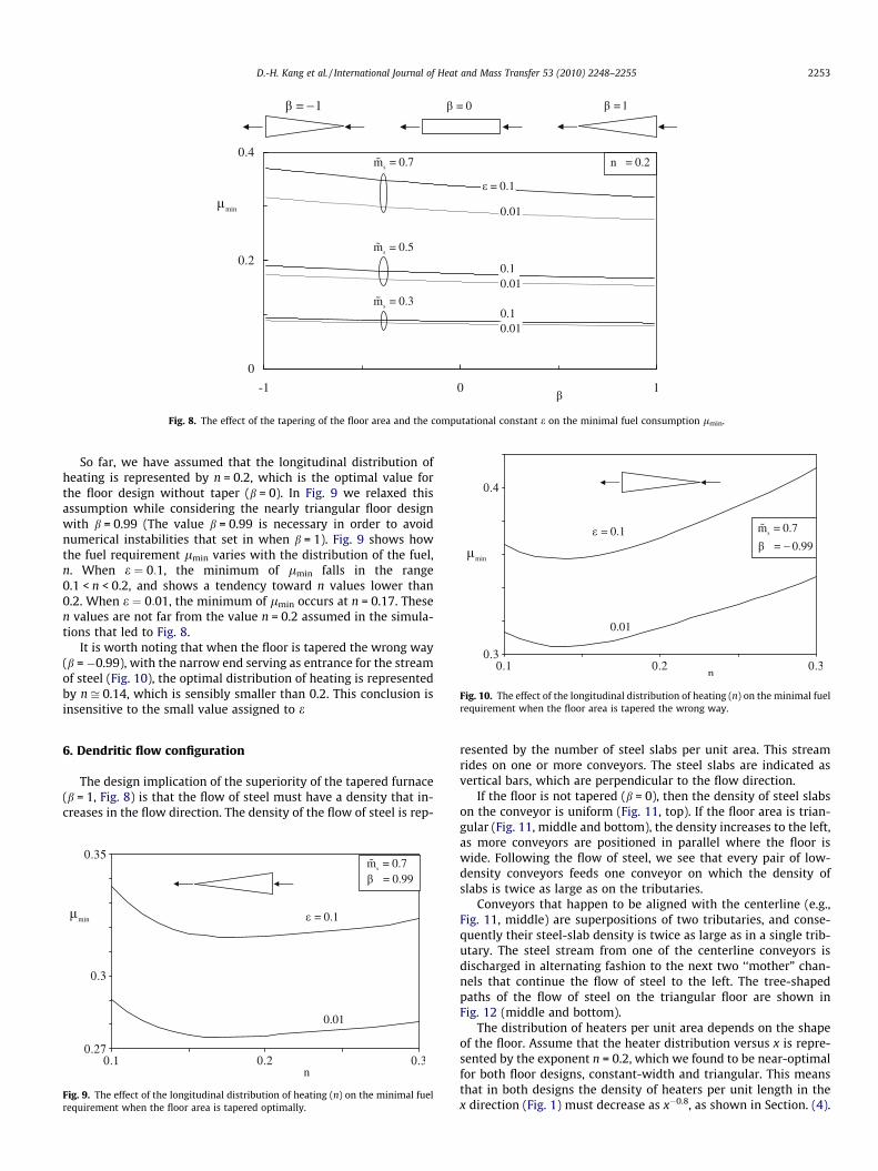
Fig. 8. The effect of the tapering of the floor area and the computational constant e on the minimal fuel consumption lmin.
Fig. 10. The effect of the longitudinal distribution of heating (n) on the minimal fuelrequirement when the floor area is tapered the wrong way.
D.-H. Kang et al. / International Journal of Heat and Mass Transfer 53 (2010) 2248–2255 2253
So far, we have assumed that the longitudinal distribution ofheating is represented by n = 0.2, which is the optimal value forthe floor design without taper (b = 0). In Fig. 9 we relaxed thisassumption while considering the nearly triangular floor designwith b = 0.99 (The value b = 0.99 is necessary in order to avoidnumerical instabilities that set in when b = 1). Fig. 9 shows howthe fuel requirement lmin varies with the distribution of the fuel,n. When e ¼ 0:1, the minimum of lmin falls in the range0.1 < n < 0.2, and shows a tendency toward n values lower than0.2. When e ¼ 0:01, the minimum of lmin occurs at n = 0.17. Thesen values are not far from the value n = 0.2 assumed in the simula-tions that led to Fig. 8.
It is worth noting that when the floor is tapered the wrong way(b = �0.99), with the narrow end serving as entrance for the streamof steel (Fig. 10), the optimal distribution of heating is representedby n ffi 0.14, which is sensibly smaller than 0.2. This conclusion isinsensitive to the small value assigned to e
6. Dendritic flow configuration
The design implication of the superiority of the tapered furnace(b = 1, Fig. 8) is that the flow of steel must have a density that in-creases in the flow direction. The density of the flow of steel is rep-
Fig. 9. The effect of the longitudinal distribution of heating (n) on the minimal fuelrequirement when the floor area is tapered optimally.
resented by the number of steel slabs per unit area. This streamrides on one or more conveyors. The steel slabs are indicated asvertical bars, which are perpendicular to the flow direction.
If the floor is not tapered (b = 0), then the density of steel slabson the conveyor is uniform (Fig. 11, top). If the floor area is trian-gular (Fig. 11, middle and bottom), the density increases to the left,as more conveyors are positioned in parallel where the floor iswide. Following the flow of steel, we see that every pair of low-density conveyors feeds one conveyor on which the density ofslabs is twice as large as on the tributaries.
Conveyors that happen to be aligned with the centerline (e.g.,Fig. 11, middle) are superpositions of two tributaries, and conse-quently their steel-slab density is twice as large as in a single trib-utary. The steel stream from one of the centerline conveyors isdischarged in alternating fashion to the next two ‘‘mother” chan-nels that continue the flow of steel to the left. The tree-shapedpaths of the flow of steel on the triangular floor are shown inFig. 12 (middle and bottom).
The distribution of heaters per unit area depends on the shapeof the floor. Assume that the heater distribution versus x is repre-sented by the exponent n = 0.2, which we found to be near-optimalfor both floor designs, constant-width and triangular. This meansthat in both designs the density of heaters per unit length in thex direction (Fig. 1) must decrease as x�0.8, as shown in Section. (4).

Fig. 11. The distribution of the flow of steel on the furnace floor: uniform density, on a floor with uniform width (top), and increasing density, on triangular floors (middle andbottom). The total flow rate ms and the floor area are the same in each drawing.
Steel
Fig. 12. The direction of the steel streams and their tributaries in Fig. 11.
2254 D.-H. Kang et al. / International Journal of Heat and Mass Transfer 53 (2010) 2248–2255
The density of heaters per unit area varies as x�0.8/p(x). In theconstant-p design, the area density of heaters decreases as x�0.8 to-ward the steel entrance. This is shown in the upper drawing ofFig. 13. In the triangular designs, the area density decreases moresharply, as x�1.8. Two distributions of heaters on triangular areasare shown in Fig. 13 (middle and bottom). The three drawings ofFig. 13 have the same area, which is the same as the area shownin Figs. 11 and 12.
7. Conclusions
This paper suggested analytically novel configurations for heat-ing a stream by convection with a large number of heaters. The dis-tributions of cross-sectional area and heaters are free to vary in thesearch for the overall minimal fuel consumption.
The best way to distribute the heaters recommends the use ofconsiderably more heaters near the exit than near the entrance.The relative merit of using the optimal (nonuniform) distributionof heaters indicated a 50% reduction in the total rate of fuel con-sumption when the heating is distributed nonuniformly.
Tapering the plan view of the heating area yields reductions inthe overall fuel requirement. The best taper is b = 1, which repre-sents a triangular floor on which the cold steel enters by crossingthe base.
The distribution of heaters per unit area depends on the shapeof the floor. The density of heaters per unit area varies as x�0.8/p(x). In the constant-p design, the area density of heaters decreasesas x�0.8 toward the steel entrance. In the triangular designs, thearea density decreases more sharply, as x�1.8.
The analysis presented in this paper is important in a funda-mental sense, because it unveils a new direction for the design ofindustrial furnaces with minimal fuel consumption. This applica-tion deserves future study because the reduction of fuel consump-tion in industrial furnaces is key to being able to control the rise ofCO2 emissions at the national and global level. In South Korea, forexample, the furnace industry constitutes a 17% share of theamount of fuel consumed in all the industries. This represents9.6% of the national energy consumption. In 2005, the CO2 emis-sions related to fuel use amounted to 60 million ton-CO2/yr. Inview of this, the government of South Korea has initiated a policy

Fig. 13. The distribution of heaters on the area occupied by the three designs of Fig. 11.
D.-H. Kang et al. / International Journal of Heat and Mass Transfer 53 (2010) 2248–2255 2255
of ‘‘Green Energy Industry as a Growth Engine”, in which thereduction of fuel use is a major objective.
Acknowledgement
This research was supported by RIST (Research Institute ofIndustrial Science and Technology), Pohang, South Korea.
References
[1] A. Bejan, S. Lorente, Design with Constructal Theory, Wiley, Hoboken, NJ, 2008.[2] W. Wang, H.X. Li, J. Zhang, A hybrid approach for supervisory control of furnace
temperature, Control Eng. Practice. 11 (11) (2003) 1325–1334.[3] N. Chakraborti, K. Deb, A. Jha, A genetic algorithm based heat transfer analysis
of a bloom re-heating furnace, Steel Res. 71 (10) (2000) 396–402.[4] F. Hollander, S.P.A. Zuurbier, Design, development and performance of on-line
computer control in a 3-zone reheating furnace, Iron Steel Eng. 59 (1982) 44–52.[5] B. Leden, A control system for fuel optimization of reheating furnaces, Scand. J.
Metall. 15 (1) (1986) 16–24.[6] Y.I. Kim, K.C. Moon, B.S. Kang, C.H. Han, K.S. Chang, Application of neural
network to the supervisory control of a reheating furnace in the steel industry,Control Eng. Practice. 6 (8) (1998) 1009–1014.
[7] A. Dunoyer, K.J. Burnham, T.S. McAlpine, Self-tuning control of an industrialpilot-scale reheating furnace: design principles and application of a bilinearapproach, IEE Proc., Control Theory Appl. 144 (1) (1997) 25–31. January.
[8] H.S. Ko, J.S. Kim, T.W. Yoon, M. Lim, D.R. Yang, I.S. Jun, Modeling and PredictiveControl of a Reheating Furnace, American Control Conference in Chicago, USA,June 2000.
[9] Y. Misaka, R. Takahashi, A. Shinjo, Y. Nariai, M. Kooriki, Computer control of a reheatfurnace at Kashima Steel Works’ hot strip mill, Iron Steel Eng. 59 (5) (1982) 51–55.
[10] Y.-Y. Yang, Y.-Z. Lu, Dynamic model based optimization control for reheatingfurnaces, Comput. Ind. 10 (1) (1988) 11–20.
[11] L.M. Pedersen, B. Wittenmark, On the Reheat Furnace Control Problem,American Control Conference in Philadelphia, PA, USA, June 1988.
[12] B. Zhang, Z. Chen, L. Xu, J. Wang, J. Zhang, H. Shao, The Modeling and Control ofa Reheating Furnace, American Control Conference, vol. 5, 2002, pp. 3823–3828.
[13] H. Ezure, Y. Seki, N. Yamaguchi, H. Shinonaga, Development of a simulator tocalculate an optimal slab heating pattern for reheat furnaces, Electr. Eng. Jpn.120 (3) (1998) 42–53.
[14] Z. Li, P.V. Barr, J.K. Brimacombe, Computer simulation of the slab reheatingfurnace, Can. Metall. Q. 27 (3) (1988) 187–196.
[15] J.G. Kim, K.Y. Huh, I.T. Kim, Three-dimensional analysis of the walking-beam-type slab reheating furnace in hot strip mill, Numer. Heat Transfer, Part A 38(6) (2000) 589–609.
[16] D. Lindholm, A finite element method for solution of the three-dimensionaltime-dependent heat conduction equation with application for heating ofsteels in reheating furnaces, Numer. Heat Transfer, Part A 35 (2) (1999) 155–172.
[17] M.Y. Kim, A heat transfer model for the analysis of transient heating of the slabin a direct-fired walking beam type reheating furnace, Int. J. Heat MassTransfer 50 (19-20) (2007) 3740–3748.
[18] A. Jaklica, F. Vodea, T. Kolenkob, Online simulation model of the slab-reheatingprocess in a pusher-type furnace, Appl. Therm. Eng. 27 (5-6) (2007) 1105–1114.
[19] S.H. Han, S.W. Baek, S.H. Kang, C.Y. Kim, Numerical analysis of heatingcharacteristics of a slab in a bench scale reheating furnace, Int. J. Heat MassTransfer 50 (9-10) (2007) 2019–2023.
[20] C.T. Hsieh, M.J. Huang, S.T. Lee, C.H. Wang, Numerical modeling of a walking-beam-type slab reheating furnace, Numer. Heat Transfer, Part A 53 (9) (2008)966–981.
[21] T. Kolenko, B. Glogovac, T. Jakli, An analysis of a heat transfer model forsituations involving gas and surface radiative heat transfer, Commun. Numer.Methods Eng. 15 (5) (1999) 349–365.
[22] A. Bejan, Advanced Engineering Thermodynamics, third ed., Wiley, Hoboken,2006.
Copyright © 2022 FDOKUMEN