074-402-P1A Vortex AC 115V Operating Manual - INFICON
20
Vortex ® AC Refrigerant Recovery Machine O P E R A T I N G M A N U A L
-
Upload
khangminh22 -
Category
Documents
-
view
0 -
download
0
Transcript of 074-402-P1A Vortex AC 115V Operating Manual - INFICON

Vortex® ACRefrigerant Recovery Machine
O P E R A T I N G M A N U A L
Preface
Vortex AC Operating Manual
Thank you for buying the INFICON® Vortex® AC Refrigerant Recovery Machine!To get the best performance from your Vortex AC, please read this manual carefully before you start using the recovery machine. If you have any questions or need additional assistance, call 800-344-3304. We’ll be happy to help you!
Safety First!
When found on the machine, this international symbol is intended to alert the user to the presence of important operating, safety and maintenance (servicing) instructions in this Manual. As used in the Manual, it is intended to draw your attention to critical items.It is important to read this entire Manual and be familiar with its contents before using the machine!The Vortex AC is a Recovery Machine for a broad range of refrigerants. Recovering refrigerants into a separate storage tank involves a process of gas compression, resulting in high pressures within the machine, the connecting hoses and the storage tank. High pressure systems must always be treated with care and respect to prevent careless accidents.
EPA CertificationThe INFICON Vortex AC is an EPA Certified machine in accordance with Section 608 of the Clean Air Act. It has been independently tested and certified to be in conformance with ARI standard 740-1998 by Underwriters Laboratories Inc.
Product SafetyFor the highest level of safety, the recovery operation should always be performed using a DOT approved storage tank with a shutoff switch (tank float) properly connected to the Vortex AC’s Over Fill Protection circuit (available as an option). Additionally, approved refrigerant hoses must be used which have shut-off devices within 12 inches (304.8 mm) of the ends to reduce the likelihood of refrigerant leakage to the atmosphere when changing tanks or setups.
ResponsibilityThe INFICON Vortex AC must only be operated by a Qualified Technician who has been properly trained in the care and use of such equipment and in the recovery process itself. Use of this equipment by unqualified personnel is potentially dangerous and should not be attempted.
TrademarksThe trademarks of the products mentioned in this manual are held by the companies that produce them.INFICON®, Vortex®, Compass™, D-TEK™ Select, TEK-Mate®, and Wey-TEK™ are trademarks of INFICON.All other brand and product names are trademarks or registered trademarks of their respective companies.The information contained in this manual is believed to be accurate and reliable. However, INFICON assumes no responsibility for its use and shall not be liable for any special, incidental, or consequential damages related to the use of this product. ©2004 All rights reserved. Reproduction or adaptation of any part of this manual without permission is unlawful.

1
Vortex AC Operating Manual
Table Of Contents
1.0 Safety Precautions . . . . . . . . . . . . . . . . . . . . . . . . . . . . . 2
2.0 Specifications, Features and Warranty. . . . . . . . . . . . . 42.1 Vortex AC Specifications . . . . . . . . . . . . . . . . . . . . . . . . . 42.2 Warranty . . . . . . . . . . . . . . . . . . . . . . . . . . . . . . . . . . . . . . 5
3.0 Setup and Operation. . . . . . . . . . . . . . . . . . . . . . . . . . . . 53.1 Getting Started . . . . . . . . . . . . . . . . . . . . . . . . . . . . . . . . . 53.2 Normal Recovery Operation . . . . . . . . . . . . . . . . . . . . . . . 63.3 PURGING the Vortex AC . . . . . . . . . . . . . . . . . . . . . . . . . 83.4 Push-Pull Operation . . . . . . . . . . . . . . . . . . . . . . . . . . . . . 83.5 Cooling The Recovery Tank . . . . . . . . . . . . . . . . . . . . . . . 93.6 Special Operating Notes . . . . . . . . . . . . . . . . . . . . . . . . . 10
4.0 Maintenance . . . . . . . . . . . . . . . . . . . . . . . . . . . . . . . . . 11
5.0 Troubleshooting . . . . . . . . . . . . . . . . . . . . . . . . . . . . . . 12
6.0 Service . . . . . . . . . . . . . . . . . . . . . . . . . . . . . . . . . . . . . . 136.1 General . . . . . . . . . . . . . . . . . . . . . . . . . . . . . . . . . . . . . . 136.2 Electrical Schematic . . . . . . . . . . . . . . . . . . . . . . . . . . . . 15
7.0 EPA Requirements . . . . . . . . . . . . . . . . . . . . . . . . . . . . 16
Vortex AC Operating Manual
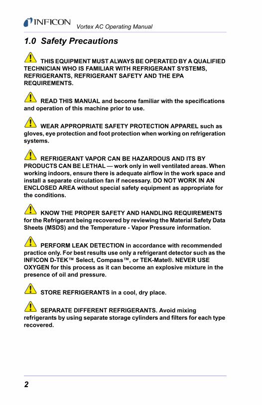
1.0 Safety Precautions
THIS EQUIPMENT MUST ALWAYS BE OPERATED BY A QUALIFIED TECHNICIAN WHO IS FAMILIAR WITH REFRIGERANT SYSTEMS, REFRIGERANTS, REFRIGERANT SAFETY AND THE EPA REQUIREMENTS.
READ THIS MANUAL and become familiar with the specifications and operation of this machine prior to use.
WEAR APPROPRIATE SAFETY PROTECTION APPAREL such as gloves, eye protection and foot protection when working on refrigeration systems.
REFRIGERANT VAPOR CAN BE HAZARDOUS AND ITS BY PRODUCTS CAN BE LETHAL — work only in well ventilated areas. When working indoors, ensure there is adequate airflow in the work space and install a separate circulation fan if necessary. DO NOT WORK IN AN ENCLOSED AREA without special safety equipment as appropriate for the conditions.
KNOW THE PROPER SAFETY AND HANDLING REQUIREMENTS for the Refrigerant being recovered by reviewing the Material Safety Data Sheets (MSDS) and the Temperature - Vapor Pressure information.
PERFORM LEAK DETECTION in accordance with recommended practice only. For best results use only a refrigerant detector such as the INFICON D-TEK™ Select, Compass™, or TEK-Mate®. NEVER USE OXYGEN for this process as it can become an explosive mixture in the presence of oil and pressure.
STORE REFRIGERANTS in a cool, dry place.
SEPARATE DIFFERENT REFRIGERANTS. Avoid mixing refrigerants by using separate storage cylinders and filters for each type recovered.
2

Vortex AC Operating Manual
NEVER OVERFILL A STORAGE CONTAINER. The safest approach is to use a DOT certified storage cylinder with a “Tank Full” cutoff switch that is properly connected to the Vortex AC’s optional Over Fill Protection Circuit. If the storage cylinder does not have a cutoff switch, or if PUSH-PULL OPERATION is used, the use of a refrigerant scale, such as the INFICON Wey-TEK™, is required to prevent overfill. OVERFILLED TANKS CAN RUPTURE EXPLOSIVELY!
OPEN SERVICE OR CYLINDER VALVES SLOWLY to ensure that all connections are tight and there is no danger.
DISCONNECT POWER before moving or servicing the INFICON Vortex AC.
This unit should be opened only by a technically qualified person who has been trained in basic electronics and refrigeration. The risk of ELECTRIC SHOCK and exposure to HOT compressor parts is possible if the unit is opened.
TO REDUCE THE RISK OF FIRE, EXTENSION CORDS SHOULD NOT BE USED with this equipment as the wiring can overheat under conditions of high current draw. If an extension cord is absolutely necessary, its length should be as short as possible and it should contain size 16 AWG or larger wiring.
FLAMMABLE ENVIRONMENTS ARE DANGEROUS when any machine is used because motors and switches can generate sparks. This equipment should be used in locations with mechanical ventilation providing at least four air changes per hour, or the equipment should be located at least 18” above the floor. DO NOT USE THIS EQUIPMENT IN THE VICINITY OF SPILLED OR OPEN CONTAINERS OF GASOLINE OR ANY OTHER FLAMMABLE LIQUID.
3

Vortex AC Operating Manual
2.0 Specifications, Features and Warranty2.1 Vortex AC SpecificationsRefrigerants . . . . . . . . . . . . . . . . . . . . . . . . . EPA Certified to ARI 740-98 for
R-134a, R-22, R407, R410A and all refrigerants listed under categories III, IV, & V in ARI standard 740-98.
Power . . . . . . . . . . . . . . . . . . . . . . . . . . . . . . 115 V(ac), 60 Hz, 10 ACompressor: . . . . . . . . . . . . . . . . . . . . . . . . 1/2 HP Oilless, No inlet valve,
AC Motor DriveCooling: . . . . . . . . . . . . . . . . . . . . . . . . . . . . Fan driven off AC compressor
motorProtection: . . . . . . . . . . . . . . . . . . . . . . . . . . High Pressure Switch
Cutoff at 550 PSICompressor motor thermally protected80% Tank Full Shutoff available
Pressure. . . . . . . . . . . . . . . . . . . . . . . . . . . . Low side design pressure 240 PSI;High side design pressure 550 PSI
Temperature . . . . . . . . . . . . . . . . . . . . . . . . Operating Range 50 to 104 °F (10 to 40 °C)
Case . . . . . . . . . . . . . . . . . . . . . . . . . . . . . . . Blow-Molded, High Impact Strength
Size . . . . . . . . . . . . . . . . . . . . . . . . . . . . . . . . 18” L X 9.5” W X 14.5” H(457.2 mm x 241.3 mm x 368.3 mm)
Weight . . . . . . . . . . . . . . . . . . . . . . . . . . . . . 27.7 lbs. (12.6 kg)
4
Vortex AC Operating Manual
2.2 WarrantyINFICON warrants your Vortex AC Refrigerant Recovery Machine to be free from defects of materials or workmanship for three years from the date of purchase. INFICON does not warrant any machine that has been subjected to misuse, negligence, or accident, or has been repaired or altered by anyone other than INFICON.The Compressor is warranted for a period of three years by the manufacturer. To keep this WARRANTY in force it is required that a standard filter or filter drier be used on the Inlet Port or Hose at all times to prevent particulates from entering the compressor. FAILURE TO USE A FILTER WILL VOID THE COMPRESSOR WARRANTY.INFICON’s liability is limited to machines returned to INFICON, transportation prepaid, not later than thirty (30) days after the warranty period expires, and which INFICON judges to have malfunctioned because of defective materials or workmanship. INFICON’s liability is limited to, at its option, repairing or replacing the defective machine or part.This WARRANTY is in lieu of all other warranties, express or implied, whether of MERCHANTABILITY or of FITNESS FOR A PARTICULAR PURPOSE or otherwise. All such other warranties are expressly disclaimed.INFICON shall have no liability in excess of the price paid to INFICON for the machine plus return transportation charges prepaid. INFICON shall have no liability for any incidental or consequential damages. All such liabilities are EXCLUDED.
3.0 Setup and Operation3.1 Getting Started
Only personnel who have been properly trained in the use and operation of Refrigeration Systems, Refrigerants and Service Equipment should operate this equipment. Failure to follow proper safety precautions could result in personal injury or death.
Review the full contents of this Manual before attempting to use the Vortex AC in actual service.Install an approved filter on the inlet. Attach the hoses per the diagram below. The Vortex AC has a female refrigerant flare fitting so that it may accept a filter with male flare fittings, the hoses then attach to the filter. DO NOT USE AN ADAPTER FITTING IN PLACE OF A FILTER AS THIS MAY CAUSE DAMAGE TO THE VALVES AND VOID THE WARRANTY.
5
Vortex AC Operating Manual
Connect the AC Power cord to a circuit that is protected by a 15 amp breaker. Use an extension cord only when absolutely necessary to perform the service — be sure it is the minimum length required, that it contains a safety ground wire and that it contains wires sized 16 AWG or larger.
When recovering refrigerant, it may be necessary to throttle the Manifold Gauge control valve(s) or the Vortex AC’s INLET Valve when a significant amount of liquid is present. This is required if a loud “knocking” sound is heard from the compressor. While the Compressor in the Vortex AC is tolerant of liquid, no compressor will run on 100% liquid without damage for more than a few minutes. In addition, a liquid “slug” can cause the High Pressure shutoff to activate, thus adding time to the process. It is thus important to open the valves slowly and monitor the process carefully. Should the compressor start to “Knock”, rotate the INLET valve clockwise until the “knocking” stops. This can also be accomplished by adjusting the Manifold Gauge valves. Exercise care to ensure that the compressor is not damaged in this way as it will void the warranty.
If the Tank Full shutoff is not in use, it is necessary to use a Refrigerant Scale to ensure that the tank is not filled to more than 80% of its capacity by weight. When operating in the NORMAL RECOVERY or PUSH-PULL mode without the tank shutoff, it is possible to overfill the tank. Check the tank weight before transporting if you are not sure. OVERFILLED TANKS CAN RUPTURE EXPLOSIVELY!
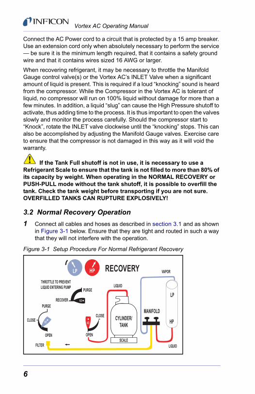
3.2 Normal Recovery Operation1 Connect all cables and hoses as described in section 3.1 and as shown
in Figure 3-1 below. Ensure that they are tight and routed in such a way that they will not interfere with the operation.
Figure 3-1 Setup Procedure For Normal Refrigerant Recovery
6

Vortex AC Operating Manual
2 Make sure that the hose from the Vortex AC to the Recovery Tank is attached to the LIQUID PORT. Open the tank’s LIQUID PORT valve, keeping the VAPOR port closed.
3 CLOSE the INLET valve (V1).
4 OPEN the DISCHARGE valve (V3) to its fully open position.
5 SET the PURGE/RECOVERY valve (V2) to the RECOVERY position.
6 Open the Manifold Gauge LIQUID valve slowly and verify that no leaks are present. Extracting as much liquid as possible will speed up the recovery process.
7 Switch ON the Vortex AC.
8 MONITOR the inlet pressure (LP, Low Pressure Gauge) and SLOWLY OPEN the Vortex AC’s INLET valve (V1). THROTTLE the INLET valve or the Manifold Gauge’s Liquid and Vapor valves if too much liquid is entering the machine.
If the Tank Full shutoff is not in use, it is necessary to use a Refrigerant Scale to ensure that the tank is not filled to more than 80% of its capacity by weight. When operating in the NORMAL RECOVERY or PUSH-PULL mode without the tank shutoff, it is possible to overfill the tank. Check the tank weight before transporting if you are not sure. OVERFILLED TANKS CAN RUPTURE EXPLOSIVELY!
9 When the liquid has been transferred, OPEN the INLET valve (V1) fully to transfer the remaining VAPOR. Ensure that the Manifold Gauge valves (liquid and vapor) are also fully opened.
10 Continue to operate until the required VACUUM has been pulled on the system, as indicated by the LP gauge. Switch OFF the Vortex AC, CLOSE the INLET (V1), and wait for 5 minutes. If the Pressure in the system, as noted on the Manifold Gauge, rises above 0 PSIG, refrigerant is still present. If this is the case, REOPEN the INLET (V1), RESTART the Vortex AC, and run until the required VACUUM is reached again. Repeat this process until all the refrigerant is removed resulting in a final reading, after the 5 minute period, of 0 PSIG or less.
11 IMMEDIATELY PURGE the Vortex AC per the procedure as described in section 3.3 of this Manual.
7

Vortex AC Operating Manual
3.3 PURGING the Vortex AC1 Rotate the PURGE/RECOVER valve (V2) to the PURGE position. Rotate
valve V3 to OPEN. See Figure 3-2.
2 Switch the POWER ON and rotate the INLET valve (V1) slowly to the PURGE. Prevent flooding the compressor with liquid, do not rotate the V1 valve quickly.
3 Observe the LP Gauge and continue to run the unit until a VACUUM of at least 20 In/Hg is achieved. Switch the POWER OFF and immediately CLOSE the Recovery Tank’s valve. The INLET valve (V1) should be returned to the CLOSE position. Finally close V3.
4 IMPORTANT — RETURN V2 TO RECOVERY POSITION
THE HOSE AND THE DISCHARGE PORT WILL CONTAIN A SMALL AMOUNT OF REFRIGERANT UNDER PRESSURE. EXERCISE CARE WHEN REMOVING THIS HOSE AND OPENING THE VALVE V3.
Figure 3-2 Setup Procedure for Purging
3.4 Push-Pull OperationThe PUSH PULL method is used to move a large amount of liquid refrigerant from the system being serviced to the recovery tank without passing it through the compressor. This method is only useful when more than 15 pounds of liquid is known to be in the system and it can be easily isolated. DO NOT ATTEMPT the PUSH PULL process unless you are sure of the situation.
Connect the refrigerant hoses as shown in Figure 3-3. The addition of a SIGHT GLASS in the line from the system being serviced to the recovery tank is an important aid to determine when the liquid has been transferred and vapor remains.
8

Vortex AC Operating Manual
This process uses the PULL from the exhausted recovery tank and the Discharge PUSH from the Vortex AC to move the liquid refrigerant. Rates in excess of 15 pounds per minute can be achieved by this procedure.
The SCALE is required in this process to ensure that the tank is not overfilled. The tank shutoff switch, if used, would stop the compressor but could not guarantee that additional refrigerant flow would cease because of the dynamics of the system, thus possibly overfilling the tank.
Figure 3-3 Setup Procedure for Push-Pull Method
3.5 Cooling The Recovery TankThe Vortex AC can be used to PRE-cool (or SUB-cool) the recovery tank if the head pressure is too high to complete the recovery process. This can occur when working with certain refrigerants with a high vapor pressure when the ambient temperature is high.If the recovery process stalls out because of high head pressure, stop the Vortex AC, shut off the hose valves and reconfigure the setup as shown in Figure 3-4. This can also be done before starting the recovery process, but it may have marginal long term effect. NOTE: This will only work if there is at least 5 pounds of liquid in the
recovery tank to develop the necessary pressure differential required.
9

Vortex AC Operating Manual
Figure 3-4 Setup Procedure for Sub-Cooling Method
POWER ON the Vortex AC and ROTATE the DISCHARGE Valve (V3) to achieve a pressure differential of at least 100 PSIG between the LP Gauge and the HP Gauge. KEEP THE HP BELOW 550 PSIG on the HP Gauge to ensure that the HP Cutoff Switch will not actuate.
After several minutes of running, the tank will be cold. POWER OFF the Vortex AC and reconfigure the setup for NORMAL RECOVERY. Repeat as needed.
3.6 Special Operating NotesDuring normal operation, when the High Pressure switch activates the machine will restart automatically when the head pressure drops below approximately 425 PSI.
When the Tank Over Fill Protection Device (OFPD) is installed, the yellow “Tank Full” signal light will be illuminated when the OFPD cable is not connected or when the tank is full.
VAPOR
Optional Connection To System
10

Vortex AC Operating Manual
4.0 MaintenanceYour Vortex AC will provide many seasons of reliable service providing it is properly maintained. The actual maintenance requirements are minimal but important.
Keep the unit clean by wiping it down with a damp cloth to remove dirt, oils, etc., prior to storage for the day. Standard household detergent or isopropyl alcohol may be used if the unit is particularly dirty — in all cases, exercise care to prevent liquids from entering the unit. Gasoline and other solvents are to be avoided as they can damage the Vortex AC’s plastic enclosure and they are hazardous.
Ensure that the Inlet and Discharge ports are protected in transit and storage — keep the inner diameter and the outer threads clear and clean. For best results, keep a FILTER permanently connected to the INLET port and change it regularly.When performance falls off it is likely that the compressor seals require replacing. This is normal with use and may occur after a year or two, or more often depending upon the conditions that are prevalent during the recovery operations. Contact your Wholesaler for assistance in selecting the proper maintenance kit.
11

Vortex AC Operating Manual
5.0 TroubleshootingPROBLEM CAUSE ACTIONUnit will not start — Compressor does not start
1. Power Cord not attached2. No voltage at receptacle3. Circuit breaker has opened
4. Discharge pressure too high, HP Switch has opened5. Electronics failure in Motor
1. Attach Power Cord
2. Verify voltage at Job Site3. Identify cause of breaker activation, rectify and reset4. Reduce pressure and rotate V2 to Purge and back to Recovery5. Factory service required
Unit will not start — Optional Over Fill Protection Device is installed.
1. Tank Full cable not connected to tank2. Float switch in Tank is open
3. Tank is full and float switch has opened
1. Connect cable
2. Check tank switch with multimeter; change tanks or use scale3. Change tanks
Compressor starts but cuts out within a few minutes — pressure indication on HP gauge is high
1. V2 is in Purge position and HP switch activates2. V3 not open and HP switch activates3. Recovery tank valve not open4. Blocked discharge hose5. Air in system/tank
1. Rotate V2 to Recovery
2. Rotate V3 to open position3. Open tank valve
4. Check & clear blockage5. Bleed air from system/tank
12
Vortex AC Operating Manual
6.0 Service 6.1 GeneralThe Vortex AC uses only UL or CSA Recognized electrical components or components which have been specially designed for this application.
DO NOT CHANGE any of these components as the safety of the machine could be compromised. All service work must be performed at an INFICON approved facility in order to maintain the safety rating and the Warranty, if applicable.Technical assistance and service information can be obtained by calling the factory at 800-344-3304.
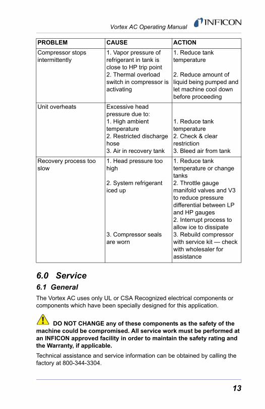
Compressor stops intermittently
1. Vapor pressure of refrigerant in tank is close to HP trip point 2. Thermal overload switch in compressor is activating
1. Reduce tank temperature
2. Reduce amount of liquid being pumped and let machine cool down before proceeding
Unit overheats Excessive head pressure due to:1. High ambient temperature2. Restricted discharge hose3. Air in recovery tank
1. Reduce tank temperature2. Check & clear restriction3. Bleed air from tank
Recovery process too slow
1. Head pressure too high
2. System refrigerant iced up
3. Compressor seals are worn
1. Reduce tank temperature or change tanks2. Throttle gauge manifold valves and V3 to reduce pressure differential between LP and HP gauges2. Interrupt process to allow ice to dissipate3. Rebuild compressor with service kit — check with wholesaler for assistance
PROBLEM CAUSE ACTION
13
Vortex AC Operating Manual
NOTE: Do not return a defective unit directly to the factory. Contact your Wholesaler or the factory for assistance.
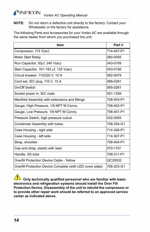
The following Parts and Accessories for your Vortex AC are available through the same dealer from whom you purchased the unit:
Only technically qualified personnel who are familiar with basic electronics and refrigeration systems should install the Over Fill Protection Device. Disassembly of the unit to rebuild the compressor or to provide other repair work should be referred to an approved service center as indicated above.
Item Part #
Compressor, 115 V(ac) 714-407-P1
Motor Start Relay 060-0055
Run Capacitor, 50μf, 240 V(ac) 043-0109
Start Capacitor, 161-193 μf, 125 V(ac) 043-0106
Circuit breaker, 110/220 V, 10 A 062-0079
Cord set, IEC plug, 110 V, 15 A 068-0391
On/Off Switch 065-0261
Socket power in, IEC male 051-1359
Manifold Assembly with extensions and fittings 708-403-P1
Gauge, High Pressure, 1/8 NPT M Conns. 708-402-P1
Gauge, Low Pressure, 1/8 NPT M Conns. 708-401-P1
Pressure Switch, high pressure cutout 032-0055
Condenser Assembly with tubes 708-204-G1
Case Housing - right side 714-306-P1
Case Housing - left side 714-307-P1
Strap, shoulder 708-404-P1
Cap and strap, plastic with lead 070-1107
Handle, SS tube 708-311-P1
Overfill Protection Device Cable - Yellow QC20032
Overfill Protection Device Complete (with LED cover plate) 708-203-G1
14

Vortex AC Operating Manual
6.2 Electrical Schematic
Figu
re 6
-1 E
lect
rical
Sch
emat
ic D
iagr
am
TR
AT
S
RO
TO
MR
OTI
CA
PA
C
rosserpmoC CA
KCALB
tupnI CAV 021
ETIHW
nruteR CAV 021
EGNARO
KCALB
KCALB
DER
KCALB
DNG CA
KCALB
ETIHW
repmuJ DPFO
rekaerB tiucriC
hctiwS rewoP
elcatpeceR rewoP CA
NUR
RO
TO
MR
OT
IC
AP
AC
KCALB
DER
DER
1C
Fu
39
1-1
61
CA
V5
21
1B
C
re
ka
e rB
A0
112
2J
V3
0-P
LV
TS
J
123
1S
L
yal
eR tr
a tS r
oto
M
83
7 -1 -
RC
4n
oxil
K IT
24
31S
12
2W
SW
S e r
us
ser
P IH
no
xilK I
T8
10
0-6
0S
P5
2
2C
Fu
05
CA
V0
42
1M
rot
oM r
os
ser
pm
oC
CA
1
32
4
5
1P
V3
0-R
LV
TS
J
123
1J
V3
0-R
LV
ketl
au
Q
40/
2X-
W1
07
1 2 3
15

Vortex AC Operating Manual
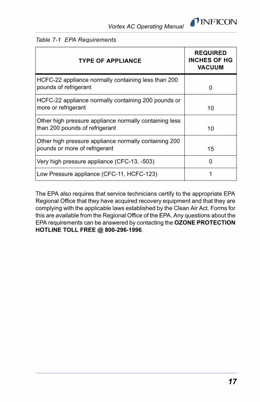
7.0 EPA RequirementsUnder Section 608 of the Clean Air Act (40 CFR Part 82), the Environmental Protection Agency (EPA) has established regulations that cover all aspects of the refrigerant recovery process.
These regulations have established service practices that maximize the recycling of ozone-depleting compounds during the servicing and disposal of air-conditioning and refrigeration equipment.
Certification requirements for recovery equipment and technicians have also been established. The INFICON Vortex AC has been EPA Certified for use by Underwriters Laboratories Inc.
The EPA has also established Evacuation Requirements for equipment which is being opened for service, to ensure that any release of CFCs or HCFCs to the atmosphere is minimized.
Technicians repairing small appliances such as household refrigerators, window air conditioners and water coolers, must recover 80% of the refrigerant when the compressor in the appliance is not operating.
Technicians repairing small appliances must recover 90% of the refrigerant when the compressor in the appliance is operating.
NOTE: These requirements may also be met by evacuating the small appliance with the recovery machine to four inches of mercury vacuum.
Other requirements are covered in the following Table 7-1.
16
Vortex AC Operating Manual
Table 7-1 EPA Requirements
The EPA also requires that service technicians certify to the appropriate EPA Regional Office that they have acquired recovery equipment and that they are complying with the applicable laws established by the Clean Air Act. Forms for this are available from the Regional Office of the EPA. Any questions about the EPA requirements can be answered by contacting the OZONE PROTECTION HOTLINE TOLL FREE @ 800-296-1996.
TYPE OF APPLIANCEREQUIRED
INCHES OF HG VACUUM
HCFC-22 appliance normally containing less than 200 pounds of refrigerant 0
HCFC-22 appliance normally containing 200 pounds or more or refrigerant 10
Other high pressure appliance normally containing less than 200 pounds of refrigerant 10
Other high pressure appliance normally containing 200 pounds or more of refrigerant 15
Very high pressure appliance (CFC-13, -503) 0
Low Pressure appliance (CFC-11, HCFC-123) 1
17

TWO TECHNOLOGY PLACEEAST SYRACUSE, NY 13057-9714 USA
Phone: +1.800.344.3304Fax: +1.315.437-3803Email: [email protected]
074-402-P1B

![tgx'+lhNnfsf]cf=j= 2073/074 sf]nflu :jLs[t](https://static.fdokumen.com/doc/165x107/6323d4d1117b4414ec0c7fc9/tgxlhnnfsfcfj-2073074-sfnflu-jlst.jpg)


![( erjaSekhar) D.O.No.402/ 101/ 2016-CRS(Pt-]I) September 29 ...](https://static.fdokumen.com/doc/165x107/631adb9b1a1adcf65a0f3e74/-erjasekhar-dono402-101-2016-crspt-i-september-29-.jpg)