PCT-410e plus - Full Gauge Controls
12
DIGITAL PRESSURE CONTROLLER AND INDICATOR Ver.04 PCT-410e plus PCT410E-05T-14662 evolution 1. DESCRIPTION The is a pressure controller for refrigeration systems that require control in their suction and discharge lines. It has seven control outputs: five digital outputs, one alarm output and one analog output for proportional control through a frequency inverter. It also includes three inputs: one input for a 4-20 mA pressure sensor, one input for a NTC temperature sensor, and one digital input. Working in pairs it is able to control up to five fans and five compressors at the same time. A more precise and safe control of the process can be achieved by using the remote communication between the suction and discharge controllers. The versatility of allows managing load switching in linear, rotation, capacities, and individual modes. And the RS-485 serial output allows communicating with SITRAD to manage the installation through the internet. PCT-410 plus PCT-410 plus e e 2. APPLICATION 3. TECHNICAL SPECIFICATIONS - To be used in the control of cooling processes, used both in the suction and in the . - Power: 12 Vdc / 250 mA - Pressure control range: 0 to 850 psi / 0 to 58.6 bar (user-configurable sensor operating range) - Sensors available for purchase: SB69-200A* (0 to 200 psi / 0 to 13.8 bar) SB69-500A* (0 to 500 psi / 0 to 34.4 bar) SB69-850A* (0 to 850 psi / 0 to 58.7 bar) * Sensors sold separately - Pressure resolution: 0.1 bar / 1 psi - Temperature sensor operating range: -50 to 105° C (SB41*) -50 to 200° C (Sb59*) * Sensors sold separately - Temperature resolution: 0.1° C between -10 and 100° C, and 1° C for the rest of the range 1° F in the full range - Maximum output current: OUT1 to OUT5 - 1 A / 250 Vac ALARM - 3 A / 250 Vac - Analog output maximum current: 10 mA - Controller operating temperature: 0 to 50° C - Operating humidity: 10 to 90% RH (without condensation) - Digital input: Configurable dry contact - Control outputs: DIGOUT1 – Digital control output 1 DIGOUT2 – Digital control output 2 DIGOUT3 – Digital control output 3 DIGOUT4 – Digital control output 4 DIGOUT5 – Digital control output 5 ALARM – Digital alarm output ANOUT – Analog output 0~10 Vdc - Product dimensions: 76 x 34 x 77 mm (WxHxD) discharge lines - Dimensions of the cut to fasten the instrument: 71 ± 0.5 x 29 ± 0.5 mm (see item 5) 4. INDICATIONS AND KEYS Set key Easy menu key LED indicator (digital output 1 on / off) LED indicator (digital output 2 on / off) LED indicator (digital output 3 on / off) LED indicator (digital output 4 on / off) LED indicator (digital output 5 on / off) LED indicator (pressure units: psi / bar) Increase key Decrease key 1 2 3 4 5 6 7 8 9 10 5 4 3 2 9 8 7 6 1 10 5 5. INSTALLATION - ASSEMBLING AND ELECTRICAL CONNECTIONS Panel (Front View) Panel (Side View) Dimension of the clipping for fixing of the instrument in panel ATTENTION 71 mm ± 0,5 29 mm ± 0,5 FOR INSTALLATIONS WHERE A SEALING IS REQUIRED TO AVOID LIQUID CONTACT, THE CUT FOR THE CONTROLLER MUST BE OF 70,5X29mm MAXIMUM. THE SIDE LOCKS MUST BE FIXED SO IT PRESSES THE RUBBER SEALING AVOIDING INFILTRATION BETWEEN THE CUT AND THE CONTROLLER. 6. OPERATIONS 6.1 Quick Access Menu Map By pressing ; it is possible to navigate through the function menus. See the functions map below: ; FUNCTIONS LOCKDOWN ; CONTROL FUNCTIONS SHUTDOWN PRESSURE SETPOINT ADJUSTMENT ; PCT-410 plus MAXIMUM AND MINIMUM DISPLAY ; RESET MAXIMUM AND MINIMUM VALUES ; ; MEASUREMENT DISPLAY ; SYSTEM RESET ; HOUR METER DISPLAY ; FUNCTION SELECTION ; EXIT FUNCTION Functions lockdown Protection level IP 65 FRONT Control functions shutdown Serial programming System supervisor PCT-410 plus PCT-410e plus PCT-410e plus PCT-410 plus PCT-410 plus PCT-410 plus PCT-410 plus PCT-410 plus PCT-410 plus PCT-410 plus PCT-410 plus PCT-410 plus IMPORTANT SCREWDRIVER SLOT 3/32''(2.4mm) FOR ADJUSTMENTS IN THE SIGNAL TERMINALS; SCREWDRIVER PHILLIPS #1 FOR ADJUSTMENTS IN THE POWER TERMINALS; THE USE OF APPROPRIATE TOOLS IS ESSENTIAL TO AVOID DAMAGE IN THE CONNECTION AT INSTRUMENT TERMINALS: WARNING ACCESSORIES: Only use original Full Gauge Controls accessories. If you have any questions, please contact technical support. AUTHORIZED SERVICE: The installation or maintenance of the product must be performed by qualified professionals only; BEFORE INSTALLING THE CONTROLLER, WE RECOMMEND READING THROUGH THE ENTIRE INSTRUCTION MANUAL IN ORDER TO AVOID POSSIBLE DAMAGE TO THE PRODUCT. PRECAUTIONS WHEN INSTALLING THE PRODUCT: Before performing any procedure on this instrument, disconnect it from the mains; Ensure that the instrument has adequate ventilation and avoid installation in panels containing devices that may cause it to operate outside the specified temperature limits; Install the product away from sources that may generate electromagnetic disturbances such as: motors, contactors, relays, solenoid valves, etc; DUE TO YOUR CONSTANT EVOLUTION, THE FULL GAUGE CONTROLS RESERVES THE RIGHT TO CHANGE THE INFORMATION CONTAINED IN THIS MANUAL AT ANY TIME WITHOUT NOTICE. Connection 12 Vdc 1 5 6 7 8 2 3 4 9 POWER SUPPLY 10 11 12 13 14 15 16 17 COMMON ALARMOUT (NC) DIGOUT5 (NO) DIGOUT4 (NO) DIGOUT3 (NO) DIGOUT2 (NO) DIGOUT1 (NO) B +12 VDC GND DIGIN ANOUT (0~10V) A B A SITRAD PCT-410 E S1 S2 S1 - Temperature sensor Pressure sensor S2 - ELECTRICAL CONNECTION TRANSDUCER: Brown: 12Vdc Green or White: 4~20mA BROWN WHITE INVERTER Power 5 Power supply + - OR GREEN E251415
-
Upload
khangminh22 -
Category
Documents
-
view
1 -
download
0
Transcript of PCT-410e plus - Full Gauge Controls

DIGITAL PRESSURE CONTROLLER AND INDICATOR
Ver
.04
PCT-410 e plus
PC
T41
0E-0
5T-1
4662
evolution
1. DESCRIPTION
The is a pressure controller for refrigeration systems that require control in their suction and discharge lines.It has seven control outputs: five digital outputs, one alarm output and one analog output for proportional control through a frequency inverter. It also includes three inputs: one input for a 4-20 mA pressure sensor, one input for a NTC temperature sensor, and one digital input.Working in pairs it is able to control up to five fans and five compressors at the same time. A more precise and safe control of the process can be achieved by using the remote communication between the suction and discharge controllers.
The versatility of allows managing load switching in linear, rotation, capacities, and individual modes. And the RS-485 serial output allows communicating with SITRAD to manage the installation through the internet.
PCT-410 plus
PCT-410 plus
e
e
2. APPLICATION
3. TECHNICAL SPECIFICATIONS
- To be used in the control of cooling processes, used both in the suction and in the .
- Power: 12 Vdc / 250 mA- Pressure control range: 0 to 850 psi / 0 to 58.6 bar (user-configurable sensor operating range)- Sensors available for purchase: SB69-200A* (0 to 200 psi / 0 to 13.8 bar)
SB69-500A* (0 to 500 psi / 0 to 34.4 bar)SB69-850A* (0 to 850 psi / 0 to 58.7 bar) * Sensors sold separately
- Pressure resolution: 0.1 bar / 1 psi- Temperature sensor operating range: -50 to 105° C (SB41*) -50 to 200° C (Sb59*)
* Sensors sold separately- Temperature resolution: 0.1° C between -10 and 100° C, and 1° C for the rest of the range 1° F in the full range- Maximum output current: OUT1 to OUT5 - 1 A / 250 Vac ALARM - 3 A / 250 Vac- Analog output maximum current: 10 mA- Controller operating temperature: 0 to 50° C- Operating humidity: 10 to 90% RH (without condensation)- Digital input: Configurable dry contact- Control outputs: DIGOUT1 – Digital control output 1DIGOUT2 – Digital control output 2DIGOUT3 – Digital control output 3DIGOUT4 – Digital control output 4DIGOUT5 – Digital control output 5ALARM – Digital alarm outputANOUT – Analog output 0~10 Vdc- Product dimensions: 76 x 34 x 77 mm (WxHxD)
discharge lines
- Dimensions of the cut to fasten the instrument: 71 ± 0.5 x 29 ± 0.5 mm (see item 5)
4. INDICATIONS AND KEYS
Set key
Easy menu key
LED indicator (digital output 1 on / off)
LED indicator (digital output 2 on / off)
LED indicator (digital output 3 on / off)
LED indicator (digital output 4 on / off)
LED indicator (digital output 5 on / off)
LED indicator (pressure units: psi / bar)
Increase key
Decrease key
1
2
3
4
5
6
7
8
9
10
543
2 9
876
1 10
5
5. INSTALLATION - ASSEMBLING AND ELECTRICAL CONNECTIONS
Panel (Front View)Panel
(Side View)
Dimension of the clippingfor fixing of the instrument
in panel
ATTENTION
71 mm± 0,5
29
mm
± 0
,5
FOR INSTALLATIONS WHERE A SEALING IS REQUIRED TO
AVOID LIQUID CONTACT, THE CUT FOR THE CONTROLLER
MUST BE OF 70,5X29mm MAXIMUM. THE SIDE LOCKS MUST BE
FIXED SO IT PRESSES THE RUBBER SEALING AVOIDING
INFILTRATION BETWEEN THE CUT AND THE CONTROLLER.
6. OPERATIONS
6.1 Quick Access Menu MapBy pressing ; it is possible to navigate through the function menus. See the functions map below:
;
FUNCTIONS LOCKDOWN
;
CONTROL FUNCTIONS
SHUTDOWN
PRESSURE SETPOINT
ADJUSTMENT
;
PCT-410 plus
MAXIMUM AND MINIMUM
DISPLAY
;
RESET MAXIMUM AND
MINIMUM VALUES
; ;
MEASUREMENT
DISPLAY
;
SYSTEM RESET
;
HOUR METER DISPLAY
;
FUNCTION SELECTION
;
EXIT FUNCTION
Functionslockdown
Protectionlevel
IP 65FRONT
Control functionsshutdown
Serialprogramming
Systemsupervisor
PCT-410 plus
PCT-410e plusPCT-410e plus
PCT-410 plus
PCT-410 plus
PCT-410 plus
PCT-410 plus
PCT-410 plus
PCT-410 plus
PCT-410 plus
PCT-410 plus
PCT-410 plus
IMPORTANT
SCREWDRIVER SLOT 3/32''(2.4mm) FOR ADJUSTMENTS IN THE SIGNAL TERMINALS;SCREWDRIVER PHILLIPS #1 FOR ADJUSTMENTS IN THE POWER TERMINALS;
THE USE OF APPROPRIATE TOOLS IS ESSENTIAL TO AVOID DAMAGE IN THE CONNECTION AT INSTRUMENT TERMINALS:
WARNING
ACCESSORIES:Only use original Full Gauge Controls accessories. If you have any questions, please contact technical support.
AUTHORIZED SERVICE:The installation or maintenance of the product must be performed by qualified professionals only;
BEFORE INSTALLING THE CONTROLLER, WE RECOMMEND READING THROUGH THE ENTIRE INSTRUCTION MANUAL IN ORDER TO AVOID POSSIBLE DAMAGE TO THE PRODUCT.
PRECAUTIONS WHEN INSTALLING THE PRODUCT:Before performing any procedure on this instrument, disconnect it from the mains;Ensure that the instrument has adequate ventilation and avoid installation in panels containing devices that may cause it to operate outside the specified temperature limits;Install the product away from sources that may generate electromagnetic disturbances such as: motors, contactors, relays, solenoid valves, etc;
DUE TO YOUR CONSTANT EVOLUTION, THE FULL GAUGE CONTROLS RESERVES THE RIGHT TO CHANGE THE INFORMATION CONTAINED IN THIS MANUAL AT ANY TIME WITHOUT NOTICE.
Connection 12 Vdc
1
5 6 7 8
2 3 4 9
POWERSUPPLY
10 11 12 13 14 15 16 17
CO
MM
ON
AL
AR
MO
UT
(NC
)
DIG
OU
T5
(NO
)
DIG
OU
T4
(NO
)
DIG
OU
T3
(NO
)
DIG
OU
T2
(NO
)
DIG
OU
T1
(NO
)
B
+1
2 V
DC
GN
D
DIG
IN
AN
OU
T (0
~1
0V
)
ABASITRADPCT-410 E
S1
S2
S1 - Temperature sensor
Pressure sensorS2 -
ELECTRICAL CONNECTION TRANSDUCER:
Brown: 12VdcGreen or White: 4~20mA
BR
OW
NW
HIT
E
INVERTER
Power
5
Powersupply
+-
OR
GR
EE
N
E251415
6.2 Quick access keys mapWhen the controller is displaying the pressure, the following keys work as shortcuts for the following functions:
/
<<
Long press: Daytime pressure setpoint adjustment.
Short press: Go to function selection.
< Short press: Maximum and minimum display [rEG,] .<
Short press: .Measurement/process display [MEAS]
6.3 Basic operations
6.3.1 Function lock [LOC,]For safety reasons the controller has a feature to allow locking functions. When this configuration is active, the parameters are protected from undue changes. However, the parameters can be viewed. In this condition the message [LOC,] will be displayed when trying to change those values. To lock functions you need to first adjust the parameter “[,F43] - Time for function locking” with a value greater than 14 (below 15, [no,,] is displayed and it means that function locking is not allowed). Select [LOC,] using the ; key (short touch), and then press/(short touch). Then keep > pressed until [LOC,] is displayed. The message [On,,] will be displayed upon releasing the key. To unlock the system, turn the controller off and then turn it on again with the key > pressed. Keep the key pressed until [LOC,] is displayed. The message [OFF,] will be displayed when the key is released.
6.3.2 Turn off the control functions [CtrL]When the control functions are turned off, the controller starts to operate only as a pressure/temperature indicator with the digital and analog outputs turned off.The type of operation used to turn off the control functions depends on the configuration of the parameter “[,F44]- Turn off the control functions”:[,,,0]Do not allow the control functions to be turned off.[,,,1] Allow turning the control functions on and off only if the functions are not locked.[,,,2] Allow turning the control functions on and off even if the functions are locked.You can access this function using the easy menu [Ctrl] and pressing / to select it. The message [Ctrl][Off,] soon will be displayed. With the control functions turned off the system's pressure display will alternate with the message [OFF,]. To turn the control functions back on, follow the same procedure used to turn them off, selecting with the ; key (short touch). The message
[Ctrl][On,,]will be displayed as soon as the user presses the / key.
NOTE: When the control functions are turned on again, PCT-410e plus will observe the value configured in the function “[,f29] Minimum time between activations.
6.3.3 Setpoint adjustment [Set,]To enter the pressure setpoint adjustment mode (Function C05). Operation only available if the control type is not individual (C01 = 0, 1, 2, 3). Adjust the new setpoint value using the < and > keys and
press / (short touch) to save the value.
6.3.4 Minimum and maximum display [rEG,]In this display mode the minimum and maximum values measured/calculated by the controller can be viewed. The minimums and maximums to be displayed are selected using the < and > keys.
The following information is available: [Pres](pressure)→ [tEmp](temperature)→
[SAtE](saturated gas temperature) → [SCSH](superheating/sub-cooling temperature)→ [dEMA](demand). When selecting the required information wait a few seconds for the minimum value and the maximum value measured/calculated to be displayed. These values are reset if the controller is turned off. After the information is displayed, the message indicating which information was previously selected will be briefly displayed. If you want to reset the minimum and maximum records of the information selected, press / (short touch). If no key is pressed, the message [----]is displayed and the instrument returns to the pressure display.NOTE: If there are no records, the messages [++++] and [____] will be displayed.
6.3.5 Reset maximum and minimum values [CrEG]This option resets all the minimum and maximum records of the values measured/calculated by the controller. To reset the minimum and maximum values, press/ (short touch) to select.
6.3.6 Measurement display [MEAS]In this display mode the values currently measured/calculated by the controller can be viewed. The information to be displayed is selected using the < and > keys. The following information is
available:[Pres](pressure) → [tEmp](temperature) → [SAtE](saturated gas temperature) →
[SCSH](superheating/sub-cooling temperature) → [dEMA] (demand) → (percentage of analog output).
After the required information has been selected, the controller will display it continuously for up to 15 seconds if no key is pressed. The message [,nA,] will be displayed if the selected information is not available. Finally the message[----] is displayed and the instrument returns to the pressure display.
6.3.7 Controller reset [rEAr]If the maximum number of automatic resets is reached, the controller will stay locked in an interlock alarm condition. This option allows the controller to be reset if no alarm condition is present in the system. This option also allows the controller to be reset if there is any remote alarm.
6.3.8 Hour meter display [Hour]This display mode allows the viewing of the number of hours and minutes for which each digital output remained switched on. It is also possible to view the time during which the analog output remained
switched on. Use < and >to select the hour meter of the output to be displayed:
[St01] → [ST02] → [ST03] → [ST04] → [ST05] → [ST06] → [AnOu]. After the output is selected wait a few seconds for the hourmeter to be displayed.[05:30] Hours: MinutesIf any output is active for more than 99 hours the display changes to:[102h]
Note: If you want to reset the hour meter of one output, select the output and press / (short touch).
6.3.9 Function menu [func] accessAccess to the controller's advanced operations menu.
6.4 Advanced operations
6.4.1 Main menu access
Access the main menu by pressing < and > at the same time. The menus will be displayed after the keys are released. It is also possible to access the main menu through the easy menu ([func]).
Select the menu you want using < and >. Press / (short touch) to enter the selected menu. The following menus are available:[Code] Enter the access code[Func] Change system's general parameters[CtrL] Change system's control parameters[GAS,] Change gas curve parameters[Main] Output maintenance mode on/off
6.4.2 Access code [Code]
Use the < and > keys to enter in the access code and press /(short touch) when ready. To change any parameter of the controller from within the advanced functions, use the access code [123,].
6.4.3 Changing the controller's parameters [Func],[CtrL],[GAS,]
Use the < and > keys to select the function you want. Press / (short touch) after selecting the
function to view its value. Use < and > to change the value of the function. If you want to return to the
main menu without changing the value of the function, press / (long touch) until [----] is
displayed. If you want to save the changed value, press / (short touch) to store the configured value in the system memory and go back to the main menu. To leave the menu and return to the main menu,
press / (long touch) until [----]is displayed.NOTE: If the function lock is active, the controller will show the message [LOC,] in the display upon
pressing < or > and will not allow the value to be changed.
6.4.4 Output maintenance mode on / off [Main]
Allows the maintenance mode to be turned on/off for an output (either digital or analog). Use < and > to select the output:
[ST01] → [ST02] → [ST03] → [ST04] → [ST05] → [ST06] → [AnOu]
After selecting the desired output, if the output is active, it is set to maintenance mode by pressing / (short touch) and the messages [Main] and [,On,] are displayed. If the output is already in
maintenance, when / is pressed (short touch) the maintenance mode is turned off for the output and the messages [Main] and [,Off]are displayed.
6.5 Parameters table
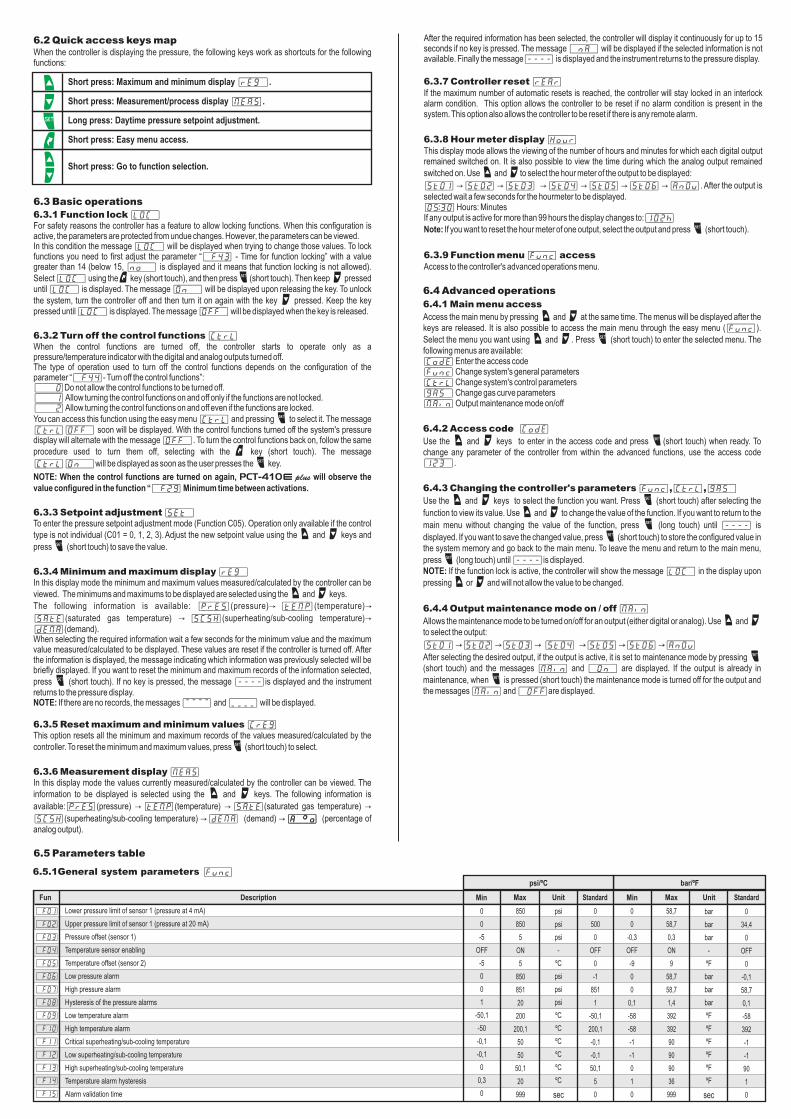
6.5.1General system parameters [Func]
[,F01]
[,F02]
[,F03]
[,F04]
[,F05]
[,F06]
[,F07]
[,F08]
[,F09]
[,F10]
[,F11]
[,F12]
[,F13]
[,F14]
[,f15]
DescriptionFun Min Max Unit
850
850
5
ON
5
850
851
20
200
200,1
50
50
50,1
20
999
psi
psi
psi
-
ºC
psi
psi
psi
ºC
ºC
ºC
ºC
ºC
ºC
sec
0
0
-0,3
OFF
-9
0
0
0,1
-58
-58
-1
-1
0
1
0
58,7
58,7
0,3
ON
9
58,7
58,7
1,4
392
392
90
90
90
36
999
bar
bar
bar
-
ºF
bar
bar
bar
ºF
ºF
ºF
ºF
ºF
ºF
sec
Min Max Unit StandardStandard
0
0
-5
OFF
-5
0
0
1
-50,1
-50
-0,1
-0,1
0
0,3
0
0
34,4
0
OFF
0
-0,1
58,7
0,1
-58
392
-1
-1
90
1
0
0
500
0
OFF
0
-1
851
1
-50,1
200,1
-0,1
-0,1
50,1
5
0
Lower pressure limit of sensor 1 (pressure at 4 mA)
pressure limit of sensor 1 (pressure at 20 mA)
Pressure offset (sensor 1)
Temperature sensor enabling
Temperature offset (sensor 2)
Low pressure alarm
High pressure alarm
Hysteresis of the pressure alarms
Low temperature alarm
High temperature alarm
Critical superheating/sub-cooling temperature
Low superheating/sub-cooling temperature
High superheating/sub-cooling temperature
Temperature alarm hysteresis
Alarm validation time
Upper
psi/ºC bar/ºF
; Short press: Easy menu access.
[,,,,][,,,,]

[,F16]
[,F17]
[,F18]
[,F19]
[,F20]
[,F21]
[,F22]
[,F23]
[,F24]
[,F25]
[,F26]
[,F27]
[,F28]
[,F29]
[,f30]
[,F31]
[,F32]
[,F33]
[,F34]
[,F35]
[,F36]
[,F37]
[,F38]
[,F39]
[,F40]
[,F41]
[,F42]
[,F43]
[,F44]
[,f45]
[,F46]
[,F47]
[,f48]
DescriptionFun Min Max Unit
10
999
999
999
999
31
31
31
31
100,0
100,0
100,0
100,0
999
999
999
999
4
1
5
999
999
999
999
1
1
1
60
2
ºF
bar
247
247
-
min
sec
sec
min
-
-
-
-
%
%
%
%
sec
-
-
-
/min
/min
-
-
sec
-
-
-
-
-
sec
sec
sec
sec
sec
sec
sec
sec/min
0
1
0
0
0
0
0
0
0
0
0
0
0
0
0
0
0
0
0
0
0
0
1
1
0
0
0
14
0
ºC
psi
1
1
10
999
999
999
999
31
31
31
31
100,0
100,0
100,0
100,0
999
999
999
999
4
1
5
999
999
999
999
1
1
1
60
2
ºF
bar
247
247
Min Max Unit StandardStandard
0
1
0
0
0
0
0
0
0
0
0
0
0
0
0
0
0
0
0
0
0
0
1
1
0
0
0
14
0
ºC
psi
1
1
0
1
0
0
0
0
0
0
0
0
0
0
0
0
0
0
0
0
0
0
0
0
1
1
0
1
1
14
0
ºC
psi
1
1
0
1
0
0
0
0
0
0
0
0
0
0
0
0
0
0
0
0
0
0
0
0
1
1
0
1
1
14
0
ºC
psi
1
1
Reset mode
Delay for automatic resets
Startup delay (power up)
Alarm inhibition time (power up)
Cyclic timer inhibition time (power up)
State of the digital outputs when an error occurs in the pressure sensor
State of the digital outputs in the event of a low pressure alarm
State of the digital outputs in the event of a high pressure alarm
State of the digital outputs in the event of a remote alarm
Value of the analog output when an error occurs in the pressure sensor
Value of the analog output in the event of a low pressure alarm
Value of the analog output in the event of a high pressure alarm
Value of the analog output in the event of a remote alarm
Minimum time between activations
Minimum time between deactivations
Stage on minimum time
Stage off minimum time
Operation mode of the digital input
Digital input inverter
Operation mode of the alarm output
Alarm on time
Alarm off time
Cyclic timer on time
Cyclic timer off time
Cyclic timer time base
Pressure switch type
Master/slave selection
Key press time to lock function adjustment
Turning off the control functions
Temperature units
Pressure units
RS485 network address (PCT-410 plus network)
RS485 network address (Sitrad)
e
psi/ºC bar/ºF
(1): The lower limit of the function disables it.(2): The upper limit of the function disables it.
6.5.1.1 Description of the general system parametersF01 - Lower pressure limit of sensor 1 (pressure at 4 mA):Pressure applied to pressure sensor 1 when its output has a current of 4 mA.
F02 - pressure limit of sensor 1 (pressure at 20 mA):Pressure applied to pressure sensor 1 when its output has a current of 20 mA.
F03 - Pressure offset (sensor 1):Allows compensating deviations in the pressure reading of sensor 1.
F04 - Temperature sensor enabling:OFF – Sensor offON – Sensor on
F05 - Temperature offset (sensor 2):Allows compensating deviations in the temperature reading of sensor 2.
F06 - Low pressure alarm:This is the reference pressure value that activates the signal indicating that the pressure of the desired point. When this alarm goes off, the pressure switch and start/stop outputs are activated/deactivated depending on the configuration of function F22 and the analog output remains with the fixed percentage value configured in F26. The activation/deactivation of the stages observe the times specified in F29 - Minimum time between activations and F30 - Minimum time between deactivations.
F07 - High pressure alarm:This is the reference pressure value that activates the signal indicating that the pressure of the desired point. When this alarm goes off, the pressure switch and start/stop outputs are activated/deactivated depending on the configuration of function F23 and the analog output remains with the fixed percentage value configured in F27. The activation/deactivation of the stages observe the times specified in F29 - Minimum time between activations and F30 - Minimum time between deactivations.
F08 - Hysteresis of the pressure alarms:This is the pressure difference that exits the alarm condition.
F09 - Low temperature alarm:This is the reference value that activates the signal indicating that the temperature is below the desired point.
F10 - High temperature alarm:This is the reference value that activates the signal indicating that the temperature is above the desired point.
F11 - Critical superheating/sub-cooling temperature:The critical superheating/sub-cooling temperature alarm is activated if the temperature falls below this level. If the instrument is configured to control the suction pressure, all pressure switch outputs will be deactivated, observing the time configured in F30 - Time between deactivations. If the instrument is configured to control the discharge pressure, all pressure switch outputs will be activated, observing the time configured in F29 - Time between activations.
F12 - Low superheating/sub-cooling temperature:The low superheating/sub-cooling alarm is activated if the temperature falls below this level. The operation of the controller remains unchanged when this alarm goes off.
Upper
F13 - High superheating/sub-cooling temperature:The low efficiency alarm is activated if the temperature rises above this level.
F14 - Temperature alarm hysteresis:This is the temperature difference that exits the alarm condition.
F15 - Alarm validation time:This is the time that the alarm will remain switched off even in alarm conditions. This inhibition timer starts counting after the startup delay has ended (F18).
F16 - Reset mode:This parameter allows the reset method of the controller to be configured when faults/alarms occur.0 - Manual reset only01 to 09 – Number of automatic resets allowed within the interval configured in F17 - Time period for automatic resets10 – Always reset automatically
F17 – Delay for automatic resets:This function sets the minimum time for automatic resets. If all automatic resets have already been performed within the time configured in this function and another fault occurs, the controller will only accept the next reset in manual mode.
F18 - Startup delay (power up):This is the time elapsed from initialization, during which the instrument displays just pressure and temperature without activating alarms and stages.
F19 - Alarm inhibition time (power up):This is the time during which the alarms remain inhibited after the instrument is powered up even if there is an alarm condition. This inhibition timer starts counting after the expiration of the time specified in F18 - Startup delay (power up).
F20 - Cyclic timer inhibition time (power up):This is the time during which the cyclic timers will remain inhibited after the instrument is powered on. This inhibition timer starts counting after the expiration of the time specified in F18 - Startup delay (power up).
F21 - State of the digital outputs when an error occurs in the pressure sensor:This function defines the state of each digital output when an error occurs in the reading of the pressure sensor. Table 1 indicates the value of the function depending on the state of each output. Only pressure switch and start / stop stages are affected by this function.
F22 - State of the digital outputs in the event of a low pressure alarm:This function defines the state of each digital output when a low pressure alarm occurs. Table 1 indicates the value of the function depending on the state of each output. Only the pressure switch and start/stop stages are affected by this function.
F23 - State of the digital outputs in the event of a high pressure alarm:This function defines the state of each digital output when a high pressure alarm occurs. Table 1 indicates the value of the function depending on the state of each output. Only the pressure switch and start/stop stages are affected by this function.
F24 - State of the digital outputs in the event of a remote alarm:This function defines the state of each digital output when a remote alarm occurs. Table 1 indicates the value of the function depending on the state of each output. Only the pressure switch and start/stop stages are affected by this function.
-
min
min
-
-
-
-
%
%
%
%
-
-
-
/min
/min
-
-
-
-
-
-
-
sec
sec
sec
sec
sec
sec
sec
sec
sec
sec
sec/min
sec
Legend:[On,,]= on [Off,]= off

F25 - Value of the analog output when an error occurs in the pressure sensor:This function defines the percentage that must be applied to the analog output when an error occurs in the reading of the pressure sensor. The maximum and minimum values of the analog output (functions C16 e C17) are ignored.
F26 - Value of the analog output in the event of a low pressure alarm:This function defines the percentage that must be applied to the analog output when a low pressure alarm occurs. The maximum and minimum values of the analog output (functions C16 e C17) are ignored.
F27 - Value of the analog output in the event of a high pressure alarm:This function defines the percentage that must be applied to the analog output when a high pressure alarm occurs. The maximum and minimum values of the analog output (functions C16 e C17) are ignored.
F28 - Value of the analog output in the event of a remote alarm:This function defines the percentage that must be applied to the analog output when a remote alarm occurs. The maximum and minimum value of the analog output (functions C16 e C17) are ignored.
F29 - Minimum time between activations:This time guarantees that no simultaneous activations of the pressure switch and/or start stop outputs will occur. The main purposes of this function are: to minimize interferences in the power grid of the facility caused by the simultaneous activation of loads, to avoid unnecessary activation of loads when there are fast variations in the pressure in the system.
F30 - Minimum time between deactivations:This time guarantees that no simultaneous deactivations of the pressure switch and/or start/stop outputs will occur. The main purposes of this function are: to minimize interferences in the power grid of the facility caused by the simultaneous activation of loads, to avoid unnecessary activation of loads when there are fast variations in the pressure in the system.
F31 - Stage on minimum time:This is the minimum time that a pressure switch or start/stop output will remain switched on, that is, the length of time between the last start up and the next stop. The main purpose of this function is to limit the number of activations of motors per hour.
F32 - Stage off minimum time:This is the minimum time that a pressure switch or start/stop output will remain switched off, that is, the length of time between the last stop and the next start up. The main purpose of this function is to limit the number of deactivations of motors per hour.
F33 - Operation mode of the digital input:It allows the operating mode of the digital output to be adjusted0 – Off: Input disabled1 – Enable economy setpoint: Selection of normal/economy setpoint2 – Switch on all pressure switch outputs: Activate all outputs3 – Switch off all pressure switch outputs: Deactivate all outputs4 – Virtual alarm: Virtual alarm (1)(2)(1): If the mode of the digital input is virtual alarm, the digital input alarm will be active, but there will be no change in the operation of the system (no outputs are activated/deactivated)(2): The virtual alarm is not counted by the reset system
F34 - Digital input inverter:0 – Off (open contact, input activated)1 – On (open contact, input deactivated)
F35 - Operation mode of the alarm output:This allows the operating mode of the dedicated alarm output to be adjusted.0 – Off: Output disabled.1 – Output activated only in the event of a transducer error: Alarm output active in the event of an error in the pressure measurement2 – Output activated with pressure alarms: Alarm output active in the event of a low/high pressure alarm.3 – Output activated with temperature alarms: Alarm output active in the event of a low/high temperature alarm.4 – Output activated with digital input alarm: Alarm output active if the digital input alarm is active.5 – Output activated with any alarm: Alarm output active if any alarm occurs.
F36 - Alarm on time:This is the time during which the alarm output will be active when it is cycling.
F37 - Alarm off time:This is the time during which the alarm output will be inactive when it is cycling. Note: To make the output stay continuously on, just configure functions F36 and F37 with a value of zero.
F38 - Cyclic timer on time:This is the time for which the outputs configured as cyclic timers will remain on.
F39 - Cyclic timer off timeThis is the time for which the outputs configured as cyclic timers will remain off.
F40 - Cyclic timer time base:This is the time base used by the functions of the cyclic timer:0 - Seconds1 - Minutes
F41 - Pressure switch type:This function configures the type of the pressure switch (low- or high-pressure). This information is required for the superheating and sub-cooling calculations.0 – Suction1 – Discharge
F42 - Master/slave selection (PCT-410 plus network):
If you want to use two or more PCT-410 plus to control several suctions/discharges in a cooling
system, it is possible to change the operations of the slave PCT-410 plus if the master
PCT-410 plus has an alarm condition. This function configures whether the controller is master or slave in the secondary communication network. For more information, see Chapter 9.0 – Master 1 – Slave
ee
ee
F43 - Key press time to lock function adjustment:When this function is active, the parameters are protected from undue changes. When the controller is locked, the user can only view the parameters. To lock the functions, see Chapter 6.3.1 - Basic Operations, item Function lock.
F44 - Turning off the control functions:This allows the output of the controller to be turned off, however the pressure and temperature measurements will continue to be performed. For more information, see Chapter 6.3.2 - Basic Operations, item Turning off the control functions.
F45 - Temperature units:This selects the system's units of measurement for temperature.0 – º C1 – º FNote: Changes to this parameter do not affect the rest of the table.
F46 - Pressure units:This selects the system's units of measurement for pressure.0 – psi1 – barNote: Changes to this parameter do not affect the rest of the table.
F47 - RS485 network address (PCT-410 plus network):
This is the address of the instrument for communication between multiple PCT-410 plus instruments (secondary RS485 network).Note: A single network must not have different equipment with the same address.
F48 - RS485 network address (Sitrad):This is the instrument's network address for communicating with SITRAD® software (primary RS485 network).Note: A single network must not have different equipment with the same address.
ee
Table 1: State of the outputs corresponding to the configuration of functions F21 to F24
Function value Output 5 Output 4 Output 3 Output 2 Output 1
0
1
2
3
4
5
6
7
8
9
10
11
12
13
14
15
16
17
18
19
20
21
22
23
24
25
26
27
28
29
30
31
Off
On
Off
Off
Off
Off
Off
Off
Off
Off
Off
Off
Off
Off
Off
Off
Off
On
On
On
On
On
On
On
On
On
On
On
On
On
On
On
Off
Off
Off
Off
Off
Off
Off
Off
On
On
On
On
On
On
On
On
Off
Off
Off
Off
Off
Off
Off
Off
On
On
On
On
On
On
On
On
Off
Off
Off
Off
On
On
On
On
Off
Off
Off
Off
On
On
On
On
Off
Off
Off
Off
On
On
On
On
Off
Off
Off
Off
On
On
On
On
Off
Off
On
On
Off
Off
On
On
Off
Off
On
On
Off
Off
On
On
Off
Off
On
On
Off
Off
On
On
Off
Off
On
On
Off
Off
On
On
Off
On
Off
On
Off
On
Off
On
Off
On
Off
On
Off
On
Off
On
Off
On
Off
On
Off
On
Off
On
Off
On
Off
On
Off
On
Off
On

6.5.2 System's control parameters [Ctrl]
C01
C02
C03
C04
C05
C06
C07
C08
C09
C10
C11
C12
C13
C14
C15
C16
C17
C18
C19
C20
C21
C22
C23
C24
C25
C26
C27
C28
C29
C30
C31
C32
C33
C34
C35
C36
C37
C38
C39
C40
C41
C42
C43
C44
C45
C46
C47
C48
C49
C50
C51
C52
C53
C54
C55
C56
C57
C58
C59
DescriptionFun Min Max Unit
4
1
850
850
850
850
425
850
850
ON
1
850
850
850
425
100
100
100
999
6
999
100
1
850
850
850
425
7
999
100
1
850
850
850
425
7
999
100
1
850
850
850
425
7
999
100
1
850
850
850
425
7
999
100
1
850
850
850
425
-
-
psi
psi
psi
psi
psi
psi
psi
-
-
psi
psi
psi
psi
%
%
%
x10h
-
x10h
%
-
psi
psi
psi
psi
-
x10h
%
-
psi
psi
psi
psi
-
x10h
%
-
psi
psi
psi
psi
-
x10h
%
-
psi
psi
psi
psi
-
x10h
%
-
psi
psi
psi
psi
0
0
0
0
0
0
0
0
0
OFF
0
0
0
0
0
0
0
0
0
0
0
0
0
0
0
0
0
0
0
0
0
0
0
0
0
0
0
0
0
0
0
0
0
0
0
0
0
0
0
0
0
0
0
0
0
0
0
0
0
4
1
58,7
58,7
58,7
58,7
29,3
58,7
58,7
ON
1
58,7
58,7
58,7
29,3
100
100
100
999
6
999
100
1
58,7
58,7
58,7
29,3
7
999
100
1
58,7
58,7
58,7
29,3
7
999
100
1
58,7
58,7
58,7
29,3
7
999
100
1
58,7
58,7
58,7
29,3
7
999
100
1
58,7
58,7
58,7
29,3
Min Max Unit StandardStandard
0
0
0
0
0
0
0
0
0
OFF
0
0
0
0
0
0
0
0
0
0
0
0
0
0
0
0
0
0
0
0
0
0
0
0
0
0
0
0
0
0
0
0
0
0
0
0
0
0
0
0
0
0
0
0
0
0
0
0
0
0
0
0
58,7
6,9
5,5
2,2
0
0
OFF
0
0
58,7
6,9
0,7
20
100
20
999
0
999
20
0
0
58,7
6,9
6,9
0
999
20
0
0
58,7
6,9
6,9
0
999
20
0
0
58,7
6,9
6,9
0
999
20
0
0
58,7
6,9
6,9
0
999
20
0
0
58,7
6,9
6,9
0
0
0
850
100
80
32
0
0
OFF
0
0
850
100
10
20
100
20
999
0
999
20
0
0
850
100
100
0
999
20
0
0
850
100
100
0
999
20
0
0
850
100
100
0
999
20
0
0
850
100
100
0
999
20
0
0
850
100
100
Control type
Control mode
Minimum setpoint limit
Maximum setpoint limit
Daytime setpoint
Economy setpoint
Hysteresis of the digital outputs
Dead zone lower limit
Dead zone upper limit
Analog output enabling
Mode of control of the analog output
Minimum setpoint limit of the analog output
Maximum setpoint limit of the analog output
Analog output pressure setpoint
Hysteresis of the analog output
Analog output minimum value
Analog output maximum value
Analog output capacity
Maximum operating time between maintenances of the analog output
Stage 1 - Stage type
Stage 1 - Maximum operating time between maintenances
Stage 1 - Capacity (1)
Stage 1 - (2)
Stage 1 - Minimum setpoint limit
Stage 1 - Maximum setpoint limit
Stage 1 - Setpoint (2)
Stage 1 - Hysteresis (2)
Stage 2 - Stage type
Stage 2 - Maximum operating time between maintenances
Stage 2 - Capacity (1)
Stage 2 - (2)
Stage 2 - Minimum setpoint limit
Stage 2 - Maximum setpoint limit
Stage 2 - Setpoint (2)
Stage 2 - Hysteresis (2)
Stage 3 - Stage type
Stage 3 - Maximum operating time between maintenances
Stage 3 - Capacity (1)
Stage 3 - (2)
Stage 3 - Minimum setpoint limit
Stage 3 - Maximum setpoint limit
Stage 3 - Setpoint (2)
Stage 3 - Hysteresis (2)
Stage 4 - Stage type
Stage 4 - Maximum operating time between maintenances
Stage 4 - Capacity (1)
Stage 4 - (2)
Stage 4 - Minimum setpoint limit
Stage 4 - Maximum setpoint limit
Stage 4 - Setpoint (2)
Stage 4 - Hysteresis (2)
Stage 5 - Stage type
Stage 5 - Maximum operating time between maintenances
Stage 5 - Capacity (1)
Stage 5 - (2)
Stage 5 - Minimum setpoint limit
Stage 5 - Maximum setpoint limit
Stage 5 - Setpoint (2)
Stage 5 - Hysteresis (2)
Control type
Control type
Control type
Control type
Control type
psi/ºC bar/ºF
-
-
bar
bar
bar
bar
bar
bar
bar
-
-
bar
bar
bar
bar
%
%
%
x10h
-
x10h
%
-
bar
bar
bar
bar
-
x10h
%
-
bar
bar
bar
bar
-
x10h
%
-
bar
bar
bar
bar
-
x10h
%
-
bar
bar
bar
bar
-
x10h
%
-
bar
bar
bar
bar
(1): Valid for C01 = 0, 1, 2, 3 (control mode turned off, linear, rotation or capacities)(2): Valid for C01 = 4 (individual control mode)
6.5.2.1 Description of the system's control parametersC01 - Control type:Function to configure the control type of the system. For more details, see Chapter 7.0 – Off: Pressure control does not use the pressure switch digital outputs.1 – Linear: Pressure control in linear mode.2 – Rotation: Pressure control in rotation mode.3 – Capacities: Pressure control in capacities mode.4 – Individual: Pressure control in individual mode.
C02 - Control mode:Function to configure the control mode of the system (pressurization, depressurization). Available when C01 = 0, 1, 2, 3.0 – Depressurize1 – Pressurize
C03 - Minimum setpoint limit:Lower limit aimed at preventing an exceedingly low setpoint (both normal and economy) pressure from being set by mistake. Available when C01 = 0, 1, 2, 3.
C04 - Maximum setpoint limit:Upper limit aimed at preventing an exceedingly high setpoint (both normal and economy) pressure from being set by mistake. Available when C01 = 0, 1, 2, 3.
C05 - Daytime setpoint:Control pressure when the controller is in daytime mode. Available when C01 = 0, 1, 2, 3.
C06 - Economy setpoint:Control pressure when the controller is in economy mode. This setpoint will be active when function F33 - Digital input operation mode is set to 1 (Activate economy setpoint) and the digital input is active. Available when C01 = 0, 1, 2, 3.
C07 - Hysteresis of the digital outputs:This is the value of the relative pressure that defines the pressure range for activating the digital stages. The points at which each compressor will be activated depends on the number of outputs and the type of digital control. Available when C01 = 0, 1, 2, 3.
Legend:[On,,]= on [Off,]= off
C08 - Dead zone lower limit:C09 - Dead zone upper limit: A dead zone can be enabled if the control type is set to linear or rotation, the control mode is set to depressurization, and the analog is off. If the pressure is within the range defined by functions P08 and P09, the number of active digital outputs configured as pressure switches will remain unchanged, even if there are fluctuations in the system pressure. A detailed description of the operation of the dead zone is included in Chapter 8 - Types of control by only digital outputs. Available when C01 = 0, 1, 2, 3.
C10 - Analog output enabling:Function that selects the method of control of the analog output.OFF – Control does not use the analog outputON – Control uses the analog output
C11 - Mode of control of the analog output:Function to configure the control mode of the output (pressurization, depressurization). Available when the control type is “Individual” (C01 = 4).0 – Depressurize 1 – Pressurize
C12 - Minimum setpoint limit of the analog output:Lower limit aimed at preventing an exceedingly low setpoint pressure for the analog output from being set by mistake. Available when the control type is “Individual” (C01 = 4).
C13 - Maximum setpoint limit of the analog output:Upper limit aimed at preventing an exceedingly high setpoint pressure for the analog output from being set by mistake. Available when the control type is “Individual” (C01 = 4).
C14 - Analog output pressure setpoint:Control pressure of the analog output. Available when the control type is “Individual” (C01 = 4).
C15 - Hysteresis of the analog output:This is the value of the relative pressure that defines the pressure range for activating the analog output. The percentage of the analog output depends on the minimum and maximum percentages of the analog output, on the number of digital outputs configured as pressure switches, and on the control type.
C16 - Analog output minimum value:This is the minimum value that the analog output will present when activated. This value limits the minimum rotation speed of the compressor/fan. The value is a % of 10 V (example: 50% = 5 V).
C17 - Analog output maximum value:This is the maximum value that the analog output will present when activated. This value limits the maximum rotation speed of the compressor/fan. The value is a % of 10 V (example: 50% = 5 V).
C18 - Analog output capacity:This function defines the capacity of the analog stage when the control type is “Capacities” (C01 = 3).
C19 - Maximum operating time between maintenances of the analog output:Time (x10h) for which the analog stage must operate without maintenance.
C20, C28, C36, C44, C52 - Stage x - Stage type (x = 1, 2, 3, 4, or 5)?The adjustment options for each of the controller's digital outputs are:0 – Stage with no function: The stage remains always off.
1 – Pressure switch: Digital output to activate a compressor/fan2 – Start/Stop: Output for frequency inverter start/stop.3 – Cyclic timer (start: on): Cyclic timer with initial state on. On/off time in accordance with the values configured in F38, F39, and F40.4 – Cyclic timer (start: off): Cyclic timer with initial state off. On/off time in accordance with the values configured in F38, F39, and F40.5 – Intra-range alarm: Configures output x as an intra-range alarm. The functions “Minimum setpoint allowed for the setpoint of stage x” and “Maximum setpoint allowed for the setpoint of stage x” indicate respectively the upper and lower pressure limits to activate the alarm.6 – Extra-range alarm: Configures output x as an extra-range alarm. The functions “Minimum setpoint allowed for the setpoint of stage x” and “Maximum setpoint allowed for the setpoint of stage x” indicate respectively the upper and lower pressure limits to activate the alarm.7 – Extra-range alarm (stage 1 setpoint): Configures output x as an extra-range alarm related to setpoint 1. The alarm will be activated when the pressure is lower than C26 (stage 1 setpoint) minus C27 (stage 1 hysteresis) or higher than C26 (stage 1 setpoint) plus C27 (stage 1 hysteresis). Note: This option (7) is not applicable to stage 1 (function C20).
C21, C29, C37, C45, C53 - Stage x - Maximum operating time between maintenances (x = 1, 2, 3, 4, or 5):Time (x10h) for which stage x must operate without maintenance.
C22, C30, C38, C46, C54 - Stage x - Capacity (x = 1, 2, 3, 4, or 5):This function defines the capacity of stage x when the control type is “Capacities” (C01 = 3).Note: The sum of the capacities of all stages configured as pressure switches and those the analog output (if active) must not exceed 100%.
C23, C31, C39, C47, C55 - Stage x - Control type (x = 1, 2, 3, 4, or 5):Function to configure the control mode (pressurization, depressurization) of stage x. Available when the control type is “Individual” (C01 = 4).0 – Depressurize 1 – Pressurize
C24, C32, C40, C48, C56 - Stage x - Minimum setpoint limit (x = 1, 2, 3, 4, or 5):Lower limit aimed at preventing an exceedingly low setpoint pressure from being set for stage x by mistake. Available when the control type is “Individual” (C01 = 4).
C25, C33, C41, C49, C57 - Stage x - Maximum setpoint limit (x = 1, 2, 3, 4, or 5):Upper limit aimed at preventing an exceedingly low setpoint pressure from being set for stage x by mistake. Available when the control type is “Individual” (C01 = 4).
C26, C34, C42, C50, C58 - Stage x - Setpoint (x = 1, 2, 3, 4, or 5):Adjustment of the control pressure of stage x. Available when the control type is “Individual” (C01 = 4).
C27, C35, C43, C51, C59 - Stage x - Hysteresis (x = 1, 2, 3, 4, or 5):This is the pressure difference in relation to the setpoint of the stage used to define whether stage x must be activated/deactivated. Available when the control type is “Individual” (C01 = 4).
P01
P02
P03
P04
P05
P06
P07
P08
P09
P10
P11
P12
P13
P14
P15
P16
P17
P18
P19
P20
P21
DescriptionFun Min Max Unit
15
850
200
850
200
850
200
850
200
850
200
850
200
850
200
850
200
850
200
850
200
-
psi
°C
°C
°C
°C
°C
°C
°C
°C
°C
°C
psi
psi
psi
psi
psi
psi
psi
psi
psi
0
-0,1
-58
-0,1
-58
-0,1
-58
-0,1
-58
-0,1
-58
-0,1
-58
-0,1
-58
-0,1
-58
-0,1
-58
-0,1
-58
15
58,7
392
58,7
392
58,7
392
58,7
392
58,7
392
58,7
392
58,7
392
58,7
392
58,7
392
58,7
392
-
bar
ºF
bar
ºF
bar
ºF
bar
ºF
bar
ºF
bar
ºF
bar
ºF
bar
ºF
bar
ºF
bar
ºF
Min Max Unit StandardStandard
0
-1
-50,1
-1
-50,1
-1
-50,1
-1
-50,1
-1
-50,1
-1
-50,1
-1
-50,1
-1
-50,1
-1
-50,1
-1
-50,1
15
-0,1
-58
-0,1
-58
-0,1
-58
-0,1
-58
-0,1
-58
-0,1
-58
-0,1
-58
-0,1
-58
-0,1
-58
-0,1
-58
15
-1
-50,1
-1
-50,1
-1
-50,1
-1
-50,1
-1
-50,1
-1
-50,1
-1
-50,1
-1
-50,1
-1
-50,1
-1
-50,1
Gas curve selection
Point 1 -Pressure of the mapped curve
Point 1 - Temperature of the mapped curve
Point 2 - Pressure of the mapped curve
Point 2 - Temperature of the mapped curve
Point 3 - Pressure of the mapped curve
Point 3 - Temperature of the mapped curve
Point 4 - Pressure of the mapped curve
Point 4 - Temperature of the mapped curve
Point 5 - Pressure of the mapped curve
Point 5 - Temperature of the mapped curve
Point 6 - Pressure of the mapped curve
Point 6 - Temperature of the mapped curve
Point 7 - Pressure of the mapped curve
Point 7 - Temperature of the mapped curve
Point 8 - Pressure of the mapped curve
Point 8 - Temperature of the mapped curve
Point 9 - Pressure of the mapped curve
Point 9 - Temperature of the mapped curve
Point 10 - Pressure of the mapped curve
Point 10 - Temperature of the mapped curve
psi/ºC bar/ºF
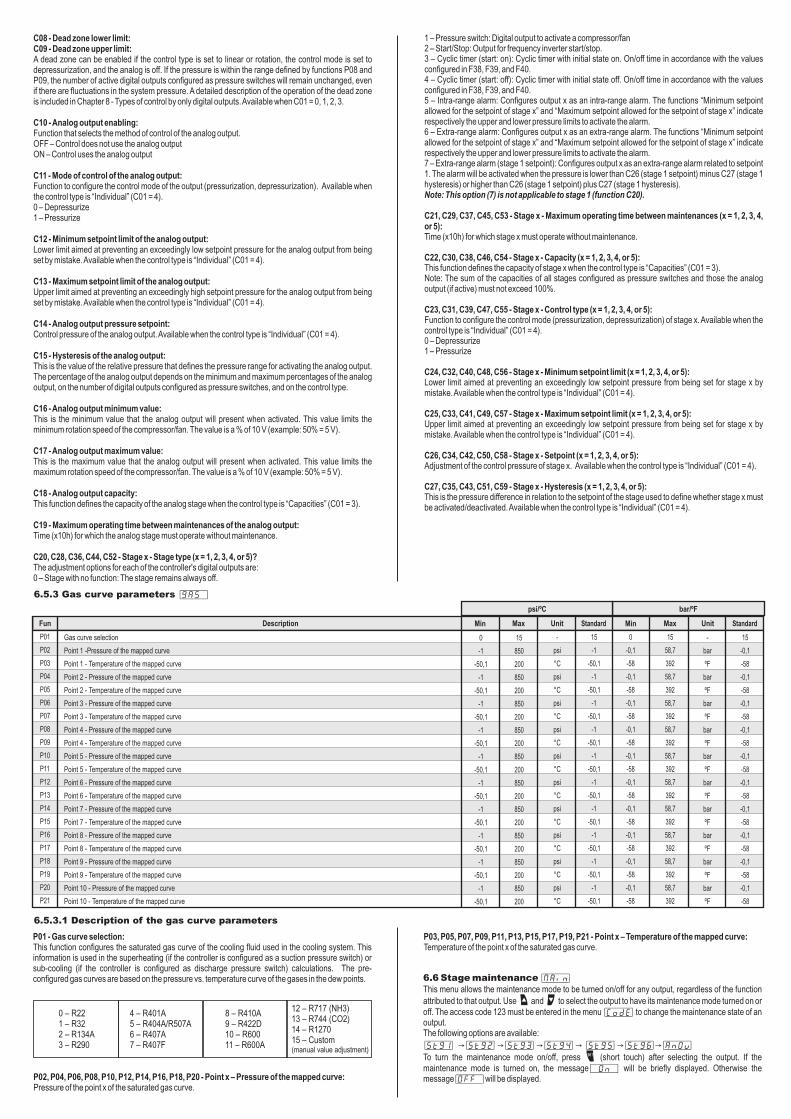
6.5.3 Gas curve parameters [GAS,]
6.5.3.1 Description of the gas curve parameters
P01 - Gas curve selection:This function configures the saturated gas curve of the cooling fluid used in the cooling system. This information is used in the superheating (if the controller is configured as a suction pressure switch) or sub-cooling (if the controller is configured as discharge pressure switch) calculations. The pre-configured gas curves are based on the pressure vs. temperature curve of the gases in the dew points.
P02, P04, P06, P08, P10, P12, P14, P16, P18, P20 - Point x – Pressure of the mapped curve:Pressure of the point x of the saturated gas curve.
0 – R221 – R322 – R134A3 – R290
4 – R401A5 – R404A/R507A6 – R407A7 – R407F
8 – R410A9 – R422D10 – R60011 – R600A
12 – R717 (NH3)13 – R744 (CO2)14 – R127015 – Custom (manual value adjustment)
6.6 Stage maintenance [MAin]This menu allows the maintenance mode to be turned on/off for any output, regardless of the function
attributed to that output. Use < and > to select the output to have its maintenance mode turned on or off. The access code 123 must be entered in the menu [Code] to change the maintenance state of an output.The following options are available:
[StG1] → [StG2] → [StG3] → [StG4] → [StG5] → [StG6]→ [AnOu]
To turn the maintenance mode on/off, press / (short touch) after selecting the output. If the maintenance mode is turned on, the message[,On,] will be briefly displayed. Otherwise the message[Off,]will be displayed.
P03, P05, P07, P09, P11, P13, P15, P17, P19, P21 - Point x – Temperature of the mapped curve:Temperature of the point x of the saturated gas curve.
7. OPERATION
7.1 Pressure control
The PCT-410 plus pressure control system has an option for controlling variable capacity compressors and fans by activating digital outputs or by using the analog output. Using the analog output the compressor/fan is controlled by means of a frequency inverter and the capacity is directly modulated by the controller. We must first establish a nomenclature for the components to better understand the operation of the logic of the variable capacity compressors/fans using the digital outputs.Pressure switch stage: This is the output that will control the activation/deactivation of a compressor/fan.Stage capacity (%): This is the power fraction that each pressure switch stage contributes to the total system power. If the capacities mode is used, the technician must make sure during the controller's startup that the sum of all capacities of the pressure switch stages does not exceed 100%.
The possible combinations in PCT-410 plus pressure control are adjusted by the parameters “C01 – Control type”, “C02 – Control mode” and “C10 – Analog output enable”. The combination are as follows:-Control using only the digital outputs (pressurizing/depressurizing)-Control using only the analog output (pressurizing/depressurizing)-Mixed control using the digital outputs and the analog output (pressurizing/depressurizing)-Individual control where each digital stage and analog output as its own activation/deactivation criteria.
7.1.1 Types of control only through digital outputsUpon configuring the type of digital control as switched on and the type of analog control as switched off, the pressure control will be performed only by the digital outputs. The possible control methods under these conditions are:-Digital outputs in linear mode-Digital outputs in rotation mode-Digital outputs in capacities mode
7.1.1.1 Digital outputs in linear modeOnly the digital outputs will be used in this control mode, and thus the controller will assume only the hysteresis value configured in the function: "digital output hysteresis." The controller will add digital outputs (pressure switch type) as the pressure deviates from the setpoint. The activation point for each output is calculated in accordance with the hysteresis value and the number of stages (pressure switch type) configured.
e
e
Step =Hysteresis of the digital output
N° Stage
Depressurization mode Pressurization mode
Pressure for activating output "N"Activation = Setpoint + (N x Step)Pressure for deactivating output "N"Activation = Setpoint + ((N-1) x Step)
Pressure for activating output "N"Activation = Setpoint + (N x Step)Pressure for deactivating output "N"Activation = Setpoint + ((N-1) x Step)
Example 1: Depressurization mode:Setpoint: 10 psiHysteresis of the digital outputs: 10 psiNumber of pressure switch stages: 5
The total number of digital outputs in this example is 5. Thus the step of each digital output is 2 psi (10 psi divided by 5). The first digital stage will be turned on when the pressure reaches 12 psi (setpoint plus step), the second at 14 psi (setpoint plus 2 times the step), the third at 16 psi (setpoint plus 3 times the step), and so on. Please note that at 20 psi (setpoint plus digital hysteresis) all digital outputs will be on.
Example 2: Pressurization mode:Setpoint: 100 psiHysteresis of the digital outputs: 10 psiNumber of pressure switch stages: 5
The total number of digital outputs in this example is 5. Thus the step of each digital output is 2 psi (10 psi divided by 5). The first digital stage will be turned on when the pressure reaches 98 psi (setpoint minus step), the second at 96 psi (setpoint minus 2 times the step), the third at 94 psi (setpoint minus 3 times the step), and so on. Please note that at 90 psi (setpoint minus digital hysteresis) all digital outputs will be on.
7.1.1.2 Digital outputs in linear mode with dead zoneNote: The control using a dead zone is only available in the depressurization mode.If the dead zone is enabled, the output activation control "freezes" the number of stages that are activated when the pressure enters the dead zone. If the pressure leaves the region delimited by the functions of the dead zone, the number of command stages will be updated in accordance with the conditions below:If the pressure rises above the upper limit of the dead zone:- The number of commend stages is immediately updated, and each command stage is added observing the value configured in function “F29 – Minimum time between activations”.If the pressure drops below the lower limit of the dead zone: - The deactivation of stages must respect the function “F30 – Minimum time between deactivations” and the number of active stages will be updated to correct the pressure in the system.If any of the following conditions occur:- The pressure of the system remains within the region delimited by the two transition thresholds for the period specified in F29; - The pressure of the system keeps falling and reaches a value lower than the transition threshold pressure. In this case, function F29 is ignored, the number of active stages is immediately decreased, and the counter related to function F29 is reset. If the pressure keeps falling and reaches a new transition threshold before the time defined in F29 has expired, the number of active stages is decreased again, the counter related to function F29 is reset and so on. The pressure thresholds used to mark out the regions where function F29 is observed are calculated as follows:
Step dead zone =Lower dead zone - setpoint
N° factive stages when leaving dead zone region -1
Pressure thresholds for immediate update of the pressure stages:Threshold N = Lower dead zone pressure – N x (Dead zone step)
Example 3: Number of pressure switch stages: 5Setpoint: 10 psiHysteresis of the digital outputs: 10 psiLower dead zone: 13 psiUpper dead zone: 17 psi
The total number of digital outputs in this example is 5. Thus the step of each digital output is 2 psi (10 psi divided by 5). The first digital stage will be turned on when the pressure reaches 12 psi (setpoint plus step), then the number of active stages remains frozen until the pressure reaches 18 psi (upper dead zone limit = 17 psi). When the pressure reaches 18 psi, the number of active stages changes to 4 (OUT 1, OUT 2, OUT 3, OUT 4, with the time between stage activations being equal to the value configured in function F29). Upon leaving the dead zone, the control changes back to operate by updating the number of active stages as usual.
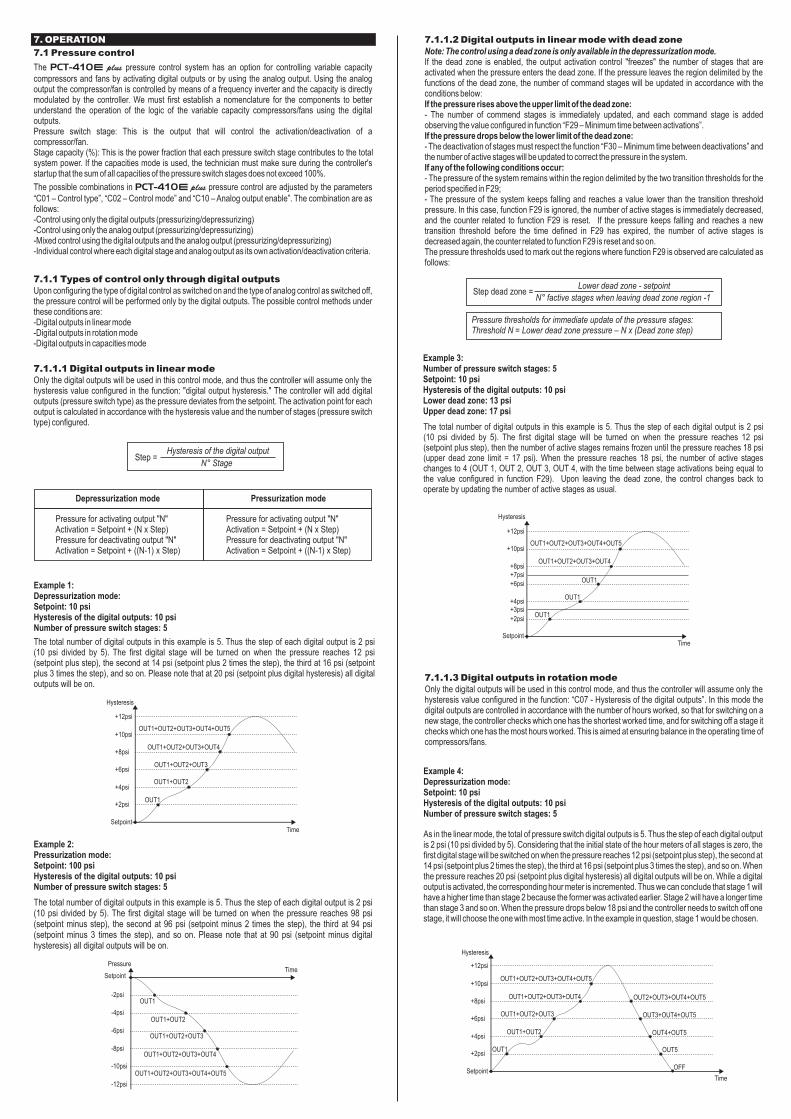
7.1.1.3 Digital outputs in rotation modeOnly the digital outputs will be used in this control mode, and thus the controller will assume only the hysteresis value configured in the function: “C07 - Hysteresis of the digital outputs”. In this mode the digital outputs are controlled in accordance with the number of hours worked, so that for switching on a new stage, the controller checks which one has the shortest worked time, and for switching off a stage it checks which one has the most hours worked. This is aimed at ensuring balance in the operating time of compressors/fans.
Example 4: Depressurization mode:Setpoint: 10 psiHysteresis of the digital outputs: 10 psiNumber of pressure switch stages: 5
As in the linear mode, the total of pressure switch digital outputs is 5. Thus the step of each digital output is 2 psi (10 psi divided by 5). Considering that the initial state of the hour meters of all stages is zero, the first digital stage will be switched on when the pressure reaches 12 psi (setpoint plus step), the second at 14 psi (setpoint plus 2 times the step), the third at 16 psi (setpoint plus 3 times the step), and so on. When the pressure reaches 20 psi (setpoint plus digital hysteresis) all digital outputs will be on. While a digital output is activated, the corresponding hour meter is incremented. Thus we can conclude that stage 1 will have a higher time than stage 2 because the former was activated earlier. Stage 2 will have a longer time than stage 3 and so on. When the pressure drops below 18 psi and the controller needs to switch off one stage, it will choose the one with most time active. In the example in question, stage 1 would be chosen.
Hysteresis
TimeSetpoint
+2psi
+4psi
+6psi
+8psi
+10psi
+12psi
OUT1+OUT2+OUT3+OUT4+OUT5
OUT1+OUT2+OUT3+OUT4
OUT1+OUT2+OUT3
OUT1+OUT2
OUT1
SetpointTime
Pressure
-2psi
-4psi
-6psi
-8psi
-10psi
-12psi
OUT1+OUT2+OUT3+OUT4+OUT5
OUT1+OUT2+OUT3+OUT4
OUT1+OUT2+OUT3
OUT1+OUT2
OUT1
Hysteresis
TimeSetpoint
OUT1
+12psi
+10psi
+8psi+7psi
+6psi
+4psi+3psi
+2psi
OUT1
OUT1
OUT1+OUT2+OUT3+OUT4
OUT1+OUT2+OUT3+OUT4+OUT5
Hysteresis
TimeSetpoint
+2psi
+4psi
+6psi
+8psi
+10psi
+12psi
OUT1+OUT2+OUT3+OUT4+OUT5
OUT1+OUT2+OUT3+OUT4
OUT1+OUT2+OUT3
OUT1+OUT2
OUT1
OUT2+OUT3+OUT4+OUT5
OUT3+OUT4+OUT5
OUT4+OUT5
OUT5
OFF

HysteresisTime
Setpoint
-2psi
-4psi
-6psi
-8psi
-10psi
-12psi
OUT1+OUT2+OUT3+OUT4+OUT5
OUT1+OUT2+OUT3+OUT4
OUT1+OUT2+OUT3
OUT1+OUT2
OUT1
OUT2+OUT3+OUT4+OUT5
OUT3+OUT4+OUT5
OUT4+OUT5
OUT5
OFF
Example 5: Pressurization mode:Setpoint: 100 psiHysteresis of the digital outputs: 10 psiNumber of pressure switch stages: 5
As in the linear mode, the total of pressure switch digital outputs is 5. Thus the step of each digital output is 2 psi (10 psi divided by 5). Considering that the initial state of the hour meters of all stages is zero, the first digital stage will be switched on when the pressure reaches 98 psi (setpoint plus step), the second at 96 psi (setpoint plus 2 times the step), the third at 94 psi (setpoint plus 3 times the step), and so on. When the pressure reaches 90 psi (setpoint plus digital hysteresis) all digital outputs will be on. While a digital output is activated, the corresponding hourmeter is simultaneously increased. Thus we can conclude that stage 1 will have a higher time than stage 2 because the former was activated earlier. Stage 2 will have a higher time than stage 3 and so on. When the pressure drops below 92 psi and the controller needs to switch off one stage, it will choose the one with the most time active. In the example in question, stage 1 would be chosen.
7.1.1.4 Digital outputs in rotation mode with dead zoneNote: The control using a dead zone is only available in the depressurization mode.In the rotation mode the dead zone operates similarly to the linear mode, but the stages with fewer hours worked will have higher priority for activation (when increasing the pressure is required) and the stages with more hours worked have higher priority for deactivation (when decreasing the pressure is required).
Example 6: Number of pressure switch stages: 5Setpoint: 10 psiHysteresis of the digital outputs: 10 psiLower dead zone: 13 psiUpper dead zone: 17 psi
As in the linear mode, the total number of digital outputs is 5. Thus the step of each digital output is 2 psi (10 psi divided by 5). Considering that the initial state of the hour meters of all stages is zero, the first digital stage will be switched on when the pressure reaches 12 psi (setpoint plus step). Then the number of active stages remain frozen until the pressure reaches 18 psi (upper dead zone threshold = 17 psi). When the pressure reaches 18 psi, the number of active stages changes to 4 (OUT 1, OUT 2, OUT 3, OUT 4, with the time between stage activations being equal to the value configured in function F29). Upon leaving the dead zone, the control changes back to operating by updating the number of active stages as usual. When the pressure reaches 20 psi (setpoint plus digital hysteresis) all digital outputs will be on. While a digital output is activated, the corresponding hour meter is simultaneously increased. Thus we can conclude that stage 1 will have a longer time than stage 2 because the former was activated earlier. Stage 2 will have a higher time than stage 3 and so on. When the pressure drops below 18 psi and the controller needs to switch off one stage, it will choose the one with the most time active. In the example in question stage 1 would be chosen. When the pressure enters the dead zone again (reaches 17 psi), the number of outputs will be frozen again. When the pressure reaches 12 psi, the number of active stages starts to be updated again, observing the conditions described in item 7.1.1.2 of dead zone (time in function P30 or dead zone step).
7.1.1.5 Digital outputs in capacities modeNote: The dead zone is not available in this control mode.Only the digital outputs will be used in this control mode, and thus the controller will assume only the hysteresis value configured in function “C07 - Digital output hysteresis”. The activation point for each output is calculated in accordance with the output capacity and the number of stages configured. The activation will occur in accordance with the demand of the system, and the controller will always activate the set with the smallest number of outputs meeting the current demand. The calculation of the demand is made considering the following formula:
Demand (%)=Pressure measured - setpoint
hysteresisx100
If more than one combination of stages is able to meet the demand, the combination that changes the state of the smaller number of relays will be employed.
Example 7:Number of pressure switch stages: 5Mode: Depressurization.Setpoint: 10 psiHysteresis of the digital outputs: 50 psiStage capacity:
OUT1
OUT2
OUT3
OUT4
OUT5
→→→→→
10%
15%
20%
25%
30%
With the values above we can predict the control activation levels:
DEMAND (%)
Demand rising:
PRESSURE(psi)
OUT 110%
OUT 215%
OUT 320%
OUT 425%
OUT 530%
CAPACITY
(%)
0
5
10
15
20
25
30
35
40
45
50
55
60
65
70
75
80
85
90
95
100
0
5
10
15
20
25
30
35
40
45
50
55
60
65
70
75
80
85
90
95
100
10
12,5
15
17,5
20
22,5
25
27,5
30
32,5
35
37,5
40
42,5
45
47,5
50
52,5
55
57,5
60
x
x
x
x
x
x
x
x
x
x
x
x
x
x
x
x
x
x
x
x
x
x
x
x
x
x
x
x
x
x
x
x
x
x
x
x
x
x
x
x
x
x
x
x
x
x
x
x
DEMAND (%)
Demand falling:
PRESSURE(psi)
OUT 110%
OUT 215%
OUT 320%
OUT 425%
OUT 530%
CAPACITY
(%)
100
95
90
85
80
75
70
65
60
55
50
45
40
35
30
25
20
15
10
5
0
60
57,5
55
52,5
50
47,5
45
42,5
40
37,5
35
32,5
30
27,5
25
22,5
20
17,5
15
12,5
10
x
x
x
x
x
x
x
x
x
x
x
x
x
x
x
x
x
x
x
x
x
x
x
x
x
x
x
x
x
x
x
x
x
x
x
x
x
x
x
x
x
x
x
x
x
x
x
x
x
x
x
x
x
x
x
x
x
100
95
90
85
80
75
70
65
60
55
50
45
40
35
30
25
20
15
10
5
0
Example 8:Number of pressure switch stages: 5Mode: Pressurization.Setpoint: 100 psiHysteresis of the digital outputs: 50 psiStage capacity:
OUT1
OUT2
OUT3
OUT4
OUT5
→→→→→
10%
15%
20%
25%
30%
With the values above we can predict the control activation levels:
DEMAND (%)
PRESSURE(psi)
OUT 110%
OUT 215%
OUT 320%
OUT 425%
OUT 530%
CAPACITY
(%)
0
5
10
15
20
25
30
35
40
45
50
55
60
65
70
75
80
85
90
95
100
0
5
10
15
20
25
30
35
40
45
50
55
60
65
70
75
80
85
90
95
100
100
97,5
95
92,5
90
87,5
85
82,5
80
77,5
75
72,5
70
67,5
65
62,5
60
57,5
55
52,5
50
x
x
x
x
x
x
x
x
x
x
x
x
x
x
x
x
x
x
x
x
x
x
x
x
x
x
x
x
x
x
x
x
x
x
x
x
x
x
x
x
x
x
x
x
x
x
x
x
Hysteresis
TimeSetpoint
+12psi
+10psi
+8psi+7psi+6psi
+4psi+3psi+2psi
OUT2+OUT3+OUT4+OUT5
OUT2+OUT3+OUT4+OUT5
OUT2+OUT3+OUT4+OUT5
OUT5
OFF
OUT1+OUT2+OUT3+OUT4+OUT5
OUT1+OUT2+OUT3+OUT4
OUT1
OUT1
OUT1
Demand rising:
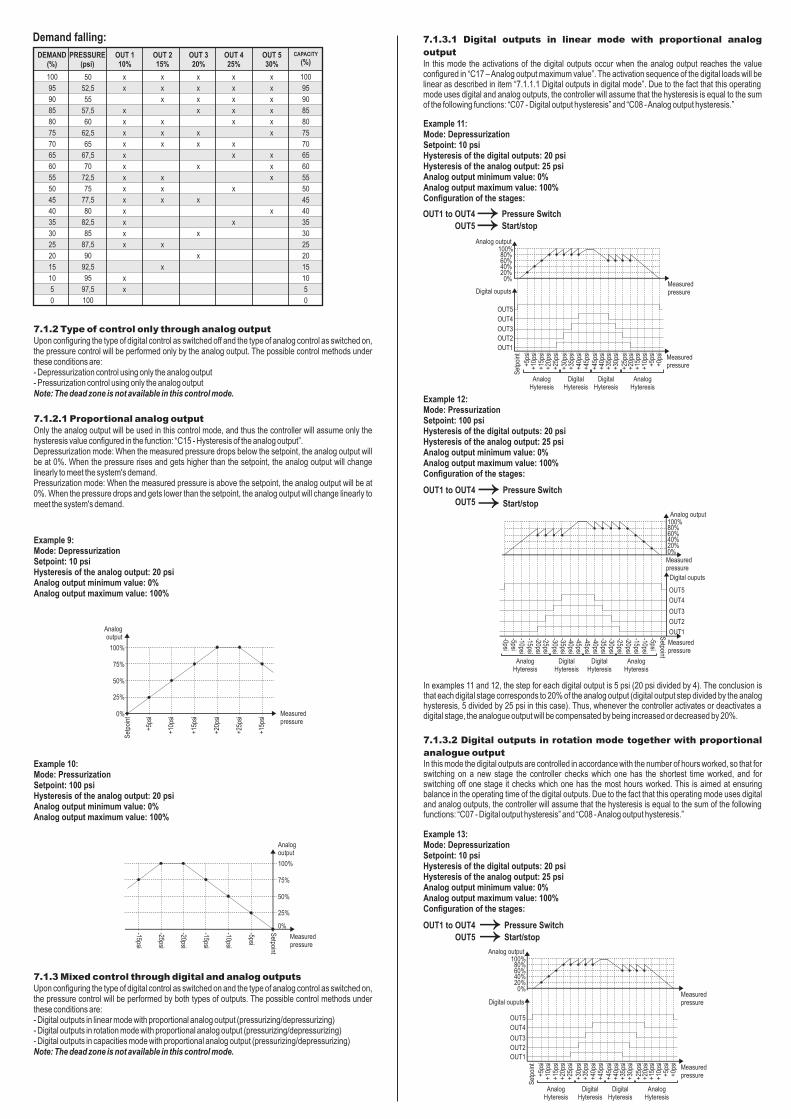
DEMAND (%)
Demand falling:
PRESSURE(psi)
OUT 110%
OUT 215%
OUT 320%
OUT 425%
OUT 530%
CAPACITY
(%)
100
95
90
85
80
75
70
65
60
55
50
45
40
35
30
25
20
15
10
5
0
x
x
x
x
x
x
x
x
x
x
x
x
x
x
x
x
x
x
x
x
x
x
x
x
x
x
x
x
x
x
x
x
x
x
x
x
x
x
x
x
x
x
x
x
x
x
x
x
x
x
x
x
x
x
x
x
x
100
95
90
85
80
75
70
65
60
55
50
45
40
35
30
25
20
15
10
5
0
7.1.2 Type of control only through analog outputUpon configuring the type of digital control as switched off and the type of analog control as switched on, the pressure control will be performed only by the analog output. The possible control methods under these conditions are:- Depressurization control using only the analog output- Pressurization control using only the analog outputNote: The dead zone is not available in this control mode.
7.1.2.1 Proportional analog outputOnly the analog output will be used in this control mode, and thus the controller will assume only the hysteresis value configured in the function: “C15 - Hysteresis of the analog output”. Depressurization mode: When the measured pressure drops below the setpoint, the analog output will be at 0%. When the pressure rises and gets higher than the setpoint, the analog output will change linearly to meet the system's demand. Pressurization mode: When the measured pressure is above the setpoint, the analog output will be at 0%. When the pressure drops and gets lower than the setpoint, the analog output will change linearly to meet the system's demand.
Example 9: Mode: DepressurizationSetpoint: 10 psiHysteresis of the analog output: 20 psiAnalog output minimum value: 0%Analog output maximum value: 100%
Example 10: Mode: PressurizationSetpoint: 100 psiHysteresis of the analog output: 20 psiAnalog output minimum value: 0%Analog output maximum value: 100%
7.1.3 Mixed control through digital and analog outputs Upon configuring the type of digital control as switched on and the type of analog control as switched on, the pressure control will be performed by both types of outputs. The possible control methods under these conditions are:- Digital outputs in linear mode with proportional analog output (pressurizing/depressurizing)- Digital outputs in rotation mode with proportional analog output (pressurizing/depressurizing)- Digital outputs in capacities mode with proportional analog output (pressurizing/depressurizing)Note: The dead zone is not available in this control mode.
7.1.3.1 Digital outputs in linear mode with proportional analog
outputIn this mode the activations of the digital outputs occur when the analog output reaches the value configured in “C17 – Analog output maximum value”. The activation sequence of the digital loads will be linear as described in item “7.1.1.1 Digital outputs in digital mode”. Due to the fact that this operating mode uses digital and analog outputs, the controller will assume that the hysteresis is equal to the sum of the following functions: “C07 - Digital output hysteresis” and “C08 - Analog output hysteresis.”
ExampleMode: DepressurizationSetpoint: 10 psiHysteresis of the digital outputs: 20 psiHysteresis of the analog output: 25 psiAnalog output minimum value: 0%Analog output maximum value: 100%Configuration of the stages:
11:
Example 12:Mode: PressurizationSetpoint: 100 psiHysteresis of the digital outputs: 20 psiHysteresis of the analog output: 25 psiAnalog output minimum value: 0%Analog output maximum value: 100%Configuration of the stages:
OUT1 to OUT4→ Pressure Switch
OUT5→ Start/stop
OUT1 to OUT4→ Pressure Switch
OUT5→ Start/stop
In examples 11 and 12, the step for each digital output is 5 psi (20 psi divided by 4). The conclusion is that each digital stage corresponds to 20% of the analog output (digital output step divided by the analog hysteresis, 5 divided by 25 psi in this case). Thus, whenever the controller activates or deactivates a digital stage, the analogue output will be compensated by being increased or decreased by 20%.
7.1.3.2 Digital outputs in rotation mode together with proportional
analogue outputIn this mode the digital outputs are controlled in accordance with the number of hours worked, so that for switching on a new stage the controller checks which one has the shortest time worked, and for switching off one stage it checks which one has the most hours worked. This is aimed at ensuring balance in the operating time of the digital outputs. Due to the fact that this operating mode uses digital and analog outputs, the controller will assume that the hysteresis is equal to the sum of the following functions: “C07 - Digital output hysteresis” and “C08 - Analog output hysteresis.”
Example 13:Mode: DepressurizationSetpoint: 10 psiHysteresis of the digital outputs: 20 psiHysteresis of the analog output: 25 psiAnalog output minimum value: 0%Analog output maximum value: 100%Configuration of the stages:
OUT1 to OUT4→ Pressure Switch
OUT5→ Start/stop
Analogoutput
Measuredpressure
Set
poin
t
100%
75%
50%
25%
0%
+5ps
i
+10p
si
+15p
si
+20p
si
+25p
si
+15p
si
Analogoutput
Measuredpressure
Setpoint
100%
75%
50%
25%
0%
-5psi
-10psi
-15psi
-20psi
-25psi
-15psi
Analog output
Measuredpressure
Set
poin
t
100%
+5ps
i+1
0psi
+15p
si+2
0psi
+25p
si Measuredpressure
80%60%40%20%0%
Digital ouputs
OUT5
OUT4
OUT3
OUT2
OUT1
+30p
si+3
5psi
+40p
si+4
5psi
+45p
si+4
0psi
+35p
si+3
0psi
+25p
si+2
0psi
+15p
si+1
0psi
+5ps
i+0
psi
Measuredpressure
100%
-5psi-10psi-15psi-20psi-25psi
80%60%40%20%0%
OUT5
OUT4
OUT3
OUT2
OUT1
-30psi-35psi-40psi-45psi-45psi-40psi-35psi-30psi
-25psi-20psi-15psi-10psi-5psi-0psi
Measuredpressure
Setpoint
AnalogHyteresis
DigitalHyteresis
DigitalHyteresis
AnalogHyteresis
AnalogHyteresis
DigitalHyteresis
DigitalHyteresis
AnalogHyteresis
Analog output
Digital ouputs
Analog output
Measuredpressure
Set
poin
t
100%
+5ps
i+1
0psi
+15p
si+2
0psi
+25p
si Measuredpressure
80%60%40%20%0%
Digital ouputs
OUT5
OUT4
OUT3
OUT2
OUT1
+30p
si+3
5psi
+40p
si+4
5psi
+45p
si+4
0psi
+35p
si+3
0psi
+25p
si+2
0psi
+15p
si+1
0psi
+5ps
i+0
psi
AnalogHyteresis
DigitalHyteresis
DigitalHyteresis
AnalogHyteresis
50
52,5
55
57,5
60
62,5
65
67,5
70
72,5
75
77,5
80
82,5
85
87,5
90
92,5
95
97,5
100

Example 14:Mode: PressurizationSetpoint: 100 psiHysteresis of the digital outputs: 20 psiHysteresis of the analog output: 25 psiAnalog output minimum value: 0%Analog output maximum value: 100%Configuration of the stages:
OUT1 to OUT4→ Pressure Switch
OUT5→ Start/stop
In examples 13 and 14 the step for each digital output is 5 psi (20 psi divided by 4). The conclusion is that each digital stage corresponds to 20% of the analog output (digital output step divided by the analog hysteresis, 5 divided by 25 psi in this case). Considering that the initial state of the hour meters of all stages is zero, the first digital stage that will be switched on when the analogue output reaches 100% is OUT 1. Being the first to be switched on, it will be also the first to be switched off as it will have the highest number of hours worked.
7.1.3.3 Digital outputs in capacities mode together with
proportional analog outputIn this operating mode the analog output works together with the digital outputs in such a way to meet the full system demand. The activation point for each digital output is calculated in accordance with the output capacity and the number of stages configured. The activation will be made such that the digital stages meet most of the demand, thus leaving only the residual needs for the analogue output. Due to the fact that this operating mode uses digital and analog outputs, the controller will assume that the hysteresis is equal to the sum of the following functions: “C07 - Digital output hysteresis” and “C15 - Analog output hysteresis.”
Example 15:Mode: DepressurizationNumber of pressure switch stages: 4Analog output minimum value: 10% of 10VAnalog output maximum value: 100% of 10VSetpoint: 10 psiHysteresis of the digital outputs: 40 psiHysteresis of the analog output: 10 psi
Configuration of the stages:
With the values above we can predict the control activation levels:
DEMAND (%)
Demand rising:
PRESSURE(psi)
OUT 1-
OUT 2Cap.
18,8%
OUT 3Cap.6,2%
OUT 4Cap.
12,5%
OUT 5Cap.
12,5%
AnalogCap. 50%
0
10
20
30
40
50
60
70
80
90
100
10
15
20
25
30
35
40
45
50
55
60
(%) (V)
0
20
40
60
80
100
82,4
77,4
97,4
92,4
100
0
2,8
4,6
6,4
8,2
10
8,4
8
9,8
9,3
10
x
x
x
x
x
x
x
x
x
x
x
x
x
x
x x
x
x
x
x
x
x
DEMAND (%)
Demand falling:
PRESSURE(psi)
OUT 1-
OUT 2Cap.
18,8%
OUT 3Cap.6,2%
OUT 4Cap.
12,5%
OUT 5Cap.
12,5%
AnalogCap. 50%
100
90
80
70
60
50
40
30
20
10
0
60
55
50
45
40
35
30
25
20
15
10
(%) (V)
100
80
60
40
20
0
16,7
22,3
2,2
20
0
10
8,2
6,4
4,6
2,8
1
2,5
3
1,2
2,8
x
x
x
x
x
x
x
x
x
x
x
x
x
x
x
x
x
x
x
x
x
x
x
x
x
x
x
x
x
x
x
x
x
x
x
x
x
x
Example 16:Mode: PressurizationNumber of pressure switch stages: 4Analog output minimum value: 10% of 10VAnalog output maximum value: 100% of 10 VSetpoint: 100 psiHysteresis of the digital outputs: 40 psiHysteresis of the analog output: 10 psi
Stage Type CapacityOUT 1 Start/Stop -OUT 2 Pressure Switch 18,8%OUT 3 Pressure Switch 6,2%OUT 4 Pressure Switch 12,5%OUT 5 Pressure Switch 12,5%Analog - 50%
Configuration of the stages:
With the values above we can predict the control activation levels:
DEMAND (%)
Demand rising:
PRESSURE(psi)
OUT 1-
OUT 2Cap.
18,8%
OUT 3Cap.6,2%
OUT 4Cap.
12,5%
OUT 5Cap.
12,5%
AnalogCap. 50%
0
10
20
30
40
50
60
70
80
90
100
100
95
90
85
80
75
70
65
60
55
50
(%) (V)
0
20
40
60
80
100
82,4
77,4
97,4
92,4
100
0
2,8
4,6
6,4
8,2
10
8,4
8
9,8
9,3
10
x
x
x
x
x
x
x
x
x
x
x
x
x
x
x x
x
x
x
x
x
x
DEMAND (%)
Demand falling:
PRESSURE(psi)
OUT 1-
OUT 2Cap.
18,8%
OUT 3Cap.6,2%
OUT 4Cap.
12,5%
OUT 5Cap.
12,5%
AnalogCap. 50%
100
90
80
70
60
50
40
30
20
10
0
50
55
60
65
70
75
80
85
90
95
100
(%) (V)
100
80
60
40
20
0
16,7
22,3
2,2
20
0
10
8,2
6,4
4,6
2,8
1
2,5
3
1,2
2,8
x
x
x
x
x
x
x
x
x
x
x
x
x
x
x
x
x
x
x
x
x
x
x
x
x
x
x
x
x
x
x
x
x
x
x
x
x
x
7.1.4 Individual control typeIn this operating mode, each output of the controller (digital outputs and analog output) has its own pressure setpoint and hysteresis, allowing them to be activated independently.
Example 17:Analog output enabledAnalog output minimum value: 0%Analog output maximum value: 100%
Configuration of the stages:
Control Mode Setpoint HysteresisOUT 1 Start/Stop -OUT 2 Pressure Switch Pressurization 40 psi 5 psiOUT 3 Pressure Switch Pressurization 30 psi 5 psiOUT 4 Pressure Switch Depressurization 60 psi 5 psiOUT 5 Pressure Switch Depressurization 70 psi 5 psiAnalog - Depressurization 50 psi 25 psi
Stage Type
Pressure(psi)
OUT 1 OUT 2 OUT 3 OUT 4 OUT 5
20
25
30
35
40
45
50
55
60
65
70
75
80
75
70
65
60
55
50
45
40
35
30
25
20
0
0
0
0
0
0
0
1
4
6
8
10
10
10
8
6
4
2
0
0
0
0
0
0
0
x
x
x
x
x
x
x
x
x
x
x
x
x
x
x
x
x
x
x
x
x
x
x
x
x
x
x
0
0
0
0
0
0
0
20
40
60
80
100
100
100
80
60
40
20
0
0
0
0
0
0
0
AnOut(V)
AnOut(%)
x
x
Measuredpressure
100%
-5psi-10psi-15psi-20psi-25psi
80%60%40%20%0%
OUT5
OUT4
OUT3
OUT2
OUT1
-30psi-35psi-40psi-45psi-45psi-40psi-35psi-30psi
-25psi-20psi-15psi-10psi-5psi-0psi
Measuredpressure
Setpoint
AnalogHyteresis
DigitalHyteresis
DigitalHyteresis
AnalogHyteresis
Analog output
Digital ouputs
Stage Type CapacityOUT 1 Start/Stop -OUT 2 Pressure Switch 18,8%OUT 3 Pressure Switch 6,2%OUT 4 Pressure Switch 12,5%OUT 5 Pressure Switch 12,5%Analog - 50%

8. ALARM SYSTEM
8.1 Monitoring of the alarm conditions
The alarm conditions are monitored regardless of the configuration of the controller's alarm output. PCT-410 plus is equipped with a system that locks the pressure switch when a number of alarms are generated within
a certain time. Whenever possible, the controller will try to correct the problem that generated the alarm. The reset system allows the user to configure how many times the PCT-410 plus will try the automatic correction (automatic reset) before quitting and switching off all loads (controller locked). The table below lists the conditions that the controller can monitor for each alarm and which are considered by the reset system. Those that are not considered will not activate the interlock alarm.
ee
8.2 Activation priorities
PCT-410 plus considers the following priority order for making decisions on which state each pressure switch or start/stop output must assume.Priority 1– Output in maintenance mode (switch off the output);Priority 2 – System in standby (control functions switched off, switch off the outputs);Priority 3 – Error in the pressure sensor (state of the outputs depending on the configuration);Priority 4 – Digital input alarm (state of the outputs depends on the configuration);Priority 5 – Critical superheating/sub-cooling temperature alarm (suction pressure switch: switch off
the outputs, discharge pressure switch: switch on the outputs);Priority 6 – High pressure alarm (state of the outputs depends on the configuration);Priority 7 – Low pressure alarm (state of the outputs depends on the configuration);Priority 8 – High temperature alarm (switch off all outputs);Priority 9 – Low temperature alarm (outputs unchanged);Priority 10 – Interlock alarm (switch off the outputs).
It is possible to control a cooling system in a distributed form using up to 32 PCT-410 plus controllers (example: one controlling the suction pressure and another controlling the discharge pressure). In this case, it is possible to connect the instruments using a secondary RS-485 network (different from the network used to communicate with Sitrad) to increase the safety of the whole system.The purpose of using this communication network is to interrupt the normal operation of the controllers configured as slaves when the controller configured as a master presents a pressure transducer error, low pressure alarm, or high pressure alarm. If any of these conditions occur, a command to activate the remote alarm is sent from the master to the slaves and the state of the outputs of those slaves will depend on the values configured in functions “F24 - State of the digital outputs in case of remote alarm” and “F28 - Value of the analog output in case of remote alarm”.
e
e9. COMMUNICATION NETWORK BETWEEN CONTROLLERS
Alarm
Error in the gas line pressure sensor
Error in the temperature sensor
Low/high pressure alarm (F06 and F07)
Low/high temperature alarm (F09 and F10)
Critical superheating/sub-cooling alarm (F11)
High superheating/sub-cooling alarm (F13)
Digital input alarm (F33)
Counted by the reset system
Yes
No
Only if the digital input is any other input than the virtual alarm
Yes
Yes
Yes
Yes
Condition for monitoring the alarm
Always
Only if the sensor is enabled
Only if the respective alarm is active
Only if the respective alarm is active
Only if the digital input is enabled
Only if the stage is configured as a pressure switch or
start/stop, or if it is the analog output
Control functions turned off (standby mode active).
Reconfigure the values of the functions.
[,OFF](flashing)
[PPPP]
11. OPTIONAL ITEMS - Sold Separately
11.1 EasyProg ver. 02
EasyProg ver. 02EasyProg ver. 02
It is an accessory that has as its main function to store the parameters of the controllers. At any time, you can load new parameters of a controller and unload them on a production line (of the same controller), for example. It has three types of connections to load or unload the parameters:
- Serial RS-485: It connects via RS-485 network to the controller (only for controllers that have RS-485).
- USB: it can be connected to the computer via the USB port, using Sitrad's Recipe Editor. The parameters can be copied, edited and saved in . The USB port can also have the function of electrically feeding the and the controller (when the USB and Serial TTL are used together).
- Serial TTL: The controller can be connected directly to by the TTL Serial connection.
Thus the may be fed by
PCT-410 plus, or vice versa.
EasyProg ver. 02 EasyProg ver. 02
e
EasyProg ver. 02
RS-485A - OrangeB - Red - Brown
LEGEND
Remote alarm
Error in the calculation of the saturated gas temperature
Low superheating/sub-cooling alarm (F12)
Maintenance alarm
Only if the superheating is active
(temperature sensor on and gas curve configured)
and the respective alarm is enabled
No
No
No
No
A AB B
A B
PRESSURE SWITCHDISCHARGE
PRESSURE SWITCHSUCTION
Interface Serial RS-485Device used to establish the connection of Full Gauge Controls' instruments with the Sitrad®.
®
Externalmesh
Terminal grounded
Connecting BlockUsed to connect more than one instrument to the Interface. The wires connections must be made in agreement with the following rules: Terminal A of the instrument connects to terminal A of the connecting block, which in turn must be connected to terminal A of the Interface.Repeat the procedure for terminals B and , being the cable shield (optional ground). Terminal of connecting block must be connected to the respective terminals of each instrument.
A AB B
A B
A AB B
A B
Interface serial RS-485
Full Gauge
RS-485
PRESSURE SWITCHSUCTION
A AB B
A B
Master
A B
A B
A B
High pressure alarm.
Low temperature alarm.
High superheating/sub-cooling alarm.
High temperature alarm.
Digital input alarm.
Remote alarm.
Low pressure alarm.
Critical superheating/sub-cooling alarm.
Low superheating/sub-cooling alarm.
Maintenance alarm.
Interlock alarm.
10. SIGNALS
Error in the pressure sensor.
Error in the temperature sensor.
Error in the calculation of the saturated gas temperature.
[Perr]
[tErr]
[ESAt]
[ESHC]
[APLO]
[APHI]
[AtLO]
[ATHI]
[AdIn]
[ArEM]
[ASHC]
[ASHL]
[ASHH]
[AMAI]
[AILO]
Error in the calculation of the superheating/sub-cooling temperature.
RS-485
RS-485
Slave 1 Slave 2
Only if the temperature sensor is on and a gas curve is configured
Only if the controller is configured as a slave
in the networkPCT-410 plus e
Keep Sitrad updated in website: http://www.sitrad.com
®
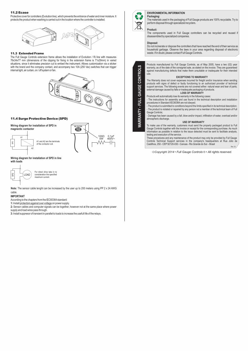
IMPORTANTAccording to the chapters from the IEC60364 standard:1: Install protectors against over voltage on power supply.2: Sensor cables and computer signals can be together, however not at the same place where power supply and load wires pass through.3: Install suppresor of transient in parallel to loads to increase the usefull life of the relays.
Note: The sensor cable lenght can be increased by the user up to 200 meters using PP 2 x 24 AWG
cable.
Wiring diagram for installation of SPD in magnectic contactor
SP
D
A1
A2
A1 and A2 are the terminalsof the contactor coil.
Wiring diagram for installation of SPD in line with loads
LOADSP
D
For direct drive take in toconsideration the specifiedmaximum current.
11.4 Surge Protective Device (SPD)
RC FILTER
ENVIRONMENTAL INFORMATIONPackaging:The materials used in the packaging of Full Gauge products are 100% recyclable. Try to perform disposal through specialized recyclers.
Product:The components used in Full Gauge controllers can be recycled and reused if disassembled by specialized companies.
Disposal:Do not incinerate or dispose the controllers that have reached the end of their service as household garbage. Observe the laws in your area regarding disposal of electronic waste. If in doubt, please contact Full Gauge Controls.
WA
RR
AN
TY -
FULL
GA
UG
E C
ON
TRO
LS
Products manufactured by Full Gauge Controls, as of May 2005, have a two (02) year warranty, as of the date of the consigned sale, as stated on the invoice. They are guaranteed against manufacturing defects that make them unsuitable or inadequate for their intended use.
EXCEPTIONS TO WARRANTYThe Warranty does not cover expenses incurred for freight and/or insurance when sending products with signs of defect or faulty functioning to an authorized provider of technical support services. The following events are not covered either: natural wear and tear of parts; external damage caused by falls or inadequate packaging of products.
LOSS OF WARRANTYProducts will automatically lose its warranty in the following cases:- The instructions for assembly and use found in the technical description and installation procedures in Standard IEC60364 are not obeyed;- The product is submitted to conditions beyond the limits specified in its technical description;- The product is violated or repaired by any person not a member of the technical team of Full Gauge Controls;- Damage has been caused by a fall, blow and/or impact, infiltration of water, overload and/or atmospheric discharge.
USE OF WARRANTYTo make use of the warranty, customers must send the properly packaged product to Full Gauge Controls together with the invoice or receipt for the corresponding purchase. As much information as possible in relation to the issue detected must be sent to facilitate analysis, testing and execution of the service.These procedures and any maintenance of the product may only be provided by Full Gauge Controls Technical Support services in the company's headquarters at Rua Júlio de Castilhos, 250 - CEP 92120-030 - Canoas - Rio Grande do Sul – Brasil
Rev. 03
11.2 EcaseProtective cover for controllers (Evolution line), which prevents the entrance of water and inner moisture. Itprotects the product when washing is carried out in the location where the controller is installed.
11.3 Extended FrameThe Full Gauge Controls extension frame allows the installation of Evolution / Ri line with measures 76x34x77 mm (dimensions of the clipping for fixing in the extension frame is 71x29mm) in varied situations, since it eliminates precision cut to embed the instrument. Allows customization via a sticker with the brand and the company contact, and accompany two 10A (250 Vac) switches that can trigger internal light, air curtain, on / off system or fan.
Copyright 2014