Welding Chrome-Moly Steels
128
PUBLISHED BY THE AMERICAN WELDING SOCIETY TO ADVANCE THE SCIENCE, TECHNOLOGY AND APPLICATION OF WELDING AND ALLIED JOINING AND CUTTING PROCESSES, INCLUDING BRAZING, SOLDERING, AND THERMAL SPRAYING WELDING JOURNAL • VOLUME 86 NUMBER 8 • AUGUST 2007 August 2007 •Welding Chrome-Moly Steels •Tooling and Equipment for Job Shops •Welding Chrome-Moly Steels •Tooling and Equipment for Job Shops
-
Upload
khangminh22 -
Category
Documents
-
view
1 -
download
0
Transcript of Welding Chrome-Moly Steels

PUBLISHED BY THE AMERICAN WELDING SOCIETY TO ADVANCE THE SCIENCE, TECHNOLOGY AND APPLICATION OF WELDINGAND ALLIED JOINING AND CUTTING PROCESSES, INCLUDING BRAZING, SOLDERING, AND THERMAL SPRAYING
WE
LD
ING
JOU
RN
AL
• VO
LU
ME
86 NU
MB
ER
8 • AU
GU
ST
2007
August 2007
•Welding Chrome-Moly Steels
•Tooling and Equipment for Job Shops
•Welding Chrome-Moly Steels
•Tooling and Equipment for Job Shops
August 07 Cover 1:4/06 Cover 7/12/07 1:31 PM Page C1

For Info go to www.aws.org/ad-index
SELECT ARC:FP_TEMP 7/6/07 2:29 PM Page C2

For Info go to www.aws.org/ad-index
NATIONAL STANDARD:FP_TEMP 7/6/07 2:28 PM Page 1

For Info go to www.aws.org/ad-index
CM INDUSTRIES:FP_TEMP 7/9/07 7:57 AM Page 2

CONTENTS24 Company Takes Its Shop to the Utah Wilderness
Job shop specializes in field welding operationsHoward M. Woodward
29 P91 and BeyondProperties of creep strength-enhanced ferritic steels and advancedchromium-molybdenum steels used for high-temperature servicewere examinedK. K. Coleman and W. F. Newell Jr.
34 Modular Fixturing Helps Fab Shop Maintain Tight TolerancesFixturing equipment helps a Massachusetts fab shop produce large-sized, yet precisely manufactured, components
38 Tips for GTA Welding 4130 Chrome-Moly Steel TubingThese suggestions will help you perform better gas tungsten arcwelds on this strong, yet malleable, steelJ. Fulcer and J. Fogle
Welding Journal (ISSN 0043-2296) is publishedmonthly by the American Welding Society for$120.00 per year in the United States and posses-sions, $160 per year in foreign countries: $7.50 persingle issue for AWS members and $10.00 per sin-gle issue for nonmembers. American Welding So-ciety is located at 550 NW LeJeune Rd., Miami, FL33126-5671; telephone (305) 443-9353. Periodi-cals postage paid in Miami, Fla., and additional mail-ing offices. POSTMASTER: Send address changesto Welding Journal, 550 NW LeJeune Rd., Miami,FL 33126-5671.
Readers of Welding Journal may make copies of ar-ticles for personal, archival, educational or researchpurposes, and which are not for sale or resale. Per-mission is granted to quote from articles, providedcustomary acknowledgment of authors andsources is made. Starred (*) items excluded fromcopyright.
Departments
Washington Watchword ..........4
Press Time News ..................6
Editorial ............................8
News of the Industry ............10
Brazing Q&A ......................14
Aluminum Q & A ................16
New Products ....................18
Welding Workbook ..............44
Coming Events....................46
Society News ....................51
Tech Topics ......................52
Guide to AWS Services..........69
New Literature....................74
Personnel ........................78
Classifieds ........................81
Advertiser Index..................84
211-s Computational Kinetics Simulation of the Dissolution and Coarsening in the HAZ during Laser Welding of 6061-T6 Al-AlloyResults showed it is possible to simulate the microstructureevolution and hardness in the HAZ of heat-treatable aluminumlaser beam weldsA. D. Zervaki et al.
222-s The Influence of Oxygen on the Nitrogen Content of Autogenous Stainless Steel Arc WeldsThe presence of oxygen in the shielding gas was shown toincrease the weld metal nitrogen content, stabilize the arc, suppress degassing, and curb porosityM. du Toit et al.
231-s Double-Electrode GMAW Process and ControlA novel welding process adds a GTAW torch to a conventionalGMAW system to create a bypass arc for increased melting current and a controlled base currentK. H. Li et al.
238-s A Look at the Optimization of Robot Welding Speed Basedon Process ModelingAn algorithm was designed to maintain complete joint penetration while maximizing productivity by using the fastest weld speedM. Ericsson et al.
245-s Repair Techniques for Fusion Reactor ApplicationsMeasurements were made of the effects of helium on the weldability of Types 304 and 316LN stainless steelsM. H. Tosten et al.
Features
Welding Research Supplement
24
34
38
3WELDING JOURNAL
August 2007 • Volume 86 • Number 8 AWS Web site www.aws.org
August 07 TOC:TOC 4/06 Layout 7/10/07 10:42 AM Page 3

First Hexavalent Chromium ExposureCitations Issued
The U.S. Occupational Safety and Health Administration(OSHA) has reported that so far in 2007 it has issued more than60 citations for violations of the new hexavalent chromium stan-dard for general industry and construction. While OSHA is notpresently specifically focusing on policing violations of the hexa-valent chromium standard, violations are being found in thecourse of normal OSHA inspections. The monitoring require-ments of the standard apparently are the most common viola-tions to date.
The hexavalent chromium standard became effective Novem-ber 2006 for large employers and May 30, 2007, for smaller em-ployers (defined as those with less than 20 employees).
In a related development, OSHA has settled outstanding liti-gation regarding the standard, and as part of that settlement hasissued a letter of interpretation that addresses specific questionsregarding the standard. This letter is available athttp://www.osha.gov/pls/oshaweb/owadisp.show_document?p_table=INTERPRETATIONS&p_id=25716.
H-1B Reform a Victim of Failed Immigration Bill
Among the collateral damage caused by the failure of the com-prehensive immigration reform legislation, which died in the U.S.Senate in June, is an initiative to reform the H-1B visa programfor highly skilled workers. Under the immigration bill, the an-nual H-1B cap of 85,000 visas would have been increased to asmany as 185,000.
But reform efforts are continuing. Already several stand-alonebills have been introduced to address the H-1B visa issue, mostof which actually are more expansive than the provisions thatwere contained in the immigration legislation, as those had beenmodified as part of compromise efforts undertaken to secure suf-ficient support.
Report Confirms Urgency of R&D Tax Credit
The research and development tax credit has never been apermanent provision of the federal tax code. It has been extendedtwelve times since its initial enactment in 1981 and is currentlyscheduled to expire at the end of 2007. The business communitycontinues to urge Congress to take timely action, and a new re-port by the Congressional Research Service (CRS) confirms theimportance of this tax credit to the U.S. economy.
According to the CRS report “Research Tax Credit: CurrentStatus and Selective Issues for Congress,” issued earlier this year,research and development, which is the “lifeblood of innovation”and therefore “a major driving force behind long-term economicgrowth,” is undertaken to a large degree by privately owned firms.However, because these firms generally cannot recapture all thereturns to their R&D investments, they are inclined to spend lesson R&D than its economic benefits would warrant. The tax credit,therefore, is vital to negate this natural inclination and thereforeincrease R&D investment. In other words, according to this CRSreport, the tax credit is not simply a tax break for businesses forsomething they would otherwise engage in; it actually encour-
ages and increases the amount of R&D investment undertakenby private business, which is vital to the U.S. economy.
Competitiveness Legislation Set to Become Law
Congress is close to passing the America Competes Act (S.761), which is designed to support U.S. competitiveness, and inparticular is a response to reports by the National Academy ofScience and the Council on Competitiveness concluding that ur-gent legislative action is necessary in this area.
This legislation will, among other things, significantly increasefunding for the National Science Foundation, the Departmentof Energy’s Office of Science, and the National Institute of Stan-dards and Technology. It will also strengthen educational oppor-tunities in science, technology, engineering, and math throughsuch measures as building training and education programs formath and science teachers and establishing more statewide spe-cialty schools in math and science.
Patent Reform Legislation SparksControversy
While there is broad agreement that the U.S. patent systemis flawed — the current application backlog is almost 800,000,the average time for approval is approaching three years, andpatent litigation is rampant — battle lines are being drawn overexactly how to fix these problems. At the center of the contro-versy is the Patent Reform Act of 2007, which is slowly but steadilymoving through Congress. This legislation would
• Give patent priority to whoever first files a patent applica-tion, as opposed to the first inventor. This is intended to pro-vide clarity and avoid litigation;• Expand the ability to challenge a patent through the Patentand Trademark Office after the patent has been granted, ratherthan having to file suit in a federal court;• Limit damage recoveries in patent infringement cases to theeconomic value of the invention itself, not the full value ofoverall product in which the invention is used; and• Increase the burden of proof for allegations of willful in-fringement.The primary supporters of the Patent Reform Act are large
corporations, many in the computer and IT sector. Many smallbusiness interests and independent inventors, however, have linedup in opposition, claiming that these reforms, while beneficial insome respects, favor these large corporations over their smallbusiness competitors. For example, replacing the “first to invent”rule with a “first to file” rule will, according to opponents, be tothe advantage of companies with large staffs of engineers and at-torneys. Similarly, expanding the ability to administratively chal-lenge a patent may result in many more challenges and thereforeraise the cost of defending patents, to the disadvantage of smallerfirms. Supporters counter that reform of the U.S. patent systemis long overdue and will assist all inventors, particularly in com-peting in foreign markets. ♦
WASHINGTONWATCHWORD
AUGUST 20074
BY HUGH K. WEBSTERAWS WASHINGTON GOVERNMENT AFFAIRS OFFICE
Contact the AWS Washington Government Affairs Office at 1747 Pennsylvania Ave. NW, Washington, DC 20006; e-mail [email protected]; FAX (202) 835-0243.
Washington August 2007 corr:Layout 1 7/11/07 1:18 PM Page 4

For Info go to www.aws.org/ad-index
MILLER ELECTRIC:FP_TEMP 7/6/07 2:28 PM Page 5

PRESS TIMENEWS
North American Robot Orders Jump 24% in First Quarterof 2007
North American robotics companies posted gains of 24% in new orders in the firstquarter, according to statistics recently released by Robotic Industries Association (RIA),Ann Arbor, Mich.
A total of 4603 robots valued at $274.5 million were sold to North American manu-facturing firms through March. When sales to companies outside North America are in-cluded, the totals are 5027 robots valued at $293.9 million, a gain of 26% in units and3% in revenue.
Donald A. Vincent, RIA’s executive vice president, explained that one of the driversin the first-quarter growth was a pickup in orders placed by automotive manufacturingcompanies and their suppliers.
In addition, from an applications standpoint, the first quarter saw growth in ordersfor robots that perform spot welding, arc welding, coating/dispensing, and material han-dling applications.
Auburn Engineering Adds Linear Vibration Welding Capabilities
Auburn Engineering, Inc., Rochester Hills, Mich., has added linear vibration weld-ing capabilities to its prototype development services. Linear vibration welding is a fric-tional application between two or more plastic parts that is capable of creating strong,airtight welds in thermoplastic parts.
The company is capable of using its existing CNC tooling resources to build customvibration fixtures in-house. This capability to create parts, and vibration welding with-out third-party outsourcing yields faster lead times and reduced fixture costs.
Auburn’s linear vibration welding unit has a 15-hp digital vibrator, for precise con-trol of amplitude, from 0.040 to 0.070 in. in increments of 0.001 in. This drive also sup-ports an 80-lb top tool weight capacity and a part size of 48 × 20 in.
Barnes Group to Open New Manufacturing Facility
Barnes Aerospace, a business segment of Barnes Group Inc., Bristol, Conn., recentlyannounced the expansion of its large fabrication operations in Ogden, Utah. It plans toopen a new 120,000-sq-ft manufacturing facility to produce precision aerospace compo-nents for use in a wide range of aircraft engine and airframe applications.
The facility will accommodate growth in the business, future opportunities, and long-term contracts with customers. Construction is scheduled for completion in the firstquarter of next year.
Airgas Acquires Lehner & Martin
Airgas, Inc., Radnor, Pa., has acquired Lehner & Martin, Inc. (L&M), a Santa Ana,Calif.-based industrial gas and welding supply distributor with branches in Placentia,Gardena, and Chino, Calif. The acquired company generated sales of more than $13million in the fiscal year ended March 31, 2007.
The operations have been integrated into Airgas West. L&M, founded by Ken Lehnerin 1975, is currently managed by his son, Mark Lehner, who will join Airgas West as anarea vice president.
Thermadyne Holdings Corp. Sells Maxweld & Braze and Unique Welding Alloys to Destiny Corp.
Thermadyne Holdings Corp. has sold its Maxweld & Braze Pty, Ltd., and UniqueWelding Alloys businesses to Destiny Corp. The two South Africa-based businesses sup-ply welding equipment and consumables, safety items and related products to distribu-tors, resellers, and large industrial and construction companies in South Africa and theentire African continent.
Goldsmith Agio Helms in cooperation with its South African partner-bank, RandMerchant Bank, acted as financial advisor to the company on the sale of the businesses.
AUGUST 20076
MEMBER
Publisher Andrew Cullison
Publisher Emeritus Jeff Weber
EditorialEditor/Editorial Director Andrew Cullison
Senior Editor Mary Ruth JohnsenAssociate Editor Howard M. Woodward
Assistant Editor Kristin CampbellPeer Review Coordinator Erin Adams
Graphics and Production Managing Editor Zaida Chavez
Senior Production Coordinator Brenda Flores
AdvertisingNational Sales Director Rob Saltzstein
Advertising Sales Representative Lea Garrigan BadwyAdvertising Production Manager Frank Wilson
American Welding Society550 NW LeJeune Rd., Miami, FL 33126
(305) 443-9353 or (800) 443-9353
Publications, Expositions, Marketing CommitteeD. L. Doench, ChairHobart Brothers Co.
T. A. Barry, Vice ChairMiller Electric Mfg. Co.J. D. Weber, Secretary
American Welding SocietyR. L. Arn, WELDtech International
S. Bartholomew, ESAB Welding & Cutting Prod.J. Deckrow, Hypertherm
J. R. Franklin, Sellstrom Mfg. Co.J. Horvath, Thermadyne Industries
D. Levin, AirgasJ. Mueller, Thermadyne Industries
R. G. Pali, J. P. Nissen Co.J. F. Saenger Jr., ConsultantS. Smith, Weld-Aid ProductsD. Wilson, Wilson Industries
H. Castner, Ex Off., Edison Welding InstituteD. C. Klingman, Ex Off., The Lincoln Electric Co.
L. G. Kvidahl, Ex Off., Northrup Grumman Ship SystemsE. C. Lipphardt, Ex Off., Consultant
S. Liu, Ex Off., Colorado School of MinesV. Y. Matthews, Ex Off., The Lincoln Electric Co.R. W. Shook, Ex Off., American Welding SocietyG. D. Uttrachi, Ex Off., WA Technology, LLC
Copyright © 2007 by American Welding Society in both printed and elec-tronic formats. The Society is not responsible for any statement made oropinion expressed herein. Data and information developed by the authorsof specific articles are for informational purposes only and are not in-tended for use without independent, substantiating investigation on thepart of potential users.
Press Time News corr:Layout 1 7/10/07 1:44 PM Page 6

For Info go to www.aws.org/ad-indexSEE US AT THE FABTECH/AWS SHOW BOOTH 6047
ESAB 1:FP_TEMP 7/6/07 2:25 PM Page 7

EDITORIAL
My husband, Terry, says we don’t make anything any more. By “we,” he means theUnited States, and what he’s implying is that the United States no longer manufacturesmuch of anything. Terry knows, of course, that his statement isn’t really correct. Duringthe 18 years I’ve worked on the Welding Journal staff, I’ve visited many types of manu-facturers, and I’ve regaled him with stories on how they use welding to make jewelry,farm equipment, rail cars, wheels, aerospace components, and pressure vessels, just toname a few. Despite that, his impression is that we’re no longer a manufacturing power,and he’s not alone in his thinking.
I believe I know where that idea originates. He’s thinking about so many of our every-day consumer items, especially electronics such as televisions, computers, and cellphones, which for the most part are not manufactured in the United States. He’s look-ing at the labels on his clothing, which indicate they’ve mostly been sewn by someone ina Third World country. And, of course, he’s heard and read all the gloom and doomreports on television and in the newspapers about problems in the U.S. auto industry, aswell as the stories saying we’ve changed from a manufacturing economy to a serviceeconomy.
Now I’m not going to claim that manufacturing hasn’t changed in the United States.Of course, it has. But the truth is, we’re still an industrial powerhouse. Even though theU.S. auto industry may not be what it once was, the Big Three is still making — and sell-ing — a tremendous number of vehicles. The economy is strong; therefore, many U.S.manufacturers are doing well. And it’s a great time to be a welder in the United Statesbecause plenty of jobs are available.
Yet somehow industry does a poor job of promoting itself, and that needs to change.Even when manufacturers try, they often fall short. Do you remember those commercialsthat ran on television a couple of years ago, the ones that went something like this: “Wedon’t make the surfboard, we make it ride better on the water, and we don’t make thepaint, we make it go on the wall more smoothly.” I used to watch those and then askmyself, “So what do they make?” And the second question I asked myself was, “If theydon’t sell to consumers, why are they bothering to advertise on television?” The adsnever mentioned what the company actually produced. In fact, I didn’t find out until Isat down to write this editorial and looked the company up on the Internet. It turns outit’s a chemical company. Now maybe I’m more ill informed than some people, or maybeeven a little dense about some things, but I figure if I didn’t know what that companymade, then there probably were other folks out there who didn’t know either. Therefore,the ads had missed their point and that money was wasted.
So what’s to be done? I wish I had all the answers. I don’t, but I can think of a few.First of all, prominently display where your products are produced on your packagingand promotional materials. Participate as individuals and as manufacturers in profes-sional and business organizations such as the American Welding Society, ASNT,Fabricators and Manufacturers Association, and National Association of Manufacturers.They are your industry advocates, and common sense tells me that by banding togetheryou can make a greater impact than you can by working alone. Spend some money on
public relations. Believe it or not, the various branch-es of the media are interested in success stories. Givethem some to report.
AUGUST 20078
Founded in 1919 to Advance the Science,Technology and Application of Welding
Fill Your Shopping Basket inthe U.S. Aisle
Mary Ruth JohnsenSenior Editor, Welding Journal
OfficersPresident Gerald D. Uttrachi
WA Technology, LLC
Vice President Gene E. LawsonESAB Welding & Cutting Products
Vice President Victor Y. MatthewsThe Lincoln Electric Co.
Vice President John C. BruskotterBruskotter Consulting Services
Treasurer Earl C. LipphardtConsultant
Executive Director Ray W. ShookAmerican Welding Society
DirectorsB. P. Albrecht (At Large), Miller Electric Mfg. Co.
O. Al-Erhayem (At Large), JOM
A. J. Badeaux Sr. (Dist. 3), Charles Cty. Career & Tech. Center
H. R. Castner (At Large), Edison Welding Institute
N. A. Chapman (Dist. 6), Entergy Nuclear Northeast
N. C. Cole (At Large), NCC Engineering
J. D. Compton (Dist. 21), College of the Canyons
L. P. Connor (Dist. 5), Consultant
G. Fairbanks (Dist. 9), Gonzalez Industrial X-Ray
D. Flood (Dist. 22), Tri Tool, Inc.
J. E. Greer (Past President), Moraine Valley C. C.
M. V. Harris (Dist. 15), Reynolds Welding Supply
R. A. Harris (Dist. 10), Consultant
W. E. Honey (Dist. 8), Anchor Research Corp.
D. C. Howard (Dist. 7), Concurrent Technologies Corp.
W. A. Komlos (Dist. 20), ArcTech LLC
D. J. Kotecki (Past President), The Lincoln Electric Co.
D. Landon (Dist. 16), Vermeer Mfg. Co.
R. C. Lanier (Dist. 4), Pitt C.C.
J. L. Mendoza (Dist. 18), CPS Energy
S. P. Moran (Dist. 12), Miller Electric Mfg. Co.
R. L. Norris (Dist. 1), Merriam Graves Corp.
T. C. Parker (Dist. 14), Miller Electric Mfg. Co.
W. R. Polanin (Dist. 13), Illinois Central College
O. P. Reich (Dist. 17), Texas State Technical College at Waco
W. A. Rice (At Large), OKI Bering, Inc.
E. Siradakis (Dist. 11), Airgas Great Lakes
N. S. Shannon (Dist. 19), Carlson Testing of Portland
K. R. Stockton (Dist. 2), PSE&G, Maplewood Testing Serv.
D. R. Wilson (At Large), Wilson Industries
Editorial corr:Layout 1 7/10/07 1:47 PM Page 8

For Info go to www.aws.org/ad-index
GEDIK:FP_TEMP 7/6/07 2:26 PM Page 9

NEWS OF THEINDUSTRY
Team Ares Reaches Key Milestones
As part of their Ares I Upper Stage production proposal, Al-liant Techsystems, Lockheed Martin, and Pratt & Whitney Rock-etdyne, Inc., the three core companies that make up Team Ares,have been utilizing internal company funds that will help NASAmitigate the development risk for its future fleet of explorationlaunch vehicles.
In particular, Lockheed Martin is leveraging its experience indesigning and manufacturing high-performance, lightweightaerostructures to fabricate a demonstration article of the com-mon bulkhead dome that separates the fuel and oxidizer com-partments of the propellant tank. The demonstration utilizesprocesses such as friction stir welding of thin gauge alloys, phased-array ultrasonic inspection of weldments, and shearography in-spection of honeycomb bonds to face-sheets. The company’s Mi-choud Operations is leading this activity in New Orleans.
Welding Scholarship to Aid Monroe Career& Technical Institute Students
When welding instructor Gregory J. Smith from the MonroeCareer & Technical Institute (MCTI) in Bartonsville, Pa., visitedthe Pennsylvania College of Technology in March 2006 for a meet-ing of the Pennsylvania Welding Educators Association, he wasimpressed by a tour of the college’s welding labs. So much, infact, that he decided to do something substantial to encourage
his students to attend the college after graduating from their highschool program.
The Monroe Career & Technical Institute Welding Scholar-ship will provide an annual award of $500 to a graduate of theschool’s welding program who enrolls as a full-time student inPenn College’s welding and fabrication engineering technologybachelor degree major, the welding technology associate degreemajor, or the welding certificate major.
Additionally, Smith said the scholarship honors the memoryof one of his students, Jason E. Ammon Honey, who died in acollision with a drunken driver in January 2006. Ammon Honeywas a junior at MCTI and Pleasant Valley High School, and heworked part time at his father’s welding business in Kunkletownat the time of his death.
California Steel Industries to Produce MoreCarbon Steel Flat Rolled Sheet, Pipe
California Steel Industries, Inc., Fontana, Calif., plans to in-crease total annual production capacity by a million tons, throughaddition of a second reheat furnace with environmental technology.
In addition to the clean-burning, natural gas-fired walkingbeam reheat furnace, the investment includes associated addi-tional improvements in cooling water treatment and in slab han-dling facilities, for a total capital investment of approximately$60 million.
AUGUST 200710
Students Compete in Five Categories at State Secondary Welding Competition
On May 4, the Welding Engineering Technology Departmentat Ferris State University, Big Rapids, Mich., hosted the 2007State Secondary Welding Competition. Students competed infive welding categories for more than $30,000 in scholarships,prizes, and awards. This fifth annual event drew 103 competi-tors from 26 educational institutions.
The combined welding winners were as follows: Chris Szeszul-ski, first place; Steven Fitzgerald, second place; Mike Concessi,third place; and Joe Klocke, honorable mention.
In the gas metal arc welding category, Kalvin Myers took firstplace; Jason Townsend took second place; Matt Krokstrom tookthird place; and Jeremy Knickerbocker took honorable mention.
With gas tungsten arc welding, the winners were Chad Mier,first place; Preston Graham, second place; Rick Hovey, thirdplace; and Devon DeFranceso, honorable mention.
For oxyfuel welding, John Estepp earned first place; ZekeChambers second place; Ryan Inman third place; and AaronSova honorable mention.
With shielded metal arc welding, Daniel Hammer won firstplace; Dalton Dougherty won second place; Jeremy Lowell wonthird place; and Phil King won honorable mention.
The winners came from the following schools: Bay Arenac SkillCenter, Mecosta-Osceola CC, Flat Rock High School, LapeerCounty TC, Alma High School, Dickinson-Irons TC, Calhoun AreaTC, Newaygo County TC, Oakland TC SW, William D. Ford TC,Traverse Bay CTC, and Cheboygan High School.
The 6th Annual State Secondary Welding Competition isscheduled for May 9, 2008.
At the 2007 State Secondary Welding Competition, hosted by Fer-ris State University’s Welding Engineering Technology Department,students competed for more than $30,000 in scholarships, prizes,and awards. Shown above, from left, are gas tungsten arc weldingwinners Chad Mier (first place), Preston Graham (second place),Rick Hovey (third place), and Devon DeFranceso (honorable mention).
NI August 2007:Layout 1 7/9/07 3:03 PM Page 10

11WELDING JOURNAL
The company now ships an average of approximately 2 mil-lion tons per year of carbon steel flat rolled sheet and pipe. Withthe proposed changes, it will have the capability and flexibility toproduce up to 3 million tons per year.
MG Systems & Welding Breaks Ground on New Addition
On April 30, MG Systems & Welding, Inc., Menomonee Falls, Wis.,broke ground on a two-story addition to expand the area for itsService and Accounting Departments. In the picture (from left) arecompany employees John Laskowski, Ron Schneider, Gary Norville,Gary Wierzbinski, Carl Lock, and Bill Hendren. The addition en-compasses 4334 sq ft of space. The main goal is to allow space forthe growing service area. Also, the larger space allows for theplanned growth in the Service Department and locates it near theEngineering and Applications Departments for better coordinationof customer services. Construction is expected to last until late Au-gust. The Service and Accounting Departments are expected tomove into the addition in mid to late September.
KUKA Selected to Supply Robotics forNegri BossiAutomation Division
KUKA Robotics Corp., Clinton Township, Mich., has recently beenselected by Negri Bossi Inc., Mississauga, Ont., Canada, to providefloor- and shelf-mounted robots for its injection molding systems.The robots will be utilized in the company’s systems being manu-factured by Negri Bossi’s new automation division that offers cus-tomers single-source automation solutions from design concept andquotation to installation, training, and hands-on troubleshooting. For info go to www.aws.org/ad-index
NI August 2007:Layout 1 7/9/07 3:04 PM Page 11

Babcock Power Opens Cladding Service Center
Babcock Power Services Inc. (BPS), Worcester, Mass., a sub-sidiary of Babcock Power Inc., Danvers, Mass., has opened a newservice center in Duncan, S.C. Cladding Technology, a divisionof BPS, will occupy the facility, allowing it to meet the power gen-eration market’s growing demand for its patented weld claddingprocess.
A specialized welding group, Cladding Technology deals withthe weld cladding process commonly referred to as hardfacing.This process consists of the application of hard metals to sur-faces that are subject to high wear. Cladding Technology devel-oped a patented resurfacing process that utilizes a tungsten car-bide matrix applied to the high wear areas as well.
Industry Notes• ThyssenKrupp, Troy, Mich., has selected Alabama as the home
for its new steel and stainless steel processing facility. A coop-erative effort between ThyssenKrupp Steel and ThyssenKruppStainless, the facility will be located in Northern Mobile andSouthern Washington counties. Initially planned as a $2.9 bil-lion investment, the company will now invest $3.7 billion inthis facility. The plant complex is scheduled to begin opera-tions in 2010. Approximately 29,000 jobs will be generated dur-ing the construction phase. When it is fully operational, theplant will employ 2700 people.
• Lucas-Milhaupt, Inc., a Handy & Harman Co., Milwaukee,
Wis., is offering refining services to its customers. Recoveryservices are being provided through Handy & Harman ofCanada, Ltd., at its facility in Toronto, Ont. Materials acceptedinclude silver-based metallic scrap such as brazing alloys, mir-ror plating sludge, fuse link scrap, and other copper/silver ma-terials. The scrap-to-cash recovery program offers businessesan environmentally responsible and cost saving alternative; forexample, a large industrial manufacturer that used to pay tohave braze scrap removed as a hazardous material can now re-ceive payment for the recovered precious metal. For more in-formation, visit www.scraptofastcash.com.
• KNUTH Machine Tools USA has moved to a new location.The facility is located in Lincolnshire, Ill., and has allowed forthe consolidation of three buildings into a single 60,000-sq-ftfacility. The larger premises house more than $8 million of ma-chine tools inventory and allow room for future expansion.
• As of May 2007, the American Torch Tip Co., Bradenton, Fla.,has purchased Precision Products Co., Canaan, N.H. The ac-quired company specializes in manufacturing plasma torchesand consumables used primarily in the metal fabricating indus-try. The acquisition will give American Torch Tip Co. an ex-panded product line and increased manufacturing capability.
• At its annual Small Business Excellence Awards Luncheon onMay 23, the Cincinnati USA Regional Chamber honoredWright Brothers, Inc., a national provider of specialty gases tothe bioscience, research, leisure, and manufacturing industries,as the region’s best small enterprises. In front of a 700-personcrowd representing the Cincinnati community, CEO Charlie
AUGUST 200712
For info go to www.aws.org/ad-index
NI August 2007:Layout 1 7/9/07 3:04 PM Page 12

Wright was presented with the honor for his company’s busi-ness achievements, management, innovations in product, serv-ice, technology, and community service.
• MISTRAS Group Inc., Princeton Junction, N.J., recently an-nounced CONAM Inspection & Engineering Services has re-ceived accreditation by the Nadcap (National Aerospace &Defense Contractors Accreditation Program) NondestructiveTesting Task Group after the completion of an audit at itsHeath, Ohio, facility. The requirements of the Nadcap auditprocess entitles CONAM to be listed in the Nadcap QualifiedManufacturers List and is valid until January 31, 2009.
• AK Steel, Middletown, Ohio, recently announced the Colum-bus, Ind., plant of its wholly owned subsidiary AK Tube LLChad received the “Safety Award of Merit” from the Fabrica-tors & Manufacturers Association, International for its 2006safety performance. According to the company, the Columbusplant’s illness and injury incidence rate of 1.48 last year wasmore than five times better than the pipe and tube industry av-erage rate of 8.3, as published by the U.S. Bureau of LaborStatistics.
• Dynamic Materials Corp. (DMC), Boulder, Colo., a providerof explosion-welded clad metal plates, has ranked eighth onBusiness Week’s Annual List of “100 Hot Growth Companies.”DMC advanced from a 51st-place ranking on last year’s list.
• The Permasteel Group, a building construction firm headquar-tered in Vancouver, B.C., Canada, has been named Builder ofthe Year by VP Buildings, a large manufacturer of preengi-
neered metal buildings. During a banquet held in honor of theoccasion on May 15, officials from VP Buildings presented theaward to Norm Elliott, a senior partner with the PermasteelGroup of companies. In addition, Permasteel’s constructionof the Word of Life Tabernacle in Sherwood Park, A.B., wasthe first-place winner in the church category while the new TICCanada Ltd. facility in Edmonton, A.B., won top honors in themanufacturing category. The largest project award for 2006went to Permasteel, Vancouver, for the new Athabasca Ori-ented Strand Board plant currently under construction forTolko Industries Ltd. in Slave Lake, Alb.
• Northwest Pipe Co., Portland, Ore., has been named as pipesupplier by John D. Stephens of Lawrenceville, Ga., for a watertransmission pipeline for Gwinnett County Department of Pub-lic Utilities. Approximately 25,000 feet of steel pipe valued atapproximately $7.5 million will be supplied by the companyfor an engineered and custom fabricated piping system. Thepipe is expected to be manufactured in the company’s Park-ersburg, W.Va., division with delivery scheduled to begin in thethird quarter of this year.
• 3M, St. Paul, Minn., has acquired Diamond Productions Inc.(DPI), Wayne, N.J., a manufacturer of superabrasive diamondand cubic boron nitride wheels and tools for dimensioning andfinishing hard-to-grind materials in metalworking, woodwork-ing, and stone fabrication markets. Terms of the transactionwere not disclosed. DPI brings industrial metalworkingstrengths as well as new applications for stone processing tothe company’s offering of grinding and finishing tools for theindustrial and commercial markets.
13WELDING JOURNAL
For info go to www.aws.org/ad-index
NI August 2007:Layout 1 7/9/07 3:05 PM Page 13

BRAZINGQ&A BY R. L. PEASLEE
Q: We are experiencing undercutting anderosion when brazing base metal 600,UNS N06600, with BNi-2 brazing fillermetal at 1066°C (1950°F). We are brazinga 0.8-mm- (0.031-in.-) wall tubing 25.4mm (1 in.) in diameter into a heavy fit-ting. The brazing filler metal, in pasteform, is applied around the tube at thejoint to be brazed. The assemblies aretaken directly to the brazing tempera-ture. After brazing, we find that the tubehas eroded, leaving a thinned tube wall,and sometimes a hole in the tubing. Whatcan we do?
A: Erosion and undercutting are control-lable and should not occur. If they dooccur, the brazing engineer probably doesnot have a good understanding of thebrazing filler metals and process. Manysuccessful brazements are made every daywith brazing filler metals that have mutu-al solubility with the base metal.
Any brazing filler metal that has mutu-al solubility with a base metal at the braz-ing temperature can alloy with the basemetal, and in so doing, dissolves some ofthe base metal to form a modified brazing
filler metal to some degree or another. Insome cases, the alloying effect improvesthe properties of the brazing filler metalin the alloyed area. Sometimes, it mayhave no effect, and at other times maychange the filler metal properties.
Braze erosion and undercutting aregenerally caused when an excessiveamount of brazing filler metal is applied.In particular, when the brazing fillermetal and the base metal are mutuallysoluble in each other. Erosion and under-cutting can result when aluminum isbrazed with an AlSi brazing filler metal,copper is brazed with a AgCu filler metal,or a nickel-based metal is brazed with aNiCrB filler metal, whenever an excessiveamount of brazing filler metal is present,and all have mutual solubility. Whenbrazing an iron-based metal with a cop-per filler metal, there isn’t a problem witherosion because there is extremely smallsolubility of copper in iron at the brazingtemperature.
Nicrobraz 130, and other nickel braz-ing filler metals that contain boron, areprone to cause erosion and undercutting.Boron is a small molecule and is the melt-
ing-point depressant. It is very mobile,and therefore moves into many base met-als with ease, which can result in somemelting of the base metal. Nicrobraz 30has silicon, a much larger molecule, as themelting-point depressant. Silicon is notvery mobile and therefore has less ten-dency to erode, but it can cause erosion, ifnot properly controlled.
In the case you presented, there is afar different erosion problem. Brazing aheavy fitting and a fairly thin tube is caus-ing part of your problem. When theassembly is heated, the heavy fitting takesa longer time to reach the brazing tem-perature. Meanwhile, the thin tube andthe brazing filler metal have alreadyreached the brazing temperature. Themolten brazing filler metal would like toflow into the joint by capillary action, butsince the heavy fitting is still far below thebrazing temperature, the molten brazingfiller metal remains at the hot tube wall.
The 600 base metal is primarily nickel.The BNi-2 brazing filler metal is also pri-marily nickel, and its boron melting pointdepressant will allow it to readily diffuseinto the 600 base metal, resulting in thesurface melting. The liquid portion of the600 base metal will then become a part ofthe brazing filler metal.
When the heavy fitting reaches thebrazing temperature, the BNi-2 brazingfiller metal and the dissolved 600 basemetal will suddenly flow into the joint andmake a fillet at the joint area. When thelarge amount of new filler metal flowsinto the joint, it leaves the eroded thinnedwall of the tube visible.
To prevent this type of erosion fromoccurring, the heating portion of thebrazing cycle should be modified to add ahold at 927°C (1700°F), long enough toallow the heavy fitting to reach the holdtemperature before increasing to thebrazing temperature. Then, when thebrazing filler metal melts, it will flowdirectly into the brazed joint and not havetime to diffuse into the tube and causeerosion. To determine the length of nec-essary hold time, the heavy fitting shouldbe adequately thermocoupled to signalwhen it reaches 927°C (1700°F).♦
R. L. PEASLEE is vice president emeritus, WallColmonoy Corp., Madison Heights, Mich.Readers may send questions to Mr. Peaslee c/o Welding Journal, 550 NW LeJeune Rd., Miami, FL 33126 or via e-mail [email protected].
AUGUST 200714
Stainless, Nickel,Aluminum, and
Low Alloy WeldingConsumables
• Consistent High
Quality Products
• Technical Support
In stock: St. Louis or Houston
1.800.776.3300www.midalloy.com
For info go to www.aws.org/ad-index
Brazing Q+A AUGUST:Layout 1 7/9/07 11:19 AM Page 14

For Info go to www.aws.org/ad-index SEE US AT THE FABTECH/AWS SHOW BOOTH 5047/39059
ESAB 2:FP_TEMP 7/6/07 2:25 PM Page 7

ALUMINUMQ&A BY TONY ANDERSON
Q: In one of my processes, I have beenusing aluminum extruded tube made of6061-T6 alloy. The way these tubes areused requires the following heating andcooling profile:
a) Ramp up from room temperature25°C (77°F) to 425°C (797°F) at the rateof 10°C per min
b) Dwell at 425°C for 2 hc) Cool down to room temperature at
the rate of 1°C per min.The initial hardness of the aluminum
tube is 80 hardness Brinell (HB). Thehardness dropped to approximately 8 HBin 6 cycles of heating and stayed at ap-proximately 8 HB after 30 cycles.
My questions are as follows:1. What is the reason for this drop in
hardness and will the hardness drop further?
2. What is the phenomenon behind thehardness drop?
3. Surface roughness of the aluminumtube is critical; will the hardness drop affect surface roughness, pitting, corro-sion, etc.?
A: What is the reason for this drop in hard-
ness and will the hardness dropfurther?
First, I question the hard-ness readings, particularly thelower reading (8 HB), whichappears too low.
On examination of yourheating and cooling profile,it is not surprising that youare experiencing a substantialreduction in hardness of youraluminum tubing. The Alu-minum Association’s Alu-minum Standards and Dataprovides typical Brinell hard-ness numbers and tensilestrengths for most aluminumalloys in various strain-hard-ened and heat-treated condi-tions. ASTM B918, StandardPractice for Heat Treatment ofWrought Aluminum Alloys, provides thetimes and temperatures recommended forobtaining the various tempers of the alu-minum heat-treated conditions. After ref-erencing these documents, it was easy toconfirm that the times and temperaturesused in your heating profile are sufficient
to drastically change the material’sstrength and hardness. In fact, these timesand temperatures are adequate to reducethe material to its lowest strength andhardness, the fully annealed condition.After reviewing the data supplied andcomparing it with data provided by The
Fig. 1 — Solution heat treatment requires that the mate-rial be heated to around 990°F, followed by quenching inwater. Artificial aging or precipitation hardening as it isalso known requires that the solution heat-treated mate-rial be reheated to around 340°F for up to 18 h.
AUGUST 200716For info go to www.aws.org/ad-index
Aluminum Q and A August 2007:Layout 1 7/6/07 12:18 PM Page 16

Aluminum Association and ASTM, I canonly conclude that your testing methodmay have been flawed. The issue of inac-curate hardness test data is probably sec-ondary as the main issue is the material’sexposure to the temperature. This tem-perature will fully anneal the material. Be-cause it is in the fully annealed condition,the material will not get any lower instrength and the hardness will not dropany further.
What is the phenomenon behind thehardness drop?
To understand this phenomenon, weneed to consider the heat-treated condi-tion of the original material and the effecton this condition due to the temperatureexposure during your process.
The 6xxx series aluminum alloys areone of the heat-treatable series of alu-minum alloys. The 6061 alloy is composedof aluminum alloyed with magnesium andsilicon. When subjected to heat treatment,the magnesium and silicon produce acompound within the aluminum calledmagnesium silicide. This magnesium sili-cide is taken into solution within the ma-terial during the heat treatment used toproduce the –T6 condition. The –T6 con-dition denotes that the material has un-dergone thermal treatment in the form ofsolution heat treatment and artificialaging — Fig. 1. During the solution heattreatment part of the –T6 process, the ma-terial is heated to approximately 990°F,followed by quenching in water. The arti-ficial aging or precipitation hardening, asit is also known, requires the solutionheat-treated material to be reheated toaround 340°F for up to 18 h. This subse-quent heating facilitates a controlled pre-cipitation of the magnesium silicide, whichconsequently optimizes the material’s me-chanical properties. The solution heat-treated and artificial aged condition (–T6)of the 6061 provides a material with theguaranteed minimum ultimate tensilestrength of 42 ksi and a typical Brinellhardness number of 95.
When the 6061-T6 material is heatedin your process, it will begin to overage(lose strength) through the additional pre-cipitation of magnesium silicide. This pre-cipitation will continue during your heat-ing process, resulting in the material pro-gressively losing strength and hardness.Eventually, all the magnesium silicide willprecipitate out of solution, and the mate-rial will become fully annealed, which isthe softest condition of this material. Theannealed condition of 6061 provides a ma-terial with the guaranteed maximum ulti-mate tensile strength of 20 ksi and a typi-cal Brinell hardness number of 30. A typ-ical annealing temperature as specified byASTM B918, Standard Practice for HeatTreatment of Wrought Aluminum Alloys,for the 6061 alloy is 765°F (407°C) for 2
to 3 h. It is therefore apparent that yourprocess is subjecting the material to timeat temperature more than adequate tofully anneal its structure.
The surface roughness of the aluminumtube is critical; will the hardness drop affectsurface roughness (pitting, etc.)?
Surface roughness of the part shouldnot be significantly affected; the potentialfor (pitting) corrosion is generally im-proved in the annealed condition so thisshould not be a problem. As the surfacecondition is critical, I would suggest thatfurther testing is performed to verify theacceptability of this characteristic.◆
17WELDING JOURNAL
TONY ANDERSON is corporate technicaltraining manager for ESAB North America andcoordinates specialized training in aluminumwelding technology for AlcoTec Wire Corpora-tion. He is a Senior Member of TWI and a Reg-istered Chartered Engineer. He is chairman ofthe Aluminum Association Technical AdvisoryCommittee for Welding and holds numerous po-sitions including chairman, vice chairman, andmember of various AWS technical committees.Questions may be sent to Mr. Anderson c/o Weld-ing Journal, 550 NW LeJeune Rd., Miami, FL33126, or via e-mail at [email protected].
For info go to www.aws.org/ad-index
Aluminum Q and A August 2007:Layout 1 7/6/07 12:19 PM Page 17

Maintenance Products LineIncludes Various Brushes
The company has added several prod-ucts to its maintenance offering. The com-fort-grip hand scrub brush with polypropy-lene fill comes with a contoured handleand rubber insert to fit more comfortablyin the hand. Two scratch brushes havebeen added as well — a V-groove brushdesigned with wire that is angled to a pointto reach in tight areas that require a nar-row face and a double-sided plastic han-dle scratch brush that offers two types offill in one brush. The different fill combi-nations include brass/white nylon,brass/stainless, or stainless/white nylon. A
tube fitting brush, useful for cleaning tubeends, is available with a ¼-in. stem forquick mounting on a cordless drill.
Weiler Corp.www.weilercorp.com(800) 835-9999
Screwdriver ContainsPowerful Motor
The 6780-20 Metal Fastening, Ad-justable Clutch Screwdriver features a0–2500 rpm motor for light-gauge sheetmetal fastening and assembly work. The6.5-A motor provides 140 in./lb of maxtorque, and the tool features a 21-position adjustable clutch for maximumfastening control. The screwdriver has anergonomic grip that gives better holdingcomfort and control. It also has a steel-re-inforced clutch housing for increaseddurability and longer tool life. The screw-driver comes with a 10-ft flexible rubbercord and a belt clip. Its Quick-Action 1⁄4-
in. hex bit holder allows for fast exchangeof accessories, and the variable-speed trig-ger produces smooth, controlled starts.
Milwaukee Electric Tool Corp.www.milwaukeetool.com(800) 729-3878
Welding GeneratorAvailable withWeatherproof StainlessSteel Case
The Miller PRO 300 welding genera-tor with an optional stainless steel caseprovides protection of the unit’s motorand generator from harsh weather condi-tions and corrosive environments. Capa-ble of shielded metal arc, gas metal arc,flux cored, DC gas tungsten arc, and aircarbon arc with a welding output range of20–410 A, it offers good arc performance
NEWPRODUCTS
AUGUST 200718
Low-Alloy Flux Cored Wires Designed for Chrome-Moly ApplicationsThe company offers a full line of low-alloy gas shielded flux cored wires
for weldability, creep resistance, and high-temperature tensile strength onchrome-moly applications. The TM-81B2 and TM-811B2 wires, designed forsteels containing 11⁄4% chrome and 1⁄2% molybdenum, can be used as replace-ments for E8018-B2 covered electrodes to increase productivity. The TM-91B3 and TM-911B3 wires match the chemistry of steels with 21⁄4% chromeand 1% molybdenum and can be used to replace E9018-B3 covered electrodes.In addition, TM-81B2 and TM-91B3 are available for use in either the flat orhorizontal position and are available in 1⁄16- and 3⁄32-in. diameters. These wiresshould be used only with a 100% CO2 shielding gas. Also, TM-811B2 and TM-911B3 have all-position capabilities and are available in 0.045, 0.052, and 1⁄16
in. These wires can be used with either 100% CO2 or a 75/25 argon/CO2 mix-ture. An argon/CO2 mixture may produce welds with tensile strengths exceed-ing 100 ksi, for the TM-811B2 wire, and 110 ksi, for the TM-911B3 wire.
Hobart Brothers Co.www.hobartbrothers.com(800) 424-1543
New Products August 2007:Layout 1 7/10/07 10:07 AM Page 18

19WELDING JOURNAL
and provides 12,000 W of peak generatorpower while welding. The product is pow-ered by a 22-hp Caterpillar industrial en-gine. It uses solid stainless steel panelswith matching stainless steel nuts andbolts. To protect the solid-state controlboard, the company developed the Vault,a sealed component impenetrable to dustand moisture.
Miller Electric Mfg. Co.www.MillerWelds.com(800) 426-4553
Rust Preventative ProtectsSteel Surfaces
Bloxide aluminized rust-preventiveweld-through primer may be applied onall steels including high tensile, carbonmoly, and chrome moly. The product isavailable in quarts, gallons, 5-gal pails, and55-gallon drums, as well as aerosol cansfor touch-up use. It protects preparededges and surfaces prior to welding andother heat-joining methods, eliminatingthe need for secondary weld preparationon steel parts. The aluminized productserves as a weld-through primer for paintand other coatings and can be applied bybrush, dip, or spray. It is temperature re-sistant to 800°F and covers approximately800 sq ft/gal. In addition, Weldable Blox-
ide allows welders to strike an arc directlyon the coating without removing the prod-uct. It is an aid to reducing porosity andpinholing.
Tempil, Inc.www.tempil.com(800) 757-8301
Flux Cored Wires Give FastTravel Speeds
The Dual Shield X-Series flux coredwires give the welder a wide range of op-erating parameters, high deposition rates,fast travel speeds, flat bead profile, lim-ited spatter, and easy slag removal. It in-cludes wires for use with CO2 or mixedgases, and wires for flat, horizontal, and
For info go to www.aws.org/ad-index For info go to www.aws.org/ad-index
For info go to www.aws.org/ad-index
New Products August 2007:Layout 1 7/10/07 10:08 AM Page 19

AUGUST 200720
all-position welding. These wires meet re-quirements for multiple weld proceduresranging from general fabrication to criti-cal welding applications.
ESAB Welding & Cutting Productswww.esabna.com(800) 372-2123
Weldable Shaft Collars LetUsers Build StructuralComponents
Stafford Weldable Shaft Collars areavailable in one- and two-piece styles tolet users custom fabricate all types ofdrive, motion control, and structural com-ponents. Machined from AISI 1018 steel,they are suitable for creating parts such
as gears, pinions, king pins, and levers.The collars are supplied standard in sizesfrom 1⁄4 to 6 in. I.D., with specials up to 16in. I.D. offered.
Stafford Manufacturing Corp.www.staffordmfg.com(800) 695-5551
Pulsed GMAW PowerSource Features WavePulse Functions
The CobraMig® 400P software algo-rithms allow for hard wire and aluminumwelding when using the Cobramatic® wirefeed cabinet (Model 150-006). Wave pulsefunctions of the product allow for gas tung-sten arc-like welds on aluminum. The wave
frequency is adjustable from 0.5 to 30 Hz.The CobraMig® 400P and the Cobra-matic® system is completely synergic asprogrammed. Wire feed speed, amperage,and arc voltage are commanded by the wirespeed potentiometer in the push-pull weld-ing gun. It is rated at 60% duty cycle in stan-dard DC and 50% in pulse DC at 400 Amax. Automatic three-phase voltage sens-ing allows for either 208/230VAC or460VAC at 50/60 Hz input.
MK Productswww.mkproducts.com(949) 863-1234
For info go to www.aws.org/ad-index For info go to www.aws.org/ad-index
New Products August 2007:Layout 1 7/10/07 10:08 AM Page 20

Fiber Discs, Belts Offeredwith Ceramic Grain
Ceramic oxide (CO) fiber discs have adurable cloth backing, are available in sixgrits from 24 to 120 in standard or 5⁄8 – 11quick change types, and in three sizes. Ac-tive additives in its coating improve grind-ing performance, prevent loading, and re-duce heat buildup in the workpiece. CObelts are available in eight width/lengthsizes and four grits for work on small con-tact surfaces or on contours and hard-to-reach areas. POLIFAN® flap discs areavailable in flat (Type 27) and conical(Type 29) styles with threaded and un-threaded arbor holes and in three diame-ters, all with a 40 grit. COMBI-DISC®CO mini fiber discs feature a rapid coolchange capability in type CD with a fe-male thread and in type CDR with a malethread. They are available in 2 and 3 in.diameters and in four grits from 36 to 120.
PFERD INC.www.pferdusa.com(978) 840–6420
GTA Torch Kit DeliversMultiple Configurations
The AK-150 Modular Flex (AK-150MF) Kit was designed to provide flex-ibility on a wide range of gas tungsten arcwelding applications. It is an all-in-one kit
that allows operators to convert their stan-dard 17F or 17FV gas tungsten arc torchinto 20 different torch styles using an ex-isting cable. The kit includes the follow-ing — 1726: 200 A, 70-deg head; 1726P:200 A, 180-deg head; 9-90: 125 A, 90-deghead; 9P: 125 A, 180-deg head; 24-90: 80A, 90-deg head; 150CE molded coil ele-ment; 150SE solid element; 150TB torchbody (without valve); 150VTB torch body(with valve); and 105Z55R ribbed handle.
Weldcraftwww.weldcraft.com(800) 752-7620
Disc Sander Designed forDemanding Applications
The Model DS12V disc sander is aheavy-duty machine featuring a 12-in. alu-minum disc, heavy-duty all-steel construc-tion, an 8- × 14-in. tilt table ranging from45 deg down to 15 deg up, a 1-hp 110/220Vsingle-phase TEFC motor, and a vacuumdust collector. It is also available with anoptional miter gauge.
Kalamazoo Industries, Inc.www.kalamazooindustries.com(269) 382-2050
21WELDING JOURNAL
For info go to www.aws.org/ad-index
New Products August 2007:Layout 1 7/10/07 10:09 AM Page 21

Welding is the most vital and fundamental manufacturing process in the construction of ships and metal hull boats.AWS’s fifth shipbuilding conference endeavors to provide up-to-date information on new and emerging technologies beingdeveloped for shipbuilding applications. The conference serves as a forum for communicating the focus and progress ofthese new innovative developments, as well as their potential value and impact to the shipbuilding community. Join anoutstanding assemblage of experts from academia and industry to explore the state of the art in shipbuilding technology.This conference is a compelling opportunity for shipbuilders, designers, suppliers, researchers, educators, and administratorsinvolved in ship procurement and construction.
©A
mer
ican
Wel
ding
Soc
iety
2007
ESV1
506
Founded in 1919 to advance the science, technology and application of welding and allied joining and cuttingprocesses, including brazing, soldering and thermal spraying.
Charting the Course in Welding: U.S. ShipyardsNewport News • Omni HotelOct. 18-19, 2007
Page 22-23:FP_TEMP 7/10/07 1:19 PM Page 22

Conference price is $550 for AWS members, $680 fornonmembers.To register or to receive a descriptive brochure,call (800) 443-9353 ext. 229, (outside North America, call 305-443-9353), or visit www.aws.org
Charting the Course in Welding: U.S. ShipyardsNewport News • Omni Hotel
Oct. 18-19, 2007
Sensor Torch Based Adaptive IntelligentSystem for Circumferential Welding of PipeYuMing Zhang, President, Adaptive IntelligentSystems LLC, Lexington, Ky.
Induction Brazing Equipment forShipbuilding ApplicationsTom Brown, Regional Sales Manager, EFDInduction Inc., Madison Heights, Mich.
Introduction to TERAC-Fairing withInductionMark Wells, Product & Application Manager,EFD Induction A.S., Skien, Norway
Single-Pass GMAW of Pipe Socket WeldsMichael Ludwig, Chief Welding Engineer,General Dynamics–Bath Iron Works, Bath,Maine
Orbital Pipe Welding Today: An OverviewKenneth J. LeDuc, Technical Specialist–Training& Service, Magnatech Limited Partnership, EastGranby, Conn.
Tandem Gas Metal Arc Welding for Out-of-Position High-Strength Steel Erection JointsNancy C. Porter, Project Manager, EdisonWelding Institute, Columbus, Ohio
Development of a Large Tee WelderMichael Ludwig, Chief Welding Engineer,General Dynamics–Bath Iron Works, Bath,Maine
Hybrid Laser-Arc Welding of Pipe and ThinSteel Panel StructuresShawn Kelly, Research Associate, AppliedResearch Laboratory, Penn State University,State College, Penn.
FSW for Naval ShipbuildingMaria Posada, Materials Engineer, NavalSurface Warfare Center, West Bethesda, Md.
Tandem MAGLars-Erik Stridh, IWE, Process R&D, ApplicationManager, ESAB AB, Gothenburg, Sweden
Independent Control of Melting Speed andBase Metal Current Using Double-ElectrodeGMAWYuMing Zhang, Professor, University ofKentucky, College of Engineering, Lexington, Ky.
Transient Thermal Tensioning to ControlBuckling DistortionRandal M. Dull, P.E., Senior Engineer, EdisonWelding Institute, Columbus, Ohio
High Speed Tandem SAWNancy C. Porter, Project Manager, EdisonWelding Institute, Columbus, Ohio
Development of a Cr-Free Consumable forJoining Austenitic Stainless SteelsJohn C. Lippold, Professor, The Ohio StateUniversity, Edison Joining Technology Center,Columbus, Ohio`
The Use of Portable XRF for Rapid AlloyVerification and AnalysisBree Allen, Director, Sales, Thermo ScientificNITON Analyzers LLC, Billerica, Mass.
Impact of the New OSHA HexavalentChromium StandardSusan R. Fiore, Senior Engineer, Edison WeldingInstitute, Columbus, Ohio
Evaluation of Modeling and SimulationSoftware for Multi-Pass Welded StructuresGarrett Sonnenberg, Engineer IV, NorthropGrumman Newport News, Newport News, Va.
Page 22-23:FP_TEMP 7/10/07 1:19 PM Page 23

AUGUST 200724
Progressive Construction Systems, anAWS Affiliate Company located in
Providence, Utah, is a specialized job shopoperated by Jeff and Debbie Baldwin.Jeff, an AWS Certified Welding Inspector(CWI), said, “Our business is a field weld-ing-based operation. We literally take ourshop to the job sites. Most of our work isin remote locations or is so customizedthat fabricating in a shop and deliveringthe product to the job site is not practicalor productive. This is what I think makesus different from most shops.” Debbienoted that, “Most all shops have aportable welding machine, but most of ourequipment is portable. We typically showup on site, set up our tables, jigs, weldingmachines, generator, and tent cover, thenwe are ready to go to work.”
Saving Customers Money on Site
Jeff recalled, “A good example of thiswas a job where we built two large chim-neys on-site on jigs (Figs. 1, 2). When theassemblies were completed, we just used acrane to lift them from the jigs right intoplace. Building those chimneys on-sitesaved several thousand dollars in trucktransportation costs alone.
“One of the best projects we have done,”Jeff said, “is a contemporary art horsestatue — Fig. 3. It stands more than 13 feethigh and weighs about 4200 pounds. This
statue is located at a horse breeding ranchthat was famous in the 1940s, that is nowconverted into a hobby ranch. Whimsicalhandrails (lead photo) and spiral staircasesare always fun to do, but are always a chal-lenge, too. Our staircases feature hand-molded parts and usually use expensivehard woods for trimming them out — Fig.4. An average staircase from us runs about$25,000, including the steel, wood, and fin-ishing. We have always preferred to finish
our own ironwork to ensure the quality ofthe finished product.”
Tooling that Works in the Field
The company’s welding capabilities in-clude shielded metal arc welding(SMAW), gas tungsten arc welding(GTAW), flux cored arc welding (FCAW),plasma arc cutting oxyacetylene (PAC-A),and oxyfuel gas cutting (OFC).
Company Takes ItsShop to the Utah
Wilderness
A do-it-all company has plans to do more
Fig. 1 — By building these steel chimneys on-site, Progressive Construction Systems savedthe customer thousands of dollars in transportation costs.
BY HOWARD M. WOODWARD
HOWARD M. WOODWARD ([email protected]) is associate editor of the Welding Journal.
Progressive Construction2:Layout 1 7/6/07 9:46 AM Page 24

25WELDING JOURNAL
“Our metals capabilities,” Jeff ex-plained, “mainly cover steel, stainlesssteel, and aluminum. We also get into air-craft metals such as Type 4130 tubing and321 stainless steel using the GTAWprocess. The tooling and equipment thatwe use in our shop is mainly from Miller,”Jeff explained, “not because we don’t likethe other brands, but its pricing has con-sistently been better for our needs.”
“Our portable welder,” he said, “is aMiller Trailblazer 301G. We use the MillerS-32P suitcase feeder for FCAW and thiscombination works great. For plasma arccutting we use a Hypertherm 1000. It givesus enough capacity but does not overdrawthe generator. The shop-based machinesinclude the Miller XMT 300 CC/CV witha S-22A feeder on solid wire using Star 66TriMix from Praxair. The XMT powersupplies are the best machines we haveused. For our precision GTA welding werecently purchased a Miller Dynasty 200 DX.
Expansion Plans Underway
“Our plans for the near future,” Jeffsaid, “are to expand and add a precisionlathe and vertical mill to the shop. We con-stantly need machine work done and thisadditional equipment will allow us to do itin-house. Matthew, one of my topwelders,” Jeff said, “has been going toschool to learn more about machine shopoperations in preparation for this expan-sion. This is a good example of continuingeducation in our shop.”
The company’s additional services in-clude drafting, engineering, and carpentryto provide their customers with a com-plete contractor service.
Views on Safety and Training
“When it comes to training,” Jeff said,“we require all employees to complete ini-tial and recurrent safety awareness, equip-ment familiarization, and basic first aidtraining. Because we work in remote loca-tions, having even a minor accident canbecome a serious matter in a big hurry.Emergency care facilities are usually morethan an hour away.” On the job, the Bald-wins require all employees to wear steel-toe boots, safety glasses, ear plugs, plusadditional personal protective equipment,as required.
Company policy requires that appli-cants for welding positions provide proofof formal education in welding from a techschool or college, in addition to SMAWcertifications in 1-4G.
Keeping Control of Quality Welds
Jeff stated, “As the company CWI, allwelds are inspected by me prior to beingput into service. We also take detailedphotos of the welds to document our weldquality. It’s amazing,” he added, “whatphotos can do to prove the quality of work-manship on a weld or entire project.”
Jeff encourages all of his employees tocontinue their educations, even if it is notin welding. Jeff said, “I have an engineer-ing degree from Utah State Universityplus an additional ten years of night schoolat Bridgerland Applied Technology Col-lege, and I still feel like I need to learn alot more.”
Fig. 6 — Maria’s carpentry skills compli-ment her weld prep and fitup talents.
Fig. 2 — CWI Jeff Baldwin performs allweld inspections personally. Here he isshown working on a steel chimney frame.
Fig. 3 — A fanciful horse sculptured fromsteel was custom made for display at aranch.
Fig. 4 — Baldwin’s artful staircases fea-ture exquisite blending of steel with expen-sive hard woods. All work is done in house.
Fig. 5 — Michael, Progressive’s artisticprojects welder, knows that working on-site in Utah in winter has its downside.
Progressive Construction2:Layout 1 7/10/07 7:56 AM Page 25

AUGUST 200726
Who’s Who at Progressive
The shop’s personnel includes Jeff, re-sponsible for the total operation of thebusiness; Debbie, who does the draftingand design work; Matthew, the leadwelder and machinist; Michael (Fig. 5),who specializes in artistic welding assign-ments; Maria (Fig. 6), who excels in weldprep and fitup as well as performing out-standing carpentry work; and Mark, ajourneyman welder who works part time.
The Progressive Construction Systemscustomer base is about 40% subcontractand 60% direct to customer. Jeff hasfound that his direct customers can be agreater time investment considering thetime necessary to help them settle on a de-sign, and then build the product. But hehas found that the direct customers alsopay on time. “General contractors,” Jeffnoted, “are always slow to pay and I do notlike to microfinance projects.”
To learn more about Progressive Con-struction Systems and its services, contactowners Jeff and Debbie Baldwin, 246 N.300 E., Providence, UT 84332; (435) 760-2500; [email protected].♦
For info go to www.aws.org/ad-index
For info go to www.aws.org/ad-index
For info go to www.aws.org/ad-index
Progressive Construction2:Layout 1 7/6/07 9:48 AM Page 26

For Info go to www.aws.org/ad-index
DESTACO:FP_TEMP 7/6/07 2:24 PM Page 27

For Info go to www.aws.org/ad-index
bohler:FP_TEMP 7/10/07 11:00 AM Page 28

Creep strength-enhanced ferriticsteel (CSEF) and advancedchromium-molybdenum steels are
experiencing worldwide usage. The desireto increase efficiency has introduced aneed for advanced materials with superiormaterial properties at higher tempera-tures. Advanced chromium-molybdenumpipe and tubing such as 9 CrMoV [P(T)91],tungsten, and/or boron-enhanced materi-als (i.e., Grades 92, 122, E911, 23, 24, etc.)are now being specified. The lessonslearned thus far with P(T)91 weldmentshave truly demonstrated that CSEF steelsare quite different and require significantlymore attention than the P(T)22 and lessermaterials.
Of the candidate advanced base mate-rials and consumables, T23 appears tohave the highest priority among chal-lenges to P91, followed by P92 and thento a lesser extent the higher chromium-and nickel-based alloys. Emphasis placedherein on Grade 91 and the importanceof maintaining preheat, interpass temper-ature, and dangers inherent in interruptedheating cycles or improper postweld heattreatment plus detailed attention to fillermetal procurement to avoid metallurgi-cal complications is equally true for theother advanced chromium-molybdenumalloys.
Comparison of Properties
These CSEF alloys have similar com-positions within a given alloy fam-ily. Specific properties, particularly
strength or enhanced corrosion resistanceat elevated temperatures, are achieved bycontrolled alloy additions such as tung-sten, vanadium, or boron. Compositionsand specifications for candidate advancedchromium-molybdenum steels for high-temperature service are shown in Tables1 and 2.
Base material development and codeacceptance have preceded effort and re-search in the areas of weld properties andwelding consumables for the advancedchromium alloys. Information presented
at recent conferences on advanced mate-rials suggest that although the base met-als offer potentially superior properties,restoration of heat-affected zones (HAZ)created by welding or remediation of coldwork/bending effects may not have beenfully examined and need further investi-gation. Like P(T)91, dealing with theHAZ in other CSEF alloys may in factoffer the most challenges. Figure 1 illus-trates the typical “soft zone” that formsin CSEF HAZs. (See Refs. 1–10.)
Comparison of P91 Steeland other CSEFs
Use of P91 is now worldwide. Thereare various sources for base materials,welding consumables, and fabrication.(See Refs. 1–13.) The art is such that fewwelding problems are encountered. Fab-rication and field erection problems havebeen noted, but are typically related toimproper or inadequate heat treating andbending operations. Design and imple-mentation of dissimilar weldments con-tinue to be a subject of much discussion.Review of creep performance for weldingconsumables remains a key factor for se-lection. Other CSEFs can be summarizedas follows:• P92: Similar to P91, but with 0.5Mo-
1.7W• E911: Similar to P91, but with 1%W • P122: Like P92, but with 11%Cr +
1%Cu• T23: Similar to P22, but stronger with
~ 2%W• T24: Similar to T22, but with V + Ti +
BRepresentative creep rupture results
for selected CSEFs are shown in Fig. 2.
Code Acceptance — Base Material
ASME/AWS specifications are ap-proved for using P91 base material andweld metal. Table 3 illustrates base metalcode cases that have been issued for
ASME Section I construction. (See Refs.15, 16.)
The American Welding Society’s D10Committee on Piping and Tubing decidedto remove P(T)91 materials from its ex-isting guideline publication on weldingCrMo piping and tubing (D10.8) and pre-pare a new document (D10.21, pending)for P(T)91 and the other advancedchromium-molybdenums. The AWS doc-ument is pending resolution of technicalitems, due to lessons learned, now beingdeliberated in various ASME committees.
Comparing Base Metal,Heat-Affected Zone, andWeld Metal Strength
Differences in hardness betweenthe base metal, weld metal, andHAZ for a P91 weldment are
shown in Fig. 1. This trend for the HAZto be a “soft zone” exists with all theCSEFs. Given that hardness can be an in-dicator for strength in low-alloy materi-als, the HAZ offers the least performance,regardless of the weld metal or base metalinvolved. Even when matching CSEF weldmetal is used, it tends to be stronger thanthe base metal and definitely strongerthan the HAZ. Increased times at tem-perature could be employed to reduce theweld metal strength, but this approach isusually not used for economic reasons.(See Refs. 14, 15, 17.)
Welding Consumables
A variety of welding consumables withAWS or other national specifications areavailable for P91 materials. (See Refs. 15,18–25.) This is not the case for the otherCSEF alloys. Table 4 provides examplesof welding consumables, and Table 5 listsconsumables for welding P91. Where anAWS classification is shown, specific con-sumables are available from more thanone source. Those without an AWS clas-sification are available on a commercialbasis and characteristically mirror base
P91 and BeyondWelding the new-generation Cr-Mo alloys for high-temperature service
BY KENT K. COLEMAN AND W. F. NEWELL JR.
KENT K. COLEMAN is manager, Boiler Life and Availability Improvement, Electric Power Research Institute, Charlotte, N.C. W. F.NEWELL JR., PE, IWE, is cofounder and vice president – Engineering, Euroweld, Ltd., Mooresville, N.C.
29WELDING JOURNAL
Newell Feature August 2007:Layout 1 7/9/07 11:02 AM Page 29

AUGUST 200730
metal compositions. In most cases, AWSA5.01, Filler Metal Procurement Guide-lines, provides the means to specify andobtain satisfactory material for materialswith a classification and those that mustbe ordered with the “-G” classification.
Welding consumables for Type P/T92, 122, 23, or 24 alloys do nothave recognized specifications at
this writing. Filler metals for these alloysare formulated to provide weld depositssimilar in composition and performanceas the base material. In lieu of a specifica-tion, manufacturers should be consultedfor consumables that are available forthese alloys. Typical compositions areshown in Table 6.
Crater cracking and other undesirablegrain boundary phenomena can be mini-mized by ordering weld metal with lowresidual element content and a –15 coat-ing as well as observing a Mn/S ratiogreater than 50. These recommendationsare offered to reduce the potential forproblems that occur as a result of low
melting constituents or other precipitatesthat influence grain boundary integrity.
Shielded metal arc welding (SMAW)and flux cored arc welding (FCAW) elec-trodes should undergo actual chemicaland mechanical testing. A satisfactorychemical analysis does not guarantee ac-ceptable mechanical properties, especiallytoughness. Mechanical testing, includingtensile and impact tests, is recommendedon a lot to lot, per size per diameter basis.
Testing and reporting only actualchemical analysis on a per size, per heatsupplied basis for gas tungsten arc weld-ing (GTAW) and submerged arc welding(SAW) bare wires is normally satisfactory.
Heating Operations
Proper application of heating opera-tions is critical to success. Applica-tion and rigorous control of preheat,
interpass, and postweld heat treatmentoperations are required to ensure that de-
sired toughness and creep resistance areobtained. Control of preheat and inter-pass temperatures and even postbakingoperations are necessary to avoid hydro-gen retention/cracking problems in thisextremely hardenable alloy family. Flame,furnace heating, electrical resistance, andelectrical induction heating have beenused successfully. Temperature monitor-ing and control of thermal gradients is ex-tremely important. For these reasons,local flame heating is not recommendedand should not be permitted. Changes insection thickness, chimney, and positioneffects must also be considered. If un-known, mock-ups should be used to es-tablish heated band, soak times, and ac-tual thermal gradients. (See Refs. 18,22–26.)
Preheat
The literature suggests that 200°C(~400°F) is adequate for preheating P91and P92 weldments. Fabricators typically
Fig. 1 — Representative microhardness across a typical P91 weldment(Ref. 10).
Fig. 2 — 103 h creep rupture values of T/P22, T/P23, T/P24, andT/P91 as a function of temperature. (Kimura/Prager, Refs. 13–15).
Table 1 — CSEF Base Material Typical Composition Ranges
Base Material Specification
P91 P92 E911 T23 T24 P122
C 0.08–0.12 0.07–0.13 0.10–0.13 0.04–0.10 0.05–0.10 0.07–0.14Mn 0.30–0.60 0.30–0.60 0.30–0.60 0.10–0.60 0.30–0.70 0.30–0.70Si 0.20–0.50 <0.50 0.10–0.30 <0.50 0.15–0.45 <0.50S <0.010 <0.010 <0.010 <0.010 <0.010 <0.010P <0.020 <0.020 <0.020 <0.030 <0.020 <0.020Cr 8.00–9.50 8.50–9.50 8.50–9.50 1.9–2.6 2.2–2.6 10.00–12.50Ni <0.40 <0.40 (<0.40) — — <0.50Cu — — — — — 0.30–1.70Mo 0.85–1.05 0.30–0.60 0.90–1.10 0.05–0.30 0.90–1.10 0.25–0.60W – 1.50–2.00 0.90–1.10 1.45–1.75 — 1.50–2.50V 0.18–0.25 0.15–0.25 0.15–0.25 0.20–0.30 0.20–0.30 0.15–0.30Nb 0.06–0.10 0.04–0.09 0.06–0.10 0.02–0.08 — 0.04–0.10N 0.030–0.070 0.030–0.070 0.050–0.080 <0.030 <0.012 0.040–0.10B — 10–60 ppm — 5–60 ppm 15–70 ppm <0.005Al <0.040 <0.040 — <0.030 <0.020 <0.040Ti — — — — 0.05–0.10 —
Newell Feature August 2007:Layout 1 7/9/07 11:02 AM Page 30

31WELDING JOURNAL
aim for 200°–250°C (~400°–500°F), but willgo as low as 121°C (250°F) for root and hotpass layers, thin-walled components, orwhere GTAW is utilized. Experience indi-cates that no elevated preheat is requiredfor T23 or T24 weldments; however, somecode bodies including ASME require pre-heat or postweld heat treatment (PWHT)for these alloys (Table 7).
Interpass
A typical maximum interpass temper-ature is 300°C (572°F); less is acceptablebut no more than 370°C (700°F). The in-terpass maximum helps to prevent thepossibility of hot cracking due to the sili-con and niobium content of the weldmetal. Field operations rarely have prob-
lems with interpass temperature on heavysections (Refs. 9, 20).
Postweld ‘Bake-Out’
Apostweld “bake-out” may be ofcritical importance, especially forheavy sections or where flux-type
processes are used. This involves main-taining the preheat/interpass temperaturefor an extended period of time subsequentto interruption or completion of the weld.When establishing the length of time nec-essary, factors that play a role includethickness of the material, length of timethe weldment has been exposed to theheat regime, and the extent of “low hy-drogen” practices used. Where properpreheat, consumables, and storage/han-dling are implemented, bake-outs can beminimized or even eliminated.
Interruption of Heating Cycle
Interruption of the heat cycle shouldbe avoided if at all possible. The mass ofthe weldment must be considered. In-creases in pipe wall thickness translateinto increases in the restraint on the weldand the cooling rate from welding tem-peratures. Therefore, the weld area is sub-jected to high residual stresses at a timewhen it may have minimum section thick-ness (or strength) and be less ductile. Ifinterruption is unavoidable, at least onefourth of the wall thickness should be de-posited and preheat must be maintaineduntil the groove is completed or a post-bake implemented.
Postweld Heat Treatment
Application of PWHT is absolutelynecessary with Grade 91, 911, 92,and 122 weldments, regardless of
diameter or thickness. • PWHT is one of the most important fac-
tors in producing satisfactory weld-ments. The PWHT methodology andimplementation must be verified to en-sure that the weldments are actually re-ceiving PWHT at the proper tempera-ture. Additional thermocouples or qual-ification testing may be required.Proper tempering of the martensitic
microstructure is essential for obtaining
Table 3 — ASME Code Acceptance
Trade Name Grade Material (seamless) Code Case Issue Date
NF616 P92 9Cr-2W 2179 August 8, 1994HCM12A P122 12Cr-2W 2180 August 8, 1994HCM2S T23 2.25Cr-1.6W-V-Cb 2199 June 5, 1995E911 E911 9Cr-1Mo-W-Cb 2327 May 2, 2000
Table 4 — Example Welding Consumables
P91 P92* E911* T23* T24* P122*
SMAW E9015-B9 X X X X XGTAW ER90S-B9 X X X XFCAW E91T1-B9 X XSAW EB9 X X X
* Filler metals available to manufacturer or OEM specifications only.
Table 5 — Consumables Listed in ASME/AWSSpecifications for Welding P91
Process Specification, ClassificationA/SFA
SMAW 5.5 E90XX-B9SAW 5.23 EB9 + fluxGTAW 5.28 ER90S-B9FCAW 5.29 E91T1-B9
Table 2 — Example Specification Designations (Refs. 1–7, 11, 12)
Alloy Code/Jurisdiction Specification or Designation
91 ASTM A 213 T91 (seamless tubes)A 335 P91 (seamless pipes)A 387 Gr 91 (plates)A 182 / A336 F91 (forgings)A 217 C12A (castings)A 234 WP91A 369 FP91
DIN/EN EN 10222-2; 1.4903 (X10CrMoVNb 9-1)BS 1503 Gr 91AFNOR NF A-49213/A-49219 Gr TU Z 10
CDVNb 09-01Japan
911 DIN 1.4905 (X11CrMoWVNb 9 1 1)G-X12CrMoWVNbN 10 1 1 (cast)
92 ASTM A 213 T92 (seamless tubes)A 335 P92 (seamless pipes)A 387 Gr 92 (plates)A 182 F92 (forgings)A 369 FP92 (forged & bored pipe)
EN X10CrWMoVNb 9-2Japan Nf 616
KA-STPA29 (pie)KA-SFVAF29 (forging)KA-STBA29 (tube)
122 Japan HCM12AHCM12, KA-SUS410J2TB
T23 ASTM A 213 T23 (seamless tubes)ENJapan HCM2S
KA-STPA24J1 (pipe)KA-SFVAF22AJ1 (forging)KA-STBA24J1 (tube)
T24 Germany 7 CrMoVTiB 10-10
Newell Feature August 2007:Layout 1 7/9/07 11:03 AM Page 31

AUGUST 200732
reasonable levels of toughness. In prac-tice, this involves selecting both an appro-priate temperature and time in accor-dance with governing code requirements.
Conclusions
Base material development and codeacceptance has preceded effort andresearch in the areas of weldment
properties and welding consumables foradvanced chromium alloys. Although thebase metals offer potentially superiorproperties, restoration of weld heat-affected zones (HAZ) or remediation ofcold work/bending effects may not havebeen fully examined and need further in-vestigation. From a welder’s standpoint,the ability to weld the creep strength-enhanced ferritic steel is rather straight-forward. For the majority of the CSEFs,proper preheat and PWHT are not op-tional, they are mandatory.
Lessons learned with P(T)91 weld-ments have truly demonstrated that theseadvanced chromium-molybdenum(CrMo) steels are quite different and re-quire significantly more attention than theP(T)22 and lesser chromium-molybde-num alloys. The members of the Ameri-can Welding Society’s D10 Committee onPiping and Tubing decided to removeP(T)91 materials from their existingguideline publication on welding CrMopiping and tubing (D10.8) and prepare anew document (D10.21, pending) for itand the other advanced chrome-molyssuch as P(T) 92, etc. Greater attention toweld metal selection, preheating, and rig-orous postweld heat treatment scheduleswere offered as some of the reasons thatthe CSEF alloys must be treated differ-ently. However, the AWS document ispending resolution of technical items, dueto lessons learned, now being deliberatedin various ASME committees.◆
References
1. Staubli, M. E., Mayer, K-H., Kern,T. U., and Vanstone, R. W. 2000. COST501/COST522 – The European collabo-ration in advanced steam turbine materi-als for ultraefficient, low emission steampower plant. Proceedings 5th InternationalCharles Parsons Turbine Conference.
2. Proceedings 3rd EPRI Conference onAdvances in Materials Technology for Fos-sil Power Plants. 2001. University of Wales,Swansea, UK.
3. Parker, J. D. 2001. Creep and frac-ture of engineering materials and struc-tures. Proceedings of the 9th InternationalConference, University of Wales, Swansea.
4. Coussement, C. 2001. New fer-ritic/martensitic creep resistant steels:Promises and challenges in the new cen-tury. EPRI Conference on 9 Cr MaterialsFabrication and Joining Technologies,Myrtle Beach, S.C.
5. Guntz, G., Julien, M., Kittmann, G.,Pellicani, F., Apoilly, and Vaillant, J.C.1994. The T91 Book, Ferritic Tubes andPipe for High Temperature Use in Boilers.Vallourec Industries, Rev 2.
6. Richardot, D., Vaillant, J. C., Arbab,A., and Bendick, W. 2000. The T92/P92Book. Vallourec & Mannessman Tubes.
7. Arndt, J., Haarmann, K., Kottmann,G., Vaillant, J. C., Bendick, W., and De-shayes, F. 1998. The T23/T24 Book, NewGrades for Waterwalls and Superheaters.
Table 6 — Typical Weld Metal Deposit Compositions and Mechanical Properties (Refs. 15, 18–25)
Weld Metal T23 T24 P911 P92
C 0.04–0.10 0.05–0.09 0.08–0.13 0.08–0.13Mn 0.10–1.00 0.30–0.80 0.50–1.20 0.40–1.00P, max 0.020 0.01 0.02 0.020S, max 0.015 0.01 0.01 0.015Si, max 0.50 0.15–0.45 0.15–0.50 0.40Cr 1.9–2.6 2.10–2.60 9.0–10.0 8.0–9.5Mo 0.05–0.30 0.80–1.10 0.9–1.1 0.30–0.60W 1.45–1.75 1.5–2.0 0.9–1.1 1.5–2.0Ni, max 0.80 0.2 0.40–0.80 0.80 (0.6)V 0.20–0.30 0.25 0.18–0.25 0.15–0.25Nb 0.02–0.08 0.01 0.04–0.07 0.04–0.07N, max 0.03 0.03 0.04–0.07 0.03–0.07Al, max 0.03 0.05 0.02 0.02B 0.0005–0.0060 0.005 0.005 0.001–0.005Ti — 0.03-0.09 — —Cu, max 0.15 — — 0.15Ult, ksi 741 852 903 904
(110–138, as-welded) (116–136, as-welded) (107–116; 1400°F 2–4 h) (107–116; 1400F 2–4 h)[90–102; 1365 2 h] [91–126; 1365F 2 h]
Yield, ksi 581 652 643 644
(126, as-welded) (96–102, as-welded) (91–102; 1400°F 2–4 h) (91–102; 1400F 2–4 h)[74–89; 1365 2 h] [74–86; 1365F 2 h]
Elong. % 201 202 203 204
(18–19, as-welded) (17–19, as-welded) (16–22; 1400°F 2–4 h) (16–22; 1400F 2–4 h)[19; 1365 2 h] [20–22; 1365F 2 h]
1. Base Material; ASME Code Case 21992. Base Material; Vallourec-Mannessman3. Base Material; ASME Code Case 23274. Base Material; ASME Code Case 2179.
Table 7 — Recommended Preheat Temperatures
Alloy Max. Preheat, F (C) Max. Interpass, F (C)
23 w/o or 340 (170) 660 (350)2491 400 (200)92 480 (250)122
Newell Feature August 2007:Layout 1 7/9/07 11:03 AM Page 32

33WELDING JOURNAL
Vallourec & Mannessmann Tubes. 8. McGeehee, A. 2004. Hardness eval-
uation of P91 weldments. Euroweld Con-ference.
9. Henry, J. Investigation of a leak ina main steamline piping joint: Causes andimplications. Euroweld Conference,Columbus, Ohio.
10. Henry, J. 2002. Heat treatment andforming issues with advanced alloys. WRCConference, Welding — Do It Right TheFirst Time, New Orleans, La.
11. Heuser, H., and Jochum, C., Fuchs,R., and Hahn, B. Matching Filler Metal forT23/T24. Bohler-Thyssen.
12. Heuser, H., and Fuchs, R. Proper-ties of Weldments in the Creep ResistantCrMo-Steels T23/T24 and P91/92 and E911Made with Matching Filler Metals. Bohler-Thyssen.
13. Prager, M. 2006. Material proper-ties presentation updates, ASME II &strength of weldments.
14. Kimura, K. 2005. PVP2006-ICPVTII-93294, Creep strength assess-ment and review of allowable tensile stressof creep strength enhanced ferritic steelsin Japan.
15. Prager, M. 2006. Presentation fromWRC/MPC Data, ASME SCII TG,CreepStrength-Enhanced Ferritic Steels. Hen-derson, Nev.
16. D10 Piping and Tubing Meeting,American Welding Society, May 7–8,2001, Cleveland, Ohio.
17. Vallourec-Mannessman. 2006.Evaluation of allowable stresses for Grade24, ASME SCII TG, creep strength-enhanced ferritic steels. Henderson, Nev.
18. ANSI/AWS A5.01, Filler Metal Pro-curement Guidelines. Miami, Fla.: Ameri-can Welding Society.
19. Newell, W. F. Jr. 2004. Guidelinesfor Welding P(T)91. Euroweld, Ltd.,March 2004.
20. ASME Boiler and Pressure VesselCode, Section I; Section II, Parts A, B, andC; Section VIII, Section IX; and B31.1,Power Piping. New York, N.Y.: AmericanSociety of Mechanical Engineers.
21. Consumables for the Welding of 9Cr - 1 Mo - ¼ V Steels including: 1) weld-ing of modified 9% Cr steel, 2) optimizedfiller metals for the fabrication/installa-tion of T(P)91, 3) SMAW of P91 pipingwith optimized filler metals and 4) TSGtest report – Welding of P91 Material:SMAW, SAW, and GTAW. Thyssen Weld-ing, April 1995, Carol Stream, Ill.
22. Dittrich, S., Heuser, H., and Swain,R. 1994. Optimized Filler Metals for theFabrication/Installation of T(P) 91. Har-risburg, N.C.
23. Farrar, J. C. M., Zhang, Z., andMarshall, A. W. 1998. Welding consum-ables for P(T)-91 creep resisting steels.Metrode Products Ltd., UK. EPRI Weld-ing and Repair Technology For Power
Plants, Third International EPRI Confer-ence, Scottsdale, Ariz.
24. Heuser, H., and Fuchs, R. Proper-ties of matching filler metals for E911(P911) and P92. Bulletin HC/4-113,Thyssen Welding.
25. T23/24, General TechnicalBrochure, Bohler-Thyssen.
26. ANSI/AWS D10.10, RecommendedPractices for Local Heating of Welds in Pip-ing and Tubing. Miami, Fla.: AmericanWelding Society.
27. ANSI/AWS D10.11, RecommendedPractices for Root Pass Welding of Pipe with-out Backing. Miami, Fla.: American Weld-ing Society.
28. Lundin, C. D., Khan, K. K., and Al-Ejel, K. A. 1994. Modified 9Cr (P91) SMAweldments microstructural evaluation.Materials Joining Group, Knoxville, Tenn.
29. Heuser, H., and Wellnitz, G. 1992.GTA/SA welding of the 9% CR T91/P91steel. AWS Annual Convention, Chicago,Ill.
30. Gold, M., Hainsworth, J., and Tan-zosh, J. M. 2001. Service experience withdesign and manufacturing approacheswith T/P91 materials. Babcock & WilcoxCo., Barberton, Ohio; EPRI Conferenceon 9 Cr Materials Fabrication and Join-ing Technologies. Myrtle Beach, S.C.
31. Newell, W. F. Jr., and Gandy, D. W.1998. Advances in P(T)91 welding using
flux and metal cored wires. EPRI Weld-ing and Repair Technology for PowerPlants, Third International EPRI Confer-ence. Scottsdale, Ariz.
32. Zhang, Z., Farrar, J. C. M., andBarnes, A. M. 2000. Weld metals for P91— Tough enough? Conference Proceed-ings, Fourth International EPRI Conferenceon Welding and Repair Technology forPower Plants. Naples, Fla.
33. Zhang, Z., Marshall, A.W., andHolloway, G. B. 2001. Flux Cored ArcWelding: The High Productivity WeldingProcess for P91 Steels. Metrode Products,Ltd.
34. Newell, W. F. Jr., and Scott, J. R2000. Properties and fabrication experi-ence with submerged arc welding of P91piping systems. Conference Proceedings,Fourth International EPRI Conference onWelding and Repair Technology for PowerPlants, Naples, Fla.
For info go to www.aws.org/ad-index
Change of Address?Moving?
Make sure delivery of your Welding Jour-nal is not interrupted. Contact the Mem-bership Department with your new ad-dress information — (800) 443-9353, ext.217; [email protected].
Newell Feature August 2007:Layout 1 7/9/07 11:04 AM Page 33

AUGUST 200734
Precision Metal Fabricators, LLC,Franklin, Mass., is a young, fast-growingfab shop focused on the fabrication andfield installation of large-scale, gantry-based ultrasonic inspection systems.
These inspection systems are designedand engineered by the shop’s principalcustomer, Matec Instrument Companies,Inc., a leading ultrasonic systems integra-tor and supplier of quality control inspec-tion instrumentation and production testequipment.
Matec’s ultrasonic gantry systems areused for nondestructive examination, pri-marily in the aerospace industry to inspectcomponents such as wing and fuselagesections, turbine disks, machinery cases,and similar items. Its customers includeBoeing and its sub-tier contractors on the787, 737, and various winglet programs.Cessna is also an airframe customer.Other applications include the JointStrike Fighter program as well as non-aerospace uses such as inspection of or-dinance, railroad wheels and axles, andthe like.
Precision Metal Fabricators was spunoff from Matec in 2004 by its president,Carmen Fruci, who then, as now, was alsothe company’s chief design engineer. The
spin-off was in response to the rapidlygrowing demand for the company’s gantrysystems and the need to solve the result-ing production/field installation bottle-necks. Here’s how it happened.
Needed: Precision on aLarge Scale
These ultrasonic gantry systems are amanufacturing challenge. Typical systemsutilize a large operating envelope — asbig as 20 × 160 ft — Fig. 1.
The gantry is fitted with “watersquirters” and associated ultrasonic sen-sors and equipment, all of which are pro-grammed to automatically traverse theworkpiece to generate and capture in-spection data. Positioning the sensors rel-ative to the workpiece is critical — toler-ances of ± 0.005 in. must be held through-out the measuring envelope.
The systems incorporate precision mo-tion control components including drives,motors, gears, and rack and pinions, sogantry structures must be precisely alignedto one another to ensure that mountingpoints, bolt holes, etc., are in the correctrelative locations — Fig. 2. As a result,
precise gantry assembly is critical, not onlyto system functionality, but also to ensurereliability and long operating life. Highloads are generated in operation and thestructure must accommodate high-precision bearings being driven over longdistances. Additionally, the structure mustprovide a stable platform for operation ofmultiple, high-precision electromechani-cal components.
Precision Work: Done Once Too Often
From the outset, Matec outsourced thelargest gantry components such as the 14-in. × 16-in. × 30-ft main carrying beamsand column weldments — Fig. 3. Theselarge structural elements were deliveredto the installation site with mounting sur-faces premachined, and mounting holespredrilled and tapped.
“Components would be machined toaccuracies commensurate with 160-ft-longprecision systems,” Fruci explained, “butno matter how accurate the machineshop’s work — all paid for at machiningcenter rates — we still had to pay techni-cians who spent inordinate amounts of
Modular FixturingHelps Fab ShopMaintain Tight
Tolerances
Modular FixturingHelps Fab ShopMaintain Tight
Tolerances
Based on a story from Bluco Corp. (www.bluco.com), Naperville, Ill.
Production bottlenecks and high assembly costs sent aMassachusetts fab shop searching for solutions that would
produce precise, easy-to-assemble fabrications
Bluco Feature August 2007:Layout 1 7/6/07 1:44 PM Page 34

35WELDING JOURNAL
time shimming, tweaking, and musclingalignments during on-site installation. Wewere actually doing the precision stufftwice.”
So Fruci undertook an initiative to re-duce the total time, effort, and cost of finalsystem assembly.
Reinventing a Process andInventing a Company
“I figured that if mounting holes couldbe precisely located, drilled, and tappedafter the gantry elements were positionedon-site, then we could eliminate the effortand cost of premachining,” Fruci ex-plained. “Then came my ‘Ah Ha’ moment.I realized that if the gantry beams wereoriginally fabricated to high enough tol-erances, then they could serve as a foun-dation on which to perform final machin-ing on-site, after the beams were installed.The trick would be to fabricate gantry el-ement weldments with flat, true, clean sur-faces, then to use these surfaces to attachprecision-ground stock, which could actas a starting point for in-the-field drillingand tapping.”
He continued, “I went to Matec man-agement and said, ‘Instead of outsourc-ing fabrication and machining to generalmachine shops, I propose we set up an op-eration dedicated to producing precisiongantry elements that can be efficiently as-sembled in the field.’ Management likedthe idea, but outsourcing large fabrica-tions had proven advantageous, so a new,separate company, Precision Metal Fab-ricators, LLC, was organized.”
According to Fruci, “Initially, buildingour welding fixturing was a by-the-seat-of-the-pants operation involving layingout with measuring tape, chalk, and string,and holding parts by hand. That sufficedfor a while, but as weldments became big-
ger and heavier and as volume grew, re-peatability and fast setup became critical.We needed a way to efficiently create pre-cision welding fixturing.”
While doing online research, Frucicame across the Demmeler modular weld-ing fixture systems from Bluco Corp.,Naperville, Ill. Fruci commented, “Themodular fixturing looked like it would fitthe bill. And, since Bluco had a rental pro-gram, we were able to explore use of com-ponents to determine the exact mixneeded before committing to purchase.”
In any case, after one month of renting,Precision Metal Fab decided to purchase.
Modular Fixturing
The fixturing system is based on a five-sided, high-tensile-strength steel tablewith a grid of accurately located 28-mm(1.1-in.) bores on 100-mm (3.9-in.) cen-ters, a pattern of grid lines across the topand a scale etched on all four edges to aidsetups. Flatness of the table is 0.004 in.overall, and the bores are located ±0.001
Fig. 1 — Main gantry structure for ultrasonic system used in fuse-lage inspection installed at end-user’s site.
Fig. 2 — Ultrasonic sensors (squirters) are driven into positionvia precision motion control on a system used to inspect compos-ite panels.
Fig. 3 — A gantry end-brace weldment clamped to Demmeler modular fixturing table.
Bluco Feature August 2007:Layout 1 7/6/07 1:45 PM Page 35

in. hole to hole and ±0.002-in. overall.System angles and blocks can be attachedto the sides of the table to act as outrig-gers for parts that are larger than the tablesurface — Fig. 4.
Fixture elements are engineered toprecision-match the table’s hole-and-gridpattern for quick setup; robust, stable per-formance; and easy removal. Structuralpieces have slots to locate fixtures be-tween holes. Positioning and clampingbolts attach fixtures, workpiece position-ers, and other elements to the worktablesor to each other — Fig. 5. The hardenedclamping bolts provide up to three tons ofclamping force and withstand up to 25tons of shear.
“We use a 10- × 5-ft Bluco table to as-semble the gantry beams’ box sections assquarely as possible,” Fruci said. “Our ma-terials are typical steels: 8036, 304 stain-less, and lots of 1018 cold-rolled. Propertechniques such as skip welding, and weld-
ing from both ends mean we avoid distor-tions due to overheating — we hold a tol-erance of less than one millimeter overthe length of the beams. Then we weldprecision-ground stripper plates to thebeams” — Fig. 6.
“With this approach, we pay techni-cians to do final drilling and tapping in thefield — after gantry elements are erectedon the customer’s site — rather than pay-ing for both milling center time while nev-ertheless having to pay field techs to makefinal adjustments anyway.”
Advanced Development
A complete 3-D solid model databaseincluding all the table’s parts, tools, andmodular elements was included with thepackage Precision Metal Fab ordered.Fruci said, “We design in 3-D models andactually have the Demmeler table in our3-D realm. When we design a part, first
we go for functionality, then we tweak itto fit the dimensioning norms of the Blucosystem.”
The company is in the process ofadding precision guided rails on eitherside of the table — Fig. 7. A small gantryrunning on the rails will be installed acrossthe table. Then, a precision drill press willbe mounted to the gantry and positionedvia a linear encoder. The resulting hybridfixturing table/machine tool will enableboth welding and drilling of a fabricatedsection without moving the workpiecefrom the fixture.
The efforts to increase Precision MetalFab’s capacity to produce high-quality,cost-effective components for customersare paying off, and the steadily increasingbusiness has led to the need for largerquarters. In March, the company movedinto new facilities almost double the orig-inal size.◆
AUGUST 200736
Fig. 4 — Welding table uses a 40-in. extension block bolted to theside to support a 20-ft section of the main gantry-carrying beam.
Fig. 5 — A Demmeler precision locating angle squares up the endof a main gantry-carrying beam section.
Fig. 6 — Precision-ground plate at end of bridge traverse assemblyaccommodates accurate attachment of critical drive components.
Fig. 7 — Precision guide rails clamped to the table preparatory topermanent attachment. Rails will carry a small gantry-mounteddrill press positioned via a linear encoder.
Bluco Feature August 2007:Layout 1 7/6/07 1:45 PM Page 36

For Info go to www.aws.org/ad-index
ARCOS:FP_TEMP 7/6/07 2:24 PM Page 37

AUGUST 200738
4130 chrome-moly steel is heavier thanaluminum and less corrosion resistantthan stainless steel. So why use it?
In a word: strength. In another word:formability.
4130 chrome-moly steel offers approx-imately 70,000 lb/in.2 of tensile strengthdown to 1⁄8-in. wall thickness, but is mal-leable enough to bend to the needs of crit-ical tubing applications used in certainracing and aviation applications. It is alsoa material that continues to be surroundedwith mystery when it comes to welding.
For many years, welding operatorshave used the oxyfuel process to weld 4130steel tubing, while others avoided it alto-gether, thinking it was too exotic and dif-ficult to weld. However, welding opera-tors are learning that it is not so different
to weld than mild steel, and in some in-stances gas tungsten arc (GTA) weldinghas replaced oxyfuel as a preferredmethod of joining.
As with most materials, heat is thenumber one enemy of 4130 steel. Fortu-nately, GTA welding creates a narrowheat-affected zone (HAZ) to minimizeweak joints or cracking that can resultfrom excessive heat.
4130 chrome-moly steel contains ap-proximately 0.28 to 0.33% carbon, 20%molybdenum, and 0.8 to 1.0% chromium.While the latter amounts of chromiummake it significantly less corrosion resist-ant than stainless steel, the amount of car-bon it contains (though higher) makes itsimilarly weldable and conductive as mildsteel.
Tips for GTA Welding4130 Chrome-Moly
Steel Tubing
Tips for GTA Welding4130 Chrome-Moly
Steel Tubing
JACK FULCER is operations and product manager at Weldcraft, Appleton, Wis., and JEFFFOGLE is process specialist, TIG solutions, at Miller Electric Co., Appleton, Wis.
How to choose thecorrect filler rodand establish aweld pool areamong the detailsprovided
BY JACK FULCER ANDJEFF FOGLE
When GTA welding chrome-moly tubing, minimizing heat creates quality welds.
Fulcer and Fogle Feature August 2007:Layout 1 7/6/07 3:20 PM Page 38

39WELDING JOURNAL
Start to Finish withSuccess
Dirt, oil, and rust can weaken or con-taminate 4130 chrome-moly steel welds,and therefore, the tubing must be thor-oughly cleaned prior to GTA welding. Re-move any rust with a 3M Scotch-Brite™pad and/or an emery cloth and wipe thetubing with a clean cloth — Fig. 1. A stain-less steel brush designated for the purposealso works.
Next, choose the appropriate filler rodfor the desired weld results. For example,more rigid welds would be best made withan ER80S-D2 classification filler rod (dueto its higher tensile strength), while anER70S-2 classification filler rod would bebetter suited for welds requiring moreflexibility or ductility. In either instance,both filler rods offer overmatchingstrength (more than the 70,000 lb/in.2 ofthe 4130 chrome-moly tubing itself).
A 3⁄32-in.-diameter filler rod works wellfor 4130 chrome-moly tubing with a wallthickness of 1⁄8 in. thick (a common thick-ness for certain aviation and racing appli-
cations). Thinner tubing (1⁄16 in.) would re-quire a 1⁄16-in.-diameter filler rod.
As with the tubing itself, clean the fillerrod with an emery cloth or Scotch Britepad to remove any contaminates that mayhave been picked up from a worktable oranother filler rod.
Note: stainless steel filler rods, despitetheir corrosion resistance, are not recommended.
A pointed, 3⁄32-in. ceriated tungstenprovides good arc transfer at a wide rangeof amperages and is an appropriatechoice for GTA welding 4130 chrome-moly tubing. Grind the tungsten with anelectric grinder or on a grinding wheeldesignated for this purpose — Fig. 2.When using a grinding wheel, grind thetungsten straight vs. at a 90-deg angle toensure that the grind marks run the lengthof the electrode, which in turn helps re-duce arc wandering.
Set the tungsten extention no fartherthan the distance of the inside-diameterof the cup being used. For example, thetungsten extension with a number four cupshould be approximately 1⁄4 in. — Fig. 3.
A DC power source with 100- to 200-
A welding capabilities is preferred forGTA welding 4130 tubing, as most of thewelding takes place in the range of 80 to120 A. Match the power source with a 200-A air-cooled GTAW torch.
It is not necessary to preheat orpostheat 4130 chrome-moly unless thewall thickness is greater than 1⁄8 in. Instead,set the power source amperage higherthan needed so there is more heat whenfirst beginning to weld on the cold mate-rial. As the tubing becomes warmer, thewelding operator should decrease theamount of heat required to complete theweld, as overheating can result in crack-ing. Use only the amount of heat requiredto obtain complete penetration of thejoint and to maintain uniform bead width.
4130 chrome-moly steel requires pureargon shielding gas, and the gas flowshould be set according to the cup sizeused. For example, when welding indoorsusing a number four cup 10 ft3/h would beadequate, whereas a cup as large as a num-ber eight would require gas flow closer to20 ft3/h. When GTA welding outdoors orin an area that is prone to breezes, in-crease the gas flow to approximately 20 to
Fig. 1 — Clean the tubing.
Fig. 3 — Set the tungsten extension. Fig. 4 — A cluster joint of three tubes.
Fig. 2 — Grind the tungsten.
Fulcer and Fogle Feature August 2007:Layout 1 7/9/07 11:09 AM Page 39

30 ft3/h as proportionate to the cup size;this higher rate helps ensure proper cov-erage of the weld pool and prevents dis-continuities such as cracking.
Backpurging the tubing is not required;however, for critical applications it is rec-ommended. Backpurging ensures that theunderside of the weld is protected fromatmospheric elements and can be donewith commercial apparatuses or individu-ally manufactured methods.
For complex or tight welding joints,such as a cluster where three to five tubesmeet, using a gas lens is recommended —Fig. 4. A gas lens replaces the collet bodythat is standard in a GTAW torch and pro-vides more laminar, less-turbulent shield-ing gas flow to better protect the weldpool. It also allows the welding operatorto move the nozzle farther away from thejoint and extend the tungsten electrodepast the nozzle by 1 in. or more. This ex-tension helps minimize tungsten inclu-sions and improves visibility of the arc andthe weld pool.
Taking Your Mark
Often 4130 chrome-moly tubing
reaches the welding op-erator with the joints al-ready prepared. Com-monly, this tubing has a‘saddle joint’ that is cuteither by an end mill ora die cutting machine,and it must be tacked toavoid shifting and creat-ing gaps during welding— Fig. 5.
To tack the tubing,first secure it with aclamp, find a comfort-able position, and becertain there is enoughroom around the workarea to move unob-structed during weld-
ing. Remember, GTA welding tubing re-quires a certain amount of agility on thepart of the welding operator, so comfortis key.
Using either a ‘pencil grip’ or a ‘stan-dard grip,’ hold the torch in a manner thatprovides the most control, and hold it ata 90-deg angle to the tubing — Fig. 6.
Place the filler rod at a 45-deg angleand weld four short tacks (approximately1⁄8 in. long) on the tubing, one in each quad-rant: top, bottom, left, and right. Thesetacks prevent the tubing from shifting andalso eliminate gaps that can lead to in-complete fusion during welding. They alsoserve as good starting and stopping pointsduring welding. For example, it is recom-mended to weld between the nine-o’clockand twelve-o’clock position first, stop, andthen weld on the opposite side.
To establish a weld pool, a good ruleof thumb is to increase the welding am-perage (via a foot petal or fingertip con-trol) until the pool is approximately twicethe diameter of the filler rod — Fig. 7. Forexample, when using a 3⁄32-in.-diameterfiller rod, establish a pool that is around3⁄16 of an inch in diameter.
Because 4130 chrome-moly steel is sus-
ceptible to carbide precipitation, careshould be taken to minimize heat input.The best way to do this is to maintain theamperage and travel speed necessary tokeep the weld pool uniform at twice thediameter of the filler rod.
There are two methods to adding thefiller metal to the weld pool. Some weld-ing operators prefer to dab the filler rodinto the weld pool at a steady rate, as isrequired when GTA welding aluminum.Others prefer to rest the filler rod on theworkpiece, keeping it in constant contactwith the weld pool.
The method chosen is primarily a mat-ter of preference and practice, but in bothcases, maintaining a shielding gas post-flow of approximately 10 to 15 s after com-pleting the weld is recommended. Doingso helps protect the weld pool from contaminants.
A Final Word
Remember, as when welding any othermaterial, becoming proficient at GTAwelding chrome-moly tubing requirespractice. Beginning welding operatorsmay find that using less heat and slowertravel speeds is necessary until they havehad more experience GTA welding on4130 tubing, while the more experiencedwelding operators may choose to weldfaster and hotter.
In either instance, the goal is the same:minimize heat, and with it the HAZ, tocreate sound, quality welds.◆
AUGUST 200740
Fig. 5 — Saddle joints. Fig. 6 — A standard torch grip.
Fig. 7 — Establish a weld pool.
Change of Address?Moving?
Make sure delivery of your Welding Jour-nal is not interrupted. Contact the Mem-bership Department with your new ad-dress information — (800) 443-9353, ext.217; [email protected].
Fulcer and Fogle Feature August 2007:Layout 1 7/9/07 11:10 AM Page 40

C O S P O N S O R E D B Y
North America’s Largest Metal Forming, Fabricating & Welding Event
November 11–14, 2007McCormick Place • Chicago, IL USA
New day. New challenge. No matter what part
of operations you’re responsible for, you need
the best there is. That’s why you and your team
need to be at the 2007 FABTECH International
& AWS Welding Show. It’s the way to go to—
� See metal fabricating machinery in action.
� Compare new products and technology.
� Talk face-to-face with suppliers.
� Evaluate new materials and consumables.
� Learn best practices from the pros.
Register today for YOUR SHOW atwww.aws.org/show
Page 41:FP_TEMP 7/10/07 1:24 PM Page 41
Weld cracking is everybody’s problem and there is more than one way to tackle it. The popular AWS-sponsored WeldCracking Conference will move to Las Vegas this fall. Now known as Weld Cracking 6, this conference will differ fromprevious weld cracking conferences, with greater emphasis on the role of the heat-affected zone in such problems. Manysolutions will be presented.
©A
mer
ican
Wel
ding
Soc
iety
2007
ESV1
513
Founded in 1919 to advance the science, technology and application of welding and allied joining and cuttingprocesses, including brazing, soldering and thermal spraying.
Conference on Weld CrackingLas Vegas • Imperial Palace Hotel & CasinoOctober 16-17, 2007
Conference price is $550 for AWS members, $680 fornonmembers. To register or to receive a descriptive brochure,call (800) 443-9353 ext. 224, (outside North America, call 305-443-9353), or visit www.aws.org/conferences
Page 42-43:FP_TEMP 7/10/07 1:48 PM Page 42

Conference on Weld CrackingLas Vegas • Imperial Palace Hotel & Casino
October 16-17, 2007
Weld cracking was brought to the attention of government,engineers, and the public during World War II, when incidentsof cracking appeared in the mass-produced Liberty shipsthat were used to deliver our troops to the battlefield.Metallurgists propelled to investigate the causes of thecracking and to find solutions. But the interest in crackingdid not stop there. The metallurgists dug deeper and foundthat the problem was more widespread than just Libertyships. They discovered that welds are made up of threeconstituents—the base metal, the weld itself, and somethingcalled the heat-affected zone (HAZ). And it was in the HAZwhere many cracks were initiated. Often, the HAZ and weldcracking can go hand in hand.
Much has been learned about weld cracking over theyears, and most of it has been put to use in plants andinfrastructure throughout the world. But industry continuesto develop new materials and new welding processes, socracking can arise in new and unexpected ways.
The latest AWS-sponsored conference on the subject, WeldCracking 6, will take place in Las Vegas on October 16-17,2007. Fourteen experts will be on hand to discuss the manytypes of cracking that take place in welds, the causes, andbest of all, the solutions, many of which are very interesting.
Experts will speak on the cracking situations facingnumerous materials, including stainless steel, aluminum,titanium, nickel-base superalloys, and the latest popularmaterial, grade 91 steel.
Cracking and Heat Treatment Problems in Grade 91 WeldsJeffrey Henry, Associate, Structural Integrity Associates, Inc.,Chattanooga, Tenn.
Weld Cracking of Stainless Steel and Nickel Alloys—Causes and CuresDonald J. Tillack,Tillack Metallurgical Consulting, Inc.,Consultant to the Nickel Institute, Catlettsburg, Ky.
Avoid Hot Cracking in Aluminum WeldsWilliam Hamilton, Quality Assurance Manager, AlcoTec WireCorp., Traverse City, Mich.
How to Avoid Cracking in Titanium WeldsJohn Lawmon, Principal Engineer, American Engineering &Manufacturing, Inc., Sheffield, Ohio
A Gleeble-Based Method for Ranking the Strain-AgeCracking Susceptibility of Nickel-Base SuperalloysDavid A. Metzler, Senior Mechanical Metallurgist, HaynesInternational, Kokomo, Ind.
Characterization of the Number and Sizes of Flaws inReactor Pressure Vessel WeldsFredric A. Simonen, Laboratory Fellow, Engineering MechanicsGroup, Pacific Northwest National Laboratory, Richland, Wash.
Practical Weld Failure Analysis, and Repair ProcedureDevelopment for Cyclically Loaded StructuresAlma Olsen, Welding Engineer and Owner, ARO Testing, Parma,Idaho
Quality Improvements in Heat TreatmentGary Lewis, Director of Business Development, SuperheatFGH, Mooresville, N.C.
Measuring Residual Stress Using X-Ray DiffractionRobert Drake, Physicist, Proto Manufacturing Ltd, Oldcastle,Ontario
Prediction of Hydrogen Cracking Delay Time to DefineInspection DelayAaron Dinovitzer, President and Principal Engineer, BMT FleetTechnology, Ltd., Kanata, Ontario
Weldability Tests: The Best Way to Prevent CrackingBruce Madigan, Assistant Professor, Welding Engineering,General Engineering Department, Montana Tech of TheUniversity of Montana,Butte, Mont.
Fracture Mechanics—Operating with DefectsKyle Koppenhoefer, Principal, Advanced Computational andEngineering Services, Gahanna, Ohio
Semiautomated Ultrasonic Testing for SolidificationCracking in High Nickel Alloy Butt WeldsRonald W. Kruzic, Corporate QA/NDE Consultant, ChicagoBridge & Iron Company, Plainfield, Ill.
Experience with Alloy 52M Temperbead Weld Overlays onDissimilar Metal Welds of PWR Pressurizer NozzlesRichard E. Smith, PhD, Associate, Structural IntegrityAssociates, Inc., Mooresville, N.C.
Page 42-43:FP_TEMP 7/10/07 1:49 PM Page 43

WELDINGWORKBOOK
Chromium-molybdenum (Cr-Mo) steels are widely used in thepetroleum industry and in elevated-temperature applicationssuch as in power-generating equipment. They come in variousproduct forms as shown in Table 1. Oxidation resistance, elevatedtemperature strength, and resistance to sulfide corrosion all in-crease as the chromium and molybdenum contents increase.
Cr-Mo steels are hardenable and undergo high and low met-allugical transformations common to low-alloy steels. Mechanicalproperties depend upon the condition of heat treatment. Preheat
is required to prevent hardening and cracking. The tensile prop-erty requirements of the ASTM specifications for these steelsvary with the product form and type of heat treatment (Table 2).
Low-hydrogen welding procedures must be used with Cr-Mosteels.The composition of the filler metal should be close to thatof the base metal except the carbon content, which is usuallylower than the base metal. However, higher carbon levels are re-quired when the weldment is to be quenched and tempered, orwhen 100% joint efficiency is required at elevated temperatures.
AUGUST 200744
Datasheet 288
Excerpted from the Welding Handbook, Vol. 4, eighth edition.
Table 1 — Representative ASTM Specifications for Chromium-Molybdenum Steel Product Forms
Type Forgings Tubes Pipe Castings Plate
1⁄2Cr-1⁄2Mo A182-F2 A213-T2 A335-P2 A356-GR5 A387-Gr2A369-FP2A426-CP2
1 Cr-1⁄2Mo A182-F12 A213-T12 A335-P12 — A387-Gr12A336-F12 A369-FP12
A426-CP1211⁄4Cr-1⁄2Mo F182-F11/F11A A199-T11 A335-P11 A217-WC6/11 A387-Gr11
A336-F11/F11A A200-T11 A369-FP11 A356-Gr6A213-T11 A426-CP11 A389-C23
21⁄4Cr-1Mo A182-F22/F22a A199-T22 A335-P22 A217-WC9 A387-Gr22A336-F22/F22A A200-T22 A369-FP22 A356-Gr10
A213-T22 A426-CP223 Cr-1Mo A182-F21 A199-T21 A335-P21 — A387-Gr21
A336-F21/F21A A200-T21 A369-FP21A213-T21 A426-CP21
5Cr-1⁄2Mo A182-F5/F5a A199-T5 A335-P5 A217-C5 A387-Gr5A336-F5/F5A A200-T5 A369-FP5
A213T5 A426-CP55Cr-1⁄2MoSi — A213-T5b A335-P5b
A426-CP5b — — 5Cr-1⁄2MoTi — A213-T5c A335-P5c — — 7Cr-1⁄2Mo A182-F7 A199-T7 A335-P7 — A387-Gr7
A200-T7 A369-FP7A213-T7 A426-CP7
9Cr-1Mo A182-F9 A199-T9 A335-P9 A217-C12 A387-Gr9A336-F9 A200-T9 A369-FP9
A213-T9 A426-CP99Cr-1Mo and A182-F91 A199-T91 A335-P91 — A387-Gr91V+Nb+N A200-T91 A369-FP91
A213-T91
Table 2 — Representative Minimum Tensile Properties of Cr-Mo Products Manufactured to ASTM Standards
Tensile Strength Yield Strength Elongation Reduction Product of AreaForm ksi MPa ksi MPa % %
Forgings 60 to 85 414 to 586 30 to 65 207 to 448 20 to 22 30 to 50Tubing 60 to 85 414 to 586 30 to 60 207 to 414 20 to 30 — Pipe 55 to 90 379 to 621 30 to 60 207 to 414 18 to 20 — Castings 70 to 90 483 to 621 40 to 60 276 to 414 18 to 20 35 to 45Plate 55 to 85 379 to 586 30 to 60 207 to 414 18 to 22 40 to 45
Chromium-Molybdenum Steels
WWB 8 07 corr:Layout 1 7/10/07 8:17 AM Page 44
Founded in 1919 to advance the science, technology and application of welding and allied processes includingjoining, brazing, soldering, cutting and thermal spraying. ©
2007
Amer
ican
Wel
ding
Soci
ety
RWM
1505
RWMA®
A STANDING COMMITTEE OF
Resistance Welding Manufacturing Alliance
The Emmet A. CraigRESISTANCE WELDING SCHOOL
is coming to Chicago!
This two-day certificate program is a resistance welding school sponsored by the AmericanWelding Society and the Resistance Welding Manufacturing Alliance, and taught by industry spe-cialists with extensive resistance welding experience. It covers the basics of resistance welding,reviews the process, and offers enrichment opportunities. Each participant may learn at their ownpace, and discuss specific welding concerns with the instructors.You are invited to bring your ownsamples for discussion.
Please plan to be present for both days of the school.The program is limited to 100 students.The registration fee includes a copy of the Resistance Welding Manual, Revised Fourth Edition(a $125 value) and a course binder containing all instructor presentations. Participants will alsoreceive a certificate of completion.
RWMA and AWS Members: $425Nonmembers: $660Tabletop Exhibit Space: $300
REGISTRATION INCLUDES:Lunch is included on both session days. Valuable manual,guide, and certificate of completion are provided, andcomplimentary admission to the show floor. (Hotelaccommodations, all other meals, and transportation arethe responsibility of the attending participant.)
For more info or to secure tabletop exhibitspace, call (800) 443-9353, ext. 223 or [email protected]
Tuesday & Wednesday, November 13 & 14, 2007at the
McCormick Center, Chicago
HURRY! LIMITED TO FIRST 100 REGISTRANTS!!
Page 45:FP_TEMP 7/10/07 1:51 PM Page 45

COMINGEVENTS
Metalriciclo 2007: Second Run; Int’l Exhibition on Technologiesfor the Recovery and Recycling of Ferrous and Nonferrous Met-als. Sept. 13–15, Garda Exhibition Center, Montichiari, Brescia,Italy. Visit www.metalriciclo.com/ENG/home.asp.
EMO Hannover — World of Machine Tools and Metalworking.Sept. 17–22, Hannover Fairgrounds, Hannover, Germany. Visitwww.hf-usa.com/emo.
24th Annual ASM Int’l Heat Treating Society Conf. and Expo.Sept. 17–19, Cobo Hall, Detroit, Mich. Visit www.asminterna-tional.org/heattreat.
3rd Technical Conf. on Injection Molding. Sept. 18–19, Wynd-ham in Playhouse Square, Cleveland, Ohio. Contact Plastics Tech-nology, www.ptonline.com/conf/leadingedge; (646) 827-4848.
5th Annual North American Hydroforming Conf. and Expo. Sept.19–21, Loews Vanderbilt Hotel, Nashville, Tenn. Contact TheTube & Pipe Assn., Int’l., www.tpatube.org; (815) 399-8775.
Marine Log Global Greenship Conf. & Expo. Sept. 20, 21, Wash-ington Marriott, Washington, D.C. Will focus on cost-effectivesolutions for meeting pollution-prevention regulations. Visitwww.marinelog.com.
Die Mold Expo. Sept. 25–27, Tech Center, Auburn Hills, Mich.Contact (800) 552-3288; www.makino.com.
METALFORM Mexico. Sept. 25–27, Cintermex, Monterrey,Mexico. Contact Precision Metalforming Assn., (216) 901-8800;www.pma.org; www.metalform.com.
National Robot Safety Conf. XIX. Oct. 1–4, Marriott Center East,Indianapolis, Ind. Contact Robotic Industries Assn., www.robot-icsonline.com/public/calendar/details.cfm?id=95.
SOUTH-TEC and SME Motorsports. Oct. 2–4, Charlotte Con-vention Center, Charlotte, N.C. Cosponsored by Society of Mfg.Engineers, Assn. for Mfg. Technology, and American MachineTool Distributors’ Assn. Visit www.amtda.org.
National Maritime Salvage Conf. & Expo. Oct. 9–11, Hyatt Re-gency Crystal City, Arlington, Va. Sponsored by American Sal-vage Assn. and Marine Log magazine. Visit www.marinelog.com.
ASME India Oil and Gas Pipeline Conf. Oct. 15–18, Le Meri-dien, New Delhi, India. Contact: American Society of Mechani-cal Engineers. Visit www.asmeconferences.org/PipelineIndia07.
3rd Annual Careers in Construction Week. Oct. 15–19,Gainesville, Fla. Contact: National Center for Construction, Ed-ucation, and Research, www.nccer.org.
Southeast Asia Wire and Tube Trade Fairs. Oct. 16–18, Bangkok,Thailand. Contact: Messe Düsseldorf North America,[email protected]; www.mdna.com.
NOTE: A DIAMOND (♦) DENOTES AN AWS-SPONSORED EVENT.
AUGUST 200746
For info go to www.aws.org/ad-index For info go to www.aws.org/ad-index
X CE August:Layout 1 7/10/07 10:29 AM Page 46

47WELDING JOURNAL
♦Weld Cracking VI Conf. Oct. 16, 17, Imperial Palace Hotel, LasVegas, Nev. To include conditions that trigger cracking in weld-ments and steps to prevent cracking in steel, stainless steels, alu-minum, and titanium. Contact: AWS Conferences and SeminarsBusiness Unit, (800) 443-9353, ext. 223; www.aws.org/conferences.
ICALEO® 2007 Conf. Oct. 29–Nov. 1, Hilton Hotel, Walt Dis-ney World Resort, Orlando, Fla. Contact: Laser Institute ofAmerica, Conference Dept., [email protected].
Kiev Technical Trade Show 2007. Oct. 31–Nov. 2, National Com-plex Expocenter of Ukraine, Kiev, Ukraine. Contact www.weld-expo.com.ua.
Safety Management Academy. Nov. 3–9, Clemson University,Clemson, S.C. Hosted by National Center for Construction Ed-ucation and Research. Contact www.nccer.org; (888) 622-3720.
16th Steelmaking Conf. and 6th Ironmaking Conf. Nov. 6–8,Metropolitano Convention Center, Rosario, Argentina.www.siderurgia.org.ar.
♦FABTECH International & AWS Welding Show. Nov. 11–14,McCormick Place, Chicago, Ill. This show is the largest event inNorth America dedicated to showcasing a full spectrum of metalforming, fabricating, tube and pipe, and welding equipment andtechnology. Contact: American Welding Society, (800/305) 443-9353, ext. 462; www.aws.org.
♦Friction Welding. Nov. 12, 13, Chicago, Ill., during theFABTECH Int’l and AWS Welding Show. Will include numerousshort presentations on linear friction, friction stir, and conven-tional friction welding. Contact: AWS Conferences and SeminarsBusiness Unit, (800) 443-9353, ext. 223; www.aws.org/conferences.
PACE 2008, The Power of Paint + Coatings. Jan. 27–30, Los An-geles Convention Center, Los Angeles, Calif. Visitwww.PACE2008.com.
MetalForm. April 1–3, Birmingham-Jefferson Convention Com-plex, Birmingham, Ala. Contact Precision Metalforming Assn.,(216) 901-8800; www.pma.org; www.metalform.com.
PICALO 2008. April 16–18, Capital Hotel, Beijing, China. ThirdPacific Int’l Conf. on Applications of Lasers and Optics. For in-formation, visit www.laserinstitute.org/conferences.
Automotive Laser Application Workshop, ALAW 2008. May13–15, Plymouth, Mich. Contact The Laser Institute of Amer-ica, www.alawlaser.org; (407) 380-1553.
Educational Opportunities
Advanced Pipe Welding. Aug. 20–24, Aug. 27–31, Sept. 4–7, Oct.1–5, Oct. 8–12, Oct. 15–19, Nov. 12–16, Nov. 19–23, Nov. 26–30,Cleveland, Ohio. Contact The Lincoln Electric Co. WeldingSchool. Visit www.lincolnelectric.com for Bulletin ED.122; (216)383-8325.
ASME Section IX Seminars. Oct. 23–25, Houston, Tex.; Dec.3–5, Atlanta, Ga.; April 8–10, 2008, Las Vegas, Nev. Contact:ASME Continuing Education Institute, (800) 843-2763;www.asme.org/education.
Automotive Body in White Training for Skilled Trades andEngineers. Orion, Mich. A 5-day course covers operations, trou-bleshooting, error recovery programs, and safety procedures for
For info go to www.aws.org/ad-index
For info go to www.aws.org/ad-index
X CE August:Layout 1 7/10/07 10:29 AM Page 47

AUGUST 200748
automotive lines and integrated cells. Contact: Applied Mfg.Technologies, Inc., (248) 409-2000; www.appliedmfg.com.
Basic Plate & Sheet Metal Welding. A six-week course offeredweeks of Sept. 10–Oct. 19, and Oct. 22–Nov. 30. Contact TheLincoln Electric Co. Welding School, Cleveland, Ohio. Visitwww.lincolnelectric.com to obtain Bulletin ED.122; (216) 383-8325.
Boiler and Pressure Vessel Inspectors Training Courses andSeminars. Columbus, Ohio. Contact: Richard McGuire, (614)888-8320; [email protected]; www.nationalboard.org.
Certified Laser Safety Officer® Exams. Sept. 21, San Francisco,Calif.; Nov. 2, Orlando, Fla. Contact: Board of Laser Safety®,www.lasersafety.org.
Comprehensive, All Common Welding Processes Program. A 15-week course offered Sept. 10–Dec. 21, Oct. 22–Feb. 8, 2008,Cleveland, Ohio. Contact The Lincoln Electric Co. WeldingSchool. Visit www.lincolnelectric.com to obtain Bulletin ED.122;(216) 383-8325.
Continuing Education for Welding Inspectors and CWIs. Sept.25–28, Dec. 11–14. Chicago, Ill. Atema, Inc. Contact (312) 861-3000; atemasolutions.com.
CWI/CWE Course and Exam. This 10-day program prepares stu-dents for the AWS CWI/CWE exam. Contact: Hobart Instituteof Welding Technology, (800) 332-9448; www.welding.org.
CWI Preparation. Courses on ultrasonic, eddy current, radiogra-phy, dye penetrant, magnetic particle, and visual at Levels 1–3.
Meet SNT-TC-1A and NAS-410 requirements. Contact: T.E.S.T.NDT, Inc., (714) 255-1500; [email protected]; www.testndt.com.
CWI Preparatory and Visual Weld Inspection Courses. Classespresented in Pascagoula, Miss., Houston, Tex., and Houma andSulphur, La. Contact: Real Educational Services, Inc., (800) 489-2890; [email protected].
Environmental Health and Safety-Related Web Seminars. These30-min-long Web seminars on various topics are online, real-timeevents conducted by industry experts. Most seminars are free.Visit www.augustmack.com/Web%20Seminars.htm.
EPRI NDE Training Seminars. EPRI offers NDE technical skillstraining in visual examination, ultrasonic examination, ASMESection XI, and UT operator training. Contact: Sherryl Stogner,(704) 547-6174; [email protected].
Essentials of Safety Seminars. Courses are held at numerouslocations nationwide to address federal and California OSHAsafety regulations. Contact: American Safety Training, Inc., (800)896-8867; www.trainosha.com.
Fabricators and Manufacturers Assn. and Tube and Pipe Assn.Courses. Contacts: (815) 399-8775; [email protected];www.fmametalfab.org.
Flux Cored Arc Welding/Semiautomatic. A one-week course of-fered Sept. 24–28, Nov. 5–9, Dec. 17–21, Cleveland, Ohio. Con-tact The Lincoln Electric Co. Welding School. Visit www.lincoln-electric.com for Bulletin ED.122; (216) 383-8325.
Fundamentals of Brazing Course. This three-day course begins
For info go to www.aws.org/ad-index
THE ANSWER FORINDEPENDENT WELDING
SHOPS!
THE ANSWER FORINDEPENDENT WELDING
SHOPS!
AWS Affiliate Company Members receive:AWS Individual Membership
Group of AWS Pocket Handbooks 62% discount on shipping
And much more...
For more information, please call(800) 443-9353, ext. 480, or
(305) 443-9353, ext. 480
X CE August:Layout 1 7/10/07 10:30 AM Page 48

49WELDING JOURNAL
on these dates: Sept. 11, Cincinnati, Ohio; Oct. 16, Greenville,S.C.; Nov. 13, Hartford, Conn. Includes furnace, torch, dip,resistance, and induction brazing of metals based on Ni, Al, Ag,Cu, etc. Contact: Kay & Associates, www.kaybrazing.com; (860)651-5595.
Fundamentals of Brazing Seminar. Sept. 18-20, Cleveland, Ohio.Topics include technology overview, terms and definitions, sixfundamentals steps of brazing, braze design, filler metals, heat-ing methods, and problem solving. Visit www.lucasmilhaupt.com.
Gas Detection Made Easy Courses. Web-based and classroomcourses for managing a gas monitor program from technology ofgas detection to confined-space safety. Contact: IndustrialScientific Corp., (800) 338-3287; www.indsci.com/serv_train.asp.
Gas Metal Arc Welding/Semiautomatic. A one-week course of-fered Sept. 17–21, Oct. 29–Nov. 2, Nov. 26–30, Dec. 10–14, Cleve-land, Ohio. Contact The Lincoln Electric Co. Welding School. Visitwww.lincolnelectric.com for Bulletin ED.122; (216) 383-8325.
Gas Tungsten Arc Welding. A one-week course offered Sept.10–14, Oct. 22–26, Dec. 3–7, Cleveland, Ohio. Contact The Lin-coln Electric Co. Welding School. Visit www.lincolnelectric.comfor Bulletin ED.122; (216) 383-8325.
Hellier NDT Courses. Contact: Hellier, 277 W. Main St., Ste. 2,Niantic, CT 06357; (860) 739-8950; FAX: (860) 739-6732.
Laser Safety Training Courses. Courses based on ANSI Z136.1,Safe Use of Lasers, presented in Orlando, Fla., or at customer’ssite. Contact: Laser Institute of America, (800) 345-3737;www.laserinstitute.org.
Machine Safeguarding Seminars. Contact: Rockford Systems,Inc., (800) 922-7533; www.rockfordsystems.com.
Machining and Grinding Courses. Contact: TechSolve,www.TechSolve.org.
Maintenance Welding. Aug. 20–24, Oct. 29–Nov. 2, Cleveland,Ohio. Contact The Lincoln Electric Co. Welding School. Visitwww.lincolnelectric.com for Bulletin ED.122; (216) 383-8325.
Modern Furnace Brazing. Oct. 24–26. Madison Heights, Mich.Course teaches successful brazing using controlled and vacuumatmospheres, joint design, and problem solving. Contact Mari-anne Huesing, [email protected]; or visit www.wall-colmonoy.com.
Motorsports Welding School, Advanced Materials Course. A five-day course begins on these dates: Sept. 17, Oct. 15, Dec. 10,Cleveland, Ohio. Contact: The Lincoln Electric Co., www.lincoln-electric.com/focus/motorsports/school/school.asp; (216) 383-8325.
Motorsports Welding School, Basic Materials Course.Cleveland, Ohio. All are five-day courses beginning on thesedates: Sept. 10, Sept. 24, Oct. 8, Nov. 12, and Dec. 3. Contact:The Lincoln Electric Co., (216) 383-8325; www.lincolnelectric.com/focus/motorsports/school/school.asp.
NACE Int’l Training and Certification Courses. Contact: Nat’lAssoc. of Corrosion Engineers, (281) 228-6223; www.nace.org.
Nat’l Robot Safety Conf. XIX. Oct. 1–4, Indianapolis MarriottCenter East, Indianapolis, Ind. Contact Robotics IndustriesAssn., wwwroboticsonline.com/public/calendar/details.cfm?id=95;(734) 994-6088.
Now there’s an AWS certification for welders, foremen andmanagers who want to lead their company’s welding team tonew heights of productivity and quality. A five-day prepcourse focuses on knowledge of the science and economicsof high-throughput welding. As an AWS Certified WeldingSupervisor, you can make a difference in making your company more profitable and competitive!
©20
06Am
erica
nWeld
ingSo
ciety
CER1
280
Consider the AWS Certified Welding Supervisor Program.
For more information on the AWS Certified Welding Supervisorprogram, visit our website at www.aws.org/certification/cws or call 1-800-443-9353 ext 470 (outside the U.S. call 305-443-9353). See a schedule of certification seminars coming to yourarea in the ‘Coming Events’ pages of this Welding Journal.
Consider the AWS Certified Welding Supervisor Program.
Impress myfriends…
Maybe savemy employer
millions…
For info go to www.aws.org/ad-index
X CE August:Layout 1 7/10/07 1:53 PM Page 49

Certified Welding Inspector (CWI)LOCATION SEMINAR DATE EXAM DATE
Corpus Christi, TX EXAM ONLY Sep. 1Miami, FL EXAM ONLY Sep. 20Anchorage, AK EXAM ONLY Sep. 22Salt Lake City, UT Sep. 23-28 Sep. 29Philadelphia, PA Sep. 23-28 Sep. 29Tulsa, OK EXAM ONLY Sep. 29Seattle, WA Sep. 30-Oct. 5 Oct. 6Minneapolis, MN Sep. 30-Oct. 5 Oct. 6St. Louis, MO Oct. 14-19 Oct. 20Miami, FL Oct. 14-19 Oct. 20Baton Rouge, LA Oct. 21-26 Oct. 27Long Beach, CA Oct. 21-26 Oct. 27Newark, NJ Oct. 28-Nov. 2 Nov. 3Roanoke, VA Oct. 28-Nov. 2 Nov. 3Corpus Christi, TX EXAM ONLY Nov. 3Nashville, TN Nov. 25-30 Dec. 1Dallas, TX Nov. 25-30 Dec. 1Portland, OR Dec. 2-7 Dec. 8Columbus, OH* Dec. 3-7 Dec. 8Sacramento, CA Dec. 9-14 Dec. 15Miami, FL Dec. 9-14 Dec. 15Syracuse, NY Dec. 9-14 Dec. 15Reno, NV Dec. 16-21 Dec. 22Houston, TX Dec. 16-21 Dec. 22Fresno, CA Jan. 6-11, 2008 Jan. 12, 2008New Orleans, LA Jan. 6-11 Jan. 12Miami, FL Jan. 13-18 Jan. 19Albuquerque, NM Jan. 13-18 Jan. 19Pittsburgh, PA Jan. 27-Feb. 1 Feb. 2Denver, CO Jan. 27-Feb. 1 Feb. 2Seattle, WA Feb. 3-8 Feb. 9Milwaukee, WI Feb. 3-8 Feb. 9Indianapolis, IN Feb. 10-15 Feb. 16Atlanta, GA Feb. 10-15 Feb. 16Houston, TX Feb. 24-29 Mar. 1San Diego, CA Feb. 24-29 Mar. 1Norfolk, VA Feb. 24-29 Mar. 1Portland, OR Mar. 2-7 Mar. 8Boston, MA Mar. 2-7 Mar. 8Phoenix, AZ Mar. 2-7 Mar. 8Miami, FL Mar. 9-14 Mar. 15Anchorage, AK Mar. 30-Apr. 4 Apr. 5Dallas, TX Mar. 30-Apr. 4 Apr. 5Chicago, IL Mar. 30 ’-Apr. 4 Apr. 5
* Mail seminar registration and fees for Columbus seminars onlyto National Board of Boiler & Pressure Vessel Inspectors, 1055Crupper Ave., Columbus, OH 43229-1183. Phone (614) 888-8320.Exam application and fees should be mailed to AWS.
9-Year Recertification for CWI and SCWILOCATION SEMINAR DATES EXAM DATE
Dallas, TX Oct. 29-Nov. 3 NO EXAM**Orlando, FL Dec. 3-8 NO EXAM**New Orleans, LA Jan. 14-19, 2008 NO EXAMDenver, CO Feb. 11-Feb. 16 NO EXAMDallas, TX Mar. 10-Mar. 15 NO EXAM**For current CWIs needing to meet education requirements without taking theexam. If needed, recertification exam can be taken at any site listed under CertifiedWelding Inspector.
Certified Welding Supervisor (CWS)LOCATION SEMINAR DATES EXAM DATE
Atlanta, GA Sept. 24-28 Sept. 29Tulsa, OK Oct. 15-19 Oct. 20Atlanta, GA Nov. 12-16 Nov. 17Long Beach, CA Nov. 26-30 Dec. 1Atlanta, GA Jan. 14-18, 2008 Jan. 19, 2008Houston, TX Jan. 28-Feb. 1 Feb. 2Baton Rouge, LA Mar. 31-Apr. 4 Apr. 5
CWS exams are also given at all CWI exam sites.
Certified Radiographic Interpreter (RI)LOCATION SEMINAR DATES EXAM DATE
St. Louis, MO Sept. 24-28 Sept. 29Philadelphia, PA Oct. 22-26 Oct. 27Seattle, WA Nov. 5-9 Nov. 10Jacksonville, FL Nov. 26-30 Dec. 1Long Beach, CA Jan. 14-18, 2008 Jan. 19, 2008Indianapolis, IN Feb. 11-15 Feb. 16Houston, TX Mar. 10-14 Mar. 15Radiographic Interpreter certification can be a stand-alone credential or can exempt you from your next 9-Year Recertification.
Certified Welding Educator (CWE)Seminar and exam are given at all sites listed under CertifiedWelding Inspector. Seminar attendees will not attend the Code Clinic portion of the seminar (usually first two days).
Senior Certified Welding Inspector (SCWI)Exam can be taken at any site listed under Certified WeldingInspector. No preparatory seminar is offered.
Certified Welding FabricatorThis program is designed to certify companies to specificrequirements in the ANSI standard AWS B5.17, Specification forthe Qualification of Welding Fabricators. There is no seminar orexam for this program. Call ext. 448 for more information.
Code Clinics & Individual Prep CoursesThe following workshops are offered at all sites where the CWIseminar is offered (code books not included with individual prepcourses): Welding Inspection Technology (general knowledge andprep course for CWI Exam-Part A); Visual Inspection Workshop(prep course for CWI Exam-Part B); and D1.1 and API-1104 Code Clinics (prep courses for CWI Exam-Part C).
On-site Training and ExaminationOn-site training is available for larger groups or for programscustomized to meet specific needs of a company. Call ext. 219 formore information.
International Courses The Mexico AWS-accredited seminar and testing location is Dalus, S.A. de C.V., Monterrey, N.L. It employs S.E.N.S.E.(Schools Excelling Through Skill Standards Education) programs. Contact Lorena Garza at [email protected] SEMINAR DATES EXAM DATE
Monterrey, Mexico Nov. 5-9 Nov. 10
For information on any of our seminars and certificationprograms, visit our website at www.aws.org/certification or contactAWS at (800/305) 443-9353, Ext. 273 for Certification and Ext.224 for Seminars.
Please apply early to save Fast Track fees. This schedule issubject to change without notice. Please verify the dates with theCertification Dept. and confirm your course status before makingfinal travel plans.
AWS Certification ScheduleCertification Seminars, Code Clinics and Examinations
Application deadlines are six weeks before the scheduled seminar or exam. Late applications will be assessed a $250 Fast Track fee.
© AWS 2007 CER1324-08
Page 50:FP_TEMP 7/10/07 1:56 PM Page 50

SOCIETYNEWSSOCIETYNEWSBY HOWARD M. WOODWARDBY HOWARD M. WOODWARD
51WELDING JOURNAL
Three Conferences to Address Current Welding Issues
This month’s AWS conference onnew welding processes will be fol-lowed in October by conferences
on weld cracking and innovative weldingprocesses affecting the nation’s shipbuild-ing industry.
Among the topics to be discussed Aug.14 and 15, in San Diego, Calif., during theConference on the Explosion of NewProcesses, are deformation resistance,magnetic pulse, disc laser, laser stir, andseveral variations of friction stir welding,plus an innovative “room-temperaturebrazing” using nanoscale layers, and up-dates on the gas metal arc process, ultra-
sonic joining of metals, and variations onfiber laser welding. One presentation willdetail a new ultrasonic impact treatmentfor improving fatigue resistance of weldedconnections.
The AWS Conference on Weld Crack-ing VI, scheduled for Oct. 16, 17, in LasVegas, Nev., will offer solutions to a num-ber of cracking and heat treatment prob-lems impacting stainless steel, nickel al-loys, aluminum, and titanium. Addressedwill be practical weld failure analysis andrepair procedures for cyclically loadedstructures, measuring residual stress usingx-ray diffraction, prediction of hydrogen
cracking delay time, ultrasonic testing forsolidification cracking in high-nickel alloybutt joint welds, and overlays placed overdissimilar metal weldments.
Chaired by Lee Kvidahl, past AWSpresident, the 5th Charting the Course inWelding: U.S. Shipyards Conference, willbe held in Newport News, Va., Oct. 18,19. Featured will be 17 papers addressingwelding-related and safety concernsunique to the shipbuilding industry.
Complete descriptions of these con-ferences and registration information isonline at www.aws.org/conferences, or call(800/305) 443-9353, ext. 229.♦
Proudly displaying the prestigious Labor-Management Award are (from left) James H. Dunn,Charlie E. Mercer, Rich Trumka, John R. Panetti, and Stephen F. Kelly.
Team Industries Receives Labor-Management Award
Team Industries, Inc., Kaukauna,Wis., an AWS Sustaining Membercompany, was selected by the
Union Label & Service Trades Depart-ment, AFL-CIO, to receive its 2007Labor-Management Award for “theirfirm dedication to the principles of pro-gressive labor-management relations andtheir commitment to the dignity of workand workers.” The company was nomi-nated by the United Association ofPlumbers and Steamfitters (UA).
Team Industries, founded in 1987, hascompleted 20 years in the union fabrica-tion business without a single grievancebeing filed. The company’s state-of-the-art facility produces piping and pressurevessels for numerous industries with em-phasis on petroleum, chemical, andpower-generating plants throughout theUnited States and Canada. It also mar-kets a welding positioner and gripper de-signed for pipe welding.
Present at the ceremony were CharlieE. Mercer and James H. Dunn, presidentand secretary-treasurer, respectively,Union Label & Service Trades Dept.;Rich Trumka, secretary-treasurer, AFL-CIO; Stephen F. Kelly, assistant generalpresident, United Assn. of Plumbers andSteamfitters; and John R. Panetti, chair-man of the board, Team Industries, Inc.
Panetti noted, “Team Industries iscommitted to the advancement of the
welding and fabrication industry by play-ing active roles on national committeesdevoted to the development of codes andstandards, including participation on theAWS D1, Structural Welding Committee,Pipe Fabrication Institute, and AmericanSociety of Mechanical Engineers commit-tees.” Team Industries has sponsored
AWS Certified Welding Inspector (CWI)training for more than 50 of its employ-ees in the shop, engineering, manage-ment, and quality control. It also helpedto develop the “UA Fabricator” classifi-cation denoting a journeyman who is aspecialist in fabrication techniques withemphasis on x-ray quality welding.♦
Society News August:Layout 1 7/10/07 3:11 PM Page 51

AUGUST 200752
Tech Topics
Standards for Public ReviewA5.16/A5.16M:200X, Specification for
Titanium and Titanium-Alloy WeldingElectrodes and Rods. Revised — $25. Re-view expired 7/30/07.
D14.5/D14.5M:200X, Specification forWelding of Presses and Press Components.Revised — $92. Review expires 8/13/07.
AWS was approved as an accreditedstandards-preparing organization by theAmerican National Standards Institute(ANSI) in 1979. AWS rules, as approvedby ANSI, require that all standards beopen to public review for comment dur-ing the approval process. The above stan-dards have been submitted for public re-view. A draft copy may be obtained fromRosalinda O’Neill, [email protected];(800/305) 443-9353, ext. 451.
ISO/DIS 9606-1, Qualification test ofwelders — Fusion welding — Part 1: Steels.
ISO/DIS 14172, Welding consumables— Covered electrodes for manual metal arcwelding of nickel and nickel alloys — Clas-sification.
ISO/DIS 2503, Gas welding equipment— Pressure regulators and pressure regula-tors with flow metering devices for gas cylin-ders used in welding, cutting and alliedprocesses up to 300 bar.
ISO/DIS 26304, Welding consumables— Solid wire electrodes, tubular cored elec-trodes and electrode-flux combinations forsubmerged arc welding of high strength
steels — Classification.Copies of the above Draft Interna-
tional Standards are available from yournational standards body, which in theUnited States is ANSI, 25 W. 43rd St., 4thFloor, New York, NY 10036; (212) 642-4900. Any comments regarding ISO doc-uments should be sent to your nationalstandards body. In the United States, ifyou wish to participate in the developmentof International Standards for welding,contact Andrew Davis, [email protected];(800/305) 443-9353, ext. 466.
Standard Approved by ANSID1.9/D1.9M:2007, Structural Welding
Code — Titanium. Approved 6/5/07.
Technical Committee Meetings
Aug. 15, International Standards Ac-tivities Committee. Pella, Iowa. Contact:A. Davis, ext. 466.
Aug. 16, Technical Activities Commit-tee. Pella, Iowa. Contact: J. Gayler, ext.472.
Sept. 18–21, D1 Committee on Struc-tural Welding. Salt Lake City, Utah. Con-tact: S. Morales, ext. 313.
All AWS technical committee meet-ings are open to the public. Persons wish-ing to attend a meeting should contact thecommittee secretary listed for the meet-ing notice at (800/305) 443-9353.♦
Technical Help Wanted
Resistance Welding ProsPros interested in the design, con-
struction, calibration, safe operation,and maintenance of resistance weld-ing equipment are sought by the J1Committee on Resistance WeldingEquipment to help prepare standardsrelated to RW consumables, compo-nents, and machinery. The commit-tee’s next meeting will be held Nov.13 during the Fabtech International& AWS Welding Show in Chicago.Contact Secretary Annette Alonso,[email protected]; (800) 443-9353,ext. 299. To apply for membership on-line, visit www.aws.org/171T.
Sign Structures ProsVolunteers are sought to help
draft a new AWS standard for weld-ing of on-premise sign structures. Ex-perts involved in the manufacture andinstallation of signs and related struc-tures as well as users of on-premisesign structures are urged to join. Int’lSign Assn. members initiated theproject and will participate. ContactJohn Gayler, [email protected];(800/305) 443-9353, ext. 472.♦
Nominees Solicited for Robotic Arc Welding Awards
Nominations are solicited for the2008 Robotic and Automatic ArcWelding Award. December 31 is
the deadline for submitting nominations. The nomination packet should include
a summary statement of the candidate’saccomplishments, interests, educationalbackground, professional experience,publications, honors, and awards.
Send your nomination package toWendy Sue Reeve, awards coordinator,550 NW LeJeune Rd., Miami, FL 33126.
For more information, contact Reeveat [email protected], or call (800/305) 443-9353, ext. 293.
In 2004, the AWS D16 Robotic and Au-tomatic Arc Welding Committee, with theapproval of the AWS Board of Directors,established the Robotic and AutomaticArc Welding Award. The award was cre-ated to recognize individuals for their sig-nificant achievements in the area of ro-botic arc welding. This work can includethe introduction of new technologies, es-
tablishment of the proper infrastructure(training, service, etc.) to enable success,and any other activity having significantlyimproved the state of a company and/orindustry. The Robotic Arc Welding Awardis funded by private contributions. It willbe presented this year at the AWS Awardsand AWS Foundation Recognition Cere-mony and Luncheon to be held in con-junction with the FABTECH Interna-tional & AWS Welding Show, Nov. 11–14,in Chicago, Ill.♦
A2.4:2007, Standard Symbols for Welding, Brazing, and NDE, Released
AWS A2.4:2007, Standard Symbolsfor Welding, Brazing, and Nonde-structive Examination, presents
detailed information and examples for theconstruction and interpretation of thesesymbols. Developed by the AWS A2 Com-mittee on Definitions and Symbols, the
document is intended to streamline com-munication between fabrication, design,and inspection personnel.
The 138-page standard lists for $108for AWS members; $144 for nonmembers.This document may be purchased fromWorld Engineering Xchange (WEX),
Ltd., in the United States and Canada bycalling toll-free (888) 935-3464; else-where, call (305) 824-1177; or FAX (305)826-6195; www.awspubs.com.
Visit www.aws.org/catalogs to down-load a catalog listing all AWS standards,books, and other products.♦
Society News August:Layout 1 7/10/07 3:11 PM Page 52

53WELDING JOURNAL
New AWS SupportersSustaining Members
Anderson Steel Supply, Inc.3811 River Dr. N.
Great Falls, MT 59405www.andersonsteel.com
Representative: Dan RooneyAnderson Steel Supply is a structural
steel fabricator servicing industrial, com-mercial, and residential construction. Italso offers a wide range of products andservices, including supplying steel andmiscellaneous metals, rebar, commercialdoors and frames, finish hardware, andbuilding specialty products.
JGC Corp.2-3-1 Minato Mirai, Nishi-KuYokohama 200-6001, Japan
Representative: Keizo HosoyaJGC Corp. is a leading engineering
contractor in Japan. It has participated inmore than 20,000 projects in more than50 countries. The wide range of its proj-ects include oil and gas development, pe-troleum refining, gas processing, petro-chemicals, and environment protection.
Maine Oxy/NESOM22 Albiston Way
Auburn, ME 04210Representative: Warren Swan
Maine Oxy offers a full line of gas,welding, and safety equipment made byleading manufacturers. Its New EnglandSchool of Metalwork (NESOM) offerscomplete welding and safety training andwelder certification programs, featuringmultiple training locations and a com-plete mobile welder training trailer.
Supporting CompaniesHackett Precision Co., Inc.
1001 W. Kirkland Ave.Nashville, TN 37216
General Electrode Engineering Co., Inc.P. O. Box 841, 109 Beaver St.
Cockeysville, MD 21030
S. Q. Fabrication, Inc.391 Progress Dr.
Andalusia, AL 36421
Affiliate CompaniesA & B Metal Services, Inc.
6219 Wendell Dr.Wesley Chapel, FL 33544
Advance Mfg. Co.8 Turnpike Industrial Rd.
PO Box 726Westfield, MA 01085
Alpine Mobile WeldingPO Box 385
Shoshone, ID 83352
Azure Dynamics9 Forbes Rd.
Woburn, MA 01801
Coastal Precision Machine250 Edsel Dr.
Richmond Hill, GA 31324
CoboxiAv Banzer 3510
Entre 4 to y 5 to anillo Frente al banco visa, Santa Cruz, Bolivia
Enduron/Custom Inc.150 Cree Crescent
Winnepeg, MB R3J 3W1Canada
Fluid Dynamics International1095 Cedar Ridge Rd.
Kendrick, ID 83537
Gastonia Iron Works624 Legion Rd., PO Box 748
Mount Holly, NC 28120
Gulf Coast Environmental Systems, LLC18150 I-45 N.
Willis, TX 77318
Kendra Construction Services, Inc.3401 State Rd.
Bakersfield, CA 93308
Magnum Piering6083 Schumacher Park Dr.
Westchester, OH 45069
Microtech Welding Corp.3601 Focus Dr.
Ft. Wayne, IN 46818
Science and Technology Corp.15 Research Dr.
Hampton, VA 23666
Vacuum Barrier Corp.4 Barten Ln., PO Box 529
Woburn, MA 01801
Educational InstitutionsAllied Skills Training Center
2045 Les Manedin, Ste. BBrownsville, TX 78521
Center for Manufacturing Excellence3000 Log City Trail
Galesburg, IL 61401
Charles H. McCann Tech. H. S.70 Hodges Cross Rd.
North Adams, MA 01247
Como-Pichton CISDHwy. 11 E.
Como, TX 75431
Red Deer College Welding Dept.100 College Blvd.
Red Deer, Alberta T4N 5H5Canada♦
Membership Counts
Member As of
Grades 7/1/07
Sustaining..........................................469Supporting.........................................284Educational.......................................427Affiliate..............................................401Welding distributor............................46Total corporate members..................1,627
Individual members.....................46,265Student + transitional members........5,220Total members..............................51,485
Prof. Koichi Masubuchi Award Nominees Sought
October 14, 2007, is the deadline forsubmitting nominations for the2008 Prof. Koichi Masubuchi
Award, sponsored by the Dept. of OceanEngineering at Massachusetts Instituteof Technology. It is presented each yearto one person who has made significantcontributions to the advancement ofmaterials joining through research and
development. The candidate must be 40years old or younger, may live anywherein the world, and need not be an AWSmember. The nomination should beprepared by someone familiar with theresearch background of the candidate.Include a résumé listing background, ex-perience, publications, honors, awards,plus at least three letters of recommen-
dation from researchers. This award was established to recog-
nize Prof. Koichi Masubuchi for his nu-merous contributions to the advancementof the science and technology of welding,especially in the fields of fabricating ma-rine and outer space structures.
Submit nominations to Prof. JohnDuPont at [email protected].♦
Society News August:Layout 1 7/10/07 3:12 PM Page 53

AUGUST 200754
Member-Get-a-Member Campaign — Final TallyFinal Results 2006–07 Campaign
Congratulations to these winners:Most New Individual Members
Linda TaylorMost New Student Members
Charles DailyInternational Sponsor Winner
Chaim Daon
Listed below are the members who par-ticipated in the June 1, 2006, through May31, 2007, campaign. See page 65 for rulesand the prize list. Call the MembershipDept. (800/305) 443-9353, ext. 480, for in-formation about your status as a memberproposer. These final result listings aredated May 31, 2007.
Winner’s CircleAWS Members who have sponsored 20 ormore new Individual Members, per year,since June 1, 1999.
J. Compton, San Fernando Valley7
E. Ezell, Mobile5
J. Merzthal, Peru2
G. Taylor, Pascagoula2
B. Mikeska, Houston1
R. Peaslee, Detroit1W. Shreve, Fox Valley1
M. Karagoulis, Detroit1S. McGill, Northeast Tennessee1
L. Taylor, Pascagoula1
T. Weaver, Johnstown/Altoona1
G. Woomer, Johnstown/Altoona1
R. Wray, Nebraska1
M. Haggard, Inland Empire1
Note: The superscript number denotes thenumber of times Winner’s Circle status hasbeen achieved by the member.
President’s GuildAWS Members sponsoring 20 or more newIndividual Members between June 1, 2006,and May 31, 2007.
L. Taylor, Pascagoula — 91J. Compton, San Fernando Valley — 30
E. Ezell, Mobile — 20
President’s RoundtableAWS Members sponsoring 9–19 new Indi-vidual Members between June 1, 2006, andMay 31, 2007.
M. Palko, Detroit — 16W. Shreve, Fox Valley — 15
C. Daon, Israel — 11R. Myers, L.A./Inland Empire — 10
R. Ellenbecker, Fox Valley — 9A. Hoover, Northwestern Pa. — 9
L. Mathieu, International — 9G. Mulee, Charlotte — 9
President’s ClubAWS Members sponsoring 3–8 new Indi-vidual Members between June 1, 2006, andMay 31, 2007.
D. Eck, Houston — 8
G. Fudala, Philadelphia — 8R. Wilsdorf, Tulsa — 7
J. Bruskotter, New Orleans — 5G. Taylor, Pascagoula — 5B. Converse, Detroit — 4
T. Ferri, Boston — 4H. Jackson, L.A/Inland Empire — 4
J. Leen, Chicago — 4K. Smythia, Kansas City — 4
B. Trees, Detroit — 4P. Zammit, Spokane — 4
S. Chuk, International — 3J. Goldsberry Jr., SE Nebraska — 3
G. Lau, Cumberland Valley — 3P. Phelps, Western Carolina — 3
T. White, Pittsburgh — 3C. Yaeger, Northeastern Carolina — 3
President’s Honor RollAWS Members sponsoring 1 or 2 new Indi-vidual Members between June 1, 2006, andMay 31, 2007. Only those sponsoring 2AWS Individual Members are listed.
C. Amick, ColumbiaA. Badeaux, Washington, D.C.G. Beer, Northern New York
W. Cash, FresnoG. Cottrell, South Florida
G. Cunningham, North TexasA. Demarco, New Orleans
J. Dolan, New JerseyT. Gamble, New Orleans
D. Gillies, Green & White Mts. R. Gollihue, Tri-State
S. Harris, TriangleD. Herr, York-Central Pa.D. Irvin, Mid-Ohio Valley
J. Jones, MaineG. Koza, Houston
M. Lamarre, Palm BeachE. Lamont, Detroit
D. Lawrence, PeoriaJ. Little, British Columbia
D. Malkiewicz, Niagara FrontierS. Modrow, Northwest
P. Newhouse, British ColumbiaE. Norman, OzarkR. Pierce, Mobile
K. Price, Northern PlainsM. Rieb, Inland EmpireD. Robinson, Arizona
D. Shackelford, L.A./Inland EmpireT. Shirk, Tidewater
W. Sims, Long IslandL. Weathers, Tulsa
E. White, SW VirginiaD. Wright, Kansas CityR. Wright, San Antonio
Student SponsorsAWS Members sponsoring 3 or more newAWS Student Members between June 1,2006, and May 31, 2007.
C. Daily, Puget Sound — 225G. Euliano, Northwestern Pa. — 116
D. Williams, North Texas — 116
A. Demarco, New Orleans — 45H. Hughes, Mahoning Valley — 44
H. Jackson, L.A./Inland Empire — 43S. Burdge, Stark Central — 34
J. Ciaramitaro, N. Central Florida — 34S. Siviski, Maine — 30
B. Yarrison, York-Central Pa. — 30B. Suckow, Northern Plains — 26
A. Zinn, Eastern Iowa — 24R. Durham, Cincinnati — 23T. Kienbaum, Colorado — 22
A. Reis, Pittsburgh — 22M. Anderson, Indiana — 21T. Geisler, Pittsburgh — 21
G. Putnam, Green & White Mts. — 21D. Ketler, Willamette Valley — 20D. Schnalzer, Lehigh Valley — 20
D. Zabel, Southeast Nebraska — 20D. Berger, New Orleans — 19
B. Lavallee, Northern New York — 19G. Smith, Lehigh Valley — 18
M. Arand, Louisville — 17R. Boyer, Nevada — 17
H. Browne, New Jersey — 17D. Marks, Lehigh Valley — 17
M. Pointer, Sierra Nevada — 17R. Robles, Corpus Christi — 17
W. Harris, Pascagoula — 16C. Donnell, Northwest Ohio — 15
R. Hutchison, Long Bch./Or. Cty. — 15D. Kowalski, Pittsburgh — 15
B. Butela, Pittsburgh — 14S. Robeson, Cumberland Valley — 14A. Badeaux, Washington D.C. — 13
J. Daugherty, Louisville — 13T. Loney, Saginaw Valley — 12L. Collins, Puget Sound — 11M. Koehler, Milwaukee — 11
T. Najor, Detroit — 11R. Norris, Maine — 11
C. Schiner, Wyoming — 11J. Cox, Northern Plains — 10
B. Faccio, Saginaw Valley — 10G. Kirk, Pittsburgh — 10
G. Koza Jr., Houston — 10S. Luis Jr., Calif. Central Coast — 10
J. Smith Jr., Mobile — 10A. Dropik, Northern Plains — 9
A. Kitchens, Olympic — 9M. Harris, Northwest — 9
D. Vranich, North Florida — 9J. Compton, San Fernando Valley — 8
L. Davis, New Orleans — 8A. Mattox, Lexington — 8
J. Morash, Boston — 8D. Newman, Ozark — 8
W. Younkins, Mid-Ohio Valley — 8T. Bridigum, Northwest — 7
M. Jones, Saginaw Valley — 7J. Robillard, Columbus — 7
T. Buchanan, Mid-Ohio Valley — 6C. Chancy, Long Bch./Or. Cty. — 6D. Combs, Santa Clara Valley — 6G. Gammill, NE Mississippi — 6
— MGM continued on page 68
Society News August:Layout 1 7/10/07 3:12 PM Page 54

SECTIONNEWSSECTIONNEWS
55
DISTRICT 1Director: Russ NorrisPhone: (603) 433-0855
District 1 ConferenceMAY 19Activity: Sixteen members of the District1 Sections met to discuss past activitiesand plan for the future. Cassie Burrell,AWS deputy executive director, made apresentation detailing the Society’s na-tional activities. Russ Norris, District 1director, conducted the program. Themeeting was held at Crisanver House inShrewsbury, Vt.
BOSTONMAY 14Activity: The Section members visitedNew England Laborers Training Centerin Hopkinton, Mass. The facility trainsmembers of The Laborers InternationalUnion of North America in welding andother skills. The facility has been approvedby the Commonwealth of Massachusettsfor training of other groups, including highschool and junior college students in weld-ing. Center staff members, Jamie Mer-loni, training director, and Marie Guil-mette, hosted the event.
CONNECTICUTJUNE 9Activity: The Section hosted a CWI examfor about 50 attendees. District 1 Direc-tor Russ Norris conducted the event withthe help of test supervisors Teila Norrisand Jim Reid, and proctors Joseph Mc-Gloin, Richard Munroe, and Steven Bowl-ing. The program was held at the Shera-ton Bradley Airport Hotel in Windsor,Conn.
MONTREALJUNE 16Activity: The Section held a board meet-ing at Nichols Deli in Montreal, Que.,Canada. In attendance were Yves Cote,Michel Marier, Gil Trigo, and District 1Director Russ Norris.
Shown at the District 1 Conference are (from left) District 1 Director Russ Norris, WarrenBallard, Walter Chojnacki, Geoff Putnam, Jim Reid, Tom Cormier, Tom Ferri, and JoeTokarski.
DISTRICT 2Director: Kenneth R. StocktonPhone: (732) 787-0805
Shown at the Connecticut Section CWI ex-amination are (front, from left) Teila Nor-ris and Jim Reid; (standing, from left)Joseph McGloin, Richard Munroe, andSteven Bowling.
Shown at the Montreal Section program are (from left) Yves Cote, District 1 Director RussNorris, Michel Marier, and Gil Trigo.
Boston Section Chair Tom Ferri (left) pres-ents an appreciation award to Marie Guil-mette and Jamie Merloni at the New Eng-land Laborers Training Center.
WELDING JOURNAL
Society News August:Layout 1 7/10/07 3:13 PM Page 55

AUGUST 200756
DISTRICT 4Director: Roy C. LanierPhone: (252) 321-4285
DISTRICT 5Director: Leonard P. ConnorPhone: (954) 981-3977
DISTRICT 7Director: Don HowardPhone: (814) 269-2895
DISTRICT 6Director: Neal A. ChapmanPhone: (315) 349-6960
DISTRICT 3Director: Alan J. Badeaux Sr.Phone: (301) 753-1759
READINGAPRIL 19Activity: The Section hosted its annualawards banquet at Lancaster County Ca-reer and Technical Center in Mount Joy,Pa. The results of the student weldingcontest were announced. Treasurer DaveHibshman presented a scholarship toJosh Kryeski. Secretary MerilynMcLaughlin presented outgoing ChairChris Ochs an appreciation award for hisservices 2005–2007.
Merilyn McLaughlin presents Chris Ochshis past chairman’s award at the ReadingSection’s awards banquet.
Mike Flagg (left) accepts the ColumbusSection helmet clock speaker-appreciationgift from Chairman Kevin Clear.
Shown at the West Palm Beach Section program are (from left) Treasurer Neil Prager, OSHACompliance Specialist Vergie Bain, and Chairman Frank Rose.
Josh Kryeski (right) receives his scholarshipaward from Reading Section TreasurerDave Hibshman.
James Lutz (left) receives his Gold Mem-ber Certificate Award from Kevin Clear,Columbus Section chairman.
WEST PALM BEACHMAY 16Speaker: Vergie Bain, compliance special-istAffiliation: OSHA, Ft. LauderdaleTopic: OSHA requirements for hexava-lent chromiumActivity: The program was held at PalmBeach Community College in West PalmBeach, Fla.
COLUMBUSMAY 31Speaker: Mike Flagg, SAW applicationsengineerAffiliation: The Lincoln Electric Co.Topic: Tandem subarc welding with PW-AC/DC technologyActivity: Following the talk, Flagg pre-sented a demonstration of submerged arctechnology. Jim Lutz received his GoldMember Award for 50 years of service tothe Society. The program was presentedat Edison Welding Institute in Columbus,Ohio.
DAYTONMAY 8Activity: The Section members toured theJ. W. Harris filler metal manufacturingplant in Lebanon, Ohio. The tour wasconducted by various company personnelincluding Dan Arthur.
Society News August:Layout 1 7/10/07 3:13 PM Page 56

57WELDING JOURNAL
MAY 29Activity: The Dayton Section memberstoured the General Motors Moraine As-sembly Plant in Dayton, Ohio. The tourfeatured the assembly line that producesGMC trucks.
JOHNSTOWN-ALTOONAMARCH 21Speaker: Gerald Uttrachi, AWS presi-dentAffiliation: WA Technology, LLCTopic: Welding race carsActivity: The Section held its past chair-men’s night program in Johnstown, Pa.
APRIL 24Activity: The Johnstown-Altoona Sectionmembers participated in a students’ dayprogram in Altoona, Pa. Awards werepresented to the outstanding welding stu-dents from six local high schools.
MAY 25Activity: The Johnstown-Altoona Sectionheld its 40th annual golf outing inBlairsville, Pa., for 37 participants.
Shown at the Columbus Section program are (from left) Owen Meston, Jason Keyes, andspeaker Mike Flagg.
Dan Arthur (left) discusses the manufacture of filler metal products for members of the Day-ton Section on May 8.
AWS President Gerald Uttrachi (left) isshown with Don Howard, District 7 direc-tor, at the Johnstown-Altoona Section pro-gram in March.
Shown are the winners in the Pittsburgh Section weld-off competition.
Welding instructor Tom Geisler (left) pres-ents Jason Heinlein with a Pittsburgh Sec-tion Scholarship.
PITTSBURGHAPRIL 2Activity: John Foley and Roger Hilty pre-sented the weld-off students with theirtest results and various awards. Later inthe day, the group of about 150 attendeestoured the MAGLEV, Inc., facilities in
Pittsburgh, Pa. The program was held atCommunity College Allegheny County.Welding instructor Tom Geisler presentedJason Heinlein a Section scholarship.Heinlein has plans to attend classes atthe Lincoln Electric Welding School thissummer.
Society News August:Layout 1 7/10/07 3:14 PM Page 57

AUGUST 200758
DISTRICT 9Director: George D. FairbanksPhone: (225) 673-6600
DISTRICT 8Director: Wallace E. HoneyPhone: (256) 332-3366
The Beaver Valley Vo-Tech students attended the Pittsburgh Section’s student day activitiesin April.
The incoming NE Mississippi officers are (from left) Robin Shull, chairman; Sam Gray,vice chair; Gary Gammill, treasurer; and Ervin Perrigan, secretary.
Ricky Collier received the PostsecondaryEducator of the Year Award at the NE Mis-sissippi Section program in April.
Larry Odom (right) receives his past chair-man’s appreciation certificate from incom-ing Chair Robin Shull at the NE MississippiSection program in May.
Shown at the Birmingham Section’s weld-off competition are first-place winners(from left) Joseph Knight (FCAW), Den-nis Wyatt (GMAW), and David Smith(SMAW).
District 8 ConferenceJUNE 8Activity: The conference was held at TriCounty Technical College in Pendleton, S.C.
NE MISSISSIPPIAPRIL 19Activity: The Section hosted a banquet atColumbus-Lowndes Development Linkin Columbus, Miss. Ricky Collier, a weld-ing instructor at East Mississippi Com-munity College, received the Postsec-ondary Educator of the Year Award.
MAY 17Activity: The NE Mississippi Sectionmembers held its installation of officersat Golden Horn Steak House in Colum-bus, Miss. The incoming officers areRobin Shull, chairman; Kevin Reed andSam Gray, vice chairs; Gary Gammill,treasurer; and Ervin Perrigan, secretary.Outgoing Chairman Larry Odom waspresented an appreciation award for hisservices.
WEST TENNESSEEMAY 24Activity: The Section hosted an all-daywelding contest at Tennessee TechnologyCenter in McKenzie, Tenn.
BIRMINGHAMAPRIL 28Activity: The Section hosted its weld-offcompetition at Lawson State CommunityCollege. Four schools participated:Bessemer Center for Technology, ShelbyCounty School of Technology, Garden-dale High School, and Bibb County AVC.Scholarships were presented to the top-three winners.
Society News August:Layout 1 7/10/07 3:14 PM Page 58

59WELDING JOURNAL
Recognized at the Mobile Section program were (from left) Grant Myers, Doug Baxter, JerryBetts, Nick Frazier, and Steve Ward.
The New Orleans Redfish Contest winners are (from left) Romeo Mamolo, Preston Mamolo,Ken Sapia, and Mike Silom.
The New Orleans Speckled Trout Contest winners are (from left) Kurt Freeman, Ben Mc-Neil, Ron Crotwell Sr., and Ron Crotwell Jr.
The New Orleans Calcutta Contest win-ners are Kurt Freeman (left) and RomeoMamolo.
Harry Sadler discussed shipbuilding at theCleveland Section program in May.
MOBILEMAY 10Activity: The Section held its election ofofficers for the new year. Elected wereRandy Henderson, chairman; TeresaHart and Joshua Sanders, vice chairs;Brenda Bradley, treasurer; and EleanorEzell, secretary. Also recognized werepast chairmen in attendance and the win-ners of the Section’s scholarship awards.Recognized were the students who passedtheir Certified Welding Supervisorsexam, including Grant Myers, Doug Bax-ter, Jerry Betts, Nick Frazier, and SteveWard.
NEW ORLEANSMAY 1Speaker: Pat Gootee, ownerAffiliation: Gootee Construction Co.Topic: The future of construction in theNew Orleans and Gulf Coast areaActivity: Past Section Chair Tony De-marco demonstrated techniques for weld-ing lead. Glen Jruaszek Sr. received a$450 scholarship as his reward for beingthe student who attended the most Sec-tion meetings during the year. Followingthe meeting, held at the New OrleansPipe Trades, the 62 members and studentswere taken on a tour of the facility’sshops.
MAY 5Activity: The New Orleans Section hostedits Ninth Annual Fishing Rodeo based atC&M Fishing Marina in Lafitte, La. Theevent, well supported by local companies,benefited student welders affiliated withthe Section. More than 120 people at-tended the event including the 70 com-peting fishermen. The Redfish Contestwinners were Romeo Mamolo, PrestonMamolo, Ken Sapia, and Mike Silom.The Speckled Trout Contest winners in-cluded Kurt Freeman, Ben McNeil, RonCrotwell Sr., and Ron Crotwell Jr. TheCalcutta Contest winners were Kurt Free-man and Romeo Mamolo.
DISTRICT 10Director: Richard A. HarrisPhone: (440) 338-5921
CLEVELANDMAY 18Speaker: Harry Sadler Affiliation: The Lincoln Electric Co. Topic: Shipbuilding in the United States Activity: Outgoing Section Chair DanHarrison presented the incoming slate ofofficers: Bob Gardner, chairman; LarryBoros and Jim Szmania, vice chairs;Mark Demchak, secretary; and HarrySadler, treasurer.
Society News August:Layout 1 7/10/07 3:15 PM Page 59

AUGUST 200760
DISTRICT 11Director: Eftihios SiradakisPhone: (989) 894-4101
Having fun at the Cleveland Section program are (from left) Paul Null, Colleen Romantic,and Bob Gardner, incoming Section chair.
Shown at the Saginaw Valley student welding awards program are (from left) welding in-structor Mike Jones from Bay-Arenac Career Center with his students Chris Szeszulski,Chad Mier, and Jeremy Knickerbocker, and District 11 Director Eftihios Siradakis.
Mark Demchak (left), Cleveland Sectionsecretary, is shown with Larry Boros, in-coming first vice chairman.
Shown at the Fox Valley Section programin November are presenters Lacy Collins(left) and Cory Satka.
Lacy Collins discussed welding metal-lurgy at the Fox Valley Section program inNovember.
MAHONING VALLEYMAY 24Activity: The Section members touredSpectrochemical Testing in Struthers,Ohio. Frank Galletta demonstrated thecompany’s chemical, physical, and met-allurgical testing procedures.
NORTHWEST OHIOMAY 17Speaker: Angie Grosjean, public relationsspecialistAffiliation: HNTB Corp., Toledo, OhioTopic: Review of the construction detailsof the I-280/Maumee River CrossingActivity: The Section hosted its OldTimers’ Night program with the presen-tation of awards. Reginald L. Scifers re-ceived the Silver Certificate Award for 25years of service to the Society.
SAGINAW VALLEYAPRILActivity: The Section presented local stu-dents with their awards for participatingin welding programs held throughoutMichigan during the 2006–2007 schoolyear. District 11 Director Eftihios Sir-adakis presented the awards.
DISTRICT 12Director: Sean P. MoranPhone: (920) 954-3828
FOX VALLEY NOVEMBER 9Speakers: Lacy Collins, Team Industries;District 12 Director Sean Moran, MillerElectric Co.; and Cory Satka, WeldSource Alliance Topic: Welding metallurgy Activity: The meeting was held at Fox Val-ley Technical College in Appleton, Wis.Following the presentations, the Sectionmembers toured the college’s welding fa-cilities.
MARCH 8Speaker: Sam Gentry, executive directorAffiliation: AWS Foundation, Inc.Topic: AWS Foundation initiatives andprograms for welding workforce develop-
Society News August:Layout 1 7/10/07 3:15 PM Page 60

61WELDING JOURNAL
DISTRICT 13Director: W. Richard PolaninPhone: (309) 694-5404
ment, and WisPASS project overview andinitiatives for a skilled workforceActivity: The Fox Valley Section hostedthis meeting for members of the Fox Val-ley, Lakeshore, Madison-Beloit, and Mil-waukee Sections. Ben Mueller of theLakeshore Section received the DistrictEducator Award from District 12 Direc-tor Sean Moran. The event began with atour of Miller Electric Mfg. Co. in Apple-ton, Wis. The meeting was held at Radis-son Paper Valley Hotel. Sixty members at-tended the program.
Sean Moran (left), District 12 director, pres-ents Ben Mueller the District EducatorAward at the March Fox Valley program.
Shown at the Fox Valley-sponsored program are (from left) Lakeshore Section officers DaveRamseur, secretary; Jeff McLeod, chairman; and John Zielonka, treasurer.
Shown at the Chicago Section meeting are (rear) Marty Vondra, and (front, from left) CraigTicheler, Chuck Hubbard, Hank Sima, Eric Krauss, and Messrs. Host and Harris.
Craig Wentzel (left) and Roger Edge, Mil-waukee Section chair and certificationchair, respectively, are shown at the Fox Val-ley Section-sponsored program.
Craig Ticheler (right) receives the District13 Educator Award from Eric Krauss atthe Chicago Section program.
Dale Dulberger, WisPASS Project Director,is shown at the Fox Valley Section-sponsoredprogram in March.
CHICAGOMAY 2Activity: The Section held a board meet-ing at Bohemian Crystal Restaurant.Craig Ticheler received the District Edu-cator Award, Martin Vondra received theDistrict Meritorious Certificate Award,and Hank Sima received the Section Ed-ucator Award.
DISTRICT 14Director: Tully C. ParkerPhone: (618) 667-7744
INDIANAMAY 5Activity: The Section’s executive commit-tee members and family members
Society News August:Layout 1 7/10/07 3:15 PM Page 61

AUGUST 200762
DISTRICT 15Director: Mace V. HarrisPhone: (952) 925-1222
camped out for two days at Brown CountyState Park for a rustic setting for its activ-ity planning meetings. The top topics dis-cussed were the Mid-West Team WeldingTournament and the Professional Weld-ing Competition to be held in Chicago.
MAY 17Speaker: Craig Allman, technical salesrepresentativeAffiliation: FlexOvitTopic: Types and uses of abrasivesActivity: The Indiana Section observed itsannual awards presentation program.Chairman Gary Dugger presented PhilBedel with the District Educator Award.
ST. LOUISMAY 10Activity: The Section hosted its annualstudents’ night program at Elks Lodge inSt. Louis, Mo., for 50 attendees. Twelvestudents received scholarships for theiroutstanding efforts and achievements inwelding technologies at local schools andSheet Metal Union Local 36. Six receivedscholarships of $500, and six received$200.
Indiana Section executive committee members roughed it at Brown County State Park.Shown are (from left) LaDonna Dugger, Treasurer Mike Anderson, Conner Flynn, ViceChair Bennie Flynn, Chairman Gary Dugger, and Tony Brosio.
Shown at the St. Louis Section program are the scholarship winners with representatives from their organizations or schools.
Craig Allman demonstrated grinding discsfor the Indiana Section members in May.
Ervin G. Stoch (left) receives the AWS Dis-tinguished Member Award from Tom Bald-win, Arrowhead Section chair, in May.
Phil Bedel (left) received the District Edu-cator Award from Gary Dugger, chairmanof the Indiana Section.
ARROWHEADMAY 18Activity: The Section hosted its annualawards-presentation program at Good-fella’s Bar and Grill in Eveleth, Minn.Ervin G. Stoch, a charter member of theSection and a member of AWS for 54years, received his AWS DistinguishedMember Award and pin from Tom Bald-win, Section chairman.
DISTRICT 16Director: David LandonPhone: (641) 621-7476
KANSAS CITYMAY 12Speaker: John Gayler, director, nationalstandards activities Affiliation: AWS Technical Services Dept.Topic: Staff report on national AWS proj-ects and activities
Society News August:Layout 1 7/10/07 3:16 PM Page 62
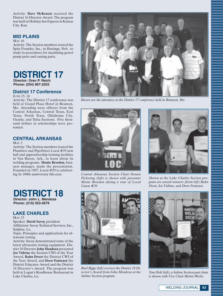
63WELDING JOURNAL
DISTRICT 18Director: John L. MendozaPhone: (210) 353-3679
DISTRICT 17Director: Oren P. ReichPhone: (254) 867-2203
Activity: Dave McKenzie received theDistrict 16 Director Award. The programwas held at Holiday Inn Express in KansasCity, Kan.
MID PLAINSMAY 16Activity: The Section members toured theSpitz Foundry, Inc., in Hastings, Neb., tostudy its procedures for machining gravelpump parts and casting parts.
Shown are the attendees at the District 17 conference held in Branson, Mo.
District 17 ConferenceJUNE 15, 16Activity: The District 17 conference washeld at Grand Plaza Hotel in Branson,Mo. Attending were officers from theCentral Arkansas, Central Texas, EastTexas, North Texas, Oklahoma City,Ozarks, and Tulsa Sections. Five thou-sand dollars in scholarships were pre-sented.
CENTRAL ARKANSASMAY 3Activity: The Section members toured thePlumbers and Pipefitters Local #29 newhall and apprenticeship training facilitiesin Van Buren, Ark., to learn about itswelding programs. Monte Breedon, busi-ness manager, made the presentation.Founded in 1907, Local #29 is celebrat-ing its 100th anniversary this year.
Shown at the Lake Charles Section pro-gram are award winners (from left) RahnDrost, Joe Vidrine, and Drew Fontenot.
Tom Holt (left), a Sabine Section past chair,is shown with Vice Chair Morris Weeks.
Ruel Riggs (left) receives the District 18 Di-rector’s Award from John Mendoza at theSabine Section program.
Central Arkansas Section Chair DennisPickering (left) is shown with presenterMonte Breedon during a tour of LocalUnion #29.
LAKE CHARLESMAY 23Speaker: David Savoy, presidentAffiliation: Savoy Technical Services, Inc.,Sulphur, La.Topic: Principles and applications for ul-trasonic testingActivity: Savoy demonstrated some of thelatest ultrasonic testing equipment. Dis-trict 18 Director John Mendoza presentedJoe Vidrine the Section CWI of the YearAward, Rahn Drost the District CWI ofthe Year Award, and Drew Fontenot theDistrict Educator Award and the District18 Director’s Award. The program washeld at Logan’s Roadhouse Restaurant inLake Charles, La.
Society News August:Layout 1 7/10/07 3:16 PM Page 63

AUGUST 200764
DISTRICT 19Director: Neil ShannonPhone: (503) 201-5142
DISTRICT 20Director: William A. KomlosPhone: (801) 560-2353
DISTRICT 21Director: Jack D. ComptonPhone: (661) 362-3218
SABINEMAY 19Activity: The Section held its installationof officers program at Weeks WeldingLabs in Beaumont, Tex. John L. Mendoza,District 18 director, presented Ruel Riggsthe District 18 Director’s Award. The in-coming slate of officers was installed, in-cluding Ken Dillard, chairman; MorrisWeeks and James Amy, vice chairs; TomHolt, secretary; and Ruel Riggs, treasurer.
District 19 conference attendees are shown at Oxarc Welding Supply Training Center in Spokane, Wash.
Shown at the District 19 conference are (from left) Wendy Sue Reeve, AWS staff representa-tive; Chuck Daily; Lena Rink, student speaker; Neil Shannon, District 19 director; and PhilZammit.
District 19 Director AwardsThe District Director Award provides
a means for District directors to recog-nize individuals who have contributedtheir time and efforts to the affairs of theirlocal Sections and/or District.
District 19 Director Neil Shannon hasnominated the following to receive thisaward for 2006–2007.
Lena Rink, Stanwood High School Stu-dent Chapter
Chuck Daily, Puget Sound SectionJerry Hope, Puget Sound SectionPhil Zammit, Spokane Section
District 19 ConferenceMAY 18, 19Activity: The meeting, hosted by theSpokane Section, was held at the OxarcWelding Supply Training Center inSpokane, Wash. This year, nine teamscompeted in the 39th Annual Stump theWelding Experts contest. Eric Waterfieldof the British Columbia Section providedthe questions. Student Lena Rink pre-sented a talk on the April 25 Washingtonstate welding contest. Leaders of the eventincluded District 19 Director Neil Shan-non, Chuck Daily, and Phil Zammit.
CALIFORNIA CENTRALCOASTOCTOBER 20Activity: The Section participated in theAllan Hancock College and Praxair Ca-reer Day event featuring a weldingdemonstration trailer. More than 100members, high school students, and visi-tor attended the event.
NOVEMBER 6Activity: The Calif. Central Coast mem-bers met at Praxair in Fresno, Calif., tostudy a number of custom-built hot rodsand talk with Miller Roadster represen-tatives.
NOVEMBER 9Activity: Calif. Central Coast Chair StanLuis and Praxair manager Joe Ingram leda tour of the Praxair pumping plant. Fea-tured were industrial gases and demon-stration of several welding processes.
NOVEMBER 13Activity: The Calif. Central Coast Sectionmembers toured the Praxair facility inSanta Maria, Calif. Special guests werestudents from the local colleges wholearned about opportunities in the weld-ing industry.
DECEMBER 7Activity: The Calif. Central Coast Section
Society News August:Layout 1 7/10/07 3:17 PM Page 64

67WELDING JOURNAL
Your Opinion Counts — Take the Online SurveyThe AWS Product Development Committee is conducting a survey to evaluate
ideas for new AWS products. Your input is a crucial part of developing new prod-ucts and services that meet the needs of the welding industry. To complete this briefsurvey, visit www.aws.org/education/pdc07-survey.html.
I thank you in advance for participating in this important effort.
Harvey Castner, chairman, Product Development Committee
DISTRICT 22Director: Dale FloodPhone: (916) 933-5844
members met at El Camino Jr. HighSchool to participate in its Career Day ac-tivities.
JANUARY 27Activity: The Calif. Central Coast Sectionmembers attended an open house atSpeed Ox Welding Supply in Richmond,Calif.
FEBRUARY 8Activity: The Calif. Central Coast Sectionmembers participated in the career dayactivities at Tommi Kunst Jr. High School.The students saw the video presentationThe Weld of Opportunity, then had a hands-on demonstration of several weldingprocesses.
MARCH 31Activity: The Calif. Central Coast Sectionmembers assisted with the Allan HancockCollege and high school welding compe-tition held at the college in Santa Maria,Calif. Nearly $15,000 in prizes wereawarded.
APRIL 4Activity: The Calif. Central Coast Sectionmembers participated in the career dayactivities at Arellanes Jr. High School inSanta Maria, Calif.
MAY 5Activity: The Calif. Central Coast Sectionparticipated in the FFA Welding Finalsheld at Cuesta College in San LuisObispo, Calif. The Section’s booth dis-played Welding Journals and offered in-formation on student memberships andwelder education opportunities.
SACRAMENTOMAY 16Activity: Fifty-five Section memberstoured Holt of California in PleasantGrove, Calif. The visit included the weld-ing and shop areas used for servicingCaterpillar earth-moving equipment. MaxJones, training development, and BobCasey, weld shop foreman, conducted theprogram. Following the tour, the Sectionconvened for the election of officers anda raffle drawing. Silvio Modena, districtmanager, northern California, for MillerElectric, presented a welding power sup-ply to raffle winner Tony Tully.
Many of the Sacramento Section members posed for a group shot during their tour of Holtof California in May.
Shown at the Sacramento Section program are (from left) Treasurer Mark Feuerbach, PastChair Rob Purvis, Chairman Mike Rabo, Newsletter Editor Matt Wysocki, District 22 Di-rector and Past Chair Dale Flood, and Secretary Don Robinson.
Sacramento Section Vice Chair LorneGrimes (left) is shown with guide Max Jonesduring the Holt of California tour.
Silvio Modena presents a weld power sup-ply to raffle winner Tony Tully at the Sacra-mento Section program.
Society News August:Layout 1 7/10/07 3:17 PM Page 67

AUGUST 200768
— MGM continued from page 54
D. Gibson, Oklahoma City — 6R. Grays, Kern — 6
L. Hjelle, Northwest — 6C. Kipp, Lehigh Valley — 6
G. Saari, Inland Empire — 6J. Angelo, El Paso — 5
J. Carney, Western Michigan — 5B. Hallila, New Orleans — 5
D. Parker, Idaho/Montana — 5J. Boyer, Lancaster — 4
E. Ezell, Mobile — 4A. Gades, Northwest — 4C. Neichoy, Houston — 4
M. Rahn, Iowa — 4R. Richwine, Indiana — 4R. Rowe, Kansas City — 4
J. Swoyer, Lehigh Valley — 4D. Wright, Kansas City — 4C. Yaeger, NE Carolina — 4T. Zablocki, Pittsburgh — 4
C. Bridwell, Ozark — 3R. Chase, L.A./Inland Empire — 3
S. Click, Lexington — 3J. Crosby, Atlanta — 3
B. Donaldson, British Columbia — 3T. Garcia, New Orleans — 3
F. Gorglione, Connecticut — 3L. Gross, Milwaukee — 3
L. Ibarra, San Francisco — 3G. Medina, El Paso — 3
W. Menegus, Lehigh Valley — 3R. Miller, Detroit — 3
S. Miner, San Francisco — 3T. Moore, New Orleans — 3
D. Robinson, Sacramento — 3R. Stein, Baltimore — 3
T. Strickland, Arizona — 3M. Tait, L.A./Inland Empire — 3
L. Taylor, Pascagoula — 3M. Vann, South Carolina — 3
R. Vann, South Carolina — 3♦
The AWS Foundation solicits giftcards to be sold during the SilentAuction to be held during the
FABTECH International & AWS Weld-ing Show, Nov. 11–14, in Chicago, Ill.
These gift cards will be available forbid at the Show, and all of the proceedswill go to benefit the AWS Foundationscholarship programs.
To participate in the Silent Auction,you may either purchase a gift card for$200 or $250 yourself, then donate thecard to the Foundation. Or you may senda check for the amount of your donationto the Foundation, and a gift card will be
purchased in your name. The Foundationpurchases cards from a variety of vendors,including Omaha Steaks, Tony Roma’s,Bass Pro Shops, JC Penney, Home Depot,Macy’s, etc.
With the holidays coming soon afterthe Show, these gift cards can be a greatway for Show attendees to do some oftheir holiday gift shopping early.
For more information or to donate acard, contact Nazdhia Prado-Pulido [email protected], or call her at(800) 443-9353, ext. 250.
The Foundation thanks the first of the2007 Silent Auction donors:
AWS Chattanooga SectionAWS Cincinnati SectionAWS Drake Well SectionAWS Northwest Section
AWS NW Pennsylvania SectionAWS Tulsa Section
Nancy and Barry CarlsonSam Gentry
Hobart Brothers Co.IWDC, Inc.
The Lincoln Electric Co.Pferd, Inc.
Select-Arc, Inc.Ray and Sandy Shook
Howard M. Woodward♦
The AWS Detroit Section has an-nounced the establishment of two$25,000 endowments: the Detroit
Arc Welding District 11 Named Scholar-ship and the Detroit Resistance WeldingDistrict 11 Named Scholarship.
The announcement was made by RayRoberts, Detroit Section chairman andAndre Young, Section treasurer.
Roberts said, “With the support of ourpast chairman Don DeCorte, current
AWS Foundation Trustee Amos Winsand,and our full executive committee, we de-cided this is a legacy that we can establishthat will provide two additional $1250scholarships at the District level to sup-port welding education. We are happy to bea part of the ‘Welding for the Strength ofAmerica Capital Campaign’ by this action.”
Sam Gentry, executive director, AWSFoundation, said, “The Detroit Sectionis always at the forefront and in a leader-
ship role at AWS. This assures a long-termcommitment for educational support bythe Detroit Section which has always pro-vided educational opportunities.”
Correction: In the July Welding Jour-nal, page 57, Andre Young was incorrectlyidentified as André Odermatt. AndréOdermatt is president of Hobart Instituteof Welding Technology, Troy, Ohio. TheWelding Journal regrets the error.♦
AWS Foundation Begins its 7th Annual Silent Auction
Detroit Section Announces Two Named Scholarships
Last Call: Nominations for Image of Welding Awards
August 15 is the deadline for sub-mitting your nominations for theImage of Welding Awards. The
awards are presented in seven categories:1) Individual; 2) AWS Section; 3) LargeBusiness (200+ employees); 4) SmallBusiness; 5) Welding Products Distribu-tor; 6) Educator; and 7) Educational Fa-
cility. The awards recognize those whohave shown notable dedication to promot-ing the image of welding in their commu-nities. The winners will be announcedNov. 12 at a special ceremony held dur-ing the FABTECH International & AWSWelding Show in Chicago, Ill.
Nominations will be judged by the
Welding Equipment Manufacturers Com-mittee (WEMCO).
Send your nominations to AdrienneZalkind, [email protected]; or mail toImage of Welding Awards, 550 NWLeJeune Rd., Miami, FL 33126. Includeyour name, phone number, e-mail andmailing addresses.♦
Society News August:Layout 1 7/10/07 3:17 PM Page 68

69WELDING JOURNAL
Guide to AWS Services550 NW LeJeune Rd., Miami, FL 33126
www.aws.org; phone (800/305) 443-9353; FAX (305) 443-7559(Phone extensions are shown in parentheses.)
AWS PRESIDENTGerald D. [email protected]
WA Technology, LLC4313 Byrnes Blvd., Florence, SC 29506
ADMINISTRATIONExecutive Director
Ray W. Shook.. [email protected] . . . . . . .(210)
CFO/Deputy Executive DirectorFrank R. Tarafa.. [email protected] . . . . . . .(252)
Deputy Executive DirectorCassie R. Burrell.. [email protected] . . . .(253)
Associate Executive DirectorJeff Weber.. [email protected] . . . . . . . . . .(246)
Executive Assistant for Board ServicesGricelda Manalich.. [email protected] . .(294)
Administrative ServicesManaging Director
Jim Lankford.. [email protected] . . . . . . . . . .(214)
IT Network DirectorArmando [email protected] .(296)
DirectorHidail Nuñ[email protected] . . . . . . . . . . . . .(287)
Human ResourcesDirector, Compensation and Benefits
Luisa Hernandez.. [email protected] . . . . . .(266)
Manager, Human Resources Dora Shade.. [email protected] . . . . . . . . .(235)
INT’L INSTITUTE of WELDINGSenior Coordinator
Sissibeth Lopez . . [email protected] . . . . . .(319)Provides liaison services with other national andinternational professional societies and standardsorganizations.
GOVERNMENT LIAISON SERVICESHugh K. Webster. . . [email protected], Chamberlain & Bean, Washington, DC
(202) 466-2976; FAX (202) 835-0243Identifies funding sources for welding educa-tion, research, and development. Monitors leg-islative and regulatory issues of importance tothe industry.
Brazing and Soldering Manufacturers’ Committee
Jeff Weber.. [email protected] . . . . . . . . . .(246)
RWMA — Resistance Welding Manufacturing Alliance
ManagerSusan Hopkins.. [email protected] . . . . . . .(295)
WEMCO — Welding EquipmentManufacturers Committee
ManagerNatalie Tapley.. [email protected] . . . . . . . .(444)
CONVENTION and EXPOSITIONSAssociate Executive Director
Jeff Weber.. [email protected] . . . . . . . . . .(246)
Corporate Director, Exhibition SalesJoe Krall.. [email protected] . . . . . . . . . . . . . .(297)Organizes the annual AWS Welding Show and
Convention, regulates space assignments, regis-tration items, and other Expo activities.
PUBLICATION SERVICESDepartment Information . . . . . . . . . . . . . .(275)
Managing DirectorAndrew Cullison.. [email protected] . . . .(249)
Welding JournalPublisher/Editor
Andrew Cullison.. [email protected] . . . .(249)
National Sales DirectorRob Saltzstein.. [email protected] . . . . . . . . .(243)
Society and Section News EditorHoward [email protected] (244)
Welding HandbookWelding Handbook Editor
Annette O’Brien.. [email protected] . . . .(303)Publishes the Society’s monthly magazine, Weld-
ing Journal, which provides information on thestate of the welding industry, its technology, andSociety activities. Publishes Inspection Trends, theWelding Handbook, and books on general weld-ing subjects.
MARKETING COMMUNICATIONSDirector
Ross Hancock.. [email protected] . . . .(226)
Assistant DirectorAdrienne Zalkind.. [email protected] . . .(416)
MEMBER SERVICESDepartment Information . . . . . . . . . . . . . .(480)
Deputy Executive DirectorCassie R. Burrell.. [email protected] . . . .(253)
DirectorRhenda A. Mayo... [email protected] . . . .(260) Serves as a liaison between Section members andAWS headquarters. Informs members about AWSbenefits and activities.
CERTIFICATION SERVICESDepartment Information . . . . . . . . . . . . . .(273)
Managing DirectorPeter Howe.. [email protected] . . . . . . . . . .(309)
Director, OperationsTerry Perez.. [email protected] . . . . . . . . . .(470)
Directs the department operations.
Director, Int’l Business & Certification ProgramsPriti Jain.. [email protected] . . . . . . . . . . . . .(258)Directs all int’l business and certification pro-
grams. Is responsible for oversight of all agencieshandling AWS certification programs.
Senior Manager, Certification ProgramsFrank Lopez Del Rincon. [email protected] (258)Manages all national certification programs, in-
cluding Accredited Test Facilities.
EDUCATION SERVICES Managing Director
Dennis Marks.. [email protected] . . . . . . .(237)
Director, Education Services Administrationand Convention Operations
John Ospina.. [email protected] . . . . . . . .(462)
Director, Education Product DevelopmentChristopher Pollock.. [email protected] (219)
Coordinates in-plant seminars and workshops.Administers the SENSE program. Assists Gov-ernment Liaison Committee and Education Com-mittees. Also responsible for conferences, exhi-bitions, and seminars. Organizes CWI, SCWI, and9-year renewal certification-driven seminars.
AWS AWARDS, FELLOWS, COUNSELORSSenior Manager
Wendy S. Reeve.. [email protected] . . . . .(293)Coordinates AWS awards and AWS Fellow andCounselor nominees.
TECHNICAL SERVICESDepartment Information . . . . . . . . . . . . . .(340)
Managing DirectorAndrew R. Davis.. [email protected] . . . . .(466)
Int’l Standards Activities, American Council ofthe Int’l Institute of Welding (IIW)
Director, National Standards ActivitiesJohn L. Gayler.. [email protected] . . . . . . .(472)Personnel and Facilities Qualification, Comput-erization of Welding Information, Arc Weldingand Cutting
Manager, Safety and HealthStephen P. Hedrick.. [email protected] (305)Metric Practice, Safety and Health, Joining of
Plastics and Composites
Technical PublicationsAWS publishes about 200 documents widely
used throughout the welding industry.Senior Manager
Rosalinda O’Neill.. [email protected] . . . .(451)
Staff Engineers/Standards Program ManagersAnnette Alonso.. [email protected] . . . . .(299)Automotive Welding, Resistance Welding, Oxy-fuel Gas Welding and Cutting, Definitions andSymbols
Stephen Borrero.. [email protected] . . .(334)Welding Iron Castings, Joining of Metals and Al-loys, Brazing and Soldering, Brazing Filler Met-als and Fluxes, Brazing Handbook, SolderingHandbook
Rakesh Gupta.. [email protected] . . . . . . .(301)Filler Metals and Allied Materials, Int’l Filler
Metals, Instrumentation for Welding, UNS Num-bers Assignment
Brian McGrath . [email protected] . . . .(311)Methods of Inspection, Mechanical Testing of
Welds, Welding in Marine Construction, Pipingand Tubing
Selvis [email protected] . . . .(313)Welding Qualification, Structural Welding
Kim [email protected] . . . . . . . . . .(215)Machinery and Equipment Welding, Robotic
and Automatic Welding, Sheet Metal Welding,Thermal Spray
Reino [email protected] . . . . . . . .(304)Welding in Sanitary Applications, High-Energy
Beam Welding, Aircraft and Aerospace, FrictionWelding, Railroad Welding.
Note: Official interpretations of AWS standardsmay be obtained only by sending a request in writ-ing to the Managing Director, Technical Services.Oral opinions on AWS standards may be ren-dered. However, such opinions represent only thepersonal opinions of the particular individualsgiving them. These individuals do not speak onbehalf of AWS, nor do these oral opinions con-stitute official or unofficial opinions or interpre-tations of AWS. In addition, oral opinions areinformal and should not be used as a substitutefor an official interpretation.
Society News August:Layout 1 7/10/07 3:18 PM Page 69

AUGUST 200770
Nominees for National Office AWS Publications Sales
Purchase AWS standards, books, and other publications from
World Engineering Xchange (WEX), Ltd. Toll-free (888) 935-3464 (U.S., Canada)
(305) 824-1177; FAX (305) 826-6195www.awspubs.com
Welding Journal ReprintsCopies of Welding Journal articles may be
purchased from Ruben Lara. Call toll-free
(800/305) 443-9353, ext. 288; [email protected]
Custom reprints of Welding Journalarticles, in quantities of 100 or more,
may be purchased from FosteReprints
Toll-free (866) 879-9144, ext. [email protected]
Only Sustaining Members, Members,Honorary Members, Life Members,or Retired Members who have been
members for a period of at least three yearsshall be eligible for election as a director ornational officer.
It is the duty of the National NominatingCommittee to nominate candidates for na-tional office. The committee shall hold anopen meeting, preferably at the Annual Meet-ing, at which members may appear to presentand discuss the eligibility of all candidates.
To be considered a candidate for the po-sitions of president, vice president, treasurer,or director-at-large, the following qualifica-tions and conditions apply:
President: To be eligible to hold the officeof president, an individual must have servedas a vice president for at least one year.
Vice President: To be eligible to hold theoffice of vice president, an individual musthave served at least one year as a director,other than executive director and secretary.
Treasurer: To be eligible to hold the of-fice of treasurer, an individual must be a
member of the Society, other than a Stu-dent Member, must be frequently availableto the national office, and should be of ex-ecutive status in business or industry withexperience in financial affairs.
Director-at-Large: To be eligible forelection as a director-at-large, an individ-ual shall previously have held office aschairman of a Section; as chairman or vicechairman of a standing, technical, or spe-cial committee of the Society; or as Districtdirector.
Interested persons should submit a let-ter stating which office they seek, includinga statement of qualifications, their willing-ness and ability to serve if nominated andelected, and a biographical sketch.
E-mail the letter to Gricelda Manalich,[email protected], c/o Damian J. Kotecki,chair, National Nominating Committee.
The next meeting of the National Nom-inating Committee is scheduled for Novem-ber 2007. The terms of office for candidatesnominated at this meeting will commenceJanuary 1, 2009.
AWS Foundation, Inc.
The AWS Foundation is a not-for-profit corporation established to provide support
for educational and scientific endeavors of the American Welding Society.
Information on gift-giving programs is available upon request.
Chairman, Board of TrusteesRonald C. Pierce
Executive Director, AWSRay Shook
Executive Director, FoundationSam Gentry
550 NW LeJeune Rd., Miami, FL 33126(305) 445-6628; (800) 443-9353, ext. 293
e-mail: [email protected] information:
(800) 443-9353, ext. 689
Honorary Meritorious Awards
The Honorary-Meritorious Awards Committee makes recommendations for thenominees presented for Honorary Membership, National MeritoriousCertificate, William Irrgang Memorial, and the George E. Willis Awards. These
awards are presented during the FABTECH International & AWS Welding Show heldeach fall. The deadline for submissions is December 31 prior to the year of awards pre-sentations. Send candidate materials to Wendy Sue Reeve, secretary, HonoraryMeritorious Awards Committee, [email protected]; 550 NW LeJeune Rd., Miami, FL33126. Descriptions of the awards follow.
National Meritorious Certificate Award:This award is given in recognition of thecandidate’s counsel, loyalty, and devotionto the affairs of the Society, assistance inpromoting cordial relations with industryand other organizations, and for the contri-bution of time and effort on behalf of theSociety.
William Irrgang Memorial Award: Thisaward is administered by the American Weld-ing Society and sponsored by The LincolnElectric Co. to honor the late William Irr-gang. It is awarded each year to the individ-ual who has done the most over the past fiveyears to enhance the American Welding So-ciety’s goal of advancing the science andtechnology of welding.
George E. Willis Award: This award is ad-ministered by the American Welding Societyand sponsored by The Lincoln Electric Co.to honor George E. Willis. It is awarded eachyear to an individual for promoting the ad-vancement of welding internationally by fos-tering cooperative participation in areas suchas technology transfer, standards rationaliza-tion, and promotion of industrial goodwill.
International Meritorious CertificateAward: This award is given in recognitionof the recipient’s significant contributionsto the worldwide welding industry. Thisaward reflects “Service to the Interna-tional Welding Community” in the broad-est terms. The awardee is not required tobe a member of the American WeldingSociety. Multiple awards can be given peryear as the situation dictates. The awardconsists of a certificate to be presentedat the awards luncheon or at another timeas appropriate in conjunction with theAWS president’s travel itinerary, and, ifappropriate, a one-year membership inthe American Welding Society.
Honorary Membership Award: AnHonorary Member shall be a person ofacknowledged eminence in the weldingprofession, or who is accredited with ex-ceptional accomplishments in the devel-opment of the welding art, upon whomthe American Welding Society sees fit toconfer an honorary distinction. An Hon-orary Member shall have full rights ofmembership.
AWS Mission Statement
The mission of the American WeldingSociety is to advance the science,
technology, and application of weldingand allied processes, including
joining, brazing, soldering, cutting, and thermal spraying.
It is the intent of the American Welding Society to build AWS to the
highest quality standards possible. The Society welcomes your suggestions.
Please contact any staff member or AWS President Gerald D. Uttrachi,
as listed on the previous page.
Society News August:Layout 1 7/10/07 3:18 PM Page 70

Conference price is $345 for AWS members, $480 fornonmembers.To register or to receive a descriptive brochure,call (800) 443-9353 ext. 229, (outside North America, call 305-443-9353), or visit www.aws.org/conferences
An AWS-sponsored conference on friction welding will be held at the Fabtech Int’l & AWS Welding Show in Chicago.Thisdaylong conference will be packed with a number of short presentations on various facets of conventional friction weld-ing, linear friction welding, and friction stir welding. Among the presentations will be talks on such topics as direct drivevs. inertia friction welding, the friction welding of automotive pistons, the linear friction welding of blades onto discs inaircraft engines, the marriage of robotics and friction stir welding, and the ability of any process within this family to weldjust about any metal or alloy—or even plastic, for that matter—and to do it without creating fumes. Also, experts willbe on hand to discuss the ability to use these processes to weld dissimilar metals on the fly.
©A
mer
ican
Wel
ding
Soc
iety
2007
ESV1
493R
Founded in 1919 to advance the science, technology and application of welding and allied joining and cuttingprocesses, including brazing, soldering and thermal spraying.
Conference on Friction WeldingChicago • McCormick PlaceNovember 12, 2007
Page 71:FP_TEMP 7/10/07 1:59 PM Page 71

©Am
eric
anW
eldi
ngSo
ciet
y20
07ES
V148
1S
Founded in 1919 to advance the science, technology and application of welding and allied joining and cuttingprocesses, including brazing, soldering and thermal spraying.
Conference on the Explosion of New ProcessesSan Diego • Doubletree Golf ResortAugust 14-15, 2007
Page 72-73:FP_TEMP 7/10/07 2:04 PM Page 72

Conference price is $550 for AWS members, $680 fornonmembers.To register or to receive a descriptive brochure,call (800) 443-9353 ext. 224, (outside North America, call 305-443-9353), or visit www.aws.org/conferences
Conference on the Explosion of New ProcessesSan Diego • Doubletree Golf Resort
August 14-15, 2007
The welding industry is now in the midst of anexplosion of new welding technologies, many ofwhich have made quick passage from the research lab to the production line. This kind of activity has not beenseen for decades. Presentations on many of thesetechnologies will form the body of this first-of-its-kindconference. Two of the main thrusts will exploreinteresting variations and improvements on lasertechnologies and on friction stir welding.
Friction Stir Welding and Processing—An Update ofRecent DevelopmentsWilliam J. Arbegast, Director, NSAF Center for FrictionStir Processing, and Director, Advanced MaterialsProcessing and Joining Center, South Dakota School ofMines and Technology
The Deformation Resistance Welding ProcessMenachem Kimchi, Technology Leader, Edison WeldingInstitute
A New Approach (Double Electrode) to HighProductivity GMAWDr. YuMing Zhang, James R. Boyd Professor, Director ofGraduate Studies, Center for Manufacturing,Department of Electrical and Computer Engineering,College of Engineering, University of Kentucky
Magnetic Pulse Welding Extends Its List ofApplicationsMichael Blakely, Operations Manager, C3 MagneticPulse Division, Hirotec America Inc.
The Fiber Laser Opens Up New Opportunities forLaser WeldingBill Shiner, Director, Industrial Market Development, IPGPhotonics Corp.
Ultrasonic Joining of Metals: Advances in Welding,Soldering and BrazingMatt Short, Project Engineer, Edison Welding Institute
Friction Stir Welding and Processing of AdvancedMaterials—Advances and ChallengesDr. S. A. David, Corporate Fellow and Group Leader,Materials Joining Group, Oak Ridge National Laboratory
Friction Stir Welded Components Are Headed toMarsMike Skinner, Business Development Manager, MTSSystems Corp.
Single-Sided Plasma Spot Welding and PlasmaBrazing Process—A Review of ApplicationsR. V. Hughes, Technical Director, Camarc LLC
Laser Stir Welding of Aluminum AlloysR. P. Martukanitz, Head, Laser Processing Division,Applied Research Laboratory, Pennsylvania StateUniversity; and Israel Stol, Senior ManufacturingSpecialist, Joining and Assembly, Alcoa Technical Center
Novel Heat Source Enables Brazing at RoomTemperatureDr. Timothy P. Weihs, President, ReactiveNanoTechnologies Inc.
CSC-Controlled Short Circuit Transfer—A NewGMAW Process That Solves Old Weld ProblemsTom Rankin, Vice President and General Manager, ITWJetline Engineering
A New Process (Ultrasonic Impact Treatment) forImproving Fatigue Strength of WeldsSougata Roy, Research Scientist III, ATLSS Center,Lehigh University
Page 72-73:FP_TEMP 7/10/07 2:05 PM Page 73

NEWLITERATURE
Tools and Ideas to EnhanceProductivity Detailed
An 8-page, full-color brochure de-scribes the company’s solutions to im-proving manufacturing machine tool pro-ductivity, safety, and precision. Detailed
and illustrated are application-specific ex-amples of electric, hydraulic, pneumatic,linear motion, and assembly technologyresources available to manufacturers toimprove the productivity of any machinetool operation. Shown are machining cen-ters, transfer machines, crankshaft turn-ing machines, assembly operations, andgrinding stations. Included are specificson how to sustain a competitive advan-tage, safer motion, faster cycle times,higher precision, greater uptime, and thecompany’s support operations. Thebrochure can be downloaded from theWeb site.
Bosch Rexroth Corp.www.boschrexroth-us.com(847) 645-3600
New Line of Surface PrepTools Illustrated
The EZEFIT® Wheel Family productbrochure displays the company’s new spe-cialized wheel designs for optimal per-formance in the surface-preparation in-dustry. Displayed are wheels for all types
of applications including customizedproducts for unique process require-ments. The line features bidirectional ro-tation to accommodate both clockwiseand counterclockwise wheel applicationsusing a single wheel. Described are wheelsin 31⁄2- and 21⁄2-in. blade widths, with oper-
AUGUST 200774
— continued on page 76
August New Lit:Layout 1 7/10/07 8:00 AM Page 74

©20
07Am
eric
anW
eldi
ngSo
ciet
yFD
N139
7-9
The American Welding Society Foundation has helped thousands of students whootherwise would be unable to afford a welding education. We are proud of the fact that wehelp hundreds of welding students annually by providing them with funding towards theireducation. In fact, we are the only industry foundation set up specifically to further weldingeducation and, in so doing, create the careers that sustain and grow our industry.
These funds are from your generous contributions. If you don’t contribute, we will not beable to expand our work and our students’ educations. And there is so much work to bedone.
Please make a scholarship contribution, or set up your own Section, District Named, orNational Named Scholarship. Contact the AWS Foundation at 1-800-443-9353, ext. 212.
“My name is Wesley Doneth. Ireceived the PraxairInternational Scholarship in2000. The AWS and AWSlocal chapters were verygenerous to me andprovided severalscholarships to help me payfor tuition at Ferris StateUniversity so I could complete myB.S. in Welding EngineeringTechnology. My father Richard is aboilermaker, and grandfather JamesWatson had 30+ years as a welder andforeman for CB&I; welding is in the blood. Ipaid for most of my schooling by workingand student loans, as many of myclassmates did, so the scholarships helped
take some of the load off. I recently joinedAlcoTec Wire Corporation, a subsidiary of
ESAB. I have been able to buy a homeand provide for my family of three alongwith my wife Dawn, thanks to a greatcareer in the welding industry. Hardwork and support from the welding
industry through AWS helped mesucceed over the last 10 years. I hope to
contribute back by staying involved withFerris State University and through workwith AWS chapters. It is a great industrywith infinite opportunities. I have theopportunity to work with numerousmanufacturers and meet new people whocontribute to the welding industry almostdaily. You learn more every day and canalways find new challenges.”
The Robert L. Peaslee–Detroit Brazing andSoldering Division Scholarship is awarded toa college junior or senior pursuing aminimum four-year bachelor’s degree inwelding engineering or welding engineeringtechnology with an emphasis on brazing andsoldering applications.
Applicants must show emphasis onbrazing and soldering applications in theircoursework.
One $2,500 award is given annually. This fundwas established in2004 by Robert L.Peaslee and theAWS DetroitBrazing andSoldering Division ofthe AWS DetroitSection.
Welding for the Strength of AmericaThe Campaign for the American Welding Society Foundation
This month’s AWS Foundation spotlights:
Spotlight on a scholar
Spotlight on a scholarship
Page 75:FP_TEMP 7/10/07 2:11 PM Page 75

ating speeds of 3600 and 1800 rev/min.Download the brochure at the Web site,or call for more information.
Wheelabrator Groupwww.wheelabratorgroup.com(800) 544-4144
CD Catalog Pictures Welding Products
The new Bug-O Systems/CypressWelding Equipment catalog is offered indigital form on a CD. The CD contains allthe products in the company’s broad weld-ing-related product lines. The CD may berequested by sending an e-mail [email protected].
Bug-O Systems/Cypress Welding Equip.www.bugo.com(800) 245-3186
Flexible Eye Protection Pictured
A brochure details the company’s lineof KleenGuard® V30 flexible eye protec-tion featuring a padded nose bridge anda ratcheted temple for easy adjustment ofthe lens angle. The impact-resistant, wrap-
around lenses meet ANSI Z87.1, and pro-vide 99.9% protection from both UVAand UVB rays. Models are available withsmoke, amber, indoor/outdoor, and clear,antifog lenses.
Kimberly-Clarkwww.kcprofessional.com(888) 346-4652
Online Videos DisplayDozens of Robots in Action
Posted on the company’s Web site aremore than 70 audiovideo clips, rangingfrom one to ten minutes in length, show-ing robots of all shapes and sizes perform-ing a wide variety of operations. Each clipis cataloged as a small color photo of therobot with a caption describing the man-ufacturer, model number, and the taskshown in the video. Clicking on the photostarts the video. Shown are robots madeby Motoman, Fanuc, Panasonic, and oth-ers, performing numerous operations in-cluding welding, handling, painting, cut-ting, and sanding. The videos can be aneducational experience for newcomers tothe robotics field as well as helping buy-ers see how the various robots performbefore pursuing a purchase.
RobotWorxwww.robots.com/movies.php(740) 383-8383
361 New Abrasive ProductsPictured in Catalog
The company’s latest full-color cata-log details more than 1400 metal-fabrica-tion products, including 361 new items.Pictured are flap discs, thin cut-off wheels,semi-flex discs, resin fiber discs, back-uppads, flap wheels, depressed-centerwheels, high-speed reinforced cut-off
wheels, stationary saw cut-off wheels, andchop saw cut-off wheels. Included is in-formation for selecting the right abrasivefor the desired results.
CGW-Camel Grinding Wheelswww.cgwheels.com(800) 447-4248
Lincoln Releases CompleteProduct Line Catalog
The 167-page, full-color, 2007 productcatalog features the company’s completelines of welding machines, wire feeders,environmental fume-exhaust systems,Magnum® guns, and Ultracore®, Metal-shield®, Outershield®, Innershield®,Blue Max®, and hardfacing consumables,and Ultrashade® autodarkening weldinghelmets. Included are details on auto-mated robotic systems and custom cells.The back cover lists contact informationfor the company’s district sales offices. Re-quest Bulletin E1.10.
The Lincoln Electric Co.www.lincolnelectric.com/products/litrequest/(888) 355-3213
FMA Offers Online Video ofthe Organization’s Benefits
A three-minute-long video posted on-line highlights the mission and memberbenefits of the Fabricators & Manufactur-ers Association, International® (FMA).Included are segments on health care ben-efits for employees, cooperative buyingpower for discounted purchases, access tothe association’s research assistance cen-ter, survey results, on-site training, andeducational seminars. At the end of thevideo, viewers may apply for FMA mem-bership, request additional information,or sign up to receive the FMA newsletter.
Fabricators & Manufacturers Assn., Int’lwww.fmanet.org/Membership/FMA-Member-ship.cfm(815) 399-8775
AUGUST 200776
— continued from page 74
August New Lit:Layout 1 7/10/07 8:00 AM Page 76

Conference price is $345 for AWS members, $480 fornonmembers.To receive a descriptive brochure, call (800) 443-9353 ext. 229, (outside North America, call 305-443-9353), or visit www.aws.org
There is a great deal of new and revived interest in hot wire welding, as a means of combining the deposition rates ofGMAW with the quality of GTAW. One version or other is already being used by participants in the oil and gas industry,by the Navy, and by builders of aircraft engines. Hot wire welding and cladding will be the subject of a one-dayconference at the FabTech Int’l and AWS Welding Show in Chicago. Presentations on both hot wire GTAW and hot wireplasma processes will be also on the agenda. One topic that will be addressed at the conference will be the popularuse of hot wire gas tungsten arc cladding of tube and piping for the offshore oil and gas industries. In anotherpresentation, hot wire GTA “narrow groove” welding will be shown to have performed well on titanium. Advantagesare increased deposition rates and faster travel speeds. Also on the agenda are “buildups, butterings, and claddings”of Inconel. Critical metallurgical and other issues will be addressed by hot wire equipment producers, users, andconsultants.
©A
mer
ican
Wel
ding
Soc
iety
2007
ESV1
507A
Founded in 1919 to advance the science, technology and application of welding and allied joining and cuttingprocesses, including brazing, soldering and thermal spraying.
AWS Hot Wire Welding and Cladding ConferenceChicago • McCormick PlaceNovember 13, 2007
Page 77:FP_TEMP 7/10/07 2:13 PM Page 77

PERSONNEL
Hypertherm Appoints Sales Manager
Hypertherm,Hanover, N.H., hasappointed Thomas(Tommy) Hanchettedistrict manager tosupport its distribu-tors in Nebraska,Kansas, SouthDakota, Colorado,and Iowa. Beforejoining the com-pany, Hanchette
served as a sales manager for a weldingand cutting manufacturer.
Test Equipment Designatesits Vice President
Test Equipment Distributors, Troy,Mich., a provider of nondestructive testingequipment and services, has named RickBallinger vice president. Ballinger, whojoined the company in 1984 as a manufac-
turing technician, most recently served asoperations manager.
President and CEO Namedat Air Liquide
Air Liquide hasnamed Michael J.Graff as presidentand CEO of Air Liq-uide USA LLC, and adirector of U.S. sub-sidiary businesses.He will lead the com-pany’s U.S. industrialgas operations andbusiness activitiesfrom its Houston,
Tex., headquarters. Graff previously held anumber of leadership positions atBP/Amoco.
Jet Edge Names Sales Manager
Jet Edge, St. Michael, Minn., a supplierof ultrahigh-pressure waterjet and abrasive
jet systems, has ap-pointed Dirk Barrettas North-Central re-gional sales manager.His territory includesMinnesota, westernIowa, northern Wis-consin, Michigan’sUpper Peninsula,North and SouthDakota, Montana,Wyoming, and Man-
itoba, Canada. With 20 years of sales expe-rience, Barrett has worked for Mohawk In-dustries, Royal Scot Distributing, CottageIndustries, and Carpet City.
VP Buildings Names Plant Manager
VP Buildings, Memphis, Tenn., a man-ufacturer of metal buildings, has namedTerry Gentle plant manager for its NorthCarolina Service Center in Kernersville.Gentle joined the company in 1976, andsince 1998 has served as the Kernersvilleplant superintendent.
AUGUST 200778
Tommy Hanchette
Michael J. Graff
Dirk Barrett
For info go to www.aws.org/ad-index
Personnel August:Layout 1 7/10/07 10:16 AM Page 78

Professional Services Industries Hires CWI
Professional Serv-ices Industries, Inc.,Green Tree, Pa., hasnamed Tim Griffithas a Certified WeldInspector (CWI) inits NondestructiveExamination De-partment. Previ-ously employed byDansco Engineer-ing, LLC, Griffith
has more than 25 years of experience inconstruction, materials testing, and in-spection services.
Tregaskiss Welding Products Fills Two Posts
Tregaskiss Welding Products, Windsor,Ont., Canada, has named Mark Morganas customer training specialist and JudyWilson as customer service specialist.Morgan is responsible for the Midwestand Pacific Northwest regions. Wilson,like Morgan, has more than 20 years ofcustomer service experience.
ESAB Appoints ProductManager
ESAB Welding &Cutting Products,Florence, S.C., hasnamed Cliff Ankersenas laser and waterjetsystems product man-ager. Ankersen mostrecently served in asimilar position at W.A. Whitney.
Handy & Harman NamesLucas-Milhaupt President
Handy & Harman Precious MetalsGroup, Milwaukee, Wis., has namedJoseph Mockus president of Lucas-Mil-haupt, Inc., and Handy & Harman ofCanada Ltd. Previously, Mockus was di-rector of business excellence for Under-writers Laboratories.
Weihs Appointed toPresident’s Council
Timothy (Tim) Weihs has been ap-pointed to the President’s Council of Ad-visors on Science and Technology’s NewNanotechnology Technical AdvisoryGroup. Weihs is CTO and cofounder ofReactive NanoTechnologies, Inc., Hunt
Valley, Md., and afull professor of ma-terials science andengineering at JohnsHopkins University.Prior to foundingRNT in 2001, Weihsworked at LawrenceLivermore NationalLaboratory wherehe codiscovered theability to control
exothermic reactions in multilayer foilswith nanoscale layers.
Senior Engineer Hired byPennoni Associates
Pennoni Associ-ates, Philadelphia,Pa., has hired Ed-ward A. Hartwell III,P.E., as a senior engi-neer in its Nation-wide Steel BridgeFabrication Inspec-tion division. Spe-cializing in weldingand steel fabrica-
79WELDING JOURNAL
Toyota is an Equal Opportunity Employer and
supports a diverse and inclusive workforce.
It’s built around you.Our innovation.
The tempo at Toyota reflects a mood of excitement. Our rise to
the top is the result of team members’ unwavering commitment
to quality. Their focus is always on innovation and continuous
improvement. Ours is building a better future for and with them.
EngineersElectrical � Manufacturing � Material Science � Mechanical � Product/Process � Quality
You’ll be joining a team that has created a globally valued
brand. A team proud to be associated with one of the most
admired companies in the world. We support great talent
working closely together - the Toyota way. Align your career
with a company that has priorities in the right place, great
respect for people, and its horizons moving forward.
www.toyotaENG.jobs or text Toyota to 78247.
Toyota Motor Engineering & Manufacturing
North America, Inc.
Tim Griffith
Cliff Ankersen
Tim Weihs
For info go to www.aws.org/ad-index
E. A. Hartwell III
Personnel August:Layout 1 7/10/07 10:17 AM Page 79
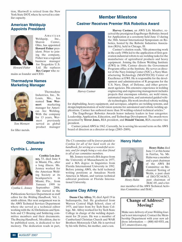
tion, Hartwell is retired from the NewYork State DOT, where he served in a sim-ilar capacity.
American WeldquipAppoints President
A m e r i c a nWeldquip, Inc.,Sharon Center,Ohio, has appointedHoward Fisher pres-ident. Prior to join-ing the company,Fisher was a regionalbusiness managerfor Tregaskiss U.S.Ltd. He replacesRex Carper who re-
mains as founder and CEO.
Thermadyne NamesMarketing Manager
ThermadyneIndustries, Inc., St.Louis, Mo., hasnamed Tom Wer-mert marketingmanager for Ameri-cas Arc Welding.With the companyfor 13 years, Wer-mert previouslyserved as globalproduct manager
for filler metals.
Obituaries
Cynthia L. Jenney
Cynthia Lou Jen-ney, 53, died June 8in Miami, Fla., aftera long illness. Ms.Jenney worked forthe American Weld-ing Society at itsheadquarters inMiami, Fla., fromJanuary 1999 toSeptember 2006.She started in the
Publications Services Department as staffeditor for the Welding Handbook, Vol. 1,ninth edition. Her next assignment was inthe AWS Technical Services Departmentwhere she served as a technical editorworking with the A2 Definitions and Sym-bols and C3 Brazing and Soldering com-mittee members and their documents.The Brazing Handbook, 5th edition, due tobe published soon, is dedicated to hermemory. The dedication reads in part,
The C3 committee will be forever grateful toCynthia for all of her hard work on thehandbook, for serving as a wonderful secre-tary, and for simply being a very dear friendto all of our committee members.
Ms. Jenney received a BA degree fromthe University of Massachusetts in 1977,and a MA degree in linguistics fromFlorida International University in 1992.Before joining AWS, she held technicalwriting positions at Amadeus NorthAmerica in Miami, and various technicaleditorial positions at Florida Interna-tional University.
Duane Clay Alfrey
Duane Clay Alfrey, 50, died April 19 inIndianapolis, Ind. He graduated fromWarren Central High School, class of1975, and later from Ivy Tech State Col-lege. Mr. Alfrey worked for Ivy Tech StateCollege in charge of the welding depart-ment for 28 years. He was a member ofCumberland Christian Church and WARBrothers Motorcycle Club. He is survivedby his wife Debra, his mother, and a son.
Henry Hahn
Henry Hahn diedJune 11 at this homein Fairfax, Va. Mr.Hahn was a memberand a past chairmanof the AWS B4Committee on Me-chanical Testing ofWelds, a past chairof ISO/TC44/SC5,past chairman ofISAC-05, and a for-
mer member of the AWS Technical Activ-ities Committee and ISAC.
AUGUST 200780
Howard Fisher
Cynthia L. Jenney
Tom Wermert
Henry Hahn
Member MilestoneCastner Receives Premier RIA Robotics Award
Harvey Castner, an AWS Life Member, re-ceived the prestigious Engelberger Robotics Awardfor Application at a ceremony held June 13 duringthe 38th Annual International Symposium on Ro-botics, hosted by the Robotic Industries Associa-tion (RIA), held in Chicago, Ill.
Castner’s citation reads, “His pioneering workin the early 1980s led to the application of first-gen-eration industrial robots to arc welding tasks for themanufacture of agricultural products and heavyequipment. Joining the Edison Welding Institute(EWI) in 1986, Castner directs the GovernmentPrograms office at the Institute. He serves as direc-tor of the Navy Joining Center (NJC), a Navy Man-ufacturing Technology (MANTECH) Center ofExcellence at EWI. He is responsible for the devel-opment and administration of R programs for theU.S. Navy, Dept. of Defense, and other govern-ment agencies. His extensive experience in weldingengineering and engineering management includesprojects that encompass robotics, arc weld vision,automated inspection, and automated guided vehi-cle technologies. His work involved robotic welding
for shipbuilding, heavy equipment, and aerospace, adaptive arc welding systems, anddesign/implementation of weld vision systems for automated and robotic welding ap-plications. Castner has authored more than 30 welding-related technical articles.”
The Engelberger Robotics Awards honor industry leaders in four categories:Leadership, Application, Education, and Technology Development. The awards werepresented by Trevor Jones, RIA president, and Donald Vincent, RIA executive vicepresident.
Castner joined AWS in 1962. Currently, he is serving his second term on the AWSboard of directors as a director-at-large (2003–2009).
Harvey Castner
Change of Address?Moving?
Make sure delivery of your Welding Jour-nal is not interrupted. Contact the Mem-bership Department with your new ad-dress information — (800) 443-9353, ext.217; [email protected].
Personnel August:Layout 1 7/10/07 10:17 AM Page 80

CLASSIFIEDS
CAREER OPPORTUNITIESCAREER OPPORTUNITIES
SERVICES
MITROWSKI RENTS
Tank Turning Rolls100 Ton - 200 Ton - 300 Ton
800-218-9620713-943-8032 Purchase on our website
at www.specialwelds.com
A Diver-Welder’s Companion
81WELDING JOURNAL
Put Your Sales Literatureand Products/Services
to Work in October 2007
Generate sales leads by showcasingyour full-color catalog or productphoto, a product description, website,or other sales literature. These show-cases reach 70,000 qualified buyers.Great exposure for just pennies a con-tact. Closing August 15, 2007
Call our sales team at:1-800-443-9353
Rob Saltzstein at ext. [email protected]
Lea Garrigan Badwy atext. 220
Check out Our New InteractiveAdvertising Index
Go to: www.aws.org/ad-index
Combine your relationship with your existing industrial customers withour line of premium quality welding alloys for maximum profitability.
Success Formula✔ Vulcan - Premium quality products
- consumable products- compliments your existing line(s) of industrial products.- leverage your existing relationship
✔ with your - customers to maximize your profitability.
“Your High Integrity and Our High Quality...An Unstoppable Combination”
✔ Doug FieldVulcan Systems, Inc.1-810-730-6052
Quality Systems through Superior Performance
AUG 2007 CLASSIFIEDS:Classified Template 7/10/07 2:21 PM Page 81

EQUIPMENT FOR SALE OR RENT
Turning RollsPositioners
& ManipulatorsNew and Used
Joe Fuller LLC@ www.joefuller.com
or email [email protected] Phone: 979-277-8343
Fax: 281-290-6184
Welding Positioners & Turning RollsNew and Used
Large selection in stock forimmediate delivery.
www.allfabcorp.com
Call, Fax or Email for a free catalog.
Email: [email protected]: www.allfabcorp.comPhone: 269-673-6572Fax: 269-673-1644
REPRINTS REPRINTS
To order custom reprints of 100 or more of articles in
Welding Journal,
call FosteReprints at(219) 879-8366 or(800) 382-0808 or.
Request for quotes can befaxed to (219) 874-2849.
You can e-mailFosteReprints at
CERTIFICATION& TRAINING
AUGUST 200782
Star-TechINDUSTRIAL SKILLS
2007 Training Programs:
- Resistance Welding Tech.
- Resistance Welding Maint.
- Weld Control Set-up.
- Ultrasonic USI Inspection
and Certification
Our 15th Year
CELEBRATING
Summer Special PricingTraining Conducted at your plant
CALL (248) 299-5764
AUG 2007 CLASSIFIEDS:Classified Template 7/10/07 2:22 PM Page 82

CERTIFICATION & TRAINING
CWI PREPARATORYGuarantee - Pass or Repeat FREE!
2-WEEK COURSE (10 DAYS)MORE HANDS-ON/PRACTICAL APPLICATIONS
Pascagoula, MS, Oct. 10–19 Nov. 28–Dec. 7Chattanooga, TN/Atlanta, GA Sept. 26–Oct. 5
Houma, LA, Sept. 12–21San Antonio, TX, Oct. 24–Nov. 2
SAT–FRI COURSE (7 DAYS)EXTRA INSTRUCTION TO GET A HEAD START
Pascagoula, MS, Oct. 13–19 Dec. 1–7Chattanooga, TN/Atlanta, GA Sept. 29–Oct. 5
Houma, LA, Sept. 15–21San Antonio, TX, Oct. 27–Nov. 2
MON–FRI COURSE (5 DAYS)GET READY - FAST PACED COURSE
Pascagoula, MS, Oct. 15–19 Dec. 3–7Chattanooga, TN/Atlanta, GA Oct. 1–5
Houma, LA, Sept. 17–21San Antonio, TX, Oct. 29–Nov. 2
(Test follows on Saturday at same facility)
SENIOR CWI PREPARATORYSan Antonio, TX Oct. 29–Nov. 2
FOR DETAILS CALL OR E-MAIL:
1-800-489-2890
Call AboutCourses for
9-Year Renewal
Titanium/Zirconium Welding SeminarAugust 7-9, 2007 (Albany, Oregon)
For details, visit:www.wahchang.com/conference
To register, contact Sheryl at:888-926-4211, ext. 6280
83WELDING JOURNAL
AUG 2007 CLASSIFIEDS:Classified Template 7/10/07 2:22 PM Page 83

ADVERTISERINDEX
Abicor Binzel . . . . . . . . . . . . . . . . . . . . . . . . . . . . . . . . . .IBCwww.abicorusa.com . . . . . . . . . . . . . . . . . . . . .800-542-4867
Aelectronic Bonding, Inc. . . . . . . . . . . . . . . . . . . . . . . . . .19www.abiusa.net . . . . . . . . . . . . . . . . . . . . . . . .888-494-2663
All-Fab Corp. . . . . . . . . . . . . . . . . . . . . . . . . . . . . . . . . . . .19www.allfabcorp.com . . . . . . . . . . . . . . . . . . . .269-673-6572
Arcos Industries, LLC . . . . . . . . . . . . . . . . . . . . . . . . . . . .37www.arcos.us . . . . . . . . . . . . . . . . . . . . . . . . . .800-233-8460
American Society for Nondestructive Testing . . . . . . . .16www.asnt.org/events/events.htm . . . . . . . . . .800-222-2768
Astro Arc Polysoude . . . . . . . . . . . . . . . . . . . . . . . . . . . . .11www.astroarc.com . . . . . . . . . . . . . . . . . . . . . .661-702-0141
AWS Certification Services . . . . . . . . . . . . . . . . . . . . .50, 49www.aws.org . . . . . . . . . . . . . . . . . . . . . . . . . . .800-443-9353
AWS Education Services . . . . . . . . . . . . . .22, 42, 71, 72, 77www.aws.org . . . . . . . . . . . . . . . . . . . . . . . . . . .800-443-9353
AWS Foundation . . . . . . . . . . . . . . . . . . . . . . . . . . . . . . . .75www.aws.org . . . . . . . . . . . . . . . . . . . . . . . . . . .800-443-9353
AWS Marketing Communications . . . . . . . . . . . . . . . . . .41www.aws.org . . . . . . . . . . . . . . . . . . . . . . . . . . .800-443-9353
AWS Member Services . . . . . . . . . . . . . . . . . . . . . .48, 74, 78www.aws.org . . . . . . . . . . . . . . . . . . . . . . . . . . .800-443-9353
Bohler Thyssen Wldg. USA, Inc. . . . . . . . . . . . . . . . . . . .28www.btwusa.com . . . . . . . . . . . . . . . . . . . . . . .800-527-0791
Bore Repair Systems, Inc. . . . . . . . . . . . . . . . . . . . . . . . . .47www.borerepair.com . . . . . . . . . . . . . . . . . . . .800-650-1005
CM Industries, Inc. . . . . . . . . . . . . . . . . . . . . . . . . . . . . . . .2www.cmindustries.com . . . . . . . . . . . . . . . . . .847-550-0033
Commercial Diving Academy . . . . . . . . . . . . . . . . . . . . . .33www.commercialdivingacademy.com . . . . . . .888-974-2232
Cor-Met . . . . . . . . . . . . . . . . . . . . . . . . . . . . . . . . . . . . . . .12www.cor-met.com . . . . . . . . . . . . . . . . . . . . . . .810-227-3251
DE-STA-CO . . . . . . . . . . . . . . . . . . . . . . . . . . . . . . . . . . . .27www.destaco.com . . . . . . . . . . . . . . . . . . . . . . .888-337-8226
Diamond Ground Products, Inc. . . . . . . . . . . . . . . . . . . .47www.diamondground.com . . . . . . . . . . . . . . .805-498-3837
Divers Academy International . . . . . . . . . . . . . . . . . . . . .19www.diversacademy.com . . . . . . . . . . . . . . . . .800-238-3483
Electron Beam Technologies, Inc. . . . . . . . . . . . . . . . . . .26www.electronbeam.com . . . . . . . . . . . . . . . . . .815-935-2211
Esab Welding and Cutting Products . . . . . . . . . . . . . .7, 15www.esabna.com . . . . . . . . . . . . . . . . . . . . . . .800-372-2123
Gedik Welding, Inc. . . . . . . . . . . . . . . . . . . . . . . . . . . . . . . .9www.gedikwelding.com . . . . . . . . . . . . . .+90 216 378 50 00
Genstar Technologies . . . . . . . . . . . . . . . . . . . . . . . . . . . .20www.genstartech.com . . . . . . . . . . . . . . . . . . .909-606-2726
Hobart Inst. of Welding Tech. . . . . . . . . . . . . . . . . . . . . .20www.welding.org . . . . . . . . . . . . . . . . . . . . . . .800-332-9448
Jancy Engineering, Inc. . . . . . . . . . . . . . . . . . . . . . . . . . . .48www.jancy.com . . . . . . . . . . . . . . . . . . . . . . . . .877-758-4437
Joe Fuller, LLC . . . . . . . . . . . . . . . . . . . . . . . . . . . . . . . . .46www.joefuller.com . . . . . . . . . . . . . . . . . . . . . .979-277-8343
J. P. Nissen Co.. . . . . . . . . . . . . . . . . . . . . . . . . . . . . . . . . .49www.nissenmarkers.com . . . . . . . . . . . . . . . .215-886-2025
Lincoln Electric Co. . . . . . . . . . . . . . . . . . . . . . . . . . . .OBCwww.lincolnelectric.com . . . . . . . . . . . . . . . . .216-481-8100
Midalloy . . . . . . . . . . . . . . . . . . . . . . . . . . . . . . . . . . . . . . .14www.midalloy.com . . . . . . . . . . . . . . . . . . . . . .800-776-3300
Miller Electric Mfg. Co. . . . . . . . . . . . . . . . . . . . . . . . . . . .5www.MillerWelds.com . . . . . . . . . . . . . . . . . . .800-426-4553
National Bronze & Metals, Inc. . . . . . . . . . . . . . . . . . . . .26www.nbmmetals.com . . . . . . . . . . . . . . . . . . . .713-869-9600
National Polytechnic Inst./College of Oceaneering . . . .13www.natpoly.edu . . . . . . . . . . . . . . . . . . . . . . .800-432-3483
National Standard . . . . . . . . . . . . . . . . . . . . . . . . . . . . . . . .1www.nationalstandard.com . . . . . . . . . . . . . .800-777-1618
Pferd, Inc. . . . . . . . . . . . . . . . . . . . . . . . . . . . . . . . . . . . . . .21www.pferdusa.com . . . . . . . . . . . . . . . . . . . . . .800-342-9015
Resistance Welding Manufacturers Assoc. . . . . . . . . . . .45www.aws.org . . . . . . . . . . . . . . . . . . . . . . . . . . .800-443-9353
Select Arc, Inc. . . . . . . . . . . . . . . . . . . . . . . . . . . . . . . . .IFCwww.select-arc.com . . . . . . . . . . . . . . . . . . . . .937-295-5215
Toyota Motor Engineering & Manufacturing . . . . . . . . .79www.toyotaENG.jobs . . . . . . . . . . . . . . .Web Contacts Only
Tregaskiss Welding Products . . . . . . . . . . . . . . . . . . . . . .17www.tregaskiss.com . . . . . . . . . . . . . . . . . . . .800-787-6966
Triangle Engineering, Inc. . . . . . . . . . . . . . . . . . . . . . . . .46www.trieng.com . . . . . . . . . . . . . . . . . . . . . . . .781-878-1500
Weld Hugger, LLC . . . . . . . . . . . . . . . . . . . . . . . . . . . . . . .26www.weldhugger.com . . . . . . . . . . . . . . . . . . .877-935-3447
IFC = Inside Front CoverIBC = Inside Back CoverOBC = Outside Back Cover
Visit Our Interactive Ad Index: www.aws.org/ad-index
AUGUST 200784
AUG 2007 CLASSIFIEDS:Classified Template 7/11/07 12:17 PM Page 84

WELDING RESEARCH
-s211WELDING JOURNAL
ABSTRACT. Laser beam welding (LBW)
has become common practice in the pro-
duction lines of several industrial sectors
including the electronics, domestic appli-
ances, and automotive industries. The ad-
vantages of LBW over conventional fusion
welding processes (mainly GMAW and
GTAW) is the lower welding heat input
and smaller weld pool and HAZ dimen-
sions, which are associated with lower
residual stresses and distortion. In addi-
tion to the general problems encountered
during the application of LBW on alu-
minum alloys (high reflectivity, porosity,
loss of alloying elements), the most im-
portant problem, which concerns the heat
treatable alloys, is the softening of the
HAZ due to the dissolution and coarsen-
ing of the strengthening precipitates. The
main objective of the present work is the
simulation of the microstructural evolu-
tion in the HAZ in order to predict the
hardness drop of the HAZ as a function of
welding conditions. Models for the nu-
merical simulation of precipitation, disso-
lution, and coarsening of β-Mg2Si phase
were developed and solved with the use of
the computational thermodynamics and
kinetics software DICTRA. In this way the
volume fraction and average precipitate
size were calculated for several types of
weld thermal cycles, under extremely non-
isothermal conditions. Calculated hard-
ness profiles in the HAZ are in good
agreement with the experimental values.
The above results point to the conclusion
that it is possible to simulate the mi-
crostructure evolution and hardness in the
HAZ of aluminum laser welds, thus open-
ing the way for a more precise control and
design of LBW of aluminum alloys.
Introduction
Fusion welding of heat-treatable alu-
minum alloys, which are strengthened
through precipitation hardening, is ac-
companied by a loss of strength in the
HAZ. This degradation often limits the
application of welding in these alloys.
Laser beam welding (LBW) has been re-
cently applied successfully (Refs. 1, 2) for
the welding of airframe components. A se-
ries of experiments on LBW of 6xxx alloys
has been carried out (Ref. 3) in order to
support current work regarding the effect
of welding parameters on weld penetra-
tion, as well as the size and hardness of
HAZ. Complete joint penetration welds
in 6061-T6 were obtained with HAZ width
of 2 mm. However, despite the limited
HAZ dimensions, a drop in HAZ hard-
ness is still apparent. Softening in the
HAZ is normally attributed to dissolution
and/or coarsening of the strengthening
precipitates. Heat-affected zone softening
is a common and more pronounced effect
when welding with conventional welding
SUPPLEMENT TO THE WELDING JOURNAL, AUGUST 2007Sponsored by the American Welding Society and the Welding Research Council
KEYWORDS
AluminumHeat-Affected ZoneHAZHardness ProfilesLaser Beam WeldingThermodynamics
Computational Kinetics Simulation of theDissolution and Coarsening in the HAZ
during Laser Welding of 6061-T6 Al-Alloy
Experimental results indicate it is possible to predict HAZ hardness of heat-treatable aluminum alloys
BY A. D. ZERVAKI AND G. N. HAIDEMENOPOULOS
A. D. ZERVAKI and G. N. HAIDEMENOPOU-LOS are with Department of Mechanical and In-dustrial Engineering, University of Thessaly, Pe-dion Areos, Volos, Greece.
Zervaki 8 07:Layout 1 7/9/07 11:53 AM Page 211

WELDING RESEARCH
AUGUST 2007, VOL. 86-s212
processes. Kou (Ref. 4) observed a hard-
ness minimum in the HAZ of 6061 alloy
welded in the artificially aged (T6) or nat-
urally aged (T4) conditions by GTAW and
attributed the softening to coarsening of
β″ precipitate, the basic strengthening pre-
cipitate, and formation of the coarser β′
precipitate. Similar results have been re-
ported by Malin (Ref. 5) on gas-metal-arc-
welded (GMAW) 6061-T6 aluminum
alloy. The aim of the present paper is to
simulate the softening reactions (dissolu-
tion and coarsening) in the HAZ of laser-
beam-welded 6061-T6 by a finite-element-
based heat flow analysis of weld thermal
cycles combined with a computational dif-
fusional kinetics analysis of dissolution
and coarsening. The latter was performed
by applying the DICTRA methodology
(Ref. 6), a software tool for handling dif-
fusion in multicomponent, multiphase sys-
tems based on the numerical solution of
the diffusion equations with local thermo-
dynamic equilibrium at the phase inter-
faces. Several models have been devel-
oped in recent years to describe diffu-
sional phase transformations in aluminum
alloys. The majority of the models deal
with isothermal transformations (Refs.7,
8). Relatively few research efforts have
been directed toward modeling of non-
isothermal transformations as those en-
countered in welding (Refs. 9–14). The
DICTRA methodology mentioned above
has been applied by Agren (Ref. 15) for
the modeling of carbide dissolution in
steels under isothermal conditions. Also,
DICTRA has been applied for the solution
of coarsening problems under isothermal
conditions (Refs. 16–19). A new coarsen-
ing model presented in Ref. 17 was im-
plemented in DICTRA. The model was
based on the assumption that coarsening
of a system can be described by perform-
ing calculations on a particle of maximum
size at the center of a spherical cell. The
maximum particle size is 1.5 times the av-
erage size according to the LSW theory of
coarsening by Lifshitz and Slyozov (Ref.
20) and Wagner (Ref. 21). In Ref. 17, the
model was applied for the description of
the coarsening behavior of carbo-nitrides
in multicomponent Cr-steels under
isothermal conditions.
In the present paper, DICTRA was
used for the simulation of dissolution, re-
precipitation, and coarsening during the
welding thermal cycle in the HAZ of 6061-
T6 laser welds. The thermal cycles in the
HAZ were calculated by the finite ele-
ment method. The results of the heat flow
analysis are compared with experimental
data regarding the weld pool shape. The
calculated thermal cycles were linearized
and used as input for the DICTRA simula-
tions. The major assumptions made are
the following:
1) The HAZ is divided into two parts
(Fig. 1): HAZ1 where the maximum tem-
Fig. 1 — Maximum temperature and corresponding hardness profile in the
HAZ due to dissolution and coarsening (TCR = 400°C, Ti=room temperature,
Tm = solidus temperature).
Fig. 2 — Thermal cycles in the HAZ (z = 0 lies on the upper surface of the
sheet). Experimental conditions: laser power = 4500 W, weld speed = 4.8
m/min, h = 56 J/mm.
Zervaki 8 07:Layout 1 7/9/07 11:54 AM Page 212

WELDING RESEARCH
-s213WELDING JOURNAL
perature of the welding cycle exceeds TCR
and where only dissolution during heating
and reprecipitation during cooling can
occur. In HAZ2, on the other hand, the
maximum temperature does not exceed
TCR and only precipitate coarsening can
occur. TCR = 400°C is an arbitrary critical
temperature, above which it is assumed
that precipitation dissolution dominates,
and below which precipitate coarsening
dominates.
2) Although the primary strengthening
phases are the metastable phases β″ and
β′, only the equilibrium precipitate β-
Mg2Si was considered in the simulations,
since kinetic data for the metastable
phases (GP-zones, β″, β′) are not yet in
cluded in the relevant databases.
Welding Thermal Cycles
The temperature distribution and the
associated thermal cycles were calculated
by employing the general-purpose finite
element program ABAQUS (Ref. 22). A
three-dimensional geometry was em-
ployed. The boundary conditions involved
heat losses due to convection and radia-
tion. The latent heat of fusion was taken
into account. The laser heat source was
modeled as a moving Gaussian energy dis-
tribution attenuated in the plate thickness
direction to account for the keyhole effect.
The details of the heat flow analysis are
presented elsewhere (Ref. 3). The evalua-
tion of the model was accomplished by
comparing the predicted weld pool shape
with the experimentally determined shape
by metallography. Calculated weld ther-
mal cycles are shown in Fig. 2 for various
z-positions in the HAZ of 6061-T6. The ef-
fect of heat input on the resulting thermal
cycle is shown in Fig. 3, which depicts the
thermal cycles at the HAZ/weld pool in-
terface at the surface of the plate. It is ev-
ident that a lower heat input results in a
steeper thermal cycle. The major parame-
ters characterizing the thermal cycle at
each point in the HAZ are the maximum
temperature, the cycle duration, as well as
the heating and cooling rates, respectively.
These parameters were evaluated and
were used as an input in the simulation of
dissolution and coarsening discussed in
the next sections.
Simulation of Disolution during
Laser Welding of 6061-T6
The weld thermal cycle used in the dis-
solution simulations was linearized as de-
picted in Fig. 4. In the Figure, Tmax is the
maximum temperature of the cycle, Tsol is
C Cαα β
βα β/ /,
Fig. 3 — Thermal cycles at the boundary HAZ/weld pool interface for three val-
ues of heat input at the surface of the plate.
Fig. 4 — Schematic representation of weld thermal cycle as used in dissolution
simulations.
Table 1 — Values of the Thermal Cycle ParametersUsed for the Dissolution Simulations
Tmax HC/HR τ(°C) (°C/s) (s)
595 103–5 × 10⁷ 7.8 × 10⁻⁶–0.39575 103–5 × 10⁷ 7 × 10⁻⁶–0.35550 103–5 × 10⁷ 6 × 10⁻⁶–0.3500 500–106 2 × 10⁻⁴–0.4450 500–106 10–4–0.2
Zervaki 8 07:Layout 1 7/9/07 11:55 AM Page 213

WELDING RESEARCH
AUGUST 2007, VOL. 86-s214
the solvus temperature, TCR = 400°C, τ is
the cycle duration, while HR and HC are
the heating and cooling rates, in °C/s, re-
spectively. The duration of the thermal
cycle is given by the relation
(1)
The parameters of the thermal cycle used
in the simulations are given in Table 1. The
dissolution problem is treated here using
the DICTRA methodology. The relevant
geometrical model is shown in Fig. 5. The
rod morphology of the β-Mg2Si precipi-
tate requires the use of cylindrical geome-
try. In the geometrical model, rα and rβ are
the radius of the α and β phase regions, re-
spectively. The geometry of Fig. 5B fol-
lows the cell model proposed by Grong
(Ref. 11), shown in Fig. 5A , where each β-
particle is surrounded by its own hexago-
nal cell and the dissolution region for the
α-phase is represented by an inscribed
cylinder with volume equal to that of the
hexagonal cell. Due to symmetry reasons
only the prescribed calculation area in Fig.
5B is considered. Surface energy effects
were not taken into account since it was
considered that dissolution of precipitates
is driven mainly by differences in chemical
free energy. For a given volume fraction of
β-phase, the sizes of the α (rα) and β (rβ)
regions are related by the expression
(2)
where fβ is the volume fraction of the
β-phase.
Further assumptions are the following:
•The problem was considered to be
one-dimensional where dissolution takes
place only in the radial direction.
•Because Mg diffuses much slower
than Si in the α-phase, it was considered
that only Mg diffusion controls the disso-
lution rate.
•The β-precipitate was considered sto-
ichiometric, and therefore, no diffusion
was considered within the β-phase.
•Depending on the amount of the
β-phase dissolved during the heating part
of the thermal cycle, reprecipitation of
that phase occurs during the cooling part
of the thermal cycle.
The initial compositions of the α and
β phases are calculated by the Thermo-
Calc software (Ref. 23) and obey the mass
balance equations
τ = −( ) +⎛⎝⎜
⎞⎠⎟
T TH HCRC R
max1 1
rf
rαβ
β= −⎛
⎝⎜⎜
⎞
⎠⎟⎟
1 11 2/
Fig. 5 — Geometrical model of dissolution simulations. A — Plan view; B — cross section.
A
A
B
B
Fig. 6 — Volume fraction (fβ) variation vs. time for r =2nm. A — Short cycles; B — longer cycles.0β

WELDING RESEARCH
-s215WELDING JOURNAL
(3)
(4)
where r0α and r0
β are the initial sizes of the
α and β phases, respectively. C and
C are the initial Mg contents of the α
and β phases, respectively. C and
C are the initial Si contents of the
α and β phases, respectively. C and
C are the Mg and Si alloy contents,
respectively.
The Mg diffusion in the α-phase
(0<r<rα) is described by the following
equation:
(5)
where C and D are the Mg content
and the diffusion coefficient of Mg in α-
phase, respectively. The flux balance at the
r C r C CSi Si Siαα
ββ0 0 0 0 0, ,+ =
r C r C CMg Mg Mgαα
ββ0 0 0 0 0, ,+ = ∂
∂= ∂
∂∂∂
⎛
⎝⎜⎜
⎞
⎠⎟⎟
Ct r r
rDCr
MgMg
Mgα
αα1
Fig. 7 — Volume fraction (fβ) variation vs. time for r =10 nm . A — Short cycles; B — longer cycles.
A
A B
C
B
Fig. 8 — Volume fraction (fβ) variation vs. time for r =50nm. A — Short cy-
cles; B — medium cycles; C — long cycles.
Fig. 9 — Volume fraction (fβ) variation vs. time for r =2, 10, 50 nm (cycle
duration = 7.8 ms).
oβ
0β
0β
α,0Mgβ,0
Mg
α,0Si
0Mg
αMg
αMg
0Si
β,0Si
Zervaki 8 07:Layout 1 7/9/07 11:57 AM Page 215

WELDING RESEARCH
AUGUST 2007, VOL. 86-s216
α/β interface is described by the equation
(6)
where uα/β is the velocity of the α/β inter-
face and C , C are the Mg concen-
trations of the α and β phases at the α/β in-
terface.
For this closed system, the boundary
conditions are
(7)
(8)
The initial condition is given by
(9)
where 0.98 wt-% is the alloy Mg composi-
tion. The initial equilibrium volume frac-
tion of the β-phase was calculated by
Thermo-Calc and is f = 1.63%.
The problem, described by Equations
1–9, was solved by the DICTRA method-
ology. In order to investigate the effect of
the initial average size of the β-phase dis-
persion on dissolution kinetics, the simu-
lations were carried out for r = 2, 10,
and 50 nm.
During the weld thermal cycle, the vol-
ume fraction of the β-Mg2Si phase
changes. The variation of fβ with time
from t = 0 up to t = τ, where τ is the du-
ration of the thermal cycle, for Tmax =
595°C, is given in Figs. 6, 7, and 8 for ini-
tial sizes r = 2, 10, and 50 nm, respec-
tively. In Fig. 6A, results for short cycles
(up to 4 × 10⁻³ s) are depicted, while Fig.
6B depicts results for longer cycles (up to
0.15 s). In all cases the thermal cycle starts
with dissolution during heating and ends
u C C DCrMgMg
α β βα β
βα β α
α
α β/
/ /
/−( ) =
∂∂
⎛
⎝⎜⎜
⎞
⎠⎟⎟
∂∂
== +CrMg
r r ra β 0
∂∂
==CrMg
r 0 0 and
C r r rMgα
α, .0 0 98 0( ) = ≤ ≤ for
Fig. 10 — Variation of volume fraction of β vs. thermal cycle duration (τ) and
initial size at Tmax= 595°C.
Fig. 11 — Variation of mean radius of β vs. thermal cycle duration (τ) and ini-
tial size (Tmax = 595°C).
Fig. 12 — Schematic representation of the weld thermal cycle, incorporated in
the coarsening calculations.
Fig. 13 — Schematic picture of the coarsening model incorporated in
DICTRA.
0β
0β
α/ββ
α/βα
0β
Zervaki 8 07:Layout 1 7/9/07 11:57 AM Page 216

WELDING RESEARCH
-s217WELDING JOURNAL
with reprecipitation during cooling. The
dissolution rate is larger for short cycles.
However, the extent of dissolution in-
creases with the thermal cycle duration
while full dissolution (f = 0) commences
for cycles longer than 10–2 s. The amount
of reprecipitation depends on the extent
of dissolution, since dissolution increases
supersaturation in Mg and Si and, there-
fore, increases the driving force for pre-
cipitation during the cooling part of the
thermal cycle. The simulation results for
the case where the initial dispersion of β
has a mean size of 10-nm are shown in Fig.
7. Here complete dissolution commences
for large cycle duration (Fig. 7B) where
reprecipitation also appears. Reprecipita-
tion for short cycles is low (Fig. 7A). This
behavior can be attributed to the fact that
the 10-nm dispersion is coarser than the 2-
nm dispersion of β-phase and the respec-
tive diffusion distances are larger. The re-
sults for the 50-nm dispersion are shown
in Fig. 8, where dissolution followed by re-
precipitation is evident only for long cycles
of the order of seconds.
The effect of initial dispersion size is
shown clearly in Fig. 9 where the variation
of the volume fraction of β-phase is com-
pared for the three cases of initial mean
size of dispersion for the same cycle dura-
tion τ = 7.8 ms. The results show that the
50-nm dispersion is practically not af-
fected by the thermal cycle, the 10-nm dis-
persion undergoes partial dissolution
while during the same thermal cycle, and
the 2-nm dispersion undergoes complete
dissolution and a significant amount of re-
precipitation.
While the above results show the vari-
ation of fβ during the thermal cycle, the
final value of the volume fraction at the
end of the thermal cycle (expressed as
f /f ) is shown as a function of thermal
cycle duration τ in Fig. 10 for Tmax =
595°C for the three initial mean dispersion
sizes of 2, 10, and 50 nm.
For a specific Tmax, the general shape
of these curves indicates that the final vol-
ume fraction of β-phase (at the end of the
thermal cycle) first decreases for short cy-
cles and then increases for longer cycles.
The minimum in f /f is shifted to longer
cycles as the initial mean size of the dis-
persion increases from 2 to 50 nm. Re-
garding the effect of Tmax, the minimum is
shifted to lower values (greater extent of
dissolution) with an increase in Tmax.
The variation of the size rβ of the β-
phase during the thermal cycle shows sim-
ilar characteristics as the variation in vol-
ume fraction. Typical results are shown in
Fig. 11, which depicts the final mean size
of the dispersion as a function of thermal
cycle duration τ, at Tmax = 595°C for the
three initial dispersion mean size of 2, 10,
and 50 nm. Again here, the final size first
decreases and then increases with cycle
duration. The minimum in rβ is shifted to
longer cycles with increasing the initial
dispersion mean size.
Simulation of Coarsening during
Laser Welding of 6061-T6
The weld thermal cycle used in the
coarsening simulations is depicted in Fig.
12. Due to DICTRA software require-
ments, the heating part of the thermal
cycle was replaced by an equivalent
isothermal part at Tmax with duration τ1
such that the areas below the T, t curves
are the same — Fig. 12. The isothermal
part is followed by a cooling part from
Tmax to Ti (room temperature) with a cool-
ing rate Hc. The overall duration of the
thermal cycle is τ. The values of the para-
meters of the thermal cycles used in the
coarsening simulations, as calculated with
the FEM method, are shown in Table 2.
Fig. 14 — Variation of r vs. τ for various values of Tmax (r = 2 nm ). Fig. 15 — Variation of r vs. τ for various values of Tmax (r = 5 nm).3β
0β
β
β0β
0β
3β
0β
Zervaki 8 07:Layout 1 7/9/07 11:58 AM Page 217

For the simulations, the coarsening mod-
ule in DICTRA was employed. According
to this method coarsening of the disper-
sion can be described by considering one
spherical particle, which has the maximum
size of the dispersion prior to the applica-
tion of the welding cycle. According to the
LSW theory of coarsening (Refs. 20, 21),
the maximum size rp is 1.5 times the mean
dispersion size . The geometrical model
is shown in Fig. 13. The spherical particle
of β-phase is embedded in a sphere of ma-
trix α-phase. At the interface between α
and β local thermodynamic equilibrium
between α-phase and β-phase with radius
rp is assumed. In this case a Gibbs-Thom-
son contribution is added to the Gibbs free
energy of the particle, which is
(10)
where γ is the interfacial energy of the β
particle in the α-phase and Vm the molar
volume. At the spherical cell boundary the
α-phase is in local equilibrium with β-
phase particle of the mean size , so the
contribution to the Gibbs energy in this
case is
(11)
The difference in the Gibbs-Thomson
contributions to the free energy causes dif-
fusion of Mg and Si atoms toward the par-
ticle with radius rp , which grows.
Due to the lower diffusivity of Mg in
Al, coarsening was considered to be con-
trolled only by Mg diffusion. The interfa-
cial energy γ was taken 0.5 Jm–2 (Ref. 11).
In order to maintain constant volume frac-
tion of β-phase and the initial overall alloy
composition, the α-phase cell grows ac-
cordingly. For a given volume fraction f of
the β-phase the relation between α and β
radii is
(12)
Characteristic results of the coarsening
simulations are shown in Fig. 14 for the
case where the initial mean dispersion size
is 2 nm. The figure depicts the variation of
cube mean size as a function of cycle
duration τ. The mean particle size in-
creases with cycle duration, the change
being more rapid for short cycles. For cy-
cles longer than about 0.3 s, particle
growth is very slow. As expected, coarsen-
ing kinetics is faster at higher Tmax. Figure
15 depicts similar results for a dispersion
of initial mean size 5 nm. Compared to the
previous case of 2 nm, coarsening kinetics
is slower because the initial dispersion is
coarser.
Comparison with Experimental
Hardness Profiles in the HAZ
In this section a comparison is at-
tempted between calculated hardness
profiles and experimental ones. The cal-
culation of hardness is based on the hard-
ness of the base metal reduced by an
amount depending on the extent of disso-
lution or coarsening in the HAZ. These in
turn depend on the final values of fβ and rβ
in the HAZ.
Hardness Profiles in HAZ1
Figure 16 depicts all the elements nec-
essary for the comparison of the calcu-
lated and experimental hardness profiles
in HAZ1. The experimental hardness pro-
file was measured after laser welding with
the following conditions: laser power 4.5
kW, laser travel speed 4.8 m/min, and focal
distance –1 mm. In Fig. 16 the variation of
the following is shown:
• Hardness profiles (i.e., hardness at
points A, B, C, D, E, and F of HAZ1), in
Fig. 16A.
• The maximum temperature Tmax and
the duration of the thermal cycle τ for
each respective point in HAZ1, in Fig.
16B.
• The volume fraction fβ of phase β-
Mg2Si at each point at the end of thermal
cycle, in Fig. 16C.
• The size rβ of phase β-Mg2Si at each
point at the end of thermal cycle, in Fig.
16D.
The hardness of the base metal is HB =
118 HV, while for the 6061-T6 used in this
study, the precipitate has f =1.63% and
r =2nm. The experimental hardness pro-
file shows that welding is accompanied by
r 3
r
2γ V
rm
p
r
2γ V
rm
rf
rαβ
β= −⎛
⎝⎜⎜
⎞
⎠⎟⎟
11
1 3/
WELDING RESEARCH
AUGUST 2007, VOL. 86-s218
Table 2 — Values of the Thermal CycleParameters Used for the CoarseningSimulations
Tmax HC τ1 τ(°C) (°C/s) (s) (s)
416 102–104 0.01 0.2–1400 102–104 0.01 0.2–1393 102–104 0.01 0.2–1380 102–104 0.01 0.2–1350 102–104 0.01 0.2–1
Table 3 — Comparison of Experimental and Calculated Microhardness Values for Certain Positionswithin HAZ1
Position ƒβ rβ Microhardness from Microhardness from(nm) calculations measurements
(HV) (HV)
A 0.0122 1.725 95.3 85B 0.01173 1.70 92 83C 0.01183 1.7029 92.8 85D 0.01245 1.7424 96.6 85E 0.013175 1.7975 100.6 87F 0.014247 1.8692 106.6 88
0β0
β
Zervaki 8 07:Layout 1 7/9/07 11:59 AM Page 218

WELDING RESEARCH
-s219WELDING JOURNAL
a reduction of hardness in HAZ1. More
specifically, the hardness is 88 HV at the
boundary with HAZ2 (point F), drops to
83 HV in point B, and increases to 85 HV
at the fusion zone boundary (point A).
The maximum temperature of the thermal
cycle Tmax increases from 451°C at point F
to 595°C at point A. The respective heat-
ing and cooling rates for these points are
HR = 12000°C/s, HC = 8326°C/s for point
F, and HR = 24375°C/s, and
HC=17727°C/s for point A, while the re-
spective cycle lengths are τF = 0.01038 s
and τA = 0.019 s. The values of Tmax, HR,
HC, and τ are the input parameters of the
thermal cycle for the simulation of disso-
lution. The simulation provides the values
of fβ and rβ at the end of the thermal cycle
for points A to F. The results are plotted
in Fig. 16C and D, respectively. Precipita-
tion hardening in HAZ1 comes from two
contributions:
• Coherency hardening, which is pro-
portional to f 1⁄2 r 1⁄2, and
• Orowan hardening (obstacle bypass-
ing), which is proportional to f 1⁄2 r–1.
The change in hardness (ΔH) due to
dissolution of β-phase relative to the hard-
ness of the base metal (HBM) is given by
(13)
where f =1.63% and r = 2 nm for the
condition T6.
The hardness for each point of HAZ1
is calculated by the expression
(14)
The results for each point of HAZ1 are
shown in Table 3. The calculated hardness
values are plotted with the experimental
values in Fig. 16A. The simulation under-
estimates the softening of the HAZ by
8–10%. This is attributed to the fact that
only dissolution was accounted for the ob-
served softening. Taking into account all
the assumptions made for the current sim-
ulation, the comparison with the experi-
mental results is satisfactory.
H H HH
HBMBM
BM= +⎛⎝⎜
⎞⎠⎟
Δ
ΔHH
f r f r
f r
f
BM=( ) − ( )
( )
+
β β β β
β β
β
1 2 0 0 1 2
0 0 1 2
1
/ /
/
/22 1 0 1 2 0 1
0 1 2 0 1r f r
f r
β β β
β β
− −
−
− ( ) ( )( ) ( )
/
/
Fig. 16 — A — Experimental and predicted microhardness profile in the HAZ1;
B — Tmax and thermal cycle duration; C — volume fraction; D — size of β
phase calculations at certain positions within HAZ1.
Fig. 17 — A — Experimental and predicted microhardness profile in the
HAZ2; B — Tmax; C — size of β phase calculations at certain positions within
HAZ2.
0β
0β
A
B
B
C
C
D
A
Zervaki 8 07:Layout 1 7/9/07 11:59 AM Page 219

WELDING RESEARCH
AUGUST 2007, VOL. 86-s220
Hardness Profiles in HAZ2
In HAZ2 the maximum temperature
Tmax does not exceed 400°C and only
coarsening was considered to take place.
As stated in the introduction, although the
primary strengthening phases are the
metastable phases β″and β′, only the equi-
librium precipitate β-Mg2Si was consid-
ered in the simulations, since kinetic data
for the metastable phases (β″, β′) are not
yet included in the relevant databases.
Taking the above into consideration,
hardness changes are attributed to the
coarsening of the β phase. Figure 17 shows
the variation of the following:
• Hardness profiles (i.e., hardness at
points A, B, C, D, E, and F of HAZ2), in
Fig. 17A.
• The maximum temperature Tmax for
each respective point in HAZ2, in Fig.
17B.
• The size rβ of phase β-Mg2Si at each
point at the end of the thermal cycle, in
Fig. 17C.
The experimental hardness profile in
Fig. 17A shows that the hardness drops
from 118 HV in the base metal to 88 HV
at the boundary with HAZ1 (point A). The
coarsening simulation shows that the size
of the β-Mg2Si phase increases from 2 nm
in the base metal to 3.22 nm at point A. In
order to calculate the hardness at each
point in HAZ2, it is considered that only
the Orowan mechanism is active (overag-
ing conditions). For this case, hardening is
proportional to f 1⁄2 r–1. During coarsening
the volume fraction f remains constant for
all points of HAZ2. Therefore, the hard-
ness of points A to F in HAZ2 is calculated
by
(15)
The calculated values are given in Table 4
and are shown in Fig. 17A. Again, taking
into account the assumptions made, the
comparison between the calculated and
experimental values is satisfactory.
Conclusions
The softening of the HAZ following
laser welding of 6061-T6 Al-alloy has been
successfully predicted by the simulation of
dissolution, reprecipitation, and coarsen-
ing of the strengthening precipitates dur-
ing the weld thermal cycle. A finite ele-
ment based analysis of heat flow was
employed for the calculation of thermal
cycles.
The computational kinetics software
DICTRA was employed for the calculation
of the variation of volume fraction and
mean size of the precipitates during the
welding thermal cycle under nonisother-
mal conditions.
Taking into account the limitations
stated in the paper, the calculated hard-
ness profiles in the HAZ are in good
agreement with the experimental values.
References
1. Tempus, G. 2001. Werkstoffe fur trans-
port und verkehr, Materials Day, ETH, Zurich,
Switzerland.
2. Zink, W. 2004. Opening lecture at the Me-
somechanics Conf. 2004, University of Patras,
Greece.
3. Zervaki, A. D. 2004. Laser welding of alu-
minum alloys: experimental study and simula-
tion of microstructure evolution in the HAZ,
PhD dissertation. University of Thessaly,
Greece.
4. Kou, S. 2003. Welding Metallurgy. pp.
359–362, Hoboken, N.J., John Willey & Sons
Inc.
5. Malin, V. 1995. Aluminum welded joints,
study of metallurgical phenomena in the HAZ of
6061-T6. Welding Journal 74(9): 305-s to 318-s.
6. Engstrom, A., Hoglud, I., and Agren, J.
1994. Computer simulation of diffusion in mul-
tiphase systems. Metallurgical Materials Trans-
actions. Vol. 25 A, pp. 1127–1134.
7. Vermolen, F. J., and Vuik, C. 2000. A
mathematical model for the dissolution of par-
ticles in multi-component alloys. Journal of
Computational and Applied Mathematics. Vol.
26, pp. 233–254.
8. Bratland, D. H., Grong, O., Schercliff, H.,
Myhr, O. R., and Tjotta, S. 1997. Modelling of
precipitation reactions in industrial processing.
Acta Materialia. Vol. 45, pp. 1–22.
9. Nicolas, M., and Deschamps, A. 2003.
Characterization and modelling of precipitate
evolution in an Al-Zn-Mg alloy during non-
isothermal heat treatments. Acta Materialia.
Vol. 51, pp. 6077–6094.
10. Grong, O., and Myhr, H. 2000. Model-
ling of nonisothermal transformations in alloys
containing a particle distribution. Acta Materi-
alia. Vol. 45, pp. 1– 22.
11. Grong, O. 1997. Metallurgical Modelling
of Welding. pp. 325–334, The Institute of Mate-
rials, Cambridge University Press, UK.
12. Ion, J. C., Easterling, K. E., and Ashby,
HH r
rBM= β
β
0
Table 4 — Comparison of Experimental and Calculated Microhardness Values for Certain Positionswithin HAZ2
Position Tmax rβ Microhardness from Microhardness from(nm) calculations measurements
(HV) (HV)
A 416 3.22 73.3 88B 400 3.05 77.3 90C 380 2.69 87.7 93D 350 2.26 104.4 103E 330 2.08 113.4 109F 310 2.02 116.8 111
Zervaki 8 07:Layout 1 7/9/07 12:00 PM Page 220

WELDING RESEARCH
-s221WELDING JOURNAL
M. F. 1984. A second report on diagrams of mi-
crostructure and hardness for HAZ in welds.
Acta Materialia. Vol. 32, pp. 1949–1962.
13. Bjorneklett, B. I., Grong, O., Myhr, H.,
and Kluken, A. O. 1998. Additivity and isoki-
netic behavior in relation to particle dissolu-
tion. Acta Materialia. Vol. 46, pp. 6257–6266.
14. Nicolas, M., and Deschamps, A. 2002.
Precipitate microstructure in the heat-affected
zone of Al-Mn-Mg MIG-welds and evolution
during post welding heat treatments. Materials
Science Forum. Vol. 396–402, pp. 1561–1566.
15. Agren, J. 1990. Kinetics of Carbide dis-
solution. Scandinavian Journal of Metallurgy.
Vol. 9, pp. 2–8.
16. Gustafson, A. 2000. Aspects of mi-
crostructural evolution in chromium steels in
high temperature applications. PhD disserta-
tion. KTH Sweden.
17. Gustafson, A., Hoglud, L., and Agren, J.
1998. Simulation of carbo-nitride coarsening in
multicomponent Cr-steels for high tempera-
ture applications. Advanced Heat Resistant
Steels for Power Generation. IOM Communica-
tions Ltd., London, pp. 270–276.
18. Gustafson, A. 2000. Coarsening of TiC
in austenitic stainless steel — experiments and
simulations in comparison. Materials Sci. Eng.
Vol. A287, pp. 52–58.
19. Prikhodovski, A., Hurdado, I., Spencer,
P. J., and Neuschutz, D. 1998. Mathematical
simulation of microstructure coarsening during
preheating of aluminium alloys. Proc. 5th Intl
Conference on Semi-Solid Processing of Alloys
and Composites, Colorado, pp. 249–256.
20. Lifshitz, I. M., and Slyozov, V. V. 1961.
The kinetics of precipitation from supersatu-
rated solid solutions, J. Phys. Chem. Solids. 19,
pp. 35–50.
21. Wagner, C. 1961. Theorie der Altrung
von Nieederschlagen durch Umblosen (Ost-
wald-Reinfund), Z. Electrochem. 65, pp.
581–591.
22. ABAQUS. 1997. Hibbit, Karlsson &
Sorensen, Inc., Pawtucket, R.I.
23. Sudman, B., Jonsson, B., and Anders-
son, J.-O. 1985. The thermo-calc databank sys-
tem. CALPHAD. Vol. 9, p. 153.
CAN WE TALK?
The Welding Journal staff encourages an exchange of ideas with you, our readers. If you’d like to ask a question, share an idea orvoice an opinion, you can call, write, e-mail or fax. Staff e-mail addresses are listed below, along with a guide to help you interact withthe right person.
Publisher/Editor Andrew Cullison [email protected], Extension 249Article Submissions
Senior EditorMary Ruth [email protected], Extension 238Feature Articles
Associate Editor Howard [email protected], Extension 244Society NewsPersonnel
Assistant Editor Kristin [email protected], Extension 257New ProductsNews of the Industry
Managing Editor Zaida [email protected], Extension 265Design and Production
Advertising Sales Director Rob Saltzstein [email protected], Extension 243Advertising Sales
Advertising Sales & Promotion Coordinator
Lea Garrigan [email protected], Extension 220Production and Promotion
Advertising Production Manager Frank [email protected], Extension 465Advertising Production
Peer Review Coordinator Erin [email protected], Extension 275Peer Review of Research Papers
Welding Journal Dept. 550 N.W. LeJeune Rd. Miami, FL 33126 (800) 443-9353FAX (305) 443-7404
Zervaki 8 07:Layout 1 7/9/07 12:01 PM Page 221

WELDING RESEARCH
-s222
ABSTRACT. The influence of an additionof 2% oxygen to argon-rich shielding gason nitrogen absorption and desorptionduring the autogenous arc welding ofaustenitic stainless steels was examined.Six shielding gases, including argon andargon-oxygen, argon-nitrogen, and argon-nitrogen-oxygen mixtures, were used toweld two experimental stainless steels(similar in composition to AISI 310, con-taining 0.002% and 0.28% nitrogen) and anitrogen-alloyed stainless steel, previouslyavailable under the trade name of Cro-manite. The presence of oxygen in theshielding gas was shown to increase theweld metal nitrogen content, stabilize thearc, suppress degassing, and curb porosity.This is attributed to the formation of amolten slag layer at the weld pool periph-ery during welding. The higher tempera-tures under the arc suppress the formationof this slag layer in the center of the pool.The slag layer retards nitrogen degassingby reducing the area available for the ad-sorption of nitrogen atoms prior to recombination. The absorption ofmonatomic nitrogen from the arc is notstrongly affected, since absorption occursat the interface between the arc plasmaand the liquid weld metal, the area notcovered by oxide during welding. This re-sults in higher weld metal nitrogen contents.
Introduction
Nitrogen-alloyed austenitic stainlesssteels offer a unique combination of highstrength and excellent toughness (Ref. 1).In addition to its beneficial effect on me-chanical properties (Refs. 2–4), nitrogenacts as a strong austenite-forming elementin stainless steel (Ref. 5), which favors its
use as a less-expensive substitute fornickel. Nitrogen is also reported to in-crease resistance to localized corrosion(Refs. 6, 7) and to reduce sensitization ef-fects during welding (Refs. 8, 9).
In nitrogen-alloyed austenitic stainlesssteels, nitrogen degassing during weldingis often a major concern. Nitrogen evolu-tion from the pool increases the risk ofporosity and reduces the weld metal ni-trogen content, adversely affecting themechanical properties and corrosion re-sistance of the joint. The addition of smallamounts of nitrogen to the shielding gashas been proposed as a method of curbingnitrogen losses, but this should be donewith care to prevent active nitrogen de-gassing during welding (Ref. 10).
Nitrogen absorption and desorptionduring arc welding are complex phenom-ena and no unified theory for the quanti-tative understanding of the extent of ni-trogen dissolution in stainless steel weldshas emerged up to this point. This projectaims at examining the influence of threevariables on nitrogen dissolution duringthe autogenous arc welding of stainlesssteel: the shielding gas composition, thebase metal nitrogen content, and the weldsurface-active element concentration.
During the first phase of this investiga-tion, experimental stainless steels withvarious nitrogen and sulfur concentra-tions were welded autogenously in argonand argon-nitrogen shielding gas atmos-pheres (Ref. 10). The results of this inves-tigation revealed that the weld metal ni-trogen content is not influenced to any
significant extent by the base metal nitro-gen content in alloys with lower sulfur lev-els. In alloys with higher sulfur concentra-tions, however, an increase in base metalnitrogen resulted in higher weld metal ni-trogen contents over the entire range ofshielding gases evaluated. The nitrogensaturation limit was reached at progres-sively lower shielding gas nitrogen con-tents as the base metal nitrogen level in-creased. Less nitrogen was required in theshielding gas to reach the saturation limitin alloys with higher sulfur concentrationsbecause an appreciable fraction of thebase metal nitrogen was prevented fromescaping by the higher level of surface coverage.
A kinetic model was developed to de-scribe the effect of shielding gas nitrogencontent, base metal nitrogen content, andweld sulfur concentration on nitrogen ab-sorption and desorption during autoge-nous arc welding (Ref. 11). This modeldisplayed good agreement with experi-mental results, and revealed that the ni-trogen desorption rate constant decreasesat higher concentrations of sulfur. This isconsistent with a site blockage model,where surface-active elements occupy afraction of the surface sites required fornitrogen adsorption. The rate constant forthe absorption of dissociated nitrogen isnot a strong function of the sulfur concentration.
As described above, sulfur was deliber-ately added to the experimental steels dur-ing the first phase of this project todemonstrate the effect of surface-activeelements on nitrogen absorption and des-orption during welding. Increasing the sul-fur content of nitrogen-alloyed stainlesssteels to reduce nitrogen losses is, how-ever, not feasible in practice, as sulfur in-creases the likelihood of hot cracking. Asan alternative, small amounts of oxygen(another surface-active element) can beadded to the shielding gas during welding.Since oxygen is routinely added to shield-ing gas mixtures for gas metal arc weldingof stainless steels to increase arc stability,
KEYWORDS
Autogenous WeldingNitrogen AbsorptionOxygen AdditionShielding GasStainless SteelSulfurWeld Pool
The Influence of Oxygen on the Nitrogen Content of Autogenous
Stainless Steel Arc Welds
A systematic investigation was conducted on the relationship of nitrogen in the weld and oxygen additions to argon and argon-nitrogen shielding gases
BY M. DU TOIT AND P. C. PISTORIUS
M. DU TOIT is Associate Professor, Department ofMaterials Science and Metallurgical Engineering,University of Pretoria, Pretoria, South Africa. P. C.PISTORIUS is Professor, Department of Materi-als Science and Metallurgical Engineering, Uni-versity of Pretoria, Pretoria, South Africa.
AUGUST 2007, VOL. 86
Toit 8 07layout:Layout 1 7/6/07 9:34 AM Page 222
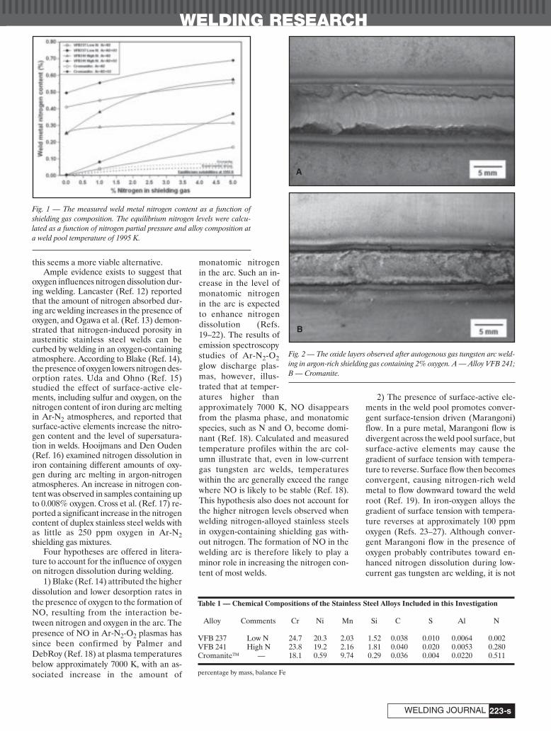
WELDING RESEARCH
-s223WELDING JOURNAL
this seems a more viable alternative.Ample evidence exists to suggest that
oxygen influences nitrogen dissolution dur-ing welding. Lancaster (Ref. 12) reportedthat the amount of nitrogen absorbed dur-ing arc welding increases in the presence ofoxygen, and Ogawa et al. (Ref. 13) demon-strated that nitrogen-induced porosity inaustenitic stainless steel welds can becurbed by welding in an oxygen-containingatmosphere. According to Blake (Ref. 14),the presence of oxygen lowers nitrogen des-orption rates. Uda and Ohno (Ref. 15)studied the effect of surface-active ele-ments, including sulfur and oxygen, on thenitrogen content of iron during arc meltingin Ar-N2 atmospheres, and reported thatsurface-active elements increase the nitro-gen content and the level of supersatura-tion in welds. Hooijmans and Den Ouden(Ref. 16) examined nitrogen dissolution iniron containing different amounts of oxy-gen during arc melting in argon-nitrogenatmospheres. An increase in nitrogen con-tent was observed in samples containing upto 0.008% oxygen. Cross et al. (Ref. 17) re-ported a significant increase in the nitrogencontent of duplex stainless steel welds withas little as 250 ppm oxygen in Ar-N2shielding gas mixtures.
Four hypotheses are offered in litera-ture to account for the influence of oxygenon nitrogen dissolution during welding.
1) Blake (Ref. 14) attributed the higherdissolution and lower desorption rates inthe presence of oxygen to the formation ofNO, resulting from the interaction be-tween nitrogen and oxygen in the arc. Thepresence of NO in Ar-N2-O2 plasmas hassince been confirmed by Palmer and DebRoy (Ref. 18) at plasma temperaturesbelow approximately 7000 K, with an as-sociated increase in the amount of
monatomic nitrogenin the arc. Such an in-crease in the level ofmonatomic nitrogenin the arc is expectedto enhance nitrogendissolution (Refs.19–22). The results ofemission spectroscopystudies of Ar-N2-O2glow discharge plas-mas, however, illus-trated that at temper-atures higher thanapproximately 7000 K, NO disappearsfrom the plasma phase, and monatomicspecies, such as N and O, become domi-nant (Ref. 18). Calculated and measuredtemperature profiles within the arc col-umn illustrate that, even in low-currentgas tungsten arc welds, temperatureswithin the arc generally exceed the rangewhere NO is likely to be stable (Ref. 18).This hypothesis also does not account forthe higher nitrogen levels observed whenwelding nitrogen-alloyed stainless steelsin oxygen-containing shielding gas with-out nitrogen. The formation of NO in thewelding arc is therefore likely to play aminor role in increasing the nitrogen con-tent of most welds.
2) The presence of surface-active ele-ments in the weld pool promotes conver-gent surface-tension driven (Marangoni)flow. In a pure metal, Marangoni flow isdivergent across the weld pool surface, butsurface-active elements may cause thegradient of surface tension with tempera-ture to reverse. Surface flow then becomesconvergent, causing nitrogen-rich weldmetal to flow downward toward the weldroot (Ref. 19). In iron-oxygen alloys thegradient of surface tension with tempera-ture reverses at approximately 100 ppmoxygen (Refs. 23–27). Although conver-gent Marangoni flow in the presence ofoxygen probably contributes toward en-hanced nitrogen dissolution during low-current gas tungsten arc welding, it is not
Fig. 1 — The measured weld metal nitrogen content as a function ofshielding gas composition. The equilibrium nitrogen levels were calcu-lated as a function of nitrogen partial pressure and alloy composition ata weld pool temperature of 1995 K.
Fig. 2 — The oxide layers observed after autogenous gas tungsten arc weld-ing in argon-rich shielding gas containing 2% oxygen. A — Alloy VFB 241;B — Cromanite.
Table 1 — Chemical Compositions of the Stainless Steel Alloys Included in this Investigation
Alloy Comments Cr Ni Mn Si C S Al N
VFB 237 Low N 24.7 20.3 2.03 1.52 0.038 0.010 0.0064 0.002VFB 241 High N 23.8 19.2 2.16 1.81 0.040 0.020 0.0053 0.280Cromanite™ — 18.1 0.59 9.74 0.29 0.036 0.004 0.0220 0.511
percentage by mass, balance Fe
A
B
Toit 8 07layout:Layout 1 7/6/07 9:35 AM Page 223

WELDING RESEARCH
-s224
expected to be the dominant mass flowmechanism in most welds.
3) Surface-active elements tend to oc-cupy a fraction of the available surfacesites, making it more difficult for nitrogento adsorb on or desorb from the metal sur-face (Refs. 19, 28). In view of the resultsobtained during the earlier stages of thisinvestigation, reduced surface availabilitymay be a viable explanation for the re-ported influence of oxygen.
4) The formation of an oxide layer onthe weld pool surface in the presence ofoxygen hampers the outflow of nitrogen
(Ref. 16). Surface oxide formation may bea likely explanation for the effect of oxygenon nitrogen dissolution, and needs to be in-vestigated further.The objective of this investigation wastherefore to systematically examine the in-fluence of oxygen additions to argon andargon-nitrogen shielding gas mixtures onnitrogen absorption and desorption duringautogenous arc welding, and to confirm themechanism responsible for enhanced nitro-gen dissolution in the presence of oxygen.
Experimental Procedure
Stainless Steel Alloys
During this investigation, the influenceof autogenous arc welding in argon-richshielding gas containing additions of oxy-gen and nitrogen on the nitrogen contentof two experimental stainless steels wasevaluated. The chemical compositions ofthese alloys, designated VFB 237 andVFB 241, are shown in Table 1. The ex-perimental alloys were designed to havecompositions similar to that of AISI 310,an austenitic stainless steel normally pro-duced without deliberate nitrogen addi-tion. This steel was selected as base alloybecause it solidifies as austenite and re-mains fully austenitic down to room tem-perature. This prevents bulk solid-statephase transformations, which may lead tochanges in the solid-state nitrogen solubil-ity, from taking place.
In order to study the influence of thebase metal nitrogen content on nitrogenabsorption and desorption during weld-ing, the experimental alloys were pro-duced with two nitrogen concentrations: alow nitrogen level (residual nitrogen con-tent of approximately 0.002%), and a highnitrogen level (approximately 0.28%).This nitrogen level exceeds the equilib-rium solubility limit of approximately0.25%, calculated at 1873 K and 1 atmos-phere nitrogen pressure.
The third steel included in this investi-gation is a high-nitrogen austenitic stain-less steel that, until recently, was commer-cially available in South Africa under thetrade name of Cromanite™. Whereas ni-trogen-alloyed stainless steels are nor-mally produced in pressurized furnaces,where a high-nitrogen partial pressureforces the nitrogen into solution, the highmanganese and chromium levels in Cro-manite raise the nitrogen solubility to suchan extent that it can be produced under at-mospheric pressure using conventionalsteel-making processes. Difficulties en-countered during the autogenous arc weld-ing of Cromanite using inert shielding gas(nitrogen losses, porosity, spattering, andmetal expulsion from the weld pool)prompted its inclusion in this investigation.
Welding Procedure
The stainless steel samples were hotrolled to a thickness of 6 mm, ground anddegreased. The plates were welded in aglove box using automatic autogenous gastungsten arc welding (GTAW). Direct cur-rent electrode negative polarity and a 2%thoriated tungsten electrode were used.To minimize atmospheric contamination,the glove box was flushed with argon for atleast fifteen minutes prior to welding, anda low argon flow rate was maintained dur-ing welding to ensure a slight positivepressure inside the glove box. Shieldingwas supplied by shielding gas flowingthrough the welding torch at a rate of 20L/min. Welding-grade argon and five pre-mixed shielding gases, listed in Table 2,were used. Welding was performed usinga current of 150 A, an arc length of 2 mm,and a welding speed of 2.7 mm/s. The mea-sured arc voltage varied from 15.7 ± 0.5 V(95% confidence interval) in shielding gaswithout oxygen, to 17.3 ± 0.6 V in shield-ing gas mixtures containing 2% oxygen.Instability of the arc, characterized byflashing, spattering, a hissing sound, andviolent metal expulsion from the pool,served as a visual indication of active ni-trogen degassing during welding.
It must be emphasized that the addi-tion of oxygen to inert shielding gas dur-ing GTAW is not recommended due to ox-idation and rapid degradation of thetungsten electrode. Although frequent re-grinding of the electrode was required, theGTAW process was selected for the excel-lent control it offers over heat input andwelding parameters, and because it allowsautogenous welding.
After welding, the nitrogen content ofeach weld was analyzed using an inert gasfusion analysis technique, taking care toremove the metal drillings required onlyfrom the weld. At least two analyses wereperformed on different samples to ensurerepeatability. In order to quantify the levelof oxygen absorption from the shieldinggas, the oxygen contents of welds per-formed in argon and in an argon-oxygenshielding gas mixture were also measured.
AUGUST 2007, VOL. 86
Fig. 3 — Scanning electron micrographs of thesurface oxide layers observed on welds performedin shielding gas containing argon and 2% oxygen.A — VFB 237; B — VFB 241; C — Cromanite.
Table 2 — Shielding Gases Used in this Investigation to Examine the Influence ofOxygen and Nitrogen Additions on NitrogenDissolution during Welding
Without O2 addition With O2 addition
Ar Ar + 2% O2
Ar + 1% N2 Ar + 1% N2 + 2% O2
Ar + 5% N2 Ar + 5% N2 + 2% O2
percentage by volume
A
B
C
Toit 8 07layout:Layout 1 7/6/07 9:35 AM Page 224

WELDING RESEARCH
-s225WELDING JOURNAL
Results and Discussion
Visual Observation and Weld Metal Nitrogen Content
The average weld metal nitrogen con-tents are given in Table 3, and showngraphically in Fig. 1. The equilibrium ni-trogen solubilities were calculated usingWada and Pehlke’s equations and interac-tion parameters (Ref. 29) at an averageweld pool temperature of 1995 K (Ref.10). Appendix A displays photographs ofthe welds and details some of the observa-tions made during welding.
Figure 1 confirms that the weld metalnitrogen contents exceed the equilibriumconcentrations calculated from Sieverts’law for the shielding gases evaluated. The
addition of nitrogen to the inert shieldinggas raises the weld metal nitrogen concen-tration in all three alloys. The results alsodemonstrate that the presence of 2% oxy-gen in the shielding gas increases the weldmetal nitrogen contents significantly.
During welding, the experimental steelwithout any deliberate nitrogen addition(VFB 237) displayed a stable arc in all theshielding gas atmospheres. None of theflashes, spattering, and violent metal ex-pulsion characteristic of active nitrogendegassing was noted, and no porosity wasobserved on the weld surfaces. The weldswere smooth, with fine surface ripples, al-though more surface oxidation was evi-dent after welding in oxygen-containingshielding gas. Arc stability and the absenceof porosity are consistent with the weld
metal nitrogen content remaining below0.2% in all cases, except for the oxygen-containing shielding gas with the highestnitrogen content (0.2% is the equilibriumsolubility limit at 1995 K and 1 atmospherenitrogen pressure).
The beneficial effect of oxygen waseven more apparent on welding the high-nitrogen experimental alloy (VFB 241).Stable arcs were observed when welding inargon and in an argon-oxygen shieldinggas mixture. With 1% nitrogen in theshielding gas, the presence of oxygen sup-pressed nitrogen degassing (even thoughthe measured weld metal nitrogen contentexceeds the solubility limit at 1 atmos-phere nitrogen pressure) and resulted in aconsiderably more stable arc. The sametrend was observed in shielding gas con-
Fig. 4 — Calculated equilibrium compositions of the liquid metal (upper graphs) and slag (lower graphs) for VFB 237 weld metal reacted with different amountsof oxygen. The results are shown for two temperatures. A — 1750 K; B — 1995 K.
Table 3 — Average Weld Metal Nitrogen Content of Welded Samples as a Function of Shielding Gas Composition
Alloy Base Weld metal N content for various shielding gas compositionsMetal N Ar Ar + 2% O2 Ar + 1% N2 Ar + 1% N2 + 2%O2 Ar + 5% N2 Ar + 5% N2 + 2% O2
Content
VFB 237 0.002% 0.004% 0.004% 0.040% 0.080% 0.170% 0.370%VFB 241 0.280% 02.50% 0.255% 0.290% 0.380% 0.315% 0.575%Cromanite™ 0.511% 0.410% 0.495% 0.450% 0.555% 0.555% 0.690%
percentage by mass
A B
Toit 8 07layout:Layout 1 7/6/07 9:36 AM Page 225

WELDING RESEARCH
-s226
taining 5% nitrogen, where the presenceof oxygen suppressed nitrogen degassingand reduced porosity. The presence ofoxygen in Ar-N2 shielding gas mixtures re-sulted in smoother welds, with finer sur-face ripples.
In Cromanite, welding in argon andargon-nitrogen mixtures caused degassingand porosity. This is consistent with theweld metal nitrogen contents exceedingthe equilibrium solubility limit of 0.32%(calculated at 1995 K and 1 atmosphere N2pressure) in all cases. The addition of oxy-gen to the shielding gas resulted in higher
weld metal nitrogen contents in all theshielding gases evaluated. Oxygen alsobrought about smoother arcs, less de-gassing, and lower levels of porosity. Theaddition of 2% oxygen to argon shieldinggas eliminated porosity and limited nitro-gen losses, resulting in a weld metal nitro-gen content comparable to that of the basemetal prior to welding (0.495% comparedto 0.51% prior to welding, and 0.41% afterwelding in argon). In nitrogen-containingshielding gas, the addition of oxygen re-sulted in the formation of fine pores at theweld interface, rather than large pores
within the weld metal. Welds appearedsmoother in the presence of oxygen, withfiner surface ripples.
Weld Oxygen Content and Surface Availability
The measured weld metal oxygen con-tents after welding in argon and in argon-oxygen shielding gas mixtures are shownin Table 4. These results indicate that verylittle oxygen was absorbed by the experi-mental alloy welds, and that welds pro-duced in argon-oxygen mixtures did notcontain significantly more oxygen thanwelds produced in argon. The beneficialinfluence of oxygen in suppressing nitro-gen degassing is therefore not consistentwith a site-blockage model. This was con-firmed by estimating the total fraction ofvacant surface sites (or the surface avail-ability), (1–θT), from Equation 1 (Ref. 19)for each weld. This equation is a simplifiedversion of an equation derived by Byrneand Belton (Ref. 30) to describe the effectof sulfur and oxygen on the fraction of va-cant surface sites in the adsorbed surfacelayer, as determined from measured rateconstants for the reaction of N2 with liquidiron and Fe-C alloys. The slight decreasein surface availability on welding in oxy-gen-containing shielding gas (amountingto reductions of 3.3 and 8.3% in VFB 237and VFB 241, respectively) does not ade-quately explain the observed increase inweld metal nitrogen contents.
(1)
where KOads is the equilibrium constant
for the adsorption of oxygen, given by
11
1
−( ) =
+ −( )+ −( )
θT
oads
sadsK wt O K wt S% %
AUGUST 2007, VOL. 86
Table 4 — Average Weld Metal Oxygen Content after Welding in Ar and Ar-O2 Shielding Gas Mixtures, and the Calculated Surface Availability at1995 K
Alloy Base Metal Ar Ar + 2% O2
Oxygen Weld Metal Surface Weld Metal SurfaceContent Oxygen Availability Oxygen Availability
Content Content
VFB 237 0.030% 0.031% (1 - θT) = 0.361 0.033% (1 - θT) =0.349VFB 241 0.020% 0.021% (1 - θT) = 0.411 0.027% (1 - θT) = 0.377Cromanite™ 0.062% 0.022% (1- θT) = 0.496 0.062% (1 - θT) = 0.297
Table 5 — Weld Pool Depth-to-Width Ratio (D/W) as a Function of Shielding Gas Composition
Alloy Ar Ar + 2% O2 Ar + 1%N2 Ar + 1%N2 + 2%O2 Ar + 5%N2 Ar + 5%N2+2%O2
VFB 237 D/W = 0.48 D/W = 0.20 D/W = 0.51 D/W = 0.20 D/W = 0.40 D/W = 0.14VFB 241 D/W = 0.57 D/W = 0.11 D/W = 0.53 D/W = 0.08 D/W = 0.38 D/W = 0.08Cromanite™ D/W = 0.32 D/W = 0.28 D/W = 0.43 D/W = 0.24 D/W = 0.34 D/W = 0.24
Fig. 5 — Calculated equilibrium compositions of the liquid metal (upper graphs) and slag (lower graphs)for VFB 241 weld metal reacted with different amounts of oxygen. The results are shown for two tem-peratures. A — 1750 K; B — 1995 K.
A B
Toit 8 07layout:Layout 1 7/6/07 9:36 AM Page 226

WELDING RESEARCH
-s227WELDING JOURNAL
Equation 2, and KSads is the equilibrium
constant for the adsorption of sulfur,where KS
ads is assumed to be equal to 65per wt-% sulfur (reported value at 1873K).
(2)
In Cromanite, the weld oxygen content de-creased significantly on welding in argon.This may be attributed to effective deoxi-dation of the weld pool in the presence ofhigh levels of manganese. Welding in anargon-oxygen shielding gas mixture, how-ever, restored the weld oxygen content toits original base metal concentration. Thisincrease in oxygen content, compared tothat measured after welding in pure argon,results in a 40% decrease in calculatedsurface availability. This reduction in sur-face availability probably played a role inincreasing the nitrogen content of Cro-manite welds.
Influence of Oxygen on Weld Pool Dimensions
As shown in Table 5, the addition ofoxygen to argon-rich shielding gas was ob-served to change the weld depth-to-width(D/W) ratio. In VFB 237, D/W variedfrom between 0.40 and 0.51 in shieldinggas without O2, to 0.2 or less in oxygen-containing shielding gas. The change inweld pool shape was even more pro-nounced in VFB 241, with D/W varying
from between 0.38 and 0.57 in shieldinggas without O2, to 0.11 or less in shieldinggas containing O2. In Cromanite, the ad-dition of oxygen changed D/W from be-tween 0.32 and 0.43 in shielding gas with-out O2, to between 0.24 and 0.28 inshielding gas containing oxygen.
As a surface-active element, oxygen isexpected to increase the weld D/W ratioby promoting convergent surface flow inthe weld pool. The weld oxygen contentsof all three alloys exceed the 100 ppm limitrequired for convergent flow, ensuringgood penetration and high D/W ratiosafter welding in argon. The addition ofoxygen, however, resulted in considerablereductions in the weld D/W ratio in the ex-perimental alloys, even though the weldoxygen levels did not differ appreciablyfrom those measured after welding inargon. This reduction in weld D/W ratio isconsistent with results published by Lu etal. (Refs. 23–27). These authors examinedthe effects of O2 and CO2 additions toargon shielding gas on the weld pool shapeduring GTAW of AISI 304L stainless steel.Their results confirmed that the addition
of up to 0.6% oxygen to argon shieldinggas increased the weld oxygen content, re-sulting in increased weld D/W ratios. Withthe addition of more than 0.6% oxygen,however, the weld oxygen contents stabi-lized at levels between 200 and 250 ppm,regardless of the shielding gas oxygen con-tent, and the weld pool shape revertedback to wide, shallow beads with low D/Wratios. This was attributed to the forma-tion of a heavy oxide layer on the weldpool surface in the presence of more than0.6% oxygen in the shielding gas. Thisoxide layer apparently inhibits convergentMarangoni flow and acts as a barrier foroxygen absorption. In view of these re-sults, the formation of surface oxides dur-ing welding was examined in more detail.
Oxide Formation during Welding
Surface oxide layers were present on allwelds performed in oxygen-containingshielding gas. In the experimental alloys,heavy oxide layers were observed at theweld periphery adjacent to the weld inter-face, while the rest of the weld pool sur-
log
.
per wt-% oxygen
K
T
oads =
−12955 4 96
Fig. 6 — Calculated equilibrium compositions of the liquid metal (upper graphs) and slag (lower graphs) for Cromanite weld metal reacted with different amountsof oxygen. The results are shown for three temperatures. A — 1750 K; B — 1995; C — 2275 K. For the lowest temperature (1750 K), no liquid slag forms untilthe amount of reacted oxygen exceeds 250 ppm, as solid Al2O3 and MnAl2O4 form instead. For the two higher temperatures, the absence of slag at lower levelsof reacted oxygen indicates that all the oxygen dissolves in the metal.
Table 6 — Compositions of the Weld Oxide Layers Estimated Using SEM-EDS Analysis
Alloy SiO2 Cr2O3 MnO Al2O3
VFB 237 44.2 16.8 38.6 0.4VFB 241 38.2 19.0 39.3 1.9Cromanite™ 2.3 62.3 26.7 0.9
percentage by mass
A B C
Toit 8 07layout:Layout 1 7/6/07 9:37 AM Page 227

WELDING RESEARCH
AUGUST 2007, VOL. 86-s228
face remained oxide-free — Fig. 2A. Theoxide layers at the weld periphery werecontinuous, fairly uniform, and tightly ad-herent. Although a heavy oxide layer wasobserved at the periphery of Cromanitewelds after welding in oxygen-containingshielding gas (Fig. 2B), the oxide layer wasnot as continuous or adherent as in thecase of the experimental alloys, and theoxide appeared to be more granular.
In order to study these surface oxidelayers in more detail, cross sections of thewelds were mounted in resin, polished toa 3 μm finish, and examined using a scan-ning electron microscope (SEM). Micro-graphs of the oxide layers are shown inFig. 3A – C. The surface oxides on the ex-perimental steels formed continuous lay-ers over short distances at the weld poolperiphery, while the central region of theweld was oxide-free. Average oxide thick-nesses of 19.7 ± 3.8 μm and 17.1 ± 4.1 μm(95% confidence interval) were measuredfor VFB 237 and VFB 241, respectively.No oxide particles were observed withinthe weld metal of the experimental alloysafter welding in oxygen-containing shield-ing gas.
The SEM examination confirmed thatthe surface layers on Cromanite welds areless uniform, and not as continuous asthose observed on the experimental alloys.The average thickness of the Cromaniteoxide layer was measured as 17.7 ± 4.3μm. The layer had a granular appearance,and consisted of a mixture of oxide parti-cles and small metal droplets. Althoughactive degassing was not observed duringwelding in argon-oxygen mixtures, thepresence of metal droplets in the surfacelayer can probably be attributed to nitro-gen evolution during welding. It is postu-lated that the formation of nitrogen bub-bles in the weld pool disrupted the oxidelayer and generated a spray of metaldroplets that became trapped in the oxidelayer. Due to the granular nature of thelayer, the surface oxide probably acted asa less effective barrier for oxygen absorp-tion, which may account for the higheroxygen content measured in these welds.Small oxide inclusions (5 μm or less in di-ameter) were observed within the Cro-manite weld metal.
The surface oxide compositions weredetermined using SEM-EDS analysistechniques (Table 6). The oxide layers onthe experimental welds were shown toconsist of almost equal amounts of SiO2and MnO, with some CrOx (assumed to beCr2O3) and a small amount of Al2O3. Noiron was detected in any of the oxide lay-ers. The Cromanite surface oxide layerwas shown to consist largely of Cr2O3, withsome MnO and low levels of SiO2 andAl2O3.
Because of the important influence of
the dissolved weld oxygen content on ni-trogen absorption and degassing duringwelding, the factors that control this oxy-gen content need to be understood. Thoseelements that form the most stable oxidestend to remove dissolved oxygen from theweld metal. In principle, it is possible toestimate the weld pool oxygen content bycalculating the deoxidation equilibria forsuch elements. This calculation is compli-cated by the presence of several reactive(deoxidizing) elements in the weld pool,namely aluminum, silicon, manganese,and chromium. The oxide compositions(Table 6) demonstrate that these elementsreacted simultaneously, and apparentlyformed a liquid oxide mixture (slag) on theweld surface.
In order to evaluate the complex reac-tion equilibrium of the four main reactiveelements in the weld pool, the FactSagepackage (v. 5.4.1) (Ref. 31) was used, withthe alloy compositions (Table 1) as inputs.In the calculation, different amounts ofoxygen were conceptually allowed to reactwith the steel to equilibrium. Equilibriumphases considered were the liquid steel(modeled using FactSage liquid solutionphase FTmisc-FeLQ (Ref. 32)), liquid slag(modeled using FactSage liquid FToxid-SLAGA), various solid-solution oxides,and stoichiometric oxides such as SiO2,Al2O3, MnO, MnAl2O4, and Cr2O3. Twotemperatures were used in the majority ofcalculations. The lower temperature, 1750K, is approximately 20 K higher than theequilibrium liquidus temperature of AISI310 and about 40 K higher than the liq-uidus of Cromanite. This temperaturerepresents the cooler weld pool periphery.The higher temperature, 1995 K, is the av-erage temperature of the pool measuredearlier (Ref. 10). An additional tempera-ture, 2275 K, was used in calculating thedeoxidation equilibria for Cromanite.This temperature falls within the pre-dicted weld pool peak temperature range,estimated for AISI 304 during GTAW at acurrent of 150 A and a welding speed of2.5 mm/s (Ref. 33).
The results of the FactSage calcula-tions are presented in Figs. 4–6. In each ofthese figures, the metal composition isgiven in the upper graph, and the compo-sition of the oxide (liquid slag) in the lowergraph. If no slag composition is given, noslag formed — typically because all theoxygen dissolved in the metal. In mostcases, the oxygen was present in two formsin the equilibrium reaction products: asdissolved oxygen in the steel, and as liquidslag. Occasionally (for the lower reactiontemperature), solid Al2O3 or (in the caseof Cromanite) MnAl2O4 were stable, butonly at low amounts of reacted oxygen,typically less than 250 ppm. The mainform of chromium oxide in the slag was
found to be CrO, with only minor levels ofCr2O3.
For all three steel compositions, Al2O3is a prominent component of the first slagto form. However, the low level of dis-solved aluminum is largely removed fromthe melt at small degrees of reaction withoxygen. The analyzed oxide compositions(Table 6) indicate that, for the experimen-tal steels, the amount of oxygen that hadreacted with the weld metal was around0.1% of the steel mass, yielding a slag con-sisting mainly of SiO2 and MnO, with a sig-nificant amount of CrOx. For these inter-mediate amounts of reacted oxygen, theanalyzed weld oxygen content (Table 4)agrees reasonably well with the predictedoxygen content at 1995 K. For this degreeof reaction, where the weld contains littlealuminum, the dissolved oxygen content ismainly determined by the weld siliconcontent. This is confirmed by the high slagSiO2 content, as well as the noticeable dif-ference between VFB 241 and VFB 237:the former has a higher silicon content,which corresponds to a lower dissolvedoxygen content. This effect is also notice-able in the weld metal analyses (Table 4).
The situation is rather different forCromanite (Fig. 6), where MnO is themajor slag oxide in most cases. The exper-imental observations of high weld oxygencontents (Table 4) and high slag CrOx con-tents (Table 6) indicate that, for this steel,the analyzed compositions correspond toboth a higher equilibration temperatureand a higher degree of reaction with oxy-gen than for the experimental steels.
These calculations confirm that a sur-face oxide layer forms at the weld periph-ery on welding in oxygen-containingshielding gas. In all three alloys, more oxy-gen dissolves in the weld metal at highertemperatures, suppressing the formationof slag at lower amounts of reacted oxy-gen. The higher temperatures under thearc therefore prevent the formation of amolten slag layer in the central regions ofthe pool.
Proposed Mechanism
The results of this investigation suggestthat the increased weld metal nitrogencontents measured after welding in oxy-gen-containing shielding gas cannot be at-tributed only to enhanced convergentMarangoni flow or increased surface cov-erage. The addition of oxygen to argonshielding gas raised the weld metal nitro-gen contents even when mass flow in thepool was clearly divergent. Welding in oxy-gen-containing shielding gas resulted inhigher weld metal nitrogen contents with-out any significant increase in weld oxygencontent, suggesting that reduced surfaceavailability plays a minor role in enhanc-
Toit 8 07layout:Layout 1 7/6/07 9:38 AM Page 228

WELDING RESEARCH
-s229WELDING JOURNAL
ing nitrogen dissolution. The conclusioncan be drawn that the higher weld metalnitrogen contents observed in the pres-ence of oxygen are mainly due to the for-mation of a surface oxide layer.
Any mechanism accounting for therole of the surface slag layer has to be con-sistent with the kinetic model developedearlier (Ref. 11). This model states thatthe weld metal nitrogen content is deter-mined by the amounts of nitrogen enter-ing and leaving the weld pool per unittime.
Nitrogen enters the pool from the arcatmosphere, i.e., the dissolution ofmonatomic nitrogen from the arc plasmainto the liquid metal, and from nitrogen-containing base metal melting at the lead-ing edge of the pool.
Dissolved nitrogen is removed fromthe weld pool by recombining to form N2molecules that escape to the atmosphere,and through solidification of nitrogen-containing weld metal at the rear of thepool.
Since the travel speed was kept con-stant, it follows that the melting and solidi-fication rates at the leading and trailingedges of the pool did not vary significantlywith changes in shielding gas composition.The presence of a slag layer can thereforeinfluence the amounts of nitrogen enteringand leaving the pool due to melting and so-lidification only through a change in theweld pool dimensions (in particular thepool volume and length). To examine theinfluence of a change in pool dimensions onthe weld metal nitrogen content, the weldpool length and volume were measuredafter welding in various shielding gases andsubstituted into the kinetic model. Themodel revealed that the increase in poollength and volume observed after weldingin oxygen-containing shielding gas does notresult in any appreciable change in the pre-dicted steady-state weld metal nitrogencontent. The presence of a surface slaglayer is therefore not expected to affect theamounts of nitrogen entering and leavingthe weld pool through melting and resolid-ification to any significant extent.
The presence of a surface oxide layercan influence the absorption ofmonatomic nitrogen from the arc and theevolution of nitrogen from the pool by act-ing as a barrier between the liquid weldmetal and the arc atmosphere. Absorptionof monatomic nitrogen, however, occursat the interface between the arc plasmaand the liquid weld metal, the area notcovered by the oxide layer. Absorption ofnitrogen from the arc is therefore not in-fluenced by the presence of oxygen. Therecombination of nitrogen to form N2molecules occurs over the entire weld poolsurface. The presence of a slag layer at theweld periphery is thus expected to retard
nitrogen evolution by reducing the surfacearea available for the adsorption of atomicnitrogen prior to recombination. Thepresence of a surface oxide layer at theweld pool periphery therefore reduces theamount of nitrogen leaving the weld poolper unit time, whereas the amount of ni-trogen entering the pool is not influencedto any significant extent. This results in anincrease in the measured weld metal ni-trogen content.
The high nitrogen content measured inCromanite after welding in oxygen-containing shielding gas can probably be at-tributed to the high nitrogen solubility inthe alloy, the granular nature of the oxideand the higher weld oxygen levels. Since therecombination of adsorbed nitrogen toform N2 requires two vacant surface sites,and the dissolution of monatomic nitrogenfrom the arc only one vacant site, the sur-face slag layer retards nitrogen desorptionto a greater extent than nitrogen absorp-tion. The granular nature of the oxide layertherefore facilitates greater nitrogen ab-sorption, while retarding nitrogen desorp-tion in the form of N2. This results in highweld metal nitrogen contents after weldingin oxygen-containing shielding gas.
Conclusions
• The addition of nitrogen to argonshielding gas during autogenous arc weld-ing raises the nitrogen content of stainlesssteel welds, but increases the likelihood ofactive degassing and porosity. An increasein base metal nitrogen content results inhigher weld metal nitrogen levels.
• The addition of 2% oxygen to argonand argon-nitrogen shielding gas mixturesincreases the weld metal nitrogen content,stabilizes the arc, suppresses degassingand limits nitrogen-induced porosity. Theaddition of oxygen to the shielding gasdoes not raise the weld oxygen content toany significant extent.
• Thermodynamic calculation of thedeoxidation equilibria in the weld metaldemonstrates that a liquid slag layer formson the weld pool surface during welding inoxygen-containing shielding gas. This slaglayer forms readily at the cooler weld pe-riphery, but is suppressed by the highertemperatures under the arc due to in-creased oxygen solubility in the moltenmetal.
• The slag layer that forms at the weldperiphery in the presence of oxygen retardsnitrogen degassing by reducing the surfacearea available for the adsorption of nitro-gen atoms prior to recombination. The ab-sorption of monatomic nitrogen is, how-ever, not strongly affected by the oxidelayer, since absorption occurs mostly at theinterface between the arc plasma and theliquid metal, the area not covered by oxide
during welding. The surface oxide layer atthe weld periphery therefore reduces theamount of nitrogen leaving the weld perunit time, whereas the amount of nitrogenentering the pool is not influenced signifi-cantly. This results in an increase in themeasured weld metal nitrogen content.
Acknowledgments
Special thanks to Columbus Stainlessfor performing the nitrogen and oxygenanalyses and the University of Pretoria forproviding laboratory facilities. The assis-tance of Karin Frost and Charl Smal isgratefully acknowledged.
References
1. Speidel, M. O., and Uggowitzer, P. J.1992. High manganese, high nitrogen austeniticstainless steels: their strength and toughness.Proceedings of the High Manganese, High Nitro-gen Austenitic Stainless Steels Conference,Chicago, Ill., pp. 135–142. ASM International.
2. Reed, R. P. 1989. Nitrogen in austeniticstainless steels. JOM 41(3): 16–21.
3. Zackay, V. F., Carlson, J. F., and Jackson,P. L. 1956. High nitrogen austenitic Cr-Mnsteels. Transactions of the American Society forMetals 48: 509–525.
4. Okagawa, R. K., Dixon, R. D., and Olson,D. L. 1983. The influence of nitrogen fromwelding on stainless steel weld metal mi-crostructures. Welding Journal 62(8): 204-s to209-s.
5. Franks, R., Binder, W. O., and Thompson,J. 1955. Austenitic chromium-manganese-nickel steels containing nitrogen. Transactionsof the American Society for Metals 47: 231–266.
6. Janik-Czachor, M., Lunarska, E., andSzklarska-Smialowska, Z. 1975. Effect of nitro-gen content in a 18Cr-5Ni-10 Mn stainless steelon the pitting susceptibility in chloride solu-tions. Corrosion 31(11): 394–398.
7. Ogawa, T., Aoki, S., Sakamoto, T., and Za-izen, T. 1982. The weldability of nitrogen-con-taining austenitic stainless steel: Part I — Chlo-ride pitting corrosion resistance. WeldingJournal 6(5): 139-s to 148-s.
8. Mozhi, T. A., Clark, W. A. T., Nishimoto,K., Johnson, W. B., and MacDonald, D. D.1985. The effect of nitrogen on the sensitizationof AISI 304 stainless steel. Corrosion 41(10):555–559.
9. Beneke, R., and Sandenbergh, R.F. 1989.The influence of nitrogen and molybdenum onthe sensitization properties of low-carbonaustenitic stainless steels. Corrosion Science29(5): 543–555.
10. Du Toit, M., and Pistorius, P. C. 2003. Ni-trogen control during the autogenous arc weld-ing of stainless steel — Part 1: Experimental ob-servations. Welding Journal 82(8): 219-s to224-s.
11. Du Toit, M., and Pistorius, P. C. 2003. Ni-trogen control during the autogenous arc weld-
Toit 8 07layout:Layout 1 7/6/07 9:38 AM Page 229

WELDING RESEARCH
AUGUST 2007, VOL. 86-s230
ing of stainless steel — Part 2: A kinetic modelfor nitrogen absorption and desorption. Weld-ing Journal 82(9): 231-s to 237-s.
12. Lancaster, J. F. 1999. Metallurgy of Weld-ing. p. 212, Cambridge, Abington Publishing.
13. Ogawa, T., Suzuki, K., and Zaizen, T.1984. The weldability of nitrogen-containingaustenitic stainless steel: Part II — Porosity,cracking and creep properties. Welding Journal63(7): 213-s to 223-s.
14. Blake, P. D. 1979. Nitrogen in steel weldmetals. Metal Construction 11(4): 196–197.
15. Uda, M., and Ohno, S. 1973. Effect ofsurface active elements on nitrogen content ofiron under arc melting. Transactions of the Na-tional Research Institute of Metallurgy 15(1): 20to 28.
16. Hooijmans, J. W., and Den Ouden, G.1992. The influence of oxygen on nitrogen ab-sorption during arc melting of iron. WeldingJournal 71(10): 377-s to 380-s.
17. Cross, C. E., Hoffmeister, H., and Huis-mann, G. 1997. Nitrogen control in hyperbaricwelding of duplex stainless steel. Welding in theWorld 39(3): 154–161.
18. Palmer, T. A., and DebRoy, T. 1998. En-hanced dissolution of nitrogen during gas tung-sten arc welding of steels. Science and Technol-ogy of Welding and Joining 3(4): 190–203.
19. Katz, J. D., and King, T. B. 1989. The ki-netics of nitrogen absorption and desorptionfrom a plasma arc by molten iron. MetallurgicalTransactions B 20B(2): 175–185.
20. Bandopadhyay, A., Banerjee, A., andDebRoy, T. 1992. Nitrogen activity determina-tion in plasmas. Metallurgical and MaterialsTransactions B 23B(2): 207–214.
21. Mundra, K., and DebRoy, T. 1995. Ageneral model for partitioning of gases betweena metal and its plasma environment. Metallurgi-cal and Materials Transactions B 26B(1):149–157.
22. Palmer, T. A., and DebRoy, T. 1996.Physical modeling of nitrogen partition be-tween the weld metal and its plasma environ-ment. Welding Journal 75(7): 197-s to 207-s.
23. Lu, S., Fujii, H., and Nogi, K. 2004.Marangoni convection and weld shape varia-tions in Ar-O2 and Ar-CO2 shielded GTA weld-ing. Materials Science and Engineering A 380(1-2): 290–297.
24. Lu, S., Fujii, H., and Nogi, K. 2005. In-fluence of welding parameters and shielding gascomposition on GTA weld shape. ISIJ Interna-tional 45(1): 66–70.
25. Lu, S., Fujii, H., and Nogi, K. 2004. Weldshape comparison with iron oxide flux and Ar-O2 shielding gas in gas tungsten arc welding.Science and Technology of Welding and Joining9(3): 272 to 276.
26. Lu, S., Fujii, H., Tanaka, M., and Nogi,K. 2004. Effects of welding parameters on theweld shape in Ar-O2 and Ar-CO2 shielded GTAwelding. IIW Document XII-1801-04, Interna-tional Institute of Welding.
27. Lu, S., Fujii, H., Sugiyama, H., Tanaka,M., and Nogi, K. 2003. Effects of oxygen addi-
tions to argon shielding gas on GTA weld shape.ISIJ International 43(10): 1590–1595.
28. Uda, M., and Ohno, S. 1978. Spatteringphenomenon for iron-nitrogen system duringarc melting. Transactions of the National Re-search Institute of Metallurgy 20(6): 16–23.
29. Wada, H., and Pehlke, R. D. 1977. Solu-bility of nitrogen in liquid Fe-Cr-Ni alloys con-taining manganese and molybdenum. Metallur-gical Transactions B 8B: 675–682.
30. Byrne, M., and Belton, G. R. 1983. Stud-ies of the interfacial kinetics of the reaction ofnitrogen with liquid iron by the 15N-14N iso-tope exchange reaction. Metallurgical Transac-tions B 14B(3): 441–449.
31. Bale, C. W., Chartrand, P., Degterov, S.A., Eriksson, G., Hack, K., Ben Mahfoud, R.,Melançon, J., Pelton, A. D., and Petersen, S.2002. FactSage thermochemical software anddatabases. Calphad 26(2): 189–228.
32. Jung, I.-H., Decterov, S. A., and Pelton,A. D. 2004. A thermodynamic model for deox-idation equilibria in steel. Metallurgical and Ma-terials Transactions B 35B(3): 493–507.
33. Zacharia, S. A., David, J. M., Vitek, J.M., and DebRoy, T. 1989. Weld pool develop-ment during GTA and laser beam welding ofType 304 stainless steel. I. Theoretical analysis.Welding Journal 68(12): 499-s to 509-s.
Toit 8 07layout:Layout 1 7/6/07 9:40 AM Page 230

WELDING RESEARCH
-s231WELDING JOURNAL
ABSTRACT. Double-electrode gas metalarc welding (DE-GMAW) is a novelprocess that decouples the melting currentinto base metal current and bypass currentby adding a bypass torch to a conventionalGMAW system to establish a bypass arc.This makes it possible to increase themelting current while the base metalcurrent can be controlled at a desired level.Experiments have been done to find theconditions that can assure a stable bypassarc is established/maintained between thewelding wire and the bypass torch. Tocontrol the base metal current at thedesired level, a group of power resistors isadded in the bypass loop. The resistance ofthe power resistor group is adjusted real-time by changing the combination of theresistors, and the change in the resistanceresults in a change in the bypass currentand thus a change in the base metalcurrent. A model has been developed tocorrelate the change of the resistanceneeded to achieve the desired base metalcurrent to the deviation of the base metalcurrent from its desired level. Experimentsdemonstrated that the developed controlsystem can adjust the bypass current in agreat range to maintain the base metalcurrent at the desired levels.
Introduction
Gas metal arc welding (GMAW) is amajor process for metals joining.Conventional GMAW is normally used inthe direct current electrode positivepolarity (DCEP), in which the wire isconnected to the positive terminal of thepower source and the power sourceoperates in the constant voltage (CV)mode. The reverse polarity contributes toa stable arc, uniform metal transfer, andgreater penetration. A CV power sourcecan adjust the welding current such thatthe wire melting rate is equal to the givenwire feed speed, and the welding voltage,
or arc length, is maintained constant. Forautomatic and semiautomatic welding, theproductivity is mostly determined by thetravel speed provided that the weldingperformance criterion is met, for example,the cross-section area of the weld bead isnot changed with the travel speed.Obviously, a faster travel speed requires alarger wire melting rate such that themelted metal is enough to form a longerweld bead in a unit time. Based on thework by Waszink and Heuvel (Ref. 1), themelting rate can be calculated by thefollowing formula if the metal transfer isin spray mode, i.e., the melting current isgreater than 250 A for mild steels.
(1)where m (kg/s) is the melting rate, I (A) isthe total melting current, L (m) is the wireextension, and S (m2) is the cross-sectionalarea of the wire. That means the meltingcurrent must be increased in order toincrease the melting rate. Unfortunately,the melting current in conventionalGMAW is the same as the base metalcurrent. Thus, a greater melting currentnot only melts the wire faster, but alsoincreases the based metal heat input,which contributes to increasing the weldpool, residual stress, and distortion. Thisfundamental characteristic of conventionalGMAW makes it difficult to increase thedeposition rate without imposing excessive heatto the base metal.
While tandem GMAW (Refs. 2, 3), T.I.M.E(Refs. 4, 5), and variable-polarity GMAW (Refs.6–8) have successfully increased the melting rateto certain degrees without changing thisfundamental characteristic of conventional
GMAW, the double-electrode GMAW process(Ref. 9) proposes a way to change thisfundamental characteristic so that themelting rate can be freely increased. In aprevious preliminary study (Ref. 9), thischange was realized by adding a plasmatorch and a second power supply to aconventional GMAW system. In thisstudy, the DE-GMAW process isimplemented without the second powersupply. In addition, the plasma torch isreplaced by a gas tungsten arc weldingtorch which is more durable and costeffective.
Principles of DE-GMAW
A DE-GMAW system (Fig. 1) isformed in this study by adding anonconsumable tungsten electrode todecouple the melting current into basemetal current and bypass current
(2)where I (A) is the total current or meltingcurrent, Ibm (A) is the base metal current,Ibp (A) is the bypass current. As can beseen in Fig. 1, the bypass current flowsback to the power source through thebypass torch without going through thebase metal. As a result, the base metalcurrent is no longer the same as themelting current and the fundamentalcharacteristics in conventional GMAW nolonger apply. On the other hand, as isillustrated later, the total melting currentis still determined by the wire feed speedand welding voltage as in conventionalGMAW. Hence, the bypass arc can changeand reduce the base metal current withoutchanging the total melting current.
The bypass loop in Fig. 1 includes anadjustable resistor. When this system isused, the user can choose the wire feedspeed based on the deposition ratedesired. The total current which melts thewire will be dictated by the wire feedspeed and the arc voltage setting. Whenthe resistance of the adjustable resistor iszero, the majority of the melting currentwould tend to flow through the bypassloop because the tungsten emits
�mI L
SI= × + ×− −5 1 10 2 2 1013
26. .
I I Ibm bp= +
KEYWORDS
Double-ElectrodeGMAWBase Metal CurrentControlHeat InputWelding Productivity
Double-Electrode GMAW Process and Control
A novel welding process adds a GTAW torch to a conventional GMAW system to create a bypass arc for increasing melting
current while controlling base current
BY K. H. LI, J. S. CHEN, AND Y. M. ZHANG
KEHAI LI, JINSONG CHEN, and YUMINGZHANG ([email protected]) are withCenter for Manufacturing and Department ofElectrical and Computer Engineering, Universityof Kentucky, Lexington, Ky.
.
Li 8 07layout:Layout 1 8/6/07 5:00 PM Page 231

WELDING RESEARCH
AUGUST 2007, VOL. 86-s232
electrons easier than the workpiece. Tocontrol the base metal current at thedesired level, the resistance of theadjustable resistor is feedback adjustedusing a current sensor that measures thebase metal current — Fig. 1.
It is apparent that the heat absorbed bythe tungsten and the power resistor iswasted. However, this heat would beapplied to the base metal if the bypassloop is not applied as in conventionalGMAW so that the base metal is over-heated. That is, in conventional GMAW,this heat is not only wasted, but alsoproduces harm to the process.
Process Stability
The presence of the bypass arc is thefundamental characteristic of the DE-GMAW process. A stable bypass arcassures the DE-GMAW function. Hence,the behavior and stability of the bypass arcmust be studied and understood. For thenovel DE-GMAW system demonstratedin Fig. 1, the behavior and stability of thebypass arc were determined by severalparameters discussed below.
Bypass Electrode
In the proposed DE-GMAW process,there are two cathodes: one is theworkpiece, and the other is the bypasselectrode, which forms the bypass arc withthe welding wire. The bypass electrodemust have a high melting point and goodelectrical conductivity. Two materials havebeen tested during the implementation:water-cooled copper and tungsten. Butthe former appears too “cold” to ignite thebypass arc even though it is very close tothe GMAW arc. It was found the tungstenelectrode is a very active bypass electrode,as it is used in GTAW. Thus, a commercialGTAW torch is used to hold the tungstenelectrode and at the same time to providethe shielding gas for the bypass electrode.With a tungsten bypass electrode, the arcstability is significantly improved.
Shielding Gas for Bypass Electrode
To protect the tungsten electrode fromoxidizing, pure argon is recommended forshielding gas. Because of the action ofelectric field and arc radiation, the argonwill be ionized. This ionized argonatmosphere further improves the stabilityof the bypass arc. If the bypass current ishigher than 150 A, a water-cooling systemis required to protect the bypass torch.
Tungsten-to-Welding Wire Distance
The horizontal distance from thetungsten end to the welding wire end, d3 inFig. 2, is also an important parameter toobtain a stable DE-GMAW process. It wasfound that a distance in the range from 2to 5 mm is optimal for achieving a stablebypass arc. A greater d3 will increase thedifficulty to start the bypass arc. A shorterd3 will expedite the melt-off of thetungsten electrode.
Tungsten-to-Workpiece Distance
The distance between the tungstenelectrode and the workpiece, d2 in Fig. 2,cannot be too large in order to start thebypass arc. In DE-GMAW process, theGMAW gun feeds in the welding wire tostrike the main arc between the weldingwire and the workpiece. The bypass arc isthen ignited via the main arc. To assure thebypass arc is ignited, the tungstenelectrode has to be close enough to themain arc. Experiments revealed that theoptimal value of d2 is about 6 mm.
Contact Tube-to-Workpiece Distance
The contact tube-to-workpiece distance(CTWD) d1, as shown in Fig. 2, is alsoimportant for achieving a stable bypass arc.A relatively longer d1 is required in order toprovide the space for the bypass torch in thecurrent implementation. Experimentalobservation showed that the optimaldistance d1 is approximately 20 mm. The
welding voltage for the GMAW powersource is preset around 28–35 Vcorrespondingly.
Angle between Tungsten and Welding Wire
Another parameter that determinesthe behavior and stability of the bypass arcis the angle θ between the tungsten andthe welding wire, illustrated in Fig. 2. TheGMAW gun is placed at a normal workposition. The angle θ can be adjusted bychanging the position of the bypass torch.Because the tungsten electrode needs topoint to the weld pool, the angle θ cannotbe too large. Considering the size of thebypass torch and the distance d1, the angleθ is limited to around 60 deg.
Control System
The control system consisted of anadjustable power resistor group controlledby IGBTs (isolated gate bipolartransistors), two current sensors to detectthe base metal current and bypass current,and a PC to run the control program. Thecontrollable power resistor group shown inFig. 3 includes four individual parallelpower resistors, and each is controlled byan IGBT. When the IGBT is in “ON”status, the corresponding power resistorwill be used in parallel with other resistors.Those IGBTs can be switched ON/OFFvery quickly in several milliseconds tochoose the parallel power resistors, andthen adjust the resistance of the powerresistor group. Assume all four powerresistors have the same resistance(R1=R2=R3=R4=R), then the nominalresistance r of the power resistor group isR/N, where N is the number of IGBTs inON status in the resistor combination. Thepossible nominal resistances are R/4, R/3/,R/2, R, and infinite (when N = 0). If theIGBT connected to Ri,i = 2,3,4, is ON, thenthe IGBT connected to Ri–1 must be ON.
Because the power resistor group wasconnected in series with the bypass torch (a
Fig. 1 — Proposed DE-GMAW system. Fig. 2 — Relationship between tungstenelectrode, welding wire, and workpiece.
Fig. 3 — Controllable power resistor group.
Li 8 07layout:Layout 1 8/6/07 5:00 PM Page 232

WELDING RESEARCH
-s233WELDING JOURNAL
GTAW torch), any change in the resistancewill affect the bypass current, and furtheraffect the base metal current based onEquation 2 because the total current doesnot change when the wire feed speed andthe welding voltage are given.
System Modeling and ControlAlgorithm
In a stable DE-GMAW process, thetwo arcs can be simplified as two parallelresistors, as shown in Fig. 4. Because thevoltage across the two terminals of thepower supply is controlled at a presetconstant, the sum of the bypass arc voltageand the voltage across the adjustablepower resistor group is constant duringDE-GMAW. Also, the bypass arc voltagemeasured between the two electrodes onlychanges slightly (will be experimentallyverified later in this paper) when thebypass arc current changes. Hence, in astable DE-GMAW process, the voltageacross the power resistor group (Fig. 4B)can only change slightly when the bypasscurrent is adjusted.
Now assume there is a change ΔIbp inthe bypass current, there must be a change Δr in the resistance of the power resistorgroup such that the voltage across thepower resistors does not change. Thus,
(3)
where Ibp0 and r0 represent the bypasscurrent and resistance before the change,and Ibp0+Δbp and r0+Δr are their valuesafter the change. Equation 3 can berewritten as
(4)In comparison with other two terms inEquation 4, ΔIbp Δr can be omitted as ahigher order small number. Hence,Equation 4 can be approximated by
(5)As a result
(6)Equation (6) implies that the
resistance of the power resistor groupshould be decreased if the bypass currentneeds to be increased, and vice versa. In astable DE-GMAW process, the totalcurrent is approximately fixed(determined by the wire feed speed). If thebase metal current is greater than therequired level, the bypass current must beincreased to reduce the base metal currentas it can be seen in Equation 2. To this end,the change of the bypass current should beequal to the negative change of the basemetal current. That means,
(7)
where ΔIbp = Ibp – Ibp0, δIbm = Δ I*bm – Ibm,
Ibp is the measured bypass current, andI*
bm is the desired base metal current.Submit Equation 7 into 6, an equation canbe obtained to determine how theresistance should change
(8a)
To assure a robust control, the needed
adjustment of the resistance should becompleted in a few steps so that thefollowing algorithm may be used for eachadjustment
(8b)
with a positive ratio K<1. While a larger Kimplies a relatively aggressive control or a
Δr Kr
II
bpbm= 0
0δ
Δrr
II
bpbm= 0
0δ
ΔI Ibp bm= −δ
I r I I r rbp bp bp0 0 0 0= +( ) +( )Δ Δ
Δ Δ Δ ΔI r I r I rbp bp bp0 0 0+ + =
Δ ΔI r I rbp bp0 0 0+ =
ΔΔ
rI
Ir
bp
bp= −
00
Fig. 4 — Electrical simplification of DE-GMAW.
Fig. 5 — Control system of DE-GMAW process.
AB
Fig. 6 — Flowchart for the control algorithm.
Li 8 07layout:Layout 1 8/6/07 5:01 PM Page 233

WELDING RESEARCH
AUGUST 2007, VOL. 86-s234
fast adjustment speed, the control of thebase metal current that determines thebase metal heat input may not require anextraordinary adjustment speed. It wasfound that K = 0.6 is fast enough.
The number of IGBTs in ON status inthe resistor combination can thus becalculated
(9)
Hence, the control system shown in Fig. 5can determine how the power resistorgroup needs to be changed to achieve thedesired base metal current.
Implementation of ControlAlgorithm
An implementation method has beenproposed to execute the controlalgorithm. First, the measurement of thebase metal current is compared with itsdesired value and Equation 8b is used tocalculate the required bypass resistancechange Δr. Second, the new resistance iscalculated as r=r0+Δr. Third, a newresistor combination can be determinedsuch that N = R/r. Finally, the first NIGBTs are switched to ON to obtain therequired bypass resistance.
When N is not an integer, theresistance r=R/N is obtained using twodifferent combinations: r1 = R/⎣N⎦ and r2= R/⎣N+1⎦, where ⎣•⎦ is an operator toreturn the integer part of N, and obviously⎣N+1⎦ = ⎣N⎦ + 1. For example, when N isequal to 2.3, this operation will return 2such that ⎣N⎦ = 2 and ⎣N+1⎦ = 3. Denote Tas the control period, which is 0.05 s. Thecontrol system will first output the resistorcombination for r2 = R/⎣N+1⎦ for a periodof TR/⎣N+1⎦ and then output the resistorcombination for r1 = R/⎣N⎦ for a period ofTR/⎣N⎦, where TR/⎣N+1⎦ + TR/⎣N⎦=Τ. To make
sure the average resistance during theperiod T is r = R/N, these two periods arecalculated as below
(10)
(11)and their ratio is
(12)
If N is an integer, Equations 10 and 11return TR/⎣N+1⎦ = 0 and TR/⎣N⎦ = T. Thus, aninteger N is a special case to Equations10–12. In the control algorithm, it is notnecessary to distinguish an integer N ornoninteger N.
Now take N = 2.3 as an instance. Onecan obtain the following results: ⎣Ν⎦ = 2,⎣N+1⎦ = 3, TR/3 = 0.3913⋅ T, and TR/2 =0.6087 ⋅ T. In the following control period T,the IGBTs associated with the first threeresistors will be ON for 39.13% of theperiod and the IGBTs with the first tworesistors will be ON for the rest (60.87%) ofthe period. The average resistance in thisperiod can be verified as 0.6087 × R/2+0.3913 × R/3 = R/2.3, which is the neededresistance for the power resistor group.
The flowchart shown in Fig. 6demonstrates the control algorithmimplemented in Matlab Simulink.
Experimental Results and Discussion
Experimental Setup
A complete DE-GMAW system wasset up with a CV power supply, a GMAWgun, a water-cooled GTAW torch, andfour 0.1-ohm power resistors controlled byfour IGBTs. The tungsten electrode,
protected by a water cooling system, had adiameter of 3.2 mm (1⁄8 in.). Both thewelding gun and torch were shielded withpure argon. The gas flow rates for GMAWgun and GTAW torch were 16.5 L/min (35ft3/h) and 7.1 L/min (15 ft3/h),respectively. The following parametersillustrated in Fig. 2 were used todetermine the geometrical relationshipbetween the GMAW gun and GTAWtorch and the workpiece: the distancefrom the GMAW contact tube to theworkpiece (d1), the distance from thebypass electrode to the workpiece (d2), thedistance between the bypass electrode andthe electrode wire (d3), and the anglebetween the electrode wire and thetungsten electrode (θ). These threedistances d1, d2, and d3 were set at 20, 5,and 4 mm, respectively. The GTAW torchwas placed ahead of the GMAW gun withan angle of 60 deg and moved from rightto left in a push mode. Experiments wereperformed on mild steel plates measuring50 × 120 × 2 mm. The low-carbon wireER70S-6 with a diameter of 1.2 mm (0.045in.) was used. The welding voltage was 35V. The power resistor group consisted offour individual power resistors, and eachhad a resistance of 0.1 ohm. Two currentsensors were used to detect the base metalcurrent and the bypass current. Thecontrol algorithm was implemented withMatLab Simulink.
In all the experiments, the base metalcurrent was sampled at 1000 Hz, and 25samples were used to calculate an averagebase metal current. The resistance of thepower resistor group was calculated each0.025 second and the digital control rate wasthus 40 Hz.
Experimental Results
Total Current Relationship with Bypass Arc
The basic idea of DE-GMAW was
T
T
N N N
N
R N
R N
/
/
+⎢⎣ ⎥⎦
⎢⎣ ⎥⎦=
+⎢⎣ ⎥⎦ − ⎢⎣ ⎥⎦( )+⎢⎣ ⎥⎦ −
1 1
1 NN N( ) ⎢⎣ ⎥⎦
TN N N
NTR N/ ⎢⎣ ⎥⎦ =
+⎢⎣ ⎥⎦ −( ) ⎢⎣ ⎥⎦1
TN N N
NTR N/ +⎢⎣ ⎥⎦ =
+⎢⎣ ⎥⎦ − ⎢⎣ ⎥⎦( )1
1
NR
r r=
+0 Δ
Fig. 7 — Current relationship. WFS = 14 m/min (550 in./min). Fig. 8 — Bypass voltage is only slightly affected by the bypass current.
Cur
rent
(A
)
Vol
tage
(V
)
Cur
rent
(am
p)
Li 8 07layout:Layout 1 8/6/07 5:01 PM Page 234

WELDING RESEARCH
-s235WELDING JOURNAL
based on Equation 2, which assumes thatwith given wire feed speed and givenwelding voltage, the total current is not orjust slightly affected because of the bypassarc. Thus, the base metal current can beadjusted by adjusting the bypass current.Experiments have proved thisassumption. The plot in Fig. 7 illustratesthe relationship between the threecurrents. As it can be seen, the totalcurrent, which is equal to the sum of thebase metal current and bypass current, isonly slightly changed because of thebypass arc. Considering a GMAWprocess, this slight change is common andacceptable in GMAW process because thepower supply will automatically adjust thetotal current to maintain a constantvoltage. This assumption is also verified inother experiments.
Voltage Changes Slightly across the Power Resistor Group
Experiments have been done to verifyanother assumption: the bypass arcvoltage is almost independent of thebypass current. To this end, the voltagebetween the two electrodes (the GMAWgun and the bypass GTAW torch) wasmonitored. As shown in Fig. 8, this voltageis only slightly changed with a mean valueof 27.5 V and a standard deviation of 2.2V while there is a very large change in thebypass current. This voltage is thedifference between the preset GMAWvoltage and the voltage across the powerresistors. With a constant GMAW voltage,it can be concluded that the voltage acrossthe adjustable power resistors only slightlychanges with the bypass current.
Bypass Current Has Wide Range of Adjustment
In DE-GMAW, the base metal currentis adjusted or controlled at a desired levelby dynamically adjusting the bypasscurrent. In order to have a goodcontrollability, the power resistors must beable to adjust the bypass current in a largerange. Experiments (Figs. 9–13) show thatthe proposed design of the power resistorgroup can adjust the bypass current in awide range. In the proposed system, theclosed-loop control is applied right after theDE-GMAW process is successfullyestablished as can be detected from thebypass current. However, to demonstratethe effect of the closed-loop control incomparison with open-loop system, theclosed-loop control was applied with a delay
Fig. 9 — Experiment 1: base metal current controlled at 220 A with bypasscurrent at 103 A. The close-loop control was applied approximately at t =0.085 s.
Fig. 11 — Experiment 3: base metal current controlled at 220 A with bypasscurrent at 189 A.
Fig. 12 — Experiment 4: base metal current controlled at 250 A with bypasscurrent at 200 A.
Fig. 10 — Experiment 2: base metal current controlled at 235 A with bypasscurrent at 171 A.
Cur
rent
(A
)C
urre
nt (
A)
Cur
rent
(A
)C
urre
nt (
A)
Con
trol
Sig
nal (
Num
ber
of R
esis
tors
)
Con
trol
Sig
nal (
Num
ber
of R
esis
tors
)
Con
trol
Sig
nal (
Num
ber
of R
esis
tors
)C
ontr
ol S
igna
l (N
umbe
r of
Res
isto
rs)
Li 8 07layout:Layout 1 8/6/07 5:02 PM Page 235

WELDING RESEARCH
-s236
in Experiment 1 after the DE-GMAWprocess was successfully established.
In Experiment 1, shown in Fig. 9, thetotal current was 323 A (average over theexperiment period), but the base metalcurrent needed to be controlled at 220 A.Based on the DE-GMAW design, theextra 103 A current must flow back to thepower supply through the bypass arc. Thatmeans the bypass current is 103 A.(Because the total current reducedgradually, the bypass current should alsoreduce gradually.) To that end, the controlsystem outputs a control signal between 2and 3. Here the control signal is thenumber of IGBTs in ON status or howmany individual power resistors combinedto obtain the required resistance. As canbe seen in the figure, the base metalcurrent has been successfully controlled atits desired level 220 A. However, beforethe closed-loop control was appliedapproximately at t = 0.85 s, the base metalcurrent was below the desired level.Moreover, the bypass current actuallyincreased so that the base metal currenteven decreased after approximaley t = 0.7s. After the closed-loop control wasapplied approximately at t = 0.85 s, theincrease in the bypass current was stoppedso that the base metal current started to
increase. The effect of the closed-loopcontrol is thus clearly seen.
In Experiment 2 (Fig. 10), the totalcurrent was increased to 407 A, but thebase metal current needed to becontrolled at 235 A. To this end, a bypasscurrent of 171 A was applied by adjustingthe power resistors. (Here the totalcurrent and the bypass current are theaverage of the measured values, so theirdifference should be very close to thedesired base metal current, but sometimesnot equal to the desired value.) As can beseen, in the beginning of the experiment,the base metal current was higher than thedesired value, thus the control algorithmtried to draw more current to the bypassloop by minimizing the bypass resistanceusing all parallel resistors. As a result, thebase metal current rapidly reached itsdesired value. To maintain this level, thecontrol signal then fell into the range of 3to 4. However, in Experiment 1, thecontrol signal was from 2 to 3. Itsresistance was higher so that its bypasscurrent was lower at 103 A.
In Experiment 3, shown in Fig. 11, thedesired base metal current was still 220 A,but the total current was increased to 409 A.In the beginning of the experiment, the basemetal current was significantly lower than
the desired value. However, the controlalgorithm rapidly reduced the control signalto increase the resistance of the bypass loop.As a result, the base metal current quicklyreached its desired value at approximately t= 0.5 s. Because of the quick actions, a smallovershoot occurred in the base metalcurrent. However, the control algorithmimmediately increased the control signal toreduce the resistance of the bypass loop.After approximately 0.2 s (approximately att = 0.7 s), the base metal current was settledat its desired value.
In Experiment 4, illustrated in Fig. 12,the bypass current was 200 A, and the totalcurrent was 453 A. This resulted in a basemetal current of 253 A (mean value),which is very close to the desired basemetal current. It can be seen that thecontrol signal is almost 4. That means allthe resistors are parallel used to obtain abypass current as high as 200 A.
Experiment 5, shown in Fig. 13,presents an example in which the bypasscurrent is larger than the base metalcurrent. In this example, the total currentwas approximately 200 A. Before thebypass arc was established at t = 3 s, theprocess was the conventional GMAW andthe liquid metal was transferred inglobular mode. After the bypass arc wasintroduced, the spray transfer wasachieved although the base metal currentwas only 60 A, approximately.
Furthermore, all these experiments(Figs. 9–13) verify the assumption that thetotal current is not significantly affected bythe bypass arc.
Response Time of the Control Algorithm
Response speed is important in thecontrol system design. It must respond fastenough to stabilize the system if there isany disturbance. Although the weldingsystem is a thermal system that usually
Fig. 13 — Experiment 5: bypass current can be larger than base metal current.In this experiment, all four IGBTs are in “ON” status.
Fig. 14 — Response of controlled DE-GMAW system.
Fig. 15 — Example workpiece welded with controlled DE-GMAW process.
A
B
AUGUST 2007, VOL. 86
Cur
rent
(am
p)
Cur
rent
(A
)
Con
trol
Sig
nal (
Num
ber
of R
esis
tors
)
Li 8 07layout:Layout 1 8/6/07 5:02 PM Page 236

WELDING RESEARCH
-s237WELDING JOURNAL
responds slowly, the workpiece may bemelted through if the control system cannot respond fast enough. Figure 14 showsthat it takes about 0.4 s for the controlledDE-GMAW system to completely settledown. This settling time appears fastenough for the DE-GMAW process.
Bypass Arc Decreases the Base MetalHeat Input
Figure 15 shows example welds forbead-on-plate tests and lap joint tests,respectively, with the controlled DE-GMAW process. Their current signals areplotted in Figs. 11 and 7, respectively. Thetravel speed is 1.65 m/min (65 in./min),which doubles the normal GMAWwelding speed. The wire feed speed was13.97 m/min (550 in./min). It can be seenthat a very smooth weld without spatterwas obtained with long weld ripplesbecause of the high travel speed. In Fig.15B, the lap joint test was performed withDE-GMAW from left to right. As can beseen in the figure, without the bypass arc,the workpiece was melted through. Thisverifies the DE-GMAW can decrease thebase metal heat input. Compared tonormal GMAW welds, both welds in Fig.15 have narrower widths and largerheights of reinforcement (Fig. 16), whichis very common in high-speed welding.
Effect of the Bypass Arc on MetalTransfer and Penetration
Figure 17 shows two frames of imagesextracted from a high-speed video. In thisexperiment, the wire feed speed is 5.33m/min (210 in./min) and the meltingcurrent is 198 A. Without the bypass arc(Fig. 17A), the metal transfer is in globularmode because the melting current is only198 A, lower than the critical current,which is approximately 225 A for 0.045-in.-diameter low-carbon wire (Refs. 9–11).However, after the bypass arc was ignited,the metal transfer became spray mode(Fig. 17B). Because the wire feed speedwas not changed, the melting current was
not changed and stayed at 198 A. Hence,the critical current needed for the spraytransfer was decreased.
A lower critical current is alsobeneficial for decreasing the dropletimpact, which affects the penetrationdepth. Figure 17 suggests that the bypassarc pushes the arc spot backward about 5mm, which is about half the length of theweld pool. The droplets thus will fall intothe molten metal instead of the base metaldirectly. The molten metal will reduce thedigging action to the base metal. Thiseffect would further reduce thepenetration in addition to reducing thebase metal current and heat input.
Conclusion
A double-electrode GMAW system wasdeveloped by adding a nonconsumabletungsten electrode in a conventionalGMAW system to form a bypass loop. Theconditions for establishing and maintaininga stable process were obtained throughexperiments. The system utilized anadjustable power resistor group controlledby IGBTs to obtain different bypasscurrents. A model has been derived tocorrelate the change of the resistanceneeded to achieve the desired base metalcurrent to the deviation of the base metalcurrent from its desired level. Experimentsverified that the control system developedcan assure a fast enough settling time for theDE-GMAW and that the bypass currentcan be adjusted to maintain a desired basemetal current in a relatively wide range oftotal current.
Acknowledgment
This work was funded by the NationalScience Foundation under grant DMI-0355324 and Toyota Motor Manu-facturing North America, Inc. The au-thors sincerely thank Stave Byerly fromToyota Motor Manufacturing NorthAmerica for his technical assistance dur-ing this study.
References
1. Waszink, J. H., and Heuvel, G. P. M. V.d.1982. Heat generation and heat flow in the fillermetal in GMAW welding. Welding Journal61:269-s to 282-s.
2. Ueyama, T., Ohnawa, T., Tanaka, M., andNakata, K. 2005. Effects of torch configurationand welding current on weld bead formation inhigh speed tandem pulsed gas metal arc weldingof steel sheets. Science and Technology ofWelding and Joining 10(6): 750–759.
3. Tsushima, S., and Kitamura, M. 1996.Tandem electrode AC-MIG welding —development of AC-MIG welding process(Report 4). Welding Research Abroad 42(2):26–32.
4. Church, J. 2001. T.I.M.E. processproduces fracture-proof welds. Welding Designand Fabrication 74(5): 32–35.
5. Lahnsteiner, R. 1992. The T.I.M.E.process — an innovative MAG welding process.Welding Review International 11(1): 17–20.
6. Talkington, J. E. 1998. Variable PolarityGas Metal Arc Welding, in Welding Engineering.The Ohio State University: Columbus, Ohio.
7. Chen, K.-X., Li, H.-Q., and Li, C.-X.2004. Progress in variable polarity plasma arcwelding. Hanjie Xuebao/Transactions of theChina Welding Institution 25(1): 124–128.
8. Cary, H., and Chaisson, W. 1986. VariablePolarity Plasma Arc Welding, Metairie, La.:Aluminum Assoc, Washington, DC.
9. O’Brien, R. L., ed. 1991. WeldingHandbook, Vol. 2: Welding Processes, 8thedition. American Welding Society.
10. Kim, Y. S., and Eagar, T. W. 1993.Analysis of metal transfer in gas metal arcwelding. Welding Journal 72(6): 269-s to 278-s.
11. Lancaster, J. F. 1986. The Physics ofWelding, 2nd Edition: International Institute ofWelding, Pergamon Press, Oxford, UK.
Fig. 16 — Cross-section of example weld. Fig. 17 — Effect of bypass arc on metal transfer. The total (melting) current in A and B is the same andis lower than the critical current. The spray mode is achieved because of the presence of the bypass arc.
A B
Li 8 07layout:Layout 1 8/6/07 5:02 PM Page 237

WELDING RESEARCH
AUGUST 2007, VOL. 86-s238
ABSTRACT. Simulation tools to searchfor optimal process parameters are ofgreat interest to reduce the number of ex-periments and thereby reduce cost andproduction time. In this paper, robot sim-ulation has been used in combination withfinite element simulations to optimizerobot speed in order to minimize distor-tion while keeping complete joint pene-tration. In an earlier work performed bythe authors, a finite element model wasdeveloped to predict heat transfer andresidual stresses of parts with complexshapes. An interface between a robot sim-ulation model and a finite element analy-sis model was also constructed. In thispaper, an iterative method for robot speedoptimization has been developed usingMATLAB. The algorithm is designed tomaintain complete joint penetration whilemaximizing productivity by utilizing thefastest weld speed. The method makes itpossible to optimize the heat input to thecomponent and thereby minimize compo-nent deformation for parts with complexshapes.
The system was evaluated on stainlesssteel plates with varying thicknesses.Robot weld paths were defined off lineand automatically downloaded to the fi-nite element software where the optimiza-tion was performed. Simulations and ex-perimental validations are presented.
Introduction
CAD-based path planning of robot-welded parts is an elegant technique.Using this method, the programming ismoved away from the robot to a graphicalcomputer system often referred to as anoff-line programming (OLP) system. Thismethod makes it possible to maintain con-stant velocity, distance from, and orienta-tion with respect to a part with complexshape. This would be virtually impossibleusing manual programming. The OLP
technology is well established in industryand has been an active research area(Refs. 1–4) for some ten years. There is,however, a need for a computer-aidedprocess planning tool by which process pa-rameters could be defined and optimizedoff line. This functionality does not exist incommercially available OLP tools today.Such a system should be capable of opti-mizing process parameters such as weld-ing speed and power due to variations inpart geometry (thickness variation), mate-rial, and part temperatures (heat sources).Of specific interest is to determine an op-timal weld speed, i.e., the speed that gen-erates the lowest component deformationwhile keeping complete joint penetration.Such a process-planning tool could be de-veloped by a combination of robot simula-tion and finite element simulations. Finiteelement analysis (FEA) for weldingprocess simulations on fairly simplyshaped parts is a well-established tech-nique (Refs. 5–11). It is usually used to in-vestigate structural behavior, usually topredict residual stresses. Manufacturingsimulations to plan welding sequences andto optimize process parameters or fixturedesigns are still rare, specifically simula-tions of complex three-dimensional parts.
In earlier works performed by the au-thors, integration between a robot simula-tion model and a FEA model was pro-posed (Refs. 12–14). This model wasdeveloped to predict heat transfer resid-ual stresses and fixture forces consideringparts with complex shapes. In the presentstudy work, a MATLAB implementationof an iterative method to optimize weld
speed and thereby minimize componentdeformation is described. Simulations andoptimizations on plates with varying thick-nessess are presented. A validation of thetemperature predictions is performed bycomparing the predictions with thermo-couple- and IR-measured temperatures.A brief description of the OLP-FEA inte-gration as well as the process model arealso summarized. A more detailed de-scription of these models can be found inRefs. 12–14.
Principle of Off-LineProgramming (OLP) andIntegration with the FEA Model
The overall architecture of the simula-tion system is given in Fig. 1. The pro-gramming of the robot motion is based ona simulation of the process by the IGRIPsystem of Deneb, Inc. The model consistsof two main parts: a) a geometric, kine-matic, and dynamic model of the robot,and b) a model of the workpiece to bewelded. The workpiece model is usuallyfirst constructed in a CAD/CAM systemand afterward exported to the OLP sys-tem. The geometrical as well as the kine-matic model of the work cell are usuallymade directly in the OLP system. In thissystem, a weld trajectory is also generatedby defining torch locations and orienta-tions. This trajectory is then simulated,and checks for collisions between theworkpiece and the weld gun are made.Checks for and elimination of robot sin-gularities are also made. A calibration ofthe model with the real cell is thereafterdone; this can include several sub stepssuch as tool point, workpiece, and signa-ture calibration (Ref. 1). A translation ofthe program to a specific robot manufac-turer language is made, and the robot co-ordinates, welding speeds, and process pa-rameters are finally exported from theOLP model to the FEA model where aheat and residual stress prediction ismade. The principle of this FEA model isgiven in the next section.
KEYWORDS
Robot SimulationOff-Line Programming (OLP)Welding SpeedFinite Element Analysis (FEA)TemperatureWeld Velocity
A Look at the Optimization of Robot WeldingSpeed Based on Process Modeling
Integrating robot simulation, finite element analysis, and numerical optimization provides a powerful tool for constructing and optimizing
off-line robot torch trajectories and process parameters
BY M. ERICSSON AND P. NYLÉN
M. ERICSSON ([email protected]) and P.NYLÉN are with University West, Sweden.
Ericsson and Nylen Layout:Layout 1 7/6/07 3:11 PM Page 238

WELDING RESEARCH
-s239WELDING JOURNAL
The Heat Transfer Model
A finite element analysis model wasused to predict the temperature evolutionoutside the molten zone. The FEA pro-gram Marc from MSC Software was used.User subroutines were developed in ear-lier work to simulate a moving heat source(Refs. 12–14). A Gaussian surface distrib-ution was used. This distribution was pre-ferred to a volumetric one (Ref. 8) be-cause it reduces the number of parameters(unknown variables) to be fit. The surfaceheat flux distribution was expressed as(Ref. 11)
where q denotes the heat transferred tothe workpiece, E the voltage, I the current,η the efficiency factor, αq the concentra-tion factor, and r the radial distance fromthe center of the heat source. This distrib-ution was truncated in the radial direction,at a cut-off limit of 5% of the maximal heatinput, as proposed by D. Radaj (Ref. 11).The parameter αq in the heat flux distrib-ution was set to achieve a fusion zone fit-ting experimental data obtained by mea-suring the top side and root side widths ofcross sections of welds. Experimental tri-als were made on plane plates to find anappropriate value of the dimensionlessparameter αq. A value of 0.1 was selected,which gave good agreement between pre-dicted geometry of the fusion zone andcorresponding measured zone. This para-meter fit was considered necessary be-cause a semi-empirical approach such as
proposed by Ref. 15 was not possible dueto the short electrode distance (1.5 mm),which made photographing of the welding
q q e
qEI
qr
q
= ⋅
=
0
0
2
(1)
–α
η α
π
Fig. 1 — The overall architecture of the simulation system. Fig. 2 — Principle outline of applied boundary conditions in the FEA model.
Table 1 — SS 316L Physical Properties(Refs. 19–21)
Nomenclature Symbol Value Unit
Density ρ 7.3•10–6 kg/mm3
Latent heat DH 2.47•10–5 J/kgof fusionSolidus Tsol 1673 KtemperatureLiquidus Tliq 1723 KtemperatureThermal k see Fig. 3conductivityHeat capacity Cp see Fig. 4Initial T0 293 Ktemperature
A
B
Fig. 3 — Conductivity for SS 316L. Top — Original values (Ref. 20); bot-tom — increased with a factor 10 above the liquidus temperature.
Fig. 4 — Specific heat for SS 316L (Ref. 20).
Ericsson and Nylen Layout:Layout 1 7/6/07 3:12 PM Page 239

WELDING RESEARCH
AUGUST 2007, VOL. 86-s240
arc not possible. The efficiency factor ηwas estimated experimentally using themethod proposed by Ref. 16. The elec-trode was kept still at a distance 1.5 mmfrom the plate. A very high efficiency wasdetermined, η = 0.90; the value higherthan other proposed efficiency values, 0.6to 0.85 (Refs. 17, 18). The major reason
for this high value might be the short elec-trode distance used. Both αq and η werekept constant through all simulations.This assumption was considered justifi-able because the electrode distance andcurrent were kept constant. Convectionboundary conditions were applied to thefree surface dissipating energy as well as at
the contact surfaces between fixture andplates. Figure 2 shows the applied bound-ary conditions. A flow of argon (Table 1),was used to protect the root side of theweld. The heat transfer coefficients wereset to 2•10–5 W/m2 at the topside of theplate (number 2 in Fig. 2B), and to 2•10–4
W/m2 at the root side of the weld (number
Table 2 — Process Parameters Used
Parameter Value
Current 100 AVoltage 10 VWeld velocity Optimized mm/sRoot gas flow rate (argon) 20 L/minShielding gas (argon) 17 L/minArc length 1.5 mmFiller metal none
Table 3 — Measured and Predicted Fusion Zones
Location Welding Speed Measured Wt Measured Wr Predicted Wt Predicted Wr(see Fig. 17) (mm/s) (mm) (mm) (mm) (mm)
(see Fig. 16)
A 13.8 3.29 0.76 3.71 1.67B 4.5 4.79 1.47 5.24 2.44C 2.1 6.15 1.0 7.1 2.24D 4.7 5.16 1.12 5.24 1.26E 14.0 4.09 3.25 3.11 0.51
Fig. 5 — Cross section and computational mesh of two-dimensional part.Dimensions in mm.
Fig. 6 — Cross section and computational mesh of the three-dimensionalpart. Note the high mesh density along the weld path and close to the steps.
Fig. 7 — Profile of the three-dimensional part. A — Along the weld path; B — perpendicular to the weld path. All dimensions in mm.
A B
Fig. 8 — Principle of optimization. Loop until ε > εmin. Fig. 9 — Thermocouple- and IR-measured temperatures.
Ericsson and Nylen Layout:Layout 1 7/6/07 3:12 PM Page 240

WELDING RESEARCH
-s241WELDING JOURNAL
3 in Fig. 2B), because forced cooling byargon was applied at the root side of theplates. The contact surfaces between theplates and the fixtures were assumed tohave a heat transfer coefficient of 10–3
W/m2 (number 1 in Fig. 2B). The locationof the arc is indicated with number 4 inFig. 2B.
The material properties used are givenin Table 1.
Temperature-dependent propertiessuch as thermal conductivity and specificheat were used — Figs. 3, 4. Phase changewas included in the analysis. Weld poolconvection has been shown to strongly af-fect the heat transfer in the weld pool. Thisconvection, however, has to be artificiallytreated in a solid mechanical model bymultiplying the thermal conductivity by a
certain factor when the temperature ex-ceeds the liquidus temperature. Thismethod has been commonly used (Refs.22–24). An intensive circulation was notedand a factor of 10 was selected. The samefactor has also been used in earlier work(Refs. 12–14) — Fig. 3.
The computational domain was dis-cretized by a nonuniform mesh withhigher densities in regions close to theweld path as well as where steep thicknessvariations were present. Eight-node brickelements were used — Figs. 5, 6.
To verify the proposed optimizationmethod, two different geometries weredefined: a) a two dimensional plate (re-ferred to as part A) with continuouslyvarying thickness according to Fig. 5, andb) a three-dimensional plate (referred to
as part B) with stepwise varying thickness— Figs. 6, 7. Grid sensitivity trials weremade for part B. The final mesh for thispart consisted of 144,000 elements. A con-stant time step of 0.05 s was used.
Robot Speed Optimization
Once the robot path and the desiredroot side temperature are chosen, therobot speed can be optimized. The liq-uidus temperature was a natural choicefor input for the optimization because themain purpose was to control penetration.The following algorithm was used, startingfrom a given robot speed s0 along the tra-jectory:
1) Compute the maximum tempera-ture TMax along the trajectory by simulat-
Fig. 10 — Predicted temperature-time histories. Fig. 11 — Measured temperature-time histories.
Fig. 12 — Predicted temperatures at the root side in the center of the weld.The target temperature is 1700 K.
Fig. 13 — Close up of predicted temperatures around 1700 K at the rootside at the center of the weld.
i
Ericsson and Nylen Layout:Layout 1 7/6/07 3:13 PM Page 241

WELDING RESEARCH
AUGUST 2007, VOL. 86-s242
ing the weld using the speed si2) Update the speed along the trajec-
tory using the iteration
Here λ is a relaxation parameter, Tmelt theliquidus temperature, and Tmax the maxi-mum temperature at each node. The iter-ation corresponds to increasing the robotspeed when the temperature becomes toohigh. As the computational cost of one it-eration is very low compared to the tem-perature calculation, each iteration ischeap. It should, however, be noticed thatthe proposed method is not an optimiza-tion method in the usual sense since itdoes not always converge to a local orglobal optimum. Iterations are thereforeperformed until the error (ε) no longer de-creases. The principle of the overall opti-mization is given in Fig. 8. An initial robotspeed is defined in IGRIP and down-loaded to Marc where the temperaturecalculation is performed. The root sidetemperatures are compared with the liq-uidus temperature and a new robot speedvector is calculated. The calculations con-tinue iteratively until an optimal velocityvector is found, i.e., the velocity vectorthat maximizes the speed while keepingcomplete joint penetration. This velocityvector is finally exported back to IGRIPfor final process simulation.
Experiments
Gas tungsten arc welding (GTAW) wasperformed on plane plates in order to val-idate the temperature predictions and tobe able to determine the concentration
factor (αq in Equation1) using an in-houserobotized weldingcell. The torch usedwas from Binzel ABand was mountedonto a six-axisIRB1400 robot fromABB. The powersource was a TIGCommander 400AC/DC from Miga-tronic AB. Through-out all experiments,thoriated tungstenelectrodes were used.The process parame-ters are shown inTable 2.
Both thermocou-ples and high-resolu-tion infrared (IR)emission measure-ments were used forthe temperature measurements. Six ther-mocouples were positioned perpendicu-larly to the welding direction. The firstgauge was positioned as close as possibleto the melted zone at a distance of 4 mmfrom the center of the weld. The rest ofthe thermocouples were positioned 0.5mm radially from the first gauge alongthe radial direction. The sampling fre-quency was 270 Hz for each thermocou-ple. The IR camera was a VARIOSCANhigh resolution, from JENOPTIK, Laser,Optik, Systeme GmbH, that works in theIR radiation spectrum of 8–12 μm. Thecamera was used both in a line scan modewith a scanning frequency of 270 Hz, aswell as in a full-frame mode with a fre-quency of 1 Hz. The analysis of the IRmeasurements was made using the IRBISPlus software provided by JENOPTIK. A
comparison between the IR results withthe thermocouple was made. The plateswere sooted before welding in order toreduce the emissivity dependency in theIR measurements. A more detailed de-scription of the sooting technique and theIR measurement principle can be foundin Ref. 25.
Results and Discussion
The thermocouple- and IR-measuredtemperature histories in a point located7mm from the center of the weld are givenin Fig. 9.
There is good agreement between thetwo techniques. The predicted and corre-sponding IR- measured temperatures atlocation B, see Fig. 17, are given in Figs.10 and 11, respectively. Due to soot evap-
s sT T
Ti i
melt
melt
i+
=−⎛
⎝
⎜⎜⎜
⎞
⎠
⎟⎟⎟
11+ (2)λ
max
Fig. 15 — Predicted temperatures at the root side in the center of the weld.The target temperature is 1700K.
Fig. 14 — Calculated weld velocities for the first 11 iterations. The velocitywas set to 3 mm/s in the first iteration.
Fig. 16 — Calculated weld velocities for the first ten iterations. The velocitywas set to 3 mm/s in the first iteration.
Ericsson and Nylen Layout:Layout 1 7/6/07 3:13 PM Page 242
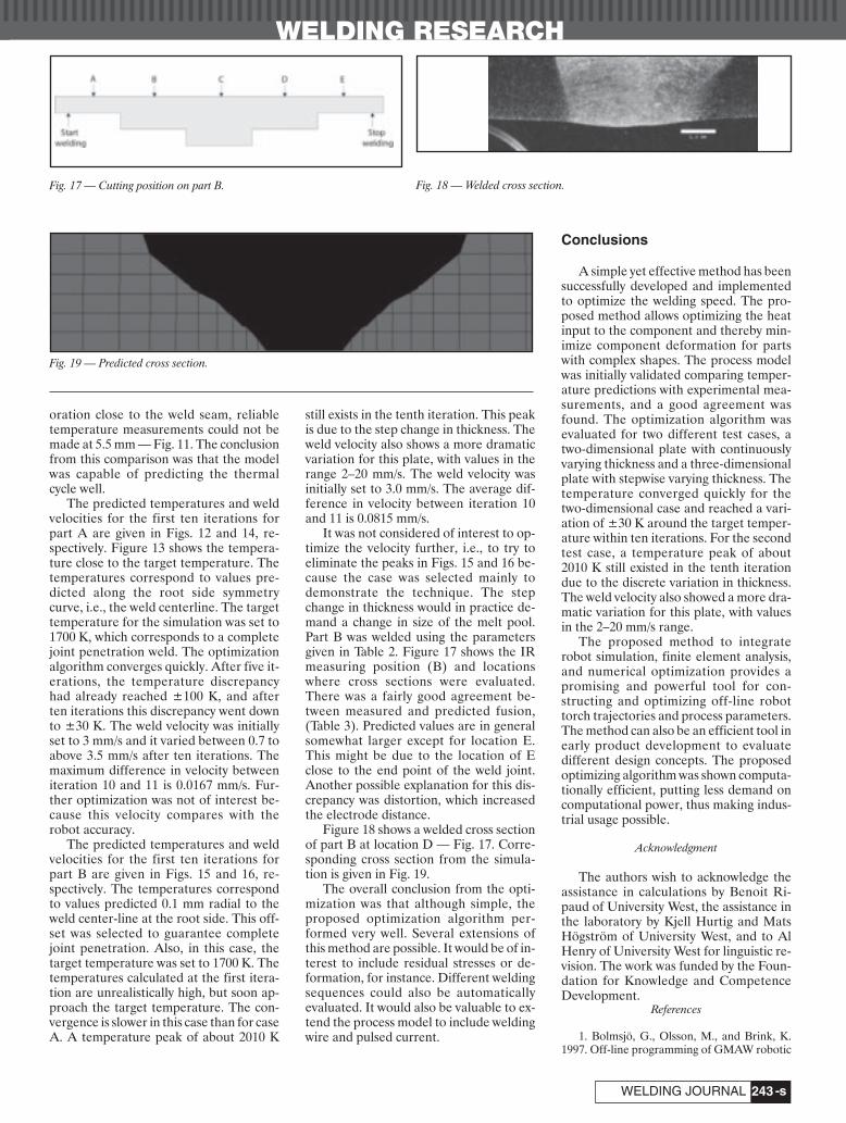
WELDING RESEARCH
-s243WELDING JOURNAL
oration close to the weld seam, reliabletemperature measurements could not bemade at 5.5 mm — Fig. 11. The conclusionfrom this comparison was that the modelwas capable of predicting the thermalcycle well.
The predicted temperatures and weldvelocities for the first ten iterations forpart A are given in Figs. 12 and 14, re-spectively. Figure 13 shows the tempera-ture close to the target temperature. Thetemperatures correspond to values pre-dicted along the root side symmetrycurve, i.e., the weld centerline. The targettemperature for the simulation was set to1700 K, which corresponds to a completejoint penetration weld. The optimizationalgorithm converges quickly. After five it-erations, the temperature discrepancyhad already reached ±100 K, and afterten iterations this discrepancy went downto ±30 K. The weld velocity was initiallyset to 3 mm/s and it varied between 0.7 toabove 3.5 mm/s after ten iterations. Themaximum difference in velocity betweeniteration 10 and 11 is 0.0167 mm/s. Fur-ther optimization was not of interest be-cause this velocity compares with therobot accuracy.
The predicted temperatures and weldvelocities for the first ten iterations forpart B are given in Figs. 15 and 16, re-spectively. The temperatures correspondto values predicted 0.1 mm radial to theweld center-line at the root side. This off-set was selected to guarantee completejoint penetration. Also, in this case, thetarget temperature was set to 1700 K. Thetemperatures calculated at the first itera-tion are unrealistically high, but soon ap-proach the target temperature. The con-vergence is slower in this case than for caseA. A temperature peak of about 2010 K
still exists in the tenth iteration. This peakis due to the step change in thickness. Theweld velocity also shows a more dramaticvariation for this plate, with values in therange 2–20 mm/s. The weld velocity wasinitially set to 3.0 mm/s. The average dif-ference in velocity between iteration 10and 11 is 0.0815 mm/s.
It was not considered of interest to op-timize the velocity further, i.e., to try toeliminate the peaks in Figs. 15 and 16 be-cause the case was selected mainly todemonstrate the technique. The stepchange in thickness would in practice de-mand a change in size of the melt pool.Part B was welded using the parametersgiven in Table 2. Figure 17 shows the IRmeasuring position (B) and locationswhere cross sections were evaluated.There was a fairly good agreement be-tween measured and predicted fusion,(Table 3). Predicted values are in generalsomewhat larger except for location E.This might be due to the location of Eclose to the end point of the weld joint.Another possible explanation for this dis-crepancy was distortion, which increasedthe electrode distance.
Figure 18 shows a welded cross sectionof part B at location D — Fig. 17. Corre-sponding cross section from the simula-tion is given in Fig. 19.
The overall conclusion from the opti-mization was that although simple, theproposed optimization algorithm per-formed very well. Several extensions ofthis method are possible. It would be of in-terest to include residual stresses or de-formation, for instance. Different weldingsequences could also be automaticallyevaluated. It would also be valuable to ex-tend the process model to include weldingwire and pulsed current.
Conclusions
A simple yet effective method has beensuccessfully developed and implementedto optimize the welding speed. The pro-posed method allows optimizing the heatinput to the component and thereby min-imize component deformation for partswith complex shapes. The process modelwas initially validated comparing temper-ature predictions with experimental mea-surements, and a good agreement wasfound. The optimization algorithm wasevaluated for two different test cases, atwo-dimensional plate with continuouslyvarying thickness and a three-dimensionalplate with stepwise varying thickness. Thetemperature converged quickly for thetwo-dimensional case and reached a vari-ation of ±30 K around the target temper-ature within ten iterations. For the secondtest case, a temperature peak of about2010 K still existed in the tenth iterationdue to the discrete variation in thickness.The weld velocity also showed a more dra-matic variation for this plate, with valuesin the 2–20 mm/s range.
The proposed method to integraterobot simulation, finite element analysis,and numerical optimization provides apromising and powerful tool for con-structing and optimizing off-line robottorch trajectories and process parameters.The method can also be an efficient tool inearly product development to evaluatedifferent design concepts. The proposedoptimizing algorithm was shown computa-tionally efficient, putting less demand oncomputational power, thus making indus-trial usage possible.
Acknowledgment
The authors wish to acknowledge theassistance in calculations by Benoit Ri-paud of University West, the assistance inthe laboratory by Kjell Hurtig and MatsHögström of University West, and to AlHenry of University West for linguistic re-vision. The work was funded by the Foun-dation for Knowledge and CompetenceDevelopment.
References
1. Bolmsjö, G., Olsson, M., and Brink, K.1997. Off-line programming of GMAW robotic
Fig. 17 — Cutting position on part B.
Fig. 19 — Predicted cross section.
Fig. 18 — Welded cross section.
Ericsson and Nylen Layout:Layout 1 7/11/07 10:43 AM Page 243

WELDING RESEARCH
AUGUST 2007, VOL. 86-s244
systems — a case study. Int. J. for the Joining ofMaterials 9(3): 86–93.
2. Buchal, R. O., Cheras, D. B., Sassani, F.,and Duncan, J. P. 1989. Simulated off-line pro-gramming of welding robots. Int. J. of RoboticsResearch 8(3): 31–43.
3. Bolmsjö, G. 1999. Programming robotwelding system using advanced simulationtools. Proc. of the International Conf. on the Join-ing of Materials JOM-9, 284–291.
4. Walter, S. 1994. Simulation and calibra-tion for off-line programming of industrial ro-bots. Proc. of Computer Technology in Welding,Paper 54.
5. Eagar, T. W., and Tsai, N. S. 1983. Tem-perature fields produced by traveling distrib-uted heat sources. Welding Journal 62(12): 346-s to 355-s.
6. Gu, M., Goldak, J., and Hughes, E. 1993.Steady state thermal analysis of welds with fillermetal addition. Canadian Metallurgical Quar-terlv 32(1): 49-s to 55-s.
7. Kou, S., and Le, Y. 1983. Three-dimen-sional heat flow and solidification during auto-genous GTA welding of aluminum plates. Met-allurgical Transactions A 14A: 2245-s to 2253-s.
8. Goldak, J., McDill, M., Oddy, A., House,R., Chi, M., and Bibby, M. 1987. Computationalheat transfer for weld mechanics. Proc. of Int.Conf. on Trends in Welding Research, Advancesin Welding Science and Technology. Eds. S. A.David: 15–20. Metals Park ASM Int.
9. Jonsson, M., Karlsson, L., and Lindgren,L. E. 1985. Deformation and stresses in buttwelding of large plates with special referencesto the material properties. J. of Eng. Mat. and
Tech. 107: 265-s to 270-s.10. Lindgren, L. E., and Karlsson, L. 1988.
Deformation and stresses in welding of shellstructures. Int. J. for Numerical Methods in Eng.25: 635-s to 655-s.
11. Radaj, D. 1992. Heat Effects of Welding:33 Berlin: Springer-Verlag.
12. Ericsson, M., Bolmsjo, G., and Nylen, P.Three-dimensional simulation of robot pathand heat transfer of a TIG-welded part withcomplex geometry. SME technical paperAD02-292 (Dearborn, Mich.: Society of Manu-facturing Engineers, 2002). 2001, Proc. 11th In-ternational Conference on Computer Technologyin Welding.
13. Ericsson, M., Nylén, P., Berglund, D.,and Lin-Peng, R. 2005. Three dimensional sim-ulation of robot path, heat transfer and residualstresses of a welded part with complex geome-try. Int. J. for the Joining of Materials 17(2).
14. Ericsson, M. Simulation of robotic TIG-welding. Technical licentiate thesis. ISBN 91-628-5702-9 2003-05-15.
15. Connor, L. P., ed. 1991. Welding tech-nology. Welding Handbook, Vol 1, 8th Ed.American Welding Society.
16. Bisen, K. B., Arenas, M., El-Kaddah, N.,and Acoff, V. L. 2003. Computation and valida-tion of weld pool dimensions and temperatureprofiles for gamma TiAl. Metallurgical and Ma-terials Transactions 34 A: 2273–2279.
17. Connor, L. P., ed. 1991. Welding tech-nology. Welding Handbook, Vol. 1, 8th ed.American Welding Society.
18. Goncalves, C. V., Vilarinho, L. O., Scotti,A., and Guimaraes, G. 2006. Estimation of heat
source and thermal efficiency in GTAW processby using inverse techniques. Journal of Materi-als Processing Technology 172: 42–51.
19. Choo, R. T. C., Szekely, J., and David, S.A. 1992. On the calculation of the free surfacetemperature of gas tungsten arc weld poolsfrom the first principles — Part II: Modellingthe weld pool and comparison with experi-ments. Metallurgical Transaction B 23B:371–384.
20. Choong, S. K. 1975. Thermophysicalproperties of stainless steel, ANL-75-55, Ar-gonne, Ill.
21. Toselo, I., Tissot, F. X., and Barras, M.Modelling of the weld behaviour for the controlof the GTA process by computer aided welding,Commissariat a l’Energie atomique, Centred’Etudes et de Recherche sur les Materiaux,Gif sur Yvette.
22. Lindgren, L-E. 2001. Finite elementmodeling and simulation of welding, Part 2: Im-proved material modeling. Journal of ThermalStresses 24: 195–231.
23. Goldak, J., and Akhlaghi, M. 2005. Com-putational Welding Mechanics, Springer Science+ Business Media, Inc.
24. Michaleris, P., and DeBiccari, A. 1997.Prediction of welding distortion. Welding Jour-nal 76(4): 172-s to 181-s.
25. Henrikson, P., and Ericsson, M. 2002.Non-contact temperature measurements usingan infrared camera in aerospace welding re-search. Proc. 6th International Conference onTrends in Welding Research, 930–935.
CALL FOR PAPERSAWS Detroit Section
International Sheet Metal Welding Conference XIIIMay 14–16, 2008Detroit, Michigan
The International Sheet Metal Welding Conference Technical Committee is actively seeking abstracts related to joiningtechnologies for thin sheet fabrications. Typical categories include:
• Resistance Welding Processes • Arc Welding Processes • High-Energy Beam Processes• Friction Joining Processes • Hybrid Joining Processes • Innovative Joining Processes• Advanced High-Strength Steels • Thin and Lightweight Materials • Coated Materials• Application Studies • Process Modeling • Process Monitoring and Control
A technical abstract in a format that is compatible with MS Word, along with a completed Author Application Formmust be submitted to the Technical Committee Chairman by September 21, 2007. Abstracts to be considered must be ofsufficient detail for a fair evaluation of the work to be presented. The paper must be related to sheet metal alloys and/orjoining processes used in manufacturing of commercial products. It is not a requirement that your presentation be anoriginal effort. Case histories, reviews, and papers that have been previously published or presented will be considered aslong as they are pertinent to the general interests of the conference attendees.
All abstracts will be considered by the Technical Committee. It is expected that the Committee's selections will beannounced by November 14, 2007. Authors must submit a manuscript to the Committee by March 19, 2008. TheProceedings will be available to all attendees at the beginning of the Conference.
You may also download additional information and the Author Application Form at www.awsdetroit.org or www.ewi.org.The completed Author Application Form and abstract should be sent to Menachem Kimchi, SMWC Technical Chairman,EWI, 1250 Arthur E. Adams Dr., Columbus, OH 43221, (614) 688-5153, FAX: (614) 688-5001, [email protected].
Ericsson and Nylen Layout:Layout 1 7/9/07 9:51 AM Page 244

WELDING RESEARCH
-s245WELDING JOURNAL
ABSTRACT. Fusion reactors, such as theplanned International Thermonuclear Ex-perimental Reactor, will require repair ofirradiated components during their life-time. Previous work has shown that weld-ing on irradiated material causes crackingin the weld heat-affected zone due to thepresence of helium. In the current study,measurements of the effects of helium(from tritium decay) on the weldability ofTypes 304 and 316LN stainless steel weremade. Low-heat-input gas metal arc weldoverlays and a series of autogenous gastungsten arc stringer beads were made on0.5-in.- (12.7-mm-) thick 304 and 316LNplates that were tritium-charged, aged,and outgassed in the same pressure vessel.The helium concentrations of both plates,as determined by helium mass spec-troscopy, were approximately 90 appm.Measurements from weld cross sectionsrevealed more extensive intergranularcracking in the heat-affected zones ofwelds on the 304 plate when compared tothose on the 316LN plate. Weld porositywas also much greater in welds on the 304plate. The large differences in the amountof helium embrittlement cracking associ-ated with the two types of stainless steelmay be related to differences in the high-temperature creep resistance of the alloysand/or the helium bubble microstructurespresent in the materials before welding.Weld porosity differences were also ob-served and can be rationalized by usingweld convection arguments.
Introduction
Work at the Savannah River Site (SRS)has shown that the weldability of stainlesssteel using conventional weldingprocesses is strongly affected by the pres-
ence of helium. This was evidenced ini-tially in attempts to repair an irradiated re-actor tank wall constructed of Type 304stainless steel (Refs. 1, 2) — Fig. 1. Heliumembrittlement cracking was observed inthe weld heat-affected zones (HAZs) inthe “repaired” areas. Subsequent researchled to the development of a low-heat-input gas metal arc welding (GMAW)overlay technique suitable for welding onstainless steels, both irradiated and tri-tium charged and aged, with a minimum ofunderbead and toe cracking up to heliumlevels of 220 appm (Ref. 3). This tech-nique employed an oscillating torch toproduce a cladding of filler metal approx-imately 0.035 in. (0.9 mm) thick with adepth of penetration into the base metalof only 0.003 in. (0.08 mm).
Weldability with the overlay techniquewas compared at SRS with conventionalgas tungsten arc welding (GTAW) andGMAW techniques. The welding methodswere also compared for irradiated vs. tri-tium-charged-and-aged 304 stainless steel(Ref. 4). Results showed the overlay tech-nique to be a significant improvementover conventional welding methods. Sur-face toe cracking was eliminated with theoverlay technique. Furthermore, cracking,both toe and underbead, was much less inthe tritium-charged-and-aged stainlesssteel than in the irradiated 304 stainlesssteel for a given helium concentration.
One material of choice for a next stepfusion device is Type 316LN stainless steel.Limited data are available on the weld-ability of thick sections of this material inthe presence of entrapped helium from ei-
ther exposure to 1) neutron fluences andthe generation of 4He or 2) high-pressuretritium gas and the subsequent decay to3He. Investigations of the weldability ofthin sections of 316 stainless steel dopedwith helium were carried out at the OakRidge National Laboratory (ORNL) incooperation with Auburn University(Refs. 5, 6). These investigations showedthat 316 stainless steel responds in a qual-itatively similar way to 304L stainless steelwhen welded after helium impregnation.That is, both are embrittled by the heliumand the embrittlement is intergranulardue to the growth of helium bubbles onthe grain boundaries. The weldability in-vestigations at ORNL/Auburn were car-ried out on very thin (0.030-in.) material.Compressive stress applied during weld-ing was shown to reduce or eliminatecracking in these thin sections. A thresh-old of 1 appm helium was suggested belowwhich cracking would not occur for repairwelds in irradiated 316 stainless steel.
The weldability of irradiated 304 and316 stainless steels has also been investi-gated in other countries, particularlyJapan. Results support the findings thatheat input is important to reduce cracking(Ref. 7), that mechanical properties areaffected by the helium embrittlementcracking (Ref. 8), and that the amount ofcracking is proportional to the heliumcontent. In another study (Ref. 9), a directcomparison of neutron-irradiated 304 and316LN seemed to show that 304 was lesssusceptible to cracking in the weld HAZswhen compared to 316LN at similar he-lium levels.
In the current comparison study, a se-ries of 316LN and 304 stainless steel testplates were exposed to high-pressure tri-tium and aged to produce 3He. Gas metalarc overlays were applied to the platesalong with a series of GTAW stringerbeads to accentuate embrittlement ef-fects. This paper describes the results ob-tained from the analysis of helium embrit-tlement cracking observed at welds on0.5-in. (12.7-mm) plates of both alloys.
Repair Techniques for Fusion Reactor Applications
Weldability tests were conducted on fusion reactor materials
BY M. H. TOSTEN, S. L. WEST, W. R. KANNE JR., AND B. J. CROSS
KEYWORDS
Stainless SteelGMAWGTAWOverlay WeldsHelium EmbrittlementPorosity
M. H. TOSTEN ([email protected])is principal scientist, S. L. WEST is senior fellowengineer, and B. J. CROSS is manager, NuclearEnergy Programs, Savannah River National Lab-oratory, Washington Savannah River Co., Aiken,S.C. W. R. KANNE JR. recently retired from Sa-vannah River National Laboratory.
Tosten Supplement August 2007:Layout 1 7/9/07 3:15 PM Page 245

WELDING RESEARCH
AUGUST 2007, VOL. 86-s246
Experimental Procedure
The welding substrate materials forthis study were obtained from a special,high-carbon lot of Type 304 stainless steelused in a previous welding study (Ref. 3)and a special grade of 316LN (316LN-IG)proposed for use in the fabrication ofITER fusion reactor components. Thestarting materials were received as largeplates in the solution annealed andquenched condition. The alloy chemistriesare shown in Table 1. Pairs of identicallysized plates of each alloy were electricaldischarge machined from the as-receivedmaterials to serve as the helium-bearingsubstrate test matrix. These plates variedin thickness from 0.030 in. (0.8 mm) to 0.5in. (12.7 mm) and measured 4.04 in. (103.4mm) in length by 1.25 in. (31.8 mm) inwidth. The results presented in this paperare restricted to a pair of 0.5-in. (12.7-mm)plates. Run-on and run-off tabs to matcheach test plate were also machined fromthe as-received materials.
The two 0.5-in. (12.7-mm) plates ana-lyzed in the current study were tritium
charged and aged in the same vessel underidentical conditions. The plates were heldat 350°C for two weeks at a tritium over-pressure of approximately 5000 lb/in.2(34.5 MPa). At the completion of thecharging run, the charging vessel wascooled to room temperature and depres-surized. The plates were subsequentlymoved to a freezer for aging and stored at–23°C to minimize tritium off-gassing.Aging time for these plates was ninemonths. Following aging, both plates werevacuum outgassed for three weeks at450°C to remove as much of the residualtritium as possible. Samples from 0.030-in.- (0.8-mm-) thick test coupons includedin the charging run as well as samples fromeach 0.5-in. (12.7-mm) plate were ana-lyzed for helium content using vaporiza-tion mass spectroscopy. An acid dissolu-tion and beta scintillation technique wasused to measure tritium levels in the testcoupons after outgassing.
All welding was performed in a tritiumfume hood using the experimental setupshown in Fig. 2. Two different type weldswere used in this study — oscillatedGMAW low-heat-input overlays and au-togenous GTAW stringer beads. All weldswere made using a shielding gas of 92%He, 7.5% Ar, 0.5% CO2 at a flow rate 40ft3/h (18.9 L/min). Prior to welding, theplates were ground with 600-grit siliconcarbide paper to provide a uniform sur-face finish and then clamped to a heatsink to provide adequate heat transferand restraint. Overlay welds were madewith 308L and 316L welding wire on the304 and 316LN plates, respectively. Weld-ing wires measured 0.035 in. (0.9 mm) in diameter.
GTAW stringer beads were made onthe plates using a variety of conditions inan attempt to “bracket” any helium em-brittlement effects. The conditions usedfor these welds, as well as those used for
Fig.1 — Sample removed from a reactor tank wall at the SRS showing toecracks and stress corrosion cracks near a gas tungsten arc weld.
Fig. 2 — GMAW gun with oscillator. The test plate is located between therun-on and run-off tabs.
Table 1 —Alloy Composition (wt-%)
Type 304 Type 316LN-IG
C 0.073 C 0.024Mn 1.390 Mn 1.82P 0.023 P 0.027S 0.016 S 0.001Si 0.520 Si 0.46Ni 8.280 Ni 12.33Cr 18.22 Cr 17.44N 0.026 Mo 2.30Fe Bal. N 0.06
Ta 0.01Cu 0.20Co 0.17B 0.0008Fe Bal.
Table 2 — Welding Conditions, 0.5-in. Plates
Alloy Weld Welding Oscillation Travel I EType Wire Speed, S0 Speed, ST (amps) (volts)O/S* (in./min) (in./min)
304 O 308L 80 3.25 75 19S None N/A 25 100 18.3S None N/A 18 100 18.6S None N/A 6 101 18.4S None N/A 3.25 100 18.5S None N/A 18 31 20
316LN-A+ O 316L 80 3.25 69 19316LN-B O 316L 80 3.25 72 19
S None N/A 25 100 19.4S None N/A 18 100 18S None N/A 6 100 17.8S None N/A 3.25 100 18.2S None N/A 18 32 21
* O — GMA overlay weld, S — GTA stringer bead+ A — Side of plate with stringer beads, B — underside of plate
Tosten Supplement August 2007:Layout 1 7/9/07 3:16 PM Page 246

WELDING RESEARCH
-s247WELDING JOURNAL
the overlays, are listedin Table 2. Figure 3 isan image showing theseries of welds madeon the 0.5-in.- (12.7-mm-) thick 304 plate.The tritium/helium-containing plate is lo-cated between the two,uncharged run-on andrun-off tabs. Similarplate and weld config-urations were used forthe 316LN welds ex-cept that a secondoverlay weld was ap-plied to the undersideof this plate. Weld heatinputs were calculatedusing the parameters
illustrated in Fig. 4. This method allowedfor a more direct comparison of the over-lay welds to the stringer beads.
Welds were examined visually using astereo microscope at 40X magnification todetermine the extent of toe cracking in theHAZs. Additionally, metallographic crosssections were prepared from each weldusing standard specimen preparationmethods. All specimens were etched usinga solution of 10% oxalic acid and water at6 V DC to reveal microstructural featuresand helium embrittlement cracking. Amontage of overlapping micrographs,taken at 50X magnification, was con-structed for each weld cross section.Cracks and weld porosity were measuredand counted using these micrographs.
Transmission electron microscopy(TEM) samples were prepared from be-
Fig. 3 — Typical weld/plate configuration. GMA overlay weld (center) withGTA stringer beads. The lower plate is the run-on tab (start of welds), themiddle plate contains tritium/helium, and the upper plate is the run-off tab(end of welds).
Fig. 5 — TEM image from a grain interior of the 304 material. The blackdots are dislocation loops punched out by the formation of helium bubbles.Dislocation loops (or bubbles) were not observed in the 316LN.
Fig. 6 — TEM image of large helium bubbles on a grain boundary andwithin the austenite matrix (e.g., at arrows) at about 0.010 in. (0.25 mm)below the GMA overlay interface on the 316LN plate.
Fig. 4 — Schematic diagram illustrating the parameters used for heat inputcalculations for both GTA stringer beads and GMA overlays.
Fig. 7 — Toe cracking in the HAZ of the highest heat input stringer beadon the 304 base plate (Heat input: 136.6 kJ/in.2).
Tosten Supplement August 2007:Layout 1 7/9/07 3:16 PM Page 247

WELDING RESEARCH
AUGUST 2007, VOL. 86-s248
neath the GMAW overlays on both plates.Thin slices were cut from the weld HAZsin an orientation parallel to the weld in-terface. Slices were centered at approxi-mately 0.010 in. (0.25 mm) and 0.050 in.(1.27 mm) from the interface. Controlsamples were sectioned in a similar man-ner, but from a region of each plate far re-moved from any welds. Disc specimens,measuring 3 mm in diameter, werepunched from the slices and ground to athickness of about 0.004 in. (0.1 mm).Specimens were polished to perforationwith a twin jet electropolisher using a so-lution of 4 vol-% perchloric acid, 37 vol-%butylcellosolve, and 59 vol-% methanol.Polishing was accomplished using an ap-plied potential of 35 V DC with the solu-tion cooled to approximately –30°C. Allspecimens were examined in a JEOL 2010operating at 200 kV.
Results
Helium and Tritium Analyses
The helium concentration in bothsteels was measured at various depthsbelow the surface of the plates. The aver-age helium concentrations, measured atapproximately 0.005 in. (0.13 mm) belowthe surfaces, were 89.1 ± 6.8 appm and87.6 ± 0.3 appm for the 304 and 316LN,respectively. Additional measurementsfrom regions of each plate to depths of ap-proximately 0.140 in. (3.6 mm) — approx-imate depth of the deepest weld root —yielded average helium concentrations of89.7 ± 6.0 appm He for the 304 plate and94.1 ± 3.0 appm for the 316LN plate.Residual tritium concentrations (aftervacuum outgassing) measured from 0.030-in.- (0.8-mm-) thick test coupons were ap-proximately 2.2 appm for the 316LN and3.0 appm for the 304.
TEM Examination
Control samples from about 0.015 in.(0.4 mm) below the surface of the 316LNand 304 plates were examined using TEM.The microstructure of the 304 plate con-sisted of equiaxed grains containing a lownumber density of dislocations, dislocationloops, and stacking faults. Carbide precipi-tates were observed on some incoherenttwin boundaries and high angle grainboundaries. Helium bubbles, measuring1–2 nm in diameter were found in the ma-trix (homogeneously nucleated) and on dis-locations in this material. Most of the ma-trix bubbles were associated with 10–20diameter dislocation loops — Fig. 5. Thesedefects were observed previously (Ref. 10)to form as a result of helium bubble nucle-ation and growth in the grain interiors. He-lium bubbles were not observed on grainboundaries or at the carbide/matrix inter-
faces. The base microstructure of the316LN plate resembled closely that of the304 microstructure except that no carbideprecipitates were observed. Helium bub-bles were not identified in this material;however, a low number density of disloca-
tion loops were observed in the grain inte-riors. Contrast differences resembling bub-bles were noted at some dislocations butthese were too indistinct to be identified asbubbles. As in the 304 plate, bubbles werenot observed on the grai boundaries.
Fig. 8 — GMA overlay welds on helium-bearing plates: A — 304; B — 316LN. Much more cracking isobserved in the 304 base metal. Some cracking in the weld metal can be seen at the arrow in Fig. 8A(Heat input: A — 23.4 kJ/in.2, B — 21.5 kJ/in.2).
Fig. 9 — Cross sections of stringer beads: A — 304; B — 316LN. Note the differences in the number ofunderbead cracks, amount (and location) of porosity, and weld pool shape between the two welds. (Heatinput: A — 28.7 kJ/in.2, B — 28.2 kJ/in.2).
Tosten Supplement August 2007:Layout 1 7/9/07 3:17 PM Page 248

WELDING RESEARCH
-s249WELDING JOURNAL
Examination of TEM specimens sec-tioned from approximately 0.050 in. (1.27mm) beneath the weld overlay on the316LN plate revealed an increase in dislo-cation density when compared to the con-trol samples. An increase in dislocationdensity is caused by weld shrinkagestresses in the HAZ (Ref. 10). Addition-ally, small helium bubbles, 1–3 nm in di-ameter, were observed on some grainboundaries. Similar to the control sample,no obvious bubbles were observed in thegrain interiors. Figure 6 is an image from0.010 in. (0.25 mm) below the overlay.This image shows that large helium bub-bles have formed on a grain boundary andwithin the matrix at this distance from theweld. Bubble growth occurred because oflocalized heating during welding and thediffusion of helium, tritium, and/or vacan-cies to preexisting grain boundary and ma-trix bubbles. Plastic deformation in theHAZ has also been shown to assist bubblegrowth via vacancy creation and disloca-tion/bubble interactions (Ref. 11).
Attempts to prepare thin foils from be-neath the overlay weld on the 304 platewere unsuccessful. Severe cracking alonggrain boundaries and in regions of α'martensite, as determined by electron dif-fraction analysis, in the weld HAZ re-sulted in preferential thinning in theseareas revealing little of the base mi-crostructure or helium bubble distribu-tion. Because of this a thorough mi-crostructural comparison was notpossible. However, the microstructure(dislocation substructure, helium bubblesize, and distribution) that developed inthe HAZ of the overlay weld on the 316LNplate was similar to that observed beneathoverlay welds on 0.250-in. (6.35-mm) 304plate material investigated in a prior study(Ref. 10).
Metallographic Examination
Analysis of the 0.5-in. (12.7-mm) platesat 40X magnification revealed no conclu-sive evidence of toe cracking in the HAZsof the GMAW overlays in either the 304 or316LN material. However, extensive toecracking was observed in the HAZs of theGTAW stringer beads. Figure 7 shows anexample of toe cracking along a stringerbead in the 304 plate. These cracks wereobserved in the HAZ of the weld madeusing the highest heat parameters. Cracks,like those shown, were visible along theentire length of this weld in the helium-containing plate. In general, cracking wasmuch more pronounced in the 304 platethan in the 316LN, with the amount ofcracking in both plates increasing withweld heat input. Toe cracks were not ob-served in the HAZs of welds on the run-on or run-off tabs of either test plate.
Microscopic examination of the pol-ished and etched weld cross-sectionsshowed numerous intergranular cracks inthe HAZ of the GMAW overlay on the 304plate as seen Fig. 8A. Generally, cracks ex-tended into the base metal by only a fewgrains. Infrequently, cracks also extendedinto the weld (e.g., Fig. 8A). This observa-tion demonstrates that cracking took placeafter solidification of the weld pool and notduring weld production. Some crackingwas observed beneath the overlay on the316LN plate but to a much lesser degreewhen compared to the 304 material — Fig.8B. In contrast, cross sections made fromthe GTAW stringer beads revealed exten-sive intragranular cracking. Similar to thetoe cracking, underbead cracking wasmuch more pronounced in the HAZs ofthe GTA welds on the 304 plate when com-pared to the similar welds on the 316LNplate. These differences are illustrated in
Figs. 9 and 10. Welds shown in each figurewere made using identical weld parame-ters. As can be seen, much more crackingoccurred in the HAZs of the 304 welds(compare Figs. 9A and 10A with Figs. 9Band 10B). Additionally, cracks extendedinto the 304 HAZ to a greater extent thanin the 316LN, but crack lengths were stillon the order of a few grains long. (It shouldbe noted that underbead cracking did notoccur on the run-on or run-off tabs.) Alsoevident from the welds in Figs. 9 and 10 arethe differences in depth of penetration (orweld pool shape). The 304 welds tended tobe shallower and had a wider weld rootwhen compared to the welds on the 316LNplate. Furthermore, as expected, the weldpool size and depth of penetration in-creased with increasing heat input for allwelds.
Another obvious difference in thewelds was the amount, size, and location ofporosity. The 304 welds contained consid-erably more porosity than the 316LNwelds. Pores were generally much larger inthe 304 welds and tended to be concen-trated at the fusion boundary. Porosity inthe 316LN appeared to be smaller andmore uniformly dispersed throughout theweld pool. The large difference in porositywould suggest a difference in helium/tri-tium content existed between the testplates; however, helium levels were essen-tially the same (around 90 appm) for bothmaterials. In addition, both test plates hadbeen vacuum outgassed under identicalconditions to remove most of the residualtritium available to contribute tobubble/pore formation.
Crack and Porosity Measurements
Crack analysis for both the overlaysand the stringer beads was conducted by
Fig. 10 — Cross-sections of stringer beads: A — 304; B — 316LN. These images further exemplify the differences in the GTA welds observed in the two steels.(Heat input: A — 84.5 kJ/in.2, B — 91.3 kJ/in.2).
Tosten Supplement August 2007:Layout 1 7/9/07 3:17 PM Page 249

WELDING RESEARCH
AUGUST 2007, VOL. 86-s250
measuring the total number and length ofcracks visible in each metallographic crosssection. To facilitate comparison, thesemeasurements were normalized for differ-ences in interface length (defined in Fig.4). These data are summarized in Tables 3and 4 and are shown graphically in Figs.11–13. Data in each of these figures arealso represented as a least squares fitforced to a straight line. Figure 11 showsthe comparison of the normalized cracklength, i.e., total measured crack lengthper unit length of interface for each heatinput (denoted as the average heat inputfor each weld condition) for the overlaysand stringer beads. Data for the stringerbeads are further illustrated in Figs. 12and 13, which show the total number ofcracks per unit length of interface and thetotal crack length per unit length of inter-face vs. heat input, respectively.
Measurements taken from beneath theGMAW overlays show that there wasabout 12 times more cracking associatedwith the overlay on the 304 plate than withthe overlay on the 316LN plate (Table 3).From Fig. 11, it can be seen also that thenormalized crack length was about 33times greater for the 304 when comparedto the 316LN. A similar trend also existedfor the GTAW stringer beads. Crack totalsfor these welds were about two to fourtimes greater in the HAZs on the 304 platewhen compared to like welds (similarwelding conditions) on the 316LN plate(Fig. 12). Also, Fig. 13 shows that the nor-malized crack lengths were three to sixtimes greater for the welds on the 304plate.
Porosity measurements for both theoverlays and stringer beads were madefrom micrographs of the weld cross sec-tions. Porosity in these welds was arbitrar-ily defined as any pore greater than 20 μm
in diameter, since smaller pores were dif-ficult to discriminate from other mi-crostructural features in the images. Lim-ited porosity was observed in the overlaywelds. In general, the overlay on the 304plate contained slightly more pores (or in-clusions) than the weld on the 316LNplate; however, the distribution of pores inboth welds varied according to location inthe weld weave. Porosity was more preva-lent in the weld “toes” (where the torchchanged direction) than at the center ofthe welds. Figure 14 is a plot of weldporosity vs. weld heat input for the stringerbeads. It is evident from this figure thatthe amount of “visible” porosity, at anygiven heat input, was greater in the weldson the 304 plate than in the welds on the316LN plate.
Discussion
The results of this study as illustrated inFigs. 11–13 indicate that Type 316LN isless susceptible to helium embrittlementcracking than Type 304 at comparable he-lium levels. The reasons for this behaviorare not completely understood but may berelated to differences in 1) the high-
temperature creep properties of the twoalloys and/or 2) the initial (prior to weld-ing) helium bubble microstructures exist-ing in the steels. During exposures to tem-peratures (T ≥ 0.4 Tm) bubbles can grow insize — particularly in the presence of anapplied stress — leading to premature in-tergranular failure. The loss in elevatedtemperature tensile and creep ductilityproperties and the tendency for weldHAZ cracking have been attributed to thegrowth and coalescence of microvoids nu-cleated at grain boundary helium bubbles.The conditions exiting in the HAZs (e.g.,high temperature and stress), during andafter welding, provide the necessary dri-ving forces to promote bubble/microvoidgrowth, coalescence, and subsequent in-tergranular failure. It is generally agreedthat intergranular cavity growth occurs byeither 1) a stress-induced cavity growthprocess with grain boundary self-diffusionas the rate controlling step (Ref. 12), 2)creep of the matrix immediately sur-rounding the cavity (Ref. 13), or 3) aprocess that couples grain boundary self-diffusion to a steady-state creep process(Ref. 14). In the present study, if one as-sumes that cavity growth is controlled by 2
Table 3 — Underbead Crack Analysis Summary, GMA Cladding Welds
Plate I E Travel Heat He Number Cracks/ Total CrackType(a) (amps) (volts) Speed Input(c) Conc. Weld Interface Length/
(in./min) (kJ/in.2) (appm) Length Weld Interface(#/in.) Length(in./in.)
304 72 19 3.25 23.4 89.1 23.8 0.33316LN-A(b) 69 19 3.25 21.5 87.6 1.9 0.01316LN-B(b) 72 19 3.25 22.4 87.6 0.0 0.0
(a) ½-in.-thick plate, constrained during welding.(b) A and B signify top (same side as GTA welds) and bottom of plate, respectively.(c) Note: J/mm2 = kJ/in.2 * 1.55.
Fig. 11 — Comparison of the normalized crack length (in./in. of weld interface)for the GMA overlay welds and GTA stringer beads. Heat input values are theaverage of the actual heat inputs for 304 and 316LN welds at each targeted heatinput level.
Fig. 12 — Total number of cracks per unit length of weld interface vs. heat inputfor the stringer beads on both plates.
Tosten Supplement August 2007:Layout 1 7/9/07 3:19 PM Page 250

WELDING RESEARCH
-s251WELDING JOURNAL
or 3 above, intergranular cracking in theHAZs of 316LN welds could be sup-pressed since 316LN is inherently moreresistant to high-temperature creep than304 because of the solid solution strength-ening effect of ~ 2 wt-% Mo. Further-more, although the starting microstruc-tures of both alloys were very similar,carbides were observed only in the 304material. A previous study (Ref. 10) of thismaterial has shown that grain boundarycarbides are potent nucleation sites for he-lium bubbles. It seems feasible that thepresence of grain boundary carbides in the304 plate could have led to an increase inthe number of bubbles on the grainboundaries in that material. These bub-bles would be available to act as additionalmicrovoid nucleation sites, thus furtherreducing this alloy’s resistance to heliumembrittlement cracking.
Figure 14 (also see images in Figs. 9and 10) shows that the 304 stringer beadscontained significantly more porosity than
the 316LN welds made using identicalwelding parameters. Porosity in welds ontritiated plates is associated with the trap-ping of helium (and tritium) in the solidi-fied weld metal that was liberated duringwelding from the fusion and heat-affectedzones. The results shown in Fig. 14 suggestthat the helium concentration in the 304plate was significantly greater than in the316LN plate; however, multiple heliumanalyses on both plates indicates that thiswas not the case since both plates had a he-lium concentration of approximately 90appm and nearly identical residual tritiumlevels (2–3 appm).
One possible explanation for the dra-matic difference in the amount of trappedporosity in the two steels may be related toweld pool convective flow. Convection isinfluenced by four forces: 1) buoyancyforce, 2) surface tension gradient force, 3)electromagnetic force, and 4) impingingforce (Ref. 15). Variations in and combi-nations of these forces can have a great af-
fect on the shape of the weld pool (depthof penetration) and the amount of retainedporosity. Heiple and Burgardt (Ref. 16)have shown — for GTA welds using thesame heat inputs and welding speeds —that weld penetration can be increased bymodifying the surface tension temperaturecoefficient of the weld by adding surface-active agents. Additionally, Heiple andRoper (Ref. 17) observed shallower pene-tration in weld pools exhibiting a radiallyoutward surface flow pattern, and deeperpenetration in welds exhibiting a radiallyinward surface flow pattern. Through theirmodeling work, Kou and Wang (Ref. 18)have postulated that convective flow canreduce weld porosity. In welds where theconvection pattern is radially outward(shallow penetration), bubbles can becaught in the solidification and becomepores. Conversely, when the convectiveflow is radially inward (deeper penetra-tion) bubbles can be swept out of the weldpool before being caught up in the solidifi-cation front.
Examination of welds in the currentstudy seem to demonstrate, at least in prin-ciple, the two situations described byHeiple and Roper (Ref. 17) and Kou andWang (Ref. 18). In all cases, the 304 weldsexhibited less penetration and much moreporosity when compared to the 316LNwelds. Additionally, pores in the 304 weldwere generally “trapped” near the bottomof the weld while pores in the 316LN weldwere more uniformly dispersed in the weldpool. If one assumes that all “forces” af-fecting weld pool convention were essen-tially the same for both steels (i.e., identicalweld parameters), these observations couldindicate that weld pool convective flow wasdifferent for the two alloys — radially out-ward for the 304 (bubble trapping, shallowpenetration) and radially inward for the316LN (bubble removal, deeper penetra-tion). However, based on the compositions
Fig. 13 — Normalized crack length vs. weld heat input for the stringer beads onboth steels.
Fig. 14 — Porosity in stringer beads vs. weld heat input. More porosity in the304 welds may indicate a higher helium content than in the 316LN plate.
Table 4 — Underbead Crack Analysis Summary, GTA Stringer Beads
Plate I E Travel Heat He Number Cracks/ Total CrackType (amps) (volts) Speed Input(a) Conc. Weld Interace Length/
(in./min) (kJ/in.2) (appm) Length Weld Interface(#/in.) Length
(in./in.)
304 31 20 18 26.5 89.7 83.7 0.57100 18.3 25 28.7 89.7 70.9 0.77100 18.6 18 38.8 89.7 31.8 0.46101 18.4 6 84.5 89.7 46.2 0.60100 18.5 3.25 136.6 89.7 26.7 0.70
316LN 32 21 18 28.8 94.1 20.5 0.11100 19.4 25 28.2 94.1 19.0 0.12100 18 18 35.3 94.1 34.0 0.27100 17.8 6 91.3 94.1 16.7 0.18100 18.2 3.25 137.1 94.1 10.8 0.14
(a) Note: J/mm2 = kJ/in.2 * 1.55
Tosten Supplement August 2007:Layout 1 7/9/07 3:20 PM Page 251

WELDING RESEARCHlisted in Table 1, this explanation is coun-terintuitive since the higher S level in the304 might be expected to produce deeperpenetration welds (radially inward flow)and, hence, less bubble trapping when com-pared to the 316LN welds.
Porosity levels in the weld pools couldalso be related to the “availability” of he-lium to reach the weld pool. If more he-lium was present on the grain boundariesin the 304 stainless steel than in the 316LNas a result of, e.g., an increased number ofcarbides, then during the high-tempera-ture excursion during the welding processmore helium would be expected to moveto the weld pool and eventually end up asadditional porosity after solidification. Ofcourse, if this were the case, then the num-ber of nucleation sites for microvoidswould decrease thus, inhibiting the em-brittlement process to some degree.
Conclusions
A weldability comparison study of tri-tium-charged-and-aged Types 304 and316LN stainless steels was conducted. Theresults of this research indicate that316LN is less susceptible to helium-embrittlement cracking than the 304. Thisconclusion is supported by the followingobservations:
1. Extensive toe cracking was associ-ated with the GTA welds with crackingmore pronounced on the 304 plate. Toecracking was not observed in the HAZs ofthe GMAW overlays on either the 304 or316LN plate.
2. There were about 10 times more un-derbead cracks/in. in the HAZs of theoverlay weld on the 304 plate compared tothe 316LN plate with cracks generally lim-ited to a few grains in length.
3. Underbead cracking was signifi-cantly greater in the HAZs of the GTAWstringer beads than the GMAW overlayson both plates. The total number of crackswas typically two to four times greater onthe 304 plate when compared to the316LN over the range of welding condi-tions. Similarly, normalized crack lengthswere two to six times greater in the HAZsof 304 GTA welds.
The increased resistance to cracking ofthe 316LN can be rationalized in terms ofits better resistance to high-temperaturecreep when compared to the 304. Differ-ences in weld porosity and depth of pene-tration may be related to weld pool con-vection effects.
Recommendations
Further study is required to fully un-derstand the fundamental reason(s) forincreased porosity in the 304 GTAWstringer beads when compared to the316LN welds at nearly the same helium
levels. Additionally, the apparent differ-ences in weldability of tritium-charged-and-aged 304 and 316LN stainless steel vs.irradiated 304 and 316LN (Ref. 9) needsto be investigated.
Acknowledgements
The authors would like to acknowledgeDrs. M. J. Morgan, E. A. Clark, and M. R.Louthan, Jr., for their technical input dur-ing the course of this work; G. K. Chap-man for the experimental setup and weld-ing; and D. Z. Nelson and C. N. Foremanfor the weld metallography.
This report is an account of work as-signed to the U.S. Home Team under TaskAgreement No. G 15 TT 96-05-15 FUwithin the Agreement among the Euro-pean Atomic Energy Community, theGovernment of Japan, the Government ofthe Russian Federation, and the Govern-ment of the United States of America onCooperation in the Engineering DesignActivities for the International Ther-monuclear Experimental Reactor (“ITEREDA Agreement”) under the auspices ofthe International Atomic Energy Agency(IAEA). The report has not been re-viewed by the ITER Publications Office.
The information contained in this arti-cle was developed during the course ofwork under Contract No. DE-AC09-96SR18500 with the U.S. Department ofEnergy.
References
1. Maloney, J. P. 1969. Repair of a nuclearreactor vessel. Trans. Am. Nuclear Soc.12(supp.): 38-39.
2. Kanne, W. R., Jr. 1988. Remote reactorrepair: GTA weld cracking caused by entrappedhelium. Welding Journal 67(8): 33 to 39.
3. Franco-Ferreira, E. A., and Kanne, W. R.,Jr. 1992. Remote reactor repair: Avoidance ofhelium-induced cracking using GMA welding.Welding Journal 71(2): 43 to 51.
4. Kanne, W. R., Jr., Chandler, G. T., Nelson,D. Z, and Franco-Ferreira, E. A. 1995. Weldingirradiated stainless steel. Journal of Nuclear Ma-terials 225(8): 69–75.
5. Wang, C. A., Grossbeck, M. L., Aglan, H.,and Chin, B. A. 1996. The effect of an appliedstress on the welding of irradiated steels. Jour-nal of Nuclear Materials 239(12): 85–89.
6. Wang, C. A., Grossbeck, M. L., and Chin,B. A. 1995. Threshold helium concentration toinitiate cracking during welding of irradiatedstainless steel. Journal of Nuclear Materials239(12): 59–68.
7. Asano, K., Nishimura, S., Saito, Y.,Sakamoto, H., Yamada,Y., Kato, T., and Hasi-moto, T. 1999. Weldability of neutron irradiatedaustenitic stainless steel. Journal of Nuclear Ma-terials 264(1): 1–9.
8. Watanabe, K., Jitsukawa, S., Hamada, S.,Kodaira, T., and Hishinuma, A. 1996. Weldabil-ity of neutron-irradiated Type 316 stainlesssteel. Fusion Engineering and Design 31(1):9–15.
9. Morishima, Y., Koshiishi, M., Kashi-
wakura, K., Hashimoto, T., and Kawano, S.2004. Re-weldability of neutron irradiated Type304 and 316L stainless steels. Journal of NuclearMaterials 329-333: 663–667.
10. Tosten, M. H., and Kestin, P. A. 1992.Helium bubble distributions beneath GMAweld overlays in Type 304 stainless steel. Proc.24th Annual Technical Meeting of the IMS: Mi-crostructural Science 19. Eds. D. A. Wheeler, G.W. E. Johnson, D. V. Miley, and M. R. Louthan,Jr., pp. 3–12. ASM International, MaterialsPark, Ohio.
11. Goods, S. H., and Krafs, C. W. 1991. He-lium-induced weld cracking in low heat inputGMA weld overlays. Welding Journal 70(5):123-s to 132-s.
12. Hull, D., and Rimmer, D. E. 1959. Thegrowth of grain boundary voids under stress.Philosophical Magazine 4: 673–87.
13. Nix, W. D., Matlock, D. K., and Dimelfi,R. J. 1977. A model for creep fracture based onthe plastic growth of cavities at the tips of grainboundary wedge cracks. Acta Metallurgica25(5): 495–503.
14. Wang, J. S., Martinez, L., and Nix, W. D.1983. The study on intergranular cavity growthcontrolled by the coupling of diffusion andpower law creep. Acta Metallurgica 31(6): 873-81.
15. Messler, R. W., Jr. 1999. Principles ofWelding. 291, New York, N.Y.: Wiley.
16. Heiple, C. R., and Burgardt, P. 1985. Ef-fects of SO2 shielding gas additions on GTAweld shape. Welding Journal 64(6): 189-s to 162-s.
17. Heiple, C. R., and Roper, J. R. 1982.Mechanism for minor element effect on GTAfusion zone geometry. Welding Journal 61(4):97-s to 102-s.
18. Kou, S., and Wang, Y. H. 1986. Weldpool convection and its effects. Welding Journal65(3): 63-s to 70-s.
AUGUST 2007, VOL. 86-s252
REPRINTS REPRINTS
To order custom reprints of 100 or more of articles in
Welding Journal,call FosteReprints at
(219) 879-8366 or(800) 382-0808 or.
Request for quotes can befaxed to (219) 874-2849.
You can e-mailFosteReprints at
Tosten Supplement August 2007:Layout 1 7/9/07 3:20 PM Page 252

For Info go to www.aws.org/ad-index
ABICOR BINZEL:FP_TEMP 7/6/07 2:23 PM Page C3

For Info go to www.aws.org/ad-index
LINCOLN:FP_TEMP 7/6/07 2:27 PM Page C4