Structural Welding Code— Steel
646
AWS D1.1/D1.1M:2015 An American National Standard Structural Welding Code — Steel American Welding Society ®
-
Upload
khangminh22 -
Category
Documents
-
view
0 -
download
0
Transcript of Structural Welding Code— Steel
AWS D1.1/D1.1M:2015An American National Standard
StructuralWelding Code —Steel
American Welding Society®

AWS D1.1/D1.1M:2015An American National Standard
Approved by theAmerican National Standards Institute
July 28, 2015
Structural Welding Code—
Steel
23rd Edition
Supersedes AWS D1.1/D1.1M:2010
Prepared by theAmerican Welding Society (AWS) D1 Committee on Structural Welding
Under the Direction of theAWS Technical Activities Committee
Approved by theAWS Board of Directors
Abstract
This code covers the welding requirements for any type of welded structure made from the commonly used carbon andlow-alloy constructional steels. Clauses 1 through 9 constitute a body of rules for the regulation of welding in steelconstruction. There are nine normative and eleven informative annexes in this code. A Commentary of the code isincluded with the document.

AWS D1.1/D1.1M:2015
ii
ISBN: 978-0-87171-864-8© 2015 by American Welding Society
All rights reservedPrinted in the United States of America
Photocopy Rights. No portion of this standard may be reproduced, stored in a retrieval system, or transmitted in anyform, including mechanical, photocopying, recording, or otherwise, without the prior written permission of the copyrightowner.
Authorization to photocopy items for internal, personal, or educational classroom use only or the internal, personal, oreducational classroom use only of specific clients is granted by the American Welding Society provided that the appropriatefee is paid to the Copyright Clearance Center, 222 Rosewood Drive, Danvers, MA 01923, tel: (978) 750-8400; Internet:<www.copyright.com>.
iii
AWS D1.1/D1.1M:2015
Statement on the Use of American Welding Society Standards
All standards (codes, specifications, recommended practices, methods, classifications, and guides) of the AmericanWelding Society (AWS) are voluntary consensus standards that have been developed in accordance with the rules of theAmerican National Standards Institute (ANSI). When AWS American National Standards are either incorporated in, ormade part of, documents that are included in federal or state laws and regulations, or the regulations of other governmen-tal bodies, their provisions carry the full legal authority of the statute. In such cases, any changes in those AWS stan-dards must be approved by the governmental body having statutory jurisdiction before they can become a part of thoselaws and regulations. In all cases, these standards carry the full legal authority of the contract or other document thatinvokes the AWS standards. Where this contractual relationship exists, changes in or deviations from requirements of anAWS standard must be by agreement between the contracting parties.
AWS American National Standards are developed through a consensus standards development process that bringstogether volunteers representing varied viewpoints and interests to achieve consensus. While AWS administers the pro-cess and establishes rules to promote fairness in the development of consensus, it does not independently test, evaluate,or verify the accuracy of any information or the soundness of any judgments contained in its standards.
AWS disclaims liability for any injury to persons or to property, or other damages of any nature whatsoever, whetherspecial, indirect, consequential, or compensatory, directly or indirectly resulting from the publication, use of, or relianceon this standard. AWS also makes no guarantee or warranty as to the accuracy or completeness of any information pub-lished herein.
In issuing and making this standard available, AWS is neither undertaking to render professional or other services for oron behalf of any person or entity, nor is AWS undertaking to perform any duty owed by any person or entity to someoneelse. Anyone using these documents should rely on his or her own independent judgment or, as appropriate, seek theadvice of a competent professional in determining the exercise of reasonable care in any given circumstances. It isassumed that the use of this standard and its provisions is entrusted to appropriately qualified and competent personnel.
This standard may be superseded by the issuance of new editions. This standard may also be corrected through publica-tion of amendments or errata, or supplemented by publication of addenda. Information on the latest editions of AWSstandards including amendments, errata, and addenda is posted on the AWS web page (www.aws.org). Users shouldensure that they have the latest edition, amendments, errata, and addenda.
Publication of this standard does not authorize infringement of any patent or trade name. Users of this standard acceptany and all liabilities for infringement of any patent or trade name items. AWS disclaims liability for the infringement ofany patent or product trade name resulting from the use of this standard.
AWS does not monitor, police, or enforce compliance with this standard, nor does it have the power to do so.
On occasion, text, tables, or figures are printed incorrectly, constituting errata. Such errata, when discovered, are postedon the AWS Webpage (www.aws.org).
Official interpretations of any of the technical requirements of this standard may only be obtained by sending a request,in writing, to the appropriate technical committee. Such requests should be addressed to the American Welding Society,Attention: Managing Director, Technical Services Division, 8669 NW 36 St, # 130, Miami, FL 33166 (see Annex N).With regard to technical inquiries made concerning AWS standards, oral opinions on AWS standards may be rendered.These opinions are offered solely as a convenience to users of this standard, and they do not constitute professionaladvice. Such opinions represent only the personal opinions of the particular individuals giving them. These individualsdo not speak on behalf of AWS, nor do these oral opinions constitute official or unofficial opinions or interpretations ofAWS. In addition, oral opinions are informal and should not be used as a substitute for an official interpretation.
This standard is subject to revision at any time by the AWS D1 Committee on Structural Welding. It must be reviewedevery five years, and if not revised, it must be either reaffirmed or withdrawn. Comments (recommendations, additions,or deletions) and any pertinent data that may be of use in improving this standard are required and should be addressedto AWS Headquarters. Such comments will receive careful consideration by the AWS D1 Committee on StructuralWelding and the author of the comments will be informed of the Committee’s response to the comments. Guests areinvited to attend all meetings of the AWS D1 Committee on Structural Welding to express their comments verbally. Pro-cedures for appeal of an adverse decision concerning all such comments are provided in the Rules of Operation of theTechnical Activities Committee. A copy of these Rules can be obtained from the American Welding Society, 8669 NW36 St, # 130, Miami, FL 33166.

This page is intentionally blank.
iv
AWS D1.1/D1.1M:2015

v
AWS D1.1/D1.1M:2015
Dedication
This 23rd edition of AWS D1.1/D1.1M:2015, StructuralWelding Code—Steel, is dedicated by the D1 Committeeon Structural Welding and the D1Q Subcommittee onSteel Structures to Keith Landwehr. In his 15 years ofservice, Keith contributed 30 years of expertise to thedevelopment of the D1.1, Structural Welding Code—Steel, D1.4, Structural Welding Code—Reinforcing Steel,D1.8, Structural Welding Code—Seismic Supplement,and other national standards. The D1 community willforever miss Keith for his commitment, but more impor-tantly, for his friendship and wise counsel, and hopesthat this dedication will inspire the structural weldingcommunity to excellence as Keith did in his service.

This page is intentionally blank.
vi
AWS D1.1/D1.1M:2015

vii
AWS D1.1/D1.1M:2015
Personnel
AWS D1 Committee on Structural WeldingA. W. Sindel, Chair Alstom Power Steam, Incorporated
T. L. Niemann, Vice Chair Minnesota Department of TransportationR. D. Medlock, 2nd Vice Chair High Steel Structures, LLC
J. Molin, Secretary American Welding SocietyF. G. Armao The Lincoln Electric Company
E. L. Bickford Acute Technological ServicesT. M. Burns AlcoTec Wire Corporation
H. H. Campbell, III Pazuzu EngineeringR. D. Campbell Bechtel
R. B. Corbit CB&IM. A. Grieco Massachusetts Department of Transportation
C. W. Holmes Modjeski and Masters, IncorporatedJ. J. Kenney Shell International E & PJ. H. Kiefer ConocoPhillips Company (Retired)S. W. Kopp High Steel Structures, LLC
V. Kuruvilla Genesis Quality SystemsJ. Lawmon American Engineering & Manufacturing, Incorporated
N. S. Lindell Oregon Iron Works, IncorporatedD. R. Luciani Canadian Welding Bureau
P. W. Marshall MHP Systems EngineeringM. J. Mayes Mayes Testing Engineers, Incorporated
D. L. McQuaid D. L. McQuaid and Associates, IncorporatedJ. Merrill AMEC E&I
D. K. Miller The Lincoln Electric CompanyJ. B. Pearson, Jr. LTK Engineering Services
D. C. Phillips Hobart Brothers CompanyD. D. Rager Rager Consulting, Incorporated
T. J. Schlafly American Institute of Steel ConstructionD. R. Scott PSI, Incorporated (Retired)
R. E. Shaw, Jr. Steel Structures Technology Center, IncorporatedR. W. Stieve Parsons Corporation
M. M. Tayarani Massachusetts Department of Transportation (Retired)P. Torchio, III Williams Enterprises of Georgia, Incorporated
D. G. Yantz Canadian Welding Bureau
Advisors to the D1 Committee on Structural Welding
W. G. Alexander WGAPEN. J. Altebrando STV, Incorporated
E. M. Beck AMECB. M. Butler Walt Disney World CompanyR. A. Dennis Consultant
G. L. Fox ConsultantH. E. Gilmer Tampa Tank-Florida Structural Steel
G. J. Hill G. J. Hill and Associates, Incorporated

viii
AWS D1.1/D1.1M:2015
M. L. Hoitomt Hoitomt Consulting ServicesJ. W. Post J. W. Post & Associates, Incorporated
K. K. Verma ConsultantB. D. Wright Advantage Aviation Technologies
AWS D1Q Subcommittee on SteelT. Schlafly, Chair American Institute of Steel Construction
P. Torchio, III, Vice Chair Williams Enterprises of Georgia, IncorporatedJ. Molin, Secretary American Welding Society
M. Bernasek C-specE. L. Bickford Acute Technological Services
J. W. Cagle C P Buckner Steel Erection, IncorporatedH. H. Campbell, III Pazazu Engineering
W. P. Capers Walt Disney World CompanyR. V. Clarke TEAM Industrial Services, IncorporatedD. A. Dunn PSI, Incorporated (Retired)M. E. Gase Midwest Steel Incorporated
W. S. Houston Pro-Weld Stud Welding AssociatesM. J. Jordan Johnson Plate and Tower FabricationJ. J. Kenney Shell International E & PJ. H. Kiefer ConocoPhillips Company (Retired)
L. A. Kloiber LeJeune Steel CompanyS. W. Kopp High Steel Structures, LLC
V. Kuruvilla Genesis Quality SystemsK. Landwehr ConsultantD. R. Luciani Canadian Welding Bureau
P. W. Marshall MHP Systems EngineeringR. P. Marslender Kiewit Offshore Services, Ltd.
G. S. Martin GE Oil & GasM. J. Mayes Mayes Testing Engineers, Incorporated
J. Merrill AMEC E&IJ. I. Miller Chevron
S. P. Moran Weir American HydroJ. C. Nordby EntergyD. D. Rager Rager Consulting, IncorporatedD. R. Scott PSI, Incorporated (Retired)
R. E. Shaw, Jr. Steel Structures Technology Center, IncorporatedA. W. Sindel Alstom Power Steam, IncorporatedR. W. Stieve Parsons CorporationS. J. Thomas ConsultantR. H. R. Tide Wiss, Janney, Elstner AssociatesJ. L. Warren CB&I
Advisors to the D1Q Committee on Steel
N. J. Altebrando STV, IncorporatedU. W. Aschemeier Subsea Global Solutions
B. M. Butler Walt Disney World CompanyH. A. Chambers SNH Market Consultants
H. E. Gilmer Tampa Tank-Florida Structural SteelM. A. Grieco Massachusetts Department of Transportation
J. Guili Tru-Weld Equipment Company
Advisors to the D1 Committee on Structural Welding (Continued)

ix
AWS D1.1/D1.1M:2015
C. W. Hayes The Lincoln Electric CompanyR. L. Holdren Arc SpecialitiesC. W. Holmes Modjeski and Masters, Incorporated
W. Jaxa-Rozen Bombardier TransportationJ. E. Koski Stud Welding Products, Incorporated
N. S. Lindell Oregon Iron WorksD. L. McQuaid D. L. McQuaid and Associates, IncorporatedR. D. Medlock High Steel Structures, LLC
D. K. Miller The Lincoln Electric CompanyJ. A. Packer University of Toronto
J. B. Pearson, Jr. LTK Engineering ServicesD. C. Phillips Hobart Brothers Company
J. W. Post J. W. Post and Associates, IncorporatedM. M. Tayarani Massachusetts Department of Transportation (Retired)
J. L. Uebele Waukesha County Tech CollegeK. K. Verma ConsultantP. Workman Tru-Weld
D. A. Wright Wright Welding TechnologiesD. G. Yantz Canadian Welding Bureau
D1Q Subcommittee Task Group on DesignW. P. Capers, Chair Walt Disney World Company
T. Green, Vice Chair Wiss, Janney, Elstner AssociatesB. M. Butler Walt Disney World CompanyD. B. Ferrell Ferrell Engineering, Incorporated
W. Jaxa-Rozen Bombardier TransportationM. J. Jordan Johnson Plate and Tower FabricationJ. J. Kenney Shell International E & P
L. A. Kloiber LeJeune Steel CompanyP. W. Marshall MHP Systems Engineering
J. M. Ocel Federal Highway AdministrationJ. A. Packer University of Toronto
J. B. Pearson, Jr. LTK Engineering ServicesT. J. Schlafly American Institute of Steel Construction
R. E. Shaw, Jr. Steel Structures Technology Center, IncorporatedR. H. R. Tide Wiss, Janney, Elstner Associates
Advisors to the D1Q Subcommittee Task Group on Design
O. W. Blodgett The Lincoln Electric Company (Retired)J. Desjardins Bombardier TransportationJ. L. Warren CB&I
D1Q Subcommittee Task Group on PrequalificationD. R. Luciani, Co-Chair Canadian Welding BureauP. Torchio, III, Co-Chair Williams Enterprises of Georgia, Incorporated
C. Zanfir, Vice Chair Canadian Welding BureauW. J. Bell Atlantic Testing Laboratories
H. H. Campbell, III Pazuzu EngineeringK. Landwehr Consultant
P. W. Marshall MHP Systems Engineering
Advisors to the D1Q Committee on Steel (Continued)

x
AWS D1.1/D1.1M:2015
J. I. Miller ChevronS. P. Moran Weir American HydroJ. C. Norby Entergy
R. E. Shaw, Jr. Steel Structures Technology Center, IncorporatedA.W. Sindel Alstom Power Steam, Incorporated
Advisor to the D1Q Subcommittee Task Group on Prequalification
J. L. Warren CB&I
D1Q Subcommittee Task Group on QualificationT. C. Myers, Chair Consultant
S. J. Findlan, Vice Chair CB&I PowerM. Bernasek C-spec
E. L. Bickford Acute Technological ServicesM. G. Collins ConocoPhillips Company
M. W. Elsemore The Boeing CompanyM. J. Harker Idaho National Laboratory
R. L. Holdren Arc SpecialtiesJ. J. Kenney Shell International E & PJ. H. Kiefer ConocoPhillips Company (Retired)
R. P. Marslender Kiewit Offshore Services, Ltd.D. W. Meyer ESAB Welding & Cutting ProductsD. D. Rager Rager Consulting, Incorporated
A. W. Sindel Alstom Power Steam, IncorporatedD. A. Stickel Caterpillar, Incorporated
B. M. Toth CB&IJ. L. Uebele Waukesha County Technical College
Advisors to the D1Q Subcommittee Task Group on Qualification
D. R. Lawrence II ConsultantG. S. Martin GE-Oil & Gas
D. C. Phillips Hobart Brothers CompanyK. K. Verma ConsultantJ. L. Warren CB&ID. G. Yantz Canadian Welding Bureau
D1Q Subcommittee Task Group on FabricationH. E. Gilmer, Chair Tampa Tank-Florida Structural Steel
J. I. Miller, Vice Chair ChevronS. E. Anderson HRV Conformance Verification
W. J. Bell Atlantic Testing LaboratoriesH. H. Campbell, III Pazuzu Engineering
R. V. Clarke TEAM Industrial Services, IncorporatedM. E. Gase Midwest Steel, Incorporated
M. A. Grieco Massachusetts Department of TransportationC. Hanson ADF Group, Incorporated
R. L. Holdren Arc SpecialtiesC. W. Holmes Modjeski & Masters, Incorporated
J. H. Kiefer ConocoPhillips Company (Retired)
D1Q Subcommittee Task Group on Prequalification (Continued)

xi
AWS D1.1/D1.1M:2015
S. W. Kopp High Steel Structures, LLCV. Kuruvilla Genesis Quality Systems
K. Landwehr ConsultantE. S. LaPann Consultant
C. A. Mankenberg Shell International E & PG. S. Martin GE-Oil & Gas
E. S. Mattfield Stonebridge Steel ErectionR. D. Medlock High Steel Structures, LLCJ. E. Mellinger Pennoni Associates, Incorporated
R. L. Mertz Alta Vista Solutions
Advisors to the D1Q Subcommittee Task Group on Fabrication
W. G. Alexander WGAPEB. Anderson Molex IncorporatedJ. W. Cagle C. P. Buckner Steel Erection, Incorporated
R. A. Dennis ConsultantG. L. Fox ConsultantG. J. Hill G. J. Hill & Associates
D. L. McQuaid D. L. McQuaid & Associates, IncorporatedJ. E. Myers Consultant
J. W. Post J. W. Post and Associates, IncorporatedT. J. Schlafly American Institute of Steel Construction
J. Sokolewicz Trinity RailR. H. R. Tide Wiss, Janney, Elstner AssociatesK. K. Verma ConsultantJ. L. Warren CB&I
D1Q Subcommittee Task Group on InspectionG. S. Martin, Chair GE-Oil & Gas
P. G. Kinney, Vice Chair Acute Technological ServicesS. E. Anderson HRV Conformance Verification
U. W. Aschemeier Subsea Global SolutionsR. V. Clarke Team Industrial Services, IncorporatedJ. M. Davis Davis NDE-Olympus NDTD. A. Dunn PSI, Incorporated (Retired)
K. R. Fogleman Valmont IndustriesM. E. Gase Midwest Steel, Incorporated
H. E. Gilmer Tampa Tank-Florida Structural SteelC. W. Hayes The Lincoln Electric Company
P. T. Hayes GE Inspection Technologies LPR. K. Holbert Alstom Power Steam, Incorporated
S. W. Kopp High Steel Structures, IncorporatedE. S. LaPann ConsultantN. S. Lindell Oregon Iron Works, Incorporated
C. A. Mankenberg Shell International E & PE. S. Mattfield Stonebridge Steel ErectionJ. E. Mellinger Pennoni Associates, Incorporated
J. Merrill AMEC E&IR. L. Mertz Alta Vista Solutions
J. B. Pearson, Jr. LTK Engineering ServicesD. R. Scott PSI, Incorporated (Retired)
D1Q Subcommittee Task Group on Fabrication (Continued)

xii
AWS D1.1/D1.1M:2015
D. G. Yantz Canadian Welding Bureau
Advisors to the D1Q Subcommittee Task Group on Inspection
E. M. Beck MACTEC Engineering & ConsultingS. M. Duke Florida Department of Transportation
G. J. Hill G. J. Hill & AssociatesJ. H. Kiefer ConocoPhillips Company (Retired)
D. L. McQuaid D.L. McQuaid & Associates, IncorporatedK. J. Steinhagen PSI, Incorporated
R. W. Stieve Parsons CorporationT. W. Studebaker St. Louis Testing
K. K. Verma ConsultantJ. L. Warren CB&I
D1Q Subcommittee Task Group on Stud WeldingW. S. Houston, Chair Pro-Weld Stud Welding Associates
U. W. Aschemeier, Vice Chair Subsea Global SolutionsH. A. Chambers Consultant
D. A. Dunn PSI, IncorporatedJ. Guili Tru-Weld Equipment Company
B. C. Hobson Image IndustriesJ. E. Koski Stud Welding Products, Incorporated
D. R. Luciani Canadian Welding BureauC. W. Makar Cox IndustriesS. P. Moran PDM Bridge, LLC
P. Torchio, III Williams Enterprises of Georgia, IncorporatedM. M. Tayarani Massachusetts Department of Transportation (Retired)
J. L. Uebele Waukesha County Technical CollegeP. Workman Tru-Weld Equipment Company
Advisors to the D1Q Subcommittee Task Group on Stud Welding
C. B. Champney Nelson Stud WeldingR. D. Campbell Bechtel
J. Guili Tru-Weld Equipment CompanyS. Schraff Nelson Stud Welding
J. L. Warren CB&I
D1Q Standing Task Group on TubularsJ. J. Kenney, Chair Shell International E & P
M. A. Grieco, Vice Chair Massachusetts Department of TransportationE. L. Bickford Acute Technological Services
R. V. Clarke TEAM Industrial Services, IncorporatedD. B. Ferrell Ferrell Engineering, Incorporated
R. B. Fletcher Atlas TubeP. A. Huckabee Gill Engineering Associates, Incorporated
L. A. Kloiber LeJeune Steel ConsultantV. Kuruvilla Genesis Quality Systems
P. W. Marshall MHP Systems EngineeringJ. Mayne Valmont Industries, Incorporated
D1Q Subcommittee Task Group on Inspection (Continued)

xiii
AWS D1.1/D1.1M:2015
J. A. Packer University of TorontoR. Sause ATLSS Center Lehigh University
Advisors to the D1Q Standing Task Group on Tubulars
J. J. Edwards DOT Quality ServicesM. J. Mayes Mayes Testing Engineers, Incorporated
R. D. Medlock High Steel Structures, LLCT. L. Niemann Minnesota Department of Transportation
D. D. Rager Rager Consulting, IncorporatedT. J. Schlafly American Institute of Steel ConstructionA. W. Sindel Alstom Power Steam, IncorporatedJ. L. Warren CB&I
D1M Standing Task Group on New MaterialsJ. L. Warren, Chair CB&I
T. J. Schlafly, Vice Chair American Institute of Steel ConstructionW. P. Capers Walt Disney World CompanyD. A. Koch Bechtel National, Incorporated
V. Kuruvilla Genesis Quality SystemsR. D. Medlock High Steel Structures, LLC
D. C. Phillips Hobart Brothers CompanyJ. L. Schoen Nucor-Yamato Steel
Advisors to the D1M Standing Task Group on New Materials
B. M. Butler Walt Disney World CompanyC. W. Hayes The Lincoln Electric Company
M. L. Hoitomt ConsultantJ. B. Pearson, Jr. LTK Engineering Services
J. W. Post J. W. Post & Associates, IncorporatedD. D. Rager Rager Consulting, Incorporated
D. Rees-Evans Steel DynamicsA. W. Sindel Alstom Power Steam, Incorporated
D1Q Standing Task Group on Tubulars (Continued)

This page is intentionally blank.
xiv
AWS D1.1/D1.1M:2015

xv
AWS D1.1/D1.1M:2015
ForewordThis foreword is not part of AWS D1.1/D1.1M:2015, Structural Welding Code—Steel,
but is included for informational purposes only.
The first edition of the Code for Fusion Welding and Gas Cutting in Building Construction was published by the Amer-ican Welding Society in 1928 and called Code 1 Part A. It was revised in 1930 and 1937 under the same title. It wasrevised again in 1941 and given the designation D1.0. D1.0 was revised again in 1946, 1963, 1966, and 1969. The 1963edition published an amended version in 1965, and the 1966 edition published an amended version in 1967. The codewas combined with D2.0, Specifications for Welding Highway and Railway Bridges, in 1972, given the designationD1.1, and retitled AWS Structural Welding Code. D1.1 was revised again in 1975, 1979, 1980, 1981, 1982, 1983, 1984,1985, 1986, 1988, 1990, 1992, 1994, 1996, 1998, 2000, 2002, 2004, 2006, 2008 and 2010. A second printing ofD1.1:2010 was published in 2011. From 1972 to 1988, the D1.1 code covered the welding of both buildings and bridges.In 1988, AWS published its first edition of AASHTO/AWS D1.5, Bridge Welding Code; coincident with this, the D1.1code changed references of buildings and bridges to statically loaded and dynamically loaded structures, respectively, inorder to make the document applicable to a broader range of structural applications. After the publishing of the 2010 edi-tion, it was decided that the AWS Structural Welding Code—Steel would be published on a five year revision cycleinstead of a two year revision cycle. This was done in order to sync the publication cycle of AWS Structural WeldingCode-Steel with the publication cycles of the AISC Steel Building Specification and the International Building Code.This 2015 edition is the 23rd edition of D1.1.
Underlined text in the clauses, subclauses, tables, figures, or forms indicates a change from the 2010 edition. A verticalline in the margin of a table or figure also indicates a change from the 2010 edition.
The following is a summary of the most significant technical changes contained in D1.1/D1.1M:2015:
The 2015 edition of the code has been reorganized. The tubular provisions, tables, and figures previously locatedthroughout the code are now within Clause 9 entitled “Tubular Structures.” The reorganization required numerous refer-ence changes and renumbering of the subclauses, tables, and figures. Many of the tables in Clause 4 contained provi-sions for Plate as well as Pipe or Tubing. The tables have been divided to only include Plate if contained in Clause 4 andPipe or Tubing if contained in Clause 9. This separation of the information contained in the tables also resulted in manychanges to the footnotes delineated in the tables.
Clauses 1, 7, and 8 have only been slightly impacted by the reorganization. However, Clauses 2, 3, 4, 5, and 6 have beengreatly impacted with the reorganization.
Summary of Changes
Clause/Table/Figure/Annex Modification
Clause 2 The most significant change to Clause 2 from the 2010 edition is that Part D entitled “SpecificRequirements for Design of Tubular Connections (Statically or Cyclically Loaded)” has beenrelocated to Clause 9.
2.4.2.7 Additional language was added regarding the calculation of effective throat of a combinationPJP flare bevel groove weld and fillet weld.

xvi
AWS D1.1/D1.1M:2015
2.9.3.5 Added provisions for wrapping welds on opposite sides of a common plane to permit sealwelding.
Table 2.5 Fatigue curve cases and figures revised to agree with AISC 360.
3.7.4 Shielding gas provisions revised to permit the use of electrodes classified to AWS A5.36.
3.13.2.1 New subclause that provides conditions under which backing other than steel may be used inprequalified WPSs.
Table 3.1 Reformatted the table moving filler metals in corresponding groups in Table 3.2. Updated thelist of base metals permitted in prequalified WPSs and corrected the group of some base metalgrades.
Table 3.2 New table for filler metal requirements that contains the information previously contained inTable 3.1 with the addition of a classification for A5.36 for carbon and low-alloy steel elec-trodes for FCAW and metal cored electrodes for GMAW processes.
Table 3.3 (Previously Table 3.2) Revised the base metals to correspond with those in Table 3.1
Table 3.4 (Previously Table 3.3) Addition of AWS A5.36.
Table 3.7 (Previously Table 3.6) Clarification of a SAW parameter variable.
Notes for Figures 3.2 and 3.3
Addition of note “O” permitting various orientations of connected elements in CJP Groove, T-,and Corner joints.
Figure 3.5 New figure for prequalified fillet weld joint details.
Figure 3.6 New figure for prequalified CJP groove, T-, and corner joints.
4.12.3 Restructured for easier reading.
4.21 (Previously 4.25, 4.26, 4.30) Reorganized “Extent of Qualification.”
4.27.7 (Previously 4.36.7) Clarified CVN Test requirements when sub-sized specimens are tested.
Tables 4.1, 4.2, 4.3, 4.4, 4.10, and 4.11
The information found in the tables that referenced pipes and tubing are now contained in thetables found in Clause 9.
Tables 4.5, 4.6, and 4.9
Added provisions for electrodes classified to AWS A5.36.
5.3.2.5 Additional language and clarification regarding baking requirements when welding with low-hydrogen electrodes for ASTM A514 and A517 steels.
5.3.4 Reorganized the list of AWS Filler metal specifications for GMAW and FCAW as well as addedAWS A5.36.
5.6 Clarified language regarding preheat and interpass temperatures.
5.7 Moved language regarding oxygen gouging to 5.14.6 and 5.25.
5.8.1 Revised for clarification.
5.8.3 Revised to delete ASTM A709 100 (690) and 100W (690W) and to include ASTM A709 GradeHPS 100W [HPS 690W] per ASTM.
5.9 (Previous 5.9 entitled “Backing, Backing Gas, or Inserts” was deleted) (Previously 5.10)Restructured for clarification.
Summary of Changes (Continued)
Clause/Table/Figure/Annex Modification

xvii
AWS D1.1/D1.1M:2015
5.9.1.3 (Previously 5.10.3) “Backing Thickness” was revised to make a general requirement that steelbacking be of sufficient thickness to prevent melt-through. The explicit thicknesses previouslyrequired were moved to commentary as recommendations.
5.14.1–5.14.4 (Previously 5.15) Substrate cleanliness requirements were significantly revised.
5.14.6 (Previously 5.15.2) Revised to clarify when oxygen gouging is permitted.
5.17.2 (Previously 5.18.2) Revised for clarity regarding when locations of the depth of the web fromtension flanges of beams or girders are considered outside the tension zone.
5.19 (Previously 5.20) Revised provisions regarding the location and sequence of member and elementsplices.
5.25 (Previously 5.26) Revised to limit oxygen gouging to as-rolled steels.
Table 5.8 (Previously Table 5.9) Note c revised to clarify when welds are exempt from reinforcement andconvexity limitations.
Table 5.9 (Previously Table 5.10) Minimum allowable convexity was eliminated from Schedule D foroutside corner joints. Table footnote b was rewritten regarding restriction on convexity wasreplaced with a note regarding concavity and now applies to Schedules B and D.
6.4.2 Revised to clarify as to what a welder, welding operator, or tack welder must demonstrate, whentheir work appears to be below the requirements of the code.
6.4.3 Revised to include tack welder.
6.10 Revised to replace “applicable requirements” with “acceptance criteria.”
6.11 Revised to remove ASTM A709 Grades 100 and 100W and include ASTM A709 Grade HPS100W [HPS 690W].
6.21.1 (Previously 6.22.1) Reference added to new Table 6.8 showing qualification and calibrationrequirements.
6.24.2 Revised to clarify when calibration for sensitivity and horizontal sweep shall be made.
Table 6.1 Revised to remove ASTM A709 Grades 100 and 100W and include ASTM A709 Grade HPS100W [HPS 690W].
Tables 6.4 and 6.5 Revised to remove the tubular provisions, now contained in Tables found in Clause 9.
Table 6.8 New table added to clarify UT equipment qualification and calibration requirements.
Clause 9 The tubular provisions extracted from the 2010 code were virtually unchanged when relocatedto Clause 9.
9.6.1.6 (Previously 2.25.1.6) The definition of 12 was revised to remove the word “chord.”
9.18 (Previously 4.21) Revised to clarify what type of welds do not require tubular qualification.
Table 9.1 New table developed from the tubular provisions contained in Table 2.5 of the previous edition.The content pertinent to nontubular members remained in Table 2.5
Tables 9.9, 9.10, 9.11, 9.12, 9.13, and 9.14
New tables developed from the tubular provisions in the previous edition of Clause 4. The contentpertinent to nontubular members remains in Clause 4.
Summary of Changes (Continued)
Clause/Table/Figure/Annex Modification

xviii
AWS D1.1/D1.1M:2015
Tables 9.16, 9.17, 9.18, and 9.19
New tables developed from the tubular provisions in the previous edition of Clause 6. The contentpertinent to nontubular members remains in Clause 6.
Table 9.5 (Previously Table 2.9) Addition of footnote “a” for clarification.
Figure 9.6 (Previously Figure 2.18) Dimension labels in the figure were revised for clarification.
Figure 9.29 (Previously Figure 6.4) Footnotes revised to remove the exception for T-,Y-, and K-connections.
Figure 9.30 (Previously Figure 6.5) Note to disregard discontinuities below the scanning level was deletedfrom the figure and the placement of the Accumulative Discontinuities arrow was revised forclarification.
Annex A Figures added to clarify effective throat for various joint types and combinations.
Annex I (Previously Annex J) Definitions for the symbols l2, rm, tw were revised and a new symbol rwand its definition were added corresponding to changes in Figure 9.6.
Annex J (Previously Annex K) Terms and definitions are now considered normative, meaning that theyinclude mandatory elements for use with this code. There was also the addition of new terms“fin” and “nondestructive testing (NDT).”
Annex M (Previously Annex N) Sample welding forms were extensively revised for clarification.
Annex R Annex R entitled “Safe Practices” was eliminated in this edition. Readers are referred in Clause1 to other publications for safety provision.
Annex U New Annex regarding AWS A5.36 filler metal classifications and properties.
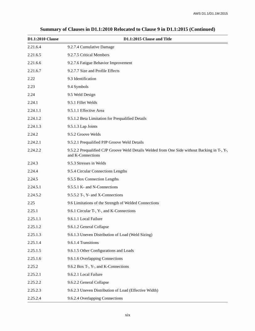
Summary of Clauses in D1.1:2010 Relocated to Clause 9 in D1.1:2015
D1.1:2010 Clause D1.1:2015 Clause and Title
2.20 9.1 General
2.21 9.2 Allowable Stresses
2.20.1 9.2.1 Eccentricity
2.21.1 9.2.2 Base Metal Stresses
2.21.2 9.2.3 Tubular Section Limitations
2.21.3 9.2.4 Weld Stresses
2.21.4 9.2.5 Fiber Stresses
2.21.5 9.2.6 Load and Resistance Factor Design
2.21.6 9.2.7 Fatigue of Circular Tube Connections
2.21.6.1 9.2.7.1 Stress Range and Member Type
2.21.6.2 9.2.7.2 Fatigue Stress Categories
2.21.6.3 9.2.7.3 Basic Allowable Stress Limitation
Summary of Changes (Continued)
Clause/Table/Figure/Annex Modification
xix
AWS D1.1/D1.1M:2015
2.21.6.4 9.2.7.4 Cumulative Damage
2.21.6.5 9.2.7.5 Critical Members
2.21.6.6 9.2.7.6 Fatigue Behavior Improvement
2.21.6.7 9.2.7.7 Size and Profile Effects
2.22 9.3 Identification
2.23 9.4 Symbols
2.24 9.5 Weld Design
2.24.1 9.5.1 Fillet Welds
2.24.1.1 9.5.1.1 Effective Area
2.24.1.2 9.5.1.2 Beta Limitation for Prequalified Details
2.24.1.3 9.5.1.3 Lap Joints
2.24.2 9.5.2 Groove Welds
2.24.2.1 9.5.2.1 Prequalified PJP Groove Weld Details
2.24.2.2 9.5.2.2 Prequalified CJP Groove Weld Details Welded from One Side without Backing in T-, Y-,and K-Connections
2.24.3 9.5.3 Stresses in Welds
2.24.4 9.5.4 Circular Connections Lengths
2.24.5 9.5.5 Box Connection Lengths
2.24.5.1 9.5.5.1 K- and N-Connections
2.24.5.2 9.5.5.2 T-, Y- and X-Connections
2.25 9.6 Limitations of the Strength of Welded Connections
2.25.1 9.6.1 Circular T-, Y-, and K-Connections
2.25.1.1 9.6.1.1 Local Failure
2.25.1.2 9.6.1.2 General Collapse
2.25.1.3 9.6.1.3 Uneven Distribution of Load (Weld Sizing)
2.25.1.4 9.6.1.4 Transitions
2.25.1.5 9.6.1.5 Other Configurations and Loads
2.25.1.6 9.6.1.6 Overlapping Connections
2.25.2 9.6.2 Box T-, Y-, and K-Connections
2.25.2.1 9.6.2.1 Local Failure
2.25.2.2 9.6.2.2 General Collapse
2.25.2.3 9.6.2.3 Uneven Distribution of Load (Effective Width)
2.25.2.4 9.6.2.4 Overlapping Connections
Summary of Clauses in D1.1:2010 Relocated to Clause 9 in D1.1:2015 (Continued)
D1.1:2010 Clause D1.1:2015 Clause and Title

xx
AWS D1.1/D1.1M:2015
2.25.2.5 9.6.2.5 Bending
2.25.2.6 9.6.2.6 Other Configurations
2.26 9.7 Thickness Transition
2.27 9.8 Material Limitations
2.27.1 9.8.1 Limitations
2.27.1.1 9.8.1.1 Yield Strength
2.27.1.2 9.8.1.2 Reduced Effective Yield
2.27.1.3 9.8.1.3 Box T-, Y-, and K-Connections
2.27.1.4 9.8.1.4 ASTM A500 Precaution
2.27.2 9.8.2 Tubular Base Metal Notch Toughness
2.27.2.1 9.8.2.1 CVN Test Requirements
2.27.2.2 9.8.2.2 LAST Requirements
2.27.2.3 9.8.2.3 Alternative Notch Toughness
3.9 9.9 Fillet Weld Requirements
3.9.2 9.9.1 Details
3.12 9.10 PJP Requirements
3.12.4 9.10.1 Details
3.12.4.1 9.10.1.1 Matched Box Connections
3.13 9.11 CJP Groove Weld Requirements
3.13.4 9.11.1 Butt Joints
3.13.5 9.11.2 Tubular T-, Y-, and K-Connections
3.13.5.1 9.11.2.1 Joint Details
4.3 9.12 Common Requirements for WPS and Welding Personnel Performance Qualification
4.3.4 9.12.1 Positions of Welds
4.4 9.13 Production Welding Positions Qualified
4.5, 4.9, 4.9.1.1(6)(b), 4.9.2.1
9.14 Type of Qualification Tests, Methods of Testing and Acceptance Criteria for WPSQualification
4.13 9.15 CJP Groove Welds for Tubular Connections
4.13.1 9.15.1 CJP Butt Joints with Backing or Backgouging
4.13.2 9.15.2 CJP Butt Joints without Backing Welded from One Side Only
4.13.3 9.15.3 T-,Y-, or K-Connections with Backing or Backgouging
4.13.4 9.15.4 T-,Y-, or K-Connections without Backing Welded from One Side Only
4.13.4.1 9.15.4.1 WPSs without Prequalified Status
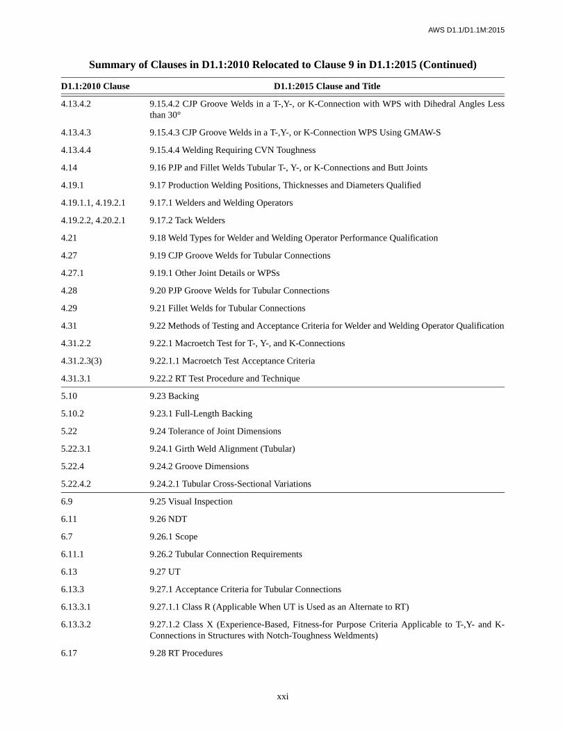
Summary of Clauses in D1.1:2010 Relocated to Clause 9 in D1.1:2015 (Continued)
D1.1:2010 Clause D1.1:2015 Clause and Title
xxi
AWS D1.1/D1.1M:2015
4.13.4.2 9.15.4.2 CJP Groove Welds in a T-,Y-, or K-Connection with WPS with Dihedral Angles Lessthan 30°
4.13.4.3 9.15.4.3 CJP Groove Welds in a T-,Y-, or K-Connection WPS Using GMAW-S
4.13.4.4 9.15.4.4 Welding Requiring CVN Toughness
4.14 9.16 PJP and Fillet Welds Tubular T-, Y-, or K-Connections and Butt Joints
4.19.1 9.17 Production Welding Positions, Thicknesses and Diameters Qualified
4.19.1.1, 4.19.2.1 9.17.1 Welders and Welding Operators
4.19.2.2, 4.20.2.1 9.17.2 Tack Welders
4.21 9.18 Weld Types for Welder and Welding Operator Performance Qualification
4.27 9.19 CJP Groove Welds for Tubular Connections
4.27.1 9.19.1 Other Joint Details or WPSs
4.28 9.20 PJP Groove Welds for Tubular Connections
4.29 9.21 Fillet Welds for Tubular Connections
4.31 9.22 Methods of Testing and Acceptance Criteria for Welder and Welding Operator Qualification
4.31.2.2 9.22.1 Macroetch Test for T-, Y-, and K-Connections
4.31.2.3(3) 9.22.1.1 Macroetch Test Acceptance Criteria
4.31.3.1 9.22.2 RT Test Procedure and Technique
5.10 9.23 Backing
5.10.2 9.23.1 Full-Length Backing
5.22 9.24 Tolerance of Joint Dimensions
5.22.3.1 9.24.1 Girth Weld Alignment (Tubular)
5.22.4 9.24.2 Groove Dimensions
5.22.4.2 9.24.2.1 Tubular Cross-Sectional Variations
6.9 9.25 Visual Inspection
6.11 9.26 NDT
6.7 9.26.1 Scope
6.11.1 9.26.2 Tubular Connection Requirements
6.13 9.27 UT
6.13.3 9.27.1 Acceptance Criteria for Tubular Connections
6.13.3.1 9.27.1.1 Class R (Applicable When UT is Used as an Alternate to RT)
6.13.3.2 9.27.1.2 Class X (Experience-Based, Fitness-for Purpose Criteria Applicable to T-,Y- and K-Connections in Structures with Notch-Toughness Weldments)
6.17 9.28 RT Procedures
Summary of Clauses in D1.1:2010 Relocated to Clause 9 in D1.1:2015 (Continued)
D1.1:2010 Clause D1.1:2015 Clause and Title

xxii
AWS D1.1/D1.1M:2015
6.17.1 9.28.1 Procedure
6.17.7 9.28.2 IQI Selection and Placement
6.18 9.29 Supplementary RT Requirements for Tubular Connections
6.18.1 9.29.1 Circumferential Groove Welds in Butt Joints
6.18.1.1 9.29.1.1 Single-Wall Exposure/Single-Wall View
6.18.1.2 9.29.1.2 Double-Wall Exposure/Single-Wall View
6.18.1.3 9.29.1.3 Double-Wall Exposure/Double-Wall View
6.27 9.30 UT of Tubular T-, Y-, and K-Connections
6.27.1 9.30.1 Procedure.
6.27.2 9.30.2 Personnel
6.27.3 9.30.3 Calibration
6.27.3.1 9.30.3.1 Range
6.27.3.2 9.30.3.2 Sensitivity Calibration
6.27.4 9.30.4 Base Metal Examination
6.27.5 9.30.5 Weld Scanning
6.27.6 9.30.6 Optimum Angle
6.27.7 9.30.7 Discontinuity Evaluation
6.27.8 9.30.8 Reports
6.27.8.1 9.30.8.1 Forms
6.27.8.2 9.30.8.2 Reported Discontinuities
6.27.8.3 9.30.8.3 Incomplete Inspection
6.27.8.4 9.30.8.4 Reference Marks
Summary of Tables in D1.1:2010 Relocated to Clause 9 in D1.1:2015
D1.1:2010 Table D1.1:2015 Table and Title
2.5 9.1 Fatigue Stress Design Parameters
2.6 9.2 Allowable Stresses in Tubular Connection Welds
2.7 9.3 Stress Categories for Type and Location of Material for Circular Sections
2.8 9.4 Fatigue Category Limitations on Weld Size or Thickness and Weld Profile (Tubular Connections)
2.9 9.5 Z Loss Dimensions for Calculating Prequalified PJP T-, Y-, and K-Tubular Connection MinimumWeld Sizes
Summary of Clauses in D1.1:2010 Relocated to Clause 9 in D1.1:2015 (Continued)
D1.1:2010 Clause D1.1:2015 Clause and Title

xxiii
AWS D1.1/D1.1M:2015
2.10 9.6 Terms for Strength of Connections (Circular Sections)
3.5 9.7 Joint Detail Applications for Prequalified CJP T-, Y-, and K-Tubular Connections
3.6 9.8 Prequalified Joint Dimensions and Groove Angles for CJP Groove Welds in Tubular T-, Y-,and K-Connections Made by SMAW, GMAW-S, and FCAW
4.1 9.9 WPS Qualification—Production Welding Positions Qualified by Pipe and Box Tube Tests
4.2 9.10 WPS Qualification—CJP Groove Welds: Number and Type of Test Specimens and Range ofThickness and Diameter Qualified
4.3 9.11 Number and Type of Test Specimens and Range of Thickness Qualified—WPS Qualification;PJP Groove Welds
4.4 9.12 Number and Type of Test Specimens and Range of Thickness Qualified—WPS Qualification;Fillet Welds
4.10 9.13 Welder and Welding Operator Qualification—Production Welding Positions Qualified by Pipeand Box Tube Tests
4.11 9.14 Welder and Welding Operator Qualification—Number and Type of Specimens and Range ofThickness and Diameter Qualified
5.5 9.15 Tubular Root Opening Tolerances Butt Joints Welded Without Backing
6.1 9.16 Visual Inspection Acceptance Criteria
6.4 9.17 Hole-Type IQI Requirements
6.5 9.18 Wire IQI Requirements
6.6 9.19 IQI Selection and Placement
Summary of Tables in D1.1:2010 Relocated to Clause 9 in D1.1:2015 (Continued)
D1.1:2010 Table D1.1:2015 Table and Title

xxiv
AWS D1.1/D1.1M:2015
Summary of Figures in D1.1:2010 Relocated to Clause 9 in D1.1:2015
D1.1:2010 Figure D1.1:2015 Figure and Title
2.13 9.1 Allowable Fatigue Stress and Strain Ranges for Stress Categories, Tubular Structures for Atmo-spheric Service
2.14 9.2 Parts of a Tubular Connection
2.15 9.3 Fillet Welded Lap Joint (Tubular)
2.16 9.4 Tubular T-, Y-, and K-Connection Fillet Weld Footprint Radius
2.17 9.5 Punching Shear Stress
2.18 9.6 Detail of Overlapping Joint
2.19 9.7 Limitations for Box T-, Y-, and K-Connections
2.20 9.8 Overlapping K-Connections
2.21 9.9 Transition of Thickness of Butt Joints in Parts of Unequal Thickness (Tubular)
3.2 9.10 Fillet Welded Prequalified Tubular Joints Made by SMAW, GMAW, and FCAW
3.5 9.11 Prequalified Joint Details for PJP T-, Y-, and K-Tubular Connections
3.6 9.12 Prequalified Joint Details for CJP T-, Y-, and K-Tubular Connections
3.7 9.13 Definitions and Detailed Selections for Prequalified CJP T-, Y-, and K-Tubular Connections
3.8 9.14 Prequalified Joint Details for CJP Groove Welds in Tubular T-, Y-, and K-Connections—Standard Flat Profiles for Limited Thickness
3.9 9.15 Prequalified Joint Details for CJP Groove Welds in Tubular T-, Y-, and K-Connections—Profile with Toe Fillet for Intermediate Thickness
3.10 9.16 Prequalified Joint Details for CJP Groove Welds in Tubular T-, Y-, and K-Connections—Concave Improved Profile for Heavy Sections or Fatigue
4.4 9.17 Positions of Test Pipe or Tubing for Groove Welds
4.6 9.18 Positions of Test Pipes or Tubing for Fillet Welds
4.7 9.19 Location of Test Specimens on Welded Test Pipe—WPS Qualification
4.8 9.20 Location of Test Specimens for Welded Box Tubing—WPS Qualification
4.20 9.21 Pipe Fillet Weld Soundness Test-WPS Qualification
4.24 9.22 Tubular Butt Joint-Welder Qualification with and without Backing
4.25 9.23 Tubular Butt Joint-WPS Qualification with and without Backing
4.26 9.24 Acute Angle Heel Test (Restraints not Shown)
4.27 9.25 Test Joint for T-, Y-, and K-Connections without Backing on Pipe or Box Tubing (≥ 6 in[150 mm] O.D.) -Welder and WPS Qualification
4.28 9.26 Test Joint for T-, Y-, and K-Connections without Backing on Pipe or Box Tubing (< 4 in[100 mm] O.D.)-Welder and WPS Qualification
4.29 9.27 Corner Macroetch Test Joint for T-, Y-, and K-Connections without Backing on Box Tubingfor CJP Groove Welds-Welder and WPS Qualification
4.34 9.28 Location of Test Specimens on Welded Test Pipe and Box Tubing-Welder Qualification

xxv
AWS D1.1/D1.1M:2015
AWS B4.0, Standard Methods for Mechanical Testing of Welds, provides additional details of test specimenpreparation and details of test fixture construction.
Commentary. The Commentary is nonmandatory and is intended only to provide insightful information into provisionrationale.
Normative Annexes. These annexes address specific subjects in the code and their requirements are mandatory require-ments that supplement the code provisions.
Informative Annexes. These annexes are not code requirements but are provided to clarify code provisions by showingexamples, providing information, or suggesting alternative good practices.
Index. As in previous codes, the entries in the Index are referred to by subclause number rather than by page number.This should enable the user of the Index to locate a particular item of interest in minimum time.
Errata. It is the Structural Welding Committee’s Policy that all errata should be made available to users of the code.Therefore, any significant errata will be published in the Society News Section of the Welding Journal and posted on theAWS web site at: http://www.aws.org/technical/d1/.
Suggestions. Your comments for improving AWS D1.1/D1.1M:2015, Structural Welding Code—Steel are welcome.Submit comments to the Managing Director, Technical Services Division, American Welding Society, 8669 NW 36 St,# 130, Miami, FL 33166; telephone (305) 443-9353; fax (305) 443-5951; e-mail [email protected]; or via the AWS web site<http://www.aws.org>.
6.4 9.29 Class R Indications
6.5 9.30 Class X Indications
6.13 9.31 Single-Wall Exposure-Single-Wall View
6.14 9.32 Double-Wall Exposure-Single-Wall View
6.15 9.33 Double-Wall Exposure-Double-Wall (Elliptical) View, Minimum Two Exposures
6.16 9.34 Double-Wall Exposure-Double-Wall View, Minimum Three Exposures
6.22 9.35 Scanning Techniques
Summary of Figures in D1.1:2010 Relocated to Clause 9 in D1.1:2015 (Continued)
D1.1:2010 Figure D1.1:2015 Figure and Title

This page is intentionally blank.
xxvi
AWS D1.1/D1.1M:2015

xxvii
AWS D1.1/D1.1M:2015
Table of Contents
Page No.
Dedication ....................................................................................................................................................................vPersonnel ....................................................................................................................................................................viiForeword .....................................................................................................................................................................xvList of Tables...........................................................................................................................................................xxxiiList of Figures .........................................................................................................................................................xxxv
1. General Requirements .......................................................................................................................................11.1 Scope...........................................................................................................................................................11.2 Limitations ..................................................................................................................................................11.3 Definitions...................................................................................................................................................11.4 Responsibilities ...........................................................................................................................................21.5 Approval......................................................................................................................................................31.6 Welding Symbols ........................................................................................................................................31.7 Safety Precautions.......................................................................................................................................31.8 Standard Units of Measurement..................................................................................................................31.9 Reference Documents .................................................................................................................................3
2. Design of Welded Connections ..........................................................................................................................52.1 Scope...........................................................................................................................................................5
Part A—Common Requirements for Design of Welded Connections (Nontubular and Tubular Members) ........52.2 General ........................................................................................................................................................52.3 Contract Plans and Specifications...............................................................................................................52.4 Effective Areas ............................................................................................................................................6
Part B—Specific Requirements for Design of Nontubular Connections (Statically or Cyclically Loaded) ........82.5 General ........................................................................................................................................................82.6 Stresses........................................................................................................................................................82.7 Joint Configuration and Details ..................................................................................................................92.8 Joint Configuration and Details—Groove Welds......................................................................................102.9 Joint Configuration and Details—Fillet Welded Joints.............................................................................102.10 Joint Configuration and Details—Plug and Slot Welds ............................................................................112.11 Filler Plates ...............................................................................................................................................112.12 Built-Up Members ....................................................................................................................................12
Part C—Specific Requirements for Design of Nontubular Connections (Cyclically Loaded) ...........................122.13 General ......................................................................................................................................................122.14 Limitations ................................................................................................................................................122.15 Calculation of Stresses ..............................................................................................................................132.16 Allowable Stresses and Stress Ranges ......................................................................................................132.17 Detailing, Fabrication, and Erection .........................................................................................................142.18 Prohibited Joints and Welds ......................................................................................................................152.19 Inspection ..................................................................................................................................................15
3. Prequalification of WPSs.................................................................................................................................453.1 Scope.........................................................................................................................................................453.2 Welding Processes.....................................................................................................................................453.3 Base Metal/Filler Metal Combinations .....................................................................................................45

xxviii
Page No.
AWS D1.1/D1.1M:2015
3.4 Engineer’s Approval for Auxiliary Attachments ......................................................................................463.5 Minimum Preheat and Interpass Temperature Requirements ...................................................................463.6 Limitation of WPS Variables ....................................................................................................................463.7 General WPS Requirements......................................................................................................................463.8 Common Requirements for Parallel Electrode and Multiple Electrode SAW ..........................................473.9 Fillet Weld Requirements..........................................................................................................................473.10 Plug and Slot Weld Requirements.............................................................................................................473.11 Common Requirements of PJP and CJP Groove Welds ...........................................................................473.12 PJP Requirements .....................................................................................................................................483.13 CJP Groove Weld Requirements...............................................................................................................483.14 Postweld Heat Treatment ..........................................................................................................................48
4. Qualification ...................................................................................................................................................1094.1 Scope.......................................................................................................................................................109
Part A—General Requirements ........................................................................................................................1094.2 General ....................................................................................................................................................1094.3 Common Requirements for WPS and Welding Personnel Performance Qualification ..........................110
Part B—Welding Procedure Specification (WPS) Qualification ......................................................................1104.4 Production Welding Positions Qualified .................................................................................................1104.5 Type of Qualification Tests .....................................................................................................................1104.6 Weld Types for WPS Qualification .........................................................................................................1104.7 Preparation of WPS.................................................................................................................................1114.8 Essential Variables ..................................................................................................................................1114.9 Methods of Testing and Acceptance Criteria for WPS Qualification .....................................................1114.10 CJP Groove Welds ..................................................................................................................................1134.11 PJP Groove Welds ...................................................................................................................................1134.12 Fillet Welds .............................................................................................................................................1134.13 Plug and Slot Welds ................................................................................................................................1144.14 Welding Processes Requiring Qualification............................................................................................114
Part C—Performance Qualification .................................................................................................................1154.15 General ....................................................................................................................................................1154.16 Type of Qualification Tests Required......................................................................................................1154.17 Weld Types for Welder and Welding Operator Performance Qualification............................................1154.18 Preparation of Performance Qualification Forms ...................................................................................1164.19 Essential Variables ..................................................................................................................................1164.20 CJP Groove Welds for Nontubular Connections.....................................................................................1164.21 Extent of Qualification............................................................................................................................1164.22 Methods of Testing and Acceptance Criteria for Welder and Welding Operator Qualification .............1164.23 Method of Testing and Acceptance Criteria for Tack Welder Qualification...........................................1174.24 Retest.......................................................................................................................................................117
Part D—Requirements for CVN Testing...........................................................................................................1184.25 General ....................................................................................................................................................1184.26 Test Locations .........................................................................................................................................1184.27 CVN Tests ...............................................................................................................................................1184.28 Test Requirements...................................................................................................................................1194.29 Retest.......................................................................................................................................................1194.30 Reporting.................................................................................................................................................119
5. Fabrication......................................................................................................................................................1655.1 Scope.......................................................................................................................................................1655.2 Base Metal...............................................................................................................................................1655.3 Welding Consumables and Electrode Requirements ..............................................................................165

xxix
Page No.
AWS D1.1/D1.1M:2015
5.4 ESW and EGW Processes.......................................................................................................................1675.5 WPS Variables.........................................................................................................................................1685.6 Preheat and Interpass Temperatures........................................................................................................1685.7 Heat Input Control for Quenched and Tempered Steels .........................................................................1685.8 Stress-Relief Heat Treatment ..................................................................................................................1685.9 Backing ...................................................................................................................................................1695.10 Welding and Cutting Equipment .............................................................................................................1695.11 Welding Environment .............................................................................................................................1695.12 Conformance with Design ......................................................................................................................1705.13 Minimum Fillet Weld Sizes ....................................................................................................................1705.14 Preparation of Base Metal.......................................................................................................................1705.15 Reentrant Corners ...................................................................................................................................1725.16 Weld Access Holes, Beam Copes, and Connection Material..................................................................1725.17 Tack Welds and Construction Aid Welds................................................................................................1725.18 Camber in Built-Up Members.................................................................................................................1735.19 Splices .....................................................................................................................................................1735.20 Control of Distortion and Shrinkage.......................................................................................................1735.21 Tolerance of Joint Dimensions................................................................................................................1745.22 Dimensional Tolerance of Welded Structural Members .........................................................................1745.23 Weld Profiles ...........................................................................................................................................1775.24 Technique for Plug and Slot Welds .........................................................................................................1775.25 Repairs ....................................................................................................................................................1775.26 Peening....................................................................................................................................................1785.27 Caulking ..................................................................................................................................................1785.28 Arc Strikes...............................................................................................................................................1795.29 Weld Cleaning.........................................................................................................................................1795.30 Weld Tabs................................................................................................................................................179
6. Inspection ........................................................................................................................................................191Part A—General Requirements ........................................................................................................................1916.1 Scope.......................................................................................................................................................1916.2 Inspection of Materials and Equipment ..................................................................................................1926.3 Inspection of WPSs.................................................................................................................................1926.4 Inspection of Welder, Welding Operator, and Tack Welder Qualifications ............................................1926.5 Inspection of Work and Records .............................................................................................................192
Part B—Contractor Responsibilities ................................................................................................................1936.6 Obligations of the Contractor..................................................................................................................193
Part C—Acceptance Criteria ...........................................................................................................................1936.7 Scope.......................................................................................................................................................1936.8 Engineer’s Approval for Alternate Acceptance Criteria .........................................................................1936.9 Visual Inspection.....................................................................................................................................1936.10 Penetrant Testing (PT) and Magnetic Particle Testing (MT) ..................................................................1936.11 Nondestructive Testing (NDT)................................................................................................................1946.12 Radiographic Testing (RT)......................................................................................................................1946.13 Ultrasonic Testing (UT) ..........................................................................................................................195
Part D—NDT Procedures.................................................................................................................................1966.14 Procedures ...............................................................................................................................................1966.15 Extent of Testing .....................................................................................................................................196
Part E—Radiographic Testing (RT) .................................................................................................................1976.16 RT of Groove Welds in Butt Joints .........................................................................................................1976.17 RT Procedures .........................................................................................................................................1976.18 Examination, Report, and Disposition of Radiographs...........................................................................199

xxx
Page No.
AWS D1.1/D1.1M:2015
Part F—Ultrasonic Testing (UT) of Groove Welds ..........................................................................................1996.19 General ....................................................................................................................................................1996.20 Qualification Requirements ....................................................................................................................1996.21 UT Equipment.........................................................................................................................................1996.22 Reference Standards................................................................................................................................2006.23 Equipment Qualification .........................................................................................................................2016.24 Calibration for Testing ............................................................................................................................2016.25 Testing Procedures ..................................................................................................................................2016.26 Preparation and Disposition of Reports ..................................................................................................2036.27 Calibration of the UT Unit with IIW Type or Other Approved Reference Blocks (Annex G)...............2036.28 Equipment Qualification Procedures ......................................................................................................2046.29 Discontinuity Size Evaluation Procedures ..............................................................................................2066.30 Scanning Patterns ....................................................................................................................................2066.31 Examples of dB Accuracy Certification..................................................................................................206
Part G—Other Examination Methods ..............................................................................................................2076.32 General Requirements.............................................................................................................................2076.33 Radiation Imaging Systems ....................................................................................................................2076.34 Advanced Ultrasonic Systems.................................................................................................................2076.35 Additional Requirements ........................................................................................................................208
7. Stud Welding ..................................................................................................................................................2457.1 Scope.......................................................................................................................................................2457.2 General Requirements.............................................................................................................................2457.3 Mechanical Requirements.......................................................................................................................2467.4 Workmanship/Fabrication .......................................................................................................................2467.5 Technique ................................................................................................................................................2467.6 Stud Application Qualification Requirements ........................................................................................2477.7 Production Control ..................................................................................................................................2487.8 Fabrication and Verification Inspection Requirements ...........................................................................2497.9 Manufacturers’ Stud Base Qualification Requirements..........................................................................249
8. Strengthening and Repair of Existing Structures .......................................................................................2558.1 General ....................................................................................................................................................2558.2 Base Metal...............................................................................................................................................2558.3 Design for Strengthening and Repair......................................................................................................2558.4 Fatigue Life Enhancement ......................................................................................................................2558.5 Workmanship and Technique ..................................................................................................................2568.6 Quality.....................................................................................................................................................256
9. Tubular Structures .........................................................................................................................................2579.1 General ....................................................................................................................................................257
Part A—Design of Tubular Connections ..........................................................................................................2579.2 Allowable Stresses ..................................................................................................................................2579.3 Identification ...........................................................................................................................................2589.4 Symbols...................................................................................................................................................2589.5 Weld Design ............................................................................................................................................2589.6 Limitations of the Strength of Welded Connections ...............................................................................2609.7 Thickness Transition ...............................................................................................................................2649.8 Material Limitations................................................................................................................................264
Part B—Prequalification of Welding Procedure Specifications (WPSs) ..........................................................2659.9 Fillet Weld Requirements........................................................................................................................2659.10 PJP Requirements ...................................................................................................................................2659.11 CJP Groove Weld Requirements.............................................................................................................265

xxxi
Page No.
AWS D1.1/D1.1M:2015
Part C—Welding Procedure Specification (WPS) Qualification......................................................................2669.12 Common Requirements for WPS and Welding Personnel Performance Qualification ..........................2669.13 Production Welding Positions Qualified .................................................................................................2669.14 Type of Qualification Tests, Methods of Testing, and Acceptance Criteria for WPS Qualification.......2669.15 CJP Groove Welds for Tubular Connections ..........................................................................................2679.16 PJP and Fillet Welds Tubular T-, Y-, or K-Connections and Butt Joints ................................................268
Part D—Performance Qualification.................................................................................................................2689.17 Production Welding Positions, Thicknesses and Diameters Qualified ...................................................2689.18 Weld Types for Welder and Welding Operator Performance Qualification............................................2689.19 CJP Groove Welds for Tubular Connections ..........................................................................................2689.20 PJP Groove Welds for Tubular Connections...........................................................................................2699.21 Fillet Welds for Tubular Connections .....................................................................................................2699.22 Methods of Testing and Acceptance Criteria for Welder and Welding Operator Qualification .............269
Part E—Fabrication .........................................................................................................................................2699.23 Backing ...................................................................................................................................................2699.24 Tolerance of Joint Dimensions................................................................................................................270
Part F—Inspection ...........................................................................................................................................2709.25 Visual Inspection.....................................................................................................................................2709.26 NDT ........................................................................................................................................................2709.27 UT ...........................................................................................................................................................2709.28 RT Procedures .........................................................................................................................................2719.29 Supplementary RT Requirements for Tubular Connections ...................................................................2719.30 UT of Tubular T-, Y-, and K-Connections ..............................................................................................271
Annexes .....................................................................................................................................................................327Annex A (Normative)—Effective Throat (E) .........................................................................................................329Annex B (Normative)—Effective Throats of Fillet Welds in Skewed T-Joints......................................................333Annex D (Normative)—Flatness of Girder Webs—Statically Loaded Structures..................................................337Annex E (Normative)—Flatness of Girder Webs—Cyclically Loaded Structures ................................................341Annex F (Normative)—Temperature-Moisture Content Charts ............................................................................347Annex G (Normative)—Qualification and Calibration of UT Units with Other Approved Reference Blocks......351Annex H (Normative)—Guideline on Alternative Methods for Determining Preheat...........................................355Annex I (Normative)—Symbols for Tubular Connection Weld Design ...............................................................365Annex J (Normative)—Terms and Definitions ......................................................................................................367Annex K (Informative)—Guide for Specification Writers .....................................................................................375Annex L (Informative)—UT Equipment Qualification and Inspection Forms ......................................................377Annex M (Informative)—Sample Welding Forms ..................................................................................................387Annex N (Informative)—Guidelines for the Preparation of Technical Inquiries for the Structural Welding
(Informative)—Committee ......................................................................................................................409Annex O (Informative)—Local Dihedral Angle .....................................................................................................411Annex P (Informative)—Contents of Prequalified WPS........................................................................................417Annex Q (Informative)—UT Examination of Welds by Alternative Techniques...................................................419Annex R (Informative)—Ovalizing Parameter Alpha ............................................................................................435Annex S (Informative)—List of Reference Documents .........................................................................................437Annex T (Informative)—Filler Metal Strength Properties .....................................................................................439Annex U (Informative—AWS A5.36 Filler Metal Classifications and Properties .................................................451
Commentary .............................................................................................................................................................467Foreword...................................................................................................................................................................469
Index .........................................................................................................................................................................587
List of AWS Documents on Structural Welding.......................................................................................................603

xxxii
List of Tables
Table Page No.
AWS D1.1/D1.1M:2015
2.1 Effective Size of Flare-Groove Welds Filled Flush......................................................................................162.2 Z Loss Dimension (Nontubular) ..................................................................................................................162.3 Allowable Stresses .......................................................................................................................................172.4 Equivalent Strength Coefficients for Obliquely Loaded Fillet Welds..........................................................182.5 Fatigue Stress Design Parameters ................................................................................................................19
3.1 Approved Base Metals for Prequalified WPSs ............................................................................................493.2 Filler Metals for Matching Strength for Table 3.1, Groups I, II, III, and IV Materials ...............................533.3 Prequalified Minimum Preheat and Interpass Temperature.........................................................................573.4 Filler Metal Requirements for Exposed Bare Applications of Weathering Steels.......................................603.5 Minimum Prequalified PJP Weld Size (E)...................................................................................................603.6 Prequalified WPS Requirements..................................................................................................................613.7 Prequalified WPS Variables .........................................................................................................................62
4.1 WPS Qualification—Production Welding Positions Qualified by Plate, Pipe, and Box Tube Tests .........1204.2 WPS Qualification-CJP Groove Welds: Number and Type of Test Specimens and Range of
Thickness Qualified ...................................................................................................................................1214.3 Number and Type of Test Specimens and Range of Thickness Qualified—WPS Qualification;
PJP Groove Welds ......................................................................................................................................1234.4 Number and Type of Test Specimens and Range of Thickness Qualified—WPS Qualification;
Fillet Welds ................................................................................................................................................1234.5 PQR Essential Variable Changes Requiring WPS Requalification for SMAW, SAW, GMAW,
FCAW, and GTAW.....................................................................................................................................1244.6 PQR Supplementary Essential Variable Changes for CVN Testing Applications Requiring WPS
Requalification for SMAW, SAW, GMAW, FCAW, and GTAW ...............................................................1274.7 PQR Essential Variable Changes Requiring WPS Requalification for ESW or EGW ..............................1284.8 Table 3.1, Table 4.9, and Unlisted Steels Qualified by PQR .....................................................................1294.9 Code-Approved Base Metals and Filler Metals Requiring Qualification per Clause 4 .............................1304.10 Welder and Welding Operator Qualification—Production Welding Positions Qualified by
Plate, Pipe, and Box Tube Tests .................................................................................................................1354.11 Welder and Welding Operator Qualification—Number and Type of Specimens and Range of
Thickness and Diameter Qualified.............................................................................................................1364.12 Welding Personnel Performance Essential Variable Changes Requiring Requalification.........................1384.13 Electrode Classification Groups.................................................................................................................1384.14 CVN Test Requirements ............................................................................................................................1394.15 CVN Test Temperature Reduction .............................................................................................................139
5.1 Allowable Atmospheric Exposure of Low-Hydrogen Electrodes..............................................................1805.2 Minimum Holding Time ............................................................................................................................1805.3 Alternate Stress-Relief Heat Treatment .....................................................................................................1805.4 Limits on Acceptability and Repair of Mill Induced Laminar Discontinuities in Cut Surfaces................1805.5 Camber Tolerance for Typical Girder ........................................................................................................1815.6 Camber Tolerance for Girders without a Designed Concrete Haunch.......................................................1815.7 Minimum Fillet Weld Sizes .......................................................................................................................1815.8 Weld Profiles ..............................................................................................................................................1825.9 Weld Profile Schedules ..............................................................................................................................182
xxxiii
Table Page No.
AWS D1.1/D1.1M:2015
6.1 Visual Inspection Acceptance Criteria .......................................................................................................2096.2 UT Acceptance-Rejection Criteria (Statically Loaded Nontubular Connections) .....................................2106.3 UT Acceptance-Rejection Criteria (Cyclically Loaded Nontubular Connections)....................................2116.4 Hole-Type IQI Requirements .....................................................................................................................2126.5 Wire IQI Requirements ..............................................................................................................................2126.6 IQI Selection and Placement......................................................................................................................2136.7 Testing Angle .............................................................................................................................................2146.8 UT Equipment Qualification and Calibration Requirements.....................................................................216
7.1 Mechanical Property Requirements for Studs ...........................................................................................2517.2 Minimum Fillet Weld Size for Small Diameter Studs ...............................................................................251
9.1 Fatigue Stress Design Parameters ..............................................................................................................2749.2 Allowable Stresses in Tubular Connection Welds .....................................................................................2759.3 Stress Categories for Type and Location of Material for Circular Sections ..............................................2779.4 Fatigue Category Limitations on Weld Size or Thickness and Weld Profile (Tubular Connections) ........2799.5 Z Loss Dimensions for Calculating Prequalified PJP T-,Y-, and K-Tubular Connection Minimum
Weld Sizes ..................................................................................................................................................2799.6 Terms for Strength of Connections (Circular Sections).............................................................................2809.7 Joint Detail Applications for Prequalified CJP T-, Y-, and K-Tubular Connections..................................2809.8 Prequalified Joint Dimensions and Groove Angles for CJP Groove Welds in Tubular T-, Y, and
K-Connections Made by SMAW, GMAW-S, and FCAW..........................................................................2819.9 WPS Qualification—Production Welding Positions Qualified by Plate, Pipe, and Box Tube Tests .........2829.10 WPS Qualification—CJP Groove Welds: Number and Type of Test Specimens and Range of
Thickness and Diameter Qualified.............................................................................................................2839.11 Number and Type of Test Specimens and Range of Thickness Qualified—WPS Qualification;
PJP Groove Welds ......................................................................................................................................2859.12 Number and Type of Test Specimens and Range of Thickness Qualified—WPS Qualification;
Fillet Welds ................................................................................................................................................2859.13 Welder and Welding Operator Qualification—Production Welding Positions Qualified by
Plate, Pipe, and Box Tube Tests .................................................................................................................2869.14 Welder and Welding Operator Qualification—Number and Type of Specimens and Range of
Thickness and Diameter Qualified.............................................................................................................2879.15 Tubular Root Opening Tolerances, Butt Joints Welded Without Backing.................................................2899.16 Visual Inspection Acceptance Criteria .......................................................................................................2909.17 Hole-Type IQI Requirements .....................................................................................................................2919.18 Wire IQI Requirements ..............................................................................................................................2919.19 IQI Selection and Placement......................................................................................................................292
B.1 Equivalent Fillet Weld Leg Size Factors for Skewed T-Joints ...................................................................334D.1 Intermediate Stiffeners on Both Sides of Web ...........................................................................................338D.2 No Intermediate Stiffeners .........................................................................................................................338D.3 Intermediate Stiffeners on One Side Only of Web.....................................................................................339E.1 Intermediate Stiffness on Both Sides of Web, Interior Girders..................................................................342E.2 Intermediate Stiffness on One Side Only of Web, Fascia Girders .............................................................343E.3 Intermediate Stiffness on One Side Only of Web, Interior Girders ...........................................................344E.4 Intermediate Stiffness on Both Sides of Web, Fascia Girders ...................................................................345E.5 No Intermediate Stiffeners, Interior or Fascia Girders...............................................................................345H.1 Susceptibility Index Grouping as Function of Hydrogen Level “H” and Composition Parameter Pcm.....358H.2 Minimum Preheat and Interpass Temperatures for Three Levels of Restraint ..........................................358Q.1 Acceptance-Rejection Criteria ...................................................................................................................424U.1 AWS A5.36/A5.36M Carbon Steel Electrode Classifications with Fixed Requirements..........................453U.2 AWS A5.36/A5.36M Tension Test Requirements .....................................................................................454U.3 AWS A5.36/A5.36M Charpy Impact Test Requirements ..........................................................................454

xxxiv
Table Page No.
AWS D1.1/D1.1M:2015
U.4 Electrode Usability Characteristics ............................................................................................................455U.5 AWS A5.36/A5.36M Composition Requirements for Shielding Gases ....................................................457U.6 Weld Metal Chemical Composition Requirements....................................................................................458U.7 AWS A5.20/A5.20M Procedure Requirements for “D” Optional Supplemental Designator....................460U.8 AWS A5.36/A5.36M Procedure Requirements for “D” Optional Supplemental Designator....................460U.9 Comparison of Classifications of AWS A5.18, A5.20, A5.28, and A5.29 Specifications to
AWS A5.36 Fixed and Open Classifications for Multiple-Pass FCAW and GMAW—MetalCored Electrodes ........................................................................................................................................461
CommentaryC-3.1 Typical Current Ranges for GMAW-S on Steel .........................................................................................498C-8.1 Guide to Welding Suitability......................................................................................................................549C-8.2 Relationship Between Plate Thickness and Burr Radius ...........................................................................549C-9.1 Survey of Diameter/Thickness and Flat Width/Thickness Limits for Tubes .............................................572C-9.2 Suggested Design Factors ..........................................................................................................................573C-9.3 Values of JD ...............................................................................................................................................573C-9.4 Structural Steel Plates ................................................................................................................................574C-9.5 Structural Steel Pipe and Tubular Shapes ..................................................................................................575C-9.6 Structural Steel Shapes...............................................................................................................................575C-9.7 Classification Matrix for Applications.......................................................................................................576C-9.8 CVN Testing Conditions ............................................................................................................................576C-9.9 CVN Test Values ........................................................................................................................................577C-9.10 HAZ CVN Test Values...............................................................................................................................577

xxxv
List of Figures
Figure Page No.
AWS D1.1/D1.1M:2015
2.1 Maximum Fillet Weld Size Along Edges in Lap Joints...............................................................................362.2 Transition of Butt Joints in Parts of Unequal Thickness (Cyclically Loaded Nontubular) .........................372.3 Transition of Thicknesses (Statically Loaded Nontubular)..........................................................................382.4 Transversely Loaded Fillet Welds................................................................................................................382.5 Minimum Length of Longitudinal Fillet Welds at End of Plate or Flat Bar Members ................................392.6 Termination of Welds Near Edges Subject to Tension.................................................................................392.7 End Return at Flexible Connections ............................................................................................................402.8 Fillet Welds on Opposite Sides of a Common Plane ...................................................................................402.9 Thin Filler Plates in Splice Joint ..................................................................................................................412.10 Thick Filler Plates in Splice Joint ................................................................................................................412.11 Allowable Stress Range for Cyclically Applied Load (Fatigue) in Nontubular Connections
(Graphical Plot of Table 2.5)........................................................................................................................422.12 Transition of Width (Cyclically Loaded Nontubular) ..................................................................................43
3.1 Weld Bead in which Depth and Width Exceed the Width of the Weld Face ...............................................643.2 Prequalified PJP Groove Welded Joint Details (Dimensions in Inches)......................................................663.2 Prequalified PJP Groove Welded Joint Details (Dimensions in Millimeters)..............................................743.3 Prequalified CJP Groove Welded Joint Details (Dimensions in Inches) .....................................................823.3 Prequalified CJP Groove Welded Joint Details (Dimensions in Millimeters) .............................................933.4 Prequalified Skewed T-Joint Details (Nontubular) ....................................................................................1043.5 Prequalified Fillet Weld Joint Details (Dimensions in Inches) ..................................................................1053.5 Prequalified Fillet Weld Joint Details (Dimensions in Millimeters)..........................................................1063.6 Prequalified CJP Groove, T-, and Corner Joint..........................................................................................107
4.1 Positions of Groove Welds.........................................................................................................................1404.2 Positions of Fillet Welds ............................................................................................................................1414.3 Positions of Test Plates for Groove Welds .................................................................................................1424.4 Positions of Test Plate for Fillet Welds ......................................................................................................1434.5 Location of Test Specimens on Welded Test Plates—ESW and EGW—WPS Qualification ...................1444.6 Location of Test Specimens on Welded Test Plate Over 3/8 in [10 mm] Thick—WPS Qualification......1454.7 Location of Test Specimens on Welded Test Plate 3/8 in [10 mm] Thick and Under—
WPS Qualification .....................................................................................................................................1464.8 Face and Root Bend Specimens.................................................................................................................1474.9 Side Bend Specimens.................................................................................................................................1484.10 Reduced-Section Tension Specimens ........................................................................................................1494.11 Guided Bend Test Jig .................................................................................................................................1504.12 Alternative Wraparound Guided Bend Test Jig .........................................................................................1514.13 Alternative Roller-Equipped Guided Bend Test Jig for Bottom Ejection of Test Specimen .....................1514.14 All-Weld-Metal Tension Specimen............................................................................................................1524.15 Fillet Weld Soundness Tests for WPS Qualification..................................................................................1534.16 Test Plate for Unlimited Thickness—Welder Qualification and Fillet Weld Consumable
Verification Tests........................................................................................................................................1544.17 Test Plate for Unlimited Thickness—Welding Operator Qualification and Fillet Weld
Consumable Verification Tests...................................................................................................................1544.18 Location of Test Specimen on Welded Test Plate 1 in [25 mm] Thick—Consumables
Verification for Fillet Weld WPS Qualification .........................................................................................155

xxxvi
Figure Page No.
AWS D1.1/D1.1M:2015
4.19 Optional Test Plate for Unlimited Thickness—Horizontal Position—Welder Qualification ....................1564.20 Test Plate for Limited Thickness—All Positions—Welder Qualification .................................................1574.21 Optional Test Plate for Limited Thickness—Horizontal Position—Welder Qualification........................1584.22 Fillet Weld Root Bend Test Plate—Welder or Welding Operator Qualification—Option 2 .....................1594.23 Method of Rupturing Specimen—Tack Welder Qualification...................................................................1604.24 Butt Joint for Welding Operator Qualification—ESW and EGW .............................................................1604.25 Fillet Weld Break and Macroetch Test Plate—Welder or Welding Operator Qualification
Option 1......................................................................................................................................................1614.26 Plug Weld Macroetch Test Plate—Welder or Welding Operator Qualification and WPS Qualification.....1624.27 Fillet Weld Break Specimen—Tack Welder Qualification ........................................................................1634.28 CVN Test Specimen Locations ..................................................................................................................164
5.1 Edge Discontinuities in Cut Material.........................................................................................................1835.2 Weld Access Hole Geometry .....................................................................................................................1845.3 Workmanship Tolerances in Assembly of Groove Welded Joints .............................................................1855.4 Requirements for Weld Profiles .................................................................................................................186
6.1 Discontinuity Acceptance Criteria for Statically Loaded Nontubular and Statically or CyclicallyLoaded Tubular Connections .....................................................................................................................218
6.2 Discontinuity Acceptance Criteria for Cyclically Loaded Nontubular Connections in Tension(Limitations of Porosity and Fusion Discontinuities) ................................................................................223
6.3 Discontinuity Acceptance Criteria for Cyclically Loaded Nontubular Connections in Compression(Limitations of Porosity or Fusion-Type Discontinuities) .........................................................................228
6.4 Hole-Type IQI ............................................................................................................................................2336.5 Wire IQI .....................................................................................................................................................2346.6 RT Identification and Hole-Type or Wire IQI Locations on Approximately Equal Thickness Joints
10 in [250 mm] and Greater in Length ......................................................................................................2356.7 RT Identification and Hole-Type or Wire IQI Locations on Approximately Equal Thickness Joints
Less than 10 in [250 mm] in Length ..........................................................................................................2366.8 RT Identification and Hole-Type or Wire IQI Locations on Transition Joints 10 in [250 mm] and
Greater in Length .......................................................................................................................................2376.9 RT Identification and Hole-Type or Wire IQI Locations on Transition Joints Less than 10 in
[250 mm] in Length ...................................................................................................................................2386.10 RT Edge Blocks .........................................................................................................................................2386.11 Transducer Crystal .....................................................................................................................................2396.12 Qualification Procedure of Search Unit Using IIW Reference Block .......................................................2396.13 Typical IIW Type Block.............................................................................................................................2406.14 Qualification Blocks...................................................................................................................................2416.15 Plan View of UT Scanning Patterns...........................................................................................................2436.16 Transducer Positions (Typical)...................................................................................................................244
7.1 Dimension and Tolerances of Standard-Type Headed Studs .....................................................................2527.2 Typical Tension Test Fixture ......................................................................................................................2527.3 Torque Testing Arrangement and Table of Testing Torques ......................................................................2537.4 Bend Testing Device ..................................................................................................................................2547.5 Suggested Type of Device for Qualification Testing of Small Studs.........................................................254
9.1 Allowable Fatigue Stress and Strain Ranges for Stress Categories, Tubular Structures forAtmospheric Service ..................................................................................................................................293
9.2 Parts of a Tubular Connection....................................................................................................................2949.3 Fillet Welded Lap Joint (Tubular) ..............................................................................................................2979.4 Tubular T-, Y-, and K-Connection Fillet Weld Footprint Radius ...............................................................2979.5 Punching Shear Stress ................................................................................................................................2989.6 Detail of Overlapping Joint........................................................................................................................2989.7 Limitations for Box T-, Y-, and K-Connections.........................................................................................299

xxxvii
Figure Page No.
AWS D1.1/D1.1M:2015
9.8 Overlapping K-Connections.......................................................................................................................2999.9 Transition of Thickness of Butt Joints in Parts of Unequal Thickness (Tubular) ......................................3009.10 Fillet Welded Prequalified Tubular Joints Made by SMAW, GMAW, and FCAW....................................3019.11 Prequalified Joint Details for PJP T-, Y-, and K-Tubular Connections......................................................3029.12 Prequalified Joint Details for CJP T-, Y-, and K-Tubular Connections .....................................................3059.13 Definitions and Detailed Selections for Prequalified CJP T-, Y-, and K-Tubular Connections.................3069.14 Prequalified Joint Details for CJP Groove Welds in Tubular T-, Y-, and K-Connections—
Standard Flat Profiles for Limited Thickness ............................................................................................3079.15 Prequalified Joint Details for CJP Groove Welds in Tubular T-, Y-, and K-Connections—
Profile with Toe Fillet for Intermediate Thickness ....................................................................................3089.16 Prequalified Joint Details for CJP Groove Welds in Tubular T-, Y-, and K-Connections—
Concave Improved Profile for Heavy Sections or Fatigue.........................................................................3099.17 Positions of Test Pipe or Tubing for Groove Welds...................................................................................3109.18 Positions of Test Pipes or Tubing for Fillet Welds.....................................................................................3119.19 Location of Test Specimens on Welded Test Pipe—WPS Qualification ...................................................3129.20 Location of Test Specimens for Welded Box Tubing—WPS Qualification ..............................................3139.21 Pipe Fillet Weld Soundness Test—WPS Qualification..............................................................................3149.22 Tubular Butt Joint—Welder Qualification with and without Backing.......................................................3159.23 Tubular Butt Joint—WPS Qualification with and without Backing ..........................................................3159.24 Acute Angle Heel Test (Restraints not Shown) .........................................................................................3169.25 Test Joint for T-, Y-, and K-Connections without Backing on Pipe or Box Tubing
(≥ 6 in [150 mm] O.D.)—Welder and WPS Qualification.........................................................................3179.26 Test Joint for T-, Y-, and K-Connections without Backing on Pipe or Box Tubing
(< 4 in [100 mm] O.D.)—Welder and WPS Qualification.........................................................................3189.27 Corner Macroetch Test Joint for T-, Y-, and K-Connections without Backing on Box Tubing
for CJP Groove Welds—Welder and WPS Qualification ..........................................................................3199.28 Location of Test Specimens on Welded Test Pipe and Box Tubing—Welder Qualification .....................3209.29 Class R Indications.....................................................................................................................................3219.30 Class X Indications ....................................................................................................................................3239.31 Single-Wall Exposure—Single-Wall View ................................................................................................3249.32 Double-Wall Exposure—Single-Wall View...............................................................................................3249.33 Double-Wall Exposure—Double-Wall (Elliptical) View, Minimum Two Exposures ...............................3259.34 Double-Wall Exposure—Double-Wall View, Minimum Three Exposures ...............................................3259.35 Scanning Techniques..................................................................................................................................326
A.1 Fillet Weld..................................................................................................................................................329A.2 Unreinforced Bevel Groove Weld ..............................................................................................................330A.3 Bevel Groove Weld with Reinforcing Fillet Weld .....................................................................................330A.4 Bevel Groove Weld with Reinforcing Fillet Weld .....................................................................................331A.5 Unreinforced Flare Bevel Groove Weld.....................................................................................................331A.6 Flare Bevel Groove Weld with Reinforcing Fillet Weld ............................................................................332F.1 Temperature-Moisture Content Chart to be Used in Conjunction with Testing Program
to Determine Extended Atmospheric Exposure Time of Low-Hydrogen SMAW Electrodes...................348F.2 Application of Temperature-Moisture Content Chart in Determining Atmospheric Exposure Time
of Low-Hydrogen SMAW Electrodes........................................................................................................349G.1 Other Approved Blocks and Typical Transducer Position .........................................................................353H.1 Zone Classification of Steels......................................................................................................................360H.2 Critical Cooling Rate for 350 HV and 400 HV .........................................................................................360H.3 Graphs to Determine Cooling Rates for Single-Pass SAW Fillet Welds ...................................................361H.4 Relation Between Fillet Weld Size and Energy Input................................................................................364Q.1 Standard Reference Reflector ....................................................................................................................425Q.2 Recommended Calibration Block ..............................................................................................................425Q.3 Typical Standard Reflector (Located in Weld Mock-Ups and Production Welds) ....................................426Q.4 Transfer Correction ....................................................................................................................................427

xxxviii
Figure Page No.
AWS D1.1/D1.1M:2015
Q.5 Compression Wave Depth (Horizontal Sweep Calibration) ......................................................................427Q.6 Compression Wave Sensitivity Calibration................................................................................................428Q.7 Shear Wave Distance and Sensitivity Calibration ......................................................................................428Q.8 Scanning Methods......................................................................................................................................429Q.9 Spherical Discontinuity Characteristics .....................................................................................................430Q.10 Cylindrical Discontinuity Characteristics ..................................................................................................430Q.11 Planar Discontinuity Characteristics ..........................................................................................................431Q.12 Discontinuity Height Dimension ...............................................................................................................431Q.13 Discontinuity Length Dimension ...............................................................................................................432Q.14 Display Screen Marking.............................................................................................................................432Q.15 Report of UT (Alternative Procedure) .......................................................................................................433R.1 Definition of Terms for Computed Alpha ..................................................................................................435U.1 AWS A5.36/A5.36M Open Classification System ....................................................................................466
CommentaryC-2.1 Balancing of Fillet Welds About a Neutral Axis .......................................................................................485C-2.2 Shear Planes for Fillet and Groove Welds .................................................................................................485C-2.3 Eccentric Loading ......................................................................................................................................486C-2.4 Load Deformation Relationship for Welds ................................................................................................486C-2.5 Example of an Obliquely Loaded Weld Group..........................................................................................487C-2.6 Graphical Solution of the Capacity of an Obliquely Loaded Weld Group ................................................488C-2.7 Single Fillet Welded Lap Joints .................................................................................................................489C-3.1 Oscillograms and Sketches of GMAW-S Metal Transfer ..........................................................................498C-3.2 Examples of Centerline Cracking ..............................................................................................................499C-3.3 Details of Alternative Groove Preparations for Prequalified Corner Joints...............................................499C-4.1 Type of Welding on Pipe That Does Not Require Pipe Qualification........................................................504C-5.1 Examples of Unacceptable Reentrant Corners...........................................................................................515C-5.2 Examples of Good Practice for Cutting Copes ..........................................................................................515C-5.3 Permissible Offset in Abutting Members...................................................................................................516C-5.4 Correction of Misaligned Members ...........................................................................................................516C-5.5 Typical Method to Determine Variations in Girder Web Flatness .............................................................517C-5.6 Illustration Showing Camber Measurement Methods................................................................................518C-5.7 Measurement of Flange Warpage and Tilt .................................................................................................519C-5.8 Tolerances at Bearing Points ......................................................................................................................520C-6.1 90° T- or Corner Joints with Steel Backing ...............................................................................................532C-6.2 Skewed T- or Corner Joints ........................................................................................................................532C-6.3 Butt Joints with Separation Between Backing and Joint ...........................................................................533C-6.4 Effect of Root Opening on Butt Joints with Steel Backing .......................................................................533C-6.5 Resolutions for Scanning with Seal Welded Steel Backing.......................................................................534C-6.6 Scanning with Seal Welded Steel Backing ................................................................................................534C-6.7 Illustration of Discontinuity Acceptance Criteria for Statically Loaded Nontubular and Statically
or Cyclically Loaded Tubular Connections................................................................................................535C-6.8 Illustration of Discontinuity Acceptance Criteria for Statically Loaded Nontubular and Statically
or Cyclically Loaded Tubular Connections 1-1/8 in [30 mm] and Greater, Typical of RandomAcceptable Discontinuities ........................................................................................................................536
C-6.9 Illustration of Discontinuity Acceptance Criteria for Cyclically Loaded Nontubular Connectionsin Tension ...................................................................................................................................................537
C-7.1 Allowable Defects in the Heads of Headed Studs......................................................................................542C-8.1 Microscopic Intrusions...............................................................................................................................550C-8.2 Fatigue Life ................................................................................................................................................550C-8.3 Toe Dressing with Burr Grinder.................................................................................................................551C-8.4 Toe Dressing Normal to Stress...................................................................................................................551C-8.5 Effective Toe Grinding ...............................................................................................................................552C-8.6 End Grinding..............................................................................................................................................552
xxxix
Figure Page No.
AWS D1.1/D1.1M:2015
C-8.7 Hammer Peening........................................................................................................................................553C-8.8 Toe Remelting ............................................................................................................................................554C-9.1 Illustrations of Branch Member Stresses Corresponding to Mode of Loading .........................................577C-9.2 Improved Weld Profile Requirements........................................................................................................578C-9.3 Simplified Concept of Punching Shear ......................................................................................................578C-9.4 Reliability of Punching Shear Criteria Using Computed Alpha ................................................................579C-9.5 Transition Between Gap and Overlap Connections ...................................................................................580C-9.6 Upper Bound Theorem...............................................................................................................................580C-9.7 Yield Line Patterns.....................................................................................................................................581

xl
This page is intentionally blank.
AWS D1.1/D1.1M:2015

AWS D1.1/D1.1M:2015
1
1.1 ScopeThis code contains the requirements for fabricating anderecting welded steel structures. When this code is stipu-lated in contract documents, conformance with all provi-sions of the code shall be required, except for thoseprovisions that the Engineer (see 1.4.1) or contract docu-ments specifically modifies or exempts.
The following is a summary of the code clauses:
1. General Requirements. This clause contains basicinformation on the scope and limitations of the code, keydefinitions, and the major responsibilities of the partiesinvolved with steel fabrication.
2. Design of Welded Connections. This clause containsrequirements for the design of welded connections com-posed of tubular, or nontubular, product form members.
3. Prequalification of WPSs. This clause contains therequirements for exempting a Welding Procedure Speci-fication (WPS) from the WPS qualification requirementsof this code.
4. Qualification. This clause contains the requirementsfor WPS qualification and the performance qualificationtests required to be passed by all welding personnel(welders, welding operators, and tack welders) to per-form welding in accordance with this code.
5. Fabrication. This clause contains general fabricationand erection requirements applicable to welded steel struc-tures governed by this code, including the requirementsfor base metals, welding consumables, welding technique,welded details, material preparation and assembly, work-manship, weld repair, and other requirements.
6. Inspection. This clause contains criteria for the quali-fications and responsibilities of inspectors, acceptancecriteria for production welds, and standard proceduresfor performing visual inspection and nondestructive test-ing (NDT).
7. Stud Welding. This clause contains the requirementsfor the welding of studs to structural steel.
8. Strengthening and Repair of Existing Structures.This clause contains basic information pertinent to thewelded modification or repair of existing steel structures.
9. Tubular Structures. This clause contains exclusivetubular requirements. Additionally, the requirements of allother clauses apply to tubulars, unless specifically notedotherwise.
1.2 LimitationsThe code was specifically developed for welded steelstructures that utilize carbon or low alloy steels that are1/8 in [3 mm] or thicker with a minimum specified yieldstrength of 100 ksi [690 MPa] or less. The code may besuitable to govern structural fabrications outside thescope of the intended purpose. However, the Engineershould evaluate such suitability, and based upon suchevaluations, incorporate into contract documents anynecessary changes to code requirements to address thespecific requirements of the application that is outsidethe scope of the code. The Structural Welding Commit-tee encourages the Engineer to consider the applicabilityof other AWS D1 codes for applications involving alu-minum (AWS D1.2), sheet steel equal to or less than3/16 in [5 mm] thick (AWS D1.3), reinforcing steel(AWS D1.4), and stainless steel (AWS D1.6), strength-ening and repair of existing structures (AWS D1.7), seis-mic supplement (AWS D1.8), and titanium (AWS D1.9).The AASHTO/AWS D1.5 Bridge Welding Code wasspecifically developed for welding highway bridge com-ponents and is recommended for those applications.
1.3 DefinitionsThe welding terms used in this code shall be interpreted inconformance with the definitions given in the latest editionof AWS A3.0, Standard Welding Terms and Definitions,Including Terms for Adhesive Bonding, Brazing, Soldering,
1. General Requirements
Structural Welding Code—Steel

CLAUSE 1. GENERAL REQUIREMENTS AWS D1.1/D1.1M:2015
2
Thermal Cutting, and Thermal Spraying, supplementedby Annex J of this code and the following definitions:
1.3.1 Engineer. “Engineer” shall be defined as a dulydesignated individual who acts for, and in behalf of, theOwner on all matters within the scope of the code.
1.3.2 Contractor. “Contractor” shall be defined as anycompany, or that individual representing a company,responsible for the fabrication, erection, manufacturing orwelding in conformance with the provisions of this code.
1.3.3 Inspectors
1.3.3.1 Contractor’s Inspector. “Contractor’s In-spector” shall be defined as the duly designated personwho acts for, and in behalf of, the Contractor on allinspection and quality matters within the scope of thecode and of the contract documents.
1.3.3.2 Verification Inspector. “Verification Inspec-tor” shall be defined as the duly designated person whoacts for, and in behalf of, the Owner or Engineer on allinspection and quality matters specified by the Engineer.
1.3.3.3 Inspector(s) (unmodified). When the term“Inspector” is used without further qualification as thespecific Inspector category described above, it appliesequally to the Contractor’s Inspector and the VerificationInspector within the limits of responsibility described in6.1.2.
1.3.4 OEM (Original Equipment Manufacturer).“OEM” shall be defined as that single Contractor thatassumes some or all of the responsibilities assigned bythis code to the Engineer.
1.3.5 Owner. “Owner” shall be defined as the individualor company that exercises legal ownership of the productor structural assembly produced under this code.
1.3.6 Code Terms “Shall,” “Should,” and “May.” “Shall,”“should,” and “may” have the following significance:
1.3.6.1 Shall. Code provisions that use “shall” aremandatory unless specifically modified in contract docu-ments by the Engineer.
1.3.6.2 Should. The word “should” is used to recom-mend practices that are considered beneficial, but are notrequirements.
1.3.6.3 May. The word “may” in a provision allowsthe use of optional procedures or practices that can beused as an alternative or supplement to code require-ments. Those optional procedures that require theEngineer’s approval shall either be specified in the con-tract documents, or require the Engineer’s approval. TheContractor may use any option without the Engineer’s
approval when the code does not specify that the Engi-neer’s approval shall be required.
1.4 Responsibilities1.4.1 Engineer’s Responsibilities. The Engineer shallbe responsible for the development of the contract docu-ments that govern products or structural assemblies pro-duced under this code. The Engineer may add to, deletefrom, or otherwise modify, the requirements of this codeto meet the particular requirements of a specific struc-ture. All requirements that modify this code shall be in-corporated into contract documents. The Engineer shalldetermine the suitability of all joint details to be used in awelded assembly.
The Engineer shall specify in contract documents, asnecessary, and as applicable, the following:
(1) Code requirements that are applicable only whenspecified by the Engineer.
(2) All additional NDT that is not specifically ad-dressed in the code.
(3) Verification inspection, when required by theEngineer.
(4) Weld acceptance criteria other than that specifiedin Clause 6.
(5) CVN toughness criteria for weld metal, basemetal, and/or HAZ when required.
(6) For nontubular applications, whether the struc-ture is statically or cyclically loaded.
(7) All additional requirements that are not specifi-cally addressed in the code.
(8) For OEM applications, the responsibilities of theparties involved.
1.4.2 Contractor’s Responsibilities. The Contractorshall be responsible for WPSs, qualification of weldingpersonnel, the Contractor’s inspection, and performingwork in conformance with the requirements of this codeand contract documents.
1.4.3 Inspector’s Responsibilities
1.4.3.1 Contractor Inspection. Contractor inspectionshall be supplied by the Contractor and shall be per-formed as necessary to ensure that materials and work-manship meet the requirements of the contract documents.
1.4.3.2 Verification Inspection. The Engineer shalldetermine if Verification Inspection shall be performed.Responsibilities for Verification Inspection shall be

3
AWS D1.1/D1.1M:2015 CLAUSE 1. GENERAL REQUIREMENTS
established between the Engineer and the VerificationInspector.
1.5 ApprovalAll references to the need for approval shall be inter-preted to mean approval by the Authority Having Juris-diction or the Engineer.
1.6 Welding SymbolsWelding symbols shall be those shown in AWSA2.4:2007, Standard Symbols for Welding, Brazing, andNondestructive Examination. Special conditions shall befully explained by added notes or details.
1.7 Safety PrecautionsSafety and health issues and concerns are beyond thescope of this standard and therefore are not fully ad-dressed herein. It is the responsibility of the user toestablish appropriate safety and health practices. Safetyand health information is available from the followingsources:
American Welding Society:
(1) ANSI Z49.1, Safety in Welding, Cutting, andAllied Processes
(2) AWS Safety and Health Fact Sheets
(3) Other safety and health information on the AWSwebsite
Material or Equipment Manufacturers:
(1) Safety Data Sheets supplied by materialsmanufacturers
(2) Operating Manuals supplied by equipmentmanufacturers
Applicable Regulatory Agencies
Work performed in accordance with this standard mayinvolve the use of materials that have been deemed haz-ardous, and may involve operations or equipment thatmay cause injury or death. This standard does not pur-port to address all safety and health risks that may be en-countered. The user of this standard should establish anappropriate safety program to address such risks as wellas to meet applicable regulatory requirements. ANSIZ49.1 should be considered when developing the safetyprogram.
1.8 Standard Units of MeasurementThis standard makes use of both U.S. Customary Unitsand the International System of Units (SI). The latter areshown within brackets ([ ]) or in appropriate columnsin tables and figures. The measurements may not beexact equivalents; therefore, each system must be usedindependently.
1.9 Reference DocumentsAnnex S contains a list of all documents referenced inthis code.

AWS D1.1/D1.1M:2015
4
This page is intentionally blank.

AWS D1.1/D1.1M:2015
5
2.1 ScopeThis clause covers requirements for design of weldedconnections. It is divided into three parts as follows:
Part A—Common Requirements for Design of WeldedConnections (Nontubular and Tubular Members)
Part B—Specific Requirements for Design of Non-tubular Connections (Statically or Cyclically Loaded).The requirements shall apply in addition to the require-ments of Part A.
Part C—Specific Requirements for Design of Non-tubular Connections (Cyclically Loaded). When applica-ble, the requirements shall apply in addition to therequirements of Parts A and B.
Part ACommon Requirements for
Design of Welded Connections(Nontubular and Tubular Members)
2.2 GeneralThis part contains requirements applicable to the designof all welded connections of nontubular and tubularstructures, independent of loading.
2.3 Contract Plans and Specifications2.3.1 Plan and Drawing Information. Complete infor-mation regarding base metal specification designation(see 3.3 and 4.8.3) location, type, size, and extent of allwelds shall be clearly shown on the contract plans andspecifications, hereinafter referred to as the contractdocuments. If the Engineer requires specific welds to beperformed in the field, they shall be designated in thecontract documents. The fabrication and erection draw-
ings, hereinafter referred to as the shop drawings, shallclearly distinguish between shop and field welds.
2.3.2 Notch Toughness Requirements. If notch tough-ness of welded joints is required, the Engineer shallspecify the minimum absorbed energy with the corre-sponding test temperature for the filler metal classifica-tion to be used, or the Engineer shall specify that theWPSs be qualified with CVN tests. If WPSs with CVNtests are required, the Engineer shall specify the mini-mum absorbed energy, the test temperature and whetherthe required CVN test performance is to be in the weldmetal, or both in the weld metal and the HAZ (see 4.2.1.3and Clause 4, Part D).
2.3.3 Specific Welding Requirements. The Engineer, inthe contract documents, and the Contractor, in the shopdrawings, shall indicate those joints or groups of joints inwhich the Engineer or Contractor require a specific as-sembly order, welding sequence, welding technique orother special precautions. See 5.4.1 and C-5.4.1 for limi-tations on the application of ESW and EGW welding.
2.3.4 Weld Size and Length. Contract design drawingsshall specify the effective weld length and, for PJPgroove welds, the required weld size “(E).”
For fillet welds and skewed T-joints, the following shallbe provided on the contract documents.
(1) For fillet welds between parts with surfaces meet-ing at an angle between 80° and 100°, contract docu-ments shall specify the fillet weld leg size.
(2) For welds between parts with the surfaces meet-ing at an angle less than 80° or greater than 100°, thecontract documents shall specify the effective throat.
End returns and hold-backs for fillet welds, if requiredby design, shall be indicated on the contract documents.
2.3.5 Shop Drawing Requirements. Shop drawingsshall clearly indicate by welding symbols or sketches thedetails of groove welded joints and the preparation of
2. Design of Welded Connections

CLAUSE 2. DESIGN OF WELDED CONNECTIONS AWS D1.1/D1.1M:2015
6
base metal required to make them. Both width and thick-ness of steel backing shall be detailed.
2.3.5.1 PJP Groove Welds. Shop drawings shall in-dicate the weld groove depths “S” needed to attain weldsize “(E)” required for the welding process and position ofwelding to be used.
2.3.5.2 Fillet Welds and Welds in Skewed T-Joints.The following shall be provided on the shop drawings:
(1) For fillet welds between parts with surfaces meet-ing at an angle between 80° and 100°, shop drawingsshall show the fillet weld leg size,
(2) For welds between parts with surfaces meeting atan angle less than 80° or greater than 100°, the shopdrawings shall show the detailed arrangement of weldsand required leg size to account for effects of joint geom-etry and, where appropriate, the Z-loss reduction for theprocess to be used and the angle,
(3) End returns and hold-backs.
2.3.5.3 Welding Symbols. The contract documentsshall show CJP or PJP groove weld requirements. Con-tract documents do not need to show groove type orgroove dimensions. The welding symbol without dimen-sions and with “CJP” in the tail designates a CJP weld asfollows:
The welding symbol without dimension and without CJPin the tail designates a weld that will develop the adjacentbase metal strength in tension and shear. A welding sym-bol for a PJP groove weld shall show dimensions enclosedin parentheses below “(E1)” and/or above “(E2)” the ref-erence line to indicate the groove weld sizes on the arrowand other sides of the weld joint, respectively, as shownbelow:
2.3.5.4 Prequalified Detail Dimensions. The jointdetails described in 3.12 and 9.10 (PJP) and 3.13 and9.11 (CJP) have repeatedly demonstrated their adequacyin providing the conditions and clearances necessary fordepositing and fusing sound weld metal to base metal.However, the use of these details shall not be interpretedas implying consideration of the effects of welding pro-cess on base metal beyond the fusion boundary nor suit-ability of the joint detail for a given application.
2.3.5.5 Special Details. When special groove detailsare required, they shall be detailed in the contractdocuments.
2.3.5.6 Specific Inspection Requirements. Any spe-cific inspection requirements shall be noted on the con-tract documents.
2.4 Effective Areas
2.4.1 Groove Welds
2.4.1.1 Effective Length. The maximum effectiveweld length of any groove weld, regardless of orienta-tion, shall be the width of the part joined, perpendicularto the direction of tensile or compressive stress. Forgroove welds transmitting shear, the effective length isthe length specified.
2.4.1.2 Effective Size of CJP Groove Welds. Theweld size of a CJP groove weld shall be the thickness ofthe thinner part joined. An increase in the effective areafor design calculations for weld reinforcement shallbe prohibited. Groove weld sizes for T-, Y-, and K-connections in tubular construction are shown in Table9.8.
2.4.1.3 Minimum Size of PJP Groove Welds. PJPgroove welds shall be equal to or greater than the size“(E)” specified in 3.12.2.1 unless the WPS is qualified inconformance with Clause 4.
2.4.1.4 Effective Size of Flare-Groove Welds. Theeffective size of flare-groove welds when filled flushshall be as shown in Table 2.1, except as allowed by4.11.5. For flare-groove welds not filled flush, the under-fill U shall be deducted. For flare-V-groove welds to sur-faces with different radii R, the smaller R shall be used.For flare-groove welds to rectangular tubular sections, Rshall be taken as two times the wall thickness.
2.4.1.5 Effective Area of Groove Welds. The effec-tive area of groove welds shall be the effective lengthmultiplied by the effective weld size.
2.4.2 Fillet Welds
2.4.2.1 Effective Length (Straight). The effectivelength of a straight fillet weld shall be the overall lengthof the full size fillet, including end returns. No reductionin effective length shall be assumed in design calcula-tions to allow for the start or stop crater of the weld.
2.4.2.2 Effective Length (Curved). The effectivelength of a curved fillet weld shall be measured along thecenterline of the effective throat.
PART A

7
AWS D1.1/D1.1M:2015 CLAUSE 2. DESIGN OF WELDED CONNECTIONS
2.4.2.3 Minimum Length. The minimum length of afillet weld shall be at least four times the nominal size, orthe effective size of the weld shall be considered not toexceed 25% of its effective length.
2.4.2.4 Intermittent Fillet Welds (MinimumLength). The minimum length of segments of an inter-mittent fillet weld shall be 1-1/2 in [38 mm].
2.4.2.5 Maximum Effective Length. For end-loadedfillet welds with a length up to 100 times the leg dimen-sion, it is allowed to take the effective length equal to theactual length. When the length of end-loaded fillet weldsexceeds 100 but not more than 300 times the weld size,the effective length shall be determined by multiplyingthe actual length by the reduction coefficient β.
where
β = reduction coefficientL = actual length of end-loaded weld, in [mm]w = weld leg size, in [mm]
When the length exceeds 300 times the leg size, the ef-fective length shall be taken as 180 times the leg size.
2.4.2.6 Calculation of Effective Throat. For filletwelds between parts meeting at angles between 80° and100° the effective throat shall be taken as the shortestdistance from the joint root to the weld face of a 90° dia-grammatic weld (see Annex A). For welds in acute an-gles between 60° and 80° and for welds in obtuse anglesgreater than 100°, the weld leg size required to providethe specified effective throat shall be calculated to ac-count for geometry (see Annex B). For welds in acuteangles between 60°and 30°, leg size shall be increased bythe Z loss dimension to account for the uncertainty ofsound weld metal in the root pass of the narrow angle forthe welding process to be used (see 2.4.3).
2.4.2.7 Reinforcing Fillet Welds. The effectivethroat of a combination PJP bevel groove weld and a fil-let weld shall be the shortest distance from the joint rootto the weld face of the diagrammatic weld minus 1/8 in[3 mm] for any groove detail requiring such deduction(see Figure 3.2 and Annex A).
The effective throat of a combination of PJP flare bevelgroove weld and a fillet weld shall be the shortest dis-tance from the joint root to the weld face of the diagram-matic weld minus the deduction for incomplete jointpenetration (see Table 2.1, Figure 3.2, and Annex A).
2.4.2.8 Minimum Size. The minimum size fillet weldshall not be smaller than the size required to transmit theapplied load nor that provided in 5.13.
β 1.2 0.2L
100w------------- 1.0≤–=
2.4.2.9 Maximum Weld Size in Lap Joints. Themaximum fillet weld size detailed along the edges ofbase metal in lap joints shall be the following:
(1) the thickness of the base metal, for metal less than1/4 in [6 mm] thick (see Figure 2.1, Detail A).
(2) 1/16 in [2 mm] less than the thickness of the basemetal, for metal 1/4 in [6 mm] or more in thickness (seeFigure 2.1, Detail B), unless the weld is designated onthe shop drawing to be built out to obtain full throatthickness for a leg size equal to the base metal thickness.In the as-welded condition, the distance between theedge of the base metal and the toe of the weld may beless than 1/16 in [2 mm] provided the weld size is clearlyverifiable.
2.4.2.10 Effective Area. The effective area shall bethe effective weld length multiplied by the effectivethroat.
2.4.3 Skewed T-Joints
2.4.3.1 General. T-joints in which the angle betweenjoined parts is greater than 100° or less than 80° shall bedefined as skewed T-joints. Prequalified skewed T-jointdetails are shown in Figure 3.4. The details of joints forthe obtuse and acute sides may be used together or inde-pendently depending upon service conditions and designwith proper consideration for effects of eccentricity.
2.4.3.2 Welds in Acute Angles Between 80° and 60°and in Obtuse Angles Greater than 100°. When weldsare deposited in angles between 80° and 60° or in anglesgreater than 100° the contract documents shall specifythe required effective throat. The shop drawings shallclearly show the placement of welds and the required legdimensions to satisfy the required effective throat (seeAnnex B).
2.4.3.3 Welds in Angles Between 60° and 30°. Whenwelding is required in an acute angle that is less than 60°but equal to or greater than 30° [Figure 3.4(D)], theeffective throat shall be increased by the Z-loss allow-ance (Table 2.2). The contract documents shall specifythe required effective throat. The shop drawings shallshow the required leg dimensions to satisfy the requiredeffective throat, increased by the Z-loss allowance (Table2.2) (see Annex B for calculation of effective throat).
2.4.3.4 Welds in Angles Less than 30°. Welds de-posited in acute angles less the 30° shall not be consid-ered as effective in transmitting applied forces except asmodified for tubular structures in 9.15.4.2.
2.4.3.5 Effective Length. The effective length ofskewed T-joints shall be the overall length of the full sizeweld. No reduction shall be assumed in design calcula-tions to allow for the start or stop of the weld.
PART A

8
CLAUSE 2. DESIGN OF WELDED CONNECTIONS AWS D1.1/D1.1M:2015
2.4.3.6 Minimum Weld Size. The requirements of2.4.2.8 shall apply.
2.4.3.7 Effective Throat. The effective throat of askewed T-joint in angles between 60° and 30° shall bethe minimum distance from the root to the diagrammaticface, less the Z loss reduction dimension. The effectivethroat of a skewed T-joint in angles between 80° and 60°and in angles greater than 100° shall be taken as theshortest distance from the joint root to the weld face.
2.4.3.8 Effective Area. The effective area of skewedT-joints shall be the specified effective throat multipliedby the effective length.
2.4.4 Fillet Welds in Holes and Slots
2.4.4.1 Diameter and Width Limitations. The mini-mum diameter of the hole or the width of slot in which afillet weld is to be deposited shall be no less than thethickness of the part in which it is made plus 5/16 in[8 mm].
2.4.4.2 Slot Ends. Except for those ends which ex-tend to the edge of the part, the ends of the slot shall besemicircular or shall have the corners rounded to a radiusnot less than the thickness of the part in which it is made.
2.4.4.3 Effective Length. For fillet welds in holes orslots, the effective length shall be the length of the weldalong the centerline of the throat.
2.4.4.4 Effective Area. The effective area shall be theeffective length multiplied by the effective throat. In thecase of fillet welds of such size that they overlap at thecenterline when deposited in holes or slots, the effectivearea shall not be taken as greater than the cross-sectionalarea of the hole or slot in the plane of the faying surface.
2.4.5 Plug and Slot Welds
2.4.5.1 Diameter and Width Limitations. The mini-mum diameter of the hole or the width of slot in which aplug or slot weld is to be deposited shall be no less thanthe thickness of the part which it is made plus 5/16 in[8 mm.]. The maximum diameter of the hole or widthof slot shall not exceed the minimum diameter plus 1/8 in[3 mm] or 2-1/4 times the thickness of the part, whicheveris greater.
2.4.5.2 Slot Length and Shape. The length of the slotin which slot welds are to be deposited shall not exceedten times the thickness of the part in which it is made.The ends of the slot shall be semicircular or shall havethe corners rounded to a radius not less than the thicknessof the part in which it is made.
2.4.5.3 Effective Area. The effective area of plug andslot welds shall be the nominal area of the hole or slot inthe plane of the faying surface.
2.4.5.4 Minimum Depth of Filling. The minimumdepth of filling of plug and slot welds shall meet the fol-lowing requirements:
(1) for slot or plug welds in material 5/8 in [16 mm]thick or less, the thickness of the material.
(2) for slot or plug welds in materials over 5/8 in[16 mm] thick, one-half the thickness of the material or5/8 in [16 mm], whichever is greater.
In no case is the minimum depth of filling required to begreater than the thickness of the thinner part beingjoined.
Part BSpecific Requirements for
Design of Nontubular Connections(Statically or Cyclically Loaded)
2.5 GeneralThe specific requirements of Part B together with the re-quirements of Part A shall apply to all connections ofnontubular members subject to static loading. The re-quirements of Parts A and B, except as modified by PartC, shall also apply to cyclic loading.
2.6 Stresses2.6.1 Calculated Stresses. The calculated stresses to becompared with the allowable stresses shall be nominalstresses determined by appropriate analysis or stressesdetermined from the minimum joint strength require-ments that may be specified in the applicable designspecifications which invoke this code for design ofwelded connections.
2.6.2 Calculated Stresses Due to Eccentricity. In thedesign of welded joints, the calculated stresses to becompared with allowable stresses, shall include thosedue to design eccentricity, if any, in alignment of con-nected parts and the position, size and type of welds,except as provided in the following:
For statically loaded structures, the location of filletwelds to balance the forces about the neutral axis or axesfor end connections of single-angle, double-angle, andsimilar members is not required. In such members, weldarrangements at the heel and toe of angle members maybe distributed to conform to the length of the variousavailable edges.
PARTS A & B

9
AWS D1.1/D1.1M:2015 CLAUSE 2. DESIGN OF WELDED CONNECTIONS
2.6.3 Allowable Base Metal Stresses. The calculatedbase metal stresses shall not exceed the allowablestresses specified in the applicable design specifications.
2.6.4 Allowable Weld Metal Stresses. The calculatedstresses on the effective area of welded joints shall notexceed the allowable stresses given in Table 2.3 exceptas allowed by 2.6.4.2, 2.6.4.3, and 2.6.4.4. The use of2.6.4.2 shall be limited to the analysis of a single linearfillet weld or fillet weld groups consisting of parallel lin-ear fillet welds all loaded at the same angle.
2.6.4.1 Stress in Fillet Welds. Stress in fillet weldsshall be considered as shear applied to the effective areafor any direction of applied load.
2.6.4.2 Alternative Allowable Fillet Weld Stress.For a single linear fillet weld or fillet weld groups con-sisting of parallel linear fillet welds all loaded at thesame angle and loaded in plane through the centroid ofthe weld group, the allowable stress may be determinedby Formula (1):
Formula (1) Fv = 0.30 FEXX (1.0 + 0.50 sin1.5Θ)
where
Fv = allowable unit stressFEXX = electrode classification number, i.e., elec-
trode strength classificationΘ = angle between the direction of force and the
axis of the weld element, degrees
2.6.4.3 Instantaneous Center of Rotation. The al-lowable stresses in weld elements within a weld groupthat are loaded in-plane and analyzed using an instan-taneous center of rotation method to maintain deforma-tion compatibility and the nonlinear load-deformationbehavior of variable angle loaded welds shall be thefollowing:
Fvx = Σ Fvix
Fvy = Σ Fviy
Fvi = 0.30 FEXX (1.0 + 0.50 sin1.5Θ) F(ρ)F(ρ) = [ρ (1.9 – 0.9ρ)]0.3
M = Σ [Fviy (x) – Fvix (y)]
where
Fvx = Total internal force in x directionFvy = Total internal force in y directionFvix = x component of stress Fvi
Fviy = y component of stress Fvi
M = Moment of internal forces about the instanta-neous center of rotation
ρ = Δi /Δm ratio of element “i” deformation todeformation in element at maximum stress
Δm = 0.209 (Θ + 6)–0.32 W, deformation of weldelement at maximum stress, in [mm]
Δu = 1.087 (Θ + 6)–0.65 W, < 0.17 W, deformationof weld element at ultimate stress (fracture),usually in element furthest from the instan-taneous center of rotation, in [mm]
W = leg size of the fillet weld, in [mm]Δ i = deformation of weld elements at intermediate
stress levels, linearly proportioned to thecritical deformation based on distance frominstantaneous center of rotation, in [mm] =riΔu/rcrit.
x = xi component of ri
y = yi component of ri
rcrit. = distance from instantaneous center of rotationto weld element with minimum Δu/ri ratio, in[mm]
2.6.4.4 Concentrically Loaded Weld Groups. Alter-natively, for the special case of a concentrically loadedweld group, the allowable shear stress for each weld ele-ment may be determined using Formula (2) and the allow-able loads of all elements calculated and added.
Formula (2) Fv = 0.30 C FEXX
where
Fv = allowable unit stressFEXX = nominal tensile strength of filler metalC = the equivalent strength coefficient for ob-
liquely loaded fillet weld, chosen from Table2.4.
2.6.5 Allowable Stress Increase. Where the applicabledesign specifications allow the use of increased stressesin the base metal for any reason, a corresponding in-crease shall be applied to the allowable stresses givenherein but not to the stress ranges allowed for base metalor weld metal subject to cyclic loading.
2.7 Joint Configuration and Details2.7.1 General Considerations. Welded connections shallbe designed to satisfy the strength and stiffness or flexi-bility requirements of the general invoking specifications.
2.7.2 Compression Member Connections and Splices
2.7.2.1 Connections and Splices Designed to BearOther than Connections to Base Plates. Unless other-wise specified in contract documents, column spliceswhich are finished to bear shall be connected by PJPgroove welds or by fillet welds sufficient to hold theparts in place. Where compression members other thancolumns are finished to bear at splices or connectionswelds shall be designed to hold all parts in alignment andshall be proportioned for 50% of the force in the mem-ber. The requirements of Table 3.5 or 5.7 shall apply.
PART B

CLAUSE 2. DESIGN OF WELDED CONNECTIONS AWS D1.1/D1.1M:2015
10
2.7.2.2 Connections and Splices Not Finished toBear Except for Connections to Base Plates. Welds join-ing splices in columns and splices and connections in othercompression members which are not finished to bear, shallbe designed to transmit the force in the members, unlessCJP welds or more restrictive requirements are specified incontract documents or governing specifications. The re-quirements of Table 3.5 or Table 5.7 shall apply.
2.7.2.3 Connections to Base Plates. At base plates ofcolumns and other compression members, the connec-tion shall be adequate to hold the members securely inplace.
2.7.3 Base Metal Through-Thickness Loading. T- andcorner joints whose function is to transmit stress normalto the surface of a connected part, especially when the basemetal thickness of the branch member or the requiredweld size is 3/4 in [20 mm] or greater, shall be given spe-cial attention during design, base metal selection and de-tailing. Joint details which minimize stress intensity onbase metal subject to stress in the through-thickness di-rection shall be used where practical. Specifying weldsizes larger than necessary to transmit calculated stressshall be avoided.
2.7.4 Combinations of Welds. Except as providedherein, if two or more welds of different type (groove,fillet, plug, slot) are combined to share the load in a sin-gle connection, the capacity of the connection shall becalculated as the sum of the individual welds determinedrelative to the direction of applied load. This method ofadding individual capacities of welds does not apply tofillet welds reinforcing PJP groove welds (see Annex A).
2.7.5 Butt, Corner, and T-Joint Surface Contouring.Fillet welds may be applied over CJP and PJP groovewelds in butt joints joining parts of unequal width orthickness, corner, and T-joints for the purpose of con-touring weld face or to reduce stress concentrations.When such surface contouring fillet welds are used instatically loaded applications, the size need not be morethan 5/16 in [8 mm]. The fillet-like reinforcement on thesurface of T- and corner joint groove welds that naturallyoccurs shall not be cause for rejection nor need it be re-moved provided it does not interfere with other elementsof the construction. No minimum contour radius need beprovided.
2.7.6 Weld Access Holes. When weld access holes arerequired, they shall be sized to provide clearances neces-sary for deposition of sound weld metal. The shape andsize requirements of 5.16.1 shall apply. The designerand detailer shall recognize that holes of the minimumrequired size may affect the maximum net area availablein the connected base metal.
2.7.7 Welds with Rivets or Bolts. Connections that arewelded to one member and bolted or riveted to the othershall be allowed. When bolts and welds share theload on a common faying surface, strain compatibilitybetween the bolts and welds shall be considered (seecommentary).
2.8 Joint Configuration and Details—Groove Welds
2.8.1 Transitions in Thicknesses and Widths. For stati-cally loaded structures, surface contouring fillet weldsneed not be provided. When surface contouring filletwelds are required by the Engineer, they shall be speci-fied in the contract documents (see Figure 2.3).
2.8.2 Partial Length CJP Groove Weld Prohibition.Intermittent or partial length CJP groove welds shall beprohibited except that members built-up of elementsconnected by fillet welds may have groove welds oflimited length at points of localized load application toparticipate in the transfer of localized load. The grooveweld shall extend at uniform size for at least the lengthrequired to transfer the load. Beyond this length, thegroove shall be made with a transition in depth to zeroover a distance not less than four times its depth. Thegroove shall be filled flush before application of the filletweld.
2.8.3 Intermittent PJP Groove Welds. Intermittent PJPgroove welds, flare bevel, and flare-groove welds may beused to transfer shear stress between connected parts.
2.8.4 Weld Tab Removal. For statically loaded non-tubular structures, weld tabs need not be removed. Whenremoval is required, or when finishing to surface require-ments other than that described by 5.14.8, the require-ments shall be specified in the contract documents.
2.9 Joint Configuration and Details—Fillet Welded Joints
2.9.1 Lap Joints
2.9.1.1 Transverse Fillet Welds. Transverse filletwelds in lap joints transferring stress between axiallyloaded parts shall be double-fillet welded (see Figure2.4) except where deflection of the joint is sufficientlyrestrained to prevent opening under load.
2.9.1.2 Minimum Overlap. The minimum overlap ofparts in stress-carrying lap joints shall be five times thethickness of the thinner part, but not less than 1 in [25 mm].Unless out-of-plane deflection of the parts is prevented,they shall be double fillet welded (see Figure 2.4) or
PART B

11
AWS D1.1/D1.1M:2015 CLAUSE 2. DESIGN OF WELDED CONNECTIONS
joined by at least two transverse lines of plug or slotwelds or two or more longitudinal fillet or slot welds.
2.9.2 Longitudinal Fillet Welds. If longitudinal filletwelds are used alone in lap joints of end connections offlat bar or plate members, the length of each fillet weldshall be no less than the perpendicular distance betweenthem (see Figure 2.5). The transverse spacing of longitu-dinal fillet welds used in end connections shall not ex-ceed 16 times the thickness of the thinner connected partunless suitable provision is made (as by intermediateplug or slot welds) to prevent buckling or separation ofthe parts. The longitudinal fillet welds may be either atthe edges of the member or in slots. The design of con-nections using longitudinal fillet welds for membersother than flat bar cross sections shall be as provided inthe general design specifications.
2.9.3 Fillet Weld Terminations
2.9.3.1 General. Fillet weld terminations may extendto the ends or sides of parts or may be stopped short ormay have end returns except as limited by the followingcases:
2.9.3.2 Lap Joints Subject to Tension. In lap jointsin which one part extends beyond the edge or side of apart subject to calculated tensile stress, fillet welds shallterminate not less than the size of the weld from the startof the extension (see Figure 2.6).
2.9.3.3 Maximum End Return Length. Weldedjoints shall be arranged to allow the flexibility assumedin the connection design. If the outstanding legs of con-nection base metal are attached with end returned welds,the length of the end return shall not exceed four timesthe nominal size of the weld (see Figure 2.7 for examplesof flexible connections).
2.9.3.4 Transverse Stiffener Welds. Except wherethe ends of stiffeners are welded to the flange, filletwelds joining transverse stiffeners to girder webs shallstart or terminate not less than four times nor more thansix times the thickness of the web from the web toe of theweb-to-flange welds.
2.9.3.5 Opposite Sides of a Common Plane. Filletwelds on the opposite sides of a common plane shallbe interrupted at the corner common to both welds (seeFigure 2.8), except as follows:
When joints are required to be sealed, or when a continu-ous weld is needed for other reasons, the contract docu-ments shall specify where these welds are required to becontinuous.
2.9.4 Fillet Welds in Holes or Slots. Fillet welds inholes or slots in lap joints may be used to transfer shearor to prevent buckling or separation of lapped parts. Min-
imum spacing and dimensions of holes or slots for filletwelds shall conform to the requirements of 2.4.4.1,2.4.4.2, 2.9.1, 2.9.2, and 2.10. These fillet welds mayoverlap subject to the limitation provisions of 2.4.4.4.Fillet welds in holes or slots are not considered to be plugor slot welds.
2.9.5 Intermittent Fillet Welds. Intermittent fillet weldsmay be used to transfer stress between connected parts.
2.10 Joint Configuration and Details—Plug and Slot Welds
2.10.1 Minimum Spacing (Plug Welds). The minimumcenter-to-center spacing of plug welds shall be four timesthe diameter of the hole.
2.10.2 Minimum Spacing (Slot Welds). The minimumcenter-to-center spacing of lines of slot welds in a direc-tion transverse to their length shall be four times thewidth of the slot. The minimum center-to-center spacingin a longitudinal direction shall be two times the lengthof the slot.
2.10.3 Prequalified Dimensions. Dimensions for pre-qualified plug and slot welds are described in 2.4.5 and3.10.
2.10.4 Prohibition in Quenched and Tempered Steels.Plug and slot welds shall be prohibited in quenched andtempered steels with specified minimum Fy greater than70 ksi [490 MPa].
2.11 Filler PlatesWherever it is necessary to use filler plates in joints re-quired to transfer applied force, the filler plates and theconnecting welds shall conform to the requirements of2.11.1 or 2.11.2, as applicable.
2.11.1 Thin Filler Plates. Filler plates less than 1/4 in[6 mm] thick shall not be used to transfer stress. Whenthe thickness of the filler plate is less than 1/4 in [6 mm],or when the thickness of the filler plate is greater than1/4 in [6 mm] but not adequate to transfer the appliedforce between the connected parts, the filler plate shallbe kept flush with the edge of the outside connected part,and the size of the weld shall be increased over therequired size by an amount equal to the thickness of thefiller plate (see Figure 2.9).
2.11.2 Thick Filler Plates. When the thickness of thefiller plate is adequate to transfer the applied forcebetween the connected parts, the filler plate shall extendbeyond the edges of the outside connected base metal.The welds joining the outside connected base metal
PART B

CLAUSE 2. DESIGN OF WELDED CONNECTIONS AWS D1.1/D1.1M:2015
12
to the filler plate shall be sufficient to transmit the forceto the filler plate, and the area subject to applied forcein the filler plate shall be adequate to avoid overstress-ing the filler plate. The welds joining filler plate to theinside connected base metal shall be sufficient to trans-mit the applied force (see Figure 2.10).
2.11.3 Shop Drawing Requirement. Joints requiringfiller plates shall be completely detailed on shop anderection drawings.
2.12 Built-Up Members
2.12.1 Minimum Required Welding. If two or moreplates or rolled shapes are used to build up a member,sufficient welding (fillet, plug, or slot type) shall be pro-vided to make the parts act in unison but not less thanthat which may be required to transmit the calculatedstress between the parts joined.
2.12.2 Maximum Spacing of Intermittent Welds
2.12.2.1 General. Except as may be provided by2.12.2.2 or 2.12.2.3, the maximum longitudinal spacingof intermittent welds connecting a plate component toother components shall not exceed 24 times the thicknessof the thinner plate nor exceed 12 in [300 mm]. The lon-gitudinal spacing between intermittent fillet welds con-necting two or more rolled shapes shall not exceed 24 in[600 mm].
2.12.2.2 Compression Members. In built-up com-pression members, except as provided in 2.12.2.3, thelongitudinal spacing of intermittent fillet weld segmentsalong the edges of an outside plate component to othercomponents shall not exceed 12 in [300 mm] nor theplate thickness times 0.730 (Fy = specified mini-mum yield strength and E is Young’s modulus of elastic-ity for the type of steel being used.) When intermittentfillet weld segments are staggered along opposite edgesof outside plate components narrower than the width pro-vided by the next sentence, the spacing shall not exceed18 in [460 mm] nor the plate thickness times 1.10
. The unsupported width of web, cover plate, ordiaphragm plates, between adjacent lines of welds, shallnot exceed the plate thickness times 1.46 . Whenunsupported transverse spacing exceeds this limit, but aportion of its width no greater than 1.46 timesthe thickness would satisfy the stress requirement, themember shall be considered acceptable.
2.12.2.3 Unpainted Weathering Steel. For membersof unpainted weathering steel exposed to atmosphericcorrosion, if intermittent fillet welds are used, the spac-
E/Fy
E/Fy
E/Fy
E/Fy
ing shall not exceed 14 times the thickness of the thinnerplate nor 7 in [180 mm].
Part CSpecific Requirements for Design
of Nontubular Connections(Cyclically Loaded)
2.13 General
2.13.1 Applicability. Part C applies only to nontubularmembers and connections subject to cyclic load, withinthe elastic range, of frequency and magnitude sufficientto initiate cracking and progressive failure (fatigue). Theprovisions of Part C provide a method for assessing theeffects of repeated fluctuations of stress on welded non-tubular structural elements which shall be applied tominimize the possibility of a fatigue failure.
2.13.2 Other Pertinent Provisions. The provisions ofParts A and B shall apply to the design of members andconnections subject to the requirements of Part C.
2.13.3 Engineer’s Responsibility. The Engineer shallprovide either complete details, including weld sizes, orshall specify the planned cycle life and the maximumrange of moments, shears, and reactions for the connec-tions in contract documents.
2.14 Limitations
2.14.1 Stress Range Threshold. No evaluation of fa-tigue resistance shall be required if the live load stressrange is less than the threshold stress range, FTH (seeTable 2.5).
2.14.2 Low Cycle Fatigue. Provisions of Part C are notapplicable to low-cycle loading cases which induce cal-culated stresses into the inelastic range of stress.
2.14.3 Corrosion Protection. The fatigue strengths de-scribed in Part C are applicable to structures withsuitable corrosion protection, or subject only to mildlycorrosive environments such as normal atmosphericconditions.
2.14.4 Redundant–Nonredundant Members. This codeno longer recognizes a distinction between redundant andnonredundant members.
PARTS B & C

13
AWS D1.1/D1.1M:2015 CLAUSE 2. DESIGN OF WELDED CONNECTIONS
2.15 Calculation of Stresses
2.15.1 Elastic Analysis. Calculated stresses and stressranges shall be nominal, based upon elastic stress analysisat the member level. Stresses need not be amplified by stressconcentration factors for local geometrical discontinuities.
2.15.2 Axial Stress and Bending. In the case of axialstress combined with bending, the maximum combinedstress shall be that for concurrent applied load cases.
2.15.3 Symmetrical Sections. For members havingsymmetrical cross sections, the connection welds shallpreferably be arranged symmetrically about the axis ofthe member, or if symmetrical arrangement is not practi-cal, the total stresses including those resulting from jointeccentricity shall be included in the calculation of thestress range.
2.15.4 Angle Members. For axially stressed angle mem-bers, the center of gravity of the connecting welds shalllie between the line of the center of gravity of the angle’scross section and the center of the connected leg, inwhich case the effects of eccentricity may be ignored. Ifthe center of gravity of the connecting weld lies outsidethis zone, the total stresses, including those resultingfrom eccentricity of the joint from the center of gravityof the angle, shall be included in the calculation of thestress range.
2.16 Allowable Stresses and Stress Ranges
2.16.1 Allowable Stresses. The calculated unit stressesin welds shall not exceed the allowable stresses de-scribed in Table 2.3.
2.16.2 Allowable Stress Ranges. Stress range is definedas the magnitude of fluctuation in stress that results fromthe repeated application and removal of the live load. Inthe case of stress reversal, the stress range shall be com-puted as the numerical sum of the maximum repeatedtensile and compressive stresses or the sum of maximumshearing stresses of opposite direction at a given point,resulting from differing arrangement of live load. Thecalculated range of stress shall not exceed the maximumcomputed by Formulas (2) through (5), as applicable (seeFigure 2.11 for graphical plot of Formulas (2) through(5) for stress categories A, B, B', C, D, E, E', and F).
For categories A, B, B', C, D, E, and E', the stressrange shall not exceed FSR as determined by Formula (2).
Formula (2)
In which:
FSR = Allowable stress range, ksi [MPa]Cf = Constant from Table 2.5 for all categories ex-
cept category F.N = Number of cycles of stress range in design
life.= Cycles per day × 365 × years of design life.
FTH = Threshold fatigue stress range, that is the max-imum stress range for infinite life, ksi [MPa]
For stress category F, the stress range shall not exceedFSR as determined by Formula (3).
Formula (3)
In which:
Cf = Constant from Table 2.5 for Category F
For tension-loaded plate elements at cruciform, T-and corner joint details with CJP welds, PJP welds, fil-let welds or combinations of the preceding, transverse tothe direction of stress, the maximum stress range on thecross section of the tension-loaded plate element shall bedetermined by (a), (b), or (c) as follows:
(a) For the cross section of a tension-loaded plateelement, the maximum stress range on the base metalcross section at the toe of the weld governed by consider-ation of crack initiation from the toe of the weld, thestress range shall not exceed FSR as determined by For-mula (2), Category C, which shall be equal to:
(b) For end connections of tension-loaded plate ele-ments using transverse PJP welds, with or without re-inforcing or contouring fillet welds, the maximum stressrange on the base metal cross section at the toe of theweld governed by consideration of crack initiation from
FSR
Cf
N-----
0.333
FTH ksi( )≥=
FSR
Cf 329×N
--------------------
0.333
FTH MPa( )≥=
FSR
Cf
N-----
0.167
FTH ksi( )≥=
FSR
Cf 11 104××N
--------------------------------
0.167
FTH MPa( )≥=
FSR44 108 ×
N----------------------
0.333
10 ksi( )≥=
FSR14.4 10
11×N
---------------------------
0.333
68.9 MPa( )≥=
PART C

CLAUSE 2. DESIGN OF WELDED CONNECTIONS AWS D1.1/D1.1M:2015
14
the root of the weld shall not exceed FSR as determinedby Formula (4).
Formula (4)
In which:
RPJP = Reduction factor for reinforced or non-reinforced PJP joints
RPJP =
2a = the length of the nonwelded root face in thedirection of the thickness of the tension-loaded plate
tp = the thickness of tension loaded plate element(in or mm)
w = the leg size of the reinforcing or contouringfillet, if any, in the direction of the thicknessof the tension-loaded plate (in or mm)
(c) For end connections of tension-loaded plate ele-ments using a pair of fillet welds, the maximum stressrange on the base metal cross section at the toe of theweld governed by consideration of crack initiation fromthe root of the weld due to tension on the root shall notexceed FSR as determined by Formula (5). Additionally,the shear stress range on the throat of the weld shall notexceed FSR by Formula (3) Category F.
Formula (5)
In which:
RFIL = Reduction Factor for joints using a pair oftransverse fillet welds only
RFIL =
FSR RPJP44 108 ×
N----------------------
0.333
ksi( )=
FSR RPJP14.4 1011×
N---------------------------
0.333
MPa( )=
0.65 0.59 2a/tp( )– 0.72 w/tp( )+
tp0.167
---------------------------------------------------------------------------- 1.0 (for in)≤
1.12 1.01 2a/tp( )– 1.24 w/tp( )+
tp0.167
---------------------------------------------------------------------------- 1.0 (for mm)≤
FSR RFIL44 108 ×
N----------------------
0.333
ksi( )=
FSR RFIL14.4 1011×
N---------------------------
0.333
MPa( )=
0.06 0.72wtp---- +
tp0.167
------------------------------------- 1.0 (for in)≤
RFIL =
2.17 Detailing, Fabrication, andErection
2.17.1 Transitions in Thickness and Width
2.17.1.1 Butt-Joint Thickness Transitions. Buttjoints between parts having unequal thicknesses and sub-ject to cyclic tensile stress shall have smooth transitionsbetween offset surfaces at a slope of no more than 1 in2-1/2 with the surface of either part. The transition maybe accomplished by sloping the weld surfaces, by cham-fering the thicker part, or by a combination of the twomethods (see Figure 2.2).
2.17.1.2 Butt-Joint Width Transitions. Butt jointsbetween parts of unequal width subject to cyclic stressinto the tensile range shall have a smooth transition be-tween the offset edges at a slope of not more than 1 on2-1/2 with the edge of either part or shall be providedwith a transition having a 24 in [600 mm] minimumradius tangent to the narrower part at the center of thebutt joint (see Figure 2.12). An increased stress rangemay be used for steels having a yield stress greater than90 ksi [620 MPa] with details incorporating the radius.
2.17.2 Backing
2.17.2.1 Welds for Attaching Steel Backing. Re-quirements for welds for attaching steel backing andwhether the backing shall be removed or left in placeshall be determined as described in 2.17.2.2, 2.17.2.3,2.17.2.4, and the stress range categories of Table 2.5.The Engineer shall note the fatigue stress category on thecontract drawings. The Contractor shall note on the shopdrawings the required location, the weld detail to beused, whether the tack welds shall be inside the grooveor shall be allowed to be outside the groove, and whetherthe backing shall be allowed to remain in place orwhether it shall be removed to provide for the intendedstress range category.
2.17.2.2 CJP T- and Corner Joints Made from OneSide. Welds for attaching backing may be made inside oroutside the joint groove. Backing for joints subject to cy-clic transverse tension (fatigue) loading shall be removedand the back side of the joint finished consistent withface weld. Any unacceptable discontinuity discovered orcaused by removal shall be repaired to the acceptancecriteria of this code.
0.10 1.24 wtp---- +
tp0.167
--------------------------------------- 1.0 (for mm)≤
PART C

15
AWS D1.1/D1.1M:2015 CLAUSE 2. DESIGN OF WELDED CONNECTIONS
2.17.2.3 CJP Butt Joints. Welds for attaching back-ing may be inside or outside the groove unless restrictedin the stress category description. Tack welds locatedoutside the joint groove shall terminate not closer than1/2 in [12 mm] from the edge of the connected part.Backing may remain in place or be removed unlessrestricted in the stress category used in design.
2.17.2.4 Longitudinal Groove Welds and CornerJoints. Steel backing, if used, shall be continuous for thefull length of the joint. Welds for attaching backing maybe inside or outside the groove (see 5.9.1.2).
2.17.3 Contouring Weld at Corner and T-Joints. Intransverse corner and T-joints subject to tension or ten-sion due to bending, a single pass contouring fillet weld,not less than 1/4 in [6 mm] in size shall be added atreentrant corners.
2.17.4 Flame Cut Edges. Flame cut edges need not bedressed provided they meet the roughness provisions of5.14.8.3.
2.17.5 Transversely Loaded Butt Joints. For trans-versely loaded butt joints, weld tabs shall be used to pro-vide for cascading the weld termination outside thefinished joint. End dams shall not be used. Weld tabsshall be removed and the end of the weld finished flushwith the edge of the member.
2.17.6 Fillet Weld Terminations. In addition to therequirements of 2.9.3.3 the following applies to weldterminations subject to cyclic (fatigue) loading. For con-nections and details with cyclic forces on outstandingelements of a frequency and magnitude that would tendto cause progressive failure initiating at a point of maxi-mum stress at the end of the weld, fillet welds shall be re-
turned around the side or end for a distance not less thantwo times the nominal weld size.
2.18 Prohibited Joints and Welds2.18.1 One-Sided Groove Welds. Groove welds, madefrom one side only without backing or made with back-ing, other than steel, that has not been qualified in con-formance with Clause 4 shall be prohibited except thatthese prohibitions for groove welds made from one sideshall not apply to the following:
(1) Secondary or nonstress carrying members.
(2) Corner joints parallel to the direction of calcu-lated stress between components of built-up members
2.18.2 Flat Position Groove Welds. Bevel-groove andJ-groove welds in butt joints welded in the flat positionshall be prohibited where V-groove or U-groove jointsare practicable.
2.18.3 Fillet Welds Less than 3/16 in [5 mm]. Filletwelds less than 3/16 in [5 mm] shall be prohibited.
2.18.4 T- and Corner CJP Welds with Backing Left inPlace. T- and corner CJP welds subject to cyclic trans-verse tension stress with the backing bar left in placeshall be prohibited.
2.19 InspectionFatigue categories B and C require that the Engineer en-sure that CJP groove welds subject to cyclic transverseapplied stress into the tensile range be inspected usingRadiographic Testing (RT) or Ultrasonic Testing (UT).
PART C

16
CLAUSE 2. DESIGN OF WELDED CONNECTIONS AWS D1.1/D1.1M:2015
Table 2.1Effective Size of Flare-Groove Welds Filled Flush (see 2.4.1.4)
Welding Process Flare-Bevel-Groove Flare-V-Groove
SMAW and FCAW-SGMAWa and FCAW-GSAW
5/16 R5/8 R5/16 R
5/8 R3/4 R1/2 R
a Except GMAW-S
Note: R = radius of outside surface.
Table 2.2Z Loss Dimension (Nontubular) (see 2.4.3.3)
Dihedral Angle Ψ
Position of Welding—V or OH Position of Welding—H or F
Process Z (in) Z (mm) Process Z (in) Z (mm)
60° > Ψ ≥ 45°
SMAWFCAW-SFCAW-GGMAW
1/81/81/8N/A
333
N/A
SMAWFCAW-SFCAW-GGMAW
1/8000
3000
45° > Ψ ≥ 30°
SMAWFCAW-SFCAW-GGMAW
1/41/43/8N/A
66
10N/A
SMAWFCAW-SFCAW-GGMAW
1/41/81/41/4
6366

17
AWS D1.1/D1.1M:2015 CLAUSE 2. DESIGN OF WELDED CONNECTIONS
Table 2.3Allowable Stresses (see 2.6.4 and 2.16.1)
Type of Applied Stress Allowable Stress Required Filler Metal Strength Level
CJP Groove Welds
Tension normal to the effective areaa Same as base metal Matching filler metal shall be usedb
Compression normal to effective area Same as base metal Filler metal with a strength level equal to or one classification (10 ksi [70 MPa]) less than matching filler metal may be used.
Tension or compression parallel to axis of the weldc
Not a welded joint design consideration
Filler metal with a strength level equal to or less than matching filler metal may be used
Shear on effective area 0.30 × classification tensile strength of filler metal except shear on the base metal shall not exceed 0.40 × yield strength of the base metal
PJP Groove Welds
Tension normal to the effective area 0.30 × classification tensile strength of filler metal
Filler metal with a strength level equal to or less than matching filler metal may be used
Compression normal to effective area of weld in joints designed to bear
0.90 × classification tensile strength of filler metal, but not more than 0.90 × yield strength of the connected base metal
Compression normal to effective area of weld in joints not designed to bear
0.75 × classification tensile strength of filler metal
Tension or compression parallel to axis of the weldc
Not a welded joint design consideration
Shear parallel to axis of effective area 0.30 × classification tensile strength of filler metal except shear on the base metal shall not exceed 0.40 × yield strength of the base metal
Fillet Welds
Shear on effective area or weld 0.30 × classification tensile strength of filler metal except that the base metal net section shear area stress shall not exceed 0.40 × yield strength of the base metald, e
Filler metal with a strength level equal to or less than matching filler metal may be used
Tension or compression parallel to axis of the weldc
Not a welded joint design consideration
Plug and Slot Welds
Shear parallel to the faying surface on the effective areaf
0.30 × classification tensile strength of filler metal Filler metal with a strength level equal to or less than matching filler metal may be used
a For definitions of effective areas, see 2.4.b For matching filler metal to base metal strength for code approved steels, see Table 3.1, Table 3.2, and Table 4.9.c Fillet welds and groove welds joining components of built-up members are allowed to be designed without regard to the tension and compression
stresses in the connected components parallel to the weld axis although the area of the weld normal to the weld axis may be included in the cross-sectional area of the member.
d The limitation on stress in the base metal to 0.40 × yield point of base metal does not apply to stress on the diagrammatic weld leg; however, a checkshall be made to assure that the strength of the connection is not limited by the thickness of the base metal on the net area around the connection, par-ticularly in the case of a pair of fillet welds on opposite sides of a plate element.
e Alternatively, see 2.6.4.2, 2.6.4.3, and 2.6.4.4. Note d (above) applies.f The strength of the connection shall also be limited by the tear-out load capacity of the thinner base metal on the perimeter area around the connection.
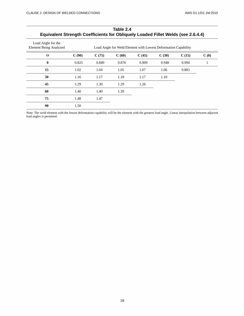
18
CLAUSE 2. DESIGN OF WELDED CONNECTIONS AWS D1.1/D1.1M:2015
Table 2.4Equivalent Strength Coefficients for Obliquely Loaded Fillet Welds (see 2.6.4.4)
Load Angle for theElement Being Analyzed Load Angle for Weld Element with Lowest Deformation Capability
Θ C (90) C (75) C (60) C (45) C (30) C (15) C (0)
0 0.825 0.849 0.876 0.909 0.948 0.994 1
15 1.02 1.04 1.05 1.07 1.06 0.883
30 1.16 1.17 1.18 1.17 1.10
45 1.29 1.30 1.29 1.26
60 1.40 1.40 1.39
75 1.48 1.47
90 1.50
Note: The weld element with the lowest deformation capability will be the element with the greatest load angle. Linear interpolation between adjacentload angles is permitted.

AW
S D
1.1/D1.1M
:2015C
LAU
SE
2. DE
SIG
N O
F W
ELD
ED
CO
NN
EC
TIO
NS
19
Table 2.5Fatigue Stress Design Parameters (see 2.14.1)
DescriptionStress
CategoryConstant
Cf
ThresholdFTH
ksi [MPa]Potential CrackInitiation Point Illustrative Examples
Section 1—Plain Material Away from Any Welding
1.1 Base metal, except non-coated weathering steel, with as-rolled or cleaned surfaces. Flame cut edges with surface roughness value of 1000 µin[25 µm] or less, but without reentrant corners.
A 250 × 108 24 [165]Away from all welds or structural connections
1.1/1.2
1.2 Non-coated weathering steel base metal with as-rolled or cleaned sur-faces. Flame cut edges with surfaceroughness value of 1000 µin [25 µm]or less, but without reentrant corners.
B 120 × 108 16 [110]Away from all welds or structural connections
1.3 Member with reentrant cornersat copes, cuts, block-outs or othergeometrical discontinuities, except weldaccess holes.
R ≥ 1 in [25 mm] with radius formed bypredrilling, subpunching and reaming orthermally cut and ground to a brightmetal surface
R ≥ 3/8 in [10 mm] and the radius neednot be ground to a bright metal surface
C
E'
44 × 108
3.9 × 10⁸
10 [69]
2.6 [18]
At any external edge or at hole perimeter
1.3
(A)
(B)
(B)(A)
(C)
(Continued)

CLA
US
E 2. D
ES
IGN
OF
WE
LDE
D C
ON
NE
CT
ION
SA
WS
D1.1/D
1.1M:2015
20
Section 1—Plain Material Away from Any Welding (Cont’d)
1.4 Rolled cross sections with weld access holes made to the requirements of 2.17.4 and 5.16.1.
Access hole R ≥ 1 in [25 mm]with radius formed by predrilling,subpunching and reaming or thermallycut and ground to a bright metal surface
Access hole R ≥ 3/8 in [10 mm] and theradius need not be ground to a brightmetal surface
C
E'
44 × 108
3.9 × 10⁸
10 [69]
2.6 [18]
At reentrant corner ofweld access hole
1.4
1.5 Members with drilled or reamed holes.
Holes containing pre-tensioned bolts
Open holes without bolts
C
D
44 × 108
22 × 108
10 [69]
7 [48]
In net section originatingat side of the hole
1.5
Section 2—Connected Material in Mechanically Fastened Joints—Not Useda
Table 2.5 (Continued)Fatigue Stress Design Parameters (see 2.14.1)
DescriptionStress
CategoryConstant
Cf
ThresholdFTH
ksi [MPa]Potential CrackInitiation Point Illustrative Examples
(A) (B)
AS SEENWITH BRACING
REMOVED
(Continued)

AW
S D
1.1/D1.1M
:2015C
LAU
SE
2. DE
SIG
N O
F W
ELD
ED
CO
NN
EC
TIO
NS
21
Section 3—Welded Joints Joining Components of Built-Up Members
3.1 Base metal and weld metal in members without attachments built-up of plates or shapes connected by continuous longitudinal CJP groove welds, backgouged and welded from second side, or by continuous fillet welds.
B 120 × 108 16 [110]
From surfaceor internal discontinuitiesin weld
3.1
3.2 Base metal and weld metal in members without attachments built upof plates or shapes, connected by continuous longitudinal CJP groove welds with left-in place continuous steel backing, or by continuous PJP groove welds.
B' .61 × 108 .12 [83]
From surfaceor internal discontinuities in weld
3.2
Table 2.5 (Continued)Fatigue Stress Design Parameters (see 2.14.1)
DescriptionStress
CategoryConstant
Cf
ThresholdFTH
ksi [MPa]Potential CrackInitiation Point Illustrative Examples
OR CJP
CJP(C)
OR(B)(A)
(E)(D)
(B)(A)
(C) (E)(D)
CJP OR PJP
CJP OR PJP
(Continued)

CLA
US
E 2. D
ES
IGN
OF
WE
LDE
D C
ON
NE
CT
ION
SA
WS
D1.1/D
1.1M:2015
22
Section 3—Welded Joints Joining Components of Built-Up Members (Cont’d)
3.3 Base metal at the ends of longitudi-nal welds that terminate at weld access holes in connected built-up members, as well as weld toes of fillet welds that wrap around ends of weld access holes.
Access hole R ≥ 1 in [25 mm] withradius formed by predrilling,subpunching and reaming or thermallycut and ground to a bright metal surface
Access hole R ≥ 3/8 in [10 mm] and theradius need not be ground to a brightmetal surface
D
E'
22 × 108
3.9 × 10⁸
7 [48]
2.6 [18]
From the weld termination into the web or flange
3.3
3.4 Base metal at ends of longitudinal intermittent fillet weld segments.
E .11 × 108 4.5 [31]
In connected material at start and stop locations of anyweld
3.4
3.5 Base metal at ends of partial length welded cover plates narrower than the flange having square or tapered ends, with or without welds across the ends.
Flange thickness ≤ 0.8 in [20 mm]
Flange thickness > 0.8 in [20 mm]
E
E'
.11 × 108
3.9 × 10⁸
4.5 [31]
2.6 [18]
In flange at toe of end weld (if present) or in flange at termination of longitudinal weld
3.5
Table 2.5 (Continued)Fatigue Stress Design Parameters (see 2.14.1)
DescriptionStress
CategoryConstant
Cf
ThresholdFTH
ksi [MPa]Potential CrackInitiation Point Illustrative Examples
WRAPPED
(A) (B)
(A) (B)
2-62-6
tf
(C)(B)(A)
(Continued)
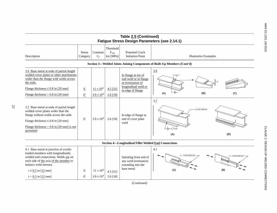
AW
S D
1.1/D1.1M
:2015C
LAU
SE
2. DE
SIG
N O
F W
ELD
ED
CO
NN
EC
TIO
NS
23
Section 3—Welded Joints Joining Components of Built-Up Members (Cont’d)
3.6 Base metal at ends of partial lengthwelded cover plates or other attachmentswider than the flange with welds acrossthe ends.
Flange thickness ≤ 0.8 in [20 mm]
Flange thickness > 0.8 in [20 mm]
E
E'
11 × 108
3.9 × 10⁸
4.5 [31]
2.6 [18]
In flange at toe ofend weld or in flangeat termination oflongitudinal weld or in edge of flange
3.6
3.7 Base metal at ends of partial length welded cover plates wider than the flange without welds across the ends.
Flange thickness ≤ 0.8 in [20 mm]
Flange thickness > 0.8 in [20 mm] is notpermitted
E' 3.9 × 10⁸ 2.6 [18]In edge of flange at end of cover plate weld
3.7
Section 4—Longitudinal Fillet Welded End Connections
4.1 Base metal at junction of axially loaded members with longitudinally welded end connections. Welds are on each side of the axis of the member to balance weld stresses.
t ≤ 0.5 in [12 mm]
t > 0.5 in [12 mm]
E
E'
.11 × 108
3.9 × 10⁸
4.5 [31]
2.6 [18]
Initiating from end ofany weld termination extending into the base metal
4.1
Table 2.5 (Continued)Fatigue Stress Design Parameters (see 2.14.1)
DescriptionStress
CategoryConstant
Cf
ThresholdFTH
ksi [MPa]Potential CrackInitiation Point Illustrative Examples
tf
(A) (B) (C)
NO WELD
TYP.
(A) (B)
t = THICKNESS t = THICKNESS
(B)(A)
(Continued)
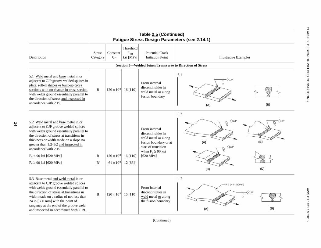
CLA
US
E 2. D
ES
IGN
OF
WE
LDE
D C
ON
NE
CT
ION
SA
WS
D1.1/D
1.1M:2015
24
Section 5—Welded Joints Transverse to Direction of Stress
5.1 Weld metal and base metal in or adjacent to CJP groove welded splices in plate, rolled shapes or built-up cross sections with no change in cross section with welds ground essentially parallel to the direction of stress and inspected inaccordance with 2.19.
B 120 × 108 16 [110]
From internal discontinuities inweld metal or along fusion boundary
5.1
5.2 Weld metal and base metal in or adjacent to CJP groove welded splices with welds ground essentially parallel to the direction of stress at transitions in thickness or width made on a slope no greater than 1:2-1/2 and inspected inaccordance with 2.19.
Fy < 90 ksi [620 MPa]
Fy ≥ 90 ksi [620 MPa]
B
B'
120 × 108
61 × 108
16 [110]
12 [83]
From internal discontinuities inweld metal or along fusion boundary or at start of transition when Fy ≥ 90 ksi[620 MPa]
5.2
5.3 Base metal and weld metal in or adjacent to CJP groove welded splices with welds ground essentially parallel to the direction of stress at transitions in width made on a radius of not less than 24 in [600 mm] with the point oftangency at the end of the groove weld and inspected in accordance with 2.19.
B 120 × 108 16 [110]
From internal discontinuities in weld metal or along the fusion boundary
5.3
Table 2.5 (Continued)Fatigue Stress Design Parameters (see 2.14.1)
DescriptionStress
CategoryConstant
Cf
ThresholdFTH
ksi [MPa]Potential CrackInitiation Point Illustrative Examples
G
(B)
CJP
(A)
CJP
(B)(A)
G
CJP
G
CJP
G
(D)(C)
CJP
(B)(A)
G
R ≥ 24 in [600 m]
(Continued)
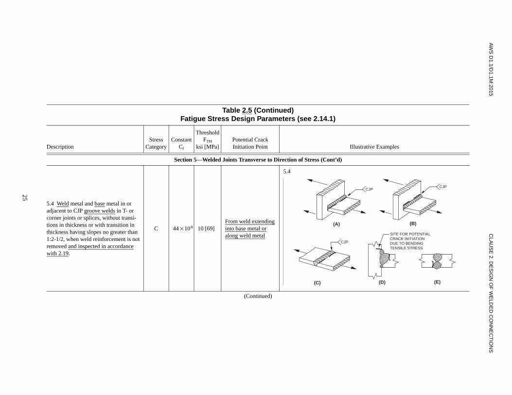
AW
S D
1.1/D1.1M
:2015C
LAU
SE
2. DE
SIG
N O
F W
ELD
ED
CO
NN
EC
TIO
NS
25
Section 5—Welded Joints Transverse to Direction of Stress (Cont’d)
5.4 Weld metal and base metal in or adjacent to CJP groove welds in T- or corner joints or splices, without transi-tions in thickness or with transition in thickness having slopes no greater than 1:2-1/2, when weld reinforcement is not removed and inspected in accordancewith 2.19.
C 44 × 108 10 [69]0From weld extendinginto base metal oralong weld metal
5.4
Table 2.5 (Continued)Fatigue Stress Design Parameters (see 2.14.1)
DescriptionStress
CategoryConstant
Cf
ThresholdFTH
ksi [MPa]Potential CrackInitiation Point Illustrative Examples
CJPCJP
(B)(A)
CJP
SITE FOR POTENTIALCRACK INITIATIONDUE TO BENDINGTENSILE STRESS
(D)(C) (E)
(Continued)

CLA
US
E 2. D
ES
IGN
OF
WE
LDE
D C
ON
NE
CT
ION
SA
WS
D1.1/D
1.1M:2015
26
Section 5—Welded Joints Transverse to Direction of Stress (Cont’d)
5.5 Base metal and weld metal in or adjacent to transverse CJP groove welded butt splices with backing leftin place.
Tack welds inside groove
Tack welds outside the groove and not closer than 1/2 in [12 mm] to edge of base metal
D
E
22 × 108
11 × 108
.7 [48]
4.5 [31]
From the toe of the groove weld or the toe of the weld attaching backing when applicable
5.5
Table 2.5 (Continued)Fatigue Stress Design Parameters (see 2.14.1)
DescriptionStress
CategoryConstant
Cf
ThresholdFTH
ksi [MPa]Potential CrackInitiation Point Illustrative Examples
(B)(A)
(D)(C)
0.5 in [12 mm]
(Continued)

AW
S D
1.1/D1.1M
:2015C
LAU
SE
2. DE
SIG
N O
F W
ELD
ED
CO
NN
EC
TIO
NS
27
Section 5—Welded Joints Transverse to Direction of Stress (Cont’d)
5.6 Base metal and weld metal at transverse end connections of tension-loaded plate elements using PJP groove welds in butt. T- or corner joints, with reinforcing or contouring fillets. FSR shall be the smaller of the toe crack or root crack stress range.
Crack initiating from weld toe:
Crack initiating from weld root:
C
C'
44 × 108
Formula(4)
10 [69]
None
Initiating from weldtoe extending intobase metal
Initiating at weld rootextending into andthrough weld
5.6
Table 2.5 (Continued)Fatigue Stress Design Parameters (see 2.14.1)
DescriptionStress
CategoryConstant
Cf
ThresholdFTH
ksi [MPa]Potential CrackInitiation Point Illustrative Examples
(C)
(A) (B)
(E)(D)
PJPPJP
SITE FOR POTENTIALCRACK INITIATIONDUE TO BENDINGTENSILE STRESS
2a 2a 2a
(Continued)

CLA
US
E 2. D
ES
IGN
OF
WE
LDE
D C
ON
NE
CT
ION
SA
WS
D1.1/D
1.1M:2015
28
Section 5—Welded Joints Transverse to Direction of Stress (Cont’d)
5.7 Base metal and weld metal at transverse end connections of tension-loaded plate elements using a pair of fillet welds on opposite sides of the plate. FSR shall be the smaller of the toe crack or root crack allowable stress range.
Crack initiating from weld toe:
Crack initiating from weld root:
C
C"
44 × 108
Formula(4)
10 [69]
None
Initiating from weldtoe extending intobase metal
Initiating at weld rootextending into andthrough weld
5.7
5.8 Base metal of tension loaded plate elements and on built-up shapes and rolled beam webs or flanges at toe of transverse fillet welds, adjacent to welded transverse stiffeners.
C 44 × 108 10 [69]
From geometrical discontinuity at toeof fillet extending into base metal
5.8
Table 2.5 (Continued)Fatigue Stress Design Parameters (see 2.14.1)
DescriptionStress
CategoryConstant
Cf
ThresholdFTH
ksi [MPa]Potential CrackInitiation Point Illustrative Examples
(C)(A) (B)
(E)(D)
T T
(C)(A) (B)
(Continued)

AW
S D
1.1/D1.1M
:2015C
LAU
SE
2. DE
SIG
N O
F W
ELD
ED
CO
NN
EC
TIO
NS
29
Section 6—Base Metal at Welded Transverse Member Connections
6.1 Base metal of equal or unequal thickness at details attached by CJP groove welds subject to longitudinal loading only when the detail embodies a transition radius, R, with the weld termi-nation ground smooth and inspected inaccordance with 2.19.
R ≥ 24 in [600 mm]
6 in ≤ R < 24 in [150 mm ≤ R < 600 mm]
2 in ≤ R < 6 in [50 mm ≤ R < 150 mm]
R < 2 in [50 mm]
B
C
D
E
120 × 108
44 × 108
22 × 108
11 × 108
16 [110]
10 [69]0
7 [48]0
.4.5 [31]
Near point of tangency of radiusat edge of member
6.1
Table 2.5 (Continued)Fatigue Stress Design Parameters (see 2.14.1)
DescriptionStress
CategoryConstant
Cf
ThresholdFTH
ksi [MPa]Potential CrackInitiation Point Illustrative Examples
CJP
R
CJP
R
(C)
(A) (B)
(Continued)

CLA
US
E 2. D
ES
IGN
OF
WE
LDE
D C
ON
NE
CT
ION
SA
WS
D1.1/D
1.1M:2015
30
Section 6—Base Metal at Welded Transverse Member Connections (Cont’d)
6.2 Base metal at details of equal thickness attached by CJP groove welds subject to transverse loading with or without longitudinal loading when the detail embodies a transition radius, R, with the weld termination ground smooth and inspected in accordancewith 2.19.
6.2(a) When weld reinforcement is removed:
R ≥ 24 in [600 mm]
6 in ≤ R < 24 in [150 mm ≤ R < 600 mm]
2 in ≤ R < 6 in [50 mm ≤ R < 150 mm]
R < 2 in [50 mm]
6.2(b) When weld reinforcement not removed:
R ≥ 6 in [150 mm]
2 in ≤ R < 6 in [50 mm ≤ R < 150 mm]
R < 2 in [50 mm]
B
C
D
E
C
D
E
120 × 108
44 × 108
22 × 108
11 × 108
44 × 108
22 × 108
11 × 108
16 [110]
10 [69]
7 [48]
4.5 [31]
10 [69]
7 [48]
4.5 [31]
Near points of tangency of radiusor in the weld or at fusion boundary of member or attachment
At toe of the weld either along edgeof member or the attachment
6.2
Table 2.5 (Continued)Fatigue Stress Design Parameters (see 2.14.1)
DescriptionStress
CategoryConstant
Cf
ThresholdFTH
ksi [MPa]Potential CrackInitiation Point Illustrative Examples
CJP
R
CJP
R
G
G
(C)
(A) (B)
(Continued)

AW
S D
1.1/D1.1M
:2015C
LAU
SE
2. DE
SIG
N O
F W
ELD
ED
CO
NN
EC
TIO
NS
31
Section 6—Base Metal at Welded Transverse Member Connections (Cont’d)
6.3 Base metal at details of unequal thickness attached by CJP groove welds, subject to transverse loading with or without longitudinal loading, when the detail embodies a transition radius, R, with the weld termination ground smooth and inspected in accordancewith 2.19.
6.3(a) When weld reinforcement is removed:
R > 2 in [50 mm]
R ≤ 2 in [50 mm]
6.3(b) When weld reinforcement isnot removed:
Any radius
D
E
E
22 × 108
11 × 108
11 × 108
.07 [48]
4.5 [31]
4.5 [31]
At toe of weld along edge of thinner material
In weld terminationin small radius
At toe of weld alongedge of thinnermaterial
6.3
Table 2.5 (Continued)Fatigue Stress Design Parameters (see 2.14.1)
DescriptionStress
CategoryConstant
Cf
ThresholdFTH
ksi [MPa]Potential CrackInitiation Point Illustrative Examples
R
(C)
(A) (B)
G
G
CJP w/REINFORCEMENT
R
GRIND
G
G
CJP GROUND SMOOTH CJP GROUND SMOOTH
(D) (E)
(Continued)

CLA
US
E 2. D
ES
IGN
OF
WE
LDE
D C
ON
NE
CT
ION
SA
WS
D1.1/D
1.1M:2015
32
Section 6—Base Metal at Welded Transverse Member Connections (Cont’d)
6.4 Base metal of equal or unequal thickness, subject to longitudinal stress at transverse members, with or without transverse stress, attached by fillet or PJP groove welds parallel to direction of stress when the detail embodies a transi-tion radius, R, with weld termination ground smooth.
R > 2 in [50 mm]
R ≤ 2 in [50 mm]
D
E
22 × 108
11 × 108
.07 [48]
4.5 [31]
Initiating in basemetal at the weldtermination or at thetoe of the weld,extending into thebase metal
6.4
Table 2.5 (Continued)Fatigue Stress Design Parameters (see 2.14.1)
DescriptionStress
CategoryConstant
Cf
ThresholdFTH
ksi [MPa]Potential CrackInitiation Point Illustrative Examples
PJP
R
PJP
R
OR
PJP
G
GRIND
(C)
(A) (B)
(D)
(Continued)

AW
S D
1.1/D1.1M
:2015C
LAU
SE
2. DE
SIG
N O
F W
ELD
ED
CO
NN
EC
TIO
NS
33
Section 7—Base Metal at Short Attachmentsb
7.1 Base metal subject to longitudinal loading at details with welds parallel or transverse to the direction of stress withor without transverse load on the detail, where the detail embodies no transition radius, and with detail length, a, in direction of stress and thickness of theattachment, b:
a < 2 in [50 mm] for any thickness, b
2 in [50 mm] ≤ a ≤ lesser of 12b or 4 in [100 mm]
a > lesser of 12b or 4 in [100 mm] when b ≤ 0.8 in [20 mm]
a > 4 in [100 mm] when b is > 0.8 in[20 mm]
C
D
E
E'
44 × 108
22 × 108
11 × 108
3.9 × 10⁸
10 [69]
7 [48]
4.5 [31]
2.6 [18]
Initiating in base metal at the weldtermination or at thetoe of the weld,extending into thebase metal
7.1
7.2 Base metal subject to longitudinal stress at details attached by fillet orPJP groove welds, with or without transverse load on detail, when the detail embodies a transition radius, R, with weld termination ground smooth.
R > 2 in [50 mm]
R ≤ 2 in [50 mm]
D
E
22 × 108
11 × 108
7 [48]
4.5 [31]
Initiating in basemetal at the weldtermination,extending into the base metal
7.2
Table 2.5 (Continued)Fatigue Stress Design Parameters (see 2.14.1)
DescriptionStress
CategoryConstant
Cf
ThresholdFTH
ksi [MPa]Potential CrackInitiation Point Illustrative Examples
b
a
b
aa
b (AVG.)
a
b
a
(C)
(A)
(B)
(D)
(E)
R
R
OR PJP
(A) (B)
(Continued)

CLA
US
E 2. D
ES
IGN
OF
WE
LDE
D C
ON
NE
CT
ION
SA
WS
D1.1/D
1.1M:2015
34
Section 8—Miscellaneous
8.1 Base metal at steel headed studanchors attached by fillet weld orautomatic stud welding.
C 44 × 108 10 [69]At toe of weld in base metal
8.1
8.2 Shear on throat of any fillet weld, continuous or intermittent, longitudinal or transverse.
F150 × 1010 Formula
(3)8 [55]
Initiating at the rootof the fillet weld,extending into theweld
8.2
Table 2.5 (Continued)Fatigue Stress Design Parameters (see 2.14.1)
DescriptionStress
CategoryConstant
Cf
ThresholdFTH
ksi [MPa]Potential CrackInitiation Point Illustrative Examples
(A) (B)
(C)(B)
(A)
(Continued)

AW
S D
1.1/D1.1M
:2015C
LAU
SE
2. DE
SIG
N O
F W
ELD
ED
CO
NN
EC
TIO
NS
35
Section 8—Miscellaneous (Cont’d)
8.3 Base metal at plug or slot welds. E 11 × 108 4.5 [31]
Initiating in the basemetal at the end ofthe plug or slot weld,extending into thebase metal
8.3
8.4 Shear on plug or slot welds. F150 × 1010 Formula
(3)8 [55]
Initiating in the weldat the faying surface,extending into theweld
8.4
8.5 Description 8.5 deals only with mechanically fastened details not pertinent to D1.1.
a AWS D1.1/D1.1M deals only with welded details. To maintain consistency and to facilitate cross referencing with other governing specifications, Section 2—Connected Material in Mechanically FastenedJoints, and Description 8.5 are not used in this table.
b “Attachment” as used herein is defined as any steel detail welded to a member, which causes a deviation in the stress flow in the member and thus reduces the fatigue resistance. The reduction is due to thepresence of the attachment, not due to the loading on the attachment.
Source: Text adapted and Illustrations Reprinted, with permission, from American Institute of Steel Construction, Inc., 2015, Specification for Structural Steel Buildings, Illinois: American Institute of SteelConstruction, Test and Figures from Table A-3.1.
Table 2.5 (Continued)Fatigue Stress Design Parameters (see 2.14.1)
DescriptionStress
CategoryConstant
Cf
ThresholdFTH
ksi [MPa]Potential CrackInitiation Point Illustrative Examples
(A) (B)
(A) (B)

36
CLAUSE 2. DESIGN OF WELDED CONNECTIONS AWS D1.1/D1.1M:2015
Figure 2.1—Maximum Fillet Weld SizeAlong Edges in Lap Joints (see 2.4.2.9)

37
AWS D1.1/D1.1M:2015 CLAUSE 2. DESIGN OF WELDED CONNECTIONS
Figure 2.2—Transition of Butt Joints in Parts of Unequal Thickness(Cyclically Loaded Nontubular) (see 2.17.1.1)

38
CLAUSE 2. DESIGN OF WELDED CONNECTIONS AWS D1.1/D1.1M:2015
Figure 2.3—Transition of Thicknesses(Statically Loaded Nontubular) (see 2.7.5 and 2.8.1)
Note: t = thicker member, t1 = thinner member.
Figure 2.4—Transversely LoadedFillet Welds (see 2.9.9.1 and 2.9.1.2)

39
AWS D1.1/D1.1M:2015 CLAUSE 2. DESIGN OF WELDED CONNECTIONS
Figure 2.5—Minimum Length ofLongitudinal Fillet Welds at End of Plate
or Flat Bar Members (see 2.9.2)
Figure 2.6—Termination of Welds Near EdgesSubject to Tension (see 2.9.3.2)
WELD SIZEOR LARGER
WELD SIZEOR LARGER
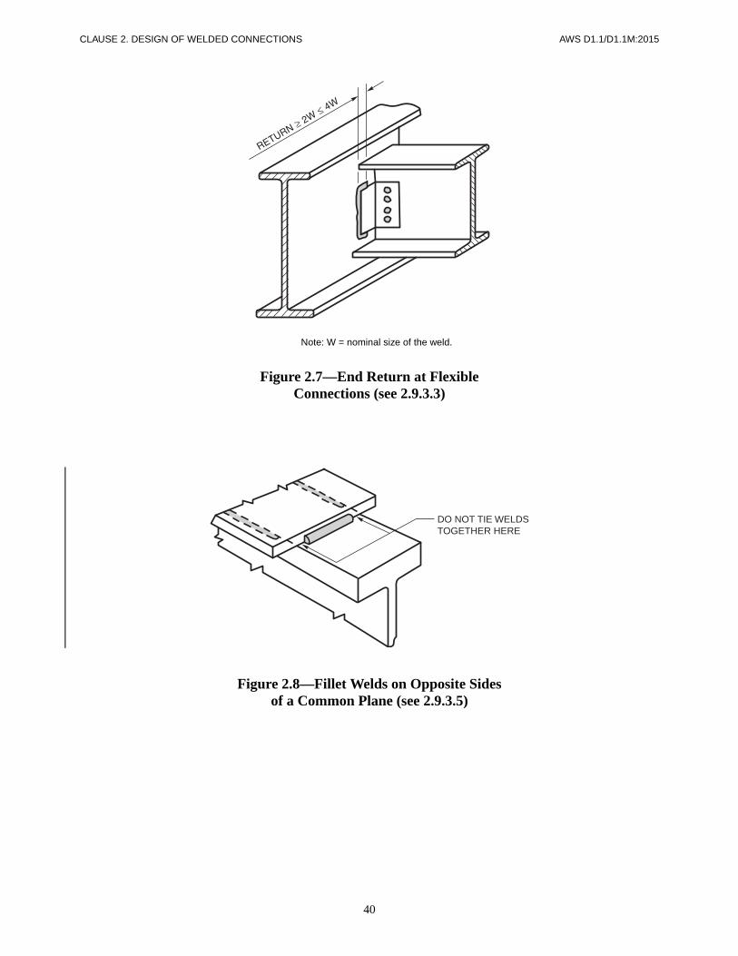
40
CLAUSE 2. DESIGN OF WELDED CONNECTIONS AWS D1.1/D1.1M:2015
Note: W = nominal size of the weld.
Figure 2.7—End Return at FlexibleConnections (see 2.9.3.3)
Figure 2.8—Fillet Welds on Opposite Sidesof a Common Plane (see 2.9.3.5)
DO NOT TIE WELDSTOGETHER HERE
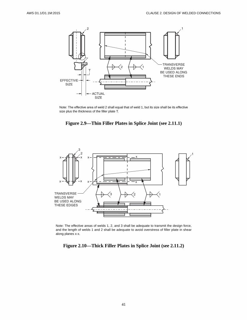
41
AWS D1.1/D1.1M:2015 CLAUSE 2. DESIGN OF WELDED CONNECTIONS
Note: The effective area of weld 2 shall equal that of weld 1, but its size shall be its effectivesize plus the thickness of the filler plate T.
Figure 2.9—Thin Filler Plates in Splice Joint (see 2.11.1)
Note: The effective areas of welds 1, 2, and 3 shall be adequate to transmit the design force,and the length of welds 1 and 2 shall be adequate to avoid overstress of filler plate in shearalong planes x-x.
Figure 2.10—Thick Filler Plates in Splice Joint (see 2.11.2)

42
CLAUSE 2. DESIGN OF WELDED CONNECTIONS AWS D1.1/D1.1M:2015
(A) U.S. CUSTOMARY UNITS
(B) METRIC UNITS
Figure 2.11—Allowable Stress Range for Cyclically Applied Load (Fatigue)in Nontubular Connections (Graphical Plot of Table 2.5) (see 2.16.2)

43
AWS D1.1/D1.1M:2015 CLAUSE 2. DESIGN OF WELDED CONNECTIONS
Figure 2.12—Transition of Width (Cyclically Loaded Nontubular) (see 2.17.1.2)

AWS D1.1/D1.1M:2015
44
This page is intentionally blank.

AWS D1.1/D1.1M:2015
45
3.1 Scope
Prequalification of WPSs (Welding Procedure Specifica-tions) shall be defined as exempt from the WPS quali-fication testing required in Clause 4. All prequalifiedWPSs shall be written. In order for a WPS to be prequal-ified, conformance with all of the applicable require-ments of Clause 3 shall be required. WPSs that do notconform to the requirements of Clause 3 may be quali-fied by tests in conformance with Clause 4. For conve-nience, Annex P lists provisions to be included in aprequalified WPS, and which should be addressed in thefabricator’s or Contractor’s welding program.
Welders, welding operators and tack welders that useprequalified WPSs shall be qualified in conformancewith Clause 4, Part C or Clause 9, Part D for tubulars.
3.2 Welding Processes
3.2.1 Prequalified Processes. SMAW, SAW, GMAW(except GMAW-S), and FCAW WPSs which conform toall of the provisions of Clause 3 shall be deemed asprequalified and are therefore approved for use withoutperforming WPS qualification tests for the process. ForWPS prequalification, conformance with all of theapplicable provisions of Clause 3 shall be required (see3.1).
3.2.2 Code Approved Processes. ESW, EGW, GTAW,and GMAW-S welding may be used, provided theWPSs are qualified in conformance with the require-ments of Clause 4. Note that the essential variable limi-tations in Table 4.5 for GMAW shall also apply toGMAW-S.
3.2.3 Other Welding Processes. Other welding pro-cesses not covered by 3.2.1 and 3.2.2 may be used,
provided the WPSs are qualified by applicable tests asdescribed in Clause 4.
3.2.4 FCAW and GMAW Power Sources. FCAWand GMAW that is done with prequalified WPSs shall beperformed using constant voltage (CV) power supplies.
3.3 Base Metal/Filler Metal Combinations
Only base metals and filler metals listed in Tables 3.1and 3.2 may be used in prequalified WPSs. (For thequalification of listed base metals and filler metals, andfor base metals and filler metals not listed in Tables 3.1and 3.2, see 4.2.1.)
The base metal/filler metal strength relationships belowshall be used in conjunction with Tables 3.1 and 3.2 todetermine whether matching or undermatching fillermetals are required.
Relationship Base Metal(s)Filler Metal Strength
Relationship Required
Matching Any steel to itself or any steel to another in the same group
Any filler metal listed in the same group
Any steel in one group to any steel in another
Any filler metal listed foreither strength group.[SMAW electrodes shallbe the low-hydrogenclassification]
Under-matching
Any steel to any steel in any group
Any filler metal listed in astrength group below thelower strength group.[SMAW electrodes shallbe the low-hydrogenclassification]
Note: See Table 2.3 or 9.2 to determine the filler metal strength require-ments to match or undermatch base metal strength.
3. Prequalification of WPSs

CLAUSE 3. PREQUALIFICATION OF WPSs AWS D1.1/D1.1M:2015
46
3.4 Engineer’s Approval for Auxiliary Attachments
Unlisted materials for auxiliary attachments which fallwithin the chemical composition range of a steel listed inTable 3.1 may be used in a prequalified WPS when ap-proved by the Engineer. The filler metal of Table 3.2 andminimum preheat shall be in conformance with 3.5,based upon the similar material strength and chemicalcomposition.
3.5 Minimum Preheat and Interpass Temperature Requirements
Table 3.3 shall be used to determine the minimum pre-heat and interpass temperatures for steels listed in thecode.
3.5.1 Base Metal/Thickness Combination. The mini-mum preheat or interpass temperature applied to a jointcomposed of base metals with different minimum pre-heats from Table 3.3 (based on Category and thickness)shall be the highest of these minimum preheats.
3.5.2 Alternate SAW Preheat and Interpass Temper-atures. Preheat and interpass temperatures for parallel ormultiple electrode SAW shall be selected in conform-ance with Table 3.3. For single-pass groove or filletwelds, for combinations of metals being welded and theheat input involved, and with the approval of the Engi-neer, preheat and interpass temperatures may be estab-lished which are sufficient to reduce the hardness in theHAZs of the base metal to less than 225 Vickers hard-ness number for steel having a minimum specified ten-sile strength not exceeding 60 ksi [415 MPa], and 280Vickers hardness number for steel having a minimumspecified tensile strength greater than 60 ksi [415 MPa],but not exceeding 70 ksi [485 MPa].
The Vickers hardness number shall be determined in con-formance with ASTM E92. If another method of hardnessis to be used, the equivalent hardness number shall be de-termined from ASTM E140, and testing shall be per-formed according to the applicable ASTM specification.
3.5.2.1 Hardness Requirements. Hardness determi-nation of the HAZ shall be made on the following:
(1) Initial macroetch cross sections of a sample testspecimen.
(2) The surface of the member during the progress ofthe work. The surface shall be ground prior to hardnesstesting:
(a) The frequency of such HAZ testing shall beat least one test area per weldment of the thicker metal
involved in a joint of each 50 ft [15 m] of groove weldsor pair of fillet welds.
(b) These hardness determinations may be discon-tinued after the procedure has been established and thediscontinuation is approved by the Engineer.
3.6 Limitation of WPS VariablesAll prequalified WPSs to be used shall be prepared bythe manufacturer, fabricator, or Contractor as writtenprequalified WPSs. The written WPS may follow anyconvenient format (see Annex M for examples). Thewelding parameters set forth in Table 3.6 shall be speci-fied on the written WPS, and for variables with limits,within the range shown. Changes to the essential vari-ables beyond those permitted by Table 3.7 shall require anew or revised prequalified WPS, or shall require that theWPS be qualified by test in accordance with Clause 4.
3.6.1 Combination of WPSs. A combination of quali-fied and prequalified WPSs may be used without qualifi-cation of the combination, provided the limitation ofessential variables applicable to each process is observed.
3.7 General WPS RequirementsAll the requirements of Table 3.6 shall be met forprequalified WPSs.
3.7.1 Vertical-Up Welding Requirements. The pro-gression for all passes in vertical position welding shallbe upward, with the following exceptions:
(1) Undercut may be repaired vertically downwardswhen preheat is in conformance with Table 3.3, but notlower than 70°F [20°C].
(2) When tubular products are welded, the progres-sion of vertical welding may be upwards or downwards,but only in the direction(s) for which the welder isqualified.
3.7.2 Width/Depth Pass Limitation. Neither the depthnor the maximum width in the cross section of weldmetal deposited in each weld pass shall exceed the widthat the surface of the weld pass (see Figure 3.1).
3.7.3 Weathering Steel Requirements. For exposed,bare, unpainted applications of weathering steel requir-ing weld metal with atmospheric corrosion resistanceand coloring characteristics similar to that of the basemetal, the electrode or electrode-flux combination shallconform to Table 3.4.
The exceptions to this requirement are as follows:
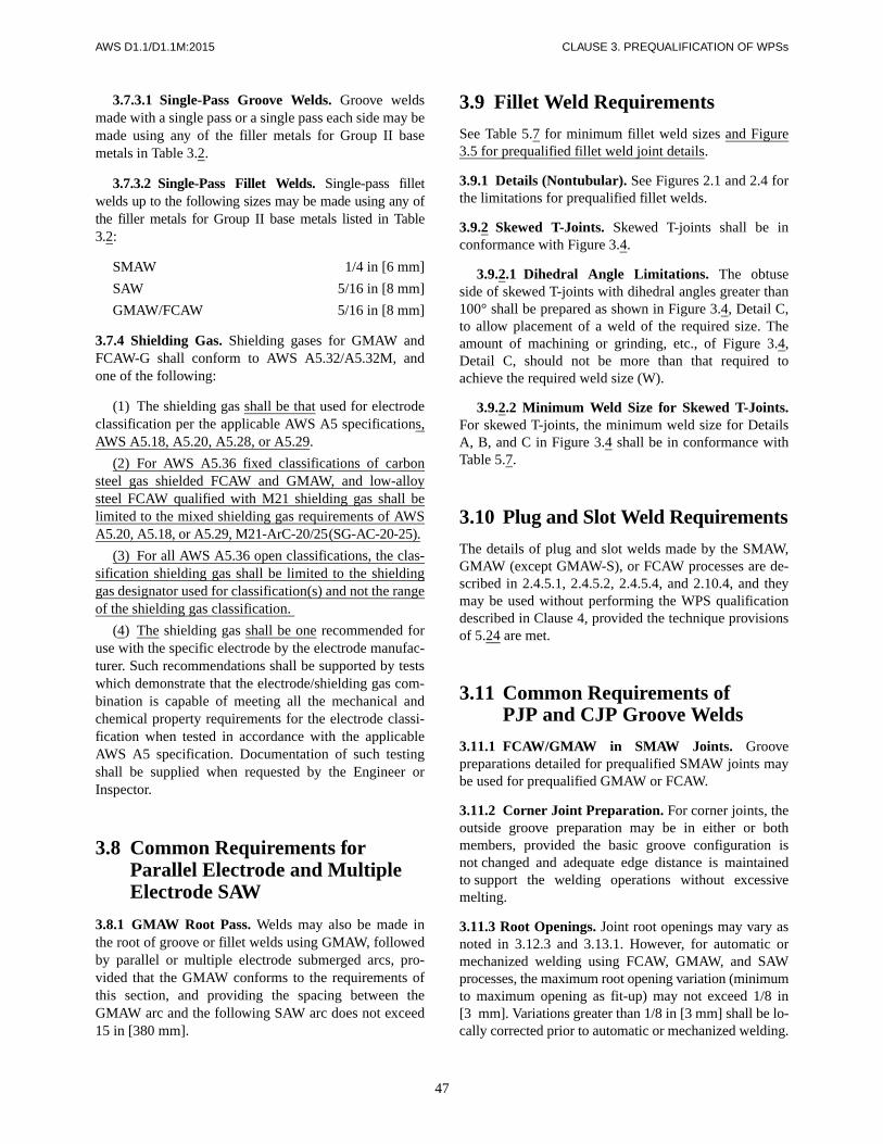
47
AWS D1.1/D1.1M:2015 CLAUSE 3. PREQUALIFICATION OF WPSs
3.7.3.1 Single-Pass Groove Welds. Groove weldsmade with a single pass or a single pass each side may bemade using any of the filler metals for Group II basemetals in Table 3.2.
3.7.3.2 Single-Pass Fillet Welds. Single-pass filletwelds up to the following sizes may be made using any ofthe filler metals for Group II base metals listed in Table3.2:
SMAW 1/4 in [6 mm]
SAW 5/16 in [8 mm]
GMAW/FCAW 5/16 in [8 mm]
3.7.4 Shielding Gas. Shielding gases for GMAW andFCAW-G shall conform to AWS A5.32/A5.32M, andone of the following:
(1) The shielding gas shall be that used for electrodeclassification per the applicable AWS A5 specifications,AWS A5.18, A5.20, A5.28, or A5.29.
(2) For AWS A5.36 fixed classifications of carbonsteel gas shielded FCAW and GMAW, and low-alloysteel FCAW qualified with M21 shielding gas shall belimited to the mixed shielding gas requirements of AWSA5.20, A5.18, or A5.29, M21-ArC-20/25(SG-AC-20-25).
(3) For all AWS A5.36 open classifications, the clas-sification shielding gas shall be limited to the shieldinggas designator used for classification(s) and not the rangeof the shielding gas classification.
(4) The shielding gas shall be one recommended foruse with the specific electrode by the electrode manufac-turer. Such recommendations shall be supported by testswhich demonstrate that the electrode/shielding gas com-bination is capable of meeting all the mechanical andchemical property requirements for the electrode classi-fication when tested in accordance with the applicableAWS A5 specification. Documentation of such testingshall be supplied when requested by the Engineer orInspector.
3.8 Common Requirements for Parallel Electrode and Multiple Electrode SAW
3.8.1 GMAW Root Pass. Welds may also be made inthe root of groove or fillet welds using GMAW, followedby parallel or multiple electrode submerged arcs, pro-vided that the GMAW conforms to the requirements ofthis section, and providing the spacing between theGMAW arc and the following SAW arc does not exceed15 in [380 mm].
3.9 Fillet Weld Requirements
See Table 5.7 for minimum fillet weld sizes and Figure3.5 for prequalified fillet weld joint details.
3.9.1 Details (Nontubular). See Figures 2.1 and 2.4 forthe limitations for prequalified fillet welds.
3.9.2 Skewed T-Joints. Skewed T-joints shall be inconformance with Figure 3.4.
3.9.2.1 Dihedral Angle Limitations. The obtuseside of skewed T-joints with dihedral angles greater than100° shall be prepared as shown in Figure 3.4, Detail C,to allow placement of a weld of the required size. Theamount of machining or grinding, etc., of Figure 3.4,Detail C, should not be more than that required toachieve the required weld size (W).
3.9.2.2 Minimum Weld Size for Skewed T-Joints.For skewed T-joints, the minimum weld size for DetailsA, B, and C in Figure 3.4 shall be in conformance withTable 5.7.
3.10 Plug and Slot Weld Requirements
The details of plug and slot welds made by the SMAW,GMAW (except GMAW-S), or FCAW processes are de-scribed in 2.4.5.1, 2.4.5.2, 2.4.5.4, and 2.10.4, and theymay be used without performing the WPS qualificationdescribed in Clause 4, provided the technique provisionsof 5.24 are met.
3.11 Common Requirements ofPJP and CJP Groove Welds
3.11.1 FCAW/GMAW in SMAW Joints. Groovepreparations detailed for prequalified SMAW joints maybe used for prequalified GMAW or FCAW.
3.11.2 Corner Joint Preparation. For corner joints, theoutside groove preparation may be in either or bothmembers, provided the basic groove configuration isnot changed and adequate edge distance is maintainedto support the welding operations without excessivemelting.
3.11.3 Root Openings. Joint root openings may vary asnoted in 3.12.3 and 3.13.1. However, for automatic ormechanized welding using FCAW, GMAW, and SAWprocesses, the maximum root opening variation (minimumto maximum opening as fit-up) may not exceed 1/8 in[3 mm]. Variations greater than 1/8 in [3 mm] shall be lo-cally corrected prior to automatic or mechanized welding.

CLAUSE 3. PREQUALIFICATION OF WPSs AWS D1.1/D1.1M:2015
48
3.12 PJP RequirementsPJP groove welds shall be made using the joint detailsdescribed in Figure 3.2. The joint dimensional limita-tions described in 3.12.3 shall apply.
3.12.1 Definition. Except as provided in 9.11.2 and Fig-ure 3.3 (B-L1-S), groove welds without steel backing,welded from one side, and groove welds welded fromboth sides, but without backgouging, are considered PJPgroove welds.
3.12.2 Weld Size. The weld size (E) of a prequalifiedPJP groove shall be as shown in Figure 3.2 for the partic-ular welding process, joint designation, groove angle, andwelding position proposed for use in welding fabrication.
3.12.2.1 Prequalified Weld Sizes
(1) The minimum weld size of PJP single- or double-V, bevel-, J-, and U-groove welds, types 2 through 9,shall be as shown in Table 3.5. The base metal thicknessshall be sufficient to incorporate the requirements of thejoint details selected, conforming to the variances out-lined in 3.12.3 and the requirements of Table 3.5.
(2) The maximum base metal thickness shall not belimited.
(3) The PJP square groove weld B-P1 and flare-bevelgroove welds BTC-P10 and B-P11 minimum weld sizesshall be calculated from Figure 3.2.
(4) Shop or working drawings shall specify the de-sign grooves depths “S” applicable for the weld size“(E)” required per 3.12.2. (Note that this requirementshall not apply to the B-P1, BTC-P10, and B-P11 details.)
3.12.3 Joint Dimensions
(1) Dimensions of groove welds specified in 3.12 mayvary on design or detail drawings within the limits of tol-erances shown in the “As Detailed” column in Figure 3.2.
(2) Fit-up tolerances of Figure 3.2 may be applied tothe dimensions shown on the detail drawing. However,the use of fit-up tolerances does not exempt the userfrom meeting the minimum weld size requirements of3.12.2.1.
(3) J- and U-grooves may be prepared before or afterassembly.
3.13 CJP Groove Weld RequirementsCJP groove welds which may be used without perform-ing the WPS qualification test described in Clause 4 shallbe as detailed in Figure 3.3 and are subject to the limita-tions described in 3.13.1.
3.13.1 Joint Dimensions. Dimensions of groove weldsspecified in 3.13 may vary on design or detail drawingswithin the limits or tolerances shown in the “As Detailed”column in Figure 3.3. Fit-up tolerance of Figure 3.3 maybe applied to the dimension shown on the detail drawing.
3.13.2 Backing. Prequalified CJP groove welds madefrom one side only, except as allowed for tubular struc-tures, shall have steel backing.
3.13.2.1 Prequalified CJP groove welds detailed withoutsteel backing or spacers may use backing other than steelas listed in 5.9.3 when the following conditions are met:
(1) The backing is removed after welding, and,
(2) The back side of the weld is backgouged to soundmetal and back welded.
Welding procedures for joints welded with backing otherthan steel in which the weld is to be left in the as-weldedcondition without backgouging and welding from theother side are not prequalified.
3.13.3 Double-Sided Groove Preparation. J- andU-grooves and the other side of partially weldeddouble-V and double-bevel grooves may be preparedbefore or after assembly. After backgouging, the otherside of partially welded double-V or double-bevel jointsshould resemble a prequalified U- or J-joint configura-tion at the joint root.
3.14 Postweld Heat TreatmentPostweld heat treatment (PWHT) shall be prequalifiedprovided that it shall be approved by the Engineer andthe following conditions shall be met.
(1) The specified minimum yield strength of the basemetal shall not exceed 50 ksi [345 MPa].
(2) The base metal shall not be manufactured byquenching and tempering (Q&T), quenching and self-tempering (Q&ST), thermo-mechanical controlled pro-cessing (TMCP) or where cold working is used toachieve higher mechanical properties (e.g., certaingrades of ASTM A500 tubing).
(3) There shall be no requirements for notch tough-ness testing of the base metal, HAZ, or weld metal.
(4) There shall be data available demonstrating thatthe weld metal shall have adequate strength and ductilityin the PWHT condition (e.g., as can be found in the rele-vant AWS A5.X filler metal specification and classifica-tion or from the filler metal manufacturer).
(5) PWHT shall be conducted in conformance with5.8.
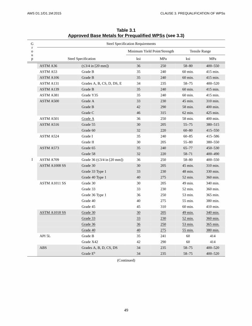
49
AWS D1.1/D1.1M:2015 CLAUSE 3. PREQUALIFICATION OF WPSs
Table 3.1Approved Base Metals for Prequalified WPSs (see 3.3)
Group
Steel Specification Requirements
Steel Specification
Minimum Yield Point/Strength Tensile Range
ksi MPa ksi MPa
I
ASTM A36 (≤3/4 in [20 mm]) 36 250 58–80 400–550
ASTM A53 Grade B 35 240 60 min. 415 min.
ASTM A106 Grade B 35 240 60 min. 415 min.
ASTM A131 Grades A, B, CS, D, DS, E 34 235 58–75 400–520
ASTM A139 Grade B 35 240 60 min. 415 min.
ASTM A381 Grade Y35 35 240 60 min. 415 min.
ASTM A500 Grade A 33 230 45 min. 310 min.
Grade B 42 290 58 min. 400 min.
Grade C 46 315 62 min. 425 min.
ASTM A501 Grade A 36 250 58 min. 400 min.
ASTM A516 Grade 55 30 205 55–75 380–515
Grade 60 32 220 60–80 415–550
ASTM A524 Grade I 35 240 60–85 415–586
Grade II 30 205 55–80 380–550
ASTM A573 Grade 65 35 240 65–77 450–530
Grade 58 32 220 58–71 400–490
ASTM A709 Grade 36 (≤3/4 in [20 mm]) 36 250 58–80 400–550
ASTM A1008 SS Grade 30 30 205 45 min. 310 min.
Grade 33 Type 1 33 230 48 min. 330 min.
Grade 40 Type 1 40 275 52 min. 360 min.
ASTM A1011 SS Grade 30 30 205 49 min. 340 min.
Grade 33 33 230 52 min. 360 min.
Grade 36 Type 1 36 250 53 min. 365 min.
Grade 40 40 275 55 min. 380 min.
Grade 45 45 310 60 min. 410 min.
ASTM A1018 SS Grade 30 30 205 49 min. 340 min.
Grade 33 33 230 52 min. 360 min.
Grade 36 36 250 53 min. 365 min.
Grade 40 40 275 55 min. 380 min.
API 5L Grade B 35 241 60 414
Grade X42 42 290 60 414
ABS Grades A, B, D, CS, DS 34 235 58–75 400–520
Grade Eb 34 235 58–75 400–520
(Continued)

50
CLAUSE 3. PREQUALIFICATION OF WPSs AWS D1.1/D1.1M:2015
Table 3.1 (Continued)Approved Base Metals for Prequalified WPSs (see 3.3)
Group
Steel Specification Requirements
Steel Specification
Minimum Yield Point/Strength Tensile Range
ksi MPa ksi MPa
II
ASTM A36 (>3/4 in [20 mm]) 36 250 58–80 400–550
ASTM A131 Grades AH32, DH32, EH32 46 315 64–85 440–590
Grades AH36, DH36, EH36 51 355 71–90 490–620
ASTM A441 40–50 275–345 60–70 415–485
ASTM A501 Grade B 50 345 70 min. 485 min.
ASTM A516 Grade 65 35 240 65–85 450–585
Grade 70 38 260 70–90 485–620
ASTM A529 Grade 50 50 345 70–100 485–690
Grade 55 55 380 70–100 485–690
ASTM A537 Class 1 45–50 310–345 65–90 450–620
ASTM A572 Grade 42 42 290 60 min. 415 min.
Grade 50 50 345 65 min. 450 min.
Grade 55 55 380 70 min. 485 min.
ASTM A588b (4 in [100 mm] and under 50 345 70 min. 485 min.
ASTM A595 Grade A 55 380 65 min. 450 min.
Grades B and C 60 410 70 min. 480 min.
ASTM A606b 45–50 310–340 65 min. 450 min.
ASTM A618 Grades Ib, II, III 46–50 315–345 65 min. 450 min.
ASTM A633 Grade A 42 290 63–83 430–570
Grades C, D 50 345 70–90 485–620
(2-1/2 in [65 mm] and under)
ASTM A709 Grade 36 (>3/4 in [20 mm]) 36 250 58–80 400–550
Grade 50 50 345 65 min. 450 min.
Grade 50Wb 50 345 70 min. 485 min.
Grade 50S 50–65 345–450 65 min. 450 min.
Grade HPS 50Wb 50 345 70 min. 485 min.
ASTM A710Grade A, Class 2
(>2 in [50 mm])50–55 345–380 60–65 415–450
ASTM A808 (2-1/2 in [65 mm] and under) 42 290 60 min. 415 min.
ASTM A913 Grade 50 50 345 65 min. 450 min.
ASTM A992 50–65 345–450 65 min. 450 min.
ASTM A1008 HSLAS Grade 45 Class 1 45 310 60 min. 410 min.
Grade 45 Class 2 45 310 55 min. 380 min.
Grade 50 Class 1 50 340 65 min. 450 min.
Grade 50 Class 2 50 340 60 min. 410 min.
Grade 55 Class 1 55 380 70 min. 480 min.
Grade 55 Class 2 55 380 65 min. 450 min.
ASTM A1008 HSLAS-F Grade 50 50 340 60 min. 410 min.
(Continued)

51
AWS D1.1/D1.1M:2015 CLAUSE 3. PREQUALIFICATION OF WPSs
Table 3.1 (Continued)Approved Base Metals for Prequalified WPSs (see 3.3)
Group
Steel Specification Requirements
Steel Specification
Minimum Yield Point/StrengthTensileRange
ksi MPa ksi MPa
II(Cont’d)
ASTM A1011 HSLAS Grade 45 Class 1 45 310 60 min. 410 min.
Grade 45 Class 2 45 310 55 min. 380 min.
Grade 50 Class 1 50 340 65 min. 450 min.
Grade 50 Class 2 50 340 60 min. 410 min.
Grade 55 Class 1 55 380 70 min. 480 min.
Grade 55 Class 2 55 380 65 min. 450 min.
ASTM A1011 HSLAS-F Grade 50 50 340 60 min. 410 min.
ASTM A1011 SS Grade 50 50 340 65 min. 450 min.
Grade 55 55 380 70 min. 480 min.
ASTM A1018 HSLAS Grade 45 Class 1 45 310 60 min. 410 min.
Grade 45 Class 2 45 310 55 min. 380 min.
Grade 50 Class 1 50 340 65 min. 450 min.
Grade 50 Class 2 50 340 60 min. 410 min.
Grade 55 Class 1 55 380 70 min. 480 min.
Grade 55 Class 2 55 380 65 min. 450 min.
ASTM A1018 HSLAS-F Grade 50 50 340 60 min. 410 min.
ASTM A1085 50–70 345–485 65 min. 450 min.
API 2H Grade 42 42 289 62–82 427–565
Grade 50 50 345 70–90 483–620
API 2MT1 Grade 50 50 345 65–90 488–620
API 2W Grade 42 42–67 290–462 62 min. 427 min.
Grade 50 50–75 345–517 65 min. 448 min.
Grade 50T 50–80 345–552 70 min. 483 min.
API 2Y Grade 42 42–67 290–462 62 min. 427 min.
Grade 50 50–75 345–517 65 min. 448 min.
Grade 50T 50–80 345–552 70 min. 483 min.
API 5L Grade X52 52 359 66 min. 455 min.
ABS Grades AH32, DH32, EH32 46 315 64–85 440–590
Grades AH36, DH36, EH36b 51 355 71–90 490–620
(Continued)
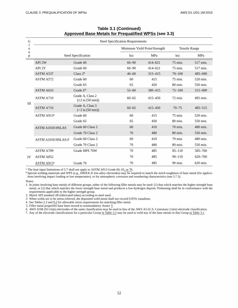
52
CLAUSE 3. PREQUALIFICATION OF WPSs AWS D1.1/D1.1M:2015
Table 3.1 (Continued)Approved Base Metals for Prequalified WPSs (see 3.3)
Group
Steel Specification Requirements
Steel Specification
Minimum Yield Point/Strength Tensile Range
ksi MPa ksi MPa
III
API 2W Grade 60 60–90 414–621 75 min. 517 min.
API 2Y Grade 60 60–90 414–621 75 min. 517 min.
ASTM A537 Class 2b 46–60 315–415 70–100 485–690
ASTM A572 Grade 60 60 415 75 min. 520 min.
Grade 65 65 450 80 min. 550 min.
ASTM A633 Grade Eb 55–60 380–415 75–100 515–690
ASTM A710Grade A, Class 2
(≤2 in [50 mm])60–65 415–450 72 min. 495 min.
ASTM A710Grade A, Class 3
(>2 in [50 mm])60–65 415–450 70–75 485–515
ASTM A913a Grade 60 60 415 75 min. 520 min.
Grade 65 65 450 80 min. 550 min.
ASTM A1018 HSLAS Grade 60 Class 2 60 410 70 min. 480 min.
Grade 70 Class 2 70 480 80 min. 550 min.
ASTM A1018 HSLAS-F Grade 60 Class 2 60 410 70 min. 480 min.
Grade 70 Class 2 70 480 80 min. 550 min.
IV
ASTM A709 Grade HPS 70W 70 485 85–110 585–760
ASTM A852 70 485 90–110 620–760
ASTM A913a Grade 70 70 485 90 min. 620 min.
a The heat input limitations of 5.7 shall not apply to ASTM A913 Grade 60, 65, or 70.b Special welding materials and WPS (e.g., E80XX-X low-alloy electrodes) may be required to match the notch toughness of base metal (for applica-
tions involving impact loading or low temperature), or for atmospheric corrosion and weathering characteristics (see 3.7.3).
Notes:1. In joints involving base metals of different groups, either of the following filler metals may be used: (1) that which matches the higher strength base
metal, or (2) that which matches the lower strength base metal and produces a low-hydrogen deposit. Preheating shall be in conformance with therequirements applicable to the higher strength group.
2. Match API standard 2B (fabricated tubes) according to steel used.3. When welds are to be stress-relieved, the deposited weld metal shall not exceed 0.05% vanadium.4. See Tables 2.3 and 9.2 for allowable stress requirements for matching filler metal.5. Filler metal properties have been moved to nonmandatory Annex T.6. AWS A5M (SI Units) electrodes of the same classification may be used in lieu of the AWS A5 (U.S. Customary Units) electrode classification.7. Any of the electrode classifications for a particular Group in Table 3.2 may be used to weld any of the base metals in that Group in Table 3.1.
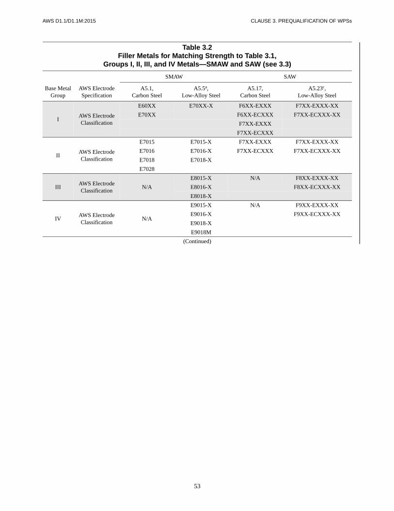
53
AWS D1.1/D1.1M:2015 CLAUSE 3. PREQUALIFICATION OF WPSs
Table 3.2Filler Metals for Matching Strength to Table 3.1,
Groups I, II, III, and IV Metals—SMAW and SAW (see 3.3)
Base Metal Group
AWS Electrode Specification
SMAW SAW
A5.1,Carbon Steel
A5.5a,Low-Alloy Steel
A5.17,Carbon Steel
A5.23c,Low-Alloy Steel
IAWS Electrode Classification
E60XX E70XX-X F6XX-EXXX F7XX-EXXX-XX
E70XX F6XX-ECXXX F7XX-ECXXX-XX
F7XX-EXXX
F7XX-ECXXX
IIAWS Electrode Classification
E7015 E7015-X F7XX-EXXX F7XX-EXXX-XX
E7016 E7016-X F7XX-ECXXX F7XX-ECXXX-XX
E7018 E7018-X
E7028
IIIAWS Electrode Classification
N/A
E8015-X N/A F8XX-EXXX-XX
E8016-X F8XX-ECXXX-XX
E8018-X
IVAWS Electrode Classification
N/A
E9015-X N/A F9XX-EXXX-XX
E9016-X F9XX-ECXXX-XX
E9018-X
E9018M
(Continued)
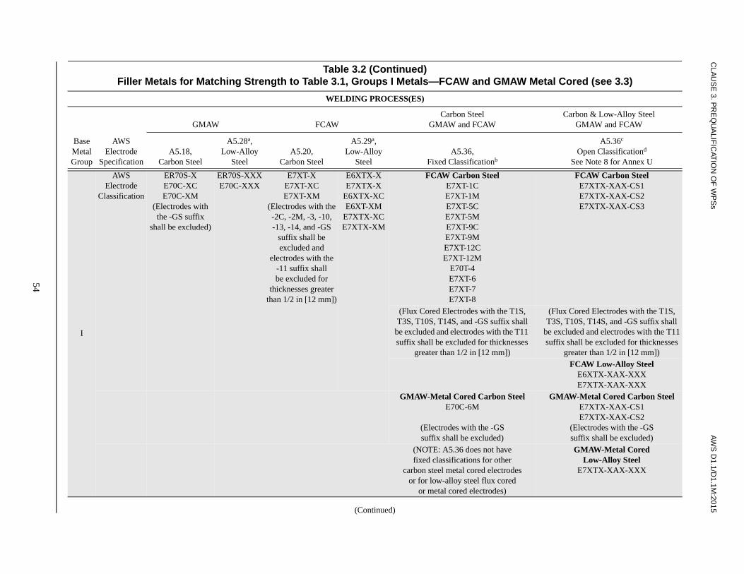
CLA
US
E 3. P
RE
QU
ALIF
ICAT
ION
OF
WP
Ss
AW
S D
1.1/D1.1M
:2015
54
Table 3.2 (Continued)Filler Metals for Matching Strength to Table 3.1, Groups I Metals—FCAW and GMAW Metal Cored (see 3.3)
WELDING PROCESS(ES)
Base Metal Group
AWSElectrode
Specification
GMAW FCAWCarbon Steel
GMAW and FCAWCarbon & Low-Alloy Steel
GMAW and FCAW
A5.18,Carbon Steel
A5.28a,Low-Alloy
SteelA5.20,
Carbon Steel
A5.29a,Low-Alloy
SteelA5.36,
Fixed Classificationb
A5.36c
Open Classificationd
See Note 8 for Annex U
I
AWSElectrode
Classification
ER70S-XE70C-XCE70C-XM
(Electrodes withthe -GS suffix
shall be excluded)
ER70S-XXXE70C-XXX
E7XT-XE7XT-XCE7XT-XM
(Electrodes with the-2C, -2M, -3, -10,-13, -14, and -GS
suffix shall be excluded and
electrodes with the-11 suffix shallbe excluded for
thicknesses greater than 1/2 in [12 mm])
E6XTX-XE7XTX-X
E6XTX-XCE6XT-XM
E7XTX-XCE7XTX-XM
FCAW Carbon SteelE7XT-1CE7XT-1ME7XT-5CE7XT-5ME7XT-9CE7XT-9ME7XT-12CE7XT-12M
E70T-4E7XT-6E7XT-7E7XT-8
FCAW Carbon SteelE7XTX-XAX-CS1E7XTX-XAX-CS2E7XTX-XAX-CS3
(Flux Cored Electrodes with the T1S, T3S, T10S, T14S, and -GS suffix shall
be excluded and electrodes with the T11 suffix shall be excluded for thicknesses
greater than 1/2 in [12 mm])
(Flux Cored Electrodes with the T1S, T3S, T10S, T14S, and -GS suffix shall
be excluded and electrodes with the T11 suffix shall be excluded for thicknesses
greater than 1/2 in [12 mm])FCAW Low-Alloy Steel
E6XTX-XAX-XXXE7XTX-XAX-XXX
GMAW-Metal Cored Carbon SteelE70C-6M
(Electrodes with the -GSsuffix shall be excluded)
GMAW-Metal Cored Carbon SteelE7XTX-XAX-CS1E7XTX-XAX-CS2
(Electrodes with the -GSsuffix shall be excluded)
(NOTE: A5.36 does not havefixed classifications for other
carbon steel metal cored electrodesor for low-alloy steel flux cored
or metal cored electrodes)
GMAW-Metal CoredLow-Alloy Steel
E7XTX-XAX-XXX
(Continued)
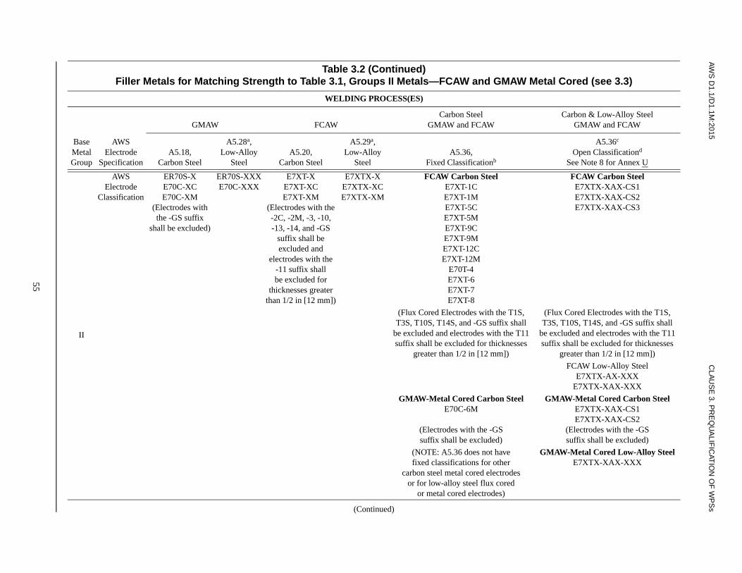
AW
S D
1.1/D1.1M
:2015C
LAU
SE
3. PR
EQ
UA
LIFIC
ATIO
N O
F W
PS
s
55
Table 3.2 (Continued)Filler Metals for Matching Strength to Table 3.1, Groups II Metals—FCAW and GMAW Metal Cored (see 3.3)
WELDING PROCESS(ES)
Base Metal Group
AWSElectrode
Specification
GMAW FCAWCarbon Steel
GMAW and FCAWCarbon & Low-Alloy Steel
GMAW and FCAW
A5.18,Carbon Steel
A5.28a,Low-Alloy
SteelA5.20,
Carbon Steel
A5.29a,Low-Alloy
SteelA5.36,
Fixed Classificationb
A5.36c
Open Classificationd
See Note 8 for Annex U
II
AWSElectrode
Classification
ER70S-XE70C-XCE70C-XM
(Electrodes withthe -GS suffix
shall be excluded)
ER70S-XXXE70C-XXX
E7XT-XE7XT-XCE7XT-XM
(Electrodes with the-2C, -2M, -3, -10,-13, -14, and -GS
suffix shall be excluded and
electrodes with the-11 suffix shallbe excluded for
thicknesses greater than 1/2 in [12 mm])
E7XTX-XE7XTX-XCE7XTX-XM
FCAW Carbon SteelE7XT-1CE7XT-1ME7XT-5CE7XT-5ME7XT-9CE7XT-9ME7XT-12CE7XT-12M
E70T-4E7XT-6E7XT-7E7XT-8
FCAW Carbon SteelE7XTX-XAX-CS1E7XTX-XAX-CS2E7XTX-XAX-CS3
(Flux Cored Electrodes with the T1S,T3S, T10S, T14S, and -GS suffix shall
be excluded and electrodes with the T11suffix shall be excluded for thicknesses
greater than 1/2 in [12 mm])
(Flux Cored Electrodes with the T1S,T3S, T10S, T14S, and -GS suffix shall
be excluded and electrodes with the T11suffix shall be excluded for thicknesses
greater than 1/2 in [12 mm])
FCAW Low-Alloy SteelE7XTX-AX-XXX
E7XTX-XAX-XXX
GMAW-Metal Cored Carbon SteelE70C-6M
(Electrodes with the -GSsuffix shall be excluded)
GMAW-Metal Cored Carbon SteelE7XTX-XAX-CS1E7XTX-XAX-CS2
(Electrodes with the -GSsuffix shall be excluded)
(NOTE: A5.36 does not havefixed classifications for other
carbon steel metal cored electrodesor for low-alloy steel flux cored
or metal cored electrodes)
GMAW-Metal Cored Low-Alloy SteelE7XTX-XAX-XXX
(Continued)

CLA
US
E 3. P
RE
QU
ALIF
ICAT
ION
OF
WP
Ss
AW
S D
1.1/D1.1M
:2015
56
Table 3.2 (Continued)Filler Metals for Matching Strength to Table 3.1, Groups II Metals—FCAW and GMAW Metal Cored (see 3.3)
WELDING PROCESS(ES)
Base Metal Group
AWSElectrode
Specification
GMAW FCAWCarbon Steel
GMAW and FCAWCarbon & Low-Alloy Steel
GMAW and FCAW
A5.18,Carbon Steel
A5.28a,Low-Alloy
SteelA5.20,
Carbon Steel
A5.29a,Low-Alloy
SteelA5.36,
Fixed Classificationb
A5.36c
Open Classificationd
See Note 8 for Annex U
III
AWS Electrode
Classification
N/A ER80S-XXXE80C-XXX
N/A E8XTX-XE8XTX-XCE8XTX-XM
FCAW Carbon SteelN/A
FCAW Carbon SteelN/A
FCAW Low-Alloy SteelE8XTX-AX-XXX
E8XTX-XAX-XXX
GMAW-Metal Cored Carbon SteelN/A
GMAW-Metal Cored Carbon SteelN/A
GMAW-Metal Cored Low-Alloy SteelE8XTX-XAX-XXX
FCAW Carbon SteelN/A
IV
AWS Electrode
Classification
N/A ER90S-XXXE90C-XXX
N/A E9XTX-XE9XTX-XCE9XTX-XM
FCAW Carbon SteelN/A
FCAW Low-Alloy SteelE9XTX-AX-XXX
E9XTX-XAX-XXX
GMAW-Metal Cored Carbon SteelN/A
GMAW-Metal Cored Carbon SteelN/A
GMAW-Metal Cored Low-Alloy SteelE9XTX-XAX-XXX
a Filler metals of alloy group B3, B3L, B4, B4L, B5, B5L, B6, B6L, B7, B7L, B8, B8L, B9, E9015-C5L, E9015-D1, E9018-D1, E9018-D3, or any BXH grade in AWS A5.5, A5.23, A5.28, or A5.29 are notprequalified for use in the as-welded condition.
b The prequalified argon based shielding gases for carbon and low-alloy steel FCAW and carbon steel GMAW-Metal Core fixed classifications shall be M21-ArC-20-25(SG-AC-20/25), see 3.7.4(2).c Filler metals of alloy group B3, B3L, B4, B4L, B5, B5L, B6, B6L, B7, B7L, B8, B8L, and B9 in AWS A5.36/A5.36M may be “PREQUALIFIED” if classified in the “AS-WELDED” condition.d The prequalified shielding gas for open classification shall be limited to the specific shielding gas for the classification of the electrode and not the range of the shielding gas designator, see 3.7.4(3).
Notes:1. In joints involving base metals of different groups, either of the following filler metals may be used: (1) that which matches the higher strength base metal, or (2) that which matches the lower strength base
metal and produces a low-hydrogen deposit. Preheating shall be in conformance with the requirements applicable to the higher strength group.2. Match API standard 2B (fabricated tubes) according to steel used.3. When welds are to be stress-relieved, the deposited weld metal shall not exceed 0.05% vanadium except alloy group B9.4. See Tables 2.3 and 9.2 for allowable stress requirements for matching filler metal.5. Filler metal properties have been moved to nonmandatory Annex T.6. AWS A5M (SI Units) electrodes of the same classification may be used in lieu of the AWS A5 (U.S. Customary Units) electrode classification.7. Any of the electrode classifications for a particular Group in Table 3.2 may be used to weld any of the base metals in that Group in Table 3.1.8. AWS A5.36/A5.36M open classifications are listed in Annex U.

57
AWS D1.1/D1.1M:2015 CLAUSE 3. PREQUALIFICATION OF WPSs
Table 3.3Prequalified Minimum Preheat and Interpass Temperature (see 3.5)
Category Steel Specification
WeldingProcess
Thickness ofThickest Part at
Point of Welding
Minimum Preheatand InterpassTemperature
in mm °F °C
A
ASTM A36
SMAWwith other than low-hydrogenelectrodes
1/8 to 3/4incl.
Over 3/4thru 1-1/2incl.
Over 1-1/2thru 2-1/2incl.
Over 2-1/2
3 to 20incl.
Over 20thru 38incl.
Over 38thru 65incl.
Over 65
a32a
150
225
300
a0a
65
110
150
ASTM A53 Grade BASTM A106 Grade BASTM A131 Grades A, B, CS, D, DS, EASTM A139 Grade BASTM A381 Grade Y35ASTM A500 Grade A
Grade BGrade C
ASTM A501 Grade AASTM A516ASTM A524 Grades I & IIASTM A573 Grade 65ASTM A709 Grade 36ASTM A1008 SS Grade 30
Grade 33 Type 1Grade 40 Type 1
ASTM A1011 SS Grade 30Grade 33Grade 36 Type 1Grade 40Grade 45Grade 50Grade 55
ASTM A1018 SS Grade 30Grade 33Grade 36Grade 40
API 5L Grade BGrade X42
ABS Grades A, B, D, CS, DSGrade E
B
ASTM A36
SMAWwith low-hydrogen electrodes, SAW, GMAW, FCAW
1/8 to 3/4incl.
Over 3/4thru 1-1/2incl.
Over 1-1/2thru 2-1/2incl.
Over 2-1/2
3 to 20incl.
Over 20 thru 38incl.
Over 38 thru 65incl.
Over 65
a 32a
50
150
225
a0a
10
65
110
ASTM A53 Grade BASTM A106 Grade BASTM A131 Grades A, B,
CS, D, DS, EAH 32 & 36DH 32 & 36EH 32 & 36
ASTM A139 Grade BASTM A381 Grade Y35ASTM A441ASTM A500 Grade A
Grade BGrade C
ASTM A501 Grades A and BASTM A516 Grades 55 & 60
65 & 70ASTM A524 Grades I & IIASTM A529 Grades 50 & 55
(Continued)

58
CLAUSE 3. PREQUALIFICATION OF WPSs AWS D1.1/D1.1M:2015
Table 3.3 (Continued)Prequalified Minimum Preheat and Interpass Temperature (see 3.5)
Category Steel Specification
WeldingProcess
Thickness ofThickest Part at
Point of Welding
Minimum Preheatand InterpassTemperature
in mm °F °C
B(Cont’d)
ASTM A537 Classes 1 & 2
SMAWwith low-hydrogen electrodes, SAW, GMAW, FCAW
1/8 to 3/4incl.
Over 3/4thru 1-1/2incl.
Over 1-1/2thru 2-1/2incl.
Over 2-1/2
3 to 20incl.
Over 20 thru 38incl.
Over 38 thru 65incl.
Over 65
a 32a
50
150
225
a0a
10
65
110
ASTM A572 Grades 42, 50, 55ASTM A573 Grade 65ASTM A588ASTM A595 Grades A, B, CASTM A606ASTM A618 Grades Ib, II, IIIASTM A633 Grades A, B
Grades C, DASTM A709 Grades 36, 50, 50S, 50W,
HPS 50WASTM A710 Grade A, Class 2
(>2 in [50 mm])ASTM A808ASTM A913b Grade 50ASTM A992ASTM A1008 HSLAS Grade 45 Class 1
Grade 45 Class 2Grade 50 Class 1Grade 50 Class 2Grade 55 Class 1Grade 55 Class 2
ASTM A1008 HSLAS-F Grade 50ASTM A1011 HSLAS Grade 45 Class 1
Grade 45 Class 2Grade 50 Class 1Grade 50 Class 2Grade 55 Class 1Grade 55 Class 2
ASTM A1011 HSLAS-F Grade 50ASTM A1018 HSLAS Grade 45 Class 1
Grade 45 Class 2Grade 50 Class 1Grade 50 Class 2Grade 55 Class 1Grade 55 Class 2
ASTM A1018 HSLAS-F Grade 50ASTM A1018 SS Grade 30
Grade 33Grade 36Grade 40
ASTM 1085API 5L Grade B
Grade X42API Spec. 2H Grades 42, 50API 2MT1 Grade 50API 2W Grades 42, 50, 50TAPI 2Y Grades 42, 50, 50TABS Grades AH 32 & 36
Grades DH 32 & 36Grades EH 32 & 36
(Continued)

59
AWS D1.1/D1.1M:2015 CLAUSE 3. PREQUALIFICATION OF WPSs
Table 3.3 (Continued)Prequalified Minimum Preheat and Interpass Temperature (see 3.5)
Category Steel Specification Welding Process
Thickness ofThickest Part at
Point of Welding
Minimum Preheatand Interpass Temperature
in mm °F °C
C
ASTM A572 Grades 60, 65
SMAW withlow-hydrogen electrodes, SAW, GMAW, FCAW
1/8 to 3/4incl.
Over 3/4thru 1-1/2incl.
Over 1-1/2thru 2-1/2incl.
Over 2-1/2
3 to 20incl.
Over 20thru 38incl.
Over 38thru 65incl.
Over 65
50
150
225
300
10
65
110
150
ASTM A633 Grade EASTM A913b Grades 60, 65, 70ASTM A710 Grade A, Class 2
(≤2 in [50 mm])ASTM A710 Grade A, Class 3
(>2 in [50 mm])ASTM A709c Grade HPS 70WASTM A852c
ASTM A1018HSLAS
Grade 60 Class 2Grade 70 Class 2
ASTM A1018HSLAS-F
Grade 60 Class 2Grade 70 Class 2
API 2W Grade 60API 2Y Grade 60API 5L Grade X52
DASTM A710
ASTM A913b
Grade A(All classes)Grades 50, 60, 65
SMAW, SAW, GMAW, and FCAW with electrodes or elec-trode-flux combinations capa-ble of depositing weld metal with a maximum diffusible hydrogen content of 8 ml/100 g (H8), when tested according to AWS A4.3.
All thicknesses≥ 1/8 in [3 mm]
a 32a a0a
a When the base metal temperature is below 32°F [0°C], the base metal shall be preheated to a minimum of 70°F [20°C] and the minimum interpasstemperature shall be maintained during welding.
b The heat input limitations of 5.7 shall not apply to ASTM A913.c For ASTM A709 Grade HPS 70W and ASTM A852, the maximum preheat and interpass temperatures shall not exceed 400°F [200°C] for
thicknesses up to 1-1/2 in [40 mm], inclusive, and 450°F [230°C] for greater thicknesses.
Notes:1. For modification of preheat requirements for SAW with parallel or multiple electrodes, see 3.5.2.2. See 5.11.2 and 5.6 for ambient and base metal temperature requirements.
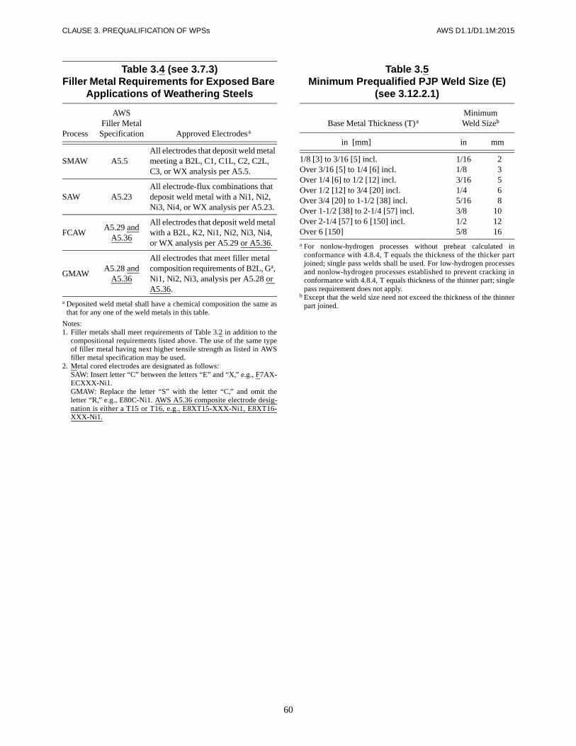
60
CLAUSE 3. PREQUALIFICATION OF WPSs AWS D1.1/D1.1M:2015
Table 3.4 (see 3.7.3)Filler Metal Requirements for Exposed Bare
Applications of Weathering Steels
Process
AWS Filler Metal
Specification Approved Electrodesa
SMAW A5.50All electrodes that deposit weld metal meeting a B2L, C1, C1L, C2, C2L, C3, or WX analysis per A5.5.
SAW A5.23All electrode-flux combinations that deposit weld metal with a Ni1, Ni2, Ni3, Ni4, or WX analysis per A5.23.
FCAWA5.29 and
A5.36
All electrodes that deposit weld metal with a B2L, K2, Ni1, Ni2, Ni3, Ni4, or WX analysis per A5.29 or A5.36.
GMAWA5.28 and
A5.36
All electrodes that meet filler metal composition requirements of B2L, Ga, Ni1, Ni2, Ni3, analysis per A5.28 or A5.36.
a Deposited weld metal shall have a chemical composition the same asthat for any one of the weld metals in this table.
Notes:1. Filler metals shall meet requirements of Table 3.2 in addition to the
compositional requirements listed above. The use of the same typeof filler metal having next higher tensile strength as listed in AWSfiller metal specification may be used.
2. Metal cored electrodes are designated as follows:SAW: Insert letter “C” between the letters “E” and “X,” e.g., F7AX-ECXXX-Ni1.GMAW: Replace the letter “S” with the letter “C,” and omit theletter “R,” e.g., E80C-Ni1. AWS A5.36 composite electrode desig-nation is either a T15 or T16, e.g., E8XT15-XXX-Ni1, E8XT16-XXX-Ni1.
Table 3.5Minimum Prequalified PJP Weld Size (E)
(see 3.12.2.1)
Base Metal Thickness (T)aMinimumWeld Sizeb
in [mm] in mm
1/8 [3] to 3/16 [5] incl.Over 3/16 [5] to 1/4 [6] incl.Over 1/4 [6] to 1/2 [12] incl.Over 1/2 [12] to 3/4 [20] incl.Over 3/4 [20] to 1-1/2 [38] incl.Over 1-1/2 [38] to 2-1/4 [57] incl.Over 2-1/4 [57] to 6 [150] incl.Over 6 [150]
1/161/803/161/405/163/801/205/80
23568
101216
a For nonlow-hydrogen processes without preheat calculated inconformance with 4.8.4, T equals the thickness of the thicker partjoined; single pass welds shall be used. For low-hydrogen processesand nonlow-hydrogen processes established to prevent cracking inconformance with 4.8.4, T equals thickness of the thinner part; singlepass requirement does not apply.
b Except that the weld size need not exceed the thickness of the thinnerpart joined.

61
AWS D1.1/D1.1M:2015 CLAUSE 3. PREQUALIFICATION OF WPSs
Table 3.6Prequalified WPS Requirements f (see 3.7)
Variable Position Weld Type SMAW
SAWd
GMAW/FCAWgSingle Parallel Multiple
Maximum Electrode Diameter
Flat
Filleta 5/16 in [8.0 mm]
1/4 in [6.4 mm] 1/8 in [3.2 mm]Groovea 1/4 in [6.4 mm]
Root pass 3/16 in [4.8 mm]
HorizontalFillet 1/4 in [6.4 mm] 1/4 in [6.4 mm]
1/8 in [3.2 mm]Groove 3/16 in [4.8 mm] Requires WPS Qualification Test
Vertical All 3/16 in [4.8 mm]b 3/32 in [2.4 mm]
Overhead All 3/16 in [4.8 mm]b 5/64 in [2.0 mm]
Maximum Current
All Fillet
Within therange of recommended operation bythe filler metal manufacturer
1000 A 1200A
Unlimited
Within therange of recommended operation by the filler metal manufacturer
All
Groove weld root passwith opening
600A
700A
Groove weld root passwithout opening
900A
Groove weld fill passes
1200A
Groove weld cap pass
Unlimited
Maximum Root Pass Thicknessd
Flat
All
3/8 in [10 mm]Unlimited
3/8 in [10 mm]
Horizontal 5/16 in [8 mm] 5/16 in [8 mm]
Vertical 1/2 in [12 mm] 1/2 in [12 mm]
Overhead 5/16 in [8 mm] 5/16 in [8 mm]
MaximumFill Pass Thickness
All All 3/16 in [5 mm]1/4 in
[6 mm]Unlimited 1/4 in [6 mm]
Maximum Single Pass Fillet Weld Sizec
Flat
Fillet
3/8 in [10 mm] Unlimited 1/2 in [12 mm]
Horizontal 5/16 in [8 mm]5/16 in
[8 mm]5/16 in[8 mm]
1/2 in[12 mm]
3/8 in [10 mm]
Vertical 1/2 in [12 mm] 1/2 in [12 mm]
Overhead 5/16 in [8 mm] 5/16 in [8 mm]
Maximum Single Pass LayerWidth
All (for GMAW/FCAW)F & H(for SAW)
Root opening> 1/2 in [12 mm],or
Split layers
Laterally displaced electrodes or split layer
Split layers Split layers
Any layer of width w
Split layersif w > 5/8 in [16 mm]
Split layers with tandem electrodesif w > 5/8 in [16 mm]
If w > 1 in [25 mm],split layers
(Note e)
a Except root passes.b 5/32 in [4.0 mm] for EXX14 and low–hydrogen electrodes.c See 3.7.3 for requirements for welding unpainted and exposed ASTM A588.d See 3.7.2 for width–to–depth limitations.e In the F, H, or OH positions for nontubulars, split layers when the layer width w > 5/8 in [16 mm]. In the vertical position for nontubulars or the flat,
horizontal, vertical, and overhead positions for tubulars, split layers when the width w > 1 in [25 mm].f Shaded area indicates nonapplicability.g GMAW-S shall not be prequalified.

62
CLAUSE 3. PREQUALIFICATION OF WPSs AWS D1.1/D1.1M:2015
Table 3.7Prequalified WPS Variables (see 3.6 and 3.7)
Prequalified WPS Variable
Process
SMAW SAW GMAW FCAW
General
1) A change in welding process(es)aX X X X
2) A change in welding position(s) X X X X
Base Metal
3) A change in base metal group number(s) (seeTable 3.1) X X X X
4) A change in the base metal preheat category (see Table 3.3) X X X X
Filler Metal
5) A change in electrode classification(s) X X X X
6) A change in electrode/flux classification(s) X
7) A change in nominal electrode diameter(s) X X X X
8) A change in the number of electrodes X
Process Parameters
9) A change in amperage > 10% increase or decrease
> 10% increase or decrease
> 10% increase or decrease
10) A change in type of current (ac or dc) or polarity X X X X
11) A change in the mode of transfer X
12) A change in voltage > 15% increase or decrease
> 15% increase or decrease
> 15% increase or decrease
13) A change in wire feed speed (if not amperage controlled)
> 10% increase or decrease
> 10% increase or decrease
> 10% increase or decrease
14) A change in travel speed > 25% increase or decrease
> 25% increase or decrease
> 25% increase or decrease
Shielding Gas
15) A change in the nominal composition of shieldinggas X
X (forFCAW-G only)
16) A decrease in shielding gas flow rate> 25%
> 25% (for FCAW-G only)
17) An increase in the gas flow rate> 50%
> 50% (for FCAW-G only)
(Continued)

63
AWS D1.1/D1.1M:2015 CLAUSE 3. PREQUALIFICATION OF WPSs
SAW Parameters
18) A change in the longitudinal spacing of arcs > 10% or 1/8 in [3 mm],
whichever is greater
19) A change in the lateral spacing of arcs > 10% or 1/8 in [3 mm],
whichever is greater
20) A change in the angular orientation of parallel electrodes
Increase or decrease > 10°
21) For mechanized or automatic SAW, a change in the angle parallel to the direction of travel of the electrode
Increase or decrease > 10°
22) For mechanized or automatic SAW, a change in the angle of electrode normal to the direction of travel
Increase or decrease > 15°
Weld Details
23) A change in the weld configuration (e.g., a fillet to a CJP groove weld, etc.) X X X X
24) A change in groove weld detail(s) as shown inFigures 3.2, 3.3, and 3.6 X X X X
Thermal
25) A change in PWHT (the addition of, deletion of)aX X X X
aA separate WPS shall be required when this variable is changed.
Note: An “X” indicates applicability for the process; a shaded block indicates nonapplicability.
Table 3.7 (Continued)Prequalified WPS Variables (see 3.6 and 3.7)
Prequalified WPS Variable
Process
SMAW SAW GMAW FCAW
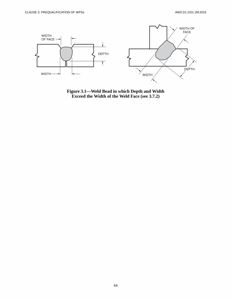
CLAUSE 3. PREQUALIFICATION OF WPSs AWS D1.1/D1.1M:2015
64
Figure 3.1—Weld Bead in which Depth and WidthExceed the Width of the Weld Face (see 3.7.2)

AWS D1.1/D1.1M:2015 CLAUSE 3. PREQUALIFICATION OF WPSs
65
Symbols for joint typesB — butt jointC — corner jointT — T-joint
BC — butt or corner jointTC — T- or corner joint
BTC — butt, T-, or corner joint
Symbols for base metal thickness and penetrationP — PJPL — limited thickness–CJPU — unlimited thickness–CJP
Symbol for weld types1 — square-groove2 — single-V-groove3 — double-V-groove4 — single-bevel-groove5 — double-bevel-groove6 — single-U-groove7 — double-U-groove8 — single-J-groove9 — double-J-groove
10 — flare-bevel-groove11 — flare-V-groove
Symbols for welding processes if not SMAWS — SAWG — GMAWF — FCAW
Notes for Figures 3.2 and 3.3
a Not prequalified for GMAW-S nor GTAW.b Joint shall be welded from one side only.c Cyclic load application places restrictions on the use of this detail for butt joints in the flat position (see 2.18.2).d Backgouge root to sound metal before welding second side.e SMAW detailed joints may be used for prequalified GMAW (except GMAW-S) and FCAW.f Minimum weld size (E) as shown in Table 3.5. S as specified on drawings.g If fillet welds are used in statically loaded structures to reinforce groove welds in corner and T-joints, these shall be equal to T1/4, but
need not exceed 3/8 in [10 mm]. Groove welds in corner and T-joints of cyclically loaded structures shall be reinforced with fillet weldsequal to T1/4, but need not exceed 3/8 in [10 mm].
h Double-groove welds may have grooves of unequal depth, but the depth of the shallower groove shall be no less than one-fourth of thethickness of the thinner part joined.
i Double-groove welds may have grooves of unequal depth, provided these conform to the limitations of Note f. Also the weld size (E)applies individually to each groove.
j The orientation of the two members in the joints may vary from 135° to 180° for butt joints, or 45° to 135° for corner joints, or 45° to 90°for T-joints.
k For corner joints, the outside groove preparation may be in either or both members, provided the basic groove configuration is notchanged and adequate edge distance is maintained to support the welding operations without excessive edge melting.
l Weld size (E) shall be based on joints welded flush.mFor flare-V-groove welds and flare-bevel-groove welds to rectangular tubular sections, r shall be as two times the wall thickness.n For flare-V-groove welds to surfaces with different radii r, the smaller r shall be used.o For corner and T-joints the member orientation may vary from 90° to less than or equal to 170° provided the groove angle and root
opening are maintained, and the angle between the groove faces and the steel backing is at least 90°. See Figure 3.6
Welding processesSMAW — shielded metal arc weldingGMAW — gas metal arc weldingFCAW — flux cored metal arc welding
SAW — submerged arc welding
Welding positionsF — flatH — horizontalV — vertical
OH — overhead
DimensionsR = Root Opening
α, β = Groove Anglesf = Root Facer = J- or U-groove Radius
S, S1 , S2 = PJP Groove WeldDepth of Groove
E, E1 , E2 = PJP Groove WeldSizes corresponding to S, S1 , S2 , respectively
Joint DesignationThe lower case letters, e.g., a, b, c, etc., are used to differentiatebetween joints that would otherwise have the same jointdesignation.
Legend for Figures 3.2 and 3.3

CLAUSE 3. PREQUALIFICATION OF WPSs AWS D1.1/D1.1M:2015
66
See Notes on Page 65
Figure 3.2—Prequalified PJP Groove Welded Joint Details(see 3.12) (Dimensions in Inches)
Square-groove weld (1)Butt joint (B)
Welding Process
Joint Designation
Base Metal Thickness (U = unlimited)
Groove Preparation
Allowed Welding Positions
Weld Size(E) NotesRoot Opening
Tolerances
T1 T2
As Detailed(see 3.12.3)
As Fit-Up(see 3.12.3)
SMAW
B-P1a 1/8 max. — R = 0 to 1/16 +1/16, –0 ±1/16 All T1 – 1/32 b
B-P1c 1/4 max. — R = min. +1/16, –0 ±1/16 All b
GMAWFCAW
B-P1a-GF 1/8 max. — R = 0 to 1/16 +1/16, –0 ±1/16 All T1 – 1/32 b, e
B-P1c-GF 1/4 max. — R = min. +1/16, –0 ±1/16 All b, e
Square-groove weld (1)Butt joint (B)
E1 + E2 MUST NOT EXCEED
Welding Process
Joint Designation
Base Metal Thickness (U = unlimited)
Groove Preparation
Allowed Welding Positions
Total Weld Size(E1 + E2) NotesRoot Opening
Tolerances
T1 T2
As Detailed(see 3.12.3)
As Fit-Up(see 3.12.3)
SMAW B-P1b 1/4 max. — R = +1/16, –0 ±1/16 All
GMAWFCAW B-P1b-GF 1/4 max. — R = +1/16, –0 ±1/16 All e
T1
2------
T1
2------
T1
2------
T1
2------
3T1
4----------
T1
2------
3T1
4----------
T1
2------
3T1
4----------

AWS D1.1/D1.1M:2015 CLAUSE 3. PREQUALIFICATION OF WPSs
67
See Notes on Page 65
Figure 3.2 (Continued)—Prequalified PJP Groove Welded Joint Details(see 3.12) (Dimensions in Inches)
Single-V-groove weld (2)Butt joint (B)Corner joint (C)
Welding Process
Joint Designation
Base Metal Thickness (U = unlimited)
Groove Preparation
Allowed Welding Positions
Weld Size(E) Notes
Root OpeningRoot Face
Groove Angle
Tolerances
T1 T2
As Detailed(see 3.12.3)
As Fit-Up(see 3.12.3)
SMAW BC-P2 1/4 min. UR = 0
f = 1/32 min.α = 60°
+1/16, –0+U, –0
+10°, –0°
+1/8, –1/16±1/16
+10°, –5°All S b, e, f, j
GMAWFCAW BC-P2-GF 1/4 min. U
R = 0f = 1/8 min.
α = 60°
+1/16, –0+U, –0
+10°, –0°
+1/8, –1/16±1/16
+10°, –5°All S a, b, f, j
SAW BC-P2-S 7/16 min. UR = 0
f = 1/4 min.α = 60°
±0+U, –0
+10°, –0°
+1/16, –0±1/16
+10°, –5°F S b, f, j
Double-V-groove weld (3)Butt joint (B)
Welding Process
Joint Designation
Base Metal Thickness (U = unlimited)
Groove Preparation
Allowed Welding Positions
TotalWeld Size(E1 + E2) Notes
Root OpeningRoot Face
Groove Angle
Tolerances
T1 T2
As Detailed(see 3.12.3)
As Fit-Up(see 3.12.3)
SMAW B-P3 1/2 min. —R = 0
f = 1/8 min.α = 60°
+1/16, –0+U, –0
+10°, –0°
+1/8, –1/16±1/16
+10°, –5°All S1 + S2 e, f, i, j
GMAWFCAW B-P3-GF 1/2 min. —
R = 0f = 1/8 min.
α = 60°
+1/16, –0+U, –0
+10°, –0°
+1/8, –1/16±1/16
+10°, –5°All S1 + S2 a, f, i, j
SAW B-P3-S 3/4 min. —R = 0
f = 1/4 min.α = 60°
±0+U, –0
+10°, –0°
+1/16, –0±1/16
+10°, –5°F S1 + S2 f, i, j

CLAUSE 3. PREQUALIFICATION OF WPSs AWS D1.1/D1.1M:2015
68
See Notes on Page 65
Figure 3.2 (Continued)—Prequalified PJP Groove Welded Joint Details(see 3.12) (Dimensions in Inches)
Single-bevel-groove weld (4)Butt joint (B)T-joint (T)Corner joint (C)
Welding Process
Joint Designation
Base Metal Thickness (U = unlimited)
Groove Preparation
Allowed Welding Positions
Weld Size(E) Notes
Root OpeningRoot Face
Groove Angle
Tolerances
T1 T2
As Detailed(see 3.12.3)
As Fit-Up(see 3.12.3)
SMAW BTC-P4 U UR = 0
f = 1/8 min.α = 45°
+1/16, –0+U –0
+10°, –0°
+1/8, –1/16±1/16
+10°, –5°All S–1/8 b, e, f,
g, j, k
GMAWFCAW BTC-P4-GF 1/4 min. U
R = 0f = 1/8 min.
α = 45°
+1/16, –0+U –0
+10°, –0°
+1/8, –1/16±1/16
+10°, –5°
F, H S a, b, f, g, j, kV, OH S–1/8
SAW TC-P4-S 7/16 min. UR = 0
f = 1/4 min.α = 60°
±0+U, –0
+10°, –0°
+1/16, –0±1/16
+10°, –5°F S b, f, g, j,
k
Double-bevel-groove weld (5)Butt joint (B)T-joint (T)Corner joint (C)
Welding Process
Joint Designation
Base Metal Thickness (U = unlimited)
Groove Preparation
Allowed Welding Positions
TotalWeld Size(E1 + E2) Notes
Root OpeningRoot Face
Groove Angle
Tolerances
T1 T2
As Detailed(see 3.12.3)
As Fit-Up(see 3.12.3)
SMAW BTC-P5 5/16 min. UR = 0
f = 1/8 min.α = 45°
+1/16, –0+U –0
+10°, –0°
+1/8, –1/16±1/16
+10°, –5°All
S1 + S2
–1/4e, f, g, i,
j, k
GMAWFCAW BTC-P5-GF 1/2 min. U
R = 0f = 1/8 min.
α = 45°
+1/16, –0+U –0
+10°, –0°
+1/8, –1/16±1/16
+10°, –5°
F, H S1 + S2a, f, g, i,
j, kV, OHS1 + S2
–1/4
SAW TC-P5-S 3/4 min. UR = 0
f = 1/4 min.α = 60°
±0+U, –0
+10°, –0°
+1/16, –0±1/16
+10°, –5°F S1 + S2
f, g, i, j, k
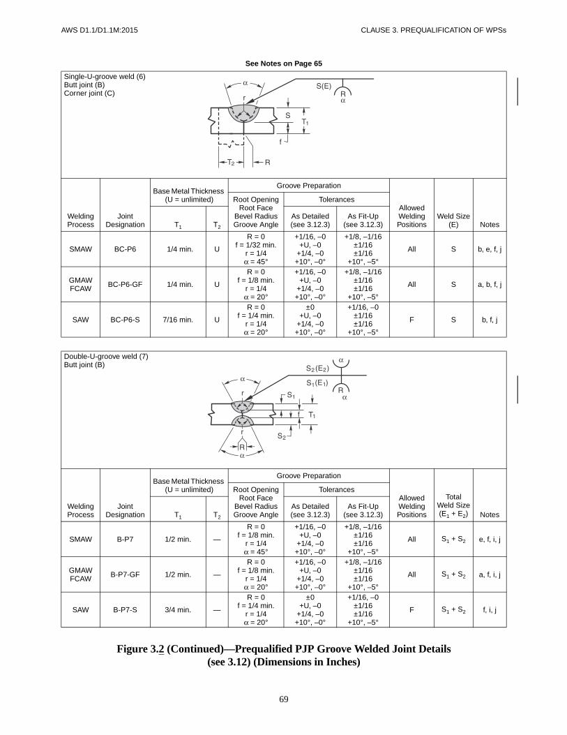
AWS D1.1/D1.1M:2015 CLAUSE 3. PREQUALIFICATION OF WPSs
69
See Notes on Page 65
Figure 3.2 (Continued)—Prequalified PJP Groove Welded Joint Details(see 3.12) (Dimensions in Inches)
Single-U-groove weld (6)Butt joint (B)Corner joint (C)
Welding Process
Joint Designation
Base Metal Thickness (U = unlimited)
Groove Preparation
Allowed Welding Positions
Weld Size(E) Notes
Root OpeningRoot Face
Bevel RadiusGroove Angle
Tolerances
T1 T2
As Detailed(see 3.12.3)
As Fit-Up(see 3.12.3)
SMAW BC-P6 1/4 min. U
R = 0f = 1/32 min.
r = 1/4α = 45°
+1/16, –0+U, –0
+1/4, –0+10°, –0°
+1/8, –1/16±1/16±1/16
+10°, –5°
All S b, e, f, j
GMAWFCAW BC-P6-GF 1/4 min. U
R = 0f = 1/8 min.
r = 1/4α = 20°
+1/16, –0+U, –0
+1/4, –0+10°, –0°
+1/8, –1/16±1/16±1/16
+10°, –5°
All S a, b, f, j
SAW BC-P6-S 7/16 min. U
R = 0f = 1/4 min.
r = 1/4α = 20°
±0+U, –0
+1/4, –0+10°, –0°
+1/16, –0±1/16±1/16
+10°, –5°
F S b, f, j
Double-U-groove weld (7)Butt joint (B)
Welding Process
Joint Designation
Base Metal Thickness (U = unlimited)
Groove Preparation
Allowed Welding Positions
TotalWeld Size(E1 + E2) Notes
Root OpeningRoot Face
Bevel RadiusGroove Angle
Tolerances
T1 T2
As Detailed(see 3.12.3)
As Fit-Up(see 3.12.3)
SMAW B-P7 1/2 min. —
R = 0f = 1/8 min.
r = 1/4α = 45°
+1/16, –0+U, –0
+1/4, –0+10°, –0°
+1/8, –1/16±1/16±1/16
+10°, –5°
All S1 + S2 e, f, i, j
GMAWFCAW B-P7-GF 1/2 min. —
R = 0f = 1/8 min.
r = 1/4α = 20°
+1/16, –0+U, –0
+1/4, –0+10°, –0°
+1/8, –1/16±1/16±1/16
+10°, –5°
All S1 + S2 a, f, i, j
SAW B-P7-S 3/4 min. —
R = 0f = 1/4 min.
r = 1/4α = 20°
±0+U, –0
+1/4, –0+10°, –0°
+1/16, –0±1/16±1/16
+10°, –5°
F S1 + S2 f, i, j

CLAUSE 3. PREQUALIFICATION OF WPSs AWS D1.1/D1.1M:2015
70
See Notes on Page 65
Figure 3.2 (Continued)—Prequalified PJP Groove Welded Joint Details(see 3.12) (Dimensions in Inches)
Single-J-groove weld (8)Butt joint (B)T-joint (T)Corner joint (C)
Welding Process
Joint Designation
Base Metal Thickness (U = unlimited)
Groove Preparation
Allowed Welding Positions
Weld Size(E) Notes
Root OpeningRoot Face
Bevel RadiusGroove Angle
Tolerances
T1 T2
As Detailed(see 3.12.3)
As Fit-Up(see 3.12.3)
SMAW
B-P8 1/4 min. —
R = 0f = 1/8 min.
r = 3/8α = 30°
+1/16, –0+U, –0
+1/4, –0+10°, –0°
+1/8, –1/16±1/16±1/16
+10°, –5°
All S e, f, g, j, k
TC-P8 1/4 min. U
R = 0f = 1/8 min.
r = 3/8αoc = 30°*αic = 45°**
+1/16, –0+U, –0
+1/4, –0+10°, –0°+10°, –0°
+1/8, –1/16±1/16±1/16
+10°, –5°+10°, –5°
All S e, f, g, j, k
GMAWFCAW
B-P8-GF 1/4 min. —
R = 0f = 1/8 min.
r = 3/8α = 30°
+1/16, –0+U, –0
+1/4, –0+10°, –0°
+1/8, –1/16±1/16±1/16
+10°, –5°
All S a, f, g, j, k
TC-P8-GF 1/4 min. U
R = 0f = 1/8 min.
r = 3/8αoc = 30°*αic = 45°**
+1/16, –0+U, –0
+1/4, –0+10°, –0°+10°, –0°
+1/8, –1/16±1/16±1/16
+10°, –5°+10°, –5°
All S a, f, g, j, k
SAW
B-P8-S 7/16 min. —
R = 0f = 1/4 min.
r = 1/2α = 20°
±0+U, –0
+1/4, –0+10°, –0°
+1/16, –0±1/16±1/16
+10°, –5°
F S f, g, j, k
TC-P8-S 7/16 min. U
R = 0f = 1/4 min.
r = 1/2αoc = 20°*αic = 45°**
±0+U, –0
+1/4, –0+10°, –0°+10°, –0°
+1/16, –0±1/16±1/16
+10°, –5°+10°, –5°
F S f, g, j, k
**αoc = Outside corner groove angle.**αic = Inside corner groove angle.

AWS D1.1/D1.1M:2015 CLAUSE 3. PREQUALIFICATION OF WPSs
71
See Notes on Page 65
Figure 3.2 (Continued)—Prequalified PJP Groove Welded Joint Details(see 3.12) (Dimensions in Inches)
Double-J-groove weld (9)Butt joint (B)T-joint (T)Corner joint (C)
Welding Process
Joint Designation
Base Metal Thickness (U = unlimited)
Groove Preparation
Allowed Welding Positions
TotalWeld Size(E1 + E2) Notes
Root OpeningRoot Face
Bevel RadiusGroove Angle
Tolerances
T1 T2
As Detailed(see 3.12.3)
As Fit-Up(see 3.12.3)
SMAW
B-P9 1/2 min. —
R = 0f = 1/8 min.
r = 3/8α = 30°
+1/16, –0+U, –0
+1/4, –0+10°, –0°
+1/8, –1/16±1/16±1/16
+10°, –5°
All S1 + S2e, f, g, i,
j, k
TC-P9 1/2 min. U
R = 0f = 1/8 min.
r = 3/8αoc = 30°*αic = 45°**
+1/16, –0+U, –0
+1/4, –0+10°, –0°+10°, –0°
+1/8, –1/16±1/16±1/16
+10°, –5°+10°, –5°
All S1 + S2e, f, g, i,
j, k
GMAWFCAW
B-P9-GF 1/2 min. —
R = 0f = 1/8 min.
r = 3/8α = 30°
+1/16, –0+U, –0
+1/4, –0+10°, –0°
+1/8, –1/16±1/16±1/16
+10°, –5°
All S1 + S2a, f, g, i,
j, k
TC-P9-GF 1/2 min. U
R = 0f = 1/8 min.
r = 3/8αoc = 30°*αic = 45°**
±0+U, –0
+1/4, –0+10°, –0°+10°, –0°
+1/16, –0±1/16±1/16
+10°, –5°+10°, –5°
All S1 + S2a, f, g, i,
j, k
SAW
B-P9-S 3/4 min. —
R = 0f = 1/4 min.
r = 1/2α = 20°
±0+U, –0
+1/4, –0+10°, –0°
+1/16, –0±1/16±1/16
+10°, –5°
F S1 + S2f, g, i, j,
k
TC-P9-S 3/4 min. U
R = 0f = 1/4 min.
r = 1/2αoc = 20°*αic = 45°**
±0+U, –0
+1/4, –0+10°, –0°+10°, –0°
+1/16, –0±1/16±1/16
+10°, –5°+10°, –5°
F S1 + S2f, g, i, j,
k
**αoc = Outside corner groove angle.**αic = Inside corner groove angle.

CLAUSE 3. PREQUALIFICATION OF WPSs AWS D1.1/D1.1M:2015
72
See Notes on Page 65
Figure 3.2 (Continued)—Prequalified PJP Groove Welded Joint Details(see 3.12) (Dimensions in Inches)
Flare-bevel-groove weld (10)Butt joint (B)T-joint (T)Corner joint (C)
Welding Process
Joint Designation
Base Metal Thickness (U = unlimited)
Groove Preparation
Allowed Welding Positions
Weld Size(E) Notes
Root OpeningRoot Face
Bend Radius
Tolerances
T1 T2 T3
As Detailed(see 3.12.3)
As Fit-Up(see 3.12.3)
SMAWFCAW-S BTC-P10 3/16
min. UT1
min.
R = 0f = 3/16 min.
r = min.
+1/16, –0+U, –0
+U, –0
+1/8, –1/16+U, –1/16
+U, –0All 5/16 r e, g, j, l
GMAWFCAW-G BTC-P10-GF 3/16
min. UT1
min.
R = 0f = 3/16 min.
r = min.
+1/16, –0+U, –0
+U, –0
+1/8, –1/16+U, –1/16
+U, –0All 5/8 r a, g, j, l,
m
SAW B-P10-S 1/2 min. N/A 1/2
min.
R = 0f = 1/2 min.
r = min.
±0+U, –0
+U, –0
+1/16, –0+U, –1/16
+U, –0F 5/16 r g, j, l, m
3T1
2----------
3T1
2----------
3T1
2----------

AWS D1.1/D1.1M:2015 CLAUSE 3. PREQUALIFICATION OF WPSs
73
See Notes on Page 65
Figure 3.2 (Continued)—Prequalified PJP Groove Welded Joint Details(see 3.12) (Dimensions in Inches)
Flare-V-groove weld (11)Butt joint (B)
Welding Process
Joint Designation
Base Metal Thickness (U = unlimited)
Groove Preparation
Allowed Welding Positions
Weld Size(E) Notes
Root OpeningRoot Face
Bend Radius
Tolerances
T1 T2
As Detailed(see 3.12.3)
As Fit-Up(see 3.12.3)
SMAWFCAW-S B-P11 3/16 min. T1 min.
R = 0f = 3/16 min.
r = min.
+1/16, –0+U, –0+U, –0
+1/8, –1/16+U, –1/16
+U, –0All 5/8 r e, j, l, m,
n
GMAWFCAW-G B-P11-GF 3/16 min. T1 min.
R = 0f = 3/16 min.
r = min.
+1/16, –0+U, –0+U, –0
+1/8, –1/16+U, –1/16
+U, –0All 3/4 r a, j, l, m,
n
SAW B-P11-S 1/2 min. T1 min.
R = 0f = 1/2 min.
r = min.
±0+U, –0+U, –0
+1/16, –0+U, –1/16
+U, –0F 1/2 r j, l, m, n
3T1
2----------
3T1
2----------
3T1
2----------

CLAUSE 3. PREQUALIFICATION OF WPSs AWS D1.1/D1.1M:2015
74
See Notes on Page 65
Figure 3.2 (Continued)—Prequalified PJP Groove Welded Joint Details(see 3.12) (Dimensions in Millimeters)
Square-groove weld (1)Butt joint (B)
ALL DIMENSIONS IN mm
Welding Process
Joint Designation
Base Metal Thickness (U = unlimited)
Groove Preparation
Allowed Welding Positions
Weld Size(E) NotesRoot Opening
Tolerances
T1 T2
As Detailed(see 3.12.3)
As Fit-Up(see 3.12.3)
SMAW
B-P1a 3 max. — R = 0 to 2 +2, –0 ±2 All T1 – 1 b
B-P1c 6 max. — R = min. +2, –0 ±2 All b
GMAWFCAW
B-P1a-GF 3 max. — R = 0 to 2 +2, –0 ±2 All T1 – 1 b, e
B-P1c-GF 6 max. — R = min. +2, –0 ±2 All b, e
Square-groove weld (1)Butt joint (B)
E1 + E2 MUST NOT EXCEED
ALL DIMENSIONS IN mm
Welding Process
Joint Designation
Base Metal Thickness (U = unlimited)
Groove Preparation
Allowed Welding Positions
Total Weld Size(E1 + E2) NotesRoot Opening
Tolerances
T1 T2
As Detailed(see 3.12.3)
As Fit-Up(see 3.12.3)
SMAW B-P1b 6 max. — R = +2, –0 ±2 All
GMAWFCAW B-P1b-GF 6 max. — R = +2, –0 ±2 All e
T1
2------
T1
2------
T1
2------
T1
2------
3T1
4----------
T1
2------
3T1
4----------
T1
2------
3T1
4----------

AWS D1.1/D1.1M:2015 CLAUSE 3. PREQUALIFICATION OF WPSs
75
See Notes on Page 65
Figure 3.2 (Continued)—Prequalified PJP Groove Welded Joint Details(see 3.12) (Dimensions in Millimeters)
Single-V-groove weld (2)Butt joint (B)Corner joint (C)
ALL DIMENSIONS IN mm
Welding Process
Joint Designation
Base Metal Thickness (U = unlimited)
Groove Preparation
Allowed Welding Positions
Weld Size(E) Notes
Root OpeningRoot Face
Groove Angle
Tolerances
T1 T2
As Detailed(see 3.12.3)
As Fit-Up(see 3.12.3)
SMAW BC-P2 6 min. UR = 0
f = 1 min.α = 60°
+2, –0+U, –0
+10°, –0°
+3, –2±2
+10°, –5°All S b, e, f, j
GMAWFCAW BC-P2-GF 6 min. U
R = 0f = 3 min.α = 60°
+2, –0+U,–0
+10°, –0°
+3, –2±2
+10°, –5°All S a, b, f, j
SAW BC-P2-S 11 min. UR = 0
f = 6 min.α = 60°
±0+U, –0
+10°, –0°
+2, –0±2
+10°, –5°F S b, f, j
Double-V-groove weld (3)Butt joint (B)
ALL DIMENSIONS IN mm
Welding Process
Joint Designation
Base Metal Thickness (U = unlimited)
Groove Preparation
Allowed Welding Positions
TotalWeld Size(E1 + E2) Notes
Root OpeningRoot Face
Groove Angle
Tolerances
T1 T2
As Detailed(see 3.12.3)
As Fit-Up(see 3.12.3)
SMAW B-P3 12 min. —R = 0
f = 3 min.α = 60°
+2, –0+U, –0
+10°, –0°
+3, –2±2
+10°, –5°All S1 + S2 e, f, i, j
GMAWFCAW B-P3-GF 12 min. —
R = 0f = 3 min.α = 60°
+2, –0+U, –0
+10°, –0°
+3, –2±2
+10°, –5°All S1 + S2 a, f, i, j
SAW B-P3-S 20 min. —R = 0
f = 6 min.α = 60°
±0+U, –0
+10°, –0°
+2, –0±2
+10°, –5°F S1 + S2 f, i, j
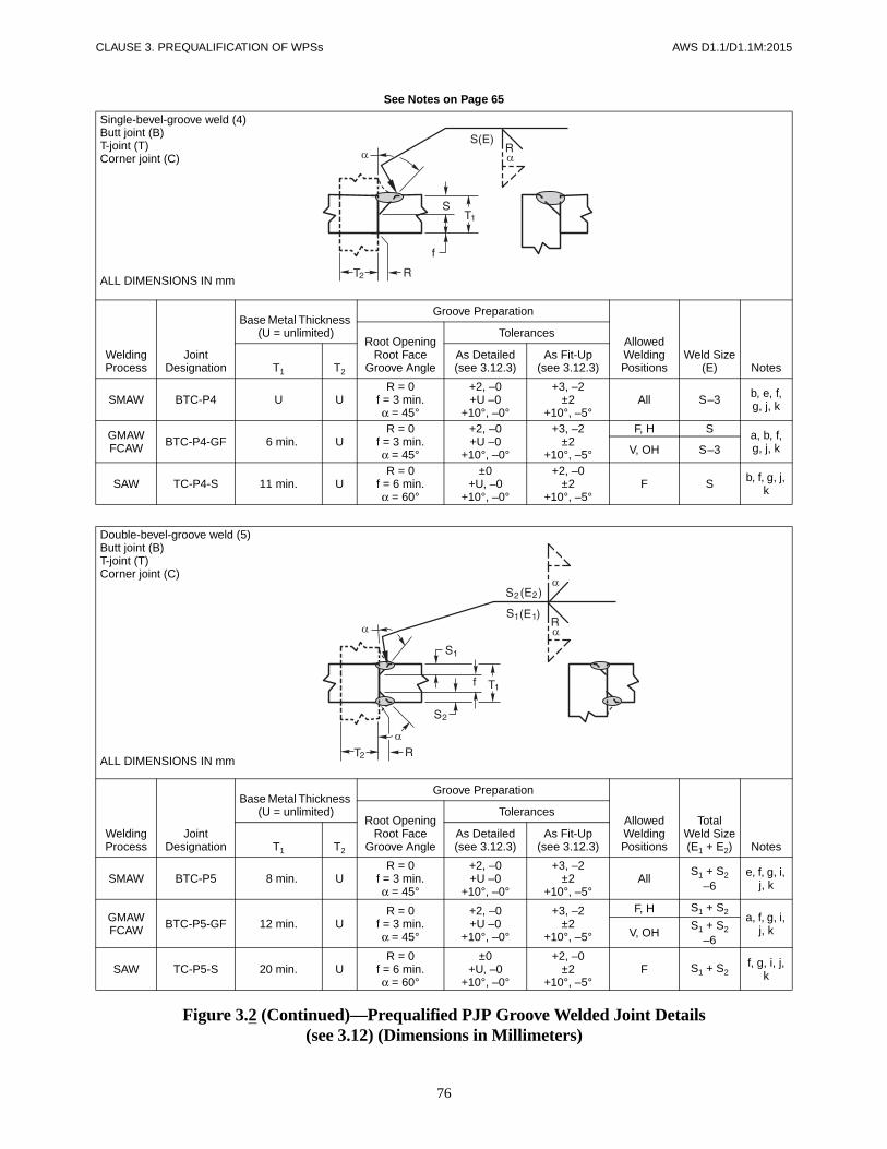
CLAUSE 3. PREQUALIFICATION OF WPSs AWS D1.1/D1.1M:2015
76
See Notes on Page 65
Figure 3.2 (Continued)—Prequalified PJP Groove Welded Joint Details(see 3.12) (Dimensions in Millimeters)
Single-bevel-groove weld (4)Butt joint (B)T-joint (T)Corner joint (C)
ALL DIMENSIONS IN mm
Welding Process
Joint Designation
Base Metal Thickness (U = unlimited)
Groove Preparation
Allowed Welding Positions
Weld Size(E) Notes
Root OpeningRoot Face
Groove Angle
Tolerances
T1 T2
As Detailed(see 3.12.3)
As Fit-Up(see 3.12.3)
SMAW BTC-P4 U UR = 0
f = 3 min.α = 45°
+2, –0+U –0
+10°, –0°
+3, –2±2
+10°, –5°All S–3 b, e, f,
g, j, k
GMAWFCAW BTC-P4-GF 6 min. U
R = 0f = 3 min.α = 45°
+2, –0+U –0
+10°, –0°
+3, –2±2
+10°, –5°
F, H S a, b, f, g, j, kV, OH S–3
SAW TC-P4-S 11 min. UR = 0
f = 6 min.α = 60°
±0+U, –0
+10°, –0°
+2, –0±2
+10°, –5°F S b, f, g, j,
k
Double-bevel-groove weld (5)Butt joint (B)T-joint (T)Corner joint (C)
ALL DIMENSIONS IN mm
Welding Process
Joint Designation
Base Metal Thickness (U = unlimited)
Groove Preparation
Allowed Welding Positions
TotalWeld Size(E1 + E2) Notes
Root OpeningRoot Face
Groove Angle
Tolerances
T1 T2
As Detailed(see 3.12.3)
As Fit-Up(see 3.12.3)
SMAW BTC-P5 8 min. UR = 0
f = 3 min.α = 45°
+2, –0+U –0
+10°, –0°
+3, –2±2
+10°, –5°All
S1 + S2
–6e, f, g, i,
j, k
GMAWFCAW BTC-P5-GF 12 min. U
R = 0f = 3 min.α = 45°
+2, –0+U –0
+10°, –0°
+3, –2±2
+10°, –5°
F, H S1 + S2a, f, g, i,
j, kV, OHS1 + S2
–6
SAW TC-P5-S 20 min. UR = 0
f = 6 min.α = 60°
±0+U, –0
+10°, –0°
+2, –0±2
+10°, –5°F S1 + S2
f, g, i, j, k
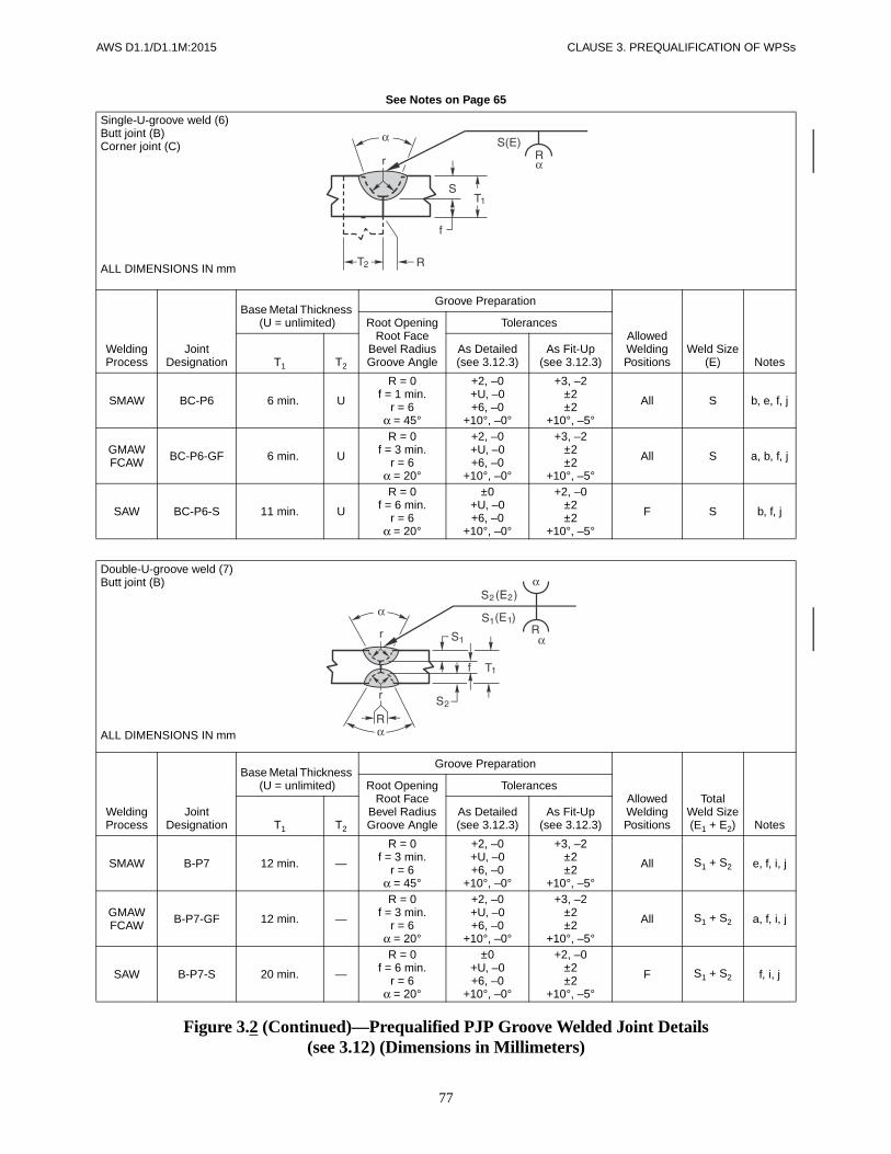
AWS D1.1/D1.1M:2015 CLAUSE 3. PREQUALIFICATION OF WPSs
77
See Notes on Page 65
Figure 3.2 (Continued)—Prequalified PJP Groove Welded Joint Details(see 3.12) (Dimensions in Millimeters)
Single-U-groove weld (6)Butt joint (B)Corner joint (C)
ALL DIMENSIONS IN mm
Welding Process
Joint Designation
Base Metal Thickness (U = unlimited)
Groove Preparation
Allowed Welding Positions
Weld Size(E) Notes
Root OpeningRoot Face
Bevel RadiusGroove Angle
Tolerances
T1 T2
As Detailed(see 3.12.3)
As Fit-Up(see 3.12.3)
SMAW BC-P6 6 min. U
R = 0f = 1 min.
r = 6α = 45°
+2, –0+U, –0+6, –0
+10°, –0°
+3, –2±2±2
+10°, –5°
All S b, e, f, j
GMAWFCAW BC-P6-GF 6 min. U
R = 0f = 3 min.
r = 6α = 20°
+2, –0+U, –0+6, –0
+10°, –0°
+3, –2±2±2
+10°, –5°
All S a, b, f, j
SAW BC-P6-S 11 min. U
R = 0f = 6 min.
r = 6α = 20°
±0+U, –0+6, –0
+10°, –0°
+2, –0±2±2
+10°, –5°
F S b, f, j
Double-U-groove weld (7)Butt joint (B)
ALL DIMENSIONS IN mm
Welding Process
Joint Designation
Base Metal Thickness (U = unlimited)
Groove Preparation
Allowed Welding Positions
TotalWeld Size(E1 + E2) Notes
Root OpeningRoot Face
Bevel RadiusGroove Angle
Tolerances
T1 T2
As Detailed(see 3.12.3)
As Fit-Up(see 3.12.3)
SMAW B-P7 12 min. —
R = 0f = 3 min.
r = 6α = 45°
+2, –0+U, –0+6, –0
+10°, –0°
+3, –2±2±2
+10°, –5°
All S1 + S2 e, f, i, j
GMAWFCAW B-P7-GF 12 min. —
R = 0f = 3 min.
r = 6α = 20°
+2, –0+U, –0+6, –0
+10°, –0°
+3, –2±2±2
+10°, –5°
All S1 + S2 a, f, i, j
SAW B-P7-S 20 min. —
R = 0f = 6 min.
r = 6α = 20°
±0+U, –0+6, –0
+10°, –0°
+2, –0±2±2
+10°, –5°
F S1 + S2 f, i, j
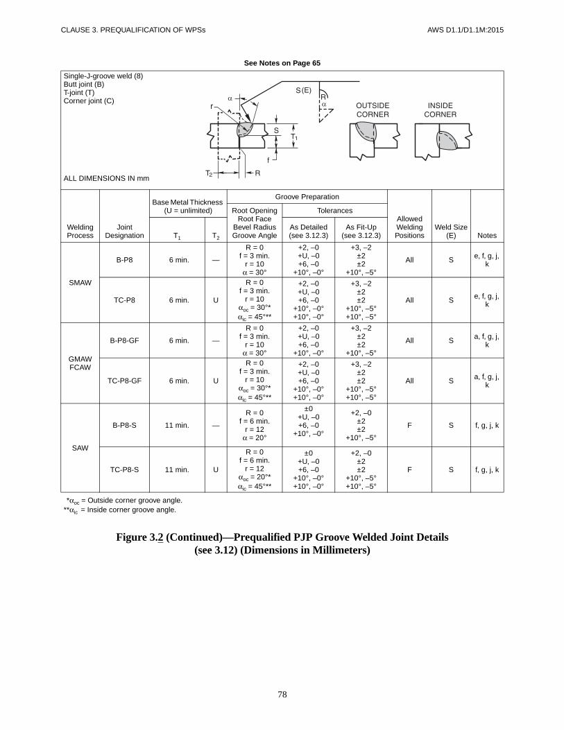
CLAUSE 3. PREQUALIFICATION OF WPSs AWS D1.1/D1.1M:2015
78
See Notes on Page 65
Figure 3.2 (Continued)—Prequalified PJP Groove Welded Joint Details(see 3.12) (Dimensions in Millimeters)
Single-J-groove weld (8)Butt joint (B)T-joint (T)Corner joint (C)
ALL DIMENSIONS IN mm
Welding Process
Joint Designation
Base Metal Thickness (U = unlimited)
Groove Preparation
Allowed Welding Positions
Weld Size(E) Notes
Root OpeningRoot Face
Bevel RadiusGroove Angle
Tolerances
T1 T2
As Detailed(see 3.12.3)
As Fit-Up(see 3.12.3)
SMAW
B-P8 6 min. —
R = 0f = 3 min.
r = 10α = 30°
+2, –0+U, –0+6, –0
+10°, –0°
+3, –2±2±2
+10°, –5°
All S e, f, g, j, k
TC-P8 6 min. U
R = 0f = 3 min.
r = 10αoc = 30°*αic = 45°**
+2, –0+U, –0+6, –0
+10°, –0°+10°, –0°
+3, –2±2±2
+10°, –5°+10°, –5°
All S e, f, g, j, k
GMAWFCAW
B-P8-GF 6 min. —
R = 0f = 3 min.
r = 10α = 30°
+2, –0+U, –0+6, –0
+10°, –0°
+3, –2±2±2
+10°, –5°
All S a, f, g, j, k
TC-P8-GF 6 min. U
R = 0f = 3 min.
r = 10αoc = 30°*αic = 45°**
+2, –0+U, –0+6, –0
+10°, –0°+10°, –0°
+3, –2±2±2
+10°, –5°+10°, –5°
All S a, f, g, j, k
SAW
B-P8-S 11 min. —
R = 0f = 6 min.
r = 12α = 20°
±0+U, –0+6, –0
+10°, –0°
+2, –0±2±2
+10°, –5°
F S f, g, j, k
TC-P8-S 11 min. U
R = 0f = 6 min.
r = 12αoc = 20°*αic = 45°**
±0+U, –0+6, –0
+10°, –0°+10°, –0°
+2, –0±2±2
+10°, –5°+10°, –5°
F S f, g, j, k
**αoc = Outside corner groove angle.**αic = Inside corner groove angle.
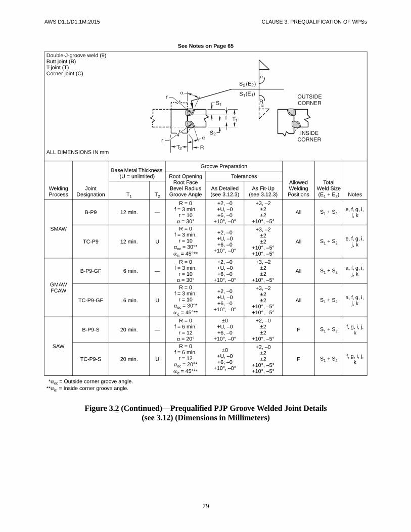
AWS D1.1/D1.1M:2015 CLAUSE 3. PREQUALIFICATION OF WPSs
79
See Notes on Page 65
Figure 3.2 (Continued)—Prequalified PJP Groove Welded Joint Details(see 3.12) (Dimensions in Millimeters)
Double-J-groove weld (9)Butt joint (B)T-joint (T)Corner joint (C)
ALL DIMENSIONS IN mm
Welding Process
Joint Designation
Base Metal Thickness (U = unlimited)
Groove Preparation
Allowed Welding Positions
TotalWeld Size(E1 + E2) Notes
Root OpeningRoot Face
Bevel RadiusGroove Angle
Tolerances
T1 T2
As Detailed(see 3.12.3)
As Fit-Up(see 3.12.3)
SMAW
B-P9 12 min. —
R = 0f = 3 min.
r = 10α = 30°
+2, –0+U, –0+6, –0
+10°, –0°
+3, –2±2±2
+10°, –5°
All S1 + S2e, f, g, i,
j, k
TC-P9 12 min. U
R = 0f = 3 min.
r = 10αoc = 30°*αic = 45°**
+2, –0+U, –0+6, –0
+10°, –0°
+3, –2±2±2
+10°, –5°+10°, –5°
All S1 + S2e, f, g, i,
j, k
GMAWFCAW
B-P9-GF 6 min. —
R = 0f = 3 min.
r = 10α = 30°
+2, –0+U, –0+6, –0
+10°, –0°
+3, –2±2±2
+10°, –5°
All S1 + S2a, f, g, i,
j, k
TC-P9-GF 6 min. U
R = 0f = 3 min.
r = 10αoc = 30°*αic = 45°**
+2, –0+U, –0+6, –0
+10°, –0°
+3, –2±2±2
+10°, –5°+10°, –5°
All S1 + S2a, f, g, i,
j, k
SAW
B-P9-S 20 min. —
R = 0f = 6 min.
r = 12α = 20°
±0+U, –0+6, –0
+10°, –0°
+2, –0±2±2
+10°, –5°
F S1 + S2f, g, i, j,
k
TC-P9-S 20 min. U
R = 0f = 6 min.
r = 12αoc = 20°*αic = 45°**
±0+U, –0+6, –0
+10°, –0°
+2, –0±2±2
+10°, –5°+10°, –5°
F S1 + S2f, g, i, j,
k
**αoc = Outside corner groove angle.**αic = Inside corner groove angle.

CLAUSE 3. PREQUALIFICATION OF WPSs AWS D1.1/D1.1M:2015
80
See Notes on Page 65
Figure 3.2 (Continued)—Prequalified PJP Groove Welded Joint Details(see 3.12) (Dimensions in Millimeters)
Flare-bevel-groove weld (10)Butt joint (B)T-joint (T)Corner joint (C)
ALL DIMENSIONS IN mm
Welding Process
Joint Designation
Base Metal Thickness (U = unlimited)
Groove Preparation
Allowed Welding Positions
Weld Size(E) Notes
Root OpeningRoot Face
Bend Radius
Tolerances
T1 T2 T3
As Detailed(see 3.12.3)
As Fit-Up(see 3.12.3)
SMAWFCAW-S BTC-P10 5
min. UT1
min.
R = 0f = 5 min.
r = min.
+2, –0+U, –0
+U, –0
+3, –2+U, –2
+U, –0All 5/16 r e, g, j, l
GMAWFCAW-G BTC-P10-GF 5
min. UT1
min.
R = 0f = 5 min.
r = min.
+2, –0+U, –0
+U, –0
+3, –2+U, –2
+U, –0All 5/8 r a, g, j, l,
m
SAW B-P10-S 12 min.
12 min. N/A
R = 0f = 12 min.
r = min.
±0+U, –0
+U, –0
+2, –0+U, –2
+U, –0F 5/16 r g, j, l, m
3T1
2----------
3T1
2----------
3T1
2----------

AWS D1.1/D1.1M:2015 CLAUSE 3. PREQUALIFICATION OF WPSs
81
See Notes on Page 65
Figure 3.2 (Continued)—Prequalified PJP Groove Welded Joint Details(see 3.12) (Dimensions in Millimeters)
Flare-V-groove weld (11)Butt joint (B)
Welding Process
Joint Designation
Base Metal Thickness (U = unlimited)
Groove Preparation
Allowed Welding Positions
Weld Size(E) Notes
Root OpeningRoot Face
Bend Radius
Tolerances
T1 T2
As Detailed(see 3.12.3)
As Fit-Up(see 3.12.3)
SMAWFCAW-S B-P11 5 min. T1 min.
R = 0f = 5 min.
r = min.
+2, –0+U, –0+U, –0
+3, –2+U, –2+U, –0
All 5/8 r e, j, l, m, n
GMAWFCAW-G B-P11-GF 5 min. T1 min.
R = 0f = 5 min.
r = min.
+2, –0+U, –0+U, –0
+3, –2+U, –2+U, –0
All 3/4 r a, j, l, m, n
SAW B-P11-S 12 min. T1 min.
R = 0f = 12 min.
r = min.
±0+U, –0+U, –0
+2, –0+U, –2+U, –0
F 1/2 r j, l, m, n
3T1
2----------
3T1
2----------
3T1
2----------

CLAUSE 3. PREQUALIFICATION OF WPSs AWS D1.1/D1.1M:2015
82
See Notes on Page 65
Figure 3.3—Prequalified CJP Groove Welded Joint Details(see 3.13) (Dimensions in Inches)
Square-groove weld (1)Butt joint (B)Corner joint (C)
Welding Process
Joint Designation
Base Metal Thickness (U = unlimited)
Groove Preparation
Allowed Welding Positions
Gas Shielding for FCAW NotesRoot Opening
Tolerances
T1 T2
As Detailed(see 3.13.1)
As Fit-Up(see 3.13.1)
SMAWB-L1a 1/4 max. — R = T1 +1/16, –0 +1/4, –1/16 All — e, j
C-L1a 1/4 max. U R = T1 +1/16, –0 +1/4, –1/16 All — e, j
FCAWGMAW B-L1a-GF 3/8 max. — R = T1 +1/16, –0 +1/4, –1/16 All Not
required a, j
Square-groove weld (1)Butt joint (B)
Welding Process
Joint Designation
Base Metal Thickness (U = unlimited)
Groove Preparation
Allowed Welding Positions
Gas Shielding for FCAW NotesRoot Opening
Tolerances
T1 T2
As Detailed(see 3.13.1)
As Fit-Up(see 3.13.1)
SMAW B-L1b 1/4 max. — R = +1/16, –0 +1/16, –1/8 All — d, e, j
GMAWFCAW B-L1b-GF 3/8 max. — R = 0 to 1/8 +1/16, –0 +1/16, –1/8 All Not
required a, d, j
SAW B-L1-S 3/8 max. — R = 0 ±0 +1/16, –0 F — jSAW B-L1a-S 5/8 max. — R = 0 ±0 +1/16, –0 F — d, j
T1
2------

AWS D1.1/D1.1M:2015 CLAUSE 3. PREQUALIFICATION OF WPSs
83
See Notes on Page 65
Figure 3.3 (Continued)—Prequalified CJP Groove Welded Joint Details(see 3.13) (Dimensions in Inches)
Square-groove weld (1)T-joint (T)Corner joint (C)
Welding Process
Joint Designation
Base Metal Thickness (U = unlimited)
Groove Preparation
Allowed Welding Positions
Gas Shielding for FCAW NotesRoot Opening
Tolerances
T1 T2
As Detailed(see 3.13.1)
As Fit-Up(see 3.13.1)
SMAW TC-L1b 1/4 max. U R = +1/16, –0 +1/16, –1/8 All — d, e, g
GMAWFCAW TC-L1-GF 3/8 max. U R = 0 to 1/8 +1/16, –0 +1/16, –1/8 All Not
required a, d, g
SAW TC-L1-S 3/8 max. U R = 0 ±0 +1/16, –0 F — d, g
Single-V-groove weld (2)Butt joint (B)
Tolerances
As Detailed(see 3.13.1)
As Fit-Up(see 3.13.1)
R = +1/16, –0 +1/4, –1/16α = +10°, –0° +10°, –5°
Welding Process
Joint Designation
Base Metal Thickness (U = unlimited) Groove Preparation Allowed
Welding Positions
Gas Shielding for FCAW NotesT1 T2 Root Opening Groove Angle
SMAW B-U2a U —R = 1/4 α = 45° All — e, jR = 3/8 α = 30° F, V, OH — e, jR = 1/2 α = 20° F, V, OH — e, j
GMAWFCAW B-U2a-GF U —
R = 3/16 α = 30° F, V, OH Required a, jR = 3/8 α = 30° F, V, OH Not req. a, jR = 1/4 α = 45° F, V, OH Not req. a, j
SAW B-L2a-S 2 max. — R = 1/4 α = 30° F — jSAW B-U2-S U — R = 5/8 α = 20° F — j
T1
2------
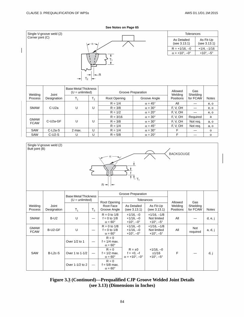
CLAUSE 3. PREQUALIFICATION OF WPSs AWS D1.1/D1.1M:2015
84
See Notes on Page 65
Figure 3.3 (Continued)—Prequalified CJP Groove Welded Joint Details(see 3.13) (Dimensions in Inches)
Single-V-groove weld (2)Corner joint (C)
Tolerances
As Detailed(see 3.13.1)
As Fit-Up(see 3.13.1)
R = +1/16, –0 +1/4, –1/16α = +10°, –0° +10°, –5°
Welding Process
Joint Designation
Base Metal Thickness (U = unlimited) Groove Preparation Allowed
Welding Positions
Gas Shielding for FCAW NotesT1 T2 Root Opening Groove Angle
SMAW C-U2a U UR = 1/4 α = 45° All — e, oR = 3/8 α = 30° F, V, OH — e, oR = 1/2 α = 20° F, V, OH — e, o
GMAWFCAW C-U2a-GF U U
R = 3/16 α = 30° F, V, OH Required a
R = 3/8 α = 30° F, V, OH Not req. a, oR = 1/4 α = 45° F, V, OH Not req. a, o
SAW C-L2a-S 2 max. U R = 1/4 α = 30° F — oSAW C-U2-S U U R = 5/8 α = 20° F — o
Single-V-groove weld (2)Butt joint (B)
Welding Process
Joint Designation
Base Metal Thickness (U = unlimited)
Groove Preparation
Allowed Welding Positions
Gas Shielding for FCAW Notes
Root OpeningRoot Face
Groove Angle
Tolerances
T1 T2
As Detailed(see 3.13.1)
As Fit-Up(see 3.13.1)
SMAW B-U2 U —R = 0 to 1/8f = 0 to 1/8
α = 60°
+1/16, –0+1/16, –0+10°, –0°
+1/16, –1/8Not limited+10°, –5°
All — d, e, j
GMAWFCAW B-U2-GF U —
R = 0 to 1/8f = 0 to 1/8
α = 60°
+1/16, –0+1/16, –0+10°, –0°
+1/16, –1/8Not limited+10°, –5°
All Not required a, d, j
SAW B-L2c-S
Over 1/2 to 1-1 —R = 0
f = 1/4 max.α = 60°
R = ±0f = +0, –f
α = +10°, –0°
+1/16, –0±1/16
+10°, –5°F — d, jOver 1 to 1-1/2 —
R = 0f = 1/2 max.
α = 60°
Over 1-1/2 to 2 —R = 0
f = 5/8 max.α = 60°

AWS D1.1/D1.1M:2015 CLAUSE 3. PREQUALIFICATION OF WPSs
85
See Notes on Page 65
Figure 3.3 (Continued)—Prequalified CJP Groove Welded Joint Details(see 3.13) (Dimensions in Inches)
Single-V-groove weld (2)Corner joint (C)
Welding Process
Joint Designation
Base Metal Thickness (U = unlimited)
Groove Preparation
Allowed Welding Positions
Gas Shielding for FCAW Notes
Root OpeningRoot Face
Groove Angle
Tolerances
T1 T2
As Detailed(see 3.13.1)
As Fit-Up(see 3.13.1)
SMAW C-U2 U UR = 0 to 1/8f = 0 to 1/8
α = 60°
+1/16, –0+1/16, –0+10°, –0°
+1/16, –1/8Not limited+10°, –5°
All — d, e, g, j
GMAWFCAW C-U2-GF U U
R = 0 to 1/8f = 0 to 1/8
α = 60°
+1/16, –0+1/16, –0+10°, –0°
+1/16, –1/8Not limited+10°, –5°
All Not required a, d, g, j
SAW C-U2b-S U UR = 0 to 1/8f = 1/4 max.
α = 60°
±0+0, –1/4+10°, –0°
+1/16, –0±1/16
+10°, –5°F — d, g, j
Double-V-groove weld (3)Butt joint (B)
Tolerances
As Detailed(see 3.13.1)
As Fit-Up(see 3.13.1)
R = ±0 +1/4, –0f = ±0 +1/16, –0
α = +10°, –0° +10°, –5°
SpacerSAW ±0 +1/16, –0
SMAW ±0 +1/8, –0
Welding Process
Joint Designation
Base Metal Thickness (U = unlimited) Groove Preparation
Allowed Welding Positions
Gas Shielding for FCAW NotesT1 T2 Root Opening Root Face
Groove Angle
SMAW B-U3aU
Spacer =1/8 × R
—R = 1/4 f = 0 to 1/8 α = 45° All —
d, e, h, jR = 3/8 f = 0 to 1/8 α = 30° F, V, OH —
R = 1/2 f = 0 to 1/8 α = 20° F, V, OH —
SAW B-U3a-SU
Spacer =1/4 × R
— R = 5/8 f = 0 to 1/4 α = 20° F — d, h, j

CLAUSE 3. PREQUALIFICATION OF WPSs AWS D1.1/D1.1M:2015
86
See Notes on Page 65
Figure 3.3 (Continued)—Prequalified CJP Groove Welded Joint Details(see 3.13) (Dimensions in Inches)
Double-V-groove weld (3)Butt joint (B)
For B-U3c-S only
T1 S1
Over to2 2-1/2 1-3/8
2-1/2 3 1-3/43 3-5/8 2-1/8
3-5/8 4 2-3/84 4-3/4 2-3/4
4-3/4 5-1/2 3-1/45-1/2 6-1/4 3-3/4
For T1 > 6-1/4 or T1 ≤ 2S1 = 2/3 (T1 – 1/4)
Welding Process
Joint Designation
Base Metal Thickness (U = unlimited)
Groove Preparation
Allowed Welding Positions
Gas Shielding for FCAW Notes
Root OpeningRoot Face
Groove Angle
Tolerances
T1 T2
As Detailed(see 3.13.1)
As Fit-Up(see 3.13.1)
SMAW B-U3bU —
R = 0 to 1/8f = 0 to 1/8α = β = 60°
+1/16, –0+1/16, –0+10°, –0°
+1/16, –1/8Not limited+10°, –5°
All — d, e, h, jGMAWFCAW B-U3-GF All Not
required a, d, h, j
SAW B-U3c-S U —
R = 0f = 1/4 min.α = β = 60°
+1/16, –0+1/4, –0+10°, –0°
+1/16, –0+1/4, –0+10°, –5° F — d, h, j
To find S1 see table above: S2 = T1 – (S1 + f)
Tolerances
As Detailed(see 3.13.1)
As Fit-Up(see 3.13.1)
R = +1/16, –0 +1/4, –1/16α = +10°, –0° +10°, –5°
Welding Process
Joint Designation
Base Metal Thickness (U = unlimited) Groove Preparation Allowed
Welding Positions
Gas Shielding for FCAW NotesT1 T2 Root Opening Groove Angle
SMAW B-U4a U —R = 1/4 α = 45° All — c, e, jR = 3/8 α = 30° All — c, e, j
GMAWFCAW B-U4a-GF U —
R = 3/16 α = 30° All Required a, c, jR = 1/4 α = 45° All Not req. a, c, jR = 3/8 α = 30° F, H Not req. a, c, j
SAW B-U4a-S U —R = 3/8 α = 30°
F — c, jR = 1/4 α = 45°
Single-bevel-groove weld (4)Butt joint (B)

AWS D1.1/D1.1M:2015 CLAUSE 3. PREQUALIFICATION OF WPSs
87
See Notes on Page 65
Figure 3.3 (Continued)—Prequalified CJP Groove Welded Joint Details(see 3.13) (Dimensions in Inches)
Tolerances
As Detailed(see 3.13.1)
As Fit-Up(see 3.13.1)
R = +1/16, –0 +1/4, –1/16α = +10°, –0° +10°, –5°
Welding Process
Joint Designation
Base Metal Thickness (U = unlimited) Groove Preparation Allowed
Welding Positions
Gas Shielding for FCAW NotesT1 T2 Root Opening Groove Angle
SMAW TC-U4a U UR = 1/4 α = 45° All — e, g, k,
o
R = 3/8 α = 30° F, V, OH — e, g, k, o
GMAWFCAW TC-U4a-GF U U
R = 3/16 α = 30° All Required a, g, k, o
R = 3/8 α = 30° F Not req. a, g, k, o
R = 1/4 α = 45° All Not req. a, g, k, o
SAW TC-U4a-S U UR = 3/8 α = 30°
F — g, k, oR = 1/4 α = 45°
Single-bevel-groove weld (4)Butt joint (B)
Welding Process
Joint Designation
Base Metal Thickness (U = unlimited)
Groove Preparation
Allowed Welding Positions
Gas Shielding for FCAW Notes
Root OpeningRoot Face
Groove Angle
Tolerances
T1 T2
As Detailed(see 3.13.1)
As Fit-Up(see 3.13.1)
SMAW B-U4b U — R = 0 to 1/8f = 0 to 1/8
α = 45°
+1/16, –0+1/16, –0+10°, –0°
+1/16, –1/8Not limited
10°, –5°
All — c, d, e, jGMAWFCAW B-U4b-GF U — All Not
required a, c, d, j
SAW B-U4b-S U —R = 0
f = 1/4 max.α = 60°
±0+0, –1/8+10°, –0°
+1/4, –0±1/16
10°, –5°F — c, d, j
Single-bevel-groove weld (4)T-joint (T)Corner joint (C)

CLAUSE 3. PREQUALIFICATION OF WPSs AWS D1.1/D1.1M:2015
88
See Notes on Page 65
Figure 3.3 (Continued)—Prequalified CJP Groove Welded Joint Details(see 3.13) (Dimensions in Inches)
Single-bevel-groove weld (4)T-joint (T)Corner joint (C)
Welding Process
Joint Designation
Base Metal Thickness (U = unlimited)
Groove Preparation
Allowed Welding Positions
Gas Shielding for FCAW Notes
Root OpeningRoot Face
Groove Angle
Tolerances
T1 T2
As Detailed(see 3.13.1)
As Fit-Up(see 3.13.1)
SMAW TC-U4b U U R = 0 to 1/8f = 0 to 1/8
α = 45°
+1/16, –0+1/16, –0+10°, –0°
+1/16, –1/8Not limited
10°, –5°
All — d, e, g, j, k
GMAWFCAW TC-U4b-GF U U All Not
requireda, d, g,
j, k
SAW TC-U4b-S U UR = 0
f = 1/4 max.α = 60°
±0+0, –1/8+10°, –0°
+1/4, –0±1/16
10°, –5°F — d, g, j, k
Tolerances
As Detailed(see 3.13.1)
As Fit-Up(see 3.13.1)
R = ±0 +1/4, –0f = +1/16, –0 ±1/16α = +10°, –0° +10°, –5°
Spacer +1/16, –0 +1/8, –0
Welding Process
Joint Designation
Base Metal Thickness (U = unlimited) Groove Preparation
Allowed Welding Positions
Gas Shielding for FCAW NotesT1 T2 Root Opening Root Face
Groove Angle
SMAW
B-U5bU
Spacer =1/8 × R
— R = 1/4 f = 0 to 1/8 α = 45° All — c, d, e, h, j
TC-U5aU
Spacer =1/4 × R
UR = 1/4 f = 0 to 1/8 α = 45° All — d, e, g,
h, j, k
R = 3/8 f = 0 to 1/8 α = 30° F, OH — d, e, g, h, j, k
Double-bevel-groove weld (5)Butt joint (B)T-joint (T)Corner joint (C)

AWS D1.1/D1.1M:2015 CLAUSE 3. PREQUALIFICATION OF WPSs
89
See Notes on Page 65
Figure 3.3 (Continued)—Prequalified CJP Groove Welded Joint Details(see 3.13) (Dimensions in Inches)
Double-bevel-groove weld (5)Butt joint (B)
Welding Process
Joint Designation
Base Metal Thickness (U = unlimited)
Groove Preparation
Allowed Welding Positions
Gas Shielding for FCAW Notes
Root OpeningRoot Face
Groove Angle
Tolerances
T1 T2
As Detailed(see 3.13.1)
As Fit-Up(see 3.13.1)
SMAW B-U5a U —
R = 0 to 1/8f = 0 to 1/8
α = 45°β = 0° to 15°
+1/16, –0+1/16, –0
+1/16, –1/8Not limited
All — c, d, e, h, j
GMAWFCAW B-U5-GF U —
R = 0 to 1/8f = 0 to 1/8
α = 45°β = 0° to 15°
+1/16, –0+1/16, –0
α + β =+10°, –0°
+1/16, –1/8Not limited
α + β =+10°, –5°
All Not required
a, c, d, h, j
Double-bevel-groove weld (5)T-joint (T)Corner joint (C)
Welding Process
Joint Designation
Base Metal Thickness (U = unlimited)
Groove Preparation
Allowed Welding Positions
Gas Shielding for FCAW Notes
Root OpeningRoot Face
Groove Angle
Tolerances
T1 T2
As Detailed(see 3.13.1)
As Fit-Up(see 3.13.1)
SMAW TC-U5b U U R = 0 to 1/8f = 0 to 1/8
α = 45°
+1/16, –0+1/16, –0+10°, –0°
+1/16, –1/8Not limited+10°, –5°
All — d, e, g, h, j, k
GMAWFCAW TC-U5-GF U U All Not
requireda, d, g, h, j, k
SAW TC-U5-S U UR = 0
f = 1/4 max.α = 60°
±0+0, –3/16+10°, –0°
+1/16, –0±1/16
+10°, –5°F — d, g, h,
j, k
α β+10° –0°
+ α β+10° –5°
+

CLAUSE 3. PREQUALIFICATION OF WPSs AWS D1.1/D1.1M:2015
90
See Notes on Page 65
Figure 3.3 (Continued)—Prequalified CJP Groove Welded Joint Details(see 3.13) (Dimensions in Inches)
Tolerances
As Detailed(see 3.13.1)
As Fit-Up(see 3.13.1)
R = +1/16, –0 +1/16, –1/8α = +10°, –0° +10°, –5°
f = ±1/16 Not Limitedr = +1/8, –0 +1/8, –0
Welding Process
Joint Designation
Base Metal Thickness (U = unlimited) Groove Preparation
Allowed Welding Positions
Gas Shielding for FCAW NotesT1 T2 Root Opening
Groove Angle
RootFace
Bevel Radius
SMAWB-U6 U —
R = 0 to 1/8 α = 45° f = 1/8 r = 1/4 All — d, e, jR = 0 to 1/8 α = 20° f = 1/8 r = 1/4 F, OH — d, e, j
C-U6 U UR = 0 to 1/8 α = 45° f = 1/8 r = 1/4 All — d, e, g, jR = 0 to 1/8 α = 20° f = 1/8 r = 1/4 F, OH — d, e, g, j
GMAWFCAW
B-U6-GF U — R = 0 to 1/8 α = 20° f = 1/8 r = 1/4 All Not req. a, d, jC-U6-GF U U R = 0 to 1/8 α = 20° f = 1/8 r = 1/4 All Not req. a, d, g, j
Double-U-groove weld (7)Butt joint (B)
Tolerances
As Detailed(see 3.13.1)
As Fit-Up(see 3.13.1)
For B-U7 and B-U7-GFR = +1/16, –0 +1/16, –1/8α = +10°, –0° +10°, –5°f = +1/16, –0 Not Limitedr = +1/4, –0 ±1/16
For B-U7-SR = +0 +1/16, –0
α = +10°, –0° +10°, –5°
f = +0, –1/4 ±1/16r = +1/4, –0 ±1/16
Welding Process
Joint Designation
Base Metal Thickness (U = unlimited) Groove Preparation
Allowed Welding Positions
Gas Shielding for FCAW NotesT1 T2
RootOpening
Groove Angle
RootFace
Bevel Radius
SMAW B-U7 U —R = 0 to 1/8 α = 45° f = 1/8 r = 1/4 All — d, e, h, jR = 0 to 1/8 α = 20° f = 1/8 r = 1/4 F, OH — d, e, h, j
GMAWFCAW B-U7-GF U — R = 0 to 1/8 α = 20° f = 1/8 r = 1/4 All Not
required a, d, j, h
SAW B-U7-S U — R = 0 α = 20° f = 1/4 max. r = 1/4 F — d, h, j
Single-U-groove weld (6)Butt joint (B)Corner joint (C)

AWS D1.1/D1.1M:2015 CLAUSE 3. PREQUALIFICATION OF WPSs
91
See Notes on Page 65
Figure 3.3 (Continued)—Prequalified CJP Groove Welded Joint Details(see 3.13) (Dimensions in Inches)
Single-J-groove weld (8)Butt joint (B)
Tolerances
As Detailed(see 3.13.1)
As Fit-Up(see 3.13.1)
B-U8 and B-U8-GFR = +1/16, –0 +1/16, –1/8α = +10°, –0° +10°, –5°f = +1/8, –0 Not Limitedr = +1/4, –0 ±1/16
B-U8-SR = ±0 +1/4, –0
α = +10°, –0° +10°, –5°f = +0, –1/8 ±1/16r = +1/4, –0 ±1/16
Welding Process
Joint Designation
Base Metal Thickness (U = unlimited) Groove Preparation
Allowed Welding Positions
Gas Shielding for FCAW NotesT1 T2
RootOpening
Groove Angle
RootFace
Bevel Radius
SMAW B-U8 U — R = 0 to 1/8 α = 45° f = 1/8 r = 3/8 All — c, d, e, jGMAWFCAW B-U8-GF U — R = 0 to 1/8 α = 30° f = 1/8 r = 3/8 All Not req. a, c, d, j
SAW B-U8-S U — R = 0 α = 45°f = 1/4 max. r = 3/8 F — c, d, j
Single-J-groove weld (8)T-joint (T)Corner joint (C)
Tolerances
As Detailed(see 3.13.1)
As Fit-Up(see 3.13.1)
TC-U8a and TC-U8a-GFR = +1/16, –0 +1/16, –1/8α = +10°, –0° +10°, –5°f = +1/16, –0 Not Limitedr = +1/4, –0 ±1/16
TC-U8a-SR = ±0 +1/4, –0
α = +10°, –0° +10°, –5°f = +0, –1/8 ±1/16r = +1/4, –0 ±1/16
Welding Process
Joint Designation
Base Metal Thickness (U = unlimited) Groove Preparation
Allowed Welding Positions
Gas Shielding for FCAW NotesT1 T2
RootOpening
Groove Angle
RootFace
Bevel Radius
SMAW TC-U8a U UR = 0 to 1/8 α = 45° f = 1/8 r = 3/8 All — d, e, g,
j, k
R = 0 to 1/8 α = 30° f = 1/8 r = 3/8 F, OH — d, e, g, j, k
GMAWFCAW TC-U8a-GF U U R = 0 to 1/8 α = 30° f = 1/8 r = 3/8 All Not
requireda, d, g,
j, k
SAW TC-U8a-S U U R = 0 α = 45°f = 1/4 max. r = 3/8 F — d, g, j, k

CLAUSE 3. PREQUALIFICATION OF WPSs AWS D1.1/D1.1M:2015
92
See Notes on Page 65
Figure 3.3 (Continued)—Prequalified CJP Groove Welded Joint Details(see 3.13) (Dimensions in Inches)
Double-J-groove weld (9)Butt joint (B)
Tolerances
As Detailed(see 3.13.1)
As Fit-Up(see 3.13.1)
R = +1/16, –0 +1/16, –1/8α = +10°, –0° +10°, –5°f = +1/16, –0 Not Limitedr = +1/8, –0 ±1/16
Welding Process
Joint Designation
Base Metal Thickness (U = unlimited) Groove Preparation
Allowed Welding Positions
Gas Shielding for FCAW NotesT1 T2
RootOpening
Groove Angle
RootFace
Bevel Radius
SMAW B-U9 U — R = 0 to 1/8 α = 45° f = 1/8 r = 3/8 All — c, d, e, h, j
GMAWFCAW B-U9-GF U — R = 0 to 1/8 α = 30° f = 1/8 r = 3/8 All Not
requireda, c, d,
h, j
Double-J-groove weld (9)T-joint (T)Corner joint (C)
Tolerances
As Detailed(see 3.13.1)
As Fit-Up(see 3.13.1)
R = +1/16, –0 +1/16, –1/8α = +10°, –0° +10°, –5°f = +1/16, –0 Not Limitedr = 1/8, –0 ±1/16
Welding Process
Joint Designation
Base Metal Thickness (U = unlimited) Groove Preparation
Allowed Welding Positions
Gas Shielding for FCAW NotesT1 T2
RootOpening
Groove Angle
RootFace
Bevel Radius
SMAW TC-U9a U UR = 0 to 1/8 α = 45° f = 1/8 r = 3/8 All — d, e, g,
h, j, k
R = 0 to 1/8 α = 30° f = 1/8 r = 3/8 F, OH — d, e, g, h, k
GMAWFCAW TC-U9a-GF U U R = 0 to 1/8 α = 30° f = 1/8 r = 3/8 All Not
requireda, d, g, h, j, k

AWS D1.1/D1.1M:2015 CLAUSE 3. PREQUALIFICATION OF WPSs
93
See Notes on Page 65
Figure 3.3 (Continued)—Prequalified CJP Groove Welded Joint Details(see 3.13) (Dimensions in Millimeters)
Square-groove weld (1)Butt joint (B)Corner joint (C)
ALL DIMENSIONS IN mm
Welding Process
Joint Designation
Base Metal Thickness (U = unlimited)
Groove Preparation
Allowed Welding Positions
Gas Shielding for FCAW NotesRoot Opening
Tolerances
T1 T2
As Detailed(see 3.13.1)
As Fit-Up(see 3.13.1)
SMAWB-L1a 6 max. — R = T1 +2, –0 +6, –2 All — e, j
C-L1a 6 max. U R = T1 +2, –0 +6, –2 All — e, j
FCAWGMAW B-L1a-GF 10 max. — R = T1 +2, –0 +6, –2 All Not
required a, j
Square-groove weld (1)Butt joint (B)
ALL DIMENSIONS IN mm
Welding Process
Joint Designation
Base Metal Thickness (U = unlimited)
Groove Preparation
Allowed Welding Positions
Gas Shielding for FCAW NotesRoot Opening
Tolerances
T1 T2
As Detailed(see 3.13.1)
As Fit-Up(see 3.13.1)
SMAW B-L1b 6 max. — R = +2, –0 +2, –3 All — d, e, j
GMAWFCAW B-L1b-GF 10 max. — R = 0 to 3 +2, –0 +2, –3 All Not
required a, d, j
SAW B-L1-S 10 max. — R = 0 ±0 +2, –0 F — jSAW B-L1a-S 16 max. — R = 0 ±0 +2, –0 F — d, j
T1
2------
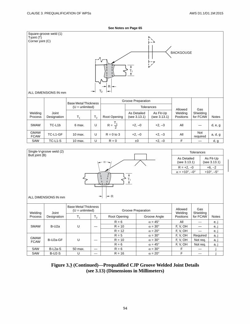
CLAUSE 3. PREQUALIFICATION OF WPSs AWS D1.1/D1.1M:2015
94
See Notes on Page 65
Figure 3.3 (Continued)—Prequalified CJP Groove Welded Joint Details(see 3.13) (Dimensions in Millimeters)
Square-groove weld (1)T-joint (T)Corner joint (C)
ALL DIMENSIONS IN mm
Welding Process
Joint Designation
Base Metal Thickness (U = unlimited)
Groove Preparation
Allowed Welding Positions
Gas Shielding for FCAW NotesRoot Opening
Tolerances
T1 T2
As Detailed(see 3.13.1)
As Fit-Up(see 3.13.1)
SMAW TC-L1b 6 max. U R = +2, –0 +2, –3 All — d, e, g
GMAWFCAW TC-L1-GF 10 max. U R = 0 to 3 +2, –0 +2, –3 All Not
required a, d, g
SAW TC-L1-S 10 max. U R = 0 ±0 +2, –0 F — d, g
Single-V-groove weld (2)Butt joint (B)
ALL DIMENSIONS IN mm
Tolerances
As Detailed(see 3.13.1)
As Fit-Up(see 3.13.1)
R = +2, –0 +6, –2α = +10°, –0° +10°, –5°
Welding Process
Joint Designation
Base Metal Thickness (U = unlimited) Groove Preparation Allowed
Welding Positions
Gas Shielding for FCAW NotesT1 T2 Root Opening Groove Angle
SMAW B-U2a U —R = 6 α = 45° All — e, jR = 10 α = 30° F, V, OH — e, jR = 12 α = 20° F, V, OH — e, j
GMAWFCAW B-U2a-GF U —
R = 5 α = 30° F, V, OH Required a, jR = 10 α = 30° F, V, OH Not req. a, jR = 6 α = 45° F, V, OH Not req. a, j
SAW B-L2a-S 50 max. — R = 6 α = 30° F — jSAW B-U2-S U — R = 16 α = 20° F — j
T1
2------

AWS D1.1/D1.1M:2015 CLAUSE 3. PREQUALIFICATION OF WPSs
95
See Notes on Page 65
Figure 3.3 (Continued)—Prequalified CJP Groove Welded Joint Details(see 3.13) (Dimensions in Millimeters)
Single-V-groove weld (2)Corner joint (C)
ALL DIMENSIONS IN mm
Tolerances
As Detailed(see 3.13.1)
As Fit-Up(see 3.13.1)
R = +2, –0 +6, –2α = +10°, –0° +10°, –5°
Welding Process
Joint Designation
Base Metal Thickness (U = unlimited) Groove Preparation Allowed
Welding Positions
Gas Shielding for FCAW NotesT1 T2 Root Opening Groove Angle
SMAW C-U2a U UR = 6 α = 45° All — e, oR = 10 α = 30° F, V, OH — e, oR = 12 α = 20° F, V, OH — e, o
GMAWFCAW C-U2a-GF U U
R = 5 α = 30° F, V, OH Required aR = 10 α = 30° F, V, OH Not req. a, oR = 6 α = 45° F, V, OH Not req. a, o
SAW C-L2a-S 50 max. U R = 6 α = 30° F — oSAW C-U2-S U U R = 16 α = 20° F — o
Single-V-groove weld (2)Butt joint (B)
ALL DIMENSIONS IN mm
Welding Process
Joint Designation
Base Metal Thickness (U = unlimited)
Groove Preparation
Allowed Welding Positions
Gas Shielding for FCAW Notes
Root OpeningRoot Face
Groove Angle
Tolerances
T1 T2
As Detailed(see 3.13.1)
As Fit-Up(see 3.13.1)
SMAW B-U2 U —R = 0 to 3f = 0 to 3α = 60°
+2, –0+2, –0
+10°, –0°
+2, –3Not limited+10°, –5°
All — d, e, j
GMAWFCAW B-U2-GF U —
R = 0 to 3f = 0 to 3α = 60°
+2, –0+2, –0
+10°, –0°
+2, –3Not limited+10°, –5°
All Not required a, d, j
SAW B-L2c-S
Over 12to 25 —
R = 0f = 6 max.
α = 60°R = ±0
f = +0, –fα = +10°, –0°
+2, –0±2
+10°, –5°F — d, jOver 25
to 38 —R = 0
f = 12 max.α = 60°
Over 38to 50 —
R = 0f = 16 max.
α = 60°

CLAUSE 3. PREQUALIFICATION OF WPSs AWS D1.1/D1.1M:2015
96
See Notes on Page 65
Figure 3.3 (Continued)—Prequalified CJP Groove Welded Joint Details(see 3.13) (Dimensions in Millimeters)
Single-V-groove weld (2)Corner joint (C)
ALL DIMENSIONS IN mm
Welding Process
Joint Designation
Base Metal Thickness (U = unlimited)
Groove Preparation
Allowed Welding Positions
Gas Shielding for FCAW Notes
Root OpeningRoot Face
Groove Angle
Tolerances
T1 T2
As Detailed(see 3.13.1)
As Fit-Up(see 3.13.1)
SMAW C-U2 U UR = 0 to 3f = 0 to 3α = 60°
+2, –0+2, –0
+10°, –0°
+2, –3Not limited+10°, –5°
All — d, e, g, j
GMAWFCAW C-U2-GF U U
R = 0 to 3f = 0 to 3α = 60°
+2, –0+2, –0
+10°, –0°
+2, –3Not limited+10°, –5°
All Not required a, d, g, j
SAW C-U2b-S U UR = 0 to 3f = 6 max.
α = 60°
±0+0, –6
+10°, –0°
+2, –0±2
+10°, –5°F — d, g, j
ALL DIMENSIONS IN mm
Tolerances
As Detailed(see 3.13.1)
As Fit-Up(see 3.13.1)
R = ±0 +6, –0f = ±0 +2, –0
α = +10°, –0° +10°, –5°
SpacerSAW ±0 +2, –0
SMAW ±0 +3, –0
Welding Process
Joint Designation
Base Metal Thickness (U = unlimited) Groove Preparation
Allowed Welding Positions
Gas Shielding for FCAW NotesT1 T2 Root Opening Root Face
Groove Angle
SMAW B-U3a USpacer = 1/8 × R —
R = 6 f = 0 to 3 α = 45° All —d, e, h,
jR = 10 f = 0 to 3 α = 30° F, V, OH —R = 12 f = 0 to 3 α = 20° F, V, OH —
SAW B-U3a-S USpacer = 1/4 × R — R = 16 f = 0 to 6 α = 20° F — d, h, j
Double-V-groove weld (3)Butt joint (B)

AWS D1.1/D1.1M:2015 CLAUSE 3. PREQUALIFICATION OF WPSs
97
See Notes on Page 65
Figure 3.3 (Continued)—Prequalified CJP Groove Welded Joint Details(see 3.13) (Dimensions in Millimeters)
Double-V-groove weld (3)Butt joint (B)
ALL DIMENSIONS IN mm
For B-U3c-S only
T1 S1
Over to50 60 3560 80 4580 90 5590 100 60
100 120 70120 140 80140 160 95
For T1 > 160 or T1 ≤ 50S1 = 2/3 (T1 – 6)
Welding Process
Joint Designation
Base Metal Thickness (U = unlimited)
Groove Preparation
Allowed Welding Positions
Gas Shielding for FCAW Notes
Root OpeningRoot Face
Groove Angle
Tolerances
T1 T2
As Detailed(see 3.13.1)
As Fit-Up(see 3.13.1)
SMAW B-U3bU —
R = 0 to 3f = 0 to 3
α = β = 60°
+2, –0+2, –0
+10°, –0°
+2, –3Not limited+10°, –5°
All — d, e, h, jGMAWFCAW B-U3-GF All Not
required a, d, h, j
SAW B-U3c-S U —
R = 0f = 6 min.
α = β = 60°
+2, –0+6, –0
+10°, –0°
+2, –0+6, –0
+10°, –5° F — d, h, j
To find S1 see table above: S2 = T1 – (S1 + f)
ALL DIMENSIONS IN mm
Tolerances
As Detailed(see 3.13.1)
As Fit-Up(see 3.13.1)
R = +2, –0 +6, –2α = +10°, –0° +10°, –5°
Welding Process
Joint Designation
Base Metal Thickness (U = unlimited) Groove Preparation Allowed
Welding Positions
Gas Shielding for FCAW NotesT1 T2 Root Opening Groove Angle
SMAW B-U4a U —R = 6 α = 45° All — c, e, jR = 10 α = 30° All — c, e, j
GMAWFCAW B-U4a-GF U —
R = 5 α = 30° All Required a, c, jR = 6 α = 45° All Not req. a, c, jR = 10 α = 30° F, H Not req. a, c, j
SAW B-U4a-S U —R = 10 α = 30°
F — c, jR = 6 α = 45°
Single-bevel-groove weld (4)Butt joint (B)

CLAUSE 3. PREQUALIFICATION OF WPSs AWS D1.1/D1.1M:2015
98
See Notes on Page 65
Figure 3.3 (Continued)—Prequalified CJP Groove Welded Joint Details(see 3.13) (Dimensions in Millimeters)
ALL DIMENSIONS IN mm
Tolerances
As Detailed(see 3.13.1)
As Fit-Up(see 3.13.1)
R = +2, –0 +6, –2α = +10°, –0° +10°, –5°
Welding Process
Joint Designation
Base Metal Thickness (U = unlimited) Groove Preparation Allowed
Welding Positions
Gas Shielding for FCAW NotesT1 T2 Root Opening Groove Angle
SMAW TC-U4a U UR = 6 α = 45° All — e, g, k,
o
R = 10 α = 30° F, V, OH — e, g, k, o
GMAWFCAW TC-U4a-GF U U
R = 5 α = 30° All Required a, g, k, o
R = 10 α = 30° F Not req. a, g, k, o
R = 6 α = 45° All Not req. a, g, k, o
SAW TC-U4a-S U UR = 10 α = 30°
F — g, k, oR = 6 α = 45°
Single-bevel-groove weld (4)Butt joint (B)
ALL DIMENSIONS IN mm
Welding Process
Joint Designation
Base Metal Thickness (U = unlimited)
Groove Preparation
Allowed Welding Positions
Gas Shielding for FCAW NotesRoot Opening
Tolerances
T1 T2
As Detailed(see 3.13.1)
As Fit-Up(see 3.13.1)
SMAW B-U4b U — R = 0 to 3f = 0 to 3α = 45°
+2, –0+2, –0
+10°, –0°
+2, –3Not limited
10°, –5°
All — c, d, e, jGMAWFCAW B-U4b-GF U — All Not
required a, c, d, j
SAW B-U4b-S U —R = 0
f = 6 max.α = 60°
±0+0, –3
+10°, –0°
+6, –0±2
10°, –5°F — c, d, j
Single-bevel-groove weld (4)T-joint (T)Corner joint (C)

AWS D1.1/D1.1M:2015 CLAUSE 3. PREQUALIFICATION OF WPSs
99
See Notes on Page 65
Figure 3.3 (Continued)—Prequalified CJP Groove Welded Joint Details(see 3.13) (Dimensions in Millimeters)
Single-bevel-groove weld (4)T-joint (T)Corner joint (C)
ALL DIMENSIONS IN mm
Welding Process
Joint Designation
Base Metal Thickness (U = unlimited)
Groove Preparation
Allowed Welding Positions
Gas Shielding for FCAW Notes
Root OpeningRoot Face
Groove Angle
Tolerances
T1 T2
As Detailed(see 3.13.1)
As Fit-Up(see 3.13.1)
SMAW TC-U4b U U R = 0 to 3f = 0 to 3α = 45°
+2, –0+2, –0
+10°, –0°
+2, –3Not limited
10°, –5°
All — d, e, g, j, k
GMAWFCAW TC-U4b-GF U U All Not
requireda, d, g,
j, k
SAW TC-U4b-S U UR = 0
f = 6 max.α = 60°
±0+0, –3
+10°, –0°
+6, –0±2
10°, –5°F — d, g, j, k
ALL DIMENSIONS IN mm
Tolerances
As Detailed(see 3.13.1)
As Fit-Up(see 3.13.1)
R = ±0 +6, –0f = +2, –0 ±2
α = +10°, –0° +10°, –5°Spacer +2, –0 +3, –0
Welding Process
Joint Designation
Base Metal Thickness (U = unlimited) Groove Preparation
Allowed Welding Positions
Gas Shielding for FCAW NotesT1 T2 Root Opening Root Face
Groove Angle
SMAW
B-U5b USpacer = 1/8 × R — R = 6 f = 0 to 3 α = 45° All — c, d, e,
h, j
TC-U5a USpacer = 1/4 × R U
R = 6 f = 0 to 3 α = 45° All — d, e, g, h, j, k
R = 10 f = 0 to 3 α = 30° F, OH — d, e, g, h, j, k
Double-bevel-groove weld (5)Butt joint (B)T-joint (T)Corner joint (C)
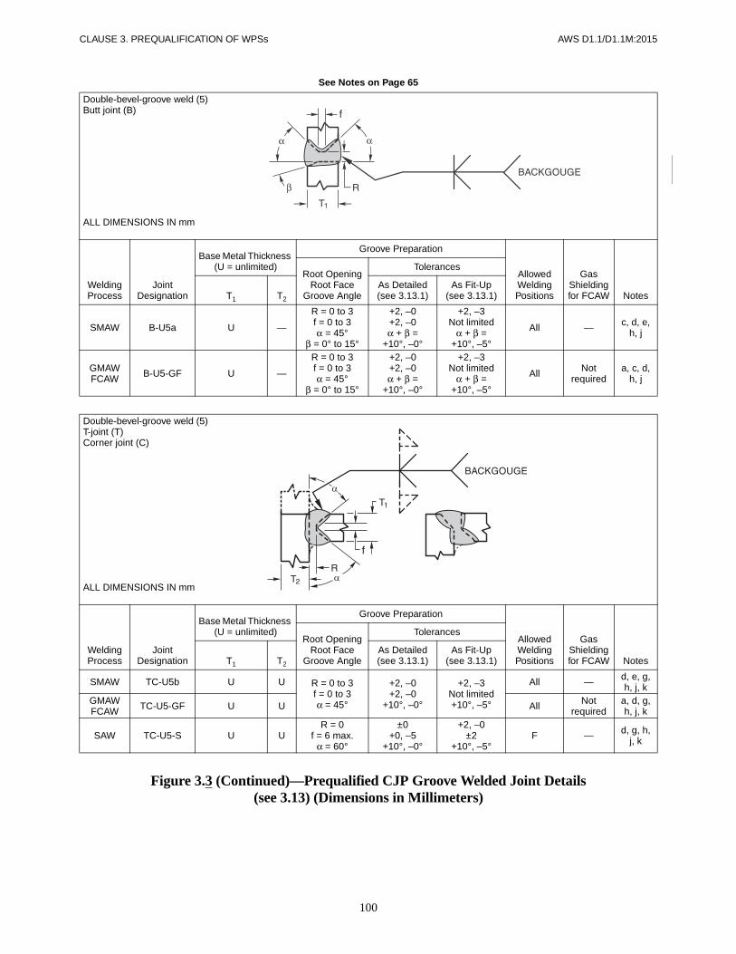
CLAUSE 3. PREQUALIFICATION OF WPSs AWS D1.1/D1.1M:2015
100
See Notes on Page 65
Figure 3.3 (Continued)—Prequalified CJP Groove Welded Joint Details(see 3.13) (Dimensions in Millimeters)
Double-bevel-groove weld (5)Butt joint (B)
ALL DIMENSIONS IN mm
Welding Process
Joint Designation
Base Metal Thickness (U = unlimited)
Groove Preparation
Allowed Welding Positions
Gas Shielding for FCAW Notes
Root OpeningRoot Face
Groove Angle
Tolerances
T1 T2
As Detailed(see 3.13.1)
As Fit-Up(see 3.13.1)
SMAW B-U5a U —
R = 0 to 3f = 0 to 3α = 45°
β = 0° to 15°
+2, –0+2, –0α + β =
+10°, –0°
+2, –3Not limited
α + β =+10°, –5°
All — c, d, e, h, j
GMAWFCAW B-U5-GF U —
R = 0 to 3f = 0 to 3α = 45°
β = 0° to 15°
+2, –0+2, –0α + β =
+10°, –0°
+2, –3Not limited
α + β =+10°, –5°
All Not required
a, c, d, h, j
Double-bevel-groove weld (5)T-joint (T)Corner joint (C)
ALL DIMENSIONS IN mm
Welding Process
Joint Designation
Base Metal Thickness (U = unlimited)
Groove Preparation
Allowed Welding Positions
Gas Shielding for FCAW Notes
Root OpeningRoot Face
Groove Angle
Tolerances
T1 T2
As Detailed(see 3.13.1)
As Fit-Up(see 3.13.1)
SMAW TC-U5b U U R = 0 to 3f = 0 to 3α = 45°
+2, –0+2, –0
+10°, –0°
+2, –3Not limited+10°, –5°
All — d, e, g, h, j, k
GMAWFCAW TC-U5-GF U U All Not
requireda, d, g, h, j, k
SAW TC-U5-S U UR = 0
f = 6 max.α = 60°
±0+0, –5
+10°, –0°
+2, –0±2
+10°, –5°F — d, g, h,
j, k

AWS D1.1/D1.1M:2015 CLAUSE 3. PREQUALIFICATION OF WPSs
101
See Notes on Page 65
Figure 3.3 (Continued)—Prequalified CJP Groove Welded Joint Details(see 3.13) (Dimensions in Millimeters)
ALL DIMENSIONS IN mm
Tolerances
As Detailed(see 3.13.1)
As Fit-Up(see 3.13.1)
R = +2, –0 +2, –3α = +10°, –0° +10°, –5°
f = ±2 Not Limitedr = +3, –0 +3, –0
Welding Process
Joint Designation
Base Metal Thickness (U = unlimited) Groove Preparation
Allowed Welding Positions
Gas Shielding for FCAW NotesT1 T2 Root Opening
Groove Angle
RootFace
Bevel Radius
SMAWB-U6 U —
R = 0 to 3 α = 45° f = 3 r = 6 All — d, e, jR = 0 to 3 α = 20° f = 3 r = 6 F, OH — d, e, j
C-U6 U UR = 0 to 3 α = 45° f = 3 r = 6 All — d, e, g, jR = 0 to 3 α = 20° f = 3 r = 6 F, OH — d, e, g, j
GMAWFCAW
B-U6-GF U — R = 0 to 3 α = 20° f = 3 r = 6 All Not req. a, d, jC-U6-GF U U R = 0 to 3 α = 20° f = 3 r = 6 All Not req. a, d, g, j
Double-U-groove weld (7)Butt joint (B)
ALL DIMENSIONS IN mm
Tolerances
As Detailed(see 3.13.1)
As Fit-Up(see 3.13.1)
For B-U7 and B-U7-GFR = +2, –0 +2, –3
α = +10°, –0° +10°, –5°f = ±2, –0 Not Limitedr = +6, –0 ±2
For B-U7-SR = +0 +2, –0
α = +10°, –0° +10°, –5°
f = +0, –6 ±2r = +6, –0 ±2
Welding Process
Joint Designation
Base Metal Thickness (U = unlimited) Groove Preparation
Allowed Welding Positions
Gas Shielding for FCAW NotesT1 T2
RootOpening
Groove Angle
RootFace
Bevel Radius
SMAW B-U7 U —R = 0 to 3 α = 45° f = 3 r =6 All — d, e, h, jR = 0 to 3 α = 20° f = 3 r =6 F, OH — d, e, h, j
GMAWFCAW B-U7-GF U — R = 0 to 3 α = 20° f = 3 r =6 All Not
required a, d, h, j
SAW B-U7-S U — R = 0 α = 20° f = 6 max. r =6 F — d, h, j
Single-U-groove weld (6)Butt joint (B)Corner joint (C)

CLAUSE 3. PREQUALIFICATION OF WPSs AWS D1.1/D1.1M:2015
102
See Notes on Page 65
Figure 3.3 (Continued)—Prequalified CJP Groove Welded Joint Details(see 3.13) (Dimensions in Millimeters)
Single-J-groove weld (8)Butt joint (B)
ALL DIMENSIONS IN mm
Tolerances
As Detailed(see 3.13.1)
As Fit-Up(see 3.13.1)
B-U8 and B-U8-GFR = +2, –0 +2, –3
α = +10°, –0° +10°, –5°f = +3, –0 Not Limitedr = +6, –0 ±1/16
B-U8-SR = ±0 +3, –0
α = +10°, –0° +10°, –5°f = +0, –1/8 ±2r = +6, –0 ±2
Welding Process
Joint Designation
Base Metal Thickness (U = unlimited) Groove Preparation
Allowed Welding Positions
Gas Shielding for FCAW NotesT1 T2
RootOpening
Groove Angle
RootFace
Bevel Radius
SMAW B-U8 U — R = 0 to 3 α = 45° f = 3 r = 10 All — c, d, e, jGMAWFCAW B-U8-GF U — R = 0 to 3 α = 30° f = 3 r = 10 All Not req. a, c, d, j
SAW B-U8-S U — R = 0 α = 45°f = 6max. r = 10 F — c, d, j
Single-J-groove weld (8)T-joint (T)Corner joint (C)
ALL DIMENSIONS IN mm
Tolerances
As Detailed(see 3.13.1)
As Fit-Up(see 3.13.1)
TC-U8a and TC-U8a-GFR = +2, –0 +2, –3
α = +10°, –0° +10°, –5°f = +2, –0 Not Limitedr = +6, –0 ±1/16
TC-U8a-SR = ±0 +6, –0
α = +10°, –0° +10°, –5°f = +0, –3 ±2r = +6, –0 ±2
Welding Process
Joint Designation
Base Metal Thickness (U = unlimited) Groove Preparation
Allowed Welding Positions
Gas Shielding for FCAW NotesT1 T2
RootOpening
Groove Angle
RootFace
Bevel Radius
SMAW TC-U8a U UR = 0 to 3 α = 45° f = 3 r = 10 All — d, e, g,
j, k
R = 0 to 3 α = 45° f = 3 r = 10 F, OH — d, e, g, j, k
GMAWFCAW TC-U8a-GF U U R = 0 to 3 α = 45° f = 3 r = 10 All Not
requireda, d, g,
j, k
SAW TC-U8a-S U U R = 0 α = 45°f = 6max. r = 10 F — d, g, j, k

AWS D1.1/D1.1M:2015 CLAUSE 3. PREQUALIFICATION OF WPSs
103
See Notes on Page 65
Figure 3.3 (Continued)—Prequalified CJP Groove Welded Joint Details(see 3.13) (Dimensions in Millimeters)
Double-J-groove weld (9)Butt joint (B)
ALL DIMENSIONS IN mm
Tolerances
As Detailed(see 3.13.1)
As Fit-Up(see 3.13.1)
R = +2, –0 +2, –3α = +10°, –0° +10°, –5°
f = +2, –0 Not Limitedr = +3, –0 ±2
Welding Process
Joint Designation
Base Metal Thickness (U = unlimited) Groove Preparation
Allowed Welding Positions
Gas Shielding for FCAW NotesT1 T2
RootOpening
Groove Angle
RootFace
Bevel Radius
SMAW B-U9 U — R = 0 to 3 α = 45° f = 3 r = 10 All — c, d, e, h, j
GMAWFCAW B-U9-GF U — R = 0 to 3 α = 30° f = 3 r = 10 All Not
requireda, c, d,
h, j
Double-J-groove weld (9)T-joint (T)Corner joint (C)
ALL DIMENSIONS IN mm
Tolerances
As Detailed(see 3.13.1)
As Fit-Up(see 3.13.1)
R = +2, –0 +2, –3α = +10°, –0° +10°, –5°
f = +2, –0 Not Limitedr = 3, –0 ±2
Welding Process
Joint Designation
Base Metal Thickness (U = unlimited) Groove Preparation
Allowed Welding Positions
Gas Shielding for FCAW NotesT1 T2
RootOpening
Groove Angle
RootFace
Bevel Radius
SMAW TC-U9a U UR = 0 to 3 α = 45° f = 3 r = 10 All — d, e, g,
h, j, k
R = 0 to 3 α = 30° f = 3 r = 10 F, OH — d, e, g, h, j, k
GMAWFCAW TC-U9a-GF U U R = 0 to 3 α = 30° f = 3 r = 10 All Not
requireda, d, g, h, j, k

CLAUSE 3. PREQUALIFICATION OF WPSs AWS D1.1/D1.1M:2015
104
a Detail (D). Apply Z loss dimension of Table 2.2 to determine effective throat.b Detail (D) shall not be prequalified for under 30°. For welder qualifications, see Table 4.10.
Notes:1. (En), (E'n) = Effective throats dependent on magnitude of root opening (Rn) (see 5.21.1). (n) represents 1 through 5.2. t = thickness of thinner part3. Not prequalified for GMAW-S or GTAW.
Figure 3.4—Prequalified Skewed T-Joint Details (Nontubular) (see 3.9.2)

AWS D1.1/D1.1M:2015 CLAUSE 3. PREQUALIFICATION OF WPSs
105
Notes for Figure 3.5
a Fillet weld size (“S”). See 2.4.2.8 and Clause 5.14 for minimum fillet weld sizes. See Table 3.7 for maximum single pass size.b See 5.22.1 for additional fillet weld assembly requirements or exceptions.c See 2.4.2.9 for maximum weld size in lap joints.d Perpendicularity of the members shall be within ±10°.
Figure 3.5—Prequalified Fillet Weld Joint Details(Dimensions in Inches) (see 3.9)
Fillet weld (12)T-joint (T)Corner joint (C)Lap joint (L)
ALL DIMENSIONS IN mm
Welding Process Joint Designation
Base MetalThickness Joint Design/Geometry
Allowed Welding Positions NotesT1 or T2 Root Opening
Tolerances
As Detailed As Fit-Up
SMAW
TC-F12 <3
R = 0 +1/16, –0
3/16 max.
All
a, b, dTC-F12a ≥3 5/16 max. a, b, d
L-F12 <3 3/16 max. a, b, cL-F12a ≥3 5/16 max. a, b, c
FMAWFCAW
TC-F12-GF <3
R = 0 +1/16, –0
3/16 max.
All
a, b, dTC-F12a-GF ≥3 5/16 max. a, b, d
L-F12-GF <3 3/16 max. a, b, cL-F12a-GF ≥3 5/16 max. a, b, c
SAW
TC-F12-S <3
R = 0 +1/16, –0
3/16 max.
F, H
a, b, dTC-F12a-S ≥3 5/16 max. a, b, d
L-F12-S <3 3/16 max. a, b, cL-F12a-S ≥3 5/16 max. a, b, c
R
S
S
T2
T1
T2
S
S
T1
R

CLAUSE 3. PREQUALIFICATION OF WPSs AWS D1.1/D1.1M:2015
106
Figure 3.5 (Continued)—Prequalified Fillet Weld Joint Details(Dimensions in Millimeters) (see 3.9)
Fillet weld (12)T-joint (T)Corner joint (C)Lap joint (L)
ALL DIMENSIONS IN mm
Welding Process Joint Designation
Base MetalThickness Joint Design/Geometry
Allowed Welding Positions NotesT1 or T2 Root Opening
Tolerances
As Detailed As Fit-Up
SMAW
TC-F12 <75
R = 0 +2, –0
5 max.
All
a, b, dTC-F12a ≥75 8 max. a, b, d
L-F12 <75 5 max. a, b, cL-F12a ≥75 8 max. a, b, c
FMAWFCAW
TC-F12-GF <75
R = 0 +2, –0
5 max.
All
a, b, dTC-F12a-GF ≥75 8 max. a, b, d
L-F12-GF <75 5 max. a, b, cL-F12a-GF ≥75 8 max. a, b, c
SAW
TC-F12-S <75
R = 0 +2, –0
5 max.
F, H
a, b, dTC-F12a-S ≥75 8 max. a, b, d
L-F12-S <75 5 max. a, b, cL-F12a-S ≥75 8 max. a, b, c
R
S
S
T2
T1
T2
S
S
T1
R

AWS D1.1/D1.1M:2015 CLAUSE 3. PREQUALIFICATION OF WPSs
107
Note: 90° ≤ Ψ ≤ 170°.
Figure 3.6—Prequalified CJP Groove, T-, and Corner Joint(see Notes for Figures 3.2 and 3.3, Note o)
R
180° = Ψ
≥90° R
T2
T1
Ψα

AWS D1.1/D1.1M:2015
108
This page is intentionally blank.

AWS D1.1/D1.1M:2015
109
4.1 ScopeThe requirements for qualification testing of weldingprocedure specifications (WPSs) and welding personnelare described as follows:
Part A—General Requirements. This part covers gen-eral requirements of both WPS and welding personnelperformance requirements.
Part B—Welding Procedure Specification (WPS)Qualification. This part covers the qualification of aWPS that is not classified as prequalified in conformancewith Clause 3.
Part C—Performance Qualification. This part coversthe performance qualification tests required by the codeto determine a welder’s, welding operator’s, or tackwelder’s ability to produce sound welds.
Part D—Requirements for CVN Testing. This partcovers general requirements and procedures for CVNtesting when specified by the contract documents.
Part AGeneral Requirements
4.2 GeneralThe requirements for qualification testing of WPSs andwelding personnel (defined as welders, welding oper-ators, and tack welders) are described in this section.
4.2.1 Welding Procedure Specification (WPS). Ex-cept for prequalified WPSs conforming to the require-ments of Clause 3, a WPS for use in production weldingshall be qualified in conformance with Clause 4, Part B.Properly documented evidence of previous WPS qualifi-cation may be used.
4.2.1.1 Qualification Responsibility. Each manu-facturer or Contractor shall conduct the tests required by
this code to qualify the WPS. Properly documentedWPSs qualified under the provisions of this code by acompany that later has a name change due to voluntaryaction or consolidation with a parent company may uti-lize the new name on its WPS documents while main-taining the supporting PQR qualification records with theold company name.
4.2.1.2 WPS Qualification to Other Standards.The acceptability of qualification to other standards isthe Engineer’s responsibility, to be exercised based uponeither the specific structure or service conditions, orboth. AWS B2.1-X-XXX Series on Standard WeldingProcedure Specifications may, in this manner, be ac-cepted for use in this code.
4.2.1.3 CVN Test Requirements. When required bycontract documents, CVN tests shall be included in theWPS qualification. The CVN tests, requirements, andprocedure shall be in conformance with the provisions ofPart D of this section, or as specified in the contractdocuments.
4.2.2 Performance Qualification of Welding Person-nel. Welders, welding operators and tack welders to beemployed to weld under this code, and using the shieldedarc welding SMAW, SAW, GMAW, GTAW, FCAW,ESW, or EGW processes, shall have been qualified bythe applicable tests as described in Part C of this section(see Commentary).
4.2.2.1 Previous Performance Qualification. Previ-ous performance qualification tests of welders, weldingoperators, and tack welders that are properly documentedare acceptable with the approval of the Engineer. The ac-ceptability of performance qualification to other standardsis the Engineer’s responsibility, to be exercised based uponeither the specific structure or service conditions, or both.
4.2.2.2 Qualification Responsibility. Each manu-facturer or Contractor shall be responsible for the qualifi-cation of welders, welding operators and tack welders,
4. Qualification

CLAUSE 4. QUALIFICATION AWS D1.1/D1.1M:2015
110
whether the qualification is conducted by the manufac-turer, Contractor, or an independent testing agency.
4.2.3 Period of Effectiveness
4.2.3.1 Welders and Welding Operators. Thewelder’s or welding operator’s qualification as specifiedin this code shall be considered as remaining in effectindefinitely unless:
(1) the welder is not engaged in a given process ofwelding for which the welder or welding operator is qual-ified for a period exceeding six months, or
(2) there is some specific reason to question awelder’s or welding operator’s ability (see 4.24.1).
4.2.3.2 Tack Welders. A tack welder who passes thetest described in Part C or those tests required for welderqualification shall be considered eligible to perform tackwelding indefinitely in the positions and with the processfor which the tack welder is qualified unless there issome specific reason to question the tack welder’s ability(see 4.24.2).
4.3 Common Requirements forWPS and Welding Personnel Performance Qualification
4.3.1 Qualification to Earlier Editions. Qualificationswhich were performed to and met the requirements ofearlier editions of AWS D1.1 or AWS D1.0 or AWSD2.0 while those editions were in effect are valid andmay be used. The use of earlier editions shall be prohib-ited for new qualifications in lieu of the current editions,unless the specific early edition is specified in the con-tract documents.
4.3.2 Aging. When allowed by the filler metal specifica-tion applicable to weld metal being tested, fully weldedqualification test specimens may be aged at 200°F to220°F [95°C to 105°C] for 48 ± 2 hours.
4.3.3 Records. Records of the test results shall be keptby the manufacturer or Contractor and shall be madeavailable to those authorized to examine them.
4.3.4 Positions of Welds. All welds shall be classifiedas flat (F), horizontal (H), vertical (V), or overhead(OH), in conformance with the definitions shown inFigure 4.1, Figure 4.2, and 9.2.1.
Test assembly positions are shown in:
(1) Figure 4.3 (groove welds in plate)
(2) Figure 4.4 (fillet welds on plate)
Part BWelding Procedure Specification
(WPS) Qualification
4.4 Production Welding Positions Qualified
The production welding positions qualified by a platetest shall conform to the requirements of Clause 4 andTable 4.1. The production welding positions qualified bya tubular test shall conform to the requirements of Clause9 and Table 9.9.
4.5 Type of Qualification Tests
The type and number of qualification tests required toqualify a WPS for a given thickness, diameter, or both,shall conform to Table 4.2 (CJP), Table 4.3 (PJP) orTable 4.4 (fillet). Details on the individual NDT andmechanical test requirements are found in the followingsubclauses:
(1) Visual Inspection (see 4.9.1)
(2) NDT (see 4.9.2)
(3) Face, root and side bend (see 4.9.3.1)
(4) Reduced Section Tension (see 4.9.3.4)
(5) All-Weld-Metal Tension (see 4.9.3.6)
(6) Macroetch (see 4.9.4)
4.6 Weld Types for WPS Qualification
For the purpose of WPS qualification, weld types shallbe classified as follows:
(1) CJP Groove Welds for Nontubular Connections(see 4.10)
(2) PJP Groove Welds for Nontubular Connections(see 4.11)
(3) Fillet Welds (see 4.12)
(4) CJP Groove Welds for Tubular Connections (see9.15)
(5) PJP Groove Welds for Tubular T-, Y-, and K-connections and Butt Joints (see 9.16)
(6) Plug and Slot Welds (see 4.13)
PARTS A & B

111
AWS D1.1/D1.1M:2015 CLAUSE 4. QUALIFICATION
4.7 Preparation of WPSThe manufacturer or Contractor shall prepare a writtenWPS that specifies all of the applicable essential vari-ables referenced in 4.8. The specific values for theseWPS variables shall be obtained from the procedurequalification record (PQR), which shall serve as writtenconfirmation of a successful WPS qualification.
4.8 Essential Variables4.8.1 SMAW, SAW, GMAW, GTAW, and FCAW.Changes beyond the limitations of PQR essential vari-ables for the SMAW, SAW, GMAW, GTAW, andFCAW processes shown in Table 4.5 and Table 4.6(when CVN testing is specified) shall require requalifica-tion of the WPS (see 4.2.1.3).
4.8.2 ESW and EGW. See Table 4.7 for the PQRessential variable changes requiring WPS requalificationfor the EGW and ESW processes.
4.8.3 Base Metal Qualification. WPSs requiring quali-fication that use base metals listed in Table 3.1 shallqualify other base metal groups in conformance withTable 4.8. WPSs for base metals not listed in Table 3.1 orTable 4.9 shall be qualified in conformance with Clause4. The use of unlisted base metals shall be approved bythe Engineer.
WPSs with steels listed in Table 4.9 shall also qualifyTable 3.1 or Table 4.9, steels in conformance with Table4.8. Table 4.9 also contains recommendations for match-ing strength filler metal and minimum preheat and inter-pass temperatures for the materials in the table.
4.8.4 Preheat and Interpass Temperature. The mini-mum preheat and interpass temperature should be estab-lished on the basis of steel composition as shown inTable 3.1. Alternatively, recognized methods of predic-tion or guidelines such as those provided in Annex H, orother methods may be used. Preheat and interpass tem-peratures lower than required per Table 3.3 or calculatedper Annex H may be used provided they are approved bythe Engineer and qualified by WPS testing.
The methods of Annex H are based on laboratory crack-ing tests and may predict preheat temperatures higherthan the minimum temperature shown in Table 3.3.Annex H may be of value in identifying situations wherethe risk of cracking is increased due to composition, re-straint, hydrogen level or lower welding heat input wherehigher preheat may be warranted. Alternatively, AnnexH may assist in defining conditions under which hydro-gen cracking is unlikely and where the minimum require-ments of Table 3.3 may be safely relaxed.
4.9 Methods of Testing and Acceptance Criteria for WPS Qualification
The welded test assemblies conforming to 4.9.2 shallhave test specimens prepared by cutting the test plate asshown in Figures 4.5 through 4.7, whichever is applica-ble. The test specimens shall be prepared for testing inconformance with Figures 4.8, 4.9, 4.10, and 4.14, asapplicable.
4.9.1 Visual Inspection of Welds. The visual accep-tance criteria for qualification of groove and fillet welds(excluding weld tabs) shall conform to the following re-quirements, as applicable:
4.9.1.1 Visual Inspection of Groove Welds. Groovewelds shall meet the following requirements:
(1) Any crack shall be unacceptable, regardless ofsize.
(2) All craters shall be filled to the full cross sectionof the weld.
(3) Weld reinforcement shall not exceed 1/8 in[3 mm]. The weld profile shall conform to Figure 5.4and shall have complete fusion.
(4) Undercut shall not exceed 1/32 in [1 mm].
(5) The weld root for CJP grooves shall be inspected,and shall not have any cracks, incomplete fusion, or in-adequate joint penetration.
(6) For CJP grooves welded from one side withoutbacking, root concavity or melt-through shall conform tothe following:
(a) The maximum root concavity shall be 1/16 in[2 mm], provided the total weld thickness is equal to orgreater than that of the base metal.
(b) The maximum melt-through shall be 1/8 in[3 mm].
4.9.1.2 Visual Inspection of Fillet Welds. Filletwelds shall meet the following requirements:
(1) Any crack shall be unacceptable, regardless ofsize.
(2) All craters shall be filled to the full cross sectionof the weld.
(3) The fillet weld leg sizes shall not be less than therequired leg sizes.
(4) The weld profile shall meet the requirements ofFigure 5.4.
PART B

CLAUSE 4. QUALIFICATION AWS D1.1/D1.1M:2015
112
(5) Base metal undercut shall not exceed 1/32 in[1 mm].
4.9.2 NDT. Before preparing mechanical test speci-mens, the qualification test plate, pipe, or tubing shall benondestructively tested for soundness as follows:
4.9.2.1 RT or UT. Either RT or UT shall be used.The entire length of the weld in test plates, except thediscard lengths at each end, shall be examined in con-formance with Clause 6, Part E or F, and Clause 9, Part Ffor tubulars.
4.9.2.2 RT or UT Acceptance Criteria. For accept-able qualification, the weld, as revealed by RT or UT,shall conform to the requirements of Clause 6, Part C orClause 9, Part F for tubulars.
4.9.3 Mechanical Testing. Mechanical testing shall beas follows:
4.9.3.1 Root, Face, and Side Bend Specimens (seeFigure 4.8 for root and face bends, Figure 4.9 for sidebends). Each specimen shall be bent in a bend test jigthat meets the requirements shown in Figures 4.11through 4.13 or is substantially in conformance withthose figures, provided the maximum bend radius is notexceeded. Any convenient means may be used to movethe plunger member with relation to the die member.
The specimen shall be placed on the die member of thejig with the weld at midspan. Face bend specimens shallbe placed with the face of the weld directed toward thegap. Root bend and fillet weld soundness specimensshall be placed with the root of the weld directed towardthe gap. Side bend specimens shall be placed with thatside showing the greater discontinuity, if any, directedtoward the gap.
The plunger shall force the specimen into the die untilthe specimen becomes U-shaped. The weld and HAZsshall be centered and completely within the bent portionof the specimen after testing. When using the wrap-around jig, the specimen shall be firmly clamped on oneend so that there is no sliding of the specimen during thebending operation. The weld and HAZs shall be com-pletely in the bent portion of the specimen after testing.Test specimens shall be removed from the jig when theouter roll has been moved 180° from the starting point.
4.9.3.2 Longitudinal Bend Specimens. When mate-rial combinations differ markedly in mechanical bendingproperties, as between two base materials or between theweld metal and the base metal, longitudinal bend tests(face and root) may be used in lieu of the transverse faceand root bend tests. The welded test assemblies conform-ing to 4.9.2 shall have test specimens prepared by cuttingthe test plate as shown in Figure 4.6 or 4.7, whichever is
applicable. The test specimens for the longitudinal bendtest shall be prepared for testing as shown in Figure 4.8.
4.9.3.3 Acceptance Criteria for Bend Tests. Theconvex surface of the bend test specimen shall bevisually examined for surface discontinuities. For accep-tance, the surface shall contain no discontinuities ex-ceeding the following dimensions:
(1) 1/8 in [3 mm] measured in any direction on thesurface
(2) 3/8 in [10 mm]—the sum of the greatest dimen-sions of all discontinuities exceeding 1/32 in [1 mm], butless than or equal to 1/8 in [3 mm]
(3) 1/4 in [6 mm]—the maximum corner crack,except when that corner crack results from visible slaginclusion or other fusion type discontinuity, then the1/8 in [3 mm] maximum shall apply
Specimens with corner cracks exceeding 1/4 in [6 mm]with no evidence of slag inclusions or other fusion typediscontinuity shall be disregarded, and a replacement testspecimen from the original weldment shall be tested.
4.9.3.4 Reduced-Section Tension Specimens (seeFigure 4.10). Before testing, the least width and corre-sponding thickness of the reduced section shall be mea-sured. The specimen shall be ruptured under tensile load,and the maximum load shall be determined. The cross-sectional area shall be obtained by multiplying the widthby the thickness. The tensile strength shall be obtained bydividing the maximum load by the cross-sectional area.
4.9.3.5 Acceptance Criteria for Reduced-SectionTension Test. The tensile strength shall be no less thanthe minimum of the specified tensile range of the basemetal used.
4.9.3.6 All-Weld-Metal Tension Specimen (seeFigure 4.14). The test specimen shall be tested in con-formance with ASTM A370, Mechanical Testing of SteelProducts.
4.9.4 Macroetch Test. The weld test specimens shall beprepared with a finish suitable for macroetch examina-tion. A suitable solution shall be used for etching to givea clear definition of the weld.
4.9.4.1 Acceptance Criteria for Macroetch Test.For acceptable qualification, the test specimen, wheninspected visually, shall conform to the followingrequirements:
(1) PJP groove welds; the actual weld size shall beequal to or greater than the specified weld size, (E).
(2) Fillet welds shall have fusion to the root of thejoint, but not necessarily beyond.
PART B

113
AWS D1.1/D1.1M:2015 CLAUSE 4. QUALIFICATION
(3) Minimum leg size shall meet the specified filletweld size.
(4) The PJP groove welds and fillet welds shall havethe following:
(a) no cracks
(b) thorough fusion between adjacent layers ofweld metal and between weld metal and base metal
(c) weld profiles conforming to specified detail,but with none of the variations prohibited in 5.23
(d) no undercut exceeding 1/32 in [1 mm]
4.9.5 Retest. If any one specimen of all those tested failsto meet the test requirements, two retests for that particulartype of test specimen may be performed with specimenscut from the same WPS qualification material. The resultsof both test specimens shall meet the test requirements.For material over 1-1/2 in [38 mm] thick, failure of a spec-imen shall require testing of all specimens of the sametype from two additional locations in the test material.
4.10 CJP Groove WeldsSee Table 4.2(1) for the requirements for qualifying aWPS of a CJP weld on nontubular connections. See Fig-ures 4.5–4.7 for the appropriate test plate.
4.10.1.1 Corner or T-Joints. Test specimens forgroove welds in corner or T-joints shall be butt jointshaving the same groove configuration as the corner orT-joint to be used on construction, except the depth ofgroove need not exceed 1 in [25 mm].
4.11 PJP Groove Welds4.11.1 Type and Number of Specimens to be Tested.The type and number of specimens that shall be tested toqualify a WPS are shown in Table 4.3. A sample weldshall be made using the type of groove design and WPS tobe used in construction, except the depth of groove neednot exceed 1 in [25 mm]. For the macroetch test requiredbelow, any steel of Groups I, II, and III of Table 3.1 maybe used to qualify the weld size on any steels or combina-tion of steels in those groups. If the PJP groove weld is tobe used for corner or T-joints, the butt joint shall have atemporary restrictive plate in the plane of the square faceto simulate the T-joint configuration. The sample weldsshall be tested as follows:
4.11.2 Weld Size Verification by Macroetch. ForWPSs which conform in all respects to Clause 4, three
macroetch cross section specimens shall be prepared todemonstrate that the designated weld size (obtained fromthe requirements of the WPS) are met.
4.11.3 Verification of CJP Groove WPS by Macro-etch. When a WPS has been qualified for a CJP grooveweld and is applied to the welding conditions of a PJPgroove weld, three macroetch cross section tests speci-mens shall be required to demonstrate that the specifiedweld size shall be equaled or exceeded.
4.11.4 Other WPS Verifications by Macroetch. If aWPS is not covered by either 4.11.2 or 4.11.3, or if thewelding conditions do not meet a prequalified status, orif these have not been used and tested for a CJP weld in abutt joint, then a sample joint shall be prepared and thefirst operation shall be to make a macroetch test speci-men to determine the weld size of the joint. Then, the ex-cess material shall be machined off on the bottom side ofthe joint to the thickness of the weld size. Tension andbend test specimens shall be prepared and tests per-formed, as required for CJP groove welds (see 4.10).
4.11.5 Flare-Groove Welds. The effective weld sizesfor qualified flare-groove welds shall be determined bythe following:
(1) Test sections shall be used to verify that the effec-tive weld size is consistently obtained.
(2) For a given set of WPS conditions, if the Contrac-tor has demonstrated consistent production of largereffective weld sizes than those shown in Table 2.1, theContractor may establish such larger effective weld sizesby qualification.
(3) Qualification required by (2) shall consist of sec-tioning the radiused member, normal to its axis, atmidlength and ends of the weld. Such sectioning shall bemade on a number of combinations of material sizesrepresentative of the range used by the Contractor inconstruction.
4.12 Fillet Welds4.12.1 Type and Number of Specimens. Except as per-mitted elsewhere in Clause 4, the type and number ofspecimens that shall be tested to qualify a single-pass fil-let weld and/or multiple-pass fillet weld WPS are shownin Table 4.4. Qualification testing may be for either asingle-pass fillet weld or multiple-pass fillet weld or both.
4.12.2 Fillet Weld Test. A fillet welded T-joint, asshown in Figure 4.15 for plate or Figure 9.21 for pipe
PART B

CLAUSE 4. QUALIFICATION AWS D1.1/D1.1M:2015
114
(Detail A or Detail B), shall be made for each WPS andposition to be used in construction. Testing is requiredfor the maximum size single-pass fillet weld and theminimum size multiple-pass fillet weld used in construc-tion. These two fillet weld tests may be combined in asingle test weldment or assembly or individually quali-fied as standalone qualifications. Each weldment shall becut perpendicular to the direction of welding at locationsshown in Figure 4.15 or Figure 9.21 as applicable. Speci-mens representing one face of each cut shall constitute amacroetch test specimen and shall be tested in conform-ance with 4.9.4.
4.12.3 Consumables Verification Test
4.12.3.1 When a Test is Required. A consumablesverification test is required when:
(1) The welding consumable does not conform to theprequalified provisions of Clause 3, and
(2) The WPS using the proposed consumable has notbeen qualified in accordance with 4.10 or 4.11.
4.12.3.2 Test Plate Weld. The test plate shall bewelded as follows:
(1) The test plate shall have the groove configurationshown in Figure 4.16 (Figure 4.17 for SAW), with steelbacking.
(2) The plate shall be welded in the 1G (flat) position.
(3) The plate length shall be adequate to provide the testspecimens required and oriented as shown in Figure 4.18.
(4) The welding test conditions of current, voltage,travel speed, and gas flow shall approximate those to beused in making production fillet welds as closely aspractical.
These conditions establish the WPS from which, whenproduction fillet welds are made, changes in essentialvariables will be measured in conformance with 4.8.
4.12.3.3 Test Requirements. The test plate shall betested as follows:
(1) Two side bend (Figure 4.9) specimens and oneall-weld-metal tension (Figure 4.14) test specimen shallbe removed from the test plate, as shown in Figure 4.18.
(2) The bend test specimens shall be tested in con-formance with 4.9.3.1. Those test results shall conformto the requirements of 4.9.3.3.
(3) The tension test specimen shall be tested in con-formance with 4.9.3.6. The test result shall determine thestrength level for the welding consumable, which shallconform to the requirements of Table 2.3 or the basemetal strength level being welded.
4.13 Plug and Slot WeldsWhen plug and slot welds are specified, WPS qualifica-tion shall be in conformance with 4.21.3.
4.14 Welding Processes Requiring Qualification
4.14.1 GTAW, GMAW-S, ESW, and EGW. GTAW,GMAW-S, ESW, and EGW may be used, provided theWPSs are qualified in conformance with the require-ments of Clause 4.
4.14.1.1 WPS Requirement (GMAW-S). Prior touse, the Contractor shall prepare a WPS(s) and qualifyeach WPS in accordance with the requirements of Clause4. The essential variable limitations in Table 4.5 forGMAW shall also apply to GMAW-S.
4.14.1.2 WPS Requirement (GTAW). Prior to use,the Contractor shall prepare a WPS(s) and qualify eachWPS in conformance with the requirements of Clause 4.
4.14.1.3 WPS Requirements (ESW/EGW)
(1) Prior to use, the Contractor shall prepare andqualify each ESW or EGW WPS to be used according tothe requirements in Clause 4. The WPS shall include thejoint details, filler metal type and diameter, amperage,voltage (type and polarity), speed of vertical travel if notan automatic function of arc length or deposition rate, os-cillation (traverse speed, length, and dwell time), type ofshielding including flow rate and dew point of gas ortype of flux, type of molding shoe, PWHT if used, andother pertinent information.
(2) All-Weld-Metal Tension Test Requirements.Prior to use, the Contractor shall demonstrate by the testdescribed in Clause 4, that each combination of shieldingand filler metal will produce weld metal having the me-chanical properties specified in the latest edition of AWSA5.25, Specification for Carbon and Low Alloy SteelElectrodes and Fluxes for Electroslag Welding, or thelatest edition of AWS A5.26, Specification for Carbonand Low Alloy Steel Electrodes for Electrogas Welding,as applicable, when welded in conformance with the WPS.
(3) Previous Qualification. WPSs that have been pre-viously qualified may be used, providing there is properdocumentation, and the WPS is approved by the Engineer.
4.14.2 Other Welding Processes. Other welding pro-cesses not listed in 3.2.1 or 4.14.1 may be used, providedthe WPSs are qualified by testing. The limitation of es-sential variables applicable to each welding process shallbe established by the Contractor developing the WPSand approved by the Engineer. Essential variable rangesshall be based on documented evidence of experience
PART B

115
AWS D1.1/D1.1M:2015 CLAUSE 4. QUALIFICATION
with the process, or a series of tests shall be conducted toestablish essential variable limits. Any change in essen-tial variables outside the range so established shall re-quire requalification.
Part CPerformance Qualification
4.15 GeneralThe performance qualification tests required by this codeare specifically devised tests to determine a welder's,welding operators, or tack welder's ability to producesound welds. The qualification tests are not intended tobe used as guides for welding or tack welding during ac-tual construction. The latter shall be performed in con-formance with a WPS.
4.15.1 Production Welding Positions Qualified
4.15.1.1 Welders and Welding Operators. Thequalified production welding positions qualified by aplate test for welders and welding operators shall be inconformance with Table 4.10. The qualified productionwelding positions qualified by a tubular test for weldersand welding operators shall be in conformance withClause 9 and Table 9.13.
4.15.1.2 Tack Welders. A tack welder shall be quali-fied by one test plate in each position in which the tackwelding is to be performed.
4.15.2 Production Thicknesses and Diameters Qualified
4.15.2.1 Welders or Welding Operators. The rangeof qualified production welding thicknesses and diame-ters for which a welder or welding operator is qualifiedfor shall be in conformance with Table 4.11.
4.15.2.2 Tack Welders. Tack welder qualificationshall qualify for thicknesses greater than or equal to1/8 in [3 mm].
4.15.3 Welder and Welding Operator QualificationThrough WPS Qualification. A welder or welding op-erator may also be qualified by welding a satisfactoryWPS qualification test plate, pipe or tubing that meetsthe requirements of 4.9. The welder or welding operator isthereby qualified in conformance with 4.15.1 and 4.15.2.
4.16 Type of Qualification Tests Required
4.16.1 Welders and Welding Operators. The type andnumber of qualification tests required for welders or
welding operators shall conform to Table 4.11. Detailson the individual NDT and mechanical test requirementsare found in the following subclauses:
(1) Visual Inspection (see 4.9.1) (use WPS requirements)
(2) Face, root, and side bend (see 4.9.3.1) (use WPSrequirements)
(3) Macroetch (see 4.22.2)
(4) Fillet Weld Break (see 4.22.4)
4.16.1.1 Substitution of RT for Guided BendTests. Except for joints welded by GMAW-S, radio-graphic examination of a welder or welding operatorqualification test plate or test pipe may be made in lieu ofbend tests described in 4.16.1(2) (see 4.22.3 for RT re-quirements).
In lieu of mechanical testing or RT of the qualificationtest assemblies, a welding operator may be qualified byRT of the initial 15 in [380 mm] of a production grooveweld. The material thickness range qualified shall be thatshown in Table 4.11.
4.16.1.2 Guided Bend Tests. Mechanical test speci-mens shall be prepared by cutting the test plate, pipe, ortubing as shown in Figures 4.16, 4.19, 4.20, 4.21, 4.22,and 9.28 for welder qualification or Figure 4.17, 4.22, or4.24 for welding operator qualification, whichever is ap-plicable. These specimens shall be approximately rectan-gular in cross section, and be prepared for testing inconformance with Figure 4.8, 4.9, 4.10, or 4.14, which-ever is applicable.
4.16.2 Tack Welders. The tack welder shall make a1/4 in [6 mm] maximum size tack weld approximately2 in [50 mm] long on the fillet-weld-break specimen asshown in Figure 4.27.
4.16.2.1 Extent of Qualification. A tack welder whopasses the fillet weld break test shall be qualified totack weld all types of joints (except CJP groove welds,welded from one side without backing; e.g., butt joints andT-, Y-, and K-connections) for the process and in the posi-tion in which the tack welder is qualified. Tack welds inthe foregoing exception shall be performed by weldersfully qualified for the process and in the position in whichthe welding is to be done.
4.17 Weld Types for Welder and Welding Operator Performance Qualification
For the purpose of welder and welding operator qualifi-cation, weld types shall be classified as follows:
PARTS B & C

CLAUSE 4. QUALIFICATION AWS D1.1/D1.1M:2015
116
(1) CJP Groove Welds for Nontubular Connections(see 4.20)
(2) PJP Groove Welds for Nontubular Connections(see 4.21.1)
(3) Fillet Welds for Nontubular Connections (see4.21.2)
(4) CJP Groove Welds for Tubular Connections (see9.19)
(5) PJP Groove Welds for Tubular Connections (see9.20)
(6) Fillet Welds for Tubular Connections (see 9.21)
(7) Plug and Slot Welds for Tubular and NontubularConnections (see 4.21.3)
4.18 Preparation of Performance Qualification Forms
The welding personnel shall follow a WPS applicable tothe qualification test required. All of the WPS essentialvariable limitations of 4.8 shall apply, in addition to theperformance essential variables of 4.19. The WeldingPerformance Qualification Record (WPQR) shall serveas written verification and shall list all of the applicableessential variables of Table 4.12. Suggested forms arefound in Annex M.
4.19 Essential VariablesChanges beyond the limitation of essential variables forwelders, welding operators, or tack welders shown inTable 4.12 shall require requalification.
4.20 CJP Groove Welds for Nontubular Connections
See Table 4.10 for the position requirements for welderor welding operator qualification on nontubular connec-tions. Note that qualification on joints with backing qual-ifies for welding production joints that are backgougedand welded from the second side.
4.20.1 Welder Qualification Plates. The following fig-ure numbers apply to the position and thickness require-ments for welders.
(1) Figure 4.16—All Positions—Unlimited Thickness
(2) Figure 4.19—Horizontal Position—Unlimited Thickness
(3) Figure 4.20—All Positions—Limited Thickness
(4) Figure 4.21—Horizontal Position—Limited Thickness
4.20.2 Welding Operator Qualification Test Plates
4.20.2.1 For Other than EGW, ESW, and PlugWelds. The qualification test plate for a welding opera-tor not using EGW or ESW or plug welding shall con-form to Figure 4.17. This shall qualify a weldingoperator for groove and fillet welding in material ofunlimited thickness for the process and position tested.
4.20.2.2 For ESW and EGW. The qualification testplate for an ESW or EGW welding operator shall consistof welding a joint of the maximum thickness of materialto be used in construction, but the thickness of the mate-rial of the test weld need not exceed 1-1/2 in [38 mm](see Figure 4.24). If a 1-1/2 in [38 mm] thick test weld ismade, no test need be made for a lesser thickness. Thetest shall qualify the welding operator for groove and fil-let welds in material of unlimited thickness for this pro-cess and test position.
4.21 Extent of Qualification
4.21.1 PJP Groove Welds for Nontubular Connec-tions. Qualification for CJP groove welds shall qualifyfor all PJP groove welds.
4.21.2 Fillet Welds for Nontubular Connections.Qualification of CJP groove welds shall qualify for filletwelds. However, where only fillet weld qualification isrequired, see Table 4.11.
4.21.3 Plug and Slot Welds. Qualification for CJPgroove welds on tubular or nontubular connections shallqualify for all plug and slot welds. See Table 4.10 forplug and slot weld qualification only. The joint shall con-sist of a 3/4 in [20 mm] diameter hole in a 3/8 in [10 mm]thick plate with a 3/8 in [10mm] minimum thicknessbacking plate (see Figure 4.26).
4.22 Methods of Testing and Acceptance Criteria forWelder and Welding Operator Qualification
4.22.1 Visual Inspection. See 4.9.1 for acceptancecriteria.
4.22.2 Macroetch Test. The test specimens shall beprepared with a finish suitable for macroetch examina-tion. A suitable solution shall be used for etching to givea clear definition of the weld.
PART C

117
AWS D1.1/D1.1M:2015 CLAUSE 4. QUALIFICATION
4.22.2.1 Plug and Fillet Weld Macroetch Tests.The face of the macroetch shall be smooth for etching.
(1) The plug weld macroetch tests shall be cut fromthe test joints per:
(a) Welder Qualification—Figure 4.26
(b) Welding Operator Qualification—Figure 4.26
(2) The fillet weld macroetch tests shall be cut fromthe test joints per:
(a) Welder Qualification—Figure 4.25
(b) Welding Operator Qualification—Figure 4.25
4.22.2.2 Macroetch Test Acceptance Criteria. Foracceptable qualification, the test specimen, wheninspected visually, shall conform to the followingrequirements:
(1) Fillet welds shall have fusion to the root of thejoint but not necessarily beyond.
(2) Minimum leg size shall meet the specified filletweld size.
(3) Plug welds shall have:
(a) No cracks
(b) Thorough fusion to backing and to sides of thehole
(c) No visible slag in excess of 1/4 in [6 mm] totalaccumulated length
4.22.3 RT. If RT is used in lieu of the prescribed bendtests, the weld reinforcement need not to be ground orotherwise smoothed for inspection unless its surface ir-regularities or juncture with the base metal would causeobjectionable weld discontinuities to be obscured in theradiograph. If the backing is removed for RT, the rootshall be ground flush (see 5.23.3.1) with the base metal.
4.22.3.1 RT Test Procedure and Technique. TheRT procedure and technique shall be in conformancewith the requirements of Clause 6, Part E and Clause 9,Part F for tubulars. For welder qualification, exclude 1-1/4 in [32 mm] at each end of the weld from evaluationin the plate test; for welding operator qualification ex-clude 3 in [75 mm] at each end of the test plate length.
4.22.3.2 RT Acceptance Criteria. For acceptablequalification, the weld, as revealed by the radiograph,shall conform to the requirements of 6.12.2, except that6.12.2.2 shall not apply.
4.22.4 Fillet Weld Break Test. The entire length of thefillet weld shall be examined visually, and then a 6 in[150 mm] long specimen (see Figure 4.25) or a quarter-section of the pipe fillet weld assembly shall be loaded in
such a way that the root of the weld is in tension. At leastone welding start and stop shall be located within the testspecimen. The load shall be increased or repeated untilthe specimen fractures or bends flat upon itself.
4.22.4.1 Acceptance Criteria for Fillet Weld BreakTest. To pass the visual examination prior to the breaktest, the weld shall present a reasonably uniform appear-ance and shall be free of overlap, cracks, and undercut inexcess of the requirements of 6.9. There shall be no po-rosity visible on the weld surface.
The broken specimen shall pass if:
(1) The specimen bends flat upon itself, or
(2) The fillet weld, if fractured, has a fracture surfaceshowing complete fusion to the root of the joint with noinclusion or porosity larger than 3/32 in [2.5 mm] ingreatest dimension, and
(3) The sum of the greatest dimensions of all inclu-sions and porosity shall not exceed 3/8 in [10 mm] in the6 in [150 mm] long specimen.
4.22.5 Root, Face, and Side Bend Specimens. See4.9.3.3 for acceptance criteria.
4.23 Method of Testing and Acceptance Criteria for Tack Welder Qualification
A force shall be applied to the specimen as shown in Fig-ure 4.23 until rupture occurs. The force may be appliedby any convenient means. The surface of the weld and ofthe fracture shall be examined visually for defects.
4.23.1 Visual Acceptance Criteria. The tack weld shallpresent a reasonably uniform appearance and shall befree of overlap, cracks, and undercut exceeding 1/32 in[1 mm]. There shall be no porosity visible on the surfaceof the tack weld.
4.23.2 Destructive Testing Acceptance Criteria. Thefractured surface of the tack weld shall show fusion to theroot, but not necessarily beyond, and shall exhibit no in-complete fusion to the base metals or any inclusion or po-rosity larger than 3/32 in [2.5 mm] in greatest dimension.
4.24 RetestWhen a welder, welding operator or tack welder eitherfails a qualification test, or if there is specific reason toquestion their welding abilities or period of effectivenesshas lapsed, the following shall apply:
PART C

CLAUSE 4. QUALIFICATION AWS D1.1/D1.1M:2015
118
4.24.1 Welder and Welding Operator RetestRequirements
4.24.1.1 Immediate Retest. An immediate retest maybe made consisting of two welds of each type and posi-tion that the welder or welding operator failed. All retestspecimens shall meet all of the specified requirements.
4.24.1.2 Retest After Further Training or Prac-tice. A retest may be made, provided there is evidencethat the welder or welding operator has had further train-ing or practice. A complete retest of the types and posi-tions failed or in question shall be made.
4.24.1.3 Retest After Lapse of Qualification Periodof Effectiveness. When a welder’s or welding operator’squalification period of effectiveness has lapsed, a requali-fication test shall be required. Welders have the option ofusing a test thickness of 3/8 in [10 mm] to qualify anyproduction welding thickness greater than or equal to1/8 in [3 mm].
4.24.1.4 Exception—Failure of a RequalificationRetest. No immediate retest shall be allowed after failureof a requalification retest. A retest shall be allowed onlyafter further training and practice per 4.24.1.2.
4.24.2 Tack Welder Retest Requirements
4.24.2.1 Retest without Additional Training. Incase of failure to pass the test requirements, the tackwelder may make one retest without additional training.
4.24.2.2 Retest After Further Training or Prac-tice. A retest may be made, provided the tack welder hashad further training or practice. A complete retest shallbe required.
Part DRequirements for CVN Testing
4.25 General4.25.1 The CVN test requirements and test procedures inthis section shall apply only when specified in thecontract documents in conformance with 4.2.1.3,5.25.5(3)[d], Table 3.1, and Table 3.2 of this code. Whilethe requirements of this section do not address CVN test-ing of base metals, it is assumed that the base metals aresuitable for applications where CVN testing of the WPSis required.
4.25.2 The CVN test specimens shall be machined andtested in conformance with ASTM E23, Standard Methodsfor Notched Bar Impact Testing of Metallic Materials,
for Type A Charpy (simple beam) Impact Specimen,ASTM A370, Standard Test Method and Definitions forMechanical Testing of Steel Products, or AWS B4.0,Standard Methods for Mechanical Testing of Welds.
4.26 Test Locations
4.26.1 The test location for individual CVN test speci-mens, unless otherwise specified on contract documents,shall be as shown in Figure 4.28 and Table 4.14.
4.26.2 The positioning of the notch for all CVN testspecimens shall be done by first machining the speci-mens from the test weld at the appropriate depth asshown in Figure 4.28. The specimens should be madeslightly over length to allow for exact positioning of thenotch. Next, the bars should be etched with a mildetchant such as 5% nital, to reveal the location of theweld fusion zone and HAZs. The centerline of the notchshall then be located in the specimens, as shown in Fig-ure 4.28.
4.27 CVN Tests
4.27.1 There are two options for the number of CVN testspecimens to be taken from a single test location:
Option A—3 specimens
Option B—5 specimens
4.27.2 CVN test specimens shall be machined from thesame welded test assembly made to determine other weldjoint properties (see Figures 4.6 and 4.7 for plate, Figures9.19 and 9.20 for tubulars). Where the size of the weldedtest assemblies is not sufficient to satisfy all the mechan-ical testing specimen requirements, an additional weldedtest assembly shall be performed. The CVN test speci-mens shall be machined from the welded test assembly inwhich the tensile test specimens are machined.
4.27.3 When CVN testing is a requirement, a PQR withCVN tests and a qualified WPS are required. Either anew PQR shall be prepared or if a PQR exists which sat-isfies all requirements except for CVN testing, it shall benecessary only to prepare an additional test weldmentwith sufficient material to provide the required CVN testspecimens. A full or partial (as noted above) test plateshall be welded using a WPS which conforms to the orig-inal “test” WPS if applicable and the limits of Tables 4.1,4.2, and 4.5, plus those supplementary essential variablesapplicable only to CVN testing (Table 4.6). A new or re-vised PQR shall be prepared and a new or revised WPS
PARTS C & D

119
AWS D1.1/D1.1M:2015 CLAUSE 4. QUALIFICATION
written to accommodate the qualification variables forCVN testing.
4.27.4 The longitudinal centerline of the specimens shallbe transverse to the weld axis and the base notch shall beperpendicular (normal) to the surface unless otherwisespecified in the contract documents.
4.27.5 The standard 10 × 10 mm specimen shall be usedwhere the test material thickness is 7/16 in [11 mm] orgreater. Sub-sized specimens shall be used where the testmaterial thickness is less than 7/16 in [11 mm], or wherethe extraction of full-sized specimens is not possible dueto the shape of the weldment. When sub-sized specimensare required, they shall be made to one of the dimensionsshown in Table 4.15. (Note: the largest possible speci-mens shall be machined from the qualification test piece.)
4.27.6 The CVN test temperature shall be specified in thecontract documents.
4.27.7 Sub-Sized CVN Test Temperature
4.27.7.1 Test Coupon Thickness 7/16 in [11 mm] orgreater. When sub-sized specimens are required, and thewidth of the specimen across the notch is less than 80%of the test coupon thickness, the test temperature shall bereduced in conformance with Table 4.15.
4.27.7.2 Test Coupon Thickness less than 7/16 in[11 mm]. When sub-sized specimens are required, andthe width of the specimen across the notch is less than80% of the test coupon thickness, the test temperatureshall be reduced by an amount equal to the difference(referring to Table 4.15) between the temperature reduc-tion corresponding to the test coupon thickness and thetemperature reduction corresponding to the Charpy spec-imen width actually tested.
4.28 Test Requirements4.28.1 Test requirements for welds between base metalswith specified minimum yield strengths of 50 ksi[345 MPa] or less shall not be less than the minimumrequirements in Table 4.14, unless otherwise specified.Test requirements for welds between base metals with aspecified minimum yield strength greater than 50 ksi[345 MPa] shall be specified in the contract documents.These requirements may include, but are not limited to,
absorbed energy, percent ductile fracture appearance,and lateral expansion values.
4.28.2 The acceptance criteria for each test shall be spec-ified in contract drawings or specifications, and shallconsist of the following:
(1) Minimum individual value—the value of whichno one specimen may be below, and
(2) Minimum average value—the value of which thearithmetic mean of three specimens shall equal or exceed.
Unless specified otherwise, in contract drawings or spec-ifications, the acceptance values for the CVN test re-quirements described in 4.28.1 for welds between basemetals with a specified minimum yield strength of 50 ksi[345 MPa] or less, are shown in Table 4.14.
4.28.3 If Option B (see 4.27.1) is chosen, the specimenswith the highest and lowest values shall be discarded,leaving 3 specimens for evaluation. For both Option Aand the 3 remaining specimens of Option B, 2 of the 3values for the specimens shall equal or exceed the speci-fied minimum average value. One of the three may belower than the specified minimum average value, but notlower than the specified minimum individual value, andthe average of the three shall not be less than the mini-mum specified average value.
4.29 Retest4.29.1 When the requirements in 4.28.2 and 4.28.3 arenot met, one retest may be performed. Each individualvalue of the remaining three specimens shall equal orexceed the minimum specified average value. Retestspecimens shall be removed from the original test weld-ment(s). If specimens cannot be provided from theseweldments, a new test weldment shall be performedand all mechanical tests required by this code shall beperformed.
4.30 Reporting4.30.1 All CVN test measured values required by thiscode, contract documents, or specifications shall bereported on the PQR.
PART D

CLA
US
E 4. Q
UA
LIFIC
ATIO
NA
WS
D1.1/D
1.1M:2015
120
Table 4.1WPS Qualification—Production Welding Positions Qualified by Plate, Pipe, and Box Tube Tests (see 4.4)
Qualification TestProduction Plate Welding
Qualified Production Pipe Welding Qualified Production Box Tube Welding Qualified
WeldType
TestPositions
Groove CJP
Groove PJP Filletc
Butt JointbT-, Y-, K-
Connections
Filletc
Butt JointT-, Y-, K-
Connections
FilletcCJP PJP CJP PJP CJP PJP CJP PJP
PLATE
CJP Groovea
1G2G3G4G
FF, HV
OH
FF, HV
OH
FF, HV
OH
FF, HV
OH
FF, HV
OH
FF, HV
OH
FF, HV
OH
FF, HV
OH
FF, HV
OH
Filleta, b
1F2F3F4F
FF, HV
OH
FF, HV
OH
FF, HV
OH
Plug/Slot
Qualifies Plug/Slot Welding for Only the Positions Tested
CJP—Complete Joint PenetrationPJP—Partial Joint Penetrationa Qualifies for a welding axis with an essentially straight line, including welding along a line parallel to the axis of circular pipe.b Qualifies for circumferential welds in pipes equal to or greater than 24 in [600 mm] nominal outer diameter.c Fillet welds in production T-, Y-, or K-connections shall conform to Figure 9.12. WPS qualification shall conform to 4.12.

121
AWS D1.1/D1.1M:2015 CLAUSE 4. QUALIFICATION
Table 4.2WPS Qualification—CJP Groove Welds: Number and Type of Test Specimens and
Range of Thickness and Diameter Qualified (see 4.5) (Dimensions in Inches)
1. Tests on Platea, b
Nominal Plate Thickness (T)
Tested, in
Number of Specimens
Nominal Plate,Pipe or Tube Thicknessc, d
Qualified, in
Reduced Section
Tension (see Fig. 4.10)
Root Bend(see Fig. 4.8)
Face Bend(see Fig. 4.8)
Side Bend(see Fig. 4.9) Min. Max.
1/8 ≤ T ≤ 3/8 2 2 2 (Note g) 1/8 2T
3/8 < T < 1 2 — — 4 1/8 2T
1 and over 2 — — 4 1/8 Unlimited
2. Tests on ESW and EGWa, f
Nominal Plate Thickness
Tested
Number of SpecimensNominal Plate Thickness
Qualified
Reduced Section
Tension (see Fig. 4.10)
All-Weld-Metal
Tension (see Fig. 4.14)
Side Bend (see Fig.
4.9)CVNTests Min. Max.
T 2 1 4 (Note e) 0.5T 1.1T
a All test plate welds shall be visually inspected (see 4.9.1) and subject to NDT (see 4.9.2).b See Figures 4.6 and 4.7 for test plate requirements.c For square groove welds that are qualified without backgouging, the maximum thickness qualified shall be limited to the test thickness.d CJP groove weld qualification on any thickness shall qualify any size of fillet or PJP groove weld for any thickness (see 4.11.3).e When specified, CVN tests shall conform to Clause 4, Part D.f See Figure 4.5 for plate requirements.g For 3/8 in plate or wall thickness, a side-bend test may be substituted for each of the required face- and root-bend tests.

CLAUSE 4. QUALIFICATION AWS D1.1/D1.1M:2015
122
Table 4.2 (Continued)WPS Qualification—CJP Groove Welds: Number and Type of Test Specimens and Range
of Thickness and Diameter Qualified (see 4.5) (Dimensions in Millimeters)
1. Tests on Platea, b
Nominal Plate Thickness (T) Tested, mm
Number of Specimens
Nominal Plate,Pipe or Tube Thicknessc, d
Qualified, mm
Reduced Section
Tension (see Fig. 4.10)
Root Bend(see Fig. 4.8)
Face Bend(see Fig. 4.8)
Side Bend(see Fig. 4.9) Min. Max.
3 ≤ T ≤ 10 2 2 2 (Note g) 3 2T
10 < T < 25 2 — — 4 3 2T
25 and over 2 — — 4 3 Unlimited
3. Tests on ESW and EGWa, f
Nominal Plate Thickness
Tested
Number of SpecimensNominal Plate Thickness
Qualified
Reduced Section
Tension (see Fig. 4.10)
All-Weld-Metal
Tension (see Fig. 4.14)
Side Bend (see Fig.
4.9)CVNTests Min. Max.
T 2 1 4 (Note e) 0.5T 1.1T
a All test plate welds shall be visually inspected (see 4.9.1) and subject to NDT (see 4.9.2).b See Figures 4.6 and 4.7 for test plate requirements.c For square groove welds that are qualified without backgouging, the maximum thickness qualified shall be limited to the test thickness.d CJP groove weld qualification on any thickness shall qualify any size of fillet or PJP groove weld for any thickness (see 4.11.3).e When specified, CVN tests shall conform to Clause 4, Part D.f See Figure 4.5 for plate requirements.g For 10 mm plate or wall thickness, a side-bend test may be substituted for each of the required face- and root-bend tests.

123
AWS D1.1/D1.1M:2015 CLAUSE 4. QUALIFICATION
Table 4.3Number and Type of Test Specimens and Range of Thickness Qualified—
WPS Qualification; PJP Groove Welds (see 4.11)
Test Groove Depth, Tin [mm]
Number of Specimensa, b Qualification Rangesc
Macroetch for Weld Size (E)
4.11.24.11.34.11.4
Reduced-Section Tension(see Fig.
4.10)
Root Bend (see
Fig. 4.8)
Face Bend (see Fig.
4.8)
Side Bend (see Fig.
4.9)Groove Depth
Nominal Plate Thickness,in [mm]
Min. Max.
1/8 ≤ T ≤ 3/8[3 ≤ T ≤ 10]
3 2 2 2 — T 1/8 [3] 2T
3/8 < T ≤ 1[10 < T ≤ 25]
3 2 — — 4 T 1/8 [3] Unlimited
a One test plate per position shall be required (see Figure 4.6 or 4.7 for test plate). Use the production PJP groove detail for qualification. All plates shallbe visually inspected (see 4.9.1).
b If a PJP bevel- or J-groove weld is to be used for T-joints or double-bevel- or double-J-groove weld is to be used for corner joints, the butt joint shall havea temporary restrictive plate in the plane of the square face to simulate a T-joint configuration.
c Any PJP qualification shall also qualify any fillet weld size on any thickness.
Table 4.4Number and Type of Test Specimens and Range of Thickness Qualified—
WPS Qualification; Fillet Welds (see 4.12)
TestSpecimen Fillet Size
Number of Welds per WPS
Test Specimens Requiredb Sizes Qualified
Macroetch4.12.14.9.4
All-Weld-Metal Tension (see Figure 4.14)
Side Bend(see Figure
4.9)Plate/Pipe Thicknessa Fillet Size
Plate T-test(Figure 4.15)
Single pass, max. size to be used in construction
1 in each position to
be used
3 faces — — Unlimited Max. tested single pass and smaller
Multiple pass, min. size to be used in construction
1 in each position to
be used
3 faces — — Unlimited Min. tested multiple pass
and larger
ConsumablesVerificationTest (Figure4.18)
— 1 in 1Gposition
— 1 2 Qualifies welding consumables to be used in T-test above
a The minimum thickness qualified shall be 1/8 in [3 mm].b All welded test plates shall be visually inspected per 4.9.1.

CLAUSE 4. QUALIFICATION AWS D1.1/D1.1M:2015
124
Table 4.5PQR Essential Variable Changes Requiring WPS Requalification for
SMAW, SAW, GMAW, FCAW, and GTAW (see 4.8.1)
Essential Variable Changes to PQR Requiring Requalification
Process
SMAW SAW GMAW FCAW GTAW
Filler Metal
1) Increase in filler metal classification strength X X X
2) Change from low-hydrogen to nonlow-hydrogen SMAW electrode
X
3) Change from one electrode or flux-electrode classification to any other electrode or flux-electrode classificationa
X X X
4) Change to an electrode or flux-electrode classificatione not covered in:
AWSA5.1 or
A5.5
AWSA5.17 or
A5.23
AWSA5.18, A5.28,
or A5.36
AWSA5.20, A5.29,
or A5.36
AWSA5.18 or
A5.28
5) Addition or deletion of filler metal X
6) Change from cold wire feed to hot wire feed or vice versa
X
7) Addition or deletion of supplemental powdered or granular filler metal or cut wire
X
8) Increase in the amount of supplemental powdered or granular filler metal or wire
X
9) If the alloy content of the weld metal is largely dependent on supplemental powdered filler metal, any WPS change that results in a weld deposit with the important alloying elements not meeting the WPS chemical composition requirements
X
10) Change in nominal filler metal diameter by:> 1/32 in[0.8 mm] increase
Any increaseb Any increase or decrease
Anyincrease
> 1/16 in[1.6 mm]
increase or decrease
11) Change in number of electrodes X X X X
Process Parameters
12) A change in the amperage for each diameter used by:
To a value not recommended
by manufacturer
> 10% increase or decrease
> 10% increase or decrease
> 10% increase or decrease
> 25% increase or decrease
13) A change in type of current (ac or dc) or polarity (electrode positive or negative for dccurrent)
X X X X X
14) A change in the mode of transfer X
15) A change from CV to CC output X X
16) A change in the voltage for each diameter used by:
> 7% increase or decrease
> 7% increase or decrease
> 7% increase or decrease
17) An increase or decrease in the wire feed speed for each electrode diameter (if not amperage controlled) by:
> 10% > 10% > 10%
(Continued)

125
AWS D1.1/D1.1M:2015 CLAUSE 4. QUALIFICATION
Table 4.5 (Continued)PQR Essential Variable Changes Requiring WPS Requalification for
SMAW, SAW, GMAW, FCAW, and GTAW (see 4.8.1)
Essential Variable Changes to PQR Requiring Requalification
Process
SMAW SAW GMAW FCAW GTAW
Process Parameters (Cont’d)
18) A change in the travel speedc by:> 15% increase
or decrease> 25% increase
or decrease> 25% increase
or decrease> 50% increase
or decrease
Shielding Gas
19) A change in shielding gas from a single gas to any other single gas or mixture of gas, or in the specified nominal percentage composition of a gas mixture, or to no gas
X X X
20) A change in total gas flow rate by:Ιncrease > 50%Decrease > 20%
Ιncrease > 50%Decrease > 20%
Ιncrease > 50%Decrease > 20%
21) A change from the actual classification shield-ing gas not covered in:
AWSA5.18, A5.28,or A5.36. For
A5.36 fixed andopen classifica-tions, variationsin the shieldinggas classifica-
tion range shallbe limited to thespecific shield-ing gas tested orthe designatorused for the
electrodeclassification.
AWSA5.20, A5.29,or A5.36. For
A5.36 fixed andopen classifica-tions, variationsin the shieldinggas classifica-
tion range shallbe limited to thespecific shield-ing gas tested orthe designatorused for the
electrodeclassification.
SAW Parameters
22) A change of > 10%, or 1/8 in [3 mm], whichever is greater, in the longitudinal spacing of the arcs
X
23) A change of > 10%, or 1/8 in [3 mm], whichever is greater, in the lateral spacing of the arcs
X
24) An increase or decrease of more than 10° in the angular orientation of any parallel electrode
X
25) For mechanized or automatic SAW; an increase or decrease of more than 3° in the angle of the electrode
X
26) For mechanized or automatic SAW, an increase or decrease of more than 5° normal to the direction of travel
X
(Continued)

CLAUSE 4. QUALIFICATION AWS D1.1/D1.1M:2015
126
Table 4.5 (Continued)PQR Essential Variable Changes Requiring WPS Requalification for
SMAW, SAW, GMAW, FCAW, and GTAW (see 4.8.1)
Essential Variable Changes to PQR Requiring Requalification
Process
SMAW SAW GMAW FCAW GTAW
General
27) A change in position not qualified by Table 4.1 or 9.9
X X X X X
28) A change in diameter, or thickness, or both, not qualified by Table 4.2 or 9.10
X X X X X
29) A change in base metal or combination of base metals not listed on the PQR or qualified by Table 4.8
X X X X X
30) Vertical Welding: For any pass from uphill to downhill or vice versa
X X X X
31) A change in groove type (e.g., single-V to double-V), except qualification of any CJP groove weld qualifies for any groove detail conforming with the requirements of 3.12, 3.13, 9.10, or 9.11
X X X X X
32) A change in the type of groove to a square groove and vice versa
X X X X X
33) A change exceeding the tolerances of 3.12, 3.13, 5.21.4.1, or 9.10, 9.11, 9.11.2, and 9.24.2.1 involving:a) A decrease in the groove angleb) A decrease in the root openingc) An increase in the root face
X X X X X
34) The omission, but not inclusion, of backing or backgouging
X X X X X
35) Decrease from preheat temperatured by:> 25°F[15°C]
> 25°F[15°C]
> 25°F[15°C]
> 25°F[15°C]
> 100°F[55°C]
36) Decrease from interpass temperatured by:> 25°F[15°C]
> 25°F[15°C]
> 25°F[15°C]
> 25°F[15°C]
> 100°F[55°C]
37) Addition or deletion of PWHT X X X X X
a The filler metal strength may be decreased without WPS requalification.b For WPSs using alloy flux, any increase or decrease in the electrode diameter shall require WPS requalification.c Travel speed ranges for all sizes of fillet welds may be determined by the largest single pass fillet weld and the smallest multiple-pass fillet weld
qualification tests.d The production welding preheat or interpass temperature may be less than the PQR preheat or interpass temperature provided that the provisions of
5.6 are met, and the base metal temperature shall not be less than the WPS temperature at the time of subsequent welding.e AWS A5M (SI Units) electrodes of the same classification may be used in lieu of the AWS A5 (U.S. Customary Units) electrode classification.
Note: An “x” indicates applicability for the process; a shaded block indicates nonapplicability.

127
AWS D1.1/D1.1M:2015 CLAUSE 4. QUALIFICATION
Table 4.6PQR Supplementary Essential Variable Changes for CVN Testing Applications
Requiring WPS Requalification for SMAW, SAW, GMAW, FCAW, and GTAW (see 4.8.1)
Variable SMAW SAW GMAW FCAW GTAW
Base Metal
1) A change in Group Number X X X X X
2) Minimum thickness qualified is T or 5/8 in [16 mm] whichever is less, except if T is less than 1/4 in [6 mm], then the minimum thickness qualified is 1/8 in [3 mm]
X X X X X
Filler Metal
3) A change in the AWS A5.X Classification, or to a weld metal or filler metal classification not covered by A5.X specifications. Carbon and low-alloy steelFCAW and GMAW-Metal Cored electrodes previously classified underA5.18, A5.20, A5.28, or A5.29, and reclassified under A5.36 without changeof manufacturer, brand name, and which meet all of the previous classificationrequirements used in PQR/WPS CVN qualification shall be acceptablewithout requalification.
X X X X X
4) A change in the Flux/Wire classification, or a change in either the electrode or flux trade name when not classified by an AWS specification, or to a crushed slag
X
5) A change in the manufacturer or the manufacturer’s brand name or type of electrode
X
Position
6) A change in position to vertical up. A 3G vertical up test qualifies for all positions and vertical down
X X X X
Preheat/Interpass Temperature
7) An increase of more than 100°F [56°C] in the maximum preheat or interpass temperature qualified
X X X X X
Postweld Heat Treatment
8) A change in the PWHT temperature and/or time ranges. The PQR test shall be subject to 80% of the aggregate times at temperature(s). The PWHT total time(s) at temperature(s) may be applied in one heating cycle
X X X X X
Electrical Characteristics
9) An increase in heat input or volume of weld metal deposited per unit length of weld, over that qualified, except when a grain refining austenitizing heat treat-ment is applied after welding. The increase may be measured by either of the following:
a)
b) Weld Metal Volume—An increase in bead size, or a decrease in the length of weld bead per unit length of electrode
X X X X X
Other Variables
10) In the vertical position, a change from stringer to weave X X X X X
11) A change from multipass per side to single pass per side X X X X X
12) A change exceeding ±20% in the oscillation variables for mechanized or automatic welding
X X X X
Heat Input (J/in)Volts Amps 60××
Travel Speed (in/min)-----------------------------------------------------=

CLAUSE 4. QUALIFICATION AWS D1.1/D1.1M:2015
128
Table 4.7PQR Essential Variable Changes Requiring WPS Requalification for ESW or EGW (see 4.8.2)
Essential Variable Changes to PQR Requiring RequalificationRequalificationby WPS Test
Requalificationby RT or UTa
Filler Metal
1) A “significant” change in filler metal or consumable guide metal composition X
Molding Shoes (fixed or movable)
2) A change from metallic to nonmetallic or vice versa X
3) A change from fusing to nonfusing or vice versa X
4) A reduction in any cross-sectional dimension or area of a solid nonfusing shoe > 25%
X
5) A change in design from nonfusing solid to water cooled or vice versa X
Filler Metal Oscillation
6) A change in oscillation traverse speed > 10 ipm (4 mm/s) X
7) A change in oscillation traverse dwell time > 2 seconds (except as necessary to compensate for joint opening variations)
X
8) A change in oscillation traverse length which affects by more than 1/8 in [3 mm], the proximity of filler metal to the molding shoes
X
Filler Metal Supplements
9) A change in consumable guide metal core cross-sectional area > 30% X
10) A change in the flux system, i.e., cored, magnetic electrode, external, etc. X
11) A change in flux composition including consumable guide coating X
12) A change in flux burden > 30% X
Electrode/Filler Metal Diameter
13) Increase or decrease in electrode diameter > 1/32 in [1 mm] X
14) A change in the number of electrodes used X
Electrode Amperage
15) An increase or decrease in the amperage > 20% X
16) A change in type of current (ac or dc) or polarity X
Electrode Arc Voltage
17) An increase or decrease in the voltage > 10% X
Process Characteristics
18) A change to a combination with any other welding process X
19) A change from single pass to multi-pass and vice versa X
20) A change from constant current to constant voltage and vice versa X
Wire Feed Speed
21) An increase or decrease in the wire feed speed > 40% X
Travel Speed
22) An increase or decrease in the travel speed (if not an automatic function of arc length or deposition rate) > 20% (except as necessary to compensate for variation in joint opening)
X
(Continued)
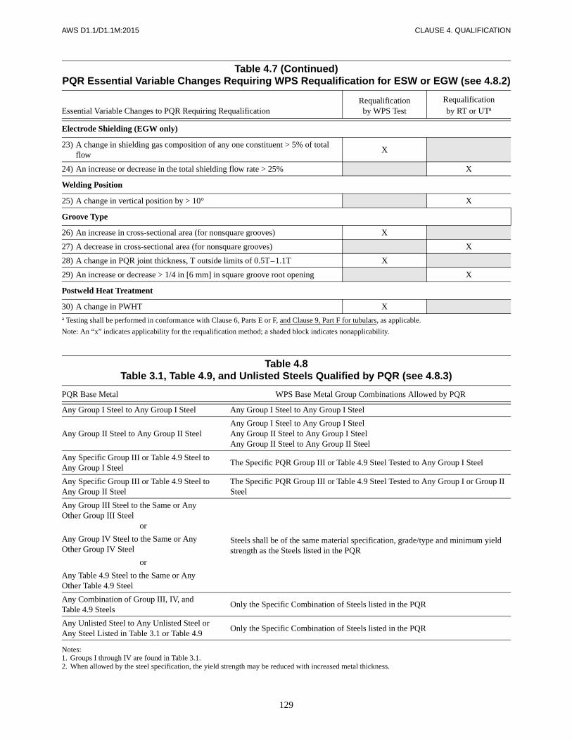
129
AWS D1.1/D1.1M:2015 CLAUSE 4. QUALIFICATION
Table 4.7 (Continued)PQR Essential Variable Changes Requiring WPS Requalification for ESW or EGW (see 4.8.2)
Essential Variable Changes to PQR Requiring RequalificationRequalificationby WPS Test
Requalificationby RT or UTa
Electrode Shielding (EGW only)
23) A change in shielding gas composition of any one constituent > 5% of total flow
X
24) An increase or decrease in the total shielding flow rate > 25% X
Welding Position
25) A change in vertical position by > 10° X
Groove Type
26) An increase in cross-sectional area (for nonsquare grooves) X
27) A decrease in cross-sectional area (for nonsquare grooves) X
28) A change in PQR joint thickness, T outside limits of 0.5T–1.1T X
29) An increase or decrease > 1/4 in [6 mm] in square groove root opening X
Postweld Heat Treatment
30) A change in PWHT Xa Testing shall be performed in conformance with Clause 6, Parts E or F, and Clause 9, Part F for tubulars, as applicable.
Note: An “x” indicates applicability for the requalification method; a shaded block indicates nonapplicability.
Table 4.8Table 3.1, Table 4.9, and Unlisted Steels Qualified by PQR (see 4.8.3)
PQR Base Metal WPS Base Metal Group Combinations Allowed by PQR
Any Group I Steel to Any Group I Steel Any Group I Steel to Any Group I Steel
Any Group II Steel to Any Group II SteelAny Group I Steel to Any Group I SteelAny Group II Steel to Any Group I SteelAny Group II Steel to Any Group II Steel
Any Specific Group III or Table 4.9 Steel to Any Group I Steel
The Specific PQR Group III or Table 4.9 Steel Tested to Any Group I Steel
Any Specific Group III or Table 4.9 Steel to Any Group II Steel
The Specific PQR Group III or Table 4.9 Steel Tested to Any Group I or Group II Steel
Any Group III Steel to the Same or Any Other Group III Steel
or
Any Group IV Steel to the Same or Any Other Group IV Steel
or
Any Table 4.9 Steel to the Same or Any Other Table 4.9 Steel
Steels shall be of the same material specification, grade/type and minimum yield strength as the Steels listed in the PQR
Any Combination of Group III, IV, and Table 4.9 Steels
Only the Specific Combination of Steels listed in the PQR
Any Unlisted Steel to Any Unlisted Steel orAny Steel Listed in Table 3.1 or Table 4.9
Only the Specific Combination of Steels listed in the PQR
Notes:1. Groups I through IV are found in Table 3.1.2. When allowed by the steel specification, the yield strength may be reduced with increased metal thickness.

CLA
US
E 4. Q
UA
LIFIC
ATIO
NA
WS
D1.1/D
1.1M:2015
130
Table 4.9Code-Approved Base Metals and Filler Metals Requiring Qualification per Clause 4
Base Metal Matching Strength Filler Metal
Base MetalThickness, T
Minimum Preheat and
Interpass Temperature
Specification
Minimum Yield Point/Strength Tensile Range
Process
AWSElectrode
Specificationa Electrode Classificationksi MPa ksi MPa in mm °F °C
ASTM A871 Grade 60
Grade 65
60
65
415
450
75 min.
80 min.
520 min.
550 min. SMAW A5.5E8015-X
Up to 3/4
Over 3/4thru 1-1/2
Over 1-1/2thru 2-1/2
Over 2-1/2
Up to 20
Over 20thru 38
Over 38thru 65
Over 65
50
125
175
225
10
50
80
110
E8016-X
E8018-X
SAW A5.23F8XX-EXXX-XX
F8XX-ECXXX-XX
GMAWA5.28
ER80S-XXX
E80C-XXXA5.36 E8XTX-XAX-XXX
FCAW
A5.29
E8XTX-X
E8XTX-XC
E8XTX-XM
A5.36E8XTX-AX-XXX
E8XTX-XAX-XXX
ASTM A514 90 620 100–130 690–895
SMAW A5.5
E10015-X(Over 2-1/2 in [65 mm]) E10016-X
E10018-X
ASTM A70990 620 100–130 690–895
E10018MGrade HPS 100W [HPS 690W](Over 2-1/2 in to 4 in[65 mm to 100 mm])
SAW A5.23F10XX-EXXX-XX
F10XX-ECXXX-XX
GMAWA5.28
ER100S-XXX
ASTM A710 Grade A. Class 180–85 550–585 90 min. 620 min.
E100C-XXX≤ 3/4 in [20 mm] A5.36 E10TX-XAX-XXX
75–80 515–550 85 min. 585 min. FCAWA5.29
A5.36
E10XTX-XCASTM A710 Grade A. Class 3≤ 2 in [50 mm] E10XTX-XM
E10TX-XAX-XXX
(Continued)
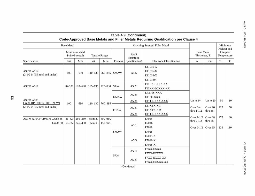
AW
S D
1.1/D1.1M
:2015C
LAU
SE
4. QU
ALIF
ICAT
ION
131
ASTM A514(2-1/2 in [65 mm] and under)
100 690 110–130 760–895 SMAW A5.5
E11015-X
Up to 3/4
Over 3/4thru 1-1/2
Over 1-1/2thru 2-1/2
Over 2-1/2
Up to 20
Over 20thru 38
Over 38thru 65
Over 65
50
125
175
225
10
50
80
110
E11016-X
E11018-X
E11018M
ASTM A517 90–100 620–690 105–135 725–930 SAW A5.23F11XX-EXXX-XX
F11XX-ECXXX-XX
ASTM A709Grade HPS 100W [HPS 690W](2-1/2 in [65 mm] and under)
100 690 110–130 760–895
GMAWA5.28
ER110S-XXX
E110C-XXXA5.36 E11TX-XAX-XXX
FCAWA5.29
E11XTX-XC
E11XTX-XMA5.36 E11TX-XAX-XXX
ASTM A1043/A1043M Grade 36 36–52 250–360 58 min. 400 min.
SMAW
A5.1
E7015
Grade 50 50–65 345–450 65 min. 450 min. E7016
E7018
E7028
A5.5
E7015-X
E7016-X
E7018-X
SAW
A5.17F7XX-EXXX
F7XX-ECXXX
A5.23F7XX-EXXX-XX
F7XX-ECXXX-XX
Table 4.9 (Continued)Code-Approved Base Metals and Filler Metals Requiring Qualification per Clause 4
Base Metal Matching Strength Filler Metal
Base MetalThickness, T
Minimum Preheat and
Interpass Temperature
Specification
Minimum Yield Point/Strength Tensile Range
Process
AWSElectrode
Specificationa Electrode Classificationksi MPa ksi MPa in mm °F °C
(Continued)

CLA
US
E 4. Q
UA
LIFIC
ATIO
NA
WS
D1.1/D
1.1M:2015
132
ASTM A1043/A1043M Grade 36 36–52 250–360 58 min. 400 min.
GMAW
A5.18
ER70S-X
E70C-XC
E70C-XM (Electrodes with the-GS suffix shall be excluded)
Up to 3/4
Over 3/4thru 1-1/2
Over 1-1/2thru 2-1/2
Over 2-1/2
Up to 20
Over 20thru 38
Over 38thru 65
Over 65
50
125
175
225
10
50
80
110
Grade 50 50–65 345–450 65 min. 450 min.
(Cont’d)
A5.36
(Fixed Classification, carbon steel)
E70C-6M
(Electrodes with the -GS suffix shall be excluded)
A5.36
(Open Classification, carbon steel)
E7XT15-XAX-CS1
E7XT15-XAX-CS2
E7XT16-XAX-CS1
E7XT16-XAX-CS2
(Electrodes with the -GS suffix shall be excluded)
A5.28ER70S-XXX
E70C-XXX
A5.36(Open Classification, GMAW-Metal Cored low-alloy steel)
FCAW A5.20
E7XT-X
E7XT-XC
E7XT-XM
(Electrodes with the -2C, -2M, -3,-10, -13, -14, and -GS suffix shallbe excluded, and electrodes withthe -11 suffix shall be excluded for thicknesses greater than 1/2 in [12 mm])
Table 4.9 (Continued)Code-Approved Base Metals and Filler Metals Requiring Qualification per Clause 4
Base Metal Matching Strength Filler Metal
Base MetalThickness, T
Minimum Preheat and
Interpass Temperature
Specification
Minimum Yield Point/Strength Tensile Range
Process
AWSElectrode
Specificationa Electrode Classificationksi MPa ksi MPa in mm °F °C
(Continued)

AW
S D
1.1/D1.1M
:2015C
LAU
SE
4. QU
ALIF
ICAT
ION
133
ASTM A1043/A1043M Grade 36 36–52 250–360 58 min. 400 min.
FCAW(Cont’d)
A5.36
(Fixed Classification, carbon steel)
E7XT-1C
E7XT-1M
E7XT-5C
E7XT-5M
E7XT-9C
E7XT-9M
E7XT-12C
E7XT-12M
E70T-4
E7XT-6
E7XT-7
E7XT-8
(Flux Cored Electrodes with the T1S, T3S, T10S, and -GS suffixshall be excluded and electrodeswith the T11 suffix shall beexcluded for thicknesses greaterthan 1/2 in [12 mm]
Up to 3/4
Over 3/4thru 1-1/2
Over 1-1/2thru 2-1/2
Over 2-1/2
Up to 20
Over 20thru 38
Over 38thru 65
Over 65
50
125
175
225
10
50
80
110
Grade 50 50–65 345–450 65 min. 450 min.
(Cont’d)
Table 4.9 (Continued)Code-Approved Base Metals and Filler Metals Requiring Qualification per Clause 4
Base Metal Matching Strength Filler Metal
Base MetalThickness, T
Minimum Preheat and
Interpass Temperature
Specification
Minimum Yield Point/Strength Tensile Range
Process
AWSElectrode
Specificationa Electrode Classificationksi MPa ksi MPa in mm °F °C
(Continued)
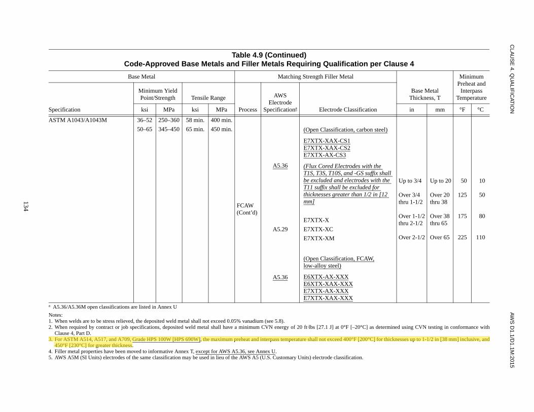
CLA
US
E 4. Q
UA
LIFIC
ATIO
NA
WS
D1.1/D
1.1M:2015
134
ASTM A1043/A1043M 36–52 250–360 58 min. 400 min.
FCAW(Cont’d)
A5.36
(Open Classification, carbon steel)
E7XTX-XAX-CS1E7XTX-XAX-CS2E7XTX-AX-CS3
(Flux Cored Electrodes with the T1S, T3S, T10S, and -GS suffix shall be excluded and electrodes with the T11 suffix shall be excluded for thicknesses greater than 1/2 in [12 mm]
Up to 3/4
Over 3/4thru 1-1/2
Over 1-1/2thru 2-1/2
Over 2-1/2
Up to 20
Over 20thru 38
Over 38thru 65
Over 65
50
125
175
225
10
50
80
110
50–65 345–450 65 min. 450 min.
A5.29
E7XTX-X
E7XTX-XC
E7XTX-XM
A5.36
(Open Classification, FCAW,low-alloy steel)
E6XTX-AX-XXXE6XTX-XAX-XXXE7XTX-AX-XXXE7XTX-XAX-XXX
a A5.36/A5.36M open classifications are listed in Annex U
Notes:1. When welds are to be stress relieved, the deposited weld metal shall not exceed 0.05% vanadium (see 5.8). 2. When required by contract or job specifications, deposited weld metal shall have a minimum CVN energy of 20 ft·lbs [27.1 J] at 0°F [–20°C] as determined using CVN testing in conformance with
Clause 4, Part D.3. For ASTM A514, A517, and A709, Grade HPS 100W [HPS 690W], the maximum preheat and interpass temperature shall not exceed 400°F [200°C] for thicknesses up to 1-1/2 in [38 mm] inclusive, and
450°F [230°C] for greater thickness. 4. Filler metal properties have been moved to informative Annex T, except for AWS A5.36, see Annex U.5. AWS A5M (SI Units) electrodes of the same classification may be used in lieu of the AWS A5 (U.S. Customary Units) electrode classification.
Table 4.9 (Continued)Code-Approved Base Metals and Filler Metals Requiring Qualification per Clause 4
Base Metal Matching Strength Filler Metal
Base MetalThickness, T
Minimum Preheat and
Interpass Temperature
Specification
Minimum Yield Point/Strength Tensile Range
Process
AWSElectrode
Specificationa Electrode Classificationksi MPa ksi MPa in mm °F °C
M.VAFAKHAH
Highlight

AW
S D
1.1/D1.1M
:2015C
LAU
SE
4. QU
ALIF
ICAT
ION
135
Table 4.10Welder and Welding Operator Qualification—Production Welding Positions Qualified by Plate, Pipe, and Box Tube Tests (see 4.15.1)g
Qualification Test Production Plate Welding Qualified Production Pipe Welding Qualified Production Box Tube Welding Qualified
WeldType
TestPositionsa
GrooveCJP
GroovePJP Filletf
Butt Jointc T-,Y-,K-Connections
Filletf
Butt Joint T-,Y-,K-Connections
FilletfCJP PJP CJP PJPc, e CJPd PJP CJP PJPe
PLATE
Grooveb
1G2G3G4G
3G + 4G
FF, H
F, H, VF, OH
All
FF, H
F, H, VF, OH
All
F, HF, H
F, H, VF, H, OH
All
FF, H
F, H, VF, OH
All
FF, H
F, H, VF, OH
All
FF, H
F, H, VF, OH
A
F, HF, H
F, H, VF, H, OH
All
FF, H
F, H, VF, OH
All
FF, H
F, H, VF, OH
All
FF, H
F, H, VF, OH
All
F, HF, H
F, H, VF, H, OH
All
Fillet
1F2F3F4F
3F + 4F
FF, H
F, H, VF, H, OH
All
FF, H
F, H, VF, H, OH
All
FF, H
F, H, VF, H, OH
All
Plug Qualifies Plug and Slot Welding for Only the Positions Tested
CJP—Complete Joint PenetrationPJP—Partial Joint Penetrationa See Figures 4.3 and 4.4.b Groove weld qualification shall also qualify plug and slot welds for the test positions indicated.c Only qualified for pipe equal to or greater than 24 in [600 mm] in diameter with backing, backgouging, or both.d Not qualified for joints welded from one side without backing, or welded from two sides without backgouging.e Not qualified for welds having groove angles less than 30° (see 9.15.4.2).f See 4.21 and 9.20 for dihedral angle restrictions for plate joints and tubular T-, Y-, K-connections.g The qualification of welding operators for electroslag welding (ESW) or electrogas welding (EGW) shall only apply for the position tested.
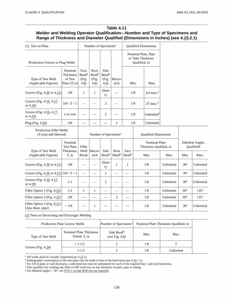
136
CLAUSE 4. QUALIFICATION AWS D1.1/D1.1M:2015
Table 4.11Welder and Welding Operator Qualification—Number and Type of Specimens andRange of Thickness and Diameter Qualified (Dimensions in Inches) (see 4.15.2.1)
(1) Test on Plate Number of Specimensa Qualified Dimensions
Production Groove or Plug Welds
Face Bendb (Fig. 4.8)
Root Bendb (Fig. 4.8)
Side Bendb (Fig. 4.9)
Macro-etch
Nominal Plate, Pipe or Tube Thickness
Qualified, in
Type of Test Weld (Applicable Figures)
Nominal Thickness
of Test Plate (T) in Min. Max.
Groove (Fig. 4.20 or 4.21) 3/8 1 1(Note
c)— 1/8 3/4 max.d
Groove (Fig. 4.16, 4.17,or 4.19)
3/8 < T < 1 — — 2 — 1/8 2T max.d
Groove (Fig. 4.16, 4.17,or 4.19)
1 or over — — 2 — 1/8 Unlimitedd
Plug (Fig. 4.26) 3/8 — — — 2 1/8 Unlimited
Production Fillet Welds(T-joint and Skewed) Number of Specimensa Qualified Dimensions
Dihedral Angles Qualifiede
Type of Test Weld (Applicable Figures)
Nominal Test Plate Thickness,
T, in
Fillet Weld Break
Macro-etch
Side Bendb
Root Bendb
Face Bendb
Nominal Plate Thickness Qualified, in
Min. Max. Min. Max.
Groove (Fig. 4.20 or 4.21) 3/8 — —(Note
c)1 1 1/8 Unlimited 30° Unlimited
Groove (Fig. 4.20 or 4.21) 3/8 < T < 1 — — 2 — — 1/8 Unlimited 30° Unlimited
Groove (Fig. 4.16, 4.17,or 4.19)
≥ 1 — — 2 — — 1/8 Unlimited 30° Unlimited
Fillet Option 1 (Fig. 4.25) 1/2 1 1 — — — 1/8 Unlimited 60° 135°
Fillet Option 2 (Fig. 4.22) 3/8 — — — 2 — 1/8 Unlimited 60° 135°
Fillet Option 3 (Fig. 9.21) [Any diam. pipe]
> 1/8 > — 1 — — — 1/8 Unlimited 30° Unlimited
(2) Tests on Electroslag and Electrogas Welding
Production Plate Groove Welds Number of Specimensa Nominal Plate Thickness Qualified, in
Type of Test WeldNominal Plate Thickness
Tested, T, inSide Bendb
(see Fig. 4.9)Min. Max.
Groove (Fig. 4.24)< 1-1/2 < 2 1/8 T
1-1/2 2 1/8 Unlimited
a All welds shall be visually inspected (see 4.22.1).b Radiographic examination of the test plate may be made in lieu of the bend tests (see 4.16.1.1).c For 3/8 in plate or wall thickness, a side-bend test may be substituted for each of the required face- and root-bend tests.d Also qualifies for welding any fillet or PJP weld size on any thickness of plate, pipe or tubing.e For dihedral angles < 30°, see 9.19.1; except 6GR test not required.

137
AWS D1.1/D1.1M:2015 CLAUSE 4. QUALIFICATION
Table 4.11 (Continued)Welder and Welding Operator Qualification—Number and Type of Specimens and
Range of Thickness and Diameter Qualified (Dimensions in Millimeters) (see 4.15.2.1)
(1) Test on Plate Number of Specimensa Qualified Dimensions
Production Groove or Plug Welds
Face Bendb (Fig. 4.8)
Root Bendb (Fig. 4.8)
Side Bendb (Fig. 4.9)
Macro-etch
Nominal Plate, Pipe or Tube Thickness
Qualified, mm
Type of Test Weld (Applicable Figures)
Nominal Thickness of Test Plate, T,
mm Min. Max.
Groove (Fig. 4.20 or 4.21) 10 1 1(Note
c)— 3 20 maxd
Groove (Fig. 4.16, 4.17,or 4.19)
10 < T < 25 — — 2 — 3 2T maxd
Groove (Fig. 4.16, 4.17,or 4.19)
25 or over — — 2 — 3 Unlimitedd
Plug (Fig. 4.26) 10 — — — 2 3 Unlimitedd
Production Fillet Welds(T-joint and Skewed) Number of Specimensa Qualified Dimensions
Dihedral Angles Qualifiede
Type of Test Weld (Applicable Figures)
Nominal Test Plate
Thickness, T, mm
Fillet Weld Break
Macro-etch
Side Bendb
Root Bendb
Face Bendb
Nominal Plate Thickness Qualified, mm
Min. Max. Min. Max.
Groove (Fig. 4.20 or 4.21) 10 — —(Note
c)1 1 3 Unlimited 30° Unlimited
Groove (Fig. 4.20 or 4.21) 10 < T < 25 — — 2 — — 3 Unlimited 30° Unlimited
Groove (Fig. 4.16, 4.17,or 4.19)
≥ 25≥ — — 2 — — 3 Unlimited 30° Unlimited
Fillet Option 1 (Fig. 4.25) 12 1 1 — — — 3 Unlimited 60° 135°
Fillet Option 2 (Fig. 4.22) 10 — — — 2 — 3 Unlimited 60° 135°
Fillet Option 3 (Fig. 9.21) [Any diam. pipe]
> 3> — 1 — — — 3 Unlimited 30° Unlimited
(2) Tests on Electroslag and Electrogas Welding
Production Plate Groove Welds Number of Specimensa Nominal Plate Thickness Qualified, mm
Type of Test WeldNominal Plate Thickness
Tested, T, mmSide Bendb
(see Fig. 4.9)Min. Max.
Groove (Fig. 4.24)< 38 < 2 3 T
38 2 3 Unlimited
a All welds shall be visually inspected (see 4.22.1).b Radiographic examination of the test plate may be made in lieu of the bend tests (see 4.16.1.1).c For 10 mm plate or wall thickness, a side-bend test may be substituted for each of the required face- and root-bend tests.d Also qualifies for welding any fillet or PJP weld size on any thickness of plate, pipe or tubing.e For dihedral angles < 30°, see 9.19.1; except 6GR test not required.

138
CLAUSE 4. QUALIFICATION AWS D1.1/D1.1M:2015
Table 4.12Welding Personnel Performance Essential Variable Changes
Requiring Requalification (see 4.19)
Essential Variable Changes to WPQR Requiring Requalification
Welding Personnel
Weldersb
Welding Operatorsb, c Tack Welders
(1) To a process not qualified (GMAW-S is considered a separate process) X X X
(2) To an SMAW electrode with an F-number (see Table 4.13) higher than the WPQR electrode F-number
X X
(3) To a position not qualified X X X
(4) To a diameter or thickness not qualified X X
(5) To a vertical welding progression not qualified (uphill or downhill) X
(6) The omission of backing (if used in the WPQR test) X X
(7) To multiple electrodes (if a single electrode was used in the WPQR test) but not vice versa
3Xa
a Not for ESW or EGW.b Welders qualified for SAW, GMAW, FCAW, or GTAW shall be considered as qualified welding operators in the same process(es) and subject to the
welder essential variable limitations.c A groove weld qualifies a slot weld for the WPQR position and the thickness ranges as shown in Table 4.11.
Notes:1. An “x” indicates applicability for the welding personnel; a shaded area indicates nonapplicability.2. WPQR = Welding Performance Qualification Record.
Table 4.13Electrode Classification Groups
(see Table 4.12)
Group Designation AWS Electrode Classification
F4 EXX15, EXX16, EXX18, EXX48, EXX15-X, EXX16-X, EXX18-X
F3 EXX10, EXX11, EXX10-X, EXX11-X
F2 EXX12, EXX13, EXX14, EXX13-X
F1 EXX20, EXX24, EXX27, EXX28, EXX20-X, EXX27-X
Note: The letters “XX” used in the classification designation in this table stand for the various strength levels (60 [415], 70 [485], 80 [550], 90 [620],100 [690], 110 [760], and 120 [830]) of electrodes.

139
AWS D1.1/D1.1M:2015 CLAUSE 4. QUALIFICATION
Table 4.14CVN Test Requirements (see 4.28.1)
Welding Processa
TestLocation
Number of Specimensb
Test Temperature
°F/°C
SpecimenSize,d0mm
Minimum Average
Absorbed Energy,e
ft·lbf [J]
Minimum Individual Absorbed Energy,e
ft·lbf [J]
Minimum AveragePercent
Shear Area,%
Minimum AverageLateral
Expansion, Mils/mm
SMAWGTAWGMAWSAWESWEGWFCAW-SFCAW-G
Weld Metal 3 (Note c) 10 × 10 20 [27] 15 [20] (Note f) (Note f)
Fusion Line+1 mm
3 (Note c) 10 × 10 20 [27] 15 [20] (Note f) (Note f)
Fusion Line+5 mm
3 (Note c) 10 × 10 20 [27] 15 [20] (Note f) (Note f)
a A WPS which combines FCAW-S with another welding process shall be specifically tested to assure CVN test criteria are met at the interface betweenthe weld deposits.
b The alternate number of specimens allowed per test location is five. The highest and lowest values shall be discarded to minimize some of the scatternormally associated with CVN testing of welds and HAZs.
c Test temperatures shall be specified in contract documents or specifications. When sub-sized specimens are required, and the width of the specimensacross the notch is less than 80% of the base metal thickness, the test temperature shall be reduced in conformance with Table 4.15.
d Full size specimens shall be used when test material is 7/16 in [11 mm] or thicker. Sub-sized specimens shall be used when test material thickness isless than 7/16 in [11 mm], or when weldment geometry prohibits the removal of full sized samples.
e Applicable in welds between base materials with a specified minimum yield strength (SMYS) of 50 ksi [345 MPa] or less. Acceptance criteria forwelds between materials exceeding SYMS of 50 ksi [345 MPa] shall be specified in the contract documents or specifications.
f Values for percent shear and lateral expansion shall be recorded when specified in the contract documents or specifications.
Table 4.15CVN Test Temperature Reduction (see 4.27.5 and 4.27.7)
For sub-sized CVN test specimens where the width across the notch is less than 80% of the base metal thickness.
Specimen Sizemm
Test Temperature Reduction Below the Specified Test Temperature
°F °C
10 × 1010 × 910 × 810 × 7.510 × 710 × 6.710 × 610 × 510 × 410 × 3.310 × 310 × 2.5
00058
10152030354050
0003568
1117192228
Example: If design drawings or specifications indicate that CVN tests shall be performed at 32°F [0°C] and 10 mm × 5 mm sub-sized specimens areused; the actual test temperature would be 12°F [–11°C].
Note: The reduction in the minimum acceptance energy values for sub-sized specimens shall be determined in conformance with ASTM A370a-97,Table 9.

140
CLAUSE 4. QUALIFICATION AWS D1.1/D1.1M:2015
Notes:1. The horizontal reference plane shall always be taken to lie below the weld under consideration.2. The inclination of axis shall be measured from the horizontal reference plane toward the vertical reference plane.3. The angle of rotation of the face shall be determined by a line perpendicular to the theoretical face of the weld which passes through
the axis of the weld. The reference position (0°) of rotation of the face invariably points in the direction opposite to that in which theaxis angle increases. When looking at point P, the angle of rotation of the face of the weld shall be measured in a clockwise directionfrom the reference position (0°).
Figure 4.1—Positions of Groove Welds (see 4.3.4)
Tabulation of Positions of Groove Welds
Position Diagram Reference Inclination of Axis Rotation of Face
Flat A 0° to 15° 150° to 210°
Horizontal B 0° to 15° 80° to 150°210° to 280°
Overhead C 0° to 80° 0° to 80°280° to 360°
Vertical DE
15° to 80°80° to 90°
80° to 280°0° to 360°

141
AWS D1.1/D1.1M:2015 CLAUSE 4. QUALIFICATION
Figure 4.2—Positions of Fillet Welds (see 4.3.4)
Tabulation of Positions of Fillet Welds
Position Diagram Reference Inclination of Axis Rotation of Face
Flat A 0° to 15° 150° to 210°
Horizontal B 0° to 15° 125° to 150°210° to 235°
Overhead C 0° to 80° 0° to 125°235° to 360°
Vertical DE
15° to 80°80° to 90°
125° to 235°0° to 360°

142
CLAUSE 4. QUALIFICATION AWS D1.1/D1.1M:2015
Figure 4.3—Positions of Test Plates for Groove Welds (see 4.3.4)

143
AWS D1.1/D1.1M:2015 CLAUSE 4. QUALIFICATION
Figure 4.4—Positions of Test Plate for Fillet Welds (see 4.3.4)

144
CLAUSE 4. QUALIFICATION AWS D1.1/D1.1M:2015
Notes:1. The groove configuration shown is for illustration only. The groove shape tested shall conform to the production groove shape that is
being qualified.2. When CVN test specimens are required, see Clause 4, Part D for requirements.3. All dimensions are minimum.
Figure 4.5—Location of Test Specimens on Welded Test Plates—ESW and EGW—WPS Qualification (see 4.9)

145
AWS D1.1/D1.1M:2015 CLAUSE 4. QUALIFICATION
Notes:1. The groove configuration shown is for illustration only. The groove shape tested shall conform to the production groove shape that is
being qualified.2. When CVN tests are required, the specimens shall be removed from their locations, as shown in Figure 4.28.3. All dimensions are minimum.
Figure 4.6—Location of Test Specimens on Welded Test PlateOver 3/8 in [10 mm] Thick—WPS Qualification (see 4.9)

146
CLAUSE 4. QUALIFICATION AWS D1.1/D1.1M:2015
Notes:1. The groove configuration shown is for illustration only. The groove shape tested shall conform to the production groove shape that is
being qualified.2. When CVN tests are required, the specimens shall be removed from their locations, as shown in Figure 4.28.3. All dimensions are minimum.4. For 3/8 in [10 mm] plate, a side-bend test may be substituted for each of the required face- and root-bend tests. See Figure 4.6(2) for
plate length and location of specimens.
Figure 4.7—Location of Test Specimens on Welded Test Plate3/8 in [10 mm] Thick and Under—WPS Qualification (see 4.9)

147
AWS D1.1/D1.1M:2015 CLAUSE 4. QUALIFICATION
a A longer specimen length may be necessary when using a wraparound type bending fixture or when testing steel with a yield strengthof 90 ksi [620 MPa] or more.
b These edges may be thermal cut and may or may not be machined.c The weld reinforcement and backing, if any, shall be removed flush with the surface of the specimen (see 5.23.3.1 and 5.23.3.2). If a
recessed backing is used, this surface may be machined to a depth not exceeding the depth of the recess to remove the backing; insuch a case, the thickness of the finished specimen shall be that specified above. Cut surfaces shall be smooth and parallel.
Notes:1. T = plate or pipe thickness.2. When the thickness of the test plate is less than 3/8 in [10 mm], the nominal thickness shall be used for face and root bends.
Figure 4.8—Face and Root Bend Specimens (see 4.9.3.1)

148
CLAUSE 4. QUALIFICATION AWS D1.1/D1.1M:2015
a A longer specimen length may be necessary when using a wraparound-type bending fixture or when testing steel with a yield strengthof 90 ksi [620 MPa] or more.
b For plates over 1-1/2 in [38 mm] thick, the specimen shall be cut into approximately equal strips with T between 3/4 in [20 mm] and1-1/2 in [38 mm] and test each strip.
c t = plate or pipe thickness.
Figure 4.9—Side Bend Specimens (see 4.9.3.1)
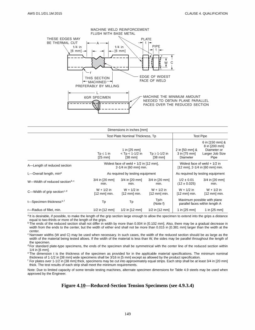
149
AWS D1.1/D1.1M:2015 CLAUSE 4. QUALIFICATION
Dimensions in inches [mm]
Test Plate Nominal Thickness, Tp Test Pipe
Tp ≤ 1 in[25 mm]
1 in [25 mm]< Tp < 1-1/2 in
[38 mm]Tp ≥ 1-1/2 in
[38 mm]
2 in [50 mm] &3 in [75 mm]
Diameter
6 in [150 mm] &8 in [200 mm]Diameter or
Larger Job Size Pipe
A—Length of reduced section Widest face of weld + 1/2 in [12 mm],2-1/4 in [60 mm] min.
Widest face of weld + 1/2 in[12 mm], 2-1/4 in [60 mm] min.
L—Overall length, mina As required by testing equipment As required by testing equipment
W—Width of reduced sectionb, c 3/4 in [20 mm]min.
3/4 in [20 mm]min.
3/4 in [20 mm]min.
1/2 ± 0.01(12 ± 0.025)
3/4 in [20 mm]min.
C—Width of grip sectionc, d W + 1/2 in[12 mm] min.
W + 1/2 in[12 mm] min.
W + 1/2 in[12 mm] min.
W + 1/2 in[12 mm] min.
W + 1/2 in[12 mm] min.
t—Specimen thicknesse, f Tp Tp Tp/n(Note f)
Maximum possible with planeparallel faces within length A
r—Radius of fillet, min. 1/2 in [12 mm] 1/2 in [12 mm] 1/2 in [12 mm] 1 in [25 mm] 1 in [25 mm]
a It is desirable, if possible, to make the length of the grip section large enough to allow the specimen to extend into the grips a distanceequal to two-thirds or more of the length of the grips.
b The ends of the reduced section shall not differ in width by more than 0.004 in [0.102 mm]. Also, there may be a gradual decrease inwidth from the ends to the center, but the width of either end shall not be more than 0.015 in [0.381 mm] larger than the width at thecenter.
c Narrower widths (W and C) may be used when necessary. In such cases, the width of the reduced section should be as large as thewidth of the material being tested allows. If the width of the material is less than W, the sides may be parallel throughout the length ofthe specimen.
d For standard plate-type specimens, the ends of the specimen shall be symmetrical with the center line of the reduced section within1/4 in [6 mm].
e The dimension t is the thickness of the specimen as provided for in the applicable material specifications. The minimum nominalthickness of 1-1/2 in [38 mm] wide specimens shall be 3/16 in [5 mm] except as allowed by the product specification.
f For plates over 1-1/2 in [38 mm] thick, specimens may be cut into approximately equal strips. Each strip shall be at least 3/4 in [20 mm]thick. The test results of each strip shall meet the minimum requirements.
Note: Due to limited capacity of some tensile testing machines, alternate specimen dimensions for Table 4.9 steels may be used whenapproved by the Engineer.
Figure 4.10—Reduced-Section Tension Specimens (see 4.9.3.4)
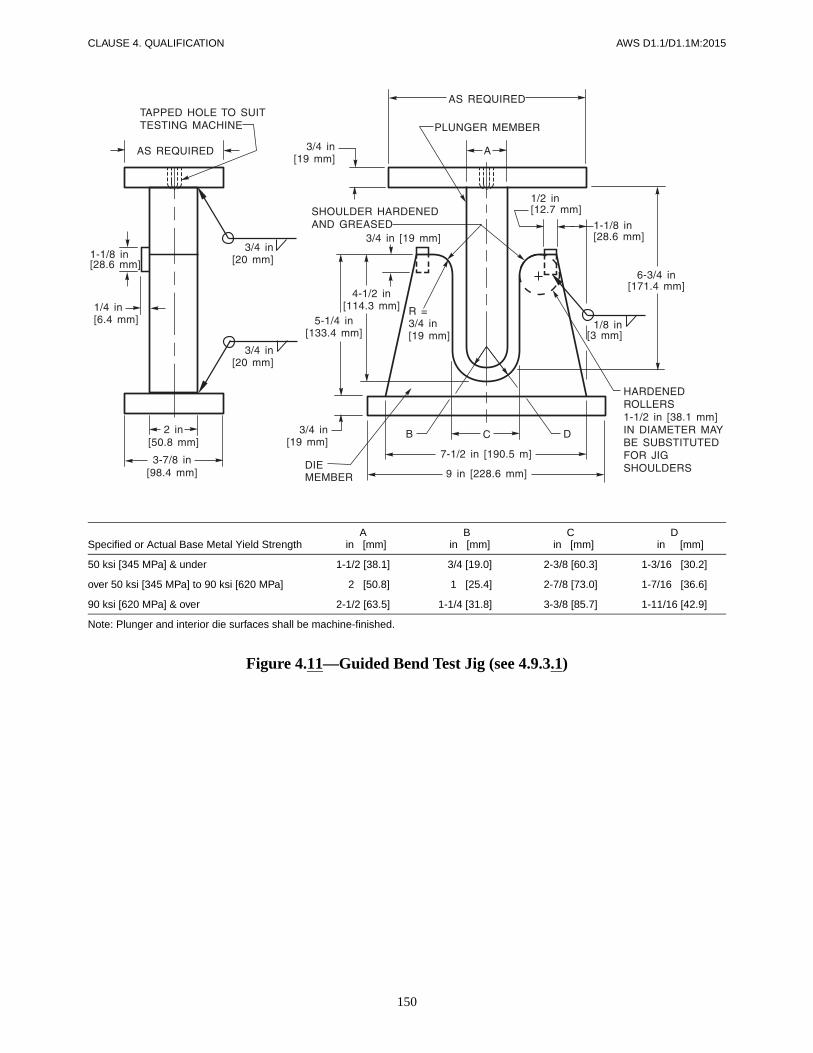
150
CLAUSE 4. QUALIFICATION AWS D1.1/D1.1M:2015
Figure 4.11—Guided Bend Test Jig (see 4.9.3.1)
Specified or Actual Base Metal Yield StrengthA
in [mm]B
in [mm]C
in [mm]D
in [mm]
50 ksi [345 MPa] & under 1-1/2 [38.1] 3/4 [19.0] 2-3/8 [60.3] 1-3/16 [30.2]
over 50 ksi [345 MPa] to 90 ksi [620 MPa] 2 [50.8] 1 /[25.4] 2-7/8 [73.0] 1-7/16 [36.6]
90 ksi [620 MPa] & over 2-1/2 [63.5] 1-1/4 [31.8]- 3-3/8 [85.7] 1-11/16 [42.9]
Note: Plunger and interior die surfaces shall be machine-finished.

151
AWS D1.1/D1.1M:2015 CLAUSE 4. QUALIFICATION
Figure 4.12—Alternative Wraparound Guided Bend Test Jig (see 4.9.3.1)
Figure 4.13—Alternative Roller-Equipped Guided Bend Test Jigfor Bottom Ejection of Test Specimen (see 4.9.3.1)
Specified or ActualBase Metal Yield Strength, ksi [MPa]
Ain
Bin
Amm
Bmm
50 [345] & under 1-1/2 3/4 38.1 19.0
over 50 [345] to 90 [620] 2 1 50.8 25.4
90 [620] over 2-1/2 1-1/4 63.5 31.8
Specified or ActualBase Metal Yield Strength, ksi [MPa]
Ain
Bin
Cin
Amm
Bmm
Cmm
50 [345] & under 1-1/2 3/4 2-3/8 38.1 19.0 60.3
over 50 [345] to 90 [620] 2 1 2-7/8 50.8 25.4 73.0
90 [620] & over 2-1/2 1-1/4 3-3/8 63.5 31.8 85.7

152
CLAUSE 4. QUALIFICATION AWS D1.1/D1.1M:2015
Dimensions in inches
Nominal Diameter
Standard Specimen Small-Size Specimens Proportional to Standard
0.500 in Round 0.350 in Round 0.250 in Round
G—Gage length 2.000 ± 0.005 1.400 ± 0.005 1.000 ± 0.005
D—Diameter (Note a) 0.500 ± 0.010 0.350 ± 0.007 0.250 ± 0.005
r—Radius of fillet, min. 3/8 1/4 3/16
A—Length of reduced section(Note b), min. 2-1/4 1-3/4 1-1/4
Dimensions (metric version per ASTM E8M)
Nominal Diameter
Standard Specimen Small-Size Specimens Proportional to Standard
12.5 mm Round 9 mm Round 6 mm Round
G—Gage length 62.5 ± 0.1 45.0 ± 0.1 30.0 ± 0.1
D—Diameter (Note a) 12.5 ± 0.2 9.0 ± 0.1 6.0 ± 0.1
r—Radius of fillet, min. 10 8 6
A—Length of reduced section(Note b), min. 75 54 36
a The reduced section may have a gradual taper from the ends toward the center, with the ends not more than 1% larger in diameter thanthe center (controlling dimension).
b If desired, the length of the reduced section may be increased to accommodate an extensometer of any convenient gage length. Referencemarks for the measurement of elongation should be spaced at the indicated gage length.
Note: The gage length and fillets shall be as shown, but the ends may be of any form to fit the holders of the testing machine in such away that the load shall be axial. If the ends are to be held in wedge grips, it is desirable, if possible, to make the length of the grip sectiongreat enough to allow the specimen to extend into the grips a distance equal to two-thirds or more of the length of the grips.
Figure 4.14—All-Weld-Metal Tension Specimen (see 4.9.3.6)

153
AWS D1.1/D1.1M:2015 CLAUSE 4. QUALIFICATION
Figure 4.15—Fillet Weld Soundness Tests for WPS Qualification (see 4.12.2)
INCHES MILLIMETERS
WeldSize T1 min. T2 min.
WeldSize T1 min. T2 min.
1/8 1/4 3/16 3 6 5
3/16 1/2 3/16 5 12 5
1/4 3/4 1/4 6 20 6
5/16 1 5/16 8 25 8
3/8 1 3/8 10 25 10
1/2 1 1/2 12 25 12
5/8 1 5/8 16 25 16
3/4 1 3/4 20 25 20
> 3/4 > 1 1 > 20 > 25 25
Note: Where the maximum plate thickness used in production is less than the value shown above, the maximumthickness of the production pieces may be substituted for T1 and T2.
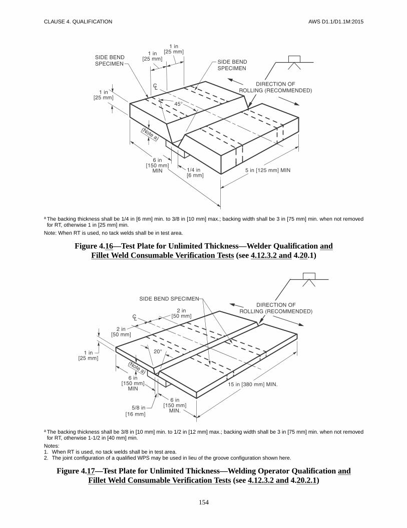
154
CLAUSE 4. QUALIFICATION AWS D1.1/D1.1M:2015
a The backing thickness shall be 1/4 in [6 mm] min. to 3/8 in [10 mm] max.; backing width shall be 3 in [75 mm] min. when not removedfor RT, otherwise 1 in [25 mm] min.
Note: When RT is used, no tack welds shall be in test area.
Figure 4.16—Test Plate for Unlimited Thickness—Welder Qualification andFillet Weld Consumable Verification Tests (see 4.12.3.2 and 4.20.1)
a The backing thickness shall be 3/8 in [10 mm] min. to 1/2 in [12 mm] max.; backing width shall be 3 in [75 mm] min. when not removedfor RT, otherwise 1-1/2 in [40 mm] min.
Notes:1. When RT is used, no tack welds shall be in test area.2. The joint configuration of a qualified WPS may be used in lieu of the groove configuration shown here.
Figure 4.17—Test Plate for Unlimited Thickness—Welding Operator Qualification andFillet Weld Consumable Verification Tests (see 4.12.3.2 and 4.20.2.1)

155
AWS D1.1/D1.1M:2015 CLAUSE 4. QUALIFICATION
Figure 4.18—Location of Test Specimen on Welded Test Plate 1 in [25 mm] Thick—Consumables Verification for Fillet Weld WPS Qualification (see 4.12.3)

156
CLAUSE 4. QUALIFICATION AWS D1.1/D1.1M:2015
a When RT is used, no tack welds shall be in test area.b The backing thickness shall be 1/4 in [6 mm] min. to 3/8 in [10 mm] max.; backing width shall be 3 in [75 mm] min. when not removed
for RT, otherwise 1 in [25 mm] min.
Figure 4.19—Optional Test Plate for Unlimited Thickness—Horizontal Position—Welder Qualification (see 4.20.1)

157
AWS D1.1/D1.1M:2015 CLAUSE 4. QUALIFICATION
a When RT is used, no tack welds shall be in test area.b The backing thickness shall be 1/4 in [6 mm] min. to 3/8 in [10 mm] max.; backing width shall be 3 in [75 mm] min. when not removed for
RT, otherwise 1 in [25 mm] min.c For 3/8 in [10 mm] plate, a side-bend test may be substituted for each of the required face- and root-bend tests.
Figure 4.20—Test Plate for Limited Thickness—All Positions—Welder Qualification (see 4.20.1)

158
CLAUSE 4. QUALIFICATION AWS D1.1/D1.1M:2015
a When RT is used, no tack welds shall be in test area.b The backing thickness shall be 1/4 in [6 mm] min. to 3/8 in [10 mm] max.; backing width shall be 3 in [75 mm] min. when not removed for
RT, otherwise 1 in [25 mm] min.c For 3/8 in [10 mm] plate, a side-bend test may be substituted for each of the required face- and root-bend tests.
Figure 4.21—Optional Test Plate for Limited Thickness—HorizontalPosition—Welder Qualification (see 4.20.1)

159
AWS D1.1/D1.1M:2015 CLAUSE 4. QUALIFICATION
a L = 7 in [175 mm] min. (welder), L = 15 in [380 mm] min. (welding operator).
Figure 4.22—Fillet Weld Root Bend Test Plate—Welder or WeldingOperator Qualification—Option 2 (see 4.21.2 and Table 4.11 or 9.21 and Table 9.14)

160
CLAUSE 4. QUALIFICATION AWS D1.1/D1.1M:2015
Figure 4.23—Method of Rupturing Specimen—Tack Welder Qualification (see 4.23)
a Root opening “R” established by WPS.b T = maximum to be welded in construction but need not exceed 1-1/2 in [38 mm].c Extensions need not be used if joint is of sufficient length to provide 17 in [430 mm] of sound weld.
Figure 4.24—Butt Joint for Welding Operator Qualification—ESW and EGW (see 4.20.2.2)

161
AWS D1.1/D1.1M:2015 CLAUSE 4. QUALIFICATION
a L = 8 in [200 mm] min. welder, 15 in [380 mm] min. (welding operator).b Either end may be used for the required macroetch specimen. The other end may be discarded.
Figure 4.25—Fillet Weld Break and Macroetch Test Plate—Welder orWelding Operator Qualification—Option 1 (see 4.21.2 and Table 4.11 or 9.21 and Table 9.14)

162
CLAUSE 4. QUALIFICATION AWS D1.1/D1.1M:2015
Notes:1. L1 = 2 in [50 mm] min. (welder), 3 in [75 mm] min. (welding operator);2. L2 = 3 in [75 mm] min. (welder), 5 in [125 mm] min. (welding operator).
Figure 4.26—Plug Weld Macroetch Test Plate—Welder or Welding OperatorQualification (see 4.13 and WPS Qualification (see 4.21.3)

163
AWS D1.1/D1.1M:2015 CLAUSE 4. QUALIFICATION
Figure 4.27—Fillet Weld Break Specimen—Tack Welder Qualification (see 4.16.2)

164
CLAUSE 4. QUALIFICATION AWS D1.1/D1.1M:2015
‘Notes:1. A = Centerline of weld on specimen centerline2. C = HAZ (+1 mm from Fusion Line)3. D = HAZ (+5 mm from Fusion Line)
Figure 4.28—CVN Test Specimen Locations (see 4.26.1)

AWS D1.1/D1.1M:2015
165
5.1 ScopeAll applicable provisions of this section shall be ob-served in the fabrication and erection of welded assem-blies and structures produced by any process acceptableunder this code (see 3.2 and 4.14).
5.2 Base Metal5.2.1 Specified Base Metal. The contract documentsshall designate the specification and classification ofbase metal to be used. When welding is involved in thestructure, approved base metals, listed in Table 3.1 orTable 4.9, should be used wherever possible.
5.2.2 Base Metal for Weld Tabs, Backing, and Spacers
5.2.2.1 Weld Tabs. Weld tabs used in welding shallconform to the following requirements:
(1) When used in welding with an approved steellisted in Table 3.1 or Table 4.9, they may be any of thesteels listed in Table 3.1 or Table 4.9.
(2) When used in welding with a steel qualified inconformance with 4.8.3 they may be:
(a) The steel qualified, or
(b) Any steel listed in Table 3.1 or Table 4.9
5.2.2.2 Backing and Shelf Bars. Steel for backingand shelf bars shall conform to the requirements of5.2.2.1 or ASTM A109 T3 and T4, except that 100 ksi[690 MPa] minimum yield strength steel as backing shallbe used only with 100 ksi [690 MPa] minimum yieldstrength steels.
5.2.2.3 Spacers. Spacers shall be of the same materialas the base metal.
5.3 Welding Consumables and Electrode Requirements
5.3.1 General
5.3.1.1 Certification for Electrodes or Electrode-Flux Combinations. When requested by the Engineer,the Contractor or fabricator shall furnish certificationthat the electrode or electrode-flux combination con-forms to the requirements of the classification.
5.3.1.2 Suitability of Classification. The classifica-tion and size of electrode, arc length, voltage, and amper-age shall be suited to the thickness of the material, typeof groove, welding positions, and other circumstancesattending the work. Welding current shall be within therange recommended by the electrode manufacturer.
5.3.1.3 Shielding Gas. A gas or gas mixture used forshielding shall conform to the requirements of AWSA5.32, Specification for Welding Shielding Gases. Whenrequested by the Engineer, the Contractor or fabricatorshall furnish the gas manufacturer’s certification that thegas or gas mixture conforms to the dew point require-ments of AWS A5.32. When mixed at the welding site,suitable meters shall be used for proportioning the gases.Percentage of gases shall conform to the requirements ofthe WPS.
5.3.1.4 Storage. Welding consumables that have beenremoved from the original package shall be protected andstored so that the welding properties are not affected.
5.3.1.5 Condition. Electrodes shall be dry and insuitable condition for use.
5.3.2 SMAW Electrodes. Electrodes for SMAW shallconform to the requirements of the latest edition of AWSA5.1/A5.1M, Specification for Carbon Steel Electrodesfor Shielded Metal Arc Welding, or to the requirementsof AWS A5.5/A5.5M, Specification for Low-Alloy SteelElectrodes for Shielded Metal Arc Welding.
5. Fabrication

CLAUSE 5. FABRICATION AWS D1.1/D1.1M:2015
166
5.3.2.1 Low-Hydrogen Electrode Storage Condi-tions. All electrodes having low-hydrogen coverings con-forming to AWS A5.1 and AWS A5.5 shall be purchasedin hermetically sealed containers or shall be baked by theuser in conformance with 5.3.2.4 prior to use. After open-ing the hermetically sealed container, electrodes not im-mediately issued for use shall be stored in ovens held at atemperature of at least 250°F [120°C]. Electrodes shallbe rebaked no more than once. Electrodes that have beenwet shall not be used.
5.3.2.2 Approved Atmospheric Time Periods. Afterhermetically sealed containers are opened or after elec-trodes are removed from baking or storage ovens, theelectrode exposure to the atmosphere shall not exceed thevalues shown in column A, Table 5.1, for the specificelectrode classification with optional supplemental desig-nators, where applicable. Electrodes exposed to the atmo-sphere for periods less than those allowed by column A,Table 5.1 may be returned to a holding oven maintainedat 250°F [120°C] min.; after a minimum hold period offour hours at 250°F [120°C] min. the electrodes may bereissued.
5.3.2.3 Alternative Atmospheric Exposure TimePeriods Established by Tests. The alternative exposuretime values shown in column B in Table 5.1 may be usedprovided testing establishes the maximum allowable time.The testing shall be performed in conformance with AWSA5.5 for each electrode classification and each electrodemanufacturer. Such tests shall establish that the maximummoisture content values of AWS A5.5 are not exceeded.Additionally, E70XX or E70XX-X (AWS A5.1 or A5.5)low-hydrogen electrode coverings shall be limited to amaximum moisture content not exceeding 0.4% by weight.These electrodes shall not be used at relative humidity-temperature combinations that exceed either the relativehumidity or moisture content in the air that prevailedduring the testing program.
For proper application of this subclause, see Annex F forthe temperature-moisture content chart and its examples.The chart shown in Annex F, or any standard psychomet-ric chart, shall be used in the determination of tempera-ture-relative humidity limits.
5.3.2.4 Baking Electrodes. Electrodes exposed tothe atmosphere for periods greater than those allowed inTable 5.1 shall be baked as follows:
(1) All electrodes having low-hydrogen coveringsconforming to AWS A5.1 shall be baked for at least twohours between 500°F and 800°F [260°C and 430°C], or
(2) All electrodes having low-hydrogen coveringsconforming to AWS A5.5 shall be baked for at least one
hour at temperatures between 700°F and 800°F [370°Cand 430°C].
All electrodes shall be placed in a suitable oven at a tem-perature not exceeding one half the final baking tempera-ture for a minimum of one half hour prior to increasingthe oven temperature to the final baking temperature.Final baking time shall start after the oven reaches finalbaking temperature.
5.3.2.5 Low-Hydrogen Electrode Restrictions forASTM A514 or A517 Steels. When used for weldingASTM A514 or A517 steels, low-hydrogen electrodesshall meet the following requirements, as applicable:
(1) When welding with E90XX-X or higher tensilestrength electrodes, the electrode may be used withoutbaking, provided the electrode is furnished in hermeti-cally sealed containers.
(2) When welding with E90XX-X or higher tensilestrength electrodes not furnished in hermetically sealedcontainers, or when welding with E80XX-X or lower ten-sile strength electrodes whether furnished in hermeticallysealed containers or otherwise, the electrodes shall bebaked for a minimum of one hour at temperatures be-tween 700°F and 800°F [370°C and 430°C] before beingused, except as provided in (c).
(3) When welding with E7018M electrodes, or elec-trodes with the optional H4R designator, the electrodemay be used without baking.
5.3.3 SAW Electrodes and Fluxes. SAW may be per-formed with one or more single electrodes, one or moreparallel electrodes, or combinations of single and parallelelectrodes. The spacing between arcs shall be such thatthe slag cover over the weld metal produced by a leadingarc does not cool sufficiently to prevent the proper welddeposit of a following electrode. SAW with multipleelectrodes may be used for any groove or fillet weld pass.
5.3.3.1 Electrode-Flux Combination Require-ments. The bare electrodes and flux used in combinationfor SAW of steels shall conform to the requirements inthe latest edition of AWS A5.17, Specification for Car-bon Steel Electrodes and Fluxes for Submerged ArcWelding, or to the requirements of the latest edition ofAWS A5.23, Specification for Low-Alloy Steel Elec-trodes and Fluxes for Submerged Arc Welding.
5.3.3.2 Condition of Flux. Flux used for SAW shallbe dry and free of contamination from dirt, mill scale, orother foreign material. All flux shall be purchased inpackages that can be stored, under normal conditions, forat least six months without such storage affecting itswelding characteristics or weld properties. Flux fromdamaged packages shall be discarded or shall be dried at

167
AWS D1.1/D1.1M:2015 CLAUSE 5. FABRICATION
a minimum temperature of 500°F [260°C] for one hourbefore use. Flux shall be placed in the dispensing systemimmediately upon opening a package, or if used from anopened package, the top one inch shall be discarded.Flux that has been wet shall not be used.
5.3.3.3 Flux Reclamation. SAW flux that has notbeen melted during the welding operation may be reusedafter recovery by vacuuming, catch pans, sweeping, orother means. The welding fabricator shall have a systemfor collecting unmelted flux, adding new flux, and weld-ing with the mixture of these two, such that the flux com-position and particle size distribution at the weld puddleare relatively constant.
5.3.3.4 Crushed Slag. Crushed slag may be usedprovided it has its own marking, using the crusher’sname and trade designation. In addition, each dry batchor dry blend (lot) of flux, as defined in AWS A5.01,Filler Metal Procurement Guidelines, shall be tested inconformance with Schedule I of AWS A5.01 and classi-fied by the Contractor or crusher per AWS A5.17 orA5.23, as applicable.
5.3.4 GMAW/FCAW Electrodes. The electrodes forGMAW or FCAW shall conform to the requirements ofthe following:
(1) AWS A5.18/A5.18M, Specification for CarbonSteel Electrodes and Rods for Gas Shielded Arc Welding;
(2) AWS A5.20/A5.20M, Specification for CarbonSteel Electrodes for Flux Cored Arc Welding;
(3) AWS A5.28/A5.28M, Specification for Low-Alloy Steel Electrodes and Rods for Gas Shielded ArcWelding;
(4) AWS A5.29/A5.29M, Specification for Low-Alloy Steel Electrodes for Flux Cored Arc Welding; or
(5) AWS A5.36/A5.36M, Specification for Carbonand Low-Alloy Steel Flux Cored Electrodes for FluxCored Arc Welding and Metal Cored Electrodes for GasMetal Arc Welding.
5.3.5 GTAW
5.3.5.1 Tungsten Electrodes. Welding current shallbe compatible with the diameter and type or classi-fication of electrode. Tungsten electrodes shall be inconformance with AWS A5.12, Specification for Tung-sten and Tungsten Alloy Electrodes for Arc Welding andCutting.
5.3.5.2 Filler Metal. The filler metal shall conformto all the requirements of the latest edition of AWS
A5.18 or AWS A5.28 and AWS A5.30, Specification forConsumable Inserts, as applicable.
5.4 ESW and EGW Processes
5.4.1 Process Limitations. The ESW and EGW pro-cesses shall be restricted to use of Table 3.1, Group I, II,and III steels, except that ESW and EGW of ASTMA710 shall not be permitted.
5.4.2 Condition of Electrodes and Guide Tubes. Elec-trodes and consumable guide tubes shall be dry, clean,and in suitable condition for use.
5.4.3 Condition of Flux. Flux used for ESW shall bedry and free of contamination from dirt, mill scale, orother foreign material. All flux shall be purchased inpackages that can be stored, under normal conditions, forat least six months without such storage affecting itswelding characteristics or weld properties. Flux frompackages damaged in transit or in handling shall be dis-carded or shall be dried at a minimum temperature of250°F [120°C] for one hour before use. Flux that hasbeen wet shall not be used.
5.4.4 Weld Starts and Stops. Welds shall be started insuch a manner as to allow sufficient heat buildup forcomplete fusion of the weld metal to the groove faces ofthe joint. Welds which have been stopped at any point inthe weld joint for a sufficient amount of time for the slagor weld pool to begin to solidify may be restarted andcompleted, provided the completed weld is examined byUT for a minimum of 6 in [150 mm] on either side of therestart and, unless prohibited by joint geometry, alsoconfirmed by RT. All such restart locations shall be re-corded and reported to the Engineer.
5.4.5 Preheating. Because of the high-heat input char-acteristic of these processes, preheating is not normallyrequired. However, no welding shall be performed whenthe temperature of the base metal at the point of weldingis below 32°F [0°C].
5.4.6 Repairs. Welds having discontinuities prohibitedby Clause 6, Part C or Clause 9, Part F shall be repairedas allowed by 5.25 utilizing a qualified welding process,or the entire weld shall be removed and replaced.
5.4.7 Weathering Steel Requirements. For ESW andEGW of exposed, bare, unpainted applications of ASTMA588 steel requiring weld metal with atmospheric corro-sion resistance and coloring characteristics similar to thatof the base metal, the electrode-flux combination shall be

CLAUSE 5. FABRICATION AWS D1.1/D1.1M:2015
168
in conformance with 4.14.1.3(2), and the filler metalchemical composition shall conform to Table 3.4.
5.5 WPS VariablesThe welding variables shall be in conformance with awritten WPS (see Annex M, Form M-1, as an example).Each pass will have complete fusion with the adjacentbase metal, and such that there will be no depressions orundue undercutting at the toe of the weld. Excessive con-cavity of initial passes shall be avoided to prevent crack-ing in the roots of joints under restraint. All welders,welding operators, and tack welders shall be informed inthe proper use of the WPS, and the applicable WPS shallbe readily available and shall be followed during the per-formance of welding.
5.6 Preheat and Interpass Temperatures
Preheat and interpass temperature shall be sufficient toprevent cracking. Base metal shall be preheated, if re-quired, to a temperature not less than the minimum valuelisted on the WPS (see 3.6 for prequalified WPS limita-tions and Table 4.5 for qualified WPS essential variablelimitations).
Preheat and all subsequent minimum interpass tempera-tures shall be maintained during the welding operationfor a distance at least equal to the thickness of the thick-est welded part (but not less than 3 in [75 mm]) in alldirections from the point of welding.
Minimum interpass temperature requirements shall beconsidered equal to the preheat requirements, unless other-wise indicated on the WPS.
Preheat and interpass temperature shall be checked justprior to initiating the arc for each pass.
For combinations of base metals, the minimum preheatshall be based on the highest minimum preheat.
5.7 Heat Input Control for Quenched and Tempered Steels
When quenched and tempered steels are welded, the heatinput shall be restricted in conjunction with the maxi-mum preheat and interpass temperatures required. Suchconsiderations shall include the additional heat input pro-duced in simultaneous welding on the two sides of acommon member. The preceding limitations shall be inconformance with the producer’s recommendations.
5.8 Stress-Relief Heat TreatmentWhere required by the contract documents, welded as-semblies shall be stress relieved by heat treating. Finalmachining after stress relieving shall be considered whenneeded to maintain dimensional tolerances.
5.8.1 Requirements. The stress-relief treatment shallconform to the following requirements:
(1) The temperature of the furnace shall not exceed600°F [315°C] at the time the welded assembly is placedin it.
(2) Above 600°F [315°C], the rate of heating in °F[°C] per hour shall not exceed 400 [560] divided by themaximum metal thickness of the thicker part, in inches[centimeters], but in no case more than 400°F [220°C]per hour. During the heating period, variations in temper-ature throughout the portion of the part being heatedshall be no greater than 250°F [140°C] within any 15 ft[5 m] interval of length. The rates of heating and coolingneed not be less than 100°F [55°C] per hour. However,in all cases, consideration of closed chambers and com-plex structures may indicate reduced rates of heating andcooling to avoid structural damage due to excessive ther-mal gradients.
(3) After a maximum temperature of 1100°F [600°C]is reached on quenched and tempered steels, or a meantemperature range between 1100°F and 1200°F [600°Cand 650°C] is reached on other steels, the temperature ofthe assembly shall be held within the specified limits fora time not less than specified in Table 5.2, based on weldthickness. When the specified stress relief is for dimen-sional stability, the holding time shall be not less thanspecified in Table 5.2, based on the thickness of thethicker part. During the holding period there shall be nodifference greater than 150°F [65°C] between the highestand lowest temperature throughout the portion of theassembly being heated.
(4) Above 600°F [315°C], cooling shall be done in aclosed furnace or cooling chamber at a rate no greaterthan 500°F [260°C] per hour divided by the maximummetal thickness of the thicker part in inches [mm], but inno case more than 500°F [260°C] per hour. From 600°F[315°C], the assembly may be cooled in still air.
5.8.2 Alternative PWHT. Alternatively, when it is im-practical to PWHT to the temperature limitations statedin 5.8.1, welded assemblies may be stress-relieved atlower temperatures for longer periods of time, as givenin Table 5.3.
5.8.3 Steels Not Recommended for PWHT. Stress re-lieving of weldments of ASTM A514, ASTM A517,ASTM A709 Grade HPS 100W [HPS 690W] and ASTM

169
AWS D1.1/D1.1M:2015 CLAUSE 5. FABRICATION
A710 steels is not generally recommended. Stress reliev-ing may be necessary for those applications whereweldments shall be required to retain dimensional stabil-ity during machining or where stress corrosion crackingmay be involved, neither condition being unique toweldments involving ASTM A514, ASTM A517, ASTMA709 Grade HPS 100W [HPS 690W], and ASTM A710steels. However, the results of notch toughness tests haveshown that PWHT may actually impair weld metal andHAZ toughness, and intergranular cracking may some-times occur in the grain-coarsened region of the weldHAZ.
5.9 Backing
5.9.1 Attachment of Steel Backing. Steel backing shallconform to the following requirements:
5.9.1.1 Fusion. Groove welds made with steel back-ing shall have the weld thoroughly fused to the backing.
5.9.1.2 Full-Length Backing. Except as permittedbelow, steel backing shall be made continuous for fulllength of the weld. All joints in steel backing shall beCJP groove weld joints meeting all the requirements ofClause 5 of this code.
For statically loaded applications, backing for welds tothe ends of closed sections, such as hollow structural sec-tion (HSS), are permitted to be made from one or twopieces with unspliced discontinuities where all of the fol-lowing conditions are met:
(1) The closed section nominal wall thickness doesnot exceed 5/8 in [16 mm].
(2) The closed section outside perimeter does not ex-ceed 64 in [1625 mm].
(3) The backing is transverse to the longitudinal axisof the closed section.
(4) The interruption in the backing does not exceed1/4 in [6 mm].
(5) The weld with discontinuous backing is not closerthan the HSS diameter or major cross section dimensionfrom other types of connections.
(6) The interruption in the backing is not located inthe corners.
For statically loaded box columns, discontinuous back-ing is permitted in the CJP welded corners, at fieldsplices and at connection details. Discontinuous backingis permitted in other closed sections where approved bythe Engineer.
5.9.1.3 Backing Thickness. Steel backing shall be ofsufficient thickness to prevent melt-through.
5.9.1.4 Cyclically Loaded Nontubular Connec-tions. Steel backing in cyclically loaded nontubularstructures shall comply with the following:
(1) Steel backing of welds that are transverse to thedirection of computed stress shall be removed, and thejoints shall be ground or finished smooth except forjoints designed in accordance with Table 2.5 (5.5).
(2) Steel backing of welds that are parallel to thedirection of stress or are not subject to computed stressneed not be removed, unless so specified by theEngineer.
(3) Where external welds are used to attach longitu-dinal steel backing that is to remain in place, the weldsshall be fillet welds that are continuous for the entirelength on both sides of the backing.
5.9.1.5 Statically Loaded Connections. Steel back-ing for welds in statically loaded structures (tubular andnontubular) need not be welded full length and need notbe removed unless specified by the Engineer.
5.9.2 Backing Welds. Backing welds may be used forbacking of groove or fillet welds. When SMAW is used,low-hydrogen electrodes shall be used.
5.9.3 Non-Steel Backing. Roots of groove welds may bebacked by copper, flux, glass tape, ceramic, iron powder,or similar materials to prevent melt-through.
5.10 Welding and Cutting EquipmentAll welding and thermal cutting equipment shall be sodesigned and manufactured, and shall be in such condi-tion, as to enable designated personnel to follow the pro-cedures and attain the results described elsewhere in thiscode.
5.11 Welding Environment5.11.1 Maximum Wind Velocity. GMAW, GTAW,EGW, or FCAW-G shall not be done in a draft or windunless the weld is protected by a shelter. Such sheltershall be of material and shape appropriate to reduce windvelocity in the vicinity of the weld to a maximum of fivemiles per hour [eight kilometers per hour].
5.11.2 Minimum Ambient Temperature. Weldingshall not be done
(1) when the ambient temperature is lower than 0°F[–20°C], or

170
CLAUSE 5. FABRICATION AWS D1.1/D1.1M:2015
(2) when surfaces are wet or exposed to rain, snow, or
(3) high wind velocities, or
(4) when welding personnel are exposed to inclementconditions.
NOTE: Zero°F does not mean the ambient environmen-tal temperature, but the temperature in the immediate vi-cinity of the weld. The ambient environmentaltemperature may be below 0°F [–20°C], but a heatedstructure or shelter around the area being welded maymaintain the temperature adjacent to the weldment at0°F [–20°C] or higher.
5.12 Conformance with DesignThe sizes and lengths of welds shall be no less than thosespecified by design requirements and detail drawings,except as allowed in Table 6.1 or Table 9.16. The loca-tion of welds shall not be changed without approval ofthe Engineer.
5.13 Minimum Fillet Weld SizesThe minimum fillet weld size, except for fillet weldsused to reinforce groove welds, shall be as shown inTable 5.7. The minimum fillet weld size shall apply in allcases, unless the design drawings specify welds of alarger size.
5.14 Preparation of Base Metal5.14.1 General. Base metal shall be sufficiently clean topermit welds to be made that will meet the quality re-quirements of this code.
5.14.2 Mill-Induced Surface Defects. Welds shall notbe placed on surfaces that contain fins, tears, cracks,slag, or other base metal defects as defined in the basemetal specifications.
5.14.3 Scale and Rust. Loose scale, thick scale, andthick rust shall be removed from the surfaces to bewelded, and from surfaces adjacent to the weld. Weldsmay be made on surfaces that contain mill scale and rustif the mill scale and rust can withstand vigorous handwire brushing and if the applicable quality requirementsof this code are met with the following exception: forgirders in cyclically loaded structures, all mill scale shallbe removed from the surfaces on which flange-to-webwelds are to be made.
5.14.4 Foreign Materials
5.14.4.1 Surfaces to be welded, and surfaces adjacentto the weld, shall be cleaned to remove excessive quanti-ties of the following:
(1) Water
(2) Oil
(3) Grease
(4) Other hydrocarbon based materials
Welding on surfaces containing residual amounts of for-eign materials is permitted provided the quality require-ments of this code are met.
5.14.4.2 Welds are permitted to be made on surfaceswith surface protective coatings or anti-spatter com-pounds, except those that are prohibited in 5.14.4.1, pro-vided the quality requirements of this code can be met.
5.14.5 Mill-Induced Discontinuities. The limits of ac-ceptability and the repair of visually observed cut surfacediscontinuities shall be in conformance with Table 5.4, inwhich the length of discontinuity is the visible long di-mension on the cut surface of material and the depth isthe distance that the discontinuity extends into the mate-rial from the cut surface. All welded repairs shall be inconformance with this code. Removal of the discontinu-ity may be done from either surface of the base metal.The aggregate length of welding shall not exceed 20% ofthe length of the plate surface being repaired except withapproval of the Engineer.
5.14.5.1 Acceptance Criteria. For discontinuitiesgreater than 1 in [25 mm] in length and depth discoveredon cut surfaces, the following procedures shall beobserved.
(1) Where discontinuities such as W, X, or Y in Fig-ure 5.1 are observed prior to completing the joint, thesize and shape of the discontinuity shall be determinedby UT. The area of the discontinuity shall be determinedas the area of total loss of back reflection, when tested inconformance with the procedure of ASTM A435, Speci-fication for Straight Beam Ultrasonic Examination ofSteel Plates.
(2) For acceptance of W, X, or Y discontinuities, thearea of the discontinuity (or the aggregate area of mul-tiple discontinuities) shall not exceed 4% of the cutmaterial area (length times width) with the followingexception: if the length of the discontinuity, or the aggre-gate width of discontinuities on any transverse section,as measured perpendicular to the cut material length, ex-ceeds 20% of the cut material width, the 4% cut materialarea shall be reduced by the percentage amount of the

171
AWS D1.1/D1.1M:2015 CLAUSE 5. FABRICATION
width exceeding 20%. (For example, if a discontinuity is30% of the cut material width, the area of discontinuitycannot exceed 3.6% of the cut material area.) The dis-continuity on the cut surface of the cut material shall beremoved to a depth of 1 in [25 mm] beyond its intersec-tion with the surface by chipping, gouging, or grinding,and blocked off by welding with a low-hydrogen processin layers not exceeding 1/8 in [3 mm] in thickness for atleast the first four layers.
(3) Repair shall not be required if a discontinuity Z,not exceeding the allowable area in 5.14.5.1(2), is dis-covered after the joint has been completed and is deter-mined to be 1 in [25 mm] or more away from the face ofthe weld, as measured on the cut base metal surface. Ifthe discontinuity Z is less than 1 in [25 mm] away fromthe face of the weld, it shall be removed to a distance of1 in [25 mm] from the fusion zone of the weld by chip-ping, gouging, or grinding. It shall then be blocked off bywelding with a low-hydrogen process in layers not ex-ceeding 1/8 in [3 mm] in thickness for at least the firstfour layers.
(4) If the area of the discontinuity W, X, Y, or Z ex-ceeds the allowable in 5.14.5.1(2), the cut material orsubcomponent shall be rejected and replaced, or repairedat the discretion of the Engineer.
5.14.5.2 Repair. In the repair and determination oflimits of mill induced discontinuities visually observedon cut surfaces, the amount of metal removed shall bethe minimum necessary to remove the discontinuity or todetermine that the limits of Table 5.4 are not exceeded.However, if weld repair is required, sufficient base metalshall be removed to provide access for welding. Cut sur-faces may exist at any angle with respect to the rollingdirection. All welded repairs of discontinuities shall bemade by:
(1) Suitably preparing the repair area
(2) Welding with an approved low-hydrogen processand observing the applicable provisions of this code
(3) Grinding the completed weld smooth and flush(see 5.23.3.1) with the adjacent surface to produce aworkmanlike finish.
NOTE: The requirements of 5.14.5.2 may not be ade-quate in cases of tensile load applied through the thick-ness of the material.
5.14.6 Joint Preparation. Machining, thermal cutting,gouging (including plasma arc cutting and gouging),chipping, or grinding may be used for joint preparation,or the removal of unacceptable work or metal, exceptthat oxygen gouging shall only be permitted for use onas-rolled steels.
5.14.7 Material Trimming. For cyclically loaded struc-tures, material thicker than specified in the followinglist shall be trimmed if and as required to produce asatisfactory welding edge wherever a weld is to carrycalculated stress:
(1) Sheared material thicker than 1/2 in [12 mm]
(2) Rolled edges of plates (other than universal millplates) thicker than 3/8 in [10 mm]
(3) Toes of angles or rolled shapes (other than wideflange sections) thicker than 5/8 in [16 mm]
(4) Universal mill plates or edges of flanges of wideflange sections thicker than 1 in [25 mm]
(5) The preparation for butt joints shall conform tothe requirements of the detail drawings
5.14.8 Thermal Cutting Processes. Electric arc cuttingand gouging processes (including plasma arc cutting andgouging) and oxyfuel gas cutting processes are recog-nized under this code for use in preparing, cutting, ortrimming materials. The use of these processes shall con-form to the applicable requirements of Clause 5.
5.14.8.1 Other Processes. Other thermal cutting andgouging processes may be used under this code, pro-vided the Contractor demonstrates to the Engineer anability to successfully use the process.
5.14.8.2 Profile Accuracy. Steel and weld metalmay be thermally cut, provided a smooth and regular sur-face free from cracks and notches is secured, and pro-vided that an accurate profile is secured by the use of amechanical guide. For cyclically loaded structures, free-hand thermal cutting shall be done only where approvedby the Engineer.
5.14.8.3 Roughness Requirements. In thermal cut-ting, the equipment shall be so adjusted and manipulatedas to avoid cutting beyond (inside) the prescribed lines.The reference standard for evaluation of cut surfacesshall be the surface roughness gauge included in AWSC4.1-77, Criteria for Describing Oxygen-Cut Surfacesand Oxygen Cutting Surface Roughness Gauge. Theroughness of thermal cut surfaces shall be evaluated byvisually comparing the cut surface to the roughness repre-sented on the roughness gauge. Surface roughness shallbe no greater than that represented by Sample 3, exceptthat for the ends of members not subject to calculatedstress, copes in beams with the flange thickness not ex-ceeding 2 in [50 mm], and for materials over 4 in to 8 in[100 mm to 200 mm] thick, surface roughness shall notexceed that represented by Sample 2.
5.14.8.4 Gouge or Notch Limitations. Roughnessexceeding these values and notches or gouges not more

CLAUSE 5. FABRICATION AWS D1.1/D1.1M:2015
172
than 3/16 in [5 mm] deep on otherwise satisfactory sur-faces shall be removed by machining or grinding.Notches or gouges exceeding 3/16 in [5 mm] deep maybe repaired by grinding if the nominal cross-sectionalarea is not reduced by more than 2%. Ground ormachined surfaces shall be faired to the original surfacewith a slope not exceeding one in ten. Cut surfaces andadjacent edges shall be left free of slag. In thermal cutsurfaces, occasional notches or gouges may, with ap-proval of the Engineer, be repaired by welding.
5.15 Reentrant CornersReentrant corners of cut material shall be formed to pro-vide a gradual transition with a radius of not less than 1in [25 mm] except corners in connection material andbeam copes. Adjacent surfaces shall meet without offsetor cutting past the point of tangency. The reentrant cor-ners may be formed by thermal cutting, followed bygrinding, if necessary, in conformance with the surfacerequirements of 5.14.8.3.
5.16 Weld Access Holes, Beam Copes, and Connection Material
Weld access holes, beam copes, and cut surfaces in con-nection materials shall be free of notches. Beam copesand cut surfaces in connection materials shall be free ofsharp reentrant corners. Weld access holes shall providea smooth transition that does not cut past the points oftangency between adjacent surfaces and shall meet thesurface requirements of 5.14.8.3.
5.16.1 Weld Access Hole Dimensions. All weld accessholes shall have a length from the edge of the weld jointpreparation at the inside surface not less than 1-1/2 timesthe thickness of the material in which the hole is made.The minimum height of the access hole shall be thethickness of the material with the access hole (tw) but notless than 3/4 in [20 mm] nor does the height need toexceed 2 in [50 mm]. The access hole shall be detailed toprovide room for weld backing as needed and provideadequate access for welding.
5.16.1.1 Weld Access Holes in Rolled Sections. Theedge of the web shall be sloped or curved from the sur-face of the flange to the reentrant surface of the accesshole. No corner of the weld access hole shall have aradius less than 3/8 in [10 mm].
5.16.1.2 Weld Access Holes in Built-up Sections.For built-up sections where the weld access hole is madeafter the section is welded, the edge of the web shall besloped or curved from the surface of the flange to the re-
entrant surface of the access hole. No corner of the weldaccess hole shall have a radius less than 3/8 in [10 mm].For built-up sections where the access hole is made be-fore the section is welded, the access hole may terminateperpendicular to the flange, providing the weld is termi-nated at least a distance equal to the weld size away fromthe access hole. Fillet welds shall not be returned throughthe access hole (see Figure 5.2).
5.16.2 Galvanized Shapes. Weld access holes and beamcopes in shapes that are to be galvanized shall be groundto bright metal. If the curved transition portion of weldaccess holes and beam copes are formed by predrilled orsawed holes, that portion of the access hole or cope neednot be ground.
5.16.3 Heavy Shapes. For rolled shapes with a flangethickness exceeding 2 in [50 mm] and welded sectionswith plate thickness exceeding 2 in [50 mm] in which thecurved surface of the access hole is thermally cut, a min-imum preheat of 150°F [65°C] extending 3 in [75 mm]from the area where the curve is to be cut shall be appliedprior to thermal cutting. For heavy sections the thermallycut surfaces of beam copes and weld access holes shallbe ground to bright metal and inspected by either MT orPT methods prior to deposition of splice welds. Weld ac-cess holes and beam copes in other shapes need not beground nor inspected by PT or MT methods.
5.17 Tack Welds and ConstructionAid Welds
5.17.1 General Requirements
(1) Tack welds and construction aid welds shall bemade with a qualified or prequalified WPS and by quali-fied personnel.
(2) Tack welds that are not incorporated in finalwelds, and construction aid welds that are not removed,shall meet visual inspection requirements before a mem-ber is accepted.
5.17.2 Exclusions. Tack welds and construction aidwelds are permitted except that:
(1) In tension zones of cyclically loaded structures,there shall be no tack welds not incorporated into thefinal weld except as permitted by 2.17.2, nor construc-tion aid welds. Locations more than 1/6 of the depth ofthe web from tension flanges of beams or girders areconsidered outside the tension zone.
(2) On members made of quenched and temperedsteel with specified yield strength greater than 70 ksi

173
AWS D1.1/D1.1M:2015 CLAUSE 5. FABRICATION
[485 MPa], tack welds outside the final weld and construc-tion aid welds shall require the approval of the Engineer.
5.17.3 Removal. At locations other than 5.17.2, tackwelds and construction aid welds not incorporated intofinal welds shall be removed when required by theEngineer.
5.17.4 Additional Tack Weld Requirements
(1) Tack welds incorporated into final welds shallbe made with electrodes meeting the requirements ofthe final welds. These welds shall be cleaned prior toincorporation.
(2) Multipass tack welds shall have cascaded ends orbe otherwise prepared for incorporation into the finalweld.
(3) Tack welds incorporated into final welds that arequalified with notch toughness or are required to bemade with filler metal classified with notch toughnessshall be made with compatible filler metals.
5.17.5 Additional Requirements for Tack Welds In-corporated into SAW Welds. The following shall applyin addition to 5.17.4 requirements.
(1) Preheat is not required for single pass tack weldsremelted by continuous SAW welds. This is an exceptionto the qualification requirements of 5.17.1.
(2) Fillet tack welds shall not exceed 3/8 in [10 mm]in size and shall not produce objectionable changes in theappearance of the weld surface.
(3) Tack welds in the roots of joints requiring spe-cific root penetration shall not result in decreasedpenetration.
(4) Tack welds not conforming to the requirements of(2) and (3) shall be removed or reduced in size by anysuitable means before welding.
(5) Tack welds in the root of a joint with steel back-ing less than 5/16 in [8 mm] thick shall be removedor made continuous for the full length of the jointusing SMAW with low-hydrogen electrodes, GMAW,or FCAW-G.
5.18 Camber in Built-Up Members5.18.1 Camber. Edges of built-up beam and girderwebs shall be cut to the prescribed camber with suitableallowance for shrinkage due to cutting and welding.However, moderate variation from the specified cambertolerance may be corrected by a careful application ofheat.
5.18.2 Correction. Corrections of errors in camber ofquenched and tempered steel shall require approval bythe Engineer.
5.19 Splices5.19.1 Subassembly Splices. All welded subassemblysplices in each component part of a cover-plated beam orbuilt-up member shall be made before the componentpart is welded to other component parts of the member.
5.19.1.1 Shop Splice Location. Shop splices of websand flanges in built-up girders may be located in a singletransverse plane or multiple transverse planes.
5.19.1.2 Cyclically Loaded Splices. For cyclicallyloaded members, the fatigue stress provisions of the gen-eral specifications shall apply.
5.19.2 Member Splices. Long girders or girder sectionsmay be made by welding subassemblies. Splices be-tween sections of rolled beams or built-up girders shallbe made in a single transverse plane, when practicable.
5.20 Control of Distortion and Shrinkage
5.20.1 Procedure and Sequence. In assembling andjoining parts of a structure or of built-up members and inwelding reinforcing parts to members, the procedure andsequence shall be such as will minimize distortion andshrinkage.
5.20.2 Sequencing. Insofar as practicable, all weldsshall be made in a sequence that will balance the appliedheat of welding while the welding progresses.
5.20.3 Contractor Responsibility. On members orstructures where excessive shrinkage or distortion couldbe expected, the Contractor shall prepare a written weld-ing sequence for that member or structure which meetsthe quality requirements specified. The welding se-quence and distortion control program shall be submittedto the Engineer, for information and comment, before thestart of welding on the member or structure in whichshrinkage or distortion is likely to affect the adequacy ofthe member or structure.
5.20.4 Weld Progression. The direction of the generalprogression in welding on a member shall be from pointswhere the parts are relatively fixed in position with re-spect to each other toward points having a greater rela-tive freedom of movement.
5.20.5 Minimized Restraint. In assemblies, joints ex-pected to have significant shrinkage should usually be

CLAUSE 5. FABRICATION AWS D1.1/D1.1M:2015
174
welded before joints expected to have lesser shrinkage.They should also be welded with as little restraint aspossible.
5.20.6 Temperature Limitations. In making weldsunder conditions of severe external shrinkage restraint,once the welding has started, the joint shall not be al-lowed to cool below the minimum specified preheat untilthe joint has been completed or sufficient weld has beendeposited to ensure freedom from cracking.
5.21 Tolerance of Joint Dimensions
5.21.1 Fillet Weld Assembly. The parts to be joined byfillet welds shall be brought into as close contact aspracticable. The root opening shall not exceed 3/16 in[5 mm] except in cases involving either shapes or plates3 in [75 mm] or greater in thickness if, after straighten-ing and in assembly, the root opening cannot be closedsufficiently to meet this tolerance. In such cases, a maxi-mum root opening of 5/16 in [8 mm] may be used, pro-vided suitable backing is used. Backing may be of flux,glass tape, iron powder, or similar materials, or weldsusing a low-hydrogen process compatible with the fillermetal deposited. If the separation is greater than 1/16 in[2 mm], the legs of the fillet weld shall be increased bythe amount of the root opening, or the Contractor shalldemonstrate that the required effective throat has beenobtained.
5.21.1.1 Faying Surface. The separation betweenfaying surfaces of plug and slot welds, and of butt jointslanding on a backing, shall not exceed 1/16 in [2 mm].Where irregularities in rolled shapes occur after straight-ening do not allow contact within the above limits, theprocedure necessary to bring the material within theselimits shall be subject to the approval of the Engineer.The use of filler plates shall be prohibited except as spec-ified on the drawings or as specially approved by the En-gineer and made in conformance with 2.11.
5.21.2 PJP Groove Weld Assembly. The parts to bejoined by PJP groove welds parallel to the length of themember shall be brought into as close contact as practi-cable. The root opening between parts shall not exceed3/16 in [5 mm] except in cases involving rolled shapes orplates 3 in [75 mm] or greater in thickness if, afterstraightening and in assembly, the root opening cannot beclosed sufficiently to meet this tolerance. In such cases, amaximum root opening of 5/16 in [8 mm] may be used,provided suitable backing is used and the final weld meetsthe requirements for weld size. Tolerances for bearingjoints shall be in conformance with the applicable contractspecifications.
5.21.3 Butt Joint Alignment. Parts to be joined at buttjoints shall be carefully aligned. Where the parts are ef-fectively restrained against bending due to eccentricity inalignment, the offset from the theoretical alignment shallnot exceed 10% of the thickness of the thinner partjoined, or 1/8 in [3 mm], whichever is smaller. In cor-recting misalignment in such cases, the parts shall not bedrawn in to a greater slope than 1/2 in [12 mm] in 12 in[300 mm]. Measurement of offset shall be based uponthe centerline of parts unless otherwise shown on thedrawings.
5.21.4 Groove Dimensions
5.21.4.1 Nontubular Cross-Sectional Variations.With the exclusion of ESW and EGW, and with the ex-ception of 5.21.4.2 for root openings in excess of thoseallowed in Figure 5.3, the dimensions of the cross sectionof the groove welded joints which vary from those shownon the detail drawings by more than these tolerances shallbe referred to the Engineer for approval or correction.
5.21.4.2 Correction. Root openings greater thanthose allowed in 5.21.4.1, but not greater than twice thethickness of the thinner part or 3/4 in [20 mm], which-ever is less, may be corrected by welding to acceptabledimensions prior to joining the parts by welding.
5.21.4.3 Engineer’s Approval. Root openingsgreater than allowed by 5.21.4.2 may be corrected bywelding only with the approval of the Engineer.
5.21.5 Gouged Grooves. Grooves produced by gougingshall be in substantial conformance with groove profiledimensions as specified in Figure 3.2 and Figure 3.3 andprovisions of 3.12.3 and 3.13.1. Suitable access to theroot shall be maintained.
5.21.6 Alignment Methods. Members to be weldedshall be brought into correct alignment and held in posi-tion by bolts, clamps, wedges, guy lines, struts, and othersuitable devices, or by tack welds until welding has beencompleted. The use of jigs and fixtures is recommendedwhere practicable. Suitable allowances shall be made forwarpage and shrinkage.
5.22 Dimensional Tolerance of Welded Structural Members
The dimensions of welded structural members shall con-form to the tolerances of (1) the general specificationsgoverning the work, and (2) the special dimensional tol-erances in 5.22.1 to 5.22.12. (Note that a tubular columnis interpreted as a compression tubular member.)
5.22.1 Straightness of Columns and Trusses. Forwelded columns and primary truss members, regardless

175
AWS D1.1/D1.1M:2015 CLAUSE 5. FABRICATION
of cross section, the maximum variation in straightnessshall be
Lengths of less than 30 ft [9 m]:
Lengths of 30 ft [9 m] to 45 ft [15 m] = 3/8 in [10 mm]
Lengths over 45 ft [15 m]:
5.22.2 Beam and Girder Straightness (No CamberSpecified). For welded beams or girders, regardless ofcross section, where there is no specified camber, themaximum variation in straightness shall be
5.22.3 Beam and Girder Camber (Typical Girder).For welded beams or girders, other than those whose topflange is embedded in concrete without a designed con-crete haunch, regardless of cross section, the maximumvariation from required camber at shop assembly (fordrilling holes for field splices or preparing field weldedsplices) shall be
at midspan, –0, +1-1/2 in [40 mm] for spans ≥ 100 ft[30 m]–0, + 3/4 in [20 mm] for spans < 100 ft[30 m]
at supports, 0 for end supports± 1/8 in [3 mm] for interior supports
at intermediate points, –0, +
where
a = distance in feet (meters) from inspection point tonearest support
S = span length in feet (meters)b = 1-1/2 in [40 mm] for spans ≥ 100 ft [30 m]b = 3/4 in [20 mm] for spans < 100 ft [30 m]
See Table 5.5 for tabulated values.
5.22.4 Beam and Girder Camber (without DesignedConcrete Haunch). For members whose top flange is
1/8 inNo. of ft of total length
10-------------------------------------------------------×
1 mm No. of meters of total length×
3/8 in + 1/8 inNo. of ft of total length – 45
10---------------------------------------------------------------------×
10 mm + 3 mmNo. of meters of total length – 15
3--------------------------------------------------------------------------------×
1/8 inNo. of ft of total length
10-------------------------------------------------------×
1 mm No. of meters of total length×
4(a)b(1 – a/S)S
---------------------------------
embedded in concrete without a designed concretehaunch, the maximum variation from required camber atshop assembly (for drilling holes for field splices or pre-paring field welded splices) shall be
at midspan, ± 3/4 in [20 mm] for spans ≥ 100 ft[30 m]± 3/8 in [10 mm] for spans < 100 ft[30 m]
at supports, 0 for end supports± 1/8 in [3 mm] for interior supports
at intermediate points, ±
where a and S are as defined above
b = 3/4 in [20 mm] for spans ≥ 100 ft [30 m]b = 3/8 in [10 mm] for spans < 100 ft [30 m]
See Table 5.6 for tabulated values.
Regardless of how the camber is shown on the detaildrawings, the sign convention for the allowable variationis plus (+) above, and minus (–) below, the detailed cam-ber shape. These provisions also apply to an individualmember when no field splices or shop assembly is re-quired. Camber measurements shall be made in the no-load condition.
5.22.5 Beam and Girder Sweep. The maximum varia-tion from straightness or specified sweep at the midpointshall be
provided the member has sufficient lateral flexibility toallow the attachment of diaphragms, cross-frames, lateralbracing, etc., without damaging the structural member orits attachments.
5.22.6 Variation in Web Flatness
5.22.6.1 Measurements. Variations from flatness ofgirder webs shall be determined by measuring the offsetfrom the actual web centerline to a straight edge whoselength is greater than the least panel dimension and placedon a plane parallel to the nominal web plane. Measure-ments shall be taken prior to erection (see Commentary).
5.22.6.2 Statically Loaded Nontubular Struc-tures. Variations from flatness of webs having a depth,D, and a thickness, t, in panels bounded by stiffeners orflanges, or both, whose least panel dimension is d shallnot exceed the following:
4(a)b(1 – a/S)S
---------------------------------
1/8 inNo. of feet of total length
10-------------------------------------------------------------×±
1 mm No. of meters of total length×±

CLAUSE 5. FABRICATION AWS D1.1/D1.1M:2015
176
Intermediate stiffeners on both sides of webwhere D/t < 150, maximum variation = d/100where D/t ≥ 150, maximum variation = d/80
Intermediate stiffeners on one side only of webwhere D/t < 100, maximum variation = d/100where D/t ≥ 100, maximum variation = d/67
No intermediate stiffenerswhere D/t ≥ 100, maximum variation = D/150(See Annex D for tabulation.)
5.22.6.3 Cyclically Loaded Nontubular Structures.Variation from flatness of webs having a depth, D, and athickness, t, in panels bounded by stiffeners or flanges,or both, whose least panel dimension is d shall not ex-ceed the following:
Intermediate stiffeners on both sides of webInterior girders—
where D/t < 150—maximum variation = d/115where D/t ≥ 150—maximum variation = d/92
Fascia girders—where D/t < 150—maximum variation = d/130where D/t ≥ 150—maximum variation = d/105
Intermediate stiffeners on one side only of webInterior girders—
where D/t < 100—maximum variation = d/100where D/t ≥ 100—maximum variation = d/67
Fascia girders—where D/t < 100—maximum variation = d/120where D/t ≥ 100—maximum variation = d/80
No intermediate stiffeners—maximum variation = D/150
(See Annex E for tabulation.)
5.22.6.4 Excessive Distortion. Web distortions oftwice the allowable tolerances of 5.22.6.2 or 5.22.6.3shall be satisfactory when occurring at the end of a girderwhich has been drilled, or subpunched and reamed; ei-ther during assembly or to a template for a field boltedsplice; provided, when the splice plates are bolted, theweb assumes the proper dimensional tolerances.
5.22.6.5 Architectural Consideration. If architec-tural considerations require tolerances more restrictivethan described in 5.22.6.2 or 5.22.6.3, specific referenceshall be included in the bid documents.
5.22.7 Variation Between Web and Flange Center-lines. For built-up H or I members, the maximum varia-tion between the centerline of the web and the centerlineof the flange at contact surface shall not exceed 1/4 in[6 mm].
5.22.8 Flange Warpage and Tilt. For welded beams orgirders, the combined warpage and tilt of flange shall be
determined by measuring the offset at the toe of theflange from a line normal to the plane of the web throughthe intersection of the centerline of the web with the out-side surface of the flange plate. This offset shall not ex-ceed 1% of the total flange width or 1/4 in [6 mm],whichever is greater, except that welded butt joints ofabutting parts shall fulfill the requirements of 5.21.3.
5.22.9 Depth Variation. For welded beams and girders,the maximum allowable variation from specified depthmeasured at the web centerline shall be
For depths up to 36 in [1 m] incl. ± 1/8 in [3 mm]
For depths over 36 in [1 m] to72 in [2 m] incl. ± 3/16 in [5 mm]
For depths over 72 in [2 m] + 5/16 in [8 mm]
– 3/16 in [5 mm]
5.22.10 Bearing at Points of Loading. The bearingends of bearing stiffeners shall be square with the weband shall have at least 75% of the stiffener bearingcross-sectional area in contact with the inner surface ofthe flanges. The outer surface of the flanges when bear-ing against a steel base or seat shall fit within 0.010 in[0.25 mm] for 75% of the projected area of web and stiff-eners and not more than 1/32 in [1 mm] for the remaining25% of the projected area. Girders without stiffenersshall bear on the projected area of the web on the outerflange surface within 0.010 in [0.25 mm] and the in-cluded angle between web and flange shall not exceed90° in the bearing length (see Commentary).
5.22.11 Tolerance on Stiffeners
5.22.11.1 Fit of Intermediate Stiffeners. Wheretight fit of intermediate stiffeners is specified, it shall bedefined as allowing a gap of up to 1/16 in [2 mm] be-tween stiffener and flange.
5.22.11.2 Straightness of Intermediate Stiffeners.The out-of-straightness variation of intermediate stiffen-ers shall not exceed 1/2 in [12 mm] for girders up to 6 ft[1.8 m] deep, and 3/4 in [20 mm] for girders over 6 ft[1.8 m] deep, with due regard for members which frameinto them.
5.22.11.3 Straightness and Location of BearingStiffeners. The out-of-straightness variation of bearingstiffeners shall not exceed 1/4 in [6 mm] up to 6 ft[1.8 m] deep or 1/2 in [12 mm] over 6 ft [1.8 m] deep.The actual centerline of the stiffener shall lie within thethickness of the stiffener as measured from the theoreti-cal centerline location.
5.22.12 Other Dimensional Tolerances. Twist of boxmembers and other dimensional tolerances of membersnot covered by 5.22 shall be individually determined and

177
AWS D1.1/D1.1M:2015 CLAUSE 5. FABRICATION
mutually agreed upon by the Contractor and the Ownerwith proper regard for erection requirements.
5.23 Weld ProfilesAll welds shall meet the visual acceptance criteria ofTables 6.1 and 9.16, and shall be free from cracks, over-laps, and the unacceptable profile discontinuities exhib-ited in Figure 5.4, Table 5.8, and Table 5.9, except asotherwise allowed in 5.23.1, 5.23.2, and 5.23.3.
5.23.1 Fillet Welds. The faces of fillet welds may beslightly convex, flat, or slightly concave as shown in Fig-ure 5.4 and as allowed by Tables 5.8, 5.9, 6.1, and 9.16.
5.23.2 Exception for Intermittent Fillet Welds. Ex-cept for undercut, as allowed by the code, the profile re-quirements of Figure 5.4 shall not apply to the ends ofintermittent fillet welds outside their effective length.
5.23.3 Groove Welds. Groove weld reinforcement shallcomply with Tables 5.8, and 5.9 and with the provisionsbelow. Welds shall have a gradual transition to the planeof the base metal surfaces.
5.23.3.1 Flush Surfaces. Welds required to be flushshall be finished so as to not reduce the thicknesses of thethinner base metal or weld metal by more than 1/32 in[1 mm]. Remaining reinforcement shall not exceed 1/32 in[1 mm] in height and shall blend smoothly into the basemetal surfaces with transition areas free from undercut.However, all reinforcement shall be removed where theweld forms part of a faying or contact surface.
5.23.3.2 Finish Methods and Values. Where surfacefinishing is required, surface roughness values (see ASMEB46.1) shall not exceed 250 microinches [6.3 microme-ters]. Chipping and gouging may be used provided theseare followed by grinding or machining. For cyclicallyloaded structures, finishing shall be parallel to the directionof primary stress, except final roughness of 125 micro-inches [3.2 micrometers] or less may be finished in anydirection.
5.23.4 Shelf Bars. Shelf bars shall conform to the re-quirements of 5.9.1.1 through 5.9.1.5. Shelf bars may beleft in place only for statically loaded members.
5.24 Technique for Plug and Slot Welds5.24.1 Plug Welds. The technique used to make plugwelds when using SMAW, GMAW (except GMAW-S),and FCAW processes shall be as follows:
5.24.1.1 Flat Position. For welds to be made in theflat position, each pass shall be deposited around the root
of the joint and then deposited along a spiral path to thecenter of the hole, fusing and depositing a layer of weldmetal in the root and bottom of the joint. The arc shallthen be moved to the periphery of the hole and the proce-dure repeated, fusing and depositing successive layers tofill the hole to the required depth. The slag covering theweld metal should be kept molten until the weld is fin-ished. If the arc is broken or the slag is allowed to cool,the slag must be completely removed before restartingthe weld.
5.24.1.2 Vertical Position. For welds to be made inthe vertical position, the arc is started at the root of thejoint at the lower side of the hole and is carried upward,fusing into the face of the inner plate and to the side ofthe hole. The arc is stopped at the top of the hole, the slagis cleaned off, and the process is repeated on the oppositeside of the hole. After cleaning slag from the weld, otherlayers should be similarly deposited to fill the hole to therequired depth.
5.24.1.3 Overhead Position. For welds to be made inthe overhead position, the procedure is the same as forthe flat position, except that the slag should be allowed tocool and should be completely removed after depositingeach successive bead until the hole is filled to the re-quired depth.
5.24.2 Slot Welds. Slot welds shall be made using tech-niques similar to those specified in 5.24.1 for plug welds,except that if the length of the slot exceeds three timesthe width, or if the slot extends to the edge of the part, thetechnique requirements of 5.24.1.3 shall apply.
5.25 Repairs
The removal of weld metal or portions of the base metalmay be done by machining, grinding, chipping, or goug-ing. It shall be done in such a manner that the adjacentweld metal or base metal is not nicked or gouged. Oxy-gen gouging shall only be permitted for use on as-rolledsteels. Unacceptable portions of the weld shall be re-moved without substantial removal of the base metal.The surfaces shall be cleaned thoroughly before welding.Weld metal shall be deposited to compensate for any de-ficiency in size.
5.25.1 Contractor Options. The Contractor has the op-tion of either repairing an unacceptable weld or remov-ing and replacing the entire weld, except as modified by5.25.3. The repaired or replaced weld shall be retested bythe method originally used, and the same technique andquality acceptance criteria shall be applied. If the Con-tractor elects to repair the weld, it shall be corrected asfollows:

CLAUSE 5. FABRICATION AWS D1.1/D1.1M:2015
178
5.25.1.1 Overlap, Excessive Convexity, or ExcessiveReinforcement. Excessive weld metal shall be removed.
5.25.1.2 Excessive Concavity of Weld or Crater,Undersize Welds, Undercutting. The surfaces shall beprepared (see 5.29) and additional weld metal deposited.
5.25.1.3 Incomplete Fusion, Excessive Weld Poros-ity, or Slag Inclusions. Unacceptable portions shall beremoved (see 5.25) and rewelded.
5.25.1.4 Cracks in Weld or Base Metal. The extentof the crack shall be ascertained by use of acid etching,MT, PT, or other equally positive means; the crack andsound metal 2 in [50 mm] beyond each end of the crackshall be removed, and rewelded.
5.25.2 Localized Heat Repair Temperature Limita-tions. Members distorted by welding shall be straight-ened by mechanical means or by application of a limitedamount of localized heat. The temperature of heatedareas as measured by approved methods shall not exceed1100°F [600°C] for quenched and tempered steel nor1200°F [650°C] for other steels. The part to be heated forstraightening shall be substantially free of stress andfrom external forces, except those stresses resulting froma mechanical straightening method used in conjunctionwith the application of heat.
5.25.3 Engineer’s Approval. Prior approval of the En-gineer shall be obtained for repairs to base metal (otherthan those required by 5.14), repair of major or delayedcracks, repairs to ESW and EGW with internal defects,or for a revised design to compensate for deficiencies.The Engineer shall be notified before welded membersare cut apart.
5.25.4 Inaccessibility of Unacceptable Welds. If, afteran unacceptable weld has been made, work is performedwhich has rendered that weld inaccessible or has creatednew conditions that make correction of the unacceptableweld dangerous or ineffectual, then the original con-ditions shall be restored by removing welds or members,or both, before the corrections are made. If this is notdone, the deficiency shall be compensated for by addi-tional work performed conforming to an approved reviseddesign.
5.25.5 Welded Restoration of Base Metal with Mis-located Holes. Except where restoration by welding isnecessary for structural or other reasons, punched ordrilled mislocated holes may be left open or filled withbolts. When base metal with mislocated holes is restoredby welding, the following requirements apply:
(1) Base metal not subjected to cyclic tensile stressmay be restored by welding, provided the Contractorprepares and follows a repair WPS. The repair weld
soundness shall be verified by appropriate NDT, whensuch tests are specified in the contract documents forgroove welds subject to compression or tension stress.
(2) Base metal subject to cyclic tensile stress may berestored by welding provided:
(a) The Engineer approves repair by welding andthe repair WPS.
(b) The repair WPS is followed in the work andthe soundness of the restored base metal is verified bythe NDT method(s) specified in the contract documentsfor examination of tension groove welds or as approvedby the Engineer.
(3) In addition to the requirements of (1) and (2),when holes in quenched and tempered base metals arerestored by welding:
(a) Appropriate filler metal, heat input, andPWHT (when PWHT is required) shall be used.
(b) Sample welds shall be made using the repairWPS.
(c) RT of the sample welds shall verify that weldsoundness conforms to the requirements of 6.12.2.1.
(d) One reduced section tension test (weld metal);two side bend tests (weld metal); and three CVN tests ofthe HAZ (coarse grained area) removed from samplewelds shall be used to demonstrate that the mechanicalproperties of the repaired area conform to the specifiedrequirements of the base metal (see Clause 4, Part D forCVN testing requirements).
(4) Weld surfaces shall be finished as specified in5.23.3.1.
5.26 PeeningPeening may be used on intermediate weld layers forcontrol of shrinkage stresses in thick welds to preventcracking or distortion, or both. No peening shall be doneon the root or surface layer of the weld or the base metalat the edges of the weld except as provided in 9.2.7.6(3)for tubulars. Care should be taken to prevent overlappingor cracking of the weld or base metal.
5.26.1 Tools. The use of manual slag hammers, chisels,and lightweight vibrating tools for the removal of slag andspatter is allowed and shall not be considered peening.
5.27 CaulkingCaulking shall be defined as plastic deformation of weldand base metal surfaces by mechanical means to seal or

179
AWS D1.1/D1.1M:2015 CLAUSE 5. FABRICATION
obscure discontinuities. Caulking shall be prohibited forbase metals with minimum specified yield strengthgreater than 50 ksi [345 MPa].
For base metals with minimum specified yield strength of50 ksi [345 MPa] or less, caulking may be used, provided:
(1) all inspections have been completed and accepted
(2) caulking is necessary to prevent coating failures
(3) the technique and limitations on caulking areapproved by the Engineer
5.28 Arc StrikesArc strikes outside the area of permanent welds shouldbe avoided on any base metal. Cracks or blemishescaused by arc strikes shall be ground to a smooth contourand checked to ensure soundness.
5.29 Weld Cleaning5.29.1 In-Process Cleaning. Before welding over previ-ously deposited weld metal, all slag shall be removedand the weld and adjacent base metal shall be cleaned bybrushing or other suitable means. This requirement shallapply not only to successive layers but also to successivebeads and to the crater area when welding is resumedafter any interruption. It shall not, however, restrict thewelding of plug and slot welds in conformance with 5.24.
5.29.2 Cleaning of Completed Welds. Slag shall be re-moved from all completed welds, and the weld and adja-
cent base metal shall be cleaned by brushing or othersuitable means. Tightly adherent spatter remaining afterthe cleaning operation is acceptable, unless its removalis required for the purpose of NDT. Welded joints shallnot be painted until after welding has been completedand the weld accepted.
5.30 Weld Tabs (See 5.2.2)
5.30.1 Use of Weld Tabs. Welds shall be terminated atthe end of a joint in a manner that will ensure soundwelds. Whenever necessary, this shall be done by use ofweld tabs aligned in such a manner to provide an exten-sion of the joint preparation.
5.30.2 Removal of Weld Tabs for Statically LoadedNontubular Structures. For statically loaded nontubularstructures, weld tabs need not be removed unless re-quired by the Engineer.
5.30.3 Removal of Weld Tabs for Cyclically LoadedNontubular Structures. For cyclically loaded nontubu-lar structures, weld tabs shall be removed upon comple-tion and cooling of the weld, and the ends of the weldshall be made smooth and flush with the edges of abut-ting parts.
5.30.4 Ends of Welded Butt Joints. Ends of weldedbutt joints required to be flush shall be finished so as notto reduce the width beyond the detailed width or the ac-tual width furnished, whichever is greater, by more than1/8 in [3 mm] or so as not to leave reinforcement at eachend that exceeds 1/8 in [3 mm]. Ends of welded buttjoints shall be faired at a slope not to exceed 1 in 10.

180
CLAUSE 5. FABRICATION AWS D1.1/D1.1M:2015
Table 5.1Allowable Atmospheric Exposure of
Low-Hydrogen Electrodes(see 5.3.2.2 and 5.3.2.3)
Electrode Column A (hours) Column B (hours)
A5.1
E70XXE70XXRE70XXHZRE7018M
4 max.9 max.9 max.9 max.
Over 4 to 10 max.
A5.5
E70XX-XE80XX-XE90XX-XE100XX-XE110XX-X
4 max.2 max.1 max.
1/2 max./1/2 max./
Over 4 to 10 max.Over 2 to 10 max.Over 1 to 5 max.Over 1/2 to 4 max.Over 1/2 to 4 max.
Notes:1. Column A: Electrodes exposed to atmosphere for longer periods
than shown shall be baked before use.2. Column B: Electrodes exposed to atmosphere for longer periods
than those established by testing shall be baked before use.3. Electrodes shall be issued and held in quivers, or other small open
containers. Heated containers are not mandatory.4. The optional supplemental designator, R, designates a low-hydrogen
electrode which has been tested for covering moisture content afterexposure to a moist environment for 9 hours and has met the maxi-mum level allowed in AWS A5.1/A5.1M, Specification for CarbonSteel Electrodes for Shielded Metal Arc Welding.
Table 5.2Minimum Holding Time (see 5.8.1)
1/4 in[6 mm]or Less
Over 1/4 in[6 mm] Through
2 in [50 mm] Over 2 in [50 mm]
15 min.
15 min. for each 1/4 in [6 mm]
or fractionthereof
2 hrs plus 15 min. for eachadditional in [25 mm]
or fraction thereofover 2 in [50 mm]
Table 5.3Alternate Stress-Relief Heat Treatment
(see 5.8.2)
Decrease in Temperature belowMinimum Specified Temperature,
Minimum Holding Time at Decreased
Temperature, Hours per Inch [25 mm]
of ThicknessΔ°F Δ°C
50100150200
306090
120
24
1020
a A spot check of 10% of the discontinuities on the cut surface in question should be explored by grinding to determine depth. If the depth of any oneof the discontinuities explored exceeds 1/8 in [3 mm], then all of the discontinuities over 1 in [25 mm] in length remaining on that cut surface shall beexplored by grinding to determine depth. If none of the discontinuities explored in the 10% spot check have a depth exceeding 1/8 in [3 mm], then theremainder of the discontinuities on that cut surface need not be explored.
Table 5.4Limits on Acceptability and Repair of Mill Induced
Laminar Discontinuities in Cut Surfaces (see 5.14.5)
Description of Discontinuity Repair Required
Any discontinuity 1 in [25 mm] in length or less None, need not be explored
Any discontinuity over 1 in [25 mm] in length and 1/8 in [3 mm] maximum depth None, but the depth should be exploreda
Any discontinuity over 1 in [25 mm] in length with depth over 1/8 in [3 mm] but not greater than 1/4 in [6 mm]
Remove, need not weld
Any discontinuity over 1 in [25 mm] in length with depth over 1/4 in [6 mm] but not greater than 1 in [25 mm]
Completely remove and weld
Any discontinuity over 1 in [25 mm] in length with depth greater than 1 in [25 mm] See 5.14.5.1

181
AWS D1.1/D1.1M:2015 CLAUSE 5. FABRICATION
Table 5.5Camber Tolerance for Typical Girder
(see 5.22.3)
Camber Tolerance (in inches)
a/SSpan 0.1 0.2 0.3 0.4 0.5
≥ 100 ft 9/16 1 1-1/4 1-7/16 1-1/2
< 100 ft 1/4 1/2 5/8 3/4 3/4
Camber Tolerance (in millimeters)
a/SSpan 0.1 0.2 0.3 0.4 0.5
≥ 30 m 14 25 34 38 40
< 30 m 7 13 17 19 20
Table 5.6Camber Tolerance for Girders without a Designed Concrete Haunch (see 5.22.4)
Camber Tolerance (in inches)
a/SSpan 0.1 0.2 0.3 0.4 0.5
≥ 100 ft 1/4 1/2 5/8 3/4 3/4
< 100 ft 1/8 1/4 5/16 3/8 3/8
Camber Tolerance (in millimeters)
a/SSpan 0.1 0.2 0.3 0.4 0.5
≥ 30 m 7 13 17 19 20
< 30 m 4 6 8 10 10
Table 5.7Minimum Fillet Weld Sizes (see 5.13)
Base Metal Thickness (T)aMinimum Sizeof Fillet Weldb
in mm in mm
T ≤ 1/4 T ≤ 6 11/8c 3c
1/4 < T ≤ 1/2 6 < T ≤ 12 3/16 5
1/2 < T ≤ 3/4 12 < T ≤ 20 1/4 6
3/4 < T 20 < T 5/16 8
a For nonlow-hydrogen processes without preheat calculated inconformance with 4.8.4, T equals thickness of the thicker part joined;single-pass welds shall be used.For nonlow-hydrogen processes using procedures established toprevent cracking in conformance with 4.8.4 and for low-hydrogenprocesses, T equals thickness of the thinner part joined; single-passrequirement shall not apply.
b Except that the weld size need not exceed the thickness of the thinnerpart joined.
c Minimum size for cyclically loaded structures shall be 3/16 in [5 mm].

182
CLAUSE 5. FABRICATION AWS D1.1/D1.1M:2015
Table 5.8Weld Profilesa (see 5.23)
Weld Type
Joint Type
Butt Corner—Inside Corner—Outside T-Joint LapButt withShelf Bar
Groove (CJP or PJP)Figure 5.4A Figure 5.4Bb Figure 5.4C bFigure 5.4Db N/A Figure 5.4G
Schedule A Schedule B Schedule A Schedule B N/A See Note c
FilletN/A Figure 5.4E Figure 5.4F Figure 5.4E Figure 5.4E N/A
N/A Schedule C Schedule C or Dd Schedule C Schedule C N/A
a Schedules A through D are given in Table 5.9.b For reinforcing fillet welds required by design, the profile restrictions apply to each groove and fillet, separately. c Welds made using shelf bars and welds made in the horizontal position between vertical bars of unequal thickness are exempt from R and C limita-
tions. See Figures 5.4G and 5.4H for typical details.d See Figure 5.4F for a description of where Schedule C and D apply.
Table 5.9Weld Profile Schedules (see 5.23)
Schedule A (t = thickness of thicker plate joined for CJP; t = weld size for PJP)
t R min. R max.
≤ 1 in [25 mm] 0 1/8 in [3 mm]
> 1 in [25 mm],≤ 2 in [50 mm]
0 3/16 in [5 mm]
> 2 in [50 mm] 0 1/4 in [6 mm]a
Schedule B (t = thickness of thicker plate joined for CJP; t = weld size for PJP; C = allowable convexity or concavity)
t R min. R max. C max.b
< 1 in [25 mm] 0 unlimited 1/8 in [3 mm]
≥ 1 in [25 mm] 0 unlimited 3/16 in [5 mm]
Schedule C (W = width of weld face or individual surface bead; C = allowable convexity)
W .C max.b
≤ 5/16 in [8 mm] 1/16 in [2 mm]
> 5/16 in [8 mm],< 1 in [25 mm]
1/8 in [3 mm]
≥ 1 in [25 mm] 3/16 in [5 mm]
Schedule D (t = thickness of thinner of the exposed edge dimensions; C = allowable convexity; see Figure 5.4F)
t C max.b
any value of t t/2
a For cyclically loaded structures, R max. for materials > 2 in [50 mm] thick is 3/16 in [5 mm].b There is no restriction on concavity as long as minimum weld size (considering both leg and throat) is achieved.

183
AWS D1.1/D1.1M:2015 CLAUSE 5. FABRICATION
Figure 5.1—Edge Discontinuities in Cut Material (see 5.14.5.1)
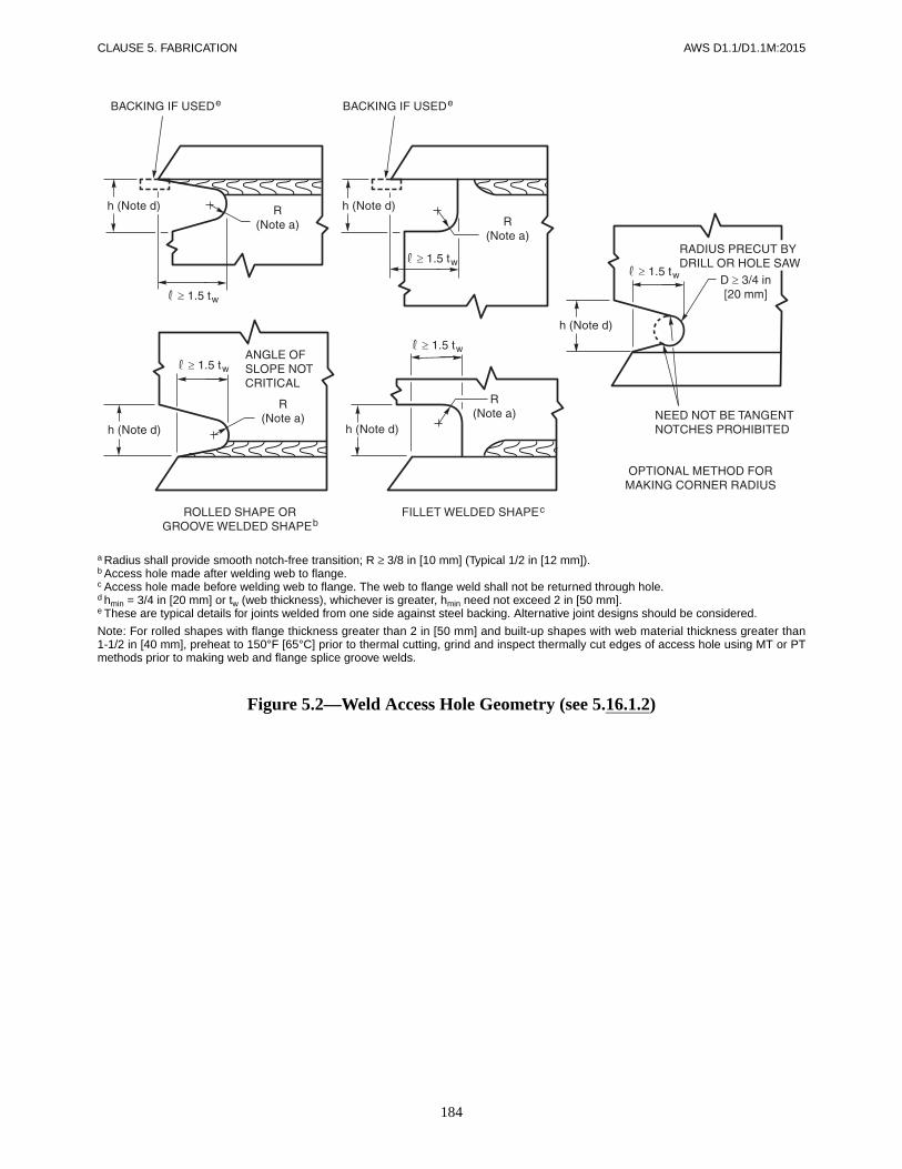
184
CLAUSE 5. FABRICATION AWS D1.1/D1.1M:2015
a Radius shall provide smooth notch-free transition; R ≥ 3/8 in [10 mm] (Typical 1/2 in [12 mm]).b Access hole made after welding web to flange.c Access hole made before welding web to flange. The web to flange weld shall not be returned through hole.d hmin = 3/4 in [20 mm] or tw (web thickness), whichever is greater, hmin need not exceed 2 in [50 mm].e These are typical details for joints welded from one side against steel backing. Alternative joint designs should be considered.
Note: For rolled shapes with flange thickness greater than 2 in [50 mm] and built-up shapes with web material thickness greater than1-1/2 in [40 mm], preheat to 150°F [65°C] prior to thermal cutting, grind and inspect thermally cut edges of access hole using MT or PTmethods prior to making web and flange splice groove welds.
Figure 5.2—Weld Access Hole Geometry (see 5.16.1.2)

185
AWS D1.1/D1.1M:2015 CLAUSE 5. FABRICATION
Figure 5.3—Workmanship Tolerances in Assembly of Groove Welded Joints
(see 5.21.4.1)
Root NotBackgouged
RootBackgouged
in mm in mm
(1) Root face of joint ±1/16 2 Not limited(2) Root opening of joints
without backing±1/16 2 +1/16
–1/8023
Root opening of joints with backing
+1/40–1/16
62 Not applicable
(3) Groove angle of joint +10°–5°0
+10°–5°0
Note: See 9.24.2.1 for tolerances for CJP tubular groove weldsmade from one side without backing.

186
CLAUSE 5. FABRICATION AWS D1.1/D1.1M:2015
Figure 5.4—Requirements for Weld Profiles (see Tables 5.8 and 5.9)
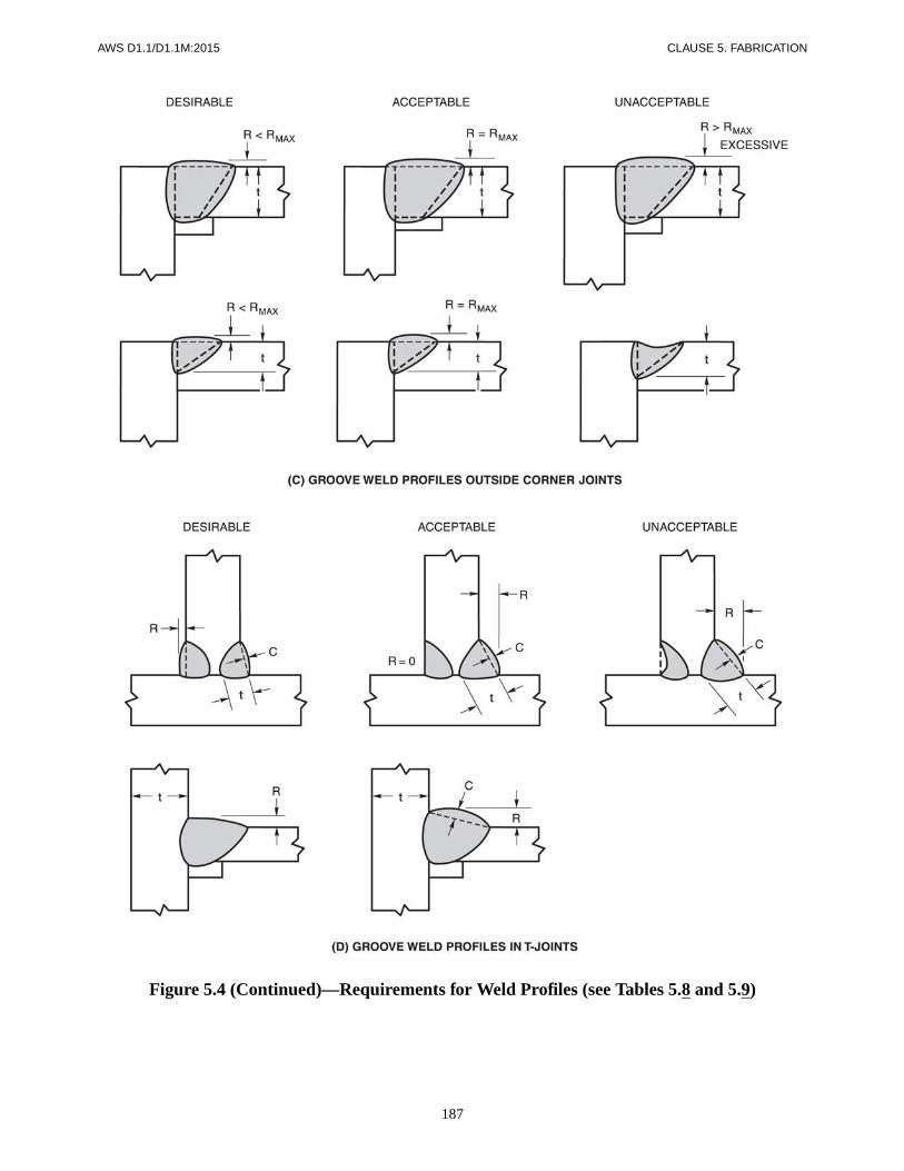
187
AWS D1.1/D1.1M:2015 CLAUSE 5. FABRICATION
Figure 5.4 (Continued)—Requirements for Weld Profiles (see Tables 5.8 and 5.9)
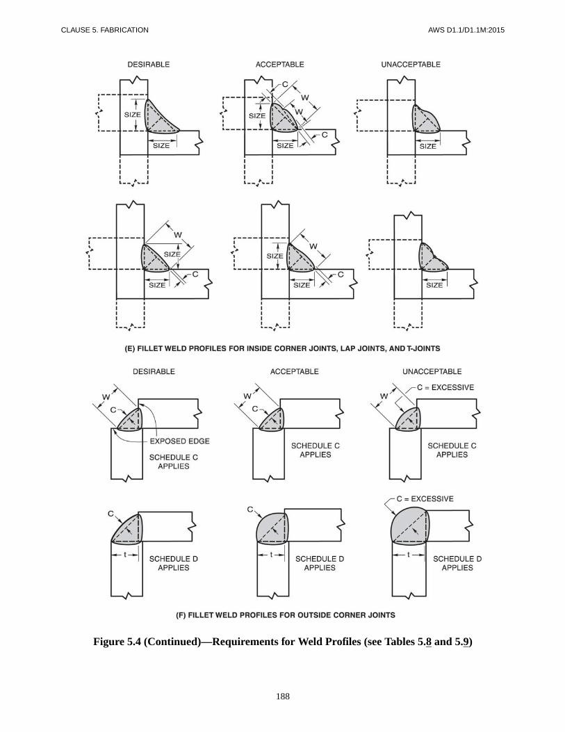
188
CLAUSE 5. FABRICATION AWS D1.1/D1.1M:2015
Figure 5.4 (Continued)—Requirements for Weld Profiles (see Tables 5.8 and 5.9)

189
AWS D1.1/D1.1M:2015 CLAUSE 5. FABRICATION
Figure 5.4 (Continued)—Requirements for Weld Profiles (see Tables 5.8 and 5.9)

AWS D1.1/D1.1M:2015
190
This page is intentionally blank.

AWS D1.1/D1.1M:2015
191
Part AGeneral Requirements
6.1 ScopeClause 6 contains all of the requirements for the Inspec-tor’s qualifications and responsibilities, acceptance crite-ria for discontinuities, and procedures for NDT.
6.1.1 Information Furnished to Bidders. When NDTother than visual is to be required, it shall be so stated inthe information furnished to the bidders. This informa-tion shall designate the categories of welds to be exam-ined, the extent of examination of each category, and themethod or methods of testing.
6.1.2 Inspection and Contract Stipulations. For thepurpose of this code, fabrication/erection inspection andtesting, and verification inspection and testing shall beseparate functions.
6.1.2.1 Contractor’s Inspection. This type of in-spection and test shall be performed as necessary prior toassembly, during assembly, during welding, and afterwelding to ensure that materials and workmanship meetthe requirements of the contract documents. Fabrica-tion/erection inspection and testing shall be the responsi-bilities of the Contractor unless otherwise provided in thecontract documents.
6.1.2.2 Verification Inspection. This type of inspec-tion and testing shall be performed and their results re-ported to the Owner and Contractor in a timely manner toavoid delays in the work. Verification inspection and test-ing are the prerogatives of the Owner who may performthis function or, when provided in the contract, waive in-dependent verification, or stipulate that both inspectionand verification shall be performed by the Contractor.
6.1.3 Definition of Inspector Categories
6.1.3.1 Contractor’s Inspector. This inspector is theduly designated person who acts for, and in behalf of, the
Contractor on all inspection and quality matters withinthe scope of the contract documents.
6.1.3.2 Verification Inspector. This inspector is theduly designated person who acts for, and in behalf of, theOwner or Engineer on all inspection and quality matterswithin the scope of the contract documents.
6.1.3.3 Inspector(s). When the term inspector is usedwithout further qualification as to the specific inspectorcategory described above, it applies equally to inspectionand verification within the limits of responsibility de-scribed in 6.1.2.
6.1.4 Inspector Qualification Requirements
6.1.4.1 Basis for Qualification. Inspectors re-sponsible for acceptance or rejection of material andworkmanship shall be qualified. The bases of Inspectorqualification shall be documented. If the Engineer electsto specify the bases of inspector qualification, it shall beso specified in contract documents.
The acceptable qualification basis shall be the following:
(1) Current or previous certification as an AWS Cer-tified Welding Inspector (CWI) in conformance with theprovisions of AWS QC1, Standard for AWS Certificationof Welding Inspectors, or
(2) Current or previous qualification by the CanadianWelding Bureau (CWB) in conformance with the re-quirements of the Canadian Standard Association (CSA)Standard W178.2, Certification of Welding Inspectors, or
(3) An individual who, by training or experience, orboth, in metals fabrication, inspection and testing, iscompetent to perform inspection of the work.
6.1.4.2 Term of Effectiveness. The qualification ofan Inspector shall remain in effect indefinitely, providedthe Inspector remains active in inspection of welded steelfabrication, unless there is specific reason to question theInspector’s ability.
6. Inspection
CLAUSE 6. INSPECTION AWS D1.1/D1.1M:2015
192
6.1.4.3 Assistant Inspector. The Inspector may besupported by Assistant Inspectors who may perform spe-cific inspection functions under the supervision of theInspector. Assistant Inspectors shall be qualified bytraining and experience to perform the specific functionsto which they are assigned. The work of Assistant In-spectors shall be regularly monitored by the Inspector,generally on a daily basis.
6.1.4.4 Eye Examination. Inspectors and AssistantInspectors shall have passed an eye examination withor without corrective lenses to prove near vision acuity ofJaeger J-2 at a distance of 12 in–17 in [300 mm–430 mm].Eye examination of all inspection personnel shall berequired every three years or less if necessary to demon-strate adequacy.
6.1.4.5 Verification Authority. The Engineer shallhave authority to verify the qualification of Inspectors.
6.1.5 Inspector Responsibility. The Inspector shall as-certain that all fabrication and erection by welding is per-formed in conformance with the requirements of thecontract documents.
6.1.6 Items to be Furnished to the Inspector. The In-spector shall be furnished complete detailed drawingsshowing the size, length, type, and location of all weldsto be made. The Inspector shall also be furnished the por-tion of the contract documents that describes materialand quality requirements for the products to be fabricatedor erected, or both.
6.1.7 Inspector Notification. The Inspector shall benotified in advance of the start of operations subject toinspection and verification.
6.2 Inspection of Materials andEquipment
The Contractor’s Inspector shall ensure that only mate-rials and equipment conforming to the requirements ofthis code shall be used.
6.3 Inspection of WPSs6.3.1 Prequalified WPS. The Contractor’s Inspectorshall ensure that all prequalified WPSs to be used for thework conform with the requirements of Clauses 3, 5, 9 (iftubular), and the contract documents.
6.3.2 WPSs Qualified by Test. The Contractor’s Inspec-tor shall ensure that all WPSs qualified by test conformwith the requirements of Clauses 4, 5, 9 (if tubular), andthe contract documents.
6.3.3 WPSs in Production. The Contractor’s Inspectorshall ensure that all welding operations are performed inconformance with WPSs that meet the requirements ofthis code and the contract documents.
6.4 Inspection of Welder, Welding Operator, and Tack Welder Qualifications
6.4.1 Determination of Qualification. The Inspectorshall allow welding to be performed only by welders,welding operators, and tack welders who are qualified inconformance with the requirements of Clause 4, orClause 9 for tubulars, or shall ensure that each welder,welding operator, or tack welder has previously demon-strated such qualification under other acceptable supervi-sion and approved by the Engineer in conformance with4.2.2.1.
6.4.2 Retesting Based on Quality of Work. When thequality of a qualified welder’s, welding operator’s, ortack welder’s work appears to be below the requirementsof this code, the Inspector may require that the welder,welding operator, or tack welder demonstrate an abilityto produce sound welds of the type that has not met re-quirements by means of a simple test, such as the filletweld break test, or by requiring complete requalificationin conformance with Clause 4, or Clause 9 for tubulars.
6.4.3 Retesting Based on Qualification Expiration.The Inspector shall require requalification of any welder,welding operator, or tack welder who has not used theprocess (for which they are qualified) for a period ex-ceeding six months (see 4.2.3.1).
6.5 Inspection of Work and Records6.5.1 Size, Length, and Location of Welds. The In-spector shall ensure that the size, length, and location ofall welds conform to the requirements of this code and tothe detail drawings and that no unspecified welds havebeen added without the approval of the Engineer.
6.5.2 Scope of Examinations. The Inspector shall, atsuitable intervals, observe joint preparation, assemblypractice, and the welding techniques, and performance ofeach welder, welding operator, and tack welder to ensurethat the applicable requirements of this code are met.
6.5.3 Extent of Examination. The Inspector shall ex-amine the work to ensure that it meets the requirementsof this code. Other acceptance criteria, different fromthose described in the code, may be used when approvedby the Engineer. Size and contour of welds shall be mea-
PART A

193
AWS D1.1/D1.1M:2015 CLAUSE 6. INSPECTION
sured with suitable gages. Visual inspection for cracks inwelds and base metal and other discontinuities should beaided by a strong light, magnifiers, or such other devicesas may be found helpful.
6.5.4 Inspector Identification of Inspections Per-formed. Inspectors shall identify with a distinguishingmark or other recording methods all parts or joints thatthey have inspected and accepted. Any recording methodwhich is mutually agreeable may be used. Die stampingof cyclically loaded members without the approval of theEngineer shall be prohibited.
6.5.5 Maintenance of Records. The Inspector shallkeep a record of qualifications of all welders, weldingoperators, and tack welders; all WPS qualifications orother tests that are made; and such other information asmay be required.
Part BContractor Responsibilities
6.6 Obligations of the Contractor6.6.1 Contractor Responsibilities. The Contractorshall be responsible for visual inspection and necessarycorrection of all deficiencies in materials and workman-ship in conformance with the requirements of this code.
6.6.2 Inspector Requests. The Contractor shall complywith all requests of the Inspector(s) to correct deficien-cies in materials and workmanship as provided in thecontract documents.
6.6.3 Engineering Judgment. In the event that faultywelding, or its removal for rewelding, damages the basemetal so that in the judgment of the Engineer its retentionis not in conformance with the intent of the contract doc-uments, the Contractor shall remove and replace thedamaged base metal or shall compensate for the defi-ciency in a manner approved by the Engineer.
6.6.4 Specified NDT Other than Visual. When NDTother than visual inspection is specified in the informa-tion furnished to bidders, it shall be the Contractor’s re-sponsibility to ensure that all specified welds shall meetthe quality requirements of Clause 6, Part C or Clause 9,Part F for tubulars, whichever is applicable.
6.6.5 Nonspecified NDT Other than Visual. If NDTother than visual inspection is not specified in the originalcontract agreement but is subsequently requested by theOwner, the Contractor shall perform any requested testingor shall allow any testing to be performed in conformance
with 6.14. The Owner shall be responsible for all associ-ated costs including handling, surface preparation, NDT,and repair of discontinuities other than those described in6.9, whichever is applicable, at rates mutually agreeablebetween Owner and Contractor. However, if such testingshould disclose an attempt to defraud or gross nonconfor-mance to this code, repair work shall be done at the Con-tractor’s expense.
Part CAcceptance Criteria
6.7 ScopeAcceptance criteria for visual and NDT inspection ofstatically and cyclically loaded nontubular connectionsare described in Part C. The extent of examination andthe acceptance criteria shall be specified in the contractdocuments in the information furnished to the bidder.
6.8 Engineer’s Approval for Alternate Acceptance Criteria
The fundamental premise of the code is to provide gen-eral stipulations applicable to most situations. Accep-tance criteria for production welds different from thosedescribed in the code may be used for a particular appli-cation, provided they are suitably documented by theproposer and approved by the Engineer. These alternateacceptance criteria may be based upon evaluation of suit-ability for service using past experience, experimentalevidence or engineering analysis considering materialtype, service load effects, and environmental factors.
6.9 Visual InspectionAll welds shall be visually inspected and shall beacceptable if the criteria of Table 6.1, or Table 9.16 (iftubular) are satisfied.
6.10 Penetrant Testing (PT) and Magnetic Particle Testing (MT)
Welds that are subject to PT and MT, in addition to visualinspection, shall be evaluated on the basis of the accep-tance criteria for visual inspection. The testing shall beperformed in conformance with 6.14.4 or 6.14.5, which-ever is applicable.
PARTS A, B, & C
CLAUSE 6. INSPECTION AWS D1.1/D1.1M:2015
194
6.11 Nondestructive Testing (NDT)Except as provided for in 9.29 for tubulars, all NDTmethods including equipment requirements and qualifi-cations, personnel qualifications, and operating methodsshall be in conformance with Clause 6, Inspection. Ac-ceptance criteria shall be as described in this section.Welds subject to NDT shall have been found acceptableby visual inspection in conformance with 6.9.
For welds subject to NDT in conformance with 6.10,6.11, 9.26.2, and 9.27.1, the testing may begin immedi-ately after the completed welds have cooled to ambienttemperature. Acceptance criteria for ASTM A514, A517,and A709 Grade HPS 100W [690W] steels shall bebased on NDT performed not less than 48 hours aftercompletion of the welds.
6.12 Radiographic Testing (RT)Welds shown by RT that do not meet the requirements ofPart C, or alternate acceptance criteria per 6.8, shall berepaired in conformance with 5.25. Discontinuities otherthan cracks shall be evaluated on the basis of being eitherelongated or rounded. Regardless of the type of disconti-nuity, an elongated discontinuity shall be defined as onein which its length exceeds three times its width. Arounded discontinuity shall be defined as one in which itslength is three times its width or less and may be roundor irregular and may have tails.
6.12.1 Discontinuity Acceptance Criteria for StaticallyLoaded Nontubular Connections. Welds that are sub-ject to RT in addition to visual inspection shall have nocracks and shall be unacceptable if the RT shows any dis-continuities exceeding the following limitations. Thelimitations given by Figure 6.1 for 1-1/8 in [30 mm]weld size (E) shall apply to all weld sizes greater than 1-1/8 in [30 mm].
(1) Elongated discontinuities exceeding the maxi-mum size of Figure 6.1.
(2) Discontinuities closer than the minimum clear-ance allowance of Figure 6.1.
(3) Rounded discontinuities greater than a maximumsize of E/3, not to exceed 1/4 in [6 mm]. However, whenE is greater than 2 in [50 mm], the maximum roundedindication may be 3/8 in [10 mm]. The minimum clear-ance of rounded discontinuities greater than or equal to3/32 in [2.5 mm] to an acceptable elongated or roundeddiscontinuity or to an edge or end of an intersecting weldshall be three times the greatest dimension of the largerof the discontinuities being considered.
(4) At the intersection of a weld with another weld ora free edge (i.e., an edge beyond which no materialextension exists), acceptable discontinuities shall con-form to the limitations of Figure 6.1, Cases I–IV.
(5) Isolated discontinuities such as a cluster ofrounded indications, having a sum of their greatestdimensions exceeding the maximum size single disconti-nuity allowed in Figure 6.1. The minimum clearance toanother cluster or an elongated or rounded discontinuityor to an edge or end of an intersecting weld shall be threetimes the greatest dimension of the larger of the disconti-nuities being considered.
(6) The sum of individual discontinuities each havinga greater dimension of less than 3/32 in [2.5 mm] shallnot exceed 2E/3 or 3/8 in [10 mm], whichever is less, inany linear 1 in [25 mm] of weld. This requirement isindependent of (1), (2), and (3) above.
(7) In-line discontinuities, where the sum of thegreatest dimensions exceeds E in any length of 6E. Whenthe length of the weld being examined is less than 6E, theallowable sum of the greatest dimensions shall be pro-portionally less.
6.12.2 Discontinuity Acceptance Criteria for Cycli-cally Loaded Nontubular Connections. Welds that aresubject to RT in addition to visual inspection shall haveno cracks and shall be unacceptable if the RT shows anyof the types of discontinuities described in 6.12.2.1,6.12.2.2, or 6.12.2.3. The limitations given by Figures6.2 and 6.3 for 1-1/2 in [38 mm] weld size (E) shall applyto all weld sizes greater than 1-1/2 in [38 mm].
6.12.2.1 Cyclically Loaded Nontubular Connec-tions in Tension
(1) Discontinuities exceeding the maximum size ofFigure 6.2.
(2) Discontinuities closer than the minimum clear-ance allowance of Figure 6.2.
(3) At the intersection of a weld with another weld ora free edge (i.e., an edge beyond which no materialextension exists), acceptable discontinuities shall con-form to the limitations of Figure 6.2, Cases I–IV.
(4) Isolated discontinuities such as a cluster ofrounded indications, having a sum of their greatestdimensions exceeding the maximum size single disconti-nuity allowed in Figure 6.2. The minimum clearance toanother cluster or an elongated or rounded discontinuityor to an edge or end of an intersecting weld shall be threetimes the greatest dimension of the larger of the disconti-nuities being considered.
PART CPART C
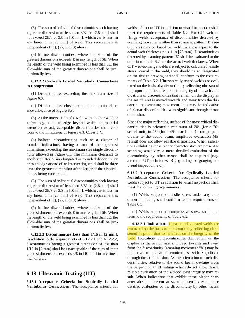
195
AWS D1.1/D1.1M:2015 CLAUSE 6. INSPECTION
(5) The sum of individual discontinuities each havinga greater dimension of less than 3/32 in [2.5 mm] shallnot exceed 2E/3 or 3/8 in [10 mm], whichever is less, inany linear 1 in [25 mm] of weld. This requirement isindependent of (1), (2), and (3) above.
(6) In-line discontinuities, where the sum of thegreatest dimensions exceeds E in any length of 6E. Whenthe length of the weld being examined is less than 6E, theallowable sum of the greatest dimensions shall be pro-portionally less.
6.12.2.2 Cyclically Loaded Nontubular Connectionsin Compression
(1) Discontinuities exceeding the maximum size ofFigure 6.3.
(2) Discontinuities closer than the minimum clear-ance allowance of Figure 6.3.
(3) At the intersection of a weld with another weld ora free edge (i.e., an edge beyond which no materialextension exists), acceptable discontinuities shall con-form to the limitations of Figure 6.3, Cases I–V.
(4) Isolated discontinuities such as a cluster ofrounded indications, having a sum of their greatestdimensions exceeding the maximum size single disconti-nuity allowed in Figure 6.3. The minimum clearance toanother cluster or an elongated or rounded discontinuityor to an edge or end of an intersecting weld shall be threetimes the greatest dimension of the larger of the disconti-nuities being considered.
(5) The sum of individual discontinuities each havinga greater dimension of less than 3/32 in [2.5 mm] shallnot exceed 2E/3 or 3/8 in [10 mm], whichever is less, inany linear 1 in [25 mm] of weld. This requirement isindependent of (1), (2), and (3) above.
(6) In-line discontinuities, where the sum of thegreatest dimensions exceeds E in any length of 6E. Whenthe length of the weld being examined is less than 6E, theallowable sum of the greatest dimensions shall be pro-portionally less.
6.12.2.3 Discontinuities Less than 1/16 in [2 mm].In addition to the requirements of 6.12.2.1 and 6.12.2.2,discontinuities having a greatest dimension of less than1/16 in [2 mm] shall be unacceptable if the sum of theirgreatest dimensions exceeds 3/8 in [10 mm] in any linearinch of weld.
6.13 Ultrasonic Testing (UT)6.13.1 Acceptance Criteria for Statically LoadedNontubular Connections. The acceptance criteria for
welds subject to UT in addition to visual inspection shallmeet the requirements of Table 6.2. For CJP web-to-flange welds, acceptance of discontinuities detected byscanning movements other than scanning pattern ‘E’ (see6.30.2.2) may be based on weld thickness equal to theactual web thickness plus 1 in [25 mm]. Discontinuitiesdetected by scanning pattern ‘E’ shall be evaluated to thecriteria of Table 6.2 for the actual web thickness. WhenCJP web-to-flange welds are subject to calculated tensilestress normal to the weld, they should be so designatedon the design drawing and shall conform to the require-ments of Table 6.2. Ultrasonically tested welds are eval-uated on the basis of a discontinuity reflecting ultrasoundin proportion to its effect on the integrity of the weld. In-dications of discontinuities that remain on the display asthe search unit is moved towards and away from the dis-continuity (scanning movement “b”) may be indicativeof planar discontinuities with significant through-throatdimension.
Since the major reflecting surface of the most critical dis-continuities is oriented a minimum of 20° (for a 70°search unit) to 45° (for a 45° search unit) from perpen-dicular to the sound beam, amplitude evaluation (dBrating) does not allow reliable disposition. When indica-tions exhibiting these planar characteristics are present atscanning sensitivity, a more detailed evaluation of thediscontinuity by other means shall be required (e.g.,alternate UT techniques, RT, grinding or gouging forvisual inspection, etc.).
6.13.2 Acceptance Criteria for Cyclically LoadedNontubular Connections. The acceptance criteria forwelds subject to UT in addition to visual inspection shallmeet the following requirements:
(1) Welds subject to tensile stress under any con-dition of loading shall conform to the requirements ofTable 6.3.
(2) Welds subject to compressive stress shall con-form to the requirements of Table 6.2.
6.13.2.1 Indications. Ultrasonically tested welds areevaluated on the basis of a discontinuity reflecting ultra-sound in proportion to its effect on the integrity of theweld. Indications of discontinuities that remain on thedisplay as the search unit is moved towards and awayfrom the discontinuity (scanning movement “b”) may beindicative of planar discontinuities with significantthrough throat dimension. As the orientation of such dis-continuities, relative to the sound beam, deviates fromthe perpendicular, dB ratings which do not allow direct,reliable evaluation of the welded joint integrity may re-sult. When indications that exhibit these planar char-acteristics are present at scanning sensitivity, a moredetailed evaluation of the discontinuity by other means
PART C
M.VAFAKHAH
Highlight

CLAUSE 6. INSPECTION AWS D1.1/D1.1M:2015
196
may be required (e.g., alternate UT techniques, RT,grinding, or gouging for visual inspection, etc.).
6.13.2.2 Scanning. CJP web-to-flange welds shallconform to the requirements of Table 6.2, and accep-tance for discontinuities detected by scanning move-ments other than scanning pattern ‘E’ (see 6.30.2.2) maybe based on a weld thickness equal to the actual webthickness plus 1 in [25 mm]. Discontinuities detected byscanning pattern ‘E’ shall be evaluated to the criteria of6.13.2 for the actual web thickness. When such web-to-flange welds are subject to calculated tensile stress nor-mal to the weld, they shall be so designated on designdrawings and shall conform to the requirements of Table6.3.
Part DNDT Procedures
6.14 ProceduresThe NDT procedures as described in this code have
been in use for many years and provide reasonable assur-ance of weld integrity; however, it appears that someusers of the code incorrectly consider each method capa-ble of detecting all unacceptable discontinuities. Users ofthe code should become familiar with all the limitationsof NDT methods to be used, particularly the inability todetect and characterize planar discontinuities with spe-cific orientations. (The limitations and complementaryuse of each method are explained in the latest edition ofAWS B1.10, Guide for Nondestructive Examination ofWelds.)
6.14.1 RT. When RT is used, the procedure and tech-nique shall be in conformance with Part E of this clauseor Clause 9, Part F for tubulars.
6.14.2 Radiation Imaging Systems. When examinationis performed using radiation imaging systems, the proce-dures and techniques shall be in conformance with PartG of this clause.
6.14.3 UT. When UT is used, the procedure and tech-nique shall be in conformance with Part F of this clause.
6.14.4 MT. When MT is used, the procedure and tech-nique shall be in conformance with ASTM E709, and thestandard of acceptance shall be in conformance withClause 6, Part C, of this code.
6.14.5 PT. For detecting discontinuities that are open tothe surface, PT may be used. The standard methods setforth in ASTM E165 shall be used for PT inspection, and
the standards of acceptance shall be in conformance withClause 6, Part C, of this code.
6.14.6 Personnel Qualification
6.14.6.1 ASNT Requirements. Personnel perform-ing NDT other than visual shall be qualified in conform-ance with the current edition of the American Society forNondestructive Testing Recommended Practice No.SNT-TC-1A. Individuals who perform NDT shall bequalified for:
(1) NDT Level II, or
(2) NDT Level I working under the NDT Level II
6.14.6.2 Certification. Certification of Level I andLevel II individuals shall be performed by a Level III in-dividual who has been certified by:
(1) The American Society for Nondestructive Test-ing, or
(2) has the education, training, experience, and hassuccessfully passed the written examination described inSNT-TC-1A.
6.14.6.3 Exemption of QC1 Requirements. Person-nel performing NDT under the provisions of 6.14.6 neednot be qualified and certified under the provisions ofAWS QC1.
6.15 Extent of TestingInformation furnished to the bidders shall clearly identifythe extent of NDT (types, categories, or location) ofwelds to be tested.
6.15.1 Full Testing. Weld joints requiring testing bycontract specification shall be tested for their full length,unless partial or spot testing is specified.
6.15.2 Partial Testing. When partial testing is speci-fied, the location and lengths of welds or categories ofweld to be tested shall be clearly designated in the con-tract documents.
6.15.3 Spot Testing. When spot testing is specified, thenumber of spots in each designated category of weldedjoint to be tested in a stated length of weld or a desig-nated segment of weld shall be included in the infor-mation furnished to the bidders. Each spot test shallcover at least 4 in [100 mm] of the weld length. Whenspot testing reveals indications of unacceptable disconti-nuities that require repair, the extent of those discontinu-ities shall be explored. Two additional spots in the same
PARTS C & D
M.VAFAKHAH
Highlight
M.VAFAKHAH
Highlight
M.VAFAKHAH
Highlight
M.VAFAKHAH
Highlight

197
AWS D1.1/D1.1M:2015 CLAUSE 6. INSPECTION
segment of weld joint shall be taken at locations awayfrom the original spot. The location of the additionalspots shall be agreed upon between the Contractor andthe Verification Inspector.
When either of the two additional spots show defects thatrequire repair, the entire segment of weld represented bythe original spot shall be completely tested. If the weldinvolves more than one segment, two additional spots ineach segment shall be tested at locations agreed upon bythe Contractor and the Verification Inspector, subject tothe foregoing interpretation.
6.15.4 Relevant Information. NDT personnel shall,prior to testing, be furnished or have access to relevantinformation regarding weld joint geometries, materialthicknesses, and welding processes used in making theweldment. NDT personnel shall be apprised of any sub-sequent repairs to the weld.
Part ERadiographic Testing (RT)
6.16 RT of Groove Welds in Butt Joints
6.16.1 Procedures and Standards. The procedures andstandards set forth in Part E shall govern RT of weldswhen such inspection is required by the contract docu-ments as provided in 6.14.1. The requirements describedherein are specifically for testing groove welds in buttjoints in plate, shapes, and bars by X-ray or gamma-raysources. The methodology shall conform to ASTM E94,Standard Recommended Practice for Radiographic Test-ing, ASTM E142, Standard Method for ControllingQuality of Radiographic Testing, ASTM E747, ControllingQuality of Radiographic Testing Using Wire Penetrame-ters, and ASTM E1032, Radiographic Examination ofWeldments.
6.16.2 Variations. Variations in testing procedures,equipment, and acceptance standards may be used uponagreement between the Contractor and the Owner. Suchvariations include, but are not limited to, the following:RT of fillet and groove welds in T and corner joints;changes in source-to-film distance; unusual applicationof film; unusual hole-type or wire-type image quality in-dicators (IQI) applications (including film side IQI); andfor RT of thicknesses greater than 6 in [150 mm] filmtypes, densities, and variations in exposure, development,and viewing techniques.
6.17 RT Procedures
6.17.1 Procedure. Radiographs shall be made using asingle source of either X- or gamma radiation. The radio-graphic sensitivity shall be judged based on hole-typeimage or wire IQIs. Radiographic technique and equip-ment shall provide sufficient sensitivity to clearly delin-eate the required hole-type IQIs and the essential holesor wires as described in 6.17.7 and 9.28.1; Tables 6.4,6.5, 9.17, and 9.18; and Figures 6.4 and 6.5. Identifyingletters and numbers shall show clearly in the radiograph.
6.17.2 Safety Requirements. RT shall be performed inconformance with all applicable safety requirements.
6.17.3 Removal of Reinforcement. When the contractdocuments require the removal of weld reinforcement,the welds shall be prepared for RT by grinding as de-scribed in 5.23.3.1. Other weld surfaces need not beground or otherwise smoothed for purposes of RT unlesssurface irregularities or the junction between weld andbase metal may cause objectionable weld discontinuitiesto be obscured in the radiograph.
6.17.3.1 Tabs. Weld tabs shall be removed prior toRT unless otherwise approved by the Engineer.
6.17.3.2 Steel Backing. When required by 5.9.1 orother provisions of the contract documents, steel backingshall be removed, and the surface shall be finished flushby grinding prior to RT. Grinding shall be as described in5.23.3.1.
6.17.3.3 Reinforcement. When weld reinforcementor backing, or both, is not removed, or wire IQI alternateplacement is not used, steel shims which extend at least1/8 in [3 mm] beyond three sides of the required hole-type IQI or wire IQI shall be placed under the hole-typeIQI or wire IQI, so that the total thickness of steel be-tween the hole-type IQI and the film is approximatelyequal to the average thickness of the weld measuredthrough its reinforcement and backing.
6.17.4 Radiographic Film. Radiographic film shall beas described in ASTM E94. Lead foil screens shall beused as described in ASTM E94. Fluorescent screensshall be prohibited.
6.17.5 Technique. Radiographs shall be made with asingle source of radiation centered as near as practicablewith respect to the length and width of that portion of theweld being examined.
6.17.5.1 Geometric Unsharpness. Gamma ray sources,regardless of size, shall be capable of meeting the geo-metric unsharpness limitation of ASME Boiler and Pres-sure Vessel Code, Section V, Article 2.
PARTS D & E

CLAUSE 6. INSPECTION AWS D1.1/D1.1M:2015
198
6.17.5.2 Source-to-Subject Distance. The source-to-subject distance shall not be less than the total lengthof film being exposed in a single plane. This provisionshall not apply to panoramic exposures made under theprovisions of 6.16.2.
6.17.5.3 Source-to-Subject Distance Limitations.The source-to-subject distance shall not be less thanseven times the thickness of weld plus reinforcement andbacking, if any, nor such that the inspecting radiationshall penetrate any portion of the weld represented in theradiograph at an angle greater than 26-1/2° from a linenormal to the weld surface.
6.17.6 Sources. X-ray units, 600 kVp maximum, andiridium 192 may be used as a source for all RT providedthey have adequate penetrating ability. Cobalt 60 shallonly be used as a radiographic source when the steelbeing radiographed exceeds 2-1/2 in [65 mm] in thick-ness. Other radiographic sources may be used with theapproval of the Engineer.
6.17.7 IQI Selection and Placement. IQIs shall be se-lected and placed on the weldment in the area of interestbeing radiographed as shown in Table 6.6.
6.17.8 Technique. Welded joints shall be radiographedand the film indexed by methods that will provide com-plete and continuous inspection of the joint within thelimits specified to be examined. Joint limits shall showclearly in the radiographs. Short film, short screens, ex-cessive undercut by scattered radiation, or any otherprocess that obscures portions of the total weld lengthshall render the radiograph unacceptable.
6.17.8.1 Film Length. Film shall have sufficientlength and shall be placed to provide at least 1/2 in[12 mm] of film beyond the projected edge of the weld.
6.17.8.2 Overlapping Film. Welds longer than 14 in[350 mm] may be radiographed by overlapping film cas-settes and making a single exposure, or by using singlefilm cassettes and making separate exposures. The provi-sions of 6.17.5 shall apply.
6.17.8.3 Backscatter. To check for backscatter radi-ation, a lead symbol “B,” 1/2 in [12 mm] high, 1/16 in[2 mm] thick shall be attached to the back of each filmcassette. If the “B” image appears on the radiograph, theradiograph shall be considered unacceptable.
6.17.9 Film Width. Film widths shall be sufficient to de-pict all portions of the weld joint, including the HAZs, andshall provide sufficient additional space for the requiredhole-type IQIs or wire IQI and film identification withoutinfringing upon the area of interest in the radiograph.
6.17.10 Quality of Radiographs. All radiographs shallbe free from mechanical, chemical, or other blemishes to
the extent that they cannot mask or be confused with theimage of any discontinuity in the area of interest in theradiograph. Such blemishes include, but are not limitedto the following:
(1) fogging
(2) processing defects such as streaks, water marks,or chemical stains
(3) scratches, finger marks, crimps, dirtiness, staticmarks, smudges, or tears
(4) loss of detail due to poor screen-to-film contact
(5) false indications due to defective screens or inter-nal faults
6.17.11 Density Limitations. The transmitted film den-sity through the radiographic image of the body of therequired hole-type IQI(s) and the area of interest shall be1.8 minimum for single film viewing for radiographsmade with an X-ray source and 2.0 minimum for radio-graphs made with a gamma-ray source. For compositeviewing of double film exposures, the minimum densityshall be 2.6. Each radiograph of a composite set shallhave a minimum density of 1.3. The maximum densityshall be 4.0 for either single or composite viewing.
6.17.11.1 H & D Density. The density measuredshall be H & D density (radiographic density), which is ameasure of film blackening, expressed as:
D = log Io/I
where:
D = H & D (radiographic) densityIo = light intensity on the film, andI = light transmitted through the film.
6.17.11.2 Transitions. When weld transitions inthickness are radiographed and the ratio of the thicknessof the thicker section to the thickness of the thinner sec-tion is 3 or greater, radiographs should be exposed toproduce single film densities of 3.0 to 4.0 in the thinnersection. When this is done, the minimum density require-ments of 6.17.11 shall be waived unless otherwise pro-vided in the contract documents.
6.17.12 Identification Marks. A radiograph identi-fication mark and two location identification marks shallbe placed on the steel at each radiograph location. Acorresponding radiograph identification mark and twolocation identification marks, all of which shall show inthe radiograph, shall be produced by placing lead num-bers or letters, or both, over each of the identical identifi-cation and location marks made on the steel to provide ameans for matching the developed radiograph to theweld. Additional identification information may be pre-
PART EPART E

199
AWS D1.1/D1.1M:2015 CLAUSE 6. INSPECTION
printed no less than 3/4 in [20 mm] from the edge of theweld or shall be produced on the radiograph by placinglead figures on the steel. Information required to show onthe radiograph shall include the Owner’s contract identi-fication, initials of the RT company, initials of the fabri-cator, the fabricator shop order number, the radiographicidentification mark, the date, and the weld repair num-ber, if applicable.
6.17.13 Edge Blocks. Edge blocks shall be used whenradiographing butt joints greater than 1/2 in [12 mm]thickness. The edge blocks shall have a length sufficientto extend beyond each side of the weld centerline for aminimum distance equal to the weld thickness, but noless than 2 in [50 mm], and shall have a thickness equalto or greater than the thickness of the weld. The mini-mum width of the edge blocks shall be equal to half theweld thickness, but not less than 1 in [25 mm]. The edgeblocks shall be centered on the weld against the platebeing radiographed, allowing no more than 1/16 in[2 mm] gap for the minimum specified length of theedge blocks. Edge blocks shall be made of radiograph-ically clean steel and the surface shall have a finish ofANSI 125 µin [3 µm] or smoother (see Figure 6.10).
6.18 Examination, Report, and Disposition of Radiographs
6.18.1 Equipment Provided by Contractor. The Con-tractor shall provide a suitable variable intensity illumi-nator (viewer) with spot review or masked spot reviewcapability. The viewer shall incorporate a means for ad-justing the size of the spot under examination. Theviewer shall have sufficient capacity to properly illumi-nate radiographs with an H & D density of 4.0. Film re-view shall be done in an area of subdued light.
6.18.2 Reports. Before a weld subject to RT by theContractor for the Owner is accepted, all of its radio-graphs, including any that show unacceptable qualityprior to repair, and a report interpreting them shall besubmitted to the Verification Inspector.
6.18.3 Record Retention. A full set of radiographs forwelds subject to RT by the Contractor for the Owner, in-cluding any that show unacceptable quality prior to re-pair, shall be delivered to the Owner upon completion ofthe work. The Contractor’s obligation to retain radio-graphs shall cease:
(1) upon delivery of this full set to the Owner, or
(2) one full year after the completion of the Con-tractor’s work, provided the Owner is given prior writtennotice.
Part FUltrasonic Testing (UT)
of Groove Welds
6.19 General
6.19.1 Procedures and Standards. The procedures andstandards set forth in Part F shall govern the UT of groovewelds and HAZs between the thicknesses of 5/16 in and8 in [8 mm and 200 mm] inclusive, when such testing isrequired by 6.14 of this code. For thicknesses less than5/16 in [8 mm] or greater than 8 in [200 mm], testingshall be performed in conformance with Annex Q. Theseprocedures and standards shall be prohibited for testingtube-to-tube T-, Y-, or K-connections.
6.19.2 Variations. Annex Q is an example of an alterna-tive technique for performing UT examination of groovewelds. Variations in testing procedure, equipment, andacceptance standards not included in Part F of Clause 6may be used with the approval of the Engineer. Suchvariations include other thicknesses, weld geometries,transducer sizes, frequencies, couplant, painted surfaces,testing techniques, etc. Such approved variations shall berecorded in the contract records.
6.19.3 Piping Porosity. To detect possible piping poros-ity, RT is recommended to supplement UT of ESW orEGW welds.
6.19.4 Base Metal. These procedures are not intended tobe employed for the procurement testing of base metals.However, welding related discontinuities (cracking,lamellar tearing, delaminations, etc.) in the adjacent basemetal which would not be acceptable under the provi-sions of this code shall be reported to the Engineer fordisposition.
6.20 Qualification Requirements
In satisfying the requirements of 6.14.6, the qualificationof the UT operator shall include a specific and practicalexamination which shall be based on the requirements ofthis code. This examination shall require the UT operatorto demonstrate the ability to apply the rules of this codein the accurate detection and disposition of discontinuities.
6.21 UT Equipment
6.21.1 Equipment Requirements. The UT instrumentshall be the pulse echo type suitable for use with trans-ducers oscillating at frequencies between 1 and 6 mega-
PARTS E & F

CLAUSE 6. INSPECTION AWS D1.1/D1.1M:2015
200
hertz. The display shall be an “A” scan rectified videotrace. The requirements shall be as shown in Table 6.8.
6.21.2 Horizontal Linearity. The horizontal linearity ofthe test instrument shall be qualified over the full sound-path distance to be used in testing in conformance with6.28.1.
6.21.3 Requirements for Test Instruments. Test in-struments shall include internal stabilization so that afterwarm-up, no variation in response greater than ± 1 dBoccurs with a supply voltage change of 15% nominal or,in the case of a battery, throughout the charge operatinglife. There shall be an alarm or meter to signal a drop inbattery voltage prior to instrument shutoff due to batteryexhaustion.
6.21.4 Calibration of Test Instruments. The test in-strument shall have a calibrated gain control (attenuator)adjustable in discrete 1 or 2 dB steps over a range of atleast 60 dB. The accuracy of the attenuator settings shallbe within plus or minus 1 dB. The procedure for qualifi-cation shall be as described in 6.23.2 and 6.28.2.
6.21.5 Display Range. The dynamic range of the instru-ment’s display shall be such that a difference of 1 dB ofamplitude can be easily detected on the display.
6.21.6 Straight-Beam (Longitudinal Wave) SearchUnits. Straight-beam (longitudinal wave) search unittransducers shall have an active area of not less than1/2 in2 [323 mm2] nor more than 1 in2 [645 mm2]. Thetransducer shall be round or square. Transducers shall becapable of resolving the three reflections as described in6.27.1.3.
6.21.7 Angle-Beam Search Units. Angle-beam searchunits shall consist of a transducer and an angle wedge.The unit may be comprised of the two separate elementsor may be an integral unit.
6.21.7.1 Frequency. The transducer frequency shallbe between 2 and 2.5 MHz, inclusive.
6.21.7.2 Transducer Dimensions. The transducercrystal shall be square or rectangular in shape and mayvary from 5/8 in to 1 in [15 mm to 25 mm] in width andfrom 5/8 in to 13/16 in [15 mm to 20 mm] in height (seeFigure 6.11). The maximum width to height ratio shall be1.2 to 1.0, and the minimum width-to-height ratio shallbe 1.0 to 1.0.
6.21.7.3 Angles. The search unit shall produce asound beam in the material being tested within plus orminus 2° of one of the following proper angles: 70°, 60°,or 45°, as described in 6.27.2.2.
6.21.7.4 Marking. Each search unit shall be markedto clearly indicate the frequency of the transducer, nomi-
nal angle of refraction, and index point. The index pointlocation procedure is described in 6.27.2.1.
6.21.7.5 Internal Reflections. Maximum allowableinternal reflections from the search unit shall be as de-scribed in 6.23.3 and 6.28.3.
6.21.7.6 Edge Distance. The dimensions of thesearch unit shall be such that the distance from the lead-ing edge of the search unit to the index point shall notexceed 1 in [25 mm].
6.21.7.7 IIW Type Block. The qualification proce-dure using the IIW reference block or other IIW typeblock shall be in conformance with 6.27.2.6 and asshown in Figure 6.12.
6.22 Reference Standards
6.22.1 IIW Standard. Any of the International Instituteof Welding (IIW) type UT reference blocks may be usedas the standard for both distance and sensitivity calibra-tion, provided the block includes the 0.060 in [1.5 mm]diameter hole as shown in Figure 6.13 and distance, reso-lution, and angle verification features of Figure 6.16(positions A through G). IIW type blocks shall conform toASTM E164. Other portable blocks may be used, pro-vided the reference level sensitivity for instrument/search unit combination is adjusted to be the equivalentof that achieved with the IIW type block (see Annex G,for examples).
6.22.2 Prohibited Reflectors. The use of a “corner” re-flector for calibration purposes shall be prohibited.
6.22.3 Resolution Requirements. The combination ofsearch unit and instrument shall resolve three holes in theRC resolution reference test block shown in Figure 6.14.The search unit position is described in 6.27.2.5. The res-olution shall be evaluated with the instrument controlsset at normal test settings and with indications from theholes brought to midscreen height. Resolution shall besufficient to distinguish at least the peaks of indicationsfrom the three holes. Use of the RC resolution referenceblock for calibration shall be prohibited. Each combina-tion of instrument search unit (shoe and transducer) shallbe checked prior to its initial use. This equipment verifi-cation shall be done initially with each search unit andUT unit combination. The verification need not be doneagain provided documentation is maintained that recordsthe following items:
(1) UT machine’s make, model and serial number
(2) Search unit’s manufacturer, type, size, angle, andserial number
PART F

201
AWS D1.1/D1.1M:2015 CLAUSE 6. INSPECTION
(3) Date of verification and technician’s name
6.23 Equipment Qualification6.23.1 Horizontal Linearity. The horizontal linearityof the test instrument shall be requalified at two-monthintervals in each of the distance ranges that the instru-ment will be used. The qualification procedure shall bein conformance with 6.28.1 (see Annex G, for alternativemethod).
6.23.2 Gain Control. The instrument’s gain control(attenuator) shall meet the requirements of 6.21.4 andshall be checked for correct calibration at two monthintervals in conformance with 6.28.2. Alternative meth-ods may be used for calibrated gain control (attenuator)qualification if proven at least equivalent with 6.28.2.
6.23.3 Internal Reflections. Maximum internal reflec-tions from each search unit shall be verified at a maxi-mum time interval of 40 hours of instrument use inconformance with 6.28.3.
6.23.4 Calibration of Angle-Beam Search Units. Withthe use of an approved calibration block, each angle-beam search unit shall be checked after each eight hoursof use to determine that the contact face is flat, thatthe sound entry point is correct, and that the beam angleis within the allowed plus or minus 2° tolerance inconformance with 6.27.2.1 and 6.27.2.2. Search unitswhich do not meet these requirements shall be correctedor replaced.
6.24 Calibration for Testing6.24.1 Position of Reject Control. All calibrations andtests shall be made with the reject (clipping or suppres-sion) control turned off. Use of the reject (clipping orsuppression) control may alter the amplitude linearity ofthe instrument and invalidate test results.
6.24.2 Technique. Calibration for sensitivity and horizon-tal sweep (distance) shall be made by the UT operator justprior to and at the location of the first weld tested. Afterthat, requirements of 6.24.3 recalibration shall apply.
6.24.3 Recalibration. Recalibration shall be made aftera change of operators, each two-hour maximum timeinterval, or when the electrical circuitry is disturbed inany way which includes the following:
(1) Transducer change
(2) Battery change
(3) Electrical outlet change
(4) Coaxial cable change
(5) Power outage (failure)
6.24.4 Straight-Beam Testing of Base Metal. Calibra-tion for straight-beam testing of base metal shall be madewith the search unit applied to Face A of the base metaland performed as follows:
6.24.4.1 Sweep. The horizontal sweep shall be ad-justed for distance calibration to present the equivalent ofat least two plate thicknesses on the display.
6.24.4.2 Sensitivity. The sensitivity shall be adjustedat a location free of indications so that the first backreflection from the far side of the plate will be 50% to75% of full screen height.
6.24.5 Calibration for Angle-Beam Testing. Calibra-tion for angle-beam testing shall be performed as follows(see Annex G, G2.4 for alternative method).
6.24.5.1 Horizontal Sweep. The horizontal sweepshall be adjusted to represent the actual sound-path dis-tance by using the IIW type block or alternative blocks asdescribed in 6.22.1. The distance calibration shall bemade using either the 5 in [125 mm] scale or 10 in[250 mm] scale on the display, whichever is appropriate.If, however, the joint configuration or thickness preventsfull examination of the weld at either of these settings,the distance calibration shall be made using 15 in or 20 in[400 mm or 500 mm] scale as required. The search unitposition is described in 6.27.2.3.
NOTE: The horizontal location of all screen indicationsis based on the location at which the left side of the tracedeflection breaks the horizontal base line.
6.24.5.2 Zero Reference Level. The zero referencelevel sensitivity used for discontinuity evaluation (“b” onthe ultrasonic test report, Annex L, Form L-11) shall beattained by adjusting the calibrated gain control (attenua-tor) of the discontinuity detector, meeting the require-ments of 6.21, so that a maximized horizontal tracedeflection (adjusted to horizontal reference line heightwith calibrated gain control [attenuator]) results on thedisplay between 40% and 60% screen height, in con-formance with 6.27.2.4.
6.25 Testing Procedures6.25.1 “X” Line. An “X” line for discontinuity locationshall be marked on the test face of the weldment in adirection parallel to the weld axis. The location distanceperpendicular to the weld axis shall be based on the di-mensional figures on the detail drawing and usually fallson the centerline of the butt joint welds, and always falls
PART F

CLAUSE 6. INSPECTION AWS D1.1/D1.1M:2015
202
on the near face of the connecting member of T and cornerjoint welds (the face opposite Face C).
6.25.2 “Y” Line. A “Y” accompanied with a weld iden-tification number shall be clearly marked on the basemetal adjacent to the weld that is subject to UT. Thismarking is used for the following purposes:
(1) Weld identification
(2) Identification of Face A
(3) Distance measurements and direction (+ or –)from the “X” line
(4) Location measurement from weld ends or edges
6.25.3 Cleanliness. All surfaces to which a search unitis applied shall be free of weld spatter, dirt, grease, oil(other than that used as a couplant), paint, and loose scaleand shall have a contour allowing intimate coupling.
6.25.4 Couplants. A couplant material shall be used be-tween the search unit and the test material. The couplantshall be either glycerin or cellulose gum and water mix-ture of a suitable consistency. A wetting agent may beadded if needed. Light machine oil may be used for cou-plant on calibration blocks.
6.25.5 Extent of Testing. The entire base metal throughwhich ultrasound must travel to test the weld shall betested for laminar reflectors using a straight-beam searchunit conforming to the requirements of 6.21.6 and cali-brated in conformance with 6.24.4. If any area of basemetal exhibits total loss of back reflection or an indica-tion equal to or greater than the original back reflectionheight is located in a position that will interfere with thenormal weld scanning procedure, its size, location, anddepth from the Face A shall be determined and reportedon the UT report, and an alternate weld scanning proce-dure shall be used.
6.25.5.1 Reflector Size. The reflector size evaluationprocedure shall be in conformance with 6.29.1.
6.25.5.2 Inaccessibility. If part of a weld is inacces-sible to testing in conformance with the requirements ofTable 6.7, due to laminar content recorded in conform-ance with 6.25.5, the testing shall be conducted usingone or more of the following alternative procedures asnecessary to attain full weld coverage:
(1) Weld surface(s) shall be ground flush in conform-ance with 5.23.3.1.
(2) Testing from Faces A and B shall be performed.
(3) Other search unit angles shall be used.
6.25.6 Testing of Welds. Welds shall be tested using anangle beam search unit conforming to the requirements
of 6.21.7 with the instrument calibrated in conformancewith 6.24.5 using the angle as shown in Table 6.7. Fol-lowing calibration and during testing, the only instru-ment adjustment allowed is the sensitivity leveladjustment with the calibrated gain control (attenuator).The reject (clipping or suppression) control shall beturned off. Sensitivity shall be increased from the refer-ence level for weld scanning in conformance with Table6.2 or Table 6.3, as applicable.
6.25.6.1 Scanning. The testing angle and scanningprocedure shall be in conformance with those shown inTable 6.7.
6.25.6.2 Butt Joints. All butt joint welds shall betested from each side of the weld axis. Corner andT-joint welds shall be primarily tested from one side ofthe weld axis only. All welds shall be tested using the ap-plicable scanning pattern or patterns shown in Figure6.15 as necessary to detect both longitudinal and trans-verse discontinuities. It is intended that, as a minimum,all welds be tested by passing sound through the entirevolume of the weld and the HAZ in two crossing direc-tions, wherever practical.
6.25.6.3 Maximum Indication. When a discontinu-ity indication appears on the screen, the maximum attain-able indication from the discontinuity shall be adjusted toproduce a horizontal reference level trace deflection onthe display. This adjustment shall be made with the cali-brated gain control (attenuator), and the instrument read-ing in decibels shall be used as the “Indication Level, a,”for calculating the “Indication Rating, d,” as shown onthe test report (Annex L, Form L-11).
6.25.6.4 Attenuation Factor. The “Attenuation Fac-tor, c,” on the test report shall be attained by subtracting1 in [25 mm] from the sound-path distance and multiply-ing the remainder by 2 for U.S. Customary Units or by0.08 for SI Units. This factor shall be rounded out to thenearest dB value. Fractional values less than 1/2 dB shallbe reduced to the lower dB level and those of 1/2 dB orgreater increased to the higher level.
6.25.6.5 Indication Rating. The “Indication Rating,d,” in the UT Report, Annex L, Form L-11, representsthe algebraic difference in decibels between the indi-cation level and the reference level with correction forattenuation as indicated in the following expressions:
Instruments with gain in dB:
a – b – c = d
Instruments with attenuation in dB:
b – a – c = d
PART F

203
AWS D1.1/D1.1M:2015 CLAUSE 6. INSPECTION
6.25.7 Length of Discontinuities. The length of discon-tinuities shall be determined in conformance with theprocedure described in 6.29.2.
6.25.8 Basis for Acceptance or Rejection. Each welddiscontinuity shall be accepted or rejected on the basis ofits indication rating and its length, in conformance withTable 6.2 for statically loaded structures or Table 6.3 forcyclically loaded structures, whichever is applicable.Only those discontinuities which are unacceptable needbe recorded on the test report, except that for welds des-ignated in the contract documents as being “FractureCritical,” acceptable ratings that are within 6 dB, inclu-sive, of the minimum unacceptable rating shall be re-corded on the test report.
6.25.9 Identification of Rejected Area. Each unaccept-able discontinuity shall be indicated on the weld by amark directly over the discontinuity for its entire length.The depth from the surface and indication rating shall benoted on nearby base metal.
6.25.10 Repair. Welds found unacceptable by UT shallbe repaired by methods allowed by 5.25 of this code. Re-paired areas shall be retested ultrasonically with resultstabulated on the original form (if available) or additionalreport forms.
6.25.11 Retest Reports. Evaluation of retested repairedweld areas shall be tabulated on a new line on the reportform. If the original report form is used, an R1, R2, …Rn shall prefix the indication number. If additional re-port forms are used, the R number shall prefix the reportnumber.
6.25.12 Steel Backing. UT of CJP groove welds withsteel backing shall be performed with a UT procedurethat recognizes potential reflectors created by the basemetal-backing interface (see Commentary C-6.25.12 foradditional guidance scanning groove welds containingsteel backing).
6.26 Preparation and Disposition of Reports
6.26.1 Content of Reports. A report form which clearlyidentifies the work and the area of inspection shall becompleted by the UT operator at the time of inspection.The report form for welds that are acceptable need onlycontain sufficient information to identify the weld, theoperator (signature), and the acceptability of the weld.An example of such a form is shown in Annex L, FormL-11.
6.26.2 Prior Inspection Reports. Before a weld subjectto UT by the Contractor for the Owner is accepted, all re-
port forms pertaining to the weld, including any thatshow unacceptable quality prior to repair, shall be sub-mitted to the Inspector.
6.26.3 Completed Reports. A full set of completed re-port forms of welds subject to UT by the Contractor forthe Owner, including any that show unacceptable qualityprior to repair, shall be delivered to the Owner uponcompletion of the work. The Contractor’s obligation toretain UT reports shall cease:
(1) upon delivery of this full set to the Owner, or
(2) one full year after completion of the Contractor’swork, provided that the Owner is given prior writtennotice.
6.27 Calibration of the UT Unit withIIW Type or Other Approved Reference Blocks (Annex G)
See 6.22 and Figures 6.13, 6.14, and 6.16.
6.27.1 Longitudinal Mode
6.27.1.1 Distance Calibration. See Annex G, G1 foralternative method.
(1) The transducer shall be set in position G on theIIW type block.
(2) The instrument shall be adjusted to produce indi-cations at 1 in [25 mm on a metric block], 2 in [50 mmon a metric block], 3 in [75 mm on a metric block], 4 in[100 mm on a metric block], etc., on the display.
6.27.1.2 Amplitude. See Annex G, G1.2 for alterna-tive method.
(1) The transducer shall be set in position G on theIIW type block.
(2) The gain shall be adjusted until the maximized in-dication from first back reflection attains 50% to 75%screen height.
6.27.1.3 Resolution
(1) The transducer shall be set in position F on theIIW type block.
(2) Transducer and instrument shall resolve all threedistances.
6.27.1.4 Horizontal Linearity Qualification. Quali-fication procedure shall be per 6.23.1.
6.27.1.5 Gain Control (Attenuation) Qualification.The qualification procedure shall be in conformance with
PART F
M.VAFAKHAH
Highlight
M.VAFAKHAH
Highlight
M.VAFAKHAH
Highlight

CLAUSE 6. INSPECTION AWS D1.1/D1.1M:2015
204
6.23.2 or an alternative method, in conformance with6.23.2, shall be used.
6.27.2 Shear Wave Mode (Transverse)
6.27.2.1 Index Point. The transducer sound entrypoint (index point) shall be located or checked by the fol-lowing procedure:
(1) The transducer shall be set in position D on theIIW type block.
(2) The transducer shall be moved until the signalfrom the radius is maximized. The point on the trans-ducer which aligns with the radius line on the calibrationblock is the point of sound entry (see Annex G, G2.1 foralternative method).
6.27.2.2 Angle. The transducer sound-path angle shall bechecked or determined by one of the following procedures:
(1) The transducer shall be set in position B on IIWtype block for angles 40° through 60°, or in position C onIIW type block for angles 60° through 70° (see Figure6.16).
(2) For the selected angle, the transducer shall bemoved back and forth over the line indicative of thetransducer angle until the signal from the radius is max-imized. The sound entry point on the transducer shallbe compared with the angle mark on the calibrationblock (tolerance ± 2°) (see Annex G, G2.2 for alternativemethods).
6.27.2.3 Distance Calibration Procedure. The trans-ducer shall be set in position D on an IIW type block (anyangle). The instrument shall then be adjusted to attain oneindication at 4 in [100 mm on a metric block] and a sec-ond indication at 8 in [200 mm on a metric block] or 9 in[225 mm on a metric block] (see Annex G, G2.3 for alter-native methods).
6.27.2.4 Amplitude or Sensitivity Calibration Pro-cedure. The transducer shall be set in position A on theIIW type block (any angle). The maximized signal shallthen be adjusted from the 0.060 in [1.59 mm] hole toattain a horizontal reference-line height indication (seeAnnex G, G2.4 for alternative method). The maximumdecibel reading obtained shall be used as the “ReferenceLevel, b” reading on the Test Report sheet (Annex L,Form L-11) in conformance with 6.22.1.
6.27.2.5 Resolution
(1) The transducer shall be set on resolution blockRC position Q for 70° angle, position R for 60° angle, orposition S for 45° angle.
(2) Transducer and instrument shall resolve the threetest holes, at least to the extent of distinguishing thepeaks of the indications from the three holes.
6.27.2.6 Approach Distance of Search Unit. Theminimum allowable distance between the toe of thesearch unit and the edge of IIW type block shall be asfollows (see Figure 6.12):
for 70° transducer,X = 2 in [50 mm]
for 60° transducer,X = 1-7/16 in [37 mm]
for 45° transducer,X = 1 in [25 mm]
6.28 Equipment Qualification Procedures
6.28.1 Horizontal Linearity Procedure. NOTE: Sincethis qualification procedure is performed with a straight-beam search unit which produces longitudinal waveswith a sound velocity of almost double that of shearwaves, it is necessary to double the shear wave distanceranges to be used in applying this procedure.
Example: The use of a 10 in [250 mm] screen calibrationin shear wave would require a 20 in [500 mm] screen cal-ibration for this qualification procedure.
The following procedure shall be used for instrumentqualification (see Annex G, G3, for alternative method):
(1) A straight-beam search unit shall be coupledmeeting the requirements of 6.21.6 to the IIW type blockor DS block in Position G, T, or U (see Figure 6.16) asnecessary to attain five back reflections in the qualifica-tion range being certified (see Figure 6.16).
(2) The first and fifth back reflections shall be ad-justed to their proper locations with use of the distancecalibration and zero delay adjustments.
(3) Each indication shall be adjusted to referencelevel with the gain or attenuation control for horizontallocation examination.
(4) Each intermediate trace deflection location shallbe correct within 2% of the screen width.
6.28.2 dB Accuracy
6.28.2.1 Procedure. NOTE: In order to attain the re-quired accuracy (± 1%) in reading the indication height,the display shall be graduated vertically at 2% intervals,or 2.5% for instruments with digital amplitude readout,
PART F
205
AWS D1.1/D1.1M:2015 CLAUSE 6. INSPECTION
at horizontal mid-screen height. These graduations shallbe placed on the display between 60% and 100% ofscreen height. This may be accomplished with use of agraduated transparent screen overlay. If this overlay isapplied as a permanent part of the UT unit, care shouldbe taken that the overlay does not obscure normal testingdisplays.
(1) A straight-beam search unit shall be coupled,meeting the requirements of 6.21.6 to the DS blockshown in Figure 6.14 and position “T,” Figure 6.16.
(2) The distance calibration shall be adjusted so thatthe first 2 in [50 mm] back reflection indication (here-after called the indication) is at horizontal mid-screen.
(3) The calibrated gain or attenuation control shall beadjusted so that the indication is exactly at or slightlyabove 40% screen height.
(4) The search unit shall be moved toward positionU, see Figure 6.16, until the indication is at exactly 40%screen height.
(5) The sound amplitude shall be increased 6 dB withthe calibrated gain or attenuation control. The indicationlevel theoretically should be exactly at 80% screenheight.
(6) The dB reading shall be recorded under “a” andactual % screen height under “b” from step 5 on the cer-tification report (Annex L, Form L-8), Line 1.
(7) The search unit shall be moved further towardposition U, Figure 6.16, until the indication is at exactly40% screen height.
(8) Step 5 shall be repeated.
(9) Step 6 shall be repeated; except, informationshould be applied to the next consecutive line on AnnexL, Form L-8.
(10) Steps 7, 8, and 9 shall be repeated consecutivelyuntil the full range of the gain control (attenuator) isreached (60 dB minimum).
(11) The information from Rows “a” and “b” shall beapplied to equation 6.28.2.2 or the nomograph describedin 6.28.2.3 to calculate the corrected dB.
(12) Corrected dB from step 11 to Row “c” shall beapplied.
(13) Row “c” value shall be subtracted from Row “a”value and the difference in Row “d,” dB error shall beapplied.
NOTE: These values may be either positive or negativeand so noted. Examples of Application of Forms L-8,L-9, and L-10 are found in Annex L.
(14) Information shall be tabulated on a form, includ-ing minimum equivalent information as displayed onForm L-8, and the unit evaluated in conformance withinstructions shown on that form.
(15) Form L-9 provides a relatively simple means ofevaluating data from item (14). Instructions for this eval-uation are given in items (16) through (18).
(16) The dB information from Row “e” (Form L-8)shall be applied vertically and dB reading from Row “a”(Form L-8) horizontally as X and Y coordinates for plot-ting a dB curve on Form L-9.
(17) The longest horizontal length, as represented bythe dB reading difference, which can be inscribed in arectangle representing 2 dB in height, denotes the dBrange in which the equipment meets the code require-ments. The minimum allowable range is 60 dB.
(18) Equipment that does not meet this minimum re-quirement may be used, provided correction factors aredeveloped and used for discontinuity evaluation outsidethe instrument acceptable linearity range, or the weldtesting and discontinuity evaluation is kept within theacceptable vertical linearity range of the equipment.
NOTE: The dB error figures (Row “d”) may be used ascorrection factor figures.
6.28.2.2 Decibel Equation. The following equationshall be used to calculate decibels:
As related to Annex L, Form L-8
dB1 = Row “a”dB2 = Row “c”% 1 = Row “b”% 2 = Defined on Form L-8
6.28.2.3 Annex L. The following notes apply to theuse of the nomograph in Annex L, Form L-10:
(1) Rows a, b, c, d, and e are on certification sheet,Annex L, Form L-8.
(2) The A, B, and C scales are on the nomograph,Annex L, Form L-10.
(3) The zero points on the C scale shall be prefixedby adding the necessary value to correspond with the in-strument settings; i.e., 0, 10, 20, 30, etc.
dB2 dB1– 20 Log ×%2
%1-------=
dB2 20 Log ×%2
%1------- dB1+=
PART F

CLAUSE 6. INSPECTION AWS D1.1/D1.1M:2015
206
6.28.2.4 Procedure. The following procedures shallapply to the use of the nomograph in Annex L, Form L-10:
(1) A straight line between the decibel reading fromRow “a” applied to the C scale and the correspondingpercentage from Row “b” applied to the A scale shall beextended.
(2) The point where the straight line from step 1crosses the pivot line B as a pivot point for a secondstraight line shall be used.
(3) A second straight line from the average % pointon the A scale through the pivot point developed in step2 and on to the dB scale C shall be extended.
(4) This point on the C scale is indicative of the cor-rected dB for use in Row “c.”
6.28.2.5 Nomograph. For an example of the use ofthe nomograph, see Annex L, Form L-10.
6.28.3 Internal Reflections Procedure
(1) Calibrate the equipment in conformance with6.24.5.
(2) Remove the search unit from the calibration blockwithout changing any other equipment adjustments.
(3) Increase the calibrated gain or attenuation 20 dBmore sensitive than reference level.
(4) The screen area beyond 1/2 in [12 mm] soundpath and above reference level height shall be free of anyindication.
6.29 Discontinuity Size Evaluation Procedures
6.29.1 Straight-Beam (Longitudinal) Testing. The sizeof lamellar discontinuities is not always easily deter-mined, especially those that are smaller than the trans-ducer size. When the discontinuity is larger than thetransducer, a full loss of back reflection will occur and a6 dB loss of amplitude and measurement to the centerlineof the transducer is usually reliable for determining dis-continuity edges. However, the approximate size evalua-tion of those reflectors, which are smaller than thetransducer, shall be made by beginning outside of thediscontinuity with equipment calibrated in conformancewith 6.24.4 and moving the transducer toward the area ofdiscontinuity until an indication on the display begins toform. The leading edge of the search unit at this point isindicative of the edge of the discontinuity.
6.29.2 Angle-Beam (Shear) Testing. The following pro-cedure shall be used to determine lengths of indications
which have dB ratings more serious than for a Class D in-dication. The length of such indication shall be determinedby measuring the distance between the transducer center-line locations where the indication rating amplitude drops50% (6 dB) below the rating for the applicable discontinu-ity classification. This length shall be recorded under “dis-continuity length” on the test report. Where warranted bydiscontinuity amplitude, this procedure shall be repeated todetermine the length of Class A, B, and C discontinuities.
6.30 Scanning Patterns (See Figure 6.15)
6.30.1 Longitudinal Discontinuities
6.30.1.1 Scanning Movement A. Rotation anglea = 10°.
6.30.1.2 Scanning Movement B. Scanning distanceb shall be such that the section of weld being tested iscovered.
6.30.1.3 Scanning Movement C. Progression dis-tance c shall be approximately one-half the transducerwidth.
NOTE: Movements A, B, and C may be combined intoone scanning pattern.
6.30.2 Transverse Discontinuities
6.30.2.1 Ground Welds. Scanning pattern D shall beused when welds are ground flush.
6.30.2.2 Unground Welds. Scanning pattern E shallbe used when the weld reinforcement is not ground flush.Scanning angle e = 15° max.
NOTE: The scanning pattern shall cover the full weldsection.
6.30.3 ESW or EGW Welds (Additional ScanningPattern). Scanning Pattern E Search unit rotation angle ebetween 45° and 60°.
NOTE: The scanning pattern shall cover the full weldsection.
6.31 Examples of dB Accuracy Certification
Annex L shows examples of the use of Forms L-8, L-9,and L-10 for the solution to a typical application of6.28.2.
PART F

207
AWS D1.1/D1.1M:2015 CLAUSE 6. INSPECTION
Part GOther Examination Methods
6.32 General RequirementsThis part contains NDT methods not addressed in
Parts D, E, or Part F of Clause 6, or Clause 9, Part F fortubulars of this code. The NDT methods set forth in partG may be used as an alternative to the methods outlinedin Parts D, E, or F of Clause 6, or Clause 9, Part F for tu-bulars, providing procedures, qualification criteria forprocedures and personnel, and acceptance criteria aredocumented in writing and approved by the Engineer.
6.33 Radiation Imaging SystemsExamination of welds may be performed using ionizingradiation methods other than RT, such as electronic im-aging, including real-time imaging systems. Sensitivityof such examination as seen on the monitoring equip-ment (when used for acceptance and rejection) and therecording medium shall be no less than that required forRT.
6.33.1 Procedures. Written procedures shall contain thefollowing essential variables:
(1) Equipment identification including manufac-turer, make, model, and serial number,
(2) Radiation and imaging control setting for eachcombination of variables established herein,
(3) Weld thickness ranges,
(4) Weld joint types,
(5) Scanning speed,
(6) Radiation source to weld distance,
(7) Image conversion screen to weld distance,
(8) Angle of X-rays through the weld (from normal),
(9) IQI location (source side or screen side),
(10) Type of recording medium (video recording,photographic still film, photographic movie film, or otheracceptable mediums),
(11) Computer enhancement (if used),
(12) Width of radiation beam,
(13) Indication characterization protocol and accep-tance criteria, if different from this code.
6.33.2 IQI. The wire-type IQI, as described in Part E,shall be used. IQI placement shall be as specified in Part
E of this clause, or Clause 9, Part F for tubulars for staticexamination. For in-motion examination, placementshall be as follows:
(1) Two IQIs positioned at each end of area of interestand tracked with the run,
(2) One IQI at each end of the run and positioned at adistance no greater than 10 ft. (3 m) between any twoIQIs during the run.
6.34 Advanced Ultrasonic Systems
Advanced Ultrasonic Systems include but are not limitedto, multiple probe, multi-channel systems, automated in-spection, time-of-flight diffraction (TOFD), and phasedarray systems.
6.34.1 Procedures. Written procedures shall contain thefollowing essential variables:
(1) Equipment identification including manufac-turer, make, model and serial numbers;
(2) Type of probes, including size, shape and angle—for phased array: number of transducer elements perprobe, beam angle, focal distance, focal spot size, andfrequency (MHz);
(3) Scanning control settings for each combination ofvariables established herein;
(4) Setup and calibration procedure for equipmentand probes using industry standards or workmanshipsamples;
(5) Weld thickness ranges;
(6) Weld joint type;
(7) Scanning speeds;
(8) Number of probes;
(9) Scanning angle;
(10) Type of scan (A, B, C, other);
(11) Type of recording medium (video recording,computer assisted, or other acceptable mediums);
(12) Computer based enhancement (if used);
(13) Identification of computer software (if used);
(14) Indication characterization protocol and accep-tance criteria, if different from this code.
PART G

CLAUSE 6. INSPECTION AWS D1.1/D1.1M:2015
208
6.35 Additional Requirements6.35.1 Procedure Qualification. Procedures shall bequalified by testing the NDT method (system) and re-cording medium to establish and record all essential vari-ables and conditions. Qualification testing shall consistof determining that each combination of the essentialvariables or ranges of variables can provide the mini-mum required sensitivity. Test results shall be recordedon the recording medium that is to be used for productionexamination. Procedures shall be approved by an indi-vidual qualified as ASNT SNT-TC-1A, Level III (see6.35.2).
6.35.2 Personnel Qualifications. In addition to the per-sonnel qualifications of 6.14.6, the following shall apply.
(1) Level III—shall have minimum of six monthsexperience using the same or similar equipment and pro-cedures for examination of welds in structural or pipingmetallic materials.
(2) Levels I and II—shall be certified by the Level IIIabove and have a minimum of three months experienceusing the same or similar equipment and procedures forexamination of welds in structural or piping metallic ma-terials. Qualification shall consist of written and practicalexaminations for demonstrating capability to use the
equipment and procedures to be used for productionexamination.
6.35.3 Image Enhancement. Computer enhancement ofthe recording images shall be acceptable for improvingthe recorded image and obtaining additional information,providing required minimum sensitivity and accuracy ofcharacterizing discontinuities are maintained. Computerenhanced images shall be clearly marked that enhance-ment was used and enhancement procedures identified.
6.35.4 Records—Radiation Imaging Examinations.Examinations, which are used for acceptance or rejectionof welds, shall be recorded on an acceptable medium.The record shall be in-motion or static, whichever is usedto accept or reject the welds. A written record shall beincluded with the recorded images giving the followinginformation as a minimum:
(1) Identification and description of welds examined
(2) Procedure(s) used
(3) Equipment used
(4) Location of the welds within the recorder medium
(5) Results, including a list of unacceptable welds andrepairs and their locations within the recorded medium.
PART G

209
CLAUSE 6. INSPECTION AWS D1.1/D1.1M:2015
Table 6.1Visual Inspection Acceptance Criteria (see 6.9)
Discontinuity Category and Inspection Criteria
Statically Loaded Nontubular Connections
Cyclically Loaded Nontubular Connections
(1) Crack ProhibitionAny crack shall be unacceptable, regardless of size or location.
X X
(2) Weld/Base Metal FusionComplete fusion shall exist between adjacent layers of weld metal and between weld metal and base metal.
X X
(3) Crater Cross SectionAll craters shall be filled to provide the specified weld size, except for the ends of intermittent fillet welds outside of their effective length.
X X
(4) Weld ProfilesWeld profiles shall be in conformance with 5.23.
X X
(5) Time of InspectionVisual inspection of welds in all steels may begin immediately after the completed welds have cooled to ambient temperature. Acceptance criteria for ASTM A514, A517, andA709 Grade HPS 100W [HPS 690W] steels shall be based on visual inspection performed not less than 48 hours after completion of the weld.
X X
(6) Undersized WeldsThe size of a fillet weld in any continuous weld may be less than the specified nominalsize (L) without correction by the following amounts (U):
L, U,specified nominal weld size, in [mm] allowable decrease from L, in [mm]
≤ 3/16 [5] ≤ 1/16 [2].01/4 [6] ≤ 3/32 [2.5]
≥ 5/16 [8] ≤ 1/8 [3].00In all cases, the undersize portion of the weld shall not exceed 10% of the weld length.On web-to-flange welds on girders, underrun shall be prohibited at the ends for a lengthequal to twice the width of the flange.
X X
(7) Undercut(A) For material less than 1 in [25 mm] thick, undercut shall not exceed 1/32 in [1 mm], with the following exception: undercut shall not exceed 1/16 in [2 mm] for any accumu-lated length up to 2 in [50 mm] in any 12 in [300 mm]. For material equal to or greater than 1 in [25 mm] thick, undercut shall not exceed 1/16 in [2 mm] for any length of weld.
X
(B) In primary members, undercut shall be no more than 0.01 in [0.25 mm] deep whenthe weld is transverse to tensile stress under any design loading condition. Undercut shallbe no more than 1/32 in [1 mm] deep for all other cases.
X
(8) Porosity(A) CJP groove welds in butt joints transverse to the direction of computed tensile stress shall have no visible piping porosity. For all other groove welds and for fillet welds, the sum of the visible piping porosity 1/32 in [1 mm] or greater in diameter shall not exceed 3/8 in [10 mm] in any linear inch of weld and shall not exceed 3/4 in [20 mm] in any12 in [300 mm] length of weld.
X
(B) The frequency of piping porosity in fillet welds shall not exceed one in each 4 in [100 mm] of weld length and the maximum diameter shall not exceed 3/32 in [2.5 mm]. Exception: for fillet welds connecting stiffeners to web, the sum of the diameters ofpiping porosity shall not exceed 3/8 in [10 mm] in any linear inch of weld and shall not exceed 3/4 in [20 mm] in any 12 in [300 mm] length of weld.
X
(C) CJP groove welds in butt joints transverse to the direction of computed tensile stress shall have no piping porosity. For all other groove welds, the frequency of piping porosity shall not exceed one in 4 in [100 mm] of length and the maximum diameter shall not exceed 3/32 in [2.5 mm].
X
Note: An “X” indicates applicability for the connection type; a shaded area indicates non-applicability.
M.VAFAKHAH
Highlight
M.VAFAKHAH
Highlight
M.VAFAKHAH
Highlight
M.VAFAKHAH
Highlight
M.VAFAKHAH
Highlight
M.VAFAKHAH
Highlight
M.VAFAKHAH
Highlight
M.VAFAKHAH
Highlight
M.VAFAKHAH
Highlight
M.VAFAKHAH
Highlight
M.VAFAKHAH
Highlight
M.VAFAKHAH
Highlight
M.VAFAKHAH
Highlight
M.VAFAKHAH
Highlight
M.VAFAKHAH
Highlight
M.VAFAKHAH
Highlight
M.VAFAKHAH
Highlight
M.VAFAKHAH
Highlight
M.VAFAKHAH
Highlight
M.VAFAKHAH
Highlight
M.VAFAKHAH
Highlight
M.VAFAKHAH
Highlight
M.VAFAKHAH
Highlight
M.VAFAKHAH
Highlight

210
CLAUSE 6. INSPECTION AWS D1.1/D1.1M:2015
Class A (large discontinuities)Any indication in this category shall be rejected (regardless of length).
Class B (medium discontinuities)Any indication in this category having a length greater than 3/4 in[20 mm] shall be rejected.
Class C (small discontinuities)Any indication in this category having a length greater than 2 in[50 mm] shall be rejected.
Class D (minor discontinuities)Any indication in this category shall be accepted regardless of length orlocation in the weld.
Scanning Levels
Sound pathb in inches [mm]Above Zero
Reference, dB
through 2-1/2 [65 mm]> 2-1/2 through 5 [65–125 mm]> 5 through 10 [125–250 mm]> 10 through 15 [250–380 mm]
14192939
b This column refers to sound path distance; NOT material thickness.
Table 6.2UT Acceptance-Rejection Criteria (Statically Loaded Nontubular Connections and Cyclically
Loaded Nontubular Connections in Compression) (see 6.13.1, 6.13.2(2), and C-6.25.6)
Weld Sizea in inches [mm] and Search Unit Angle
Discontinuity Severity Class
5/16through
3/4[8–20]
> 3/4through1-1/2
[20–38]> 1-1/2 through 2-1/2
[38–65]> 2-1/2 through 4
[65–100]> 4 through 8
[100–200]
70° 70° 70° 60° 45° 70° 60° 45° 70° 60° 45°
Class A+5 & lower
+2 & lower
–2 & lower
+1 & lower
+3 & lower
–5 & lower
–2 & lower
0 &lower
–7 & lower
–4 & lower
–1 & lower
Class B+6 +3 –1
0+2+3
+4+5
–4–3
–10
+1+2
–6–5
–3–2
0+1
Class C+7 +4 +1
+2+4+5
+6+7
–2 to+2
+1+2
+3+4
–4 to+2
–1 to+2
+2+3
Class D+8
& up+5
& up+3
& up+6
& up+8
& up+3
& up+3
& up+5
& up+3
& up+3
& up+4
& up
a Weld size in butt joints shall be the nominal thickness of the thinner of the two parts being joined.
Notes:1. Class B and C discontinuities shall be separated by at least 2L, L being the length of the longer discontinuity, except that when two or more such
discontinuities are not separated by at least 2L, but the combined length of discontinuities and their separation distance is equal to or less than themaximum allowable length under the provisions of Class B or C, the discontinuity shall be considered a single acceptable discontinuity.
2. Class B and C discontinuities shall not begin at a distance less than 2L from weld ends carrying primary tensile stress, L being the discontinuitylength.
3. Discontinuities detected at “scanning level” in the root face area of CJP double groove weld joints shall be evaluated using an indication rating 4 dBmore sensitive than described in 6.25.6.5 when such welds are designated as “tension welds” on the drawing (subtract 4 dB from the indication rating“d”). This shall not apply if the weld joint is backgouged to sound metal to remove the root face and MT used to verify that the root face has beenremoved.
4. ESW or EGW: Discontinuities detected at “scanning level” which exceed 2 in [50 mm] in length shall be suspected as being piping porosity andshall be further evaluated with radiography.
5. For indications that remain on the display as the search unit is moved, refer to 6.13.1.

211
AWS D1.1/D1.1M:2015 CLAUSE 6. INSPECTION
Table 6.3UT Acceptance-Rejection Criteria (Cyclically Loaded Nontubular Connections in Tension)
(see 6.13.2 and C-6.25.6)
Weld Sizea in inches [mm] and Search Unit Angle
Discontinuity Severity Class
5/16through
3/4[8–20]
> 3/4through1-1/2
[20–38]> 1-1/2 through 2-1/2
[38–65]> 2-1/2 through 4
[65–100]> 4 through 8
[100–200]
70° 70° 70° 60° 45° 70° 60° 45° 70° 60° 45°
Class A+10 & lower
+8 & lower
+4 & lower
+7 & lower
+9 & lower
+1 & lower
+4 & lower
+6 &lower
–2 & lower
+1 & lower
+3 & lower
Class B+11 +9 +5
+6+8+9
+10+11
+2+3
+5+6
+7+8
–10
+2+3
+4+5
Class C+12 +10 +7
+8+10+11
+12+13
+4+5
+7+8
+9+10
+1+2
+4+5
+6+7
Class D+13& up
+11& up
+9& up
+12& up
+14& up
+6& up
+9& up
+11& up
+3& up
+6& up
+8& up
a Weld size in butt joints shall be the nominal thickness of the thinner of the two parts being joined.
Notes:1. Class B and C discontinuities shall be separated by at least 2L, L being the length of the longer discontinuity, except that when two or more such
discontinuities are not separated by at least 2L, but the combined length of discontinuities and their separation distance is equal to or less than themaximum allowable length under the provisions of Class B or C, the discontinuity shall be considered a single acceptable discontinuity.
2. Class B and C discontinuities shall not begin at a distance less than 2L from weld ends carrying primary tensile stress, L being the discontinuitylength.
3. Discontinuities detected at “scanning level” in the root face area of CJP double groove weld joints shall be evaluated using an indication rating 4 dBmore sensitive than described in 6.25.6.5 when such welds are designated as “tension welds” on the drawing (subtract 4 dB from the indication rating“d”). This shall not apply if the weld joint is backgouged to sound metal to remove the root face and MT used to verify that the root face has beenremoved.
4. For indications that remain on the display as the search unit is moved, refer to 6.13.2.1.
Class A (large discontinuities)Any indication in this category shall be rejected (regardless of length).
Class B (medium discontinuities)Any indication in this category having a length greater than 3/4 in[20 mm] shall be rejected.
Class C (small discontinuities)Any indication in this category having a length greater than 2 in[50 mm] in the middle half or 3/4 in [20 mm] length in the top orbottom quarter of weld thickness shall be rejected.
Class D (minor discontinuities)Any indication in this category shall be accepted regardless of length orlocation in the weld.
Scanning Levels
Sound pathb in [mm]Above Zero
Reference, dB
through 2-1/2 [65 mm]> 2-1/2 through 5 [65–125 mm]> 5 through 10 [125–250 mm]> 10 through 15 [250–380 mm]
20253545
b This column refers to sound path distance; NOT material thickness.

212
CLAUSE 6. INSPECTION AWS D1.1/D1.1M:2015
Table 6.4Hole-Type IQI Requirements (see 6.17.1)
Nominal MaterialThickness Range, in
Nominal MaterialThickness Range, mm
Source Side
Designation Essential Hole
Up to 0.25 incl. Up to 6 incl. 10 4TOver 0.25 to 0.375 Over 6 through 10 12 4TOver 0.375 to 0.50 Over 10 through 12 15 4TOver 0.50 to 0.625 Over 12 through 16 15 4TOver 0.625 to 0.75 Over 16 through 20 17 4TOver 0.75 to 0.875 Over 20 through 22 20 4TOver 0.875 to 1.00 Over 22 through 25 20 4TOver 1.00 to 1.25 Over 25 through 32 25 4TOver 1.25 to 1.50 Over 32 through 38 30 2TOver 1.50 to 2.00 Over 38 through 50 35 2TOver 2.00 to 2.50 Over 50 through 65 40 2TOver 2.50 to 3.00 Over 65 through 75 45 2TOver 3.00 to 4.00 Over 75 through 100 50 2TOver 4.00 to 6.00 Over 100 through 150 60 2TOver 6.00 to 8.00 Over 150 through 200 80 2T
Table 6.5Wire IQI Requirements (see 6.17.1)
Nominal MaterialThickness Range, in
Nominal MaterialThickness Range, mm
Source SideMaximum Wire Diameter
in mm
Up to 0.25 incl. Up to 6 incl. 0.010 0.25Over 0.25 to 0.375 Over 6 to 10 0.013 0.33Over 0.375 to 0.625 Over 10 to 16 0.016 0.41Over 0.625 to 0.75 Over 16 to 20 0.020 0.51Over 0.75 to 1.50 Over 20 to 38 0.025 0.63Over 1.50 to 2.00 Over 38 to 50 0.032 0.81Over 2.00 to 2.50 Over 50 to 65 0.040 1.02Over 2.50 to 4.00 Over 65 to 100 0.050 1.27Over 4.00 to 6.00 Over 100 to 150 0.063 1.60Over 6.00 to 8.00 Over 150 to 200 0.100 2.54

213
AWS D1.1/D1.1M:2015 CLAUSE 6. INSPECTION
Table 6.6IQI Selection and Placement (see 6.17.7)
Equal T≥ 10 in [250 mm] L
Equal T< 10 in [250 mm] L
Unequal T≥ 10 in [250 mm] L
Unequal T< 10 in [250 mm] L
IQI Types Hole Wire Hole Wire Hole Wire Hole Wire
Number of IQIs
Nontubular 2 2 1 1 3 2 2 1
ASTM Standard Selection— E1025 E747 E1025 E747 E1025 E747 E1025 E747
Table 6.4 6.5 6.4 6.5 6.4 6.5 6.4 6.5
Figures 6.6 6.7 6.8 6.9
T = Nominal base metal thickness (T1 and T2 of Figures).L = Weld Length in area of interest of each radiograph.
Note: T may be increased to provide for the thickness of allowable weld reinforcement provided shims are used under hole IQIs per 6.17.3.3.

214
CLAUSE 6. INSPECTION AWS D1.1/D1.1M:2015
Table 6.7Testing Angle (see 6.25.5.2)
Procedure Chart
Material Thickness, in [mm]
Application
5/16 [8]to
1-1/2 [38]
> 1-1/2 [38]to
> 1-3/4 [45]
> 1-3/4 [45]to
> 2-1/2 [65]
> 2-1/2 [65]to
> 3-1/2 [90]
> 3-1/2 [90]to
> 4-1/2 [110]
> 4-1/2 [110]to
> 5 [130]
> 5 [130]to
> 6-1/2 [160]
> 6-1/2 [160]to
> 7 [180]
> 7 [180]to
> 8 [200]
* * * * * * * * *
Butt Joint 1 O 1 F1Gor4
F1Gor5
F6or7
F8or10
F9
or11
F12or13
F 12 F
T-Joint 1 O 1ForXF
4ForXF
5ForXF
7ForXF
10ForXF
11ForXF
13ForXF
— —
Corner Joint 1 O 1ForXF
1Gor4
ForXF
1Gor5
ForXF
6or7
ForXF
8or10
ForXF
9or11
ForXF
13or14
ForXF
— —
ESW/EGW Welds
1 O 1 O1Gor4
1**1Gor3
P1orP3
6or7
P311or15
P311or15
P311or15
P311or
15**P3
Notes:1. Where possible, all examinations shall be made from Face A and in Leg 1, unless otherwise specified in this table.2. Root areas of single groove weld joints which have backing not requiring removal by contract, shall be tested in Leg 1, where possible, with Face A
being that opposite the backing. (Grinding of the weld face or testing from additional weld faces may be necessary to permit complete scanning ofthe weld root.)
3. Examination in Leg II or III shall be made only to satisfy provisions of this table or when necessary to test weld areas made inaccessible by anunground weld surface, or interference with other portions of the weldment, or to meet the requirements of 6.25.6.2.
4. A maximum of Leg III shall be used only where thickness or geometry prevents scanning of complete weld areas and HAZs in Leg I or Leg II.5. On tension welds in cyclically loaded structures, the top quarter of thickness shall be tested with the final leg of sound progressing from Face B
toward Face A, the bottom quarter of thickness shall be tested with the final leg of sound progressing from Face A toward Face B; i.e., the topquarter of thickness shall be tested either from Face A in Leg II or from Face B in Leg I at the Contractor’s option, unless otherwise specified in thecontract documents.
6. The weld face indicated shall be ground flush before using procedure 1G, 6, 8, 9, 12, 14, or 15. Face A for both connected members shall be in thesame plane.
(See Legend on next page)

215
AWS D1.1/D1.1M:2015 CLAUSE 6. INSPECTION
Table 6.7 (Continued)Testing Angle (see 6.25.5.2)
Legend:X — Check from Face C.G — Grind weld face flush.O — Not required.* — Required only where display reference height indication of discontinuity is noted at the weld metal-base
metal interface while searching at scanning level with primary procedures selected from first column.** — Use 15 in [400 mm] or 20 in [500 mm] screen distance calibration.P — Pitch and catch shall be conducted for further discontinuity evaluation in only the middle half of the
material thickness with only 45° or 70° transducers of equal specification, both facing the weld. (Trans-ducers must be held in a fixture to control positioning—see sketch.) Amplitude calibration for pitchand catch is normally made by calibrating a single search unit. When switching to dual search units forpitch and catch inspection, there should be assurance that this calibration does not change as a result ofinstrument variables.
F — Weld metal-base metal interface indications shall be further evaluated with either 70°, 60°, or 45°transducer—whichever sound path is nearest to being perpendicular to the suspected fusion surface.
Face A — the face of the material from which the initial scanning is done (on T- and corner joints, follow abovesketches).
Face B — opposite Face A (same plate).Face C — the face opposite the weld on the connecting member or a T- or corner joint.
Procedure Legend
Area of Weld Thickness
No.Top
QuarterMiddle
HalfBottomQuarter
1 70° 70° 70°
2 60° 60° 60°
3 45° 45° 45°
4 60° 70° 70°
5 45° 70° 70°
6 70° G Face A 70° 60°
7 60° G Face B 70° 60°
8 70° G Face A 60° 60°
9 70° G Face A 60° 45°
10 60° G Face B 60° 60°
11 45° G Face B 70°** 45°
12 70° G Face A 45° 70° G Face B
13 45° G Face B 45° 45°
14 70° G Face A 45° 45°
15 70° G Face A 70° A Face B 70° G Face B

216
CLAUSE 6. INSPECTION AWS D1.1/D1.1M:2015
Table 6.8UT Equipment Qualification and Calibration Requirements (see 6.21.1)
Type of Qualificationor Calibration Activity Minimum Frequency
Description Code Clause Minimum Frequency Code Clause
EquipmentQualificationProcedures
InstrumentsHorizontal Linearity 6.28.1 2 months 6.23.1
Gain Control/dB Accuracy 6.28.2 2 months 6.23.2
Search Units
Internal Reflections 6.28.3 40 hours of usea 6.23.3
Angle Beam Search Units(Index Point, Angle)
6.27.2.16.27.2.2
8 hours of usea 6.23.4
Instrument/Search Unit
Combinations
Resolution (Angle Beam)6.22.36.27.2.5
Prior to initial useb 6.22.3
Resolution (Straight Beam) 6.27.1.3 Prior to initial useb 6.22.3
Calibrationfor Testing
Straight Beam(for Base Material
Testing)
Range6.24.4.1 or 6.27.1.1
Just prior to and atthe location of thefirst weld testedc
6.24.2
Sensitivity6.24.4.2 or 6.27.1.2
Angle Beams
Range6.24.5.16.27.2.3
Sensitivity6.24.5.26.27.2.4
Index Point 6.27.2.1
Angle 6.27.2.2
Straight Beamand Angle Beam
Recalibration 6.24.3 2 hoursd 6.24.3
a Must be performed for each search unit.b Must be performed for each combination of search unit (transducer and shoe) and instrument prior to initial use.c After the requirements of 6.24.2 are met the recalibration requirements of 6.24.3 shall apply.d Or when electrical circuitry is disturbed in any way which includes the following:
(1) Transducer Change(2) Battery Change(3) Electrical outlet change(4) Coaxial cable change(5) Power outage (failure)

217
AWS D1.1/D1.1M:2015 CLAUSE 6. INSPECTION
Legend for Figures 6.1, 6.2, and 6.3
Dimensions of DiscontinuitiesB = Maximum allowed dimension of a radiographed discontinuity.L = Largest dimension of a radiographed discontinuity.L' = Largest dimension of adjacent discontinuities.C = Minimum clearance measured along the longitudinal axis of
the weld between edges of porosity or fusion-type discontinu-ities (larger of adjacent discontinuities governs), or to an edgeor an end of an intersecting weld.
C1 = Minimum allowed distance between the nearest discontinuityto the free edge of a plate or tubular, or the intersection of alongitudinal weld with a girth weld, measured parallel to thelongitudinal weld axis.
W = Smallest dimension of either of adjacent discontinuities.
Definitions of Discontinuities• An elongated discontinuity shall have the largest dimen-
sion (L) exceed 3 times the smallest dimension.
• A rounded discontinuity shall have the largest dimension(L) less than or equal to 3 times the smallest dimension.
• A cluster shall be defined as a group of nonaligned,acceptably-sized, individual adjacent discontinuitieswith spacing less than the minimum allowed (C) for thelargest individual adjacent discontinuity (L'), but withthe sum of the greatest dimensions (L) of all discontinui-ties in the cluster equal to or less than the maximumallowable individual discontinuity size (B). Such clustersshall be considered as individual discontinuities of size Lfor the purpose of assessing minimum spacing.
• Aligned discontinuities shall have the major axes of eachdiscontinuity approximately aligned.
Material DimensionsE = Weld sizeT = Plate or pipe thickness for CJP groove welds
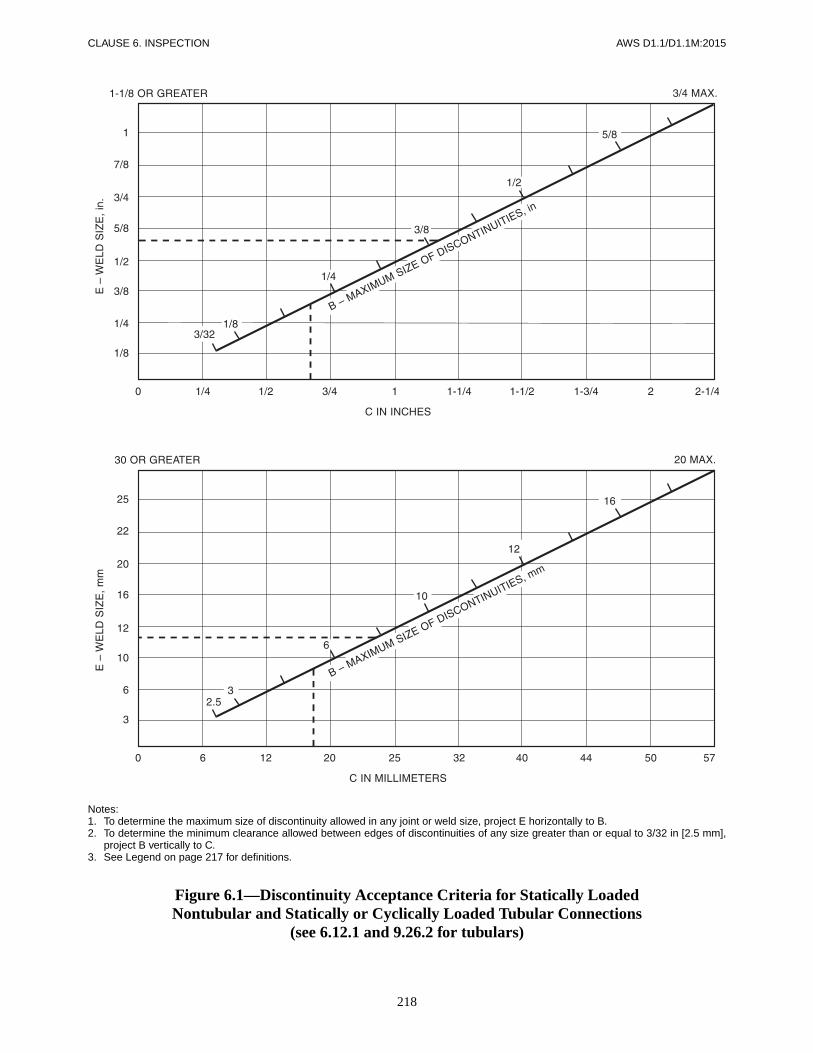
218
CLAUSE 6. INSPECTION AWS D1.1/D1.1M:2015
Notes:1. To determine the maximum size of discontinuity allowed in any joint or weld size, project E horizontally to B.2. To determine the minimum clearance allowed between edges of discontinuities of any size greater than or equal to 3/32 in [2.5 mm],
project B vertically to C.3. See Legend on page 217 for definitions.
Figure 6.1—Discontinuity Acceptance Criteria for Statically LoadedNontubular and Statically or Cyclically Loaded Tubular Connections
(see 6.12.1 and 9.26.2 for tubulars)

219
AWS D1.1/D1.1M:2015 CLAUSE 6. INSPECTION
a The elongated discontinuity may be located in either weld “A” or “B.” For the purposes of this illustration the elongated discontinuity “B”was located in weld “B.”
Case I—Discontinuity at Weld Intersection
Figure 6.1 (Continued)—Discontinuity Acceptance Criteria for Statically LoadedNontubular and Statically or Cyclically Loaded Tubular Connections
(see 6.12.1 and 9.26.2 for tubulars)

220
CLAUSE 6. INSPECTION AWS D1.1/D1.1M:2015
Case II—Discontinuity at Free Edge of CJP Groove Weld
Figure 6.1 (Continued)—Discontinuity Acceptance Criteria for Statically LoadedNontubular and Statically or Cyclically Loaded Tubular Connections
(see 6.12.1 and 9.26.2 for tubulars)

221
AWS D1.1/D1.1M:2015 CLAUSE 6. INSPECTION
Case III—Discontinuity at Weld Intersection
Figure 6.1 (Continued)—Discontinuity Acceptance Criteria for Statically LoadedNontubular and Statically or Cyclically Loaded Tubular Connections
(see 6.12.1 and 9.26.2 for tubulars)

222
CLAUSE 6. INSPECTION AWS D1.1/D1.1M:2015
Case IV—Discontinuity at Free Edge of CJP Groove Weld
Figure 6.1 (Continued)—Discontinuity Acceptance Criteria for Statically LoadedNontubular and Statically or Cyclically Loaded Tubular Connections
(see 6.12.1 and 9.26.2 for tubulars)

223
AWS D1.1/D1.1M:2015 CLAUSE 6. INSPECTION
Notes:1 To determine the maximum size of discontinuity allowed in any joint or weld size, project E horizontally to B.2. To determine the minimum clearance allowed between edges of discontinuities of any size, project B vertically to C.3. See Legend on page 217 for definitions.
Figure 6.2—Discontinuity Acceptance Criteria for Cyclically Loaded NontubularConnections in Tension (Limitations of Porosity and Fusion Discontinuities)
(see 6.12.2.1)

224
CLAUSE 6. INSPECTION AWS D1.1/D1.1M:2015
a The elongated discontinuity may be located in either weld “A” or “B.” For the purposes of this illustration the elongated discontinuity “B”was located in weld “B.”
Case I—Discontinuity at Weld Intersection
Figure 6.2 (Continued)—Discontinuity Acceptance Criteria for Cyclically LoadedNontubular Connections in Tension (Limitations of Porosity and Fusion Discontinuities)
(see 6.12.2.1)

225
AWS D1.1/D1.1M:2015 CLAUSE 6. INSPECTION
Case II—Discontinuity at Free Edge of CJP Groove Weld
Figure 6.2 (Continued)—Discontinuity Acceptance Criteria for Cyclically LoadedNontubular Connections in Tension (Limitations of Porosity and Fusion Discontinuities)
(see 6.12.2.1)
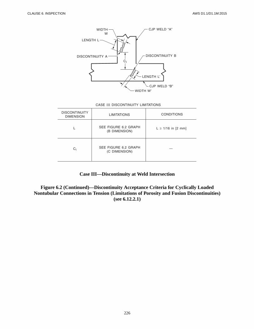
226
CLAUSE 6. INSPECTION AWS D1.1/D1.1M:2015
Case III—Discontinuity at Weld Intersection
Figure 6.2 (Continued)—Discontinuity Acceptance Criteria for Cyclically LoadedNontubular Connections in Tension (Limitations of Porosity and Fusion Discontinuities)
(see 6.12.2.1)

227
AWS D1.1/D1.1M:2015 CLAUSE 6. INSPECTION
Case IV—Discontinuity at Free Edge of CJP Groove Weld
Figure 6.2 (Continued)—Discontinuity Acceptance Criteria for Cyclically LoadedNontubular Connections in Tension (Limitations of Porosity and Fusion Discontinuities)
(see 6.12.2.1)

228
CLAUSE 6. INSPECTION AWS D1.1/D1.1M:2015
a The maximum size of a discontinuity located within this distance from an edge of plate shall be 1/8 in [3 mm], but a 1/8 in [3 mm] discon-tinuity shall be 1/4 in [6 mm] or more away from the edge. The sum of discontinuities less than 1/8 in [3 mm] in size and located withinthis distance from the edge shall not exceed 3/16 in [5 mm]. Discontinuities 1/16 in [2 mm] to less than 1/8 in [3 mm] shall not berestricted in other locations unless they are separated by less than 2 L (L being the length of the larger discontinuity); in which case, thediscontinuities shall be measured as one length equal to the total length of the discontinuities and space and evaluated as shown in thisfigure.
Notes:1. To determine the maximum size of discontinuity allowed in any joint or weld size, project E horizontally to B.2. To determine the minimum clearance allowed between edges of discontinuities of any size, project B vertically to C.3. See Legend on page 217 for definitions.
Figure 6.3—Discontinuity Acceptance Criteria for Cyclically Loaded NontubularConnections in Compression (Limitations of Porosity or Fusion-Type Discontinuities)
(see 6.12.2.2)
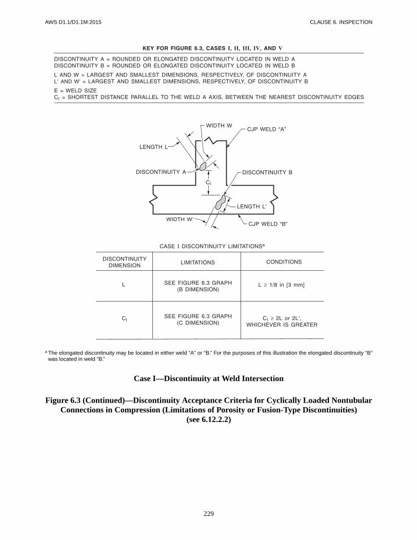
229
AWS D1.1/D1.1M:2015 CLAUSE 6. INSPECTION
a The elongated discontinuity may be located in either weld “A” or “B.” For the purposes of this illustration the elongated discontinuity “B”was located in weld “B.”
Case I—Discontinuity at Weld Intersection
Figure 6.3 (Continued)—Discontinuity Acceptance Criteria for Cyclically Loaded NontubularConnections in Compression (Limitations of Porosity or Fusion-Type Discontinuities)
(see 6.12.2.2)

230
CLAUSE 6. INSPECTION AWS D1.1/D1.1M:2015
Case II—Discontinuity at Free Edge of CJP Groove Weld
Figure 6.3 (Continued)—Discontinuity Acceptance Criteria for Cyclically Loaded NontubularConnections in Compression (Limitations of Porosity or Fusion-Type Discontinuities)
(see 6.12.2.2)

231
AWS D1.1/D1.1M:2015 CLAUSE 6. INSPECTION
Case III—Discontinuity at Weld Intersection
Figure 6.3 (Continued)—Discontinuity Acceptance Criteria for Cyclically Loaded NontubularConnections in Compression (Limitations of Porosity or Fusion-Type Discontinuities)
(see 6.12.2.2)
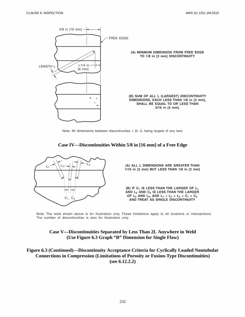
232
CLAUSE 6. INSPECTION AWS D1.1/D1.1M:2015
Case IV—Discontinuities Within 5/8 in [16 mm] of a Free Edge
Case V—Discontinuities Separated by Less Than 2L Anywhere in Weld(Use Figure 6.3 Graph “B” Dimension for Single Flaw)
Figure 6.3 (Continued)—Discontinuity Acceptance Criteria for Cyclically Loaded NontubularConnections in Compression (Limitations of Porosity or Fusion-Type Discontinuities)
(see 6.12.2.2)

233
AWS D1.1/D1.1M:2015 CLAUSE 6. INSPECTION
Figure 6.4—Hole-Type IQI (see 6.17.1 and 9.28.1)
(Reprinted by permission of the American Society for Testing and Materials, copyright.)
Table of Dimensions of IQI(in)
Numbera A B C D E F
IQI Thickness and Hole Diameter
Tolerances
5–20 ± 1.500± 0.015
± 0.750± 0.015
± 0.438± 0.015
± 0.250± 0.015
± 0.500± 0.015
± 0.250± 0.030 ± 0.0005
21–59 ± 1.500± 0.015
± 0.750± 0.015
± 0.438± 0.015
± 0.250± 0.015
± 0.500± 0.015
± 0.250± 0.030 ± 0.0025
60–179 ± 2.250± 0.030
± 1.375± 0.030
± 0.750± 0.030
± 0.375± 0.030
± 1.000± 0.030
± 0.375± 0.030 ± 0.0050
Table of Dimensions of IQI(mm)
Numbera A B C D E F
IQI Thickness and Hole Diameter
Tolerances
5–20 38.10± 0.38.
19.05± 0.38.
11.13± 0.38.
6.35± 0.38.
12.70± 0.38.
± 6.35± 0.80 ± 0.013
21–59 38.10± 0.38.
19.05± 0.38.
11.13± 0.38.
6.35± 0.38.
12.70± 0.38.
± 6.35± 0.80 ± 0.06
60–179 57.15± 0.80.
34.92± 0.80.
19.05± 0.80.
9.52± 0.80.
25.40± 0.80.
± 9.525.± 0.80 ± 0.13
a IQIs No. 5 through 9 are not 1T, 2T, and 4T.
Note: Holes shall be true and normal to the IQI. Do not chamfer.

234
CLAUSE 6. INSPECTION AWS D1.1/D1.1M:2015
Figure 6.5—Wire IQI (see 6.17.1 and 9.28.1)
(Reprinted by permission of the American Society for Testing and Materials, copyright.)
Image Quality Indicator (Wire Penetrameter) Sizes
Wire Diameter, in [mm]
Set A Set B Set C Set D
0.0032 [0.08] 0.010 [0.25] 0.032 [0.81] 0.10 [2.5]
0.004 [0.1] 0.013 [0.33] 0.040 [1.02] 0.125 [3.2]
0.005 [0.13] 0.016 [0.4] 0.050 [1.27] 0.160 [4.06]
0.0063 [0.16] 0.020 [0.51] 0.063 [1.6] 0.20 [5.1]
0.008 [0.2] 0.025 [0.64] 0.080 [2.03] 0.25 [6.4]
0.010 [0.25] 0.032 [0.81] 0.100 [2.5] 0.32 [8]

235
AWS D1.1/D1.1M:2015 CLAUSE 6. INSPECTION
a Alternate source side IQI placement allowed for tubular applications and other applications when approved by the Engineer.
Figure 6.6—RT Identification and Hole-Type or Wire IQI Locations on ApproximatelyEqual Thickness Joints 10 in [250 mm] and Greater in Length (see 6.17.7 and 9.28.2)

236
CLAUSE 6. INSPECTION AWS D1.1/D1.1M:2015
a Alternate source side IQI placement allowed for tubular applications and other applications when approved by the Engineer.
Figure 6.7—RT Identification and Hole-Type or Wire IQI Locations on ApproximatelyEqual Thickness Joints Less than 10 in [250 mm] in Length (see 6.17.7 and 9.28.2)

237
AWS D1.1/D1.1M:2015 CLAUSE 6. INSPECTION
a Alternate source side IQI placement allowed for tubular applications and other applications when approved by the Engineer.
Figure 6.8—RT Identification and Hole-Type or Wire IQI Locations on TransitionJoints 10 in [250 mm] and Greater in Length (see 6.17.7 and 9.28.2)

238
CLAUSE 6. INSPECTION AWS D1.1/D1.1M:2015
a Alternate source side IQI placement allowed for tubular applications and other applications when approved by the Engineer.
Figure 6.9—RT Identification and Hole-Type or Wire IQI Locations on TransitionJoints Less than 10 in [250 mm] in Length (see 6.17.7 and 9.28.2)
Figure 6.10—RT Edge Blocks (see 6.17.13)
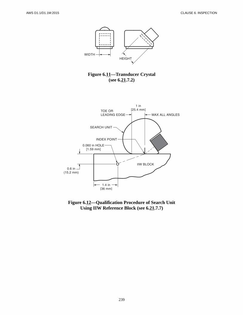
239
AWS D1.1/D1.1M:2015 CLAUSE 6. INSPECTION
Figure 6.11—Transducer Crystal(see 6.21.7.2)
Figure 6.12—Qualification Procedure of Search UnitUsing IIW Reference Block (see 6.21.7.7)

240
CLAUSE 6. INSPECTION AWS D1.1/D1.1M:2015
Notes:1. The dimensional tolerance between all surfaces involved in referencing or calibrating shall be within ±0.005 in [0.13 mm] of detailed
dimension.2. The surface finish of all surfaces to which sound is applied or reflected from shall have a maximum of 125 µin [3.17 µm] r.m.s.3. All material shall be ASTM A36 or acoustically equivalent.4. All holes shall have a smooth internal finish and shall be drilled 90° to the material surface.5. Degree lines and identification markings shall be indented into the material surface so that permanent orientation can be maintained.6. These notes shall apply to all sketches in Figures 6.13 and 6.14.
Figure 6.13—Typical IIW Type Block (see 6.22.1)
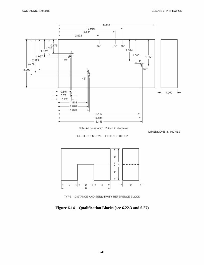
241
AWS D1.1/D1.1M:2015 CLAUSE 6. INSPECTION
Figure 6.14—Qualification Blocks (see 6.22.3 and 6.27)

242
CLAUSE 6. INSPECTION AWS D1.1/D1.1M:2015
Figure 6.14 (Continued)—Qualification Blocks (see 6.22.3 and 6.27) (Metric)

243
AWS D1.1/D1.1M:2015 CLAUSE 6. INSPECTION
Notes:1. Testing patterns are all symmetrical around the weld axis with the exception of pattern D, which shall be conducted directly over the
weld axis.2. Testing from both sides of the weld axis shall be made wherever mechanically possible.
Figure 6.15—Plan View of UT Scanning Patterns (see 6.30)

244
CLAUSE 6. INSPECTION AWS D1.1/D1.1M:2015
Figure 6.16—Transducer Positions (Typical) (see 6.22, 6.27, and 6.28)

AWS D1.1/D1.1M:2015
245
7.1 ScopeClause 7 contains general requirements for welding ofsteel studs to steel, and stipulates specific requirements:
(1) For mechanical properties and material of steelstuds, and requirements for qualification of stud bases.
(2) For application qualification testing, operatorqualification, preproduction testing, and workmanship.
(3) For stud welding during production, fabrication/erection, and inspection.
(4) For the stud manufacturer’s certification of studbase weldability.
NOTE: Approved steels; for studs, see 7.2.6; for basemetals, see Table 3.1 (Groups I and II). For guidance,see C-7.6.1.
7.2 General Requirements7.2.1 Stud Design. Studs shall be of suitable design forarc welding to steel members with the use of automati-cally timed stud welding equipment. The type and size ofthe stud shall be as specified by the drawings, specifica-tions, or special provisions. For headed-type studs, seeFigure 7.1. Alternative head configurations may be usedwith proof of mechanical and embedment tests confirm-ing full-strength development of the design, and with theapproval of the Engineer.
7.2.2 Arc Shields. An arc shield (ferrule) of heat-resistant ceramic or other suitable material shall be fur-nished with each stud.
7.2.3 Flux. A suitable deoxidizing and arc stabilizingflux for welding shall be furnished with each stud of5/16 in [8 mm] diameter or larger. Studs less than5/16 in [8 mm] in diameter may be furnished with orwithout flux.
7.2.4 Stud Bases. A stud base, to be qualified, shallhave passed the test described in 7.9. Only studs with
qualified stud bases shall be used. Qualification of studbases in conformance with 7.9 shall be at the manu-facturer’s expense. The arc shield used in productionshall be the same as used in qualification tests or asrecommended by the manufacturer. When requested bythe Engineer, the Contractor shall provide the followinginformation:
(1) A description of the stud and arc shield
(2) Certification from the manufacturer that the studbase is qualified in conformance with 7.9.
(3) Qualification tests data
7.2.5 Stud Finish
7.2.5.1 Stud finish shall be produced by heading, roll-ing, or machining. Finished studs shall be of uniformquality and condition, free of defects that may affect thewelding quality, suitability for intended application, orfit of the studs in the specified ceramic arc shields (fer-rules). Such defects include laps, fins, seams, cracks,twists, bends, thread defects, discontinuities, or foreignmaterials (see 7.4.1 and 7.4.2).
7.2.5.2 Headed studs are subject to cracks or bursts inthe stud head which are abrupt interruption of the periph-ery caused by radial separation of the metal extendingfrom the head inward to the stud shank. These cracks orbursts shall not be the cause for rejection, provided thatthey do not exceed one half of the distance from the studhead to the stud shank as determined by visual inspection(see Figure C-7.1.) Studs shall be rejected if the cracks orbursts are of a number or width that does not permit thehead to fit into the welding tool chuck or cause arcingbetween the stud head and the chuck affecting chuck lifeor weld quality.
7.2.6 Stud Material. Studs shall be made from colddrawn bar conforming to the requirements of ASTMA29, Standard Specification for Steel Bars, Carbon andAlloy, Hot-Wrought, General Requirements for Grades
7. Stud Welding

CLAUSE 7. STUD WELDING AWS D1.1/D1.1M:2015
246
1010 through 1020, inclusive either semi-killed or killedaluminum or silicon deoxidation.
7.2.7 Base Metal Thickness. When welding directly tobase metal, the base metal shall be no thinner than 1/3the stud diameter. When welding through deck, the studdiameter shall be no greater than 2.5 times the base mate-rial thickness. In no case shall studs be welded throughmore than two plies of metal decking.
7.3 Mechanical Requirements7.3.1 Standard Mechanical Requirements. At themanufacturer’s option, mechanical properties of studsshall be determined by testing either the steel after coldfinishing or the full diameter finished studs. In eithercase, the studs shall conform to the standard propertiesshown in Table 7.1.
7.3.2 Testing. Mechanical properties shall be determinedin conformance with the applicable sections of ASTMA370, Mechanical Testing of Steel Products. A typicaltest fixture is used, similar to that shown in Figure 7.2.
7.3.3 Engineer’s Request. Upon request by the Engi-neer, the Contractor shall furnish:
(1) The stud manufacturer’s certification that thestuds, as delivered, conform to the applicable require-ments of 7.2 and 7.3.
(2) Certified copies of the stud manufacturer’s testreports covering the last completed set of in-plant qualitycontrol mechanical tests, required by 7.3 for each diame-ter delivered.
(3) Certified material test reports (CMTR) from thesteel supplier indicating diameter, chemical properties,and grade on each heat number delivered.
7.3.4 Absence of Quality Control Tests. When qualitycontrol tests are not available, the Contractor shall fur-nish a chemical test report conforming to 7.2.6 and amechanical test report conforming to the requirementsof 7.3 for each lot number. Unidentified and untraceablestuds shall not be used.
7.3.5 Additional Studs. The Contractor is responsiblefor furnishing additional studs of each type and size, atthe request of the Engineer, for checking the requirementsof 7.2 and 7.3. Testing shall be at the Owner’s expense.
7.4 Workmanship/Fabrication7.4.1 Cleanliness. At the time of welding, the studsshall be free from rust, rust pits, scale, oil, moisture, or
other deleterious matter that would adversely affect thewelding operation.
7.4.2 Coating Restrictions. The stud base shall not bepainted, galvanized, or cadmium-plated prior to welding.
7.4.3 Base Metal Preparation. The areas to which thestuds are to be welded shall be free of scale, rust, mois-ture, paint, or other injurious material to the extentnecessary to obtain satisfactory welds and prevent objec-tionable fumes. These areas may be cleaned by wirebrushing, scaling, prick-punching, or grinding.
7.4.4 Moisture. The arc shields or ferrules shall be keptdry. Any arc shields which show signs of surface mois-ture from dew or rain shall be oven dried at 250°F[120°C] for two hours before use.
7.4.5 Spacing Requirements. Longitudinal and lateralspacings of stud shear connectors (type B) may vary amaximum of 1 in [25 mm] from the location shown inthe drawings. The minimum distance from the edge of astud base to the edge of a flange shall be the diameter ofthe stud plus 1/8 in [3 mm], but preferably not less than1-1/2 in [40 mm].
7.4.6 Arc Shield Removal. After welding, arc shieldsshall be broken free from studs to be embedded in con-crete, and, where practical, from all other studs.
7.4.7 Acceptance Criteria. The studs, after welding,shall be free of any discontinuities or substances thatwould interfere with their intended function and have afull 360° flash. However, nonfusion on the legs of theflash and small shrink fissures shall be acceptable. Thefillet weld profiles shown in Figure 5.4 shall not apply tothe flash of automatically timed stud welds.
7.5 Technique
7.5.1 Automatic Mechanized Welding. Studs shall bewelded with automatically timed stud welding equip-ment connected to a suitable source of direct currentelectrode negative power. Welding voltage, current,time, and gun settings for lift and plunge should be set atoptimum settings, based on past practice, recommenda-tions of stud and equipment manufacturer, or both. AWSC5.4, Recommended Practices for Stud Welding, shouldalso be used for technique guidance.
7.5.2 Multiple Welding Guns. If two or more studwelding guns shall be operated from the same powersource, they shall be interlocked so that only one gun canoperate at a time, and so that the power source has fullyrecovered from making one weld before another weld isstarted.

247
AWS D1.1/D1.1M:2015 CLAUSE 7. STUD WELDING
7.5.3 Movement of Welding Gun. While in operation,the welding gun shall be held in position without move-ment until the weld metal has solidified.
7.5.4 Ambient and Base Metal Temperature Re-quirements. Welding shall not be done when the basemetal temperature is below 0°F [–18°C] or when the sur-face is wet or exposed to falling rain or snow. When thetemperature of the base metal is below 32°F [0°C], oneadditional stud in each 100 studs welded shall be testedby methods described in 7.7.1.3 and 7.7.1.4, except thatthe angle of testing shall be approximately 15°. This is inaddition to the first two studs tested for each start of anew production period or change in set-up. Set-up includesstud gun, power source, stud diameter, gun lift andplunge, total welding lead length, and changes greaterthan ± 5% in current (amperage) and time.
7.5.5 FCAW, GMAW, SMAW Fillet Weld Option.At the option of the Contractor, studs may be weldedusing prequalified FCAW, GMAW, or SMAW pro-cesses, provided the following requirements are met:
7.5.5.1 Surfaces. Surfaces to be welded and surfacesadjacent to a weld shall be free from loose or thick scale,slag, rust, moisture, grease, and other foreign materialthat would prevent proper welding or produce objection-able fumes.
7.5.5.2 Stud End. For fillet welds, the end of the studshall also be clean.
7.5.5.3 Stud Fit (Fillet Welds). For fillet welds, thestud base shall be prepared so that the base of the studfits against the base metal.
7.5.5.4 Fillet Weld Minimum Size. When filletwelds shall be used, the minimum size shall be the largerof those required in Table 5.7 or Table 7.2.
7.5.5.5 Preheat Requirements. The base metal towhich studs are welded shall be preheated in conform-ance with the requirements of Table 3.3.
7.5.5.6 SMAW Electrodes. SMAW welding shall beperformed using low-hydrogen electrodes 5/32 in or3/16 in [4.0 mm or 4.8 mm] in diameter, except that asmaller diameter electrode may be used on studs 7/16 in[11.1 mm] or less in diameter for out-of-position welds.
7.5.5.7 Visual Inspection. FCAW, GMAW, andSMAW welded studs shall be visually inspected in con-formance with 6.9.
7.6 Stud Application Qualification Requirements
7.6.1 Purpose. Studs which are shop or field applied inthe flat (down-hand) position to a planar and horizontal
surface shall be considered prequalified by virtue of themanufacturer’s stud base qualification tests (see 7.9), andno further application testing shall be required. The limitof flat position is defined as 0°–15° slope on the surfaceto which the stud is applied.
Examples of stud applications that require tests of thissection are the following:
(1) Studs which are applied on nonplanar surfaces orto a planar surface in the vertical or overhead positions.
(2) Studs which are welded through decking. Thetests shall be with material representative of the condi-tion to be used in construction.
(3) Studs welded to other than Groups I or II steelslisted in Table 3.1.
7.6.2 Responsibilities for Tests. The Contractor shall beresponsible for the performance of these tests. Tests maybe performed by the Contractor, the stud manufacturer,or by another testing agency satisfactory to all partiesinvolved.
7.6.3 Preparation of Specimens
7.6.3.1 Test Specimens. To qualify applications involv-ing materials listed in Table 3.1, Groups I and II: specimensmay be prepared using ASTM A36 steel base materials orbase materials listed in Table 3.1, Groups I and II.
7.6.3.2 Recorded Information. To qualify applica-tions involving materials other than those listed in Table3.1, Groups I and II, the test specimen base material shallbe of the chemical, physical and grade specifications tobe used in production.
7.6.4 Number of Specimens. Ten specimens shall bewelded consecutively using recommended procedures andsettings for each diameter, position, and surface geometry.
7.6.5 Test Required. The ten specimens shall be testedusing one or more of the following methods: bending,torquing, or tensioning.
7.6.6 Test Methods
7.6.6.1 Bend Test. Studs shall be tested by alter-nately bending 30° in opposite directions in a typical testfixture as shown in Figure 7.4 until failure occurs. Alter-natively, studs may be bent 90° from their original axis.Type C studs, when bent 90°, shall be bent over a pinwith a diameter of 4 times the diameter of the stud. Ineither case, a stud application shall be considered quali-fied if the studs are bent 90° and fracture occurs in theplate or shape material or in the shank of the stud and notin the weld.
7.6.6.2 Torque Test. Studs shall be torque testedusing a torque test arrangement that is substantially in

CLAUSE 7. STUD WELDING AWS D1.1/D1.1M:2015
248
conformance with Figure 7.3. A stud application shall beconsidered qualified if all test specimens are torqued todestruction without failure in the weld.
7.6.6.3 Tension Test. Studs shall be tension tested todestruction using any machine capable of supplying therequired force. A stud application shall be consideredqualified if the test specimens do not fail in the weld.
7.6.7 Application Qualification Test Data. Applica-tion Qualification Test Data shall include the following:
(1) Drawings that show shapes and dimensions ofstuds and arc shields.
(2) A complete description of stud and base materi-als, and a description (part number) of the arc shield.
(3) Welding position and settings (current, time).
(4) A record, which shall be made for each qualifica-tion and shall be available for each contract. A suggestedWPS/PQR form for nonprequalified application may befound in Annex M, Form M-7.
7.7 Production Control7.7.1 Pre-Production Testing
7.7.1.1 Start of Shift. Before production weldingwith a particular set-up and with a given size and type ofstud, and at the beginning of each day’s or shift’s pro-duction, testing shall be performed on the first two studsthat are welded. The stud technique may be developed ona piece of material similar to the production member inthickness and properties. If actual production thickness isnot available, the thickness may vary ± 25%. All teststuds shall be welded in the same general position asrequired on the production member (flat, vertical, oroverhead).
7.7.1.2 Production Member Option. Instead ofbeing welded to separate material, the test studs may bewelded on the production member, except when separateplates are required by 7.7.1.5.
7.7.1.3 Flash Requirement. Studs shall exhibit full360° flash with no evidence of undercut into the studbase.
7.7.1.4 Bend Test. In addition to visual examination,the test shall consist of bending the studs after they are al-lowed to cool, to an angle of approximately 30° from theiroriginal axes by either striking the studs with a hammeron the unwelded end or placing a pipe or other suitablehollow device over the stud and manually or mechanicallybending the stud. At temperatures below 50°F [10°C],bending shall preferably be done by continuous slow ap-
plication of load. For threaded studs, the torque test ofFigure 7.3 shall be substituted for the bend test.
7.7.1.5 Event of Failure. If on visual examinationthe test studs do not exhibit 360° flash, or if on testing,failure occurs in the weld zone of either stud, the proce-dure shall be corrected, and two more studs shall bewelded to separate material or on the production memberand tested in conformance with the provisions of 7.7.1.3and 7.7.1.4. If either of the second two studs fails, addi-tional welding shall be continued on separate plates untiltwo consecutive studs are tested and found to be satisfac-tory before any more production studs are welded to themember.
7.7.2 Production Welding. Once production weldinghas begun, any changes made to the welding setup, as de-termined in 7.7.1, shall require that the testing in 7.7.1.3and 7.7.1.4 be performed prior to resuming productionwelding.
7.7.3 Repair of Studs. In production, studs on which afull 360° flash is not obtained may, at the option of theContractor, be repaired by adding the minimum filletweld as required by 7.5.5 in place of the missing flash.The repair weld shall extend at least 3/8 in [10 mm] be-yond each end of the discontinuity being repaired.
7.7.4 Operator Qualification. The pre-production testrequired by 7.7.1, if successful, shall also serve to qualifythe stud welding operator. Before any production studsare welded by an operator not involved in the pre-production set-up of 7.7.1, the first two studs welded bythe operator shall have been tested in conformance withthe provisions of 7.7.1.3 and 7.7.1.4. When the twowelded studs have been tested and found satisfactory, theoperator may then weld production studs.
7.7.5 Removal Area Repair. If an unacceptable studhas been removed from a component subjected to tensilestresses, the area from which the stud was removed shallbe made smooth and flush. Where in such areas the basemetal has been pulled out in the course of stud removal,SMAW with low-hydrogen electrodes in conformancewith the requirements of this code shall be used to fill thepockets, and the weld surface shall be flush.
In compression areas of members, if stud failures areconfined to shanks or fusion zones of studs, a new studmay be welded adjacent to each unacceptable area in lieuof repair and replacement on the existing weld area (see7.4.5). If base metal is pulled out during stud removal,the repair provisions shall be the same as for tensionareas except that when the depth of discontinuity is thelesser of 1/8 in [3 mm] or 7% of the base metal thickness,the discontinuity may be faired by grinding in lieu of fill-ing with weld metal. Where a replacement stud is to be

249
AWS D1.1/D1.1M:2015 CLAUSE 7. STUD WELDING
provided, the base metal repair shall be made prior towelding the replacement stud. Replacement studs (otherthan threaded type which should be torque tested) shallbe tested by bending to an angle of approximately 15°from their original axes. The areas of components ex-posed to view in completed structures shall be madesmooth and flush where a stud has been removed.
7.8 Fabrication and Verification Inspection Requirements
7.8.1 Visual Inspection. If a visual inspection revealsany stud that does not show a full 360° flash or any studthat has been repaired by welding, such stud shall be bentto an angle of approximately 15° from its original axis.Threaded studs shall be torque tested. The method ofbending shall be in conformance with 7.7.1.4. The direc-tion of bending for studs with less than a 360° flash shallbe opposite to the missing portion of the flash. Torquetesting shall be in conformance with Figure 7.3.
7.8.2 Additional Tests. The Verification Inspector,where conditions warrant, may select a reasonable num-ber of additional studs to be subjected to the tests de-scribed in 7.8.1.
7.8.3 Bent Stud Acceptance Criteria. The bent studshear connectors (Type B) and deformed anchors (TypeC) and other studs to be embedded in concrete (Type A)that show no sign of failure shall be acceptable for useand left in the bent position. When bent studs are re-quired by the contract documents to be straightened, thestraightening operation shall be done without heating,and before completion of the production stud weldingoperation.
7.8.4 Torque Test Acceptance Criteria. Threadedstuds (Type A) torque tested to the proof load torquelevel in Figure 7.3 that show no sign of failure shall beacceptable for use.
7.8.5 Corrective Action. Welded studs not conformingto the requirements of the code shall be repaired orreplaced by the Contractor. The Contractor shall revisethe welding procedure as necessary to ensure that sub-sequent stud welding will meet code requirements.
7.8.6 Owner’s Option. At the option and the expense ofthe Owner, the Contractor may be required, at any time,to submit studs of the types used under the contract for aqualification check in conformance with the proceduresof 7.9.
7.9 Manufacturers’ Stud Base Qualification Requirements
7.9.1 Purpose. The purpose of these requirements is toprescribe tests for the stud manufacturers’ certification ofstud base weldability.
7.9.2 Responsibility for Tests. The stud manufacturershall be responsible for the performance of the qualifica-tion test. These tests may be performed by a testingagency satisfactory to the Engineer. The agency per-forming the tests shall submit a certified report to themanufacturer of the studs giving procedures and resultsfor all tests including the information described in7.9.10.
7.9.3 Extent of Qualification. Qualification of a studbase shall constitute qualification of stud bases with thesame geometry, flux, and arc shield, having the same di-ameter and diameters that are smaller by less than 1/8 in[3 mm]. A stud base qualified with an approved grade ofASTM A29 steel and meets the standard mechanicalproperties (see 7.3.1) shall constitute qualification for allother approved grades of ASTM A29 steel (see 7.2.6),provided that conformance with all other provisionsstated herein shall be achieved.
7.9.4 Duration of Qualification. A size of stud basewith arc shield, once qualified, shall be considered quali-fied until the stud manufacturer makes any change in thestud base geometry, material, flux, or arc shield whichaffects the welding characteristics.
7.9.5 Preparation of Specimens
7.9.5.1 Materials. Test specimens shall be preparedby welding representative studs to suitable specimenplates of ASTM A36 steel or any of the other materialslisted in Table 3.1 or Table 4.9. Studs to be weldedthrough metal decking shall have the weld base qualifi-cation testing done by welding through metal deckingrepresentative of that used in construction, galvanizedper ASTM A653 coating designation G90 for one thick-ness of deck or G60 for two deck plies. When studs areto be welded through decking, the stud base qualificationtest shall include decking representative of that to beused in construction. Welding shall be done in the flatposition (plate surface horizontal). Tests for threadedstuds shall be on blanks (studs without threads).
7.9.5.2 Welding Equipment. Studs shall be weldedwith power source, welding gun, and automatically con-trolled equipment as recommended by the stud manu-facturer. Welding voltage, current, and time (see 7.9.6)shall be measured and recorded for each specimen. Liftand plunge shall be at the optimum setting as recom-mended by the manufacturer.

CLAUSE 7. STUD WELDING AWS D1.1/D1.1M:2015
250
7.9.6 Number of Test Specimens
7.9.6.1 High Current. For studs 7/8 in [22 mm] orless in diameter, 30 test specimens shall be welded con-secutively with constant optimum time, but with current10% above optimum. For studs over 7/8 in [22 mm] di-ameter, 10 test specimens shall be welded consecutivelywith constant optimum time. Optimum current and timeshall be the midpoint of the range normally recom-mended by the manufacturer for production welding.
7.9.6.2 Low Current. For studs 7/8 in [22 mm] orless in diameter, 30 test specimens shall be welded con-secutively with constant optimum time, but with current10% below optimum. For studs over 7/8 in [22 mm] di-ameter, 10 test specimens shall be welded consecutivelywith constant optimum time, but with current 5% belowoptimum.
7.9.6.3 Metal Deck. For studs to be welded throughmetal deck, the range of weld base diameters shall bequalified by welding 10 studs at the optimum current andtime as recommended by the manufacturer conformingto the following:
(1) Maximum and minimum diameters weldedthrough one thickness of 16 gage deck, coating designa-tion G90.
(2) Maximum and minimum diameters welded throughtwo plies of 16 gage deck coating designation G60.
(3) Maximum and minimum diameters weldedthrough one thickness of 18 gage G60 deck over onethickness of 16 gage G60 deck.
(4) Maximum and minimum diameters weldedthrough two plies of 18 gage deck, both with G60 coat-ing designation.
The range of diameters from maximum to minimumwelded through two plies of 18 gage metal deck with G60galvanizing shall be qualified for welding through one ortwo plies of metal deck 18 gage or less in thickness.
7.9.7 Tests
7.9.7.1 Tension Tests. Ten of the specimens weldedin conformance with 7.9.6.1 and ten in conformance with7.9.6.2 shall be subjected to a tension test in a fixturesimilar to that shown in Figure 7.2, except that studswithout heads may be gripped on the unwelded end inthe jaws of the tension testing machine. A stud base shallbe considered as qualified if all test specimens have atensile strength equal to or above the minimum describedin 7.3.1.
7.9.7.2 Bend Tests (Studs 7/8 in [22 mm] or less indiameter). Twenty of the specimens welded in conform-ance with 7.9.6.1 and twenty in conformance with7.9.6.2 shall be bend tested by being bent alternately 30°from their original axes in opposite directions until fail-ure occurs. Studs shall be bent in a bend testing deviceas shown in Figure 7.4, except that studs less than 1/2 in[12 mm] diameter may be bent using a device as shownin Figure 7.5. A stud base shall be considered as quali-fied if, on all test specimens, fracture occurs in the platematerial or shank of the stud and not in the weld or HAZ.All test specimens for studs over 7/8 in [22 mm] shallonly be subjected to tensile tests.
7.9.7.3 Weld through Deck Tests. All 10 of thewelds through deck stud specimens shall be tested bybending 30° in opposite directions in a bend testing de-vice as shown in Figure 7.4, or by bend testing 90° fromtheir original axis or tension testing to destruction in amachine capable of supplying the required force. Withany test method used, the range of stud diameters frommaximum to minimum shall be considered as qualifiedweld bases for through deck welding if, on all test speci-mens, fracture occurs in the plate material or shank of thestud and not in the weld or HAZ.
7.9.8 Retests. If failure occurs in a weld or the HAZ inany of the bend test groups of 7.9.7.2 or at less than spec-ified minimum tensile strength of the stud in any of thetension groups in 7.9.7.1, a new test group (described in7.9.6.1 or 7.9.6.2, as applicable) shall be prepared andtested. If such failures are repeated, the stud base shallfail to qualify.
7.9.9 Acceptance. For a manufacturer’s stud base andarc shield combination to be qualified, each stud of eachgroup of 30 studs shall, by test or retest, meet the re-quirements described in 7.9.7. Qualification of a givendiameter of stud base shall be considered qualificationfor stud bases of the same nominal diameter (see 7.9.3,stud base geometry, material, flux, and arc shield).
7.9.10 Manufacturer’s Qualification Test Data. Thetest data shall include the following:
(1) Drawings showing shapes and dimensions withtolerances of stud, arc shields, and flux;
(2) A complete description of materials used in thestuds, including the quantity and type of flux, and adescription of the arc shields; and
(3) Certified results of tests.

251
AWS D1.1/D1.1M:2015 CLAUSE 7. STUD WELDING
Table 7.1Mechanical Property
Requirements for Studs (see 7.3.1)
Type Aa Type Bb Type Cc
Tensilestrength
psi min.MPa min.
61 000,420
65 000,450
80 000,552
Yield strength(0.2% offset)
psi min.MPa min.
49 000,340
51 000,350
—
(0.5% offset)psi min.MPa min.
— —70 000
,485
Elongation% in 2 in min.% in 5x dia. min.
17%14%
20%15%
—
Reductionof area
% min. 50% 50% —
a Type A studs shall be general purpose of any type and size used forpurposes other than shear transfer in composite beam design and con-struction.
b Type B studs shall be studs that are headed, bent, or of other config-uration in 3/8 in [10 mm], 1/2 in [12 mm], 5/8 in [16 mm], 3/4 in[20 mm], 7/8 in [22 mm], and 1 in [25 mm] diameter that are used asan essential component in composite beam design and concrete anchor-age design.
c Type C studs shall be cold-worked deformed steel bars manufacturedin conformance with specification ASTM A496 having a nominaldiameter equivalent to the diameter of a plain wire having the sameweight per foot as the deformed wire. ASTM A496 specifies a maxi-mum diameter of 0.628 in [16 mm] maximum. Any bar suppliedabove that diameter shall have the same physical characteristicsregarding deformations as required by ASTM A496.
Table 7.2Minimum Fillet Weld Size
for Small Diameter Studs (see 7.5.5.4)
Stud Diameter Min. Size Fillet
in mm in mm
1/4 thru 7/161/2
5/8, 3/4, 7/81
6 thru 1112
16, 20, 2225
3/161/405/163/80
568
10

252
CLAUSE 7. STUD WELDING AWS D1.1/D1.1M:2015
a Manufactured length before welding.
Figure 7.1—Dimension and Tolerances of Standard-Type Headed Studs (see 7.2.1)
Standard Dimensions, in
Shank Diameter(C)
Length Tolerances
(L)
Head Diameter
(H)
Minimum Head Height
(T)
3/8 +0.010–0.010 ±1/16 3/4 ± 1/64 9/32
1/2 +0.010–0.010 ± 1/16 /1 ± 1/64 9/32
5/8 +0.010–0.010 ± 1/16 1-1/4 ± 1/64- 9/32
3/4 +0.015–0.015 ± 1/16 1-1/4 ± 1/64- 3/8
7/8 +0.015–0.015 ± 1/16 1-3/8 ± 1/64- 3/8
1 +0.020–0.020 ± 1/16 1-5/8 ± 1/64- 1/2
Standard Dimensions, mm
10 +0.25–0.25 ± 1.6 19 ± 0.40 7.1
13 +0.25–0.25 ± 1.6 25 ± 0.40 7.1
16 +0.25–0.25 ± 1.6 32 ± 0.40 7.1
19 +0.40–0.40 ± 1.6 32 ± 0.40 9.5
22 +0.40–0.40 ± 1.6 35 ± 0.40 9.5
25 +0.40–0.40 ± 1.6 41 ± 0.40 12.7
Figure 7.2—Typical Tension Test Fixture (see 7.3.2)

253
AWS D1.1/D1.1M:2015 CLAUSE 7. STUD WELDING
Note: Dimensions of test fixture details should be appropriate to the size of the stud. The threads of the stud shall be clean and free oflubricant other than the residue of cutting/cold forming lubricants in the “as received” condition from the manufacturer.
a Torque figures are based on Type A threaded studs with a minimum yield stress of 49 000 psi [340 MPa].b Mean Effective Thread Area (M.E.T.A) shall be defined as the effective stress area based on a mean diameter taken approximately
midway between the minor and the pitch diameters.c Values are calculated on a proof testing torque of 0.9 times Nominal Stud Diameter times 0.2 Friction Coefficient Factor times Mean
Effective Thread Area times Minimum Yield Stress for unplated studs in the as-received condition. Plating, coatings, or oil/greasedeposits will change the Friction Coefficient Factor.
Figure 7.3—Torque Testing Arrangement and Table of Testing Torques (see 7.6.6.2)
Required Proof Torque for Testing Threaded Studsa
Nominal Diameter M.E.T.A.b Thread
Series
Proof Testing Torquec
in mm in2 mm2 no./in pitch-mm lb-ft Joule
0.236 M60 0.031 20.1 1.00 ISO-724 5.4 7.4
1/4 6.4 0.0360.032
23.220.6
2820
UNFUNC
6.65.9
9.07.8
5/16 7.9 0.0580.052
37.433.5
2418
UNFUNC
13.311.9
18.116.1
0.315 M80 0.057 36.6 1.25 ISO-724 13.2 17.9
3/8 9.5 0.0880.078
56.850.3
2416
UNFUNC
24.321.5
32.929.2
0.394 M10 0.090 58.0 1.50 ISO-724 26.2 35.5
7/16 11.1 0.1180.106
76.168.4
2014
UNFUNC
37.934.8
51.447.2
0.472 M12 0.131 84.3 1.75 ISO-724 45.7 61.9
1/2 12.7 0.1600.142
103.291.6
2013
UNFUNC
58.852.2
79.770.8
0.551 M14 0.178 115.0 2.00 ISO-724 72.7 98.5
9/16 14.3 0.2030.182
131.0117.4
1812
UNFUNC
83.975.2
113.8102.0
5/8 15.9 0.2550.226
164.5145.8
1811
UNFUNC
117.1103.8
158.8140.8
0.630 M16 0.243 157.0 2.00 ISO-724 113.4 153.7
3/4 19.1 0.3720.334
240.0215.5
1610
UNFUNC
205.0184.1
278.0249.7
0.787 M20 0.380 245.0 2.50 ISO-724 221.2 299.9
0.866 M22 0.470 303.0 2.50 ISO-724 300.9 408.0
7/8 22.2 0.5090.462
328.4298.1
149
UNFUNC
327.3297.1
443.9402.9
0.945 M24 0.547 353.0 3.00 ISO-724 382.4 518.5
1 25.4 0.6780.606
437.4391.0
128
UNFUNC
498.3445.4
675.7604.0
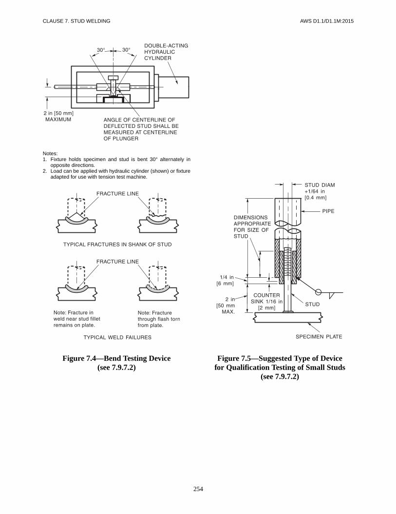
CLAUSE 7. STUD WELDING AWS D1.1/D1.1M:2015
254
Notes:1. Fixture holds specimen and stud is bent 30° alternately in
opposite directions.2. Load can be applied with hydraulic cylinder (shown) or fixture
adapted for use with tension test machine.
Figure 7.4—Bend Testing Device(see 7.9.7.2)
Figure 7.5—Suggested Type of Devicefor Qualification Testing of Small Studs
(see 7.9.7.2)

AWS D1.1/D1.1M:2015
255
8.1 GeneralStrengthening or repairing an existing structure shallconsist of modifications to meet design requirementsspecified by the Engineer. The Engineer shall preparea comprehensive plan for the work. Such plans shallinclude, but are not limited to, design, workmanship,inspection, and documentation. Except as modified in thissection, all provisions of this code shall apply equally tothe strengthening and repairing of existing structures,including heat straightening of distorted members.
8.2 Base Metal8.2.1 Investigation. Before preparing drawings andspecifications for strengthening or repairing existingstructures, the types of base metal used in the originalstructure shall be determined either from existing draw-ings, specifications or from representative base metaltests.
8.2.2 Suitability for Welding. The suitability of thebase metal for welding shall be established (see TableC-8.1 for guidance).
8.2.3 Other Base Metals. Where base metals other thanthose listed in Table 3.1 are to be joined, special consid-eration by the Engineer shall be given to the selection offiller metal and WPSs.
8.3 Design for Strengthening and Repair
8.3.1 Design Process. The design process shall considerapplicable governing code provisions and other parts ofthe general specifications. The Engineer shall specify thetype and extent of survey necessary to identify existingconditions that require strengthening or repair in order tosatisfy applicable criteria.
8.3.2 Stress Analysis. An analysis of stresses in the areaaffected by the strengthening or repair shall be made.Stress levels shall be established for all in-situ dead andlive load cases. Consideration shall be made for accumu-lated damage that members may have sustained in pastservice.
8.3.3 Fatigue History. Members subject to cyclic load-ing shall be designed according to the requirements forfatigue stresses. The previous loading history shall beconsidered in the design. When the loading history is notavailable, it shall be estimated.
8.3.4 Restoration or Replacement. Determinationshall be made whether the repairs should consist ofrestoring corroded or otherwise damaged parts or ofreplacing entire members.
8.3.5 Loading During Operations. The Engineer shalldetermine the extent to which a member will be allowedto carry loads while heating, welding or thermal cuttingis performed. When necessary, the loads shall be reduced.The local and general stability of the member shall be in-vestigated, considering the effect of elevated temperatureextending over parts of the cross-sectional area.
8.3.6 Existing Connections. Existing connections instructures requiring strengthening or repair shall be eval-uated for design adequacy and reinforced as necessary.
8.3.7 Use of Existing Fasteners. When design calcula-tions show rivets or bolts will be overstressed by the newtotal load, only existing dead load shall be assigned tothem. If rivets or bolts are overstressed by dead load aloneor are subject to cyclic loading, then sufficient base metaland welding shall be added to support the total load.
8.4 Fatigue Life Enhancement8.4.1 Methods. The following methods of recondition-ing critical weld details may be used when written proce-dures have been approved by the Engineer:
8. Strengthening and Repair of Existing Structures

CLAUSE 8. STRENGTHENING AND REPAIR OF EXISTING STRUCTURES AWS D1.1/D1.1M:2015
256
(1) Profile Improvement. Reshaping the weld face bygrinding with a carbide burr to obtain a concave profilewith a smooth transition from base material to weld.
(2) Toe Grinding. Reshaping only the weld toes bygrinding with a burr or pencil grinder.
(3) Peening. Shot peening of weld surface, or hammerpeening of weld toes.
(4) TIG Dressing. Reshaping of weld toe by the re-melting of existing weld metal with heat from GTAWarc (no filler metal used).
(5) Toe Grinding plus Hammer Peening. When usedtogether, the benefits are cumulative.
8.4.2 Stress Range Increase. The Engineer shall estab-lish the appropriate increase in the allowable stressrange.
8.5 Workmanship and Technique8.5.1 Base Metal Condition. Base metal to be repairedand surfaces of existing base metal in contact with newbase metal shall be cleaned of dirt, rust and other foreignmatter except adherent paint film as per SSPC SP2 (Sur-face Preparation Specification #2—Hand Tool Clean-ing). The portions of such surfaces which will be weldedshall be thoroughly cleaned of all foreign matter includ-ing paint for at least 2 in [50 mm] from the root of theweld.
8.5.2 Member Discontinuities. When required by theEngineer, unacceptable discontinuities in the memberbeing repaired or strengthened shall be corrected prior toheat straightening, heat curving, or welding.
8.5.3 Weld Repairs. If weld repairs are required, theyshall be made in conformance with 5.25, as applicable.
8.5.4 Base Metal of Insufficient Thickness. Base metalhaving insufficient thickness to develop the requiredweld size or required capacity shall be, as determined bythe Engineer: (1) built up with weld metal to the requiredthickness, (2) cut back until adequate thickness is avail-able, (3) reinforced with additional base metal, or (4) re-moved and replaced with base metal of adequatethickness or strength.
8.5.5 Heat Straightening. When heat straightening orheat curving methods are used, the maximum tempera-ture of heated areas as measured using temperature sensi-tive crayons or other positive means shall not exceed1100°F [600°C] for quenched and tempered steel, nor1200°F [650°C] for other steels. Accelerated cooling ofsteel above 600°F [315°C] shall be prohibited.
8.5.6 Welding Sequence. In strengthening or repairingmembers by the addition of base metal or weld metal, orboth, welding and weld sequencing shall, as far as practi-cable, result in a balanced heat input about the neutralaxis to minimize distortion and residual stresses.
8.6 Quality
8.6.1 Visual Inspection. All members and welds af-fected by the work shall be visually inspected in con-formance with the Engineer’s comprehensive plan.
8.6.2 NDT. The method, extent, and acceptance criteriaof NDT shall be specified in the contract documents.

AWS D1.1/D1.1M:2015
257
9.1 GeneralThis Clause supplements Clauses 1–8. The specific re-quirements of Clause 9 apply only to tubular connec-tions. For design purposes this clause shall be used withthe applicable requirements of Clause 2, Part A. All pro-visions of Clause 9 apply to static applications and cyclicapplications, with the exception of the fatigue provisionsof 9.2.7, which are unique to cyclic applications.
This clause is divided into parts, as follows:
Part A — Design of Tubular ConnectionsPart B — Prequalification of Welding Procedure
Specifications (WPSs)Part C — Welding Procedure Specification (WPS)
QualificationPart D — Performance QualificationPart E — FabricationPart F — Inspection
Part ADesign of Tubular Connections
9.2 Allowable Stresses9.2.1 Eccentricity. Moments caused by significant de-viation from concentric connections shall be provided forin analysis and design [see Figure 9.2(H) for an illustra-tion of an eccentric connection].
9.2.2 Base Metal Stresses. These provisions may beused in conjunction with any applicable design specifica-tions in either allowable stress design (ASD) or load andresistance factor design (LRFD) formats. Unless the ap-plicable design specification provides otherwise, tubularconnection design shall be as described in 9.2.6, 9.2.7,and 9.6. The base metal stresses shall be those specifiedin the applicable design specifications, except as limitedby 9.2.3.
9.2.3 Tubular Section Limitations. Limitations on di-ameter/thickness for circular sections, and largest flatwidth/thickness ratio for box sections, beyond whichlocal buckling or other local failure modes shall be con-sidered, shall be in conformance with the governing de-sign code. Limits of applicability for the criteria given in9.6 shall be observed as follows:
(1) Circular tubes: D/t < 3300/Fy [for Fy in ksi],22 800/Fy (for Fy in MPa)
(2) Box section gap connections: D/t ≤ 210/ [forFy in ksi], 550/ (for Fy in MPa) but not more than 35
(3) Box section overlap connections: D/t ≤ 190/[for Fy in ksi], 500/ (for Fy in MPa)
9.2.4 Welds Stresses. The allowable stresses in weldsshall not exceed those given in Table 9.2, or as allowedby 2.6.4, except as modified by 9.2.6, 9.2.7, and 9.6.
9.2.5 Fiber Stresses. Fiber stresses due to bending shallnot exceed the values described for tension and compres-sion, unless the members are compact sections (able todevelop full plastic moment) and any transverse weld isproportioned to develop fully the strength of sectionsjoined.
9.2.6 Load and Resistance Factor Design. Resistancefactors, Φ, given elsewhere in this clause, may be usedin context of load and resistance factor design (LRFD)calculations in the following format:
Φ × (Pu or Mu) = Σ (LF × Load)
where Pu or Mu is the ultimate load or moment as givenherein; and LF is the load factor as defined in the govern-ing LRFD design code, e.g., ANSI/AISC 360, Specifica-tion for Structural Steel Buildings.
9.2.7 Fatigue of Circular Tube Connections
9.2.7.1 Stress Range and Member Type. In thedesign of members and connections subject to repeatedvariations in live load stress, consideration shall be given
Fy
Fy
Fy
Fy
9. Tubular Structures

CLAUSE 9. TUBULAR STRUCTURES AWS D1.1/D1.1M:2015
258
to the number of stress cycles, the expected range ofstress, and type and location of member or detail.
9.2.7.2 Fatigue Stress Categories. The type andlocation of material shall be categorized as shown inTable 9.1 and Table 9.3.
9.2.7.3 Basic Allowable Stress Limitation. Wherethe applicable design specification has a fatigue require-ment, the maximum stress shall not exceed the basic al-lowable stress provided elsewhere, and the range ofstress at a given number of cycles shall not exceed thevalues given in Figure 9.1.
9.2.7.4 Cumulative Damage. Where the fatigue en-vironment involves stress ranges of varying magnitudeand varying numbers of applications, the cumulative fa-tigue damage ratio, D, summed over all the various loads,shall not exceed unity, where
where
n = number of cycles applied at a given stress range
N = number of cycles for which the given stressrange would be allowed in Figure 9.1
9.2.7.5 Critical Members. For critical memberswhose sole failure mode would be catastrophic, D (see9.2.7.4) shall be limited to a fractional value of 1/3.
9.2.7.6 Fatigue Behavior Improvement. For thepurpose of enhanced fatigue behavior, and where speci-fied in contract documents, the following profile im-provements may be undertaken for welds in tubular T-,Y-, or K-connections:
(1) A capping layer may be applied so that the as-welded surface merges smoothly with the adjoining basemetal, and approximates the profile shown in Figure9.16. Notches in the profile shall not be deeper than0.04 in or 1 mm, relative to a disc having a diameterequal to or greater than the branch member thickness.
(2) The weld surface may be ground to the profileshown in Figure 9.16. Final grinding marks shall betransverse to the weld axis.
(3) The toe of the weld may be peened with a bluntinstrument, so as to produce local plastic deformationwhich smooths the transition between weld and basemetal, while inducing a compressive residual stress.Such peening shall always be done after visual inspec-tion, and be followed by MT as described below. Consid-eration should be given to the possibility of locallydegraded notch toughness due to peening.
D nN----=
In order to qualify fatigue categories X1 and K1, repre-sentative welds (all welds where peening has been ap-plied) shall receive MT for surface and near-surfacediscontinuities. Any indications which cannot be re-solved by light grinding shall be repaired in conformancewith 5.25.1.4.
9.2.7.7 Size and Profile Effects. Applicability ofwelds to the fatigue categories listed below is limited tothe following weld size or base metal thicknesses:
C1 2 in [50 mm] thinner member at transitionC2 1 in [25 mm] attachmentD 1 in [25 mm] attachmentE 1 in [25 mm] attachmentET 1.5 in [38 mm] branchF 0.7 in [18 mm] weld sizeFT 1 in [25 mm] weld size
For applications exceeding these limits, considerationshould be given to reducing the allowable stresses or im-proving the weld profile (see Commentary). For T-, Y-,and K-connections, two levels of fatigue performance areprovided for in Table 9.4. The designer shall designatewhen Level I is to apply; in the absence of such designa-tion, and for applications where fatigue is not a consider-ation, Level II shall be the minimum acceptable standard.
9.3 IdentificationMembers in tubular structures shall be identified asshown in Figure 9.2.
9.4 SymbolsSymbols used in this clause are as shown in Annex I.
9.5 Weld Design9.5.1 Fillet Welds
9.5.1.1 Effective Area. The effective area shall be inconformance with 2.4.2.10 and the following:
The effective length of fillet welds in structural T-, Y-, andK-connections shall be calculated in conformance with9.5.4 or 9.5.5, using the radius or face dimensions of thebranch member as measured to the centerline of the weld.
9.5.1.2 Beta Limitation for Prequalified Details.Details for prequalified fillet welds in tubular T-, Y-, andK-connections are described in Figure 9.10. These de-tails are limited to β ≤ 1/3 for circular connections, andβ ≤ 0.8 for box sections. They are also subject to thelimitations of 9.9.1. For a box section with large corner
PART A

259
AWS D1.1/D1.1M:2015 CLAUSE 9. TUBULAR STRUCTURES
radii, a smaller limit on β may be required to keep thebranch member and the weld on the flat face.
9.5.1.3 Lap Joints. Lap joints of telescoping tubes(as opposed to an interference slip-on joint as used intapered poles) in which the load is transferred via theweld may be single fillet welded in conformance withFigure 9.3.
9.5.2 Groove Welds. The effective area shall be in con-formance with 2.4.1.5 and the following: the effectivelength of groove welds in structural T-, Y-, and K-connections shall be calculated in conformance with9.5.4 or 9.5.5, using the mean radius rm or face dimen-sions of the branch member.
9.5.2.1 Prequalified PJP Groove Weld Details.Prequalified PJP groove welds in tubular T-, Y-, or K-connections shall conform to Figure 9.11. The Engineershall use the figure in conjunction with Table 9.5 to cal-culate the minimum weld size in order to determine themaximum weld stress except where such calculations arewaived by 9.6.1.3(2).
The Z loss dimension shall be deducted from the distancefrom the work point to the theoretical weld face to findthe minimum weld size.
9.5.2.2 Prequalified CJP Groove Weld DetailsWelded from One Side without Backing in T-, Y-, andK-Connections. See 9.11.2 for the detail options. Iffatigue behavior improvement is required, the details se-lected shall be based on the profile requirements of9.2.7.6 and Table 9.4.
9.5.3 Stresses in Welds. When weld allowable stresscalculations are required for circular sections, the nomi-nal stress in the weld joining branch to chord in a simpleT-, Y-, or K-connection shall be computed as:
where
tb = thickness of branch membertw = effective throat of the weldƒa and ƒb = nominal axial and bending stresses in the
branch
For rm and rw, see Figure 9.4.
Ka and Kb are effective length and section factors givenin 9.5.4 and 9.5.5.
In ultimate strength or LRFD format, the following ex-pression for branch axial load capacity P shall apply forboth circular and box sections:
Pu = Qw ⋅ Leff
fweld
tb
tw----
fa
Ka------
rm
rw----- fb
Kb------ rm
2
rw2
-----+=
where
Qw = weld line load capacity (kips/inch)Leff = weld effective length
For fillet welds,
Qw = 0.6 tw FEXX
with Φ = 0.8
where FEXX = classified minimum tensile strength ofweld deposit.
9.5.4 Circular Connection Lengths. Length of weldsand the intersection length in T-, Y-, and K-connectionsshall be determined as 2πrKa where r is the effectiveradius of the intersection [see 9.5.2, 9.5.1.1, and9.6.1.3(4)].
where
θ = the acute angle between the two member axesβ = diameter ratio, branch/main, as previously defined
NOTE: The following may be used as conservativeapproximations:
9.5.5 Box Connection Lengths
9.5.5.1 K- and N-Connections. The effective lengthof branch welds in structural, planar, gap K- and N-connections between box sections, subjected to predomi-nantly static axial load, shall be taken as:
2ax + 2b, for θ ≤ 50°
2ax + b, for θ ≥ 60°
Thus for θ ≤ 50° the heel, toe and sides of the branch canbe considered fully effective. For θ ≥ 60°, the heel isconsidered ineffective due to uneven distribution of load.For 50° < θ < 60°, interpolate.
9.5.5.2 T-, Y-, and X-Connections. The effectivelength of branch welds in structural, planar, T-, Y-, and
Ka x + y + 3 x2 y2+( )=
x = 1/(2 π sin θ )
y1
3π------
3 β2–
2 β2–--------------
=
Ka1 1/sin θ+
2-------------------------- for axial load=
Kb3 1/sin θ+
4 sin θ-------------------------- for in-plane bending=
Kb1 3/sin θ+
4-------------------------- for out-of-plane bending=
PART A
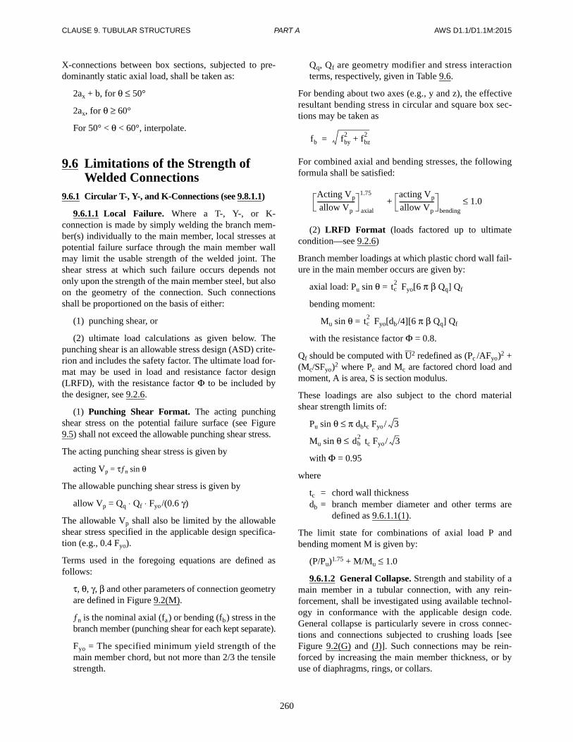
CLAUSE 9. TUBULAR STRUCTURES AWS D1.1/D1.1M:2015
260
X-connections between box sections, subjected to pre-dominantly static axial load, shall be taken as:
2ax + b, for θ ≤ 50°
2ax, for θ ≥ 60°
For 50° < θ < 60°, interpolate.
9.6 Limitations of the Strength of Welded Connections
9.6.1 Circular T-, Y-, and K-Connections (see 9.8.1.1)
9.6.1.1 Local Failure. Where a T-, Y-, or K-connection is made by simply welding the branch mem-ber(s) individually to the main member, local stresses atpotential failure surface through the main member wallmay limit the usable strength of the welded joint. Theshear stress at which such failure occurs depends notonly upon the strength of the main member steel, but alsoon the geometry of the connection. Such connectionsshall be proportioned on the basis of either:
(1) punching shear, or
(2) ultimate load calculations as given below. Thepunching shear is an allowable stress design (ASD) crite-rion and includes the safety factor. The ultimate load for-mat may be used in load and resistance factor design(LRFD), with the resistance factor Φ to be included bythe designer, see 9.2.6.
(1) Punching Shear Format. The acting punchingshear stress on the potential failure surface (see Figure9.5) shall not exceed the allowable punching shear stress.
The acting punching shear stress is given by
acting Vp = τƒn sin θ
The allowable punching shear stress is given by
allow Vp = Qq ⋅ Qf ⋅ Fyo/(0.6 γ)
The allowable Vp shall also be limited by the allowableshear stress specified in the applicable design specifica-tion (e.g., 0.4 Fyo).
Terms used in the foregoing equations are defined asfollows:
τ, θ, γ, β and other parameters of connection geometryare defined in Figure 9.2(M).
ƒn is the nominal axial (fa) or bending (fb) stress in thebranch member (punching shear for each kept separate).
Fyo = The specified minimum yield strength of themain member chord, but not more than 2/3 the tensilestrength.
Qq, Qf are geometry modifier and stress interactionterms, respectively, given in Table 9.6.
For bending about two axes (e.g., y and z), the effectiveresultant bending stress in circular and square box sec-tions may be taken as
For combined axial and bending stresses, the followingformula shall be satisfied:
(2) LRFD Format (loads factored up to ultimatecondition—see 9.2.6)
Branch member loadings at which plastic chord wall fail-ure in the main member occurs are given by:
axial load: Pu sin θ = Fyo[6 π β Qq] Qf
bending moment:
Mu sin θ = Fyo[db/4][6 π β Qq] Qf
with the resistance factor Φ = 0.8.
Qf should be computed with U2 redefined as (Pc /AFyo)2 +(Mc/SFyo)2 where Pc and Mc are factored chord load andmoment, A is area, S is section modulus.
These loadings are also subject to the chord materialshear strength limits of:
Pu sin θ ≤ π dbtc Fyo/
Mu sin θ ≤ tc Fyo/
with Φ = 0.95
where
tc = chord wall thicknessdb = branch member diameter and other terms are
defined as 9.6.1.1(1).
The limit state for combinations of axial load P andbending moment M is given by:
(P/Pu)1.75 + M/Mu ≤ 1.0
9.6.1.2 General Collapse. Strength and stability of amain member in a tubular connection, with any rein-forcement, shall be investigated using available technol-ogy in conformance with the applicable design code.General collapse is particularly severe in cross connec-tions and connections subjected to crushing loads [seeFigure 9.2(G) and (J)]. Such connections may be rein-forced by increasing the main member thickness, or byuse of diaphragms, rings, or collars.
fb fby2
fbz2+=
Acting Vp
allow Vp------------------------
axial
1.75 acting Vp
allow Vp----------------------
bending1.0≤+
tc2
tc2
3
db2 3
PART A

261
AWS D1.1/D1.1M:2015 CLAUSE 9. TUBULAR STRUCTURES
(1) For unreinforced circular cross connections, theallowable transverse chord load, due to compressivebranch member axial load P, shall not exceed
P sin θ = Fy (1.9 + 7.2 β)QβQf
(2) For circular cross connections reinforced by a“joint can” having increased thickness tc, and length, L,the allowable branch axial load, P, may be employed as
P = P(1) + [P(2) – P(1)]L/2.5D for L < 2.5/D
P = P(2) for L ≥ 2.5/D
where P(1) is obtained by using the nominal main mem-ber thickness in the equation in (1); and P(2) is obtainedby using the joint can thickness in the same equation.
The ultimate limit state may be taken as 1.8 times theforegoing ASD allowable, with Φ = 0.8.
(3) For circular K-connections in which the mainmember thickness required to meet the local shear provi-sions of 9.6.1.1 extends at least D/4 beyond the connect-ing branch member welds, general collapse need not bechecked.
9.6.1.3 Uneven Distribution of Load (Weld Sizing)
(1) Due to differences in the relative flexibilities ofthe main member loaded normal to its surface, and thebranch member carrying membrane stresses parallel toits surface, transfer of load across the weld is highly non-uniform, and local yielding can be expected before theconnection reaches its design load. To prevent “unzip-ping” or progressive failure of the weld and ensure duc-tile behavior of the joint, the minimum welds provided insimple T-, Y-, or K-connections shall be capable of de-veloping, at their ultimate breaking strength, the lesser ofthe brace member yield strength or local strength (punch-ing shear) of the main member. The ultimate breakingstrength of fillet welds and PJP groove welds shall becomputed at 2.67 times the basic allowable stress for60 ksi [415 MPa] or 70 ksi [485 MPa] tensile strengthand at 2.2 times the basic allowable stress for higherstrength levels. The ultimate punching shear shall betaken as 1.8 times the allowable Vp of 9.6.1.1.
(2) This requirement may be presumed to be met bythe prequalified joint details of Figure 9.14 (CJP) and9.10.1 (PJP), when matching materials (Table 3.1) areused.
(3) Compatible strength of welds may also be pre-sumed with the prequalified fillet weld details of Figure9.10, when the following effective throat requirementsare met:
(a) E = 0.7 tb for elastic working stress design ofmild steel circular steel tubes (Fy ≤ 40 ksi [280 MPa]
tc2
joined with overmatched welds (classified strength FEXX =70 ksi [485 MPa])
(b) E = 1.0 tb for ultimate strength design (LRFD)of circular or box tube connections of mild steel, Fy ≤40 ksi [280 MPa], with welds satisfying the matchingstrength requirements of Tables 3.1 and 3.2.
(c) E = lesser of tc or 1.07 tb for all other cases
(4) Fillet welds smaller than those required in Fig-ure 9.10 to match connection strength, but sized only toresist design loads, shall at least be sized for the follow-ing multiple of stresses calculated per 9.5.3, to accountfor non-uniform distribution of load:
ASD LRFD
E60XX and E70XX— 1.35 1.5
Higher strengths— 1.60 1.8
9.6.1.4 Transitions. Flared connections and tube sizetransitions not excepted below shall be checked for localstresses caused by the change in direction at the transi-tion (see Note d to Table 9.3). Exception, for static loads:
Circular tubes having D/t less than 30, and
Transition slope less than 1:4.
9.6.1.5 Other Configurations and Loads
(1) The term “T-, Y-, and K-connections” is oftenused generically to describe tubular connections in whichbranch members are welded to a main member, or chord,at a structural node. Specific criteria are also given forcross (X-) connections (also referred to as double-tee) in9.6.1.1 and 9.6.1.2. N-connections are a special case ofK-connections in which one of the branches is perpen-dicular to the chord; the same criteria apply (see Com-mentary for multiplanar connections).
(2) Connection classifications as T-, Y-, K-, or crossshould apply to individual branch members according tothe load pattern for each load case. To be considered a K-connection, the punching load in a branch membershould be essentially balanced by loads on other bracesin the same plane on the same side of the joint. In T- andY-connections the punching load is reacted as beamshear in the chord. In cross connections the punchingload is carried through the chord to braces on the oppo-site side. For branch members that carry part of their loadas K-connections, and part as T-, Y-, or cross connec-tions, interpolate based on the portion of each in total, oruse computed alpha (see Commentary).
(3) For multiplanar connections, computed alpha asgiven in Annex R may be used to estimate the beneficialor deleterious effect of the various branch member loadson main member ovalizing. However, for similarly loaded
PART A
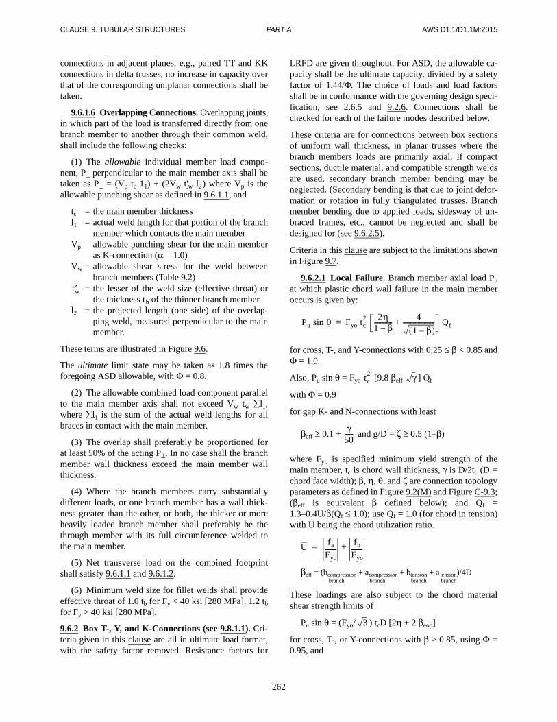
CLAUSE 9. TUBULAR STRUCTURES AWS D1.1/D1.1M:2015
262
connections in adjacent planes, e.g., paired TT and KKconnections in delta trusses, no increase in capacity overthat of the corresponding uniplanar connections shall betaken.
9.6.1.6 Overlapping Connections. Overlapping joints,in which part of the load is transferred directly from onebranch member to another through their common weld,shall include the following checks:
(1) The allowable individual member load compo-nent, P⊥ perpendicular to the main member axis shall betaken as P⊥ = (Vp tc 11) + (2Vw t'w l2) where Vp is theallowable punching shear as defined in 9.6.1.1, and
tc = the main member thicknessl1 = actual weld length for that portion of the branch
member which contacts the main memberVp = allowable punching shear for the main member
as K-connection (α = 1.0)Vw = allowable shear stress for the weld between
branch members (Table 9.2)= the lesser of the weld size (effective throat) or
the thickness tb of the thinner branch memberl2 = the projected length (one side) of the overlap-
ping weld, measured perpendicular to the mainmember.
These terms are illustrated in Figure 9.6.
The ultimate limit state may be taken as 1.8 times theforegoing ASD allowable, with Φ = 0.8.
(2) The allowable combined load component parallelto the main member axis shall not exceed Vw tw l1,where l1 is the sum of the actual weld lengths for allbraces in contact with the main member.
(3) The overlap shall preferably be proportioned forat least 50% of the acting P⊥. In no case shall the branchmember wall thickness exceed the main member wallthickness.
(4) Where the branch members carry substantiallydifferent loads, or one branch member has a wall thick-ness greater than the other, or both, the thicker or moreheavily loaded branch member shall preferably be thethrough member with its full circumference welded tothe main member.
(5) Net transverse load on the combined footprintshall satisfy 9.6.1.1 and 9.6.1.2.
(6) Minimum weld size for fillet welds shall provideeffective throat of 1.0 tb for Fy < 40 ksi [280 MPa], 1.2 tb
for Fy > 40 ksi [280 MPa].
9.6.2 Box T-, Y, and K-Connections (see 9.8.1.1). Cri-teria given in this clause are all in ultimate load format,with the safety factor removed. Resistance factors for
t′w
LRFD are given throughout. For ASD, the allowable ca-pacity shall be the ultimate capacity, divided by a safetyfactor of 1.44/Φ. The choice of loads and load factorsshall be in conformance with the governing design speci-fication; see 2.6.5 and 9.2.6. Connections shall bechecked for each of the failure modes described below.
These criteria are for connections between box sectionsof uniform wall thickness, in planar trusses where thebranch members loads are primarily axial. If compactsections, ductile material, and compatible strength weldsare used, secondary branch member bending may beneglected. (Secondary bending is that due to joint defor-mation or rotation in fully triangulated trusses. Branchmember bending due to applied loads, sidesway of un-braced frames, etc., cannot be neglected and shall bedesigned for (see 9.6.2.5).
Criteria in this clause are subject to the limitations shownin Figure 9.7.
9.6.2.1 Local Failure. Branch member axial load Pu
at which plastic chord wall failure in the main memberoccurs is given by:
for cross, T-, and Y-connections with 0.25 ≤ β < 0.85 andΦ = 1.0.
Also, Pu sin θ = Fyo [9.8 βeff ] Qf
with Φ = 0.9
for gap K- and N-connections with least
βeff ≥ 0.1 + and g/D = ζ ≥ 0.5 (1–β)
where Fyo is specified minimum yield strength of themain member, tc is chord wall thickness, γ is D/2tc (D =chord face width); β, η, θ, and ζ are connection topologyparameters as defined in Figure 9.2(M) and Figure C-9.3;(βeff is equivalent β defined below); and Qf =1.3–0.4U/β(Qf ≤ 1.0); use Qf = 1.0 (for chord in tension)with U being the chord utilization ratio.
U =
βeff = (bcompression + acompression + btension + atension)/4D branch branch branch branch
These loadings are also subject to the chord materialshear strength limits of
Pu sin θ = (Fyo/ ) tcD [2η + 2 βeop]
for cross, T-, or Y-connections with β > 0.85, using Φ =0.95, and
Pu sin θ Fyo tc2 2η
1 β–------------
4
1 β–( )---------------------+ Qf=
tc2 γ
γ50------
fa
Fyo-------
fb
Fyo-------+
3
PART A

263
AWS D1.1/D1.1M:2015 CLAUSE 9. TUBULAR STRUCTURES
Pu sin θ = (Fyo/ ) tcD [2η + βeop + βgap]
for gap K- and N-connections with β ≥ 0.1 + γ/50, usingΦ = 0.95 (this check is unnecessary if branch membersare square and equal width), where
βgap = β for K- and N-connections with ζ ≤ 1.5 (1–β)βgap = βeop for all other connectionsβeop (effective outside punching) = 5β/γbut not more than β
9.6.2.2 General Collapse. Strength and stability of amain member in a tubular connection, with any rein-forcement, shall be investigated using available technol-ogy in conformance with the applicable design code.
(1) General collapse is particularly severe in crossconnections and connections subjected to crushing loads.Such connections may be reinforced by increasing themain member thickness or by use of diaphragms, gus-sets, or collars.
For unreinforced matched box connections, the ultimateload normal to the main member (chord) due to branchaxial load P shall be limited to:
Pu sin θ = 2tc Fyo(ax + 5 tc)
with Φ = 1.0 for tension loads,and Φ = 0.8 for compression.
and
with Φ = 0.8 for cross connections, end post reactions,etc., in compression, and E = modulus of elasticity
or
Pu sin θ = 1.5 [1 + 3ax/H] (Qf)
with Φ = 0.75 for all other compression branch loads
(2) For gap K- and N-connections, beam shear ade-quacy of the main member to carry transverse loadsacross the gap region shall be checked including inter-action with axial chord forces. This check is not requiredfor U ≤ 0.44 in stepped box connections having β +η ≤ H/D (H is height of main member in plane of truss).
9.6.2.3 Uneven Distribution of Load (EffectiveWidth). Due to differences in the relative flexibilities ofthe main member loaded normal to its surface and thebranch member carrying membrane stresses parallel toits surface, transfer of load across the weld is highly non-uniform, and local yielding can be expected before theconnection reaches its design load. To prevent progres-sive failure and ensure ductile behavior of the joint, boththe branch members and the weld shall be checked, asfollows:
3
Pu sin θ47 tc
3
H 4tc–----------------- EFyo(Qf)=
tc2 EFyo
(1) Branch Member Check. The effective widthaxial capacity Pu of the branch member shall be checkedfor all gap K- and N-connections, and other connectionshaving β > 0.85. (Note that this check is unnecessary ifbranch members are square and equal width.)
Pu = Fytb[2a + bgap + beoi – 4tb]
with Φ = 0.95
where
Fy = specified minimum yield strength of branchtb = branch wall thicknessa, b = branch dimensions [see Figure 9.2(B)]bgap = b for K- and N-connections with ζ ≤ 1.5(1–β)bgap = beoi for all other connections
beoi = ≤ b
NOTE: τ ≤ 1.0 and Fy ≤ Fyo are presumed.
(2) Weld Checks. The minimum welds provided insimple T-, Y-, or K-connections shall be capable of de-veloping at their ultimate breaking strength, the lesser ofthe branch member yield strength or local strength of themain member.
This requirement may be presumed to be met by theprequalified joint details of Figure 9.12 (CJP and PJP),when matching materials (Tables 3.1 and 3.2) are used,
(3) Fillet welds shall be checked as described in 9.5.5.
9.6.2.4 Overlapping Connections. Lap joints reducethe design problems in the main member by transferringmost of the transverse load directly from one branchmember to the other (see Figure 9.8).
The criteria of this clause are applicable to staticallyloaded connections meeting the following limitations:
(1) The larger, thicker branch is the thru member.
(2) β ≥ 0.25.
(3) The overlapping branch member is 0.75 to 1.0times the size of the through member with at least 25%of its side faces overlapping the through member.
(4) Both branch members have the same yieldstrength.
(5) All branch and chord members are compact boxtubes with width/thickness ≤ 35 for branches, and ≤ 40for chord.
The following checks shall be made:
(1) Axial capacity Pu of the overlapping tube, using
Φ = 0.95 with
5bγτ------ Fyo
Fy-------
PART A
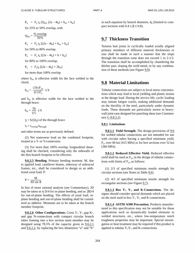
CLAUSE 9. TUBULAR STRUCTURES AWS D1.1/D1.1M:2015
264
Pu = Fy tb [QOL (2a – 4tb) + beo + bet]
for 25% to 50% overlap, with
QOL =
Pu = Fy tb [(2a – 4tb) + beo + bet]
for 50% to 80% overlap.
Pu = Fy tb [(2a – 4tb) + b + bet]
for 80% to 100% overlap.
Pu = Fytb [(2a – 4tb) + 2bet]
for more than 100% overlap
where beo is effective width for the face welded to thechord,
beo = ≤ b
and bet is effective width for the face welded to thethrough brace.
bet = ≤ b
γt = b/(2tb) of the through brace
τt = toverlap/tthrough
and other terms are as previously defined.
(2) Net transverse load on the combined footprint,treated as a T- or Y-connection.
(3) For more than 100% overlap, longitudinal shear-ing shall be checked, considering only the sidewalls ofthe thru branch footprint to be effective.
9.6.2.5 Bending. Primary bending moment, M, dueto applied load, cantilever beams, sidesway of unbracedframes, etc., shall be considered in design as an addi-tional axial load, P:
P =
In lieu of more rational analysis (see Commentary), JDmay be taken as η D/4 for in-plane bending, and as βD/4for out-of-plane bending. The effects of axial load, in-plane bending and out-of-plane bending shall be consid-ered as additive. Moments are to be taken at the branchmember footprint.
9.6.2.6 Other Configurations. Cross T-, Y-, gap K-,and gap N-connections with compact circular branchtubes framing into a box section main member may bedesigned using 78.5% of the capacity given in 9.6.2.1and 9.6.2.2, by replacing the box dimension “a” and “b”
% overlap50%
------------------------
5b( )Fyo
γ τ( )Fy-------------------
5bγtτt--------
MJD sin θ--------------------
in each equation by branch diameter, db (limited to com-pact sections with 0.4 ≤ β ≤ 0.8).
9.7 Thickness Transition
Tension butt joints in cyclically loaded axially alignedprimary members of different material thicknesses orsize shall be made in such a manner that the slopethrough the transition zone does not exceed 1 in 2-1/2.The transition shall be accomplished by chamfering thethicker part, sloping the weld metal, or by any combina-tion of these methods (see Figure 9.9).
9.8 Material Limitations
Tubular connections are subject to local stress concentra-tions which may lead to local yielding and plastic strainsat the design load. During the service life, cyclic loadingmay initiate fatigue cracks, making additional demandson the ductility of the steel, particularly under dynamicloads. These demands are particularly severe in heavy-wall joint-cans designed for punching shear (see Commen-tary C-9.8.2.2).
9.8.1 Limitations
9.8.1.1 Yield Strength. The design provisions of 9.6for welded tubular connections are not intended for usewith circular tubes having a specified minimum yield,Fy, over 60 ksi [415 MPa] or for box sections over 52 ksi[360 MPa].
9.8.1.2 Reduced Effective Yield. Reduced effectiveyield shall be used as Fyo in the design of tubular connec-tions with limits of Fyo as follows:
(1) 2/3 of specified minimum tensile strength forcircular sections (see Notes in Table 9.6).
(2) 4/5 of specified minimum tensile strength forrectangular sections (see Figure 9.7).
9.8.1.3 Box T-, Y-, and K-Connections. The de-signer should consider special demands which are placedon the steel used in box T-, Y-, and K-connections.
9.8.1.4 ASTM A500 Precaution. Products manufac-tured to this specification may not be suitable for thoseapplications such as dynamically loaded elements inwelded structures, etc., where low-temperature notchtoughness properties may be important. Special investi-gation or heat treatment may be required if this product isapplied to tubular T-,Y-, and K-connections.
PART A
265
AWS D1.1/D1.1M:2015 CLAUSE 9. TUBULAR STRUCTURES
9.8.2 Tubular Base Metal Notch Toughness
9.8.2.1 CVN Test Requirements. Welded tubularmembers in tension shall be required to demonstrateCVN test absorbed energy of 20 ft⋅lb at 70°F [27 J at21°C] for the following conditions:
(1) Base metal thickness of 2 in [50 mm] or greaterwith a specified minimum yield strength of 40 ksi[280 MPa] or greater.
CVN testing shall be in conformance with ASTM A673(Frequency H, heat lot). For the purposes of this sub-clause, a tension member is defined as one having morethan 10 ksi [70 MPa] tensile stress due to design loads.
9.8.2.2 LAST Requirements. Tubulars used as themain member in structural nodes, whose design is gov-erned by cyclic or fatigue loading (e.g., the joint can inT-, Y-, and K-connections) shall be required to demon-strate CVN test absorbed energy of 20 ft⋅lb [27 J] at theLowest Anticipated Service Temperature (LAST) for thefollowing conditions:
(1) Base metal thickness of 2 in [50 mm] or greater.
(2) Base metal thickness of 1 in [25 mm] or greaterwith a specified yield strength of 50 ksi [345 MPa] orgreater.
When the LAST is not specified, or the structure is notgoverned by cyclic or fatigue loading, testing shall be ata temperature not greater than 40°F [4°C]. CVN testingshall normally represent the as-furnished tubulars, and betested in conformance with ASTM A673 Frequency H(heat lot).
9.8.2.3 Alternative Notch Toughness. Alternativenotch toughness requirements shall apply when specifiedin contract documents. The Commentary gives addi-tional guidance for designers. Toughness should be con-sidered in relation to redundancy versus criticality of thestructure at an early stage in planning and design.
Part BPrequalification of Welding
Procedure Specifications (WPSs)
9.9 Fillet Weld Requirements9.9.1 Details. For prequalified status, fillet weldedtubular connections shall conform to the followingprovisions:
(1) Prequalified WPSs. Fillet welded tubular con-nections made by SMAW, GMAW, or FCAW processesthat may be used without performing WPS qualificationtests are detailed in Figure 9.10 (see 9.5.1.2 for limita-tions). These details may also be used for GMAW-Squalified in conformance with 9.15.4.3.
(2) Details for lap joints are shown in Figure 9.3.
9.10 PJP Requirements9.10.1 Details. Details for PJP tubular groove welds thatare accorded prequalified status shall conform to the fol-lowing provisions:
(1) PJP tubular groove welds, other than T-, Y-, andK-connections, may be used without performing theWPS qualification tests, when these may be applied andshall meet all of the joint dimension limitations as de-scribed in Figure 3.2.
(2) PJP T-, Y-, and K-tubular connections, weldedonly by the SMAW, GMAW, or FCAW process, may beused without performing the WPS qualification tests,when they may be applied and shall meet all of the jointdimension limitations as described in Figure 9.11. Thesedetails may also be used for GMAW-S qualified in con-formance with 9.15.4.3.
9.10.1.1 Matched Box Connections. Details for PJPgroove welds in these connections, the corner dimen-sions and the radii of the main tube are shown in Figure9.11. Fillet welds may be used in toe and heel zones (seeFigure 9.10). If the corner dimension or the radius of themain tube, or both, are less than as shown in Figure 9.11,a sample joint of the side detail shall be made and sec-tioned to verify the weld size. The test weld shall bemade in the horizontal position. This requirement may bewaived if the branch tube is beveled as shown for CJPgroove welds in Figure 9.12.
9.11 CJP Groove Weld Requirements9.11.1 Butt Joints. For tubular groove welds to begiven prequalified status, the following conditions shallapply:
(1) Prequalified WPSs. Where welding from bothsides or welding from one side with backing is possible,any WPS and groove detail that is appropriately prequal-ified in conformance with Clause 3 may be used, except
PARTS A & B
CLAUSE 9. TUBULAR STRUCTURES AWS D1.1/D1.1M:2015
266
that SAW is only prequalified for diameters greater thanor equal to 24 in [600 mm]. Welded joint details shall bein conformance with Clause 3.
(2) Nonprequalified Joint Detail. There are noprequalified joint details for CJP groove welds in buttjoints made from one side without backing (see 9.15.2).
9.11.2 Tubular T-, Y-, and K-Connections. Details forCJP groove welds welded from one side without backingin tubular T-, Y-, and K-connections used in circular tubesare described in this section. The applicable range of De-tails A, B, C, and D are described in Figures 9.12 and9.13, and the ranges of local dihedral angles, [Ψ], corre-sponding to these are described in Table 9.7.
Joint dimensions including groove angles are describedin Table 9.8 and Figure 9.14. When selecting a profile(compatible with fatigue category used in design) as afunction of thickness, the guidelines of 9.2.7.7 shall beobserved. Alternative weld profiles that may be requiredfor thicker sections are described in Figure 9.15. In theabsence of special fatigue requirements, these profilesshall be applicable to branch thicknesses exceeding 5/8in [16 mm].
Improved weld profiles meeting the requirements of9.2.7.6 and 9.2.7.7 are described in Figure 9.16. In theabsence of special fatigue requirements, these profilesshall be applicable to branch thicknesses exceeding1-1/2 in [38 mm] (not required for static compressionloading).
Prequalified details for CJP groove welds in tubular T-,Y-, and K-connections utilizing box sections are furtherdescribed in Figure 9.12. The foregoing details are sub-ject to the limitation of 9.11.1.
NOTE: See the Commentary (C-9.15.4) for engineeringguidance in the selection of a suitable profile.
The joint dimensions and groove angles shall not varyfrom the ranges detailed in Table 9.8 and shown in Fig-ure 9.12 and Figures 9.14–9.16. The root face of jointsshall be zero unless dimensioned otherwise. It may bedetailed to exceed zero or the specified dimension by notmore than 1/16 in [2 mm]. It may not be detailed lessthan the specified dimensions.
9.11.2.1 Joint Details. Details for CJP groove weldsin tubular T-, Y-, and K-connections are described in9.11.2. These details are prequalified for SMAW andFCAW. These details may also be used for GMAW-Squalified in conformance with 9.15.4.3.
Part CWelding Procedure Specification
(WPS) Qualification
9.12 Common Requirements forWPS and Welding Personnel Performance Qualification
9.12.1 Positions of Welds. All welds shall be classifiedas flat (F), horizontal (H), vertical (V), and overhead(OH), in conformance with the definitions shown in Fig-ures 4.1 and 4.2.
Test assembly positions are shown in:
(1) Figure 9.17 (groove welds in pipe or tubing)
(2) Figure 9.18 (fillet welds in pipe or tubing)
9.13 Production Welding Positions Qualified
Tubular production welding positions qualified by atubular test shall conform to the requirements of Table9.9. Tubular production welding positions qualified by aplate test shall conform to the requirements in Clause 4and Table 4.1.
9.14 Type of Qualification Tests, Methods of Testing, and Acceptance Criteria forWPS Qualification
The type and number of qualification tests required toqualify a WPS for a given thickness, diameter or both,shall conform to Table 9.10 (CJP), Table 9.11 (PJP), orTable 9.12 (Fillet). Details on the individual NDT andmechanical test requirements are found in 4.5.
The welded test assemblies shall have test specimensprepared by cutting the pipe or tubing as shown in Figure9.19 or Figure 9.20. Methods of testing and acceptancecriteria shall be per 4.9 with the following exceptions:
(1) For T-, Y- and K-connections melt-through is notlimited.
(2) For tubulars, the full circumference of the weldshall be RT or UT examined in conformance with Clause6, Part C and Clause 9, Part F, as applicable.
PARTS B & C

267
AWS D1.1/D1.1M:2015 CLAUSE 9. TUBULAR STRUCTURES
9.15 CJP Groove Welds for Tubular Connections
CJP groove welds shall be classified as follows:
(1) CJP butt joints with backing or backgouging (see9.15.1).
(2) CJP butt joints without backing welded from oneside only (see 9.15.2).
(3) T-, Y-, K-connections with backing or backgoug-ing (see 9.15.3).
(4) T-, Y-, K-connections without backing weldedfrom one side only (see 9.15.4).
9.15.1 CJP Butt Joints with Backing or Backgouging.A WPS with backing or backgouging shall be qualifiedusing the detail shown in Figure 9.23(A) (with back-gouging) or Figure 9.23(B) (with backing).
9.15.2 CJP Butt Joints without Backing Welded fromOne Side Only. A WPS without backing welded fromone side only shall be qualified using the joint detailshown in Figure 9.23(A).
9.15.3 T-, Y-, or K-Connections with Backing orBackgouging. A WPS for tubular T-, Y-, or K-connec-tions with backing or backgouging shall be qualifiedusing:
(1) the appropriate nominal pipe OD selected fromTable 9.10, and
(2) the joint detail of Figure 9.23(B), or
(3) for nominal pipe ODs equal to or greater than24 in [600 mm], a plate qualification in conformancewith 4.9 using the joint detail of Figure 9.23(B).
9.15.4 T-, Y-, or K-Connections without BackingWelded from One Side Only. When qualification isrequired, a WPS for T-, Y-, or K-connections withoutbacking welded from one side only shall require thefollowing:
9.15.4.1 WPSs without Prequalified Status. For aWPS whose essential variables are outside the prequali-fied range, qualification for CJP tubular groove weldsshall require the following:
(1) Qualification in conformance with Figure 9.25 forpipes with outside diameters greater than or equal to 4 in[100 mm] or Figure 9.25 and Figure 9.27 for box tubes.Qualification in conformance with Figure 9.26 for pipeswith outside diameters less than 4 in [100 mm] or Figure9.26 and Figure 9.27 for box tubes.
(2) A Sample Joint or Tubular Mock-Up. The samplejoint or tubular mock-up shall provide at least one mac-roetch test section for each of the following conditions:
(a) The groove combining the greatest groovedepth with the smallest groove angle, or combination ofgrooves to be used: test with welding position vertical.
(b) The narrowest root opening to be used with a37.5° groove angle: one test welded in the flat positionand one test welded in the overhead position.
(c) The widest root opening to be used with a37.5° groove angle: one test to be welded in the flat posi-tion and one test to be welded in the overhead position.
(d) For matched box connections only, the mini-mum groove angle, corner dimension and corner radiusto be used in combination: one test in horizontal position.
(3) The macroetch test specimens required in (1) and(2) above shall be examined for discontinuities and shallhave:
(a) No cracks
(b) Thorough fusion between adjacent layers ofweld metal and between weld metal and base metal
(c) Weld details conforming to the specified de-tail but with none of the variations prohibited in 5.23.
(d) No undercut exceeding the values allowed in6.9.
(e) For porosity 1/32 in [1 mm] or larger, accumu-lated porosity shall not exceed 1/4 in [6 mm]
(f) No accumulated slag, the sum of the greatestdimension of which shall not exceed 1/4 in [6 mm]
Those specimens not conforming to (a) through (f) shallbe considered unacceptable; (b) through (f) not applica-ble to backup weld.
9.15.4.2 CJP Groove Welds in a T-, Y-, or K-Connection WPS with Dihedral Angles Less than 30°.The sample joint described in 9.15.4.1(2)(a) shall be re-quired. Three macroetch test sections shall be cut fromthe test specimens, shall conform to the requirements of9.15.4.1(3), and shall show the required theoretical weld(with due allowance for backup welds to be discounted,as shown in Details C and D of Figures 9.14–9.16) (seeFigure 9.24 for test joint details).
9.15.4.3 CJP Groove Welds in a T-, Y-, or K-Con-nection WPS Using GMAW-S. For T-, Y-, and K-con-nections, where GMAW-S is used, qualification inconformance with Clause 4 shall be required prior towelding the standard joint configurations detailed in9.11.2. The joint tested shall incorporate a 37.5° single
PART C
CLAUSE 9. TUBULAR STRUCTURES AWS D1.1/D1.1M:2015
268
bevel groove, offset root and restriction ring as shown inFigure 9.25.
9.15.4.4 Weldments Requiring CVN Toughness.WPSs for butt joints (longitudinal or circumferentialseams) within 0.5D of attached branch members, in tubu-lar connection joint cans requiring CVN testing under9.8.2.2, shall be required to demonstrate weld metalCVN absorbed energy of 20 ft·lb [27 J] at the LAST(Lowest Anticipated Service Temperature), or at 0ºF [-18ºC], whichever is lower. If AWS specifications for thewelding materials to be used do not encompass thisrequirement, or if production welding is outside therange covered by prior testing, e.g., tests per AWS fillermetal specifications, then weld metal CVN tests shall bemade during WPS qualification, as described in Clause 4,Part D.
9.16 PJP and Fillet Welds TubularT-, Y-, or K-Connections and Butt Joints
When PJP groove welds are specified, in T-, Y-, or K-connections or butt welds, qualification shall be in con-formance with Table 9.11. When fillet welds are speci-fied in T-, Y- or K-connections, qualification shall be inconformance with 4.12, Table 9.12 and Figure 9.21.
Part DPerformance Qualification
9.17 Production Welding Positions, Thicknesses and Diameters Qualified
9.17.1 Welders and Welding Operators. The qualifiedtubular production welding positions qualified by a tubu-lar test for welders and welding operators shall be inconformance with Table 9.13. The qualified tubular pro-duction welding positions qualified by a plate test forwelders and welding operators shall be in conformancewith Clause 4 and Table 4.10.
For tests on tubulars, the number and type of test speci-mens and the range of qualified production weldingthicknesses and diameters for which a welder or weldingoperator is qualified shall be in conformance with Table9.14. Mechanical test specimens shall be prepared bycutting the pipe or tubing as shown in Figure 9.28 and asspecified in 4.16.1.2.
If tests are performed using plate, the qualification limi-tations shall be in conformance with Table 4.11.
9.17.2 Tack Welders. Tack welder qualification shallqualify for tubular thickness greater than 1/8 in [3 mm]and all diameters, but does not include CJP butt jointsand T-, Y-, and K-connections welded from one side.Tack welds in the foregoing exception shall be per-formed by welders fully qualified for the process and po-sition in which the welding is to be done.
9.18 Weld Types for Welder and Welding Operator Performance Qualification
For the purpose of welder and welding operator qualifi-cation, weld types shall be classified as follows:
(1) CJP Groove Welds for Tubular Connections (see9.19)
(2) PJP Groove Welds for Tubular Connections (see9.20)
(3) Fillet Welds for Tubular Connections (see 9.21)
Plate welds parallel to the tubular centerline and tubularlongseam welds do not require tubular qualification andmay be qualified using Clause 4 (see Commentary).
9.19 CJP Groove Welds for Tubular Connections
Welder or welding operator qualification tests shall usethe following details:
(1) CJP groove butt joints with backing or backgoug-ing in pipe. Use Figure 9.22(B).
(2) CJP groove butt joints without backing or back-gouging. Use Figure 9.22(A).
(3) CJP groove butt joints or T-, Y-, and K-connec-tions with backing in box tubing. Use Figure 9.22(B) inpipe (any diameter), plate or box tubing.
(4) CJP groove T-, Y-, and K-Connections weldedfrom one side with backing in pipe. Use Figure 9.22(B)in pipe of the appropriate diameter.
(5) CJP groove T-, Y-, and K-connections weldedfrom one side without backing in pipe. Use Figure 9.25for nominal pipe diameter of ≥ 6 in [150 mm] or Figure9.26 for nominal pipe ≤ 4 in [100 mm].
PARTS C & D

269
AWS D1.1/D1.1M:2015 CLAUSE 9. TUBULAR STRUCTURES
(6) CJP groove T-, Y-, and K-connection weldedfrom one side without backing or backgouging in boxtubing. The options are the following:
(a) Figure 9.25 in pipe (any diameter) or box tub-ing plus Figure 9.27 in box tubing.
(b) Figure 9.25 in box tubing with macroetchspecimens removed from the locations shown in Figure9.27.
See Table 9.14 for the production ranges of diameter andthickness qualified by the test assembly diameters andthicknesses.
9.19.1 Other Joint Details or WPSs. For joint details,WPSs, or assumed depth of sound welds that are moredifficult than those described herein, a test described in9.15.4.2 shall be performed by each welder in addition tothe 6GR tests (see Figures 9.26 or 9.27). The test posi-tion shall be vertical.
9.20 PJP Groove Welds for Tubular Connections
Qualification for CJP groove welds on tubular connec-tions shall qualify for all PJP groove welds.
9.21 Fillet Welds for Tubular Connections
See Table 9.14 for fillet weld qualification requirements.
9.22 Methods of Testing and Acceptance Criteria for Welder and Welding Operator Qualification
9.22.1 Macroetch Test for T-, Y-, and K-Connections.The corner macroetch test joint for T-, Y-, and K-con-nections on box tubing in Figure 9.27 shall have fourmacroetch test specimens cut from the weld corners atthe locations shown in Figure 9.27. One face from eachcorner specimen shall be smooth for etching. If thewelder tested on a 6GR coupon (Figure 9.26) using boxtubing, the four required corner macroetch test speci-mens may be cut from the corners of the 6GR coupon ina manner similar to Figure 9.27. One face from each cor-ner specimen shall be smooth for etching.
9.22.1.1 Macroetch Test Acceptance Criteria. Foracceptable qualification, the test specimen, when in-
spected visually, shall conform to Clause 4 and the fol-lowing requirements:
(1) Fillet welds and the corner macroetch test jointfor T-, Y-, and K-connections on box tubing, Figure9.27, shall have:
(a) No cracks
(b) Thorough fusion between adjacent layers ofweld metals and between weld metal and base metal
(c) Weld profiles conforming to intended detail,but with none of the variations prohibited in 5.23
(d) No undercut exceeding 1/32 in [1 mm]
(e) For porosity 1/32 in [1 mm] or larger, accumu-lated porosity not exceeding 1/4 in [6 mm]
(f) No accumulated slag, the sum of the greatestdimensions of which shall not exceed 1/4 in [4 mm]
9.22.2 RT Test Procedure and Technique. Weldedtest pipe or tubing 4 in [100 mm] in diameter or largershall be examined for a minimum of one-half of the weldperimeter selected to include a sample of all positionswelded. For example, a test pipe or tube welded in the5G, 6G, or 6GR position shall be radiographed from thetop centerline to the bottom centerline on either side.Welded test pipe or tubing less than 4 in [100 mm] indiameter shall require 100% RT.
Part EFabrication
9.23 Backing9.23.1 Full-Length Backing. Except as permitted below,steel backing shall be made continuous for the full lengthof the weld. All joints in the steel backing shall be CJPgroove weld joints meeting all the requirements ofClause 5 of this code.
For statically loaded applications, backing for welds tothe ends of closed sections, such as hollow structural sec-tions (HSS), are permitted to be made from one or twopieces with unspliced discontinuities where all of the fol-lowing conditions are met:
(1) The closed section nominal wall thickness doesnot exceed 5/8 in [16 mm].
(2) The closed section outside perimeter does not ex-ceed 64 in [1625 mm].
PARTS D & E

CLAUSE 9. TUBULAR STRUCTURES AWS D1.1/D1.1M:2015
270
(3) The backing is transverse to the longitudinal axisof the closed section.
(4) The interruption in the backing does not exceed1/4 in [6 mm].
(5) The weld with discontinuous backing is not closerthan the HSS diameter or major cross section dimensionfrom other types of connections.
(6) The interruption in the backing is not located inthe corners.
For statically loaded box columns, discontinuous back-ing is permitted in the CJP welded corners, at fieldsplices and at connection details. Discontinuous backingis permitted in other closed sections where approved bythe Engineer.
NOTE: Commercially available steel backing for pipeand tubing is acceptable, provided there is no evidenceof melting on exposed interior surfaces.
9.24 Tolerance of Joint Dimensions
9.24.1 Girth Weld Alignment (Tubular). Abutting partsto be joined by girth welds shall be carefully aligned. Notwo girth welds shall be located closer than one pipediameter or 3 ft [1 m], whichever is less. There shall beno more than two girth welds in any 10 ft [3 m] intervalof pipe, except as may be agreed upon by the Owner andContractor. Radial offset of abutting edges of girth seamsshall not exceed 0.2t (where t is the thickness of the thin-ner member) and the maximum allowable shall be 1/4 in[6 mm], provided that any offset exceeding 1/8 in [3 mm]is welded from both sides. However, with the approval ofthe Engineer, one localized area per girth seam may beoffset up to 0.3t with a maximum of 3/8 in [10 mm], pro-vided the localized area is under 8t in length. Filler metalshall be added to this region to provide a 4 to 1 transitionand may be added in conjunction with making the weld.Offsets in excess of this shall be corrected as provided in5.21.3. Longitudinal weld seams of adjoining sectionsshall be staggered a minimum of 90°, unless closer spac-ing is agreed upon by the Owner and fabricator.
9.24.2 Groove Dimensions
9.24.2.1 Tubular Cross-Sectional Variations. Vari-ation in cross section dimension of groove welded joints,from those shown on the detailed drawings, shall be inconformance with 5.21.4.1 except:
(1) Tolerances for T-, Y-, and K-connections are in-cluded in the ranges given in 9.11.2.
(2) The tolerances shown in Table 9.15 apply to CJPtubular groove welds in butt joints, made from one sideonly, without backing.
Part FInspection
9.25 Visual InspectionAll welds shall be visually inspected and shall be accept-able if the criteria in Table 9.16 are satisfied.
9.26 NDT9.26.1 Scope. Acceptance criteria for inspection of tu-bular connections are described in Part C of Clause 6, asapplicable, and Part F of this clause. The acceptance cri-teria shall be specified in the contract documents on in-formation furnished to the bidder.
9.26.2 Tubular Connection Requirements. For CJPgroove butt joints welded from one side without backing,the entire length of all completed tubular production weldsshall be examined by either RT or UT. The acceptancecriteria shall conform to 6.12.1 for RT (see Figure 6.1) or9.27.1 for UT, as applicable.
9.27 UT9.27.1 Acceptance Criteria for Tubular Connections.Acceptance criteria for UT shall be as provided in con-tract documents. Class R or Class X, or both, may be in-corporated by reference. Amplitude based acceptancecriteria as given by 6.13.1 may also be used for groovewelds in butt joints in tubing 24 in [600 mm] in diameterand over, provided all relevant provisions of Clause 6,Part F, are followed. However, these amplitude criteriashall not be applied to tubular T, Y-, and K-connections.
9.27.1.1 Class R (Applicable When UT is Used as anAlternate to RT). All indications having one-half (6 dB)or less amplitude than the standard sensitivity level (withdue regard for 9.30.6) shall be disregarded. Indicationsexceeding the disregard level shall be evaluated asfollows:
(1) Isolated random spherical reflectors, with 1 in[25 mm] minimum separation up to the standard sensi-tivity level shall be accepted. Larger reflectors shall beevaluated as linear reflectors.
(2) Aligned spherical reflectors shall be evaluated aslinear reflectors.
PARTS E & F

271
AWS D1.1/D1.1M:2015 CLAUSE 9. TUBULAR STRUCTURES
(3) Clustered spherical reflectors having a density ofmore than one per square inch [645 square millimeters]with indications above the disregard levels (projectedarea normal to the direction of applied stress, averagedover a 6 in [150 mm] length of weld) shall be rejected.
(4) Linear or planar reflectors whose lengths (extent)exceed the limits of Figure 9.29 shall be rejected. Addi-tionally, root reflectors shall not exceed the limits ofClass X.
9.27.1.2 Class X (Experience-Based, Fitness-for-Purpose Criteria Applicable to T-, Y-, and K-Connections in Structures with Notch-Tough Weld-ments). All indications having half (6 dB) or less ampli-tude than the standard sensitivity level (with due regardfor 9.30.6) shall be disregarded. Indications exceedingthe disregard level shall be evaluated as follows:
(1) Spherical reflectors shall be as described in ClassR, except that any indications within the following limitsfor linear or planar shall be acceptable.
(2) Linear or planar reflectors shall be evaluated bymeans of beam boundary techniques, and those whosedimensions exceeded the limits of Figure 9.30 shall berejected. The root area shall be defined as that lyingwithin 1/4 in [6 mm] or tw/4, whichever is greater, of theroot of the theoretical weld, as shown in Figure 9.14.
9.28 RT Procedures9.28.1 Procedure. In addition to the requirements of6.17, IQI selection shall conform to Tables 9.17 and 9.18and Figures 6.4 and 6.5.
9.28.2 IQI Selection and Placement. IQIs shall be se-lected and placed on the weldment in the area of interestbeing radiographed as shown in Table 9.19. When acomplete circumferential pipe weld is radiographed witha single exposure and the radiation source is placed at thecenter of the curvature, at least three equally spaced IQIsshall be used. Steel backing shall not be considered partof the weld or weld reinforcement in IQI selection.
9.29 Supplementary RT Requirements for Tubular Connections
9.29.1 Circumferential Groove Welds in Butt Joints.The technique used to radiograph circumferential buttjoints shall be capable of covering the entire circumfer-ence. The technique shall preferably be single-wall expo-sure/single-wall view. Where accessibility or pipe size
prohibits this, the technique may be double-wall expo-sure/single-wall view or double-wall exposure/double-wall view.
9.29.1.1 Single-Wall Exposure/Single-Wall View.The source of radiation shall be placed inside the pipeand the film on the outside of the pipe (see Figure 9.31).Panoramic exposure may be made if the source-to-objectrequirements are satisfied; if not, a minimum of three ex-posures shall be made. The IQI may be selected andplaced on the source side of the pipe. If not practicable, itmay be placed on the film side of the pipe.
9.29.1.2 Double-Wall Exposure/Single-Wall View.Where access or geometrical conditions prohibit single-wall exposure, the source may be placed on the outsideof the pipe and film on the opposite wall outside the pipe(see Figure 9.32). A minimum of three exposures shallbe required to cover the complete circumference. TheIQI may be selected and placed on the film side of thepipe.
9.29.1.3 Double-Wall Exposure/Double-Wall View.When the outside diameter of the pipe is 3-1/2 in [90mm] or less, both the source side and film side weld maybe projected onto the film and both walls viewed for ac-ceptance. The source of radiation shall be offset from thepipe by a distance that is at least seven times the outsidediameter. The radiation beam shall be offset from theplane of the weld centerline at an angle sufficient to sep-arate the images of the source side and film side welds.There shall be no overlap of the two zone interpreted. Aminimum of two exposures 90° to each other shall be re-quired (see Figure 9.33). The weld may also be radio-graphed by superimposing the two welds, in which casethere shall be a minimum of three exposures 60° to eachother (see Figure 9.34). In each of these two techniques,the IQI shall be placed on the source side of the pipe.
9.30 UT of Tubular T-, Y-, andK-Connections
9.30.1 Procedure. All UT shall be in conformance witha written procedure which has been prepared or approvedby an individual certified as SNT-TC-1A, Level III, andexperienced in UT of tubular structures. The procedureshall be based upon the requirements of this clause andClause 6, Part F, as applicable. The procedure shall con-tain, as a minimum, the following information regardingthe UT method and techniques:
(1) The type of weld joint configuration to be exam-ined (i.e., the applicable range of diameter, thickness,and local dihedral angle). Conventional techniques aregenerally limited to diameters of 12-3/4 in [325 mm] and
PART F

CLAUSE 9. TUBULAR STRUCTURES AWS D1.1/D1.1M:2015
272
larger, thicknesses of 1/2 in [12 mm] and above, andlocal dihedral angles of 30° or greater. Special tech-niques for smaller sides may be used, provided they arequalified as described herein, using the smaller size ofapplication.
(2) Acceptance criteria for each type and size weld
(3) Type(s) of UT instrumentation (make and model)
(4) Transducer (search unit) frequency, size andshape of active area, beam angle, and type of wedge onangle beam probes. Procedures using transducers withfrequencies up to 6 MHz, sized down to 1/4 in [6 mm],and of different shape than specified elsewhere, may beused, provided they are qualified as described herein.
(5) Surface preparation and couplant (where used)
(6) Type of calibration test block and referencereflector
(7) Method of calibration and required accuracy fordistance (sweep), vertical linearity, beam spread, angle,sensitivity, and resolution
(8) Recalibration interval for each item in (7) above
(9) Method for determining acoustical continuity ofbase metal (see 9.30.4), and for establishing geometry asa function of local dihedral angle and thickness
(10) Scanning pattern and sensitivity (see 9.30.5)
(11) Transfer correction for surface curvature androughness (where amplitude methods are used (see9.30.3)
(12) Methods for determining effective beam angle (incurved material), indexing root area, and discontinuitylocations
(13) Method of discontinuity length and heightdetermination
(14) Method of discontinuity verification during exca-vation and repair
9.30.2 Personnel. In addition to personnel requirementsof 6.14.6, when examination of T-, Y-, and K-connec-tions is to be performed, the operator shall be required todemonstrate an ability to apply the special techniques re-quired for such an examination. Practical tests for thispurpose shall be performed upon mock-up welds thatrepresent the type of welds to be inspected, including arepresentative range of dihedral angle and thickness to beencountered in production, using the applicable qualifiedand approved procedures. Each mock-up shall containnatural or artificial discontinuities that yield UT indica-tions above and below the reject criteria specified in theapproved procedure.
Performance shall be judged on the basis of the ability ofthe operator to determine the size and classification ofeach discontinuity with an accuracy required to accept orreject each weldment and accurately locate the unaccept-able discontinuities along the weld and within the crosssection of the weld. At least 70% of the unacceptable dis-continuities shall be correctly identified as unacceptable.Every discontinuity exceeding its maximum acceptabledimensions by a factor of two, or by an amplitude of 6dB shall be located and reported.
9.30.3 Calibration. UT equipment qualification andcalibration methods shall meet the requirements of theapproved procedure and Clause 6, Part F, except as follows:
9.30.3.1 Range. Range (distance) calibration shallinclude, as a minimum, the entire sound path distance tobe used during the specific examination. This may beadjusted to represent either the sound-path travel, surfacedistance, or equivalent depth below contact surface, dis-played along the instrument horizontal scale, as de-scribed in the approved procedure.
9.30.3.2 Sensitivity Calibration. Standard sensitiv-ity for examination of production welds using amplitudetechniques shall be: basic sensitivity + distant amplitudecorrection + transfer correction. This calibration shall beperformed at least once for each joint to be tested; exceptthat, for repetitive testing of the same size and configura-tion, the calibration frequency of 6.24.3 may be used.
(1) Basic Sensitivity. Reference level screen heightobtained using maximum reflection from the 0.060 in[1.5 mm] diameter hole in the IIW type block (or otherblock which results in the same basic calibration sensi-tivity) as described in 6.24 (or 6.27).
(2) Distance Amplitude Correction. The sensitivitylevel shall be adjusted to provide for attenuation lossthroughout the range of sound path to be used by eitherdistance amplitude correction curves, electronic means,or as described in 6.25.6.4. Where high frequency trans-ducers are used, the greater attenuation shall be takeninto account. Transfer correction may be used to accom-modate UT through tight layers of paint not exceeding10 mils [0.25 mm] in thickness.
9.30.4 Base Metal Examination. The entire area sub-ject to UT scanning shall be examined by the longitudi-nal wave technique to detect laminar reflectors that couldinterfere with the intended, directed sound wave propa-gation. All areas containing laminar reflectors shall bemarked for identification prior to weld examination andthe consequences considered in selection of search unitangles and scanning techniques for examination of the
PART F

273
AWS D1.1/D1.1M:2015 CLAUSE 9. TUBULAR STRUCTURES
welds in that area. The Engineer shall be notified of basematerial discontinuities that exceed the limits of 5.14.5.1.
9.30.5 Weld Scanning. Weld scanning of T-, Y-, andK-connections shall be performed from the branch mem-ber surface (see Figure 9.35). All examinations shall bemade in leg I and II where possible. For initial scanning,the sensitivity shall be increased by 12 dB above that es-tablished in 9.30.3 for the maximum sound path. Indica-tion evaluation shall be performed with reference to thestandard sensitivity.
9.30.6 Optimum Angle. Indications found in the rootareas of groove welds in butt joints and along the fusionface of all welds shall be further evaluated with either70°, 60°, or 45° search angle, whichever is nearest tobeing perpendicular to the expected fusion face.
9.30.7 Discontinuity Evaluation. Discontinuities shallbe evaluated by use of a combination of beam boundaryand amplitude techniques. Sizes shall be given as lengthand height (depth dimension) or amplitude, as applica-ble. Amplitude shall be related to “standard calibration.”In addition, discontinuities shall be classified as linear orplanar versus spherical, by noting changes in amplitudeas the transducer is swung in an arc centered on the re-flector. The location (position) of discontinuities within
the weld cross section, as well as from an established ref-erence point along the weld axis, shall be determined.
9.30.8 Reports
9.30.8.1 Forms. A report form that clearly identifiesthe work and the area of inspection shall be completed bythe UT technician at the time of inspection. A detailedreport and sketch showing the location along the weldaxis, location within the weld cross section, size (or indi-cation rating), extent, orientation, and classification foreach discontinuity shall be completed for each weld inwhich significant indications are found.
9.30.8.2 Reported Discontinuities. When specified,discontinuities approaching unacceptable size, particu-larly those about which there is some doubt in their eval-uation, shall also be reported.
9.30.8.3 Incomplete Inspection. Areas for whichcomplete inspection was not practicable shall also benoted, along with the reason why the inspection wasincomplete.
9.30.8.4 Reference Marks. Unless otherwise speci-fied, the reference position and the location and extent ofunacceptable discontinuities shall also be marked physi-cally on the workpiece.
PART F
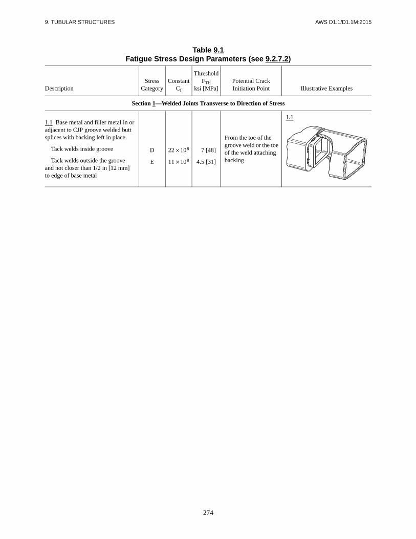
274
9. TUBULAR STRUCTURES AWS D1.1/D1.1M:2015
Table 9.1Fatigue Stress Design Parameters (see 9.2.7.2)
DescriptionStress
CategoryConstant
Cf
ThresholdFTH
ksi [MPa]Potential CrackInitiation Point Illustrative Examples
Section 1—Welded Joints Transverse to Direction of Stress
1.1 Base metal and filler metal in or adjacent to CJP groove welded butt splices with backing left in place.
Tack welds inside groove
Tack welds outside the grooveand not closer than 1/2 in [12 mm]to edge of base metal
D
E
22 × 108
11 × 108
.7 [48]
4.5 [31]
From the toe of the groove weld or the toe of the weld attaching backing
1.1

AW
S D
1.1/D1.1M
:20159. T
UB
ULA
R S
TR
UC
TU
RE
S
275
Table 9.2Allowable Stresses in Tubular Connection Welds (see 9.2.4)
Type of Weld Tubular Application Kind of Stress
Allowable StressDesign (ASD)
Load and Resistance Factor Design (LRFD)
Required Filler MetalStrength LevelaAllowable Stress
Resistance Factor Φ
Nominal Strength
CJP GrooveWeld
Longitudinal butt joints (longitudinal seams)
Tension or compression parallel to axis of the weldb Same as for base metalc 0.9 0.6 Fy Filler metal with strength
equal to or less than matching filler metal may be usedBeam or torsional shear
Base metal 0.40 Fy
Filler metal 0.3 FEXX
0.90.8
0.6 Fy
0.6 FEXX
Circumferential butt joints (girth seams)
Compression normal to the effective areab
Same as for base metal
0.9 Fy
Matching filler metal shall be used
Shear on effective areaBase metal 0.9Weld metal 0.8
0.6 Fy
0.6 FEXX
Tension normal to the effective area
0.9 Fy
Weld joints in structural T-, Y-, or K-connections in structures designed for critical loading such as fatigue, which would normally call for CJP welds
Tension, compression or shear on base metal adjoining weld conforming to detail of Figures 9.12 and 9.14–9.16 (tubular weld made from outside only without backing)
Same as for base metal or as limited by connection geometry (see 9.6 provisions for ASD)
Same as for base metal or as limited by connection geometry (see 9.6 provisions for LRFD)
Matching filler metal shall be used
Tension, compression, or shear on effective area of groove welds, made from both sides or with backing
Fillet Weld
Longitudinal joints of built-up tubular members
Tension or compression parallel to axis of the weld
Same as for base metal 0.90 FyFiller metal with a strength level equal to or less than matching filler metal may be usedShear on effective area 0.30 FEXX
e 0.75 0.6 FEXX
Joints in structural T-, Y-, or K-connections in circular lap joints and joints of attachments to tubes
Shear on effective throat regardless of direction of loading (see 9.5 and 9.6.1.3)
0.30 FEXX or as limited by connection geometry(see 9.6)
0.75 0.6 FEXX Filler metal with a strength level equal to or less than matching filler metal may be usedd
or as limited by connection geometry (see 9.6 for provision for LRFD)
(Continued)
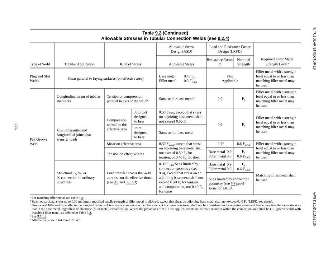
9. TU
BU
LAR
ST
RU
CT
UR
ES
AW
S D
1.1/D1.1M
:2015
276
Table 9.2 (Continued)Allowable Stresses in Tubular Connection Welds (see 9.2.4)
Type of Weld Tubular Application Kind of Stress
Allowable StressDesign (ASD)
Load and Resistance Factor Design (LRFD)
Required Filler MetalStrength LevelaAllowable Stress
Resistance Factor Φ
Nominal Strength
Plug and Slot Welds
Shear parallel to faying surfaces (on effective area)Base metal 0.40 Fy
Filler metal 0.3 FEXX
NotApplicable
Filler metal with a strength level equal to or less than matching filler metal may be used
PJP GrooveWeld
Longitudinal seam of tubular members
Tension or compression parallel to axis of the weldb Same as for base metalc 0.9 Fy
Filler metal with a strength level equal to or less than matching filler metal may be used
Circumferential and longitudinal joints that transfer loads
Compression normal to the effective area
Joint not designedto bear
0.50 FEXX, except that stress on adjoining base metal shall not exceed 0.60 Fy
0.9 Fy
Filler metal with a strength level equal to or less than matching filler metal may be used
Joint designedto bear
Same as for base metal
Shear on effective area 0.30 FEXX, except that stress on adjoining base metal shall not exceed 0.50 Fy for tension, or 0.40 Fy for shear
0.75 0.6 FEXX Filler metal with a strength level equal to or less than matching filler metal may be used
Tension on effective areaBase metal 0.9Filler metal 0.8
Fy
0.6 FEXX
Structural T-, Y-, or K-connection in ordinary structures
Load transfer across the weld as stress on the effective throat (see 9.5 and 9.6.1.3)
0.30 FEXX or as limited by connection geometry (see 9.6), except that stress on an adjoining base metal shall not exceed 0.50 Fy for tension and compression, nor 0.40 Fy for shear
Base metal 0.9Filler metal 0.8
Fy
0.6 FEXX
Matching filler metal shall be usedor as limited by connection
geometry (see 9.6 provi-sions for LRFD)
a For matching filler metal see Table 3.2.b Beam or torsional shear up to 0.30 minimum specified tensile strength of filler metal is allowed, except that shear on adjoining base metal shall not exceed 0.40 Fy (LRFD; see shear).c Groove and fillet welds parallel to the longitudinal axis of tension or compression members, except in connection areas, shall not be considered as transferring stress and hence may take the same stress as
that in the base metal, regardless of electrode (filler metal) classification. Where the provisions of 9.6.1 are applied, seams in the main member within the connection area shall be CJP groove welds withmatching filler metal, as defined in Table 3.2.
d See 9.6.1.3.e Alternatively, see 2.6.4.2 and 2.6.4.3.

277
AWS D1.1/D1.1M:2015 9. TUBULAR STRUCTURES
Table 9.3Stress Categories for Type and Location of Material for Circular Sections (see 9.2.7.2)
Stress Category Situation Kinds of Stressa
A Plain unwelded pipe TCBR
B Pipe with longitudinal seam TCBR
B Butt splices, CJP groove welds, ground flush and inspected by RT or UT (Class R)
TCBR
B Members with continuously welded longitudinal stiffeners
TCBR
C1 Butt splices, CJP groove welds, as welded TCBR
C2 Members with transverse (ring) stiffeners TCBR
D Members with miscellaneous attachments such as clips, brackets, etc.
TCBR
D Cruciform and T-joints with CJP welds (except at tubular connections)
TCBR
DT Connections designed as a simple T-, Y-, or K-connections with CJP groove welds conforming to Figures 9.14–9.16 (including overlapping connections in which the main member at each intersection meets punching shear requirements) (see Note b)
TCBR in branch member
(Note: Main member must be checked separately per category K1 or K2 )
E Balanced cruciform and T-joints with PJP groove welds or fillet welds (except at tubular connections)
TCBR in member; weld must also be checked per category F
E Members where doubler wrap, cover plates, longitudinal stiffeners, gusset plates, etc., terminate (except at tubular connections)
TCBR in member; weld must also be checked per category F
ET Simple T-, Y-, and K-connections with PJP groove welds or fillet welds; also, complex tubular connections in which the punching shear capacity of the main member cannot carry the entire load and load transfer is accomplished by overlap (negative eccentricity), gusset plates, ring stiffeners, etc. (see Note b)
TCBR in branch member
(Note: Main member in simple T-, Y-, orK-connections must be checked separately per category K1 or K2 ; weld must also be checked per category FT and 9.6.1)
F End weld of cover plate or doubler wrap; welds on gusset plates, stiffeners, etc.
Shear in weld
F Cruciform and T-joints, loaded in tension or bending, having fillet or PJP groove welds (except at tubular connections)
Shear in weld (regardless of direction of loading) (see 9.5)
FT Simple T-, Y-, or K-connections loaded in tension or bending, having fillet or PJP groove welds
Shear in weld (regardless of direction of loading)
X2 Intersecting members at simple T-, Y-, and K-connections; any connection whose adequacy is determined by testing an accurately scaled model or by theoretical analysis (e.g., finite element)
Greatest total range of hot spot stress or strain on the outside surface of intersecting members at the toe of the weld joiningthem—measured after shakedown in model or prototype connection or calculated with best available theory
(Continued)

278
9. TUBULAR STRUCTURES AWS D1.1/D1.1M:2015
Table 9.3 (Continued)Stress Categories for Type and Location of Material for Circular Sections (see 9.2.7.2)
Stress Category Situation Kinds of Stressa
X1 As for X2 , profile improved per 9.2.7.6 and 9.2.7.7 As for X2
X1 Unreinforced cone-cylinder intersection Hot-spot stress at angle change; calculate per Note d
K2 Simple T-, Y-, and K-connections in which the gamma ratio R/tc of main member does not exceed 24 (see Note c).
Punching shear for main members; calculate per Note e
K1 As for K2 , profile improved per 9.2.7.6 and 9.2.7.7
a T = tension, C = compression, B = bending, R = reversal—i.e., total range of nominal axial and bending stress.b Empirical curves (Figure 9.1) based on “typical” connection geometries; if actual stress concentration factors or hot spot strains are known, use of
curve X1 or X2 is preferred.c Empirical curves (Figure 9.1) based on tests with gamma (R /tc) of 18 to 24; curves on safe side for very heavy chord members (low R /tc); for chord
members (R /tc greater than 24) reduce allowable stress in proportion to
Where actual stress concentration factors or hot-spot strains are known, use of curve X1 or X2 is preferred.
d Stress concentration factor – SCF =
where
e Cyclic range of punching shear is given by
whereτ and θ are defined in Figure 9.2, and
= cyclic range of nominal branch member stress for axial load.= cyclic range of in-plane bending stress.= cyclic range of out-of-plane bending stress.
α is as defined in Table 9.6.
Allowable fatigue stressStress from curve K
----------------------------------------------------------24
R/tc--------- 0.7
=
1
Cos Ψ---------------- 1.17 tan Ψ γb+
Ψ angle change at transition=γb radius to thickness ratio of tube at transition=
Vp τ sin θ α fa 0.67fby( )21.5fbz( )2
++( )= [ ]
fa fby fbz

279
AWS D1.1/D1.1M:2015 9. TUBULAR STRUCTURES
Table 9.4Fatigue Category Limitations on Weld Size or
Thickness and Weld Profile (Tubular Connections) (see 9.2.7.7)
Weld Profile
Level I Level II
Limiting Branch Member Thicknessfor Categories X1, K1, DT
in [mm]
Limiting Branch Member Thicknessfor Categories X2, K2
in [mm]
Standard flat weld profileFigure 9.14
0.375 [10] 0.625 [16]
Profile with toe filletFigure 9.15
0.625 [16] 1.50 [38]0qualified for unlimited thicknessfor static compression loading
Concave profile, as welded,Figure 9.16with disk test per 9.2.7.6(1)
1.00 [25]0 unlimited
Concave smooth profileFigure 9.16fully ground per 9.2.7.6(2)
unlimited —
Table 9.5Z Loss Dimensions for Calculating Prequalified PJP T-, Y-,
and K-Tubular Connection Minimum Weld Sizes (see 9.5.2.1)
Joint IncludedAngle φ
Position of Welding: V or OH Position of Welding: H or F
Process Z (in) Z (mm) Process Z (in) Z (mm)
φ ≥ 60°
SMAWFCAW-SFCAW-GGMAWGMAW-Sa
000
N/A0
000
N/A0
SMAWFCAW-SFCAW-GGMAWGMAW-Sa
00000
00000
60° > φ ≥ 45°
SMAWFCAW-SFCAW-GGMAWGMAW-Sa
1/81/81/8N/A1/8
333
N/A3
SMAWFCAW-SFCAW-GGMAWGMAW-Sa
1/8000
1/8
30003
45° > φ ≥ 30°
SMAWFCAW-SFCAW-GGMAWGMAW-Sa
1/41/43/8N/A3/8
66
100N/A100
SMAWFCAW-SFCAW-GGMAWGMAW-Sa
1/41/81/41/41/4
63666
a See 9.10.1(2) for qualification requirements for welding prequalified PJP T-, Y-, K-Connections details with GMAW-S.

280
9. TUBULAR STRUCTURES AWS D1.1/D1.1M:2015
Table 9.6Terms for Strength of Connections (Circular Sections) (see 9.6.1.1)
Branch memberGeometry and loadmodifier Qq
For axial loadsd
For bending
Qβ For β ≤ 0.6
(needed for Qq) For β > 0.6
chord
ovalizing
α = 1.0 + 0.7 g/db
α = 1.0 ≤ α < 1.7
For axial load in gap K-connections having all members in same plane and loads transverse to main member essentially balanceda
parameterα = 1.7α = 2.4
For axial load in T- and Y-connectionsFor axial load in cross connections
α (needed for Qq)α = 0.67α = 1.5
For in-plane bendingc
For out-of-plane bendingc
Main member stressinteraction term Qf
b, cQf = 1.0 – λ γ U2
λ = 0.030λ = 0.044λ = 0.018
For axial load in branch memberFor in-plane bending in branch memberFor out-of-plane bending in branch member
a Gap g is defined in Figures 9.2(E), (F), and (H); db is branch diameter.b U is the utilization ratio (ratio of actual to allowable) for longitudinal compression (axial, bending) in the main member at the connection under
consideration.
U2
c For combinations of the in-plane bending and out-of-plane bending, use interpolated values of α and λ.d For general collapse (transverse compression) also see 9.6.1.2.
Notes:1. γ , β are geometry parameters defined by Figure 9.2(M).2. Fyo = the specified minimum yield strength of the main member, but not more than 2/3 the tensile strength.
Table 9.7Joint Detail Applications for PrequalifiedCJP T-, Y-, and K-Tubular Connections
(see 9.11.2 and Figure 9.13)
Detail Applicable Range of Local Dihedral Angle, Ψ
ABCD
180° to 135°150° to 50°75° to 30°40° to 15°
Not prequalified forgroove angles under 30°
Notes:1. The applicable joint detail (A, B, C, or D) for a particular part of the
connection shall be determined by the local dihedral angle, Ψ, whichchanges continuously in progressing around the branch member.
2. The angle and dimensional ranges given in Detail A, B, C, or Dinclude maximum allowable tolerances.
3. See Annex J for definition of local dihedral angle.
Qq1.7α
-------0.18
β----------+
Qβ0.7 α 1–( )=
Qq2.1α
-------0.6β
-------+ Qβ
1.2 α 0.67–( )=
Qβ 1.0=
Qβ0.3
β 1 0.833β–( )----------------------------------=
= fa
0.6Fyo----------------
2 fb
0.6Fyo----------------
2+

281
AWS D1.1/D1.1M:2015 9. TUBULAR STRUCTURES
Table 9.8Prequalified Joint Dimensions and Groove Angles for CJP Groove Welds in Tubular
T-, Y-, and K-Connections Made by SMAW, GMAW-S, and FCAW (see 9.11.2)
Detail AΨ = 180° – 135°
Detail BΨ = 150° – 50°
Detail CΨ = 75° – 30°b
Detail DΨ = 40° – 15°b
End preparation (ω)max. 90°a (Note a)
min. 10° or45° for Ψ > 105° 10°
Fit-up or root opening (R)
max.
FCAW-SSMAWd
3/16 in[5 mm]
GMAW-SFCAW-Ge
3/16 in[5 mm]
FCAW-SSMAWd
1/4 in[6 mm]
GMAW-SFCAW-Ge
1/4 in [6 mm]for φ > 45°
5/16 in[8 mm]
for φ ≤ 45°
(Note c)W max. φ
FCAW-SSMAW 1/8 in [3 mm] 25°–40°
(1) 3/16 in [5 mm] 15°–25°
GMAW-S 1/8 in [3 mm] 30°–40°FCAW-G 1/4 in [6 mm] 25°–30°
(2) 3/8 in [10 mm] 20°–25°1/2 in [12 mm] 15°–20°
min. 1/16 in[2 mm]
No min. forφ > 90°
1/16 in[2 mm]
No min. forφ > 120°
1/16 in[2 mm]
1/16 in[2 mm]
Joint includedangle φ
max.90°
60° forΨ ≤ 105°
40°; if moreuse Detail B
min. 45°37-1/2°; if lessuse Detail C
1/2 Ψ
Completedweld tw
≥ tb ≥ tb forΨ > 90°
≥ tb /sin Ψ forΨ < 90°
≥ tb /sin Ψbut need not
exceed 1.75 tb≥ 2tb
L≥ tb /sin Ψ
but need notexceed 1.75 tb
Weld may bebuilt up tomeet this
a Otherwise as needed to obtain required φ.b Not prequalified for groove angles (φ) under 30°.c Initial passes of back-up weld discounted until width of groove (W) is sufficient to assure sound welding; the necessary width of weld groove (W)
provided by back-up weld.d These root details apply to SMAW and FCAW-S.e These root details apply to GMAW-S and FCAW-G.
Notes:1. For GMAW-S see 9.15.4.3. These details are not intended for GMAW (spray transfer).2. See Figure 9.14 for minimum standard profile (limited thickness).3. See Figure 9.15 for alternate toe-fillet profile.4. See Figure 9.16 for improved profile (see 9.2.7.6 and 9.2.7.7).

9. TU
BU
LAR
ST
RU
CT
UR
ES
AW
S D
1.1/D1.1M
:2015
282
Table 9.9WPS Qualification—Production Welding Positions Qualified by Plate, Pipe, and Box Tube Tests (see 9.13)
Qualification TestProduction Plate Welding
Qualified Production Pipe Welding Qualified Production Box Tube Welding Qualified
WeldType
TestPositions
Groove CJP
Groove PJP Filletg
Butt JointT-, Y-, K-
Connections
Filletg
Butt JointT-, Y-, K-
Connections
FilletgCJP PJP CJP PJP CJP PJP CJP PJP
TUBULAR
CJP Groove
1G Rotated F F F Fa F F F Fa F F F
2G F, H F, H F, H (F, H)a F, H F, H F, H (F, H)a F, H F, H F, H
5G F, V, OH F, V, OH F, V, OH (F, V, OH)a F, V, OH F, V, OH F, V, OH (F, V, OH)a F, V, OH F, V, OH F, V, OH
(2G + 5G) All All All Alla All Allc Alle All Alla All Alld Alle, f All
6G All All All Alla All Alle All Alla All Alle, f All
6GR Allb All All Allb All Allc All All Allb All Alld All All
Fillet
1F Rotated F F F
2F F, H F, H F, H
2F Rotated F, H F, H F, H
4F F, H, OH F, H, OH F, H, OH
5F All All All
CJP—Complete Joint PenetrationPJP—Partial Joint Penetrationa Production butt joint details without backing or backgouging require qualification testing of the joint detail shown in Figure 9.23(A).b Limited to prequalified joint details (see 9.10 or 9.11).c For production joints of CJP T-, Y-, and K-connections that conform to either 9.14, 9.15, or 9.16 and Table 9.8, use Figure 9.25 detail for testing. For other production joints, see 9.15.4.1.d For production joints of CJP T-, Y-, and K-connections that conform to Figure 9.12, and Table 9.8, use Figures 9.25 and 9.27 detail for testing, or, alternatively, test the Figure 9.25 joint and cut macroetch
specimens from the corner locations shown in Figure 9.27. For other production joints, see 9.15.4.1.e For production joints of PJP T-, Y-, and K-connections that conform to Figure 9.11, use either the Figure 9.23(A) or Figure 9.23(B) detail for testing.f For matched box connections with corner radii less than twice the chord member thickness, see 9.10.1.1.g Fillet welds in production T-, Y-, or K-connections shall conform to Figure 9.10. WPS qualification shall conform to 9.16.

283
AWS D1.1/D1.1M:2015 9. TUBULAR STRUCTURES
Table 9.10WPS Qualification—CJP Groove Welds: Number and Type of Test Specimens and
Range of Thickness and Diameter Qualified (see 9.14) (Dimensions in Inches)
1. Tests on Pipe or Tubinga, e
NominalPipe Size or
Diam., in
Nominal Wall Thickness,
T, in
Number of SpecimensNominal
Diameterd of Pipe or Tube Size
Qualified, in
Nominal Pipeor Tube Wall Thicknessb, c
Qualified, in
Reduced Section
Tension (see Fig. 4.10)
Root Bend(see Fig.
4.8)
Face Bend (see Fig.
4.8)
Side Bend(see Fig.
4.9) Min. Max.
Job Size TestPipes
< 24
1/8 ≤ T ≤ 3/8 2 2 2 (Note f)Test diam. and over
1/8 2T
3/8 < T < 3/4 2 — — 4Test diam. and over
T/2 2T
T ≥ 3/4 2 — — 4Test diam. and over
3/8 Unlimited
≥ 24
1/8 ≤ T ≤ 3/8 2 2 2 (Note f)Test diam. and over
1/8 2T
3/8 < T < 3/4 2 — — 4 24 and over T/2 2T
T ≥ 3/4 2 — — 4 24 and over 3/8 Unlimited
Standard TestPipes
2 in Sch. 80or 3 in Sch. 40
2 2 2 — 3/4 through 4 1/8 3/4
6 in Sch. 120or 8 in Sch. 80
2 — — 4 4 and over 3/16 Unlimited
a All pipe or tube welds shall be visually inspected (see 4.9.1) and subject to NDT (see 4.9.2).b For square groove welds that are qualified without backgouging, the maximum thickness qualified shall be limited to the plate thickness.c CJP groove weld qualification on any thickness or diameter shall qualify any size of fillet or PJP groove weld for any thickness or diameter (see 4.11.3).d Qualification with any pipe diameter shall qualify all box section widths and depths.e See Table 9.9 for the groove details required for qualification of tubular butt and T-, Y-, K-connection joints.f For 3/8 in wall thickness, a side-bend test may be substituted for each of the required face- and root-bend tests.

284
9. TUBULAR STRUCTURES AWS D1.1/D1.1M:2015
Table 9.10 (Continued)WPS Qualification—CJP Groove Welds: Number and Type of Test Specimens and Range
of Thickness and Diameter Qualified (see 9.14) (Dimensions in Millimeters)
1. Tests on Pipe or Tubinga, e
NominalPipe Size or Diam., mm
Nominal Wall Thickness,
T, mm
Number of SpecimensNominal
Diameterd of Pipe or Tube Size
Qualified, mm
Nominal Pipeor Tube Wall Thicknessb, c
Qualified, mm
Reduced Section
Tension (see Fig. 4.10)
Root Bend
(see Fig.4.8)
Face Bend (see Fig.
4.8)
Side Bend(see Fig.
4.9) Min. Max.
Job Size TestPipes
< 600
3 ≤ T ≤ 10 2 2 2 (Note f)Test diam. and over
3 2T
10 < T < 20 2 — — 4Test diam. and over
T/2 2T
T ≥ 20 2 — — 4Test diam. and over
10 Unlimited
≥ 600
3 ≤ T ≤ 10 2 2 2 (Note f)Test diam. and over
3 2T
10 < T < 20 2 — — 4 600 and over T/2 2T
T ≥ 20 2 — — 4 600 and over 10 Unlimited
Standard TestPipes
DN 50 × 5.5 mm WTor DN 80 × 5.5 mm WT
2 2 2 —20 through
1003 20
DN 150 × 14.3 mm WTor DN 200 × 12.7 mm WT
2 — — 4 100 and over 5 Unlimited
a All pipe or tube welds shall be visually inspected (see 4.9.1) and subject to NDT (see 4.9.2).b For square groove welds that are qualified without backgouging, the maximum thickness qualified shall be limited to the test thickness.c CJP groove weld qualification on any thickness or diameter shall qualify any size of fillet or PJP groove weld for any thickness or diameter (see 4.11.3).d Qualification with any pipe diameter shall qualify all box section widths and depths.e See Table 9.9 for the groove details required for qualification of tubular butt and T-, Y-, K-connection joints.f For 10 mm wall thickness, a side-bend test may be substituted for each of the required face- and root-bend tests.

285
AWS D1.1/D1.1M:2015 9. TUBULAR STRUCTURES
Table 9.11Number and Type of Test Specimens and Range of Thickness Qualified—
WPS Qualification; PJP Groove Welds (see 9.14)
Test Groove Depth, Tin [mm]
Number of Specimensa, b Qualification Rangesc, d
Macroetch for Weld Size (E)
4.11.24.11.34.11.4
Reduced-Section Tension(see Fig.
4.10)
Root Bend (see
Fig. 4.8)
Face Bend (see Fig.
4.8)
Side Bend (see Fig.
4.9)Groove Depth
Nominal Pipe or Tubing Thickness, in [mm]
Min. Max.
1/8 ≤ T ≤ 3/8[3 ≤ T ≤ 10]
3 2 2 2 — T 1/8 [3] 2T
3/8 < T ≤ 1[10 < T ≤ 25]
3 2 — — 4 T 1/8 [3] Unlimited
a One pipe or tubing per position shall be required (see Figure 9.23). Use the production PJP groove detail for qualification. All pipes or tubing shall bevisually inspected (see 4.9.1).
b If a PJP bevel- or J-groove weld is to be used for T-joints or double-bevel- or double-J-groove weld is to be used for corner joints, the butt joint shall havea temporary restrictive plate in the plane of the square face to simulate a T-joint configuration.
c See the pipe diameter qualification requirements of Table 9.10.d Any PJP qualification shall also qualify any fillet weld size on any thickness.
Table 9.12Number and Type of Test Specimens and Range of Thickness Qualified—
WPS Qualification; Fillet Welds (see 9.14)
TestSpecimen Fillet Size
Number of Welds per WPS
Test Specimens Requiredb Sizes Qualified
Macroetch4.12.14.9.4
All-Weld-Metal Tension (see Figure 4.14)
Side Bend(see Figure
4.9)Pipe
Thicknessa Fillet Size
Pipe T-testc
(Figure 9.21)
Single pass, max. size to be used in construction
1 in each position to
be used (see Table 9.9)
3 faces (except for 4F & 5F,4 faces req’d)
— — Unlimited Max. tested single pass and smaller
Multiple pass, min. size to be used in construction
1 in each position to
be used (see Table 9.9)
3 faces (except for 4F & 5F,4 faces req’d)
— — Unlimited Min. tested multiple pass
and larger
a The minimum thickness qualified shall be 1/8 in [3 mm].b All welded test pipes shall be visually inspected per 4.9.1.c See Table 9.10 for pipe diameter qualification.

9. TU
BU
LAR
ST
RU
CT
UR
ES
AW
S D
1.1/D1.1M
:2015
286
Table 9.13Welder and Welding Operator Qualification—Production Welding Positions Qualified by Pipe and Box Tube Tests (see 9.17.1)
Qualification Test Production Plate Welding Qualified Production Pipe Welding Qualified Production Box Tube Welding Qualified
WeldType
TestPositionsa
GrooveCJP
GroovePJP Filletg
Butt Joint T-,Y-,K-Connections
Filletg
Butt Joint T-,Y-,K-Connections
FilletgCJPe PJPe CJPd, e PJPd, e CJP PJP CJP PJPd
TUBULAR
Grooveb (Pipe or
Box)
1G Rotatedh
2Gh
5Gh
6Gh
(2G + 5G)h
FF, H
F, V, OHAllAll
FF, H
F, V, OHAllAll
F, HF, H
F, V, OHAllAll
FF, H
F, V, OHAllAll
FF, H
F, V, OHAllAll
FF, H
F, V, OHAllAll
F, HF, H
F, V, OHAllAll
FF, H
F, V, OHAllAll
FF, H
F, V, OHAllAll
FF, H
F, V, OHAllAll
F, HF, H
F, V, HAllAll
6GR(Fig. 9.25)
All All All Allc All All All All Allc All All All
6GR (Figs.9.25 & 9.27)
All All All Allc All All All All Allc All Alld, f All All
PipeFillet
1F Rotated2F
2F Rotated4F5F
FF, HF, H
F, H, OHAll
FF, HF, H
F, H, OHAll
FF, HF, H
F, H, OHAll
CJP—Complete Joint PenetrationPJP—Partial Joint Penetrationa See Figures 9.17 and 9.18.b Groove weld qualification shall also qualify plug and slot welds for the test positions indicated.c Not qualified for joints welded from one side without backing, or welded from two sides without backgouging.d Not qualified for welds having groove angles less than 30° (see 9.15.4.2).eQualification using box tubing (Figure 9.25) also qualifies welding pipe equal to or greater than 24 in [600 mm] in diameter.f Pipe or box tubing is required for the 6GR qualification (Figure 9.25). If box tubing is used per Figure 9.25, the macroetch test may be performed on the corners of the test specimen (similar to Figure 9.27).g See 9.15 for dihedral angle restrictions for tubular T-, Y-, K-connections.h Qualification for welding production joints without backing or backgouging shall require using the Figure 9.22(A) joint detail. For welding production joints with backing or backgouging, either Figure 9.22(A) or Figure
9.22(B) joint detail may be used for qualification.

287
AWS D1.1/D1.1M:2015 9. TUBULAR STRUCTURES
Table 9.14Welder and Welding Operator Qualification—Number and Type of Specimens andRange of Thickness and Diameter Qualified (Dimensions in Inches) (see 9.17.1)
Tests on Pipe or Tubingf Number of Specimensa
Nominal Pipeor Tube SizeQualified, in
Nominal Plate,Pipe, or Tube
Wall Thicknessd Qualified, in
Production CJPGroove Butt Joints
1G and 2GPositions Only
5G, 6G, and 6GRPositions Only
Typeof Test Weld
Nominal Size of
Test Pipe, in
Nominal Test
Thickness, in
Face Bendb
Root Bendb
Side Bendb
Face Bendb
Root Bendb
Side Bendb Min. Max. Min. Max.
Groove ≤ 4 Unlimited 1 1 Note c 2 2 Note c 3/4 4 1/8 3/4
Groove > 4 ≤ 3/8 1 1 Note c 2 2 Note c Note e Unlimited 1/8 3/4
Groove > 4 > 3/8 — — 2 — — 4 Note e Unlimited 3/16 Unlimited
Qualified Dimensions
Production T-, Y-, orK-Connection CJP Groove Welds
Number ofSpecimensa
Nominal Pipe or Tube Size Qualified, in
Nominal Wall or Plate Thicknessd Qualified, in
Dihedral Angles Qualifiedh
Type ofTest Weld
Nominal Size of
Test Pipe,in
Nominal Test
Thickness,in
Side Bendb
Macro-etch Min. Max. Min. Max. Min. Max.
Pipe Groove (Fig. 9.25)
≥ 6 O.D. ≥ 1/2 4 — 4 Unlimited 3/16 Unlimited 30° Unlimited
Pipe Groove (Fig. 9.26)
< 4 O.D. ≥ 0.203 Note i — 3/4 < 4 1/8 Unlimited 30° Unlimited
Box Groove (Fig. 9.27)
Unlimited ≥ 1/2 4 4Unlimited (Box only)
Unlimited (Box only)
3/16 Unlimited 30° Unlimited
Production T-, Y-, orK-Connection Fillet Welds Number of Specimensa Qualified Dimensions
Type ofTest Weld
Nominal Size of
Test Pipe, D
Nominal Test
Thickness, in
Fillet Weld Break
Macro-etch
Root Bendb
Face Bendb
Nominal Pipeor Tube SizeQualified, in
Nominal Wall or Plate Thickness
QualifiedDihedral Angles
Qualifiedh
Min. Max. Min. Max. Min. Max.
5G position (Groove)
Unlimited ≥ 1/8 — — 2c 2c Note e Unlimited 1/8d Unlimitedd 30° Unlimited
Option 1—Fillet(Fig. 4.26)g
— ≥ 1/2 1 1 — — 24 Unlimited 1/8 Unlimited 60° Unlimited
Option 2—Fillet(Fig. 4.23)g
— 3/8 — — 2 — 24 Unlimited 1/8 Unlimited 60° Unlimited
Option 3—Fillet(Fig. 9.21)
Unlimited ≥ 1/8 — 1 — — D Unlimited 1/8 Unlimited 30° Unlimited
a All welds shall be visually inspected (see 4.22.1).b Radiographic examination of the test pipe or tubing may be made in lieu of the bend tests (see 4.16.1.1).c For 3/8 in wall thickness, a side-bend test may be substituted for each of the required face- and root-bend tests.d Also qualifies for welding any fillet or PJP weld size on any thickness of plate, pipe or tubing.e The minimum pipe size qualified shall be 1/2 the test diameter or 4 in, whichever is greater.f See Table 9.13 for appropriate groove details.g Two plates required, each subject to the test specimen requirements described. One plate shall be welded in the 3F position and the other in the 4F position.h For dihedral angles < 30°, see 9.19.1; except 6GR test not required.i Two root and two face bends.

288
9. TUBULAR STRUCTURES AWS D1.1/D1.1M:2015
Table 9.14 (Continued)Welder and Welding Operator Qualification-Number and Type of Specimens and
Range of Thickness and Diameter Qualified (Dimensions in Millimeters) (see 9.17.1)
Tests on Pipe or Tubinge Number of Specimensa
Nominal Pipeor Tube Size
Qualified, mm
Nominal Plate,Pipe or Tube
Wall Thicknessd Qualified, mm
Production CJPGroove Butt Joints
1G and 2GPositions Only
5G, 6G, and 6GRPositions Only
Typeof Test Weld
Nominal Size of
Test Pipe, mm
Nominal Test
Thickness, mm
Face Bendb
Root Bendb
Side Bendb
Face Bendb
Root Bendb
Side Bendb Min. Max. Min. Max.
Groove ≤ 100 Unlimited 1 1 Note c 2 2 Note c 20 100 3 20
Groove > 100 ≤ 10 1 1 Note c 2 2 Note c Note e Unlimited 3 20
Groove > 100 > 10 — — 2 — — 4 Note e Unlimited 5 Unlimited
Qualified Dimensions
Production T-, Y-, orK-Connection CJP Groove Welds
Number ofSpecimensa
Nominal Pipe or Tube Size Qualified, mm
Nominal Wall or Plate Thicknessd Qualified, mm
Dihedral Angles Qualifiedh
Type ofTest Weld
Nominal Size of
Test Pipe,mm
Nominal Test
Thickness,mm
Side Bendb
Macro-etch Min. Max. Min. Max. Min. Max.
Pipe Groove (Fig. 9.25)
≥ 150 O.D. ≥ 12 4 — 100 Unlimited 5 Unlimited 30° Unlimited
Pipe Groove (Fig. 9.26)
< 100 O.D. ≥ 5 Note i — 20 < 100 3 Unlimited 30° Unlimited
Box Groove (Fig. 9.27)
Unlimited ≥ 12 4 4Unlimited (Box only)
Unlimited (Box only)
5 Unlimited 30° Unlimited
Production T-, Y-, orK-Connection Fillet Welds Number of Specimensa Qualified Dimensions
Type ofTest Weld
Nominal Size of
Test Pipe, D
Nominal Test
Thickness, mm
Fillet Weld Break
Macro-etch
Root Bendb
Face Bendb
Nominal Pipeor Tube Size
Qualified, mm
Nominal Wall or Plate Thickness Qualified, mm
Dihedral Angles Qualifiedh
Min. Max. Min. Max. Min. Max.
5G position (Groove)
Unlimited ≥ 3 — — 2c 2c Note e Unlimited 3d Unlimitedd 30° Unlimited
Option 1—Fillet(Fig. 4.25)g
— ≥ 12 1 1 — — 600 Unlimited 3 Unlimited 60° Unlimited
Option 2—Fillet(Fig. 4.22)g
— 10 — — 2 — 600 Unlimited 3 Unlimited 60° Unlimited
Option 3—Fillet(Fig. 9.21)
Unlimited ≥ 3 — 1 — — D Unlimited 3 Unlimited 30° Unlimited
a All welds shall be visually inspected (see 4.22.1).b Radiographic examination of the test pipe or tubing may be made in lieu of the bend tests (see 4.16.1.1).c For 10 mm wall thickness, a side-bend test may be substituted for each of the required face- and root-bend tests.d Also qualifies for welding any fillet or PJP weld size on any thickness of plate, pipe or tubing.e The minimum pipe size qualified shall be 1/2 the test diameter or 100 mm, whichever is greater.f See Table 9.13 for appropriate groove details.g Two plates required, each subject to the test specimen requirements described. One plate shall be welded in the 3F position and the other in the 4F position.h For dihedral angles < 30°, see 9.19.1; except 6GR test not required.i Two root and two face bends.

289
AWS D1.1/D1.1M:2015 9. TUBULAR STRUCTURES
Table 9.15Tubular Root Opening Tolerances,
Butt Joints Welded Without Backing(see 9.24.2.1)
Root Face of Joint
Root Opening of Joints without Steel Backing
Groove Angle of
Joint
in mm in mm deg
SMAWGMAWFCAW
±1/16±1/32±1/16
±2±1±2
±1/16±1/16±1/16
±2±2±2
±5±5±5
Note: Root openings wider than allowed by the above tolerances, butnot greater than the thickness of the thinner part, may be built up bywelding to acceptable dimensions prior to the joining of the parts bywelding.

290
9. TUBULAR STRUCTURES AWS D1.1/D1.1M:2015
Table 9.16Visual Inspection Acceptance Criteria (see 9.25)
Discontinuity Category and Inspection Criteria Tubular Connections (All Loads)
(1) Crack ProhibitionAny crack shall be unacceptable, regardless of size or location.
X
(2) Weld/Base Metal FusionComplete fusion shall exist between adjacent layers of weld metal and between weld metal and base metal.
X
(3) Crater Cross SectionAll craters shall be filled to provide the specified weld size, except for the ends of intermittent fillet welds outside of their effective length.
X
(4) Weld ProfilesWeld profiles shall be in conformance with 5.23.
X
(5) Time of InspectionVisual inspection of welds in all steels may begin immediately after the completed welds have cooled to ambient temperature. Acceptance criteria for ASTM A514, A517, andA709 Grade HPS 100W [HPS 690W] steels shall be based on visual inspection performed not less than 48 hours after completion of the weld.
X
(6) Undersized WeldsThe size of a fillet weld in any continuous weld may be less than the specified nominalsize (L) without correction by the following amounts (U):
L, U,specified nominal weld size, in [mm] allowable decrease from L, in [mm]
≤ 3/16 [5] ≤ 1/16 [2].01/4 [6] ≤ 3/32 [2.5]
≥ 5/16 [8] ≤ 1/8 [3].00In all cases, the undersize portion of the weld shall not exceed 10% of the weld length.On web-to-flange welds on girders, underrun shall be prohibited at the ends for a lengthequal to twice the width of the flange.
X
(7) Undercut(A) For material less than 1 in [25 mm] thick, undercut shall not exceed 1/32 in [1 mm], with the following exception: undercut shall not exceed 1/16 in [2 mm] for any accumu-lated length up to 2 in [50 mm] in any 12 in [300 mm]. For material equal to or greater than 1 in [25 mm] thick, undercut shall not exceed 1/16 in [2 mm] for any length of weld.
(B) In primary members, undercut shall be no more than 0.01 in [0.25 mm] deep whenthe weld is transverse to tensile stress under any design loading condition. Undercut shallbe no more than 1/32 in [1 mm] deep for all other cases.
X
(8) Porosity(A) CJP groove welds in butt joints transverse to the direction of computed tensile stress shall have no visible piping porosity. For all other groove welds and for fillet welds, the sum of the visible piping porosity 1/32 in [1 mm] or greater in diameter shall not exceed 3/8 in [10 mm] in any linear inch of weld and shall not exceed 3/4 in [20 mm] in any12 in [300 mm] length of weld.
(B) The frequency of piping porosity in fillet welds shall not exceed one in each 4 in [100 mm] of weld length and the maximum diameter shall not exceed 3/32 in [2.5 mm]. Exception: for fillet welds connecting stiffeners to web, the sum of the diameters ofpiping porosity shall not exceed 3/8 in [10 mm] in any linear inch of weld and shall not exceed 3/4 in [20 mm] in any 12 in [300 mm] length of weld.
X
(C) CJP groove welds in butt joints transverse to the direction of computed tensile stress shall have no piping porosity. For all other groove welds, the frequency of piping porosity shall not exceed one in 4 in [100 mm] of length and the maximum diameter shall not exceed 3/32 in [2.5 mm].
X
Note: An “X” indicates applicability for the connection type; a shaded area indicates non-applicability.

291
AWS D1.1/D1.1M:2015 9. TUBULAR STRUCTURES
Table 9.17Hole-Type IQI Requirements (see 9.28.1)
NominalMaterial Thicknessa
Range, in
NominalMaterial Thicknessa
Range, mm
Film Side
Designation Essential Hole
Up to 0.25 incl. Up to 6 incl. 7 4TOver 0.25 to 0.375 Over 6 through 10 10 4TOver 0.375 to 0.50 Over 10 through 12 12 4TOver 0.50 to 0.625 Over 12 through 16 12 4TOver 0.625 to 0.75 Over 16 through 20 15 4TOver 0.75 to 0.875 Over 20 through 22 17 4TOver 0.875 to 1.00 Over 22 through 25 17 4TOver 1.00 to 1.25 Over 25 through 32 20 4TOver 1.25 to 1.50 Over 32 through 38 25 2TOver 1.50 to 2.00 Over 38 through 50 30 2TOver 2.00 to 2.50 Over 50 through 65 35 2TOver 2.50 to 3.00 Over 65 through 75 40 2TOver 3.00 to 4.00 Over 75 through 100 45 2TOver 4.00 to 6.00 Over 100 through 150 50 2TOver 6.00 to 8.00 Over 150 through 200 60 2Ta Single-wall radiographic thickness.
Table 9.18Wire IQI Requirements (see 9.28.1)
NominalMaterial Thicknessa
Range, in
NominalMaterial Thicknessa
Range, mm
Film SideMaximum Wire Diameter
in mm
Up to 0.25 incl. Up to 6 incl. 0.008 0.20Over 0.25 to 0.375 Over 6 to 10 0.010 0.25Over 0.375 to 0.625 Over 10 to 16 0.013 0.33Over 0.625 to 0.75 Over 16 to 20 0.016 0.41Over 0.75 to 1.50 Over 20 to 38 0.020 0.51Over 1.50 to 2.00 Over 38 to 50 0.025 0.63Over 2.00 to 2.50 Over 50 to 65 0.032 0.81Over 2.50 to 4.00 Over 65 to 100 0.040 1.02Over 4.00 to 6.00 Over 100 to 150 0.050 1.27Over 6.00 to 8.00 Over 150 to 200 0.063 1.60a Single-wall radiographic thickness.
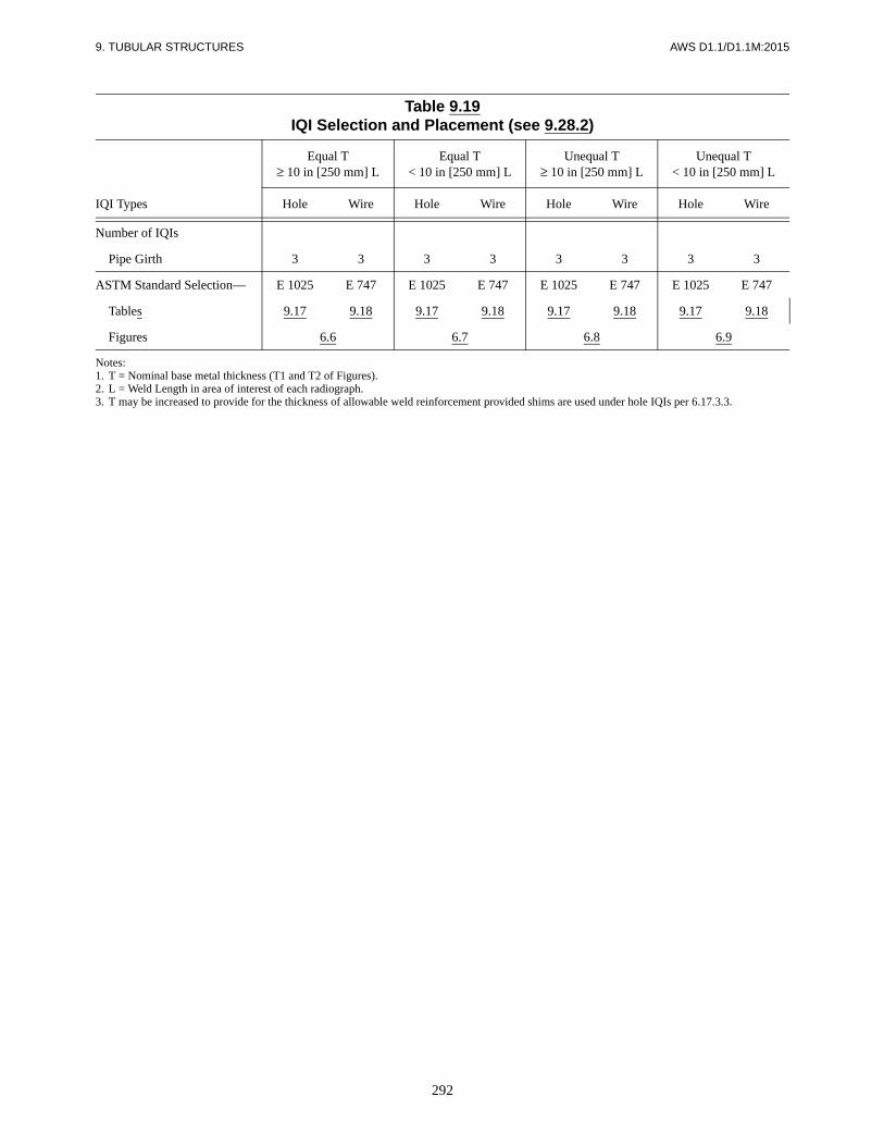
292
9. TUBULAR STRUCTURES AWS D1.1/D1.1M:2015
Table 9.19IQI Selection and Placement (see 9.28.2)
Equal T≥ 10 in [250 mm] L
Equal T< 10 in [250 mm] L
Unequal T≥ 10 in [250 mm] L
Unequal T< 10 in [250 mm] L
IQI Types Hole Wire Hole Wire Hole Wire Hole Wire
Number of IQIs
Pipe Girth 3 3 3 3 3 3 3 3
ASTM Standard Selection— E 1025 E 747 E 1025 E 747 E 1025 E 747 E 1025 E 747
Tables 9.17 9.18 9.17 9.18 9.17 9.18 9.17 9.18
Figures 6.6 6.7 6.8 6.9
Notes:1. T = Nominal base metal thickness (T1 and T2 of Figures).2. L = Weld Length in area of interest of each radiograph.3. T may be increased to provide for the thickness of allowable weld reinforcement provided shims are used under hole IQIs per 6.17.3.3.
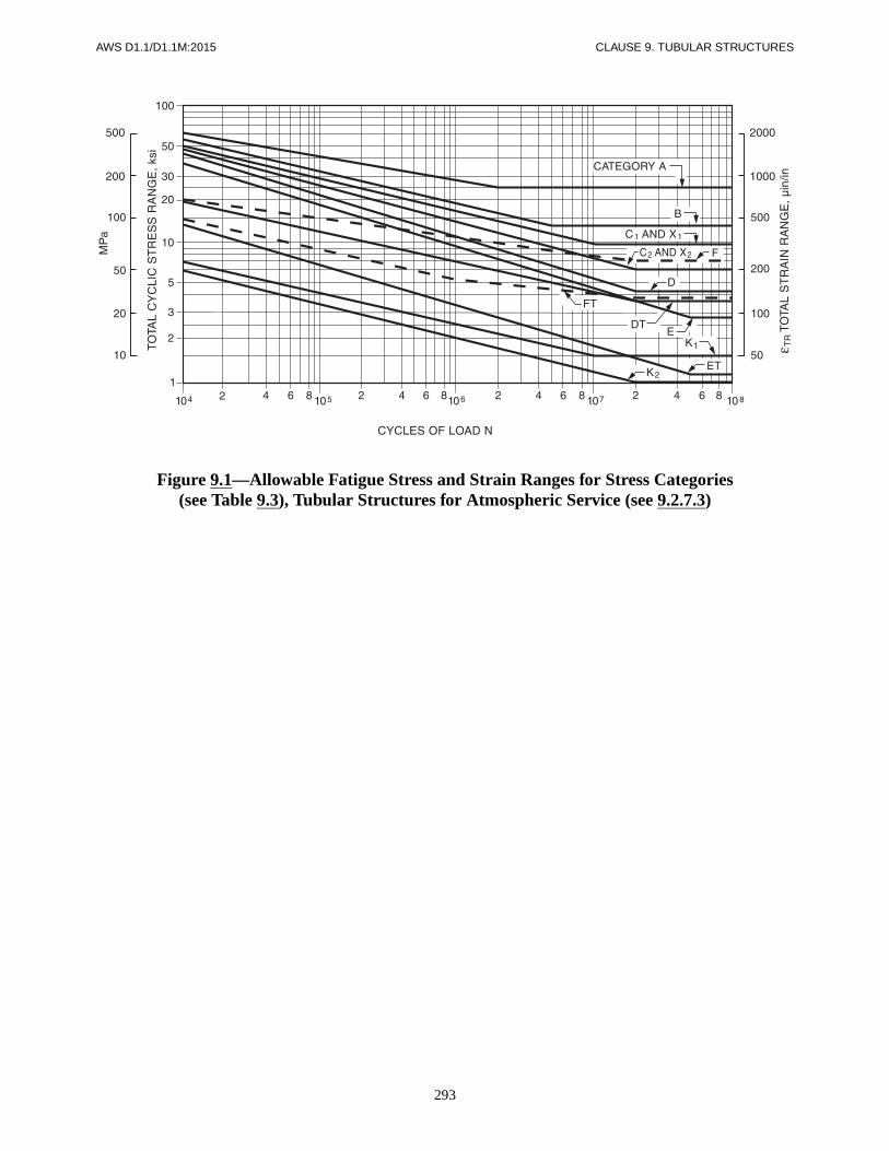
293
AWS D1.1/D1.1M:2015 CLAUSE 9. TUBULAR STRUCTURES
Figure 9.1—Allowable Fatigue Stress and Strain Ranges for Stress Categories(see Table 9.3), Tubular Structures for Atmospheric Service (see 9.2.7.3)

294
CLAUSE 9. TUBULAR STRUCTURES AWS D1.1/D1.1M:2015
a Relevant gap is between braces whose loads are essentially balanced. Type (2) may also be referred to as an N-connection.
Figure 9.2—Parts of a Tubular Connection (see 9.3)

295
AWS D1.1/D1.1M:2015 CLAUSE 9. TUBULAR STRUCTURES
Figure 9.2 (Continued)—Parts of a Tubular Connection (see 9.3)

296
CLAUSE 9. TUBULAR STRUCTURES AWS D1.1/D1.1M:2015
Figure 9.2 (Continued)—Parts of a Tubular Connection (see 9.3)

297
AWS D1.1/D1.1M:2015 CLAUSE 9. TUBULAR STRUCTURES
Note: L = size as required.
Figure 9.3—Fillet Welded Lap Joint (Tubular) [see 9.5.1.3 and 9.9.1(2)]
Figure 9.4—Tubular T-, Y-, andK-Connection Fillet Weld Footprint
Radius (see 9.5.3)

298
CLAUSE 9. TUBULAR STRUCTURES AWS D1.1/D1.1M:2015
Figure 9.5—Punching Shear Stress(see 9.6.1.1)
Figure 9.6—Detail of Overlapping Joint(see 9.6.1.6)

299
AWS D1.1/D1.1M:2015 CLAUSE 9. TUBULAR STRUCTURES
Notes:1. –0.55H ≤ e ≤ 0.25H2. θ ≥ 30°3. H/tc and D/tc ≤ 35 (40 for overlap K- and N-connections)4. a/tb and b/tb ≤ 355. Fyo ≤ 52 ksi [360 MPa]6. 0.5 ≤ H/D ≤ 2.07. Fyo/Fult ≤ 0.8
Figure 9.7—Limitations for Box T-, Y-,and K-Connections [see 9.6.2 and 9.8.1.2(2)]
Figure 9.8—Overlapping K-Connections(see 9.6.2.4)

CLA
US
E 9. T
UB
ULA
R S
TR
UC
TU
RE
SA
WS
D1.1/D
1.1M:2015
300
Notes:1. Groove may be of any allowed or qualified type and detail.2. Transition slopes shown are the maximum allowed.3. In (B), (D), and (E) groove may be any allowed or qualified type and detail. Transition slopes shown are maximum allowed.
Figure 9.9—Transition of Thickness of Butt Joints in Parts of Unequal Thickness (Tubular) (see 9.7)

301
AWS D1.1/D1.1M:2015 CLAUSE 9. TUBULAR STRUCTURES
Figure 9.10—Fillet Welded Prequalified Tubular Joints Made bySMAW, GMAW, and FCAW (see 9.9.1)
Notes:1. t = thickness of thinner part.2. L = minimum size (see 9.6.1.3 which may require increased
weld size for combinations other than 36 ksi [250 MPa] basemetal and 70 ksi [485 MPa] electrodes).
3. Root opening 0 in to 3/16 in [5 mm] (see 5.21).4. Not prequalified for φ < 30°. For φ < 60°, the Z loss dimensions
in Table 9.5 apply. See Table 9.13 for welder qualification positionrequirements.
5. See 9.5.1.2 for limitations on β = d/D.6. Ψ = dihedral angle.

302
CLAUSE 9. TUBULAR STRUCTURES AWS D1.1/D1.1M:2015
Figure 9.11—Prequalified Joint Details for PJP T-, Y-, andK-Tubular Connections (see 9.10.1)

303
AWS D1.1/D1.1M:2015 CLAUSE 9. TUBULAR STRUCTURES
Figure 9.11 (Continued)—Prequalified Joint Details for PJP T-, Y-, andK-Tubular Connections (see 9.10.1)

304
CLAUSE 9. TUBULAR STRUCTURES AWS D1.1/D1.1M:2015
Notes:1. t = thickness of thinner section.2. Bevel to feather edge except in transition and heel zones.3. Root opening: 0 in to 3/16 in [5 mm].4. Not prequalified for under 30°.5. Weld size (effective throat) tw ≥ t; Z Loss Dimensions shown in Table 9.5.6. Calculations per 9.6.1.3 shall be done for leg length less than 1.5t, as shown.7. For Box Section, joint preparation for corner transitions shall provide a smooth transition from one detail to another. Welding shall be
carried continuously around corners, with corners fully built up and all weld starts and stops within flat faces.8. See Annex J for definition of local dihedral angle, Ψ.9. W.P. = work point.
Figure 9.11 (Continued)—Prequalified Joint Details for PJP T-, Y-, andK-Tubular Connections (see 9.10.1)

305
AWS D1.1/D1.1M:2015 CLAUSE 9. TUBULAR STRUCTURES
Notes:1. Details A, B, C, D as shown in Figure 9.14 and all notes from Table 9.8 apply.2. Joint preparation for corner welds shall provide a smooth transition from one detail to another. Welding shall be carried continuously
around corners, with corners fully built up and all arc starts and stops within flat faces.3. References to Figure 9.14 include Figures 9.15 and 9.16 as appropriate to thickness (see 9.2.7.7).
Figure 9.12—Prequalified Joint Details for CJP T-, Y-, andK-Tubular Connections (see 9.11.2)

306
CLAUSE 9. TUBULAR STRUCTURES AWS D1.1/D1.1M:2015
Figure 9.13—Definitions and Detailed Selections for Prequalified CJP T-,
Y-, and K-Tubular Connections(see 9.11.2 and Table 9.7)

307
AWS D1.1/D1.1M:2015 CLAUSE 9. TUBULAR STRUCTURES
Notes:1. See Table 9.8 for dimensions tw, L, R, W, ω, φ.2. Minimum standard flat weld profile shall be as shown by solid line.3. A concave profile, as shown by dashed lines, shall also be applicable.4. Convexity, overlap, etc. shall be subject to the limitations of 5.23.5. Branch member thickness, tb, shall be subject to limitations of 9.2.7.7.
Figure 9.14—Prequalified Joint Details for CJP Groove Welds in Tubular T-, Y-, andK-Connections—Standard Flat Profiles for Limited Thickness (see 9.11.2)

308
CLAUSE 9. TUBULAR STRUCTURES AWS D1.1/D1.1M:2015
Notes:1. Sketches illustrate alternate standard profiles with toe fillet.2. See 9.2.7.7 for applicable range of thickness tb.3. Minimum fillet weld size, F = tb/2, shall also be subject to limits of Table 5.7.4. See Table 9.8 for dimensions tw, L, R, W, ω, φ.5. Convexity and overlap shall be subject to the limitations of 5.23.6. Concave profiles, as shown by dashed lines shall also be acceptable.
Figure 9.15—Prequalified Joint Details for CJP Groove Welds in Tubular T-, Y-, andK-Connections—Profile with Toe Fillet for Intermediate Thickness (see 9.11.2)

309
AWS D1.1/D1.1M:2015 CLAUSE 9. TUBULAR STRUCTURES
Notes:1. Illustrating improved weld profiles for 9.2.7.6(1) as welded and 9.2.7.6(2) fully ground.2. For heavy sections or fatigue critical applications as indicated in 9.2.7.7.3. See Table 9.8 for dimensions tb, L, R, W, ω, φ.
Figure 9.16—Prequalified Joint Details for CJP Groove Welds in Tubular T-, Y-, andK-Connections—Concave Improved Profile for Heavy Sections or Fatigue (see 9.11.2)

310
CLAUSE 9. TUBULAR STRUCTURES AWS D1.1/D1.1M:2015
Figure 9.17—Positions of Test Pipe or Tubing for Groove Welds (see 9.12.1)

311
AWS D1.1/D1.1M:2015 CLAUSE 9. TUBULAR STRUCTURES
Reproduced from AWS A3.0M/A3.0:2010, Standard Welding Terms and Definitions, Including Terms for Adhesive Bonding, Brazing,Soldering, Thermal Cutting, and Thermal Spraying, Figure B.20, Miami: American Welding Society.
Figure 9.18—Positions of Test Pipes or Tubing for Fillet Welds (see 9.12.1)

312
CLAUSE 9. TUBULAR STRUCTURES AWS D1.1/D1.1M:2015
Note: Duplicate test pipes or tubes or larger job size pipe may be required when CVN testing is specified on contract documents orspecifications.
Figure 9.19—Location of Test Specimens on Welded Test Pipe—WPS Qualification (see 9.14)

313
AWS D1.1/D1.1M:2015 CLAUSE 9. TUBULAR STRUCTURES
Figure 9.20—Location of Test Specimens for Welded Box Tubing—WPS Qualification (see 9.14)

314
CLAUSE 9. TUBULAR STRUCTURES AWS D1.1/D1.1M:2015
Notes:1. See Table 9.9 for position requirements.2. Pipe shall be of sufficient thickness to prevent melt-through.
Notes:1. See Table 9.9 for position requirements.2. Pipe shall be of sufficient thickness to prevent melt-through.3. All dimensions are minimums.
Figure 9.21—Pipe Fillet Weld Soundness Test—WPS Qualification (see 4.12.2 and 9.16)

315
AWS D1.1/D1.1M:2015 CLAUSE 9. TUBULAR STRUCTURES
Note: T = qualification pipe or box tube wall thickness
Figure 9.22—Tubular Butt Joint—Welder Qualificationwith and without Backing (see 9.19)
Note: T = qualification pipe or box tube wall thickness.
Figure 9.23—Tubular Butt Joint—WPS Qualification with and without Backing(see 9.15.1 and 9.15.2)

316
CLAUSE 9. TUBULAR STRUCTURES AWS D1.1/D1.1M:2015
Figure 9.24—Acute Angle Heel Test (Restraints not Shown) (see 9.15.4.2)

317
AWS D1.1/D1.1M:2015 CLAUSE 9. TUBULAR STRUCTURES
Figure 9.25—Test Joint for T-, Y-, and K-Connections without Backing on Pipe or BoxTubing (≥6 in [150 mm] O.D.)—Welder and WPS Qualification (see 9.15.4.1 and 9.19)

318
CLAUSE 9. TUBULAR STRUCTURES AWS D1.1/D1.1M:2015
Figure 9.26—Test Joint for T-, Y-, and K-Connections without Backing on Pipe or BoxTubing (<4 in [100 mm] O.D.)—Welder and WPS Qualification (see 9.15.4.1 and 9.19)

319
AWS D1.1/D1.1M:2015 CLAUSE 9. TUBULAR STRUCTURES
Figure 9.27—Corner Macroetch Test Joint for T-, Y-, and K-Connections without Backing on Box Tubing for CJP Groove Welds—Welder and WPS Qualification (see 9.15.4.1 and 9.19)
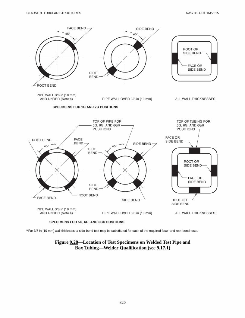
320
CLAUSE 9. TUBULAR STRUCTURES AWS D1.1/D1.1M:2015
a For 3/8 in [10 mm] wall thickness, a side-bend test may be substituted for each of the required face- and root-bend tests.
Figure 9.28—Location of Test Specimens on Welded Test Pipe andBox Tubing—Welder Qualification (see 9.17.1)

321
AWS D1.1/D1.1M:2015 CLAUSE 9. TUBULAR STRUCTURES
a Internal linear or planar reflectors above standard sensitivity.b Minor reflectors (above disregard level up to and including standard sensitivity). Adjacent reflectors separated by less than their average
length shall be treated as continuous.
Figure 9.29—Class R Indications (see 9.27.1.1)

322
CLAUSE 9. TUBULAR STRUCTURES AWS D1.1/D1.1M:2015
a Root area discontinuities falling outside theoretical weld (dimensions “tw” or “L” in Figures 9.14, 9.15, and 9.16) are to be disregarded.
Figure 9.29 (Continued)—Class R Indications (see 9.27.1.1)

323
AWS D1.1/D1.1M:2015 CLAUSE 9. TUBULAR STRUCTURES
Figure 9.30—Class X Indications (see 9.27.1.2)
1. Aligned discontinuities separated by less than (L1 +L2)/2 and parallel discontinuities separated by lessthan (H1 + H2)/2 shall be evaluated as continuous.
2. Accumulative discontinuities shall be evaluatedover 6 in [150 mm] or D/2 length of weld (which-ever is less), where tube diameter = D.
T-, Y-, AND K-ROOT DISCONTINUITIES
1. For CJP weld in single welded T-, Y-, and K-tubularconnections made without backing.
2. Discontinuities in the backup weld in the root,Details C and D of Figures 9.14, 9.15, and 9.16shall be disregarded.
INTERNAL REFLECTORS ANDALL OTHER WELDS
Discontinuities that are within H or tw/6 of the outsidesurface shall be sized as if extending to the surface ofthe weld.

324
CLAUSE 9. TUBULAR STRUCTURES AWS D1.1/D1.1M:2015
Figure 9.31—Single-Wall Exposure—Single-Wall View (see 9.29.1.1)
Figure 9.32—Double-Wall Exposure—Single-Wall View (see 9.29.1.2)

325
AWS D1.1/D1.1M:2015 CLAUSE 9. TUBULAR STRUCTURES
Figure 9.33—Double-Wall Exposure—Double-Wall (Elliptical) View,Minimum Two Exposures (see 9.29.1.3)
Figure 9.34—Double-Wall Exposure—Double-Wall View,Minimum Three Exposures (see 9.29.1.3)

326
CLAUSE 9. TUBULAR STRUCTURES AWS D1.1/D1.1M:2015
Figure 9.35—Scanning Techniques (see 9.30.5)

AWS D1.1/D1.1M:2015
327
Normative Information
These annexes contain information and requirements that are considered a part of the standard.
Annex A Effective Throat (E)
Annex B Effective Throats of Fillet Welds in Skewed T-Joints
Annex D Flatness of Girder Webs—Statically Loaded Structures
Annex E Flatness of Girder Webs—Cyclically Loaded Structures
Annex F Temperature-Moisture Content Charts
Annex G Qualification and Calibration of UT Units with Other Approved Reference Blocks
Annex H Guideline on Alternative Methods for Determining Preheat
Annex I Symbols for Tubular Connection Weld Design
Annex J Terms and Definitions
Informative Information
These annexes are not considered a part of the standard and are provided for informational purposes only.
Annex K Guide for Specification Writers
Annex L UT Equipment Qualification and Inspection Forms
Annex M Sample Welding Forms
Annex N Guidelines for the Preparation of Technical Inquiries for the Structural Welding Committee
Annex O Local Dihedral Angle
Annex P Contents of Prequalified WPS
Annex Q UT Examination of Welds by Alternative Techniques
Annex R Ovalizing Parameter Alpha
Annex S List of Reference Documents
Annex T Filler Metal Strength Properties
Annex U AWS A5.36 Filler Metal Classifications and Properties
Annexes

AWS D1.1/D1.1M:2015
328
This page is intentionally blank.

AWS D1.1/D1.1M:2015
329
Annex A (Normative)
Effective Throat (E)
This annex is part of AWS D1.1/D1.1M:2015, Structural Welding Code—Steel,and includes mandatory elements for use with this standard.
Figure A.1—Fillet Weld (see 2.4.2.6)
EFFECTIVE THROAT
DIAGRAMMATICFILLET WELD FACE
WELD SIZE
WELD SIZEJOINT ROOT
80°–100°

ANNEX A AWS D1.1/D1.1M:2015
330
Figure A.2—Unreinforced Bevel Groove Weld
Figure A.3—Bevel Groove Weld with Reinforcing Fillet Weld (see 2.4.2.7)
DIAGRAMMATICGROOVE WELD FACE
1/8 in [3 mm]AS REQUIRED
JOINT ROOT
EFFECTIVE SIZEOF A BEVEL GROOVE WELD
WITH DEDUCTION OF1/8 in [3 mm] i.e., (E) = S – 1/8
EFFECTIVE SIZEOF A BEVEL GROOVE WELD
WITHOUT DEDUCTIONi.e., (E) = S
DIAGRAMMATICGROOVE WELD FACE1/8 in [3 mm]
AS REQUIRED
JOINT ROOT
DIAGRAMMATICFILLET WELD FACE
EFFECTIVE THROAT (E) OF THEREINFORCED BEVEL GROOVE WELD
SHORTEST DISTANCE FROM THE JOINT ROOTTO THE WELD FACE OF THE DIAGRAMMATIC WELD

AWS D1.1/D1.1M:2015 ANNEX A
331
Figure A.4—Bevel Groove Weld with Reinforcing Fillet Weld (see 2.4.2.7)
Figure A.5—Unreinforced Flare Bevel Groove Weld
DIAGRAMMATICFILLET WELD FACE
1/8 in [3 mm]AS REQUIRED
JOINT ROOT
EFFECTIVE THROAT (E) OF THEREINFORCED BEVEL GROOVE WELD
SHORTEST DISTANCE FROMTHE JOINT ROOT TO THE WELD FACE
OF THE DIAGRAMMATIC WELD
DIAGRAMMATICGROOVE WELD FACEJOINT ROOT
EFFECTIVE SIZE OF AFLARE BEVEL GROOVE WELD
IF FILLED FLUSH
INCOMPLETE JOINTPENETRATION DERIVED
FROM TABLE 2.1

ANNEX A AWS D1.1/D1.1M:2015
332
Figure A.6—Flare Bevel Groove Weld with Reinforcing Fillet Weld (see 2.4.2.7)
DIAGRAMMATICGROOVE WELD FACE
JOINT ROOT
EFFECTIVE THROAT (E)OF THE REINFORCED FLARE
BEVEL GROOVE WELD
INCOMPLETE JOINTPENETRATION DERIVED
FROM TABLE 2.1
DIAGRAMMATICFILLET WELD FACE
SHORTEST DISTANCE FROM THE JOINT ROOTTO THE WELD FACE OF THE DIAGRAMMATIC WELD

AWS D1.1/D1.1M:2015
333
Table B.1 is a tabulation showing equivalent leg sizefactors for the range of dihedral angles between 60°and 135°, assuming no root opening. Root opening(s)1/16 in [2 mm] or greater, but not exceeding 3/16 in[5 mm], shall be added directly to the leg size. Therequired leg size for fillet welds in skewed joints shall becalculated using the equivalent leg size factor for correctdihedral angle, as shown in the example.
EXAMPLE(U.S. Customary Units)
Given: Skewed T-joint, angle: 75°; root opening:1/16 (0.063) in
Required: Strength equivalent to 90° fillet weld ofsize: 5/16 (0.313) in
Procedure: (1) Factor for 75° from Table B.1: 0.86(2) Equivalent leg size, w, of skewed joint,without root opening:w = 0.86 × 0.313 = 0.269 in(3) With root opening of: 0.063 in(4) Required leg size, w = 0.332 inof skewed fillet weld: [(2) + (3)](5) Rounding up to a practical dimension:w = 3/8 in
EXAMPLE(SI Units)
Given: Skewed T-joint, angle: 75°; root opening:2 mm
Required: Strength equivalent to 90° fillet weld ofsize: 8 mm
Procedure: (1) Factor for 75° from Table B.1: 0.86(2) Equivalent leg size, w, of skewed joint,without root opening:w = 0.86 × 8 = 6.9 mm(3) With root opening of: 2 mm(4) Required leg size, w, of 8.9 mmskewed fillet weld: [(2) + (3)](5) Rounding up to a practical dimension:w = 9.0 mm
For fillet welds having equal measured legs (wn), the dis-tance from the root of the joint to the face of the diagram-matic weld (tn) may be calculated as follows:
For root openings > 1/16 in [2 mm] and ≤ 3/16 in[5 mm], use
For root openings < 1/16 in [2 mm], use
where the measured leg of such fillet weld (wn) is theperpendicular distance from the surface of the joint to theopposite toe, and (R) is the root opening, if any, betweenparts (see Figure 3.4). Acceptable root openings aredefined in 5.21.1.
tn
wn Rn–
2 sinΨ2----
-------------------=
Rn 0 and t'n tn= =
Annex B (Normative)
Effective Throats of Fillet Welds in Skewed T-Joints
This annex is part of AWS D1.1/D1.1M:2015, Structural Welding Code—Steel,and includes mandatory elements for use with this standard.

ANNEX B AWS D1.1/D1.1M:2015
334
Table B.1Equivalent Fillet Weld Leg Size Factors for Skewed T-Joints
Dihedral angle, Ψ 60° 65° 70° 75° 80° 85° 90° 95°
Comparable fillet weld size for same strength
0.71 0.76 0.81 0.86 0.91 0.96 1.00 1.03
Dihedral angle, Ψ 100° 105° 110° 115° 120° 125° 130° 135°
Comparable fillet weld size for same strength
1.08 1.12 1.16 1.19 1.23 1.25 1.28 1.31

AWS D1.1/D1.1M:2015
335
Annex C
There is no Annex C. Annex C has been omitted in order to avoid potential confusion with references to Commentary clauses.

AWS D1.1/D1.1M:2015
336
This page is intentionally blank.

AWS D1.1/D1.1M:2015
337
Annex D (Normative)
Flatness of Girder Webs—Statically Loaded Structures
This annex is part of AWS D1.1/D1.1M:2015, Structural Welding Code—Steel,and includes mandatory elements for use with this standard.
Notes:1. D = Depth of web.2. d = Least panel dimension.

338
ANNEX D AWS D1.1/D1.1M:2015
Table D.1Intermediate Stiffeners on Both Sides of Web
Thickness of Web, in
Depth ofWeb, in Least Panel Dimension, in
5/16Less than 4747 and over
2520
3125
3830
4435
5040 45 50 55 60 65 70 75 80 85
3/8Less than 5656 and over
2520
3125
3830
4435
5040
5645
6350 55 60 65 70 75 80 85
7/16Less than 6666 and over
2520
3125
3830
4435
5040
5645
6350
6955 60 65 70 75 80 85
1/2Less than 7575 and over
2520
3125
3830
4435
5040
5645
6350
6955
7560
8165 70 75 80 85
9/16Less than 8484 and over
2520
3125
3830
4435
5040
5645
6350
6955
7560
8165
8870 75 80 85
5/8Less than 9494 and over
2520
3125
3830
4435
5040
5645
6350
6955
7560
8165
8870
9475 80 85
Maximum Allowable Variation, in
1/4 5/16 3/8 7/16 1/2 9/16 5/8 11/16 3/4 13/16 7/8 15/16 1 1-1/16
Thickness of Web, mm
Depth ofWeb, m Least Panel Dimension, meters
8.0Less than 1.191.19 and over
0.630.51
0.790.63
0.970.76
1.120.89
1.271.02 1.14 1.27 1.40 1.52 1.65 1.78 1.90 2.03 2.16
9.5Less than 1.421.42 and over
0.630.51
0.790.63
0.970.76
1.120.89
1.271.02
1.421.14
1.601.27 1.40 1.52 1.65 1.78 1.90 2.03 2.16
11.1Less than 1.681.68 and over
0.630.51
0.790.63
0.970.76
1.120.89
1.271.02
1.421.14
1.601.27
1.751.40 1.52 1.65 1.78 1.90 2.03 2.16
12.7Less than 1.901.90 and over
0.630.51
0.790.63
0.970.76
1.120.89
1.271.02
1.421.14
1.601.27
1.751.40
1.901.52
2.061.65 1.78 1.90 2.03 2.16
14.3Less than 2.132.13 and over
0.630.51
0.790.63
0.970.76
1.120.89
1.271.02
1.421.14
1.601.27
1.751.40
1.901.52
2.061.65
2.241.78 1.90 2.03 2.16
15.9Less than 2.392.39 and over
0.630.51
0.790.63
0.970.76
1.120.89
1.271.02
1.421.14
1.601.27
1.751.40
1.901.52
2.061.65
2.241.78
2.391.90 2.03 2.16
Maximum Allowable Variation, millimeters
6 8 10 11 12 14 16 18 20 21 22 24 25 27
Note: For actual dimensions not shown, use the next higher figure.
Table D.2No Intermediate Stiffeners
Thickness of Web, in Depth of Web, in
Any 38 47 56 66 75 84 94 103 113 122 131 141 150 159 169 178 188
Maximum Allowable Variation, in
1/4 5/16 3/8 7/16 1/2 9/16 5/8 11/16 3/4 13/16 7/8 15/16 1 1-1/16 1-1/8 1-3/16 1-1/4
Thickness of web, mm Depth of Web, meters
Any 0.97 1.19 1.42 1.68 1.90 2.13 2.39 2.62 2.87 3.10 3.33 3.58 3.81 4.04 4.29 4.52 4.77
Maximum Allowable Variation, millimeters
6 8 10 11 12 14 16 18 20 21 22 24 25 27 29 30 32
Note: For actual dimensions not shown, use the next higher figure.

AWS D1.1/D1.1M:2015 ANNEX D
339
Table D.3Intermediate Stiffeners on One Side Only of Web
Thickness of Web, in
Depth ofWeb, in Least Panel Dimension, in
5/16Less than 3131 and over
2517
3121 25 29 34 38 42 46 50 54 59 63 67 71
3/8Less than 3838 and over
2517
3121
3825 29 34 38 42 46 50 54 59 63 67 71
7/16Less than 4444 and over
2517
3121
3825
4429 34 38 42 46 50 54 59 63 67 71
1/2Less than 5050 and over
2517
3121
3825
4429
5034 38 42 46 50 54 59 63 67 71
9/16Less than 5656 and over
2517
3121
3825
4429
5034
5638 42 46 50 54 59 63 67 71
5/8Less than 6363 and over
2517
3121
3825
4429
5034
5638
6342 46 50 54 59 63 67 71
Maximum Allowable Variation, in
1/4 5/16 3/8 7/16 1/2 9/16 5/8 11/16 3/4 13/16 7/8 15/16 1 1-1/16
Thickness of Web, mm
Depth ofWeb, m Least Panel Dimension, meters
8.0Less than 0.780.78 and over
0.630.43
0.790.53 0.63 0.74 0.86 0.97 1.07 1.17 1.27 1.37 1.50 1.60 1.70 1.80
9.5Less than 0.970.97 and over
0.630.43
0.790.53
0.970.63 0.74 0.86 0.97 1.07 1.17 1.27 1.37 1.50 1.60 1.70 1.80
11.1Less than 1.121.12 and over
0.630.43
0.790.53
0.970.63
1.120.74 0.86 0.97 1.07 1.17 1.27 1.37 1.50 1.60 1.70 1.80
12.7Less than 1.271.27 and over
0.630.43
0.790.53
0.970.63
1.120.74
1.270.86 0.97 1.07 1.17 1.27 1.37 1.50 1.60 1.70 1.80
14.3Less than 1.421.42 and over
0.630.43
0.790.53
0.970.63
1.120.74
1.270.86
1.420.97 1.07 1.17 1.27 1.37 1.50 1.60 1.70 1.80
15.9Less than 1.601.60 and over
0.630.43
0.790.53
0.970.63
1.120.74
1.270.86
1.420.97
1.601.07 1.17 1.27 1.37 1.50 1.60 1.70 1.80
Maximum Allowable Variation, millimeters
6 8 10 11 12 14 16 18 20 21 22 24 25 27
Note: For actual dimensions not shown, use the next higher figure.

AWS D1.1/D1.1M:2015
340
This page is intentionally blank.
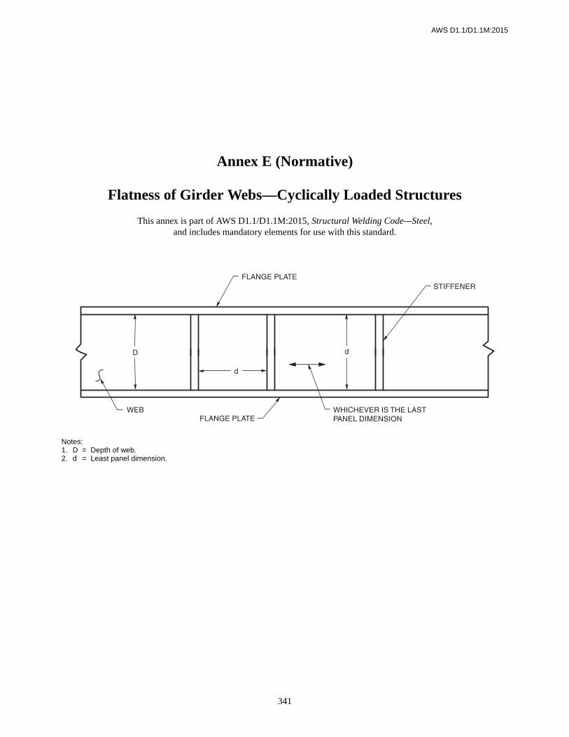
AWS D1.1/D1.1M:2015
341
Notes:1. D = Depth of web.2. d = Least panel dimension.
Annex E (Normative)
Flatness of Girder Webs—Cyclically Loaded Structures
This annex is part of AWS D1.1/D1.1M:2015, Structural Welding Code—Steel,and includes mandatory elements for use with this standard.

342
ANNEX E AWS D1.1/D1.1M:2015
Table E.1Intermediate Stiffeners on Both Sides of Web, Interior Girders
Thickness of Web, in
Depth ofWeb, in Least Panel Dimension, in
5/16Less than 4747 and over
2923
3629
4335
5040 46 52 58 63 69 75 81 86 92 98
3/8Less than 5656 and over
2923
3629
4335
5040
5846 52 58 63 69 75 81 86 92 98
7/16Less than 6666 and over
2923
3629
4335
5040
5846
6552 58 63 69 75 81 86 92 98
1/2Less than 7575 and over
2923
3629
4335
5040
5846
6552
7258
7963 69 75 81 86 92 98
9/16Less than 8484 and over
2923
3629
4335
5040
5846
6552
7258
7963
8669 75 81 86 92 98
5/8Less than 9494 and over
2923
3629
4335
5040
5846
6552
7258
7963
8669
9375 81 86 92 98
Maximum Allowable Variation, in
1/4 5/16 3/8 7/16 1/2 9/16 5/8 11/16 3/4 13/16 7/8 15/16 1 1-1/16
Thickness of Web, mm
Depth ofWeb, m Least Panel Dimension, meters
8.0Less than 1.191.19 and over
0.740.58
0.910.74
1.090.89
1.271.02 1.17 1.32 1.47 1.60 1.75 1.90 2.06 2.18 2.34 2.49
9.5Less than 1.421.42 and over
0.740.58
0.910.74
1.090.89
1.271.02
1.471.17 1.32 1.47 1.60 1.75 1.90 2.06 2.18 2.34 2.49
11.1Less than 1.681.68 and over
0.740.58
0.910.74
1.090.89
1.271.02
1.471.17
1.651.32 1.47 1.60 1.75 1.90 2.06 2.18 2.34 2.49
12.7Less than 1.901.90 and over
0.740.58
0.910.74
1.090.89
1.271.02
1.471.17
1.651.32
1.831.47
2.001.60 1.75 1.90 2.06 2.18 2.34 2.49
14.3Less than 2.132.13 and over
0.740.58
0.910.74
1.090.89
1.271.02
1.471.17
1.651.32
1.831.47
2.001.60
2.181.75 1.90 2.06 2.18 2.34 2.49
15.9Less than 2.392.39 and over
0.740.58
0.910.74
1.090.89
1.271.02
1.471.17
1.651.32
1.831.47
2.001.60
2.181.75
2.361.90 2.06 2.18 2.34 2.49
Maximum Allowable Variation, millimeters
6 8 10 11 12 14 16 18 20 21 22 24 25 27
Note: For actual dimensions not shown, use the next higher figure.

343
AWS D1.1/D1.1M:2015 ANNEX E
Table E.2Intermediate Stiffeners on One Side Only of Web, Fascia Girders
Thickness of Web, in
Depth ofWeb, in Least Panel Dimension, in
5/16Less than 3131 and over
3020
3825 30 35 40 45 50 55 60 65 70 75 80 85
3/8Less than 3838 and over
3020
3825 30 35 40 45 50 55 60 65 70 75 80 85
7/16Less than 4444 and over
3020
3825
4530 35 40 45 50 55 60 65 70 75 80 85
1/2Less than 5050 and over
3020
3825
4530
5335 40 45 50 55 60 65 70 75 80 85
9/16Less than 5656 and over
3020
3825
4530
5335
6040 45 50 55 60 65 70 75 80 85
5/8Less than 6363 and over
3020
3825
4530
5335
6040
6845 50 55 60 65 70 75 80 85
Maximum Allowable Variation, in
1/4 5/16 3/8 7/16 1/2 9/16 5/8 11/16 3/4 13/16 7/8 15/16 1 1-1/16
Thickness of Web, mm
Depth ofWeb, m Least Panel Dimension, meters
8.0Less than 0.780.78 and over
0.760.51
0.970.63 0.76 0.89 1.02 1.14 1.27 1.40 1.52 1.65 1.78 1.90 2.03 2.16
9.5Less than 0.970.97 and over
0.760.51
0.970.63 0.76 0.89 1.02 1.14 1.27 1.40 1.52 1.65 1.78 1.90 2.03 2.16
11.1Less than 1.121.12 and over
0.760.51
0.970.63
1.140.76 0.89 1.02 1.14 1.27 1.40 1.52 1.65 1.78 1.90 2.03 2.16
12.7Less than 1.271.27 and over
0.760.51
0.970.63
1.140.76
1.350.89 1.02 1.14 1.27 1.40 1.52 1.65 1.78 1.90 2.03 2.16
14.3Less than 1.421.42 and over
0.760.51
0.970.63
1.140.76
1.350.89
1.521.02 1.14 1.27 1.40 1.52 1.65 1.78 1.90 2.03 2.16
15.9Less than 1.601.60 and over
0.760.51
0.970.63
1.140.76
1.350.89
1.521.02
1.731.14 1.27 1.40 1.52 1.65 1.78 1.90 2.03 2.16
Maximum Allowable Variation, millimeters
6 8 10 11 12 14 16 18 20 21 22 24 25 27
Note: For actual dimensions not shown, use the next higher figure.

344
ANNEX E AWS D1.1/D1.1M:2015
Table E.3Intermediate Stiffeners on One Side Only of Web, Interior Girders
Thickness of Web, in
Depth ofWeb, in Least Panel Dimension, in
5/16Less than 3131 and over
2517
3121 25 29 34 38 42 46 50 54 59 63 67 71
3/8Less than 3838 and over
2517
3121
3825 29 34 38 42 46 50 54 59 63 67 71
7/16Less than 4444 and over
2517
3121
3825
4429 34 38 42 46 50 54 59 63 67 71
1/2Less than 5050 and over
2517
3121
3825
4429
5034 38 42 46 50 54 59 63 67 71
9/16Less than 5656 and over
2517
3121
3825
4429
5034
5638 42 46 50 54 59 63 67 71
5/8Less than 6363 and over
2517
3121
3825
4429
5034
5638
6342 46 50 54 59 63 67 71
Maximum Allowable Variation, in
1/4 5/16 3/8 7/16 1/2 9/16 5/8 11/16 3/4 13/16 7/8 15/16 1 1-1/16
Thickness of Web, mm
Depth ofWeb, m Least Panel Dimension, meters
8.0Less than 0.780.79 and over
0.630.43
0.790.53 0.63 0.74 0.86 0.97 1.07 1.17 1.27 1.37 1.50 1.60 1.70 1.80
9.5Less than 0.970.97 and over
0.630.43
0.790.53
0.970.63 0.74 0.86 0.97 1.07 1.17 1.27 1.37 1.50 1.60 1.70 1.80
11.1Less than 1.121.12 and over
0.630.43
0.790.53
0.970.63
1.120.74 0.86 0.97 1.07 1.17 1.27 1.37 1.50 1.60 1.70 1.80
12.7Less than 1.271.27 and over
0.630.43
0.790.53
0.970.63
1.120.74
1.270.86 0.97 1.07 1.17 1.27 1.37 1.50 1.60 1.70 1.80
14.3Less than 1.421.42 and over
0.630.43
0.790.53
0.970.63
1.120.74
1.270.86
1.420.97 1.07 1.17 1.27 1.37 1.50 1.60 1.70 1.80
15.9Less than 1.601.60 and over
0.630.43
0.790.53
0.970.63
1.120.74
1.270.86
1.420.97
1.601.07 1.17 1.27 1.37 1.50 1.60 1.70 1.80
Maximum Allowable Variation, millimeters
6 8 10 11 12 14 16 18 20 21 22 24 25 27
Note: For actual dimensions not shown, use the next higher figure.

345
AWS D1.1/D1.1M:2015 ANNEX E
Table E.4Intermediate Stiffeners on Both Sides of Web, Fascia Girders
Thickness of Web, in
Depth ofWeb, in Least Panel Dimension, in
5/16Less than 4747 and over
3326
4133
4939 47 53 59 66 71 79 85 92 98 105 112
3/8Less than 5656 and over
3326
4133
4939
5747 53 59 66 71 79 85 92 98 105 112
7/16Less than 6666 and over
3326
4133
4939
5747
6553
7359 66 71 79 85 92 98 105 112
1/2Less than 7575 and over
3326
4133
4939
5747
6553
7359
8166 71 79 85 92 98 105 112
9/16Less than 8484 and over
3326
4133
4939
5747
6553
7359
8166
8971 79 85 92 98 105 112
5/8Less than 9494 and over
3326
4133
4939
5747
6553
7359
8166
8971
9879 85 92 98 105 112
Maximum Allowable Variation, in
1/4 5/16 3/8 7/16 1/2 9/16 5/8 11/16 3/4 13/16 7/8 15/16 1 1-1/16
Thickness of Web, mm
Depth ofWeb, m Least Panel Dimension, meters
8.0Less than 1.191.19 and over
0.840.66
1.040.84
1.240.99 1.19 1.35 1.50 1.68 1.83 2.01 2.16 2.34 2.49 2.67 2.84
9.5Less than 1.421.42 and over
0.840.66
1.040.84
1.240.99
1.451.19 1.35 1.50 1.68 1.83 2.01 2.16 2.34 2.49 2.67 2.84
11.1Less than 1.681.68 and over
0.840.66
1.040.84
1.240.99
1.451.19
1.651.35
1.851.50 1.68 1.83 2.01 2.16 2.34 2.49 2.67 2.84
12.7Less than 1.901.90 and over
0.840.66
1.040.84
1.240.99
1.451.19
1.651.35
1.851.50
2.061.68 1.83 2.01 2.16 2.34 2.49 2.67 2.84
14.3Less than 2.132.13 and over
0.840.66
1.040.84
1.240.99
1.451.19
1.651.35
1.851.50
2.061.68
2.261.83 2.01 2.16 2.34 2.49 2.67 2.84
15.9Less than 2.392.39 and over
0.840.66
1.040.84
1.240.99
1.451.19
1.651.35
1.851.50
2.061.68
2.261.83
2.492.01 2.16 2.34 2.49 2.67 2.84
Maximum Allowable Variation, millimeters
6 8 10 11 12 14 16 18 20 21 22 24 25 27
Note: For actual dimensions not shown, use the next higher figure.
Table E.5No Intermediate Stiffeners, Interior or Fascia Girders
Thickness of Web, in Depth of Web, in
Any 38 47 56 66 75 84 94 103 113 122 131 141 150 159 169 178 188
Maximum Allowable Variation, in
1/4 5/16 3/8 7/16 1/2 9/16 5/8 11/16 3/4 13/16 7/8 15/16 1 1-1/16 1-1/8 1-3/16 1-1/4
Thickness of Web, mm Depth of Web, meters
Any 0.97 1.19 1.42 1.68 1.90 2.13 2.39 2.62 2.87 3.10 3.33 3.58 3.81 4.04 4.29 4.52 4.77
Maximum Allowable Variation, millimeters
6 8 10 11 12 14 16 18 20 21 22 24 25 27 29 30 32
Note: For actual dimensions not shown, use the next higher figure.

AWS D1.1/D1.1M:2015
346
This page is intentionally blank.

AWS D1.1/D1.1M:2015
347
Annex F (Normative)
Temperature-Moisture Content Charts
This annex is part of AWS D1.1/D1.1M:2015, Structural Welding Code—Steel,and includes mandatory elements for use with this standard.

348
ANNEX F AWS D1.1/D1.1M:2015
Notes:1. Any standard psychrometric chart may be used in lieu of this chart.2. See Figure F.2 for an example of the application of this chart in establishing electrode exposure conditions.
Figure F.1—Temperature-Moisture Content Chart to be Used in Conjunction withTesting Program to Determine Extended Atmospheric Exposure Time of
Low-Hydrogen SMAW Electrodes (see 5.3.2.3)

AWS D1.1/D1.1M:2015 ANNEX F
349
Figure F.2—Application of Temperature-Moisture Content Chart in Determining Atmospheric Exposure Time of Low-Hydrogen SMAW Electrodes (see 5.3.2.3)

AWS D1.1/D1.1M:2015
350
This page is intentionally blank.

AWS D1.1/D1.1M:2015
351
G1. Longitudinal ModeG1.1 Distance Calibration
G1.1.1 The transducer shall be set in position H onthe DC block, or M on the DSC block.
G1.1.2 The instrument shall be adjusted to produceindications at 1 in [25 mm], 2 in [50 mm], 3 in [75 mm],4 in [100 mm], etc., on the display.
NOTE: This procedure establishes a 10 in [250 mm]screen calibration and may be modified to establishother distances as allowed by 6.24.4.1.
G1.2 Amplitude. With the transducer in position de-scribed in G1.1, the gain shall be adjusted until the maxi-mized indication from the first back reflection attains50% to 75% screen height.
G2. Shear Wave Mode (Transverse)G2.1 Sound Entry (Index) Point Check
G2.1.1 The search unit shall be set in position J or Lon the DSC block; or I on the DC block.
G2.1.2 The search unit shall be moved until the sig-nal from the radius is maximized.
G2.1.3 The point on the Search Unit that is in linewith the line on the calibration block is indicative of thepoint of sound entry.
NOTE: This sound entry point shall be used for all fur-ther distance and angle checks.
G2.2 Sound Path Angle Check
G2.2.1 The transducer shall be set in position:
K on the DSC block for 45° through 70°
N on the SC block for 70°
O on the SC block for 45°
P on the SC block for 60°
G2.2.2 The transducer shall be moved back and forthover the line indicative of the transducer angle until thesignal from the radius is maximized.
G2.2.3 The sound entry point on the transducer shallbe compared with the angle mark on the calibrationblock (tolerance 2°).
G2.3 Distance Calibration
G2.3.1 The transducer shall be in position (FigureG.1) L on the DSC block. The instrument shall be ad-justed to attain indications at 3 in [75 mm] and 7 in[180 mm] on the display.
G2.3.2 The transducer shall be set in position J on theDSC block (any angle). The instrument shall be adjustedto attain indications at 1 in [25 mm], 5 in [125 mm], 9 in[230 mm] on the display.
Annex G (Normative)
Qualification and Calibration of UT Unitswith Other Approved Reference Blocks
(See Figure G.1)
This annex is part of AWS D1.1/D1.1M:2015 , Structural Welding Code—Steel,and includes mandatory elements for use with this standard.

ANNEX G AWS D1.1/D1.1M:2015
352
G2.3.3 The transducer shall be set in position I on theDC block (any angle). The instrument shall be adjustedto attain indication at 1 in [25 mm], 2 in [50 mm], 3 in[75 mm], 4 in [100 mm], etc., on the display.
NOTE: This procedure establishes a 10 in [250 mm]screen calibration and may be modified to establishother distances as allowed by 6.24.5.1.
G2.4 Amplitude or Sensitivity Calibration
G2.4.1 The transducer shall be set in position L onthe DSC block (any angle). The maximized signal shallbe adjusted from the 1/32 in [0.8 mm] slot to attain a hor-izontal reference line height indication.
G2.4.2 The transducer shall be set on the SC block inposition:
N for 70° angleO for 45° angleP for 60° angle
The maximized signal from the 1/16 in [1.6 mm] holeshall be adjusted to attain a horizontal reference lineheight indication.
G2.4.3 The decibel reading obtained in G2.4.1 orG2.4.2 shall be used as the “reference level” “b” on theTest Report sheet (Annex L, Form L-11) in conformancewith 6.22.1.
G3. Horizontal Linearity ProcedureNOTE: Since this qualification procedure is performedwith a straight beam search unit which produces longitu-dinal waves with a sound velocity of almost double thatof shear waves, it is necessary to double the shear wavedistance ranges to be used in applying this procedure.
G3.1 A straight beam search unit, meeting the require-ments of 6.21.6, shall be coupled in position:
G on the IIW type block (Figure 6.16)
H on the DC block (Figure G.1)
M on the DSC block (Figure G.1)
T or U on the DS block (Figure 6.16)
G3.2 A minimum of five back reflections in the qualifi-cation range being certified shall be attained.
G3.3 The first and fifth back reflections shall be ad-justed to their proper locations with use of the distancecalibration and zero delay adjustments.
G3.4 Each indication shall be adjusted to reference levelwith the gain or attenuation control for horizontal loca-tion examination.
G3.5 Each intermediate trace deflection location shallbe correct within ± 2% of the screen width.
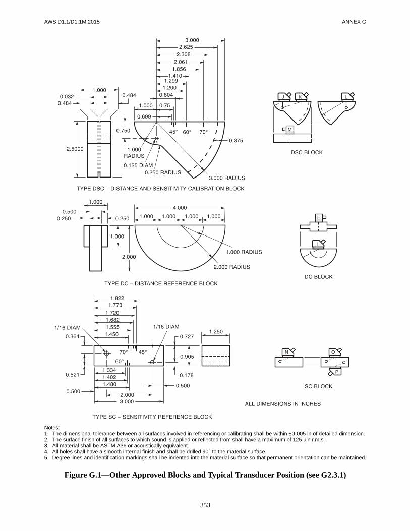
AWS D1.1/D1.1M:2015 ANNEX G
353
Notes:1. The dimensional tolerance between all surfaces involved in referencing or calibrating shall be within ±0.005 in of detailed dimension.2. The surface finish of all surfaces to which sound is applied or reflected from shall have a maximum of 125 µin r.m.s.3. All material shall be ASTM A36 or acoustically equivalent.4. All holes shall have a smooth internal finish and shall be drilled 90° to the material surface.5. Degree lines and identification markings shall be indented into the material surface so that permanent orientation can be maintained.
Figure G.1—Other Approved Blocks and Typical Transducer Position (see G2.3.1)

ANNEX G AWS D1.1/D1.1M:2015
354
Notes:1. The dimensional tolerance between all surfaces involved in referencing or calibrating shall be within ±0.13 mm of detailed dimension.2. The surface finish of all surfaces to which sound is applied or reflected from shall have a maximum of 3.17 µm r.m.s.3. All material shall be ASTM A36 or acoustically equivalent.4. All holes shall have a smooth internal finish and shall be drilled 90° to the material surface.5. Degree lines and identification markings shall be indented into the material surface so that permanent orientation can be maintained.
Figure G.1 (Continued)—Other Approved Blocks and Typical Transducer Position(see G2.3.1) (Metric)

AWS D1.1/D1.1M:2015
355
H1. IntroductionThe purpose of this guide is to provide some optional al-ternative methods for determining welding conditions(principally preheat) to avoid cold cracking. The meth-ods are based primarily on research on small scale testscarried out over many years in several laboratoriesworld-wide. No method is available for predicting opti-mum conditions in all cases, but the guide does considerseveral important factors such as hydrogen level andsteel composition not explicitly included in the require-ments of Table 3.3. The guide may therefore be of valuein indicating whether the requirements of Table 3.3 areoverly conservative or in some cases not sufficientlydemanding.
The user is referred to the Commentary for more detailedpresentation of the background scientific and research in-formation leading to the two methods proposed.
In using this guide as an alternative to Table 3.3, carefulconsideration shall be given to the assumptions made,the values selected, and past experience.
H2. MethodsTwo methods are used as the basis for estimating weld-ing conditions to avoid cold cracking:
(1) HAZ hardness control
(2) Hydrogen control
H3. HAZ Hardness ControlH3.1 The provisions included in this guide for use ofthis method are restricted to fillet welds.
H3.2 This method is based on the assumption thatcracking will not occur if the hardness of the HAZ is keptbelow some critical value. This is achieved by control-ling the cooling rate below a critical value dependent onthe hardenability of the steel. Hardenability of steel inwelding relates to its propensity towards formation of ahard HAZ and can be characterized by the cooling ratenecessary to produce a given level of hardness. Steelswith high hardenability can, therefore, produce hardHAZ at slower cooling rates than a steel with lowerhardenability.
Equations and graphs are available in the technical litera-ture that relate the weld cooling rate to the thickness ofthe steel members, type of joint, welding conditions andvariables.
H3.3 The selection of the critical hardness will dependon a number of factors such as steel type, hydrogen level,restraint, and service conditions. Laboratory tests withfillet welds show that HAZ cracking does not occur if theHAZ Vickers Hardness No. (HV) is less than 350 HV,even with high-hydrogen electrodes. With low-hydrogenelectrodes, hardnesses of 400 HV could be toleratedwithout cracking. Such hardness, however, may not betolerable in service where there is an increased risk ofstress corrosion cracking, brittle fracture initiation, orother risks for the safety or serviceability of the structure.
The critical cooling rate for a given hardness can be ap-proximately related to the carbon equivalent (CE) of thesteel (see Figure H.2). Since the relationship is only ap-proximate, the curve shown in Figure H.2 may be con-servative for plain carbon and plain carbon-manganesesteels and thus allow the use of the high hardness curvewith less risk.
Annex H (Normative)
Guideline on Alternative Methods for Determining Preheat
This annex is part of AWS D1.1/D1.1M:2015, Structural Welding Code—Steel,and includes mandatory elements for use with this standard.

ANNEX H AWS D1.1/D1.1M:2015
356
Some low-alloy steels, particularly those containingcolumbium (niobium), may be more hardenable thanFigure H.2 indicates, and the use of the lower hardnesscurve is recommended.
H3.4 Although the method can be used to determine apreheat level, its main value is in determining the mini-mum heat input (and hence minimum weld size) that pre-vents excessive hardening. It is particularly useful fordetermining the minimum size of single-pass fillet weldsthat can be deposited without preheat.
H3.5 The hardness approach does not consider the pos-sibility of weld metal cracking. However, from experi-ence it is found that the heat input determined by thismethod is usually adequate to prevent weld metal crack-ing, in most cases, in fillet welds if the electrode is not ahigh-strength filler metal and is generally of a low-hy-drogen type [e.g., low-hydrogen (SMAW) electrode,GMAW, FCAW, SAW].
H3.6 Because the method depends solely on controllingthe HAZ hardness, the hydrogen level and restraint arenot explicitly considered.
H3.7 This method is not applicable to quenched andtempered steels [see H5.2(3) for limitations].
H4. Hydrogen ControlH4.1 The hydrogen control method is based on the as-sumption that cracking will not occur if the averagequantity of hydrogen remaining in the joint after it hascooled down to about 120°F [50°C] does not exceed acritical value dependent on the composition of the steeland the restraint. The preheat necessary to allow enoughhydrogen to diffuse out of the joint can be estimatedusing this method.
H4.2 This method is based mainly on results of re-strained PJP groove weld tests; the weld metal used inthe tests matched the parent metal. There has not beenextensive testing of this method on fillet welds; however,by allowing for restraint, the method has been suitablyadapted for those welds.
H4.3 A determination of the restraint level and the orig-inal hydrogen level in the weld pool is required for thehydrogen method.
In this guide, restraint is classified as high, medium,and low, and the category must be established fromexperience.
H4.4 The hydrogen control method is based on a singlelow-heat input weld bead representing a root pass and as-sumes that the HAZ hardens. The method is, therefore,
particularly useful for high strength, low-alloy steelshaving quite high hardenability where hardness control isnot always feasible. Consequently, because it assumesthat the HAZ fully hardens, the predicted preheat may betoo conservative for carbon steels.
H5. Selection of MethodH5.1 The following procedure is recommended as a guidefor selection of either the hardness control or hydrogencontrol method.
Determine carbon and carbon equivalent:
to locate the zone position of the steel in Figure H.1 (seeH6.1.1 for the different ways to obtain chemical analysis).
H5.2 The performance characteristics of each zone andthe recommended action are as follows:
(1) Zone I. Cracking is unlikely, but may occur withhigh hydrogen or high restraint. Use hydrogen controlmethod to determine preheat for steels in this zone.
(2) Zone II. The hardness control method and se-lected hardness shall be used to determine minimum en-ergy input for single-pass fillet welds without preheat.
If the energy input is not practical, use hydrogen methodto determine preheat.
For groove welds, the hydrogen control method shall beused to determine preheat.
For steels with high carbon, a minimum energy to controlhardness and preheat to control hydrogen may be requiredfor both types of welds, i.e., fillet and groove welds.
(3) Zone III. The hydrogen control method shall beused. Where heat input is restricted to preserve the HAZproperties (e.g., some quenched and tempered steels), thehydrogen control method should be used to determinepreheat.
H6. Detailed GuideH6.1 Hardness Method
H6.1.1 The carbon equivalent shall be calculated asfollows:
The chemical analysis may be obtained from:
(1) Mill test certificates
CE = C + (Mn + Si)
6-----------------------
(Cr + Mo + V)5
-----------------------------------(Ni + Cu)
15-----------------------+ +
CE = C + (Mn + Si)
6-----------------------
(Cr + Mo + V)5
-----------------------------------(Ni + Cu)
15-----------------------+ +
M.VAFAKHAH
Highlight
M.VAFAKHAH
Highlight
M.VAFAKHAH
Highlight
M.VAFAKHAH
Highlight
M.VAFAKHAH
Highlight
M.VAFAKHAH
Highlight
M.VAFAKHAH
Highlight
M.VAFAKHAH
Highlight
M.VAFAKHAH
Highlight
M.VAFAKHAH
Highlight
M.VAFAKHAH
Highlight
M.VAFAKHAH
Highlight
M.VAFAKHAH
Highlight
M.VAFAKHAH
Highlight
M.VAFAKHAH
Highlight

AWS D1.1/D1.1M:2015 ANNEX H
357
(2) Typical production chemistry (from the mill)
(3) Specification chemistry (using maximum values)
(4) User tests (chemical analysis)
H6.1.2 The critical cooling rate shall be determinedfor a selected maximum HAZ hardness of either 400 HVor 350 HV from Figure H.2.
H6.1.3 Using applicable thicknesses for “flange” and“web” plates, the appropriate diagram shall be selectedfrom Figure H.3 and the minimum energy input for single-pass fillet welds shall be determined. This energy inputapplies to SAW welds.
H6.1.4 For other processes, minimum energy input forsingle-pass fillet welds can be estimated by applying thefollowing multiplication factors to the energy estimatedfor the SAW process in H6.1.3:
Welding Process Multiplication Factor
SAW 1SMAW 1.50GMAW, FCAW 1.25
H6.1.5 Figure H.4 may be used to determine fillet sizesas a function of energy input.
H6.2 Hydrogen Control Method
H6.2.1 The value of the composition parameter, Pcm,shall be calculated as follows:
The chemical analysis shall be determined as in H6.1.1.
H6.2.2 The hydrogen level shall be determined andshall be defined as follows:
(1) H1 Extra-Low Hydrogen. These consumablesgive a diffusible hydrogen content of less than 5 ml/100gdeposited metal when measured using ISO 3690-1976or, a moisture content of electrode covering of 0.2%maximum in conformance with AWS A5.1 or A5.5. Thismay be established by testing each type, brand, orwire/flux combination used after removal from the pack-age or container and exposure for the intended duration,with due consideration of actual storage conditions priorto immediate use. The following may be assumed tomeet this requirement:
Pcm CSi30------
Mn20--------
Cu20-------
Ni60------
Cr20------
Mo15--------
V10------ 5B+ + + + + + + +=
(a) Low-hydrogen electrodes taken from hermeti-cally sealed containers, dried at 700°F–800°F [370°–430°C] for one hour and used within two hours afterremoval,
(b) GMAW with clean solid wires.
(2) H2 Low Hydrogen. These consumables give adiffusible hydrogen content of less than 10 ml/100g de-posited metal when measured using ISO 3690-1976, or amoisture content of electrode covering of 0.4% maxi-mum in conformance with AWS A5.1. This may be es-tablished by a test on each type, brand of consumable, orwire/flux combination used. The following may be as-sumed to meet this requirement:
(a) Low-hydrogen electrodes taken from hermeti-cally sealed containers conditioned in conformance with5.3.2.1 of the code and used within four hours afterremoval,
(b) SAW with dry flux.
(3) H3 Hydrogen Not Controlled. All otherconsumables not meeting the requirements of H1 or H2.
H6.2.3 The susceptibility index grouping from TableH.1 shall be determined.
H6.2.4 Minimum Preheat Levels and Interpass.Table H.2 gives the minimum preheat and interpass tem-peratures that shall be used. Table H.2 gives three levelsof restraint. The restraint level to be used shall be deter-mined in conformance with H6.2.5.
H6.2.5 Restraint. The classification of types ofwelds at various restraint levels should be determined onthe basis of experience, engineering judgment, research,or calculation.
Three levels of restraint have been provided:
(1) Low Restraint. This level describes common fil-let and groove welded joints in which a reasonable free-dom of movement of members exists.
(2) Medium Restraint. This level describes fillet andgroove welded joints in which, because of membersbeing already attached to structural work, a reduced free-dom of movement exists.
(3) High Restraint. This level describes welds inwhich there is almost no freedom of movement for mem-bers joined (such as repair welds, especially in thickmaterial).
M.VAFAKHAH
Highlight
M.VAFAKHAH
Highlight
M.VAFAKHAH
Highlight
M.VAFAKHAH
Highlight
M.VAFAKHAH
Highlight
M.VAFAKHAH
Highlight
M.VAFAKHAH
Highlight
M.VAFAKHAH
Highlight

ANNEX H AWS D1.1/D1.1M:2015
358
Table H.1Susceptibility Index Grouping as Function of Hydrogen Level “H”
and Composition Parameter Pcm (see H6.2.3)
Hydrogen Level, H
Susceptibility Indexb Groupingc
Carbon Equivalent = Pacm
< 0.18 < 0.23 < 0.28 < 0.33 < 0.38
H1 A B C D E
H2 B C D E F
H3 C D E F G
a
b Susceptibility index—12 Pcm + log10 H.c Susceptibility Index Groupings, A through G, encompass the combined effect of the composition parameter,
Pcm, and hydrogen level, H, in conformance with the formula shown in Note b.
The exact numerical quantities are obtained from the Note b formula using the stated values of Pcm and thefollowing values of H, given in ml/100g of weld metal [see H6.2.2, (1), (2), (3)]:
H1—5; H2—10; H3—30.
For greater convenience, Susceptibility Index Groupings have been expressed in the table by means of letters,A through G, to cover the following narrow ranges:
A = 3.0; B = 3.1–3.5; C = 3.6–4.0; D = 4.1–4.5; E = 4.6–5.0; F = 5.1–5.5; G = 5.6–7.0
These groupings are used in Table H.2 in conjunction with restraint and thickness to determine the minimumpreheat and interpass temperature.
Table H.2Minimum Preheat and Interpass Temperatures for Three Levels of Restraint (see H6.2.4)
Restraint Level
0Thicknessa
in
Minimum Preheat and Interpass Temperature (°F)b
Susceptibility Index Grouping
A B C D E F G
Low
< 3/8 < 65 < 65 < 65 < 65 140 280 300
3/8–3/4 incl. < 65 < 65 65 140 210 280 300
> 3/4–1-1/2 incl. < 65 < 65 65 175 230 280 300
> 1-1/2–3 incl. 65 65 100 200 250 280 300
> 3 65 65 100 200 250 280 300
Medium
< 3/8 < 65 < 65 < 65 < 65 160 280 320
3/8–3/4 incl. < 65 < 65 65 175 240 290 320
> 3/4–1-1/2 incl. < 65 65 165 230 280 300 320
> 1-1/2–3 incl. 65 175 230 265 300 300 320
> 3 200 250 280 300 320 320 320
High
< 3/8 < 65 < 65 < 65 100 230 300 320
3/8–3/4 incl. < 65 65 150 220 280 320 320
> 3/4–1-1/2 incl. 65 185 240 280 300 320 320
> 1-1/2–3 incl. 240 265 300 300 320 320 320
> 3 240 265 300 300 320 320 320
(Continued)a Thickness is that of the thicker part welded.b “<” indicates that preheat and interpass temperatures lower than the temperature shown may be suitable to avoid hydrogen cracking. Preheat and
interpass temperatures that are both lower than the listed temperature and lower than Table 3.3 shall be qualified by test.
Pcm C + =Si30------
Mn20--------
Cu20-------
Ni60------
Cr20------
Mo15--------
V10------ 5B+ + + + + + +

AWS D1.1/D1.1M:2015 ANNEX H
359
Table H.2 (Continued)Minimum Preheat and Interpass Temperatures for Three Levels of Restraint (see H6.2.4)
Restraint Level
0Thicknessa
mm
Minimum Preheat and Interpass Temperature (°C)b
Susceptibility Index Grouping
A B C D E F G
Low
< 10 < < 20 < 20 < 20 < 20 60 140 150
> 10–20 incl. < 20 < 20 20 60 100 140 150
> 20–38 incl. < 20 < 20 20 80 110 140 150
> 38–75 incl. 20 20 40 95 120 140 150
> 75< 20 20 40 95 120 140 150
Medium
< 10< < 20 < 20 < 20 < 20 70 140 160
> 10–20 incl. < 20 < 20 20 80 115 145 160
> 20–38 incl. 20 20 75 110 140 150 160
> 38–75 incl. 20 80 110 130 150 150 160
> 75< 95 120 140 150 160 160 160
High
< 10< < 20 < 20 20 40 110 150 160
> 10–20 incl. < 20 20 65 105 140 160 160
> 20–38 incl. 20 85 115 140 150 160 160
> 38–75 incl. 115 130 150 150 160 160 160
> 75< 115 130 150 150 160 160 160a Thickness is that of the thicker part welded.b “<” indicates that preheat and interpass temperatures lower than the temperature shown may be suitable to avoid hydrogen cracking. Preheat and
interpass temperatures that are both lower than the listed temperature and lower than Table 3.3 shall be qualified by test.

ANNEX H AWS D1.1/D1.1M:2015
360
Notes:1. CE = C + (Mn + Si)/6 + (Cr + Mo + V)/5 + (Ni + Cu)/15.2. See H5.2(1), (2), or (3) for applicable zone characteristics.
Figure H.1—Zone Classification of Steels (see H5.1)
Note: CE = C + (Mn + Si)/6 + (Cr + Mo + V)/5 + (Ni + Cu)/15.
Figure H.2—Critical Cooling Rate for 350 HV and 400 HV (see H3.3)

AWS D1.1/D1.1M:2015 ANNEX H
361
Figure H.3—Graphs to Determine Cooling Ratesfor Single-Pass SAW Fillet Welds (see H6.1.3)

ANNEX H AWS D1.1/D1.1M:2015
362
Figure H.3 (Continued)—Graphs to Determine Cooling Ratesfor Single-Pass SAW Fillet Welds (see H6.1.3)

AWS D1.1/D1.1M:2015 ANNEX H
363
Figure H.3 (Continued)—Graphs to Determine Cooling Ratesfor Single-Pass SAW Fillet Welds (see H6.1.3)

ANNEX H AWS D1.1/D1.1M:2015
364
Figure H.4—Relation Between Fillet Weld Size and Energy Input (see H6.1.5)

AWS D1.1/D1.1M:2015
365
α (alpha) chord ovalizing parametera width of rectangular hollow section productax ratio of a to sin θb transverse width of rectangular tubesbet (be(ov)) branch effective width at through memberbeo (be) branch effective width at chordbeoi (bep) branch effective width for outside punchingbgap effective width at gap of K-connectionsβ (beta) diameter ratio of db to D
ratio of rb to R (circular sections)ratio of b to D (box sections)
βgap dimensionless effective width at gap of K-connections
βeoi dimensionless ratio of beoi to the width of the main member
βeop dimensionless effective width for outside punching
βeff effective β for K-connection chord face plastification
c corner dimensionD outside diameter OD (circular tubes) or
outside width of main member (box sections)
D cumulative fatigue damage ratio,
db diameter of branch memberη (eta) ratio of ax to DεTR (epsilon) total strain rangeF toe fillet weld sizeFEXX classified minimum tensile strength of weld
depositFy yield strength of base metalFyo yield strength of main memberfa axial stress in branch memberfa axial stress in main member
nN----
fb bending stress in branch memberfb bending stress in main memberfby nominal stress, in-plane bendingfbz nominal stress, out-of-plane bendingfn nominal stress in branch memberg gap in K-connectionsH web depth (box chord) in plane of trussγ (gamma) main member flexibility parameter;
ratio R to tc (circular sections); ratio of D to 2tc (box sections)
γb radius to thickness ratio of tube at transitionγt thru member γ (for overlap conn.)ID inside diameterK– connection configurationKa relative length factorKb relative section factorλ (lambda) interaction sensitivity parameterL size of fillet weld dimension as shown in
Figure 9.3L length of joint canLF load factor (partial safety factor for load in
LRFD)l1 actual weld length where branch contacts
main memberl2 projected length (one side) of overlapping
weld, measured perpendicular to the mainmember
M applied momentMc moment in chordMu ultimate momentn cycle of load appliedN number of cycles allowed at given stress
rangeOD outside diameter
Annex I (Normative)
Symbols for Tubular Connection Weld Design
This annex is part of AWS D1.1/D1.1M:2015, Structural Welding Code—Steel,and includes mandatory elements for use with this standard.
Symbols used in Clause 9, Part A, are as follows:
Symbol Meaning Symbol Meaning

ANNEX I AWS D1.1/D1.1M:2015
366
P axial load in branch memberPc axial load in chordPu ultimate loadP⊥ individual member load component
perpendicular to main member axisp projected footprint length of overlapping
memberq amount of overlapφ (phi) joint included angleπ (pi) ratio of circumference to diameter of
circleΨ (psi) local dihedral angle. See definition
Annex JΨ (psi bar) supplementary angle to the local
dihedral angle change at transitionQb geometry modifierQf stress interaction termQq branch member geometry and load pattern
modifierR outside radius, main memberR root opening (joint fit-up)r corner radius of rectangular hollow sections
as measured by radius gager effective radius of intersectionrb radius of branchrm radius to the midpoint of the branch wall
thicknessrw radius to midpoint of the effective throatSCF stress concentration factorΣ l1 (sigma) summation of actual weld lengthsT– connection configurationTCBR tension/compression or bending, or both,
total range of nominal stress
t wall thickness of tubetb wall thickness of branch member
branch member for dimensioning of CJP groove welds
thinner member for dimensioning PJP groove welds and fillet welds
tc wall thickness of main member joint can thickness
tw weld size (effective throat)the lesser of the weld size (effective throat)
or the thickness tb of the inner branchmember
τ (tau) branch-to-main relative thickness geometry parameter; ratio of tb to tc
τ t toverlap/t thru
θ (theta) acute angle between two member axes
angle between member center linesbrace intersection angle
U utilization ratio of axial and bending stress to allowable stress, at point under consideration in main member
Vp punching shear stressVw allowable stress for weld between branch
members
x algebraic variable
Y– connection configuration
y algebraic variable
Z Z loss dimension
ζ (zeta) ratio of gap to D
t'w
12 π sin θ----------------------
13 π--------
3 β2–
2 β2–--------------⋅
Symbol Meaning Symbol Meaning
AWS D1.1/D1.1M:2015
367
A*alloy flux. A flux upon which the alloy content of the
weld metal is largely dependent.
*all-weld-metal test specimen. A test specimen with thereduced section composed wholly of weld metal.
*amplitude length rejection level (UT). The maximumlength of discontinuity allowed by various indicationratings associated with weld size, as indicated inTables 6.2 and 6.3.
*angle of bevel. See bevel angle.
arc gouging. Thermal gouging that uses an arc cuttingprocess variation to form a bevel or groove.
as-welded. The condition of weld metal, welded joints,and weldments after welding, but prior to any subse-quent thermal, mechanical, or chemical treatments.
*attenuation (UT). The loss in acoustic energy whichoccurs between any two points of travel. This lossmay be due to absorption, reflection, etc. (In thiscode, using the shear wave pulse-echo method of test-ing, the attenuation factor is 2 dB per inch of soundpath distance after the first inch.)
automatic welding. Welding with equipment that re-quires only occasional or no observation of the weld-ing, and no manual adjustment of the equipmentcontrols. Variations of this term are automatic braz-ing, automatic soldering, automatic thermal cutting,and automatic thermal spraying.
*auxiliary attachments. Members or appurtenancesattached to main stress-carrying members by welding.Such members may or may not carry loads.
axis of a weld. See weld axis.
Bbackgouging. The removal of weld metal and base metal
from the weld root side of a welded joint to facilitatecomplete fusion and CJP upon subsequent weldingfrom that side.
backing. A material or device placed against the backside of the joint, or at both sides of a weld in ESW andEGW, to support and retain molten weld metal. Thematerial may be partially fused or remain unfusedduring welding and may be either metal or nonmetal.
backing pass. A weld pass made for a backing weld.
backing ring. Backing in the form of a ring, generallyused in the welding of pipe.
backing weld. Backing in the form of a weld.
*backup weld (tubular structures). The initial closingpass in a CJP groove weld, made from one side only,which serves as a backing for subsequent welding, butis not considered as a part of the theoretical weld (Fig-ures 9.14 through 9.16, Details C and D).
back weld. A weld made at the back of a single grooveweld.
Annex J (Normative)
Terms and Definitions
This annex is part of AWS D1.1/D1.1M:2015, Structural Welding Code—Steel,and includes mandatory elements for use with this standard.
The terms and definitions in this glossary are divided into three categories: (1) general welding terms compiled by theAWS Committee on Definitions and Symbols; (2) terms, defined by the AWS Structural Welding Committee, whichapply only to UT, designated by (UT) following the term; and (3) other terms, preceded by asterisks, which are definedas they relate to this code.
For the purposes of this document, the following terms and definitions apply:

ANNEX J AWS D1.1/D1.1M:2015
368
base metal. The metal or alloy that is welded, brazed,soldered, or cut.
bevel angle. The angle between the bevel of a jointmember and a plane perpendicular to the surface ofthe member.
box tubing. Tubular product of square or rectangularcross section. See tubular.
*brace intersection angle, θ (tubular structures). Theacute angle formed between brace centerlines.
*Building Code. The term Building Code, whenever theexpression occurs in this code, refers to the buildinglaw or specification or other construction regulationsin conjunction with which this code is applied. In theabsence of any locally applicable building law orspecifications or other construction regulations, it isrecommended that the construction be required tocomply with the Specification for the Design, Fabri-cation, and Erection of Structural Steel for Buildingsof the American Institute of Steel Construction(AISC).
butt joint. A joint between two members aligned ap-proximately in the same plane.
butt weld. A nonstandard term for a weld in a butt joint.See butt joint.
C*cap pass. One or more weld passes that form the weld
face (exposed surface of completed weld). Adjacentcap passes may partially cover, but not completelycover, a cap pass.
*caulking. Plastic deformation of weld and base metalsurfaces by mechanical means to seal or obscure dis-continuities.
complete fusion. Fusion over the entire fusion faces andbetween all adjoining weld beads.
CJP (complete joint penetration). A joint root condi-tion in a groove weld in which weld metal extendsthrough the joint thickness.
*CJP groove weld (statically and cyclically loadedstructures). A groove weld which has been madefrom both sides or from one side on a backing havingCJP and fusion of weld and base metal throughout thedepth of the joint.
*CJP groove weld (tubular structures). A groove weldhaving CJP and fusion of weld and base metalthroughout the depth of the joint or as detailed in Fig-ures 9.9, 9.12 through 9.16, and 9.24. A CJP tubular
groove weld made from one side only, without back-ing, is allowed where the size or configuration, orboth, prevent access to the root side of the weld.
complete penetration. A nonstandard term for CJP.
construction aid weld. A weld made to attach a piece orpieces to a weldment for temporary use in handling,shipping, or working on the structure.
consumable guide ESW. See ESW.
continuous weld. A weld that extends continuouslyfrom one end of a joint to the other. Where the joint isessentially circular, it extends completely around thejoint.
*contract documents. Any codes, specifications, draw-ings, or additional requirements that are contractuallyspecified by the Owner.
*Contractor. Any company, or that individual repre-senting a company, responsible for the fabrication,erection manufacturing or welding, in conformancewith the provisions of this code.
*Contractor’s Inspector. The duly designated personwho acts for, and in behalf of, the Contractor on allinspection and quality matters within the scope of thecode and of the contract documents.
corner joint. A joint between two members located ap-proximately at right angles to each other in the formof an L.
*cover pass. See cap pass.
CO2 welding. A nonstandard term for GMAW with car-bon dioxide shielding gas.
crater. A depression in the weld face at the terminationof a weld bead.
*CVN. Charpy V-notch.
D*decibel (dB) (UT). The logarithmic expression of a
ratio of two amplitudes or intensities of acoustic energy.
*decibel rating (UT). See preferred term indicationrating.
defect. A discontinuity or discontinuities that by natureor accumulated effect (for example total crack length)render a part or product unable to meet minimumapplicable acceptance standards or specifications.This term designates rejectability.
defective weld. A weld containing one or more defects.
*defect level (UT). See indication level.
*defect rating (UT). See indication rating.

AWS D1.1/D1.1M:2015 ANNEX J
369
depth of fusion. The distance that fusion extends intothe base metal or previous bead from the surfacemelted during welding.
*dihedral angle. See local dihedral angle.
discontinuity. An interruption of the typical structure ofa material, such as a lack of homogeneity in its me-chanical or metallurgical, or physical characteristics.A discontinuity is not necessarily a defect.
downhand. A nonstandard term for flat welding position.
*drawings. Refers to plans design and detail drawings,and erection plans.
E*edge angle (tubular structures). The acute angle be-
tween a bevel edge made in preparation for weldingand a tangent to the member surface, measured locallyin a plane perpendicular to the intersection line. Allbevels open to outside of brace.
*effective length of weld. The length throughout whichthe correctly proportioned cross section of the weldexists. In a curved weld, it shall be measured alongthe weld axis.
EGW (electrogas welding). An arc welding process thatuses an arc between a continuous filler metal elec-trode and the weld pool, employing approximatelyvertical welding progression with backing to confinethe molten weld metal. The process is used with orwithout an externally supplied shielding gas and with-out the application of pressure.
ESW (electroslag welding). A welding process that pro-duces coalescence of metals with molten slag thatmelts the filler metal and the surfaces of the work-pieces. The weld pool is shielded by this slag, whichmoves along the full cross section of the joint as weld-ing progresses. The process is initiated by an arc thatheats the slag. The arc is then extinguished by theconductive slag, which is kept molten by its resistanceto electric current passing between the electrode andthe workpieces.
consumable guide ESW. An electroslag welding pro-cess variation in which filler metal is supplied by anelectrode and its guiding member.
*end return. The continuation of a fillet weld around acorner of a member as an extension of the principalweld.
*Engineer. A duly designated individual who acts forand in behalf of the Owner on all matters within thescope of the code.
F*fatigue. Fatigue, as used herein, is defined as the dam-
age that may result in fracture after a sufficient num-ber of stress fluctuations. Stress range is defined asthe peak-to-trough magnitude of these fluctuations. Inthe case of stress reversal, stress range shall be com-puted as the numerical sum (algebraic difference) ofmaximum repeated tensile and compressive stresses,or the sum of shearing stresses of opposite direction ata given point, resulting from changing conditions ofload.
faying surface. The mating surface of a member that isin contact with or in close proximity to another mem-ber to which it is to be joined.
FCAW (flux cored arc welding). An arc weldingprocess that uses an arc between a continuous fillermetal electrode and the weld pool. The process is usedwith shielding gas from a flux contained within thetubular electrode, with or without additional shieldingfrom an externally supplied gas, and without the ap-plication of pressure.
*FCAW-G (flux cored are welding—gas shielded). Aflux cored arc welding process variation in which ad-ditional shielding is obtained from an externally sup-plied gas or gas mixture.
*FCAW-S (flux cored arc welding—self shielded). Aflux cored arc welding process where shielding isexclusively provided by a flux contained within thetubular electrode.
filler metal. The metal or alloy to be added in making awelded, brazed, or soldered joint.
fillet weld leg. The distance from the joint root to the toeof the fillet weld.
fin. A defect in a bar or other rolled section caused by thesteel spreading into the clearance between the rolls.This produces a thick overfill which, if rolled again,usually becomes a lap.
flare-bevel-groove weld. A weld in the groove formedbetween a joint member with a curved surface andanother with a planar surface.
*flash. The material which is expelled or squeezed out ofa weld joint and which forms around the weld.
flat welding position. The welding position used to weldfrom the upper side of the joint at a point where theweld axis is approximately horizontal, and the weldface lies in an approximately horizontal plane.
flux cored arc welding. See FCAW.

ANNEX J AWS D1.1/D1.1M:2015
370
fusion. The melting together of filler metal and basemetal (substrate), or of base metal only, to produce aweld.
*fusion-type discontinuity. Signifies slag inclusion, in-complete fusion, incomplete joint penetration, andsimilar discontinuities associated with fusion.
fusion zone. The area of base metal melted as deter-mined on the cross section of a weld.
Ggas metal arc welding. See GMAW.
*gas pocket. A nonstandard term for porosity.
*Geometric unsharpness. The fuzziness or lack of defi-nition in a radiographic image resulting from thesource size, object-to-film distance, and source-to-object distance. Geometric unsharpness may be ex-pressed mathematically as:
Ug = F (Li – Lo)Lo
Where Ug is the geometric unsharpness, F is the size ofthe focal spot or gamma radiation, Li is the source-to-film distance, and Lo is the source-to-object distance.
GMAW (gas metal arc welding). An arc welding pro-cess that uses an arc between a continuous filler metalelectrode and the weld pool. The process is used withshielding from an externally supplied gas and withoutthe application of pressure.
GMAW-S (gas metal arc welding-short circuit arc). Agas metal arc welding process variation in which theconsumable electrode is deposited during repeatedshort circuits.
gouging. See thermal gouging.
groove angle. The total included angle of the groove be-tween workpieces.
*groove angle, φ (tubular structures). The angle be-tween opposing faces of the groove to be filled withweld metals, determined after the joint is fit-up.
groove face. The surface of a joint member included inthe groove.
groove weld. A weld made in the groove between theworkpieces.
GTAW. Gas tungsten arc welding.
HHAZ (heat-affected zone). The portion of the base
metal whose mechanical properties or microstructure
have been altered by the heat of welding, brazing, sol-dering, or thermal cutting.
heat-affected zone. See HAZ.
horizontal fixed position (pipe welding). The positionof a pipe joint in which the axis of the pipe is approxi-mately horizontal, and the pipe is not rotated duringwelding (see Figures 4.1, 4.2, and 9.17).
horizontal welding position, fillet weld. The weldingposition in which the weld is on the upper side of anapproximately horizontal surface and against an ap-proximately vertical surface (see Figures 4.1, 4.2, 4.3,and 4.4).
*horizontal reference line (UT). A horizontal line nearthe center of the UT instrument scope to which allechoes are adjusted for dB reading.
horizontal rotated position (pipe welding). The posi-tion of a pipe joint in which the axis of the pipe is ap-proximately horizontal, and welding is performed inthe flat position by rotating the pipe (see Figures 4.1,4.2, and 9.17).
*hot-spot strain (tubular structures). The cyclic totalrange of strain which would be measured at the pointof highest stress concentration in a welded connec-tion. When measuring hot-spot strain, the strain gageshould be sufficiently small to avoid averaging highand low strains in the regions of steep gradients.
I*IQI (image quality indicator). A device whose image
in a radiograph is used to determine RT quality level.It is not intended for use in judging the size nor forestablishing acceptance limits of discontinuities.
image quality indicator. See IQI.
*indication (UT). The signal displayed on the oscillo-scope signifying the presence of a sound wave reflec-tor in the part being tested.
*indication level (UT). The calibrated gain or attenua-tion control reading obtained for a reference lineheight indication from a discontinuity.
*indication rating (UT). The decibel reading in relationto the zero reference level after having been correctedfor sound attenuation.
intermittent weld. A weld in which the continuity isbroken by recurring unwelded spaces.
interpass temperature. In a multipass weld, the temper-ature of the weld area between weld passes.

AWS D1.1/D1.1M:2015 ANNEX J
371
Jjoint. The junction of members or the edges of members
that are to be joined or have been joined.
joint penetration. The distance the weld metal extendsfrom the weld face into a joint, exclusive of weldreinforcement.
joint root. That portion of a joint to be welded where themembers approach closest to each other. In cross sec-tion, the joint root may be either a point, a line, or anarea.
*joint welding procedure. The materials and detailedmethods and practices employed in the welding of aparticular joint.
Llap joint. A joint between two overlapping members in
parallel planes.
*layer. A stratum of weld metal or surfacing material.The layer may consist of one or more weld beads laidside by side.
*leg (UT). The path the shear wave travels in a straightline before being reflected by the surface of materialbeing tested. See sketch for leg identification. Note:Leg I plus leg II equals one V-path.
leg of a fillet weld. See fillet weld leg.
*local dihedral angle, Ψ (tubular structures). The an-gle, measured in a plane perpendicular to the line ofthe weld, between tangents to the outside surfaces ofthe tubes being joined at the weld. The exterior dihe-dral angle, where one looks at a localized section ofthe connection, such that the intersecting surfacesmay be treated as planes.
Mmanual welding. Welding with the torch, gun or elec-
trode holder held and manipulated by hand. Acces-sory equipment, such as part motion devices andmanually controlled filler material feeders may be
used. See automatic welding, mechanized welding,and semiautomatic welding.
mechanized process (XXXX-ME). An operation withequipment requiring manual adjustment by an opera-tor in response to visual observation, with the torch,gun, wire guide assembly, or electrode holder held bya mechanical device. See mechanized welding.
mechanized welding (W-ME). See mechanized process.
*MT. Magnetic particle testing.
N*nondestructive testing (NDT). The process of deter-
mining acceptability of a material or a component inaccordance with established criteria without impair-ing its future usefulness.
*node (UT). See leg.
*nominal tensile strength of the weld metal. The ten-sile strength of the weld metal indicated by the classi-fication number of the filler metal (e.g., nominaltensile strength of E60XX is 60 ksi [420 MPa]).
O*OEM (Original Equipment Manufacturer). A single
Contractor that assumes some or all of the responsi-bilities assigned by this code to the Engineer.
overhead welding position. The welding position inwhich welding is performed from the underside of thejoint (see Figures 4.1, 4.2, 4.3, and 4.4).
overlap, fusion welding. The protrusion of weld metalbeyond the weld toe or weld root.
*Owner. The individual or company that exercises legalownership of the product or structural assembly pro-duced to this code.
oxygen cutting (OC). A group of thermal cutting pro-cesses that severs or removes metal by means of thechemical reaction between oxygen and the base metalat elevated temperature. The necessary temperature ismaintained by the heat from an arc, an oxyfuel gasflame, or other source.
oxygen gouging. Thermal gouging that uses an oxygencutting process variation to form a bevel or groove.
P*parallel electrode. See SAW.
partial joint penetration. See PJP.

ANNEX J AWS D1.1/D1.1M:2015
372
pass. See weld pass.
peening. The mechanical working of metals using im-pact blows.
*pipe. Hollow circular cross section produced or manu-factured in accordance with a pipe product specifica-tion. See tubular.
*piping porosity (ESW and EGW). Elongated porositywhose major dimension lies in a direction approxi-mately parallel to the weld axis.
*piping porosity (general). Elongated porosity whosemajor dimension lies in a direction approximatelynormal to the weld surface. Frequently referred toas pin holes when the porosity extends to the weldsurface.
PJP. Joint penetration that is intentionally less thancomplete.
plug weld. A weld made in a circular hole in one mem-ber of a joint fusing that member to another member.A fillet-welded hole shall not be construed as con-forming to this definition.
porosity. Cavity-type discontinuities formed by gas en-trapment during solidification or in a thermal spraydeposit.
positioned weld. A weld made in a joint that has beenplaced to facilitate making the weld.
*postweld heat treatment. Any heat treatment afterwelding.
preheating. The application of heat to the base metal im-mediately before welding, brazing, soldering, thermalspraying, or cutting.
preheat temperature, welding. The temperature of thebase metal in the volume surrounding the point ofwelding immediately before welding is started. In amultiple-pass weld, it is also the temperature immedi-ately before the second and subsequent passes arestarted.
*PT. Liquid penetrant testing.
*PWHT. Postweld heat treatment.
Qqualification. See welder performance qualification
and WPS qualification.
Rrandom sequence. A longitudinal sequence in which the
weld bead increments are made at random.
*reference level (UT). The decibel reading obtained fora horizontal reference-line height indication from areference reflector.
*reference reflector (UT). The reflector of known ge-ometry contained in the IIW reference block or otherapproved blocks.
reinforcement of weld. See weld reinforcement.
*resolution (UT). The ability of UT equipment to giveseparate indications from closely spaced reflectors.
root face. That portion of the groove face within thejoint root.
root gap. A nonstandard term for root opening.
root of joint. See joint root.
root of weld. See weld root.
root opening. A separation at the joint root between theworkpieces.
*RT. Radiographic testing.
SSAW (submerged arc welding). An arc welding pro-
cess that uses an arc or arcs between a bare metalelectrode or electrodes and the weld pool. The arc andmolten metal are shielded by a blanket of granularflux on the workpieces. The process is used withoutpressure and with filler metal from the electrode andsometimes from a supplemental source (welding rod,flux, or metal granules).
*single electrode. One electrode connected exclu-sively to one power source which may consist of oneor more power units.
*parallel electrode. Two electrodes connected elec-trically in parallel and exclusively to the same powersource. Both electrodes are usually fed by means of asingle electrode feeder. Welding current, when speci-fied, is the total for the two.
*multiple electrodes. The combination of two ormore single or parallel electrode systems. Each of thecomponent systems has its own independent powersource and its own electrode feeder.
*scanning level (UT). The dB setting used during scan-ning, as described in Tables 6.2 and 6.3.
semiautomatic welding. Manual welding with equip-ment that automatically controls one or more of thewelding conditions.
AWS D1.1/D1.1M:2015 ANNEX J
373
*shelf bar. Steel plates, bars, or similar elements used tosupport the overflow of excess weld metal depositedin a horizontal groove weld joint.
shielded metal arc welding. See SMAW.
shielding gas. Protective gas used to prevent or reduceatmospheric contamination.
single-welded joint. A joint that is welded from one sideonly.
size of weld. See weld size.
slot weld. A weld made in an elongated hole in onemember of a joint fusing that member to anothermember. The hole may be open at one end. A filletwelded slot shall not be construed as conforming tothis definition.
SMAW (shielded metal arc welding). An arc weldingprocess with an arc between a covered electrode andthe weld pool. The process is used with shieldingfrom the decomposition of the electrode covering,without the application of pressure, and with fillermetal from the electrode.
*sound beam distance (UT). See sound path distance.
*sound path distance (UT). The distance between thesearch unit test material interface and the reflector asmeasured along the centerline of the sound beam.
spatter. The metal particles expelled during fusion weld-ing that do not form a part of the weld.
stringer bead. A type of weld bead made without appre-ciable weaving motion.
*stud base. The stud tip at the welding end, includingflux and container, and 1/8 in [3 mm] of the body ofthe stud adjacent to the tip.
*stud welding (SW). An arc welding process that pro-duces coalescence of metals by heating them with anarc between a metal stud, or similar part, and the otherworkpiece. When the surfaces to be joined are prop-erly heated, they are brought together under pressure.Partial shielding may be obtained by the use of aceramic ferrule surrounding the stud. Shielding gas orflux may or may not be used.
submerged arc welding. See SAW.
Ttack weld. A weld made to hold parts of a weldment in
proper alignment until the final welds are made.
*tack welder. A fitter, or someone under the direction ofa fitter, who tack welds parts of a weldment to holdthem in proper alignment until the final welds aremade.
*tandem. Refers to a geometrical arrangement of elec-trodes in which a line through the arcs is parallel tothe direction of welding.
thermal gouging. A thermal cutting process variationthat removes metal by melting or burning the entireremoved portion, to form a bevel or groove.
throat of a fillet weld.
actual throat. The shortest distance between the weldroot and the face of a fillet weld.
theoretical throat. The distance from the beginningof the joint root perpendicular to the hypotenuse ofthe largest right triangle that can be inscribed withinthe cross section of a fillet weld. This dimension isbased on the assumption that the root opening is equalto zero.
throat of a groove weld. A nonstandard term for grooveweld size.
T-joint. A joint between two members located approxi-mately at right angles to each other in the form of a T.
toe of weld. See weld toe.
*transverse discontinuity. A weld discontinuity whosemajor dimension is in a direction perpendicular to theweld axis “X,” see Annex L, Form L-11.
*tubular. A generic term that refers to sections includ-ing pipe products (see pipe) and the family of square,rectangular, and round hollow-section products pro-duced or manufactured in accordance with a tubularproduct specification. Also referred to as hollowstructural section (HSS).
*tubular connection. A connection in the portion of astructure that contains two or more intersecting mem-bers, at least one of which is a tubular member.
*tubular joint. A joint in the interface created by a tubu-lar member intersecting another member (which mayor may not be tubular).
U*unacceptable discontinuity. See defect.
undercut. A groove melted into the base metal adjacentto the weld toe or weld root and left unfilled by weldmetal.
*UT. Ultrasonic testing.

ANNEX J AWS D1.1/D1.1M:2015
374
V*Verification Inspector. The duly designated person
who acts for, and in behalf of, the Owner on all inspec-tion and quality matters designated by the Engineer.
vertical welding position. The welding position in whichthe weld axis, at the point of welding, is approximatelyvertical, and the weld face lies in an approximatelyvertical plane (see Figures 4.1, 4.2, 4.3, and 4.4).
*vertical position (pipe welding). The position of a pipejoint in which welding is performed in the horizontalposition and the pipe is not rotated during welding(see Figures 4.1, 4.2, and 9.17).
*V-path (UT). The distance a shear wave sound beamtravels from the search unit test material interface tothe other face of the test material and back to the orig-inal surface.
Wweave bead. A type of weld bead made with transverse
oscillation.
weld. A localized coalescence of metals or nonmetalsproduced by heating the materials to the welding tem-perature, with or without the application of pressureor by the applications of pressure alone and with orwithout the use of filler material.
weldability. The capacity of a material to be weldedunder the imposed fabrication conditions into a spe-cific, suitably designed structure and to perform satis-factorily in the intended service.
weld axis. A line through the length of a weld, perpendic-ular to and at the geometric center of its cross section.
weld bead. A weld resulting from a pass. See stringerbead and weave bead.
welder. One who performs a manual or semiautomaticwelding operation.
welder certification. Written certification that a welderhas produced welds meeting a prescribed standard ofwelder performance.
welder performance qualification. The demonstrationof a welder’s ability to produce welds meeting pre-scribed standards.
weld face. The exposed surface of a weld on the sidefrom which welding was done.
welding. A joining process that produces coalescence ofmaterials by heating them to the welding temperature,with or without the application of pressure or by theapplication of pressure alone, and with or without theuse of filler metal. See also the Master Chart of Weld-ing and Allied Processes in the latest edition of AWSA3.0.
welding machine. Equipment used to perform the weld-ing operation. For example, spot welding machine,arc welding machine, and seam welding machine.
welding operator. One who operates adaptive control,automatic, mechanized, or robotic welding equipment.
welding sequence. The order of making the welds in aweldment.
weld pass. A single progression of welding along a joint.The result of a pass is a weld bead or layer.
weld reinforcement. Weld metal in excess of the quan-tity required to fill a joint.
weld root. The points, as shown in cross section, at whichthe root surface intersects the base metal surfaces.
weld size.fillet weld size. For equal leg fillet welds, the leglengths of the largest isosceles right triangle that canbe inscribed within the fillet weld cross section. Forunequal leg fillet welds, the leg lengths of the largestright triangle that can be inscribed within the filletweld cross section.
NOTE: When one member makes an angle with theother member greater than 105°, the leg length (size)is of less significance than the effective throat, whichis the controlling factor for the strength of the weld.
groove weld size. The joint penetration of a grooveweld.
weld tab. Additional material that extends beyond eitherend of the joint, on which the weld is started orterminated.
weld toe. The junction of the weld face and the base metal.
weldment. An assembly whose component parts arejoined by welding.
WPS qualification. The demonstration that welds madeby a specific procedure can meet prescribed standards.
*WPS (welding procedure specification). The detailedmethods and practices including all joint welding pro-cedures involved in the production of a weldment. Seejoint welding procedure.
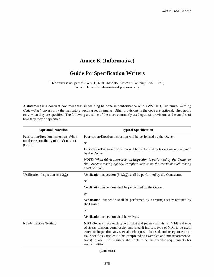
AWS D1.1/D1.1M:2015
375
A statement in a contract document that all welding be done in conformance with AWS D1.1, Structural WeldingCode—Steel, covers only the mandatory welding requirements. Other provisions in the code are optional. They applyonly when they are specified. The following are some of the more commonly used optional provisions and examples ofhow they may be specified.
Optional Provision Typical Specification
Fabrication/Erection Inspection [When not the responsibility of the Contractor (6.1.2)]
Fabrication/Erection inspection will be performed by the Owner.
or
Fabrication/Erection inspection will be performed by testing agency retainedby the Owner.
NOTE: When fabrication/erection inspection is performed by the Owner orthe Owner’s testing agency, complete details on the extent of such testingshall be given.
Verification Inspection (6.1.2.2) Verification inspection (6.1.2.2) shall be performed by the Contractor.
or
Verification inspection shall be performed by the Owner.
or
Verification inspection shall be performed by a testing agency retained bythe Owner.
or
Verification inspection shall be waived.
Nondestructive Testing NDT General: For each type of joint and (other than visual [6.14] and typeof stress [tension, compression and shear]) indicate type of NDT to be used,extent of inspection, any special techniques to be used, and acceptance crite-ria. Specific examples (to be interpreted as examples and not recommenda-tions) follow. The Engineer shall determine the specific requirements foreach condition.
Annex K (Informative)
Guide for Specification Writers
This annex is not part of AWS D1.1/D1.1M:2015, Structural Welding Code—Steel,but is included for informational purposes only.
(Continued)
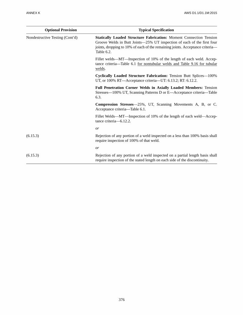
376
ANNEX K AWS D1.1/D1.1M:2015
Nondestructive Testing (Cont’d) Statically Loaded Structure Fabrication: Moment Connection TensionGroove Welds in Butt Joints—25% UT inspection of each of the first fourjoints, dropping to 10% of each of the remaining joints. Acceptance criteria—Table 6.2.
Fillet welds—MT—Inspection of 10% of the length of each weld. Accep-tance criteria—Table 6.1 for nontubular welds and Table 9.16 for tubularwelds.
Cyclically Loaded Structure Fabrication: Tension Butt Splices—100%UT, or 100% RT—Acceptance criteria—UT: 6.13.2; RT: 6.12.2.
Full Penetration Corner Welds in Axially Loaded Members: TensionStresses—100% UT, Scanning Patterns D or E—Acceptance criteria—Table6.3.
Compression Stresses—25%, UT, Scanning Movements A, B, or C.Acceptance criteria—Table 6.1.
Fillet Welds—MT—Inspection of 10% of the length of each weld—Accep-tance criteria—6.12.2.
or
(6.15.3) Rejection of any portion of a weld inspected on a less than 100% basis shallrequire inspection of 100% of that weld.
or
(6.15.3) Rejection of any portion of a weld inspected on a partial length basis shallrequire inspection of the stated length on each side of the discontinuity.
Optional Provision Typical Specification

AWS D1.1/D1.1M:2015
377
This annex contains examples for use of three forms, L-8, L-9, and L-10, for recording of UT test data. Each example offorms L-8, L-9, and L-10 shows how the forms may be used in the UT inspection of welds. Form L-11 is for reporting re-sults of UT inspection of welds.
Annex L (Informative)
UT Equipment Qualification and Inspection Forms
This annex is not part of AWS D1.1/D1.1M:2015, Structural Welding Code—Steel,but is included for informational purposes only.

ANNEX L AWS D1.1/D1.1M:2015
378
Ultrasonic Unit Calibration Report—AWS
Ultrasonic Unit Model ___________________________ Serial No. _____________________________________
Search Unit—Size______________ Type ________________________ Frequency________________ MHz
Calibration—Date ______________ Interval ______________________ Method ______________________
Block Serial No.________________ Data ____________________ As Found ___________________ As Adjusted
SUPPLEMENTAL INSTRUCTIONS
• Start with the lowest dB level that you can obtain a 40 percent display height indication from directly over the two insection of the DS block. Add 6 dBs and record this dB reading “a” and display height “b” as the starting point on thetabulation chart.
• After recording these values in Rows “a” and “b,” slide the transducer to obtain a new 40 percent display height. With-out moving the transducer add 6 dBs and record the new dB reading and the new display height in the appropriate row.Repeat this step as many times as the unit allows.
• Find the average % screen values from Row “b” by disregarding the first 3 and the last 3 tabulations. Use this as %2 incalculating the corrected reading.
• The following equation is used to calculate Row “c”:%1 is Row “b”%2 is the average of Row “b” disregarding
the first and last three tabulations.dB1 is Row “a”dB2 is Row “c”
• The dB Error “d” is established by subtracting Row “c” from Row “a”: (a – c = d).
• The Collective dB Error “e” is established by starting with the dB Error “d” nearest to 0.0, collectively add the dB Error“d” values horizontally, placing the subtotals in Row “e.”
• Moving horizontally, left and right from the Average % line, find the span in which the largest and smallest CollectivedB Error figures remain at or below 2 dB. Count the number of horizontal spaces of movement, subtract one, and mul-tiply the remainder by six. This dB value is the acceptable range of the unit.
• In order to establish the acceptable range graphically, Form L-8 should be used in conjunction with Form L-9 as follows:(1) Apply the collective dB Error “e” values vertically on the horizontal offset coinciding with the dB reading values “a.”(2) Establish a curve line passing through this series of points.(3) Apply a 2 dB high horizontal window over this curve positioned vertically so that the longest section is completely
encompassed within the 2 dB Error height.(4) This window length represents the acceptable dB range of the unit.
Accuracy Required: Minimum allowable range is ______ . %2 (Average)___________ %
Equipment is: Acceptable for Use _________ Not Acceptable for Use _________ Recalibration Due Date__________
Total qualified range _______ dB to _______ dB = _______ dB Total error _______ dB (From the Chart above)
Total qualified range _______ dB to _______ dB = _______ dB Total error _______ dB (From Form L-9)
Calibrated by __________________________________ Level _______ Location ________________________
Row Number 1 2 3 4 5 6 7 8 9 10 11 12 13
a dB Reading
b Display Height
c Corrected Reading
d dB Error
e Collective dB Error
dB2 20%2
%1------- log× dB1+=
Form L-8

AWS D1.1/D1.1M:2015 ANNEX L
379
78
XX
12
11
78
80
66
69
1.7
2.0
August 17, 1996
Ultrasonic Unit Calibration Report—AWS
Ultrasonic Unit Model ___________________________ Serial No. _____________________________________
Search Unit—Size______________ Type ________________________ Frequency________________ MHz
Calibration—Date ______________ Interval ______________________ Method ______________________
Block Serial No.________________ Data _________________ As Found ___________________ As Adjusted
SUPPLEMENTAL INSTRUCTIONS
• Start with the lowest dB level that you can obtain a 40 percent display height indication from directly over the two insection of the DS block. Add 6 dBs and record this dB reading “a” and display height “b” as the starting point on thetabulation chart.
• After recording these values in Rows “a” and “b,” slide the transducer to obtain a new 40 percent display height. With-out moving the transducer add 6 dBs and record the new dB reading and the new display height in the appropriate row.Repeat this step as many times as the unit allows.
• Find the average % screen values from Row “b” by disregarding the first 3 and the last 3 tabulations. Use this as %2 incalculating the corrected reading.
• The following equation is used to calculate Row “c”:%1 is Row “b”%2 is the average of Row “b” disregarding
the first and last three tabulations.dB1 is Row “a”dB2 is Row “c”
• The dB Error “d” is established by subtracting Row “c” from Row “a”: (a – c = d).
• The Collective dB Error “e” is established by starting with the dB Error “d” nearest to 0.0, collectively add the dB Error“d” values horizontally, placing the subtotals in Row “e.”
• Moving horizontally, left and right from the Average % line, find the span in which the largest and smallest CollectivedB Error figures remain at or below 2 dB. Count the number of horizontal spaces of movement, subtract one, and mul-tiply the remainder by six. This dB value is the acceptable range of the unit.
• In order to establish the acceptable range graphically, Form L-8 should be used in conjunction with Form L-9 as follows:(1) Apply the collective dB Error “e” values vertically on the horizontal offset coinciding with the dB reading values “a.”(2) Establish a curve line passing through this series of points.(3) Apply a 2 dB high horizontal window over this curve positioned vertically so that the longest section is completely
encompassed within the 2 dB Error height.(4) This window length represents the acceptable dB range of the unit.
Accuracy Required: Minimum allowable range is 60 dB. %2 (Average)___________ %
Equipment is: Acceptable for Use ______ Not Acceptable for Use ______ Recalibration Due Date_________________
Total qualified range _______ dB to _______ dB = _______ dB Total error _______ dB (From the Chart above)
Total qualified range _______ dB to _______ dB = _______ dB Total error _______ dB (From Form L-9)
Calibrated by __________________________________ Level _________ Location ________________________
ROW NUMBER 1 2 3 4 5 6 7 8 9 10 11 12 13
a dB Reading 6 12 18 24 30 36 42 48 54 60 66 72 78b Display Height 69 75 75 77 77 77 77 78 77 78 79 80 81c Corrected Reading 7.1 12.3 18.3 24.1 30.1 36.1 42.1 48.0 54.1 60.0 65.9 71.8 77.7d dB Error –1.1 –0.3 –0.3 –0.1 –0.1 –0.1 –0.1 0.0 –0.1 0.0 +0.1 +0.2 +0.3e Collective dB Error –2.2 –1.1 –0.8 –0.5 –0.4 –0.3 –0.2 –0.1 –0.1 0.0 +0.1 +0.3 +0.6
dB2 20%2
%1------- log× dB1+=
USN-501" ROUND
June 17, 19961234-5678
SAB
2 MonthsXX
AWS D1.1
2.2547859-5014
Form L-8

ANNEX L AWS D1.1/D1.1M:2015
380
dB Accuracy Evaluation
Form L-9

AWS D1.1/D1.1M:2015 ANNEX L
381
dB Accuracy Evaluation—AWS
Note: The first line of example of the use of Form L-8 is shown in this example.
Form L-9

ANNEX L AWS D1.1/D1.1M:2015
382
Decibel (Attenuation or Gain) Values Nomograph
Note: See 6.28.2.3 for instruction on use of this nomograph.
Form L-10

AWS D1.1/D1.1M:2015 ANNEX L
383
Decibel (Attenuation or Gain) Values Nomograph—AWS
Procedure for using the Nomograph:• Extend a straight line between the decibel reading from Row “a” applied to the C scale and the corresponding percentage from
Row “b” applied to the A scale.• Use the point where the straight line above crosses the pivot line B as a pivot line for a second straight line.• Extend a second straight line from the average sign point on scale A, through the pivot point developed above, and onto the dB scale C.• This point on the C scale is indicative of the corrected dB for use in Row “c.”
Notes:1. The 6 dB reading and 69% scale are derived from the instrument reading and become dB1 “b” and %1 “c,” respectively.2. %2 is 78 – constant.3. dB2 (which is corrected dB “d”) is equal to 20 times X log (78/69) + 6 or 7.1.
Form L-10

ANNEX L AWS D1.1/D1.1M:2015
384
Report of UT of Welds
Project _________________________________________________________________________ Report no. _________________
Form L-11
Weld identification____________________________________________________
Material thickness ____________________________________________________
Weld joint AWS ______________________________________________________
Welding process _____________________________________________________
Quality requirements—section no. _______________________________________
Remarks ___________________________________________________________
Line
num
ber
Indi
catio
nnu
mbe
r
Tran
sduc
eran
gle
From
Fac
e
Leg
a
Decibels Discontinuity
Dis
cont
inui
tyev
alua
tion
Remarks
Indi
catio
nle
vel
Ref
eren
cele
vel
Atte
nuat
ion
fact
or
Indi
catio
nra
ting
Leng
th
Ang
ular
dist
ance
(sou
nd p
ath)
Dep
th fr
om“A
” su
rfac
e
Distance
a b c d From X From Y
1
2
3
4
5
6
7
8
9
10
11
12
13
14
15
16
17
18
19
20
21
22
23
24
25
26
We, the undersigned, certify that the statements in this record are correct and that the welds were prepared and tested in conformancewith the requirements of Clause 6, Part F of AWS D1.1/D1.1M, ( __________ ) Structural Welding Code—Steel.
(year)
Test date ___________________________________________
Inspected by ________________________________________
Note: This form is applicable to Clause 2, Parts B or C (Staticallyand Cyclically Loaded Nontubular Structures). Do NOT use thisform for Tubular Structures (Clause 9, Part A).
Manufacturer or Contractor ____________________________
Authorized by _______________________________________
Date ______________________________________________

AWS D1.1/D1.1M:2015 ANNEX L
385
aUse Leg I, II, or III (see Annex J for definition of Leg).
Notes:1. In order to attain Rating “d”
a. With instruments with gain control, use the formula a – b – c = d.b. With instruments with attenuation control, use the formula b – a – c = d.c. A plus or minus sign shall accompany the “d” figure unless “d” is equal to zero.
2. Distance from X is used in describing the location of a weld discontinuity in a direction perpendicular to the weld referenceline. Unless this figure is zero, a plus or minus sign shall accompany it.
3. Distance from Y is used in describing the location of a weld discontinuity in a direction parallel to the weld referenceline. This figure is attained by measuring the distance from the “Y” end of the weld to the beginning of said discontinuity.
4. Evaluation of Retested Repaired Weld Areas shall be tabulated on a new line on the report form. If the original reportform is used, Rn shall prefix the indication number. If additional forms are used, the R number shall prefix the reportnumber.

AWS D1.1/D1.1M:2015
386
This page is intentionally blank.

AWS D1.1/D1.1M:2015
387
This annex contains example forms for the recording ofWPS information procedure qualification test data, qual-ification test results, welder qualification, welding opera-tor qualification, and tack welder qualification datarequired by this code. Also included are laboratory reportforms for recording the results of NDT of welds.
It is recommended that the qualification and NDT informa-tion required by this code be recorded on these forms or sim-ilar forms which have been prepared by the user. Variationsof these forms to suit the user’s needs are permitted.
M1. Use of FormsFor joint details on the WPS, a sketch or a reference to theapplicable prequalified joint detail may be used (e.g., B-U4a).
The WPS forms contain lines for inclusion of informa-tion that may not be required by the code; these linesneed not be completed in order to comply with code re-quirements.
M2. Prequalified WPSsM2 is sufficient for the purpose of documenting prequal-ified WPSs.
M3. Example FormsExamples of completed WPSs and a PQR have been in-cluded for informational purposes. Separate forms for
WPSs and PQRs are provided for welding process cate-gories GTAW/SMAW, GMAW/FCAW, and SAW. Thenames are fictional and the test data given is not fromany actual test and should not be used. The Committeetrusts that these examples will assist code users in pro-ducing acceptable documentation.
M4. WPSs Qualified by Testing
The WPS may be qualified by testing in conformancewith the provisions of Clause 4. In this case, a supportingPQR is required in addition to the WPS. For the WPS,state the allowed ranges qualified by testing or statethe appropriate tolerances on essential variable (e.g.,250 amps ± 10%).
For the PQR, the actual joint details and the values of es-sential variables used in the testing should be recorded.An example of a completed PQR form is provided forguidance in filling out the form. A copy of the Mill TestReport for the material tested should be attached. Also,Testing Laboratory Data Reports may also be included asbackup information or a PQR Test Result Form similarto the example in this annex may be used. Cross refer-ences to the required mechanical tests as applicable tothe WPS being qualified are provided on the form forready reference. Note that not all tests referenced arerequired.
Annex M (Informative)
Sample Welding Forms
This annex is not part of AWS D1.1/D1.1M:2015, Structural Welding Code—Steel,but is included for informational purposes only.

ANNEX M AWS D1.1/D1.1M:2015
388
Index of Forms
FormNo. Title
PageNo.
M-1 Procedure Qualification Record (PQR) forms 389
M-2 Welding Procedure Specification (WPS) forms 395
M-3 WPS Qualification Test Record for Electroslag and Electrogas Welding 400
M-4 Welder, Welding Operator, or Tack Welder Performance Qualification Test Record (Single-Process) forms 401
M-5 Welder, Welding Operator, or Tack Welder Performance Qualification Test Record (Multi-Process) forms 403
M-6 Report of Radiographic Examination of Welds 405
M-7 Report of Magnetic-Particle Examination of Welds 406
M-8 Stud Welding Application Qualification Test, Pre-Production Test, PQR, or WQR Form 407

AWS D1.1/D1.1M:2015 ANNEX M
389
Blank Sample PQR Form (GTAW & SMAW – page 1)PROCEDURE QUALIFICATION RECORD (PQR)
Company Name PQR No. Rev. No. Date
BASE METALS SpecificationType orGrade
AWSGroup No. Thickness Size (NPS) Schedule Diameter
Base MaterialWelded ToBacking MaterialOther
JOINT DETAILS JOINT DETAILS (Sketch)Groove TypeGroove AngleRoot OpeningRoot FaceBackgougingMethod
POSTWELD HEAT TREATMENTTemperatureTime at TemperatureOther
PROCEDUREWeld Layer(s)Weld Pass(es)ProcessType (Manual, Mechanized, etc.)
PositionVertical Progression
Filler Metal (AWS Spec.)AWS ClassificationDiameterManufacturer/Trade Name
Shielding Gas Compos. (GTAW)
Flow Rate (GTAW)
Nozzle Size (GTAW)
Preheat TemperatureInterpass Temperature
Electrical Characteristics — — — — — — — —Electrode Diameter (GTAW)
Current Type & PolarityAmpsVoltsCold or Hot Wire Feed (GTAW)
Travel SpeedMaximum Heat Input
Technique — — — — — — — —Stringer or WeaveMulti or Single Pass (per side)
Oscillation (GTAW Mech./Auto.)
Traverse LengthTraverse SpeedDwell Time
PeeningInterpass Cleaning
Other
Form M-1 (Front) (See http://go.aws.org/D1forms)

ANNEX M AWS D1.1/D1.1M:2015
390
Blank Sample PQR Form (GMAW & FCAW – page 1)PROCEDURE QUALIFICATION RECORD (PQR)
Company Name PQR No. Rev. No. Date
BASE METALS SpecificationType orGrade
AWSGroup No. Thickness Size (NPS) Schedule Diameter
Base MaterialWelded ToBacking MaterialOther
JOINT DETAILS JOINT DETAILS (Sketch)Groove TypeGroove AngleRoot OpeningRoot FaceBackgougingMethod
POSTWELD HEAT TREATMENTTemperatureTime at TemperatureOther
PROCEDUREWeld Layer(s)Weld Pass(es)ProcessType (Semiautomatic, Mechanized, etc.)
PositionVertical Progression
Filler Metal (AWS Spec.)AWS ClassificationDiameterManufacturer/Trade Name
Shielding Gas Composition
Flow RateNozzle Size
Preheat TemperatureInterpass Temperature
Electrical Characteristics — — — — — — — —Current Type & PolarityTransfer Mode (GMAW)
Power Source Type (cc, cv, etc.)
AmpsVoltsWire Feed SpeedTravel SpeedMaximum Heat Input
Technique — — — — — — — —Stringer or WeaveMulti or Single Pass (per side)
Oscillation (Mechanized/Automatic)
Traverse LengthTraverse SpeedDwell Time
Number of ElectrodesContact Tube to Work Dist.PeeningInterpass Cleaning
Other
Form M-1 (Front) (See http://go.aws.org/D1forms)

AWS D1.1/D1.1M:2015 ANNEX M
391
Blank Sample PQR Form (SAW – page 1)PROCEDURE QUALIFICATION RECORD (PQR)
Company Name PQR No. Rev. No. Date
BASE METALS SpecificationType orGrade
AWSGroup No. Thickness Size (NPS) Schedule Diameter
Base MaterialWelded ToBacking MaterialOther
JOINT DETAILS JOINT DETAILS (Sketch)Groove TypeGroove AngleRoot OpeningRoot FaceBackgougingMethod
POSTWELD HEAT TREATMENTTemperatureTime at TemperatureOther
PROCEDUREWeld Layer(s)Weld Pass(es)Process SAWType (Semiautomatic, Mechanized, etc.)
PositionFiller Metal (AWS Spec.)AWS ClassificationElectrode DiameterElectrode/Flux Classification
Manufacturer/Trade NameSupplemental Filler Metal
Preheat TemperatureInterpass Temperature
Electrical Characteristics — — — — — — — —Current Type & PolarityAmpsVoltsWire Feed SpeedTravel SpeedMaximum Heat Input
Technique — — — — — — — —Stringer or WeaveMulti or Single Pass (per side)
Number of ElectrodesLongitudinal Spacing of ArcsLateral Spacing of ArcsAngle of Parallel ElectrodesAngle of Electrode (Mech./Auto.)
Normal To Direction of TravelOscillation (Mechanized/Automatic)
Traverse LengthTraverse SpeedDwell Time
PeeningInterpass Cleaning
Other
Form M-1 (Front) (See http://go.aws.org/D1forms)

ANNEX M AWS D1.1/D1.1M:2015
392
Blank Sample PQR Form (Test Results – page 2)PROCEDURE QUALIFICATION RECORD (PQR) TEST RESULTS
We, the undersigned, certify that the statements in this record are correct and that the test welds were prepared, welded, and tested inaccordance with the requirements of Clause 4 of AWS D1.1/D1.1M, ( __________ ) Structural Welding Code—Steel.
(year)
(See http://go.aws.org/D1forms)
PQR No. Rev. No.
TESTS
✓ Type of Tests Clause/Figure(s) Reference Acceptance Criteria Result RemarksVisual Inspection 4.9.1 4.9.1Radiographic Examination 4.9.2.1 4.9.2.2Ultrasonic Testing 4.9.2.1 4.9.2.22 Transverse Root Bends 4.9.3.1/Fig. 4.8 4.9.3.32 Transverse Face Bends 4.9.3.1/Fig. 4.8 4.9.3.32 Longitudinal Root Bends 4.9.3.1/Fig. 4.8 4.9.3.32 Longitudinal Face Bends 4.9.3.1/Fig. 4.8 4.9.3.32 Side Bends 4.9.3.1/Fig. 4.9 4.9.3.34 Side Bends 4.9.3.1/Fig. 4.9 4.9.3.32 Tensile Tests 4.9.3.4/Fig. 4.10 4.9.3.5All-Weld-Metal Tensions 4.9.3.6/Figs. 4.14 and 4.18 4.14.1.3(b)3 Macroetch 4.9.4 4.9.4.14 Macroetch 4.9.4 4.9.4.1CVN Tests 4 Part D/Fig. 4.28 4.30 and Table 4.14
TENSILE TEST DETAILS
Specimen Number Width Thickness Area
UltimateTensile Load
UltimateUnit Stress
Type ofFailure and Location
TOUGHNESS TEST DETAILS
Specimen Number
NotchLocation
SpecimenSize
TestTemperature
AbsorbedEnergy
PercentShear
LateralExpansion Average
CERTIFICATION
Welder’s Name ID Number Stamp Number Tests Conducted byLaboratoryTest NumberFile Number
Title
Name Signature
Date
Form M-1 (Back)

AWS D1.1/D1.1M:2015 ANNEX M
393
Example PQR (GMAW & FCAW – page 1)PROCEDURE QUALIFICATION RECORD (PQR)
Company Name PQR No. Rev. No. Date
BASE METALS SpecificationType orGrade
AWSGroup No. Thickness Size (NPS) Schedule Diameter
Base Material ASTM A131 A I 1 in – – –Welded To ASTM A131 A I 1 in – – –Backing Material ASTM A131 A I 1/4 inOther
JOINT DETAILS JOINT DETAILS (Sketch)Groove Type Single V Groove Butt JointGroove Angle 35° includedRoot Opening 1/4 inRoot Face –Backgouging NoneMethod –
POSTWELD HEAT TREATMENTTemperature –Time at Temperature –
Other –
PROCEDUREWeld Layer(s) – – – – –Weld Pass(es) 1 2–8 9–11 12–15 16Process FCAW FCAW FCAW FCAW FCAWType(Semiautomatic, Mechanized, etc.)
Semi-automatic
Semi-automatic
Semi-automatic
Semi-automatic
Semi-automatic
Position 4G 4G 4G 4G 4GVertical Progression – – – – –
Filler Metal (AWS Spec.) A5.20 A5.20 A5.20 A5.20 A5.20AWS Classification E71T-1C E71T-1C E71T-1C E71T-1C E71T-1CDiameter 0.045 in 0.045 in 0.045 in 0.045 in 0.045 inManufacturer/Trade Name – – – – –
Shielding Gas Composition 100% CO2 100% CO2 100% CO2 100% CO2 100% CO2
Flow Rate 45–55 cfh 45–55 cfh 45–55 cfh 45–55 cfh 45–55 cfhNozzle Size #4 #4 #4 #4 #4
Preheat Temperature 75° min. 75° min. 75° min. 75° min. 75° min.Interpass Temperature 75°–350° 75°–350° 75°–350° 75°–350° 75°–350°
Electrical Characteristics — — — — — — — —Current Type & Polarity DCEP DCEP DCEP DCEP DCEPTransfer Mode (GMAW) – – – – –Power Source Type (cc, cv, etc.) – – – – –Amps 180 200 200 200 200Volts 26 27 27 27 27Wire Feed Speed (Amps) (Amps) (Amps) (Amps) (Amps)Travel Speed 8 ipm 10 ipm 11 ipm 9 ipm 11 ipmMaximum Heat Input – – – – –
Technique — — — — — — — —Stringer or Weave Stringer Stringer Stringer Stringer StringerMulti or Single Pass (per side) Multipass Multipass Multipass Multipass MultipassOscillation (Mechanized/Automatic) – – – – –Number of Electrodes 1 1 1 1 1Contact Tube to Work Dist. 3/4–1 in 3/4–1 in 3/4–1 in 3/4–1 in 3/4–1 inPeening None None None None NoneInterpass Cleaning Wire Brush Wire Brush Wire Brush Wire Brush Wire Brush
Other
Form M-1 (Front) (See http://go.aws.org/D1forms)
Red Inc. 231 0 01/18/2015

ANNEX M AWS D1.1/D1.1M:2015
394
Example PQR (GMAW & FCAW – page 2)PROCEDURE QUALIFICATION RECORD (PQR) TEST RESULTS
We, the undersigned, certify that the statements in this record are correct and that the test welds were prepared, welded, and tested inaccordance with the requirements of Clause 4 of AWS D1.1/D1.1M, ( __________ ) Structural Welding Code—Steel.
(year)
(See http://go.aws.org/D1forms)
PQR No. Rev. No.
TESTS
✓ Type of Tests Clause/Figure(s) Reference Acceptance Criteria Result Remarks✓ Visual Inspection 4.9.1 4.9.1 Acceptable✓ Radiographic Examination 4.9.2.1 4.9.2.2 Acceptable
Ultrasonic Testing 4.9.2.1 4.9.2.22 Transverse Root Bends 4.9.3.1/Fig. 4.8 4.9.3.32 Transverse Face Bends 4.9.3.1/Fig. 4.8 4.9.3.32 Longitudinal Root Bends 4.9.3.1/Fig. 4.8 4.9.3.32 Longitudinal Face Bends 4.9.3.1/Fig. 4.8 4.9.3.32 Side Bends 4.9.3.1/Fig. 4.9 4.9.3.3
✓ 4 Side Bends 4.9.3.1/Fig. 4.9 4.9.3.3 Acceptable < 1/16 in Opening✓ 2 Tensile Tests 4.9.3.1/Fig. 4.10 4.9.3.5 Acceptable✓ All-Weld-Metal Tensions 4.9.3.1/Figs. 4.14 and 4.18 4.14.1.3(b) Acceptable *See Note
3 Macroetch 4.9.4 4.9.4.14 Macroetch 4.9.4 4.9.4.1
✓ CVN Tests 4 Part D/Fig 4.28 4.30 and Table 4.14
Notes: *All-Weld-Metal Tension: T/Y: 83 100/72 600 psi, Elongation in 2 in: 28%, Laboratory Test No. PW 231
TENSILE TEST DETAILS
Specimen Number Width Thickness Area
UltimateTensile Load
UltimateUnit Stress
Type ofFailure and Location
231-1 0.75 in 100 in 0.75 in2 52 500 lb 70 000 psi Ductile/Weld Metal231-2 0.75 in 100 in 0.75 in2 52 275 lb 69 700 psi Ductile/Weld Metal
TOUGHNESS TEST DETAILS
Specimen Number
NotchLocation
SpecimenSize
TestTemperature
AbsorbedEnergy
PercentShear
LateralExpansion Average
231-7 BM 10 × 10 mm –20°F 126 ft·lb 50% 45 mils
125/50/45231-8 BM 10 × 10 mm –20°F 124 ft·lb 50% 45 mils231-9 BM 10 × 10 mm –20°F 125 ft·lb 50% 45 mils
231-10 HAZ 10 × 10 mm –20°F 86 ft·lb 50% 45 mils85 ft·lb50%
45 mils
231-11 HAZ 10 × 10 mm –20°F 84 ft·lb 50% 45 mils231-12 HAZ 10 × 10 mm –20°F 85 ft·lb 50% 45 mils
231-13 WM 10 × 10 mm –20°F 27 ft·lb 50% 45 mils28 ft·lb50%
45 mils
231-14 WM 10 × 10 mm –20°F 29 ft·lb 50% 45 mils231-14 WM 10 × 10 mm –20°F 28 ft·lb 50% 45 mils
CERTIFICATION
Welder’s Name ID Number Stamp Number Tests Conducted byW. T. Williams 261 – Laboratory Red Inc. & ABC Testing
Test Number PQR 231 (per D. Miller)File Number WeldingForms/PQR231.pdf
TitleQ.C. Mgr.Name SignatureR. M. BoncrackDate
Form M-1 (Back) 12/15/2015
231 0

AWS D1.1/D1.1M:2015 ANNEX M
395
Blank Sample WPS Form (GTAW & SMAW)WELDING PROCEDURE SPECIFICATION (WPS)
Company Name WPS No. Rev. No. Date
Authorized by Date Supporting PQR(s) CVN Report
BASE METALS SpecificationType orGrade
AWSGroup No.
BASE METAL THICKNESS As-Welded With PWHT
Base Material CJP Groove WeldsWelded To CJP Groove w/CVNBacking Material PJP Groove WeldsOther Fillet Welds
DIAMETER
JOINT DETAILS JOINT DETAILS (Sketch)Groove TypeGroove AngleRoot OpeningRoot FaceBackgougingMethod
POSTWELD HEAT TREATMENTTemperatureTime at TemperatureOther
PROCEDUREWeld Layer(s)Weld Pass(es)ProcessType (Manual, Mechanized, etc.)
PositionVertical Progression
Filler Metal (AWS Spec.)AWS ClassificationDiameterManufacturer/Trade Name
Shielding Gas Compos. (GTAW)
Flow Rate (GTAW)
Nozzle Size (GTAW)
Preheat TemperatureInterpass Temperature
Electrical Characteristics — — — — — — — —Electrode Diameter (GTAW)
Current Type & PolarityAmpsVoltsCold or Hot Wire Feed (GTAW)
Travel SpeedMaximum Heat Input
Technique — — — — — — — —Stringer or WeaveMulti or Single Pass (per side)
Oscillation (GTAW Mech./Auto.)
Traverse LengthTraverse SpeedDwell Time
PeeningInterpass Cleaning
Other
Form M-2 (See http://go.aws.org/D1forms)
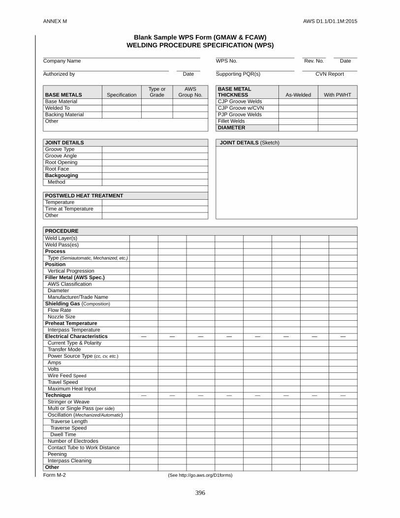
ANNEX M AWS D1.1/D1.1M:2015
396
Blank Sample WPS Form (GMAW & FCAW)WELDING PROCEDURE SPECIFICATION (WPS)
Company Name WPS No. Rev. No. Date
Authorized by Date Supporting PQR(s) CVN Report
BASE METALS SpecificationType orGrade
AWSGroup No.
BASE METAL THICKNESS As-Welded With PWHT
Base Material CJP Groove WeldsWelded To CJP Groove w/CVNBacking Material PJP Groove WeldsOther Fillet Welds
DIAMETER
JOINT DETAILS JOINT DETAILS (Sketch)Groove TypeGroove AngleRoot OpeningRoot FaceBackgougingMethod
POSTWELD HEAT TREATMENTTemperatureTime at TemperatureOther
PROCEDUREWeld Layer(s)Weld Pass(es)ProcessType (Semiautomatic, Mechanized, etc.)
PositionVertical Progression
Filler Metal (AWS Spec.)AWS ClassificationDiameterManufacturer/Trade Name
Shielding Gas (Composition)Flow RateNozzle Size
Preheat TemperatureInterpass Temperature
Electrical Characteristics — — — — — — — —Current Type & PolarityTransfer ModePower Source Type (cc, cv, etc.)AmpsVoltsWire Feed SpeedTravel SpeedMaximum Heat Input
Technique — — — — — — — —Stringer or WeaveMulti or Single Pass (per side)Oscillation (Mechanized/Automatic)Traverse LengthTraverse SpeedDwell Time
Number of ElectrodesContact Tube to Work DistancePeeningInterpass Cleaning
Other
Form M-2 (See http://go.aws.org/D1forms)
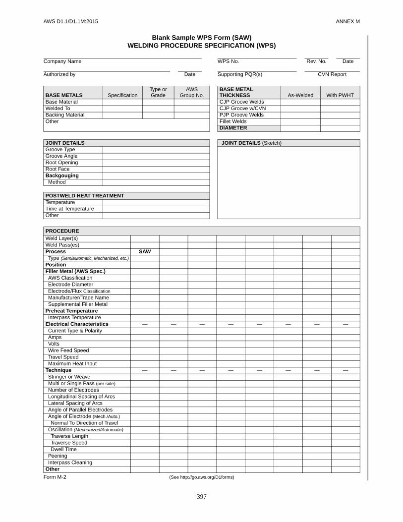
AWS D1.1/D1.1M:2015 ANNEX M
397
Blank Sample WPS Form (SAW)WELDING PROCEDURE SPECIFICATION (WPS)
Company Name WPS No. Rev. No. Date
Authorized by Date Supporting PQR(s) CVN Report
BASE METALS SpecificationType orGrade
AWSGroup No.
BASE METAL THICKNESS As-Welded With PWHT
Base Material CJP Groove WeldsWelded To CJP Groove w/CVNBacking Material PJP Groove WeldsOther Fillet Welds
DIAMETER
JOINT DETAILS JOINT DETAILS (Sketch)Groove TypeGroove AngleRoot OpeningRoot FaceBackgougingMethod
POSTWELD HEAT TREATMENTTemperatureTime at TemperatureOther
PROCEDUREWeld Layer(s)Weld Pass(es)Process SAWType (Semiautomatic, Mechanized, etc.)
PositionFiller Metal (AWS Spec.)AWS ClassificationElectrode DiameterElectrode/Flux ClassificationManufacturer/Trade NameSupplemental Filler Metal
Preheat TemperatureInterpass Temperature
Electrical Characteristics — — — — — — — —Current Type & PolarityAmpsVoltsWire Feed SpeedTravel SpeedMaximum Heat Input
Technique — — — — — — — —Stringer or WeaveMulti or Single Pass (per side)Number of ElectrodesLongitudinal Spacing of ArcsLateral Spacing of ArcsAngle of Parallel ElectrodesAngle of Electrode (Mech./Auto.)Normal To Direction of Travel
Oscillation (Mechanized/Automatic)Traverse LengthTraverse SpeedDwell Time
PeeningInterpass Cleaning
Other
Form M-2 (See http://go.aws.org/D1forms)

ANNEX M AWS D1.1/D1.1M:2015
398
Example WPS (Prequalified)WELDING PROCEDURE SPECIFICATION (WPS)
Company Name WPS No. Rev. No. DateC. W. Hayes 01/03/2015 None (Prequalified) NoAuthorized by Date Supporting PQR(s) CVN Report
BASE METALS SpecificationType orGrade
AWSGroup No.
BASE METAL THICKNESS As-Welded With PWHT
Base Material ASTM A36 – II CJP Groove Welds > 3/4–2.5 in –Welded To ASTM A36 – II CJP Groove w/CVN – –Backing Material ASTM A36 – – PJP Groove Welds – –Other Fillet Welds – –
DIAMETER – –
JOINT DETAILS JOINT DETAILS (Sketch)Groove Type Single V Groove Butt JointGroove Angle 20°Root Opening 5/8 inRoot Face –Backgouging NoneMethod –
POSTWELD HEAT TREATMENTTemperature N.A.Time at Temperature –
Other –
PROCEDUREWeld Layer(s) AllWeld Pass(es) AllProcess SAWType (Semiautomatic, Mechanized, etc.) Mechanized
Position FFiller Metal (AWS Spec.) A5.17AWS Classification EM12KElectrode Diameter 5/32 inElectrode/Flux Classification F7A2-EM12KManufacturer/Trade Name (Flux XYZ)Supplemental Filler Metal –
Preheat Temperature 150°F min.Interpass Temperature 500°F max.
Electrical Characteristics — — — — — — — —Current Type & Polarity DCEPAmps 500–600Volts 26–30Wire Feed Speed –Travel Speed 20–25 ipmMaximum Heat Input –
Technique — — — — — — — —Stringer or Weave StringerMulti or Single Pass (per side) MultipassNumber of Electrodes 1Longitudinal Spacing of Arcs –Lateral Spacing of Arcs –Angle of Parallel Electrodes –Angle of Electrode (Mech./Auto.) 5° ± 2°Normal To Direction of Travel 90° ± 2°
Oscillation (Mechanized/Automatic) NoneTraverse Length –Traverse Speed –Dwell Time –
Peening NoneInterpass Cleaning Slag Removed
Other –
Form M-2 (See http://go.aws.org/D1forms)
LECO W2081 2 01/03/2015

AWS D1.1/D1.1M:2015 ANNEX M
399
Example WPS (Single-Process)WELDING PROCEDURE SPECIFICATION (WPS)
Company Name WPS No. Rev. No. DateJ. Jones 12/01/2015 231 NoAuthorized by Date Supporting PQR(s) CVN Report
BASE METALS SpecificationType orGrade
AWSGroup No.
BASE METAL THICKNESS As-Welded With PWHT
Base Material ASTM A131 A I CJP Groove Welds 3/4–1-1/2 in –Welded To ASTM A131 A I CJP Groove w/CVN – –Backing Material ASTM A131 A I PJP Groove Welds – –Other Fillet Welds – –
DIAMETER – –
JOINT DETAILS JOINT DETAILS (Sketch)Groove Type Single V Groove Butt JointGroove Angle 35° includedRoot Opening 1/4 inRoot Face –Backgouging NoneMethod –
POSTWELD HEAT TREATMENTTemperature NoneTime at Temperature –
Other –
PROCEDUREWeld Layer(s) AllWeld Pass(es) AllProcess FCAWType (Semiautomatic, Mechanized, etc.) Semiauto
Position OHVertical Progression –
Filler Metal (AWS Spec.) A5.20AWS Classification E71T-1CDiameter 0.045 inManufacturer/Trade Name –
Shielding Gas (Composition) 100% CO2
Flow Rate 45–55 cfhNozzle Size #4
Preheat Temperature 60° min.Interpass Temperature 60°–350°
Electrical Characteristics —Current Type & Polarity DCEPTransfer Mode –Power Source Type (cc, cv, etc.) CVAmps 180–220Volts 25–26Wire Feed Speed (Amps)Travel Speed 8–12 ipmMaximum Heat Input –
Technique —Stringer or Weave StringerMulti or Single Pass (per side) MultipassOscillation (Mechanized, Automatic) –Number of Electrodes 1Contact Tube to Work Dist. 1/2–1 inPeening NoneInterpass Cleaning Wire Brush
Other –
Form M-2 (See http://go.aws.org/D1forms)
RED Inc. 2010 0 12/01/2015
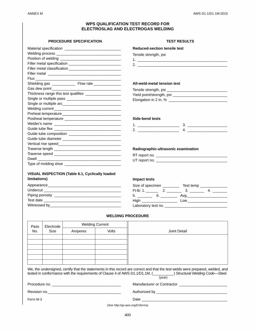
ANNEX M AWS D1.1/D1.1M:2015
400
WELDING PROCEDURE
We, the undersigned, certify that the statements in this record are correct and that the test welds were prepared, welded, andtested in conformance with the requirements of Clause 4 of AWS D1.1/D1.1M, (__________) Structural Welding Code—Steel.
(year)
Procedure no. _________________________________ Manufacturer or Contractor _______________________
Revision no.___________________________________ Authorized by __________________________________
Form M-3 Date _________________________________________
(See http://go.aws.org/D1forms)
PassNo.
Electrode Size
Welding Current
Joint DetailAmperes Volts
PROCEDURE SPECIFICATION
Material specification ___________________________Welding process _______________________________Position of welding _____________________________Filler metal specification _________________________Filler metal classification _________________________Filler metal ___________________________________Flux _________________________________________Shielding gas ___________ Flow rate _____________Gas dew point _________________________________Thickness range this test qualifies _________________Single or multiple pass __________________________Single or multiple arc____________________________Welding current________________________________Preheat temperature ____________________________Postheat temperature ___________________________Welder’s name ________________________________Guide tube flex ________________________________Guide tube composition _________________________Guide tube diameter ____________________________Vertical rise speed______________________________Traverse length ________________________________Traverse speed ________________________________Dwell ________________________________________Type of molding shoe ___________________________
VISUAL INSPECTION (Table 6.1, Cyclically loaded limitations)
Appearance___________________________________Undercut _____________________________________Piping porosity ________________________________Test date _____________________________________Witnessed by__________________________________
TEST RESULTS
Reduced-section tensile test
Tensile strength, psi1. ___________________________________________2. ___________________________________________
All-weld-metal tension test
Tensile strength, psi _____________________________Yield point/strength, psi __________________________Elongation in 2 in, % ____________________________
Side-bend tests
1. ____________________ 3. ___________________2. ____________________ 4. ___________________
Radiographic-ultrasonic examination
RT report no. __________________________________UT report no. __________________________________
Impact tests
Size of specimen ________ Test temp _____________Ft·lb: 1. ______ 2. _______ 3. _______ 4. _______5. _______ 6. ________ Avg.___________________High _________________ Low ___________________Laboratory test no. ______________________________
WPS QUALIFICATION TEST RECORD FORELECTROSLAG AND ELECTROGAS WELDING

AWS D1.1/D1.1M:2015 ANNEX M
401
Sample Welder Qualification Blank Form (Single-Process)WELDER, WELDING OPERATOR, OR TACK WELDER
PERFORMANCE QUALIFICATION TEST RECORD
We, the undersigned, certify that the statements in this record are correct and that the test welds were prepared, welded, and tested inaccordance with the requirements of Clause 4 of AWS D1.1/D1.1M (_______) Structural Welding Code—Steel.
(year)
Manufacturer or Contractor _________________________ Authorized by ___________________________________
Date _________________________________________
Form M-4 (See http://go.aws.org/D1forms)
Name
OPTIONALPHOTO ID
Test Date Rev.ID Number Record No.Stamp No. Std. Test No.Company WPS No.Division Qualified To
BASE METALS SpecificationType or Grade
AWSGroup No. Size (NPS) Schedule Thickness Diameter
Base MaterialWelded To
VARIABLES Actual Values RANGE QUALIFIEDType of Weld JointBase Metal
Groove Fillet Groove FilletPlate ThicknessPipe/Tube ThicknessPipe Diameter
Welding ProcessType (Manual, Semiautomatic,
Mechanized, Automatic)
BackingFiller Metal (AWS Spec.)AWS ClassificationF-Number
PositionGroove – Plate & Pipe ≥ 24 inGroove – Pipe < 24 inFillet – Plate & Pipe ≥ 24 inFillet – Pipe < 24 in
ProgressionGMAW Transfer ModeSingle or Multiple ElectrodesGas/Flux Type
TEST RESULTS
Type of TestAcceptance
Criteria Results Remarks
CERTIFICATION
Test Conducted byLaboratoryTest NumberFile Number

ANNEX M AWS D1.1/D1.1M:2015
402
Example Welder Qualification (Single-Process)WELDER, WELDING OPERATOR, OR TACK WELDER
PERFORMANCE QUALIFICATION TEST RECORD
We, the undersigned, certify that the statements in this record are correct and that the test welds were prepared, welded, and tested inaccordance with the requirements of Clause 4 of AWS D1.1/D1.1M (_______) Structural Welding Code—Steel.
(year)
Manufacturer or Contractor _________________________ Authorized by ___________________________________
Date _________________________________________
Form M-4 (See http://go.aws.org/D1forms)
Name Z. W. Elder
OPTIONALPHOTO ID
Test Date 12/12/2015 Rev.ID Number 00-001-ZWE Record No. WPQ-001 0Stamp No. ZWE-1 Std. Test No. ST-001 0Company RED Inc. WPS No. WPS-001 0Division – Qualified To AWS D1.1
BASE METALS SpecificationType or Grade
AWSGroup No. Size (NPS) Schedule Thickness Diameter
Base Material ASTM A36 UNS K02600 I – – 3/8 in –Welded To ASTM A36 UNS K02600 I – – 3/8 in –
VARIABLES Actual Values RANGE QUALIFIED
Type of Weld Joint Plate – Groove (Fig. 4.31) with Backing Groove, Fillet, Plug, and Slot Welds(T-, Y-, K-Groove PJP only)
Base Metal Group I to Group I Any AWS D1.1 Qualified Base Metal
Groove Fillet Groove FilletPlate Thickness 3/8 in – 1/8 in – 3/4 in 1/8 in min.Pipe/Tube Thickness – – 1/8 in – 3/4 in UnlimitedPipe Diameter – – 24 in min. Unlimited
Welding Process GMAW GMAWType (Manual, Semiautomatic,
Mechanized, Automatic)Semiautomatic Semiautomatic, Mechanized, Automatic
Backing With With (incl. Backgouging and Backwelding)Filler Metal (AWS Spec.) A5.18 A5.xxAWS Classification ER70S-6 AllF-Number – –
Position 2G, 3G, and 4GGroove – Plate and Pipe ≥ 24 in AllGroove – Pipe < 24 in –Fillet – Plate and Pipe ≥ 24 in AllFillet – Pipe < 24 in All
Progression Vertical Up Vertical UpGMAW Transfer Mode Globular Spray, Pulsed, GlobularSingle or Multiple Electrodes Single SingleGas/Flux Type A5.32 SG-C A5.xx Approved
TEST RESULTS
Type of TestAcceptance
Criteria Results RemarksVisual Examination per 4.9.1 4.9.1 Acceptable –Each Position: 1 Root Bend per 4.8.3.1 and Fig. 4.8 4.9.3.3 Acceptable –Each Position: 1 Race Bend per 4.9.3.1 and Fig. 4.8 4.9.3.3 Acceptable 3G: Small (<1/16 in) Opening
CERTIFICATION
Test Conducted byLaboratory Welding Forms LabTest Number Fictitious Test XYZFile Number Welding Forms/Sample-WPQ-for-GMAW.pdf
Red Inc. E. M. Ployee (Q.C. Mgr.)
12/12/2015

AWS D1.1/D1.1M:2015 ANNEX M
403
Sample Welder Qualification Blank Form (Multi-Process)WELDER, WELDING OPERATOR, OR TACK WELDER
PERFORMANCE QUALIFICATION TEST RECORD
We, the undersigned, certify that the statements in this record are correct and that the test welds were prepared, welded, and tested inaccordance with the requirements of Clause 4 of AWS D1.1/D1.1M (_______) Structural Welding Code—Steel.
(year)
Manufacturer or Contractor _________________________ Authorized by ___________________________________
Date _________________________________________
Form M-5 (See http://go.aws.org/D1forms)
Name
OPTIONALPHOTO ID
Test Date Rev.ID Number Record No.Stamp No. Std. Test No.Company WPS No.Division Qualified To
BASE METALS SpecificationType or Grade
AWSGroup No. Size (NPS) Schedule Thickness Diameter
Base MaterialWelded To
VARIABLES Actual Values RANGE QUALIFIEDType of Weld JointBase Metal
Groove Fillet Groove FilletPlate ThicknessPipe/Tube ThicknessPipe Diameter
Welding ProcessType (Manual, Semiautomatic,
Mechanized, Automatic)
BackingFiller Metal (AWS Spec.)AWS ClassificationF-Number
PositionGroove – Plate and Pipe ≥ 24 inGroove – Pipe < 24 inFillet – Plate and Pipe ≥ 24 inFillet – Pipe < 24 in
ProgressionGMAW Transfer ModeSingle or Multiple ElectrodesGas/Flux Type
TEST RESULTS
Type of TestAcceptance
Criteria Results Remarks
CERTIFICATION
Test Conducted byLaboratoryTest NumberFile Number

ANNEX M AWS D1.1/D1.1M:2015
404
Example Welder Qualification (Multi-Process)WELDER, WELDING OPERATOR, OR TACK WELDER
PERFORMANCE QUALIFICATION TEST RECORD
We, the undersigned, certify that the statements in this record are correct and that the test welds were prepared, welded, and tested inconformance with the requirements of Clause 4 of AWS D1.1/D1.1M (_______) Structural Welding Code—Steel.
(year)
Manufacturer or Contractor _________________________ Authorized by ___________________________________
Date _________________________________________
Form M-5 (See http://go.aws.org/D1forms)
Name Z. W. Elder
OPTIONALPHOTO ID
Test Date 12/12/2015 Rev.ID Number 00-001-ZWE Record No. WPQ-003 0Stamp No. ZWE-01 Std. Test No. ST-003 0Company RED Inc. WPS No. WPS-003 0Division – Qualified To AWS D1.1
BASE METALS SpecificationType or Grade
AWSGroup No. Size (NPS) Schedule Thickness Diameter
Base Material ASTM A36 UNS K02600 II – – 1 in –Welded To ASTM A36 UNS K02600 II – – 1 in –
VARIABLES Actual Values RANGE QUALIFIED
Type of Weld Joint Plate – Groove (Fig. 4.31) with Backing Groove, Fillet, Plug, and Slot Welds(T-, Y-, K-Groove PJP only)
Base Metal Group II to Group II Any AWS D1.1 Qualified Base Metal
Groove Fillet Groove FilletPlate Thickness 1 in – 1/8 in min. 1/8 in min.Pipe/Tube Thickness – – 1/8 in min. UnlimitedPipe Diameter – – 24 in min. Unlimited
Welding Process GTAW SMAW FCAW GTAW SMAW FCAWType (Manual, Semiautomatic,
Mechanized, Automatic)Manual Manual Semiauto Man/Mech/
Auto Manual Semi/Mech/Auto
Backing With With With With With WithFiller Metal (AWS Spec.) A5.18 A5.1 A5.20 A5.xx A5.xx A5.xxAWS Classification ER70S-2 E7018 E70T-6 All All AllF-Number – 4 – – 1 thru 4 –
Position 1G 1G 1GGroove – Plate and Pipe ≥ 24 in F F FGroove – Pipe < 24 in – – –Fillet – Plate and Pipe ≥ 24 in F, H F, H F, HFillet – Pipe < 24 in F, H F, H F, H
Progression – – – – – –GMAW Transfer Mode – – – – – –Single or Multiple Electrodes Single – Single Single – Single
Gas/Flux Type A5.32 SG-A – None A5.xx Approved – A5.xx
Approved
TEST RESULTS
Type of TestAcceptance
Criteria Results RemarksVisual Examination per 4.9.1 4.9.1 Acceptable –2 Transverse Side Bends per 4.9.3.1 and Fig. 4.9 4.9.3.3 Acceptable –
CERTIFICATION
Test Conducted byLaboratory Welding Forms LabTest Number Fictitious Test XYZFile Number Welding Forms/Sample-WPQ-for-GTAW-SMAW-FCAW.pdf
Red Inc. E. M. Ployee (Q.C. Mgr.)
12/12/2015

AWS D1.1/D1.1M:2015 ANNEX M
405
REPORT OF RADIOGRAPHIC EXAMINATION OF WELDS
Project _________________________________________________________________________________________Quality requirements—section no. ____________________________________________________________________Reported to ______________________________________________________________________________________
WELD LOCATION AND IDENTIFICATION SKETCH
TechniqueSource ________________________________Film to source __________________________Exposure time __________________________Screens _______________________________Film type ______________________________
(Describe length, width, and thickness of all joints radiographed)
We, the undersigned, certify that the statements in this record are correct and that the test welds were prepared and tested inconformance with the requirements of AWS D1.1/D1.1M, (__________) Structural Welding Code—Steel.
(year)
Radiographer(s) _______________________________ Manufacturer or Contractor _______________________
Interpreter ____________________________________ Authorized by __________________________________
Test date _____________________________________ Date _________________________________________
Form M-6 (See http://go.aws.org/D1forms)
Date Weld identification Area
Interpretation Repairs
RemarksAccept. Reject Accept. Reject
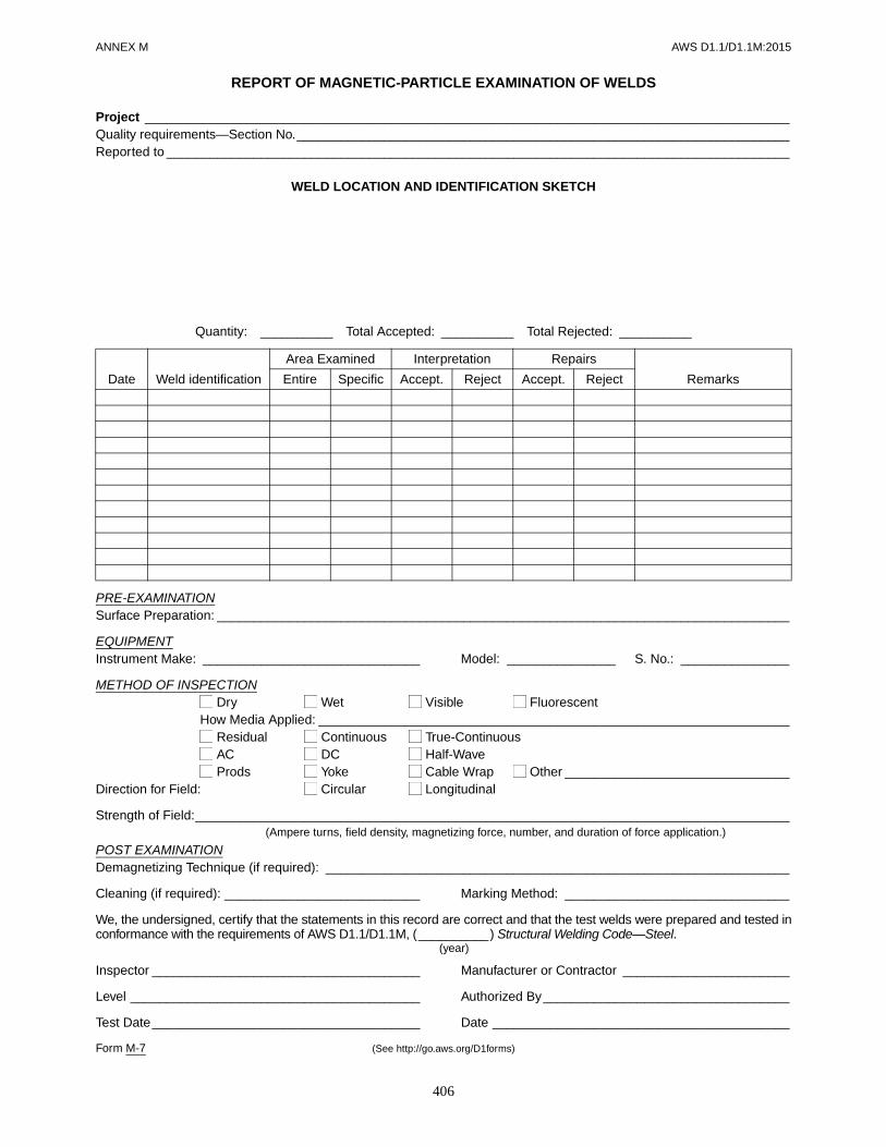
ANNEX M AWS D1.1/D1.1M:2015
406
REPORT OF MAGNETIC-PARTICLE EXAMINATION OF WELDS
Project _________________________________________________________________________________________Quality requirements—Section No.____________________________________________________________________Reported to ______________________________________________________________________________________
WELD LOCATION AND IDENTIFICATION SKETCH
Quantity: __________ Total Accepted: __________ Total Rejected: __________
PRE-EXAMINATIONSurface Preparation: _______________________________________________________________________________
EQUIPMENTInstrument Make: ______________________________ Model: _______________ S. No.: _______________
METHOD OF INSPECTION Dry Wet Visible Fluorescent
How Media Applied: _________________________________________________________________ Residual Continuous True-Continuous AC DC Half-Wave Prods Yoke Cable Wrap Other _______________________________
Direction for Field: Circular Longitudinal
Strength of Field:__________________________________________________________________________________(Ampere turns, field density, magnetizing force, number, and duration of force application.)
POST EXAMINATIONDemagnetizing Technique (if required): ________________________________________________________________
Cleaning (if required): ___________________________ Marking Method: _______________________________
We, the undersigned, certify that the statements in this record are correct and that the test welds were prepared and tested inconformance with the requirements of AWS D1.1/D1.1M, (__________) Structural Welding Code—Steel.
(year)
Inspector _____________________________________ Manufacturer or Contractor _______________________
Level ________________________________________ Authorized By__________________________________
Test Date_____________________________________ Date _________________________________________
Form M-7 (See http://go.aws.org/D1forms)
Date Weld identification
Area Examined Interpretation Repairs
RemarksEntire Specific Accept. Reject Accept. Reject

AWS D1.1/D1.1M:2015 ANNEX M
407
Company name________________________________Operator name ________________________________Test number __________________________________Weld stud material _____________________________Weld stud size and PN#/Manufacturer ______________Base MaterialSpecification __________________________________Alloy and temper _______________________________Surface condition HR CRCoating ______________________________________Cleaning method_______________________________Decking gage _________________________________Shape of Base MaterialFlat Round TubeAngle Inside Outside Inside radiusThickness ____________________________________FerrulePart No./Manufacturer ___________________________Ferrule description _____________________________Equipment DataApplication Settings, Current, and Time Settings
Make __________________ Model _______________Stud gun: Make ____________ Model ____________Weld time (seconds) ____________________________Current (amperage)_____________________________Polarity: DCEN _____________ DCEP____________Lift __________________________________________Plunge (protrusion) _____________________________Weld cable size __________ Length _______________Number of grounds (workpiece leads) ______________
Stud Base Sketch/Application Detail
STUD WELDING APPLICATION QUALIFICATION TEST DATA FORM PER SUBCLAUSE 7.6 YesPRE-PRODUCTION TEST PER SUBCLAUSE 7.7.1 (WPS) Yes
OR PROCEDURE QUALIFICATION RECORD (PQR) YesOR WELDER QUALIFICATION RECORD (WQR) Yes
WELD TEST RESULTS
*Note: Torque test optional for threaded fasteners only.
Mechanical tests conducted by_______________________________________________ Date _________________(Company)
We, the undersigned, certify that the statements in this record are correct and that the test welds were prepared, welded, andtested in conformance with the requirements of Clause 7 of AWS D1.1/D1.1M, (__________) Structural Welding Code—Steel.
(year)
Signed by ____________________________________ Title _________________ Date _________________(Contractor/Applicator/Other)
Form M-8 Company _____________________________________
(See http://go.aws.org/D1forms)
Stud No. Visual Acceptance Option #1 Bend Test Option #2 Tension Test Option #3 Torque Test*123456789
100
Welding PositionFlat (Down hand) Horizontal (Side hand) Angular—degrees from normal OverheadShielding GasShielding gas(es)/Composition ____________________Flow rate _____________________________________

AWS D1.1/D1.1M:2015
408
This page is intentionally blank.

AWS D1.1/D1.1M:2015
409
N1. IntroductionThe American Welding Society (AWS) Board of Direc-tors has adopted a policy whereby all official interpreta-tions of AWS standards are handled in a formal manner.Under this policy, all interpretations are made by thecommittee that is responsible for the standard. Officialcommunication concerning an interpretation is directedthrough the AWS staff member who works with thatcommittee. The policy requires that all requests for aninterpretation be submitted in writing. Such requests willbe handled as expeditiously as possible, but due to thecomplexity of the work and the procedures that must befollowed, some interpretations may require considerabletime.
N2. ProcedureAll inquiries shall be directed to:
Managing DirectorTechnical Services DivisionAmerican Welding Society8669 NW 36 Street, # 130Miami, FL 33166
All inquiries shall contain the name, address, and affilia-tion of the inquirer, and they shall provide enough infor-mation for the committee to understand the point ofconcern in the inquiry. When the point is not clearlydefined, the inquiry will be returned for clarification. Forefficient handling, all inquiries should be typewritten andin the format specified below.
N2.1 Scope. Each inquiry shall address one single provi-sion of the code, unless the point of the inquiry involvestwo or more interrelated provisions. The provision(s)shall be identified in the scope of the inquiry along withthe edition of the code that contains the provision(s) theinquirer is addressing.
N2.2 Purpose of the Inquiry. The purpose of the inquiryshall be stated in this portion of the inquiry. The purposecan be either to obtain an interpretation of a code’s re-quirement, or to request the revision of a particular pro-vision in the code.
N2.3 Content of the Inquiry. The inquiry should beconcise, yet complete, to enable the committee to quicklyand fully understand the point of the inquiry. Sketchesshould be used when appropriate and all paragraphs, fig-ures, and tables (or the Annex), which bear on the in-quiry shall be cited. If the point of the inquiry is to obtaina revision of the code, the inquiry must provide technicaljustification for that revision.
N2.4 Proposed Reply. The inquirer should, as a pro-posed reply, state an interpretation of the provision thatis the point of the inquiry, or the wording for a proposedrevision, if that is what inquirer seeks.
N3. Interpretation of Code ProvisionsInterpretations of code provisions are made by the Struc-tural Welding Committee. The secretary of the commit-tee refers all inquiries to the chair of the particularsubcommittee that has jurisdiction over the portion of
Annex N (Informative)
Guidelines for the Preparation of Technical Inquiriesfor the Structural Welding Committee
This annex is not part of AWS D1.1/D1.1M:2015, Structural Welding Code—Steel,but is included for informational purposes only.
ANNEX N AWS D1.1/D1.1M:2015
410
the code addressed by the inquiry. The subcommitteereviews the inquiry and the proposed reply to determinewhat the response to the inquiry should be. Following thesubcommittee’s development of the response, the inquiryand the response are presented to the entire StructuralWelding Committee for review and approval. Upon ap-proval by the committee, the interpretation is an officialinterpretation of the Society, and the secretary transmitsthe response to the inquirer and to the Welding Journalfor publication.
N4. Publication of Interpretations
All official interpretations shall appear in the WeldingJournal and will be posted on the AWS web site.
N5. Telephone Inquiries
Telephone inquiries to AWS Headquarters concerningthe Structural Welding Code should be limited to ques-tions of a general nature or to matters directly related to
the use of the code. The AWS Board of Directors’ policyrequires that all AWS staff members respond to a tele-phone request for an official interpretation of any AWSstandard with the information that such an interpretationcan be obtained only through a written request. Head-quarters staff cannot provide consulting services. How-ever, the staff can refer a caller to any of those consultantswhose names are on file at AWS Headquarters.
N6. The Structural Welding CommitteeThe activities of the Structural Welding Committee re-garding interpretations are limited strictly to the interpre-tation of code provisions or to consideration of revisionsto existing provisions on the basis of new data or technol-ogy. Neither AWS staff nor the committees are in a posi-tion to offer interpretive or consulting services on: (1)specific engineering problems, or (2) code requirementsapplied to fabrications outside the scope of the code orpoints not specifically covered by the code. In such cases,the inquirer should seek assistance from a competent en-gineer experienced in the particular field of interest.

AWS D1.1/D1.1M:2015
411
Annex O (Informative)
Local Dihedral Angle
This annex is not part of AWS D1.1/D1.1M:2015, Structural Welding Code—Steel,but is included for informational purposes only.

ANNEX O AWS D1.1/D1.1M:2015
412

AWS D1.1/D1.1M:2015 ANNEX O
413

ANNEX O AWS D1.1/D1.1M:2015
414
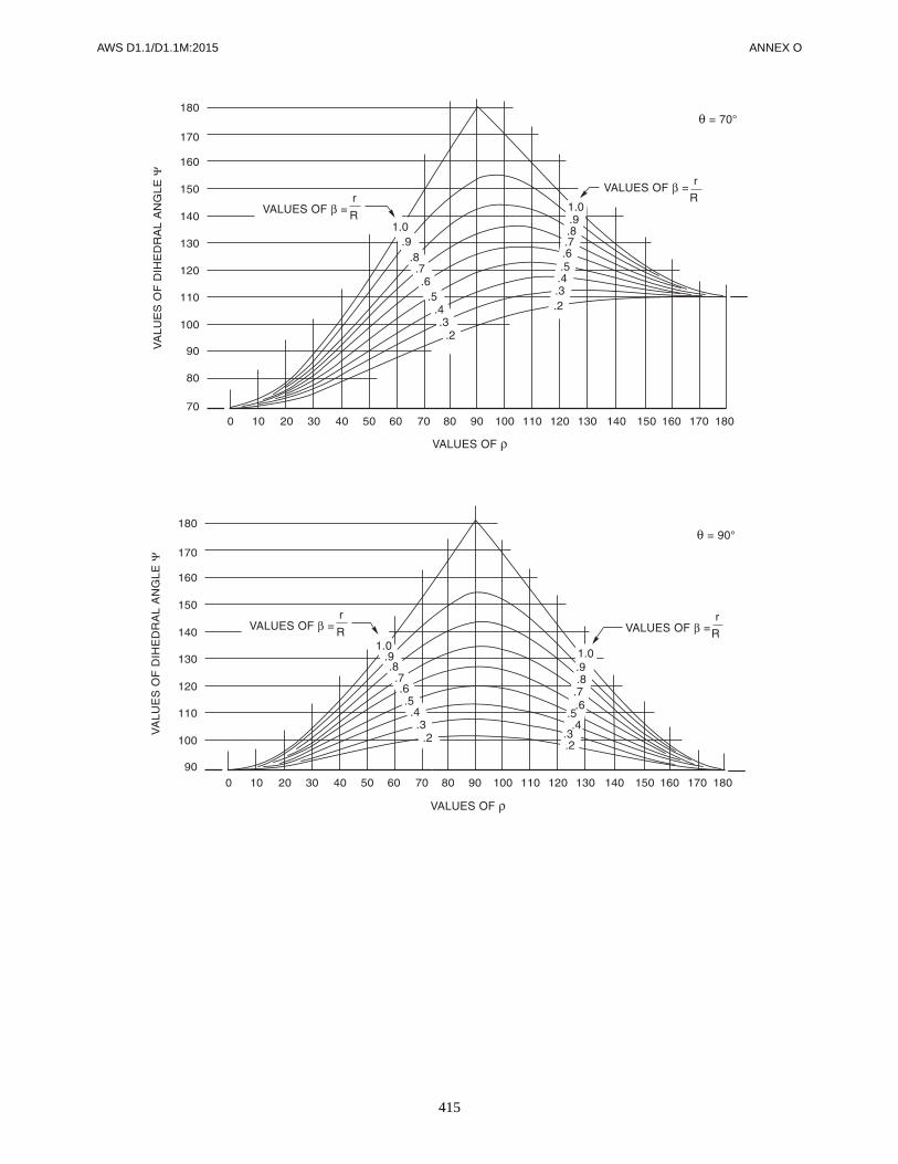
AWS D1.1/D1.1M:2015 ANNEX O
415

AWS D1.1/D1.1M:2015
416
This page is intentionally blank.

AWS D1.1/D1.1M:2015
417
1.2 Limitations2.4.1.4 Effective Size of Flare-Groove Welds2.4.2.9 Maximum Weld Size in Lap Joints – Fillet
Welds2.4.4.2 Slot Ends2.4.3 Skewed T-Joints (all subclauses)3.2.1 Prequalified Processes3.3 Base Metal/Filler Metal Combinations3.5 Minimum Preheat and Interpass Temperature
Requirements (all subclauses)3.6 Limitation of WPS Variables (all subclauses)3.7 General WPS Requirements (all subclauses)3.9.2 Fillet Weld Requirements—Skewed
T-Joints3.10 Plug and Slot Weld Requirements3.12 PJP Requirements (all subclauses)3.13 CJP Groove Weld Requirements
(all subclauses)Table 3.7 Prequalified WPS Variables5.2.2 Base Metal for Weld Tabs, Backing, and Spacers5.3.1.2 Suitability of Classification – Welding
Consumables and Electrode Requirements
5.3.2 SMAW Electrodes (all subclauses)5.3.3 SAW Electrodes and Fluxes (all subclauses)5.3.4 GMAW/FCAW Electrodes5.5 WPS Variables5.7 Heat Input Control for Quenched and
Tempered Steels5.9 Backing (all subclauses)5.13 Minimum Fillet Weld Sizes5.14 Preparation of Base Metal (all subclauses)5.21.1.1 Faying Surface5.24 Technique for Plug and Slot Welds
(all subclauses)5.26 Peening (all subclauses)5.29.1 In-Process Cleaning7.5.5 FCAW, GMAW, SMAW Fillet Weld Option
(all subclauses)7.7.5 Removal Area Repair9.10 PJP Requirements (all subclauses)9.11 CJP Groove Weld Requirements (all subclauses)9.23 Backing (all subclauses)
Annex P (Informative)
Contents of Prequalified WPS
This annex is not part of AWS D1.1/D1.1M:2015, Structural Welding Code—Steel,but is included for informational purposes only.
Prequalified welding requires a written WPS addressing the following code subclauses as applicable to weldments ofconcern. In addition to the requirements for a written WPS, this code imposes many other requirements and limitationson prequalified welding. The organization using prequalified welding is required by the code to conform with all the rele-vant requirements.
The specification of the WPS may meet the users needs. Items such as assembly tolerances may be referenced.

AWS D1.1/D1.1M:2015
418
This page is intentionally blank.

AWS D1.1/D1.1M:2015
419
Q1. GeneralThe purpose of this annex is to describe alternative tech-niques for UT of welds. The techniques described areproven methods currently being used for other appli-cations but not presently detailed in the code. The alter-native techniques presented require qualified, writtenprocedures, special UT operator qualifications, and spe-cial calibration methods needed to obtain the required ac-curacy in discontinuity sizing. The use of this annex andthe resulting procedures developed, including the appli-cable acceptance criteria, are subject to approval by theEngineer.
This annex is nonmandatory unless specified in the con-tract documents. When so specified, however, the entirerequirements contained herein (as applicable) shall beconsidered mandatory unless specifically modified in thecontract documents.
Applicable requirements of the code regarding in-strumentation and operator qualifications, except asamended herein, may be used to supplement this annex.However, it is not intended that these techniques be usedto supplement the existing requirements of Clause 6 ofthe code since the procedures and techniques specifiedtherein are complete and represent a different approachfor the UT of welds.
Part ABasic UT Procedures
Q2. IntroductionThe basic UT procedure, instrumentation and operator
requirements contained in this Part A are necessary to
ensure maximum accuracy in discontinuity evaluationand sizing. The methods described herein are not new.They have been used by other industries, including theshipbuilding and offshore structures, for the past 25years. Although they have not been prohibited, they havenot been organized and specifically made available foruse in AWS documents. Some of the methods includedin this section are also contained in the American Petro-leum Institute’s API RP 2X, Recommended Practices forUltrasonic Examination of Offshore Structural Fabrica-tion and Guidelines for Qualification of Ultrasonic Tech-nicians. Additional, useful information can be obtainedby reference. For maximum control of discontinuity siz-ing, emphasis has been placed upon: the UT procedurewhich shall be written and qualified; UT technician spe-cial requirements; and UT instrumentation and calibrationrequirements. AWS recognizes the inherent limitationsand inconsistencies of UT examination for discontinuitycharacterization and sizing. The accuracies obtainable arerequired to be proven by the UT technician using the ap-plicable procedures and equipment.
Procedure qualification results should be furnished to theEngineer. AWS makes no claim for accuracies possiblefor using the methods contained herein.
Q3. UT Procedure
All UT shall be performed in conformance with a writtenprocedure which shall contain a minimum of the follow-ing information regarding the UT method and examina-tion techniques:
(1) The types of weld joint configurations to beexamined
Annex Q (Informative)
UT Examination of Welds by Alternative Techniques
This annex is not part of AWS D1.1/D1.1M:2015, Structural Welding Code—Steel,but is included for informational purposes only.

ANNEX Q AWS D1.1/D1.1M:2015
420
(2) Acceptance criteria for the types of weld joints tobe examined (additional criteria when the acceptance cri-teria of Clause 6, Part C are not invoked by the Engineer)
(3) Type of UT equipment (manufacturer, modelnumber, serial number)
(4) Type of transducer, including frequency, size,shape, angle and type of wedge if it is different than thatin 6.21.6 or 6.21.7
(5) Scanning surface preparation and couplantrequirements
(6) Type of calibration test block(s) with the appro-priate reference reflectors
(7) Method of calibration and calibration interval
(8) Method for examining for laminations prior toweld evaluation if the method is different from 6.25.5
(9) Weld root index marking and other preliminaryweld marking methods
(10) Scanning pattern and sensitivity requirements
(11) Methods for determining discontinuity locationheight, length and amplitude level
(12) Transfer correction methods for surface rough-ness, surface coatings and part curvature, if applicable
(13) Method of verifying the accuracy of the com-pleted examination. This verification may be by re-UTby others (audits), other NDE methods, macroetch speci-men, gouging or other visual techniques as may beapproved by the Engineer
(14) Documentation requirements for examinations,including any verifications performed
(15) Documentation retention requirements. The writ-ten procedure shall be qualified by testing mock-upwelds which represent the production welds to be exam-ined. The mock-up welds shall be sectioned, properlyexamined, and documented to prove satisfactory per-formance of the procedure. The procedure and all quali-fying data shall be approved by an individual who hasbeen certified Level III in UT by testing in conformancewith ASNT SNT-TC-1A and who is further qualified byexperience in examination of the specific types of weldjoints to be examined.
Q4. UT Operator and EquipmentIn addition to the requirements of 6.14.6, 6.20, and9.30.2, the UT operator shall demonstrate ability to usethe written procedure, including all special techniquesrequired and, when discontinuity height and length are
required, shall establish ability and accuracy for deter-mining these dimensions.
UT equipment shall meet the requirements of 6.21 and asrequired in this annex. Alternate equipment which uti-lizes computerization, imaging systems, mechanizedscanning, and recording devices, may be used, when ap-proved by the Engineer. Transducers with frequencies upto 6 MHz, with sizes down to 1/4 in [6 mm] and of anyshape may be used, provided they are included in theprocedure and properly qualified.
Q5. Reference Standard
The standard reflector shall be a 1.5 mm diameter side-drilled hole or equivalent. The reflector may be placed inany design of calibration block, weld mock-up or actualproduction part at the option of the user. Orientation andtolerances for placement of the reflector are shown inFigure Q.1. A recommended calibration block is shownin Figure Q.2. Alternate possible uses of the reflector areshown in Figure Q.3. When placed in weld mock-upsand sections of production weldments, the reflectorshould be in locations where it is difficult to direct soundbeams, thereby ensuring detection of discontinuities inall areas of interest.
Q6. Calibration Methods
Calibration methods described herein are considered ac-ceptable and are to be used for accomplishing these alter-nate UT procedures. The code recognizes that othercalibration methods may be preferred by the individualuser. If other methods are used, they should produceresults which can be shown to be at least equal to themethods recommended herein. The standard reflectordescribed in Q5 should be considered the standard reflec-tor for these and for all other methods which might beused.
Q6.1 Standard Sensitivity. Standard sensitivity shouldconsist of the sum of the following:
(1) Basic Sensitivity. The maximized indicationfrom the standard reflector, plus
(2) Distance Amplitude Correction. Determinedfrom indications from multiple standard reflectors atdepths representing the minimum, middle and maximumto be examined, plus
(3) Transfer Correction. Adjustment for materialtype, shape and scanning surface conditions as describedbelow:

AWS D1.1/D1.1M:2015 ANNEX Q
421
For precise sensitivity standardization, transfer correc-tion should be performed. This will ensure that the dif-ferences in acoustical properties, scanning surfaces andpart shape between the calibration standard and the cali-bration block are utilized when performing the standardsensitivity calibration. Transfer correction values shouldbe determined initially before examination and when ma-terial type, shape, thickness and scanning surfaces varysuch that different values exceeding ± 25% of the origi-nal values are expected. The transfer correction valuesshould be determined as shown in Figure Q.4.
Q6.1.1 Scanning Sensitivity. Scanning sensitivityshould be standard sensitivity + approximately 6 dB–12 dB or as required to verify sound penetration fromindications of surface reflections. Indication evaluationshould be performed with reference to the standard sensi-tivity except that standard sensitivity is not required ifhigher or lower sensitivity is more appropriate for deter-mining the maximum discontinuity size (height andlength).
Q6.2 Compression Wave
Q6.2.1 Depth (Horizontal Sweep). Indications frommultiple reflections obtained from the thickness of thecalibration standard or from a gaged area of a mock-upor production weldment should be used, as shown in Fig-ure Q.5. Accuracy of calibration should be within ± 5%of actual thickness for examination of base metal forlaminations and ± 2% for determining discontinuity size(height) and location.
Q6.2.2 Sensitivity Calibration (Standard). Thesearch unit should be placed over the standard reflectorsat a minimum of 3 depths to ensure coverage throughoutthe thickness to be examined in conformance withFigure Q.6. The dB values obtained from the maximizedindications from each reflector should be recorded. Adistance amplitude curve (DAC) should be established orelectronic methods used to know the display indicationlocations which represent the standard reflector at thevarious thicknesses to be examined.
Q6.3 Shear Wave
Q6.3.1 Depth (Horizontal Sweep). Indications fromthe selected standard reflectors should be used to coverthe maximum depth to be used during examination inconformance with Figure Q.7. Accuracy should bewithin ± 1% to facilitate the most accurate discontinuityheight measurement. The delay technique should be usedfor discontinuities with depth greater than approximately1.5 in to maximize the most accurate discontinuity depthreading (and discontinuity height) accuracy.
Q6.3.2 Sensitivity (Standard). Standard reflectorslocated at the minimum, middle, and maximum depths
below the surface to be used for examination should beused in conformance with Figure Q.7. Indications shouldbe maximized and a DAC established or electronic meth-ods used to locate the display indications which representthe standard reflector at the various depths selected. TheDAC should be adjusted, based upon the results of thetransfer correction. The sensitivity calibration methodsdescribed herein are not essential when actual discon-tinuity size (height and length) is required. In this case,it is only necessary to maintain sufficient sensitivitythroughout the part being examined so that all disconti-nuities are found and properly evaluated.
Q7. Scanning
Scanning shall be as described in 6.30 and 9.30.7. In ad-dition, for special applications not covered in the abovecode references, the scanning methods of Figure Q.8should be used, as applicable.
Q8. Weld Discontinuity Characterization Methods
Q8.1 Discontinuities should be characterized as follows:
(1) Spherical (individual pores and widely spacedporosity, nonelongated slag)
(2) Cylindrical (elongated slag, aligned pores ofporosity, hollow beads)
(3) Planar (incomplete fusion, inadequate joint pene-tration, cracks)
Q8.2 The following methods should be used for deter-mining basic discontinuity characteristics:
Q8.2.1 Spherical. Sound is reflected equally in alldirections. Indication remains basically unchanged as thesearch unit is moved around the spherical discontinuityas shown in Figure Q.9.
Q8.2.2 Cylindrical. Sound is reflected equally in onedirection but is changed in other directions. Indicationremains basically unchanged when the search unit ismoved in one direction but is drastically changed whenmoved in other directions as shown in Figure Q.10.
Q8.2.3 Planar. Sound is reflected at its maximumfrom only one angle of incidence with one plane. Indica-tion is changed with any angular movement of the searchunit as shown in Figure Q.11. Indications from crackstypically have multiple peaks as a result of the manydiscontinuity facets usually present.
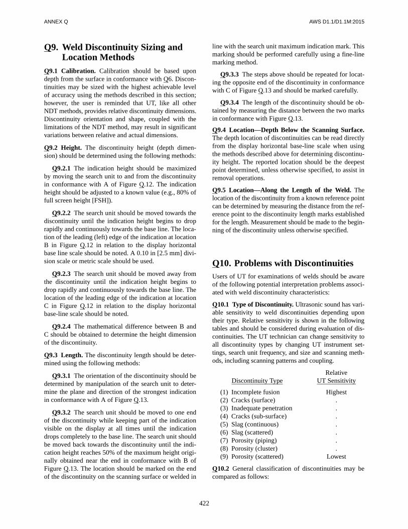
ANNEX Q AWS D1.1/D1.1M:2015
422
Q9. Weld Discontinuity Sizing and Location Methods
Q9.1 Calibration. Calibration should be based upondepth from the surface in conformance with Q6. Discon-tinuities may be sized with the highest achievable levelof accuracy using the methods described in this section;however, the user is reminded that UT, like all otherNDT methods, provides relative discontinuity dimensions.Discontinuity orientation and shape, coupled with thelimitations of the NDT method, may result in significantvariations between relative and actual dimensions.
Q9.2 Height. The discontinuity height (depth dimen-sion) should be determined using the following methods:
Q9.2.1 The indication height should be maximizedby moving the search unit to and from the discontinuityin conformance with A of Figure Q.12. The indicationheight should be adjusted to a known value (e.g., 80% offull screen height [FSH]).
Q9.2.2 The search unit should be moved towards thediscontinuity until the indication height begins to droprapidly and continuously towards the base line. The loca-tion of the leading (left) edge of the indication at locationB in Figure Q.12 in relation to the display horizontalbase line scale should be noted. A 0.10 in [2.5 mm] divi-sion scale or metric scale should be used.
Q9.2.3 The search unit should be moved away fromthe discontinuity until the indication height begins todrop rapidly and continuously towards the base line. Thelocation of the leading edge of the indication at locationC in Figure Q.12 in relation to the display horizontalbase-line scale should be noted.
Q9.2.4 The mathematical difference between B andC should be obtained to determine the height dimensionof the discontinuity.
Q9.3 Length. The discontinuity length should be deter-mined using the following methods:
Q9.3.1 The orientation of the discontinuity should bedetermined by manipulation of the search unit to deter-mine the plane and direction of the strongest indicationin conformance with A of Figure Q.13.
Q9.3.2 The search unit should be moved to one endof the discontinuity while keeping part of the indicationvisible on the display at all times until the indicationdrops completely to the base line. The search unit shouldbe moved back towards the discontinuity until the indi-cation height reaches 50% of the maximum height origi-nally obtained near the end in conformance with B ofFigure Q.13. The location should be marked on the endof the discontinuity on the scanning surface or welded in
line with the search unit maximum indication mark. Thismarking should be performed carefully using a fine-linemarking method.
Q9.3.3 The steps above should be repeated for locat-ing the opposite end of the discontinuity in conformancewith C of Figure Q.13 and should be marked carefully.
Q9.3.4 The length of the discontinuity should be ob-tained by measuring the distance between the two marksin conformance with Figure Q.13.
Q9.4 Location—Depth Below the Scanning Surface.The depth location of discontinuities can be read directlyfrom the display horizontal base-line scale when usingthe methods described above for determining discontinu-ity height. The reported location should be the deepestpoint determined, unless otherwise specified, to assist inremoval operations.
Q9.5 Location—Along the Length of the Weld. Thelocation of the discontinuity from a known reference pointcan be determined by measuring the distance from the ref-erence point to the discontinuity length marks establishedfor the length. Measurement should be made to the begin-ning of the discontinuity unless otherwise specified.
Q10. Problems with DiscontinuitiesUsers of UT for examinations of welds should be awareof the following potential interpretation problems associ-ated with weld discontinuity characteristics:
Q10.1 Type of Discontinuity. Ultrasonic sound has vari-able sensitivity to weld discontinuities depending upontheir type. Relative sensitivity is shown in the followingtables and should be considered during evaluation of dis-continuities. The UT technician can change sensitivity toall discontinuity types by changing UT instrument set-tings, search unit frequency, and size and scanning meth-ods, including scanning patterns and coupling.
RelativeDiscontinuity Type UT Sensitivity
(1) Incomplete fusion Highest(2) Cracks (surface) .(3) Inadequate penetration .(4) Cracks (sub-surface) .(5) Slag (continuous) .(6) Slag (scattered) .(7) Porosity (piping) .(8) Porosity (cluster) .(9) Porosity (scattered) Lowest
Q10.2 General classification of discontinuities may becompared as follows:
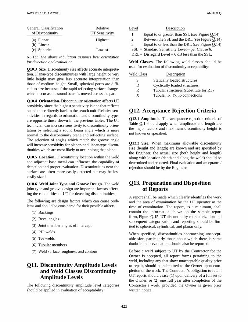
AWS D1.1/D1.1M:2015 ANNEX Q
423
General Classification Relative of Discontinuity UT Sensitivity
(a) Planar Highest(b) Linear .(c) Spherical Lowest
NOTE: The above tabulation assumes best orientationfor detection and evaluation.
Q10.3 Size. Discontinuity size affects accurate interpreta-tion. Planar-type discontinuities with large height or verylittle height may give less accurate interpretation thanthose of medium height. Small, spherical pores are diffi-cult to size because of the rapid reflecting surface changeswhich occur as the sound beam is moved across the part.
Q10.4 Orientation. Discontinuity orientation affects UTsensitivity since the highest sensitivity is one that reflectssound more directly back to the search unit. Relative sen-sitivities in regards to orientation and discontinuity typesare opposite those shown in the previous tables. The UTtechnician can increase sensitivity to discontinuity orien-tation by selecting a sound beam angle which is morenormal to the discontinuity plane and reflecting surface.The selection of angles which match the groove anglewill increase sensitivity for planar- and linear-type discon-tinuities which are most likely to occur along that plane.
Q10.5 Location. Discontinuity location within the weldand adjacent base metal can influence the capability ofdetection and proper evaluation. Discontinuities near thesurface are often more easily detected but may be lesseasily sized.
Q10.6 Weld Joint Type and Groove Design. The weldjoint type and groove design are important factors affect-ing the capabilities of UT for detecting discontinuities.
The following are design factors which can cause prob-lems and should be considered for their possible affects:
(1) Backings
(2) Bevel angles
(3) Joint member angles of intercept
(4) PJP welds
(5) Tee welds
(6) Tubular members
(7) Weld surface roughness and contour
Q11. Discontinuity Amplitude Levels and Weld Classes Discontinuity Amplitude Levels
The following discontinuity amplitude level categoriesshould be applied in evaluation of acceptability:
Level Description
1 Equal to or greater than SSL (see Figure Q.14)2 Between the SSL and the DRL (see Figure Q.14)3 Equal to or less than the DRL (see Figure Q.14)SSL = Standard Sensitivity Level—per Clause 6.DRL= Disregard Level = 6 dB less than the SSL.
Weld Classes. The following weld classes should beused for evaluation of discontinuity acceptability:
Weld Class Description
S Statically loaded structuresD Cyclically loaded structuresR Tubular structures (substitute for RT)X Tubular T-, Y-, K-connections
Q12. Acceptance-Rejection CriteriaQ12.1 Amplitude. The acceptance-rejection criteria ofTable Q.1 should apply when amplitude and length arethe major factors and maximum discontinuity height isnot known or specified.
Q12.2 Size. When maximum allowable discontinuitysize (height and length) are known and are specified bythe Engineer, the actual size (both height and length)along with location (depth and along the weld) should bedetermined and reported. Final evaluation and acceptance/rejection should be by the Engineer.
Q13. Preparation and Dispositionof Reports
A report shall be made which clearly identifies the workand the area of examination by the UT operator at thetime of examination. The report, as a minimum, shallcontain the information shown on the sample reportform, Figure Q.15. UT discontinuity characterization andsubsequent categorization and reporting should be lim-ited to spherical, cylindrical, and planar only.
When specified, discontinuities approaching unaccept-able size, particularly those about which there is somedoubt in their evaluation, should also be reported.
Before a weld subject to UT by the Contractor for theOwner is accepted, all report forms pertaining to theweld, including any that show unacceptable quality priorto repair, should be submitted to the Owner upon com-pletion of the work. The Contractor’s obligation to retainUT reports should cease (1) upon delivery of a full set tothe Owner, or (2) one full year after completion of theContractor’s work, provided the Owner is given priorwritten notice.

ANNEX Q AWS D1.1/D1.1M:2015
424
Table Q.1Acceptance-Rejection Criteria (see Q12.1)
Maximum Discontinuity Amplitude Level Obtained
Maximum Discontinuity Lengths by Weld Classes
Statically Loaded Cyclically Loaded Tubular Class R Tubular Class X
Level 1—Equal to or greaterthan SSL (see Q6.1 andFigure Q.14)
> 5 dB above SSL =none allowed
0 thru 5 dB aboveSSL = 3/4 in [20 mm]
> 5 dB above SSL =none allowed
0 thru 5 dB aboveSSL = 1/2 in [12 mm]
See Figure 9.29See Figure 9.30(Utilizes height)
Level 2—Between the SSLand the DRL (see Figure Q.14)
2 in [50 mm]
Middle 1/2 of weld =2 in [50 mm]
Top & bottom 1/4 of weld =3/4 in [20 mm]
See Figure 9.29See Figure 9.30(Utilizes height)
Level 3—Equal to or less than the DRL (see Figure Q.14)
Disregard (when specified by the Engineer, record for information)

AWS D1.1/D1.1M:2015 ANNEX Q
425
Notes:1. d1 = d2 ± 0.5 mm d3 = d4 ± 0.5 mm
SP1 = SP2 ± 1 mm SP3 = SP4 ± 1 mm2. The above tolerances should be considered as appropriate. The reflector should, in all cases, be placed in a manner to allow maximizing
the reflection and UT indication. (This is a general comment for all notes in Annex Q.)
Figure Q.1—Standard Reference Reflector (see Q5)
Note: Dimensions should be required to accommodate search units for the sound path distances required.
Figure Q.2—Recommended Calibration Block (see Q5)

ANNEX Q AWS D1.1/D1.1M:2015
426
Figure Q.3—Typical Standard Reflector (Located inWeld Mock-Ups and Production Welds) (see Q5)

AWS D1.1/D1.1M:2015 ANNEX Q
427
Procedure:1. Place two similar angle beam search units on the calibration block or mock-up to be used in the position shown above.2. Using through transmission methods, maximize the indication obtained and obtain a dB value of the indication.3. Transfer the same two search units to the part to be examined, orient in the same direction in which scanning will be performed, and
obtain a dB value of indications as explained above from the least three locations.4. The difference in dB between the calibration block or mock-up and the average of that obtained from the part to be examined should
be recorded and used to adjust the standard sensitivity.
Figure Q.4—Transfer Correction (see Q6.1)
Figure Q.5—Compression Wave Depth (Horizontal Sweep Calibration) (see Q6.2.1)

ANNEX Q AWS D1.1/D1.1M:2015
428
Figure Q.6—Compression Wave Sensitivity Calibration (see Q6.2.2)
Figure Q.7—Shear Wave Distance and Sensitivity Calibration (see Q6.3.1)
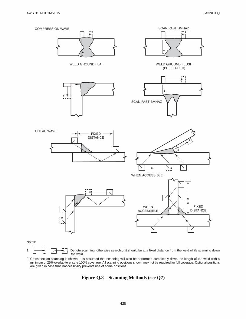
AWS D1.1/D1.1M:2015 ANNEX Q
429
Notes:
1. Denote scanning, otherwise search unit should be at a fixed distance from the weld while scanning downthe weld.
2. Cross section scanning is shown. It is assumed that scanning will also be performed completely down the length of the weld with aminimum of 25% overlap to ensure 100% coverage. All scanning positions shown may not be required for full coverage. Optional positionsare given in case that inaccessibility prevents use of some positions.
Figure Q.8—Scanning Methods (see Q7)
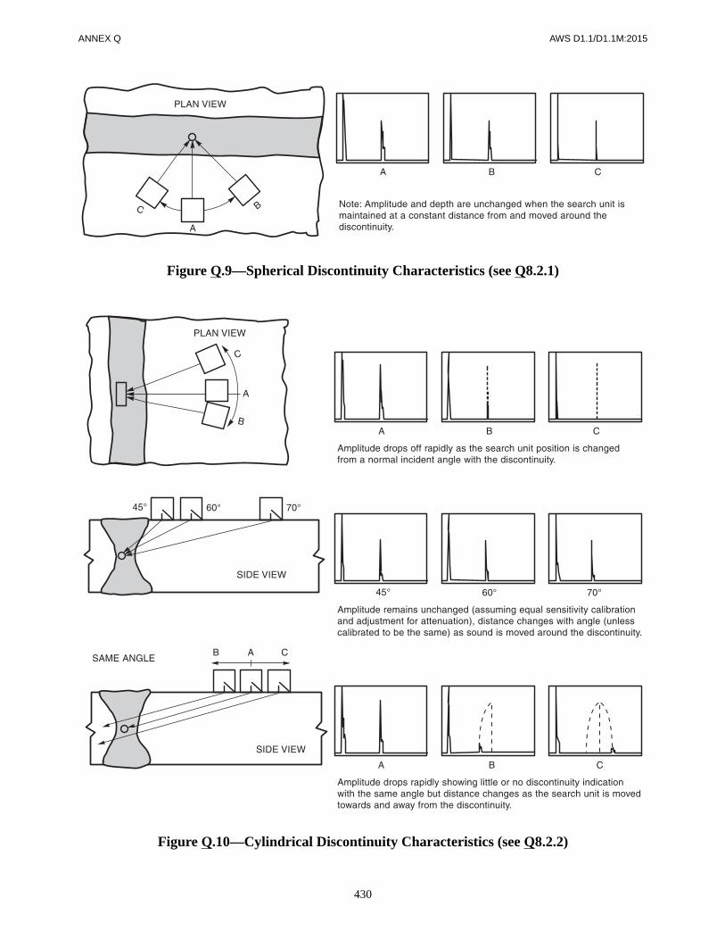
ANNEX Q AWS D1.1/D1.1M:2015
430
Figure Q.9—Spherical Discontinuity Characteristics (see Q8.2.1)
Figure Q.10—Cylindrical Discontinuity Characteristics (see Q8.2.2)

AWS D1.1/D1.1M:2015 ANNEX Q
431
Figure Q.11—Planar Discontinuity Characteristics (see Q8.2.3)
Figure Q.12—Discontinuity Height Dimension (see Q9.2)

ANNEX Q AWS D1.1/D1.1M:2015
432
Figure Q.13—Discontinuity Length Dimension (see Q9.3)
Note: The display screen may be marked to show SSL establishedduring sensitivity calibration with the DRL located 6 dB below.
Figure Q.14—Display Screen Marking (see Q11)

AWS D1.1/D1.1M:2015 ANNEX Q
433
Page __________ of _________
Project______________________________________________________________ Report No. _________________
Weld I.D. _______________________ Thickness ______________________ Class __________________________
UT Procedure No. ________________________________ Technique ______________________________________
UT Instrument ____________________________________________________________________________________
Search Unit: No. ____________ Angle ________________ Freq._________________ Size _________________
RESULT (identify and describe each discontinuity)
Sketch (identify each discontinuity listed above)
NDT Tech. ______________________________________ Contractor ______________________________________
Date Examined __________________________________ Approved _______________________________________
Date Approved___________________________________
Figure Q.15—Report of UT (Alternative Procedure) (see Q13)
No. Location fromAmpl.Level Length Height Comments

AWS D1.1/D1.1M:2015
434
This page is intentionally blank.

AWS D1.1/D1.1M:2015
435
Figure R.1 gives a formula and defines the terms used forcomposing a value of the chord ovalizing parameteralpha α when designing multiplanar tubular joints. Thevalues of alpha obtained are compatible with both staticstrength design (Table 9.6) and fatigue (Table 9.3, Note e)using the punching shear format.
Alpha is evaluated separately for each branch for whichpunching shear is checked (the “reference brace”), and foreach load case, with summation being carried out for allbraces present at the node, each time alpha is evaluated. Inthe summation, the cosine term expresses the influence ofbraces as a function of position around the circumference,and the exponential decay term expresses the lessening in-fluence of braces as distance L1 increases; these terms are
both unity for the reference brace which appears again inthe denominator. In complex space frames, the repetitivecalculation may be incorporated into a joint design post-processor to the design computer analysis.
For hand calculations, the designer might prefer the sim-pler forms of alpha given in Table 9.6. However, thesedo not cover multiplanar cases where higher values ofalpha may apply (e.g., 3.8 for a hubstyle cross joint withfour branches), and require a somewhat arbitrary classifi-cation of joint types. For joints whose load pattern fallsin between the standard cases (e.g., part of the load iscarried as in a K-joint and part as a T-joint) interpolatedvalues of alpha should be determined. Computed alphawould take care of this automatically.
Annex R (Informative)
Ovalizing Parameter Alpha
This annex is not part of AWS D1.1/D1.1M:2015, Structural Welding Code—Steel,but is included for informational purposes only.
Figure R.1—Definition of Terms for Computed Alpha

AWS D1.1/D1.1M:2015
436
This page is intentionally blank.

AWS D1.1/D1.1M:2015
437
1. AISC Load and Resistance Factor Design Specifi-cation for Structural Steel in Buildings
2. ANSI/AISC 360-10, Specification for StructuralBuildings
3. ANSI Z49.1, Safety in Welding, Cutting, and AlliedProcesses
4. API 2W, Specification for Steel Plates for OffshoreStructures, Produced by Thermo-Mechanical Con-trol Processing
5. API 2Y, Specification for Steel Plates, Quenched-and-Tempered, for Offshore Structures
6. ASME Boiler and Pressure Vessel Code, Section V,Article 2
7. ASME B46.1, Surface Texture (Surface Roughness,Waviness, and Lay)
8. American Society for Nondestructive Testing, Rec-ommended Practice No. SNT-TC-1A
9. ASTM A108, Specification for Steel Bars, Carbon,Cold-Finished, Standard Quality Grades
10. ASTM A370, Mechanical Testing of Steel Products
11. ASTM A435, Specification for Straight Beam Ultra-sonic Examination of Steel Plates
12. ASTM A6, Standard Specification for General Re-quirements for Rolled Structural Steel Bars, Plates,Shapes, and Sheet Piling
13. ASTM A673, Specification for Sampling Procedurefor Impact Testing of Structural Steel
14. ASTM E23, Standard Methods for Notched BarImpact Testing of Metallic Materials, for Type ACharpy (Simple Beam) Impact Specimen
15. ASTM E92, Test Method for Vickers Hardness ofMetallic Materials
16. ASTM E94, Standard Recommended Practice forRadiographic Testing
17. ASTM E140, Hardness Conversion Tables forMetals
18. ASTM E142, Standard Method for ControllingQuality of Radiographic Testing
19. ASTM E165, Test Method for Liquid PenetrantExamination
20. ASTM E709, Guide for Magnetic ParticleInspection
21. ASTM E747, Controlling Quality of RadiographicTesting Using Wired Penetrameters
22. ASTM E1032, Radiographic Examination ofWeldments
23. All ASTM base metals listed in Table 3.1 and Table4.9 are found in ASTM 01.04, Steel—Structural, Re-inforcing, Pressure Vessel Railway, ASTM 01.03,Steel-Plate, Sheet, Strip, Wire; Stainless Steel Bar,and ASTM 01.01, Steel-Piping, Tubing, Fittings
24. AWS A2.4:2007, Standard Symbols for Welding,Brazing, and Nondestructive Examination
25. AWS A3.0, Standard Welding Terms and Definitions,Including Terms for Adhesive Bonding, Brazing,Soldering, Thermal Cutting, and Thermal Spraying
Annex S (Informative)
List of Reference Documents
This annex is not part of AWS D1.1/D1.1M:2015, Structural Welding Code—Steel,but is included for informational purposes only.

ANNEX S AWS D1.1/D1.1M:2015
438
26. AWS A5.01M/A5.01:2013 (ISO 14344:2010 MOD),Procurement Guidelines for Consumables—Weldingand Allied Processes—Flux and Gas Shielded Elec-trical Welding Processes
27. AWS A5.1/A5.1M:2012, Specification for CarbonSteel Electrodes for Shielded Metal Arc Welding
28. AWS A5.5/A5.5M:2014, Specification for Low-Alloy Steel Electrodes for Shielded Metal Arc Welding
29. AWS A5.12M/A5.12:2009 (ISO 6848:2004 MOD),Specification for Tungsten and Oxide DispersedTungsten Electrodes for Arc Welding and Cutting
30. AWS A5.17/A5.17M-97 (R2007), Specification forCarbon Steel Electrodes and Fluxes for SubmergedArc Welding
31. AWS A5.18/A5.18M:2005, Specification for Car-bon Steel Electrodes and Rods for Gas Shielded ArcWelding
32. AWS A5.20/A5.20M:2005, Specification for Car-bon Steel Electrodes for Flux Cored Arc Welding
33. AWS A5.23/A5.23M:2011, Specification for Low-Alloy Steel Electrodes and Fluxes for SubmergedArc Welding
34. AWS A5.25/A5.25M-97 (R2009), Specification forCarbon and Low-Alloy Steel Electrodes and Fluxesfor Electroslag Welding
35. AWS A5.26/A5.26M-97 (R2009), Specification forCarbon and Low-Alloy Steel Electrodes for Electro-gas Welding
36. AWS A5.28/A5.28M:2005, Specification for Low-Alloy Steel Filler Metals for Gas Shielded ArcWelding
37. AWS A5.29/A5.29M:2010, Specification for Low-Alloy Steel Electrodes for Flux Cored Arc Welding
38. AWS A5.30/A5.30M:2007, Specification for Con-sumables Inserts
39. AWS A5.32M/A5.32:2011 (ISO 14175:2008 MOD),Welding Consumables—Gases and Gas Mixturesfor Fusion Welding and Allied Processes
40. AWS A5.36/A5.36M:2012, Specification for Car-bon and Low-Alloy Steel Flux Cored Electrodes forFlux Cored Arc Welding and Metal Cored Elec-trodes for Gas Metal Arc Welding
41. AWS B1.10M/B1.10:2009, Guide for Nondestruc-tive Examination of Welds
42. AWS C4.1-77 (R2010), Criteria for DescribingOxygen-Cut Surfaces and Oxygen Cutting SurfaceRoughness Gauge
43. AWS C5.4-93, Recommended Practices for StudWelding
44. AWS D1.0, Code for Welding in BuildingConstruction
45. AWS D1.3/D1.3M:2008, Structural Welding Code—Sheet Steel
46. AWS D1.6/D1.6M:2007, Structural Welding Code—Stainless Steel
47. AWS D2.0, Specification for Welded Highway andRailway Bridges
48. AWS QC1:2007, Standard for AWS Certification ofWelding Inspectors
49. AWS Welding Handbook, Volume 1, 9th Edition,Chapter 13
50. Canadian Standard Association (CSA) StandardW178.2, Certification of Welding Inspectors
51. The International Institute of Welding (IIW) Ultra-sonic Reference Block

AWS D1.1/D1.1M:2015
439
AWS A5.1/A5.1M, Specification for Carbon Steel Electrodesfor Shielded Metal Arc Weldinga, b
AWS Classification Tensile Strength Yield Strength at 0.2% Offset ElongationPercentage in 4xDiameter LengthA5.1 A5.1M A5.1 (ksi) A5.1M (MPa) A5.1 (ksi) A5.1M (MPa)
E6010E6011E6012E6013E6018E6019E6020E6022E6027
E4310E4311E4312E4313E4318E4319E4320E4322E4327
606060606060606060
430430430430430430430430430
48484848484848
Not Sp48
330330330330330330330
ecified330
22221717222222
Not Specified22
E7014E7015E7016E7018E7024E7027E7028E7048E7018M
E4914E4915E4916E4918E4924E4927E4928E4948E4918M
7070707070707070
Note d
490490490490490490490490
Note d
5858585858585858
53–72e
400400400400400400400400
370–500e
17222222
c17c
22222224
a Requirements are in the as-welded condition with aging.b Single values are minimum.c Weld metal from electrodes identified as E7024-1 [E4924-1] shall have elongation of 22% minimum.d Tensile strength of this weld metal is a nominal 70 ksi [490 MPa].e For 3/32 in [2.4 mm] electrodes, the maximum yield strength is 77 ksi [530 MPa].
Annex T (Informative)
Filler Metal Strength Properties
This annex is not part of AWS D1.1/D1.1M:2015, Structural Welding Code—Steel,but is included for informational purposes only.
The data contained in this annex are copied from the appropriate A5 specification. Values shown are for referencepurposes only and other process variables may have to be controlled in order to achieve the Nominal Tensile Strengthand Nominal Yield Strength. (See the applicable AWS A5 Filler Metal Specification for a more specific description.)
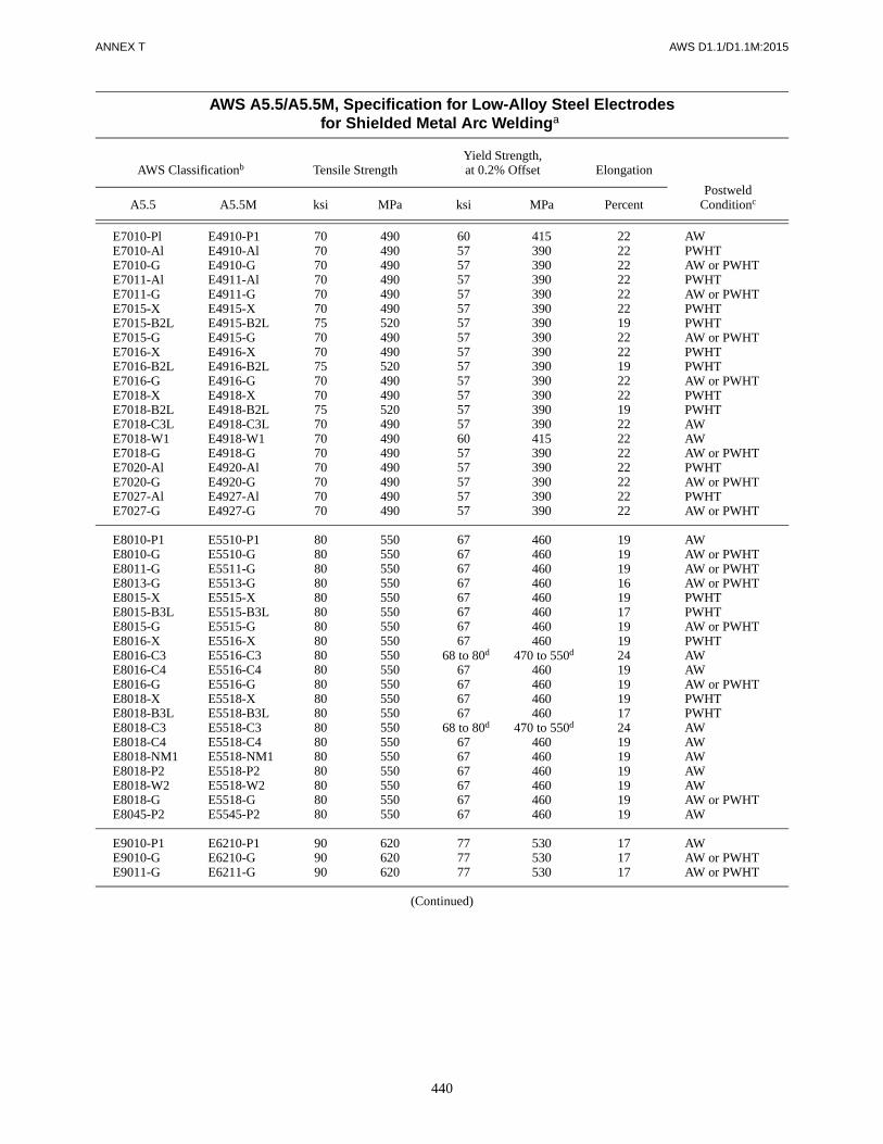
ANNEX T AWS D1.1/D1.1M:2015
440
AWS A5.5/A5.5M, Specification for Low-Alloy Steel Electrodesfor Shielded Metal Arc Weldinga
AWS Classificationb Tensile StrengthYield Strength,at 0.2% Offset Elongation
PostweldConditioncA5.5 A5.5M ksi MPa ksi MPa Percent
E7010-PlE7010-AlE7010-GE7011-AlE7011-GE7015-XE7015-B2LE7015-GE7016-XE7016-B2LE7016-GE7018-XE7018-B2LE7018-C3LE7018-W1E7018-GE7020-AlE7020-GE7027-AlE7027-G
E4910-P1E4910-AlE4910-GE4911-AlE4911-GE4915-XE4915-B2LE4915-GE4916-XE4916-B2LE4916-GE4918-XE4918-B2LE4918-C3LE4918-W1E4918-GE4920-AlE4920-GE4927-AlE4927-G
7070707070707570707570707570707070707070
490490490490490490520490490520490490520490490490490490490490
6057575757575757575757575757605757575757
415390390390390390390390390390390390390390415390390390390390
2222222222221922221922221922222222222222
AWPWHTAW or PWHTPWHTAW or PWHTPWHTPWHTAW or PWHTPWHTPWHTAW or PWHTPWHTPWHTAWAWAW or PWHTPWHTAW or PWHTPWHTAW or PWHT
E8010-P1E8010-GE8011-GE8013-GE8015-XE8015-B3LE8015-GE8016-XE8016-C3E8016-C4E8016-GE8018-XE8018-B3LE8018-C3E8018-C4E8018-NM1E8018-P2E8018-W2E8018-GE8045-P2
E5510-P1E5510-GE5511-GE5513-GE5515-XE5515-B3LE5515-GE5516-XE5516-C3E5516-C4E5516-GE5518-XE5518-B3LE5518-C3E5518-C4E5518-NM1E5518-P2E5518-W2E5518-GE5545-P2
8080808080808080808080808080808080808080
550550550550550550550550550550550550550550550550550550550550
6767676767676767
d68 to 80d
67676767
d68 to 80d
676767676767
460460460460460460460460
d470 to 550d
460460460460
d470 to 550d
460460460460460460
1919191619171919241919191724191919191919
AWAW or PWHTAW or PWHTAW or PWHTPWHTPWHTAW or PWHTPWHTAWAWAW or PWHTPWHTPWHTAWAWAWAWAWAW or PWHTAW
E9010-P1E9010-GE9011-G
E6210-P1E6210-GE6211-G
909090
620620620
777777
530530530
171717
AWAW or PWHTAW or PWHT
(Continued)

AWS D1.1/D1.1M:2015 ANNEX T
441
E9013-GE9015-XE9015-GE9016-XE9016-GE9018ME9018-P2E9018-XE9018-GE9045-P2
E6213-GE6215-XE6215-GE6216-XE6216-GE6218ME6218-P2E6218-XE6218-GE6245-P2
90909090909090909090
620620620620620620620620620620
7777777777
d78 to 90d
77777777
530530530530530
d540 to 620d
530530530530
14171717172417171717
AW or PWHTPWHT
AW or PWHTPWHT
AW or PWHTAWAW
PWHTAW or PWHT
AW
E10010-GE10011-GE10013-GE10015-XE10015-GE10016-XE10016-GE10018ME10018-XE10018-GE10045-P2
E6910-GE6911-GE6913-GE6915-XE6915-GE6916-XE6916-GE6918ME6918-XE6918-GE6945-P2
100100100100100100100100100100100
690690690690690690690690690690690
87878787878787
d 88 to 100d
878787
600600600600600600600
d610 to 690d
600600600
1616131616161620161616
AW or PWHTAW or PWHTAW or PWHT
PWHTAW or PWHT
PWHTAW or PWHT
AWPWHT
AW or PWHTAW
E11010-GE11011-GE11013-GE11015-GE11016-GE11018-GE11018M
E7610-GE7611-GE7613-GE7615-GE7616-GE7618-GE7618M
110110110110110110110
760760760760760760760
979797979797
d 98 to 110d
670670670670670670
d680 to 760d
15151315151520
AW or PWHTAW or PWHTAW or PWHTAW or PWHTAW or PWHTAW or PWHT
AW
E12010-GE12011-GE12013-GE12015-GE12016-GE12018-GE12018ME12018M1
E8310-GE8311-GE8313-GE8315-GE8316-GE8318-GE8318ME8318M1
120120120120120120120120
830830830830830830830830
107107107107107107
d108 to 120d
d108 to 120d
740740740740740740
d745 to 830d
d745 to 830d
1414111414141818
AW or PWHTAW or PWHTAW or PWHTAW or PWHTAW or PWHTAW or PWHT
AWAW
a Single values are minimum, except as otherwise specified.b The letter suffix “X” as used in this table represents the suffixes (A1, B1, B2, etc.) which are tested in the PWHT condition only.c “AW” signifies as-welded, which may or may not be aged, at the manufacturer’s option. “PWHT” signifies postweld heat treated.d For 3/32 in [2.5 mm] electrodes, the upper value for the yield strength may be 5 ksi [35 MPa] higher than the indicated value.
AWS A5.5/A5.5M, Specification for Low-Alloy Steel Electrodesfor Shielded Metal Arc Weldinga (Continued)
AWS Classificationb Tensile StrengthYield Strength,at 0.2% Offset Elongation
PostweldConditioncA5.5 A5.5M ksi MPa ksi MPa Percent

ANNEX T AWS D1.1/D1.1M:2015
442
AWS A5.17/A5.17M, Specification for Carbon Steel Electrodesand Fluxes for Submerged Arc Welding
Flux-Electrode Classificationa
Tensile Strengthpsi [MPa]
Yield Strengthb
psi [MPa]Elongationb
%A5.17 A5.17M
F6XX-EXXXF7XX-EXXX
F43XX-EXXXF48XX-EXXX
60 000–80 000 [430–560]70 000–95 000 [480–660]
48 000 [330]58 000 [400]
2222
a The letter “S” will appear after the “F” as part of the classification designation when the flux being classified is a crushed slag or a blend of crushedslag with unused (virgin) flux. The letter “C” will appear after the “E” as part of the classification designation when the electrode being classified isa composite electrode. The letter “X” used in various places in this table stands for, respectively, the condition of heat treatment, the toughness of theweld metal, and the classification of the electrode.
b Minimum requirements. Yield strength at 0.2% offset and elongation in 2 in [51 mm] gage length.
AWS A5.18/A5.18M, Specification for Carbon Steel Electrodesand Rods for Gas Shielded Arc Welding
aAWS Classificationa
Shielding Gas
Tensile Strength(minimum)
bYield Strengthb
(minimum)bElongationb
% (minimum)A5.18 A5.18M psi MPa psi MPa
ER70S-2ER70S-3ER70S-4ER70S-6ER70S-7
ER48S-2ER48S-3ER48S-4ER48S-6ER48S-7
CO2c 70 000 480 58 000 400 22
ER70S-G ER48S-G d 70 000 480 58 000 400 22
E70C-3XE70C-6X
E48C-3XE48C-6X
75–80% Ar/balance CO2or CO2
70 000 480 58 000 400 22
E70C-G(X) E48C-G(X) d 70 000 480 58 000 400 22
E70C-GS(X) E48C-GS(X) d 70 000 480 Not Specified Not Specified
a The final X shown in the classification represents a “C” or “M” which corresponds to the shielding gas with which the electrode is classified. The useof “C” designates 100% CO2 shielding (AWS A5.32 Class SG-C); “M” designates 75–80% Ar/balance CO2 (AWS A5.32 Class SG-AC-Y, where Yis 20 to 25). For E70C-G [E48C-G] and E70C-GS [E48C-GS], the final “C” or “M” may be omitted.
b Yield strength at 0.2% offset and elongation in 2 in [50 mm] gage length.c CO2 = carbon dioxide shielding gas (AWS A5.32 Class SG-C). The use of CO2 for classification purposes is not to be construed to preclude the use
of Ar/CO2 (AWS A5.32 Class SG-AC-Y) or Ar/O2 (AWS A5.32 Class SG-AO-X) shielding gas mixtures. A filler metal tested with gas blends, suchas Ar/O2, or Ar/CO2, may result in weld metal having higher strength and lower elongation.
d Shielding gas is as agreed between purchaser and supplier, unless designated by the “C” or “M” suffix.

AWS D1.1/D1.1M:2015 ANNEX T
443
AWS A5.20/A5.20M, Specification for Carbon Steel Electrodesfor Flux Cored Arc Welding
AWS ClassificationTensile Strength
ksi [MPa]
Minimum YieldStrengtha
ksi [MPa]Minimum %Elongationb
Minimum CharpyV-Notch Impact EnergyA5.20 A5.20M
E7XT-1C, -1ME7XT-2Cc, -2Mc
E7XT-3c
E7XT-4E7XT-5C, -5ME7XT-6E7XT-7E7XT-8E7XT-9C, -9ME7XT-10c
E7XT-11E7XT-12C, -12ME6XT-13c
E7XT-13c
E7XT-14c
E6XT-GE7XT-GE6XT-GSc
E7XT-GSc
E49XT-1C, -1ME49XT-2Cc, -2Mc
E49XT-3c
E49XT-4E49XT-5C, -5ME49XT-6E49XT-7E49XT-8E49XT-9C, -9ME49XT-10c
E49XT-11E49XT-12C, -12ME43XT-13c
E49XT-13c
E49XT-14c
E43XT-GE49XT-GE43XT-GSc
E49XT-GSc
70–95 [490–670]70 [490] min.70 [490] min.
70–95 [490–670}70–95 [490–670}70–95 [490–670}70–95 [490–670}70–95 [490–670}70–95 [490–670}
70 [490] min.70–95 [490–670]70–90 [490–620]
60 [430] min.70 [490] min.70 [490] min.
60–80 [430–600]70–95 [490–670]
60 [430] min.70 [490] min.
58 [390]Not SpecifiedNot Specified
58 [390]58 [390]58 [390]58 [390]58 [390]58 [390]
Not Specified58 [390]58 [390]
Not SpecifiedNot SpecifiedNot Specified
48 [330]58 [390]
Not SpecifiedNot Specified
22Not SpecifiedNot Specified
222222222222
No Specifiedd20d
22Not SpecifiedNot SpecifiedNot Specified
2222
Not SpecifiedNot Specified
20 ft·lbf @ 0°F [27 J @ –20°C]Not SpecifiedNot SpecifiedNot Specified
20 ft·lbf @ –20°F [27 J @ –30°C]20 ft·lbf @ –20°F [27 J @ –30°C]
Not Specified20 ft·lbf @ –20°F [27 J @ –30°C]20 ft·lbf @ –20°F [27 J @ –30°C]
Not SpecifiedNot Specified
20 ft·lbf @ –20°F [27 J @ –30°C]Not SpecifiedNot SpecifiedNot SpecifiedNot SpecifiedNot SpecifiedNot SpecifiedNot Specified
a Yield strength at 0.2% offset.b In 2 in [50 mm] gage length when a 0.500 in [12.5 mm] nominal diameter tensile specimen and nominal gage length to diameter ratio of 4:1 is used.c These classifications are intended for single pass welding. They are not for multiple pass welding. Only tensile strength is specified.d In 1 in [25 mm] gage length when a 0.250 in [6.5 mm] nominal diameter tensile specimen is used as permitted for 0.045 in [1.2 mm] and smaller sizes of
the E7XT-11[E49XT-11] classification.

ANNEX T AWS D1.1/D1.1M:2015
444
AWS A5.23/A5.23M, Specification for Low-Alloy SteelElectrodes and Fluxes for Submerged Arc Welding
Flux-Electrode Classificationa
Tensile Strengthb
psi [MPa]
Yield Strengthb
(0.2% Offset)psi [MPa]
Elongationb
(%)A5.23 A5.23M
Multiple Pass Classifications
F7XX-EXX-XX0F8XX-EXX-XX0F9XX-EXX-XX0F10XX-EXX-XXF11XX-EXX-XXF12XX-EXX-XXF13XX-EXX-XX
F49XX-EXX-XXF55XX-EXX-XXF62XX-EXX-XXF69XX-EXX-XXF76XX-EXX-XXF83XX-EXX-XXF90XX-EXX-XX
70 000–95 000 [490–660]80 000–100 000 [550–700]90 000–110 000 [620–760]
100 000–120 000 [690–830]110 000–130 000 [760–900]120 000–140 000 [830–970]130 000–150 000 [900–1040]
58 000 [400]68 000 [470]78 000 [540]88 000 [610]98 000 [680]
108 000 [740]118 000 [810]
22201716
c15c
c14c
c14c
Two-Run Classifications
F6TXX-EXX0F7TXX-EXX0F8TXX-EXX0F9TXX-EXX0F10TXX-EXXF11TXX-EXXF12TXX-EXXF13TXX-EXX
F43TXX-EXXF49TXX-EXXF55TXX-EXXF62TXX-EXXF69TXX-EXXF76TXX-EXXF83TXX-EXXF90TXX-EXX
60 000 [430]70 000 [490]80 000 [550]90 000 [620]
100 000 [690]110 000 [760]120 000 [830]130 000 [900]
50 000 [350]60 000 [415]70 000 [490]80 000 [555]90 000 [625]
100 000 [690]110 000 [760]120 000 [830]
2222201716151414
a The letter “S” will appear after the “F” as part of the classification designation when the flux being classified is a crushed slag or a blend of crushedslag with unused (virgin) flux. The letter “C” will appear after the “E” as part of the classification designation when the electrode used is a compositeelectrode. For two-run classifications, the letter “G” will appear after the impact designator (immediately before the hyphen) to indicate that thebase steel used for classification is not one of the base steels prescribed in AWS A5.23/A5.23M but is a different steel, as agreed between purchaserand supplier. The letter “X” used in various places in this table stands for, respectively, the condition of heat treatment, the toughness of the weldmetal, and the classification of the weld metal.
b For multiple pass classifications, the requirements listed in the table for yield strength and % elongation (in 2 in [50 mm] gage length) are minimumrequirements. For two-run classifications, the requirements listed for tensile strength, yield strength and % elongation (in 1 in [25 mm] gage length)are all minimum requirements.
c Elongation may be reduced by one percentage point for F11XX-EXX-XX, F11XX-ECXX-XX, F12XX-EXX-XX, F12XX-ECXX-XX, F13XX-EXX-XX,and F13XX-ECXX-XX [F76-EXX-XX, F76-ECXX-XX, F83XX-EXX-XX, F83XX-ECXX-XX, F90XX-EXX-XX, and F90XX-ECXX-XX] weld metalsin the upper 25% of their tensile strength range.

AWS D1.1/D1.1M:2015 ANNEX T
445
AWS A5.28/A5.28M, Specification for Low-Alloy SteelElectrodes and Rods for Gas Shielded Arc Welding
AWS Classification
Shielding Gasa
Tensile Strength (minimum)
Yield Strengthb
(minimum) Elongationb Percent
(minimum)Testing
ConditionA5.28 A5.28M psi MPa psi MPa
ER70S-B2LE70C-B2LER70S-A1
ER49S-B2LE49C-B2LER49S-A1
Argon/1–5% O2
(Classes SG-AO-1 thru SG-AO-5)
75 000 515 58 000 400 19
PWHT
ER80S-B2E80C-B2
ER55S-B2E55C-B2
80 000 550 68 000 470 19
ER80S-B3LE80C-B3L
ER55S-B3LE55C-B3L
80 000 550 68 000 470 17
ER90S-B3E90C-B3
ER62S-B3E62C-B3
90 000 620 78 000 540 17
ER80S-B6 ER55S-B6 80 000 550 68 000 470 17
E80C-B6 E55C-B6 80 000 550 68 000 470 17
ER80S-B8 ER55S-B8 80 000 550 68 000 470 17
E80C-B8 E55C-B8 80 000 550 68 000 470 17
ER90S-B9 ER62S-B9Argon/5% O2
(Class SG-AC-5)
90 000 620 60 000 410 16
E90C-B9 E62C-B9Argon/5–25% CO2 (Classes SG-AC-5 thru SG-AC-25)
E70C-Ni2 E49C-Ni2
Argon/1–5% O2 (Classes SG-AO-1
thru SG-AO-5)
70 000 490 58 000 400 24 PWHT
ER80S-Ni1E80C-Ni1
ER55S-Ni1E55C-Ni1
80 000 550 68 000 470 24 As-Welded
ER80S-Ni2E80C-Ni2ER80S-Ni3E80C-Ni3
ER55S-Ni2E55C-Ni2ER55S-Ni3E55C-Ni3
80 000 550 68 000 470 24 PWHT
ER80S-D2 ER55S-D2 CO2 (Class SG-C) 80 000 550 68 000 470 17
As-Welded
ER90S-D2E90C-D2
ER62S-D2E62C-D2
Argon/1–5% O2 (Classes SG-AO-1
thru SG-AO-5)90 000 620 78 000 540 17
ER100S-1 ER69S-1Argon/2% O2
(Class SG-AO-2)
100 000 690 88 000 610 16
ER110S-1 ER76S-1 110 000 760 95 000 660 15
ER120S-1 ER83S-1 120 000 830 105 000 730 14
E90C-K3 E62C-K3
Argon/5–25% CO2 (Classes SG-AC-5 thru SG-AC-25)
90 000 620 78 000 540 18
E100C-K3 E69C-K3 100 000 690 88 000 610 16
E110C-K3E110C-K4
E76C-K3E76C-K4
110,000 760 98 000 680 15
E120C-K4 E83C-K4 120 000 830 108 000 750 15
E80C-W2 E55C-W2 80 000 550 68 000 470 22
(Continued)
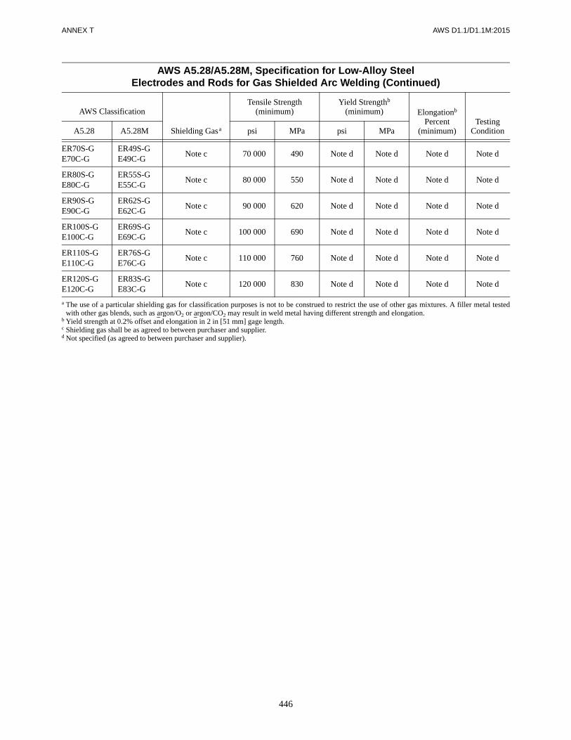
ANNEX T AWS D1.1/D1.1M:2015
446
ER70S-GE70C-G
ER49S-GE49C-G
Note c 70 000 490 Note d Note d Note d Note d
ER80S-GE80C-G
ER55S-GE55C-G
Note c 80 000 550 Note d Note d Note d Note d
ER90S-GE90C-G
ER62S-GE62C-G
Note c 90 000 620 Note d Note d Note d Note d
ER100S-GE100C-G
ER69S-GE69C-G
Note c 100 000 690 Note d Note d Note d Note d
ER110S-GE110C-G
ER76S-GE76C-G
Note c 110 000 760 Note d Note d Note d Note d
ER120S-GE120C-G
ER83S-GE83C-G
Note c 120 000 830 Note d Note d Note d Note d
a The use of a particular shielding gas for classification purposes is not to be construed to restrict the use of other gas mixtures. A filler metal testedwith other gas blends, such as argon/O2 or argon/CO2 may result in weld metal having different strength and elongation.
b Yield strength at 0.2% offset and elongation in 2 in [51 mm] gage length.c Shielding gas shall be as agreed to between purchaser and supplier.d Not specified (as agreed to between purchaser and supplier).
AWS A5.28/A5.28M, Specification for Low-Alloy SteelElectrodes and Rods for Gas Shielded Arc Welding (Continued)
AWS Classification
Shielding Gasa
Tensile Strength (minimum)
Yield Strengthb
(minimum) Elongationb Percent
(minimum)Testing
ConditionA5.28 A5.28M psi MPa psi MPa

AW
S D
1.1/D1.1M
:2015A
NN
EX
T
447
AWS A5.29/A5.29M, Specification for Low-Alloy Steel Electrodes for Flux Cored Arc Welding
AWS Classificationa, b
Conditionc
TensileStrength
ksi [MPa]
YieldStrength
ksi [MPa]
%Elongation Minimum
Charpy V-NotchImpact Energy MinimumA5.29 A5.29M
E7XT5-A1C, -A1M E49XT5-A1C, -A1M PWHT 70–90 [490–620] 58 [400] min. 20 20 ft·lbf @ –20°F [27 J @ –30°C]
E8XT1-A1C, -A1M E55XT1-A1C, -A1M PWHT 80–100 [550–690] 68 [470] min. 19 Not Specified
E8XT1-B1C, -B1M, -B1LC, -B1LM E55XT1-B1C, -B1M, -B1LC, -B1LM PWHT 80–100 [550–690] 68 [470] min. 19 Not Specified
E8XT1-B2C, -B2M, -B2HC, -B2HM,-B2LC, -B2LM
E8XT5-B2C, -B2M, -B2LC, -B2LM
E55XT1-B2C, -B2M, -B2HC, -B2HM,-B2LC, -B2LM
E55XT5-B2C, -B2M, -B2LC, -B2LMPWHT 80–100 [550–690] 68 [470] min. 19 Not Specified
E9XT1-B3C, -B3M, -B3LC, -B3LM,-B3HC, -B3HM
E9XT5-B3C, -B3M
E62XT1-B3C, -B3M, -B3LC, -B3LM,-B3HC, -B3HM
E62XT5-B3C, -B3MPWHT 90–110 [620–760] 78 [540] min. 17 Not Specified
E10XT1-B3C, -B3M E69XT1-B3C, -B3M PWHT 100–120 [690–830] 88 [610] min. 16 Not Specified
E8XT1-B6C,d -B6M,d -B6LC,d -B6LM,d
E8XT5-B6C,d -B6M,d -B6LC,d -B6LMdE55XT1-B6C, -B6M, -B6LC, -B6LME55XT5-B6C, -B6M, -B6LC, -B6LM PWHT 80–100 [550–690] 68 [470] min. 19 Not Specified
E8XT1-B8C,d -B8M,d -B8LC,d -B8LMd
E8XT5-B8C,d -B8M,d -B8LC,d -B8LMdE55XT1-B8C, -B8M, -B8LC, -B8LME55XT5-B8C, -B8M, -B8LC, -B8LM
PWHT 80–100 [550–690] 68 [470] min. 19 Not Specified
E9XT1-B9C, -B9M E62XT1-B9C, -B9M PWHT 90–120 [620–830] 78 [540] min. 16 Not Specified
E6XT1-Ni1C, -Ni1M E43XT1-Ni1C, -Ni1M AW 60–80 [430–550] 50 [340] min. 22 20 ft·lbf @ –20°F [27 J @ –30°C]
E7XT6-Ni1 E49XT6-Ni1 AW 70–90 [490–620] 58 [400] min. 20 20 ft·lbf @ –20°F [27 J @ –30°C]
E7XT8-Ni1 E49XT8-Ni1 AW 70–90 [490–620] 58 [400] min. 20 20 ft·lbf @ –20°F [27 J @ –30°C]
E8XT1-Ni1C, -Ni1M E55XT1-Ni1C, -Ni1M AW 80–100 [550–690] 68 [470] min. 19 20 ft·lbf @ –20°F [27 J @ –30°C]
E8XT5-Ni1C, -Ni1M E55XT5-Ni1C, -Ni1M PWHT 80–100 [550–690] 68 [470] min. 19 20 ft·lbf @ –60°F [27 J @ –50°C]
E7XT8-Ni2 E49XT8-Ni2 AW 70–90 [490–620] 58 [400] min. 20 20 ft·lbf @ –20°F [27 J @ –30°C]
E8XT8-Ni2 E55XT8-Ni2 AW 80–100 [550–690] 68 [470] min. 19 20 ft·lbf @ –20°F [27 J @ –30°C]
E8XT1-Ni2C, -Ni2M E55XT1-Ni2C, -Ni2M AW 80–100 [550–690] 68 [470] min. 19 20 ft·lbf @ –40°F [27 J @ –40°C]
E8XT5-Ni2C,e -Ni2Me E55XT5-Ni2C,e -Ni2Me PWHT 80–100 [550–690] 68 [470] min. 19 20 ft·lbf @ –75°F [27 J @ –60°C]
E9XT1-Ni2C, -Ni2M E62XT1-Ni2C, -Ni2M AW 90–110 [620–760] 78 [540] min. 17 20 ft·lbf @ –40°F [27 J @ –40°C]
E8XT5-Ni3C,e -Ni3Me E55XT5-Ni3C,e -Ni3Me PWHT 80–100 [550–690] 68 [470] min. 19 20 ft·lbf @ –100°F [27 J @ –70°C]
E9XT5-Ni3C,e -Ni3Me E62XT5-Ni3C,e -Ni3Me PWHT 90–110 [620–760] 78 [540] min. 17 20 ft·lbf @ –100°F [27 J @ –70°C]
(Continued)

AN
NE
X T
AW
S D
1.1/D1.1M
:2015
448
E8XT11-Ni3 E55XT11-Ni3 AW 80–100 [550–690] 68 [470] min. 19 20 ft·lbf @ 0°F [27 J @ –20°C]
E9XT1-D1C, -D1M E62XT1-D1C, -D1M AW 90–110 [620–760] 78 [540] min. 17 20 ft·lbf @ –40°F [27 J @ –40°C]
E9XT5-D2C, -D2M E62XT5-D2C, -D2M PWHT 90–110 [620–760] 78 [540] min. 17 20 ft·lbf @ –60°F [27 J @ –50°C]
E10XT5-D2C, -D2M E69XT5-D2C, -D2M PWHT 100–120 [690–830] 88 [610] min. 16 20 ft·lbf @ –40°F [27 J @ –40°C]
E9XT1-D3C, -D3M E62XT1-D3C, -D3M AW 90–110 [620–760] 78 [540] min. 17 20 ft·lbf @ –20°F [27 J @ –30°C]
E8XT5-K1C, -K1M E55XT5-K1C, -K1M AW 80–100 [550–690] 68 [470] min. 19 20 ft·lbf @ –40°F [27 J @ –40°C]
E7XT7-K2 E49XT7-K2 AW 70–90 [490–620] 58 [400] min. 20 20 ft·lbf @ –20°F [27 J @ –30°C]
E7XT4-K2 E49XT4-K2 AW 70–90 [490–620] 58 [400] min. 20 20 ft·lbf @ 0°F [27 J @ –20°C]
E7XT8-K2 E49XT8-K2 AW 70–90 [490–620] 58 [400] min. 20 20 ft·lbf @ –20°F [27 J @ –30°C]
E7XT11-K2 E49XT11-K2 AW 70–90 [490–620] 58 [400] min. 20 20 ft·lbf @ +32°F [27 J @ 0°C]
E8XT1-K2C, -K2ME8XT5-K2C, -K2M
E55XT1-K2C, -K2ME55XT5-K2C, -K2M AW 80–100 [550–690] 68 [470] min. 19 20 ft·lbf @ –20°F [27 J @ –30°C]
E9XT1-K2C, -K2M E62XT1-K2C, -K2M AW 90–110 [620–760] 78 [540] min. 17 20 ft·lbf @ 0°F [27 J @ –20°C]
E9XT5-K2C, -K2M E62XT5-K2C, -K2M AW 90–110 [620–760] 78 [540] min. 17 20 ft·lbf @ –60°F [27 J @ –50°C]
E10XT1-K3C, -K3M E69XT1-K3C, -K3M AW 100–120 [690–830] 88 [610] min. 16 20 ft·lbf @ 0°F [27 J @ –20°C]
E10XT5-K3C, -K3M E69XT5-K3C, -K3M AW 100–120 [690–830] 88 [610] min. 16 20 ft·lbf @ –60°F [27 J @ –50°C]
E11XT1-K3C, -K3M E76XT1-K3C, -K3M AW 110–130 [760–900] 98 [680] min. 15 20 ft·lbf @ 0°F [27 J @ –20°C]
E11XT5-K3C, -K3M E76XT5-K3C, -K3M AW 110–130 [760–900] 98 [680] min. 15 20 ft·lbf @ –60°F [27 J @ –50°C]
E11XT1-K4C, -K4M E76XT1-K4C, -K4M AW 110–130 [760–900] 98 [680] min. 15 20 ft·lbf @ 0°F [27 J @ –20°C]
E11XT5-K4C, -K4M E76XT5-K4C, -K4M AW 110–130 [760–900] 98 [680] min. 15 20 ft·lbf @ –60°F [27 J @ –50°C]
E12XT5-K4C, -K4M E83XT5-K4C, -K4M AW 120–140 [830–970 108 [745] min. 14 20 ft·lbf @ –60°F [27 J @ –50°C]
E12XT1-K5C, -K5M E83XT1-K5C, -K5M AW 120–140 [830–970 108 [745] min. 14 Not Specified
E7XT5-K6C, -K6M E49XT5-K6C, -K6M AW 70–90 [490–620] 58 [400] min. 20 20 ft·lbf @ –75°F [27 J @ –60°C]
E6XT8-K6 E43XT8-K6 AW 60–80 [430–550] 50 [340] min. 22 20 ft·lbf @ –20°F [27 J @ –30°C]
E7XT8-K6 E49XT8-K6 AW 70–90 [490–620] 58 [400] min. 20 20 ft·lbf @ –20°F [27 J @ –30°C]
AWS A5.29/A5.29M, Specification for Low-Alloy Steel Electrodes for Flux Cored Arc Welding (Continued)
AWS Classificationa, b
Conditionc
TensileStrength
ksi [MPa]
YieldStrength
ksi [MPa]
%Elongation Minimum
Charpy V-NotchImpact Energy MinimumA5.29 A5.29M
(Continued)

AW
S D
1.1/D1.1M
:2015A
NN
EX
T
449
E10XT1-K7C, -K7M E69XT1-K7C, -K7M AW 100–120 [690–830] 88 [610] min. 16 20 ft·lbf @ –60°F [27 J @ –50°C]
E9XT8-K8 E62XT8-K8 AW 90–110 [620–760] 78 [540] min. 17 20 ft·lbf @ –20°F [27 J @ –30°C]
E10XT1-K9C, -K9M E69XT1-K9C, -K9M AW 100–120 [690–830]f 82–97 [560–670] 18 35 ft·lbf @ –60°F [27 J @ –50°C]
E8XT1-W2C, -W2M E55XT1-W2C, -W2M AW 80–100 [550–690] 68 [470] min. 19 20 ft·lbf @ –20°F [27 J @ –30°C]
EXXTX-G,g -GC,g -GMg EXXTX-G,g -GC,g -GMg
The weld deposit composition, condition of test (AW or PWHT) and Charpy V-Notch impactproperties are as agreed upon between the supplier and purchaser. Requirements for the tensiontest, positionality, slag system and shielding gas, if any, conform to those indicated by the digitsused.
EXXTG-Xg EXXTG-Xg
The slag system, shielding gas, if any, condition of test (AW or PWHT) and Charpy V-Notchimpact properties are as agreed upon between the supplier and purchaser. Requirements for thetension test, positionality and weld deposit composition conform to those indicated by the digitsused.
EXXTG-Gg EXXTG-GgThe slag system, shielding gas, if any, condition of test (AW or PWHT), Charpy V-Notch impactproperties and weld deposit composition are as agreed upon between the supplier and purchaser.Requirements for the tension test and positionality conform to those indicated by the digits used.
a The “Xs” in actual classification will be replaced with the appropriate designators.b The placement of a “G” in a designator position indicates that those properties have been agreed upon between the supplier and purchaser.c AW = As Welded. PWHT = Postweld heat treated.d These electrodes are presently classified E502TX-X or E505TX-X in AWS A5.22-95. With the next revision of A5.22 they will be removed and exclusively listed in this specification.e PWHT temperatures in excess of 1150°F [620°C] will decrease the Charpy V-Notch impact properties.f For this classification (E10XT1-K9C, -K9M [E69XT1-K9C, -K9M]) the tensile strength range shown is not a requirement. It is an approximation.g The tensile strength, yield strength, and % elongation requirements for EXXTX-G, -GC, -GM [EXXTX-G, -GC, -GM]; EXXTG-X and EXXTG-G [EXXTG-X and EXXXTG-G] electrodes are as shown
in this table for other electrode classifications (not including the E10XT1-K9C, -K9M [E69XT1-K9C, -K9M] classifications) having the same tensile strength designator.
AWS A5.29/A5.29M, Specification for Low-Alloy Steel Electrodes for Flux Cored Arc Welding (Continued)
AWS Classificationa, b
Conditionc
TensileStrength
ksi [MPa]
YieldStrength
ksi [MPa]
%Elongation Minimum
Charpy V-NotchImpact Energy MinimumA5.29 A5.29M

AWS D1.1/D1.1M:2015
450
This page is intentionally blank.

AWS D1.1/D1.1M:2015
451
Annex U provides information and applicability to D1.1code users of this new specification. Additionally, fillermetals of the previous filler metal specifications andclassifications in existing WPSs which have been re-classified with fixed or open classifications of AWSA5.36 are exempt from PQR requalification due to there-classification of the electrode(s) if the electrode(s)meet all of the previous classification requirements. Acomparison list of multiple-pass Annex T electrode clas-sifications for the AWS A5.36 fixed and open classifi-cations are at the end of this annex. With all of thevariations of the AWS A5.36 open classification system,the listing was limited to the D1.1:2010 Annex T classi-fications. Other AWS A5.36 classifications may be usedin this code.
AWS filler specification A5.36/A5.36M:2012, Specifica-tion for Carbon and Low-Alloy Steel Flux Cored Elec-trodes for Flux Cored Arc Welding and Metal CoredElectrodes for Gas Metal Arc Welding, has two methodsof classifying carbon steel FCAW and GMAW-metalcored electrodes, fixed classification and open classifica-tion. AWS A5.36 uses several different tables for theclassification of electrodes (6 tables and 1 figure), whichare included in this annex. Note that additional footnoteswith restrictions may have been added to tables to facili-tate compliance with prequalified and qualified WPS re-quirements for filler metals in the previous filler metalspecifications for existing WPSs.
The fixed classification is for carbon steel electrodesonly and was to be identical to the requirements of AWSA5.18 GMAW and AWS A5.20 FCAW specifications,however, certain classifications in both the GMAW-metal cored and the FCAW electrodes were not included,
E70C-6C, E70C-3C, E70C-3M, and E7XT-11, but canbe classified under the open classification system. Also,the optional designator “J” was eliminated and the “D”designator does not support the previous “D” designatorof AWS A5.20 and therefore cannot be used inter-changeably. While the T-12 FCAW electrodes have thesame requirements as AWS A5.20 in the fixed classifica-tion, the T-12 in the open classification does not.
The open classification system is used for classification ofcarbon and low-alloy steel electrodes for both FCAW andGMAW-metal cored. Caution is necessary when compar-ing previous AWS A5.18, A5.20, A5.28, and A5.29 clas-sifications and requirements directly with either the fixedor open classifications, as there are possible differences inmechanical and chemical requirements. Under the openclassification system, there are few defined mandatory re-quirements for an electrode classification, but any shield-ing gas or any strength classification may be applied aswell as an electrode may be classified either as As-Welded (AW) or Postweld Heat Treated (PWHT) or both.Previously carbon steel electrodes were always classifiedas AW, but under AWS A5.36 may be classified asPWHT. Likewise, low-alloy steel electrodes classified asPWHT now also may be classified in the AW condition.
Shielding gas requirements are a major change to previ-ous specifications and classification requirements. Forthe purposes of the D1.1 code for prequalified WPSs, re-strictions have been placed on AWS A5.36 classificationrequirements. The argon mixed shielding gas require-ments have been restricted to the previous classificationmixed shielding gas requirements of AWS A5.18, A5.20,A5.28, and A5.29 for prequalified WPSs or to other spe-cific shielding gases of AWS A5.36 Table 5 used for
Annex U (Informative)
AWS A5.36 Filler Metal Classifications and Properties
This annex is not part of AWS D1.1/D1.1M:2015, Structural Welding Code—Steel,but is included for informational purposes only.

ANNEX U AWS D1.1/D1.1M:2015
452
classification, not to the entire range of a shielding gasdesignator (see 3.7.4 of the code).
Under the open classification system, other argon basedshielding gases may be used for classification. However,changes to the argon content and minor gas(es) in theblend may affect the mechanical and chemical welddeposit, i.e., a 70 ksi [490 MPa] electrode classificationunder the previous specifications may now increase pos-sibly to 90 ksi [620 MPa] or decrease to 60 ksi [430 MPa]in mechanical properties.
For those code users welding Demand Critical connec-tions with the Optional “D” designator of AWS A5.20and A5.29, the A5.36 “D” designator requirements forheat inputs have been changed. AWS A5.36 electrodesclassified with optional “D” designator are not inter-changeable with the AWS A5.20 or AWS A5.29 elec-trodes for seismic Demand Critical connections due tothis difference in heat input requirements. AWS D1.8/D1.8M, Structural Welding Code—Seismic Supplement,will have similar restrictions on interchanging the twodifferent “D” designators.

AWS D1.1/D1.1M:2015 ANNEX U
453
Table U.1AWS A5.36/A5.36M Carbon Steel Electrode Classifications with Fixed Requirementsa, b
Source Specification forElectrode Classification
and RequirementsClassification Designationb, c
ElectrodeType
ShieldingGasd
Weld Deposit Requirements
Mechanical PropertieseWeld
Depositf
AWS A5.20/A5.20M
E7XT-1Cg
FluxCored
C1 Tensile Strength: 70 ksi–95 ksiMinimum Yield Strength: 58 ksii
Min. Charpy Impact: 20 ft·lbf @ 0°FMinimum % Elongation: 22%j
CS1E7XT-1Mg M21i
E7XT-5Cg C1
Tensile Strength: 70 ksi–95 ksiMinimum Yield Strength: 58 ksii
Min. Charpy Impact: 20 ft·lbf @ –20°FMinimum % Elongation: 22%j
CS1E7XT-5Mg M21
E7XT-6g
None CS3E7XT-8g
E7XT-9Cg C1CS1
E7XT-9Mg M21i
E7XT-12Cg C1 Tensile Strength: 70 ksi–90 ksiMinimum Yield Strength: 58 ksii
Min. Charpy Impact: 20 ft·lbf @ –20°FMinimum % Elongation: 22%j
CS2E7XT-12Mg M21i
E70T-4g
None
Tensile Strength: 70 ksi–95 ksiMinimum Yield Strength: 58 ksii
Min. Charpy Impact: Not SpecifiedMinimum % Elongation: 22%j
CS3E7XT-7g
AWS A5.18/A5.18M E70C-6Mh MetalCored
M21i
Tensile Strength: 70 ksi minimumMinimum Yield Strength: 58 ksii
Min. Charpy Impact: 20 ft·lbf @ –20°FMinimum % Elongation: 22%j
CS1
a These multiple pass electrodes are classified according to the fixed classification system utilized in AWS A5.20/A5.20M or AWS A5.18/A5.18M, asapplicable, which has been carried over for these specific electrodes as a part of AWS A5.36/A5.36M. The mechanical property and weld depositrequirements are as defined in this table. These same electrodes may also be classified to the same requirements or to different requirements using theopen classification system introduced in this specification. In this case, the classification designations are as prescribed in Figure U.1. See Table A.1or Table A.3, as applicable, in Annex A of AWS A5.36/A5.36M for comparisons of the “fixed classification” designations and equivalent “open clas-sification” designations for the above electrodes when both are classified to the requirements listed in this table.
b AWS A5.36 excluded the E7XT-11 multiple-pass electrodes in AWS A5.20 from the above table, but they can be classified under the open classifi-cation. Metal Cored classifications, E70C-6C, E70C-3C, E70C-3M, under AWS A5.18/A5.18M were also excluded, but can be classified under theopen classification.
c The electrodes shown in the shaded panels are self-shielded.d See Table U.5.e Mechanical properties are obtained by testing weld metal from the groove weld shown in Figure 2 of AWS A5.36/A5.36M. Welding and testing shall
be done as prescribed in AWS A5.36/A5.36M. The requirements for welding and testing are the same as those given in AWS A5.20/A5.20M. Allmechanical property testing for the classifications listed in this table shall be done in the as-welded condition.
f See Table U.6.g The “D,” “Q,” and “H” optional designators, which are not part of the electrode classification designation, may be added to the end of the designation
as established in AWS A5.20/A5.20M, i.e., E7XT-XXD, E7XT-XXQ, E7XT-XXHX, E7XT-XXDHX, or E7XT-XXQHX, as applicable. The “J”optional, supplemental designator listed in AWS A5.20/A5.20M is no longer required. The open classification system introduced in this AWS A5.36/A5.36M specification eliminates the need for this designator.
h The “H” optional, supplemental designator, which is not part of the electrode classification designation, may be added to the end of the designation asestablished in AWS A5.18/A5.18M, i.e., E70C-6 MHZ. Provisions for the “J,” “D,” and “Q” optional, supplemental designators have not been estab-lished in AWS A5.18/A5.18M and, as a result, may not be used with the E70C-6M designation. However, that does not preclude their use with metalcored electrodes classified utilizing the open classification system under the AWS A5.36/A5.36M specification.
i For purposes of the D1.1 code, the prequalified argon/CO2 mixed shielding gas shall be limited to SG-AC-20/25 as with the previous AWS A5.18 andAWS A5.20 classification shielding gas requirements, and not the shielding gas range of M21.
Source: Adapted from AWS A5.36/A5.36M:2012, Specification for Carbon and Low-Alloy Steel Flux Cored Electrodes for Flux Cored Arc Welding andMetal Cored Electrodes for Gas Metal Arc Welding, Table 1, American Welding Society.
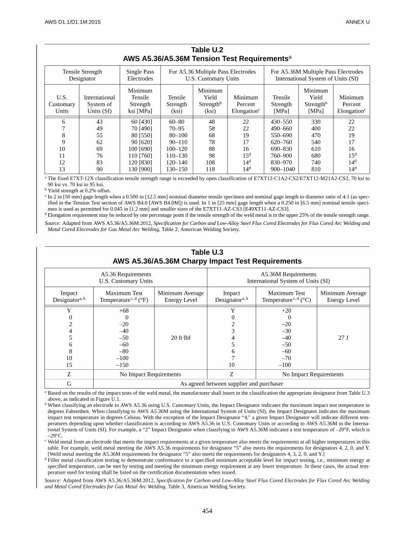
AWS D1.1/D1.1M:2015 ANNEX U
454
Table U.2AWS A5.36/A5.36M Tension Test Requirementsa
Tensile StrengthDesignator
Single Pass Electrodes
For A5.36 Multiple Pass ElectrodesU.S. Customary Units
For A5.36M Multiple Pass ElectrodesInternational System of Units (SI)
U.S.Customary
Units
InternationalSystem ofUnits (SI)
MinimumTensile
Strengthksi [MPa]
TensileStrength
(ksi)
MinimumYield
Strengthb
(ksi)
MinimumPercent
Elongationc
TensileStrength[MPa]
MinimumYield
Strengthb
[MPa]
MinimumPercent
Elongationc
6789
10111213
4349556269768390
60 [430]70 [490]80 [550]90 [620]
100 [690]110 [760]120 [830]130 [900]
60–8070–9580–10090–110
100–120110–130120–140130–150
485868788898
108118
2222191716
c15d
c14d
c14d
430–550490–660550–690620–760690–830760–900830–970900–1040
330400470540610680740810
2222191716
c15d
c14d
c14d
a The fixed E7XT-12X classification tensile strength range is exceeded by open classification of E7XT12-C1A2-CS2/E7XT12-M21A2-CS2, 70 ksi to90 ksi vs. 70 ksi to 95 ksi.
b Yield strength at 0.2% offset.c In 2 in [50 mm] gage length when a 0.500 in [12.5 mm] nominal diameter tensile specimen and nominal gage length to diameter ratio of 4:1 (as spec-
ified in the Tension Test section of AWS B4.0 [AWS B4.0M]) is used. In 1 in [25 mm] gage length when a 0.250 in [6.5 mm] nominal tensile speci-men is used as permitted for 0.045 in [1.2 mm] and smaller sizes of the E7XT11-AZ-CS3 [E49XT11-AZ-CS3].
d Elongation requirement may be reduced by one percentage point if the tensile strength of the weld metal is in the upper 25% of the tensile strength range.
Source: Adapted from AWS A5.36/A5.36M:2012, Specification for Carbon and Low-Alloy Steel Flux Cored Electrodes for Flux Cored Arc Welding andMetal Cored Electrodes for Gas Metal Arc Welding, Table 2, American Welding Society.
Table U.3AWS A5.36/A5.36M Charpy Impact Test Requirements
A5.36 RequirementsU.S. Customary Units
A5.36M RequirementsInternational System of Units (SI)
ImpactDesignatora, b
Maximum TestTemperaturec, d (°F)
Minimum AverageEnergy Level
ImpactDesignatora, b
Maximum TestTemperaturec, d (°C)
Minimum AverageEnergy Level
Y024568
1015
+680
–20–40–50–60–80
–1000–1500
20 ft·lbf
Y0234567
10
+200
–20–30–40–50–60–70
–1000
27 J
Z No Impact Requirements Z No Impact Requirements
G As agreed between supplier and purchasera Based on the results of the impact tests of the weld metal, the manufacturer shall insert in the classification the appropriate designator from Table U.3
above, as indicated in Figure U.1.b When classifying an electrode to AWS A5.36 using U.S. Customary Units, the Impact Designator indicates the maximum impact test temperature in
degrees Fahrenheit. When classifying to AWS A5.36M using the International System of Units (SI), the Impact Designator indicates the maximumimpact test temperature in degrees Celsius. With the exception of the Impact Designator “4,” a given Impact Designator will indicate different tem-peratures depending upon whether classification is according to AWS A5.36 in U.S. Customary Units or according to AWS A5.36M in the Interna-tional System of Units (SI). For example, a “2” Impact Designator when classifying to AWS A5.36M indicates a test temperature of –20°F, which is–29°C.
c Weld metal from an electrode that meets the impact requirements at a given temperature also meets the requirements at all higher temperatures in thistable. For example, weld metal meeting the AWS A5.36 requirements for designator “5” also meets the requirements for designators 4, 2, 0, and Y.[Weld metal meeting the A5.36M requirements for designator “5” also meets the requirements for designators 4, 3, 2, 0, and Y.]
d Filler metal classification testing to demonstrate conformance to a specified minimum acceptable level for impact testing, i.e., minimum energy atspecified temperature, can be met by testing and meeting the minimum energy requirement at any lower temperature. In these cases, the actual tem-perature used for testing shall be listed on the certification documentation when issued.
Source: Adapted from AWS A5.36/A5.36M:2012, Specification for Carbon and Low-Alloy Steel Flux Cored Electrodes for Flux Cored Arc Weldingand Metal Cored Electrodes for Gas Metal Arc Welding, Table 3, American Welding Society.

AWS D1.1/D1.1M:2015 ANNEX U
455
Table U.4Electrode Usability Characteristics
ElectrodeUsability
Designatora Process General Description of Electrode Typeb, cTypical Positions
of Weldingd, e Polarityf
T1 FCAW-G Flux cored electrodes of this type are gas shielded andhave a rutile base slag. They are characterized by a spraytransfer, low spatter loss, and a moderate volume of slagwhich completely covers the weld bead.
H, F, VU, & OH DCEP
T1S FCAW-G Flux cored electrodes of this type are similar to the “T1”type electrodes but with higher manganese or silicon, orboth. They are designed primarily for single pass weld-ing in the flat and horizontal positions. The higher levelsof deoxidizers in this electrode type allow single passwelding of heavily oxidized or rimmed steel.
H, F, VU, & OH DCEP
T3S FCAW-S Flux cored electrodes of this type are self shielded andare intended for single pass welding and are character-ized by a spray type transfer. The titanium-based slagsystem is designed to make very high welding speedspossible.
H, F DCEP
T4 FCAW-S Flux cored electrodes of this type are self shielded andare characterized by a globular type transfer. Its fluoride-based basic slag system is designed to make very highdeposition rates possible and to produce very low sulfurwelds for improved resistance to hot cracking.
H, F DCEP
T5 FCAW-G Flux cored electrodes of this type are gas shielded andare characterized by a globular transfer, slightly convexbead contour, and a thin slag that may not completelycover the weld bead. They have a lime-fluoride slag sys-tem and develop improved impact properties and bettercold cracking resistance than typically exhibited by the“T1” type electrodes.
H, F, VU, & OH DCEP or DCENg
T6 FCAW-S Flux cored electrodes of this type are self shielded andare characterized by a spray transfer. Its oxide-basedslag system is designed to produce good low temperatureimpacts, good penetration into the root of the weld, andexcellent slag removal.
H & F DCEP
T7 FCAW-S Flux cored electrodes of this type are self shielded andare characterized by a small droplet to spray type trans-fer. The fluoride-based slag system is designed to pro-vide high deposition rates in the downhand positionswith the larger diameters and out of position capabilitieswith the smaller diameters.
H, F, VU, & OH DCEN
T8 FCAW-S Flux cored electrodes of this type are self shielded andare characterized by a small droplet to spray type trans-fer. The fluoride-based slag system is designed to pro-vide improved out-of-position control. The weld metalproduced typically exhibits very good low temperaturenotch toughness and crack resistance.
H, F, VD, VU, & OH DCEN
T9 FCAW-G Flux cored electrodes of this type are similar in designand application to the T1 types but with improved weldmetal notch toughness capabilities.
H, F, VU, & OH DCEP
(Continued)

ANNEX U AWS D1.1/D1.1M:2015
456
T10S FCAW-S
Flux cored electrodes of this type are self shielded andare characterized by a small droplet transfer. The fluo-ride-based slag system is designed to make single passwelds at high travel speeds on steel of any thickness.
H, F DCEN
T11 FCAW-S
Flux cored electrodes of this type are self shielded andare characterized by a smooth spray type transfer, lim-ited slag coverage, and are generally not recommendedfor the welding of materials over 3/4 in [20 mm] thick.
H, F, VD, & OH DCEN
T12 FCAW-G
Flux cored electrodes of this type are similar in designand application to the T1 types. However, they havebeen modified for improved impact toughness and tomeet the lower manganese requirements of the A-No. 1Analysis Group in the ASME Boiler and Pressure Ves-sel Code, Section IX.
H, F, VU, & OH DCEP
T14S FCAW-S
Flux cored electrodes of this type are self shielded andare characterized by a smooth spray-type transfer. Theslag system is designed for single pass welds in all posi-tions and at high travel speeds.
H, F, VD, & OH DCEN
T15 GMAW-C
Electrodes of this type are gas shielded compositestranded or metal cored electrodes. The core ingredientsare primarily metallic. The nonmetallic components inthe core typically total less than 1% of the total electrodeweight. These electrodes are characterized by a spray arcand excellent bead wash capabilities. Applications aresimilar in many ways to solid GMAW electrodes.
H, F, OH, VD, & VU DCEP or DCEN
T16 GMAW-CThis electrode type is a gas shielded metal cored elec-trode specifically designed for use with AC powersources with or without modified waveforms.
H, F, VD, VU, & OH ACh
T17 FCAW-SThis flux cored electrode type is a self-shielded electrodespecifically designed for use with AC power sourceswith or without modified waveforms.
H, F, VD, VU, & OH ACh
G As agreed between supplier and purchaser Not specified Not specified
a An “S” is added to the end of the Usability Designator when the electrode being classified is recommended for single pass applications only.b For more information refer to A7, Description and Intended Use, in AWS A5.36/A5.36M Annex A.c Properties of weld metal from electrodes that are used with external shielding gas will vary according to the shielding gas used. Electrodes classified
with a specific shielding gas should not be used with other shielding gases without first consulting the manufacturer of the electrode.d H = horizontal position, F = flat position, OH = overhead position, VU = vertical position with upward progression, VD = vertical position with
downward progression.e Electrode sizes suitable for out-of-position welding, i.e., welding positions other that flat and horizontal, are usually those sizes that are smaller than
the 3/32 in [2.4 mm] size or the nearest size called for in Clause 9 for the groove weld. For that reason, electrodes meeting the requirements for thegroove weld tests may be classified as EX1TX-XXX-X (where X represents the tensile strength, usability, shielding gas, if any, condition of heattreatment, impact test temperature, and weld metal composition designators) regardless of their size.
f The term “DCEP” refers to direct current electrode positive (dc, reverse polarity). The term “DCEN” refers to direct current electrode negative (dc,straight polarity).
g Some EX1T5-XXX-X electrodes may be recommended for use on DCEN for improved out-of-position welding. Consult the manufacturer for therecommended polarity.
h For this electrode type the welding current can be conventional sinusoidal alternating current, a modified AC waveform alternating between positive andnegative, an alternating DCEP waveform, or an alternating DCEN waveform.
Source: Adapted from AWS A5.36/A5.36M:2012, Specification for Carbon and Low-Alloy Steel Flux Cored Electrodes for Flux Cored Arc Weldingand Metal Cored Electrodes for Gas Metal Arc Welding, Table 4, American Welding Society.
Table U.4 (Continued)Electrode Usability Characteristics
ElectrodeUsability
Designatora Process General Description of Electrode Typeb, cTypical Positions
of Weldingd, e Polarityf

AWS D1.1/D1.1M:2015 ANNEX U
457
Table U.5AWS A5.36/A5.36M Composition Requirements for Shielding Gases
AWS A5.36/A5.36M Shielding Gas Designatora
AWS A5.32M/A5.32 CompositionRanges for Indicated Main/Sub Groupb
Nominal Composition of Shielding Gases to be Used forClassification of Gas Shielded Electrodes to AWS A5.36/A5.36Mc, d
Oxidizing Componentse
ISO 14175 Designationf
Oxidizing Componentsc, g
% CO2 % O2 % CO2 % O2
C1M12M13M14M20M21M22M23M24M25M26M27M31M32M33M34M35
1000.5 ≤ CO2 ≤ 5
—0.5 ≤ CO2 ≤ 55 < CO2 ≤ 15
15 < CO2 ≤ 25—
0.5 ≤ CO2 ≤ 55 < CO2 ≤ 155 < CO2 ≤ 15
15 < CO2 ≤ 2515 < CO2 ≤ 2525 < CO2 ≤ 50
—25 < CO2 ≤ 505 < CO2 ≤ 25
25 < CO2 ≤ 50
——
0.5 ≤ O2 ≤ 30.5 ≤ O2 ≤ 3
——
3 < O2 ≤ 103 < O2 ≤ 100.5 ≤ O2 ≤ 33 < O2 ≤ 100.5 ≤ O2 ≤ 33 < O2 ≤ 10
—10 < O2 ≤ 15
2 < O2 ≤ 1010 < O2 ≤ 1510 < O2 ≤ 15
C1M12 – ArC – 3M13 – ArO – 2
M14 – ArCO – 3/2M20 – ArC – 10M21 – ArC – 20M22 – ArO – 7
M23 – ArOC – 7/3M24 – ArCO – 10/2M25 – ArCO – 10/7M26 – ArCO – 20/2M27 – ArCO – 20/7
M31 – ArC – 38M32 – ArO – 12.5
M33 – ArCO – 38/6M34 – ArCO – 15/12.5M35 – ArCO – 38/12.5
1003
—3
1020—3
1010202038—381538
——22
——772727
—12.56
12.512.5
Z The designator “Z” indicates that the shielding gas used for electrode classification is not one of the shieldinggases specified in this table but is a different composition as agreed upon between the supplier and purchaser.
a The Shielding Gas Designators are identical to the Main group/Sub-group designators used in AWS A5.32M/A5.32:2011 [ISO 14175:2008 MOD],Welding Consumables-Gases and Gas Mixtures for Fusion Welding and Allied Processes, for these same shielding gases.
b Under AWS A5.32M/A5.32:2011, the inert gas used for the balance of the gas mixture may be either argon, helium, or some mixture thereof.c For purposes of the D1.1 code for fixed classifications, the prequalified argon/CO2 mixed shielding gas for carbon steel FCAW and GMAW-metal
cored electrodes shall be limited to SG-AC-20/25 as with the previous AWS A5.18 and AWS A5.20 classification shielding gas requirements, andnot the shielding gas range of M21.
d For open classifications of carbon and low-alloy steel FCAW and GMAW-metal cored electrodes, the electrodes classified with the previous shield-ing gas requirements of AWS A5.18, A5.20, A5.28, and A5.29 shall be considered as prequalified. Other AWS A5.36, Table 5 shielding gas classifi-cations used for classifying an electrode are limited to the specific shielding gas in the shielding gas classification range.
e The mixture tolerances are as follows:For a component gas with a nominal concentration of >5%, ±10% of nominal.For a component gas with a nominal concentration of 1%–5%, ±0.5% absolute.For a component gas with a nominal composition of <1%, not specified in this standard.
f AWS A5.32M/A5.32:2011 shielding gas designators begin with “AWS A5.32 (ISO 14175).” That part of the designation has been omitted from theShielding Gas Designator for brevity.
g The inert gas to be used for the balance of the gas mixtures specified for the classification of gas shielded flux cored and metal cored electrodes shall beargon.
Source: Adapted from AWS A5.36/A5.36M:2012, Specification for Carbon and Low-Alloy Steel Flux Cored Electrodes for Flux Cored Arc Welding andMetal Cored Electrodes for Gas Metal Arc Welding, Table 5, American Welding Society.

AN
NE
X U
AW
S D
1.1/D1.1M
:2015
458
Table U.6Weld Metal Chemical Composition Requirementsa
Weld Metal Designation
UNS Numberb
Weight Percentc
C Mn Si S P Ni Cr Mo V Al Cu Otherd
Carbon Steel Electrodes
CS1e — 0.12 1.75 0.90 0.030 0.030 f0.50f f0.20f 0.30f 0.08f — 0.35f —
CS2e, g — 0.12 1.60 0.90 0.030 0.030 f0.50f f0.20f 0.30f 0.08f — 0.35f —
CS3e — 0.30 1.75 0.60 0.030 0.030 f0.50f f0.20f 0.30f 0.08f 1.8f, h 0.35f —
Molybdenum Steel Electrodes
A1 W1703X 0.12 1.25 0.80 0.030 0.030 — — 0.40–0.65 — — — —
Chromium-Molybdenum Steel Electrodes
B1 W5103X 0.05–0.12 1.25 0.80 0.030 0.030 — 0.40–0.65 0.40–0.65 — — — —
B1L W5113X 0.05 1.25 0.80 0.030 0.030 — 0.40–0.65 0.40–0.65 — — — —
B2 W5203X 0.05–0.12 1.25 0.80 0.030 0.030 — 1.00–1.50 0.40–0.65 — — — —
B2L W5213X 0.05 1.25 0.80 0.030 0.030 — 1.00–1.50 0.40–0.65 — — — —
B2H W5223X 0.10–0.15 1.25 0.80 0.030 0.030 — 1.00–1.50 0.40–0.65 — — — —
B3 W5303X 0.05–0.12 1.25 0.80 0.030 0.030 — 2.00–2.50 0.90–1.20 — — — —
B3L W5313X 0.05 1.25 0.80 0.030 0.030 — 2.00–2.50 0.90–1.20 — — — —
B3H W5323X 0.10–0.15 1.25 0.80 0.030 0.030 — 2.00–2.50 0.90–1.20 — — — —
B6 W50231 0.05–0.12 1.20 1.00 0.030 0.025 0.40 4.0–6.0 0.45–0.65 — — 0.35 —
B6L W50230 0.05 1.20 1.00 0.030 0.025 0.40 4.0–6.0 0.45–0.65 — — 0.35 —
B8 W50431 0.05–0.12 1.20 1.00 0.030 0.040 0.40 8.0–10.5 0.85–1.20 — — 0.50 —
B8L W50430 0.05 1.20 1.00 0.030 0.040 0.40 8.0–10.5 0.85–1.20 — — 0.50 —
B91i W50531 0.08–0.13 j1.20j 0.50 0.015 0.020 j0.80j 8.0–10.5 0.85–1.20 0.15–0.30 0.04 0.25 Nb: 0.02–0.10N: 0.02–0.07
B92 — 0.08–0.15 1.20j 0.50 0.015 0.020 0.80j 8.0–10.0 0.30–0.70 0.15–0.30 0.04 0.25
Nb: 0.02–0.08W: 1.5–2.0B: 0.006N: 0.02–0.08 Cok
Nickel Steel Electrodes
Ni1 W2103X 0.12 1.75 0.80 0.030 0.030 0.80–1.10 0.15 0.35 0.05 1.8h — —
Ni2 W2203X 0.12 1.50 0.80 0.030 0.030 1.75–2.75 — — — 1.8h — —
Ni3 W2303X 0.12 1.50 0.80 0.030 0.030 2.75–3.75 — — — 1.8h — —
(Continued)

AW
S D
1.1/D1.1M
:2015A
NN
EX
U
459
Manganese-Molybdenum Steel Electrodes
D1 W1913X 0.12 1.25–2.00 0.80 0.030 0.030 — — 0.25–0.55 — — — —
D2 W1923X 0.15 1.65–2.25 0.80 0.030 0.030 — — 0.25–0.55 — — — —
D3 W1933X 0.12 1.00–1.75 0.80 0.030 0.030 — — 0.40–0.65 — — — —
Other Low-Alloy Steel Electrodes
K1 W2113X 0.15 0.80–1.40 0.80 0.030 0.030 0.80–1.10 0.15 0.20–0.65 0.05 — — —
K2 W2123X 0.15 0.50–1.75 0.80 0.030 0.030 1.00–2.00 0.15 0.35 0.05 1.8h — —
K3 W2133X 0.15 0.75–2.25 0.80 0.030 0.030 1.25–2.60 0.15 0.25–0.65 0.05 — — —
K4 W2223X 0.15 1.20–2.25 0.80 0.030 0.030 1.75–2.60 0.20–0.60 0.20–0.65 0.03 — — —
K5 W2162X 0.10–0.25 0.60–1.60 0.80 0.030 0.030 0.75–2.00 0.20–0.70 0.15–0.55 0.05 — — —
K6 W2104X 0.15 0.50–1.50 0.80 0.030 0.030 0.40–1.00 0.20 0.15 0.05 1.8h — —
K7 W2205X 0.15 1.00–1.75 0.80 0.030 0.030 2.00–2.75 — — — — — —
K8 W2143X 0.15 1.00–2.00 0.40 0.030 0.030 0.50–1.50 0.20 0.20 0.05 1.8h — —
K9 W23230 0.07 0.50–1.50 0.60 0.015 0.015 1.30–3.75 0.20 0.50 0.05 — 0.06 —
K10 — 0.12 1.25–2.25 0.80 0.030 0.030 1.75–2.75 0.20 0.50 — — 0.50 —
K11 — 0.15 1.00–2.00 0.80 0.030 0.030 0.40–1.00 0.20 0.50 0.05 1.8h — —
W2 W2013X 0.12 0.50–1.30 0.35–0.80 0.030 0.030 0.40–0.80 0.45–0.70 — — — 0.30–0.75 —
G — (m) As agreed upon between supplier and purchaser
GSn — As agreed upon between supplier and purchasera The weld metal shall be analyzed for the specific elements for which values are shown in this table.b Refer to ASTM DS-56/SAE HS-1086, Metals & Alloys in the Unified Numbering System. An “X,” when present in the last position, represents the usability designator for the electrode type used to deposit
the weld metal. An exception to this applies to the “11” electrode type where a “9” is used instead of an “11.”c Single values are maximums.d An analysis of the weld deposit for boron is required and shall be reported if this element is intentionally added or if it is known to be present at levels in excess of 0.0010%.e The total of all the elements listed in this table for this classification shall not exceed 5%.f The analysis of these elements shall be reported only if intentionally added.g Meets the lower Mn requirements of the A-No. 1 Analysis Group in the ASME Boiler and Pressure Vessel Code, Section IX Welding and Brazing Qualifications, QW- 422.h Applicable to self-shielded electrodes only. Electrodes intended for use with gas shielding normally do not have significant additions of aluminum.i The “B91” designation is a new designation, replacing the “B9” designation previously used for this alloy type.j Mn + Ni = 1.40% maximum. See A7.16.2 in Annex A of AWS A5.36/A5.36M.k Analysis for Co is required to be reported if intentionally added, or if it is known to be present at levels greater than 0.20%.l The limit for gas shielded electrodes is 0.18% maximum. The limit for self-shielded electrodes is 0.30% maximum.mThe composition of weld metal is not particularly meaningful since electrodes in this category are intended only for single pass welds. Dilution from the base metal in such welds is usually quite high. See
A7.2 in Annex A of AWS A5.36/A5.36M.
Source: Reproduced from AWS A5.36/A5.36M:2012, Specification for Carbon and Low-Alloy Steel Flux Cored Electrodes for Flux Cored Arc Welding and Metal Cored Electrodes for Gas Metal ArcWelding, Table 6, American Welding Society.
Table U.6 (Continued)Weld Metal Chemical Composition Requirementsa
Weld Metal Designation
UNS Numberb
Weight Percentc
C Mn Si S P Ni Cr Mo V Al Cu Otherd

ANNEX U AWS D1.1/D1.1M:2015
460
Table U.7AWS A5.20/A5.20M Procedure Requirements for “D” Optional Supplemental Designator
Optional Supplemental
Designator
Procedure Heat Input(Fast or SlowCooling Rate)
Preheat Temperature
°F [°C]
Interpass Temperature
°F [°C]
Heat InputRequirement forAny Single Passa
Required AverageHeat Input for
All Passesa
D
low(fast cooling rate)
70°F ± 25°F[20°C ± 15°C]
200°F ± 25°F[90°C ± 15°C]
For electrode diameters < 3/32 in [2.4 mm]
33 kJ/in[1.3 kJ/mm]maximum
30 +2, –5 kJ/in[1.2 +0.1, –0.2 kJ/mm]
For electrode diameters ≥ 3/32 in [2.4 mm]
44 kJ/in[1.7 kJ/mm] maximum
40 +2, –5 kJ/in[1.6 +0.1, –0.2 kJ/mm]
high(slow cooling rate)
300°F ± 25°F[150°C ± 15°C]
500°F ± 50°F[260°C ± 25°C]
75 kJ/in[3.0 kJ/mm] minimum
80 +5, –2 kJ/in[3.1 +0.2, –0.1 kJ/mm]
a Does not apply to first layer. The first layer may have one or two passes.
Source: Adapted from AWS A5.20/A5.20M:2005, Specification for Carbon Steel Electrodes for Flux Cored Arc Welding, Table 9, American WeldingSociety.
Table U.8AWS A5.36/A5.36M Procedure Requirements for “D” Optional Supplemental Designator
OptionalSupplemental
Designator
Procedure HeatInput (fast or slow
cooling rate)
Preheat Temperature
°F [°C]
Interpass Temperature
°F [°C]
Heat InputRequirement forAny Single Passa
Required AverageHeat Input for
All Passesa
D
Low(fast cooling rate)
120°F [50°C]max.
250°F [120°C]max.
For electrode diameters < 3/32 in [2.4 mm]
38 kJ/in [1.5 kJ/mm]max.
24 kJ/in–36 kJ/in[0.9 kJ/mm–1.4 kJ/mm]
For electrode diameters ≥ 3/32 in [2.4 mm]
44 kJ/in [1.7 kJ/mm]max.
35 kJ/in–42 kJ/in[1.4 kJ/mm–1.6 kJ/mm]
High(slow cooling rate)
250°F [120°C]min.
450°F [240°C]min.
65 kJ/in [2.6 kJ/mm]min.
65 kJ/in–85 kJ/in[2.6 kJ/mm–3.3 kJ/mm]
a Does not apply to first layer. The first layer may have one or two passes.
Note: The changes in “D” designator requirements for preheat and interpass temperatures, and heat inputs are bolded and underlined.
Source: Adapted from AWS A5.36/A5.36M:2012, Specification for Carbon and Low-Alloy Steel Flux Cored Electrodes for Flux Cored Arc Weldingand Metal Cored Electrodes for Gas Metal Arc Welding, Table 10, American Welding Society.

AWS D1.1/D1.1M:2015 ANNEX U
461
Table U.9Comparison of Classifications of AWS A5.18, A5.20, A5.28, and A5.29
Specifications to AWS A5.36 Fixed and Open Classificationsfor Multiple-Pass FCAW and GMAW—Metal Cored Electrodes
Annex T A5.36
Specification ClassificationFixed
Classification Open Classification
Annex V ShieldingGas Classification
Requirements
A5.18
E70C-3C Not Applicable E7XT15-C1A0-CS1 SG-C
E70C-3M Not Applicable E7XT15-M21A0-CS1 SG-AC-20-25
E70C-6C Not Applicable E7XT15-C1A2-CS1 SG-C
E70C-6M E70C-6M E7XT15-M21A2-CS1 SG-AC-20-25
E70C-G Not Applicable E7XT15-XAX-G As Agreed
A5.20
E7XT-1C E7XT-1C E7XT1-C1A0-CS1 SG-C
E7XT-1M E7XT-1M E7XT1-M21A0-CS1 SG-AC-20-25
E7XT-4 E70T-4 E7XT4-AZ-CS3
E7XT-5C E7XT-5C E7XT5-C1A2-CS1 SG-C
E7XT-5M E7XT-5M E7XT5-M21A2-CS1 SG-AC-20-25
E7XT-6 E7XT-6 E7XT6-A2-CS3
E7XT-7 E7XT-7 E7XT7-AZ-CS3
E7XT-8 E7XT-8 E7XT8-A2-CS3
E7XT-9C E7XT-9C E7XT9-C1A2-CS1 SG-C
E7XT-9M E7XT-9M E7XT9-M21A2-CS1 SG-AC-20-25
E7XT-11 Not Applicable E7XT11-AZ-CS3
E7XT-12C E7XT-12C Not Applicable SG-C
E7XT-12M E7XT-12M Not Applicable SG-AC-20-25
E6XT-G Not Applicable E6XTG-XXX-G As Agreed
E7XT-G Not Applicable E7XTG-XXX-G As Agreed
A5.28
E70C-B2L Not ApplicableE7XT15-M13PZ-B2LE7XT15-M22PZ-B2L
SG-AO-1-5
E80C-B2 Not ApplicableE8XT15-M13PZ-B2E8XT15-M22PZ-B2
SG-AO-1-5
E80C-B3L Not ApplicableE8XT15-M13PZ-B3LE8XT15-M22PZ-B3L
SG-AO-1-5
E90C-B3 Not ApplicableE9XT15-M13PZ-B3E9XT15-M22PZ-B3
SG-AO-1-5
E80C-B6 Not ApplicableE8XT15-M13PZ-B6E8XT15-M22PZ-B6
SG-AO-1-5
E80C-B8 Not ApplicableE8XT15-M13PZ-B8E8XT15-M22PZ-B8
SG-AO-1-5
E90C-B9 Not ApplicableE9XT15-M20PZ-B9E9XT15-M21PZ-B9
SG-AC-5-25
E70C-Ni2 Not ApplicableE7XT15-M13P8-Ni2E7XT15-M22P8-Ni2
SG-AO-1-5
(Continued)

ANNEX U AWS D1.1/D1.1M:2015
462
A5.28(Cont’d)
E80C-Ni1 Not ApplicableE8XT15-M13A5-Ni1E8XT15-M22A5-Ni1
SG-AO-1-5
E80C-Ni2 Not ApplicableE8XT15-M13P8-Ni2E8XT15-M22P8-Ni2
SG-AO-1-5
E80C-Ni3 Not ApplicableE8XT15-M13P10-Ni3E8XT15-M22P10-Ni3
SG-AO-1-5
E90C-D2 Not ApplicableE9XT15-M13A2-D2E9XT15-M22A2-D2
SG-AO-1-5
E90C-K3 Not ApplicableE9XT15-M12A6-K3E9XT15-M20A6-K3E9XT15-M21A6-K3
SG-AC-5-25
E100C-K3 Not ApplicableE10XT15-M12A6-K3E10XT15-M20A6-K3E10XT15-M21A6-K3
SG-AC-5-25
E110C-K3 Not ApplicableE11XT15-M12A6-K3E11XT15-M20A6-K3E11XT15-M21A6-K3
SG-AC-5-25
E110C-K4 Not ApplicableE11XT15-M12A6-K4E11XT15-M20A6-K4E11XT15-M21A6-K4
SG-AC-5-25
E120C-K4 Not ApplicableE12XT15-M12A6-K4E12XT15-M20A6-K4E12XT15-M21A6-K4
SG-AC-5-25
E80C-W2 Not ApplicableE8XT15-M12A2-W2E8XT15-M20A2-W2E8XT15-M21A2-W2
SG-AC-5-25
E70C-G Not Applicable E7XTG-XXX-X As Agreed
E80C-G Not Applicable E8XTG-XXX-X As Agreed
E90C-G Not Applicable E9XTG-XXX-X As Agreed
E100C-G Not Applicable E10XTG-XXX-X As Agreed
E110C-G Not Applicable E11XTG-XXX-X As Agreed
E120C-G Not Applicable E12XTG-XXX-X As Agreed
A5.29
E7XT5-A1C, -A1M Not ApplicableE7XT5-C1P2-A1E7XT5-M21P2-A1
SG-CSG-AC-20-25
E8XT1-A1C, -A1M Not ApplicableE8XT1-C1PZ-A1E8XT1-M21PZ-A1
SG-CSG-AC-20-25
E8XT1-B1C, -B1M,-B1LC, -B1LM
Not Applicable
E8XT1-C1PZ-B1E8XT1-M21PZ-B1E8XT1-C1PZ-B1LE8XT1-M21PZ-B1L
SG-CSG-AC-20-25SG-CSG-AC-20-25
Table U.9 (Continued)Comparison of Classifications of AWS A5.18, A5.20, A5.28, and A5.29
Specifications to AWS A5.36 Fixed and Open Classificationsfor Multiple-Pass FCAW and GMAW—Metal Cored Electrodes
Annex T A5.36
Specification ClassificationFixed
Classification Open Classification
Annex V ShieldingGas Classification
Requirements
(Continued)

AWS D1.1/D1.1M:2015 ANNEX U
463
A5.29(Cont’d)
E8XT1-B2C, -B2M,-B2HC, -B2HM, -B2LC,-B2LM
Not Applicable
E8XT1-C1PZ-B2E8XT1-M21PZ-B2E8XT1-C1PZ-B2HE8XT1-M21PZ-B2HE8XT1-C1PZ-B2LE8XT1-M21PZ-B2L
SG-CSG-AC-20-25SG-CSG-AC-20-25SG-CSG-AC-20-25
E8XT5-B2C, -B2M,-B2LC, -B2LM
Not Applicable
E8XT5-C1PZ-B2E8XT5-M21PZ-B2E8XT5-C1PZ-B2LE8XT5-M21PZ-B2L
SG-CSG-AC-20-25SG-CSG-AC-20-25
E9XT1-B3C, -B3M,-B3LC, -B3LM, -B3HC,-B3HM
Not Applicable
E9XT1-C1PZ-B3E9XT1-M21PZ-B3E9XT1-C1PZ-B3LE9XT1-M21PZ-B3LE9XT1-C1PZ-B3HE9XT1-M21PZ-B3H
SG-CSG-AC-20-25SG-CSG-AC-20-25SG-CSG-AC-20-25
E9XT5-B3C, -B3M Not ApplicableE9XT5-C1PZ-B3E9XT5-M21PZ-B3
SG-CSG-AC-20-25
E10XT1-B3C, -B3M Not ApplicableE10XT1-C1PZ-B3E10XT1-M21PZ-B3
SG-CSG-AC-20-25
E8XT1-B6C, -B6M,-B6LC, -B6LM
Not Applicable
E8XT1-C1PZ-B6E8XT1-M21PZ-B6E8XT1-C1PZ-B6LE8XT1-M21PZ-B6L
SG-CSG-AC-20-25SG-CSG-AC-20-25
E8XT5-B6C, -B6M,-B6LC, -B6LM
Not Applicable
E8XT5-C1PZ-B6E8XT5-M21PZ-B6E8XT5-C1PZ-B6LE8XT5-M21PZ-B6L
SG-CSG-AC-20-25SG-CSG-AC-20-25
E8XT1-B8C, -B8M,-B8LC, -B8LM
Not Applicable
E8XT1-C1PZ-B8E8XT1-M21PZ-B8E8XT1-C1PZ-B8LE8XT1-M21PZ-B8L
SG-CSG-AC-20-25SG-CSG-AC-20-25
E8XT5-B8C, -B8M,-B8LC, -B8LM
Not Applicable
E8XT5-C1PZ-B8E8XT5-M21PZ-B8E8XT5-C1PZ-B8LE8XT5-M21PZ-B8L
SG-CSG-AC-20-25SG-CSG-AC-20-25
E9XT1-B9C, -B9M Not ApplicableE9XT1-C1PZ-B9E9XT1-M21PZ-B9
SG-CSG-AC-20-25
E6XT1-Ni1C, -Ni1M Not ApplicableE6XT1-C1A2-Ni1E6XT1-M21A2-Ni1
SG-CSG-AC-20-25
E7XT6-Ni1 Not Applicable E7XT6-A2-Ni1
E7XT8-Ni1 Not Applicable E7XT8-A2-Ni1
Table U.9 (Continued)Comparison of Classifications of AWS A5.18, A5.20, A5.28, and A5.29
Specifications to AWS A5.36 Fixed and Open Classificationsfor Multiple-Pass FCAW and GMAW—Metal Cored Electrodes
Annex T A5.36
Specification ClassificationFixed
Classification Open Classification
Annex V ShieldingGas Classification
Requirements
(Continued)

ANNEX U AWS D1.1/D1.1M:2015
464
A5.29(Cont’d)
E8XT1-Ni1C, -Ni1M Not ApplicableE8XT1-C1A2-Ni1E8XT1-M21A2-Ni1
SG-CSG-AC-20-25
E8XT5-Ni1C, -Ni1M Not ApplicableE8XT5-C1P6-Ni1E8XT5-M21P6-Ni1
SG-CSG-AC-20-25
E7XT8-Ni2 Not Applicable E7XT8-A2-Ni2
E8XT8-Ni2 Not Applicable E8XT8-A2-Ni2
E8XT1-Ni2C, -Ni2M Not ApplicableE8XT1-C1A4-Ni2E8XT1-M21A4-Ni2
SG-CSG-AC-20-25
E8XT5-Ni2C, -Ni2M Not ApplicableE8XT5-C1P8-Ni2a
E8XT5-M21P8-Ni2aSG-CSG-AC-20-25
E9XT1-Ni2C, -Ni2M Not ApplicableE9XT1-C1A4-Ni2E9XT1-M21A4-Ni2
SG-CSG-AC-20-25
E8XT5-Ni3C, -Ni3M Not ApplicableE8XT5-C1P10-Ni3E8XT5-M21P10-Ni3
SG-CSG-AC-20-25
E9XT5-Ni3C, -Ni3M Not ApplicableE9XT5-C1P10-Ni3E9XT5-M21P10-Ni3
SG-CSG-AC-20-25
E8XT11-Ni3 Not Applicable E8XT11-A0-Ni3
E9XT1-D1C, -D1M Not ApplicableE9XT1-C1A4-D1E9XT1-M21A4-D1
SG-CSG-AC-20-25
E9XT5-D2C, -D2M Not ApplicableE9XT5-C1P6-D2E9XT5-M21P6-D2
SG-CSG-AC-20-25
E10XT5-D2C, -D2M Not ApplicableE10XT5-C1P4-D2E10XT5-M21P4-D2
SG-CSG-AC-20-25
E9XT1-D3C, -D3M Not ApplicableE9XT1-C1A2-D3E9XT1-M21A2-D3
SG-CSG-AC-20-25
E8XT5-K1C, -K1M Not ApplicableE8XT5-C1A4-K1E8XT5-M21A4-K1
SG-CSG-AC-20-25
E7XT7-K2 Not Applicable E7XT7-A2-K2
E7XT4-K2 Not Applicable E7XT4-A0-K2
E7XT8-K2 Not Applicable E7XT8-A2-K2
E7XT11-K2 Not Applicable E7XT11-A-K2b
E8XT1-K2C, -K2M Not ApplicableE8XT1-C1A2-K2E8XT1-M21A2-K2
SG-CSG-AC-20-25
E8XT5-K2C, -K2M Not ApplicableE8XT5-C1A2-K2E8XT5-M21A2-K2
SG-CSG-AC-20-25
E9XT1-K2C, -K2M Not ApplicableE9XT1-C1A0-K2E9XT1-M21A0-K2
SG-CSG-AC-20-25
E9XT5-K2C, -K2M Not ApplicableE9XT5-C1A6-K2E9XT5-M21A6-K2
SG-CSG-AC-20-25
Table U.9 (Continued)Comparison of Classifications of AWS A5.18, A5.20, A5.28, and A5.29
Specifications to AWS A5.36 Fixed and Open Classificationsfor Multiple-Pass FCAW and GMAW—Metal Cored Electrodes
Annex T A5.36
Specification ClassificationFixed
Classification Open Classification
Annex V ShieldingGas Classification
Requirements
(Continued)

AWS D1.1/D1.1M:2015 ANNEX U
465
A5.29(Cont’d)
E10XT1-K3C, -K3M Not ApplicableE10XT1-C1A0-K3E10XT1-M21A0-K3
SG-CSG-AC-20-25
E10XT5-K3C, -K3M Not ApplicableE10XT5-C1A6-K3E10XT5-M21A6-K3
SG-CSG-AC-20-25
E11XT1-K3C, -K3M Not ApplicableE11XT1-C1A0-K3E11XT1-M21A0-K3
SG-CSG-AC-20-25
E11XT5-K3C, -K3M Not ApplicableE11XT5-C1A6-K3E11XT5-M21A6-K3
SG-CSG-AC-20-25
E11XT1-K4C, -K4M Not ApplicableE11XT1-C1A0-K4E11XT1-M21A0-K4
SG-CSG-AC-20-25
E11XT5-K4C, -K4M Not ApplicableE11XT5-C1A6-K4E11XT5-M21A6-K4
SG-CSG-AC-20-25
E12XT5-K4C, -K4M Not ApplicableE12XT5-C1A6-K4E12XT5-M21A6-K4
SG-CSG-AC-20-25
E12XT1-K5C, -K5M Not ApplicableE12XT1-C1AZ-K5E12XT1-M21AZ-K5
SG-CSG-AC-20-25
E7XT5-K6C, -K6M Not ApplicableE7XT5-C1A8-K6a
E7XT5-M21A8-K6aSG-CSG-AC-20-25
E6XT8-K6 Not Applicable E6XT6-A2-K6
E7XT8-K6 Not Applicable E7XT8-A2-K6
E10XT1-K7C, -K7M Not ApplicableE10XT1-C1A6-K7E10XT1-M21A6-K7
SG-CSG-AC-20-25
E9XT8-K8 Not Applicable E9XT8-A2-K8
E10XT1-K9C, -K9M Not ApplicableE10XT1-C1A6-K9c
E10XT1-M21A6-K9cSG-CSG-AC-20-25
E8XT1-W2C, -W2M Not ApplicableE8XT1-C1A2-W2E8XT1-M21A2-W2
SG-CSG-AC-20-25
EXXTX-G Not Applicable EXXTX-XX-G
EXXTX-GC, -GM Not ApplicableEXXTX-C1XX-GEXXTX-M21XX-G
SG-CSG-AC-20-25
EXXTG-X Not Applicable EXXTG-XXX-X As Agreed
EXXTG-G Not Applicable EXXTG-XXX-G As Agreeda The existing AWS A5.29 CVN temperature is –75°F [–60°C], for which there is not a designator in A5.36, therefore, the open classification compar-
ison is an approximation.b The existing AWS A5.29 CVN temperature is +32°F [0°C], for which there is not a designator in A5.36, therefore, the open classification comparison
is not complete due to lack of CVN test temperature.c AWS A5.36 does not address the specific requirements for a K9 electrode, designed for military applications, in which the yield strength is controlled and
the tensile strength is reported as a reference. AWS A5.29 reported the tensile as an approximation (100 ksi–120 ksi [690 MPa–830 MPa]), not arequirement and controlled the yield at 82 ksi–97 ksi [570 MPa–670 MPa].
Table U.9 (Continued)Comparison of Classifications of AWS A5.18, A5.20, A5.28, and A5.29
Specifications to AWS A5.36 Fixed and Open Classificationsfor Multiple-Pass FCAW and GMAW—Metal Cored Electrodes
Annex T A5.36
Specification ClassificationFixed
Classification Open Classification
Annex V ShieldingGas Classification
Requirements

ANNEX U AWS D1.1/D1.1M:2015
466
Mandatory Classification Designatorsa
Designates an electrode.
Tensile Strength Designator. For A5.36 one or two digits indicate the minimum tensilestrength (when multiplied by 10 000 psi) of weld metal deposited with the electrode underthe welding conditions specified in this specification. For A5.36M two digits are used toindicate the minimum tensile strength (when multiplied by 10 Megapascals [MPa]). SeeTable U.2.
Position Designator. This designator is either “0” or “1.” A “0” is for flat and horizontalpositions only. “1” is for all positions (flat, horizontal, vertical with downward progression,and/or vertical with upward progression and overhead).
Usability Designator. This letter is the letter “T” followed by some number from 1 through17 or the letter “G.” The letter “T” identifies the electrode as a flux cored electrode or metalcored electrode. This designator refers to the usability of the electrode with requirements forpolarity and general operating characteristics (see Table U.4). The letter “G” indicates thatthe polarity and general operating characteristics are not specified. An “S” appears at the endof this designator when the electrode being classified is intended for single pass welding only.
Shielding Gas Designator. Indicates the type of shielding gas, if any, used for classifica-tion (see Table U.5). The letter “Z” in this position indicates that the shielding gas composi-tion is as agreed upon between supplier and purchaser. When no designator appears in thisposition, it indicates that the electrode is self shielded and that no external shielding gas isused.
Designates the condition of heat treatment in which the tests were conducted. “A” is for as-welded and “P” is for postweld heat treated. The time and temperature of the PWHT isspecified in 9.2.1.2 and Table 8 in A5.36. The letter “G” in this position indicates that thePWHT procedure is as agreed upon between supplier and purchaser. This designator isomitted when the electrode being classified is intended for single pass welding only.
Impact Designator. For A5.36 this designator indicates the temperature in °F at or abovewhich the impact strength of the weld metal referred to above meets or exceeds 20 ft·lbf.For A5.36M this designator indicates the temperature in °C at or above which the impactstrength of the weld metal meets or exceeds 27 J. The impact designator may be either one ortwo digits (see Table U.3). A “Z” in this position indicates that there are no impact require-ments for the electrode classification. This designator is omitted when the electrode beingclassified is intended for single pass welding only. A “G” in this position indicates the impactrequirements are not specified but are as agreed upon between purchaser and supplier.
Deposit Composition Designator. One, two, or three characters are used to designate thecomposition of the deposited weld metal (see Table U.6). The letter “G” indicates that thechemical composition is not specified. No designator is used in this position when the elec-trode being classified is a single pass electrode.
E X X T X-X X X-X-X H X Optional Supplemental Designatorsb
Optional, supplemental diffusible hydrogen designator.
For flux cored electrodes, the letter “D” or “Q” when present in this position indicates the weldmetal will meet supplemental mechanical property requirements with welding done using lowheat input, fast cooling rate procedures and using high heat input, slow cooling rate procedures(see Tables U.7 and U.8 for changes in heat input requirements between A5.20 and A5.36).
a The combination of these designators constitutes the flux cored or metal cored electrode classification.b These designators are optional and do not constitute a part of the flux cored or metal cored electrode classification.
Source: Adapted from AWS A5.36/A5.36M:2012, Specification for Carbon and Low-Alloy Steel Flux Cored Electrodes for FluxCored Arc Welding and Metal Cored Electrodes for Gas Metal Arc Welding, Figure 1, American Welding Society.
Figure U.1—A5.36/A5.36M Open Classification System

AWS D1.1/D1.1M:2015
467
Commentary on
Structural Welding
Code—Steel
18th Edition
Prepared by theAWS D1 Committee on Structural Welding
Under the Direction of theAWS Technical Activities Committee
Approved by theAWS Board of Directors

AWS D1.1/D1.1M:2015
468
This page is intentionally blank.

AWS D1.1/D1.1M:2015 COMMENTARY
469
ForewordThis foreword is not part of the Commentary of AWS D1.1/D1.1M:2015,
Structural Welding Code—Steel, but is included for informational purposes only.
This commentary on AWS D1.1/D1.1M:2015 has been prepared to generate better understanding in the application ofthe code to welding in steel construction.
Since the code is written in the form of a specification, it cannot present background material or discuss the StructuralWelding Committee’s intent; it is the function of this commentary to fill this need.
Suggestions for application as well as clarification of code requirements are offered with specific emphasis on new orrevised sections that may be less familiar to the user.
Since publication of the first edition of the code, the nature of inquiries directed to the American Welding Society andthe Structural Welding Committee has indicated that there are some requirements in the code that are either difficult tounderstand or not sufficiently specific, and others that appear to be overly conservative.
It should be recognized that the fundamental premise of the code is to provide general stipulations applicable to any sit-uation and to leave sufficient latitude for the exercise of engineering judgment.
Another point to be recognized is that the code represents the collective experience of the committee and while someprovisions may seem overly conservative, they have been based on sound engineering practice.
The committee, therefore, believes that a commentary is the most suitable means to provide clarification as well asproper interpretation of many of the code requirements. Obviously, the size of the commentary had to impose some lim-itations with respect to the extent of coverage.
This commentary is not intended to provide a historical background of the development of the code, nor is it intended toprovide a detailed resume of the studies and research data reviewed by the committee in formulating the provisions ofthe code.
Generally, the code does not treat such design considerations as loading and the computation of stresses for the purposeof proportioning the load-carrying members of the structure and their connections. Such considerations are assumed tobe covered elsewhere, in a general building code, bridge specification, or similar document.
As an exception, the code does provide allowable stresses in welds, fatigue provisions for welds in cyclically loadedstructures and tubular structures, and strength limitations for tubular connections. These provisions are related to partic-ular properties of welded connections.
The Committee has endeavored to produce a useful document suitable in language, form, and coverage for welding insteel construction. The code provides a means for establishing welding standards for use in design and construction bythe Owner or the Owner’s designated representative. The code incorporates provisions for regulation of welding that areconsidered necessary for public safety.
The committee recommends that the Owner or Owner’s representative be guided by this commentary in application ofthe code to the welded structure. The commentary is not intended to supplement code requirements, but only to providea useful document for interpretation and application of the code; none of its provisions are binding.
It is the intention of the Structural Welding Committee to revise the commentary on a regular basis so that commentaryon changes to the code can be promptly supplied to the user. In this manner, the commentary will always be current withthe edition of the Structural Welding Code—Steel with which it is bound.
Changes in the commentary have been indicated by underlining. Changes to illustrations are indicated by vertical linesin the margin.

AWS D1.1/D1.1M:2015
470
This page is intentionally blank.

AWS D1.1/D1.1M:2015
471
C-1.1 ScopeThe Structural Welding Code—Steel, hereinafter referredto as the code, provides welding requirements for theconstruction of steel structures. It is intended to be com-plimentary with any general code or specification for de-sign and construction of steel structures.
When using the code for other structures, Owners,architects, and Engineers should recognize that not all ofits provisions may be applicable or suitable to their par-ticular structure. However, any modifications of the codedeemed necessary by these authorities should be clearlyreferenced in the contractual agreement between theOwner and the Contractor.
C-1.3 DefinitionsC-1.3.1 Engineer. The code does not define the Engineerin terms of education, professional registration, profes-
sional license, area of specialization, or other such crite-rion. The code does not provide for a test of theEngineer’s competence or ability. However, the assump-tion throughout the code as it relates to responsibilitiesand authorities assigned to the Engineer is that the in-dividual is competent and capable of executing theseresponsibilities. Applicable building codes may have re-quirements to be met by the Engineer. These require-ments may include, but not be limited to, compliancewith local jurisdictional laws and regulations governingthe Practice of Engineering.
C-1.3.3.1 Contractor’s Inspector. In past editions ofthis code, the term “fabrication-erection inspector” wasused to designate the individual who oversees the Contrac-tor’s work. Specific responsibilities of the Contractor’s In-spector are defined in 6.1. In some industries, this may bereferred to as “quality control” or “QC inspection.”
Commentary on
Structural Welding Code—Steel
C-1. General Requirements
Users of this code may notice that there is no Annex C. This was done intentionally to avoid any confusion with com-mentary references which use “C-” to identify text, tables, and figures that are part of the commentary. Identifying com-mentary on code text is relatively straightforward. If there exists commentary on code text, for example 2.3.2 of thecode, you can identify it in Clause C-2 of the commentary labeled C-2.3.2. The “C-” indicates it is commentary, the“2.3.2” identifies the portion of the code on which the commentary refers. Likewise, C-Table 3.7 indicates commentaryon Table 3.7, and C-Figure 3.1 indicates commentary on Figure 3.1. If a code subclause, table, or figure does not havecommentary associated with it, then there will be no labeled section in the commentary for that code component. This iswhy when reading through the commentary the numbering can seem erratic, and it seems some sections are missing. Forexample, you might read the following three sections of the commentary in order: C-5.22.6.1, C-5.22.6.2, C-5.22.6.4.You may notice in this sequence that C-5.22.6.3 is missing. This is not a typo but rather an indication that no commen-tary exists on 5.22.6.3 of the code. The commentary has tables and figures of its own. These are identified in a slightly dif-ferent way, be careful not to confuse these with commentary on code table and figures. For example, the first table inClause C-8 supporting commentary is labeled “Table C-8.1.” Notice that the “C-” does not come before “Table” but in-stead after it. “C-Table 3.7” is commentary on Table 3.7 in the code; “Table C-8.1” is the first commentary table inClause C-8. The same is true for the labeling of figures, e.g., “C-Figure 3.1” and “Figure C-3.1.”

COMMENTARY AWS D1.1/D1.1M:2015
472
C-1.3.3.2 Verification Inspector. The Verification In-spector’s duties are identified by the Engineer. The Engi-neer has the responsibility to determine whether or notverification inspection will be required for a specificproject, and when required, to define the responsibilities ofthat Inspector. In some industries, this type of inspection iscalled “quality assurance” or “QA inspection.” Buildingcodes may specify verification inspection requirements.The Engineer should then identify such requirements incontract documents.
C-1.3.3.3 Inspector(s) (unmodified). When the word“Inspector” is used without the modifying term“Contractor’s” or “Verification,” the provision is equallyapplicable to both types of Inspectors (see 6.1.4 as anexample).
C-1.3.4 OEM (Original Equipment Manufacturer).The primary industries and applications governed by thiscode typically involve separate entities, fitting into thebroad categories of Contractor and Engineer. For someapplications of this code, one entity functions as both theEngineer and Contractor. In this code, this is referred toas an Original Equipment Manufacturer (OEM). Exam-ples would include metal building systems, equipmentskids and platforms, material storage systems, transmis-sion towers, light poles, and sign structures. For thesesituations, contract documents should define how thevarious responsibilities are handled. By definition, thiscode separates the functions of the Engineer from thoseof the Contractor, and yet these are merged for OEMapplications. Many possible arrangements exist, but thefollowing general categories capture many examples ofOEM applications:
• OEM 1—The OEM assumes responsibility for “turn-key products,” and the Owner has no involvement inengineering or inspection issues.
• OEM 2—A turnkey product is delivered, but theOwner supplies his own Verification Inspector whoreports findings to the Owner.
• OEM 3—The duties of the code-defined Engineer areaddressed by both the OEM and the Owner’s Engineer.
To address each of the preceding situations, examples ofpossible contractual language are included below. Theseshould be reviewed to be certain they are applicable tothe specific situation.
Sample Language for OEM 1:
“D1.1 shall be used. The Contractor’s Engineer shall as-sume the responsibilities of the Engineer as defined in1.3.1. Deviations from the code requirements as de-scribed in 1.4.1, shall not be allowed.”
Sample Language for OEM 2:
“D1.1 shall be used. The Contractor’s Engineer shall as-sume the responsibilities of the Engineer as defined in1.3.1, except all references to the “Engineer” in Clause 6shall mean the “Owner.” Verification inspection shall beas determined by the Owner, and the Verification Inspec-tor shall report the results to the Owner. In addition, deci-sions made by the Contractor’s Engineer that requirechanges to the code as described by 1.4.1 shall be sub-mitted to the Owner for approval.”
Sample Language for OEM 3:
No specific suggested language is supplied here becausethe number of permutations is too great. The user is en-couraged to look at each reference to the Engineer andresolve how each situation is to be handled. As an exam-ple, the contents of Clauses 1, 2, and 6 may be assignedto the Owner’s Engineer, and the responsibilities ofClauses 3, 4, 5, and 7 assigned to the Contractor’sEngineer.
C-1.3.6.2 Should. “Should” provisions are advisory(see 5.28 for example—arc strikes should be avoided,but they are not prohibited). However, if they arepresent, they “shall” (i.e., are required to) be removed.
Certain code provisions are options that are given to theContractor (see 5.26 as an example where peening is al-lowed (may) but not required (shall) on intermediateweld layers).
C-1.3.6.3 May. Some code provisions are not man-datory unless the Engineer invokes them in the contractdocuments.
C-1.4 ResponsibilitiesC-1.4.1 Engineer’s Responsibilities. The Engineer is re-sponsible at the time of contract preparation for provid-ing recommendations to the Owner or contractingauthority with respect to the suitability of the code tomeet the particular requirements of a specific structure.The Engineer may change any code requirements, but thebasis for such changes should be well documented andtake into consideration the suitability for service usingpast experience, experimental evidence or engineeringanalysis, considering material type, load effects and envi-ronmental factors.
The Engineer may recommend, from time to time duringthe course of the project, additional changes to code pro-visions for the good of the project. Such changes shouldbe documented. The effect upon the contractual relation-ship should be resolved between the parties involved.
Common examples of contract-letting code modifica-tions include resolution of unforeseen project difficulties,

AWS D1.1/D1.1M:2015 COMMENTARY
473
handling of minor nonconformances, and dealing withspecific code violation issues. For example, acceptanceof a minor nonconformance with due consideration ofservice requirements may be more desirable for the over-all project than mandating a repair that would result infull code conformance, but a less desirable final product.
The fundamental premise of the code is to provide generalstipulations applicable to most situations. Acceptance cri-teria for production welds different from those specifiedin the code may be used, but there should be a basis ofsuch alternate acceptance criteria, such as past experience,experimental evidence, or engineering analysis.
After the contract is awarded, the Engineer can changerequirements in the code, but the changes should be doc-umented and agreed upon between the parties involved.The Engineer cannot unilaterally modify or change anyprovision of the code after the contracts are awardedwithout potentially creating conflict with the terms of thecontract. These types of modifications should be mutu-ally agreed upon between the parties involved in order tosatisfactorily address unexpected circumstances.
The Engineer is required to determine the suitability ofthe particular joint detail for the specific weldedassembly. Prequalified joint details, as well as the partic-ular joint details that may be qualified by testing, maynot be suitable for all loading conditions or restraintconditions. Consideration should be made to through-thickness properties of steels, likelihood of lamellartearing, sizes and proportions of members being joined,and other factors.
C-1.4.1(1) Certain provisions of the code are mandatoryonly when specified by the Engineer. This is required bythe code to be done in contract documents.
C-1.4.1(2) The Engineer has the authority and the re-sponsibility to determine what NDT (if any) will be spec-ified for a specific project. The Engineer should take intoconsideration the consequences of failure, the applicabil-ity of the inspection process to the specific weld in-volved, and recognize limitations of the NDT methodsspecified and the extent of that NDT.
C-1.4.1(3) Verification inspection is not required by thecode and, if used, is required by the code to be specifiedby the Engineer (see 6.1.2.2). The Engineer may elect tohave no verification inspection, verification inspection ofonly a portion of the fabrication, or verification inspec-tion that totally replaces the Contractor’s inspection.However, when the Engineer elects to eliminate the Con-tractor’s inspection, the Engineer should be aware thatthere are a great number of responsibilities assigned tothe Contractor’s Inspector that include activities that maynot be traditionally considered as part of verification in-spection (see 6.1.2.1, 6.2, 6.3, 6.5, 6.9, and 9.25). These
activities are important for controlling weld quality. Itshould not be assumed that NDT, no matter how exten-sive, will eliminate the need for control of these activities.
C-1.4.1(5) Notch toughness for weld metal, base metal,and/or HAZs is not mandated by this code. Such require-ments, when necessary, are required by the code to bespecified in the contract documents.
C-1.4.1(6) The code contains provisions for both stati-cally and cyclically loaded, nontubular applications. Thecriteria for such fabrications differ, and as such, the ap-plicable steel form and loading conditions are requiredby the code to be specified in contract documents.
C-1.4.1(7) The Engineer is responsible to specify addi-tional fabrication and inspection requirements that arenot necessarily addressed in the code. These additionalrequirements may be necessary because of conditionssuch as: extreme operating temperatures (either hot orcold) of the structure, unique material fabrication re-quirements, etc.
C-1.4.1(8) For OEM applications (see 1.3.4), some ofthe responsibilities of the Engineer are performed by theContractor. The code requires that contract documentsdefine these responsibilities (see C-1.3.4).
C-1.4.2 Contractor’s Responsibilities. The abbreviatedlist in 1.4.2 highlights major areas of the Contractor’s re-sponsibilities, and is not exhaustive. Responsibilities forContractors are contained throughout the code.
C-1.4.3 Inspector’s Responsibilities. Subclause 1.4.3highlights major areas of responsibility for the variousinspectors and is not exhaustive. Clause 6 highlights spe-cific responsibilities.
C-1.8 Standard Units of MeasurementD1.1 has a two unit system: U.S. Customary and SI (met-ric) Units. Throughout the code, the user will find dimen-sions in U.S. Customary Units followed by SI (metric) inbrackets [ ]. The SI Units are “soft” conversions of theU.S. Customary Units; that is each “soft’ conversionvalue has been rounded off from the SI value using aconversion that is close as opposed to a rational valuebased on a conversion factor. For example, the soft con-version of 1/2 in is 12 mm, and the hard conversion is12.7 mm. Similarly, the soft conversion for each inch is25 mm and the hard conversion is 25.4 mm. It is inappro-priate to pick and choose between U.S. Customary andSI tolerances; each system of units should be used as awhole, and the system used should be the same as thatused in the shop drawings. In terms of WPSs, fabricatorsshould not be required to rerun PQRs for a change inunits. However, WPSs should be drafted in the appropri-ate units.

AWS D1.1/D1.1M:2015
474
This page is intentionally blank.

AWS D1.1/D1.1M:2015
475
C-2.3 Contract Plans and Specifications
C-2.3.2 Notch Toughness Requirements. Notch tough-ness is a material property which provides a measure ofits sensitivity to brittle fracture. The CVN test is the mostcommon method of measuring notch toughness. Othertests are available and may be more reliable, but they arealso more complex and expensive. More precise mea-sures of toughness are not justified unless fracture me-chanics methods are used in design.
The demand for toughness depends upon load type, rateof application of the load, temperature and other factors.Redundancy and the consequences of fracture may alsobe considered in determining CVN test requirements fora welded joint. Many applications do not require a mea-sure of notch toughness. In applications where a mini-mum CVN test value is required, the specification of afiller metal classification that includes CVN test valuesmay suffice. Many filler metal classifications are avail-able that provide CVN test criteria. Most filler metalsused in structural field applications are not tested forCVN test values. Of the filler metals that are tested forCVN test values and used in structural applications, themost common meet 20 ft·lbs at –20° or 0°F [27 J at –29°or –18°C]. In more severe cases, WPSs can be qualifiedto meet CVN test values. It should be recognized that aCVN test criteria in filler metal or in a WPS qualificationrelates to a material’s susceptibility to brittle fracture butis not a precise measure of the material property in a pro-duction joint. The goal of most CVN test requirements isto provide some assurance that the material is not on itslower shelf of notch toughness at the structure’s servicetemperature.
Structural shapes and plates have been surveyed andCVN test resulted in values of 15 ft·lbs [20 J] or higher at40°F [4°C]. These surveys were conducted at the requestof mill producers in order to show that CVN testing ofbase metal was unnecessary for most building applica-tions (see Reference 6). Subclauses 4.8.1, C-2.5.2.2,
C-9.15.4.4, and Clause 4, Part D contain information onCVN test values (see also Fracture and Fatigue Controlin Structures, Barsom and Rolfe [Reference 1]).
C-2.3.4 Weld Size and Length. The Engineer preparingcontract design drawings cannot specify the depth ofgroove “S” without knowing the welding process and theposition of welding. The code is explicit in stipulatingthat only the weld size “(E)” is to be specified on the de-sign drawings for PJP groove welds (see 2.3.5.1) This al-lows the Contractor to produce the weld size assigning adepth of preparation to the groove shown on the shopdrawings as related to the Contractor’s choice of weldingprocess and position of welding.
The root penetration will generally depend on the angleat the root of the groove in combination with the rootopening, the welding position, and the welding process.For joints using bevel and V-groove welds, these factorsdetermine the relationship between the depth of prepara-tion and the weld size for prequalified PJP groove welds.
The strength of fillet welds is dependent upon the throatsize; however, leg size of fillet welds is more useful andmeasurable dimension for execution of the work. Onboth the contract documents and shop drawings, whenthe parts joined meet at an angle between 80° and 100°,the effective size is taken to be the throat dimension of a90° fillet weld, and is designated on both contract docu-ments and on shop drawings by leg size.
In the acute angle side of significantly skewed T-joints[see Figure 3.4(A), (B), and (C)], the relationship be-tween leg size and effective throat is complex. When theparts meet at angles less than 80° or greater than 100°,the contract documents show the required effectivethroat to provide for design conditions, and shop draw-ings show leg size required to provide specified effectivethroat.
When the acute angle is between 30 and 60°, the effec-tive weld size is dependent upon the Z-loss reduction [seeFigure 3.4(D)] which is dependent upon the welding pro-
C-2. Design of Welded Connections

COMMENTARY AWS D1.1/D1.1M:2015
476
cess and position. Specifying only the effective throatsize required to satisfy design conditions on the contractdocuments enables the fabricator, using welding pro-cesses suitable to his equipment and practice, to indicatehis intent and instructions by appropriate WPSs, and sym-bols on the shop drawings.
C-2.3.5.4 Prequalified Detail Dimensions. The back-ground and basis for prequalification of joints is explainedin C-3.2.1 Designers and detailers should note that theprequalification of joint geometries is based upon provensatisfactory conditions of shape, clearances, welding posi-tion and access to a joint between plate elements for aqualified welder to deposit sound weld metal well fused tothe base metal. Other design considerations important tothe suitability of a particular joint for a particular applica-tion are not part of the prequalified status. Such consider-ations include, but are not necessarily limited to:
(1) the effect of restraint imposed by rigidity of con-nected base metal on weld metal contraction,
(2) the potential for causing lamellar tearing by largeweld deposits under restrained conditions on base metalstressed in the through-thickness direction,
(3) limitations on welder access to the joint forproper positioning and manipulation of the electrode im-posed by base metal nearby but not part of the joint,
(4) the potential for biaxial or triaxial state of stressat intersecting welds,
(5) limitations on access to allow reliable UT or RTinspection,
(6) effect of tensile residual stresses from weldshrinkage,
(7) effect of larger than necessary welds on distortion.
C-2.4 Effective AreasC-2.4.1.4 Effective Size of Flare-Groove Welds.
Rectangular hollow structural sections are formed in amanner that may not result in a 90° angle. The researchsupporting Table 2.1 accounts for this practice and 2twas found to be acceptable.
C-2.4.2.5 Maximum Effective Length. When longi-tudinal fillet welds parallel to the stress are used to trans-mit the load to the end of an axially loaded member, thewelds are termed “end loaded.” Typical examples ofsuch welds would include, but are not necessarily limitedto, longitudinally welded lap joints at the end of axiallyloaded members, welds attaching bearing stiffeners,welds attaching transverse stiffeners to the webs of gird-
ers designed on basis of tension field action, and similarcases. Typical examples of longitudinally loaded filletwelds which are not considered end loaded include, butare not limited to, welds that connect plates or shapes toform a built-up cross sections in which the shear force isapplied to each increment of length of weld stress de-pending upon the distribution of shear load along thelength of the member, welds attaching beam web con-nection angles and shear plates because the flow of shearforce from the beam or girder web to the weld is essen-tially uniform throughout the weld length, that is, theweld is not end-loaded despite the fact that it is loadedparallel to the weld axis. Neither does the reduction fac-tor apply to welds attaching stiffeners to webs designedon basis of conventional beam shear because the stiffen-ers and welds are not subject to calculated axial stress butmerely serve to keep the web flat.
The distribution of stress along the length of end loadedfillet welds is far from uniform and is dependent uponcomplex relationships between the stiffness oflongitudinal fillet weld relative to the stiffness of theconnected base metals. Beyond some length, it is non-conservative to assume that the average stress over thetotal length of the weld may be taken as equal the fullallowable stress. Experience has shown that when thelength of the weld is equal to approximately 100 timesthe weld size or less, it is reasonable to assume the effec-tive length is equal to the actual length. For weld lengthsgreater than 100 times the weld size, the effective lengthshould be taken less than the actual length. The reductioncoefficient, β, provided in 2.4.2.5 is the equivalent (inU.S. Units and terminology) of Eurocode 3, which is asimplified approximation to exponential formulas devel-oped by finite element studies and tests performed inEurope over many years. The criteria is based upon com-bined consideration of ultimate strength for fillet weldswith leg size less than 1/4 in [6 mm] and upon judgmentbased serviceability limit of slightly less than 1/32 in[1 mm] displacement at the end of the weld for weldswith leg size 1/4 in [6 mm] and larger. Mathematically,multiplication of the actual length by the β factor leads toan expression which implies that the effective lengthreaches a maximum when the actual length is approxi-mately 300 times the leg size; therefore the maximumeffective length of an end loaded fillet weld is taken as180 times the weld leg size.
C-2.6 StressesC-2.6.1 Calculated Stresses. It is intended that the calcu-lated stresses to be compared with the allowable stressesbe nominal stresses determined by appropriate analysis

AWS D1.1/D1.1M:2015 COMMENTARY
477
methods and not “hot spot” stresses which might be de-termined by finite element analysis using a mesh finerthan approximately one foot. Some applicable invokingdesign specifications require that certain joints be de-signed to provide, not only for the calculated forces dueto applied loads, but also for a certain minimum percent-age of the strength of the member, regardless of the mag-nitude of the forces applied to the joint. Examples of suchrequirements are to be found in the AISC Specifications.
C-2.6.2 Calculated Stresses due to Eccentricity. Testshave shown that balancing welds about the neutral axisof a single angle or double-angle member or similarmembers does not increase the load carrying capacity ofthe connection. Therefore, unbalanced welds are allowed.It should be noted that end returns are not necessary, astearing is not a problem (see Figure C-2.1).
C-2.6.4 Allowable Weld Metal Stresses. The philosophyunderlying the code provisions for stresses in welds canbe described by the following principles:
(1) The weld metal in CJP groove welds subject totension stresses normal to the effective area should havemechanical properties closely comparable to those of thebase metal. This, in effect, provides nearly homogenousweldment of unreduced cross section so that stressesused in proportioning the component parts may be usedin and adjacent to the deposited weld metal. For stressesresulting from other directions of loading, lower strengthweld metal may be used, provided that the strength re-quirements are met.
(2) For fillet welds and PJP groove welds, the de-signer has a greater flexibility in the choice of mechani-cal properties of weld metal as compared with thosecomponents that are being joined. In most cases, theforce to be transferred by these welds is less than the ca-pacity of the components. Such welds are proportionedfor the force to be transferred. This can be achieved withweld metal of lower strength than the base metal, pro-vided the throat area is adequate to support the givenforce. Because of the greater ductility of the lowerstrength weld metal, this choice may be preferable.
A working stress equal to 0.3 times the tensile strength ofthe filler metal, as designated by the electrode classifica-tion, applied to the throat of a fillet weld has been shownby tests (Reference 7) to provide a factor of safety rang-ing from 2.2 for shear forces parallel to the longitudinalaxis of the weld, to 4.6 for forces normal to the axisunder service loading. This is the basis for the valuesgiven in Table 2.3.
(3) The stresses on the effective throat of fillet weldsis always considered to be shear. Although a resistance
to failure of fillet welds loaded perpendicular to theirlongitudinal axis is greater than that of fillet weldsloaded parallel to this axis, higher load capacities havenot been assigned in Table 2.3 for fillet welds loadednormal to their longitudinal axis.
Alternative criteria allowing higher allowable stressesfor fillet welds loaded obliquely to the longitudinal axisof the weld is provided in 2.6.4.2.
(4) The load-carrying capacity of any weld is deter-mined by the lowest of the capacities calculated in eachplane of stress transfer. These planes for shear in filletand groove welds are illustrated in Figure C-2.2.
(a) Plane 1-1, in which the capacity may be gov-erned by the allowable shear stress for material “A.”
(b) Plane 2-2, in which the capacity is governedby the allowable shear stress of the weld metal.
(c) Plane 3-3 in which the capacity may be gov-erned by the allowable shear stress for material “B.”
C-2.6.4.2 Alternative Allowable Fillet Weld Stress.It has long been recognized that the strength and defor-mation performance of fillet weld elements is dependenton the angle Θ that the force makes with the axis of theweld element. Transversely loaded fillet welds have ap-proximately 50% greater strength than longitudinallyloaded welds. Conversely, it has been known that trans-versely loaded fillet welds have less distortion capacityprior to fracture than longitudinally loaded fillet welds.Following the tests by Higgins and Preece, WeldingJournal Research Supplement, October 1968 (Reference7), in the interests of simplicity and because the methodsfor handling interaction between longitudinal and trans-verse loading cases were not available, the allowable stresson fillet welds in the code has been limited to 0.3 FEXX.
This value is based upon the lower strength test resultsfor welds loaded longitudinally with a factor safetyagainst rupture of approximately 2.2 to 2.7. The samebasic criteria still applies; however, the code now pro-vides the option, of a higher allowable stress for filletwelds based upon calculation of a value specific to theangle of loading.
The ultimate shear strength of a single fillet weld ele-ment at various angles of application of load was origi-nally obtained from the load-deformation relationshipsby Butler (1972) for E60 electrodes (Reference 3).Curves for E70 electrodes were obtained by Lesik (1990)(Reference 4). The strength and deformation perfor-mance of welds is dependent on the angle Θ that the re-sultant elemental force makes with the axis of the weldelement (see Figure C-2.3). The actual load deformation

COMMENTARY AWS D1.1/D1.1M:2015
478
relationship for fillet welds taken from Lesik is shown inFigure C-2.4.
The following is the formula for weld ultimate stress, Fv.
Fv = 0.852 (1.0 + 0.50 sin1.5 Θ) FEXX
Because the allowable stress is limited to 0.3 FEXX forlongitudinally loaded welds (Θ = 0°), the test results indi-cate that formulas in 2.6.4.2 and 2.6.4.3 provide a safetyfactor greater than the commonly accepted value of 2.
C-2.6.4.3 Instantaneous Center of Rotation. Whenweld groups are loaded in shear by an external load thatdoes not act through the center of gravity of the group,the load is eccentric and will tend to cause a relative rota-tion and translation between the parts connected by thewelds. The point about which rotation tends to take placeis called the instantaneous center of rotation. Its locationis dependent upon the load eccentricity, geometry of theweld group and the deformation of the weld at differentangles of the resultant elemental force relative to theweld axis. The individual resistance force of each unitweld element can be assumed to act on a line perpendicu-lar to a ray passing through the instantaneous center ofrotation and the elements location (see Figure C-2.3).
The total resistance of all weld elements combine to resistthe eccentric load, and when the correct location of the in-stantaneous center of rotation has been selected, the in-plane equations of statics (Σx, Σy, ΣM) will be satisfied. Acomplete explanation of the procedure, including sampleproblems is given in Tide (Reference 5). Numerical tech-niques, such as those given in Brandt (Reference 2), havebeen developed to locate the instantaneous center of rota-tion to convergence tolerance. To eliminate possiblecomputational difficulties, the maximum deformation inthe weld elements is limited to the lower bound value of0.17W. For design convenience, a simple elliptical for-mula is used for F(ρ) to closely approximate the empiri-cally derived polynomial in Lesik (Reference 4).
C-2.6.4.4 Concentrically Loaded Weld Groups. Aweld loaded transverse to its longitudinal axis has agreater capacity but a lower reduced deformation capa-bility as compared to a weld loaded along its longitudinalaxis. Therefore, when welds loaded at varying anglesare combined in a single weld group the designermust account for their relative deformation capabilitiesto ensure that the entire weld group has strain compat-ibility. The procedure in 2.6.4.3 accounts for straincompatibility.
Since the introduction of the equation in 2.6.4.2, whichgives the strength of a linear fillet weld loaded in-planethrough its center of gravity as: Fv = 0.3 FEXX [1 + 0.5sin1.5(Θ)] many engineers have simply added the capac-ity of the individual line welds in a weld group while
neglecting load-deformation compatibility. This is an un-conservative practice.
The design of a concentrically but obliquely loaded weldgroup, in addition to being performed using 2.6.4.4 asdemonstrated in Figure C-2.5, can be accomplishedgraphically using Figure C-2.6, the load-deformationcurves. For example, to find the strength of the concen-trically loaded weld group shown in Figure C-2.5, firstthe weld element with the most limited deformationcapacity is determined. In this case it is the transverselyloaded weld. By drawing a vertical line from the point offracture, the strength increase or decrease for the remain-ing elements can be determined.
C-2.7 Joint Configuration and DetailsC-2.7.1 General Considerations. In general, detailsshould minimize constraint which would inhibit ductilebehavior, avoid undue concentration of welding, as wellas afford ample access for depositing the weld metal.
C-2.7.3 Base Metal Through-Thickness Loading. Therolling of steel to produce shapes and plates for use insteel structures causes the base metal to have differentmechanical properties in the different orthogonal direc-tions. This makes it necessary for the designers, detailersand the fabricators to recognize the potential for lamina-tions and/or lamellar tearing to affect the integrity of thecompleted joints, especially when thick base metal isinvolved.
Laminations do not result from the welding. They are a re-sult of the steel manufacturing processes. They generallydo not affect the strength of base metal when the plane ofthe lamination is parallel to the stress field, that is, stressedin the longitudinal or transverse direction. They do havedirect effect upon the ability of base metal at T- and cornerjoints to transmit through-thickness forces.
Lamellar tears, if and when they occur, generally are theresult of the contraction of large weld metal depositsunder conditions of high restraint. Lamellar tears rarelyoccur when the weld size is less than about 3/4 in to 1 in[20 mm to 25 mm]. Lamellar tears rarely occur underfillet welds. Lamellar tears do not occur in the absence ofrestraint to contraction of hot solidified weld metal; how-ever, in large welds, the solidified initial weld passes de-posited in the root area of the weld, can provide aninternal rigid abutment to tensile contraction strains ofthe subsequently deposited weld passes.
Because lamellar tears are caused by solidified weldmetal contraction that is forced to be accommodatedwithin a short gage length by localized balancing com-pressive restraint, the unit through-thickness direction

AWS D1.1/D1.1M:2015 COMMENTARY
479
strains in the base metal can be many times larger thanyield point strain. Lamellar tears may result. The local-ized strains that can produce lamellar tears occur uponcooling during fabrication and constitute the most severecondition that will be imposed upon the base metal in thevicinity of the joint in the life of the structure. Becausethe compressive and tensile stresses within or, in closeproximity to, the joint are self equilibrating, and becausethe strains associated with applied design stresses are asmall fraction of those associated with weld shrinkage,externally applied loads do not initiate lamellar tears;however, if tears have been initiated by the welding, ex-isting lamellar tears may be extended.
The design and detailing of T- and corner joints establishthe conditions which may increase or decrease the poten-tial for lamellar tearing, and make the fabrication of aweldment a straight forward operation or a difficult orvirtually impossible one. Therefore, attention on the partof all members of the team, designer, detailer, fabricatorand welder is necessary to minimize the potential forlamellar tearing.
Definitive rules cannot be provided in the code to assurelamellar tearing will not occur; hence, this commentaryis intended to provide understanding of the causes and toprovide guidance on means to minimize the probabilityof occurrence. The following precautions have beendemonstrated in tests and experience to minimize the riskof tearing:
(1) Base metal thickness and weld size should be ade-quate to satisfy design requirements; however, designingjoints on basis of stresses lower than the code allowablestresses, rather than providing a conservative design, re-sults in increased restraint and increased weld size andshrinkage strain that will need to be accommodated.Therefore such a practice increases rather than diminishesthe potential for lamellar tearing.
(2) Use low-hydrogen electrodes when welding largeT- and corner joints. Absorbed hydrogen is not deemedto be a principal cause for lamellar tearing initiation, butthe use of low-hydrogen electrodes on large joints (longi-tudinal, transverse or through thickness) to minimize thetendency for hydrogen-induced cold cracking is goodpractice in any case. Use of nonlow-hydrogen electrodesmay invite trouble.
(3) Application of a layer of “buttering” weld passesapproximately 1/8 in to 3/16 in [3 mm to 5 mm] thick tothe face of the base metal to be stressed in the through-thickness direction prior to assembly of the joint hasbeen demonstrated in tests and experience to reduce thelikelihood of lamellar tearing. Such a “buttered” layerprovides tough weld metal with a cast grain structure in
lieu of the fibrous anisotropic rolled steel grain structureat the location of the most intense weld shrinkage strains.
(4) In large joints, sequence weld passes in a mannerthat builds out the surface of base metal stressed in thelongitudinal direction prior to depositing weld beadsagainst the face of the base metal stressed in the through-thickness direction. This procedure allows a significantpart of the weld shrinkage to take place in the absence ofrestraint.
(5) On corner joints, where feasible, the beveled jointpreparation should be on the base metal stressed in thethrough-thickness direction so that the weld metal fusesto the base metal on a plane into the thickness of the basemetal to the maximum degree practical.
(6) Double-V and double-bevel joints require depo-sition of much less weld metal than single-V and singlebevel joints, and therefore, reduce the amount of weldshrinkage to be accommodated by approximately one-half. Where practical, use of such joints may be helpful.
(7) In weldments involving several joints of differentthickness base metal, the larger joints should be weldedfirst so that the weld deposits which may involve thegreatest amount of weld shrinkage may be completedunder conditions of lowest restraint possible. The smallerjoints, although welded under conditions of higher re-straint, will involve a smaller amount of weld shrinkageto be accommodated.
(8) The area of members to which large welds willtransfer stresses in the through-thickness directionshould be inspected during layout to assure that jointweld shrinkage does not apply through-thickness strainson base metal with preexisting laminations or large in-clusions (see ASTM A578).
(9) Properly executed peening of intermediate weldpasses has been demonstrated to reduce the potential forlamellar tearing. Root passes should not be peened inorder to avoid the possibility of introducing cracks in theinitial thin weld passes which may go undetected andsubsequently propagate through the joint. Intermediatepasses should be peened with a round nosed tool withsufficient vigor to plastically deform the surface of thepass and change the tensile residuals to compressive re-sidual stresses, but not so vigorously to cause a choppedup surface or overlaps. Finish passes should not bepeened.
(10) Avoid the use of over-strength filler metal.
(11) When practical, use base metal with low(< 0.006%) sulfur or base metal with improved through-thickness properties.

COMMENTARY AWS D1.1/D1.1M:2015
480
(12) Critical joints should be examined by RT or UTafter the joint has cooled to ambient temperature.
(13) If minor discontinuities are detected the Engineershould carefully evaluate whether the discontinuities canbe left unrepaired without jeopardizing the suitability forservice or structural integrity. Gouging and repair weld-ing will add additional cycles of heating and cooling andweld contraction under restraint conditions that are likelyto be more severe than the conditions under which thejoint was initially welded. Repair operations may cause amore detrimental condition.
(14) When lamellar tears are identified and repair isdeemed advisable, the work should not be undertakenwithout first reviewing the WPS and an effort made toidentify the cause of the unsatisfactory result. A specialWPS or a change in the joint detail may be required.
C-2.7.4 Combinations of Welds. Fillet welds depositedover groove welds do not directly increase the effectivethroat of the joint; therefore the strength of the joint maynot be taken as the algebraic sum of the strength of thegroove weld and the strength of the fillet.
C-2.7.5 Butt, Corner, and T-Joint Surface Contour-ing. Reinforcing and contouring fillet welds serve a use-ful purpose in T- and corner joints, and in butt jointsjoining parts of unequal width or thickness. They providea fillet which reduces the severity of the stress concentra-tion that would exist at the ninety degree geometricchange in section.
C-2.7.6 Weld Access Holes. Weld access holes are notrequired nor even desirable for every application. How-ever it is important to recognize that any transverse jointin the flange of wide flange, H and similar cross sectionsmade without the use of a weld access hole cannot beconsidered as a prequalified CJP groove welded joint.This is true, because prequalified CJP groove weldedjoints are limited to the cases of plain plate elements toplain plate elements shown in Figure 3.3. The decision touse prequalified CJP joints or to use non-prequalifiedjoints without access holes depends upon considerationof several factors which include but may not be limitedto the following:
(1) The size of the members being joined.
(2) Whether the joint is a shop or field weld, that is,whether the parts may be positioned for welding so thatoverhead welding may be avoided and reinforcing filletsmay be readily deposited at the location of peak stressconcentrations.
(3) The variation in the restraint to weld shrinkageand the distribution of applied stress along the length oftransverse joint due to geometry of parts being joined.
For example, the high restraint due to the column web inthe region of the column flange centerline as comparedto lower restraint away from the centerline causes weld-ing residual stresses and applied stresses to peak sharplyin the difficult-to-weld region at the middle of beamflange.
(4) Whether, in the case of geometry that affordsmore uniform restraint without a “hard spot” along thelength of the joint, the probability of increased number ofsmall internal weld metal discontinuities, but without thelarge discontinuity of the weld access hole, might pro-vide a higher strength joint. For example, tests of end-plate moment connections (Murray 1996) have shownthat joints between beam ends and end plates made with-out weld access holes, but with unrepaired discontinui-ties in the region of the web to flange junction providehigher strength than similar connections made using accessholes but with fewer internal discontinuities.
Research, thought and ingenuity are being directed towardimproved details for welding of beam-to-column momentconnections. Alternative joint design and details to pro-vide the strength and suitability for service should beconsidered where they are applicable. Engineering judg-ment is required.
When weld access holes are required, the minimum re-quirements of 5.16 apply. The minimum required size toprovide clearances for good workmanship and soundwelds may have a significant effect upon net sectionproperties of the connected members.
C-2.7.7 Welds with Rivets or Bolts. In previous edi-tions of the code, it was permitted to share loadingbetween welds and high-strength bolts when the jointwas designed and the bolts were installed as a slip-criti-cal connection. Limitations on such use were provided inthe Specifications for Structural Joints Using ASTMA325 or A490 Bolts of the Research Council on Struc-tural Connections (RCSC Specification). Based uponresearch by Kulak and Grondin, (Strength of Joints thatCombine Bolts and Welds; Geoffrey L. Kulak and Gil-bert Y. Grondin; Engineering Journal, Second Quarter,2003, page 89), permission was withdrawn in the 2000version of the RCSC Specification, and the RCSC Speci-fication provided no guidance.
The AISC Specification for Structural Steel Buildings(March 2005), section J1.8, provides new guidance forthe sharing of loads between bolts and welds. Boltsshould not be considered as sharing the load in combina-tion with welds, except that shear connections with boltsinstalled in standard holes or short slots transverse to thedirection of the load may be considered to share the loadwith longitudinally loaded fillet welds. In such connec-tions, the available strength of the bolts should not be

AWS D1.1/D1.1M:2015 COMMENTARY
481
taken as greater than 50% of the available strength ofbearing-type bolts in the connection. When transversefillet welds are used in combination with bolts, the defor-mation at the time of weld fracture is such that almost nobolt shear strength is developed.
C-2.8 Joint Configuration and Details—Groove Welds
C-2.8.1 Transitions in Thickness and Width. In ten-sion applications, stress concentrations that occur atchanges in material thickness or width of stressed ele-ments, or both, are dependent upon the abruptness oftransition, with stress concentration factors varying be-tween 1 and 3. In statically loaded applications, suchgeometric changes are not of structural significancewhen a notch-free transition is provided. The Engineershould consider the use of added contouring fillet weldsor other details to improve the stress flow continuity instatic applications at locations such as butt splices in theaxially aligned tension chords of long-span trusses, jointssubjected to cold temperature applications where brittlefracture is a concern, or other high-stress or severeservice locations. Fatigue provisions provide for the effectsof geometrical discontinuities in cyclic load applications.
C-2.9 Joint Configuration and Details—Fillet Welded Joints
C-2.9.1.1 Transverse Fillet Welds. Because trans-versely loaded fillet welded lap joints involve eccentric-ity, the applied force tends to open the joint and causeprying action on the root of the weld as shown in DetailB of Figure C-2.7 unless restrained by a force, R, shownin Detail A. The code requires that this mode of action beprevented by double fillet welds or other means.
C-2.9.2 Longitudinal Fillet Welds. The transfer offorce by longitudinal fillet welds alone at the ends ofmembers causes an effect known as shear lag in the tran-sition region between the joint where shear stress is con-centrated along the edges of the member to the locationwhere stress in the member may be considered uniformacross the cross section. The disposition of the longitudi-nal welds relative to the shape of the cross section affectsthe design of the member as well as the strength of theconnection. For the simple case of flat bar and plate typecross sections, experience as well as theory have shownthe requirements of 2.9.2 assures the adequacy of theconnection as well as the connected parts. For other crosssections, the effective area of the connected member isdependent upon the disposition of the connecting weldsat the end; therefore, reference should be made to the
applicable specification for member and structure de-sign.
C-2.9.3.1 Fillet Weld Terminations—General. Inmost cases, whether fillet welds terminate at the ends orsides of a member has no effect upon the suitability forservice of a joint, thus, this is the default case; however, inseveral situations the manner of termination is important.Separate rational rules are provided for individual cases.
C-2.9.3.2 Lap Joints Subject to Tension. When ajoint is made between members in which one connectedpart extends beyond the edge or end of the other part, it isimportant that notches are avoided in the edge of a partsubject to calculated tension stress. A good practice foravoiding such notches in critical locations is to strike thearc for welding slightly back from the edge and then pro-ceed with the deposition of the weld bead in the directionaway from the edge to be protected against notches.
C-2.9.3.3 Maximum End Return Length. For fram-ing angles and simple end-plate connections in which theflexibility of the connection assumed in the design of themember is important, tests have shown that the staticstrength of the connection is not dependent upon thepresence or absence of an end return. Therefore, a weldmade along the outstanding leg of the connection (gener-ally the vertical weld) may be stopped short of the end,or carried to the extreme top and bottom ends of theangle or returned slightly along the horizontal ends. Ifreturns are used however, it is important to ensure thatthe length be limited in order that flexibility of the con-nection is not impaired.
C-2.9.3.4 Transverse Stiffener Welds. Experiencehas shown that, when stiffeners are not welded to theflanges, it is important to stop the stiffener-to-web weldsa short distance away from the toe of the web-to-flangeweld. If this is not done, slight twisting of the flange dur-ing normal handling and shipment will induce extremelyhigh bending stresses in the extremely short gage lengthbetween the termination of the stiffener weld and the toeof the web-to-flange weld. A few cycles of these non-calculated stresses into the inelastic range initiate crack-ing which ultimately may propagate through the web orflange in service. The nonwelded length has a maximumlimit to avoid column buckling in the nonstiffened por-tion of the web.
C-2.9.3.5 Opposite Sides of a Common Plane. Anattempt to tie two fillet welds deposited on opposite sidesof a common plane of contact between two parts couldresult in notches or masking of poor fit-up.
Certain design or application requirements may necessi-tate that welds be continuous. Welds may be required tobe continuous for corrosion resistance, for sanitary wash

COMMENTARY AWS D1.1/D1.1M:2015
482
down conditions, or for hot dipped galvanized applica-tions, and others. Subclause 2.9.3.5 requires interruptedwelds unless an exception is noted in the contract docu-ments. As a general practice, fillet welds should be inter-rupted on the opposite sides of a common plane in orderto eliminate the potential of workmanship defects, suchas undercut. Due to the inherent challenges associatedwith making quality continuous welds, special inspectionmay be justified, particularly for cyclically loaded struc-tures. MT or PT of the welds in the corners may be justi-fied; when this is the case, this clause requires theinspection method and frequency to be specified in con-tract documents.
C-2.12 Built-Up MembersC-2.12.2.1 General. Irrespective of the requirement
for sufficient welding to assure that parts act in unison, amaximum spacing for intermittent fillet welds is speci-fied to assure tightness of joints that will allow paintingto seal nonwelded portions of the joint and to prevent un-sightly “quilting” of base metal between welds for jointsthat are protected from corrosion by enclosure within abuilding.
C-2.12.2.2 Compression Members. The criteria forspacing of intermittent fillet welds attaching outsideplates of members subject to compression are derivedfrom classical elastic plate buckling theory and are con-sistent with the criteria provided in the AISC Specifica-tion for Design Fabrication and Erection of StructuralSteel Buildings.
C-2.12.2.3 Unpainted Weathering Steel. For un-painted weathering steel which will be exposed to atmo-spheric corrosion, based upon experience and testing,closer spacing is required to provide for resistance tobulking of corrosion products between parts causing un-sightly “quilting” between welds and the potential forinitiating cracking at weld terminations.
C-2.13 GeneralC-2.13.1 Applicability. The provisions of Part C of thecode apply to structures and weldments subject to manycycles of application, removal and re-application of thelive load within the elastic range of stress. This type ofloading is generally termed high cycle fatigue. The max-imum calculated design stresses allowed under the codeare in the range of 0.60 Fy or as similarly allowed byother standard invoking codes and specifications. Thus,the maximum range of stress due to application and re-moval of live load is generally some fraction of thisstress level. Although these conditions were not adopted
for the purpose of limiting the scope of applicability ofthe code provisions, they do establish natural boundarieswhich should be recognized.
Design for fatigue resistance is not normally required forbuilding structures; however, cases involving cyclicloading which might cause crack initiation and fatiguecrack propagation include but are not necessarily limitedto the following:
(1) Members supporting lifting equipment.
(2) Members supporting rolling traffic loads.
(3) Members subject to wind induced harmonicvibration.
(4) Support for reciprocating machinery.
To place some perspective upon the scope of applicabil-ity, for example, if the stress range on the connected basemetal of a relatively sensitive welded detail (the end of apartial length cover plate) due to cycles of applicationand removal of full live load is 30 ksi [210 MPa], thepredicted life to fatigue failure is 36,000 cycles (4 appli-cations per day for 25 years). For the same detail, if therange of stress is less than 4.5 ksi [32 MPa], infinite lifewould be expected. Therefore, if the cycles of applica-tion of full live load is less than a few thousand cycles orthe range of resulting stress is less than the thresholdstress range, fatigue need not be a concern.
C-2.14 LimitationsC-2.14.2 Low Cycle Fatigue. Because earthquake load-ing involves a relatively low number of cycles of highstress into the inelastic range, reliance upon the provi-sions of this Part C for design for earthquake loading isnot appropriate.
C-2.14.4 Redundant–Nonredundant Members. Theconcept of recognizing a distinction between redundantand nonredundant members and details is not basedupon consideration of any difference in the fatigue per-formance of any given member or detail, but rather uponthe consequences of failure. Prior to the adoption ofAASHTO/AWS D1.5, AASHTO Specifications providedcriteria for fracture critical members which included spe-cial base metal and inspection requirements, but whichincorporated by reference, reduced allowable stress rangecurves as in D1.1 Clause 9 as it related to dynamicallyloaded structures (discontinued 1996). The reduced al-lowable stress range curves, designated for nonredundantstructures, were derived by arbitrarily limiting the fatiguestress ranges to approximately 80% of the stress rangecurves for redundant members and details. With the adop-tion of AASHTO/AWS D1.5, reference to AWS D1.1

AWS D1.1/D1.1M:2015 COMMENTARY
483
Code Clause 9 as it related to dynamically loaded struc-tures (discontinued 1996) for allowable stresses andstresses and stress ranges has been eliminated and shiftedto the AASHTO design specifications. Subsequently,within AASHTO it was decided that specifying allowablestress ranges that were only 80% of the mean minus 2standard deviation curves for fatigue detail test data, inaddition to special base metal and inspection require-ments, constituted a double conservatism. Hence, in thecurrent AASHTO LRFD Specification for the design ofbridges, the lowered allowable stress ranges for design ofnonredundant members and details has been eliminatedwhile special base metal and inspection requirementshave been retained.
C-2.15 Calculation of StressesC-2.15.1 Elastic Analysis. The criteria contained inTables 2.5 and 9.1 are based upon fatigue testing of fullsize specimens typical of the cases presented. The effectsof local geometrical stress concentrations are accountedfor by the stress categories.
C-2.16 Allowable Stresses and Stress Ranges
C-2.16.2 Allowable Stress Range. The stress range-cycle life curves criteria provided by Formulas (2)through (4) and plotted graphically in Figure 2.11 weredeveloped through research sponsored by National Co-operative Highway Research Program on actual detailswhich incorporated realistic geometrical discontinuitiesmaking it inappropriate to amplify calculated stresses toaccount for notch effect. This research is published as re-search reports 102 and 147 “Effects of Weldments onStrength of Beams” and “Strength of Steel Beams WithWelded Stiffeners and Attachments.” Subsequent re-
search in the United States and abroad on other real de-tails support cases contained in Tables 2.5 and 9.1 butnot contained in the NCHRP test program.
When a plate element, which is connected by a trans-verse CJP or PJP weld or by a pair of transverse filletwelds on opposite sides of the plate, is subjected to cycli-cally applied load, the toes of the transverse welds aregenerally the critical location for crack initiation into theconnected base metal. The critical stress range for crackinitiation at this location is the same for each of the jointtypes and may be determined by Formula (2), and Cate-gory C criteria.
If the transverse weld is a PJP weld or a pair of filletwelds, consideration is given to the potential for crackinitiation from the root of the welds, as well as crack ini-tiation from the opposite weld toe when the base metal towhich the load is delivered is subject to bending tensilestress. The maximum stress range for the joint to accountfor cracking from the root is determined by multiplyingthe allowable stress range criteria for cracking from thetoe by a reduction factor. The relative size of the non-welded thickness dimension of the joint to the platethickness is the essential parameter in the reduction fac-tor incorporated in Formula (4). For the case of a pair offillet welds on opposite sides of the plate, 2a/tp becomesunity and the reduction factor formula reduces to For-mula (5) (see Reference 8).
C-2.17 Detailing, Fabrication, and Erection
C-2.17.6 Fillet Weld Terminations. In fillet weldedangle brackets, angle beam seats, framing angles andsimilar connections, in which the applied load tends toseparate the connected parts and apply a prying tensilestress at the root of the weld, the weld is required to bereturned to protect the root at the start of the weld againstcrack initiation.
COMMENTARY AWS D1.1/D1.1M:2015
484
1. Rolfe, S. T. and Barsom, J. M. Fracture and FatigueControl in Structures. Prentice Hall, 1977.
2. Brandt, G. D. “A General Solution for EccentricLoads on Weld Groups.” AISC Engineering Journal,3rd Qtr., 1982.
3. Butler, L., Pal, J. S., and Kulak, G. L. “EccentricallyLoaded Welded Connections.” Journal of The Struc-tural Division, ASCE 98 (ST5) 1972.
4. Lesik, D. F. and Kennedy, D. J. L. “Ultimate Strengthof Fillet Welded Connections Loaded In-Plane.” Ca-nadian Journal of Civil Engineering, 17(1) 1990.
5. Tide, R. H. R. “Eccentrically Loaded WeldGroups—AISC Design Tables.” AISC EngineeringJournal 17(4) 1980.
6. R. J. Dexter, et al. University of Minnesota.7/20/2000 MTR Survey of Plate Material Used inStructural Fabrication; R. L. Brockenbrough; AISC;3/1/2001 Statistical Analysis of Charpy V-NotchToughness for Steel Wide Flange Structural Shapes;J. Cattan; AISC; 7/95.
7. Higgins, T. R. and Preece, F. R. “Proposed WorkingStresses of Fillet Welds in Building Construction.”Welding Journal Supplement, October 1968.
8. Frank, K. H. and Fisher, J. W. “Fatigue Strength ofFillet Welded Cruciform Joints.” Journal of TheStructural Division, ASCE 105 (ST9), September1979, pp. 1727–1740.
References for Clause C-2

AWS D1.1/D1.1M:2015 COMMENTARY
485
Figure C-2.1—Balancing of Fillet Welds About a Neutral Axis (see C-2.6.2)
Figure C-2.2—Shear Planes for Fillet and Groove Welds (see C-2.6.4)

COMMENTARY AWS D1.1/D1.1M:2015
486
Figure C-2.3—Eccentric Loading(see C-2.6.4.2 and C-2.6.4.3)
Figure C-2.4—Load Deformation Relationshipfor Welds (see C-2.6.4.2 and C-2.6.4.3)

AWS D1.1/D1.1M:2015 COMMENTARY
487
Element 1: Θ = 45; L = 1.41; C = 1.29Element 2: Θ = 0; L = 1; C = 0.825Element 3: Θ = 90; L = 1; C = 1.5
Allowable Strength = D(0.707)(0.3FEXX)(0.0625)ΣCi LiΣCiLi = [1.29(1.41) + 0.825(1) + 1.50(1)]
D = weld size in 16ths
Figure C-2.5—Example of an ObliquelyLoaded Weld Group (see C-2.6.4.4)

CO
MM
EN
TAR
YA
WS
D1.1/D
1.1M:2015
488
Figure C-2.6—Graphical Solution of the Capacity of an Obliquely Loaded Weld Group (see C-2.6.4.4)

AWS D1.1/D1.1M:2015 COMMENTARY
489
Figure C-2.7—Single Fillet Welded Lap Joints (see C-2.9.1.1)

AWS D1.1/D1.1M:2015
490
This page is intentionally blank.

AWS D1.1/D1.1M:2015
491
C-3.2 Welding Processes
C-3.2.1 Prequalified Processes. Certain SMAW, SAW,GMAW (excluding GMAW-S), and FCAW WPSs inconjunction with certain related types of joints have beenthoroughly tested and have a long record of proven satis-factory performance. These WPSs and joints are desig-nated as prequalified and may be used without tests orqualification (see Clause 4).
Prequalified provisions are given in Clause 3, which in-cludes WPSs, with specific reference to preheat, fillermetals, electrode size, and other pertinent requirements.Additional requirements for prequalified joints in tubularconstruction are given in Clause 9.
The use of prequalified joints and WPSs does not neces-sarily guarantee sound welds. Fabrication capability isstill required, together with effective and knowledgeablewelding supervision to consistently produce soundwelds.
The code does not prohibit the use of any welding pro-cess. It also imposes no limitation on the use of any othertype of joint; nor does it impose any procedural restric-tions on any of the welding processes. It provides for theacceptance of such joints, welding processes, and WPSson the basis of a successful qualification by the Contrac-tor conducted in conformance with the requirements ofthe code (see Clause 4).
Short circuiting transfer is a type of metal transfer inGMAW-S in which melted material from a consumableelectrode is deposited during repeated short circuits.
Short circuiting arc welding uses the lowest range ofwelding currents and electrode diameters associated withGMAW. Typical current ranges for steel electrodes areshown in Table C-3.1. This type of transfer produces asmall, fast freezing weld pool that is generally suited forthe joining of thin sections, for out-of-position welding,and for the filling of large root openings. When weld heatinput is extremely low, plate distortion is small. Metal is
transferred from the electrode to the work only during aperiod when the electrode is in contact with the weldpool. There is no metal transfer across the arc gap.
The electrode contacts the molten weld pool at a steadyrate in a range of 20 to over 200 times each second. Thesequence of events in the transfer of metal and the corre-sponding current and voltage is shown in Figure C-3.1.As the wire touches the weld metal, the current increases.It would continue to increase if an arc did not form, asshown at E in Figure C-3.1. The rate of current increasemust be high enough to maintain a molten electrode tipuntil filler metal is transferred. Yet, it should not occur sofast that it causes spatter by disintegration of the transfer-ring drop of filler metal. The rate of current increase iscontrolled by adjustment of the inductance in the powersource. The value of inductance required depends onboth the electrical resistance of the welding circuit andthe temperature range of electrode melting. The open cir-cuit voltage of the power source must be low enough sothat an arc cannot continue under the existing weldingconditions. A portion of the energy for arc maintenanceis provided by the inductive storage of energy during theperiod of short circuiting.
As metal transfer only occurs during short circuiting,shielding gas has very little effect on this type of transfer.Spatter can occur. It is usually caused by either gas evo-lution or electromagnetic forces on the molten tip of theelectrode.
C-Figure 3.2 Prequalified PJP Groove Welded JointDetails
Effective Weld Size of Flare-Bevel-Groove WeldedJoints. Tests have been performed on cold formedASTM A500 material exhibiting a “c” dimension assmall as T1 with a nominal radius of 2t. As the radius in-creases, the “c” dimension also increases.
The corner curvature may not be a quadrant of a circletangent to the sides. The corner dimension, “c,” may beless than the radius of the corner.
C-3. Prequalification of WPSs

COMMENTARY AWS D1.1/D1.1M:2015
492
C-3.2.4 FCAW and GMAW Power Sources. CV powersources have volt-ampere relationships that yield largecurrent changes from small arc voltage changes. Con-stant current (CC) power sources have a volt-ampere re-lationship that yield small current changes from large arcvoltage changes. Best welding results for FCAW andGMAW are normally achieved using CV output. CCmay be used for FCAW or GMAW, providing WPSs arequalified by test in accordance with Clause 4.
C-3.3 Base Metal/Filler Metal Combinations
Filler metals with designators listed in Note c of Table3.2 obtain their classification tensile strength by PWHTat 1275°F or 1350°F [690°C or 730°C]. In the as-weldedcondition their tensile strengths may exceed 100 ksi[690 MPa].
The electrodes and electrode-flux combinations match-ing the approved base metals for use in prequalifiedjoints are listed in Table 3.2. In this table, groups of steelspecifications of Table 3.1 specifications are matchedwith filler metal classifications having similar tensilestrengths in Table 3.2. In joints involving base metalsthat differ in tensile strengths, electrodes applicable tothe lower strength material may be used provided theyare of the low-hydrogen type if the higher strength basemetal requires the use of such electrodes.
AWS A5.36/A5.36M, Specification for Carbon andLow-Alloy Steel Flux Cored Electrodes for Flux CoredArc Welding and Metal Cored Electrodes for Gas MetalArc Welding, is the first specification combining carbonand low-alloy steel electrodes into a single specificationwith fixed and open classification systems. A5.36 com-bines all tubular electrodes, both FCAW and GMAW,for welding carbon steel and low-alloy steel. The specifi-cation has two classification systems for carbon steelelectrodes, fixed and open classifications, for multipasselectrodes, except that T11 FCAW and E70C-6C, E70C-3C, E70C-3M, and E70C-G GMAW are classified underopen classification system. Low-Alloy steel FCAW andGMAW-metal cored can only be classified by the openclassification system. Annex U has more detailed datafor mechanical and chemical classifications for elec-trodes under the A5.36 specification.
Because of the two classification systems, the D1.1:2010Table 3.1 is not able to accommodate the new A5.36classifications along with the existing specifications. Inthe 2015 edition of D1.1, Table 3.1 is split into Table 3.1for base materials and Table 3.2 for filler metals, still re-taining the material groups as the previous table. Decem-
ber, 2015 is the date set for A5.36 to be the governingspecification for these FCAW and GMAW electrodes;however, existing contracts with fabricators may stillexist for many years beyond this date with the currentelectrode specifications A5.18, A5.20, A5.28, and A5.29in approved WPSs, and must be maintained within theCode to allow fulfillment of contract requirements.
In new Table 3.2, the AWS A5.36 fixed and open classi-fication of electrodes are intended to be identical or assimilar as possible to the existing classifications ofA5.18, A5.20, A5.28, and A5.29 specifications in Table3.1 for consistency with existing prequalified and quali-fied WPSs. In this way these prequalified and qualifiedWPS may be “Grandfathered” with editing changes only.AWS A5.36/A5.36M:2012, Specification for Carbonand Low-Alloy Steel Flux Cored Electrodes for FluxCored Arc Welding and Metal Cored Electrodes for GasMetal Arc Welding, filler metal with fixed or open classi-fications that are identical to the mechanical and chemi-cal properties of the previous specifications A5.18,A5.20, A5.28, and A5.29, and having the same shieldinggas requirements for classification of these specificationsare considered “grandfathered” for existing valid WPSs.Editing of the prequalified and qualified WPSs with thenew A5 specification and classification is the onlychange required for the WPSs.
AWS A5.36 does not identify any particular shieldinggas for qualification of electrodes except for the carbonsteel fixed classifications. The A5.36-2012 classificationsystems use shielding gas ranges for classification; how-ever, the nominal shielding gas percentage of the range isthe actual classification gas per Table 5 of A5.36.
To provide continuity, the shielding gases identified inthe classifications shown in D1.1:2015 Tables 3.2 and4.9 are identical to the previous A5.18, A5.20, A5.28,and A5.29 in order to maintain existing prequalified andqualified WPSs. Other shielding gases may be used forclassification but, for the purposes of the code provi-sions, are to be limited to the specific shielding gas ormixture used for classification, and not the range of theshielding gas designator of Table 5 of A5.36.
Carbon steel FCAW T-12 classification under the A5.20specification has a controlled chemical composition andmechanical properties. Under the new specificationA5.36, these requirements remain identical, however,under the open classification the chemical compositionrequirement remains as in A5.20, but the mechanical re-quirement range is expanded to an upper tensile strengthof 95ksi, rather than the previous 90 ksi of A5.20 or thefixed classification of A5.36.
The “J” optional designator does not exist in A5.36, andfor those FCAW electrodes that were previously classi-

AWS D1.1/D1.1M:2015 COMMENTARY
493
fied with the “J” designator, the open classification isrequired to classify an electrode with the lower CVNtemperature requirement of a “J” designator.
The optional “D” designator requirements for DemandCritical applications can now be applied to the GMAW-metal cored electrodes. However, the heat input leveltested in filler metals complying with AWS A5.36 is notthe same as those tested in AWS A5.20. Therefore,WPSs with electrodes using the “D” designator of AWSA5.36 will need to be evaluated and potentially modifiedto use heat inputs within the heat input range tested inAWS A5.36. D1.8, Seismic Supplement will also reflectthe differences in interchangeability of the two “D”designators as it pertains to heat input classificationrequirements.
In the open classification of electrodes, both carbon andlow-alloy steel may be classified in the as-welded orpostweld heat treated condition, or both. The letter “A”for as-welded or the letter “P” for postweld heat treatedconditions is located in between the shielding gas desig-nator, if applicable, and the CVN test temperature (e.g.,E8XT1-C1A8-CS1; E7XT15-M21P6-CS2).
There are both subtle and major changes in A5.36, toonumerous to elaborate on in this commentary. Obtaining acopy of A5.36 by Engineers and manufacturers, fabrica-tors, or Contractors for their reference is highly advisable.
C-Figures 3.2 and 3.3. Notes for Figures 3.2 and 3.3.Note “o” allows prequalified weld status for steel backedweld joints where the orientation of the members ex-ceeds the allowances in Note j (see Figure 3.6). Grind-ing, machining or forming may be utilized to modify thebacking bar.
C-3.5 Minimum Preheat and Interpass Temperature Requirements
The principle of applying heat until a certain temperatureis reached and then maintaining that temperature as aminimum is used to control the cooling rate of weldmetal and adjacent base metal. The higher temperatureallows more rapid hydrogen diffusion and reduces thetendency for cold cracking. The entire part or only themetal in the vicinity of the joint to be welded may be pre-heated (see Table 3.3). For a given set of welding condi-tions, cooling rates will be faster for a weld madewithout preheat than for a weld made with preheat. Thehigher preheat temperatures result in slower coolingrates. When cooling is sufficiently slow, it will effec-tively reduce hardening and cracking.
For quenched and tempered steels, slow cooling is notdesirable and is not recommended by the steel producer.
The preheat temperatures in Table 3.3 are minimum tem-peratures. Preheat and interpass temperatures are to besufficiently high to ensure sound welds. The amountof preheat needed to slow down cooling rates so as toproduce crack-free welds will depend on many factorsincluding:
(1) The ambient temperature
(2) Heat from the arc
(3) Heat dissipation of the joint
(4) Chemistry of the steel (weldability)
(5) Hydrogen content of deposited weld metal
(6) Degree of restraint in the joint
Point 1 is considered above.
Point 2 is not presently considered in the code.
Point 3 is partly expressed in the thickness of material.
Point 4 is expressed indirectly in grouping of steel desig-nations.
Point 5 is presently expressed either as nonlow-hydrogenwelding process or a low-hydrogen welding process.
Point 6 is least tangible and only the general condition isrecognized in the provisions of Table 3.3.
Based on these factors, the requirements of Table 3.3should not be considered all-encompassing, and the em-phasis on preheat and interpass temperatures as beingminimum temperatures assumes added validity.
Caution is to be used when preheating and weldingquenched and tempered steel since these steels may haveminimum and maximum interpass temperatures, as wellas heat input restrictions (see 5.7).
C-3.7 General WPS RequirementsC-3.7.2 Width/Depth Pass Limitation. The weld nug-get or bead shape is an important factor affecting weldcracking. Solidification of molten weld metal due to thequenching effect of the base metal starts along the sidesof the weld metal and progresses inward until completed.The last liquid metal to solidify lies in a plane throughthe centerline of the weld. If the weld depth is greaterthan the width of the face, the weld surface may solidify

COMMENTARY AWS D1.1/D1.1M:2015
494
prior to center solidification. When this occurs, theshrinkage forces acting on the still hot, semi-liquid cen-ter or core of the weld may cause a centerline crack todevelop, as shown in Figure C-3.2(A) and (B). This crackmay extend throughout the longitudinal length of theweld and may or may not be visible at the weld surface.This condition may also be obtained when fillet weldsare made simultaneously on both sides of a joint with thearcs directly opposite each other, as shown in FigureC-3.2(C).
The purpose of limiting the ratio of bead width to beaddepth is to prevent shrinkage cracking of weld passeswhich are too deep for their width. Weld bead dimen-sions may best be measured by sectioning and etching asample weld. WPSs which produce narrow beads that donot comply with this provision may be qualified perClause 4.
C-3.7.3 Weathering Steel Requirements. The require-ments in this subclause are for exposed, bare, unpaintedapplications of weathering steel where atmospheric cor-rosion resistance and coloring characteristics similar tothose of the base metal are required. The filler metalsspecified in Table 3.4 meet this requirement. Whenwelding these steels for other applications, the electrode,the electrode-flux combination, or grade of weld metalspecified in Table 3.2 is satisfactory.
The use of filler metals other than those listed in Table3.4 for welding weathering steel (used in bare, exposedapplications) is allowed for certain size single-pass fillets(related to welding process), as shown in 3.7.3. Here, theamount of weld metal-base metal admixture results inweld metal coloring and atmospheric corrosion charac-teristics similar to the base metal.
In multiple-pass welds, a filler metal from Table 3.2 maybe used to fill the joint except for the last two layers.Filler metal as specified in Table 3.4 should be used forthe last two surface layers and ends of welds.
Surface capping option allows use of noncorrosionmatching filler material for interior weld passes on multi-pass groove welds. The last fill pass and cap pass arewelded with Table 3.4 filler to minimize dilution of theunderlying filler metal on the surface of the weld.
C-Table 3.6 Maximum Root Pass Thickness (Variable).The thickness of a root pass can be measured by subtract-ing the unfilled depth from the nominal plate thickness ordepth of the groove for double-sided joint preparation.
C-Table 3.6 Maximum Fill Pass Thickness (Variable).The thickness of a fill pass can be measured by subtract-ing the unfilled depth from the plate surface of a new fillpass/layer from the depth of the previously deposited
pass/layer. Penetration into the preceding pass/layer isnot counted as part of thickness.
C-Table 3.6 Electrical Limitations. Tests have demon-strated that an empirical relation appears to exist betweenthe angle at the root of the groove and the maximum cur-rent that can be used without producing weld profilesprone to cracking, as shown in Figure C-3.2. Under thesecircumstances, only prequalified bevel and V-grooveswithout backing are effective.
J- and U-grooves have a greater angle at the root than thegroove angle and, in their case, the probability of an un-desirable crack-prone weld nugget is very small. How-ever, the code makes no distinction between V-groovesand J- and U-grooves in this regard. It makes the require-ments of Table 3.6 applicable to all grooves. Since theuse of J-and U-grooves is less frequent, this requirementdoes not appear to be unreasonable.
The empirical relation defines the acceptable amount ofcurrent, in amperes, as approximately ten times the in-cluded groove angle. This applies primarily to prequali-fied joints welded without backing using bevel and Vgrooves. Since the included angle for such prequalifiedjoints is 60°, the maximum amperage allowed by thecode is 600 A; for a 90° fillet weld, the maximum currentallowed is 1000 A. This limitation applies only to passesfusing both faces of the joint, except for the cover pass.
C-Table 3.6 Requirement for Multiple ElectrodeSAW. When using GMAW plus SAW in tandem (seeTable 3.6), the maximum 15 in [380 mm] spacing be-tween the gas metal arc and the leading submerged arc isrequired to preserve the preheating effects of the first arcfor the subsequent main weld deposited by the remainingtwo high deposition rate submerged arcs. The short spac-ing also provides a better condition for remelting the firstpass.
C-Table 3.6 Requirements for GMAW/FCAW. Thissection provides the requirements for GMAW andFCAW WPSs when prequalified WPSs are used.
The gas shielding at the point of welding is to be pro-tected from the wind to prevent interruption in shielding andresulting contamination of the weld by the atmosphere.
The prequalified provisions apply only to GMAW usingspray and globular transfer modes of metal deposition.GMAW-S is not prequalified and therefore must be qual-ified in conformance with Clause 4. Experience hasshown frequent cases of lack of penetration and fusionwith this mode of metal transfer. A common reason forthis unreliability is the low-heat input per unit of depos-ited weld metal resulting in a tendency toward little or no
AWS D1.1/D1.1M:2015 COMMENTARY
495
melting of the base metal. Therefore, each user is re-quired to demonstrate the ability of the selected WPS toproduce sound welds when using GMAW-S.
C-Table 3.7 Prequalified WPS Variables
(1) Purpose of Table 3.7. This commentary providesexplanation and examples for the application of Table3.7 for a prequalified WPS. Table 3.7 was included inD1.1 in 2010, eliminating the need for the user to utilizeTable 4.5 for prequalified WPSs. Table 3.7 identifieswhat must be included in a prequalified WPS. Some ofthe variables listed in Table 4.5 were not applicable toprequalified WPSs. An “X” in Table 3.7 indicates that achange in that variable, or a change outside the range in-dicated for that variable, requires a new prequalifiedWPS.
(2) Where to get values. The amperage (or wire feedspeed if amperage is not controlled), voltage, and travelspeed identified on the prequalified WPS is required tomeet the conditions of Table 3.6, and be suitable for thematerial thickness, welding position, and be capable ofmeeting the quality requirements of this code. Specificvalues or ranges of values that meet these provisions maybe listed on the prequalified WPS.
(3) What combination of variables can be listed ona single WPS. It is permissible for one WPS to list mul-tiple combinations of variables on a single WPS. For ex-ample, a separate WPS is not required for each and everygrade of steel for which the WPS is applicable. A singleWPS can list, for example, A36, A53, and A106 in thatall are Group I steels (see Table 3.1). Furthermore, A131and A572 Grade 50 could also be listed on the aforemen-tioned WPS, even though they are in Group II, so long asthe other welding variables (electrode type, for example)are applicable to all the steels listed.
(4) Changes that can be made to one prequalifiedWPS. Once a prequalified WPS has been written,changes can be made to that WPS, within the limits pre-scribed by Table 3.7. For example, if the initial WPSlisted only E7016, and a Contractor wishes to use E7018,then the initial WPS would need to be modified to reflectthe acceptability of using E7018, per item 5 of Table 3.7.Until E7018 is added to the WPS, the use of that elec-trode would not be acceptable, even though it is aprequalified filler metal, per Table 3.2. However, a sin-gle WPS could list both E7016 and E7018, providingboth are equally acceptable for the application. Thoughsuch changes are a matter of paperwork, rather than a re-test as would be the case for qualified WPS, it is impor-tant to note such changes to the WPS will likely requireresubmittal of the revised WPS.
It is generally advantageous for the Contractor to includein a single WPS a range of conditions wherein the sameprequalified WPS can be used (multiple steels, or refer-ence to the Table 3.1 Group number, for example) so asto minimize the amount of paperwork involved. Therange of permitted conditions, however, must be withinthe bounds of Table 3.7 and other code requirements.Overly inclusive WPSs may preclude clear communica-tion to the welder and the inspector.
(5) Changes that require a new or modified pre-qualified WPS. If an existing prequalified WPS lists anamperage range of 300 amps, plus or minus 30 amps, andthe Contractor wishes to use 400 amps, the WPS wouldneed to be modified to reflect the acceptability of the useof this higher amperage since this is outside the rangepermitted by Table 3.7, item 9. Also, with this higheramperage, the travel speed value or range may need to beadjusted as well so as to comply with the requirements ofTable 3.6, for example. The existing WPS can be modi-fied, adding a new combination of variables that will re-sult in a weld that meets the requirements of this code butwith the higher amperage range.
(6) Changes that require a qualified WPS. Somechanges to a WPS may push the WPS out of the range ofprequalification. For example, if the welding process onthe prequalified WPS is GMAW with variables that re-sult in spray transfer, it would not be acceptable to add tothe prequalified WPS variables that would result in shortcircuit transfer. However, such parameters could be qual-ified by test in accordance with Clause 4.
C-3.10 Plug and Slot Weld Requirements
Plug and slot welds conforming to the dimensional re-quirements of 2.5, welded by techniques described in5.24 and using materials listed in Table 3.1 or Table 4.9are considered prequalified and may be used without per-forming joint WPS qualification tests.
C-3.11 Common Requirements of PJP and CJP Groove Welds
C-3.11.2 Corner Joint Preparation. The code allowsan alternative option for preparation of the groove in oneor both members for all bevel- and J-groove welds incorner joints as shown in Figure C-3.3.
This provision was prompted by lamellar tearing consid-erations allowing all or part of the preparation in the

COMMENTARY AWS D1.1/D1.1M:2015
496
vertical member of the joint. Such groove preparation re-duces the residual tensile stresses, arising from shrinkageof welds on cooling, that act in the through-thickness di-rection in a single vertical plane, as shown in prequali-fied corner joints diagrammed in Figures 3.2, 3.3, and3.4. Therefore, the probability of lamellar tearing can bereduced for these joints by the groove preparation nowallowed by the code. However, some unprepared thick-ness, “a,” as shown in Figure C-3.3, should be main-tained to prevent melting of the top part of the verticalplate. This may easily be done by preparing the groove inboth members (angle β).
C-3.13 CJP Groove Weld Requirements
C-3.13.1 Joint Dimensions. After preparation, the sec-ond side of double welded joints may not exactly matchthe sketches shown for prequalified welded joints inFigure 3.3 due to inherent limitations of the backgouging process. U- and J-shapes may appear to be com-bined with V- and bevel shapes. This is an acceptablecondition.
C-3.14 Postweld Heat TreatmentHistorically, the D1.1 requirements for PWHT have beenlargely based on experience with ASME code fabricationof plain carbon-manganese steels. The structural steel in-dustry is increasingly moving away from carbon manga-nese steels to newer steels which are metallurgically morecomplex such as low alloy and microalloyed [e.g.,Cb(Nb) and V additions] steels. The newer steels can befurnished in the as-rolled condition or with heat treat-ments such as quenching and tempering (Q&T), quench-ing and self-tempering (QST), or thermo-mechanicallycontrolled processing (TMCP) to obtain higher yieldstrength. In general, Cb(Nb) and V additions are not usedin pressure vessel steels, and when included, they are usu-
ally restricted to low values. The exception in pressurevessel steels is SA-737 which has additions of Cb(Nb) orV depending upon the grade. There have been a leastseven Welding Research Council (WRC) Bulletins ontopics relevant to the subjects of PWHT and microalloyedsteels. A summary of the overall conclusions indicatesthat:
(1) PWHT (at 1150°F [620°C] for a few hours) of as-rolled or normalized carbon-manganese and low alloysteels (having a 50 ksi [345 MPa] or lower yieldstrength) does not adversely affect strength. PWHT, re-gardless of temperature or duration, degrades the notchtoughness of Cb(Nb) or V microalloyed base metals andHAZs. Degradation varies in severity and may or maynot affect the suitability for service.
(2) Steels manufactured by Q&T, QST, or TMCPprocessing need to have the development of their PWHTbased on the specific material and processing. PWHTmay reduce strength and notch toughness properties. Theresponse to PWHT is very dependent on composition.Some Japanese data indicate that 1025°F [550°C] maybe a more appropriate PWHT temperature for certainTMCP steels. The optimum PWHT temperature is de-pendent on specific composition, strength, and notchtoughness requirements.
(3) ASTM A710 Grade A, age hardening Ni, Cu, Cr,Mo, Cb(Nb) steel is susceptible to cracking in the HAZduring PWHT. Grades B and C have not been studied.Some grades of ASTM A514/A517 are marginal forPWHT due to low ductility and possible HAZ crackingduring PWHT as well as loss of strength and toughness.Some specifications place specific limits on PWHT suchas ASTM A913 or “High-Strength Low-Alloy SteelShapes of Structural Quality, Produced by the Quench-ing and Self-Tempering Process (QST)” which requiresthat “shapes shall not be formed and postweld heattreated at temperatures exceeding 1100°F [600°F].” TheAPI offshore structures specifications 2W for TMCPsteels and 2Y for Q&T steels have similar warnings re-garding “Post Manufacturing Heating” which need to beconsidered when PWHT is contemplated.

AWS D1.1/D1.1M:2015 COMMENTARY
497
References for Clause C-3
1. Stout, R. D. Postweld Heat Treatment of PressureVessels.” WRC Bulletin 302(1), February 1985.
2. Shinohe, N., Sekizawa, M., and Pense, A. W. “LongTime Stress Relief Effects in ASTM A737 Grade Band Grade C Microalloyed Steels.” WRC Bulletin322(4), April 1987.
3. Konkol, P. J. “Effect of Long-Time Postweld HeatTreatment of Properties of Constructional-SteelWeldments.” WRC Bulletin 330(2), January 1988.
4. Pense, A. W. “Mechanical Property Characterizationof A 588 Steel Plates and Weldments.” WRC Bulletin332(2), April 1988.
5. Japanese Pressure Vessel Research Council, “Char-acterization of the PWHT Behavior of 500 N/mm2Class TMCP Steels.” WRC Bulletin 371, April 1992.
6. Xu, P., Somers, B. R. and Pense, A. W. “Vanadiumand Columbium Additions to Pressure Vessel Steels.”WRC Bulletin 395, September 1994.
7. Spaeder Jr., C. E. and Doty, W. D. “ASME Post-WeldHeat Treating Practices: An Interpretive Report.”WRC Bulletin 407(2), December 1995.

COMMENTARY AWS D1.1/D1.1M:2015
498
Figure C-3.1—Oscillograms and Sketches of GMAW-S Metal Transfer (see C-3.2.1)
Table C-3.1Typical Current Ranges for GMAW-S on Steel (see C-3.2.1)
ElectrodeDiameter
Welding Current, Amperes (Electrode Positive)
Flat and HorizontalPositions
Vertical and Overhead Positions
in mm min. max. min. max.
0.0300.0350.045
0.80.91.2
5075
100
150175225
5075
100
125150175

AWS D1.1/D1.1M:2015 COMMENTARY
499
Figure C-3.2—Examples of Centerline Cracking (see C-3.7.2)
Figure C-3.3—Details of Alternative Groove Preparations for Prequalified Corner Joints(see C-3.11.2)

AWS D1.1/D1.1M:2015
500
This page is intentionally blank.

AWS D1.1/D1.1M:2015
501
Part AGeneral Requirements
C-4.2 GeneralC-4.2.1.1 Qualification Responsibility. All Con-
tractors are responsible for their final product. Therefore,it is their responsibility to comply with the qualificationrequirements of the code relative to WPSs. For properlydocumented WPSs conducted by the Contractor in con-formance with this code, it is recommended by the codethat they be accepted by the Engineer for the contract.
C-4.2.2 Performance Qualification of Welding Per-sonnel. The qualification tests are especially designed todetermine the ability of the welders, welding operators,and tack welders to produce sound welds by following aWPS. The code does not imply that anyone who satisfac-torily completes qualification tests can do the weldingfor which they are qualified for all conditions that mightbe encountered during production welding. It is essentialthat welders, welding operators, and tack welders havesome degree of training for these differences.
Ideally, welders, welding operators and tack welderswelding quenched and tempered high-strength steelsshould have experience welding such base metals. In lieuof such experience, the Contractor should ensure that theContractor’s personnel receive instruction and training inthe welding of such steels. It is further recommended thatother personnel, such as fitters and thermal cutters (burn-ers) involved in fabrication utilizing quenched and temperedhigh-strength steel be experienced or receive instructionand training prior to the start of thermal cutting operations.
C-4.2.2.1 Previous Performance Qualification.Standards other than D1.1 have welder and welding op-erator qualification tests that are similar or even identicalto those required by this standard. This provision allowsthe Engineer to accept other qualification tests if inhis/her judgment, the skills measured by these alternate
tests are essentially the same as the tests prescribed bythis code. For example, AWS B2.1, Specification forWelding Procedure and Performance Qualification, aswell as the ASME code, may be used in this manner forqualification of welding personnel. The performancequalification tests of other D1 standards, such as D1.2,D1.3, D1.4, D1.5, and D1.6, may be used in a similarmanner. The Engineer is assigned the responsibility ofdetermining the acceptability of qualification to otherstandards as there are differences between these stan-dards, and such differences may be significant, dependingon the specific structure, or service conditions, or both.
C-4.3 Common Requirements for WPS and Welding Personnel Performance Qualification
C-4.3.4 Positions of Test Welds. This subclausedefines welding positions for qualification test weldsand production welds. Position is an essential variablefor all of the WPSs, except for the EGW and ESWprocesses which are made in only one position. Rela-tionships between the position and configuration of thequalification test weld and the type of weld and posi-tions qualified are shown in Table 4.1. It is essential toperform testing and evaluation of the welds to be en-countered in construction prior to their actual use on thejob. This will assure that all the necessary positions aretested as part of the qualification process.
Part BWelding Procedure Specification (WPS)
C-4.5 Type of Qualification TestsTable 4.2 summarizes the requirements for the numberand type of test specimens and the range of thicknesses
C-4. Qualification
COMMENTARY AWS D1.1/D1.1M:2015
502
qualified. A test plate thickness of 1 in [25 mm] orover qualifies a WPS for unlimited thickness. The 1 in[25 mm] thickness has been shown to generally reflectthe influence of weld metal chemistry, heat input, andpreheat temperature on the weld metal and HAZ. Al-though the term direction of rolling is deemed recom-mended, the mechanical properties of steel plate mayvary significantly with the direction of rolling and mayaffect the test results. For example, tensile strength andimpact toughness are often greater in the longitudinaldirection than in the transverse direction unless crossrolling is used. Similarly, the rolling direction shown inthe sketches often gives better results in the bend tests.For some applications, toughness results are required andthe direction of rolling should be referenced on the testresults.
C-4.7 Preparation of WPSThe written WPS and PQR may follow any convenientformat (see Annex M for examples).
C-4.8 Essential VariablesThis code allows some degree of departure from the vari-ables used to qualify a WPS. However, departure fromvariables which affect the mechanical or chemical com-position of material properties, or soundness of the weld-ment is allowed without requalification. These lattervariables are referred to as essential variables. The basemetal essential variables are listed in 4.8.3. The weldingprocess essential variables are listed in 4.8.1. The posi-tions of test welds are listed in 4.3.4 and 9.12.1. Changesin these variables beyond the variation allowed by thesubject subclauses require requalification of the WPS.Similarly, changes beyond those shown in 4.8.2 requirerequalification using RT or UT only.
These essential variables are to be specific in the WPSdocument and followed in welding fabrication.
Table 4.6 lists the supplementary essential variable re-quirements for PQR qualification where CVN testing isrequired by contract documents. The requirements ofTable 4.6 are in addition to the essential variable require-ments of Table 4.5. The essential variable requirementsof Table 4.5 should be fully met for procedure qualifica-tion without CVN testing and the essential variables ofTable 4.6 should be fully met to further qualify the PQRto meet CVN testing requirements. The requirements ofTable 4.6 do not change any of the requirements in Table4.5. In Table 4.6, the Essential Variable on line 6 elimi-nates the need for CVN testing in all positions but doesnot change the requirements of Table 4.5 regarding
welding positions. All WPS qualification requirementsfor strength and soundness according to Table 4.5 arestill required.
C-4.8.1 SMAW, SAW, GMAW, GTAW, and FCAW.Travel speed affects heat input, weld cooling rates, andweld metallurgy, which are important for the HAZ, forfracture toughness control, and for welding quenchedand tempered steels. Proper selection of travel speed isalso necessary to avoid incomplete fusion and slagentrapment.
Electrode extension or contact tube to work distance isan important welding variable which affects the amper-age as well as the transfer mode. At a set wire feed speed,using a constant voltage power source, longer electrodeextensions cause the welding current to decrease. Thismay reduce weld penetration and heat input and causefusion discontinuities. Shorter extension causes an in-crease in welding current. A variation in electrode exten-sion may cause a spray transfer to change to globular orshort circuiting modes. It is important to control elec-trode extension as well as other welding variables.
Semiautomatic welding processes may be controlled byusing wire feed speed, electrode extension and arc length,or voltage. For machine operation, electrode extensionmay be premeasured; for manual welding, it is visuallyestimated. Welding on pipe (or tubing) material productforms does not necessarily mean that pipe welding isbeing performed. There is obviously a difference betweenwelding around a pipe as opposed to welding along a pipeparallel to the pipe axis (centerline). A girth weld in a buttjoint is completely different from a longitudinal grooveweld that joins rolled plate to make a pipe; a socket jointwith a fillet weld is completely different from a fillet weldalong the pipe length attaching a plate plug. Obviously,the skills for straight line progression parallel to the pipeaxis are no different from the skills for welding platewrought shapes using a straight line progression; there-fore, the pipe product form limitation does not apply inthese straight line cases. Refer to Figure C-4.1.
C-4.9 Methods of Testing and Acceptance Criteria forWPS Qualification
C-4.9.3.2 Longitudinal Bend Specimens. Provisionhas been made in this subclause for longitudinal bendtests when material combinations differ markedly inmechanical bending properties.
C-4.9.3.3 Acceptance Criteria for Bend Tests. Thenew, more definitive wording for bend test acceptancewas added to aid the interpretation of the test results. The

AWS D1.1/D1.1M:2015 COMMENTARY
503
purpose of the bend test is to prove the soundness of theweld. The statement regarding the total quantity of indi-cations was added to restrict the accumulative amount ofdiscontinuities.
A maximum limit on tears originating at the corners wasadded to prevent the case where the corner cracks mightextend halfway across the specimen, and under the previ-ous criteria, would be judged acceptable.
C-4.11 PJP Groove Welds for Nontubular Connections
C-4.11.1 Type and Number of Specimens to be Tested.This subclause addresses the requirements for qualifica-tion of PJP groove welds that require qualification by theContractor because the joint design and WPS to be usedin construction do not meet prequalified status as de-scribed in 3.1, or a WPS qualified to produce CJP weldsutilizing a specific joint design is proposed for use as aPJP weld. The intent is to establish the weld size that willbe produced using the joint design and WPS proposedfor construction. Certain joint designs in combinationwith a specific welding process and position may showthat the groove preparation planned will not give the de-sired weld size (E).
Macroetch test specimens are only required for WPSqualifications that meet the requirements of 4.11.2 or4.11.3. Additional testing is required for those WPS thatfall under the criteria of 4.11.4. These test requirementsare shown in Table 4.3.
C-4.12 Fillet Welds for Tubular and Nontubular Connections
C-4.12.1 Type and Number of Specimens. When sin-gle-pass fillet welds are to be used, one test weld is re-quired as shown in Figures 4.15 and 9.21 using themaximum size single-pass fillet weld. If multiple-passfillet welds only are used, then one test weld is required,as shown in Figures 4.15 and 9.21, using the minimumsize multiple-pass fillet weld to be used. Each of thesetests is presumed to evaluate the most critical situation.
C-4.14 Welding Processes Requiring Qualification
The code does not restrict welding to the prequalifiedWPSs described in 3.1. As other WPSs and new ideasbecome available, their use is allowed, provided they arequalified by the requirements described in Clause 4, Part
B. Where a Contractor has previously qualified a WPSmeeting all the requirements described in Part B of thissection, the Structural Welding Committee recommendsthat the Engineer accept properly documented evidenceof a previous test and not require the test be performedagain. Proper documentation means that the Contractorhas complied with the requirements of Clause 4, Part B,and the results of the qualification tests are recorded onappropriate forms such as those found in Annex M.When used, the form in Annex M should provide appro-priate information listing all essential variables and theresults of qualification tests performed.
There are general stipulations applicable to any situation.The acceptability of qualification to other standards isthe Engineer’s responsibility to be exercised based on thespecific structures and service conditions. The StructuralWelding Committee does not address qualification toany other welding standard.
C-4.14.1.3 WPS Requirements (ESW/EGW). Thewelding processes, procedures, and joint details for ESWand EGW are not accorded prequalified status in thecode. The WPSs are to be established in conformancewith Clause 4. Welding of quenched and tempered steelswith either of these processes is prohibited since thehigh-heat input associated with them has been known tocause serious deterioration of the mechanical propertiesof the HAZ.
Part CPerformance Qualification
C-4.15 GeneralThe welder qualification test is specifically designed todetermine a welder’s ability to produce sound welds inany given test joint. After successfully completing thewelder qualification tests, the welder should be consid-ered to have minimum acceptable qualifications.
Knowledge of the material to be welded is beneficial tothe welder in producing a sound weldment; therefore, itis recommended that before welding quenched andtempered steels, welders should be given instructionsrelative to the properties of this material or have hadprior experience in welding the particular steel.
From time to time, the Contractor may upgrade or addnew control equipment. The previously qualified weld-ing operator may need training to become familiar withthis new equipment. The emphasis is placed on the word“training” rather than “requalification” since several beads

COMMENTARY AWS D1.1/D1.1M:2015
504
on a plate or a tube, as appropriate, may be sufficient.The intention is that the Contractor would train the weld-ing operator to weld using the new equipment.
C-4.19 Essential VariablesThe ability of a welder to produce a sound weld isconsidered by the code to be dependent upon certainessential variables, and these are listed in Table 4.12.
C-Table 4.13. Electrodes for SMAW are grouped rela-tive to the skill required of the welder. The F Group des-ignation allows a welder qualified with an electrode ofone group designation to use other electrodes listed in anumerically lower designation. For example, a welderqualified with an E6010 electrode will also be qualifiedto weld an E6011 electrode, group designation F3 and isallowed to weld with electrodes having group designa-tion F2 and F1; the welder is not qualified to weld withelectrodes having a group designation F4.
Note: Pipe qualification is not required and plate qualificationis acceptable for groove and fillet welds in the flat, horizontal,vertical, and overhead positions.
Figure C-4.1—Type of Welding on PipeThat Does Not Require Pipe Qualification
(see Tables 4.10 and 9.13)
AWS D1.1/D1.1M:2015
505
C-5.1 ScopeThe criteria contained in Clause 5 are intended to providedefinition to the producer, supervisor, engineer andwelder of what constitutes good workmanship duringfabrication and erection. Compliance with the criteria isachievable and expected. If the workmanship criteria arenot generally met, it constitutes a signal for correctiveaction.
C-5.2 Base MetalThe ASTM A6 and A20 specifications govern the de-livery requirements for steels, provide for dimensionaltolerances, delineate the quality requirements, and out-line the type of mill conditioning.
Material used for structural applications is usually fur-nished in the as-rolled condition. The Engineer shouldrecognize that surface imperfections (seams, scabs, etc.)acceptable under A6 and A20 may be present on the ma-terial received at the fabricating shop. Special surfacefinish quality, when needed in as-rolled products, shouldbe specified in the information furnished to the bidders.
The steels listed as approved in Table 3.1 or Table 4.9 ofthe code include those considered suitable for welded cy-clically loaded structures and statically loaded structuresas well as tubular structures. Also listed are other ASTMspecifications, American Bureau of Shipping (ABS)specifications, and American Petroleum Institute (API)specifications that cover types of materials that havebeen used in tubular structures. All of the steels approvedare considered weldable by the WPSs that may be quali-fied or prequalified to this code. Every code-approvedsteel is listed in Table 3.1 or Table 4.9.
The ASTM specifications for grades of structural steelused in building construction for which WPSs are wellestablished are listed in Tables 3.1 and 4.9 together withother ASTM specifications covering other types of mate-
rial having infrequent application but which are suitablefor use in statically loaded structures. The ASTM A588,A514, and A517 specifications contain grades withchemistries that are considered suitable for use in the un-painted or weathered condition. ASTM A618 is availablewith enhanced corrosion resistance.
Structural steels that are generally considered applicablefor use in welded steel cyclically loaded structures arelisted in Table 3.1 and Table 4.9 as approved steels.Other ASTM specifications for other types of steel hav-ing infrequent applications, but suitable for use in cycli-cally loaded structures, are also listed as approved steels.Steels conforming to these additional ASTM specifica-tions, A500, A501, and A618, covering structural tubing,and A516 and A517 pressure vessel plates are consideredweldable and are included in the list of approved steelsfor cyclically loaded structures.
The complete listing of approved steels in Table 3.1 andTable 4.9 provides the designer with a group of weldablesteels having a minimum specified yield strength rangefrom 30 ksi to 100 ksi [210 MPa to 690 MPa], and in thecase of some of the materials, notch toughness character-istics which make them suitable for low-temperatureapplication.
Other steels may be used when their weldability has beenestablished according to the qualification procedure re-quired by Clause 4.
The code restricts the use of steels to those whose speci-fied minimum yield strength does not exceed 100 ksi[690 MPa]. Some provisions of 9.6.1 rely upon the abil-ity of steel to strain harden.
C-5.3 Welding Consumables and Electrode Requirements
C-5.3.1.3 Shielding Gas. From information suppliedby the manufacturers of shielding gas, it has been deter-
C-5. Fabrication
COMMENTARY AWS D1.1/D1.1M:2015
506
mined that a dew point of –40°F [–40°C] is a practicalupper limit providing adequate moisture protection. Adew point of –40°F [–40°C] converts to approximately128 parts per million (ppm) by volume of water vapor orabout 0.01% available moisture. This moisture contentappears very low but, when dissociated at welding tem-peratures, could contribute hydrogen to that already as-sociated with the electrode. Therefore, it is mandatory tohave –40°F [–40°C] or lower dew point in shielding gas.Shielding gas purchased as certified to AWS A5.32 meetsthis requirement.
C-5.3.2 SMAW Electrodes. The ability of low-hydrogen electrodes to prevent underbead cracking is de-pendent on the moisture content in the coating. Duringwelding, the moisture dissociates into hydrogen and oxy-gen; hydrogen is absorbed in the molten metal, and po-rosity and cracks may appear in the weld after the weldmetal solidifies. The provisions of the code for handling,storage, drying, and use of low-hydrogen electrodesshould be strictly adhered to in order to prevent moistureabsorption by the coating material.
C-5.3.2.1 Low-Hydrogen Electrode Storage Condi-tions. The term “low-hydrogen” is widely used in thewelding industry, and yet, this term is not officiallydefined in industry documents, such as AWS A3.0. As aresult, a great deal of confusion and misinterpretation hasbecome associated with these words. It may be useful toprovide a brief summary of its evolution.
The phenomenon of Hydrogen Induced Cracking (HIC)is usually associated with the simultaneous interaction ofthree factors in a weldment: (1) High applied or residualstress, (2) the presence of a steel microstructure that issusceptible to HIC, and (3) the presence of a high con-centration of diffusible (atomic) hydrogen. In the case ofwelded structures, the first factor is usually fixed by thestrength levels of the filler metals and base metals beingused. The remaining two items are typically controlledthrough preheat (to promote less HIC-sensitive micro-structures) and the use of adequate welding processesand techniques to minimize hydrogen. In order to avoidHIC, there are many combinations of preheat and hydro-gen control that may be used. For example, higher levelsof diffusible hydrogen can be tolerated with higher levelsof preheat and interpass temperature. Conversely, withlower levels of diffusible hydrogen, lower preheat andinterpass temperatures may be used.
For years the only real option for arc welding wasSMAW. Its use of cellulosic or rutile electrodes (e.g.,E6010) were a vast improvement over the previouslyused bare electrodes, greatly reducing the nitrogen con-tent of weld deposits. However, the same coatings thatprovided for this improvement in weld quality did so by
allowing a large amount of hydrogen to enter theweldment as a result of the electrode coverings’ decom-position in the arc. The amount varied, but 40 ml–80 ml/100 grams of diffusible hydrogen in the weld metal wasnot unusual. This high level of diffusible hydrogen wasacceptable, and crack-free welds were possible, whenwelding was restricted to lower strength steels that wereless susceptible to HIC. For more sensitive steels, andthicker steels, the HIC tendencies were overcome withadditional preheat and interpass temperature. However,HIC was a not uncommon occurrence, especially inthicker weldments where inadequate preheating and veryhigh residual stresses made cracking almost inevitable.
The welding industry met this challenge by developingSMAW electrodes with low-hydrogen coatings. Suchcoatings had, and still have today, specific limits on themaximum permitted moisture content in the electrodecoating. Such electrodes included the AWS A5.1 andA5.5 E7015, E7016, E7018, and E7028 classifications.These products became known as “low-hydrogen elec-trodes,” even though the term was not defined by anAWS standard. Nevertheless, the contrast between these“low-hydrogen electrodes” and the alternative cellulosicor rutile electrodes was distinct: the weld deposits madewith electrodes having the low-hydrogen coatings depos-ited weld metal with substantially less hydrogen. Thisallowed “hard to weld steels” to be welded with less orno preheat, and greatly reduced HIC. The subsequentdevelopment of semiautomatic processes, such as GMAWand FCAW, enabled weldments to be made with similarhydrogen levels as the low-hydrogen SMAW electrodes.However, the term “low-hydrogen” was never used forthese processes and their electrodes, since it never wentthrough the evolutionary process of hydrogen minimiza-tion. To capture these processes, terms such as “low-hydrogen processes” began to be used, again without for-mal definition.
There continues to be much debate about what numbersactually represent adequate “low-hydrogen.” Today, thediffusible hydrogen content of actual weld metal can bemeasured, and is typically expressed in units of ml/100 gof deposited weld metal. Rather than debating the defini-tion of “low-hydrogen,” it is more common today to dis-cuss hydrogen contents in terms of this unit ofmeasurement. For the vast majority of typical industrialapplications governed by this code, the use of thesesemiautomatic processes will provide adequately lowlevels of hydrogen introduction to prevent HIC. The stip-ulation of “low-hydrogen” electrodes in contract docu-ments has sometimes been strictly interpreted to excludethe semiautomatic processes and instead require the useof the SMAW electrodes with low-hydrogen coatings.Indeed, such contract language is typically rooted in the

AWS D1.1/D1.1M:2015 COMMENTARY
507
thought pattern of the 1950s, to distinguish betweenSMAW electrodes that did not deposit weld metal of alow-hydrogen content. Typically, there is no reason torestrict the use of semiautomatic processes. Further, theD1.1 Code provides the necessary restrictions on accept-able filler metals, steels and preheat limits, and there isgenerally no need for contract documents to add addi-tional restrictions with respect to acceptable filler metals.For preheat and other purposes, D1.1 treats GMAW,FCAW, SAW, GTAW, ESW, and EGW in the same wayas “low-hydrogen” SMAW.
Tests have shown there can be a wide variation in themoisture absorption rate of various brands of electrodesrepresenting a given AWS classification. Some elec-trodes absorb very little moisture during standard expo-sure times while others absorb moisture very rapidly.The moisture control requirements of 5.3.2.1 are neces-sarily conservative to cover this condition and ensurethat sound welds can be produced.
The time restrictions on the use of electrodes after re-moval from a storage oven may seem overly restrictiveto some users. The rate of moisture absorption in areasof low humidity is lower than that encountered in areasof high humidity. The code covers the most restrictivesituations.
C-5.3.2.5 Low-Hydrogen Electrode Restrictions forASTM A514 or A517 Steels. For carbon steel low-hydrogen electrodes, AWS A5.1/A5.1M, Specificationfor Carbon Steel Electrodes for Shielded Metal ArcWelding, specifies a moisture limit of 0.6% by weightin the low-hydrogen electrode covering either “as-received” or “conditioned,” except for E7018M, whichhas a specified moisture limit of 0.1%. Moisture-resistantlow-hydrogen electrodes, which use the optional desig-nator R, have a specific moisture limit of 0.3%. Alloysteel low-hydrogen electrodes covered in AWS A5.5/A5.5M, Specification for Low-Alloy Steel Electrodes forShielded Metal Arc Welding, have a specified maximummoisture content in the as manufactured condition. Forthe E70XX-X class electrodes, it is 0.4%; for E80XX-Xelectrodes, it is 0.2%; for the E90XX-X, E100XX-X,E110XX-X, and E120XX-X class electrodes, it is 0.15%.Electrodes with the optional H4 designator provide suffi-cient limits of coating moisture to assure the actual dif-fusible hydrogen level is limited to a maximum value of4 ml/100 g of deposited weld metal, regardless of theelectrode tensile classification.
Experience has shown that the limits specified above formoisture contents in electrode coverings are not alwayssufficiently restrictive for some applications using theE80XX-X and lower classes. Electrodes of classifica-tions lower than E90XX-X are subject to more stringent
moisture level requirements when used for welding thehigh-strength quenched and tempered steels, ASTMA514 and A517. All such electrodes are required to bedried between 700°F and 800°F [370°C and 430°C] be-fore use. Electrodes of classifications below E90XX-Xare not required by AWS A5.5 to have a moisture con-tent less than 0.15%, and the required drying will achieveat least this moisture level. This precaution was neces-sary because of the sensitivity of high-strength steels andweld metal to hydrogen cracking.
C-5.3.3.1 Electrode-Flux Combinations. Electrodesand fluxes conforming to the classification designationof these specifications may be used as prequalified, pro-vided the provisions of 3.3, Table 3.1 and Table 3.2 areobserved. The Contractor should follow the supplier’srecommendations for the proper use of fluxes.
C-5.3.3.2 Condition of Flux. The requirements ofthis section are necessary to assure that the flux is not amedium for introduction of hydrogen into the weld be-cause of absorbed moisture in the flux. Whenever thereis a question about the suitability of the flux due toimproper storage or package damage, the flux should bediscarded or dried in conformance with the manufac-turer’s recommendations.
C-5.3.3.3 Flux Reclamation. For recovery of theunfused flux through the vacuum recovery system, a dis-tinction has to be made between fused and bondedfluxes. Fused fluxes, in general, tend to become morecoarse as they are recycled (especially where particlesare less than 200 mesh). In this case, the vacuum systemgenerally filters out some of the fines—and hence at least25% virgin material should be added to replenish thefines before it is reused. Bonded fluxes on the otherhand, because of their method of manufacture, tend tobreak up in the flux recovery system giving rise to agreater proportion of smaller particles. In order to com-pensate for the flux break-up, at least 25% virgin mate-rial (although 50% is more common among users) needsto be added to the recycled flux before it is reused. Forboth categories of fluxes, it is essential to separate outany possible metallics (from plate rust or mill scale) be-fore recycling the flux.
The quality of recovered flux from manual collectionsystems is dependent on the consistency of that collec-tion technique. The Contractor should follow a proce-dure that assures that a consistent ratio of virgin flux isadded and mixed with the recovered flux.
C-5.3.3.4 Crushed Slag. The slag formed duringSAW may not have the same chemical composition asunused (virgin) flux. Its composition is affected by thecomposition of the original flux, the base metal plate andelectrode composition, and the welding parameters.
M.VAFAKHAH
Highlight
COMMENTARY AWS D1.1/D1.1M:2015
508
Although it may be possible to crush and reuse someSAW slag as a welding flux, the crushed slag, regardlessof any addition of virgin flux to it, may be a new chemi-cally different flux. It can be classified under the AWSA5.17 or A5.23 specification, but should not be consid-ered to be the same as virgin flux.
C-5.4 ESW and EGW Processes
The procedures to be used for ESW and EGW aredetailed in 5.4, and the essential variables for these pro-cedures are given in 4.8.2.
The code requires the qualification of WPSs since weld-ing variables influence the operation of the process withrespect to adequate penetration, complete fusion of thejoint area, and ability to produce a sound weld.
These are relatively new processes, and insufficient ex-perience is the justification for not according a prequali-fied status to them.
C-5.4.1 Process Limitations. The ESW and EGW pro-cesses can be advantageous because both deposit weldmetal in very thick plates in one pass at very high deposi-tion rates and with minimum distortion. The relativelyhigh heat input and slow cooling rate of ESW and EGWprocesses can produce welds with softened heat-affectedzones (HAZs) in quench and tempered (Q&T), thermo-mechanical control process (TMCP), and precipitationhardened (PH) steels. Reduced fracture toughness, i.e.,local brittle zones (LBZ), may occur in the HAZ of thesewelds.
When fatigue cracks occur, the initiation is often at thetoe of welds where there is a stress concentration. Fa-tigue crack growth progresses perpendicular to the prin-cipal stress field and is a function of the live load stressrange. The larger size of the HAZ and any LBZ in ESWand EGW process welds will mean larger fatigue crackscan remain in the region of lower fracture toughness.Furthermore, high loads may concentrate any plasticstraining in softened HAZ regions. These two factors, ei-ther individually or in combination, will increase the riskof brittle fracture. The square groove joint design usedwith the ESW and EGW processes compound this prob-lem because it orients the HAZ and LBZ perpendicularto the tensile stresses. Standard tensile and bend testprocedure qualifications will not reveal this condition.If these issues apply for the intended application, thedesigner or Engineer should consider additional testingsuch as CTOD (crack tip opening displacement) fracturetoughness and fatigue tests.
The Engineer and Contractor who desire to use theseprocesses are encouraged to investigate the potentialconsequences with respect to material and process selec-tion. ESW-NG, a specific variation of the process, hasrelatively lower heat input and therefore reduces the sizeof the HAZ and impairment in the HAZ notch toughness.
C-5.5 WPS Variables
It is the intent of the code that welders, welding opera-tors, and tack welders be able to properly use the WPS.This may be accomplished through experience, training,or instruction, as necessary.
C-5.7 Heat Input Control for Quenched and Tempered Steels
The strength and toughness of the HAZ of welds inquenched and tempered steels are related to the coolingrate. Contrary to principles applicable to other steels, thefairly rapid dissipation of welding heat is needed to re-tain adequate strength and toughness. The austenitizedHAZ must be cooled rapidly to ensure the formation ofthe hardening constituents in the steel microstructure.Overheating of quenched and tempered steel followed byslow cooling prevents the formation of a hardened mi-crostructure.
The deposition of many small weld beads improves thenotch toughness of the weld by grain refining and thetempering action of ensuing passes. A weave bead, withits slower travel speed, increases heat input and is there-fore not recommended. Because the maximum heat inputfor various quenched and tempered steels varies over awide range, heat input as developed and recommendedby the steel producers should be strictly observed.
C-5.8 Stress Relief Heat Treatment
This subclause provides for two PWHT methods forstress relief of a welded assembly. The first method re-quires the assembly to be heated to 1100°F [600°C] max-imum. for quenched and tempered steels, and between1100°F and 1200°F [600°C to 650°C] for other steels.The assembly is held at this temperature for the timespecified in Table 5.2. In 5.8.2, an alternative method al-lows a decrease in temperature below the minimum spec-ified in the first method, when the holding time isincreased. The alternative method is used when it is im-practical to PWHT the welded assembly at higher tem-

AWS D1.1/D1.1M:2015 COMMENTARY
509
peratures. These temperatures are sufficiently below thecritical temperature to preclude any change in properties.
If the purpose of the PWHT is to stress relieve the weld,the holding time is based on the weld metal thicknesseven though some material in the weldment is thickerthan the weld. If the purpose of the PWHT is to maintaindimensional stability during subsequent machining, theholding time is based on the thickest component in theweldment. Certain quenched and tempered steels, ifstress relieved as a carbon or low-alloy steel, may un-dergo undesirable changes in microstructure, causing adeterioration of mechanical properties or cracking, orboth. Such steels should only be stress relieved after con-sultation with the steel producer and in strict conform-ance with the producer’s recommendations.
PRECAUTIONARY NOTE: Consideration should begiven to possible distortion due to stress relief.
C-5.9 Backing
All prequalified CJP groove welds made from one sideonly, except as allowed for tubular structures, are re-quired to have complete fusion of the weld metal with asteel backing. Other backing, such as listed in 5.9.3, maybe used, if qualified in conformance with Clause 4.When steel backing is used, it is required to be continu-ous for the entire length of the weld except as provided in5.9.1.2 or 9.23.1. When not continuous, the unweldedbutt joint of the backing will act as a stress raiser thatmay initiate cracking.
C-5.9.1.2 Full-Length Backing. Experience hasshown that a tightly fitted but unwelded square butt jointin steel backing constitutes a severe notch and crack-likecondition that potentially leads to transverse cracks in theweld when the unfused area is perpendicular to the stressfield. Such cracks will, in many cases, propagate into thebase metal.
Discontinuities in backing are not avoidable in some de-tails where piece geometry requires a discontinuity andthe lack of access prevents welding the backing. Backingwelded parallel to the axis of the member will strain withthe member. The unwelded discontinuity will provide astress concentration and defect when it is perpendicularto the stress field. The stress concentration may initiatecracking. Residual stresses, high restraint and cyclicloads increase the risk of such cracking. Compressivestresses decrease the risk of cracking unless there isstress reversal in the applied stress cycle. The code per-mits discontinuous backing in selected specific applica-tions or where the Engineer approves.
C-5.9.1.3 Backing Thickness. Recommended mini-mum nominal thickness of steel backing is shown in thefollowing table:
Commercially available steel backing for pipe and tub-ing is acceptable, provided there is no evidence of melt-ing on exposed interior surfaces.
C-5.9.1.4 Cyclically Loaded Nontubular Connec-tions. Steel backing transverse to applied stress forms apoint of stress concentration and may be a source of fa-tigue crack initiation in cyclically loaded structures.Therefore, the provisions of 5.9.1.3 require the removalof backing that is transverse to the direction of computedstress in cyclically loaded structures.
C-5.11 Welding Environment
C-5.11.2 Minimum Ambient Temperature. Experi-ence has shown that welding personnel cannot produceoptimum results when working in an environment wherethe temperature is lower than 0°F [–20°C]. Reference ismade in 5.11.2 relative to the use of a heated structure orshelter to protect the welder, and the area being welded,from inclement weather conditions. If the temperature inthis structure or shelter provides an environment at 0°F[–20°C], or above, the prohibition of 5.11.2 is not appli-cable. The environmental conditions inside the structureor shelter do not alter the preheat or interpass tempera-ture requirements for base metals stated elsewhere in thecode.
C-5.12 Conformance with Design
Either or both legs of fillet welds may be oversized with-out correction, provided the excess does not interferewith satisfactory end use of a member. Attempts to re-move excess material from oversized welds serve no pur-pose. Adequacy of throat dimension and conformance tothe weld profiles of Figure 5.4 should be the only accep-tance criteria.
Thickness, min.
Process in mm
GTAW 1/8 3
SMAW 3/16 5
GMAW 1/4 6
FCAW-S 1/4 6
FCAW-G 3/8 10
SAW 3/8 10

COMMENTARY AWS D1.1/D1.1M:2015
510
C-5.13 Minimum Fillet Weld SizesThe code specifies minimum fillet weld sizes based upontwo independent considerations.
(1) For nonlow-hydrogen processes, the minimumsize specified is intended to ensure sufficient heat inputto reduce the possibility of cracking in either the HAZ orweld metal.
(2) When possibility of cracking is reduced by use oflow-hydrogen processes or by nonlow-hydrogen pro-cesses using a procedure established in conformance with4.8.4, the specified minimum is intended to maintain rea-sonable proportionality with the thinner connected parts.
In both cases, the minimum size applies if it is largerthan the size required to satisfy design requirements.
C-5.14 Preparation of Base MetalC-5.14.1 General. For quality welds, base metal cleanli-ness is important. However, it is neither required nornecessary for base metal to be perfectly clean beforewelds are made. It is difficult both to establish quantifi-able limits of cleanliness and to measure to those limits;therefore this provision uses the practical standard of theresultant weld quality. If the base metal is sufficientlyclean so as to facilitate a weld being made that meets therequirements of this code, it is clean enough. If the re-sultant welds do not meet the quality requirements of thiscode, cleaner base metal may be required.
C-5.14.2 Mill-Induced Surface Defects. The base metalto which welds are attached must be sufficiently soundso as to not affect the strength of the connection. Basemetal defects may be repaired prior to the deposition ofthe prescribed weld. This subclause does not limit basemetal repairs by welding. Defects that may be exposedon cut edges are governed by 5.14.5. and C-5.14.3.
C-5.14.3 Scale and Rust. Excessive rust or scale cannegatively affect weld quality. The code permits weldingon surfaces that contain thin mill scale, provided:
(1) the mill scale remains intact after wire brushing,and
(2) the resultant weld quality is not adversely affected(see C-5.14.1).
C-5.14.4 Foreign Materials. This subclause prohibitsvolumetric (three-dimensional) quantities of contami-nants from being left in place on the surface to be weldedand adjacent areas. Surfaces contaminated by the materi-als listed in 5.14.4.1 must be cleaned, such as by wipingprior to welding. Special consideration should be givento the removal of surface contaminants containing hydro-
carbons or condensed moisture, as the hydrogen releasedinto the molten weld pool can cause serious weld imper-fections, e.g., cracking. The cleaning operations, whichmay involve just wiping, need not remove all foreigncontaminants nor do they require the use of solvents;welding through thin layers of remaining contaminants isacceptable, unless they degrade the quality requirementsof this code resulting in unacceptable welds.
C-5.14.5.2 Repair. Mill-induced defects observed oncut surfaces are caused by entrapped slag or refractoryinclusions, deoxidation products, or blow holes. The re-pair procedures for discontinuities of cut surfaces maynot be adequate where tension is applied in the through-thickness direction of the material. For other directionsof loading, this article allows some lamination-type dis-continuities in the material. Experience and tests haveshown that laminations parallel to the direction of tensilestresses do not generally adversely affect the load carry-ing capacity of a structural member. The user shouldnote that the repair procedures of 5.14.5.2 are only in-tended for correction of material with sheared or thermalcut edges.
C-5.14.6 Joint Preparation. Oxygen gouging on steelsthat are quenched and tempered or thermomechanicallycontrolled processed (TMCP) is prohibited because ofthe high/heat input of the process (see C-5.7).
C-5.14.8.3 Roughness Requirements. Correctionsare allowed for thermal cut surfaces that exceed the max-imum allowable surface roughness values. Occasionalnotches or gouges of limited depth may be corrected, thedeeper ones only with approval. Depth limitations repre-sent the collective judgment of the Committee and reflectthe structural requirements and typical workmanship ca-pability of the Contractor.
By referring to “occasional notches and gouges,” theCommittee refrained from assigning any numerical val-ues on the assumption that the Engineer–being the onemost familiar with the specific conditions of the struc-ture–will be a better judge of what is acceptable. The En-gineer may choose to establish the acceptance criteria foroccasional notches and gouges.
C-5.15 Reentrant Corners
Minimum radii are specified for reentrant corners toavoid effects of stress concentrations. The code does notspecify a minimum radius for corners of beam copes ofhot-rolled beams or welded built-up cross sections be-cause any arbitrarily selected minimum radius would ex-tend up into the beam fillet or the bottom of the flange, insome cases, making the radius extremely difficult or im-

AWS D1.1/D1.1M:2015 COMMENTARY
511
possible to provide. Further, the peak stress can be ac-commodated only by localized yielding, and themagnitude of the elastic stress concentration factors isnot significantly affected by the differences in radii ofany practical size.
Statically loaded and tubular structures allow, and gener-ally require, a smaller reentrant corner radius than is al-lowed for cyclically loaded structures. The smallerradius is necessary for some standard bolted or rivetedconnections.
See Figure C-5.1 for examples of unacceptable reentrantcorners.
C-5.16 Weld Access Holes, Beam Copes, and Connection Material
C-5.16.1 Weld Access Hole Dimensions. Solidified butstill hot weld metal contracts significantly as it cools toambient temperature. Shrinkage of large welds betweenelements which are not free to move to accommodate theshrinkage-induced strains in the material adjacent to theweld can exceed the yield point strain. In thick material,the weld shrinkage is restrained in the thickness direc-tions as well as in the width and length directions, caus-ing triaxial stresses to develop that may inhibit the abilityof ductile steel to deform in a ductile manner. (Figure C-5.2 shows examples of good practice for forming copes.)
Under these conditions, the possibility of brittle fractureincreases. Generously sized weld access holes, Figure5.2, are required to provide increased relief from concen-trated weld shrinkage strains, to avoid close juncture ofwelds in orthogonal directions, and to provide adequateclearance for the exercise of high-quality workmanshipin hole preparation, welding, and ease of inspection.Welded closure of weld access holes is not recom-mended. When weld access holes are required to beclosed for cosmetic or corrosion protection reasons, seal-ing by use of mastic materials may be preferable to weld-ing.
C-5.16.2 Galvanized Shapes and C-5.16.3 HeavyShapes. The preheat prior to cutting copes and accessholes in heavy sections and the grinding of sections to begalvanized are intended to reduce the formation of a hardsurface layer and the tendency to initiate cracks.
C-5.18 Camber in Built-Up MembersHeat upsetting (also referred to as flame shrinking) is de-formation of a member by application of localized heat.
It is allowed for the correction of moderate variationsfrom specified dimensions. The upsetting is accom-plished by careful application of heat with the resultingtemperature not exceeding the maximum temperaturespecified in 5.25.2.
C-5.20 Control of Distortion and Shrinkage
C-5.20.2 When making splices between sections,whether in the shop or field, the welding sequenceshould be reasonably balanced between the web andflange welds as well as about the major and minor axesof the member.
C-5.21 Tolerance of Joint Dimensions
C-5.21.1 Fillet Weld Assembly. Except for the separa-tion of faying surfaces in lap joints and backing bars, agap of 3/16 in [5 mm] maximum is allowed for filletwelding material not exceeding 3 in [75 mm] in thick-ness. For material over 3 in [75 mm], the maximum al-lowable gap is 5/16 in [8 mm].
These gaps are necessitated by the allowable mill toler-ances and inability to bring thick parts into closer align-ment. The code presupposes straightening of materialprior to assembly or an application of external loadmechanism to force and keep the material in alignmentduring assembly.
These gaps may require sealing either with a weld orother material capable of supporting molten weld metal.It should be realized that upon release of any externaljacking loads, additional stresses may act upon thewelds. Any gap 1/16 in [2 mm] or greater in size requiresan increase in size of fillet by the amount of separation.
C-5.21.2 PJP Groove Weld Assembly. See C-5.21.1.
C-5.21.3 Butt Joint Alignment. Typical sketches of theapplication of the alignment requirements for abuttingparts to be joined in welds in butt joints are shown in Fig-ures C-5.3 and C-5.4.
C-5.21.4.2 Correction. Root openings wider thanthose allowed by Figure 5.3 and Table 9.15 may be cor-rected by building up one or both sides of the groovefaces by welding. In correcting root openings, the user iscautioned to obtain the necessary approvals from the En-gineer where required. The final weld is to be made onlyafter the joint has been corrected to conform to the speci-fied root opening tolerance, thus keeping shrinkage to aminimum.

COMMENTARY AWS D1.1/D1.1M:2015
512
C-5.22 Dimensional Tolerances of Welded Structural Members
C-5.22.2 Beam and Girder Straightness (No CamberSpecified) and C-5.22.3 Beam and Girder Camber(Typical Girder). Allowable variation in straightness ofwelded built-up members are the same as those specifiedin ASTM A6 for hot-rolled shapes.
C-5.22.4 Beam and Girder Camber (without De-signed Concrete Haunch). The cambering of weldedbeams or girders is used to eliminate the appearance ofsagging or to match elevation of adjacent building com-ponents when the member is fully loaded.
Although the tolerance on camber is of less importancethan camber per se, for consistency, allowable variationin camber is based upon the typical loading case of dis-tributed load which causes a parabolic deflected shape.
The tolerances shown are to be measured when membersare assembled to drill holes for field splices or to preparefield welded splices (see Figure C-5.6).
When the deck is designed with a concrete haunch, the1-1/2 in [40 mm] tolerance at mid-span is based upon anassumed 2 in [50 mm] design haunch. The 1/2 in [12 mm]difference is for field deviations and other contingencies.
When the Contractor checks individual members, careshould be exercised to assure that the tolerances of theassembly will be met.
There are two sets of tolerances for allowable variationfrom specified camber. The first set of tolerances appliesto all welded beams and girders, except members whosetop flange is embedded in concrete without a designedconcrete haunch. Here the camber tolerance is positivewith no minus tolerance allowed.
The second set of tolerances applies to welded memberswhere the top flange is embedded in concrete without adesigned haunch; the variation allowed has both a plusand minus tolerance.
C-5.22.6.1 Measurements. Allowable tolerances forvariations from flatness of dynamically loaded girderwebs are given in the code separately for interior and fas-cia girders. The stricter tolerance for fascia girders isbased only on appearance as there are no structural re-quirements for the difference. Even fascia girder distor-tion allowed will be somewhat noticeable, particularlywhen members are painted with a glossy finish. The fas-cia tolerances are considered satisfactory for most re-quirements. If more stringent tolerances are needed forappearance, they should be included in contract docu-ments as stated in 5.22.6.1, but some degree of distortionis unavoidable.
Variations from flatness in girder webs are determinedby measuring offset from the nominal web centerline to astraight edge whose length is greater than the least paneldimension and placed on a plane parallel to the nominalweb plane (see Figure C-5.5 for typical measurementmethod).
C-5.22.6.2 Statically Loaded Nontubular Struc-tures. The flatness tolerances for webs with intermediatestiffeners on both sides and subject to dynamic loading isthe same as that for interior bridge girders (see 5.22.6.3).When subject to static loading only, the tolerance issomewhat more liberal. The tolerance given for interme-diate stiffeners placed only on one side of the web is thesame for either cyclic or static loading and is the same asthat for interior bridge girders.
NOTE: The AISC Specification for Design, Fabrication,and Erection of Structural Steel for Buildings states thatthe tolerances for flatness of girder webs given in5.22.6.2 need not apply for statically loaded girders.
C-5.22.6.4 Excessive Distortion. Web distortions oftwice the amount allowed for interior or fascia girderpanels are allowed in end panels of girders if the installa-tion of field bolted splice plates will reduce the distortionto the level otherwise allowed. To avoid the possibilityof costly field correction, the Contractor should deter-mine by a shop assembly that the bolted splice plate willreduce the distortion to acceptable limits.
C-5.22.8 Flange Warpage and Tilt. The combinedwarpage and tilt Δ of the flange of welded beams andgirders is measured as shown in Figure C-5.7. In theCommittee’s judgment, this tolerance is easier to usethan the ASTM A6 specification criteria, although bothsets of tolerances are in reasonable agreement.
Tolerance on twist is not specified because the torsionalstiffness of open (nonbox) shapes is very low, such thattwist is readily eliminated by interconnection with othermembers during erection. Members of box cross sectionsare approximately 1000 times as stiff in torsion as anopen I or W shape with equivalent bending and area sec-tion properties. Once a closed box section has beenwelded, it is extremely difficult to correct any twist thatmay have been built in without cutting one corner apartand rewelding. Because twist resulting from welding isnot entirely predictable and extremely difficult to correctin closed box members, the following apply.
(1) Appropriate provisions should be incorporated indesign to ensure reliable service performance of suchmembers with some arbitrary measure of twist.
(2) Due cognizance should be taken of the size of theelement, of the effect of the twist when placing concrete

AWS D1.1/D1.1M:2015 COMMENTARY
513
on the structure, and the use of such connection detailsthat will satisfactorily accommodate the twist.
C-5.22.10 Bearing at Points of Loading. Figure C-5.8illustrates application of the code requirement.
C-5.22.12 Other Dimensional Tolerances. Tolerancesspecified in 5.22 are limited to routinely encounteredcases. Dimensional tolerances not covered in 5.22 shouldbe established to reflect construction or suitability forservice requirements.
C-5.23 Weld ProfilesThe 1982 edition changed the fillet weld convexity re-quirements in such a way that the maximum convexityformula applies not only to the total face width of theweld, but also to the width of an individual bead on theface of a multiple-pass weld. This was done to eliminatethe possibility of accepting a narrow “ropey” bead on theface of an otherwise acceptable weld. The new formula,which is based on the “width of face,” provides the sameconvexity requirement as the previous formula whichwas based on “leg size.”
When a fillet weld is started, the weld metal, due to itssurface tension, is rounded at the end. Sometimes this issuch that there is a slight curve inward. Also, at both thestart and finishing ends, this curve prevents the weldfrom being full size to the very end. Therefore, these por-tions are not included as part of the effective weld length.If the designer has any concern relative to the notch ef-fects of the ends, a continuous fillet weld should be spec-ified which would generally reduce the required weldsize.
C-5.25 RepairsC-5.25.1 Contractor Options. The code allows theContractors, at their option, to either repair or removeand replace an unacceptable weld. It is not the intent ofthe code to give the Inspector authority to specify themode of correction.
C-5.25.2 Localized Heat Repair Temperature Limi-tations. Application of localized heat is allowed forstraightening members; however, this should be donecarefully so as not to exceed temperature limitations thatwould adversely affect the properties of the steel.Quenched and tempered steels that are heated above1100°F [600°C] may experience deterioration of me-chanical properties as a result of the formation of an un-desirable microstructure when cooled to roomtemperature. Other steels that are heated above 1200°F[650°C] may experience the possibility of undesirable
transformation products or grain coarsening, or both.However, these maximums are sufficiently below themetal lower transformation temperature to allow sometolerance in temperature measurement method.
C-5.25.5 Welded Restoration of Base Metal withMislocated Holes. The technique for making plug weldsset forth in 5.24.1 of this code is not satisfactory for re-storing the entire cross section of the base metal at mislo-cated holes. Plug welds are intended to transmit shearfrom one plane surface to another and not to develop thefull cross section of the hole. One method of restoringunacceptable holes is to fill one-half the depth or lesswith steel backing of the same material specification asthe base metal, gouge an elongated boat-shaped cavitydown to the backing, then fill the cavity by weldingusing the stringer bead technique. After the first side iswelded, gouge another elongated boat-shaped cavitycompletely removing the temporary backing on the sec-ond side, and complete by welding using the stringerbead technique.
C-5.26 Peening
Except as provided in 9.2.7.6(3), peening of the surfacelayer of the weld is prohibited because mechanical work-ing of the surface may mask otherwise unacceptable sur-face discontinuities. For similar reasons, the use oflightweight vibrating tools for slag removal should beused with discretion.
C-5.27 Caulking
The code has historically prohibited any plastic deforma-tion of the weld or base metal surfaces for the purpose ofobscuring or sealing discontinuities. However, sincesome minor discontinuities may interfere with the integ-rity of the coating system, limited caulking may now beused for the softer welds and base metals when approvedby the Engineer.
There are no prohibitions against the use of mastic ornonmetallic fillers for cosmetic reasons provided that allrequired inspections of the weld and base metal havebeen completed and accepted prior to application.
C-5.28 Arc Strikes
Arc strikes result in heating and very rapid cooling.When located outside the intended weld area, they mayresult in hardening or localized cracking, and may serveas potential sites for initiating fracture.
COMMENTARY AWS D1.1/D1.1M:2015
514
C-5.29 Weld CleaningThe removal of slag from a deposited weld bead is man-datory to prevent the inclusion of the slag in any follow-ing bead and to allow for visual inspection.
C-5.30 Weld TabsThe termination, start or stop, of a groove weld tends tohave more discontinuities than are generally found else-
where in the weld. This is due to the mechanism of start-ing and stopping the arc. Hence, weld tabs should beused to place these zones outside the finished, functionalweld where they can be removed as required by 5.30.2 or5.30.3. Weld tabs will also help maintain the full crosssection of the weld throughout its specified length. It isimportant that they be installed in a manner that will pre-vent cracks from forming in the area where the weld tabis joined to the member.

AWS D1.1/D1.1M:2015 COMMENTARY
515
Figure C-5.1—Examples of Unacceptable Reentrant Corners (see C-5.15)
Figure C-5.2—Examples of Good Practice for Cutting Copes (see C-5.16)

COMMENTARY AWS D1.1/D1.1M:2015
516
Figure C-5.3—Permissible Offset in Abutting Members (see C-5.21.3)
Note: In correcting misalignment that exceeds the allowance, the parts are not to be drawn to a slope greater than 1/2 in [12 mm] in 12 in[300 mm].
Figure C-5.4—Correction of Misaligned Members (see C-5.21.3)
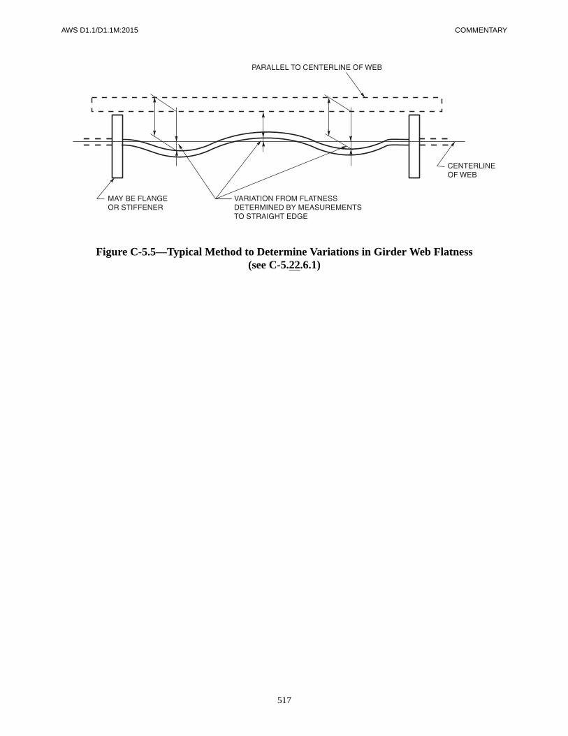
AWS D1.1/D1.1M:2015 COMMENTARY
517
Figure C-5.5—Typical Method to Determine Variations in Girder Web Flatness(see C-5.22.6.1)

COMMENTARY AWS D1.1/D1.1M:2015
518
Note: Plus tolerance indicates point is above the detailed camber shape. Minus tolerance indicates point is below the detailed cambersurface.
Figure C-5.6—Illustration Showing Camber Measurement Methods (see C-5.22.4)

AWS D1.1/D1.1M:2015 COMMENTARY
519
Figure C-5.7—Measurement of Flange Warpage and Tilt (see C-5.22.8)

COMMENTARY AWS D1.1/D1.1M:2015
520
Figure C-5.8—Tolerances at Bearing Points (see C-5.22.10)
AWS D1.1/D1.1M:2015
521
C-6.1 Scope
This clause of the code is designed to clarify the separateresponsibilities of the Contractor/fabricator/erector, asopposed to the Owner/Engineer, etc.
The provisions clarify the basic premise of contractualobligations when providing product and services. Thosewho submit competitive bids or otherwise enter into acontract to provide materials and workmanship for struc-tural weldments in conformance with the provisions ofthe code assume an obligation to furnish the products asspecified in the contract documents and are fully respon-sible for product quality.
In this clause, the term fabrication/erection inspection isseparated from verification inspection. In the originaldraft of this section, these separate functions were desig-nated as quality control and quality assurance, respec-tively. These terms were replaced with the broader termsnow contained in the code to avoid confusion with theusage in some industries (e.g., nuclear). Quality assur-ance means specific tasks and documentation proceduresto some users of the code. It was advantageous to usemore general terms that place greater emphasis on timelyinspection. Inspection by the Owner should be plannedand timely if it is to improve the quality of the construc-tion.
C-6.1.1 Information Furnished to Bidders. It is essen-tial that the Contractor know in advance which welds aresubject to NDTs and which testing procedures will beused. Unless otherwise provided in the contract docu-ments, the quality criteria for acceptance of welds arestated in Clause 6, Part C and Clause 9, Part F for tubu-lars. It is not necessary to write in the contract documentsexactly which weld or what portions of specific weldswill be examined by a specific test method. A general de-scription of weld test requirements may be specified(e.g., “10% of the length of all fillet welds shall be in-spected by MT,” or “All CJP butt joint welds in tensionflanges of girders shall be radiographed”).
If the location of tension flange butt joint welds is not ob-vious, their location should be designated on the plans.
When spot checking is specified (e.g., 10% of all filletwelds), it should not be taken to imply that the Contrac-tor be notified prior to welding which specific welds orportion of welds will be tested. It is a basic premise ofthe specifications that if random tests or spot tests aremade, there should be a sufficient number of randomtests to give a reliable indication of weld quality.
There are different acceptance criteria for staticallyloaded structures, cyclically loaded structures, and tubu-lar structures. The basic difference in acceptance criteriafor each of these structures is based upon the differencebetween static, and fatigue loading.
When fatigue crack growth is anticipated, initial welddiscontinuity sizes are smaller. All criteria are estab-lished in an attempt to preclude weld failure during theanticipated service life of the weldment.
C-6.1.2 Inspection and Contract Stipulations. Thissubclause describes the responsibility of the Contractorfor fabrication/erection inspection and testing, which isbasically the quality control responsibility described inother contract documents. The Owner has the right, butgenerally not the responsibility, to provide independentinspection to verify that the product meets specified re-quirements. This quality assurance function may be doneindependently by the Owner or their representative or,when provided in the contract, verification inspectionmay be waived or it may be stipulated that the Contractorperform both the inspection and the verification. Whenthis is done, quality control and quality assurance remainseparate functions. Verification inspection should be per-formed independently by personnel whose primary re-sponsibility is quality assurance and not production.
C-6.1.3 Definition of Inspector Categories. This sub-clause describes the difference between the Inspectorrepresenting the Owner and the Inspector representingthe Contractor.
C-6. Inspection
COMMENTARY AWS D1.1/D1.1M:2015
522
C-6.1.5 Inspector Responsibility. This subclause re-quires that the Inspector verify that all fabrication anderection by welding is performed in conformance withthe requirements of the contract documents. This in-cludes not only welding but also materials, assembly,preheating, NDT, and all other requirements of the codeand provisions of the contract documents.
C-6.1.6 Items to be Furnished to the Inspector. In-spectors need a complete set of approved drawings to en-able them to properly do their work. They need befurnished only the portion of the contract documents de-scribing the requirements of products that they will in-spect. Much of the contract documents deal with mattersthat are not the responsibility of the Inspector; these por-tions need not be furnished.
C-6.1.7 Inspector Notification. If the Inspectors are notnotified in advance of the start of operations, they cannotproperly perform the functions required of them by thecode.
C-6.2 Inspection of Materialsand Equipment
This code provision is all-encompassing. It requires in-spection of materials and review of materials certifica-tion and mill test reports. It is important that this work bedone in a timely manner so that unacceptable materialsare not incorporated in the work.
C-6.3 Inspection of WPS QualificationThe requirements of this section, including any qualifica-tion testing required by Clause 4, should be completedbefore any welding is begun on any weldments requiredby the contract documents. Qualification should alwaysbe done before work is started, but all qualification doesnot have to be completed before any work can be started.
C-6.4 Inspection of Welder, Welding Operator, and Tack Welder Qualifications
C-6.4.1 Determination of Qualification. It is importantthat the Inspector determine that all welders are qualifiedbefore work is begun on the project. If discovered afterwelding has begun, lack of welder qualification docu-
mentation may cause serious delays in the acceptance ofweldments.
C-6.4.2 Retesting Based on Quality of Work. Exam-ples of methods the inspector may choose to demonstratethe ability to produce sound welds include the following:
(1) an interview of the welder,
(2) increased visual inspection for a limited timeperiod,
(3) observation of the welding, or a simplified weldtest developed to evaluate the issue of concern,
(4) requalification in compliance with Clause 4 orClause 9 for tubulars.
C-6.4.3 Retesting Based on Qualification Expiration.If evidence cannot be supplied that shows a welder,welding operator, or tack welder has used the weldingprocess within the last six months, he or she is not con-sidered qualified to weld using that process without newqualification testing. Because active welders can main-tain their certification as long as they continue to do goodwork, it is important that Inspectors regularly evaluatethe quality of the welds produced by each welder, weld-ing operator, and tack welder.
C-6.5 Inspection of Work and RecordsExcept for final visual inspection, which is required forevery weld, the Inspector inspects the work at suitableintervals to ensure that the requirements of the applicablesections of the code are met. Such inspections should beconducted, on a sampling basis, prior to assembly, dur-ing assembly, and during welding. The inspector identi-fies final acceptance or rejection of the work either bymarking on the work or with other recording methods.The method of identification should not be destructive tothe weldment. Die stamping of welds is not recom-mended since die stamp marks may form sites for crackinitiation.
C-6.5.4 Inspector Identification of Inspections Per-formed. Die stamp marks may form sites for crackinitiation.
C-6.6 Obligations of the ContractorC-6.6.1 Contractor Responsibilities. The Contractorconducts inspection to the extent necessary to ensureconformance with the code, except as provided in 6.6.5.
AWS D1.1/D1.1M:2015 COMMENTARY
523
Part CAcceptance Criteria
C-6.8 Engineer’s Approval for Alternate Acceptance Criteria
The criteria provided in Clause 5, Fabrication, are basedupon knowledgeable judgment of what is achievable by aqualified welder. The criteria in Clause 5 should not beconsidered as a boundary of suitability for service. Suit-ability for service analysis would lead to widely varyingworkmanship criteria unsuitable for a standard code.Furthermore, in some cases, the criteria would be moreliberal than what is desirable and producible by a quali-fied welder. In general, the appropriate quality accep-tance criteria and whether a deviation produces a harmfulproduct should be the Engineer’s decision. When modifi-cations are approved, evaluation of suitability for serviceusing modern fracture mechanics techniques, a history ofsatisfactory service in similar structures, or experimentalevidence is recognized as a suitable basis for alternateacceptance criteria for welds.
C-Tables 6.1 and 9.16, Item 8—Piping Porosity. Ta-bles 6.1 and 9.16 contain visual acceptance criteria forsurface-breaking piping porosity, since this is visuallydetectable, and may significantly reduce the cross-sec-tional areas of the weld available to resist applied loads.Other forms of surface-breaking porosity do not reducethe cross-sectional area as significantly (see Annex J fora definition of piping porosity).
C-6.9 Visual InspectionThis subclause makes visual inspection of welds manda-tory and contains the acceptance criteria for it. The fabri-cation requirements of Clause 5, are also subject tovisual inspection. Allowable depth of undercut was re-vised in the 1980 edition of the code to more accuratelyreflect an acceptable percentage reduction of cross-sec-tional area for three categories of stress. The undercutvalues are for structures and individual members that areessentially statically loaded.
Undercut values for cyclically loaded structures ortubular structures (6.9 and 9.25) have not been changedand should be specified for structures and individualmembers subject to cyclic loading.
C-6.11 NDTExcept as required in 9.2.6.1, the weld quality require-ments for NDT are not a part of the contract unless NDT
is specified in information furnished to the bidders or issubsequently made a part of the contract. Both theOwner and Contractor should give careful attention tothe provisions of 6.6.5 and 6.14.1. When, in addition tothe requirement for visual inspection, NDT is specified,the acceptance criteria of 6.11, 6.12, or 6.13 apply. Theacceptance criteria for ASTM A514, A517, and A709,Grade HPS 100W high-strength quenched and temperedsteels are based on inspection, visual or NDT, conductedat least 48 hours after completion of the weld. Sincehigh-strength steels, when welded, and weld metals aresusceptible to delayed cracking caused by hydrogen em-brittlement, stress rupture, etc., it has been necessary toimpose this time restriction to assure that any delayedcracking has a reasonable chance of being discoveredduring inspection.
C-6.12 RTC-6.12.1 Discontinuity Acceptance Criteria for Stati-cally Loaded Nontubular Connections. See Figures C-6.7 and C-6.8.
C-6.12.2.1 Cyclically Loaded Nontubular Connec-tions in Tension. See Figure C-6.9.
C-6.13 UTC-6.13.1 Acceptance Criteria for Statically LoadedNontubular Connections. In the notes in Table 6.2, thekey words that are most often misinterpreted are “…fromweld ends carrying primary tensile stress.” This phrasegenerally refers to the ends of groove welds that are sub-ject to applied tensile design loads that are normal to theweld throat. When box columns are used with momentconnection members welded to the outside surface and di-aphragm plates welded on the inside to transfer the pri-mary stress through the box column member, the ends ofthe moment plate-to-box column plate welds are subjectto the 2L distance from the weld end, but the welds on di-aphragm plates on the inside of the box are not subject tothis restriction. The weld ends of the diaphragm plates donot carry primary tensile stress because this stress is car-ried through the width of the adjacent box member plates.
The note of Table 6.2 on scanning levels was added be-cause experience with UT acceptance level provisionspreviously required by the code resulted in acceptance ofsome rather large gas pockets and piping porosity thatcan occur in ESW and EGW welds. The shape of thesegas defects, which are peculiar to ESW and EGW welds,is such that they reflect less ultrasound than the usualweld discontinuities. Testing at 6 dB more sensitive thanstandard testing amplitudes will not guarantee accurate

COMMENTARY AWS D1.1/D1.1M:2015
524
evaluation of gas defects in ESW or EGW welds. Thistype of discontinuity is easily evaluated by RT, which isrecommended if indications of pipe or other gas disconti-nuities are seen at scanning levels.
C-6.13.2 Acceptance Criteria for Cyclically LoadedNontubular Connections. See Clause C-6, Part F. Thecode provides acceptance criteria for welds subject totensile stresses that differ from those subject only tocompressive stresses. Groove welds subject to compres-sive stresses only and which are indicated on design orshop drawings are required to conform to the acceptancecriteria of Table 6.2. Groove welds subject to tensilestresses under any condition of loading and welds subjectonly to compressive stresses but not specifically desig-nated as such on design or shop drawings are required toconform to the acceptance criteria of Table 6.3, whichare up to 6 dB higher than those in Table 6.2.
Part DNDT Procedures
C-6.14 ProceduresIn addition to visual inspection, which is always neces-sary to achieve compliance with code requirements, fourNDT methods are provided for in the code: (1) RT, (2)UT, (3) MT, and (4) PT.
RT and UT are used to detect both surface and internaldiscontinuities. MT is used to detect surface and nearsurface discontinuities. PT is used to detect discontinui-ties open to the surface. Other NDT methods may beused upon agreement between Owner and Contractor.
C-6.14.6 Personnel Qualification. In addition to LevelII technicians, Level III individuals may also performNDT tests provided they meet the requirements of NDTLevel II. NDT Level III engineers and technicians aregenerally supervisors and may not be actively engaged inthe actual work of testing. Since there is no performancequalification test for individuals qualified to NDT LevelIII, all individuals providing testing services under thecode are required to be qualified to Level II, which hasspecific performance qualification requirements.
C-6.15 Extent of TestingIt is important that joints to be nondestructively exam-ined be clearly described in the information furnished tobidders as explained in Part A of this Commentary.
Part ERadiographic Testing
C-6.16 RT of Groove Welds in Butt Joints
C-6.16.1 Procedures and Standards (RT). The proce-dures and standards set forth in this section are primarilydesigned for the RT of CJP groove welds in cyclicallyloaded structures and statically loaded structures. Typi-cal geometries for structural connections and design re-quirements for these structures were taken into accountin the preparation of the specification. An effort wasmade to incorporate the methodology of ASTM and toutilize procedures described in the ASME Boiler andPressure Vessel Code whenever possible.
C-6.17 RT ProcedureThe single source of inspecting radiation is specified toavoid confusion or blurring of the radiographic image.Elsewhere in the code, limits are placed on the size ofthe source to limit geometric unsharpness. RT sensitiv-ity is judged solely on the quality of the IQI image(s), asin both ASTM and ASME.
C-6.17.3 Removal of Reinforcement. When the Ownerwishes weld surfaces to be ground flush or otherwisesmoothed in preparation for RT, it should be stated in thecontract documents. The Owner and the Contractorshould attempt to agree in advance on which weld sur-face irregularities will not be ground unless surface irreg-ularities interfere with interpretation of the radiograph. Itis extremely difficult and often impossible to separate in-ternal discontinuities from surface discontinuities whenreviewing radiographs in the absence of information de-scribing the weld surface. When agreement can bereached on weld surface preparation prior to RT, rejec-tions and delays will generally be reduced.
C-6.17.3.1 Tabs. Weld tabs are generally removedprior to RT so that the radiograph will represent the weldas finished and placed in service. Contraction cracks arecommonly found in the weld at the interface betweenweld tabs and the edge of the plate or shape joined by theweld. These cracks are hard to identify in the radiographunder the best conditions. It is considered necessary toremove the weld tabs before attempting to radiograph theboundaries of the welded joint (see also C-6.17.13).
C-6.17.3.3 Reinforcement. When weld reinforce-ment, or backing, or both, is not removed, shims placedunder the IQIs are required so that the IQI image may beevaluated on the average total thickness of steel (weld

AWS D1.1/D1.1M:2015 COMMENTARY
525
metal, backing, reinforcement) exposed to the inspectingradiation.
C-6.17.4 Radiographic Film. Provisions of this sectionare to provide fine-grain film and to avoid coarseness inthe image that may result from the use of fluorescentscreens.
C-6.17.5 Technique. The source of radiation is centeredwith respect to the portion of the weld being examined toavoid as much geometric distortion as possible.
C-6.17.5.1 Geometric Unsharpness. This sub-clause is provided to limit geometric unsharpness, whichcauses distortion and blurring of the radiographic image.
C-6.17.5.2, C-6.17.5.3 Source-to-Subject Distanceand Limitations. These sections are intended to limitgeometric distortion of the object as shown in the radio-graph. An exception is made for panoramic exposures intubular structures, which are covered by 9.29 of the code.
C-6.17.6 Sources. This subclause intends that X-rayunits, 600 kVp maximum, and iridium 192 sources maybe used for all RT, provided they have adequate penetrat-ing ability and can produce acceptable radiographic sen-sitivity based upon IQI image as provided in 6.17.7 and9.28.2. Since cobalt 60 produces poor radiographic con-trast in materials of limited thickness, it is not approvedas a radiographic source when the thickness of steelbeing radiographed is equal to, or less than, 2-1/2 in [65mm]. When the thickness of steel being radiographed ex-ceeds 2-1/2 in [65 mm], cobalt 60 is often preferred forits penetrating ability. Care should be taken to ensurethat the effective size of the radiograph source is smallenough to preclude excessive geometric unsharpness.
C-6.17.7 IQI Selection and Placement. Since radio-graphic sensitivity and the acceptability of radiographsare based upon the image of the required IQIs, care istaken in describing the manufacture and use of the re-quired IQIs. IQIs are placed at the extremities of weldjoints where geometric distortion is anticipated to con-tribute to lack of sensitivity in the radiograph as shown inFigures 6.6–6.9.
IQIs may only be placed on the source side unless other-wise approved by the Engineer. Failure to place the IQIson the source side during the radiographic exposure,without prior approval of the Engineer, should be causefor rejection of the radiographs.
C-6.17.8.3 Backscatter. Backscattered radiation cancause general fogging and produce artifacts in the radio-graph. The method described in this section will identifybackscattered radiation so that corrective steps can betaken.
C-6.17.11.1 H & D Density. It is the intent of thespecification to use radiographic films within the fulllimits of the useful film density. An effort is made in thiscode to avoid the necessity of making multiple exposuresor using films of more than one exposure speed when ex-amining welded joints routinely expected to be encoun-tered in cyclically loaded structures and statically loadedstructures.
C-6.17.11.2 Transitions. The weld transitions inthickness provided for in this subclause are expected tobe gradual with a maximum slope of 1 on 2-1/2 as shownin Figure 2.2.
C-6.17.12 Identification Marks. This subclause de-scribes all information required to identify the radio-graph and also provides methods for matching theradiograph to the weld joint, so that weld repairs, whennecessary, may be made without repetitive or unneces-sarily large excavations.
C-6.17.13 Edge Blocks. Flange-to-flange welded buttjoints that join segments of thick flanges in beams andgirders are particularly difficult to radiograph due to geo-metric distortion and undercut from scattered radiation atthe ends of the weld that represent the flange edges.Weld defects at these critical locations are limited underthe provisions of 6.12.
On weldments over 1/2 in [12 mm] in thickness, it wasdemonstrated by using drilled holes and lead indicatorsnear the top edge of a weldment that a substantial portionof this edge was over exposed and could not be shown,which left the possibility of not showing defects. Byusing edge blocks and a standard source alignment, leadindicators and drilled holes could be shown on aradiograph at the plate edge.
C-6.18 Examination, Report, and Disposition of Radiographs
C-6.18.1 Equipment Provided by Contractor. A suit-able, variable intensity illuminator with spot review ormasked spot review capability is required since more ac-curate film viewing is possible when the viewers’ eyesare not subjected to light from portions of the radiographnot under examination. The ability to adjust the light in-tensity reduces eye discomfort and enhances visibility offilm discontinuities. Subdued light in the viewing areaallows the reviewer’s eyes to adjust so that small discon-tinuities in the radiographic image can be seen. Film re-view in complete darkness is not advisable since thecontrast between darkness and the intense light from por-tions of the radiograph with low density cause discom-fort and loss of accuracy. In general, within the limits of

COMMENTARY AWS D1.1/D1.1M:2015
526
density approved by the code, the greater the film den-sity, the greater the radiographic sensitivity.
C-6.18.3 Reports and Retention. The term a full set ofradiographs as used in 6.18.3 means one radiograph ofacceptable quality from each radiographic exposure re-quired for complete RT. If Contractors elect to load morethan one film in each cassette to produce an extra radio-graph for their own use or to avoid possible delays, extraexposures due to film artifacts, or both, the extra radio-graphs, unless otherwise specified, are the property of theContractor.
Part FUT of Groove Welds
C-6.19 General
C-6.19.1 UT Procedures and Standards. The UT pro-visions are written as a precise, direct method of testingweldments. These provisions were designed to ensure re-producibility of test results when examining specific re-flectors. Most groove welds may be satisfactorily testedusing the provisions of Clause 6, Part F.
Provisions for UT of welds in T-, Y-, and K-tubular con-nections can be found in 9.27.1 and 9.30. Detailed proce-dures have not been included in this section of the codebecause of the complex geometry associated with thesewelds. UT procedures for these welded joints should beapproved by both the Engineer and Contractor.
The UT of fillet welds was not included in the code be-cause of the inability to formulate a simple proceduregiving satisfactory results. Considerable information canbe obtained about the location of a discontinuity in a fil-let weld, as well as its size and orientation, when usingspecial techniques. The complexity and limitations ofUT increase as the size of the fillet weld decreases. Filletweld sizes less than 3/4 in [20 mm] usually require theuse of miniature search units for complete evaluation.The frequency for miniature search units should behigher than the 2.25 MHz nominal frequency normallyrequired, in order to control the sound beam divergence.This frequency change would also affect the 2 decibelsper inch [25 mm] attenuation factor used for indicationevaluation. Variations from the code provisions for UTmay be acceptable upon agreement from the Engineer. Itis recommended that details of such agreements be inwriting so that all parties know how the welds are to beinspected.
C-6.19.2 Variations. UT through paint layers on paintedsurfaces has been changed to an essential variable requir-ing approval by the Engineer. Although the code prohib-its routine UT through paint layers, it does not necessarilymean that a good, tight, uniform coat of paint will inter-fere with the application of UT procedure. When paint ispresent, it should be measured and reported.
During routine fabrication of structural steel, all weldsshould be inspected and accepted prior to being painted.Most testing where painted surfaces are involved is onmembers that have been in service, and the condition ofthat test surface should be considered before routine test-ing is done.
C-6.19.3 Piping Porosity. The general nature of pipingporosity in ESW and EGW welds is usually such thatholes in the central portion of the weld may be maskedby other surrounding holes. The branches or tunnels ofpiping porosity have a tendency to tail out toward theedges of the weld nugget. UT can only effectively evalu-ate the first major reflector intercepted by the sound path.Some discontinuities may be masked in this manner; thisis true for all UT.
RT should be used to evaluate suspected piping porosityin ESW and EGW welds used in building construction(see Note 4 of Table 6.2). No mention of additional RT ispresently made with reference to testing ESW and EGWwelds in Table 6.3 since these processes are not presentlyaccepted for tension welds. UT of ESW and EGW weldsat higher scanning levels will give intermittent responsesfrom piping porosity. This indicates RT should be used asdescribed above.
The pitch-and-catch technique for evaluating incompletefusion by UT in ESW and EGW welds is intended to beused only as a secondary test to be conducted in an areaalong the original groove face in the middle half of theplate thickness. This test is specified to further evaluatean UT indication in this area which appears on the dis-play at scanning level but is acceptable by indication rat-ing. The expected pitch-catch amplitude response fromsuch a reflector is very high, making it unnecessary touse the applicable amplitude acceptance levels. How-ever, since no alternative is provided, these decibel rat-ings are to be used. Since only a specific location isbeing evaluated, predetermined positioning of the probecan be made. Probe-holding fixtures are most helpful inthis operation.
The use of the 70° probe in the primary application is ad-equate in testing ESW and EGW weld fusion surfaces ofmaterial 2-1/2 in [65 mm] and less in thickness becauseacceptance levels are such that proper evaluation can beexpected.
AWS D1.1/D1.1M:2015 COMMENTARY
527
C-6.21 UT EquipmentStandards are established for UT discontinuity detectors toensure adequate mechanical and electrical performancewhen used in conformance with the requirements of thecode.
Subclauses 6.21.1 through 6.21.5 cover the specificequipment features that are to be considered for equip-ment qualification; 6.22.1 covers the reference standards;6.23.1 through 6.23.4 cover the time interval require-ments and references to the applicable 6.27 referenceblock usage; and 6.28 presents detailed qualification pro-cedures. Examples of these applications are included inAnnex L, Form L-8.
C-6.21.6 Straight Beam (Longitudinal Wave) SearchUnit. The size limitations of the active areas of straightbeam transducers have not been changed; however, thesizes being given as 1/2 in2 [160 mm2] and 1 in2
[645 mm2] have been misinterpreted as being 1/2 in[12.7 mm] square and 1 in [25.4 mm] square, instead ofthe intended 1/2 square in and 1 square in, respectively.
These active area requirements are now written out toeliminate the confusion.
C-6.21.7.2 Transducer Dimensions. Tables 6.2 and6.3 of Clause 6 were developed within a limited range ofparameters. Modifications to the equipment parametersor procedures of Clause 6 may result in test resultssignificantly different than those intended. Users arecautioned that any change in testing parameters (e.g.,transducer sizes, angles, shapes, frequencies, equipmentcalibrations, etc.) may invalidate the applicability ofTables 6.2 and 6.3. Approval of the Engineer for modifi-cations to the testing equipment or procedures should bemade only when the effects of such changes upon accep-tance criteria have been established.
C-6.22 Reference StandardsC-6.22.1 IIW Standard. The code no longer requiresthe Type 1 IIW UT Reference Block. Any of the IIW“type” blocks may be used.
The standard shown in Figure 6.13 is commonly knownin the US as an IIW type reference block. IIW is an acro-nym for the International Institute of Welding. It is re-ferred to as an IIW “type” reference block because it waspatterned after the “true” IIW block but does not con-form to IIW requirements in IIS/IIW-23-59. “True” IIWblocks are only made out of steel (to be precise, killed,open hearth or electric furnace, low-carbon steel in thenormalized condition with a grain size of McQuaid-Ehn#8) where IIW “type” blocks can be commercially ob-
tained in a selection of materials. The dimensions of“true” IIW blocks are in metric units while IIW “type”blocks usually have US Customary units. IIW “type”blocks may also include additional calibration and refer-ences features such as notches, circular grooves, andscales that are not specified by IIW.
C-Figure 6.13 All of the notes shown herewith pertainto all of the reference blocks in both Figure 6.13 andAnnex G.
C-6.22.2 Prohibited Reflectors. The code prohibits theuse of square corners for calibration purposes because ofthe inability of acquiring amplitude standardization fromvarious corners that are called “square.” Factors that canaffect amplitude standardization are the size of the filletor chamfer on the corner, if any; the amount the corner isout of square (variation from 90°); and surface finish ofthe material. When a 60° probe is used, it is very difficultto identify the indication from the corner due to high am-plitude wave mode conversions occurring at the corner.
C-6.23 Equipment Qualification
C-6.23.1 Horizontal Linearity. The use of ASTM E317for horizontal linearity qualification has been eliminated,and a step-by-step procedure outlined in 6.28.1 is usedfor certification.
C-6.23.2 Gain Control. Caution is needed when apply-ing alternate methods for vertical linearity certification.Normal ways of translating voltage ratios to dB gradua-tions generally cannot be used due to potentiometer load-ing and capacitance problems created by the high-frequency current transfer. A high degree of shielding isalso needed in all wiring.
C-6.23.4 Calibration of Angle Beam Search Units.Since the contact surfaces of search units wear and causeloss of indication location accuracy, the code requires ac-curacy checks of the search unit after a maximum ofeight hours use. The responsibility for checking the accu-racy of the search unit after this time interval is placed onthe individual performing the work.
C-6.24 Calibration for Testing
C-6.24.4.1 Sweep. Indications of at least two platethicknesses are to be displayed in order to ensure properdistance calibration because the initial pulse locationmay be incorrect due to a time delay between the trans-ducer crystal face and the search unit face.
COMMENTARY AWS D1.1/D1.1M:2015
528
C-6.24.5.1 Horizontal Sweep. At least two indica-tions other than the initial pulse are also to be used forthis distance calibration due to the built-in time delay be-tween the transducer face and the face of the search unit.
NOTE 1: The initial pulse location will always be off tothe left of the zero point on the display.
NOTE 2: Caution is to be exercised to ensure that thepulse at the left side of the screen is the initial pulse andnot one from a reference reflector. (Verify by removingsearch unit from workpiece.)
The note has been added to the end of this subclause toensure duplication of location data.
C-6.25 Testing ProceduresC-6.25.4 Couplants. It is recognized that couplants, otherthan those specifically required in the code, may workequally well or better for some applications. It is beyondthe scope of the code to list all fluids and greases thatcould be acceptable couplant materials. Any couplantmaterial, other than those listed in the code, that has dem-onstrated its capability of performing to code require-ments, may be used in inspection with the approval of theEngineer and the UT operator.
Tests should be conducted to determine if there is a dif-ference in responses from the reference reflector, due todifferences between the couplant used for calibrationcompared to the couplant used in actual testing. Anymeasurable difference should be taken into account indiscontinuity evaluation.
See Annex L, Form L-11 for a sample UT report form.
C-6.25.5 Extent of Testing. The provision to search thebase metal for laminar reflectors is not intended as acheck of the acceptability of the base metal, but rather todetermine the ability of the base metal to accept specifiedUT procedures.
C-6.25.5.1 Reflector Size. A procedure for lamellarsize evaluation is now included in 6.29.1.
C-6.25.5.2 Inaccessibility. The requirement in thissubclause to grind the weld surface or surfaces flush isnecessary only to obtain geometric accessibility for analternate UT procedure when laminar discontinuities inthe base metal prohibit testing using standard procedure.Contract documents may require flush grinding of ten-sion groove welds to improve fatigue performance andfacilitate more accurate RT and UT.
C-Table 6.7 The procedure chart was established on thebasis that a search unit angle of 70° will best detect and
more accurately evaluate discontinuities having a majordimension oriented normal or near normal to the com-bined residual and applied tensile stresses (most detri-mental to weld integrity). It should be assumed that alldiscontinuities could be oriented in this direction, and the70° probe should be used whenever possible. For opti-mum results, a 10 in [250 mm] sound path has been es-tablished as a routine maximum. There are, however,some joint sizes and configurations that require longersound paths to inspect the weld completely.
Testing procedures 6, 8, 9, 12, 14, and 15 in the proce-dure legend of Table 6.7, identified by the top quarterdesignation GA or the bottom quarter designation GB,require evaluation of discontinuities directly beneath thesearch unit. More accurate results may be obtained bytesting these large welds from both face A and face B, asalso provided for in this table.
The procedure chart was developed taking into accountthe above factors. The reason for the very exacting re-quirements of the code with respect to the application ofthe search unit (frequency, size, angle) is to maintain thebest condition for reproducibility of results. It is the in-tent of the code that welds be examined using search unitangles and weld faces specified in Table 6.7. Use ofother angles or weld faces may result in a more criticalexamination than established by the code.
Legend “P” 60° probes are prohibited for evaluationwhen using the pitch-and-catch method of testing be-cause of the high energy loss that is possible due to wavemode conversion.
C-6.25.6 Testing of Welds. When required by Tables6.2 and 6.3 as applicable, the sensitivity for scanning isincreased by at least four decibels above the maximumreject level at the maximum testing sound path. This in-creased sensitivity assures that unacceptable discontinui-ties are not missed during scanning. Scanning at theupper dB levels required by Tables 6.2 and 6.3 may re-quire specific scanning techniques that differ from thetechniques used when testing with a lesser dB level. It isimportant to note that the scanning level is determined bysound path distance and not material thickness. Forexample, assume ultrasonic testing on a 2 in [50 mm]thick weld joint in a cyclically loaded nontubular con-nection (Table 6.3). Using Table 6.7 procedure 4, theweld is divided into three separate testing areas. They arethe top quarter, the middle half, and the bottom quarter ofthe weld thickness. The sound path distance for the topquarter would be 7 in to 8 in [180 mm to 200 mm] (test-ing in leg 2 using a 60 transducer), the sound path dis-tance for the middle half would be 1-1/2 in to 4-3/8 in[38 mm to 111 mm], and the sound path distance for thebottom quarter would be 4-3/8 in to 5-7/8 in [111 mm to

AWS D1.1/D1.1M:2015 COMMENTARY
529
150 mm]. The scanning levels, as determined by Table6.3, are 35 dB for the top quarter, 25 dB for the middlehalf, and 35 dB for the bottom quarter. In order to mini-mize the problems associated with scanning at high dBlevels, it is often necessary to perform the testing in mul-tiple steps, scanning each of the three areas (top quarter,middle half, and bottom quarter) as separate activitiesusing the scanning level applicable to the sound path re-quired for each. Failure to use the required scanninglevel may result in improper acceptance of serious flaws.
C-6.25.6.4 Attenuation Factor. The attenuation rateof 2 decibels per inch [2 dB per 25 mm] of sound travel,excluding the first inch [25 mm], is established to pro-vide for the combination of two factors: the distancesquare law and the attenuation (absorption) of sound en-ergy in the test material. The sound path used is the di-mension shown on the display. The rounding off ofnumbers to the nearest decibel is accomplished by main-taining the fractional or decimal values throughout thecalculation, and at the final step, advancing to the nearestwhole decibel value when values of one-half decibel ormore are calculated or by dropping the part of the decibelless than one-half.
C-6.25.7 Length of Discontinuities. The required sixdecibel drop in sound energy may be determined by add-ing six decibels of gain to the indication level with thecalibrated gain control and then rescanning the weld areauntil the amplitude of the discontinuity indication dropsback to the reference line.
When evaluating the length of a discontinuity that doesnot have equal reflectivity over its full length, its lengthevaluation could be misinterpreted. When a six decibelvariation in amplitude is obtained by probe movementand the indication rating is greater than that of a minorreflector, the operator should record each portion of thediscontinuity that varies by ± 6 dB as a separate disconti-nuity to determine whether it is acceptable under thecode based on length, location, and spacing.
C-6.25.8 Basis for Acceptance or Rejection. In pro-cedures specified for UT, the zero reference level fordiscontinuity evaluation is the maximum indication re-flected from a 0.06 in [1.5 mm] diameter hole in the IIWultrasonic reference block. When actual testing of weldsis performed, the minimum acceptable levels are given indecibels for various weld thicknesses. In general, thehigher the indication rating or acceptance level, thesmaller the cross-sectional area of the discontinuity nor-mal to the applied stress in the weld.
Indication ratings up to 6 dB more sensitive than unac-ceptable are to be recorded on the test report for weldsdesignated as being “Fracture Critical” so that future
testing, if performed, may determine if there is disconti-nuity growth.
C-6.25.12 Steel Backing. Steel backing is considered bymany UT operators to be a deterrent to effective UT ofgroove welds due to the spurious indications that resulton the screen. However, the reflection from the steelbacking may be used by the UT operator as a confirma-tion that the ultrasound waves are penetrating throughthe entire cross section of the weld root area. The pres-ence of the steel backing indication and absence of anyother trace on the UT screen is evidence of a weld free ofmajor discontinuities. It also proves that the weld zone,in which the sound wave is passing through, is free ofthose discontinuities that could disrupt the sound wavesnormal path. The sound wave can be disrupted by atten-uation, reflection, or refraction so as to prevent return ofthe sound wave to the transducer, which can result in ac-ceptance of a weld containing a critical size discontinuity.
UT of complex welded joints can be performed reliablyand economically. Weld joint mock-ups, UT operatortraining, and knowledge of the weld joint and applicableUT equipment will ensure testing reliability and economy.
Spurious indications from steel backing will result from avariety of configurations. The following examples in-clude combined inspection procedures and techniques.
(1) T- or Corner Joints
(a) 90° Dihedral Angle. The end of the steelbacking in Figure C-6.1 will act as a reflector (“RB”),provided the root gap and penetration depth is as large asshown. “RB” will result in a horizontal trace at approxi-mately an equal sound path distance to a welding discon-tinuity at point “D.”
Resolution Technique:
1. Use straight beam UT from point “C” to determine ifdiscontinuity “D” exists (if “C” is accessible).
2. Determine if the indication is relatively continuousfor the length of the weld joint. NOTE: Most weldingdiscontinuities are not relatively uniform.
3. Evaluate weld from point “B” to determine if “D”exists. NOTE: Point “F” may require modification byflush grinding to effect ultrasound access to point“D.”
4. Increase transducer angle to provide better access to“D.”
5. Remove a small section of the backing so that “RB” isnot accessible to the sound wave to confirm that “D”actually exists or “RB” is the source of the indication.

COMMENTARY AWS D1.1/D1.1M:2015
530
6. Select an area of largest discontinuity rating for ex-ploratory grinding or gouging to determine if “D” exists.
(b) Skewed T- or Corner Joints. The interpreta-tion of a T-joint becomes more complex as the dihedralangle changes. The increase in complexity is due to anincrease in the steel backing reflection and the positionof the end of the steel backing in relation to the upper toeof the weld. As shown in Figure C-6.2(A), the reflectionof “RB” can also be interpreted as an under-bead crack(“CU”).
With the dihedral angle greater than 90° as shown in Fig-ure C-6.2(B), “RB” is now at an equal sound path dis-tance to a slag inclusion (“D”). Resolution of theseconditions is the same as for the 90° T- or corner joints[see C-6.25.12(1)(a)].
(2) Butt Joints
(a) Separation Between Backing and Joint. Themost common spurious indication (“IS”) is caused by anoffset of the joined parts (fit-up problem) or joining twoplates of different thickness resulting in a separation ofthe faying surface between the steel backing and the plate.Based on the sound path distance and depth, the indica-tion in Figure C-6.3 appears to be a root discontinuity suchas a crack or lack of fusion, when tested from point “A.”
Resolution Technique:
1. Accurately mark the location (“L”) of the indication.
2. Repeat the UT from point “A1.”
3. An “L” indication from point “A1” is verification thata discontinuity does exist at the root.
4. The lack of the “L” indication from point “A1” is evi-dence that “IS” is the source of the reflection.
(b) Surface Geometry and Backing with Simi-lar Sound Paths. Another source of confusion is the sur-face weld profile and the steel backing resulting in areflection at the same sound path distance. The rootopening in Figure C-6.4(A) is large enough in this weldjoint to allow the sound wave to transmit to the steelbacking resulting in reflection and a large indicationfrom point “RB.”
In Figure C-6.4(B) the root opening is tighter and thesound wave entrance is slightly farther from the “A” sideof the weld joint, which results in sound wave reflectionand a large indication from the surface of the weld rein-forcement (“WR”).
At this stage in the UT process the UT operator is facedwith a complex interpretation of the indications; thesound path distance is the same for both (A) and (B). Is
the indication a surface discontinuity, the weld reinforce-ment, or the edge of the steel backing?
Resolution Technique:
1. UT weld (B) from point “A.1” to determine if there isa discontinuity in the area of “WR.”
2. Any indication at “WR” is justification for examina-tion by grinding to specifically identify the disconti-nuity and judge criticality.
3. If no indication results from the test at “A.1,” thenrepeat the test from “A.”
• Confirmation that the indication from “WR” is theweld reinforcement is done by first manipulating thetransducer until maximum screen trace height is ob-tained, then wet “WR” with couplant and rub it witha finger while introducing sound waves from “A.”
• If “WR” is the reflector, the trace on the screen willbecome unstable corresponding to the movementof the finger. NOTE: This technique works best onthicker plate. Sound waves tend to flood very thinplate, which can influence the UT operator to ac-cept indications that result from a discontinuity.
4. If “WR” is not the reflector, the steel backing can beverified as the source of reflection as follows:
• Position the transducer at “A.1” on (A) to obtainmaximum screen trace height;
• Calculate the projected surface distance from thetransducer exit point to the reflector;
• Mark that dimension on the opposite side of theweld from the transducer, which is now “L.”
• Measure the dimension from “L” to “WR”—if theUT unit is calibrated correctly, this dimensionshould be the width of the steel backing. NOTE: Itis important the UT operator be knowledgeable re-garding the size of the steel backing used and thebasic root opening dimension to remove some ofthe questions regarding the source of the reflection.
5. As a general rule, it is advisable to divide the weldinto two parts, as shown in (B), by the centerline(“CL”) mark:
• Reflectors should be evaluated from the same sideof the weld the transducer is on to minimize spuri-ous indications.
(3) Seal Welded Steel Backing. The contract mayrequire seal welds on all steel backing. The seal weld canresult in the inability to transmit ultrasound through theentire cross section of the groove weld. The NDT LevelIII should determine the most practical width of the steel

AWS D1.1/D1.1M:2015 COMMENTARY
531
backing and the complementary shear wave transducerangle for testing, prior to fabrication.
In Figure C-6.6(A) the location of the ends of the steelbacking is critical because it interferes with the reflectionof the sound wave to the upper portion of the weld joint.Location of the end of the steel backing in the general re-gion of “B” to “B.1” results in the sound wave entering thesteel backing and either returning as “RB” indication, or,not returning at all if the conditions are right as for “A.1.”
In Figure C-6.6(B) the same condition exists when thesound wave enters the steel backing at “B” and continues
to propagate through the bar and into the perpendicularplate. If an indication is noted on the screen, it is verylikely to be spurious.
Resolution Techniques:
1. Changing the specified dimensions of the steel back-ing to be seal welded by increasing the width willminimize this problem.
2. Or, decrease the angle of the transducer if 1. above isnot practical.

COMMENTARY AWS D1.1/D1.1M:2015
532
Figure C-6.1—90° T- or Corner Joints with Steel Backing
Figure C-6.2—Skewed T- or Corner Joints

AWS D1.1/D1.1M:2015 COMMENTARY
533
Figure C-6.3—Butt Joints with Separation Between Backing and Joint
Figure C-6.4—Effect of Root Opening on Butt Joints with Steel Backing

COMMENTARY AWS D1.1/D1.1M:2015
534
Figure C-6.5—Resolutions for Scanning with Seal Welded Steel Backing
Figure C-6.6—Scanning with Seal Welded Steel Backing

AW
S D
1.1/D1.1M
:2015C
OM
ME
NTA
RY
535
Figure C-6.7—Illustration of Discontinuity Acceptance Criteria for Statically LoadedNontubular and Statically or Cyclically Loaded Tubular Connections (see 6.12.1)

CO
MM
EN
TAR
YA
WS
D1.1/D
1.1M:2015
536
Notes:1. C—Minimum clearance allowed between edges of discontinuities 3/32 in [2.5 mm] or larger (per Figure 6.1). Larger of adjacent discontinuities governs.2. X1—Largest permissible elongated discontinuity for 1-1/8 in [30 mm] joint thickness (see Figure 6.1).3. X2—Multiple discontinuities within a length allowed by Figure 6.1 may be handled as a single discontinuity.4. X3–X4—Rounded-type discontinuity less than 3/32 in [2.5 mm].5. X5—Rounded-type discontinuities in a cluster. Such a cluster having a maximum of 3/4 in [20 mm] for all pores in the cluster is treated as requiring the same clearance as a 3/4 in [20
mm] long discontinuity of Figure 6.1.6. Interpretation: Rounded and elongated discontinuities are acceptable as shown. All are within the size limits and the minimum clearance allowed between discontinuities or the end of
a weld joint.
Figure C-6.8—Illustration of Discontinuity Acceptance Criteria for Statically LoadedNontubular and Statically or Cyclically Loaded Tubular Connections 1-1/8 in [30 mm]
and Greater, Typical of Random Acceptable Discontinuities (see 6.12.1)

AWS D1.1/D1.1M:2015 COMMENTARY
537
Notes:1. A—Minimum clearance allowed between edges of porosity or fusion-type discontinuities 1/16 in [2 mm] or larger. Larger of adjacent
discontinuities governs.2. X1—Largest allowable porosity or fusion-type discontinuity for 3/4 in [20 mm] joint thickness (see Figure 6.2).3. X2, X3, X4—Porosity or fusion-type discontinuity 1/16 in [2 mm] or larger, but less than maximum allowable for 3/4 in [20 mm] joint
thickness.4. X5, X6—Porosity or fusion-type discontinuity less than 1/16 in [2 mm].5. Porosity or fusion-type discontinuity X4 is not acceptable because it is within the minimum clearance allowed between edges of such
discontinuities (see 6.12.2.1 and Figure 6.2). Remainder of weld is acceptable.6. Discontinuity size indicated is assumed to be its greatest dimension.
Figure C-6.9—Illustration of Discontinuity Acceptance Criteria for Cyclically Loaded Nontubular Connections in Tension (see 6.12.2.1)

AWS D1.1/D1.1M:2015
538
This page is intentionally blank.
AWS D1.1/D1.1M:2015
539
C-7.1 ScopeStud welding is unique among the approved welding pro-cesses in this code in that not only are the arc length andthe weld time automatically controlled, but it also lendsitself to a significant production proof test. Once theequipment is properly set, the process is capable of alarge number of identical sound welds when attention isgiven to proper workmanship and techniques. Many mil-lions of studs have been successfully applied. For otherreasons outlined above, formal procedure qualificationsare not required when studs are welded in the flat (down-hand) position to materials listed in Table 3.1, Group Iand II. Procedures developed under the application quali-fication requirements of 7.6 are an exception to the fore-going. Since this constitutes the basic change from otherapproved welding processes in this code, stud weldinghas been moved to Clause 7.
There are provisions for the following:
(1) Tests to establish mechanical properties and thequalification of stud bases by the stud manufacturer
(2) Tests to establish or verify the welding setup(essential variables) and to qualify the operator andapplications
(3) Tests for inspection requirement
C-7.2 General RequirementsC-7.2.5 Stud Finish. Heads of shear connectors or an-chor studs are subject to cracks or bursts, which arenames for the same thing. Cracks or bursts designate anabrupt interruption of the periphery of the stud head byradial separation of the metal. Such interruptions do notadversely affect the structural strength, corrosion resis-tance, or other functional requirements of headed studs.
A typical example of calculating the crack length or burstis as follows:
0.5 in [13 mm] headed anchorH- Head Diameter = 1.0 in [25 mm]C- Shank Diameter = 0.5 in [13 mm]CL- Crack Length
CL ≤ (H – C)/4CL ≤ (1.0 – 0.5)/4CL ≤ 0.125 in [3.2 mm]
C-7.3 Mechanical RequirementsThe subclause on mechanical requirements has been ex-panded to show three strength levels of studs. The lowerstrength level, Type A, is used for general purpose studsand the higher strength level, Type B, is used as an es-sential component of composite beam design and con-struction. Type B studs are the most used in compositeconstruction for highway bridges.
C-7.4 Workmanship/FabricationSeveral items of cleanliness are needed to produce soundquality studs. There is new emphasis on keeping thestuds. Type B studs are used as an essential componentin composite beam construction for highway bridges andbuildings. Type C studs are commonly used as embed-ded connections in concrete/steel construction.
C-7.4.6 Arc Shield Removal and C-7.4.7 AcceptanceCriteria. These subclauses clearly call for used arcshields to be removed and a visual inspection to be madeby the applicator. Good judgment would call for thischeck to be performed as soon as practical after the studis welded to avoid a large number of defective studs inthe case of equipment malfunction.
The expelled metal around the base of the stud is desig-nated as flash in conformance with the definition of flashin Annex J of this code. It is not a fillet weld such asthose formed by conventional arc welding. The expelledmetal, which is excess to the weld required for strength,is not detrimental but, on the contrary, is essential to pro-
C-7. Stud Welding

COMMENTARY AWS D1.1/D1.1M:2015
540
vide a good weld. The containment of this excess moltenmetal around a welded stud by the ferrule (arc shield) as-sists in securing sound fusion of the entire cross sectionof the stud base. The stud weld flash may have nonfusionin its vertical leg and overlap on its horizontal leg; and itmay contain occasional small shrink fissures or other dis-continuities that usually form at the top of the weld flashwith essentially radial or longitudinal orientation, or both,to the axis of the stud. Such nonfusion on the vertical legof the flash and small shrink fissures are acceptable.
C-7.5 TechniqueC-7.5.1 Automatic Mechanized Welding. Techniqueis a subclause that covers the requirements for equipmentand initial settings.
C-7.5.5 FCAW, GMAW, SMAW Fillet Weld Option.The code also allows studs to be fillet welded, at theoption of the Contractor, by the SMAW, GMAW, andFCAW processes, although the use of automatically-timed equipment is generally preferred. Welders shouldbe qualified in conformance with Clause 4 for this appli-cation. The option was included for situations whereonly limited numbers of studs are to be welded in thefield. Obviously, the Contractor’s decision in this matterwould be one of economics. The electrode diameter isspecified to help ensure that minimum heat input is pro-vided in conjunction with the applicable preheat require-ments of Table 3.3.
Studs welded by the use of automatically timed weldingequipment or fillet welded by SMAW, GMAW, and FCAWare considered to have been welded by a prequalified WPS.
C-7.6 Stud Application Qualification Requirements
Studs applied to a vertical surface may require modifiedarc shields and modified arc shields may also be requiredwhen welding to other than flat surfaces. Since this andother special cases are not covered by the manufacture’sstud base qualification, the Contractor should be respon-sible for the performance of these tests. Test data servethe same purpose as WPS qualification for other pro-cesses. Inspectors should accept evidence of previousspecial application tests based on satisfactory preproduc-tion tests with the specific stud welding set up in use.
C-7.6.1 Purpose. Special conditions where applicationqualification requirements apply have been enlargedfrom consideration of modified arc shields and weldposition to include welds through decking and for studswelded to other than Group I or II steels from Table 3.1.
The weld through decking application has been addedbecause of problems associated only at the productionsite that are not related to the Manufacturer’s Stud BaseQualification. These include, but are not limited to, deckfit-up, weather conditions, the flange thickness and pos-sible coatings on the steel beams, deck coating thicknessand number of deck plies. It is recommended that appli-cation qualification be performed at the job site, usingthe same welding equipment, operators, materials, coat-ing thickness, and beam conditions as those at the site. Itis recommended that the heaviest metal deck thickness,whether one or two plies, be tested along with the thick-est coating (galvanized if used) to qualify work for eachproject. While the welding variable developed for thisworst case would not necessarily apply to every stud tobe used on the project, the equipment to be used wouldhave been proven for the worst case. The operatorswould be qualified, the PQR/WQR records would beestablished for the site, and the preproduction testing of7.7.1 could then be used for each other set up and pro-duction period.
It is recommended that the Engineer accept properly docu-mented evidence of weld through decking application testswhere new work would fall within previous limits.
The application test for other than Group I or II steels hasbeen added to serve as a reminder that the Engineershould evaluate each such application.
Most steels in Group III of Table 3.1 and the steels inTable 4.9 are heat-treated steels, and the heat from studwelding can lead to reduced base plate static or dynamicphysical properties. For example, thin quenched-and-tempered steels may have reduced tensile properties, andthicker quenched-and-tempered steels are more likely tohave reduced notch toughness in the stud weld HAZ. TheEngineer should particularly evaluate the applicationwhere studs will be welded in members subject to cyclictensile stress or to stress reversal. The application testwill serve to prove only that the stud itself is acceptablewith the metal used.
C-7.7 Production Control
Applicator testing is required for the first two studs ineach day’s production or any change in the set up suchas changing of any one of the following: stud gun, timer,power source, stud diameter, gun lift and plunge, totalwelding lead length, or changes greater than 5% in cur-rent amperage) and time. Users who are unfamiliar withany of these terms are encouraged to refer to the latestedition AWS C5.4, Recommended Practices for StudWelding. At the very high currents used in stud welding,

AWS D1.1/D1.1M:2015 COMMENTARY
541
it is very important to have adequate lead size and goodlead connections.
C-7.7.1.4 Bend Test. Bending some stud and basematerials at temperatures below 50°F [10°C], creates in-adequate toughness to pass a hammer test.
C-7.8 Fabrication and Verification Inspection Requirements
In addition to visual and bend tests by the applicator,studs are to be visually inspected and bend tested by theinspector.
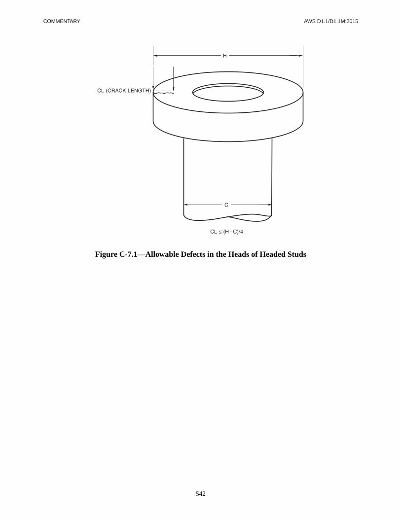
COMMENTARY AWS D1.1/D1.1M:2015
542
Figure C-7.1—Allowable Defects in the Heads of Headed Studs

AWS D1.1/D1.1M:2015
543
C-8.1 GeneralThere are many technical and workmanship conditionsthat are common to strengthening, repairing, and heatstraightening steel members, and as a result, Clause 8 hasbeen expanded to include heat straightening, a form ofrepairing steel members.
Clause 8 of this document is not intended to replaceASTM A6 provisions for conditioning new steel, but toprovide recommendations for repair and strengthening ofmembers in existing structures.
C-8.2 Base MetalC-8.2.1 Investigation. The first essential requirement instrengthening, repairing, and heat straightening existingstructures is the identification of the material.
Weldability of the existing steel is of primary impor-tance. Together with the mechanical properties of thematerial, it will provide information essential for the es-tablishment of safe and sound WPSs. Only then will real-istic data be available for reliable cost estimates. Shouldpoor weldability make such cost economically prohibi-tive, other means of joining should be considered by theEngineer.
Mechanical properties may be subject to variability, de-termined by tests of representative samples taken fromthe existing structure. Hardness testing may also provide,by correlation, an estimation of the tensile properties ofthe material.
In cases of unknown weldability, References 1 and 2provide examples of simple and inexpensive techniquesto make a preliminary determination whether or not thebase metal is suitable for welding.
Low melting temperature base metal elements such assulfur, phosphorus, copper, tin, lead, and zinc can causesolidification or “hot” cracking. Utilizing low admixtureWPSs and joint details that do not rely on penetration to
gain strength may help minimize hot cracking tendencies.Higher levels of carbon, coupled with higher levels of al-loys, whether intentionally or unintentionally added, in-crease steel hardenability and increase hydrogen-relatedor “cold” cracking tendencies. Low-hydrogen practice,higher preheat and interpass temperature, as well aspostheat operations, reduce cold cracking tendencies. Thematerial may range from easily weldable to unacceptableweldability. Investigation into the relative weldability isessential (see References 3, 5, and 6).
C-8.2.2 Suitability for Welding. Welding to stainlesssteel, wrought iron, and cast iron is not addressed in thegeneral body of this code. However, these materials aresometimes encountered in older structures that are beingrenovated. As shown in Table C-8.1, a WPS and quali-fied welding supervision is needed in each case becauseof the inherent difficulty in welding. Guidance for weld-ing stainless steel is given in References 3 and 4. Guid-ance for welding wrought iron is given in Reference 5.Guidance for welding cast iron is given in References 3,4, 5, and 6.
C-8.3 Design for Strengthening and Repair
C-8.3.1 Design Process. It is strongly recommended thatlocations that are considered for welding or heating be in-spected. Thermal expansion associated with either processcan extend any existing crack further into the member.
C-8.3.3 Fatigue History. Generally, in the case of cycli-cally loaded structures, sufficient data regarding past ser-vice are not available to estimate the remaining fatiguelife. A conservative estimate of remaining fatigue lifeshould be made based on whatever loading history isavailable. Practical methods to extend the expectedfatigue life of a member include: reducing the stressor stress range, providing connection geometry lesssusceptible to fatigue failure, and using fatigue lifeenhancement techniques.
C-8. Strengthening and Repair of Existing Structures

COMMENTARY AWS D1.1/D1.1M:2015
544
C-8.3.5 Loading During Operations. Repair, strength-ening and heat straightening of existing structures differfrom new construction inasmuch as these operations mayhave to be executed with the structure or the structuralelement under some condition of working stress.
There is guidance in the literature (References 1, 2, 7, 8,9, 10, 11, and 12) with respect to welding of structuralmembers under load. Each situation should be evaluatedon its own merits, and sound engineering judgmentexercised.
Research (References 7, 11, and 19) indicates that resid-ual stresses due to mill rolling practice and welding onlyhave an effect on member capacity for some specificstructural functions. Because of offsetting tensile andcompressive residual force levels, residual stresses resultin no quantifiable degradation of a member’s flexuralcapacity. A similar condition exists for tensile members,provided that the heating or welding affects only a por-tion of the member’s cross-sectional area. Compressionmembers are more sensitive to residual stress distributionbecause of overall and local buckling possibilities. Bal-anced flame heating or welding about the neutral axismay be essential to avoid this type of problem. Regard-less of the stress conditions, the heating or weldingshould not be performed over the entire cross section atthe same time.
C-8.3.7 Use of Existing Fasteners. The retrofitting pro-visions for combining welds with overstressed rivets orbolts is more restrictive than 2.7.3 which deals with con-necting elements not overstressed at the time of retrofit-ting (see Reference 22).
C-8.4 Fatigue Life Enhancement
C-8.4.1 Fatigue Life Enhancement. When properlyadministered, these reconditioning methods may be usedfor enhancing the fatigue life of existing structures, par-ticularly when the applied stress is normal to the axis ofthe weldment. The following techniques affect fatiguelife only from the point of view of failure from the weldtoe. The possibility of fatigue crack initiation from otherfeatures of the weld, e.g., the root area, should not beoverlooked. Typical uses include the repair of fatiguecracks and the extension of fatigue life of existing build-ings and equipment.
Welded joints represent particularly severe stress con-centrations. Research at The Welding Institute (TWI),Cambridge, England, identified an acute line of micro-scopic slag intrusions along the toes of all welds made byall arc processes except GTAW. All processes however,were found to produce some degree of undercut at the
toe, notwithstanding ideal weld profiles (see FigureC-8.1). The practical implication was that all welds havea pre-existing discontinuity in the form of either micro-scopic undercut or slag intrusions, or both. Normalinspection methods cannot detect these discontinuities,which in any case are unavoidable when using existingwelding technologies (see References 28, 32 [Chapters 1and 2], and 33).
In plain material, fatigue life is spent in crack initiationand propagation. In weldments, however, it is assumedthat crack-like discontinuities already exist. Therefore,the fatigue life of welds is spent solely in crack propaga-tion. This, along with residual tensile stresses at or nearthe yield point, is the essential reason why weldments canendure fewer cycles to fatigue failure than a similarlyloaded plain material (see Figure C-8.2).
Fatigue life enhancement can be obtained by recondi-tioning the weld toes. The small pre-existing discontinui-ties are either removed or the sharp openings dulled (seeFigure C-8.5). Toe grinding and GTAW (TIG) dressingextend fatigue life by restoring a crack initiation phase.Peening, by the introduction of a compressive stress, re-tards the rate of crack propagation. The resulting weldprofile also complements the overall joint resistance tofatigue cracking by reducing the geometric stress con-centration. When these pre-existing toe discontinuitiesare perpendicular to the applied stress, fatigue life en-hancement methods are most effective (Figure C-8.4) (seeReference 32 [Chapter 4]).
(1) Profile improvement for round tubular sections isto conform to 9.2.7.6, 9.2.7.7, and is to conform to thecorresponding sections from the Commentary, C-9.2.7.6and C-9.2.7.7. Acceptable profiles in conformance withFigure 9.16 may be attained by (1) adding a cappinglayer, (2) grinding the weld surface, and (3) peening theweld toe with a blunt instrument. Figure C-2.8 providesprecise profile criteria. Fatigue category limitations onweld size or thickness and weld profile are required tomeet the criteria of Table 9.4, Level I.
(2) Toe grinding should be done along the centerlineof the weld toe for both tubular connections (T-, Y-, orK-) and nontubular joints. The recommended tools in-clude a high-speed grinder for use with a tungsten car-bide burr. The tip radius should be scaled to the platethickness according to Table C-8.2. These radii are theminimum recommended, larger sizes may prove morebeneficial.
Grinding should be carried out to a minimum depth of0.03 in–0.04 in [0.8 mm–1.0 mm] below the platesurface or approximately 0.02 in–0.03 in [0.5 mm–0.8 mm] below the deepest undercut to a maximum totaldepth of 1/16 in [2 mm] or 5% of the plate thickness,

AWS D1.1/D1.1M:2015 COMMENTARY
545
whichever is greater. The axis of the burr should be atapproximately 45° to the main plate (see Figure C-8.3).The angle of the burr axis should be a maximum 45° ofthe direction of travel to ensure that the grinding marksare nearly perpendicular to the weld toe line (parallel tothe direction of stress). The ends of longitudinallystressed welds require special care to be effective (seeFigure C-8.6). The finishing pass should be light to ob-tain a good surface finish. Check visually and with MTor PT for any remaining undercut or other discontinuities(see References 28, 29, 32 [Chapter 2], 34, and 37).
(3) Hammer peening applies to steels with yieldstrengths up to 115 ksi [800 MPa] and thicknesses notless than 3/8 in [10 mm]. Steel hammer bits should haveapproximately hemispherical tips with diameters be-tween 1/4 in and 1/2 in [6 mm and 12 mm]. The indenta-tion should be centered on the weld toe so that metal oneach side (both weld metal and base metal) is deformed,resulting in a smooth surface free from obvious individ-ual blows. The hammer should be held at 45° to the platesurface and approximately perpendicular to the directionof travel. The indentation in mild steel (yield strength upto 36 ksi [250 MPa]) should be approximately 0.02 in[0.5 mm]; in medium-strength steel (yield strength be-tween 36 ksi and 65 ksi [250 MPa and 450 MPa])0.01 in [0.25 mm]; and in high-strength steel (yieldstrength between 65 ksi and 115 ksi [450 MPa and800 MPa]) 0.004 in [0.1 mm] (see Figure C-8.7). Thesedepths are roughly equivalent to four peening passes.The weld is to be checked visually and with MT or PTprior to peening (see References 28, 29, 32 [Chapter 2],34, and 36).
The benefit of hammer peening is derived from the intro-duction of compressive residual stresses; thus, it is criti-cal to ensure that nothing which will cause stress relief(e.g., PWHT) be performed after peening. Also, hammerpeening should be applied when the joint is “in place”and carrying dead-load.
(4) GTAW (TIG) dressing consists of remelting theexisting weld metal to a depth of approximately 1/16 in[2 mm] along the weld toe without the addition of fillermetal. The weld surface should be free from rust, slag,and scale. The tip of the electrode should be kept sharpand clean. The tip should be located horizontally 0.02 into 0.06 in [0.5 mm to 1.5 mm] from the weld toe (seeFigure C-8.8). Where toughness of the HAZ may createproblems, a modified technique using a second temper-ing pass may be used (see References 28, 32 [Chapters 2and 4], and 35).
(5) Toe grinding followed by hammer peening inhibitsfatigue crack initiation and the rate of crack propagation.Thus, for critical joints, this combined treatment offers
superior resistance to fatigue failure. The weld surfaceshould be checked visually and by MT for surface discon-tinuities prior to peening. During peening operations, vi-sually check after each pass (see References 30, 31, and34).
C-8.4.2 Stress Range Increase. The allowable stressrange for cyclically loaded connections may be increasedby a factor of 1.3 along the S-N design curve, which isequivalent to a factor of 2.2 on cycle life, for an S/Nslope of approximately 1/3, when toe grinding, hammerpeening, or GTAW (TIG) dressing is used. However, theeffect of toe grinding and hammer peening is cumulative.A factor of 1.5 on the stress range may be allowed athigh cycles (N = 107), but reduced to a factor of 1.0 (nobenefit) at low cycles (N = 104). For nontubular joints,the improvement factor should not exceed the highest as-welded fatigue design category.
Tubular sections for T-, Y-, and K-joints are discussed in9.2.7.6 and 9.2.7.7 (see References 28, 29, 30, 32, 34, 35,and 36).
NOTE: Current research at Lehigh University on beamswith welded cover plates suggests that this joint does notrespond to enhancement techniques (especially hammerpeening) as well as previous testing had indicated.
C-8.5 Workmanship and TechniqueC-8.5.2 Member Discontinuities. Welding or applyingheat to steel in the presence of existing cracks can resultin crack propagation because of the stress levels that mayexist at the crack tip. As a result, it is strongly recom-mended that any crack-like discontinuities be removedprior to applying heat or welding. This can be accom-plished by drilling a hole at the termination of the crackor by grinding. References 23 and 26 provide guidancefor repairing many commonly observed conditions. Pro-cedures for repairing existing welds are also required toconform to the provisions of Clause 5.
C-8.5.4 Base Metal of Insufficient Thickness. Corro-sion or wear with resultant section loss may reduce thethickness of the parts below that required to provide ade-quate weld size. Building up the edge of the thin sectionmay be performed by welding, provided the thickness ofthe overall section is adequate to carry the load.
Corrosion or wear may reduce the thickness of partsbelow that required to support the load. Similarly, in-creased loads may require additional member thickness.Increasing member thickness by facing with weld metalwould generally be ineffective except for small, localizedregions. Reinforcement of the member by the use ofadditional plates or similar attachments is preferred.

COMMENTARY AWS D1.1/D1.1M:2015
546
C-8.5.5 Heat Straightening. Heat straightening of steelmembers requires the sequencing of various heating pat-terns. Literature (References 1, 8, 9, 13, 14, 15, 16, 17,and 18) exists that provides guidance as to the mechanicsof heat straightening. The actual process remains one ofoperator experience.
Limits (including significant safety factors) are placed onthe temperature to which steel can be heated to avoidpossible metallurgical changes in the steel when it subse-quently cools down to an ambient temperature. Thechemistry and prior tempering of the steel dictates thecritical temperature.
Rapid cooling of steel from elevated temperatures downto about 600°F [315°C] is not recommended because un-desirable metallurgical transformations can occur (see 5.8for a more detailed discussion of this subject).
Reference 20 (AASHTO Div. II, Section 11.4.12.2.3)also considers 600°F [315°C] as the critical temperature.Furthermore, Reference 21 shows that at this tempera-ture, the moduli of elasticity and yield point of steel arenot significantly reduced from that of steel at ambienttemperature.
Cooling rates suggested in other parts of the generalspecification for the appropriate grade and thickness of
steel are recommended. A water mist, wet rags, or forcedair is considered to be accelerated cooling and may onlybe used when the steel temperature is below 600°F[315°C].
C-8.5.6 Welding Sequence. Welding procedures shouldbe adjusted so that the total heat input per unit length ofthe weld for a given thickness and geometry of the mate-rial will maintain the temperature isotherms relativelynarrow and minor in relation to the cross section of thestress-carrying member.
C-8.6 Quality
The Engineer determines the level of inspection andNDT as appropriate for the job conditions. It is recom-mended that the contract document requirements bemade compatible with Clause 6 and Clause 9 of thiscode.
Examination of rivets and bolts affected by theheat induced by welding or straightening should beconsidered.
References for Clause C-8
1. Blodgett, O. W. Design of Welded Structures, 12thPrinting. Cleveland, OH: The James F. Lincoln ArcWelding Foundation, 1982.
2. Ricker, D. T. “Field welding to existing steel struc-tures.” Engineering Journal 25(1): Chicago, IL.American Institute of Steel Construction 1988.
3. American Welding Society. Welding Handbook,Volume 4. Miami, FL: American Welding Society,1982.
4. Lincoln Arc Welding. The Procedure Handbook ofArc Welding, 12th Ed. Cleveland, OH: The James F.Lincoln Arc Welding Foundation, June 1973.
5. Jefferson, T. B. and Woods, G. Metals and How toWeld Them, 2nd Ed. Cleveland, OH: W. E. Publica-tions, The James F. Lincoln Arc Welding Founda-tion, 1972.
6. American Welding Society, Guide for Welding IronCastings, AWS D11.2. Miami, FL: American Weld-ing Society, 1989.
7. Nagaraja Rao, N. R. and Tall, L. “Columns rein-forced under load.” Welding Journal, Vol. 42, Re-search Supplement 177-s, April 1963.
8. Shanafelt, G. O. and Horn, W. B. “Guidelines forevaluation and repair of damaged steel bridge mem-bers.” Report No. 271. Washington, DC: NationalCooperative Highway Research Program, Transpor-tation Research Board, June 1984.
9. Tide, R. H. R. “Basic considerations when rein-forcing existing steel structures.” Conference Pro-ceedings, National Engineering Conference andConference of Operating Personnel, New Orleans,LA. Chicago, IL: American Institute of Steel Con-struction, April 1987.

AWS D1.1/D1.1M:2015 COMMENTARY
547
10. Tide, R. H. R. “Effects of fabrication on local stressconditions.” Conference Proceedings, ASCE SeventhStructures and Pacific Rim Engineering Conference,San Francisco, CA. New York, NY: AmericanSociety of Civil Engineers, May 1989.
11. Marzouk, H. and Mohan, S. “Strengthening of wide-flange columns under load.” Canadian Journal ofCivil Engineering 17(5), October 1990. Ottawa,Ontario, Canada: Canadian Society of Civil Engineers.
12. Tide, R. H. R. “Reinforcing steel members and theEffects of Welding.” Engineering Journal 27(4):1990.
13. Stitt, J. R. “Distortion control during welding oflarge structures.” Paper 844B, Air Transport andSpace Meeting. New York, NY: Society of Auto-motive Engineers, Inc. and American Society ofMechanical Engineers, April 1964.
14. Holt, Richard E. “Primary concepts of flame bend-ing.” Welding Journal, June 1971.
15. United States Steel Corporation. Fabrication Aidsfor Continuously Heat-Curved Girders, ADUSS88-5538-01. Pittsburgh, PA: United States SteelCorporation, April 1972.
16. Stewart, J. P. Flame Straightening Technology,LaSalle, QUE, 1981.
17. Roeder, C. W. “Experimental study of heat induceddeformation.” Journal of Structural Engineering112(ST10) 1986. New York, NY: American Societyof Civil Engineers.
18. Avent, R. R. “Heat straightening of steel; from Artto Science.” Conference Proceedings, National SteelConstruction Conference, Miami Beach, FL. Chi-cago, IL: American Institute of Steel Construction,June 1988.
19. American Society of Civil Engineers. Plastic Designin Steel, a Guide and Commentary. New York, NY:ASCE, 1971.
20. American Association of State Highway and Trans-portation Officials. Standard Specifications forHighway Bridges, 15th Edition. Washington, DC:AASHTO, 1992:
21. United States Steel Corporation. Steel Design Man-ual, ADUSS 27-3400-04. Pittsburgh, PA: UnitedStates Steel Corporation, January 1981.
22. Jarosch, K. H. and Bowman, M.D. “Tension buttjoints with bolts and welds in combination.” Engi-neering Journal 23(1) 1986.
23. Fisher, J. W. Fatigue and Fracture in Steel Bridges.New York, NY: John Wiley and Sons, Inc., 1984.
24. Fisher, J. W. Bridge Fatigue Guide—Design andDetails. Chicago, IL: American Institute of SteelConstruction, 1977.
25. Welding in the World. “Recommendations for re-pairs and or strengthening of steel structures,”26(11/12), Great Britain.
26. Haagensen, P. J. “Improving the fatigue perfor-mance of welded joints,” Proceedings, InternationalConference on Offshore Welded Structures. London,England, November 1982.
27. Maddox, S. J. Aspects of the Improvement inFatigue Strength of Fillet Welds by Peening. Cam-bridge, England: The Welding Institute, 1985.
28. Maddox, S. J., Fatigue Strength of Welded Struc-tures, Second Edition. Abington Publishing, 1992.
29. Haagensen, P. J. IIW DOC. XIII-WG2-22-93,Repair Methods and Life Extension, 1993.
30. Haagensen, P. J. The Effect of Grinding and Peeningon the Fatigue Strength of Welded T-Joints. IIWDoc. XIII-1510-93. 1993.
31. Haagensen, P. J., Life Extension and Repair by Grind-ing and Peening, IIW Doc. XIII-1511-93, 1993.
32. The Welding Institute. Improving the Fatigue Per-formance of Welded Joints. Cambridge, England:The Welding Institute, 1983.
Maddox, S. J., Chapter 1 “An introduction to thefatigue of welded joints”
Booth, G. S., Chapter 2 “A review of fatigue strengthimprovement techniques”
Woodley, C. C, Chapter 4 “Practical applications ofweld toe grinding”
Haagensen, P. J., Chapter 5 “Effect of TIG dressing onfatigue performance and hardness of steel weldments”
33. Maddox, S. J. “International efforts on fatigue ofwelded construction.” Welding & Metal Fabrica-tion, December 1992.
34. Commission IIW Working Group 2—ImprovementTechniques, Proposed IIW Specification for Weld

COMMENTARY AWS D1.1/D1.1M:2015
548
Toe Improvement by Hammer Peening or BurrGrinding, 1993.
35. Takenouchi et. al. Fatigue Performances of Repair-ing Welds with TIG-Dressing for Fatigue DamagedHighway Bridges, IIW Doc. XIII-1509-93. Japan, 1993.
36. Welsch, W. “Peening improves fatigue life.” Weld-ing Design & Fabrication, September 1990.
37. Connect, No. 12, The Welding Institute, Cambridge,England, (from AWS Welding Journal, February 12,1991).
38. CETIM/Centre Technique Des Industries Meca-niques. Improving the Fatigue Strength of WeldedJoints by TIG or Plasma Dressing. IIW Doc. XIII-WG2-10-91, 1991.

AWS D1.1/D1.1M:2015 COMMENTARY
549
Table C-8.1Guide to Welding Suitability (see C-8.2.2)
Structure Category
Base Metal
ASTM, ABS, and API Steels per 3.3 and
Table 3.1
Discontinued, Unknown Steels, Cast Steels,and Stainless Steels Wrought Iron Cast Iron
Static or Cyclic NontubularClause 2, Part B
Check for prequalified status per Clause 3. Prequalified WPSs may be used per Clause 3.
ASTM A7, A373, A441—Use Table 3.1 (Group II) and Clause 3.Others, see Note a.
Notes a and b apply. Notes a and b apply.
Cyclic NontubularClause 2, Part C
Check for prequalified status per Clause 3. Prequalified WPSs may be used per Clause 3.
ASTM A7, A373, A441—Use Table 3.1 (Group II) and Clause 3.Others, see Note a.
Notes a and b apply. Not recommended.
TubularClause 9, Part A
Prequalified WPSs may be used per Clause 9.
Static TubularCheck for prequalified status per Clause 9.
Note a applies. Notes a and b apply.Notes a and b apply. Not recommended.
Cyclic TubularCheck for prequalified status per Clause 9.
Note a applies. Notes a and b apply. Not recommended.
a Established Welding Suitability: Existence of previous satisfactory welding may justify the use of Table 3.2 (Group II) filler metals. If not previouslywelded, obtain samples and prepare WPS qualification. Conduct in place weld test on safe area of structure if samples are not available.
b Persons qualified to establish welding suitability must provide a written WPS and should monitor welding operations.
Note: A written WPS is required and must have Engineer approval.
Table C-8.2Relationship Between Plate Thickness and
Burr Radius [see C-8.4.1(2)]
Plate Thickness(in)
Plate Thickness (mm)
Burr Radius(mm)
< 0.79 < 20 50.79–1.14 20–29 61.18–1.54 30–39 81.57–1.93 40–49 101.97–2.52 50–64 122.56–3.11 65–79 163.15–3.90 80–99 183.94–4.69 100–119 204.72–5.87 120–149 255.91–7.09 150–180 30

COMMENTARY AWS D1.1/D1.1M:2015
550
Note: Microscopic intrusions at weld toe act as pre-existing discontinuities (see C-8.4.1).
Figure C-8.1—Microscopic Intrusions
Figure C-8.2—Fatigue Life (see C-8.4.1)

AWS D1.1/D1.1M:2015 COMMENTARY
551
Figure C-8.3—Toe Dressing with Burr Grinder (see C-8.4.1)
Figure C-8.4—Toe Dressing Normal to Stress (see C-8.4.1)

COMMENTARY AWS D1.1/D1.1M:2015
552
Figure C-8.5—Effective Toe Grinding (see C-8.4.1)
Figure C-8.6—End Grinding [see C-8.4.1(2)]

AWS D1.1/D1.1M:2015 COMMENTARY
553
Figure C-8.7—Hammer Peening[see C-8.4.1(3)]
(Courtesy of S. Maddox, IIW, Com. XIII)

COMMENTARY AWS D1.1/D1.1M:2015
554
Figure C-8.8—Toe Remelting [see C-8.4.1(4)](Courtesy of P. Haagensen, IIW, Com. XIII)

AWS D1.1/D1.1M:2015
555
Part ADesign of Tubular Connections
C-9.1 GeneralThe tubular provisions of this code originally evolvedfrom a background of practices and experience withfixed offshore platforms of welded tubular construction.Like bridges, these are subject to a moderate amount ofcyclic loading. Like conventional building structures,they are redundant to a degree which keeps isolated jointfailures from being catastrophic. The requirements ofClause 9, Part A, are intended to be generally applicableto a wide variety of tubular structures.
C-9.2 Allowable StressesThis part dealing with allowable stresses for tubular sec-tions includes requirements for square and rectangularsections as well as circular tubes.
In commonly used types of tubular connections, the welditself may not be the factor limiting the capacity of thejoint. Such limitations as local failure (punching shear),general collapse of the main member, and lamellar tear-ing are discussed because they are not adequately cov-ered in other codes.
C-9.2.2 Base Metal Stresses. Limiting diameter/thick-ness and width/thickness ratios depend on the applica-tion. Referring to Table C-9.1, the left hand side dealswith connection design issues covered by the AWS D1.1code. The first three columns define stocky members forwhich simplified design rules apply; beyond these limitsthe more detailed calculations given in the code areperformed.
The limits for designing members against local bucklingat various degrees of plasticity are shown on the right-hand side. These are an amalgam of API, AISC, and AISI
requirements. Naturally, requirements of the governingdesign specification would take precedence here.
C-9.2.4 Weld Stresses. The allowable unit stresses inwelds are presented in Table 9.2. This table is a consoli-dated and condensed version which lists for each type ofweld the allowable unit stress for tubular application andthe kind of stress the weld will experience. The requiredweld metal strength level is also specified. This table ispresented in the same format as Table 2.3.
C-9.2.7.2 Fatigue Stress Categories. The basis forthe fatigue stress categories can be found in Reference1. These were derived from the data on circular sectionsand provide only approximate guidance for box sections.
The stress categories and fatigue curves have been re-vised in order to be consistent with current cyclicallyloaded structure provisions 2.16.2 and the latest revisionof API RP 2A (Reference 9).
The sloping portion of most of the early curves has beenretained. Following API, curves X and K have been splitinto two curves each. The upper curve represents thesmall-scale laboratory quality specimens in the historical(pre-1972) data base, while the lower curve representsrecent large scale tests having welds without profile con-trol. In interpreting the latter, earlier editions of theAmerican codes emphasized weld profile while proposedBritish rules (Reference 12) emphasize thickness effects.The current hypothesis is that both weld profile and sizeeffects are important to understanding fatigue perfor-mance, and that they are interrelated. This is also an areawhere design and welding cannot be separated, and9.2.7.7 makes reference to a consistent set of “standard”weld profile control practices and fatigue category selec-tions, as a function of thickness. Improved profiles andgrinding are discussed in 9.2.7.6 along with peening asan alternative method of fatigue improvement.
The endurance limits on most of the curves have beendelayed beyond the traditional two million cycles. Thehistorical data base did not provide much guidance in
C-9. Tubular Structures
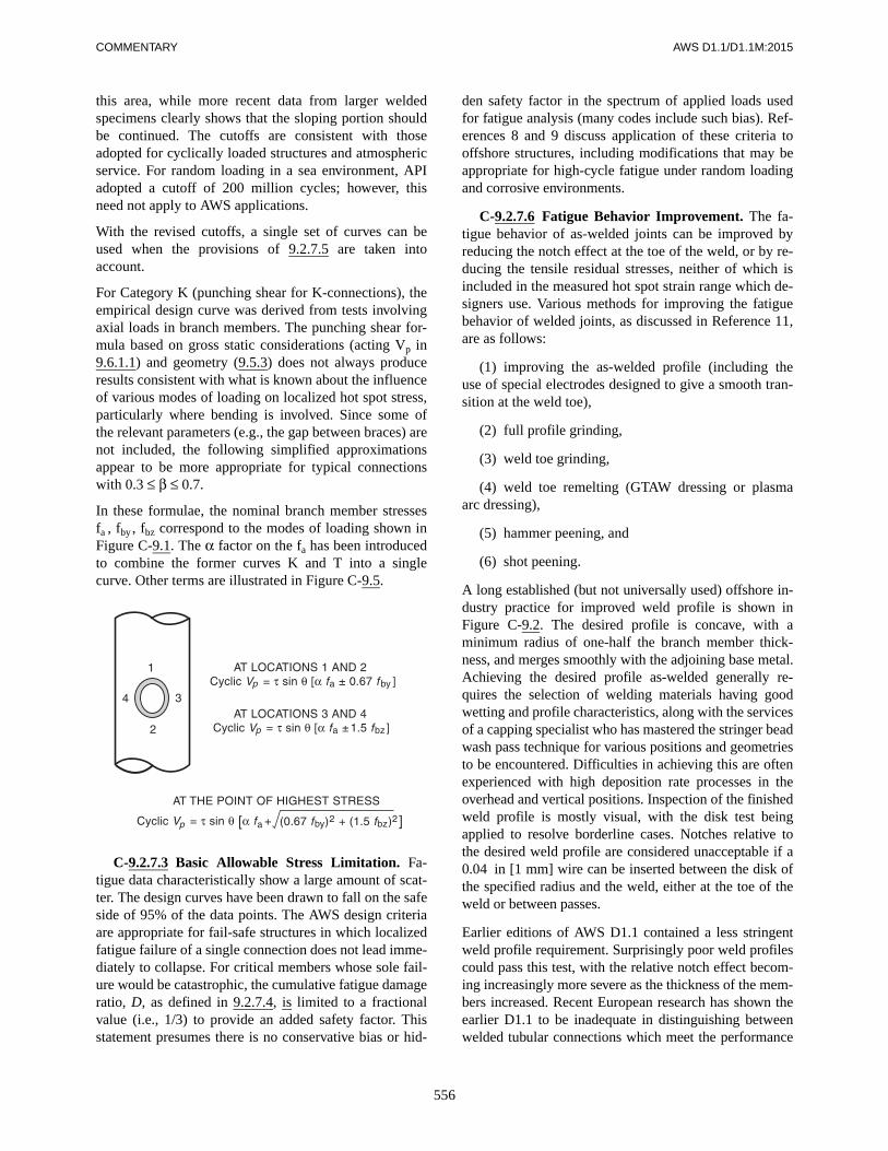
COMMENTARY AWS D1.1/D1.1M:2015
556
this area, while more recent data from larger weldedspecimens clearly shows that the sloping portion shouldbe continued. The cutoffs are consistent with thoseadopted for cyclically loaded structures and atmosphericservice. For random loading in a sea environment, APIadopted a cutoff of 200 million cycles; however, thisneed not apply to AWS applications.
With the revised cutoffs, a single set of curves can beused when the provisions of 9.2.7.5 are taken intoaccount.
For Category K (punching shear for K-connections), theempirical design curve was derived from tests involvingaxial loads in branch members. The punching shear for-mula based on gross static considerations (acting Vp in9.6.1.1) and geometry (9.5.3) does not always produceresults consistent with what is known about the influenceof various modes of loading on localized hot spot stress,particularly where bending is involved. Since some ofthe relevant parameters (e.g., the gap between braces) arenot included, the following simplified approximationsappear to be more appropriate for typical connectionswith 0.3 ≤ β ≤ 0.7.
In these formulae, the nominal branch member stressesfa , fby , fbz correspond to the modes of loading shown inFigure C-9.1. The α factor on the fa has been introducedto combine the former curves K and T into a singlecurve. Other terms are illustrated in Figure C-9.5.
C-9.2.7.3 Basic Allowable Stress Limitation. Fa-tigue data characteristically show a large amount of scat-ter. The design curves have been drawn to fall on the safeside of 95% of the data points. The AWS design criteriaare appropriate for fail-safe structures in which localizedfatigue failure of a single connection does not lead imme-diately to collapse. For critical members whose sole fail-ure would be catastrophic, the cumulative fatigue damageratio, D, as defined in 9.2.7.4, is limited to a fractionalvalue (i.e., 1/3) to provide an added safety factor. Thisstatement presumes there is no conservative bias or hid-
den safety factor in the spectrum of applied loads usedfor fatigue analysis (many codes include such bias). Ref-erences 8 and 9 discuss application of these criteria tooffshore structures, including modifications that may beappropriate for high-cycle fatigue under random loadingand corrosive environments.
C-9.2.7.6 Fatigue Behavior Improvement. The fa-tigue behavior of as-welded joints can be improved byreducing the notch effect at the toe of the weld, or by re-ducing the tensile residual stresses, neither of which isincluded in the measured hot spot strain range which de-signers use. Various methods for improving the fatiguebehavior of welded joints, as discussed in Reference 11,are as follows:
(1) improving the as-welded profile (including theuse of special electrodes designed to give a smooth tran-sition at the weld toe),
(2) full profile grinding,
(3) weld toe grinding,
(4) weld toe remelting (GTAW dressing or plasmaarc dressing),
(5) hammer peening, and
(6) shot peening.
A long established (but not universally used) offshore in-dustry practice for improved weld profile is shown inFigure C-9.2. The desired profile is concave, with aminimum radius of one-half the branch member thick-ness, and merges smoothly with the adjoining base metal.Achieving the desired profile as-welded generally re-quires the selection of welding materials having goodwetting and profile characteristics, along with the servicesof a capping specialist who has mastered the stringer beadwash pass technique for various positions and geometriesto be encountered. Difficulties in achieving this are oftenexperienced with high deposition rate processes in theoverhead and vertical positions. Inspection of the finishedweld profile is mostly visual, with the disk test beingapplied to resolve borderline cases. Notches relative tothe desired weld profile are considered unacceptable if a0.04 in [1 mm] wire can be inserted between the disk ofthe specified radius and the weld, either at the toe of theweld or between passes.
Earlier editions of AWS D1.1 contained a less stringentweld profile requirement. Surprisingly poor weld profilescould pass this test, with the relative notch effect becom-ing increasingly more severe as the thickness of the mem-bers increased. Recent European research has shown theearlier D1.1 to be inadequate in distinguishing betweenwelded tubular connections which meet the performance

557
AWS D1.1/D1.1M:2015 COMMENTARY
of AWS Fatigue Classification X1, and those which fallshort (References 11 and 12).
Notch stress analysis and fracture mechanics consider-ations, while confirming the inadequacy of the old pro-file requirements for heavy sections, also indicate thatthe tighter requirements of Figure C-9.2 are more effec-tive in maintaining Class X1 fatigue performance over awide range of thicknesses (Reference 13). Figure C-9.2also suggests the use of light grinding to correct toe de-fects, such as excessive notch depth or undercut. Oncegrinding starts, note that the allowable notch depth is re-duced to 0.01 in [0.25 mm]; merely flattening the tops ofthe individual weld passes, while leaving sharp canyonsin between, does little to improve the fatigue perfor-mance, even though it would meet the letter of the disktest.
Since the toes of welds frequently contain microscopiccracks and other crack-like defects, MT is necessary toensure these defects have been eliminated. Judicious useof grinding to resolve MT indication, often done rou-tinely as part of the inspection, also enhances the weldprofile.
Depending upon circumstances, it may be more cost ef-fective to grind the entire weld profile smooth. Thiswould avoid the use of special welding techniques, pro-file checking, corrective grinding, and MT, as describedabove, for controlling the as-welded profile. For tubularconnections, with multiple concave pass caps, fatiguecracks may start in the notch between passes; here, weldtoe grinding alone is not as effective as with flat-fillet-weld profiles that were used in much of the research.
Weld toe remelting techniques can improve the geometryof the notch at the weld toe, and have been shown in thelaboratory to improve the fatigue performance of weldedconnections. However, unless carefully controlled, therapid cycle of heating and cooling tends to produce unac-ceptably hard HAZs, with possible susceptibility tostress corrosion cracking in aggressive environments(e.g., seawater).
Hammer peening with a round-nose tool also improvesthe weld toe geometry; this additionally induces a com-pressive residual stress in the surface layers where fa-tigue cracks would otherwise be initiated. Excessivedeformation of the base metal may render it susceptibleto strain embrittlement from subsequent nearby welding.Also, surface layers may be so smeared as to obscure orobliterate pre-existing cracks; thus the requirement forMT. Shot peening is less radical in its deformation ef-fects, but also less effective in improving geometry.
It should be emphasized that, for many tubular structureapplications, the performance of fatigue Classifications
X2, K2, and ET will suffice, and the foregoing measurestaken to improve fatigue performance are not required.Furthermore, the “standard” weld profile practices de-scribed in 9.11.2 can achieve the performance of fatigueClassifications X1, K1, and DT for all but the heaviestsections.
C-9.2.7.7 Size and Profile Effects. The adverse sizeeffect in the fatigue of welded connections is well docu-mented (recent References 11, 12, and 13, as well asmany earlier ones). For welded joints with a sharp notchat the weld toe, scaling up the size of the weld and thesize of the notch results in a decrease in fatigue perfor-mance. When the application exceeds the scale of thedata base, size effect should be accounted for in design.Reference 12 suggests decreasing the fatigue strength inproportion to
Other authorities (Reference 14) indicate a milder sizeeffect, approximating an exponent of –0.10.
The geometric notch effect largely responsible for thesize effect in welds is not present in fully ground profilesand is relatively minor for those profiles which mergesmoothly with the adjoining base metal (Fatigue Catego-ries B and C1). The stated size limits (beyond which weare outside the historical data base) for most of the othercategories are similar to those cited in Reference 12, ex-cept that the dimensions in inches have been rounded off.The larger size limits for Categories X2, K2, and DTreflect the fact that these S-N curves have already beendrawn to fall below the recent large-scale test data.
Reference 13 discusses the role of size effect relative toweld profile, at various levels of fatigue performance.The “standard” weld profile practices for T-, Y-, andK-connections referred to in 9.2.7.7 vary with thicknessso as to define two fatigue performance levels which aresize-independent. However, where an inferior profile isextended beyond its standard range, the size effect (re-duction in performance) would come into play. “Im-proved” weld profiles which meet the requirements of9.2.7.6(1) keep the notch effect constant over a widerange of thicknesses, thereby mitigating the size effect.The smooth surface profile of fully ground welds alsoexhibit no size effects. Since peening only improves arelative limited volume of the welded joint, the size ef-fect would be expected to show up fairly soon if peeningis the only measure taken; however, peening should notincur a size effect penalty where it is done in addition toprofile control.
The size effect may also exhibit itself in static ultimatestrength behavior, since the design rules are based in
size( )size limit( )
--------------------------- 0.25–

COMMENTARY AWS D1.1/D1.1M:2015
558
part on tests to tensile fracture. For tubular T-, Y-, andK-connections involving high-strength steels of low orunknown notch toughness, the Level I profile selectionsare recommended in preference to larger notches allowedby Level II.
C-9.6 Limitations of the Strength of Welded Connections
A number of unique failure modes are possible intubular connections. In addition to the usual checks onweld stress provided for in most design codes, the de-signer should check for the following:
Circular Box
(1) Local failure* 9.6.1.1 9.6.2.1(2) General collapse 9.6.1.2 9.6.2.2(3) Progressive failure (unzipping) 9.6.1.3 9.6.2.3(4) Materials problems 9.8 9.8.1.3
*Overlapping connections are covered by 9.6.1.6 and9.6.2.4, respectively.
C-9.6.1.1 Local Failure. The design requirementsare stated in terms of nominal punching shear stress (seeFigure C-9.3 for the simplified concept of punchingshear). The actual localized stress situation is more com-plex than this simple concept suggests, and includes shellbending and membrane stress as well. Whatever theactual mode of main member failure, the allowable Vp isa conservative representation of the average shear stressat failure in static tests of simple welded tubular connec-tions, including a safety factor of 1.8. For backgrounddata, the user should consult References 1–6.
Treatment of box sections has been made as consistent aspossible with that of circular sections. Derivation of thebasic allowable Vp for box sections included a safety fac-tor of 1.8, based on limit analyses utilizing the ultimatetensile strength, which was assumed to be 1.5 times thespecified minimum yield. This is why α (alpha) in Table9.6 limits Fy in the design formula for punching shear to2/3 the tensile strength.
A favorable redistribution of load was also assumedwhere appropriate. Localized yielding should be ex-pected to occur within allowable load levels. Fairly gen-eral yielding with deflection exceeding 0.02D can beexpected at loads exceeding 120%–160% of the staticallowable.
Alternatives to the punching shear approach for sizingtubular connections can be found in the literature (forexample, Reference 3). However, such empirical rules,particularly design equations which are not dimensionally
complete, should be limited in application to the tubeconfigurations and sizes (and units) from which derived.
In the 1984 edition, substantial changes were made in thepunching shear requirements for circular sections, tobring them up to date. These include:
(1) Elimination of Ka and Kb from the formula for act-ing Vp. Although logical from the standpoint of geometryand statics, these produce inappropriate trends in compar-ison to test data on the strength of tubular connections.
(2) New expressions for the allowable basic Vp and anew modifier Qq which give results numerically similarto those in Reference 2.
(3) Introduction of the chord ovalizing parameter, α,which matches available results from single-plane jointsand offers a promising extension to multiplanar joints(Reference 3).
(4) A new expression for Qf, based on the recent testsof Yura (Reference 4).
(5) Nonlinear interaction between axial load andbending in the branch member, based on the fully plasticbehavior of tubular sections (Reference 5).
Figure C-9.4 shows the reliability of the new punchingshear criteria based on computed alpha, as a histogram ofthe ratio of test ultimate strength (P test) to the allowable.The data base of Reference 6 was used. Inappropriatetests have been deleted, and effective Fy conforming tothe 2/3 rule have been estimated, as described in IIW-docXV-405-77.
The test results cluster tightly just on the safe side of thenominal ultimate strength safety factor of 1.8. Using a log-normal safety index format, the median ultimate strengthfor joints failing by plastic collapse is 3.45 standard devia-tions above the design load, comparable to safety indicesof 3 to 4 for connections in other types of construction. Bydiscriminating between different joint types, the new crite-ria achieve similar overall economy and greater safety thanthe less precise criteria they replace.
The apparently large safety factor and safety indexshown for tension tests is biased by the large number ofsmall tubes in the data base. If only tubes with tc = 0.25 in[7 mm] are considered, the mean safety factor drops to 3.7;for tc = 0.5 in [13 mm], the safety factor is only 2.2. Con-sidering the singularity (sharp notch) at the toe of typicalwelds, and the unfavorable size effect in fracture-controlled failures, no bonus for tension loading has beenallowed.
In the 1992 edition, the code has also included tubularconnection design criteria in ultimate strength format,9.6.1.1(2) for circular sections. This was derived from,

559
AWS D1.1/D1.1M:2015 COMMENTARY
and intended to be equivalent to, the earlier punchingshear criteria. The thin-wall assumption was made (i.e.,no tb /db correction), and the conversion for bending useselastic section modulus.
When used in the context of AISC-LRFD, with aresistance factor of 0.8, this is nominally equivalent withthe allowable stress design (ASD) safety factor of 1.8 forstructures having 40% dead load and 60% service loads.The change of resistance factor on material shearing wasdone to maintain this equivalency.
LRFD falls on the safe side of ASD for structures havinga lower proportion of dead load. AISC criteria for ten-sion and compression members appear to make theequivalency trade-off at about 25% dead load; thus, theLRFD criteria given herein are nominally more conser-vative for a larger part of the population of structures.However, since the tb/db correction to punching shear isnot made acting Vp = τ sin θ fn (1 – tb/db).
The ASD punching shear format also contains extraconservatism.
Figure C-9.4 indicates a safety index of 3.45, appro-priate for selection of the joint can as a member (safetyindex is the safety margin of the design criteria, includ-ing hidden bias, expressed in standard deviations of totaluncertainty). For further comparison, the ASCE Com-mittee on Tubular Structures in Reference 2 derived aresistance factor of 0.81 for similar Yura-based tubularconnection design criteria, targeting a safety index of3.0.
Since the local failure criteria in 9.6 are used to select themain member or chord, the choice of safety index iscomparable to that used for designing other structuralmembers—rather than the higher values often cited forconnection material such as rivets, bolts, or fillet welds,which raise additional reliability issues, e.g., local ductil-ity and workmanship.
For offshore structures, typically dominated by environ-mental loading which occurs when they are un-manned,the 1986 draft of API RP2A-LRFD proposed more lib-eral resistance factors of 0.90 to 0.95, corresponding to areduced target safety index of 2.5 (actually, as low as 2.1for tension members). API also adjusted their allowablestress design criteria to reflect the benefit typical tb/db
ratios.
In Canada (Reference 21), using these resistance factorswith slightly different load factors, a 4.2% difference inoverall safety factor results. This is within calibrationaccuracy.
C-9.6.1.2 General Collapse. In addition to localizedfailure of the main member, which occurs in the vicinity
of the welded-on branch, a more widespread mode ofgeneral collapse failure may occur. In cylindrical mem-bers, this occurs by a general ovalizing plastic failure inthe cylindrical shell of the main member. In box sections,this may involve web crippling or buckling of the sidewalls of the main member (see Reference 15).
C-9.6.1.3 Uneven Distribution of Load (WeldSizing). The initial elastic distribution of load transferacross the weld in a tubular connection is highly nonuni-form, with peak line load (kips/in or MPa/mm) oftenbeing a factor of two or three higher than that indicatedon the basis of nominal sections, geometry, and statics,as per 9.5.3. Some local yielding is required for tubularconnections to redistribute this and reach their designcapacity. If the weld is a weak link in the system, it may“unzip” before this redistribution can happen.
The criteria given in the code are intended to prevent thisunzipping, taking advantage of the higher safety factorsin weld allowable stresses than elsewhere. For example,the line load ultimate strength of an 0.7t fillet weld madewith E70XX electrodes is 0.7t (2.67 × 0.3 × 70) = 39t,adequate to match the yield strength of mild steel branchmaterial.
For another example, if the peak line load is really twicenominal, designing for 1.35 times the nominal line loadwill give a joint safety factor of 1.8, when the weldstrength is 2.67 times its allowable stress. IIW rules, andLRFD-based strength calculations, suggest larger match-ing weld sizes are required, e.g., 1.0t or 1.2t (1.07t in thedraft Eurocode). Given this easy way out of the problem,there has not been much testing to validate the foregoingAWS logic for smaller welds.
C-9.6.2 Box T-, Y-, and K-Connections. In D1.1-90and earlier editions of the code, treatment of box sectionshad been made as consistent as possible with that of cir-cular sections. Derivation of the basic allowable punch-ing shear Vp for box sections included a safety factor of1.8, based on a simple yield line limit analysis, but utiliz-ing the ultimate tensile strength, which was assumed tobe 1.5 times the specified minimum yield. This is why Fy
in the design formula for punching shear was limited to2/3 times the tensile strength. A favorable redistributionof load was also assumed where appropriate. Localizedyielding should be expected to occur within allowableload levels. Fairly general yielding, with connection dis-tortion exceeding 0.02 D, can be expected at loads ex-ceeding 120%–160% of the static allowable.
A rational approach to the ultimate strength of steppedbox connections can be taken, using the upper bound the-orem of limit analysis (see Figure C-9.6) and yield linepatterns (similar to those shown in Figure C-9.7). Vari-ous yield patterns for plastic chord face failure should be

COMMENTARY AWS D1.1/D1.1M:2015
560
assumed in order to find the minimum computed capac-ity, which may be equal to or greater than the true value.Fan corners (as shown for the T-connection) often pro-duce lower capacities than plain corners as shown for theother cases. Suggested design factors, given in Table C-9.2, are consistent with the way we take advantage ofstrain hardening, load redistribution, etc., in using tests tofailure as the basis for empirical design criteria. In gen-eral, the capacity will be found to be a function of thedimensionless topology parameters β, η, and ξ (definedin the figure), as well as the chord thickness-squared(corresponding to τ and γ in the punching shear format).
For very large β (over 0.85) and K-connections with gapapproaching zero, yield line analysis indicates extremelyhigh and unrealistic connection capacity. In such cases,other limiting provisions based on material shear failureof the stiffer regions, and reduced capacity for the moreflexible regions (i.e., effective width) can control thedesign.
Although the old AWS criteria covered these consider-ations (Reference 18), for bending as well as for axialload (Reference 19), more authoritative expressions rep-resenting a much larger data base have been developedover the years by CIDECT (Commité International pourle Developpement et l’Etude de la Construction Tubu-laire) (Reference 20) and by members of IIW Sub-committee XV-E (Reference 24). These criteria havebeen adapted for limit state design of steel structures inCanada (Packer et al Reference 21). The Canadian codeis similar to the AISC-LRFD format. In the 1992 edition,these updated criteria were incorporated into the AWScode, using the thickness-squared ultimate strength for-mat and Packer’s resistance factors, where applicable.
C-9.6.2.1 Local Failure. Load factors vary fromequation to equation to reflect the differing amounts ofbias and scatter apparent when these equations are com-pared to test data (Reference 21). For example, the equa-tion for plastic chord face failure of T-, Y-, and crossconnections is based on yield line analysis, ignoring thereserve strength which comes from strain hardening; thisbias provides the safety factor with a Φ of unity. The sec-ond equation, for gap K- and N-connections was empiri-cally derived, had less hidden bias on the safe side, anddraws a lower resistance factor.
In the transition between gap connections and overlapconnections, there is a region for which no criteria aregiven. (see Figure C-9.5). Offshore structure detailingpractice typically provides a minimum gap “g” of 2 in[50 mm], or a 3 in [75 mm] minimum overlap “q,” toavoid weld interference. For smaller diameter box con-nections, the limitations are stated in relation to themember proportions. These limitations also serve to
avoid the touching-toes case for stepped box connec-tions, in which a disproportionately stiff load path is cre-ated that cannot handle all the load it attracts, possiblyleading to progressive failure.
C-9.6.2.2 General Collapse. To avoid a somewhatawkward adaptation of column buckling allowable to thebox section web crippling problem (e.g., Reference 15),AISC-LRFD web yielding, crippling, and transversebuckling criteria have been adapted to tension, one-sided, and two-sided load cases, respectively. The resis-tance factors given are those of AISC. Packer (Reference22) indicates a reasonably good correlation with avail-able box connection test results, mostly of the two-sidedvariety.
C-9.6.2.3 Uneven Distribution of Load (EffectiveWidth). For box sections, this problem is now treated interms of effective width concepts, in which load deliveryto more flexible portions of the chord is ignored. Criteriafor branch member checks are given in 9.6.2.3(1), basedempirically on IIW/CIDECT work. Criteria for load cal-culation in welds (9.5.5) are based upon the testing ofPacker (Reference 23) for gap K- and N-connections; andupon extrapolation and simplification of the IIW effec-tive width concepts for T-, Y-, and cross connections.
C-9.6.2.4 Overlapping Connections. By providingdirect transfer of load from one branch member to theother in K- and N-connections, overlapping joints reducethe punching demands on the main member, allowing theuse of thinner chord members in trusses. These are par-ticularly advantageous in box sections, in that the mem-ber end preparations are not as complex as for circulartubes.
Fully overlapped connections, in which the overlappingbrace is welded entirely to the through brace, with nochord contact whatsoever, have the advantage of evensimpler end preparations. However, the punching prob-lem that was in the chord for gap connections, is nowtransferred to the thru brace, which also has high beamshear and bending loads in carrying these loads to thechord.
Most of the testing of overlapped connections has beenfor perfectly balanced load cases, in which compressivetransverse load of one branch is offset by the tension loadof the other. In such overlapped connections, subjectedto balanced and predominantly axial static loading, testshave shown that it is not necessary to complete the “hid-den” weld at the toe of the through member. In realworld design situations, however, localized chord shearloading or purlin loads delivered to the panel points of atruss result in unbalanced loads. In these unbalanced sit-uations, the most heavily loaded member should be thethrough brace, with its full circumference welded to the

561
AWS D1.1/D1.1M:2015 COMMENTARY
chord, and additional checks of net load on the combinedfootprint of all braces are required.
C-9.6.2.5 Bending. Since international criteria forbending capacity of tubular connections are not as welldeveloped as for axial loads, the effects of primary bend-ing moments are approximated as an additional axialload. In the design expression, JD represents half themoment arm between stress blocks creating the moment,analogous to concrete design—half, because only halfthe axial capacity lies on each side of the neutral axis.Various ultimate limit states are used in deriving the ex-pressions for JD in Table C-9.3. For chord face plastifi-cation, a uniform punching shear or line load capacity isassumed. For the material shear strength limit, the effec-tive width is used. General collapse reflects a side wallfailure mechanism. Finally, a simplified expression forJD is given, which may conservatively be used for any ofthe governing failure modes.
Caution should be exercised where deflections due tojoint rotations could be important, e.g., sidesway of por-tal frames in architectural applications. Previous editionsof the code provided a 1/3 decrease in allowable connec-tion capacity for this situation.
C-9.6.2.6 Other Configurations. The equivalenceof box and circular branch members on box chords isbased on their respective perimeters (0.785 is π/4). Thisin effect applies the concept of punching shear to theproblem, even though these international criteria are al-ways given in ultimate strength format. The results areon the safe side of available test results.
C-9.8 Material Limitations
A rational approach to the ultimate strength of steppedbox connections can be taken, using the upper boundtheorem of limit analysis (see Figure C-9.6) and yield linepatterns similar to those shown in Figure C-9,7. Variousyield line patterns should be assumed in order to find theminimum computed capacity, which may be equal to orgreater than the true value. Fan corners (as shown for theT-joint) often produce lower capacity than plain cornersshown for the other cases. Suggested design factors aregiven in Table C-9.2; these are intended to be consistentwith those used in the body of the code. For T- and Y-connections, the geometry modifier is found to be a func-tion of η as well as β, in contrast to the simpler expressiongiven in 9.5.1. For K-connections, the gap parameter ξalso should be taken into account. The dimensionless ge-ometry parameters, η, β, and ξ are defined in Figure 9.2.
For gaps approaching 0 and for very large β approachingunity, yield line analysis indicates extremely and un-
realistically high joint capacity. The limiting provisionsof 9.6.1.1 and 9.6.1.3 should also be checked.
C-9.8.1.3 Box T-, Y-, or K-Connections. Tubularconnections are subject to stress concentrations whichmay lead to local yielding and plastic strains. Sharpnotches and discontinuities at the toe of the welds, andfatigue cracks which initiate under cyclic loading, placeadditional demands on the ductility and notch toughnessof the steel, particularly under cyclic loads. These de-mands are particularly severe in the main member oftubular T-, Y-, and K-connections. Cold-formed box tub-ing (e.g., ASTM A500 and tubing fabricated from bentplates) is susceptible to degraded toughness due to strainaging in the corners, when these severely deformed re-gions are subjected to even moderate heat of nearbywelding. Suitability of such tubing for the intended ser-vice should be evaluated using tests representing theirfinal condition (i.e., strained and aged, if the tubing isnot normalized after forming) (see C-9.8.2.2 for a dis-cussion of CVN testing requirements).
C-9.8.2 Tubular Base Metal Notch Toughness. Somesteels are listed by strength group (Groups I, II, III, IV,and V) and toughness class (Classes A, B, and C) in TablesC-9.4, C9.5, and C-9.6. These listings are for guidanceto designers, and follow long-established practice foroffshore structures, as described in Reference 9 and thefollowing:
Strength Groups. Steels may be grouped according tostrength level and welding characteristics as follows(also see 3.3 and 3.5):
(1) Group I designates mild structural carbon steelswith specified minimum yield strengths of 40 ksi[280 MPa] or less. Carbon equivalent (defined in AnnexH, H6.1.1) is generally 0.40% or less, and these steelsmay be welded by any of the welding processes as de-scribed in the code.
(2) Group II designates intermediate strength low alloysteels with specified minimum yield strengths of over40 ksi through 52 ksi [280 MPa through 360 MPa]. Car-bon equivalent ranges up to 0.45% and higher, and thesesteels require the use of low-hydrogen welding processes.
(3) Group III designates high-strength low-alloysteels with specified minimum yield strengths in excessof 52 ksi through 75 ksi [360 MPa through 515 MPa].Such steels may be used, provided that each applicationis investigated with regard to the following:
(a) Weldability and special WPSs which maybe required. Low-hydrogen WPSs would generally bepresumed.

COMMENTARY AWS D1.1/D1.1M:2015
562
(b) Fatigue problems which may result from theuse of higher working stresses, and
(c) Notch toughness in relation to other elementsof fracture control, such as fabrication, inspection proce-dures, service stress, and temperature environment.
(4) Groups IV and V include higher strength con-structional steels in the range of over 75 ksi through100 ksi yield [515 MPa through 690 MPa]. Extreme careshould be exercised with regard to hydrogen control toavoid cracking and heat input to avoid loss of strengthdue to over-tempering.
Toughness Class. Toughness classifications A, B, and Cmay be used to cover various degrees of criticality shownin the matrix of Table C-9.7, and as described below:
Primary (or fracture critical) structure covers elementswhose sole failure would be catastrophic.
Secondary structure covers elements whose failurewould not lead to catastrophic collapse, under conditionsfor which the structure could be occupied or capable ofmajor off-site damages (e.g., pollution), or both.
For tubular space-frame structures, fracture of a singlebrace or its end connection is not likely to lead tocollapse under normal or even moderately severeloads. The strength is reduced somewhat, however, andthe risk of collapse under extreme overload increasescorrespondingly.
(1) Class C steels are those which have a history ofsuccessful application in welded structures at servicetemperatures above freezing, but for which impact testsare not specified. Such steels are applicable to structuralmembers involving limited thickness, moderate forming,low restraint, modest stress concentration, quasi-staticloading (rise time 1 second or longer) and structural re-dundancy such that an isolated fracture would not be cata-strophic. Examples of such applications are piling, bracesin space frames, floor beams, and columns.
(2) Class B steels are suitable for use where thickness,cold work, restraint, stress concentration, and impactloading or lack of redundancy, or both, indicate the needfor improved notch toughness. Where impact tests arespecified, Class B steels should exhibit CVN energy of15 ft⋅lb [20 J] for Group I, 25 ft⋅lb [34 J] for Group II,and 35 ft⋅lb [48 J] for Group III, at the lowest anticipatedservice temperature. Steels listed herein as Class B cangenerally meet these CVN requirements at temperaturesranging from 50°F to 32°F [10°C to 0°C].
Examples of such applications are connections in sec-ondary structure, and bracing in primary structure. Whenimpact tests are specified for Class B steel, heat-lot test-ing in conformance with ASTM A673, Frequency H, is
normally used. However, there is no positive assurancethat Class B toughness will be present in pieces of steelthat are not tested.
(3) Class A steels are suitable for use at subfreezingtemperatures and for critical applications involving ad-verse combinations of the factors cited above. Critical ap-plications may warrant CVN testing at 36°F–54°F[20°C–30°C] below the lowest anticipated service tem-perature. This extra margin of notch toughness preventsthe propagation of brittle fractures from large discontinui-ties, and provides for crack arrest in thicknesses of severalinches. Steels enumerated herein as Class A can generallymeet the CVN requirements stated above at temperaturesranging from –4°F to –40°F [–20°C to –40°C]. Impacttesting frequency for Class A steels should be in conform-ance with the specification under which the steel isordered; in the absence of other requirements, heat-lottesting may be used.
C-9.8.2.1 CVN Test Requirements. These minimalnotch toughness requirements for heavy-section tensionmembers follow the provisions recently proposed byAISC. They rely to a considerable extent on thetemperature-shift phenomenon described by Barsom(Reference 16). The temperature-shift effect is that stati-cally loaded materials exhibit similar levels of ductilityas cyclically loaded CVN test specimens tested at ahigher temperature. For higher strength steels, GroupsIII, IV, and V, the temperature-shift is less effective; alsofracture mechanics strain energy release considerationswould suggest higher required energy values. Testing as-rolled steels on a heat-lot basis leaves one exposed toconsiderable variation within the heat, with CVN testsshowing more scatter than strength properties. However,it is better than no testing at all.
C-9.8.2.2 LAST Requirements. The main membersin tubular connections are subject to local stress concen-trations which may lead to local yielding and plasticstrains at the design load. During the service life, cyclicloading may initiate fatigue cracks, making additionaldemands on the ductility of the steel, These demands areparticularly severe in heavy-wall joint-cans designed forpunching shear.
C-9.8.2.3 Alternative Notch Toughness. The condi-tions listed in (1)–(4) below should be considered whenspecifying notch toughness requirements.
(1) Underwater Connections. For underwater por-tions of template-type offshore platforms, API recom-mends that steel for joint cans (such as jacket leg jointcans, chords in major X and K joints, and through mem-bers in connections designed as overlapping) meet one ofthe following notch toughness criteria at the temperaturegiven in Table C-9.8.

563
AWS D1.1/D1.1M:2015 COMMENTARY
(a) NRL Drop-Weight Test no-break perfor-mance. (preferred)
(b) CVN energy: 15 ft⋅lb [20 J] for Group I steels,25 ft⋅lb [34 J] for Group II steels, and 35 ft⋅lb [4 J] forGroup III steels (transverse test).
The preferred NRL crack arrest criteria follow from useof the Fracture Analysis Diagram (Reference 17), andfrom failures of heavy connections meeting temperature-shifted CVN initiation criteria. For service temperatures at40°F [4°C] or higher, these requirements may normally bemet by using any of the Class A steels.
(2) Atmospheric Service. For connections exposedto lower temperatures and possible impact, or for criticalconnections at any location in which it is desired to pre-vent all brittle fractures, the tougher Class A steelsshould be considered, e.g., API Spec. 2H, Gr. 42 orGr. 50. For 50 ksi [345 MPa] yield and higher strengthsteels, special attention should be given to welding pro-cedures, in order to avoid degradation of the HAZs. Evenfor the less demanding service of ordinary structures, thefollowing group/class base metals are NOT recom-mended for use as the main members in tubular connec-tions: IIC, IIIB, IIIC, IV, and V.
(3) Critical Connections. For critical connectionsinvolving high restraint (including adverse geometry,high yield strength, thick sections, or any combination ofthese conditions), and through-thickness tensile loads inservice, consideration should be given to the use of steelhaving improved through-thickness (Z-direction) proper-ties, e.g., API Spec. 2H, Supplements S4 and S5, orASTM A770.
(4) Brace Ends. Although the brace ends at tubularconnections are also subject to stress concentration, theconditions of service are not quite as severe as the mainmember (or joint can). For critical braces, for which brit-tle fracture would be catastrophic, consideration shouldbe given to the use of stub-ends in the braces having thesame class as the joint can, or one class lower. This pro-vision need not apply to the body of braces (betweenconnections).
C-9.11 CJP Groove Weld Requirements
C-9.11.1 Butt Joints. Where groove details in T-, Y-,and K-connections deviate from the prequalified detailsof 3.13.4, or there is some question as to the suitabilityof these joint details for a new WPS, then a mock-upor sample joint is called for, in order to validate theWPS.
Part CWelding Procedure Specification
(WPS) Qualification
C-9.12 Common Requirements for WPS and Welding Personnel Performance Qualification
C-9.12.1 Positions of Test Welds. This subclause de-fines welding positions for qualification test welds andproduction welds. Position is an essential variable for allof the WPSs, except for the EGW and ESW processeswhich are made in only one position. Each WPS shall bequalified for each position for which it will be used infabrication. Relationships between the position and con-figuration of the qualification test weld and the type ofweld and positions qualified are shown in Table 9.9. It isessential to perform testing and evaluation of the weldsto be encountered in construction prior to their actual useon the job. This will assure that all the necessary posi-tions are tested as part of the qualification process.
C-9.14 Type of Qualification Tests, Methods of Testing and Acceptance Criteria for WPS Qualification
C-Table 9.10 WPS Qualification—CJP GrooveWelds; Number and Type of Test Specimens andRange of Thickness and Diameter Qualified. TheWPS qualification for pipe includes conditions for largediameter job size pipe. This is intended for WPS qualifi-cation of large diameter pipe by automatic welding pro-cesses, such as SAW, and may be applied to any weldingprocess that can be used on large diameter pipe, but noton 8 in [200 mm] Sch. 120 pipe.
C-9.15 CJP Groove Welds for Tubular Connections
Welding on tubular members differs from that in conven-tional plate and wide flange construction in several im-portant aspects. Position often changes continuously ingoing around the joint; in T-, Y-, and K-connections, thejoint geometry also changes. Often there is no access tothe root side of the weld; and circumstances may pre-clude the use of backing (e.g., the use of tubes as a con-duit, or the complicated geometry of T-, Y-, and K-connections). Yet, for many structures, the conditions of

COMMENTARY AWS D1.1/D1.1M:2015
564
service demand that these welds meet the strength andfatigue performance qualities conventionally associatedwith CJP groove welds. To meet these needs, a special-ized set of practices regarding WPS and welder qualifi-cations, as well as prequalified joint details, has evolvedfor tubular structures. These provisions supplement thosegiven elsewhere in the code.
Several specialized tubular applications are defined inwhich CJP groove welds are allowed to be welded fromthe outside only, without backing:
(1) Pipe Butt Joints. In butt joints, CJP groovewelds made from one side are prohibited under the con-ventional provisions for cyclically loaded structures andstatically loaded structures, yet they are widely used inpressure piping applications. They are now allowed fortubular structures, but only when all the special provi-sions of 9.15.2 are followed.
(2) T-, Y-, and K-Connections. Where groove de-tails in T-, Y-, and K-connections differ from theprequalified details of 9.11.2, or there is some questionas to the suitability of the joint details for WPS, then amock-up or sample joint in conformance with 9.15.4.1 isrequired, in order to validate the WPS.
Additional WPS qualification tests may be required onaccount of some essential variable other than joint de-sign. These circumstances include (but are not limited to)the following:
(a) The use of a process outside the prequalifiedrange (e.g., GMAW-S).
(b) The use of base metal or welding materialsoutside the prequalified range (e.g., the use of propri-etary steels or a nonlow-hydrogen root pass on thick ma-terial).
(c) The use of welding conditions outside theprequalified range (e.g., amps, volts, preheat, speed, anddirection of travel).
(d) The need to satisfy special Owner testing re-quirements (e.g., impact tests).
Qualification for CJP welds using tubular box sectionsdetailed with single-welded T, Y-, and K-connections re-quires additional tests as stated in Table 9.9 and shown inFigure 9.27. In this test, the welder demonstrates the skilland technique to deposit sound weld metal around thecorners of a box tube member. This macroetch test is notrequired for fillet or PJP groove welds (see CommentaryC-9.19 for further discussion).
For these tests, the joint configurations of Figures 9.25and 9.27 are used in order to simulate the root conditionand limited access of T-, Y-, and K-connections. Con-
ventional specimens for mechanical testing are then pre-pared in conformance with Table 9.10.
PJP T-, Y-, and K-connections are also provided for.They can be executed by welders having the commonpipe qualifications 2G plus 5G. This could be advanta-geous in areas where 6GR qualified welders are notreadily available. Although lower fatigue allowables ap-ply, the static strength of such joints is almost the sameas for CJP, particularly where mild steel is used with E70filler metal.
C-9.15.4 T-, Y-, and K-Connections without BackingWelded from One Side Only. Under carefully de-scribed conditions (see Figures 9.12 and Figures9.14–9.16), the code allows CJP groove welds in tubularT-, Y-, and K-connections to be made from one sidewithout backing. Lack of access and complex geometrypreclude more conventional techniques. A very highlevel of welder skill (as demonstrated by the 6GR test) isrequired. When matching materials (see Table 3.1) areused, such joints may be presumed to equal the strengthof the sections joined subject to the limitations of 9.5 and9.2.7.
In making the weld in a T-, Y-, or K-connection, the ge-ometry and position vary continuously as one progressesaround the joint. The details shown in Figures 9.12 andFigures 9.14–9.16 were developed from experience withall-position SMAW and fast-freezing GMAW-S. Thesedetails are also applicable to FCAW processes with simi-lar fast-freezing characteristics. The wider grooves (andwider root openings) shown for GMAW were found nec-essary to accommodate the shrouded tip of the weldinggun. Although the later process is not prequalified forGMAW-S, the joint details are still applicable to suchGMAW WPSs.
In many applications, particularly with small tubes, thePJP of 9.10.1 will be entirely adequate. Although requir-ing additional strength checks by the designer, the lessstringent requirements for fit-up and welder’s skill resultin significant economies on the job. For very large tubesin which inside access is possible, the conventional CJPgroove welds made from both sides are applicable.
For applications where increased fatigue performance as-sociated with CJP groove welds is needed for T-, Y-, andK-connections, the code refers to a consistent set of“standard” weld profiles, as described earlier in C-9.2.7.7. Once learned, these should become a naturalprogression with thickness for the welders to follow.They have evolved from the following experience.
For very thin tubular connections, flat profiles (Figure9.14) represent those commonly obtained on small tubu-lar connections used for onshore applications. They also

565
AWS D1.1/D1.1M:2015 COMMENTARY
are similar to the profiles obtained on some of the scalemodels used to develop the historical fatigue data base.Here the entire weld cap is made in one pass, with weav-ing as required. Using E6010 electrodes, the more artisticcapping specialist could make this a concave profile,merging smoothly with the adjoining base metal. Withthe advent of higher strength steels and heavier sections,requiring low-hydrogen electrodes, and with the intro-duction of high deposition rates, semiautomatic weldingprocesses, this seems to have become a lost art.
For heavier thicknesses, a definite fillet is added at theweld toe as required to limit the weld toe notch effect tothat of a 45° fillet weld (see Figure 9.15). These filletwelds are scaled to the branch member thickness so as toapproximate a concave weld shape. However, we arealso constrained by the need to maintain minimum filletweld sizes to avoid creating dangerously high hardnessesin the HAZ at the weld toe (this is also the location of the“hot spot” which may experience localized yielding atthe design load levels). This alternative “standard” pro-file is easier to communicate to the welders, and easierfor them to achieve out of position than the idealizedconcave weld profile shown in earlier editions of thecode. The resulting weld profile is much like that ob-served on early Gulf of Mexico offshore platforms,whose fatigue performance over several decades of ser-vice has been consistent with Categories X1, K1, andDT.
For branch member thicknesses in excess of 0.625 in[16mm] (typically associated with chord thicknesses inexcess of 1.25 in [32 mm]) designers are going beyondthe historical fatigue data base and the experience ofearly Gulf of Mexico platforms.
The size effect begins to manifest itself, and fatigue per-formance would begin to decline toward the lower leveldefined by fatigue Categories X2 and K2, unless theprofile is further improved. Branch members of 1.5 in[38 mm] and chord thicknesses of 3 in [75 mm], repre-sent the limits of the recent large-scale European tests,and further adverse size effects (performance below X2and K2) would be expected if sharply notched weld pro-files were to be scaled up even further. Figure 9.16 de-scribes a concave weld profile which merges smoothlywith the adjoining base metal, mitigating the notch effectand providing an improved level of fatigue performancefor heavier sections.
The standardized pipe butt joint test specimens, specifiedin Part B of Clause 4 for WPS qualification, are satisfac-tory for establishing metallurgical soundness of WPSsand materials. They cannot cover the full range of con-tinuously varying geometry and position encountered instructural T-, Y-, and K-connections.
The prequalified joint details given in 9.11.2 are basedon experience with full scale mock-ups of such connec-tions that often reveal practical problems that do notshow up in the standard test specimen. The Code re-quires qualification of processes not prequalified andWPSs with essential variables outside prequalifiedranges meeting the provisions of 9.15.4.1. This sub-clause provides for sample joint or tubular mock-uptests. WPS for box sections may be based on either plateor pipe tests for position and compatibility. When mock-up tests for box sections for T-, Y-, and K-connectionsare considered, box tubes should be used.
Additional tests are required for connections with grooveangles less than 30° as outlined in 9.15.4.2.
C-9.15.4.4 Weldments Requiring CVN Tough-ness. Weld metal and HAZ toughness should be basedon the same engineering considerations as used to estab-lish the base metal toughness requirements. However,fracture avoidance, by increasing toughness alone, maynot be cost effective. Consideration should be given tofatigue cracking, hydrogen-induced cold cracking, andsolidification hot cracking. Other parts of the code ad-dress these other problems, via design, qualification,technique, and inspection requirements. Notch toughnessjust helps us live with imperfect solutions.
Weld Metal. Notch tough base metals should be joinedwith filler metals possessing compatible properties. Thetest temperatures and minimum energy values in TableC-9.9 are recommended for matching the performance ofthe various steel grades as listed in Tables C-9.4, C-9.5,and C-9.6. When WPS qualification by test is required(i.e., when the WPS is not prequalified, when compara-ble impact performance has not been previously demon-strated, or when the welding consumables are to beemployed outside the range of essential variables cov-ered by prior testing), qualification should include CVNtesting of the as deposited weld metal. Specimens shouldbe removed from the test weld, and CVN tested, in con-formance with Clause 4, Part D, Requirements for CVNTesting. Single specimen energy values (one of three)may be 5 ft⋅lb [7 J] lower without requiring retest.
Since AWS WPS requirements are concerned primarilywith tensile strength and soundness (with minor empha-sis on fracture toughness), it is appropriate to consideradditional essential variables which have an influence onfracture toughness—e.g., specific brand wire/flux com-binations, and the restriction of SAW consumables to thelimits actually tested for AWS classification. Note that,for Class A steels, specified energy levels higher than theAWS classifications require that all WPSs be qualifiedby test, rather than having prequalified status.

COMMENTARY AWS D1.1/D1.1M:2015
566
CVN testing is a method for qualitative assessment ofmaterial toughness. Although lacking the fracture me-chanics basis of crack tip opening displacement (CTOD)testing, the method has been and continues to be a rea-sonable measure of fracture safety, when employed witha definitive program of NDT to eliminate weld area de-fects. The recommendations contained herein are basedon practices which have generally provided satisfactoryfracture experience in structures located in moderatetemperature environments (e.g., 40°F [4°C] sea waterand 14°F [–10°C] air exposure). For environments whichare either more or less hostile, impact testing tempera-tures should be reconsidered, based on local temperatureexposures.
For critical welded connections, the more technicalCTOD test is appropriate. CTOD tests are run at realistictemperatures and strain rates, representing those of theengineering application, using specimens having the fullprototype thickness. This yields quantitative informationuseful for engineering fracture mechanics analysis anddefect assessment, in which the required CTOD is re-lated to anticipated stress levels (including residualstress) and discontinuity sizes.
Representative CTOD requirements range from 0.004 inat 40°F [0.10 mm at 4°C] to 0.015 in at 14°F [0.38 mm at–10°C]. Achieving the higher levels of toughness mayrequire some difficult trade-offs against other desirableattributes of the welding process—for example, the deeppenetration and relative freedom from trapped slag of up-hill passes, versus the lower heat input and highly refinedweld layers of downhill passes.
HAZ. In addition to weld metal toughness, considerationshould be given to controlling the properties of the HAZ.Although the heat cycle of welding sometimes improvesas-rolled base metals of low toughness, this regionwill often have degraded toughness properties. TheHAZ is often the site of hydrogen-induced underbeadcracking. A number of early failures in welded tubularjoints involved fractures which either initiated in or prop-agated through the HAZ, often before significant fatigueloading.
Clause 4, Part D gives requirements for sampling bothweld metal and HAZ, with CVN test energy and temper-ature to be specified in contract documents. The averageHAZ values in Table C-9.10 have been found by experi-ence to be reasonably attainable, where single-specimenenergy values (one of three) 5 ft⋅lb [7 J] lower are al-lowed without requiring retest.
As criticality of the component’s performance increases,lower testing temperatures (implying more restrictiveWPSs) would provide HAZs which more closely matchthe performance of the adjoining weld metal and parent
material, rather than being a potential weak link in thesystem. The Owner may also wish to consider more ex-tensive sampling of the HAZ than the single set of CVNtests required by Clause 4, Part D, e.g., sampling at 0.4mm, 2 mm, and 5 mm from the fusion line. (These di-mensions may change with heat input.) More extensivesampling increases the likelihood of finding local brittlezones with low toughness values.
Since HAZ toughness is as much dependent on the steelas on the welding parameters, a preferable alternative foraddressing this issue is through weldability prequalifica-tion of the steel. Reference 25 of Clause C-2 spells outsuch a prequalification procedure, using CTOD as wellas CVN testing. This prequalification testing is presentlybeing applied as a supplementary requirement for high-performance steels such as API Specs 2W and 2Y, and isaccepted as a requirement by some producers.
Caution: Clause 4 of this code allows testing one 50 ksi[345 MPa] steel to qualify all other grades of 50 ksi[345 MPa] and below. Consequently, selection of API-2H-50-Z (very low sulfur, 200 ft⋅lb [270 J] upper shelfCVNs) for qualification test plates will virtually assuresatisfying a HAZ CVN test requirement of 25 ft⋅lb [34 J],even when welded with high-heat inputs and high inter-pass temperatures. There is no reasonable way to ex-trapolate this test to ordinary A572 Grade 50 with theexpectation of reproducing either the HAZ impact ener-gies or the 8:1 degradation of the test on API-2H-50-Z.Thus, separate CVN testing of different steel grades,thickness ranges, and processing routes should be con-sidered, if HAZ toughness is being addressed via WPStesting.
Local Brittle Zones (LBZ). Within the weld HAZsthere may exist locally embrittled regions. Under certainconditions, those LBZs may be detrimental. The engi-neer should consider the risk of LBZs and determine ifcounter measures should be employed to limit the extentof LBZs and their influence on structural performance.Some counter measures and mitigating circumstances inoffshore practice are listed below:
(1) The use of steels with moderate crack-arrest capa-bilities, as demonstrated by no-break in the NRL drop-weight test (small discontinuity)
(2) Overmatch and strain hardening in conventionalnormalized 42 ksi to 50 ksi [290 MPa to 345 MPa] car-bon-manganese steels in which the weld metal and HAZhave higher yield strength than adjacent base metal, forc-ing plastic strains to go elsewhere
(3) The tendency for fatigue cracks in welded tubularjoints to grow out of the HAZ before they reach appre-

567
AWS D1.1/D1.1M:2015 COMMENTARY
ciable size (assuming one avoids unfavorable tangencyof joining can weld seam with the brace footprint)
(4) Prequalified limits on weld layer thickness inwelding procedures, which along with observing limitson heat input, promote grain refinement in the HAZ andminimize the extent LBZ
(5) Composition changes, e.g., reduced limits on va-nadium and nitrogen, and increased titanium
Part DPerformance Qualification
C-9.17 Production Welding Positions, Thicknesses and Diameters Qualified
C-Table 9.13. Welding on pipe (or tubing) materialproduct forms does not necessarily mean that pipe weld-ing is being performed. There is obviously a differencebetween welding around a pipe as opposed to weldingalong a pipe parallel to the pipe axis (centerline). A girthweld in a butt joint is completely different from a longi-tudinal groove weld that joins rolled plate to make apipe; a socket joint with a fillet weld is completely differ-ent from a fillet weld along the pipe length attaching aplate plug. Obviously, the skills for straight line progres-sion parallel to the pipe axis are no different from theskills for welding plate wrought shapes using a straightline progression; therefore, the pipe product form limita-tion does not apply in these straight line cases. Refer toFigure C-9.8.
Qualification of welders using job size pipe or tubingis allowed because pipe sizes specified in Table 9.14for welder qualification are not always available to theContractor.
C-9.19 CJP Groove Welds for Tubular Connections
Because of the special skills required to successfully exe-cute a CJP groove weld in tubular T-, Y-, and K-connec-tions, the 6GR level of welder qualification for theprocess being used is always required. Also, wheregroove angles less than 30° are to be used, the acuteangle sample joint test of 9.15.4.2 is also required foreach welder. When box sections are used in performance
qualification, bend tests taken from the faces do not eval-uate the welder’s ability to carry sound weld metalaround the relatively abrupt corners. These bend tests donot fulfill the needs of CJP groove welds in T-, Y-, andK-connections because the corners in these connectionsmay be highly stressed. Due to the concerns for weldersto demonstrate their skill to weld the corners of box tubeswhen CJP is required, the corner macroetch test of Fig-ure 9.27 was developed.
The corner macroetch test shown in Figure 9.27 is an ad-ditional performance test required for welders expectedto make CJP groove welds in box tube T-, Y-, and K-connections.
For this case, qualified 6GR welders tested on roundtubes or pipe per Figure 9.25 would only be required topass the additional corner macroetch test per Figure 9.27,provided all the requirements of Table 9.13 and 9.15.4.2are met.
If the Contractor wishes to qualify a welder without ex-isting 6GR status for CJP groove welds in T-, Y-, and K-connections using box tubes, the welder is to weld the6GR test assembly of Figure 9.25 and Figure 9.26 usingeither a round or box tube in conformance with the limi-tations of Table 9.14. In addition, the welder is to passthe corner macroetch test using Figure 9.27 or, if boxsections were used, Figure 9.25 or Figure 9.26, by pass-ing a macroetch test on the corner sections of the testweldment.
Qualification on 2G plus 5G or 6G pipe tests also quali-fies for butt joints in box sections (with applicabilitybased on thickness, neglecting diameter) but not viceversa. For these butt joints, the macroetch corner test ofFigure 9.27 is not necessary because all production jointsrequire NDT per 9.26.2.
Table 9.14 does not differentiate between pipe (circulartubing) and box sections. For this reason, the followinginterpretation is appropriate:
(1) Qualification on the 6GR pipe test also qualifiesfor T-, Y-, and K-connections and groove welds in boxsections.
(2) Qualification on 5G and 2G pipe tests also quali-fies for box sections (with applicability based on thick-ness, neglecting diameter), but not vice versa.
(3) Qualification for groove welds in box sectionsalso qualifies for plate (and vice versa if within the limi-tation of Table 9.13 and 4.19 of the code).

COMMENTARY AWS D1.1/D1.1M:2015
568
(4) When box sections are used in qualification, bendtests taken from the faces do not evaluate the welder’sability to carry sound welding around corners. Thesebend tests do not fulfill the needs of T-, Y-, and K-con-nections, because the corners in these connections arehighly stressed. Where a 6GR test utilizes box sections,RT is recommended to evaluate the corners.
PJP T-, Y-, and K-connections are also provided for.They can be executed by welders having the commonpipe qualifications 2G plus 5G.
Part EFabrication
C-9.23 BackingC-9.23.1 Full-Length Backing. Experience has shownthat a tightly fitted, but unwelded square butt joint insteel backing constitutes a severe notch and crack-likecondition that potentially leads to transverse cracks in theweld when the unfused area is perpendicular to the stressfield. Such cracks will, in many cases, propagate into thebase metal.
Discontinuities in backing are not avoidable in some de-tails where piece geometry requires a discontinuity andthe lack of access prevents welding the backing. Backingwelded parallel to the axis of the member will strain withthe member. The unwelded discontinuity will provide astress concentration and defect when it is perpendicularto the stress field. The stress concentration may initiatecracking. Residual stresses, high restraint and cyclicloads increase the risk of such cracking. Compressivestresses decrease the risk of cracking unless there isstress reversal in the applied stress cycle. The code per-mits discontinuous backing in selected specific applica-tions or where the Engineer approves.
C-9.24 Tolerance of Joint DimensionsC-9.24.2.2 Correction. Root openings wider than
those allowed by Figure 5.3 and Table 9.15 may be cor-rected by building up one or both sides of the groovefaces by welding. In correcting root openings, the user iscautioned to obtain the necessary approvals from the En-gineer where required. The final weld is to be made onlyafter the joint has been corrected to conform to the speci-fied root opening tolerance, thus keeping shrinkage to aminimum.
Part FInspection
C-9.26 NDTC-9.26.1 Weld quality requirements for tubular struc-tures are essentially the same as for statically loadedstructures. RT can generally not be applied successfullyto inspection of tubular T-, Y-, and K-connections.
C-9.26.2 Tubular Connection Requirements. Thestatic RT requirements of 6.12.1 are applicable to longi-tudinal groove welds in butt joints with the reinforce-ment left on. For cyclic loading, this is consistent withthe reduced allowable stress range of Category C details.If the weld reinforcement is removed to upgrade fatigueperformance, upgrading the cyclic RT criteria to 6.12.2would also be consistent.
When UT is used as an alternative to RT for longitudinalgroove welds in butt joints, the nontubular criteria aretypically used, following the logic of the previous para-graph. The tubular UT requirements of 9.27.1.1 Class Rare similar to ASME Boiler and Pressure Vessel Code,Section VIII, and may also be considered for longitudi-nal groove welds. The relaxed provisions for the rootcondition of longitudinal groove welds are not appropri-ate for circumferential groove welds that are cyclicallyloaded in tension.
Because of the complex geometry, RT is not applicableto welds in tubular to tubular T-, Y-, and K-connections.The internal UT acceptance criteria of 9.27.1.2 Class Xis appropriate since the fatigue performance is similar tothat of basic welded profiles with the reinforcement leftin place. When surface profile improvements in 9.2.7.6are specified by the Engineer to improve the fatigueperformance to Level I in Table 9.4, an upgrade of theinternal inspection criteria to Class R may also beappropriate.
See P. W. Marshall, “Experience-Based, Fitness-for-Purpose Ultrasonic Reject Criteria for Tubular Struc-tures,” Fitness for Purpose in Welded Construction,Proc. AWS/WRC/WI Conference, Atlanta, May 1982(also Proc. 2nd Int’l. Conference on Welding of TubularStructures, IIW, Boston, 1984).
C-9.27 UTC-9.27.1 UT Acceptance Criteria for Tubular Con-nections. The UT procedures and acceptance criteria setforth in Clause 6, i.e., 6.13.1 and 6.13.2, are not applica-ble to tubular T-, Y-, and K-connections. Acceptance cri-

569
AWS D1.1/D1.1M:2015 COMMENTARY
teria for the latter are set forth in 9.27.1. Contractdocuments should state the extent of testing, which of theacceptance criteria apply (Class R or Class X), andwhere applicable. Because of the complex geometry oftubular T-, Y-, and K-connections, standardized step-by-step UT procedures, such as those given in Clause 6, donot apply. Any variety of equipment and techniques maybe satisfactory providing the following general principlesare recognized.
The inspection technique should fully consider the ge-ometry of the joint. This can be simplified by idealizinglocalized portions of welds as joining two flat plates, inwhich case the principal variables are local dihedral an-gles, material thickness, and bevel preparation; curvatureeffects may then be reintroduced as minor corrections.Plotting cards superimposing the sound beam on a cross-sectional view of the weld are helpful. Inspectionsshould be referenced to the local weld axis rather than tothe brace axis. Every effort should be made to orient thesound beams perpendicular to the weld fusion line; insome cases this will mean multiple inspection with a va-riety of transducer angles.
The use of amplitude calibrations to estimate discontinu-ity size should consider sound path attenuation, transfermechanism (to correct differences in surface roughnessand curvature), and discontinuity orientation (e.g., a sur-face discontinuity may produce a larger echo than an in-terior discontinuity of the same size). Transfer correctionis described in 3.6.5 of Reference 10.
Amplitude calibration becomes increasingly difficult forsmall diameter (under 12 in [300 mm]) or with thin wall(under 1/2 in [12 mm]), or both. In the root area of tubu-lar T-, Y-, and K-connections, prominent corner reflec-tors are often present which cannot be evaluated solelyon the basis of amplitude; in this case, beam boundarytechniques are useful for determining the size of thelarger discontinuities of real concern. Beam boundarytechniques are described in 3.8.3.2 of Reference 10 ofC-2.
The UT acceptance criteria should be applied with the judg-ment of the Engineer, considering the following factors:
(1) For tubular T-, Y-, and K-connections having CJPgroove welds made from the outside only (see Figures9.12 and Figures 9.14–9.16), root discontinuities are lessdetrimental and more difficult to repair than those else-where in the weld.
(2) It should be recognized that both false alarms (UTdiscontinuities that are not subsequently verified duringthe repair) and occasionally missed discontinuities mayoccur. The former is a part of the cost of the inspection,while the latter emphasize the need for structural redun-dancy and notch-tough steel.
C-9.28 RT ProceduresC-9.28.2 IQI Selection and Placement. Since radio-graphic sensitivity and the acceptability of radiographsare based upon the image of the required IQIs, care istaken in describing the manufacture and use of the re-quired IQIs. IQIs are placed at the extremities of weldjoints where geometric distortion is anticipated to con-tribute to lack of sensitivity in the radiograph as shown inFigures 6.6–6.9.
C-9.30 UT of Tubular T-, Y-, andK-Connections
The UT requirements of this section represent the state ofthe art available for examination of tubular structures, es-pecially T-, Y-, and K-connections. Height determina-tion of elongated reflectors with a dimension (H) lessthan the beam height (see Figure 9.30) is considerablyless accurate than length determination where the reflec-tors extend beyond the beam boundaries, and requiresmore attention in regards to procedure qualification andapproval, and in the training and certification of UT op-erators.
This section sets forth requirements for procedures, per-sonnel, and their qualifications. It is based largely onpractices that have been developed for fixed offshoreplatforms of welded tubular construction. These are de-scribed in detail in Reference 10.

COMMENTARY AWS D1.1/D1.1M:2015
570
1. Marshall, P. W. and Toprac, A. A. “Basis for tubularjoint design.” Welding Journal. Welding ResearchSupplement, May 1974. (Also available as AmericanSociety for Civil Engineers preprint 2008.)
2. Graff, W. J., et al. “Review of design considerationsfor tubular joints.” Progress Report of the Commit-tee on Tubular Structures, ASCE Preprint 810043.New York: May 1981.
3. Marshall, P. W. and Luyties, W. H. “Allowablestresses for fatigue design.” Proceedings of The 3rdInternational Conference on The Behavior of Off-shore Structures. Boston: August 1982.
4. Yura, Joseph A. et al. “Chord stress effects on theultimate strength of tubular joints.” PEMSEL Report82.1. University of Texas: American Petroleum In-stitute, December 1982.
5. Stamenkovic, A. et al. “Load interaction in T-jointsof steel circular, hollow sections.” (with discussionby P. W. Marshall). Journal of Structural Engineer-ing. ASCE 9 (109): September 1983. (See also Pro-ceedings of International Conference on Joints inStressed Steel Work. Teeside Polytechnical Institute,May 1981.)
6. Rodabaugh, E. C. “Review of data relevant to thedesign of tubular joints for use in fixed offshoreplatforms.” WRC Bulletin 256, January 1980.
7. Cran, J. A., et al. Hollow Structural Sections-DesignManual for Connections. Canada: The Steel Com-pany of Canada (STELCO), 1971.
8. Marshall, P. W. “Basic considerations for tubularjoint design in offshore construction.” WRC Bulletin193, April 1974.
9. American Petroleum Institute. Recommended Prac-tice for Planning, Designing, and Constructing FixedOffshore Platforms. API RP 2A, 17th Ed. Dallas:American Petroleum Institute, 1987.
10. American Petroleum Institute. Recommended Prac-tice for Ultrasonic Examination of Offshore Struc-tural Fabrication and Guidelines for Qualificationof Ultrasonic Techniques. API RP 2X, 1st Ed. Dal-las: American Petroleum Institute, 1980.
11. Haagensen, P. J. “Improving the fatigue perfor-mance of welded joints.” Proceedings of Interna-tional Conference on Offshore Welded Structures,36. London, November 1982.
12. Snedden, N. W. Background to Proposed New Fa-tigue Design Rules for Welded Joints in OffshoreStructures.” United Kingdom: United Kingdom De-partment of Energy, AERE Harwell, May 1981.
13. Marshall, P. W. “Size effect in tubular weldedjoints.” ASCE Structures Congress 1983, SessionST6. Houston, October 1983.
14. Society of Automotive Engineers. Society of Auto-motive Engineers Fatigue Design Handbook, AE-4.Warrendale: Society of Automotive Engineers,1968.
15. Davies, G., et al. “The behavior of full width RHJScross joints.” Welding of Tubular Structures. Pro-ceedings of the 2nd International Conference, IIW.Boston: Pergamon Press, July 1984.
16. Rolfe, S. T. and Barsom, J. M. Fracture and FatigueControl in Structures. Prentice Hall, 1977.
17. Carter, R. M., Marshall, P. W., et al. “Material prob-lems in offshore structures,” Proc. Offshore Tech.Conf., OTC 1043, May 1969.
18. Marshall, P. W. “Designing tubular connectionswith AWS D1.1.” Welding Journal, March 1989.
19. Sherman, D. R. and Herlache, S. M. “Beam connec-tions to rectangular tubular columns,” AISC Na-tional Steel Construction Conference. Miami, FL,June 1988.
References for Clause C-9

571
AWS D1.1/D1.1M:2015 COMMENTARY
20. Giddings, T. W. and Wardenier, J. The Strength andBehavior of Statically Loaded Welded Connectionsin Structural Hollow Sections, Section 6, CIDECTMonograph. British Steel Corp. Tubes Div., 1986.
21. Packer, J. A., Birkemoe, P. C., and Tucker, W. J.“Canadian implementation of CIDECT monograph6,” CIDECT Rept. 5AJ-84/9E, IIW Doc. SC-XV-84-072. Univ. of Toronto, July 1984.
22. Packer, J. A. “Review of American RHS web crip-pling provisions.” ASCE Journal of Structural Engi-neering, December 1987.
23. Packer, J. A. and Frater, G. S. “Weldment designfor hollow section joints,” CIDECT Rept. 5AN-87/1-E,IIW Doc. XV-664-87. Univ. of Toronto, April 1987.
24. International Institute of Welding. IIW S/C XV-E,Design Recommendations for Hollow Section Joints—Predominantly Static Loading, 2nd Edition, IIW Doc.XV-701-89. Helsinki, Finland: International Instituteof Welding Annual Assembly, September 1989.
25. American Petroleum Institute. Recommended Prac-tice for Pre-Production Qualification of Steel Platesfor Offshore Structures, API RP2Z, 1st Edition. Dal-las: American Petroleum Institute, 1987.

572
COMMENTARY AWS D1.1/D1.1M:2015
Table C-9.1Survey of Diameter/Thickness and Flat Width/Thickness Limits for Tubes (see C-9.2.2)
For Fy in ksi
For AWS Connection Design For Member Design
Local FailureUlt Vp = 0.57 Fyo
General Collapse at Chord Sidewall
Yield
Cone-Cylinder1:4 Flare
Applicabilityof Rules
in 9.6
FullPlasticDesign
Plastic Moments, Limited Rotation
YieldMomentor Limitof ElasticBehavior
FullYieldAxial
Limit ofLocal
BucklingFormulae
Cir
cula
r T
ubes
16 for K-Connection12 for T & Y9 for X
— 30
60 300
AP
IR
P2A
—
AIS
C
Box
Sec
tions 8 for K & N
22 20
For Gap Connections
atM = S( ) No Limit
AIS
IC
lass
A
7 for T & K For Overlap
AIS
IC
lass
B
For Fy in MPa
For AWS Connection Design For Member Design
Local FailureUlt Vp = 0.57 Fyo
General Collapse at Chord Sidewall
Yield
Cone-Cylinder1:4 Flare
Applicabilityof Rules
in 9.6
FullPlasticDesign
Plastic Moments, Limited Rotation
YieldMomentor Limitof ElasticBehavior
FullYieldAxial
Limit ofLocal
BucklingFormulae
Cir
cula
r T
ubes
112 for K-Connec-tion84 for T & Y63 for X
— 210
60 300A
PIR
P2A
—
AIS
C
Box
Sec
tions 56 for K & N
15.4 140
For Gap Connections
atM = S( ) No Limit
AIS
IC
lass
A
49 for T & K For Overlap
AIS
IC
lass
B
Notes:1. AISI Class A = hot formed.2. AISI Class B = cold formed and welded.3. Flat width may be taken as D – 3t for box section member design.
3300Fy
------------
1300Fy
------------1500
Fy------------
6000Fy
------------
2070Fy
------------8970
Fy------------
3300
Fy
------------13 000
Fy----------------
210
Fy
--------- 35≤ 190
Fy
---------210
Fy
---------238
Fy 10–---------------------
Fy 10–
238
Fy
---------
190
Fy
--------- 150
Fy
---------238
Fy
---------
23 100Fy
----------------
9100Fy
------------10 500
Fy----------------
42 000Fy
----------------
14 490Fy
----------------62 790
Fy----------------
8731
Fy
------------91 000
Fy----------------
556
Fy
--------- 35≤ 503
Fy
---------556
Fy
---------630
Fy 70–---------------------
Fy 70–
630
Fy
---------
503
Fy
--------- 397
Fy
---------630
Fy
---------

573
AWS D1.1/D1.1M:2015 COMMENTARY
Table C-9.2Suggested Design Factors (see C-9.6.2)
AssumedValue for K
SF forStatic Loads
SF Where 1/3Increase Applies
Where the ultimate breaking strength of the connection—includes effects of strain hardening, etc.—can be utilized;
Fail-safe structures and designs consistent with 9.5.1Critical members whose sole failure would be catastrophic
11.5a
11.5a1.82.7
1.42.0
Architectural applications where localized deformation would be objectionable
1.0* 1.7 1.3
a Applicable where main member, Fy, is not taken to exceed 2/3 the specified minimum tensile strength.
Table C-9.3Values of JD (see C-9.6.2.5)
Governing Failure Mode In-Plane Bending Out-of-Plane Bending
Plastic Chord Wall Failure
Chord Material Shear Strength
General Collapse
Branch Member Effective Width
Conservative Approximation for Any Mode
ηD (β η/2)+2 β η+( )
--------------------------------βD (η β/2)+
2 η β+( )--------------------------------
ηD (βeop η/2)+
2 βeop η+( )--------------------------------------
βD [η βeop 1 βeop/2β–( )]+
2 η βeop+( )-------------------------------------------------------------------
ηD + 5tc
4---------------------
D2----
ηD (βeoi η/2)+
2 η βeoi+( )--------------------------------------
βD [η βeoi 1 βeoi/2β–( )]+
2 η βeoi+( )----------------------------------------------------------------
ηD4
--------βD4
-------

574
COMMENTARY AWS D1.1/D1.1M:2015
Table C-9.4Structural Steel Plates (see C-9.8.2)
Strength Group
Toughness Class Specification and Grade
Yield Strength Tensile Strength
ksi MPa ksi MPa
I CASTM A36 (to 2 in [50 mm] thick)ASTM A131 Grade A (to 1/2 in [12 mm] thick)
3634
250235
58–8058–71
400–550440–490
I BASTM A131 Grades B, DASTM A573 Grade 65ASTM A709 Grade 36T2
343536
235240250
58–7165–7758–80
400–490450–550400–550
I A ASTM A131 Grades CS, E 34 235 58–71 400–490
II C
ASTM A242 (to 1/2 in [12 mm] thick)ASTM A572 Grade 42 (to 2 in [50 mm] thick)ASTM A572 Grade 50 (to 1/2 in [12 mm] thick)a
ASTM A588 (4 in [100 mm] and under)
50425050
345290345345
706065
70 min.
480415450
485 min.
II B
ASTM A709 Grades 50T2, 50T3ASTM A131 Grade AH32ASTM A131 Grade AH36ASTM A808 (strength varies with thickness)ASTM A516 Grade 65
50.045.5
5142–50
35
345315350
290–345240
6568–8571–9060–6565–85
450470–585490–620415–450450–585
II A
API Spec 2H Grade 42Grade 50 (to 2-1/2 in [65 mm] thick)
(over 2-1/2 in [65 mm] thick)API Spec 2W Grade 42 (to 1 in [25 mm] thick)
(over 1 in [25 mm] thick)Grade 50 (to 1 in [25 mm] thick)
(over 1 in [25 mm] thick)Grade 50T (to 1 in [25 mm] thick)
(over 1 in [25 mm] thick)API Spec 2Y Grade 42 (to 1 in [25 mm] thick)
(over 1 in [25 mm] thick)Grade 50 (to 1 in [25 mm] thick)
(over 1 in [25 mm] thick)Grade 50T (to 1 in [25 mm] thick)
(over 1 in [25 mm] thick)ASTM A131 Grades DH32, EH32
Grades DH36, EH36ASTM A537 Class I (to 2-1/2 in [65 mm] thick)ASTM A633 Grade A
Grades C, DASTM A678 Grade A
425047
42–6742–6250–7550–7050–8050–7542–6742–6250–7550–7050–8050–75.045.5
5150425050
290345325
290–462290–427345–517345–483345–522345–517290–462290–462345–517345–483345–572345–517
315350345290345345
62–8070–9070–90
626265657070626265657070
68–8571–9070–9063–8370–9070–90
430–550483–620483–620
427427448448483483427427448448483483
470–585490–620485–620435–570485–620485–620
III C ASTM A633 Grade E 60 415 80–100 550–690
III A
ASTM A537 Class II (to 2-1/2 in [65 mm] thick)ASTM A678 Grade BAPI Spec 2W Grade 60 (to 1 in [25 mm] thick)
(over 1 in [25 mm] thick)API Spec 2Y Grade 60 (to 1 in [25 mm] thick)
(over 1 in [25 mm] thick)ASTM A710 Grade A Class 3
(quenched and precipitation heat treated)thru 2 in [50 mm]2 in [50 mm] to 4 in [100 mm]over 4 in [100 mm]
6060
60–9060–8560–9060–85
756560
415415
414–621414–586414–621414–586
515450415
80–10080–100
75757575
857570
550–690550–690
517517517517
585515485
IV CASTM A514 (over 2-1/2 in [65 mm] thick)ASTM A517 (over 2-1/2 in [65 mm] thick)
9090
620620
110–130110–130
760–890760–896
V CASTM A514 (to 2-1/2 in [65 mm] thick)ASTM A517 (to 2-1/2 in [65 mm] thick)
10001000
690690
110–130110–130
760–895760–895
a To 2 in [50 mm] Thick for Type 1 or 2 Killed, Fine Grain Practice.
Note: See list of Referenced Specifications for full titles of the above.
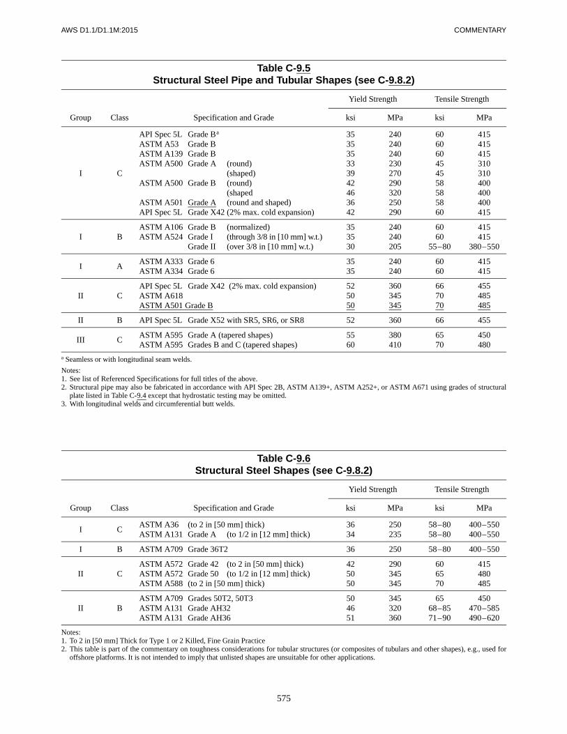
575
AWS D1.1/D1.1M:2015 COMMENTARY
Table C-9.5Structural Steel Pipe and Tubular Shapes (see C-9.8.2)
Group Class Specification and Grade
Yield Strength Tensile Strength
ksi MPa ksi MPa
I C
API Spec 5L Grade Ba
ASTM A53 Grade BASTM A139 Grade BASTM A500 Grade A (round)
(shaped)ASTM A500 Grade B (round)
(shapedASTM A501 Grade A (round and shaped)API Spec 5L Grade X42 (2% max. cold expansion)
353535333942463642
240240240230270290320250290
606060454558585860
415415415310310400400400415
I BASTM A106 Grade B (normalized)ASTM A524 Grade I (through 3/8 in [10 mm] w.t.)
Grade II (over 3/8 in [10 mm] w.t.)
353530
240240205
6060
55–80
415415
380–550
I AASTM A333 Grade 6ASTM A334 Grade 6
3535
240240
6060
415415
II CAPI Spec 5L Grade X42 (2% max. cold expansion)ASTM A618ASTM A501 Grade B
525050
360345345
667070
455485485
II B API Spec 5L Grade X52 with SR5, SR6, or SR8 52 360 66 455
III CASTM A595 Grade A (tapered shapes)ASTM A595 Grades B and C (tapered shapes)
5560
380410
6570
450480
a Seamless or with longitudinal seam welds.
Notes:1. See list of Referenced Specifications for full titles of the above.2. Structural pipe may also be fabricated in accordance with API Spec 2B, ASTM A139+, ASTM A252+, or ASTM A671 using grades of structural
plate listed in Table C-9.4 except that hydrostatic testing may be omitted.3. With longitudinal welds and circumferential butt welds.
Table C-9.6Structural Steel Shapes (see C-9.8.2)
Group Class Specification and Grade
Yield Strength Tensile Strength
ksi MPa ksi MPa
I CASTM A36 (to 2 in [50 mm] thick)ASTM A131 Grade A (to 1/2 in [12 mm] thick)
3634
250235
58–8058–80
400–550400–550
I B ASTM A709 Grade 36T2 36 250 58–80 400–550
II CASTM A572 Grade 42 (to 2 in [50 mm] thick)ASTM A572 Grade 50 (to 1/2 in [12 mm] thick)ASTM A588 (to 2 in [50 mm] thick)
425050
290345345
606570
415480485
II BASTM A709 Grades 50T2, 50T3ASTM A131 Grade AH32ASTM A131 Grade AH36
504651
345320360
6568–8571–90
450470–585490–620
Notes:1. To 2 in [50 mm] Thick for Type 1 or 2 Killed, Fine Grain Practice2. This table is part of the commentary on toughness considerations for tubular structures (or composites of tubulars and other shapes), e.g., used for
offshore platforms. It is not intended to imply that unlisted shapes are unsuitable for other applications.

576
COMMENTARY AWS D1.1/D1.1M:2015
Table C-9.7Classification Matrix for Applications (see C-9.8.2)
Table C-9.8CVN Testing Conditions (see C-9.8.2.2)
Diameter/Thickness Test Temperature Test Condition
Over 3020–30
Under 20
36°F [20°C] below LASTa
54°F [30°C] below LAST1
18°F [10°C] below LAST1
Flat plateFlat plate
As fabricated
a LAST = Lowest Anticipated Service Temperature.

577
AWS D1.1/D1.1M:2015 COMMENTARY
Table C-9.9CVN Test Values (see C-9.15.4.4)
SteelGroup
SteelClass
CVN Test Temperature
Weld Metal Avg.
ft·lb (Joules)
III
CBA
0°F [–18°C]0°F [–18°C]
–20°F [–29°C]
202020
[27][27][27]
IIIIII
CBA
0°F [–18°C]–20°F [–29°C]–40°F [–40°C]
202025
[27][27][34]
IIIIIIIII
CBA
–20°F [–29°C]–40°F [–40°C]–40°F [–40°C]
202030
[27][27][40]
IV and V Special Investigation
Note: Code requirements represent the lowest common denominatorfrom the foregoing table.
Table C-9.10HAZ CVN Test Values (see 9.15.4.4)
SteelGroup
SteelClass
CVN Test Temperature
HAZ
ft·lb (Joules)
I C 50°F [10°C] For information onlyI B 40°F [4°C] 15 [20]I A 14°F [–10°C] 15 [20]
II C 50°F [10°C] For information onlyII B 40°F [4°C] 15 [20]II A 14°F [–10°C] 25 [34]
III A 14°F [–10°C] 30 [40]
Figure C-9.1—Illustrations of Branch Member StressesCorresponding to Mode of Loading (see C-9.2.7.2)

578
COMMENTARY AWS D1.1/D1.1M:2015
Note: Minimum requirements for outside weld at tubular Note: MPI indication, excessive convexity, or undercut in weld toeconnections designated to meet 9.2.7.6(1). passes or between adjacent passes may be corrected by light grinding.
Figure C-9.2—Improved Weld Profile Requirements (see C-9.2.7.6)
Figure C-9.3—Simplified Concept ofPunching Shear (see C-9.6.1.1)

579
AWS D1.1/D1.1M:2015 COMMENTARY
Notes:1. SF = Safety Factor.2. Data base: 306 (nonoverlap) joints (see Reference 6).
Figure C-9.4—Reliability of Punching Shear CriteriaUsing Computed Alpha (see C-9.6.1.1)

580
COMMENTARY AWS D1.1/D1.1M:2015
Figure C-9.5—Transition Between Gap and Overlap Connections(see C-9.6.2.1)
Key:K = Reserve strength factor for strain hardening, triaxial stress, large deflection behavior, etc.SF = Safety FactorFy = Specified yield strength of main memberai = Regular rotation of yield line i as determined by geometry of mechanismLi = Length of yield line segmenttc = Wall thickness of chord
Figure C-9.6—Upper Bound Theorem(see C-9.2.7.2, C-9.6.2, and C-9.8)

581
AWS D1.1/D1.1M:2015 COMMENTARY
Figure C-9.7—Yield Line Patterns (see C-9.6.2 and C-9.8)

AWS D1.1/D1.1M:2015
582
This page is intentionally blank.

AWS D1.1/D1.1M:2015
583
Preheat—Background Review and Discussion
General Observations. The probability of hydrogencracking depends on a number of factors. Some of thesecan be classed as global (e.g., chemical composition andthickness) and can therefore be defined, while otherswhich are local factors (e.g., the details of the weld rootgeometry, or local segregation of certain chemical ele-ments) cannot be defined.
In some cases, these factors may dominate, and thismakes it virtually impossible to predict in any rationalmanner the precise preheating conditions that are neces-sary to avoid hydrogen cracking. These situations shouldbe recognized from experience and conservative proce-dures adopted. However, in the majority of cases, it ispossible with present day knowledge of the hydrogencracking phenomenon to predict a preheat and otherwelding procedure details to avoid hydrogen crackingthat will be effective in the majority of cases withoutbeing overly conservative.
The preheat levels predicted from such a system shouldbe compatible with experience. The requirements shouldallow fabricators to optimize preheating conditions forthe particular set of circumstances with which they areconcerned. Thus, rather than calling for a certain preheatfor a given steel specification, the alternative guide al-lows preheats to be based on the chemistry of the platebeing welded, as determined from mill reports or analy-sis. Fabricators may then, through knowledge of the par-ticular set of circumstances they have, be able to uselower preheats and a more economical welding proce-dure. On the other hand, the requirements should providebetter guidance for more critical joints; e.g., high re-
straint situations that will allow fabricators to undertakeadequate precautions.
Basis of Predicting Preheat. Research has shown thatthere are the following four basic prerequisites for hydro-gen cracking to occur:
(1) susceptible microstructure (hardness may give arough indication of susceptibility)
(2) appropriate level of diffusible hydrogen
(3) appropriate level of restraint
(4) suitable temperature
One or more of these prerequisites may dominate, but thepresence of all is necessary for hydrogen cracking to oc-cur. Practical means to prevent this cracking, such as pre-heat, are designed to control one or more of these factors.
In the past, two different approaches have been taken forpredicting preheat. On the basis of a large number of fil-let weld controlled thermal severity (CTS) tests, amethod based on critical HAZ hardness has been pro-posed (References 1 and 2). By controlling the weldcooling rate so that the hardness of HAZs does not ex-ceed the critical level, the risk of hydrogen crackingcould be removed.
The acceptable critical hardness can be a function of thehydrogen content. This approach does not recognize theeffect of preheat on the removal of hydrogen from theweld during cooling; although recommended in the guidefor predicting a minimum energy input for welding with-out preheat, it tends to be overly conservative when pre-dicting preheat levels.
The second method for predicting preheat is based on thecontrol of hydrogen. Recognizing the effect of the low
C-Annex H
Guidelines on Alternative Methodsfor Determining Preheat
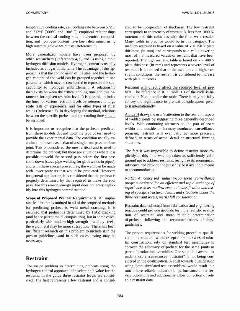
COMMENTARY AWS D1.1/D1.1M:2015
584
temperature cooling rate, i.e., cooling rate between 572°Fand 212°F [300°C and 100°C], empirical relationshipsbetween the critical cooling rate, the chemical composi-tion, and hydrogen content have been determined usinghigh restraint groove weld tests (Reference 3).
More generalized models have been proposed byother researchers (References 4, 5, and 6) using simplehydrogen diffusion models. Hydrogen content is usuallyincluded as a logarithmic term. The advantage of this ap-proach is that the composition of the steel and the hydro-gen content of the weld can be grouped together in oneparameter, which may be considered to represent the sus-ceptibility to hydrogen embrittlement. A relationshipthen exists between the critical cooling time and this pa-rameter, for a given restraint level. It is possible to indexthe lines for various restraint levels by reference to largescale tests or experience, and for other types of filletwelds (Reference 7). In developing the method, relationsbetween the specific preheat and the cooling time shouldbe assumed.
It is important to recognize that the preheats predictedfrom these models depend upon the type of test used toprovide the experimental data. The condition usually ex-amined in these tests is that of a single root pass in a buttjoint. This is considered the most critical and is used todetermine the preheat; but there are situations where it ispossible to weld the second pass before the first passcools down (stove pipe welding for girth welds in pipes),and with these special procedures, the weld can be madewith lower preheats that would be predicted. However,for general application, it is considered that the preheat isproperly determined by that required to make the rootpass. For this reason, energy input does not enter explic-itly into this hydrogen control method.
Scope of Proposed Preheat Requirements. An impor-tant feature that is omitted in all of the proposed methodsfor predicting preheat is weld metal cracking. It isassumed that preheat is determined by HAZ cracking(and hence parent metal composition), but in some cases,particularly with modern high strength low alloy steels,the weld metal may be more susceptible. There has beeninsufficient research on this problem to include it in thepresent guidelines, and in such cases testing may benecessary.
RestraintThe major problem in determining preheats using thehydrogen control approach is in selecting a value for therestraint. In the guide three restraint levels are consid-ered. The first represents a low restraint and is consid-
ered to be independent of thickness. The low restraintcorresponds to an intensity of restraint, k, less than 1000 N/mm/mm and this coincides with the fillet weld results.Many welds in practice would be in this category. Themedium restraint is based on a value of k = 150 × platethickness (in mm) and corresponds to a value coveringmost of the measured values of restraint that have beenreported. The high restraint table is based on k = 400 ×plate thickness (in mm) and represents a severe level ofrestraint. It is noticed that in the medium and higher re-straint conditions, the restraint is considered to increasewith plate thickness.
Restraint will directly affect the required level of pre-heat. The reference to it in Table 3.3 of the code is in-cluded in Note a under the table. There it may not fullyconvey the significance in preheat considerations givento it internationally.
Annex H draws the user’s attention to the restraint aspectof welded joints by suggesting three generally describedlevels. With continuing alertness on the part of userswithin and outside an industry-conducted surveillanceprogram, restraint will eventually be more preciselydefined, in terms of actual detail or structural framingsituations.
The fact it was impossible to define restraint more ex-plicitly at this time was not taken as sufficiently validground not to address restraint, recognize its pronouncedinfluence and provide the presently best available meansto accommodate it.
NOTE: A concerted industry-sponsored surveillanceprogram designed for an efficient and rapid exchange ofexperience so as to allow eventual classification and list-ing of specific structural details and situations under thethree restraint levels, merits full consideration.
Restraint data collected from fabrication and engineeringpractice could provide grounds for more realistic evalua-tion of restraint and more reliable determinationof preheats following the recommendations of theseguidelines.
The present requirements for welding procedure qualifi-cation in structural work, except for some cases of tubu-lar construction, rely on standard test assemblies to“prove” the adequacy of preheat for the same joints asparts of production assemblies. One should be aware thatunder these circumstances “restraint” is not being con-sidered in the qualification. A shift towards qualificationusing “joint simulated test assemblies” would result in amuch more reliable indication of performance under ser-vice conditions and additionally allow collection of reli-able restraint data.

AWS D1.1/D1.1M:2015 COMMENTARY
585
Relation Between Energy Input and Fillet Leg SizeAlthough the heat input to the plate is of prime consider-ation in regard to cooling rate and potential HAZ hard-ness, it is often more practical to specify weld size. Therelation between energy input and fillet weld size (i.e.,leg length) is not unique but depends on process, polar-ity, and other factors. Some workers have suggested thatrelationships exist between cooling rate and the totalcross-sectional area of fused metal. The latter, however,is difficult to measure and would not be a suitable way ofspecifying weld sizes in practice.
The weld dimensions and welding conditions have beenmeasured in fillet weld tests and these data used to makeplots of leg lengths squared versus energy input. Anothersource is information derived from the deposition ratedata where it has been assumed that all of the metal de-posited went into forming an ideal fillet. Where a rootopening was present, the leg length was smaller for thesame energy input than for the condition of perfect fit-up. The results of these plots are shown in Figure H.4.
For manual covered electrodes with large quantitiesof iron powder in the covering, a larger fillet size forthe same energy is produced. For SAW, electrode polar-ity and electrode extensions have a marked effect, aswould be expected. For the normal practical range ofwelding conditions, a single scatter band can be consid-ered, and a lower bound curve selected as a basis forwelding procedure design.
ApplicationIt should be clear that the proposed methods presupposea good engineering understanding of the concepts in-volved as well as sound appreciation of the influence ofthe basic factors and their interplay built into the preheatmethodology.
Engineering judgment should be exercised in the selec-tion of the applicable hardness curve and a realistic eval-uation of the restraint level should be part of the judgment.
The method of measuring effective preheat remains anindependent matter and requires separate and continuousattention.
The effectiveness of preheat in preventing cracking willdepend significantly on the area preheated and themethod used.
Since the objective is to retard the cooling rate to allowthe escape of hydrogen, a larger preheated area will stayhot longer and be more effective.
There appears no need to change the reference in Note aunder Table 3.3 to preheating within a 3 in [75 mm] ra-dius from the point of welding, as other work has con-firmed the validity of this requirement.
The methods of preheating (equipment, gases) should bethe subject of another investigation with major inputfrom fabricators with the objective to report on theireconomy and effectiveness.
References for C-Annex H
1. British Standards 5135-1974.
2. Coe, F. R. Welding steels without hydrogen cracking.Welding Institute of Canada, 1973.
3. Graville, B. A. “Determining requirements for pre-heat.” Technology Focus. Welding Institute of Can-ada, October 1980.
4. Ito, F. and Bessyo, K. A prediction of welding
procedures to avoid HAZ cracking. IIW documentNo. IX-631-69.
5. McParlan, M. and Graville, B. A. Welding Journal55(4): p. 92-s. Res. Suppl., April 1976.
6. Suzuki, M. Cold cracking and its prevention in steelwelding. IIW document No. IXC-1074-78.
7. Tersaki et al., Trans. JWS 10(1), April 1979.

AWS D1.1/D1.1M:2015
586
This page is intentionally blank.

587
AWS D1.1/D1.1M:2015
A“A” scan (UT), 6.21.1Acceptance criteria
alternate, 6.8bend tests, 4.9.3.3, C-4.9.3.3discontinuities, 5.14.5.1, 6.12.1,
6.12.2, C-6.8, C-6.9fillet weld, 4.22.4.1macroetch test, 4.9.4.1, 4.22.2.2,
9.22.1.1MT, 6.10NDT, 6.11, 9.26.1, C-6.11nontubular structures, 6.12.2, 6.13.1,
6.13.2PT, 6.10reduced section tension test, 4.9.3.5RT, 4.9.2.2, 4.22.3.2, 6.12.1, 6.12.2,
C-6.12.1stud welding, 7.4.7, 7.8.3, 7.8.4,
C-7.4.7tack welds, 4.23tubular structures, 9.27.1, Fig. 6.1UT, 4.9.2.2, 6.13.1, 6.13.2, 9.27.1,
C-6.13, C-6.13.2, C-9.27.1visual, 4.9.1, 4.22.3.2, 6.9, 9.25,
C-6.9Aging, 4.3.2AISC Load and Resistance Factor
Design Specification for Structural Steel in Buildings, 9.2.6, 9.6.1.1(2), Table 9.2
Alignment, 5.21girth weld (tubular), 9.24.1jigs and fixtures for, 5.21.6offset, 5.21.3welds in butt joints, 5.21.3, C-5.21.3
Allowable stresses, 2.16, 9.2, C-2.16, C-9.2
ASD, 9.2.2, 9.6.1.1, 9.6.1.2, 9.6.1.3, 9.6.1.6, Table 9.2
base metal, 2.6.3, 9.2.2, C-9.2.2fatigue, 9.2.7.2, C-9.2.7.2fiber, 9.2.5
limitation, 9.2.7.3weld metal, 2.6.4, 2.16.1, 9.2.4,
9.5.3, C-9.2.4All-weld-metal tension, 4.9.3.6,
4.14.1.3(2)Alpha (α) (ovalizing parameter),
9.6.1.5, Annex R, Fig. C-9.4Angle beam (UT) search units, 6.21.7,
6.23.4, C-6.23.4Angle member, 2.15.4AMSE B46.1, 5.23.3.2ANSI Z49.1, 1.7Anti-spatter compounds, 5.14.4.2Approval, 1.5Arc shield, 7.22, 7.2.4, 7.2.5.1, 7.4.4,
7.4.6, 7.6.7, 7.9.3, 7.9.4, 7.9.9, 7.9.10, C-7.4.6, C-7.6, C-7.6.1, C-7.9.10(1)
Arc strikes, 5.28, C-5.28Architectural consideration, 5.22.6.5As-detailed tolerance, 3.12.3, 3.13.1,
Figs. 3.2, 3.3, 3.5ASME Boiler & Pressure Vessel Code,
6.17.5.1, 9.26.2, C-9.26.2, Table U.4
ASNT (American Society of Nondestructive Testing), 6.14.6.2(1)
ASNT Recommended Practice SNT-TC-1A, 6.14.6.1, 6.14.6.2(2), 6.35.1, 9.30.1, Annex U3
Assembly, 5.21.1, 5.21.4, C-5.21.1, C-5.21.4
Assistant Inspectors, 6.1.4.3, 6.1.4.4ASTM A6, C-5.2, C-5.22.2, C-5.22.8,
C-8.1ASTM A370, 4.9.3.6, 4.25.2, 7.3.2ASTM A435, 5.14.5.1(1)ASTM A588, 5.4.7, C-5.2, C-9.4,
C-9.6, Tables 3.1, 3.3, 3.6 (Notes)ASTM A673, 9.8.2.1, 9.8.2.2ASTM E23, 4.25.2ASTM E94, 6.16.1, 6.17.4
ASTM E142, 6.16.1ASTM E165, 6.14.5ASTM E709, 6.14.4ASTM E747, 6.16.1, Tables 6.6, 9.19ASTM E1032, 6.16.1, Tables 6.6, 9.19ASTM base metals, C-9.4, C-9.6,
C-9.8, Tables 3.1–3.3, 4.9Atmospheric corrosion resistance,
3.7.3, 5.4.7, C-3.7.3Atmospheric exposure time periods,
5.3.2.2, 5.3.2.3Attachments, Tables 2.5, 9.2
auxiliary, 3.4, Annex JAttenuation factor, 6.19.1, 6.25.6.4,
C-6.19.1, C-6.25.6.4Attenuator, see Gain controlAWS A2.4, 1.6AWS A3.0, 1.3AWS B1.10, Guide for Nondestructive
Examination of Welds, 6.14AWS B4.0, 4.25.23, Table U.2
(footnote)AWS D1.3, 1.2AWS A5.36, Annex UAxially aligned, 9.7, C-2.8.1Axially loaded parts, 2.9.1.1
BBackgouging, 3.12.1, 3.13.2.1, 3.13.3,
9.15, 9.15.1, 9.15.3, 9.19, Annex J, Table 4.5(34)
chipping, 5.14.5.1, 5.14.6, 5.23.3.2, 5.25
grinding, 5.14.5.1, 5.14.5.2, 5.14.6, 5.14.8.4, 5.15, 5.23.3.2, 5.25, 6.17.3.2, 7.4.3, 7.7.5, 8.4.1, 9.2.7.6, C-5.16.2, C-8.4.1, C-9.2.7.6
oxygen gouging, 5.14.6, 5.25, C-15.4.6, Annex J
Index
588
INDEX AWS D1.1/D1.1M:2015
Backing, 2.3.5, 2.17.2, 2.18.1, 2.18.4, 3.12.1, 3.13.2, 4.20, 4.22.3, 5.2.2.2, 5.9, 5.16.1, 5.21.1. 5.21.1.1, 5.21.2, 6.17.3.2, 6.17.3.3, 9.5.2.2, 9.11.1. 9.11.2, 9.15, 9.19, 9.23, 9.28.2, Annex J, C-5.9, C-5.25.5, C-6.17.3.3, C-6.25.12, C-9.15, C-9.23, Tables 4.5(34), 4.12(6)
UT, 6.25.12, C-6.25.12Backing, attachment of, 5.9.1Backing, removal of, 2.17.2.1-2.17.2.3,
3.13.2.1, 4.22.3, 5.9.1.5, 5.17.5, 6.17.3.2, 6.17.3.3, C-5.9.1.4, CH6.17.3.3, C-6.25.12
Backing thickness, 5.9.13, C-5.9.1.3Backscatter, 6.17.8.3, C-6.17.8.3Baking, 5.3.2.1, 5.3.2.2, 5.3.2.4, 5.3.2.5Base metal, Annex J, Tables 2.5,
3.7(3), (4), 4.5(29), 4.6, 4.9essential variables, 4.8.3examination, 9.30.4filler metal combinations, 3.3, 4.2.1foreign materials, 5.14.4limitations (tubular), 9.8.1notch toughness (tubular), 9.8.2preparation, 5.14, 7.4.3, 8.2qualification, 4.8.3removal, 5.25, 7.7.5repair, 5.14.5.2, 5.25, 5.25.1.4,
5.25.3, 5.25.5specifications, 2.3.1, 9.2.2stresses, 2.63, 2.65, 9.2.2surfaces, 5.14, 5.27, 8.5.1thermal cutting, 5.14.8.3thickness, 2.7.3, 3.5.1, 3.12.2.1,
7.2.7, 8.5.4toughness, 9.8.2unlisted, 3.3, 4.8.3UT, 6.19.4, 6.24.4, 6.25.2, 6.25.5
Base plates, 2.7.2.2, 2.7.2.3Beams
access holes, 5.16built-up edges, 5.18.1camber, 5.22.3copes, 5.14.8.3, 5.16cover plates, C-8.4.2depth, 5.17.2, 5.22.9splices, 5.19.2straightness, 5.22.2sweep, 5.22.5tilt, 5.22.8warpage, 5.22.8
Bearing at points of loading, 5.22.10bearing stiffeners, 5.22.10, 5.22.11.3tolerances, 5.21.2, 5.22.11
Bend test requirements, 4.9.3.1–4.9.3.3, 4.16.1.2
Bend jig, 4.9.3.1
Bend test, stud welds, 7.6.6.1, 7.7.1.4, 7.9.7.2, 7.9.7.3
Bidders, 5.22.6.5, 6.1.1, 6.15, C-5.2Bolt holes, mislocated
restoration by welding, 5.25.5Bolts, 2.7.7, 8.3.7Box cross section twist, C-5.22.8Box section, Table C-9.1
connection lengths, 9.5.5corner radii, 9.5.1.2gap connections, 9.2.3matched connections, 9.10.1.1overlap, 9.2.3
Box tube design rules, 9.6.2Bracing, 5.22.5Branch member, 9.5.3, 9.6.1, 9.6.2.3,
9.6.2.4Break test, fillet welds, 4.16.2.1, 4.22.4Building code, Annex JBuilt-up members, 2.12.1, 5.18
intermittent welds, 2.12.2.1, 2.12.2.2Bursts, 7.2.5Butt joints, 2.17.1, 2.17.5, 5.21.3,
5.30.4, 6.16, 6.25.6.2, 9.7, 9.11.1, 9.15.1, 9.15.2, 9.15.4.4, 9.16, 9.19, 9.29.1
CCalibration, UT, 6.24, 6.27, 9.30.3,
Annex Gangle beam, 6.23.4, 6.24.5block (IIW), 6.22.1dB accuracy, 6.28.2equipment, 6.21.4, 6.22.1, 6.27,
6.23.2horizontal linearity, 6.28.1longitudinal mode, 6.26.1, 6.27.1nomograph, 6.28.2.5, Annex Lshear wave mode, 6.27.2, Annex G2
Camber, 5.18, 5.22.2, 5.22.3, 5.22.4beams, 5.18.1, 5.22.2–5.22.4girders, 5.18.1, 5.22.2–5.22.4measurement, C-5.22.6.1, Fig. C-5.6quenched and tempered steel, 5.18.2tolerance, C-5.22.4, Tables 5.5, 5.6
Cap pass, Annex JCarbon equivalent, Annex H, H5.1,
H6.1.1, Table H.1, Figs. H.1, H.2Caulking, 5.27, Annex JCenter-of-gravity loading, 2.6.4.2Center-of-rotation, 2.6.4.3Circular sections
connection lengths, 9.5.4limitations, 9.2.3strength terms, Table 9.6stress categories, 9.2.7.2
Chipping, 5.14.5.1, 5.14.6, 5.23.3.2, 5.25
CJP groove welds, 2.3.5.3, 2.4.1.2, 2.7.2.2, 2.8.2, 2.17.2.2, 2.18.4, 2.19, 3.11, 3.13, 4.10, 4.11.3, 4.20, 4.21, 6.13.2.2, 6.25.12, 9.5.2.2, 9.11, 9.15, 9.19, 9.20, Tables 4.1, 4.2, 4.5(32), 4.10, 9.9, 9.10, 9.13
Cleaning, 5.29, 7.4.1weld spatter, 5.26.1, 5.29.2, 6.25.3,
Annex JClipping control (UT), 6.24.1, 6.25.6Code interpretations, Annex NCollapse, 9.6.1.2, 9.6.2.2, Tables C-9.1,
C-9.3Columns, variation from
straightness, 5.22.1Combination of welds, 2.7.4Compression members
acceptance, 6.12.2.1, 6.12.2.2built-up, 2.12.2.2column, 5.22connections, 2.7.2splices, 2.7.2.2stresses, 9.2.5, C-8.3.5, Tables 2.3,
9.2weld spacing, 2.12.2.2
Concavity, 4.9.1.1(6), 5.5, 5.23.1, 5.25.1.2, Table 5.9
Constant voltage, 3.2.4, Table 4.7(20)Construction aid weld, 5.17, Annex JConsumables verification test, 4.12.3,
Table 4.4Contouring welds, 2.7.5, 2.8.1,
2.16.2(b), 2.17Contract documents, 1.1, 1.2, 1.3.3.1,
1.3.6.1, 1.3.6.3, 1.4.1, 1.4.2, 1.4.3.1, 2.3, 2.3.3, 2.3.4, 2.3.5.3, 2.3.5.5, 2.3.5.6, 2.4.3.2, 2.4.3.3, 2.7.2.1, 2.7.2.2, 2.8.1, 2.8.4, 2.9.3.5, 2.13.3, 4.26.1, 4.27.6, 4.28, 5.2.1, 6.1.4.1, 6.7, 6.15.2, 8.6.2, 9.26.1, 9.27.1, Annex J
Contractor, 1.3.2, 1.3.6.3, 1.4.3.1, 5.25.1, Annex J
obligations of, 2.3.3, 2.17.2.1, 4.3.3, 4.7, 4.14, 5.3.1.1, 5.3.1.3, 5.21.1, 6.6, 6.18, 6.26.3, 7.2.4, 7.3.3–7.3.5, 7.8.5, 7.8.6
responsibilities, 1.4.2, 4.2.1.1, 4.2.2.2, 5.20.3, 6.6, 7.6.2
Contractor’s Inspector,1.3.3.1, 6.1.3.1, 6.2–6.5, Annex J
Convexity, 5.23.1, 5.25.1.1, Table 5.9, Figs. 9.14, 9.15
Cooling rates, 5.8, Annex H, C-3.5. C-4.8.1, C-5.4.1, Tables U.7, U.8, Fig. U.1
Cope holes, 5.16

589
AWS D1.1/D1.1M:2015 INDEX
Corner joints, 2.7.3, 2.7.5, 2.17.2.2, 2.17.2.4, 2.17.3, 2.18.1, 3.11.2, 4.10.1.1, 6.16.2, Fig. 3.6
Corner reflector (prohibited), 6.22.2, C-6.22.2
Correction of deficiencies, 6.6.1, 6.6.2Corrosion protection, 2.14.3, C-5.16.1Cover plates, beams, C-8.4.2, Tables
2.5, 9.1Cracks, 4.9.1.1, 4.9.3.3, 4.9.4.1,
4.22.2.2, 4.22.4.1, 4.32.1, 5.14.2, 5.14.8.2, 5.23, 5.25.1.4, 5.25.3, 5.28, 6.5.3, 6.12.1, 6.12.2, 7.2.5, 9.8, 9.15.4.(3), 9.22.1.1(1), Annex Q8.3, Q10, C-5.4.1, C-5.9.1.2, C-5.30, C-6.17.3.1, C-8.4.1, C-8.5.2, C-9.2.7.6, C-9.23, Tables 6.9(1), 9.16(1)
Craters, 4.9.1, 5.25.1.2, Tables 6.1(3), 9.16(3)
Crushed slag, 5.3.3.4, Table 4.6(4)Cumulative damage, 9.2.7.4CVN test, 2.3.2, 4 Part D, 9.8.2.1,
Annex J, Figs. 9.19, 9.20Sub-sized test temperature, 4.27.7
Cyclic loads, 2 Part B, 2 Part D, 9.1stress range, 2.16.2, Table 9.3, Figs.
2.11, 9.1Cyclically loaded structures, 2 Part C
acceptance criteria, 6.12.1, 6.12.2, 6.13.2, 6.25.8, Table 6.1
allowable stress, 2 Part B, 2 Part C, Table 2.3
backing, 2.17.2.2, 5.9.1.4beams, cover plates, Tables 2.5, 9.1combined stresses, 2.15.2fatigue stress, 2.16.2, 5.19.1.2,
Tables 2.5, 9.1fillet welds, 2.17.6finishing, 5.23.3.2flatness of girder webs, 5.22.6.3,
Annex Egirders, 5.14.3increased unit stress, 2.6.5material thickness, 5.14.7NDT, 6 Part Cprohibited welds, 2.18RT, 6.12.2splices, 5.19.1.2tack welds, 5.17.2tension members, 2.17.2.2, 6.12.2.1,
C-6.9thermal cutting, 5.14.8.2transition of radius, 2.17.1.2transition of thickness or width in
butt joints, 2.17.1, 9.7unit stress, 2.16.1. Table 2.3UT, 6.13.2
visual inspection, 6.9, 9.25, Tables 6.1, 9.16
weld tabs, 5.30.3
DDecibel calculating equation, 6.28.2.2Deficiencies in the work, 6.6.1Definitions, 9.13, C-1.3Details, 2.3.4.4, 2.7–2.10, 3.9.1, 9.5.1.2,
9.5.2.1, 9.5.2.2, 9.9.1, 9.10.1, 9.11.2.1, 9.19, C-2.7–C-2.9, C-Fig. 3.2, Table 3.7, Figs. 3.2-3.5, 9.11, 9.12, 9.14–9.16, C-3.3
Dew point, 4.14.1.3, 5.3.1.3, C-5.3.1.3Diagrammatic weld, 2.4.2.6, 2.4.2.7,
Annex B, Fig. A.3, Fig. A.4, Fig. A.6
Diaphragm plates, 2.12.2.2, C-6.13.1Die stamping, 6.5.4, C-6.5Dihedral angle, 3.9.2.1, 9.11.2,
9.15.4.2, 9.30.1(1), 9.30.1(9), 9.30.2, Annexes B, I, J, O, C-6.25.12(1)(a), C-6.25.12.1(b), C-9.27.1, Tables 2.2, 4.10, 4.11, 9.7, 9.13, 9.14, B.1, Figs. 9.10, 9.11
Dimensional tolerances, 5.8, 5.22, 5.22.6.4, 5.22.12, C-5.2, C-5.22, C-5.22.12
Discontinuities, 2.15.1, 4.9.3.3, 4.22.3, 5.4.6, 5.9.1.2, 5.14.5, 5.23, 5.27, 6.1, 6.5.3, 6.6.4, 6.12, 6.12.1, 6.12.2, 6.13.1, 6.13.2, 6.14, 6.14.5, 6.15.3, 6.17.3, 6.19.4, 6.20, 6.25.6.2, 6.25.7, 6.25.8, 6.29.1, 6.29.2, 6.30.1, 6.30.2, 6.35.3, 7.2.5.1, 7.4.7, 8.5.2, 9.2.7.6, 9.15.4.1, 9.23.1, 9.30.2, 9.30.4, 9.30.7, 9.30.8, Annexes J, Q, C-2.7.3, C-2.7.6, C-2.8.1, C-2.16.2, C-4.9.3.3, C-5.9.1.2, C-5.14.5.2, C-5.26, C-5.27, C-5.30, C-6.13.1, C-6.14, C-6.17.3, C-6.18, C-6.19.3, C-6.25.5.2, C-Table 6.7, C-6.25.6, C-6.25.12, C-7.4.6, C-8.4.1, C-8.5, C-9.8.1.3, C-9.8.2, C-9.23, C-9.27, Tables 2.5, 5.4, 6.2, 6.3, Figs. 5.1, 6.1–6.3, 9.29, 9.30, C-6.8, C-6.9, C-8.1
acceptance criteria, 4.9, 4.9.3.3, 4.22.3.2, 5.14.5.1, 5.23, 6.1, 6.5.3, 6.12, 6.12.1, 6.12.2, 6.13.1, 6.13.2, 7.4.7, Annex Q, C-4.9.3.3, C-6.12.1, C-6.13.1, C-7.4.6, C-9.27.1, Figs.6.1, C-6.7, C-6.8
dimensions, 4.22.4.1, 6.12.1, 6.12.1.1, 9.4.3.3, 9.30.2, Annex Q, Figs. 6.1-6.3, 9.29
elongated, 6.12, 6.12.1(1), 6.12.1(3), 6.12.1(5), 6.12.2.1(4), 6.12.2.2(4), Annex J, C-6.8, Figs. 6.1–6.3
in-line, 6.12.1(7), 6.12.2.1(7), 6.12.2.2(6)
isolated, 6.12.1(5), 6.12.2.1(4), 6.12.2.2(4)
length, 5.14.5, 5.14.5.1, 6.12, 6.12.1(7), 6.12.2.1(6), 6.12.2.2(6), 6.25.7-6.25.9, 6.29.2, Annex Q9.3–Q9.5, C-6.25.7, Table 5.4
repair, 2.17.2.2, 5.4.6, 5.14.5, 5.14.5.1(3), 6.6.5, 6.15.3, 6.25.10, C-5.14.5.2, Table 5.4
rounded, 6.12, 6.12.1(3), 6.12.1(5), 6.12.2.1(4), 6.12.2.2(4), Figs. 6.1-6.3, C-6.8
Discontinuity size evaluation (UT), 6.29
angle beam testing, 6.24.5straight beam testing, 6.24.4
Disposition of radiographs, 6.18, C-6.18
Distortion, 5.20, 5,20.1, 5.20.3, 5.22.6.4, 5.26, 8.5.6, C-2.3.5.4, C-2.6.4.2, C-3.2.1, C-5.4.1, C-5.8, C-5.20, C-5.22.6.1, C-5.22.6.4, C-6.17.5, C-6.17.5.1, C-6.17.2, C-17.3, C-6.17.7, C-6.17.13
straightening, 5.25.2, C-5.25.2Drawings, 2.3.1, 2.3.3-2.3.5, 2.3.5.1,
2.3.5.2, 2.4.3.2, 2.4.3.3, 2.11.3, 2.17.2.1, 3.12.2.1, 3.12.3(1), 3.13.1, 4.28.2, 5.12, 5.13, 5.14.7(5), 5.21.1.1, 5.21.2, 5.21.4.1, 5.22.4, 6.1.6, 6.5.1, 6.13.2.2, 7.2.1, 7.4.5, 7.6.7(1), 7.9.10(1), 8.21, 9.24.2.1, Annex J, C-1.8, C-2.3.4, C-6.1.6, C-6.13.2
Dryingarc shields, 7.4.4electrodes, C-5.3.2, C-5.3.2.5flux, 5.3.3.2, 5.4.3, 7.4.4, C-5.3.3.2ovens, 5.3.2.1, 5.3.2.2, 5.3.2.4
EEccentricity, 2.4.3.1, 2.6.2, 2.15.3,
2.15.4, 5.21.3, C-2.6.2, C-2.6.4.3, C-2.9.1.1
Edge blocks, 6.17.13, C-6.17.13, Figs. 6.10, 9.33
Edge discontinuities, 5.14.5.1, Fig. 5.1

590
INDEX AWS D1.1/D1.1M:2015
Effective throat, 2.4.2.2, 2.4.2.6, 2.4.2.7, 2.4.2.10, 2.4.3.2, 2.4.3.3 2.4.3.7, 2.4.3.8, 5.21.1, 9.6.1.3, 9.6.1.6, Annexes A, B, Table 9.2, Fig. 3.4, see also Effective weld size
Effective weld area, 2.4.1.5, 2.4.2.10, 2.24.1.1, 2.24.2
Effective weld length, 2.3.4, 2.4.1.1, 2.4.2.1, 2.4.2.2, 2.4.2.10, 2.24.1.1
box, 2.24.5circular, 2.24.4
Effective weld size, 2.4.1.4, 2.4.1.5, 4.11.5, C-2.3.4
diagrammatic weld, 2.4.2.6, 2.4.2.7, Annex A
Effective width (box sections),9.6.2.3, 9.6.2.4, C-9.6.2.4
EGW (Electrogas welding), 3.2.2, 4.8.2, 4.17, 5.4, 9.18, Table 4.11
all-weld-metal tension test, 4.14.1.3(2)
CVN tests, 2.3.2, 4.2.1.3, 4 Part D, 4.27, C-9.8.2.1, Table 4.2, Fig. 4.6
electrodes, 4.14.1.3(2), 5.4.2flux, 5.4.3guide tubes, 5.4.2joint details, 4.14.1.3(1), Figs. 4.5,
4.24mechanical properties, 4.14.1.3(2),
preheating, 5.4.5, 5.25.5(d)preheating, 5.4.5previous qualifications, 4.14.1.3(3)qualification, 4.14.1, 4.14.1.3(1)quenched and tempered steels, 5.4.1,
5.7, C-3.5, C-4.8repairs, 5.4.6, 5.25shielding gas, 3.7.4, 5.3.1.3, Tables
3.7, 4.5starts and stops, 5.4.4wind protection, 5.11.1WPS, 4.14.1.3(1), 5.4WPS qualification, essential
variables, 4.8.2, Table 4.7WPS test record form, Annex M
Elastic analysis, 2.15.1, C-2.15.1Electrodes, 3.3, 3.7.3, 4.14.1.3(1),
5.3.1.1, 5.3.1.5, 5.3.2, 5.3.2.1, 5.3.2.2, 5.3.2.3, 5.3.2.4, 5.3.2.5, 5.3.3, 5.3.4, 5.3.5.1, 5.4.2, 5.9.2, 5.17.4, 5.17.5, 7.5.5, 7.5.5.6, 7.7.5, C-3.7.2, C-4.14.1.3, C-5.3.3, C-5.3.4, Annex H3.3, H6.1.1, Tables 3.1, 3.3, 3.4, 3.6, 3.7, 4.7, 4.9, 4.12, 4.13, 5.1, Figs. F.1, F.2
drying, 5.3.2.1, C-5.3.2.1EGW, 4.8.2, 4.14.1.3, Table 4.7ESW, 4.8.2, 4.14.1.3, Table 4.7
FCAW, 3.2.1, 3.2.4, 3.3, 3.4, 3.7.3.2, 3.10, 3.11.1, 3.11.3, 4.2.2, 4.8, 5.3.4, Tables 3.1–3.4, 3.7, Figs. 3.2, 3.3, 3.5
for atmospheric corrosion resistance, 3.7.3, C-3.7.3, Table 3.4
GMAW, 3.2, 3.7.3.2, 3.7.4, 3.8, 3.10, 4.8, 5.3.4, 5.24.1, 7.5.5, 9.10.1, Annex H3.5, H6.1.4, Tables 2.1, 2.2, 3.1–3.4, 4.5, 4.9, 4.14, 9.5, 9.15
low hydrogen, 5.3.2.1, 5.3.2.3–5.3.2.5, 5.9.2, 5.14.5.1, 5.14.5.2, 5.17.4, 5.21, 7.5.5.2, 7.5.5.6, 7.7.5, Annex H3.5, H6.2.2, H6.1.1(a), C-2.7.3 (2), C-3.3, C-5.3.2, C-5.3.2.1, C-5.3.2.5, C-5.13, C-9.8.2, Tables 3.1, 3.2, 3.4–3.6, 4.5, 5.1, 5.7, Figs. F.1, F.2
manufacturer’s certification, 5.3.1.1, 5.3.1.3, Annex H
SAW, 3.8, 5.3.3.1, Tables 3.1, 3.3, 3.4
SMAW, 3.2.1, 3.7.3.2, 3.10, 3.11.1, 4.2.2, 4.8.1, 5.3.2, 5.9.2, 5.24.1, 7.5.5, 7.5.5.6, 7.5.5.7, 7.7.5, 9.10.1(2), 9.11.2.1, Annex F.1, F.2, H6.1.4, Tables 2.1, 2.2, 3.1–3.4, 3.6, 3.7, 9.5, 9.8, 9.15, Figs. 3.2, 3.3, 3.5, 4.5, 4.6, 4.9, 4.12, 4.14, 9.10
storage, 5.3.1.4, 5.3.2.1, 5.3.2.4, 5.3.3.1, C-5.3.2.1
welder qualification groups, Table 9.15
End returns, 2.3.4, 2.3.5.2, 2.4.2.1, 2.9.3.1, 2.9.3.3
Energy input, Annex H, C-HEngineer, 1.1, 1.2, 1.5, 1.3.1, 1.3.3.2,
1.3.4, 1.3.6.1, 1.4, 1.4.1, 1.4.3.2, 1.5, 2.3.2, 2.3.3, 2.13.3, 2.19, 3.2, 3.4, 3.5.2.1, 4.2.1.2, 4.2.2.1, 4.8.3, 4.8.4, 4.14.1.3(3), 4.14.2, 5.3.1.1, 5.3.1.3, 5.4.4, 5.9.1.2, 5.9.1.4, 5.9.1.5, 5.12, 5.14.5, 5.14.5.1(4), 5.14.8.1 5.14.8.2, 5.14.8.4, 5.17.1, 5.17.3, 5.18.2, 5.20.3, 5.21.1.1, 5.21.3.1, 5.21.4.1, 5.21.4.4, 5.25.3, 5.25.5(2), 5.27(b), 5.30.2, 6.1.3.2, 6.1.4.1, 6.1.4.5, 6.4.1, 6.5.1, 6.5.3, 6.5.4, 6.6.3, 6.8, 6.17.3.1, 6.17.6, 6.19.2, 6.19.4, 6.32, 7.2, 7.3.3, 7.3.5, 7.8.5, 7.9.2, 8.1, 8.3.1, 8.3.5, 8.4.1, 8.5.2, 8.5.4, 8.6.1, 9.5.2.1, 9.24.1, C-1.3.1, C-1.3.3, C-1.4.1, C-1.4.3.1
Equipment hazards, 1.7UT, 6.21
welding, 5.10, 6.3, 7.2.1, 7.5.1Essential variables, 3.2.3, 3.6, 4.8,
4.14.2, 4.19, Table 4.5EGW, 2.3.3, 3.2.2, 4.8.2, 4.14.1,
4.14.1.3, 4.20.2.2, 5.4, 5.4.1, 5.4.7, 5.11.1, 5.25.3, 6.30.3, C-4.14.1.3, C-5.4, C-5.4.1, C-6.13.1, C-6.19.3, Tables 4.2, 4.7, 4.14, 6.2, 6.7, Fig. 4.5
ESW, 2.33, 3.2.2, 4.2.2, 4.8.2, 4.14.1, 4.14.1.3, 4.20.2.1, 4.20.2.2, Annex J, C-4.14.1.3, C-5.4, C-6.13, C-6.19.3, Table 4.7, Fig. 4.24
FCAW, 3.7.3, 3.10, 5.3.4, 5.11, 5.24.1, 7.5.5, C-3.7.3, Tables 3.1, 3.3, 3.4, 4.6, 4.9, 4.12, 4.14
GMAW, 3.2, 3.7.4, 3.8.1, 3.10, 3.11.1, 3.11.3, 4.8, 4.14.1, 5.3.4, 5.11.1, 5.24.1, 7.5.5, 7.5.5.7, 7.5.5.2, 7.7.5, 9.10.1(2), 9.11.2.1, 9.15.4.3, Annex H, C-3.1, 5.3.1.1, Tables 3.1, 3.3, 3.4, 4.5, 4.6, 4.9, 9.8, U.9, Fig. 9.10
SAW, 3.2.1, 3.5.2, 3.7.3.2, 3.8, 4.2.2, 4.8.1, 4.12.3.2, Annex H.3, Tables 3.2, 4.5
SMAW, Table 4.6tack welder qualification, 4.3.2,
4.15.2.2, 4.23, 6.4, 9.17.2, C-6.4, Table 4.12
welder, 4.3.2, 4.19, C-4.19, Table 4.11
welding operator, 4.3.2, 4.23, 4.15.1.1, 4.15.2.1, 4.15.3, 4.19, 4.20, 4.22, Tables 4.10, 4.11, 9.13, 9.14
ESW (Electroslag welding), 3.2.2, 4.8.2, 4.17, 5.4, 9.18
CVN tests, 4.2.1.3, 4.27, 4.27.3, 5.25.5(d), 9.15.4.4, 4 Part D, Tables 4.2, 4.15, Figs. 4.6, 4.7
electrodes, 4.14.1.3(2), 5.4.2flux, 5.3, 5.4.3guide tubes, 5.4.2joint details, 1.4.1, 2.3.5.4, 2.7.3,
4.14.1.3(1), 4.14.1.3, 9.11.2.1, Figs. 4.5, 4.24
previous qualifications, 4.14.1.3(3)qualification, 4.14.1, 4.14.1.3(1),
C-4.14.1.3quenched and tempered steels,
2.10.4, 5.4.1, 5.7, Annex H3.7, H5.1, C-3.5, C-4.8.1, C-4.14.1.3, C-4.15, C-5.3.2.5, C-5.7, C-5.8, C-5.25.2, C-7.6
stops and starts, 5.4.4

591
AWS D1.1/D1.1M:2015 INDEX
WPS, 4.14.1.1, 4.14.1.2, 4.14.1.3(1)–(3), 4.14.2, 5.4, Table 4.7
WPS test record form, Annex MExisting structures, Clause 8, 8.5, C-8
design, 8.3fatigue stresses, 8.4live load, 8.3.2, 9.2.7.1materials, 8.2, 8.4(1)repair, 8.3.2, 8.3.4, 8.3.6, 8.5rivets or bolts, loads on, 8.3.7,
C-8.3.7strengthening, 8.1, 8.2, 8.3.2, 8.3.6,
8.5.6, C-8.1-C-8.3, C-8.3.5workmanship, 8.1, 8.5, C-8.1, C-8.5
Exposed application, 3.7.3, C-3.7.3, Table 3.4
Exposure (RT)single wall,9.29.1.1, 9.31double wall, 9.29.1.2, 9.29.1.3, 9.32–
9.34Extension bars, see Weld tabsEye examination, 6.1.4.4
FFabrication, Clause 5Fabricator, 3.6, 5.3.1.3, 5.3.3.3, 6.17.12,
9.24.1, see also ContractorFace-bend test, 4.9.3.1, 4.9.3.2, 4.9.3.3,
Fig. 4.8Failure, local, 9.6.1.1, C-9.6.1.1Fatigue, 2.13.1, 2.14.1–2.14.3, 2.16.2,
2.19, 9.1allowable stress, 9.2.7.3, Figs. 2.11,
9.1increase in, 2.6.5, 9.2.7.4behavior improvement, 9.2.7.6categories, 9.2.7.2, 9.11.2, Tables
2.5, 9.1, 9.4critical members, 9.2.7.5cumulative damage, 9.2.7.4cyclically loaded structures, 2.2,
2.12, 5.19.1.2, 5.9.1.4, 5.22.6.3, Annex E, Tables 9.1, 2.5, Fig. 2.11
history, 8.3.3life enhancement, 8.4loading, 8.3.5peening, 8.4.1, 9.2.7.6(3)size and profile effects, 9.2.7.7stress categories, 9.2.7.2, Tables 9.1,
9.3, Fig. 9.1stress cycles, 9.2.7.1stress range, 9.2.7.1, Figs. 2.11, 9.1tubular structures, 9.11.2, 9.2.7.6,
Tables 9.2–9.4Faying surfaces, 2.4.5.3, 2.7.7, 5.21.1.1,
Tables 2.3, 2.5
FCAW (Flux Cored Arc Welding), 3.2.4
backing, 5.9, C-5.9electrodes, 5.3.1.5, 5.3.4layer thickness, Table 3.6limitations, 3.2.4, 9.11power sources, 3.2.4, C-3.2.4prequalified WPS, Clause 3, 3.2.4shielding gas, 5.3.1.3, C-5.3.1.3WPS qualification, Clause 4
essential variables, Table 4.5FCAW-G, FCAW-S, Annex JFerrules, 7.4.4, 7.2.5.1Fiber stresses, 9.2.5Field welds, 2.3.1, 5.22.3, C-2.7.6,
C-5.22.4Fillers (nonmetallic), 5.27, C-5.27Filler metals
base metal combinations, 3.3, 3.5.1, 3.5.2, 3.7.3, Tables 3.1, 3.2
classifications, Annex Ucut wire, Table 4.5(7)electrode-flux, 5.3.1.1electrodes, 3.3, 5.3, Table 3.1granular, Table 4.5(8)hydrogen control, Annex H2.4, H4,
H6.2matching requirements, 3.3, Tables
2.3, 9.2powdered, Table 4.5(9)properties, Annexes T, Ustorage, 5.3.1.4, 5.3.2.1, C-5.3.2.1strength level match, Table 2.3welder group designation, 4.3.2.1
Filler plates, 2.11, 5.21.1.1, Figs. 2.9, 2.10
Fillet welds, 2.4.2allowable stresses, 2.6.3, 2.6.4,
2.6.4.2, 2.6.4.3, 2.6.5, 2.16, 8.4.2, 9.2 Tables 2.3, 2.5, Fig. 2.11
along an edge, 2.4.2.9, Fig. 2.1assembly tolerances, 5.21, C-5.21break test, 4.22.4.1, 4.22.4, 6.4.2combination with PJP weld, Annex Aconcavity, 5.23.1convexity, 5.23.1, 5.23.3, Fig. 5.4curved, effective length, 2.4.2.2details, 3.9.1, 9.9.1, Figs. 2.1, 9.10effective area, 2.4effective length, 2.4.2.1, 2.4.2.2effective throat, Annexes A, Bend connections, 2.9.2, C-2.9.2energy input, Annex H, H.5, H.6,
Fig. H.4holes, 2.9.4intermittent, 2.4.2.4, 2.9.5joint details, Figs. 3.2-3.5
lap joints, 2.4.2.9, 2.9.1, 2.9.3.2, 9.5.1.3, 9.6.2.4, C-2.9.3.2, Fig. 2.1
longitudinal, 2.9.2macroetch test for, 4.9.4, 4.22.2maximum size, 2.4.2.8, 2.18.3, 3.9,
5.13,7.5.5.4, Table 5.7minimum size, 2.18.3, 3.9, 5.13,
7.5.5.4, 9.9.1(2), Table 5.7tolerance, 5.12
opposite sides, of common plane, 2.9.3.5
pipe positions, 4.3.4, 9.12.1, Figs. 9.17, 9.18
prequalified, 3.4.3.5, 3.9, 9.11.2, Fig. 2.1
profiles, 5.23reinforcing, 2.4.2.7, 2.7.4, 2.7.5,
Annex Ashear stress, 2.6.4.1slots, 2.9.4soundness test, Figs. 4.15, 9.21straight, 2.4.2.1studs, 7.5.5.2, 7.5.5.3terminations, 2.9.3, 2.17.6test plates, 4.4transverse, 2.9.1.1WPS qualification, 4.12
Film (RT)length, 6.17.8.1overlapping cassette, 6.17.8.2width, 6.17.9
Fit-up tolerance, 3.13.1Flare-groove welds, 2.4.1.4, 2.8.3,
4.11.5, Table 2.1Flat position, 5.24.1.1, Figs. 4.1–4.4Fluorescent screens, 6.17.4Flux, 5.4.3, 7.2.3
condition, 5.3.3.2, 5.4.3damaged packages, 5.3.3.2drying, 5.3.3.2, 5.4.3electrode combination, 5.3.3.1fused, 5.3.3.2packaging, 5.3.3.2, 5.4.3reclamation, 5.3.3.3, C-5.3.3.3SAW, 5.3.3.2, 5.3.3.3storage, 5.4.3SAW, 5.3.3.2, 5.3.3.3
Fogging, 6.17.10Footprint (tubular connection), Fig. 9.4Forms, Annexes L, M
GGain control (attenuator), 6.21.4,
6.23.2, 6.24.5.2, 6.25.6, 6.25.6.3, 6.27.1.5, 6.28.2.1
Gamma ray, 6.17

592
INDEX AWS D1.1/D1.1M:2015
Gap (g), 9.2.3, 9.6.2.1, 9.6.2.2, 9.6.2.6, Annex I, Table 9.6, Figs. 9.2, 9.7
General collapsebox, 9.6.2.2circular, 9.6.1.2
Geometric unsharpness, 6.17.5.1, Annex J
Girderscamber, 5.22.3, 5.22.4depth, 5.22.9splices, 5.19.1stiffeners, 2.9.3.4, 5.22.11straightness, 5.22.2, 5.22.5tilt, 5.22.8warpage, 5.22.8web flatness, 5.22.6, Annexes D, E
Girth welds, 9.24.1Glass tape, 5.9.3, 5.21.1GMAW (Gas metal arc welding), 3.2.1,
3.11, Annex Jbacking thickness, C-5.9.1.3electrodes, 5.3.4layer thickness, Table 3.6power sources, 3.2.4prequalified WPSs, Tables 3.6, 3.7
essential variables, Tables 4.5, 4.6properties of electrodes for, 5.3.4protection from environment, 5.11root pass, 3.8.1shielding gas, 3.7.4GMAW-S, 3.2.2, 4.14.1, 9.15.4.3,
Annex J, Tables 9.8, C-3.1, Fig. C-3.1
Gouging, 5.14.5.1, 5.14.6, 5.14.8, 5.21.5, 5.23.3.2, 5.25
Gouges, 5.14.8.4, C-5.14.8.3Grease, 5.14.4.1, 6.25.3, 7.5.5.1Grinding, 5.14.5.2, 5.14.6, 6.17.3Groove angle, Annex J, Table 9.8, Figs.
3.2, 3.3, 9.14Groove welds, 2.3.5, 2.4.1, 2.8
allowable stresses, Tables 2.3, 9.2backing, 2.17.2, 3.13.2, 5.2.2.2, 5.9,
5.9.1.3, 9.23bevel, 2.4.2.7, 2.8.3, 3.13.3, Annex
A, Table 2.1CJP, 2.3.5.3, 2.4.1.2, 2.7.2.2, 2.8.2,
2.17.2.2, 2.18.4, 2.19, 3.11, 3.13, 4.10, 4.11.3, 4.20, 4.21, 6.13.2.2, 6.25.12, 9.5.2.2, 9.11, 9.15, 9.19, 9.20, Tables 2.3, 4.1, 4.2, 4.5(32), 4.10, 9.9, 9.10, 9.13
cross sections of, 2.16.2, 5.21.4.1, Table 2.5
detail dimensions, 2.3.5.4, Figs. 3.2, 3.3
dimensional tolerances, 3.12.3, 3.13.1, 5.21.4
effective area, 2.4.1.5effective length, 2.4.1.1, 9.5.2effective weld size, 2.4.1.2, 9.5.2,
Table 2.1limitations, 3.13.1, 3.13.3one sided, 2.18.1, 9.5.2.2partial length, 2.8.2PJP, 2.3.4, 2.3.5.1, 2.3.5.3, 2.3.5.4,
2.4.1.3, 2.7.2.1, 2.7.4, 2.7.5, 2.8.3, 3.12, 4.6, 4.9.4.1, 4.11, 4.17, 4.21, 5.21.2, 9.5.2.1, 9.6.1.3, 9.10, 9.16, 9.18, 9.20, Annexes I, J, M, C-2.3.4, C-2.6.4, C-2.16.2, C-9.15, C-4.11, Tables 2.3, 2.5, 9.3, 9.11
prequalified, 3.12.2.1, 9.10, 9.11, Table 9.5
profiles, 5.23.3, Fig. 5.4symbols, 2.3.5.3termination, 5.30throat, see effective weld sizetubular, 9.5.2, Table 9.8
Groove weld test plate, 4.9, Figs. 4.3, 4.45
GTAW (Gas tungsten arc welding), 4.14.1.2, 4.14.1.2, 5.3.5, Annex J
essential variables, Table 4.5Guided bend test jig, 4.9.3.1, 4.16.1.2Guide tubes, 5.4.2Gussets, 9.6.2.2
HH & D Density, 6.17.11.1Hammers, 5.26.1Hardness, 3.5.2, Annex H3HAZ (Heat-affected zone)
hardness control, Annex H3, H5hardness of, 3.5.2.1notch toughness, C-9.15.4.4testing of, 3.5.2.1
Hazardous materials, 1.7Heat input, 5.4.5, 5.7, Tables 4.6(9),
U.7, U.8Heat treatment, 3.14, 5.8, Tables 4.6,
4.7Hermetically sealed containers, 5.3.2.1,
5.3.2.2, 5.3.2.5Hole-type IQI, 6.17.3.3, 6.17.7, Tables
6.4, 9.17, Figs. 6.4, 6.7design, 6.17.7, 9.28.2, Tables 6.4,
9.17essential hole size, Tables 6.4, 9.17location, 6.17.7, 9.28.2, Figs. 6.9,
6.10, 9.31, 9.32minimum exposure, 9.29number required, 6.17.7, 9.28.2, 9.29thickness, 6.17.3
Holes, access, 2.7.6, 5.16Holes
approved WPS, 5.25.5(2)(b)quenched and tempered steels,
5.25.5(3)restoration by welding, 5.25.5subject to other stresses, 5.25.5(1)subject to tensile stresses, 5.25.5(2)surface finish, 5.25.5(4)tests required, 5.25.5(3)(d)unacceptable, bolt or punched
appearance, 5.25.5(1)Horizontal position, Figs. 4.1–4.4, 4.19,
4.21, 9.17, 9.18Hydrogen control, Annex H4, H6.2Hydrogen cracking, Annex H
IIIW UT reference block, 6.22.1, 6.27Identification marks, 6.5.4In-plane bending, 9.5.4, 9.6.2.5In-process cleaning, 5.29.1Inadequate joint penetration, 4.9.1.1,
5.23Incomplete fusion, 5.25.1.3, Fig. 5.4Indication rating, 6.25.6.3, 6.25.6.5,
6.25.8, 6.25.9, 6.29.2, 9.30.8.1Inspection, Clause 6
equipment, 6.2fatigue, 2.19general, 6.1, 6.15incomplete, 9.30.8.3materials, 6.2MT, 6.10, 6.14.4NDT, 4.9.2, 6.11, 6.14, 9.26, C-6.11,
C-9.26personnel, 6.1.4.4, 6.14.6pipe and tubing, 4.9.1PT, 6.10, 6.14.6records, 6.5reference standards, 6.22RT, 6.12, 6.14.1specific requirements, 2.3.5.6studs, 7.1, 7.5, 7.6, 7.8UT, 6.14.3verification, 6.1.2.2, 6.1.3.2visual, 4.9.1, 5.14.5.2, 6.5.3,6.9,
7.5.5.7, 7.7.1.3-7.7.1.5, 7.8.1, 9.25, Tables 6.1, 9.16
welder qualification, 6.4work, 6.5WPS qualification, 6.3
Inspector, 6.1–6.5, 6.26.1, 6.26.2, 7.8.2assistant inspector, 6.1.4.3, 6.1.4.4AWS Certified Welding, 6.1.4.1Canadian CSA/CWG, 6.1.4.1

593
AWS D1.1/D1.1M:2015 INDEX
Contractor’s, 1.3.3.1, 6.1.2.1, 6.1.3.1, Annex J, C-1.3.3.1
fabrication/erection, 6.1.1, 6.1.2identification of accepted welds, 6.5.4qualification, 6.1.4unmodified, 1.3.3.3verification, 1.3.3.2, 6.1.2, 6.6.2,
Annex J, C-1.3.3.2vision requirements, 6.1.4.4
Intermittent welds, 2.4.2.4, 2.12.2Interpass temperature, 3.5, 3.5.2, 4.8.3,
4.8.4, 5.6, 5.20.6, 5.7, Annex H6.2.4, Table 3.3
Interpretation of code provisions, Foreword, Annex N
Intersection length, 9.5.4IQI, 6.16.2, 6.17.1, 6.17.3.3, 6.17.7,
6.17.9, 6.17.11, 9.28.1, 9.28.2, 9.29.1.1, Tables 6.4–6.6, 9.17–9.19, Figs. 6.4–6.9
Iridium-192, 6.17.6Iron powder, 5.9.3, 5.21.1Isotope radiation, 6.17.1, 9.28.1
JJ-grooves, 2.18.2, C-3.11.2Job size pipe or tubing, C-9.14, C-Table
9.13, Table 9.10, Fig. 4.10Joint root openings, 3.11.3Joints
butt, 2.7.5, 2.17.1.1, 2.17.1.2, 2.17.5, 5.21.3, 5.30.4, 6.16.1, 6.25.6.2, 9.7, 9.11.1, 9.15.1, 9.15.2, 9.16, 9.29.1, 4.24, 9.9, 9.22, 9.23, Annex J, C-6.25.15(2), Figs. C-6.3, C-6.4
corner, 2.7.5, 2.17.2.2, 2.17.2.4, 2.17.3, 3.11.2, 4.10.1.1, Annex J, C-6.25.12, Figs. 3.2, 3.3
transition in thickness and width, 2.8.1, 2.17.1, 9.7
KK-connection, 9.5.2.2, 9.6.1, 9.6.1.5,
9.6.2, 9.8.1.3, 9.11.2, 9.15.3, 9.15.4, 9.15.4.3, 9.16, 9.22.1, 9.30, C-9.15(2)
LLamellar tearing, C-2.7.3, C-3.11.2Laminar reflector, 6.25.5, 9.30.4
Laminations, Annex Q6.2.1, C-2.7.3, C-5.14.5.2
Lap joints, 2.4.2.9, 2.9.1, 2.9.2, 2.9.3.2, 9.5.1.3, 9.6.2.4, Annex J, Figs. 2.1, 9.3
Limitation of variables, WPS qualification, 3.6, 4.8
ESW and EGW, 4.8.2, 5.4, Table 4.7FCAW, Table 4.5GMAW, Table 4.5SAW, Table 4.5SMAW, Table 4.5
Limitation of variables, tack welders, 4.19base metals, Table 4.12electrodes, Table 4.12position, Table 4.12welding process, Table 4.12
Limitation of variables, welder qualification, 4.18
base metals, Table 4.12electrodes, Table 4.12position, Table 4.12progression of welding, Table 4.12welding process, Table 4.12
Limitation of variables, welding operator qualification, 4.19
base metals, Table 4.12electrodes, Table 4.12position, Table 4.12progression of welding, Table 4.12welding process, Table 4.12
Linearity (UT)horizontal, 6.21.2, 6.23.1, 6.27.1.4,
6.28.1, Annex G3Load
uneven distribution of, 9.6.1.3, 9.6.2.3
Load and Resistance Factor Design (LRFD), 9.2.2, 9.2.6, 9.5.3, 9.6.1.1, 9.6.2, Table 9.2
Local dihedral angle, see Dihedral angle
Local failurebox, 9.6.2.1circular, 9.6.1.1
Longitudinal bend specimens, 4.9.3.2Low alloy steel, 1.2, 3.7.4, 4.14.1.3,
5.3.2, 5.3.3.1, 5.3.4, Tables 3.1, 3.2, 4.6, 4.9
Low-hydrogen electrodes, 3.3, 5.3.2.1, 7.5.5.6, Annex H3.3, C-2.7.3(2), Tables 3.3, 5.1
atmospheric exposure, 5.3.2.2, 5.3.2.3, Table 5.1
condition, 5.3.2.1, 5.3.2.4established by tests, 5.3.2.3, Annex Fredrying, 5.3.2.2, 5.4.3, 7.4.4restrictions, 5.3.2.5storage, 5.3.2.1, 5.3.2.4
Lowest Anticipated Service Temperature (LAST), 9.8.2.2, 9.15.4.4
Lubricants, Fig. 7.3
MMachining, 5.14.6, 5.25, 7.2.5.1Macroetch test, 4.9.4, 4.11, 4.22.2,
4.22.2.1, 4.22.2.2Macroetch test specimen, 3.5.2.1(1),
4.11.4, 4.12.2, 9.15.4.1(3), 9.22.1, Figs. 4.25, 4.26, 9.27
Manufacturerelectrode certification, 5.3.1.1responsibility, 4.2.1.1, 4.2.2.2shielding gas certification, 5.3.1.3stud certification, 7.1, 7.2, 7.3.3, 7.9
Mastic, C-5.16.1, C-5.27Matching strength, 3.3, Tables 2.3, 3.2,
4.9Material limitations, 9.8May (definition), 1.3.6.3Maximum current, Table 3.6Maximum electrode diameter, Table 3.6Maximum fill pass thickness, Table 3.6Maximum root pass thickness, Table 3.6Maximum single pass layer width,
Table 3.6Mean Effective Thread Area, Fig. 7.3Mechanical testing, 4.9.3Melt-thru, see Melt-throughMelt-through, 4.9.11(6), 5.9.1.3, 5.9.3,
9.14(1), Fig. 9.21Member splices, 5.19.2Metal cored electrodes, Annex U,
C-3.3, Tables 3.2, 3.4 (Note 2), 4.6, U.4, U.9
Method of testing, 4.9, 4.22, 4.23, 9.14, 9.22
Mill induced laminar discontinuities, 5.14.5, Table 5.4
Mill scale, 5.3.3.2, 5.4.3, 5.14.3, 6.25.3, 7.4, 7.5.5.1
Minimum weld sizefillet, 2.4.2.8, 7.5.5.4, 9.6.1.6(6),
C-5.13, Table 5.7PJP, 2.4.1.3, 3.12.2.1, 9.5.2.1, Tables
3.5, 9.5skewed, 3.9.2.2
Misalignment, 5.21.3, Fig. C-5.4Mislocated holes, 5.25Mock-up,9.15.4.1, 9.30.2, Annex
Q3(15), Q5, Fig. Q.3MT (magnetic particle testing), 9.2.7.6,
6.10, 6.14.4, Annex Jsample form, test report form,
Annex M, Form M-7

594
INDEX AWS D1.1/D1.1M:2015
Multiple arc, 5.3.3, Annex M, Form M-3
Multiple electrodes, 3.5.2, 3.8, 5.3.3, Annexes J, M, Forms M-4, M-5, Tables 3.6, 4.12
Multiple pass, 4.12.2, 5.17.4, Annex M, Form M-3, C-3.7.3, C-4.12.1
NN-connections, 9.5.5.1, 9.6.2.1-9.6.2.3,
9.6.2.6, C-9.6.2.1-C-9.6.2.4NDT, 4.9.2, 4.16.1, 5.25.5(1),
5.29.2,6.1, 6.6.4, 6.6.5, 6.7, 6.11, 6.14, 6.15, 6.32, 6.35.1, 8.6.2, 9.26, C-4.9.2, C-6.11, C-9.26
MT, 6.14.4personnel qualification, 6.14.6, 9.30.2PT, 6.10, 6.14.5RT, 6.12, 6.14.1, 6.16, 6.17, 9.28,
9.29UT, 6.13, 6.14.3, 9.30, C-6.13.1
Nomograph, 6.2.8.2.1(11), 6.2.8.2.3–6.28.2.5, Annex L
Nonconformance, C-1.4.1, 6.6.5Nonfusion, 7.4.7, c-7.4.7, see also
Incomplete fusionNonredundant, 2.14.4, 9.2.7.6, 9.30.2,
C-2.14.4, C-9.2.7.2Notches, 5.16, 9.2.7.6 (1), C-2.9.3.2,
C-2.9.3.5, C-5.14.8.3, C-6.22.1, C-9.2.7.6, C-9.2.7.7, C-9.8.1.3
Notch toughness, 2.3.2, 3.14(3), 5.8.3, 9.2.7.6(3), 9.8.1.4, 9.8.2, 9.8.2.3, C-1.4.1 (5), C-2.3.2, C-3.14(1), (2), C-5.2, C-5.4, C-5.7, C-7.6, C-9.2.7.7, C-9.8.1.3, C-9.8.2(c), C-9.15.14.4, Tables 4.6, U.4
base metal, 9.2.7.6(1), (3), 9.2.7.7, 9.8.2, C-9.8.2
weld metal, 9.15.4.4
OOEM (Original Equipment
Manufacturer), 1.3.4, 1.4.1 (8), Annex J, C-1.3.4, C-1.4.1 (8)
Offset, 5.15, 5.21, 5.22.6.1, 5.22.8, 9.15.4.3, 9.24.1, 9.29.1.3, Annexes L, T, U, C-5.22.6.1, C-6.25.12(2), C-8.3.5, C-9.6.2.4, Table 7.1, Fig. C-5.3
Oscillation, 4.14.1.3(1), Annexes J, M, Table 4.7
Out-of-plane bending, 9.5.4, 9.6.2.5, Annex I, Tables 9.3, 9.6, C-9.3
Ovalizing parameter alpha, Annex ROverhead position, 5.24.1.3, 9.6.2.5,
9.17, 9.18, Figs. 4.1–4.4Overlap, 2.4.4.4, 2.9.1.2, 2.9.4,
4.22.4.1, 4.23.1, 5.4, 5.23, 5.25.11, 5.26, 9.2.3(3), 9.6.1.6(3), 9.6.2.4, 9.29.1.3, Annex I, C-2.7.3, C-9.6, C-9.6.2.1, C-9.6.2.4, C-9.8.2.3, Tables 9.3, C-9.1, Figs. 9.6–9.8, 9.14, 9.15, Q.8, C-9.4, C-9.5
Owner, Foreword, 1.3.1, 1.3.3.2, 1.3.5, 5.21.3.1, 5.22.12, 6.1.2.2, 6.1.3.2, 6.6.5, 6.16.2, 6.17.12, 6.18.2, 6.18.3, 6.26.2, 6.26.3, 7.3.5, 7.8.6, 9.24.1, Annexes J, K, Q, C-1.1, C-1.3.4, C-1.4.1, C-6.1, C-6.11, C-6.14, C-16.7.3, C-9.15, C-9.15.4.4
Oxygen cutting, 5.14.6, 5.14.8.3, Annex J, C-5.14.6
plate preparation, 5.14.8.2repair, 5.16roughness, 5.14.6, C-5.14.6
Oxygen gouging, 5.14.8.2, 5.16, 5.25, 8.5.5
metal removal, 5.25on quenched and tempered steels,
5.14.6, 5.25, 8.5.5
PPaint removal, 5.14, 6.25.3, 8.5.1Parallel electrodes, 5.3.3, Annex M,
Table 3.7Peening, 5.26, 9.2.7.6, Annexes J, M, P,
C-1.3.6.2, C-2.7.3(a)acceptable peening, 5.26, C-5.26slag removal, 5.26.1use of vibrating tools, 5.26.1
Penetrameters, 6.16.1, 6.17.1, 6.17.3.3, 6.17.9, 6.17.11, Tables 6.4, 9.17, Fig. 6.4, see also hole-type IQI or wire IQI
Performance qualification, 4 Part C,9 Part D
Personnel qualification for NDT, 6.7, 9.26.1, 9.30.2
Pipe weldsjob-size pipe, Tables 4.11, 9.14procedure qualification test
specimens, 4.9.2test position, Figs. 9.17, 9.18test specimens, location, Figs. 4.5–
4.7, 9.19, 9.20, 9.28tests required, 9.19, C-9.19visual inspection, 4.9.1welder qualification, 4.17, 9.18, Figs.
4.19–4.22, 9.22–9.27
Piping porosity, C-6.1, Table 6.1PJP groove welds, 2.3.4, 2.3.5.1,
2.3.5.3, 2.3.5.4, 2.4.1.3, 2.7.2.1, 2.7.4, 2.7.5, 2.8.3, 4.6, 4.9.4.1, 4.11, 4.17, 4.21, 5.21.2, 9.5.2.1, 9.6.1.3, 9.10, 9.16, 9.18, 9.20, C-2.6.4, C-2.16.2, C-9.15, Annexes I, J, M, C-2.3.4, C-2.6.4, C-4.11, Tables 2.3, 2.5, 9.3, 9.11
Plastic deformation, 5.27, 9.2.7.6(3), Annex J, C-5.27
Plastic moment, Table C-9.1, 9.2.5Plate qualification test specimens, 4.9,
Figs. 4.5–4.7Plug welds, 2.4.5.3, 2.7.4, 2.4.5.4,
2.10.1, 3.9.2, 4.20.2.1, 4.22.2.2, 5.2.4.1, 5.24.2, 9.13, C-2.4.5.4, Tables 4.10, 4.11
allowable stresses, Tables 2.3, 9.2assembly, 5.21.1effective area, 2.4.5.3filling, 3.10.1macroetch test, 4.9.4, 4.11.1, 4.11.4,
4.12.2, 4.22.2, 9.22.1.1, Figs. 4.25, 4.26, 9.27
prequalified dimensions, 2.10.3, 3.9.2
qualification tests, 4.21.3, Fig. 4.26quenched and tempered steels,
2.10.4, 3.10.1size, 3.10.1spacing, 2.10.1stresses, Table 2.3technique for making, 5.24.1thickness, 3.10.1
Porosity, 6.12.2.1, Tables 6.1, 9.16Position 1F rotated, 4.12.3.2, 9.14,
Annex M, Tables 4.1, 4.4, 4.10, 6.7, 9.9, 9.13
Position 2F rotated, 4.1, 4.10, 9.9, 9.13Position 1G rotated, 4.1, 4.10, 9.9, 9.13Position of welding, 2.3.5.1, 4.2.3.2,
4.3.4, 9.12.1, Annex M, C-2.3.4, C-4.3.4, Tables 2.2, 9.5
Power sources, 3.2.4, Table U.4Preheat, 3.4, 3.5, 3.5.1, 3.7.1, 4.8.4, 5.6,
Annex H, Commentary Annex H, C-5.3.2.1, C-5.3.2.4, C-5.11.2, C-5.16.2, C-6.1.5, C-7.5.5, C-8.2.1, C-9.15, C-Annex H, Tables 3.3, H.2, C-3.5, C-4.6
effect on hardness, 3.5.2, C-3.5Prequalification of WPSs, Clause 3Prequalified joint details, 22.3.5.4,
9.5.1.2, 9.9.1, 9.11.1, Figs. 3.2, 3.4, 9.11, 9.12, 9.14–9.16
Procedure qualification record (PQR), 4.7, Annex M
Processes, 3.2.1–3.2.3

595
AWS D1.1/D1.1M:2015 INDEX
Profile effects, 9.2.7.7Profiles, weld, 4.9.4, 5.23, 9.2.7.7,
C-5.12, C-5.23, C-9.2.7.7, Tables 5.8, 6.1, 9.16, Figs. 5.4, 9.16
Progression of welding, 3.7.1, Annex JProhibited welded joints, 2.18, 2.18.1,
2.18.3Protective coatings, 5.14PT, 6.10Punched holes, repair, 5.25.5Punching shear stress, 9.6.1PWHT (Postweld Heat Treatment),
3.14, 4.14.1.3, 5.8.2, 5.8.3, 5.25.5. C-3.3, C-3.14, C-5.8, C-8.4.1, Tables 3.7, 4.5–4.7
QQualification, Clause 4, Annexes G, L,
Tables 9.9, 9.10, 9.12–9.14, 9.19–9.28
forms, Annexes K, Mgeneral requirements, Clause 4inspector, 6.1NDT, 6.14.6prequalified WPSs, 3.6previously qualified WPSs, 4.2.1,
C-4.16records, 4.3.3, 6.5, 6.19, 6.22.3,
6.35.4responsibility, 4.2.2.2retests, 4.9.5, 4.24.2.1, 7.9.8stud application, 7.6, C-7.6tack welders, 4.2.2, 4.2.3, 5.5, 6.4,
6.5.5, 9.17.2, C-4.2.2UT unit, Annex G, C-6.25.12, 6.27,
6.22.3welders, 4 Part C, 4.2.2, 9 Part D, C-
4.2.2welding operators, 1.1, 3.1, 4.2.2,
4.15, 4.16, 4.19, 4 Part D, 6.4.1, 6.5.5, 7.7.4, 9.17.1, C-4.2.22
WPSs, 3.2.1, 3.2.2, 3.2.4, 3.3, 3.6, 3.7, 4 Part B
Quality of welds, C-9.26.1Quenched and tempered steel, 2.10.4,
5.7, 5.8.1, 5.17.2, 5.18.2, 5.25.2, 8.5.5, C-5.7, C-5.8, C-6.11, C-7.6
RRadiation imaging, 6.33, 6.14.2, 6.35.4RT, 2.19, 4.9.2, 4.16.1.1, 4.22.3, 9.22.2,
9.26.2, 9.27.1, 9.28, 9.29, Annexes J, K, M, C-6.17.6, C-6.18.3, C-6.19.3, C-6.25.5.2, C-9.22
acceptance, 6.12.1, 6.12.2.2, Figs. 6.1, 6.4, 9.29, 9.30
backscattered radiation, 6.17.8.3elongated discontinuities, 6.12.1,
Figs. 6.1, 6.4, 9.29, 9.30extent of testing, 6.15, C-6.15
partial testing, 6.15.2spot testing, 6.15.3
film type, 6.17.4, C-6.17.4film width, 6.17.9, C-6.17.9gamma ray sources, 6.17.6, C-6.17.6general, 6.17.1, 6.17.8, 9.28.1hole-type IQI, 6.17.1, 6.17.3.3,
6.17.9, 6.17.11, Tables 6.4, 9.17, Fig. 6.4
IQIs, 6.17.1, 6.17.7, 9.28.1, 9.28.2, C-4.3.4, C-6.17.7, Tables 6.4, 6.5, 9.17, 9.18, Figs. 6.8–6.10, 9.31, 9.32
minimum acceptable image, Fig. 6.2minimum exposure, butt joint welds,
9.29radiograph illuminator, 6.18.1,
C-6.18.1safety, 6.17.2source location, 6.17.2, C-6.17.2sources, 6.17.6, C-6.17.6surface preparation, 6.17.3wire IQI, 6.17.1, 6.17.3.3, 6.17.9,
9.28.1, Figs. 6.8–6.10, 9.31, 9.32
X-ray unit size, 6.17.6, C-6.17.6Radiographs, 4.22.3, 6.12.1, 6.12.2,
6.17, 6.17.5-C-6.17, 9.28, Figs. 6.2, 6.3
Contractor’s obligation, 6.18.2, C-6.18.2
density limitations, 6.17.11, 9.28.1,C-6.17.11
density measurements, 6.17.11.2, C-6.17.11.2
disposition, 6.19, C-6.19geometric unsharpness, 6.17.5.1,
Annex Jidentification of, 6.17.12quality, 6.17.10submitted to Owner, 6.18.3
Radiography, 6.17.2, 6.19.3, C-6.17.2, C-6.19.3
Records, 4.3.3Reduced-section tension tests, 4.5(4),
4.9.3.4, 4.9.3.5, 5.25.5(3)(d), Tables 4.2, 4.3, 9.10, 9.11, Fig. 4.10
acceptance criteria, 4.9.3.5test specimens, Fig. 4.10
Redundant, 2.14.4, 9.27.1.2, C-2.14.4, C-9.1, C-9.2.7.3, C-9.8.2.3, Table C-9.2, Fig. 9.1
Reentrant corners, 2.17.3, 5.15, 5.16, C-5.15, Table 2.5, Fig. C-5.1
Reference block, UT IIW, 6.22.1other approved design, 6.22.1,
Annex G, Figs. 6.16, G.1Reference standards, 6.22, Annex S,
C-6.22Reinforcement, 2.12.2.1, 5.23.3,
5.23.3.1, 6.17.3, C-6.17.3removal of, 5.23.3.2, 6.17.3.3not removed, 6.17.3.3, C-6.17.3.3
Reject control (UT), 6.24.1, 6.25.6, C-6.25.6
Repair, 5.14.5.2, 5.14.6, 5.14.8.3, 5.16.5.18.1, 5.21.4.1, 5.25.5, 6.25.10, C-5.14.6, C-5.14.8.3, C-5.16, C-5.18, C-5.25.5
of cracks, 5.25.1.4of existing structures, Clause 8of plate, 5.14.5.2, C-5.14.5.2of studs, 7.7.3, 7.7.5
Report forms, Annex MReports, 6.26, C-6.19, Fig. Q15Residual stress, 8.5.6, 9.2.7.6,
C-2.3.5.4, C-2.7.3, C-5.3.2.1, C-5.9.1.2, C-8.3.5, C-9.2.7.6, C-9.23
Responsibilities, 1.4, 2.13.3, C-1.4Restoration by welding, of holes, 5.25.5Restraint, Annex H, 4.8.4, 5.5, 5.20.5,
5.20.6, Fig. 9.24Retests, 4.9.5, 4.24, 4.29, 6.25.11, 7.9.8,
C-6.4.2, C-9.15.4.4Rivets, 2.7.7, 8.3.7, C-2.7.7, C-8.3.7Root-bend test, 4.9.3.3Root face, 3.11.3, 5.21.4.2, C-5.21.4.2,
Fig. 3.3Root opening, 3.11.3, 5.21.4.2,
C-5.21.4.2build-up of, 5.21.4.1, 5.21.4.2
Root pass, 3.7.4(4), 3.8.1, Table 3.6RT procedure, 6.17, 9.28Run-off plates, 2.8.4, 2.17.5, 5.2.2,
5.30, C-5.30, C-6.17.3.1, see also Weld tabs
Rust, 5.14.3, 7.4.1, 7.4.3, 7.5.5.1, 8.5, C-5.14.3
Rust-inhibitive coating, 5.14, C-5.14
SSafety and health, 1.7, 6.17.2Sample joint, 4.11.4, 9.10.1.1,
9.15.4.1(2), 9.15.4.2, C-9.11, C-9.15, C-9.15.4, C-9.19
Sample report forms, Annexes L, M, Q13

596
INDEX AWS D1.1/D1.1M:2015
SAW (Submerged arc welding), 3.2.1, 3.8, Annex J
electrode diameter, Annex M, C-7.5, Tables 3.6, 3.7, 4.5
electrodes and fluxes, 5.3.3, Annex Tflux reclamation, 5.3.3.3, C-5.3.3.3hardness testing, 3.5.2.1interpass temperature, 3.5.2, 4.8.4,
Annex J, Tables 4.5, 4.6layer thickness, Table 3.6limitations, 3.13, 9.11macroetch test specimens, 3.5.2.1maximum current, Table 3.6multiple arcs, 3.5.2, 3.8, Table 3.6multiple electrodes, 5.3.3
definition, Annex JGMAW root pass, 3.8.1reduction of preheat and interpass
temperatures, 3.5.2weld current limitations, Table 3.6weld layer thickness, Table 3.6
parallel electrodes 5.3.3definition, Annex JGMAW root pass, 3.8.1reduction of preheat and interpass
temperatures, 3.5.2weld layer thickness, Table 3.6welding current limitations, Table
3.6preheat, 3.5.2prequalified WPSs, Clause 3sample joint, 3.5.2.1single electrodes, 5.3.3, Annex J,
Table 3.6tack welds, 5.17.4, 5.17.5WPS qualification, 4 Part B
essential variables, 4.8, Annex JScale, 5.14.3Scanning, 6.13.2.2, 6.25.6.1, 6.30,
9.30.5, Figs. 6.15, 9.35, Q.7, Q.8Secondary bending, 9.6.2Section modulus, 9.6.1.1Sensitivity (UT), 6.24.4.2, 9.30.3.2,
G2.4Sequence, 5.20.1, 5.20.2Shall (definition), 1.3.6.1Shear connectors, 7.8.3, C-7.2.5, 7.4.5Shear stress, 2.6.4, 9.6.1.1, C-2.6.4,
C-2.9, C-9.6.1.1, Fig. 9.5Shielding gas, 3.7.4, 5.3.1.3, Annex J,
C-5.3.1.3, Tables 3.7, 4.5wind protection, 5.11.1
Shop splices, 5.19.1Shop welds, 2.3.1Short circuiting transfer, see GMAW-SShould (definition), 1.3.6.2Shrinkage, 5.20
due to cutting, 5.18, 5.20, C-5.18, C-5.208
due to welding, 5.20, C-5.16.1Side bend, 4.9.3.1
specimens, Fig. 4.9Side-bend test, 4.9.3.1, 4.9.3.3,
4.12.3.3, 4.16.1.2, Figs. 4.9, 4.18Sidesway, 9.6.2, 9.6.2.5, C-9.6.2.5Size effects, 9.2.7.7, C-9.2.7.7Skewed T-joints, 2.3.4, 2.3.5.2, 2.4.3,
2.4.3.7, 3.9.2, Annex B, C-2.3.4, Table 2.2, Fig. 3.44
Slag, 4.22.2.2, 5.3.3, 5.3.3.4, 5.4.4, 5.14, 5.24, 5.29, 7.5.5.1, 9.15.4.1, Table U.4, C-5.29
Slag inclusion, 4.9.3.3, 5.25.1.3, Annex J, C-6.25.12
Slag removal, required, 5.29.2use of slag hammers, 5.26.1use of vibrating tools, 5.26.1
Slip-critical, 2.7.7Slot welds, 2.4.5.3, 2.7.4, 2.10, 4.13,
4.21.3, 5.24.1.2, C-2.7.4, C-2.7.5, C-3.10
effective area, 2.4.5.3ends, 2.4.4.2filling, 2.4.5.4in quenched and tempered steels,
2.10.4operator qualification, 4.21.3prequalified dimensions, 2.10.3size, 2.4.5, 3.10.1spacing, 2.10.2technique for making, 5.24.2thickness, 3.10.1, 5.24.2welder qualification, 4.15.3
SMAW (Shielded metal arc welding), 3.2.1, 3.7.3.2, 4.2.2, 4.8, 5.3.2, 5.24, 7.5.5, 7.5.6, 9.10, 9.11, Annex J, C-5.3.2, C-5.13
atmospheric exposure, 5.3.2.3, C-5.3.2.1
electrodes, 5.3.2.1, 7.5.5.6, C-5.3.2essential variables, Table 4.5layer thickness, Table 3.6maximum fillet weld size, Table 3.6of studs, 7.5.5prequalified WPSs, Clause 3root pass, Table 3.6
SNT-TC-1A qualification, 6.14.6Spacers, 5.2.2.3Spatter, 5.29.2, 6.25.3, Annex JSpecial details, 2.3.5.5Special inspection requirements, 2.3.5.6Splice plates, 2.11.2, 5.22.6.4Splices, 2.7.2.1, 2.7.2.2, 5.19
cyclically loaded, 5.19.1.2member, 5.19.2shop, 5.19.1.1subassembly, 5.19.1
Split layers, Table 3.6
Spot testing (NDT), 6.15.3, C-6.15.3Stainless steel, 1.2, C-8.2.2Standard units of measurement, 1.8Statically loaded structures, Clause 2
allowable stresses, 2.6.4, 2.16, Table 2.3
backing, 2.6.4.1combinations of welds, 2.7.4connections for built-up members,
2.12.1dimensional tolerances, 5.22eccentricity, 2.6.2, C-2.6.2flatness of girder webs, 5.22.6.1,
5.22.6.2, Annex Dquality of welds
acceptance criteria, 6.9, 6.13.1, 9.25
increased unit stress, C-6.9, C-6.11, C-9.26
MT, 6.10PT, 6.10RT, 6.12.1UT, 6.13.1, C-6.13.1visual inspection, 6.9, 9.25, C-6.9
spacers, 5.2.2transition of thickness, 2.8.1, C-2.8.1,
Fig. 2.3transition of widths, 2.8.1, C-2.8.1undercut, Tables 6.1, 9.16, Annex Jweb flatness, girders, Annex D, Fig.
C-5.5welds and rivets, bolts, 2.7.7, C-2.7.7
Steels, quenched and tempered, 2.10.4, 5.7, 5.17, 5.25.2, 8.5.5, C-5.7, C-5.25
camber correction, 5.18.1heat input control, 5.7oxygen gouging, 8.5.5, 5.7
Stiffenersbearing, 5.22.11.2, 5.22.11.3intermediate, 5.22.6.2, 5.22.11.1straightness, 5.22.11.2, 5.22.11.3tolerance, 5.22.11
Straightening, 5.25.2, 7.8.3, 8.1, 8.5.5, C-8.1, C-8.2.1, C-8.5.5
Straightness, 5.22.1, 5.22.2, 5.22.11.2, C-5.22.2
Strengthening of existing structures, Clause 8
base metal, 8.2design, 8.3.1stress analysis, 8.3.2suitability for welding, 8.2.2
Stress, buckling, 9.6.2.1, C-9.6.2.1Stress relief, 5.8
alternate temperatures, 5.8.2, Table 5.3
cooling, 5.8.1heating, 5.8.1

597
AWS D1.1/D1.1M:2015 INDEX
holding time, 5.8.1, Tables 5.2, 5.3quenched and tempered steels, 5.8.1temperature, 5.8.1, 5.8.2
Stringer pass, Table 4.6(10)Studs, acceptance
application qualification, 7.6base qualification, 7.2.4, 7.2.6, 7.3-
7.5, 7.6.1, 7.6.5, 7.6.6.3, 7.7.1.4, 7.7.1.5, 7.8, 7.9, 7.9.5.1
certification, 7.2.4, 7.3.3, 7.9cracks, 7.2.5decking, 7.2.7, 7.6.1, 7.9.5.1description, 7.2.4, 7.6.7, 7.9.10design, 7.2.1fillet weld size, 7.5.5.4finish, 7.2.5flash, 7.4.7, 7.7.1.3, 7.7.1.5, Annex Jlength of studs, 7.2.1, Fig. 7.1manufacturers, 7.6.2, 7.9materials, 7.6.3.2, 7.6.7, 7.9.5.1,
7.9.10mechanical requirements, 7.3moisture, 7.4.1, 7.4.3, 7.4.4, 7.5.5.1not prequalified, 7.6.7oil, 7.4.1removal, 7.4.1rust, 7.4.6, 7.7.5scale, 7.4.1, 7.4.3, 7.5.5.1shear connectors, 7.4.5, 7.8.3,
C-7.2.5standard type connectors, 7.2.1, Fig.
7.1tensile requirements, 7.9.7.1torque testing, 7.6.6.2, 7.7.1.4, 7.8.1,
7.8.4, Fig. 7.3type A, 7.8.3, 7.8.4, Table 7.1type B, 7.4.5, 7.8.3, Table 7.1
Stud welding, Clause 7application qualification
requirements, 7.6arc shields, 7.2.2, 7.4.4, 7.4.6, 7.9.3,
C-7.4.6automatically timed welding
equipment, 7.2.1, 7.5.1, 7.5.2, C-7.5
bursts, 7.2.5certification, 7.2.4, 7.3.3, 7.9decking, 7.2.7, 7.6.1, 7.9.5.1, C-7.6electrode diameters, 7.5.5.6fabrication and verification of fillet
welded studs, 7.8ferrule, 7.2.2, 7.2.5.1, 7.4.4, 7.4.6,
7.9.3, Annex Jflash, 7.4.7, 7.7.1.3, 7.7.1.5, 7.7.3,
7.8.1, C-7.4.6flux, 7.2.3, 7.9.3, 7.9.4, 7.9.9, 7.9.10general requirements, 7.2inspection, 7.5.5.7, 7.7.1.3, 7.7.1.4,
7.7.1.5, 7.8, C-7.7.1.4
inspection requirements, 7.8length of studs, 7.2.1, Fig. 7.1low-hydrogen electrodes, 7.5.5.6,
7.7.5minimum size, 7.5.5.4, Table 7.2moisture, 7.4.1, 7.4.3, 7.4.4, 7.5.5.1operator qualification. 7.7.4preheat requirements, 7.5.5.5prequalified processes (SMAW,
GMAW, FCAW), 7.5.5pre-production testing, 7.7.1production control, 7.7production welding, 7.7.2profiles, 7.4.7repair, 7.7.3, 7.7.5rust, 7.4.1, 7.4.3, 7.5.5.1scale, 7.4.1, 7.4.3, 7.5.5.1stud base qualification, 7.2.4, 7.2.6,
7.6.1, 7.9, 7.9.5.1technique, 7.5, 7.1.1torque tests, 7.6.6.5, 7.8.1, 7.8.4, Fig.
7.3workmanship, 7.4
Subassembly splices, 5.19.1Surface defects, 5.14.2Surface preparation, 5.14, 5.29, 7.4.3,
8.5Surface roughness, 5.14.8.3, 5.23.3.1,
Annex Q2 (12), C-9.27, Table 2.5 (1.1, 1.2)
Surface roughness guide, 5.14.8.3Sweep (fabrication), 5.22.5Sweep (UT), 6.24.2, 6.24.4.1, 6.24.5.1
TTack welder qualification, 4 Part A,
4.2.2, 4.2.3, 4 Part C, 4.15.1.2, 4.15.2.2, 4.16.2.1, 6.4, 9.17.2, C-4, C-6.4
essential variables, 4.19, Table 4.12method of testing specimens, 4.23period of effectiveness, 4.2.3.2, 4.24,
4.24.1.3retests, 4.24.2, 6.4.2, 6.4.3test report form, Annex Mtest specimens, 4.3.2, 4.16.2, 4.23,
4.27, Fig. 9.28tests, 4.23
Tack weldsin final weld, 5.17.1, 5.17.3, 5.17.4multiple pass, 5.17.4, 5.17.5size, 5.17.5
Technical inquiries, iii, xxxi, Annex NTelescoping tubes, 9.5.1.3Temperature, ambient, 5.11.2, 6.11,
C-2.7, C-3.5, C-5.11.2, C-5.16.1, C-8.5.5, Tables 3.3, 6.1, 9.16
Temperature limitations, 5.8.2, 5.20.6, 5.25.2, C-5.25.2
Temperature sensitive crayons, 8.5.5Tension members, 9.8.2.1, C-9.6.1.1,
C-9.8.2.1built-up, 2.8.2, 2.12.1, 2.12.2.2, 2.18,
5.16.1.2, 5.18, 5.19, 5.20.1, 5.22.7, C-2.4.2.5, C-2.12, C-5.15, C-5.18, C-5.22.2, Tables 2.3, 2.5, Fig. 5.2
intermittent weld, 2.12.2.1repair, 5.14.5.2, C-5.14.5.2stress, 2.6.2, 5.25.5, 9.25, 9.8.2.1,
Annex I, C-2.6.4, C-2.8, C-2.9.3.2, C-9.6.1.1, Tables 2.3, 9.2, 9.3
Tension test, stud weld, 7.6.6.3, 7.9.7.1, 7.9.7.3, Fig. 7.2
Tension test fixture, Fig. 7.2Terms, Annex JTesting agency, 4.2.2.2, 7.6.2, 7.9.2,
Annex KTest plates, welded
aging, 4.3.2, 4.9.2.1, 4.20.2, Table 4.4, Figs. 4.3, 4.5
tack welder qualification, 4.23, Figs. 4.23, 4.27
welder qualification, 4.2.3.2, 4.15.2.2, 4.16.1.2, 4.20.1, 4.22.2.1, 4.22.3.1, Annex M, Figs. 4.16, 4.19–4.21, 9.22, 9.28
welding operator qualification, 4.15.3, 4.16.1.1, 4.16.1.2, 4.20.2, 4.22.3.1, Tables 4.10, 4.11, Figs. 4.17, 4.22, 4.25, 4.26
WPS qualification, Figs. 4.2.1, 4.9, 4.15.3, Tables 4.1–4.4, 9.9, Figs. 4.5–4.7, 4.18, 4.26, 9.19
Test specimens, 4.3.2, 4.9, 4.9.3.1, 4.9.3.2, 4.9.5, 4.10, 4.11.4, 4.12.3.2, 4.12.3.3, 4.16.1.2, 4.22.2, 4.25.2, 4.27.2, 7.6.3.1, 7.6.6.3, 7.9.5.1, 7.9.6, 7.9.7.1-7.9.7.3, 9.17.1, C-4.5, C-Table 9.10, Tables 4.2–4.4, 4.15, 9.10–9.12, 9.14, Figs. 4.5–4.7, 4.22, 9.19, 9.20, 9.28
Test weld positions, 4.3.4, 9.12.1, C-4.3.4, Figs. 4.1–4.4, 9.17, 9.18
Thermal cutting, 5.14.6, 5.14.8, 5.14.8.1, 5.14.8.2, 5.14.8.3, 5.15, 5.16.3, 8.3.5
Through-thickness loading, 2.7.3, C-2.7.3
T-joints, 2.4.3, 2.7.5, 2.17.3, 3.9.2, 3.9.2.2, 4.10.1.1, 4.11.1, Annex B, Tables 4.3, 9.3, 9.11, Figs. 3.2, 3.3, 3.6
598
INDEX AWS D1.1/D1.1M:2015
Tolerancesalignment, 5.21.3, 9.24.1camber, 5.18, 5.22.2, 5.22.3, 5.22.4,
5.22.4, C-5.18, C-5.22.2, C-5.22.4, Tables 5.5, 5.6, Fig. C-5.6
dimensional, 3.12.3, 3.13.1, 5.8, 5.21.4.1, 5.22, 5.22.6.4, 5.22.12, 9.24, C-5.2, C-5.21, C-5.22, C-5.22.12, Table 9.15, Figs. 3.2, 3.3, 3.5, 5.3, 6.4, 7.1
flatness, 5.22.6.1-5.22.6.3, 6.17.3.2, C-5.22.6.1, C-5.22.6.2 C-6.17.3.2, Fig. C-5.5
offset, 5.21.3, 5.22.6.1, 5.22.8, 9.24.1, C-5.22.6.1, Table 7.1, Fig. C-5.3
variation from straightness, 5.22.1, 5.22.2, 5.22.5, C-5.22.2
warpage, 5.22.8, C-5.22.8, Fig. C-5.7Torque testing, 7.6.6.2, 7.7.1.4, 7.8.1,
7.8.4, Fig. 7.3Transducer calibration, 6.24.3, 6.27,
6.27.2.2(2), 6.27.2.3, 6.27.2.4, Annex G, C-6.24.4.1, C-6.24.5.1
Transducer specifications, 6.21.6, 6.21.7, C-6.21.6
Transitions of thickness or widths, 2.75, 2.8.1, 2.17.1.1, 2.17.1.2, 6.17.11.2, 9.7, C-2.8.1, C-6.17.11.2, Table 2.5, Figs. 2.2, 2.3, 2.12, 9.9
Transverse bend specimens, 4.9.3.1, 4.9.3.2, 4.27.4, C-4.9.3.2, Figs. 4.8, 4.9
Tubular structures, Clause 9, 9 Part A, Table 9.2, Fig. 9.1
acute angle heel test, 9.15.4.2, Fig. 9.24
allowable load components, 2.6.4.4, C-9.6.1.1
allowable shear stress, 9.6.1.1, 9.6.1.6
Allowable Stress Design (ASD), 9.2.2, Table 9.2
box, 9.6.2, 9.10.1.1, Tables 9.9, 9.13, Figs. 9.7, 9.20, 9.25–9.28
circular,9.2.3(1), 9.5.4, 9.6.1, 9.8.1.1, Tables 9.3, 9.6, C-9.6
allowable stresses in welds, 9.2.4, C-9.2.4, Table 9.2
fiber stresses, 9.2.5allowable unit stresses, 9.2.5, 9.6,
C-9.2.4axial load, 9.5.2.2, 9.5.4, 9.5.5.1,
9.5.5.2, 9.6.1.1, 9.6.2.1-9.6.2.3, 9.6.2.5, 9.7, Annex I, C-9.6.1.1(5), C-9.6.2, C-9.6.2.5, Tables 9.3, 9.6
bending, 9.6.2.5, C-9.6.2.5, Table C-9.3
box connections, 9.6.2, 9.6.2.2, 9.10.1.1, 9.15.4.1(d), C-9.6.2
box section parts, 9.6.2, 9.8.1.1, 9.11.2, C-9.6.2, C-9.6.2.3, C-9.19
box section qualification, test specimens, Fig. 9.20
box section strength, 9.2.3, 9.5.3, 9.8.1.2(1), Tables 9.3, 9.6
circular section, Fig. 9.2(A)CJP, 9.5.2.2, 9.11, 9.11.2, 9.14, 9.15,
9.19, C-9.11, C-9.15, C-9.19, Tables 9.7, 9.8, 9.10, Figs. 9.12–9.16, 9.27
collapse, 9.6.1.2, 9.6.2.2, C-9.6.1.2, C-9.6.2.2
cross joints, 9.6.2.1, Fig. 9.2(G)crushing load, 9.6.2.2, C-9.6.2.2details of welded joints, 9.5.1.2, Figs.
3.2, 3.3, 9.10–9.14dimensional tolerances, 5.21.4.2effective fillet length, 9.5.1.1effective weld areas, 9.5.1.1failure, 9.6.1.3, 9.6.2.1, C-9.6.1.1,
C-9.6.2.1, Table C-9.1fatigue, 9.2.7, 9.2.7.2, 9.2.7.6,
9.2.7.7, C-9.2.7.2, C-9.2.7.3, C-9.2.7.6, Tables 9.1, 9.4, Figs. 9.1, 9.16
fillet welds, 9.5.1.2, 9.5.2.2, 9.6.1.3(4), 9.6.1.6(6), 9.11, 9.12.1(2), 9.16, 9.18(3), 9.21, 9.22.1.1(1), Table 9.12, Fig. 9.18
details, 9.5.1.1fillet welded, 9.10.1fillet welds for tubular T-, Y-, and
K-connections, 9.5.1.2, 9.18(3) Fig. 9.10
flared connections, 9.6.1.4groove welds, 9.5.2, 9.10, 9.11, 9.15,
9.19, 9.24.2, 9.29identification, 9.3, Fig. 9.2inspection, 9.25, Table 9.16intersection lengths of welds
in box sections, 9.5.5in T-, Y-, and K-connections, 9.5.4
joint can, 9.6.1.2(2), 9.8, 9.15.4.4K-connections, see T-, Y-, and K-
connectionslap joints, 9.5.1.3length of welds, 9.5.4, 9.5.5Load and Resistance Factor Design
(LRFD), 9.2.2, 9.2.6, 9.5.3, 9.6.1.1, 9.6.1.3(b), Table 9.2
main member load, 9.5.3, 9.6.2.1mock-up, 9.15.4.1
NDT of tubular structures, 9.26.2RT, 9.29UT, 9.30, 9.27.1
notch toughnessbase metal, 9.8.2HAZ, C-9.15.4.4weld metal, C-9.15.4.4
overlapping joints, 9.6.1.6, 9.6.2.4box, 9.6.2.4, C-9.6.2.1, C-9.6.2.4,
Figs. 9.8, C-2.6circular, Fig. 9.6
PJP groove welds in matched box connections, 9.10.1.1
prequalified joint details, 9.15.4, Table 9.8
processes and proceduresT-, Y-, and K-connections (less
than 30°), 9.15.4.2other joint details, 9.19.1
punching shear stress, 9.6.1.1qualification tests, 4.15.3, Tables
4.10, 9.13, 9.14RT, 9.28, 9.29strength of connections, limitations
of, 9.6symbols, 9.4, Annex IT-, Y-, and K-connections, 9.5.2.2,
9.5.3, 9.5.4, 9.5.5.2, 9.6.1.2, 9.6.1.3, 9.6.1.5, 9.6.2.6, 9.8.1.3, 9.10.1, 9.11.2, 9.15.4, 9.16, 9.19, 9.22.1, 9.27.1.2, 9.30, 9.30.5, Tables 4.10, 9.2, 9.3, 9.13
test specimens, qualification, 4.9.2transfer of load, 9.6.2.3transition slope, 9.6.1.4transition of thickness, 9.7transitions, tube size, 9.6.1.4, Fig.
9.2(K)tubular grooves in T-, Y-, and
K-connections, 9.11.2undercut, Table 9.16unit stresses, base metals, 9.2.2unit stresses, welds, 9.2.4UT, 9.30WPS qualification tests, 9.14
butt joints welded from one side, 9.15.2
Y-connections, see T-, Y-, and K-connections
UUltimate load, 9.2.6, 9.6.1.1, 9.6.2,
9.6.2.2, Annex IUndercut, 3.7.1(1), 4.9.4.1, 4.22.4.1,
4.23.1, 5.5, 5.23.2, 5.23.3.1, 5.25.1.2, 7.7.1.3, 9.15.4.1,

599
AWS D1.1/D1.1M:2015 INDEX
9.22.1.1, Annex J, C-6.9, C-8.4.1, Tables 6.1, 9.16
Undermatching strength, 3.3Unequal thicknesses, 2.17.1, Table 2.5,
Figs. 2.2, 9.9Unequal width, 2.7.5, 2.17.1.2Unlisted base metals, 4.8.3Unlisted materials, 3.4Unit stresses
base metal, 2.6.3, 2.6.5, 2.15.2, 9.2.2shear, 2.6.4.1tension, Tables 2.3, 9.2welds, 9.2.4, 2.6.4, 2.16.1
Unzipping, 9.6.1.3, 9.6.2.3UT (Ultrasonic testing), 6.13, Annex J
acceptance criteria, 4.9.2.2, 6.13.1, 6.13.2, 9.26.2, 9.27.1, Annexes K, Q, Table 6.3
attenuation factor, 6.25.6.4, Annex Jbacking, 6.25.12, Annex Qbase metal discontinuities, 6.19.4,
C-6.25.5.2calibration, 6.21.4, 6.22-6.24, 6.27,
9.30.3, Annex G, Table 6.8calibration for angle beams, 6.23.4,
6.24.5, 6.27, Table 6.8, Annex G
distance, 6.24.5.1horizontal sweep, 6.24.5.1zero reference level sensitivity,
6.24.5.2calibration for longitudinal mode,
6.27.1, Annex G, G7calibration for shear mode, 6.27.2,
Annex Gamplitude calibration, 6.27.1.2,
6.27.2.4, 9.30.3.2(2), C-9.27, Annexes G, Q
approach distance, 6.27.2.6distance calibration, 6.27.2.3,
Annex Gresolution, 6.27.2.5sound entry point, 6.27.2.1,
6.27.2.2, Annex Gsound path angle, 6.27.2.2transducer positions, 6.27.2.1(1),
6.27.2.2(1), 6.27.2.3-6.27.2.5, Annex G
calibration for straight beam, 6.24.4horizontal sweep, 6.24.4.1,
6.24.5.1, Annex Qsensitivity, 6.24.4.2
calibration for testing, 6.24distance, 6.24.5.1horizontal sweep, 6.24.4.1,
6.24.5.1zero reference level sensitivity,
6.24.5.2crossing patterns, 6.25.6.2
discontinuities, longitudinal, 6.25.6.2, 6.29.1, 6.30.1
discontinuities, transverse, 6.25.6.2, 6.30.2 Annexes J, L
discontinuity length determination, 6.25.7, 6.29.2
discontinuity size evaluation procedures, 6.29
angle beam testing, 6.29.2straight beam testing, 6.29.1
equipment, 6.21gain control, 6.21.4horizontal linearity, 6.21.2search units, 6.21.6, 6.21.7
equipment qualification, 6.23, 6.28, 9.30.3, Annex L, Table 6.8
calibration block, 6.23.4dB accuracy, 6.28.2,6.31, Annex Lgain control, 6.23.2, 6.27.1.5horizontal linearity, 6.23.1, 6.28.1,
Annex Ginternal reflections, 6.21.7.5,
6.23.3, 6.28.3verification, 6.23.3
ESW and EGW, 6.19.3examples, 6.31, Annexes G, Lextent of testing, 6.19.1, 6.25.5groove welds, 6 part Findication length, 6.25.5laminar reflector, 6.25.5, 9.30.4longitudinal mode calibration, 6.27.1,
Annex Gnomograph, 6.28.2.3, 6.28.2.4,
6.28.5, Annex Loperator requirements, 9.30.2personnel qualification, 6.14.6,
6.35.1, 9.30.2procedure, 6.19.1, 6.25, 9.30.1procedures, equipment qualification,
6.28, Annex Ghorizontal linearity, 6.21.2, 6.23.1,
6.27.1.4, 6.28.1, Annex Ginternal reflections, 6.27.7.5,
6.23.3, 6.28.3vertical linearity, 6.28.2.1, 9.30.1
procedures, discontinuity size evaluation, 6.29
angle beam testing, 6.29.2straight beam testing, 6.29.1
qualification blocks, 6.22.3reference blocks, IIW, 6.21.7.7,
6.22.1, 6.27, Annex Ginformation on, 6.25.6.3, 6.25.6.5,
6.26.1other approved blocks, 6.22.1,
6.27, Annex Greports, 6.25.11, 6.25.6.5, 6.26,
9.30.8disposition, 6.26.3
reflector size, 6.25.5.1repairs, 6.25.10scanning patterns, 6.30search units
amplitude, 6.13.1, 6.27.1.2, 6.27.2.4, 9.27.1, 9.30.3.2, Annex G
angle beam, 6.21.7,6.22.3, 6.23.4, 6.25.6, 6.27.2.1, 6.27.2.2, 6.27.2.5, 6.29.2
approach distance, 6.27.2.6dimensions, 6.21.6, 6.21.7.2,
6.21.7.6distance calibration, 6.24.4.1,
6.24.5.1, 6.27.1.1, 6.27.3, 9.30.3.1, Annex G
resolution, 6.22.3, 6.27.1.3, 6.27.2.5
sensitivity, 6.24.2, 6.24.4.2, 6.24.5.2, 6.27.2.4
shear wave mode, 6.27.2, Annex Gsound entry point, 6.27.2.1,
6.27.2.2, Annex Gsound path angle, 6.27.2.2,
Annex Gstraight beam, 6.21.6, 6.25.5,
6.28.1, Annex Gspot testing, 6.15.3testing angle, 6.25.5.2, 6.25.6.1,
Table 6.7testing procedure, 6.19.2, 6.25,
9.30.1cleanliness of surfaces, 6.25.3couplant materials, 6.25.4discontinuity evaluation, 9.30.7testing of repairs, 6.25.10
thickness limitations, 6.19.1transducer locations, 6.27.2.2, Fig.
6.16transducer size, 6.21.6, 6.21.7.2,
6.29.1tubular structures, 9.30weld identification, 6.25.1, 6.25.2
UT (Alternative Method), 6.19.1, 6.19.2, Annex Q
acceptance criteria, Annex Q3(2), Q12
amplitude, Annex Q6.1(2), Q11, Q12.1, Figs. Q.9–Q.11, Q.15
calibration, Annex Q3(7),Q6, Q9.1calibration test block, Annex Q3(6),
Q5compression wave, Annex Q6.2, Fig.
Q.5DAC (Distance Amplitude
Correction), Annex Q6.2.2, Q6.3.2, Fig. Q.7
discontinuities, Annex Q3(11), Q5, Q6.3, Q8-Q12, Fig. Q.15

600
INDEX AWS D1.1/D1.1M:2015
cylindrical, Annex Q8.1(2), Q8.2.2, Q13, Fig. Q10
height, Annex Q3(11), Q4, Q6.1.1, Q6.2, Q9.2, Q10.3, Q12, Figs. Q.12, Q.15
length, Annex Q3(11), Q4, Q6.1.1, Q9.3, Q12, Figs. Q.13, Q.15
location, Annex Q3(11), 6.2, Q9, Q10.5, Q12.2, Fig. Q.15
orientation, Annex Q9.1, Q9.3.1, Q10.4
planar, Annex Q8.1(3), Q8.2.3, Q10.2(a), Q10.3, Q10.4, Q13, Fig. Q.11
spherical, Annex Q8.1(1), Q8.2.1, Q10.2(c), Q10.3, Q13, Fig. Q.9
display, Annex Q9.2.2, Q9.2.3, Q9.4documentation requirements, Annex
Q3(14), Q3(15)equipment, Annex Q3(3), Q4laminations, Annex Q3(8)Level III (ASNT), Annex Q3(15)operator, Annex Q4procedures, Annex Q2, Q3reports, Annex Q13, Fig. Q.15scanning, Annex Q3(5), Q3(10),
Q6.1.1, Q7, Q9.4, Fig. Q.8sensitivity, Annex Q3(10), Q6.1.1,
Q6.2.2, Q6.3.2, Q10, Figs. Q.4, Q.6, Q.7, Q.14
shear wave, Annex Q6.3, Q.7standard reflector, Annex Q5, Q6,
Figs. Q.1, Q.3transducer, Annex Q3(4), Q4transfer correction, Annex Q3(12),
Q6(3), Fig. Q.4weld classes, Annex Q11weld marking, Annex Q3(9), Q9.2.3,
Q9.3.3, Q9.3.4, Q9.5, Fig. Q.13UT report forms, Q.15, Annex L
VVerification inspection, 1.4, 1.4.3.2,
6.1.2.2, 7.8, C-1.4.1(3), C-6.1.2Verification Inspector, 1.3.3.2, 6.1.3.2,
7.8.2, Annex JVertical position, 3.7.1, 5.24.1.2, Annex
J, Tables 4.6, 4.7, Figs. 4.1–4.4, 9.17, 9.18
prequalified, 3.7.1restrictions on, 3.7.1
Vickers hardness, 3.5.2, Annex H3.3Vision acuity, 6.1.4.4
Visual inspection, 4.9.1, 4.22.1, 6.5.3, 6.6.1, 6.6.4, 6.9, 7.5.5.7, 7.8.1, 8.6.1, 9.25
WWarpage, 5.21.6, 5.22.8, C-5.22.8, Fig.
C-5.7Weathering steel, 2.12.2.3, 3.7.3, 5.4.7,
C-3.7.3, C-2.12.2.3, Tables 2.5, 3.4
Web-to-flange welds, 2.9.3.4, 6.13.1, 6.13.2.2, C-2.9.3.4, Tables 6.1, 9.16
Weld access holes, 2.7.6, 5.16, 5.16.1, 5.16.1.1, 5.16.1.2, 5.16.2, 5.16.3, C-2.7.6, C-5.16, Table 2.5
Weld cleaning, 5.29completed welds, 5.29.2in-process cleaning, 5.29.1use of manual hammers, 5.26.1use of lightweight vibrating tools,
5.26.1, C-5.26Weld length, see Welds, lengthWeld profiles, see Welds, profilesWeld size, see Welds, sizeWeld spatter, removal of, 6.25.32Weld starts and stops, 5.4.4, Fig. 9.11Weld tabs, 2.8.4, 2.17.5, 4.9.1, 5.2.2,
5.2.2.1, 5.30, 5.30.1–5.30.3, 6.17.3.1, C-5.30, C-6.17.3.1, Annex P
Weld thickness (UT), 4.9.1.1, 5.8, 6.13.1, 6.13.2.2, 6.17.13, 6.33.1, 6.34.1, C-6.25.6, C-6.25.8, Tables 6.3, 6.7
Welder qualification, 4 Part C, 9 Part Dessential variables, 4.19, Table 4.12fillet weld tests, 4.21.2, 4.22.2.1,
Figs. 4.27, 9.21groove weld tests, 9.19limited thickness, 4.15.2.2, 4.20.1,
Figs. 4.20, 4.21method of testing, 4.22.3.1, 9.22number of specimens, 4.15.2.1,
9.17.1, Tables 4.11, 9.14period of effectiveness, 4.2.3.1pipe welding tests, 4.21.1, 4.21.3,
9.19, 9.20plate, 4.20.1, 4.21, Figs. 4.16, 4.19–
4.21position, 4.15.1.1, 9.17.1production welding position,
4.15.1.1, 9.17.1, Tables 4.10, 9.13
records, 4.3.3retest, 4.24T-, Y-, and K-connections, 4.11, 9.14test results, 4.16
bend tests, 4.16.1fillet weld break tests, 4.22.4macroetch test, 4.22.2.2, 9.22.1.1RT, 4.22.3.2visual, 4.9.1
test specimens, 4.16.1, Fig. 4.23location, pipe and rectangular
tubing, 4.16.1.2, Fig. 9.28preparation, 4.16.1.2
tests required, 4.2.3.2, 4.5tubular butt, 4.13.3, 9.15.1, 9.19,
Figs. 9.22, 9.23Welders, 3.1, 4.2, 4.2.2, 4.2.3, 4.15.1,
4.15.2, 4.16.1, 4.16.2, 4.19, 4.20.1, 4.24.1.3, 5.5, 6.4, 6.5.5, 9.17, Table 4.12
Weldingat low temperatures, 5.11.2, 7.5.4,
C-5.2, C-5.11.2equipment, 5.10, 6.3progression, 5.20.2
Welding consumables, 4.12.3.3Welding operator qualification, 4 Part
D, 7.7.4essential variables, 4.8, 4.19, C-4.8,
C-4.19, Table 4.12ESW/EGW weld tests, 4.20.2, 4.8.2,
Table 4.10, Fig. 4.24fillet weld tests, 9.21, Figs. 4.22,
4.25, 4.26groove weld tests, 4.20, 4.21.1, 9.19,
9.20method of testing, 4.22, 9.22number of specimens, 4.15.2.1,
9.17.1, Tables 4.11, 9.14period of effectiveness, 4.2.3.1,
4.24.1.3pipe weld tests, Figs. 4.22, 4.25plate weld tests, 4.12.3.27plug welds, 4.21.3, Fig. 4.26preparation of test specimens, 7.6.3,
7.9.5retests, 4.9.5, 4.24stud welds, 7.7.4, C-7.1test report form, Annex Mtest results required, 4.16
bend tests, 4.16.1fillet weld break tests, 4.22.4macroetch tests, 4.22.2.3RT, 4.22.3.2visual, 4.9.1
test specimens, 4.16.1Welding operators, 4.15.1, 4.16.1,
4.2.2, 4.2.3, 5.20.2, 6.4, 7.7.4, 9.17.1, C-4.2.2, Table 4.10
Welding Performance Qualification Record (WPQR), 4.18, Table 4.12
Welding personnel, 4.2.2, C-4.2.2Welding sequences, 5.20.2
UT (Alternative Method) (Cont’d)

601
AWS D1.1/D1.1M:2015 INDEX
Welding symbols, 1.6, 2.3.5Welds
acceptability, 6.7, 9.26.1, C-9.26.1access hole geometry, Fig. 5.2accessibility, 5.25.4, 6.25.5.2,
C-6.25.5.2area, 2.4.1.5, 2.4.2.10cleaning, 5.29, C-5.29diagrammatic, 2.4.2.6, 2.4.3.7,
Annex Afatigue stress provisions, 2.16.2,
5.19.1.2, C-2.16.2, Tables 2.5, 9.1
length, 2.3.4, 2.4.1.1, 2.4.2.10, Tables 6.1, 9.16
notch toughness (tubular), 2.3.2, 9.8.2, 9.15.4.4, C-2.3.2, C-3.1.4
painting, 5.29.2profiles, 5.23, 9.11.2, Tables 5.4, 5.8,
9.4quality, 6.7, 9.26.1size, 2.3.4, 2.4.1, 2.4.2, 2.4.2.8,
2.4.2.9, 2.4.3.6, 3.12.2, 4.11.2, 5.13, 9.2.7.7, Tables 3.5, 5.7, 7.2, Figs. 2.1, 2.5, 2.6
stresses, 9.2.4, 9.5.3surfaces, 5.23.3.1temporary, 5.17.1termination, 2.9.3
Wind velocity, 5.11.1, 5.11.2Wire feed speed, Table 4.5(17)Wire IQI, 6.17.3.3, Tables 6.5, 9.18,
Figs. 6.5–6.9Workmanship tolerances, 5.21.4.1, Fig.
5.3WPS (Welding Procedure Specification),
Clause 3, 4.3, 4 Part B, 5.5, 6.6, 9 Part B, 9 Part C, Annex P
essential variables, 4.8.1, 4.8.2, 4.18, Tables 4.5, 4.7
qualification, 4.4, 4.5, 4.11, 4.12.1, 6.5.5, 9.12, 9.14, Tables 4.1–4.4, 9.9–9.12, Figs. 4.5–4.7, 4.15, 4.18, 4.26, 9.10, 9.19–9.21, 9.23, 9.25–9.27
sample forms, Annex Mspecific values required, 4.7
WPS qualification, see WPS, qualification
XX-rays, 6.16.1, 6.17.6, 6.17.11, 6.33,
C-6.17.6
YYield line analysis, C-9.6.2, C-9.6.2.1,
C-9.8Yield strength, 1.2, 2.12.2.2, 3.14,
4.28.1, 4.28.2, 5.2.2.2, 5.17.1, 5.27, 9.6.1.1, 9.6.1.3, 9.6.2.1, 9.6.2.3, 9.6.2.4, 9.8.1.1, 9.8.2.1, 9.8.2.2, Annexes I, T, U, C-3.14, C-5.2, C-8.4.1, C-9.6.1.3, C-9.8.2, C-9.15.4.4, Tables 2.3, 4.8, 4.14, 7.1, 9.6, C-9.4-C-9.6, Figs. 4.8, 4.9, 4.11–4.13, C-9.6
ZZ loss, 2.3.5.2, 2.4.2.6, 2.4.3.3, 2.4.3.7,
9.5.2.1, Annex I, C-2.3.4, Tables 2.2, 9.5, Figs. 3.4, 9.10, 9.11

AWS D1.1/D1.1M:2015
602
This page is intentionally blank.

AWS D1.1/D1.1M:2015 LIST OF AWS DOCUMENTS
603
List of AWS Documents on Structural Welding
Designation Title
D1.1/D1.1M Structural Welding Code—Steel
D1.2/D1.2M Structural Welding Code—Aluminum
D1.3/D1.3M Structural Welding Code—Sheet Steel
D1.4/D1.4M Structural Welding Code—Reinforcing Steel
D1.5M/D1.5 Bridge Welding Code
D1.6/D1.6M Structural Welding Code—Stainless Steel
D1.7/D1.7M Guide for Strengthening and Repairing Existing Structures
D1.8/D1.8M Structural Welding Code—Seismic Supplement
D1.9/D1.9M Structural Welding Code—Titanium

AWS D1.1/D1.1M:2015
604
This page is intentionally blank.