PLX51-DF1-ENI - ProSoft Technology
80
PLX51-DF1-ENI DF1 to EtherNet/IP™ Router November 30, 2021 USER MANUAL
-
Upload
khangminh22 -
Category
Documents
-
view
2 -
download
0
Transcript of PLX51-DF1-ENI - ProSoft Technology
PLX51-DF1-ENI DF1 to EtherNet/IP™ Router
November 30, 2021
USER MANUAL

ProSoft Technology, Inc. Page 2 of 80
Your Feedback Please
We always want you to feel that you made the right decision to use our products. If you have suggestions, comments, compliments or complaints about our products, documentation, or support, please write or call us.
ProSoft Technology, Inc.
+1 (661) 716-5100 +1 (661) 716-5101 (Fax) www.prosoft-technology.com [email protected]
PLX51-DF1-ENI User Manual
November 30, 2021
ProSoft Technology®, is a registered copyright of ProSoft Technology, Inc. All other brand or product names are or may be trademarks of, and are used to identify products and services of, their respective owners.
In an effort to conserve paper, ProSoft Technology no longer includes printed manuals with our product shipments. User Manuals, Datasheets, Sample Ladder Files, and Configuration Files are provided at our website: www.prosoft-technology.com
Content Disclaimer
This documentation is not intended as a substitute for and is not to be used for determining suitability or reliability of these products for specific user applications. It is the duty of any such user or integrator to perform the appropriate and complete risk analysis, evaluation and testing of the products with respect to the relevant specific application or use thereof. Neither ProSoft Technology nor any of its affiliates or subsidiaries shall be responsible or liable for misuse of the information contained herein. Information in this document including illustrations, specifications and dimensions may contain technical inaccuracies or typographical errors. ProSoft Technology makes no warranty or representation as to its accuracy and assumes no liability for and reserves the right to correct such inaccuracies or errors at any time without notice. If you have any suggestions for improvements or amendments or have found errors in this publication, please notify us.
No part of this document may be reproduced in any form or by any means, electronic or mechanical, including photocopying, without express written permission of ProSoft Technology. All pertinent state, regional, and local safety regulations must be observed when installing and using this product. For reasons of safety and to help ensure compliance with documented system data, only the manufacturer should perform repairs to components. When devices are used for applications with technical safety requirements, the relevant instructions must be followed. Failure to use ProSoft Technology software or approved software with our hardware products may result in injury, harm, or improper operating results. Failure to observe this information can result in injury or equipment damage.
© 2021 ProSoft Technology. All Rights Reserved.
For professional users in the European Union
If you wish to discard electrical and electronic equipment (EEE), please contact your dealer or supplier for further information.
Warning – Cancer and Reproductive Harm – www.P65Warnings.ca.gov
Agency Approvals and Certifications
Please visit our website: www.prosoft-technology.com
PLX51-DF1-ENI Contents DF1 to EtherNet/IP™ Router User Manual
ProSoft Technology, Inc. Page 3 of 80
Contents
Your Feedback Please ....................................................................................................................... 2 Content Disclaimer ............................................................................................................................. 2 Agency Approvals and Certifications .................................................................................................. 2
1 Preface 5
1.1 About the PLX35-NB2 Network Bridge ..................................................................... 5 1.2 Features .................................................................................................................... 6 1.3 Architecture ............................................................................................................... 7 1.4 Additional Information ............................................................................................. 10 1.5 Support ................................................................................................................... 10
2 Installation 11
2.1 Module Layout ........................................................................................................ 11 2.2 Module Mounting .................................................................................................... 13 2.3 Power ...................................................................................................................... 14 2.4 RS232/RS485 Port ................................................................................................. 14
3 Setup 15
3.1 Install Configuration Software ................................................................................. 15 3.2 Network Parameters ............................................................................................... 16 3.3 Creating a New Project ........................................................................................... 20 3.4 DF1 Parameters...................................................................................................... 22 3.5 Message Routing .................................................................................................... 26
3.5.1 Bridge Mode............................................................................................................ 26 3.5.2 DF1 Slave Mode ..................................................................................................... 34 3.5.3 Scheduled Tag Mode .............................................................................................. 39 3.5.4 Unscheduled Mode ................................................................................................. 42
3.6 Module Download ................................................................................................... 43 3.7 RSLogix 5000 Configuration ................................................................................... 46
3.7.1 Studio 5000 Configuration (Version 20+) ............................................................... 46 3.7.2 RSLogix 5000 Configuration (Pre-Version 20) ....................................................... 50
4 Operation 55
4.1 Message Routing .................................................................................................... 55 4.2 RSLogix 5000 assemblies ...................................................................................... 55
4.2.1 Input Assembly ....................................................................................................... 56 4.2.2 Output Assembly .................................................................................................... 57
4.1 Unscheduled Messaging ........................................................................................ 58
5 Diagnostics 62
5.1 LEDs ....................................................................................................................... 62 5.2 Module Status Monitoring ....................................................................................... 63 5.3 DF1 Packet Capture ............................................................................................... 68 5.4 Module Event Log ................................................................................................... 71 5.5 Web Server ............................................................................................................. 72
PLX51-DF1-ENI Preface DF1 to EtherNet/IP™ Router User Manual
ProSoft Technology, Inc. Page 4 of 80
6 Technical Specifications 73
6.1 Dimensions ............................................................................................................. 73 6.2 Electrical ................................................................................................................. 74 6.3 Ethernet .................................................................................................................. 74 6.4 DF1 Protocol ........................................................................................................... 75 6.5 Agency Approvals & Certifications.......................................................................... 75
7 Appendix 76
7.1 Example - Logix CPU to DF1 Bridge Mode ............................................................ 76
8 Support, Service & Warranty 80
8.1 Contacting Technical Support ................................................................................. 80 8.2 Warranty Information .............................................................................................. 80
PLX51-DF1-ENI Preface DF1 to EtherNet/IP™ Router User Manual
ProSoft Technology, Inc. Page 5 of 80
1 Preface
1.1 About the PLX35-NB2 Network Bridge
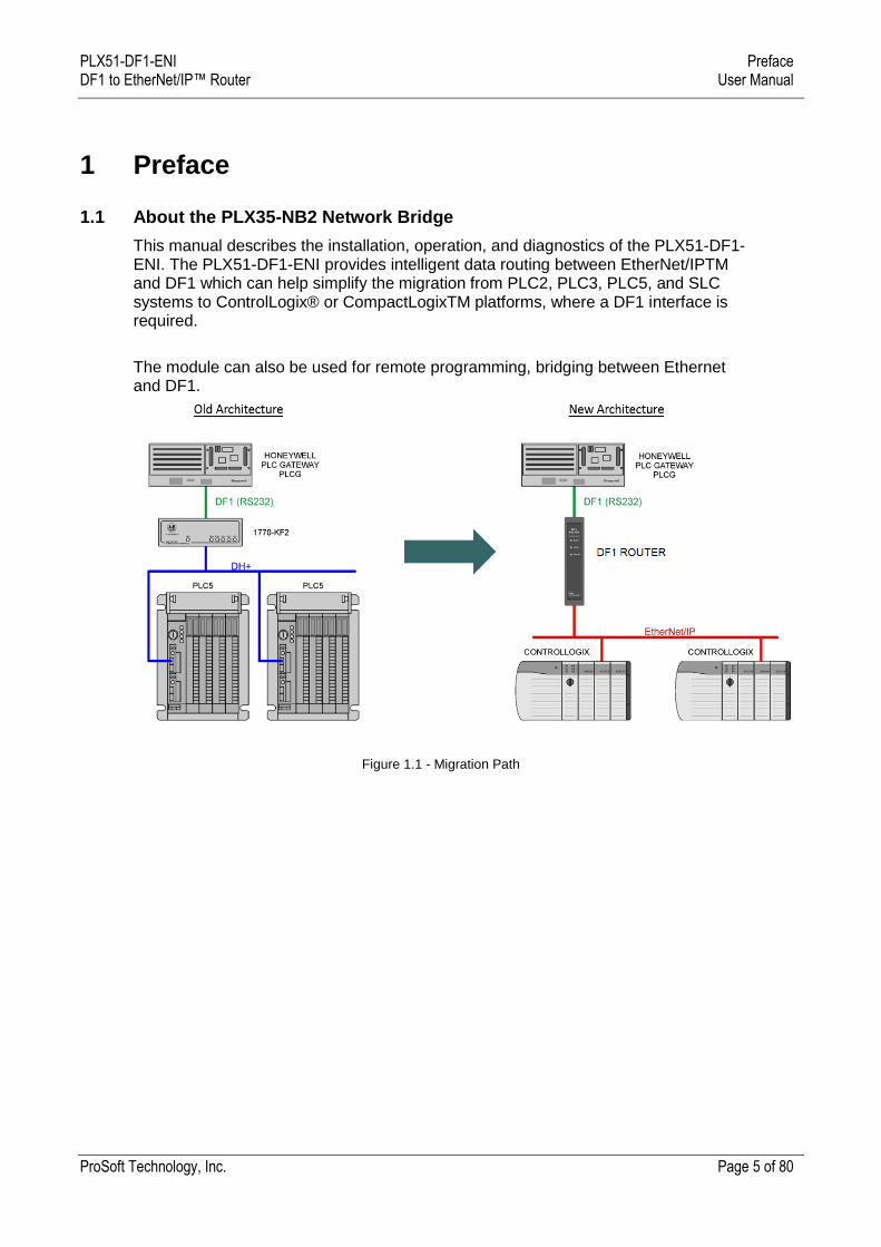
This manual describes the installation, operation, and diagnostics of the PLX51-DF1-ENI. The PLX51-DF1-ENI provides intelligent data routing between EtherNet/IPTM and DF1 which can help simplify the migration from PLC2, PLC3, PLC5, and SLC systems to ControlLogix® or CompactLogixTM platforms, where a DF1 interface is required.
The module can also be used for remote programming, bridging between Ethernet and DF1.
Figure 1.1 - Migration Path
PLX51-DF1-ENI Preface DF1 to EtherNet/IP™ Router User Manual
ProSoft Technology, Inc. Page 6 of 80
1.2 Features
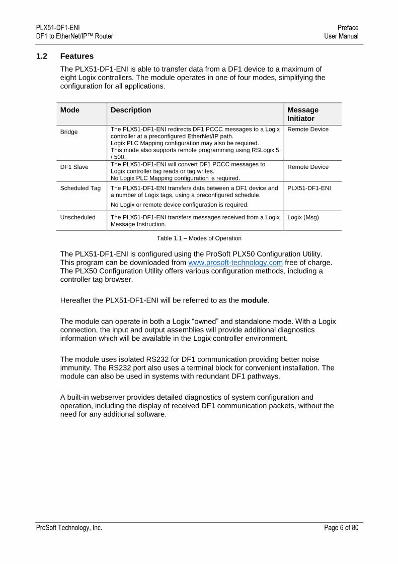
The PLX51-DF1-ENI is able to transfer data from a DF1 device to a maximum of eight Logix controllers. The module operates in one of four modes, simplifying the configuration for all applications.
Mode Description Message Initiator
Bridge The PLX51-DF1-ENI redirects DF1 PCCC messages to a Logix controller at a preconfigured EtherNet/IP path. Logix PLC Mapping configuration may also be required. This mode also supports remote programming using RSLogix 5 / 500.
Remote Device
DF1 Slave The PLX51-DF1-ENI will convert DF1 PCCC messages to Logix controller tag reads or tag writes. No Logix PLC Mapping configuration is required.
Remote Device
Scheduled Tag The PLX51-DF1-ENI transfers data between a DF1 device and a number of Logix tags, using a preconfigured schedule.
No Logix or remote device configuration is required.
PLX51-DF1-ENI
Unscheduled The PLX51-DF1-ENI transfers messages received from a Logix Message Instruction.
Logix (Msg)
Table 1.1 – Modes of Operation
The PLX51-DF1-ENI is configured using the ProSoft PLX50 Configuration Utility. This program can be downloaded from www.prosoft-technology.com free of charge. The PLX50 Configuration Utility offers various configuration methods, including a controller tag browser.
Hereafter the PLX51-DF1-ENI will be referred to as the module.
The module can operate in both a Logix “owned” and standalone mode. With a Logix connection, the input and output assemblies will provide additional diagnostics information which will be available in the Logix controller environment.
The module uses isolated RS232 for DF1 communication providing better noise immunity. The RS232 port also uses a terminal block for convenient installation. The module can also be used in systems with redundant DF1 pathways.
A built-in webserver provides detailed diagnostics of system configuration and operation, including the display of received DF1 communication packets, without the need for any additional software.
PLX51-DF1-ENI Preface DF1 to EtherNet/IP™ Router User Manual
ProSoft Technology, Inc. Page 7 of 80
1.3 Architecture
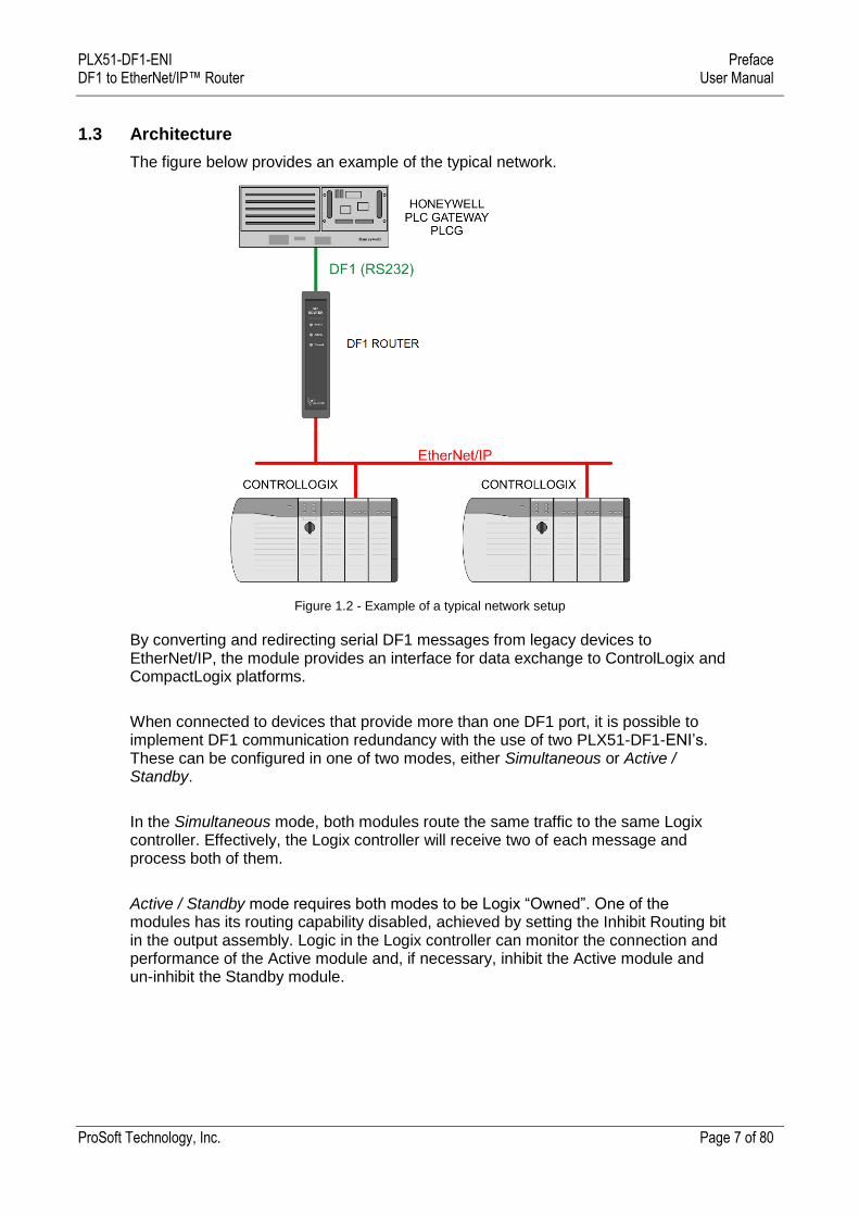
The figure below provides an example of the typical network.
Figure 1.2 - Example of a typical network setup
By converting and redirecting serial DF1 messages from legacy devices to EtherNet/IP, the module provides an interface for data exchange to ControlLogix and CompactLogix platforms.
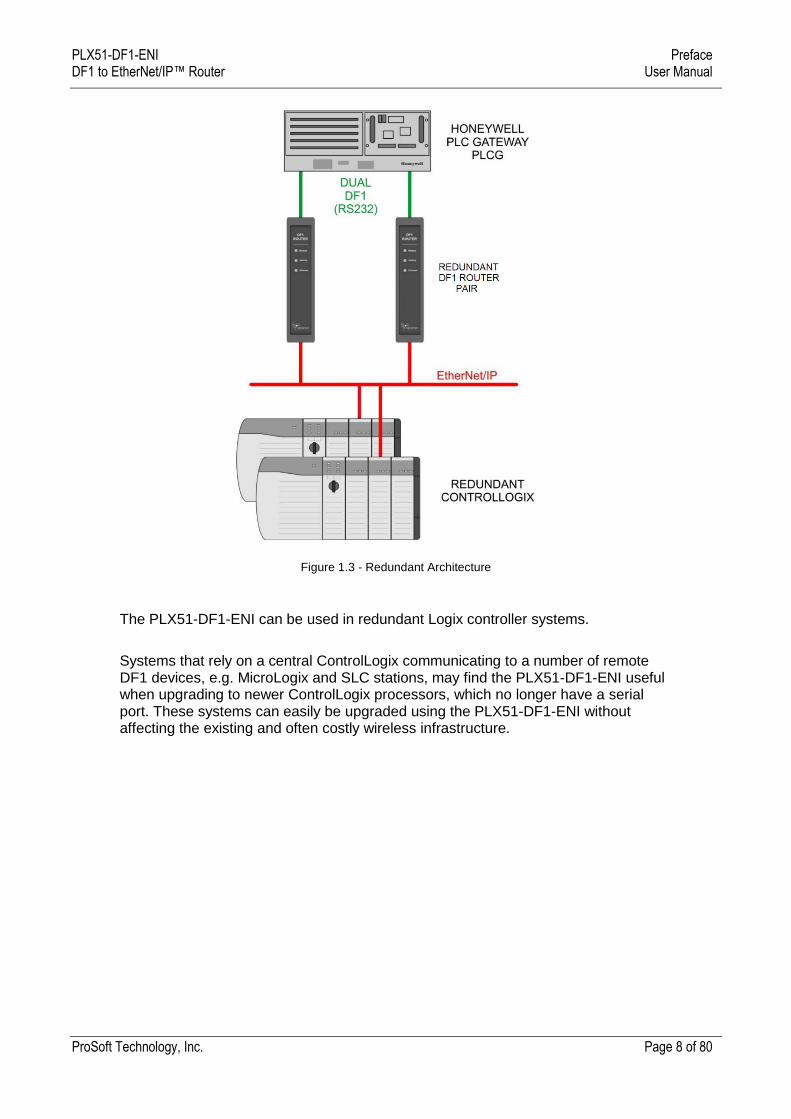
When connected to devices that provide more than one DF1 port, it is possible to implement DF1 communication redundancy with the use of two PLX51-DF1-ENI’s. These can be configured in one of two modes, either Simultaneous or Active / Standby.
In the Simultaneous mode, both modules route the same traffic to the same Logix controller. Effectively, the Logix controller will receive two of each message and process both of them.
Active / Standby mode requires both modes to be Logix “Owned”. One of the modules has its routing capability disabled, achieved by setting the Inhibit Routing bit in the output assembly. Logic in the Logix controller can monitor the connection and performance of the Active module and, if necessary, inhibit the Active module and un-inhibit the Standby module.
PLX51-DF1-ENI Preface DF1 to EtherNet/IP™ Router User Manual
ProSoft Technology, Inc. Page 8 of 80
Figure 1.3 - Redundant Architecture
The PLX51-DF1-ENI can be used in redundant Logix controller systems.
Systems that rely on a central ControlLogix communicating to a number of remote DF1 devices, e.g. MicroLogix and SLC stations, may find the PLX51-DF1-ENI useful when upgrading to newer ControlLogix processors, which no longer have a serial port. These systems can easily be upgraded using the PLX51-DF1-ENI without affecting the existing and often costly wireless infrastructure.
PLX51-DF1-ENI Preface DF1 to EtherNet/IP™ Router User Manual
ProSoft Technology, Inc. Page 9 of 80
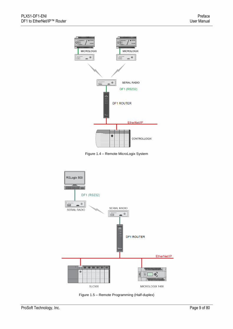
Figure 1.4 – Remote MicroLogix System
Figure 1.5 – Remote Programming (Half-duplex)
PLX51-DF1-ENI Preface DF1 to EtherNet/IP™ Router User Manual
ProSoft Technology, Inc. Page 10 of 80
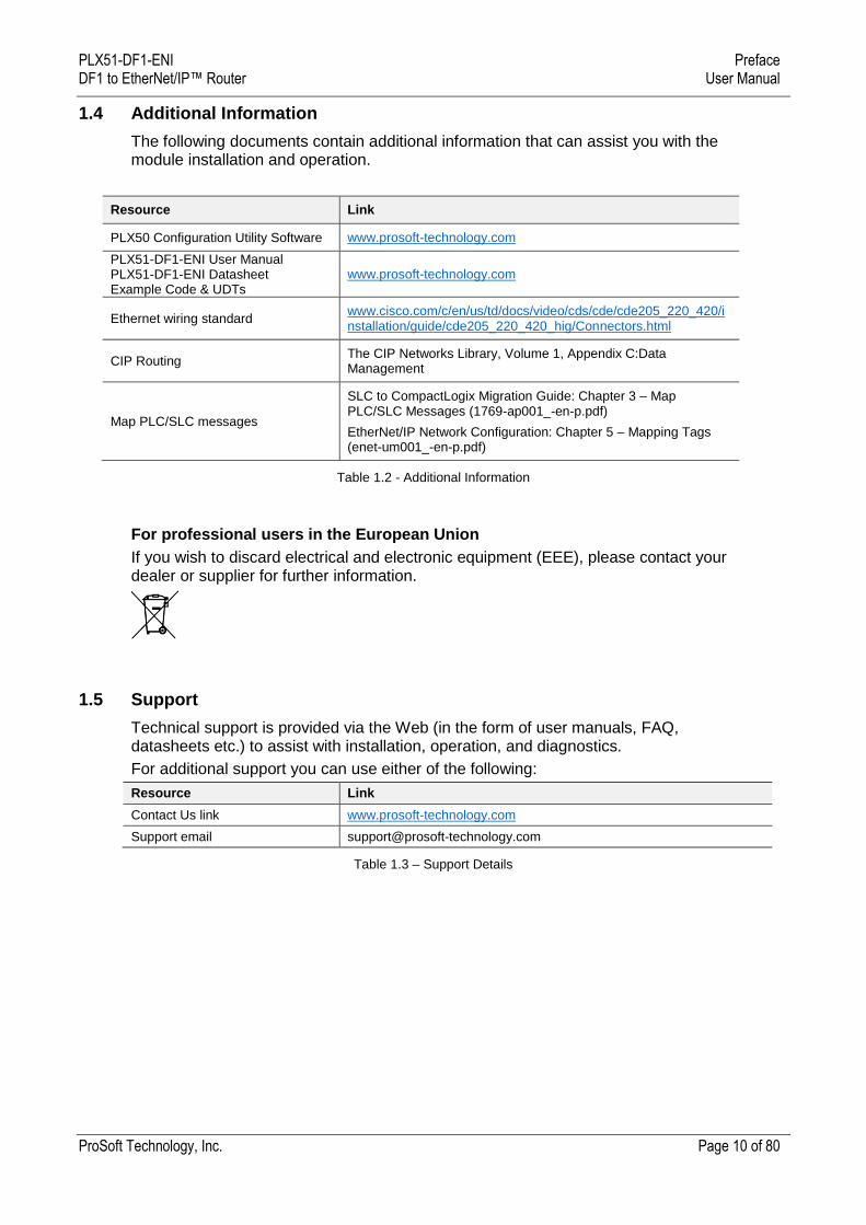
1.4 Additional Information
The following documents contain additional information that can assist you with the module installation and operation.
Resource Link
PLX50 Configuration Utility Software www.prosoft-technology.com
PLX51-DF1-ENI User Manual PLX51-DF1-ENI Datasheet Example Code & UDTs
www.prosoft-technology.com
Ethernet wiring standard www.cisco.com/c/en/us/td/docs/video/cds/cde/cde205_220_420/installation/guide/cde205_220_420_hig/Connectors.html
CIP Routing The CIP Networks Library, Volume 1, Appendix C:Data Management
Map PLC/SLC messages
SLC to CompactLogix Migration Guide: Chapter 3 – Map PLC/SLC Messages (1769-ap001_-en-p.pdf)
EtherNet/IP Network Configuration: Chapter 5 – Mapping Tags (enet-um001_-en-p.pdf)
Table 1.2 - Additional Information
For professional users in the European Union
If you wish to discard electrical and electronic equipment (EEE), please contact your dealer or supplier for further information.
1.5 Support
Technical support is provided via the Web (in the form of user manuals, FAQ, datasheets etc.) to assist with installation, operation, and diagnostics.
For additional support you can use either of the following:
Resource Link
Contact Us link www.prosoft-technology.com
Support email [email protected]
Table 1.3 – Support Details
PLX51-DF1-ENI Installation DF1 to EtherNet/IP™ Router User Manual
ProSoft Technology, Inc. Page 11 of 80
2 Installation
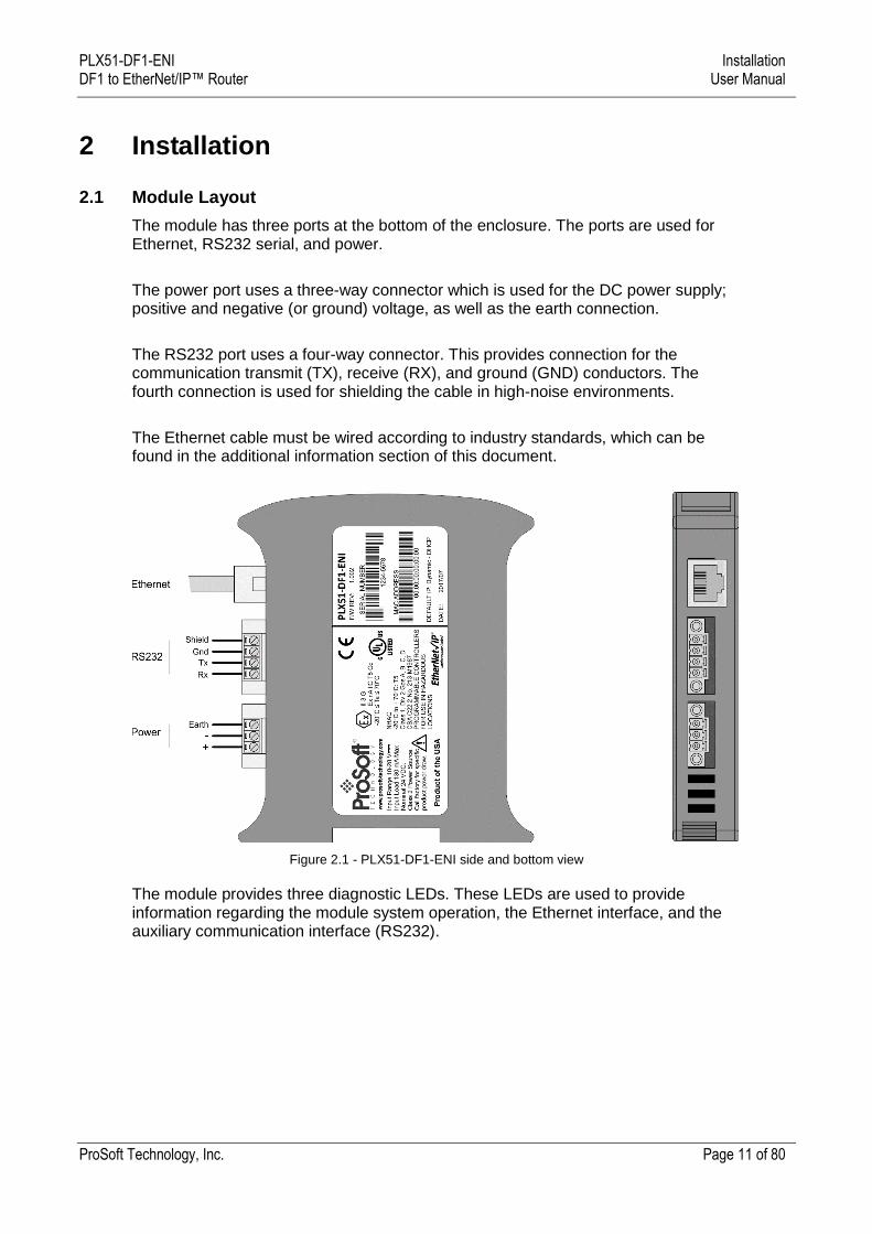
2.1 Module Layout
The module has three ports at the bottom of the enclosure. The ports are used for Ethernet, RS232 serial, and power.
The power port uses a three-way connector which is used for the DC power supply; positive and negative (or ground) voltage, as well as the earth connection.
The RS232 port uses a four-way connector. This provides connection for the communication transmit (TX), receive (RX), and ground (GND) conductors. The fourth connection is used for shielding the cable in high-noise environments.
The Ethernet cable must be wired according to industry standards, which can be found in the additional information section of this document.
Figure 2.1 - PLX51-DF1-ENI side and bottom view
The module provides three diagnostic LEDs. These LEDs are used to provide information regarding the module system operation, the Ethernet interface, and the auxiliary communication interface (RS232).
PLX51-DF1-ENI Installation DF1 to EtherNet/IP™ Router User Manual
ProSoft Technology, Inc. Page 12 of 80
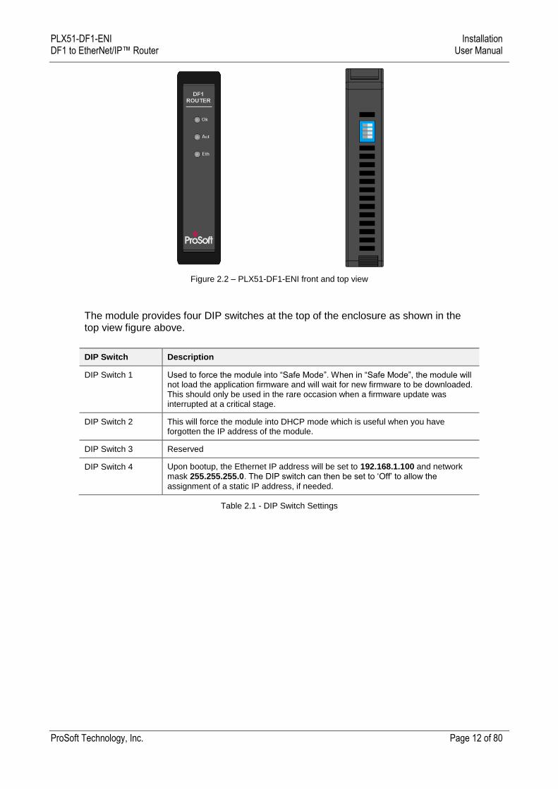
Figure 2.2 – PLX51-DF1-ENI front and top view
The module provides four DIP switches at the top of the enclosure as shown in the top view figure above.
DIP Switch Description
DIP Switch 1 Used to force the module into “Safe Mode”. When in “Safe Mode”, the module will not load the application firmware and will wait for new firmware to be downloaded. This should only be used in the rare occasion when a firmware update was interrupted at a critical stage.
DIP Switch 2 This will force the module into DHCP mode which is useful when you have forgotten the IP address of the module.
DIP Switch 3 Reserved
DIP Switch 4 Upon bootup, the Ethernet IP address will be set to 192.168.1.100 and network mask 255.255.255.0. The DIP switch can then be set to ‘Off’ to allow the
assignment of a static IP address, if needed.
Table 2.1 - DIP Switch Settings
PLX51-DF1-ENI Installation DF1 to EtherNet/IP™ Router User Manual
ProSoft Technology, Inc. Page 13 of 80
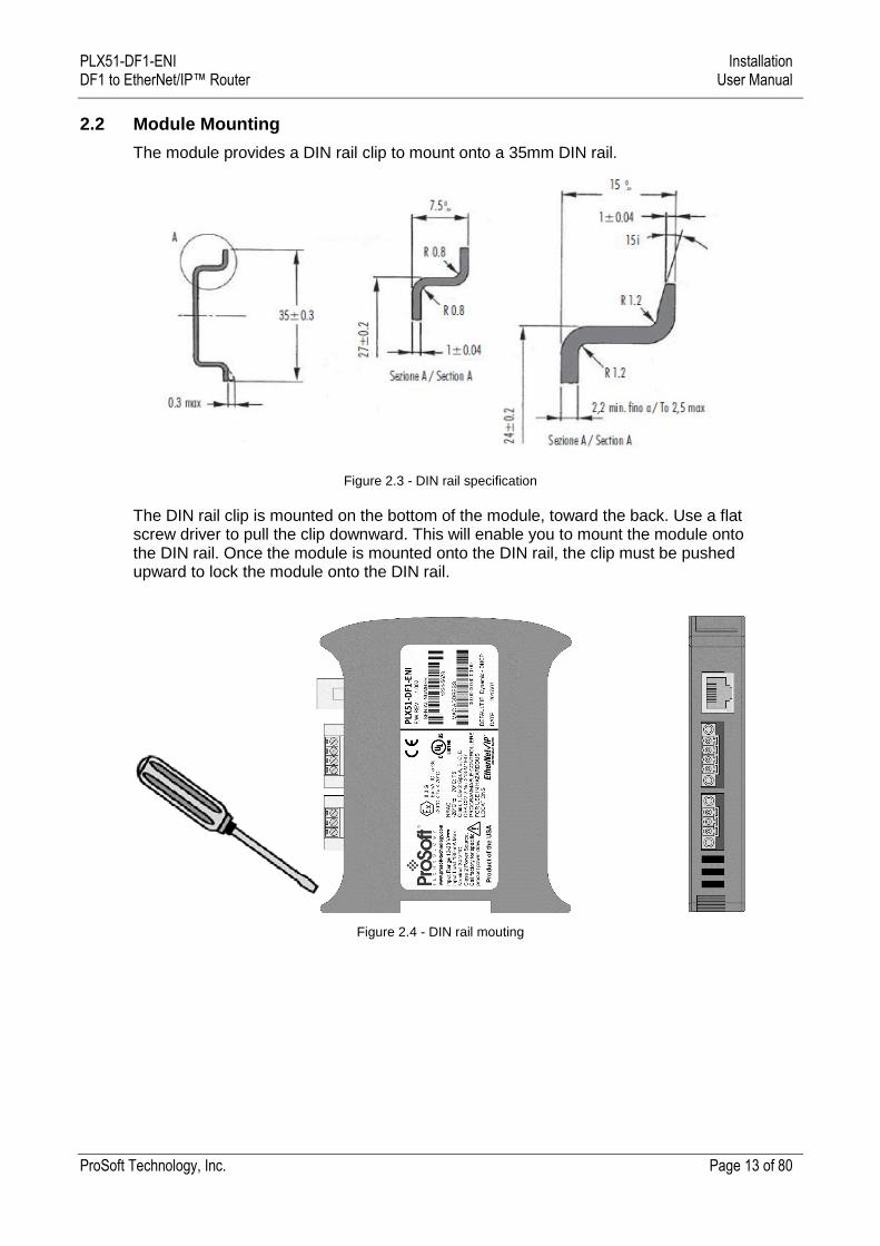
2.2 Module Mounting
The module provides a DIN rail clip to mount onto a 35mm DIN rail.
Figure 2.3 - DIN rail specification
The DIN rail clip is mounted on the bottom of the module, toward the back. Use a flat screw driver to pull the clip downward. This will enable you to mount the module onto the DIN rail. Once the module is mounted onto the DIN rail, the clip must be pushed upward to lock the module onto the DIN rail.
Figure 2.4 - DIN rail mouting

PLX51-DF1-ENI Installation DF1 to EtherNet/IP™ Router User Manual
ProSoft Technology, Inc. Page 14 of 80
2.3 Power
A three-way power connector is used to connect Power+, Power– (GND), and earth. The module requires an input voltage of 10 to 28 VDC. Refer to the technical specifications section in this document.
Figure 2.5 - Power connector
2.4 RS232/RS485 Port
The four-way RS232 connector is used to connect the transmit (TX), receive (RX), and GND conductors for serial communication. The shield terminal can be used for shielded cable in high noise environments.
NOTE: The shield of the RS232 port is internally connected to the power connector earth. Thus, when using a shield it is important to connect the Earth terminal on the power connector to a clean earth. Failing to do this can lower the signal quality of the RS232 communication.
NOTE: When using a shielded cable, it is important that only one end of the shield is connected to earth to avoid current loops. It is recommended to connect the shield to the PLX51-DF1-ENI module, not to the other DF1 device.
Figure 2.6 - RS232 connector
PLX51-DF1-ENI Setup DF1 to EtherNet/IP™ Router User Manual
ProSoft Technology, Inc. Page 15 of 80
3 Setup
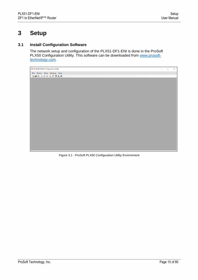
3.1 Install Configuration Software
The network setup and configuration of the PLX51-DF1-ENI is done in the ProSoft PLX50 Configuration Utility. This software can be downloaded from www.prosoft-technology.com.
Figure 3.1 - ProSoft PLX50 Configuration Utility Environment
PLX51-DF1-ENI Setup DF1 to EtherNet/IP™ Router User Manual
ProSoft Technology, Inc. Page 16 of 80
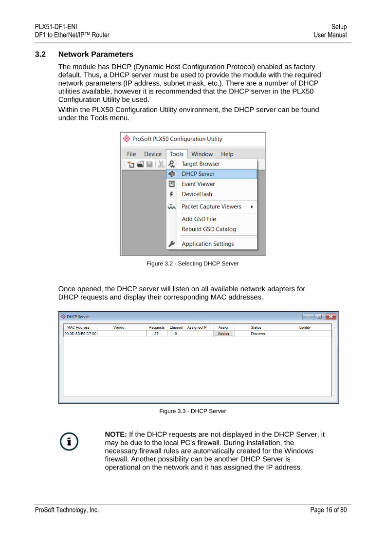
3.2 Network Parameters
The module has DHCP (Dynamic Host Configuration Protocol) enabled as factory default. Thus, a DHCP server must be used to provide the module with the required network parameters (IP address, subnet mask, etc.). There are a number of DHCP utilities available, however it is recommended that the DHCP server in the PLX50 Configuration Utility be used.
Within the PLX50 Configuration Utility environment, the DHCP server can be found under the Tools menu.
Figure 3.2 - Selecting DHCP Server
Once opened, the DHCP server will listen on all available network adapters for DHCP requests and display their corresponding MAC addresses.
Figure 3.3 - DHCP Server
NOTE: If the DHCP requests are not displayed in the DHCP Server, it may be due to the local PC’s firewall. During installation, the necessary firewall rules are automatically created for the Windows firewall. Another possibility can be another DHCP Server is operational on the network and it has assigned the IP address.
PLX51-DF1-ENI Setup DF1 to EtherNet/IP™ Router User Manual
ProSoft Technology, Inc. Page 17 of 80
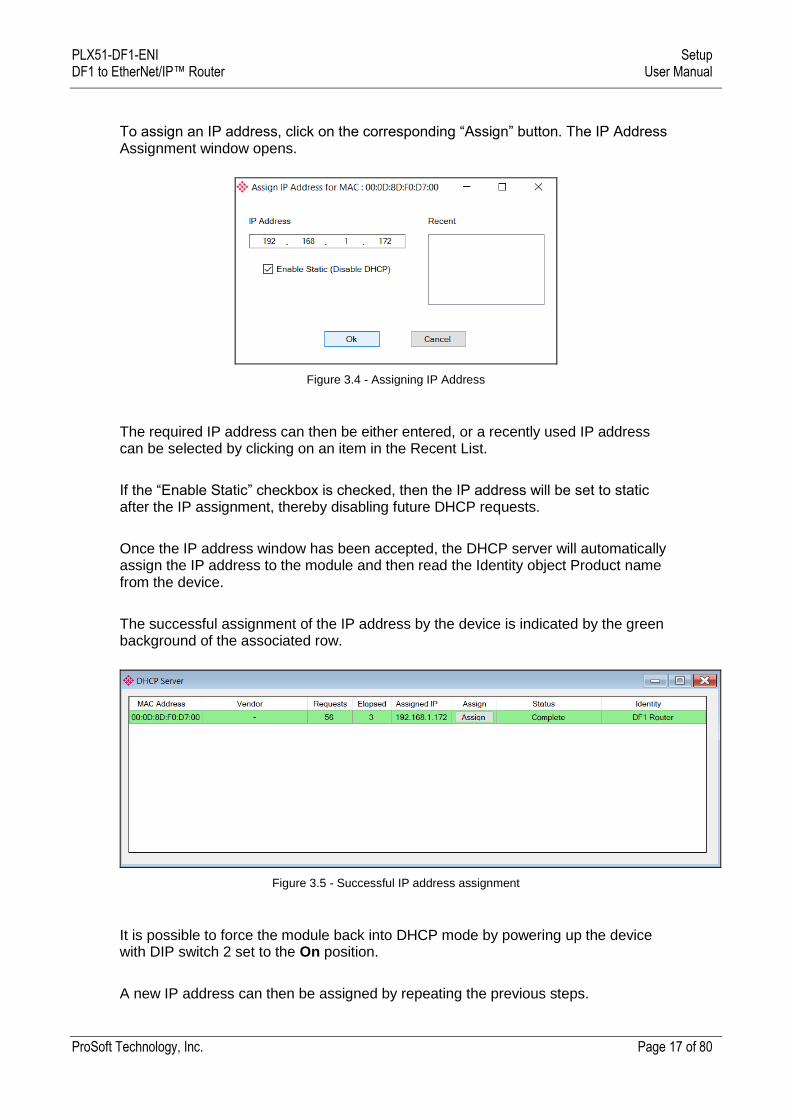
To assign an IP address, click on the corresponding “Assign” button. The IP Address Assignment window opens.
Figure 3.4 - Assigning IP Address
The required IP address can then be either entered, or a recently used IP address can be selected by clicking on an item in the Recent List.
If the “Enable Static” checkbox is checked, then the IP address will be set to static after the IP assignment, thereby disabling future DHCP requests.
Once the IP address window has been accepted, the DHCP server will automatically assign the IP address to the module and then read the Identity object Product name from the device.
The successful assignment of the IP address by the device is indicated by the green background of the associated row.
Figure 3.5 - Successful IP address assignment
It is possible to force the module back into DHCP mode by powering up the device with DIP switch 2 set to the On position.
A new IP address can then be assigned by repeating the previous steps.
PLX51-DF1-ENI Setup DF1 to EtherNet/IP™ Router User Manual
ProSoft Technology, Inc. Page 18 of 80
NOTE: It is important to return DIP switch 2 back to the Off position, to avoid the module returning to a DHCP mode after the power is cycled again.
In addition to the setting the IP address, a number of other network parameters can be set during the DHCP process. These settings can be viewed and edited in the PLX50 Configuration Utility Application Settings, in the DHCP Server tab.
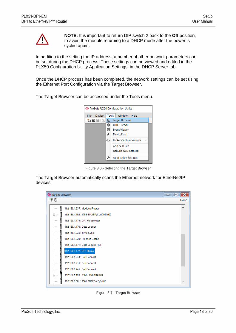
Once the DHCP process has been completed, the network settings can be set using the Ethernet Port Configuration via the Target Browser.
The Target Browser can be accessed under the Tools menu.
Figure 3.6 - Selecting the Target Browser
The Target Browser automatically scans the Ethernet network for EtherNet/IP devices.
Figure 3.7 - Target Browser
PLX51-DF1-ENI Setup DF1 to EtherNet/IP™ Router User Manual
ProSoft Technology, Inc. Page 19 of 80
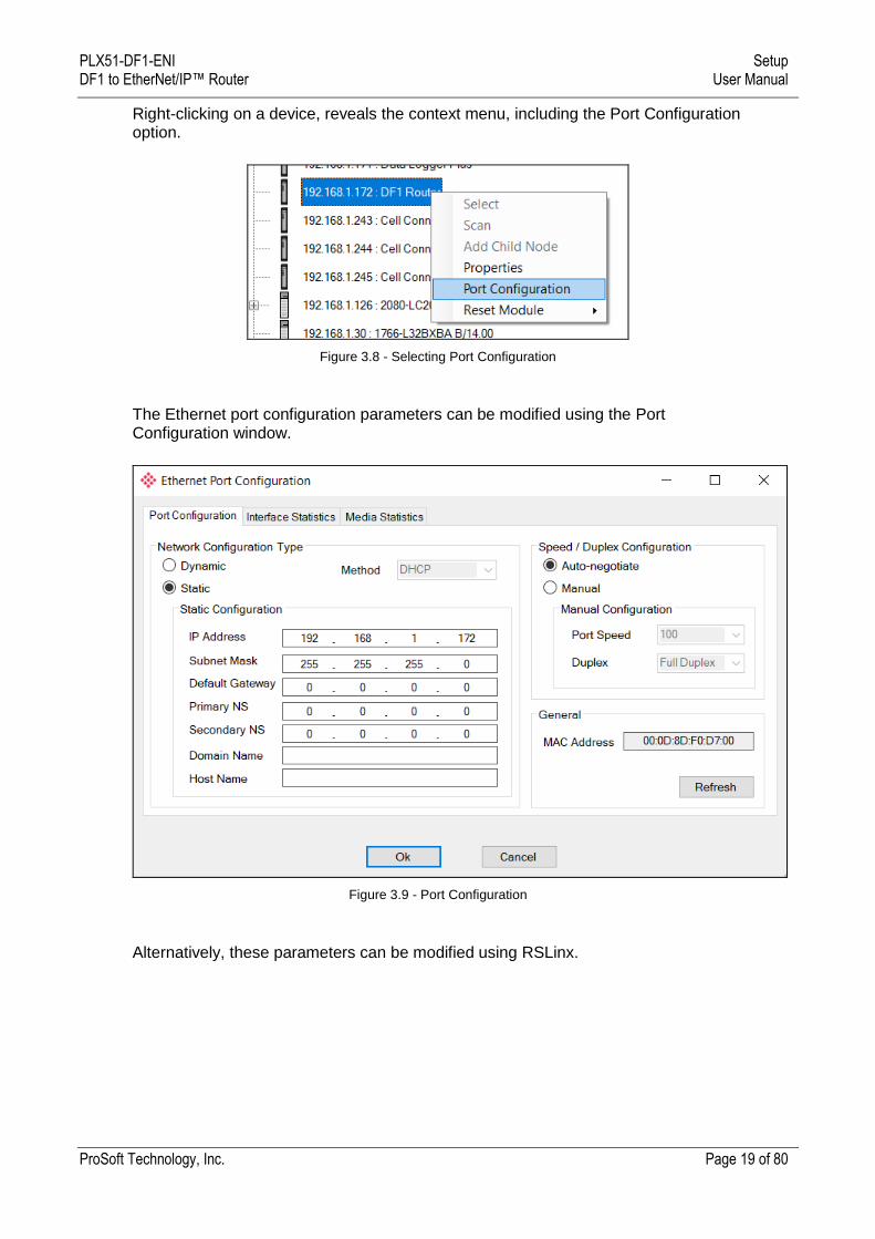
Right-clicking on a device, reveals the context menu, including the Port Configuration option.
Figure 3.8 - Selecting Port Configuration
The Ethernet port configuration parameters can be modified using the Port Configuration window.
Figure 3.9 - Port Configuration
Alternatively, these parameters can be modified using RSLinx.
PLX51-DF1-ENI Setup DF1 to EtherNet/IP™ Router User Manual
ProSoft Technology, Inc. Page 20 of 80
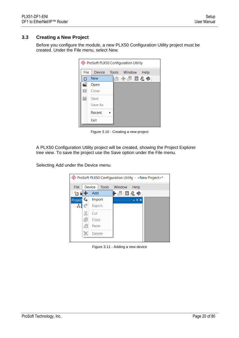
3.3 Creating a New Project
Before you configure the module, a new PLX50 Configuration Utility project must be created. Under the File menu, select New.
Figure 3.10 - Creating a new project
A PLX50 Configuration Utility project will be created, showing the Project Explorer tree view. To save the project use the Save option under the File menu.
Selecting Add under the Device menu.
Figure 3.11 - Adding a new device
PLX51-DF1-ENI Setup DF1 to EtherNet/IP™ Router User Manual
ProSoft Technology, Inc. Page 21 of 80
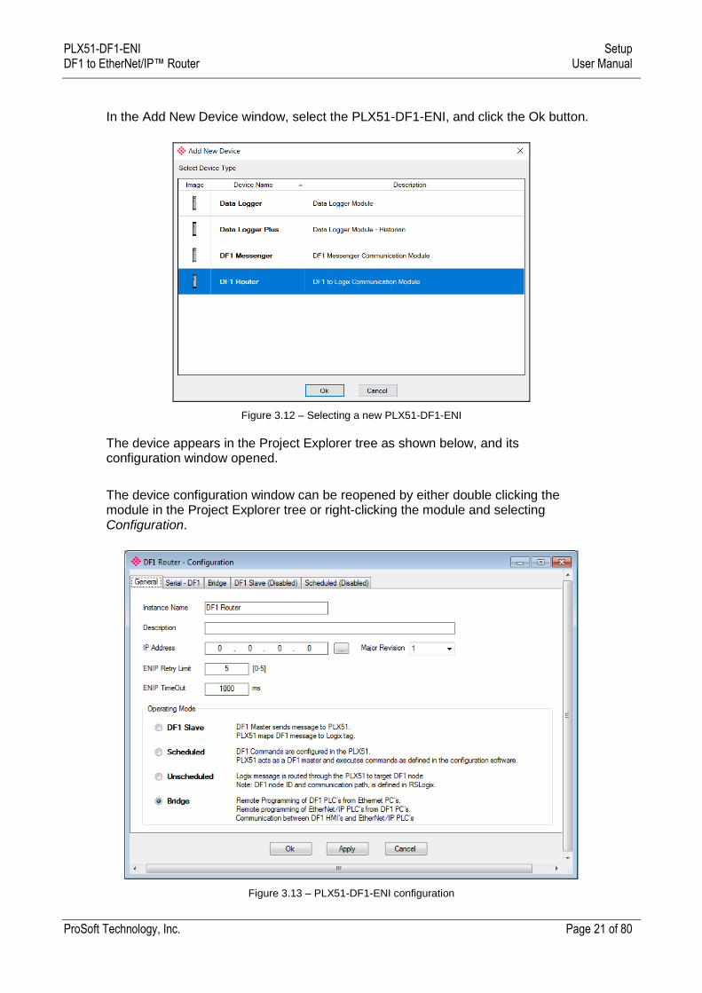
In the Add New Device window, select the PLX51-DF1-ENI, and click the Ok button.
Figure 3.12 – Selecting a new PLX51-DF1-ENI
The device appears in the Project Explorer tree as shown below, and its configuration window opened.
The device configuration window can be reopened by either double clicking the module in the Project Explorer tree or right-clicking the module and selecting Configuration.
Figure 3.13 – PLX51-DF1-ENI configuration
PLX51-DF1-ENI Setup DF1 to EtherNet/IP™ Router User Manual
ProSoft Technology, Inc. Page 22 of 80
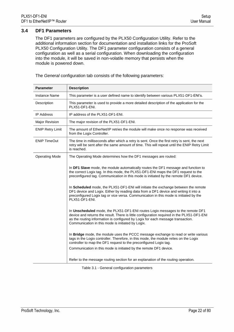
3.4 DF1 Parameters
The DF1 parameters are configured by the PLX50 Configuration Utility. Refer to the additional information section for documentation and installation links for the ProSoft PLX50 Configuration Utility. The DF1 parameter configuration consists of a general configuration as well as a serial configuration. When downloading the configuration into the module, it will be saved in non-volatile memory that persists when the module is powered down.
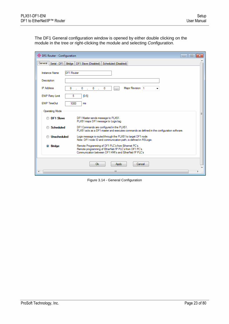
The General configuration tab consists of the following parameters:
Parameter Description
Instance Name This parameter is a user defined name to identify between various PLX51-DF1-ENI’s.
Description This parameter is used to provide a more detailed description of the application for the PLX51-DF1-ENI.
IP Address IP address of the PLX51-DF1-ENI.
Major Revision The major revision of the PLX51-DF1-ENI.
ENIP Retry Limit The amount of EtherNet/IP retries the module will make once no response was received from the Logix Controller.
ENIP TimeOut The time in milliseconds after which a retry is sent. Once the first retry is sent, the next retry will be sent after the same amount of time. This will repeat until the ENIP Retry Limit is reached.
Operating Mode The Operating Mode determines how the DF1 messages are routed:
In DF1 Slave mode, the module automatically routes the DF1 message and function to
the correct Logix tag. In this mode, the PLX51-DF1-ENI maps the DF1 request to the preconfigured tag. Communication in this mode is initiated by the remote DF1 device.
In Scheduled mode, the PLX51-DF1-ENI will initiate the exchange between the remote
DF1 device and Logix. Either by reading data from a DF1 device and writing it into a preconfigured Logix tag or vice versa. Communication in this mode is initiated by the PLX51-DF1-ENI.
In Unscheduled mode, the PLX51-DF1-ENI routes Logix messages to the remote DF1
device and returns the result. There is little configuration required in the PLX51-DF1-ENI as the routing information is configured by Logix for each message transaction. Communication in this mode is initiated by Logix.
In Bridge mode, the module uses the PCCC message exchange to read or write various
tags in the Logix controller. Therefore, in this mode, the module relies on the Logix controller to map the DF1 request to the preconfigured Logix tag.
Communication in this mode is initiated by the remote DF1 device.
Refer to the message routing section for an explanation of the routing operation.
Table 3.1 - General configuration parameters
PLX51-DF1-ENI Setup DF1 to EtherNet/IP™ Router User Manual
ProSoft Technology, Inc. Page 23 of 80
The DF1 General configuration window is opened by either double clicking on the module in the tree or right-clicking the module and selecting Configuration.
Figure 3.14 - General Configuration
PLX51-DF1-ENI Setup DF1 to EtherNet/IP™ Router User Manual
ProSoft Technology, Inc. Page 24 of 80
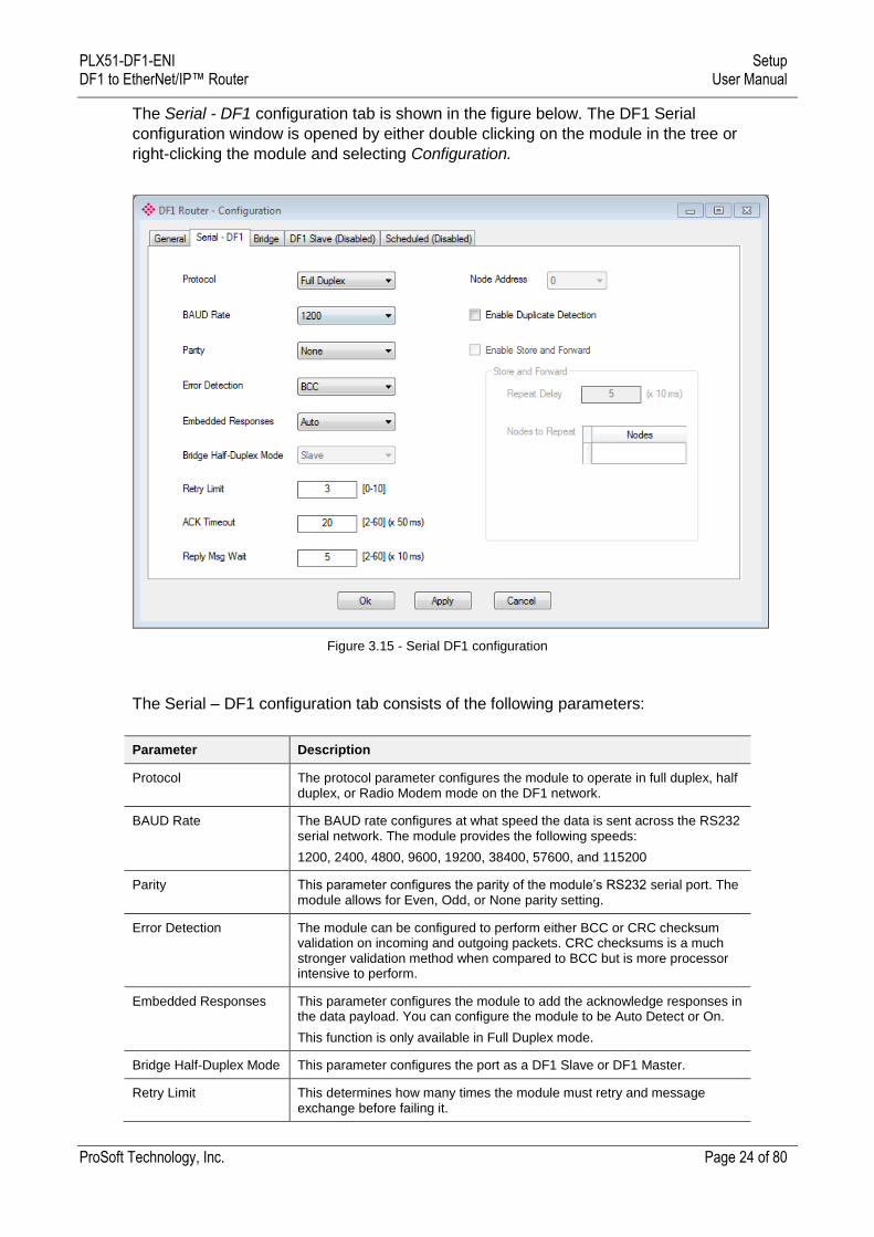
The Serial - DF1 configuration tab is shown in the figure below. The DF1 Serial
configuration window is opened by either double clicking on the module in the tree or
right-clicking the module and selecting Configuration.
Figure 3.15 - Serial DF1 configuration
The Serial – DF1 configuration tab consists of the following parameters:
Parameter Description
Protocol The protocol parameter configures the module to operate in full duplex, half duplex, or Radio Modem mode on the DF1 network.
BAUD Rate The BAUD rate configures at what speed the data is sent across the RS232 serial network. The module provides the following speeds:
1200, 2400, 4800, 9600, 19200, 38400, 57600, and 115200
Parity This parameter configures the parity of the module’s RS232 serial port. The module allows for Even, Odd, or None parity setting.
Error Detection The module can be configured to perform either BCC or CRC checksum validation on incoming and outgoing packets. CRC checksums is a much stronger validation method when compared to BCC but is more processor intensive to perform.
Embedded Responses This parameter configures the module to add the acknowledge responses in the data payload. You can configure the module to be Auto Detect or On.
This function is only available in Full Duplex mode.
Bridge Half-Duplex Mode This parameter configures the port as a DF1 Slave or DF1 Master.
Retry Limit This determines how many times the module must retry and message exchange before failing it.
PLX51-DF1-ENI Setup DF1 to EtherNet/IP™ Router User Manual
ProSoft Technology, Inc. Page 25 of 80
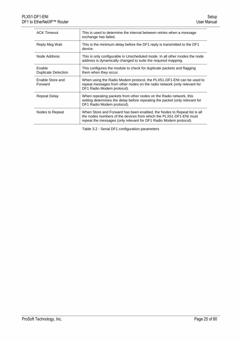
ACK Timeout This is used to determine the interval between retries when a message exchange has failed.
Reply Msg Wait This is the minimum delay before the DF1 reply is transmitted to the DF1 device.
Node Address This is only configurable in Unscheduled mode. In all other modes the node address is dynamically changed to suite the required mapping.
Enable Duplicate Detection
This configures the module to check for duplicate packets and flagging them when they occur.
Enable Store and Forward
When using the Radio Modem protocol, the PLX51-DF1-ENI can be used to repeat messages from other nodes on the radio network (only relevant for DF1 Radio Modem protocol).
Repeat Delay When repeating packets from other nodes on the Radio network, this setting determines the delay before repeating the packet (only relevant for DF1 Radio Modem protocol).
Nodes to Repeat When Store and Forward has been enabled, the Nodes to Repeat list is all the nodes numbers of the devices from which the PLX51-DF1-ENI must repeat the messages (only relevant for DF1 Radio Modem protocol).
Table 3.2 - Serial DF1 configuration parameters
PLX51-DF1-ENI Setup DF1 to EtherNet/IP™ Router User Manual
ProSoft Technology, Inc. Page 26 of 80
3.5 Message Routing
The module can be configured to route DF1 data in one of four modes:
Bridge mode
DF1 Slave mode
Schedule Tag mode
Unscheduled mode
3.5.1 Bridge Mode
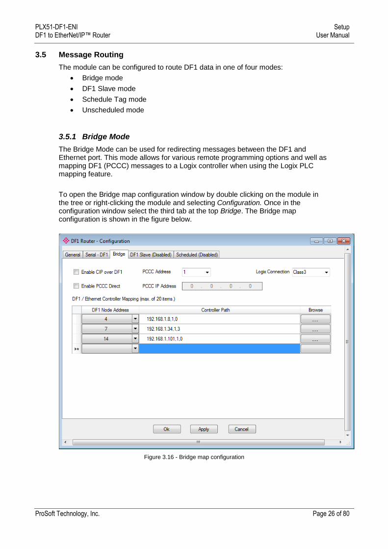
The Bridge Mode can be used for redirecting messages between the DF1 and Ethernet port. This mode allows for various remote programming options and well as mapping DF1 (PCCC) messages to a Logix controller when using the Logix PLC mapping feature.
To open the Bridge map configuration window by double clicking on the module in the tree or right-clicking the module and selecting Configuration. Once in the configuration window select the third tab at the top Bridge. The Bridge map configuration is shown in the figure below.
Figure 3.16 - Bridge map configuration
PLX51-DF1-ENI Setup DF1 to EtherNet/IP™ Router User Manual
ProSoft Technology, Inc. Page 27 of 80
The module can emulate more than one destination DF1 Node Address, and thus route multiple messages to different Ethernet devices. For this reason it is important to enter the correct associate DF1 Node address in each mapping record.
When using PCCC data messaging the connection class can be configured by selecting either Class 3 or Unconnected (UCMM) messaging. This is done by selecting from the Connection drop-down box in the Bridge tab.
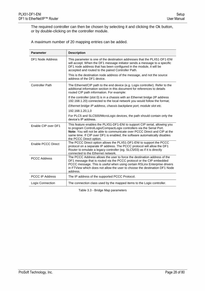
The controller paths can either be entered manually or you can browse to them by clicking the Browse button. The Target Browser requires the controller to be available on the network. The Target Browser will open and automatically scan for all EtherNet/IP devices.
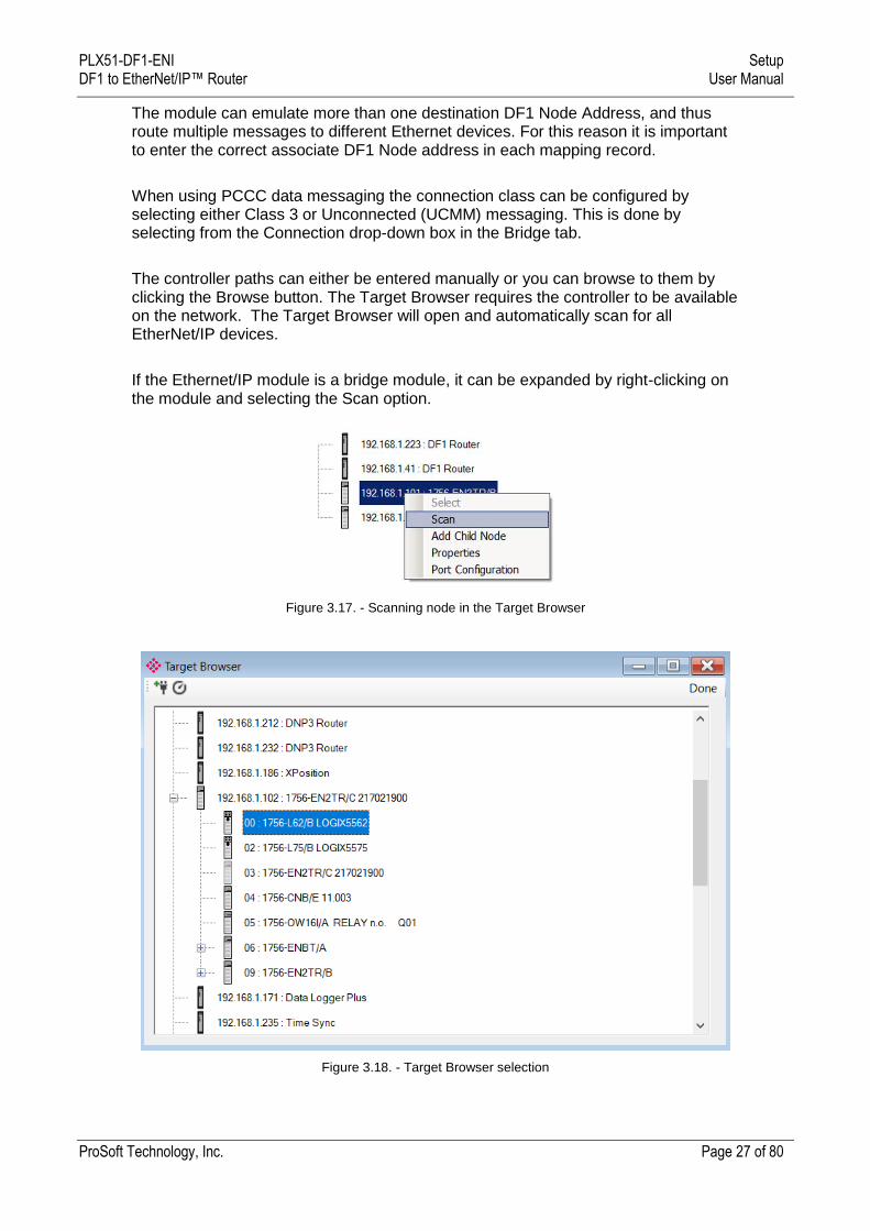
If the Ethernet/IP module is a bridge module, it can be expanded by right-clicking on the module and selecting the Scan option.
Figure 3.17. - Scanning node in the Target Browser
Figure 3.18. - Target Browser selection
PLX51-DF1-ENI Setup DF1 to EtherNet/IP™ Router User Manual
ProSoft Technology, Inc. Page 28 of 80
The required controller can then be chosen by selecting it and clicking the Ok button, or by double-clicking on the controller module.
A maximum number of 20 mapping entries can be added.
Parameter Description
DF1 Node Address This parameter is one of the destination addresses that the PLX51-DF1-ENI will accept. When the DF1 message initiator sends a message to a specific DF1 node address that has been configured in the module, it will be accepted and routed to the paired Controller Path.
This is the destination node address of the message, and not the source address of the DF1 device.
Controller Path The Ethernet/CIP path to the end device (e.g. Logix controller). Refer to the additional information section in this document for references to details routed CIP path information. For example:
If the controller (slot 0) is in a chassis with an Ethernet bridge (IP address 192.168.1.20) connected to the local network you would follow the format;
Ethernet bridge IP address, chassis backplane port, module slot etc.
192.168.1.20,1,0
For PLC5 and SLC500/MicroLogix devices, the path should contain only the device’s IP address.
Enable CIP over DF1 This feature enables the PLX51-DF1-ENI to support CIP serial, allowing you to program ControlLogix/CompactLogix controllers via the Serial Port. Note: You will not be able to communicate over PCCC Direct and CIP at the
same time. If CIP over DF1 is enabled, the software automatically disables the PCCC Direct option.
Enable PCCC Direct The PCCC Direct option allows the PLX51-DF1-ENI to support the PCCC protocol on a separate IP address. The PCCC protocol will allow the DF1 Router to emulate a legacy controller (eg. SLC5/03) as if it is directly connected to the Ethernet network.
PCCC Address The PCCC Address allows the user to force the destination address of the DF1 message that is routed via the PCCC protocol or the CIP embedded PCCC message. This is useful when using certain RSLinx Enterprise drivers in FTView which does not allow the user to choose the destination DF1 Node address.
PCCC IP Address The IP address of the supported PCCC Protocol.
Logix Connection The connection class used by the mapped items to the Logix controller.
Table 3.3 - Bridge Map parameters
PLX51-DF1-ENI Setup DF1 to EtherNet/IP™ Router User Manual
ProSoft Technology, Inc. Page 29 of 80
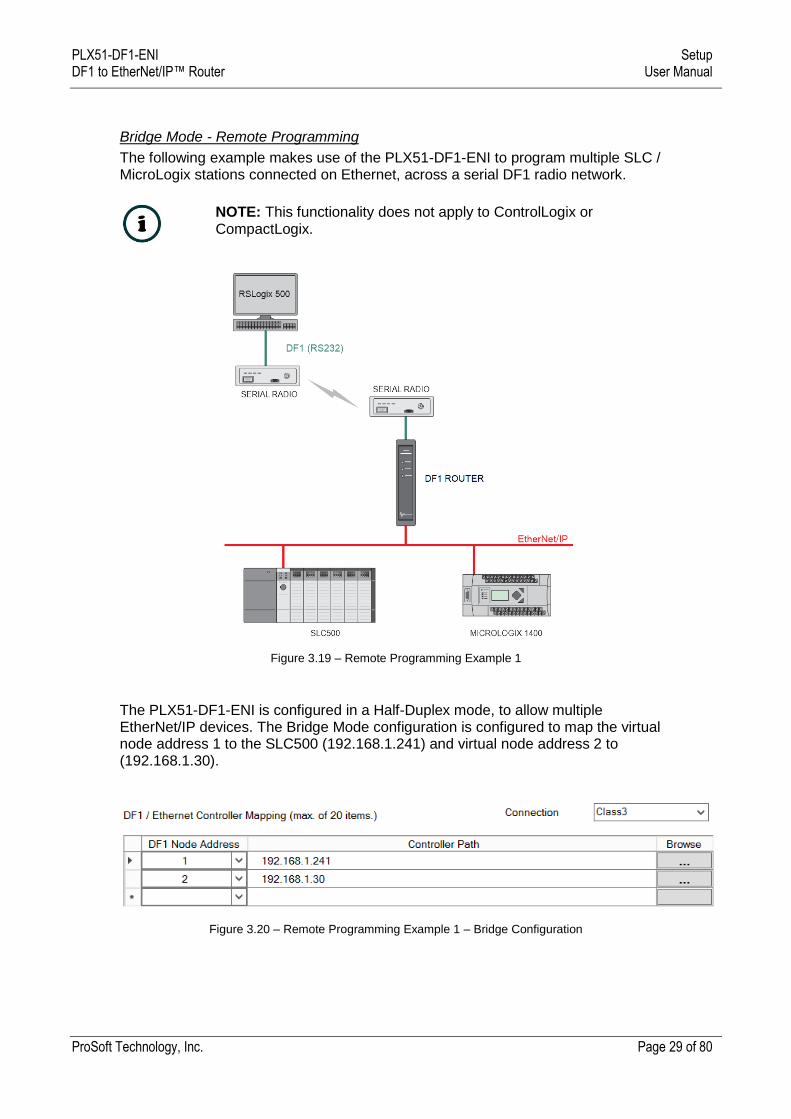
Bridge Mode - Remote Programming
The following example makes use of the PLX51-DF1-ENI to program multiple SLC / MicroLogix stations connected on Ethernet, across a serial DF1 radio network.
NOTE: This functionality does not apply to ControlLogix or CompactLogix.
Figure 3.19 – Remote Programming Example 1
The PLX51-DF1-ENI is configured in a Half-Duplex mode, to allow multiple EtherNet/IP devices. The Bridge Mode configuration is configured to map the virtual node address 1 to the SLC500 (192.168.1.241) and virtual node address 2 to (192.168.1.30).
Figure 3.20 – Remote Programming Example 1 – Bridge Configuration
PLX51-DF1-ENI Setup DF1 to EtherNet/IP™ Router User Manual
ProSoft Technology, Inc. Page 30 of 80
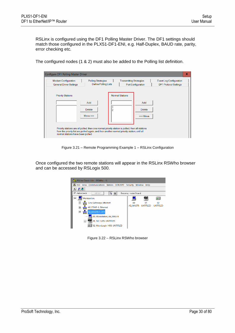
RSLinx is configured using the DF1 Polling Master Driver. The DF1 settings should match those configured in the PLX51-DF1-ENI, e.g. Half-Duplex, BAUD rate, parity, error checking etc.
The configured nodes (1 & 2) must also be added to the Polling list definition.
Figure 3.21 – Remote Programming Example 1 – RSLinx Configuration
Once configured the two remote stations will appear in the RSLinx RSWho browser and can be accessed by RSLogix 500.
Figure 3.22 – RSLinx RSWho browser
PLX51-DF1-ENI Setup DF1 to EtherNet/IP™ Router User Manual
ProSoft Technology, Inc. Page 31 of 80
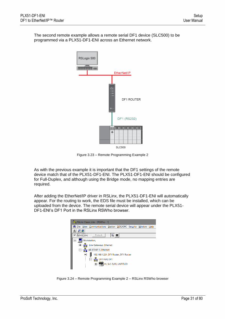
The second remote example allows a remote serial DF1 device (SLC500) to be programmed via a PLX51-DF1-ENI across an Ethernet network.
Figure 3.23 – Remote Programming Example 2
As with the previous example it is important that the DF1 settings of the remote device match that of the PLX51-DF1-ENI. The PLX51-DF1-ENI should be configured for Full-Duplex, and although using the Bridge mode, no mapping entries are required.
After adding the EtherNet/IP driver in RSLinx, the PLX51-DF1-ENI will automatically appear. For the routing to work, the EDS file must be installed, which can be uploaded from the device. The remote serial device will appear under the PLX51-DF1-ENI’s DF1 Port in the RSLinx RSWho browser.
Figure 3.24 – Remote Programming Example 2 – RSLinx RSWho browser
PLX51-DF1-ENI Setup DF1 to EtherNet/IP™ Router User Manual
ProSoft Technology, Inc. Page 32 of 80
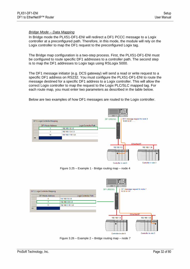
Bridge Mode – Data Mapping
In Bridge mode the PLX51-DF1-ENI will redirect a DF1 PCCC message to a Logix controller at a preconfigured path. Therefore, in this mode, the module will rely on the Logix controller to map the DF1 request to the preconfigured Logix tag.
The Bridge map configuration is a two-step process. First, the PLX51-DF1-ENI must be configured to route specific DF1 addresses to a controller path. The second step is to map the DF1 addresses to Logix tags using RSLogix 5000.
The DF1 message initiator (e.g. DCS gateway) will send a read or write request to a specific DF1 address on RS232. You must configure the PLX51-DF1-ENI to route the message destined for a specific DF1 address to a Logix controller. This will allow the correct Logix controller to map the request to the Logix PLC/SLC mapped tag. For each route map, you must enter two parameters as described in the table below.
Below are two examples of how DF1 messages are routed to the Logix controller.
Figure 3.25 – Example 1 - Bridge routing map – node 4
Figure 3.26 – Example 2 – Bridge routing map – node 7
PLX51-DF1-ENI Setup DF1 to EtherNet/IP™ Router User Manual
ProSoft Technology, Inc. Page 33 of 80
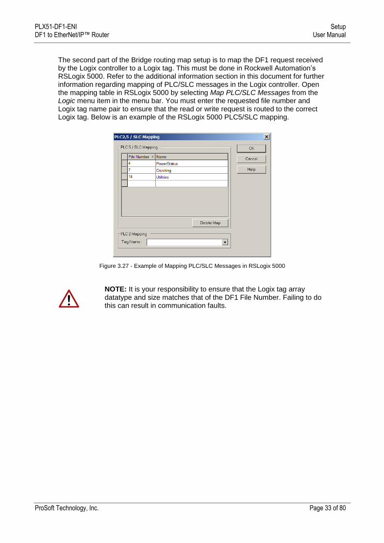
The second part of the Bridge routing map setup is to map the DF1 request received by the Logix controller to a Logix tag. This must be done in Rockwell Automation’s RSLogix 5000. Refer to the additional information section in this document for further information regarding mapping of PLC/SLC messages in the Logix controller. Open the mapping table in RSLogix 5000 by selecting Map PLC/SLC Messages from the Logic menu item in the menu bar. You must enter the requested file number and Logix tag name pair to ensure that the read or write request is routed to the correct Logix tag. Below is an example of the RSLogix 5000 PLC5/SLC mapping.
Figure 3.27 - Example of Mapping PLC/SLC Messages in RSLogix 5000
NOTE: It is your responsibility to ensure that the Logix tag array datatype and size matches that of the DF1 File Number. Failing to do this can result in communication faults.
PLX51-DF1-ENI Setup DF1 to EtherNet/IP™ Router User Manual
ProSoft Technology, Inc. Page 34 of 80
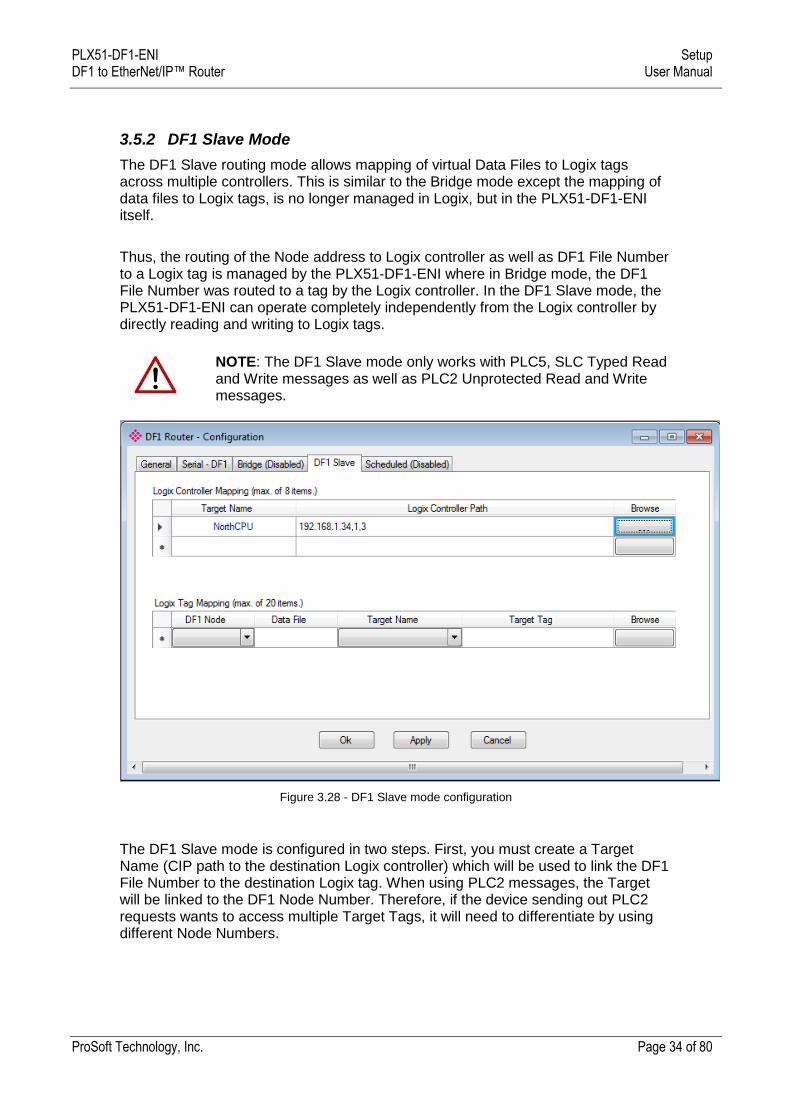
3.5.2 DF1 Slave Mode
The DF1 Slave routing mode allows mapping of virtual Data Files to Logix tags across multiple controllers. This is similar to the Bridge mode except the mapping of data files to Logix tags, is no longer managed in Logix, but in the PLX51-DF1-ENI itself.
Thus, the routing of the Node address to Logix controller as well as DF1 File Number to a Logix tag is managed by the PLX51-DF1-ENI where in Bridge mode, the DF1 File Number was routed to a tag by the Logix controller. In the DF1 Slave mode, the PLX51-DF1-ENI can operate completely independently from the Logix controller by directly reading and writing to Logix tags.
NOTE: The DF1 Slave mode only works with PLC5, SLC Typed Read and Write messages as well as PLC2 Unprotected Read and Write messages.
Figure 3.28 - DF1 Slave mode configuration
The DF1 Slave mode is configured in two steps. First, you must create a Target Name (CIP path to the destination Logix controller) which will be used to link the DF1 File Number to the destination Logix tag. When using PLC2 messages, the Target will be linked to the DF1 Node Number. Therefore, if the device sending out PLC2 requests wants to access multiple Target Tags, it will need to differentiate by using different Node Numbers.
PLX51-DF1-ENI Setup DF1 to EtherNet/IP™ Router User Manual
ProSoft Technology, Inc. Page 35 of 80
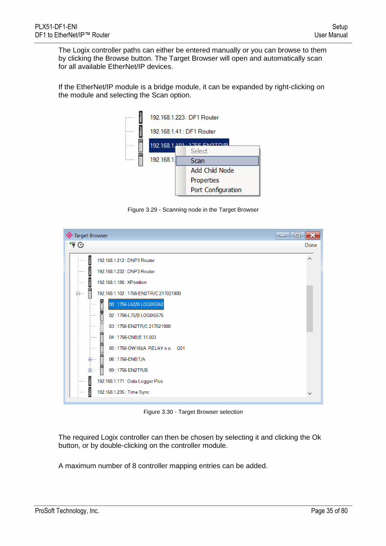
The Logix controller paths can either be entered manually or you can browse to them by clicking the Browse button. The Target Browser will open and automatically scan for all available EtherNet/IP devices.
If the EtherNet/IP module is a bridge module, it can be expanded by right-clicking on the module and selecting the Scan option.
Figure 3.29 - Scanning node in the Target Browser
Figure 3.30 - Target Browser selection
The required Logix controller can then be chosen by selecting it and clicking the Ok button, or by double-clicking on the controller module.
A maximum number of 8 controller mapping entries can be added.
PLX51-DF1-ENI Setup DF1 to EtherNet/IP™ Router User Manual
ProSoft Technology, Inc. Page 36 of 80
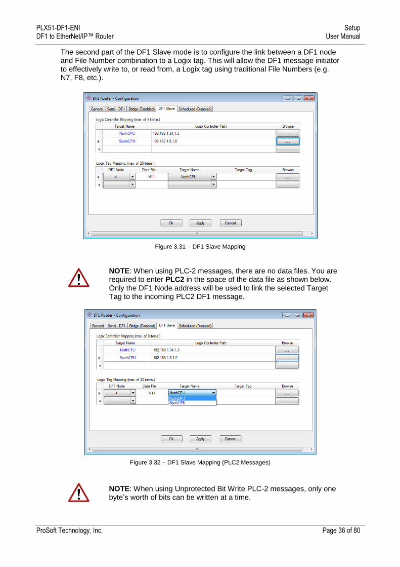
The second part of the DF1 Slave mode is to configure the link between a DF1 node and File Number combination to a Logix tag. This will allow the DF1 message initiator to effectively write to, or read from, a Logix tag using traditional File Numbers (e.g. N7, F8, etc.).
Figure 3.31 – DF1 Slave Mapping
NOTE: When using PLC-2 messages, there are no data files. You are required to enter PLC2 in the space of the data file as shown below. Only the DF1 Node address will be used to link the selected Target Tag to the incoming PLC2 DF1 message.
Figure 3.32 – DF1 Slave Mapping (PLC2 Messages)
NOTE: When using Unprotected Bit Write PLC-2 messages, only one byte’s worth of bits can be written at a time.
PLX51-DF1-ENI Setup DF1 to EtherNet/IP™ Router User Manual
ProSoft Technology, Inc. Page 37 of 80
The module can emulate more than one destination DF1 Node Address, and thus route multiple messages to different Logix controllers. For this reason it is important to enter the correct associate DF1 Node address in each mapping record.
The next column is used to enter the DF1 data file. It is important to enter only the file here (e.g. N11) and not a data word address (e.g. N11:0). The first element of the entered DF1 file (e.g. N11:0) will then map to the first element of the Logix array and so on. When using PLC2 messages, type in “PLC2” into the Data File field as shown in figure 3.27.
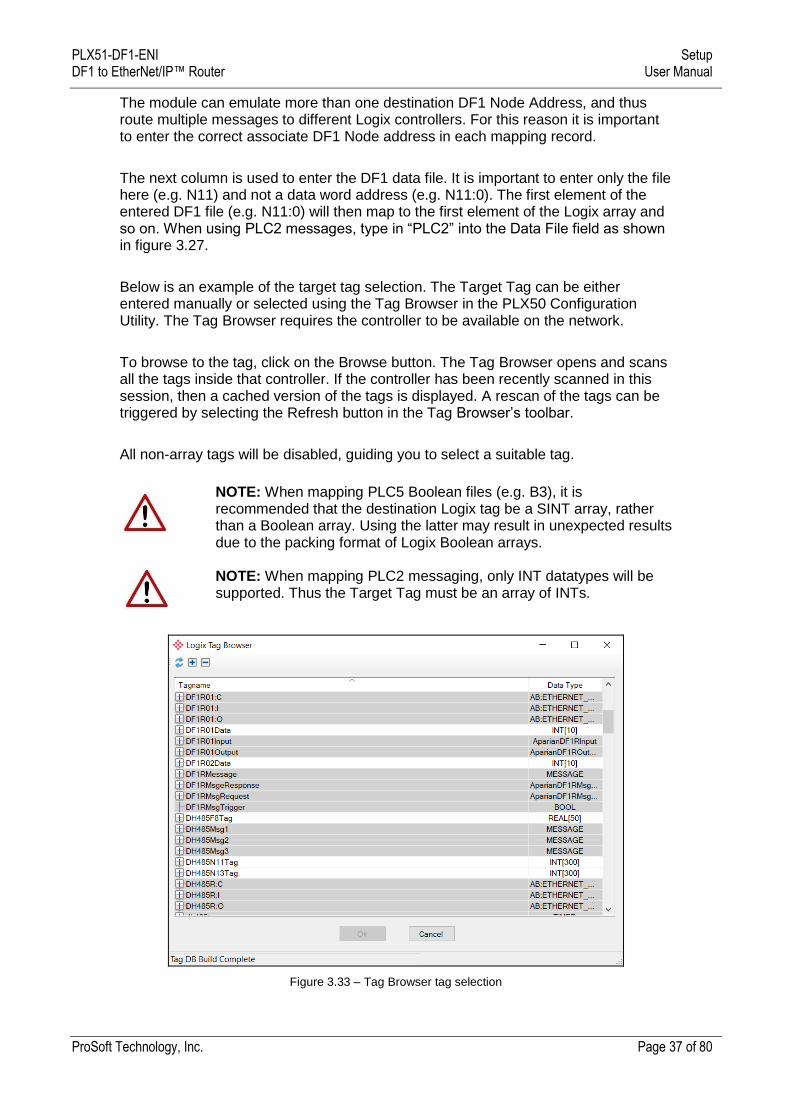
Below is an example of the target tag selection. The Target Tag can be either entered manually or selected using the Tag Browser in the PLX50 Configuration Utility. The Tag Browser requires the controller to be available on the network.
To browse to the tag, click on the Browse button. The Tag Browser opens and scans all the tags inside that controller. If the controller has been recently scanned in this session, then a cached version of the tags is displayed. A rescan of the tags can be triggered by selecting the Refresh button in the Tag Browser’s toolbar.
All non-array tags will be disabled, guiding you to select a suitable tag.
NOTE: When mapping PLC5 Boolean files (e.g. B3), it is recommended that the destination Logix tag be a SINT array, rather than a Boolean array. Using the latter may result in unexpected results due to the packing format of Logix Boolean arrays. NOTE: When mapping PLC2 messaging, only INT datatypes will be supported. Thus the Target Tag must be an array of INTs.
Figure 3.33 – Tag Browser tag selection
PLX51-DF1-ENI Setup DF1 to EtherNet/IP™ Router User Manual
ProSoft Technology, Inc. Page 38 of 80
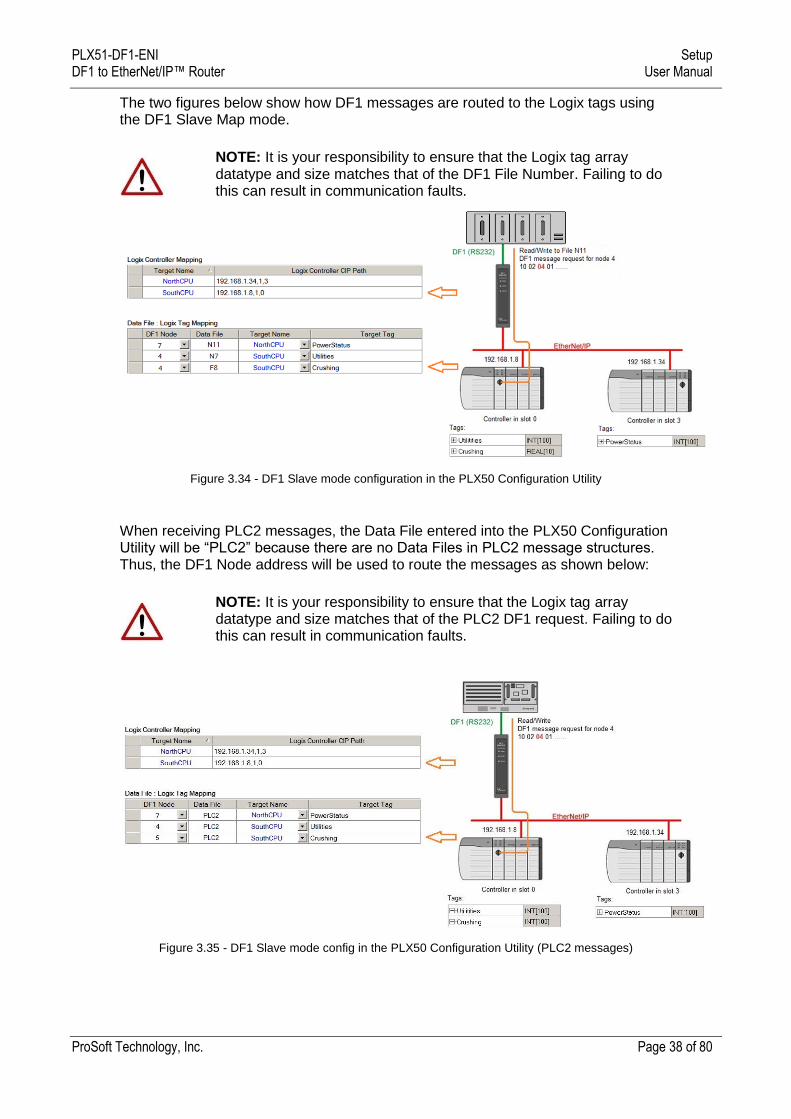
The two figures below show how DF1 messages are routed to the Logix tags using the DF1 Slave Map mode.
NOTE: It is your responsibility to ensure that the Logix tag array datatype and size matches that of the DF1 File Number. Failing to do this can result in communication faults.
Figure 3.34 - DF1 Slave mode configuration in the PLX50 Configuration Utility
When receiving PLC2 messages, the Data File entered into the PLX50 Configuration Utility will be “PLC2” because there are no Data Files in PLC2 message structures. Thus, the DF1 Node address will be used to route the messages as shown below:
NOTE: It is your responsibility to ensure that the Logix tag array datatype and size matches that of the PLC2 DF1 request. Failing to do this can result in communication faults.
Figure 3.35 - DF1 Slave mode config in the PLX50 Configuration Utility (PLC2 messages)
PLX51-DF1-ENI Setup DF1 to EtherNet/IP™ Router User Manual
ProSoft Technology, Inc. Page 39 of 80
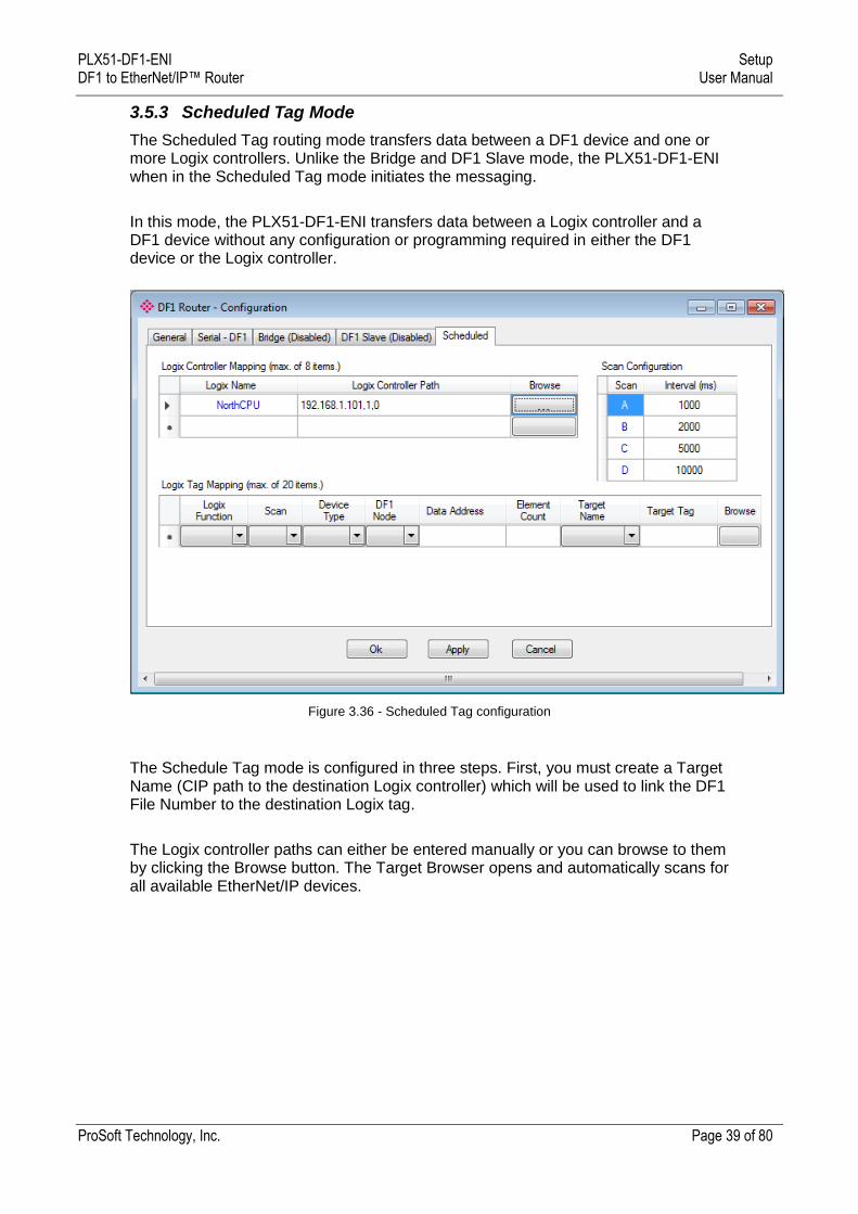
3.5.3 Scheduled Tag Mode
The Scheduled Tag routing mode transfers data between a DF1 device and one or more Logix controllers. Unlike the Bridge and DF1 Slave mode, the PLX51-DF1-ENI when in the Scheduled Tag mode initiates the messaging.
In this mode, the PLX51-DF1-ENI transfers data between a Logix controller and a DF1 device without any configuration or programming required in either the DF1 device or the Logix controller.
Figure 3.36 - Scheduled Tag configuration
The Schedule Tag mode is configured in three steps. First, you must create a Target Name (CIP path to the destination Logix controller) which will be used to link the DF1 File Number to the destination Logix tag.
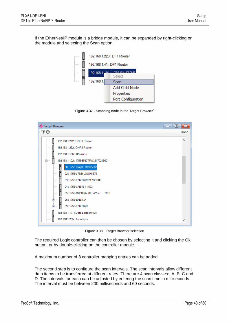
The Logix controller paths can either be entered manually or you can browse to them by clicking the Browse button. The Target Browser opens and automatically scans for all available EtherNet/IP devices.
PLX51-DF1-ENI Setup DF1 to EtherNet/IP™ Router User Manual
ProSoft Technology, Inc. Page 40 of 80
If the EtherNet/IP module is a bridge module, it can be expanded by right-clicking on the module and selecting the Scan option.
Figure 3.37 - Scanning node in the Target Browser`
Figure 3.38 - Target Browser selection
The required Logix controller can then be chosen by selecting it and clicking the Ok button, or by double-clicking on the controller module.
A maximum number of 8 controller mapping entries can be added.
The second step is to configure the scan intervals. The scan intervals allow different data items to be transferred at different rates. There are 4 scan classes:. A, B, C and D. The intervals for each can be adjusted by entering the scan time in milliseconds. The interval must be between 200 milliseconds and 60 seconds.
PLX51-DF1-ENI Setup DF1 to EtherNet/IP™ Router User Manual
ProSoft Technology, Inc. Page 41 of 80
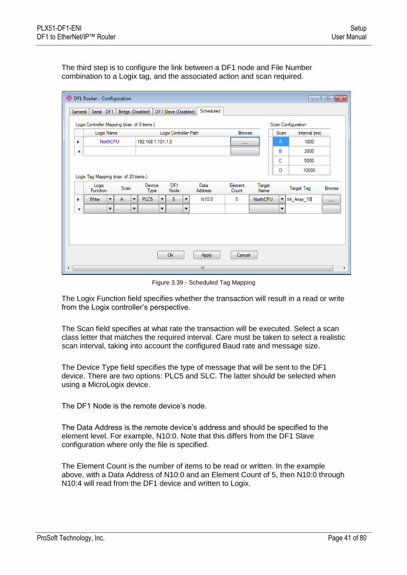
The third step is to configure the link between a DF1 node and File Number combination to a Logix tag, and the associated action and scan required.
Figure 3.39 - Scheduled Tag Mapping
The Logix Function field specifies whether the transaction will result in a read or write from the Logix controller’s perspective.
The Scan field specifies at what rate the transaction will be executed. Select a scan class letter that matches the required interval. Care must be taken to select a realistic scan interval, taking into account the configured Baud rate and message size.
The Device Type field specifies the type of message that will be sent to the DF1 device. There are two options: PLC5 and SLC. The latter should be selected when using a MicroLogix device.
The DF1 Node is the remote device’s node.
The Data Address is the remote device’s address and should be specified to the element level. For example, N10:0. Note that this differs from the DF1 Slave configuration where only the file is specified.
The Element Count is the number of items to be read or written. In the example above, with a Data Address of N10:0 and an Element Count of 5, then N10:0 through N10:4 will read from the DF1 device and written to Logix.
PLX51-DF1-ENI Setup DF1 to EtherNet/IP™ Router User Manual
ProSoft Technology, Inc. Page 42 of 80
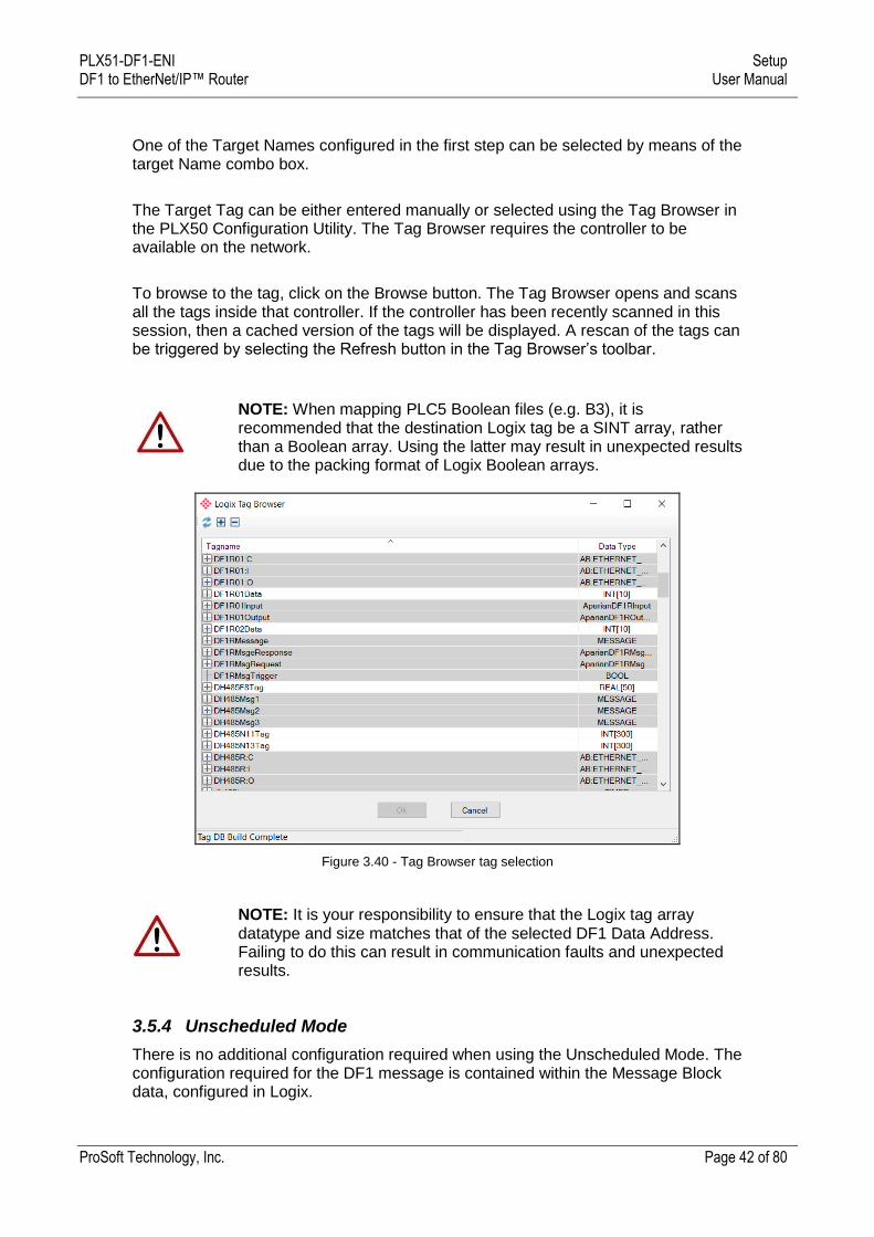
One of the Target Names configured in the first step can be selected by means of the target Name combo box.
The Target Tag can be either entered manually or selected using the Tag Browser in the PLX50 Configuration Utility. The Tag Browser requires the controller to be available on the network.
To browse to the tag, click on the Browse button. The Tag Browser opens and scans all the tags inside that controller. If the controller has been recently scanned in this session, then a cached version of the tags will be displayed. A rescan of the tags can be triggered by selecting the Refresh button in the Tag Browser’s toolbar.
NOTE: When mapping PLC5 Boolean files (e.g. B3), it is recommended that the destination Logix tag be a SINT array, rather than a Boolean array. Using the latter may result in unexpected results due to the packing format of Logix Boolean arrays.
Figure 3.40 - Tag Browser tag selection
NOTE: It is your responsibility to ensure that the Logix tag array datatype and size matches that of the selected DF1 Data Address. Failing to do this can result in communication faults and unexpected results.
3.5.4 Unscheduled Mode
There is no additional configuration required when using the Unscheduled Mode. The configuration required for the DF1 message is contained within the Message Block data, configured in Logix.
PLX51-DF1-ENI Setup DF1 to EtherNet/IP™ Router User Manual
ProSoft Technology, Inc. Page 43 of 80
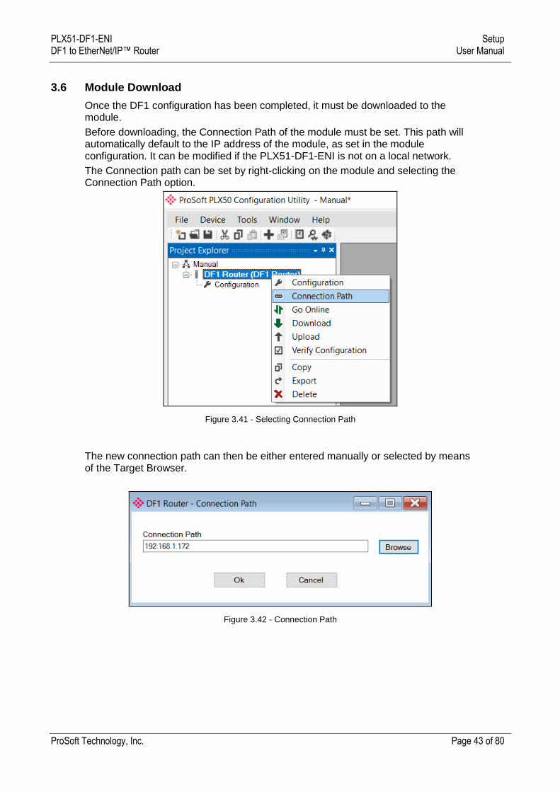
3.6 Module Download
Once the DF1 configuration has been completed, it must be downloaded to the module.
Before downloading, the Connection Path of the module must be set. This path will automatically default to the IP address of the module, as set in the module configuration. It can be modified if the PLX51-DF1-ENI is not on a local network.
The Connection path can be set by right-clicking on the module and selecting the Connection Path option.
Figure 3.41 - Selecting Connection Path
The new connection path can then be either entered manually or selected by means of the Target Browser.
Figure 3.42 - Connection Path

PLX51-DF1-ENI Setup DF1 to EtherNet/IP™ Router User Manual
ProSoft Technology, Inc. Page 44 of 80
To initiate the download, right-click on the module and select the Download option.
Figure 3.43 - Selecting Download
Once complete, you will be notified that the download was successful.
Figure 3.44 - Successful download
During the download process, the module’s time will be compared to that of the PC’s time. Should the difference be greater than 30 seconds, you will be prompted to set the module time to that of the PC time.
Figure 3.45 - Setting module time
The module time is used only for the event log.
PLX51-DF1-ENI Setup DF1 to EtherNet/IP™ Router User Manual
ProSoft Technology, Inc. Page 45 of 80
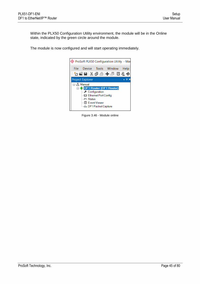
Within the PLX50 Configuration Utility environment, the module will be in the Online state, indicated by the green circle around the module.
The module is now configured and will start operating immediately.
Figure 3.46 - Module online
PLX51-DF1-ENI Setup DF1 to EtherNet/IP™ Router User Manual
ProSoft Technology, Inc. Page 46 of 80
3.7 RSLogix 5000 Configuration
The PLX51-DF1-ENI modules can be easily integrated with Allen-Bradley Logix family of controllers.
For Logix versions 20 and beyond, the modules can be added using the EDS Add-On-Profile (AOP), described in section 3.7.1.
There are 2 EDS files (EDS and NP EDS) for the PLX51-DF1-ENI. One supports routing using the DF1 protocol and the other supports EDS AOP in Logix (NP Suffix). Two EDS files exist because Studio 5000 does not decorate the AOP if there exists a Port Object or Legacy Port (required for DF1 routing).
The EDS file supports routing to DF1. If the customer tries to upload this EDS file in RSLogix, the AOP will not work. This is the EDS stored in the module.
The NP EDS file supports EDS AOP. This file will successfully create the EDS AOP in RSLogix. This file can be registered manually using the EDS Hardware Installation Tool.
Important: For older versions (19 and below), the module must be added using a Generic Profile described in section 3.7.2.
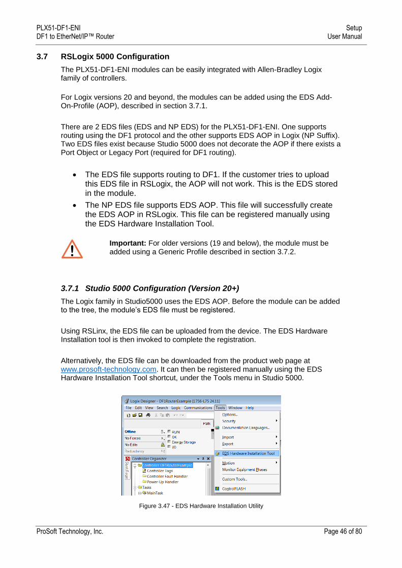
3.7.1 Studio 5000 Configuration (Version 20+)
The Logix family in Studio5000 uses the EDS AOP. Before the module can be added to the tree, the module’s EDS file must be registered.
Using RSLinx, the EDS file can be uploaded from the device. The EDS Hardware Installation tool is then invoked to complete the registration.
Alternatively, the EDS file can be downloaded from the product web page at www.prosoft-technology.com. It can then be registered manually using the EDS Hardware Installation Tool shortcut, under the Tools menu in Studio 5000.
Figure 3.47 - EDS Hardware Installation Utility
PLX51-DF1-ENI Setup DF1 to EtherNet/IP™ Router User Manual
ProSoft Technology, Inc. Page 47 of 80
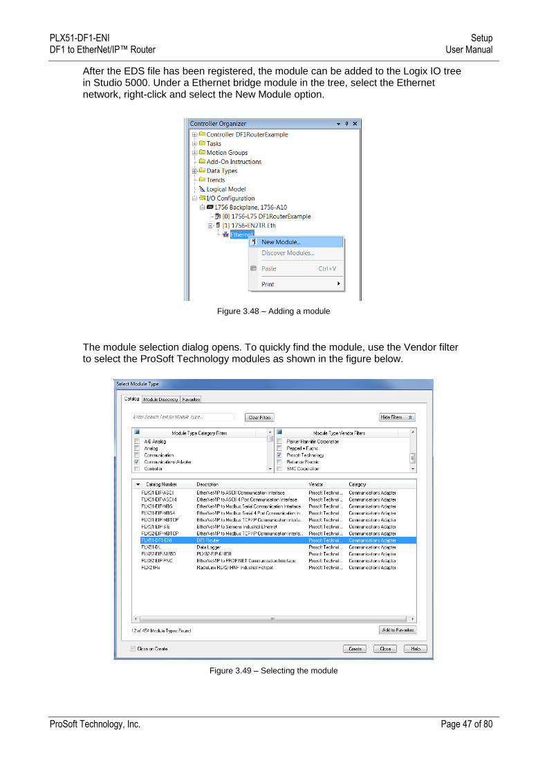
After the EDS file has been registered, the module can be added to the Logix IO tree in Studio 5000. Under a Ethernet bridge module in the tree, select the Ethernet network, right-click and select the New Module option.
Figure 3.48 – Adding a module
The module selection dialog opens. To quickly find the module, use the Vendor filter to select the ProSoft Technology modules as shown in the figure below.
Figure 3.49 – Selecting the module
PLX51-DF1-ENI Setup DF1 to EtherNet/IP™ Router User Manual
ProSoft Technology, Inc. Page 48 of 80
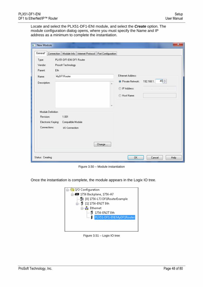
Locate and select the PLX51-DF1-ENI module, and select the Create option. The module configuration dialog opens, where you must specify the Name and IP address as a minimum to complete the instantiation.
Figure 3.50 – Module instantiation
Once the instantiation is complete, the module appears in the Logix IO tree.
Figure 3.51 – Logix IO tree
PLX51-DF1-ENI Setup DF1 to EtherNet/IP™ Router User Manual
ProSoft Technology, Inc. Page 49 of 80
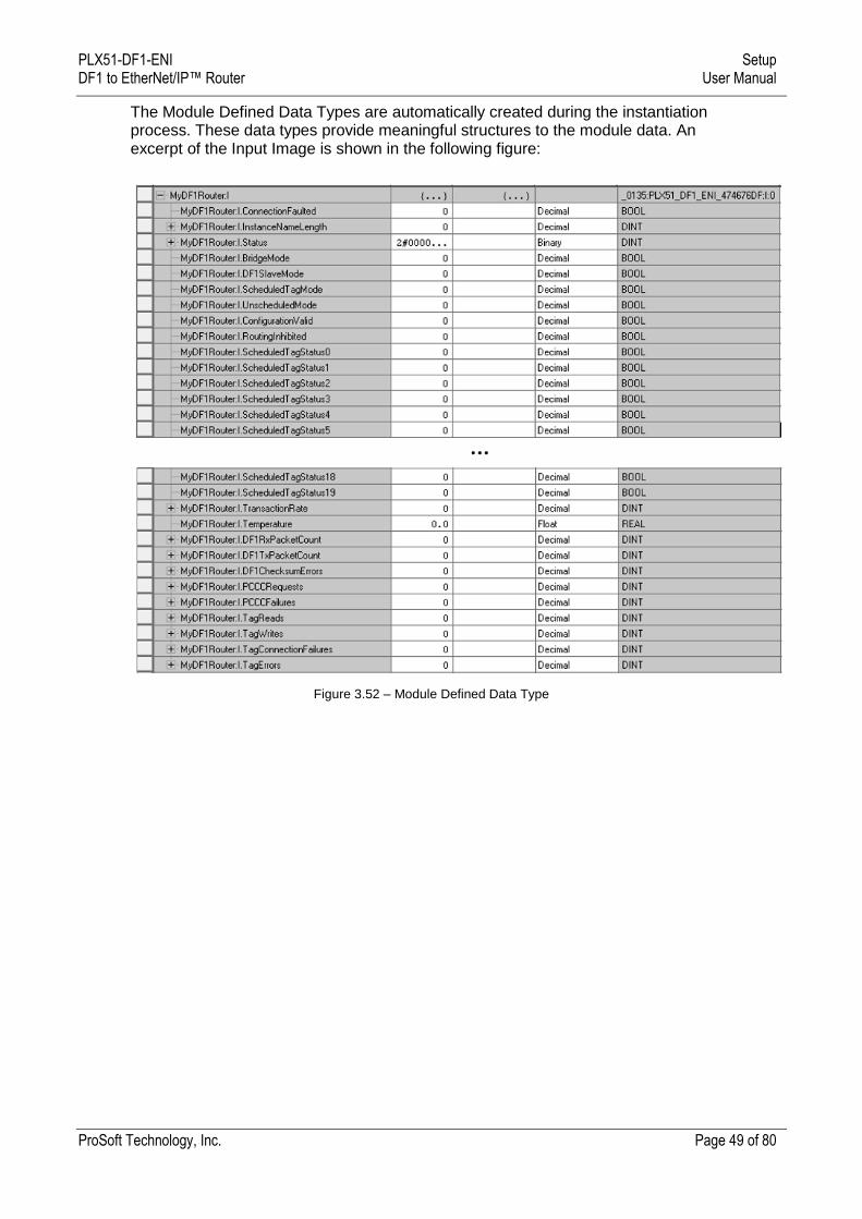
The Module Defined Data Types are automatically created during the instantiation process. These data types provide meaningful structures to the module data. An excerpt of the Input Image is shown in the following figure:
Figure 3.52 – Module Defined Data Type
PLX51-DF1-ENI Setup DF1 to EtherNet/IP™ Router User Manual
ProSoft Technology, Inc. Page 50 of 80
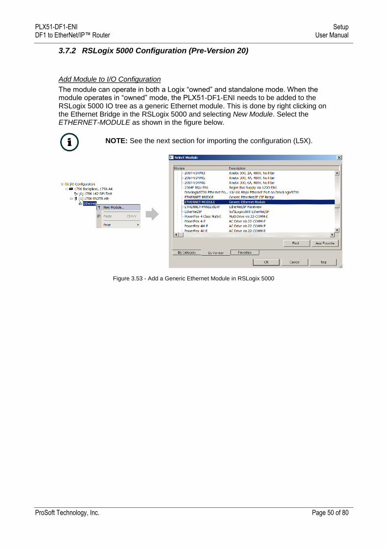
3.7.2 RSLogix 5000 Configuration (Pre-Version 20)
Add Module to I/O Configuration
The module can operate in both a Logix “owned” and standalone mode. When the module operates in “owned” mode, the PLX51-DF1-ENI needs to be added to the RSLogix 5000 IO tree as a generic Ethernet module. This is done by right clicking on the Ethernet Bridge in the RSLogix 5000 and selecting New Module. Select the ETHERNET-MODULE as shown in the figure below.
NOTE: See the next section for importing the configuration (L5X).
Figure 3.53 - Add a Generic Ethernet Module in RSLogix 5000

PLX51-DF1-ENI Setup DF1 to EtherNet/IP™ Router User Manual
ProSoft Technology, Inc. Page 51 of 80
In the Module Properties dialog, enter the IP address, the assembly instance, and size for the input, output, and configuration. Below are the required connection parameters.
Connection Parameter Assembly Instance Size
Input 100 34 (32-bit)
Output 101 1 (32-bit)
Configuration 102 0 (8-bit)
Table 3.4 - RSLogix class 1 connection parameters for the PLX51-DF1-ENI
Figure 3.54 - RSLogix General module properties in RSLogix 5000
NOTE: You will need to enter the exact connection parameters before the module will establish a class 1 connection with the Logix controller.
PLX51-DF1-ENI Setup DF1 to EtherNet/IP™ Router User Manual
ProSoft Technology, Inc. Page 52 of 80
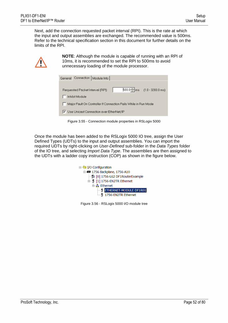
Next, add the connection requested packet interval (RPI). This is the rate at which the input and output assemblies are exchanged. The recommended value is 500ms. Refer to the technical specification section in this document for further details on the limits of the RPI.
NOTE: Although the module is capable of running with an RPI of 10ms, it is recommended to set the RPI to 500ms to avoid unnecessary loading of the module processor.
Figure 3.55 - Connection module properties in RSLogix 5000
Once the module has been added to the RSLogix 5000 IO tree, assign the User Defined Types (UDTs) to the input and output assemblies. You can import the required UDTs by right-clicking on User-Defined sub-folder in the Data Types folder of the IO tree, and selecting Import Data Type. The assemblies are then assigned to the UDTs with a ladder copy instruction (COP) as shown in the figure below.
Figure 3.56 - RSLogix 5000 I/O module tree
PLX51-DF1-ENI Setup DF1 to EtherNet/IP™ Router User Manual
ProSoft Technology, Inc. Page 53 of 80
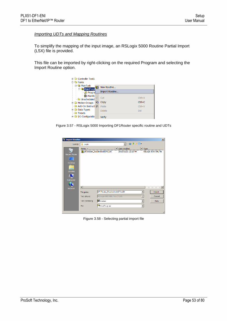
Importing UDTs and Mapping Routines
To simplify the mapping of the input image, an RSLogix 5000 Routine Partial Import (L5X) file is provided.
This file can be imported by right-clicking on the required Program and selecting the Import Routine option.
Figure 3.57 - RSLogix 5000 Importing DF1Router specific routine and UDTs
Figure 3.58 - Selecting partial import file
PLX51-DF1-ENI Setup DF1 to EtherNet/IP™ Router User Manual
ProSoft Technology, Inc. Page 54 of 80
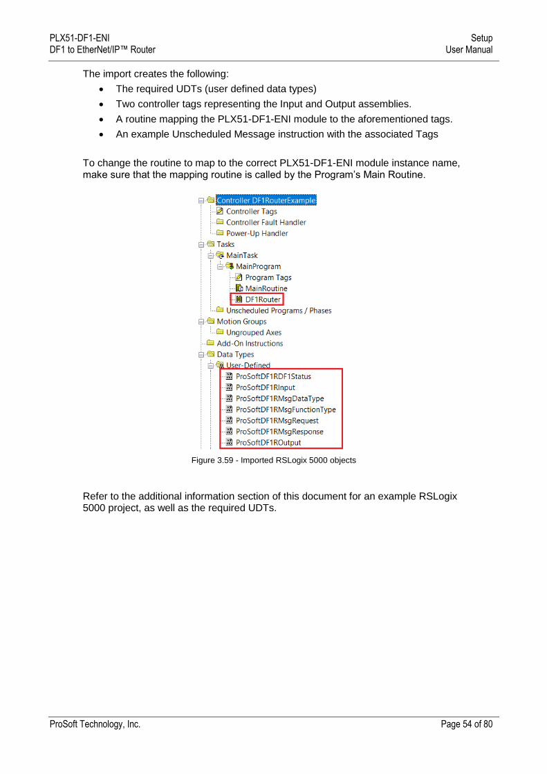
The import creates the following:
The required UDTs (user defined data types)
Two controller tags representing the Input and Output assemblies.
A routine mapping the PLX51-DF1-ENI module to the aforementioned tags.
An example Unscheduled Message instruction with the associated Tags
To change the routine to map to the correct PLX51-DF1-ENI module instance name, make sure that the mapping routine is called by the Program’s Main Routine.
Figure 3.59 - Imported RSLogix 5000 objects
Refer to the additional information section of this document for an example RSLogix 5000 project, as well as the required UDTs.
PLX51-DF1-ENI Operation DF1 to EtherNet/IP™ Router User Manual
ProSoft Technology, Inc. Page 55 of 80
4 Operation
4.1 Message Routing
When the PLX51-DF1-ENI has been set up, the DF1 message initiator sends a read/write to a DF1 address, then routed to a Logix tag. There are various indicators to determine if the mapping has routed the DF1 messages correctly. Refer to the diagnostics section for a more detailed explanation.
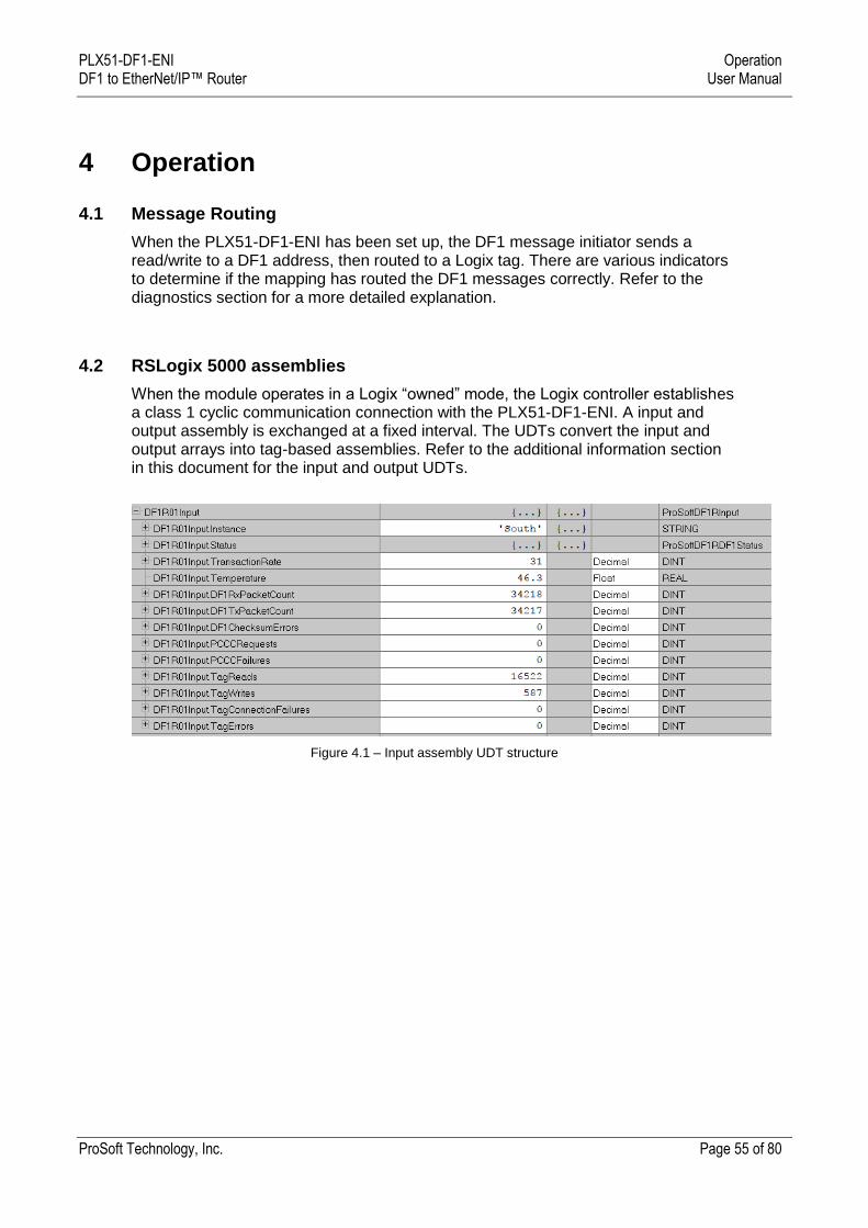
4.2 RSLogix 5000 assemblies
When the module operates in a Logix “owned” mode, the Logix controller establishes a class 1 cyclic communication connection with the PLX51-DF1-ENI. A input and output assembly is exchanged at a fixed interval. The UDTs convert the input and output arrays into tag-based assemblies. Refer to the additional information section in this document for the input and output UDTs.
Figure 4.1 – Input assembly UDT structure
PLX51-DF1-ENI Operation DF1 to EtherNet/IP™ Router User Manual
ProSoft Technology, Inc. Page 56 of 80
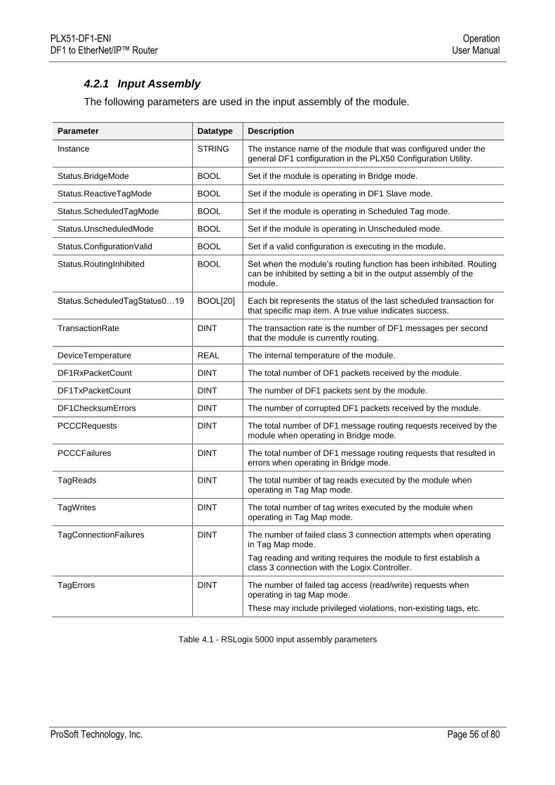
4.2.1 Input Assembly
The following parameters are used in the input assembly of the module.
Parameter Datatype Description
Instance STRING The instance name of the module that was configured under the general DF1 configuration in the PLX50 Configuration Utility.
Status.BridgeMode BOOL Set if the module is operating in Bridge mode.
Status.ReactiveTagMode BOOL Set if the module is operating in DF1 Slave mode.
Status.ScheduledTagMode BOOL Set if the module is operating in Scheduled Tag mode.
Status.UnscheduledMode BOOL Set if the module is operating in Unscheduled mode.
Status.ConfigurationValid BOOL Set if a valid configuration is executing in the module.
Status.RoutingInhibited BOOL Set when the module’s routing function has been inhibited. Routing can be inhibited by setting a bit in the output assembly of the module.
Status.ScheduledTagStatus0…19 BOOL[20] Each bit represents the status of the last scheduled transaction for that specific map item. A true value indicates success.
TransactionRate DINT The transaction rate is the number of DF1 messages per second that the module is currently routing.
DeviceTemperature REAL The internal temperature of the module.
DF1RxPacketCount DINT The total number of DF1 packets received by the module.
DF1TxPacketCount DINT The number of DF1 packets sent by the module.
DF1ChecksumErrors DINT The number of corrupted DF1 packets received by the module.
PCCCRequests DINT The total number of DF1 message routing requests received by the module when operating in Bridge mode.
PCCCFailures DINT The total number of DF1 message routing requests that resulted in errors when operating in Bridge mode.
TagReads DINT The total number of tag reads executed by the module when operating in Tag Map mode.
TagWrites DINT The total number of tag writes executed by the module when operating in Tag Map mode.
TagConnectionFailures DINT The number of failed class 3 connection attempts when operating in Tag Map mode.
Tag reading and writing requires the module to first establish a class 3 connection with the Logix Controller.
TagErrors DINT The number of failed tag access (read/write) requests when operating in tag Map mode.
These may include privileged violations, non-existing tags, etc.
Table 4.1 - RSLogix 5000 input assembly parameters
PLX51-DF1-ENI Operation DF1 to EtherNet/IP™ Router User Manual
ProSoft Technology, Inc. Page 57 of 80
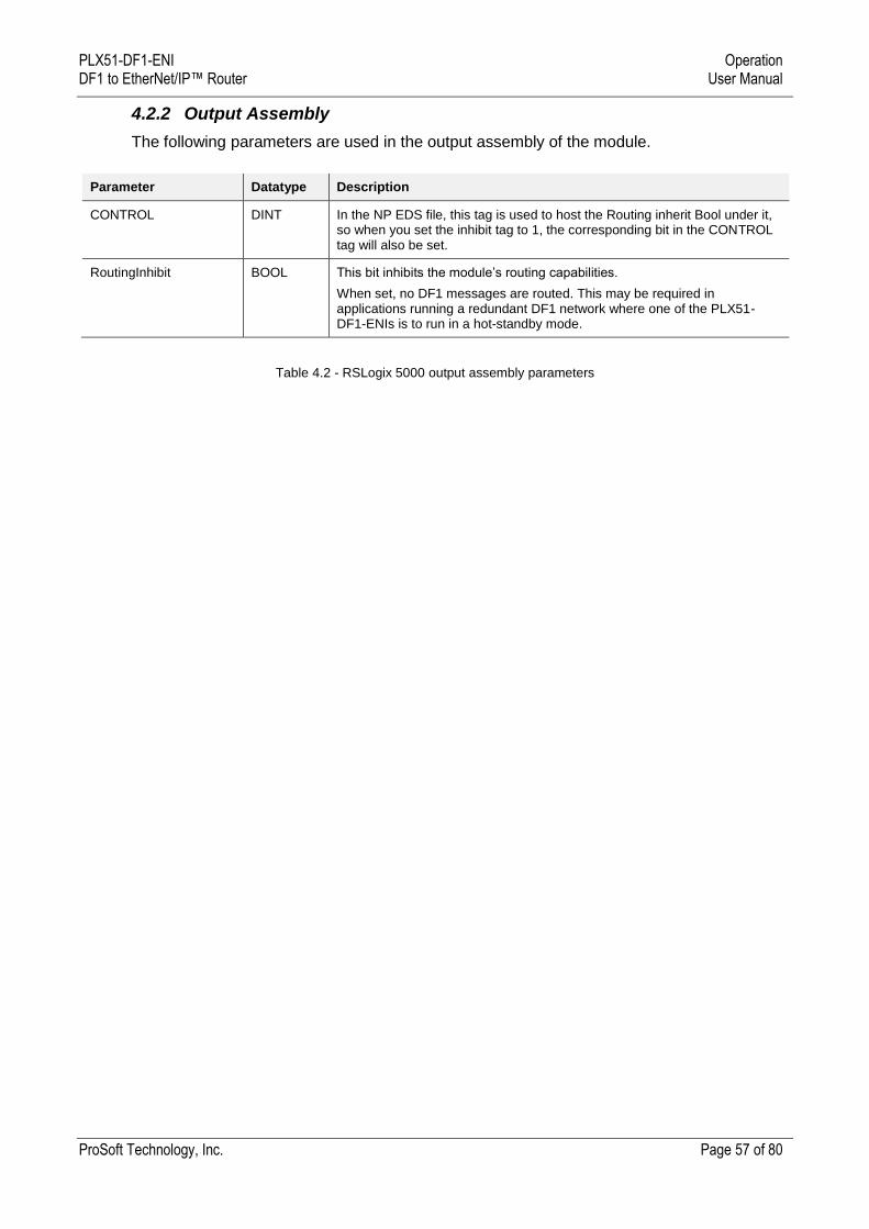
4.2.2 Output Assembly
The following parameters are used in the output assembly of the module.
Parameter Datatype Description
CONTROL DINT In the NP EDS file, this tag is used to host the Routing inherit Bool under it, so when you set the inhibit tag to 1, the corresponding bit in the CONTROL tag will also be set.
RoutingInhibit BOOL This bit inhibits the module’s routing capabilities.
When set, no DF1 messages are routed. This may be required in applications running a redundant DF1 network where one of the PLX51-DF1-ENIs is to run in a hot-standby mode.
Table 4.2 - RSLogix 5000 output assembly parameters
PLX51-DF1-ENI Operation DF1 to EtherNet/IP™ Router User Manual
ProSoft Technology, Inc. Page 58 of 80
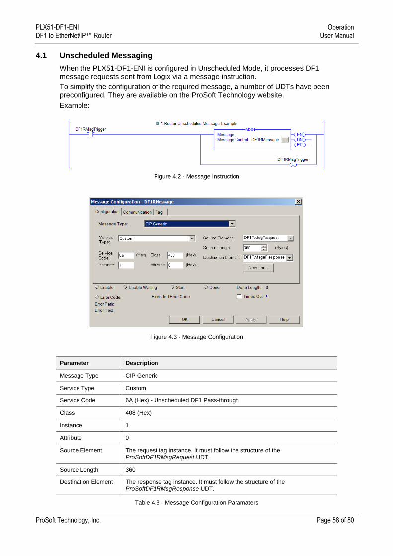
4.1 Unscheduled Messaging
When the PLX51-DF1-ENI is configured in Unscheduled Mode, it processes DF1 message requests sent from Logix via a message instruction.
To simplify the configuration of the required message, a number of UDTs have been preconfigured. They are available on the ProSoft Technology website.
Example:
Figure 4.2 - Message Instruction
Figure 4.3 - Message Configuration
Parameter Description
Message Type CIP Generic
Service Type Custom
Service Code 6A (Hex) - Unscheduled DF1 Pass-through
Class 408 (Hex)
Instance 1
Attribute 0
Source Element The request tag instance. It must follow the structure of the ProSoftDF1RMsgRequest UDT.
Source Length 360
Destination Element The response tag instance. It must follow the structure of the ProSoftDF1RMsgResponse UDT.
Table 4.3 - Message Configuration Paramaters
PLX51-DF1-ENI Operation DF1 to EtherNet/IP™ Router User Manual
ProSoft Technology, Inc. Page 59 of 80
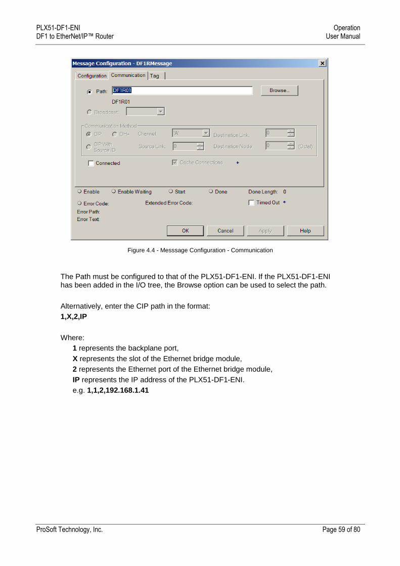
Figure 4.4 - Messsage Configuration - Communication
The Path must be configured to that of the PLX51-DF1-ENI. If the PLX51-DF1-ENI has been added in the I/O tree, the Browse option can be used to select the path.
Alternatively, enter the CIP path in the format:
1,X,2,IP
Where:
1 represents the backplane port,
X represents the slot of the Ethernet bridge module,
2 represents the Ethernet port of the Ethernet bridge module,
IP represents the IP address of the PLX51-DF1-ENI.
e.g. 1,1,2,192.168.1.41
PLX51-DF1-ENI Operation DF1 to EtherNet/IP™ Router User Manual
ProSoft Technology, Inc. Page 60 of 80
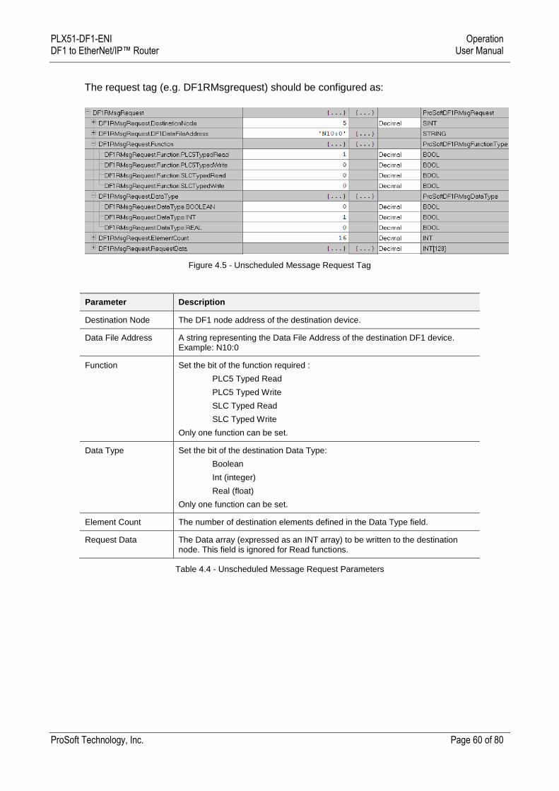
The request tag (e.g. DF1RMsgrequest) should be configured as:
Figure 4.5 - Unscheduled Message Request Tag
Parameter Description
Destination Node The DF1 node address of the destination device.
Data File Address A string representing the Data File Address of the destination DF1 device. Example: N10:0
Function Set the bit of the function required :
PLC5 Typed Read
PLC5 Typed Write
SLC Typed Read
SLC Typed Write
Only one function can be set.
Data Type Set the bit of the destination Data Type:
Boolean
Int (integer)
Real (float)
Only one function can be set.
Element Count The number of destination elements defined in the Data Type field.
Request Data The Data array (expressed as an INT array) to be written to the destination node. This field is ignored for Read functions.
Table 4.4 - Unscheduled Message Request Parameters

PLX51-DF1-ENI Operation DF1 to EtherNet/IP™ Router User Manual
ProSoft Technology, Inc. Page 61 of 80
Figure 4.6 - Unscheduled Message Response Tag
Parameter Description
Status The status returned by the destination DF1 device.
A value of zero indicates success.
Response Length The number of bytes returned by the destination DF1 device.
Response Data The data response from the destination DF1 device expressed as an INT array.
Table 4.5 - Unscheduled Message Response Parameters
After the message has been successfully executed (Msg.DN), the Response Data should be copied (using a COP instruction) to the required Data Tag of an appropriate data type.
PLX51-DF1-ENI Diagnostics DF1 to EtherNet/IP™ Router User Manual
ProSoft Technology, Inc. Page 62 of 80
5 Diagnostics
5.1 LEDs
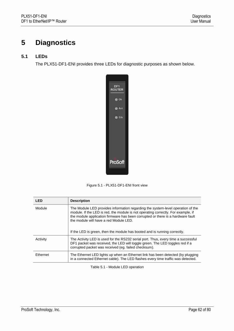
The PLX51-DF1-ENI provides three LEDs for diagnostic purposes as shown below.
Figure 5.1 - PLX51-DF1-ENI front view
LED Description
Module The Module LED provides information regarding the system-level operation of the module. If the LED is red, the module is not operating correctly. For example, if the module application firmware has been corrupted or there is a hardware fault the module will have a red Module LED.
If the LED is green, then the module has booted and is running correctly.
Activity The Activity LED is used for the RS232 serial port. Thus, every time a successful DF1 packet was received, the LED will toggle green. The LED toggles red if a corrupted packet was received (eg. failed checksum).
Ethernet The Ethernet LED lights up when an Ethernet link has been detected (by plugging in a connected Ethernet cable). The LED flashes every time traffic was detected.
Table 5.1 - Module LED operation
PLX51-DF1-ENI Diagnostics DF1 to EtherNet/IP™ Router User Manual
ProSoft Technology, Inc. Page 63 of 80
5.2 Module Status Monitoring
The PLX51-DF1-ENI provides a range of statistics that can assist with module operation, maintenance, and diagnostics. The statistics can be accessed in full by the PLX50 Configuration Utility or using the web server in the module.
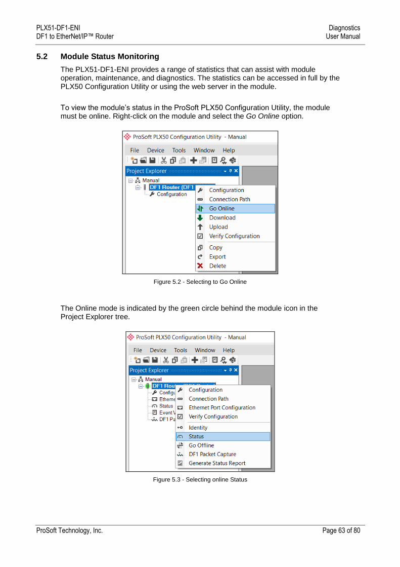
To view the module’s status in the ProSoft PLX50 Configuration Utility, the module must be online. Right-click on the module and select the Go Online option.
Figure 5.2 - Selecting to Go Online
The Online mode is indicated by the green circle behind the module icon in the Project Explorer tree.
Figure 5.3 - Selecting online Status

PLX51-DF1-ENI Diagnostics DF1 to EtherNet/IP™ Router User Manual
ProSoft Technology, Inc. Page 64 of 80
The Status monitoring window can be opened by either double-clicking on the Status item in the Project Explorer tree, or by right-clicking on the module and selecting Status.
The status window contains multiple tabs to display the current status of the module.
Figure 5.4 - Status monitoring - General
The General tab displays the following general parameters. It can also be used to set the module time to the PC time:
Parameter Description
Mode Indicates the current operating mode:
Bridge, DF1 Slave, Scheduled Tag, or Unscheduled.
Owned Indicates if the module is currently owned (Class 1) by a Logix controller.
Routing Indicates whether the routing of module is enabled or inhibited. The routing operation can be inhibited in the output assembly of the module.
Transaction Rate The number of DF1 messages per second that the module is currently routing.
Up Time Indicates the elapsed time since the module was powered-up.
Module Time Indicates the module’s internal time. The module time is stored in UTC (Universal Coordinate Time) but displayed on this page according to the local PC Time Zone settings.
MAC Address Displays the module’s unique Ethernet MAC address.
Temperature The internal temperature of the module.
Processor Scan The amount of time (microseconds) of the module’s processor in the last scan.
DIP Switch Position The status of the DIP switches when the module booted.
Note that this status will not change if the DIP switches are altered when the module is running.
Table 5.2 - Parameters displayed in the Status Monitoring – General Tab
PLX51-DF1-ENI Diagnostics DF1 to EtherNet/IP™ Router User Manual
ProSoft Technology, Inc. Page 65 of 80
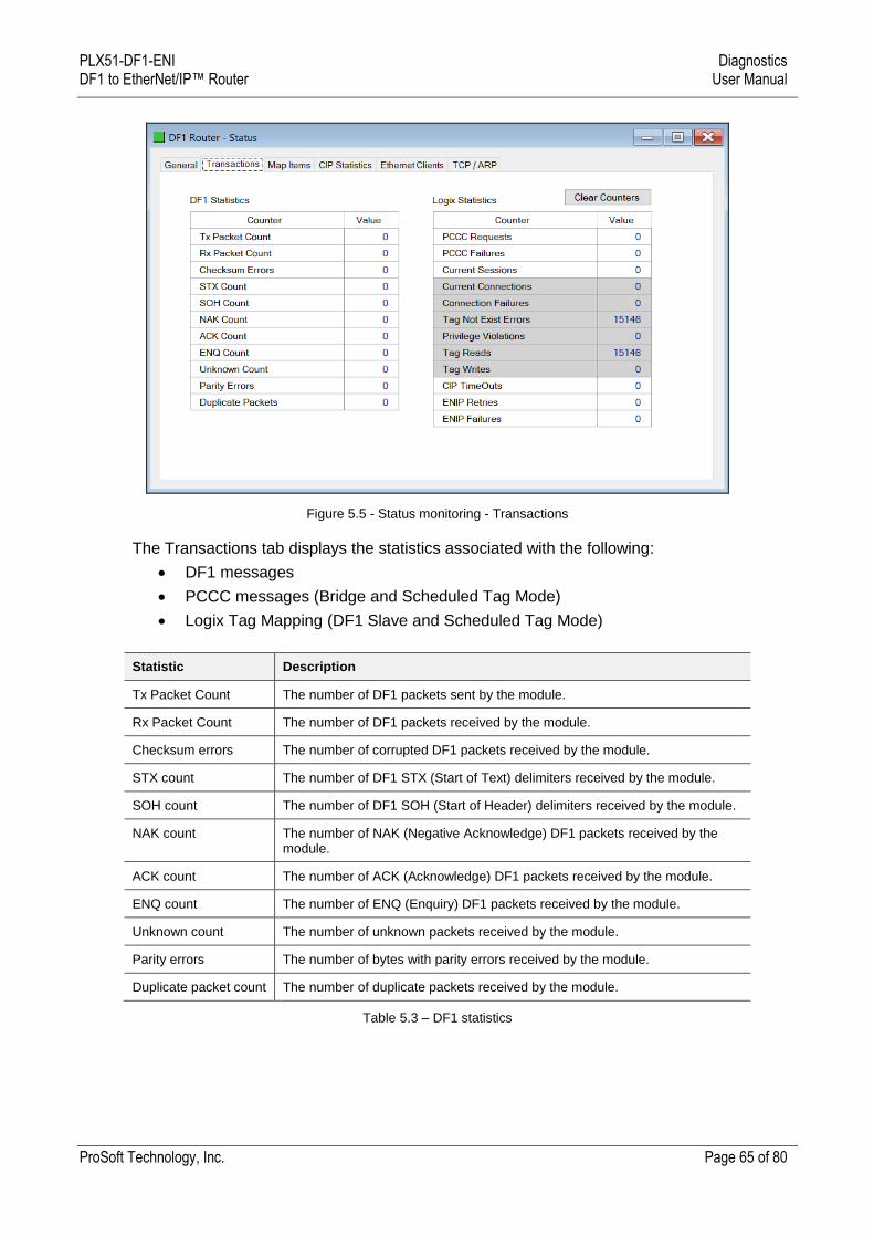
Figure 5.5 - Status monitoring - Transactions
The Transactions tab displays the statistics associated with the following:
DF1 messages
PCCC messages (Bridge and Scheduled Tag Mode)
Logix Tag Mapping (DF1 Slave and Scheduled Tag Mode)
Statistic Description
Tx Packet Count The number of DF1 packets sent by the module.
Rx Packet Count The number of DF1 packets received by the module.
Checksum errors The number of corrupted DF1 packets received by the module.
STX count The number of DF1 STX (Start of Text) delimiters received by the module.
SOH count The number of DF1 SOH (Start of Header) delimiters received by the module.
NAK count The number of NAK (Negative Acknowledge) DF1 packets received by the module.
ACK count The number of ACK (Acknowledge) DF1 packets received by the module.
ENQ count The number of ENQ (Enquiry) DF1 packets received by the module.
Unknown count The number of unknown packets received by the module.
Parity errors The number of bytes with parity errors received by the module.
Duplicate packet count The number of duplicate packets received by the module.
Table 5.3 – DF1 statistics
PLX51-DF1-ENI Diagnostics DF1 to EtherNet/IP™ Router User Manual
ProSoft Technology, Inc. Page 66 of 80
The following PCCC statistics are only relevant when the module is running in either Bridge or Unscheduled mode.
Statistic Description
PCCC Requests The number of EtherNet/IP PCCC requests that have been sent to a Logix controller.
PCCC Failures The number of failed EtherNet/IP PCCC responses that have been received by the PLX51-DF1-ENI from a Logix controller.
Current Sessions The current number of open EtherNet/IP PCCC sessions.
Table 5.4 - PCCC statistics
The following Tag Mapping statistics are only relevant when the module is running in either DF1 Slave or Scheduled Tag mode.
Statistic Description
Current Connections The number of current open class 3 connections.
Connection Failures The number of failed attempts at establishing a class 3 connection with a Logix controller.
Tag Not Exist Errors The number of tag read and tag write transactions that failed due to the destination tag not existing.
Privilege Violation Errors The number of tag read and tag write transactions that failed due to a privilege violation error.
This may be caused by the External Access property of the Logix tag being set to either None or Read Only.
Tag Reads The number of tag read transactions executed by the PLX51-DF1-ENI module.
Tag Writes The number of tag write transactions executed by the PLX51-DF1-ENI module.
CIP Timeout This count increases when no response was received for the Tag Read/Write.
ENIP Retries This count increases when no response was received from the Logix Controller by the time the ENIP timeout is reached.
ENIP Failures This count increases when the ENIP Retry Limit is reached and no response has been received from the Logix Controller.
Table 5.5 - Tag Mapping statistics
PLX51-DF1-ENI Diagnostics DF1 to EtherNet/IP™ Router User Manual
ProSoft Technology, Inc. Page 67 of 80
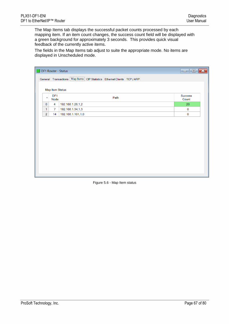
The Map Items tab displays the successful packet counts processed by each mapping item. If an item count changes, the success count field will be displayed with a green background for approximately 3 seconds. This provides quick visual feedback of the currently active items.
The fields in the Map Items tab adjust to suite the appropriate mode. No items are displayed in Unscheduled mode.
Figure 5.6 - Map Item status
PLX51-DF1-ENI Diagnostics DF1 to EtherNet/IP™ Router User Manual
ProSoft Technology, Inc. Page 68 of 80
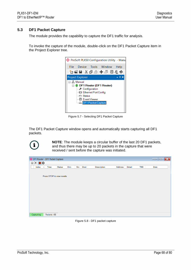
5.3 DF1 Packet Capture
The module provides the capability to capture the DF1 traffic for analysis.
To invoke the capture of the module, double-click on the DF1 Packet Capture item in the Project Explorer tree.
Figure 5.7 - Selecting DF1 Packet Capture
The DF1 Packet Capture window opens and automatically starts capturing all DF1 packets.
NOTE: The module keeps a circular buffer of the last 20 DF1 packets, and thus there may be up to 20 packets in the capture that were received / sent before the capture was initiated.
Figure 5.8 - DF1 packet capture
PLX51-DF1-ENI Diagnostics DF1 to EtherNet/IP™ Router User Manual
ProSoft Technology, Inc. Page 69 of 80
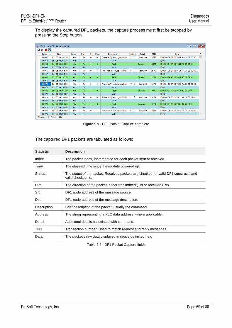
To display the captured DF1 packets, the capture process must first be stopped by pressing the Stop button.
Figure 5.9 - DF1 Packet Capture complete
The captured DF1 packets are tabulated as follows:
Statistic Description
Index The packet index, incremented for each packet sent or received.
Time The elapsed time since the module powered up.
Status The status of the packet. Received packets are checked for valid DF1 constructs and valid checksums.
Dirn The direction of the packet, either transmitted (Tx) or received (Rx).
Src DF1 node address of the message source.
Dest DF1 node address of the message destination.
Description Brief description of the packet, usually the command.
Address The string representing a PLC data address, where applicable.
Detail Additional details associated with command.
TNS Transaction number. Used to match request and reply messages.
Data The packet’s raw data displayed in space delimited hex.
Table 5.6 - DF1 Packet Capture fields
PLX51-DF1-ENI Diagnostics DF1 to EtherNet/IP™ Router User Manual
ProSoft Technology, Inc. Page 70 of 80
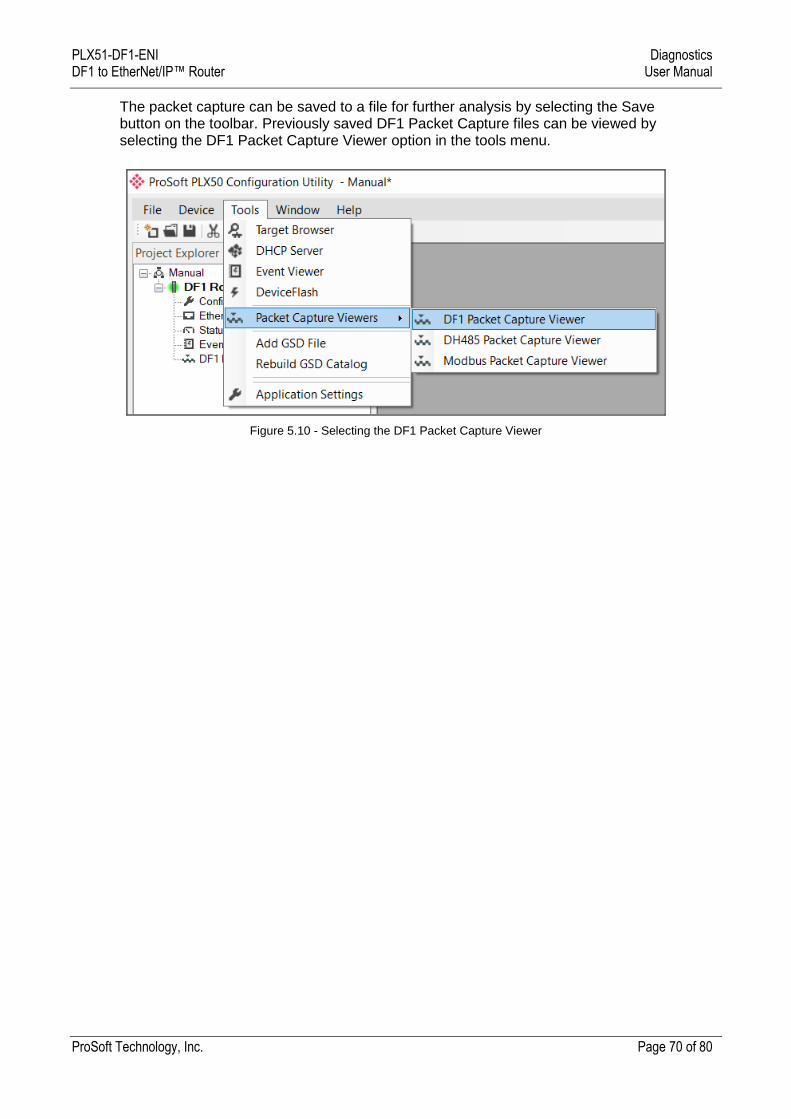
The packet capture can be saved to a file for further analysis by selecting the Save button on the toolbar. Previously saved DF1 Packet Capture files can be viewed by selecting the DF1 Packet Capture Viewer option in the tools menu.
Figure 5.10 - Selecting the DF1 Packet Capture Viewer

PLX51-DF1-ENI Diagnostics DF1 to EtherNet/IP™ Router User Manual
ProSoft Technology, Inc. Page 71 of 80
5.4 Module Event Log
The PLX51-DF1-ENI module logs various diagnostic records to an internal event log. These logs are stored in non-volatile memory and can be displayed using the PLX50 Configuration Utility or via the web interface. To view them in the PLX50 Configuration Utility, select the Event Viewer option in the Project Explorer tree.
Figure 5.11. - Selecting the module Event Log
The Event Log window opens and automatically reads all the events from the module. The log entries are sorted to have the latest record at the top. Custom sorting is achieved by double-clicking on the column headings.
Figure 5.12. – Module Event Log
The log can also be stored to a file for future analysis, by selecting the Save button in the tool menu. To view previously saved files, use the Event Log Viewer option under the tools menu.
PLX51-DF1-ENI Diagnostics DF1 to EtherNet/IP™ Router User Manual
ProSoft Technology, Inc. Page 72 of 80
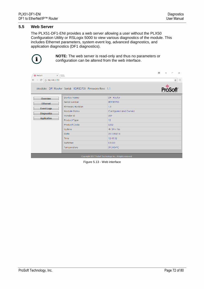
5.5 Web Server
The PLX51-DF1-ENI provides a web server allowing a user without the PLX50 Configuration Utility or RSLogix 5000 to view various diagnostics of the module. This includes Ethernet parameters, system event log, advanced diagnostics, and application diagnostics (DF1 diagnostics).
NOTE: The web server is read-only and thus no parameters or configuration can be altered from the web interface.
Figure 5.13 - Web interface

PLX51-DF1-ENI Technical Specifications DF1 to EtherNet/IP™ Router User Manual
ProSoft Technology, Inc. Page 73 of 80
6 Technical Specifications
6.1 Dimensions
Below are the enclosure dimensions as well as the DIN rail dimensions. All dimensions are in millimeters.
Figure 6.1 - PLX51-DF1-ENI enclosure dimensions
Figure 6.2 - DIN dimensions
PLX51-DF1-ENI Technical Specifications DF1 to EtherNet/IP™ Router User Manual
ProSoft Technology, Inc. Page 74 of 80
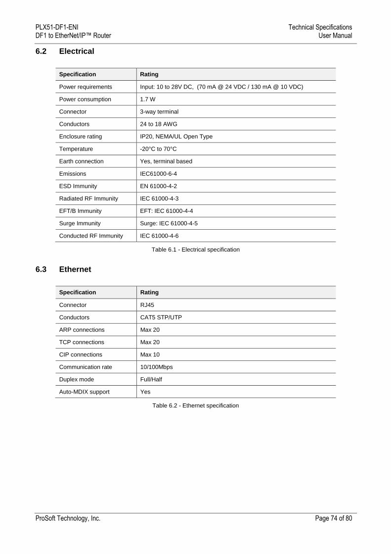
6.2 Electrical
Specification Rating
Power requirements Input: 10 to 28V DC, (70 mA @ 24 VDC / 130 mA @ 10 VDC)
Power consumption 1.7 W
Connector 3-way terminal
Conductors 24 to 18 AWG
Enclosure rating IP20, NEMA/UL Open Type
Temperature -20°C to 70°C
Earth connection Yes, terminal based
Emissions IEC61000-6-4
ESD Immunity EN 61000-4-2
Radiated RF Immunity IEC 61000-4-3
EFT/B Immunity EFT: IEC 61000-4-4
Surge Immunity Surge: IEC 61000-4-5
Conducted RF Immunity IEC 61000-4-6
Table 6.1 - Electrical specification
6.3 Ethernet
Specification Rating
Connector RJ45
Conductors CAT5 STP/UTP
ARP connections Max 20
TCP connections Max 20
CIP connections Max 10
Communication rate 10/100Mbps
Duplex mode Full/Half
Auto-MDIX support Yes
Table 6.2 - Ethernet specification
PLX51-DF1-ENI Technical Specifications DF1 to EtherNet/IP™ Router User Manual
ProSoft Technology, Inc. Page 75 of 80
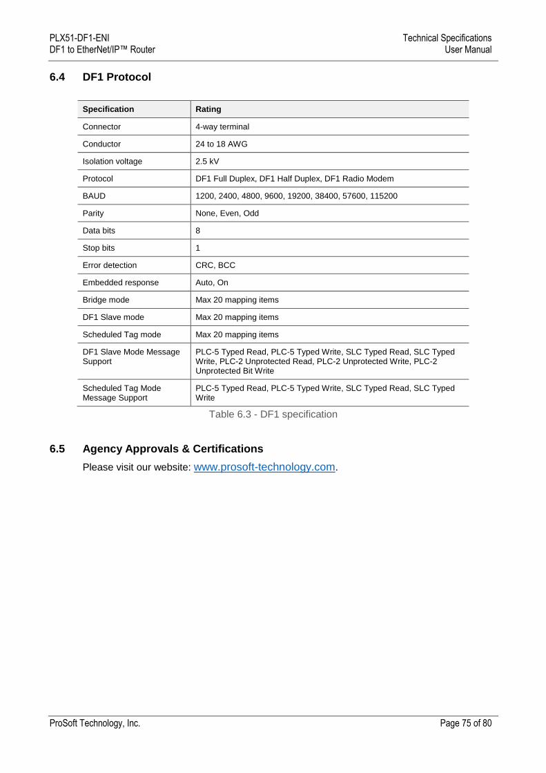
6.4 DF1 Protocol
Specification Rating
Connector 4-way terminal
Conductor 24 to 18 AWG
Isolation voltage 2.5 kV
Protocol DF1 Full Duplex, DF1 Half Duplex, DF1 Radio Modem
BAUD 1200, 2400, 4800, 9600, 19200, 38400, 57600, 115200
Parity None, Even, Odd
Data bits 8
Stop bits 1
Error detection CRC, BCC
Embedded response Auto, On
Bridge mode Max 20 mapping items
DF1 Slave mode Max 20 mapping items
Scheduled Tag mode Max 20 mapping items
DF1 Slave Mode Message Support
PLC-5 Typed Read, PLC-5 Typed Write, SLC Typed Read, SLC Typed Write, PLC-2 Unprotected Read, PLC-2 Unprotected Write, PLC-2 Unprotected Bit Write
Scheduled Tag Mode Message Support
PLC-5 Typed Read, PLC-5 Typed Write, SLC Typed Read, SLC Typed Write
Table 6.3 - DF1 specification
6.5 Agency Approvals & Certifications
Please visit our website: www.prosoft-technology.com.
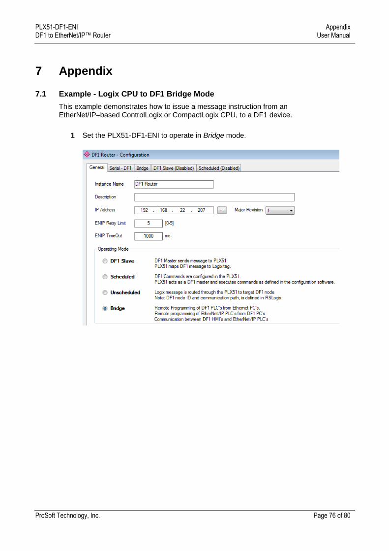
PLX51-DF1-ENI Appendix DF1 to EtherNet/IP™ Router User Manual
ProSoft Technology, Inc. Page 76 of 80
7 Appendix
7.1 Example - Logix CPU to DF1 Bridge Mode
This example demonstrates how to issue a message instruction from an EtherNet/IP–based ControlLogix or CompactLogix CPU, to a DF1 device.
1 Set the PLX51-DF1-ENI to operate in Bridge mode.
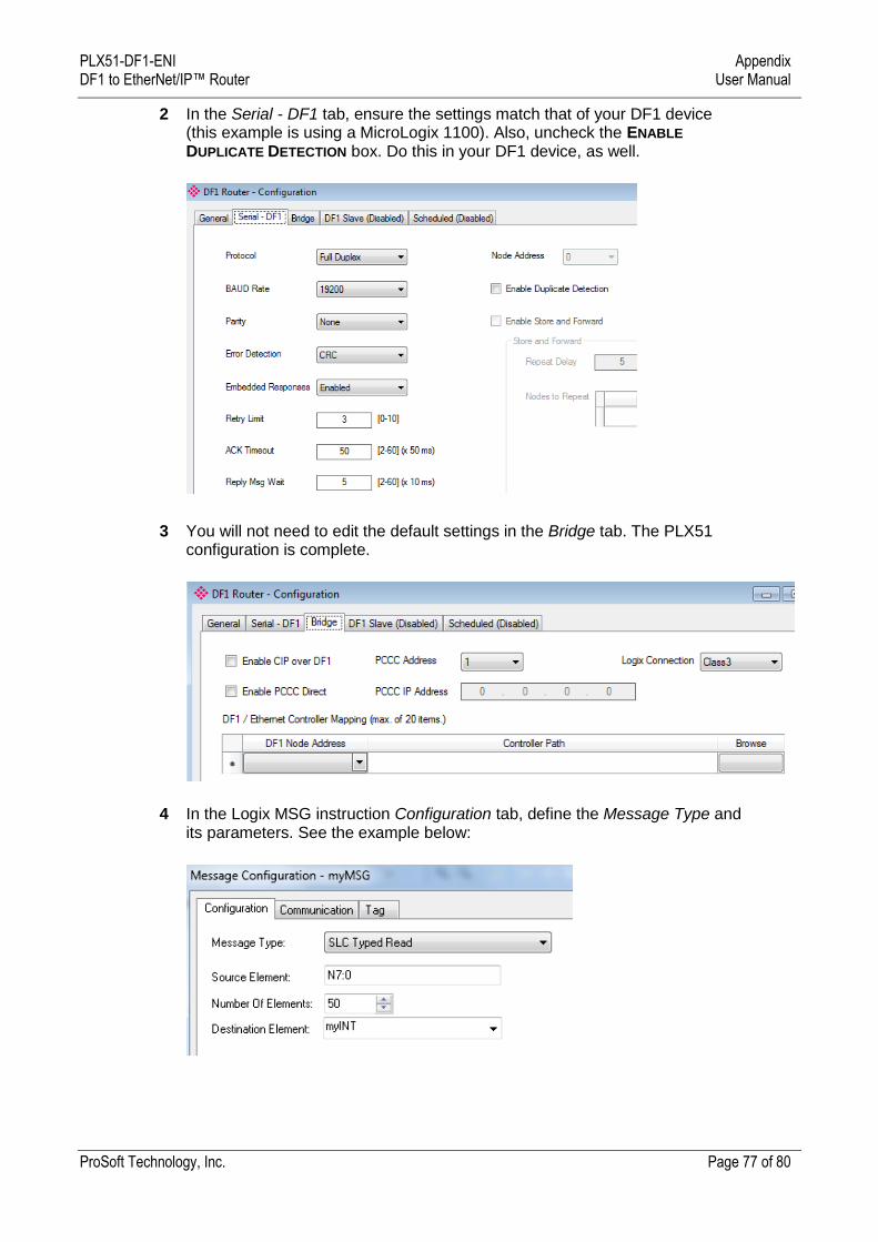
PLX51-DF1-ENI Appendix DF1 to EtherNet/IP™ Router User Manual
ProSoft Technology, Inc. Page 77 of 80
2 In the Serial - DF1 tab, ensure the settings match that of your DF1 device (this example is using a MicroLogix 1100). Also, uncheck the ENABLE
DUPLICATE DETECTION box. Do this in your DF1 device, as well.
3 You will not need to edit the default settings in the Bridge tab. The PLX51 configuration is complete.
4 In the Logix MSG instruction Configuration tab, define the Message Type and its parameters. See the example below:
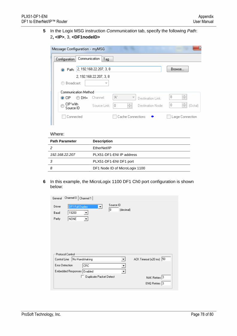
PLX51-DF1-ENI Appendix DF1 to EtherNet/IP™ Router User Manual
ProSoft Technology, Inc. Page 78 of 80
5 In the Logix MSG instruction Communication tab, specify the following Path:
2, <IP>, 3, <DF1nodeID>
Where:
Path Parameter Description
2 EtherNet/IP
192.168.22.207 PLX51-DF1-ENI IP address
3 PLX51-DF1-ENI DF1 port
8 DF1 Node ID of MicroLogix 1100
6 In this example, the MicroLogix 1100 DF1 Ch0 port configuration is shown below:
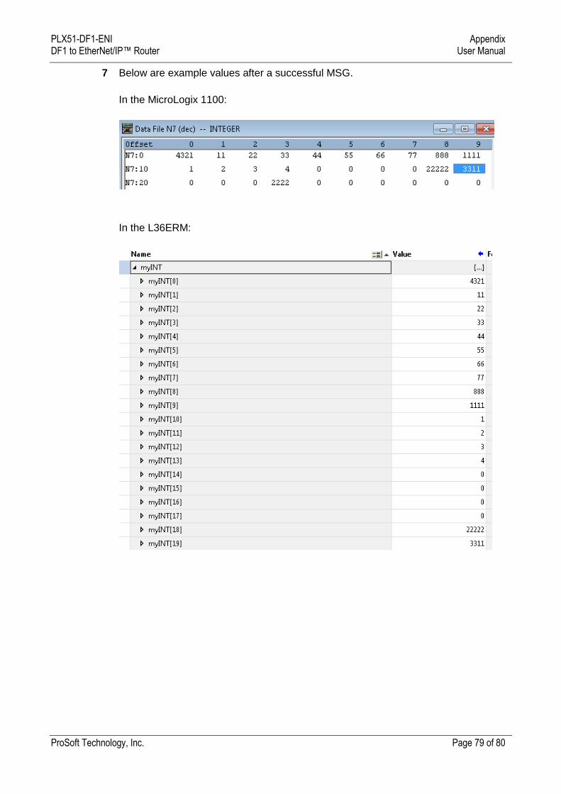
PLX51-DF1-ENI Appendix DF1 to EtherNet/IP™ Router User Manual
ProSoft Technology, Inc. Page 79 of 80
7 Below are example values after a successful MSG.
In the MicroLogix 1100:
In the L36ERM:
PLX51-DF1-ENI Support, Service & Warranty DF1 to EtherNet/IP™ Router User Manual
ProSoft Technology, Inc. Page 80 of 80
8 Support, Service & Warranty
8.1 Contacting Technical Support
ProSoft Technology, Inc. is committed to providing the most efficient and effective support possible. Before calling, please gather the following information to assist in expediting this process:
1 Product Version Number 2 System architecture 3 Network details
If the issue is hardware related, we will also need information regarding:
1 Module configuration and associated ladder files, if any 2 Module operation and any unusual behavior 3 Configuration/Debug status information 4 LED patterns 5 Details about the interfaced serial, Ethernet or Fieldbus devices
Note: For technical support calls within the United States, ProSoft’s 24/7 after-hours phone support is available for urgent plant-down issues.
North America (Corporate Location) Europe / Middle East / Africa Regional Office
Phone: +1.661.716.5100
Languages spoken: English, Spanish
REGIONAL TECH SUPPORT
Phone: +33.(0)5.34.36.87.20
Languages spoken: French, English
REGIONAL TECH SUPPORT
Latin America Regional Office Asia Pacific Regional Office
Phone: +52.222.264.1814
Languages spoken: Spanish, English
REGIONAL TECH SUPPORT
Phone: +60.3.2247.1898
Languages spoken: Bahasa, Chinese, English, Japanese, Korean
REGIONAL TECH SUPPORT
For additional ProSoft Technology contacts in your area, please visit:
https://www.prosoft-technology.com/About-Us/Contact-Us.
8.2 Warranty Information
For complete details regarding ProSoft Technology’s TERMS & CONDITIONS OF SALE, WARRANTY, SUPPORT, SERVICE AND RETURN MATERIAL AUTHORIZATION INSTRUCTIONS, please see the documents at: www.prosoft-technology/legal