
MVI56-EGD - ProSoft Technology
112
MVI56-EGD ControlLogix ® Platform GE Ethernet Global Data Communication Module March 3, 2021 USER MANUAL
-
Upload
khangminh22 -
Category
Documents
-
view
2 -
download
0
Transcript of MVI56-EGD - ProSoft Technology
MVI56-EGD ControlLogix® Platform
GE Ethernet Global Data Communication Module
March 3, 2021
USER MANUAL
Your Feedback Please
We always want you to feel that you made the right decision to use our products. If you have suggestions, comments, compliments or complaints about our products, documentation, or support, please write or call us.
How to Contact Us
ProSoft Technology, Inc.
+1 (661) 716-5100 +1 (661) 716-5101 (Fax) www.prosoft-technology.com [email protected]
Copyright © 2021 ProSoft Technology, Inc. All rights reserved.
MVI56-EGD User Manual
March 3, 2021
ProSoft Technology ®, ProLinx ®, inRAx ®, ProTalk ®, and RadioLinx ® are Registered Trademarks of ProSoft Technology, Inc. All other brand or product names are or may be trademarks of, and are used to identify products and services of, their respective owners.
ProSoft Technology® Product Documentation
In an effort to conserve paper, ProSoft Technology no longer includes printed manuals with our product shipments. User Manuals, Datasheets, Sample Ladder Files, and Configuration Files are provided at: www.prosoft-technology.com
For professional users in the European Union
If you wish to discard electrical and electronic equipment (EEE), please contact your dealer or supplier for further information.
Prop 65 Warning – Cancer and Reproductive Harm – www.P65Warnings.ca.gov
Important Installation Instructions
Power, Input, and Output (I/O) wiring must be in accordance with Class I, Division 2 wiring methods, Article 501-4 (b) of the National Electrical Code, NFPA 70 for installation in the U.S., or as specified in Section 18-1J2 of the Canadian Electrical Code for installations in Canada, and in accordance with the authority having jurisdiction. The following warnings must be heeded:
WARNING - EXPLOSION HAZARD - SUBSTITUTION OF COMPONENTS MAY IMPAIR SUITABILITY FOR CLASS I, DIV. 2;
WARNING - EXPLOSION HAZARD - WHEN IN HAZARDOUS LOCATIONS, TURN OFF POWER BEFORE REPLACING OR WIRING MODULES
WARNING - EXPLOSION HAZARD - DO NOT DISCONNECT EQUIPMENT UNLESS POWER HAS BEEN SWITCHED OFF OR THE AREA IS KNOWN TO BE NON-HAZARDOUS.
THIS DEVICE SHALL BE POWERED BY CLASS 2 OUTPUTS ONLY.
MVI (Multi Vendor Interface) Modules
WARNING - EXPLOSION HAZARD - DO NOT DISCONNECT EQUIPMENT UNLESS POWER HAS BEEN SWITCHED OFF OR THE AREA IS KNOWN TO BE NON-HAZARDOUS.
AVERTISSEMENT - RISQUE D'EXPLOSION - AVANT DE DÉCONNECTER L'ÉQUIPEMENT, COUPER LE COURANT OU S'ASSURER QUE L'EMPLACEMENT EST DÉSIGNÉ NON DANGEREUX.
Warnings
North America Warnings
Power, Input, and Output (I/O) wiring must be in accordance with Class I, Division 2 wiring methods, Article 501-4 (b) of the National Electrical Code, NFPA 70 for installation in the U.S., or as specified in Section 18-1J2 of the Canadian Electrical Code for installations in Canada, and in accordance with the authority having jurisdiction. The following warnings must be heeded:
A Warning - Explosion Hazard - Substitution of components may impair suitability for Class I, Division 2. B Warning - Explosion Hazard - When in hazardous locations, turn off power before replacing or rewiring
modules. C Warning - Explosion Hazard - Do not disconnect equipment unless power has been switched off or the
area is known to be non-hazardous.
Avertissement - Risque d'explosion - Avant de déconnecter l'équipement, couper le courant ou s'assurer que l'emplacement est désigné non dangereux.
D Suitable for use in Class I, Division 2 Groups A, B, C and D Hazardous Locations or Non-Hazardous Locations.
ATEX Warnings and Conditions of Safe Usage
Power, Input, and Output (I/O) wiring must be in accordance with the authority having jurisdiction.
A Warning - Explosion Hazard - When in hazardous locations, turn off power before replacing or wiring modules.
B Warning - Explosion Hazard - Do not disconnect equipment unless power has been switched off or the area is known to be non-hazardous.
C These products are intended to be mounted in an IP54 enclosure. The devices shall provide external means to prevent the rated voltage being exceeded by transient disturbances of more than 40%. This device must be used only with ATEX certified backplanes.
D DO NOT OPEN WHEN ENERGIZED.
Battery Life Advisory
The MVI46, MVI56, MVI56E, MVI69, and MVI71 modules use a rechargeable Lithium Vanadium Pentoxide battery to backup the real-time clock and CMOS. The battery should last for the life of the module. The module must be powered for approximately twenty hours before the battery becomes fully charged. After it is fully charged, the battery provides backup power for the CMOS setup and the real-time clock for approximately 21 days. When the battery is fully discharged, the module will revert to the default BIOS and clock settings.
Note: The battery is not user replaceable.
Agency Approvals and Certifications
Please visit our website: www.prosoft-technology.com
MVI56-EGD ♦ ControlLogix Platform Contents GE Ethernet Global Data Communication Module User Manual
ProSoft Technology, Inc. Page 5 of 112
Contents
Your Feedback Please ....................................................................................................................... 2 How to Contact Us .............................................................................................................................. 2 ProSoft Technology® Product Documentation ................................................................................... 2 Important Installation Instructions ....................................................................................................... 3 MVI (Multi Vendor Interface) Modules ................................................................................................ 3 Warnings ............................................................................................................................................ 3 Battery Life Advisory ........................................................................................................................... 4
Guide to the MVI56-EGD User Manual 9
1 Start Here 11
1.1 System Requirements ............................................................................................ 12 1.2 Package Contents .................................................................................................. 13 1.3 Installing ProSoft Configuration Builder Software................................................... 13 1.4 Setting Jumpers ...................................................................................................... 14 1.5 Installing the Module in the Rack ............................................................................ 15 1.6 Connecting Your PC to the ControlLogix Processor .............................................. 16 1.7 Opening the Sample Ladder Logic ......................................................................... 17
1.7.1 Determining the Firmware Version of Your Processor ........................................... 17 1.7.2 Selecting the Slot Number for the Module .............................................................. 19 1.7.3 Configuring the RSLinx Driver for the PC COM Port .............................................. 20
1.8 Downloading the Sample Program to the Processor.............................................. 22 1.9 Connecting your PC to the Module ......................................................................... 23 1.10 Using the RSLogix 5000 v16 Add-On Instruction ................................................... 24
1.10.1 Creating a New RSLogix 5000 Project ................................................................... 24
2 Configuring the MVI56-EGD Module 34
2.1 Using ProSoft Configuration Builder ....................................................................... 35 2.1.1 Setting Up the Project ............................................................................................. 35 2.1.2 Renaming PCB Objects .......................................................................................... 37
2.2 [Module] .................................................................................................................. 39 2.2.1 Module Name.......................................................................................................... 39 2.2.2 Module Type ........................................................................................................... 39 2.2.3 Read Register Start ................................................................................................ 39 2.2.4 Read Register Count .............................................................................................. 39 2.2.5 Write Register Start ................................................................................................ 39 2.2.6 Write Register Count .............................................................................................. 39 2.2.7 Failure Flag Count .................................................................................................. 39
2.3 [SNTP Client] .......................................................................................................... 40 2.3.1 NTP Server IP Address .......................................................................................... 41 2.3.2 Time Zone ............................................................................................................... 41 2.3.3 Use Daylight Savings Time ..................................................................................... 41 2.3.4 Database Register .................................................................................................. 41
2.4 [EGD Exchanges] ................................................................................................... 42 2.4.1 Exch Type ............................................................................................................... 42 2.4.2 Cast Type ................................................................................................................ 43
Contents MVI56-EGD ♦ ControlLogix Platform User Manual GE Ethernet Global Data Communication Module
Page 6 of 112 ProSoft Technology, Inc.
2.4.3 DB Reg ................................................................................................................... 43 2.4.4 Reg Count ............................................................................................................... 43 2.4.5 Swap Code ............................................................................................................. 44 2.4.6 P/C Time ................................................................................................................. 44 2.4.7 IP Address .............................................................................................................. 45 2.4.8 Exch ID ................................................................................................................... 45 2.4.9 CS Major, CS Minor ................................................................................................ 46 2.4.10 EGD Exchange Command List Example ................................................................ 47
2.5 [EGD Multicast Group List] ..................................................................................... 48 2.6 Ethernet Configuration ............................................................................................ 49 2.7 Downloading the Project to the Module Using a Serial COM Port ......................... 50
3 Ladder Logic 51
3.1 Controller Tags ....................................................................................................... 51 3.2 Module Status Data and Variables (ModuleDef) .................................................... 53
3.2.1 Backplane Object .................................................................................................... 53 3.2.2 User Data Objects (MNETDATA) ........................................................................... 54 3.2.3 Status Object (InStat) ............................................................................................. 54 3.2.4 Consumer/Producer Status .................................................................................... 56
3.3 Adding the Module to an Existing Project ............................................................... 57
4 Diagnostics and Troubleshooting 61
4.1 LED Status Indicators ............................................................................................. 62 4.1.1 Ethernet LED Indicators .......................................................................................... 62 4.1.2 Clearing a Fault Condition ...................................................................................... 63 4.1.3 Troubleshooting ...................................................................................................... 63
4.2 Using ProSoft Configuration Builder (PCB) for Diagnostics ................................... 64 4.2.1 Using the Diagnostic Window in ProSoft Configuration Builder ............................. 64 4.2.2 Navigation ............................................................................................................... 66 4.2.3 Main Menu .............................................................................................................. 67 4.2.4 Database View Menu .............................................................................................. 70 4.2.5 Network Menu ......................................................................................................... 72 4.2.6 EGD Menu .............................................................................................................. 73 4.2.7 Producer/Consumer List Menu ............................................................................... 75 4.2.8 Producer/Consumer Status Menu .......................................................................... 76
4.3 Reading Status Data from the Module ................................................................... 76
5 Reference 77
5.1 Product Specifications ............................................................................................ 77 5.1.1 General Specifications ............................................................................................ 77 5.1.2 Hardware Specifications ......................................................................................... 78 5.1.3 Functional Specifications ........................................................................................ 79 5.1.4 SNTP Support ......................................................................................................... 80
5.2 Functional Overview ............................................................................................... 81 5.2.1 Ethernet Global Data Compatible Devices ............................................................. 81 5.2.2 EGD Command Server ........................................................................................... 82 5.2.3 EGD Data Producer ................................................................................................ 99 5.2.4 EGD Data Consumer ............................................................................................ 100 5.2.5 General Concepts ................................................................................................. 101 5.2.6 Normal Data Transfer ........................................................................................... 103
MVI56-EGD ♦ ControlLogix Platform Contents GE Ethernet Global Data Communication Module User Manual
ProSoft Technology, Inc. Page 7 of 112
5.2.7 Special Function Blocks ........................................................................................ 105 5.3 Exchange Configuration Form .............................................................................. 108
6 Support, Service & Warranty 109
6.1 Contacting Technical Support ............................................................................... 109 6.2 Warranty Information ............................................................................................ 109
Index 111
Contents MVI56-EGD ♦ ControlLogix Platform User Manual GE Ethernet Global Data Communication Module
Page 8 of 112 ProSoft Technology, Inc.
MVI56-EGD ♦ ControlLogix Platform Start Here GE Ethernet Global Data Communication Module User Manual
ProSoft Technology, Inc. Page 9 of 112 March 3, 2021
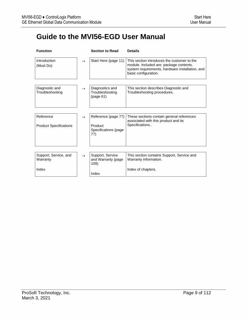
Guide to the MVI56-EGD User Manual
Function Section to Read Details
Introduction
(Must Do)
Start Here (page 11) This section introduces the customer to the module. Included are: package contents, system requirements, hardware installation, and basic configuration.
Diagnostic and Troubleshooting
Diagnostics and Troubleshooting (page 61)
This section describes Diagnostic and Troubleshooting procedures.
Reference
Product Specifications
Reference (page 77)
Product Specifications (page 77)
These sections contain general references associated with this product and its Specifications..
Support, Service, and Warranty
Index
Support, Service and Warranty (page 109)
Index
This section contains Support, Service and Warranty information.
Index of chapters.
Start Here MVI56-EGD ♦ ControlLogix Platform User Manual GE Ethernet Global Data Communication Module
Page 10 of 112 ProSoft Technology, Inc.
MVI56-EGD ♦ ControlLogix Platform Start Here GE Ethernet Global Data Communication Module User Manual
ProSoft Technology, Inc. Page 11 of 112
1 Start Here
In This Chapter
System Requirements ........................................................................... 12
Package Contents ................................................................................. 13
Installing ProSoft Configuration Builder Software .................................. 13
Setting Jumpers ..................................................................................... 14
Installing the Module in the Rack ........................................................... 15
Connecting Your PC to the ControlLogix Processor .............................. 16
Opening the Sample Ladder Logic ........................................................ 17
Downloading the Sample Program to the Processor ............................. 22
Connecting your PC to the Module ........................................................ 23
Using the RSLogix 5000 v16 Add-On Instruction .................................. 24
To get the most benefit from this User Manual, you should have the following skills:
Rockwell Automation® RSLogix™ software: launch the program, configure ladder logic, and transfer the ladder logic to the processor
Microsoft Windows: install and launch programs, execute menu commands, navigate dialog boxes, and enter data
Hardware installation and wiring: install the module, and safely connect GE Ethernet Global Data and ControlLogix devices to a power source and to the MVI56-EGD module’s application port(s)
Start Here MVI56-EGD ♦ ControlLogix Platform User Manual GE Ethernet Global Data Communication Module
Page 12 of 112 ProSoft Technology, Inc.
1.1 System Requirements
The MVI56-EGD module requires the following minimum hardware and software components:
Rockwell Automation ControlLogix™ processor, with compatible power supply and one free slot in the rack, for the MVI56-EGD module. The module requires 800 mA of available power.
Rockwell Automation RSLogix 5000 programming software version 2.51 or higher
Rockwell Automation RSLinx communication software
Pentium® II 450 MHz minimum. Pentium III 733 MHz (or better) recommended
Supported operating systems: o Microsoft Windows 10 o Microsoft Windows 7 Professional (32-or 64-bit) o Microsoft Windows XP Professional with Service Pack 1 or 2 o Microsoft Windows Vista o Microsoft Windows 2000 Professional with Service Pack 1, 2, or 3 o Microsoft Windows Server 2003
128 Mbytes of RAM minimum, 256 Mbytes of RAM recommended
100 Mbytes of free hard disk space (or more based on application requirements)
256-color VGA graphics adapter, 800 x 600 minimum resolution (True Color 1024 768 recommended)
ProSoft Configuration Builder, HyperTerminal or other terminal emulator program.
Note: You can install the module in a local or remote rack. For remote rack installation, the module requires EtherNet/IP or ControlNet communication with the processor.
MVI56-EGD ♦ ControlLogix Platform Start Here GE Ethernet Global Data Communication Module User Manual
ProSoft Technology, Inc. Page 13 of 112
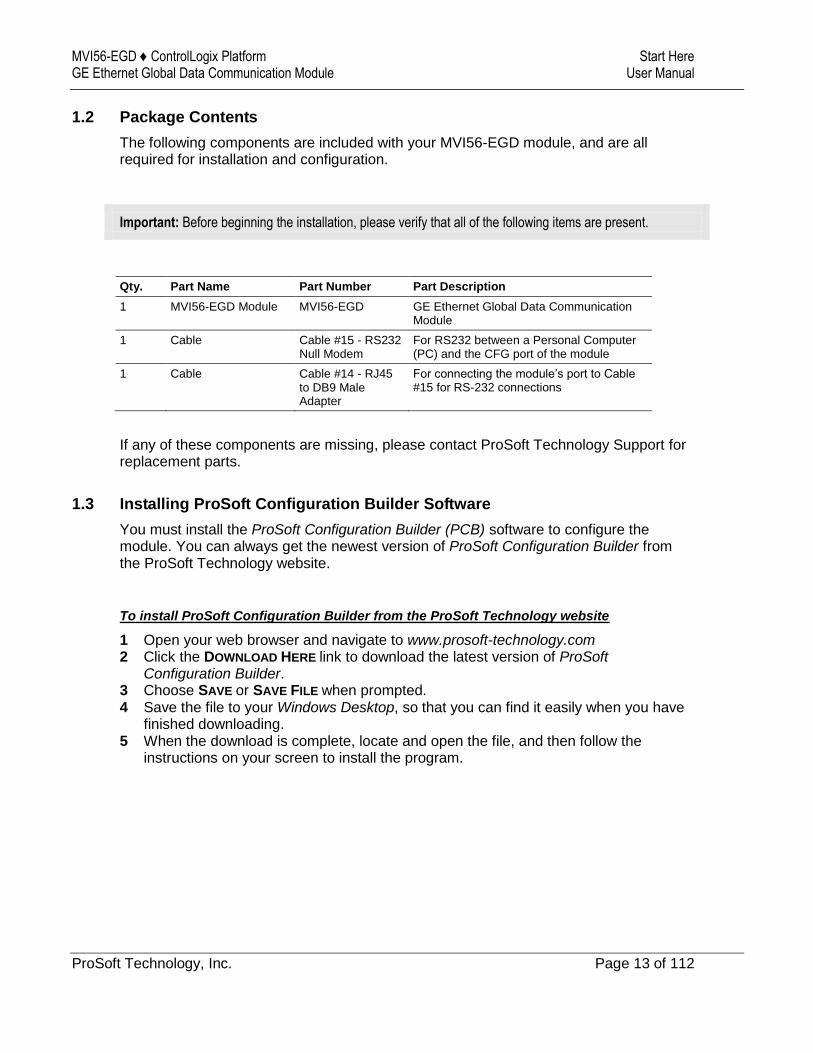
1.2 Package Contents
The following components are included with your MVI56-EGD module, and are all required for installation and configuration.
Important: Before beginning the installation, please verify that all of the following items are present.
Qty. Part Name Part Number Part Description
1 MVI56-EGD Module MVI56-EGD GE Ethernet Global Data Communication Module
1 Cable Cable #15 - RS232 Null Modem
For RS232 between a Personal Computer (PC) and the CFG port of the module
1 Cable Cable #14 - RJ45 to DB9 Male Adapter
For connecting the module’s port to Cable #15 for RS-232 connections
If any of these components are missing, please contact ProSoft Technology Support for replacement parts.
1.3 Installing ProSoft Configuration Builder Software
You must install the ProSoft Configuration Builder (PCB) software to configure the module. You can always get the newest version of ProSoft Configuration Builder from the ProSoft Technology website.
To install ProSoft Configuration Builder from the ProSoft Technology website
1 Open your web browser and navigate to www.prosoft-technology.com 2 Click the DOWNLOAD HERE link to download the latest version of ProSoft
Configuration Builder. 3 Choose SAVE or SAVE FILE when prompted. 4 Save the file to your Windows Desktop, so that you can find it easily when you have
finished downloading. 5 When the download is complete, locate and open the file, and then follow the
instructions on your screen to install the program.
Start Here MVI56-EGD ♦ ControlLogix Platform User Manual GE Ethernet Global Data Communication Module
Page 14 of 112 ProSoft Technology, Inc.
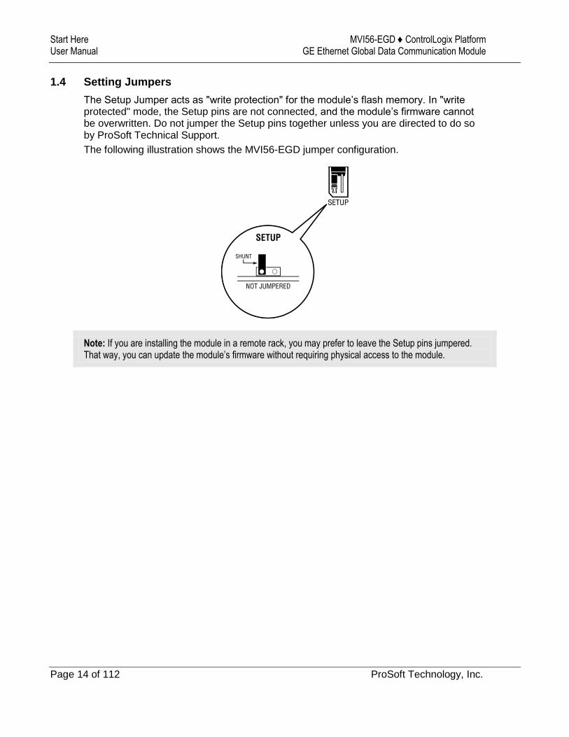
1.4 Setting Jumpers
The Setup Jumper acts as "write protection" for the module’s flash memory. In "write protected" mode, the Setup pins are not connected, and the module’s firmware cannot be overwritten. Do not jumper the Setup pins together unless you are directed to do so by ProSoft Technical Support.
The following illustration shows the MVI56-EGD jumper configuration.
Note: If you are installing the module in a remote rack, you may prefer to leave the Setup pins jumpered. That way, you can update the module’s firmware without requiring physical access to the module.
MVI56-EGD ♦ ControlLogix Platform Start Here GE Ethernet Global Data Communication Module User Manual
ProSoft Technology, Inc. Page 15 of 112
1.5 Installing the Module in the Rack
If you have not already installed and configured your ControlLogix processor and power supply, please do so before installing the MVI56-EGD module. Refer to your Rockwell Automation product documentation for installation instructions.
Warning: You must follow all safety instructions when installing this or any other electronic devices. Failure to follow safety procedures could result in damage to hardware or data, or even serious injury or death to personnel. Refer to the documentation for each device you plan to connect to verify that suitable safety procedures are in place before installing or servicing the device.
After you have checked the placement of the jumpers, insert MVI56-EGD into the ControlLogix chassis. Use the same technique recommended by Rockwell Automation to remove and install ControlLogix modules.
Warning: When you insert or remove the module while backplane power is on, an electrical arc can occur. This could cause an explosion in hazardous location installations. Verify that power is removed or the area is non-hazardous before proceeding. Repeated electrical arcing causes excessive wear to contacts on both the module and its mating connector. Worn contacts may create electrical resistance that can affect module operation.
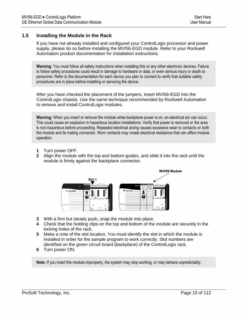
1 Turn power OFF. 2 Align the module with the top and bottom guides, and slide it into the rack until the
module is firmly against the backplane connector.
3 With a firm but steady push, snap the module into place. 4 Check that the holding clips on the top and bottom of the module are securely in the
locking holes of the rack. 5 Make a note of the slot location. You must identify the slot in which the module is
installed in order for the sample program to work correctly. Slot numbers are identified on the green circuit board (backplane) of the ControlLogix rack.
6 Turn power ON.
Note: If you insert the module improperly, the system may stop working, or may behave unpredictably.
Start Here MVI56-EGD ♦ ControlLogix Platform User Manual GE Ethernet Global Data Communication Module
Page 16 of 112 ProSoft Technology, Inc.
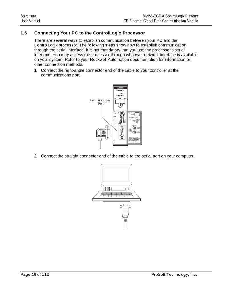
1.6 Connecting Your PC to the ControlLogix Processor
There are several ways to establish communication between your PC and the ControlLogix processor. The following steps show how to establish communication through the serial interface. It is not mandatory that you use the processor's serial interface. You may access the processor through whatever network interface is available on your system. Refer to your Rockwell Automation documentation for information on other connection methods.
1 Connect the right-angle connector end of the cable to your controller at the communications port.
2 Connect the straight connector end of the cable to the serial port on your computer.
MVI56-EGD ♦ ControlLogix Platform Start Here GE Ethernet Global Data Communication Module User Manual
ProSoft Technology, Inc. Page 17 of 112
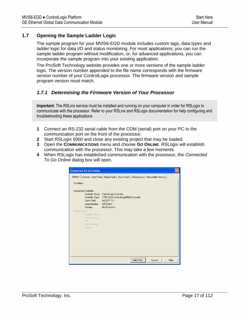
1.7 Opening the Sample Ladder Logic
The sample program for your MVI56-EGD module includes custom tags, data types and ladder logic for data I/O and status monitoring. For most applications, you can run the sample ladder program without modification, or, for advanced applications, you can incorporate the sample program into your existing application.
The ProSoft Technology website provides one or more versions of the sample ladder logic. The version number appended to the file name corresponds with the firmware version number of your ControlLogix processor. The firmware version and sample program version must match.
1.7.1 Determining the Firmware Version of Your Processor
Important: The RSLinx service must be installed and running on your computer in order for RSLogix to communicate with the processor. Refer to your RSLinx and RSLogix documentation for help configuring and troubleshooting these applications.
1 Connect an RS-232 serial cable from the COM (serial) port on your PC to the communication port on the front of the processor.
2 Start RSLogix 5000 and close any existing project that may be loaded. 3 Open the COMMUNICATIONS menu and choose GO ONLINE. RSLogix will establish
communication with the processor. This may take a few moments. 4 When RSLogix has established communication with the processor, the Connected
To Go Online dialog box will open.
Start Here MVI56-EGD ♦ ControlLogix Platform User Manual GE Ethernet Global Data Communication Module
Page 18 of 112 ProSoft Technology, Inc.
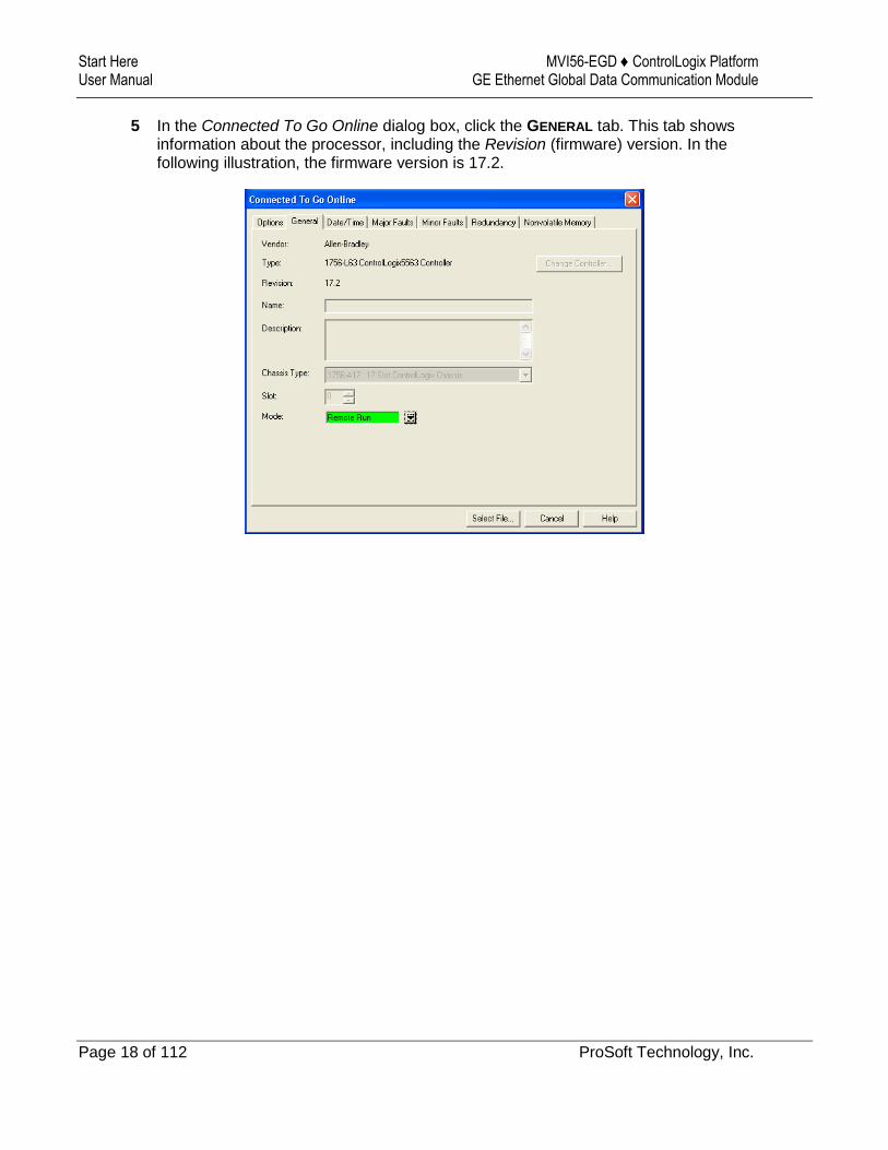
5 In the Connected To Go Online dialog box, click the GENERAL tab. This tab shows information about the processor, including the Revision (firmware) version. In the following illustration, the firmware version is 17.2.
MVI56-EGD ♦ ControlLogix Platform Start Here GE Ethernet Global Data Communication Module User Manual
ProSoft Technology, Inc. Page 19 of 112
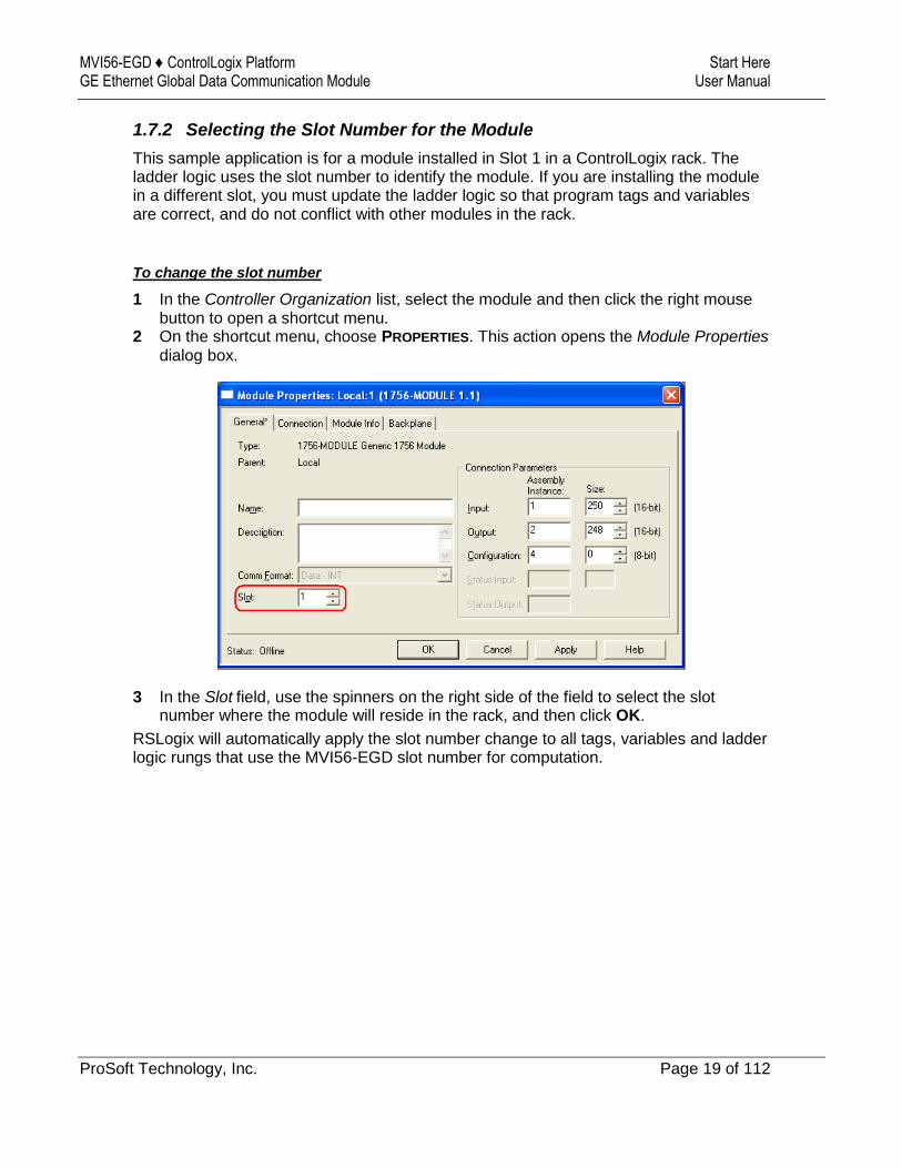
1.7.2 Selecting the Slot Number for the Module
This sample application is for a module installed in Slot 1 in a ControlLogix rack. The ladder logic uses the slot number to identify the module. If you are installing the module in a different slot, you must update the ladder logic so that program tags and variables are correct, and do not conflict with other modules in the rack.
To change the slot number
1 In the Controller Organization list, select the module and then click the right mouse button to open a shortcut menu.
2 On the shortcut menu, choose PROPERTIES. This action opens the Module Properties dialog box.
3 In the Slot field, use the spinners on the right side of the field to select the slot number where the module will reside in the rack, and then click OK.
RSLogix will automatically apply the slot number change to all tags, variables and ladder logic rungs that use the MVI56-EGD slot number for computation.
Start Here MVI56-EGD ♦ ControlLogix Platform User Manual GE Ethernet Global Data Communication Module
Page 20 of 112 ProSoft Technology, Inc.
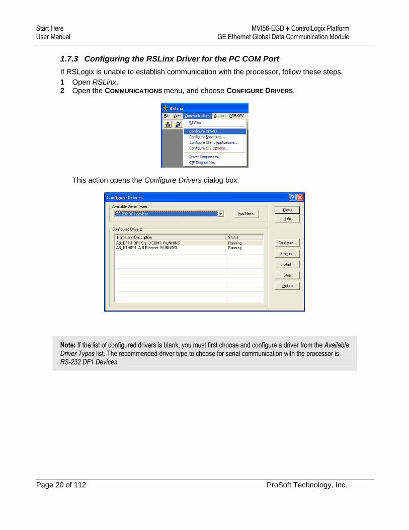
1.7.3 Configuring the RSLinx Driver for the PC COM Port
If RSLogix is unable to establish communication with the processor, follow these steps.
1 Open RSLinx. 2 Open the COMMUNICATIONS menu, and choose CONFIGURE DRIVERS.
This action opens the Configure Drivers dialog box.
Note: If the list of configured drivers is blank, you must first choose and configure a driver from the Available Driver Types list. The recommended driver type to choose for serial communication with the processor is RS-232 DF1 Devices.
MVI56-EGD ♦ ControlLogix Platform Start Here GE Ethernet Global Data Communication Module User Manual
ProSoft Technology, Inc. Page 21 of 112
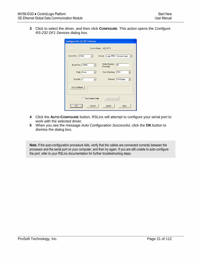
3 Click to select the driver, and then click CONFIGURE. This action opens the Configure RS-232 DF1 Devices dialog box.
4 Click the AUTO-CONFIGURE button. RSLinx will attempt to configure your serial port to work with the selected driver.
5 When you see the message Auto Configuration Successful, click the OK button to dismiss the dialog box.
Note: If the auto-configuration procedure fails, verify that the cables are connected correctly between the processor and the serial port on your computer, and then try again. If you are still unable to auto-configure the port, refer to your RSLinx documentation for further troubleshooting steps.

Start Here MVI56-EGD ♦ ControlLogix Platform User Manual GE Ethernet Global Data Communication Module
Page 22 of 112 ProSoft Technology, Inc.
1.8 Downloading the Sample Program to the Processor
Note: The key switch on the front of the ControlLogix processor must be in the REM or PROG position.
1 If you are not already online with the processor, open the Communications menu, and then choose DOWNLOAD. RSLogix 5000 will establish communication with the processor. You do not have to download through the processor's serial port, as shown here. You may download through any available network connection.
2 When communication is established, RSLogix 5000 will open a confirmation dialog box. Click the DOWNLOAD button to transfer the sample program to the processor.
3 RSLogix 5000 will compile the program and transfer it to the processor. This process may take a few minutes.
4 When the download is complete, RSLogix 5000 will open another confirmation dialog box. If the key switch is in the REM position, click OK to switch the processor from PROGRAM mode to RUN mode.
Note: If you receive an error message during these steps, refer to your RSLogix documentation to interpret and correct the error.

MVI56-EGD ♦ ControlLogix Platform Start Here GE Ethernet Global Data Communication Module User Manual
ProSoft Technology, Inc. Page 23 of 112
1.9 Connecting your PC to the Module
With the module securely mounted, connect your PC to the Configuration/Debug port using an RJ45-DB-9 Serial Adapter Cable and a Null Modem Cable.
1 Attach both cables as shown. 2 Insert the RJ45 cable connector into the Configuration/Debug port of the module. 3 Attach the other end to the serial port on your PC.
Start Here MVI56-EGD ♦ ControlLogix Platform User Manual GE Ethernet Global Data Communication Module
Page 24 of 112 ProSoft Technology, Inc.
1.10 Using the RSLogix 5000 v16 Add-On Instruction
Important: If you are using an older version of RSLogix 5000 (version 15 or older), please refer to Using the Sample Program in a New Application or Using the Sample Program in an Existing Application.
If you have RSLogix 5000 version 16 or newer, you can use an Add-On Instruction to simplify the task of configuring the module, either as a new application, or within an existing application.
Download the manuals and sample program from the ProSoft Technology web site
You can always download the latest version of the sample ladder logic and user manuals for the MVI56-EGD module from the ProSoft Technology web site, at www.prosoft-technology.com/support/downloads
From that link, navigate to the download page for your module and choose the sample ladder program to download for your version of RSLogix 5000 and your processor.
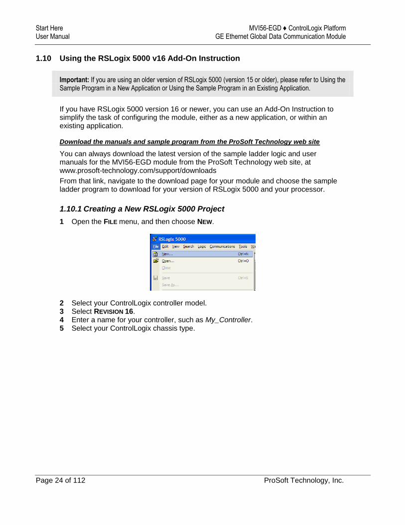
1.10.1 Creating a New RSLogix 5000 Project
1 Open the FILE menu, and then choose NEW.
2 Select your ControlLogix controller model. 3 Select REVISION 16. 4 Enter a name for your controller, such as My_Controller. 5 Select your ControlLogix chassis type.

MVI56-EGD ♦ ControlLogix Platform Start Here GE Ethernet Global Data Communication Module User Manual
ProSoft Technology, Inc. Page 25 of 112
6 Select SLOT 0 for the controller.

Start Here MVI56-EGD ♦ ControlLogix Platform User Manual GE Ethernet Global Data Communication Module
Page 26 of 112 ProSoft Technology, Inc.
Creating the Module
1 Add the MVI56-EGD module to the project.
In the CONTROLLER ORGANIZATION window, select I/O CONFIGURATION and click the right mouse button to open a shortcut menu. On the shortcut menu, choose NEW
MODULE...
This action opens the SELECT MODULE dialog box.
2 Select the 1756-MODULE (GENERIC 1756 MODULE) from the list and click OK. This action opens the NEW MODULE dialog box.
MVI56-EGD ♦ ControlLogix Platform Start Here GE Ethernet Global Data Communication Module User Manual
ProSoft Technology, Inc. Page 27 of 112
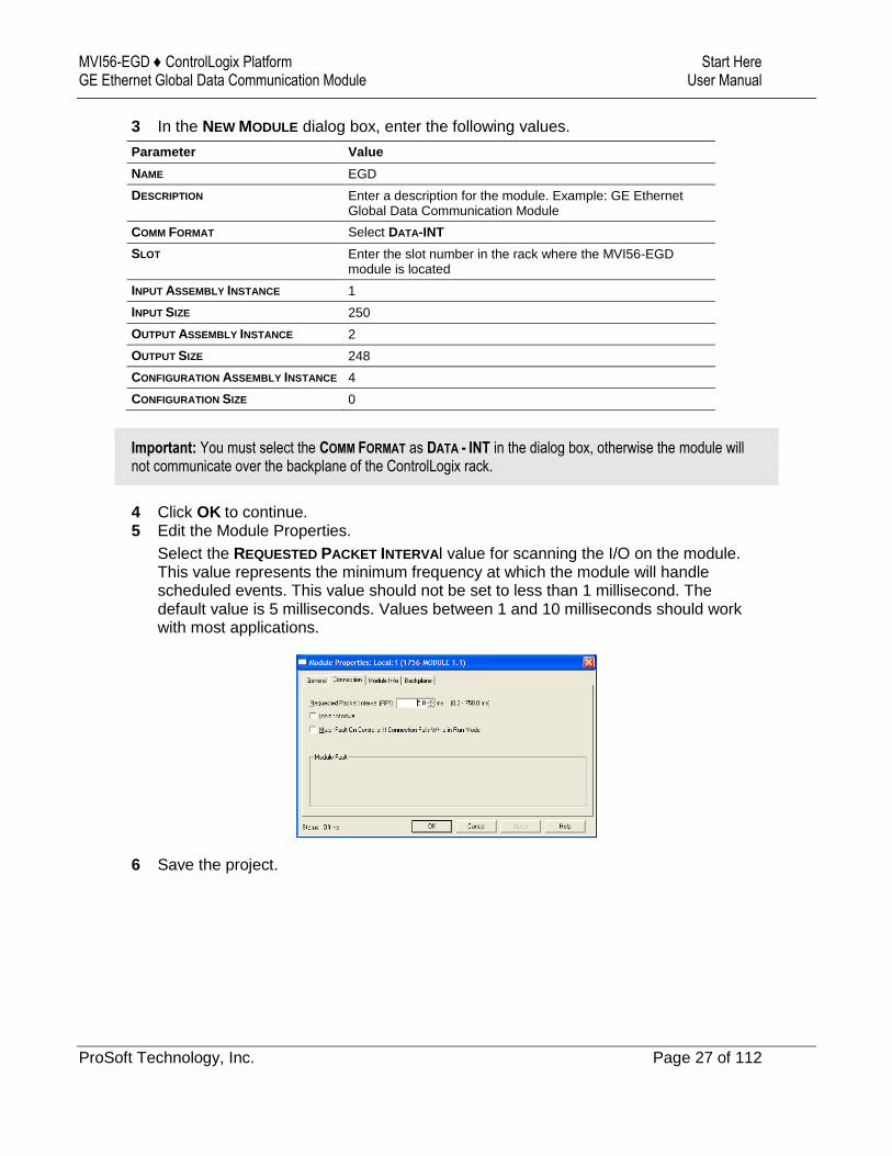
3 In the NEW MODULE dialog box, enter the following values.
Parameter Value
NAME EGD
DESCRIPTION Enter a description for the module. Example: GE Ethernet Global Data Communication Module
COMM FORMAT Select DATA-INT
SLOT Enter the slot number in the rack where the MVI56-EGD module is located
INPUT ASSEMBLY INSTANCE 1
INPUT SIZE 250
OUTPUT ASSEMBLY INSTANCE 2
OUTPUT SIZE 248
CONFIGURATION ASSEMBLY INSTANCE 4
CONFIGURATION SIZE 0
Important: You must select the COMM FORMAT as DATA - INT in the dialog box, otherwise the module will not communicate over the backplane of the ControlLogix rack.
4 Click OK to continue. 5 Edit the Module Properties.
Select the REQUESTED PACKET INTERVAl value for scanning the I/O on the module. This value represents the minimum frequency at which the module will handle scheduled events. This value should not be set to less than 1 millisecond. The default value is 5 milliseconds. Values between 1 and 10 milliseconds should work with most applications.
6 Save the project.
Start Here MVI56-EGD ♦ ControlLogix Platform User Manual GE Ethernet Global Data Communication Module
Page 28 of 112 ProSoft Technology, Inc.
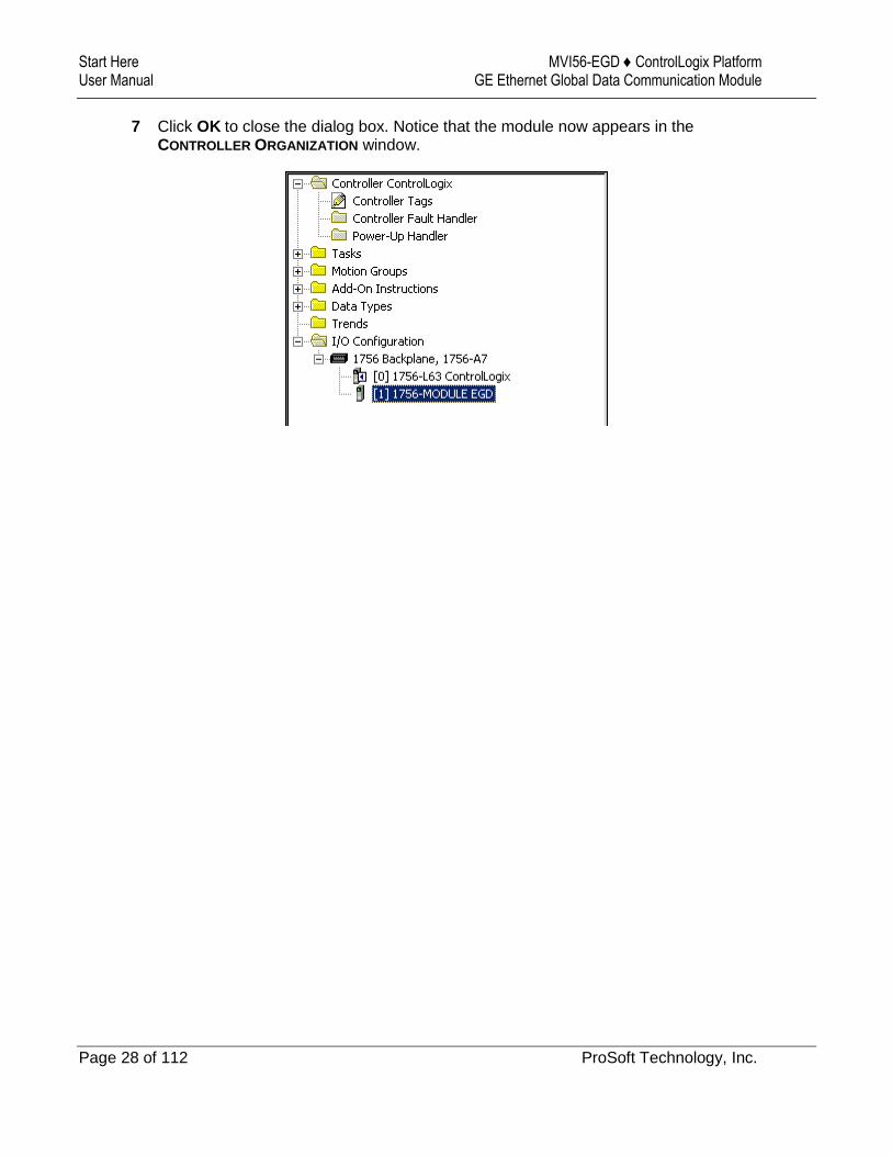
7 Click OK to close the dialog box. Notice that the module now appears in the CONTROLLER ORGANIZATION window.
MVI56-EGD ♦ ControlLogix Platform Start Here GE Ethernet Global Data Communication Module User Manual
ProSoft Technology, Inc. Page 29 of 112
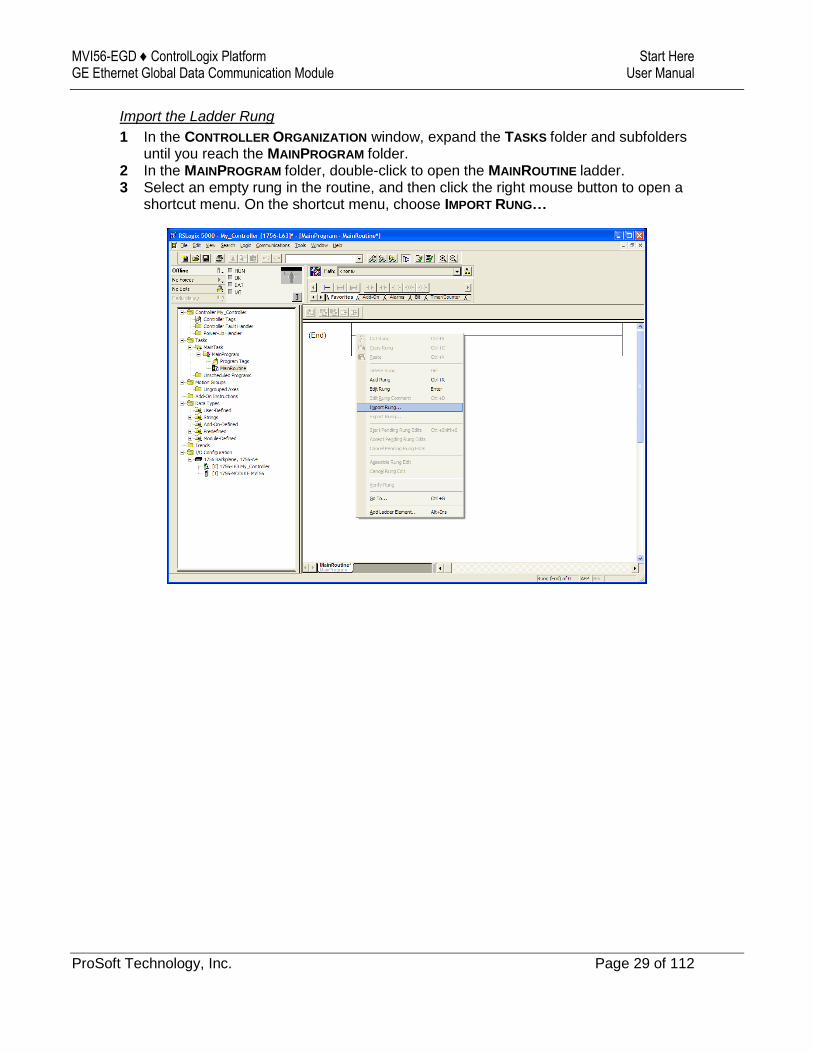
Import the Ladder Rung
1 In the CONTROLLER ORGANIZATION window, expand the TASKS folder and subfolders until you reach the MAINPROGRAM folder.
2 In the MAINPROGRAM folder, double-click to open the MAINROUTINE ladder. 3 Select an empty rung in the routine, and then click the right mouse button to open a
shortcut menu. On the shortcut menu, choose IMPORT RUNG…
Start Here MVI56-EGD ♦ ControlLogix Platform User Manual GE Ethernet Global Data Communication Module
Page 30 of 112 ProSoft Technology, Inc.
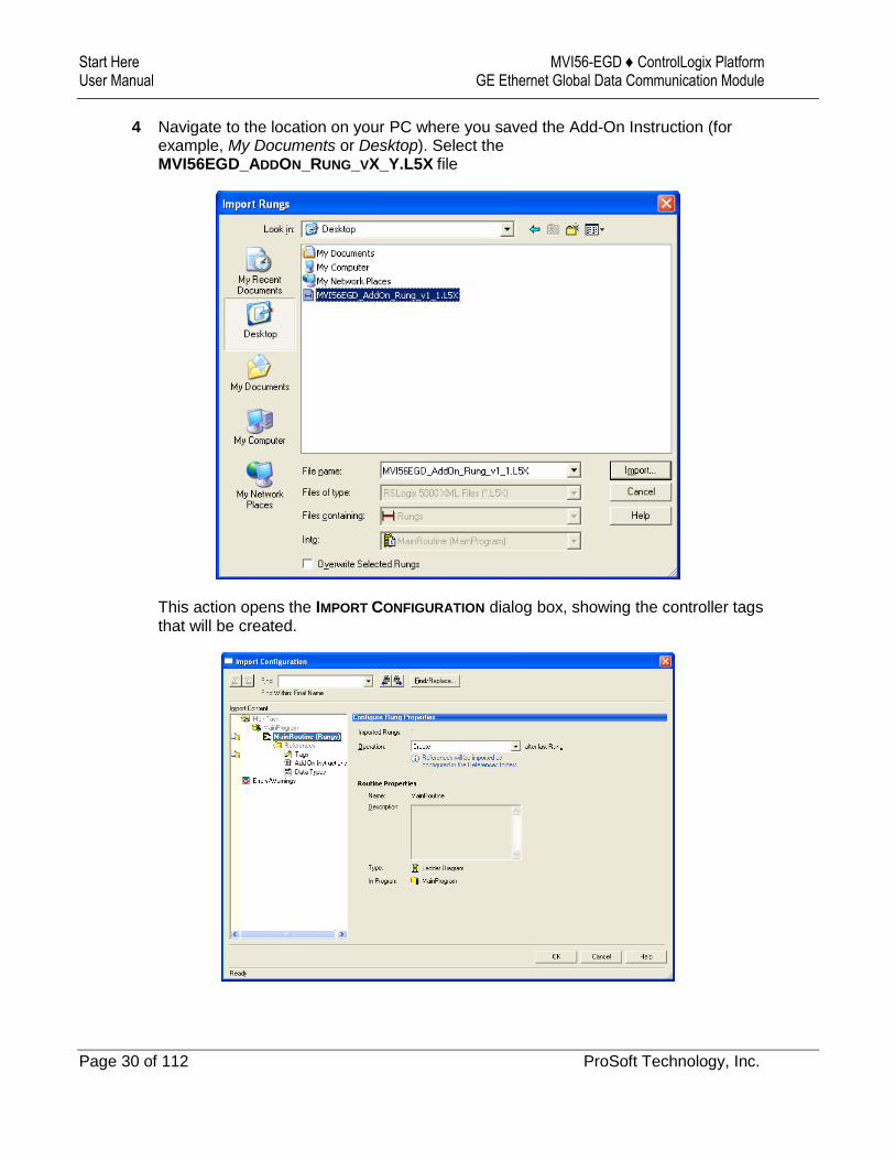
4 Navigate to the location on your PC where you saved the Add-On Instruction (for example, My Documents or Desktop). Select the MVI56EGD_ADDON_RUNG_VX_Y.L5X file
This action opens the IMPORT CONFIGURATION dialog box, showing the controller tags that will be created.
MVI56-EGD ♦ ControlLogix Platform Start Here GE Ethernet Global Data Communication Module User Manual
ProSoft Technology, Inc. Page 31 of 112
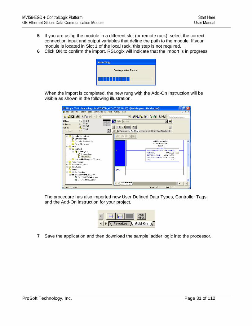
5 If you are using the module in a different slot (or remote rack), select the correct connection input and output variables that define the path to the module. If your module is located in Slot 1 of the local rack, this step is not required.
6 Click OK to confirm the import. RSLogix will indicate that the import is in progress:
When the import is completed, the new rung with the Add-On Instruction will be visible as shown in the following illustration.
The procedure has also imported new User Defined Data Types, Controller Tags, and the Add-On instruction for your project.
7 Save the application and then download the sample ladder logic into the processor.
Start Here MVI56-EGD ♦ ControlLogix Platform User Manual GE Ethernet Global Data Communication Module
Page 32 of 112 ProSoft Technology, Inc.
Adjusting the Input and Output Array Sizes
The module internal database is divided into two user-configurable areas:
Read Data
Write Data.
The Read Data area is moved from the module to the processor, while the Write Data area is moved from the processor to the module. You can configure the start register and size of each area in ProSoft Configuraton Builder (PCB). The size of each area you configure must match the Add-On Instruction controller tag array sizes for the READDATA
and WRITEDATA arrays.
The MVI56-EGD sample program is configured for 600 registers of READDATA and 600 registers of WRITEDATA, which is sufficient for most application. This topic describes how to configure user data for applications requiring more than 600 registers of ReadData and WriteData.
Important: Because the module pages data in blocks of 200 registers at a time, you should configure your user data in multiples of 200 registers.
Caution: When you change the array size, RSLogix may reset the EGD tag values to zero. To avoid data loss, be sure to save your settings before continuing.
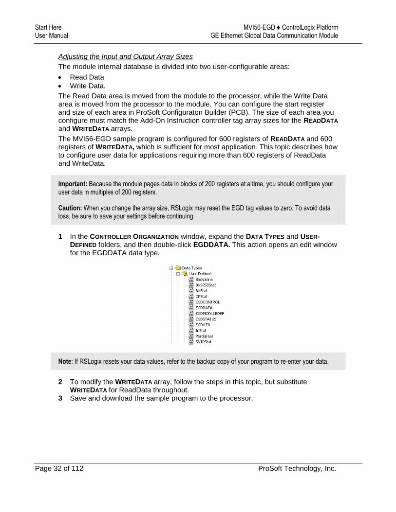
1 In the CONTROLLER ORGANIZATION window, expand the DATA TYPES and USER-DEFINED folders, and then double-click EGDDATA. This action opens an edit window for the EGDDATA data type.
Note: If RSLogix resets your data values, refer to the backup copy of your program to re-enter your data.
2 To modify the WRITEDATA array, follow the steps in this topic, but substitute WRITEDATA for ReadData throughout.
3 Save and download the sample program to the processor.
MVI56-EGD ♦ ControlLogix Platform Start Here GE Ethernet Global Data Communication Module User Manual
ProSoft Technology, Inc. Page 33 of 112
Configuring the MVI56-EGD Module MVI56-EGD ♦ ControlLogix Platform User Manual GE Ethernet Global Data Communication Module
Page 34 of 112 ProSoft Technology, Inc.
2 Configuring the MVI56-EGD Module
In This Chapter
Using ProSoft Configuration Builder ...................................................... 35
[Module] ................................................................................................. 39
[SNTP Client] ......................................................................................... 40
[EGD Exchanges] .................................................................................. 42
[EGD Multicast Group List] .................................................................... 48
Ethernet Configuration ........................................................................... 49
Downloading the Project to the Module Using a Serial COM Port ......... 50
Warning: When interfacing with a GE RX3i Controller, all reserved bits within the RX3i Controller must be set to 0 in order to communicate with the MVI56-EGD. Also, the use of a Configuration Server is not supported.

MVI56-EGD ♦ ControlLogix Platform Configuring the MVI56-EGD Module GE Ethernet Global Data Communication Module User Manual
ProSoft Technology, Inc. Page 35 of 112
2.1 Using ProSoft Configuration Builder
ProSoft Configuration Builder (PCB) provides a quick and easy way to manage module configuration files customized to meet your application needs. PCB is not only a powerful solution for new configuration files, but also allows you to import information from previously installed (known working) configurations to new projects.
2.1.1 Setting Up the Project
To begin, start PROSOFT CONFIGURATION BUILDER (PCB).
If you have used other Windows configuration tools before, you will find the screen layout familiar. PCB’s window consists of a tree view on the left, and an information pane and a configuration pane on the right side of the window. When you first start PCB, the tree view consists of folders for Default Project and Default Location, with a Default Module in the Default Location folder. The following illustration shows the PCB window with a new project.
Configuring the MVI56-EGD Module MVI56-EGD ♦ ControlLogix Platform User Manual GE Ethernet Global Data Communication Module
Page 36 of 112 ProSoft Technology, Inc.
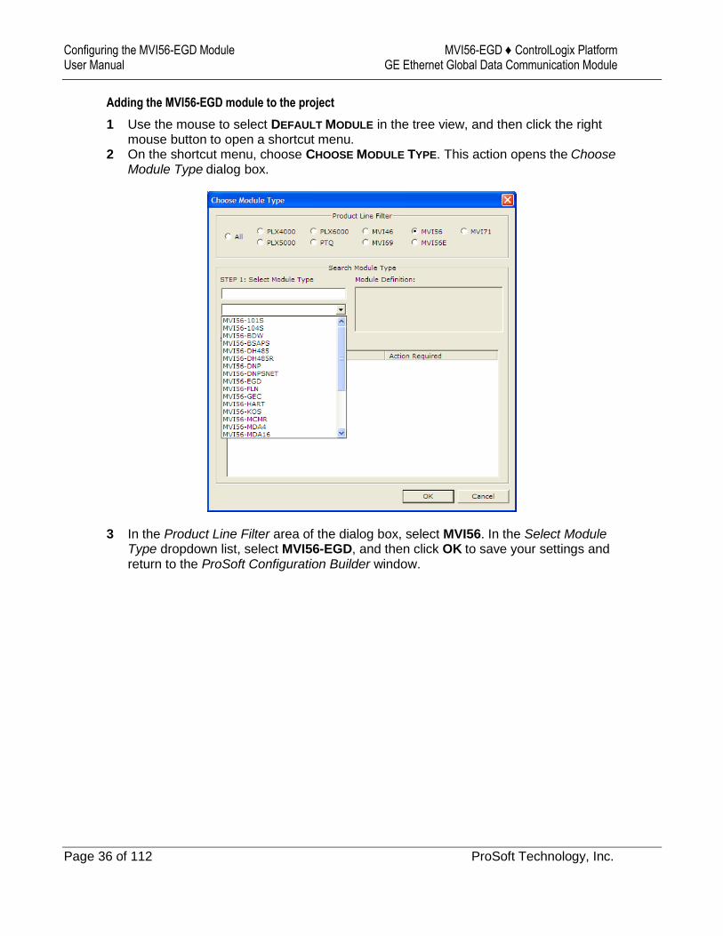
Adding the MVI56-EGD module to the project
1 Use the mouse to select DEFAULT MODULE in the tree view, and then click the right mouse button to open a shortcut menu.
2 On the shortcut menu, choose CHOOSE MODULE TYPE. This action opens the Choose Module Type dialog box.
3 In the Product Line Filter area of the dialog box, select MVI56. In the Select Module Type dropdown list, select MVI56-EGD, and then click OK to save your settings and return to the ProSoft Configuration Builder window.
MVI56-EGD ♦ ControlLogix Platform Configuring the MVI56-EGD Module GE Ethernet Global Data Communication Module User Manual
ProSoft Technology, Inc. Page 37 of 112
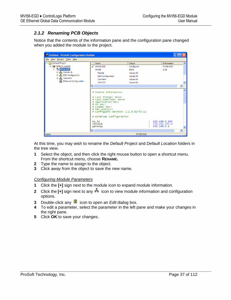
2.1.2 Renaming PCB Objects
Notice that the contents of the information pane and the configuration pane changed when you added the module to the project.
At this time, you may wish to rename the Default Project and Default Location folders in the tree view.
1 Select the object, and then click the right mouse button to open a shortcut menu. From the shortcut menu, choose RENAME.
2 Type the name to assign to the object. 3 Click away from the object to save the new name.
Configuring Module Parameters
1 Click the [+] sign next to the module icon to expand module information.
2 Click the [+] sign next to any icon to view module information and configuration options.
3 Double-click any icon to open an Edit dialog box. 4 To edit a parameter, select the parameter in the left pane and make your changes in
the right pane. 5 Click OK to save your changes.
Configuring the MVI56-EGD Module MVI56-EGD ♦ ControlLogix Platform User Manual GE Ethernet Global Data Communication Module
Page 38 of 112 ProSoft Technology, Inc.
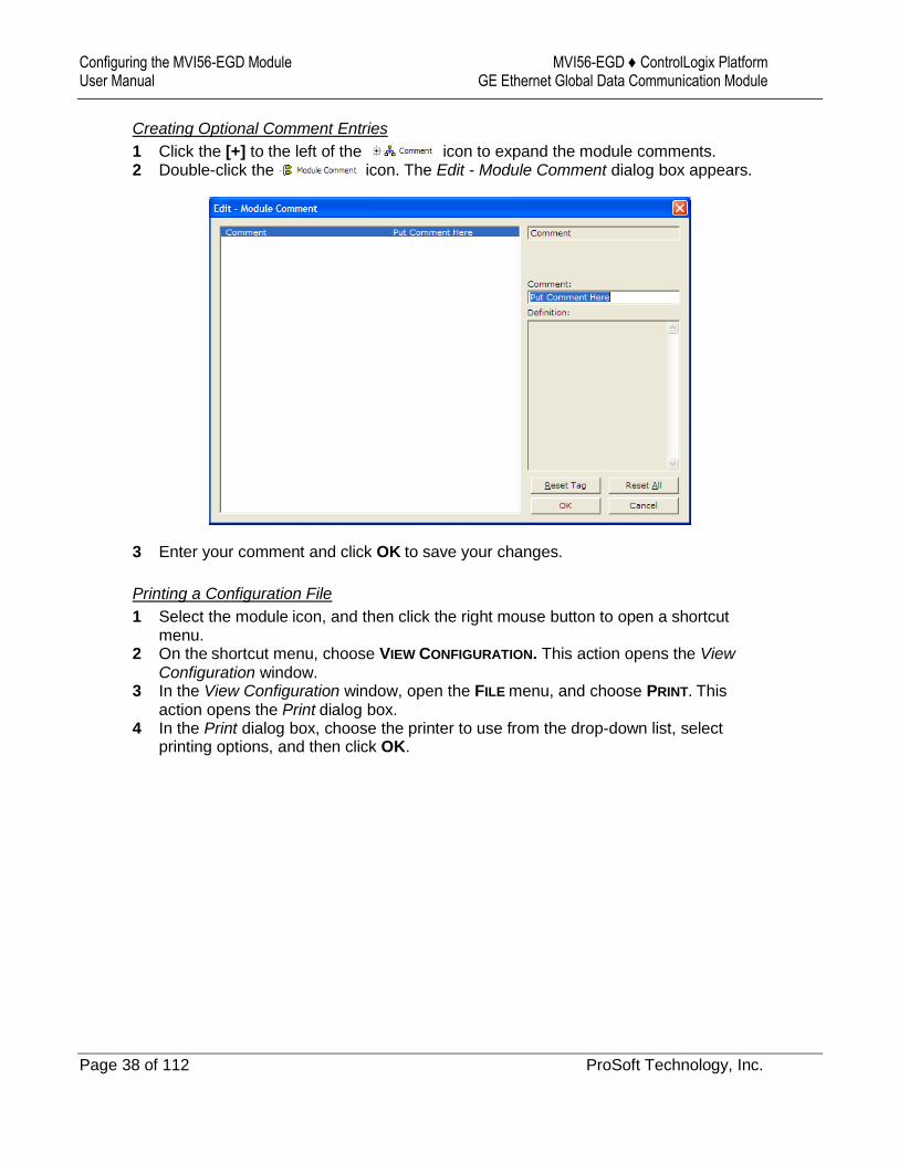
Creating Optional Comment Entries
1 Click the [+] to the left of the icon to expand the module comments. 2 Double-click the icon. The Edit - Module Comment dialog box appears.
3 Enter your comment and click OK to save your changes.
Printing a Configuration File
1 Select the module icon, and then click the right mouse button to open a shortcut menu.
2 On the shortcut menu, choose VIEW CONFIGURATION. This action opens the View Configuration window.
3 In the View Configuration window, open the FILE menu, and choose PRINT. This action opens the Print dialog box.
4 In the Print dialog box, choose the printer to use from the drop-down list, select printing options, and then click OK.
MVI56-EGD ♦ ControlLogix Platform Configuring the MVI56-EGD Module GE Ethernet Global Data Communication Module User Manual
ProSoft Technology, Inc. Page 39 of 112
2.2 [Module]
This section designates database addresses for input and output on the module and on the processor, and identifies the method of failure for the communications for the module if the processor is not in run mode.
2.2.1 Module Name
0 to 80 characters
This parameter assigns a name to the module that can be viewed using the configuration/debug port. Use this parameter to identify the module and the configuration file.
2.2.2 Module Type
The part number for the module, for example MVI56-EGD
2.2.3 Read Register Start
0 to 3999
This parameter specifies the starting register address of a block of data registers to transfer from the module to the processor.
2.2.4 Read Register Count
0 to 4000
This parameter specifies the number of registers to transfer from the module to the processor.
2.2.5 Write Register Start
0 to 3999
This parameter specifies the starting register address of a module register block where data transferred from the processor will be stored.
2.2.6 Write Register Count
Range 0 to 4000
This parameter specifies the number of registers to transfer from the processor to the module. Valid entry for this parameter is 0 to 3999.
2.2.7 Failure Flag Count
0 through 65535
This parameter specifies the number of successive transfer errors that must occur before halting communication on the application port(s). If the parameter is set to 0, the application port(s) will continue to operate under all conditions. If the value is set larger than 0 (1 to 65535), communications will cease if the specified number of failures occur.

Configuring the MVI56-EGD Module MVI56-EGD ♦ ControlLogix Platform User Manual GE Ethernet Global Data Communication Module
Page 40 of 112 ProSoft Technology, Inc.
2.3 [SNTP Client]
The [SNTP CLIENT] section specifies the parameters for the Simple Network Time Protocol (SNTP) Client, which keeps the internal clock set correctly. This version of the driver supports the unicast implementation of the SNTP Revision 3 and stratum between 1 and 14.
The module can be configured to periodically synchronize its clock with a remote SNTP server. Approximately every 6 minutes, the module sends 10 consecutive requests to the remote SNTP Client (at approximately 6-second intervals). You can check these requests and responses from the SNTP Client Configuration Menu (press the [N] key from the Configuration/Debug Main Menu). If the module receives a valid response from the SNTP server, the computations value will be also be incremented. After 10 consecutive successful requests and responses, the module will synchronize its internal clock (an average is performed based on all 10 responses for better accuracy). The Time Set Cnt value is incremented every time the clock is synchronized.
After the synchronization is performed, the time valid register is set to Yes. If the module cannot connect to the remote SNTP server after 3 consecutive attempts, the time valid register is set to No. You can also configure the GMT settings to use, and the database address where the date and time information can be copied.
The following parameters in the configuration file set up the SNTP Client:
The database register parameter defines a database register where the SNTP time and date values are copied. It occupies four words as follows:
Word Offset Description
0 and 1 Date and time in Unix format (long integer)
2 and 3 Microseconds (long integer)
MVI56-EGD ♦ ControlLogix Platform Configuring the MVI56-EGD Module GE Ethernet Global Data Communication Module User Manual
ProSoft Technology, Inc. Page 41 of 112
2.3.1 NTP Server IP Address
Enter in dotted notation
This parameter sets the IP address of the NTP server to contact for time acquisition. Select an NTP server with the greatest accuracy that is available all the time from your network. Set this IP address to 0.0.0.0 to disable SNTP server requests.
2.3.2 Time Zone
-11 to 11
This parameter sets the time zone offset from UTC. Positive values are for time zones west of UTC, and negative values are for time zones east of UTC. Set this value to 0 to use UTC in the module.
2.3.3 Use Daylight Savings Time
YES or NO
This parameter specifies if daylight savings time will be used in the time computation.
2.3.4 Database Register
-1 or 0 to 3992 as an even value
This parameter specifies if the NTP time computed by the driver is to be placed into the module’s database. If a value of -1 is specified, the time will not be placed into the database. If the value is between 0 and 3992, the time will be placed in the database. The first 4 bytes represent the seconds since 1/1/1970, and the second 4 bytes represent the number of microseconds. An even value should be used for the register value in order for the data to be stored correctly.

Configuring the MVI56-EGD Module MVI56-EGD ♦ ControlLogix Platform User Manual GE Ethernet Global Data Communication Module
Page 42 of 112 ProSoft Technology, Inc.
2.4 [EGD Exchanges]
In order to interface the module with EGD devices, you must construct an exchange list. The exchanges specify messages that will be produced or consumed at a user-defined frequency using the module's internal database. Messages can be broadcast to all nodes on the network, sent to a multicast group on the network or associated with a single node on the network. Up to 100 exchanges can be defined for the driver. Up to 700 word registers can be produced or consumed in a single exchange.
The [EGD Exchanges] section defines the messages that will be produced and consumed by the driver. The UDP protocol on the IP network is used to transport these over Ethernet between all the EGD devices.
For the exchanges to operate correctly, the other EGD devices must be configured and correctly set up. The primary reason for user problems with the module is failure to provide devices that are correctly configured. Before trying to connect the module to the network, the remote device must be able to communicate with ProSoft Configuration Builder. You must understand and document all parameters.
2.4.1 Exch Type
Producer: exchange will send data from the module's database to another station or stations
Consumer: exchange will receive data from another station
The Exchange Type field defines the direction data moves during the exchange.
Producer exchanges (P) are generated by the driver from data module’s database. This produced (transmitted) data will be available to any other stations on the network that wish to consume (receive) it.
Consumer exchanges (C) place data received from other producing EGD devices into the module’s database.
MVI56-EGD ♦ ControlLogix Platform Configuring the MVI56-EGD Module GE Ethernet Global Data Communication Module User Manual
ProSoft Technology, Inc. Page 43 of 112
2.4.2 Cast Type
When the Exchange Type is Producer, the cast type field determines if the exchange is a unicast ("U" = point-to-point) exchange, multicast ("M"=multicast group) or a broadcast ("B" = all nodes) exchange.
Producer Unicast - produce message to another station
Producer Multicast - produce message to a group of stations. In order to use this option you need to configure the same Multicast IP address used in the exchange also at the EGD MULTICAST ADDRESS section.
Important: For Multicast mode, use transmit rates of 1 or 2 for best results.
Producer Broadcast - produce message to all stations (set exchange IP address to 255.255.255.255)
When the Exchange Type is Consumer, the cast type field determines how the local database area associated to this exchange will be updated in case an COMS Error (timeout) occurs.
Consumer No DB Change on COMS Error
Consumer Set DB to -1 On COMS Error
Consumer Set DB to 0 On COMS Error
Consumer Set DB to 1 On COMS Error
2.4.3 DB Reg
The DB Reg field determines the starting register address of the module database area from which data will be produced (sent) or area into which data will be consumed (received). The validity of the entry depends on the number of registers (Reg Count) to be produced or consumed. To be valid, the sum of the DB Reg and Reg Count values cannot exceed the range of the module’s database.
2.4.4 Reg Count
Number of database registers to send or receive in the exchange.
Configuring the MVI56-EGD Module MVI56-EGD ♦ ControlLogix Platform User Manual GE Ethernet Global Data Communication Module
Page 44 of 112 ProSoft Technology, Inc.
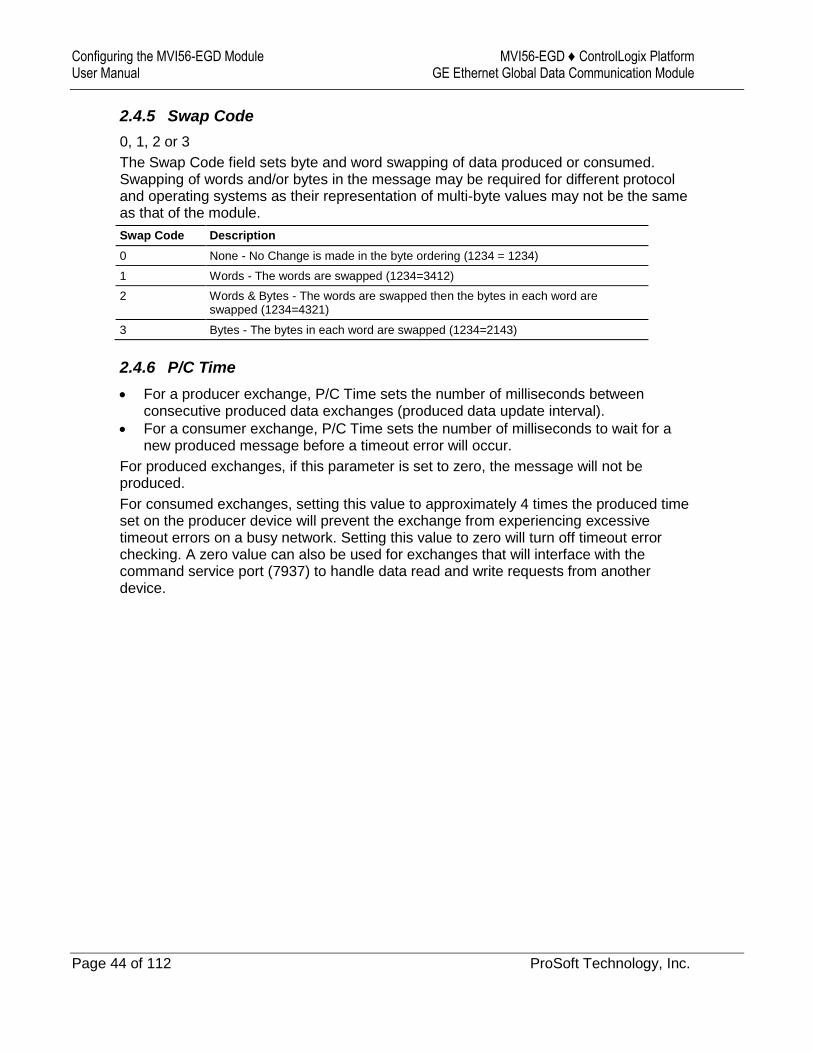
2.4.5 Swap Code
0, 1, 2 or 3
The Swap Code field sets byte and word swapping of data produced or consumed. Swapping of words and/or bytes in the message may be required for different protocol and operating systems as their representation of multi-byte values may not be the same as that of the module.
Swap Code Description
0 None - No Change is made in the byte ordering (1234 = 1234)
1 Words - The words are swapped (1234=3412)
2 Words & Bytes - The words are swapped then the bytes in each word are swapped (1234=4321)
3 Bytes - The bytes in each word are swapped (1234=2143)
2.4.6 P/C Time
For a producer exchange, P/C Time sets the number of milliseconds between consecutive produced data exchanges (produced data update interval).
For a consumer exchange, P/C Time sets the number of milliseconds to wait for a new produced message before a timeout error will occur.
For produced exchanges, if this parameter is set to zero, the message will not be produced.
For consumed exchanges, setting this value to approximately 4 times the produced time set on the producer device will prevent the exchange from experiencing excessive timeout errors on a busy network. Setting this value to zero will turn off timeout error checking. A zero value can also be used for exchanges that will interface with the command service port (7937) to handle data read and write requests from another device.
MVI56-EGD ♦ ControlLogix Platform Configuring the MVI56-EGD Module GE Ethernet Global Data Communication Module User Manual
ProSoft Technology, Inc. Page 45 of 112
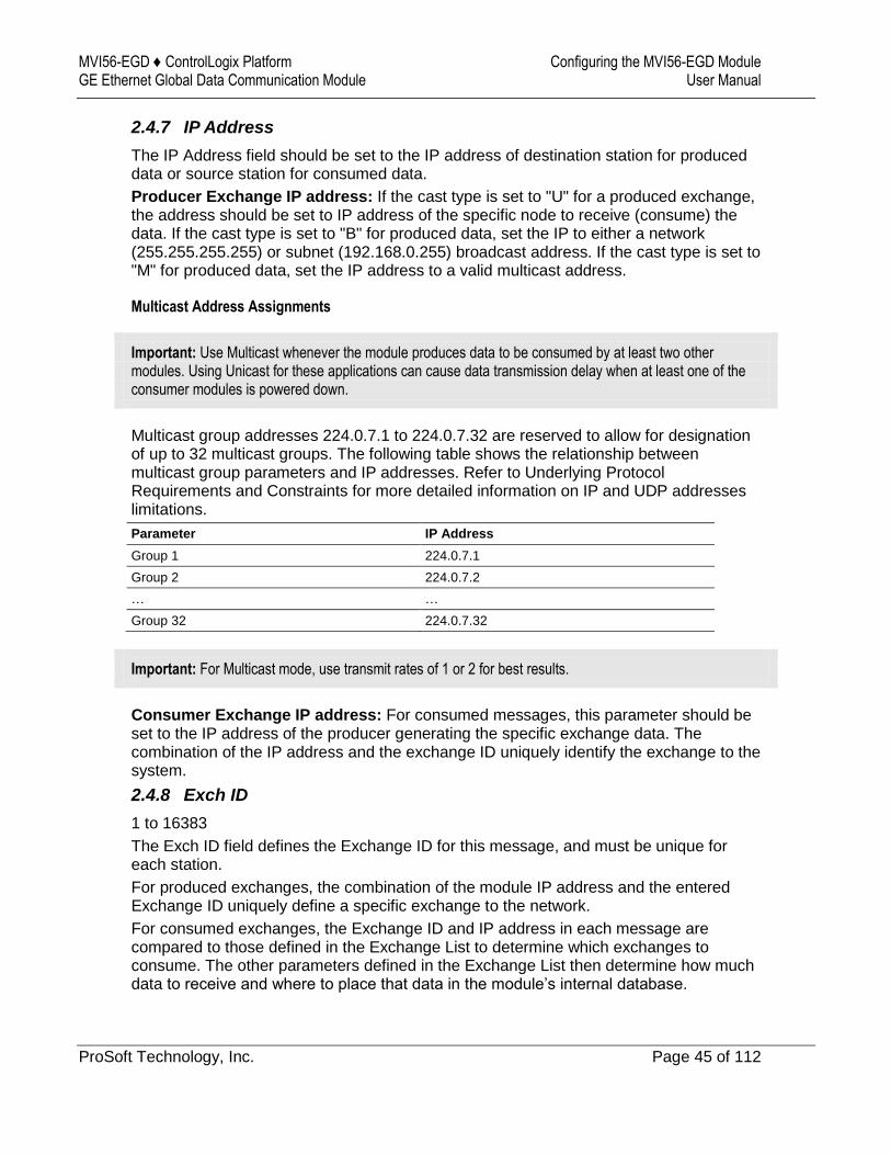
2.4.7 IP Address
The IP Address field should be set to the IP address of destination station for produced data or source station for consumed data.
Producer Exchange IP address: If the cast type is set to "U" for a produced exchange, the address should be set to IP address of the specific node to receive (consume) the data. If the cast type is set to "B" for produced data, set the IP to either a network (255.255.255.255) or subnet (192.168.0.255) broadcast address. If the cast type is set to "M" for produced data, set the IP address to a valid multicast address.
Multicast Address Assignments
Important: Use Multicast whenever the module produces data to be consumed by at least two other modules. Using Unicast for these applications can cause data transmission delay when at least one of the consumer modules is powered down.
Multicast group addresses 224.0.7.1 to 224.0.7.32 are reserved to allow for designation of up to 32 multicast groups. The following table shows the relationship between multicast group parameters and IP addresses. Refer to Underlying Protocol Requirements and Constraints for more detailed information on IP and UDP addresses limitations.
Parameter IP Address
Group 1 224.0.7.1
Group 2 224.0.7.2
… …
Group 32 224.0.7.32
Important: For Multicast mode, use transmit rates of 1 or 2 for best results.
Consumer Exchange IP address: For consumed messages, this parameter should be set to the IP address of the producer generating the specific exchange data. The combination of the IP address and the exchange ID uniquely identify the exchange to the system.
2.4.8 Exch ID
1 to 16383
The Exch ID field defines the Exchange ID for this message, and must be unique for each station.
For produced exchanges, the combination of the module IP address and the entered Exchange ID uniquely define a specific exchange to the network.
For consumed exchanges, the Exchange ID and IP address in each message are compared to those defined in the Exchange List to determine which exchanges to consume. The other parameters defined in the Exchange List then determine how much data to receive and where to place that data in the module’s internal database.
Configuring the MVI56-EGD Module MVI56-EGD ♦ ControlLogix Platform User Manual GE Ethernet Global Data Communication Module
Page 46 of 112 ProSoft Technology, Inc.
2.4.9 CS Major, CS Minor
This is an optional functionality that can be used to prevent unexpected results when changes are performed to existing producer and consumer exchanges.
The purpose of the Configuration Signature (CS) is to guarantee that the produced exchange will contain data in a format expected by a consumer. Therefore, it prevents the consumer from processing received data exchanges which may have an incompatible format due to producer configuration changes.
The Configuration Signature consists of two one-byte integer value (CS Major and CS Minor). The CS Major must be equal for both Producer and Consumer exchanges. The CS Minor reflects backward compatible modifications made to an exchange (for example: adding registers to the producer exchange count). Truncating data within an exchange (send less data than before) would not be backward-compatible and, therefore, would require a change in the major number to prevent processing errors.
Whenever a consumer receives an exchange message, it will look for a configured consumer exchange that contains the same Exchange ID. If it finds a matching produced exchange it will compare the Configuration Signature for validation. If the exchange is not validated, then the data will not be consumed.
By default, the <ModuleOrGateway > will perform validity checking but can be configured to ignore validity checking. To disable validity checking, configure all exchanges with both CS Major and CS Minor values equal to ZERO (0).
When acting as a consumer, the following rules are used by the module to validate an exchange based on its Configuration Signature:
MVI56-EGD ♦ ControlLogix Platform Configuring the MVI56-EGD Module GE Ethernet Global Data Communication Module User Manual
ProSoft Technology, Inc. Page 47 of 112
Rules for CS Validation
An exchange will be considered valid if at least one of the following conditions is true:
Producer CS Major and CS Minor are both equal to 0
Consumer CS Major and CS Minor are both equal to 0
Producer CS Major is equal to Consumer CS Major AND Producer CS Minor is greater than or equal to Consumer CS Minor
The following table contains some examples that will help you to understand the consumer criteria to validate received exchanges based on the Configuration Signature:
Producer CS Major
Producer CS Minor
Consumer CS Major
Consumer CS Minor
Will Data be Consumed?
Comment
0 0 0 0 Yes Same CS value of 0.0 (Major.Minor) validates the exchange
0 0 1 2 Yes Producer CS value of 0.0 (Major.Minor) validates the exchange
1 2 0 0 Yes Consumer CS value of 0.0 (Major.Minor) validates the exchange
1 2 1 2 Yes Same CS value (1.2) validates the exchange
2 2 1 2 No CS Major mismatch - exchange is not validated
1 2 2 2 No CS Major mismatch - exchange is not validated
1 2 1 1 Yes Same CS Major and Consumer CS Minor is less than Producer CS Minor - exchange is validated
1 2 1 3 No Same CS Major but Consumer CS Minor is greater than Producer CS Minor - exchange is not validated
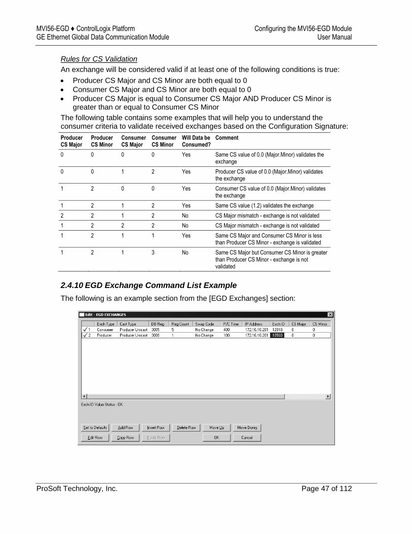
2.4.10 EGD Exchange Command List Example
The following is an example section from the [EGD Exchanges] section:

Configuring the MVI56-EGD Module MVI56-EGD ♦ ControlLogix Platform User Manual GE Ethernet Global Data Communication Module
Page 48 of 112 ProSoft Technology, Inc.
2.5 [EGD Multicast Group List]
This section contains the list of multicast group addresses the EGD server should process (consumer messages for this server produced on other units). This list may contain up to 16 IP addresses. The reserved group addresses for the EGD protocol are 224.0.7.1 to 224.0.7.32. The module will support other group addresses than this data set.
Important: Use Multicast whenever the module produces data to at least two other modules. Using Unicast for these applications can cause data transmission delay when at least one of the consumer modules is powered down.
MVI56-EGD ♦ ControlLogix Platform Configuring the MVI56-EGD Module GE Ethernet Global Data Communication Module User Manual
ProSoft Technology, Inc. Page 49 of 112
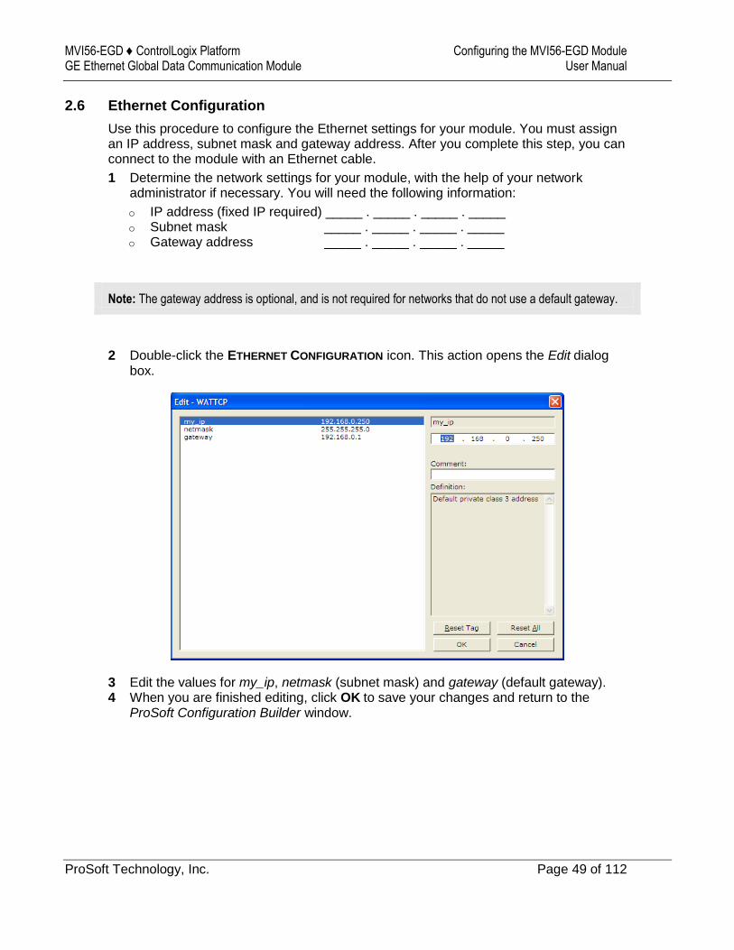
2.6 Ethernet Configuration
Use this procedure to configure the Ethernet settings for your module. You must assign an IP address, subnet mask and gateway address. After you complete this step, you can connect to the module with an Ethernet cable.
1 Determine the network settings for your module, with the help of your network administrator if necessary. You will need the following information:
o IP address (fixed IP required) _____ . _____ . _____ . _____ o Subnet mask _____ . _____ . _____ . _____ o Gateway address _____ . _____ . _____ . _____
Note: The gateway address is optional, and is not required for networks that do not use a default gateway.
2 Double-click the ETHERNET CONFIGURATION icon. This action opens the Edit dialog box.
3 Edit the values for my_ip, netmask (subnet mask) and gateway (default gateway). 4 When you are finished editing, click OK to save your changes and return to the
ProSoft Configuration Builder window.
Configuring the MVI56-EGD Module MVI56-EGD ♦ ControlLogix Platform User Manual GE Ethernet Global Data Communication Module
Page 50 of 112 ProSoft Technology, Inc.
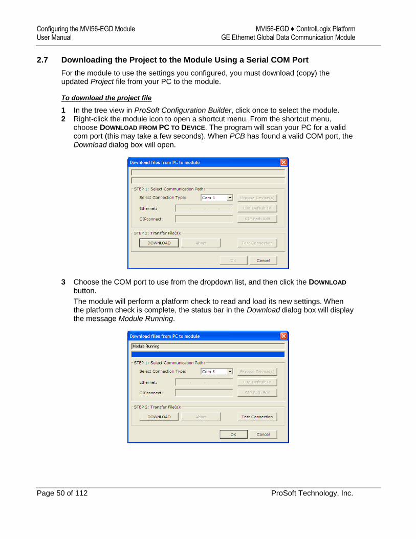
2.7 Downloading the Project to the Module Using a Serial COM Port
For the module to use the settings you configured, you must download (copy) the updated Project file from your PC to the module.
To download the project file
1 In the tree view in ProSoft Configuration Builder, click once to select the module. 2 Right-click the module icon to open a shortcut menu. From the shortcut menu,
choose DOWNLOAD FROM PC TO DEVICE. The program will scan your PC for a valid com port (this may take a few seconds). When PCB has found a valid COM port, the Download dialog box will open.
3 Choose the COM port to use from the dropdown list, and then click the DOWNLOAD
button.
The module will perform a platform check to read and load its new settings. When the platform check is complete, the status bar in the Download dialog box will display the message Module Running.
MVI56-EGD ♦ ControlLogix Platform Ladder Logic GE Ethernet Global Data Communication Module User Manual
ProSoft Technology, Inc. Page 51 of 112
3 Ladder Logic
In This Chapter
Controller Tags ...................................................................................... 51
Module Status Data and Variables (ModuleDef) .................................... 53
Adding the Module to an Existing Project .............................................. 57
Ladder logic is required for application of the MVI56-EGD module. Tasks that must be handled by the ladder logic are module data transfer, special block handling, and status data receipt. Additionally, a power-up handler may be needed to handle the initialization of the module’s data and to clear any processor fault conditions.
The sample ladder logic is extensively commented, to provide information on the purpose and function of each rung. For most applications, the sample ladder will work without modification.
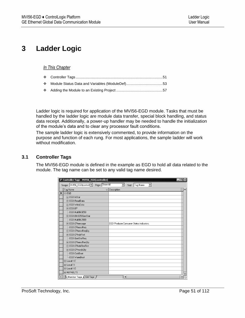
3.1 Controller Tags
The MVI56-EGD module is defined in the example as EGD to hold all data related to the module. The tag name can be set to any valid tag name desired.
Ladder Logic MVI56-EGD ♦ ControlLogix Platform User Manual GE Ethernet Global Data Communication Module
Page 52 of 112 ProSoft Technology, Inc.
MVI56-EGD ♦ ControlLogix Platform Ladder Logic GE Ethernet Global Data Communication Module User Manual
ProSoft Technology, Inc. Page 53 of 112
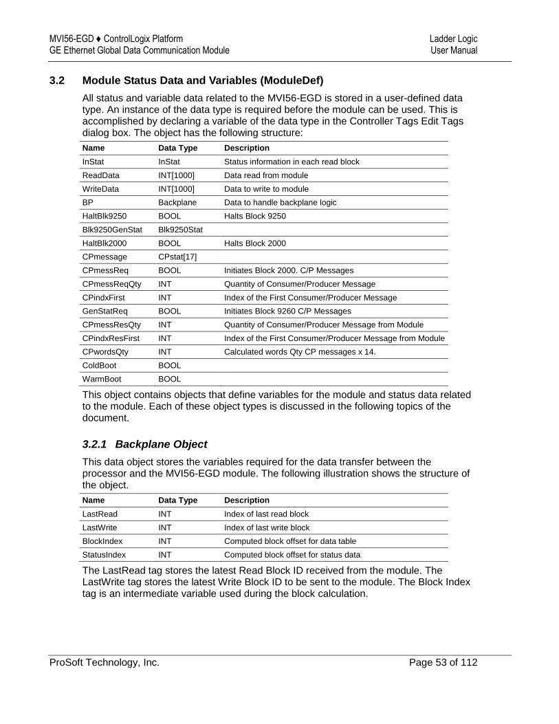
3.2 Module Status Data and Variables (ModuleDef)
All status and variable data related to the MVI56-EGD is stored in a user-defined data type. An instance of the data type is required before the module can be used. This is accomplished by declaring a variable of the data type in the Controller Tags Edit Tags dialog box. The object has the following structure:
Name Data Type Description
InStat InStat Status information in each read block
ReadData INT[1000] Data read from module
WriteData INT[1000] Data to write to module
BP Backplane Data to handle backplane logic
HaltBlk9250 BOOL Halts Block 9250
Blk9250GenStat Blk9250Stat
HaltBlk2000 BOOL Halts Block 2000
CPmessage CPstat[17]
CPmessReq BOOL Initiates Block 2000. C/P Messages
CPmessReqQty INT Quantity of Consumer/Producer Message
CPindxFirst INT Index of the First Consumer/Producer Message
GenStatReq BOOL Initiates Block 9260 C/P Messages
CPmessResQty INT Quantity of Consumer/Producer Message from Module
CPindxResFirst INT Index of the First Consumer/Producer Message from Module
CPwordsQty INT Calculated words Qty CP messages x 14.
ColdBoot BOOL
WarmBoot BOOL
This object contains objects that define variables for the module and status data related to the module. Each of these object types is discussed in the following topics of the document.
3.2.1 Backplane Object
This data object stores the variables required for the data transfer between the processor and the MVI56-EGD module. The following illustration shows the structure of the object.
Name Data Type Description
LastRead INT Index of last read block
LastWrite INT Index of last write block
BlockIndex INT Computed block offset for data table
StatusIndex INT Computed block offset for status data
The LastRead tag stores the latest Read Block ID received from the module. The LastWrite tag stores the latest Write Block ID to be sent to the module. The Block Index tag is an intermediate variable used during the block calculation.

Ladder Logic MVI56-EGD ♦ ControlLogix Platform User Manual GE Ethernet Global Data Communication Module
Page 54 of 112 ProSoft Technology, Inc.
3.2.2 User Data Objects (MNETDATA)
These objects hold data to be transferred between the processor and the MVI56-EGD module. The user data is the read and write data transferred between the processor and the module as pages of data up to 200 words long.
Name Data Type Description
ReadData INT[600] Data read from module. Set array equal to the size set in the Configuration file.
WriteData INT[600] Data to write to module. Set array equal to the size set in the Configuration file.
The read data (READDATA) is an array set to match the value entered in the Read Register Count parameter of the configuration file. For ease of use, this array should be dimensioned as an even increment of 200 words. This data is paged up to 200 words at a time from the module to the processor. The ReadData task places the data received into the proper position in the read data array. Use this data for status and control in the ladder logic of the processor.
The write data (WRITEDATA) is an array set to match the value entered in the Write Register Count parameter of the configuration file. For ease of use, this array should be dimensioned as even increments of 200 words. This data is paged up to 200 words at a time from the processor to the module. The WriteData task places the write data into the output image for transfer to the module. This data is passed from the processor to the module for status and control information for use in other nodes on the network.
3.2.3 Status Object (InStat)
This object stores the status data of the module. The InStat object (shown in the following example) is updated each time a read block is received by the processor. Use this data to monitor the state of the module at a "real-time" rate.
Name Data Type Description
PassCnt INT Program cycle/scan counter
BlkCntr BlkStat
SNTP SNTPstat
Within the InStat objects are objects containing the status information for the EGD protocol. Refer to Status Data Area and Error Codes for a complete listing of the data stored in this object.
MVI56-EGD ♦ ControlLogix Platform Ladder Logic GE Ethernet Global Data Communication Module User Manual
ProSoft Technology, Inc. Page 55 of 112
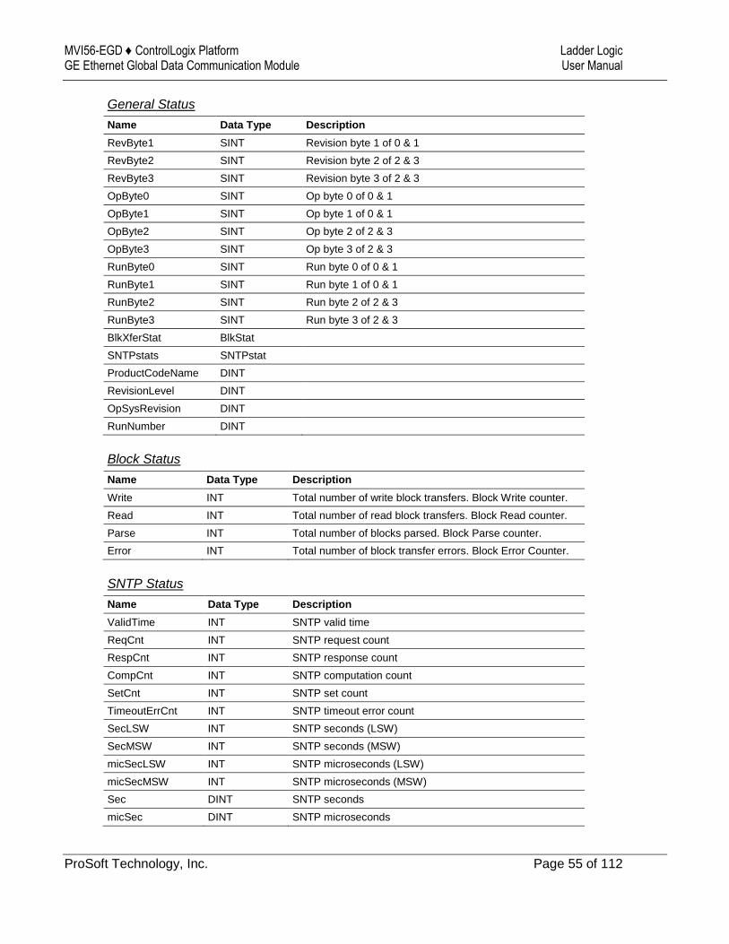
General Status
Name Data Type Description
RevByte1 SINT Revision byte 1 of 0 & 1
RevByte2 SINT Revision byte 2 of 2 & 3
RevByte3 SINT Revision byte 3 of 2 & 3
OpByte0 SINT Op byte 0 of 0 & 1
OpByte1 SINT Op byte 1 of 0 & 1
OpByte2 SINT Op byte 2 of 2 & 3
OpByte3 SINT Op byte 3 of 2 & 3
RunByte0 SINT Run byte 0 of 0 & 1
RunByte1 SINT Run byte 1 of 0 & 1
RunByte2 SINT Run byte 2 of 2 & 3
RunByte3 SINT Run byte 3 of 2 & 3
BlkXferStat BlkStat
SNTPstats SNTPstat
ProductCodeName DINT
RevisionLevel DINT
OpSysRevision DINT
RunNumber DINT
Block Status
Name Data Type Description
Write INT Total number of write block transfers. Block Write counter.
Read INT Total number of read block transfers. Block Read counter.
Parse INT Total number of blocks parsed. Block Parse counter.
Error INT Total number of block transfer errors. Block Error Counter.
SNTP Status
Name Data Type Description
ValidTime INT SNTP valid time
ReqCnt INT SNTP request count
RespCnt INT SNTP response count
CompCnt INT SNTP computation count
SetCnt INT SNTP set count
TimeoutErrCnt INT SNTP timeout error count
SecLSW INT SNTP seconds (LSW)
SecMSW INT SNTP seconds (MSW)
micSecLSW INT SNTP microseconds (LSW)
micSecMSW INT SNTP microseconds (MSW)
Sec DINT SNTP seconds
micSec DINT SNTP microseconds
Ladder Logic MVI56-EGD ♦ ControlLogix Platform User Manual GE Ethernet Global Data Communication Module
Page 56 of 112 ProSoft Technology, Inc.
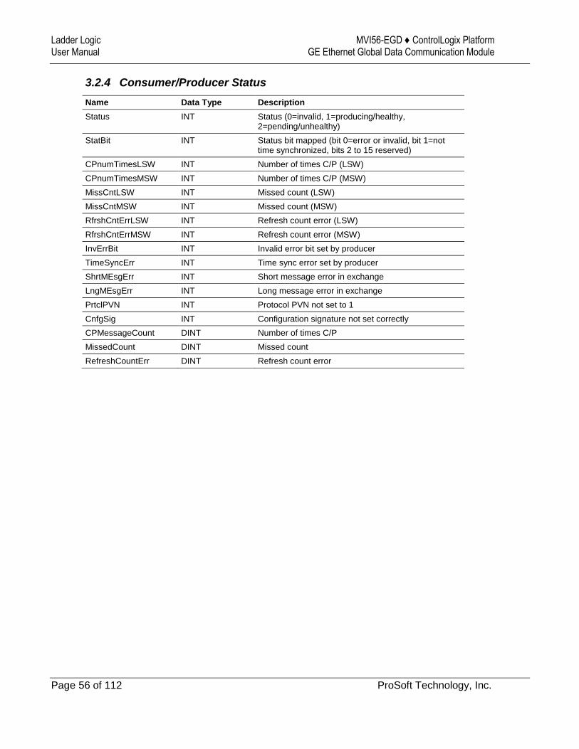
3.2.4 Consumer/Producer Status
Name Data Type Description
Status INT Status (0=invalid, 1=producing/healthy, 2=pending/unhealthy)
StatBit INT Status bit mapped (bit 0=error or invalid, bit 1=not time synchronized, bits 2 to 15 reserved)
CPnumTimesLSW INT Number of times C/P (LSW)
CPnumTimesMSW INT Number of times C/P (MSW)
MissCntLSW INT Missed count (LSW)
MissCntMSW INT Missed count (MSW)
RfrshCntErrLSW INT Refresh count error (LSW)
RfrshCntErrMSW INT Refresh count error (MSW)
InvErrBit INT Invalid error bit set by producer
TimeSyncErr INT Time sync error set by producer
ShrtMEsgErr INT Short message error in exchange
LngMEsgErr INT Long message error in exchange
PrtclPVN INT Protocol PVN not set to 1
CnfgSig INT Configuration signature not set correctly
CPMessageCount DINT Number of times C/P
MissedCount DINT Missed count
RefreshCountErr DINT Refresh count error
MVI56-EGD ♦ ControlLogix Platform Ladder Logic GE Ethernet Global Data Communication Module User Manual
ProSoft Technology, Inc. Page 57 of 112
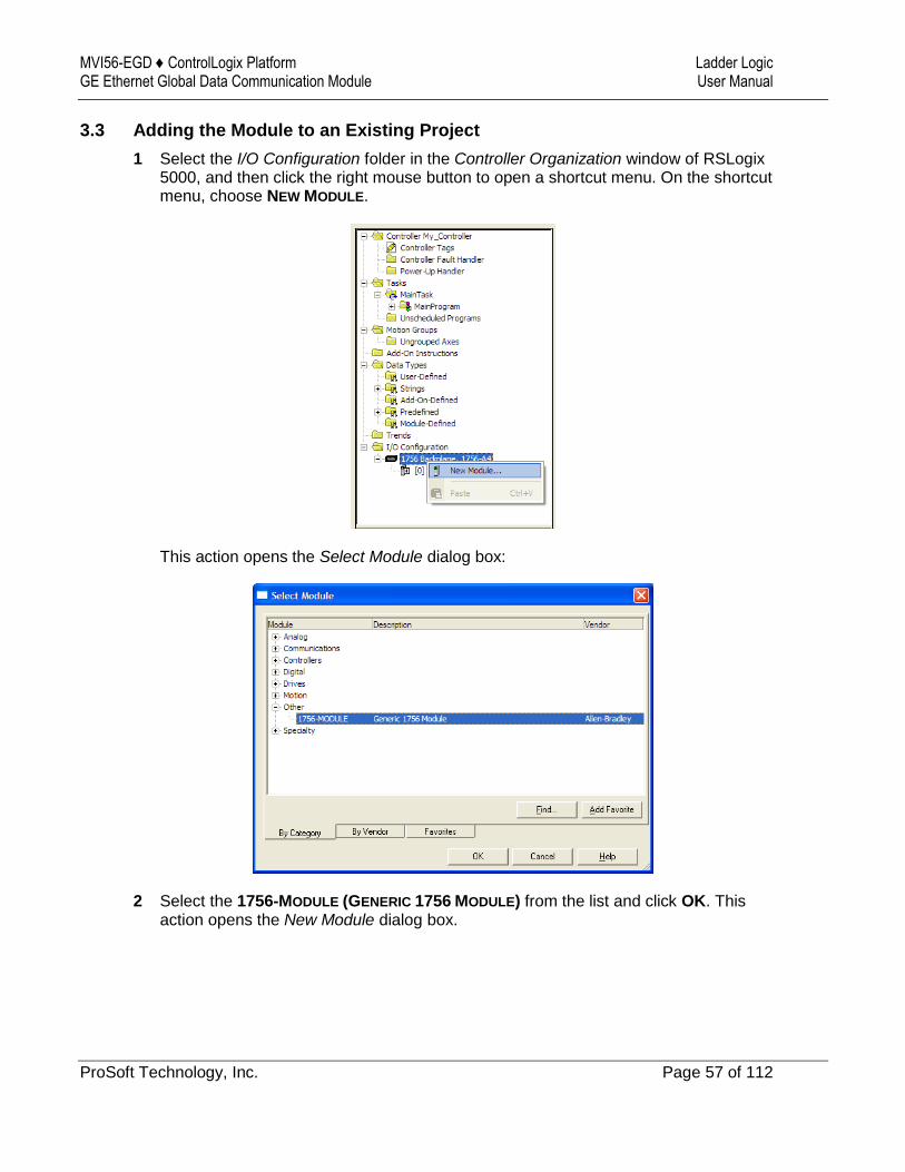
3.3 Adding the Module to an Existing Project
1 Select the I/O Configuration folder in the Controller Organization window of RSLogix 5000, and then click the right mouse button to open a shortcut menu. On the shortcut menu, choose NEW MODULE.
This action opens the Select Module dialog box:
2 Select the 1756-MODULE (GENERIC 1756 MODULE) from the list and click OK. This action opens the New Module dialog box.
Ladder Logic MVI56-EGD ♦ ControlLogix Platform User Manual GE Ethernet Global Data Communication Module
Page 58 of 112 ProSoft Technology, Inc.
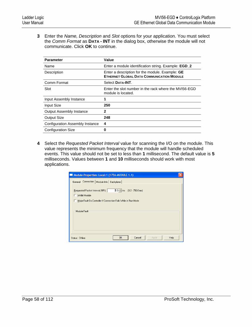
3 Enter the Name, Description and Slot options for your application. You must select the Comm Format as DATA - INT in the dialog box, otherwise the module will not communicate. Click OK to continue.
Parameter Value
Name Enter a module identification string. Example: EGD_2
Description Enter a description for the module. Example: GE
ETHERNET GLOBAL DATA COMMUNICATION MODULE
Comm Format Select DATA-INT.
Slot Enter the slot number in the rack where the MVI56-EGD module is located.
Input Assembly Instance 1
Input Size 250
Output Assembly Instance 2
Output Size 248
Configuration Assembly Instance 4
Configuration Size 0
4 Select the Requested Packet Interval value for scanning the I/O on the module. This value represents the minimum frequency that the module will handle scheduled events. This value should not be set to less than 1 millisecond. The default value is 5 milliseconds. Values between 1 and 10 milliseconds should work with most applications.
MVI56-EGD ♦ ControlLogix Platform Ladder Logic GE Ethernet Global Data Communication Module User Manual
ProSoft Technology, Inc. Page 59 of 112
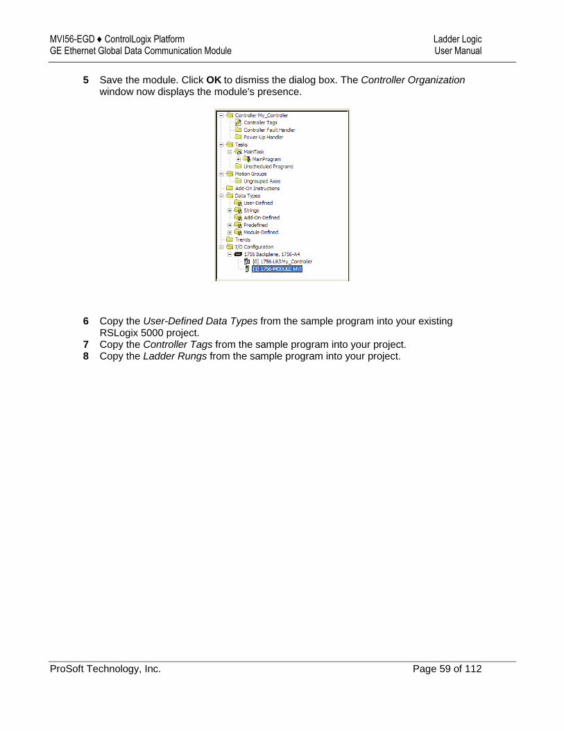
5 Save the module. Click OK to dismiss the dialog box. The Controller Organization window now displays the module's presence.
6 Copy the User-Defined Data Types from the sample program into your existing RSLogix 5000 project.
7 Copy the Controller Tags from the sample program into your project. 8 Copy the Ladder Rungs from the sample program into your project.

Ladder Logic MVI56-EGD ♦ ControlLogix Platform User Manual GE Ethernet Global Data Communication Module
Page 60 of 112 ProSoft Technology, Inc.

MVI56-EGD ♦ ControlLogix Platform Diagnostics and Troubleshooting GE Ethernet Global Data Communication Module User Manual
ProSoft Technology, Inc. Page 61 of 112
4 Diagnostics and Troubleshooting
In This Chapter
LED Status Indicators ............................................................................ 62
Using ProSoft Configuration Builder (PCB) for Diagnostics ................... 64
Reading Status Data from the Module ................................................... 76
The module provides information on diagnostics and troubleshooting in the following forms:
LED status indicators on the front of the module provide general information on the module's status.
Status data contained in the module can be viewed through the Configuration/Debug port, using the troubleshooting and diagnostic capabilities of ProSoft Configuration Builder (PCB).
Status data values can be transferred from the module to processor memory and can be monitored there manually or by customer-created logic.

Diagnostics and Troubleshooting MVI56-EGD ♦ ControlLogix Platform User Manual GE Ethernet Global Data Communication Module
Page 62 of 112 ProSoft Technology, Inc.
4.1 LED Status Indicators
The LEDs indicate the module’s operating status as follows:
LED Color Status Indication
CFG Green On Data is being transferred between the module and a remote terminal using the Configuration/Debug port.
Off No data is being transferred on the Configuration/Debug port.
APP STATUS
Amber Off The MVI56-EGD is working normally.
On The MVI56-EGD module program has recognized a communication error on one of its ports.
BP ACT Amber On The LED is on when the module is performing a write operation on the backplane.
Off The LED is off when the module is performing a read operation on the backplane. Under normal operation, the LED should blink rapidly on and off.
OK Red/ Green
Off The card is not receiving any power and is not securely plugged into the rack.
Green The module is operating normally.
Red The program has detected an error or is being configured. If the LED remains red for over 10 seconds, the program has probably halted. Remove the card from the rack and re-insert the card to restart the module’s program.
BATT Red Off The battery voltage is OK and functioning.
On The battery voltage is low or battery is not present. Allow battery to charge by keeping module plugged into rack for 24 hours. If BAT LED still does not go off, contact ProSoft Technology, as this is not a user serviceable item.
If the APP, BP ACT and OK LEDs blink at a rate of every one-second, call ProSoft Technology support. There is a serious problem with the module, and it will have to be sent back to ProSoft.
4.1.1 Ethernet LED Indicators
LED State Description
Data OFF No activity on the Ethernet port.
GREEN Flash The Ethernet port is actively transmitting or receiving data.
Link OFF No physical network connection is detected. No Ethernet communication is possible. Check wiring and cables.
GREEN Solid Physical network connection detected. This LED must be ON solid for Ethernet communication to be possible.
MVI56-EGD ♦ ControlLogix Platform Diagnostics and Troubleshooting GE Ethernet Global Data Communication Module User Manual
ProSoft Technology, Inc. Page 63 of 112
4.1.2 Clearing a Fault Condition
Typically, if the OK LED on the front of the module becomes illuminated red for more than ten seconds, a hardware problem has been detected in the module or the program has exited. To attempt to clear the condition:
1 Remove the card from the rack and re-insert the card in the rack 2 Verify the configuration data being transferred to the module from the ControlLogix
processor
If the module's OK LED does not turn green, make sure the module is inserted completely into the rack. If this does not cure the problem, contact ProSoft Technology Support.
4.1.3 Troubleshooting
Use the following troubleshooting steps if you encounter problems when the module is powered up. If these steps do not resolve your problem, please contact ProSoft Technology Technical Support.
Processor Errors
Problem description Steps to take
Processor fault Verify that the module is plugged into the slot that has been configured for the module in the I/O Configuration of RSLogix.
Verify that the slot location in the rack has been configured correctly in the ladder logic.
Processor I/O LED flashes
This indicates a problem with backplane communications. A problem could exist between the processor and any installed I/O module, not just the MVI56-EGD. Verify that all modules in the rack are correctly configured in the ladder logic.
Module Errors
Problem description Steps to take
BP ACT LED (not present on MVI56E modules) remains OFF or blinks slowly
MVI56E modules with scrolling LED display: <Backplane Status> condition reads ERR
This indicates that backplane transfer operations are failing. Connect to the module’s Configuration/Debug port to check this.
To establish backplane communications, verify the following items:
The processor is in RUN or REM RUN mode.
The backplane driver is loaded in the module.
The module is configured for read and write data block transfer.
The ladder logic handles all read and write block situations.
The module is properly configured in the processor I/O configuration and ladder logic.
OK LED remains RED The program has halted or a critical error has occurred. Connect to the Configuration/Debug port to see if the module is running. If the program has halted, turn off power to the rack, remove the card from the rack and re-insert it, and then restore power to the rack.

Diagnostics and Troubleshooting MVI56-EGD ♦ ControlLogix Platform User Manual GE Ethernet Global Data Communication Module
Page 64 of 112 ProSoft Technology, Inc.
4.2 Using ProSoft Configuration Builder (PCB) for Diagnostics
The Configuration and Debug menu for this module is arranged as a tree structure, with the Main menu at the top of the tree, and one or more submenus for each menu command. The first menu you see when you connect to the module is the Main menu.
Because this is a text-based menu system, you enter commands by typing the [command letter] from your computer keyboard in the Diagnostic window in ProSoft Configuration Builder (PCB). The module does not respond to mouse movements or clicks. The command executes as soon as you press the [COMMAND LETTER] — you do not need to press [ENTER]. When you type a [COMMAND LETTER], a new screen will be displayed in your terminal application.
4.2.1 Using the Diagnostic Window in ProSoft Configuration Builder
Tip: You can have a ProSoft Configuration Builder Diagnostics window open for more than one module at a time.
To connect to the module’s Configuration/Debug serial port
1 Start PCB, and then select the module to test. Click the right mouse button to open a shortcut menu.
2 On the shortcut menu, choose DIAGNOSTICS.
This action opens the Diagnostics dialog box.
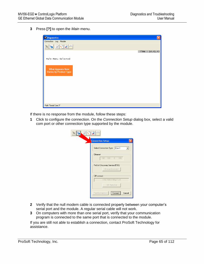
MVI56-EGD ♦ ControlLogix Platform Diagnostics and Troubleshooting GE Ethernet Global Data Communication Module User Manual
ProSoft Technology, Inc. Page 65 of 112
3 Press [?] to open the Main menu.
If there is no response from the module, follow these steps:
1 Click to configure the connection. On the Connection Setup dialog box, select a valid com port or other connection type supported by the module.
2 Verify that the null modem cable is connected properly between your computer’s serial port and the module. A regular serial cable will not work.
3 On computers with more than one serial port, verify that your communication program is connected to the same port that is connected to the module.
If you are still not able to establish a connection, contact ProSoft Technology for assistance.
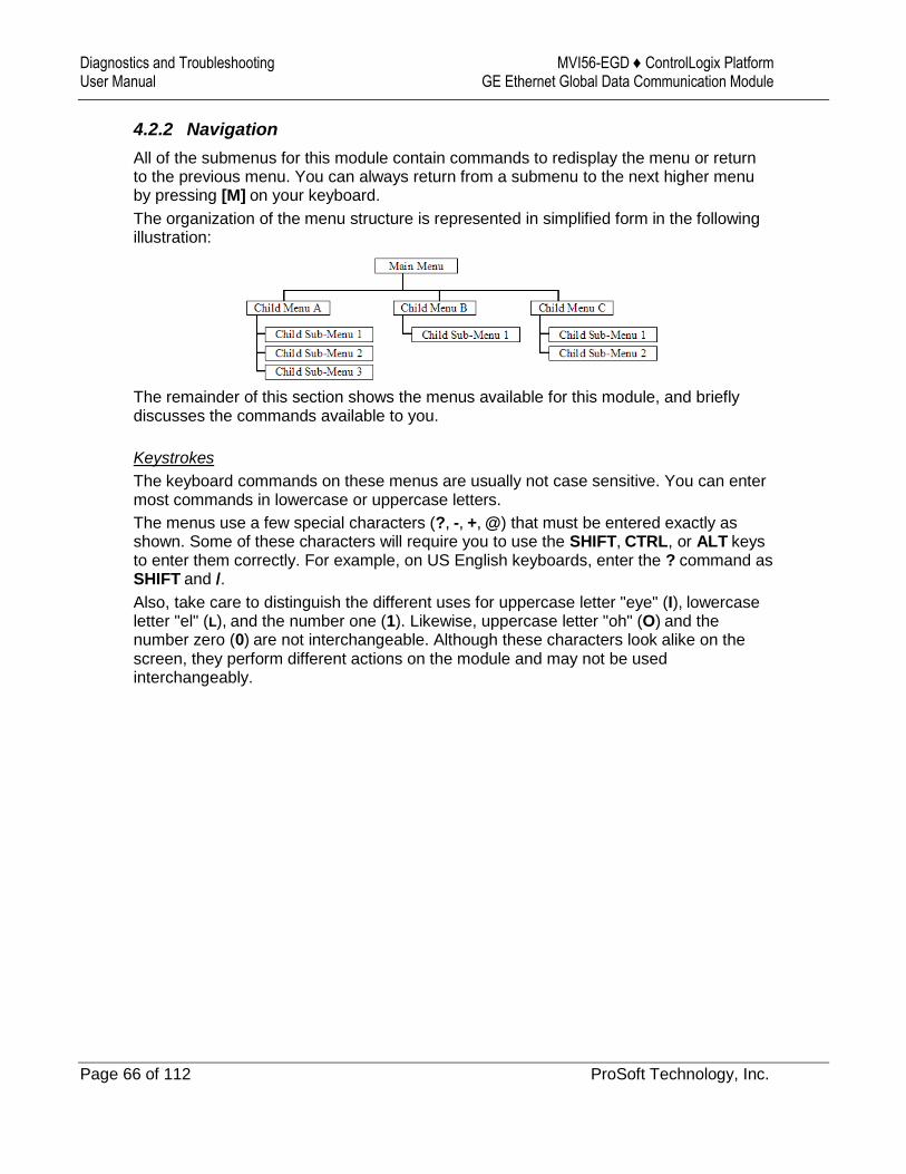
Diagnostics and Troubleshooting MVI56-EGD ♦ ControlLogix Platform User Manual GE Ethernet Global Data Communication Module
Page 66 of 112 ProSoft Technology, Inc.
4.2.2 Navigation
All of the submenus for this module contain commands to redisplay the menu or return to the previous menu. You can always return from a submenu to the next higher menu by pressing [M] on your keyboard.
The organization of the menu structure is represented in simplified form in the following illustration:
The remainder of this section shows the menus available for this module, and briefly discusses the commands available to you.
Keystrokes
The keyboard commands on these menus are usually not case sensitive. You can enter most commands in lowercase or uppercase letters.
The menus use a few special characters (?, -, +, @) that must be entered exactly as shown. Some of these characters will require you to use the SHIFT, CTRL, or ALT keys to enter them correctly. For example, on US English keyboards, enter the ? command as SHIFT and /.
Also, take care to distinguish the different uses for uppercase letter "eye" (I), lowercase letter "el" (L), and the number one (1). Likewise, uppercase letter "oh" (O) and the number zero (0) are not interchangeable. Although these characters look alike on the screen, they perform different actions on the module and may not be used interchangeably.
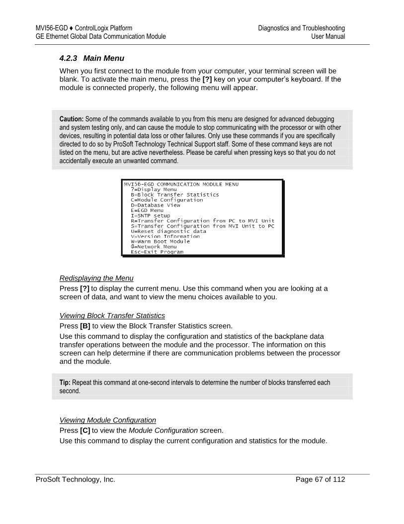
MVI56-EGD ♦ ControlLogix Platform Diagnostics and Troubleshooting GE Ethernet Global Data Communication Module User Manual
ProSoft Technology, Inc. Page 67 of 112
4.2.3 Main Menu
When you first connect to the module from your computer, your terminal screen will be blank. To activate the main menu, press the [?] key on your computer’s keyboard. If the module is connected properly, the following menu will appear.
Caution: Some of the commands available to you from this menu are designed for advanced debugging and system testing only, and can cause the module to stop communicating with the processor or with other devices, resulting in potential data loss or other failures. Only use these commands if you are specifically directed to do so by ProSoft Technology Technical Support staff. Some of these command keys are not listed on the menu, but are active nevertheless. Please be careful when pressing keys so that you do not accidentally execute an unwanted command.
Redisplaying the Menu
Press [?] to display the current menu. Use this command when you are looking at a screen of data, and want to view the menu choices available to you.
Viewing Block Transfer Statistics
Press [B] to view the Block Transfer Statistics screen.
Use this command to display the configuration and statistics of the backplane data transfer operations between the module and the processor. The information on this screen can help determine if there are communication problems between the processor and the module.
Tip: Repeat this command at one-second intervals to determine the number of blocks transferred each second.
Viewing Module Configuration
Press [C] to view the Module Configuration screen.
Use this command to display the current configuration and statistics for the module.
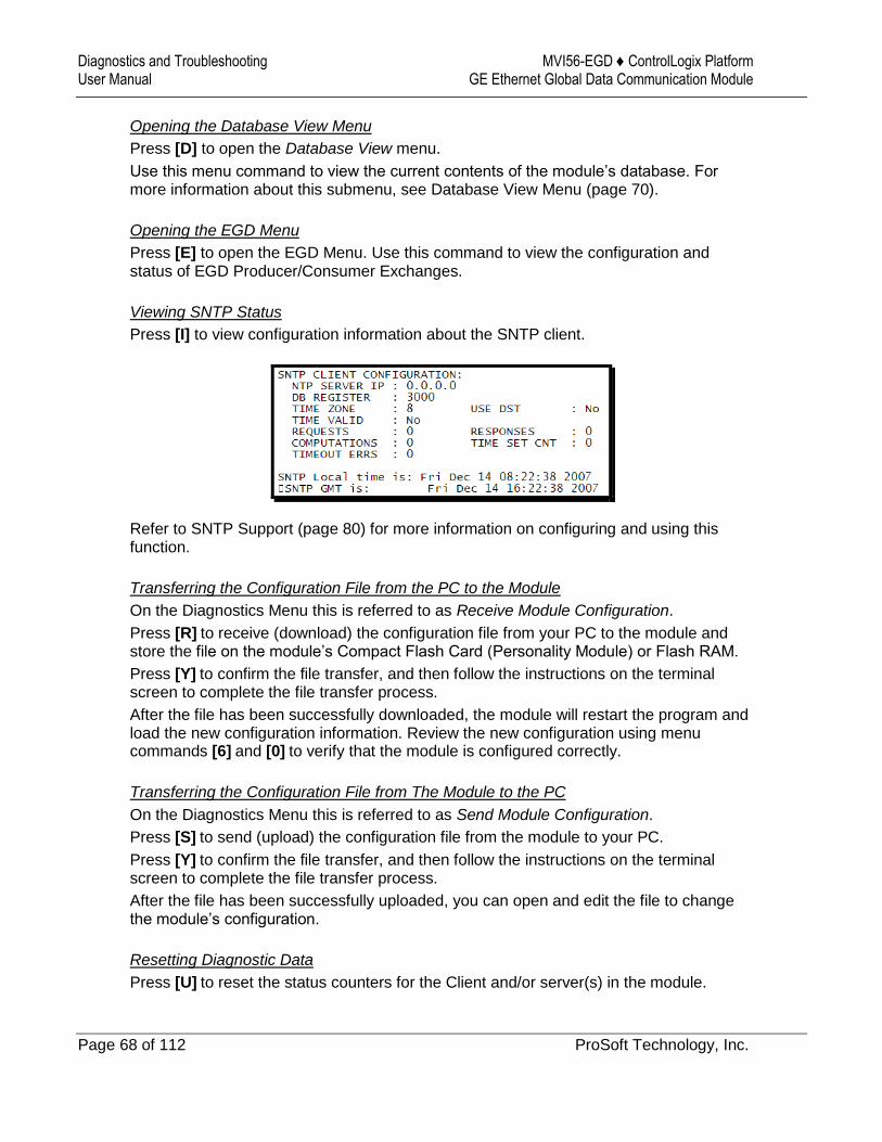
Diagnostics and Troubleshooting MVI56-EGD ♦ ControlLogix Platform User Manual GE Ethernet Global Data Communication Module
Page 68 of 112 ProSoft Technology, Inc.
Opening the Database View Menu
Press [D] to open the Database View menu.
Use this menu command to view the current contents of the module’s database. For more information about this submenu, see Database View Menu (page 70).
Opening the EGD Menu
Press [E] to open the EGD Menu. Use this command to view the configuration and status of EGD Producer/Consumer Exchanges.
Viewing SNTP Status
Press [I] to view configuration information about the SNTP client.
Refer to SNTP Support (page 80) for more information on configuring and using this function.
Transferring the Configuration File from the PC to the Module
On the Diagnostics Menu this is referred to as Receive Module Configuration.
Press [R] to receive (download) the configuration file from your PC to the module and store the file on the module’s Compact Flash Card (Personality Module) or Flash RAM.
Press [Y] to confirm the file transfer, and then follow the instructions on the terminal screen to complete the file transfer process.
After the file has been successfully downloaded, the module will restart the program and load the new configuration information. Review the new configuration using menu commands [6] and [0] to verify that the module is configured correctly.
Transferring the Configuration File from The Module to the PC
On the Diagnostics Menu this is referred to as Send Module Configuration.
Press [S] to send (upload) the configuration file from the module to your PC.
Press [Y] to confirm the file transfer, and then follow the instructions on the terminal screen to complete the file transfer process.
After the file has been successfully uploaded, you can open and edit the file to change the module’s configuration.
Resetting Diagnostic Data
Press [U] to reset the status counters for the Client and/or server(s) in the module.

MVI56-EGD ♦ ControlLogix Platform Diagnostics and Troubleshooting GE Ethernet Global Data Communication Module User Manual
ProSoft Technology, Inc. Page 69 of 112
Viewing Version Information
Press [V] to view version information for the module.
Use this command to view the current version of the software for the module, as well as other important values. You may be asked to provide this information when calling for technical support on the product.
Values at the bottom of the display are important in determining module operation. The Program Scan Counter value is incremented each time a module’s program cycle is complete.
Tip: Repeat this command at one-second intervals to determine the frequency of program execution.
Warm Booting the Module
Press [W] from the Main menu to warm boot (restart) the module.
This command will cause the program to exit and reload, refreshing configuration parameters that must be set on program initialization. Only use this command if you must force the module to reboot.
Opening the Network Menu
Press [@] to open the Network menu.
The Network menu allows you to send, receive and view the WATTCP.CFG file that contains the IP, gateway and other network specification information. For more information about this submenu, see Network Menu (page 72).
Exiting the Program
Press [ESC] to restart the module and force all drivers to be loaded. The module will use the configuration stored in the module's flash memory to configure the module.
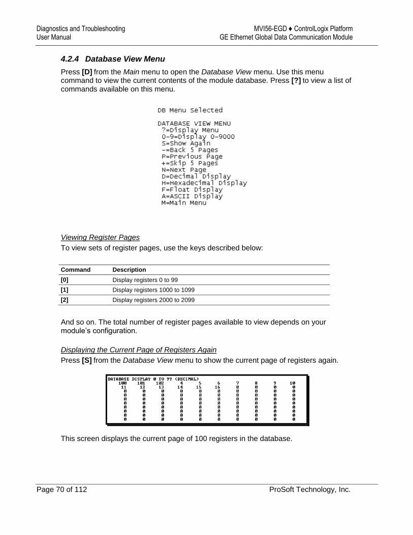
Diagnostics and Troubleshooting MVI56-EGD ♦ ControlLogix Platform User Manual GE Ethernet Global Data Communication Module
Page 70 of 112 ProSoft Technology, Inc.
4.2.4 Database View Menu
Press [D] from the Main menu to open the Database View menu. Use this menu command to view the current contents of the module database. Press [?] to view a list of commands available on this menu.
Viewing Register Pages
To view sets of register pages, use the keys described below:
Command Description
[0] Display registers 0 to 99
[1] Display registers 1000 to 1099
[2] Display registers 2000 to 2099
And so on. The total number of register pages available to view depends on your module’s configuration.
Displaying the Current Page of Registers Again
Press [S] from the Database View menu to show the current page of registers again.
This screen displays the current page of 100 registers in the database.

MVI56-EGD ♦ ControlLogix Platform Diagnostics and Troubleshooting GE Ethernet Global Data Communication Module User Manual
ProSoft Technology, Inc. Page 71 of 112
Moving Back Through 5 Pages of Registers
Press [-] from the Database View menu to skip five pages back in the database to see the 100 registers of data starting 500 registers before the currently displayed page.
Moving Forward (Skipping) Through 5 Pages of Registers
Press [+] from the Database View menu to skip five pages ahead in the database to see the 100 registers of data starting 500 registers after the currently displayed page.
Viewing the Previous Page of Registers
Press [P] from the Database View menu to display the previous page of data.
Viewing the Next Page of Registers
Press [N] from the Database View menu to display the next page of data.
Viewing Data in Decimal Format
Press [D] from the Database View menu to display the data on the current page in decimal format.
Viewing Data in Hexadecimal Format
Press [H] from the Database View menu to display the data on the current page in hexadecimal format.
Viewing Data in Floating-Point Format
Press [F] from the Database View menu to display the data on the current page in floating-point format. The program assumes that the values are aligned on even register boundaries. If floating-point values are not aligned as such, they are not displayed properly.
Viewing Data in ASCII (Text) Format
Press [A] from the Database View menu to display the data on the current page in ASCII format. This is useful for regions of the database that contain ASCII data.
Returning to the Main Menu
Press [M] to return to the Main menu.
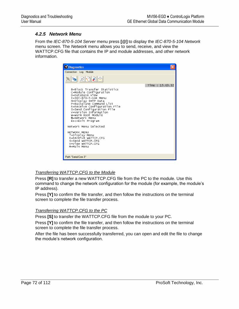
Diagnostics and Troubleshooting MVI56-EGD ♦ ControlLogix Platform User Manual GE Ethernet Global Data Communication Module
Page 72 of 112 ProSoft Technology, Inc.
4.2.5 Network Menu
From the IEC-870-5-104 Server menu press [@] to display the IEC-870-5-104 Network menu screen. The Network menu allows you to send, receive, and view the WATTCP.CFG file that contains the IP and module addresses, and other network information.
Transferring WATTCP.CFG to the Module
Press [R] to transfer a new WATTCP.CFG file from the PC to the module. Use this command to change the network configuration for the module (for example, the module’s IP address).
Press [Y] to confirm the file transfer, and then follow the instructions on the terminal screen to complete the file transfer process.
Transferring WATTCP.CFG to the PC
Press [S] to transfer the WATTCP.CFG file from the module to your PC.
Press [Y] to confirm the file transfer, and then follow the instructions on the terminal screen to complete the file transfer process.
After the file has been successfully transferred, you can open and edit the file to change the module’s network configuration.
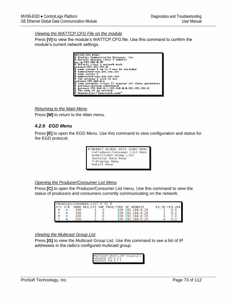
MVI56-EGD ♦ ControlLogix Platform Diagnostics and Troubleshooting GE Ethernet Global Data Communication Module User Manual
ProSoft Technology, Inc. Page 73 of 112
Viewing the WATTCP.CFG File on the module
Press [V] to view the module’s WATTCP.CFG file. Use this command to confirm the module’s current network settings.
Returning to the Main Menu
Press [M] to return to the Main menu.
4.2.6 EGD Menu
Press [E] to open the EGD Menu. Use this command to view configuration and status for the EGD protocol.
Opening the Producer/Consumer List Menu
Press [C] to open the Producer/Consumer List menu. Use this command to view the status of producers and consumers currently communicating on the network.
Viewing the Multicast Group List
Press [G] to view the Multicast Group List. Use this command to see a list of IP addresses in the radio’s configured multicast group.
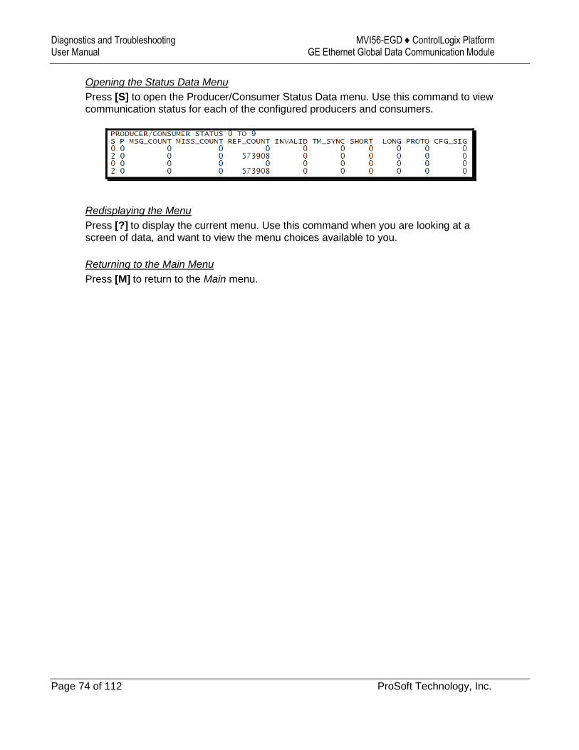
Diagnostics and Troubleshooting MVI56-EGD ♦ ControlLogix Platform User Manual GE Ethernet Global Data Communication Module
Page 74 of 112 ProSoft Technology, Inc.
Opening the Status Data Menu
Press [S] to open the Producer/Consumer Status Data menu. Use this command to view communication status for each of the configured producers and consumers.
Redisplaying the Menu
Press [?] to display the current menu. Use this command when you are looking at a screen of data, and want to view the menu choices available to you.
Returning to the Main Menu
Press [M] to return to the Main menu.
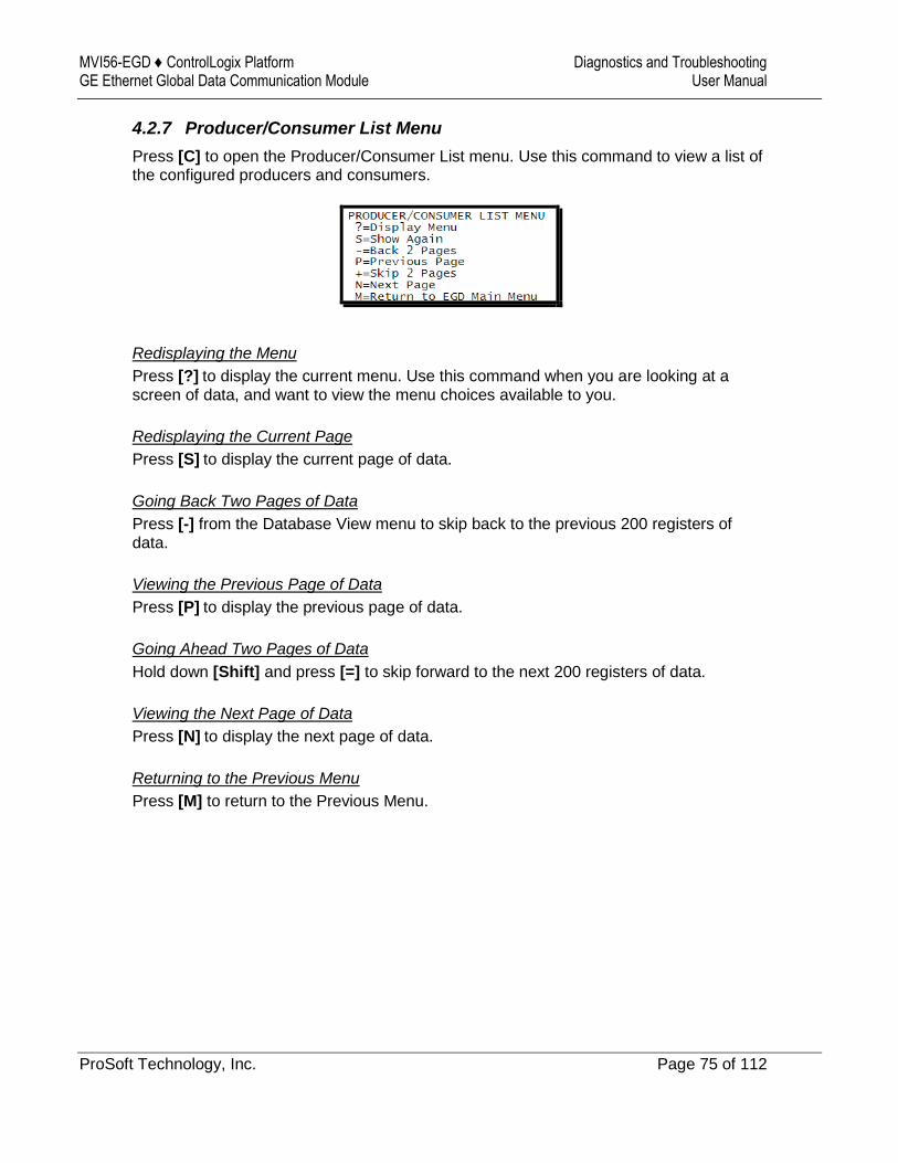
MVI56-EGD ♦ ControlLogix Platform Diagnostics and Troubleshooting GE Ethernet Global Data Communication Module User Manual
ProSoft Technology, Inc. Page 75 of 112
4.2.7 Producer/Consumer List Menu
Press [C] to open the Producer/Consumer List menu. Use this command to view a list of the configured producers and consumers.
Redisplaying the Menu
Press [?] to display the current menu. Use this command when you are looking at a screen of data, and want to view the menu choices available to you.
Redisplaying the Current Page
Press [S] to display the current page of data.
Going Back Two Pages of Data
Press [-] from the Database View menu to skip back to the previous 200 registers of data.
Viewing the Previous Page of Data
Press [P] to display the previous page of data.
Going Ahead Two Pages of Data
Hold down [Shift] and press [=] to skip forward to the next 200 registers of data.
Viewing the Next Page of Data
Press [N] to display the next page of data.
Returning to the Previous Menu
Press [M] to return to the Previous Menu.
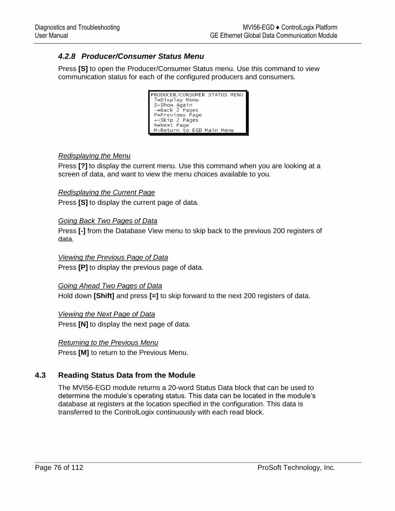
Diagnostics and Troubleshooting MVI56-EGD ♦ ControlLogix Platform User Manual GE Ethernet Global Data Communication Module
Page 76 of 112 ProSoft Technology, Inc.
4.2.8 Producer/Consumer Status Menu
Press [S] to open the Producer/Consumer Status menu. Use this command to view communication status for each of the configured producers and consumers.
Redisplaying the Menu
Press [?] to display the current menu. Use this command when you are looking at a screen of data, and want to view the menu choices available to you.
Redisplaying the Current Page
Press [S] to display the current page of data.
Going Back Two Pages of Data
Press [-] from the Database View menu to skip back to the previous 200 registers of data.
Viewing the Previous Page of Data
Press [P] to display the previous page of data.
Going Ahead Two Pages of Data
Hold down [Shift] and press [=] to skip forward to the next 200 registers of data.
Viewing the Next Page of Data
Press [N] to display the next page of data.
Returning to the Previous Menu
Press [M] to return to the Previous Menu.
4.3 Reading Status Data from the Module
The MVI56-EGD module returns a 20-word Status Data block that can be used to determine the module’s operating status. This data can be located in the module’s database at registers at the location specified in the configuration. This data is transferred to the ControlLogix continuously with each read block.
MVI56-EGD ♦ ControlLogix Platform Reference GE Ethernet Global Data Communication Module User Manual
ProSoft Technology, Inc. Page 77 of 112
5 Reference
In This Chapter
Product Specifications ........................................................................... 77
Functional Overview .............................................................................. 81
Exchange Configuration Form ............................................................. 108
5.1 Product Specifications
The Ethernet Global Data (EGD) module can be used to interface many different protocols with EGD devices. The EGD driver supports both the producer/consumer service port (18246) and the command service port (7937) using the UDP protocol over an IP network. The user defines the data to be produced and consumed in a configuration file downloaded to the module.
GE Fanuc Automation and GE Drive Systems developed an Ethernet Global Data, or EGD, exchange for PLC and computer data in 1998. Ethernet Global Data (EGD) offers versatility where a mix of control devices requires cooperation with each other. This involves sharing of information across the applications regardless of device or network type, often at high speed, and with high reliability. High reliability means fewer communication failures and having the ability to detect failures upon occurrence. Particular emphasis is delivered for applications requiring periodic or frequent updates and time synchronization of devices. The protocol supports Unicast, Broadcast and Multicast group messaging. Efficiency is based on the fact that each device on the network can produce these types of messages and each device determines which of these messages to consume.
5.1.1 General Specifications
Single Slot - 1756 backplane compatible
The module is recognized as an Input/Output module and has access to processor memory for data transfer between processor and module.
Ladder Logic is used for data transfer between module and processor. Sample ladder file included.
Configuration data obtained from configuration text file downloaded to module. Sample configuration file included
Local or remote rack
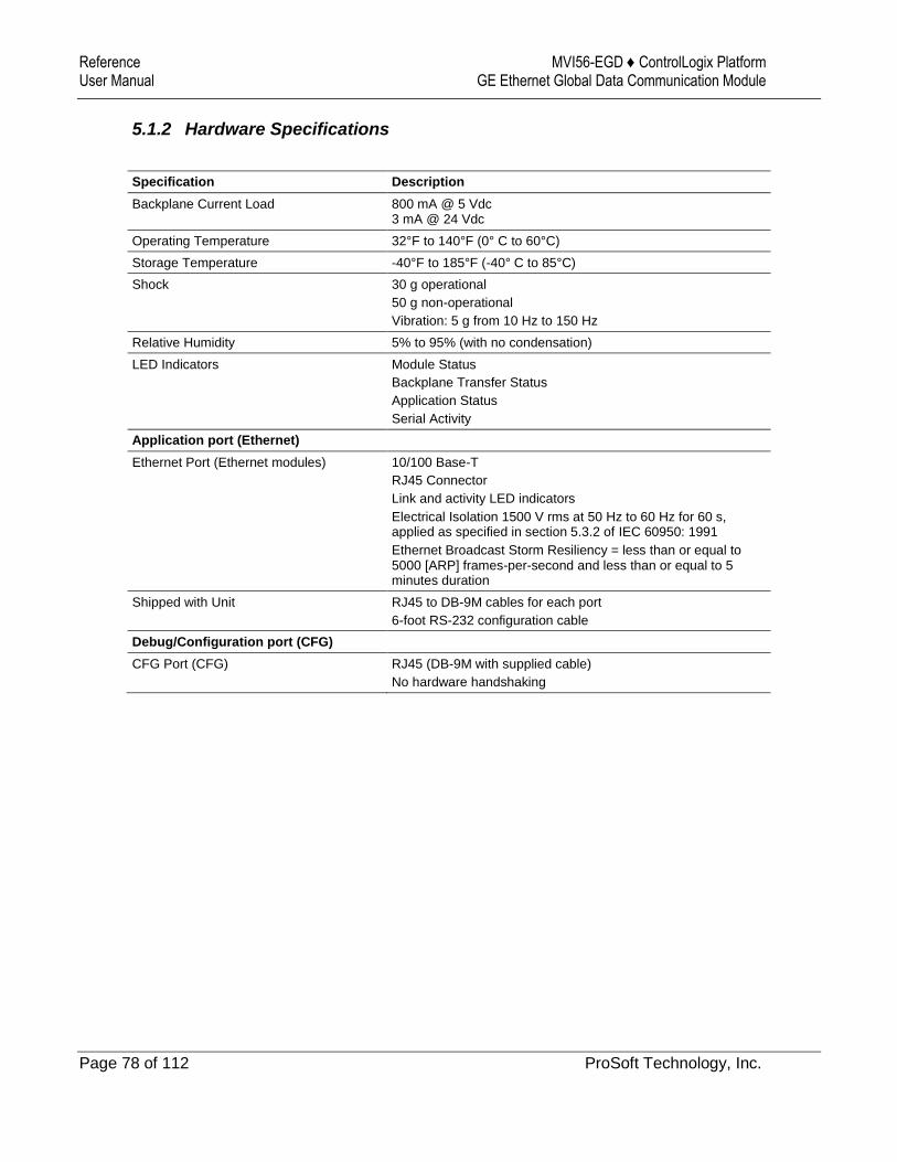
Reference MVI56-EGD ♦ ControlLogix Platform User Manual GE Ethernet Global Data Communication Module
Page 78 of 112 ProSoft Technology, Inc.
5.1.2 Hardware Specifications
Specification Description
Backplane Current Load 800 mA @ 5 Vdc 3 mA @ 24 Vdc
Operating Temperature 32°F to 140°F (0° C to 60°C)
Storage Temperature -40°F to 185°F (-40° C to 85°C)
Shock 30 g operational
50 g non-operational
Vibration: 5 g from 10 Hz to 150 Hz
Relative Humidity 5% to 95% (with no condensation)
LED Indicators Module Status
Backplane Transfer Status
Application Status
Serial Activity
Application port (Ethernet)
Ethernet Port (Ethernet modules) 10/100 Base-T
RJ45 Connector
Link and activity LED indicators
Electrical Isolation 1500 V rms at 50 Hz to 60 Hz for 60 s, applied as specified in section 5.3.2 of IEC 60950: 1991
Ethernet Broadcast Storm Resiliency = less than or equal to 5000 [ARP] frames-per-second and less than or equal to 5 minutes duration
Shipped with Unit RJ45 to DB-9M cables for each port
6-foot RS-232 configuration cable
Debug/Configuration port (CFG)
CFG Port (CFG) RJ45 (DB-9M with supplied cable)
No hardware handshaking
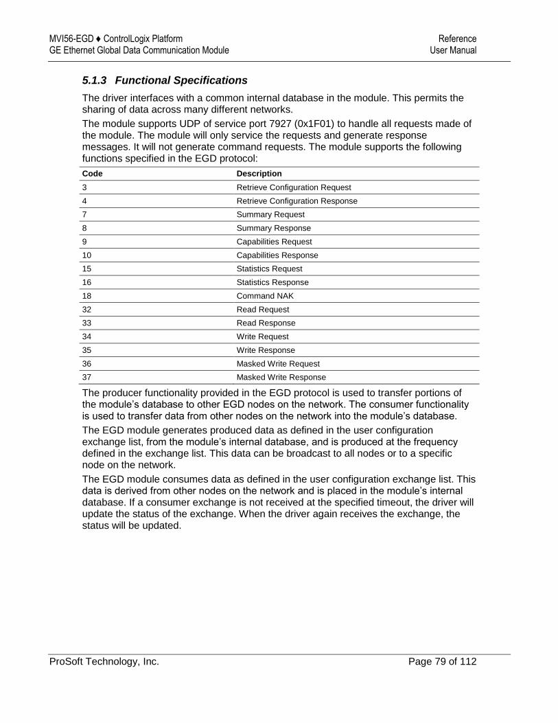
MVI56-EGD ♦ ControlLogix Platform Reference GE Ethernet Global Data Communication Module User Manual
ProSoft Technology, Inc. Page 79 of 112
5.1.3 Functional Specifications
The driver interfaces with a common internal database in the module. This permits the sharing of data across many different networks.
The module supports UDP of service port 7927 (0x1F01) to handle all requests made of the module. The module will only service the requests and generate response messages. It will not generate command requests. The module supports the following functions specified in the EGD protocol:
Code Description
3 Retrieve Configuration Request
4 Retrieve Configuration Response
7 Summary Request
8 Summary Response
9 Capabilities Request
10 Capabilities Response
15 Statistics Request
16 Statistics Response
18 Command NAK
32 Read Request
33 Read Response
34 Write Request
35 Write Response
36 Masked Write Request
37 Masked Write Response
The producer functionality provided in the EGD protocol is used to transfer portions of the module’s database to other EGD nodes on the network. The consumer functionality is used to transfer data from other nodes on the network into the module’s database.
The EGD module generates produced data as defined in the user configuration exchange list, from the module’s internal database, and is produced at the frequency defined in the exchange list. This data can be broadcast to all nodes or to a specific node on the network.
The EGD module consumes data as defined in the user configuration exchange list. This data is derived from other nodes on the network and is placed in the module’s internal database. If a consumer exchange is not received at the specified timeout, the driver will update the status of the exchange. When the driver again receives the exchange, the status will be updated.

Reference MVI56-EGD ♦ ControlLogix Platform User Manual GE Ethernet Global Data Communication Module
Page 80 of 112 ProSoft Technology, Inc.
5.1.4 SNTP Support
SNTP is used for time synchronization of produced and consumed commands. When an exchange occurs the driver compares time stamps from the previous exchange. When the new exchange time is less than the previous exchange, the exchange is ignored. This can occur when the Ethernet packets are routed and delayed. Time synchronization provides for data integrity. The following table lists the parameters defined in this section:
The SNTP driver will compute a new clock value every 5 minutes using the average value of 10 samples each collected over an approximate 6-second period. This new value will be used to adjust the clock maintained by the SNTP driver and used by the application. If a valid database register is specified, the driver will place the time value into the module’s database. The first two registers will contain the number of seconds and the next two registers will contain the number of microseconds since January 1, 1970.
A list of some of the common NTP servers can be obtained at http://www.ntp.org/, http://www.eecis.udel.edu/~mills/ntp/servers.html, along with the appropriate IP address. Other server lists can be found on the Internet by searching on "NTP Servers" with your browser.

MVI56-EGD ♦ ControlLogix Platform Reference GE Ethernet Global Data Communication Module User Manual
ProSoft Technology, Inc. Page 81 of 112
5.2 Functional Overview
GE Fanuc Automation and GE Drive Systems developed an Ethernet Global Data, or EGD, exchange for PLC and computer data in 1998. GE Ethernet Global Data (EGD) offers versatility where a mix of control devices requires cooperation with each other. This involves sharing of information across the applications regardless of device or network type, often at high speed, and with high reliability. Bandwidth utilization is optimized by using efficient communication methods. High reliability means fewer communication failures and having the ability to detect failures upon occurrence. Particular emphasis is delivered for applications requiring periodic or frequent updates and time synchronization of devices. The protocol supports Unicast, Broadcast and Multicast group messaging. Efficiency is based on the fact each device on the network can produce these types of messages and each device determines which of these messages to consume.
5.2.1 Ethernet Global Data Compatible Devices
Devices that support the Ethernet Global Data protocol:
GE Series 90-70 PLC CPU (CMM742 with EGD support)
GE Series 90-30 PLC CPU 364 (with EGD support)
VersaMax CPU E05
Several drives and turbines
Ethernet Global Data Service for NT
CIMPLICITY HMI software
Several HMI products
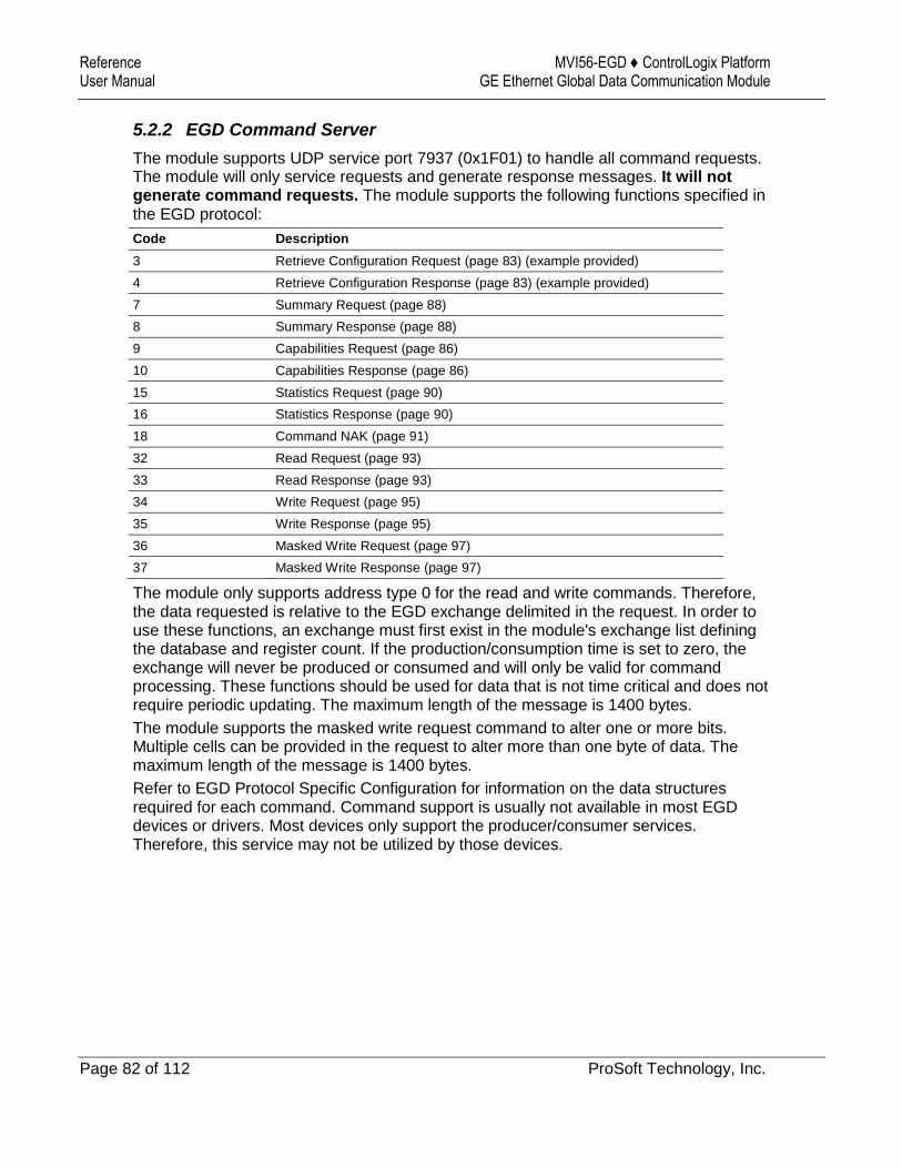
Reference MVI56-EGD ♦ ControlLogix Platform User Manual GE Ethernet Global Data Communication Module
Page 82 of 112 ProSoft Technology, Inc.
5.2.2 EGD Command Server
The module supports UDP service port 7937 (0x1F01) to handle all command requests. The module will only service requests and generate response messages. It will not generate command requests. The module supports the following functions specified in the EGD protocol:
Code Description
3 Retrieve Configuration Request (page 83) (example provided)
4 Retrieve Configuration Response (page 83) (example provided)
7 Summary Request (page 88)
8 Summary Response (page 88)
9 Capabilities Request (page 86)
10 Capabilities Response (page 86)
15 Statistics Request (page 90)
16 Statistics Response (page 90)
18 Command NAK (page 91)
32 Read Request (page 93)
33 Read Response (page 93)
34 Write Request (page 95)
35 Write Response (page 95)
36 Masked Write Request (page 97)
37 Masked Write Response (page 97)
The module only supports address type 0 for the read and write commands. Therefore, the data requested is relative to the EGD exchange delimited in the request. In order to use these functions, an exchange must first exist in the module's exchange list defining the database and register count. If the production/consumption time is set to zero, the exchange will never be produced or consumed and will only be valid for command processing. These functions should be used for data that is not time critical and does not require periodic updating. The maximum length of the message is 1400 bytes.
The module supports the masked write request command to alter one or more bits. Multiple cells can be provided in the request to alter more than one byte of data. The maximum length of the message is 1400 bytes.
Refer to EGD Protocol Specific Configuration for information on the data structures required for each command. Command support is usually not available in most EGD devices or drivers. Most devices only support the producer/consumer services. Therefore, this service may not be utilized by those devices.
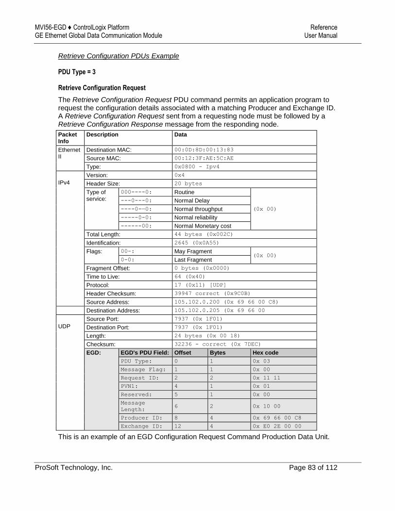
MVI56-EGD ♦ ControlLogix Platform Reference GE Ethernet Global Data Communication Module User Manual
ProSoft Technology, Inc. Page 83 of 112
Retrieve Configuration PDUs Example
PDU Type = 3
Retrieve Configuration Request
The Retrieve Configuration Request PDU command permits an application program to request the configuration details associated with a matching Producer and Exchange ID. A Retrieve Configuration Request sent from a requesting node must be followed by a Retrieve Configuration Response message from the responding node.
Packet Info
Description Data
Ethernet II
Destination MAC: 00:0D:8D:00:13:83
Source MAC: 00:12:3F:AE:5C:AE
Type: 0x0800 - Ipv4
IPv4
Version: 0x4
Header Size: 20 bytes
Type of service:
000----0: Routine
(0x 00)
---0---0: Normal Delay
----0-—0: Normal throughput
-----0-0: Normal reliability
------00: Normal Monetary cost
Total Length: 44 bytes (0x002C)
Identification: 2645 (0x0A55)
Flags: 00-: May Fragment (0x 00)
0-0: Last Fragment
Fragment Offset: 0 bytes (0x0000)
Time to Live: 64 (0x40)
Protocol: 17 (0x11) [UDP]
Header Checksum: 39947 correct (0x9C0B)
Source Address: 105.102.0.200 (0x 69 66 00 C8)
Destination Address: 105.102.0.205 (0x 69 66 00
UDP
Source Port: 7937 (0x 1F01)
Destination Port: 7937 (0x 1F01)
Length: 24 bytes (0x 00 18)
Checksum: 32236 - correct (0x 7DEC)
EGD: EGD's PDU Field: Offset Bytes Hex code
PDU Type: 0 1 0x 03
Message Flag: 1 1 0x 00
Request ID: 2 2 0x 11 11
PVN1: 4 1 0x 01
Reserved: 5 1 0x 00
Message
Length: 6 2 0x 10 00
Producer ID: 8 4 0x 69 66 00 C8
Exchange ID: 12 4 0x E0 2E 00 00
This is an example of an EGD Configuration Request Command Production Data Unit.
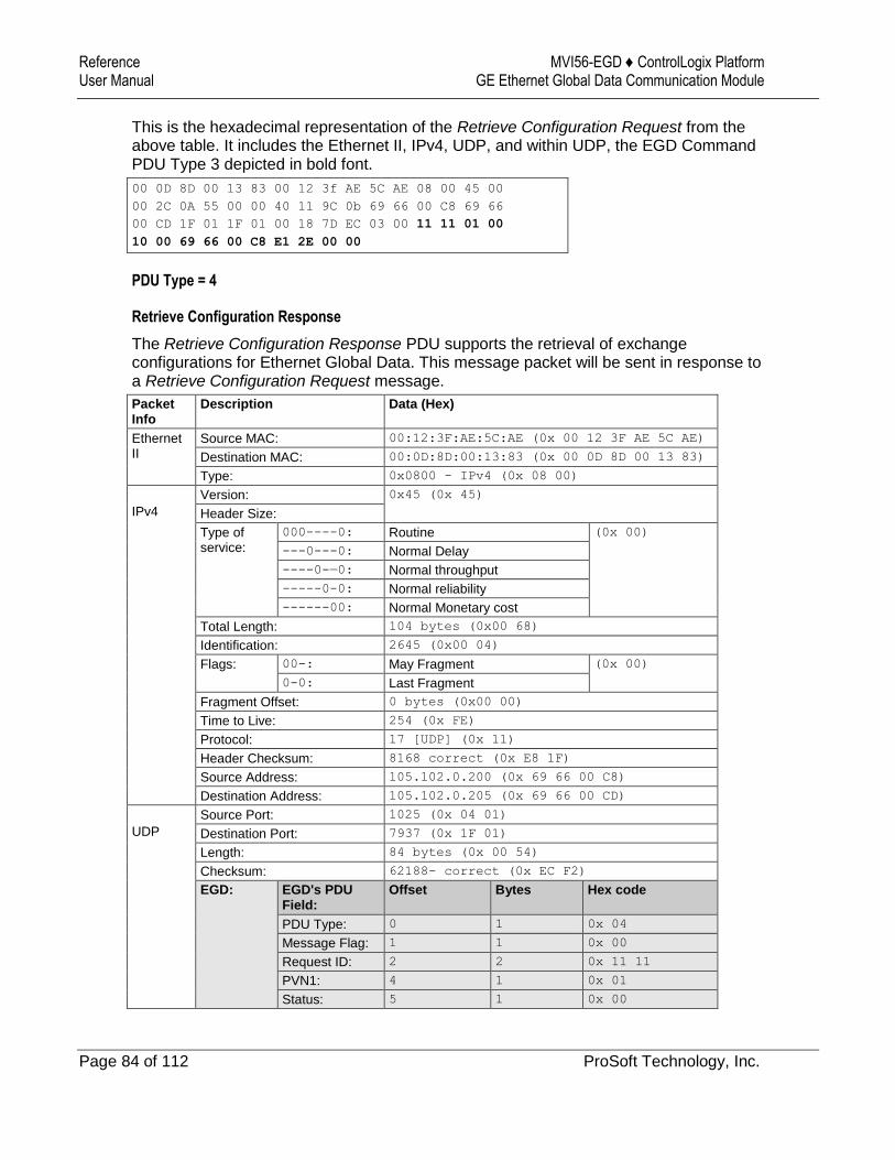
Reference MVI56-EGD ♦ ControlLogix Platform User Manual GE Ethernet Global Data Communication Module
Page 84 of 112 ProSoft Technology, Inc.
This is the hexadecimal representation of the Retrieve Configuration Request from the above table. It includes the Ethernet II, IPv4, UDP, and within UDP, the EGD Command PDU Type 3 depicted in bold font.
00 0D 8D 00 13 83 00 12 3f AE 5C AE 08 00 45 00
00 2C 0A 55 00 00 40 11 9C 0b 69 66 00 C8 69 66
00 CD 1F 01 1F 01 00 18 7D EC 03 00 11 11 01 00
10 00 69 66 00 C8 E1 2E 00 00
PDU Type = 4
Retrieve Configuration Response
The Retrieve Configuration Response PDU supports the retrieval of exchange configurations for Ethernet Global Data. This message packet will be sent in response to a Retrieve Configuration Request message.
Packet Info
Description Data (Hex)
Ethernet II
Source MAC: 00:12:3F:AE:5C:AE (0x 00 12 3F AE 5C AE)
Destination MAC: 00:0D:8D:00:13:83 (0x 00 0D 8D 00 13 83)
Type: 0x0800 - IPv4 (0x 08 00)
IPv4
Version: 0x45 (0x 45)
Header Size:
Type of service:
000----0: Routine (0x 00)
---0---0: Normal Delay
----0-—0: Normal throughput
-----0-0: Normal reliability
------00: Normal Monetary cost
Total Length: 104 bytes (0x00 68)
Identification: 2645 (0x00 04)
Flags: 00-: May Fragment (0x 00)
0-0: Last Fragment
Fragment Offset: 0 bytes (0x00 00)
Time to Live: 254 (0x FE)
Protocol: 17 [UDP] (0x 11)
Header Checksum: 8168 correct (0x E8 1F)
Source Address: 105.102.0.200 (0x 69 66 00 C8)
Destination Address: 105.102.0.205 (0x 69 66 00 CD)
UDP
Source Port: 1025 (0x 04 01)
Destination Port: 7937 (0x 1F 01)
Length: 84 bytes (0x 00 54)
Checksum: 62188- correct (0x EC F2)
EGD: EGD's PDU Field:
Offset Bytes Hex code
PDU Type: 0 1 0x 04
Message Flag: 1 1 0x 00
Request ID: 2 2 0x 11 11
PVN1: 4 1 0x 01
Status: 5 1 0x 00
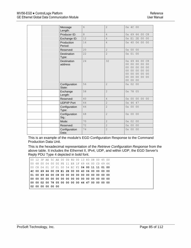
MVI56-EGD ♦ ControlLogix Platform Reference GE Ethernet Global Data Communication Module User Manual
ProSoft Technology, Inc. Page 85 of 112
Message Length:
6 2 0x 4C 00
Producer ID: 8 4 0x 69 66 00 C8
Exchange ID: 12 4 0x E1 2E 00 00
Production Period:
16 4 0x 40 06 00 00
Reserved: 20 2 0x 00 00
Destination Type:
22 2 0x 01 00
Destination address
24 32 0x 69 66 00 C8
00 00 00 00 00
00 00 00 00 00
00 00 00 00 00
00 00 00 00 00
00 00 00 00 00
00 00 00
Configuration State:
56 2 0x 02 00
Exchange Length:
58 2 0x 78 05
Reserved: 60 4 0x 00 00 00 00
UDP/IP Port 64 2 0x 46 47
Configuration Type:
66 2 0x 00 00
Configuration Sig.:
68 2 0x 00 00
Mode: 70 2 0x 02 00
Reserved: 72 2 0x 00 00
Configuration Data:
74 2 0x 00 00
This is an example of the module's EGD Configuration Response to the Command Production Data Unit.
This is the hexadecimal representation of the Retrieve Configuration Response from the above table. It includes the Ethernet II, IPv4, UDP, and within UDP, the EGD Server's Reply PDU Type 4 depicted in bold font.
00 12 3F AE 5C AE 00 0D 8D 00 13 83 08 00 45 00
00 68 00 04 00 00 FE 11 E8 1F 69 66 00 CD 69 66
00 C8 04 01 1F 01 00 54 EC F2 04 00 11 11 01 00
4C 00 69 66 00 C8 E1 2E 00 00 40 06 00 00 00 00
01 00 69 66 00 C8 00 00 00 00 00 00 00 00 00 00
00 00 00 00 00 00 00 00 00 00 00 00 00 00 00 00
00 00 02 00 78 05 00 00 00 00 46 47 00 00 00 00
02 00 00 00 00 00
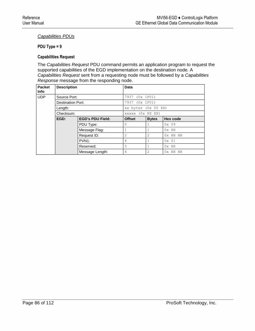
Reference MVI56-EGD ♦ ControlLogix Platform User Manual GE Ethernet Global Data Communication Module
Page 86 of 112 ProSoft Technology, Inc.
Capabilities PDUs
PDU Type = 9
Capabilities Request
The Capabilities Request PDU command permits an application program to request the supported capabilities of the EGD implementation on the destination node. A Capabilities Request sent from a requesting node must be followed by a Capabilities Response message from the responding node.
Packet Info
Description Data
UDP Source Port: 7937 (0x 1F01)
Destination Port: 7937 (0x 1F01)
Length: xx bytes (0x 00 XX)
Checksum: xxxxx (0x XX XX)
EGD: EGD's PDU Field: Offset Bytes Hex code
PDU Type: 0 1 0x 09
Message Flag: 1 1 0x HH
Request ID: 2 2 0x HH HH
PVN1: 4 1 0x 01
Reserved: 5 1 0x HH
Message Length: 6 2 0x HH HH
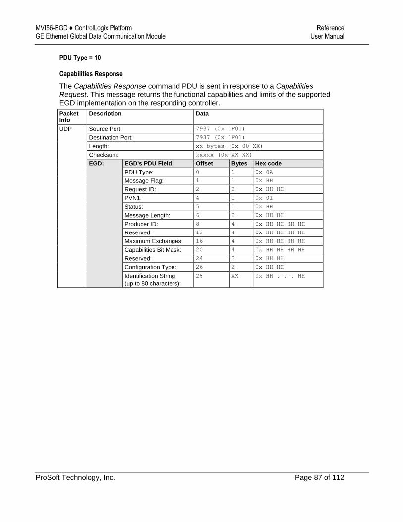
MVI56-EGD ♦ ControlLogix Platform Reference GE Ethernet Global Data Communication Module User Manual
ProSoft Technology, Inc. Page 87 of 112
PDU Type = 10
Capabilities Response
The Capabilities Response command PDU is sent in response to a Capabilities Request. This message returns the functional capabilities and limits of the supported EGD implementation on the responding controller.
Packet Info
Description Data
UDP Source Port: 7937 (0x 1F01)
Destination Port: 7937 (0x 1F01)
Length: xx bytes (0x 00 XX)
Checksum: xxxxx (0x XX XX)
EGD: EGD's PDU Field: Offset Bytes Hex code
PDU Type: 0 1 0x 0A
Message Flag: 1 1 0x HH
Request ID: 2 2 0x HH HH
PVN1: 4 1 0x 01
Status: 5 1 0x HH
Message Length: 6 2 0x HH HH
Producer ID: 8 4 0x HH HH HH HH
Reserved: 12 4 0x HH HH HH HH
Maximum Exchanges: 16 4 0x HH HH HH HH
Capabilities Bit Mask: 20 4 0x HH HH HH HH
Reserved: 24 2 0x HH HH
Configuration Type: 26 2 0x HH HH
Identification String
(up to 80 characters):
28 XX 0x HH . . . HH
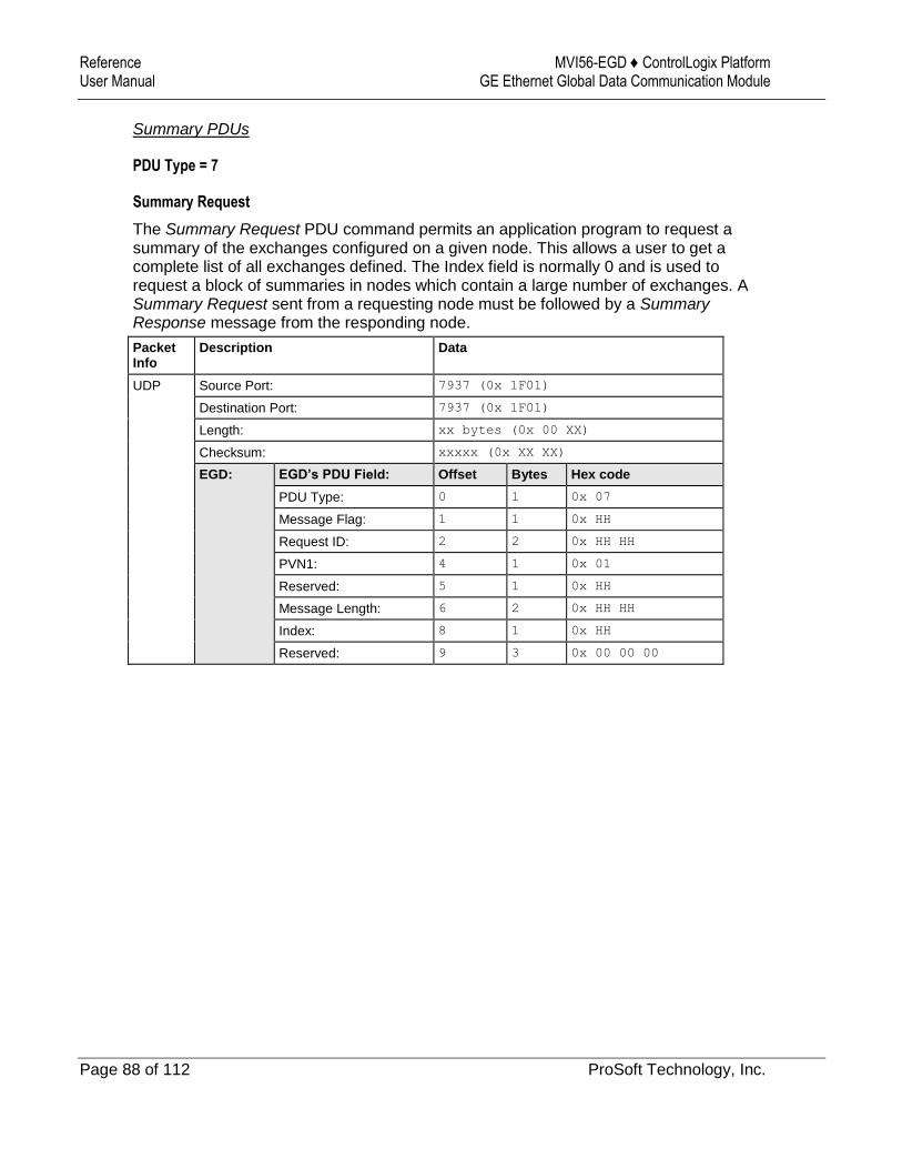
Reference MVI56-EGD ♦ ControlLogix Platform User Manual GE Ethernet Global Data Communication Module
Page 88 of 112 ProSoft Technology, Inc.
Summary PDUs
PDU Type = 7
Summary Request
The Summary Request PDU command permits an application program to request a summary of the exchanges configured on a given node. This allows a user to get a complete list of all exchanges defined. The Index field is normally 0 and is used to request a block of summaries in nodes which contain a large number of exchanges. A Summary Request sent from a requesting node must be followed by a Summary Response message from the responding node.
Packet Info
Description Data
UDP Source Port: 7937 (0x 1F01)
Destination Port: 7937 (0x 1F01)
Length: xx bytes (0x 00 XX)
Checksum: xxxxx (0x XX XX)
EGD: EGD’s PDU Field: Offset Bytes Hex code
PDU Type: 0 1 0x 07
Message Flag: 1 1 0x HH
Request ID: 2 2 0x HH HH
PVN1: 4 1 0x 01
Reserved: 5 1 0x HH
Message Length: 6 2 0x HH HH
Index: 8 1 0x HH
Reserved: 9 3 0x 00 00 00
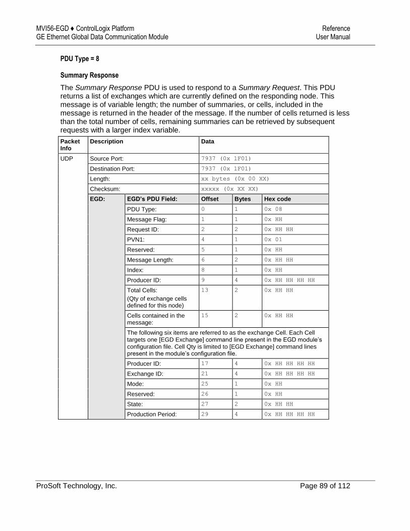
MVI56-EGD ♦ ControlLogix Platform Reference GE Ethernet Global Data Communication Module User Manual
ProSoft Technology, Inc. Page 89 of 112
PDU Type = 8
Summary Response
The Summary Response PDU is used to respond to a Summary Request. This PDU returns a list of exchanges which are currently defined on the responding node. This message is of variable length; the number of summaries, or cells, included in the message is returned in the header of the message. If the number of cells returned is less than the total number of cells, remaining summaries can be retrieved by subsequent requests with a larger index variable.
Packet Info
Description Data
UDP Source Port: 7937 (0x 1F01)
Destination Port: 7937 (0x 1F01)
Length: xx bytes (0x 00 XX)
Checksum: xxxxx (0x XX XX)
EGD: EGD’s PDU Field: Offset Bytes Hex code
PDU Type: 0 1 0x 08
Message Flag: 1 1 0x HH
Request ID: 2 2 0x HH HH
PVN1: 4 1 0x 01
Reserved: 5 1 0x HH
Message Length: 6 2 0x HH HH
Index: 8 1 0x HH
Producer ID: 9 4 0x HH HH HH HH
Total Cells:
(Qty of exchange cells defined for this node)
13 2 0x HH HH
Cells contained in the message:
15 2 0x HH HH
The following six items are referred to as the exchange Cell. Each Cell targets one [EGD Exchange] command line present in the EGD module’s configuration file. Cell Qty is limited to [EGD Exchange] command lines present in the module’s configuration file.
Producer ID: 17 4 0x HH HH HH HH
Exchange ID: 21 4 0x HH HH HH HH
Mode: 25 1 0x HH
Reserved: 26 1 0x HH
State: 27 2 0x HH HH
Production Period: 29 4 0x HH HH HH HH
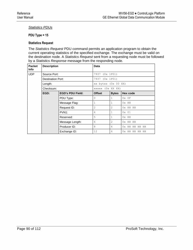
Reference MVI56-EGD ♦ ControlLogix Platform User Manual GE Ethernet Global Data Communication Module
Page 90 of 112 ProSoft Technology, Inc.
Statistics PDUs
PDU Type = 15
Statistics Request
The Statistics Request PDU command permits an application program to obtain the current operating statistics of the specified exchange. The exchange must be valid on the destination node. A Statistics Request sent from a requesting node must be followed by a Statistics Response message from the responding node.
Packet Info
Description Data
UDP Source Port: 7937 (0x 1F01)
Destination Port: 7937 (0x 1F01)
Length: xx bytes (0x 00 XX)
Checksum: xxxxx (0x XX XX)
EGD: EGD's PDU Field: Offset Bytes Hex code
PDU Type: 0 1 0x 0F
Message Flag: 1 1 0x HH
Request ID: 2 2 0x HH HH
PVN1: 4 1 0x 01
Reserved: 5 1 0x HH
Message Length: 6 2 0x HH HH
Producer ID: 8 4 0x HH HH HH HH
Exchange ID: 12 4 0x HH HH HH HH

MVI56-EGD ♦ ControlLogix Platform Reference GE Ethernet Global Data Communication Module User Manual
ProSoft Technology, Inc. Page 91 of 112
PDU Type = 16
Statistics Response
The Statistics Response PDU command returns the operating statistics for the Producer and Exchange ID specified in the request message.
Packet Info
Description Data
UDP Source Port: 7937 (0x 1F01)
Destination Port: 7937 (0x 1F01)
Length: xx bytes (0x 00 XX)
Checksum: xxxxx (0x XX XX)
EGD: EGD's PDU Field: Offset Bytes Hex code
PDU Type: 0 1 0x 10
Message Flag: 1 1 0x HH
Request ID: 2 2 0x HH HH
PVN1: 4 1 0x 01
Status: 5 1 0x HH
Message Length: 6 2 0x HH HH
Producer ID: 8 4 0x HH HH HH HH
Exchange ID: 12 4 0x HH HH HH HH
Configuration Time: 16 4 0x HH HH HH HH
Due Time: 20 4 0x HH HH HH HH
State: 24 4 0x HH HH HH HH
Exchange Length: 28 4 0x HH HH HH HH
Message Count: 32 4 0x HH HH HH HH
Missed Count: 36 4 0x HH HH HH HH
Refresh Error Count: 40 4 0x HH HH HH HH
Reserved: 44 4 0x HH HH HH HH
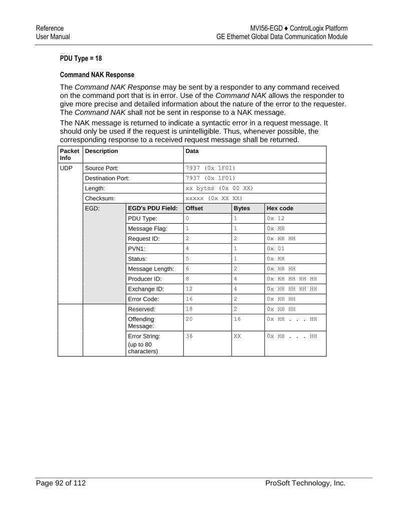
Reference MVI56-EGD ♦ ControlLogix Platform User Manual GE Ethernet Global Data Communication Module
Page 92 of 112 ProSoft Technology, Inc.
Command NAK PDU
PDU Type = 18
Command NAK Response
The Command NAK Response may be sent by a responder to any command received on the command port that is in error. Use of the Command NAK allows the responder to give more precise and detailed information about the nature of the error to the requester. The Command NAK shall not be sent in response to a NAK message.
The NAK message is returned to indicate a syntactic error in a request message. It should only be used if the request is unintelligible. Thus, whenever possible, the corresponding response to a received request message shall be returned.
Packet Info
Description Data
UDP Source Port: 7937 (0x 1F01)
Destination Port: 7937 (0x 1F01)
Length: xx bytes (0x 00 XX)
Checksum: xxxxx (0x XX XX)
EGD: EGD's PDU Field: Offset Bytes Hex code
PDU Type: 0 1 0x 12
Message Flag: 1 1 0x HH
Request ID: 2 2 0x HH HH
PVN1: 4 1 0x 01
Status: 5 1 0x HH
Message Length: 6 2 0x HH HH
Producer ID: 8 4 0x HH HH HH HH
Exchange ID: 12 4 0x HH HH HH HH
Error Code: 16 2 0x HH HH
Reserved: 18 2 0x HH HH
Offending Message:
20 16 0x HH . . . HH
Error String:
(up to 80 characters)
36 XX 0x HH . . . HH

MVI56-EGD ♦ ControlLogix Platform Reference GE Ethernet Global Data Communication Module User Manual
ProSoft Technology, Inc. Page 93 of 112
Read PDUs
PDU Type = 32
Read Request
The Read Request PDU is used to request the contents of one or more contiguous groups of memory from a specific peer controller. The header defines parameters which apply to all of the individual cell references in the message. Each cell reference specifies an offset into the specified exchange or target-specific address and the number of bytes to read. Based on the address type, the Domain ID must contain an Exchange and Producer ID or target-specific address which is valid on the destination node. A Read Request sent from a requesting node must be followed by a Read Response message from the responding node.
Packet Info
Description Data
UDP Source Port: 7937 (0x 1F01)
Destination Port: 7937 (0x 1F01)
Length: xx bytes (0x 00 XX)
Checksum: xxxxx (0x XX XX)
EGD: EGD’s PDU Field: Offset Bytes Hex code
PDU Type: 0 1 0x 20
Message Flag: 1 1 0x HH
Request ID: 2 2 0x HH HH
PVN1: 4 1 0x 01
Option Length: 5 1 0x HH
Message Length: 6 2 0x HH HH
Configuration Signature: 8 2 0x HH HH
Address Type: 10 1 0x HH
Cell Count: 11 1 0x HH
Producer ID: 12 4 0x HH HH HH HH
Exchange ID: 16 4 0x HH HH HH HH
Time Stamp: 20 8 0x HH . . . HH
Reserved: 28 4 0x HH HH HH HH
The following two items are referred to as the exchange Cell. Each Cell targets one [EGD Exchange] command line present in the EGD module’s configuration file.
Offset: reads the DB Register specified in the Command.
Length: is Bytes count, not Words.
Multiple Cells may be requested dependent on the Cell Count field specified above.
Offset: 32 2 0x HH HH
Length: 34 2 0x HH HH
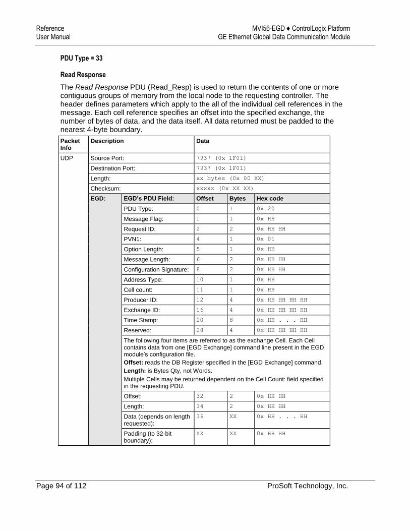
Reference MVI56-EGD ♦ ControlLogix Platform User Manual GE Ethernet Global Data Communication Module
Page 94 of 112 ProSoft Technology, Inc.
PDU Type = 33
Read Response
The Read Response PDU (Read_Resp) is used to return the contents of one or more contiguous groups of memory from the local node to the requesting controller. The header defines parameters which apply to the all of the individual cell references in the message. Each cell reference specifies an offset into the specified exchange, the number of bytes of data, and the data itself. All data returned must be padded to the nearest 4-byte boundary.
Packet Info
Description Data
UDP Source Port: 7937 (0x 1F01)
Destination Port: 7937 (0x 1F01)
Length: xx bytes (0x 00 XX)
Checksum: xxxxx (0x XX XX)
EGD: EGD’s PDU Field: Offset Bytes Hex code
PDU Type: 0 1 0x 20
Message Flag: 1 1 0x HH
Request ID: 2 2 0x HH HH
PVN1: 4 1 0x 01
Option Length: 5 1 0x HH
Message Length: 6 2 0x HH HH
Configuration Signature: 8 2 0x HH HH
Address Type: 10 1 0x HH
Cell count: 11 1 0x HH
Producer ID: 12 4 0x HH HH HH HH
Exchange ID: 16 4 0x HH HH HH HH
Time Stamp: 20 8 0x HH . . . HH
Reserved: 28 4 0x HH HH HH HH
The following four items are referred to as the exchange Cell. Each Cell contains data from one [EGD Exchange] command line present in the EGD module’s configuration file.
Offset: reads the DB Register specified in the [EGD Exchange] command.
Length: is Bytes Qty, not Words.
Multiple Cells may be returned dependent on the Cell Count: field specified in the requesting PDU.
Offset: 32 2 0x HH HH
Length: 34 2 0x HH HH
Data (depends on length requested):
36 XX 0x HH . . . HH
Padding (to 32-bit boundary):
XX XX 0x HH HH
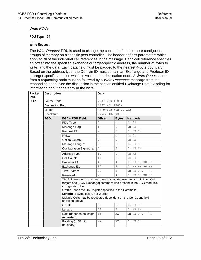
MVI56-EGD ♦ ControlLogix Platform Reference GE Ethernet Global Data Communication Module User Manual
ProSoft Technology, Inc. Page 95 of 112
Write PDUs
PDU Type = 34
Write Request
The Write Request PDU is used to change the contents of one or more contiguous groups of memory on a specific peer controller. The header defines parameters which apply to all of the individual cell references in the message. Each cell reference specifies an offset into the specified exchange or target-specific address, the number of bytes to write, and the data. Each data field must be padded to the nearest 4-byte boundary. Based on the address type, the Domain ID must contain an Exchange and Producer ID or target-specific address which is valid on the destination node. A Write Request sent from a requesting node must be followed by a Write Response message from the responding node. See the discussion in the section entitled Exchange Data Handling for information about coherency in the write.
Packet Info
Description Data
UDP Source Port: 7937 (0x 1F01)
Destination Port: 7937 (0x 1F01)
Length: xx bytes (0x 00 XX)
Checksum: xxxxx (0x XX XX)
EGD: EGD’s PDU Field: Offset Bytes Hex code
PDU Type: 0 1 0x 22
Message Flag: 1 1 0x HH
Request ID: 2 2 0x HH HH
PVN1: 4 1 0x 01
Option Length: 5 1 0x HH
Message Length: 6 2 0x HH HH
Configuration Signature: 8 2 0x HH HH
Address Type: 10 1 0x HH
Cell Count: 11 1 0x HH
Producer ID: 12 4 0x HH HH HH HH
Exchange ID: 16 4 0x HH HH HH HH
Time Stamp: 20 8 0x HH . . . HH
Reserved: 28 4 0x HH HH HH HH
The following two items are referred to as the exchange Cell. Each Cell targets one [EGD Exchange] command line present in the EGD module’s configuration file.
Offset: reads the DB Register specified in the Command.
Length: is Bytes count, not Words.
Multiple Cells may be requested dependent on the Cell Count field specified above.
Offset: 32 2 0x HH HH
Length: 34 2 0x HH HH
Data (depends on length requested):
36 XX 0x HH . . . HH
Padding (to 32-bit boundary):
XX XX 0x HH HH
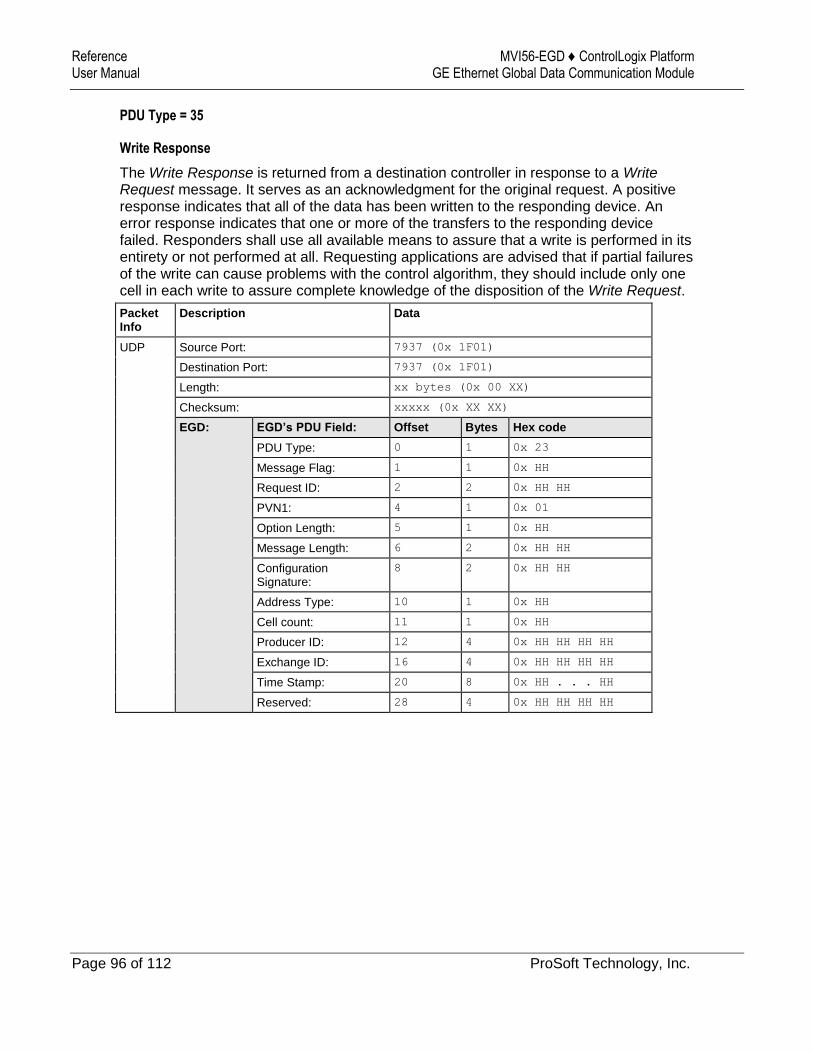
Reference MVI56-EGD ♦ ControlLogix Platform User Manual GE Ethernet Global Data Communication Module
Page 96 of 112 ProSoft Technology, Inc.
PDU Type = 35
Write Response
The Write Response is returned from a destination controller in response to a Write Request message. It serves as an acknowledgment for the original request. A positive response indicates that all of the data has been written to the responding device. An error response indicates that one or more of the transfers to the responding device failed. Responders shall use all available means to assure that a write is performed in its entirety or not performed at all. Requesting applications are advised that if partial failures of the write can cause problems with the control algorithm, they should include only one cell in each write to assure complete knowledge of the disposition of the Write Request.
Packet Info
Description Data
UDP Source Port: 7937 (0x 1F01)
Destination Port: 7937 (0x 1F01)
Length: xx bytes (0x 00 XX)
Checksum: xxxxx (0x XX XX)
EGD: EGD’s PDU Field: Offset Bytes Hex code
PDU Type: 0 1 0x 23
Message Flag: 1 1 0x HH
Request ID: 2 2 0x HH HH
PVN1: 4 1 0x 01
Option Length: 5 1 0x HH
Message Length: 6 2 0x HH HH
Configuration Signature:
8 2 0x HH HH
Address Type: 10 1 0x HH
Cell count: 11 1 0x HH
Producer ID: 12 4 0x HH HH HH HH
Exchange ID: 16 4 0x HH HH HH HH
Time Stamp: 20 8 0x HH . . . HH
Reserved: 28 4 0x HH HH HH HH
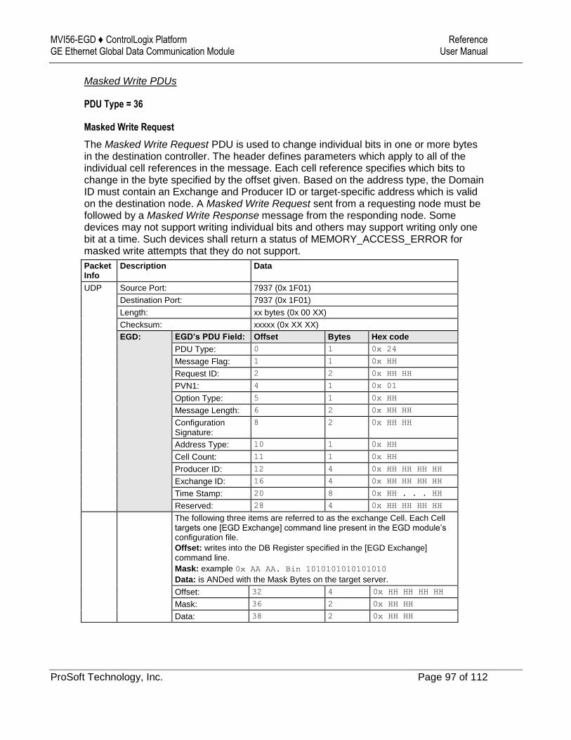
MVI56-EGD ♦ ControlLogix Platform Reference GE Ethernet Global Data Communication Module User Manual
ProSoft Technology, Inc. Page 97 of 112
Masked Write PDUs
PDU Type = 36
Masked Write Request
The Masked Write Request PDU is used to change individual bits in one or more bytes in the destination controller. The header defines parameters which apply to all of the individual cell references in the message. Each cell reference specifies which bits to change in the byte specified by the offset given. Based on the address type, the Domain ID must contain an Exchange and Producer ID or target-specific address which is valid on the destination node. A Masked Write Request sent from a requesting node must be followed by a Masked Write Response message from the responding node. Some devices may not support writing individual bits and others may support writing only one bit at a time. Such devices shall return a status of MEMORY_ACCESS_ERROR for masked write attempts that they do not support.
Packet Info
Description Data
UDP Source Port: 7937 (0x 1F01)
Destination Port: 7937 (0x 1F01)
Length: xx bytes (0x 00 XX)
Checksum: xxxxx (0x XX XX)
EGD: EGD’s PDU Field: Offset Bytes Hex code
PDU Type: 0 1 0x 24
Message Flag: 1 1 0x HH
Request ID: 2 2 0x HH HH
PVN1: 4 1 0x 01
Option Type: 5 1 0x HH
Message Length: 6 2 0x HH HH
Configuration Signature:
8 2 0x HH HH
Address Type: 10 1 0x HH
Cell Count: 11 1 0x HH
Producer ID: 12 4 0x HH HH HH HH
Exchange ID: 16 4 0x HH HH HH HH
Time Stamp: 20 8 0x HH . . . HH
Reserved: 28 4 0x HH HH HH HH
The following three items are referred to as the exchange Cell. Each Cell targets one [EGD Exchange] command line present in the EGD module’s configuration file.
Offset: writes into the DB Register specified in the [EGD Exchange]
command line.
Mask: example 0x AA AA. Bin 1010101010101010
Data: is ANDed with the Mask Bytes on the target server.
Offset: 32 4 0x HH HH HH HH
Mask: 36 2 0x HH HH
Data: 38 2 0x HH HH
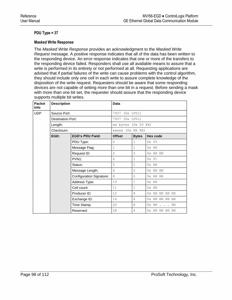
Reference MVI56-EGD ♦ ControlLogix Platform User Manual GE Ethernet Global Data Communication Module
Page 98 of 112 ProSoft Technology, Inc.
PDU Type = 37
Masked Write Response
The Masked Write Response provides an acknowledgment to the Masked Write Request message. A positive response indicates that all of the data has been written to the responding device. An error response indicates that one or more of the transfers to the responding device failed. Responders shall use all available means to assure that a write is performed in its entirety or not performed at all. Requesting applications are advised that if partial failures of the write can cause problems with the control algorithm, they should include only one cell in each write to assure complete knowledge of the disposition of the write request. Requesters should be aware that some responding devices are not capable of setting more than one bit in a request. Before sending a mask with more than one bit set, the requester should assure that the responding device supports multiple bit writes.
Packet Info
Description Data
UDP Source Port: 7937 (0x 1F01)
Destination Port: 7937 (0x 1F01)
Length: xx bytes (0x 00 XX)
Checksum: xxxxx (0x XX XX)
EGD: EGD’s PDU Field: Offset Bytes Hex code
PDU Type: 0 1 0x 25
Message Flag: 1 1 0x HH
Request ID: 2 2 0x HH HH
PVN1: 4 1 0x 01
Status: 5 1 0x HH
Message Length: 6 2 0x HH HH
Configuration Signature: 8 2 0x HH HH
Address Type: 10 1 0x HH
Cell count: 11 1 0x HH
Producer ID: 12 4 0x HH HH HH HH
Exchange ID: 16 4 0x HH HH HH HH
Time Stamp: 20 8 0x HH . . . HH
Reserved: 28 4 0x HH HH HH HH
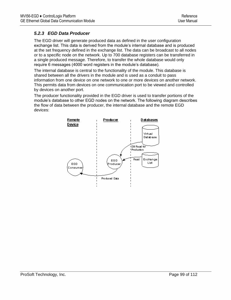
MVI56-EGD ♦ ControlLogix Platform Reference GE Ethernet Global Data Communication Module User Manual
ProSoft Technology, Inc. Page 99 of 112
5.2.3 EGD Data Producer
The EGD driver will generate produced data as defined in the user configuration exchange list. This data is derived from the module’s internal database and is produced at the set frequency defined in the exchange list. The data can be broadcast to all nodes or to a specific node on the network. Up to 700 database registers can be transferred in a single produced message. Therefore, to transfer the whole database would only require 6 messages (4000 word registers in the module’s database).
The internal database is central to the functionality of the module. This database is shared between all the drivers in the module and is used as a conduit to pass information from one device on one network to one or more devices on another network. This permits data from devices on one communication port to be viewed and controlled by devices on another port.
The producer functionality provided in the EGD driver is used to transfer portions of the module’s database to other EGD nodes on the network. The following diagram describes the flow of data between the producer, the internal database and the remote EGD devices:
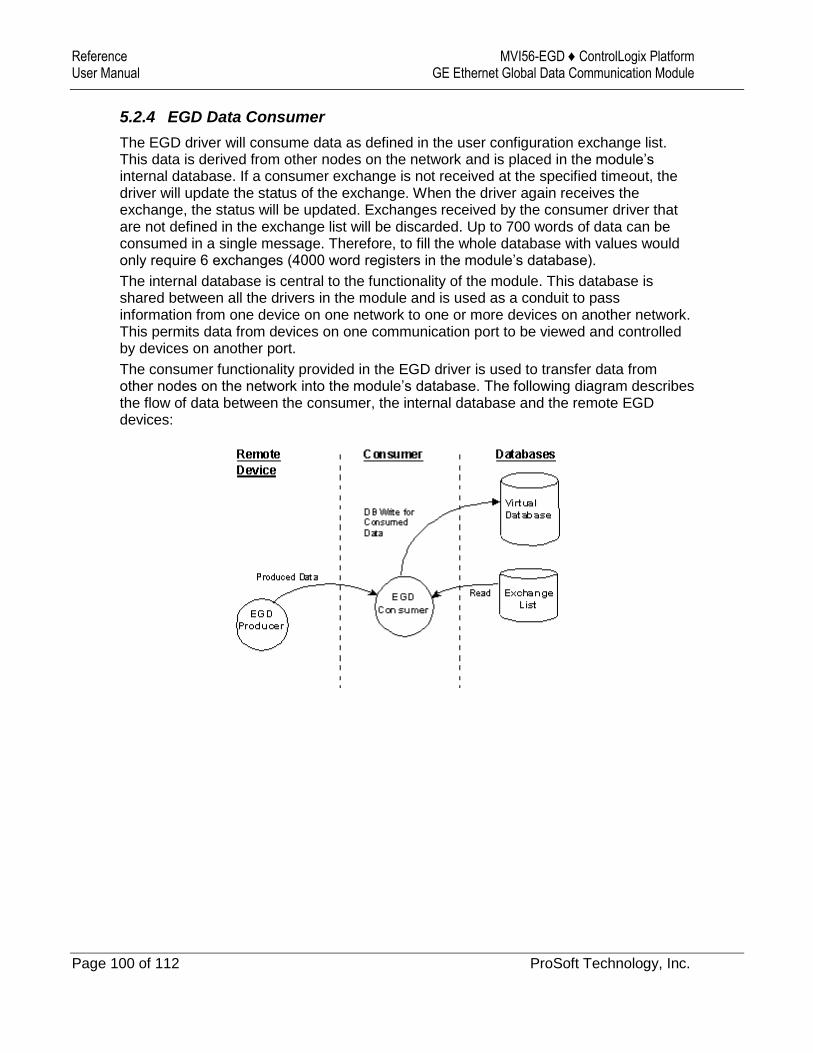
Reference MVI56-EGD ♦ ControlLogix Platform User Manual GE Ethernet Global Data Communication Module
Page 100 of 112 ProSoft Technology, Inc.
5.2.4 EGD Data Consumer
The EGD driver will consume data as defined in the user configuration exchange list. This data is derived from other nodes on the network and is placed in the module’s internal database. If a consumer exchange is not received at the specified timeout, the driver will update the status of the exchange. When the driver again receives the exchange, the status will be updated. Exchanges received by the consumer driver that are not defined in the exchange list will be discarded. Up to 700 words of data can be consumed in a single message. Therefore, to fill the whole database with values would only require 6 exchanges (4000 word registers in the module’s database).
The internal database is central to the functionality of the module. This database is shared between all the drivers in the module and is used as a conduit to pass information from one device on one network to one or more devices on another network. This permits data from devices on one communication port to be viewed and controlled by devices on another port.
The consumer functionality provided in the EGD driver is used to transfer data from other nodes on the network into the module’s database. The following diagram describes the flow of data between the consumer, the internal database and the remote EGD devices:
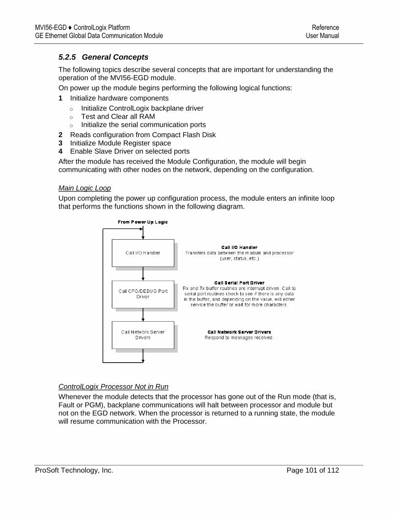
MVI56-EGD ♦ ControlLogix Platform Reference GE Ethernet Global Data Communication Module User Manual
ProSoft Technology, Inc. Page 101 of 112
5.2.5 General Concepts
The following topics describe several concepts that are important for understanding the operation of the MVI56-EGD module.
On power up the module begins performing the following logical functions:
1 Initialize hardware components
o Initialize ControlLogix backplane driver o Test and Clear all RAM o Initialize the serial communication ports
2 Reads configuration from Compact Flash Disk 3 Initialize Module Register space 4 Enable Slave Driver on selected ports
After the module has received the Module Configuration, the module will begin communicating with other nodes on the network, depending on the configuration.
Main Logic Loop
Upon completing the power up configuration process, the module enters an infinite loop that performs the functions shown in the following diagram.
ControlLogix Processor Not in Run
Whenever the module detects that the processor has gone out of the Run mode (that is, Fault or PGM), backplane communications will halt between processor and module but not on the EGD network. When the processor is returned to a running state, the module will resume communication with the Processor.
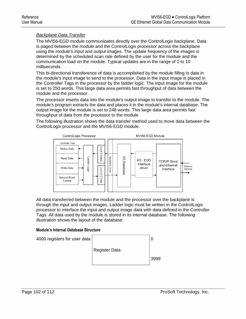
Reference MVI56-EGD ♦ ControlLogix Platform User Manual GE Ethernet Global Data Communication Module
Page 102 of 112 ProSoft Technology, Inc.
Backplane Data Transfer
The MVI56-EGD module communicates directly over the ControlLogix backplane. Data is paged between the module and the ControlLogix processor across the backplane using the module's input and output images. The update frequency of the images is determined by the scheduled scan rate defined by the user for the module and the communication load on the module. Typical updates are in the range of 1 to 10 milliseconds.
This bi-directional transference of data is accomplished by the module filling in data in the module's input image to send to the processor. Data in the input image is placed in the Controller Tags in the processor by the ladder logic. The input image for the module is set to 250 words. This large data area permits fast throughput of data between the module and the processor.
The processor inserts data into the module's output image to transfer to the module. The module's program extracts the data and places it in the module's internal database. The output image for the module is set to 248 words. This large data area permits fast throughput of data from the processor to the module
The following illustration shows the data transfer method used to move data between the ControlLogix processor and the MVI56-EGD module.
All data transferred between the module and the processor over the backplane is through the input and output images. Ladder logic must be written in the ControlLogix processor to interface the input and output image data with data defined in the Controller Tags. All data used by the module is stored in its internal database. The following illustration shows the layout of the database:
Module’s Internal Database Structure
4000 registers for user data 0
Register Data
3999
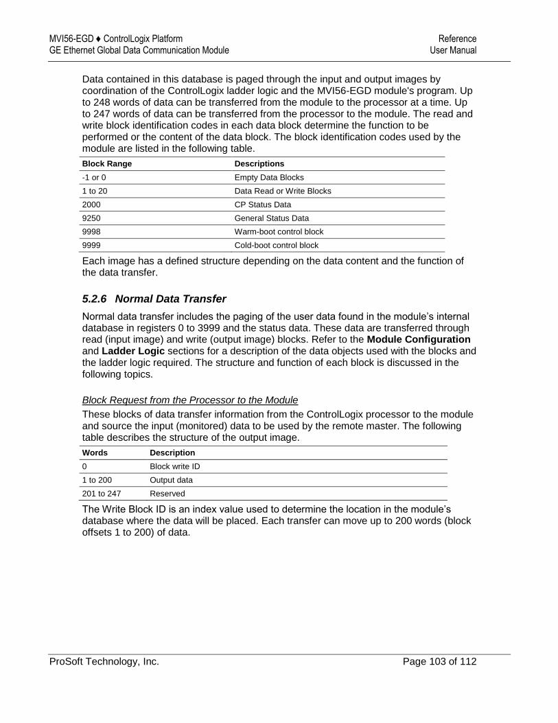
MVI56-EGD ♦ ControlLogix Platform Reference GE Ethernet Global Data Communication Module User Manual
ProSoft Technology, Inc. Page 103 of 112
Data contained in this database is paged through the input and output images by coordination of the ControlLogix ladder logic and the MVI56-EGD module's program. Up to 248 words of data can be transferred from the module to the processor at a time. Up to 247 words of data can be transferred from the processor to the module. The read and write block identification codes in each data block determine the function to be performed or the content of the data block. The block identification codes used by the module are listed in the following table.
Block Range Descriptions
-1 or 0 Empty Data Blocks
1 to 20 Data Read or Write Blocks
2000 CP Status Data
9250 General Status Data
9998 Warm-boot control block
9999 Cold-boot control block
Each image has a defined structure depending on the data content and the function of the data transfer.
5.2.6 Normal Data Transfer
Normal data transfer includes the paging of the user data found in the module’s internal database in registers 0 to 3999 and the status data. These data are transferred through read (input image) and write (output image) blocks. Refer to the Module Configuration and Ladder Logic sections for a description of the data objects used with the blocks and the ladder logic required. The structure and function of each block is discussed in the following topics.
Block Request from the Processor to the Module
These blocks of data transfer information from the ControlLogix processor to the module and source the input (monitored) data to be used by the remote master. The following table describes the structure of the output image.
Words Description
0 Block write ID
1 to 200 Output data
201 to 247 Reserved
The Write Block ID is an index value used to determine the location in the module’s database where the data will be placed. Each transfer can move up to 200 words (block offsets 1 to 200) of data.
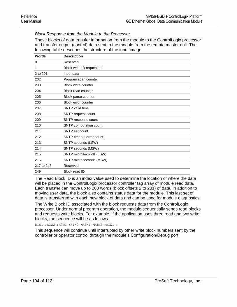
Reference MVI56-EGD ♦ ControlLogix Platform User Manual GE Ethernet Global Data Communication Module
Page 104 of 112 ProSoft Technology, Inc.
Block Response from the Module to the Processor
These blocks of data transfer information from the module to the ControlLogix processor and transfer output (control) data sent to the module from the remote master unit. The following table describes the structure of the input image.
Words Description
0 Reserved
1 Block write ID requested
2 to 201 Input data
202 Program scan counter
203 Block write counter
204 Block read counter
205 Block parse counter
206 Block error counter
207 SNTP valid time
208 SNTP request count
209 SNTP response count
210 SNTP computation count
211 SNTP set count
212 SNTP timeout error count
213 SNTP seconds (LSW)
214 SNTP seconds (MSW)
215 SNTP microseconds (LSW)
216 SNTP microseconds (MSW)
217 to 248 Reserved
249 Block read ID
The Read Block ID is an index value used to determine the location of where the data will be placed in the ControlLogix processor controller tag array of module read data. Each transfer can move up to 200 words (block offsets 2 to 201) of data. In addition to moving user data, the block also contains status data for the module. This last set of data is transferred with each new block of data and can be used for module diagnostics.
The Write Block ID associated with the block requests data from the ControlLogix processor. Under normal program operation, the module sequentially sends read blocks and requests write blocks. For example, if the application uses three read and two write blocks, the sequence will be as follows:
R1W1R2W2R3W1R1W2R2W1R3W2R1W1
This sequence will continue until interrupted by other write block numbers sent by the controller or operator control through the module’s Configuration/Debug port.

MVI56-EGD ♦ ControlLogix Platform Reference GE Ethernet Global Data Communication Module User Manual
ProSoft Technology, Inc. Page 105 of 112
5.2.7 Special Function Blocks
Special Function blocks are special blocks used to control the module. The current version of the software supports the following blocks.
Code Description
-1 or 0 Empty data blocks
1 to 20 Data read or write blocks
2000 C/P status data
9250 General status data
9998 Warm boot module
9999 Cold boot module
C/P Status Data Block (2000)
Block 2000 Request
Words Description
0 2000 Command Block ID
1 Number of C/P messages (1 to 17)
2 First C/P index (0 to 99)
3 to 247 Reserved
Block 2000 Response
Words Description
0 Reserved
1 Block write ID requested
2 Number of C/P messages (0 to 17) Will be set to 0 if error in request.
3 First C/P index (0 to 99)
4 to 17 C/P Status Data
18 to 31 C/P Status Data
32 to 45 C/P Status Data
46 to 59 C/P Status Data
60 to 73 C/P Status Data
74 to 87 C/P Status Data
88 to 101 C/P Status Data
102 to 115 C/P Status Data
116 to 129 C/P Status Data
130 to 143 C/P Status Data
144 to 157 C/P Status Data
158 to 171 C/P Status Data
172 to 185 C/P Status Data
186 to 199 C/P Status Data
200 to 213 C/P Status Data
214 to 227 C/P Status Data
228 to 241 C/P Status Data
242 to 248 Reserved
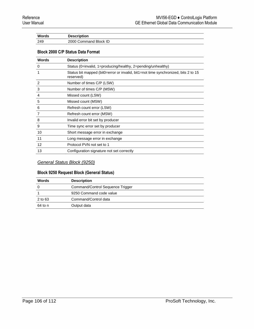
Reference MVI56-EGD ♦ ControlLogix Platform User Manual GE Ethernet Global Data Communication Module
Page 106 of 112 ProSoft Technology, Inc.
Words Description
249 2000 Command Block ID
Block 2000 C/P Status Data Format
Words Description
0 Status (0=invalid, 1=producing/healthy, 2=pending/unhealthy)
1 Status bit mapped (bit0=error or invalid, bit1=not time synchronized, bits 2 to 15 reserved)
2 Number of times C/P (LSW)
3 Number of times C/P (MSW)
4 Missed count (LSW)
5 Missed count (MSW)
6 Refresh count error (LSW)
7 Refresh count error (MSW)
8 Invalid error bit set by producer
9 Time sync error set by producer
10 Short message error in exchange
11 Long message error in exchange
12 Protocol PVN not set to 1
13 Configuration signature not set correctly
General Status Block (9250)
Block 9250 Request Block (General Status)
Words Description
0 Command/Control Sequence Trigger
1 9250 Command code value
2 to 63 Command/Control data
64 to n Output data

MVI56-EGD ♦ ControlLogix Platform Reference GE Ethernet Global Data Communication Module User Manual
ProSoft Technology, Inc. Page 107 of 112
Block 9250 Response Block (General Status)
Words Description
0 Command/Control Sequence Trigger
1 9250 Command code value
2 Program scan counter
3 Product code bytes 0 & 1
4 Product code bytes 2 & 3
5 Revision bytes 0 & 1
6 Revision bytes 2 & 3
7 Op bytes 0 & 1
8 Op bytes 2 & 3
9 Run bytes 0 & 1
10 Run bytes 2 & 3
11 Block write counter
12 Block read counter
13 Block parse counter
14 Block error counter
15 SNTP valid time
16 SNTP request count
17 SNTP response count
18 SNTP computation count
19 SNTP set count
20 SNTP timeout error count
21 SNTP seconds (LSW)
22 SNTP seconds (MSW)
23 SNTP microseconds (LSW)
24 SNTP microseconds (MSW)
25 to 248 Reserved
249 9250 Command Code Value
Software Reset Block (9998/9999)
This block is sent from the ControlLogix processor to the module (output image) when the module is required to perform a warm-boot (software reset) operation. This block is commonly sent to the module any time configuration data modifications are made. This will cause the module to read the new configuration information and to restart. The following table describes the format of the control block.
Offset Description Length
0 9998 or 9999 1
1 to 247 Spare 247
Because many of the parameters set in the configuration file require the program to restart, this function works the same as the cold-boot function. It will cause the module to exit and restart the program.

Reference MVI56-EGD ♦ ControlLogix Platform User Manual GE Ethernet Global Data Communication Module
Page 108 of 112 ProSoft Technology, Inc.
5.3 Exchange Configuration Form
Use this form to design the exchange list for an application.
1 2 3 4 5 6 7 8 9 10
Exchange Type (C/P)
Cast Type (B/M/U)
Database Address
Register Count
Swap Code
Prod/Cons Time
IP Address
Exchange ID
CFG Signature Version
Major Minor

MVI56-EGD ♦ ControlLogix Platform Support, Service & Warranty GE Ethernet Global Data Communication Module User Manual
ProSoft Technology, Inc. Page 109 of 112
6 Support, Service & Warranty
6.1 Contacting Technical Support
ProSoft Technology, Inc. is committed to providing the most efficient and effective support possible. Before calling, please gather the following information to assist in expediting this process:
1 Product Version Number 2 System architecture 3 Network details
If the issue is hardware related, we will also need information regarding:
1 Module configuration and associated ladder files, if any 2 Module operation and any unusual behavior 3 Configuration/Debug status information 4 LED patterns 5 Details about the interfaced serial, Ethernet or Fieldbus devices
Note: For technical support calls within the United States, ProSoft’s 24/7 after-hours phone support is available for urgent plant-down issues.
North America (Corporate Location) Europe / Middle East / Africa Regional Office
Phone: +1.661.716.5100
Languages spoken: English, Spanish
REGIONAL TECH SUPPORT
Phone: +33.(0)5.34.36.87.20
Languages spoken: French, English
REGIONAL TECH SUPPORT
Latin America Regional Office Asia Pacific Regional Office
Phone: +52.222.264.1814
Languages spoken: Spanish, English
REGIONAL TECH SUPPORT
Phone: +60.3.2247.1898
Languages spoken: Bahasa, Chinese, English, Japanese, Korean
REGIONAL TECH SUPPORT
For additional ProSoft Technology contacts in your area, please visit: https://www.prosoft-technology.com/About-Us/Contact-Us.
6.2 Warranty Information
For complete details regarding ProSoft Technology’s TERMS & CONDITIONS OF SALE, WARRANTY, SUPPORT, SERVICE AND RETURN MATERIAL AUTHORIZATION INSTRUCTIONS, please see the documents at: www.prosoft-technology/legal
MVI56-EGD ♦ ControlLogix Platform Guide to the MVI56-EGD User Manual GE Ethernet Global Data Communication Module User Manual
ProSoft Technology, Inc. Page 110 of 112 March 3, 2021
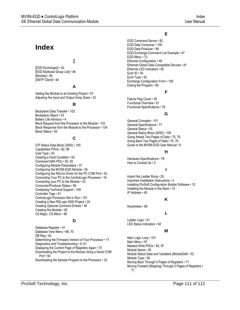
MVI56-EGD ♦ ControlLogix Platform Index GE Ethernet Global Data Communication Module User Manual
ProSoft Technology, Inc. Page 111 of 112
Index
[
[EGD Exchanges] • 42 [EGD Multicast Group List] • 48 [Module] • 39 [SNTP Client] • 40
A
Adding the Module to an Existing Project • 57 Adjusting the Input and Output Array Sizes • 32
B
Backplane Data Transfer • 102 Backplane Object • 53 Battery Life Advisory • 4 Block Request from the Processor to the Module • 103 Block Response from the Module to the Processor • 104 Block Status • 55
C
C/P Status Data Block (2000) • 105 Capabilities PDUs • 82, 86 Cast Type • 43 Clearing a Fault Condition • 63 Command NAK PDU • 82, 92 Configuring Module Parameters • 37 Configuring the MVI56-EGD Module • 34 Configuring the RSLinx Driver for the PC COM Port • 20 Connecting Your PC to the ControlLogix Processor • 16 Connecting your PC to the Module • 23 Consumer/Producer Status • 56 Contacting Technical Support • 109 Controller Tags • 51 ControlLogix Processor Not in Run • 101 Creating a New RSLogix 5000 Project • 24 Creating Optional Comment Entries • 38 Creating the Module • 26 CS Major, CS Minor • 46
D
Database Register • 41 Database View Menu • 68, 70 DB Reg • 43 Determining the Firmware Version of Your Processor • 17 Diagnostics and Troubleshooting • 9, 61 Displaying the Current Page of Registers Again • 70 Downloading the Project to the Module Using a Serial COM
Port • 50 Downloading the Sample Program to the Processor • 22
E
EGD Command Server • 82 EGD Data Consumer • 100 EGD Data Producer • 99 EGD Exchange Command List Example • 47 EGD Menu • 73 Ethernet Configuration • 49 Ethernet Global Data Compatible Devices • 81 Ethernet LED Indicators • 62 Exch ID • 45 Exch Type • 42 Exchange Configuration Form • 108 Exiting the Program • 69
F
Failure Flag Count • 39 Functional Overview • 81 Functional Specifications • 79
G
General Concepts • 101 General Specifications • 77 General Status • 55 General Status Block (9250) • 106 Going Ahead Two Pages of Data • 75, 76 Going Back Two Pages of Data • 75, 76 Guide to the MVI56-EGD User Manual • 9
H
Hardware Specifications • 78 How to Contact Us • 2
I
Import the Ladder Rung • 29 Important Installation Instructions • 3 Installing ProSoft Configuration Builder Software • 13 Installing the Module in the Rack • 15 IP Address • 45
K
Keystrokes • 66
L
Ladder Logic • 51 LED Status Indicators • 62
M
Main Logic Loop • 101 Main Menu • 67 Masked Write PDUs • 82, 97 Module Name • 39 Module Status Data and Variables (ModuleDef) • 53 Module Type • 39 Moving Back Through 5 Pages of Registers • 71 Moving Forward (Skipping) Through 5 Pages of Registers •
71
Index MVI56-EGD ♦ ControlLogix Platform User Manual GE Ethernet Global Data Communication Module
Page 112 of 112 ProSoft Technology, Inc.
MVI (Multi Vendor Interface) Modules • 3
N
Navigation • 66 Network Menu • 69, 72 Normal Data Transfer • 103 NTP Server IP Address • 41
O
Opening the Database View Menu • 68 Opening the EGD Menu • 68 Opening the Network Menu • 69 Opening the Producer/Consumer List Menu • 73 Opening the Sample Ladder Logic • 17 Opening the Status Data Menu • 74
P
P/C Time • 44 Package Contents • 13 Pinouts • 3 Printing a Configuration File • 38 Producer/Consumer List Menu • 75 Producer/Consumer Status Menu • 76 Product Specifications • 9, 77 ProSoft Technology® Product Documentation • 2
R
Read PDUs • 82, 93 Read Register Count • 39 Read Register Start • 39 Reading Status Data from the Module • 76 Redisplaying the Current Page • 75, 76 Redisplaying the Menu • 67, 74, 75, 76 Reference • 9, 77 Reg Count • 43 Renaming PCB Objects • 37 Resetting Diagnostic Data • 68 Retrieve Configuration PDUs Example • 82, 83 Returning to the Main Menu • 71, 73, 74 Returning to the Previous Menu • 75, 76 Rules for CS Validation • 47
S
Selecting the Slot Number for the Module • 19 Setting Jumpers • 14 Setting Up the Project • 35 SNTP Status • 55 SNTP Support • 68, 80 Software Reset Block (9998/9999) • 107 Special Function Blocks • 105 Start Here • 9, 11 Statistics PDUs • 82, 90 Status Object (InStat) • 54 Summary PDUs • 82, 88 Support, Service & Warranty • 9, 109 Swap Code • 44 System Requirements • 12
T
Time Zone • 41 Transferring the Configuration File from The Module to the
PC • 68 Transferring the Configuration File from the PC to the
Module • 68 Transferring WATTCP.CFG to the Module • 72 Transferring WATTCP.CFG to the PC • 72 Troubleshooting • 63
U
Use Daylight Savings Time • 41 User Data Objects (MNETDATA) • 54 Using ProSoft Configuration Builder • 35 Using ProSoft Configuration Builder (PCB) for Diagnostics •
64 Using the Diagnostic Window in ProSoft Configuration
Builder • 64 Using the RSLogix 5000 v16 Add-On Instruction • 24
V
Viewing Block Transfer Statistics • 67 Viewing Data in ASCII (Text) Format • 71 Viewing Data in Decimal Format • 71 Viewing Data in Floating-Point Format • 71 Viewing Data in Hexadecimal Format • 71 Viewing Module Configuration • 67 Viewing Register Pages • 70 Viewing SNTP Status • 68 Viewing the Multicast Group List • 73 Viewing the Next Page of Data • 75, 76 Viewing the Next Page of Registers • 71 Viewing the Previous Page of Data • 75, 76 Viewing the Previous Page of Registers • 71 Viewing the WATTCP.CFG File on the module • 73 Viewing Version Information • 69
W
Warm Booting the Module • 69 Warnings • 3 Warranty Information • 109 Write PDUs • 82, 95 Write Register Count • 39 Write Register Start • 39
Y
Your Feedback Please • 2