
Technology Overlays
54
Capacity Technology Overlays Multi-Services Multi-Services Multi-Services Spectral Efficiency NEW SPECTRUM Site Approvals Site Sharing Site Sharing Site Sharing Base Station Antenna Product Guide • Stadium and Multibeam Antennas • Low Band Antennas • High Band Antennas • Multi-Band Antennas
-
Upload
khangminh22 -
Category
Documents
-
view
1 -
download
0
Transcript of Technology Overlays

CapacityTechnology Overlays
Multi-Services Multi-Services
Multi-Services Spectral EfficiencyN e w S p e c t r u m
Site Approvals
Site Sharing
Site SharingSite Sharing
Base Station Antenna Product Guide• Stadium and Multibeam Antennas
• Low Band Antennas
• High Band Antennas
• Multi-Band Antennas
Stad
ium
and
Mul
tibea
m A
nten
nas
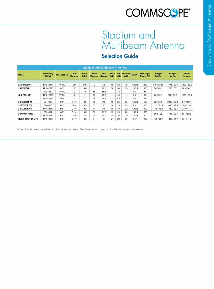
Stadium and Multibeam AntennaSelection Guide
Stadium and Multibeam Antennas
Model Frequency (MHz) Polarization Tilt
(Degree)Gain (dBi)
HBW (Degree)
VBW (Degree)
USLS (dB)
F/B (dB)
Isolation (dB) VSWR Max. Input
Power (W)Weight (kg/lb)
Length (mm/in)
Width (mm/in)
2x9NPA2010F 1710–2170 VPOL ±4° 27.0 5 5.8 18 30 16 1.43:1 300 140 / 308.6 1771 / 69.7 1486 / 58.55NPX1006F 1710–2170 ±45° 6 23.0 11 11.0 18 30 25 1.43:1 300 30 / 66.1 890 / 35 865 / 34.1
CNLPA3055F790–960 VPOL 0 11.0 55 55.5 - 38 - 1.5:1 50
30 / 66.1 850 / 33.5 1350 / 53.11710–2170 VPOL 0 11.1 50 49.5 - 43 - 1.5:1 502300–2690 VPOL 0 11.7 46 46.3 - 45 - 1.5:1 50
2CPX208M-V1 824–960 ±45° 0–10 18.5 35 9.5 18 25 25 1.29:1 500 32 / 70.5 2090 / 82.3 510 / 20.12CPX208R-V1 824–960 ±45° 0–10 18.5 35 9.5 18 25 25 1.3:1 500 32.5 / 71.7 2090 / 82.3 504 / 19.82NPX210R-V1 1710–2170 ±45° 0–10 19.2 34 6.8 18 30 22 1.43:1 300 18.5 / 40.8 1330 / 52.4 370 / 14.7
2UNPX203.6R2698–894 ±45° 0–10 14.5 33 21.0 15 20 22 1.43:1 500
29.5 / 65 1745 / 68.7 564 / 22.21710–2170 ±45° 0–10 17.5 35 11.0 15 30 20 1.43:1 300
HBXX-3817TB1-VTM 1710–2180 ±45° 0–10 19.3 34 6.7 21 29 30 1.4:1 250 16.5 / 36.4 1390 / 54.7 301 / 11.9
Note: Specifications are subject to change without notice. See www.commscope.com for the most current information.
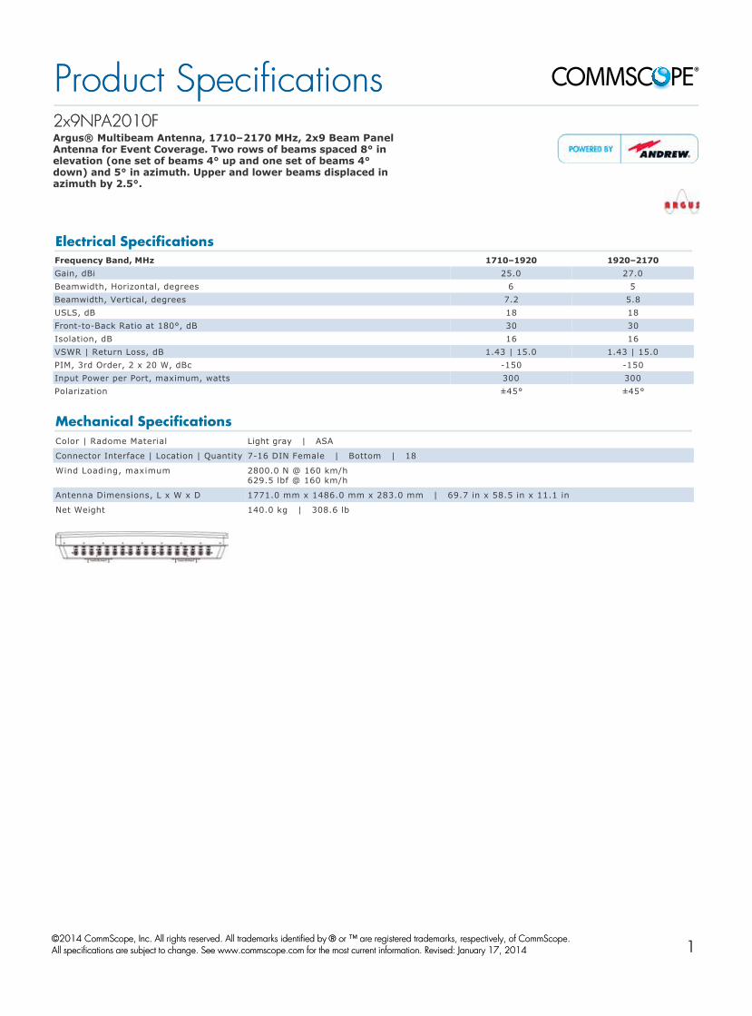
2x9NPA2010F2x9NPA2010F Argus® Multibeam Antenna, 1710–2170 MHz, 2x9 Beam Panel Antenna for Event Coverage. Two rows of beams spaced 8° in elevation (one set of beams 4° up and one set of beams 4° down) and 5° in azimuth. Upper and lower beams displaced in azimuth by 2.5°.
Electrical SpecificationsFrequency Band, MHz 1710–1920 1920–2170Gain, dBi 25.0 27.0Beamwidth, Horizontal, degrees 6 5Beamwidth, Vertical, degrees 7.2 5.8USLS, dB 18 18FronttoBack Ratio at 180°, dB 30 30Isolation, dB 16 16VSWR | Return Loss, dB 1.43 | 15.0 1.43 | 15.0PIM, 3rd Order, 2 x 20 W, dBc 150 150Input Power per Port, maximum, watts 300 300Polarization ±45° ±45°
Mechanical SpecificationsColor | Radome Material Light gray | ASA
Connector Interface | Location | Quantity 716 DIN Female | Bottom | 18
Wind Loading, maximum 2800.0 N @ 160 km/h 629.5 lbf @ 160 km/h
Antenna Dimensions, L x W x D 1771.0 mm x 1486.0 mm x 283.0 mm | 69.7 in x 58.5 in x 11.1 in
Net Weight 140.0 kg | 308.6 lb
Product SpecificationsProduct Specifications
©©2014 CommScope, Inc. All rights reserved. All trademarks identified by 2014 CommScope, Inc. All rights reserved. All trademarks identified by ® ® or ™ are registered trademarks, respectively, of CommScope.or ™ are registered trademarks, respectively, of CommScope. All specifications are subject to change. See www.commscope.com for the most current information. Revised: January 17, 2014All specifications are subject to change. See www.commscope.com for the most current information. Revised: January 17, 2014
page 1 of 1page 1 of 1April 16, 2014April 16, 20141

5NPX1006F5NPX1006F Argus® Multibeam Antenna, 1710–2170 MHz, 5x 10¹⁴° horizontal beamwidth, fixed electrical tilt
Electrical SpecificationsFrequency Band, MHz 1710–1920 1920–2170Gain, dBi 22.0 23.0Beamwidth, Horizontal, degrees 12 11Beamwidth, Vertical, degrees 12.0 11.0Beam Tilt, degrees 6 6USLS, dB 18 18FronttoBack Ratio at 180°, dB 30 30Isolation, dB 25 25VSWR | Return Loss, dB 1.43 | 15.0 1.43 | 15.0PIM, 3rd Order, 2 x 20 W, dBc 150 150Input Power per Port, maximum, watts 300 300Polarization ±45° ±45°
Mechanical SpecificationsColor | Radome Material Gray | ASA, UV stabilized
Connector Interface | Location | Quantity 716 DIN Female | Bottom | 10
Wind Loading, maximum 1060.0 N @ 160 km/h 238.3 lbf @ 160 km/h
Antenna Dimensions, L x W x D 890.0 mm x 865.0 mm x 250.0 mm | 35.0 in x 34.1 in x 9.8 in
Net Weight 30.0 kg | 66.1 lb
Product SpecificationsProduct Specifications
©©2014 CommScope, Inc. All rights reserved. All trademarks identified by 2014 CommScope, Inc. All rights reserved. All trademarks identified by ® ® or ™ are registered trademarks, respectively, of CommScope.or ™ are registered trademarks, respectively, of CommScope. All specifications are subject to change. See www.commscope.com for the most current information. Revised: April 15, 2014All specifications are subject to change. See www.commscope.com for the most current information. Revised: April 15, 2014
page 1 of 1page 1 of 1April 16, 2014April 16, 20142

CNLPA3055FCNLPA3055F Argus® Stadium Triband Antenna, 790–960, 1710–2170, and 2300–2690 MHz, 50° horizontal beam. This triband antenna produces rectangular patterns with sharp cutoff for illuminating a section of the crowd. The three bands are internally triplexed, allowing a single connector interface to be used.
Electrical SpecificationsFrequency Band, MHz 790–960 1710–2170 2300–2690Gain by all Beam Tilts, average, dBi 11.0 11.1 11.7Gain by all Beam Tilts Tolerance, dB ±0.8 ±0.7 ±0.6Beamwidth, Horizontal, degrees 55 50 46Beamwidth, Horizontal at 20 dB, degrees 91 83 75Beamwidth, Horizontal Tolerance, degrees ±4.7 ±5.2 ±2.4Beamwidth, Vertical, degrees 55.5 49.5 46.3Beamwidth, Vertical Tolerance, degrees ±5.5 ±5.1 ±2.3Beam Tilt, degrees 0 0 0FronttoBack Ratio at 180°, dB 38 43 45VSWR | Return Loss, dB 1.5 | 14.0 1.5 | 14.0 1.5 | 14.0PIM, 3rd Order, 2 x 20 W, dBc 150 150 150Input Power per Port, maximum, watts 50 50 50Polarization Vertical Vertical Vertical
Mechanical SpecificationsConnector Interface | Location | Quantity 716 DIN Female | Bottom | 1
Wind Speed, maximum 200.0 km/h | 124.3 mph
Antenna Dimensions, L x W x D 850.0 mm x 1350.0 mm x 120.0 mm | 33.5 in x 53.1 in x 4.7 in
Net Weight 30.0 kg | 66.1 lb
Product SpecificationsProduct Specifications
©©2014 CommScope, Inc. All rights reserved. All trademarks identified by 2014 CommScope, Inc. All rights reserved. All trademarks identified by ® ® or ™ are registered trademarks, respectively, of CommScope.or ™ are registered trademarks, respectively, of CommScope. All specifications are subject to change. See www.commscope.com for the most current information. Revised: January 17, 2014All specifications are subject to change. See www.commscope.com for the most current information. Revised: January 17, 2014
page 1 of 1page 1 of 1April 16, 2014April 16, 20143

2CPX208M2CPX208M--V1V1 Argus® Twin Beam Antenna, 824–960 MHz, 37° horizontal beamwidth, with manual electrical tilt (not upgradeable)
Electrical SpecificationsFrequency Band, MHz 824–890 890–960Gain, dBi 18.0 18.5Beam Centers, Horizontal, degrees ±27 ±27Beamwidth, Horizontal, degrees 39 35Beamwidth, Vertical, degrees 10.0 9.5Beam Tilt, degrees 0–10 0–10USLS, dB 18 18FronttoBack Ratio at 180°, dB 25 25Isolation, dB 25 25VSWR | Return Loss, dB 1.29 | 18.0 1.29 | 18.0PIM, 3rd Order, 2 x 20 W, dBc 150 150Input Power per Port, maximum, watts 500 500Polarization ±45° ±45°
Mechanical SpecificationsConnector Interface | Location | Quantity 716 DIN Female | Bottom | 4
Wind Loading, maximum 1500.0 N @ 160 km/h 337.2 lbf @ 160 km/h
Wind Speed, maximum 200.0 km/h | 124.3 mph
Antenna Dimensions, L x W x D 2090.0 mm x 510.0 mm x 108.0 mm | 82.3 in x 20.1 in x 4.3 in
Net Weight 32.0 kg | 70.5 lb
Product SpecificationsProduct Specifications
©©2014 CommScope, Inc. All rights reserved. All trademarks identified by 2014 CommScope, Inc. All rights reserved. All trademarks identified by ® ® or ™ are registered trademarks, respectively, of CommScope.or ™ are registered trademarks, respectively, of CommScope. All specifications are subject to change. See www.commscope.com for the most current information. Revised: January 17, 2014All specifications are subject to change. See www.commscope.com for the most current information. Revised: January 17, 2014
page 1 of 1page 1 of 1April 16, 2014April 16, 20144
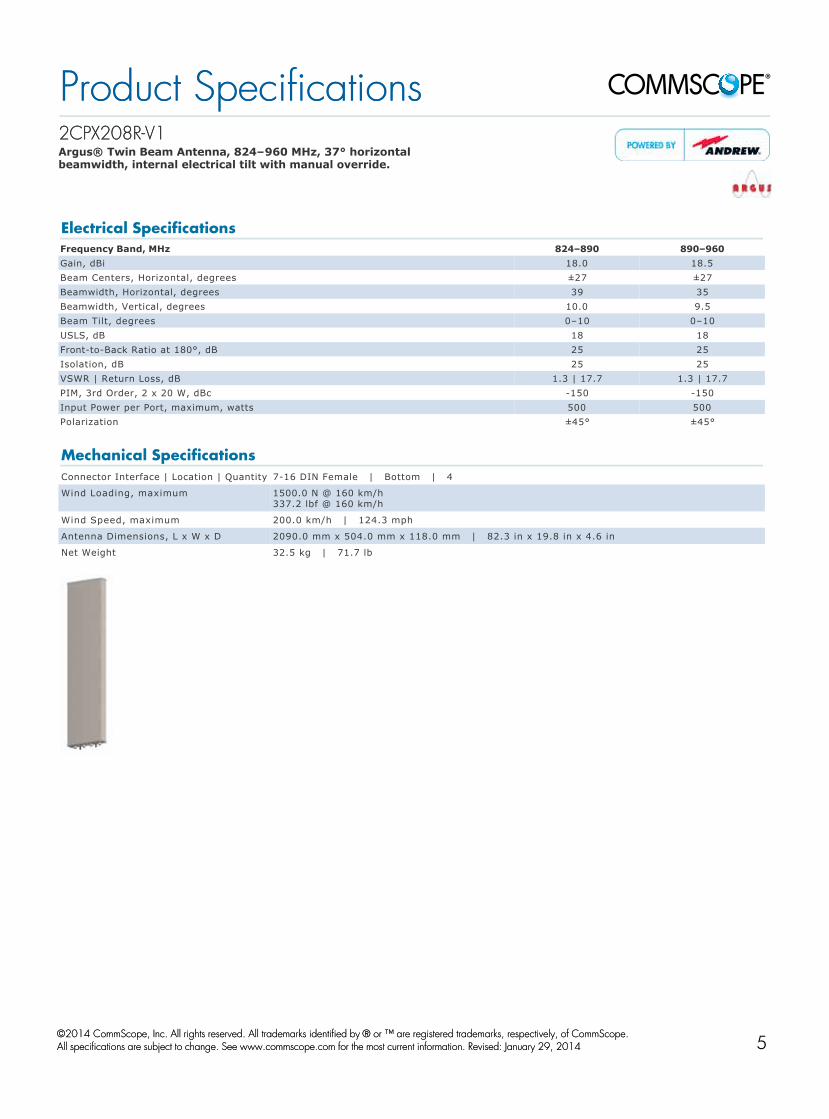
2CPX208R2CPX208R--V1V1 Argus® Twin Beam Antenna, 824–960 MHz, 37° horizontal beamwidth, internal electrical tilt with manual override.
Electrical SpecificationsFrequency Band, MHz 824–890 890–960Gain, dBi 18.0 18.5Beam Centers, Horizontal, degrees ±27 ±27Beamwidth, Horizontal, degrees 39 35Beamwidth, Vertical, degrees 10.0 9.5Beam Tilt, degrees 0–10 0–10USLS, dB 18 18FronttoBack Ratio at 180°, dB 25 25Isolation, dB 25 25VSWR | Return Loss, dB 1.3 | 17.7 1.3 | 17.7PIM, 3rd Order, 2 x 20 W, dBc 150 150Input Power per Port, maximum, watts 500 500Polarization ±45° ±45°
Mechanical SpecificationsConnector Interface | Location | Quantity 716 DIN Female | Bottom | 4
Wind Loading, maximum 1500.0 N @ 160 km/h 337.2 lbf @ 160 km/h
Wind Speed, maximum 200.0 km/h | 124.3 mph
Antenna Dimensions, L x W x D 2090.0 mm x 504.0 mm x 118.0 mm | 82.3 in x 19.8 in x 4.6 in
Net Weight 32.5 kg | 71.7 lb
Product SpecificationsProduct Specifications
©©2014 CommScope, Inc. All rights reserved. All trademarks identified by 2014 CommScope, Inc. All rights reserved. All trademarks identified by ® ® or ™ are registered trademarks, respectively, of CommScope.or ™ are registered trademarks, respectively, of CommScope. All specifications are subject to change. See www.commscope.com for the most current information. Revised: January 29, 2014All specifications are subject to change. See www.commscope.com for the most current information. Revised: January 29, 2014
page 1 of 1page 1 of 1April 16, 2014April 16, 20145
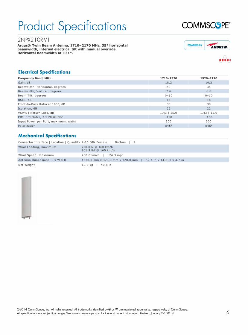
2NPX210R2NPX210R--V1V1 Argus® Twin Beam Antenna, 1710–2170 MHz, 35° horizontal beamwidth, internal electrical tilt with manual override. Horizontal Beamwidth at ±31°.
Electrical SpecificationsFrequency Band, MHz 1710–1920 1920–2170Gain, dBi 18.2 19.2Beamwidth, Horizontal, degrees 40 34Beamwidth, Vertical, degrees 7.6 6.8Beam Tilt, degrees 0–10 0–10USLS, dB 18 18FronttoBack Ratio at 180°, dB 30 30Isolation, dB 22 22VSWR | Return Loss, dB 1.43 | 15.0 1.43 | 15.0PIM, 3rd Order, 2 x 20 W, dBc 150 150Input Power per Port, maximum, watts 300 300Polarization ±45° ±45°
Mechanical SpecificationsConnector Interface | Location | Quantity 716 DIN Female | Bottom | 4
Wind Loading, maximum 720.0 N @ 160 km/h 161.9 lbf @ 160 km/h
Wind Speed, maximum 200.0 km/h | 124.3 mph
Antenna Dimensions, L x W x D 1330.0 mm x 370.0 mm x 120.0 mm | 52.4 in x 14.6 in x 4.7 in
Net Weight 18.5 kg | 40.8 lb
Product SpecificationsProduct Specifications
©©2014 CommScope, Inc. All rights reserved. All trademarks identified by 2014 CommScope, Inc. All rights reserved. All trademarks identified by ® ® or ™ are registered trademarks, respectively, of CommScope.or ™ are registered trademarks, respectively, of CommScope. All specifications are subject to change. See www.commscope.com for the most current information. Revised: January 29, 2014All specifications are subject to change. See www.commscope.com for the most current information. Revised: January 29, 2014
page 1 of 1page 1 of 1April 16, 2014April 16, 20146

2UNPX203.6R22UNPX203.6R2 Argus® Dual Band Twin Beam Antenna, 698–894 and 17102170 MHz, 37° horizontal beamwidth, internal electrical tilt.
Electrical SpecificationsFrequency Band, MHz 698–790 790–894 1710–1920 1920–2170Gain, dBi 13.8 14.5 16.2 17.5Beam Centers, Horizontal, degrees ±28 ±28 ±30 ±30Beamwidth, Horizontal, degrees 40 33 42 35Beamwidth, Vertical, degrees 24.0 21.0 12.0 11.0Beam Tilt, degrees 1–16 1–16 0–10 0–10USLS, dB 15 15 15 15FronttoBack Ratio at 180°, dB 20 20 30 30Isolation, dB 22 22 20 20VSWR | Return Loss, dB 1.43 | 15.0 1.43 | 15.0 1.43 | 15.0 1.43 | 15.0PIM, 3rd Order, 2 x 20 W, dBc 150 150 150 150Input Power per Port, maximum, watts 500 500 300 300Polarization ±45° ±45° ±45° ±45°
Mechanical SpecificationsConnector Interface | Location | Quantity 716 DIN Female | Bottom | 8
Wind Loading, maximum 1550.0 N @ 160 km/h 348.5 lbf @ 160 km/h
Wind Speed, maximum 200.0 km/h | 124.3 mph
Antenna Dimensions, L x W x D 1745.0 mm x 564.0 mm x 127.0 mm | 68.7 in x 22.2 in x 5.0 in
Net Weight 29.5 kg | 65.0 lb
Product SpecificationsProduct Specifications
©©2014 CommScope, Inc. All rights reserved. All trademarks identified by 2014 CommScope, Inc. All rights reserved. All trademarks identified by ® ® or ™ are registered trademarks, respectively, of CommScope.or ™ are registered trademarks, respectively, of CommScope. All specifications are subject to change. See www.commscope.com for the most current information. Revised: January 24, 2014All specifications are subject to change. See www.commscope.com for the most current information. Revised: January 24, 2014
page 1 of 1page 1 of 1April 16, 2014April 16, 20147

HBXXHBXX--3817TB13817TB1--VTMVTM Andrew® Twin Beam Capacity Antenna, 1710–2180 MHz, 2x 38° horizontal beamwidth, RET compatible
*Values calculated using NGMN Alliance NPBASTA v9.6
Electrical SpecificationsFrequency Band, MHz 1710–1880 1850–1990 1920–2180Gain by all Beam Tilts, average, dBi 18.9 19.1 19.3Gain by all Beam Tilts Tolerance, dB ±0.4 ±0.4 ±0.6
Gain by Beam Tilt, average, dBi0 ° | 18.7 5 ° | 19.0 10 ° | 18.9
0 ° | 18.9 5 ° | 19.2 10 ° | 19.1
0 ° | 19.3 5 ° | 19.5 10 ° | 19.0
Beam Centers, Horizontal, degrees ±27 ±27 ±27Beamwidth, Horizontal, degrees 38 36 34Beamwidth, Horizontal Tolerance, degrees ±1.5 ±1.3 ±2.2Beamwidth, Vertical, degrees 7.5 7.1 6.7Beamwidth, Vertical Tolerance, degrees ±0.4 ±0.3 ±0.5Beam Tilt, degrees 0–10 0–10 0–10Horizontal Sidelobe, dB 20 20 20USLS, dB 20 20 21Gain Rolloff at Boresite, dB 9 9 9Gain Rolloff at Boresite Tolerance, dB ±2 ±2 ±2FronttoBack Total Power at 180° ± 30°, dB 30 31 29Isolation, Cross Polarization, port to port, dB 30 30 30VSWR | Return Loss, dB 1.4 | 15.6 1.4 | 15.6 1.4 | 15.6PIM, 3rd Order, 2 x 20 W, dBc 150 150 150Input Power per Port, maximum, watts 250 250 250Polarization ±45° ±45° ±45°
Mechanical SpecificationsColor | Radome Material Light gray | Fiberglass, UV resistant
Connector Interface | Location | Quantity 716 DIN Female | Bottom | 4
Wind Loading, maximum 438.0 N @ 150 km/h 98.5 lbf @ 150 km/h
Wind Speed, maximum 241.0 km/h | 149.8 mph
Antenna Dimensions, L x W x D 1390.0 mm x 301.0 mm x 181.0 mm | 54.7 in x 11.9 in x 7.1 in
Net Weight 16.5 kg | 36.4 lb
Model with factory installed AISG 2.0 RET HBXX3817TB1A2M
Product SpecificationsProduct Specifications
©©2014 CommScope, Inc. All rights reserved. All trademarks identified by 2014 CommScope, Inc. All rights reserved. All trademarks identified by ® ® or ™ are registered trademarks, respectively, of CommScope.or ™ are registered trademarks, respectively, of CommScope. All specifications are subject to change. See www.commscope.com for the most current information. Revised: December 23, 2013All specifications are subject to change. See www.commscope.com for the most current information. Revised: December 23, 2013
page 1 of 1page 1 of 1May 9, 2014May 9, 20148

Low Band Base Station AntennaSelection Guide
Note: Specifications are subject to change without notice. See www.commscope.com for the most current information.
Single Band
Model Frequency (MHz) Polarization Tilt
(Degree)Gain (dBi)
HBW (Degree)
VBW (Degree)
USLS (dB)
F/B (dB)
Isolation (dB) VSWR Max. Input
Power (W)Weight (kg/lb)
Length (mm/in)
Width (mm/in)
33° Horizontal Beamwidth ModelsLDX-3316DS-VTM 790–960 ±45° 2–12 17.9 32 15.0 14 29 30 1.4:1 300 17.9 / 39.5 1306 / 51.4 591 / 23.3
65° Horizontal Beamwidth ModelsLDX-6513DS-VTM 790–960 ±45° 0–15 15.2 65 14.0 16 30 30 1.4:1 350 9.3 / 20.5 1294 / 50.9 269 / 10.6LDX-6515DSP-VTM 790–960 ±45° 0–10 17.1 65 8.1 17 28 30 1.4:1 350 17.9 / 39.4 2339 / 92.1 269 / 10.6LDX-6515DS-VTM 790–960 ±45° 0–10 16.4 64 9.7 18 24 30 1.4:1 350 15.0 / 33.1 2070 / 81.5 269 / 10.6LDX-6516DS-VTM 790–960 ±45° 0–8 17.5 64 7.1 19 24 30 1.4:1 350 21.0 / 46.3 2574 / 101.3 269 / 10.6
85°/90° Horizontal Beamwidth ModelsLRX-8512DS-VTM 698–960 ±45° 0–15 14.0 85 14.4 15 24 30 1.4:1 400 13.6 / 30.0 1293 / 50.9 301 / 11.9LDX-9013DS-VTM 790–960 ±45° 0–10 15.2 90 10.4 16 27 30 1.4:1 300 12.0 / 26.5 1831 / 72.1 225 / 8.9LDX-9014DS-VTM 790–960 ±45° 0–8 15.8 89 7.5 17 22 30 1.4:1 300 18.1 / 39.9 2435 / 95.9 225 / 8.9
Single Band Quad
Model Frequency (MHz) Polarization Tilt
(Degree)Gain (dBi)
HBW (Degree)
VBW (Degree)
USLS (dB)
F/B (dB)
Isolation (dB) VSWR Max. Input
Power (W)Weight (kg/lb)
Length (mm/in)
Width (mm/in)
65° Horizontal Beamwidth ModelsLDXX-6515DS-VTM 2x 790–960 ±45° 0–10 17.0 63 9.6 20 27 30 1.4:1 350 35.6 / 78.5 2070 / 81.5 549 / 21.6LDXX-6516DS-VTM 2x 790–960 ±45° 0–8 17.3 64 7.1 17 24 30 1.4:1 350 32.1 / 70.8 2567 / 101.1 549 / 21.6
85°/90° Horizontal Beamwidth ModelsLDXX-9013DS-VTM 2x 790–960 ±45° 0–10 15.1 87 10.6 17 27 30 1.5:1 300 30.0 / 66.1 1830 / 72.0 549 / 21.6
Low
Ban
d A
nten
nas
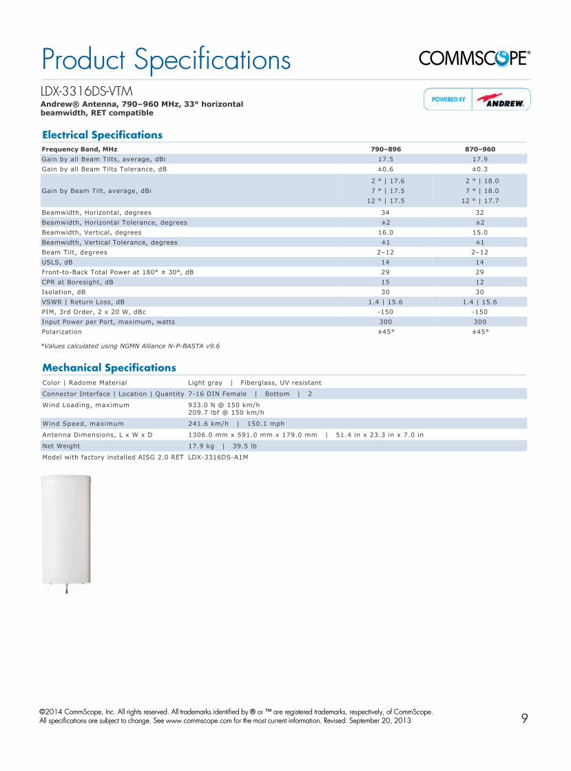
LDXLDX--3316DS3316DS--VTMVTM Andrew® Antenna, 790–960 MHz, 33° horizontal beamwidth, RET compatible
*Values calculated using NGMN Alliance NPBASTA v9.6
Electrical SpecificationsFrequency Band, MHz 790–896 870–960Gain by all Beam Tilts, average, dBi 17.5 17.9Gain by all Beam Tilts Tolerance, dB ±0.6 ±0.3
Gain by Beam Tilt, average, dBi2 ° | 17.6 7 ° | 17.5 12 ° | 17.5
2 ° | 18.0 7 ° | 18.0 12 ° | 17.7
Beamwidth, Horizontal, degrees 34 32Beamwidth, Horizontal Tolerance, degrees ±2 ±2Beamwidth, Vertical, degrees 16.0 15.0Beamwidth, Vertical Tolerance, degrees ±1 ±1Beam Tilt, degrees 2–12 2–12USLS, dB 14 14FronttoBack Total Power at 180° ± 30°, dB 29 29CPR at Boresight, dB 15 12Isolation, dB 30 30VSWR | Return Loss, dB 1.4 | 15.6 1.4 | 15.6PIM, 3rd Order, 2 x 20 W, dBc 150 150Input Power per Port, maximum, watts 300 300Polarization ±45° ±45°
Mechanical SpecificationsColor | Radome Material Light gray | Fiberglass, UV resistant
Connector Interface | Location | Quantity 716 DIN Female | Bottom | 2
Wind Loading, maximum 933.0 N @ 150 km/h 209.7 lbf @ 150 km/h
Wind Speed, maximum 241.6 km/h | 150.1 mph
Antenna Dimensions, L x W x D 1306.0 mm x 591.0 mm x 179.0 mm | 51.4 in x 23.3 in x 7.0 in
Net Weight 17.9 kg | 39.5 lb
Model with factory installed AISG 2.0 RET LDX3316DSA1M
Product SpecificationsProduct Specifications
©©2014 CommScope, Inc. All rights reserved. All trademarks identified by 2014 CommScope, Inc. All rights reserved. All trademarks identified by ® ® or ™ are registered trademarks, respectively, of CommScope.or ™ are registered trademarks, respectively, of CommScope. All specifications are subject to change. See www.commscope.com for the most current information. Revised: September 20, 2013All specifications are subject to change. See www.commscope.com for the most current information. Revised: September 20, 2013
page 1 of 1page 1 of 1May 9, 2014May 9, 20149

LDXLDX--6513DS6513DS--VTMVTM Andrew® Antenna, 790–960 MHz, 65° horizontal beamwidth, RET compatible variable electrical tilt
Electrical SpecificationsFrequency Band, MHz 790–896 870–960Gain, dBi 15.0 15.2Beamwidth, Horizontal, degrees 65 65Beamwidth, Vertical, degrees 15.2 14.5Beam Tilt, degrees 0–15 0–15USLS, typical, dB 16 16FronttoBack Ratio at 180°, dB 32 30Isolation, dB 30 30VSWR | Return Loss, dB 1.4 | 15.6 1.4 | 15.6PIM, 3rd Order, 2 x 20 W, dBc 150 150Input Power per Port, maximum, watts 350 350Polarization ±45° ±45°
Mechanical SpecificationsColor | Radome Material Light gray | PVC, UV resistant
Connector Interface | Location | Quantity 716 DIN Female | Bottom | 2
Wind Loading, maximum 402.2 N @ 150 km/h 90.4 lbf @ 150 km/h
Wind Speed, maximum 241.5 km/h | 150.0 mph
Antenna Dimensions, L x W x D 1294.0 mm x 269.0 mm x 132.0 mm | 50.9 in x 10.6 in x 5.2 in
Net Weight 9.3 kg | 20.5 lb
Model with factory installed AISG 2.0 RET LDX6513DSA1M
Product SpecificationsProduct Specifications
©©2014 CommScope, Inc. All rights reserved. All trademarks identified by 2014 CommScope, Inc. All rights reserved. All trademarks identified by ® ® or ™ are registered trademarks, respectively, of CommScope.or ™ are registered trademarks, respectively, of CommScope. All specifications are subject to change. See www.commscope.com for the most current information. Revised: September 20, 2013All specifications are subject to change. See www.commscope.com for the most current information. Revised: September 20, 2013
page 1 of 1page 1 of 1April 16, 2014April 16, 201410

LDXLDX--6515DSP6515DSP--VTMVTM Andrew® Antenna, 790–960 MHz, 65° horizontal beamwidth, RET compatible variable electrical tilt
Electrical SpecificationsFrequency Band, MHz 790–896 870–960Gain, dBi 17.1 17.1Beamwidth, Horizontal, degrees 65 65Beamwidth, Vertical, degrees 8.7 8.1Beam Tilt, degrees 0–10 0–10USLS, typical, dB 17 16FronttoBack Ratio at 180°, dB 27 28Isolation, dB 30 30VSWR | Return Loss, dB 1.4 | 15.6 1.4 | 15.6PIM, 3rd Order, 2 x 20 W, dBc 150 150Input Power per Port, maximum, watts 350 350Polarization ±45° ±45°
Mechanical SpecificationsColor | Radome Material Light gray | PVC, UV resistant
Connector Interface | Location | Quantity 716 DIN Female | Bottom | 2
Wind Loading, maximum 828.2 N @ 150 km/h 186.2 lbf @ 150 km/h
Wind Speed, maximum 241.5 km/h | 150.0 mph
Antenna Dimensions, L x W x D 2339.0 mm x 269.0 mm x 132.0 mm | 92.1 in x 10.6 in x 5.2 in
Net Weight 17.9 kg | 39.4 lb
Model with factory installed AISG 2.0 RET LDX6515DSPA1M
Product SpecificationsProduct Specifications
©©2014 CommScope, Inc. All rights reserved. All trademarks identified by 2014 CommScope, Inc. All rights reserved. All trademarks identified by ® ® or ™ are registered trademarks, respectively, of CommScope.or ™ are registered trademarks, respectively, of CommScope. All specifications are subject to change. See www.commscope.com for the most current information. Revised: September 20, 2013All specifications are subject to change. See www.commscope.com for the most current information. Revised: September 20, 2013
page 1 of 1page 1 of 1April 16, 2014April 16, 201411

LDXLDX--6515DS6515DS--VTMVTM Andrew® Antenna, 790–960 MHz, 65° horizontal beamwidth, RET compatible variable electrical tilt
*Values calculated using NGMN Alliance NPBASTA v9.6
Electrical SpecificationsFrequency Band, MHz 790–896 870–960Gain by all Beam Tilts, average, dBi 16.2 16.4Gain by all Beam Tilts Tolerance, dB ±0.2 ±0.3
Gain by Beam Tilt, average, dBi0 ° | 16.1 5 ° | 16.3 10 ° | 16.2
0 ° | 16.3 5 ° | 16.4 10 ° | 16.2
Beamwidth, Horizontal, degrees 64 64Beamwidth, Horizontal Tolerance, degrees ±1.4 ±1Beamwidth, Vertical, degrees 10.2 9.7Beamwidth, Vertical Tolerance, degrees ±0.7 ±0.4Beam Tilt, degrees 0–10 0–10USLS, dB 17 18FronttoBack Total Power at 180° ± 30°, dB 25 24CPR at Boresight, dB 28 25CPR at Sector, dB 16 14Isolation, dB 30 30VSWR | Return Loss, dB 1.4 | 15.6 1.4 | 15.6PIM, 3rd Order, 2 x 20 W, dBc 150 150Input Power per Port, maximum, watts 350 350Polarization ±45° ±45°
Mechanical SpecificationsColor | Radome Material Light gray | PVC, UV resistant
Connector Interface | Location | Quantity 716 DIN Female | Bottom | 2
Wind Loading, maximum 718.0 N @ 150 km/h 161.4 lbf @ 150 km/h
Wind Speed, maximum 241.5 km/h | 150.0 mph
Antenna Dimensions, L x W x D 2070.0 mm x 269.0 mm x 132.0 mm | 81.5 in x 10.6 in x 5.2 in
Net Weight 15.0 kg | 33.1 lb
Model with factory installed AISG 2.0 RET LDX6515DSA1M
Product SpecificationsProduct Specifications
©©2014 CommScope, Inc. All rights reserved. All trademarks identified by 2014 CommScope, Inc. All rights reserved. All trademarks identified by ® ® or ™ are registered trademarks, respectively, of CommScope.or ™ are registered trademarks, respectively, of CommScope. All specifications are subject to change. See www.commscope.com for the most current information. Revised: January 17, 2014All specifications are subject to change. See www.commscope.com for the most current information. Revised: January 17, 2014
page 1 of 1page 1 of 1May 9, 2014May 9, 201412

LDXLDX--6516DS6516DS--VTMVTM Andrew® Antenna, 790–960 MHz, 65° horizontal beamwidth, RET compatible variable electrical tilt
*Values calculated using NGMN Alliance NPBASTA v9.6
Electrical SpecificationsFrequency Band, MHz 790–896 870–960Gain by all Beam Tilts, average, dBi 17.3 17.5Gain by all Beam Tilts Tolerance, dB ±0.3 ±0.3
Gain by Beam Tilt, average, dBi0 ° | 17.2 4 ° | 17.4 8 ° | 17.3
0 ° | 17.5 4 ° | 17.6 8 ° | 17.6
Beamwidth, Horizontal, degrees 64 64Beamwidth, Horizontal Tolerance, degrees ±1.3 ±1Beamwidth, Vertical, degrees 7.6 7.1Beamwidth, Vertical Tolerance, degrees ±0.5 ±0.3Beam Tilt, degrees 0–8 0–8USLS, dB 19 19FronttoBack Total Power at 180° ± 30°, dB 25 24CPR at Boresight, dB 24 22CPR at Sector, dB 17 16Isolation, dB 30 30VSWR | Return Loss, dB 1.4 | 15.6 1.4 | 15.6PIM, 3rd Order, 2 x 20 W, dBc 153 153Input Power per Port, maximum, watts 350 350Polarization ±45° ±45°
Mechanical SpecificationsColor | Radome Material Light gray | PVC, UV resistant
Connector Interface | Location | Quantity 716 DIN Female | Bottom | 2
Wind Loading, maximum 922.0 N @ 150 km/h 207.3 lbf @ 150 km/h
Wind Speed, maximum 201.0 km/h | 124.9 mph
Antenna Dimensions, L x W x D 2574.0 mm x 269.0 mm x 132.0 mm | 101.3 in x 10.6 in x 5.2 in
Net Weight 21.0 kg | 46.3 lb
Model with factory installed AISG 2.0 RET LDX6516DSA1M
Product SpecificationsProduct Specifications
©©2014 CommScope, Inc. All rights reserved. All trademarks identified by 2014 CommScope, Inc. All rights reserved. All trademarks identified by ® ® or ™ are registered trademarks, respectively, of CommScope.or ™ are registered trademarks, respectively, of CommScope. All specifications are subject to change. See www.commscope.com for the most current information. Revised: January 17, 2014All specifications are subject to change. See www.commscope.com for the most current information. Revised: January 17, 2014
page 1 of 1page 1 of 1May 9, 2014May 9, 201413

LRXLRX--8512DS8512DS--VTMVTM Andrew® Antenna, 698–960 MHz, 85° horizontal beamwidth, RET compatible
Electrical SpecificationsFrequency Band, MHz 698–806 806–896 870–960Gain, dBi 13.5 13.9 14.0Beamwidth, Horizontal, degrees 85 85 85Beamwidth, Vertical, degrees 16.8 15.3 14.4Beam Tilt, degrees 0–15 0–15 0–15USLS, typical, dB 16 15 15FronttoBack Ratio at 180°, dB 26 25 24CPR at Boresight, dB 20 27 24CPR at Sector, dB 13 11 10Isolation, dB 30 30 30VSWR | Return Loss, dB 1.4 | 15.6 1.4 | 15.6 1.5 | 14.0PIM, 3rd Order, 2 x 20 W, dBc 153 153 153Input Power per Port, maximum, watts 400 400 400Polarization ±45° ±45° ±45°
Mechanical SpecificationsColor | Radome Material Light gray | Fiberglass, UV resistant
Connector Interface | Location | Quantity 716 DIN Female | Bottom | 2
Wind Loading, maximum 402.0 N @ 150 km/h 90.4 lbf @ 150 km/h
Wind Speed, maximum 241.4 km/h | 150.0 mph
Antenna Dimensions, L x W x D 1293.0 mm x 301.0 mm x 181.0 mm | 50.9 in x 11.9 in x 7.1 in
Net Weight 13.6 kg | 30.0 lb
Model with factory installed AISG 2.0 RET LRX8512DSA1M
Product SpecificationsProduct Specifications
©©2014 CommScope, Inc. All rights reserved. All trademarks identified by 2014 CommScope, Inc. All rights reserved. All trademarks identified by ® ® or ™ are registered trademarks, respectively, of CommScope.or ™ are registered trademarks, respectively, of CommScope. All specifications are subject to change. See www.commscope.com for the most current information. Revised: December 26, 2013All specifications are subject to change. See www.commscope.com for the most current information. Revised: December 26, 2013
page 1 of 1page 1 of 1April 16, 2014April 16, 201414

LDXLDX--9013DS9013DS--VTMVTM Andrew® Antenna, 790–960 MHz, 90° horizontal beamwidth, RET compatible
Electrical SpecificationsFrequency Band, MHz 790–896 870–960Gain, dBi 14.9 15.2Beamwidth, Horizontal, degrees 90 90Beamwidth, Vertical, degrees 11.4 10.4Beam Tilt, degrees 0–10 0–10
USLS by Beam Tilt, dB0 ° 6 ° 10 °14 16 14
0 ° 6 ° 10 °14 16 14
FronttoBack Ratio at 180°, dB 25 27CPR at Boresight, dB 19 19CPR at Sector, dB 15 15Isolation, dB 30 30VSWR | Return Loss, dB 1.5 | 14.0 1.4 | 15.6PIM, 3rd Order, 2 x 20 W, dBc 150 150Input Power per Port, maximum, watts 300 300Polarization ±45° ±45°
Mechanical SpecificationsColor | Radome Material Light gray | Fiberglass, UV resistant
Connector Interface | Location | Quantity 716 DIN Female | Bottom | 2
Wind Loading, maximum 391.5 N @ 150 km/h 88.0 lbf @ 150 km/h
Wind Speed, maximum 241.6 km/h | 150.1 mph
Antenna Dimensions, L x W x D 1831.0 mm x 225.0 mm x 164.0 mm | 72.1 in x 8.9 in x 6.5 in
Net Weight 12.0 kg | 26.5 lb
Model with factory installed AISG 2.0 RET LDX9013DSA1M
Product SpecificationsProduct Specifications
©©2014 CommScope, Inc. All rights reserved. All trademarks identified by 2014 CommScope, Inc. All rights reserved. All trademarks identified by ® ® or ™ are registered trademarks, respectively, of CommScope.or ™ are registered trademarks, respectively, of CommScope. All specifications are subject to change. See www.commscope.com for the most current information. Revised: February 11, 2014All specifications are subject to change. See www.commscope.com for the most current information. Revised: February 11, 2014
page 1 of 1page 1 of 1April 16, 2014April 16, 201415
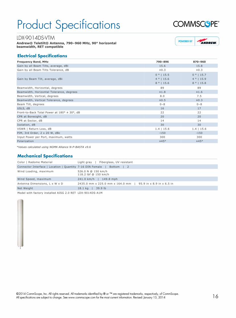
LDXLDX--9014DS9014DS--VTMVTM Andrew® Teletilt® Antenna, 790–960 MHz, 90° horizontal beamwidth, RET compatible
*Values calculated using NGMN Alliance NPBASTA v9.6
Electrical SpecificationsFrequency Band, MHz 790–896 870–960Gain by all Beam Tilts, average, dBi 15.6 15.8Gain by all Beam Tilts Tolerance, dB ±0.3 ±0.3
Gain by Beam Tilt, average, dBi0 ° | 15.5 4 ° | 15.6 8 ° | 15.6
0 ° | 15.7 4 ° | 15.9 8 ° | 15.8
Beamwidth, Horizontal, degrees 89 89Beamwidth, Horizontal Tolerance, degrees ±1.8 ±1.6Beamwidth, Vertical, degrees 8.0 7.5Beamwidth, Vertical Tolerance, degrees ±0.5 ±0.3Beam Tilt, degrees 0–8 0–8USLS, dB 16 17FronttoBack Total Power at 180° ± 30°, dB 22 22CPR at Boresight, dB 20 20CPR at Sector, dB 14 14Isolation, dB 30 30VSWR | Return Loss, dB 1.4 | 15.6 1.4 | 15.6PIM, 3rd Order, 2 x 20 W, dBc 150 150Input Power per Port, maximum, watts 300 300Polarization ±45° ±45°
Mechanical SpecificationsColor | Radome Material Light gray | Fiberglass, UV resistant
Connector Interface | Location | Quantity 716 DIN Female | Bottom | 2
Wind Loading, maximum 526.0 N @ 150 km/h 118.2 lbf @ 150 km/h
Wind Speed, maximum 241.0 km/h | 149.8 mph
Antenna Dimensions, L x W x D 2435.0 mm x 225.0 mm x 164.0 mm | 95.9 in x 8.9 in x 6.5 in
Net Weight 18.1 kg | 39.9 lb
Model with factory installed AISG 2.0 RET LDX9014DSA1M
Product SpecificationsProduct Specifications
©©2014 CommScope, Inc. All rights reserved. All trademarks identified by 2014 CommScope, Inc. All rights reserved. All trademarks identified by ® ® or ™ are registered trademarks, respectively, of CommScope.or ™ are registered trademarks, respectively, of CommScope. All specifications are subject to change. See www.commscope.com for the most current information. Revised: January 13, 2014All specifications are subject to change. See www.commscope.com for the most current information. Revised: January 13, 2014
page 1 of 1page 1 of 1May 9, 2014May 9, 201416

LDXXLDXX--6515DS6515DS--VTMVTM Andrew® Quad Port Teletilt® Antenna, 790–960 MHz, 65° horizontal beamwidth, RET compatible
Electrical SpecificationsFrequency Band, MHz 790–862 824–894 870–960Gain, dBi 16.3 16.4 17.0Beamwidth, Horizontal, degrees 67 65 63Beamwidth, Vertical, degrees 10.3 10.2 9.6Beam Tilt, degrees 0–10 0–10 0–10
USLS by Beam Tilt, dB0 ° 6 ° 10 °17 21 19
0 ° 6 ° 10 °17 21 18
0 ° 6 ° 10 °16 20 20
FronttoBack Ratio at 180°, dB 32 28 27CPR at Boresight, dB 24 23 23CPR at Sector, dB 14 13 10Isolation, dB 30 30 30VSWR | Return Loss, dB 1.4 | 15.6 1.4 | 15.6 1.4 | 15.6PIM, 3rd Order, 2 x 20 W, dBc 150 150 150Input Power per Port, maximum, watts 350 350 350Polarization ±45° ±45° ±45°
Mechanical SpecificationsColor | Radome Material Light gray | Fiberglass, UV resistant
Connector Interface | Location | Quantity 716 DIN Female | Bottom | 4
Wind Loading, maximum 1170.0 N @ 150 km/h 263.0 lbf @ 150 km/h
Wind Speed, maximum 241.0 km/h | 149.8 mph
Antenna Dimensions, L x W x D 2070.0 mm x 549.0 mm x 165.0 mm | 81.5 in x 21.6 in x 6.5 in
Net Weight 35.6 kg | 78.5 lb
Model with factory installed AISG 2.0 RET LDXX6515DSA2M
Product SpecificationsProduct Specifications
©©2014 CommScope, Inc. All rights reserved. All trademarks identified by 2014 CommScope, Inc. All rights reserved. All trademarks identified by ® ® or ™ are registered trademarks, respectively, of CommScope.or ™ are registered trademarks, respectively, of CommScope. All specifications are subject to change. See www.commscope.com for the most current information. Revised: January 29, 2014All specifications are subject to change. See www.commscope.com for the most current information. Revised: January 29, 2014
page 1 of 1page 1 of 1April 16, 2014April 16, 201417

LDXXLDXX--6516DS6516DS--VTMVTM Andrew® Quad Port Teletilt® Antenna, 790–960 MHz, 65° horizontal beamwidth, RET compatible
*Values calculated using NGMN Alliance NPBASTA v9.6
Electrical SpecificationsFrequency Band, MHz 790–862 824–894 870–960Gain by all Beam Tilts, average, dBi 16.8 17.1 17.3Gain by all Beam Tilts Tolerance, dB ±0.5 ±0.2 ±0.4
Gain by Beam Tilt, average, dBi0 ° | 16.7 4 ° | 16.8 8 ° | 16.7
0 ° | 17.0 4 ° | 17.2 8 ° | 17.1
0 ° | 17.2 4 ° | 17.3 8 ° | 17.3
Beamwidth, Horizontal, degrees 70 67 64Beamwidth, Horizontal Tolerance, degrees ±3.5 ±3.1 ±4Beamwidth, Vertical, degrees 7.9 7.5 7.1Beamwidth, Vertical Tolerance, degrees ±0.4 ±0.4 ±0.3Beam Tilt, degrees 0–8 0–8 0–8USLS, typical, dB 16 17 17FronttoBack Total Power at 180° ± 30°, dB 26 26 24CPR at Boresight, dB 24 24 25CPR at Sector, dB 16 16 12Isolation, dB 30 30 30Isolation, Cross Polarization, port to port, dB 30 30 30VSWR | Return Loss, dB 1.4 | 15.6 1.4 | 15.6 1.4 | 15.6PIM, 3rd Order, 2 x 20 W, dBc 150 150 150Input Power per Port, maximum, watts 350 350 350Polarization ±45° ±45° ±45°
Mechanical SpecificationsColor | Radome Material Light gray | Fiberglass, UV resistant
Connector Interface | Location | Quantity 716 DIN Female | Bottom | 4
Wind Loading, maximum 1436.0 N @ 150 km/h 322.8 lbf @ 150 km/h
Wind Speed, maximum 241.0 km/h | 149.8 mph
Antenna Dimensions, L x W x D 2567.0 mm x 549.0 mm x 165.0 mm | 101.1 in x 21.6 in x 6.5 in
Net Weight 32.1 kg | 70.8 lb
Model with factory installed AISG 2.0 RET LDXX6516DSA2M
Product SpecificationsProduct Specifications
©©2014 CommScope, Inc. All rights reserved. All trademarks identified by 2014 CommScope, Inc. All rights reserved. All trademarks identified by ® ® or ™ are registered trademarks, respectively, of CommScope.or ™ are registered trademarks, respectively, of CommScope. All specifications are subject to change. See www.commscope.com for the most current information. Revised: April 16, 2014All specifications are subject to change. See www.commscope.com for the most current information. Revised: April 16, 2014
page 1 of 1page 1 of 1May 9, 2014May 9, 201418

LDXXLDXX--9013DS9013DS--VTMVTM Andrew® Quad Port Teletilt® Antenna, 790–960 MHz, 90° horizontal beamwidth, RET compatible
Electrical SpecificationsFrequency Band, MHz 790–862 824–894 870–960Gain, dBi 14.7 14.7 15.1Beamwidth, Horizontal, degrees 90 88 87Beamwidth, Vertical, degrees 11.4 11.0 10.6Beam Tilt, degrees 0–10 0–10 0–10
USLS by Beam Tilt, dB0 ° 6 ° 10 °19 15 15
0 ° 6 ° 10 °17 15 15
0 ° 6 ° 10 °16 17 15
FronttoBack Ratio at 180°, dB 26 27 27CPR at Boresight, dB 18 18 19CPR at Sector, dB 10 11 11Isolation, dB 30 30 30VSWR | Return Loss, dB 1.5 | 14.0 1.5 | 14.0 1.5 | 14.0PIM, 3rd Order, 2 x 20 W, dBc 150 150 150Input Power per Port, maximum, watts 300 300 300Polarization ±45° ±45° ±45°
Mechanical SpecificationsColor | Radome Material Light gray | Fiberglass, UV resistant
Connector Interface | Location | Quantity 716 DIN Female | Bottom | 4
Wind Loading, maximum 1188.1 N @ 150 km/h 267.1 lbf @ 150 km/h
Wind Speed, maximum 241.0 km/h | 149.8 mph
Antenna Dimensions, L x W x D 1830.0 mm x 549.0 mm x 165.0 mm | 72.0 in x 21.6 in x 6.5 in
Net Weight 30.0 kg | 66.1 lb
Model with factory installed AISG 2.0 RET LDXX9013DSA2M
Product SpecificationsProduct Specifications
©©2014 CommScope, Inc. All rights reserved. All trademarks identified by 2014 CommScope, Inc. All rights reserved. All trademarks identified by ® ® or ™ are registered trademarks, respectively, of CommScope.or ™ are registered trademarks, respectively, of CommScope. All specifications are subject to change. See www.commscope.com for the most current information. Revised: January 29, 2014All specifications are subject to change. See www.commscope.com for the most current information. Revised: January 29, 2014
page 1 of 1page 1 of 1April 16, 2014April 16, 201419

High Band Base Station AntennaSelection Guide
Note: Specifications are subject to change without notice. See www.commscope.com for the most current information.
Single Band Ultra-Wideband
Model Frequency (MHz) Polarization Tilt
(Degree)Gain (dBi)
HBW (Degree)
VBW (Degree)
USLS (dB)
F/B (dB)
Isolation (dB) VSWR Max. Input
Power (W)Weight (kg/lb)
Length (mm/in)
Width (mm/in)
65° Horizontal Beamwidth ModelsHWX-6516DS1-VTM 1710–2690 ±45° 0–10 18.5 61 5.0 21 28 30 1.5:1 300 6.0 / 13.2 1390 / 54.7 170 / 6.7
Single Band Quad Ultra-Wideband
Model Frequency (MHz) Polarization Tilt
(Degree)Gain (dBi)
HBW (Degree)
VBW (Degree)
USLS (dB)
F/B (dB)
Isolation (dB) VSWR Max. Input
Power (W)Weight (kg/lb)
Length (mm/in)
Width (mm/in)
65° Horizontal Beamwidth ModelsHWXX-6516DS1-VTM 2x 1710–2690 ±45° 0–10 18.3 63 5.3 20 27 30 1.5:1 350 10.2 / 22.5 1390 / 54.7 305 / 12.0VVPX303F1 2x 1710–2690 ±45° 0 13.2 62 19.0 17 25 30 1.5:1 250 5.0 / 11.0 420 / 16.5 290 / 11.4VVPX306M-V5 2x 1710–2690 ±45° 0–10 16.3 61 10.1 18 29 30 1.5:1 250 8.5 / 18.7 875 / 34.4 290 / 11.4
Single Band Hex Port Ultra-Wideband
Model Frequency (MHz) Polarization Tilt
(Degree)Gain (dBi)
HBW (Degree)
VBW (Degree)
USLS (dB)
F/B (dB)
Isolation (dB) VSWR Max. Input
Power (W)Weight (kg/lb)
Length (mm/in)
Width (mm/in)
65° Horizontal Beamwidth ModelsHWXXX-6516DS-VTM 3x 1710–2690 ±45° 0–10 18.3 62 5.1 21 26 30 1.5:1 350 19.5 / 43.0 1390 / 54.7 504 / 19.8
Hig
h Ba
nd A
nten
nas

HWXHWX--6516DS16516DS1--VTMVTM Andrew® Teletilt® Antenna, 1710–2690 MHz, 65° horizontal beamwidth, RET compatible
*Values calculated using NGMN Alliance NPBASTA v9.6
Electrical SpecificationsFrequency Band, MHz 1710–1880 1850–1990 1920–2170 2300–2500 2500–2690Gain by all Beam Tilts, average, dBi 17.1 17.2 17.7 18.3 18.5Gain by all Beam Tilts Tolerance, dB ±0.3 ±0.3 ±0.7 ±0.2 ±0.4
Gain by Beam Tilt, average, dBi0 ° | 17.1 5 ° | 17.2 10 ° | 16.9
0 ° | 17.2 5 ° | 17.3 10 ° | 16.9
0 ° | 17.7 5 ° | 17.8 10 ° | 17.4
0 ° | 18.1 5 ° | 18.4 10 ° | 18.1
0 ° | 18.6 5 ° | 18.7 10 ° | 18.1
Beamwidth, Horizontal, degrees 68 66 65 61 60Beamwidth, Horizontal Tolerance, degrees ±2.4 ±2.3 ±1.9 ±2.2 ±1.9Beamwidth, Vertical, degrees 6.8 6.4 6.1 5.4 5.0Beamwidth, Vertical Tolerance, degrees ±0.3 ±0.2 ±0.4 ±0.3 ±0.3Beam Tilt, degrees 0–10 0–10 0–10 0–10 0–10USLS, dB 18 17 17 21 20FronttoBack Total Power at 180° ± 30°, dB 27 27 27 28 26CPR at Boresight, dB 17 19 20 21 17CPR at Sector, dB 14 12 11 10 9Isolation, dB 30 30 30 30 30VSWR | Return Loss, dB 1.5 | 14.0 1.5 | 14.0 1.5 | 14.0 1.5 | 14.0 1.5 | 14.0PIM, 3rd Order, 2 x 20 W, dBc 150 150 150 150 150Input Power per Port, maximum, watts 350 350 350 300 300Polarization ±45° ±45° ±45° ±45° ±45°
Mechanical SpecificationsColor | Radome Material Light gray | PVC, UV resistant
Connector Interface | Location | Quantity 716 DIN Female | Bottom | 2
Wind Loading, maximum 273.0 N @ 150 km/h 61.4 lbf @ 150 km/h
Wind Speed, maximum 241.0 km/h | 149.8 mph
Antenna Dimensions, L x W x D 1390.0 mm x 170.0 mm x 105.0 mm | 54.7 in x 6.7 in x 4.1 in
Net Weight 6.0 kg | 13.2 lb
Model with factory installed AISG 2.0 RET HWX6516DS1A1M
Product SpecificationsProduct Specifications
©©2014 CommScope, Inc. All rights reserved. All trademarks identified by 2014 CommScope, Inc. All rights reserved. All trademarks identified by ® ® or ™ are registered trademarks, respectively, of CommScope.or ™ are registered trademarks, respectively, of CommScope. All specifications are subject to change. See www.commscope.com for the most current information. Revised: January 31, 2014All specifications are subject to change. See www.commscope.com for the most current information. Revised: January 31, 2014
page 1 of 1page 1 of 1May 9, 2014May 9, 201420

HWXXHWXX--6516DS16516DS1--VTMVTM Andrew® Quad Port Teletilt® Antenna, 1710–2690 MHz, 65° horizontal beamwidth RET compatible
*Values calculated using NGMN Alliance NPBASTA v9.6
Electrical SpecificationsFrequency Band, MHz 1710–1880 1850–1990 1920–2170 2300–2500 2500–2690Gain by all Beam Tilts, average, dBi 17.2 17.4 17.8 18.0 18.3Gain by all Beam Tilts Tolerance, dB ±0.3 ±0.4 ±0.5 ±0.3 ±0.3
Gain by Beam Tilt, average, dBi0 ° | 17.0 5 ° | 17.3 10 ° | 17.1
0 ° | 17.3 5 ° | 17.4 10 ° | 17.2
0 ° | 17.8 5 ° | 17.9 10 ° | 17.6
0 ° | 17.8 5 ° | 18.1 10 ° | 18.0
0 ° | 18.3 5 ° | 18.4 10 ° | 17.9
Beamwidth, Horizontal, degrees 66 65 65 63 62Beamwidth, Horizontal Tolerance, degrees ±2.7 ±2.7 ±2.1 ±2.1 ±3Beamwidth, Vertical, degrees 6.7 6.4 6.1 5.3 5.1Beamwidth, Vertical Tolerance, degrees ±0.3 ±0.2 ±0.4 ±0.2 ±0.2Beam Tilt, degrees 0–10 0–10 0–10 0–10 0–10USLS, dB 16 16 17 20 21FronttoBack Total Power at 180° ± 30°, dB 25 26 27 27 26CPR at Boresight, dB 16 17 16 19 18CPR at Sector, dB 15 14 14 9 10Isolation, dB 30 30 30 30 30Isolation, Intersystem, dB 30 30 30 30 30VSWR | Return Loss, dB 1.5 | 14.0 1.5 | 14.0 1.5 | 14.0 1.5 | 14.0 1.5 | 14.0PIM, 3rd Order, 2 x 20 W, dBc 150 150 150 150 150Input Power per Port, maximum, watts 350 350 350 350 350Polarization ±45° ±45° ±45° ±45° ±45°
Mechanical SpecificationsColor | Radome Material Light gray | PVC, UV resistant
Connector Interface | Location | Quantity 716 DIN Female | Bottom | 4
Wind Loading, maximum 512.0 N @ 150 km/h 115.1 lbf @ 150 km/h
Wind Speed, maximum 241.0 km/h | 149.8 mph
Antenna Dimensions, L x W x D 1390.0 mm x 305.0 mm x 118.0 mm | 54.7 in x 12.0 in x 4.6 in
Net Weight 10.2 kg | 22.5 lb
Model with factory installed AISG 2.0 RET HWXX6516DS1A2M
Product SpecificationsProduct Specifications
©©2014 CommScope, Inc. All rights reserved. All trademarks identified by 2014 CommScope, Inc. All rights reserved. All trademarks identified by ® ® or ™ are registered trademarks, respectively, of CommScope.or ™ are registered trademarks, respectively, of CommScope. All specifications are subject to change. See www.commscope.com for the most current information. Revised: January 10, 2014All specifications are subject to change. See www.commscope.com for the most current information. Revised: January 10, 2014
page 1 of 1page 1 of 1May 9, 2014May 9, 201421

VVPX303F1VVPX303F1 Argus® Quad Antenna, 2 x 17102690 MHz, fixed electrical tilt
Electrical SpecificationsFrequency Band, MHz 1710–1920 1920–2170 2300–2690Gain, dBi 11.8 12.5 13.2Beamwidth, Horizontal, degrees 68 66 62Beamwidth, Vertical, degrees 27.0 23.0 19.0Beam Tilt, degrees 0 0 0USLS, dB 17 17 17FronttoBack Ratio at 180°, dB 25 25 25Isolation, dB 30 30 30VSWR | Return Loss, dB 1.5 | 14.0 1.5 | 14.0 1.5 | 14.0PIM, 3rd Order, 2 x 20 W, dBc 150 150 150Input Power per Port, maximum, watts 250 250 250Polarization ±45° ±45° ±45°
Mechanical SpecificationsConnector Interface | Location | Quantity 716 DIN Female | Bottom | 4
Wind Loading, maximum 180.0 N @ 160 km/h 40.5 lbf @ 160 km/h
Wind Speed, maximum 200.0 km/h | 124.3 mph
Antenna Dimensions, L x W x D 420.0 mm x 290.0 mm x 103.0 mm | 16.5 in x 11.4 in x 4.1 in
Net Weight 5.0 kg | 11.0 lb
Product SpecificationsProduct Specifications
©©2014 CommScope, Inc. All rights reserved. All trademarks identified by 2014 CommScope, Inc. All rights reserved. All trademarks identified by ® ® or ™ are registered trademarks, respectively, of CommScope.or ™ are registered trademarks, respectively, of CommScope. All specifications are subject to change. See www.commscope.com for the most current information. Revised: March 20, 2014All specifications are subject to change. See www.commscope.com for the most current information. Revised: March 20, 2014
page 1 of 1page 1 of 1April 16, 2014April 16, 201422

VVPX306MVVPX306M--V5V5 Argus® Quad Antenna, 2 x 1710–2690 MHz, 65° horizontal beamwidth, variable electrical tilt
*Values calculated using NGMN Alliance NPBASTA v9.6
Electrical SpecificationsFrequency Band, MHz 1710–1920 1920–2170 2300–2690Gain by all Beam Tilts, average, dBi 15.0 15.6 16.3Gain by all Beam Tilts Tolerance, dB ±0.4 ±0.3 ±0.5
Gain by Beam Tilt, average, dBi0 ° | 14.9 5 ° | 14.9 10 ° | 15.0
0 ° | 15.6 5 ° | 15.6 10 ° | 15.6
0 ° | 16.4 5 ° | 16.4 10 ° | 16.0
Beamwidth, Horizontal, degrees 65 64 61Beamwidth, Horizontal Tolerance, degrees ±3.4 ±3.5 ±5.4Beamwidth, Vertical, degrees 13.9 12.5 10.1Beamwidth, Vertical Tolerance, degrees ±0.9 ±0.8 ±0.8Beam Tilt, degrees 0–10 0–10 0–10USLS, dB 18 18 18FronttoBack Total Power at 180° ± 30°, dB 24 26 29CPR at Boresight, dB 11 18 21CPR at Sector, dB 18 12 12Isolation, dB 30 30 30Isolation, Intersystem, dB 30 30 30VSWR | Return Loss, dB 1.5 | 14.0 1.5 | 14.0 1.5 | 14.0PIM, 3rd Order, 2 x 20 W, dBc 150 150 150Input Power per Port, maximum, watts 250 250 250Polarization ±45° ±45° ±45°
Mechanical SpecificationsConnector Interface | Location | Quantity 716 DIN Female | Bottom | 4
Wind Loading, maximum 326.0 N @ 150 km/h 73.3 lbf @ 150 km/h
Wind Speed, maximum 250.0 km/h | 155.3 mph
Antenna Dimensions, L x W x D 875.0 mm x 290.0 mm x 103.0 mm | 34.4 in x 11.4 in x 4.1 in
Net Weight 8.5 kg | 18.7 lb
Product SpecificationsProduct Specifications
©©2014 CommScope, Inc. All rights reserved. All trademarks identified by 2014 CommScope, Inc. All rights reserved. All trademarks identified by ® ® or ™ are registered trademarks, respectively, of CommScope.or ™ are registered trademarks, respectively, of CommScope. All specifications are subject to change. See www.commscope.com for the most current information. Revised: February 20, 2014All specifications are subject to change. See www.commscope.com for the most current information. Revised: February 20, 2014
page 1 of 1page 1 of 1May 9, 2014May 9, 201423

HWXXXHWXXX--6516DS6516DS--VTMVTM Andrew® Hex Port Teletilt® Antenna, 1710–2690 MHz, 65° horizontal beamwidth, RET compatible
*Values calculated using NGMN Alliance NPBASTA v9.6
Electrical SpecificationsFrequency Band, MHz 1710–1880 1850–1990 1920–2180 2300–2500 2500–2690Gain by all Beam Tilts, average, dBi 17.2 17.3 17.6 17.9 17.9Gain by all Beam Tilts Tolerance, dB ±0.3 ±0.4 ±0.5 ±0.3 ±0.5
Gain by Beam Tilt, average, dBi0 ° | 17.0 5 ° | 17.2 10 ° | 17.2
0 ° | 17.1 5 ° | 17.3 10 ° | 17.3
0 ° | 17.5 5 ° | 17.7 10 ° | 17.7
0 ° | 17.7 5 ° | 17.9 10 ° | 17.9
0 ° | 17.7 5 ° | 18.0 10 ° | 17.8
Beamwidth, Horizontal, degrees 62 63 64 62 61Beamwidth, Horizontal Tolerance, degrees ±3.6 ±2.9 ±4.2 ±3.9 ±5.3Beamwidth, Vertical, degrees 7.3 6.8 6.4 5.3 5.0Beamwidth, Vertical Tolerance, degrees ±0.4 ±0.3 ±0.5 ±0.2 ±0.3Beam Tilt, degrees 0–10 0–10 0–10 0–10 0–10USLS, dB 15 16 17 15 14FronttoBack Total Power at 180° ± 30°, dB 24 24 23 23 20CPR at Boresight, dB 23 21 19 19 19CPR at Sector, dB 13 10 9 8 14Isolation, dB 30 30 30 30 30VSWR | Return Loss, dB 1.5 | 14.0 1.5 | 14.0 1.5 | 14.0 1.5 | 14.0 1.5 | 14.0PIM, 3rd Order, 2 x 20 W, dBc 150 150 150 150 150Input Power per Port, maximum, watts 350 350 350 300 300Polarization ±45° ±45° ±45° ±45° ±45°
Mechanical SpecificationsColor | Radome Material Light gray | Fiberglass, UV resistant
Connector Interface | Location | Quantity 716 DIN Female | Bottom | 6
Wind Loading, maximum 715.0 N @ 150 km/h 160.7 lbf @ 150 km/h
Wind Speed, maximum 241.0 km/h | 149.8 mph
Antenna Dimensions, L x W x D 1390.0 mm x 504.0 mm x 118.0 mm | 54.7 in x 19.8 in x 4.6 in
Net Weight 19.5 kg | 43.0 lb
Model with factory installed AISG 2.0 RET HWXXX6516DSA3M
Product SpecificationsProduct Specifications
©©2014 CommScope, Inc. All rights reserved. All trademarks identified by 2014 CommScope, Inc. All rights reserved. All trademarks identified by ® ® or ™ are registered trademarks, respectively, of CommScope.or ™ are registered trademarks, respectively, of CommScope. All specifications are subject to change. See www.commscope.com for the most current information. Revised: April 16, 2014All specifications are subject to change. See www.commscope.com for the most current information. Revised: April 16, 2014
page 1 of 1page 1 of 1May 9, 2014May 9, 201424
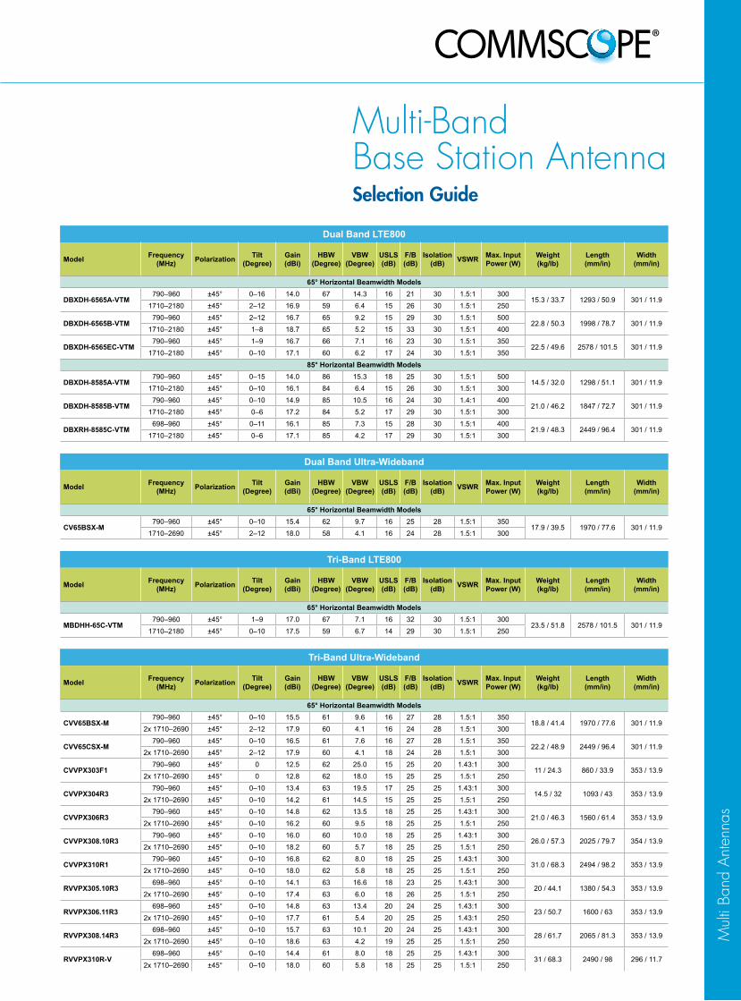
Multi-Band Base Station AntennaSelection Guide
Dual Band LTE800
Model Frequency (MHz) Polarization Tilt
(Degree)Gain (dBi)
HBW (Degree)
VBW (Degree)
USLS (dB)
F/B (dB)
Isolation (dB) VSWR Max. Input
Power (W)Weight (kg/lb)
Length (mm/in)
Width (mm/in)
65° Horizontal Beamwidth Models
DBXDH-6565A-VTM790–960 ±45° 0–16 14.0 67 14.3 16 21 30 1.5:1 300
15.3 / 33.7 1293 / 50.9 301 / 11.91710–2180 ±45° 2–12 16.9 59 6.4 15 26 30 1.5:1 250
DBXDH-6565B-VTM790–960 ±45° 2–12 16.7 65 9.2 15 29 30 1.5:1 500
22.8 / 50.3 1998 / 78.7 301 / 11.91710–2180 ±45° 1–8 18.7 65 5.2 15 33 30 1.5:1 400
DBXDH-6565EC-VTM790–960 ±45° 1–9 16.7 66 7.1 16 23 30 1.5:1 350
22.5 / 49.6 2578 / 101.5 301 / 11.91710–2180 ±45° 0–10 17.1 60 6.2 17 24 30 1.5:1 350
85° Horizontal Beamwidth Models
DBXDH-8585A-VTM790–960 ±45° 0–15 14.0 86 15.3 18 25 30 1.5:1 500
14.5 / 32.0 1298 / 51.1 301 / 11.91710–2180 ±45° 0–10 16.1 84 6.4 15 26 30 1.5:1 300
DBXDH-8585B-VTM790–960 ±45° 0–10 14.9 85 10.5 16 24 30 1.4:1 400
21.0 / 46.2 1847 / 72.7 301 / 11.91710–2180 ±45° 0–6 17.2 84 5.2 17 29 30 1.5:1 300
DBXRH-8585C-VTM698–960 ±45° 0–11 16.1 85 7.3 15 28 30 1.5:1 400
21.9 / 48.3 2449 / 96.4 301 / 11.91710–2180 ±45° 0–6 17.1 85 4.2 17 29 30 1.5:1 300
Dual Band Ultra-Wideband
Model Frequency (MHz) Polarization Tilt
(Degree)Gain (dBi)
HBW (Degree)
VBW (Degree)
USLS (dB)
F/B (dB)
Isolation (dB) VSWR Max. Input
Power (W)Weight (kg/lb)
Length (mm/in)
Width (mm/in)
65° Horizontal Beamwidth Models
CV65BSX-M790–960 ±45° 0–10 15.4 62 9.7 16 25 28 1.5:1 350
17.9 / 39.5 1970 / 77.6 301 / 11.91710–2690 ±45° 2–12 18.0 58 4.1 16 24 28 1.5:1 300
Tri-Band LTE800
Model Frequency (MHz) Polarization Tilt
(Degree)Gain (dBi)
HBW (Degree)
VBW (Degree)
USLS (dB)
F/B (dB)
Isolation (dB) VSWR Max. Input
Power (W)Weight (kg/lb)
Length (mm/in)
Width (mm/in)
65° Horizontal Beamwidth Models
MBDHH-65C-VTM790–960 ±45° 1–9 17.0 67 7.1 16 32 30 1.5:1 300
23.5 / 51.8 2578 / 101.5 301 / 11.91710–2180 ±45° 0–10 17.5 59 6.7 14 29 30 1.5:1 250
Tri-Band Ultra-Wideband
Model Frequency (MHz) Polarization Tilt
(Degree)Gain (dBi)
HBW (Degree)
VBW (Degree)
USLS (dB)
F/B (dB)
Isolation (dB) VSWR Max. Input
Power (W)Weight (kg/lb)
Length (mm/in)
Width (mm/in)
65° Horizontal Beamwidth Models
CVV65BSX-M790–960 ±45° 0–10 15.5 61 9.6 16 27 28 1.5:1 350
18.8 / 41.4 1970 / 77.6 301 / 11.92x 1710–2690 ±45° 2–12 17.9 60 4.1 16 24 28 1.5:1 300
CVV65CSX-M790–960 ±45° 0–10 16.5 61 7.6 16 27 28 1.5:1 350
22.2 / 48.9 2449 / 96.4 301 / 11.92x 1710–2690 ±45° 2–12 17.9 60 4.1 18 24 28 1.5:1 300
CVVPX303F1790–960 ±45° 0 12.5 62 25.0 15 25 20 1.43:1 300
11 / 24.3 860 / 33.9 353 / 13.92x 1710–2690 ±45° 0 12.8 62 18.0 15 25 25 1.5:1 250
CVVPX304R3790–960 ±45° 0–10 13.4 63 19.5 17 25 25 1.43:1 300
14.5 / 32 1093 / 43 353 / 13.92x 1710–2690 ±45° 0–10 14.2 61 14.5 15 25 25 1.5:1 250
CVVPX306R3790–960 ±45° 0–10 14.8 62 13.5 18 25 25 1.43:1 300
21.0 / 46.3 1560 / 61.4 353 / 13.92x 1710–2690 ±45° 0–10 16.2 60 9.5 18 25 25 1.5:1 250
CVVPX308.10R3790–960 ±45° 0–10 16.0 60 10.0 18 25 25 1.43:1 300
26.0 / 57.3 2025 / 79.7 354 / 13.92x 1710–2690 ±45° 0–10 18.2 60 5.7 18 25 25 1.5:1 250
CVVPX310R1790–960 ±45° 0–10 16.8 62 8.0 18 25 25 1.43:1 300
31.0 / 68.3 2494 / 98.2 353 / 13.92x 1710–2690 ±45° 0–10 18.0 62 5.8 18 25 25 1.5:1 250
RVVPX305.10R3698–960 ±45° 0–10 14.1 63 16.6 18 23 25 1.43:1 300
20 / 44.1 1380 / 54.3 353 / 13.92x 1710–2690 ±45° 0–10 17.4 63 6.0 18 26 25 1.5:1 250
RVVPX306.11R3698–960 ±45° 0–10 14.8 63 13.4 20 24 25 1.43:1 300
23 / 50.7 1600 / 63 353 / 13.92x 1710–2690 ±45° 0–10 17.7 61 5.4 20 25 25 1.43:1 250
RVVPX308.14R3698–960 ±45° 0–10 15.7 63 10.1 20 24 25 1.43:1 300
28 / 61.7 2065 / 81.3 353 / 13.92x 1710–2690 ±45° 0–10 18.6 63 4.2 19 25 25 1.5:1 250
RVVPX310R-V698–960 ±45° 0–10 14.4 61 8.0 18 25 25 1.43:1 300
31 / 68.3 2490 / 98 296 / 11.72x 1710–2690 ±45° 0–10 18.0 60 5.8 18 25 25 1.5:1 250
Mul
ti Ba
nd A
nten
nas

Quad Band Ultra-Wideband
Model Frequency (MHz) Polarization Tilt
(Degree)Gain (dBi)
HBW (Degree)
VBW (Degree)
USLS (dB)
F/B (dB)
Isolation (dB) VSWR Max. Input
Power (W)Weight (kg/lb)
Length (mm/in)
Width (mm/in)
65° Horizontal Beamwidth Models
CV3PX308R1790–960 ±45° 0–10 15.6 64 10.5 23 26 25 1.43:1 300
27.1 / 59.7 2067 / 81.4 353 / 13.93x 1710–2690 ±45° 0–10 16.2 66 7.1 19 25 25 1.5:1 250
CV3PX310R1790–960 ±45° 0–10 16.8 62 8.0 18 25 25 1.43:1 300
36.0 / 79.4 2533 / 99.7 353 / 13.93x 1710–2690 ±45° 0–10 18.0 62 5.8 18 25 25 1.5:1 250
Multi-Port Ultra-Wideband
Model Frequency (MHz) Polarization Tilt
(Degree)Gain (dBi)
HBW (Degree)
VBW (Degree)
USLS (dB)
F/B (dB)
Isolation (dB) VSWR Max. Input
Power (W)Weight (kg/lb)
Length (mm/in)
Width (mm/in)
65° Horizontal Beamwidth Models
RV4PX310B1698–960 ±45° 0–10 16.5 62 8.0 18 25 25 1.43:1 300
37.0 / 81.6 2533 / 99.7 353 / 13.94x 1710–2690 ±45° 0–10 18.0 62 5.8 18 25 25 1.5:1 250
RV4PX310R698–960 ±45° 0–10 16.5 62 8.0 18 25 25 1.43:1 300
37.0 / 81.6 2533 / 99.7 353 / 13.94x 1710–2690 ±45° 0–10 18.0 62 5.8 18 25 25 1.5:1 250
Note: Specifications are subject to change without notice. See www.commscope.com for the most current information.
Multi-Band Base Station AntennaSelection Guide

DBXDHDBXDH--6565A6565A--VTMVTM Andrew® Dual Band Antenna, 790–960 MHz and 1710–2180 MHz, 65° horizontal beamwidth, RET compatible
*Values calculated using NGMN Alliance NPBASTA v9.6
Electrical SpecificationsFrequency Band, MHz 790–896 870–960 1710–1880 1850–1990 1920–2180Gain by all Beam Tilts, average, dBi 13.8 14.0 16.7 16.8 16.9Gain by all Beam Tilts Tolerance, dB ±0.5 ±0.4 ±0.4 ±0.4 ±0.5
Gain by Beam Tilt, average, dBi0 ° | 13.9 8 ° | 13.9 16 ° | 13.4
0 ° | 14.2 8 ° | 14.1 16 ° | 13.6
2 ° | 16.8 7 ° | 16.9 12 ° | 16.5
2 ° | 16.9 7 ° | 17.0 12 ° | 16.4
2 ° | 16.9 7 ° | 17.1 12 ° | 16.5
Beamwidth, Horizontal, degrees 69 67 63 59 59Beamwidth, Horizontal Tolerance, degrees ±3.2 ±3.9 ±4.4 ±2.4 ±2.2Beamwidth, Vertical, degrees 15.2 14.3 7.1 6.7 6.4Beamwidth, Vertical Tolerance, degrees ±1 ±0.7 ±0.4 ±0.3 ±0.5Beam Tilt, degrees 0–16 0–16 2–12 2–12 2–12USLS, dB 15 16 14 15 16FronttoBack Total Power at 180° ± 30°, dB 20 21 26 26 26CPR at Boresight, dB 25 23 22 21 20CPR at Sector, dB 12 8 9 9 10Isolation, dB 30 30 30 30 30Isolation, Intersystem, dB 30 30 30 30 30VSWR | Return Loss, dB 1.5 | 14.0 1.5 | 14.0 1.5 | 14.0 1.5 | 14.0 1.5 | 14.0PIM, 3rd Order, 2 x 20 W, dBc 150 150 150 150 150Input Power per Port, maximum, watts 300 300 250 250 250Polarization ±45° ±45° ±45° ±45° ±45°
Mechanical SpecificationsColor | Radome Material Light gray | Fiberglass, UV resistant
Connector Interface | Location | Quantity 716 DIN Female | Bottom | 4
Wind Loading, maximum 403.0 N @ 150 km/h 90.6 lbf @ 150 km/h
Wind Speed, maximum 241.0 km/h | 149.8 mph
Antenna Dimensions, L x W x D 1293.0 mm x 301.0 mm x 181.0 mm | 50.9 in x 11.9 in x 7.1 in
Net Weight 15.3 kg | 33.7 lb
Model with factory installed AISG 2.0 RET DBXDH6565AA2M
Product SpecificationsProduct Specifications
©©2014 CommScope, Inc. All rights reserved. All trademarks identified by 2014 CommScope, Inc. All rights reserved. All trademarks identified by ® ® or ™ are registered trademarks, respectively, of CommScope.or ™ are registered trademarks, respectively, of CommScope. All specifications are subject to change. See www.commscope.com for the most current information. Revised: January 10, 2014All specifications are subject to change. See www.commscope.com for the most current information. Revised: January 10, 2014
page 1 of 1page 1 of 1May 9, 2014May 9, 201425

DBXDHDBXDH--6565B6565B--VTMVTM Andrew® Dual Band Antenna, 790–960 MHz and 1710–2180 MHz, 65° horizontal beamwidth, RET compatible
Electrical SpecificationsFrequency Band, MHz 790–896 870–960 1710–1880 1850–1990 1920–2180Gain, dBi 15.8 16.7 18.7 18.6 18.3Beamwidth, Horizontal, degrees 66 65 65 63 63Beamwidth, Vertical, degrees 10.0 9.2 5.2 5.0 4.8Beam Tilt, degrees 2–12 2–12 1–8 1–8 1–8USLS, typical, dB 15 15 15 15 15FronttoBack Ratio at 180°, dB 28 29 33 32 31Isolation, dB 30 30 30 30 30Isolation, Intersystem, dB 37 35 40 40 40VSWR | Return Loss, dB 1.5 | 14.0 1.5 | 14.0 1.5 | 14.0 1.5 | 14.0 1.5 | 14.0PIM, 3rd Order, 2 x 20 W, dBc 150 150 150 150 150Input Power per Port, maximum, watts 500 500 400 400 400Polarization ±45° ±45° ±45° ±45° ±45°
Mechanical SpecificationsColor | Radome Material Light gray | Fiberglass, UV resistant
Connector Interface | Location | Quantity 716 DIN Female | Bottom | 4
Wind Loading, maximum 681.0 N @ 150 km/h 153.1 lbf @ 150 km/h
Wind Speed, maximum 241.0 km/h | 149.8 mph
Antenna Dimensions, L x W x D 1998.0 mm x 301.0 mm x 181.0 mm | 78.7 in x 11.9 in x 7.1 in
Net Weight 22.8 kg | 50.3 lb
Model with factory installed AISG 2.0 RET DBXDH6565BA2M
Product SpecificationsProduct Specifications
©©2014 CommScope, Inc. All rights reserved. All trademarks identified by 2014 CommScope, Inc. All rights reserved. All trademarks identified by ® ® or ™ are registered trademarks, respectively, of CommScope.or ™ are registered trademarks, respectively, of CommScope. All specifications are subject to change. See www.commscope.com for the most current information. Revised: January 29, 2014All specifications are subject to change. See www.commscope.com for the most current information. Revised: January 29, 2014
page 1 of 1page 1 of 1April 16, 2014April 16, 201426
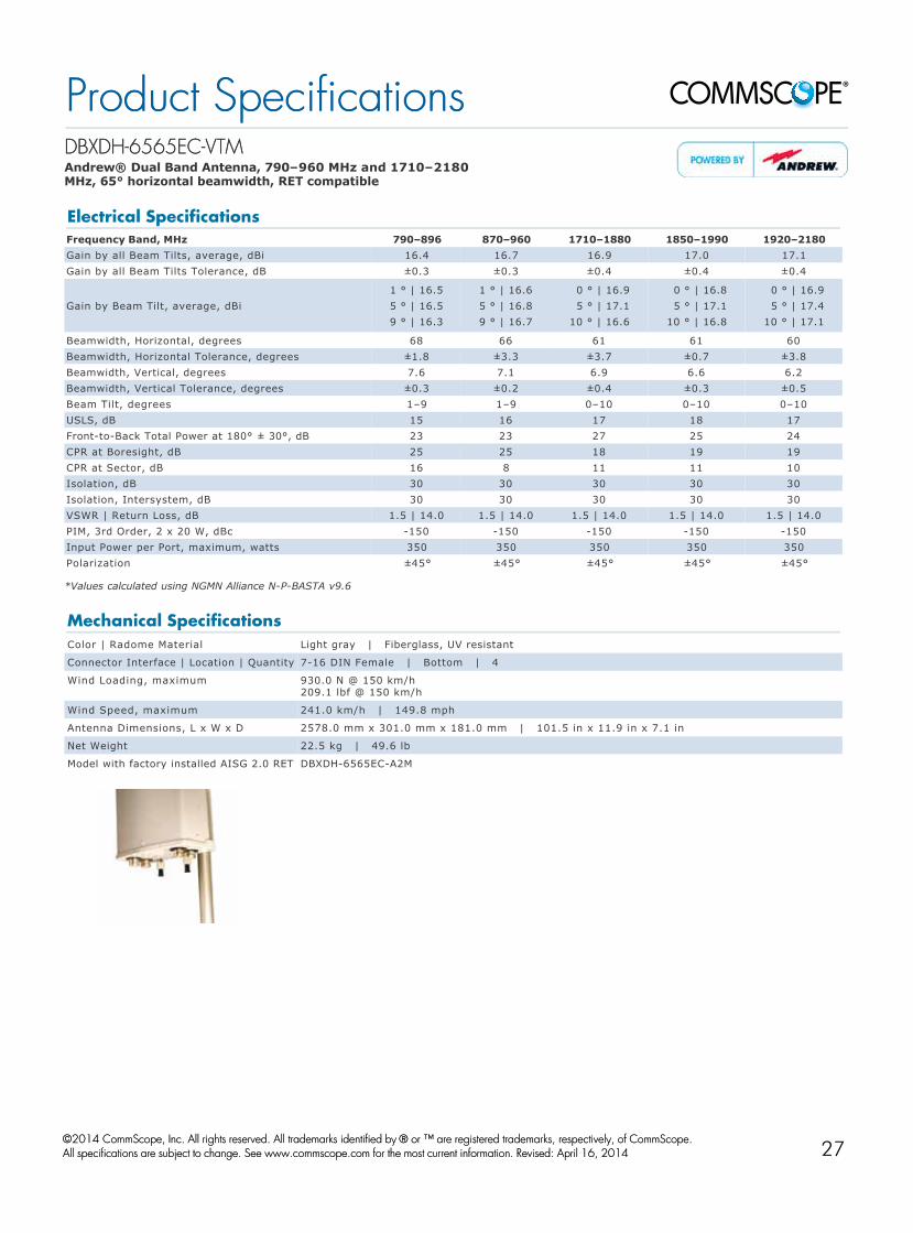
DBXDHDBXDH--6565EC6565EC--VTMVTM Andrew® Dual Band Antenna, 790–960 MHz and 1710–2180 MHz, 65° horizontal beamwidth, RET compatible
*Values calculated using NGMN Alliance NPBASTA v9.6
Electrical SpecificationsFrequency Band, MHz 790–896 870–960 1710–1880 1850–1990 1920–2180Gain by all Beam Tilts, average, dBi 16.4 16.7 16.9 17.0 17.1Gain by all Beam Tilts Tolerance, dB ±0.3 ±0.3 ±0.4 ±0.4 ±0.4
Gain by Beam Tilt, average, dBi1 ° | 16.5 5 ° | 16.5 9 ° | 16.3
1 ° | 16.6 5 ° | 16.8 9 ° | 16.7
0 ° | 16.9 5 ° | 17.1 10 ° | 16.6
0 ° | 16.8 5 ° | 17.1 10 ° | 16.8
0 ° | 16.9 5 ° | 17.4 10 ° | 17.1
Beamwidth, Horizontal, degrees 68 66 61 61 60Beamwidth, Horizontal Tolerance, degrees ±1.8 ±3.3 ±3.7 ±0.7 ±3.8Beamwidth, Vertical, degrees 7.6 7.1 6.9 6.6 6.2Beamwidth, Vertical Tolerance, degrees ±0.3 ±0.2 ±0.4 ±0.3 ±0.5Beam Tilt, degrees 1–9 1–9 0–10 0–10 0–10USLS, dB 15 16 17 18 17FronttoBack Total Power at 180° ± 30°, dB 23 23 27 25 24CPR at Boresight, dB 25 25 18 19 19CPR at Sector, dB 16 8 11 11 10Isolation, dB 30 30 30 30 30Isolation, Intersystem, dB 30 30 30 30 30VSWR | Return Loss, dB 1.5 | 14.0 1.5 | 14.0 1.5 | 14.0 1.5 | 14.0 1.5 | 14.0PIM, 3rd Order, 2 x 20 W, dBc 150 150 150 150 150Input Power per Port, maximum, watts 350 350 350 350 350Polarization ±45° ±45° ±45° ±45° ±45°
Mechanical SpecificationsColor | Radome Material Light gray | Fiberglass, UV resistant
Connector Interface | Location | Quantity 716 DIN Female | Bottom | 4
Wind Loading, maximum 930.0 N @ 150 km/h 209.1 lbf @ 150 km/h
Wind Speed, maximum 241.0 km/h | 149.8 mph
Antenna Dimensions, L x W x D 2578.0 mm x 301.0 mm x 181.0 mm | 101.5 in x 11.9 in x 7.1 in
Net Weight 22.5 kg | 49.6 lb
Model with factory installed AISG 2.0 RET DBXDH6565ECA2M
Product SpecificationsProduct Specifications
©©2014 CommScope, Inc. All rights reserved. All trademarks identified by 2014 CommScope, Inc. All rights reserved. All trademarks identified by ® ® or ™ are registered trademarks, respectively, of CommScope.or ™ are registered trademarks, respectively, of CommScope. All specifications are subject to change. See www.commscope.com for the most current information. Revised: April 16, 2014All specifications are subject to change. See www.commscope.com for the most current information. Revised: April 16, 2014
page 1 of 1page 1 of 1May 9, 2014May 9, 201427

DBXDHDBXDH--8585A8585A--VTMVTM Andrew® Dual Band Antenna, 790–960 MHz and 1710–2180 MHz, 85° horizontal beamwidth, RET compatible
Electrical SpecificationsFrequency Band, MHz 790–896 870–960 1710–1880 1850–1990 1920–2180Gain, dBi 13.2 14.0 15.9 16.0 16.1Beamwidth, Horizontal, degrees 87 86 85 85 84Beamwidth, Vertical, degrees 16.5 15.3 7.3 6.9 6.4Beam Tilt, degrees 0–15 0–15 0–10 0–10 0–10USLS, typical, dB 17 18 15 15 15FronttoBack Ratio at 180°, dB 22 25 28 26 26Isolation, dB 30 30 30 30 30Isolation, Intersystem, dB 40 40 35 35 35VSWR | Return Loss, dB 1.5 | 14.0 1.5 | 14.0 1.5 | 14.0 1.5 | 14.0 1.5 | 14.0PIM, 3rd Order, 2 x 20 W, dBc 150 150 150 150 150Input Power per Port, maximum, watts 500 500 300 300 300Polarization ±45° ±45° ±45° ±45° ±45°
Mechanical SpecificationsColor | Radome Material Light gray | Fiberglass, UV resistant
Connector Interface | Location | Quantity 716 DIN Female | Bottom | 4
Wind Loading, maximum 402.7 N @ 150 km/h 90.5 lbf @ 150 km/h
Wind Speed, maximum 241.0 km/h | 149.8 mph
Antenna Dimensions, L x W x D 1298.0 mm x 301.0 mm x 181.0 mm | 51.1 in x 11.9 in x 7.1 in
Net Weight 14.5 kg | 32.0 lb
Model with factory installed AISG 2.0 RET DBXDH8585AA2M
Product SpecificationsProduct Specifications
©©2014 CommScope, Inc. All rights reserved. All trademarks identified by 2014 CommScope, Inc. All rights reserved. All trademarks identified by ® ® or ™ are registered trademarks, respectively, of CommScope.or ™ are registered trademarks, respectively, of CommScope. All specifications are subject to change. See www.commscope.com for the most current information. Revised: January 30, 2014All specifications are subject to change. See www.commscope.com for the most current information. Revised: January 30, 2014
page 1 of 1page 1 of 1April 16, 2014April 16, 201428

DBXDHDBXDH--8585B8585B--VTMVTM Andrew® Dual Band Antenna, 790–960 MHz and 1710–2180 MHz, 85° horizontal beamwidth, RET compatible
Electrical SpecificationsFrequency Band, MHz 790–896 870–960 1710–1880 1850–1990 1920–2180Gain, dBi 14.3 14.9 17.2 17.1 17.1Beamwidth, Horizontal, degrees 85 85 84 85 85Beamwidth, Vertical, degrees 11.2 10.5 5.2 4.8 4.4Beam Tilt, degrees 0–10 0–10 0–6 0–6 0–6USLS, typical, dB 16 16 17 18 18FronttoBack Ratio at 180°, dB 22 24 29 29 29Isolation, dB 30 30 30 30 30Isolation, Intersystem, dB 30 30 30 30 30VSWR | Return Loss, dB 1.4 | 15.6 1.4 | 15.6 1.5 | 14.0 1.5 | 14.0 1.5 | 14.0PIM, 3rd Order, 2 x 20 W, dBc 150 150 150 150 150Input Power per Port, maximum, watts 400 400 300 300 300Polarization ±45° ±45° ±45° ±45° ±45°
Mechanical SpecificationsColor | Radome Material Light gray | Fiberglass, UV resistant
Connector Interface | Location | Quantity 716 DIN Female | Bottom | 4
Wind Loading, maximum 618.6 N @ 150 km/h 139.1 lbf @ 150 km/h
Wind Speed, maximum 241.0 km/h | 149.8 mph
Antenna Dimensions, L x W x D 1847.0 mm x 301.0 mm x 181.0 mm | 72.7 in x 11.9 in x 7.1 in
Net Weight 21.0 kg | 46.2 lb
Model with factory installed AISG 2.0 RET DBXDH8585BA2M
Product SpecificationsProduct Specifications
©©2014 CommScope, Inc. All rights reserved. All trademarks identified by 2014 CommScope, Inc. All rights reserved. All trademarks identified by ® ® or ™ are registered trademarks, respectively, of CommScope.or ™ are registered trademarks, respectively, of CommScope. All specifications are subject to change. See www.commscope.com for the most current information. Revised: January 30, 2014All specifications are subject to change. See www.commscope.com for the most current information. Revised: January 30, 2014
page 1 of 1page 1 of 1April 16, 2014April 16, 201429

DBXRHDBXRH--8585C8585C--VTMVTM Andrew® Dual Band Teletilt® Antenna, 698–960 MHz and 1710–2180 MHz, 85° horizontal beamwidth, RET compatible
Electrical SpecificationsFrequency Band, MHz 698–806 806–896 870–960 1710–1880 1850–1990 1920–2180Gain, dBi 15.1 15.0 16.2 17.0 16.7 17.1Beamwidth, Horizontal, degrees 88 85 85 81 84 85Beamwidth, Vertical, degrees 8.4 7.6 7.3 4.7 4.4 4.2Beam Tilt, degrees 0–11 0–11 0–11 0–6 0–6 0–6USLS, typical, dB 15 15 15 16 17 17FronttoBack Ratio at 180°, dB 30 28 28 29 29 29FronttoBack Total Power at 180° ± 20°, dB 16 19 20 23 22 22CPR at Boresight, dB 25 22 21 20 20 20CPR at Sector, dB 13 11 10 8 9 10Isolation, dB 30 30 30 30 30 30Isolation, Intersystem, dB 30 30 30 30 30 30VSWR | Return Loss, dB 1.5 | 14.0 1.5 | 14.0 1.5 | 14.0 1.5 | 14.0 1.5 | 14.0 1.5 | 14.0PIM, 3rd Order, 2 x 20 W, dBc 150 150 150 150 150 150Input Power per Port, maximum, watts 400 400 400 300 300 300Polarization ±45° ±45° ±45° ±45° ±45° ±45°
Mechanical SpecificationsColor | Radome Material Light gray | Fiberglass, UV resistant
Connector Interface | Location | Quantity 716 DIN Female | Bottom | 4
Wind Loading, maximum 879.0 N @ 150 km/h 197.6 lbf @ 150 km/h
Wind Speed, maximum 241.0 km/h | 149.8 mph
Antenna Dimensions, L x W x D 2449.0 mm x 301.0 mm x 181.0 mm | 96.4 in x 11.9 in x 7.1 in
Net Weight 21.9 kg | 48.3 lb
Model with factory installed AISG 2.0 RET DBXRH8585CA2M
Product SpecificationsProduct Specifications
©©2014 CommScope, Inc. All rights reserved. All trademarks identified by 2014 CommScope, Inc. All rights reserved. All trademarks identified by ® ® or ™ are registered trademarks, respectively, of CommScope.or ™ are registered trademarks, respectively, of CommScope. All specifications are subject to change. See www.commscope.com for the most current information. Revised: March 19, 2014All specifications are subject to change. See www.commscope.com for the most current information. Revised: March 19, 2014
page 1 of 1page 1 of 1April 16, 2014April 16, 201430

CV65BSXCV65BSX--MM Andrew® Dual Band Teletilt® Antenna, 790–960 MHz and 1710–2690 MHz, 65° horizontal beamwidth, RET compatible
*Values calculated using NGMN Alliance NPBASTA v9.6
Electrical SpecificationsFrequency Band, MHz 790–896 870–960 1710–1880 1850–1990 1920–2180 2300–2500 2500–2690Gain by all Beam Tilts, average, dBi 15.3 15.4 17.2 17.5 17.6 17.7 18.0Gain by all Beam Tilts Tolerance, dB ±0.5 ±0.4 ±0.3 ±0.3 ±0.5 ±0.6 ±0.4
Gain by Beam Tilt, average, dBi0 ° | 15.4 5 ° | 15.4 10 ° | 15.1
0 ° | 15.4 5 ° | 15.5 10 ° | 15.1
2 ° | 17.1 7 ° | 17.3 12 ° | 17.2
2 ° | 17.4 7 ° | 17.6 12 ° | 17.4
2 ° | 17.5 7 ° | 17.7 12 ° | 17.6
2 ° | 17.6 7 ° | 17.9 12 ° | 17.5
2 ° | 17.8 7 ° | 18.1 12 ° | 17.7
Beamwidth, Horizontal, degrees 63 62 71 66 67 57 58Beamwidth, Horizontal Tolerance, degrees ±2.7 ±1.9 ±4.6 ±2.4 ±5 ±3.5 ±4.6
Beamwidth, Vertical, degrees 10.5 9.7 5.6 5.3 5.0 4.3 4.1Beamwidth, Vertical Tolerance, degrees ±0.8 ±0.6 ±0.3 ±0.3 ±0.3 ±0.2 ±0.2Beam Tilt, degrees 0–10 0–10 2–12 2–12 2–12 2–12 2–12USLS, dB 16 16 16 17 17 16 18FronttoBack Total Power at 180° ± 30°, dB 25 25 26 24 22 22 24
CPR at Sector, dB 11 11 12 9 9 5 7Isolation, dB 28 28 28 28 28 28 28Isolation, Intersystem, dB 30 30 30 30 30 30 30VSWR | Return Loss, dB 1.5 | 14.0 1.5 | 14.0 1.5 | 14.0 1.5 | 14.0 1.5 | 14.0 1.5 | 14.0 1.5 | 14.0PIM, 3rd Order, 2 x 20 W, dBc 150 150 150 150 150 150 150Input Power per Port, maximum, watts 350 350 350 350 350 300 300Polarization ±45° ±45° ±45° ±45° ±45° ±45° ±45°
Mechanical SpecificationsColor | Radome Material Light gray | Fiberglass, UV resistant
Connector Interface | Location | Quantity 716 DIN Female | Bottom | 4
Wind Loading, maximum 669.0 N @ 150 km/h 150.4 lbf @ 150 km/h
Wind Speed, maximum 241.4 km/h | 150.0 mph
Antenna Dimensions, L x W x D 1970.0 mm x 301.0 mm x 181.0 mm | 77.6 in x 11.9 in x 7.1 in
Net Weight 17.9 kg | 39.5 lb
Model with factory installed AISG 2.0 RET CV65BSX2X2
Product SpecificationsProduct Specifications
©©2014 CommScope, Inc. All rights reserved. All trademarks identified by 2014 CommScope, Inc. All rights reserved. All trademarks identified by ® ® or ™ are registered trademarks, respectively, of CommScope.or ™ are registered trademarks, respectively, of CommScope. All specifications are subject to change. See www.commscope.com for the most current information. Revised: March 3, 2014All specifications are subject to change. See www.commscope.com for the most current information. Revised: March 3, 2014
page 1 of 1page 1 of 1May 9, 2014May 9, 201431

MBDHHMBDHH--65C65C--VTMVTM Andrew® Triband Teletilt® Antenna, 790–960 MHz and 2 x 1710–2180 MHz, 65° horizontal beamwidth, RET compatible
Electrical SpecificationsLB LB HB1 HB1 HB1 HB2 HB2 HB2
Frequency Band, MHz 790–896 870–960 1710–1880 1850–1990 1920–2180 1710–1880 1850–1990 1920–2180Gain, dBi 16.5 17.0 17.4 17.5 17.5 16.6 16.6 16.8Beamwidth, Horizontal, degrees 69 67 59 59 58 62 60 58Beamwidth, Horizontal Tolerance, degrees ±3 ±4 ±5 ±5 ±5 ±5 ±5 ±4Beamwidth, Vertical, degrees 7.9 7.1 7.1 6.7 6.2 7.0 6.7 6.3Beam Tilt, degrees 1–9 1–9 0–10 0–10 0–10 0–10 0–10 0–10USLS, typical, dB 15 16 14 14 15 14 14 14FronttoBack Ratio at 180°, dB 27 32 31 29 29 30 29 28CPR at Boresight, dB 22 24 20 19 18 20 20 18CPR at Sector, dB 14 8 12 14 12 12 12 13Isolation, dB 30 30 30 30 30 30 30 30Isolation, Intersystem, dB 30 30 30 30 30 30 30 30VSWR | Return Loss, dB 1.5 | 14.0 1.5 | 14.0 1.5 | 14.0 1.5 | 14.0 1.5 | 14.0 1.5 | 14.0 1.5 | 14.0 1.5 | 14.0PIM, 3rd Order, 2 x 20 W, dBc 150 150 150 150 150 150 150 150Input Power per Port, maximum, watts 300 300 250 250 250 250 250 250Polarization ±45° ±45° ±45° ±45° ±45° ±45° ±45° ±45°
Mechanical SpecificationsColor | Radome Material Light gray | PVC, UV resistant
Connector Interface | Location | Quantity 716 DIN Female | Bottom | 6
Wind Loading, maximum 930.0 N @ 150 km/h 209.1 lbf @ 150 km/h
Wind Speed, maximum 241.4 km/h | 150.0 mph
Antenna Dimensions, L x W x D 2578.0 mm x 301.0 mm x 181.0 mm | 101.5 in x 11.9 in x 7.1 in
Net Weight 23.5 kg | 51.8 lb
Model with factory installed AISG 2.0 RET MBDHH65CA3M
Product SpecificationsProduct Specifications
©©2014 CommScope, Inc. All rights reserved. All trademarks identified by 2014 CommScope, Inc. All rights reserved. All trademarks identified by ® ® or ™ are registered trademarks, respectively, of CommScope.or ™ are registered trademarks, respectively, of CommScope. All specifications are subject to change. See www.commscope.com for the most current information. Revised: January 29, 2014All specifications are subject to change. See www.commscope.com for the most current information. Revised: January 29, 2014
page 1 of 1page 1 of 1April 16, 2014April 16, 201432

CVV65BSXCVV65BSX--MM Andrew® Triband Antenna, 1 x 790–960 MHz and 2 x 1710–2690 MHz, 65° horizontal beamwidth, RET compatible
*Values calculated using NGMN Alliance NPBASTA v9.6
Electrical SpecificationsFrequency Band, MHz 790–896 870–960 1710–1880 1850–1990 1920–2180 2300–2500 2500–2690Gain by all Beam Tilts, average, dBi 15.4 15.5 17.3 17.5 17.7 17.7 17.9Gain by all Beam Tilts Tolerance, dB ±0.4 ±0.4 ±0.2 ±0.3 ±0.5 ±0.6 ±0.4
Gain by Beam Tilt, average, dBi0 ° | 15.4 5 ° | 15.4 10 ° | 15.2
0 ° | 15.5 5 ° | 15.6 10 ° | 15.2
2 ° | 17.2 7 ° | 17.4 12 ° | 17.2
2 ° | 17.3 7 ° | 17.5 12 ° | 17.4
2 ° | 17.5 7 ° | 17.8 12 ° | 17.6
2 ° | 17.5 7 ° | 17.9 12 ° | 17.5
2 ° | 17.7 7 ° | 18.1 12 ° | 17.7
Beamwidth, Horizontal, degrees 62 61 70 68 67 58 60Beamwidth, Horizontal Tolerance, degrees ±2.7 ±1.8 ±3.2 ±2.9 ±5.5 ±5.2 ±5.8
Beamwidth, Vertical, degrees 10.5 9.6 5.6 5.3 5.1 4.3 4.1Beamwidth, Vertical Tolerance, degrees ±0.8 ±0.7 ±0.3 ±0.2 ±0.3 ±0.2 ±0.2Beam Tilt, degrees 0–10 0–10 2–12 2–12 2–12 2–12 2–12USLS, dB 17 16 16 17 17 16 18FronttoBack Total Power at 180° ± 30°, dB 25 27 26 25 23 21 24
CPR at Sector, dB 11 11 12 10 10 5 6Isolation, dB 28 28 28 28 28 28 28Isolation, Intersystem, dB 30 30 30 30 30 30 30VSWR | Return Loss, dB 1.5 | 14.0 1.5 | 14.0 1.5 | 14.0 1.5 | 14.0 1.5 | 14.0 1.5 | 14.0 1.5 | 14.0PIM, 3rd Order, 2 x 20 W, dBc 150 150 150 150 150 150 150Input Power per Port, maximum, watts 350 350 350 350 350 300 300Polarization ±45° ±45° ±45° ±45° ±45° ±45° ±45°
Mechanical SpecificationsColor | Radome Material Light gray | Fiberglass, UV resistant
Connector Interface | Location | Quantity 716 DIN Female | Bottom | 6
Wind Loading, maximum 669.0 N @ 150 km/h 150.4 lbf @ 150 km/h
Wind Speed, maximum 241.0 km/h | 149.8 mph
Antenna Dimensions, L x W x D 1970.0 mm x 301.0 mm x 181.0 mm | 77.6 in x 11.9 in x 7.1 in
Net Weight 18.8 kg | 41.4 lb
Model with factory installed AISG 2.0 RET CVV65BSX3X2
Product SpecificationsProduct Specifications
©©2014 CommScope, Inc. All rights reserved. All trademarks identified by 2014 CommScope, Inc. All rights reserved. All trademarks identified by ® ® or ™ are registered trademarks, respectively, of CommScope.or ™ are registered trademarks, respectively, of CommScope. All specifications are subject to change. See www.commscope.com for the most current information. Revised: April 16, 2014All specifications are subject to change. See www.commscope.com for the most current information. Revised: April 16, 2014
page 1 of 1page 1 of 1May 9, 2014May 9, 201433

CVV65CSXCVV65CSX--MM Andrew® Triband Teletilt® Antenna, 1 x 790–960 MHz and 2 x 1710–2690 MHz, 65° horizontal beamwidth, RET compatible
*Values calculated using NGMN Alliance NPBASTA v9.6
Electrical SpecificationsFrequency Band, MHz 790–896 870–960 1710–1880 1850–1990 1920–2180 2300–2500 2500–2690Gain by all Beam Tilts, average, dBi 16.4 16.5 17.3 17.5 17.7 17.7 17.9Gain by all Beam Tilts Tolerance, dB ±0.4 ±0.4 ±0.2 ±0.3 ±0.5 ±0.6 ±0.4
Gain by Beam Tilt, average, dBi0 ° | 16.4 5 ° | 16.4 10 ° | 16.2
0 ° | 16.5 5 ° | 16.5 10 ° | 16.2
2 ° | 17.2 7 ° | 17.4 12 ° | 17.2
2 ° | 17.3 7 ° | 17.5 12 ° | 17.4
2 ° | 17.5 7 ° | 17.8 12 ° | 17.6
2 ° | 17.5 7 ° | 17.9 12 ° | 17.5
2 ° | 17.7 7 ° | 18.1 12 ° | 17.7
Beamwidth, Horizontal, degrees 62 61 70 68 67 58 60Beamwidth, Horizontal Tolerance, degrees ±2 ±2 ±3.2 ±2.9 ±5.5 ±5.2 ±5.8
Beamwidth, Vertical, degrees 8.2 7.6 5.6 5.3 5.1 4.3 4.1Beamwidth, Vertical Tolerance, degrees ±0.5 ±0.5 ±0.3 ±0.2 ±0.3 ±0.2 ±0.2Beam Tilt, degrees 0–10 0–10 2–12 2–12 2–12 2–12 2–12USLS, dB 17 16 16 17 17 16 18FronttoBack Total Power at 180° ± 30°, dB 26 27 26 25 23 21 24
CPR at Sector, dB 13 14 12 10 10 5 6Isolation, dB 28 28 28 28 28 28 28Isolation, Intersystem, dB 30 30 30 30 30 30 30VSWR | Return Loss, dB 1.5 | 14.0 1.5 | 14.0 1.5 | 14.0 1.5 | 14.0 1.5 | 14.0 1.5 | 14.0 1.5 | 14.0PIM, 3rd Order, 2 x 20 W, dBc 150 150 150 150 150 150 150Input Power per Port, maximum, watts 350 350 350 350 350 300 300Polarization ±45° ±45° ±45° ±45° ±45° ±45° ±45°
Mechanical SpecificationsColor | Radome Material Light gray | Fiberglass, UV resistant
Connector Interface | Location | Quantity 716 DIN Female | Bottom | 6
Wind Loading, maximum 879.0 N @ 150 km/h 197.6 lbf @ 150 km/h
Wind Speed, maximum 241.0 km/h | 149.8 mph
Antenna Dimensions, L x W x D 2449.0 mm x 301.0 mm x 181.0 mm | 96.4 in x 11.9 in x 7.1 in
Net Weight 22.2 kg | 48.9 lb
Model with factory installed AISG 2.0 RET CVV65CSX3X2
Product SpecificationsProduct Specifications
©©2014 CommScope, Inc. All rights reserved. All trademarks identified by 2014 CommScope, Inc. All rights reserved. All trademarks identified by ® ® or ™ are registered trademarks, respectively, of CommScope.or ™ are registered trademarks, respectively, of CommScope. All specifications are subject to change. See www.commscope.com for the most current information. Revised: April 16, 2014All specifications are subject to change. See www.commscope.com for the most current information. Revised: April 16, 2014
page 1 of 1page 1 of 1May 9, 2014May 9, 201434

CVVPX303F1CVVPX303F1 Argus® Triband Antenna, 790–960 MHz and 2 x 1710–2690 MHz, 65° horizontal beamwidth, fixed electrical tilt
Electrical SpecificationsFrequency Band, MHz 790–890 890–960 1710–1920 1920–2170 2300–2690Gain, dBi 11.8 12.5 11.8 12.5 12.8Beamwidth, Horizontal, degrees 64 62 60 60 62Beamwidth, Vertical, degrees 27.0 25.0 25.0 22.0 18.0Beam Tilt, degrees 0 0 0 0 0USLS, dB 15 15 15 15 15FronttoBack Ratio at 180°, dB 25 25 25 25 25Isolation, dB 20 20 25 25 25Isolation, Intersystem, dB 30 30 30 30 30VSWR | Return Loss, dB 1.43 | 15.0 1.43 | 15.0 1.5 | 14.0 1.5 | 14.0 1.5 | 14.0PIM, 3rd Order, 2 x 20 W, dBc 150 150 150 150 150Input Power per Port, maximum, watts 300 300 250 250 250Polarization ±45° ±45° ±45° ±45° ±45°
Mechanical SpecificationsConnector Interface | Location | Quantity 716 DIN Female | Bottom | 6
Wind Loading, maximum 450.0 N @ 160 km/h 101.2 lbf @ 160 km/h
Wind Speed, maximum 200.0 km/h | 124.3 mph
Antenna Dimensions, L x W x D 860.0 mm x 353.0 mm x 209.0 mm | 33.9 in x 13.9 in x 8.2 in
Net Weight 11.0 kg | 24.3 lb
Product SpecificationsProduct Specifications
©©2014 CommScope, Inc. All rights reserved. All trademarks identified by 2014 CommScope, Inc. All rights reserved. All trademarks identified by ® ® or ™ are registered trademarks, respectively, of CommScope.or ™ are registered trademarks, respectively, of CommScope. All specifications are subject to change. See www.commscope.com for the most current information. Revised: January 17, 2014All specifications are subject to change. See www.commscope.com for the most current information. Revised: January 17, 2014
page 1 of 1page 1 of 1April 16, 2014April 16, 201435

CVVPX304R3CVVPX304R3 Argus® Triband Antenna, 790–960 MHz and 2 x 1710–2690 MHz, 65° horizontal beamwidth, internal electrical tilt with manual override.
Electrical SpecificationsFrequency Band, MHz 790–890 890–960 1710–1920 1920–2170 2300–2690Gain, dBi 13.2 13.4 13.0 13.5 14.2Beamwidth, Horizontal, degrees 65 63 62 61 62Beamwidth, Vertical, degrees 21.0 19.5 20.0 18.0 14.5Beam Tilt, degrees 0–10 0–10 0–10 0–10 0–10USLS, dB 17 17 15 15 15FronttoBack Ratio at 180°, dB 25 25 25 25 25Isolation, dB 25 25 25 25 25Isolation, Intersystem, dB 30 30 30 30 30VSWR | Return Loss, dB 1.43 | 15.0 1.43 | 15.0 1.5 | 14.0 1.5 | 14.0 1.5 | 14.0PIM, 3rd Order, 2 x 20 W, dBc 150 150 150 150 150Input Power per Port, maximum, watts 300 300 250 250 250Polarization ±45° ±45° ±45° ±45° ±45°
Mechanical SpecificationsConnector Interface | Location | Quantity 716 DIN Female | Bottom | 6
Wind Loading, maximum 580.0 N @ 160 km/h 130.4 lbf @ 160 km/h
Wind Speed, maximum 200.0 km/h | 124.3 mph
Antenna Dimensions, L x W x D 1093.0 mm x 353.0 mm x 209.0 mm | 43.0 in x 13.9 in x 8.2 in
Net Weight 14.5 kg | 32.0 lb
Product SpecificationsProduct Specifications
©©2014 CommScope, Inc. All rights reserved. All trademarks identified by 2014 CommScope, Inc. All rights reserved. All trademarks identified by ® ® or ™ are registered trademarks, respectively, of CommScope.or ™ are registered trademarks, respectively, of CommScope. All specifications are subject to change. See www.commscope.com for the most current information. Revised: January 29, 2014All specifications are subject to change. See www.commscope.com for the most current information. Revised: January 29, 2014
page 1 of 1page 1 of 1April 16, 2014April 16, 201436

CVVPX306R3CVVPX306R3 Argus® Triband Antenna, 790–960 MHz and 2 x 1710–2690 MHz, 65° horizontal beamwidth, internal electrical tilt with manual override.
Electrical SpecificationsFrequency Band, MHz 790–890 890–960 1710–1920 1920–2170 2300–2690Gain, dBi 14.5 14.8 14.5 15.2 16.2Beamwidth, Horizontal, degrees 64 62 60 60 62Beamwidth, Vertical, degrees 14.8 13.5 13.5 12.0 9.5Beam Tilt, degrees 0–10 0–10 0–10 0–10 0–10USLS, dB 18 18 18 18 18FronttoBack Ratio at 180°, dB 25 25 25 25 25Isolation, dB 25 25 25 25 25Isolation, Intersystem, dB 30 30 30 30 30VSWR | Return Loss, dB 1.43 | 15.0 1.43 | 15.0 1.5 | 14.0 1.5 | 14.0 1.5 | 14.0PIM, 3rd Order, 2 x 20 W, dBc 150 150 150 150 150Input Power per Port, maximum, watts 300 300 250 250 250Polarization ±45° ±45° ±45° ±45° ±45°
Mechanical SpecificationsConnector Interface | Location | Quantity 716 DIN Female | Bottom | 6
Wind Loading, maximum 820.0 N @ 160 km/h 184.3 lbf @ 160 km/h
Wind Speed, maximum 200.0 km/h | 124.3 mph
Antenna Dimensions, L x W x D 1560.0 mm x 353.0 mm x 209.0 mm | 61.4 in x 13.9 in x 8.2 in
Net Weight 21.0 kg | 46.3 lb
Product SpecificationsProduct Specifications
©©2014 CommScope, Inc. All rights reserved. All trademarks identified by 2014 CommScope, Inc. All rights reserved. All trademarks identified by ® ® or ™ are registered trademarks, respectively, of CommScope.or ™ are registered trademarks, respectively, of CommScope. All specifications are subject to change. See www.commscope.com for the most current information. Revised: January 29, 2014All specifications are subject to change. See www.commscope.com for the most current information. Revised: January 29, 2014
page 1 of 1page 1 of 1April 16, 2014April 16, 201437

CVVPX308.10R3CVVPX308.10R3 Argus® Triband Antenna, 790–960 MHz and 2 x 1710–2690 MHz, 65° horizontal beamwidth, internal electrical tilt with manual override.
Electrical SpecificationsFrequency Band, MHz 790–890 890–960 1710–1920 1920–2170 2300–2690Gain, dBi 15.8 16.0 16.5 17.2 18.2Beamwidth, Horizontal, degrees 60 60 65 62 60Beamwidth, Vertical, degrees 11.0 10.0 8.0 7.0 5.7Beam Tilt, degrees 0–10 0–10 0–10 0–10 0–10USLS, dB 18 18 18 18 18FronttoBack Ratio at 180°, dB 25 25 25 25 25Isolation, dB 25 25 25 25 25Isolation, Intersystem, dB 30 30 30 30 30VSWR | Return Loss, dB 1.43 | 15.0 1.43 | 15.0 1.5 | 14.0 1.5 | 14.0 1.5 | 14.0PIM, 3rd Order, 2 x 20 W, dBc 150 150 150 150 150Input Power per Port, maximum, watts 300 300 250 250 250Polarization ±45° ±45° ±45° ±45° ±45°
Mechanical SpecificationsConnector Interface | Location | Quantity 716 DIN Female | Bottom | 6
Wind Loading, maximum 1060.0 N @ 160 km/h 238.3 lbf @ 160 km/h
Wind Speed, maximum 200.0 km/h | 124.3 mph
Antenna Dimensions, L x W x D 2025.0 mm x 354.0 mm x 210.0 mm | 79.7 in x 13.9 in x 8.3 in
Net Weight 26.0 kg | 57.3 lb
Product SpecificationsProduct Specifications
©©2014 CommScope, Inc. All rights reserved. All trademarks identified by 2014 CommScope, Inc. All rights reserved. All trademarks identified by ® ® or ™ are registered trademarks, respectively, of CommScope.or ™ are registered trademarks, respectively, of CommScope. All specifications are subject to change. See www.commscope.com for the most current information. Revised: March 14, 2014All specifications are subject to change. See www.commscope.com for the most current information. Revised: March 14, 2014
page 1 of 1page 1 of 1April 16, 2014April 16, 201438

CVVPX310R1CVVPX310R1 Argus® Triband Antenna, 790–960 MHz and 2 x 1710–2690 MHz, 65° horizontal beamwidth, internal electrical tilt with manual override. Bands cascaded SRET.
Electrical SpecificationsFrequency Band, MHz 790–890 890–960 1710–1920 1920–2170 2300–2690Gain, dBi 16.5 16.8 16.5 17.0 18.0Beamwidth, Horizontal, degrees 64 62 60 60 62Beamwidth, Vertical, degrees 8.8 8.0 8.2 7.2 5.8Beam Tilt, degrees 0–10 0–10 0–10 0–10 0–10USLS, dB 18 18 18 18 18FronttoBack Ratio at 180°, dB 25 25 25 25 25Isolation, dB 25 25 25 25 25Isolation, Intersystem, dB 30 30 30 30 30VSWR | Return Loss, dB 1.43 | 15.0 1.43 | 15.0 1.5 | 14.0 1.5 | 14.0 1.5 | 14.0PIM, 3rd Order, 2 x 20 W, dBc 150 150 150 150 150Input Power per Port, maximum, watts 300 300 250 250 250Polarization ±45° ±45° ±45° ±45° ±45°
Mechanical SpecificationsConnector Interface | Location | Quantity 716 DIN Female | Bottom | 6
Wind Loading, maximum 1300.0 N @ 160 km/h 292.3 lbf @ 160 km/h
Wind Speed, maximum 200.0 km/h | 124.3 mph
Antenna Dimensions, L x W x D 2494.0 mm x 353.0 mm x 209.0 mm | 98.2 in x 13.9 in x 8.2 in
Net Weight 31.0 kg | 68.3 lb
Product SpecificationsProduct Specifications
©©2014 CommScope, Inc. All rights reserved. All trademarks identified by 2014 CommScope, Inc. All rights reserved. All trademarks identified by ® ® or ™ are registered trademarks, respectively, of CommScope.or ™ are registered trademarks, respectively, of CommScope. All specifications are subject to change. See www.commscope.com for the most current information. Revised: January 29, 2014All specifications are subject to change. See www.commscope.com for the most current information. Revised: January 29, 2014
page 1 of 1page 1 of 1April 16, 2014April 16, 201439

RVVPX305.10R3RVVPX305.10R3 Argus® Multiband Antenna, 698–960 MHz and 2 x 1710–2690 MHz, 65° horizontal beamwidth, internal electrical tilt with manual override.
Electrical SpecificationsFrequency Band, MHz 698–790 790–890 890–960 1710–1920 1920–2170 2300–2690Gain by all Beam Tilts, average, dBi 13.3 13.5 14.1 16.4 16.9 17.4Gain by all Beam Tilts Tolerance, dB ±0.2 ±0.2 ±0.2 ±0.6 ±0.4 ±0.6
Gain by Beam Tilt, average, dBi0 ° | 13.3 5 ° | 13.3 10 ° | 13.3
0 ° | 13.6 5 ° | 13.5 10 ° | 13.5
0 ° | 14.1 5 ° | 14.1 10 ° | 14.0
0 ° | 16.4 5 ° | 16.4 10 ° | 16.4
0 ° | 16.9 5 ° | 16.8 10 ° | 16.9
0 ° | 17.6 5 ° | 17.5 10 ° | 17.1
Beamwidth, Horizontal, degrees 68 69 63 62 63 62Beamwidth, Horizontal Tolerance, degrees ±1.9 ±1.9 ±2 ±2.9 ±4.8 ±6.4Beamwidth, Vertical, degrees 20.2 18.1 16.6 8.2 7.3 6.0Beamwidth, Vertical Tolerance, degrees ±1 ±1.1 ±0.8 ±0.5 ±0.6 ±0.5Beam Tilt, degrees 0–10 0–10 0–10 0–10 0–10 0–10USLS, dB 18 18 18 18 18 18Null Fill, dB 22 22 22FronttoBack Total Power at 180° ± 30°, dB 24 23 23 23 25 26CPR at Boresight, dB 17 13 13 21 18 18CPR at Sector, dB 11 10 8 7 5 4Isolation, dB 25 25 25 25 25 25Isolation, Intersystem, dB 28 30 30 27 28 30VSWR | Return Loss, dB 1.43 | 15.0 1.43 | 15.0 1.43 | 15.0 1.5 | 14.0 1.5 | 14.0 1.5 | 14.0PIM, 3rd Order, 2 x 20 W, dBc 150 150 150 150 150 150Input Power per Port, maximum, watts 300 300 300 250 250 250Polarization ±45° ±45° ±45° ±45° ±45° ±45°
Mechanical SpecificationsConnector Interface | Location | Quantity 716 DIN Female | Bottom | 6
Wind Loading, maximum 570.0 N @ 150 km/h 128.1 lbf @ 150 km/h
Wind Speed, maximum 250.0 km/h | 155.3 mph
Antenna Dimensions, L x W x D 1380.0 mm x 353.0 mm x 209.0 mm | 54.3 in x 13.9 in x 8.2 in
Net Weight 20.0 kg | 44.1 lb
Product SpecificationsProduct Specifications
©©2014 CommScope, Inc. All rights reserved. All trademarks identified by 2014 CommScope, Inc. All rights reserved. All trademarks identified by ® ® or ™ are registered trademarks, respectively, of CommScope.or ™ are registered trademarks, respectively, of CommScope. All specifications are subject to change. See www.commscope.com for the most current information. Revised: March 27, 2014All specifications are subject to change. See www.commscope.com for the most current information. Revised: March 27, 2014
page 1 of 1page 1 of 1May 9, 2014May 9, 201440

RVVPX306.11R3RVVPX306.11R3 Argus® Multiband Antenna, 698–960 MHz and 2 x 1710–2690 MHz, 65° horizontal beamwidth, internal electrical tilt with manual override.
*Values calculated using NGMN Alliance NPBASTA v9.6
Electrical SpecificationsFrequency Band, MHz 698–790 790–890 890–960 1710–1920 1920–2170 2300–2690Gain by all Beam Tilts, average, dBi 13.9 14.2 14.8 16.8 17.3 17.7Gain by all Beam Tilts Tolerance, dB ±0.2 ±0.2 ±0.1 ±0.6 ±0.3 ±0.6
Gain by Beam Tilt, average, dBi0 ° | 13.9 5 ° | 13.9 10 ° | 13.9
0 ° | 14.2 5 ° | 14.2 10 ° | 14.1
0 ° | 14.8 5 ° | 14.8 10 ° | 14.7
0 ° | 16.8 5 ° | 16.8 10 ° | 16.8
0 ° | 17.2 5 ° | 17.2 10 ° | 17.3
0 ° | 17.8 5 ° | 17.8 10 ° | 17.5
Beamwidth, Horizontal, degrees 68 69 63 62 63 61Beamwidth, Horizontal Tolerance, degrees ±1.6 ±1.8 ±2 ±2.8 ±5.1 ±6.3Beamwidth, Vertical, degrees 16.4 14.7 13.4 7.5 6.7 5.4Beamwidth, Vertical Tolerance, degrees ±0.8 ±0.9 ±0.5 ±0.5 ±0.5 ±0.4Beam Tilt, degrees 0–10 0–10 0–10 0–10 0–10 0–10USLS, dB 20 20 20 21 22 20FronttoBack Total Power at 180° ± 30°, dB 25 23 24 23 25 25CPR at Boresight, dB 16 13 13 21 19 18CPR at Sector, dB 11 10 8 7 5 5Isolation, dB 25 25 25 25 25 25Isolation, Intersystem, dB 25 25 25 25 25 25VSWR | Return Loss, dB 1.43 | 15.0 1.43 | 15.0 1.43 | 15.0 1.43 | 15.0 1.43 | 15.0 1.43 | 15.0PIM, 3rd Order, 2 x 20 W, dBc 150 150 150 150 150 150Input Power per Port, maximum, watts 300 300 300 250 250 250Polarization ±45° ±45° ±45° ±45° ±45° ±45°
Mechanical SpecificationsConnector Interface | Location | Quantity 716 DIN Female | Bottom | 6
Wind Loading, maximum 748.0 N @ 150 km/h 168.2 lbf @ 150 km/h
Wind Speed, maximum 250.0 km/h | 155.3 mph
Antenna Dimensions, L x W x D 1600.0 mm x 353.0 mm x 209.0 mm | 63.0 in x 13.9 in x 8.2 in
Net Weight 23.0 kg | 50.7 lb
Product SpecificationsProduct Specifications
©©2014 CommScope, Inc. All rights reserved. All trademarks identified by 2014 CommScope, Inc. All rights reserved. All trademarks identified by ® ® or ™ are registered trademarks, respectively, of CommScope.or ™ are registered trademarks, respectively, of CommScope. All specifications are subject to change. See www.commscope.com for the most current information. Revised: February 13, 2014All specifications are subject to change. See www.commscope.com for the most current information. Revised: February 13, 2014
page 1 of 1page 1 of 1May 9, 2014May 9, 201441
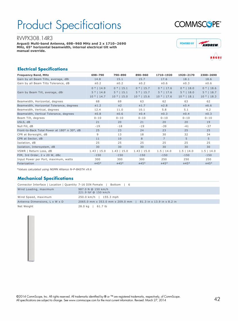
RVVPX308.14R3RVVPX308.14R3 Argus® Multiband Antenna, 698–960 MHz and 2 x 1710–2690 MHz, 65° horizontal beamwidth, internal electrical tilt with manual override.
*Values calculated using NGMN Alliance NPBASTA v9.6
Electrical SpecificationsFrequency Band, MHz 698–790 790–890 890–960 1710–1920 1920–2170 2300–2690Gain by all Beam Tilts, average, dBi 14.8 15.1 15.7 17.6 18.1 18.6Gain by all Beam Tilts Tolerance, dB ±0.2 ±0.2 ±0.2 ±0.6 ±0.3 ±0.6
Gain by Beam Tilt, average, dBi0 ° | 14.9 5 ° | 14.8 10 ° | 14.7
0 ° | 15.1 5 ° | 15.1 10 ° | 15.0
0 ° | 15.7 5 ° | 15.7 10 ° | 15.6
0 ° | 17.6 5 ° | 17.6 10 ° | 17.6
0 ° | 18.0 5 ° | 18.0 10 ° | 18.1
0 ° | 18.6 5 ° | 18.7 10 ° | 18.3
Beamwidth, Horizontal, degrees 68 69 63 62 63 62Beamwidth, Horizontal Tolerance, degrees ±1.2 ±2 ±1.7 ±2.8 ±5.4 ±6.6Beamwidth, Vertical, degrees 12.4 11.0 10.1 5.8 5.1 4.2Beamwidth, Vertical Tolerance, degrees ±0.8 ±0.6 ±0.4 ±0.3 ±0.4 ±0.3Beam Tilt, degrees 0–10 0–10 0–10 0–10 0–10 0–10USLS, dB 21 20 21 20 20 19Null Fill, dB 19 18 19 39 41 37FronttoBack Total Power at 180° ± 30°, dB 25 23 24 23 25 25CPR at Boresight, dB 9 13 18 30 32 34CPR at Sector, dB 11 10 8 7 5 5Isolation, dB 25 25 25 25 25 25Isolation, Intersystem, dB 30 30 30 30 30 30VSWR | Return Loss, dB 1.43 | 15.0 1.43 | 15.0 1.43 | 15.0 1.5 | 14.0 1.5 | 14.0 1.5 | 14.0PIM, 3rd Order, 2 x 20 W, dBc 150 150 150 150 150 150Input Power per Port, maximum, watts 300 300 300 250 250 250Polarization ±45° ±45° ±45° ±45° ±45° ±45°
Mechanical SpecificationsConnector Interface | Location | Quantity 716 DIN Female | Bottom | 6
Wind Loading, maximum 987.0 N @ 150 km/h 221.9 lbf @ 150 km/h
Wind Speed, maximum 250.0 km/h | 155.3 mph
Antenna Dimensions, L x W x D 2065.0 mm x 353.0 mm x 209.0 mm | 81.3 in x 13.9 in x 8.2 in
Net Weight 28.0 kg | 61.7 lb
Product SpecificationsProduct Specifications
©©2014 CommScope, Inc. All rights reserved. All trademarks identified by 2014 CommScope, Inc. All rights reserved. All trademarks identified by ® ® or ™ are registered trademarks, respectively, of CommScope.or ™ are registered trademarks, respectively, of CommScope. All specifications are subject to change. See www.commscope.com for the most current information. Revised: March 27, 2014All specifications are subject to change. See www.commscope.com for the most current information. Revised: March 27, 2014
page 1 of 1page 1 of 1May 9, 2014May 9, 201442

RVVPX310RRVVPX310R--VV Argus® Multiband Antenna, 698–960 MHz and 2 x 1710–2690 MHz, 65° horizontal beamwidth, internal electrical tilt with manual override. Bands cascaded SRET.
Electrical SpecificationsFrequency Band, MHz 698–790 790–890 890–960 1710–1920 1920–2170 2300–2690Gain, dBi 16.0 16.2 16.5 16.8 17.2 18.0Beamwidth, Horizontal, degrees 66 63 61 65 62 60Beamwidth, Vertical, degrees 9.8 8.8 8.0 8.2 7.2 5.8Beam Tilt, degrees 0–10 0–10 0–10 0–10 0–10 0–10USLS, dB 18 18 18 18 18 18Null Fill, dB 22 22 22 22 22 22FronttoBack Ratio at 180°, dB 25 25 25 25 25 25Isolation, dB 25 25 25 25 25 25Isolation, Intersystem, dB 30 30 30 30 30 30VSWR | Return Loss, dB 1.43 | 15.0 1.43 | 15.0 1.43 | 15.0 1.5 | 14.0 1.5 | 14.0 1.5 | 14.0PIM, 3rd Order, 2 x 20 W, dBc 150 150 150 150 150 150Input Power per Port, maximum, watts 300 300 300 250 250 250Polarization ±45° ±45° ±45° ±45° ±45° ±45°
Mechanical SpecificationsConnector Interface | Location | Quantity 716 DIN Female | Bottom | 6
Wind Loading, maximum 1100.0 N @ 160 km/h 247.3 lbf @ 160 km/h
Wind Speed, maximum 200.0 km/h | 124.3 mph
Antenna Dimensions, L x W x D 2490.0 mm x 296.0 mm x 244.0 mm | 98.0 in x 11.7 in x 9.6 in
Net Weight 31.0 kg | 68.3 lb
Product SpecificationsProduct Specifications
©©2014 CommScope, Inc. All rights reserved. All trademarks identified by 2014 CommScope, Inc. All rights reserved. All trademarks identified by ® ® or ™ are registered trademarks, respectively, of CommScope.or ™ are registered trademarks, respectively, of CommScope. All specifications are subject to change. See www.commscope.com for the most current information. Revised: January 29, 2014All specifications are subject to change. See www.commscope.com for the most current information. Revised: January 29, 2014
page 1 of 1page 1 of 1April 16, 2014April 16, 201443

CV3PX308R1CV3PX308R1 Argus® Multi Band Antenna, 790–960 MHz and 3 x 1710–2690 MHz, 65° horizontal beamwidth, internal electrical tilt with manual override. Bands cascaded SRET.
*Values calculated using NGMN Alliance NPBASTA v9.6
Electrical SpecificationsFrequency Band, MHz 790–896 870–960 1710–2170 2300–2500 2500–2690Gain by all Beam Tilts, average, dBi 15.3 15.6 15.4 16.1 16.2Gain by all Beam Tilts Tolerance, dB ±0.4 ±0.3 ±0.5 ±0.5 ±0.5
Gain by Beam Tilt, average, dBi0 ° | 15.4 5 ° | 15.4 10 ° | 15.3
0 ° | 15.6 5 ° | 15.6 10 ° | 15.5
0 ° | 15.5 5 ° | 15.4 10 ° | 15.4
0 ° | 16.3 5 ° | 16.1 10 ° | 15.8
0 ° | 16.5 5 ° | 16.3 10 ° | 16.0
Beamwidth, Horizontal, degrees 65 64 61 66 61Beamwidth, Horizontal Tolerance, degrees ±1.6 ±1.5 ±3 ±5 ±6Beamwidth, Vertical, degrees 11.1 10.5 9.9 7.8 7.1Beamwidth, Vertical Tolerance, degrees ±0.6 ±0.4 ±1.1 ±0.5 ±0.5Beam Tilt, degrees 0–10 0–10 0–10 0–10 0–10USLS, dB 22 23 21 20 19FronttoBack Total Power at 180° ± 30°, dB 24 26 23 27 25CPR at Boresight, dB 17 16 18 19 20CPR at Sector, dB 9 9 5 6 4Isolation, dB 25 25 25 25 25Isolation, Intersystem, dB 30 30 30 30 30VSWR | Return Loss, dB 1.43 | 15.0 1.43 | 15.0 1.5 | 14.0 1.5 | 14.0 1.5 | 14.0PIM, 3rd Order, 2 x 20 W, dBc 150 150 150 150 150Input Power per Port, maximum, watts 300 300 250 250 250Polarization ±45° ±45° ±45° ±45° ±45°
Mechanical SpecificationsConnector Interface | Location | Quantity 716 DIN Female | Bottom | 8
Wind Loading, maximum 951.0 N @ 150 km/h 213.8 lbf @ 150 km/h
Wind Speed, maximum 241.0 km/h | 149.8 mph
Antenna Dimensions, L x W x D 2067.0 mm x 353.0 mm x 209.0 mm | 81.4 in x 13.9 in x 8.2 in
Net Weight 27.1 kg | 59.7 lb
Product SpecificationsProduct Specifications
©©2014 CommScope, Inc. All rights reserved. All trademarks identified by 2014 CommScope, Inc. All rights reserved. All trademarks identified by ® ® or ™ are registered trademarks, respectively, of CommScope.or ™ are registered trademarks, respectively, of CommScope. All specifications are subject to change. See www.commscope.com for the most current information. Revised: January 29, 2014All specifications are subject to change. See www.commscope.com for the most current information. Revised: January 29, 2014
page 1 of 1page 1 of 1May 9, 2014May 9, 201444

CV3PX310R1CV3PX310R1 Argus® Multi Band Antenna, 790–960 MHz and 3 x 1710–2690 MHz, 65° horizontal beamwidth, internal electrical tilt with manual override. Bands cascaded SRET.
Electrical SpecificationsBand 1 Band 1 Band 2 Band 2 Band 2 Band 3 Band 3 Band 3 Band 4 Band 4 Band 4
Frequency Band, MHz 790–890 890–960 1710–1920
1920–2170
2300–2690
1710–1920
1920–2170
2300–2690
1710–1920
1920–2170
2300–2690
Gain, dBi 16.5 16.8 16.5 17.0 18.0 16.5 17.0 18.0 16.5 16.7 17.7Beamwidth, Horizontal, degrees 64 62 60 60 62 60 60 62 60 60 62
Beamwidth, Vertical, degrees 8.8 8.0 8.0 7.2 5.8 8.0 7.2 5.8 8.0 7.2 5.8Beam Tilt, degrees 0–10 0–10 0–10 0–10 0–10 0–10 0–10 0–10 0–10 0–10 0–10USLS, dB 18 18 18 18 18 18 18 18 18 18 18FronttoBack Ratio at 180°, dB 25 25 25 25 25 25 25 25 25 25 25
Isolation, dB 25 25 25 25 25 25 25 25 25 25 25Isolation, Intersystem, dB 30 30 30 30 30 30 30 30 30 30 30
VSWR | Return Loss, dB 1.43 | 15.0
1.43 | 15.0
1.5 | 14.0
1.5 | 14.0
1.5 | 14.0
1.5 | 14.0
1.5 | 14.0
1.5 | 14.0
1.5 | 14.0
1.5 | 14.0
1.5 | 14.0
PIM, 3rd Order, 2 x 20 W, dBc 150 150 150 150 150 150 150 150 150 150 150
Input Power per Port, maximum, watts 300 300 250 250 250 250 250 250 250 250 250
Polarization ±45° ±45° ±45° ±45° ±45° ±45° ±45° ±45° ±45° ±45° ±45°
Mechanical SpecificationsConnector Interface | Location | Quantity 716 DIN Female | Bottom | 8
Wind Loading, maximum 1320.0 N @ 160 km/h 296.7 lbf @ 160 km/h
Wind Speed, maximum 200.0 km/h | 124.3 mph
Antenna Dimensions, L x W x D 2533.0 mm x 353.0 mm x 209.0 mm | 99.7 in x 13.9 in x 8.2 in
Net Weight 36.0 kg | 79.4 lb
Product SpecificationsProduct Specifications
©©2014 CommScope, Inc. All rights reserved. All trademarks identified by 2014 CommScope, Inc. All rights reserved. All trademarks identified by ® ® or ™ are registered trademarks, respectively, of CommScope.or ™ are registered trademarks, respectively, of CommScope. All specifications are subject to change. See www.commscope.com for the most current information. Revised: January 29, 2014All specifications are subject to change. See www.commscope.com for the most current information. Revised: January 29, 2014
page 1 of 1page 1 of 1April 16, 2014April 16, 201445

RV4PX310B1RV4PX310B1 Argus® Multiband Antenna, 698–960 MHz and 4 x 1710–2690 MHz, 65° horizontal beamwidth, internal electrical tilt with manual override. Internal BiasTee from port 1 band 1. Bands cascaded SRET.
Electrical SpecificationsLB LB LB HB1/HB2 HB1/HB2 HB1/HB2 HB3/HB4 HB3/HB4 HB3/HB4
Frequency Band, MHz 698–790 790–890 890–960 1710–1920
1920–2170
2300–2690
1710–1920
1920–2170
2300–2690
Gain, dBi 16.0 16.2 16.5 16.8 17.2 18.0 16.5 16.9 17.7Beamwidth, Horizontal, degrees 67 65 62 62 62 62 62 62 62Beamwidth, Vertical, degrees 9.8 8.8 8.0 8.2 7.2 5.8 8.2 7.2 5.8Beam Tilt, degrees 0–10 0–10 0–10 0–10 0–10 0–10 0–10 0–10 0–10USLS, dB 18 18 18 18 18 18 18 18 18Null Fill, dB 22 22 22 22 22 22 22 22 22FronttoBack Ratio at 180°, dB 25 25 25 25 25 25 25 25 25Isolation, dB 25 25 25 25 25 25 25 25 25Isolation, Intersystem, dB 30 30 30 30 30 30 30 30 30
VSWR | Return Loss, dB 1.43 | 15.0
1.43 | 15.0
1.43 | 15.0 1.5 | 14.0 1.5 | 14.0 1.5 | 14.0 1.5 | 14.0 1.5 | 14.0 1.5 | 14.0
PIM, 3rd Order, 2 x 20 W, dBc 150 150 150 150 150 150 150 150 150Input Power per Port, maximum, watts 300 300 300 250 250 250 250 250 250
Polarization ±45° ±45° ±45° ±45° ±45° ±45° ±45° ±45° ±45°
Mechanical SpecificationsConnector Interface | Location | Quantity 716 DIN Female | Bottom | 10
Wind Loading, maximum 1320.0 N @ 160 km/h 296.7 lbf @ 160 km/h
Wind Speed, maximum 200.0 km/h | 124.3 mph
Antenna Dimensions, L x W x D 2533.0 mm x 353.0 mm x 209.0 mm | 99.7 in x 13.9 in x 8.2 in
Net Weight 37.0 kg | 81.6 lb
Product SpecificationsProduct Specifications
©©2014 CommScope, Inc. All rights reserved. All trademarks identified by 2014 CommScope, Inc. All rights reserved. All trademarks identified by ® ® or ™ are registered trademarks, respectively, of CommScope.or ™ are registered trademarks, respectively, of CommScope. All specifications are subject to change. See www.commscope.com for the most current information. Revised: February 3, 2014All specifications are subject to change. See www.commscope.com for the most current information. Revised: February 3, 2014
page 1 of 1page 1 of 1April 16, 2014April 16, 201446

RV4PX310RRV4PX310R Argus® Multiband Antenna, 698–960 MHz and 4 x 1710–2690 MHz, 65° horizontal beamwidth, internal electrical tilt with manual override. Bands cascaded SRET.
Electrical SpecificationsLB LB LB HB1/HB2 HB1/HB2 HB1/HB2 HB3/HB4 HB3/HB4 HB3/HB4
Frequency Band, MHz 698–790 790–890 890–960 1710–1920
1920–2170
2300–2690
1710–1920
1920–2170
2300–2690
Gain, dBi 16.0 16.2 16.5 16.8 17.2 18.0 16.5 16.9 17.7Beamwidth, Horizontal, degrees 67 65 62 62 62 62 62 62 62Beamwidth, Vertical, degrees 9.8 8.8 8.0 8.2 7.2 5.8 8.2 7.2 5.8Beam Tilt, degrees 0–10 0–10 0–10 0–10 0–10 0–10 0–10 0–10 0–10USLS, dB 18 18 18 18 18 18 18 18 18Null Fill, dB 22 22 22 22 22 22 22 22 22FronttoBack Ratio at 180°, dB 25 25 25 25 25 25 25 25 25Isolation, dB 25 25 25 25 25 25 25 25 25Isolation, Intersystem, dB 30 30 30 30 30 30 30 30 30
VSWR | Return Loss, dB 1.43 | 15.0
1.43 | 15.0
1.43 | 15.0 1.5 | 14.0 1.5 | 14.0 1.5 | 14.0 1.5 | 14.0 1.5 | 14.0 1.5 | 14.0
PIM, 3rd Order, 2 x 20 W, dBc 150 150 150 150 150 150 150 150 150Input Power per Port, maximum, watts 300 300 300 250 250 250 250 250 250
Polarization ±45° ±45° ±45° ±45° ±45° ±45° ±45° ±45° ±45°
Mechanical SpecificationsConnector Interface | Location | Quantity 716 DIN Female | Bottom | 10
Wind Loading, maximum 1320.0 N @ 160 km/h 296.7 lbf @ 160 km/h
Wind Speed, maximum 200.0 km/h | 124.3 mph
Antenna Dimensions, L x W x D 2533.0 mm x 353.0 mm x 209.0 mm | 99.7 in x 13.9 in x 8.2 in
Net Weight 37.0 kg | 81.6 lb
Product SpecificationsProduct Specifications
©©2014 CommScope, Inc. All rights reserved. All trademarks identified by 2014 CommScope, Inc. All rights reserved. All trademarks identified by ® ® or ™ are registered trademarks, respectively, of CommScope.or ™ are registered trademarks, respectively, of CommScope. All specifications are subject to change. See www.commscope.com for the most current information. Revised: March 20, 2014All specifications are subject to change. See www.commscope.com for the most current information. Revised: March 20, 2014
page 1 of 1page 1 of 1April 16, 2014April 16, 201447

www.commscope.comVisit our Web site or contact your local CommScope representative for more information.
© 2014 CommScope, Inc. All rights reserved.
All trademarks identified by ® or ™ are registered trademarks or trademarks, respectively, of CommScope, Inc. This document is for planning purposes only and is not intended to modify or supplement any specifications or warranties relating to CommScope products or services.
CA-106251.2 - EN.GB (05/14)
We’re proud to be a part of your network’s story.Here at CommScope, we embrace our role as a trusted resource, partner, and facilitator. We create the infrastructure that connects the world and evolves with every advance in technology. By investing all of our capabilities, resources, relationships, and products into your toughest challenges, we continue our long history of solving problems together—paving the way for new ideas and fresh ways of thinking.
We’re a trusted resource and partner around the world because we’re invested in you: your people, your networks, your success. It inspires us to build relationships and infrastructure… connect people and technologies across protocols, oceans, and time zones… and share what we learn along the way.
This is our promise to you. This is CommScope.