
DF1 Driver - PRO-FACE
64
1 Rockwell Automation, Inc. DF1 Driver 1 System Configuration ....................................................................................................... 3 2 Selection of External Device ............................................................................................ 7 3 Example of Communication Setting ................................................................................. 8 4 Setup Items .................................................................................................................... 24 5 Cable Diagram ............................................................................................................... 31 6 Supported Device........................................................................................................... 46 7 Device Code and Address Code .................................................................................... 57 8 Error Messages .............................................................................................................. 64
-
Upload
khangminh22 -
Category
Documents
-
view
2 -
download
0
Transcript of DF1 Driver - PRO-FACE

1
Rockwell Automation, Inc.
DF1 Driver
1 System Configuration....................................................................................................... 3
2 Selection of External Device ............................................................................................ 7
3 Example of Communication Setting ................................................................................. 8
4 Setup Items .................................................................................................................... 24
5 Cable Diagram ............................................................................................................... 31
6 Supported Device........................................................................................................... 46
7 Device Code and Address Code.................................................................................... 57
8 Error Messages.............................................................................................................. 64

DF1 Driver
GP-Pro EX Device/PLC Connection Manual 2
IntroductionThis manual describes how to connect the Display and the External Device (target PLC).
In this manual, the connection procedure will be described by following the below sections:
1 System ConfigurationThis section shows the types of External Devices which can be connected and SIO type.
"1 System Configuration" (page 3)
2 Selection of External DeviceSelect a model (series) of the External Device to be connected and connection method.
"2 Selection of External Device" (page 7)
3 Example of Communication SettingsThis section shows setting examples for communicating between the Display and the External Device.
"3 Example of Communication Setting" (page 8)
4 Communication SettingsThis section describes communication setup items on the Display.Set communication settings of the Display with GP-Pro EX or in offline mode.
"4 Setup Items" (page 24)
Operation
5 Communication SettingsThis section shows cables and adapters for connecting the Display and the External Device.
"5 Cable Diagram" (page 31)

DF1 Driver
GP-Pro EX Device/PLC Connection Manual 3
1 System Configuration
The system configuration in the case when the External Device of Rockwell Automation, Inc. and the Display are
connected is shown.
Series CPU Module Link I/F SIO Type Setting Example Cable Diagram
SLC500SLC 5/03SLC 5/04SLC 5/05
Channel 0 RS232C
Setting Example 1 (page 8)
Cable Diagram 1 (page 31)
1770-KF32760-RB1775-KA5130-RM
RS232C Cable Diagram 2 (page 34)
1771-KGM RS232C Cable Diagram 3 (page 36)
PLC-5
PLC-5/11PLC-5/20PLC-5/30PLC-5/40PLC-5/40LPLC-5/60PLC-5/60L
Channel 0
RS232C Setting Example 2 (page 11)
Cable Diagram 2 (page 34)
RS422/485 (4wire)
Setting Example 3 (page 14)
Cable Diagram 6 (page 42)
ControlLogix Logix5550 CPU Direct RS232C Setting Example 4 (page 17)
Cable Diagram 1 (page 31)
MicroLogix
MicroLogix 1500(1764-LRP) Channel 1 RS232C
Setting Example 5 (page 21)
Cable Diagram 1 (page 31)
MicroLogix 1000MicroLogix 1200MicroLogix 1500(1764-LSP,1764-LRP)
Channel 0 RS232C Cable Diagram 4 (page 38)
AIC + Advanced Interface Converter1761-NET-AIC
RS232C Cable Diagram 5 (page 40)
CompactLogix
1769-L201769-L301769-L311769-L32E1769-L35E
Channel 0 RS232C Setting Example 4 (page 17)
Cable Diagram 1 (page 31)

DF1 Driver
GP-Pro EX Device/PLC Connection Manual 4
IPC COM PortWhen connecting IPC with an External Device, the COM port used depends on the series and SIO type. Please
refer to the IPC manual for details.
Usable port
SeriesUsable Port
RS-232C RS-422/485(4 wire) RS-422/485(2 wire)
PS-2000B COM1*1 , COM2, COM3*1, COM4
*1 The RI/5V can be switched. Use the IPC’s switch to change if necessary.
- -
PS-3450A, PS-3451A,PS3000-BA, PS3001-BD COM1, COM2*1*2 COM2*1*2 COM2*1*2
PS-3650A (T41 model),PS-3651A (T41 model) COM1*1 - -
PS-3650A (T42 model),PS-3651A (T42 model) COM1*1*2, COM2 COM1*1*2 COM1*1*2
PS-3700A (Pentium®4-M)PS-3710A
COM1*1, COM2*1, COM3*2 , COM4
*2 Set up the SIO type with the DIP Switch. Please set up as follows according to SIO type to be used.
COM3*2 COM3*2
PS-3711A COM1*1, COM2*2 COM2*2 COM2*2
PS4000*3
*3 When making communication between an External Device and COM port on the Expansion slot, only RS-232C is supported. However, ER (DTR/CTS) control cannot be executed because of the specification of COM port. For connection with External Device, use user-created cables and disable Pin Nos. 1, 4, 6 and 9. Please refer to the IPC manual for details of pin layout.
COM1, COM2 - -
PL3000 COM1*1*2, COM2*1, COM3, COM4 COM1*1*2 COM1*1*2
PE-4000B Atom N270 COM1, COM2 - -
PE-4000B Atom N2600 COM1, COM2 COM3*4 , COM4*4, COM5*4, COM6*4
*4 Set up the SIO type with the BIOS. Please refer to the IPC manual for details of BIOS.
COM3*4, COM4*4, COM5*4, COM6*4
PS5000 (Slim Panel Type Core i3 Model) *5 *6 COM1, COM2*4 COM2*4 COM2*4
PS5000 (Slim Panel Type Atom Model) *5 *6
COM1, COM2*7 COM2*7 COM2*7
PS5000 (Enclosed Panel Type)*8 COM1 - -
PS5000 (Modular Type PFXPU/PFXPP)*5 *6
PS5000 (Modular Type PFXPL2B5-6)
COM1*7 COM1*7 COM1*7
PS5000 (Modular Type PFXPL2B1-4) COM1, COM2*7 COM2*7 COM2*7
PS6000 COM1*9 *10 *10
DF1 Driver
GP-Pro EX Device/PLC Connection Manual 5
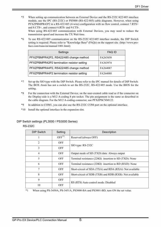
DIP Switch settings (PL3000 / PS3000 Series)RS-232C
*5 When setting up communication between an External Device and the RS-232C/422/485 interface module, use the IPC (RS-232C) or PS5000 (RS-422/485) cable diagrams. However, when using PFXZPBMPR42P2 in a RS-422/485 (4-wire) configuration with no flow control, connect 7.RTS+ and 8.CTS+, and connect 6.RTS- and 9.CTS-. When using RS-422/485 communication with External Devices, you may need to reduce the transmission speed and increase the TX Wait time.
*6 To use RS-422/485 communication on the RS-232C/422/485 interface module, the DIP Switch setting is required. Please refer to "Knowledge Base" (FAQs) on the support site. (http://www.pro- face.com/trans/en/manual/1001.html)
*7 Set up the SIO type with the DIP Switch. Please refer to the IPC manual for details of DIP Switch. The BOX Atom has not a switch to set the RS-232C, RS-422/485 mode. Use the BIOS for the setting.
*8 For the connection with the External Device, on the user-created cable read as if the connector on the Display-side is a M12 A-coding 8 pin socket. The pin assignment is the same as described in the cable diagram. For the M12 A-coding connector, use PFXZPSCNM122.
*9 In addition to COM1, you can also use the RS-232C COM port on the optional interface.
*10 Install the optional interface in the expansion slot.
DIP Switch Setting Description
1 OFF*1
*1 When using PS-3450A, PS-3451A, PS3000-BA and PS3001-BD, turn ON the set value.
Reserved (always OFF)
2 OFFSIO type: RS-232C
3 OFF
4 OFF Output mode of SD (TXD) data: Always output
5 OFF Terminal resistance (220Ω) insertion to SD (TXD): None
6 OFF Terminal resistance (220Ω) insertion to RD (RXD): None
7 OFF Short-circuit of SDA (TXA) and RDA (RXA): Not available
8 OFF Short-circuit of SDB (TXB) and RDB (RXB): Not available
9 OFFRS (RTS) Auto control mode: Disabled
10 OFF
Settings FAQ ID
PFXZPBMPR42P2, RS422/485 change method FA263858
PFXZPBMPR42P2 termination resistor setting FA263974
PFXZPBMPR44P2, RS422/485 change method FA264087
PFXZPBMPR44P2 termination resistor setting FA264088

DF1 Driver
GP-Pro EX Device/PLC Connection Manual 6
RS-422/485 (4 wire)
RS-422/485 (2 wire)
DIP Switch Setting Description
1 OFF Reserved (always OFF)
2 ONSIO type: RS-422/485
3 ON
4 OFF Output mode of SD (TXD) data: Always output
5 OFF Terminal resistance (220Ω) insertion to SD (TXD): None
6 OFF Terminal resistance (220Ω) insertion to RD (RXD): None
7 OFF Short-circuit of SDA (TXA) and RDA (RXA): Not available
8 OFF Short-circuit of SDB (TXB) and RDB (RXB): Not available
9 OFFRS (RTS) Auto control mode: Disabled
10 OFF
DIP Switch Setting Description
1 OFF Reserved (always OFF)
2 ONSIO type: RS-422/485
3 ON
4 OFF Output mode of SD (TXD) data: Always output
5 OFF Terminal resistance (220Ω) insertion to SD (TXD): None
6 OFF Terminal resistance (220Ω) insertion to RD (RXD): None
7 ON Short-circuit of SDA (TXA) and RDA (RXA): Available
8 ON Short-circuit of SDB (TXB) and RDB (RXB): Available
9 ONRS (RTS) Auto control mode: Enabled
10 ON

DF1 Driver
GP-Pro EX Device/PLC Connection Manual 7
2 Selection of External Device
Select the External Device to be connected to the Display.
Setup Items Setup Description
Number of Devices/PLCs Enter an integer from 1 to 4 to define the number of Devices/PLCs to connect to the display.
Manufacturer Select the manufacturer of the External Device to connect. Select "Rockwell Automation, Inc.".
Series
Select the External Device model (series) and the connection method. Select "DF1".In System configuration, make sure the External Device you are connecting is supported by "DF1".
"1 System Configuration" (page 3)
Port Select the Display port to connect to the External Device.
Use System Area
Check this option to synchronize the system data area of the Display and the device (memory) of the External Device. When synchronized, you can use the External Device’s ladder program to switch the display or display the window on the Display.
Cf. GP-Pro EX Reference Manual "LS Area (Direct Access Method Area)"This feature can also be set in GP-Pro EX or in the Display's offline mode.
Cf. GP-Pro EX Reference Manual "System Settings [Display Unit] - [System Area] Settings Guide"
Cf. Maintenance/Troubleshooting Guide "Main Unit - System Area Settings"

DF1 Driver
GP-Pro EX Device/PLC Connection Manual 8
3 Example of Communication Setting
Examples of communication settings of the Display and the External Device, recommended by Pro-face, are
shown.
3.1 Setting Example 1
Settings of GP-Pro EX
Communication Settings
To display the setup screen, from the [Project] menu, point to [System Settings] and select [Device/PLC].
• For [DF1 Mode], select [Full Duplex] or [Half Duplex Mster] according to your driver.

DF1 Driver
GP-Pro EX Device/PLC Connection Manual 9
Device Setting
To display the [Individual Device Settings] dialog box, from [Device-Specific Settings] in the [Device/PLC]
window, select the external device and click [Settings] .
To connect multiple External Devices, from [Device-Specific Settings] in the [Device/PLC] window, click [Add
Device] to add another External Device.
• For Full Duplex, "Destination ID (Local)" is not used.
[Device Settings] [Compatible Settings]

DF1 Driver
GP-Pro EX Device/PLC Connection Manual 10
Settings of External DeviceUse the ladder software "RSLogix 500" for communication settings.
Open "Channel Configuration" of "RSLogix 500" to perform the settings in the "Chan. 0 - System" tab.
For Full Duplex
For Half Duplex
Notes
• Please refer to the manual of the ladder software for more detail on other setting description.
Setup Items Setup Description
Driver DF1 Full Duplex
Baud 19200
Parity NONE
Stop Bits 1
Control Line No Handshaking
Error Detection CRC
Embedded Responses Auto-detect
Duplicate Packet Detect Disabled
ACK Timeout 50
NAK Retries 3
ENQ Retries 3
Source ID 0
Setup Items Setup Description
Driver DF1 Half Duplex Slave
Baud 19200
Parity NONE
Stop Bits 1
Control Line No Handshaking
Error Detection CRC
EOT Suppression Disabled
Duplicate Packet Detect Disabled
Poll Timeout 3000
Message Retries 3
Pre Transmit Delay 0
Node Address 0

DF1 Driver
GP-Pro EX Device/PLC Connection Manual 11
3.2 Setting Example 2
Settings of GP-Pro EX
Communication Settings
To display the setup screen, from the [Project] menu, point to [System Settings] and select [Device/PLC].
• For [DF1 Mode], select [Full Duplex] or [Half Duplex Mster] according to your driver.

DF1 Driver
GP-Pro EX Device/PLC Connection Manual 12
Device Setting
To display the [Individual Device Settings] dialog box, from [Device-Specific Settings] in the [Device/PLC]
window, select the external device and click [Settings] .
To connect multiple External Devices, from [Device-Specific Settings] in the [Device/PLC] window, click [Add
Device] to add another External Device.
• For Full Duplex, "Destination ID (Local)" is not used.
[Device Settings] [Compatible Settings]

DF1 Driver
GP-Pro EX Device/PLC Connection Manual 13
Settings of External DeviceUse the ladder software "RSLogix 5" for communication settings.
Open "Channel Configuration" of "RSLogix 5" to perform the settings in the "Chan. 0" tab.
For Full Duplex
For Half Duplex
Notes
• Please refer to the manual of the ladder software for more detail on other setting description.
Setup Items Setup Description
Communication Mode System (Point-To-Point)
Baud Rate 19200
Parity NONE
Bits per Char 8
Stop Bits 1
Control Line No Handshaking
Error Detection CRC
Embedded Responses Auto-detect
Detect Duplicate Messages Disabled
ACK Timeout 50
NAK Receive 3
DF1 ENQs 3
MSG Application Timeout 30 seconds
Station Address 0
Setup Items Setup Description
Communication Mode System (Slave)
Baud Rate 19200
Parity NONE
Bits per Char 8
Stop Bits 1
Control Line No Handshaking
Error Detection CRC
Detect Duplicate Messages Disabled
RTS Send Delay 0
RTS Off Delay 0
ACK Timeout 50
DF1 Retries 3
MSG Application Timeout 30 seconds
Station Address 0
DF1 Driver
GP-Pro EX Device/PLC Connection Manual 14
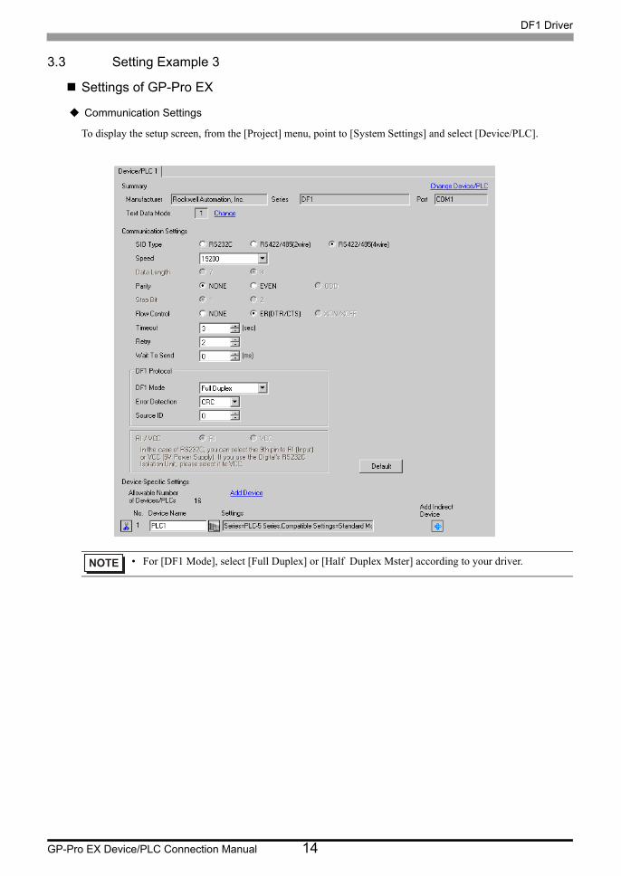
3.3 Setting Example 3
Settings of GP-Pro EX
Communication Settings
To display the setup screen, from the [Project] menu, point to [System Settings] and select [Device/PLC].
• For [DF1 Mode], select [Full Duplex] or [Half Duplex Mster] according to your driver.

DF1 Driver
GP-Pro EX Device/PLC Connection Manual 15
Device Setting
To display the [Individual Device Settings] dialog box, from [Device-Specific Settings] in the [Device/PLC]
window, select the external device and click [Settings] .
To connect multiple External Devices, from [Device-Specific Settings] in the [Device/PLC] window, click [Add
Device] to add another External Device.
• For Full Duplex, "Destination ID (Local)" is not used.
[Device Settings] [Compatible Settings]

DF1 Driver
GP-Pro EX Device/PLC Connection Manual 16
Settings of External DeviceUse the ladder software "RSLogix 5" for communication settings.
Open "Channel Configuration" of "RSLogix 5" to perform the settings in the "Chan. 0" tab.
For Full Duplex
For Half Duplex
Notes
• Please refer to the manual of the ladder software for more detail on other setting description.
Setup Items Setup Description
Communication Mode System (Point-To-Point)
Baud Rate 19200
Parity NONE
Bits per Char 8
Stop Bits 1
Control Line No Handshaking
Error Detection CRC
Embedded Responses Auto-detect
Detect Duplicate Messages Disabled
ACK Timeout 50
NAK Receive 3
DF1 ENQs 3
MSG Application Timeout 30 seconds
Station Address 0
Setup Items Setup Description
Communication Mode System (Slave)
Baud Rate 19200
Parity NONE
Bits per Char 8
Stop Bits 1
Control Line No Handshaking
Error Detection CRC
Detect Duplicate Messages Disabled
RTS Send Delay 0
RTS Off Delay 0
ACK Timeout 50
DF1 Retries 3
MSG Application Timeout 30 seconds
Station Address 0

DF1 Driver
GP-Pro EX Device/PLC Connection Manual 17
3.4 Setting Example 4
Settings of GP-Pro EX
Communication Settings
To display the setup screen, from the [Project] menu, point to [System Settings] and select [Device/PLC].
• For [DF1 Mode], select [Full Duplex] or [Half Duplex Mster] according to your driver.

DF1 Driver
GP-Pro EX Device/PLC Connection Manual 18
Device Setting
To display the [Individual Device Settings] dialog box, from [Device-Specific Settings] in the [Device/PLC]
window, select the external device and click [Settings] .
To connect multiple External Devices, from [Device-Specific Settings] in the [Device/PLC] window, click [Add
Device] to add another External Device.
• For Full Duplex, "Destination ID (Local)" is not used.
[Device Settings] [Compatible Settings]

DF1 Driver
GP-Pro EX Device/PLC Connection Manual 19
Settings of External DeviceUse the ladder software "RSLogix 5000" for communication settings. Please refer to the manual of the External
Device for more details.
Open the [Controller Properties] dialog box from the ladder software and set in the [Serial Port] tab, then in the
[System Protocol] tab as below.
[Serial Port] tab
• For Full Duplex
• For Half Duplex
[System Protocol] tab
• For Full Duplex
Setup Items Setup Description
Baud Rate 19200
Data Bits 8
Parity NONE
Stop Bits 1
Control Line Full Duplex
RTS Send Delay 0
RTS Off Delay 0
Setup Items Setup Description
Baud Rate 19200
Data Bits 8
Parity NONE
Stop Bits 1
Control Line Half Duplex
RTS Send Delay 0
RTS Off Delay 0
Setup Items Setup Description
Protocol DF1 Point to Point
Station Address 0
NAK Receive Limit 3
ENQ Transmit Limit 3
ACK Timeout 50
Embedded Responses Autodetect
Error Detection CRC
Enable Duplicate Detection Disabled

DF1 Driver
GP-Pro EX Device/PLC Connection Manual 20
• For Half Duplex
Notes
• Please refer to the manual of the ladder software for more detail on other setting description.
Setup Items Setup Description
Protocol DF1 Slave
Station Address 0
Transmit Retries 3
Slave Poll Timeout 3000
EOT Suppression Disabled
Error Detection CRC
Enable Duplicate Detection Disabled
DF1 Driver
GP-Pro EX Device/PLC Connection Manual 21
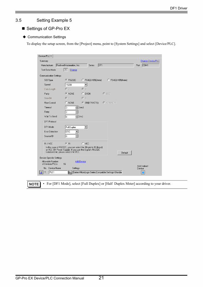
3.5 Setting Example 5
Settings of GP-Pro EX
Communication Settings
To display the setup screen, from the [Project] menu, point to [System Settings] and select [Device/PLC].
• For [DF1 Mode], select [Full Duplex] or [Half Duplex Mster] according to your driver.

DF1 Driver
GP-Pro EX Device/PLC Connection Manual 22
Device Setting
To display the [Individual Device Settings] dialog box, from [Device-Specific Settings] in the [Device/PLC]
window, select the external device and click [Settings] .
To connect multiple External Devices, from [Device-Specific Settings] in the [Device/PLC] window, click [Add
Device] to add another External Device.
• For Full Duplex, "Destination ID (Local)" is not used.
[Device Settings] [Compatible Settings]
DF1 Driver
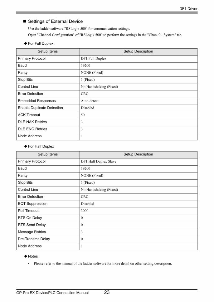
GP-Pro EX Device/PLC Connection Manual 23
Settings of External DeviceUse the ladder software "RSLogix 500" for communication settings.
Open "Channel Configuration" of "RSLogix 500" to perform the settings in the "Chan. 0 - System" tab.
For Full Duplex
For Half Duplex
Notes
• Please refer to the manual of the ladder software for more detail on other setting description.
Setup Items Setup Description
Primary Protocol DF1 Full Duplex
Baud 19200
Parity NONE (Fixed)
Stop Bits 1 (Fixed)
Control Line No Handshaking (Fixed)
Error Detection CRC
Embedded Responses Auto-detect
Enable Duplicate Detection Disabled
ACK Timeout 50
DLE NAK Retries 3
DLE ENQ Retries 3
Node Address 1
Setup Items Setup Description
Primary Protocol DF1 Half Duplex Slave
Baud 19200
Parity NONE (Fixed)
Stop Bits 1 (Fixed)
Control Line No Handshaking (Fixed)
Error Detection CRC
EOT Suppression Disabled
Poll Timeout 3000
RTS On Delay 0
RTS Send Delay 0
Message Retries 3
Pre-Transmit Delay 0
Node Address 1

DF1 Driver
GP-Pro EX Device/PLC Connection Manual 24
4 Setup Items
Set communication settings of the Display with GP-Pro EX or in offline mode of the Display.
The setting of each parameter must be identical to that of External Device.
"3 Example of Communication Setting" (page 8)
4.1 Communication Setting with GP-Pro EX
Communication SettingsTo display the setup screen, from the [Project] menu, point to [System Settings] and select [Device/PLC].
Setup Items Setup Description
SIO Type Select the SIO type to communicate with the External Device.
Speed Select speed (bps) between the External Device and the Display.
Data Length Data length is displayed.
Parity Select how to check parity.
Stop Bit Stop bit length is displayed.
Flow Control Select the communication control method to prevent overflow of transmission and reception data.
Timeout Enter the number of seconds (sec) before the reception timeout error occurs in the Display when communicating with the External Device, using "an integer from 1 to 127".
continued to next page

DF1 Driver
GP-Pro EX Device/PLC Connection Manual 25
Device SettingTo display the [Individual Device Settings] dialog box, from [Device-Specific Settings] in the [Device/PLC]
window, select the external device and click [Settings] .
To connect multiple External Devices, from [Device-Specific Settings] in the [Device/PLC] window, click [Add
Device] to add another External Device.
[Device Settings] tab.
Retry In case of no response from the External Device, use an integer from 0 to 255 to enter how many times the Display retransmits the command.
Wait To Send Use an integer from 0 to 255 to enter standby time (ms) for the Display from receiving packets to transmitting next commands.
DF1 Mode Set the type of DF1 protocol. Select either "Full Duplex" or "Half Duplex Master".
Error Detection Set how to check error. Select either "CRC" or "BCC".
Source ID Set the Display ID.
RI/VCCYou can switch RI/VCC of the 9th pin when you select RS232C for SIO type.It is necessary to change RI/5V by changeover switch of IPC when connect with IPC. Please refer to the manual of the IPC for more detail.
• Refer to the GP-Pro EX Reference Manual for Indirect Device.
Cf. GP-Pro EX Reference Manual "Changing the Device/PLC at Runtime (Indirect Device)"
Setup Items Setup Description
Series Select any of "SLC500 Series", "PLC-5 Series", "ControlLogix/CompactLogix Series", and "MicroLogix Series" for the driver series name.
Destination ID (Remote) Use an integer from 0 to 254 to enter the Destination ID.
Destination ID (Local) Use an integer from 0 to 254 to enter the Destination (local) ID.
Setup Items Setup Description

DF1 Driver
GP-Pro EX Device/PLC Connection Manual 26
[Compatible Settings] tab
.
Setup Items Setup Description
Compatible Settings
Select either "Standard Mode" or "GP-PRO/PB3 Compatible Mode".When "Standard Mode" is selected, the Double Word word order of all devices is set to "Low word first [L/H]".When "GP-PRO/PB3 Compatible Mode" is selected, the Double Word word order of some devices is set to "High word first [H/L]".
"6 Supported Device" (page 46)
• When ControlLogix/CompactLogix is used, "Standard Mode" only can be set.

DF1 Driver
GP-Pro EX Device/PLC Connection Manual 27
4.2 Setting on Offline Screen
Communication SettingsTo display the setting screen, touch [Device/PLC Settings] from [Peripheral Settings] in offline mode. Touch the
External Device you want to set from the displayed list, and touch [Communication Settings].
(Page 1/2)
• Refer to the Maintenance/Troubleshooting guide for information on how to enter offline mode or about the operation.
Cf. Maintenance/Troubleshooting Guide "Offline Mode"
• The number of the setup items to be displayed for 1 page in the offline mode depends on the Display in use. Please refer to the Reference manual for details.
Setup Items Setup Description
SIO Type
Select the SIO type to communicate with the External Device.
To make the communication settings correctly, confirm the serial interface specifications of Display unit for [SIO Type].We cannot guarantee the operation if a communication type that the serial interface does not support is specified.For details concerning the serial interface specifications, refer to the manual for Display unit.
Speed Select speed (bps) between the External Device and the Display.
Data Length Data length is displayed.
Parity Select how to check parity.
Stop Bit Stop bit length is displayed.
Flow Control Select the communication control method to prevent overflow of transmission and reception data.
Timeout Enter the number of seconds (sec) before the reception timeout error occurs in the Display when communicating with the External Device, using "an integer from 1 to 127".

DF1 Driver
GP-Pro EX Device/PLC Connection Manual 28
(Page 2/2)
Retry In case of no response from the External Device, use an integer from 0 to 255 to enter how many times the Display retransmits the command.
Wait To Send Use an integer from 0 to 255 to enter standby time (ms) for the Display from receiving packets to transmitting next commands.
Setup Items Setup Description
DF1 Mode Set the type of DF1 protocol. Select either "Full Duplex" or "Half Duplex Master".
Error Detection Set how to check error.
Source ID Set the Display ID.
Setup Items Setup Description
DF1 Driver
GP-Pro EX Device/PLC Connection Manual 29
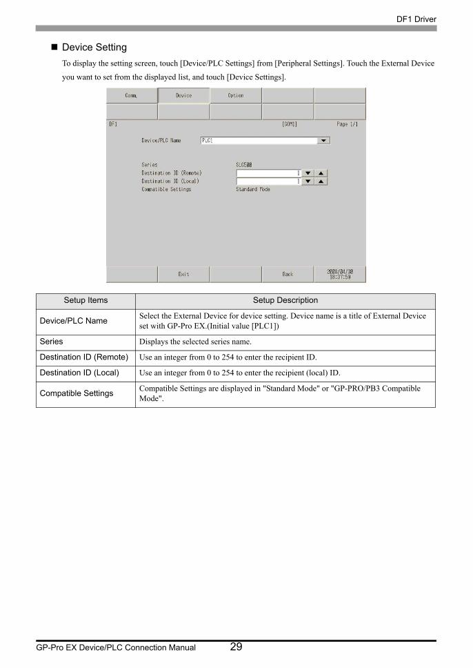
Device SettingTo display the setting screen, touch [Device/PLC Settings] from [Peripheral Settings]. Touch the External Device
you want to set from the displayed list, and touch [Device Settings].
Setup Items Setup Description
Device/PLC Name Select the External Device for device setting. Device name is a title of External Device set with GP-Pro EX.(Initial value [PLC1])
Series Displays the selected series name.
Destination ID (Remote) Use an integer from 0 to 254 to enter the recipient ID.
Destination ID (Local) Use an integer from 0 to 254 to enter the recipient (local) ID.
Compatible Settings Compatible Settings are displayed in "Standard Mode" or "GP-PRO/PB3 Compatible Mode".
DF1 Driver
GP-Pro EX Device/PLC Connection Manual 30
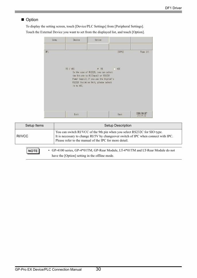
OptionTo display the setting screen, touch [Device/PLC Settings] from [Peripheral Settings].
Touch the External Device you want to set from the displayed list, and touch [Option].
Setup Items Setup Description
RI/VCCYou can switch RI/VCC of the 9th pin when you select RS232C for SIO type.It is necessary to change RI/5V by changeover switch of IPC when connect with IPC. Please refer to the manual of the IPC for more detail.
• GP-4100 series, GP-4*01TM, GP-Rear Module, LT-4*01TM and LT-Rear Module do not have the [Option] setting in the offline mode.

DF1 Driver
GP-Pro EX Device/PLC Connection Manual 31
5 Cable Diagram
The cable diagram shown below may be different from the cable diagram recommended by Rockwell
Automation, Inc. Please be assured there is no operational problem in applying the cable diagram shown in this
manual.
• The FG pin of the main body of the External Device must be D-class grounded. Please refer to the manual of
the External Device for more details.
• SG and FG are connected inside the Display. When connecting SG to the External Device, design the system
not to form short-circuit loop.
• Connect the isolation unit, when communication is not stabilized under the influence of a noise etc..
Cable Diagram 1
1A)
Display (Connection Port)
Cable Remarks
GP3000 (COM1)GP4000*1 (COM1)SP5000*2 (COM1/2)SP-5B00 (COM1)ST3000 (COM1)ST6000 (COM1)STM6000 (COM1)LT3000 (COM1)IPC*3
PC/AT
*1 All GP4000 models except GP-4100 Series and GP-4203T
*2 Except SP-5B00
*3 Only the COM port which can communicate by RS-232C can be used. IPC COM Port (page 4)
1A RS232C cable by Pro-faceCA3-CBL232/5M-01 (5m)
9/25 pin conversion adapter is required.
1B User-created cable The cable length must be 15m or less.
GP-4105 (COM1) GP-4115T (COM1) GP-4115T3 (COM1)
1C User-created cable The cable length must be 15m or less.
LT-4*01TM (COM1)LT-Rear Module (COM1) 1D
RJ45 RS-232C Cable (5m) by Pro-facePFXZLMCBRJR21 The cable length must be
5m or less.
Display
CA3-CBL232/5M-019/25 pin
conversion adapter
External Device

DF1 Driver
GP-Pro EX Device/PLC Connection Manual 32
1B)
1C)
SG
CD
DR(DSR)
RS(RTS)
CS(CTS)
FG
SD(TXD)
RD(RXD)
ER(DTR)
5
1
6
7
8
3
2
COM
DCD
DSR
RTS
CTS
RXD
TXD
DTR4
5
1
6
7
8
2
3
4
Display
D-sub 9 pin (socket)
Pin Signalname
External Device sideD-sub 9 pin (socket)
Pin Signalname
Shell
ShieldDisplay side
SG
CD
DR(DSR)
RS(RTS)
CS(CTS)
SD(TXD)
RD(RXD)
ER(DTR)
COM
DCD
DSR
RTS
CTS
RXD
TXD
DTR
5
1
6
7
8
2
3
4
Display
Signalname
External Device sideD-sub 9 pin (socket)
Pin Signalname
Shield Terminal blockDisplay side

DF1 Driver
GP-Pro EX Device/PLC Connection Manual 33
1D)
Number Name Notes
(1)RJ45 RS-232C Cable (5m) by Pro-face
PFXZLMCBRJR21
COM
DCD
DSR
RTS
CTS
RXD
TXD
DTR
5
1
6
7
8
2
3
4
External Device sideD-sub 9 pin (socket)
Pin Signalname
Display
GND
TXD
RXD
(1)

DF1 Driver
GP-Pro EX Device/PLC Connection Manual 34
Cable Diagram 2
2A)
2B)
Display (Connection Port)
Cable Remarks
GP3000 (COM1)GP4000*1 (COM1)SP5000*2 (COM1/2)SP-5B00 (COM1)ST3000 (COM1)ST6000 (COM1)STM6000 (COM1)LT3000 (COM1)IPC*3
PC/AT
*1 All GP4000 models except GP-4100 Series and GP-4203T
*2 Except SP-5B00
*3 Only the COM port which can communicate by RS-232C can be used. IPC COM Port (page 4)
2A RS232C cable by Pro-faceCA3-CBL232/5M-01 (5m)
2B User-created cable The cable length must be 15m or less.
GP-4105 (COM1) GP-4115T (COM1) GP-4115T3 (COM1)
2C User-created cable The cable length must be 15m or less.
LT-4*01TM (COM1)LT-Rear Module (COM1) 2D
RJ45 RS-232C Cable (5m) by Pro-facePFXZLMCBRJR21 The cable length must be
5m or less.
Display
CA3-CBL232/5M-01
External Device
or
I/F module 25 pin
SG
CD
DR(DSR)
RS(RTS)
CS(CTS)
SD(TXD)
RD(RXD)
ER(DTR)
5
1
6
7
8
3
2
COM
DCD
DSR
RTS
CTS
RXD
TXD
DTR4
7
8
6
4
5
GND1
3
2
20
Display
D-sub 9 pin (socket)
Pin Signalname
External Device sideD-sub 25 pin (plug)
Pin Signalname
ShieldDisplay side

DF1 Driver
GP-Pro EX Device/PLC Connection Manual 35
2C)
2D)
Number Name Notes
(1)RJ45 RS-232C Cable (5m) by Pro-face
PFXZLMCBRJR21
SG
CD
DR(DSR)
RS(RTS)
CS(CTS)
SD(TXD)
RD(RXD)
ER(DTR)
COM
DCD
DSR
RTS
CTS
RXD
TXD
DTR
7
8
6
4
5
GND1
3
2
20
Display
Signalname
External Device sideD-sub 25 pin (plug)
Pin Signalname
Shield Terminal blockDisplay side
COM
DCD
DSR
RTS
CTS
RXD
TXD
DTR
7
8
6
4
5
GND1
3
2
20
External Device sideD-sub 25 pin (plug)
Pin Signalname
Display
GND
TXD
RXD
(1)

DF1 Driver
GP-Pro EX Device/PLC Connection Manual 36
Cable Diagram 3
3A)
Display(Connection Port)
Cable Remarks
GP3000 (COM1)GP4000*1 (COM1)SP5000*2 (COM1/2)SP-5B00 (COM1)ST3000 (COM1)ST6000 (COM1)STM6000 (COM1)LT3000 (COM1)IPC*3
PC/AT
*1 All GP4000 models except GP-4100 Series and GP-4203T
*2 Except SP-5B00
*3 Only the COM port which can communicate by RS-232C can be used. IPC COM Port (page 4)
3A User-created cable The cable length must be 15m or less.
GP-4105 (COM1) GP-4115T (COM1) GP-4115T3 (COM1)
3B User-created cable The cable length must be 15m or less.
LT-4*01TM (COM1)LT-Rear Module (COM1) 3C
RJ45 RS-232C Cable (5m) by Pro-facePFXZLMCBRJR21 The cable length must be 5m
or less.
SG
CD
DR(DSR)
RS(RTS)
CS(CTS)
SD(TXD)
RD(RXD)
ER(DTR)
5
1
6
7
8
3
2
COM
DCD
DSR
RTS
CTS
RXD
TXD
DTR4
7
8
6
4
5
GND1
3
2
11
Display
D-sub 9 pin (socket)
Pin Signalname
External Device sideD-sub 15 pin (socket)
Pin Signalname
Shield
Display side

DF1 Driver
GP-Pro EX Device/PLC Connection Manual 37
3B)
3C)
Number Name Notes
(1)RJ45 RS-232C Cable (5m) by Pro-face
PFXZLMCBRJR21
SG
CD
DR(DSR)
RS(RTS)
CS(CTS)
SD(TXD)
RD(RXD)
ER(DTR)
COM
DCD
DSR
RTS
CTS
RXD
TXD
DTR
7
8
6
4
5
GND1
3
2
11
Display
Signalname
External Device sideD-sub 15 pin (socket)
Pin Signalname
Shield Terminal blockDisplay side
COM
DCD
DSR
RTS
CTS
RXD
TXD
DTR
7
8
6
4
5
GND1
3
2
11
External Device sideD-sub 15 pin (socket)
Pin Signalname
Display
GND
TXD
RXD
(1)
DF1 Driver
GP-Pro EX Device/PLC Connection Manual 38
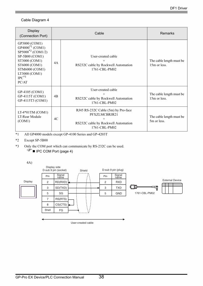
Cable Diagram 4
4A)
Display(Connection Port)
Cable Remarks
GP3000 (COM1)GP4000*1 (COM1)SP5000*2 (COM1/2)SP-5B00 (COM1)ST3000 (COM1)ST6000 (COM1)STM6000 (COM1)LT3000 (COM1)IPC*3
PC/AT
*1 All GP4000 models except GP-4100 Series and GP-4203T
*2 Except SP-5B00
*3 Only the COM port which can communicate by RS-232C can be used. IPC COM Port (page 4)
4A
User-created cable+
RS232C cable by Rockwell Automation1761-CBL-PM02
The cable length must be 15m or less.
GP-4105 (COM1) GP-4115T (COM1) GP-4115T3 (COM1)
4B
User-created cable+
RS232C cable by Rockwell Automation1761-CBL-PM02
The cable length must be 15m or less.
LT-4*01TM (COM1)LT-Rear Module (COM1) 4C
RJ45 RS-232C Cable (5m) by Pro-facePFXZLMCBRJR21
+RS232C cable by Rockwell Automation
1761-CBL-PM02
The cable length must be 5m or less.
SG
RS(RTS)
CS(CTS)
SD(TXD)
RD(RXD)
5
7
8
3
2
FG
TXD
RXD
GND
3
2
5
Display
D-sub 9 pin (socket)
Pin Signalname
D-sub 9 pin (plug)
Pin Signalname
Shell
Shield
User-created cable
1761-CBL-PM02
External Device
Display side

DF1 Driver
GP-Pro EX Device/PLC Connection Manual 39
4B)
4C)
Number Name Notes
(1)RJ45 RS-232C Cable (5m) by Pro-face
PFXZLMCBRJR21
SG
RS(RTS)
CS(CTS)
SD(TXD)
RD(RXD)
TXD
RXD
GND
3
2
5
Display
Signalname
D-sub 9 pin (plug)
Pin Signalname
Shield
User-created cable
1761-CBL-PM02
External Device
Terminal blockDisplay side
TXD
RXD
GND
3
2
5
D-sub 9 pin (plug)
Pin Signalname
1761-CBL-PM02
External DeviceDisplay
GND
TXD
RXD
(1)

DF1 Driver
GP-Pro EX Device/PLC Connection Manual 40
Cable Diagram 5
5A)
Display(Connection Port)
Cable Remarks
GP3000 (COM1)GP4000*1 (COM1)SP5000*2 (COM1/2)SP-5B00 (COM1)ST3000 (COM1)ST6000 (COM1)STM6000 (COM1)LT3000 (COM1)IPC*3
PC/AT
*1 All GP4000 models except GP-4100 Series and GP-4203T
*2 Except SP-5B00
*3 Only the COM port which can communicate by RS-232C can be used. IPC COM Port (page 4)
5A User-created cable The cable length must be 15m or less.
GP-4105 (COM1) GP-4115T (COM1) GP-4115T3 (COM1)
5B User-created cable The cable length must be 15m or less.
LT-4*01TM (COM1)LT-Rear Module (COM1) 5C
RJ45 RS-232C Cable (5m) by Pro-facePFXZLMCBRJR21 The cable length must be
5m or less.
RXD
TXD
GND
2
3
5
SG
RS(RTS)
CS(CTS)
SD(TXD)
RD(RXD)
5
7
8
3
2
FG
Display
D-sub 9 pin (socket)
Pin Signalname External DevicePin Signal
name
Shell
Shield1761-NET-AIC port1D-sub 9 pin (socket)
1761-NET-AIC
1761-CBL-AM00
User-created cable
Display side

DF1 Driver
GP-Pro EX Device/PLC Connection Manual 41
5B)
5C)
Number Name Notes
(1)RJ45 RS-232C Cable (5m) by Pro-face
PFXZLMCBRJR21
RXD
TXD
GND
2
3
5
SG
RS(RTS)
CS(CTS)
SD(TXD)
RD(RXD)
Display Signalname External DevicePin Signal
name
Shield1761-NET-AIC port1D-sub 9 pin (socket)
1761-NET-AIC
1761-CBL-AM00
User-created cable
Terminal blockDisplay side
RXD
TXD
GND
2
3
5
External DevicePin Signal
name
1761-NET-AIC port1D-sub 9 pin (socket)
1761-NET-AIC
1761-CBL-AM00
Display
GND
TXD
RXD
(1)

DF1 Driver
GP-Pro EX Device/PLC Connection Manual 42
Cable Diagram 6
Display(Connection Port)
Cable Remarks
GP3000*1 (COM1)AGP-3302B (COM2)GP-4*01TM (COM1)GP-Rear Module (COM1)ST3000*2 (COM2)LT3000 (COM1)IPC*3
*1 All GP3000 models except AGP-3302B
*2 Except AST-3211A and AST-3302B
*3 Only the COM port which can communicate by RS-422/485 (4 wire) can be used. (Except PE-4000B, PS5000, and PS6000)
IPC COM Port (page 4)
6A
COM port conversion adapter by Pro-faceCA3-ADPCOM-01
+Terminal block conversion adapter by Pro-face
CA3-ADPTRM-01+
User-created cable
The cable length must be 61m or less.
6B User-created cable
GP3000*4 (COM2)
*4 All GP3000 models except GP-3200 series and AGP-3302B
6C
Online adapter by Pro-faceCA4-ADPONL-01
+Terminal block conversion adapter by Pro-face
CA3-ADPTRM-01+
User-created cableThe cable length must be 61m or less.
6D
Online adapter by Pro-faceCA4-ADPONL-01
+User-created cable
GP-4106 (COM1) GP-4116T (COM1) 6E User-created cable The cable length must be
61m or less.
GP4000*5 (COM2)GP-4201T (COM1)SP5000*6 (COM1/2)SP-5B00 (COM2)ST6000*7 (COM2)ST-6200 (COM1)STM6000 (COM1)
*5 All GP4000 models except GP-4100 series, GP-4*01TM, GP-Rear Module, GP-4201T and GP-4*03T
*6 Except SP-5B00
*7 Except ST-6200
6F
RS-422 terminal block conversion adapter by Pro-facePFXZCBADTM1*8
+User-created cable
*8 When using a Terminal Block Conversion Adapter (CA3-ADPTRM-01) instead of the RS-422 Terminal Block Conversion Adapter, refer to Cable Diagram 6A.
The cable length must be 61m or less.
6B User-created cable
PE-4000B*9
PS5000*9
PS6000*96G User-created cable The cable length must be
61m or less.

DF1 Driver
GP-Pro EX Device/PLC Connection Manual 43
6A)
6B)
6C)
*9 Only the COM port which can communicate by RS-422/485 (4 wire) can be used. IPC COM Port (page 4)
RDB16
SDB
SDA
14
2
FG1
RDA3
SDA
SDB
TERM
RDA
RDB
CA3-ADPTRM-01
Display
Signalname
External Device sideD-sub 25 pin (plug)
Pin Signalname
Shield
CA3-ADPCOM-01
Terminalblock
User-created cable
RDB16
SDB
SDA
14
2
FG1
RDA3
RDA
RDB
SDA
SDB
3
7
1
2
8
4
CSA
ERA
9 ERB
CSB6
Display
Terminationresistance
D-sub 9 pin (socket)
Pin Signalname
External Device sideD-sub 25 pin (plug)
Pin Signalname
ShieldDisplay side
RDB16
SDB
SDA
14
2
FG1
RDA3
SDA
SDB
TERM
RDA
RDB
CA4-ADPONL-01
CA3-ADPTRM-01
Display
TerminalblockSignalname
Shield External Device sideD-sub 25 pin (plug)
Pin Signalname
User-created cable

DF1 Driver
GP-Pro EX Device/PLC Connection Manual 44
6D)
6E)
*1 The resistance in the Display is used as the termination resistance. Set the value of the DIP Switch on the rear of the Display as shown in the table below.
DIP Switch No. Set Value
1 OFF
2 OFF
3 ON
4 ON
RDB16
SDB
SDA
14
2
FG1
RDA3
RDB
RDA
7
CA4-ADPONL-01
2
SDA
SDB
3
8
Display
Shield External Device sideD-sub 25 pin (plug)
Pin Signalname
D-sub 9 pin (plug)
Pin Signalname
User-created cable
RDB16
SDB
SDA
14
2
FG1
RDA3
RDA
RDB
SDA
SDB
CSA
ERA
ERB
CSB
Display
Terminationresistance*1 Signal
name
External Device sideD-sub 25 pin (plug)
Pin Signalname
Shield Terminal block
Display side

DF1 Driver
GP-Pro EX Device/PLC Connection Manual 45
6F)
6G)
RDB16
SDB
SDA
14
2
FG1
RDA3
SDA
SDB
TERM
RDA
RDB
PFXZCBADTM1
Display
Signalname
External Device sideD-sub 25 pin (plug)
Pin Signalname
ShieldTerminalblock
User-created cable
RDB16
SDB
SDA
14
2
FG1
RDA3
Rx+
Rx-
Tx+
Tx-
NC
NC
NC
NC
2
1
3
4
8
7
9
6
Display
Terminationresistance
D-sub 9 pin (socket)
Pin Signalname
External Device sideD-sub 25 pin (plug)
Pin Signalname
ShieldDisplay side
DF1 Driver
GP-Pro EX Device/PLC Connection Manual 46
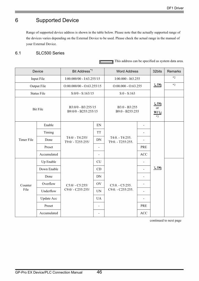
6 Supported Device
Range of supported device address is shown in the table below. Please note that the actually supported range of
the devices varies depending on the External Device to be used. Please check the actual range in the manual of
your External Device.
6.1 SLC500 Series
This address can be specified as system data area.
Device Bit Address*1 Word Address 32bits Remarks
Input File I:00.000/00 - I:63.255/15 I:00.000 - I63.255 *2
Output File O:00.000/00 - O:63.255/15 O:00.000 - O:63.255 *2
Status File S:0/0 - S:163/15 S:0 - S:163
Bit File B3:0/0 - B3:255/15B9:0/0 - B255:255/15
B3:0 - B3:255B9:0 - B255:255
*3
Timer File
Enable
T4:0/ - T4:255/T9:0/ - T255:255/
EN
T4:0. - T4:255.T9:0. - T255:255.
-
Timing TT -
Done DN -
Preset - PRE
Accumulated - ACC
Counter File
Up Enable
C5:0/ - C5:255/C9:0/ - C255:255/
CU
C5:0. - C5:255.C9:0. - C255:255.
-
Down Enable CD -
Done DN -
Overflow OV -
Underflow UN -
Update Acc UA -
Preset - PRE
Accumulated - ACC
continued to next page
or
DF1 Driver
GP-Pro EX Device/PLC Connection Manual 47
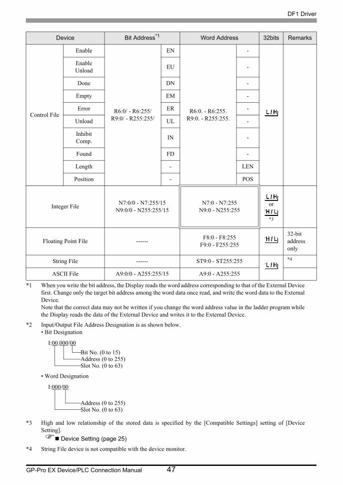
Control File
Enable
R6:0/ - R6:255/R9:0/ - R255:255/
EN
R6:0. - R6:255.R9:0. - R255:255.
-
Enable Unload EU -
Done DN -
Empty EM -
Error ER -
Unload UL -
Inhibit Comp. IN -
Found FD -
Length - LEN
Position - POS
Integer File N7:0/0 - N7:255/15N9:0/0 - N255:255/15
N7:0 - N7:255N9:0 - N255:255
*3
Floating Point File ------ F8:0 - F8:255F9:0 - F255:255
32-bit address only
String File ------ ST9:0 - ST255:255 *4
ASCII File A9:0/0 - A255:255/15 A9:0 - A255:255
*1 When you write the bit address, the Display reads the word address corresponding to that of the External Device first. Change only the target bit address among the word data once read, and write the word data to the External Device. Note that the correct data may not be written if you change the word address value in the ladder program while the Display reads the data of the External Device and writes it to the External Device.
*2 Input/Output File Address Designation is as shown below. • Bit Designation
• Word Designation
*3 High and low relationship of the stored data is specified by the [Compatible Settings] setting of [Device Setting].
Device Setting (page 25)
*4 String File device is not compatible with the device monitor.
Device Bit Address*1 Word Address 32bits Remarks
or
I:00.000/00Bit No. (0 to 15)Address (0 to 255)Slot No. (0 to 63)
I:000/00
Address (0 to 255)Slot No. (0 to 63)

DF1 Driver
GP-Pro EX Device/PLC Connection Manual 48
• If the bit address of the Timer File, Counter File, and Control File device are read by the device monitor, writing speed on the base monitor may be delayed.
• Please refer to the GP-Pro EX Reference Manual for system data area.Cf. GP-Pro EX Reference Manual "LS Area (Direct Access Method Area)"
• Please refer to the precautions on manual notation for icons in the table.
"Manual Symbols and Terminology"

DF1 Driver
GP-Pro EX Device/PLC Connection Manual 49
6.2 PLC-5 Series
This address can be specified as system data area.
Device Bit Address Word Address 32bitsRemark
s
Input File I:0/0 - I:377/17 I:0 - I:377
*1Output File O:0/0 - I:377/17 O:0 - I:377
Status File S:0/0 - S:163/15 S:0 - S:163
Bit File B3:0/0 - B999:999/15 B3:0 - B999:999
*1
Timer File
Enable
T3:0/ - T999:999/
EN
T3:0. - T999:999.
-
Timing TT -
Done DN -
Preset - PRE
Accumulated - ACC
Counter File
Up Enable
C3:0/ - C999:999/
CU
C3:0. - C999:999.
-
Down Enable CD -
Done DN -
Overflow OV -
Underflow UN -
Update Acc UA -
Preset - PRE
Accumulated - ACC
continued to next page
or
or

DF1 Driver
GP-Pro EX Device/PLC Connection Manual 50
Control File
Enable
R3:0/ - R999:999/
EN
R3:0. - R999:999.
-
Enable Unload EU -
Done DN -
Empty EM -
Error ER -
Unload UL -
Inhibit Comp. IN -
Found FD -
Length - LEN
Position - POS
Integer File N3:0/0 - N999:999/15 N3:0 - N999:999
*1
Floating Point File ------ F3:0 - F999:99932-bit
address only
String File ------ ST3:0 - ST999:999 *2
ASCII File A3:0/0 - A999:999/15 A3:0 - A999:999
*1BCD File D3:0/0 - D999:999/15 D3:0 - D999:999
*1 High and low relationship of the stored data is specified by the [Compatible Settings] setting of [Device Setting]. Device Setting (page 25)
*2 String File device is not compatible with the device monitor.
• If the bit address of the Timer File, Counter File, and Control File device are read by the device monitor, writing speed on the base monitor may be delayed.
• Please refer to the GP-Pro EX Reference Manual for system data area.Cf. GP-Pro EX Reference Manual "LS Area (Direct Access Method Area)"
• Please refer to the precautions on manual notation for icons in the table.
"Manual Symbols and Terminology"
Device Bit Address Word Address 32bitsRemark
s
or
or

DF1 Driver
GP-Pro EX Device/PLC Connection Manual 51
6.3 MicroLogix Series
This address can be specified as system data area.
Device Bit Address*1 Word Address 32bitsRemar
ks
Input File I:00.000/00 - I:08.255/15 I:00.000 - I08.255 *2
Output File O:00.000/00 - O:08.255/15 O:00.000 - O:08.255 *2
Status File S:0/0 - S:163/15 S:0 - S:163
Bit File B3:0/0 - B3:255/15B9:0/0 - B255:255/15
B3:0 - B3:255B9:0 - B255:255
*3
Timer File
Enable
T4:0/ - T4:255/T9:0/ - T255:255/
EN
T4:0. - T4:255.T9:0. - T255:255.
-
Timing TT -
Done DN -
Preset - PRE
Accumulated - ACC
Counter File
Up Enable
C5:0/ - C5:255/C9:0/ - C255:255/
CU
C5:0. - C5:255.C9:0. - C255:255.
-
Down Enable CD -
Done DN -
Overflow OV -
Underflow UN -
Update Acc UA -
Preset - PRE
Accumulated - ACC
continued to next page
or

DF1 Driver
GP-Pro EX Device/PLC Connection Manual 52
Control File
Enable
R6:0/ - R6:255/R9:0/ - R255:255/
EN
R6:0. - R6:255.R9:0. - R255:255.
-
Enable Unload EU -
Done DN -
Empty EM -
Error ER -
Unload UL -
Inhibit Comp. IN -
Found FD -
Length - LEN
Position - POS
Integer File N7:0/0 - N7:255/15N9:0/0 - N255:255/15
N7:0 - N7:255N9:0 - N255:255
*3
Floating Point File ------ F8:0 - F8:255F9:0 - F255:255
32-bit address
only
String File ------ ST9:0 - ST255:255 *4
Long Word File L9:0/0 - L255:255/31 L9:0 - L255:255
*1 When you write the bit address, the Display reads the word address corresponding to that of the External Device first. Change only the target bit address among the word data once read, and write the word data to the External Device. Note that the correct data may not be written if you change the word address value in the ladder program while the Display reads the data of the External Device and writes it to the External Device.
*2 Input/Output File Address Designation is as shown below. • Bit Designation
• Word Designation
*3 High and low relationship of the stored data is specified by the [Compatible Settings] setting of [Device Setting].
Device Setting (page 25)
*4 String File device is not compatible with the device monitor.
Device Bit Address*1 Word Address 32bitsRemar
ks
or
I:00.000/00Bit No. (0 to 15)Address (0 to 255)Slot No. (0 to 8)
I:000/00
Address (0 to 255)Slot No. (0 to 8)

DF1 Driver
GP-Pro EX Device/PLC Connection Manual 53
• If the bit address of the Timer File, Counter File, and Control File device are read by the device monitor, writing speed on the base monitor may be delayed.
• Please refer to the GP-Pro EX Reference Manual for system data area.Cf. GP-Pro EX Reference Manual "LS Area (Direct Access Method Area)"
• Please refer to the precautions on manual notation for icons in the table.
"Manual Symbols and Terminology"

DF1 Driver
GP-Pro EX Device/PLC Connection Manual 54
6.4 ControlLogix/CompactLogix Series
This address can be specified as system data area.
Device Bit Address*1
*1 When you write the bit address, the Display reads the word address corresponding to that of the External Device first. Change only the target bit address among the word data once read, and write the word data to the External Device. Note that the correct data may not be written if you change the word address value in the ladder program while the Display reads the data of the External Device and writes it to the External Device.
Word Address 32bits Remarks
BOOL BOOL0:0/0 - BOOL999:999/31 BOOL0:000 - BOOL999:999 *2
INT INT0:0/0 - INT999:999/15 INT0:000 - INT999:999 *2
REAL ------ REAL0:000 - REAL999:999 *2
DINT DINT0:0/0 - DINT999:999/31 DINT0:000 - DINT999:999 *2
SINT SINT0:0/0 - SINT999:999/7 SINT0:000 - SINT999:998 *2

DF1 Driver
GP-Pro EX Device/PLC Connection Manual 55
*2 To access those addresses and use them in the program of the External Device, you need to set the External Device first.
The following procedure shows how to assign the device in the RSLogix5000 software and specify the address in GP-Pro EX.
1) Tag setting of External Device Create the Tag Name in the RSLogix5000 software, and set the Type. Map the created Tag Name to a File Number.
Set the range used in GP-Pro EX for the Element. Maximum Element GP-Pro EX can access is 999. When you do not define the Element, only one item is available to use. (Example) Tag Name: N8, Type: When INT is set, only one word of N8 can be used.
1st line: Tag Name"N7" is INT data type with Element 2002nd line:Tag Name "DINT1" is DINT data type with Element 1003rd line: Tag Name "DATA2" is SINT data type with Element 50
2) Address Specification in GP-Pro EX When you access the External Device from GP-Pro EX, specify Type, File Number and Element.
<Example of address mapping of GP-Pro EX and External Device>
Tag Name :Set optionally.Type :Select the data type among below to set the Element.
Match the device name of GP-Pro EX BOOT(32bit data type) INT(word data type) DINT(dword data type) SINT(byte data type) REAL(float data type)
<Example 1> Tag Name TypeN7 INT[200]DINT1 DINT[100]DATA2 SINT[50]
File Number : Assign the Tag Name created by RSLogix5000 to the optional File Number. You can not assign different Tag Names to the same File Number.
<Example2> File Number Name2 DATA21 DINT17 N7
Address of GP-Pro EX File No.1 Memory of the External Device
DINT1:0 DINT 1[0]
DINT1:1 DINT 1[1]
DNT1:2 DINT 1[2]

DF1 Driver
GP-Pro EX Device/PLC Connection Manual 56
• Please refer to the GP-Pro EX Reference Manual for system data area.Cf. GP-Pro EX Reference Manual "LS Area (Direct Access Method Area)"
• Please refer to the precautions on manual notation for icons in the table.
"Manual Symbols and Terminology"
DF1 Driver
GP-Pro EX Device/PLC Connection Manual 57
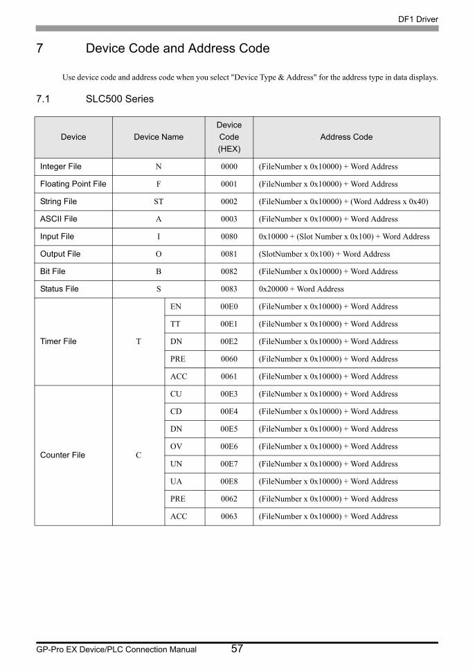
7 Device Code and Address Code
Use device code and address code when you select "Device Type & Address" for the address type in data displays.
7.1 SLC500 Series
Device Device NameDevice Code(HEX)
Address Code
Integer File N 0000 (FileNumber x 0x10000) + Word Address
Floating Point File F 0001 (FileNumber x 0x10000) + Word Address
String File ST 0002 (FileNumber x 0x10000) + (Word Address x 0x40)
ASCII File A 0003 (FileNumber x 0x10000) + Word Address
Input File I 0080 0x10000 + (Slot Number x 0x100) + Word Address
Output File O 0081 (SlotNumber x 0x100) + Word Address
Bit File B 0082 (FileNumber x 0x10000) + Word Address
Status File S 0083 0x20000 + Word Address
Timer File T
EN 00E0 (FileNumber x 0x10000) + Word Address
TT 00E1 (FileNumber x 0x10000) + Word Address
DN 00E2 (FileNumber x 0x10000) + Word Address
PRE 0060 (FileNumber x 0x10000) + Word Address
ACC 0061 (FileNumber x 0x10000) + Word Address
Counter File C
CU 00E3 (FileNumber x 0x10000) + Word Address
CD 00E4 (FileNumber x 0x10000) + Word Address
DN 00E5 (FileNumber x 0x10000) + Word Address
OV 00E6 (FileNumber x 0x10000) + Word Address
UN 00E7 (FileNumber x 0x10000) + Word Address
UA 00E8 (FileNumber x 0x10000) + Word Address
PRE 0062 (FileNumber x 0x10000) + Word Address
ACC 0063 (FileNumber x 0x10000) + Word Address

DF1 Driver
GP-Pro EX Device/PLC Connection Manual 58
Control File R
EN 00F0 (FileNumber x 0x10000) + Word Address
EU 00F1 (FileNumber x 0x10000) + Word Address
DN 00F2 (FileNumber x 0x10000) + Word Address
EM 00F3 (FileNumber x 0x10000) + Word Address
ER 00F4 (FileNumber x 0x10000) + Word Address
UL 00F5 (FileNumber x 0x10000) + Word Address
IN 00F6 (FileNumber x 0x10000) + Word Address
FD 00F7 (FileNumber x 0x10000) + Word Address
LEN 0064 (FileNumber x 0x10000) + Word Address
POS 0065 (FileNumber x 0x10000) + Word Address
Device Device NameDevice Code(HEX)
Address Code

DF1 Driver
GP-Pro EX Device/PLC Connection Manual 59
7.2 PLC-5 Series
Device Device NameDevice Code(HEX)
Address Code
Integer File N 0000 (FileNumber x 0x10000) + Word Address
Floating Point File F 0001 (FileNumber x 0x10000) + Word Address
String File ST 0002 (FileNumber x 0x10000) + (Word Address x 0x40)
ASCII File A 0003 (FileNumber x 0x10000) + Word Address
BCD File D 0004 (FileNumber x 0x10000) + Word Address
Input File I 0080 0x10000 + (Slot Number x 0x100) + Word Address
Output File O 0081 (SlotNumber x 0x100) + Word Address
Bit File B 0082 (FileNumber x 0x10000) + Word Address
Status File S 0083 0x20000 + Word Address
Timer File T
EN 00E0 (FileNumber x 0x10000) + Word Address
TT 00E1 (FileNumber x 0x10000) + Word Address
DN 00E2 (FileNumber x 0x10000) + Word Address
PRE 0060 (FileNumber x 0x10000) + Word Address
ACC 0061 (FileNumber x 0x10000) + Word Address
Counter File C
CU 00E3 (FileNumber x 0x10000) + Word Address
CD 00E4 (FileNumber x 0x10000) + Word Address
DN 00E5 (FileNumber x 0x10000) + Word Address
OV 00E6 (FileNumber x 0x10000) + Word Address
UN 00E7 (FileNumber x 0x10000) + Word Address
UA 00E8 (FileNumber x 0x10000) + Word Address
PRE 0062 (FileNumber x 0x10000) + Word Address
ACC 0063 (FileNumber x 0x10000) + Word Address

DF1 Driver
GP-Pro EX Device/PLC Connection Manual 60
Control File R
EN 00F0 (FileNumber x 0x10000) + Word Address
EU 00F1 (FileNumber x 0x10000) + Word Address
DN 00F2 (FileNumber x 0x10000) + Word Address
EM 00F3 (FileNumber x 0x10000) + Word Address
ER 00F4 (FileNumber x 0x10000) + Word Address
UL 00F5 (FileNumber x 0x10000) + Word Address
IN 00F6 (FileNumber x 0x10000) + Word Address
FD 00F7 (FileNumber x 0x10000) + Word Address
LEN 0064 (FileNumber x 0x10000) + Word Address
POS 0065 (FileNumber x 0x10000) + Word Address
Device Device NameDevice Code(HEX)
Address Code

DF1 Driver
GP-Pro EX Device/PLC Connection Manual 61
7.3 MicroLogix Series
Device Device NameDevice Code(HEX)
Address Code
Integer File N 0000 (FileNumber x 0x10000) + Word Address
Floating Point File F 0001 (FileNumber x 0x10000) + Word Address
String File ST 0002 (FileNumber x 0x10000) + (Word Address x 0x40)
Long Word File L 0005 (FileNumber x 0x10000) + Word Address
Input File I 0080 0x10000 + (Slot Number x 0x100) + Word Address
Output File O 0081 (SlotNumber x 0x100) + Word Address
Bit File B 0082 (FileNumber x 0x10000) + Word Address
Status File S 0083 0x20000 + Word Address
Timer File T
EN 00E0 (FileNumber x 0x10000) + Word Address
TT 00E1 (FileNumber x 0x10000) + Word Address
DN 00E2 (FileNumber x 0x10000) + Word Address
PRE 0060 (FileNumber x 0x10000) + Word Address
ACC 0061 (FileNumber x 0x10000) + Word Address
Counter File C
CU 00E3 (FileNumber x 0x10000) + Word Address
CD 00E4 (FileNumber x 0x10000) + Word Address
DN 00E5 (FileNumber x 0x10000) + Word Address
OV 00E6 (FileNumber x 0x10000) + Word Address
UN 00E7 (FileNumber x 0x10000) + Word Address
UA 00E8 (FileNumber x 0x10000) + Word Address
PRE 0062 (FileNumber x 0x10000) + Word Address
ACC 0063 (FileNumber x 0x10000) + Word Address

DF1 Driver
GP-Pro EX Device/PLC Connection Manual 62
Control File R
EN 00F0 (FileNumber x 0x10000) + Word Address
EU 00F1 (FileNumber x 0x10000) + Word Address
DN 00F2 (FileNumber x 0x10000) + Word Address
EM 00F3 (FileNumber x 0x10000) + Word Address
ER 00F4 (FileNumber x 0x10000) + Word Address
UL 00F5 (FileNumber x 0x10000) + Word Address
IN 00F6 (FileNumber x 0x10000) + Word Address
FD 00F7 (FileNumber x 0x10000) + Word Address
LEN 0064 (FileNumber x 0x10000) + Word Address
POS 0065 (FileNumber x 0x10000) + Word Address
Device Device NameDevice Code(HEX)
Address Code

DF1 Driver
GP-Pro EX Device/PLC Connection Manual 63
7.4 ControlLogix/CompactLogix Series
Device Device NameDevice Code(HEX)
Address Code
INT INT 0010 (FileNumber x 0x10000) + Word Address
REAL REAL 0011 (FileNumber x 0x10000) + Word Address
DINT DINT 0012 (FileNumber x 0x10000) + Word Address
SINT SINT 0013 (FileNumber x 0x10000) + (Address divided by 2)
BOOL BOOL 0090 (FileNumber x 0x10000) + Word Address
DF1 Driver
GP-Pro EX Device/PLC Connection Manual 64
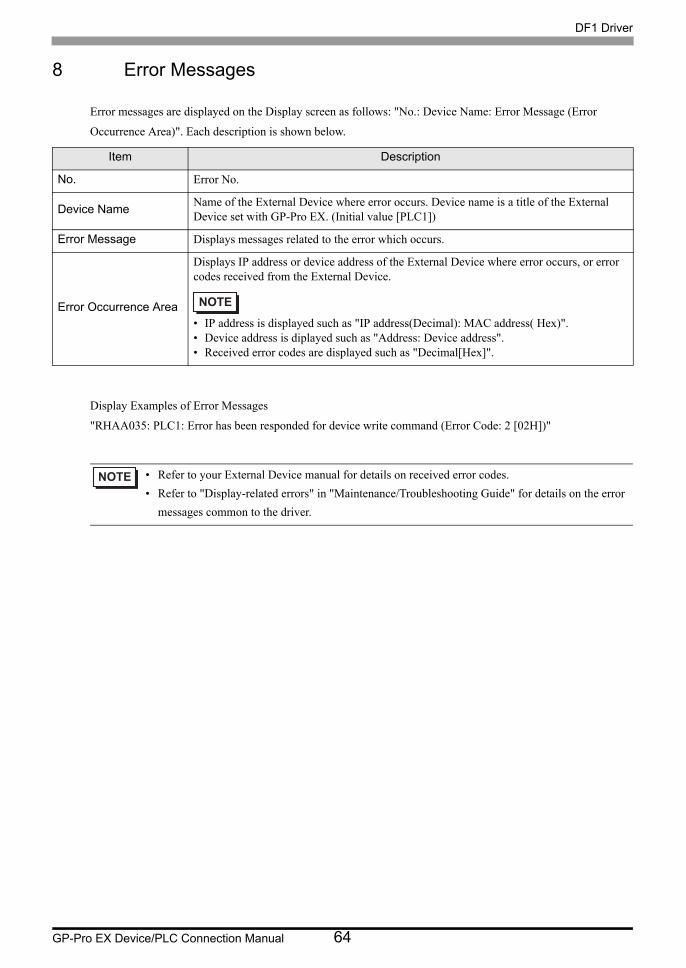
8 Error Messages
Error messages are displayed on the Display screen as follows: "No.: Device Name: Error Message (Error
Occurrence Area)". Each description is shown below.
Display Examples of Error Messages
"RHAA035: PLC1: Error has been responded for device write command (Error Code: 2 [02H])"
Item Description
No. Error No.
Device Name Name of the External Device where error occurs. Device name is a title of the External Device set with GP-Pro EX. (Initial value [PLC1])
Error Message Displays messages related to the error which occurs.
Error Occurrence Area
Displays IP address or device address of the External Device where error occurs, or error codes received from the External Device.
• IP address is displayed such as "IP address(Decimal): MAC address( Hex)".• Device address is diplayed such as "Address: Device address".• Received error codes are displayed such as "Decimal[Hex]".
• Refer to your External Device manual for details on received error codes.• Refer to "Display-related errors" in "Maintenance/Troubleshooting Guide" for details on the error
messages common to the driver.