Allen-Bradley DF1 Driver Help - OPCTurkey
58
Allen-Bradley DF1 Driver Help ©2015 Kepware, Inc.
-
Upload
khangminh22 -
Category
Documents
-
view
1 -
download
0
Transcript of Allen-Bradley DF1 Driver Help - OPCTurkey

Allen-Bradley DF1 Driver Help
©2015 Kepware, Inc.
Allen-Bradley DF1 Driver Help
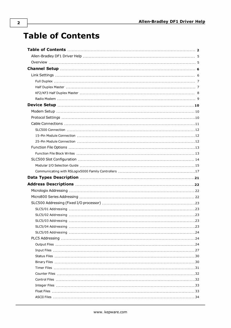
Table of ContentsTable of Contents 2
Allen-Bradley DF1 Driver Help 5
Overview 5
Channel Setup 6
Link Settings 6
Full Duplex 7
Half Duplex Master 7
KF2/KF3 Half Duplex Master 8
Radio Modem 9
Device Setup 10
Modem Setup 10
Protocol Settings 10
Cable Connections 11
SLC500 Connection 12
15-Pin Module Connection 12
25-Pin Module Connection 12
Function File Options 13
Function File Block Writes 13
SLC500 Slot Configuration 14
Modular I/O Selection Guide 15
Communicating with RSLogix5000 Family Controllers 17
Data Types Description 21
Address Descriptions 22
Micrologix Addressing 22
Micro800 Series Addressing 22
SLC500 Addressing (Fixed I/O processor) 23
SLC5/01 Addressing 23
SLC5/02 Addressing 23
SLC5/03 Addressing 23
SLC5/04 Addressing 23
SLC5/05 Addressing 24
PLC5 Addressing 24
Output Files 24
Input Files 27
Status Files 30
Binary Files 30
Timer Files 31
Counter Files 32
Control Files 32
Integer Files 33
Float Files 33
ASCII Files 34
www. kepware.com
2

Allen-Bradley DF1 Driver Help
String Files 34
BCD Files 35
Long Files 35
Micrologix PID Files 36
PLC5 PID Files 37
Micrologix Message Files 38
PLC5 Message Files 39
Block Transfer Files 39
High Speed Counter File (HSC) 40
Real-Time Clock File (RTC) 41
Channel 0 Communication Status File (CS0) 42
Channel 1 Communication Status File (CS1) 42
I/O Module Status File (IOS) 42
Error Descriptions 44
Address Validation 44
Address <address> is out of range for the specified device or register. 44
Array size is out of range for address <address>. 44
Array support is not available for the specified address: <address>. 44
Data Type <type> is not valid for device address <address>. 44
Device address <address> contains a syntax error. 45
Device address <address> is not supported by model <model name>. 45
Device address <address> is read only. 45
Missing address. 45
Serial Communications 45
Communications error on <channel name> [<error mask>] 46
COMn does not exist. 46
COMn is in use by another application. 46
Error opening COMn. 46
Unable to set comm parameters on COMn. 46
Device Status Messages 47
Device <device name> is not responding. 47
Unable to write to <address> on device <device name>. 47
Device Specific Messages 47
Checksum error occurred writing to address <address> on device <device name>. 48
Device <device name> timed out writing to address <address>. 48
Error writing to address <address> on device <device name>. Slave sink/source full. 48
Error writing to address <address> on device <device name> [Status=<STS>, Ext. Status=<EXT.STS>]. 49
Error writing to address <address> on device <device name>. Framing error. 49
Error writing to address <address> on device <device name>. Slave source empty. 49
Unable to read data starting at <start address> on device <device name> [Status=<STS>, Ext.Status=<EXT. STS>]. 49
Unable to read data starting at <start address> on device <device name> [Status=<STS>, Ext.Status=<EXT. STS>]. Block deactivated. 50
Unable to read function file <fun. file element> on device <device name> [Status=<STS>, Ext.Status=< EXT. STS>]. 50
www. kepware.com
3
Allen-Bradley DF1 Driver Help
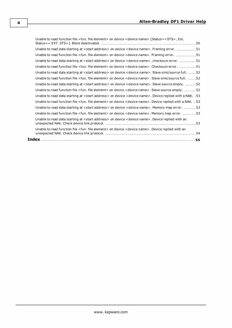
Unable to read function file <fun. file element> on device <device name> [Status=<STS>, Ext.Status=< EXT. STS>]. Block deactivated. 50
Unable to read data starting at <start address> on device <device name>. Framing error. 51
Unable to read function file <fun. file element> on device <device name>. Framing error. 51
Unable to read data starting at <start address> on device <device name>. checksum error. 51
Unable to read function file <fun. file element> on device <device name>. Checksum error. 51
Unable to read data starting at <start address> on device <device name>. Slave sink/source full. 52
Unable to read function file <fun. file element> on device <device name>. Slave sink/source full. 52
Unable to read data starting at <start address> on device <device name>. Slave source empty. 52
Unable to read function file <fun. file element> on device <device name>. Slave source empty. 52
Unable to read data starting at <start address> on device <device name>. Device replied with a NAK. 53
Unable to read function file <fun. file element> on device <device name>. Device replied with a NAK. 53
Unable to read data starting at <start address> on device <device name>. Memory map error. 53
Unable to read function file <fun. file element> on device <device name>. Memory map error. 53
Unable to read data starting at <start address> on device <device name>. Device replied with anunexpected NAK. Check device link protocol. 53
Unable to read function file <fun. file element> on device <device name>. Device replied with anunexpected NAK. Check device link protocol. 54
Index 55
www. kepware.com
4
Allen-Bradley DF1 Driver Help
Allen-Bradley DF1 Driver HelpHelp version 1.035
CONTENTS
OverviewWhat is the Allen-Bradley DF1 Driver?
Channel SetupHow do I configure a channel for use with this driver?
Device SetupHow do I configure a device for use with this driver?
Data Types DescriptionWhat data types are supported by this driver?
Address DescriptionsHow do I address a data location on an Allen-Bradley DF1 device?
Error DescriptionsWhat error messages are produced by the Allen-Bradley DF1 Driver?
OverviewThe Allen-Bradley DF1 Driver provides a reliable way to connect Allen-Bradley DF1 devices to OPC Clientapplications, including HMI, SCADA, Historian, MES, ERP, and countless custom applications. This driversupports Allen-Bradley Micrologix, SLC500, and PLC5 series PLCs.
www. kepware.com
5

Allen-Bradley DF1 Driver Help
Channel SetupSupported Link ProtocolsAllen-Bradley DF1 Full-Duplex (point-to-point communication)Allen-Bradley DF1 Half-Duplex Master (multi-drop communication) also known as Allen-Bradley DF1 Polled-Mode.*Allen-Bradley DF1 Radio Modem (point-to-point and multi-drop communication).**
*Slave-to-slave communication is not supported.**Store and forward feature is not supported.
Note: For required firmware versions for Allen-Bradley DF1 Radio Modem support, refer toDevice Setup.
Supported Communication Parameters*Baud Rate: 300, 600, 1200, 2400, 9600, 19200Parity: None, Even, or OddData Bits: 5, 6, 7 or 8Stop Bits: 1 or 2
*Not all devices may support all listed configurations.
Note: Error Checking should be set to CRC or BCC within the device.
See Also: Link Settings
Link SettingsTo access the Link Settings dialog after the Channel Wizard has closed, left-click on the channel and selectProperties. Then, select the Link Settings tab.
Station NumberThe Station Number should be set based on the device being communicated with (excluding radio modems). Thefollowing should be taken into account:
l If the destination device is on a DH+ or DH-485 network, communication must go through a Serial-to-DH+/DH-485 converter (i.e. KF2/KF3 module). In this case, the device being communicated with is theconverter, not the destination device itself (which is a Micrologix, SLC500, or PLC-5). The station numberfor this configuration should be set to the converter's node address.
www. kepware.com
6
Allen-Bradley DF1 Driver Help
l If the destination device is not on a DH+ or DH-485 network, the device being communicated with is aMicrologix, SLC500, or PLC-5 PLC. The station number for this configuration can be set to an arbitraryunique address.
Standard Serial ConfigurationStation Number = Arbitrary unique address on the network for the local PC. The range for DH-485 is 1 to 63.Otherwise, the range is 0 to 255.
DH+/DH-485 Converter ConfigurationStation Number = Converter's node address (e.g. KF2/KF3 node address).
Link ProtocolThe Allen-Bradley DF1 Driver implements the following link protocols:
Standard Serial ConfigurationFull-Duplex (a.k.a Allen-Bradley DF1 )Half-Duplex Master (a.k.a Polled-Mode)KF2/KF3 Half-Duplex MasterRadio Modem
DH+/DH-485 Converter ConfigurationFull-Duplex (a.k.a Allen-Bradley DF1 )KF2/KF3 Half-Duplex Master
Slave Re-Poll Delay (ms)For more information, refer to Slave Re-Poll Delay.
Only accept responses for Station NumFor more information, refer to Full-Duplex.
Full DuplexFull-duplex protocol is used over a point-to-point link, allowing for high performance two-way communicationsbetween peers.
Only accept responses for Station Num:When checked, this parameter limits the acceptance of responses to those that are destined for the station asindicated by the Station Num field.
Half Duplex MasterHalf-Duplex Protocol is a multi-drop protocol with one master and one or more slaves. Generally, Half-Duplexprovides lower data throughput than Full Duplex, but it adds the flexibility of being able to communicate withmultiple devices from a single COM port. Half-Duplex is a master/slave protocol. In Half-Duplex Master mode, thedriver is the master and all devices on the network are slaves. It is necessary that all the devices on the networkbe configured as Half-Duplex Slave since only one master is allowed on the network. For more information onconfiguring the Micrologix/SLC500/PLC5 device using RSLogix, refer to the Rockwell documentation.
Note: If the destination device is on a DH-485 or DH+ network, communication must go through a KF2/KF3module respectively. If the KF2/KF3 module is configured as a Half-Duplex Slave, the KF2/KF3 Half-DuplexMaster Link Protocol must be chosen.
Master Responsibilities and Update RatesThe driver (master) is responsible for polling the slaves for data. In general, slaves would be polled in a round-robin manner. Due to the nature of OPC, how often a slave gets polled depends on the slave tags' update rate. Inthis manner, slaves are only polled when a Read/Write operation is requested from them. This reduces the trafficon the network and prevents unnecessary requests from taking place. In essence, the design of the client project(specifically update rates assigned) determines the traffic on the network. The faster the update rate, the moreoften a slave will be polled.
Messages, Sink and SourceThere are three messages exchanged between master and slave in a Read/Write operation. The first is the mastermessage requesting the slave to perform a Read/Write operation. The slave does not respond immediately withdata as in full-duplex mode. The second message is a poll message from the master to the slave requesting thedata gathered from the last master message operation. The third is the slave response with the data requested in
www. kepware.com
7
Allen-Bradley DF1 Driver Help
the master message. Incoming requests to the slave are placed in what is termed a "sink". Once the slaveperforms the operation requested, it places the result in what is termed a "source".
Number of AttemptsThe number of attempts for master messages and polls share the same number of attempts as configured in thedevice Fail after xxx successive timeouts. This attempt count is misleading in Half-Duplex mode since thereare multiple messages sent from the master in a single data request. For all intents and purposes:
Let cnAttempts = xxx in Fail after xxx successive timeouts# attempts for master message timeout = cnAttempts# attempts for poll timeout = cnAttempts# attempts for request timeout = # attempts for master message timeout + # attempts for poll timeout ==cnAttempts X 2
Source Empty and Slave Re-Poll DelayThe Allen-Bradley DF1 driver is optimized to send master messages and polls as quickly as possible to increasedata throughput. The initial slave poll will not be delayed since a delay is unnecessary. If the slave needs time toprocess requests in its sink, it will be apparent in the initial poll response. It is at this time in which the driverintroduces a delay and re-polls the slave. Such a delay allows the slave time to process the request before thenext poll. This delay is set with the Slave Re-Poll Delay field. The slave will be re-polled cnAttempts times.
Sink and Source FullBoth sink and source are essentially buffers and buffers have limitations. More importantly, it is possible for thesink to fill up with requests. If this occurs, the slave will not acknowledge any master messages it receives. Ifafter cnAttempts the slave does not ACK the master, it is most likely the case that the slave sink is full. The driverwill then poll the slave emptying any responses the slave may have, making room for responses of the requeststhat were in the full sink. This polling action will take place until the slave source is empty after cnAttempts. Onthe next slave request, it is likely that the sink will be empty. If it is not, it may mean the driver is polling the slavetoo quickly. If this is the case, increase the Slave Re-Poll Delay. Likewise, the slave source may also become fulland the driver will again poll the slave until the source is empty after cnAttempts.
Accepted and Discarded Slave ResponsesIn the above sections, it has been mentioned that the slave is polled until the emptied. This is possible if the slavesource is full of queued up responses. On any given poll, only the response to the last master message isaccepted, all others are discarded.
Note: Slave-to-slave communication is not supported.
KF2/KF3 Half Duplex MasterHalf-Duplex Protocol is a multi-drop protocol with one master and one or more slaves. Generally, Half-Duplexprovides lower data throughput than Full Duplex, but it adds the flexibility of being able to communicate withmultiple KF2/KF3 modules from a single COM port. Half-Duplex is a master/slave protocol. In Half-Duplex Mastermode, the driver is the master and all KF2/KF3 modules on the network are slaves. It is necessary that all thedevices on the network be configured as Half-Duplex Slave since only one master is allowed on the network. Formore information on configuring the KF2/KF3 module for Half-Duplex slave operation, refer to the Rockwelldocumentation.
Master Responsibilities and Update RatesThe driver (master) is responsible for polling the slaves for data. In general, slaves would be polled in a round-robin manner. Due to the nature of OPC, how often a slave gets polled depends on the update rate of the slave’stags. In this manner, slaves are only polled when a Read/Write operation is requested from them. This reducesthe traffic on the network and prevents unnecessary requests from taking place. In essence, the design of theclient project (specifically update rates assigned) determines the traffic on the network. The faster the updaterate, the more often a slave will be polled.
Messages, Sink and SourceThere are three messages exchanged between master and slave in a Read/Write operation. The first is the mastermessage requesting the slave to perform a Read/Write operation. The slave does not respond immediately withdata as in full-duplex mode. The second message is a poll message from the master to the slave requesting thedata gathered from the last master message operation. The third is the slave response with the data requested inthe master message. Incoming requests to the slave are placed in what is termed a "sink". Once the slaveperforms the operation requested, it places the result in what is termed a "source".
Number of Attempts
www. kepware.com
8
Allen-Bradley DF1 Driver Help
The number of attempts for master messages and polls share the same number of attempts as configured in thedevice Fail after xxx successive timeouts. This attempt count is misleading in Half-Duplex mode since thereare multiple messages sent from the master in a single data request. For all intents and purposes:
Let cnAttempts = xxx in Fail after xxx successive timeouts# attempts for master message timeout = cnAttempts# attempts for poll timeout = cnAttempts# attempts for request timeout = # attempts for master message timeout + # attempts for poll timeout ==cnAttempts X 2
Source Empty and Slave Re-Poll DelayThe Allen-Bradley DF1 driver is optimized to send master messages and polls as quickly as possible to increasedata throughput. The initial slave poll will not be delayed since a delay is unnecessary. If the slave needs time toprocess requests in its sink, it will be apparent in the initial poll response. It is at this time in which the driverintroduces a delay and re-polls the slave. Such a delay allows the slave time to process the request before thenext poll. This delay is configured in Channel Properties (under the Protocol tab) and is called Slave Re-PollDelay. The slave will be re-polled cnAttempts times.
Sink and Source FullBoth sink and source are essentially buffers and buffers have limitations. More importantly, it is possible for thesink to fill up with requests. If this occurs, the slave will not acknowledge any master messages it receives. Ifafter cnAttempts the slave does not ACK the master, it is most likely the case that the slave sink is full. The driverwill then poll the slave emptying any responses the slave may have, making room for responses of the requeststhat were in the full sink. This polling action will take place until the slave source is empty after cnAttempts. Onthe next slave request, it is likely that the sink will be empty. If it is not, it may mean the driver is polling the slavetoo quickly. If this is the case, increase the Slave Re-Poll Delay. Likewise, the slave source may also become fulland the driver will again poll the slave until the source is empty after cnAttempts.
Accepted and Discarded Slave ResponsesIn the above sections, it has been mentioned that the slave is polled until the emptied. This is possible if the slavesource is full of queued up responses. On any given poll, only the response to the last master message isaccepted: all others are discarded.
Note: Slave-to-slave communication is not supported.
Radio ModemThe Radio Modem protocol is a command/reply protocol. There are no ACKs or NAKs during the request/responseprocedure. This reduces the number of bytes the radio modems have to transmit and receive to complete atransaction. This protocol supports full-duplex communications over a point-to-point link allowing for highperformance two-way communications between peers. It also supports master/slave communications allowingfor multi-drop configurations. Performance exceeds both Full-Duplex and Half-Duplex Protocols.
www. kepware.com
9
Allen-Bradley DF1 Driver Help
Device SetupSupported DevicesMicrologix Series*SLC500 Series*PLC-5 Series (excluding the PLC-5/250 and PLC-5/VME series)RSLogix5000 Controllers with DF1 Port
*Radio Modem link protocol requires the following firmware upgrades:
SLC 5/03, SLC 5/04 and SLC 5/05: Series C FRN6MicroLogix 1200: Series C FRN7MicroLogix 1500: Series C FRN8
Device IDThe Device ID is the Allen-Bradley DF1 network address of the PLC. For PLCs on a DH-485 or DH+ network, therange is 1-63. Otherwise, the range is 0-255.
For Full Duplex, the default address of 1 will work.For Half-Duplex, the address must match the slave address.For Radio Modem, the address must match the slave/peer address.
Ethernet EncapsulationThis driver supports Ethernet Encapsulation, which allows the driver to communicate with serial devicesattached to an Ethernet network using a terminal server. Ethernet Encapsulation mode may be invoked throughthe COM ID dialog in Channel Properties. For more information, refer to the OPC Server's help documentation.
DH-485 and DH+ SupportAn Allen Bradley KF3 or compatible device is needed to connect the driver to the DH-485 network. There are fouroptions for communicating to a device on DH+ using the Allen-Bradley DF1 Device Driver.
l Allen Bradley KF2 or compatible device.l 1784-U2DHP USB converter. This converter appears as a new serial port to the system.l DataLink DL Interface Cards (PCI/ISA/PC104). These cards add virtual serial ports for seamlessconfiguration.
l DataLink DL4500 Ethernet-to-DH+ Converter. Configure the device for Ethernet Encapsulation. NIC isrequired.
See Also:Cable ConnectionsFunction File OptionsSLC500 Slot ConfigurationCommunicating with RSLogix5000 Family Controllers
Modem SetupThis driver supports modem functionality. For more information, please refer to the topic "Modem Support" in theOPC Server Help documentation.
Protocol SettingsError Checking MethodThere are twomethods of error checking available in the Allen-Bradley DF1 driver: Block Check Character (BCC)and 16-bit Cyclic Redundancy Check (CRC-16). Users must choose the checksummethod expected by thedevice; otherwise, the device will not respond.
Request SizeThis parameter is used to change the size of a data request. It can be important in refining the application'sperformance. If the application accesses large areas of PLCmemory consecutively, then a large request size maybe beneficial. If the data is spread throughout the PLC, then a small request size may be beneficial. The defaultsetting is the large request size.
Swap PLC-5 Float Words?PLC-5 Floats follow the IEEE 754 standard. They contain a sign bit S, an exponent E and a mantissa M. The 32-bitlayout of this IEEE 754 Float is as shown below.
www. kepware.com
10
Allen-Bradley DF1 Driver Help
Upper Word Lower WordSEEEEEEE EMMMMMMM MMMMMMMM MMMMMMMMByte 3 Byte 2 Byte 1 Byte 0
Allen-Bradley PLC-5 devices transfer binary Floating-point data on the serial link in the following order:Upper Word Lower WordByte 2 Byte 3 Byte 0 Byte 1
This means the upper word is received first, followed by the lower word. Due to this ordering, a swap of thewords is required, providing:Lower Word Upper WordByte 0 Byte 1 Byte 2 Byte 3
The result passed on to the client is as follows:Byte 3 Byte 2 Byte 1 Byte 0
Some PLC-5 emulated devices (such as the Avtron ADDvantage-32) already transfer binary Floating point data onthe serial link with the lower word first.Lower Word Upper WordByte 0 Byte 1 Byte 2 Byte 3
In this case, no swap is required. The result passed on to the client is as follows:Byte 3 Byte 2 Byte 1 Byte 0
Generally is if the device transfers the lower word first, the upper word in the packet on the serial link does notrequire word swapping. This only applies to PLC-5 emulated devices; that is, devices that use the Allen-BradleyDF1 protocol with PLC-5 commands. Allen-Bradley PLC-5 devices always transfer the upper word first followed bythe lower word so the Float words must be swapped. This is the default setting.
Support Float Access to SLC/Micrologix N Files?SLC and Micrologix users can select whether the driver will natively support Float access to Integer Files. Thedefault setting is Yes.
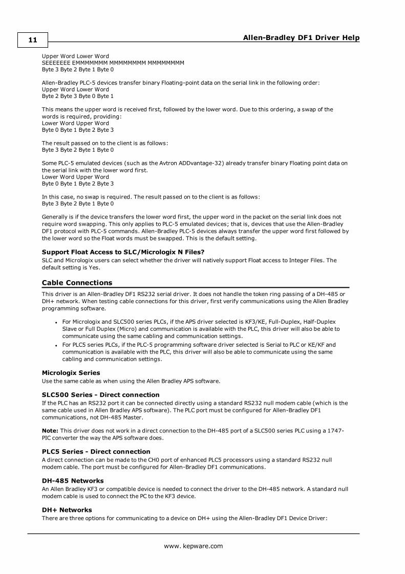
Cable ConnectionsThis driver is an Allen-Bradley DF1 RS232 serial driver. It does not handle the token ring passing of a DH-485 orDH+ network. When testing cable connections for this driver, first verify communications using the Allen Bradleyprogramming software.
l For Micrologix and SLC500 series PLCs, if the APS driver selected is KF3/KE, Full-Duplex, Half-DuplexSlave or Full Duplex (Micro) and communication is available with the PLC, this driver will also be able tocommunicate using the same cabling and communication settings.
l For PLC5 series PLCs, if the PLC-5 programming software driver selected is Serial to PLC or KE/KF andcommunication is available with the PLC, this driver will also be able to communicate using the samecabling and communication settings.
Micrologix SeriesUse the same cable as when using the Allen Bradley APS software.
SLC500 Series - Direct connectionIf the PLC has an RS232 port it can be connected directly using a standard RS232 null modem cable (which is thesame cable used in Allen Bradley APS software). The PLC port must be configured for Allen-Bradley DF1communications, not DH-485 Master.
Note: This driver does not work in a direct connection to the DH-485 port of a SLC500 series PLC using a 1747-PIC converter the way the APS software does.
PLC5 Series - Direct connectionA direct connection can be made to the CH0 port of enhanced PLC5 processors using a standard RS232 nullmodem cable. The port must be configured for Allen-Bradley DF1 communications.
DH-485 NetworksAn Allen Bradley KF3 or compatible device is needed to connect the driver to the DH-485 network. A standard nullmodem cable is used to connect the PC to the KF3 device.
DH+ NetworksThere are three options for communicating to a device on DH+ using the Allen-Bradley DF1 Device Driver:
www. kepware.com
11
Allen-Bradley DF1 Driver Help
l Allen Bradley KF2 or compatible device. A standard null modem cable is used to connect the PC to the KF2device.
l DataLink DL Interface Cards (PCI/ISA/PC104). Consult AB documentation for DH+ wiring.l DataLink DL4500 Ethernet-to-DH+ Converter. Consult DL4500 documentation for wiring.
SLC500 Connection
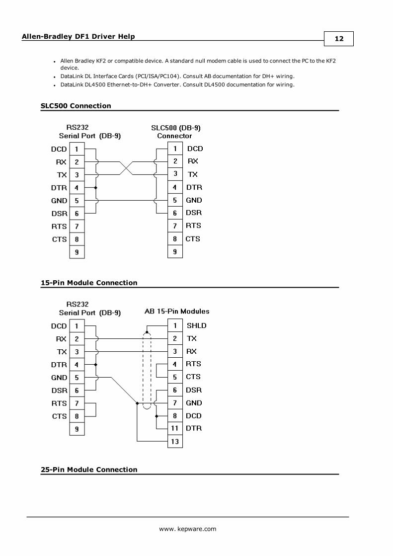
15-Pin Module Connection
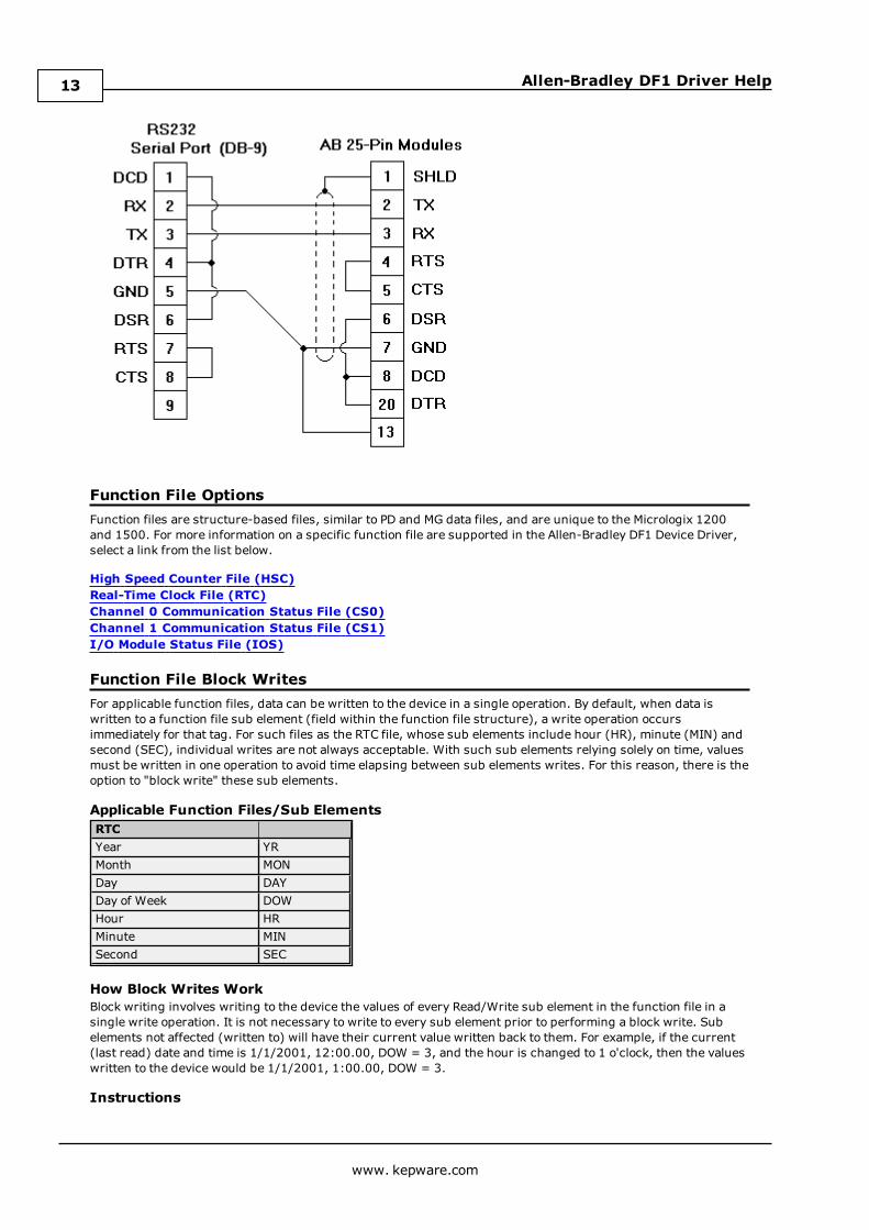
25-Pin Module Connection
www. kepware.com
12
Allen-Bradley DF1 Driver Help
Function File OptionsFunction files are structure-based files, similar to PD and MG data files, and are unique to the Micrologix 1200and 1500. For more information on a specific function file are supported in the Allen-Bradley DF1 Device Driver,select a link from the list below.
High Speed Counter File (HSC)Real-Time Clock File (RTC)Channel 0 Communication Status File (CS0)Channel 1 Communication Status File (CS1)I/O Module Status File (IOS)
Function File Block WritesFor applicable function files, data can be written to the device in a single operation. By default, when data iswritten to a function file sub element (field within the function file structure), a write operation occursimmediately for that tag. For such files as the RTC file, whose sub elements include hour (HR), minute (MIN) andsecond (SEC), individual writes are not always acceptable. With such sub elements relying solely on time, valuesmust be written in one operation to avoid time elapsing between sub elements writes. For this reason, there is theoption to "block write" these sub elements.
Applicable Function Files/Sub ElementsRTCYear YRMonth MONDay DAYDay of Week DOWHour HRMinute MINSecond SEC
How Block Writes WorkBlock writing involves writing to the device the values of every Read/Write sub element in the function file in asingle write operation. It is not necessary to write to every sub element prior to performing a block write. Subelements not affected (written to) will have their current value written back to them. For example, if the current(last read) date and time is 1/1/2001, 12:00.00, DOW = 3, and the hour is changed to 1 o'clock, then the valueswritten to the device would be 1/1/2001, 1:00.00, DOW = 3.
Instructions
www. kepware.com
13
Allen-Bradley DF1 Driver Help
1. Go to the Function File Options tab in the Device Properties dialog. Check the checkbox labeled Blockwrite supporting function files?. This notifies the driver to utilize block writes on function filessupporting block writes. The changes will be effective immediately after hitting theOK or Apply buttons.
2. Write the desired value to the sub element tag(s) in question. The sub element tag(s) will immediatelytake on the value(s) written to it.
Note: After a sub element is written to at least once in block write mode, the tag's value does not originatefrom the controller, but instead from the driver's write cache. After the block write is done, all subelement tag values will originate from the controller.
3. Once the entire desired sub elements are written to, the block write that will send these values to thecontroller may be performed. To instantiate a block write, reference tag address RTC:<element>._SET.Setting this tag's value to "True" will cause a block write to occur based on the current (last read) subelements and the sub elements affected (written to). The _SET tag is treated as a Write Only tag;meaning, a write to this tag is not reflected in subsequent reads on it. Setting this tag's value to "False"performs no action.
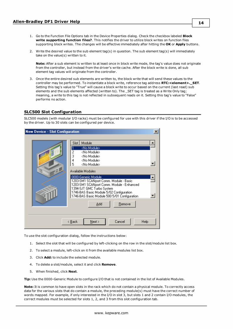
SLC500 Slot ConfigurationSLC500 models (with modular I/O racks) must be configured for use with this driver if the I/O is to be accessedby the driver. Up to 30 slots can be configured per device.
To use the slot configuration dialog, follow the instructions below:
1. Select the slot that will be configured by left-clicking on the row in the slot/module list box.
2. To select a module, left-click on it from the available modules list box.
3. Click Add: to include the selected module.
4. To delete a slot/module, select it and click Remove.
5. When finished, clickNext.
Tip: Use the 0000-Generic Module to configure I/O that is not contained in the list of Available Modules.
Note: It is common to have open slots in the rack which do not contain a physical module. To correctly accessdata for the various slots that do contain a module, the preceding module(s) must have the correct number ofwords mapped. For example, if only interested in the I/O in slot 3, but slots 1 and 2 contain I/O modules, thecorrect modules must be selected for slots 1, 2, and 3 from this slot configuration tab.
www. kepware.com
14
Allen-Bradley DF1 Driver Help
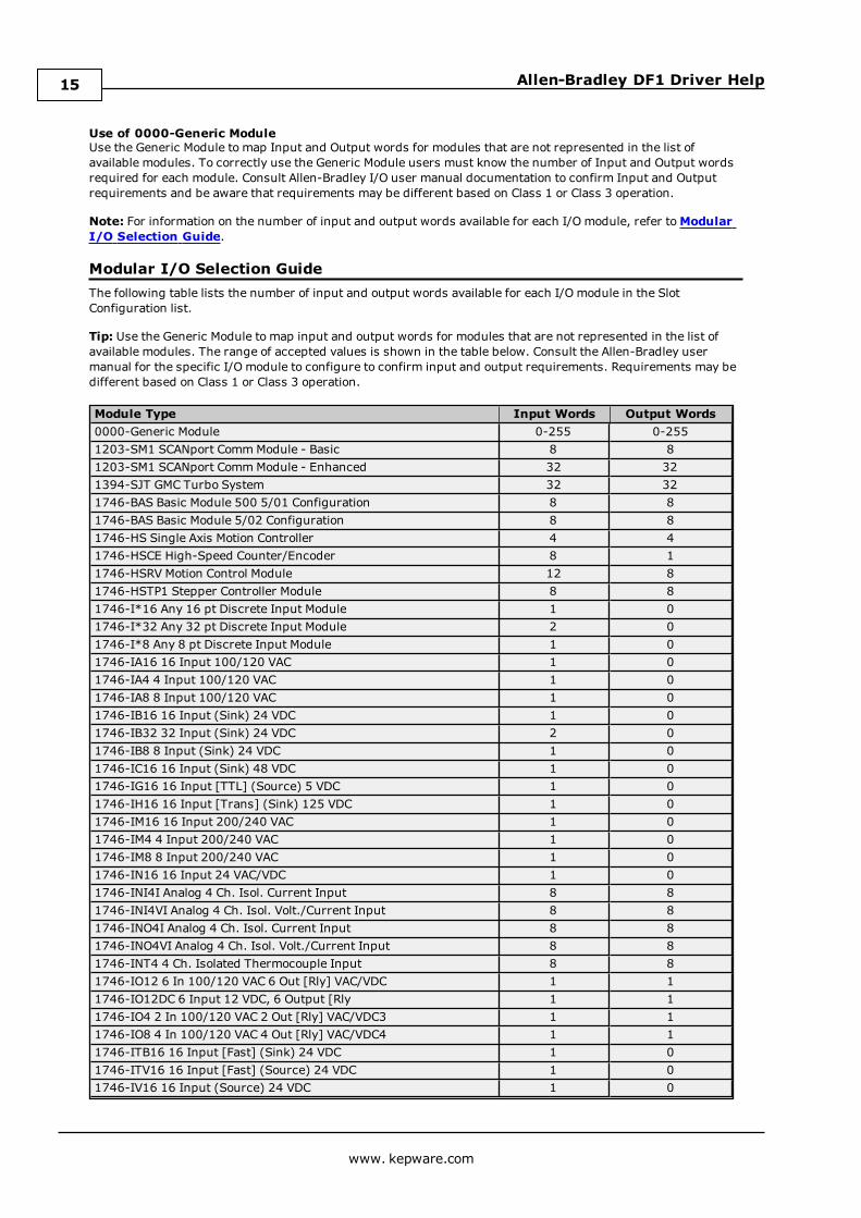
Use of 0000-Generic ModuleUse the Generic Module to map Input and Output words for modules that are not represented in the list ofavailable modules. To correctly use the Generic Module users must know the number of Input and Output wordsrequired for each module. Consult Allen-Bradley I/O user manual documentation to confirm Input and Outputrequirements and be aware that requirements may be different based on Class 1 or Class 3 operation.
Note: For information on the number of input and output words available for each I/O module, refer toModularI/O Selection Guide.
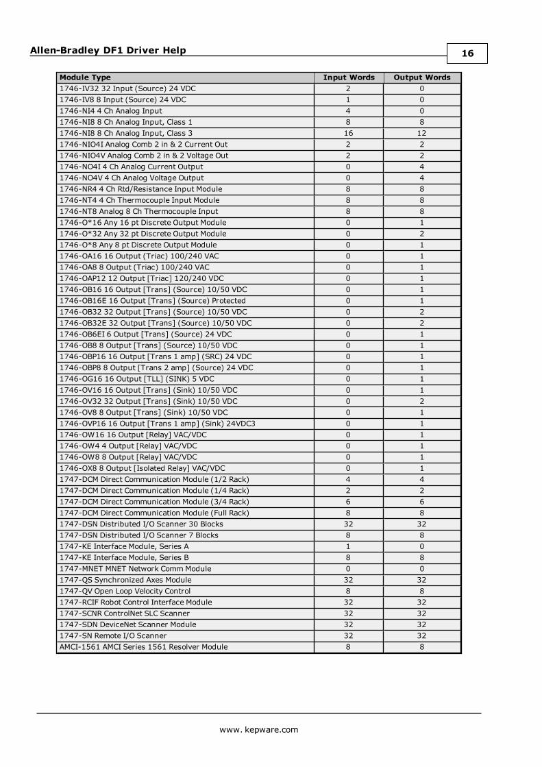
Modular I/O Selection GuideThe following table lists the number of input and output words available for each I/O module in the SlotConfiguration list.
Tip: Use the Generic Module to map input and output words for modules that are not represented in the list ofavailable modules. The range of accepted values is shown in the table below. Consult the Allen-Bradley usermanual for the specific I/O module to configure to confirm input and output requirements. Requirements may bedifferent based on Class 1 or Class 3 operation.
Module Type Input Words Output Words0000-Generic Module 0-255 0-2551203-SM1 SCANport CommModule - Basic 8 81203-SM1 SCANport CommModule - Enhanced 32 321394-SJT GMC Turbo System 32 321746-BAS Basic Module 500 5/01 Configuration 8 81746-BAS Basic Module 5/02 Configuration 8 81746-HS Single Axis Motion Controller 4 41746-HSCE High-Speed Counter/Encoder 8 11746-HSRV Motion Control Module 12 81746-HSTP1 Stepper Controller Module 8 81746-I*16 Any 16 pt Discrete Input Module 1 01746-I*32 Any 32 pt Discrete Input Module 2 01746-I*8 Any 8 pt Discrete Input Module 1 01746-IA16 16 Input 100/120 VAC 1 01746-IA4 4 Input 100/120 VAC 1 01746-IA8 8 Input 100/120 VAC 1 01746-IB16 16 Input (Sink) 24 VDC 1 01746-IB32 32 Input (Sink) 24 VDC 2 01746-IB8 8 Input (Sink) 24 VDC 1 01746-IC16 16 Input (Sink) 48 VDC 1 01746-IG16 16 Input [TTL] (Source) 5 VDC 1 01746-IH16 16 Input [Trans] (Sink) 125 VDC 1 01746-IM16 16 Input 200/240 VAC 1 01746-IM4 4 Input 200/240 VAC 1 01746-IM8 8 Input 200/240 VAC 1 01746-IN16 16 Input 24 VAC/VDC 1 01746-INI4I Analog 4 Ch. Isol. Current Input 8 81746-INI4VI Analog 4 Ch. Isol. Volt./Current Input 8 81746-INO4I Analog 4 Ch. Isol. Current Input 8 81746-INO4VI Analog 4 Ch. Isol. Volt./Current Input 8 81746-INT4 4 Ch. Isolated Thermocouple Input 8 81746-IO12 6 In 100/120 VAC 6 Out [Rly] VAC/VDC 1 11746-IO12DC 6 Input 12 VDC, 6 Output [Rly 1 11746-IO4 2 In 100/120 VAC 2 Out [Rly] VAC/VDC3 1 11746-IO8 4 In 100/120 VAC 4 Out [Rly] VAC/VDC4 1 11746-ITB16 16 Input [Fast] (Sink) 24 VDC 1 01746-ITV16 16 Input [Fast] (Source) 24 VDC 1 01746-IV16 16 Input (Source) 24 VDC 1 0
www. kepware.com
15
Allen-Bradley DF1 Driver Help
Module Type Input Words Output Words1746-IV32 32 Input (Source) 24 VDC 2 01746-IV8 8 Input (Source) 24 VDC 1 01746-NI4 4 Ch Analog Input 4 01746-NI8 8 Ch Analog Input, Class 1 8 81746-NI8 8 Ch Analog Input, Class 3 16 121746-NIO4I Analog Comb 2 in & 2 Current Out 2 21746-NIO4V Analog Comb 2 in & 2 Voltage Out 2 21746-NO4I 4 Ch Analog Current Output 0 41746-NO4V 4 Ch Analog Voltage Output 0 41746-NR4 4 Ch Rtd/Resistance Input Module 8 81746-NT4 4 Ch Thermocouple Input Module 8 81746-NT8 Analog 8 Ch Thermocouple Input 8 81746-O*16 Any 16 pt Discrete Output Module 0 11746-O*32 Any 32 pt Discrete Output Module 0 21746-O*8 Any 8 pt Discrete Output Module 0 11746-OA16 16 Output (Triac) 100/240 VAC 0 11746-OA8 8 Output (Triac) 100/240 VAC 0 11746-OAP12 12 Output [Triac] 120/240 VDC 0 11746-OB16 16 Output [Trans] (Source) 10/50 VDC 0 11746-OB16E 16 Output [Trans] (Source) Protected 0 11746-OB32 32 Output [Trans] (Source) 10/50 VDC 0 21746-OB32E 32 Output [Trans] (Source) 10/50 VDC 0 21746-OB6EI 6 Output [Trans] (Source) 24 VDC 0 11746-OB8 8 Output [Trans] (Source) 10/50 VDC 0 11746-OBP16 16 Output [Trans 1 amp] (SRC) 24 VDC 0 11746-OBP8 8 Output [Trans 2 amp] (Source) 24 VDC 0 11746-OG16 16 Output [TLL] (SINK) 5 VDC 0 11746-OV16 16 Output [Trans] (Sink) 10/50 VDC 0 11746-OV32 32 Output [Trans] (Sink) 10/50 VDC 0 21746-OV8 8 Output [Trans] (Sink) 10/50 VDC 0 11746-OVP16 16 Output [Trans 1 amp] (Sink) 24VDC3 0 11746-OW16 16 Output [Relay] VAC/VDC 0 11746-OW4 4 Output [Relay] VAC/VDC 0 11746-OW8 8 Output [Relay] VAC/VDC 0 11746-OX8 8 Output [Isolated Relay] VAC/VDC 0 11747-DCM Direct Communication Module (1/2 Rack) 4 41747-DCM Direct Communication Module (1/4 Rack) 2 21747-DCM Direct Communication Module (3/4 Rack) 6 61747-DCM Direct Communication Module (Full Rack) 8 81747-DSN Distributed I/O Scanner 30 Blocks 32 321747-DSN Distributed I/O Scanner 7 Blocks 8 81747-KE Interface Module, Series A 1 01747-KE Interface Module, Series B 8 81747-MNET MNET Network CommModule 0 01747-QS Synchronized Axes Module 32 321747-QV Open Loop Velocity Control 8 81747-RCIF Robot Control Interface Module 32 321747-SCNR ControlNet SLC Scanner 32 321747-SDN DeviceNet Scanner Module 32 321747-SN Remote I/O Scanner 32 32AMCI-1561 AMCI Series 1561 Resolver Module 8 8
www. kepware.com
16
Allen-Bradley DF1 Driver Help
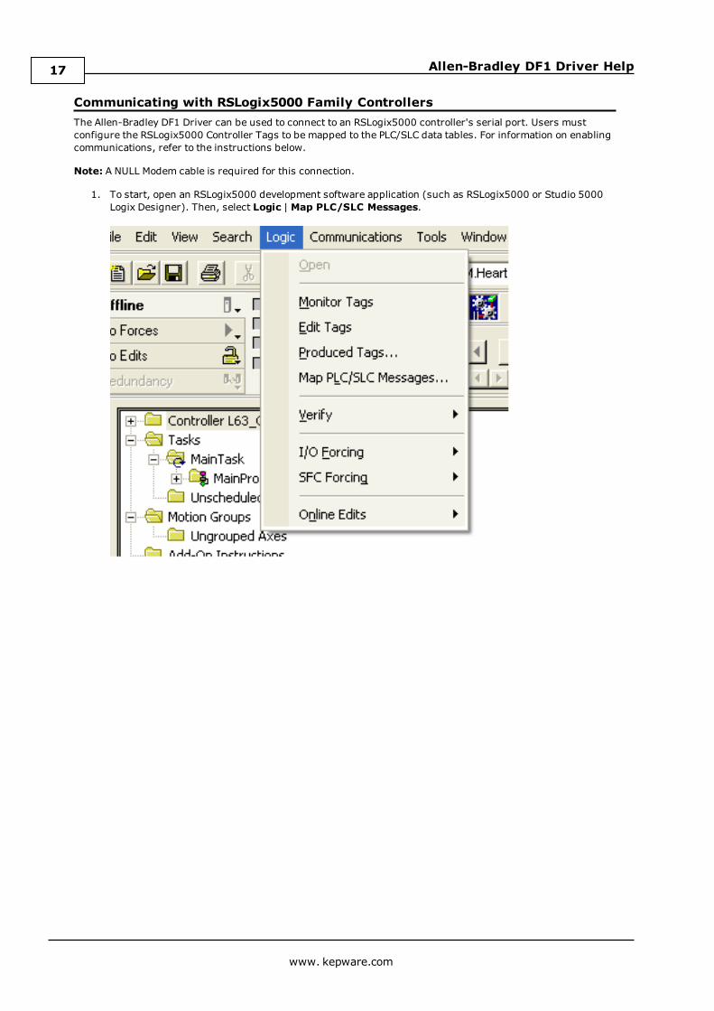
Communicating with RSLogix5000 Family ControllersThe Allen-Bradley DF1 Driver can be used to connect to an RSLogix5000 controller's serial port. Users mustconfigure the RSLogix5000 Controller Tags to be mapped to the PLC/SLC data tables. For information on enablingcommunications, refer to the instructions below.
Note: A NULL Modem cable is required for this connection.
1. To start, open an RSLogix5000 development software application (such as RSLogix5000 or Studio 5000Logix Designer). Then, select Logic | Map PLC/SLC Messages.
www. kepware.com
17
Allen-Bradley DF1 Driver Help
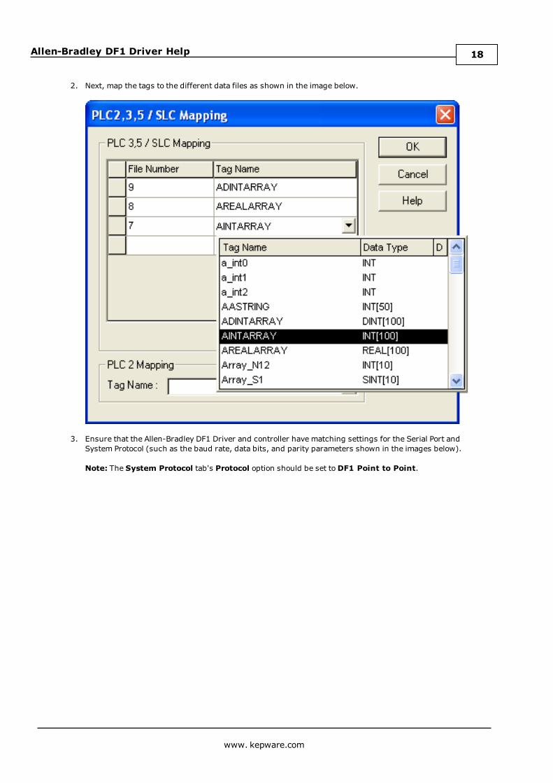
2. Next, map the tags to the different data files as shown in the image below.
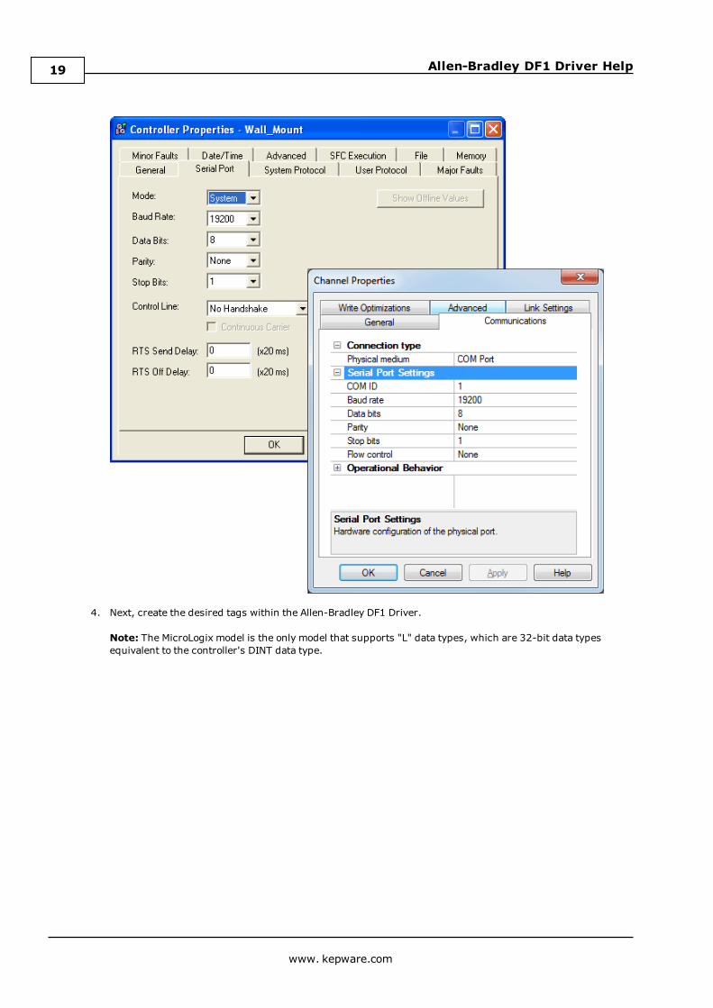
3. Ensure that the Allen-Bradley DF1 Driver and controller have matching settings for the Serial Port andSystem Protocol (such as the baud rate, data bits, and parity parameters shown in the images below).
Note: The System Protocol tab's Protocol option should be set toDF1 Point to Point.
www. kepware.com
18
Allen-Bradley DF1 Driver Help
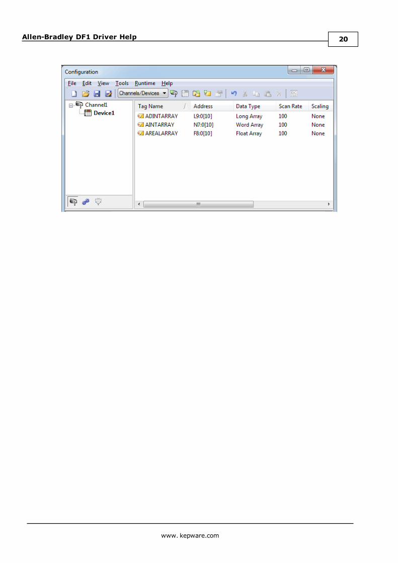
4. Next, create the desired tags within the Allen-Bradley DF1 Driver.
Note: The MicroLogix model is the only model that supports "L" data types, which are 32-bit data typesequivalent to the controller's DINT data type.
www. kepware.com
19
Allen-Bradley DF1 Driver Help
www. kepware.com
20
Allen-Bradley DF1 Driver Help
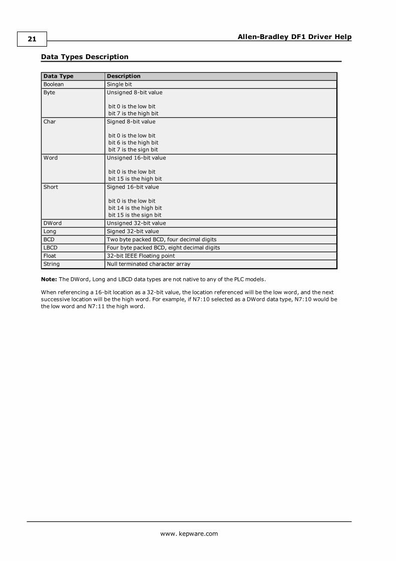
Data Types Description
Data Type DescriptionBoolean Single bitByte Unsigned 8-bit value
bit 0 is the low bitbit 7 is the high bit
Char Signed 8-bit value
bit 0 is the low bitbit 6 is the high bitbit 7 is the sign bit
Word Unsigned 16-bit value
bit 0 is the low bitbit 15 is the high bit
Short Signed 16-bit value
bit 0 is the low bitbit 14 is the high bitbit 15 is the sign bit
DWord Unsigned 32-bit valueLong Signed 32-bit valueBCD Two byte packed BCD, four decimal digitsLBCD Four byte packed BCD, eight decimal digitsFloat 32-bit IEEE Floating pointString Null terminated character array
Note: The DWord, Long and LBCD data types are not native to any of the PLCmodels.
When referencing a 16-bit location as a 32-bit value, the location referenced will be the low word, and the nextsuccessive location will be the high word. For example, if N7:10 selected as a DWord data type, N7:10 would bethe low word and N7:11 the high word.
www. kepware.com
21
Allen-Bradley DF1 Driver Help
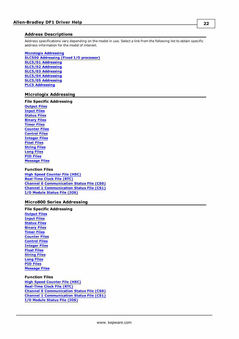
Address DescriptionsAddress specifications vary depending on the model in use. Select a link from the following list to obtain specificaddress information for the model of interest.
Micrologix AddressingSLC500 Addressing (Fixed I/O processor)SLC5/01 AddressingSLC5/02 AddressingSLC5/03 AddressingSLC5/04 AddressingSLC5/05 AddressingPLC5 Addressing
Micrologix AddressingFile Specific AddressingOutput FilesInput FilesStatus FilesBinary FilesTimer FilesCounter FilesControl FilesInteger FilesFloat FilesString FilesLong FilesPID FilesMessage Files
Function FilesHigh Speed Counter File (HSC)Real-Time Clock File (RTC)Channel 0 Communication Status File (CS0)Channel 1 Communication Status File (CS1)I/O Module Status File (IOS)
Micro800 Series AddressingFile Specific AddressingOutput FilesInput FilesStatus FilesBinary FilesTimer FilesCounter FilesControl FilesInteger FilesFloat FilesString FilesLong FilesPID FilesMessage Files
Function FilesHigh Speed Counter File (HSC)Real-Time Clock File (RTC)Channel 0 Communication Status File (CS0)Channel 1 Communication Status File (CS1)I/O Module Status File (IOS)
www. kepware.com
22
Allen-Bradley DF1 Driver Help
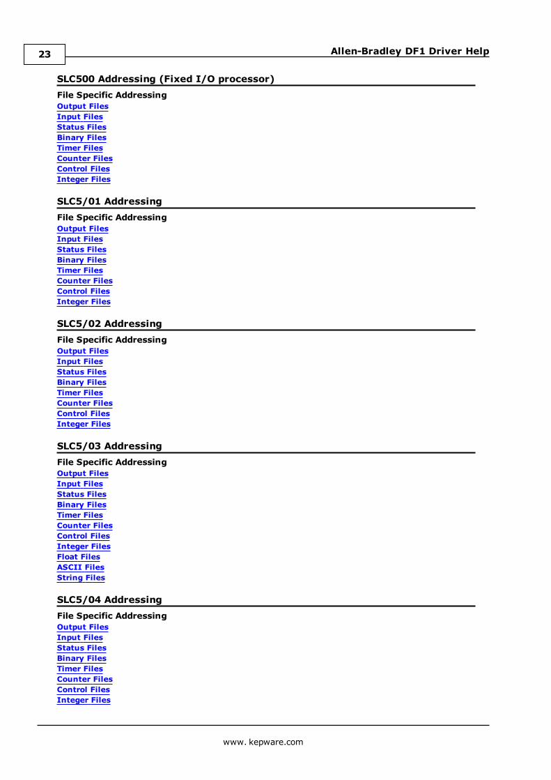
SLC500 Addressing (Fixed I/O processor)File Specific AddressingOutput FilesInput FilesStatus FilesBinary FilesTimer FilesCounter FilesControl FilesInteger Files
SLC5/01 AddressingFile Specific AddressingOutput FilesInput FilesStatus FilesBinary FilesTimer FilesCounter FilesControl FilesInteger Files
SLC5/02 AddressingFile Specific AddressingOutput FilesInput FilesStatus FilesBinary FilesTimer FilesCounter FilesControl FilesInteger Files
SLC5/03 AddressingFile Specific AddressingOutput FilesInput FilesStatus FilesBinary FilesTimer FilesCounter FilesControl FilesInteger FilesFloat FilesASCII FilesString Files
SLC5/04 AddressingFile Specific AddressingOutput FilesInput FilesStatus FilesBinary FilesTimer FilesCounter FilesControl FilesInteger Files
www. kepware.com
23
Allen-Bradley DF1 Driver Help
Float FilesASCII FilesString Files
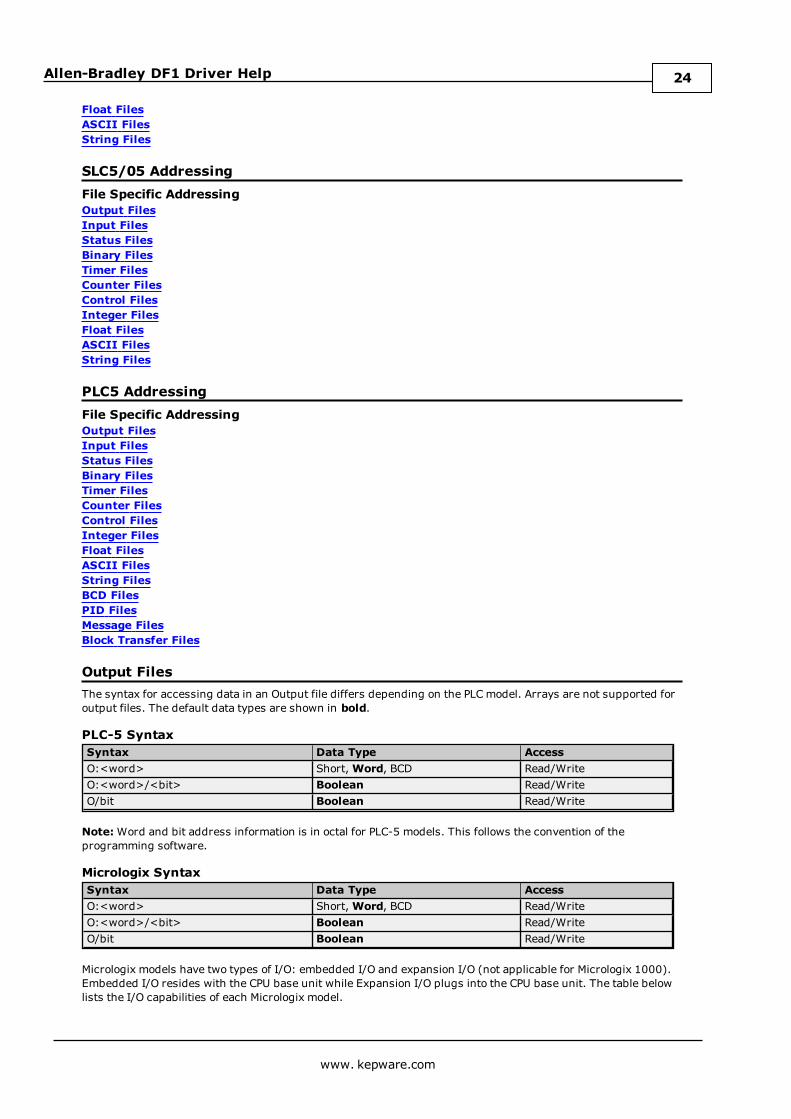
SLC5/05 AddressingFile Specific AddressingOutput FilesInput FilesStatus FilesBinary FilesTimer FilesCounter FilesControl FilesInteger FilesFloat FilesASCII FilesString Files
PLC5 AddressingFile Specific AddressingOutput FilesInput FilesStatus FilesBinary FilesTimer FilesCounter FilesControl FilesInteger FilesFloat FilesASCII FilesString FilesBCD FilesPID FilesMessage FilesBlock Transfer Files
Output FilesThe syntax for accessing data in an Output file differs depending on the PLCmodel. Arrays are not supported foroutput files. The default data types are shown in bold.
PLC-5 SyntaxSyntax Data Type AccessO:<word> Short,Word, BCD Read/WriteO:<word>/<bit> Boolean Read/WriteO/bit Boolean Read/Write
Note:Word and bit address information is in octal for PLC-5 models. This follows the convention of theprogramming software.
Micrologix SyntaxSyntax Data Type AccessO:<word> Short,Word, BCD Read/WriteO:<word>/<bit> Boolean Read/WriteO/bit Boolean Read/Write
Micrologix models have two types of I/O: embedded I/O and expansion I/O (not applicable for Micrologix 1000).Embedded I/O resides with the CPU base unit while Expansion I/O plugs into the CPU base unit. The table belowlists the I/O capabilities of each Micrologix model.
www. kepware.com
24
Allen-Bradley DF1 Driver Help
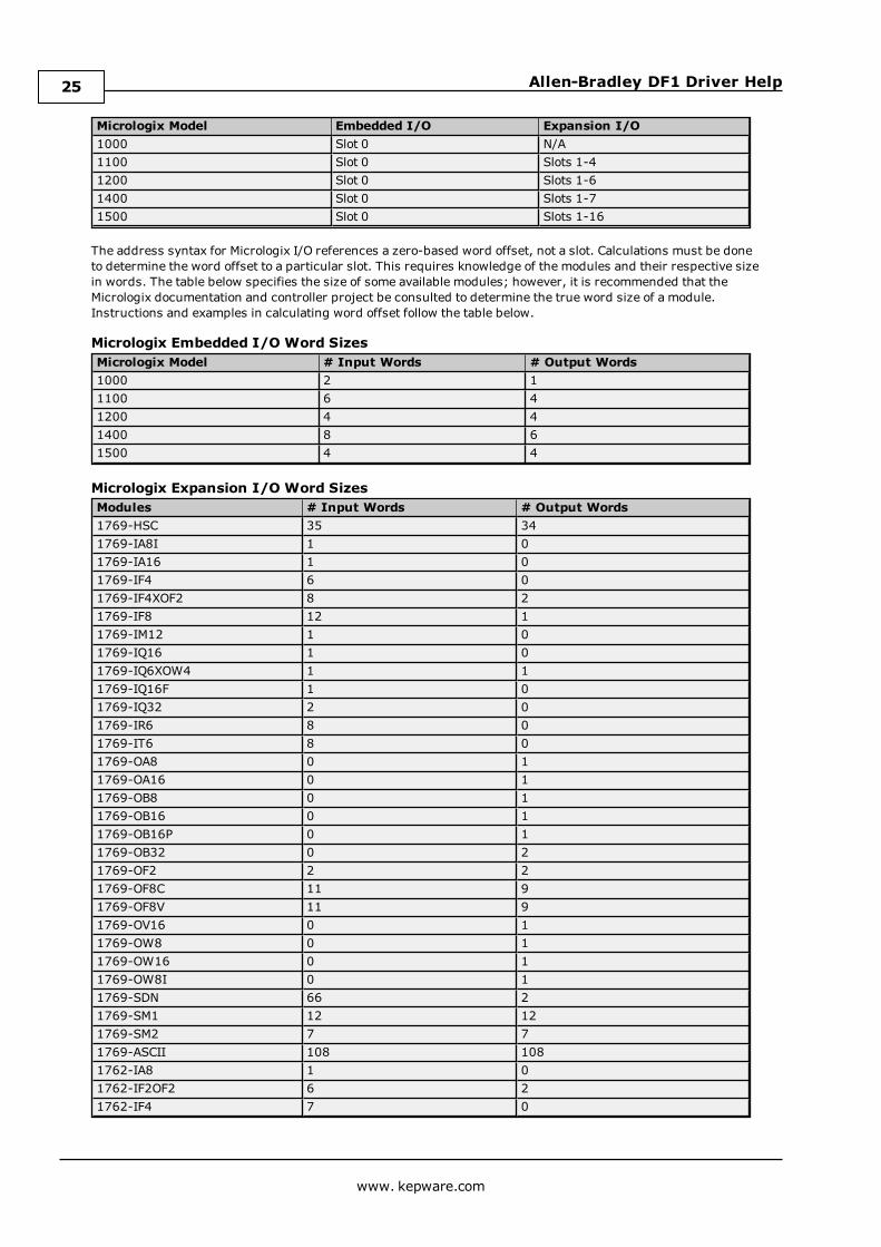
Micrologix Model Embedded I/O Expansion I/O1000 Slot 0 N/A1100 Slot 0 Slots 1-41200 Slot 0 Slots 1-61400 Slot 0 Slots 1-71500 Slot 0 Slots 1-16
The address syntax for Micrologix I/O references a zero-based word offset, not a slot. Calculations must be doneto determine the word offset to a particular slot. This requires knowledge of the modules and their respective sizein words. The table below specifies the size of some available modules; however, it is recommended that theMicrologix documentation and controller project be consulted to determine the true word size of a module.Instructions and examples in calculating word offset follow the table below.
Micrologix Embedded I/O Word SizesMicrologix Model # Input Words # Output Words1000 2 11100 6 41200 4 41400 8 61500 4 4
Micrologix Expansion I/O Word SizesModules # Input Words # Output Words1769-HSC 35 341769-IA8I 1 01769-IA16 1 01769-IF4 6 01769-IF4XOF2 8 21769-IF8 12 11769-IM12 1 01769-IQ16 1 01769-IQ6XOW4 1 11769-IQ16F 1 01769-IQ32 2 01769-IR6 8 01769-IT6 8 01769-OA8 0 11769-OA16 0 11769-OB8 0 11769-OB16 0 11769-OB16P 0 11769-OB32 0 21769-OF2 2 21769-OF8C 11 91769-OF8V 11 91769-OV16 0 11769-OW8 0 11769-OW16 0 11769-OW8I 0 11769-SDN 66 21769-SM1 12 121769-SM2 7 71769-ASCII 108 1081762-IA8 1 01762-IF2OF2 6 21762-IF4 7 0
www. kepware.com
25
Allen-Bradley DF1 Driver Help
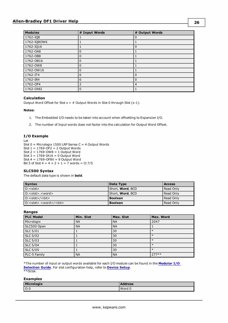
Modules # Input Words # Output Words1762-IQ8 1 01762-IQ8OW6 1 11762-IQ16 1 01762-OA8 0 11762-OB8 0 11762-OB16 0 11762-OW8 0 11762-OW16 0 11762-IT4 6 01762-IR4 6 01762-OF4 2 41762-OX6I 0 1
CalculationOutput Word Offset for Slot x = # Output Words in Slot 0 through Slot (x-1).
Notes:
1. The Embedded I/O needs to be taken into account when offsetting to Expansion I/O.
2. The number of Input words does not factor into the calculation for Output Word Offset.
I/O ExampleLetSlot 0 = Micrologix 1500 LRP Series C = 4 Output WordsSlot 1 = 1769-OF2 = 2 Output WordsSlot 2 = 1769-OW8 = 1 Output WordSlot 3 = 1769-IA16 = 0 Output WordSlot 4 = 1769-OF8V = 9 Output WordBit 5 of Slot 4 = 4 + 2 + 1 = 7 words = O:7/5
SLC500 SyntaxThe default data type is shown in bold.
Syntax Data Type AccessO:<slot> Short,Word, BCD Read OnlyO:<slot>.<word> Short,Word, BCD Read OnlyO:<slot>/<bit> Boolean Read OnlyO:<slot>.<word>/<bit> Boolean Read Only
RangesPLC Model Min. Slot Max. Slot Max. WordMicrologix NA NA 2047SLC500 Open NA NA 1SLC 5/01 1 30 *SLC 5/02 1 30 *SLC 5/03 1 30 *SLC 5/04 1 30 *SLC 5/05 1 30 *PLC-5 Family NA NA 277**
*The number of input or output words available for each I/O module can be found in theModular I/OSelection Guide. For slot configuration help, refer toDevice Setup.**Octal.
ExamplesMicrologix AddressO:0 Word 0
www. kepware.com
26
Allen-Bradley DF1 Driver Help
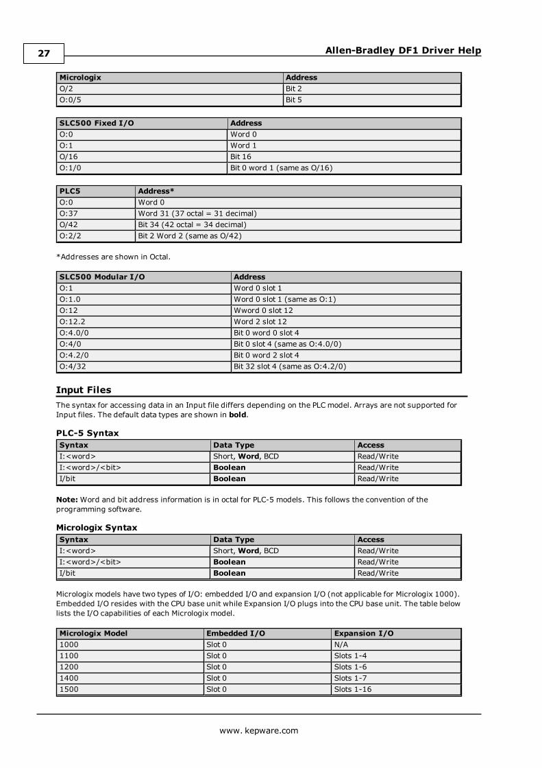
Micrologix AddressO/2 Bit 2O:0/5 Bit 5
SLC500 Fixed I/O AddressO:0 Word 0O:1 Word 1O/16 Bit 16O:1/0 Bit 0 word 1 (same as O/16)
PLC5 Address*O:0 Word 0O:37 Word 31 (37 octal = 31 decimal)O/42 Bit 34 (42 octal = 34 decimal)O:2/2 Bit 2 Word 2 (same as O/42)
*Addresses are shown in Octal.
SLC500 Modular I/O AddressO:1 Word 0 slot 1O:1.0 Word 0 slot 1 (same as O:1)O:12 Wword 0 slot 12O:12.2 Word 2 slot 12O:4.0/0 Bit 0 word 0 slot 4O:4/0 Bit 0 slot 4 (same as O:4.0/0)O:4.2/0 Bit 0 word 2 slot 4O:4/32 Bit 32 slot 4 (same as O:4.2/0)
Input FilesThe syntax for accessing data in an Input file differs depending on the PLCmodel. Arrays are not supported forInput files. The default data types are shown in bold.
PLC-5 SyntaxSyntax Data Type AccessI:<word> Short,Word, BCD Read/WriteI:<word>/<bit> Boolean Read/WriteI/bit Boolean Read/Write
Note:Word and bit address information is in octal for PLC-5 models. This follows the convention of theprogramming software.
Micrologix SyntaxSyntax Data Type AccessI:<word> Short,Word, BCD Read/WriteI:<word>/<bit> Boolean Read/WriteI/bit Boolean Read/Write
Micrologix models have two types of I/O: embedded I/O and expansion I/O (not applicable for Micrologix 1000).Embedded I/O resides with the CPU base unit while Expansion I/O plugs into the CPU base unit. The table belowlists the I/O capabilities of each Micrologix model.
Micrologix Model Embedded I/O Expansion I/O1000 Slot 0 N/A1100 Slot 0 Slots 1-41200 Slot 0 Slots 1-61400 Slot 0 Slots 1-71500 Slot 0 Slots 1-16
www. kepware.com
27
Allen-Bradley DF1 Driver Help
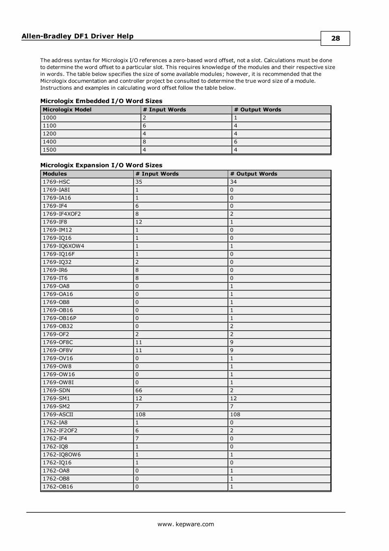
The address syntax for Micrologix I/O references a zero-based word offset, not a slot. Calculations must be doneto determine the word offset to a particular slot. This requires knowledge of the modules and their respective sizein words. The table below specifies the size of some available modules; however, it is recommended that theMicrologix documentation and controller project be consulted to determine the true word size of a module.Instructions and examples in calculating word offset follow the table below.
Micrologix Embedded I/O Word SizesMicrologix Model # Input Words # Output Words1000 2 11100 6 41200 4 41400 8 61500 4 4
Micrologix Expansion I/O Word SizesModules # Input Words # Output Words1769-HSC 35 341769-IA8I 1 01769-IA16 1 01769-IF4 6 01769-IF4XOF2 8 21769-IF8 12 11769-IM12 1 01769-IQ16 1 01769-IQ6XOW4 1 11769-IQ16F 1 01769-IQ32 2 01769-IR6 8 01769-IT6 8 01769-OA8 0 11769-OA16 0 11769-OB8 0 11769-OB16 0 11769-OB16P 0 11769-OB32 0 21769-OF2 2 21769-OF8C 11 91769-OF8V 11 91769-OV16 0 11769-OW8 0 11769-OW16 0 11769-OW8I 0 11769-SDN 66 21769-SM1 12 121769-SM2 7 71769-ASCII 108 1081762-IA8 1 01762-IF2OF2 6 21762-IF4 7 01762-IQ8 1 01762-IQ8OW6 1 11762-IQ16 1 01762-OA8 0 11762-OB8 0 11762-OB16 0 1
www. kepware.com
28
Allen-Bradley DF1 Driver Help
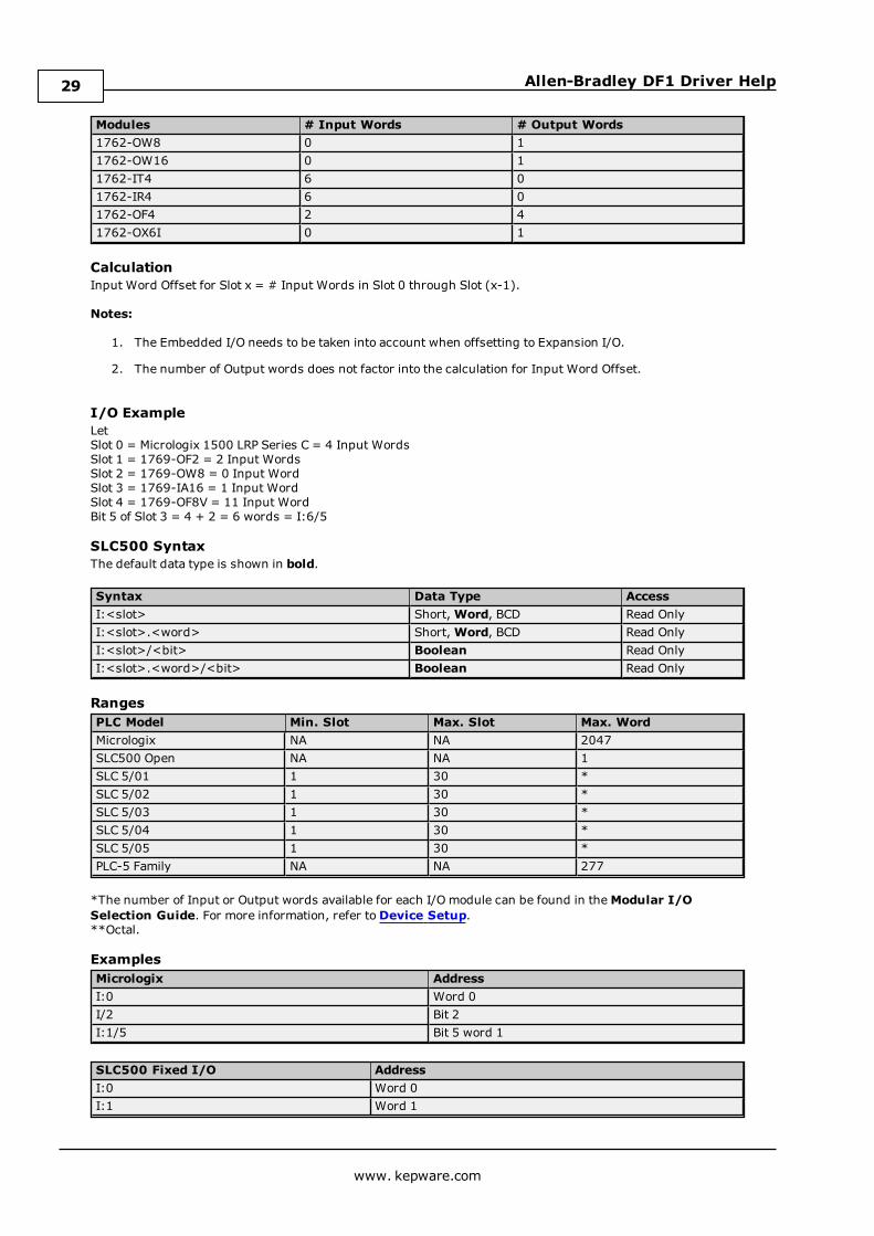
Modules # Input Words # Output Words1762-OW8 0 11762-OW16 0 11762-IT4 6 01762-IR4 6 01762-OF4 2 41762-OX6I 0 1
CalculationInput Word Offset for Slot x = # Input Words in Slot 0 through Slot (x-1).
Notes:
1. The Embedded I/O needs to be taken into account when offsetting to Expansion I/O.
2. The number of Output words does not factor into the calculation for Input Word Offset.
I/O ExampleLetSlot 0 = Micrologix 1500 LRP Series C = 4 Input WordsSlot 1 = 1769-OF2 = 2 Input WordsSlot 2 = 1769-OW8 = 0 Input WordSlot 3 = 1769-IA16 = 1 Input WordSlot 4 = 1769-OF8V = 11 Input WordBit 5 of Slot 3 = 4 + 2 = 6 words = I:6/5
SLC500 SyntaxThe default data type is shown in bold.
Syntax Data Type AccessI:<slot> Short,Word, BCD Read OnlyI:<slot>.<word> Short,Word, BCD Read OnlyI:<slot>/<bit> Boolean Read OnlyI:<slot>.<word>/<bit> Boolean Read Only
RangesPLC Model Min. Slot Max. Slot Max. WordMicrologix NA NA 2047SLC500 Open NA NA 1SLC 5/01 1 30 *SLC 5/02 1 30 *SLC 5/03 1 30 *SLC 5/04 1 30 *SLC 5/05 1 30 *PLC-5 Family NA NA 277
*The number of Input or Output words available for each I/O module can be found in theModular I/OSelection Guide. For more information, refer toDevice Setup.**Octal.
ExamplesMicrologix AddressI:0 Word 0I/2 Bit 2I:1/5 Bit 5 word 1
SLC500 Fixed I/O AddressI:0 Word 0I:1 Word 1
www. kepware.com
29
Allen-Bradley DF1 Driver Help
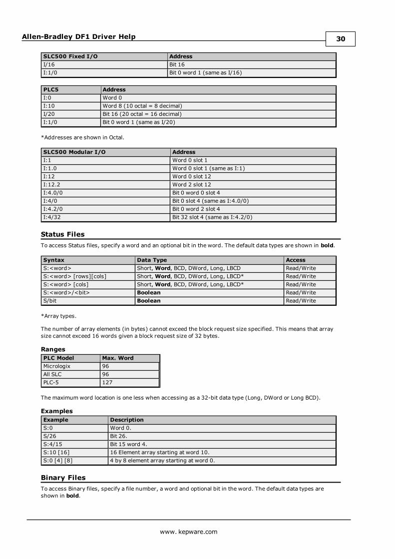
SLC500 Fixed I/O AddressI/16 Bit 16I:1/0 Bit 0 word 1 (same as I/16)
PLC5 AddressI:0 Word 0I:10 Word 8 (10 octal = 8 decimal)I/20 Bit 16 (20 octal = 16 decimal)I:1/0 Bit 0 word 1 (same as I/20)
*Addresses are shown in Octal.
SLC500 Modular I/O AddressI:1 Word 0 slot 1I:1.0 Word 0 slot 1 (same as I:1)I:12 Word 0 slot 12I:12.2 Word 2 slot 12I:4.0/0 Bit 0 word 0 slot 4I:4/0 Bit 0 slot 4 (same as I:4.0/0)I:4.2/0 Bit 0 word 2 slot 4I:4/32 Bit 32 slot 4 (same as I:4.2/0)
Status FilesTo access Status files, specify a word and an optional bit in the word. The default data types are shown in bold.
Syntax Data Type AccessS:<word> Short,Word, BCD, DWord, Long, LBCD Read/WriteS:<word> [rows][cols] Short,Word, BCD, DWord, Long, LBCD* Read/WriteS:<word> [cols] Short,Word, BCD, DWord, Long, LBCD* Read/WriteS:<word>/<bit> Boolean Read/WriteS/bit Boolean Read/Write
*Array types.
The number of array elements (in bytes) cannot exceed the block request size specified. This means that arraysize cannot exceed 16 words given a block request size of 32 bytes.
RangesPLC Model Max. WordMicrologix 96All SLC 96PLC-5 127
The maximumword location is one less when accessing as a 32-bit data type (Long, DWord or Long BCD).
ExamplesExample DescriptionS:0 Word 0.S/26 Bit 26.S:4/15 Bit 15 word 4.S:10 [16] 16 Element array starting at word 10.S:0 [4] [8] 4 by 8 element array starting at word 0.
Binary FilesTo access Binary files, specify a file number, a word and optional bit in the word. The default data types areshown in bold.
www. kepware.com
30
Allen-Bradley DF1 Driver Help
Syntax Data Type AccessB<file>:<word> Short,Word, BCD,
DWord, Long, LBCDRead/Write
B<file>:<word> [rows][cols] Short,Word, BCD,DWord, Long, LBCD*
Read/Write
B<file>:<word> [cols] Short,Word, BCD,DWord, Long, LBCD*
Read/Write
B<file>:<word>/<bit> Boolean Read/WriteB<file>/bit Boolean Read/Write
*Array types.
The number of array elements (in bytes) cannot exceed the block request size specified. This means that thearray size cannot exceed 16 words given a block request size of 32 bytes.
RangesPLC Model File Number Max. WordMicrologix 3-255 255All SLC 3-255 255PLC-5 3-999 1999
The maximumword location is one less when accessing as a 32-bit data type (Long, DWord or Long BCD).
ExamplesExample DescriptionB3:0 Word 0.B3/26 Bit 26.B12:4/15 Bit 15 word 4.B3:10 [20] 20 Element array starting at word 10.B15:0 [6] [6] 6 by 6 element array starting at word 0.
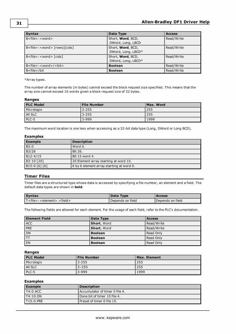
Timer FilesTimer files are a structured type whose data is accessed by specifying a file number, an element and a field. Thedefault data types are shown in bold.
Syntax Data Type AccessT<file>:<element>.<field> Depends on field Depends on field
The following fields are allowed for each element. For the usage of each field, refer to the PLC's documentation.
Element Field Data Type AccessACC Short, Word Read/WritePRE Short, Word Read/WriteDN Boolean Read OnlyTT Boolean Read OnlyEN Boolean Read Only
RangesPLC Model File Number Max. ElementMicrologix 3-255 255All SLC 3–255 255PLC-5 3-999 1999
ExamplesExample DescriptionT4:0.ACC Accumulator of timer 0 file 4.T4:10.DN Done bit of timer 10 file 4.T15:0.PRE Preset of timer 0 file 15.
www. kepware.com
31
Allen-Bradley DF1 Driver Help
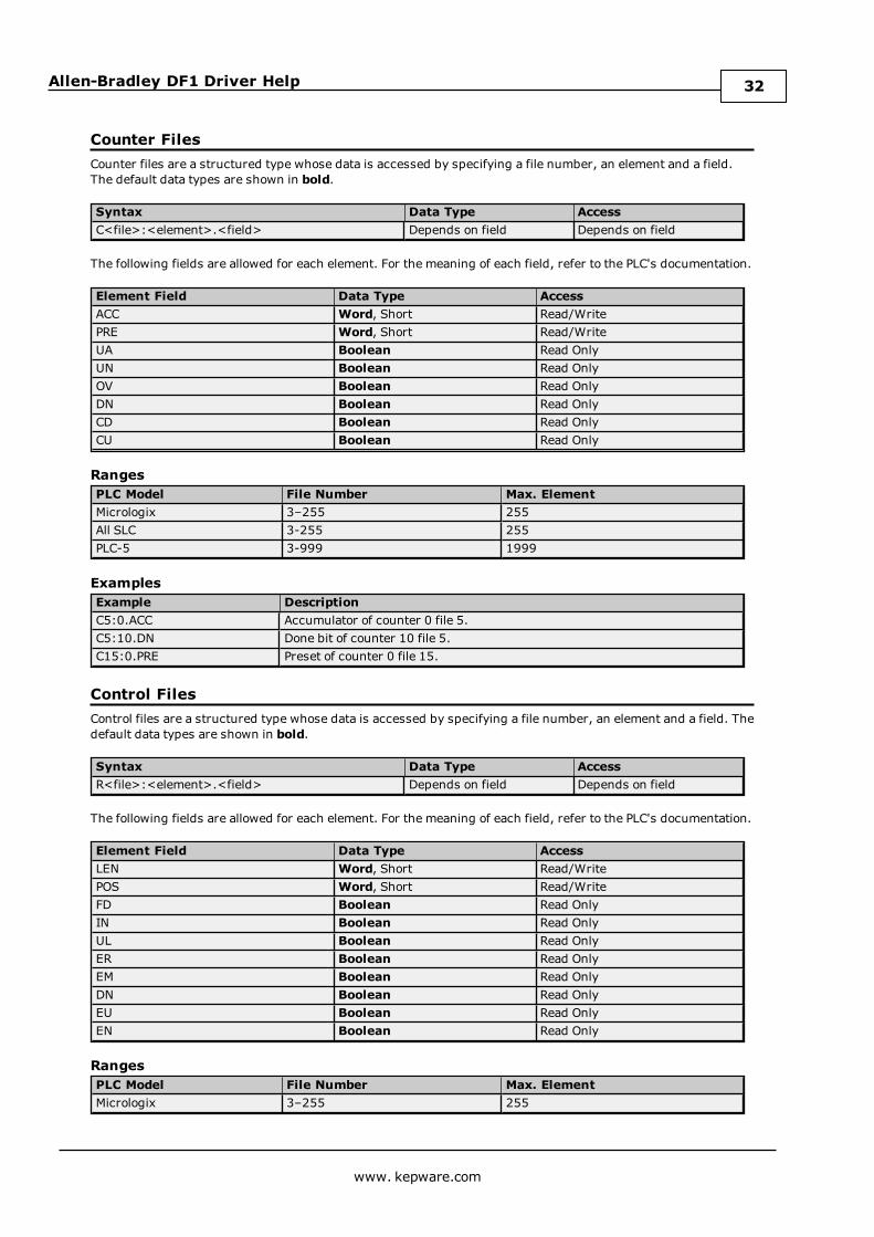
Counter FilesCounter files are a structured type whose data is accessed by specifying a file number, an element and a field.The default data types are shown in bold.
Syntax Data Type AccessC<file>:<element>.<field> Depends on field Depends on field
The following fields are allowed for each element. For the meaning of each field, refer to the PLC's documentation.
Element Field Data Type AccessACC Word, Short Read/WritePRE Word, Short Read/WriteUA Boolean Read OnlyUN Boolean Read OnlyOV Boolean Read OnlyDN Boolean Read OnlyCD Boolean Read OnlyCU Boolean Read Only
RangesPLC Model File Number Max. ElementMicrologix 3–255 255All SLC 3-255 255PLC-5 3-999 1999
ExamplesExample DescriptionC5:0.ACC Accumulator of counter 0 file 5.C5:10.DN Done bit of counter 10 file 5.C15:0.PRE Preset of counter 0 file 15.
Control FilesControl files are a structured type whose data is accessed by specifying a file number, an element and a field. Thedefault data types are shown in bold.
Syntax Data Type AccessR<file>:<element>.<field> Depends on field Depends on field
The following fields are allowed for each element. For the meaning of each field, refer to the PLC's documentation.
Element Field Data Type AccessLEN Word, Short Read/WritePOS Word, Short Read/WriteFD Boolean Read OnlyIN Boolean Read OnlyUL Boolean Read OnlyER Boolean Read OnlyEM Boolean Read OnlyDN Boolean Read OnlyEU Boolean Read OnlyEN Boolean Read Only
RangesPLC Model File Number Max. ElementMicrologix 3–255 255
www. kepware.com
32
Allen-Bradley DF1 Driver Help
PLC Model File Number Max. ElementAll SLC 3–255 255PLC-5 3-999 1999
ExamplesExample DescriptionR6:0.LEN Length field of control 0 file 6.R6:10.DN Done bit of control 10 file 6.R15:18.POS Position field of control 18 file 15.
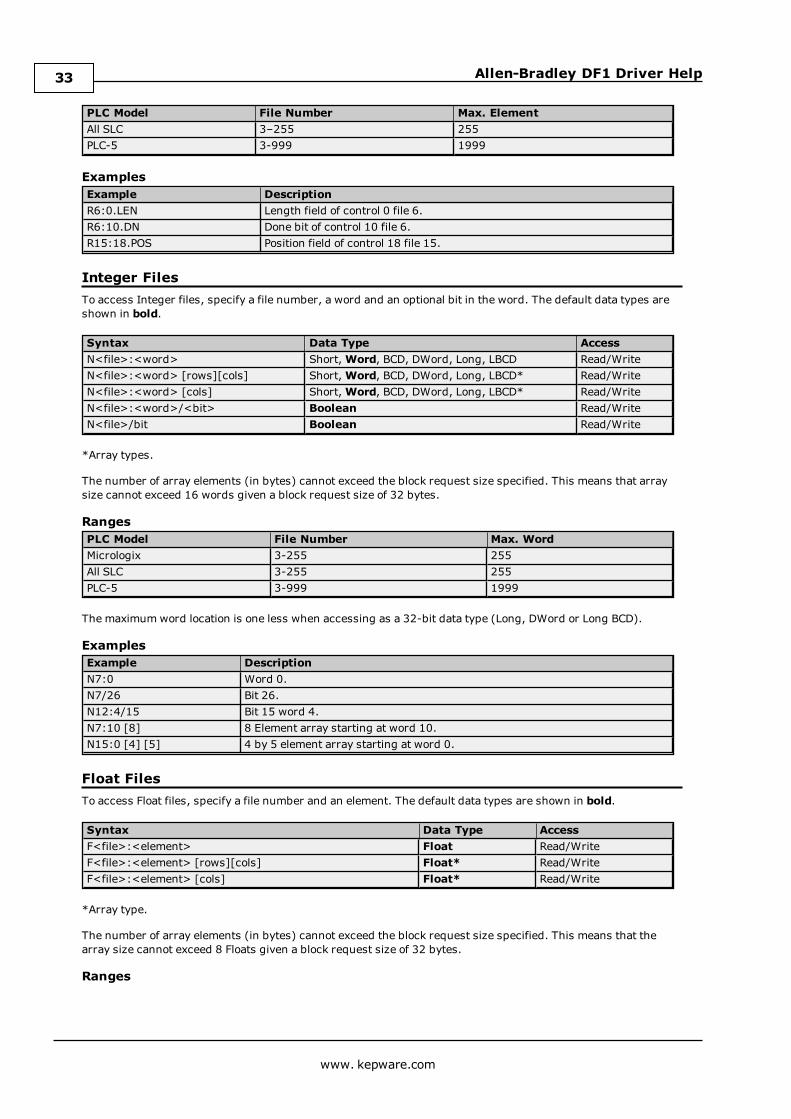
Integer FilesTo access Integer files, specify a file number, a word and an optional bit in the word. The default data types areshown in bold.
Syntax Data Type AccessN<file>:<word> Short,Word, BCD, DWord, Long, LBCD Read/WriteN<file>:<word> [rows][cols] Short,Word, BCD, DWord, Long, LBCD* Read/WriteN<file>:<word> [cols] Short,Word, BCD, DWord, Long, LBCD* Read/WriteN<file>:<word>/<bit> Boolean Read/WriteN<file>/bit Boolean Read/Write
*Array types.
The number of array elements (in bytes) cannot exceed the block request size specified. This means that arraysize cannot exceed 16 words given a block request size of 32 bytes.
RangesPLC Model File Number Max. WordMicrologix 3-255 255All SLC 3-255 255PLC-5 3-999 1999
The maximumword location is one less when accessing as a 32-bit data type (Long, DWord or Long BCD).
ExamplesExample DescriptionN7:0 Word 0.N7/26 Bit 26.N12:4/15 Bit 15 word 4.N7:10 [8] 8 Element array starting at word 10.N15:0 [4] [5] 4 by 5 element array starting at word 0.
Float FilesTo access Float files, specify a file number and an element. The default data types are shown in bold.
Syntax Data Type AccessF<file>:<element> Float Read/WriteF<file>:<element> [rows][cols] Float* Read/WriteF<file>:<element> [cols] Float* Read/Write
*Array type.
The number of array elements (in bytes) cannot exceed the block request size specified. This means that thearray size cannot exceed 8 Floats given a block request size of 32 bytes.
Ranges
www. kepware.com
33
Allen-Bradley DF1 Driver Help
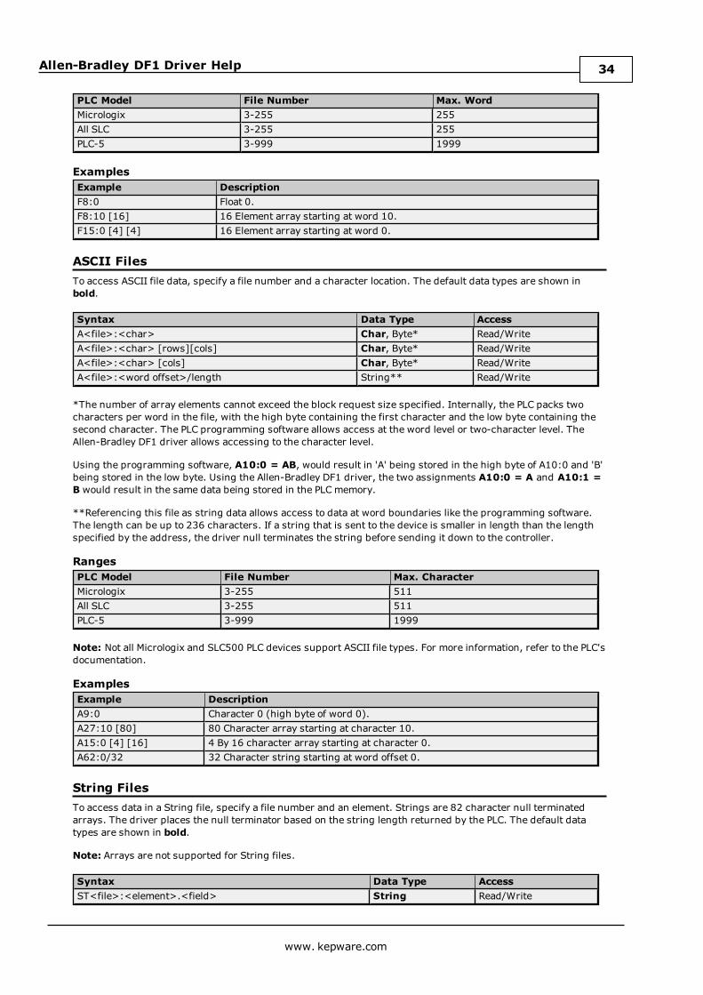
PLC Model File Number Max. WordMicrologix 3-255 255All SLC 3-255 255PLC-5 3-999 1999
ExamplesExample DescriptionF8:0 Float 0.F8:10 [16] 16 Element array starting at word 10.F15:0 [4] [4] 16 Element array starting at word 0.
ASCII FilesTo access ASCII file data, specify a file number and a character location. The default data types are shown inbold.
Syntax Data Type AccessA<file>:<char> Char, Byte* Read/WriteA<file>:<char> [rows][cols] Char, Byte* Read/WriteA<file>:<char> [cols] Char, Byte* Read/WriteA<file>:<word offset>/length String** Read/Write
*The number of array elements cannot exceed the block request size specified. Internally, the PLC packs twocharacters per word in the file, with the high byte containing the first character and the low byte containing thesecond character. The PLC programming software allows access at the word level or two-character level. TheAllen-Bradley DF1 driver allows accessing to the character level.
Using the programming software, A10:0 = AB, would result in 'A' being stored in the high byte of A10:0 and 'B'being stored in the low byte. Using the Allen-Bradley DF1 driver, the two assignments A10:0 = A and A10:1 =B would result in the same data being stored in the PLCmemory.
**Referencing this file as string data allows access to data at word boundaries like the programming software.The length can be up to 236 characters. If a string that is sent to the device is smaller in length than the lengthspecified by the address, the driver null terminates the string before sending it down to the controller.
RangesPLC Model File Number Max. CharacterMicrologix 3-255 511All SLC 3-255 511PLC-5 3-999 1999
Note: Not all Micrologix and SLC500 PLC devices support ASCII file types. For more information, refer to the PLC'sdocumentation.
ExamplesExample DescriptionA9:0 Character 0 (high byte of word 0).A27:10 [80] 80 Character array starting at character 10.A15:0 [4] [16] 4 By 16 character array starting at character 0.A62:0/32 32 Character string starting at word offset 0.
String FilesTo access data in a String file, specify a file number and an element. Strings are 82 character null terminatedarrays. The driver places the null terminator based on the string length returned by the PLC. The default datatypes are shown in bold.
Note: Arrays are not supported for String files.
Syntax Data Type AccessST<file>:<element>.<field> String Read/Write
www. kepware.com
34

Allen-Bradley DF1 Driver Help
RangesPLC Model File Number Max. WordMicrologix 3-255 255All SLC 3-255 255PLC-5 3-999 999
ExamplesExample DescriptionST9:0 String 0.ST18:10 String 10.
BCD FilesTo access BCD files, specify a file number and a word. The default data types are shown in bold.
Syntax Data Type AccessD<file>:<word> BCD, LBCD Read/WriteD<file>:<word> [rows][cols] BCD, LBCD* Read/WriteD<file>:<word> [cols] BCD, LBCD* Read/Write
*Array types.
The number of array elements (in bytes) cannot exceed the block request size specified. This means that thearray size cannot exceed 16 BCD, given a block request size of 32 bytes.
RangesPLC Model File Number Max WordMicrologix NA NAAll SLC NA NAPLC-5 3-999 999
ExamplesExample DescriptionD9:0 Word 0.D27:10 [16] 16 Element array starting at word 10.D15:0 [4] [8] 32 Element array starting at word 0.
Long FilesTo access Long files, specify a file number and a DWord. The default data types are shown in bold.
Syntax Data Type AccessL<file>:<DWord> Long, DWord, LBCD Read/WriteL<file>:<DWord> [rows][cols] Long, DWord, LBCD* Read/WriteL<file>:<DWord> [cols] Long, DWord, LBCD* Read/Write
*Array types.
The number of array elements cannot exceed 16.
RangesPLC Model File Number Max. WordMicrologix 3-255 255All SLC NA NAPLC5 NA NA
Examples
www. kepware.com
35
Allen-Bradley DF1 Driver Help
Example DescriptionL9:0 Word 0.L9:10 [8] 8 Element array starting at word 10.L15:0 [4] [5] 4 by 5 element array starting at word 0.
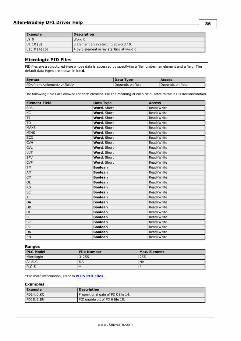
Micrologix PID FilesPID files are a structured type whose data is accessed by specifying a file number, an element and a field. Thedefault data types are shown in bold.
Syntax Data Type AccessPD<file>:<element>.<field> Depends on field Depends on field
The following fields are allowed for each element. For the meaning of each field, refer to the PLC's documentation.
Element Field Data Type AccessSPS Word, Short Read/WriteKC Word, Short Read/WriteTI Word, Short Read/WriteTD Word, Short Read/WriteMAXS Word, Short Read/WriteMINS Word, Short Read/WriteZCD Word, Short Read/WriteCVH Word, Short Read/WriteCVL Word, Short Read/WriteLUT Word, Short Read/WriteSPV Word, Short Read/WriteCVP Word, Short Read/WriteTM Boolean Read/WriteAM Boolean Read/WriteCM Boolean Read/WriteOL Boolean Read/WriteRG Boolean Read/WriteSC Boolean Read/WriteTF Boolean Read/WriteDA Boolean Read/WriteDB Boolean Read/WriteUL Boolean Read/WriteLL Boolean Read/WriteSP Boolean Read/WritePV Boolean Read/WriteDN Boolean Read/WriteEN Boolean Read/Write
RangesPLC Model File Number Max. ElementMicrologix 3-255 255All SLC NA NAPLC-5 * *
*For more information, refer to PLC5 PID Files.
ExamplesExample DescriptionPD14:0.KC Proportional gain of PD 0 file 14.PD18:6.EN PID enable bit of PD 6 file 18.
www. kepware.com
36
Allen-Bradley DF1 Driver Help
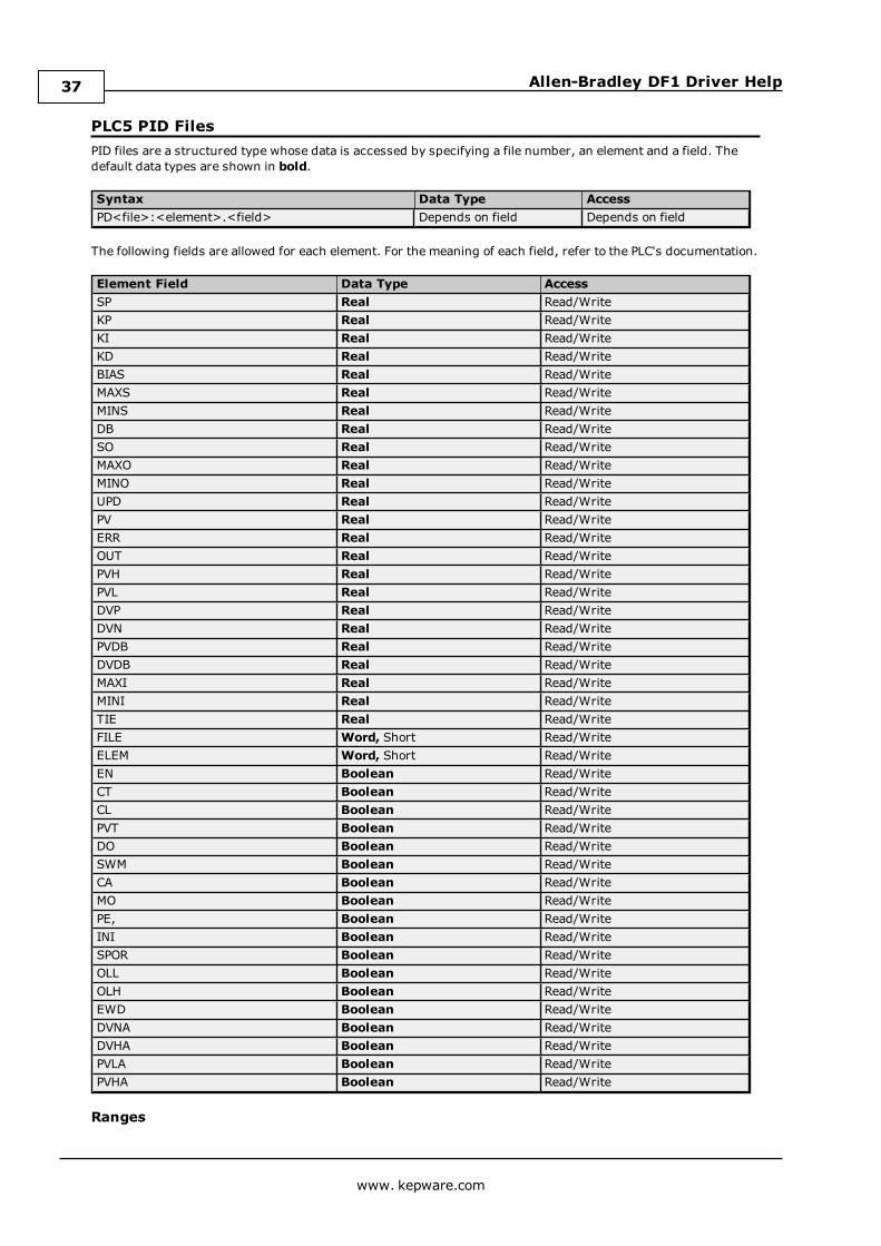
PLC5 PID FilesPID files are a structured type whose data is accessed by specifying a file number, an element and a field. Thedefault data types are shown in bold.
Syntax Data Type AccessPD<file>:<element>.<field> Depends on field Depends on field
The following fields are allowed for each element. For the meaning of each field, refer to the PLC's documentation.
Element Field Data Type AccessSP Real Read/WriteKP Real Read/WriteKI Real Read/WriteKD Real Read/WriteBIAS Real Read/WriteMAXS Real Read/WriteMINS Real Read/WriteDB Real Read/WriteSO Real Read/WriteMAXO Real Read/WriteMINO Real Read/WriteUPD Real Read/WritePV Real Read/WriteERR Real Read/WriteOUT Real Read/WritePVH Real Read/WritePVL Real Read/WriteDVP Real Read/WriteDVN Real Read/WritePVDB Real Read/WriteDVDB Real Read/WriteMAXI Real Read/WriteMINI Real Read/WriteTIE Real Read/WriteFILE Word, Short Read/WriteELEM Word, Short Read/WriteEN Boolean Read/WriteCT Boolean Read/WriteCL Boolean Read/WritePVT Boolean Read/WriteDO Boolean Read/WriteSWM Boolean Read/WriteCA Boolean Read/WriteMO Boolean Read/WritePE, Boolean Read/WriteINI Boolean Read/WriteSPOR Boolean Read/WriteOLL Boolean Read/WriteOLH Boolean Read/WriteEWD Boolean Read/WriteDVNA Boolean Read/WriteDVHA Boolean Read/WritePVLA Boolean Read/WritePVHA Boolean Read/Write
Ranges
www. kepware.com
37
Allen-Bradley DF1 Driver Help
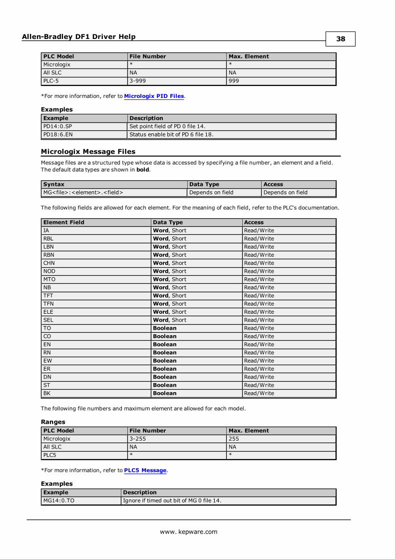
PLC Model File Number Max. ElementMicrologix * *All SLC NA NAPLC-5 3-999 999
*For more information, refer toMicrologix PID Files.
ExamplesExample DescriptionPD14:0.SP Set point field of PD 0 file 14.PD18:6.EN Status enable bit of PD 6 file 18.
Micrologix Message FilesMessage files are a structured type whose data is accessed by specifying a file number, an element and a field.The default data types are shown in bold.
Syntax Data Type AccessMG<file>:<element>.<field> Depends on field Depends on field
The following fields are allowed for each element. For the meaning of each field, refer to the PLC's documentation.
Element Field Data Type AccessIA Word, Short Read/WriteRBL Word, Short Read/WriteLBN Word, Short Read/WriteRBN Word, Short Read/WriteCHN Word, Short Read/WriteNOD Word, Short Read/WriteMTO Word, Short Read/WriteNB Word, Short Read/WriteTFT Word, Short Read/WriteTFN Word, Short Read/WriteELE Word, Short Read/WriteSEL Word, Short Read/WriteTO Boolean Read/WriteCO Boolean Read/WriteEN Boolean Read/WriteRN Boolean Read/WriteEW Boolean Read/WriteER Boolean Read/WriteDN Boolean Read/WriteST Boolean Read/WriteBK Boolean Read/Write
The following file numbers and maximum element are allowed for each model.
RangesPLC Model File Number Max. ElementMicrologix 3-255 255All SLC NA NAPLC5 * *
*For more information, refer to PLC5 Message.
ExamplesExample DescriptionMG14:0.TO Ignore if timed out bit of MG 0 file 14.
www. kepware.com
38
Allen-Bradley DF1 Driver Help
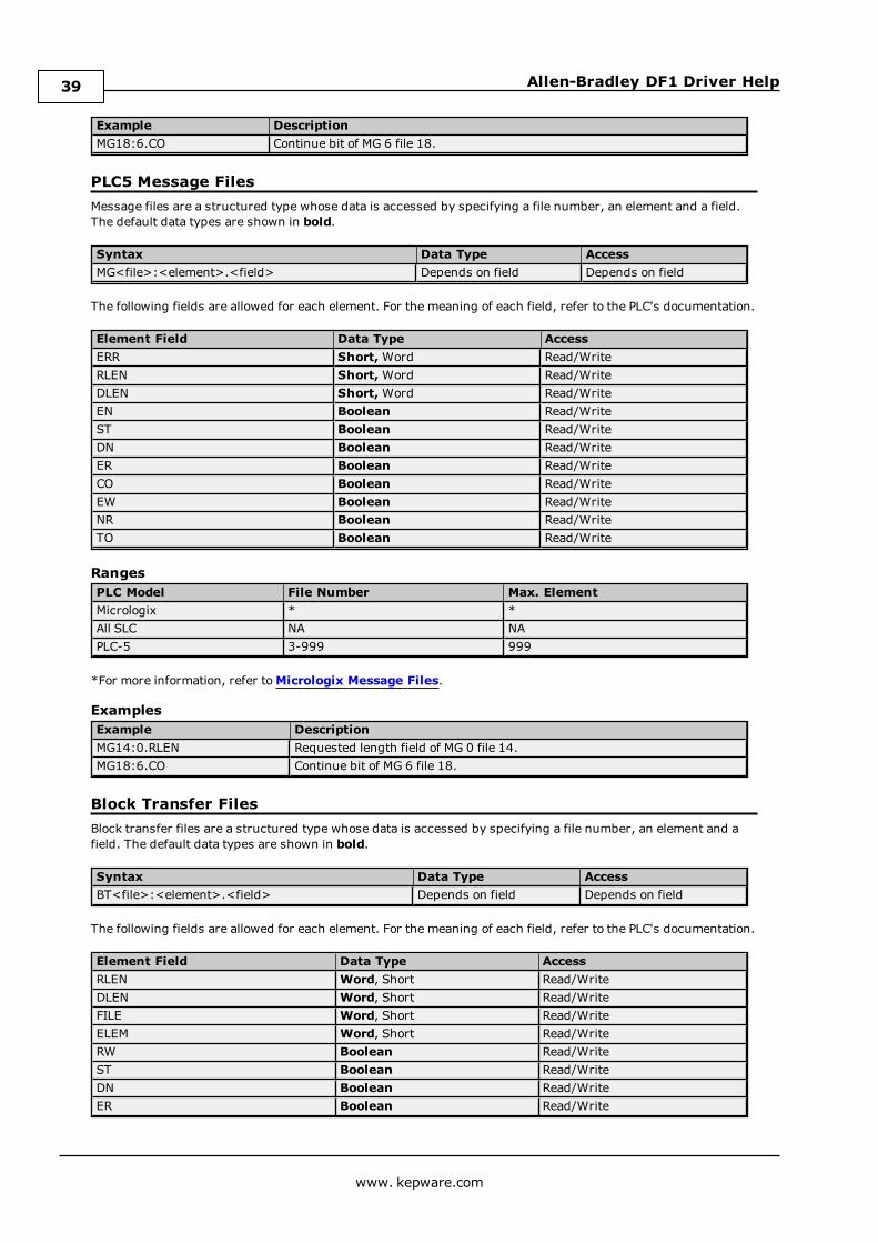
Example DescriptionMG18:6.CO Continue bit of MG 6 file 18.
PLC5 Message FilesMessage files are a structured type whose data is accessed by specifying a file number, an element and a field.The default data types are shown in bold.
Syntax Data Type AccessMG<file>:<element>.<field> Depends on field Depends on field
The following fields are allowed for each element. For the meaning of each field, refer to the PLC's documentation.
Element Field Data Type AccessERR Short,Word Read/WriteRLEN Short,Word Read/WriteDLEN Short,Word Read/WriteEN Boolean Read/WriteST Boolean Read/WriteDN Boolean Read/WriteER Boolean Read/WriteCO Boolean Read/WriteEW Boolean Read/WriteNR Boolean Read/WriteTO Boolean Read/Write
RangesPLC Model File Number Max. ElementMicrologix * *All SLC NA NAPLC-5 3-999 999
*For more information, refer toMicrologix Message Files.
ExamplesExample DescriptionMG14:0.RLEN Requested length field of MG 0 file 14.MG18:6.CO Continue bit of MG 6 file 18.
Block Transfer FilesBlock transfer files are a structured type whose data is accessed by specifying a file number, an element and afield. The default data types are shown in bold.
Syntax Data Type AccessBT<file>:<element>.<field> Depends on field Depends on field
The following fields are allowed for each element. For the meaning of each field, refer to the PLC's documentation.
Element Field Data Type AccessRLEN Word, Short Read/WriteDLEN Word, Short Read/WriteFILE Word, Short Read/WriteELEM Word, Short Read/WriteRW Boolean Read/WriteST Boolean Read/WriteDN Boolean Read/WriteER Boolean Read/Write
www. kepware.com
39
Allen-Bradley DF1 Driver Help
Element Field Data Type AccessCO Boolean Read/WriteEW Boolean Read/WriteNR Boolean Read/WriteTO Boolean Read/Write
RangesPLC Model File Number Max. ElementMicrologix NA NAAll SLC NA NAPLC-5 3-999 1999
ExamplesExample DescriptionBT14:0.RLEN Requested length field of BT 0 file 14.BT18:6.CO Continue bit of BT 6 file 18.
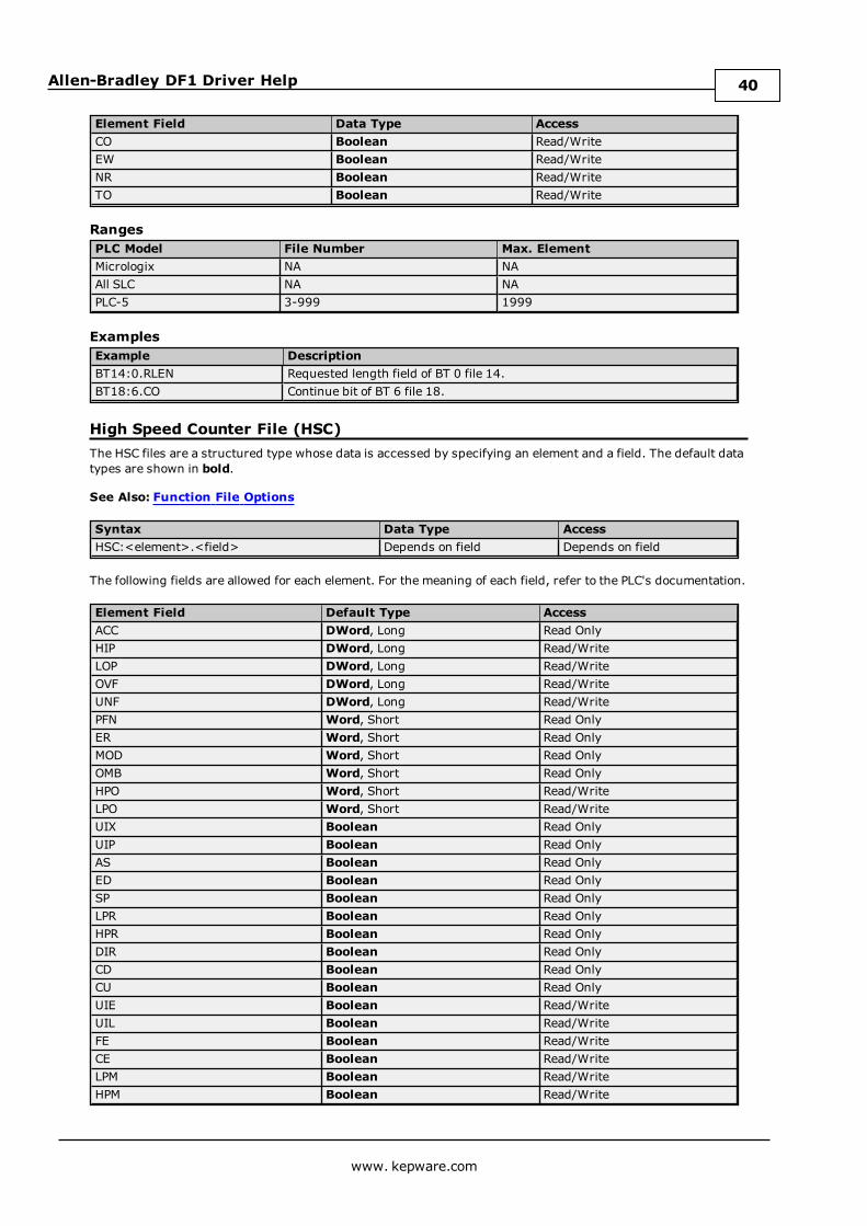
High Speed Counter File (HSC)The HSC files are a structured type whose data is accessed by specifying an element and a field. The default datatypes are shown in bold.
See Also: Function File Options
Syntax Data Type AccessHSC:<element>.<field> Depends on field Depends on field
The following fields are allowed for each element. For the meaning of each field, refer to the PLC's documentation.
Element Field Default Type AccessACC DWord, Long Read OnlyHIP DWord, Long Read/WriteLOP DWord, Long Read/WriteOVF DWord, Long Read/WriteUNF DWord, Long Read/WritePFN Word, Short Read OnlyER Word, Short Read OnlyMOD Word, Short Read OnlyOMB Word, Short Read OnlyHPO Word, Short Read/WriteLPO Word, Short Read/WriteUIX Boolean Read OnlyUIP Boolean Read OnlyAS Boolean Read OnlyED Boolean Read OnlySP Boolean Read OnlyLPR Boolean Read OnlyHPR Boolean Read OnlyDIR Boolean Read OnlyCD Boolean Read OnlyCU Boolean Read OnlyUIE Boolean Read/WriteUIL Boolean Read/WriteFE Boolean Read/WriteCE Boolean Read/WriteLPM Boolean Read/WriteHPM Boolean Read/Write
www. kepware.com
40
Allen-Bradley DF1 Driver Help
Element Field Default Type AccessUFM Boolean Read/WriteOFM Boolean Read/WriteLPI Boolean Read/WriteHPI Boolean Read/WriteUFI Boolean Read/WriteOFI Boolean Read/WriteUF Boolean Read/WriteOF Boolean Read/WriteMD Boolean Read/Write
RangesPLC Model File Number Max. ElementMicrologix N/A 254All SLC N/A N/APLC5 N/A N/A
ExamplesExample DescriptionHSC:0.OMB Output mask setting for high speed counter 0.HSC:1.ED Error detected indicator for high speed counter 1.
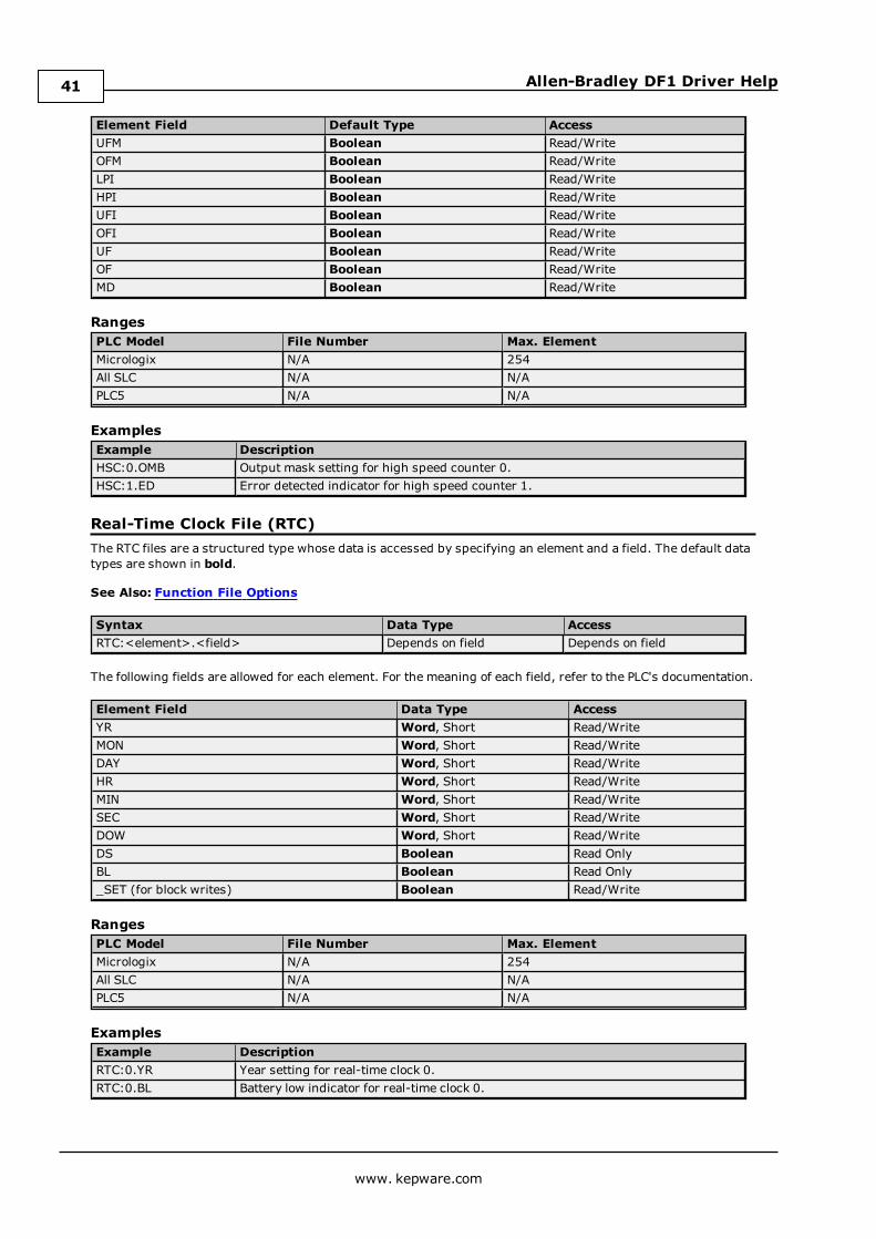
Real-Time Clock File (RTC)The RTC files are a structured type whose data is accessed by specifying an element and a field. The default datatypes are shown in bold.
See Also: Function File Options
Syntax Data Type AccessRTC:<element>.<field> Depends on field Depends on field
The following fields are allowed for each element. For the meaning of each field, refer to the PLC's documentation.
Element Field Data Type AccessYR Word, Short Read/WriteMON Word, Short Read/WriteDAY Word, Short Read/WriteHR Word, Short Read/WriteMIN Word, Short Read/WriteSEC Word, Short Read/WriteDOW Word, Short Read/WriteDS Boolean Read OnlyBL Boolean Read Only_SET (for block writes) Boolean Read/Write
RangesPLC Model File Number Max. ElementMicrologix N/A 254All SLC N/A N/APLC5 N/A N/A
ExamplesExample DescriptionRTC:0.YR Year setting for real-time clock 0.RTC:0.BL Battery low indicator for real-time clock 0.
www. kepware.com
41
Allen-Bradley DF1 Driver Help
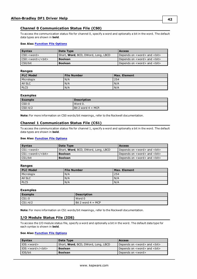
Channel 0 Communication Status File (CS0)To access the communication status file for channel 0, specify a word and optionally a bit in the word. The defaultdata types are shown in bold.
See Also: Function File Options
Syntax Data Type AccessCS0:<word> Short,Word, BCD, DWord, Long, LBCD Depends on <word> and <bit>CS0:<word>/<bit> Boolean Depends on <word> and <bit>CS0/bit Boolean Depends on <word> and <bit>
RangesPLC Model File Number Max. ElementMicrologix N/A 254All SLC N/A N/APLC5 N/A N/A
ExamplesExample DescriptionCS0:0 Word 0.CS0:4/2 Bit 2 word 4 = MCP.
Note: For more information on CS0 words/bit meanings, refer to the Rockwell documentation.
Channel 1 Communication Status File (CS1)To access the communication status file for channel 1, specify a word and optionally a bit in the word. The defaultdata types are shown in bold.
See Also: Function File Options
Syntax Data Type AccessCS1:<word> Short,Word, BCD, DWord, Long, LBCD Depends on <word> and <bit>CS1:<word>/<bit> Boolean Depends on <word> and <bit>CS1/bit Boolean Depends on <word> and <bit>
RangesPLC Model File Number Max. ElementMicrologix N/A 254All SLC N/A N/APLC5 N/A N/A
ExamplesExample DescriptionCS1:0 Word 0CS1:4/2 Bit 2 word 4 = MCP
Note: For more information on CS1 words/bit meanings, refer to the Rockwell documentation.
I/O Module Status File (IOS)To access the I/O module status file, specify a word and optionally a bit in the word. The default data type foreach syntax is shown in bold.
See Also: Function File Options
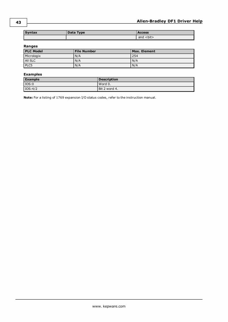
Syntax Data Type AccessIOS:<word> Short,Word, BCD, DWord, Long, LBCD Depends on <word> and <bit>IOS:<word>/<bit> Boolean Depends on <word> and <bit>IOS/bit Boolean Depends on <word>
www. kepware.com
42
Allen-Bradley DF1 Driver Help
Syntax Data Type Accessand <bit>
RangesPLC Model File Number Max. ElementMicrologix N/A 254All SLC N/A N/APLC5 N/A N/A
ExamplesExample DescriptionIOS:0 Word 0.IOS:4/2 Bit 2 word 4.
Note: For a listing of 1769 expansion I/O status codes, refer to the instruction manual.
www. kepware.com
43
Allen-Bradley DF1 Driver Help
Error DescriptionsThe following categories of messages may be generated. Click on the link for a list of the related message.
Address ValidationDevice-Specific MessagesDevice Status MessagesSerial Communication Messages
Address ValidationThe following messages may be generated. Click on the link for a description of the message.
Address <address> is out of range for the specified device or register.Array size is out of range for address <address>.Array support is not available for the specified address: <address>.Data Type <type> is not valid for device address <address>.Device address <address> contains a syntax error.Device address <address> is not supported by model <model name>.Device address <address> is read only.Missing address.
Address <address> is out of range for the specified device or register.Error Type:Warning
Possible Cause:A tag address that has been specified statically references a location that is beyond the range of supportedlocations for the device.
Solution:Verify that the address is correct; if it is not, re-enter it in the client application.
Array size is out of range for address <address>.Error Type:Warning
Possible Cause:A tag address that has been specified statically is requesting an array size that is too large for the address type orblock size of the driver.
Solution:Re-enter the address in the client application to specify a smaller value for the array or a different starting point.
Array support is not available for the specified address: <address>.Error Type:Warning
Possible Cause:A tag address that has been specified statically contains an array reference for an address type that doesn'tsupport arrays.
Solution:Re-enter the address in the client application to remove the array reference or correct the address type.
Data Type <type> is not valid for device address <address>.Error Type:Warning
Possible Cause:A tag address that has been specified statically has been assigned an invalid data type.
www. kepware.com
44
Allen-Bradley DF1 Driver Help
Solution:Modify the requested data type in the client application.
Device address <address> contains a syntax error.Error Type:Warning
Possible Cause:A tag address that has been specified statically contains one or more invalid characters.
Solution:Re-enter the address in the client application.
Device address <address> is not supported by model <model name>.Error Type:Warning
Possible Cause:A tag address that has been specified statically references a location that is valid for the communications protocolbut not supported by the target device.
Solution:
1. Verify that the address is correct; if it is not, re-enter it in the client application.
2. Verify the selected model name for the device is correct.
Device address <address> is read only.Error Type:Warning
Possible Cause:A tag address that has been specified statically has a requested access mode that is not compatible with what thedevice supports for that address.
Solution:Change the access mode in the client application.
Missing address.Error Type:Warning
Possible Cause:A tag address that has been specified statically has no length.
Solution:Re-enter the address in the client application.
Serial CommunicationsThe following messages may be generated. Click on the link for a description of the message.
Communications error on <channel name> [<error mask>].COMn does not exist.COMn is in use by another application.Error opening COMn.Unable to set comm parameters on COMn.
www. kepware.com
45
Allen-Bradley DF1 Driver Help
Communications error on <channel name> [<error mask>]Error Type:Serious
Error Mask Definitions:B = Hardware break detected.F = Framing error.E = I/O error.O = Character buffer overrun.R = RX buffer overrun.P = Received byte parity error.T = TX buffer full.
Possible Cause:
1. The serial connection between the device and the Host PC is bad.
2. The communications parameters for the serial connection are incorrect.
Solution:
1. Verify the cabling between the PC and the device.
2. Verify that the specified communications parameters match those of the device.
COMn does not exist.Error Type:Fatal
Possible Cause:The specified COM port is not present on the target computer.
Solution:Verify that the proper COM port has been selected.
COMn is in use by another application.Error Type:Fatal
Possible Cause:The serial port assigned to a device is being used by another application.
Solution:Verify that the correct port has been assigned to the channel.
Error opening COMn.Error Type:Fatal
Possible Cause:The specified COM port could not be opened due an internal hardware or software problem on the targetcomputer.
Solution:Verify that the COM port is functional and may be accessed by other Windows applications.
Unable to set comm parameters on COMn.Error Type:Fatal
www. kepware.com
46
Allen-Bradley DF1 Driver Help
Possible Cause:The serial parameters for the specified COM port are not valid.
Solution:Verify the serial parameters and make any necessary changes.
Device Status MessagesThe following messages may be generated. Click on the link for a description of the message.
Device <device name> is not responding.Unable to write to <address> on device <device name>.
Device <device name> is not responding.Error Type:Serious
Possible Cause:
1. The serial connection between the device and the Host PC is broken.
2. The communications parameters for the serial connection are incorrect.
3. The named device may have been assigned an incorrect Network ID.
4. The response from the device took longer to receive than the amount of time specified in the "RequestTimeout" device setting.
Solution:
1. Verify the cabling between the PC and the device.
2. Verify that the specified communication parameters match those of the device.
3. Verify that the Network ID given to the named device matches that of the actual device.
4. Increase the Request Timeout setting so that the entire response can be handled.
Unable to write to <address> on device <device name>.Error Type:Serious
Possible Cause:
1. The serial connection between the device and the host PC is broken.
2. The communication parameters for the serial connection are incorrect.
3. The named device may have been assigned an incorrect network ID.
Solution:
1. Verify the cabling between the PC and the device.
2. Verify that the specified communication parameters match those of the device.
3. Verify that the Network ID given to the named device matches that of the actual device.
Device Specific MessagesThe following messages may be generated. Click on the link for a description of the message.
Checksum error occurred writing to address <address> on device <device name>.Device <device name> timed out writing to address <address>.Error writing to address <address> on device <device name> [Status=<STS>, Ext. Status=<EXT.STS>].Error writing to address <address> on device <device name>. Framing error.
www. kepware.com
47
Allen-Bradley DF1 Driver Help
Error writing to address <address> on device <device name>. Slave sink/source full.Error writing to address <address> on device <device name>. Slave source empty.Unable to read data starting at <start address> on device <device name> [Status=<STS>, Ext.Status=<EXT. STS>].Unable to read data starting at <start address> on device <device name> [Status=<STS>, Ext.Status=<EXT. STS>]. Block deactivated.Unable to read function file <fun. file address> on device <device name> [Status=<STS>, Ext.Status=<EXT. STS>].Unable to read function file <fun. file element> on device <device name> [Status=<STS>, Ext.Status=<EXT. STS>]. Block deactivated.Unable to read data starting at <start address> on device <device name>. Framing error.Unable to read function file <fun. file element> on device <device name>. Framing error.Unable to read data starting at <start address> on device <device name>. checksum error.Unable to read function file <fun. file element> on device <device name>. checksum error.Unable to read data starting at <start address> on device <device name>. Slave sink/source full.Unable to read function file <fun. file element> on device <device name>. Slave sink/source full.Unable to read data starting at <start address> on device <device name>. Slave source empty.Unable to read function file <fun. file element> on device <device name>. Slave source empty.Unable to read data starting at <start address> on device <device name>. Device replied with aNAK.Unable to read function file <fun. file element> on device <device name>. Device replied with aNAK.Unable to read data starting at <start address> on device <device name>. Memory map error.Unable to read function file <fun. file element> on device <device name>. Memory map error.Unable to read data starting at <start address> on device <device name>. Device replied with anunexpected NAK. Check device link protocol.Unable to read function file <fun. file element> on device <device name>. Device replied with anunexpected NAK. Check device link protocol.
Checksum error occurred writing to address <address> on device <devicename>.Error Type:Serious
Possible Cause:There is bad cabling connecting the devices causing noise and checksum errors.
Solution:Inspect cabling between the Host PC and the device.
Device <device name> timed out writing to address <address>.Error Type:Serious
Possible Cause:
1. The device is not responding.
2. The serial connection between the device and the Host PC is broken.
Solution:Inspect cabling between the Host PC and the device. Verify the device is on and operating properly.
Error writing to address <address> on device <device name>. Slavesink/source full.Error Type:Serious
Possible Cause:The slave device cannot accept any more requests from the master. The client may be requesting data too fast.
www. kepware.com
48
Allen-Bradley DF1 Driver Help
Solution:The driver will automatically poll and re-poll the slave to empty its source and in turn make room for responsesfrom requests previously in the full sink. If this error occurs too often, decrease the update rate on suspectedtags, not necessarily the tag being written to.
Error writing to address <address> on device <device name> [Status=<STS>,Ext. Status=<EXT. STS>].Error Type:Serious
Possible Cause:
1. Node cannot be found.
2. Duplicate node detected.
3. The address requested in the block does not exist in the PLC.
4. Processor is in programmode.
Solution:Check the status and extended status codes that are being returned by the PLC. The codes are displayed inhexadecimal.
Note:Status code errors in the low nibble of the status code indicate errors found by the local node. Errors found bythe local node occur when the KF module cannot see the destination PLC on the network for some reason.
Status code errors in the high nibble of the status code indicate errors found by the PLC. These errors aregenerated when the block of data the driver is asking for is not available in the PLC.
Error writing to address <address> on device <device name>. Framing error.Error Type:Serious
Possible Cause:
1. Unexpected frame received.
2. Frame size mismatch.
Solution:The device is returning an invalid write response or one of unexpected size. If this error occurs frequently,contact Technical Support.
Error writing to address <address> on device <device name>. Slave sourceempty.Error Type:Serious
Possible Cause:The slave device does not have a response prepared for the write request to address < address>. The slave re-poll delay may be set to short.
Solution:The driver will automatically poll and re-poll the slave in seek of a poll response. If this error occurs too often,increase the slave re-poll delay on the given channel.
Unable to read data starting at <start address> on device <device name>[Status=<STS>, Ext. Status=<EXT. STS>].Error Type:Serious
www. kepware.com
49
Allen-Bradley DF1 Driver Help
Possible Cause:
1. Node cannot be found.
2. Duplicate node detected.
Solution:Check the status and extended status codes that are being returned by the PLC. The codes are displayed inhexadecimal.
Note:This error message applies to local node errors. Status code errors in the low nibble of the status code indicateerrors found by the local node. The driver will continue to retry reading these blocks of data periodically. Errorsfound by the local node occur when the KF module cannot see the destination PLC on the network for somereason.
Unable to read data starting at <start address> on device <device name>[Status=<STS>, Ext. Status=<EXT. STS>]. Block deactivated.Error Type:Serious
Possible Cause:
1. The address requested in the block does not exist in the PLC.
2. Processor is in programmode.
Solution:Check the status and extended status codes that are being returned by the PLC. The codes are displayed inhexadecimal.
Note:This error message applies to remote node errors. Status code errors in the high nibble of the status codeindicate errors found by the PLC. These errors are generated when the block of data the driver is asking for is notavailable in the PLC. The driver will not ask for these blocks again after receiving this kind of error. This kind oferror can be generated if the address does not exist in the PLC.
Unable to read function file <fun. file element> on device <device name>[Status=<STS>, Ext. Status=< EXT. STS>].Error Type:Serious
Possible Cause:
1. Node cannot be found.
2. Duplicate node detected.
Solution:Check the status and extended status codes that are being returned by the PLC. The codes are displayed inhexadecimal.
Note:This error message applies to local node errors. Status code errors in the low nibble of the status code indicateerrors found by the local node. The driver will continue to retry reading this function file periodically. Errorsfound by the local node occur when the KF module cannot see the destination PLC on the network for somereason.
Unable to read function file <fun. file element> on device <device name>[Status=<STS>, Ext. Status=< EXT. STS>]. Block deactivated.Error Type:Serious
www. kepware.com
50
Allen-Bradley DF1 Driver Help
Possible Cause:
1. The function file address requested in the block does not exist in the PLC.
2. Processor is in programmode.
Solution:Check the status and extended status codes that are being returned by the PLC. The codes are displayed inhexadecimal.
Note:This error message applies to remote node errors. Status code errors in the high nibble of the status codeindicate errors found by the PLC. These errors are generated when the function file the driver is asking for is notavailable in the PLC. The driver will not ask for this function file again after receiving this kind of error. This kindof error can be generated if the function file address does not exist in the PLC.
Unable to read data starting at <start address> on device <device name>.Framing error.Error Type:Serious
Possible Cause:
1. Unexpected frame received.
2. Frame size mismatch.
Solution:The device is returning an invalid read response or one of unexpected size. If this error occurs frequently,contact Technical Support.
Unable to read function file <fun. file element> on device <device name>.Framing error.Error Type:Serious
Possible Cause:
1. Unexpected frame received.
2. Frame size mismatch.
Solution:The device is returning an invalid function file read response or one of unexpected size. If this error occursfrequently, contact Technical Support.
Unable to read data starting at <start address> on device <device name>.checksum error.Error Type:Serious
Possible Cause:There is bad cabling connecting the devices causing noise and checksum errors.
Solution:Inspect cabling between the Host PC and the device.
Unable to read function file <fun. file element> on device <device name>.Checksum error.Error Type:Serious
Possible Cause:
www. kepware.com
51
Allen-Bradley DF1 Driver Help
There is bad cabling connecting the devices causing noise and checksum errors.
Solution:Inspect cabling between the Host PC and the device.
Unable to read data starting at <start address> on device <device name>.Slave sink/source full.Error Type:Serious
Possible Cause:The slave device cannot accept anymore requests from the master. The client may be requesting data too fast.
Solution:The driver will automatically poll and re-poll the slave to empty its source and in turn make room for responsesfrom requests previously in the full sink. If this error occurs too often, decrease the update rate on suspectedtags.
Unable to read function file <fun. file element> on device <device name>.Slave sink/source full.Error Type:Serious
Possible Cause:The slave device cannot accept anymore requests from the master. The client may be requesting data too fast.
Solution:The driver will automatically poll and re-poll the slave to empty its source and in turn make room for responsesfrom requests previously in the full sink. If this error occurs too often, decrease the update rate on suspectedfunction file tags.
Unable to read data starting at <start address> on device <device name>.Slave source empty.Error Type:Serious
Possible Cause:The slave device does not have a response prepared for the data request starting at <start address>. The slavere-poll delay may be set to short.
Solution:The driver will automatically poll and re-poll the slave in seek of a poll response. If this error occurs too often,increase the slave re-poll delay on the given channel.
Unable to read function file <fun. file element> on device <device name>.Slave source empty.Error Type:Serious
Possible Cause:The slave device does not have a response prepared for the request of function file <fun. file element>. The slavere-poll delay may be set to short.
Solution:The driver will automatically poll and re-poll the slave in seek of a poll response. If this error occurs too often,increase the slave re-poll delay on the given channel.
www. kepware.com
52

Allen-Bradley DF1 Driver Help
Unable to read data starting at <start address> on device <device name>.Device replied with a NAK.Error Type:Serious
Possible Cause:The server sent an invalid response or one of unexpected size.
Solution:If this error occurs frequently, contact Technical Support.
Unable to read function file <fun. file element> on device <device name>.Device replied with a NAK.Error Type:Serious
Possible Cause:The server sent an invalid response or one of unexpected size.
Solution:If this error occurs frequently, contact Technical Support.
Unable to read data starting at <start address> on device <device name>.Memory map error.Error Type:Serious
Possible Cause:There was an error writing to memory on the server.
Solution:If this error occurs frequently, contact Technical Support.
Unable to read function file <fun. file element> on device <device name>.Memory map error.Error Type:Serious
Possible Cause:There was an error writing to memory on the server.
Solution:If this error occurs frequently, contact Technical Support.
Unable to read data starting at <start address> on device <device name>.Device replied with an unexpected NAK. Check device link protocol.Error Type:Serious
Possible Cause:The server either sent an invalid response or one of unexpected size. The server's Protocol Link settings may notmatch the device configuration.
Solution:Ensure that the device's Link Protocol settings match that of the channel's. If this error occurs frequently, contactTechnical Support.
www. kepware.com
53

Allen-Bradley DF1 Driver Help
Unable to read function file <fun. file element> on device <device name>.Device replied with an unexpected NAK. Check device link protocol.Error Type:Serious
Possible Cause:The server either sent an invalid response or one of unexpected size. The server's Protocol Link settings may notmatch the device configuration.
Solution:Ensure that the device's Link Protocol settings match that of the channel. If this error occurs frequently, contactTechnical Support.
www. kepware.com
54
Allen-Bradley DF1 Driver Help
Index
1
15-Pin Module Connection 12
2
25-Pin Module Connection 12
A
Address <address> is out of range for the specified device or register. 44Address Descriptions 22Address Validation 44Array size is out of range for address <address>. 44Array support is not available for the specified address <address>. 44ASCII Files 34Avtron 11
B
BCD 21BCD Files 35Binary Files 30Block Transfer Files 39Boolean 21Byte 21
C
Cable Connections 11Channel 0 Communication Status File 42Channel 1 Communication Status File 42Channel Setup 6Char 21Checksum 10Checksum error occurred writing to address <address> on device <device name>. 48Communicating with RSLogix5000 Family Controllers 17Communication Parameters 6Communications error on <channel name> [<error mask>] 46COMn does not exist. 46COMn is in use by another application. 46Control Files 32Counter Files 32
D
Data Type <type> is not valid for device address <address>. 44Data Types Description 21Device <device name> is not responding. 47Device <device name> timed out writing to address <address>. 48Device address <address> contains a syntax error. 45
www. kepware.com
55
Allen-Bradley DF1 Driver Help
Device address <address> is not supported by model <model name>. 45Device address <address> is read only. 45Device ID 10Device Setup 10Device Specific Messages 47Device Status Messages 47DWord 21
E
Error Checking 10Error Descriptions 44Error opening COMn. 46Error writing to address <address> on device <device name> [Status=<STS> Ext. Status=<EXT.
STS>]. 49Error writing to address <address> on device <device name>. Framing error. 49Error writing to address <address> on device <device name>. Slave sink/source full. 48Error writing to address <address> on device <device name>. Slave source empty. 49Ethernet Encapsulation 10
F
Float 10, 21Float Files 33Framing 46Full-Duplex 7Full Duplex 7Function File Block Writes 13Function File Options 13
H
Half-Duplex 7Half Duplex Master 7Help Contents 5High Speed Counter File 40
I
I/O Module Status File 42Input Files 27Integer Files 33
K
KF2/KF3 Half Duplex Master 8
L
LBCD 21Link Protocols 7Link Settings 6Long 21Long Files 35
www. kepware.com
56
Allen-Bradley DF1 Driver Help
M
Mask 46Micro800 Series Addressing 22Micrologix Addressing 22Micrologix Message Files 38Micrologix PID Files 36Missing address. 45Modem Setup 10Modular I/O Selection Guide 15
O
Output Files 24Overrun 46Overview 5
P
Parity 46PLC5 Addressing 24PLC5 Message Files 39PLC5 PID Files 37Protocol Settings 10
R
Radio Modem 6, 9Real-Time Clock File (RTC) 41
S
Serial Communications 45Short 21SLC5/01 Addressing 23SLC5/02 Addressing 23SLC5/03 Addressing 23SLC5/04 23SLC5/05 24SLC500 Addressing (Fixed I/O processor) 23SLC500 Connection 12SLC500 Slot Configuration 14Station Number 6Status Files 30String 21String Files 34Supported Devices 10Supported Protocols 6Swap PLC-5 Float Words 10
T
Timer Files 31
www. kepware.com
57
Allen-Bradley DF1 Driver Help
U
Unable to read data starting at <start address> on device <device name> [Status=<STS> Ext. Status=<EXT.STS>]. 49
Unable to read data starting at <start address> on device <device name> [Status=<STS> Ext. Status=<EXT.STS>]. Block deactivated. 50
Unable to read data starting at <start address> on device <device name>. Checksum error. 51Unable to read data starting at <start address> on device <device name>. Device replied with a NAK. 53Unable to read data starting at <start address> on device <device name>. Device replied with an unexpected
NAK. Check device link protocol. 53Unable to read data starting at <start address> on device <device name>. Framing error. 51Unable to read data starting at <start address> on device <device name>. Memory map error. 53Unable to read data starting at <start address> on device <device name>. Slave sink/source full. 52Unable to read data starting at <start address> on device <device name>. Slave source empty. 52Unable to read function file <fun. file element> on device <device name> [Status=<STS> Ext. Status=<EXT.
STS>]. 50Unable to read function file <fun. file element> on device <device name> [Status=<STS> Ext. Status=<EXT.
STS>]. Block deactivated. 50Unable to read function file <fun. file element> on device <device name>. Checskum error. 51Unable to read function file <fun. file element> on device <device name>. Device replied with a NAK. 53Unable to read function file <fun. file element> on device <device name>. Device replied with an unexpected
NAK. Check device link protocol. 54Unable to read function file <fun. file element> on device <device name>. Framing error. 51Unable to read function file <fun. file element> on device <device name>. Memory map error. 53Unable to read function file <fun. file element> on device <device name>. Slave sink/source full. 52Unable to read function file <fun. file element> on device <device name>. Slave source empty. 52Unable to set comm parameters on COMn. 46Unable to write to <address> on device <device name>. 47
W
Word 21
www. kepware.com
58