
Plasmonic hollow-core photonic band gap fiber for efficient sensing of biofluids
8
Journal of Optics J. Opt. 16 (2014) 045001 (8pp) doi:10.1088/2040-8978/16/4/045001 Plasmonic hollow-core photonic band gap fiber for efficient sensing of biofluids Tushar Biswas, Rik Chattopadhyay and Shyamal K Bhadra Fiber optics and Photonics Division, CSIR-Central Glass and Ceramic Research Institute, 196, Raja S C Mullick Road, Jadavpur, Kolkata-700032, India E-mail: [email protected] Received 1 October 2013, revised 31 December 2013 Accepted for publication 5 February 2014 Published 12 March 2014 Abstract We report a new family of hollow-core photonic crystal fibers with embedded metal wires for sensitive refractive index measurement of fluids. These fibers operate on the principle of resonant coupling of the guided core mode with the surface plasmon mode generated at the surface of metal wires embedded in the photonic crystal structure. A maximum sensitivity of 2151 nm RIU -1 (nanometer per refractive index unit) can be achieved even for refractive index values lower than 1.26. The fiber is simple in design and can be fabricated with a certain modification to the conventional hollow-core photonic band gap fiber manufacturing technique. The proposed design is useful for detecting a small change in refractive index of the sample and may be implemented to estimate the bulk permittivity of the core fluid. Keywords: photonic bandgap fiber, surface plasmon, fiber optic sensors PACS numbers: 42.81.i, 42.81.Pa, 42.81.Wg (Some figures may appear in colour only in the online journal) 1. Introduction Plasmonic microstructured optical fibers (MOFs) have po- tential application in refractive index (RI) sensing [1–10]. Plasmonic MOFs can be used to obtain highly sensitive and miniaturized RI sensors integrated with large microfluidic channels. These sensors need a specialized core design along with precise metal coating in the analyte channel. The use of metal nanowire filled MOF surface plasmon resonance (SPR) sensors has been proposed to overcome the complicacy of metal coating of analyte channels [9]. These metal nanowire embedded sensors require all the air holes of the MOF to be filled with the analyte. This is problematic, because the fluid channels are extremely small (diameter about 2.576 μm), and thus a special arrangement is needed to make the analyte enter. In the recent work [10], an SPR based RI sensor using polymer MOF has been proposed. In this sensor the outer side of the fiber is coated with nanoscale metal film instead of coating the inner surface of the analyte channel. Though the coating can be done easily, the structure itself is tricky to design. The attenuation loss in these sensors is quite low, so the change in core mode intensity is difficult to detect. Hence for a faithful detection of RI, appreciable length is required. On the other hand, the sensor proposed in this study offers a high attenuation loss. Even an 8–10 mm long fiber will give a sufficient change in the signal to be detected. We propose a simple hollow-core photonic bandgap fiber (HC-PBGF), in which the air holes of the first ring of the photonic crystal (PC) cladding are filled with metal to obtain the SPR based refractive index (RI) sensing effect. The core of the fiber can be filled with gases or liquids whose RIs are to be sensed. Unlike the existing SPR based wavelength interrogated RI sensors, these fibers have two sensitive plasmonic peaks, which enable the sensor, built by employing these fibers, to give more confirmatory results. Besides, the numerical results show that RI values lower than 1.26 can be sensed efficiently. We present the design of an HC-PBGF operating at the center wavelength of 1550 nm. The pitch 3 (center to center distance of the air holes) and diameter d of the air hole should be 2.74 μm and 2.60 μm, respectively. An HC-PBGF having these structural parameters can be fabricated using the conventional stack and draw method. The band structure of the HC-PBGF is calculated by using the plane wave expansion method (PWEM) [11], and the propagation 2040-8978/14/045001+08$33.00 1 c 2014 IOP Publishing Ltd Printed in the UK
Transcript of Plasmonic hollow-core photonic band gap fiber for efficient sensing of biofluids
Journal of Optics
J. Opt. 16 (2014) 045001 (8pp) doi:10.1088/2040-8978/16/4/045001
Plasmonic hollow-core photonic band gapfiber for efficient sensing of biofluidsTushar Biswas, Rik Chattopadhyay and Shyamal K Bhadra
Fiber optics and Photonics Division, CSIR-Central Glass and Ceramic Research Institute, 196,Raja S C Mullick Road, Jadavpur, Kolkata-700032, India
E-mail: [email protected]
Received 1 October 2013, revised 31 December 2013Accepted for publication 5 February 2014Published 12 March 2014
AbstractWe report a new family of hollow-core photonic crystal fibers with embedded metal wires forsensitive refractive index measurement of fluids. These fibers operate on the principle ofresonant coupling of the guided core mode with the surface plasmon mode generated at thesurface of metal wires embedded in the photonic crystal structure. A maximum sensitivity of2151 nm RIU−1 (nanometer per refractive index unit) can be achieved even for refractiveindex values lower than 1.26. The fiber is simple in design and can be fabricated with a certainmodification to the conventional hollow-core photonic band gap fiber manufacturingtechnique. The proposed design is useful for detecting a small change in refractive index of thesample and may be implemented to estimate the bulk permittivity of the core fluid.
Keywords: photonic bandgap fiber, surface plasmon, fiber optic sensorsPACS numbers: 42.81.i, 42.81.Pa, 42.81.Wg
(Some figures may appear in colour only in the online journal)
1. Introduction
Plasmonic microstructured optical fibers (MOFs) have po-tential application in refractive index (RI) sensing [1–10].Plasmonic MOFs can be used to obtain highly sensitive andminiaturized RI sensors integrated with large microfluidicchannels. These sensors need a specialized core design alongwith precise metal coating in the analyte channel. The use ofmetal nanowire filled MOF surface plasmon resonance (SPR)sensors has been proposed to overcome the complicacy ofmetal coating of analyte channels [9]. These metal nanowireembedded sensors require all the air holes of the MOF to befilled with the analyte. This is problematic, because the fluidchannels are extremely small (diameter about 2.576 µm), andthus a special arrangement is needed to make the analyte enter.In the recent work [10], an SPR based RI sensor using polymerMOF has been proposed. In this sensor the outer side of thefiber is coated with nanoscale metal film instead of coatingthe inner surface of the analyte channel. Though the coatingcan be done easily, the structure itself is tricky to design. Theattenuation loss in these sensors is quite low, so the change incore mode intensity is difficult to detect. Hence for a faithful
detection of RI, appreciable length is required. On the otherhand, the sensor proposed in this study offers a high attenuationloss. Even an 8–10 mm long fiber will give a sufficient changein the signal to be detected. We propose a simple hollow-corephotonic bandgap fiber (HC-PBGF), in which the air holesof the first ring of the photonic crystal (PC) cladding arefilled with metal to obtain the SPR based refractive index (RI)sensing effect. The core of the fiber can be filled with gases orliquids whose RIs are to be sensed. Unlike the existing SPRbased wavelength interrogated RI sensors, these fibers havetwo sensitive plasmonic peaks, which enable the sensor, builtby employing these fibers, to give more confirmatory results.Besides, the numerical results show that RI values lower than1.26 can be sensed efficiently.
We present the design of an HC-PBGF operating atthe center wavelength of 1550 nm. The pitch 3 (center tocenter distance of the air holes) and diameter d of the airhole should be 2.74 µm and 2.60 µm, respectively. AnHC-PBGF having these structural parameters can be fabricatedusing the conventional stack and draw method. The bandstructure of the HC-PBGF is calculated by using the planewave expansion method (PWEM) [11], and the propagation
2040-8978/14/045001+08$33.00 1 c© 2014 IOP Publishing Ltd Printed in the UK
J. Opt. 16 (2014) 045001 T Biswas et al
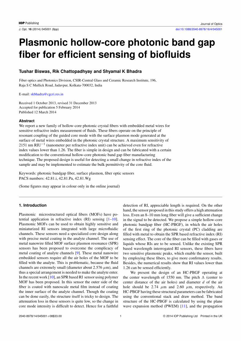
Figure 1. Schematic diagram of the photonic crystal lattice in (a)direct and (b) reciprocal space.
characteristics of the fiber are simulated through the finiteelement method (FEM) [12] using COMSOL multiphysicssoftware. The HC-PBGF can guide light in the core havingRI value less than air by Bragg’s reflection. If the core RIvalue is made larger than 1.2, the fiber can guide light bymodified total internal reflection (MTIR). Next, we studythe propagation characteristics of the same fiber when the airholes of the first ring of the PC cladding are filled with silverto obtain an SPR based sensing effect. In practice, the airholes in the first ring of the conventional PC cladding can befilled with metals by employing the Taylor wire [13] processin the well-known stack and draw method used for fabricatingHC-PBGFs. Jing Hou et al reported the fabrication techniqueof a solid core photonic crystal fiber (PCF) with metal wirein the first ring [14]. We study four types of plasmonicfiber structure having different metal wire combinations andcore sizes. SPR for low RI values can be achieved onlyby replacing all the air holes of the first ring of the PCcladding. Finally, the losses of the fundamental core modesin these specially designed fibers at wide spectral range arecalculated for different core-analytes. Then the variation of theabsorption loss of the fundamental mode for each core-analytewith wavelength is plotted to obtain the loss spectrum. Theloss spectrum shows that the absorption peak gets shifted asthe dielectric permittivity of the core-analyte changes. Thisproperty can be utilized to identify the changes in RI ofdifferent liquids and gases—particularly biofluids.
2. HC-PBGF design optimization
A PCF can guide light in the core either by MTIR or by Bragg’sreflection [15, 16]. Both type of guidance can be obtainedin an HC-PCF by changing the core filling material. In thissection, we optimize the structural parameters of an HC-PCFthat can guide light at the center wavelength of 1550 nm ina core medium having an RI value lower than 1.26, which isessential for the low RI sensor that we proposed to design.So we first design an HC-PBGF having operating wavelengthcenter around 1550 nm.
The operating wavelength band of the PBGF can bedetermined by calculating the out-of-plane band gap map ofa defect-less PC cladding, which is generally a periodic arrayof air holes in a silica host. The out-of-plane band gap map isthe variation of the forbidden wavelength band of the cladding
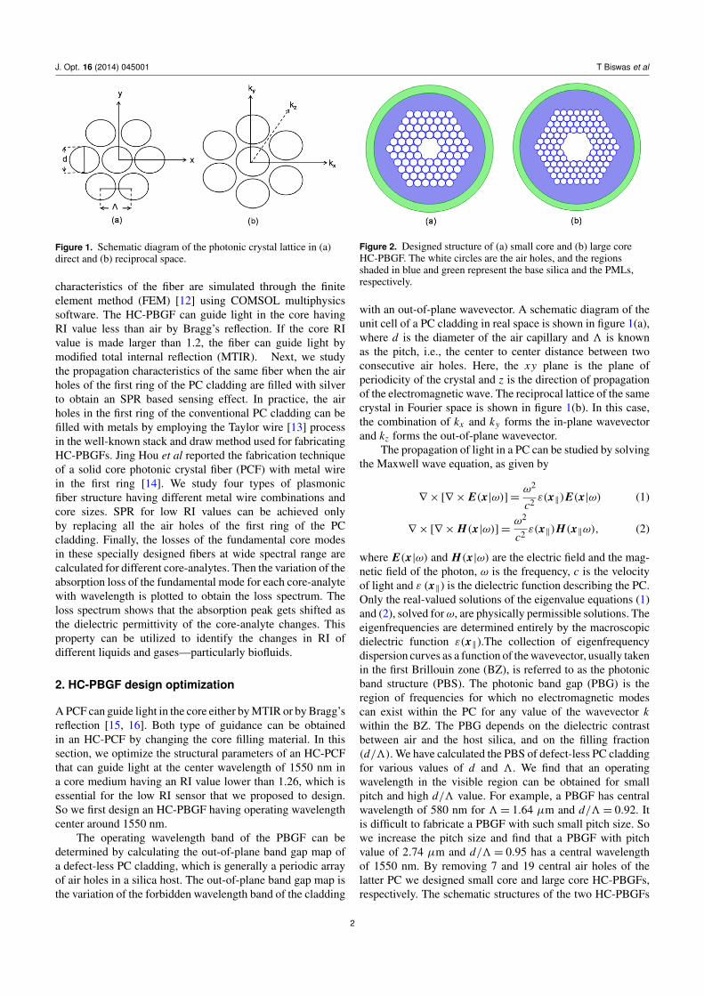
Figure 2. Designed structure of (a) small core and (b) large coreHC-PBGF. The white circles are the air holes, and the regionsshaded in blue and green represent the base silica and the PMLs,respectively.
with an out-of-plane wavevector. A schematic diagram of theunit cell of a PC cladding in real space is shown in figure 1(a),where d is the diameter of the air capillary and 3 is knownas the pitch, i.e., the center to center distance between twoconsecutive air holes. Here, the xy plane is the plane ofperiodicity of the crystal and z is the direction of propagationof the electromagnetic wave. The reciprocal lattice of the samecrystal in Fourier space is shown in figure 1(b). In this case,the combination of kx and ky forms the in-plane wavevectorand kz forms the out-of-plane wavevector.
The propagation of light in a PC can be studied by solvingthe Maxwell wave equation, as given by
∇ × [∇ × E(x|ω)]=ω2
c2 ε(x‖)E(x|ω) (1)
∇ × [∇ × H(x|ω)]=ω2
c2 ε(x‖)H(x‖ω), (2)
where E(x|ω) and H(x|ω) are the electric field and the mag-netic field of the photon, ω is the frequency, c is the velocityof light and ε (x‖) is the dielectric function describing the PC.Only the real-valued solutions of the eigenvalue equations (1)and (2), solved forω, are physically permissible solutions. Theeigenfrequencies are determined entirely by the macroscopicdielectric function ε(x‖).The collection of eigenfrequencydispersion curves as a function of the wavevector, usually takenin the first Brillouin zone (BZ), is referred to as the photonicband structure (PBS). The photonic band gap (PBG) is theregion of frequencies for which no electromagnetic modescan exist within the PC for any value of the wavevector kwithin the BZ. The PBG depends on the dielectric contrastbetween air and the host silica, and on the filling fraction(d/3). We have calculated the PBS of defect-less PC claddingfor various values of d and 3. We find that an operatingwavelength in the visible region can be obtained for smallpitch and high d/3 value. For example, a PBGF has centralwavelength of 580 nm for 3= 1.64 µm and d/3= 0.92. Itis difficult to fabricate a PBGF with such small pitch size. Sowe increase the pitch size and find that a PBGF with pitchvalue of 2.74 µm and d/3= 0.95 has a central wavelengthof 1550 nm. By removing 7 and 19 central air holes of thelatter PC we designed small core and large core HC-PBGFs,respectively. The schematic structures of the two HC-PBGFs
2
J. Opt. 16 (2014) 045001 T Biswas et al
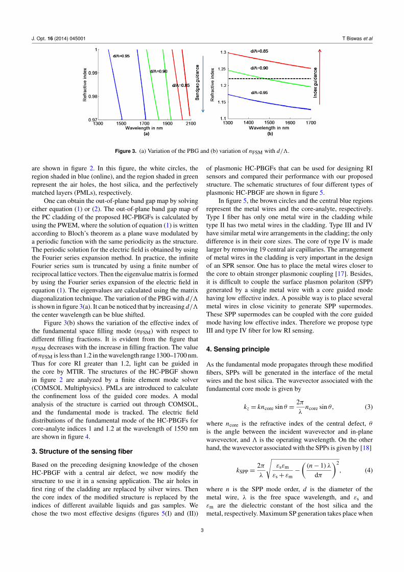
Figure 3. (a) Variation of the PBG and (b) variation of nFSM with d/3.
are shown in figure 2. In this figure, the white circles, theregion shaded in blue (online), and the region shaded in greenrepresent the air holes, the host silica, and the perfectivelymatched layers (PMLs), respectively.
One can obtain the out-of-plane band gap map by solvingeither equation (1) or (2). The out-of-plane band gap map ofthe PC cladding of the proposed HC-PBGFs is calculated byusing the PWEM, where the solution of equation (1) is writtenaccording to Bloch’s theorem as a plane wave modulated bya periodic function with the same periodicity as the structure.The periodic solution for the electric field is obtained by usingthe Fourier series expansion method. In practice, the infiniteFourier series sum is truncated by using a finite number ofreciprocal lattice vectors. Then the eigenvalue matrix is formedby using the Fourier series expansion of the electric field inequation (1). The eigenvalues are calculated using the matrixdiagonalization technique. The variation of the PBG with d/3is shown in figure 3(a). It can be noticed that by increasing d/3the center wavelength can be blue shifted.
Figure 3(b) shows the variation of the effective index ofthe fundamental space filling mode (nFSM) with respect todifferent filling fractions. It is evident from the figure thatnFSM decreases with the increase in filling fraction. The valueof nFSM is less than 1.2 in the wavelength range 1300–1700 nm.Thus for core RI greater than 1.2, light can be guided inthe core by MTIR. The structures of the HC-PBGF shownin figure 2 are analyzed by a finite element mode solver(COMSOL Multiphysics). PMLs are introduced to calculatethe confinement loss of the guided core modes. A modalanalysis of the structure is carried out through COMSOL,and the fundamental mode is tracked. The electric fielddistributions of the fundamental mode of the HC-PBGFs forcore-analyte indices 1 and 1.2 at the wavelength of 1550 nmare shown in figure 4.
3. Structure of the sensing fiber
Based on the preceding designing knowledge of the chosenHC-PBGF with a central air defect, we now modify thestructure to use it in a sensing application. The air holes infirst ring of the cladding are replaced by silver wires. Thenthe core index of the modified structure is replaced by theindices of different available liquids and gas samples. Wechose the two most effective designs (figures 5(I) and (II))
of plasmonic HC-PBGFs that can be used for designing RIsensors and compared their performance with our proposedstructure. The schematic structures of four different types ofplasmonic HC-PBGF are shown in figure 5.
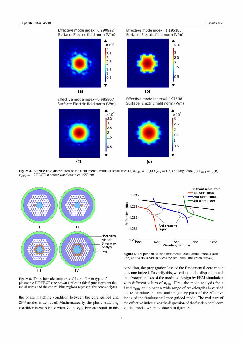
In figure 5, the brown circles and the central blue regionsrepresent the metal wires and the core-analyte, respectively.Type I fiber has only one metal wire in the cladding whiletype II has two metal wires in the cladding. Type III and IVhave similar metal wire arrangements in the cladding; the onlydifference is in their core sizes. The core of type IV is madelarger by removing 19 central air capillaries. The arrangementof metal wires in the cladding is very important in the designof an SPR sensor. One has to place the metal wires closer tothe core to obtain stronger plasmonic coupling [17]. Besides,it is difficult to couple the surface plasmon polariton (SPP)generated by a single metal wire with a core guided modehaving low effective index. A possible way is to place severalmetal wires in close vicinity to generate SPP supermodes.These SPP supermodes can be coupled with the core guidedmode having low effective index. Therefore we propose typeIII and type IV fiber for low RI sensing.
4. Sensing principle
As the fundamental mode propagates through these modifiedfibers, SPPs will be generated in the interface of the metalwires and the host silica. The wavevector associated with thefundamental core mode is given by
kz = kncore sin θ =2πλ
ncore sin θ, (3)
where ncore is the refractive index of the central defect, θis the angle between the incident wavevector and in-planewavevector, and 3 is the operating wavelength. On the otherhand, the wavevector associated with the SPPs is given by [18]
kSPP =2πλ
√εsεm
εs+ εm−
((n− 1) λ
dπ
)2
, (4)
where n is the SPP mode order, d is the diameter of themetal wire, λ is the free space wavelength, and εs andεm are the dielectric constant of the host silica and themetal, respectively. Maximum SP generation takes place when
3
J. Opt. 16 (2014) 045001 T Biswas et al
Figure 4. Electric field distribution of the fundamental mode of small core (a) ncore = 1, (b) ncore = 1.2, and large core (a) ncore = 1, (b)ncore = 1.2 PBGF at center wavelength of 1550 nm.
Figure 5. The schematic structures of four different types ofplasmonic HC-PBGF (the brown circles in this figure represent themetal wires and the central blue regions represent the core-analyte).
the phase matching condition between the core guided andSPP modes is achieved. Mathematically, the phase matchingcondition is established when kz and kSPP become equal. In this
Figure 6. Dispersion of the fundamental core guided mode (solidline) and various SPP modes (the red, blue, and green curves).
condition, the propagation loss of the fundamental core modegets maximized. To verify this, we calculate the dispersion andthe absorption loss of the modified design by FEM simulationwith different values of ncore. First, the mode analysis for afixed ncore value over a wide range of wavelengths is carriedout to calculate the real and imaginary parts of the effectiveindex of the fundamental core guided mode. The real part ofthe effective index gives the dispersion of the fundamental coreguided mode, which is shown in figure 6.
4
J. Opt. 16 (2014) 045001 T Biswas et al
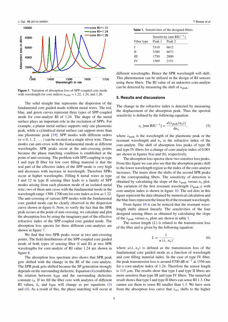
Figure 7. Variation of absorption loss of SPP-coupled core modewith wavelength for core indices ncore = 1.22, 1.24, and 1.26.
The solid straight line represents the dispersion of thefundamental core guided mode without metal wires. The red,blue, and green curves represent three types of SPP-coupledmode for core-analyte RI of 1.24. The shape of the metalsurface plays an important role in the excitation of SPPs. Forexample, a planar metal surface supports only one plasmonicpeak, while a cylindrical metal surface can support more thanone plasmonic peak [19]. SPP modes with different orders(n = 0, 1, 2 . . . , ) can be excited on a single silver wire. Thesemodes can anti-cross with the fundamental mode at differentwavelengths. SPR peaks occur at the anti-crossing pointsbecause the phase matching condition is established at thepoint of anti-crossing. The problem with SPP coupling in typeI and type II fiber for low core filling material is that thereal part of the effective index of the SPP mode is very highand decreases with increase in wavelength. Therefore SPRsoccur at higher wavelengths. Filling 6 metal wires in typeI and 12 in type II sensing fiber leads to a family of SPPmodes arising from each plasmon mode of an isolated metalwire; two of them anti-cross with the fundamental mode in thewavelength range 1300–1700 nm for core index as low as 1.22.The anti-crossing of various SPP modes with the fundamentalcore guided mode can be clearly observed in the dispersioncurve shown in figure 6. Now, to verify the fact that the SPRpeak occurs at the point of anti-crossing, we calculate and plotthe absorption loss by using the imaginary part of the effectiverefractive index of the SPP-coupled core guided mode. Theabsorption loss spectra for three different core-analytes areshown in figure 7.
We find that two SPR peaks occur at two anti-crossingpoints. The field distributions of the SPP-coupled core guidedmode of both types of sensing fiber (I and II) at two SPRwavelengths for core-analyte of RI value 1.24 are shown infigure 8.
The absorption loss spectrum also shows that SPR peakgets shifted with the change in the RI of the core-analyte.The SPR peak gets shifted because the SP generation stronglydepends on the surrounding dielectric. Equation (4) establishesthe relation between kSPP and the surrounding dielectricconstant εd. If we fill the fiber core with analytes of differentRI values, kz and kSPP will change as per equations (3)and (4). As a result of this, the phase matching will occur at
Table 1. Sensitivities of the designed fibers.
Sensitivity (nm RIU−1)Fiber type Peak 1 Peak 2
I 5310 6612II 5389 6673III 1750 2000IV 1569 2151
different wavelengths. Hence the SPR wavelength will shift.This phenomenon can be utilized in the design of RI sensorsusing these fibers. The RI value of an unknown core-analytecan be detected by measuring the shift of λpeak.
5. Results and discussions
The change in the refractive index is detected by measuringthe displacement of the absorption peak. Thus the spectralsensitivity is defined by the following equation:
sλ [nm RIU−1] =
d(λpeak(na))
dna, (5)
where λpeak is the wavelength of the plasmonic peak or theresonant wavelength and na is the refractive index of thecore-analyte. The shift of absorption loss peaks of type IIIand type IV fibers for a change of core-analyte index of 0.001are shown in figures 9(a) and (b), respectively.
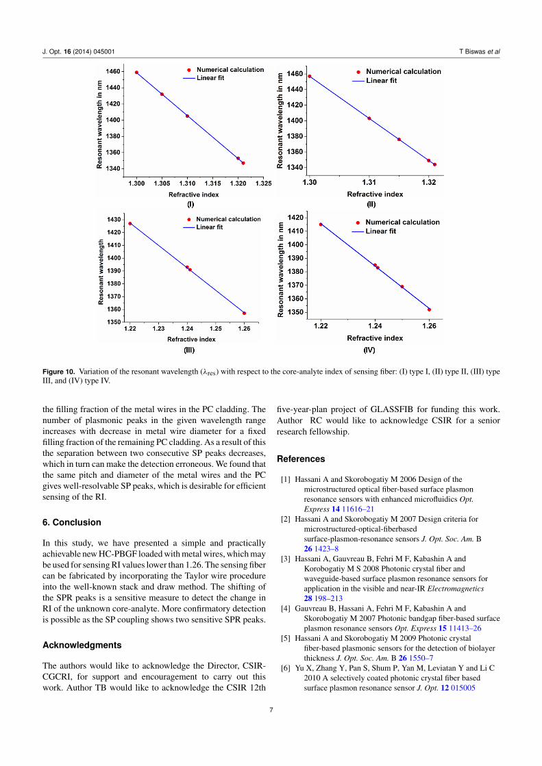
The absorption loss spectra show two sensitive loss peaks.From this figure we can also see that the absorption peaks shiftto the lower wavelength region as the index of the core-analyteincreases. The insets show the shifts of the second SPR peaksof the corresponding fibers. The sensitivity of detection isobtained by calculating the slope of the λpeak versus na plot.The variation of the first resonant wavelength (λpeak I) withcore-analyte index is shown in figure 10. The red dots in thisfigure represent the data obtained by numerical calculation andthe blue lines represent the linear fit of the resonant wavelength.
From figure 10 it can be noticed that the resonant wave-length shifts almost linearly. The sensitivities of the fourdesigned sensing fibers as obtained by calculating the slopeof the λpeak versus na plots are shown in table 1.
The sensor length (L) is related to the transmission lossof the fiber and is given by the following equation:
L =1
α (λ, na), (6)
where α(λ, na) is defined as the transmission loss of thefundamental core guided mode as a function of wavelengthand core filling material index. In the case of type IV fiber,the peak transmission loss is around 8700 dB m−1 at 1556 nmfor a core-analyte index of 1.24. Therefore the sensor lengthis 115 µm. The results show that type I and type II fibers aremore sensitive than type III and type IV fibers. The numericalresult shows that type I and type II fibers can sense RI 1.3. Onecannot use them to sense RI smaller than 1.3. We have seenfrom the absorption loss curve that λres shifts to the higher
5
J. Opt. 16 (2014) 045001 T Biswas et al
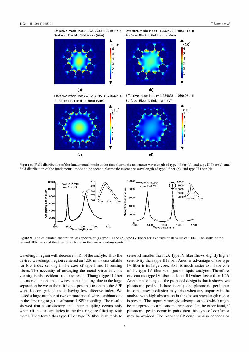
Figure 8. Field distribution of the fundamental mode at the first plasmonic resonance wavelength of type I fiber (a), and type II fiber (c), andfield distribution of the fundamental mode at the second plasmonic resonance wavelength of type I fiber (b), and type II fiber (d).
Figure 9. The calculated absorption loss spectra of (a) type III and (b) type IV fibers for a change of RI value of 0.001. The shifts of thesecond SPR peaks of the fibers are shown in the corresponding insets.
wavelength region with decrease in RI of the analyte. Thus thedesired wavelength region centered on 1550 nm is unavailablefor low index sensing in the case of type I and II sensingfibers. The necessity of arranging the metal wires in closevicinity is also evident from the result. Though type II fiberhas more than one metal wires in the cladding, due to the largeseparation between them it is not possible to couple the SPPwith the core guided mode having low effective index. Wetested a large number of two or more metal wire combinationsin the first ring to get a substantial SPP coupling. The resultsshowed that a satisfactory and linear coupling occurs onlywhen all the air capillaries in the first ring are filled up withmetal. Therefore either type III or type IV fiber is suitable to
sense RI smaller than 1.3. Type IV fiber shows slightly highersensitivity than type III fiber. Another advantage of the typeIV fiber is its large core. So it is much easier to fill the coreof the type IV fiber with gas or liquid analytes. Therefore,one can use type IV fiber to detect RI values lower than 1.26.Another advantage of the proposed design is that it shows twoplasmonic peaks. If there is only one plasmonic peak thenin some cases confusion may arise when any impurity in theanalyte with high absorption in the chosen wavelength regionis present. The impurity may give absorption peak which mightbe interpreted as a plasmonic response. On the other hand, ifplasmonic peaks occur in pairs then this type of confusionmay be avoided. The resonant SP coupling also depends on
6
J. Opt. 16 (2014) 045001 T Biswas et al
Figure 10. Variation of the resonant wavelength (λres) with respect to the core-analyte index of sensing fiber: (I) type I, (II) type II, (III) typeIII, and (IV) type IV.
the filling fraction of the metal wires in the PC cladding. Thenumber of plasmonic peaks in the given wavelength rangeincreases with decrease in metal wire diameter for a fixedfilling fraction of the remaining PC cladding. As a result of thisthe separation between two consecutive SP peaks decreases,which in turn can make the detection erroneous. We found thatthe same pitch and diameter of the metal wires and the PCgives well-resolvable SP peaks, which is desirable for efficientsensing of the RI.
6. Conclusion
In this study, we have presented a simple and practicallyachievable new HC-PBGF loaded with metal wires, which maybe used for sensing RI values lower than 1.26. The sensing fibercan be fabricated by incorporating the Taylor wire procedureinto the well-known stack and draw method. The shifting ofthe SPR peaks is a sensitive measure to detect the change inRI of the unknown core-analyte. More confirmatory detectionis possible as the SP coupling shows two sensitive SPR peaks.
Acknowledgments
The authors would like to acknowledge the Director, CSIR-CGCRI, for support and encouragement to carry out thiswork. Author TB would like to acknowledge the CSIR 12th
five-year-plan project of GLASSFIB for funding this work.Author RC would like to acknowledge CSIR for a seniorresearch fellowship.
References
[1] Hassani A and Skorobogatiy M 2006 Design of themicrostructured optical fiber-based surface plasmonresonance sensors with enhanced microfluidics Opt.Express 14 11616–21
[2] Hassani A and Skorobogatiy M 2007 Design criteria formicrostructured-optical-fiberbasedsurface-plasmon-resonance sensors J. Opt. Soc. Am. B26 1423–8
[3] Hassani A, Gauvreau B, Fehri M F, Kabashin A andKorobogatiy M S 2008 Photonic crystal fiber andwaveguide-based surface plasmon resonance sensors forapplication in the visible and near-IR Electromagnetics28 198–213
[4] Gauvreau B, Hassani A, Fehri M F, Kabashin A andSkorobogatiy M 2007 Photonic bandgap fiber-based surfaceplasmon resonance sensors Opt. Express 15 11413–26
[5] Hassani A and Skorobogatiy M 2009 Photonic crystalfiber-based plasmonic sensors for the detection of biolayerthickness J. Opt. Soc. Am. B 26 1550–7
[6] Yu X, Zhang Y, Pan S, Shum P, Yan M, Leviatan Y and Li C2010 A selectively coated photonic crystal fiber basedsurface plasmon resonance sensor J. Opt. 12 015005
7

J. Opt. 16 (2014) 045001 T Biswas et al
[7] Pei-pei Z, Jian-quan Y, Hai-xia C and Ying L 2013 A surfaceplasmon resonance sensor based on a multicore photoniccrystal fiber Opt. Lett. 9 0342
[8] Shuai B, Xia L, Zhang Y and Liu D 2012 A multi-core holeyfiber based plasmonic sensor with large detection range andhigh linearity Opt. Express 20 5974–86
[9] Fu X, Lu Y, Huang X, Hao C, Wu B and Yao J 2011 Surfaceplasmon resonance sensor based on photonic crystal fiberfilled with silver nanowires Opt. Appl. 41 941–51
[10] Lu Y, Hao C J, Wu B Q, Musideke M, Duan L C, Wen W Qand Yao J Q 2013 Surface plasmon resonance sensor basedon polymer photonic crystal fibers with metal nanolayersSensors 13 956–65
[11] Maradudin A 1994 Out of plane propagation ofelectromagnetic waves in a two-dimensional dielectricmedium J. Mod. Opt. 41 275–84
[12] Saitoh K and Koshiba M 2002 Full-vectorialimaginary-distance beam propagation method based onfinite element scheme: application to photonic crystal fibersIEEE J. Quantum Electron. 38 927–33
[13] Taylor G F 1924 A method of drawing metallic filaments and adiscussion of their properties and uses Phys. Rev. 23 655–60
[14] Hou J, Bird D, George A, Maier S, Kuhlmey B T andKnight J C 2008 Metallic mode confinement inmicrostructured fibres Opt. Express 16 5983–90
[15] Russell P 2003 Photonic crystal fibers Science 299 358–62[16] Benabid F 2006 Hollow-core photonic bandgap fibre: new
lightguidance for new science and technology Phil. Trans.R. Soc. A 364 3439–62
[17] Schmidt M A, Sempere L N P, Tyagi H K, Poulton C G andRussell P S J 2008 Waveguiding and plasmon resonances intwo-dimensional photonic lattices of gold and silvernanowires Phys. Rev. B 77 033417
[18] Nagasaki A, Saitoh K and Koshiba M 2011 Polarizationcharacteristics of photonic crystal fibers selectively filledwith metal wires into cladding air holes Opt. Express19 3799–808
[19] Schmidt M A and Russell P S J 2008 Long-range spirallingsurface plasmon modes on metallic nanowires Opt. Express16 13617–23
8