
Advantages of use of Tubular/Hollow Sections over ...
12
https://doi.org/10.36375/prepare_u.iei.a224 Advantages of use of Tubular/Hollow Sections over Conventional Open Sections in Hydro-Carbon Industry Structures Amresh Kumar, Papia Mandal and Anurag Sinha Structural Division Engineers India Limited Gurugram Complex, Gurugram Haryana-122001 [email protected] ABSTRACT - Tubular/ Hollow sections are gaining popularity in recent times, due to its higher strength-to-weight ratio than conventional open sections as well as for the reason that, hollow sections create lightweight and visually attractive structures. Due to their cross sectional configuration, such sections have inherent advantage in torsional buckling resistance capacity and axial load carrying capacity. Thus, its usage is continuously being increased in the hydrocarbon sector as well. Tubular/ hollow sections have been successfully used in many components of the structures, in which traditionally MC boxed sections were used due to its reduced requirement of welding, as compared to MC boxed sections. Therefore, it is imperative to analyze hollow sections and open rolled sections considering design strength and steel quantity requirements, to enable the designers to select the appropriate section, fitting the functional requirements and economics of the project. This study presents the comparative benefits of using hollow sections instead of open sections by presenting a theoretical comparison as well as a case study of three categories of industrial structures in hydrocarbon industry. Further it presents a detailed account of limitations in use of hollow sections on large scale in industrial structures of hydro carbon sector. Keywords –Hollow sections; Lateral torsional strength; Yield strength; IS 4923; Industrial structures; Weight-to-strength ratio. INTRODUCTION The excellent properties of the tubular shape have been recognized for a long time; there are examples of bridges etc. made of tubular sections as long back as last century. However, in the absence of readymade hollow sections, large tubular sections have been prepared by welding open sections such as channels or angles. Hollow sections are gaining popularity in recent times, due to its higher strength-to-weight ratio than conventional sections as well as for the reason that, hollow sections create lightweight and visually attractive structures. Many examples in nature show the excellent properties of the tubular shape with regard to loading in compression, torsion and bending in all directions. For examples, tall slender plants such as bamboo tree or small weeds etc. Thus, use of hollow sections is in a way a nature inspired choice. Due to geometric configuration, such sections have inherent advantage in torsional buckling resistance capacity and axial load carrying capacity. Even though predominant use of hollow section has been observed in infrastructure projects only, yet its usage is continuously increasing in the hydrocarbon sector as well. In the recent projects, tubular/ hollow sections have been successfully used in various structures, such as pipe supports, operating platforms and trusses in the shed or other structures, small pipe racks, or structural components such as vertical and plan bracings, longitudinal/ tie members of pipe racks and other structures etc. Many components of the structures, in which traditionally MC boxed sections were used, have been grossly taken over by hollow sections, due to its reduced requirement of welding, as compared to boxed sections fabricated from channels/angles. BENEFITS OF USING HOLLOW SECTION OVER CONVENTIONAL OPEN SECTIONS- Following has been the main reasons for increasing use of hollows sections- I. Aesthetic Reasons- Due to aesthetic reasons, hollow sections have been the first choice for buildings where structural members are exposed such as in airports, malls, exhibition centers and other amenity buildings. In structural members, as the length of member increases, their axial capacity
-
Upload
khangminh22 -
Category
Documents
-
view
5 -
download
0
Transcript of Advantages of use of Tubular/Hollow Sections over ...
https://doi.org/10.36375/prepare_u.iei.a224
Advantages of use of Tubular/Hollow Sections overConventional Open Sections in Hydro-Carbon
Industry StructuresAmresh Kumar, Papia Mandal and Anurag Sinha
Structural DivisionEngineers India Limited
Gurugram Complex, Gurugram [email protected]
ABSTRACT - Tubular/ Hollow sections are gainingpopularity in recent times, due to its higherstrength-to-weight ratio than conventional opensections as well as for the reason that, hollowsections create lightweight and visuallyattractive structures. Due to their cross sectionalconfiguration, such sections have inherentadvantage in torsional buckling resistancecapacity and axial load carrying capacity. Thus,its usage is continuously being increased in thehydrocarbon sector as well. Tubular/ hollowsections have been successfully used in manycomponents of the structures, in whichtraditionally MC boxed sections were used due toits reduced requirement of welding, as comparedto MC boxed sections. Therefore, it is imperativeto analyze hollow sections and open rolledsections considering design strength and steelquantity requirements, to enable the designersto select the appropriate section, fitting thefunctional requirements and economics of theproject. This study presents the comparativebenefits of using hollow sections instead of opensections by presenting a theoretical comparisonas well as a case study of three categories ofindustrial structures in hydrocarbon industry.Further it presents a detailed account oflimitations in use of hollow sections on largescale in industrial structures of hydro carbonsector.
Keywords –Hollow sections; Lateral torsionalstrength; Yield strength; IS 4923; Industrialstructures; Weight-to-strength ratio.
INTRODUCTION
The excellent properties of the tubular shapehave been recognized for a long time; there areexamples of bridges etc. made of tubular sectionsas long back as last century. However, in theabsence of readymade hollow sections, largetubular sections have been prepared by weldingopen sections such as channels or angles.
Hollow sections are gaining popularity in recenttimes, due to its higher strength-to-weight ratio
than conventional sections as well as for thereason that, hollow sections create lightweightand visually attractive structures. Many examplesin nature show the excellent properties of thetubular shape with regard to loading incompression, torsion and bending in all directions.For examples, tall slender plants such as bambootree or small weeds etc. Thus, use of hollowsections is in a way a nature inspired choice. Dueto geometric configuration, such sections haveinherent advantage in torsional bucklingresistance capacity and axial load carryingcapacity.
Even though predominant use of hollow sectionhas been observed in infrastructure projects only,yet its usage is continuously increasing in thehydrocarbon sector as well. In the recent projects,tubular/ hollow sections have been successfullyused in various structures, such as pipe supports,operating platforms and trusses in the shed orother structures, small pipe racks, or structuralcomponents such as vertical and plan bracings,longitudinal/ tie members of pipe racks and otherstructures etc. Many components of thestructures, in which traditionally MC boxedsections were used, have been grossly taken overby hollow sections, due to its reducedrequirement of welding, as compared to boxedsections fabricated from channels/angles.
BENEFITS OF USING HOLLOW SECTION OVERCONVENTIONAL OPEN SECTIONS-
Following has been the main reasons forincreasing use of hollows sections-
I. Aesthetic Reasons-
Due to aesthetic reasons, hollow sections havebeen the first choice for buildings wherestructural members are exposed such as inairports, malls, exhibition centers and otheramenity buildings. In structural members, as thelength of member increases, their axial capacity

https://doi.org/10.36375/prepare_u.iei.a224
decreases. The decrease in capacity is very lessfor hollow sections as compared to open sections.This makes hollow sections preferable choice formembers of large span trusses. Thus, hollowsections are valuable in providing long spanstructures having a feel of openness andaesthetics which have always been an architect’sdelight.
II. Design benefits-
Hollow sections are made of similar steel as usedfor open steel sections, thus in principle there isno difference as long as mechanical and chemicalproperties are concerned. However, distribution
of mass on cross sectional plane plays animportant role in determining the strength-to-weight ratios of structural section. The moremass is placed away from the centroid of cross-sectional area, the more strength section hasagainst Euler buckling and lateral-torsionalbuckling, which is required for a section to beloaded to its full compressive or bending strength.In this aspect, hollow sections (by having totalmass placed away from centroid) have a majoradvantage over conventional I-sections, channelsand angles, which have most of the mass placednear centroid or along axes passing thoughcentroid (Fig. 1).
Fig. 1 Centroid (intersection of x- and y-axis) and massdistribution around centroid for different types of
structural steel sections
Further, Table-I & II below show a comparison ofunit weights of members required for a givenBending moment and Axial compressioncapacity. The percentage reduction in materialis calculated and highlighted wherever there is
a saving. Effective lengths of the members havebeen considered as 0m (fully restraint), 4m &8m for bending as well as for axial compressionto incorporate the effect of slenderness onmember capacity.
TABLE-I: COMPARISON OF BENDING CAPACITIES
TABLE- I(A): OPEN AND HOLLOW SECTION REQUIRED FOR GIVEN BENDING CAPACITIES (LEFF=0M)L_EFF=0M
BENDINGCAPACITY
I-SECTION UNIT WEIGHT HOLLOW SECTION UNITWEIGHT
DIFFERENCE IN
WEIGHT(IN KN-M) ( IN KG/M) ( IN KG/M)50 MB200 24.2 RHS200X100X6 26.4 9.09%100 MB300 44.2 RHS280X100X6 33.94 -23.21%150 MB300 44.2 SHS250X250X6 45.24 2.35%200 MB300 44.2 RHS300X150X8 53.22 20.41%250 MB400 61.5 RHS350X250X6 54.66 -11.12%300 MB400 61.5 RHS400X300X6 64.08 4.20%350 MB400 61.5 RHS400X300X6 64.08 4.20%400 NPB 450X190X67.15 67.15 RHS500X200X6 64.08 -4.57%450 NPB 450X190X67.15 67.15 RHS400X300X8 84.62 26.02%500 NPB 500X200X79.36 79.36 SHS400X400X8 97.18 22.45%550 NPB 500X200X79.36 79.36 SHS400X400X8 97.18 22.45%

https://doi.org/10.36375/prepare_u.iei.a224
600 NPB 500X200X79.36 79.36 RHS500X300X8 97.18 22.45%650 MB500 86.9 RHS500X300X8 97.18 11.83%700 NPB 500X200X107.31 107.31 RHS500X300X10 120.43 12.23%750 NPB 500X200X107.31 107.31 RHS500X300X10 120.43 12.23%800 NPB 500X200X107.31 107.31 RHS500X300X10 120.43 12.23%850 NPB 600X220X107.56 107.56 RHS500X200X14 143.74 33.64%900 NPB 600X220X107.56 107.56 RHS500X300X14 165.72 54.07%950 NPB 600X220X107.56 107.56 HOLLOW SECTIONS FOR THESE CAPACITIES
ARE NOT AVAILABLE-
1000 NPB 600X220X122.45 122.45 -
TABLE-I(B): OPEN AND HOLLOW SECTION REQUIRED FOR GIVEN BENDING CAPACITIES (LEFF=4M)
L_EFF=4MBENDINGCAPACITY
I-SECTION UNIT WEIGHT HOLLOW SECTION UNIT WEIGHT DIFFERENCEIN WEIGHT
(IN KN-M) ( IN KG/M) ( IN KG/M)50 MB300 44.2 RHS250X100X6 31.11 -29.62%100 WPB 200X200X50.92 50.92 SHS220X220X6 39.59 -22.25%150 MB400 61.5 SHS250X250X6 45.24 -26.44%200 NPB 450X190X67.15 67.15 RHS350X250X6 54.66 -18.60%250 NPB 450X190X67.15 67.15 RHS400X200X6 54.66 -18.60%300 NPB 500X200X79.36 79.36 RHS400X300X6 64.08 -19.25%350 NPB 500X200X79.36 79.36 RHS500X200X6 64.08 -19.25%400 NPB 500X200X90.68 90.68 SHS350X350X8 84.62 -6.68%450 NPB 500X200X107.31 107.31 RHS400X300X8 84.62 -21.14%500 NPB 500X200X107.31 107.31 SHS400X400X8 97.18 -9.44%550 NPB 600X220X107.56 107.56 SHS400X400X8 97.18 -9.65%600 NPB 600X220X107.56 107.56 RHS500X300X8 97.18 -9.65%650 NPB 600X220X107.56 107.56 RHS500X300X10 120.43 11.97%700 NPB 600X220X122.45 122.45 RHS500X300X10 120.43 -1.65%750 WPB 600X300X128.79 128.79 RHS500X300X10 120.43 -6.49%800 WPB 600X300X128.79 128.79 SHS400X400X12 143.29 11.26%850 WPB 700X300X149.89 149.89 RHS500X300X14 165.72 10.56%900 WPB 700X300X149.89 149.89 HOLLOW SECTIONS FOR THESE CAPACITIES
ARE NOT AVAILABLE-
950 WPB 700X300X149.89 149.89 -1000 WPB 700X300X149.89 149.89 -
TABLE-I(C): OPEN AND HOLLOW SECTION REQUIRED FOR GIVEN BENDING CAPACITIES (LEFF=8M)
L_EFF=8MBENDINGCAPACITY
I-SECTION UNITWEIGHT
HOLLOW SECTION UNIT WEIGHT DIFFERENCEIN WEIGHT
(IN KN-M) ( IN KG/M) ( IN KG/M)50 WPB 200X200X50.92 50.92 SHS220X220X6 39.59 -22.25%100 NPB 450X190X67.15 67.15 SHS250X250X6 45.24 -32.63%150 WPB 250X250X73 73.14 RHS350X250X6 54.66 -25.27%200 WPB 300X300X100.84 100.84 RHS400X300X6 64.08 -36.45%250 WPB 300X300X100.84 100.84 RHS400X300X6 64.08 -36.45%300 WPB 300X300X117.03 117.03 SHS350X350X8 84.62 -27.69%350 WPB 300X300X117.03 117.03 SHS350X350X8 84.62 -27.69%400 WPB 300X300X117.03 117.03 SHS400X400X8 97.18 -16.96%450 WPB 360X370X136.65 136.65 SHS400X400X8 97.18 -28.88%500 WPB 360X370X136.65 136.65 SHS400X400X8 97.18 -28.88%550 WPB 700X300X149.89 149.89 RHS500X300X10 120.43 -19.65%600 WPB 700X300X149.89 149.89 RHS500X300X10 120.43 -19.65%650 WPB 600X300X177.77 177.77 RHS500X300X10 120.43 -32.26%
https://doi.org/10.36375/prepare_u.iei.a224
700 WPB 600X300X177.77 177.77 SHS400X400X12 143.29 -19.40%750 WPB 600X300X177.77 177.77 HOLLOW SECTIONS FOR THESE CAPACITIES
ARE NOT AVAILABLE-
800 WPB 600X300X177.77 177.77 -850 WPB 600X300X177.77 177.77 -900 WPB 600X300X177.77 177.77 -950 WPB 700X300X204.48 204.48 -1000 WPB 700X300X204.48 204.48 -
From these tables, following observations areclear regarding the bending capacities of opensections vis-à-vis hollow sections-i. At smaller effective lengths, especially in
case of fully laterally supported beams,benefits of use of hollow sections arethere only for a very small number ofsections. Maximum bending strength thatcan be achieved by using hollow sections
is only 900KN-m, which is quite lesserthan that of parallel flange I-sections.
ii. As the effective length increases, bendingcapacity of I-sections decrease whereascapacity of hollow sections doesn’t reducemuch. Due to this, for larger effectivelengths such as 6m and 8m, for anyrequired bending capacity there is a moreeconomical hollow section available thanI-sections.
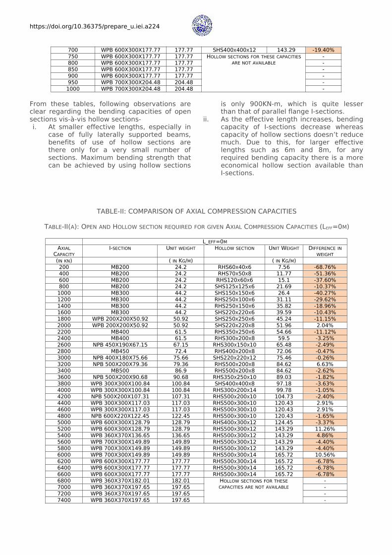
TABLE-II: COMPARISON OF AXIAL COMPRESSION CAPACITIES
TABLE-II(A): OPEN AND HOLLOW SECTION REQUIRED FOR GIVEN AXIAL COMPRESSION CAPACITIES (LEFF=0M)
L_EFF=0MAXIALCAPACITY
I-SECTION UNIT WEIGHT HOLLOW SECTION UNIT WEIGHT DIFFERENCE INWEIGHT
(IN KN) ( IN KG/M) ( IN KG/M)200 MB200 24.2 RHS60X40X6 7.56 -68.76%400 MB200 24.2 RHS70X50X8 11.77 -51.36%600 MB200 24.2 RHS120X60X6 15.1 -37.60%800 MB200 24.2 SHS125X125X6 21.69 -10.37%1000 MB300 44.2 SHS150X150X6 26.4 -40.27%1200 MB300 44.2 RHS250X100X6 31.11 -29.62%1400 MB300 44.2 RHS250X150X6 35.82 -18.96%1600 MB300 44.2 SHS220X220X6 39.59 -10.43%1800 WPB 200X200X50.92 50.92 SHS250X250X6 45.24 -11.15%2000 WPB 200X200X50.92 50.92 SHS220X220X8 51.96 2.04%2200 MB400 61.5 RHS350X250X6 54.66 -11.12%2400 MB400 61.5 RHS300X200X8 59.5 -3.25%2600 NPB 450X190X67.15 67.15 RHS300X150X10 65.48 -2.49%2800 MB450 72.4 RHS400X200X8 72.06 -0.47%3000 NPB 400X180X75.66 75.66 SHS220X220X12 75.46 -0.26%3200 NPB 500X200X79.36 79.36 RHS500X200X8 84.62 6.63%3400 MB500 86.9 RHS500X200X8 84.62 -2.62%3600 NPB 500X200X90.68 90.68 RHS350X250X10 89.03 -1.82%3800 WPB 300X300X100.84 100.84 SHS400X400X8 97.18 -3.63%4000 WPB 300X300X100.84 100.84 RHS300X200X14 99.78 -1.05%4200 NPB 500X200X107.31 107.31 RHS500X200X10 104.73 -2.40%4400 WPB 300X300X117.03 117.03 RHS500X300X10 120.43 2.91%4600 WPB 300X300X117.03 117.03 RHS500X300X10 120.43 2.91%4800 NPB 600X220X122.45 122.45 RHS500X300X10 120.43 -1.65%5000 WPB 600X300X128.79 128.79 RHS400X300X12 124.45 -3.37%5200 WPB 600X300X128.79 128.79 RHS500X300X12 143.29 11.26%5400 WPB 360X370X136.65 136.65 RHS500X300X12 143.29 4.86%5600 WPB 700X300X149.89 149.89 RHS500X300X12 143.29 -4.40%5800 WPB 700X300X149.89 149.89 RHS500X300X12 143.29 -4.40%6000 WPB 700X300X149.89 149.89 RHS500X300X14 165.72 10.56%6200 WPB 600X300X177.77 177.77 RHS500X300X14 165.72 -6.78%6400 WPB 600X300X177.77 177.77 RHS500X300X14 165.72 -6.78%6600 WPB 600X300X177.77 177.77 RHS500X300X14 165.72 -6.78%6800 WPB 360X370X182.01 182.01 HOLLOW SECTIONS FOR THESE
CAPACITIES ARE NOT AVAILABLE-
7000 WPB 360X370X197.65 197.65 -7200 WPB 360X370X197.65 197.65 -7400 WPB 360X370X197.65 197.65 -
https://doi.org/10.36375/prepare_u.iei.a224
7600 WPB 700X300X204.48 204.48 -7800 WPB 700X300X204.48 204.48 -8000 WPB 600X300X211.92 211.92 -
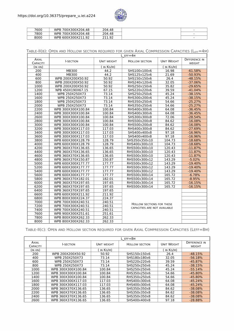
TABLE-II(B): OPEN AND HOLLOW SECTION REQUIRED FOR GIVEN AXIAL COMPRESSION CAPACITIES (LEFF=4M)L_EFF=4M
AXIALCAPACITY I-SECTION UNIT WEIGHT HOLLOW SECTION UNIT WEIGHT DIFFERENCE IN
WEIGHT(IN KN) ( IN KG/M) ( IN KG/M)200 MB300 44.2 SHS100X100X6 16.98 -61.58%400 MB300 44.2 SHS125X125X6 21.69 -50.93%600 WPB 200X200X50.92 50.92 SHS150X150X6 26.4 -48.15%800 WPB 200X200X50.92 50.92 RHS240X120X6 32.05 -37.06%1000 WPB 200X200X50.92 50.92 RHS250X150X6 35.82 -29.65%1200 NPB 450X190X67.15 67.15 SHS220X220X6 39.59 -41.04%1400 WPB 250X250X73 73.14 SHS250X250X6 45.24 -38.15%1600 WPB 250X250X73 73.14 RHS300X200X6 45.24 -38.15%1800 WPB 250X250X73 73.14 RHS350X250X6 54.66 -25.27%2000 WPB 250X250X73 73.14 RHS350X250X6 54.66 -25.27%2200 WPB 300X300X100.84 100.84 RHS400X300X6 64.08 -36.45%2400 WPB 300X300X100.84 100.84 RHS400X300X6 64.08 -36.45%2600 WPB 300X300X100.84 100.84 SHS300X300X8 72.06 -28.54%2800 WPB 300X300X100.84 100.84 RHS500X200X8 84.62 -16.08%3000 WPB 300X300X100.84 100.84 RHS500X200X8 84.62 -16.08%3200 WPB 300X300X117.03 117.03 RHS400X300X8 84.62 -27.69%3400 WPB 300X300X117.03 117.03 SHS400X400X8 97.18 -16.96%3600 WPB 300X300X117.03 117.03 SHS400X400X8 97.18 -16.96%3800 WPB 600X300X128.79 128.79 SHS350X350X10 104.73 -18.68%4000 WPB 600X300X128.79 128.79 RHS400X300X10 104.73 -18.68%4200 WPB 360X370X136.65 136.65 RHS500X300X10 120.43 -11.87%4400 WPB 360X370X136.65 136.65 RHS500X300X10 120.43 -11.87%4600 WPB 360X370X136.65 136.65 RHS500X300X10 120.43 -11.87%4800 WPB 360X370X150.87 150.87 RHS500X300X12 143.29 -5.02%5000 WPB 600X300X177.77 177.77 RHS500X300X12 143.29 -19.40%5200 WPB 600X300X177.77 177.77 RHS500X300X12 143.29 -19.40%5400 WPB 600X300X177.77 177.77 RHS500X300X12 143.29 -19.40%5600 WPB 600X300X177.77 177.77 RHS500X300X14 165.72 -6.78%5800 WPB 360X370X182.01 182.01 RHS500X300X14 165.72 -8.95%6000 WPB 360X370X197.65 197.65 RHS500X300X14 165.72 -16.15%6200 WPB 360X370X197.65 197.65 RHS500X300X14 165.72 -16.15%6400 WPB 360X370X197.65 197.65
HOLLOW SECTIONS FOR THESECAPACITIES ARE NOT AVAILABLE
6600 WPB 600X300X211.92 211.926800 WPB 800X300X224.37 224.377000 WPB 700X300X240.51 240.517200 WPB 700X300X240.51 240.517400 WPB 700X300X240.51 240.517600 WPB 900X300X251.61 251.617800 WPB 800X300X262.33 262.338000 WPB 800X300X262.33 262.33
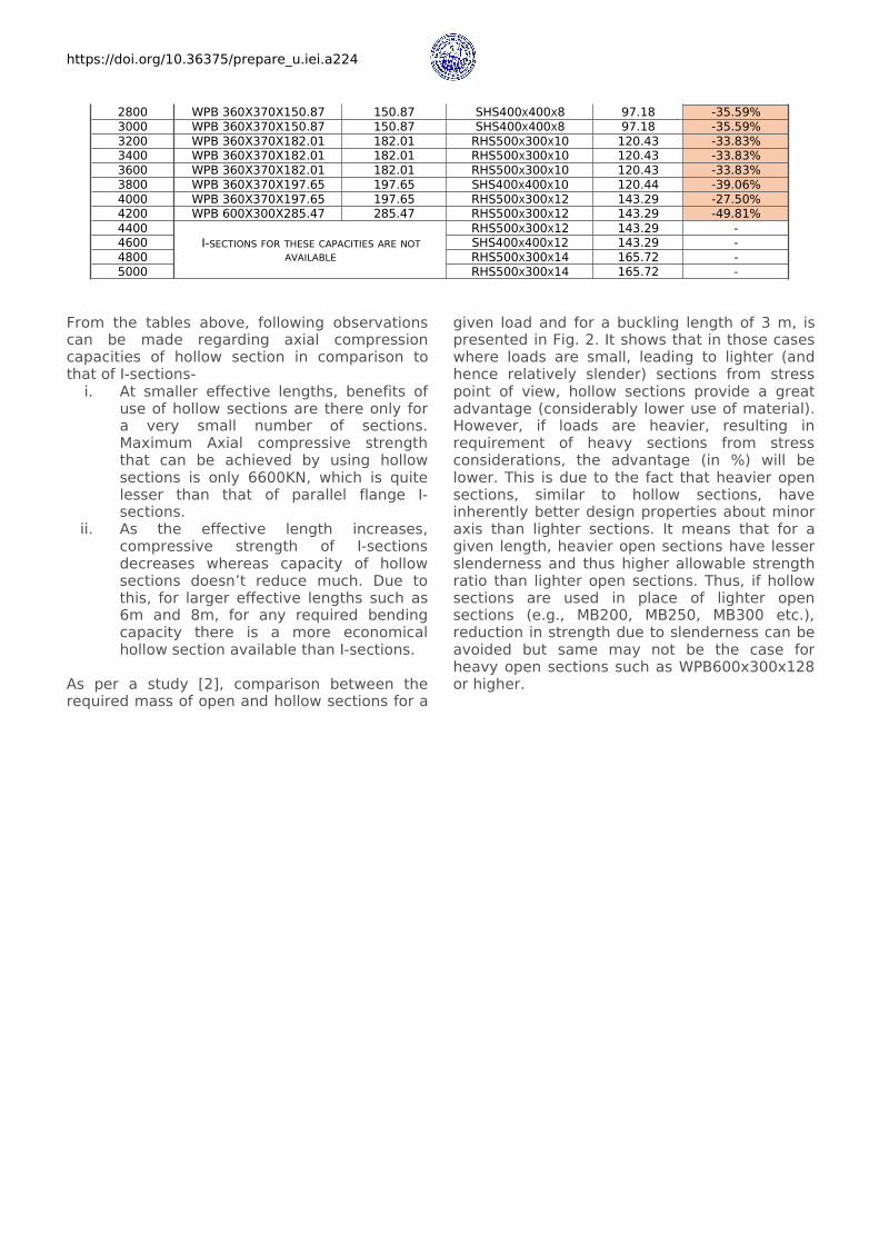
TABLE-II(C): OPEN AND HOLLOW SECTION REQUIRED FOR GIVEN AXIAL COMPRESSION CAPACITIES (LEFF=8M)
L_EFF=8MAXIALCAPACITY I-SECTION UNIT WEIGHT HOLLOW SECTION UNIT WEIGHT DIFFERENCE IN
WEIGHT(IN KN) ( IN KG/M) ( IN KG/M)200 WPB 200X200X50.92 50.92 SHS150X150X6 26.4 -48.15%400 WPB 250X250X73 73.14 SHS180X180X6 32.05 -56.18%600 WPB 250X250X73 73.14 SHS220X220X6 39.59 -45.87%800 WPB 250X250X73 73.14 SHS250X250X6 45.24 -38.15%1000 WPB 300X300X100.84 100.84 SHS250X250X6 45.24 -55.14%1200 WPB 300X300X100.84 100.84 RHS350X250X6 54.66 -45.80%1400 WPB 300X300X100.84 100.84 RHS350X250X6 54.66 -45.80%1600 WPB 300X300X117.03 117.03 RHS400X300X6 64.08 -45.24%1800 WPB 300X300X117.03 117.03 RHS400X300X6 64.08 -45.24%2000 WPB 360X370X136.65 136.65 SHS350X350X8 84.62 -38.08%2200 WPB 360X370X136.65 136.65 SHS350X350X8 84.62 -38.08%2400 WPB 360X370X136.65 136.65 SHS350X350X8 84.62 -38.08%2600 WPB 360X370X136.65 136.65 SHS400X400X8 97.18 -28.88%
https://doi.org/10.36375/prepare_u.iei.a224
2800 WPB 360X370X150.87 150.87 SHS400X400X8 97.18 -35.59%3000 WPB 360X370X150.87 150.87 SHS400X400X8 97.18 -35.59%3200 WPB 360X370X182.01 182.01 RHS500X300X10 120.43 -33.83%3400 WPB 360X370X182.01 182.01 RHS500X300X10 120.43 -33.83%3600 WPB 360X370X182.01 182.01 RHS500X300X10 120.43 -33.83%3800 WPB 360X370X197.65 197.65 SHS400X400X10 120.44 -39.06%4000 WPB 360X370X197.65 197.65 RHS500X300X12 143.29 -27.50%4200 WPB 600X300X285.47 285.47 RHS500X300X12 143.29 -49.81%4400
I-SECTIONS FOR THESE CAPACITIES ARE NOTAVAILABLE
RHS500X300X12 143.29 -4600 SHS400X400X12 143.29 -4800 RHS500X300X14 165.72 -5000 RHS500X300X14 165.72 -
From the tables above, following observationscan be made regarding axial compressioncapacities of hollow section in comparison tothat of I-sections-i. At smaller effective lengths, benefits of
use of hollow sections are there only fora very small number of sections.Maximum Axial compressive strengththat can be achieved by using hollowsections is only 6600KN, which is quitelesser than that of parallel flange I-sections.
ii. As the effective length increases,compressive strength of I-sectionsdecreases whereas capacity of hollowsections doesn’t reduce much. Due tothis, for larger effective lengths such as6m and 8m, for any required bendingcapacity there is a more economicalhollow section available than I-sections.
As per a study [2], comparison between therequired mass of open and hollow sections for a
given load and for a buckling length of 3 m, ispresented in Fig. 2. It shows that in those caseswhere loads are small, leading to lighter (andhence relatively slender) sections from stresspoint of view, hollow sections provide a greatadvantage (considerably lower use of material).However, if loads are heavier, resulting inrequirement of heavy sections from stressconsiderations, the advantage (in %) will belower. This is due to the fact that heavier opensections, similar to hollow sections, haveinherently better design properties about minoraxis than lighter sections. It means that for agiven length, heavier open sections have lesserslenderness and thus higher allowable strengthratio than lighter open sections. Thus, if hollowsections are used in place of lighter opensections (e.g., MB200, MB250, MB300 etc.),reduction in strength due to slenderness can beavoided but same may not be the case forheavy open sections such as WPB600x300x128or higher.

https://doi.org/10.36375/prepare_u.iei.a224
Fig. 2: Mass required for Open and Hollow Sections for a given Load
III. Lesser Requirement of Corrosion Protection
The closed shape without sharp corners reducesthe area to be protected and extends thecorrosion protection life. Fig. 3 below showssurfaces requiring painting or other corrosionprotect in hollow and open sections.
IV. Material and Cost savings
As explained above, due to better utilization ofmass hollow sections exhibit higher strength ascompared to open section of same weight andsame effective length and hence result insignificant savings in material and cost.
Fig. 3: Surfaces Requiring Painting in Hollow andOpen Sections
Although the manufacturing costs of hollowsections are higher than for other sections,leading to higher unit material cost, butreduction in overall quantity of steel requiredhave resulted in lower overall cost for structure.
In order to establish the actual savings indifferent types of structure sample design havebeen performed for T-supports, Pipe rack andTechnological structures; first usingconventional open sections or built-up boxsections and then using standard hollow
https://doi.org/10.36375/prepare_u.iei.a224
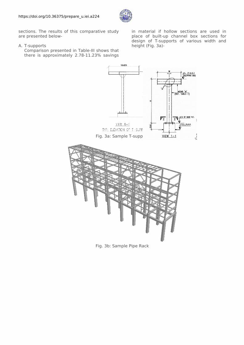
sections. The results of this comparative studyare presented below-
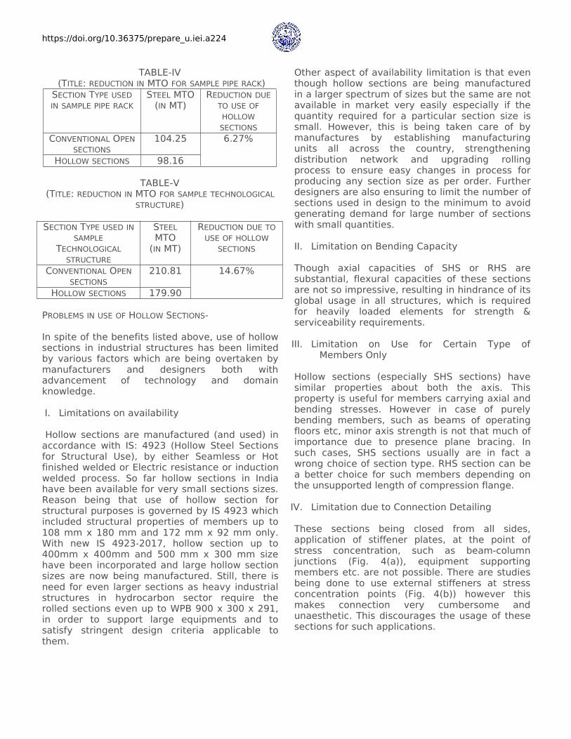
A. T-supportsComparison presented in Table-III shows thatthere is approximately 2.78-11.23% savings
in material if hollow sections are used inplace of built-up channel box sections fordesign of T-supports of various width andheight (Fig. 3a)-
Fig. 3a: Sample T-support
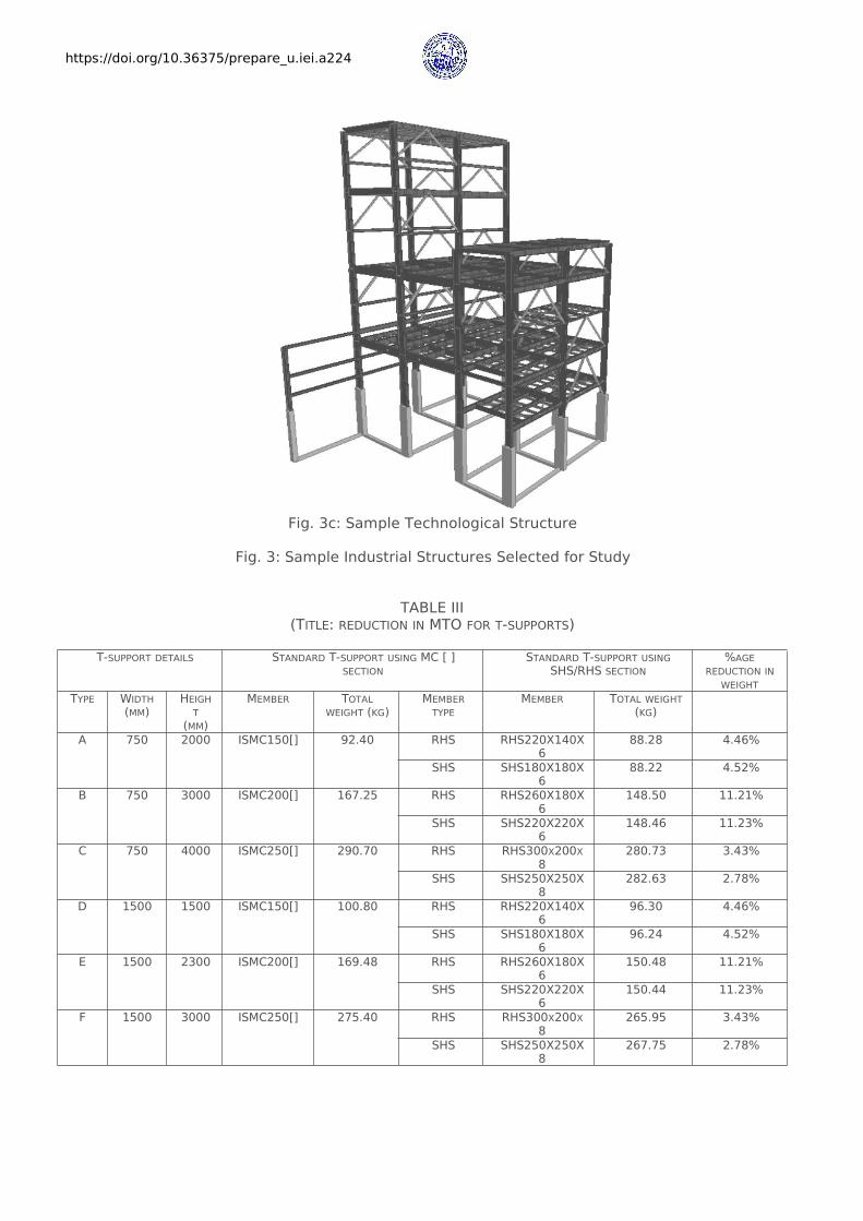
Fig. 3b: Sample Pipe Rack
https://doi.org/10.36375/prepare_u.iei.a224
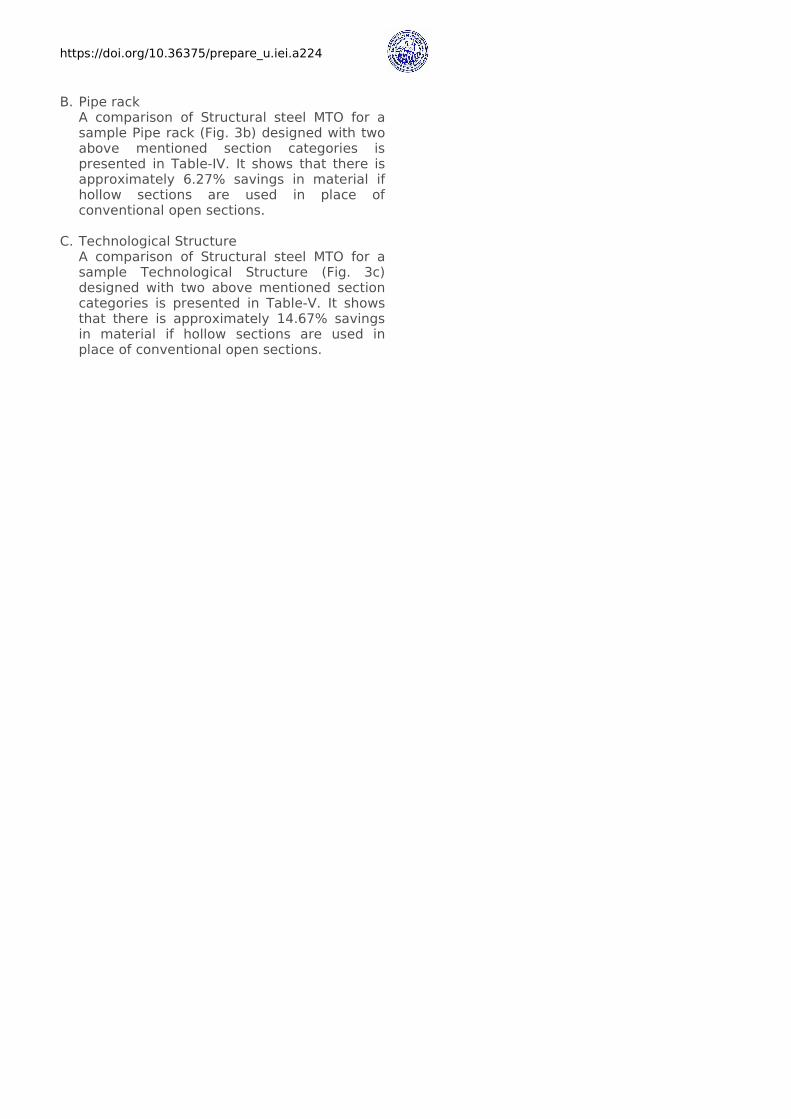
Fig. 3c: Sample Technological Structure
Fig. 3: Sample Industrial Structures Selected for Study
TABLE III(TITLE: REDUCTION IN MTO FOR T-SUPPORTS)
T-SUPPORT DETAILS STANDARD T-SUPPORT USING MC [ ]SECTION
STANDARD T-SUPPORT USINGSHS/RHS SECTION
%AGEREDUCTION INWEIGHT
TYPE WIDTH(MM)
HEIGHT(MM)
MEMBER TOTALWEIGHT (KG)
MEMBERTYPE
MEMBER TOTAL WEIGHT(KG)
A 750 2000 ISMC150[] 92.40 RHS RHS220X140X6
88.28 4.46%
SHS SHS180X180X6
88.22 4.52%
B 750 3000 ISMC200[] 167.25 RHS RHS260X180X6
148.50 11.21%
SHS SHS220X220X6
148.46 11.23%
C 750 4000 ISMC250[] 290.70 RHS RHS300X200X8
280.73 3.43%
SHS SHS250X250X8
282.63 2.78%
D 1500 1500 ISMC150[] 100.80 RHS RHS220X140X6
96.30 4.46%
SHS SHS180X180X6
96.24 4.52%
E 1500 2300 ISMC200[] 169.48 RHS RHS260X180X6
150.48 11.21%
SHS SHS220X220X6
150.44 11.23%
F 1500 3000 ISMC250[] 275.40 RHS RHS300X200X8
265.95 3.43%
SHS SHS250X250X8
267.75 2.78%
https://doi.org/10.36375/prepare_u.iei.a224
B. Pipe rackA comparison of Structural steel MTO for asample Pipe rack (Fig. 3b) designed with twoabove mentioned section categories ispresented in Table-IV. It shows that there isapproximately 6.27% savings in material ifhollow sections are used in place ofconventional open sections.
C. Technological StructureA comparison of Structural steel MTO for asample Technological Structure (Fig. 3c)designed with two above mentioned sectioncategories is presented in Table-V. It showsthat there is approximately 14.67% savingsin material if hollow sections are used inplace of conventional open sections.
https://doi.org/10.36375/prepare_u.iei.a224
TABLE-IV(TITLE: REDUCTION IN MTO FOR SAMPLE PIPE RACK)SECTION TYPE USEDIN SAMPLE PIPE RACK
STEEL MTO(IN MT)
REDUCTION DUETO USE OFHOLLOWSECTIONS
CONVENTIONAL OPENSECTIONS
104.25 6.27%
HOLLOW SECTIONS 98.16
TABLE-V(TITLE: REDUCTION IN MTO FOR SAMPLE TECHNOLOGICAL
STRUCTURE)
SECTION TYPE USED INSAMPLE
TECHNOLOGICALSTRUCTURE
STEELMTO(IN MT)
REDUCTION DUE TOUSE OF HOLLOW
SECTIONS
CONVENTIONAL OPENSECTIONS
210.81 14.67%
HOLLOW SECTIONS 179.90
PROBLEMS IN USE OF HOLLOW SECTIONS-
In spite of the benefits listed above, use of hollowsections in industrial structures has been limitedby various factors which are being overtaken bymanufacturers and designers both withadvancement of technology and domainknowledge.
I. Limitations on availability
Hollow sections are manufactured (and used) inaccordance with IS: 4923 (Hollow Steel Sectionsfor Structural Use), by either Seamless or Hotfinished welded or Electric resistance or inductionwelded process. So far hollow sections in Indiahave been available for very small sections sizes.Reason being that use of hollow section forstructural purposes is governed by IS 4923 whichincluded structural properties of members up to108 mm x 180 mm and 172 mm x 92 mm only.With new IS 4923-2017, hollow section up to400mm x 400mm and 500 mm x 300 mm sizehave been incorporated and large hollow sectionsizes are now being manufactured. Still, there isneed for even larger sections as heavy industrialstructures in hydrocarbon sector require therolled sections even up to WPB 900 x 300 x 291,in order to support large equipments and tosatisfy stringent design criteria applicable tothem.
Other aspect of availability limitation is that eventhough hollow sections are being manufacturedin a larger spectrum of sizes but the same are notavailable in market very easily especially if thequantity required for a particular section size issmall. However, this is being taken care of bymanufactures by establishing manufacturingunits all across the country, strengtheningdistribution network and upgrading rollingprocess to ensure easy changes in process forproducing any section size as per order. Furtherdesigners are also ensuring to limit the number ofsections used in design to the minimum to avoidgenerating demand for large number of sectionswith small quantities.
II. Limitation on Bending Capacity
Though axial capacities of SHS or RHS aresubstantial, flexural capacities of these sectionsare not so impressive, resulting in hindrance of itsglobal usage in all structures, which is requiredfor heavily loaded elements for strength &serviceability requirements.
III. Limitation on Use for Certain Type ofMembers Only
Hollow sections (especially SHS sections) havesimilar properties about both the axis. Thisproperty is useful for members carrying axial andbending stresses. However in case of purelybending members, such as beams of operatingfloors etc, minor axis strength is not that much ofimportance due to presence plane bracing. Insuch cases, SHS sections usually are in fact awrong choice of section type. RHS section can bea better choice for such members depending onthe unsupported length of compression flange.
IV. Limitation due to Connection Detailing
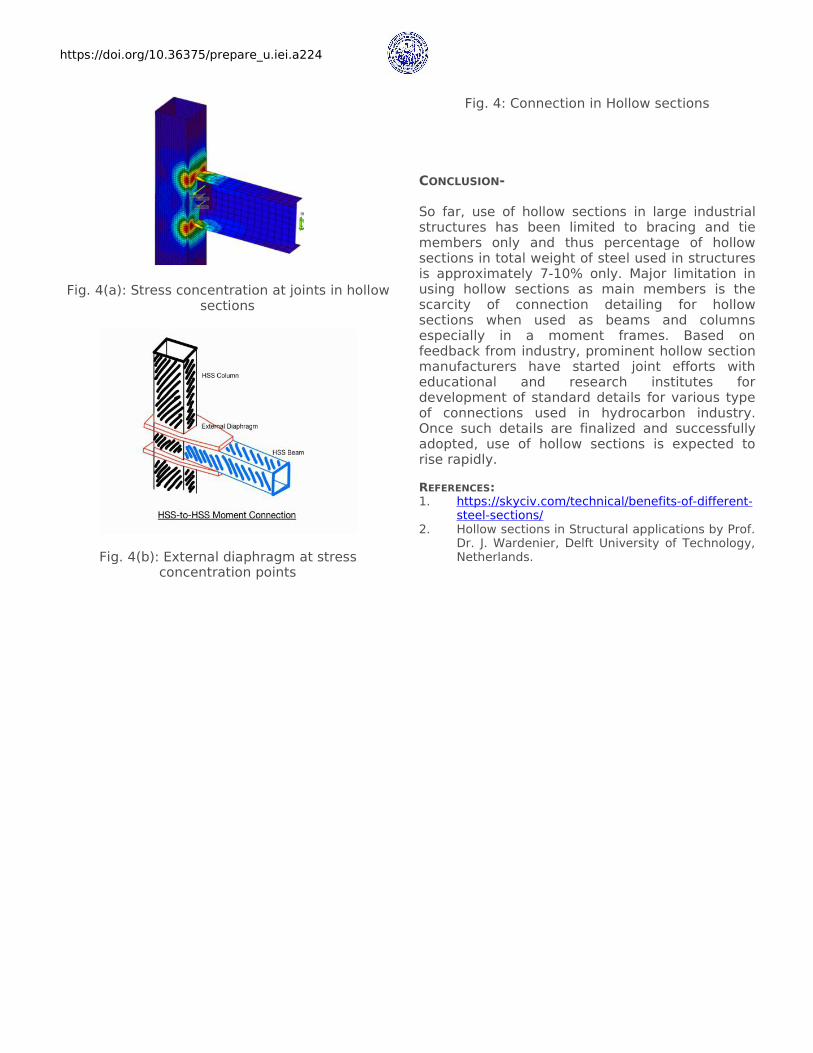
These sections being closed from all sides,application of stiffener plates, at the point ofstress concentration, such as beam-columnjunctions (Fig. 4(a)), equipment supportingmembers etc. are not possible. There are studiesbeing done to use external stiffeners at stressconcentration points (Fig. 4(b)) however thismakes connection very cumbersome andunaesthetic. This discourages the usage of thesesections for such applications.
https://doi.org/10.36375/prepare_u.iei.a224
Fig. 4(a): Stress concentration at joints in hollowsections
Fig. 4(b): External diaphragm at stressconcentration points
Fig. 4: Connection in Hollow sections
CONCLUSION-
So far, use of hollow sections in large industrialstructures has been limited to bracing and tiemembers only and thus percentage of hollowsections in total weight of steel used in structuresis approximately 7-10% only. Major limitation inusing hollow sections as main members is thescarcity of connection detailing for hollowsections when used as beams and columnsespecially in a moment frames. Based onfeedback from industry, prominent hollow sectionmanufacturers have started joint efforts witheducational and research institutes fordevelopment of standard details for various typeof connections used in hydrocarbon industry.Once such details are finalized and successfullyadopted, use of hollow sections is expected torise rapidly.REFERENCES:1. https://skyciv.com/technical/benefits-of-different-
steel-sections/2. Hollow sections in Structural applications by Prof.
Dr. J. Wardenier, Delft University of Technology,Netherlands.