Co-electrospraying of tumour cell mimicking hollow polymeric ...
35
The University of Manchester Research Co-electrospraying of tumour cell mimicking hollow polymeric microspheres for diffusion magnetic resonance imaging DOI: 10.1016/j.msec.2019.03.062 Document Version Accepted author manuscript Link to publication record in Manchester Research Explorer Citation for published version (APA): Zhou, F. L., Wu, H. H., McHugh, D. J., Wimpenny, I., Zhang, X., Gough, J. E., Hubbard Cristinacce, P. L., & Parker, G. J. M. (2019). Co-electrospraying of tumour cell mimicking hollow polymeric microspheres for diffusion magnetic resonance imaging. Materials Science and Engineering C, 101, 217-227. https://doi.org/10.1016/j.msec.2019.03.062 Published in: Materials Science and Engineering C Citing this paper Please note that where the full-text provided on Manchester Research Explorer is the Author Accepted Manuscript or Proof version this may differ from the final Published version. If citing, it is advised that you check and use the publisher's definitive version. General rights Copyright and moral rights for the publications made accessible in the Research Explorer are retained by the authors and/or other copyright owners and it is a condition of accessing publications that users recognise and abide by the legal requirements associated with these rights. Takedown policy If you believe that this document breaches copyright please refer to the University of Manchester’s Takedown Procedures [http://man.ac.uk/04Y6Bo] or contact [email protected] providing relevant details, so we can investigate your claim. Download date:10. Jan. 2022
-
Upload
khangminh22 -
Category
Documents
-
view
3 -
download
0
Transcript of Co-electrospraying of tumour cell mimicking hollow polymeric ...

The University of Manchester Research
Co-electrospraying of tumour cell mimicking hollowpolymeric microspheres for diffusion magnetic resonanceimagingDOI:10.1016/j.msec.2019.03.062
Document VersionAccepted author manuscript
Link to publication record in Manchester Research Explorer
Citation for published version (APA):Zhou, F. L., Wu, H. H., McHugh, D. J., Wimpenny, I., Zhang, X., Gough, J. E., Hubbard Cristinacce, P. L., &Parker, G. J. M. (2019). Co-electrospraying of tumour cell mimicking hollow polymeric microspheres for diffusionmagnetic resonance imaging. Materials Science and Engineering C, 101, 217-227.https://doi.org/10.1016/j.msec.2019.03.062Published in:Materials Science and Engineering C
Citing this paperPlease note that where the full-text provided on Manchester Research Explorer is the Author Accepted Manuscriptor Proof version this may differ from the final Published version. If citing, it is advised that you check and use thepublisher's definitive version.
General rightsCopyright and moral rights for the publications made accessible in the Research Explorer are retained by theauthors and/or other copyright owners and it is a condition of accessing publications that users recognise andabide by the legal requirements associated with these rights.
Takedown policyIf you believe that this document breaches copyright please refer to the University of Manchester’s TakedownProcedures [http://man.ac.uk/04Y6Bo] or contact [email protected] providingrelevant details, so we can investigate your claim.
Download date:10. Jan. 2022
Manuscript Details
Manuscript number MSEC_2018_3180_R1
Title Co-electrospraying of Tumour Cell Mimicking Hollow Polymeric Microspheres forDiffusion Magnetic Resonance Imaging
Article type Research Paper
Abstract
Diffusion magnetic resonance imaging (dMRI) is considered as a useful tool to study solid tumours. However, theinterpretation of dMRI signal and validation of quantitative measurements of is challenging. One way to address thesechallenges is by using a standard reference material that can mimic tumour cell microstructure. There is a growinginterest in using hollow polymeric microspheres, mainly prepared by multiple steps, as mimics of cells in healthy anddiseased tissue. The present work reports on tumour cell-mimicking materials composed of hollow microspheres forapplication as a standard material in dMRI. These microspheres were prepared via one-step co-electrosprayingprocess. The shell material was poly(D,L-lactic-co-glycolic acid) (PLGA) polymers with different molecule weightsand/or ratios of glycolic acid-to-lactic, while the core was polyethylene glycol (PEG) or ethylene glycol. The resultantco-electrosprayed products were characterised by optical microscopy, scanning electron microscopy (SEM) andsynchrotron X-ray micro-CT. These products were found to have variable structures and morphologies, e.g. fromspherical particles with/without surface hole, through beaded fibres to smooth fibres, which mainly depend on PLGAcomposition and core materials. Only the shell material of PLGA polymer with ester terminated, Mw 50,000–75,000 gmol-1, and lactide:glycolide 85:15 formed hollow microspheres via the co-electrospraying process using the corematerial of 8 wt.% PEG/chloroform as the core. A water-filled test object (or phantom) was designed and constructedfrom samples of the material generated from co-electrosprayed PLGA microspheres and tested on a 7 tesla MRIscanner. The preliminary MRI results provide evidence that hollow PLGA microspheres can restrict/hinder waterdiffusion as cells do in tumour tissue, implying that the phantom may be suitable for use as a quantitative validationand calibration tool for dMRI.
Keywords Co-electrospraying; hollow microspheres; tumour cells; diffusion magneticresonance imaging; phantom
Taxonomy Materials Structure, Materials Characterization Techniques
Corresponding Author Fenglei Zhou
Order of Authors Fenglei Zhou
Suggested reviewers Weiwei Deng, Chi-Hwa Wang, Gareth Williams
Submission Files Included in this PDF
File Name [File Type]
List of Response to the Manuscript MSEC_2018_3180_20190308.docx [Response to Reviewers]
Highlights.docx [Highlights]
Revised Manuscript_ MSEC_2018_3180_Co-ES PLGA microspheres_20190308.docx [Manuscript File]
Supplementary material for manuscript MSEC_2018_3180.docx [Supplementary Material]
To view all the submission files, including those not included in the PDF, click on the manuscript title on your EVISEHomepage, then click 'Download zip file'.
Research Data Related to this Submission
There are no linked research data sets for this submission. The following reason is given:Data will be made available on request

Highlights:
Hollow PLGA microspheres are fabricated from by one-step co-electrospraying.
2D SEM and 3D micro-CT are used to characterise hollow PLGA microspheres.
3D hollow PLGA microspheres are used as a first-of-a-kind tumour cell model. This model shows promising as a quantitative validation tool for diffusion
MRI.
1
Co-electrospraying of Tumour Cell Mimicking Hollow Polymeric Microspheres for Diffusion Magnetic Resonance Imaging
Feng-Lei Zhoua,b,*, HuiHui Wub,c, Damien J McHugha, Ian Wimpennya,b, Xun Zhangd, Julie E. Goughb, Penny L Hubbard Cristinaccee,D, and Geoff JM Parkera,f,*,D
a Division of Neuroscience and Experimental Psychology, The University of Manchester,
Manchester M13 9PT, United Kingdom
b The School of Materials, The University of Manchester, Manchester M13 9PL, United
Kingdom
c Pan Tianshou Arts and Design Academy, Ningbo University, No.818, Fenghua Road,
Ningbo, China, 315200
d Henry Moseley X-ray Imaging Facility, School of Materials, The University of Manchester,
Manchester, M13 9PL, UK
e School of Psychological Sciences, The University of Manchester, Manchester M13 9PT,
United Kingdom
f Bioxydyn Limited, Rutherford House, Manchester Science Park, Pencroft Way, Manchester
M15 6SZ, United Kingdom
Corresponding Authors
E-mails: [email protected]; [email protected]
Author Contribution
DP. L. Hubbard Cristinacce and G. J. M. Parker are joint senior authors.
Abstract: Diffusion magnetic resonance imaging (dMRI) is considered as a useful tool to
study solid tumours. However, the interpretation of dMRI signal and validation of
quantitative measurements of is challenging. One way to address these challenges is by using
a standard reference material that can mimic tumour cell microstructure. There is a growing
interest in using hollow polymeric microspheres, mainly prepared by multiple steps, as
mimics of cells in healthy and diseased tissue. The present work reports on tumour cell-

2
mimicking materials composed of hollow microspheres for application as a standard material
in dMRI. These microspheres were prepared via one-step co-electrospraying process. The
shell material was poly(D,L-lactic-co-glycolic acid) (PLGA) polymers with different
molecule weights and/or ratios of glycolic acid-to-lactic, while the core was polyethylene
glycol (PEG) or ethylene glycol. The resultant co-electrosprayed products were characterised
by optical microscopy, scanning electron microscopy (SEM) and synchrotron X-ray micro-
CT. These products were found to have variable structures and morphologies, e.g. from
spherical particles with/without surface hole, through beaded fibres to smooth fibres, which
mainly depend on PLGA composition and core materials. Only the shell material of PLGA
polymer with ester terminated, Mw 50,000–75,000 g mol-1, and lactide:glycolide 85:15
formed hollow microspheres via the co-electrospraying process using the core material of 8
wt.% PEG/chloroform as the core. A water-filled test object (or phantom) was designed and
constructed from samples of the material generated from co-electrosprayed PLGA
microspheres and tested on a 7 tesla MRI scanner. The preliminary MRI results provide
evidence that hollow PLGA microspheres can restrict/hinder water diffusion as cells do in
tumour tissue, implying that the phantom may be suitable for use as a quantitative validation
and calibration tool for dMRI.
Keywords: Co-electrospraying; hollow microspheres; tumour cells; diffusion magnetic
resonance imaging; phantom
1. INTRODUCTION
Hollow polymeric nano/microstructures with cylindrical or spherical geometries are of
special interest for use in encapsulation,[1-3] controlled release,[4-6] filtration,[7, 8]
nanoreactors,[9] and tissue microstructure mimics.[10-13] One important category is hollow
microspheres, which currently are mainly fabricated using template and emulsion

3
techniques.[14, 15] Those techniques often require multiple steps due to extra procedures to
remove the template/core materials. Recently, co-electrospinning and co-electrospraying have
been successfully used to produce hollow polymeric nano/microfibres[16, 17] and
nano/microspheres[11, 18, 19] respectively. The main advantage of co-
electrospinning/spraying lies in the fact that they are one-step processes[16, 18] and allow
flexibility of controlling the size and patterning of hollow fibres[13, 20] and microspheres.[18,
21]
Poly(D,L-lactic-coglycolic acid) (PLGA) is an FDA-approved synthetic polymer having good
biocompatibility and biodegradability, and is one of the most commonly used and extensively
investigated polymers for sustained drug/protein carriers in the forms of spherical
particles[22, 23] and cylindrical fibres.[9] There have been extensive studies on solid PLGA
microspheres, for example by the technique of electrospraying,[23-29] but a very limited
number of reports on hollow PLGA microspheres,[30, 31] which have mainly been produced
to date by the emulsion technique.
Apart from their use in drug delivery, there is interest in using polymer microspheres or
microcylinders as mimics of biological tissue. For example, the microstructure of red blood
cells with biconcave discoidal shape was mimicked by electrosprayed solid PLGA
particles.[32] Our interest is primarily in tumour tissue microstructure, within the context of
mimicking structures that influence the signal observed during non-invasive magnetic
resonance imaging (MRI). Imaging tumour microstructure in vivo has received increasing
interest in recent years as it may provide a clinical tool for detecting tumour cell proliferation,
cell death and infiltration of healthy tissues. Diffusion magnetic resonance imaging (dMRI) is
currently considered as a promising tool to detect and stage cancer, and measure tumour
response to therapy. dMRI is sensitive to the passive diffusion of water molecules in tissue,
which in turn is sensitive to tissue microstructural characteristics such as cell size and shape,

4
cell membrane permeability to water and cell volume fraction, all of which are relevant to
distinguishing tumours from normal tissues and to the monitoring of the impact of
therapy.[33, 34] The signal is sensitive to the water motion in tissues over distances of tens
of microns, and is commonly quantified by determining the apparent diffusion coefficient
(ADC) of water, which is impeded by the presence of cellular membranes and
macromolecular structures. ADC is a key quantitative parameter in diffusion MR imaging of
tumours and has been investigated as a biomarker of tumour stage and treatment response.[33,
35, 36]
T2 relaxation time mapping is another quantitative MRI technique that has been widely used
as non-invasive biomarker for early biochemical changes in vivo.[37, 38] Application of this
quantitative technique has been extended to tumour for differentiating normal from cancerous
tissue.[35] T2 is typically elevated in tumours but is affected by a number of physiological
and microanatomical parameters including pO2, pH, water content and macromolecular
content, as well as the presence (or absence) of irregular vasculature, necrotic tissue, and/or
densely pack proliferating cells.[35] MR images sensitised to T2 (T2-weighted images) have
long been used as a tool to identify abnormalities including tumours in standard radiological
practice and are therefore a useful and relevant tool for high resolution MRI of tissues.
Tumour microstructural models,[34, 39] developed to investigate the relationship between the
diffusion MRI signal, imaging parameters, and specific tissue properties such as cell size and
cell volume fraction, require validation by a physical test object or phantom that is capable of
mimicking the desirable microstructural properties of tumour cells. Additionally, the
deployment of quantitative ADC measurements for monitoring tumour status requires
standardisation and quality control using physical phantoms that mimic tumour tissue to a
relevant level of accuracy. We have previously demonstrated that co-electrospun hollow
polycaprolactone (PCL) microfibres were able to mimic brain white matter, grey matter, and

5
cardiac fibres, with dMRI measurements (ADC and fractional anisotropy) showing sensitivity
to microfibre size and orientation in hollow fibre phantoms;[10, 12, 40] this has now been
extended to co-electrosprayed hollow PCL microspheres.[19] In our first efforts towards
developing a tumour cell-mimicking physical phantom, we found that PCL hollow
microspheres may be useful for testing microstructural models relevant to the characterisation
of tumour tissue.[11] However, the use of PCL has the major disadvantage of being
hydrophobic, which means that the produced microsphere materials are unable to characterise
water diffusion and relied instead on the use of organic solvents that are a poor representation
of true tissue and are challenging to handle in routine MRI environments.
Here we report the preparation and characterization of hydrophilic tumour cell mimicking
hollow PLGA microspheres and preliminary MRI results, i.e. ADC and T2 maps, acquired
from a PLGA phantom. The present work is a development of our recent work on PCL
phantoms that were limited to an organic solvent – cyclohexane - as test liquid for dMRI
measurement. Due to the fact that PLGA polymer is more hydrophilic than PCL,[41, 42] this
enables us to employ water (widely used as a standard due to its convenience and safety and
more relevant to mimicking biological systems) as the diffusion liquid in a PLGA phantom.
The developed PLGA phantom will significantly enhance the utility of phantoms for
mimicking the tumour microenvironment for imaging purposes.
2. EXPERIMENTAL
2.1. Materials
Three different forms of the polymer poly(D,L-lactide-co-glycolic) acid (PLGA) were
purchased. PLGA-1 (ester terminated, Mw 50,000–75,000 g mol-1, lactide: glycolide 85:15),
was obtained from Sigma Aldrich (Dorset, UK). PLGA-2 (acid terminated, Mw 50,000 g
mol-1, 50:50) and PLGA-3 (PEG-PLGA (Mw 5000:45000 (50:50), g mol-1) were purchased

6
from Jinan Daigang Biomaterial Co., Ltd. (China). All polymers were used as received.
Chloroform, ethylene glycol solvent and polyethylene glycol (PEG, Mn = 35,000 g mol-1)
were also purchased from Sigma Aldrich (Dorset, UK). Deionized water was used to dissolve
PEG.
2.2. Co-electrospraying of PLGA
A schematic of co-electrospraying of PLGA microspheres is depicted in Fig. 1 and a detailed
description of the experimental setup is provided elsewhere.[43] A grounded aluminium ring
(not shown) was introduced as an auxiliary electrode and placed just below the coaxial
spinneret. All experiments were conducted in a fume cupboard under ambient conditions.
PLGA in chloroform was used as shell solution in the co-electrospraying process and the core
solution was varied from PEG/water, PEG/water-ethanol, PEG/chloroform to ethylene glycol.
In the case of the electrospraying of solid PLGA spheres, only the outer needle of the coaxial
spinneret was used.
Step 1 Step 2 Step 3 Step 4
Figure 1. Workflow for co-electrospraying of PLGA microspheres as tumour cell mimicking MR phantom. Step 1: schematic of equipment used, including syringe pumps, polymer solutions, coaxial spinneret, sprayed spheres, voltage supply and collecting coil. Step 2: SEMs of electrosprayed sphere (top), cut sphere demonstrating hollow structure (middle) and bulk structure of materials after removal from collecting coil. Step 3: bulk phantom consisting of electrospun material in NMR tube with added water. Step 4: MRI scanner (top) used to generate MRI images (bottom) of phantom.
2.3. Optical and scanning electron microscopy

7
The morphology of electrosprayed PLGA microspheres was observed using an Olympus
BH2-UMA optical microscope and a Philips XL30 FEG SEM or a Phenom G2 pro desktop
Scanning Electron Microscope (SEM) with an accelerating voltage of 5 kV. In order to
quickly determine whether PLGA microspheres were formed, a glass slide was introduced
into the setup and held in contact with the collector, in the centre of the spraying zone for a
few minutes at the start of the electrospraying process, for optical microscopy. The
electrosprayed PCL particles collected on the aluminium foil were coated with thin platinum
to increase their conductivity before SEM imaging. To observe their internal structure, the
spheres were embedded in optimal cutting temperature (OCT) cryosectioning media, and then
frozen in a cryostat chamber (-30°C). The frozen OCT block was cryosectioned into micron-
scale slices of defined thickness ranging from 10 to 30 μm. The OCT slices were mounted on
pin stubs with double-sided carbon tape and then gently washed with distilled water in order
to dissolve the OCT matrix, and the samples were air dried before being coated with a layer
of platinum film.
2.4. Synchrotron phase contrast X-ray CT and data analysis
Tomography was performed at the Diamond-Manchester Imaging Beamline I13-2 of
Diamond Light Source, UK. A filtered (950 um C, 2 mm Al) polychromatic ‘pink’ beam (5-
35 keV) with parallel geometry was used for imaging[44]. Prior to the Micro-XCT scanning,
tubular bulk samples, constituted of PLGA microspheres, were prepared for scanning in wet
condition. The sample measured approximately 1 mm diameter x 5 mm length. The wet
sample was immersed in distilled water for ~1 week prior to scanning and then inserted into a
20 μl pipette tip, filled with distilled water. The tubular bulk sample of PLGA microspheres
was positioned against the walls of the tip to restrict its movement during scanning and the tip
was then sealed with parafilm. Then the sample was mounted on a magnetic stage for
scanning.

8
Acquisition of phase contrast tomography data was performed using a pco.edge 5.5 detector
(PCO AG, Germany) coupled to a CdWO4 scintillator (0.75 mm thick) positioned 45 mm
away from the sample; the final magnifications for acquisition were x1.25 and x10
magnification (FOVs 6.7 x 5.6 mm and 0.83 x 0.70, respectively). This provided a pixel size
of 2.6 um and 0.33 um, respectively. The sample was rotated 180 degrees with 0.05o between
each exposure (0.1 – 0.25 seconds). 3600 projection images were acquired for each sample
and reconstructed with flat and dark field correction.[45], Commercial software specialising
in 3D image processing, quantification, visualization and image-based modelling, was used to
process and quantify morphological features (AVIZO 9.2 (FEI, Oregan, USA). For the
purpose of this study, shell thickness, thickness variation, spheres connectivity and spheres
shape were the features of interest.
2.5. 3D Image demonizing, segmentation and quantification
The as-reconstructed virtual slices were noisy, which can potentially lead to mis-
segmentation and errors in quantification. Therefore, prior to segmentation, a windowed non-
local means algorithm was implemented in AVIZO 9.2 to remove the noises in the
images.[46] The voxels representing the sphere walls in the filtered image stack were
identified and labelled using a grey value threshold. Details on the sphere were further
quantified using the labelled image.
The sphere wall thickness was determined using the ‘Local Thickness’ module in FiJi.[47]
The local thickness was calculated using the diameter of the largest inscribed sphere that fits
inside the sphere wall and contains the point.[47] This allows a local thickness value to be
assigned to all the voxels representing the sphere wall. However, in order to obtain the sphere
wall thickness, only the values obtained from the centre line of the sphere wall should be
considered. In order to remove the redundant points, the skeleton image of the sphere wall
was obtained using the ‘AnalyzeSkeleton’ plugin in FiJi.[48] The skeletonisation operation
9
picks out the voxels representing the centre line of the sphere wall, which is later used as a
mask for the average sphere wall calculation.
2.6. Phantom preparation
Tubular bulk samples of PLGA microspheres were collected using a method previously used
in the study of co-electrospraying of PCL sphere phantoms.[11] The tubular bulk sample was
then placed in a water-filled NMR tube (5 mm outer diameter, Fig. 1) and placed in a vacuum
chamber at moderate vacuum, which degassed the microspheres and filled them with water.
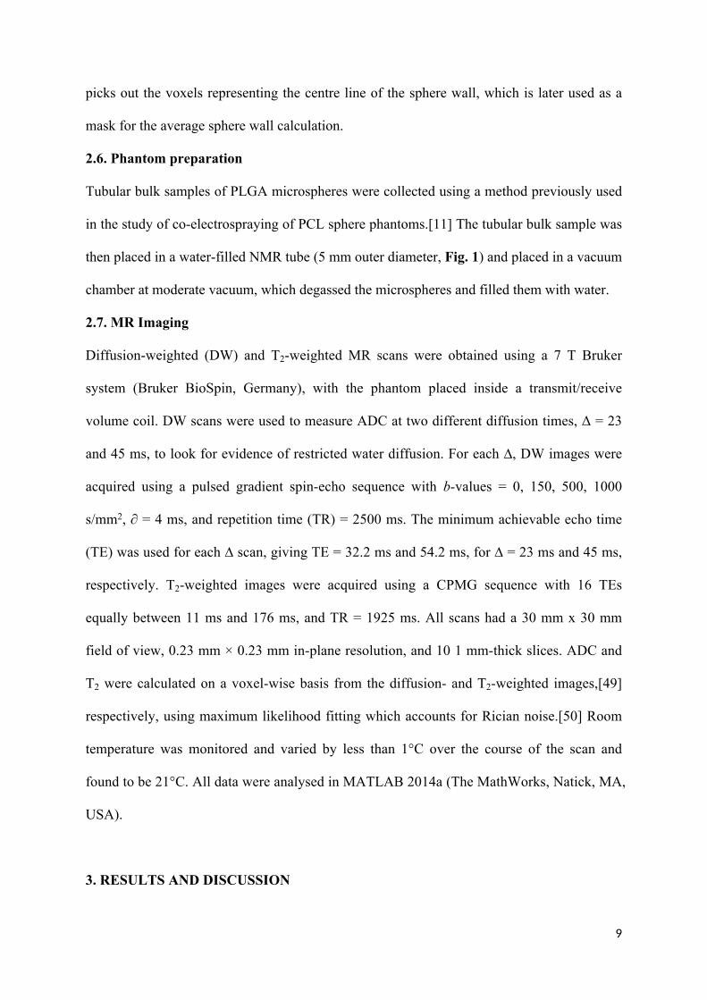
2.7. MR Imaging
Diffusion-weighted (DW) and T2-weighted MR scans were obtained using a 7 T Bruker
system (Bruker BioSpin, Germany), with the phantom placed inside a transmit/receive
volume coil. DW scans were used to measure ADC at two different diffusion times, Δ = 23
and 45 ms, to look for evidence of restricted water diffusion. For each ∆, DW images were
acquired using a pulsed gradient spin-echo sequence with b-values = 0, 150, 500, 1000
s/mm2, ∂ = 4 ms, and repetition time (TR) = 2500 ms. The minimum achievable echo time
(TE) was used for each ∆ scan, giving TE = 32.2 ms and 54.2 ms, for ∆ = 23 ms and 45 ms,
respectively. T2-weighted images were acquired using a CPMG sequence with 16 TEs
equally between 11 ms and 176 ms, and TR = 1925 ms. All scans had a 30 mm x 30 mm
field of view, 0.23 mm × 0.23 mm in-plane resolution, and 10 1 mm-thick slices. ADC and
T2 were calculated on a voxel-wise basis from the diffusion- and T2-weighted images,[49]
respectively, using maximum likelihood fitting which accounts for Rician noise.[50] Room
temperature was monitored and varied by less than 1°C over the course of the scan and
found to be 21°C. All data were analysed in MATLAB 2014a (The MathWorks, Natick, MA,
USA).
3. RESULTS AND DISCUSSION

10
PLGA is a copolymer of poly lactic acid (PLA) and poly glycolic acid (PGA). Glycolic acid
is more hydrophilic than lactic acid, and therefore a high ratio of glycolic acid-to-lactic acid
increases the hydrophilicity of the polymer. A previous study has reported that PLGA
microparticles with higher hydrophilicity often show a faster degradation rate in an aqueous
medium.[51] The hydrophilic property of PLGA can be modified by forming a copolymer
with PEG, which has been widely used in controlled drug delivery carrier, for example PEG-
PLGA micro/nanoparticles.[23, 30] Therefore in this study, three types of PLGA polymers
with different ratios of glycolic acid-to-lactic acid were chosen to investigate the formability
of solid spherical particles in electrospraying (denoted as PLGA-1, PLGA-2 and PLGA-3 in
the Materials section).
Based on the study on the electrospraying of PLGA polymer described in the Supplementary
Materials, the co-electrospraying process is firstly reported, where three different forms of
PLGA polymer were used as the shell material and three materials including ethylene glycol,
olive oil and PEG were used as the core. A more detailed investigation of PEG as the core
material is then described, followed by the production of a three-dimensional structure of
hollow PLGA microspheres for use as a phantom for MR imaging.
3.1. Co-electrospraying of PLGA
3.1.1. Co-electrospraying of PLGA with various core materials
In the co-electrospraying process, with increasing applied voltage and flow rate, four or five
spraying modes are often sequentially observed,[52-54] among which the cone-jet mode is
the most desirable state for producing well-defined core-shell structured particles with
uniform sizes[55]. The formation of a stable coaxial cone and jet are strongly influenced by
not only core/shell materials and operating parameters,[1, 53, 54] but also setup
configuration.[56, 57] In co-electrospinning, there are a few commonly used liquid materials
including water, glycerol, ethanol, ethylene glycol, lipid and olive oil.[55] Here we used

11
ethylene glycol, water, olive oil or their mixtures as core with three types of
PLGA/chloroform solutions to observe the process stability. The investigated solutions which
were used in the co-electrospraying experiments are summarized in Table 1.
Table 1. Types of core–shell fibres: composition of the solutions (Typical temperature of the environment is of ~20°C, typical humidity is ~30%). Flow rate of shell 3.0 ml/h and core 1.0 ml/h.
Set ShellCore
Concentration Solvents Core solvents ratio (w/w)
Applied electric
field (kV/cm)
Figures
1 PLGA-1ethylene glycol
5 wt. %-
Chloroform- - 15.0/20 Fig. 2a,d
2 PLGA-1ethylene glycol/water
5 wt. %-
Chloroform-
-9/1 12.0/20 Fig. 2b,e
3 PLGA-1ethylene glycol/water
5 wt. %-
Chloroform-
-5/5 12.0/20 Fig. 2c,f
4 PLGA-2PEG
12 wt. %15 wt.%
ChloroformWater
-- 9.0/20 Fig. 2g
5 PLGA-2Olive oil
12 wt. %-
Chloroform-
-- 9.0/20 Fig. 2h
6 PLGA-3PEG
12 wt. %15 wt.%
ChloroformWater
-- 9.0/20 Fig. 2i
7 PLGA-3PEG
12 wt. %15 wt.%
ChloroformWater/ethanol
-8/2 9.0/20 Fig. 2j
8 PLGA-3Ethylene glycol
12 wt. %-
Chloroform-
-- 12.0/20 Fig. 2k
9 PLGA-3Ethylene glycol/water
12 wt. %-
Chloroform-
-- 12.0/20 Fig. 2l
For PLGA-1, the mixture of ethylene glycol/water with three blending ratios, 100/0, 90/10
and 50/50, was used as the core solution. The co-electrospraying processes of 5 wt.% PLGA-
1/chloroform with three core solutions were observed to be stable but the jet stability tended
to decrease with the increasing water content in the core. This could be explained by the
miscible interface between ethylene glycol core and chloroform, but the immiscibility
between water and chloroform. All resultant particles appeared spherical (Fig. 2a-c), but
some had large openings on their surface (Fig. 2d-f). It has previously been reported that
PLGA microspheres produced from PLGA in acetonitrile/dichloromethane (5/5 v/v) with
water/ethylene glycol (5/5 v/v) were core-shell structured but did not have such openings on
their surface.[57] In our previous study on co-electrospraying of polycaprolactone (PCL),

12
similar surface holes were observed on these hollow PCL microspheres that were collected in
an ethanol medium but not on other solid collectors, and were influenced by core solution and
core flow rate.[19] The mechanism behind the formation of hollow PLGA microspheres with
surface openings still remains unclear, though the proposed solvent evaporation and/or
extraction responsible for the formation of single hole on the surface of PCL microspheres
could be applied here. Our microspheres with surface holes were formed in one step, which
represents a considerable advantage of co-electrospraying over previously reported multiple-
step techniques including template and shell-breaking, etc.[52]
For PLGA-2, two core solutions, 15 wt.% PEG/water and olive oil were co-electrosprayed
with 12 wt.% PLGA/chloroform. The PEG/water core caused process instability, which
resulted in a fibre dominant structure with a few large particles (Fig. 2g). When olive oil was
used, the jet became more stable from which beaded fibres were produced (Fig. 2h),
indicating that olive oil was likely to have been well encapsulated in PLGA fibres.
For PLGA-3, four core solutions were co-electrosprayed with 12 wt.% PLGA in chloroform.
For the combination of PLGA-3/chloroform with PEG/water, the jet became unstable, similar
to the process of PLGA-2. However in the resultant particles became more abundant than that
obtained from PLGA-2 (Fig. 2g-i). After introducing 20 wt.% ethanol in PEG/water core,
process stability was achieved, which however still resulted in particles and fibres (Fig. 2j).
PLGA is not dissolved in either water or ethanol in the core solution but the addition of
ethanol can enhance the miscibility between the core and PLGA/chloroform shell solution.
When ethylene glycol was only used as the core, the stability was better than PEG/water, but
the addition of 50 wt.% water into ethylene glycol destabilized the jet again, which was
similar to the process using the combination of PLGA-1/chloroform and ethylene glycol. As
shown in Fig. 2k-l, particles were produced from both ethylene glycol and ethylene/water
core solutions. However, PLGA particles from the former appeared more uniform, though

13
particle sizes were different, which was mainly caused by the shell flow rate. These
observations show that the immiscibility between the core and shell solutions at the core/shell
interface can cause jet instability, which however can be improved by adding or directly
employing shell solvent-miscible liquid. These findings are consistent with the co-
electrospraying process of PLLA/chloroform shell and PVA/water core [58] and further
confirmed by a recently developed computational fluid dynamic model for the co-
electrospraying process.[59]
It is obvious that the effect of miscibility between the core and shell solutions on the co-
electrospraying of PLGA is different from the co-electrospinning process of an immiscible
core-shell combination, PCL/chloroform+dimethylformamide (DMF) (8:2) as shell and
polyethylene oxide (PEO)/water as core, as demonstrated in our previous work in which the
process could be stable over a few hours allowing us to produce hollow microfibre bulk
structures.[12, 13] The effect miscibility/solubility between core and shell solutions on the jet
stability and formation of core-shell or hollow microfibres in co-electrospinning has been and
is still a topic of debate.[1, 7, 9, 60-63] For example, in the co-electrospinning of PLGA shell
with PEO core solutions, the core solvent of chloroform/DMF mixture can dissolve PLGA,
which still produces hollow PLGA microfibres.[9] This seems consistent with the formation
of hollow PLGA microspheres produced using PEG/chloroform as the core (Fig. 3f). In
another study[7] it was found that stable hollow poly(vinylidene fluoride-co-hexafluoro
propylene) (PVDF-HFP) microfibres were produced from both immiscible and partially
miscible core/shell solution pairs.
(a) (b) (c)
50 μm 50 μm 50 μm

14
Figure 2. SEM micrographs of co-electrosprayed PLGA products from (a-c) 5 wt.% PLGA-1 in chloroform with ethylene glycol, ethylene glycol/water 9/1 and ethylene glycol/water 5/5; (d-f) surface opening on PLGA spheres in a-c; (g-h) 12 wt.% PLGA-2 in chloroform with 15 wt.% PEG/water and olive oil as core; (i-l) 12 wt.% PLGA-3 in chloroform with 15 wt.% PEG in water, 15 wt.% PEG in water/ethanol (8/2), ethylene glycol and ethylene glycol/water 5/5 as core.
Together with previous studies, including ours,[13, 19, 43] our observations show that in co-
electrospinning the shell solution has to be sufficiently viscous and electrospinnable by itself
in order to obtain stable process and thus core-shell structured or hollow microfibres,
irrespective of the miscibility or solubility of the core and sheath solutions; for co-
electrospraying, the shell solution, e.g. PCL/chloroform, PLGA/chloroform or
PLLA/chloroform, has to be electrosprayable, appropriately viscous and miscible with the
core solution in order to obtain stable jet and core-shell structured or hollow spherical
microparticles. It was claimed in a recent study[64] that immiscible and miscible liquids can
be utilized to fabricate core–shell nanoparticles. However, two core polymer solutions used in
(d) (e) (f)
(g) (h) (i)
(j) (k) (i)
10 μm
100 μm
10 μm 10 μm
20 μm100 μm
20 μm 100 μm 100 μm
15
that study, polyvinylpyrrolidone (PVP) in DMF/ethanol and PCL in acetonitrile, are miscible
with PLGA in tetrahydrofuran (THF) and acetonitrile. In the absence of more extensive
knowledge, we should point out that the requirements proposed above appear only to apply to
polymer-based shell solutions, because most previously published co-electrospraying works
focused on the electrified coaxial jet of two immiscible pure liquids.[1, 21, 54, 65]
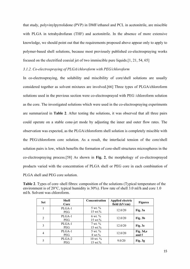
3.1.2. Co-electrospraying of PLGA/chloroform with PEG/chloroform
In co-electrospraying, the solubility and miscibility of core/shell solutions are usually
considered together as solvent mixtures are involved.[66] Three types of PLGA/chloroform
solutions used in the previous section were co-electrosprayed with PEG /chloroform solution
as the core. The investigated solutions which were used in the co-electrospraying experiments
are summarized in Table 2. After testing the solutions, it was observed that all three pairs
could operate on a stable cone-jet mode by adjusting the inner and outer flow rates. The
observation was expected, as the PLGA/chloroform shell solution is completely miscible with
the PEG/chloroform core solution. As a result, the interfacial tension of the core/shell
solution pairs is low, which benefits the formation of core-shell structures microspheres in the
co-electrospraying process.[58] As shown in Fig. 2, the morphology of co-electrosprayed
products varied with the concentration of PLGA shell or PEG core in each combination of
PLGA shell and PEG core solution.
Table 2. Types of core–shell fibres: composition of the solutions (Typical temperature of the environment is of 20°C, typical humidity is 30%). Flow rate of shell 3.0 ml/h and core 1.0 ml/h. Solvent was chloroform.
Set ShellCore
Concentration Applied electric field (kV/cm) Figures
1 PLGA-1PEG
5 wt. %15 wt.% 12.0/20 Fig. 3a
2 PLGA-1PEG
6 wt. %15 wt.% 12.0/20 Fig. 3b
3 PLGA-1PEG
7 wt. %15 wt.% 12.0/20 Fig. 3c
4 PLGA-1PEG
5 wt. %8 wt.% 12.0/20 Fig. 3d,e
and f
5 PLGA-2PEG
10 wt. %15 wt.% 9.0/20 Fig. 3g

16
6 PLGA-2PEG
12 wt. %15 wt.% 9.0/20 Fig. 3h
7 PLGA-2PEG
15 wt. %15 wt.% 9.0/20 Fig. 3i
8 PLGA-2PEG
20 wt. %15 wt.% 9.0/20 Fig. 3j
9 PLGA-3PEG
12 wt. %15 wt.% 12.0/20 Fig. 3k
10 PLGA-3PEG
12 wt. %8 wt.% 12.0/20 Fig. 3l
For the co-electrospraying of PLGA-1, spherical particles, which were observed in
electrospraying of 5 wt. %, 6 wt.% and 7 wt.% solutions, remained at the concentration of 5
wt.% (Fig. 3a) and 6 wt.% (Fig. 3b) but changed to the structure of beads interconnected by a
slender fibre at 7 wt.% (Fig. 3c) (usually called beaded fibres in electrospinning [67]). This
feature can be explained by the increase in PLGA concentration causing particle
electrospraying to transform to fibre electrospinning, with beads-on-a-string structure as a
result of the onset of fibre formation at a high polymer molecular entanglement. It was
previously reported [66] that PLGA particles could change into beaded fibres when an
appropriate liquid (DMF or acetone), completely miscible with PLGA/dimethyl carbonate
(DMC) shell solution, was introduced as core solution in co-electrospraying. The presence of
DMF or acetone could help suppress the Rayleigh instability, which is driven by surface
tension of the solution and is responsible for electrospraying.[66] When the concentration of
PEG/chloroform core solution was decreased from 15 wt.% to 8 wt.%, the spherical particles
were still observed (Fig. 3d). Fig. 3e-f shows the spherical and hollow microstructures PLGA
microspheres before and after cryo-sectioning, respectively.
For the co-electrospraying of PLGA-2, spherical particles remained at the concentration of 10
wt.% (Fig. 3g) but changed into the structure of beaded fibres at higher concentrations of 12
wt.% (Fig. 3h) and 15 wt.% (Fig. 3i). For 12 wt.% PLGA-2 solution, spherical particles
appeared still dominant with thinner fibres between microspheres; for 15 wt.% PLGA
solution, beaded fibres with larger sizes became dominant. When PLGA concentration was

17
increased to 20 wt.%, only microfibres were present (Fig. 3j). We note, however, that this
trend is consistent with the morphology transition from spherical to fibrous shapes occurring
to the electrospraying of PLGA-2 and further work will be required to determine their cross-
sections. For PLGA-3, spherical particles were observed in the co-electrospraying of 12 wt.%
PLGA concentration with both 8 wt.% and 15 wt.% PEG/chloroform solutions (Fig. 3k-l).
The spheres from 8 wt.% solution were much smaller than those from 15 wt.% solution,
indicating the core solution with a higher concentration increase the overall size of co-
electrosprayed spheres, but in both cases the sizes of spheres were much less uniform than
those from PLGA-1.
(g) (h) (i)
(a) (b) (c)
(d) (e) (f)
100 μm 100 μm 100 μm
100 μm 5 μm 5 μm
130 μm 130 μm 130 μm

18
Figure 3. SEM micrographs of co-electrosprayed PLGA products from (a-c) 5 wt.%, 6 wt.%, and 7 wt.% PLGA-1 shell with 15 wt.% PEG core; (d-e) 5 wt.% PLGA-1 shell with 8 wt.% PEG core; (f) cryo-sectioned PLGA-1 sphere in d and e; (g-j) 10 wt.%, 12 wt.% , 15 wt.% and 20 wt.% PLGA-2 in chloroform as shell with PEG in chloroform (15 wt.%); (k-l) 12 wt.% PLGA-3 in chloroform with 8 wt.% and 15 wt.% PEG/chloroform.
The morphological transition can be understood in terms of three different molecular chain
entanglement regimes: dilute, semi-dilute unentangled and semi-dilute entangled.[68] For
electrospraying of spheres, the regime of choice is the semi-dilute entangled regime, where
the entangled network can stabilize the droplet against rupture by Coulombic fission, and the
particles remain monodisperse and spherical.[27] For the electrospinning of smooth fibres,
polymer concentration is generally well above the semi-dilute entangled regime. Based on
our observations, the proposed polymer solution regime in electrospraying/electrospinning is
a useful guide for determining the optimal solution concentration required a stable co-
electrospraying/electrospinning process, though the latter process was more complex due to
the interaction at the core/shell interface.
3.2. Three-dimensional (3D) PLGA microsphere assembly
In electrospraying/co-electrospraying, nano/microspheres are usually collected on the surface
of aluminium foil[69] or a liquid bath,[18, 70, 71] resulting in the formation of a 2D planar
layer of microspheres. However, in the context of biomedical applications including tissue
scaffolds and tissue mimetic microstructures, 2D electrosprayed/co-electrosprayed constructs
of microspheres lack the microenvironment characteristics of 3D tissues. Despite the
popularity of nano/microspheres by electrospraying/co-electrospraying, the production of
microsphere constructs in a 3D bulk form remains a challenge. Various synthetic and natural
polymers have already been adopted for 3D scaffold fabrication by different techniques such
20 μm 50 μm 50 μm
(j) (k) (l)

19
as solvent casting and particulate leaching, gas foaming, freeze-drying, phase separation and
microsphere sintering.[72] In this study, a simple but effective method, which was developed
in our previous study for generating 3D structures of solid PCL microspheres,[73] was
employed to collect solid (Fig. 4a-c) and hollow (Fig. 4d-f) microspheres from PLGA-1.
As shown in Fig. 4a and d, at the macroscale level the tubular bulk structures of PLGA
microspheres had an inner diameter of ~1 mm and a wall thickness of ~60 μm and ~200 μm,
which can be tuned by the collecting wire diameter and production time; at the microscale
level electrosprayed PLGA microspheres had a diameter of 14.2 1.9 µm (mean SD) (Fig.
4b) and were solid (Fig. 4c). This PLGA microsphere-based 3D structure could potentially be
used as scaffold for bone regeneration.[74] Co-electrosprayed PLGA microspheres were
found to have an outer diameter of 12.2 1.7 µm (Fig. 4e) and be hollow with a wall
thickness of 2.6 0.7 µm (Fig. 4f). The diameters of these hollow spheres are very close to
the lower size limit of cancer cells that typically have diameters larger than 10 microns, with
greater variation in size and shape compared with cells in healthy tissue.[34] However, co-
electrospraying would allow the tuning of the microsphere sizes to match the dimensions of
cancer cells by adjusting process parameters and/or solution properties, e.g. solution flow
rate.[18, 21, 65]
(a) (b) (c)
(d) (e) (f)
20 μm
10 μm
20 μm
20 μm
1 mm
1 mm

20
Figure 4. (a-c) Electrospraying of PLGA-1/chloroform, 5 wt.% for solid PLGA microspheres phantom, 9.0 kv, 20 cm, 3.0 ml/h on copper wire; (d-f) Co-electrospraying of PLGA-1/ chloroform (5 wt.%) with PEG/chloroform (8 wt.%), 12.0 kv, 3.0/1.0 ml/h,20 cm; (e-f) cryo-sectioning of hollow PLGA microspheres in (c-d).
3.3. Synchrotron CT of 3D PLGA microspheres
As shown in Fig. 5a, the external PLGA wall can be clearly distinguished due to phase
contrast effects induced by the sphere walls. The non-local means filter significantly reduced
the noise level in the image while preserving the edges between the sphere walls and the
background (Fig. 5b). As shown by the labelled spheres in Fig. 5c, PLGA formed the outer
surface of the microspheres leaving the majority of the volume unoccupied (core), allowing
quantification the wall thickness of hollow PLGA microspheres. Each connected wall was
assigned a colour showing wall thickness (Fig. 5d). It is worth pointing out that the gaps were
present in the labelled walls. The formation of these gaps was assumed to be a combined
result of limited resolution, processing (i.e. filtering to remove noise) and the existence of
local thin area on the microsphere wall or real gaps (Fig. 5e).
10 μm
(a) (b) (c)
(d) (e) (f)
10 μm

21
Figure 5. (a) raw virtual slice; (b) virtual slice after applying non-local means filter; (c) sphere labelling; (d) sphere separation; (e) SEM image showing a microsphere having a hole in its surface (highlighted by a red circle); (f) local thickness calculated using the diameter of the largest inscribed sphere; (g) 3D reconstructed microspheres with different colours showing wall thickness; (h) a
(h)(i)
(j) (k)
5 μm
(g)

22
histogram showing the average wall thickness distribution; (i) SEM image showing the wall thickness of a microsphere; (j) a histogram showing diameter distribution of the spheres; (k) volume fraction plotted against the volume of the sub-region.
Fig. 5f shows the diameter of the largest inscribed sphere that fits inside the sphere wall and
contains the point, which was used to calculate the local thickness. Fig. 5g is the 3D
reconstructed microspheres with different colours. Fig. 5h shows the corresponding sphere
wall thickness distribution with the centre at 3 μm, which is a close match with SEM
measurements from Fig. 4f. A representative cross-sectional image (Fig. 5i) demonstrates the
wall thickness of a hollow PLGA microsphere, which was 2.98 μm along the arrow-
highlighted profile. Fig. 5j shows the distribution of equivalent spherical diameter, namely
the diameter of a sphere having equivalent volume to PLGA microsphere. 1000 sub-regions
have been randomly selected in the region of interest (ROI). The volume fraction of the
spheres was calculated in each of these regions and was plotted against the volume of the
sub-region in Fig. 5k. It is clear that the volume fraction of hollow microspheres varied with
the volume of the sub-region in the ROI.
3.4. MR imaging of 3D PLGA microspheres
The 3D structure of hollow PCL microspheres (shown in Fig. 4d) was used to construct a
phantom for MR scanning. Fig. 6 shows the MRI ADC maps from the two diffusion times,
and boxplots of values obtained from phantom and free water regions of ROI. There is little
difference in the free water ADC values measured at the two diffusion times, as expected for
freely diffusing liquid experiencing no barriers to molecular motion. The ADC in the
phantom ROI is observed to be lower than in the free water, and moreover exhibits a
dependence on the diffusion time. For water in the phantom ROI, ADC is lower at the longer
diffusion time, indicating that the spheres are restricting and/or hindering water diffusion.
Time-dependent diffusion has been observed in a range of biological tissues,[75-77] and
characterizing this dependence has recently been shown to provide microstructural

23
information about tumor tissue.[33] Although the dependence of ADC on acquisition
parameters precludes direct comparisons between studies, it is encouraging that the phantom
ADCs observed here (1.34-1.50 µm2/ms) are in a biologically relevant range; for example, a
mean ADC of 1.44 µm2/ms has been reported in colorectal liver metastases,[78] and ADCs
ranging from 0.828-1.503 µm2/ms have been reported in gliomas. The T2 in the phantom, 161
± 32 ms (median ± IQR) is much lower than free water but similar to that reported for
gliomas by Oh et al.,[79] although it should again be noted that differences in acquisition
parameters and/or analysis methods preclude a direct comparison of values. Nevertheless,
these preliminary experiments provide initial evidence that the PLGA phantoms can be used
for quantitative MRI, and have diffusion and relaxation properties in a physiologically
relevant range. A detailed performance analysis including the stability and reproducibility of
PLGA microsphere phantoms has just been reported in a separate MR study.[80]
Figure 6. (a) one MRI slice through the PLGA microsphere phantom indicating water and spheres/water regions of interest; (b) ADC measurements from water and sphere region;(c) T2 measurement from water and sphere region.
4. CONCLUSIONS
To summarize, we have achieved a stable co-electrospraying process of a 3D bulk structure
comprised of hollow PLGA microspheres, mainly by optimizing shell and core solutions. We
have shown that optimizing the PLGA electrospraying process helps to obtain a stable jet in
co-electrospraying and thus core-shell structured PLGA microspheres. In co-electrospraying,
(a) (b) (c)
24
the introduction of core solutions played a significant role in both the process stability and the
morphology of the final products. The core-shell combination with a miscible interface
between the core solution and PLGA/chloroform shell was found to generate a stable jet and
thus well-defined hollow structures. For instance, when ethylene glycol and PEG/chloroform
were used as the core, the resultant PLGA microspheres were found to be hollow. Hollow
microspheres produced using ethylene glycol core had one opening on their surface, which
could find application in a range of areas including encapsulation, drug/gene delivery,
biomedical imaging, and theranostics.[52] Hollow PLGA microspheres generated using the
core of PEG/chloroform, which did not have such a surface opening, could be used to mimic
the microstructure of tumour cells. A 3D tubular structure of hollow PLGA microspheres was
successfully produced on a grounded copper wire in the co-electrospraying of
PLGA/chloroform with PEG/chloroform. Micro-CT revealed that these PLGA microspheres
had a wall thickness of ~3 μm, which was consistent with SEM measurements, and had a
sub-region dependent volume fraction in the ROI. We have shown that a 3D tubular structure
of hollow PLGA microspheres can be constructed into a water-filled MR phantom that may
be suitable for use as a quantitative validation and calibration tool for diffusion MRI. The
results of our study provide evidence that the spheres are restricting/hindering water diffusion
as cells do in tumour tissue.[33] Work is underway in our laboratory to optimize co-
electrosprayed core-shell or hollow microspheres in terms of sizes and volume fraction.
Research in this area has the potential to enable the development of tailored co-
electrosprayed tissue-mimetic materials, potentially providing substitutes for animal tissues,
and allowing the validation and calibration of various imaging modalities including diffusion
MRI.
Notes

25
The authors declare no competing financial interest.
Acknowledgements
F.L.Z., D.J.M. and G.J.M.P. acknowledge the support by the CRUK&EPSRC Cancer Imaging Centre in Cambridge and Manchester (C8742/A18097). I.W. was supported by the Engineering and Physical Sciences Research Council (EPSRC) (EP/M006328/1). H.H.W. is grateful for a scholarship from the China Scholarship Council (CSC) during her PhD study at Donghua University and the K. C. Wong Magna Fund in Ningbo University. The authors thank Dr Gowsihan Poologasundarampillai for the synchrotron X-ray Tomography work performed at Diamond Light Source, beamtime MT15507 on the I13 Diamond-Manchester Branchline. We also acknowledge Dr Shashidhara Maratha, Miss Jekaterina Maksimcuka, Mr Cian Vyas and Dr Gil Costa Machado for assistance with data collection. This work was made possible by the facilities and support provided by the Diamond-Manchester Collaboration and the Research Complex at Harwell, funded in part by EPSRC (EP/M023877/1).
References
[1] I.G. Loscertales, A. Barrero, I. Guerrero, R. Cortijo, M. Marquez, A.M. Gañán-Calvo, Micro/Nano Encapsulation via Electrified Coaxial Liquid Jets, Science 295 (2002) 1695-1698.[2] S. Klein, J. Kuhn, R. Avrahami, S. Tarre, M. Beliavski, M. Green, E. Zussman, Encapsulation of Bacterial Cells in Electrospun Microtubes, Biomacromolecules 10 (2009) 1751-1756.[3] A.L. Yarin, E. Zussman, J.H. Wendorff, A. Greiner, Material encapsulation and transport in core-shell micro/nanofibers, polymer and carbon nanotubes and micro/nanochannels, Journal of Materials Chemistry 17 (2007) 2585-2599.[4] P. Davoodi, F. Feng, Q. Xu, W.-C. Yan, Y.W. Tong, M.P. Srinivasan, V.K. Sharma, C.-H. Wang, Coaxial electrohydrodynamic atomization: Microparticles for drug delivery applications, Journal of Controlled Release 205 (2015) 70-82.[5] S.K. Tiwari, R. Tzezana, E. Zussman, S.S. Venkatraman, Optimizing partition-controlled drug release from electrospun core–shell fibers, International Journal of Pharmaceutics 392 (2010) 209-217.[6] H. Nie, Z. Dong, D.Y. Arifin, Y. Hu, C.-H. Wang, Core/shell microspheres via coaxial electrohydrodynamic atomization for sequential and parallel release of drugs, Journal of Biomedical Materials Research Part A 95A (2010) 709-716.[7] Rafi Halaui, Eyal Zussman, Rafail Khalfin, Raphael Semiat, Y. Cohen, Polymeric microtubes for water filtration by co-axial electrospinning technique, Polymer Advanced Techologies (2016).[8] R. Halaui, A. Moldavsky, Y. Cohen, R. Semiat, E. Zussman, Development of micro-scale hollow fiber ultrafiltration membranes, Journal of Membrane Science 379 (2011) 370-377.[9] A. Sitt, J. Soukupova, D. Miller, D. Verdi, R. Zboril, H. Hess, J. Lahann, Microscale Rockets and Picoliter Containers Engineered from Electrospun Polymeric Microtubes, Small 12 (2016) 1432-1439.[10] I. Teh, F.-L. Zhou, P.L. Hubbard Cristinacce, G.J.M. Parker, J.E. Schneider, Biomimetic Phantom for Cardiac Diffusion MRI, Journal of Magnetic Resonance Imaging 43 (2016) 594-600.

26
[11] D.J. McHugh, F. Zhou, P.L. Hubbard Cristinacce, J.H. Naish, G.J.M. Parker, Ground Truth for Diffusion MRI in Cancer: A Model-Based Investigation of a Novel Tissue-Mimetic Material, in: S. Ourselin, C.D. Alexander, C.-F. Westin, J.M. Cardoso (Eds.) Information Processing in Medical Imaging: 24th International Conference, IPMI 2015, Sabhal Mor Ostaig, Isle of Skye, UK, June 28 - July 3, 2015, Proceedings, Springer International Publishing, Cham, 2015, pp. 179-190.[12] P.L. Hubbard, F.-L. Zhou, S.J. Eichhorn, G.J.M. Parker, Biomimetic phantom for the validation of diffusion magnetic resonance imaging, Magnetic Resonance in Medicine 73 (2015) 299-305.[13] F.-L. Zhou, P.L. Hubbard, S.J. Eichhorn, G.J.M. Parker, Coaxially Electrospun Axon-Mimicking Fibers for Diffusion Magnetic Resonance Imaging, ACS Applied Materials & Interfaces 4 (2012) 6311-6316.[14] G.-D. Fu, G.L. Li, K.G. Neoh, E.T. Kang, Hollow polymeric nanostructures—Synthesis, morphology and function, Progress in Polymer Science 36 (2011) 127-167.[15] Y. Zhao, L. Jiang, Hollow Micro/Nanomaterials with Multilevel Interior Structures, Advanced Materials 21 (2009) 3621-3638.[16] Y. Dror, W. Salalha, R. Avrahami, E. Zussman, A.L. Yarin, R. Dersch, A. Greiner, J.H. Wendorff, One-Step Production of Polymeric Microtubes by Co-electrospinning, Small 3 (2007) 1064-1073.[17] I.G. Loscertales, A. Barrero, M. Márquez, R. Spretz, R. Velarde-Ortiz, G. Larsen, Electrically Forced Coaxial Nanojets for One-Step Hollow Nanofiber Design, Journal of the American Chemical Society 126 (2004) 5376-5377.[18] M.-W. Chang, E. Stride, M. Edirisinghe, Controlling the thickness of hollow polymeric microspheres prepared by electrohydrodynamic atomization, Journal of the Royal Society Interface 7 (2010) S451-S460.[19] F.-L. Zhou, A. Chirazi, J.E. Gough, P.L. Hubbard Cristinacce, S.J. Eichhorn, G.J.M. Parker, Hollow Polycaprolactone Microspheres with/without a Single Surface Hole by Co-Electrospraying, Langmuir 33 (2017) 13262-13271.[20] G.H. Lee, J.-C. Song, K.-B. Yoon, Controlled wall thickness and porosity of polymeric hollow nanofibers by coaxial electrospinning, Macromolecular Research 18 (2010) 571-576.[21] Á.G. Marín, I.G. Loscertales, M. Márquez, A. Barrero, Simple and Double Emulsions via Coaxial Jet Electrosprays, Physical Review Letters 98 (2007) 014502.[22] F. Danhier, E. Ansorena, J.M. Silva, R. Coco, A. Le Breton, V. Préat, PLGA-based nanoparticles: An overview of biomedical applications, Journal of Controlled Release 161 (2012) 505-522.[23] H.K. Makadia, S.J. Siegel, Poly Lactic-co-Glycolic Acid (PLGA) as Biodegradable Controlled Drug Delivery Carrier, Polymers 3 (2011) 1377-1397.[24] J. Xie, J. Jiang, P. Davoodi, M.P. Srinivasan, C.-H. Wang, Electrohydrodynamic atomization: A two-decade effort to produce and process micro-/nanoparticulate materials, Chemical Engineering Science 125 (2015) 32-57.[25] B. Almería, A. Gomez, Electrospray synthesis of monodisperse polymer particles in a broad (60 nm–2 μm) diameter range: guiding principles and formulation recipes, Journal of Colloid and Interface Science 417 (2014) 121-130.[26] Dirk Grafahrend, Philip Jungbecker, Gunnar Seide, Holger Leonards, Thomas Gries, Martin Möller, D. Klee, Development and Optimization of an Electrospraying Device for the Continuous Collection of Nano- and Microparticles The Open Chemical and Biomedical Methods Journal 3 (2010) 1-9.[27] B. Almería, W. Deng, T.M. Fahmy, A. Gomez, Controlling the morphology of electrospray-generated PLGA microparticles for drug delivery, Journal of Colloid and Interface Science 343 (2010) 125-133.

27
[28] J. Yao, L. Kuang Lim, J. Xie, J. Hua, C.-H. Wang, Characterization of electrospraying process for polymeric particle fabrication, Journal of Aerosol Science 39 (2008) 987-1002.[29] J. Xie, L.K. Lim, Y. Phua, J. Hua, C.-H. Wang, Electrohydrodynamic atomization for biodegradable polymeric particle production, Journal of Colloid and Interface Science 302 (2006) 103-112.[30] G.-H. Zhang, R.-X. Hou, D.-X. Zhan, Y. Cong, Y.-J. Cheng, J. Fu, Fabrication of hollow porous PLGA microspheres for controlled protein release and promotion of cell compatibility, Chinese Chemical Letters 24 (2013) 710-714.[31] D. Cheng, H. Gao, L. Hao, X. Cao, Y. Wang, Facile development of a hollow composite microsphere with porous surface for cell delivery, Materials Letters 111 (2013) 238-241.[32] N. Doshi, A.S. Zahr, S. Bhaskar, J. Lahann, S. Mitragotri, Red blood cell-mimicking synthetic biomaterial particles, Proceedings of the National Academy of Sciences 106 (2009) 21495-21499.[33] O. Reynaud, K.V. Winters, D.M. Hoang, Y.Z. Wadghiri, D.S. Novikov, S.G. Kim, Surface-to-volume ratio mapping of tumor microstructure using oscillating gradient diffusion weighted imaging, Magnetic Resonance in Medicine 76 (2016) 237-247.[34] M. Damien Joseph, The effect of tumour microstructure on diffusion-weighted MRI measurements, School of Cancer and Enabling Sciences, The University of Manchester, Manchester, 2015, pp. 180.[35] Thomas E. Yankeelov, David R. Pickens, R.R. Price, Quantitative MRI in Cancer, in: Richard D. Dortch, M.D. Does (Eds.) Quantitative measumrnet of T1, T2, T2*, and proton density, CRC Press, 2011, pp. p.53-55.[36] A.R. Padhani, G. Liu, D. Mu-Koh, T.L. Chenevert, H.C. Thoeny, T. Takahara, A. Dzik-Jurasz, B.D. Ross, M. Van Cauteren, D. Collins, D.A. Hammoud, G.J.S. Rustin, B. Taouli, P.L. Choyke, Diffusion-Weighted Magnetic Resonance Imaging as a Cancer Biomarker: Consensus and Recommendations, Neoplasia (New York, N.Y.) 11 (2009) 102-125.[37] T. Baum, G.B. Joseph, D.C. Karampinos, P.M. Jungmann, T.M. Link, J.S. Bauer, Cartilage and meniscal T2 relaxation time as non-invasive biomarker for knee osteoarthritis and cartilage repair procedures, Osteoarthritis and Cartilage 21 (2013) 1474-1484.[38] T.J. Mosher, B.J. Dardzinski, Cartilage MRI T2 Relaxation Time Mapping: Overview and Applications, Semin Musculoskelet Radiol 08 (2004) 355-368.[39] E. Panagiotaki, S. Walker-Samuel, B. Siow, S.P. Johnson, V. Rajkumar, R.B. Pedley, M.F. Lythgoe, D.C. Alexander, Noninvasive Quantification of Solid Tumor Microstructure Using VERDICT MRI, Cancer Research 74 (2014) 1902-1912.[40] A.Q. Ye, P.L.H. Cristinacce, F.L. Zhou, Z. Yin, G.J.M. Parker, R.L. Magin, Diffusion tensor MRI phantom exhibits anomalous diffusion, Engineering in Medicine and Biology Society (EMBC), 2014 36th Annual International Conference of the IEEE (2014) 746-749.[41] Z.G. Tang, J.T. Callaghan, J.A. Hunt, The physical properties and response of osteoblasts to solution cast films of PLGA doped polycaprolactone, Biomaterials 26 (2005) 6618-6624.[42] H.W. Ouyang, J.C.H. Goh, X.M. Mo, S.H. Teoh, E.H. Lee, Characterization of anterior cruciate ligament cells and bone marrow stromal cells on various biodegradable polymeric films, Materials Science and Engineering: C 20 (2002) 63-69.[43] F.-L. Zhou, P.L. Hubbard, S.J. Eichhorn, G.J.M. Parker, Jet deposition in near-field electrospinning of patterned polycaprolactone and sugar-polycaprolactone core–shell fibres, Polymer 52 (2011) 3603-3610.[44] C. Rau, U. Wagner, Z. Pešić, A. De Fanis, Coherent imaging at the Diamond beamline I13, physica status solidi (a) 208 (2011) 2522-2525.[45] R.C. Atwood, A.J. Bodey, S.W.T. Price, M. Basham, M. Drakopoulos, A high-throughput system for high-quality tomographic reconstruction of large datasets at Diamond

28
Light Source, Philosophical Transactions of the Royal Society A: Mathematical, Physical and Engineering Sciences 373 (2015).
[46] A. Buades, B. Coll, J.-M. Morel, A Non-Local Algorithm for Image Denoising, IEEE Computer Society Conference on Computer Vision and Pattern Recognition,Washington, DC, USA, 2005, pp. 60-65.[47] R. Dougherty, K.H. Kunzelmann, Computing Local Thickness of 3D Structures with ImageJ, Microscopy and Microanalysis 13 (2007) 1678-1679.[48] I. Arganda-Carreras, R. Fernández-González, A. Muñoz-Barrutia, C. Ortiz-De-Solorzano, 3D reconstruction of histological sections: Application to mammary gland tissue, Microscopy Research and Technique 73 (2010) 1019-1029.[49] T.C. Farrar, E.D. Becker, Pulse and Fourier Transform NMR: Introduction to Theory and Methods, Academic Press, New York, 1971.[50] S. Walker-Samuel, M. Orton, L.D. McPhail, S.P. Robinson, Robust estimation of the apparent diffusion coefficient (ADC) in heterogeneous solid tumors, Magnetic Resonance in Medicine 62 (2009) 420-429.[51] H. Keles, A. Naylor, F. Clegg, C. Sammon, Investigation of factors influencing the hydrolytic degradation of single PLGA microparticles, Polymer Degradation and Stability 119 (2015) 228-241.[52] Y. Si, M. Chen, L. Wu, Syntheses and biomedical applications of hollow micro-/nano-spheres with large-through-holes, Chemical Society Reviews 45 (2016) 690-714.[53] L. Zhang, T. Si, A.J. Fischer, A. Letson, S. Yuan, C.J. Roberts, R.X. Xu, Coaxial Electrospray of Ranibizumab-Loaded Microparticles for Sustained Release of Anti-VEGF Therapies, PLOS ONE 10 (2015) e0135608.[54] X. Chen, L. Jia, X. Yin, J. Cheng, J. Lu, Spraying modes in coaxial jet electrospray with outer driving liquid, Physics of Fluids 17 (2005) 032101.[55] L. Zhang, J. Huang, T. Si, R.X. Xu, Coaxial electrospray of microparticles and nanoparticles for biomedical applications, Expert Review of Medical Devices 9 (2012) 595-612.[56] S. Yuan, F. Lei, Z. Liu, Q. Tong, T. Si, R.X. Xu, Coaxial Electrospray of Curcumin-Loaded Microparticles for Sustained Drug Release, PLOS ONE 10 (2015) e0132609.[57] T. Si, L. Zhang, G. Li, C.J. Roberts, X. Yin, R. Xu, Experimental design and instability analysis of coaxial electrospray process for microencapsulation of drugs and imaging agents, Journal of Biomedical Optics 18 (2013) 075003-075003.[58] C.H. Lim, M.E. Mullins, Synthesis of Core-Shell Biopolymer Particles Using Coaxial Electrospray, MRS Online Proceedings Library Archive 1418 (2012) mrsf11-1418-mm1410-1419 (1416 pages).[59] W.-C. Yan, P. Davoodi, Y.W. Tong, C.-H. Wang, Computational Study of Core-shell Droplet Formation in Coaxial Electrohydrodynamic Atomization Process, AIChE Journal (2016) n/a-n/a.[60] X. Ji, P. Wang, Z. Su, G. Ma, S. Zhang, Enabling multi-enzyme biocatalysis using coaxial-electrospun hollow nanofibers: redesign of artificial cells, Journal of Materials Chemistry B 2 (2014) 181-190.[61] Y.K. Sung, B.W. Ahn, T.J. Kang, Magnetic nanofibers with core (Fe3O4 nanoparticle suspension)/sheath (poly ethylene terephthalate) structure fabricated by coaxial electrospinning, Journal of Magnetism and Magnetic Materials 324 (2012) 916-922.[62] H. Chen, N. Wang, J. Di, Y. Zhao, Y. Song, L. Jiang, Nanowire-in-Microtube Structured Core/Shell Fibers via Multifluidic Coaxial Electrospinning, Langmuir 26 (2010) 11291–11296.[63] A.K. Moghe, B.S. Gupta, Co‐axial Electrospinning for Nanofiber Structures: Preparation and Applications, Polymer Reviews 48 (2008) 353-377.

29
[64] Y. Cao, B. Wang, Y. Wang, D. Lou, Polymer-controlled core-shell nanoparticles: a novel strategy for sequential drug release, RSC Advances 4 (2014) 30430-30439.[65] Y.K. Hwang, U. Jeong, E.C. Cho, Production of Uniform-Sized Polymer Core−Shell Microcapsules by Coaxial Electrospraying, Langmuir 24 (2008) 2446-2451.[66] C.J. Luo, M. Edirisinghe, Core-Liquid-Induced Transition from Coaxial Electrospray to Electrospinning of Low-Viscosity Poly(lactide-co-glycolide) Sheath Solution, Macromolecules 47 (2014) 7930-7938.[67] H. Fong, I. Chun, D.H. Reneker, Beaded nanofibers formed during electrospinning, Polymer 40 (1999) 4585-4592.[68] Suresh L. Shenoy, W. Douglas Bates, Harry L. Frisch, G.E. Wnek, Role of chain entanglements on fiber formation during electrospinning of polymer solutions: good solvent, non-specific polymer–polymer interaction limit, Polymer 46 (2005) 3372–3384.[69] N. Bock, M.A. Woodruff, D.W. Hutmacher, T.R. Dargaville, Electrospraying, a Reproducible Method for Production of Polymeric Microspheres for Biomedical Applications, Polymers 3 (2011) 131-149.[70] Y. Wu, R.L. Clark, Controllable porous polymer particles generated by electrospraying, Journal of Colloid and Interface Science 310 (2007) 529-535.[71] B. Almería, T.M. Fahmy, A. Gomez, A multiplexed electrospray process for single-step synthesis of stabilized polymer particles for drug delivery, Journal of Controlled Release 154 (2011) 203-210.[72] B. Oana, C. Qi-Zhi, R.B. Aldo, Inorganic and Composite Bioactive Scaffolds for Bone Tissue Engineering, Biomaterials Fabrication and Processing Handbook, CRC Press2008, pp. 3-43.[73] F.-L. Zhou, P.L. Hubbard Cristinacce, S.J. Eichhorn, G.J.M. Parker, Preparation and characterization of polycaprolactone microspheres by electrospraying, Aerosol Science and Technology 50 (2016) 1201-1215.[74] W. Huang, X. Li, X. Shi, C. Lai, Microsphere based scaffolds for bone regenerative applications, Biomaterials Science 2 (2014) 1145-1153.[75] E.E. Sigmund, D.S. Novikov, D. Sui, O. Ukpebor, S. Baete, J.S. Babb, K. Liu, T. Feiweier, J. Kwon, K. McGorty, J. Bencardino, E. Fieremans, Time-dependent diffusion in skeletal muscle with the random permeable barrier model (RPBM): application to normal controls and chronic exertional compartment syndrome patients, NMR in Biomedicine 27 (2014) 519-528.[76] S. Kim, G. Chi-Fishman, A.S. Barnett, C. Pierpaoli, Dependence on diffusion time of apparent diffusion tensor of ex vivo calf tongue and heart, Magnetic Resonance in Medicine 54 (2005) 1387-1396.[77] M.D. Does, E.C. Parsons, J.C. Gore, Oscillating gradient measurements of water diffusion in normal and globally ischemic rat brain, Magnetic Resonance in Medicine 49 (2003) 206-215.[78] H.H. Tam, D.J. Collins, G. Brown, I. Chau, D. Cunningham, M.O. Leach, D.-M. Koh, The role of pre-treatment diffusion-weighted MRI in predicting long-term outcome of colorectal liver metastasis, The British Journal of Radiology 86 (2013) 20130281.[79] J. Oh, S. Cha, A.H. Aiken, E.T. Han, J.C. Crane, J.A. Stainsby, G.A. Wright, W.P. Dillon, S.J. Nelson, Quantitative apparent diffusion coefficients and T2 relaxation times in characterizing contrast enhancing brain tumors and regions of peritumoral edema, Journal of Magnetic Resonance Imaging 21 (2005) 701-708.[80] D.J. McHugh, F.-L. Zhou, I. Wimpenny, G. Poologasundarampillai, J.H. Naish, P.L. Hubbard Cristinacce, G.J.M. Parker, A biomimetic tumor tissue phantom for validating diffusion-weighted MRI measurements, Magnetic Resonance in Medicine 80 (2018) 147-158.

1
Supplementary materials for manuscript MSEC_2018_3180
Electrospraying of PLGA in chloroform for solid sphere generation
The investigated solutions used in the electrospraying experiments are summarized in Table
1. Previous studies on electrospraying of PLGA [1-2] have shown that for a given
PLGA/solvent system, polymer solution concentration and flow rate are two major
parameters affecting the microparticle morphology. Here, we systematically investigate the
effect of PLGA concentration on particle morphology in the electrospraying process of
PLGA/chloroform solution. Starting at an upper concentration limit, determined by the onset
of electrospinning, electrospraying of PLGA/chloroform solutions in of each category
(PLGA-1, PLGA-2 and PLGA-3), at a flow rate of 3 mL/h, yielded PLGA products with
different morphologies (Fig. 1).
Table 1. Types of solid microspheres: composition of the solutions (Typical temperature of the environment is ~20°C, typical humidity is ~40%). Chloroform used as solvent.
Set Polymer Concentration Flow rate (ml/h)
Applied electric field
(kV/cm)Figure
1 PLGA-1 5 wt. % 3.0 10.0/20 Fig. 1a2 PLGA-1 6 wt. % 3.0 10.0/20 Fig. 1b3 PLGA-1 7 wt. % 3.0 10.0/20 Fig. 1c4 PLGA-2 10 wt. % 3.0 7.0/20 Fig. 1d5 PLGA-2 12 wt. % 3.0 9.0/15 Fig. 1e6 PLGA-2 15 wt. % 3.0 6.0/20 Fig. 1f7 PLGA-2 20 wt. % 2.0 15.0/20 Fig. 1g8 PLGA-3 12 wt. % 3.0 9.0/20 Fig. 1h9 PLGA-3 15 wt. % 3.0 9.0/20 Fig. 1i
Note: PLGA-1 (ester terminated, Mw 50,000–75,000 g mol-1, lactide: glycolide 85:15); PLGA-2 (acid terminated, Mw 50,000 g mol-1, 50:50); PLGA-3 (PEG-PLGA (Mw 5000:45000 (50:50), g mol-1)
For PLGA-1, a composite structure of spherical and flattened particles was observed for all
three polymer concentrations, 5 wt.%, 6 wt.% and 7 wt.%, (Fig. 1a-c). The flat structures
have also been reported in the electrospraying of PCL in chloroform. [3] The presence of flat
particles, usually with larger sizes than spherical particles, was likely to be a direct
consequence of incomplete solvent evaporation, which resulted in the collapsed morphology

2
upon the collector. It is believed that some of electrosprayed particles produced from these
PLGA solutions were still partially wet when hitting the collector and tended to collapse.
For PLGA-2, spherical particles were obtained at polymer concentrations of 10 wt.%, 12 wt.%
and 15 wt.% (Fig. 1d-f), while nanofibres were observed for a higher concentration of 20 wt%
(Fig. 1g). Spherical particles from 12 wt.% and 15 wt.% were found to have one or multiple
fibres attached to the particle core. Fibres were extremely thin, on the nanometre scale,
appearing as discrete extensions from the sphere shells. This can be explained in terms of the
competition between Coulomb fission and polymer chain entanglements in electrospraying.
[1, 3] In both 12 wt.% and 15 wt.% PLGA-2 solutions, it is believed that the polymer chain is
partially entangled, which is sufficiently strong to preserve the particle integrity, but too weak
to prevent the particle from deforming via stretching during the fission process. As a result,
some of the electrosprayed microspheres presented a certain degree of concomitant fiber
formation between the particles, as illustrated in the SEM micrographs (Fig. 1e -f).
In the case of PLGA-3, the sizes of microspheres from 12 wt.% solution (Fig. 1h) were much
larger than those from 15 wt.% solution (Fig. 1i), and some of the 15 wt.% solution spheres
were elongated or attached to one or multiple fine fibres, indicating that a higher polymer
concentration resulted in the morphology transition from spherical to non-spherical shapes.[1,
3]
(a) (b) (c)
100 μm 100 μm 100 μm

3
Figure 1. Effect of polymer concentration of the morphology of electrosprayed PLGA products. SEM micrographs of electrosprayed PLGA products from (a-c) 5 wt.%, 6 wt.% and 7 wt.% PLGA-1 in chloroform; (d-g) 10 wt.%, 12 wt. %, 15 wt. % and 20 wt.% PLGA-2 in chloroform; Optical micrographs of electrosprayed PLGA products from (h-i) 12 wt.% and 15 wt.% PLGA-3 in chloroform. Inset in (e) is a cross section of PLGA microspheres. White arrows and inset in Fig. 1i highlight the fibres.
References[1] Almería, B.; Deng, W.; Fahmy, T. M.; Gomez, A., Controlling the morphology of electrospray-generated PLGA microparticles for drug delivery. Journal of Colloid and Interface Science 2010, 343 (1), 125-133.[2] Jafari-Nodoushan, M.; Barzin, J.; Mobedi, H., Size and morphology controlling of PLGA microparticles produced by electro hydrodynamic atomization. Polymers for Advanced Technologies 2015, 26 (5), 502-513.[3] Bock, N.; Woodruff, M. A.; Hutmacher, D. W.; Dargaville, T. R., Electrospraying, a Reproducible Method for Production of Polymeric Microspheres for Biomedical Applications. Polymers 2011, 3 (1), 131-149.
(d) (e) (f)
60 μm60 μm60 μm
(g) (h) (i)
20 μm 50 μm 50 μm
40 μm
20 μm