Photonic band-gap structures of core-shell simple cubic crystals from holographic lithography
14
University of Pennsylvania ScholarlyCommons Departmental Papers (MSE) Department of Materials Science & Engineering 3-20-2006 Photonic Bandgap Structures of Core-Shell Simple Cubic Crystals from Holographic Lithography Jun Hyuk Moon University of Pennsylvania Shu Yang University of Pennsylvania, [email protected] Seung-Man Yang Korea Advanced Institute of Science and Technology Postprint version. Published in Applied Physics Letters, Volume 88, Issue 12, Article 121101, 20 March 2006, 3 pages. Publisher URL: http://dx.doi.org/10.1063/1.2187438 This paper is posted at ScholarlyCommons. http://repository.upenn.edu/mse_papers/85 For more information, please contact [email protected].
-
Upload
independent -
Category
Documents
-
view
0 -
download
0
Transcript of Photonic band-gap structures of core-shell simple cubic crystals from holographic lithography
University of PennsylvaniaScholarlyCommons
Departmental Papers (MSE) Department of Materials Science & Engineering
3-20-2006
Photonic Bandgap Structures of Core-Shell SimpleCubic Crystals from Holographic LithographyJun Hyuk MoonUniversity of Pennsylvania
Shu YangUniversity of Pennsylvania, [email protected]
Seung-Man YangKorea Advanced Institute of Science and Technology
Postprint version. Published in Applied Physics Letters, Volume 88, Issue 12, Article 121101, 20 March 2006, 3 pages.Publisher URL: http://dx.doi.org/10.1063/1.2187438
This paper is posted at ScholarlyCommons. http://repository.upenn.edu/mse_papers/85For more information, please contact [email protected].
Applied Physics Letters
1
Photonic Bandgap Structures of Core-Shell Simple Cubic Crystals
from Holographic Lithography
Jun Hyuk Moon and Shu Yanga)
Department of Materials Science and Engineering, University of Pennsylvania, 3231 Walnut
Street, Philadelphia, Pennsylvania 19104, USA
Seung-Man Yang
Department of Chemical and Biomolecular Engineering, Korea Advanced Institute of Science
and Technology, 305-701 Guseong-dong, Yuseong-gu, Daejeon, Korea
We report the investigation of photonic bandgap properties of a core-shell simple cubic structure
(air core with a dielectric shell) using a two-parameter level-set approach. The proposed
structure can be obtained by partially backfilling high refractive index materials into a polymeric
template fabricated by multi-beam interference lithography. We find that the shell formation in
the inverted simple cubic structure increases the complete photonic bandgap width by 10 – 20 %
in comparison to that of a completely filled structure. The bandgap between the 5th and 6th
bands begins to appear at a refractive index contrast of 2.7. This study suggests the importance
to investigate the core-shell formation in three-dimensional photonic crystals through backfilling,
which may offer an additional control over their photonic bandgap properties. a Electronic mail: [email protected]
Applied Physics Letters
2
A three-dimensional (3D) photonic crystal (PC) that possesses a complete photonic band gap
(PBG) is highly desirable to confine, manipulate and guide photons for a broad range of
applications, including low-threshold lasers,1 light-emitting devices,2 optical biosensors,3 and
microphotonic devices.4 To fabricate 3D photonic crystals, many methods have been used, such
as self-assembly of colloidal particles and block copolymers,5,6 layer-by-layer photolithography,7
direct-write assembly,8 and two-photon lithography.9 Among them, interference (or holographic)
lithography10 is a very promising candidate, which enables rapid production of defect-free 3D
crystals over a large area with considerable control over both lattice size and symmetry.
In holographic lithography, the focused laser beams interfere to generate periodic patterns
in photosensitive polymers, which, however, typically have low refractive indices. For example,
the refractive index of SU-8 photoresist is ~1.6. Therefore, back-filling with a higher index
inorganic material is needed, followed by removal of the polymer template to fabricate PC with a
complete PBG. Chemical vapor deposition and liquid phase deposition have been used to
infiltrate high index materials, such as titania (n = 2.5 – 3.0),11 silicon (n = 3.5),12 and germanium
(n = 4.0)13 into sacrificial polymeric templates. It should be noted that the deposition reaction
usually occurs between the liquid or vapor precursors and the corresponding functional groups
on the template surface. A shell structure is formed at first, which grows continuously normal to
Applied Physics Letters
3
the initial surface to fill the interstitial voids (e.g. Fig 1(b) and (c)). Previously it was found that
in a partially filled inverted face-centered cubic opal, the shell formation could enhance the PBG,
and the bandwidth of a directional L-stopgap could be tuned with the core-to-shell ratio.14,15
In this letter, we use a two-parameter level-set approach to investigate the PBG properties
of core-shell formation in a simple cubic P (Pm3m) structure. Of the various PC structures,
diamond D and gyroid G have received much attention due to their large gap width and
robustness.16-19 However, it is not straightforward to produce these structures by multi-beam
interference lithography since each term in the level-set equation is dependent on all 3D (x, y,
and z) coordinates. The accessible lattice size is limited by the choice of beam parameters and
the wavelength of the laser. In comparison, the simple cubic P (Pm3m) structure can be size-
scalable via triple exposures of a two-beam interference pattern, where the angle between the
beams of the individual gratings can be varied.20 This primitive structure shows a relatively wide
and full PBG with a maximum gap to mid-gap ratio of 13% between 5th and 6th bands for a
dielectric contrast of 13:1 and a volume fraction of 0.26.21 Moreover, the pseudo gaps along the
(100) direction (X-gap) in the simple cubic structure are very wide and appeared over a large
range of filling ratios.22 The position of the pseudo gap between the 2nd and 3rd bands is more
sensitive to the lattice constant than that of the L-gap in fcc structure, which makes the simple
Applied Physics Letters
4
cubic structure attractive for tunable photonic crystals and optical sensors. In this letter we
investigate the photonic bandgap properties of the core-shell P structure.
The formation of the P structure has been analyzed via the level-set approach.23 In this
approach, the surface of a porous dielectric structure is represented by the solution to scalar-
valued functions F(x, y, z) of three independent variables, and the volume fraction can be
controlled by varying the parameter, t. Therefore, the structure is defined as
F(x, y, z) > t for dielectric, and F(x, y, z) < t for air (1)
Using a similar approach, we propose two level-set surfaces of interference patterns to
simulate triply periodic structures with a shell-like morphology given by
t1 < F(x, y, z) < t2 for dielectric, and
t1 > F(x, y, z) and t2 < F(x, y, z) for air (2)
This structure is divided into the inner-core (air) and the outer-shell (dielectric) surfaces defined
by t2 and t1, respectively. The resulting two level surfaces share the same normal vectors such
that they are in parallel to each other. Because the shell morphology can be formed from either
liquid phase deposition or CVD process, the use of two t parameters in the equation offers close
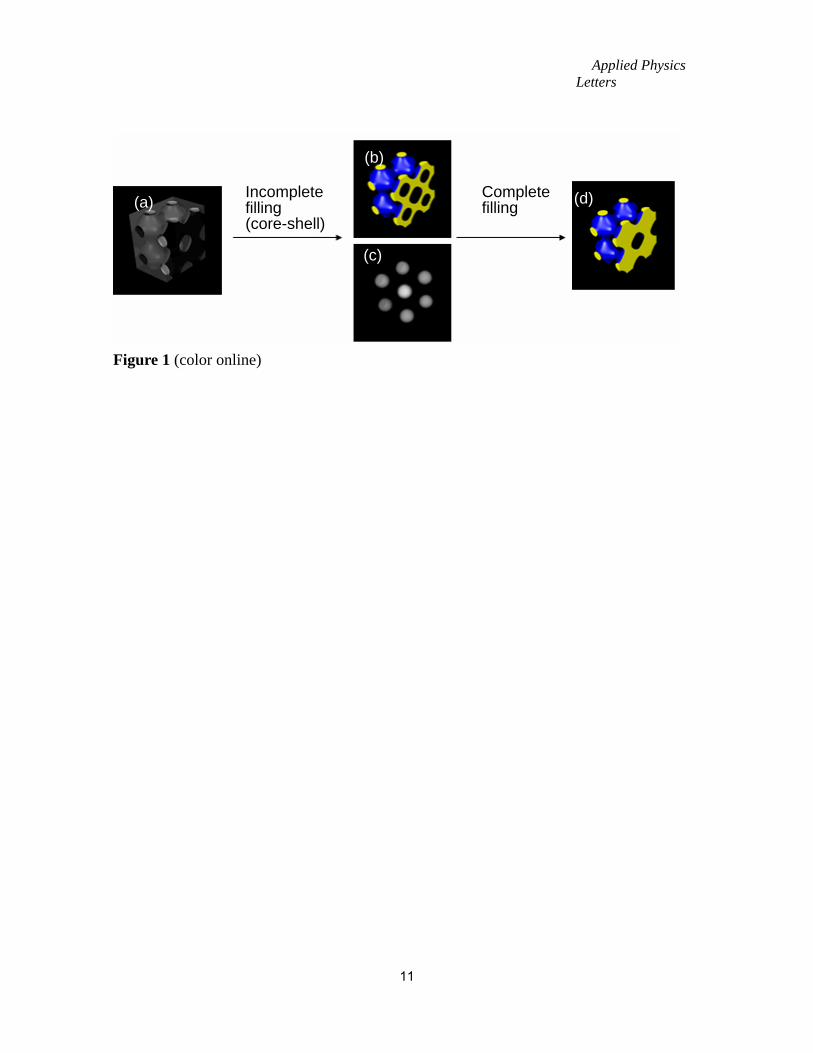
approximation to the real deposited surfaces. For example, Fig. 1 shows a schematic diagram of
a simple cubic structure formed from interference lithography, and the evolution of its replicas
from air-core-shell to completely-filled structures. Since the sum of a level surface and the
Applied Physics Letters
5
surface translated by half a lattice period gives a constant maximum value in the level-set
equation, i.e. F(-x, -y,- z) = - F(x, y, z), the volume fraction is symmetrically related to the
exposure intensity. Therefore, the desired volume fraction of the primitive photonic crystals
with high refractive index (Figure 1c) can be obtained from templates (Figure 1a) with controlled
exposure intensity.
In the bandgap calculation, we use the level-set surface of F(x, y, z) = sin(x) + sin(y) +
sin(z) for Eq. 2 and two-parameters, t1 and t2, for the outer and inner surfaces of dielectric
materials (n = nd), respectively.20 The band structures of the PC are calculated using the MIT
photonic bands (MPB) software package.24 We first calculate the complete PBG with only a
single parameter t1 (i.e., completely filled structure) ranging from 0.6 to 0.9. A bandgap appears
between the 5th and 6th bands. The maximum PBG is found at t1 = 0.83 - 0.85 with nd = 3.50,
and the corresponding volume fraction is 0.25 – 0.26, which agrees well with the results from
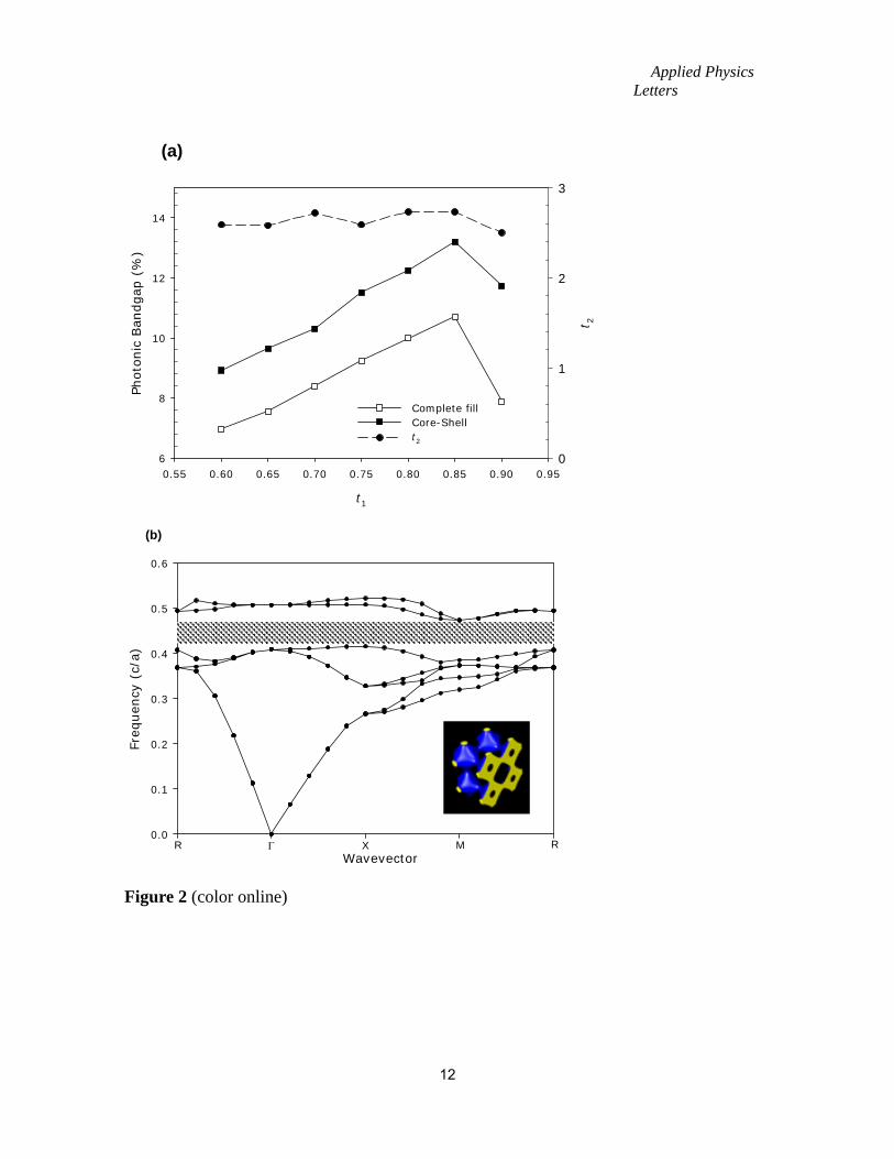
literature.20 Then, we optimize t2 to maximize the complete bandgap width while keeping the t1
fixed (i.e., core-shell structure). For t1 ranging from 0.65 to 0.90, the maximum PBG is obtained
at t2 = 2.5 – 2.7, which is smaller than t2 = 3.0 required for a completely filled simple cubic
structure (see Fig 2(a)). Therefore, the formation of shell in a simple cubic structure increases
the complete PBG by 10 – 20 % within the range of aforementioned t1. By analogy, it has been
reported that bandgap of 2D square lattice can be increased by the introduction of additional
Applied Physics Letters
6
square lattice of smaller unit atoms, which effectively reduces the crystal symmetry.25 Fig 2(b)
shows the calculated photonic band structure of a core-shell P structure with the maximum PBG.
It is found that the introduction of an air core lifts the 6th band especially at wavevector M (the
bottom of the 6th band), resulting in the increase of PBG. The inset shows the optimized
structure. Compared to the volume fraction of 0.26 for completely filled structures, the
optimized core-shell P structure has a slightly lower volume fraction of 0.25. However, such
photonic bandgap enhancement is not observed in core-shell diamond and gyroid structures.
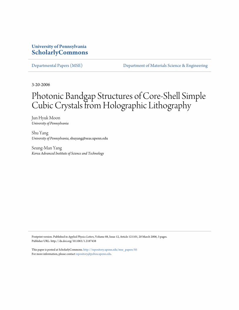
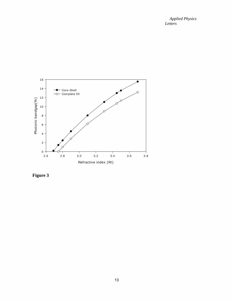
Figure 3 shows the gap/mid-gap ratios of the P structure shown in Fig 2(b) as a function
of the refractive index. The bandgap is calculated from the P surface with the largest PBG, that
is t1 = 0.84 for complete filling, and t1 = 0.84 and t2 = 2.70 for a core-shell structure. Previously,
it has been reported that the minimum refractive index required to open a complete PBG is
approximately 2.0 for D, 2.2 for G and 2.8 for P structures.21,22 In the core-shell P structure, the
minimum index contrast required to open a complete PBG is found to be less than 2.7. Thus, in
practice a simple cubic photonic crystal with a complete PBG at optical wavelengths can be
achieved by the deposition of anatase titania into photoresist templates.11
In conclusion, we have investigated the photonic bandgap properties of a core-shell
simple cubic structure using a two-parameter level-set approach. The 3D structure is defined by
the inner-core (air) and the outer-shell (dielectric) surfaces. The proposed structure can be
Applied Physics Letters
7
fabricated by backfilling a sacrificial polymer template created by multi-beam interference
lithography. The photonic bandgap width is found increased in the core-shell primitive structure
in comparison to that of the completely filled one. A complete bandgap between the 5th and 6th
bands begins to appear at a refractive index contrast of 2.7. This suggests that the core-shell
formation may offer additional controls over photonic properties. The two-parameter level-set
approach presented in this letter may provide a useful guidance for the fabrication of 3D
photonic structures through backfilling.
This work is supported by the Office of Naval Research (ONR) through the MURI
program, Grant # N00014-05-0303, and the Korea Research Foundation postdoc fellowship
(JHM), Grant # KRF-2005-000-10299. SMY acknowledges supports from National R&D Project
of Nano Science and Technology of Korea, BK-21 Program and CUPS-ERC. The authors would
like to thank Martin Maldovan and Chaitanya K. Ullal (MIT) for useful discussions.
Applied Physics Letters
8
References 1 H. G. Park, S. H. Kim, S. H. Kwon, Y. G. Ju, J. K. Yang, J. H. Baek, S. B. Kim, and Y. H.
Lee, Science 305, 1444 (2004). 2 B. J. Matterson, J. M. Lupton, A. F. Safonov, M. G. Salt, W. L. Barnes, and I. D. W.
Samuel, Adv. Mater. (Weinheim, Ger.) 13, 123 (2001). 3 Y. J. Lee and P. V. Braun, Adv. Mater. (Weinheim, Ger.) 15, 563 (2003). 4 M. Francois, J. Danglot, B. Grimbert, P. Mounaix, M. Muller, O. Vanbesien, and D.
Lippens, Microelec. Eng. 61-2, 537 (2002). 5 V. L. Colvin, MRS Bull. 26, 637 (2001). 6 A. C. Edrington, A. M. Urbas, P. DeRege, C. X. Chen, T. M. Swager, N. Hadjichristidis,
M. Xenidou, L. J. Fetters, J. D. Joannopoulos, Y. Fink, and E. L. Thomas, Adv. Mater. (Weinheim, Ger.) 13, 421 (2001).
7 K. Aoki, H. T. Miyazaki, H. Hirayama, K. Inoshita, T. Baba, K. Sakoda, N. Shinya, and Y. Aoyagi, Nat. Mater. (London) 2, 117 (2003).
8 G. M. Gratson, M. J. Xu, and J. A. Lewis, Nature (London) 428, 386 (2004). 9 B. H. Cumpston, S. P. Ananthavel, S. Barlow, D. L. Dyer, J. E. Ehrlich, L. L. Erskine, A.
A. Heikal, S. M. Kuebler, I. Y. S. Lee, D. McCord-Maughon, J. Q. Qin, H. Rockel, M. Rumi, X. L. Wu, S. R. Marder, and J. W. Perry, Nature (London) 398, 51 (1999).
10 M. Campbell, D. N. Sharp, M. T. Harrison, R. G. Denning, and A. J. Turberfield, Nature (London) 404, 53 (2000); J. H. Moon, and S. Yang, J. Macromol. Sci. C: Polym. Rev. 45, 351 (2005). 11 J. Wijnhoven, L. Bechger, and W. L. Vos, Chem. Mater. 13, 4486 (2001). 12 A. Blanco, E. Chomski, S. Grabtchak, M. Ibisate, S. John, S. W. Leonard, C. Lopez, F.
Meseguer, H. Miguez, J. P. Mondia, G. A. Ozin, O. Toader, and H. M. van Driel, Nature (London) 405, 437 (2000).
13 H. Miguez, F. Meseguer, C. Lopez, M. Holgado, G. Andreasen, A. Mifsud, and V. Fornes, Langmuir 16, 4405 (2000).
14 K. Busch and S. John, Phys. Rev. E 58, 3896 (1998). 15 K. P. Velikov, A. Moroz, and A. van Blaaderen, Appl. Phys. Lett. 80, 49 (2002). 16 M. Maldovan and E. L. Thomas, Nat. Mater. (London) 3, 593 (2004). 17 M. Maldovan, C. K. Ullal, W. C. Carter, and E. L. Thomas, Nat. Mater. (London) 2, 664
(2003). 18 L. Martin-Moreno, F. J. Garcia-Vidal, and A. M. Somoza, Phys. Rev. Lett. 83, 73 (1999). 19 D. N. Sharp, A. J. Turberfield, and R. G. Denning, Phys. Rev. B 68, 205102 (2003).
Applied Physics Letters
9
20 C. K. Ullal, M. Maldovan, E. L. Thomas, G. Chen, Y. J. Han, and S. Yang, Appl. Phys. Lett. 84, 5434 (2004).
21 M. Maldovan, A. M. Urbas, N. Yufa, W. C. Carter, and E. L. Thomas, Phys. Rev. B 65, 165123 (2002).
22 R. Biswas, M. M. Sigalas, K. M. Ho, and S. Y. Lin, Phys. Rev. B 65, 205121 (2002). 23 C. K. Ullal, M. Maldovan, M. Wohlgemuth, and E. L. Thomas, J. Opt. Soc. Am. A 20,
948 (2003). 24 http://ab-initio.mit.edu/mpb/. 25 C. M. Anderson and K. P. Giapis, Phys. Rev. Lett. 77, 2949 (1996).
Applied Physics Letters
10
Figure Captions:
Figure 1 (color online). Templating method to produce PC of high refractive index materials. (a)
Template, (b) air core/dielectric shell, (c) air core, and (d) completely filled structure.
Figure 2.(color online) (a) Complete photonic bandgap of the simple cubic lattice with core-shell
and completely filled structures, respectively. The t2 is optimized with respect to t1 to maximize
the bandgap width. (b) Photonic band structure of the simple cubic lattice with t1=0.85 and t2 =
2.7 or 25% filled, and nd =3.50, showing complete PBG between 5th and 6th bands.
Figure 3. Gap/mid-gap ratio as a function of refractive index contrast in the simple cubic
structure shown in Fig. 2(b).
Applied Physics Letters
11
Figure 1 (color online)
(a)
(b)
(c)
(d) Incomplete filling (core-shell)
Completefilling
Applied Physics Letters
12
t1
0.55 0.60 0.65 0.70 0.75 0.80 0.85 0.90 0.95
Phot
onic
Ban
dgap
(%
)
6
8
10
12
14
t 2
0
1
2
3
Complete fillCore-Shellt2
Figure 2 (color online)
Freq
uen
cy (
c/a)
0.0
0.1
0.2
0.3
0.4
0.5
0.6
R Γ X M RWavevector
(b)
(a)
Applied Physics Letters
13
Refractive index (RI)
2.6 2.8 3.0 3.2 3.4 3.6 3.8
Photo
nic
ban
dgap
(%)
0
2
4
6
8
10
12
14
16
Core-ShellComplete fill
Figure 3