Sustainable Energy for Water Desalination System Relative to Basra Climate
Upload
independentCategory
view
3download
0
Desalination 346 (2014) 30–36
Contents lists available at ScienceDirect
Desalination
j ourna l homepage: www.e lsev ie r .com/ locate /desa l
Performance of a newly developed titanium oxidenanotubes/polyethersulfone blend membrane for waterdesalination using vacuum membrane distillation
H. Abdallah a, A.F. Moustafa b, Adnan AlHathal AlAnezi c,⁎, H.E.M. El-Sayed d,1
a Chemical Engineering and Pilot Plant Department, Engineering Research Division, National Research Center, El Buhouth St, Dokki, Giza, Egyptb Environmental Screening — Environmental Management Unit, Beni Suef Governorates, Egyptc Department of Chemical Engineering Technology, College of Technological Studies, The Public Authority for Applied Education and Training (PAAET), P.O. Box 42325, Shuwaikh 70654, Kuwaitd Mechanical Engineering Department, Engineering Research Division, National Research Center, El Buhouth St, Dokki, Giza, Egypt
H I G H L I G H T S G R A P H I C A L A B S T R A C T
• Fabrications of (TNTs-PES) blend mem-brane by immersion precipitation.
• Performance of (TNTs-PES) membranewas investigated for desalination usingVMD.
• The developed (TNTs-PES) membranewas superior in terms of salt rejection.
• The permeate flux was significantly af-fected by the time of the VMD experi-ment.
• At optimum conditions the permeateflux reached 15.2 kg/m2h, where thesalt rejection was 98%.
⁎ Corresponding author. Tel.: +965 55509994; fax: +9E-mail addresses: [email protected] (H. Abda
(A.A. AlAnezi).1 Currently a Visiting Scholar at Civil and Environme
University of Windsor, 401 Sunset Avenue, Windsor, ON N
http://dx.doi.org/10.1016/j.desal.2014.05.0030011-9164/© 2014 Elsevier B.V. All rights reserved.
a b s t r a c t
a r t i c l e i n f oArticle history:Received 9 February 2014Received in revised form 30 April 2014Accepted 2 May 2014Available online xxxx
Keywords:Titanium oxide nanotubesPolyethersulfoneVacuummembrane distillationDesalination
The present paper introduces a comprehensive study of the performance of newly developed titanium oxidenanotubes (TNTs) incorporated into a Polyethersulfone (PES) blend membrane for desalination using vacuummembrane distillation (VMD) process. The study examines the effect of different operating conditions. Theresults showed a maximum salt rejection of 98% and a permeate flux of 15.2 kg/m2 h at 7000 ppm feed salt con-centration for the TNTs–PES membrane at a temperature of 65 °C and a vacuum pressure of 300 mbar with feedflow rate of 11 mL/s. A comparison between the performance of the developed TNTs-PES membrane, and com-mercial Polytetrafluoroethylene (PTFE) membrane was performed at different feed salt concentrations. Theachieved results showed a significant improvement in the performance of the new membrane compared tothe commercial PTFE membrane, where the salt rejection reached 99.3% at feed concentration 3000 ppm and96.7% at 35,000 ppm using the new membrane, compared to salt rejection of up to 90.6% at 3000 ppm and62.5% at 35,000 ppm using PTFE membrane. The dense TNTs layer formed on the top surface of the TNTs-PESblend membrane is considered a selective layer that prevents salt passage through the membrane. The declinein permeate flux may be overcome by membrane washing every hour.
© 2014 Elsevier B.V. All rights reserved.
65 22314430.llah), [email protected]
ntal Engineering Department,9B 3P4, Canada.
1. Introduction
Membrane technology is considered a very effective separationmethod, particularly in the area of water/wastewater treatment and
31H. Abdallah et al. / Desalination 346 (2014) 30–36
water desalination. The application of nanoparticles or nanotubes topolymeric membranes has attracted the attention of many researchersrecently. Moreover, the family of inorganic nanotubes has been expand-ed extensively from carbon nanotubes to sulfides [1], nitrides [2] andoxides [3]. One-dimensional nanostructured titanium oxide is ofgreat interest for possible applications in high effect solar cells [4],photocatalysts [5,6], gas sensors [7], molecular straws [8] and semicon-ductor devices due to its nanotubular structure, high specific surfacearea, ion-changeable ability, and size-dependent properties. Currently,methods developed for fabricating titanium oxides-based nanotubes,include the assisted-template method [9,10], the sol–gel process [11],electrochemical anodic oxidation [12,13], and hydrothermal treatment[14,15]. The latter process is of great interest due to its ability to yieldvery low-dimensional, well-separated crystallized nanotubes, and apure-phase structure [16].
Duringmembrane fabrication, nanoparticles and nanotubes have re-cently shown significant potential in improving polymeric membraneperformance. The remarkable effect of the addition of nanoparticles/nanotubes during membrane preparation may be attributed to theinteractions between nanoparticle surfaces and polymer chains and/orsolvents, which lead to the production of desirable structured mem-branes. These modifications of membrane structure result in favorableselectivity, permeability, and satisfactory performance in ultra-filtration and nano-filtrationmembranes [17]. Moreover, the nanoparti-cle functional groups and their hydrophilic properties were found to beable to control membrane fouling phenomena, which is a majordrawback of membrane separation technology [18–20]. There are twomajor ways of incorporating nanoparticles into polymeric membranes;(i) assembling engineered nanoparticles on the surface of the porousmembranes, where these are deposited/coated on top of themembranesurface [21–33], or (ii) blending them with polymeric casting solution,wherein the nanoparticles are disperseduniformly in themembrane so-lution by one of thewell-knownmethods; melt, solvent, sol–gel mixingand in-situ grafting [34–40].
Polyethersulfone (PES) is a widely used polymer in membranepreparation, and is now rapidly becoming the material of choice formembrane applications. Its advantages include being a high perfor-mance engineering thermoplastic, given its high glass transitiontemperature, good mechanical properties, and excellent thermal andchemical stability. However, the hydrophobicity of PES limits itsapplication, especially in the field of water desalination [41,42]. Thus,the introduction of nanoparticles to PES membranes is very useful inovercoming many of the disadvantages.
Among the different operational membrane techniques, namelymicro-, ultra-, or nano-filtration, and reverse osmosis, dialysis, etc.,membrane distillation (MD) is considered one of themost popular tech-niques utilized for seawater desalination applications. The idea of MD isbased on separating two components present in phase equilibrium;vapor/liquid or liquid/liquid. Themain driving force for such separationis the vapor pressure gradient resulting from a temperature differencebetween hot feed (salt water) and cold permeate (purewater). MDpro-vides many advantages over other distillation separation methods.These advantages include; the (i) capability to produce ultra-purewater, regardless of the salt concentration in the feed stream,(ii) lower operating cost, (iii) the unique feature of the possibility ofachieving complete rejection of non-volatile substances, and (iv) com-mercially long life with saline solutions [43–45]. Among the four well-knownmodes of operation of MD, direct contact membrane distillation(DCMD), air gap membrane distillation (AGMD), sweep gas membranedistillation (SGMD), and vacuum membrane distillation (VMD)[46–49], the latter configuration is utilized in the current study.
In this study, titanium nanotubes synthesized using the hydrother-mal method were blended into PES during polymeric membrane prepa-ration in order to enhance its performance. VMD operational techniqueswere utilized in desalination experiments. The performance of the devel-oped TNTs-PES blend membrane was tested in terms of permeate flux
and percent salt rejection at different operating conditions. In addition,the performance of the developed TNTs-PES blendmembrane was com-pared with the well-known commercial Polytetrafluoroethylene (PTFE)flat-sheet membrane at different feed salt concentrations.
2. Experimental work
2.1. Materials
Polyethersulfone (PES), Ultrason E 6020P, molecular weightof 58,000 g/mol and glass transition temperature of Tg = 225 °Cand N-Methylpyrrolidone as a solvent were purchased from BASFchemical company. TiO2 nano powder, NaOH, HCl, acetonitrile, andtetramethylsiloxane were purchased from Sigma Aldrich Company.Commercial Polytetrafluoroethylene (PTFE) flat-sheet membraneswere supplied by Millipore Corporation. The specifications of thesupplied membrane are as follows; diameter of 4.7 cm, thickness of120 μm, porosity of 75%, and pore diameter of 0.2 μm. Synthetic salt solu-tions were prepared with different concentrations using distilled waterand commercial NaCl, where the commercial NaCl used as a food salt,and contains 98.5% sodium chloride and 70–30 ppm potassium iodine.
2.2. Synthesis of titanium oxide nanotubes
The approach of self-organized synthesis using the hydrothermalmethod is applied in the present study for the preparation of thetitanium oxide nanotubes. TiO2 nanopowder was dispersed in150 mL of 10 M NaOH and stirred for 15 min. The dispersion wasthen transferred to a Teflon lined autoclave (KH-300) and heatedat 150 °C for 16 h. The white precipitate obtained was washed with1 M HCl first, then with distilled water, and finally dried at 80 °Cfor 4 h. A detailed description of the preparation method is describedelsewhere [50,51].
2.3. Titanium oxide nanotubes membrane fabrication
For the preparation of the titanium oxide nanotube solution, 5 wt.%of tetramethylsiloxane was added first to the acetonitrile solvent, then5 wt.% of the titanium oxide nanotube powder was added under con-stant stirring for 3 h. For the preparation of the polymer casting solution,18 wt.% of PES was dissolved first in the N-Methylpyrrolidone (NMP)solvent and then added to 9% of the previously prepared nanotube solu-tion under constant stirring for 6 h at room temperature. The preparedpolymer solutionwas cast on a smooth flat glass plate by a casting knifewith uniform speed, where the membrane thickness was sustained at0.2 ± 0.01 mm. Subsequently, the polymer solution on the glass plateswas solidified by immediate immersion in a coagulation bath containingdistilled water. The membrane was spontaneously released from theplate and kept for 24 h to ensure complete removal of solvent fromthe membrane. Finally, the membranes were dried by placing thembetween two sheets of filter paper for 24 h at room temperature.
2.4. Desalination experiments
A flat sheet membrane module supplied byMillipore was utilized inthe desalination experiments. The effective area of themembrane in themodulewas determined to be 17.34 cm2. A one liter jacketedmixer ves-sel was filled with different concentrations of previously prepared feedsalt solutions. The salt solution in the mixer feed vessel was heatedusing a circulation water bath to the jacket, which was controlled by athermostat to be kept in the range of (25–65 °C). The feed temperatureinside the mixer feed vessel was continuously monitored using a ther-mometer fitted to the feed vessel. The saline solution was continuouslyfed to themembranemodule from the jacketed feedmixer by a peristal-tic pump. The permeate water vapor was drawn from the membranemodule to a chiller condenserwith the aid of a vacuumpumpconnected
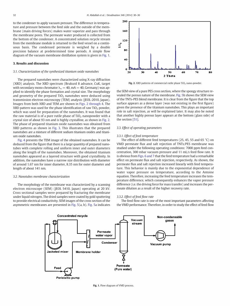
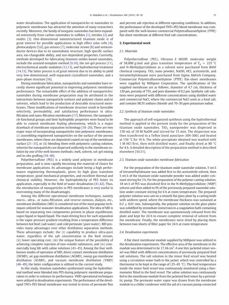
Fig. 2. XRD patterns of commercial rutile phase TiO2 nano-powder.
32 H. Abdallah et al. / Desalination 346 (2014) 30–36
to the condenser to apply vacuum pressure. The difference in tempera-ture and pressure between the feed side and the outside of the mem-brane (main driving forces) makes water vaporize and pass throughthe membrane pores. The permeate water produced is collected fromthe bottom of the condenser. A concentrated solution recycle streamfrom the membrane module is returned to the feed vessel on a contin-uous basis. The condensed permeate is weighed by a doubleprecision balance at predetermined time periods. A simple flowdiagram of the vacuum membrane distillation system is given in Fig. 1.
3. Results and discussion
3.1. Characterization of the synthesized titanium oxide nanotubes
The prepared nanotubes were characterized using X-ray diffraction(XRD) analysis. The XRD spectrum (Brukurd 8 advance, CuK, targetwith secondarymono chromator λυ=40,mA=40, Germany) was ap-plied to identify the phase formation and crystal size. The morphologyand geometry of the prepared TiO2 nanotubes were deduced usingtransmission electron microscopy (TEM) analysis (JEOL-2010, Japan).Images from both XRD and TEM are shown in Figs. 2 through 4. TheXRD pattern was used for the phase identification of raw TiO2 powder,which was used for preparation of the nanotubes. It was found thatthe raw material is of a pure rutile phase of TiO2 nanopowder with acrystal size of about 93 nm and is highly crystalline, as shown in Fig. 2.The phase of prepared titanium oxide nanotubes was obtained fromXRD patterns as shown in Fig. 3. This illustrates that the preparednanotubes are a mixture of different sodium titanium oxides and titani-um oxide nanotubes.
Fig. 4 presents the TEM image of the obtained nanotubes. It can bededuced from the figure that there is a large quantity of prepared nano-tubes with complete rolling and uniform inner and outer diametersalong the length of the nanotubes. Moreover, the obtained titaniumnanotubes appeared as a layered structure with good crystallinity. Inaddition, the nanotubes have a narrow size distribution with diameterof around 1.67 nm for inner diameter, 8.35 nm for outer diameter andlength of about 141 nm.
3.2. Nanotubes membrane characterization
The morphology of the membrane was characterized by a scanningelectron microscope (SEM) (JEOL 5410, Japan) operating at 20 kV.Cross sectional samples were prepared by fracturing the membraneunder liquid nitrogen. Thedried sampleswere coated by gold sputteringto provide electrical conductivity. SEM images of the cross section of theasymmetric membranes are presented in Fig. 5(a, b). Fig. 5a indicates
Fig. 1. Flow diagram
the SEMviewof a pure PES cross section,where the spongy structure re-vealed the porous nature of themembrane. Fig. 5b shows the SEM viewof the TNTs-PES blendmembrane. It is clear from the figure that the topsurface appears as a dense layer (was not existing in the first figure)given the presence of the titanium nanotubes. This plays an importantrole in salt rejection, as will be explained later. It may also be notedthat another highly porous layer appears at the bottom (glass side) ofthe section [51].
3.3. Effect of operating parameters
3.3.1. Effect of feed temperatureThe effect of different feed temperatures (25, 45, 55 and 65 °C) on
VMD permeate flux and salt rejection of TNTs/PES membrane wasstudied under the following operating conditions: 7000 ppm feed con-centration, 300 mbar vacuum pressure and 11 mL/s feed flow rate. Itis obvious fromFigs. 6 and 7 that the feed temperature had a remarkableeffect on permeate flux and salt rejection, respectively. As shown, thepermeate flux and salt rejection increased linearly with feed tempera-ture. This behavior is mainly due to the exponential dependence ofwater vapor pressure on temperature, according to the Antoineequation. Therefore, increasing the feed temperature increases the tem-perature difference, which consequently enhances the vapor pressuredifference (i.e. thedriving force formass transfer) and increases the per-meate dilution as a result of the higher recovery rate.
3.3.2. Effect of feed flow rateThe feed flow rate is one of the most important parameters affecting
the VMDperformance. Therefore, in order to study the effect of feed flow
of VMD process.
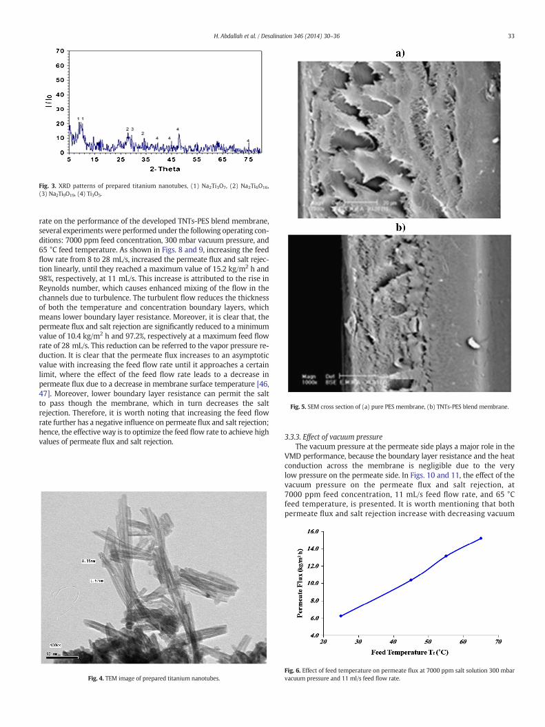
Fig. 3. XRD patterns of prepared titanium nanotubes, (1) Na2Ti3O7, (2) Na2Ti6O16,(3) Na2Ti9O19, (4) Ti3O5.
Fig. 5. SEM cross section of (a) pure PES membrane, (b) TNTs-PES blend membrane.
33H. Abdallah et al. / Desalination 346 (2014) 30–36
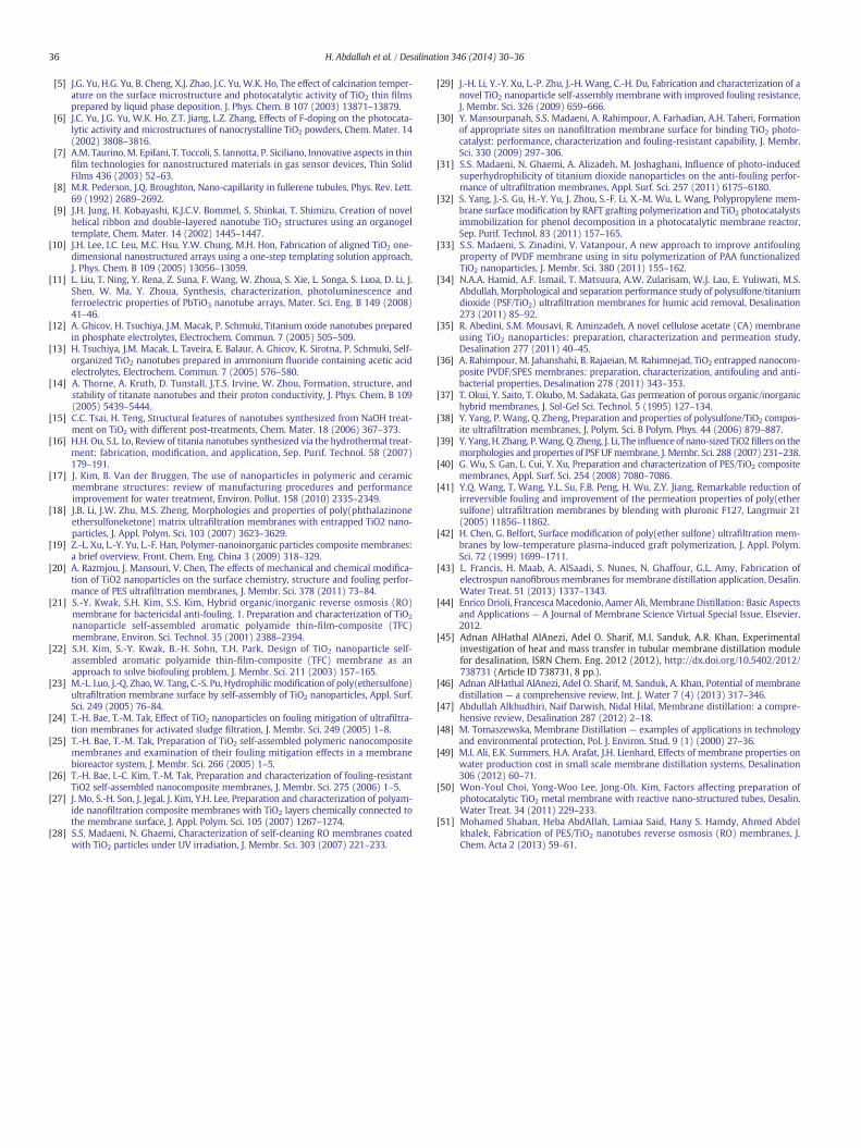
rate on the performance of the developed TNTs-PES blend membrane,several experimentswere performed under the following operating con-ditions: 7000 ppm feed concentration, 300 mbar vacuum pressure, and65 °C feed temperature. As shown in Figs. 8 and 9, increasing the feedflow rate from 8 to 28 mL/s, increased the permeate flux and salt rejec-tion linearly, until they reached a maximum value of 15.2 kg/m2 h and98%, respectively, at 11 mL/s. This increase is attributed to the rise inReynolds number, which causes enhanced mixing of the flow in thechannels due to turbulence. The turbulent flow reduces the thicknessof both the temperature and concentration boundary layers, whichmeans lower boundary layer resistance. Moreover, it is clear that, thepermeate flux and salt rejection are significantly reduced to a minimumvalue of 10.4 kg/m2 h and 97.2%, respectively at a maximum feed flowrate of 28 mL/s. This reduction can be referred to the vapor pressure re-duction. It is clear that the permeate flux increases to an asymptoticvalue with increasing the feed flow rate until it approaches a certainlimit, where the effect of the feed flow rate leads to a decrease inpermeate flux due to a decrease in membrane surface temperature [46,47]. Moreover, lower boundary layer resistance can permit the saltto pass though the membrane, which in turn decreases the saltrejection. Therefore, it is worth noting that increasing the feed flowrate further has a negative influence on permeate flux and salt rejection;hence, the effective way is to optimize the feed flow rate to achieve highvalues of permeate flux and salt rejection.
Fig. 4. TEM image of prepared titanium nanotubes.
3.3.3. Effect of vacuum pressureThe vacuum pressure at the permeate side plays a major role in the
VMD performance, because the boundary layer resistance and the heatconduction across the membrane is negligible due to the verylow pressure on the permeate side. In Figs. 10 and 11, the effect of thevacuum pressure on the permeate flux and salt rejection, at7000 ppm feed concentration, 11 mL/s feed flow rate, and 65 °Cfeed temperature, is presented. It is worth mentioning that bothpermeate flux and salt rejection increase with decreasing vacuum
Fig. 6. Effect of feed temperature on permeate flux at 7000 ppm salt solution 300 mbarvacuum pressure and 11 ml/s feed flow rate.
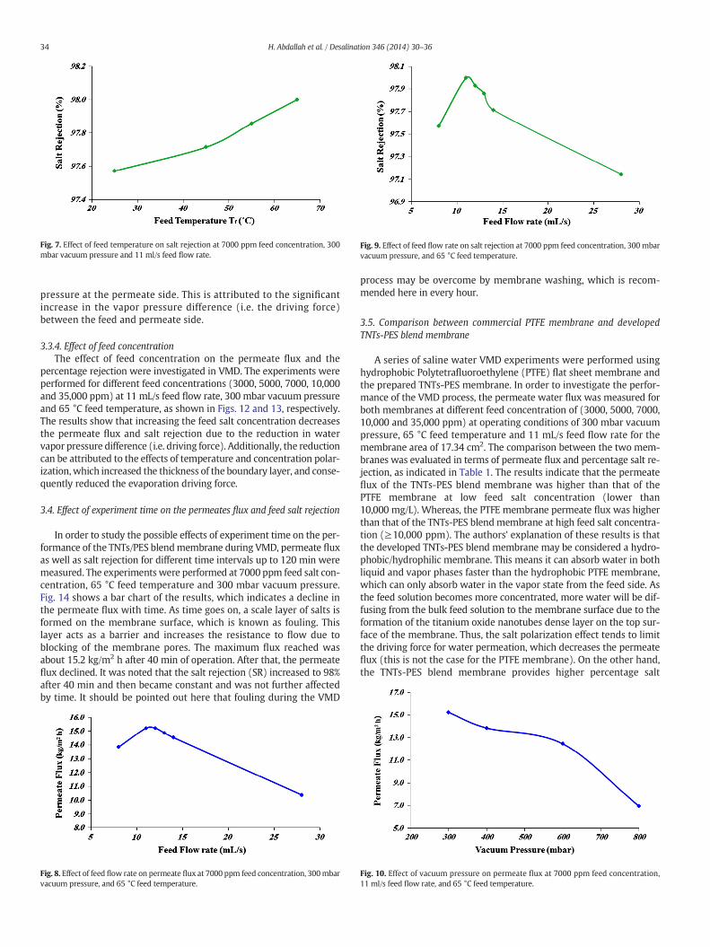
Fig. 7. Effect of feed temperature on salt rejection at 7000 ppm feed concentration, 300mbar vacuum pressure and 11 ml/s feed flow rate.
Fig. 9. Effect of feed flow rate on salt rejection at 7000 ppm feed concentration, 300 mbarvacuum pressure, and 65 °C feed temperature.
34 H. Abdallah et al. / Desalination 346 (2014) 30–36
pressure at the permeate side. This is attributed to the significantincrease in the vapor pressure difference (i.e. the driving force)between the feed and permeate side.
3.3.4. Effect of feed concentrationThe effect of feed concentration on the permeate flux and the
percentage rejection were investigated in VMD. The experiments wereperformed for different feed concentrations (3000, 5000, 7000, 10,000and 35,000 ppm) at 11 mL/s feed flow rate, 300 mbar vacuum pressureand 65 °C feed temperature, as shown in Figs. 12 and 13, respectively.The results show that increasing the feed salt concentration decreasesthe permeate flux and salt rejection due to the reduction in watervapor pressure difference (i.e. driving force). Additionally, the reductioncan be attributed to the effects of temperature and concentration polar-ization,which increased the thickness of the boundary layer, and conse-quently reduced the evaporation driving force.
3.4. Effect of experiment time on the permeates flux and feed salt rejection
In order to study the possible effects of experiment time on the per-formance of the TNTs/PES blendmembrane during VMD, permeate fluxas well as salt rejection for different time intervals up to 120 min weremeasured. The experiments were performed at 7000 ppm feed salt con-centration, 65 °C feed temperature and 300 mbar vacuum pressure.Fig. 14 shows a bar chart of the results, which indicates a decline inthe permeate flux with time. As time goes on, a scale layer of salts isformed on the membrane surface, which is known as fouling. Thislayer acts as a barrier and increases the resistance to flow due toblocking of the membrane pores. The maximum flux reached wasabout 15.2 kg/m2 h after 40 min of operation. After that, the permeateflux declined. It was noted that the salt rejection (SR) increased to 98%after 40 min and then became constant and was not further affectedby time. It should be pointed out here that fouling during the VMD
Fig. 8. Effect of feed flow rate on permeate flux at 7000 ppm feed concentration, 300mbarvacuum pressure, and 65 °C feed temperature.
process may be overcome by membrane washing, which is recom-mended here in every hour.
3.5. Comparison between commercial PTFE membrane and developedTNTs-PES blend membrane
A series of saline water VMD experiments were performed usinghydrophobic Polytetrafluoroethylene (PTFE) flat sheet membrane andthe prepared TNTs-PES membrane. In order to investigate the perfor-mance of the VMD process, the permeate water flux was measured forboth membranes at different feed concentration of (3000, 5000, 7000,10,000 and 35,000 ppm) at operating conditions of 300 mbar vacuumpressure, 65 °C feed temperature and 11 mL/s feed flow rate for themembrane area of 17.34 cm2. The comparison between the two mem-branes was evaluated in terms of permeate flux and percentage salt re-jection, as indicated in Table 1. The results indicate that the permeateflux of the TNTs-PES blend membrane was higher than that of thePTFE membrane at low feed salt concentration (lower than10,000 mg/L). Whereas, the PTFE membrane permeate flux was higherthan that of the TNTs-PES blendmembrane at high feed salt concentra-tion (≥10,000 ppm). The authors' explanation of these results is thatthe developed TNTs-PES blend membrane may be considered a hydro-phobic/hydrophilic membrane. This means it can absorb water in bothliquid and vapor phases faster than the hydrophobic PTFE membrane,which can only absorb water in the vapor state from the feed side. Asthe feed solution becomes more concentrated, more water will be dif-fusing from the bulk feed solution to the membrane surface due to theformation of the titanium oxide nanotubes dense layer on the top sur-face of the membrane. Thus, the salt polarization effect tends to limitthe driving force for water permeation, which decreases the permeateflux (this is not the case for the PTFE membrane). On the other hand,the TNTs-PES blend membrane provides higher percentage salt
Fig. 10. Effect of vacuum pressure on permeate flux at 7000 ppm feed concentration,11 ml/s feed flow rate, and 65 °C feed temperature.

Fig. 11. Effect of vacuum pressure on % salt rejection at 7000 ppm feed concentration,11 ml/s feed flow rate, and 65 °C feed temperature.
Fig. 12. Effect of feed salt concentration on permeate flux at 300 mbar vacuum pressure,11 mL/s feed flow rate and 65 °C feed temperature.
Fig. 14. Performance of the developed TNTs-PES blend membrane with time at 7000 ppmfeed salt concentration, 65 °C temperature, and 300 mbar vacuum pressure.
Table 1Comparison between PTFE membrane and prepared TNTs-PES membrane.
Feed concentrationppm
PTFE TNTs-PES PTFE TNTs-PES
Permeate flux(kg/m2 h)
Salt rejection(%)
3000 21.5 24.9 90.6 99.35000 18.4 21.8 88.2 98.67000 12.7 15.2 79.4 98.010,000 10.2 8.00 68.6 97.835,000 7.20 5.50 62.5 96.7
35H. Abdallah et al. / Desalination 346 (2014) 30–36
rejection over the whole range of feed concentrations. Again, the denseTNT layer formed on the top surface of the TNTs-PES blendmembrane isconsidered a selective layer that prevents salt passage through themembrane.
4. Conclusions
Introducing titanium oxide nanotubes during polymeric membranefabrication has resulted in significant improvements in the membraneperformance in terms of permeate flux and salt rejection. Vacuummembrane distillation (VMD) for water desalination experimentswere carried out in the present study at different operating conditions.
Fig. 13. Effect of salt concentration on salt rejection at 300mbar vacuumpressure, 11mL/sfeed flow rate, and 65 °C feed temperature.
The results showed a maximum salt rejection of 98% and a permeateflux of 15.2 kg/m2 h at the optimum conditions of 65 °C feed tempera-ture, 7000 ppm feed salt concentration, 300 mbar vacuum pressure,and 11 mL/s feed flow rate. The permeate flux was found to be signifi-cantly affected by the time of the VMD experiment. The formation ofsalt scales that blocked themembrane pores hindered the flow of fluidsacross the membrane. After 40min of operation, the permeate flux wasdeclining after it reached a value of 15.2 kg/m2 h. On the other hand, thesalt rejection reached 98% at 40min of operation and remained constantafter that until the end of the experiment (120 min).
The developed TNTs-PES blendmembrane was superior to the com-mercial PTFE hydrophobic membrane in terms of salt rejection.Employing the developed TNTs-PES blend membrane in VMD using afeed concentration of 3000 ppm provided a higher salt rejection of99.3% and higher permeate flux of 24.9 kg/m2 h, compared to 90.6%and 21.5 kg/m2 h in the case of the PTFE membrane, therefore usingthe developed new membrane in a high salt feed concentration of35,000 ppm provided 96.7% salt rejection compared to 62.5% in thecase of the PTFEmembrane but the permeate flux of the newmembranedeclined at increasing feed concentration to 5.5 kg/m2 h compared to7.2 kg/m2 h using the PTFE membrane, where the dense layer formedon the top surface of the developed TNTs-PES blend membrane limitedthe permeate flux at feed salt concentrations higher than 7000 ppm.From the above findings, the authors recommend the possibility ofusing the developed TNTs-PES blend membrane in nanofiltration (NF)and reverse osmosis (RO) operational regimes in addition to VMD oper-ation, due to the presence of a double hydrophobic/hydrophilic property.
References
[1] Y. Feldman, E. Wasserman, D.J. Srolovitz, R. Tenne, High-rate, gas-phase growth ofMoS2 nested inorganic fullerenes and nanotubes, Science 267 (1995) 222–225.
[2] N.G. Chopra, R.J. Luyken, K. Cherry, V.H. Crespi, M.L. Cohen, S.G. Louie, A. Zettl, Boronnitride nanotubes, Science 269 (1995) 966–967.
[3] R. Tenne, C.N.R. Rao, Inorganic nanotubes, Philos. Trans. R. Soc. Lond. A 362 (2004)2099–2125.
[4] U. Bach, D. Lupo, P. Comte, J.E. Moser, F. Welssortels, J. Salbeck, H. Spreitzer, M.Grätzel, Solid-state dye-sensitized mesoporous TiO2 solar cells with high photon-to-electron conversion efficiencies, Nature 395 (1998) 583–585.
36 H. Abdallah et al. / Desalination 346 (2014) 30–36
[5] J.G. Yu, H.G. Yu, B. Cheng, X.J. Zhao, J.C. Yu, W.K. Ho, The effect of calcination temper-ature on the surface microstructure and photocatalytic activity of TiO2 thin filmsprepared by liquid phase deposition, J. Phys. Chem. B 107 (2003) 13871–13879.
[6] J.C. Yu, J.G. Yu, W.K. Ho, Z.T. Jiang, L.Z. Zhang, Effects of F-doping on the photocata-lytic activity and microstructures of nanocrystalline TiO2 powders, Chem. Mater. 14(2002) 3808–3816.
[7] A.M. Taurino, M. Epifani, T. Toccoli, S. Iannotta, P. Siciliano, Innovative aspects in thinfilm technologies for nanostructured materials in gas sensor devices, Thin SolidFilms 436 (2003) 52–63.
[8] M.R. Pederson, J.Q. Broughton, Nano-capillarity in fullerene tubules, Phys. Rev. Lett.69 (1992) 2689–2692.
[9] J.H. Jung, H. Kobayashi, K.J.C.V. Bommel, S. Shinkai, T. Shimizu, Creation of novelhelical ribbon and double-layered nanotube TiO2 structures using an organogeltemplate, Chem. Mater. 14 (2002) 1445–1447.
[10] J.H. Lee, I.C. Leu, M.C. Hsu, Y.W. Chung, M.H. Hon, Fabrication of aligned TiO2 one-dimensional nanostructured arrays using a one-step templating solution approach,J. Phys. Chem. B 109 (2005) 13056–13059.
[11] L. Liu, T. Ning, Y. Rena, Z. Suna, F. Wang, W. Zhoua, S. Xie, L. Songa, S. Luoa, D. Li, J.Shen, W. Ma, Y. Zhoua, Synthesis, characterization, photoluminescence andferroelectric properties of PbTiO3 nanotube arrays, Mater. Sci. Eng. B 149 (2008)41–46.
[12] A. Ghicov, H. Tsuchiya, J.M. Macak, P. Schmuki, Titanium oxide nanotubes preparedin phosphate electrolytes, Electrochem. Commun. 7 (2005) 505–509.
[13] H. Tsuchiya, J.M. Macak, L. Taveira, E. Balaur, A. Ghicov, K. Sirotna, P. Schmuki, Self-organized TiO2 nanotubes prepared in ammonium fluoride containing acetic acidelectrolytes, Electrochem. Commun. 7 (2005) 576–580.
[14] A. Thorne, A. Kruth, D. Tunstall, J.T.S. Irvine, W. Zhou, Formation, structure, andstability of titanate nanotubes and their proton conductivity, J. Phys. Chem. B 109(2005) 5439–5444.
[15] C.C. Tsai, H. Teng, Structural features of nanotubes synthesized from NaOH treat-ment on TiO2 with different post-treatments, Chem. Mater. 18 (2006) 367–373.
[16] H.H. Ou, S.L. Lo, Review of titania nanotubes synthesized via the hydrothermal treat-ment: fabrication, modification, and application, Sep. Purif. Technol. 58 (2007)179–191.
[17] J. Kim, B. Van der Bruggen, The use of nanoparticles in polymeric and ceramicmembrane structures: review of manufacturing procedures and performanceimprovement for water treatment, Environ. Pollut. 158 (2010) 2335–2349.
[18] J.B. Li, J.W. Zhu, M.S. Zheng, Morphologies and properties of poly(phthalazinoneethersulfoneketone) matrix ultrafiltration membranes with entrapped TiO2 nano-particles, J. Appl. Polym. Sci. 103 (2007) 3623–3629.
[19] Z.-L. Xu, L.-Y. Yu, L.-F. Han, Polymer-nanoinorganic particles composite membranes:a brief overview, Front. Chem. Eng. China 3 (2009) 318–329.
[20] A. Razmjou, J. Mansouri, V. Chen, The effects of mechanical and chemical modifica-tion of TiO2 nanoparticles on the surface chemistry, structure and fouling perfor-mance of PES ultrafiltration membranes, J. Membr. Sci. 378 (2011) 73–84.
[21] S.-Y. Kwak, S.H. Kim, S.S. Kim, Hybrid organic/inorganic reverse osmosis (RO)membrane for bactericidal anti-fouling. 1. Preparation and characterization of TiO2
nanoparticle self-assembled aromatic polyamide thin-film-composite (TFC)membrane, Environ. Sci. Technol. 35 (2001) 2388–2394.
[22] S.H. Kim, S.-Y. Kwak, B.-H. Sohn, T.H. Park, Design of TiO2 nanoparticle self-assembled aromatic polyamide thin-film-composite (TFC) membrane as anapproach to solve biofouling problem, J. Membr. Sci. 211 (2003) 157–165.
[23] M.-L. Luo, J.-Q. Zhao,W. Tang, C.-S. Pu, Hydrophilic modification of poly(ethersulfone)ultrafiltration membrane surface by self-assembly of TiO2 nanoparticles, Appl. Surf.Sci. 249 (2005) 76–84.
[24] T.-H. Bae, T.-M. Tak, Effect of TiO2 nanoparticles on fouling mitigation of ultrafiltra-tion membranes for activated sludge filtration, J. Membr. Sci. 249 (2005) 1–8.
[25] T.-H. Bae, T.-M. Tak, Preparation of TiO2 self-assembled polymeric nanocompositemembranes and examination of their fouling mitigation effects in a membranebioreactor system, J. Membr. Sci. 266 (2005) 1–5.
[26] T.-H. Bae, I.-C. Kim, T.-M. Tak, Preparation and characterization of fouling-resistantTiO2 self-assembled nanocomposite membranes, J. Membr. Sci. 275 (2006) 1–5.
[27] J. Mo, S.-H. Son, J. Jegal, J. Kim, Y.H. Lee, Preparation and characterization of polyam-ide nanofiltration composite membranes with TiO2 layers chemically connected tothe membrane surface, J. Appl. Polym. Sci. 105 (2007) 1267–1274.
[28] S.S. Madaeni, N. Ghaemi, Characterization of self-cleaning RO membranes coatedwith TiO2 particles under UV irradiation, J. Membr. Sci. 303 (2007) 221–233.
[29] J.-H. Li, Y.-Y. Xu, L.-P. Zhu, J.-H. Wang, C.-H. Du, Fabrication and characterization of anovel TiO2 nanoparticle self-assembly membrane with improved fouling resistance,J. Membr. Sci. 326 (2009) 659–666.
[30] Y. Mansourpanah, S.S. Madaeni, A. Rahimpour, A. Farhadian, A.H. Taheri, Formationof appropriate sites on nanofiltration membrane surface for binding TiO2 photo-catalyst: performance, characterization and fouling-resistant capability, J. Membr.Sci. 330 (2009) 297–306.
[31] S.S. Madaeni, N. Ghaemi, A. Alizadeh, M. Joshaghani, Influence of photo-inducedsuperhydrophilicity of titanium dioxide nanoparticles on the anti-fouling perfor-mance of ultrafiltration membranes, Appl. Surf. Sci. 257 (2011) 6175–6180.
[32] S. Yang, J.-S. Gu, H.-Y. Yu, J. Zhou, S.-F. Li, X.-M. Wu, L. Wang, Polypropylene mem-brane surface modification by RAFT grafting polymerization and TiO2 photocatalystsimmobilization for phenol decomposition in a photocatalytic membrane reactor,Sep. Purif. Technol. 83 (2011) 157–165.
[33] S.S. Madaeni, S. Zinadini, V. Vatanpour, A new approach to improve antifoulingproperty of PVDF membrane using in situ polymerization of PAA functionalizedTiO2 nanoparticles, J. Membr. Sci. 380 (2011) 155–162.
[34] N.A.A. Hamid, A.F. Ismail, T. Matsuura, A.W. Zularisam, W.J. Lau, E. Yuliwati, M.S.Abdullah, Morphological and separation performance study of polysulfone/titaniumdioxide (PSF/TiO2) ultrafiltration membranes for humic acid removal, Desalination273 (2011) 85–92.
[35] R. Abedini, S.M. Mousavi, R. Aminzadeh, A novel cellulose acetate (CA) membraneusing TiO2 nanoparticles: preparation, characterization and permeation study,Desalination 277 (2011) 40–45.
[36] A. Rahimpour, M. Jahanshahi, B. Rajaeian, M. Rahimnejad, TiO2 entrapped nanocom-posite PVDF/SPES membranes: preparation, characterization, antifouling and anti-bacterial properties, Desalination 278 (2011) 343–353.
[37] T. Okui, Y. Saito, T. Okubo, M. Sadakata, Gas permeation of porous organic/inorganichybrid membranes, J. Sol-Gel Sci. Technol. 5 (1995) 127–134.
[38] Y. Yang, P. Wang, Q. Zheng, Preparation and properties of polysulfone/TiO2 compos-ite ultrafiltration membranes, J. Polym. Sci. B Polym. Phys. 44 (2006) 879–887.
[39] Y. Yang, H. Zhang, P.Wang, Q. Zheng, J. Li, The influence of nano-sized TiO2fillers on themorphologies and properties of PSF UFmembrane, J. Membr. Sci. 288 (2007) 231–238.
[40] G. Wu, S. Gan, L. Cui, Y. Xu, Preparation and characterization of PES/TiO2 compositemembranes, Appl. Surf. Sci. 254 (2008) 7080–7086.
[41] Y.Q. Wang, T. Wang, Y.L. Su, F.B. Peng, H. Wu, Z.Y. Jiang, Remarkable reduction ofirreversible fouling and improvement of the permeation properties of poly(ethersulfone) ultrafiltration membranes by blending with pluronic F127, Langmuir 21(2005) 11856–11862.
[42] H. Chen, G. Belfort, Surface modification of poly(ether sulfone) ultrafiltration mem-branes by low-temperature plasma-induced graft polymerization, J. Appl. Polym.Sci. 72 (1999) 1699–1711.
[43] L. Francis, H. Maab, A. AlSaadi, S. Nunes, N. Ghaffour, G.L. Amy, Fabrication ofelectrospun nanofibrousmembranes for membrane distillation application, Desalin.Water Treat. 51 (2013) 1337–1343.
[44] Enrico Drioli, FrancescaMacedonio, Aamer Ali, Membrane Distillation: Basic Aspectsand Applications — A Journal of Membrane Science Virtual Special Issue, Elsevier,2012.
[45] Adnan AlHathal AlAnezi, Adel O. Sharif, M.I. Sanduk, A.R. Khan, Experimentalinvestigation of heat and mass transfer in tubular membrane distillation modulefor desalination, ISRN Chem. Eng. 2012 (2012), http://dx.doi.org/10.5402/2012/738731 (Article ID 738731, 8 pp.).
[46] Adnan AlHathal AlAnezi, Adel O. Sharif, M. Sanduk, A. Khan, Potential of membranedistillation — a comprehensive review, Int. J. Water 7 (4) (2013) 317–346.
[47] Abdullah Alkhudhiri, Naif Darwish, Nidal Hilal, Membrane distillation: a compre-hensive review, Desalination 287 (2012) 2–18.
[48] M. Tomaszewska, Membrane Distillation — examples of applications in technologyand environmental protection, Pol. J. Environ. Stud. 9 (1) (2000) 27–36.
[49] M.I. Ali, E.K. Summers, H.A. Arafat, J.H. Lienhard, Effects of membrane properties onwater production cost in small scale membrane distillation systems, Desalination306 (2012) 60–71.
[50] Won-Youl Choi, Yong-Woo Lee, Jong-Oh. Kim, Factors affecting preparation ofphotocatalytic TiO2 metal membrane with reactive nano-structured tubes, Desalin.Water Treat. 34 (2011) 229–233.
[51] Mohamed Shaban, Heba AbdAllah, Lamiaa Said, Hany S. Hamdy, Ahmed Abdelkhalek, Fabrication of PES/TiO2 nanotubes reverse osmosis (RO) membranes, J.Chem. Acta 2 (2013) 59–61.
Copyright © 2022 FDOKUMEN