Parametric analysis of the selective laser melting process
6
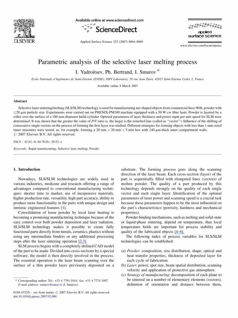
Parametric analysis of the selective laser melting process I. Yadroitsev, Ph. Bertrand, I. Smurov * Ecole Nationale d’Inge ´nieurs de Saint-Etienne (ENISE), DIPI Laboratory, 58 rue Jean Parot, 42023 Saint-Etienne Cedex 2, France Available online 4 March 2007 Abstract Selective laser sintering/melting (SLS/SLM) technology is used for manufacturing net-shaped objects from commercial Inox 904L powder with 20 mm particle size. Experiments were carried out on PHENIX-PM100 machine equipped with a 50 W cw fiber laser. Powder is layered by a roller over the surface of a 100 mm-diameter build cylinder. Optimal parameters of layer thickness and power input per unit speed for SLM were determined. It was shown that the greater the value of P/V ratio is, the larger is the remelted line (called as ‘‘vector’’). Influence of the shifting of consecutive single vectors on the process of forming the first layer was studied. Different strategies for forming objects with less than 1 mm-sized inner structures were tested, as, for example, forming a 20 mm 20 mm 5 mm box with 140 mm-thick inner compartment walls. # 2007 Elsevier B.V. All rights reserved. PACS : 42.62.–b; 64.70.Dv; 28.52.–s Keywords: Rapid manufacturing; Selective laser melting; Powder 1. Introduction Nowadays, SLS/SLM technologies are widely used in various industries, medicine and research offering a range of advantages compared to conventional manufacturing techni- ques: shorter time to market, use of inexpensive materials, higher production rate, versatility, high part accuracy, ability to produce more functionality in the parts with unique design and intrinsic engineered features [1]. Consolidation of loose powder by local laser heating is becoming a promising manufacturing technique because of the easy control over both powder deposition and laser radiation. SLS/SLM technology makes it possible to create fully functional parts directly from metals, ceramics, plastics without using any intermediate binders or any additional processing steps after the laser sintering operation [2,3]. SLM process begins with a completely defined CAD model of the part to be made. Divided into cross-sections by a special software, the model is then directly involved in the process. The essential operation is the laser beam scanning over the surface of a thin powder layer previously deposited on a substrate. The forming process goes along the scanning direction of the laser beam. Each cross-section (layer) of the part is sequentially filled with elongated lines (vectors) of molten powder. The quality of a part produced by this technology depends strongly on the quality of each single vector and each single layer. Identification of the optimal parameters of laser power and scanning speed is a crucial task because these parameters happen to be the most influential on the part’s characteristics (porosity, hardness and mechanical properties). Powder binding mechanisms, such as melting and solid-state or liquid-phase sintering, depend on temperature, thus local temperature fields are important for process stability and quality of the fabricated objects [4–6]. The following index of process variables for SLS/SLM technologies can be established: (a) Powder: composition, size distribution, shape, optical and heat transfer properties, thickness of deposited layer for each cycle of fabrication. (b) Laser: power, spot size, beam spatial distribution, scanning velocity and application of protective gas atmosphere. (c) Strategy of manufacturing: decomposition of each plane to be sintered on a number of elementary elements (vectors), definition of orientation and distance between them, www.elsevier.com/locate/apsusc Applied Surface Science 253 (2007) 8064–8069 * Corresponding author. Tel.: +33 4 7791 0161; fax: +33 4 7774 3497. E-mail address: [email protected] (I. Smurov). 0169-4332/$ – see front matter # 2007 Elsevier B.V. All rights reserved. doi:10.1016/j.apsusc.2007.02.088
Transcript of Parametric analysis of the selective laser melting process
www.elsevier.com/locate/apsusc
Applied Surface Science 253 (2007) 8064–8069
Parametric analysis of the selective laser melting process
I. Yadroitsev, Ph. Bertrand, I. Smurov *
Ecole Nationale d’Ingenieurs de Saint-Etienne (ENISE), DIPI Laboratory, 58 rue Jean Parot, 42023 Saint-Etienne Cedex 2, France
Available online 4 March 2007
Abstract
Selective laser sintering/melting (SLS/SLM) technology is used for manufacturing net-shaped objects from commercial Inox 904L powder with
�20 mm particle size. Experiments were carried out on PHENIX-PM100 machine equipped with a 50 W cw fiber laser. Powder is layered by a
roller over the surface of a 100 mm-diameter build cylinder. Optimal parameters of layer thickness and power input per unit speed for SLM were
determined. It was shown that the greater the value of P/V ratio is, the larger is the remelted line (called as ‘‘vector’’). Influence of the shifting of
consecutive single vectors on the process of forming the first layer was studied. Different strategies for forming objects with less than 1 mm-sized
inner structures were tested, as, for example, forming a 20 mm � 20 mm � 5 mm box with 140 mm-thick inner compartment walls.
# 2007 Elsevier B.V. All rights reserved.
PACS : 42.62.–b; 64.70.Dv; 28.52.–s
Keywords: Rapid manufacturing; Selective laser melting; Powder
1. Introduction
Nowadays, SLS/SLM technologies are widely used in
various industries, medicine and research offering a range of
advantages compared to conventional manufacturing techni-
ques: shorter time to market, use of inexpensive materials,
higher production rate, versatility, high part accuracy, ability to
produce more functionality in the parts with unique design and
intrinsic engineered features [1].
Consolidation of loose powder by local laser heating is
becoming a promising manufacturing technique because of the
easy control over both powder deposition and laser radiation.
SLS/SLM technology makes it possible to create fully
functional parts directly from metals, ceramics, plastics without
using any intermediate binders or any additional processing
steps after the laser sintering operation [2,3].
SLM process begins with a completely defined CAD model
of the part to be made. Divided into cross-sections by a special
software, the model is then directly involved in the process.
The essential operation is the laser beam scanning over the
surface of a thin powder layer previously deposited on a
* Corresponding author. Tel.: +33 4 7791 0161; fax: +33 4 7774 3497.
E-mail address: [email protected] (I. Smurov).
0169-4332/$ – see front matter # 2007 Elsevier B.V. All rights reserved.
doi:10.1016/j.apsusc.2007.02.088
substrate. The forming process goes along the scanning
direction of the laser beam. Each cross-section (layer) of the
part is sequentially filled with elongated lines (vectors) of
molten powder. The quality of a part produced by this
technology depends strongly on the quality of each single
vector and each single layer. Identification of the optimal
parameters of laser power and scanning speed is a crucial task
because these parameters happen to be the most influential on
the part’s characteristics (porosity, hardness and mechanical
properties).
Powder binding mechanisms, such as melting and solid-state
or liquid-phase sintering, depend on temperature, thus local
temperature fields are important for process stability and
quality of the fabricated objects [4–6].
The following index of process variables for SLS/SLM
technologies can be established:
(a) P
owder: composition, size distribution, shape, optical andheat transfer properties, thickness of deposited layer for
each cycle of fabrication.
(b) L
aser: power, spot size, beam spatial distribution, scanningvelocity and application of protective gas atmosphere.
(c) S
trategy of manufacturing: decomposition of each plane tobe sintered on a number of elementary elements (vectors),
definition of orientation and distance between them,
I. Yadroitsev et al. / Applied Surface Science 253 (2007) 8064–8069 8065
definition of relative positions of elementary elements in
two consecutive planes.
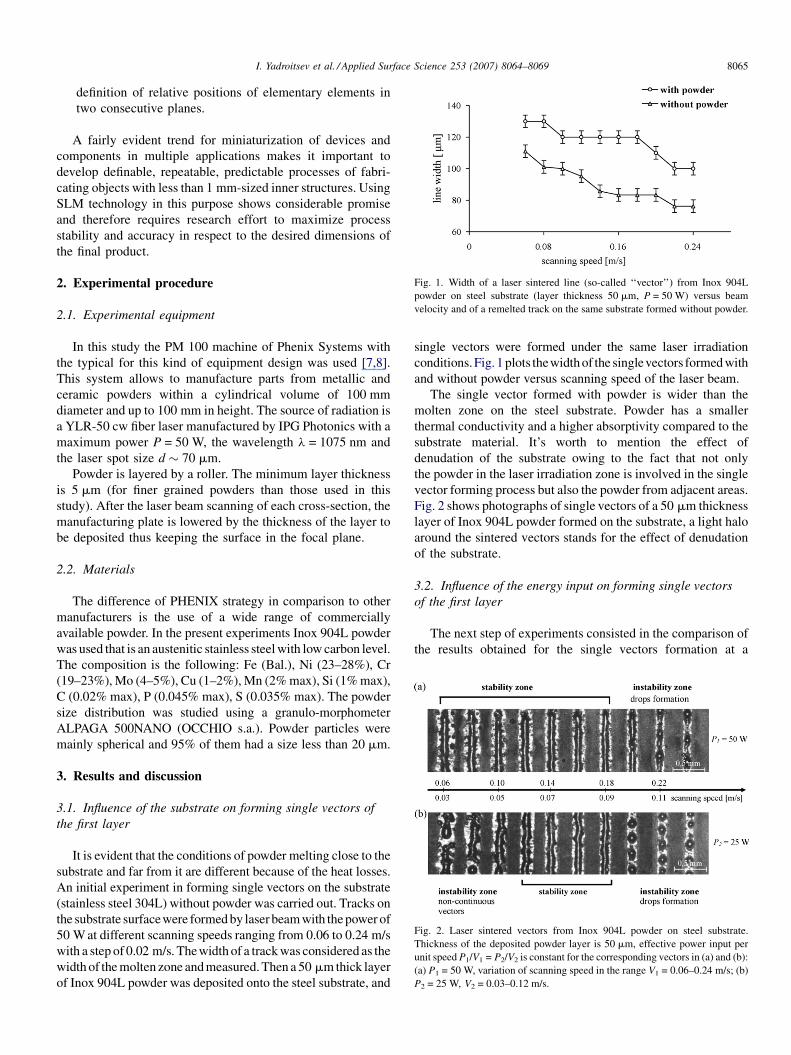
Fig. 1. Width of a laser sintered line (so-called ‘‘vector’’) from Inox 904L
powder on steel substrate (layer thickness 50 mm, P = 50 W) versus beam
velocity and of a remelted track on the same substrate formed without powder.
Fig. 2. Laser sintered vectors from Inox 904L powder on steel substrate.
Thickness of the deposited powder layer is 50 mm, effective power input per
unit speed P1/V1 = P2/V2 is constant for the corresponding vectors in (a) and (b):
(a) P1 = 50 W, variation of scanning speed in the range V1 = 0.06–0.24 m/s; (b)
P2 = 25 W, V2 = 0.03–0.12 m/s.
A fairly evident trend for miniaturization of devices and
components in multiple applications makes it important to
develop definable, repeatable, predictable processes of fabri-
cating objects with less than 1 mm-sized inner structures. Using
SLM technology in this purpose shows considerable promise
and therefore requires research effort to maximize process
stability and accuracy in respect to the desired dimensions of
the final product.
2. Experimental procedure
2.1. Experimental equipment
In this study the PM 100 machine of Phenix Systems with
the typical for this kind of equipment design was used [7,8].
This system allows to manufacture parts from metallic and
ceramic powders within a cylindrical volume of 100 mm
diameter and up to 100 mm in height. The source of radiation is
a YLR-50 cw fiber laser manufactured by IPG Photonics with a
maximum power P = 50 W, the wavelength l = 1075 nm and
the laser spot size d � 70 mm.
Powder is layered by a roller. The minimum layer thickness
is 5 mm (for finer grained powders than those used in this
study). After the laser beam scanning of each cross-section, the
manufacturing plate is lowered by the thickness of the layer to
be deposited thus keeping the surface in the focal plane.
2.2. Materials
The difference of PHENIX strategy in comparison to other
manufacturers is the use of a wide range of commercially
available powder. In the present experiments Inox 904L powder
was used that is an austenitic stainless steel with low carbon level.
The composition is the following: Fe (Bal.), Ni (23–28%), Cr
(19–23%), Mo (4–5%), Cu (1–2%), Mn (2% max), Si (1% max),
C (0.02% max), P (0.045% max), S (0.035% max). The powder
size distribution was studied using a granulo-morphometer
ALPAGA 500NANO (OCCHIO s.a.). Powder particles were
mainly spherical and 95% of them had a size less than 20 mm.
3. Results and discussion
3.1. Influence of the substrate on forming single vectors of
the first layer
It is evident that the conditions of powder melting close to the
substrate and far from it are different because of the heat losses.
An initial experiment in forming single vectors on the substrate
(stainless steel 304L) without powder was carried out. Tracks on
the substrate surfacewere formed by laser beam with the power of
50 W at different scanning speeds ranging from 0.06 to 0.24 m/s
with a step of 0.02 m/s. Thewidth of a track was considered as the
width of the molten zone and measured. Then a 50 mm thick layer
of Inox 904L powder was deposited onto the steel substrate, and
single vectors were formed under the same laser irradiation
conditions.Fig. 1 plots thewidth of the singlevectors formed with
and without powder versus scanning speed of the laser beam.
The single vector formed with powder is wider than the
molten zone on the steel substrate. Powder has a smaller
thermal conductivity and a higher absorptivity compared to the
substrate material. It’s worth to mention the effect of
denudation of the substrate owing to the fact that not only
the powder in the laser irradiation zone is involved in the single
vector forming process but also the powder from adjacent areas.
Fig. 2 shows photographs of single vectors of a 50 mm thickness
layer of Inox 904L powder formed on the substrate, a light halo
around the sintered vectors stands for the effect of denudation
of the substrate.
3.2. Influence of the energy input on forming single vectors
of the first layer
The next step of experiments consisted in the comparison of
the results obtained for the single vectors formation at a
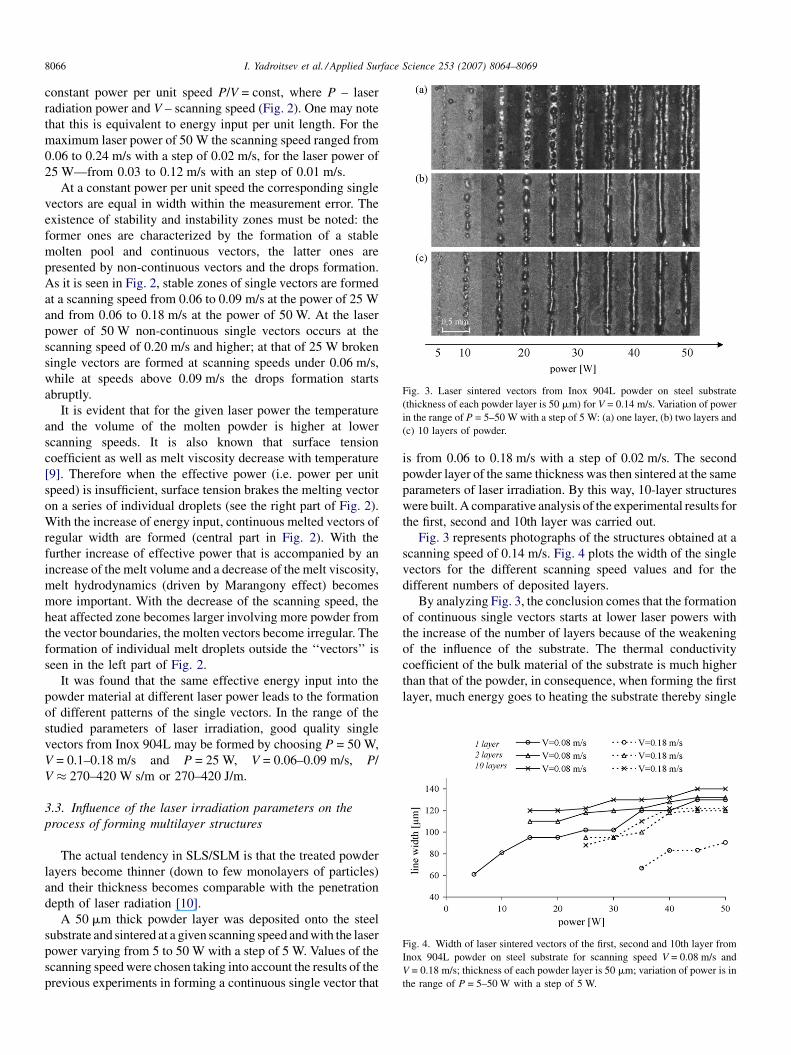
Fig. 3. Laser sintered vectors from Inox 904L powder on steel substrate
(thickness of each powder layer is 50 mm) for V = 0.14 m/s. Variation of power
in the range of P = 5–50 W with a step of 5 W: (a) one layer, (b) two layers and
(c) 10 layers of powder.
Fig. 4. Width of laser sintered vectors of the first, second and 10th layer from
Inox 904L powder on steel substrate for scanning speed V = 0.08 m/s and
V = 0.18 m/s; thickness of each powder layer is 50 mm; variation of power is in
the range of P = 5–50 W with a step of 5 W.
I. Yadroitsev et al. / Applied Surface Science 253 (2007) 8064–80698066
constant power per unit speed P/V = const, where P – laser
radiation power and V – scanning speed (Fig. 2). One may note
that this is equivalent to energy input per unit length. For the
maximum laser power of 50 W the scanning speed ranged from
0.06 to 0.24 m/s with a step of 0.02 m/s, for the laser power of
25 W—from 0.03 to 0.12 m/s with an step of 0.01 m/s.
At a constant power per unit speed the corresponding single
vectors are equal in width within the measurement error. The
existence of stability and instability zones must be noted: the
former ones are characterized by the formation of a stable
molten pool and continuous vectors, the latter ones are
presented by non-continuous vectors and the drops formation.
As it is seen in Fig. 2, stable zones of single vectors are formed
at a scanning speed from 0.06 to 0.09 m/s at the power of 25 W
and from 0.06 to 0.18 m/s at the power of 50 W. At the laser
power of 50 W non-continuous single vectors occurs at the
scanning speed of 0.20 m/s and higher; at that of 25 W broken
single vectors are formed at scanning speeds under 0.06 m/s,
while at speeds above 0.09 m/s the drops formation starts
abruptly.
It is evident that for the given laser power the temperature
and the volume of the molten powder is higher at lower
scanning speeds. It is also known that surface tension
coefficient as well as melt viscosity decrease with temperature
[9]. Therefore when the effective power (i.e. power per unit
speed) is insufficient, surface tension brakes the melting vector
on a series of individual droplets (see the right part of Fig. 2).
With the increase of energy input, continuous melted vectors of
regular width are formed (central part in Fig. 2). With the
further increase of effective power that is accompanied by an
increase of the melt volume and a decrease of the melt viscosity,
melt hydrodynamics (driven by Marangony effect) becomes
more important. With the decrease of the scanning speed, the
heat affected zone becomes larger involving more powder from
the vector boundaries, the molten vectors become irregular. The
formation of individual melt droplets outside the ‘‘vectors’’ is
seen in the left part of Fig. 2.
It was found that the same effective energy input into the
powder material at different laser power leads to the formation
of different patterns of the single vectors. In the range of the
studied parameters of laser irradiation, good quality single
vectors from Inox 904L may be formed by choosing P = 50 W,
V = 0.1–0.18 m/s and P = 25 W, V = 0.06–0.09 m/s, P/
V � 270–420 W s/m or 270–420 J/m.
3.3. Influence of the laser irradiation parameters on the
process of forming multilayer structures
The actual tendency in SLS/SLM is that the treated powder
layers become thinner (down to few monolayers of particles)
and their thickness becomes comparable with the penetration
depth of laser radiation [10].
A 50 mm thick powder layer was deposited onto the steel
substrate and sintered at a given scanning speed and with the laser
power varying from 5 to 50 W with a step of 5 W. Values of the
scanning speed were chosen taking into account the results of the
previous experiments in forming a continuous single vector that
is from 0.06 to 0.18 m/s with a step of 0.02 m/s. The second
powder layer of the same thickness was then sintered at the same
parameters of laser irradiation. By this way, 10-layer structures
were built. A comparative analysis of the experimental results for
the first, second and 10th layer was carried out.
Fig. 3 represents photographs of the structures obtained at a
scanning speed of 0.14 m/s. Fig. 4 plots the width of the single
vectors for the different scanning speed values and for the
different numbers of deposited layers.
By analyzing Fig. 3, the conclusion comes that the formation
of continuous single vectors starts at lower laser powers with
the increase of the number of layers because of the weakening
of the influence of the substrate. The thermal conductivity
coefficient of the bulk material of the substrate is much higher
than that of the powder, in consequence, when forming the first
layer, much energy goes to heating the substrate thereby single
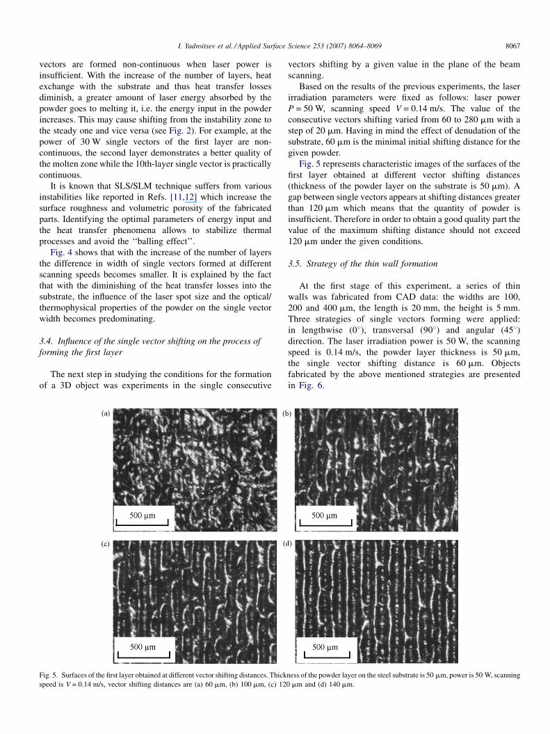
I. Yadroitsev et al. / Applied Surface Science 253 (2007) 8064–8069 8067
vectors are formed non-continuous when laser power is
insufficient. With the increase of the number of layers, heat
exchange with the substrate and thus heat transfer losses
diminish, a greater amount of laser energy absorbed by the
powder goes to melting it, i.e. the energy input in the powder
increases. This may cause shifting from the instability zone to
the steady one and vice versa (see Fig. 2). For example, at the
power of 30 W single vectors of the first layer are non-
continuous, the second layer demonstrates a better quality of
the molten zone while the 10th-layer single vector is practically
continuous.
It is known that SLS/SLM technique suffers from various
instabilities like reported in Refs. [11,12] which increase the
surface roughness and volumetric porosity of the fabricated
parts. Identifying the optimal parameters of energy input and
the heat transfer phenomena allows to stabilize thermal
processes and avoid the ‘‘balling effect’’.
Fig. 4 shows that with the increase of the number of layers
the difference in width of single vectors formed at different
scanning speeds becomes smaller. It is explained by the fact
that with the diminishing of the heat transfer losses into the
substrate, the influence of the laser spot size and the optical/
thermophysical properties of the powder on the single vector
width becomes predominating.
3.4. Influence of the single vector shifting on the process of
forming the first layer
The next step in studying the conditions for the formation
of a 3D object was experiments in the single consecutive
Fig. 5. Surfaces of the first layer obtained at different vector shifting distances. Thick
speed is V = 0.14 m/s, vector shifting distances are (a) 60 mm, (b) 100 mm, (c) 12
vectors shifting by a given value in the plane of the beam
scanning.
Based on the results of the previous experiments, the laser
irradiation parameters were fixed as follows: laser power
P = 50 W, scanning speed V = 0.14 m/s. The value of the
consecutive vectors shifting varied from 60 to 280 mm with a
step of 20 mm. Having in mind the effect of denudation of the
substrate, 60 mm is the minimal initial shifting distance for the
given powder.
Fig. 5 represents characteristic images of the surfaces of the
first layer obtained at different vector shifting distances
(thickness of the powder layer on the substrate is 50 mm). A
gap between single vectors appears at shifting distances greater
than 120 mm which means that the quantity of powder is
insufficient. Therefore in order to obtain a good quality part the
value of the maximum shifting distance should not exceed
120 mm under the given conditions.
3.5. Strategy of the thin wall formation
At the first stage of this experiment, a series of thin
walls was fabricated from CAD data: the widths are 100,
200 and 400 mm, the length is 20 mm, the height is 5 mm.
Three strategies of single vectors forming were applied:
in lengthwise (08), transversal (908) and angular (458)direction. The laser irradiation power is 50 W, the scanning
speed is 0.14 m/s, the powder layer thickness is 50 mm,
the single vector shifting distance is 60 mm. Objects
fabricated by the above mentioned strategies are presented
in Fig. 6.
ness of the powder layer on the steel substrate is 50 mm, power is 50 W, scanning
0 mm and (d) 140 mm.
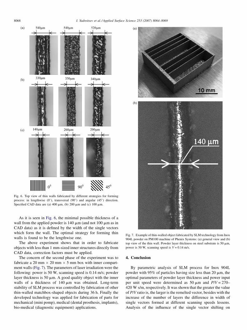
Fig. 6. Top view of thin walls fabricated by different strategies for forming
process: in lengthwise (08), transversal (908) and angular (458) direction.
Specified CAD data are (a) 400 mm, (b) 200 mm and (c) 100 mm.
Fig. 7. Example of thin-walled object fabricated by SLM technology from Inox
904L powder on PM100 machine of Phenix Systems: (a) general view and (b)
top view of the thin wall. Powder layer thickness on steel substrate is 50 mm,
power is 50 W, scanning speed is V = 0.14 m/s.
I. Yadroitsev et al. / Applied Surface Science 253 (2007) 8064–80698068
As it is seen in Fig. 6, the minimal possible thickness of a
wall from the applied powder is 140 mm (and not 100 mm as in
CAD data) as it is defined by the width of the single vectors
which form the wall. The optimal strategy for forming thin
walls is found to be the lengthwise one.
The above experiment shows that in order to fabricate
objects with less than 1 mm-sized inner structures directly from
CAD data, correction factors must be applied.
The concern of the second phase of the experiment was to
fabricate a 20 mm � 20 mm � 5 mm box with inner compart-
ment walls (Fig. 7). The parameters of laser irradiation were the
following: power is 50 W, scanning speed is 0.14 m/s; powder
layer thickness is 50 mm. A good quality object with the inner
walls of a thickness of 140 mm was obtained. Long-term
stability of SLM process was controlled by fabrication of other
thin-walled matchbox-shaped objects during 36 h. Finally the
developed technology was applied for fabrication of parts for
mechanical (mini pomp), medical (dental prosthesis, implants),
bio-medical (diagnostic equipment) applications.
4. Conclusion
By parametric analysis of SLM process for Inox 904L
powder with 95% of particles having size less than 20 mm, the
optimal parameters of powder layer thickness and power input
per unit speed were determined as 50 mm and P/V = 270–
420 W s/m, respectively. It was shown that the greater the value
of P/V ratio is, the larger is the remelted vector, besides with the
increase of the number of layers the difference in width of
single vectors formed at different scanning speeds lessens.
Analysis of the influence of the single vector shifting on
I. Yadroitsev et al. / Applied Surface Science 253 (2007) 8064–8069 8069
forming the first layer showed that the value of the maximum
shifting distance should not exceed 120 mm. Strategy for
forming objects with less than 1 mm-sized inner structures was
elaborated: the optimal method for forming thin walls is to do it
in lengthwise direction necessarily applying a correction factor
to make the resulting dimensions of the part conform to those
specified in CAD. The results of the parametric analysis were
successfully implemented in manufacturing functional proto-
types for mechanical and bio-medical applications.
References
[1] Terry Wohlers et al., Wohlers Report 2005. Rapid Prototyping, Tooling &
Manufacturing State of the Industry, Annual Worldwide Progress Report,
2005.
[2] W. Meiners, K. Wissenbach, R. Poprawe, Direct selective laser sinter-
ing of steel powder, in: Proceedings of the LANE’97, 1997, pp. 615–
622.
[3] C. Over, W. Meiners, K. Wissenbach, M. Lindemann, G. Hammann,
Selective laser melting: a new approach for the direct manufacturing of
metal parts and tools, in: Proceedings of the International Conferences on
LANE, 2001, pp. 391–398.
[4] A. Simchi, F. Petzoldt, H. Pohl, Direct metal laser sintering: material
considerations and mechanisms of particle bonding, Int. J. Powder Metall.
37 (2) (2001) 49–61.
[5] J.-P. Kruth, P. Mercelis, J. van Vaerenbergh, L. Froyen, M. Rombouts,
Binding mechanisms in selective laser sintering and selective laser melt-
ing, Rapid Prototyping J. 11 (1) (2005) 26–36.
[6] Y.P. Kathuria, Microstructuring by selective laser sintering of metallic
powder, Surf. Coatings Technol. 116–119 (1999) 643–647.
[7] D.L. Bourell, H.L. Marcus, J.W. Barlow, J.J. Beaman, Selective laser
sintering of metals and ceramics, Int. J. Powder Metall. 28 (4) (1992)
369–381.
[8] G.N. Levy, R. Schindel, J.-P. Kruth, Rapid manufacturing and rapid tooling
with layer manufacturing (LM) technologies, state of the art and future
perspectives, CIRP Ann. Manuf. Technol. 52 (2) (2003) 589–609.
[9] I.S. Grigoriev, E.Z. Meilikhov, Physical Quantities, Handbook, Energoa-
tomizdat, Moscow, 1991.
[10] A.V. Gusarov, J.-P. Kruth, Modelling of radiation transfer in metallic
powders at laser treatment, Int. J. Heat Mass Transfer 48 (16) (2005)
3423–3434.
[11] N.K. Tolochko, S.E. Mozzharov, I.A. Yadroitsev, T. Laoui, L. Froyen, V.I.
Titov, M.B. Ignatiev, Balling processes during selective laser treatment of
powders, Rapid Prototyping J. 10 (2) (2004) 78–87.
[12] N.K. Tolochko, M.K. Arshinov, A.V. Gusarov, V.I. Titov, T. Laoui, L.
Froyen, Mechanisms of selective laser sintering and heat transfer in Ti
powder, Rapid Prototyping J. 9 (5) (2003) 314–326.