
Modeling and Experimental Studies on Polymer Melting and ...
19
Citation: Wilczy ´ nski, K.; Wilczy ´ nski, K.J.; Buziak, K. Modeling and Experimental Studies on Polymer Melting and Flow in Injection Molding. Polymers 2022, 14, 2106. https://doi.org/10.3390/ polym14102106 Academic Editor: Ming-Shyan Huang Received: 4 April 2022 Accepted: 18 May 2022 Published: 21 May 2022 Publisher’s Note: MDPI stays neutral with regard to jurisdictional claims in published maps and institutional affil- iations. Copyright: © 2022 by the authors. Licensee MDPI, Basel, Switzerland. This article is an open access article distributed under the terms and conditions of the Creative Commons Attribution (CC BY) license (https:// creativecommons.org/licenses/by/ 4.0/). polymers Review Modeling and Experimental Studies on Polymer Melting and Flow in Injection Molding Krzysztof Wilczy ´ nski 1, * , Krzysztof J. Wilczy ´ nski 2 and Kamila Buziak 1 1 Polymer Processing Department, Faculty of Mechanical and Industrial Engineering, Warsaw University of Technology, Narbutta 85, 02-524 Warsaw, Poland; [email protected] 2 Politech Ltd., 86-031 Osielsko, Poland; [email protected] * Correspondence: [email protected] Abstract: Injection molding, in addition to extrusion, is the most important technology in the polymer processing industry. When modeling injection molding, the global approach is necessary to take into account the solid polymer transport, polymer melting and the polymer melt flow. The model of polymer melting is fundamental for the development of such a global injection molding model. In the paper, the state-of-the-art of modeling and experimentation of the flow and melting in injection molding machines has been presented and discussed. It has been concluded that the existing mathematical models have no strong experimental basis. Therefore, experimentation of the polymer flow and melting in the injection molding machine has been performed, and the effect of processing conditions: the screw speed, the plasticating stroke and the back pressure on the process course has been investigated. Starving in the beginning sections of the screw has been observed, which was not presented in the literature so far. The novel concepts of injection molding modeling have been discussed. Keywords: polymers; injection molding; modeling; melting 1. Introduction At present, the polymer processing designing is aided by computer process simula- tions. Modeling allows you to predict the course of the process on the basis of processing conditions, i.e., material characteristics, process operating parameters and machine geome- try data. An immense number of different types of polymeric materials and the variety of their applications require the use of various processing methods, among which extrusion and injection molding play a special role. Extrusion is the most mass technology in the polymer processing industry since more than half of all plastics are extruded. Extrusion is also fundamental for compounding, i.e., mixing, pelletizing, filling, reinforcing, etc. Injection molding is suited well for mass production of parts of complex shapes and precise dimensions. About one-third of all thermoplastics are injection molded. Extrusion is the process of continuous forming of polymer products, the so-called profiles, e.g., pipes, rods, plates, films, etc. Extrusion consists of the continuous melting of a polymer in the plasticating unit of the extruder and then pushing (extruding) this melted material, under the pressure developed in the plasticating unit, through the openings of the forming tool that is called the die. Melting occurs as a result of the polymer heating up by the extruder heating system and as a result of energy dissipation in the extruded material. Injection molding is a cyclic process of forming polymer products called moldings. It consists of cyclic melting of a polymer in the plasticating unit of the injection molding machine and then injecting the melted polymer, under the pressure developed in the plasticating unit, into the injection mold, shaping the product. Similar to extrusion, melting takes place here as a result of the polymer heating up by the heating system and as a result of energy dissipation in the material. Polymers 2022, 14, 2106. https://doi.org/10.3390/polym14102106 https://www.mdpi.com/journal/polymers
-
Upload
khangminh22 -
Category
Documents
-
view
4 -
download
0
Transcript of Modeling and Experimental Studies on Polymer Melting and ...
Citation: Wilczynski, K.; Wilczynski,
K.J.; Buziak, K. Modeling and
Experimental Studies on Polymer
Melting and Flow in Injection
Molding. Polymers 2022, 14, 2106.
https://doi.org/10.3390/
polym14102106
Academic Editor: Ming-Shyan Huang
Received: 4 April 2022
Accepted: 18 May 2022
Published: 21 May 2022
Publisher’s Note: MDPI stays neutral
with regard to jurisdictional claims in
published maps and institutional affil-
iations.
Copyright: © 2022 by the authors.
Licensee MDPI, Basel, Switzerland.
This article is an open access article
distributed under the terms and
conditions of the Creative Commons
Attribution (CC BY) license (https://
creativecommons.org/licenses/by/
4.0/).
polymers
Review
Modeling and Experimental Studies on Polymer Melting andFlow in Injection MoldingKrzysztof Wilczynski 1,* , Krzysztof J. Wilczynski 2 and Kamila Buziak 1
1 Polymer Processing Department, Faculty of Mechanical and Industrial Engineering, Warsaw University ofTechnology, Narbutta 85, 02-524 Warsaw, Poland; [email protected]
2 Politech Ltd., 86-031 Osielsko, Poland; [email protected]* Correspondence: [email protected]
Abstract: Injection molding, in addition to extrusion, is the most important technology in the polymerprocessing industry. When modeling injection molding, the global approach is necessary to takeinto account the solid polymer transport, polymer melting and the polymer melt flow. The model ofpolymer melting is fundamental for the development of such a global injection molding model. Inthe paper, the state-of-the-art of modeling and experimentation of the flow and melting in injectionmolding machines has been presented and discussed. It has been concluded that the existingmathematical models have no strong experimental basis. Therefore, experimentation of the polymerflow and melting in the injection molding machine has been performed, and the effect of processingconditions: the screw speed, the plasticating stroke and the back pressure on the process coursehas been investigated. Starving in the beginning sections of the screw has been observed, whichwas not presented in the literature so far. The novel concepts of injection molding modeling havebeen discussed.
Keywords: polymers; injection molding; modeling; melting
1. Introduction
At present, the polymer processing designing is aided by computer process simula-tions. Modeling allows you to predict the course of the process on the basis of processingconditions, i.e., material characteristics, process operating parameters and machine geome-try data.
An immense number of different types of polymeric materials and the variety oftheir applications require the use of various processing methods, among which extrusionand injection molding play a special role. Extrusion is the most mass technology in thepolymer processing industry since more than half of all plastics are extruded. Extrusionis also fundamental for compounding, i.e., mixing, pelletizing, filling, reinforcing, etc.Injection molding is suited well for mass production of parts of complex shapes and precisedimensions. About one-third of all thermoplastics are injection molded.
Extrusion is the process of continuous forming of polymer products, the so-calledprofiles, e.g., pipes, rods, plates, films, etc. Extrusion consists of the continuous melting ofa polymer in the plasticating unit of the extruder and then pushing (extruding) this meltedmaterial, under the pressure developed in the plasticating unit, through the openings of theforming tool that is called the die. Melting occurs as a result of the polymer heating up bythe extruder heating system and as a result of energy dissipation in the extruded material.
Injection molding is a cyclic process of forming polymer products called moldings.It consists of cyclic melting of a polymer in the plasticating unit of the injection moldingmachine and then injecting the melted polymer, under the pressure developed in theplasticating unit, into the injection mold, shaping the product. Similar to extrusion, meltingtakes place here as a result of the polymer heating up by the heating system and as a resultof energy dissipation in the material.
Polymers 2022, 14, 2106. https://doi.org/10.3390/polym14102106 https://www.mdpi.com/journal/polymers

Polymers 2022, 14, 2106 2 of 19
The course of the injection molding process is depicted in Figure 1. The plasticatingunit is the basic component of the injection molding machine, and it performs functionssimilar to those in the extruder. However, there are essential differences here. The rotatingscrew conveys the molten polymer to the screw front, and then the polymer is injected intothe mold through the axial displacement of the screw.
Polymers 2022, 14, x FOR PEER REVIEW 2 of 20
melting takes place here as a result of the polymer heating up by the heating system and
as a result of energy dissipation in the material.
The course of the injection molding process is depicted in Figure 1. The plasticating
unit is the basic component of the injection molding machine, and it performs functions
similar to those in the extruder. However, there are essential differences here. The rotat-
ing screw conveys the molten polymer to the screw front, and then the polymer is in-
jected into the mold through the axial displacement of the screw.
Figure 1. Injection molding process: (A)—injection (mold filling), (B)—holding, (C)—plasticating
(melting), (D)—mold opening and molding (part) ejection; 1—molding (part), 2—mold cavity,
3—cooling channels, 4—screw, 5—heaters, 6—hopper, 7—screw drive system (with permission
from Rheology in Polymer Processing. Modeling and Simulation by K. Wilczyński; Carl Hanser Verlag:
Munich 2021 [1]).
Figure 1. Injection molding process: (A)—injection (mold filling), (B)—holding, (C)—plasticating(melting), (D)—mold opening and molding (part) ejection; 1—molding (part), 2—mold cavity,3—cooling channels, 4—screw, 5—heaters, 6—hopper, 7—screw drive system (with permissionfrom Rheology in Polymer Processing. Modeling and Simulation by K. Wilczynski; Carl Hanser Verlag:Munich 2021 [1]).

Polymers 2022, 14, 2106 3 of 19
When modeling extrusion and injection molding, the global approach is necessary totake into account the solid polymer transport, polymer melting and the polymer melt flow.The model of polymer melting is fundamental for the development of such global models.
When modeling the polymer melt flow in injection molds, the input data are basicallyunknown, for example, the polymer temperature. Thus, a global model of the injectionmolding process is needed that would describe both the flow in the injection moldingmachine and in the mold. The process output parameters from the plasticating unit wouldbe the input parameters for the mold.
The first modeling approaches for screw processing of polymers were made for extru-sion. The first analysis of flow in single screw machines were performed by Rowell andFinlayson [2] and later by Carley et al. [3,4], who described the drag flow and pressureflow for an isothermal Newtonian fluid. Solid conveying was modeled first by Darnell andMol [5], who described material transport and pressure development.
The first melting studies in the single screw extruder were carried out by Maddockand Street [6,7], who used the technique of pulling out the screw from an extruder. Theyanalyzed the cross-sections of the polymer removed from the screw and observed themelting mechanism. According to this mechanism, the so-called contiguous solid melting(CSM), a melt layer was formed between the barrel and the solid material, which wasscrapped off by the transverse flow in the screw and accumulated at the active screwflight. The solid was gradually diminished by the effects of heat conduction from thebarrel and viscous dissipation in the polymer melt (Figure 2). Thus, two steps of meltingwere distinguished, the so-called pre-melting zone (or delay zone), corresponding tothe formation of the polymer melt layer, and the melting zone (or plasticating zone),corresponding to the accumulation of the polymer melt at the active screw flight.
Polymers 2022, 14, x FOR PEER REVIEW 3 of 20
When modeling extrusion and injection molding, the global approach is necessary to
take into account the solid polymer transport, polymer melting and the polymer melt
flow. The model of polymer melting is fundamental for the development of such global
models.
When modeling the polymer melt flow in injection molds, the input data are basi-
cally unknown, for example, the polymer temperature. Thus, a global model of the injec-
tion molding process is needed that would describe both the flow in the injection mold-
ing machine and in the mold. The process output parameters from the plasticating unit
would be the input parameters for the mold.
The first modeling approaches for screw processing of polymers were made for ex-
trusion. The first analysis of flow in single screw machines were performed by Rowell
and Finlayson [2] and later by Carley et al. [3,4], who described the drag flow and pres-
sure flow for an isothermal Newtonian fluid. Solid conveying was modeled first by
Darnell and Mol [5], who described material transport and pressure development.
The first melting studies in the single screw extruder were carried out by Maddock
and Street [6,7], who used the technique of pulling out the screw from an extruder. They
analyzed the cross-sections of the polymer removed from the screw and observed the
melting mechanism. According to this mechanism, the so-called contiguous solid melting
(CSM), a melt layer was formed between the barrel and the solid material, which was
scrapped off by the transverse flow in the screw and accumulated at the active screw
flight. The solid was gradually diminished by the effects of heat conduction from the
barrel and viscous dissipation in the polymer melt (Figure 2). Thus, two steps of melting
were distinguished, the so-called pre-melting zone (or delay zone), corresponding to the
formation of the polymer melt layer, and the melting zone (or plasticating zone), corre-
sponding to the accumulation of the polymer melt at the active screw flight.
Figure 2. Melting mechanism (CSM) at flood fed single screw extrusion of polypropylene [8].
Tadmor et al. [9–11] did a similar experiment and proposed the first model of pol-
ymer melting in extrusion, which allowed for the elaboration of the first computer model
of polymer extrusion EXTRUD [12]. This polymer melting model was based on the
computation of the velocity and temperature distribution in the polymer melt film and
temperature distribution in the polymer solid bed (Figure 2). Then, a mass balance in the
polymer melt film and the polymer solid, as well as an energy balance at the interface
melt film/solid bed, were carried out. Finally, the melting rate was predicted. Later, more
detailed models were proposed for solid conveying [13,14] and for the pre-melting zone
(or delay zone) [15]. Thus, the extrusion model has been substantially improved. Studies
of polymer melting performed by other researchers confirmed the Tadmor model.
Many books have been written on extrusion, for example, by Fischer [16], Mc Kelvey
[17], Schenkel [18], Fenner [19], Tadmor and Klein [20], Hensen et al. [21], White [22],
White and Potente [23], Tadmor and Gogos [24], White and Kim [25], Rauwendaal [26],
Lafleur and Vergnes [27], Agassant et al. [28], Chung [29], Campbell and Spalding [30]
and Vlachopoulos and Polychronopoulos [31].
The issue of modeling the extrusion has been presented in books, for example, by
White and Potente [23], Rauwendaal [26], Agassant et al. [28], and has been reviewed in
papers by Arrifin et al. [32], Wilczyński et al. [33], Teixeira et al. [34], Malik et al. [35],
Wilczyński et al. [36], Hyvärinen et al. [37], Lewandowski et al. [38] and Marschik et al.
[39].
Figure 2. Melting mechanism (CSM) at flood fed single screw extrusion of polypropylene [8].
Tadmor et al. [9–11] did a similar experiment and proposed the first model of polymermelting in extrusion, which allowed for the elaboration of the first computer model of poly-mer extrusion EXTRUD [12]. This polymer melting model was based on the computationof the velocity and temperature distribution in the polymer melt film and temperaturedistribution in the polymer solid bed (Figure 2). Then, a mass balance in the polymer meltfilm and the polymer solid, as well as an energy balance at the interface melt film/solidbed, were carried out. Finally, the melting rate was predicted. Later, more detailed modelswere proposed for solid conveying [13,14] and for the pre-melting zone (or delay zone) [15].Thus, the extrusion model has been substantially improved. Studies of polymer meltingperformed by other researchers confirmed the Tadmor model.
Many books have been written on extrusion, for example, by Fischer [16], Mc Kelvey [17],Schenkel [18], Fenner [19], Tadmor and Klein [20], Hensen et al. [21], White [22], White andPotente [23], Tadmor and Gogos [24], White and Kim [25], Rauwendaal [26], Lafleur andVergnes [27], Agassant et al. [28], Chung [29], Campbell and Spalding [30] and Vlachopoulosand Polychronopoulos [31].
The issue of modeling the extrusion has been presented in books, for example, byWhite and Potente [23], Rauwendaal [26], Agassant et al. [28], and has been reviewedin papers by Arrifin et al. [32], Wilczynski et al. [33], Teixeira et al. [34], Malik et al. [35],Wilczynski et al. [36], Hyvärinen et al. [37], Lewandowski et al. [38] and Marschik et al. [39].
The flood fed single screw extrusion was widely studied and modeled; however, littleinformation was available on the starve fed extrusion. The first studies were carried out byLopez-Latorre and McKelvey [40] and later by Isherwood et al. [41], Strand et al. [42] andThompson et al. [43]. Recently, Wilczynski et al. [8,44] performed extensive experimental

Polymers 2022, 14, 2106 4 of 19
studies on the starve fed extrusion and proposed the mechanism and model of polymermelting. Then, they built the first computer model of this process, SSEM-Starve [45]. Twostages of melting have been distinguished. In the partially filled section of the screw, thepolymer granules were collected at the active screw flight and were melted by conduction,mainly. In the fully filled section, the unmolten solid particles were suspended in the earliermolten polymer, and melting progressed by heat dissipation (Figure 3). This model waslater extended to the non-conventional screw configurations [46,47] and to the extrusion ofpolyblends and composites [48–50].
Polymers 2022, 14, x FOR PEER REVIEW 4 of 20
The flood fed single screw extrusion was widely studied and modeled; however,
little information was available on the starve fed extrusion. The first studies were carried
out by Lopez-Latorre and McKelvey [40] and later by Isherwood et al. [41], Strand et al.
[42] and Thompson et al. [43]. Recently, Wilczyński et al. [8,44] performed extensive ex-
perimental studies on the starve fed extrusion and proposed the mechanism and model
of polymer melting. Then, they built the first computer model of this process,
SSEM-Starve [45]. Two stages of melting have been distinguished. In the partially filled
section of the screw, the polymer granules were collected at the active screw flight and
were melted by conduction, mainly. In the fully filled section, the unmolten solid parti-
cles were suspended in the earlier molten polymer, and melting progressed by heat dis-
sipation (Figure 3). This model was later extended to the non-conventional screw con-
figurations [46,47] and to the extrusion of polyblends and composites [48–50].
Figure 3. Melting mechanism at starve fed single screw extrusion of polypropylene [8].
The polymer flow in the classical flood fed extrusion in comparison with the poly-
mer flow in the starve fed extrusion is depicted in Figure 4. It is worth noting that the
difference in the flow rate (extrusion throughput) was very small here, about 2%. How-
ever, the filling of the screw was significantly different. A detailed discussion of this issue
has been presented in [51] based on the extensive process simulations and experimenta-
tions.
Figure 4. Polymer flow in the flood fed/starve fed single screw extrusion [8].
The research on melting in twin-screw extruders was much more limited. It is worth
noting here that twin screw extrusion is performed with metered feeding, mainly, thus
with clear starving.
The studies were performed mainly for co-rotating twin-screw extruders, both by
experimentation, by Bawiskar and White [52], Todd [53], Sakai [54] and Gogos [55–57],
and by modeling. Potente and Melish [58], as well as Bawiskar and White [59], developed
the models based on the classical Tadmor model [20] while assuming the gradual form-
ing of the molten layer from the barrel toward the screw. Bawiskar and White [59] de-
scribed the formation of two stratified layers of polymer melt in contact with the barrel
and solid pellets in contact with the colder screw. Potente and Melisch [58] considered
the melting of particles uniformly suspended in the polymer melt. Vergnes et al. [60,61],
as well as Zhu et al. [62], developed dispersive models based on the analysis of the flow
of the solid/melt mixture of an equivalent viscosity. Based on these investigations, the
global models of the co-rotating twin screw extrusion were built [34,63–68]. This issue
was reviewed and discussed by Teixeira [69].
Melting in counter-rotating twin-screw extruders is much less known. The first ob-
servations were presented by Janssen [70]. White et al. [71,72] noticed that melting occurs
here more rapidly than in co-rotating extruders. Wilczyński and White [73] revealed the
Figure 3. Melting mechanism at starve fed single screw extrusion of polypropylene [8].
The polymer flow in the classical flood fed extrusion in comparison with the polymerflow in the starve fed extrusion is depicted in Figure 4. It is worth noting that the differencein the flow rate (extrusion throughput) was very small here, about 2%. However, thefilling of the screw was significantly different. A detailed discussion of this issue has beenpresented in [51] based on the extensive process simulations and experimentations.
Polymers 2022, 14, x FOR PEER REVIEW 4 of 20
The flood fed single screw extrusion was widely studied and modeled; however,
little information was available on the starve fed extrusion. The first studies were carried
out by Lopez-Latorre and McKelvey [40] and later by Isherwood et al. [41], Strand et al.
[42] and Thompson et al. [43]. Recently, Wilczyński et al. [8,44] performed extensive ex-
perimental studies on the starve fed extrusion and proposed the mechanism and model
of polymer melting. Then, they built the first computer model of this process,
SSEM-Starve [45]. Two stages of melting have been distinguished. In the partially filled
section of the screw, the polymer granules were collected at the active screw flight and
were melted by conduction, mainly. In the fully filled section, the unmolten solid parti-
cles were suspended in the earlier molten polymer, and melting progressed by heat dis-
sipation (Figure 3). This model was later extended to the non-conventional screw con-
figurations [46,47] and to the extrusion of polyblends and composites [48–50].
Figure 3. Melting mechanism at starve fed single screw extrusion of polypropylene [8].
The polymer flow in the classical flood fed extrusion in comparison with the poly-
mer flow in the starve fed extrusion is depicted in Figure 4. It is worth noting that the
difference in the flow rate (extrusion throughput) was very small here, about 2%. How-
ever, the filling of the screw was significantly different. A detailed discussion of this issue
has been presented in [51] based on the extensive process simulations and experimenta-
tions.
Figure 4. Polymer flow in the flood fed/starve fed single screw extrusion [8].
The research on melting in twin-screw extruders was much more limited. It is worth
noting here that twin screw extrusion is performed with metered feeding, mainly, thus
with clear starving.
The studies were performed mainly for co-rotating twin-screw extruders, both by
experimentation, by Bawiskar and White [52], Todd [53], Sakai [54] and Gogos [55–57],
and by modeling. Potente and Melish [58], as well as Bawiskar and White [59], developed
the models based on the classical Tadmor model [20] while assuming the gradual form-
ing of the molten layer from the barrel toward the screw. Bawiskar and White [59] de-
scribed the formation of two stratified layers of polymer melt in contact with the barrel
and solid pellets in contact with the colder screw. Potente and Melisch [58] considered
the melting of particles uniformly suspended in the polymer melt. Vergnes et al. [60,61],
as well as Zhu et al. [62], developed dispersive models based on the analysis of the flow
of the solid/melt mixture of an equivalent viscosity. Based on these investigations, the
global models of the co-rotating twin screw extrusion were built [34,63–68]. This issue
was reviewed and discussed by Teixeira [69].
Melting in counter-rotating twin-screw extruders is much less known. The first ob-
servations were presented by Janssen [70]. White et al. [71,72] noticed that melting occurs
here more rapidly than in co-rotating extruders. Wilczyński and White [73] revealed the
Figure 4. Polymer flow in the flood fed/starve fed single screw extrusion [8].
The research on melting in twin-screw extruders was much more limited. It is worthnoting here that twin screw extrusion is performed with metered feeding, mainly, thus withclear starving.
The studies were performed mainly for co-rotating twin-screw extruders, both by ex-perimentation, by Bawiskar and White [52], Todd [53], Sakai [54] and Gogos [55–57], and bymodeling. Potente and Melish [58], as well as Bawiskar and White [59], developed the modelsbased on the classical Tadmor model [20] while assuming the gradual forming of the moltenlayer from the barrel toward the screw. Bawiskar and White [59] described the formation of twostratified layers of polymer melt in contact with the barrel and solid pellets in contact with thecolder screw. Potente and Melisch [58] considered the melting of particles uniformly suspendedin the polymer melt. Vergnes et al. [60,61], as well as Zhu et al. [62], developed dispersivemodels based on the analysis of the flow of the solid/melt mixture of an equivalent viscosity.Based on these investigations, the global models of the co-rotating twin screw extrusion werebuilt [34,63–68]. This issue was reviewed and discussed by Teixeira [69].
Melting in counter-rotating twin-screw extruders is much less known. The firstobservations were presented by Janssen [70]. White et al. [71,72] noticed that meltingoccurs here more rapidly than in co-rotating extruders. Wilczynski and White [73] revealedthe mechanism of melting in counter-rotating twin-screw extruders. They observed thatmelting was initiated both between the screws and at the barrel. The melting between thescrews was induced by frictional work on the granules by the calendering stresses betweenthe screws. The melting at the barrel was initiated by the barrel temperature higher thanthe melting point and was propagated by the viscous dissipation heating of the melt film.These observations (Figure 5) allowed us to develop models of melting in both of thoseregions [74]. Further studies of melting were reported by Wang and Min [75,76] as well as

Polymers 2022, 14, 2106 5 of 19
by Wilczynski et al. [77]. Based on these studies, the global models of the counter-rotatingtwin screw extrusion were built [78–81].
Polymers 2022, 14, x FOR PEER REVIEW 5 of 20
mechanism of melting in counter-rotating twin-screw extruders. They observed that
melting was initiated both between the screws and at the barrel. The melting between the
screws was induced by frictional work on the granules by the calendering stresses be-
tween the screws. The melting at the barrel was initiated by the barrel temperature higher
than the melting point and was propagated by the viscous dissipation heating of the melt
film. These observations (Figure 5) allowed us to develop models of melting in both of
those regions [74]. Further studies of melting were reported by Wang and Min [75,76] as
well as by Wilczyński et al. [77]. Based on these studies, the global models of the coun-
ter-rotating twin screw extrusion were built [78–81].
Figure 5. Melting mechanism observed in counter-rotating twin screw extrusion [74].
The methods of investigating and modeling the polymer flow and melting in the
extrusion process were adopted to modeling of these in injection molding. However,
while many books and review papers have been devoted to the modeling of extrusion,
there has been much less to injection molding. These were mainly limited to modeling
the flow in injection molds without considering the polymer flow and melting in the
plasticating unit, e.g., by Manzione et al. [82], Kennedy and Zheng [83], Kamal et al. [84],
Osswald et al. [85] and Wang et al. [86]. Other books have been devoted to the mold de-
sign, e.g., by Menges et al. [87], Rees [88], Unger [89], Mennig and Stoeckhert [90],
Kazmer [91], Turng and Chen [92], Beaumont [93] and Catoen and Rees [94], or to the
injection molding machines by Johannaber [95]. An important review paper on modeling
and optimization of injection molding was presented by Fernandes et al. [96]. At present,
the important software for simulating the flow in injection molds are MOLDFLOW [97],
Moldex3D [98] and CADMOULD [99], by example recently used in [100,101]. Simula-
tions of the polymer flow in injection molds were also performed using the CFD software
COMSOL Multiphysics [102] with an example of [103].
The first experimental studies of melting in injection molding machines were carried
out by Donovan et al. [104] using the “screw pulling out technique”. They revealed that
the screw recharge process was the transient plasticating extrusion which gradually ap-
proached the equilibrium extrusion behavior as the screw rotated. If the time of screw
rotation was a high fraction of the total cycle time, the plasticating behavior was similar
to the extrusion behavior, but if the time of screw rotation was a small fraction of the total
cycle time, the plasticating behavior was substantially different.
The reports were also presented on the experimental study of the solid bed transport
and melting in the screw channel of the injection molding machines [105–107] with the
use of “transparent windows” made in the barrel to observe the polymer flow.
Important experimental studies on polymer melting in injection molding machines
were carried out by Gao et al. [105]. They developed the visual system to observe the
polymer flow in the reciprocating screw injection molding machine. The effects of pro-
Figure 5. Melting mechanism observed in counter-rotating twin screw extrusion [74].
The methods of investigating and modeling the polymer flow and melting in theextrusion process were adopted to modeling of these in injection molding. However,while many books and review papers have been devoted to the modeling of extrusion,there has been much less to injection molding. These were mainly limited to modelingthe flow in injection molds without considering the polymer flow and melting in theplasticating unit, e.g., by Manzione et al. [82], Kennedy and Zheng [83], Kamal et al. [84],Osswald et al. [85] and Wang et al. [86]. Other books have been devoted to the molddesign, e.g., by Menges et al. [87], Rees [88], Unger [89], Mennig and Stoeckhert [90],Kazmer [91], Turng and Chen [92], Beaumont [93] and Catoen and Rees [94], or to theinjection molding machines by Johannaber [95]. An important review paper on modelingand optimization of injection molding was presented by Fernandes et al. [96]. At present,the important software for simulating the flow in injection molds are MOLDFLOW [97],Moldex3D [98] and CADMOULD [99], by example recently used in [100,101]. Simulationsof the polymer flow in injection molds were also performed using the CFD softwareCOMSOL Multiphysics [102] with an example of [103].
The first experimental studies of melting in injection molding machines were carriedout by Donovan et al. [104] using the “screw pulling out technique”. They revealed that thescrew recharge process was the transient plasticating extrusion which gradually approachedthe equilibrium extrusion behavior as the screw rotated. If the time of screw rotation was ahigh fraction of the total cycle time, the plasticating behavior was similar to the extrusionbehavior, but if the time of screw rotation was a small fraction of the total cycle time, theplasticating behavior was substantially different.
The reports were also presented on the experimental study of the solid bed transportand melting in the screw channel of the injection molding machines [105–107] with the useof “transparent windows” made in the barrel to observe the polymer flow.
Important experimental studies on polymer melting in injection molding machineswere carried out by Gao et al. [105]. They developed the visual system to observe the poly-mer flow in the reciprocating screw injection molding machine. The effects of processingconditions on the polymer melting were studied, and it was concluded that the modelingof the plasticating phase cannot be treated simply as an extrusion process.
Different barrel temperatures, plastication strokes, screw rotation speeds, and backpressures were used to observe their effects on the melting behavior.
It was observed that there was more polymer melted at a lower screw speed than ata higher speed. As the plastication stroke was the same, a lower speed resulted in longerplastication time, while a higher speed resulted in shorter plastication time.
It was also seen that for the case of the lower plastication stroke, the melting wasfaster, while for the case of the higher plastication stroke, the polymer melting length was

Polymers 2022, 14, 2106 6 of 19
longer. With a small injection stroke, the injection volume was small in comparison to theamount of material enclosed in the screw channel. As a result, the residence time wascomparatively long, and hence melting was primarily due to heat conduction. Conversely,with a long injection stroke, the injection volume was large in comparison with the screwchannel volume, and the melting was primarily due to the shearing.
It is known that the back pressure affects the melting, temperature distribution, andpressure distribution in the screw channel. Different back pressures result in differentpressure profiles in the screw channel and different plastication times. It was observed thatan increase in back pressure was advantageous to the melting. A higher back pressure alsoled to a larger left-hand melt pool size than a lower back pressure.
An increase in the dwelling time results in more heat being conducted and conse-quently melts more polymer.
A comparison between the barrel temperature and the temperature at the interface ofthe polymer and barrel showed that the polymer-barrel interface temperature was higherthan the barrel temperature, even more than 20 ◦C. This resulted from the combinationeffects of shear heating at the polymer-barrel interface and the barrel heat loss to the envi-ronment. It is worth noting that in injection molding modeling, the polymer temperatureat the wall is commonly assumed to be the same as the barrel temperature, which is not anaccurate reflection of reality.
Modeling of plasticization during injection molding has been a complex problem,particularly for the solid conveying section. This can be further complicated by a break-up of the solid bed due to the reciprocation motion in the process. The break-up of thesolid bed can introduce inhomogeneities in the moldings. The solid bed break-up in areciprocating screw was experimentally studied using a transparent barrel system designedby Jin et al. [106]. It was observed that the break-up occurred in the latter melting stage,where the solid bed strength was reduced because of the continuous reducing the solid bedthickness, where also the melt pressure was high. The onset of break-up was dependenton the process conditions. It was observed that the solid bed broke easier at the higherscrew rotation speed and that the longer injection stroke, the higher backpressure and thelonger dwell time. The break-up typically started by forming a slit or slits that were nearlyperpendicular to the screw flight. It is worth noting that the properly designed barrierscrew may be effectively used to prevent solid-bed break-up.
Other visual studies were performed by Pham et al. [107]. The results confirmed theusual view of a contiguous solid bed melting process. It was observed that the solid bedwidth increased with the screw rotation speed, as predicted by a classical theory. The solidbed break-up was seen at every screw speed. Conductive melting from the flight side ofthe solid bed was also viewed. The solid bed velocity was distinct from the screw velocity.
Donovan [108,109] was the first who proposed the model for polymer melting inthe injection molding process. This was a heuristic model which required experimentalevaluation of an empirical parameter specific to a particular polymer over the studied rangeof operating conditions. This model was based on the steady-state extrusion model [110].
Lipshitz et al. [111] proposed the model for melting, which was based on the detailedphysical mechanisms taking place in the reciprocating screw injection molding machine.This model permitted the computation of the solid bed profile as a function of time duringthe injection cycle. It consisted of the dynamic extrusion melting model for the rotationperiod, the transient heat conduction model with a phase transition for the screw restperiod, and the model for the drifting of the beginning of melting during the injection cycle.
Several papers have been published on the modeling of plasticating in injectionmolding machines. Rauwendaal [112,113] studied the effects of axial screw movementon solids and melt conveying in reciprocating extruders. Dormeier and Panreck [114]briefly discussed the melting process when the screw stopped in the reciprocating extruder.Rao [115] developed a relatively simple model for describing the plasticating process ina reciprocating injection molding screw by combining the melting model for extrusion ofTadmor (20) with the conduction melting model of Donovan (108).

Polymers 2022, 14, 2106 7 of 19
Potente [116] presented the mathematical approach to simulate the polymer melting ininjection molding. However, this model did not take into account the solid conveying andtransient sections and used some special modeling empirical constants. Later, he calculatedthe power requirement of the plasticating systems of the injection molding machines andthe extruders [117].
Bereaux et al. [118] developed a simple model of throughput and pressure develop-ment for single screw extruders and injection molding machines. The model is based onviewing the entire screw simply as a pump, conveying a solid fraction and a molten fraction.This concept results from that during most of the melting process, a conveying of the solidmaterial side by side with the melt takes place. This two-phase conveying can be drawnto the one-phase flow model of a melt pump by assuming that the pressure gradient inthe screw channel is solely due to melt flow, but the flow rate at any cross-section can beconsidered as the sum of the solid bed flow rate and the melt pool flow rate.
At that time, no studies existed for modeling the transient melting process in the feed-ing stage (with rotating screw), the injection stage and the whole cycle of injection molding.
Yung et al. [119–121] were the first who considered the whole cycle of the process,which comprised of three stages: feeding (screw rotating and moving backward), stop-ping (no screw movement) and injecting (screw moving forward without rotation) anddeveloped the transient models for the melting process in these.
Another comprehensive model of plasticization in injection molding, which reflectswell the process dynamics, was developed by Steller and Iwko [122,123]. This model takesinto account the periodical action of the screw, to-and-from screw motion with controlledstroke and static and dynamic melting. However, this model does not take into account theexistence of a delay zone, uses a simplified melting model, and the equations of energy andmomentum are solved analytically. More details of this model were published in [124–126].
A few years ago, a novel model for the plasticization process of injection moldingwas proposed by Fernandes et al. [127]. In this study, the software developed by Gaspar-Cunha [128] for modeling the extrusion process was modified to take into account thebackward movement of the screw, the presence of a non-return valve and the heat con-duction during the idle time. The model used the Tadmor approach [20] for temperaturecomputation during the plasticating and 3D transient equation of heat conduction for thepolymer in the injection chamber during the idle times. The computation of the pressureprofile was done by force and torque balances on a differential screw channel element [20].The forces included friction between the barrel and the solid bed, friction due to the contactof the solids with the screw root and screw walls and normal reactions and forces due tothe pressure gradient. The model was used to study the effect of some important processparameters, such as barrel temperature profile, screw speed, backpressure and flow rateduring injection and cycle times. An experimental assessment of the computational resultswas also done.
Recently, a comprehensive model of injection molding has been presented by Iwko et al. [129].The main assumptions of this model are the following:
• The process is quasi-steady;• The polymer melting contains two phases: the static melting at the stationary screw
and the dynamic melting at the rotating screw with its axial backward movement;• The screw retreat is computed by the equality of the calculated pressure in the front of
the screw and the back pressure;• Three zones of the plasticating system are distinguished: the feed port and the solid
conveying zone, the delay zone, as well as the melting and melt conveying zone.
The starting point for modeling was the model of steady state extrusion, which issimilar to the classical extrusion model of Tadmor [20]. However, in contrast to the steadyconditions characteristic of extrusion, the lengths and positions of dynamical zones changein time within the injection cycle. So as to describe these changes, it was assumed thattwo coupled states are valid during the cycle: at the end of screw rotation, i.e., at the

Polymers 2022, 14, 2106 8 of 19
beginning of static melting, and at the beginning of screw rotation, i.e., at the beginning ofdynamic melting.
The model makes it possible to predict the most important process characteristics,such as the solid bed profile, the pressure and temperature distributions, the mass flowrate, the power consumption and the screw torque. The model was verified experimentallyfor five thermoplastic polymers during the injection molding with different back pressures,screw speeds, dwell times and barrel temperatures. The important output process parame-ters, such as the temperature and pressure profiles, the power demand by the screw, thetorque on the screw and the screw rotation time, were measured. It was found that themodel correctly determines the dynamics of the plasticization process under the changes inthe most important input parameters.
It follows from the above literature data that the development of an adequate and com-prehensive model of the melting process in injection molding has not been fully completedso far. It also results from the literature [36] that there exist several commercial softwareprograms for the extrusion process, such as EXTRUD [20], SPR [130], NEXTRUCAD [131],REX [132,133], PASS [134], SSEM [135–137], or the research computer models developedby Fukase et al. [138], Zavadsky and Karnis [139], Vincelette et al. [140] and Amellal andLafleur [141]. However, there is probably one computer program—PSI—available for theanalysis of the injection molding process [142].
In summarizing, there are several models of injection molding (plasticating unit)describing the process with different levels of complexity, accuracy and scope of the de-scription of process phenomena. These models were developed mainly based on theexperiments and observations performed for the extrusion process and were verified exper-imentally by selected process parameters measurements, such as pressure and temperatureprofile, power consumption, etc. However, these were not related to the melting rate orsolid bed profile.
It is worth noting that most of the research on the polymer flow in extrusion andinjection molding is related to polymeric materials in the form of granules. Studies onthe polymer melting and flow behavior of polymer powders instead of granules are verylimited [143,144].
An early model of Donovan [108] was based on the injection molding studies with the“screw pulling-out technique”; however, the photographs of the screws removed from thebarrel were not presented. Thus, there is an obvious lack of experimental studies on thepolymer flow and melting in injection molding machines showing the filling of the screwand transport mechanism, especially in the beginning sections of the screw. The reason isthat it is difficult to perform such an experiment, and it is especially difficult to quicklyremove the screw from the injection molding machine in order to prevent the material frommelting and to maintain the structure (state) of the material corresponding to the momentof stopping the machine.
Therefore, in this review paper, the experiments have been performed to evaluatethe existing concepts of process modeling and to clear the physical basis of modeling. Inthe experiment, the “screw pulling-out technique” was applied to observe the polymertransport and melting. Based on these experiments, novel concepts of modeling havebeen proposed.
In general, the existing models of the injection molding process (plasticating unit)discussed above differ from the extrusion models in that they involve the static and dynamicphases of melting (stationary and rotating screw) with an axial screw movement. However,it is assumed that the screw is fully filled with a material as in the flood fed extrusion(Figure 2), which is inconsistent with our observation [36] where starvation is clearly seenas in the starve fed extrusion (Figure 3).
Polymers 2022, 14, 2106 9 of 19
2. Experiment2.1. Material and Process Data
The polystyrene Polystyrol 454H (manufactured by BASF, Ludwigshafen, Germany)was used in the research. The basic material data were as follows: the specific densityρ = 1.05 g/cm3, the melt flow index MFI = 4.0 g/10 min (M = 5.0 kg, T = 200 ◦C), and theVicat temperature Tv = 85 ◦C (F = 50 N).
The injection molding machine FORMOplast 235/80 (manufactured by PONAR,Zywiec, Poland) was applied with the clamping force Fclamp = 80 T.
A conventional screw of the diameter D = 45 mm, the length L = 540 mm and the screwpitch t = 36 mm was used. The lengths of the screw sections were equal to LF = 305 mm (thefeeding sectrion), LC = 135 mm (the compression section), LM = 100 mm (the metering section).The depths of the screw channel in the sections were equal to HF = 10 mm (the feeding section),HM = 3.3 mm (the metering section) and the compression ratio, which is the ratio of the screwchannel depth in the feeding section to the screw channel depth in the metering section wasequal to CR = HF/HM = 3.
Different processing conditions have been applied to study their effect on the polymerflow as well as melting in the injection molding machine. The screw rotation speeds wereequal to N = 100 rpm and 300 rpm, the plastication strokes: hplast = 1 D and 3 D, and theback pressures (hydraulic): Pback = 0 MPa, 2 MPa and 3 MPa.
The temperature was set at TI = 190 ◦C, TII = 200 ◦C, TIII = 220 ◦C in the barrel sections,and Tnozzle = 230 ◦C in the nozzle.
2.2. Results
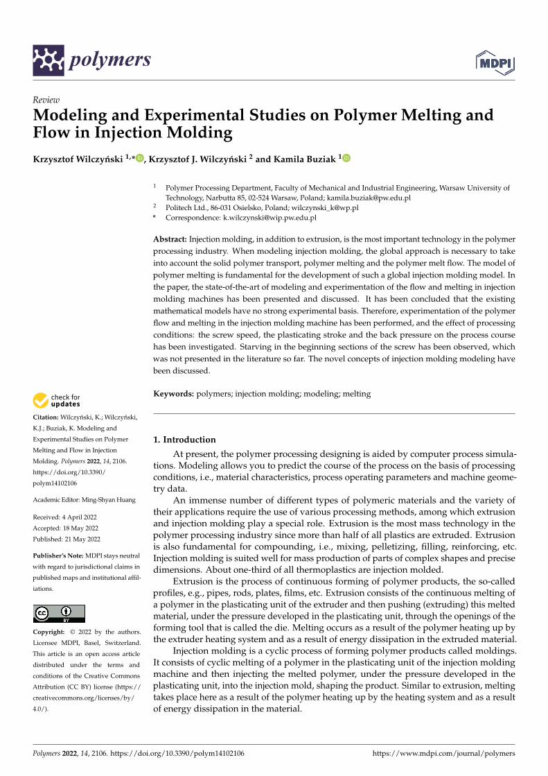
The results of the experiments are depicted in Figures 6–19. An important observationis that in all the cases under study, the screw channel was not fully filled in the beginningsection of the screw, and starvation was clearly seen. A yellow mark means the region ofstarving.
Polymers 2022, 14, x FOR PEER REVIEW 9 of 20
Therefore, in this review paper, the experiments have been performed to evaluate
the existing concepts of process modeling and to clear the physical basis of modeling. In
the experiment, the “screw pulling-out technique” was applied to observe the polymer
transport and melting. Based on these experiments, novel concepts of modeling have
been proposed.
In general, the existing models of the injection molding process (plasticating unit)
discussed above differ from the extrusion models in that they involve the static and dy-
namic phases of melting (stationary and rotating screw) with an axial screw movement.
However, it is assumed that the screw is fully filled with a material as in the flood fed
extrusion (Figure 2), which is inconsistent with our observation [36] where starvation is
clearly seen as in the starve fed extrusion (Figure 3).
2. Experiment
2.1. Material and Process Data
The polystyrene Polystyrol 454H (manufactured by BASF, Ludwigshafen, Germany)
was used in the research. The basic material data were as follows: the specific density ρ =
1.05 g/cm3, the melt flow index MFI = 4.0 g/10 min (M = 5.0 kg, T = 200 °C), and the Vicat
temperature Tv = 85 °C (F = 50 N).
The injection molding machine FORMOplast 235/80 (manufactured by PONAR,
Żywiec, Poland) was applied with the clamping force Fclamp = 80 T.
A conventional screw of the diameter D = 45 mm, the length L = 540 mm and the
screw pitch t = 36 mm was used. The lengths of the screw sections were equal to LF = 305
mm (the feeding sectrion), LC = 135 mm (the compression section), LM = 100 mm (the
metering section). The depths of the screw channel in the sections were equal to HF = 10
mm (the feeding section), HM = 3,3 mm (the metering section) and the compression ratio,
which is the ratio of the screw channel depth in the feeding section to the screw channel
depth in the metering section was equal to CR = HF/HM = 3.
Different processing conditions have been applied to study their effect on the pol-
ymer flow as well as melting in the injection molding machine. The screw rotation speeds
were equal to N = 100 rpm and 300 rpm, the plastication strokes: hplast = 1 D and 3 D, and
the back pressures (hydraulic): Pback = 0 MPa, 2 MPa and 3 MPa.
The temperature was set at TI = 190 °C, TII = 200 °C, TIII = 220 °C in the barrel sections,
and Tnozzle = 230 °C in the nozzle.
2.2. Results
The results of the experiments are depicted in Figures 6–19. An important observa-
tion is that in all the cases under study, the screw channel was not fully filled in the be-
ginning section of the screw, and starvation was clearly seen. A yellow mark means the
region of starving.
An effect of the screw speed (N = 100 rpm and 300 rpm) on the polymer flow in the
injection molding process at the constant plastication stroke and the constant back pres-
sure is shown in Figures 6-10. It is seen that when screw speed increases, the melting
slows, which results from the shorter plastication time. It is also seen that the starvation
decreases since more polymer is delivered in front of the screw tip.
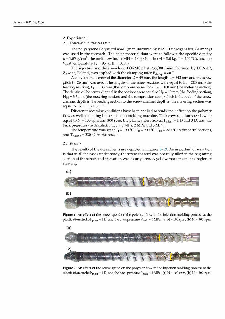
Figure 6. An effect of the screw speed on the polymer flow in the injection molding process at theplastication stroke hplast = 1 D, and the back pressure Pback = 0 MPa: (a) N = 100 rpm, (b) N = 300 rpm.
Polymers 2022, 14, x FOR PEER REVIEW 10 of 20
Figure 6. An effect of the screw speed on the polymer flow in the injection molding process at the
plastication stroke hplast = 1 D, and the back pressure Pback = 0 MPa: (a) N = 100 rpm, (b) N = 300 rpm.
Figure 7. An effect of the screw speed on the polymer flow in the injection molding process at the
plastication stroke hplast = 1 D, and the back pressure Pback = 2 MPa: (a) N = 100 rpm, (b) N = 300 rpm.
Figure 8. An effect of the screw speed on the polymer flow in the injection molding process at the
plastication stroke hplast = 3 D, and the back pressure Pback = 0 MPa: (a) N = 100 rpm, (b) N = 300 rpm.
Figure 9. An effect of the screw speed on the polymer flow in the injection molding process at the
plastication stroke hplast = 3 D, and the back pressure Pback = 2 MPa: (a) N = 100 rpm, (b) N = 300 rpm.
Figure 10. An effect of the screw speed on the polymer flow in the injection molding process at the
plastication stroke hplast = 3 D, and the back pressure Pback = 3 MPa: (a) N = 100 rpm, (b) N = 300 rpm.
An effect of the plastication stroke (hplast = 1 D, hplast = 3 D) on the polymer flow in the
injection molding process at the constant screw speed and the constant back pressure is
shown in Figures 11–15. It is seen that when the plastication stroke increases, the starva-
tion increases, too.
Figure 7. An effect of the screw speed on the polymer flow in the injection molding process at theplastication stroke hplast = 1 D, and the back pressure Pback = 2 MPa: (a) N = 100 rpm, (b) N = 300 rpm.
Polymers 2022, 14, 2106 10 of 19
Polymers 2022, 14, x FOR PEER REVIEW 10 of 20
Figure 6. An effect of the screw speed on the polymer flow in the injection molding process at the
plastication stroke hplast = 1 D, and the back pressure Pback = 0 MPa: (a) N = 100 rpm, (b) N = 300 rpm.
Figure 7. An effect of the screw speed on the polymer flow in the injection molding process at the
plastication stroke hplast = 1 D, and the back pressure Pback = 2 MPa: (a) N = 100 rpm, (b) N = 300 rpm.
Figure 8. An effect of the screw speed on the polymer flow in the injection molding process at the
plastication stroke hplast = 3 D, and the back pressure Pback = 0 MPa: (a) N = 100 rpm, (b) N = 300 rpm.
Figure 9. An effect of the screw speed on the polymer flow in the injection molding process at the
plastication stroke hplast = 3 D, and the back pressure Pback = 2 MPa: (a) N = 100 rpm, (b) N = 300 rpm.
Figure 10. An effect of the screw speed on the polymer flow in the injection molding process at the
plastication stroke hplast = 3 D, and the back pressure Pback = 3 MPa: (a) N = 100 rpm, (b) N = 300 rpm.
An effect of the plastication stroke (hplast = 1 D, hplast = 3 D) on the polymer flow in the
injection molding process at the constant screw speed and the constant back pressure is
shown in Figures 11–15. It is seen that when the plastication stroke increases, the starva-
tion increases, too.
Figure 8. An effect of the screw speed on the polymer flow in the injection molding process at theplastication stroke hplast = 3 D, and the back pressure Pback = 0 MPa: (a) N = 100 rpm, (b) N = 300 rpm.
Polymers 2022, 14, x FOR PEER REVIEW 10 of 20
Figure 6. An effect of the screw speed on the polymer flow in the injection molding process at the
plastication stroke hplast = 1 D, and the back pressure Pback = 0 MPa: (a) N = 100 rpm, (b) N = 300 rpm.
Figure 7. An effect of the screw speed on the polymer flow in the injection molding process at the
plastication stroke hplast = 1 D, and the back pressure Pback = 2 MPa: (a) N = 100 rpm, (b) N = 300 rpm.
Figure 8. An effect of the screw speed on the polymer flow in the injection molding process at the
plastication stroke hplast = 3 D, and the back pressure Pback = 0 MPa: (a) N = 100 rpm, (b) N = 300 rpm.
Figure 9. An effect of the screw speed on the polymer flow in the injection molding process at the
plastication stroke hplast = 3 D, and the back pressure Pback = 2 MPa: (a) N = 100 rpm, (b) N = 300 rpm.
Figure 10. An effect of the screw speed on the polymer flow in the injection molding process at the
plastication stroke hplast = 3 D, and the back pressure Pback = 3 MPa: (a) N = 100 rpm, (b) N = 300 rpm.
An effect of the plastication stroke (hplast = 1 D, hplast = 3 D) on the polymer flow in the
injection molding process at the constant screw speed and the constant back pressure is
shown in Figures 11–15. It is seen that when the plastication stroke increases, the starva-
tion increases, too.
Figure 9. An effect of the screw speed on the polymer flow in the injection molding process at theplastication stroke hplast = 3 D, and the back pressure Pback = 2 MPa: (a) N = 100 rpm, (b) N = 300 rpm.
Polymers 2022, 14, x FOR PEER REVIEW 10 of 20
Figure 6. An effect of the screw speed on the polymer flow in the injection molding process at the
plastication stroke hplast = 1 D, and the back pressure Pback = 0 MPa: (a) N = 100 rpm, (b) N = 300 rpm.
Figure 7. An effect of the screw speed on the polymer flow in the injection molding process at the
plastication stroke hplast = 1 D, and the back pressure Pback = 2 MPa: (a) N = 100 rpm, (b) N = 300 rpm.
Figure 8. An effect of the screw speed on the polymer flow in the injection molding process at the
plastication stroke hplast = 3 D, and the back pressure Pback = 0 MPa: (a) N = 100 rpm, (b) N = 300 rpm.
Figure 9. An effect of the screw speed on the polymer flow in the injection molding process at the
plastication stroke hplast = 3 D, and the back pressure Pback = 2 MPa: (a) N = 100 rpm, (b) N = 300 rpm.
Figure 10. An effect of the screw speed on the polymer flow in the injection molding process at the
plastication stroke hplast = 3 D, and the back pressure Pback = 3 MPa: (a) N = 100 rpm, (b) N = 300 rpm.
An effect of the plastication stroke (hplast = 1 D, hplast = 3 D) on the polymer flow in the
injection molding process at the constant screw speed and the constant back pressure is
shown in Figures 11–15. It is seen that when the plastication stroke increases, the starva-
tion increases, too.
Figure 10. An effect of the screw speed on the polymer flow in the injection molding process at theplastication stroke hplast = 3 D, and the back pressure Pback = 3 MPa: (a) N = 100 rpm, (b) N = 300 rpm.
Polymers 2022, 14, x FOR PEER REVIEW 11 of 20
Figure 11. An effect of the plastication stroke on the polymer flow in the injection molding process
at the screw speed N = 100 rpm, and the back pressure Pback = 0 MPa: (a) hplast = 1 D, (b) hplast = 3 D.
Figure 12. An effect of the plastication stroke on the polymer flow in the injection molding process
at the screw speed N = 100 rpm, and the back pressure Pback = 2 MPa: (a) hplast = 1 D, (b) hplast = 3 D.
Figure 13. An effect of the plastication stroke on the polymer flow in the injection molding process
at the screw speed N = 300 rpm, and the back pressure Pback = 0 MPa: (a) hplast = 1 D, (b) hplast = 3 D.
Figure 14. An effect of the plastication stroke on the polymer flow in the injection molding process
at the screw speed N = 300 rpm, and the back pressure Pback = 2 MPa: (a) hplast = 1 D, (b) hplast = 3 D.
Figure 15. An effect of the plastication stroke on the polymer flow in the injection molding process
at the screw speed N = 300 rpm, and the back pressure Pback = 3 MPa: (a) hplast = 1 D, (b) hplast = 3 D.
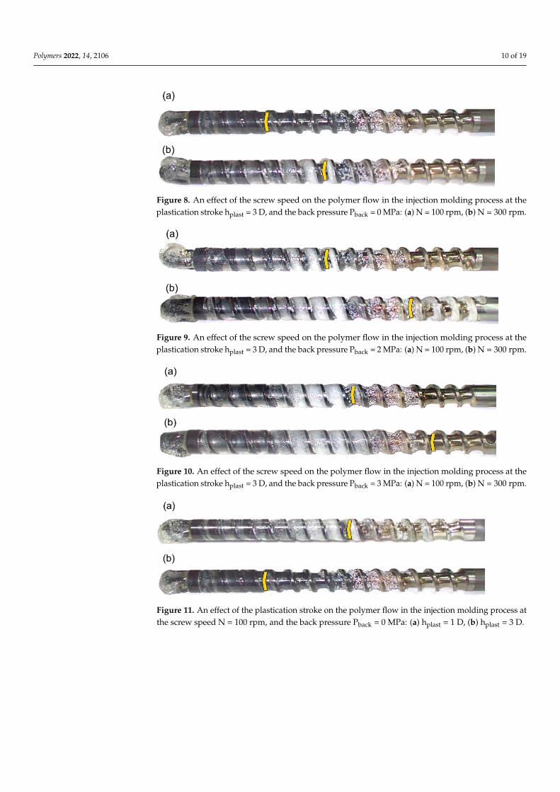
Figure 11. An effect of the plastication stroke on the polymer flow in the injection molding process atthe screw speed N = 100 rpm, and the back pressure Pback = 0 MPa: (a) hplast = 1 D, (b) hplast = 3 D.
Polymers 2022, 14, 2106 11 of 19
Polymers 2022, 14, x FOR PEER REVIEW 11 of 20
Figure 11. An effect of the plastication stroke on the polymer flow in the injection molding process
at the screw speed N = 100 rpm, and the back pressure Pback = 0 MPa: (a) hplast = 1 D, (b) hplast = 3 D.
Figure 12. An effect of the plastication stroke on the polymer flow in the injection molding process
at the screw speed N = 100 rpm, and the back pressure Pback = 2 MPa: (a) hplast = 1 D, (b) hplast = 3 D.
Figure 13. An effect of the plastication stroke on the polymer flow in the injection molding process
at the screw speed N = 300 rpm, and the back pressure Pback = 0 MPa: (a) hplast = 1 D, (b) hplast = 3 D.
Figure 14. An effect of the plastication stroke on the polymer flow in the injection molding process
at the screw speed N = 300 rpm, and the back pressure Pback = 2 MPa: (a) hplast = 1 D, (b) hplast = 3 D.
Figure 15. An effect of the plastication stroke on the polymer flow in the injection molding process
at the screw speed N = 300 rpm, and the back pressure Pback = 3 MPa: (a) hplast = 1 D, (b) hplast = 3 D.
Figure 12. An effect of the plastication stroke on the polymer flow in the injection molding process atthe screw speed N = 100 rpm, and the back pressure Pback = 2 MPa: (a) hplast = 1 D, (b) hplast = 3 D.
Polymers 2022, 14, x FOR PEER REVIEW 11 of 20
Figure 11. An effect of the plastication stroke on the polymer flow in the injection molding process
at the screw speed N = 100 rpm, and the back pressure Pback = 0 MPa: (a) hplast = 1 D, (b) hplast = 3 D.
Figure 12. An effect of the plastication stroke on the polymer flow in the injection molding process
at the screw speed N = 100 rpm, and the back pressure Pback = 2 MPa: (a) hplast = 1 D, (b) hplast = 3 D.
Figure 13. An effect of the plastication stroke on the polymer flow in the injection molding process
at the screw speed N = 300 rpm, and the back pressure Pback = 0 MPa: (a) hplast = 1 D, (b) hplast = 3 D.
Figure 14. An effect of the plastication stroke on the polymer flow in the injection molding process
at the screw speed N = 300 rpm, and the back pressure Pback = 2 MPa: (a) hplast = 1 D, (b) hplast = 3 D.
Figure 15. An effect of the plastication stroke on the polymer flow in the injection molding process
at the screw speed N = 300 rpm, and the back pressure Pback = 3 MPa: (a) hplast = 1 D, (b) hplast = 3 D.
Figure 13. An effect of the plastication stroke on the polymer flow in the injection molding process atthe screw speed N = 300 rpm, and the back pressure Pback = 0 MPa: (a) hplast = 1 D, (b) hplast = 3 D.
Polymers 2022, 14, x FOR PEER REVIEW 11 of 20
Figure 11. An effect of the plastication stroke on the polymer flow in the injection molding process
at the screw speed N = 100 rpm, and the back pressure Pback = 0 MPa: (a) hplast = 1 D, (b) hplast = 3 D.
Figure 12. An effect of the plastication stroke on the polymer flow in the injection molding process
at the screw speed N = 100 rpm, and the back pressure Pback = 2 MPa: (a) hplast = 1 D, (b) hplast = 3 D.
Figure 13. An effect of the plastication stroke on the polymer flow in the injection molding process
at the screw speed N = 300 rpm, and the back pressure Pback = 0 MPa: (a) hplast = 1 D, (b) hplast = 3 D.
Figure 14. An effect of the plastication stroke on the polymer flow in the injection molding process
at the screw speed N = 300 rpm, and the back pressure Pback = 2 MPa: (a) hplast = 1 D, (b) hplast = 3 D.
Figure 15. An effect of the plastication stroke on the polymer flow in the injection molding process
at the screw speed N = 300 rpm, and the back pressure Pback = 3 MPa: (a) hplast = 1 D, (b) hplast = 3 D.
Figure 14. An effect of the plastication stroke on the polymer flow in the injection molding process atthe screw speed N = 300 rpm, and the back pressure Pback = 2 MPa: (a) hplast = 1 D, (b) hplast = 3 D.
Polymers 2022, 14, x FOR PEER REVIEW 11 of 20
Figure 11. An effect of the plastication stroke on the polymer flow in the injection molding process
at the screw speed N = 100 rpm, and the back pressure Pback = 0 MPa: (a) hplast = 1 D, (b) hplast = 3 D.
Figure 12. An effect of the plastication stroke on the polymer flow in the injection molding process
at the screw speed N = 100 rpm, and the back pressure Pback = 2 MPa: (a) hplast = 1 D, (b) hplast = 3 D.
Figure 13. An effect of the plastication stroke on the polymer flow in the injection molding process
at the screw speed N = 300 rpm, and the back pressure Pback = 0 MPa: (a) hplast = 1 D, (b) hplast = 3 D.
Figure 14. An effect of the plastication stroke on the polymer flow in the injection molding process
at the screw speed N = 300 rpm, and the back pressure Pback = 2 MPa: (a) hplast = 1 D, (b) hplast = 3 D.
Figure 15. An effect of the plastication stroke on the polymer flow in the injection molding process
at the screw speed N = 300 rpm, and the back pressure Pback = 3 MPa: (a) hplast = 1 D, (b) hplast = 3 D. Figure 15. An effect of the plastication stroke on the polymer flow in the injection molding process atthe screw speed N = 300 rpm, and the back pressure Pback = 3 MPa: (a) hplast = 1 D, (b) hplast = 3 D.
Polymers 2022, 14, x FOR PEER REVIEW 12 of 20
An effect of the back pressure (Pback = 0 MPa, Pback = 2 MPa, Pback = 3 MPa) on the
polymer flow in the injection molding process at the constant screw speed and the con-
stant plastication stroke is shown in Figures 16–19. It is seen that when the back pressure
increases, the starvation decreases.
Figure 16. An effect of the back pressure on the polymer flow in the injection molding process at
the screw speed N = 100 rpm, and the plasticating stroke hplast = 1 D: (a) Pback = 0 MPa, (b) Pback = 2
MPa.
Figure 17. An effect of the back pressure on the polymer flow in the injection molding process at
the screw speed N = 100 rpm, and the plasticating stroke hplast = 3 D: (a) Pback = 0 MPa, (b) Pback = 2
MPa, (c) Pback = 3 MPa.
Figure 18. An effect of the back pressure on the polymer flow in the injection molding process at
the screw speed N = 300 rpm, and the plasticating stroke hplast = 1 D: (a) Pback = 0 MPa, (b) Pback = 2
MPa, (c) Pback = 3 MPa.
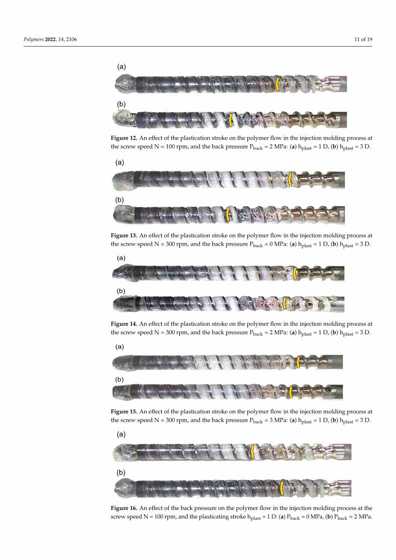
Figure 16. An effect of the back pressure on the polymer flow in the injection molding process at thescrew speed N = 100 rpm, and the plasticating stroke hplast = 1 D: (a) Pback = 0 MPa, (b) Pback = 2 MPa.

Polymers 2022, 14, 2106 12 of 19
Polymers 2022, 14, x FOR PEER REVIEW 12 of 20
An effect of the back pressure (Pback = 0 MPa, Pback = 2 MPa, Pback = 3 MPa) on the
polymer flow in the injection molding process at the constant screw speed and the con-
stant plastication stroke is shown in Figures 16–19. It is seen that when the back pressure
increases, the starvation decreases.
Figure 16. An effect of the back pressure on the polymer flow in the injection molding process at
the screw speed N = 100 rpm, and the plasticating stroke hplast = 1 D: (a) Pback = 0 MPa, (b) Pback = 2
MPa.
Figure 17. An effect of the back pressure on the polymer flow in the injection molding process at
the screw speed N = 100 rpm, and the plasticating stroke hplast = 3 D: (a) Pback = 0 MPa, (b) Pback = 2
MPa, (c) Pback = 3 MPa.
Figure 18. An effect of the back pressure on the polymer flow in the injection molding process at
the screw speed N = 300 rpm, and the plasticating stroke hplast = 1 D: (a) Pback = 0 MPa, (b) Pback = 2
MPa, (c) Pback = 3 MPa.
Figure 17. An effect of the back pressure on the polymer flow in the injection molding process at thescrew speed N = 100 rpm, and the plasticating stroke hplast = 3 D: (a) Pback = 0 MPa, (b) Pback = 2 MPa,(c) Pback = 3 MPa.
Polymers 2022, 14, x FOR PEER REVIEW 12 of 20
An effect of the back pressure (Pback = 0 MPa, Pback = 2 MPa, Pback = 3 MPa) on the
polymer flow in the injection molding process at the constant screw speed and the con-
stant plastication stroke is shown in Figures 16–19. It is seen that when the back pressure
increases, the starvation decreases.
Figure 16. An effect of the back pressure on the polymer flow in the injection molding process at
the screw speed N = 100 rpm, and the plasticating stroke hplast = 1 D: (a) Pback = 0 MPa, (b) Pback = 2
MPa.
Figure 17. An effect of the back pressure on the polymer flow in the injection molding process at
the screw speed N = 100 rpm, and the plasticating stroke hplast = 3 D: (a) Pback = 0 MPa, (b) Pback = 2
MPa, (c) Pback = 3 MPa.
Figure 18. An effect of the back pressure on the polymer flow in the injection molding process at
the screw speed N = 300 rpm, and the plasticating stroke hplast = 1 D: (a) Pback = 0 MPa, (b) Pback = 2
MPa, (c) Pback = 3 MPa.
Figure 18. An effect of the back pressure on the polymer flow in the injection molding process at thescrew speed N = 300 rpm, and the plasticating stroke hplast = 1 D: (a) Pback = 0 MPa, (b) Pback = 2 MPa,(c) Pback = 3 MPa.
Polymers 2022, 14, x FOR PEER REVIEW 13 of 20
Figure 19. An effect of the back pressure on the polymer flow in the injection molding process at
the screw speed N = 300 rpm, and the plasticating stroke hplast = 3 D: (a) Pback = 0 MPa, (b) Pback = 2
MPa, (c) Pback = 3 MPa.
It can be concluded from the presented experiment that starvation appears in the
injection molding process when the screw moves forward, injecting the polymer into the
mold. This is dependent on the screw speed, the plastication stroke and the back pres-
sure. The starvation increases when the screw speed and the back pressure decrease, and
the plastication stroke increases. It is also clearly seen that melting slows down when
screw speed increases which is consistent with Gao’s observation [105].
3. Future Concepts of Injection Molding Process Modeling
There are distinct differences between the polymer flow and melting in injection
molding machines and extrusion machines (reciprocating machines vs. non-reciprocating
machines). In the typical cycle of injection molding, the screw starts the process in the
forward position in the barrel. It rotates (screw recharge) and conveys the polymer for-
ward, and the pressure is developed before the screw tip until the desired volume of the
molded part is reached. The screw is then idled in the back position while the polymer
previously injected into the mold is being cooled. After cooling the part, the mold opens,
and the part is ejected. Then, the mold closes, and the screw moves forward by hydraulic
pressure, injecting the newly melted portion of the polymer collected at the tip of the
screw into the empty mold, and then starvation appears. The valve, such as the check
ring, prevents the back flow during injection. The injection molding cycle is composed of
three stages: feeding (screw rotating and moving backward), stopping (no screw move-
ment) and injecting (screw moving forward without rotation).
The injection molding process is performed both in the plasticating unit of the injec-
tion molding machine and in the mold. To some extent, it is similar to extrusion; how-
ever, extrusion is a continuous process in which the extruder cooperates with the die
continuously, without any interruptions. Injection molding is a cyclic process, and the
cooperation of the injection molding machine (plasticating unit) with the mold is not
continuous. However, the flow in the plasticating unit influences the flow in the mold,
similarly to the extrusion, where the flow in the extruder (plasticating unit) influences the
flow in the die. In the extrusion and injection molding process, the process output pa-
rameters in the plasticizing unit are the process inputs for the flow in the die and in the
mold, respectively.
The conclusion is that the correct modeling of the injection molding process, and the
correct modeling of the flow in the injection mold, would require including the modeling
of flow in the plasticating unit into the global model of the process.
It results from the presented experiment that when injecting the polymer, the star-
vation appears, and this should be included in the process modeling. This can be done by
Figure 19. An effect of the back pressure on the polymer flow in the injection molding process at thescrew speed N = 300 rpm, and the plasticating stroke hplast = 3 D: (a) Pback = 0 MPa, (b) Pback = 2 MPa,(c) Pback = 3 MPa.
An effect of the screw speed (N = 100 rpm and 300 rpm) on the polymer flow in theinjection molding process at the constant plastication stroke and the constant back pressureis shown in Figures 6–10. It is seen that when screw speed increases, the melting slows,which results from the shorter plastication time. It is also seen that the starvation decreasessince more polymer is delivered in front of the screw tip.
Polymers 2022, 14, 2106 13 of 19
An effect of the plastication stroke (hplast = 1 D, hplast = 3 D) on the polymer flow inthe injection molding process at the constant screw speed and the constant back pressure isshown in Figures 11–15. It is seen that when the plastication stroke increases, the starvationincreases, too.
An effect of the back pressure (Pback = 0 MPa, Pback = 2 MPa, Pback = 3 MPa) onthe polymer flow in the injection molding process at the constant screw speed and theconstant plastication stroke is shown in Figures 16–19. It is seen that when the back pressureincreases, the starvation decreases.
It can be concluded from the presented experiment that starvation appears in theinjection molding process when the screw moves forward, injecting the polymer into themold. This is dependent on the screw speed, the plastication stroke and the back pressure.The starvation increases when the screw speed and the back pressure decrease, and theplastication stroke increases. It is also clearly seen that melting slows down when screwspeed increases which is consistent with Gao’s observation [105].
3. Future Concepts of Injection Molding Process Modeling
There are distinct differences between the polymer flow and melting in injectionmolding machines and extrusion machines (reciprocating machines vs. non-reciprocatingmachines). In the typical cycle of injection molding, the screw starts the process in theforward position in the barrel. It rotates (screw recharge) and conveys the polymer forward,and the pressure is developed before the screw tip until the desired volume of the moldedpart is reached. The screw is then idled in the back position while the polymer previouslyinjected into the mold is being cooled. After cooling the part, the mold opens, and thepart is ejected. Then, the mold closes, and the screw moves forward by hydraulic pressure,injecting the newly melted portion of the polymer collected at the tip of the screw into theempty mold, and then starvation appears. The valve, such as the check ring, prevents theback flow during injection. The injection molding cycle is composed of three stages: feeding(screw rotating and moving backward), stopping (no screw movement) and injecting (screwmoving forward without rotation).
The injection molding process is performed both in the plasticating unit of the injectionmolding machine and in the mold. To some extent, it is similar to extrusion; however, ex-trusion is a continuous process in which the extruder cooperates with the die continuously,without any interruptions. Injection molding is a cyclic process, and the cooperation of theinjection molding machine (plasticating unit) with the mold is not continuous. However,the flow in the plasticating unit influences the flow in the mold, similarly to the extrusion,where the flow in the extruder (plasticating unit) influences the flow in the die. In theextrusion and injection molding process, the process output parameters in the plasticizingunit are the process inputs for the flow in the die and in the mold, respectively.
The conclusion is that the correct modeling of the injection molding process, and thecorrect modeling of the flow in the injection mold, would require including the modelingof flow in the plasticating unit into the global model of the process.
It results from the presented experiment that when injecting the polymer, the starvationappears, and this should be included in the process modeling. This can be done by adoptingthe concepts developed by Wilczynski et al. [8,36,44] for starve fed single screw extrusion.
In general, the models of solid conveying in the classical single screw extrusion withgravitational (flood) feeding are based on the work of Darnell and Mol [5], that is, onthe assumption that the polymer granules are transported as a solid bed without rela-tive movement of the granules. However, some experiments, for example, performed byFang et al. [145], indicated that this cannot be valid any longer since a relative movementof the individual granules in the screw channel is clearly seen. Thus, in order to modelthe solid transport in the single screw extruder, the discrete element method (DEM) wasapplied. This was first performed by Potente and Pohl [146], who studied the polymer flowin the hopper region in the extruder. Later, important and fundamental studies were carriedout by Moysey and Thompson [147–149], who performed the first computations for com-
Polymers 2022, 14, 2106 14 of 19
pacting granules and the pressure/throughput relation in the feed zone of the single screwextruder [150]. Further studies of this issue were performed by Schöppner et al. [151,152],who proposed the model which enabled the computation of solid conveying with consid-ering the pressure build-up and the filling degree. It can be concluded that the discreteelement method (DEM), which is a useful and powerful tool for modeling the solid con-veying in single screw extruders, could also be applied to modeling this in the injectionmolding process. A good example of the discrete element method software is EDEM [153].
Similarly, as the model of Darnell and Mol [5] for solid conveying, the model ofTadmor and Klein [20] for polymer melting was usually the basis for modeling the extrusionprocess, as well as the injection molding. However, the models of melting presented so farwere mainly based on the a priori assumed melting mechanism. Instead of the meltingmechanism assumed, the polymer melting in single screw (non-reciprocating) extruderscan be modeled by solving the conservation equations of mass, momentum and energy.This concept was presented first by Viriyayuthakorn and Kassahun [154], who proposedthe 3D model without assuming any particular melting mechanism. The phase changeproblem was solved using the functional dependence of the specific heat on the temperature.The solution of equations of momentum and energy provided the solid/melt distribution,which was determined by the temperature distribution. Syrjala [155] carried out the 2Dsimulation of the polymer melting without any melting mechanism assumed. However, inboth cases, the computations were not validated experimentally.
Later, Altinkaynak et al. [156] carried out the experimental and theoretical researchon modeling of polymer melting using this approach. The two-phase solid/melt polymerflow was studied with the Cross-WLF rheological model, which allowed us to considerthe solid material as a high-viscous fluid while the molten material as a low-viscous fluid.Hopmann et al. [157] solved the equations of momentum and energy using the finitevolume method (FVM) with the Carreau rheological model. Kazmer et al. [158] used thisapproach to modeling the polymer melting in barrier screws, as well as Lewandowskiand Wilczynski in conventional screws [159]. This approach can be probably also appliedfor modeling the polymer melting in the injection molding process, e.g., using the AnsysPolyflow software [160].
It is worth noting that when modeling the injection molding process, the three sepa-rated phases of the process have to be considered, i.e., the feeding phase, the idle phaseand the injecting phase, and the concepts presented above should be applied separatelyto these.
The promising concept would be the coupled DEM/CFD modeling. Recently, EDEMand Ansys have developed an open-source, two-way coupling between EDEM and AnsysFluent to provide a unique capability to model particle/fluid flows.
4. Conclusions
The issue of modeling of polymer injection molding has been reviewed and discussed,which includes both the plasticating unit and the injection mold. It has been noted thata comprehensive (global) concept of modeling of injection molding might be useful forsimulating the polymer flow in injection molds, and the global model of the process mightbe considered for simulating the polymer flow in the plasticating unit as well as in themold. The output parameters of the plasticating unit computations would be the inputparameters for the mold flow computations.
It has also been concluded that the existing mathematical models of injection moldinghave no strong experimental basis. Thus, experimentation of the polymer flow and melt-ing in the injection molding machine have been performed, and the effect of processingconditions: screw speed, plasticating stroke and back pressure on the process course hasbeen studied. Starvation has been discovered, which was not presented in the literatureso far, and which may considerably influence the process modeling. The novel conceptsof injection molding modeling have been discussed. The DEM/CFD concept has beenindicated as promising.

Polymers 2022, 14, 2106 15 of 19
Author Contributions: Conceptualization, K.W. and K.J.W.; methodology, K.W. and K.J.W.; valida-tion, K.B.; writing—original draft preparation, K.W. and K.J.W.; writing—review and editing, K.W.;visualization, K.B. All authors have read and agreed to the published version of the manuscript.
Funding: This research received no external funding.
Institutional Review Board Statement: Not applicable.
Informed Consent Statement: Not applicable.
Data Availability Statement: The data presented in this study are available on request from thecorresponding author.
Conflicts of Interest: The authors declare no conflict of interest.
References1. Wilczynski, K. Rheology in Polymer Processing. Modeling and Simulation; Carl Hanser Verlag: Munich, Germany, 2021; ISBN 978-1-56990-660-6.2. Rowell, H.S.; Finlayson, D. Screw Viscous Pumps. Engineering 1928, 126, 249.3. Carley, J.F.; Mallouk, R.S.; McKelvey, J.M. Simplified Flow Theory for Screw Extruders. Ind. Eng. Chem. 1953, 45, 974–978.
[CrossRef]4. Carley, J.F.; Strub, R.A. Basic Concepts of Extrusion. Ind. Eng. Chem. 1953, 45, 970–974. [CrossRef]5. Darnell, W.H.; Mol, E.A.J. Solids Conveying in Extruders. SPE-J. 1956, 20, 20–29.6. Maddock, B.H. A Visual Analysis of Flow and Mixing in Extruder Screws. SPE ANTEC Tech. Pap. 1959, 15, 383.7. Street, L.F. Plastifying Extrusion. Intern. Plast. Eng. 1961, 1, 289–296.8. Wilczynski, K.; Lewandowski, A.; Wilczynski, K.J. Experimental Study for Starve-Fed Single Screw Extrusion of Thermoplastics.
Polym. Eng. Sci. 2012, 52, 1258–1270. [CrossRef]9. Tadmor, Z. Fundamentals of Plasticating Extrusion. I. A Theoretical Model for Melting. Polym. Eng. Sci. 1966, 6, 185–190.
[CrossRef]10. Marshall, D.I.; Klein, I. Fundamentals of Plasticating Extrusion. II. Experiments. Polym. Eng. Sci. 1966, 6, 191–197. [CrossRef]11. Tadmor, Z.; Duvdevani, I.J.; Klein, I. Melting in Plasticating Extruders Theory and Experiments. Polym. Eng. Sci. 1967, 7, 198–217.
[CrossRef]12. Tadmor, Z.; Klein, I. Computer Programs for Plastic Engineers; Reinhold Book Corporation: New York, NY, USA, 1968.13. Tadmor, Z.; Broyer, E. Solids Conveying in Screw Extruders—Part I: A Modified Isothermal Model. Polym. Eng. Sci. 1972, 12,
12–24. [CrossRef]14. Tadmor, Z.; Broyer, E. Solids Conveying in Screw Extruders—Part II: A Modified Non-Isothermal Model. Polym. Eng. Sci. 1972,
12, 376–378. [CrossRef]15. Kacir, L.; Tadmor, Z. Solids Conveying in Screw Extruders. Part III: The Delay Zone. Polym. Eng. Sci. 1972, 12, 387–395. [CrossRef]16. Fisher, E.G. Extrusion of Plastics, 1st ed.; Iliffe Books Ltd.: London, UK, 1958.17. McKelvey, J.M. Polymer Processing; John Wiley & Sons Inc: New York, NY, USA, 1962; ISBN 978-0471584438.18. Schenkel, G. Kunststoff-Extrudertechnik; Carl Hanser: Munich, Germany, 1963.19. Fenner, R.T. Extruder Screw Design; Iliffe Books Ltd.: London, UK, 1970.20. Tadmor, Z.; Klein, I. Engineering Principles of Plasticating Extrusion; Van Nostrand Reinhold Co.: New York, NY, USA, 1970;
ISBN 978-0442156350.21. Hensen, F.; Knappe, W.; Potente, H. Handbuch der Kunststoff-Extrusiontechnik. Grundlagen; Carl Hanser: Munich, Germany, 1989;
ISBN 978-3446143395.22. White, J.L. Rubber Processing; Hanser Publishers: Munich, Germany, 1995; ISBN 978-3446166004.23. White, J.L.; Potente, H. Screw Extrusion. Science and Technology; Hanser Publishers: Munich, Germany, 2003; ISBN 978-3-446-19624-7.24. Tadmor, Z.; Gogos, C.G. Principles of Polymer Processing, 2nd ed.; John Wiley & Sons Inc: New York, NY, USA, 2006; ISBN 978-0-471-38770-1.25. White, J.L.; Kim, E.K. Twin Screw Extrusion. Technology and Principles, 2nd ed.; Hanser Publishers: Munich, Germany, 2010;
ISBN 978-1569904718.26. Rauwendaal, C. Polymer Extrusion, 5th ed.; Carl Hanser: Munich, Germany, 2014; ISBN 978-1-56990-516-6.27. Lafleur, P.G.; Vergnes, B. Polymer Extrusion; ISTE-Wiley: London, UK, 2014; ISBN 1848216505.28. Agassant, J.F.; Avenas, P.; Carreau, P.J.; Vergnes, B.; Vincent, M. Polymer Processing. Principles and Modeling, 2nd ed.; Carl Hanser:
Munich, Germany, 2017; ISBN 978-1-56990-605-7.29. Chung, C.I. Extrusion of Polymers. Theory and Practice, 3rd ed.; Carl Hanser: Munich, Germany, 2020; ISBN 978-1-56990-609-5.30. Campbell, G.A.; Spalding, M.A. Analyzing and Troubleshooting Single-Screw Extruders; Carl Hanser: Munich, Germany, 2021;
ISBN 978-1-56990-784-9.31. Vlachopoulos, J.; Polychronopoulos, N.D. Understanding Rheology and Technology of Polymer Extrusion; Polydynamic: Dundas, ON,
Canada, 2019; ISBN 978-0-9952407-2-8.32. Ariffin, A.; Ahmad, M.S.B. Review: Single Screw Extruder in Particulate Filler Composite. Polym.-Plast. Technol. 2011, 50, 395–403.
[CrossRef]

Polymers 2022, 14, 2106 16 of 19
33. Wilczynski, K.; Nastaj, A.; Lewandowski, A.; Wilczynski, K.J. Multipurpose Computer Model for Screw Processing of Plastics.Polym.-Plast. Technol. 2012, 51, 626–633. [CrossRef]
34. Teixeira, C.; Gaspar-Cunha, A.; Covas, J.A. Flow and Heat Transfer Along the Length of a Co-rotating Twin Screw Extruder.Polym.-Plast. Technol. 2012, 51, 1567–1577. [CrossRef]
35. Malik, M.; Kalyon, D.M.; Golba, J.C., Jr. Simulation of Co-Rotating Twin Screw Extrusion Process Subject to Pressure-DependentWall Slip at Barrel and Screw Surfaces: 3D FEM Analysis for Combinations of Forward- and Reverse-Conveying Screw Elements.Int. Polym. Proc. 2014, 29, 51–62. [CrossRef]
36. Wilczynski, K.; Nastaj, A.; Lewandowski, A.; Wilczynski, K.J.; Buziak, K. Fundamentals of Global Modeling for Polymer Extrusion.Polymers 2019, 11, 2106. [CrossRef]
37. Hyvärinen, M.; Jabeen, R.; Kärki, T. The Modeling of Extrusion Processes for Polymers—A Review. Polymers 2020, 12, 1306.[CrossRef]
38. Lewandowski, A.; Wilczynski, K. Modeling of Twin Screw Extrusion of Polymeric Materials. Polymers 2022, 14, 274. [CrossRef]39. Marschik, C.; Roland, W.; Osswald, T.A. Melt Conveying in Single-Screw Extruders: Modeling and Simulation. Polymers 2022,
14, 875. [CrossRef] [PubMed]40. Lopez-Latorre, L.; McKelvey, J.M. Melting and Pressurization in Starve Feed Extrusion. Adv. Polym. Technol. 1984, 3, 355–364.
[CrossRef]41. Isherwood, D.P.; Pieris, R.N.; Kassatly, J. The Effect of Metered Starve Feeding on the Performance of a Small Extruder. J. Eng. Ind.
1984, 106, 132–136. [CrossRef]42. Strand, S.R.; Spalding, M.A.; Hyun, S.K. Modeling of the Solids-Conveying Section of a Starve Fed Single Screw Plasticating
Extruder. SPE ANTEC Tech. Pap. 1992, 38, 2537–2541.43. Thompson, M.R.; Donoian, G.; Christiano, J.P. Melting Mechanism of a Starved-Fed Single-Screw Extruder for Calcium Carbonate
Filled Polyethylene. Polym. Eng. Sci. 2000, 40, 2014–2026. [CrossRef]44. Wilczynski, K.; Nastaj, A.; Wilczynski, K.J. Melting Model for Starve Fed Single Screw Extrusion of Thermoplastics. Int. Polym.
Proc. 2013, 28, 34–42. [CrossRef]45. Wilczynski, K.J.; Nastaj, A.; Lewandowski, A.; Wilczynski, K. A Composite Model for Starve Fed Single Screw Extrusion of
Thermoplastics. Polym. Eng. Sci. 2014, 54, 2362–2374. [CrossRef]46. Wilczynski, K.J.; Lewandowski, A.; Nastaj, A.; Wilczynski, K. Modeling for Starve Fed/Flood Fed Mixing Single-Screw Extruders.
Int. Polym. Proc. 2016, 31, 82–91. [CrossRef]47. Wilczynski, K.J.; Lewandowski, A.; Nastaj, A.; Wilczynski, K. A Global Model for Starve-Fed Nonconventional Single-Screw
Extrusion of Thermoplastics. Adv. Polym. Technol. 2017, 36, 23–35. [CrossRef]48. Wilczynski, K.J.; Lewandowski, A.; Wilczynski, K. Experimental Study of Melting of Polymer Blends in a Starve Fed Single Screw
Extruder. Polym. Eng. Sci. 2016, 56, 1349–1356. [CrossRef]49. Wilczynski, K.J.; Nastaj, A.; Wilczynski, K. A Computer Model for Starve-Fed Single-Screw Extrusion of Polymer Blends. Adv.
Polym. Technol. 2018, 37, 2142–2151. [CrossRef]50. Wilczynski, K.J.; Buziak, K. A Computer Model of Starve Fed Single Screw Extrusion of Wood Plastic Composites. Polymers 2021,
13, 1252. [CrossRef] [PubMed]51. Wilczynski, K.J. Experimental and Theoretical Study on Screw Filling in Starve Fed Single Screw Extruders. Int. Polym. Proc. 2018,
33, 171–179. [CrossRef]52. Bawiskar, S.; White, J.L. Solids Conveying and Melting in a Starve Fed Self-wiping Co-Rotating Twin Screw Extruder. Int. Polym.
Proc. 1995, 10, 105–110. [CrossRef]53. Todd, D.B. Melting of Plastics in Kneading Blocks. SPE ANTEC Tech. Papers 1992, 39, 2528–2536. [CrossRef]54. Sakai, T. The Development of On-line Techniques and Novel Processing Systems for the Monitoring and Handling of the
Evolution of Microstructure in Nonreactive and Reactive Polymer Systems. Adv. Polym. Technol. 1995, 14, 277–290. [CrossRef]55. Gogos, C.G.; Tadmor, Z.; Kim, M.H. Melting Phenomena and Mechanisms in Polymer Processing Equipment. Adv. Polym. Technol.
1998, 17, 285–305. [CrossRef]56. Qian, B.; Gogos, C.G. The Importance of Plastic Energy Dissipation (PED) to the Heating and Melting of Polymer Particulates in
Intermeshing Co-Rotating Twin-Screw Extruders. Adv. Polym. Technol. 2000, 19, 287–299. [CrossRef]57. Qian, B.; Todd, D.B.; Gogos, C.G. Plastic Energy Dissipation and its Role on Heating/Melting of Single-Component Polymers and
Multi-Component Polymer Blends. Adv. Polym. Technol. 2003, 22, 85–95. [CrossRef]58. Potente, H.; Melisch, U. Theoretical and Experimental Investigations of the Melting of Pellets in Co-Rotating Twin-Screw
Extruders. Int. Polym. Proc. 1996, 11, 101–108. [CrossRef]59. Bawiskar, S.; White, J.L. Melting Model for Modular Self Wiping Co-Rotating Twin Screw Extruders. Polym. Eng. Sci. 1998, 38,
727–740. [CrossRef]60. Vergnes, B.; Delacour, M.L.; Souveton, G.; Bouvier, J.M. A Study of Polymer Melting in a Co-Rotating Twin Screw Extruder. In
Proceedings of the International Polymer Processing Society 15th Annual Meeting (PPS-15), Hertogenbosch, The Netherlands,31 May–4 June 1999.
61. Vergnes, B.; Souveton, G.; Delacour, M.L.; Ainser, A. Experimental and Theoretical Study of Polymer Melting in a Co-rotatingTwin Screw Extruder. Int. Polym. Proc. 2001, 16, 351–362. [CrossRef]
Polymers 2022, 14, 2106 17 of 19
62. Zhu, L.; Narh, K.A.; Geng, X. Modeling of Particle-Dispersed Melting Mechanism and its Application in Corotating Twin-ScrewExtrusion. J. Polym. Sci. B Polym. Phys. 2001, 39, 2461–2468. [CrossRef]
63. Potente, H.; Ansalh, J.; Klarholz, B. Design of Tightly Intermeshing Co-Rotating Twin Screw Extruders. Int. Polym. Proc. 1994, 9,11–25. [CrossRef]
64. Bawiskar, S.; White, J.L. A Composite Model for Solid Conveying, Melting, Pressure and Fill Factor Profiles in ModularCo-Rotating Twin Screw Extruders. Int. Polym. Proc. 1997, 12, 331–340. [CrossRef]
65. Vergnes, B.; Valle, G.D.; Delamare, L. A Global Computer Software for Polymer Flows in Corotating Twin Screw Extruders. Polym.Eng. Sci. 1998, 38, 1781–1792. [CrossRef]
66. Potente, H.; Bastian, M.; Flecke, J. Design of a Compounding Extruder by Means of the SIGMA Simulation Software. Adv. Polym.Technol. 1999, 18, 147–170. [CrossRef]
67. White, J.L.; Kim, B.-J.; Bawiskar, S.; Keum, J.M. Development of a Global Computer Software for Modular Self-Wiping CorotatingTwin Screw Extruders. Polym.-Plast. Technol. 2001, 40, 385–405. [CrossRef]
68. White, J.L.; Keum, J.; Jung, H.; Ban, K.; Bumm, S. Corotating Twin-Screw Extrusion Reactive Extrusion-Devolatilization Modeland Software. Polym.-Plast. Technol. 2006, 45, 539–548. [CrossRef]
69. Teixeira, C.F. Designing Screws for Polymer Compounding in Twin-Screw Extruders. Ph.D. Thesis, University of Minho, Braga,Portugal, 2013.
70. Janssen, L.P.B.M. Twin Screw Extrusion; Elsevier Scientific Pub. Co.: Amsterdam, The Netherlands, 1978; ISBN 978-0444416292.71. Lim, S.; White, J.L. Flow Mechanisms, Material Distributions and Phase Morphology Development in a Modular Intermeshing
Counter-Rotating Twin Screw Extruder of Leistritz Design. Int. Polym. Proc. 1994, 9, 33–45. [CrossRef]72. Cho, J.W.; White, J.L. Melting and Blending in a Modular Co-Rotating/Counter-Rotating Twin Screw Extruder. Int. Polyrn Proc.
1996, 11, 21–28. [CrossRef]73. Wilczynski, K.; White, J.L. Experimental Study of Melting in an Intermeshing Counter-Rotating Twin Screw Extruder. Int. Polym.
Proc. 2001, 16, 257–262. [CrossRef]74. Wilczynski, K.; White, J.L. Melting Model for Intermeshing Counter-Rotating Twin-Screw Extruders. Polym. Eng. Sci. 2003, 43,
1715–1726. [CrossRef]75. Wang, D.; Min, K. In-Line Monitoring and Analysis of Polymer Melting Behavior in an Intermeshing Counter-Rotating Twin-Screw
Extruder by Ultrasound Waves. Polym. Eng. Sci. 2005, 45, 998–1010. [CrossRef]76. Wang, D.; Min, K. Experiments and Analysis of Effect of Calender Gaps on Melting of PVC Powders in an Intermeshing
Counter-Rotating Twin-Screw Extruder. Int. Polym. Proc. 2006, 21, 17–23. [CrossRef]77. Wilczynski, K.; Lewandowski, A.; Wilczynski, K.J. Experimental Study of Melting of LDPE/PS Polyblend in an Intermeshing
Counter-Rotating Twin Screw Extruder. Polym. Eng. Sci. 2012, 52, 449–458. [CrossRef]78. Wilczynski, K.; Jiang, Q.; White, J.L. A Composite Model for Melting, Pressure and Fill Factor Profiles in a Metered Fed Closely
Intermeshing Counter-Rotating Twin Screw Extruder. Int. Polym. Proc. 2007, 22, 198–203. [CrossRef]79. Wilczynski, K.; White, J.L. Modelowanie procesu wytłaczania dwuslimakowego (Modeling of Twin Screw Extrusion). Polimery
2008, 53, 754–759.80. Wilczynski, K.; Nastaj, A.; Lewandowski, A.; Wilczynski, K.J. Modelowanie przepływu tworzyw w procesie wytłaczania
dwuslimakowego przeciwbieznego. Badania symulacyjne i doswiadczalne—weryfikacja modelu (Modeling of the Polymer MeltFlow in a Twin-Screw Counter Rotating Extrusion Process. Simulation and Experimental Studies—Verification of the AdoptedMode). Polimery 2011, 56, 45–50. [CrossRef]
81. Lewandowski, A.; Wilczynski, K.J.; Nastaj, A.; Wilczynski, K. A Composite Model for an Intermeshing Counter-RotatingTwin-Screw Extruder and its Experimental Verification. Polym. Eng. Sci. 2015, 55, 2838–2848. [CrossRef]
82. Manzione, L.T. (Ed.) Applications of Computer Aided Engineering in Injection Molding; Carl Hanser: Munich, Germany, 1992;ISBN 978-0-195-20752-1.
83. Kennedy, P.; Zheng, R. Flow Analysis of Injection Molds; Carl Hanser: Munich, Germany, 1992; ISBN 978-1-569-90512-8.84. Kamal, M.R.; Isayev, A.I.; Liu, S.J. Injection Molding. Technology and Fundamentals; Carl Hanser: Munich, Germany, 2009;
ISBN 978-3-446-41685-7.85. Osswald, T.; Turng, L.S.; Gramman, P. Injection Molding Handbook; Carl Hanser: Munich, Germany, 2009; ISBN 978-3-446-40781-7.86. Wang, M.; Chang, R.; Hsu, C. Molding Simulation. Theory and Practice; Carl Hanser: Munich, Germany, 2018; ISBN 978-1-569-90619-4.87. Menges, G.; Michaeli, W.; Mohren, P. How to Make Injection Molds, 3rd ed.; Carl Hanser: Munich, Germany, 2001; ISBN 978-1-569-90282-0.88. Rees, H. Mold Engineering, 2nd ed.; Carl Hanser: Munich, Germany, 2002; ISBN 978-1-569-90322-3.89. Unger, P. Gastrow Injection Molds, 4th ed.; Carl Hanser: Munich, Germany, 2006; ISBN 978-1-569-90402-2.90. Mennig, G.; Stoeckhert, K. Mold-Making Handbook, 3rd ed.; Carl Hanser: Munich, Germany, 2006; ISBN 978-1-569-90446-6.91. Kazmer, D. Injection Mold Design Engineering, 2nd ed.; Carl Hanser: Munich, Germany, 2016; ISBN 978-1-569-90570-8.92. Turng, L.; Chen, S. Advanced Injection Molding Technologies; Carl Hanser: Munich, Germany, 2019; ISBN 978-1-569-90603-3.93. Beaumont, J. Runner and Gating Design Handbook, 3rd ed.; Carl Hanser: Munich, Germany, 2020; ISBN 978-1-569-90590-6.94. Catoen, B.; Rees, H. Injection Mold Design Handbook; Carl Hanser: Munich, Germany, 2021; ISBN 978-1-569-90815-0.95. Johannaber, F. Injection Molding Machines, 4th ed.; Carl Hanser: Munich, Germany, 2007; ISBN 978-1-569-90418-3.96. Fernandes, C.; Pontes, A.J.; Viana, J.C.; Gaspar-Cunha, A. Modeling and Optimization of the Injection-Molding Process: A Review.
Adv. Polym. Technol. 2016, 37, 429–449. [CrossRef]

Polymers 2022, 14, 2106 18 of 19
97. MOLDFLOW Plastic Injection and Compression Mold Simulation. Available online: www.autodesk.com/products/moldflow(accessed on 7 March 2021).
98. Wilczynski, K.; Narowski, P. Simulation Studies on the Effect of Material Characteristics and Runners Layout Geometry on theFilling Imbalance in Geometrically Balanced Injection Molds. Polymers 2019, 11, 639. [CrossRef] [PubMed]
99. Moldex3D Plastic Injection Molding Simulation Software. Available online: www.moldex3d.com (accessed on 7 March 2021).100. Wilczynski, K.; Narowski, P. A Strategy for Problem Solving of Filling Imbalance in Geometrically Balanced Injection Molds.
Polymers 2020, 12, 805. [CrossRef]101. CADMOULD Plastic Injection Molding Simulation. Available online: www.simcon.com/cadmould (accessed on 7 March 2021).102. COMSOL Multiphysics Simulation Software. Available online: www.comsol.com/comsol-multiphysics (accessed on 9 May 2022).103. Sullivan, A.; Saigal, A.; Zimmerman, M.A. Practical Simulation and Experimental Measurement of Liquid Crystal Polymer
Directionality during Injection Molding. Polym. Eng. Sci. 2019, 59, E414–E424. [CrossRef]104. Donovan, R.C.; Thomas, D.E.; Leversen, L.D. An Experimental Study of Plasticating in a Reciprocating-Screw Injection Molding
Machine. Polym. Eng. Sci. 1971, 11, 353–360. [CrossRef]105. Gao, F.; Jin, Z.; Chen, X. A Visual Barrel System for Study of Reciprocating Screw Injection Molding. Polym. Eng. Sci. 2000, 40,
1334–1343. [CrossRef]106. Jin, Z.; Gao, F.; Zhu, F. An Experimental Study of Solid-Bed Break-up in Plasticization of a Reciprocating-Screw Injection Molding.
Polym. Eng. Sci. 2004, 44, 1313–1318. [CrossRef]107. Pham, T.L.; Balcaen, J.; Charmeau, J.Y.; Bereaux, Y. In-Line Visualisation of Polymer Plastication in an Injection Molding Screw.
Key Eng. Mater. 2013, 554, 1683–1691. [CrossRef]108. Donovan, R.C. A Theoretical Melting Model for a Reciprocating-Screw Injection Molding Machine. Polym. Eng. Sci. 1971, 11,
361–368. [CrossRef]109. Donovan, R.C. The Plasticating Process in Injection Molding. Polym. Eng. Sci. 1974, 14, 101–111. [CrossRef]110. Donovan, R.C. A Theoretical Melting Model for Plasticating Extruders. Polym. Eng. Sci. 1971, 11, 247–257. [CrossRef]111. Lipshitz, S.D.; Lavie, R.; Tadmor, Z. A Melting Model for Reciprocating Screw Injection-Molding Machines. Polym. Eng. Sci. 1974,
14, 553–559. [CrossRef]112. Rauwendaal, C. Melt Conveying in Reciprocating extruders. SPE-ANTEC Tech. Pap. 1991, 36, 433–435.113. Rauwendaal, C. Conveying and Melting in Screw Extruders with Axial Movement. Int. Polym. Process. 1992, 7, 26–31. [CrossRef]114. Dormeier, S.; Panreck, K. Dynamic behavior of temperature during extrusion. Kunststoffe 1990, 11, 32–33.115. Rao, N.S.; Schumacher, G.; Schott, N.R.; Edwards, R. Calculations of Melting Performance of Injection Molding Screws by an
Easily Applicable Model. SPE-ANTEC Tech. Pap. 2001, 46, 5.116. Potente, H.; Schulte, H.; Effen, N. Simulation of Injection Molding and Comparison with Experimental Values. Int. Polym. Process.
1993, 8, 224–235. [CrossRef]117. Potente, H.; Bornemann, M. Non-isothermal Model for the Drive Power Calculation of Single-Screw Plasticating Units. Int. Polym.
Process. 2008, 23, 345–350. [CrossRef]118. Bereaux, Y.; Charmeau, J.-Y.; Moguedet, M. A simple model of throughput and pressure development for single screw. J. Mater.
Process. Technol. 2009, 209, 611–618. [CrossRef]119. Yung, K.L.; Yan, X. Analysis of a melting model for an extruder with reciprocation. J. Mater. Process. Technol. 2001, 117, 21–27.
[CrossRef]120. Yung, K.L.; Yan, X.; Lau, K.H. Simulation of transient process in melting section of reciprocating extruder. Polymer 2002, 3, 983–988.
[CrossRef]121. Yung, K.L.; Yan, X. Transient melting models for the three stages of reciprocating extrusion. J. Mater. Process. Technol. 2003, 139,
170–177. [CrossRef]122. Steller, R.; Iwko, J. Polymer Plastication during Injection Molding. Part 1. Mathematical model. Int. Polym. Process. 2008, 23,
252–262. [CrossRef]123. Iwko, J.; Steller, R. Polymer Plastication during Injection Molding. Part 2. Simulations and Experiments. Int. Polym. Process. 2008,
23, 263–269. [CrossRef]124. Steller, R.; Iwko, J. Modeling of the process of polymers plasticization during injection molding. Part 1. Model assumptions and
solid polymer transport. Polimery 2008, 53, 836–840. (In Polish) [CrossRef]125. Steller, R.; Iwko, J. Modeling of the process of polymers plasticization during injection molding. Part 2. The melting zone. Polimery
2011, 56, 51–57. (In Polish) [CrossRef]126. Iwko, J.; Steller, R.; Wróblewski, R.; Kaczmar, J. Experimental verification of computer model for polymer plastication process in
injection molding. Polimery 2015, 60, 644–656. [CrossRef]127. Fernandes, C.; Pontes, A.J.; Viana, J.C.; Nóbrega, J.M.; Gaspar-Cunha, A. Modeling of Plasticating Injection Molding-Experimental
Assessment. Int. Polym. Process. 2014, 29, 558–569. [CrossRef]128. Gaspar-Cunha, A. Modeling and Optimization of Single Screw Extrusion. Ph.D. Thesis, University of Minho, Braga, Portugal, 2000.129. Iwko, J.; Steller, R.; Wróblewski, R. Experimentally Verified Mathematical Model of Polymer Plasticization Process in Injection
Molding. Polymers 2018, 10, 968. [CrossRef]130. Klein, I.; Klein, R.J. The SPR System of CAE Software. In Computer Modeling for Extrusion and Other Continuous Polymer Processes;
O’Brien, K.T., Ed.; Hanser Publishers: New York, NY, USA, 1992; Chapter 5; pp. 103–252. ISBN 978-1569900680.
Polymers 2022, 14, 2106 19 of 19
131. Agur, E.E.; Vlachopoulos, J. Numerical Simulation of a Single-Screw Plasticating Extruder. Polym. Eng. Sci. 1982, 22, 1084–1094.[CrossRef]
132. Potente, H.; Hanhart, W.; Schöppner, V. Potential Applications for Computer-aided Extruder Design. Int. Polym. Proc. 1993, 8,335–344. [CrossRef]
133. Potente, H.; Hanhart, W.; Reski, T. Design and Processing Optimization of Extruder Screws. Polym. Eng. Sci. 1994, 34, 937–945.[CrossRef]
134. Sebastian, D.H.; Rakos, R. Extrusion Process Analysis with PASS. In Computer Modeling for Extrusion and Other Continuous PolymerProcesses; O’Brien, K.T., Ed.; Hanser Publishers: New York, NY, USA, 1992; Chapter 7; pp. 331–448. ISBN 978-1569900680.
135. Wilczynski, K. A Computer Model for Single-Screw Plasticating Extrusion. Polym.-Plast. Technol. 1996, 35, 449–477. [CrossRef]136. Wilczynski, K. Single Screw Extrusion Model for Plasticating Extruders. Polym.-Plast. Technol. 1999, 38, 581–608. [CrossRef]137. Wilczynski, K.; Buziak, K.; Wilczynski, K.J.; Lewandowski, A.; Nastaj, A. Computer Modeling for Single-Screw Extrusion of
Wood-Plastic Composites. Polymers 2018, 10, 295. [CrossRef]138. Fukase, H.; Kunio, T.; Shinya, S.; Nomura, A. A Plasticating Model for Single-Screw Extruders. Polym. Eng. Sci. 1982, 22, 578–586.
[CrossRef]139. Zawadsky, E.; Karnis, J. Mathematical Model of a Single-Screw Plasticating Extruder. J. Rheol. Acta 1985, 24, 556–565. [CrossRef]140. Vincelette, A.R.; Guerrero, C.S.; Carreau, P.J.; Lafleur, P.G. A Model for Single-Screw Plasticating Extruders. Int. Polym. Proc. 1989,
4, 232–241. [CrossRef]141. Amellal, K.; Lafleur, P.G. Computer Simulation of Conventional and Barrier Screw Extruders. Plast. Rub. Compos. Pro. 1993, 19,
227–239.142. PSI—Paderborner Spritzgießsimulation. Available online: www.ktp.uni-paderborn.de/en/foerderverein/software/psi (accessed
on 7 March 2021).143. Kontopoulou, M.; Vlachopoulos, J. Melting and Densification of Thermoplastic Powders. Polym. Eng. Sci. 2001, 41, 62–73.
[CrossRef]144. Demirci, A.; Teke, I.; Goger, A.; Canbaz, E.; Vlachopoulos, J. Gelation of Poly (vinyl chloride) Inside a Single Screw Extruder and
its Effect on Product Properties. J. Vinyl. Addit. Technol. 2019, 25, E174–E180. [CrossRef]145. Fang, S.; Chen, L.; Zhu, F. Studies on the Theory of Single Screw Plasticating Extrusion. Part II: Non-Plug Flow Solid Conveying.
Polym. Eng. Sci. 1991, 31, 1117–1122. [CrossRef]146. Pohl, T.C.; Potente, H. Simulation and Analyses of the Polymer-Pellet-Flow into the First Section of a Single Screw. SPE ANTEC
Tech. Pap. 2001, 46, 185–189.147. Moysey, P.A.; Thompson, M.R. Investigation of Solids Transport in a Single-Screw Extruder Using a 3-D Discrete Particle
Simulation. Polym. Eng. Sci. 2004, 44, 2203–2215. [CrossRef]148. Moysey, P.A.; Thompson, M.R. Modelling the Solids Inflow and Solids Conveying of Single-Screw Extruders Using the Discrete
Element Method. Powder Technol. 2005, 153, 95–107. [CrossRef]149. Moysey, P.A.; Thompson, M.R. Determining the Collision Properties of Semi-Crystalline and Amorphous Thermoplastics for
DEM Simulations of Solids Transport in an Extruder. Chem. Eng. Sci. 2007, 62, 3699–3709. [CrossRef]150. Moysey, P.A.; Thompson, M.R. Discrete Particle Simulations of Solids Compaction and Conveying in a Single-Screw Extruder.
Polym. Eng. Sci. 2008, 48, 62–73. [CrossRef]151. Leßmann, J.-S.; Weddige, R.; Schöppner, V.; Porsch, A. Modelling the Solids Throughput of Single Screw Smooth Barrel Extruders
as a Function of the Feed Section Parameters. Int. Polym. Proc. 2012, 27, 469–477. [CrossRef]152. Trippe, J.; Schöppner, V. Modeling of Solid Conveying Pressure Throughput Behavior of Single Screw Smooth Barrel Extruders
under Consideration of Backpressure and High Screw Speeds. Int. Polym. Process. 2018, 33, 486–496. [CrossRef]153. Altair EDEM Discrete Element Method (DEM) Software. Available online: www.altair.com/edem (accessed on 7 March 2022).154. Viriyayuthakorn, M.; Kassahun, B. A Three Dimensional Model for Plasticating Extrusion Screw Design. SPE ANTEC Tech. Pap.
1985, 33, 81–84.155. Syrjala, S. A New Approach for the Simulation of Melting in Extruders. Int. Commun. Heat Mass 2000, 27, 623–634. [CrossRef]156. Altinkaynak, A.; Gupta, M.; Spalding, M.A.; Crabtree, S.L. Melting in a Single Screw Extruder: Experiments and 3D Finite
Element Simulations. Int. Polym. Proc. 2011, 26, 182–196. [CrossRef]157. Hopmann, C.; Kremer, C.; Grammel, S. Predicting the Melting Behavior within a Single Screw Extruder Using 3D FVM simulation.
In Proceedings of the Polymer Processing Society 28th Annual Meeting (PPS-28), Pattaya, Thailand, 11–15 December 2012.158. Kazmer, D.O.; Grosskopf, C.M.; Venoor, V. Vortical Fountain Flows in Plasticating Screws. Polymers 2018, 10, 823. [CrossRef]
[PubMed]159. Lewandowski, A.; Wilczynski, K. General Model of Polymer Melting in Extrusion Process. Polimery 2018, 63, 444–452. [CrossRef]160. Ansys Polyflow Polymer Processing Simulation Software. Available online: www.ansys.com/products/fluids/ansys-polyflow
(accessed on 7 March 2022).