Numerical Simulation of Heat and MaSs Transport ... - CORE
36
NASA Technical Memorandum 107015 Numerical Simulation of Heat and MaSs Transport During Space Crystal Growth With MEPHISTO Minwu Yao Ohio Aerospace Institute Cleveland, Ohio Raghu Raman University of Florida .......... - Gainesville, Florida -! =_ Henry C. de Groh III Lewis Research Center Cleveland, Ohio July 1995 Nation_dAeronautics and Space Administralion "(NASA-T_-107015) NUNERICAL $[HULATION OF HEAT ANU HASS TRANSPQR[ DURING SPACE CRYSTAL GRONTH gITH HEPH[ST0 (NASA. Le_is Research Center) 32 p I G3/29 N95-32718 Unclas 0062_98 brought to you by CORE View metadata, citation and similar papers at core.ac.uk provided by NASA Technical Reports Server
-
Upload
khangminh22 -
Category
Documents
-
view
3 -
download
0
Transcript of Numerical Simulation of Heat and MaSs Transport ... - CORE

NASA Technical Memorandum 107015
Numerical Simulation of Heat and MaSs
Transport During Space CrystalGrowth With MEPHISTO
Minwu Yao
Ohio Aerospace InstituteCleveland, Ohio
Raghu RamanUniversity of Florida
.......... - Gainesville, Florida-! =_
Henry C. de Groh IIILewis Research Center
Cleveland, Ohio
July 1995
Nation_dAeronautics andSpace Administralion
"(NASA-T_-107015) NUNERICAL
$[HULATION OF HEAT ANU HASS
TRANSPQR[ DURING SPACE CRYSTAL
GRONTH gITH HEPH[ST0 (NASA. Le_is
Research Center) 32 p
I
G3/29
N95-32718
Unclas
0062_98
https://ntrs.nasa.gov/search.jsp?R=19950026297 2020-06-16T06:21:10+00:00Zbrought to you by COREView metadata, citation and similar papers at core.ac.uk
provided by NASA Technical Reports Server
i
Trade names or _ufacturecs' name, s are used in this report for idcntLficafion
only. "rnis usage does hoe constitu_ an official eadol_m_nt, cdthcr expressed
or implied, by the National Aeronautics and Space AdminisCation.
NUMERICAL SIMULATION OF HEAT AND MASS TRANSPORT
- DURING SPACE CRYSTAL GROWTH WITH MEPHISTO
Minwu Yao
Ohio Aerospace Institute, Brook Park, OH 44142
Raghu Raman
University of Florida, Gainesville, FL 32611
Henry C. de Groh llI
NASA Lewis Research Center, MS 10S-l, Cleveland, OH 44135
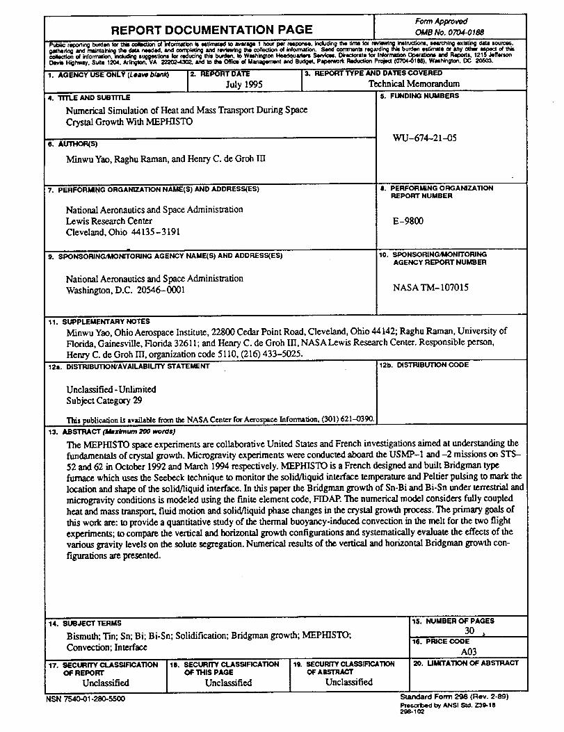
ABSTRACT
The MEPHISTO space experiments are collaborative United States and
French investigations aimed at understanding the fundamentals of crystal
growth. Microgravity experiments were conducted aboard the USMP-1 and
-2 missions on STS-52 and 62 in October 1992 and March 1994 respectively.
MEPHISTO is a French designed and built Bridgman type furnace which uses
the Seebeck technique to monitor the solid/liquid interface temperature and
Peltier pulsing to mark the location and shape of the solid/liquid interface.
In this paper the Bridgman growth of Sn-Bi and Bi-Sn under terrestrial and
microgravity conditions is modeled using the finite element code, FIDAP*.
The numerical model considers fully coupled heat and mass transport, fluid
motion and solid/liquid phase changes in the crystal growth process. The
primary goals of this work are: to provide a quantitative study of the thermal
buoyancy-induced convection in the melt for the two flight experiments; to
compare the vertical and horizontal growth configurations and systematically
evaluate the effects of various gravity levels on the solute segregation. Nu-
merical results of the vertical and horizontal Bridgman growth configurations
are presented.
* NASA does not endorse commercial products. Details about the products named in
this paper were included for completeness and accuracy. No endorsement or criticism of
these products by NASA should be assumed.
Numerical Modeling of Bridgman Growth in Space with MEPHISTO
1. INTRODUCTION
The low gravity (g) environment of space has the potential to produce conditions in which
buoyancy-driven convection is suppressed. This convection-freeenvironment can then be used
to examine the influence of convection on various phenomena. Of significant interest to industry
and the scientific community is how convection influences solidification processes. This interest is
due to the complex relationship among thermal conditions, thermal and solutal convection, growth
morphology, and macrosegregation in solidified alloy ingots and sensitive electronic materials
[1,2]. Direct, quantitative analysis of convection in molten metals and semiconductors is particu-
larly difficult. These materials are generally opaque, which hinders non-intrusive measurements.
Furthermore, the chemical volatility of the melt makes the insertion of thermocouples impractical.
Thus, most studies are limited to indirect measurement techniques such as temperature and See-
beck measurements, Peltier pulsing and post-mortem analysis. The role of numerical modeling
then becomes crucial in analyzing the system. A better understanding of how convection influ-
ences solidification can be achieved through synergistic numerical [3] and analytical rnodeling in
combination with various solidification experiments on earth [4,5] and in space.
MEPHISTO [6] is a collaborative effort among Dr. R. Abbaschian (Univ. of Florida at
Gainesville), Dr. J.J. Favier and teams from Centre d'Etudes Nucleaires de Grenoble (CENG) and
Centre National d'Etudes Spatiales (CNES) in France, and NASA. The MEPHISTO furnace was
designed and built by the French teams and solidifies three samples simultaneously in a Bridgman
type arrangement. The French team examined the non-faceted solidification of Sn-Bi alloys in the
first flight of MEPHISTO. In the second flight of MEPHISTO the faceted growth of the semi-metal
Bi (alloyed with a small amount of Sn) was studied. The furnace uses the Seebeck technique in
one of the samples to measure the temperature of the solid/liquid (s/l) interface, Peltier pulsing to
mark the shape of the interface in the second sample, and has quench capabilities which enable
the solute profile in the liquid in front of the interface to be determined in the third ingot. During
flight, all pertinent aspects of MEPHISTO are monitored and controlled through the Payload
Operations Control Center (POCC), at NASA's Marshall Space Flight Center, enabling repeated
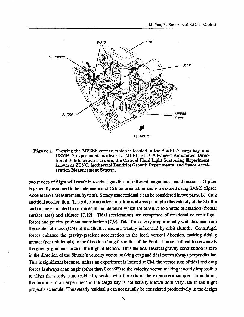
melting and solidification runs to be performed at a variety of growth rates. As shown in Figure
1, the MEPHISTO furnace is located during flight on an experiment bridge known as MPESS
(the Mission-Particular Equipment Support Structure) in the Shuttle's cargo bay. Goals of the
MEPHISTO experiments include determination of how convection influences: a) morphological
stability of the s/l interface and the resulting segregation patterns, and b) atomic attachment kinetics
at the freezing interface, measured in part from the growth rate and undercooling measurements.
An important part of analyzing processes in space is a full understanding and appreciation for
the residual gravity present, both quasi steady and transient (.q-jitter) [7-10]. For example, during
MEPHISTO 2 the Shuttle was flown in the -ZLV, +YVV attitude, which is with the cargo bay
toward the Earth and the right (starboard) wing into the velocity vector; and in the -XLV, -ZVV
attitude, which is with the Shuttle's tail to the Earth and the cargo bay into the velocity vector. These
2
M. Yao, R. Raman and H.C. de Groh Ill
MEPHISTO ,
SAMS ZENO
•IDGE
AADSF MPESSCarrier
FORWARD
Figure 1. Showing the MPESS carrier, which is located in the Shuttle's cargo bay, andUSMP- 2 experiment hardwares: MEPHISTO, Advanced Automated Direc-tional Solidification Furnace, the Critical Fluid Light Scattering Experimentknown as ZENO, Isothermal Dendrite Growth Experiments, and Space Accel-
erationMeasurement System.
two modes of flight will result in residual gravities of different magnitudes and directions. G-jitter
is generally assumed to be independent of Orbiter orientation and is measured using SAMS (Space
Acceleration Measurement System). Steady state residual g can be considered in two parts, i.e. drag
and tidal acceleration. The g due to aerodynamic drag is always parallel to the velocity of the Shuttle
and can be estimated from values in the literature which are sensitive to Shuttle orientation (frontal
surfacearea)and altitude[7,12].Tidal accelerationsare comprised of rotationalor centrifugal
forcesand gravity-gradientcontributions[7,9].Tidalforcesvaryproportionallywithdistancefrom
the centerof mass (CM) of the Shuttle,and are weakly influencedby orbitaltitude.Centrifugal
forces enhance the gravity-gradient acceleration in the local vertical direction, making tidal g
greater (per unit length) in the direction along the radius of the Earth. The centrifugal force cancels
the gravity-gradient force in the flight direction. Thus the tidal residual gravity contribution is zero
in the direction of the Shuttle's velocity vector, making drag and tidal forces always perpendicular.
This is significant because, unless an experiment is located at CM, the vector sum of tidal and drag
forces is always at an angle (other than 0 or 90 °) to the velocity vector, making it nearly impossible
to align the steady state residual g vector with the axis of the experiment sample. In addition,
the location of an experiment in the cargo bay is not usually known until very late in the flight
project's schedule. Thus steady residual g can not usually be considered productively in the design
3
Numerical Modeling ofBridgman Growth inSpace with MEPHISTO
of the experiment hardware. The MEPHISTO furnace on STS-62 was located at approximately
(x,y,z) = (24,1.05,10.8) meters, with CM at approximately (x,y,z) = (27.7,0,9.4) meters. With these
locations and literature data [7,12] the tidal forces can be estimated and then summed with the drag
to determine the total residual steady g and its direction. In this work we examine numerically
the effects of these quasi-steady accelerations. The detrimental effects of g-jitter were found to be
greater than those due to drag and tidal accelerations during MEPHISTO 1. A comparison of the
quasi-steady and g-jitter forces is provided elsewhere [12]. Numerical examination of g-jitter and
Bridgman solidification win be dealt with in a later paper.
Theoretical work presently being done in support of MEPHISTO includes the examination of
scaling laws, analytical modeling, and parametric experimental studies [13-23]. Our simulations
are being used to determine the thermal, solutal and flow fields, and to check the validity, extension
and generalization of the scaling laws developed. Similar numerical techniques are being used to
examine other space experiments [23] such as the gallium arsenide crystal growth in microgravity
experiment [24].
In this paper, we report the recent progress in our ongoing numerical modeling in support
of the MEPHISTO experiments. Our main objectives are: to provide a quantitative study of the
thermal buoyancy-induced convection in the melt for the two MEPHISTO space experiments; to
compare the vertical and horizontal growth configurations; and systematically evaluate the effects
of various gravity levels on the solute segregation. Two basic growth configurations are examined
in this work: one with the residual gravity vector parallel to the ampoule axis and the second with
the residual g perpendicular to the ampoule axis. Calculation of the solute field was included in our
analysis of MEPHISTO 1 but was omitted from our simulations of MEPHISTO 2. And although
we have solved for interface shape, our presentation of these preliminary results will concentrate
on the global fluid flow and the likely effects of this flow on macrosegregation.
2. MEPHISTO GROUND AND SPACE EXPERIMENTS
All MEPHISTO ground and space experiments have used Bridgrnan type furnaces with an
isothermal hot zone, an insulated gradient zone, and an isothermal chill zone. The MEPHISTO
furnace was designed and built by the French teams and solidifies three samples simultaneously
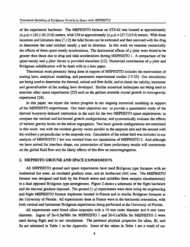
in a dual opposed Bridgman type arrangement. Figure 2 shows a schematic of the flight hardware
and the thermal gradient imposed. The ground (l-g) experiments were done using the engineering
and flight MEPHISTO furnace duplicates located in France and in similar Bridgrnan furnaces at
the University of Florida. All experiments done in France were in the horizontal orientation, with
both vertical and horizontal Bridgman experiments being performed at the University of Florida.
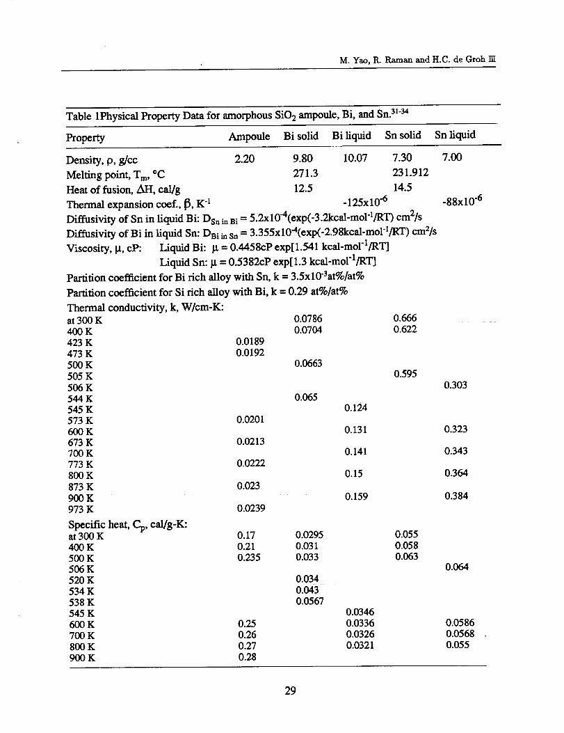
All experiments used fused silica ampoule s with a 10 mm outer diameter and 6 mm inner
diameter. Ingots of sn'0.5at%Bi for MEPHISTO 1 and Bi-0.1at%Sn for MEPHISTO 2 were
used during flight and in our simulations. The pertinent physical properties for silica, Bi, and
Sn are tabulated in Table 1 in the Appendix. Some of the values in Table 1 are a result of our
4
M. Yao, R. Raman and H.C. de Groh Ill
Temperature
I
Cold zone Hot zone Samples Hot zone
gelting
Solidification
I
Figure 2. Schematic of MEPHISTO furnace and sample temperature profile.
own distillation of several sources in an effort to obtain more accurate properties over a wider
temperature range.
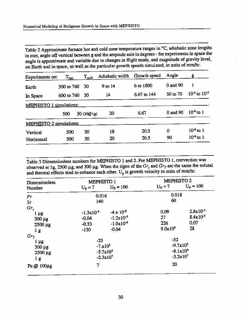
Solidification growth speeds in the ground based experiments ranged from 3.6 to 1800 mrn/hr,
and measured thermal gradients at the s/l interface from 90 to 214 K/era. During flight, growth
speeds varied from about 6 to 170 mm/hr with thermal gradients of approximately 200 K/crn in the
liquid. The thermal gradients imposed along the ampoule wall depend on the temperatures of the hot
and cold zones and the longitudinal length of the insulated (adiabatic) zone. Information regarding
the hot and cold zone temperatures and the length of adiabatic zone used in the ground based and
flight experiments are listed in Table 2 in Appendix. Of critical importance in numerical modeling
efforts is the accuracy of the input boundary conditions. In this work, the temperatures of the outer
surface of the ampoule are used as input boundary conditions. However, complete experimentally
measured temperatures were not available along the length of either the furnace or ampoule. The
temperatures along the length of the furnace and chill were measured using thermocouples; and,
ground based MEPHISTO experiments have shown the ampoule surface temperature to be equal to
the furnace (and chill) temperature at locations away from the gradient region. However, an accurate
measure of the furnace and ampoule temperature through the adiabatic zone was not available, thus
the temperature in the gradient zone between the hot and cold zones was calculated using a zero
radial heat loss condition from the adiabatic zone. Also, in the experiments, the isothermal condition
5
Numerical Modeling of Bridgman Growth in Space with MEPHISTO
of the hot and cold zones near the adiabatic zone could not be practically maintained due to local
heat loss at the zone boundaries. To achieve a smoother, more characteristic longitudinal input
temperature profile, the length of the adiabatic zone was adjusted in the model to give a realistic
(experimentally verified) temperature gradient in the liquid.
3. MATHEMATICAL MODEL
In this paper, we consider heat and mass transport, fluid motion and solid/liquid phase changes
in the crystal growth process. In particular, the constitutive property of the melt is assumed to be
Newtonian and its motion is described by the following Navier-Stokes equation:
(0u )P0 -_-+u-Vu =-Vp + V. [/z(Vu + (Vu)T)] + p0g[1 -- ft(T - To)] (1)
where u is the velocity vector, P0 is fluid density at the reference temperature To, p is pressure,
/.t is viscosity, T is the temperature variable, g is the acceleration of gravity, fit is the volumetric
expansion coefficient, and the Boussinesq model is adopted to approximate the buoyancy force
caused by density variation with temperature. Here the change in density associated with species
concentration has been neglected. The incompressibility condition is given by
v.u=o. (2)
The heat transport is controlled by the balance of thermal energy
(3)
where % is specific heat and t¢ is thermal conductivity. The solute transport is governed by the
balance of species concentration
0C
-_- + u-VC V. (DVC) (4)
where C is the concentration of impurity and D denotes the mass diffusion coefficient. On each
segment of the boundary, it is necessary to prescribe appropriate boundary conditions. Details of
the computational boundary conditions used in the modeling will be given in section 4.
The change of phase from liquid to solid is described mathematically by the following phase
conditions
Tt(S,t) = T,(S,t) = T,,, ,
r_tVTt . fi - I%VT_ . fi = psL(u s - u*). fi,
p (u - = p,(us - u*). fi,
(5)
(6)
(7)
6

M. Yao, R. Raman and H.C. de Groh l]I
(uI - u') x fa= 0 (8)
which need to be satisfied at the solid/liquid interface. Here subscripts and superscripts, s and l,
refer to the solid & liquid region, respectively; u s is the solid pulling velocity; u* is the velocity of
the interface; Tm is the melting temperature; fi is the unit norm of the interface pointing from the
liquid to the solid; L is the latent heat of fusion. From a physical point of view, equations (5)-(8)
represent thermal equilibrium at the interface; the heat flux balance between the phases which
includes latent heat release; the mass flux balance across the interface and the no-slip condition at
the liquid side of the interface, respectively.
In order to include the solute (species) umlsport in the phase change analysis, it is necessary
to add two more interface conditions:
DIVC_. fi-D, VC,. fi = Cs(u s - u*). fi- Ct(u l- u*). fi, (9)
c, = kCz (10)
where k is the partition coefficient. Eqn. (9) describes the mass conservation for solute transport
across the interface and eqn. (10) is actually the chemical equilibrium determined by the phase
diagram. In this case, the melting temperature depends on solute concentration and condition (5)
becomes
T, = Ts = Tin(C) = TA + mC, (5')
dT,._
m = re(C) =
where TA is a constant and
(11)
is the rate of change of the melting temperature with respect to C. Note that the model summarized
in this section assumes a sharp solid/liquid interface; the problem will be solved by the interface
tracking approach with deformable grids.
4. NUMERICAL SIMULATION
4.1 The FEM Model
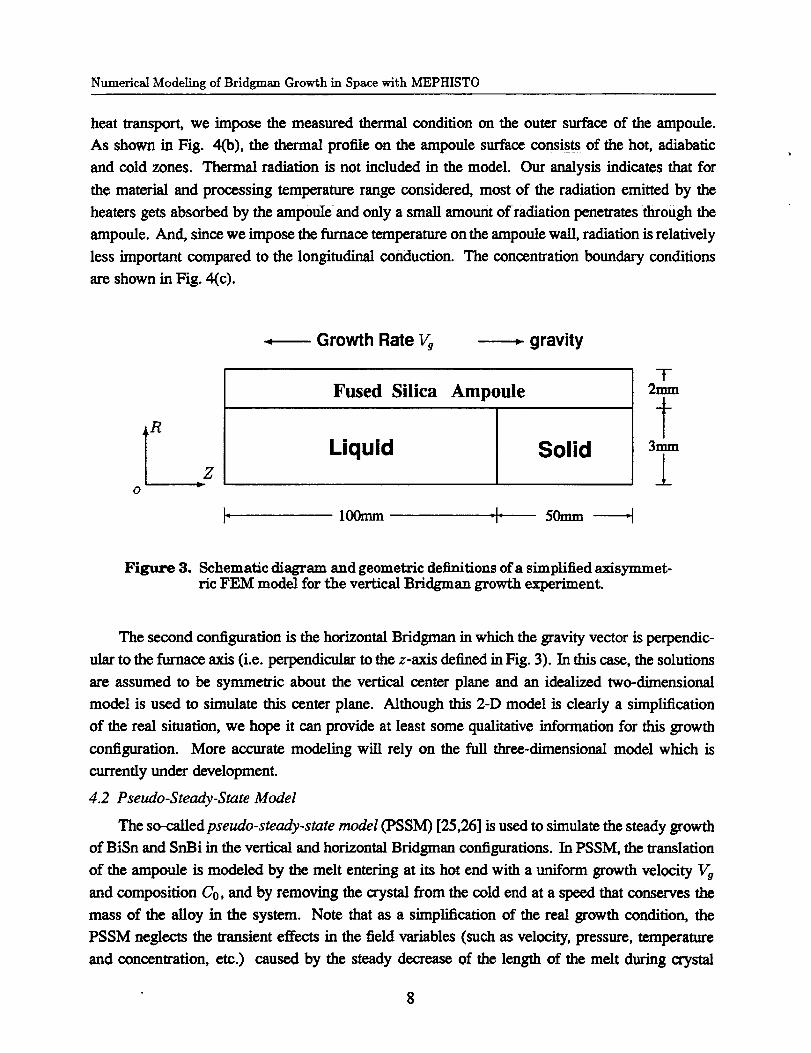
In this paper we consider two Bridgrnan growth configurations. The first is the bottom seeded
(vertical) Bridgman growth. In this configuration the hot (melt) zone is on the top and the cold
(crystal) zone is at the bottom. The furnace axis is parallel to the gravity vector which is in the
vertical direction pointing downwards. For this configuration it is reasonable to assume that the
heat, species and flow fields are all axisymmetric. Therefore a simplified axisymmetric model,
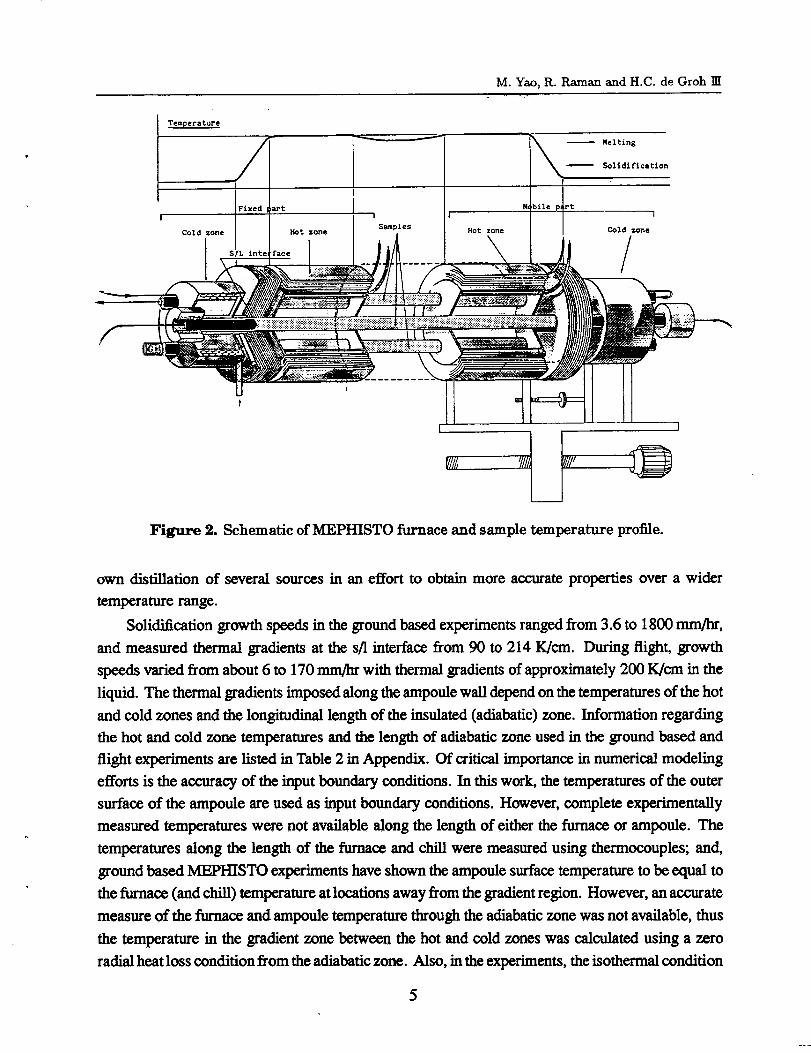
as depicted in Figure 3, is used to model the vertical Bfidgrnan growth. A 15cm portion of the
90cm-long rod-shaped sample is modeled. The computational boundary conditions imposed for
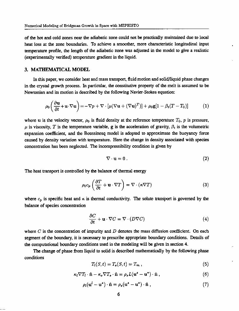
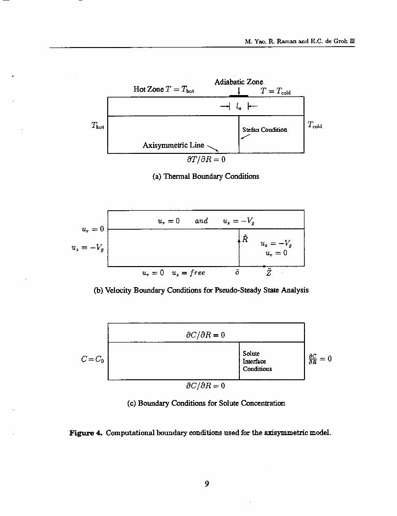
the energy, momentum and species equations are summarized in Figure 4. For the momentum
equation, we specify no-slip conditions on the surface between the sample and ampoule wail. For
7
Numerical Modeling of Bridgman Growth in Space with MEPHISTO
heat transport, we impose the measured thermal condition on the outer surface of the ampoule.
As shown in Fig. 4(b), the thermal profile on the ampoule surface consists of the hot, adiabatic
and cold zones. Thermal radiation is not included in the model. Our analysis indicates that for
the material and processing temperature range considered, most of the radiation emitted by the
heaters gets absorbed by the ampoule and only a small amount of radiation penetrates through the
ampoule. And, since we impose the furnace temperature on the ampoule wall, radiation is relatively
less important compared to the longitudinal conduction. The concentration boundary conditions
are shown in Fig. 4(c).
o
Z
Growth Rate Vg _- gravity
Fused Silica Ampoule
Liquid Solid
I. lOO + 5o== ----t
7-2mm
t3mm
±
Figure 3. Schematic diagram and geometric definitions of a simplified axisymmet-ric FEM model for the vertical Bridgman growth experiment.
The second configuration is the horizontal Bridgrnan in which the gravity vector is perpendic-
ular to the furnace axis (i.e. perpendicular to the z-axis defined in Fig. 3). In this case, the solutions
are assumed to be symmetric about the vertical center plane and an idealized two-dimensional
model is used to simulate this center plane. Although this 2-D model is clearly a simplification
of the real situation, we hope it can provide at least some qualitative information for this growth
configuration. More accurate modeling will rely on the full three-dimensional model which is
currently under development.
4.2 Pseudo-Steady-State Model
The so-called pseudo-steady-state model (PSSM) [25,26] is used to simulate the steady growth
of BiSn and SnBi in the vertical and horizontal Bridgman configurations. In PSSM, the translation
of the ampoule is modeled by the melt entering at its hot end with a uniform growth velocity Vg
and composition Co, and by removing the crystal 1Yore the cold end at a speed that conserves the
mass of the alloy in the system. Note that as a simplification of the real growth condition, the
PSSM neglects the transient effects in the field variables (such as velocity, pressure, temperature
and concentration, etc.) caused by the steady decrease of the length of the melt during crystal
8
M. Yao, R. Raman and H.C. de Groh III
Thor
Hot Zone T = Thor
Adiabatic Zone
T -- Tcold
Stefan Conditiont-"
Axisymmetric Line "-x
or�on = o
(a) Thermal Boundary Conditions
Tcold
_r --0
'U z _ _ g_
u_ = 0 and Uz = -Vg
U z _-- -Vg
Ur "-0
b
u_=O u==free 6 2
(b) Velocity Boundary Conditions for Pseudo-Steady State Analysis
C= Co
OC/OR=O
Solute
Interface
Conditions
oc/oR = o
(c) Boundary Conditions for Solute Concentration
Figure 4. Computational boundary conditions used for the axisymmetric model.
9
Numerical Modeling of Bridgman Growth in Space with MEPHISTO
growth and the displacement of the ampoule in the furnace. It is known that for sufficiently long
ampoules the thermal end effects are negligibly small [25]. Another important feature of PSSM is
the use of the moving coordinate system by fixing its origin at the center of the moving solid/liquid
interface.
4.3 The Front Tracking Approach
The most challenging difficulty posed by phase change problems is the moving solid_iquid
interface whose position is usually an unknown function of time and space and needs to be
determined as a part of the solution. In the literature, various numerical techniques have been
proposed to deal with the moving interface for phase change problems [27]. Among them, two
main classes of methods can be distinguished, namely the fixed-grid enthalpy methods and the
front-tracking methods. The front-tracking technique with a deforming mesh is used in our
modeling.
Unlike the enthalpy method, the phase change front tracking method can model the phase
change problems with a sharp (single) solid/liquid interface. The front tracking approach used in
this work involves a deformable spatial mesh in which nodes located on the interface are allowed
to move such that they remain on the moving boundary. For each node on the moving interface,
an additional degree of freedom is introduced. This new degree of freedom determines directly the
position of the node in space and is an integral part of the representation of the moving interface.
To update the interface position and remesh the interior domains, a method of spines is used. It
is a generalization of the method developed by Saito and Scriven [28], in which the moving nodes
lie on and the interface movement is guided by the generator lines called spines. In particular, the
position of the moving node is represented parametrically by
xi -- otz[hj+l +wt_(hj - hj+l)] + _
Yi = c_y[hj+l + wti(hj - hi+l)] + _
zi = Ctz[hj+l + wti(hj - hi+l)] +/_z
(12)
where hj is the interface location parameter for a given spine, (ctx, aN, az) is the direction vector,
(_=,_Sy, _z) is the base point of the spine. The location (zi, Yi, zi) of the moving node on the spine
is determined from its relative position, wti, to the moving interfaces located at hj and hj+l. Here
hj are the new degree of freedom introduced.
For steady state problems, applying Galerkin's formulation and the standard discretization
procedure to the momentum equation (1) results in a nonlinear algebraic system in the following
matrix form [29] ....... _ _ ...... ......
A(U)U + K(T, U)- CP + BX = F (13)
where X is the global vector of the moving interface unknowns, A(U) accounts for contribution
from the convective terms, K(U) includes the diffusive terms, C is the matrix discretization of the
10
M.Yao, R. Raman and H.C. de Groh 11I
divergence, B represents the contribution of the normal stress balance condition at boundary, F is
a body force vector.
4.4 The Segregated Solver
System (13) along with the energy equation, species equation and other interface and boundary
conditions are solved by a segregated solution procedure. In contrast to the traditional fully coupled
approach (such as the Newton-type solver), the segregated solution algorithm does not form the
global system matrix directly. Instead, it decomposes the global system matrix into smaller sub-
matrices each governing the nodal unknowns associated with only one conservation equation.
These segregated sub-matrices are then solved in a sequential manner. Since the storage of the
individual sub-matrices is considerably less than that needed to store the global system matrix,
the storage requirements of the segregated approach are substantially less than those of the fully
coupled approach.
4.5 Special Formulation for Concentration
A special difficulty in solving mass transfer in phase-change problems is the discontinuity of
solute concentration itself across the interface, as indicated by interface condition (10). Further-
more, the melting temperature is no longer a constant; instead it has to be determined by the local
solute concentration. However in the standard FEM formulation, both the trial and test function
have to be at least C O continuous, and no jump is allowed for the primitive variables. Therefore, a
special treatment is necessary for the species equation.
To eliminate the discontinuity of C at the interface, the following transformation
= C,/k (14)
is performed for concentration in the solid region. The interface condition (10) is then reduced to
C: =(7,* (15)
and thus C becomes continuous across the phase change interface. It can be proved [30] that the
mass flux balance condition (9) can be rewritten in the following form
(DzVCI - D, VC,) . fi = h¢Ct (16)
where the coefficient
hc = p,(1 - k)(u _ - u*). fi + D,(1 - k)fi. VC;ICt. (17)
The second term in (17) involves spatial gradient of concentration at the solid side. Since the solute
diffusivity in solid, i.e. D,, is usually several orders of magnitude smaller than that of the liquid
Dr, it is reasonable to assume this term is negligible. In our computation, the interface condition
(16) is imposed through a species transfer boundary element at the moving interface.
11
Numerical Modeling of Bridgman Growth in Space with MEPHISTO
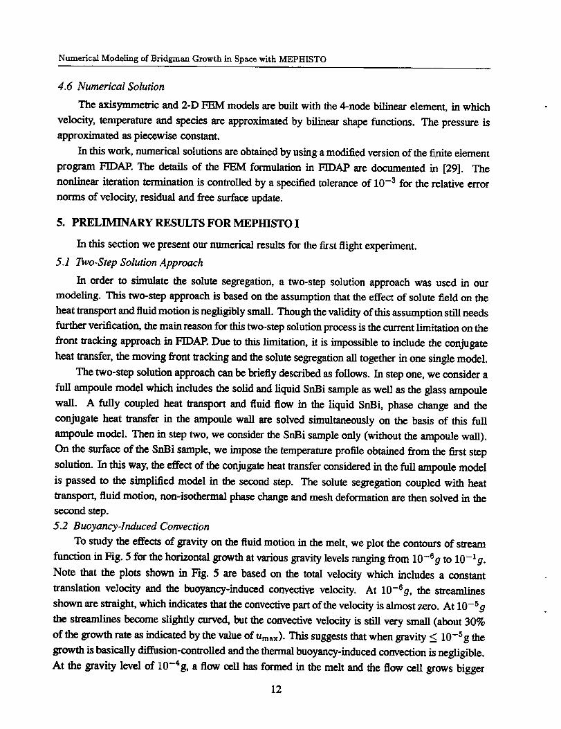
4.6 Numerical Solution
The axisymmetric and 2-D FEM models are built with the 4-node bilinear element, in which
velocity, temperature and species are approximated by bilinear shape functions. The pressure is
approximated as piecewise constant.
In this work, numerical solutions are obtained by using a modified version of the finite element
program FIDAP. The details of the FEM formulation in FIDAP are documented in [29]. The
nonlinear iteration termination is controlled by a specified tolerance of 10 -3 for the relative error
norms of velocity, residual and free surface update.
5. PRELIMINARY RESULTS FOR MEPHISTO I
In this section we present our numerical results for the first flight experiment.
5.1 Two-Step Solution Approach
In order to simulate the solute segregation, a two-step solution approach was used in our
modeling. This two-step approach is based on the assumption that the effect of solute field on the
heat transport and fluid motion is negligibly small. Though the validity of this assumption still needs
further verification, the main reason for this two-step solution process is the current limitation on the
front tracking approach in FIDAP. Due to this limitation, it is impossible to include the conjugate
heat transfer, the moving front tracking and the solute segregation all together in one single model.
The two-step solution approach can be briefly described as follows. In step one, we consider a
full ampoule model which includes the solid and liquid SnBi sample as well as the glass ampoule
wall. A fully coupled heat transport and fluid flow in the liquid SnBi, phase change and the
conjugate heat transfer in the ampoule wall are solved simultaneously on the basis of this full
ampoule model. Then in step two, we consider the SnBi sample only (without the ampoule wall).
On the surface of the SrtBi sample, we impose the temperature profile obtained from the first step
solution. In this way, the effect of the conjugate heat transfer considered in the full ampoule model
is passed to the simplified model in the second step. The solute segregation coupled with heat
transport, fluid motion, non-isothermal phase change and mesh deformation are then solved in the
second step.
5.2 Buoyancy-Induced Convection
To study the effects of gravity on the fluid motion in the melt, we plot the contours of stream
function in Fig. 5 for the horizontal growth at various gravity levels ranging from 10 -69 to 10 -1 g-
Note that the plots shown in Fig. 5 ate based on the total velocity which includes a constant
translation velocity and the buoyancy-induced convective velocity. At 10-tg, the streamlines
shown are straight, which indicates that the convective pan of the velocity is almost zero. At 10 -sg
the streamlines become slightly curved, but the convective velocity is still very small (about 30%
of the growth rate as indicated by the value of ltmax). This Suggests that when gravity < 10 -Sg the
growth is basically diffusion-controlled and the thermal buoyancy-induced convection is negligible.
At the gravity level of 10 -4g, a flow cell has formed in the melt and the flow cell grows bigger
12
M. Yao, R. Raman and H.C. de Groh III
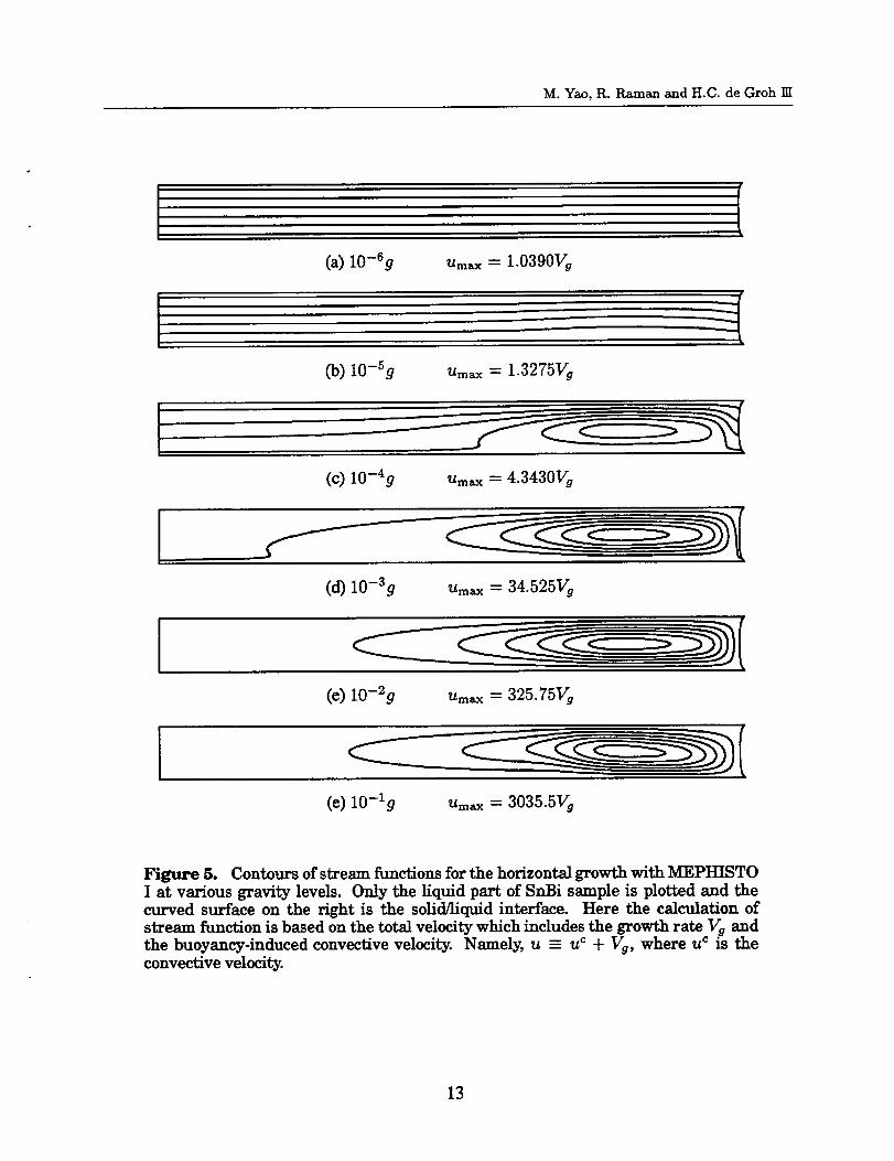
(a) 10-6g um_ = 1.0390Vg
(b) lO-_g u_ = 1.3275Vg
(c) 10-4g Um_x = 4.3430Vg
(d) 10-3g Um_x = 34:525Vg
(¢) 10-2g Um_x = 325.75Vg
(¢) 10-1g Umax = 3035.5Vg
Figure 5. Contours of stream functions for the horizontal growth with MEPHISTOI at various gravity levels. Only the liquid part of SnBi saraple is plotted and thecurved surface on the right is the solid/liquid interface. Here the calculation ofstream function is based on the total velocity which includes the growth rate Vg andthe buoyancy-induced convective velocity. Namely, u - u c 4- Vg, where u c is theconvective velocity.
13
Numerical Modeling of Bridgman Growth in Space with MEPHISTO
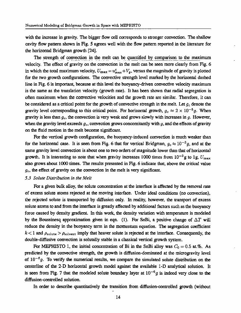
with the increase in gravity. The bigger flow cell corresponds to stronger convection. The shallow
cavity flow pattern shown in Fig. 5 agrees well with the flow pattern reported in the literature for
the horizontal Bridgman growth [24].
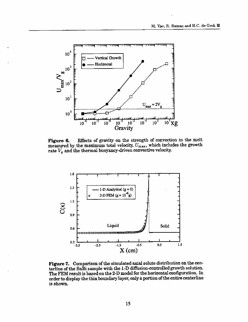
The strength of convection in the melt can be quantified by comparison to the maximum
velocity. The effect of gravity on the convection in the melt can be seen more dearly from Fig. 6m Cin which the total maximum velocity, Umax - um_ +Vg, versus the magnitude of gravity is plotted
for the two growth configurations. The convective strength level marked by the horizontal dashed
line in Fig. 6 is important, because at this level the buoyancy-driven convective velocity maximum
is the same as the translation velocity (growth rate). It has been shown that radial segregation is
often maximum when the convective velocities and the growth rate are similar. Therefore, it can
be considered as a critical point for the growth of convective strength in the melt. Let 9c denote the
gravity level corresponding to this critical point. For horizontal growth, g_ _ 2 x 10-59. When
gravity is less than go, the convection is very weak and grows slowly with increases in g. However,
when the gravity level exceeds gc, convection grows concomitantly with g, and the effects of gravity
on the fluid motion in the melt become significant.
For the vertical growth configuration, the buoyancy-induced convection is much weaker than
for the horizontal ease. It is seen from Fig. 6 that for vertical Bridgman, ge _ 10-39, and at the
same gravity level convection is about one to two orders of magnitude lower than that of horizontal
growth. It is interesting to note that when gravity increases 1000 times from 10-3g to 1g, Um_x
also grows about 1000 times. The results presented in Fig. 6 indicate that, above the critical value
go, the effect of gravity on the convection in the melt is very significant.
5.3 Solute Distribution in the Melt
For a given bulk alloy, the solute concentration at the interface is affected by the removal rate
of excess solute atoms rejected at the moving interface. Under ideal conditions (no convection),
the rejected solute is transported by diffusion only. In reality, however, the transport of excess
solute atoms to and from the interface is greatly affected by additional factors such as the buoyancy
force caused by density gradient. In this work, the density variation with temperature is modeled
by the Boussinesq approximation given in eqn. (1). For SnBi, a positive change of AT will
reduce the density in the buoyancy term in the momentum equation. The segregation coefficient
k < 1 and Psolute > Psolvent imply that he, aver solute is rejected at the interface. Consequently, the
double-diffusive convection is solutally stable in a classical vertical growth system.
For MEPHISTO I, the initial concentration of Bi in the SnBi alloy was Co = 0.5 at.%. As
predicted by the convective strength, the growth is di_sion-dominated at the microgravity level
of 10 -Sg. To verify the numerical results, we compare the simulated solute distribution on the
centerline of the 2-D horizontal growth model against the available 1-D analytical solution. It
is seen from Fig. 7 that the modeled solute boundary layer at 10-6g is indeed very close to the
diffusion-controlled solution.
In order to describe quantitatively the transition from diffusion-controlled growth (without
14
M: Yao, R. Raman and H.C. de Groh m
10 4
103
102
101
10 °
.lllilil i I lllli" I i lllllii[ I IIIIIII I I IIIII|_ I I IIIIII l I llllli_ I llilll_ I I
o
[3 .........VerticalGrowth I
.dmax = 2Vg
.................... ;_4_; ...........................................i0 "6 10 .5 10 .4 10 .3 i0 "2 i0 -I i0 ° lo_xg
Gravity
Figure 6. Effectsof gravity on the strength of convection in the melt
measured by the maximum totalvelocity,Umax, which includes the growth
rate Vg and the thermal buoyancy-driven convectivevelocity.
X
L_
1.8
13 I
1.2 --
0.9
0.6
' I ' I ' I
SoUd
I-DAnalytical(g= 0)
o 2-D FEM (g = 10_g)
i I i I i I, ,-2.$ -1.5 -03
X (cm)
0.3 I ,-3.5 03 1.5
Figure 7. Comparison ofthe simulated axialsolutedistributionon the cen-
terlineofthe SnBi sample with the 1-D diffusion-controlledgrowth solution.
The FEM resultisbased on the 2-D model forthe horizontalconfiguration.In
order to display the thin boundary layer, only a portion of the entire centerlineis shown.
15
Numerical Modeling of Brldgman Growth in Space with MEPHISTO
bulk convection) to growth with intensive laminar convective mixing, we compute two-important
segregation parameters. The first is the effective segregation coefficient keff defined as [26]
keer - k <C>x / <<C>> (18)
where < C >x is the lateral average of solute concentration over the solid/liquid interface and
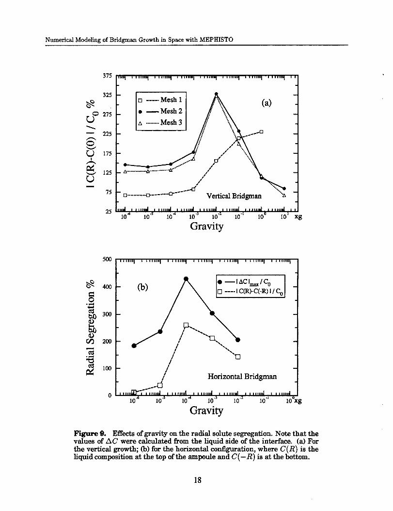
<< C >> is the volumetric average of solute concentration in the melt. The second is the percentage
radial segregation AC defined as
ZxC -I,_Clm_x/Co (19)
OF
zxc -ICtop -Cbo.o=l/Co. (20)
Here [_C]max is the maximum difference in liquid concentration at the interface. For directional
solidification, the diffusion-controlled growth with a planar interface leads to uniform radial solute
distribution, thus we may have A C ,_ 0. However, if the s/l interface is not flat, for example,
due to radial temperature gradients, significant radial solute gradients may develop even under
diffusion-controlled conditions. If the melt is sufficiently long that the diffusion layer near the
interface occupies only a small fraction of the total length, kerr approaches unity when there is no
convective flow in the melt other than the unidirectional growth velocity Vg. The other limit of keir
represents the steady-state well-mixed growth in which the intense convection leads to a complete
mixing in the melt. In this case the value of k_r approaches k.
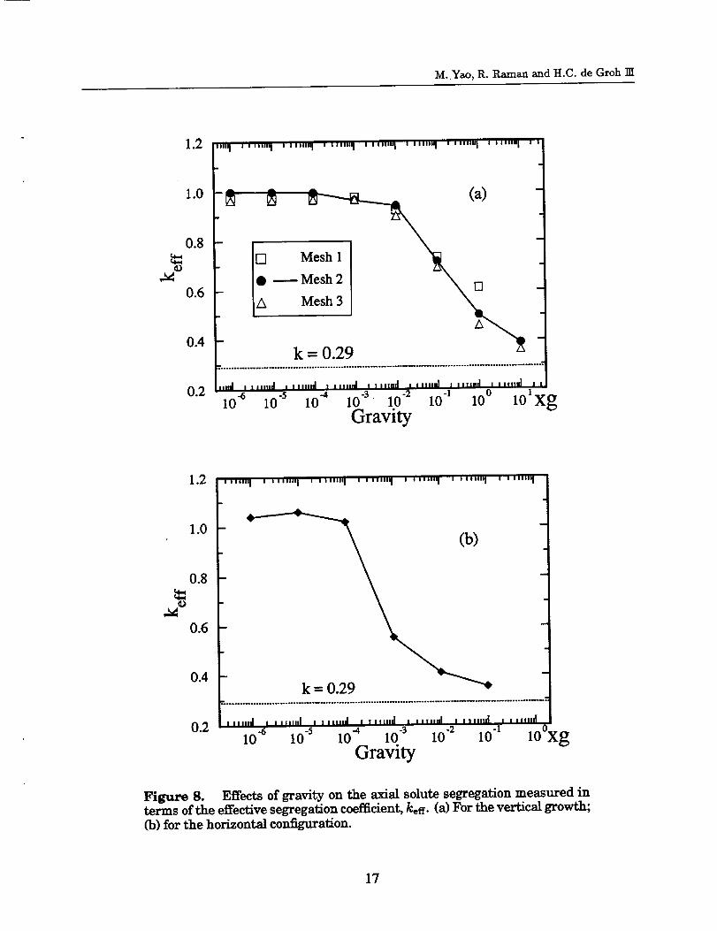
The computed k_er and AC for both the vertical and horizontal growth are plotted as a function
of gravity levels in Figs. 8 and 9, respectively. For the vertical growth case, the values of kerr are
very close to one when gravity is less than 10-2g as shown in Fig. 8(a). The value of keer starts to
decrease rapidly at 10-2g and does approach k with increasing gravity levels. The corresponding
radial segregation presented in Fig. 9(a) shows that there is a radial solute gradient at the interface
even in the diffusion dominated growth range. The radial segregation reaches a maximum at about
10-2g and then decreases with the increase of gravity. The radial segregation in the liquid is caused
by the nonplanar shape of the interface, and since we feel improvements are still possible in our
interface shape results, we will be examining segregation in more detail in a later paper. For the
horizontal configuration, the value of keer starts to decrease dramatically at a much lower gravity
level of 10-4g, because of the much stronger convection. It is seen from Fig. 8(b) that keer is
very close to k at 10 -1 g which indicates that a well-mixed state has been achieved at this gravity
level. Note that although the values of the radial segregation computed by eqns. (19) and (20)
are different, the predicted maximum AC occurs at the same gravity level of 10-4g for horizontal
growth as shown in Fig. 9(b). The plots of kerr and AC vs. the magnitude of gravity presented
here agree very well with the schematic curves given by Kim, Adornato and Brown in [26].
By considering the worst orientation of gravity vector during the space experiment (namely the
horizontal configuration), the results presented in Figs. 8 and 9 suggest that the growth is basically
16
M. Yao, R. P_man and H.C. de Groh ]II
1.2 ['II'1 ....... I , ,,,,,"1 , ,,,,,,'1 , ,,,,,,'1 , ,,,',"1 ' '"'"q ' '"''l ']
! !
L- \ [] -i
lolxg10 -6 10 "5 10 "4 10 -3 10 -2 10 1 10 °
Gravity
1.2 L,,,,.,I ,',,-"I''"'"'I''"""I ''"""I ''"''I ' '",'"I
1.0
0.8
0.6
0.4
ti k -- 0.29 -'*0.2 t,,,,,,I , ..,..I . ,,,,,,,I, ,,,,,.,I. ,.,.,,,Ii ,,.,.,,I, ,,,,,,d
10 4 10 "s 10 4 10 -3 10 .2 10 "1 100cgGravity
Figure 8. Effectsofgravity on the axialsolutesegregationmeasured in
terms ofthe effectivesegregationcoefficient,keer.(a)For the verticalgrowth;(b)forthe horizontalconfiguration.
17
Numerical Modeling of Brldgman Growth in Space with MEPHISTO
375 _'""1 ' '""'1 ' '"'"1 ' '"'"1 ' '""1 ' '""'1 ' '""1 ' '"''1 '
I325nio.....M°shliAC _'1- I_ ........."°_31 // -\
_" 175
125I--"_, .............'-' / x.,
75 D ...... o- ..... .-o.'-" Vertical Bridgman "_,
25 h,,.l . ,,,,.,I , .,,.J , ,,..J [ ,,,,,,,I . ,,,.,,I . ,,,,.,I I ,,.,,.I ,I0 "_ 10 "s 104 10 .3 10 .2 10 "I I0 ° 101 Xg
Gravity
5OO
4OO
Or._ 200
lOO
0
(b) /',, i*-'_c'_,ICo
e'* / "-.../ "C_d'
// Horizontal Bridgman
I IIIIl_/'llllll|| l I IIlllEi I I IIl|llti I l IIIInJ i I illlili I ||lllld
10 _ 10"s I0 "4 10"3 i0 "2 10 "i 10 o
Gravity
Figure 9. Effects of gravity on the radial solute segregation. Note that thevalues of AC were calculated from the liquid side of the interface. (a) For
the vertical growth; (b) for the horizontal configuration, where C(R) is the
liquid composition at the top ofthe ampoule and C(-R) is at the bottom.
18
M. Yao, R. Raman and H.C. de Groh III
diffusion-controlled when the magnitude of gravity is less than 10 -Sg. Therefore our numerical
observation supports the diffusion-controlled growth assumption used by the French team [13,16].
Another interesting point is the gravity level at which the radial segregation reaches its maximum.
For both growth configurations, the maximum AC occurs at the approximate ending point of the
gravity range over which keer indicates diffusion-controlled growth. For example, for the horizontal
growth the ending point of the gravity range for keer -_ 1 is 10 -4 g, that is exactly the same gravity
level at which AC has its maximum, as one can see from Fig. 8(b) and Fig. 9(b). Actually this
gravity level corresponds to a weak convection in the melt with an incomplete mixing of solute.
This in turn leads the concentration field adjacent to the interface highly distorted and the amount of
radial segregation reaches its maximum, though the axial segregation (measured by k_er) indicates
diffusion-controlled growth.
5.4 Convergence of Numerical Solutions
In order to check the convergence and accuracy of the numerical solutions, a set of three
meshes were used in the modeling for the vertical growth case. The three meshes are referred to as
mesh 1 to 3 in Fig. 8(a) and Fig. 9(a). Mesh 1 is the coarsest with a total of 820 bilinear elements
and 913 nodes. Mesh 2 is the intermediate with a total of 1344 elements and 1469 nodes. Mesh 3
is the finest with about 3000 elements.
For velocity, the numerical solutions from the three meshes are all very close. For example the
difference between the maximum velocities predicted by mesh 1 and mesh 3 is less than 1%, which
suggests that even mesh 1 can provide a very good solution for velocity. Our analysis shows that
the most difficult variable for numerical convergence is the solute concentration, perhaps due to
the very thin solute boundary layer near the interface. For the effective segregation coefficient, the
results presented in Fig. 8(a) show that when gravity is less than 10-1g the values of keer computed
from the three meshes are very close. But the error of the mesh 1 becomes unacceptable at 1g.
For the calculation of the radial segregation, mesh 1 fails completely as can be seen in Fig. 9(a).
This suggests that a coarse mesh is not capable of resolving the thin solute boundary layer. In all
the cases, the differences between the solutions obtained from meshes 2 and 3 are very small. Our
experience also indicates that grading towards the interface (i.e. gradually reducing element size
towards interface) helps improve the solution accuracy for solute concentration.
6. PRELIMINARY RESULTS FOR MEPHISTO H
For MEPHISTO 2, seven gravity levels were considered: 10-6g, 10"Sg, 10-4g, 10-3g, 10-2g,
10-1g and lg. The 10-6g to 10"3g eases simulate the range of accelerations expected during space
processing and the lg case simulates ground based experiments.
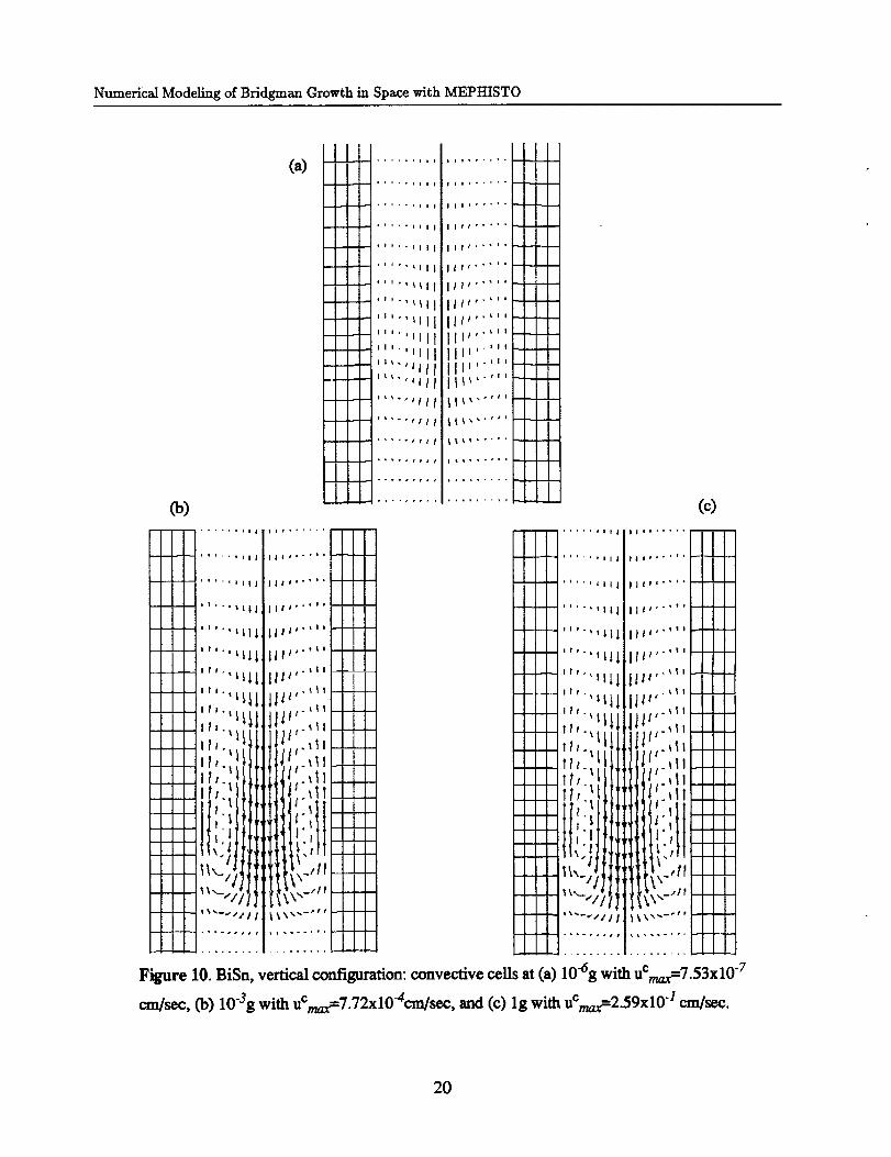
Figs. 10(a), 10Co) and 10(c) show the velocity vectors for three gravity levels for the vertical
configuration. It is seen that the flow cell forms at a g-level of 10-Sg and builds up as gravity in-
creases. At a gravity level of 10"3g, the flow velocities become comparable to the growth velocity.
19
Numerical Modeling of Bridgman Growth in Space with MEPHISTO
Ii
(a) -- +
---- i
i
_ .,. ,,l|ll
°+''.ill|
'''''Jlll
-- '''''_111
..... '_lll
- ".,_11 1II ,ill
..... 'ill
''''°#rll
Ill ......
i fl, .... '
II1,''''+
llt "''''
Ill "''''
itr ,-'''
Ill "'
Itt "'
II_ "'II "'II "'II 'I_ '
_,-,''
li_.-.''
(c)..... .II| III| .......
11,+, ii | ||i...*,+ -- --.={_--
''''' LII III'''''" ----I'I'I
''''" Ill llt_'-'''---- .'-_-
I
!|1• _1| --'-'-
't'"+t_ it+"';' -+-
tl "_II 1I'" _ I
- tt,.lill tllI.,l_'''_ _,
_'1 1._ -4-.!
I_x -1ii1 _11,_ ,iI _,,_I "I/Ill il p_'"' _ I
+ '"-"Ill i!,'".... -'+x'-.]/ll _XXx_-'+* -"7"
Figure 10. BiSn, vertical configuration: convective cells at (a) 10"6g with uCmxf7.53x10 "7
cm/sec, Co) 10-3g with uCmaxf7.72x10-4cm/sec, and (c) lg with uCmaxf2.59x10 -I cm/sec.
2O
M_ Yao, R. Raman and H.C. de Groh llI
(a)
I l Ii I II I I
I _. l i t ti
I t I I Ii%--j
_ _ _ ,, _ _ _ _.. ._.,*"_,-"._": _ : ...... _ __.-_,--__C _.,................ _ _ °
I
II
I I I I I I I I I llllllIIIIIllllllllI I I I l I i I I I I I ,' I IJ IIIlillilllllllllll
(_) I I I I ! I I I I I I I I I IIIIII IIIlll.llll/llll/II I I I I I I i I I I/II_ i lel_lll/ll
I I I l I 1 I 'I I I 1 t '1 I I '1 I _1I I t ', ', _1_ ', '1I I '1'k_| t I II I I I I I I I I I I I I I I I I1t1111111111111111111I I I I I t I_ II_,lllilllll I illlllll /I
I I I I I I I I I [1
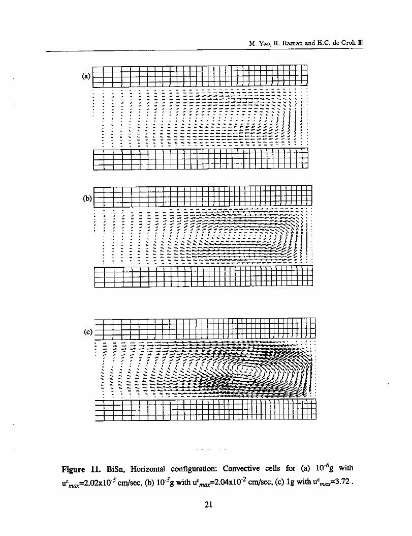
Figure 11. BiSn, Horizontalconfiguration:Convective cellsfor (a) I0"6g with
uCmax=2.02x10-scm/sec,(b)I03g withUCmax=2.04x10⁻²cm/scc,(c)lg withuCmax=3.72.
21
Numerical Modeling of Bridgman Growth in Space with MEPHISTO
A very strong convective cell is seen for the lg case. Figs. 1 l(a), 1 l(b) and 11(c) show the veloc-
ity vectors for three gravity levels for the horizontal configuration. It is seen that the velocities are
greater and stronger convective cells are formed for this configuration.
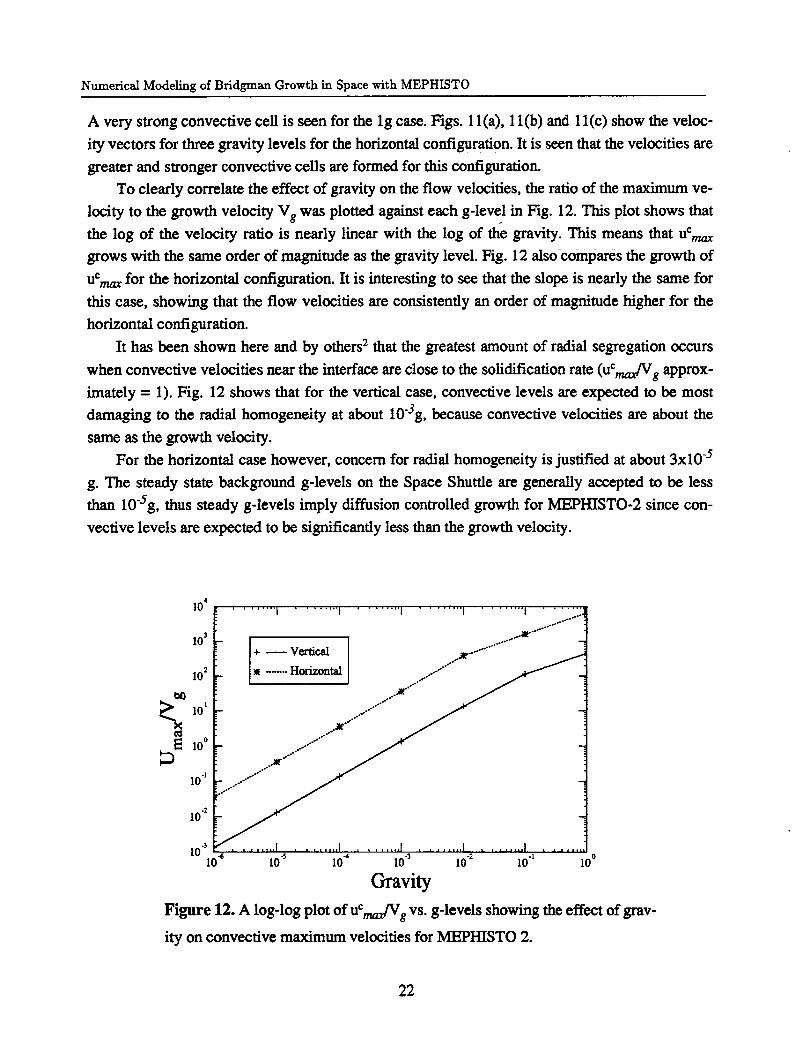
To clearly correlate the effect of gravity on the flow velocities, the ratio of the maximum ve-
locrity to the growth velocity Vg was plotted against each g-level in Fig. 12. This plot shows that
the log of the velocity ratio is nearly linear with the log of the gravity. This means that UCmax
grows with the same order of magnitude as the gravity level. Fig. 12 also compares the growth of
Uemaz for the horizontal configuration. It is interesting to see that the slope is nearly the same for
this case, showing that the flow velocities are consistently an order of magnitude higher for the
horizontal configuration.
It has been shown here and by others 2 that the greatest amount of radial segregation occurs
when convective velocities near the interface are close to the solidification rate (uCmax/Vg approx-
imately = 1). Fig. 12 shows that for the vertical case, convective levels are expected to be most
damaging to the radial homogeneity at about 10-3g, because convective velocities are about the
same as the growth velocity.
For the horizontal case however, concern for radial homogeneity is justified at about 3x10 -5
g. The steady state background g-levels on the Space Shuttle are generally accepted to be less
than 10-5g, thus steady g-levels imply diffusion controlled growth for MEPHISTO-2 since con-
vective levels are expected to be significantly less than the growth velocity.
10 *........ I ........ I ........ I ........ I ........ I ...... "
..o..O..-°"
103
I + _ Vertical ..._ ...... "
.,_¢.°°°.
._°°°
10 -* _ .....-
10 .2
I0"_ ........ I .......... I ......I0_ I0"s 10-4 i0"3 I0"2 i0q I0°
Gravity
Figure 12. A log-log plot of UCmax/Vgvs. g-levels showing the effect of grav-
ity on convective maximum velocities for MEPHISTO 2.
22
M. Yao, R. P_man and H.C. de Groh TIT
Residual gravity transients caused by thruster firings and other disturbances are often in the
range of 10"4g and greater for short periods; the response of solidification processes to non-steady
gravity is presently under investigation and will be dealt with in a later paper. However, results
from the first flight of MEPHISTO show experimental indications of convection during, for ex-
ample, crew exercise, when the magnitude of the transient acceleration is in the range of 5x10⁻⁴g.
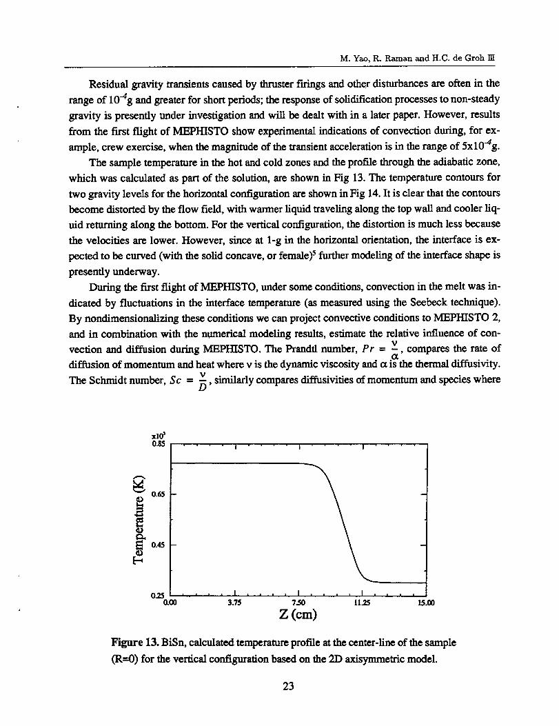
The sample temperature in the hot and cold zones and the profile through the adiabatic zone,
which was calculated as part of the solution, are shown in Fig 13. The temperature contours for
two gravity levels for the horizontal configuration are shown in Fig 14. It is clear that the contours
become distorted by the flow field, with warmer liquid traveling along the top wall and cooler liq-
uid returning along the bottom. For the vertical configuration, the distortion is much less because
the velocities are lower. However, since at 1-g in the horizontal orientation, the interface is ex-
pected to be curved (with the solid concave, or female) s further modeling of the interface shape is
presently underway.
During the first flight of MEPHISTO, under some conditions, convection in the melt was in-
dieated by fluctuations in the interface temperature (as measured using the Seebeck technique).
By nondimensionalizing these conditions we earl project convective conditions to MEPHISTO 2,
and in combination with the numerical modeling results, estimate the relative influence of con-
vection and diffusion during MEPHISTO. The Prandtl number, Pr = v, compares the rate ofa
diffusion of momentum and heat where v is the dynamic viscosity and a is the thermal diffusivity.v
The Schmidt number, Sc = _, similarly compares diffusivities of momentum and species where
xlo_0.85
0.65
0.45
&O0 15.00
I I I
• . I .... I .... I .
3.75 7.50 il.25
Z (era)
Figure 13. BiSn, calculated temperature profile at the center-line of the sample
(R=0) for the vertical configuration based on the 2D axisymmetric model.
23
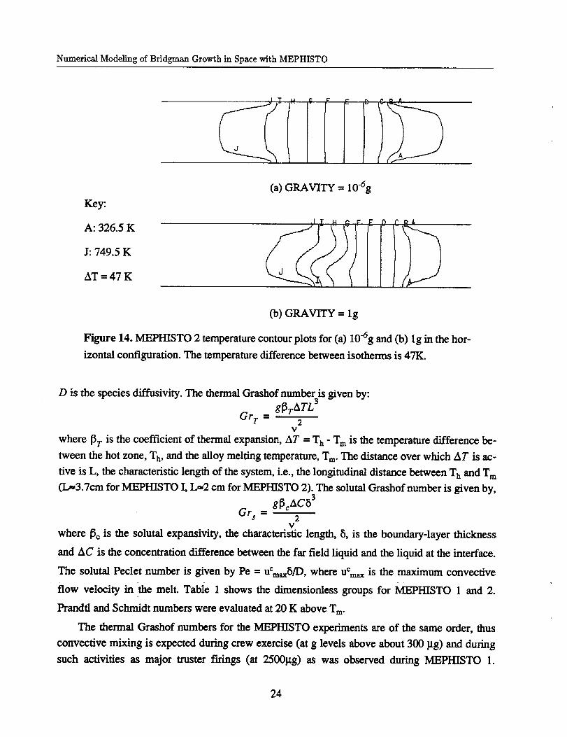
Numerical Modeling of Bridgman Growth in Space with MEPHISTO
(a) GRAVITY = 10-dg
Key:
J: 749.5 K
AT = 47 K i
(b)GRAVITY = Ig
Figure 14. MEPHISTO 2 temperature contour plots for (a) 10-6g and Co) Ig in the hor-
izontal configuration. The temperature difference between isotherms is 47K.
D is the species diffusivity. The thermal Grashof number is given by:
g[3TATL 3Grr = 2
v
where [3r is the coefficient of thermal expansion, AT -- T h - T m is the temperature difference be-
tween the hot zone, T h, and the alloy melting temperature, Tm. The distance over which AT is ac-
tive is L, the characteristic length of the system, i.e., the longitudinal distance between T h and T m
(I._3.7cm for MEPHISTO I, I._2 cm for MEPHISTO 2). The solutal Grashof number is given by,
g_cAC5 3
Grs = 2v
where [_c is the solutal expansivity, the characteristic length, 5, is the boundary-layer thickness
and AC is the concentration difference between the far field liquid and the liquid at the interface.
The solutal PecIet number is given by Pe = UCmxS/D, where UCm,x is the maximum convective
flow velocity in the melt. Table 1 shows the dimensionless groups for MEPHISTO 1 and 2.
Prandtl and Schrnidt numbers were evaluated at 20 K above T m.
The thermal Grashof numbers for the MEPHISTO experiments are of the same order, thus
convective mixing is expected during crew exercise (at g levels above about 300 ]lg) and during
such activities as major truster firings (at 2500_g) as was observed during MEPHISTO 1.
24

M. Yao, R. R_nan and H.C. de Groh HI
Amounts of convection insufficient to cause disturbances detected by Seebeck interface tempera-
ture measurements may still influence the solidification process significantly. For example, rather
slow flow velocities have been shown to be most detrimental to radial homogeneity (Brown
(1988), Yao and de Groh (1994)). The solutal Peclet numbers shown in Table 1 indicate that con-
vective and diffusive transport are of the same order when gravity is in the 10 to 100 _tg range.
This indicates that for MEPHISTO 1 and 2 diffusion-dominated growth was likely during sleep
periods (at g levels less than about 5_tg). This is consistent with Fig. 9 results, which show the ra-
dial solutal gradient in the liquid to be relatively small at g levels below 10"Sg.
7. CONCLUSIONS
The goal of this work was to, using numerical techniques, quantify buoyancy-driven convection
during Bridgman solidification and to determine the effect of gravity on convective velocities in the
vertical and horizontal configurations for two recent NASA space experiment projects, MEPHISTO
1 and 2. For MEPHISTO 1, the solute field was included in our analysis, however, for MEPHISTO
2, solute was omitted ......
Numerical simulation indicates that the buoyancy-induced convection in the melt intensifies
quite rapidly as gravity increases. At equivalent gravity, flow velocities occurring during horizontal
conditions were about 15 times greater than those duri_rlg vertical growth for both MEPI-IISTO 1
and 2. By considering the worst orientation of gravity vector during the space experiment (namely
the horizontal configuration), our results suggest that the growth is basically diffusion-controlled at
g-levels below 10-Sg for both MEPHISTO 1 and 2. Therefore our numerical observation supports
the diffusion-controlled growth assumption [13] and the assumption that under quasi-diffusive
conditions residual convection does not perturb the concentration field significantly at low g-levels
[16] used in the analysis by the French team.
ACKNOWLEDGMENTS
This work was supported by NASA's Micro-gravity Science and Application Program (Grant
# NAG 3-1096 and NCC 3-208). The authors wish to thank R. Abbaschian, A. Gokhale, JJ.
Favier and the rest of the MEPHISTO team for their helpful guidance. We also would like to
thank Natarajan Ramanan at Fluid Dynamics International for technical support and very helpful
comments on using the free surface solution approach in FIDAP. The authors are grateful to Thomas
Glasgow, Mohammad Kassemi and Emily Nelson for their review and valuable comments.
25
Numerical Modeling of Bridgrnan Growth in Space with MEPHISTO
REFERENCES
[1] M.C. Flemings, Solidification Processing, McGraw-HiU, p. 42 (1974).
[2] M.A. Brown, Theory of transport processes in single crystal growth from the melt, A/ChE J,
Vol. 34 (1988), pp. 881-911.
[3] M. Yao and H.C. de Groh IR, Three-Dimensional Finite Element Method Simulation of
Bridgman Crystal Growth and Comparison with Experiments, Num. Heat Trans_., Part A,
Vol. 24 (1993), pp. 393-412.
[4] D. Gadonniex, A. Gokhale, and R. Abbaschian, Morphological Stability of Faceted
Solid/Liquid Interfaces in Dilute Bi-Sn Alloys, 32nd Aerospace SCI. Meeting, Jan. 1994,
ALAA 94-0791.
[5] H.C. de Groh Ill and T. Lindstrom, Interface Shape and Convection during Solidification and
Melting of Succinonitrile, NASA TM 106487 (1994).
[6] R. Abbachian, A.B. Gokhale, LL Favier and S.R. CorieU, In-Situ Monitoring of Crystal
Growth Using MEPHISTO, NASA Science Requirements Document, October, 1992.
[7] E. Nelson, An Examination of Anticipated g-jitter on Space Station and its Effects on Materials
Processes, NASA TM 103775, May 1991.
[8] M.J.B. Rogers, C.R. Baugher, R.C. Blanchard, R. DeLombard, W.W. Durgin, D.H. Matthiesen,
W. Neupert, and P. Roussel, Low Gravity Environment On-board Columbia During STS-40,
31st Aerospace SCI. Meeting, AIAA 93-0833, 1993.
[9] R.C. Blanchard, J.Y. Nicholson, and J.R. Ritter, Preliminary OARE Absolute Acceleration
Measurements on STS-50, NASA TM 107724, Feb. 1993.
[10] G.L. Martin, C.R. Bangher, E Henderson, STS-52 Mission Acceleration Measurements Sum-
mary - Sensor Report, Acceleration Characterization and Analysis Project, Space Sci. Lab.,
NASA Marshall Space Flight Center, Sept. 1993.
[11] R.J. Schaefer and S.R. CorieU, Convection-induced distortion of a solid-liquid interface,
Metall. Trans. A, Vol. 15A, 1994, pp. 2109-2115.
[12] H.C. de Groh 11/and E.S. Nelson, On Residual Acceleration During Space Experiments, in
Heat Transfer in Microgravity Systems, edited by S.S. Sadhal and A. Gopinath, HTD-Vol.
290, ASME 1994, pp. 23-33.
[13] J.J. Favier, J.P. Catrandet, A. Rouzand and D. Camel, Mass Transport Phenomena during
solidification in Microgravity; Preliminary Results of the First Mephisto Flight Experiment,
J. Crystal Growth, Vol. 140 (1994) pp. 237-243.
[14] J.P. Garandet, J.J. Favier and D. Camel, Solute Boundary Layer Concept and Scaling Analysis:
Two Keys to Segregation Phenomena in Melt Crystal Growth, J. Crystal Growth, Vol. 130
(1993) 113-122.
26
M. Yao, R. Rzsnan and H.C. de Groh IN
[25]
[26]
[27]
[28]
[29]
[15] S.R. Coriell, R.E Boisvert, G.B. McFadden, L.N. Brush and J.J. Favier, Morphological
Stability of A Binary Alloy During Directional Solidification: Initial "Dransient, J. Crystal
Growth, Vol. 140 (1994) pp. 139-147.
[16] J.P. Garandet, Convection Related Radial Segregation in A Idealized Horizontal Bridgman
Configuration; The Quasi Diffusive Regime Limit, J. Crystal Growth, Vol. 125 0992) pp.
112-120.
[17] R.J. Schaefer and S.R. Coriell, Convection-Induced Distortion of A Solid-Liquid Interface,
Metall. Trans. A, Vol. 15A (1994) pp. 2109-2115.
[18] S.R. Coriell and G.B. McFadden, Instability During Directional Solidification: Gravitational
Effects, in Low-Gravity Fluid Dynamics and Transport Phenomena, ed. Koster and Sani, VoI.
130, AIAA (1990) pp. 369-384.
[19] D. Thevenard, A. Rouzaud, J. Comera and J.J. Favier, Influence of Convective Thermal
Oscillations on A Solidification Interface in Bridgman Growth, J. Crystal Growth, Vol 108
(1991) pp. 572-582.
[20] M.D. Dupouy, D. Camel and J.J. Favier, Natural Convection in Directional Dendritic Solidifi-
cation of Metallic Alloys-I: Macroscopic Effects, Acta Metall. Vol 37 (1989) pp. 1143-1157.
[21] M. Helmenberg, A. Rouzaud, D. Camel and J.J. Favier, Morphological and Thermosolutal
Instabilities inside A Deformable Solute Boundary Layer during Unidirectional Solidification,
J. Crystal Growth, Vol. 85 (1987) pp. 49-58.
[22] J.J. Favier and D. Camel, Analytical and Experimental Study of Transport Processes during
Directional Solidification and Crystal Growth, J. Crystal Growth, Vol. 79 (1986) pp. 50-64.
[23] A. Rouzaud, D. Camel and J.J. gavier, A Comparative Study of Thermal and Thermosolutal
Convective Effects in Vertical Bridgman Crystal Growth, J. Crystal Growth, Vol. 73 (1985)
pp. 149-166.
[24] W.A. Arnold, D.A. Jacqmin, R.L. Gaug and A. Chait, Three-Dimensional Flow Transport
Modes in Directional Solidification during Space Processing, J. Spacecraft and Rockets, Vol.
28 (1991) pp. 238-234.
P.M. Adomato and R. Brown, Convection and Segregation in Directional Solidification of
Dilute and Non-Dilute Binary Alloys: Effects of Ampoule and Furnace Design, J. Crystal
Growth, Vol. 80 (1987) pp. 155-190.
D.H. Kim, P.M. Adornato and R. Brown, Effect of Vertical Magnetic Field on Convection
and Segregation in Vertical Bddgman Crystal Growth, J. Crystal Growth, Vol. 89 (1988) pp.
339-356.
J. Crank, Free and Moving Boundary Problems, Clarendon Press, Oxford, 1984.
H. Saito and L.E. Scriven, Study of Coating Flow by the Finite Element Method, J. comp.
Phys., Vol. 42, 53 (1981).
M. Engieman, FIDAP Theoretical Manual (version 7), Fluid Dynamics International, Inc.,
500 Davis St. Suite 600, Evanston, IL 60201, 1993.
27
Numerical Modeling of Bridgman Growth in Space with MEPHISTO
[30] N. Ramanan, A Note on Derivation of Transfer Coefficient for Species Transfer Boundary
Element, (private communication) 1993.
[31] S.Z. Beer, editor, Liquid Metals, 1972, Marcel Dekker Inc., New York, p. 186.
[32] H.E. Boyer and T.L. Gall, editors, Metals Handbook, Desk Edition, 1985, ASM, Metals Park,
Ohio, p. 144.
[33] Y.S. Touloukian et al., editors, Thermophysical Properties of Matter, the TPRC Data Series
Volumes 1,2,4,5, and 11, 1970, Purdue Research Foundation, lFdPlenuml
[34] Niwa et al., J of M, Jan. 1957, p. 96.
28
M.Yao,R.Ramanand H.C. de Groh nl
Table 1Physical Property Data for amorphous SiO 2 ampoule, Bi, and Sn: TM
Property Ampoule Bi solid Bi liquid Sn solid Sn liquid
Density, O, g/cc 2.20 9.80 10.07 7.30 7.00
Melting point, Tin, °C 271.3 231.912
Heat of fusion, AH, cal/g 12.5 14.5
Thermal expansion coef., _3, K "1 -125x10 "6
Dif:f-usivity of Sn in liquid Bi: Dsnin m = 5-2xl0"4(exp("3-2kcal'm°l'I/RT) cm2/s
Dif:fusivity of Bi in liquid Sn: D m in Sn = 3.355x10"4(exp("2"98kcal'm°ll/RT) cm2/s
Viscosity, It, cP: Liquid Bi: IX= 0.4458cP exp[1.541 kcal-mol'I/RT]
Liquid Sn: ix = 0.5382cP exp[1.3 kcal-mol'l/RT]
Partition coefficient for Bi rich alloy with Sn, k = 3.5x10³at%/at%
Partition coefficient for Si rich alloy with Bi, k = 0.29 at%/at%
Thermal conductivity, k, W/cm-K:
at 300 K400 K423 K473 K500 K505 K
506 K544 K545 K573 K 0.0201600K673 K 0.0213700 K773 K 0.0222800 K873 K 0.023
900K973 K 0.0239
Specific heat, Cp, cal/g-K:at300 K 0.17400 K 0.21500 K 0.235506 K520 K534 K538 K545 K600 K 0.25700 K 0.26800 K 0.27900 K 0.28
0.0786 0.6660.0704 0.622
0.01890.0192
0.0663
0.065
0.02950.0310.033
0.034
0.043
0.0567
0.124
0.131
0.141
0.15
0.159
0.03460.03360.03260.0321
0.595
0.0550.0580.063
-88x10 _
0.303
0.323
0.343
0.364
0.384
0.064
0.05860.05680.055
29
Numerical Modeling ofBridgman Growth inSpace with MEPHISTO
Table 2 Approximate furnacehot and cold zone temperaturerangesin °C, adiabaticzone lengths
in ram, angle off vertical between g and the ampoule axis in degrees - for experiments in space the
angle is approximate and variable due to changes in flight mode, and magnitude of gravity level,
on Earth and in space, as well as the particular growth speeds simulated, in units of ram/hr.
Experiments on: Tho t Teota Adiabaticwidth Growth speed Angle g
Earth 500 to 760 30 9 to 14 6 to 1800 0 and 90 1
In Space 600 to 760 50 14 6.67 to 144 50 to 70 104 to 10 .3
_MEPI-]/STO I simulations:
500 50 (30@1g) 20 6.67 0 and 90 10 e to 1
_PHISTO 2 simulations:
Vertical 500 30 18 20.5 0 104 to 1
Horizontal 500 30 20 20.5 90 104 to 1
Table 3 Dimensionless numbers for MEPHISTO 1 and 2. For MEPI-IISTO 1, convection was
observed at lg, 2500 gg, and 300 _tg. When the signs of the Gr s and Gr r are the same the solutal
and thermal effects tend to enhance each other. Up is growth velocity in units of ram/hr.
Dimensionless MEPHISTO I MEPHISTO 2
Number Up = 7 Up = I00 Up = 7 Up = I00
PF
Sc
Gr s
l_tg
300 _tg
2500 _tg
lg
GrT
l_tg
300 l_g
2500 _tg
lg
Pc @ 100_tg
0.016 0.018
140 60
-1.3x10 _
_.04
-0.33
-130
-23
-7.x103
-5.7x10⁴
-2.3x10⁷
7
-4 x 10 "s 0.09 2.8x10 "5
-1.2x10 "_ 27 8.4x10 "3
-1.0xl0 "4 226 0.07
-0.04 9.0x10⁴ 28
-32
-9.7x10³
-8.1x10⁴
-3.2x10⁷
2O
3O
I FormAppco_dREPORT DOCUMENTATION PAGE OMBNo.0704-0188
_erzn¢ andm,_r,uz_tM_ _. anUcemp_e_a_ rwpw,,_j_ .o_. o,nom'=__._ _c,2Fz_=r_=.a,__ ou_,_e_umm_ anyoew__ o,0=a_eczk>n _ _orrrmlon, bckxrv_ suggastlo_ kx reducingml burden, _e w_r,,ipo_ Heaoqu_wlW'Z- _s_ncm. uf_ectorate_lm._ _ Nq_on_ _._._.,x,nw'zon
Highway, Suite 1204. Ar_ VA 2220_-430P_ and to the Office of Mam@em_ntand Budget. paperwo_ ReOuct_onPmjecz(o7o4-olea], was gton. tx; zzx_
1. AGENCY USE ONLY (Leave blank) 2. REPORT DATE 3. REPORT TYPE AND DATES COVERED
July 19954. TITLE AND SUBTITLE
Numerical Simulation of Heat and Mass Transport During Space
Crystal Growth With MEPI-I]STO
e. AUmOR(S)
Minwu Yao, Raghu Raman, and Henry C. de Groh Ill
7. PERFORMING ORGANIZATION NAME(S) AND ADDRESS(ES)
National Aeronautics and Space AdministrationLewis Research CenterCleveland, Ohio 44135-3191
9. SPONSOPJNG/MONI'_OPJNG AGENCY NAME(S) AND ADDRESS(ES)
National Aeronautics and Space AdministrationWashington, D.C. 20546- 0001
TechnicalMemorandum
5.FUNDINGNUMBERS
WU-674--21--05
8. PERFORMING ORGANIZATION
REPORT NUMBER
E-9800
10. SPONSORING/MONITORING
AGENCY REPORT NUMBER
NASA TM-107015
11. SUPPLEMENTARY NOTES
Minwu Yao, Ohio Aerospace Institute, 22800 Cedar Point Road, Cleveland, Ohio 44142; Raghu Raman, University ofFlorida, Gainesville, Florida 32611; and Henry C. de Groh III, NASA Lewis Research Center. Responsible person,Henry C. de Groh n'I, organization code 5110, (216) 433-5025.
,, , ,,
12x. DISTRIBUTION/AVAILABILITY STATEMENT
Unclassified -Unlimited
Subject Category29
This publication is availablefrom the NASA Center for Aerospace Information. (301) 621--0390.:
12b. DISTHIBUTION CODE
13. ABSTRACT (Maximum 200 words)
The MEPHISTO space experiments are collaborative United States and French investigations aimed at understanding thefundamentals of crystal growth. Microgravity experiments were conducted aboard the USMP-1 and -2 missions on STS--52 and 62 in October 1992 and March 1994 respectively. MEPHISTO is a French designed and built Bridgman typefurnace which uses the Seebeck technique to monitor the solid/liquid interface temperature and Peltier pulsing to mark thelocation and shape of the solid/liquid interface. In this paper the Bridgman growth of Sn-Bi and Bi-Sn under terrestrial and
microgravity conditions is modeled using the f'miteelement code, FIDAP. The numerical model considers fully coupledheat and mass transport, fluid motion and solid/liquid phase changes in the crystal growth process. The primary goals of
this work are: to provide a quantitative study of the thermal buoyancy-induced convection in the melt for the two flightexperiments; to compare the vertical and horizontal growth configurations and systematically evaluate the effects of thevarious gravity levels on the solute segregation. Numerical results of the vertical and horizontal Bridgman growth con-figurations are presented.
14. SUBJECT TERMS
Bismuth; Tin; Sn; Bi; Bi-Sn; Solidification; Bridgman growth; MEPHISTO;Convection; Interface
17. SECURITY CLASSIFICATIONOF REPORT
Unclassified
NSN7540-01-280-5500
18. SECURITY CLASSIFICATION
OF THIS PAGE
Unclassified
19. SECURITY CLASSIFICATIONOF ABSTRACT
Unclassified
15. NUMBER OF PAGES
3016. PRICE CODE
A0320. UMITATION OF AB_rHACT
Standard Form 298 (Rev. 2-89)
Prescrloed by ANSI _td. Z39-18298-102


. -._._ g.g-I
o qDzo
r-