Experimental and numerical analysis of seat belt bunching ...
Upload
khangminh22Category
view
0download
0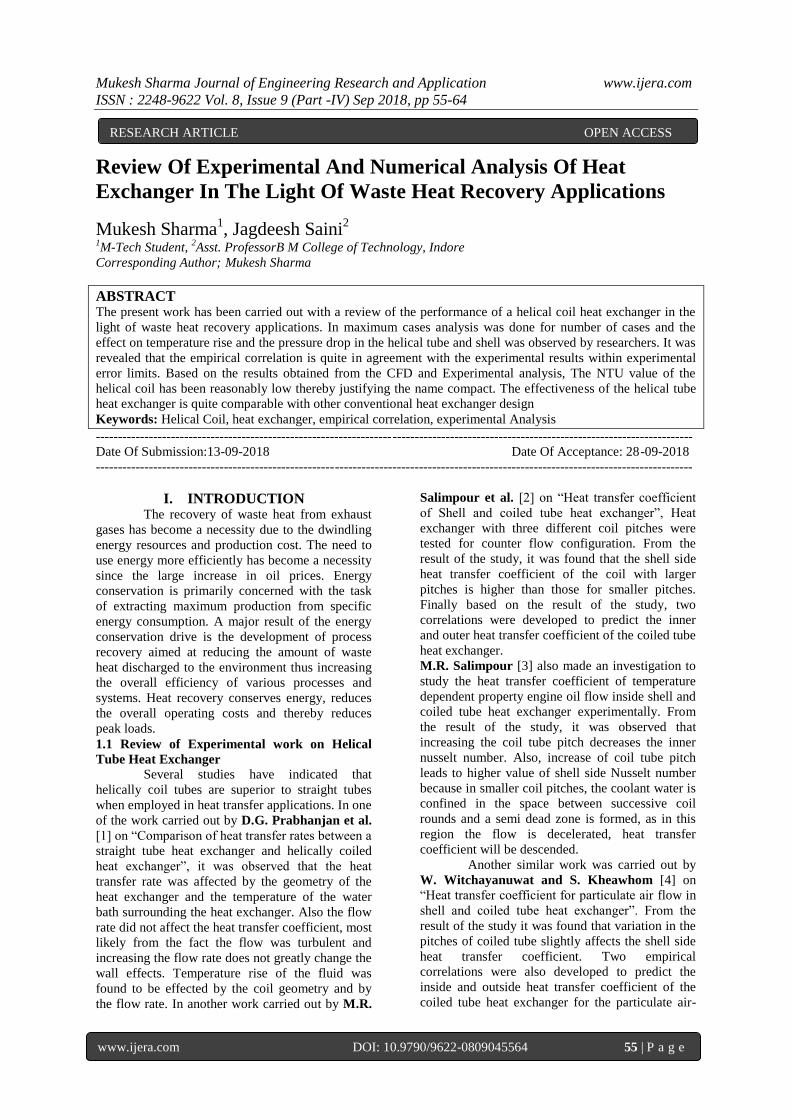
Mukesh Sharma Journal of Engineering Research and Application www.ijera.com
ISSN : 2248-9622 Vol. 8, Issue 9 (Part -IV) Sep 2018, pp 55-64
www.ijera.com DOI: 10.9790/9622-0809045564 55 | P a g e
Review Of Experimental And Numerical Analysis Of Heat
Exchanger In The Light Of Waste Heat Recovery Applications
Mukesh Sharma1, Jagdeesh Saini
2
1M-Tech Student,
2Asst. ProfessorB M College of Technology, Indore
Corresponding Author; Mukesh Sharma
ABSTRACT The present work has been carried out with a review of the performance of a helical coil heat exchanger in the
light of waste heat recovery applications. In maximum cases analysis was done for number of cases and the
effect on temperature rise and the pressure drop in the helical tube and shell was observed by researchers. It was
revealed that the empirical correlation is quite in agreement with the experimental results within experimental
error limits. Based on the results obtained from the CFD and Experimental analysis, The NTU value of the
helical coil has been reasonably low thereby justifying the name compact. The effectiveness of the helical tube
heat exchanger is quite comparable with other conventional heat exchanger design
Keywords: Helical Coil, heat exchanger, empirical correlation, experimental Analysis
---------------------------------------------------------------------------------------------------------------------------------------
Date Of Submission:13-09-2018 Date Of Acceptance: 28-09-2018
---------------------------------------------------------------------------------------------------------------------------------------
I. INTRODUCTION The recovery of waste heat from exhaust
gases has become a necessity due to the dwindling
energy resources and production cost. The need to
use energy more efficiently has become a necessity
since the large increase in oil prices. Energy
conservation is primarily concerned with the task
of extracting maximum production from specific
energy consumption. A major result of the energy
conservation drive is the development of process
recovery aimed at reducing the amount of waste
heat discharged to the environment thus increasing
the overall efficiency of various processes and
systems. Heat recovery conserves energy, reduces
the overall operating costs and thereby reduces
peak loads.
1.1 Review of Experimental work on Helical
Tube Heat Exchanger Several studies have indicated that
helically coil tubes are superior to straight tubes
when employed in heat transfer applications. In one
of the work carried out by D.G. Prabhanjan et al.
[1] on “Comparison of heat transfer rates between a
straight tube heat exchanger and helically coiled
heat exchanger”, it was observed that the heat
transfer rate was affected by the geometry of the
heat exchanger and the temperature of the water
bath surrounding the heat exchanger. Also the flow
rate did not affect the heat transfer coefficient, most
likely from the fact the flow was turbulent and
increasing the flow rate does not greatly change the
wall effects. Temperature rise of the fluid was
found to be effected by the coil geometry and by
the flow rate. In another work carried out by M.R.
Salimpour et al. [2] on “Heat transfer coefficient
of Shell and coiled tube heat exchanger”, Heat
exchanger with three different coil pitches were
tested for counter flow configuration. From the
result of the study, it was found that the shell side
heat transfer coefficient of the coil with larger
pitches is higher than those for smaller pitches.
Finally based on the result of the study, two
correlations were developed to predict the inner
and outer heat transfer coefficient of the coiled tube
heat exchanger.
M.R. Salimpour [3] also made an investigation to
study the heat transfer coefficient of temperature
dependent property engine oil flow inside shell and
coiled tube heat exchanger experimentally. From
the result of the study, it was observed that
increasing the coil tube pitch decreases the inner
nusselt number. Also, increase of coil tube pitch
leads to higher value of shell side Nusselt number
because in smaller coil pitches, the coolant water is
confined in the space between successive coil
rounds and a semi dead zone is formed, as in this
region the flow is decelerated, heat transfer
coefficient will be descended.
Another similar work was carried out by
W. Witchayanuwat and S. Kheawhom [4] on
“Heat transfer coefficient for particulate air flow in
shell and coiled tube heat exchanger”. From the
result of the study it was found that variation in the
pitches of coiled tube slightly affects the shell side
heat transfer coefficient. Two empirical
correlations were also developed to predict the
inside and outside heat transfer coefficient of the
coiled tube heat exchanger for the particulate air-
RESEARCH ARTICLE OPEN ACCESS

Mukesh Sharma Journal of Engineering Research and Application www.ijera.com
ISSN : 2248-9622 Vol. 8, Issue 9 (Part -IV) Sep 2018, pp 55-64
www.ijera.com DOI: 10.9790/9622-0809045564 56 | P a g e
flow water system. In another work by H.
Shokouhmand et al. [5] on “Experimental and
investigation of Shell and Coil tube Heat exchanger
using Wilson Plot”, an experiment was
performed for both the Parallel flow and
counter flow configuration. Overall heat transfer
coefficients of the heat exchangers were calculated
using Wilson plots. It was observed that the shell-
side Nusselt numbers of counter-flow configuration
were slightly more than the ones of parallel-flow
configuration. Finally, it was observed that the
overall heat transfer coefficients of counter-flow
configuration are 0–40% more than those of
parallel-flow configuration.
Paisarn Naphon et al. [6] made a detailed
survey on Single phase and double phase flow and
Heat transfer characteristic in helically coiled
tubes, spirally coiled tubes and other coiled tubes.
In one of his paper “Thermal performance and
pressure drop of the Helical coil Heat Exchanger
with or without helically crimped fins”, [7] he
studied the thermal performance and pressure drop
of Heat Exchanger in which the heat exchanger
consists of thirteen turns concentric helical coil
tubes with coil tubes consisting of two different
coil diameters. He concluded that outlet cold water
temperature increases with increasing hot water
mass flow rate. Inlet hot and cold water mass flow
rates and inlet hot water temperature also have a
significant effect on the heat exchanger
effectiveness. Paisarn Naphon et al. [8] also made a
study on effect of curvature ratio on the heat
transfer and flow development in the horizontal
spirally coiled tubes. It was observed that because
of centrifugal force, the heat transfer and pressure
drop are more in spirally coil tube compared to that
of straight tube.
Andrea cioncolini et al. [9] made a study
on laminar to turbulent flow transition in helically
coiled tubes. The influence of curvature on the
laminar to turbulent flow transition in helically
coiled pipes was analyzed from direct inspection of
the experimental friction factor profiles obtained
for twelve coils. The coils studied had ratios of coil
diameter to tube diameter ranging from 6.9 to 369
while the coil pitches were small enough to neglect
the effect of torsion on the flow.
Unlike the study made by Andrea cioncolini et al.
[9] on laminar to turbulent flow transition in
helically coiled tubes, R.A. Seban et al. [10] have
done an investigation on laminar flow of oil and
turbulent flow of water in coiled tubes having ratio
of coil to tube diameter of 17 and 104. The friction
factor for laminar and turbulent flow corresponding
with the results of Ito and are predictable by his
equations when for non-isothermal flow the
properties are evaluated at the mean film
temperature. B.V.S.S.S. Prasad et al. [11] also
conducted experiments on helical tube heat
exchanger and developed a correlation for pressure
drop and heat transfer coefficient for the tube and
shell side. In the tube side, the laminar friction
factor and Nusselt numbers are represented as
functions of Re√(d/D), whereas in turbulent flow
the results are correlated with Re(d/D)2. The
pressure drop and heat transfer values for the shell
side are found to follow the classical Blasius and
Dittus-Boelter type relations, while a strong
dependence on the coil to tube diameter ratio is
detected. The performance of the exchanger has
been tested not only as simulated experimental
exchanger but also as a waste heat recovery device
for a 60 HP gas turbine.
1.2 Review of Computational work on Helical
Tube Heat Exchanger
Not Much work has been carried out in
Computational Fluid Dynamics in respect of Heat
Exchanger. In one of the paper carried out by J.S.
Jayakumar et al. [12] on “Experimental and CFD
estimation of Heat Transfer in helically coiled Heat
Exchanger”, they made an attempt to find out the
boundary condition for proper modeling
considering different boundary conditions. They
found that constant temperature or constant heat
flux boundary conditions does not yield proper
modeling. Hence, the heat exchanger was analyzed
considering conjugate heat transfer. The CFD
analysis was made using ANSYS. The
experimental and CFD results were compared and
based on the experimental results, a correlation was
developed to calculate the inner tube heat transfer
coefficient of the helical coil.
J.S. Jayakumar et al. [13] also made an
investigation on “CFD analysis of single phase
flows through helical coil”. Here, they made an
attempt to see the outcome by varying the coil
pitch, pipe diameter and pitch circle diameter using
the CFD package ANSYS. It was observed that
when the coil pitch is zero, local Nusselt number at
the top and bottom points on the periphery of a
cross section are almost the same. For this case,
only centrifugal but no torsonal force is acting on
the fluid. As we increase the pitch, torsonal or
rotational forces comes into effect. When the pipe
diameter is small, the secondary flows are weaker
and hence mixing is lesser. This produces nearly
the same heat transfer in the upper half cross
section in a given plane. When the pitch coil
diameter is more, the effect of coil curvature on
flow decreases and hence centrifugal force plays a
lesser role in flow characteristic.
In another paper on “Development of Heat
transfer coefficient correlation for concentric
helical coil heat exchanger”, by Rahul Kharat,
Nitin Bhardwaj and R.S. Jha, [14] improved heat

Mukesh Sharma Journal of Engineering Research and Application www.ijera.com
ISSN : 2248-9622 Vol. 8, Issue 9 (Part -IV) Sep 2018, pp 55-64
www.ijera.com DOI: 10.9790/9622-0809045564 57 | P a g e
transfer coefficient correlation was developed for
the flue gas side of heat exchanger from
experimental and CFD data. Also the effect of
different functional dependent variable such as gap
between the concentric coil, tube diameter and coil
diameter which affects the heat transfer were
analyzed.
Based on the above mentioned
comprehensive literature review, it can be
concluded that the geometry of a helical tube is the
main concern in order to obtain increasing heat
load which is the first priority in the modern day
heat exchanger. The parameters that affect the heat
transfer coefficient are coil to tube diameter ratio,
pitch of the coil and coil diameter. So, while doing
an analysis, these parameters need to be taken into
account with the aim of achieving higher heat
transfer coefficient.
II. METHODOLOGY To achieve the above mentioned objectives, the
following methodologies are being adopted.
a) The model used for the computational study is
a three dimensional model of a helical tube
heat exchanger. All geometries were generated
using Ansys Geometry which is the
preprocessor.
b) The flow arrangement that was considered in
the problem was a cross counter flow
configuration.
c) The tube volume was split from the shell
volume in order to generate hollow area
corresponding to interior of tubes.
d) Once the geometry is complete, mesh is
generated. Due to highly irregular nature of the
tube and shell side volume, unstructured grid
was generated. The scheme selected for
meshing is tetrahedral meshing.
e) Fluid flow and heat transfer characteristic were
analyzed using Ansys by applying different
conditions at the domain boundary. The inner
and outer walls of the tubes were defined as
coupled for energy transfer from the hot fluid
(exhaust gas) to the cold fluid (water). The
analysis was done using k-ε turbulence model
with standard wall function.
f) For momentum equation, the walls of the tube
were taken as no slip one and the walls of the
shell were taken as no-slip adiabatic ones.
g) The analysis were carried out by varying the
velocity of cold stream (water) and different
output parameters like outlet temperature of
both the fluids, heat transfer coefficient of both
the tube and shell side were obtained.
h) A correlation was developed using regression
analysis in Microsoft excel to estimate the
inside tube heat transfer coefficient for
turbulent regime.
i) An experimental analysis of helical tube heat
exchanger was carried out and the developed
correlation was used to estimate the inside tube
heat transfer coefficient experimentally. The
simulated results were validated by comparing
with the present experiments.
III. HEAT EXCHANGER A heat exchanger is a device that is used
to transfer thermal energy between two or more
fluids, between a solid surface and a fluid, or
between solid particulates and a fluid, at different
temperatures and in thermal contact. In heat
exchangers, there are usually no external heat and
work interactions. Many types of Heat Exchanger
have been developed for use at such varied levels
of technological sophistication and sizes as Steam
power plants, Chemical processing plants, building
heating and air conditioning, household
refrigerators, car radiators and so on. The proper
design, operation and maintenance of heat
exchangers will make the process energy efficient
and minimize energy losses. Heat exchanger
performance can deteriorate with time, off design
operations and other interferences such as fouling,
scaling etc. It is necessary to assess periodically the
heat exchanger performance in order to maintain
them at a high efficiency level.
3.1. Classifications of Heat Exchanger
Heat Exchangers are available in so many sizes,
types, configuration and Flow arrangement and
they are classified according to as:
I. Classification by transfer process: Heat
exchanger can be classified as direct contact
and indirect contact. In the Direct contact type,
heat transfer takes place between two
immiscible fluids, such as a gas and liquid,
coming into direct contact. Cooling towers, jet
condensers for water vapor, and other vapors
utilizing water spray are typical example of
direct contact exchangers. In the Indirect
contact type of Heat exchangers, such as
automobile radiators, the hot and cold fluid are
separated by an impervious surface and they
are referred to as surface heat exchanger.
There is no mixing of the two fluids.
II. According to compactness: The definition of
compactness is quite an arbitrary matter. The
ratio of the heat transfer surface area on one
side of the heat exchanger to the volume can
be used as a measure of the compactness of
heat exchangers. A heat exchanger having
surface area density on any one side greater
than about 700 m2/m
3 quite arbitrarily is
referred to as compact heat exchanger
regardless of its structural design. For
example, automobile radiators having an area
density of the order of 1100 m2/m
3 and the

Mukesh Sharma Journal of Engineering Research and Application www.ijera.com
ISSN : 2248-9622 Vol. 8, Issue 9 (Part -IV) Sep 2018, pp 55-64
www.ijera.com DOI: 10.9790/9622-0809045564 58 | P a g e
glass ceramic heat exchanger for some
vehicular gas turbine engines having an area
density on the order of 6600 m2/m
3 are
compact heat exchanger. On the other extreme
of the compactness scale, plane tubular and
shell and tube type exchangers, having an area
density in the range of 70 and 500 m2/m
3 are
not considered compact.
III. Classification by construction type:
a) Tubular heat exchanger: This type of heat
exchanger can accommodate a wide range of
operating pressure and temperature. Shell and
tube heat exchanger is a common example of
tabular heat exchanger which consists of round
tubes mounted on a cylindrical shell with their
axes parallel to that of the shell.
b) Plate heat exchanger: As the name implies,
Plate heat exchangers are usually constructed
of thin plates. The plates may be smooth or
may have some form of corrugation. The
compactness factor for plate heat exchangers
ranges from 120 to 230 m2/m
3.
c) Plate fin heat exchanger: This type of heat
exchanger is generally used for gas to gas
applications but they are used for low pressure
applications not exceeding about 10 atm. The
maximum operating temperatures are limited
to 800 °C. Plate fin heat exchangers also have
been used for cryogenic applications.
d) Tube fin heat exchanger: This type of heat
exchanger is used for wide range of tube fluid
operating pressure not exceeding about 30 atm.
and operating temperature from low cryogenic
applications to about 87 °C.
e) Regenerative heat exchanger: Regenerative
heat exchanger can be either static or dynamic.
The static type has no moving parts and
consists of a porous mass through which hot
and cold fluid passes alternatively. In dynamic
type regenerators, a matrix is arranged in the
form of a drum which rotates about an axis so
that a given portion of the matrix passes
periodically through the hot stream and then
through the cold stream.
IV. Classifications by flow arrangement:
a) Parallel flow: The hot and cold fluids enter at
the same end of the heat exchanger, flow
through in the same direction, and leave
together at the other end.
b) Counter flow: The hot and cold fluids enter in
the opposite ends of the heat exchanger and
flow through in opposite directions.
c) Cross flow: The two fluids usually flow at
right angles to each other. The flow may be
mixed or unmixed, depending on the design.
Fig.1 Parallel flow Fig.2 Counter flow
Fig. 3 Cross flow, both fluid unmixed Fig.4 Cross flow, one fluid mixed and other unmixed
IV. Classifications by Heat transfer
Mechanism:
a) Single-phase forced or free convection.
b) Phase change (boiling or condensation)
c) Radiation or combined convection and
radiation.

Mukesh Sharma Journal of Engineering Research and Application www.ijera.com
ISSN : 2248-9622 Vol. 8, Issue 9 (Part -IV) Sep 2018, pp 55-64
www.ijera.com DOI: 10.9790/9622-0809045564 59 | P a g e
3.2. Temperature distribution in Heat
Exchangers
In stationary type heat exchangers, the
heat transfer from the hot to the cold fluid causes a
change in temperature of one or both fluids flowing
through the heat exchanger. Figure 1a characterizes
a pure counter flow heat exchanger in which the
temperature rise in the cold fluid is equal to the
temperature drop in the hot fluid. Thus the
temperature difference ∆T between the hot and
cold fluids is constant throughout. However, in all
other cases (i.e fig.1b to e), the temperature
difference ∆T between the hot and cold fluids
varies with position along the path of flow. Figure
1b correspond to a situation in which the hot fluid
condenses and heat is transferred to the cold fluid,
causing its temperature rise along the path of flow.
In figure 1c, cold fluid is evaporating and cooling
the hot fluid along its path of flow. Figure 1d
shows a parallel flow arrangement in which both
fluids flow in the same direction, with the cold
fluid experiencing a temperature rise and the hot
fluid a temperature drop. The outlet temperature of
the cold fluid cannot exceed that of the hot fluid.
Therefore, the temperature effectiveness of parallel
flow exchangers is limited because of this
limitation, generally they not considered for heat
recovery. Figure 1e shows a counter flow
arrangement in which fluid flow in opposite
directions. The exit temperature of the cold fluid
can be higher than that of hot fluid. Theoretically,
the exit temperature of one fluid may approach the
inlet temperature of the other. Therefore, the
thermal efficiency of the counter flow heat
exchanger can be twice that of parallel flow heat
exchanger. Figure 2 shows the temperature
distribution of a multipass and cross-flow
arrangement in which heat transfer exhibit a more
complicated pattern.
Fig.5 Axial temperature distribution in typical
single-pass heat transfer matrices
3.3. Overall Heat Transfer Coefficient
In the heat transfer analysis of heat
exchangers, various thermal resistances in the path
of heat flow from the hot to the cold fluid are
combined into an overall heat transfer coefficient
(U). Consider that the total thermal resistance (R)
to heat flow across a tube, between the inside and
outside flow, is composed of the following thermal
resistances.
Mukesh Sharma Journal of Engineering Research and Application www.ijera.com
ISSN : 2248-9622 Vol. 8, Issue 9 (Part -IV) Sep 2018, pp 55-64
www.ijera.com DOI: 10.9790/9622-0809045564 60 | P a g e
And the various terms are given by,
R = 1
A i hi+
1
kA m+
1
Ao ho (1)
The thermal resistance (R) can be expressed as an
overall heat transfer coefficient based on either the
inside or the outside surface of the tube. Overall
heat transfer coefficient (Uo) based on outer surface
is defined as
Uo = 1
d od i
1
h i +
1
2k do ln
d od i
+ 1
h o
(2)
Similarly, the overall heat transfer coefficient (Ui)
based on inner surface is defined as
Ui = 1
d id o
1
h o +
1
2k di ln
d od i
+ 1
hi
(3)
When the wall thickness is small and its thermal
conductivity is high, the tube resistance can be
neglected and the overall heat transfer coefficient
for inner surface reduces to
Ui = 1
1
h i +
1
h o (4)
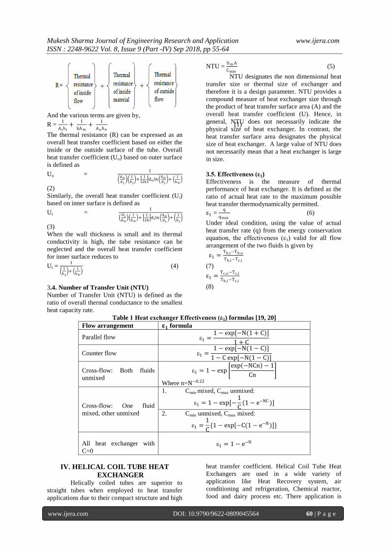
3.4. Number of Transfer Unit (NTU)
Number of Transfer Unit (NTU) is defined as the
ratio of overall thermal conductance to the smallest
heat capacity rate.
NTU = Um A
Cmin (5)
NTU designates the non dimensional heat
transfer size or thermal size of exchanger and
therefore it is a design parameter. NTU provides a
compound measure of heat exchanger size through
the product of heat transfer surface area (A) and the
overall heat transfer coefficient (U). Hence, in
general, NTU does not necessarily indicate the
physical size of heat exchanger. In contrast, the
heat transfer surface area designates the physical
size of heat exchanger. A large value of NTU does
not necessarily mean that a heat exchanger is large
in size.
3.5. Effectiveness (ε1)
Effectiveness is the measure of thermal
performance of heat exchanger. It is defined as the
ratio of actual heat rate to the maximum possible
heat transfer thermodynamically permitted.
ε1 = q
qmax (6)
Under ideal condition, using the value of actual
heat transfer rate (q) from the energy conservation
equation, the effectiveness (ε1) valid for all flow
arrangement of the two fluids is given by
ε1 =Th ,i−Th ,o
Th ,i−Tc ,i
(7)
ε1 =Tc ,o −Tc ,i
Th ,i−Tc ,i
(8)
Table 1 Heat exchanger Effectiveness (ε1) formulas [19, 20]
Flow arrangement 𝛆𝟏 formula
Parallel flow ε1 =1 − exp[−N(1 + C)]
1 + C
Counter flow ε1 =1 − exp[−N(1 − C)]
1 − C exp[−N(1 − C)]
Cross-flow: Both fluids
unmixed
ε1 = 1 − exp exp −NCn − 1
Cn
Where n=N−0.22
Cross-flow: One fluid
mixed, other unmixed
1. Cmin mixed, Cmax unmixed:
ε1 = 1 − exp[−1
C(1 − e−NC )]
2. Cmin unmixed, Cmax mixed:
ε1 =1
C{1 − exp[−C(1 − e−N)]}
All heat exchanger with
C=0
ε1 = 1 − e−N
IV. HELICAL COIL TUBE HEAT
EXCHANGER Helically coiled tubes are superior to
straight tubes when employed to heat transfer
applications due to their compact structure and high
heat transfer coefficient. Helical Coil Tube Heat
Exchangers are used in a wide variety of
application like Heat Recovery system, air
conditioning and refrigeration, Chemical reactor,
food and dairy process etc. There application is

Mukesh Sharma Journal of Engineering Research and Application www.ijera.com
ISSN : 2248-9622 Vol. 8, Issue 9 (Part -IV) Sep 2018, pp 55-64
www.ijera.com DOI: 10.9790/9622-0809045564 61 | P a g e
mainly in controlling the temperature of the
reactors for exothermic reactions, in cryogenics and
also in other heat transfer applications.
4.1Fluid flow in curved tubes
When a fluid flows through a straight
tube, the fluid velocity is maximum at the tube
center, zero at the tube wall & symmetrically
distributed about the axis. However, when the fluid
flows through a curved tube, the primary velocity
profile is distorted by the addition of secondary
flow pattern. The secondary flow is generated by
centrifugal action and acts in a plane perpendicular
to the primary flow. Since the velocity is maximum
at the center, the fluid at the center is subjected to
the maximum centrifugal action, which pushes the
fluid towards the outer wall. The fluid at the outer
wall moves in ward along the tube wall to replace
the fluid ejected outwards. This results in the
formation of two vortices symmetrical about a
horizontal plane through the tube center.
Fig.7 Schematic of Helically coiled tubes and
Secondary flow in enlarged cross-sectional view
4.2 Geometry of Shell and coiled tube heat
exchanger
The geometry of the helical tube and shell is shown
in fig.4.4. In the figure, d is the diameter of the
coiled tube, Rc is the curvature radius of the coil, D
is the diameter of the shell and b is the coil pitch.
Fig.8 A typical shell and coil tube heat exchanger
The important dimensionless parameters
of coiled tube are Reynold number (Re), Nusselt
number (Nu), and Dean number (De). As Reynold
number is used in order to characterize the flow in
case of a straight pipe, Dean number comes into
account in case of a helical pipe.
Reynold number (Re) =ρVd
μ, Nusselt number (Nu)
= hd
k
Dean number (De) = Re(d
2Rc)0.5
Shell side Reynold number and Nusselt number are
defined as,
Re =ρVdh
μ and Nu =
hdh
k, Where dh is the
hydraulic diameter of shell and it is expressed as,
dh =D2−2πRc do
2 γ−1
D−2πRc do γ−1 , γ is the dimensional pitch =
b
2πRc
The critical Reynold number for the transition from
laminar to turbulent flow in helical coils is a
function of the coil parameters. The critical
Reynolds number may be determined using the
correlation developed by Schmidt.
Recr = 2300[1 + 8.6(d2Rc
)0.45]
(9)
For flow inside a circular tube, the turbulent flow is
usually observed for
Re =ρvD
μ> 2300
(10)
However, this critical value is strongly dependent
on the surface roughness, the inlet condition and
the fluctuation in the flow. In general, the transition
may occur in the range 2000>Re>4000.
4.3 Applications of Helical tube heat exchanger
a) Helical coils are used for transferring heat in
chemical reactors and agitated vessels because
heat transfer coefficients are higher in helical
coils. This is especially important when
chemical reactions have high heats of reaction
are carried out and the heat generated (or
consumed) has to be transferred rapidly to
maintain the temperature of the reaction. Also,
because helical coils have a compact
configuration, more heat transfer surface can
be provided per unit of space than by the use
of straight tubes.
b) Because of the compact configuration of
helical coils, they can be readily used in heat
transfer application with space limitations, for
example, in steam generations in marine and
industrial applications.
c) Helical coiled tubes have been and are used
extensively in cryogenic industry for the
liquefaction of gases.

Mukesh Sharma Journal of Engineering Research and Application www.ijera.com
ISSN : 2248-9622 Vol. 8, Issue 9 (Part -IV) Sep 2018, pp 55-64
www.ijera.com DOI: 10.9790/9622-0809045564 62 | P a g e
4.4 Advantages and Disadvantages of Helical
tube heat exchanger
Advantages
a) Coils give better heat transfer performance,
since they have lower wall resistance & higher
process side coefficient.
b) A coil can provide a large surface area in a
relatively small reactor volume.
c) Coils are more versatile for scale – up.
Disadvantages
a) For highly reactive material or highly
corrosive material coils cannot be used, instead
jackets are used.
b) Cleaning of vessels with coils becomes much
difficult than with jackets.
c) Coils play a major role in selection of agitation
system. Densely packed coils can create
unmixed regions by interfering with fluid flow.
V. WASTE HEAT RECOVERY Waste heat is heat, which is generated in a
process by way of fuel combustion or chemical
reaction, and then “dumped” into the environment
even though it could still be reused for some useful
and economic purpose. The essential quality of
heat is not the amount but rather its “value”. Large
quantity of hot flue gases is generated from Boilers,
Kilns, Ovens and Furnaces. If some of this waste
heat could be recovered, a considerable amount of
primary fuel could be saved. The energy lost in
waste gases cannot be fully recovered. However,
much of the heat could be recovered and loss can
be minimized [22].
The energy conservation and its efficient utilization
are very much essential and it can be achieved by
the following ways.
By increasing the overall thermal efficiency of
existing process.
Using the heat recovery system to extract heat
that would otherwise go as waste.
By tapping alternative energy sources namely,
tidal, solar, geothermal, hydrothermal and
wind power.
5.1. Benefits of Waste heat recovery
I. Direct benefit: Recovery of waste heat has direct
effect on the efficiency of the process. This is
reflected by reduction in the utility consumption
and costs and process cost.
II. Indirect benefit:
Reduction in pollution.
Reduction in equipment size.
Reduction in auxiliary energy consumption.
The exhaust gas can be recovered by using
suitable heat exchanger. Compact heat exchanger
can be used for heat recovery purpose because of
its several advantageous over conventional type.
Compact heat exchangers are characterized by
having a high area density, which means a high
ratio of heat transfer surface to heat exchanger
volume.
Table 2 Area density of generic compact heat
exchanger
Liquid-liquid
compact heat
exchanger
>300 m2/m
3
Gas-liquid
compact heat
exchanger
>700 m2/m
3
Laminar flow
heat exchanger >3000 m
2/m
3
5.2. Temperature of waste gases from process
equipment in low, medium and high
temperature ranges [22]
Table 3 Typical waste heat temperature at low
temperature range from various sources
Sl.
No.
Name of
device
Temperature
(°C)
1. Air
compressor 27-50
2. Pumps 27-88
3.
Internal
combustion
engine
66-120
4.
Air
conditioning
and
Refrigeration
condensers
32-43
5.
Drying,
baking and
curing ovens
93-230
Table 4 Typical waste heat temperature at
medium temperature range from various
sources
Sl.
No.
Name of
device
Temperature
(°C)
1. Steam boiler
exhausts 230-480
2. Gas turbine
exhausts 370-540
3.
Heat
treatment
furnaces
425-650
4.
Reciprocating
engine
exhausts
315-600
5. Catalytic
crackers 425-650

Mukesh Sharma Journal of Engineering Research and Application www.ijera.com
ISSN : 2248-9622 Vol. 8, Issue 9 (Part -IV) Sep 2018, pp 55-64
www.ijera.com DOI: 10.9790/9622-0809045564 63 | P a g e
Table 5 Typical waste heat temperature at High
temperature range from various sources
Sl.
No.
Name of
device
Temperature
(°C)
1.
Nickel
refining
furnace
1370-1650
2.
Aluminum
refining
furnace
650-760
3.
Steel
heating
furnace
925-1050
4. Open hearth
furnace 650-700
5.
Glass
melting
furnace
1000-1550
Rating and sizing are two important
problems in the thermal analysis of heat exchanger.
The rating problem is concerned with the
determination of heat transfer rate, the fluid outlet
temperature and pressure drop whereas the sizing
problem is concerned with the determination of the
matrix of dimension to meet the specified heat
transfer and pressure drop requirement.
Heat transfer is defined as the
transmission of energy from one region to another
as a result of temperature gradient that takes place
by three modes namely Conduction, Convection
and Radiation. Heat transmission, in majority of
real situation, occurs as a result of these modes of
heat transfer. The three modes are similar in that a
temperature differential must exist and the heat
exchange is in the direction of decreasing
temperature. In the present work, the exhaust gas
from diesel engine which comes under the category
of low temperature range (66-120°C) has been used
as the shell side fluid for heat transfer analysis. The
exhaust gas transfer heat to the cold fluid (water)
that is flowing through the helical tube.
Computational Fluid Dynamics is
becoming a wide spread tool, used by a vast
number of engineers. CFD provides an option,
which is cheaper, obtains a complete set of results
and is suitable for almost all complexity of
problems. CFD is also well suited for trouble
shooting and also it has a faster turnaround time
than experiments.
The present work begins with the CFD
analysis of helical tube heat exchanger in order to
see the effect of temperature rise and pressure drop
along the length of the helical tube and the shell.
The exhaust gas from diesel engine has been used
as the shell side fluid for heat transfer analysis. The
exhaust gas transfer heat to the cold fluid (water)
that is flowing through the helical tube.
CFD provides the flexibility to change
design parameters without the expense of hardware
changes. It therefore costs less than laboratory or
field experiments, allowing engineers to try more
alternative designs than would be feasible
otherwise. It also reduces design cycle time and
cost by optimizing through computer predictions
and provides higher level of confidence in
prototype or field installed performance. Moreover
it investigates and understands the “why” for
existing problem or new equipment. The main
objective of the present study is to analyze the shell
and helical tube heat exchanger both
computationally and experimentally and to validate
the CFD results by comparing with the present
experiment.
VI. CONCLUSION A literature survey has been carried out to
study the Shell and helical tube heat exchanger
both computationally and experimentally. In
maximum cases analysis was done for number of
cases and the effect on temperature rise and the
pressure drop in the helical tube and shell was
observed by researchers. It was revealed that the
empirical correlation is quite in agreement with the
experimental results within experimental error
limits. Based on the results obtained from the CFD
and Experimental analysis, The NTU value of the
helical coil has been reasonably low thereby
justifying the name compact. The effectiveness of
the helical tube heat exchanger is quite comparable
with other conventional heat exchanger design.
REFERENCE [1]. D.G. Prabhanjan, G.S.V. Raghavan and T.J.
Rennie, Comparison of heat transfer rates
between a straight tube heat exchanger and
helically coiled heat exchanger. International
communication in heat and mass transfer,
vol. 29, pp. 185-191.
[2]. M.R. Salimpour, Heat transfer coefficient of
Shell and coiled tube heat exchangers.
Experimental Thermal and Fluid Science 33
(2009) 203-207.
[3]. M.R. Salimpour, Heat transfer characteristic
of temperature-dependent- property fluid in
shell and coiled tube heat exchangers.
International communication in heat and
mass transfer 35 (2008) 1190-1195.
[4]. W. Witchayanuwat and S. Kheawhom, Heat
transfer coefficient for particulate Airflow in
shell and Coiled tube heat exchangers.
World academy of science, Engineering and
technology 53 2009.
[5]. H. Shokouhmand, M.R. Salimpour and M.A.
Akhavan-Behabadi, Experimental
investigation of shell and coiled tube heat

Mukesh Sharma Journal of Engineering Research and Application www.ijera.com
ISSN : 2248-9622 Vol. 8, Issue 9 (Part -IV) Sep 2018, pp 55-64
www.ijera.com DOI: 10.9790/9622-0809045564 64 | P a g e
exchangers using Wilson plots. International
communication in heat and mass transfer 35
(2008), 84-92.
[6]. Paisarn Naphon, Somchai Wongwises, A
review of flow and heat transfer
characteristics in curved tubes. Renewable
and sustainable Energy Reviews 10 (2006)
463-490.
[7]. Paisarn Naphon, Thermal performance and
pressure drop of the helically coiled heat
exchangers with and without helically
crimped fins. (2006).
[8]. Paisarn Naphon and Jamnean Suwagrai,
Effect of curvature ratios on the heat transfer
and flow developments in the horizontal
spirally coiled tubes. International journal of
heat and mass transfer, vol. 50, issues 3-4,
Feb. 2007, pp. 444-451.
[9]. Andrea Cioncolini, LorenzoSantini, An
experimental investigation regarding the
laminar to turbulent flow transition in
helically coiled pipes. Experimental Thermal
and Fluid science 30 (2006) 367-380.
[10]. R.A. Seban, E.F. Mclaughlin, Heat transfer
in tube coils with laminar and turbulent
flow. International journal of heat and mass
transfer, vol. 6, pp. 387-395.
[11]. B.V.S.S.S. Prasad, D.H. Das and A.K.
Prabhakar, Pressure drop, Heat transfer and
Performance of a helically coiled tabular
exchanger. Heat recovery system and CHP
vol. 9, pp. 249-256, 1989.
[12]. J.S. Jayakumar, S.M. Mahajani, J.C.
Mandal, P.K. Vijayan, Rohidas Bhoi,
Experimental and CFD estimation of heat
transfer in helically coiled heat exchangers.
[13]. J.S. Jayakumar, S.M. Mahajani, J.C.
Mandal, P.K. Vijayan, Kannan N Iyer, CFD
analysis of single phase flows through
helical coils. Computers and chemical
engineering (2008).
[14]. Rahul Kharat, Nitin Bhardwaj, R.S. Jha,
Development of heat transfer coefficient
correlation for concentric helical coil heat
exchanger. International journal of Thermal
Sciences 48 (2009) 2300-2308.
[15]. Anderson J.D., Computational fluid
dynamics, International Edition. New York:
McGraw-Hill, 1995.
[16]. Fluent User Guide, Fluent Inc. January 11,
2005.
[17]. Amarvir chilka, Ashish kulkarni, Modeling
turbulent flows in Fluent, product version
6.1.
[18]. http:\\www.en.wikipedia.org\wiki\computati
onal fluid dynamics.
[19]. M. Necati özisik, Heat Transfer- A basic
approach. McGraw-Hill International
Editions, pp. 524-566.
[20]. J.P. Holman, Heat Transfer, McGraw-Hill
edition.
[21]. C P Kothandaraman, S Subramanyan, Heat
and Mass Transfer data book, Fifth edition.
New age international publishers.
[22]. Fuel economy in furnaces and waste heat
recovery-PCRA.
Mukesh Sharma "Review Of Experimental And Numerical Analysis Of Heat Exchanger In The
Light Of Waste Heat Recovery Applications "International Journal of Engineering Research
and Applications (IJERA) , vol. 8, no.9, 2018, pp 55-64
Copyright © 2022 FDOKUMEN