Exposure to Diesel Exhaust Particle Extracts (DEPe) Impairs ...
Upload
khangminh22Category
view
1download
0
NUMERICAL AND EXPERIMENTAL ANALYSIS OF A DIESEL EXHAUST HEAT
RECOVERY SYSTEM FOR INTAKE AIR HEATING OF REMOTE ARCTIC
UNDERGROUND MINES
by
Marco Antonio Rodrigues de Brito
B.Eng., Universidade Federal de Pernambuco, 2017
A THESIS SUBMITTED IN PARTIAL FULFILLMENT OF
THE REQUIREMENTS FOR THE DEGREE OF
MASTER OF APPLIED SCIENCE
in
THE FACULTY OF GRADUATE AND POSTDOCTORAL STUDIES
(Mining Engineering)
THE UNIVERSITY OF BRITISH COLUMBIA
(Vancouver)
August 2019
© Marco Antonio Rodrigues de Brito, 2019

ii
The following individuals certify that they have read, and recommend to the Faculty of Graduate
and Postdoctoral Studies for acceptance, a thesis/dissertation entitled:
Numerical and experimental analysis of a diesel exhaust heat recovery system for intake air
heating of remote arctic underground mines.
submitted by Marco A. Rodrigues de Brito in partial fulfillment of the requirements for
the degree of Master of Applied Science
in Mining Engineering
Examining Committee:
Dr. Seyed Ali Ghoreishi-Madiseh
Supervisor
Dr. Scott Dunbar
Supervisory Committee Member
Dr. Davide Elmo
Supervisory Committee Member

iii
Abstract
Remote mines operating in cold areas of Canada and other Arctic countries are often subjected to
subfreezing temperatures that can get as low as -40°C. When those mines are underground, they
need to heat their intake airflow up to a comfortable temperature for the adequate operation of
machinery and personnel. Remote mines are also frequently not connected to the electrical power
grid and need to depend on diesel generators to produce their electric power. As it has been
demonstrated by several authors in literature, these commercial diesel generators consistently
discard almost 70% of the total energy that is input as fuel. Such energy being neglected mostly in
the form of heat through exhaust and other means. Knowing so much energy exists in the exhaust,
usually in high grade, a system is proposed to recover thermal energy from the exhaust of the diesel
generators, transport it and deliver it to the cold intake airflow of a remote underground mine. The
overall alternative heating system is modeled analytically (with MATLAB) using real climate
history data from a Canadian remote mine to evaluate its performance. Also, a pilot-test scale
experimental setup is designed, constructed and tested and the heat exchanger utilized for intake
air heating is further numerically modeled with computational fluid dynamics (using Ansys Fluent)
to investigate its behavior in detail. Results from all the models created point to the system
effectively recovering a significant part of the waste heat and delivering it to the cold airflow. It is
also shown that due to the high temperature gradients created by the subfreezing temperatures the
intake air heating unit holds the potential to deliver most of the recovered heat, with the exhaust
heat recovery unit mostly driving the performance of the system.

iv
Lay Summary
In underground mines, a constant flow of air needs to be supplied to the underground workings,
for machinery and personnel employed there. These mines are often located in cold areas close to
the Arctic pole, where temperatures can get very cold, which makes it necessary for them to heat
the air that goes underground. This is usually achieved by fossil-fueled burners, however, not only
this creates an environmental hazard contributing to the greenhouse effect, it also results in great
cost for the mine. Frequently, these mines are also located in remote areas with no connection to
the electric grid having to rely on diesel generators. This research explores the potential of heating
the mine airflow using recovered heat from the exhaust of their diesel generators. Results show
that the proposed system can be successfully used to recover heat from exhaust and deliver it to a
cold intake airflow.

v
Preface
This research has been developed as part of a larger project concerning waste heat recovery for
mining applications in collaboration with Mr. Durjoy Baidya under the supervision of Prof. Dr.
Seyed Ali Ghoreishi-Madiseh. This thesis was developed as a complement to another master’s
thesis and several journal articles and conference proceedings that have been published on the
matter. The master’s thesis is:
• D. Baidya, Diesel exhaust heat recovery: a study on combined heat and power generation
strategy for energy-efficient remote mining in Canada, The University of British Columbia,
2019.
The focus of the work presented here remains on the intake air heating unit and its impact on the
system as a whole. Which contrasts to the other thesis as mentioned above that focused on the
exhaust heat recovery unit. The analytical, numerical and experimental model presented here have
been developed by the author. All the MATLAB codes have been developed by the author, as well
as all the numerical models and the intake air heating experimental system design. Assembly of
the pilot scale test setup has been done fully by Mr. Aaron Hope, Millwright. Experimental tests
have been performed in collaboration with Mr. Durjoy Baidya on the outer area of the Coal and
Mineral Processing laboratory (CMP) annex to the Frank Forward building at The University of
British Columbia.

vi
None of the work developed for this thesis has been published yet. However, the author has
participated in several minor subprojects, related both directly and indirectly to the research
performed here, that resulted in publications as listed below.
➢ Journal articles:
• L. Amiri, M.A. Rodrigues de Brito, D. Baidya, A.F. Kuyuk, S.A. Ghoreishi-Madiseh,
A.P. Sasmito, F.P. Hassani, Numerical investigation of rock-pile based waste heat storage
for remote communities in cold climates, Appl. Energy. 252(October), 12.
• Baidya, D., de Brito, M. A. R., Sasmito, A. P., Scoble, M., & Ghoreishi-Madiseh, S. A.
(2019). Recovering waste heat from diesel generator exhaust; an opportunity for combined
heat and power generation in remote Canadian mines. Journal of Cleaner Production,
225(July), 785-805.
• Ghoreishi-Madiseh, S. A., Fahrettin Kuyuk, A., Rodrigues de Brito, M. A., Baidya, D.,
Torabigoodarzi, Z., & Safari, A. (2019). Application of Borehole Thermal Energy Storage
in Waste Heat Recovery from Diesel Generators in Remote Cold Climate
Locations. Energies, 12(4), 13.
• Ghoreishi-Madiseh, S. A., Kuyuk, A. F., & Rodrigues de Brito, M. A. (2019). An
analytical model for transient heat transfer in ground-coupled heat exchangers of closed-
loop geothermal systems. Applied Thermal Engineering, 150(January), 696–705.
• Ghoreishi-Madiseh, S. A., Safari, A., Amiri, L., Baidya, D., Brito, M. A. R., & Kuyuk, A.
F. (2019). Investigation of viability of seasonal waste heat storage in rock piles for remote
communities in cold climates. Energy Procedia, 159(February), 6.

vii
➢ Conference proceedings:
• M.A. Rodrigues de Brito, D. Baidya, S.A. Ghoreishi-Madiseh, Investigation of the
techno-economic feasibility of recovering waste heat of diesel generator exhaust for
heating mine intake air, in: 17th Noth Am. Mine Vent. Symp., Montreal, QC, 2019:p. 10.
• D. Baidya, M.A. Rodrigues de Brito, S.A. Ghoreishi-madiseh, Techno-economic
assessment of integrating thermal energy storage with diesel exhaust waste heat recovery
system for remote mines in cold climates, in: Int. Conf. Appl. Energy 2019, Västerås, BC,
2019: p. 6.
Finally, the author would like to mention that all the figures generated by self (including charts
and contours) are here pasted as image metafiles. Thus, when reading the digital version of this
thesis all said figures can be significantly zoomed in without any loss of quality for better
visualization of their details.

viii
Table of Contents
Abstract ......................................................................................................................................... iii
Lay Summary ............................................................................................................................... iv
Preface .............................................................................................................................................v
Table of Contents ....................................................................................................................... viii
List of Tables ..................................................................................................................................x
List of Figures ............................................................................................................................... xi
List of Symbols ........................................................................................................................... xiv
List of Subscripts and Superscripts............................................................................................xv
List of Abbreviations ................................................................................................................. xvi
Acknowledgements ................................................................................................................... xvii
Dedication ................................................................................................................................. xviii
Chapter 1: Introduction ................................................................................................................1
1.1 Background ..................................................................................................................... 1
1.2 General Research Objectives .......................................................................................... 6
1.3 Specific Research Objectives .......................................................................................... 6
1.4 Thesis Outline ................................................................................................................. 7
Chapter 2: Literature Review .....................................................................................................10
2.1 Diesel Internal Combustion Engine and Waste Heat .................................................... 10
2.2 Waste Heat Recovery Technologies ............................................................................. 11
2.3 Heat Exchangers ........................................................................................................... 14
2.4 Alternative Thermal Energy Solutions in the Canadian Mining Industry .................... 18

ix
Chapter 3: System Description and Analytical Model .............................................................21
3.1 System Description ....................................................................................................... 21
3.2 Thermodynamic Principles of the System .................................................................... 24
3.3 Code Description .......................................................................................................... 27
3.4 Analytical Results of Coupled Analysis ....................................................................... 28
Chapter 4: Numerical Modeling of the Intake Air Heating Unit ............................................35
4.1 Unit Description ............................................................................................................ 35
4.2 Simulation Methods ...................................................................................................... 37
4.3 Mesh Sensitivity Analysis............................................................................................. 41
4.4 Simulation Results ........................................................................................................ 44
4.4.1 Performance Employing Glycol ............................................................................... 50
Chapter 5: Experimental Pilot-Test Setup ................................................................................56
5.1 Description of Experimental Setup ............................................................................... 56
5.2 Experimental Results and Numerical Validation .......................................................... 60
Chapter 6: Conclusions and Recommendations .......................................................................68
6.1 Perspectives for the mining engineering industry ......................................................... 70
6.2 Recommendations for further studies ........................................................................... 71
References .....................................................................................................................................72
Appendices ....................................................................................................................................81
Appendix A - Analytical MATLAB code used ........................................................................ 81
Appendix B - Equipment Listing .............................................................................................. 86
B.1 Exhaust heat recovery setup...................................................................................... 86
B.2 Intake air heating setup ............................................................................................. 87

x
List of Tables
Table 3.1. Mine real data and parameters for the assumed generator model and power plant ..... 23
Table 3.2. Parameters of the heat exchanger units and pipeline connection ................................ 29
Table 4.1. Material properties and boundary conditions of mesh sensitivity analysis ................. 41
Table 4.2. Parameters of the meshes used for the sensitivity analysis ......................................... 43
Table 4.3. Material properties and boundary conditions of initial tests with a full row using water
....................................................................................................................................................... 47
Table 4.4. Overall results for sequential set of simulations for all 8 passes using water ............. 49
Table 4.5. Material properties and boundary conditions of glycol simulations ............................ 50
Table 4.6. Overall results for sequential set of simulations for all 8 passes using glycol ............ 51
Table 4.7. Experimental data used as input for water/glycol comparison .................................... 54
Table 5.1. Experimental results from exhaust heat recovery unit on full system run ................... 61
Table 5.2. Experimental results from intake air heating unit on full system run .......................... 61
Table 5.3. Experimental results from exhaust heat recovery unit on full system run with variable
water flow ..................................................................................................................................... 65
Table 5.4. Experimental results from intake air heating unit on full system run with variable
water flow ..................................................................................................................................... 66

xi
List of Figures
Figure 1.1 Fossil-fueled heaters: a) direct; b) indirect; modified from ref. [4] .............................. 2
Figure 1.2 Ekati Diamond Mine during: a) Summer; b) Winter seasons [10,11] ........................... 3
Figure 1.3 CAT Diesel generator model C175-16 (3.1ekW) [23] .................................................. 5
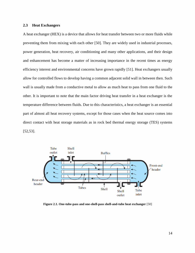
Figure 2.1. One-tube-pass and one-shell-pass shell-and-tube heat exchanger [50] ...................... 14
Figure 2.2. Compact cross-flow heat exchanger: a) both fluids unmixed; b) one fluid mixed, one
unmixed [50] ................................................................................................................................. 15
Figure 3.1. Diagram of the proposed system with main points of interest for temperatures ........ 22
Figure 3.2. Daily mean temperatures for the location of the remote mine in Northwest
Territories, Canada for 2017 [61]. ................................................................................................ 24
Figure 3.3. Flowchart of overall actions performed by the developed MATLAB code ............... 28
Figure 3.4. Energy values for the base coupled scenario compared with the previously published
uncoupled results .......................................................................................................................... 30
Figure 3.5. Sensitivity analysis on the effectiveness of the intake air heating unit ...................... 31
Figure 3.6. Simultaneous sensitivity analysis on the effectiveness of both heat exchangers: a)
Annual heat saved by the system; b) Percentage of annual heat saved by total heat demand; c)
Heat discarded (relative to a cooled exhaust temperature of 189.5 °C) ....................................... 32
Figure 4.1. Cross-flow heat exchanger used in the pilot scale setup: a)Real picture; b)
Manufacturer’s representation with real dimensions .................................................................... 35
Figure 4.2. 3D CAD model of the pilot scale of the cross-flow heat exchanger used in the pilot
scale: a)Perspective; b)Front view ................................................................................................ 36
xii
Figure 4.3. Example of mesh created for a section of the cross-flow heat exchanger with all three
domains (gas, solid and liquid) ..................................................................................................... 38
Figure 4.4. Subdivisions of the cross-flow heat exchanger used in different steps of the analysis:
a)Full heat exchanger; b)One liquid pass (or row); c)Unitary section of the pass (~1/10 of a row)
....................................................................................................................................................... 39
Figure 4.5. Modelled section showing 5 different levels of mesh refinement, refinement increases
(minimum element size decreases) from a) to e) .......................................................................... 42
Figure 4.6. Results for mesh sensitivity analysis: a)Gas side; b)Liquid side ............................... 43
Figure 4.7. Temperature contours of heat exchanger section: a)Test 1 (Coarse); b)Test 4
(Superfine) .................................................................................................................................... 44
Figure 4.8. Contours of the unitary section with extended air domain: a)Temperature; b)Velocity
....................................................................................................................................................... 45
Figure 4.9. Full row model developed for further simulations: a)Perspective; b)Area between fins
in detail.......................................................................................................................................... 46
Figure 4.10. Temperature contours of the whole heat exchanger, assembly of the contours of
each individual pass. ..................................................................................................................... 48
Figure 4.11. Heat exchanged per pass for several fresh intake air temperatures .......................... 52
Figure 4.12. Total heat transfer rate and air temperature change for several different fresh intake
air temperatures ............................................................................................................................. 53
Figure 4.13. Water and glycol heat exchanged per pass comparison assuming constant
temperatures for each load ............................................................................................................ 54
Figure 4.14. Water and glycol total heat transfer rate and air temperature change comparison .. 55
xiii
Figure 5.1. First part of the experimental setup used in previous studies (Exhaust heat recovery
system), heat exchanger in detail .................................................................................................. 56
Figure 5.2. Preliminary draft of the pilot scale intake air heating unit ......................................... 57
Figure 5.3. Ductwork with insulated interior fabricated in sheet metal as per author’s design.... 58
Figure 5.4. Pilot-scale test setup of the intake air heating unit constructed for the study ............ 59
Figure 5.5. Draft of full both units interconnected, exhaust heat recovery and intake air heating 60
Figure 5.6. Heat recovered (on the exhaust heat recovery unit) and heat delivered (on the intake
air heating unit) for full cycle run ................................................................................................. 62
Figure 5.7. Airduct outlet with temperature sensors and cross-flow heat exchanger in evidence 63
Figure 5.8. Results for intake air heating unit with full system operational ................................. 64
Figure 5.9. Heat recovered (on the exhaust heat recovery unit) and heat delivered (on the intake
air heating unit) for full cycle run with variable water flow and constant load ............................ 66

xiv
List of Symbols
φ Viscous-dissipation function (W/m³)
ε Effectiveness (non-dimensional)
ρ Density (kg/m³)
μ Dynamic viscosity (Pa.s)
Γ Local effectiveness (non-dimensional)
û Specific internal energy of fluid (J/kg)
cp Isobaric heat capacity (J/kg-°C)
C Heat capacity rate (W/°C)
g Gravity vector (m/s²)
k Thermal conductivity (W/m-°C)
�̇� Mass flow rate (kg/s)
P Pressure (Pa)
�̇� Heat transfer rate (W)
t Time (s)
T Temperature (°C)
u Velocity vector (m/s)
�̇�
Volumetric flow rate (m³/s)

xv
List of Subscripts and Superscripts
act Actual
air Relative to air
amb Ambient
dem Demand
c Cold fluid
h Hot fluid
exh Relative to exhaust
in Inlet
out Outlet
min Minimum
max Maximum
s Supply
sav Saved
set Set-point
t Total
r Return
u Unit

xvi
List of Abbreviations
CAD Computer-aided design
CFD Computational fluid dynamics
CHP Combined heat and power
DE Diesel engine
DEHR Diesel exhaust heat recovery
ekW Electric kilowatt
EHR Exhaust heat recovery
EHRU Exhaust heat recovery unit
HVAC Heating, ventilation and air conditioning
HEX Heat exchanger
IAHU Intake air heating unit
ICE Internal combustion engine
LPM Liters per minute
NWT Northwest Territories
ORC Organic Rankine cycle
TEG Thermoelectric generators
WHR Waste heat recovery

xvii
Acknowledgements
I would like to start showing my appreciation to Professor Bantwal Rabindranath Baliga for
enticing me with the wonders of heat transfer and without even knowing, starting the flame that
brought me here.
Special gratitude goes to Dr. Seyed Ali Ghoreishi Madiseh, that always gave me such countless
opportunities both in academia and in life, and guided me through the way, showing me how much
you can do with some thermodynamics and a lot of hard work.
I also want to thank all my friends, colleagues and co-workers, that helped in the moments of need
and brought knowledge and understanding whenever they could, who shared so much with me and
allowed me to share some with them. It would not have been the same without you.
Moreover, I’d like to show my appreciation for all the help that Mr. Aaron Hope, Millwright gave
me during this project, without him the experimental part of this work wouldn’t have been possible.
Then I would like to thank my mother Lucia, who always worked so hard and gave her everything
to support me, both financially and morally throughout my entire life. She is the one who made
everything possible and is the greatest responsible for the person I am today.
And finally, I would like to thank my wife Karoline Pereira. The one who helped me with so many
of the hardest parts of life, who sacrificed so much to be by my side, who showed me purpose in
times of confusion. I cannot thank you enough.

xviii
Dedication
I dedicate this work to my wife Karoline, who has above all things stood by my side.
“I whish I could do better by you…’cause that is what you deserve.”

1
Chapter 1: Introduction
1.1 Background
There are currently about 1,200 mining establishments operating in Canada, many of which are
located in remote Arctic areas [1]. These mines often experience extremely cold temperatures,
mainly during wintertime, that could be as low as -40°C. Such harsh weather conditions make it
necessary for these sites to take measures in order to cope with the cold temperature and achieve
conditions that are comfortable for the workforce and appropriate for the operating equipment [2].
In those cases, heating of the communal areas and of the sanitary and domestic water becomes
necessary. Besides these general needs that are common for every remote arctic community (not
only commercial as mining, but also residential ones) if a site is that of an underground operation
there is an additional need to heat the intake air that is sent into the workings [3]. Mine intake air
has to be heated whenever it falls below 0°C since subfreezing temperatures can cause ice
formation in the airways increasing the airflow resistance [4]. Ice can also build-up in large blocks
and dislodge, leading to hazard to personnel. These ice formations also directly affect the operation
and maintenance of equipment potentially causing permanent damage [2,4]. Preheating of said
intake air aims at raising its temperature to a value greater than 1°C, usually up to 4-7°C which is
considered enough for normal underground work. This number however changes from case to case
since in mines with considerable depth the air suffers natural auto compression and heating from
geothermal gradient contributing to the desired temperature increase [4].
In a mine with a large airflow demand the heating costs can become very high and represent a
considerable part of the energy expenses of the mine [3], which by themselves are appraised to be
15-24% of the total cost of a mine operation [5,6]. It is estimated that heating very large airflows

2
through temperatures differences so high can be more expensive than creating the airflow itself
[4], and such costs could be as high as $2,000 per m³/s of air [7].
Figure 1.1 Fossil-fueled heaters: a) direct; b) indirect; modified from ref. [4]
Heating of mine intake air is commonly performed through direct or indirect heating with fossil
fuel-powered furnaces as shown in Figure 1.1. Such furnaces usually employ natural gas if the site
has access to a pipeline, or propane when it does not. However, if the site is remote, all the fuel
must be transported to the site in a tight time window through winter roads and then stored for
long periods of time. In such scenario diesel fuel (or heavy oil) becomes the usual choice as it is
more stable, thus safer to store and transport, besides having a high energy density [8]. These
remote mines are frequently off-grid having no connection to power lines [9], which means they
also have to solely rely on diesel for power generation (through diesel gen-sets) [6]. The
transportation and storage of this large amount of fuel, that could be up to millions of liters, also
incurs significant additional costs to the operation. A remote Arctic mine, the Ekati Diamond Mine
in the Northwest Territories in Canada is shown in Figure 1.2 during the Summer and Winter
seasons.
Fan
Hot-air
furnaceAir in
(bypass)
Fan
Boiler
Air in
(bypass)
Air in
Steam
coils
a) b)

3
Figure 1.2 Ekati Diamond Mine during: a) Summer; b) Winter seasons [10,11]
Having such high dependence on fossil fuels also raises serious concerns regarding the current
situation of the environment [12]. The world today faces an energy crisis due to the fast growth of
population and consequent energy demand. This has started a change in the responsiveness of our
energy use [13]. Meanwhile, scientists around the globe have already agreed upon human’s
liability on the recent changes in global climate, and if there is not a major mutual concern
regarding the levels of greenhouse gases that rise, such changes will surely lead to harmful effects
on the global population, industry and economy [12]. Thus, it is essential that mining companies
develop and employ sustainable mining models that require them to be responsible for the
environmental consequences of their operations and minimize its impact [14]. To help achieve
that, governments are also implementing increasingly restrictive policies, the most directly
impacting one being the carbon emission taxation that is levied by some countries, including
Canada [14]. The current values for carbon tax in Canada vary among the provinces but in British
Columbia it is currently C$35 per tonne of carbon dioxide equivalent emissions, being planned to
rise to C$50 in 2021–2022 [3]. With all that in mind, it is essential that new energy efficiency
a) b)

4
technologies based on alternative forms of energy generation and conversion are studied,
developed and implemented in the mining industry [6].
One of the most promising technologies that could help mitigate the aforementioned problems is
waste heat recovery (WHR). As the name implies, such technique consists of recovering energy
manifested as heat from some source that would be otherwise discarded or rejected to the
environment. This occurs frequently in processes where large quantities of heat are generated, as
in internal combustion engines (ICE) [15] or when heat is a sub product of the operation of a
system, as in compressor stations or mineral processing operations [4].
The power generation unit most commonly used in remote mining applications is the diesel moto-
generator (also known as diesel generator-set or diesel gen-set). Such system is composed of a
diesel internal combustion engine and an electric generator (usually some kind of alternator) that
work together to generate electric energy by combusting diesel fuel. A model of generator
commonly employed in the mining industry is displayed in Figure 1.3. However, despite all efforts
to improve ICE performance, they are still known to have low overall efficiencies ranging from
30-40% depending on operating conditions [16–18]. The rest of the energy being discarded
through the exhaust, coolant, friction, lubricating oil, radiation to the environment and other minor
losses. Among those, the exhaust stream contains the majority of the energy lost, being usually
around 40% of the energy consumed [19]. In a heavy-duty large-scale engine that could represent
exhaust streams as hot as 500-750°C [20]. Moreover, researches have shown that for every
kilowatt of electric power generated by a common diesel gen-set, about three kilowatt of fuel is
consumed, and approximately one kilowatt of heat is discarded through the exhaust stream of the

5
generator [3]. Meanwhile, remote Canadian mines have massive power plants in order to generate
the necessary power for all their operations. It is estimated that a Canadian metal mine producing
one million tonnes per year has an average power demand of 21MW, which means (in case of
remote mines) several immense diesel gen-sets generating electricity and continuously rejecting a
huge amount of heat [21]. Having this in mind, it becomes evident that the exhaust streams of
diesel generators used in remote arctic mine sites represent a potential source for waste heat to be
recovered. If successfully recovered, such heat could be used to heat the underground mine intake
air and help extenuate the dependence of fossil fuels for heating purposes. Such combination of
power generation and heat provision is frequently employed in other industries and is referred to
as cogeneration or combined heat and power (CHP) [22].
Figure 1.3 CAT Diesel generator model C175-16 (3.1ekW) [23]
Although waste heat recovery of diesel generators has been studied and employed in industrial
operations, the existing work focus mostly on recovering the heat rejected from the engine coolant
(or jacketwater) [17]. The works that concentrate on exhaust heat recovery (EHR) generally aim

6
at using it for power generation purposes by means of turbochargers, organic Rankine cycles
(ORC) or thermoelectric generators (TEG) [15,20,24–26]. This work focuses on developing CHP
technology for use in remote arctic underground mines, by means of conceiving and analysing a
viable WHR system that uses heat recovered from the exhaust of diesel generators to pre-heat mine
intake air.
1.2 General Research Objectives
The main goal of this research was to develop a viable EHR system for mine intake air heating
and to prove its feasibility by a series of analytical, numerical and experimental tests. For that, the
system proposed, economically investigated and partially studied by this research team in previous
works [3,27] was here further developed and deeper analyzed.
The overall thermodynamic performance of the system was by analytical means. Some of its
specific components were evaluated numerically and finally a model of the proposed system was
built in pilot-test scale for final evaluation and comparison of the obtained results. With these steps,
the author sought to prove how effective this technology can be in the mining industry and how it
could help mines in the future to be less fossil fuel dependent, more energy efficient and
consequently more environmentally friendly.
1.3 Specific Research Objectives
To achieve the above general objectives, the following specific objectives were targeted:
• Design a simple system capable of recovering heat from the exhaust of a diesel generator
and delivering it to the intake air of an underground mine;

7
• Develop a coupled analytical thermodynamic iterative model of the proposed system by
means of a MATLAB code to evaluate its individual thermal properties as well as its
overall thermal performance. Thus, use the code to prove the viability of the system,
evaluate the impact of some specific parameters on the overall performance and compare
the results with previous, decoupled analysis of the system established by the author;
• Develop a computational fluid dynamics model on Ansys Fluent of the intake air heating
unit and investigate its operation and its performance, mainly the heat transfer rates and the
air temperature change demonstrating it can provide the heat necessary for practical
working of the unit;
• Build an experimental model of the proposed system and perform pilot tests evaluating the
main operational outcomes as heat transfer rates and temperature changes, comparing the
results with the previous models developed and investigating its practicality for a large-
scale system for remote underground mines.
1.4 Thesis Outline
This thesis is divided in six chapters based on their content, with each specific approach for the
research separated in its own chapter. The chapters are as described below.
Chapter 1 gave information on the background of remote arctic mining, described some of the
challenges that exist in such inhospitable scenarios and how this study could help
provide a green solution to the extremely high heating demands that exist there.

8
Chapter 2 provides a concise literature review on important topics discussed throughout this thesis,
explaining relevant concepts to this research and describing some of the progress that
has been done in them by other researchers.
Chapter 3 describes in detail the proposed system as well as its thermodynamic principles. Then,
it reports the procedure used to develop the MATLAB code employed for the analytical
evaluation of the impact of the intake air heating unit to the performance of the system
as well as the results of said analysis.
Chapter 4 gives a deep analysis on the operation of the intake air heating unit, here chosen to be a
compact finned-tube cross-flow heat exchanger, to further understand its performance
and corroborate the experimental results presented in chapter 5. In it, the unit is modelled
numerically using computational fluent dynamics software (Ansys Fluent 19.1) and
simulated in a number of scenarios replicating the behavior of the existing pilot-scale
system developed for this study.
Chapter 5 demonstrates the process of the creation of a pilot-scale test setup of the system proposed
here, as designed by the author, shows the results of the experimental tests and compares
them with numerical counterparts calculated using the numerical model developed in
Chapter 4 to further endorse the previous findings as well as show the performance of
the whole system working together.

9
Chapter 6 summarizes all the conclusions achieved throughout this study, evidencing the
perspectives its potential brings to the mining industry and mentions a few
recommendations for further studies looking into the proposed technology.
10
Chapter 2: Literature Review
To fully understand the analyses, assumptions and results presented in this work, it is necessary to
first have a general overview of the main topics studied here. Most important, one should
comprehend the basic principles of diesel engines and generators, heat exchangers, heat recovery
and its potentials to the current mining industry. For that end, a broad literature review is performed
on all these relevant topics and is presented in the following subsections.
2.1 Diesel Internal Combustion Engine and Waste Heat
An internal combustion engine is a machine which purpose is to generate mechanical power from
the chemical energy present in a fuel. The ‘internal’ term means that the oxidizing reaction of the
fuel, commonly known as combustion, happens inside the engine itself [28]. A diesel engine (DE)
works through a Diesel thermodynamic cycle and is also called compression-ignition engine since
the combustion reaction is triggered by an extreme compression of the fuel-air mixture. The diesel
engines are one of the main types of ICE used in industry and are commonly employed in field
applications due to their relatively higher thermal efficiency when compared to other types of
engines [26]. One of the major applications being in power generation units called diesel
generators. It is estimated that about 15% of all the installed power generation capacity of the
world is based on diesel power plants [26].
Although several core industries have been developing technologies to try to improve the DE
overall efficiency, it is still considerably low when compared to technologies that don’t involve
combustion [29]. Due to the nature of the reaction inside the combustion chamber, only about 38%
is successfully converted to useful mechanical work, with the remaining energy from fuel being

11
rejected in the form of heat on the exhaust stream (around 30%), on the engine coolant
(approximately 25%) and the rest (about 7%) being discarded as friction losses, noise and radiation
to the environment [29,30]. In fact, previous studies compared several diesel generators of
different capacities and distinct loads and showed that as the capacity increases, diesel gen-sets
tend to neglect through the exhaust gases about the same amount of energy that is generated as
electricity [3]. This means that it is a fair assumption to say that for every watt of electricity
generated in a diesel gen-set, one watt of heat will be available in the exhaust. Besides that, all of
the energy being discarded shows that ICE, mainly through jacketwater and exhaust, represent a
potential opportunity for waste heat recovery, since any additional energy that could be reutilized
would raise the overall efficiency of a diesel generator [16]. Such potential has been demonstrated
in several works of literature and will be discussed in detail in the following sections.
2.2 Waste Heat Recovery Technologies
Over the years, several techniques of waste heat recovery have been developed that focus on
different sources of energy and different end-users for that energy. It is possible to separate four
main types of technology based on how the recovered energy is utilized. The energy can be
recovered and redirected to the engine itself, which is a well stablished technology commonly used
in industry. This is achieved though the turbocharger. In a turbocharged engine the exhaust gases
are redirected to a turbine which powers a compressor that compresses the inlet air of the engine.
This turbine-compressor set is able to recover some of the energy present on the exhaust and
transfer it to the air entering the engine. With a higher pressure and density, more air and
consequently more fuel are driven into the reaction chamber. This allows the engine to produce
12
more power at a more efficient rate [15]. Today, most of the large-scale diesel engines (and
therefore diesel gen-sets) have turbochargers, including the one shown in Figure 1.3.
A second main type of application is for electricity generation. In this kind of system, the heat is
recovered and converted into electricity using some energy conversion technology. This has been
extensively researched and several results can be found in literature. The two most used
technologies being via Organic Rankine Cycle (ORC) [25,31–33] or via Thermoelectric
Generators (TEG) [34–36]. An ORC is a Rankine thermodynamic cycle that operates using organic
fluids as the working fluid in order to successfully operate using low grade heat sources, as the
exhaust stream and the jacketwater. Several studies have shown that ORC based technologies are
capable of increasing the output of a diesel engine in about 10-11% [25,37]. Another study has
shown that the efficiency of a ORC increases with torque and the maximum possible efficiency of
the cycle is around 5-7% which represents an increase in overall system efficiency of 1.53%
[38,39]. Meanwhile, TEG systems are smaller, and easier to implement, containing no moving
parts but are known to have an even smaller efficiency [15]. Studies performed to evaluate the
TEG performance when coupled to the exhaust stream of vehicle size diesel engines have reported
efficiencies of the TEG system around 1-5% [40–42] while generating electric power as low as
100-400W [34,41,42].
The third application for the discarded energy would be the direct use of heat whenever it is needed,
representing a cogeneration system. Some studies have focused on the heat recovery of diesel
waste heat [29,43,44] without any focus on the end application, but very few studies have ben done
evaluating the viability of using this energy for direct heat usage, since it needs a large heat demand

13
to be viable. Most of the applications of waste heat for direct heat use are not from diesel power
plants and use other sources of heat instead, as heat rejection from residential ventilation [45] and
heat discarded from mine exhaust air [46]. All the literature on diesel exhaust heat recovery
(DEHR) for direct use in heating applications that is currently available was performed by this
research group [3,17,47].
The fourth application would be heat recovery for cooling. This less intuitive application is
achieved through a refrigeration by absorption cycle. These consist of a refrigeration cycle in
which the compressor is replaced by a generator and an absorber. Some studies have investigated
the viability of using waste heat for refrigeration. It has ben found that for a 16kW ICE it was
possible to reach 34.4kW of refrigeration with an exergy efficiency of 18.6% [48]. Other study
estimated that for a waste heat absorption based cycle in a ship could provide air conditioning for
more than 9000m² allowing for monthly savings over C$100,000 [49].
It is important to mention that although some use of jacketwater heat in waste heat recovery (WHR)
has been implemented in some industries and is used by some of the researches cited previously,
the exhaust stream contains more heat and has a greater economical potential for heat recovery
than the engine coolant [29]. Besides, no other work than the ones developed by this group has
focused on the potential of DEHR for direct heating purposes. For that reason, this source of heat
is the focus of this research.
14
2.3 Heat Exchangers
A heat exchanger (HEX) is a device that allows for heat transfer between two or more fluids while
preventing them from mixing with each other [50]. They are widely used in industrial processes,
power generation, heat recovery, air conditioning and many other applications, and their design
and enhancement has become a matter of increasing importance in the recent times as energy
efficiency interest and environmental concerns have grown rapidly [51]. Heat exchangers usually
allow for controlled flows to develop having a common adjacent solid wall in between then. Such
wall is usually made from a conductive metal to allow as much heat to pass from one fluid to the
other. It is important to note that the main factor driving heat transfer in a heat exchanger is the
temperature difference between fluids. Due to this characteristics, a heat exchanger is an essential
part of almost all heat recovery systems, except for those cases when the heat source comes into
direct contact with heat storage materials as in rock bed thermal energy storage (TES) systems
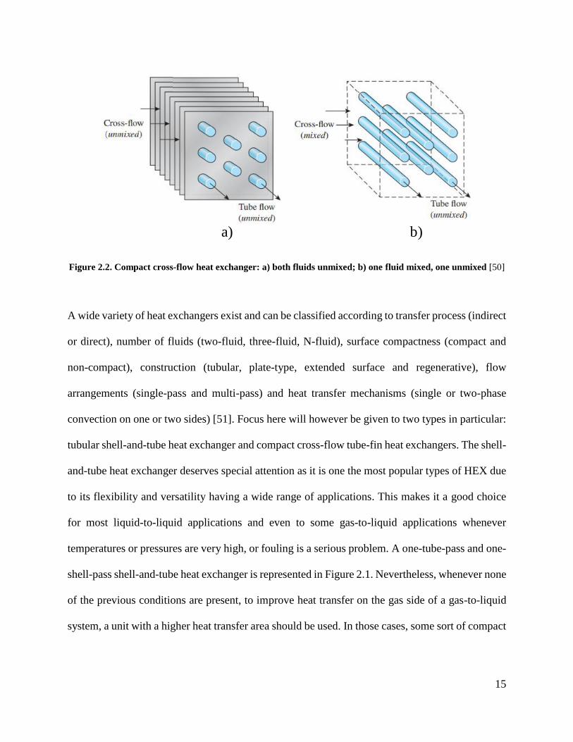
[52,53].
Figure 2.1. One-tube-pass and one-shell-pass shell-and-tube heat exchanger [50]
15
Figure 2.2. Compact cross-flow heat exchanger: a) both fluids unmixed; b) one fluid mixed, one unmixed [50]
A wide variety of heat exchangers exist and can be classified according to transfer process (indirect
or direct), number of fluids (two-fluid, three-fluid, N-fluid), surface compactness (compact and
non-compact), construction (tubular, plate-type, extended surface and regenerative), flow
arrangements (single-pass and multi-pass) and heat transfer mechanisms (single or two-phase
convection on one or two sides) [51]. Focus here will however be given to two types in particular:
tubular shell-and-tube heat exchanger and compact cross-flow tube-fin heat exchangers. The shell-
and-tube heat exchanger deserves special attention as it is one the most popular types of HEX due
to its flexibility and versatility having a wide range of applications. This makes it a good choice
for most liquid-to-liquid applications and even to some gas-to-liquid applications whenever
temperatures or pressures are very high, or fouling is a serious problem. A one-tube-pass and one-
shell-pass shell-and-tube heat exchanger is represented in Figure 2.1. Nevertheless, whenever none
of the previous conditions are present, to improve heat transfer on the gas side of a gas-to-liquid
system, a unit with a higher heat transfer area should be used. In those cases, some sort of compact
a) b)

16
cross-flow heat exchanger is usually employed, commonly having transversal fins. A simple
representation of two different cross-flow heat exchanger types is shown in Figure 2.2.
Whenever a heat exchanger is being selected or designed, it is common to face some sort of trade-
off relationship. The performance of a heat exchanger is directly related to the total area available
for heat transfer to happen, which means that usually adding more area (in the form of fins or more
passes of pipe) increases the heat transfer rate. On the other hand, adding more material translates
in more associated cost. Additional passes and fins also mean more resistance to flow leading to
higher pressure drops. A higher pressure drop in a heat exchanger is directly responsible for an
increase in the energy necessary to move such flow and consequently in electricity (pumping) costs
[51]. In summary, for the best cost-efficiency to be achieved for a given duty or in a specific
system, a heat exchanger has to be carefully selected having in mind the desired goals for that
individual task.
The heat transfer and fluid flow for a fluid inside a heat exchanger is governed by a set of very
complex coupled partial differential equations of continuity, which are shown in Eq. (2.1-2.3) [54].
These equations are also known as the Navier-Stokes equations for which are no known general
solutions. Thus, in order to analyze fluid flow and heat transfer solutions for very specific scenarios
simplifications are used. However, if the investigation of complex cases becomes necessary,
numerical and computational methods ought to be employed.

17
𝜕𝜌
𝜕𝑡+ 𝛁 ∙ (𝜌𝒖) = 0 ( 2.1 )
𝜌 [𝜕𝒖
𝜕𝑡+ (𝒖 ∙ ∇)𝒖] − 𝜇∇2𝒖 = −∇𝑃 + 𝜌𝒈 ( 2.2 )
𝜌𝜕û
𝜕𝑡+ 𝑃(𝛁 ∙ 𝒖) = 𝛁 ∙ (𝑘𝛁T) + 𝛷 ( 2.3 )
To describe it in simple terms, computational fluid dynamics (CFD) is a field that studies numerical
tools for the solutions of fluid flow and heat transfer problems [55]. In order to apply CFD to solve
a problem, the domains are discretized in both space and time and the set of continuous equations
for conservation is substituted by a set of discretized ones for each of the elements of the domain.
Those equations are then solved iteratively until the solution converges to a value respecting a
previously defined tolerance. A lot of advances in the field have happened along the past decades
and today this process is implemented in several known commercial CAD/CAE software in a very
efficient and automated manner, one of the most popular ones being Ansys Fluent. However, it
still is important for one to know the main principles of computational fluid dynamics when
operating such software.
Since the heat exchanger is a crucial component of a heat recovery system [56], several studies
have focused on developing and enhancing heat exchangers for that purpose and a few most
relevant ones can be mentioned. Shell-and-tube and cross-flow configurations have been compared
on their performance for exhaust heat recovery for truck applications showing a much lower
pressure drop for cross-flow [16]. Researchers have also looked forward to improve the heat
recovered through a shell-and-tube heat exchanger from the exhaust stream of a diesel generator
and were able to improve effectiveness from 0.52 to 0.74 by optimization of construction
parameters as shell and tube diameter, number of tubes and shell length [29]. A study was done to

18
evaluate the improvement of heat recovery from exhaust of a heavy-duty diesel gen-set (120ekW)
in a tubular heat exchanger by adding a corrugated tube and a twisted tape insert for more
turbulence which resulted in an improvement of about 82% and 233% respectively [44]. Another
study has focused on investigating the exergy balance on enhanced designs of finned-tube heat
exchanger with a vortex generator for EHR of a diesel engine [57]. Lastly, an analysis was
performed on an innovative design for a double-pipe, finned counter flow heat exchanger for
exhaust heat recovery which found that adding 1.0m long fins along the tubes of the unit increase
its overall effectiveness in around 10-13%.
For the scope of this study, both simplified analytical thermodynamic relations of the system and
a CFD model of a component of the system proposed were utilized.
2.4 Alternative Thermal Energy Solutions in the Canadian Mining Industry
Having in mind the necessity of alternative energy solutions as described in section 1.1, several
works of literature have focused on alternative technologies for mining. Some work has been done
on mine exhaust heat recovery for underground mines [46,58], which consists of recovering heat
from the exhaust air stream from the exhaust ventilation shaft and delivering it to the intake air
stream via a two-heat exchanger system connected by a pipeline. Such works have shown the
system might be able to save around C$400,000 annually with payback times of around 3 years.
Another point of interest is the use of the so-called natural heat exchange areas like the one
implemented in Creighton mine in Sudbury, ON. In such system a structure denominated by rock-
pit, consequence of subsidence from an underground operation, is used as a natural heat exchanger.

19
Intake air for the underground workings is aspirated through the pit and exchanges heat on the
way, freezing the rocks during winter, which heats up the air. On summer the hot intake air thaws
the material which cools down the intake stream. It is estimated that by these means about 11GWh
of energy can be saved per year, leading to around US$437,000 of savings [6,59].
This group has also performed studies investigating the viability of EHR systems for remote
communities (mostly residential ones inhabited by first nations) that could be successfully
employed for remote mines as well. They include both TES systems that couple heat exchangers
with vertical borehole thermal energy storage [17] as well as direct waste heat storage in rock-beds
that dispense the use of intermediate heat exchangers [52,53]. These systems have been shown to
have relatively low payback periods which would allow them to be employed in practical means
in the mining industry for both intake air heating in underground operations and space/domestic
hot water heating in underground and surface operations.
Thus, it is safe to say that there is a broad range of applications for thermal energy management
systems and alternative energy systems in the mining industry. Several companies have even been
reported to implement some alternative technologies without disclosing many details or
developing literature work. It is known that several minor operations in Canada implement some
sort of jacketwater heat recovery system for both surface and underground heating applications.
Reports have also indicated that there are plans to implement waste heat recovery systems for
mineral processing, more specifically heap leaching, using the heat to raise the temperature of the
barren solution and keep the thermal integrity of the process. Another use that has not been yet
implemented in Canada is the use of waste heat recovery for cooling, via absorption cycles. This

20
has been reported in Australia and could possibly represent a viable technology for mines in
Canada also, mainly as the popularity of WHR systems grows with time. With all that said, it is
important that the development of energy efficient technologies continues to grow and that
government policies keep being implemented in order for companies to keep searching for
alternative solutions and, perhaps that way, mining can become a more sustainable and ultra-
efficient industry.

21
Chapter 3: System Description and Analytical Model
This chapter focus on the first practical steps of this research, giving a detailed description of the
proposed system and its operation as well as the introductory analytical work that gives a bold
estimation of the overall performance the system.
3.1 System Description
The system proposed in this study consists of two main heat exchangers coupled by a pipeline that
connects the diesel power plant to the intake air that needs heating. A version of the system has
been presented in a previous work [3] and Figure 3.1 represents a simplified schematic of the
intake air heating system. The heat exchangers are shown within dashed boxes: the exhaust heat
recovery unit (EHRU) and the intake air heating unit (IAHU). The former was selected as a one-
shell-pass and one-tube-pass shell-and-tube heat exchanger, due to the high temperatures and
considerable fouling involved, while the latter is a compact cross-flow fin-and-tube HEX, selected
to take advantage of its larger heat transfer area, since lower temperatures are involved, and fouling
will not be a significant problem. The cross-flow HEX is a unit commonly employed for heating,
ventilation and air-conditioning systems, and has even been implemented in other mine ventilation
solutions [58], inspiring its choice here. Although direct gas-to-gas heat exchangers exist and are
frequently used for heat recovery purposes in buildings (in the form of regenerators or plate type
multi-layered units [45]) they were not considered a valid option here. The main reason for that is
that the power plant in a remote underground mine is usually positioned at a considerable distance
from the intake shaft in order to avoid contamination of the fresh air. Besides, it is much more
practical to transport high temperature liquid through long distances then a hot stream of air.
Moreover, leakages from the exhaust gases into the fresh air could compromise the whole

22
operation of the system and the workings. Another advantage of the proposed design is that the
system becomes modular. Meaning that every diesel gen-set will have an EHRU attached to it.
The units are all interconnected and the hot working fluid for all of them is pumped to one IAHU.
This allows the system to be modified as demand and availability changes during the mine life
without compromising its operation. It is extremely important to notice that this system does not
necessarily substitute the conventional fossil-fueled heater as shown in Figure 1.1. The goal here
is to provide as much heat as possible from the diesel exhaust to the fresh intake air and supplement
it as needed with the conventional heating system.
Figure 3.1. Diagram of the proposed system with main points of interest for temperatures
All the previous work regarding this project has ben done implementing a decoupled
thermodynamic model of the proposed system [3,27]. Meaning that the heat exchangers were
independently considered and analysed, with focus on the EHRU. Due to the decoupled nature of

23
that previous model, the effectiveness of the IAHU could end up taking unrealistically high values.
Here however, a coupled model was developed that is able to capture more realistic temperatures
and consequently heat values regarding the performance of the system. Which is done aiming to
perform a definitive system level analysis evaluating the impact of the IAHU on its overall
performance. Using a coupled analysis also allows for the pipeline losses to be taken into
consideration.
Table 3.1. Mine real data and parameters for the assumed generator model and power plant
Mine Parameters Generator Parameters
Yearly mined material (Mt of ore) 2.1 Gen-set model CAT 3516
Total installed power capacity (MW) 47 Engine model 3516 TA, V-16, Diesel
Average yearly consumption (GWh) 161 Gen-set capacity (MW) 1.75
Average yearly power demand (MW) 18 Gen-set load (MW) [%] 1.225 [70%]
Airflow demand (m³/s) 708 Average number of gen-sets 15
Intake air temperature set-point (°C) 4.0 Max Engine Backpressure (Pa) 6,700
In this analysis a remote underground operation located in the Northwest Territories is selected
and its real parameters are taken from literature and implemented on the model [8,60]. Important
information about it is presented in Table 3.1. Data regarding this mine is used all along this
chapter for a valid representation of a real remote arctic mine. In order to evaluate the available
energy, the diesel power plant is modeled based on the average power generated by the mine. Even
though the exact model and capacity of the generators is not known. Using representative values
respecting the power generated should lead to valid approximations for available energy on the
exhaust since the diesel generators follow well stablished industry standards and as shown
previously in literature [3] power rejected tends to a constant value as capacity rates increase.

24
Bearing this in mind, the information regarding the power plant modeling and the assumed
generator model are also presented in Table 3.1. Data for the generators is gathered from the
manufacturer’s performance data sheets.
Figure 3.2. Daily mean temperatures for the location of the remote mine in Northwest Territories, Canada for
2017 [61].
As it will be shown in the following sections the heat demand of the mine depends on ambient
temperatures which are constantly changing. Thus, historical climate data from the original
location of the mine is obtained from the government of Canada database [61]. The daily ambient
temperatures for the location can be seen in Figure 3.2 along with the selected set-point
temperature used for most of the analysis. Finally, the thermodynamic relations of the system can
be found and solved.
3.2 Thermodynamic Principles of the System
In order to evaluate the performance of the system the thermodynamic equations governing the
system have to be developed. Here a ε-NTU analysis is performed employing a few reasonable

25
assumptions. The main parameter of interest being the total amount of heat that would be
successfully recovered and delivered to the intake air of the mine by utilizing the system. The
thermodynamic model was developed based on directives from literature [46,50,51] and the main
ones are presented in Eq (3.1-3.5). The total amount of heat exchanged in each of the heat
exchanger units is given by:
�̇�𝑎𝑐𝑡 = 𝐶ℎ(𝑇ℎ,𝑖𝑛 − 𝑇ℎ,𝑜𝑢𝑡) = 𝐶𝑐(𝑇𝑐,𝑜𝑢𝑡 − 𝑇𝑐,𝑖𝑛) ( 3.1 )
where each C is given by:
𝐶 = �̇�𝑐𝑝 ( 3.2 )
For each of the hot and cold fluids in both heat exchangers. Thus, the effectiveness of each HEX
can be found by the following relation:
𝜀 = �̇�𝑎 �̇�𝑚𝑎𝑥⁄ ( 3.3 )
in which the maximum rate of heat transfer for each heat exchanger is given by:
�̇�𝑚𝑎𝑥 = 𝐶𝑚𝑖𝑛 × ΔTmax = 𝐶𝑚𝑖𝑛(𝑇ℎ,𝑜𝑢𝑡 − 𝑇𝑐,𝑖𝑛) ( 3.4 )
Moreover, Cmin being the minimum of the two heat capacity rates in each heat exchanger.
Meanwhile, the energy demand for heating the intake air to the set-point temperature (minimum
temperature to which air must be heated) can be found by:
�̇�𝑑𝑒𝑚 = 𝜌𝑎𝑖𝑟 × �̇�𝑎𝑖𝑟 × 𝑐𝑝𝑎𝑖𝑟(𝑇𝑠𝑒𝑡 − 𝑇𝑎𝑚𝑏) ( 3.5 )
Employing these equations and correlating to the system shown in Figure 3.1, a set of six equations
and six unknowns can be written assuming a constant effectiveness for each of the heat exchangers.
This is considered a reasonable assumption as long as a conservative value is used. Nevertheless,
in the following sections the impact of each of the HEX effectiveness on the performance of the
system will be evaluated. The six equations, Eq (3.6-3.11), are as follows.

26
𝑇2 = 𝑇1 − (𝐶𝑚𝑖𝑛,1 × 𝜀𝑒𝑥ℎ 𝐶𝑒𝑥ℎ⁄ ) × (𝑇1 − 𝑇6) ( 3.6 )
𝑇3 = 𝑇6 + (𝐶𝑒𝑥ℎ 𝐶𝑔𝑙𝑦,𝑢⁄ ) × (𝑇1 − 𝑇2) ( 3.7 )
𝑇4 = 𝑇3 − (�̇�𝑙𝑜𝑠𝑠,𝑠 𝐶𝑔𝑙𝑦,𝑡⁄ ) ( 3.8 )
𝑇8 = 𝑇7 + (𝐶𝑚𝑖𝑛,2 × 𝜀𝑎𝑖𝑟 𝐶𝑎𝑖𝑟⁄ ) × (𝑇4 − 𝑇7) ( 3.9 )
𝑇5 = 𝑇4 − (𝐶𝑎𝑖𝑟 𝐶𝑔𝑙𝑦,𝑡⁄ ) × (𝑇8 − 𝑇7) ( 3.10 )
𝑇6 = 𝑇5 − (�̇�𝑙𝑜𝑠𝑠,𝑟 𝐶𝑔𝑙𝑦,𝑡⁄ ) ( 3.11 )
in which the subscripts s and r represent the supply and return pipelines and u and t refer to values
relative to one unit (or module) of the exhaust heat recovery part of the system, and to the full total
system (and all of its modules) respectively. The values for heat saved can then be calculated by:
�̇�𝑠𝑎𝑣 = 𝐶𝑎𝑖𝑟 × (𝑇7 − 𝑇8) ( 3.12 )
Since the exhaust should not be cooled excessively to avoid condensation and consequent
corrosion problems a minimum exhaust cooling temperature is defined as Texh,min. Based on such
number a value for heat discarded can be calculated for the energy that is not used whenever there
is not enough demand to use the full potential of the EHRU and cool the exhaust down to the
minimum temperature. Hence, the heat discarded can be found by:
�̇�𝑑𝑖𝑠𝑐 = 𝐶𝑒𝑥ℎ × (𝑇2 − 𝑇𝑒𝑥ℎ,𝑚𝑖𝑛) ( 3.13 )
It can be noted that if all heat capacity rates and effectiveness are constant in the Eq (3.6-3.11) the
equation set becomes all linear and can be solved by conventional means. However, one of the
advantages of this model is to allow for variable thermophysical properties to be used depending
on the temperatures found for each period of time. For that to be implemented an iterative solving
algorithm has to be employed. It is also important to note that these equations describe the steady-
27
state operation of the system, which would be stablished for periods with constant input parameters
(mainly temperatures). Based on mean temperatures such periods can be then modeled as months,
days or hours. For the scope of this work, the daily analysis was deemed sufficient.
Therefore, having all the thermodynamic fundamentals of the system described and the
assumptions stated, a MATLAB code was developed to implement them with an iterative
approach.
3.3 Code Description
The code was developed on MATLAB focusing on the iteration process that solves the set of Eq.
(3.6-3.11) to find the temperatures of interest, T2 to T6 and T8 (since T1 and T7 are constant)
successively for every instance of time in the defined period. Using these temperatures, the heat
savings, heat demand and heat discarded values can be found. Here the analysis was done daily,
using daily temperatures read from a spreadsheet file. However, it was developed in a way that
allows for any other period of time to be used (months or hours). The iterations repeat for every
instance of the time period until a tolerance previously defined by the user is achieved (here 0.001
°C was used). Most thermophysical parameters are considered constant with exception of density
for air which is deemed the only parameter with relevant variations in the temperature ranges
estimated for the system. After all desired variables are calculated the temperatures and energy
values are written to an excel spreadsheet for ease of data manipulation. A full version of one
variant of the code is reported in Appendix A . Additionally, the flowchart in Figure 3.3
demonstrates the solution process used by the code.

28
Figure 3.3. Flowchart of overall actions performed by the developed MATLAB code
3.4 Analytical Results of Coupled Analysis
Using the developed code, a run was performed for the base model. For the sake of comparison
results are shown in Figure 3.4. along with previously published results for the decoupled model
of the system. The results show a satisfactory performance of the system successfully recovering
about 151,010GJ of heat per year, providing about 55% of the total heat demand of the mine for
intake air heating purposes. It is possible to see that the results are very similar for the coupled and
Read environmental
data from file
Read mine/power
plant parameters
Read thermo-physical
parameters for all
fluids
Read heat exchangers
and pipeline data
Solve set of equations
Calculate desired
energy parameters
Write temperatures
and energy parameters
to file
Check if end of period
was achieved
If tolerance
is achieved
If tolerance is
not achieved
Proceed to next
instance of time
If not end of
period
If end of
period

29
decoupled analysis with a very subtle overestimation of the decoupled one. One of the causes for
such phenomena is that the previous model would not take the effectiveness of the IAHU into
account in the calculations and would just assume a fixed amount of energy being transferred in
that part of the system. That would lead to resulting effectiveness for such unit that changed from
extremely low values to unrealistically high ones. In the coupled analysis however, a reasonable
value of 67% is assumed for the effectiveness of said unit, based on similar devices found in
literature [58,62]. Thus, this constant value is close to the average of the numbers that would occur
in the decoupled analysis, resulting in the comparable overall energy amounts seen in Figure 3.4.
Some of the main parameters used in the analysis are listed in Table 3.2 and were used unless
otherwise specified. The reported heat loss on the pipes was calculated based on a conduction
model for commercial insulation according to literature [63].
Table 3.2. Parameters of the heat exchanger units and pipeline connection
Exhaust Heat Recovery Unit Intake Air Heating Unit
cp,exh (J/kg-°C) 1050 cp,air (J/kg-°C) 1010
�̇�exh (kg/s) 2.33 �̇�air (m³/s) 702
Texh,in (°C) 476.22 ρair (kg/m³) Ideal-gas model
Texh,min (°C) 189.5 Tset (°C) 4.0
�̇�gly,u (kg/s) 3 �̇�gly,t (kg/s) 45
Cgly,u (W/°C) 10,050 Cgly,t (W/°C) 150,750
εexh 0.615 εair 0.67
�̇�𝑙𝑜𝑠𝑠,𝑠 (W/m) 52.3 �̇�𝑙𝑜𝑠𝑠,𝑟 (W/m) 16
It is important to keep in mind that even though the coupled analysis ended up resulting in very
similar values to the much simpler decoupled one, the current method allows for the IAHU impact
on the system to be evaluated in detail. If nothing else, the base results show that the assumptions

30
used on the decoupled analysis were valid and appropriate for an initial study of the proposed
system. Note that the results below also prove that for a system of this magnitude the amount of
energy loss in the existing pipeline would be negligible.
Figure 3.4. Energy values for the base coupled scenario compared with the previously published uncoupled
results
To evaluate the impact of the IAHU on the overall performance of the system a sensitivity analysis
is conducted implementing a series of increasing effectiveness values (40-90%). Note that a heat
exchanger effectiveness is a crucial parameter intended to be a measure of the performance of a
specific unit. Some operating conditions (i.e., heat capacity ratio) are known to impact
effectiveness but for a given HEX type it depends mostly on geometric characteristics, e.g., total
heat transfer area [50]. Thus, the goal of this analysis is to check how a better heat exchanger (with
-40
-30
-20
-10
0
10
20
30
40
50
60
70
En
ergy
[10³
GJ]
Coupled vs Decoupled (NWT)
Heat demand - Coupled
Heat demand - Decoupled
Saved Heat - Coupled
Saved Heat - Decoupled
Discarded Heat - Coupled
Discarded Heat - Decoupled

31
a larger heat transfer area and consequently higher cost) would impact the performance of the
system.
Figure 3.5. Sensitivity analysis on the effectiveness of the intake air heating unit
For the more detailed intake air heating unit investigation, the code was modified to loop over the
whole calculation using distinct effectiveness for the intake air heating unit and the annual energy
values were reported, the main ones being shown in Figure 3.5. It is possible to see a difference of
only 20% in the amount of energy saved by the system (about 25,000 GJ) from the lowest
effectiveness to the highest. This shows that for a constant effectiveness of the EHRU, the
exclusive change of the other unit does not have a great impact in the overall system performance.
Hence, it can be said that instead of selecting a unit with a very high effectiveness for the intake
air part of the system, one should instead give preference to a unit with a lower pressure drop,
since this is a common trade-off in heat exchangers design [51]. These two factors are the ones
-300
-200
-100
0
100
200
300
0.4 0.45 0.5 0.55 0.6 0.65 0.7 0.75 0.8 0.85 0.9
Ener
gy (
10³
GJ)
εair
Saved Heat
Discarded Heat
Heat Demand

32
most directly related with better manufacturing techniques and increase of material that imply in
a rise in cost of the desired unit.
Figure 3.6. Simultaneous sensitivity analysis on the effectiveness of both heat exchangers: a) Annual heat
saved by the system; b) Percentage of annual heat saved by total heat demand; c) Heat discarded (relative to
a cooled exhaust temperature of 189.5 °C)
Furthermore, to evaluate if such behaviour is caused by the constancy of the other parameters, that
could be somehow limiting the overall amount of heat that the system is able to recover, a new
analysis is performed. Here the code was modified to loop over different effectiveness for both

33
heat exchangers in the system at the same time leading to the results presented in Figure 3.6. This
required the mass flow rate of glycol per module (�̇�gly,u ) to be changed from 3kg/s to 4.1kg/s to
enable the glycol loop to absorb all the available heat without experiencing an undesirably large
temperature change. It is important to note that in some cases with very high performance of both
heat exchangers, the heat recovered from the exhaust led to a real minimum cooled exhaust
temperature lower than the design one (Texh,min = 189.5°C). This however would be a challenge in
a real system due to the high possibility of condensation and corrosion related problems. Thus, if
such performance is desired from the system, a solution for the corrosion problem would have to
be worked on. This could be in the form of filtration and treatment of the exhaust gases, or perhaps
through the use of a highly corrosion resistant heat exchanger coupled with an efficient drainage
scheme.
It is possible to see in the contours in Figure 3.6. that the influence of the effectiveness of the intake
air heating unit is minimal when compared to the EHRU one. While improving the IAHU
performance alone (horizontal direction) barely had any significant effect in the results, improving
the EHRU performance (vertical direction) led to an increase of almost 70% in the overall saved
energy, allowing the system to provide more than 70% of the heat demand of the mine. This
behaviour could be due the extremely low temperatures found in the intake air side of the cycle,
creating a very large temperature difference between fluids. These give the potential for most of
the heat that has been captured to be delivered even with a small effectiveness. The conclusion is
that while it might be worth improving both heat exchangers at the same time, improving the
EHRU is largely more effective when it comes to saving heat. This confirms the previously
mentioned thought that when selecting the IAHU one should give preference to lower pressure

34
drops rather than unit effectiveness, since the pressure drop in such unit, for very large flows of
air, is responsible for one of the highest costs associated with the system [3]. Another important
point to be noted is that in Figure 3.6c, the heat discarded is still calculated with the design
minimum cooled exhaust temperature in mind, which is here deemed to be a value that safely
avoids the risk of condensation. Because of that, the large blue area forms on the top of said contour
plot meaning that for all those cases the exhaust is being cooled to a lower temperature than the
design one (but that extra energy is not counted because cooling the exhaust so much here is not
of interest), every day except when less or no heat is needed (mostly on summer). One could then
use this information to find the best possible heat exchanger effectiveness that would grant the
lowest exhaust temperature to still be the design one.
These results show once more that the system proposed here has good potential for energy saving
in remote arctic underground mines and that it its implementation about 55% of the heat needed
by a highly demanding mine, leading to more than 150,000GJ of savings per year.
Another point that is worth mentioning, is that a model like this could be further expanded to
consider other sources of waste heat available in a mine, or it could be coupled with other similar
models (like other ones developed in studies published by this group [46]) for that same end. The
idea is that a larger system could be developed that would manage all thermal energy in a mine,
recovering energy from all points where it is available and delivering it wherever it is necessary.
For that, it would be essential to use an extensive model like the one developed here to evaluate
the viability of such system.

35
Chapter 4: Numerical Modeling of the Intake Air Heating Unit
The system proposed in this study consists mainly of two interconnected heat exchangers, the
previously mentioned exhaust heat recovery unit and the intake air heating unit, as displayed in
Figure 3.1. The first of which has been extensively studied in previous works by this group [3,27].
Thus, during the majority of the analyses presented in here, the IAHU remains in focus. In the
following sections, more details are given regarding said unit, mainly when it comes to the small
scale one used in the experimental pilot setup as will be discussed in the next chapter.
4.1 Unit Description
Figure 4.1. Cross-flow heat exchanger used in the pilot scale setup: a)Real picture; b) Manufacturer’s
representation with real dimensions
As previously mentioned in section 3.1 the type of unit selected for intake air heating in this study
is a compact cross-flow fin-and-tube heat exchanger. The main reasons being its large heat transfer
area usually implemented to improve performance in the gas side, and its design to achieve low

36
pressure drop. For these reasons this type of unit is commonly employed in off-the-shelf air
conditioning units for both the evaporator and the condenser side and other heating, ventilation
and air conditioning (HVAC) related units. It is also used as a radiator in the vast majority of fossil-
fueled cars to cool down the engine coolant. Besides, this type of unit has also been showed to be
a good option for mine ventilation systems [46,58]. The unit selected for the pilot test scale setup
can be seen in Figure 4.1. This specific device has one pass on the gas side and 8 passes on the
liquid side, with a unmixed flow on the former and mixed on the latter [64].
Figure 4.2. 3D CAD model of the pilot scale of the cross-flow heat exchanger used in the pilot scale:
a)Perspective; b)Front view
To better understand the operation of this unit and to corroborate the experimental test results, the
IAHU was 3D modelled in SolidWorks 2017 (as seen in Figure 4.2) and later numerically
investigated using Ansys Fluent 19.1. The computational fluid dynamics analysis allows for
temperature profiles, heat transfer rates, effectiveness and velocity fields to be evaluated and
investigated in more detail than the existing experimental setup with the only significant limitation
being the computational power of the machine used for the simulations. It is important to note that

37
for the small scale analyses presented here, the main parameters for the intake air section of the
system will be the heat transferred and the temperature difference experience by the cold air. The
actual air temperatures will not be as low as it would be seen in a real case scenario of a remote
arctic mine in need of intake air heating due to practical limitations of the experimental setup
constructed for this study. Nevertheless, temperature differences, heat transfer rates, effectiveness
and velocity fields are still comparable and can be used to develop conservative estimations of the
large scale performance, mainly when considering that the maximum temperature difference
(ΔTmax) between fluids is one of the main factors driving the heat transfer and it would be higher
in a real scenario.
4.2 Simulation Methods
In a CFD analysis, the first step is to determine the geometry of the model that needs to be
investigated, as shown in Figure 4.2. Afterwards, the domains have to be discerned and modelled
accordingly. For this specific unit, all three domains were modelled: gas (cold intake air), solid
(the heat exchanger itself) and liquid (working fluid in the cycle), different from the model
developed for EHRU in previous studies [27]. Although this considerably increases the
computational demand and complexity of the analysis it was deemed necessary due to the nature
of finned tubes that cannot be simplified as simple walls without thickness. Hence, after the
domains are fully defined, they are discretized in space in what is called a mesh which is one of
the factors that make the analysis so demanding. A mesh is composed of hundreds, thousands or
even millions of interconnected elements that are stored as individual coordinates for each piece
(see Figure 4.3.) As the simulation runs, the discretized Navier-Stokes equations are solved
iteratively for every element successively until the tolerances are met. Such process can be

38
extremely time consuming for large domains and/or small elements depending on the
computational power of the machine used to run it. Because of that, several techniques are usually
employed to simplify the analysis as possible and lower the computational time. With that in mind,
the developed 3D model was partitioned, and each subpart used in a different section of the
analysis, these are all represented in Figure 4.4.
Figure 4.3. Example of mesh created for a section of the cross-flow heat exchanger with all three domains
(gas, solid and liquid)
The type, or geometry of the elements in the mesh is also an important parameter in the simulation.
Hexahedral (or square in 2D) elements are usually preferred as they can cover an area with a lower
number of elements than the tetrahedral ones. The former also commonly leads to less truncation
error as it can be implemented to follow the direction of fluid flows and field of gradients. They
are however hard to implement in more complicated geometries. In this study after successive
trials with different types and geometries, the assembly meshing method called Cutcell was used

39
and was essential for the successful simulation of the unit, being then used for the whole study.
This method converts complex assembly geometries in cartesian coordinates with faces following
the main coordinate axes and implements smaller elements on intricate details of the domain. The
mesh displayed in Figure 4.3 is a Cutcell mesh [65].
Figure 4.4. Subdivisions of the cross-flow heat exchanger used in different steps of the analysis: a)Full heat
exchanger; b)One liquid pass (or row); c)Unitary section of the pass (~1/10 of a row)
Before the case of interest can be run, a mesh sensitivity analysis needs to be performed. Since the
domains are discretized in space, the sizes of the elements have to be small enough to capture the
phenomena taking place in the operation of the equipment (i.e., pressure and temperature
gradients). The mesh sensitivity analysis seeks to prove that the mesh used for the analysis is fine
enough so that results cannot be made more accurate with even further mesh refinement. For this
part of the study the heat exchanger section shown in Figure 4.4c) was used.
a)
b) c)

40
Another important part of the CFD analysis is the correct implementation of the boundary
conditions, which are particularly important for simulation of smaller parts of the domain. Due to
the nature of the one-unmixed-gas-pass mixed-liquid-multipass cross-flow heat exchanger it is
known that the passes work independently of each other for the unmixed side (gas) in a sort of in
parallel configuration and in series for the mixed side (liquid) [64,66]. For this reason, it becomes
a fair assumption to say that the boundaries between passes are adiabatic. Therefore, one fluid pass
(or row) was modelled as shown in Figure 4.4b) and used for the rest of this chapter for the sake
of simplification and reduction of computational time. The simulations were carried considering
no heat loss occurred in the pipes between passes and the outlet temperature of each pass was
assumed to be the inlet temperature of the subsequent one. Other than that, the boundary conditions
for lateral sections of the solid domain are considered either symmetric (for the unitary piece) or
adiabatic (for the full row). Since the performance of the steady-state operation of the system was
sought, all simulations were run to reflect that.
A final important point to mention is the viscous model used simulate turbulence within the flow.
Turbulence is the irregular motion of the fluid domain when under specific flow conditions. Such
motion is known to be directly related to the heat transfer in a heat exchanger and it is important
that the appropriate method is selected to model turbulence [67]. These models also affect the way
the fluid is calculated near the walls, which is essentially where the heat transfer happens in a
HEX. However, there is not a definitive turbulence model that can reliably predict flows in all
sorts of conditions and different users commonly disagree on the most appropriate models for each
condition. Here the Standard K-ε model was used along with an Enhanced Wall Treatment that
improves precision of flow near the walls. The reason for that is that after a very long process

41
testing distinct viscous modeling methods this was the one that led to the best match with
experimental data, resulting in a flow behaviour closer to the real one for the conditions
implemented here as will be shown in Chapter 5:.
4.3 Mesh Sensitivity Analysis
In this study it was reasonably assumed that the smallest area with the higher gradients of
temperature is in between fins, which is also the area in which the flow conditions determine the
heat transfer happening in the gas side [68]. Hence, the main parameter used for this mesh
sensitivity analysis was the average number of elements in between fins. Accordingly, using only
a small unitary section of the heat exchanger as shown in Figure 4.4b) should be enough to give a
good assessment of the impact of element size in the overall heat transfer. The main input
parameters and boundary conditions utilized are reported in Table 4.1.
Table 4.1. Material properties and boundary conditions of mesh sensitivity analysis
Gas Liquid Solid
Material Air Water Aluminum
ρ (kg/m³) 1.225 998.2 2719
cp (J/kg-°C) 1006.43 4182 871
k (W/m-°C) 0.0242 0.6 202.4
Inlet velocity (m/s) 1.03 0.277 -
Inlet mass flow rate (kg/s) 0.110 0.0233
Inlet temperature (°C) 16 66 -
Outlet Pressure-outlet Pressure-outlet -
Top/Bottom Wall boundaries Symmetric - Symmetric
Lateral wall boundaries - - Adiabatic

42
Figure 4.5. Modelled section showing 5 different levels of mesh refinement, refinement increases (minimum
element size decreases) from a) to e)
The section utilized consists of a finned pipe with about 1/10 of the total length of a row. Meshes
with increasing refinement levels were created and run until heat transfer and temperature
difference results between meshes changed less than 1%. Images of the mesh evidencing the region
surrounding the fins are displayed in Figure 4.5.

43
Table 4.2. Parameters of the meshes used for the sensitivity analysis
Discrepancy Gas Liquid
Test # Description Element
count
Minimum element
size [mm]
Elements
across gap ΔT (%) ΔT (%)
1 Coarse 503,464 0.40 4 - -
2 Fine 727,386 0.35 5 4.0% 4.0%
3 Finer 1,089,449 0.30 6 2.4% 2.6%
4 Superfine 1,704,492 0.25 7 1.5% 1.4%
5 Ultrafine 2,297,668 0.22 8 0.7% 0.7%
Figure 4.6. Results for mesh sensitivity analysis: a)Gas side; b)Liquid side
The element size for each mesh was gradually reduced to achieve an increment of one additional
element in the gap between fins for each different one. Figure 4.6 shows the main results from the
analysis, temperature change and heat transfer rate for each fluid. Note that the scale of the vertical
axis does not start from zero to better show the converging behaviour of the results, since the
change is still too small to see in a plot which axis starts from zero. It is possible to see that the
discrepancy between results with sequential number of elements across the gap drops down to less
than 1% from 7 to 8 elements (see Table 4.2). This shows that a sufficient refinement was achieved
and enhancing the mesh will not significantly improve results for this scenario. Thus, the
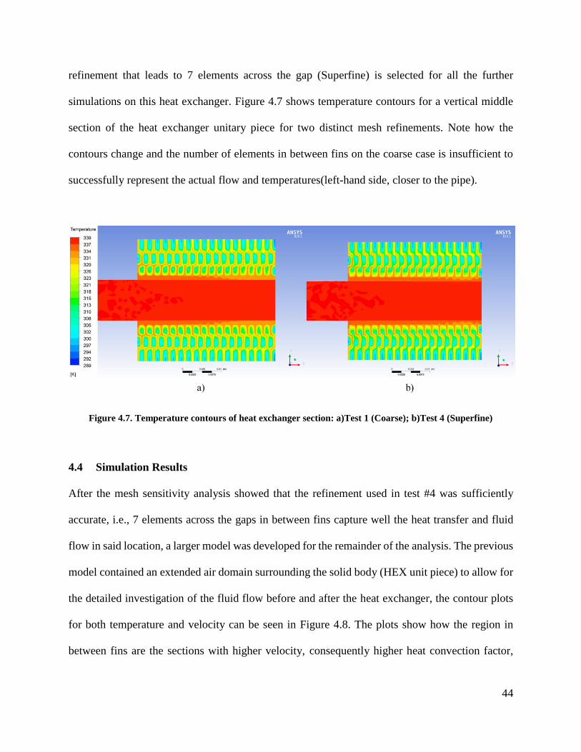
44
refinement that leads to 7 elements across the gap (Superfine) is selected for all the further
simulations on this heat exchanger. Figure 4.7 shows temperature contours for a vertical middle
section of the heat exchanger unitary piece for two distinct mesh refinements. Note how the
contours change and the number of elements in between fins on the coarse case is insufficient to
successfully represent the actual flow and temperatures(left-hand side, closer to the pipe).
Figure 4.7. Temperature contours of heat exchanger section: a)Test 1 (Coarse); b)Test 4 (Superfine)
4.4 Simulation Results
After the mesh sensitivity analysis showed that the refinement used in test #4 was sufficiently
accurate, i.e., 7 elements across the gaps in between fins capture well the heat transfer and fluid
flow in said location, a larger model was developed for the remainder of the analysis. The previous
model contained an extended air domain surrounding the solid body (HEX unit piece) to allow for
the detailed investigation of the fluid flow before and after the heat exchanger, the contour plots
for both temperature and velocity can be seen in Figure 4.8. The plots show how the region in
between fins are the sections with higher velocity, consequently higher heat convection factor,

45
higher heat transfer rate and temperature gradients. Thus, confirming the previous expectations
regarding the model and its region of interest.
Figure 4.8. Contours of the unitary section with extended air domain: a)Temperature; b)Velocity

46
With the mesh sensitivity evaluated, a larger model was sought, one that could comprise the
performance of the whole heat exchanger. However, with the mesh refinement deemed necessary,
a model of the complete heat exchanger became unviable with the existing computational
resources available, since it was estimated that the model would have more than 100 million
elements. Then, a method was developed for the evaluation in which one row (or pass) of the heat
exchanger was modelled. This allows for each pass to be simulated almost independently and
successively, similar to methods previously used in literature for this kind of heat exchanger
[64,66]. In this analysis the outlet temperature of each row was used as the inlet temperature of the
following one, assuming no heat is lost in the inter-row connections. The new model is shown in
Figure 4.9. A pipe can be seen protruding from the main geometry, such protrusion (considered
insulated) seeks to allow the in-pipe flow to fully develop before it reaches the heat exchanger.
Figure 4.9. Full row model developed for further simulations: a)Perspective; b)Area between fins in detail
It is important to mention that the process of manually conducting eight simulations to account for
the whole heat exchanger would be extremely laborious and time consuming preventing the
development of a considerable number of simulations for different cases. To mitigate that, the
author developed a code using both script commands (used in a journal file read by Fluent that
a) b)

47
inputs series of instructions automatically) and the more advanced scheme commands (derived
from the original programming language used in Fluent). This code was implemented for all full
HEX simulations which were run in Béluga, the High Power Computing cluster available to this
group. Such code would implement the correct boundary conditions, read fluid outlet temperature
after the simulation was finished, input it as the fluid inlet temperature, run the simulation once
again, and repeat this process 6 more times leading to a less laborious and less time consuming
process (that would still take about 12 hours to end). Without this code it would have been
impossible in practical terms to successfully perform most of the simulations that are here reported.
Table 4.3. Material properties and boundary conditions of initial tests with a full row using water
Gas Liquid Solid
Material Air Water Aluminum
ρ (kg/m³) 1.225 998.2 2719
cp (J/kg-°C) 1006.43 4182 871
k (W/m-°C) 0.0242 0.6 202.4
Inlet velocity (m/s) 1.11 0.166 -
Inlet mass flow rate (kg/s) 0.119 0.0126
Inlet temperature (°C) 15.3 81.5 -
Outlet Pressure-outlet Pressure-outlet -
Top/Bottom Wall boundaries Symmetric - Symmetric
Lateral wall boundaries - - Adiabatic
Following such methodology, all eight passes are individually simulated, one after the other. The
input data and boundary conditions were slightly modified to match results of previous
experimental results of the EHRU and are listed in Table 4.3. Hence, the performance of the whole
heat exchanger was evaluated. Figure 4.10 shows an assembly of the temperature contours of each

48
row representing what would be the contours of the full heat exchanger. It is possible to see the
gradual temperature drop of the liquid over the consecutive passes. It can also be seen that the air
temperature change decreases from the first row to the eighth one, consequence of a lower
temperature difference between the fluids. It is important to mention that even using the maximum
amount of computational resources available on the high power computing clusters of Béluga,
each simulation of a specific pass would take about 1.5 hours to complete, leading to a total time
of about 12 hours for the full heat exchanger.
Figure 4.10. Temperature contours of the whole heat exchanger, assembly of the contours of each individual
pass.
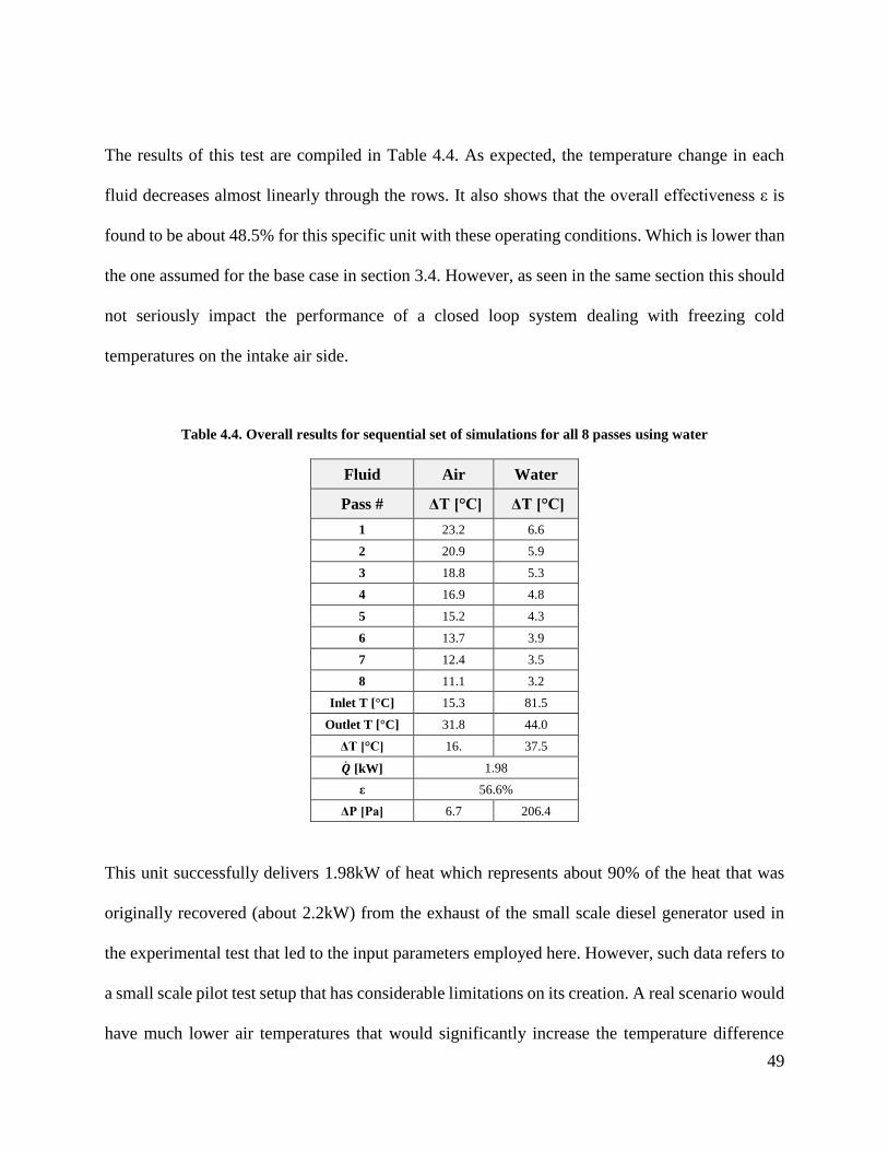
49
The results of this test are compiled in Table 4.4. As expected, the temperature change in each
fluid decreases almost linearly through the rows. It also shows that the overall effectiveness ε is
found to be about 48.5% for this specific unit with these operating conditions. Which is lower than
the one assumed for the base case in section 3.4. However, as seen in the same section this should
not seriously impact the performance of a closed loop system dealing with freezing cold
temperatures on the intake air side.
Table 4.4. Overall results for sequential set of simulations for all 8 passes using water
Fluid Air Water
Pass # ΔT [°C] ΔT [°C]
1 23.2 6.6
2 20.9 5.9
3 18.8 5.3
4 16.9 4.8
5 15.2 4.3
6 13.7 3.9
7 12.4 3.5
8 11.1 3.2
Inlet T [°C] 15.3 81.5
Outlet T [°C] 31.8 44.0
ΔT [°C] 16. 37.5
�̇� [kW] 1.98
ε 56.6%
ΔP [Pa] 6.7 206.4
This unit successfully delivers 1.98kW of heat which represents about 90% of the heat that was
originally recovered (about 2.2kW) from the exhaust of the small scale diesel generator used in
the experimental test that led to the input parameters employed here. However, such data refers to
a small scale pilot test setup that has considerable limitations on its creation. A real scenario would
have much lower air temperatures that would significantly increase the temperature difference
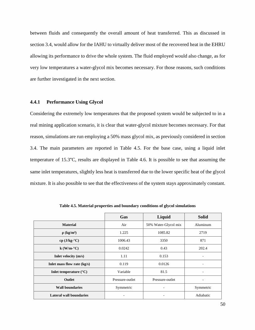
50
between fluids and consequently the overall amount of heat transferred. This as discussed in
section 3.4, would allow for the IAHU to virtually deliver most of the recovered heat in the EHRU
allowing its performance to drive the whole system. The fluid employed would also change, as for
very low temperatures a water-glycol mix becomes necessary. For those reasons, such conditions
are further investigated in the next section.
4.4.1 Performance Using Glycol
Considering the extremely low temperatures that the proposed system would be subjected to in a
real mining application scenario, it is clear that water-glycol mixture becomes necessary. For that
reason, simulations are run employing a 50% mass glycol mix, as previously considered in section
3.4. The main parameters are reported in Table 4.5. For the base case, using a liquid inlet
temperature of 15.3°C, results are displayed in Table 4.6. It is possible to see that assuming the
same inlet temperatures, slightly less heat is transferred due to the lower specific heat of the glycol
mixture. It is also possible to see that the effectiveness of the system stays approximately constant.
Table 4.5. Material properties and boundary conditions of glycol simulations
Gas Liquid Solid
Material Air 50% Water-Glycol mix Aluminum
ρ (kg/m³) 1.225 1085.82 2719
cp (J/kg-°C) 1006.43 3350 871
k (W/m-°C) 0.0242 0.43 202.4
Inlet velocity (m/s) 1.11 0.153 -
Inlet mass flow rate (kg/s) 0.119 0.0126 -
Inlet temperature (°C) Variable 81.5 -
Outlet Pressure-outlet Pressure-outlet -
Wall boundaries Symmetric - Symmetric
Lateral wall boundaries - - Adiabatic
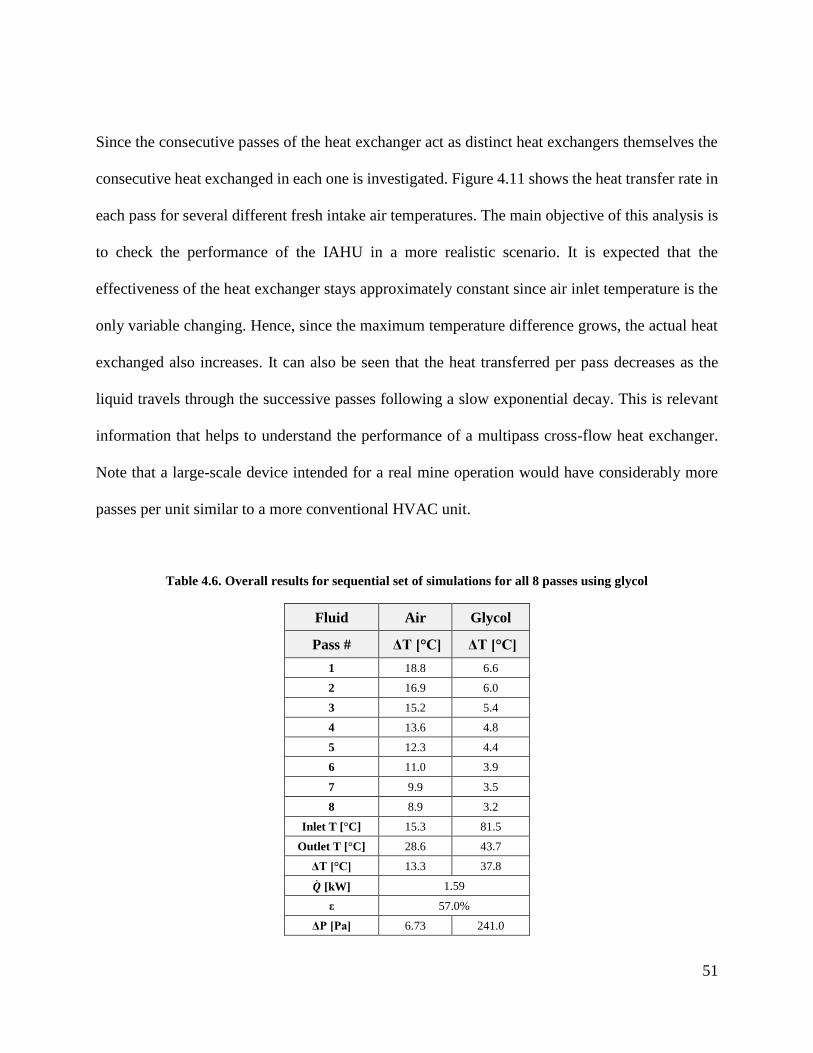
51
Since the consecutive passes of the heat exchanger act as distinct heat exchangers themselves the
consecutive heat exchanged in each one is investigated. Figure 4.11 shows the heat transfer rate in
each pass for several different fresh intake air temperatures. The main objective of this analysis is
to check the performance of the IAHU in a more realistic scenario. It is expected that the
effectiveness of the heat exchanger stays approximately constant since air inlet temperature is the
only variable changing. Hence, since the maximum temperature difference grows, the actual heat
exchanged also increases. It can also be seen that the heat transferred per pass decreases as the
liquid travels through the successive passes following a slow exponential decay. This is relevant
information that helps to understand the performance of a multipass cross-flow heat exchanger.
Note that a large-scale device intended for a real mine operation would have considerably more
passes per unit similar to a more conventional HVAC unit.
Table 4.6. Overall results for sequential set of simulations for all 8 passes using glycol
Fluid Air Glycol
Pass # ΔT [°C] ΔT [°C]
1 18.8 6.6
2 16.9 6.0
3 15.2 5.4
4 13.6 4.8
5 12.3 4.4
6 11.0 3.9
7 9.9 3.5
8 8.9 3.2
Inlet T [°C] 15.3 81.5
Outlet T [°C] 28.6 43.7
ΔT [°C] 13.3 37.8
�̇� [kW] 1.59
ε 57.0%
ΔP [Pa] 6.73 241.0

52
Figure 4.11. Heat exchanged per pass for several fresh intake air temperatures
The total heat transfer rate as well as the overall temperature change in the fresh intake air side are
represented in Figure 4.12. It can be seen that overall heat transfer rate and consequently
temperature change increases linearly (note the two lines with different inclinations), achieving in
the extreme scenarios a heat transfer rate of about 2.5kW which is higher than the rate of heat
recovered from exhaust. This helps to demonstrate that a large scale waste heat recovery system
operating in a remote Arctic mine would be able to take advantage of the very low temperatures
of the fresh intake air flow and deliver almost all the heat that is recovered. When operating in a
closed-loop the steady-state heat transfer settles for an approximately equal amount in both sides
(except for eventual heat losses). This value would certainly be a number between the observed
rates for the open-loop results.

53
Figure 4.12. Total heat transfer rate and air temperature change for several different fresh intake air
temperatures
Since the experimental pilot-scale tests performed for this work were all based on water as the
operating liquid, it would be interesting to see how the glycol mix would perform compared to the
water based system. Hence, the data in Table 4.7 is taken from real pilot-scale tests for a more
realistic comparison between water and glycol, considering real temperatures from the generator
and the exhaust heat recovery system. Figure 4.13 shows the heat exchanged per pass for each of
the successive passes for both glycol and water using temperatures representing different loads of
the diesel generator. It is possible to see that although both liquids have a subtle exponential decay,
not only glycol constantly gives less heat than water if it is at the same temperature (due to its
lower specific heat) but the rate of heat transfer decays faster than that for pure water. It is also
noticeable that the differences between cases (both distinct fluids and loads) decrease tending to
converge to a minimum heat transfer happening between the much lower temperature gradients.
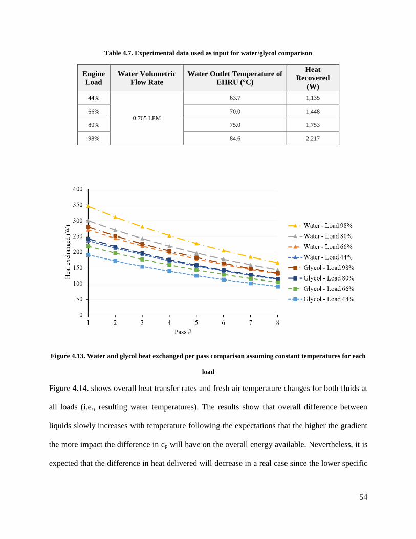
54
Table 4.7. Experimental data used as input for water/glycol comparison
Engine
Load
Water Volumetric
Flow Rate
Water Outlet Temperature of
EHRU (°C)
Heat
Recovered
(W)
44%
0.765 LPM
63.7 1,135
66% 70.0 1,448
80% 75.0 1,753
98% 84.6 2,217
Figure 4.13. Water and glycol heat exchanged per pass comparison assuming constant temperatures for each
load
Figure 4.14. shows overall heat transfer rates and fresh air temperature changes for both fluids at
all loads (i.e., resulting water temperatures). The results show that overall difference between
liquids slowly increases with temperature following the expectations that the higher the gradient
the more impact the difference in cp will have on the overall energy available. Nevertheless, it is
expected that the difference in heat delivered will decrease in a real case since the lower specific

55
heat of the glycol mixture would lead to a higher outlet temperature from the EHRU assuming the
heat recovered stays approximately constant.
Figure 4.14. Water and glycol total heat transfer rate and air temperature change comparison
Finally, all these results show that not only the system proposed here works well in delivering
heat from exhaust to cold air, but several conditions in a real case scenario would actually boost
its performance and make even more beneficial to a mine in need of intake air heating.

56
Chapter 5: Experimental Pilot-Test Setup
To prove that a real-life exhaust heat recovery system would be able to recover significant portion
of the energy available in a diesel generator and deliver it to a fresh airflow for mining applications,
an experimental setup was designed, built and tested. This chapter seeks to demonstrate the
construction of the designed system and report the results of the tests performed in it, as well as
the comparison of such results with the numerical model of the IAHU previously presented.
5.1 Description of Experimental Setup
The pilot-scale test part of this study has the main goal of testing the closest possible to a real case
application of the system, using energy recovered from a real diesel generator to heat a flow of
cold fresh air. This was done employing the experimental scale version of the EHRU, co-designed
by the author for previous studies of this group [27] and shown in Figure 5.1. The shell-and-tube
heat exchanger used can be seen in detail in the top right corner. A list with the main pieces of
equipment used in such system is reported in Appendix B .
Figure 5.1. First part of the experimental setup used in previous studies (Exhaust heat recovery system), heat
exchanger in detail

57
This system recovers heat from the exhaust stream of a diesel generator and transfers it to a flow
of water. Hence, the air heating portion of the project was designed having in mind to pump the
water to another module where the heat would be transferred from the water into a cold air flow.
It is important to mention that all parts of this exhaust heat recovery system were designed and
constructed as a composition of mobile units that can be wheeled around and tested anywhere.
This was necessary since there was no permission for the diesel generator to be run inside of the
CMP building which led to significant additional challenges when designing and building the
system. Thus, to achieve the desired goal a pilot-scale cold air heating unit was conceived
consisting mainly of a small portable air conditioning unit and a radiator-like cross-flow heat
exchanger, a draft of the arrangement is shown in Figure 5.2. This drawing was done in SolidWorks
2017 as the other designs shown in section 4.1, and was sent to a sheet metal company for the
fabrication of the ductwork. The cross-flow heat exchanger can be seen midway through the duct.
Figure 5.2. Preliminary draft of the pilot scale intake air heating unit
After the duct was fabricated and delivered (the part can be seen in Figure 5.3) the assembly
process was initiated coupling all the other components of the system. A list with the main

58
components of the intake air heating part of the system is reported in Appendix B . To provide the
cold air that would be heated, for cost, space and practicality limitations, a generic mobile air
conditioning unit was chosen, which can provide air as cold as approximately 15°C. Such
temperature is warmer than the one to be found in arctic mines in need of intake air heating, but
this is deemed sufficient to demonstrate a significant temperature change in the cold airflow. From
previous work done in section 4.4.1 it is also demonstrated that the real lower air temperatures
would only help the performance of the IAHU.
Figure 5.3. Ductwork with insulated interior fabricated in sheet metal as per author’s design
The unit was constructed to be mobile as the rest of the experimental setup. Several sensors were
attached to the inside of the duct outlet to measure the different temperatures obtained across the
duct cross sectional area as expected according to simulation results. Since it would be unfeasible
to measure the individual outlet temperature of each pass diverse points (nine points with one
temperature sensor each) were selected for measurements that would later be averaged. The fully
assembled system is shown in Figure 5.4. Note that the inside of the ductwork was insulated for a

59
better performance of the system, as well as the connections for water. The author actually intended
the insulation to be outside of the duct, the insulation being inside blocks a small part of the heat
exchanger interfering with heat transfer. Besides, even with the existing insulation, as will be
reported in the following sections, there were still considerable sources of heat loss on the system
which significantly lowered its performance. Several environmental factors were also noticed to
impact measurements and performance itself e.g., the sun shining directly into the metal parts of
the system and wind blowing into warm surfaces.
Figure 5.4. Pilot-scale test setup of the intake air heating unit constructed for the study
With the last part of the system constructed and insulated by the author to the best possible, the
whole system could be connected together and tested. A depiction of both units interconnected is
shown in Figure 5.5. During this study the steady-state performance of the system is focused. In
the tests performed here it would take about 10-15 minutes for the system to reach a steady-state
depending on the weather conditions and parameters inputs.
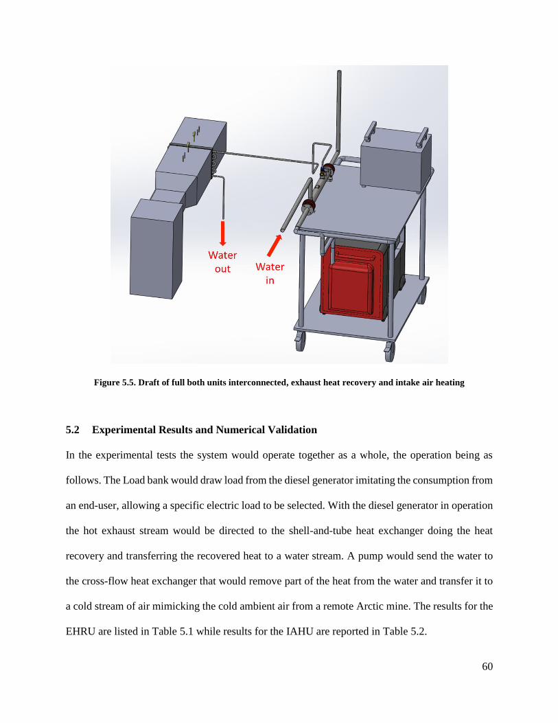
60
Figure 5.5. Draft of full both units interconnected, exhaust heat recovery and intake air heating
5.2 Experimental Results and Numerical Validation
In the experimental tests the system would operate together as a whole, the operation being as
follows. The Load bank would draw load from the diesel generator imitating the consumption from
an end-user, allowing a specific electric load to be selected. With the diesel generator in operation
the hot exhaust stream would be directed to the shell-and-tube heat exchanger doing the heat
recovery and transferring the recovered heat to a water stream. A pump would send the water to
the cross-flow heat exchanger that would remove part of the heat from the water and transfer it to
a cold stream of air mimicking the cold ambient air from a remote Arctic mine. The results for the
EHRU are listed in Table 5.1 while results for the IAHU are reported in Table 5.2.

61
Table 5.1. Experimental results from exhaust heat recovery unit on full system run
Engine
Load
Water
Flow
EHRU
Exhaust
Inlet
(°C)
Exhaust
Outlet
(°C)
Water
Inlet
(°C)
Water
Outlet
(°C)
Heat
Recovered
(kW)
ε
Heat
rec./Heat
avail.
22%
0.765
LPM
168.10 75.70 40.9 58.4 0.92 72.6% 83%
44% 197.90 84.60 42.2 63.7 1.14 72.8% 52%
66% 239.00 97.40 42.5 70 1.45 72.1% 44%
80% 284.70 115.70 41.7 75 1.75 69.6% 44%
98% 366.60 151.80 42.5 84.6 2.22 66.3% 45%
Table 5.2. Experimental results from intake air heating unit on full system run
Engine
Load Airflow
IAHU
Water
Inlet
(°C)
Water
Outlet
(°C)
Air
Inlet
(°C)
Air
Outlet
(°C)
Heat
Delivered
(kW)
ε
Heat
del./Heat
rec.
Heat
del./Heat
avail.
22%
205CFM
(0.0968
m³/s)
55.80 36.60 12.6 20.93 1.00 48.3% 109% 91%
44% 60.60 39.90 13.7 22.82 1.09 47.2% 97% 50%
66% 67.20 43.50 12.9 23.75 1.25 47.2% 90% 40%
80% 72.70 46.10 13.8 25.63 1.40 47.2% 81% 36%
98% 81.50 51.30 15.3 27.71 1.59 47.0% 67% 30%
It is possible to see that the effectiveness of both devices stays approximately constant, with the
EHRU experiencing a slightly higher change due to the much larger change in operating conditions
(i.e., exhaust inlet temperature and consequently maximum temperature differential) when varying
generator loads. Also note that the EHRU is capable of recovering roughly around 54% of the
energy available on the exhaust (estimated based on literature [3]). Moreover, the IAHU is able to
deliver about 89% of the energy that has already been recovered, or 49% of the available energy

62
on the exhaust of the diesel generator, with the lowest value being around 30% for higher loads
(when the maximum energy is available). In that case, the energy delivered to the cold fresh air is
found to be 1.6kW, which is considerably lower than the amount previously shown in section 4.4,
the reason for this will be later addressed by the author. It is a fact that every heat exchanger has
specific operating ranges in which they are designed to operate better. In a real world scenario, the
heat exchangers would be selected to be operating in maximum performance for the average load
consumption (40-70%) of each one allowing it to perform somewhat better than the one used here.
Figure 5.6. Heat recovered (on the exhaust heat recovery unit) and heat delivered (on the intake air heating
unit) for full cycle run
A chart is displayed in Figure 5.6 showing the heat successfully recovered from the exhaust in the
first heat exchanger (EHRU) and then the heat successfully delivered to the cold air in the second
heat exchanger (IAHU). Note that in that the discrepancy gets higher as the load increases, due to
the higher temperatures in the system leading to points of higher energy loss and disturbance by

63
the ambient conditions. Besides, there were several limitations on the performance of the IAHU
due to its construction which will be later discussed. It is possible to see that in the lowest load
more heat is delivered than it is recovered, this happens due to the open-cycle nature of the test
and shows that there is potential for all (or close) of the recovered heat to be delivered depending
on the operating parameters of the system, as previously reported in sections 3.4 and 4.4.
Figure 5.7. Airduct outlet with temperature sensors and cross-flow heat exchanger in evidence
Finally, to validate the results obtained in section 4.4 and the model employed to achieve them,
the numerical model is used to simulate the exact cases run using the experimental setup. However,
when running these cases, the author noticed a flaw in the construction of the duct that significantly
impacts the performance of the unit. Due to the way the cross-flow heat exchanger is mounted into
the frame that goes in the duct, a portion of said unit is blocked (around all four of the edges, but
mostly on the top and the bottom) preventing air to flow there (see Figure 5.7). Thus, with these
conditions taken into account, the model was adapted and utilized for the following simulations.

64
Results of this analysis are shown in Figure 5.8. The difference between model and real operation
is about 5-8% for all parameters and is mainly due to energy losses to the ambient air, heat
introduction by sunlight, and human error on measurements.
Figure 5.8. Results for intake air heating unit with full system operational

65
Another series of tests was performed to see the influence of the flow rate of working fluid in the
system. For that the water flow rate was varied and the measurements recorded. The results for
such tests are reported in
Table 5.3 for the EHRU and in Table 5.4 for the IAHU. As can be seen, the flow rate does not
have a big impact the performance of the systems, with only a minor change in heat transfer rate
happening that is a direct consequence of the change in fluid velocity inside the pipes of the heat
exchangers (mainly in the IAHU). It can be noted however that the effectiveness of the devices
drops slightly (again, mainly for the IAHU). This shows that the operating range of fluid velocity
that the cross-flow heat exchanger was designed for is more limited than the other device. That is
totally comprehensible as the cross-flow HEX used here is not specifically designed for this mean
and is a radiator used for engine coolant that is supposed to operate with low flows and velocities
of the liquid inside the pipes. Thus, in a real case scenario the flow of liquid should be chosen to
keep velocity in the most efficient range of operation for which the units were designed, while
keeping temperature change of fluid in a reasonable level to improve heat transfer and minimize
losses. For this system specifically it is clear that the units perform slightly better with a low flow
rate (below one liter per minute).
Table 5.3. Experimental results from exhaust heat recovery unit on full system run with variable water flow
Engine
Load
Water
Flow
(LPM)
EHRU
Exhaust
Inlet
(°C)
Exhaust
Outlet
(°C)
Water
Inlet
(°C)
Water
Outlet
(°C)
Heat
Recovered
(kW)
ε
Heat
rec./Heat
avail.
82%
0.89 299.30 153.10 40.4 65.1 1.51 56.5% 37%
1.019 296.60 154.10 40.3 62.2 1.53 55.6% 37%
1.105 297.10 155.90 40.5 60.9 1.55 55.0% 38%
1.216 298.70 157.70 41.2 59.8 1.56 54.8% 38%

66
Table 5.4. Experimental results from intake air heating unit on full system run with variable water flow
Water
Flow
(LPM)
Airflow
IAHU
Water
Inlet
(°C)
Water
Outlet
(°C)
Air
Inlet
(°C)
Air
Outlet
(°C)
Heat
Delivered
(kW)
ε
Heat
del./Heat
rec.
Heat
del./Heat
avail.
0.89
205CFM
(0.0968
m³/s)
61.90 43.10 15.4 25.39 1.17 40.43% 77% 29%
1.019 59.30 42.90 15.4 25.16 1.14 37.36% 75% 28%
1.105 57.90 42.90 15.4 24.94 1.12 35.29% 72% 27%
1.216 56.90 43.20 15.8 25.17 1.10 33.33% 71% 27%
Figure 5.9 shows the energy recovered and delivered during this series of tests involving variable
water flows. Note that the overall energy is almost constant, with a small increase of the heat
recovered (higher velocity of the fluid inside the pipes of the shell-and-tube HEX improves heat
transfer) but a minor decrease in the heat delivered (as the liquid temperature is not so high
anymore and the temperature differential drops). For a closed-loop, the heat transfer rates can be
expected to lay in between the two lines in the chart.
Figure 5.9. Heat recovered (on the exhaust heat recovery unit) and heat delivered (on the intake air heating
unit) for full cycle run with variable water flow and constant load
0
500
1,000
1,500
2,000
2,500
0.85 0.9 0.95 1 1.05 1.1 1.15 1.2 1.25
Q(W
)
Water flow (LPM)
Heat recovered (EHRU) Heat delivered (IAHU)

67
It is important to notice that the system holds the potential for a considerably more efficient
operation if the construction flaw did not exist. Another limitation for the operation of the unit is
the fact that the cross-flow heat exchanger used here, although selected based on its capacity, was
not manufactured specifically for this mean (different from the shell-and-tube working as EHRU)
and is actually designed to cool down engine coolant for internal combustion engines. It is safe to
say that for a real industrial-scale system, an IAHU categorically and correctly designed for its
purpose would perform better and have significant higher effectiveness for its operating conditions
(mainly due to very cold air temperatures), allowing for virtually most of heat recovered to be
delivered to the cold intake air. Also, it is important to remember that besides successfully
recovering a significant part of the heat available and delivering it, the system is also cost-effective,
which has been demonstrated in a previous study developed by the author [3].

68
Chapter 6: Conclusions and Recommendations
Remote mines located in cold areas of Canada and other countries close to the Arctic pole are
exposed to extremely low temperatures and because of that they have a great cost with intake air
heating to bring the subfreezing air to a comfortable temperature for machinery and human
workers. At the same time, remote mines not connected to the power grid rely on diesel generators
for power, which have been demonstrated to constantly discard a lot of energy in the form of heat
through various means, mainly the exhaust stream. The system proposed here holds the potential
to mitigate a good extent of the aforementioned cost with a green solution that also will decrease
their greenhouse gas emissions, using part of the energy that is being neglected.
After doing an extensive literature research, it was found that exhaust heat recovery, and waste
heat recovery systems in general are usually developed aiming to generate electricity, with only a
few studies focusing on the use of the energy in the form of heat as it is. Using the heat directly
however, is a strategy that avoids the significant energy losses consequent of conversion that
usually undermines the financial viability of common waste heat recovery systems. Also, the use
of waste heat recovery in mining applications as reported in literature, is very limited to a few
specific applications, and except for other works developed by this group no other work has been
done in exhaust heat recovery for mine heating applications, i.e., to heat underground mine intake
air.
Based on that potential, an uncomplicated system was conceived that could recover heat from the
exhaust stream of a diesel generator, transport it through a distance and deliver it to a cold intake

69
airflow of a mine. The system, consisting mainly of two interconnected heat exchangers of
different types, each selected by its individual properties, was then modeled by several different
methodologies, all seeking to demonstrate its viability for the situation that led to its creation.
Then, an analytical model was created on MATLAB to evaluate the overall performance of the
system in a series of situations using real climate history data and other parameters from a remote
Arctic mine located in Northwest Territories, Canada. The coupled model developed was an
enhancement of a previous one co-developed by the author for a pervious study that had some
limitations in its methods and did not consider the coupled nature of the system (these were pointed
by peer-reviewers) and that the author wanted to investigate further in detail. It turns out that the
model results showed that previous values reported were good estimations of the operation of the
system since: the heat loss through the pipes for a system this size, as long as adequate off-the-
shelf insulation is implemented, does not have a great effect in in its performance. Also, it was
shown that since there is so much energy available in the exhaust stream (at a high grade) and the
intake air temperature is so low, there is potential to deliver most of the heat that is recovered, with
the exhaust heat recovery unit driving the overall performance of the coupled system. Then, it was
shown that there during several periods during a year a considerable amount of energy is still
neglected after supplying the existing demand, which creates the opportunity for even larger
savings if some sort of energy storage method is implemented.
Next, a numerical model of the cross-flow heat exchanger selected to be utilized in the pilot-test
scale version of the system was created to evaluate its performance in detail, investigate its
operation under more realistic conditions and corroborate the experimental tests to be later

70
performed. After a considerable effort to successfully model the unit using computational fluid
dynamics that involved coding, extensive and time consuming simulations and parametric
investigation, it was found that the unit would effectively transfer the heat to a fresh cold airflow
as intended being able to deliver most of the heat that had been recovered. Actually, it is shown
that for more realistic conditions (with much colder air) there is potential to deliver all of the heat
that is recovered, which would be limited only by heat losses in a real case closed-loop system.
Finally, the pilot-test scale version of the system was fully designed and built all using mobile
equipment, which represented a huge additional challenge not only for equipment selection but
also to perform the tests having the minimal possible environmental interference in the
experiments. Although some assembly limitations and construction faults decreased the
performance of the intake air heating unit, the system still worked effectively delivering most of
the heat that was recovered (67-100%) and about 30-91% of the heat that was available in the
exhaust of the small-scale diesel generator. It was also demonstrated that when taking into account
the construction liabilities, the numerical model would successfully represent the unit utilized,
having their results validated against each other.
6.1 Perspectives for the mining engineering industry
From this study it becomes clear that an exhaust waste heat recovery system of this sort would be
significantly beneficial to a remote underground mine in need of intake air heating. Following
some other studies from the author on the financial viability of a similar system (which has been
already proved [3]), this work seeks to further validate those results, showing in detail the operation
71
of the alternative intake air heating system and show that it has the potential to create significant
savings in all mines where opportunity exists. It is imperative that companies at least investigate
the possibility of implementing a system like this when opening a new mine in a remote location
of Canada, or other Arctic countries.
Also, as previously mentioned in this work. There are several other works in literature developed
by this group on waste heat recovery use and alternative energy solutions for mines in Canada.
Some of the research developed here, mainly the analytical model, could (and will be) be coupled
with similar models developed for other systems to evaluate the overall performance of a greater
thermal energy management system to be implemented in Canadian mines. The idea would be to
have one interconnected system that goes through the whole mine recovering waste heat wherever
it is available and delivering it wherever it is necessary.
6.2 Recommendations for further studies
After developing this research a few points are raised regarding possible benefit from further
investigation into some aspects of it. It would certainly be useful to investigate the performance of
an industrial-scale larger version of the system demonstrated here to be implemented in a real mine
scenario, using better thermal technology and not having the budget, construction and practicality
limitations involved here. Besides, the analytical model used here should be extended to take into
account other sources of heat, as well as different end-users in a mine and evaluate what
performance a larger system as such would have.

72
References
[1] The Mining Association of Canada, Facts & Figures 2018: Facts and Figures of the
Canadian Mining Industry, 2019. https://mining.ca/wp-content/uploads/2019/03/Facts-and-
Figures-English-Web_0.pdf.
[2] H.L. Hartman, J.M. Mutmansky, R. V Ramani, Y.J. Wang, Mine ventilation and air
conditioning, Wiley, 1997.
[3] D. Baidya, M.A.R. de Brito, A.P. Sasmito, M. Scoble, S.A. Ghoreishi-Madiseh, Recovering
waste heat from diesel generator exhaust; an opportunity for combined heat and power
generation in remote Canadian mines, J. Clean. Prod. 225 (2019) 785–805.
doi:10.1016/j.jclepro.2019.03.340.
[4] M.J. McPherson, Subsurface Ventilation and Environmental Engineering, Springer Science
& Business Media, Dordrecht, 1993. doi:10.1007/978-94-011-1550-6.
[5] M. Levesque, D. Millar, J. Paraszczak, Energy and mining-The home truths, J. Clean. Prod.
84 (2014) 233–255. doi:10.1016/j.jclepro.2013.12.088.
[6] S.A. Ghoreishi-madiseh, A.P. Sasmito, F.P. Hassani, L. Amiri, Performance evaluation of
large scale rock-pit seasonal thermal energy storage for application in underground mine
ventilation, Appl. Energy. 185 (2017) 1940–1947. doi:10.1016/j.apenergy.2016.01.062.
[7] A.E. Hall, D.M. Mchaina, S. Hardcastle, Controlled recirculation in Canadian underground
potash mines, Min. Sci. Technol. 10 (1990) 305–314.
[8] A.M. Wilson, E. De Souza, Arctic mine air heating, Airfinders Inc. (2015) 8.
http://www.airfinders.ca/wp-content/uploads/2015/06/Arctic-mine-air-heating.pdf.
[9] J. Royer, Status of remote/off-grid communities in Canada, Natural Resources Canada,
Ottawa, 2013. https://www.nrcan.gc.ca/energy/publications/sciences-

73
technology/renewable/smart-grid/11916.
[10] Dominion Diamond Mines, Aerial view of the Ekati Diamond Mine, (2017).
https://www.ddmines.com/portfolio-item/aerial-view-of-the-ekati-diamond-mine/%0A
(accessed June 10, 2019).
[11] The deepest mines in the world, Ekati diamond mine, (1999).
https://sites.google.com/site/thedeepestminesoftheworld/canada/ekati-diamond-mine
(accessed June 10, 2019).
[12] E.D. Coyle, R.A. Simmons, Understanding the global energy crisis, Purdue University
Press, 2014.
[13] S.A. Ghoreishi-Madiseh, A.F. Kuyuk, M.A. Rodrigues de Brito, An analytical model for
transient heat transfer in ground-coupled heat exchangers of closed-loop geothermal
systems, Appl. Therm. Eng. 150 (2019) 696–705.
doi:10.1016/j.applthermaleng.2019.01.020.
[14] B. Bharathan, A.P. Sasmito, S.A. Ghoreishi-Madiseh, Analysis of energy consumption and
carbon footprint from underground haulage with different power sources in typical
Canadian mines, J. Clean. Prod. 166 (2017) 21–31. doi:10.1016/J.JCLEPRO.2017.07.233.
[15] M. Hatami, D.D. Ganji, M. Gorji-Bandpy, A review of different heat exchangers designs
for increasing the diesel exhaust waste heat recovery, Renew. Sustain. Energy Rev. 37
(2014) 168–181. doi:10.1016/j.rser.2014.05.004.
[16] S. Mavridou, G.C. Mavropoulos, D. Bouris, D.T. Hountalas, G. Bergeles, Comparative
design study of a diesel exhaust gas heat exchanger for truck applications with conventional
and state of the art heat transfer enhancements, Appl. Therm. Eng. 30 (2010) 935–947.
doi:10.1016/j.applthermaleng.2010.01.003.

74
[17] S.A. Ghoreishi-Madiseh, A. Fahrettin Kuyuk, A.M. Rodrigues de Brito, D. Baidya, Z.
Torabigoodarzi, A. Safari, S.A. Ghoreishi-Madiseh, A.F. Kuyuk, M.A.R. Brito, D. Baidya,
Z. Torabigoodarzi, A. Safari, Application of Borehole Thermal Energy Storage in Waste
Heat Recovery from Diesel Generators in Remote Cold Climate Locations, Energies. 12
(2019) 13. doi:10.3390/en12040656.
[18] S.A. Ghoreishi-Madiseh, A. Safari, L. Amiri, D. Baidya, M.A.R. Brito, A.F. Kuyuk, A.R.
De Brito, A.F. Kuyuk, I. Norman, J. Fournier, B. Lacarrière, S.A. Ghoreishi-Madiseh, A.
Safari, L. Amiri, D. Baidya, M.A.R. Brito, A.F. Kuyuk, Investigation of viability of seasonal
waste heat storage in rock piles for remote communities in cold climates, Energy Procedia.
159 (2019) 66–71. doi:https://doi.org/10.1016/j.egypro.2018.12.019.
[19] S.N. Hossain, S. Bari, Additional Power Generation From Waste Energy of Diesel Engine
Using Parallel Flow Shell and Tube Heat Exchanger, J. Eng. Gas Turbines Power. 136
(2013) 011401. doi:10.1115/1.4025345.
[20] T. Wang, Y. Zhang, Z. Peng, G. Shu, A review of researches on thermal exhaust heat
recovery with Rankine cycle, Renew. Sustain. Energy Rev. 15 (2011) 2862–2871.
doi:10.1016/j.rser.2011.03.015.
[21] J. Paraszczak, K. Fytas, Renewable energy sources–a promising opportunity for remote
mine sites?, in: Proc. Int. Conf. Renew. Energies Power Qual., 2012: pp. 28–30.
doi:10.24084/repqj10.288.
[22] S. Ogriseck, Integration of Kalina cycle in a combined heat and power plant, a case study,
Appl. Therm. Eng. 29 (2009) 2843–2848. doi:10.1016/j.applthermaleng.2009.02.006.
[23] CAT, Electric Power Generation: C175-16, (2019).
https://www.cat.com/en_US/products/new/power-systems/electric-power-

75
generation/diesel-generator-sets/1000028916.html (accessed June 10, 2019).
[24] D. Di Battista, M. Mauriello, R. Cipollone, Waste heat recovery of an ORC-based power
unit in a turbocharged diesel engine propelling a light duty vehicle, Appl. Energy. 152
(2015) 109–120. doi:https://doi.org/10.1016/j.apenergy.2015.04.088.
[25] S.N. Hossain, S. Bari, Waste Heat Recovery From the Exhaust of a Diesel Generator Using
Shell and Tube Heat Exchanger, Proc. ASME 2013 Int. Mech. Eng. Congr. Expo. (2013)
1–8.
[26] S.N. Hossain, S. Bari, Waste heat recovery from the exhaust of a diesel generator using
Rankine Cycle, Energy Convers. Manag. 75 (2013) 141–151.
doi:10.1016/j.enconman.2013.06.009.
[27] D. Baidya, Diesel exhaust heat recovery: a study on combined heat and power generation
strategy for energy-efficient remote mining in Canada, The University of British Columbia,
2019.
[28] J.B. Heywood, Internal Combustion Engine Fundementals, 1st ed., Mcgraw-Hill, New
York, 1988. doi:10987654.
[29] S. Bari, S.N. Hossain, Waste heat recovery from a diesel engine using shell and tube heat
exchanger, Appl. Therm. Eng. 61 (2013) 355–363.
doi:10.1016/j.applthermaleng.2013.08.020.
[30] P.R. Raghupatruni, Performance Analysis of capture of heat energy from diesel engine
exhaust, (2007).
[31] M.H. Yang, Payback period investigation of the organic Rankine cycle with mixed working
fluids to recover waste heat from the exhaust gas of a large marine diesel engine, Energy
Convers. Manag. 162 (2018) 189–202. doi:10.1016/j.enconman.2018.02.032.

76
[32] M. Jiménez-Arreola, R. Pili, C. Wieland, A. Romagnoli, Analysis and comparison of
dynamic behavior of heat exchangers for direct evaporation in ORC waste heat recovery
applications from fluctuating sources, Appl. Energy. 216 (2018) 724–740.
doi:10.1016/j.apenergy.2018.01.085.
[33] H.G. Zhang, E.H. Wang, B.Y. Fan, Heat transfer analysis of a finned-tube evaporator for
engine exhaust heat recovery, Energy Convers. Manag. 65 (2013) 438–447.
doi:10.1016/j.enconman.2012.09.017.
[34] P. Fernández-Yañez, O. Armas, A. Capetillo, S. Martínez-Martínez, Thermal analysis of a
thermoelectric generator for light-duty diesel engines, Appl. Energy. 226 (2018) 690–702.
doi:https://doi.org/10.1016/j.apenergy.2018.05.114.
[35] Y. Kishita, Y. Ohishi, M. Uwasu, M. Kuroda, H. Takeda, K. Hara, Evaluating the life cycle
CO2 emissions and costs of thermoelectric generators for passenger automobiles: a scenario
analysis, J. Clean. Prod. 126 (2016) 607–619. doi:10.1016/J.JCLEPRO.2016.02.121.
[36] D.T. Hountalas, C. Katsanos, V.T. Lamaris, Recovering energy from the diesel engine
exhaust using mechanical and electrical turbocompounding, SAE Tech. Pap. (2007) 776–
790. doi:10.4271/2007-01-1563.
[37] G. Shu, X. Li, H. Tian, X. Liang, H. Wei, X. Wang, Alkanes as working fluids for high-
temperature exhaust heat recovery of diesel engine using organic Rankine cycle, Appl.
Energy. 119 (2014) 204–217. doi:10.1016/j.apenergy.2013.12.056.
[38] Y.Q. Zhang, Y.T. Wu, G.D. Xia, C.F. Ma, W.N. Ji, S.W. Liu, K. Yang, F. Bin Yang,
Development and experimental study on organic Rankine cycle system with single-screw
expander for waste heat recovery from exhaust of diesel engine, Energy. 77 (2014) 499–
508. doi:10.1016/j.energy.2014.09.034.

77
[39] F. Alshammari, A. Pesyridis, A. Karvountzis-Kontakiotis, B. Franchetti, Y. Pesmazoglou,
Experimental study of a small scale organic Rankine cycle waste heat recovery system for
a heavy duty diesel engine with focus on the radial inflow turbine expander performance,
Appl. Energy. 215 (2018) 543–555. doi:https://doi.org/10.1016/j.apenergy.2018.01.049.
[40] T.Y. Kim, A.A. Negash, G. Cho, Waste heat recovery of a diesel engine using a
thermoelectric generator equipped with customized thermoelectric modules, Energy
Convers. Manag. 124 (2016) 280–286. doi:10.1016/j.enconman.2016.07.013.
[41] P. Fernández-Yáñez, A. Gómez, R. García-Contreras, O. Armas, Evaluating thermoelectric
modules in diesel exhaust systems: potential under urban and extra-urban driving
conditions, J. Clean. Prod. 182 (2018) 1070–1079. doi:10.1016/j.jclepro.2018.02.006.
[42] B. Orr, A. Akbarzadeh, M. Mochizuki, R. Singh, A review of car waste heat recovery
systems utilising thermoelectric generators and heat pipes, Appl. Therm. Eng. 101 (2016)
490–495. doi:10.1016/j.applthermaleng.2015.10.081.
[43] W. Villasmil, L.J. Fischer, J. Worlitschek, A review and evaluation of thermal insulation
materials and methods for thermal energy storage systems, Renew. Sustain. Energy Rev.
103 (2019) 71–84. doi:10.1016/j.rser.2018.12.040.
[44] V. Mokkapati, C.-S. Sen Lin, Numerical study of an exhaust heat recovery system using
corrugated tube heat exchanger with twisted tape inserts, Int. Commun. Heat Mass Transf.
57 (2014) 53–64. doi:10.1016/j.icheatmasstransfer.2014.07.002.
[45] M.J. Alonso, P. Liu, H.M. Mathisen, G. Ge, C. Simonson, Review of heat/energy recovery
exchangers for use in ZEBs in cold climate countries, Build. Environ. 84 (2015) 228–237.
doi:10.1016/j.buildenv.2014.11.014.
[46] H. Kalantari, S.A. Ghoreishi-Madiseh, Study of mine exhaust heat recovery system with
78
coupled heat exchangers, Energy Procedia. 158 (2019) 3976–3981.
doi:10.1016/j.egypro.2019.01.844.
[47] M.A. Rodrigues de Brito, D. Baidya, S.A. Ghoreishi-Madiseh, Investigation of the techno-
economic feasibility of recovering waste heat of diesel generator exhaust for heating mine
intake air, in: 17th Noth Am. Mine Vent. Symp., Montreal, QC, 2019.
[48] J. Wang, J. Wu, Investigation of a mixed effect absorption chiller powered by jacket water
and exhaust gas waste heat of internal combustion engine, Int. J. Refrig. 50 (2015) 193–
206. doi:10.1016/j.ijrefrig.2014.11.001.
[49] G. Shu, Y. Liang, H. Wei, H. Tian, J. Zhao, L. Liu, A review of waste heat recovery on two-
stroke IC engine aboard ships, Renew. Sustain. Energy Rev. 19 (2013) 385–401.
doi:https://doi.org/10.1016/j.rser.2012.11.034.
[50] Y. Cengel, A. Ghajar, Heat and mass transfer: fundamentals and applications, 4th ed.,
McGraw-Hill Higher Education, Ney York, 2014.
[51] R.K. Shah, D.P. Sekulic, Fundamentals of heat exchanger design, 1st ed., John Wiley &
Sons, Hoboken, New Jersey, 2003.
[52] S.A. Ghoreishi-Madiseh, A. Safari, L. Amiri, D. Baidya, M.A.R. Brito, A.F. Kuyuk, A.R.
De Brito, A.F. Kuyuk, I. Norman, J. Fournier, B. Lacarrière, S.A. Ghoreishi-Madiseh, A.
Safari, L. Amiri, D. Baidya, M.A.R. Brito, A.F. Kuyuk, Investigation of viability of seasonal
waste heat storage in rock piles for remote communities in cold climates, Energy Procedia.
159 (2019) 66–71. doi:https://doi.org/10.1016/j.egypro.2018.12.019.
[53] L. Amiri, M.A. Rodrigues de Brito, D. Baidya, A.F. Kuyuk, S.A. Ghoreishi-Madiseh, A.P.
Sasmito, F.P. Hassani, Numerical investigation of rock-pile based waste heat storage for
remote communities in cold climates, Appl. Energy. 252 (2019).

79
[54] F.M. White, Fluid Mechanics, 8th ed., Mcgraw-Hill Education, New York, 2016.
[55] J.D. Anderson, J. Wendt, Computational fluid dynamics, Springer, 1995.
[56] V. Pandiyarajan, M.C. Pandian, E. Malan, R. Velraj, R. V. Seeniraj, M. Chinna Pandian, E.
Malan, R. Velraj, R. V. Seeniraj, Experimental investigation on heat recovery from diesel
engine exhaust using finned shell and tube heat exchanger and thermal storage system,
Appl. Energy. 88 (2011) 77–87. doi:10.1016/j.apenergy.2010.07.023.
[57] M. Hatami, M.D. Boot, D.D. Ganji, M. Gorji-Bandpy, Comparative study of different
exhaust heat exchangers effect on the performance and exergy analysis of a diesel engine,
Appl. Therm. Eng. 90 (2015) 23–37. doi:10.1016/j.applthermaleng.2015.06.084.
[58] H. Dello Sbarba, K. Fytas, J. Paraszczak, Economics of exhaust air heat recovery systems
for mine ventilation, Int. J. Mining, Reclam. Environ. 26 (2012) 185–198.
doi:10.1080/17480930.2012.710085.
[59] L. Amiri, S.A. Ghoreishi-madiseh, A.P. Sasmito, F.P. Hassani, Effect of buoyancy-driven
natural convection in a rock-pit mine air preconditioning system acting as a large-scale
thermal energy storage mass, Appl. Energy. 221 (2018) 268–279.
doi:10.1016/j.apenergy.2018.03.088.
[60] G. Robinson, C. Gherghel, E. De Souza, Positive pressure ventilation system conversion at
Diavik Diamond Mine, (2015) 17. http://www.airfinders.ca/wp-
content/uploads/2014/05/main-ventilation-system-flow-reversal.pdf.
[61] Government of Canada, Historical Climate Data, Environ. Nat. Resour. (2018).
http://climate.weather.gc.ca/historical_data/search_historic_data_e.html (accessed
December 10, 2018).
[62] H. Kalantari, S.A. Ghoreishi-Madiseh, Study of mine exhaust heat recovery system with

80
coupled heat exchangers, Energy Procedia. 158 (2019) 3976–3981.
doi:10.1016/j.egypro.2019.01.844.
[63] M.L. Nayyar, Piping handbook, 7th ed., Mcgraw-Hill, New York, 2000.
[64] H.A. Navarro, L. Cabezas-Gómez, A new approach for thermal performance calculation of
cross-flow heat exchangers, Int. J. Heat Mass Transf. 48 (2005) 3880–3888.
doi:10.1016/j.ijheatmasstransfer.2005.03.027.
[65] Sharcnet, Ansys 17.0 Documentation, (2015). view-
source:https://www.sharcnet.ca/Software/Ansys/17.0/en-us/help/ (accessed July 5, 2019).
[66] Y. Long, S. Wang, J. Wang, T. Zhang, Mathematical Model of Heat Transfer for a Finned
Tube Cross-flow Heat Exchanger with Ice Slurry as Cooling Medium, Procedia Eng. 146
(2016) 513–522. doi:10.1016/j.proeng.2016.06.386.
[67] Ansys Inc, Modeling Turbulent Flows, (2006).
http://www.southampton.ac.uk/~nwb/lectures/GoodPracticeCFD/Articles/Turbulence_Not
es_Fluent-v6.3.06.pdf.
[68] M.S. Mon, U. Gross, Numerical study of fin-spacing effects in annular-finned tube heat
exchangers, Int. J. Heat Mass Transf. 47 (2004) 1953–1964.
doi:10.1016/j.ijheatmasstransfer.2003.09.034.

81
Appendices
Appendix A - Analytical MATLAB code used
clear all
close all
clc
%%------Reading weather data------%
syms x y
[A,B,C]= xlsread('Neo.xlsx','NWT');
T_air_amb = A(:,2);
days = A(:,1);
months = A(:,3);
period = length(days);
sec_period = 24*3600; % Amount of seconds in one unit of period (24*3600 for
day)
%% -------Mine/Power plant parameters------------%
W_mine_avg = 18; % Average power consumption per year from Gen-sets [MW]
% W_gen_max = 2.725; % Maximum generator power capacity [MW]
W_gen_max = 1.750; % Maximum generator power capacity [MW]
L_gen_avg = 0.7; % Generator average load [%]
W_gen_avg = L_gen_avg.*W_gen_max; %Average generator load
N_gen_avg = round(W_mine_avg./W_gen_avg); %Average number of operational
generators
%% --------Ambient air data----------%%
cp_air = 1010; % Isobaric heat capacity of air [J/kg-K]
k_air = 0.0229; % Thermal conductivity of air [W/m-k]
rho_air = 1.39; % Density of air [kg/m³]
mu_air = 16.2*(10^(-6)); % Dynamic viscosity of air [Pa.s]
P_air = 101000;
R_gas_air = 287.03;
syms C_gas_air(x)
V_dot_air = 708; % Volumetric flow rate of air [m³/s]
% M_dot_air = V_dot_air*rho_air; % Mass flow rate of air [kg/s]
% C_air = cp_air*M_dot_air; % Heat capacity rate of air [W/K]
C_gas_air(x) = cp_air*V_dot_air*P_air/(R_gas_air*(273.15+x));
T_set = 4.0;
DeltaT = zeros(period,1);
for i=1:period
DeltaT(i) = T_set - T_air_amb(i);
if DeltaT(i)<0
DeltaT(i)=0;
end
end
%------------Plot DeltaT--------%
% plot(days,DeltaT)
% xlim([0 365])

82
% %title('')
% xlabel('Time(days)')
% ylabel('\DeltaT(°C)')
%% -----Exhaust stream data--------%
cp_exh = 1050; % Isobaric heat capacity of exhaust [J/kg-K]
k_exh = 0.0458; % Thermal conductivity of exhaust [W/m-k]
rho_exh = 0.58; % Density of exhaust [kg/m³]
mu_exh = 31.1*(10^(-6)); % Dynamic viscosity of exhaust[Pa.s]
% M_dot_exh = 4.172; % Mass flow rate of exhaust [kg/s]
M_dot_exh = 2.33; % Mass flow rate of exhaust [kg/s]
C_exh = cp_exh*M_dot_exh; % Heat capacity rate of exhaust [W/K]
% T_exh_in = 449; %Exhaust temperature at inlet [°C]
T_exh_in = 476.22; %Exhaust temperature at inlet [°C]
T_exh_min = 189.5; %Minimum temperature to which exhaust should be cooled
[°C]
%% -----Water-Glychol mixture data--------%
cp_gly = 3350; % Isobaric heat capacity of water-glycol mix [J/kg-K]
k_gly = 0.42; % Thermal conductivity of water-glycol mix [W/m-k]
rho_gly = 1085.82; % Density of water-glycol mix [kg/m³]
mu_gly = 1500*(10^(-6)); % Dynamic viscosity of water-glycol mix[Pa.s]
M_dot_gly_unit = 4.1; % Mass flow rate of water-glycol mix [kg/s]
M_dot_gly_total = M_dot_gly_unit*N_gen_avg; % Total mass flow rate of glycol
for all generators [kg/s]
C_gly_u = cp_gly*M_dot_gly_unit; % Heat capacity rate of water-glycol mix
per EHRU [W/K]
C_gly_t = cp_gly*M_dot_gly_total; % Heat capacity rate of water-glycol mix
total EHRUs[W/K]
%% -----Heat exchangers calculation-------%%
T = zeros(period,8);
T_old = zeros (8,1);
Q_dot_loss1 = 52.3; % Heat loss on the piping lines (supply + return)
[W/m]
Q_dot_loss2 = 16; % Heat loss on the piping lines (supply + return) [W/m]
L_pipeline = 1000; % Lenght of the pipeline (one way) [m]
Q_dot_loss_pipe1 = Q_dot_loss1*L_pipeline; % Heat loss on the pipe
Q_dot_loss_pipe2 = Q_dot_loss2*L_pipeline; % Heat loss on the pipe
Eff_exh = 0.615 % Effectiveness of the exhaust heat recovery unit (EHRU)
Eff_air = 0.67; % Effectiveness of the intake air heating unit (IAHU)
C_min_1 = min(C_exh,C_gly_u); % C minimum between exhaust and glychol
Q_req = zeros(period,1); % Heat required for intake air heating
Q_sav = zeros(period,1); % Heat saved by using the system
Q_disc = zeros(period,1); % Heat discarded still safely available
Q_sav_mon = zeros(12,1); % Heat saved by using the system monthly
Q_req_mon = zeros(12,1); % Heat required monthly
Q_disc_mon = zeros(12,1); % Heat discarded monthly

83
tol = 0.001;
it_max = 50;
for i=1:period
% for i=1:1
T(i,1) = T_exh_in; % Temperature at point 1 [°C]
T(i,7) = T_air_amb(i); % Temperature at point 7 [°C]
T(i,6) = 10; % Initial guess for temperature at point 6 [°C]
res = ones(6,1);
k = 0;
if (T_air_amb(i) < T_set)
while ((min(res)>= tol) && (k < it_max))
for j=1:8
T_old(j) = T(i,j);
end
C_min_2 = min(C_gas_air(mean([T(i,7) T(i,8)])),C_gly_t); % C
minimum between air and glychol
k = k + 1
T(i,2) = T(i,1) - (C_min_1*Eff_exh/C_exh)*(T(i,1) - T(i,6));
T(i,3) = T(i,6) + (C_exh/C_gly_u)*(T(i,1) - T(i,2));
T(i,4) = T(i,3) - (Q_dot_loss_pipe1*0.75/C_gly_t);
T(i,8) = T(i,7) + (C_min_2*Eff_air/C_gas_air(mean([T(i,7)
T(i,8)])))*(T(i,4) - T(i,7));
T(i,5) = T(i,4) - (C_gas_air(mean([T(i,7)
T(i,8)]))/C_gly_t)*(T(i,8) - T(i,7));
T(i,6) = T(i,5) - (Q_dot_loss_pipe2*0.25/C_gly_t);
res(1) = abs(T(i,2) - T_old(2));
res(2) = abs(T(i,3) - T_old(3));
res(3) = abs(T(i,4) - T_old(4));
res(4) = abs(T(i,5) - T_old(5));
res(5) = abs(T(i,6) - T_old(6));
res(6) = abs(T(i,8) - T_old(8));
display(k);
display(res);
Q_air(i) = C_gas_air(mean([T(i,7) T(i,8)]))*(T(i,8) -
T(i,7))*sec_period;
Q_req(i) = C_gas_air(mean([T_set T_air_amb(i)]))*(T_set -
T_air_amb(i))*sec_period;
if (T(i,8) <= T_set)
Q_sav(i) = Q_air(i);
Q_disc(i) = N_gen_avg*C_exh*(T(i,2)-T_exh_min)*sec_period;
elseif (T(i,8) > T_set)
Q_sav(i) = Q_req(i);
T_aux = T(i,1) - (Q_sav(i)/sec_period + Q_dot_loss_pipe1 +
Q_dot_loss_pipe2)/(C_exh*N_gen_avg);
Q_disc(i) = N_gen_avg*C_exh*(T_aux - T_exh_min)*sec_period;
end
end
elseif (T_air_amb(i) >= T_set)
Q_sav(i) = 0;
T(i,6) = 0;

84
Q_disc(i) = N_gen_avg*C_exh*(T(i,1)-T_exh_min)*sec_period;
end
display(T(i,:));
m = months(i);
if (Q_disc(i)<0)
Q_disc(i)=0;
end
Q_sav_mon(m) = Q_sav_mon(m) + Q_sav(i);
Q_req_mon(m) = Q_req_mon(m) + Q_req(i);
Q_disc_mon(m) = Q_disc_mon(m) + Q_disc(i);
end
T_exh_min_real = min(T(T(:,2)>0,2))
%% ------------Plot Ts--------%%
plot(days,T(:,7))
xlim([0 365])
%title('')
xlabel('Time(days)')
ylabel('T(°C)')
hold on
plot(days,T(:,8))
xlim([0 365])
%title('')
xlabel('Time(days)')
ylabel('T(°C)')
legend ('T_{ambient}','T_{intake}')
plot(days,T(:,1))
xlim([0 365])
title('')
xlabel('Time(days)')
ylabel('T(°C)')
hold on
plot(days,T(:,2))
xlim([0 365])
title('')
xlabel('Time(days)')
ylabel('T(°C)')
legend ('T_{1}','T_{2}')
figure
plot(days,T(:,3))
xlim([0 365])
%title('')
xlabel('Time(days)')
ylabel('T(°C)')
hold on
plot(days,T(:,6))
xlim([0 365])
%title('')
xlabel('Time(days)')
ylabel('T(°C)')
legend ('T_{3}','T_{6}')
%% --------Plot Qs-------%%

85
figure
plot(days,Q_sav)
xlim([0 365])
%title('')
xlabel('Time(days)')
ylabel('Qdot(W)')
legend ('Qdot_{saved}')
figure
bar([1:12],[Q_sav_mon./1000000000, Q_req_mon./1000000000,
Q_disc_mon./1000000000])
% xlim([1 12])
%title('')
xlabel('Time(months)')
ylabel('Q(GJ)')
legend ('Q_{saved}','Q_{required}','Q_{discarded}')
%% --------Write Qs and Ts to file------%
filename = 'results.xlsx';
xlRange1 = 'B2';
xlRange2 = 'B2';
sheet1 = 1;
sheet2 = 2;
Z1 = cell(13,3);
Z2 = cell(period,8);
Z1(1,1:3) = {'Q_saved (GJ)', 'Q_required (GJ)','Q_discarded (GJ)'};
Z2(1,1:8) = {'T1', 'T2', 'T3', 'T4', 'T5', 'T6', 'T7', 'T8'};
for i=2:13
Z1(i,1) = [{Q_sav_mon(i-1)/1E9}];
Z1(i,2) = [{Q_req_mon(i-1)/1E9}];
Z1(i,3) = [{Q_disc_mon(i-1)/1E9}];
end
for i=2:366
Z2(i,1) = [{T(i-1,1)}];
Z2(i,2) = [{T(i-1,2)}];
Z2(i,3) = [{T(i-1,3)}];
Z2(i,4) = [{T(i-1,4)}];
Z2(i,5) = [{T(i-1,5)}];
Z2(i,6) = [{T(i-1,6)}];
Z2(i,7) = [{T(i-1,7)}];
Z2(i,8) = [{T(i-1,8)}];
end
xlswrite(filename,Z1,sheet1,xlRange1)
xlswrite(filename,Z2,sheet2,xlRange2)

86
Appendix B - Equipment Listing
B.1 Exhaust heat recovery setup
No Equipment Quantity Model Description
01 Generator Load Bank 01 SIMPLEX Swift-E 10kW Draws a specific electric load
from the generator.
02 Diesel Generator 01 DuroStar DS7000Q
Typical mobile diesel moto
generator used in residential
applications.
03 Shell-and-Tube Heat
Exchanger 01
Bowman Exhaust Gas
Cooler #2-25-3737-4
Heat exchanger designed
specially for exhaust heat
recovery with 10kW capacity.
04 Peristaltic Pump 01 Cole Parmer Peristaltic
Pump 7553-20
Mini peristaltic pump with
controllable speed 6-600 RPM.
05 Pump Speed Controller 01 MasterFlex Speed
Controller 7553-71
Electronic speed controller for
small peristaltic pump.
06 Water Tank 01 Uline Plastic Drum S-9945 55 Gallon capacity plastic
drum.
07 Tank Heater 01 Uline Plastic Drum Band
Heater H-2961
300 Watts heater that indirectly
heats the water inside the tank.
08 Air Mass Flow Meter 01 OMEGA FMA1800A Air flowmeter with max cap.
For 1000L/min.
09 Water Volumetric Flow
Meter 01
OMEGA Micro-flow meter
#FTB324D
Paddlewheel flow meter for
water range: 300-3000mL/min.
10 Temperature Sensors 05 K-type Thermocouples
Sealed high temperature
thermocouple temperature
sensors with NPT connections
for in-flow measurement.
11 Pressure Gauges 04 Analogic Pressure Gauges
Analogic sealed pressure
gauges with NPT connection
for in-flow measurement cap.
5PSI.
12 Thermocouple
Temperature Reader 01
THTK-6 Thermometer
88598 4ch K SD Logger
Thermocouple reader with 4 K-
type ports and data logging.

87
B.2 Intake air heating setup
No Equipment Quantity Model Description
12 Mobile Air Conditioner 01 Senville SENP/10 Portable Air conditioner device.
13 Air Duct 01 Galvanized ductwork
fabricated in sheet metal
Duct for heat exchanger that
connects to air conditioner.
14 Hot Wire/Vane
Anemometer 01
Hot Wire/Vane Anemometer
TPI 575
Anemometer to measure the
airflow velocity and
temperature in the duct.
15 Temperature Sensors 12 K-type Thermocouples
Sealed high temperature
thermocouple temperature
sensors with NPT connections
for in-flow measurement.
16 Pressure Gauges 03 Analogic Pressure Gauges
Analogic sealed presssure
gauges with NPT connection for
in-flow measurement cap. 5PSI.
17 Thermocouple
Temperature Reader 03 THTK-6 Thermometer
Thermocouple reader with 4 K-
type ports and data logging.
Copyright © 2022 FDOKUMEN