Exhaust Gas Concentrations Estimation in Diesel Engines
36
Chapter 2 Exhaust Gas Concentrations Estimation in Diesel Engines 2.1 Introduction Driven by the advancements in diesel engines and especially due to the stringent regulations in the recent years that have enhanced the introduction of the after- treatment (AT) systems, the control and diagnostic logics in the modern ECU are accomplishing a renewal. The typical configuration of a short route EGR and a vari- able geometry turbine (VGT) shall be extended to include dual EGR loops, and dif- ferent systems for eliminating particles, hydrocarbons and NO x in the exhaust. This modernisation must be run jointly with the improvements in the ways of retrieving information from the states of the engine, particularly from engine-out concentra- tions. This chapter gives an overview on the actual state on technologies related with diesel engine and the different sources of information from the exhaust gas concentration on diesel engines: sensors, models and adaptive estimators. A spe- cific discussion about the λ and NO x estimation in CI engines is made due to their relevance in the present dissertation. 2.2 Diesel Engine Subsystems There exists different possible diesel engine layouts, but they all share at some point the following subsystems (Bosch 2011): the fuel path, the air path, the after-treatment and the control system. 2.2.1 The Fuel Path System The common-rail (CR) system and the direct injection (DI) is standard in current diesel engines (Schommers et al. 2000). The main advantages of the CR against D. Blanco-Rodriguez, Modelling and Observation of Exhaust Gas Concentrations 13 for Diesel Engine Control, Springer Theses, DOI: 10.1007/978-3-319-06737-7_2, © Springer International Publishing Switzerland 2014
-
Upload
independent -
Category
Documents
-
view
0 -
download
0
Transcript of Exhaust Gas Concentrations Estimation in Diesel Engines

Chapter 2Exhaust Gas Concentrations Estimationin Diesel Engines
2.1 Introduction
Driven by the advancements in diesel engines and especially due to the stringentregulations in the recent years that have enhanced the introduction of the after-treatment (AT) systems, the control and diagnostic logics in the modern ECU areaccomplishing a renewal. The typical configuration of a short route EGR and a vari-able geometry turbine (VGT) shall be extended to include dual EGR loops, and dif-ferent systems for eliminating particles, hydrocarbons and NOx in the exhaust. Thismodernisation must be run jointly with the improvements in the ways of retrievinginformation from the states of the engine, particularly from engine-out concentra-tions. This chapter gives an overview on the actual state on technologies relatedwith diesel engine and the different sources of information from the exhaust gasconcentration on diesel engines: sensors, models and adaptive estimators. A spe-cific discussion about the λ and NOx estimation in CI engines is made due to theirrelevance in the present dissertation.
2.2 Diesel Engine Subsystems
There exists different possible diesel engine layouts, but they all share at some pointthe following subsystems (Bosch 2011): the fuel path, the air path, the after-treatmentand the control system.
2.2.1 The Fuel Path System
The common-rail (CR) system and the direct injection (DI) is standard in currentdiesel engines (Schommers et al. 2000). The main advantages of the CR against
D. Blanco-Rodriguez, Modelling and Observation of Exhaust Gas Concentrations 13for Diesel Engine Control, Springer Theses, DOI: 10.1007/978-3-319-06737-7_2,© Springer International Publishing Switzerland 2014

14 2 Exhaust Gas Concentrations Estimation in Diesel Engines
other systems, such as the distributor pump and the unit pump injector, are themultiple injections and the control flexibility. A pressurised deposit monitored by arail pressure sensor is capable of maintaining the pressure highly constant during theinjection.
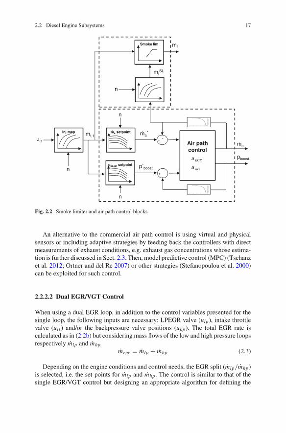
In the ECU, the total injected fuel mass (mf ) is modelled by a look-up tablefunction of the injection duration (tid ) and the rail pressure (prail). The SOI actuation(usoi ) is determined by a calibrated look-up table as function of speed (n) and thedesired mf and is measured in degrees with respect to the top dead centre (TDC). Inthe case of sharp load steps and in order to avoid the excessive emissions of HC andsoot, the smoke limiter function limits mf until the air path responds and suppliesthe air mass flow (ma) required for the combustion, as depicted later in Fig. 2.2.
mf = f (tid , prail) (2.1a)
usoi = f (n,mf ). (2.1b)
2.2.2 The Air Path System
In a commercial CI engine, the following subsystems can usually be found in the airpath: the air filter (in order to clean the entering air, although causing a minimumpressure drop in the line), a (single or double stage) turbocharger (TC) including anintercooler for cooling the compressed air (thus increasing the density), the intakeand exhaust manifolds, the EGR loops (high and low pressure loops) and the pipe-outline (the after-treatment devices are considered as an independent subsystem becauseof the different possibilities existing today, even though they are really connected tothe pipe-out line).
A single TC is the common layout in commercial engines, but some mount alsodual stage TC (Varnier 2012). The main function is increasing the intake air massflow by increasing the density with a compressor usually powered by a turbine shaftlocated at the engine exhaust (Saidur et al. 2012). One of the main drawbacks of thesystem is the turbolag of the TC which is associated with the inertial response of theturbo shaft to accelerations, especially at low speed and low loads, when the exhaustenergy is quite low (Park et al. 2010). In order to get the maximum efficiency of thecompressor and turbine, two types of control are usual: waste-gate (WG) valves anda variable geometry turbine (VGT), also known as variable nozzle turbine (VNT).The WG configuration is based on the use of a fixed geometry in the turbine with avalve that acts bypassing the flow minimising the effective exhaust flow through theturbine. This solution has practically been replaced by the use of the VGT, whichis based on movable nozzles that vary the turbine work depending on the operatingpoint. The VGT allows to increment the engine performance reducing the specificfuel consumption and also adds a major flexibility to the control, admittedly thatincrements the related complexity and calibration effort. In a dual stage TC, there

2.2 Diesel Engine Subsystems 15
Fig. 2.1 Nominal NOx emis-sions depending on [CO2]intfor nominal tests in the CIengine explained in Chap. 3.Values are normalised withthe maximum NOx value foreach operating point, whichcorresponds to uegr = 100(fully closed) for each pairof [n,mf ]
0 1 2 3 40
0.2
0.4
0.6
0.8
1
[CO2]int
[%]
NO
x/NO
x,E
GR
=0 [−
]
exists a wide variety of possibilities of combining WG, VGT and fixed geometriesin the high pressure (HP) and low pressure (LP) turbines (Galindo et al. 2009).
The exhaust gas recirculation (EGR) is the most widely extended NOx reductionsystem (Pla 2009) and is used in CI engines since the middle of the 90s. The basicidea is recirculating a portion of the exhaust gas to the intake. The principal effectof the EGR system is reducing the effective O2 (increasing effective [CO2]int ) at theintake and then diminishing the peak temperature in the cylinder and thus reducingNOx as it is shown in Fig. 2.1.
The EGR rate in steady-state operation can be defined as the quotient betweenthe total EGR mass flow megr and the intake mass flow (mint )
mint = ma + megr (2.2a)
EGR = megr
mint(2.2b)
The work by Ladommatos et al. (1996a, b, 1997a, b, 2000) is a good reference forunderstanding the effects of the EGR in the combustion and emissions. In addition tothe internal EGR (inert gas fraction that stays in the cylinder after the combustion),the external EGR can comprise high pressure EGR (HPEGR) and low pressure EGR(LPEGR) loops. The HPEGR is based on the extraction of a portion of the exhaustgas upstream of the turbine and driven normally to the intercooler output (hot EGR).The LPEGR extracts a portion of the exhaust gas at some point downstream of theturbine (it is usual to locate it downstream of the diesel particulate filter for avoidingdamage in the compressor) and is guided at the compressor inlet (after the air filter).Besides the installation of valves for controlling the flow, coolers are installed forincreasing the flow density.
The HPEGR, namely EGR for simplification, is the standard in CI engines due tothe simple layout and control: the pressure differences between exhaust and intake

16 2 Exhaust Gas Concentrations Estimation in Diesel Engines
facilitate that gas goes to the intake with some exceptions, which can occur forhigh EGR rates, problem that can be solved e.g. by introducing a throttle valve(van Nieuwstadt 2003). Even though the LPEGR did not enter into massive produc-tion, there exists today a certain interest in combining both loops for further reductionof emissions that can push up to relax the AT efficiencies (Millo et al. 2012; Desanteset al. 2013) and thus the cost of complex systems.
2.2.2.1 EGR/VGT Control
The air path is managed independently of the fuel injection system. The effects ofthe injection settings are considered in the air path as instantaneous inputs for amultiple input multiple output (MIMO) control problem. More concretely, the fuelinjection quantity (mf ) and the engine speed (n) are used as scheduling variables fordefining the set-points for the EGR and VGT actuation. Then, for a common layoutof HPEGR and VGT (or WG), the inputs are the EGR valve position (uegr ) and theturbine actuation (uvgt or uwg), besides other actuators such as valves for bypassingthe flow over the EGR cooler (ubp,egr ) if necessary. If the TC is dual stage, it is usualthat only one of the turbines can be actuated. For other layouts, different controlstrategies can be designed, e.g. with a twin turbo sequential parallel configuration,an extra variable is necessary in order to coordinate the switching (Galindo et al.2009). Varnier (2012) gives a complete review on boosting technologies and itsassociated control.
TheEGR/VGTcontrol strategy basically consists on twomaps for determining theset-points for the air mass flow (ma) and the boost pressure (pboost ), while uegr anduvgt are commanded for reaching these set-points (Guzzella and Amstutz 1998). Thecoupling of the EGR/VGT system is avoided by defining control regions, with andwithout EGR. When engine is working in the EGR area, uegr is controlled in closedloop for reaching the required air mass flow set-point scheduled by mf and n. TheVGT is commanded in open loop by a feed-forward controller that imposes a givenuvgt depending also on mf and n. This structure avoids the problem of the EGR/VGTcoupling that can be exemplified as follows: when the EGR valve is opened, a closingon turbine nozzles increments the exhaust backpressure and the turbine regime, thiseffect produces a higher recirculation of EGR reducing the effective air mass flow atthe intake (the EGRmass flow replaces the fresh air). However, when the EGR valveis fully closed, a closing of the turbine nozzles produces an increase of the intake airmass flow. This occurs for medium-high engine loads and uvgt is controlled in closedloop, while the EGR valve keeps closed. The control objective is then reaching theintake air mass flow set-point. Figure 2.2 schematises the air path and the smokelimiter controller.
Furthermore, some corrections or maps switching are applied depending on com-bustion modes or for cold starting strategies (the references for injection and air pathare modified). The engine coolant temperature (Tcool ) is also used for correctionsand for defining the cold starting strategies.
2.2 Diesel Engine Subsystems 17
Fig. 2.2 Smoke limiter and air path control blocks
An alternative to the commercial air path control is using virtual and physicalsensors or including adaptive strategies by feeding back the controllers with directmeasurements of exhaust conditions, e.g. exhaust gas concentrations whose estima-tion is further discussed in Sect. 2.3. Then, model predictive control (MPC) (Tschanzet al. 2012; Ortner and del Re 2007) or other strategies (Stefanopoulou et al. 2000)can be exploited for such control.
2.2.2.2 Dual EGR/VGT Control
When using a dual EGR loop, in addition to the control variables presented for thesingle loop, the following inputs are necessary: LPEGR valve (ulp), intake throttlevalve (uit ) and/or the backpressure valve positions (ubp). The total EGR rate iscalculated as in (2.2b) but considering mass flows of the low and high pressure loopsrespectively mlp and mhp
megr = mlp + mhp (2.3)
Depending on the engine conditions and control needs, the EGR split (mlp/mhp)is selected, i.e. the set-points for mlp and mhp. The control is similar to that of thesingle EGR/VGT control but designing an appropriate algorithm for defining the

18 2 Exhaust Gas Concentrations Estimation in Diesel Engines
Table 2.1 Approximatecharacteristic response timesfor the main actuationvariables in a CI engine
Command Response time
u prail , usoi , uid 100–600µsuhp (uegr ) 0.2–0.5 sulp 0.2–1suvgt , uwg 0.5–1.5 s
EGR split (Shutty et al. 2007). A common solution in steady-state is controllingulp and if necessary opening uhp for reaching the ma set-point (EGR is not directlymeasured). Indeed, the LP loop itself might be sufficient for getting the requiredma set-point. For transient operation, the discussion must evaluate the characteristicresponse times of the systems: the HPEGR line is faster than the LPEGR line due tothe higher pressure differences and the shorter length. This produces that differenttrade-offs between uhp and ulp may be stated during transients. An intrinsic benefitof using a dual loop EGR is that for the EGR engine area, the total megr quantity maybe increased leading to further reductions on NOx, which can alleviate the needs ofAT or could move the deNOx
1 trade-off to select a lean NOx trap (LNT) rather thana selective catalyst reduction (SCR) system. Model based and optimal approachesto the control problem of dual EGR loops can be found in (Haber and Wang 2010;Chauvin et al. 2011; Desantes et al. 2013).
2.2.2.3 Control of the Air and Fuel Paths
Some authors have proposed a joint control of the air and fuel paths for optimising theengine transient operation. For that, fast acting variables linked to the fuel path (usoi
or prail) are able to track NOx or soot while uegr and uvgt are arranged to improve theengine transient response while keeping the engine operation (ensuring the torqueon wheels) without exceeding emission limits. This can be made by feeding back thecontrollerswith real timemeasurements of exhaust gas concentrations (typicallyNOxand soot, or exhaust oxygen) (Deng et al. 2012; Tschanz et al. 2012). Table 2.1 sumsup the characteristic response times for step variations in the inputs, showing how theassociated fuel path responses are quite faster than the air path ones. Furthermore,the response times of the TC are in general higher than those related to the EGR loopdue to the turbolag problem.
Some authors have proposed a transient operation optimization of the enginemanagement strategy (EMS), see e.g. (Alberer and del Re 2009b). However, man-ufacturers are still reluctant to change the actual implementation in the fuel and airpath system: the EMS is confided to fixed calibrations and optimised for steady-stateoperation with a validation in transient operation without feedback on exhaust enginestates.
1 The term deNOx refers in general to an AT system for reducing NOx, see Sect. 2.2.3.

2.2 Diesel Engine Subsystems 19
2.2.3 The After-Treatment Systems
The new stringent regulations have forced to get an impressive development in dieselengines, and particularly with the after-treatment devices (AT); Johnson (2012) andTwigg (2007) present complete reviews on emissions control and available AT tech-nologies. The standard configuration for AT in diesel engines for EURO 6 willcomprise
• a diesel oxidation catalyst (DOC) for three main functions: oxidising CO and HC,heating the exhaust gas and oxidising NO to NO2, which is useful in the DPFregeneration and also facilitates the SCR performance;
• a diesel particulate filter (DPF) for eliminating soot; and• a deNOx system for reducing NOx that it is usually a selective catalyst reduction(SCR) or a lean NOx trap (LNT).
The DPF and LNT action is based on substrate materials that store the pollutantsthrough mechanisms or chemical principles. When the system is full, a regenera-tion by means of post-injections and thus increasing exhaust heat is necessary. TheDOC system is built from ceramic and catalytic noble metals, such as platinum orrhodium, for enhancing the oxidation of CO and HC as well as NO to NO2. SCRsystems eliminate NOx by dosing urea and water (principle component is ammo-nia) and reacting with NOx for obtaining N2 and water, where a dedicated controlmanagement is necessary for optimising its dosing (Chi and Da Costa 2005; Roberts2011). The SCR requires an specific installation for the urea storage that increasesthe cost and weight, and for this reason, the SCR is more extended in HD than inLD. Major concerns in SCR are the light-off related with the minimum temperaturefor guarantying the efficiency of the system (critical when the engine is cold or it isworking in low-load operation); and the ammonia slip, due to the excessive injectionof urea, which does not react withNOx, constituting an economical cost and affectingthe output of the NOx sensors based on ZrO2 (see Sect. 2.3.1).
DPF and DOC are standard in EURO 5 cars, and deNOx systems will also bewith the application of EURO 6. Anyway, the trade-off between SCR and LNT is notsolved (Bickerstaffe 2009), and different factors influence the final decision. Think-ing of future regulations, manufacturers struggle between getting lower removalefficiencies (around 85%) by using LNT or allowing the engines to work on muchhigher efficiencies and then higher NOx production but with the use of a SCR witha removal efficiency nearly 98% (Johnson 2012).
The selection of the layout of the ATs in the engine is another important trade-off and influence the correct operation of the systems. Some possibilities are latershown in Fig. 5.1; however this is a trending discussion. It seems logical that theDOC should be located first because it is required for a proper performance ofDPF and SCR, but the trade-off between DPF and SCR or LNT present advantagesand drawbacks. Indeed, there are some research on moving the DPF upstream ofthe turbine for preventing turbine and compressor damage (if it is located beforethe EGR loop) (Payri et al. 2011b) or doing something similar with the DOC

20 2 Exhaust Gas Concentrations Estimation in Diesel Engines
(Carberry et al. 2005). There are also some alternatives that combine some of thesystems for reducing the packaging and final weight (Frobert et al. 2012).
With respect to the feedback, the knowledge of the concentrations upstream anddownstreamof theAT systems allows to diagnose the performance, and is required fordirect control of the final emissions. The temperature also influences the regenerationof the DPF and LNT as well as it is critical for the SCR light-off (key reactions areinhibited at low temperatures). The pressure drop in the line could also be used fordetecting failures or when the DPF or LNT are full. The decision on the sensor set fora proper control and diagnosing is a challenging problem that requires a specific studyout of the scope of this work. The use of sensors and models for estimating exhaustgas concentrations, especially NOx and exhaust oxygen, is discussed in Sect. 2.3.
2.2.4 The Control System
Aspresented in previous sections, themoderndiesel enginehas evolveduntil reachingtoday an important and increasing complexity,which is reflectedwith the introductionof different subsystems for improving the performance andminimising the emissions.The vehicle electronics in the 80s were reduced to the radio plus simple enginecontrollers. At the same time, these were based on mechanical and hydraulic deviceswith a simple electronic assistant, and dedicated to specific functions such as theignition in the case of SI engines. However, the evolution of the engines has beenclosely related with the rise of complexity of the modern embedded electronicsin automotive, as it is well depicted in (Ebert and Jones 2009). Nowadays, safetyperformance, fuel efficiency and comfort are major demands and these are achievedby installing proper control units. Modern cars have between 20 and 70 control unitswith a size of 108 in object instructions, while in the first 90s this was in the order of106, according to Ebert and Jones (2009).
From all the control units in the vehicle, the ECU is in charge of managing theengine. Others work with the braking systems, the air conditioning in the cabin orthe gear shifting management (Bosch 2011). In the beginning of the 00s, the ECUEDC16 model by Bosch for diesel engines changed the view of the diesel control byusing the final torque demand on the wheels as the feedback for a proper air and fuelpathmanagement. This ECU also included a fully flexible control of the common-rail(pilot, main and post-injections), the VGT and the EGR, all in the same processor.The current EDC17 (Hammel et al. 2003) model coordinates a bigger number of datafrom sensors, actuators and models in order to get a full management of the dieselengine.
From all the requirements and purposes of the ECU, the on-board diagnostics(OBD) standards were applied to engines in order to implement safety routines fordetecting sensors or engine systems malfunctions (van Basshuysen and Schaefer2004). Currently, about 40% of the automotive electronics are devoted to OBDfunctions. The gradual introduction of the AT systems in diesel engines, especiallywith the current trade-off between selecting SCR (more complex due to the urea

2.2 Diesel Engine Subsystems 21
dosing but effective) or LNT (more simple but less effective), is requiring a renewalof the current diesel air path control (Bickerstaffe 2009), and new functions andmanaging strategies are being developed; see for instance (Yang et al. 2009) whopropose an independent control unit for the AT line separated from the main ECU.
2.2.4.1 Summary on the Information Required for a GlobalDiesel Management
The commercial diesel enginemanagement focuses on referencesmeasuredupstreamof the combustion chamber,with no direct feedback from the exhaust line. Thismakesthat emissions are controlled in open loop and possible changes and the ageing arenot taken into account. The sensors set used in the automotive in the beginning of00s (Fleming 2001) had hardly changed until the end of the last decade. A majorfactor is the unnecessary of increasing the number and the type of sensors due to thecurrent control logic. Furthermore, other important factor is the low cost of pressure,temperature and rotational motion sensors (bellow 3$ per unit) against the highercost (minimum>10–20$) of more sophisticated sensors, such as NOx or in-cylinderpressure ones [references obtained from (Fleming 2001) and conversations withengine manufacturers].
Table 2.2 summarises the usual inputs and sensors that are installed in currentdiesel engines, while indicating possible alternatives in a short future (Turner 2009),which are essentially driven by the emission standards (the need of ATs control anddiagnosis). It is rather complicated establishing an universal sensor set and somediscrepancies can be found, e.g. GM is starting to include pcyl sensors in enginesand some AUDI and BMW vehicles already install NOx sensors before and/or afterthe SCR system.
Alternatively, model based strategies present different advantages: models canbe used for engine calibration saving costs (Arsie et al. 2011); models can easilybe linked in control and diagnosis algorithms as they present faster responses thansensors; and the fusion of sensors and models permits to estimate variables or updateparameters on real time solving the drift and ageing and improving the dynamicresponses of the original signals.
This section has emphasised the importance of the information about engine statesand how to correctly retrieve them on-board. Next section deals with the topic ofexhaust gas concentration estimation inCI engines, stressing the variablesNOx andλ.
2.3 Dynamic Exhaust Gas Concentration Estimation
Previous section has made a review on the different technologies in order to managethe diesel engine and has underlined the need of reliable methods for estimatingvariables online. Test-bed measurement systems are usual for testing and researchbut these present in general deficient dynamic responses and overall limited on-board

22 2 Exhaust Gas Concentrations Estimation in Diesel Engines
Table 2.2 Summary of the on-board sensors and control inputs used in a commercial LD dieselengine for control and feedback, and split between the main engine subsystems
System Inputs Standard Expectedsensors sensors
Injectionu prail
[usoi , uid ]pilot,main,postn, prail
pcyl∗
f uel quali t y
Air pathuvgt , uhp, ulp
uit , ubp
pboost , ma, Tcool
Tboost , pamb, Tamb
megr , Tegr
nvgt ,λint∗
AT [usoi , uid ]post , uurea NO x∗, soot, λexh
∗
The inputs column defines the main actuator signals in the diesel engine. The remaining columnsshow the variables that are measured by sensors, differentiating between standard for EURO 5 carsand the possible expectations in a short future. Admittedly, some discrepancies can exist betweenthis distinction depending on the considered car and sector (luxury, utility, etc.). The symbol *represents sensors that can be found in some actual engine models but with less probability. Theinjection settings are defined by the rail pressure control u prail , the injection timing command (usoi )and the injection duration uid , and these settings can be specified for pilot injections main injectionsand possible post injections (variable utmi makes reference to the duration of themain injection only).A detailed summary on the symbols and acronyms used in this work appears in the beginning of thisdocument. The interested reader is also referred to Turner (2009) for finding basic comprehensiveexplanations about the principles of measurement of the main automotive sensors
capabilities. However, in the last years, and forced by the stringent emission laws,developments of on-board gas concentration sensors have proliferated and some ofthem are a reality today, such as NOx or wide-band lambda sensors. Furthermore,COMs and data fusion (DF) techniques that combine different information sourcescan also be used for real-time (RT) estimations.
Current section gives a review on the different methods for the estimation ofthe exhaust gas concentration in CI engines, emphasising the on-board methods.Therefore, in addition to being feasible from the point of view of cost and engineimplementation, the accuracy and dynamic responses of these estimators should beissued. Hereinafter the following three main possibilities are discussed:
• sensors,• models and/or virtual sensors, and• DF techniques for combining different information sources.
2.3.1 Sensors
A subsequent division is made between test bedmeasurements systems and on-boardgas concentration sensors, such as exhaust gas oxygen (EGO), universal exhaustgas oxygen (UEGO) sensors, fast soot sensors and finally innovative solution formonitoring e.g. NOx by using the substrate materials of the AT systems.

2.3 Dynamic Exhaust Gas Concentration Estimation 23
2.3.1.1 Test Bed Sensors
Some of the most common test bed sensors are the following: gas analysers (Horiba2001) for different gas concentrations; opacimeters based on Beer-Lambert law(Lapuerta et al. 2005) and smoke meters for soot; and gravimetric devices or spec-trometers for PM (Mamakos et al. 2013), among others. But these are expensive,require from specific installations and their dynamic responses are questionable.Nevertheless, there have been some developments for fast response emissions analy-sers for NOx, CO2 or particles and portable emission measurement systems (PEMS)(Franco et al. 2013) are being generalised for on-board inspections but with limiteddynamic accuracy (Mrosek et al. 2011) and packaging. Finally, standard proceduresfor measuring emissions in test-cells can show representative errors in the dynamiccycles with respect to the actual transient emissions (Mamakos et al. 2013; Viskup etal. 2011) and this should be taken into account when processing the data (Geivanidisand Samaras 2008; Chan et al. 1997; Arrègle et al. 2006b; Bedick et al. 2009) (seeSect. 2.3.2.3).
2.3.1.2 On-board Gas Concentration Sensors
Oxygen Sensors
In 1968, the introduction of EGO sensors (Dueker et al. 1975) was the key for theimplantation of the primary three way catalyst (TWC) control in SI engines. Thesesensors offered a binary lean/rich resolution for measuring oxygen concentrationand thus the equivalent air-to-fuel ratio or lambda, which represents the excess airfactorwith respect to the stoichiometric air-to-fuel ratio (approximately 14.5 in dieselengines)
λ = ma
m f
1
14.5(2.4)
In the end of the 90s, planar UEGO sensors were implemented for SI and CI engines.It is common to use directly the term lambda probe for referring to these sensors. Theterm lambda is due to the characteristic shape of the signal output in narrow-bandlambda sensors, which is similar to theλ letter from theGreek alphabet (see Fig. 2.3).Furthermore, these are also known as switching-type sensors. UEGO sensors presentfull and linear resolution on oxygen over a wide range, hence the term wide-band.UEGO and EGO response characteristics are shown in Fig. 2.3.
λmeasurement in CI engines is used for correcting injector drift. In the case of lowtemperature combustion (LTC) processes (Lu et al. 2011), intake charge composition,and hence λ is important for the combustion stability and control (Chiang et al. 2007;Agrell et al. 2005). Some studies about wide-band lambda sensors performance canbe found in (Regitz and Collings 2008b; Klett et al. 2005).

24 2 Exhaust Gas Concentrations Estimation in Diesel Engines
Sen
sor
volta
ge U
(m
V)
0.8 0.9 1 1.1
200
400
600Lean
Rich
0.7 1 2 3
100
200
300
Lean
Rich
1.2
800
EGO response UEGO response
Fig. 2.3 Characteristic outputs of oxygen lambda sensors. Left Narrow-band lambda or EGOsensors. Right Wide-band lambda or UEGO sensors
NOx−ZrO2 Sensors
The development of on-board NOx sensors has been driven by those which are basedon ZrO2 layers (Kato et al. 1996; Nakanouchi et al. 1996) and able to measure gas atwet condition (i.e. without removing exhaust gaswater steam content as gas analysersdo). These sensors have suffered an evolution over the last 15years (Zhuiykov andMiura 2007) and now are manufactured using the planar ZrO2 multilayer technology(Moos 2005), which combines thick film screen printing and ceramic tape casting(Riegel et al. 2002). Modern versions offer reduced warmup time, smaller size,lower weight and cost-effective production, which encourage their implementationon commercial engines. This kind of sensors simultaneously provides ameasurementof the relative air-to-fuel ratio (λ) and NOx concentration and must play a major rolein the SCR control and diagnosis (Hofmann et al. 2004; Hsieh and Wang 2011;Künkel 2001; van Nieuwstadt and Upadhyay 2005).
The working principle is well explained in Riegel et al. (2002) and layout isschematised in Fig. 2.4. This sensor presents two cavities with membranes for mea-suring oxygen and NOx, respectively. In a first outer cavity, an electrochemical pumpadjusts the oxygen concentration from the diffusing gas to a predefined value (pumpintensity Ip1) by reducing O2 to O2− with an electrode (usually Pt), thus providinga linear amperometric measurement of λ. At the same time, a faster binary outputis provided, differentiating between rich and lean conditions in the exhaust gases(similar to EGO sensor output). The measurement principle of this first cavity issimilar to that of a wide-band UEGO sensor. In addition, NO is oxidised to NO2,and then the NO2 is diffused to a second inner cavity, where the oxygen producedthrough the dissociation of the NO2 is pumped out in a similar way by means of asecond electrochemical pump (Ip2). The output of this pump is proportional to theNOx concentration in the exhaust gases. A heater is necessary for keeping the sensorat high temperatures, where the device gets good resolution, i.e. the sensor needs

2.3 Dynamic Exhaust Gas Concentration Estimation 25
Fig. 2.4 Schematic representation of aNOx–ZrO2 sensor, where themain reactions in the chambersand diffusion barriers are shown
some lag for starting to measure when switching on (the same occurs for UEGO sen-sors). Therefore, these sensors provide three signal outputs: a fast binary λ (around100ms), lean or rich, suitable e.g. for TWC diagnosis, a slower (around 500ms ofresponse time) full resolution λ and NOx (with a response around 750ms).
NOx and UEGO Sensor Limitations
Because of the importance of NOx and UEGO sensors in the present work, responselimitations of these sensors are underlined. Several studies have evaluated the accu-racy and response times of real time NOx sensor measurements for different applica-tions, such as Smith (2000), Manchur and Checkel (2005) and Galindo et al. (2011).
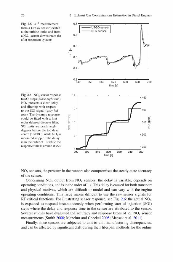
Conventional UEGO sensors exhibit fast response times around 70ms with suffi-cient accuracy (Schilling et al. 2008). This can be improved, as proposed in Albererand del Re (2009a), moving the O2 sensor upstream of the turbine and using aKalman filter (1960) for taking into account pressure effect on the output signal. Ifthe NOx sensor is placed downstream of the AT systems, its response is affected bya considerable transport delay and filtering. Figure 2.5 compares λ−1 signals from aUEGO sensor located upstream of the AT systems, and from a NOx sensor locateddownstream of an AT line including DOC, DPF and SCR in a turbocharged dieselengine. The NOx sensor signal is significantly slower and more filtered than that ofa UEGO sensor, although the steady-state accuracy seems to be sufficiently accuratein both devices at a glance. Due to the measurement principles of both UEGO and
26 2 Exhaust Gas Concentrations Estimation in Diesel Engines
Fig. 2.5 λ−1 measurementfrom a UEGO sensor locatedat the turbine outlet and froma NOx sensor downstream theafter-treatment systems
640 650 660 670 680 690 7000.3
0.4
0.5
0.6
0.7
0.8
time [s]
λ−1 [−
]
UEGO sensorNOx sensor
Fig. 2.6 NOx sensor responseto SOI steps (black-right axis).NOx presents a clear delayand filtering with respectto the SOI signal (gray-leftaxis). The dynamic responsecould be fitted with a firstorder delayed discrete filter.SOI units are crank angledegrees before the top deadcentre (◦BTDC), while NOx ismeasured in ppm. The delayis in the order of 1 s while theresponse time is around 0.75 s
290 300 310 320 330 340 3506
8
10
12
14
time [s]
SO
I [ºB
TD
C]
290 300 310 320 330 340 350
250
300
350
400
450
NO
x [ppm
]
NOx sensors, the pressure in the runners also compromises the steady-state accuracyof the sensor.
Concerning NOx output from NOx sensors, the delay is variable, depends onoperating conditions, and is in the order of 1 s. This delay is caused for both transportand physical motives, which are difficult to model and can vary with the engineoperating conditions. This issue makes difficult to use the raw sensor signals forRT critical functions. For illustrating sensor response, see Fig. 2.6: the actual NOxis expected to respond instantaneously when performing start of injection (SOI)steps where the delay and response time in the sensor are attributed to the sensor.Several studies have evaluated the accuracy and response times of RT NOx sensormeasurements (Smith 2000; Manchur and Checkel 2005; Mrosek et al. 2011).
Finally, since sensors are subjected to unit-to-unit manufacturing discrepancies,and can be affected by significant drift during their lifespan, methods for the online

2.3 Dynamic Exhaust Gas Concentration Estimation 27
characterisation of sensors would improve the application of these for automotivecontrol purposes. Usual calibration methods consist of a specific test rig which gen-erates known composition synthesis gas which is used for the static and dynamiccalibration of the sensor, while high speed valves are needed for dynamic calibration(Regitz and Collings 2008a); or some solutions based on openly mounted sensorswith valves allocated before the sensor, where gas composition is changed withinmilliseconds (Tobias et al. 1999). However, these calibration methods are restrictedto laboratory use and cannot be performed during the operation phase on the engine.Chapter 3 presents a contribution for the online characterisation of NOx output bymeans of SOI steps (Galindo et al. 2011); furthermore, λ−1 output from wide-bandlambda sensors may be characterised by means of load steps.
Fast Soot Sensors
According to (Kasper 2004), particles with lower diameters affect more to alveolardeposition after healthy tests with persons, which underline the risk of underestimat-ing the effect of the residual soot downstream of the DPF. This carries out a sensitiveproblem for sensors: in addition to robustness, packaging and dynamic limitations,on-board soot sensorsmust measure with high resolution at low-soot values (this sen-sitive problem is also linked with NOx sensors). Another problem with soot sensorsis the selection of an appropriate metric as different metrics can be used depending onthe physical measuring principle: particle number, total mass, sizes or light absorbingproperties (opacity). A common solution for fast soot sensors, described in WareyandHall (2005), is measuring the electrical conductivity of the carbonaceous fractionof the PM, which acts as a resistance between two electrodes located in the sensor.One of them is feed with a high voltage DC, while the current generated in the otheris transformed to voltage, conditioned and then acquired for being converted intoa soot estimation. This layout is similar to other fast soot sensors, see e.g. Steppanet al. (2011) and Nelson (2011). Even though these sensors have not reached thematurity of UEGO or NOx sensors, some companies have already introduced themin the market or are targeted for start of production in 2013.
Sensors in Development, Other Alternatives
A relevant problem of fast NOx–ZrO2 sensors is the low sensitivity when the NOxconcentration is small, i.e. downstreamof SCRorLNTsystems; and the related cross-sensitivity to ammonia. In that field, it can be underlined the work by Moos (Mooset al. 2008; Moos and Schönauer 2008; Moos 2010; Geupel et al. 2011; Schönaueret al. 2011; Groß et al. 2012).
An alternative is using the catalysts and/or substrate materials of the AT devicesfor determining the NOx, soot or ammonia by means of measuring the impedancevariance of the material. This allows to profit the proper AT device for measuring,developing an integrated device. These are often called in situ monitoring devices.
28 2 Exhaust Gas Concentrations Estimation in Diesel Engines
Moos (2010) show results for in situ sensors in order to detect loadings of oxygenin TWC, NOx in LNT, NH3 in SCR-catalyst and soot in DPF, among others. Theprincipal advantage of the approach is the simple and inexpensive setup required asthe devices themselves are used as sensors.
Concretely for NOx sensoring, see Geupel et al. (2011) and Groß et al. (2012)who extend the use of integrating-typeNOx sensors formeasuring instantaneousNOxconcentration, especially in the low ppm range (where NOx concentration is low),incorporating temperature based corrections in the measurements. Groß et al. 2012also present results with respect to NO/NO2 differentiation and cross-sensitivitieswith other gas components. Other alternatives for innovative sensors could be usingelectromagnetic waves (Moos 2010) or radio-frequency signals which coincide withthe oxidation/reduction rate of a TWC for determining oxygen loading without usinglambda sensors (Moos et al. 2008).
NH3 on-board sensors (Moos and Schönauer 2008) are also being developed forclosed loop urea dosing control, based on the same principles of the wide-bandlambda sensors: the mixed-potential principle between electrodes, separated by asolid electrolyte, where an electric force is created. Delphi has already marketed acommercial version where the reference electrode is in direct contact with exhaustgas (Wang et al. 2008). Schönauer et al. (2011) show results with mixed potentialammonia sensors and suggest some improvements in the technology.
2.3.2 Models and Virtual Sensors
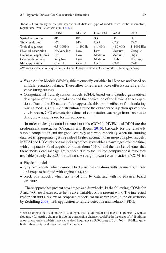
Modelling or virtual sensing2 is an important tool in the design, analysis and controlof IC engines. It is not in vain that model-based strategies in ECU have each timehigher responsibilities, overall in control and OBD functions (Stewart et al. 2010).Furthermore, models are quite helpful in the analysis and design phases: hardwareand software in the loop (HIL and SIL) are usual because of the reduced cost andtime-to-implement with respect to a pure experimental approach. However, the accu-racy, reliability, computational cost and time effort of models depend highly on thestructure, data used for calibration and the dynamic conditions. A classification onmodels for automotive is made in Guardiola et al. (2012) and these are compared inTable 2.3:
• Mean valuemodels (MV), which average the physical quantities over a time range,neglecting in-cycle variations. They can be further subdivided in data driven mod-els (DDM) and physical mean value engine models (MVEM).
• Emptying-and-filling models (E&FM), based on first-principle equations and withcertain capability for estimating in-cycle variations. They are usually crank-anglesolved.
2 The term virtual sensing is often used for RT on-board models for estimating variables that cannotbe measured easily or their measurements are not reliable, in contrast with using physical sensors.
2.3 Dynamic Exhaust Gas Concentration Estimation 29
Table 2.3 Summary of the characteristics of different type of models used in the automotive,reproduced from Guardiola et al. (2012)
DDM MVEM E and FM WAM CFD
Spatial resolution 0D 0D 0D 1D 3DTime resolution MV MV CAS CAS CASTypical acq. rates 0.5–100Hz 1–200Hz >1MHz >10MHz 1–100MHzPhysical description No/Very low Low Low Medium ComplexPrediction capabilities No Low Medium Medium HighComputational cost Very low Low Medium High Very highMain application Control Control CAE CAE CAE
MV mean value, acq. acquisition, CAS crank angle solved, CAE computer aided-engineering
• Wave Action Models (WAM), able to quantify variables in 1D space and based onan Euler equation balance. These allow to represent wave effects (useful e.g. forvalve lifting tuning).
• Computational fluid dynamics models (CFD), based on a detailed geometricaldescription of the engine volumes and the application of the Navier-Stokes equa-tions. Due to the 3D nature of this approach, this tool is effective for simulatingmixing models, i.e. EGR distribution around the cylinders or injection spray mod-els. However, CFD characteristic times of computation can range from seconds todays, preventing its use for RT purposes.
In order to design control oriented models (COMs), MVEM and DDM are thepredominant approaches (Calendini and Breuer 2010), basically for the relativelysimple computation and the good accuracy achieved, especially when the trainingdata set is appropriate, getting indeed higher accuracy than more complex models.MVEM and DDM rely on twomain hypothesis: variables are averaged over the time,with computation (and acquisition) rates about 50Hz,3 and the number of states thatthese models can manage are reduced due to the limited computational resourcesavailable (mainly the ECU limitations). A straightforward classification of COMs is:
• Physical models,• gray box models, which combine first principle equations with parameters, curvesand maps to be fitted with engine data, and
• black box models, which are fitted only by data and with no physical basedstructure.
These approaches present advantages and drawbacks. In the following, COMs forλ and NOx are discussed, as being core variables of the present work. The interestedreader can find a review on proposed models for these variables in the dissertationby (Schilling 2008) with application to failure detection and isolation (FDI).
3 For an engine that is spinning at 3,000 rpm, that is equivalent to a rate of 1–100Hz. A typicalfrequency for getting changes inside the combustion chamber could be in the order of 1◦ if talkingabout crank angle, and this makes a required frequency (at 3,000 rpm) of 50×360 = 18MHz, quitehigher than the typical rates used in MV models.
30 2 Exhaust Gas Concentrations Estimation in Diesel Engines
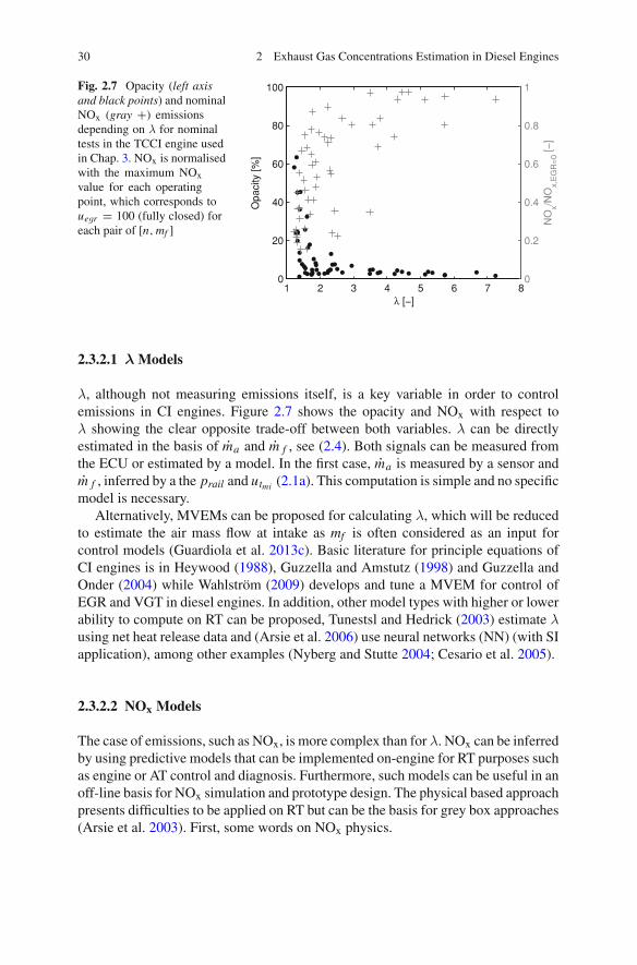
Fig. 2.7 Opacity (left axisand black points) and nominalNOx (gray +) emissionsdepending on λ for nominaltests in the TCCI engine usedin Chap. 3. NOx is normalisedwith the maximum NOxvalue for each operatingpoint, which corresponds touegr = 100 (fully closed) foreach pair of [n,mf ]
1 2 3 4 5 6 7 80
20
40
60
80
100
Opa
city
[%]
λ [−]
0
0.2
0.4
0.6
0.8
1
NO
x/NO
x,E
GR
=0 [−
]
2.3.2.1 λ Models
λ, although not measuring emissions itself, is a key variable in order to controlemissions in CI engines. Figure 2.7 shows the opacity and NOx with respect toλ showing the clear opposite trade-off between both variables. λ can be directlyestimated in the basis of ma and m f , see (2.4). Both signals can be measured fromthe ECU or estimated by a model. In the first case, ma is measured by a sensor andm f , inferred by a the prail and utmi (2.1a). This computation is simple and no specificmodel is necessary.
Alternatively, MVEMs can be proposed for calculating λ, which will be reducedto estimate the air mass flow at intake as mf is often considered as an input forcontrol models (Guardiola et al. 2013c). Basic literature for principle equations ofCI engines is in Heywood (1988), Guzzella and Amstutz (1998) and Guzzella andOnder (2004) while Wahlström (2009) develops and tune a MVEM for control ofEGR and VGT in diesel engines. In addition, other model types with higher or lowerability to compute on RT can be proposed, Tunestsl and Hedrick (2003) estimate λusing net heat release data and (Arsie et al. 2006) use neural networks (NN) (with SIapplication), among other examples (Nyberg and Stutte 2004; Cesario et al. 2005).
2.3.2.2 NOx Models
The case of emissions, such as NOx, is more complex than for λ. NOx can be inferredby using predictive models that can be implemented on-engine for RT purposes suchas engine or AT control and diagnosis. Furthermore, such models can be useful in anoff-line basis for NOx simulation and prototype design. The physical based approachpresents difficulties to be applied on RT but can be the basis for grey box approaches(Arsie et al. 2003). First, some words on NOx physics.

2.3 Dynamic Exhaust Gas Concentration Estimation 31
NOx Physical-Based Models
The term NOx includes all nitrogen oxides but the nitric oxide (NO) is the predomi-nant in diesel engines (Heywood 1988). NOx formation is affected by three differentmechanisms: thermal, prompt and from fuel-bound nitrogen (Arrègle et al. 2010).The thermal mechanism is the most important in diesel engines where high temper-atures benefit reaction of N and O2 from air producing NOx. NOx formation physicsin combustion and explosion processes were modelled by Zeldovych (1946) in 1946,and formulated for IC engines by Lavoie et al. (1970) in 1970 with the well-knownextended-Zeldovych mechanism
N + NO � NO2N + O2 � NO + ON + OH � NO + H
(2.5)
According toHeywood (1988), the typical characteristic times of theNO formation indiesel engines combustion is in the order of seconds and thus under the hypothesis ofequilibrium of certain species, the dNO/dt can be fittedwith the initial NO formationrate by the Arrhenius equation
dNO
dt= k1
T 0.5e−k2/T [O2]0.5[N] (2.6)
The strong dependency with the temperature T is clear: when T increases, NO (andthus NOx) increases exponentially. The other mechanisms can be relevant in somespecific conditions such as LTC (Andersson 2006; Desantes et al. 2012).
Cylinder conditions such as temperature, pressure and oxygen concentration(Brand 2005; Luján et al. 2008; Timoney et al. 2005) are themost important variablesfor determining NOx concentration.
Because of the cylinder severe conditions, price and signals problems have pre-vented to use in-cylinder sensors in commercial vehicles. Although in-cylinder pres-sure cost is one of the main factors burdening its application for automotive engines,the continuous improvements of pressure sensors and its applications are justify-ing its nearby implementation (Powell 1993). The case of the temperature sensorsis more complicated (Fleming 2001), and their use is not foreseen in applications.Therefore, the solution for estimating the in-cylinder conditions on RT is then usingvirtual sensors.
Physical models for NOx estimation are often based in the heat release, usingpressure sensor signal for estimating flame temperature (T f ) in the cylinder. Theproblem is not trivial and a multi-zone discretisation is advisable. Furthermore, theresidual gases (internal EGR) affect the process and these are not always easy toestimate. An usual solution to the problem is applying mass and energy conservationequations to each zone (walls, injector neighbourhood, etc.) in conjunction with heattransfer equations, among them it stands out the heat transfer to cylinder wall (Payriet al. 2005), which can be approached by using Woschni equation (Woschni 1967).

32 2 Exhaust Gas Concentrations Estimation in Diesel Engines
Finally, NOx emissions for both Diesel and gasoline engines are calculated by usingthe extended Zeldovych mechanism. Good examples for estimating NOx by usingheat release are Arregle et al. (2006a), Payri et al. (2011a), Guardiola et al. (2011)andWestlund et al. (2008). In the case of SI engines, some authors use the ionisationcurrent on the spark for approaching the pressure (Andersson and Eriksson 2002,2009), but this is not available on the diesel engine. Nevertheless, the accuracy ofthe prediction is not as satisfactory as expected, and the drift cannot be eliminated.
There is an open discussion about using time or crank angle based models for theNOx prediction. For the case of pressure based models, crank angle sampling seemsmore logical as volume can be easily linked with pressure trace. However, thesemodels require heavy calculations and big memory resources. The time required forcompleting one engine cycle is often bigger than the characteristic time of the engine.In order to overcome this limitation some authors have proposed simplifications.Guardiola et al. (2011) develop a semi-physical discrete event model based on theheat release calculation but considering only one zone as the main contributor tothe NOx formation; and the process is supposed adiabatic, approaching T f with theadiabatic temperature of the process. This approach requires specific corrections,especially when the combustion temperature is low. Other examples are Westlund(2011) who present a fast physical model for NOx and soot, or Arsie et al. (2003)who present a hierarchical model structure for engine control design with differentmodels and layers, ranging from physical based to mean value approaches.
Control-Oriented Models for NOx
Literature about COMs for NOx is extensive. Schilling (2008) gives a short reviewon different COMs for NOx and presents a NOx virtual sensor (see also referencestherein). His work is based on deriving maps from complex models (Schilling et al.2006, 2008) or engine data (Lughofer et al. 2011; Desantes et al. 2011), building amodel that is easy to integrate into the engine ECU, but with limited extrapolationcapabilities. In commercial ECUs the prevailing approach is to use look-up tablesto model nonlinear and operating point dependent behaviours because of the simpleprogramming in spite of the intensive tuning effort (Guardiola et al. 2013a); eventhough other possibilities can be commented. Winkler-Ebner et al. (2010) design avirtual NOx sensor for SCR control and diagnosis. Black box models rely on systemidentification (Karlsson et al. 2010) but are often operating point dependent and itsadaptation is not an easy task. Hirsch et al. (2008) present a gray box model for NOxand PM. Other non-linear approaches are Takagi-Sugeno fuzzy models (Takagi andSugeno 1985; Lughofer et al. 2011), Hammerstein-Wiener (HW) (Falck et al. 2012),or NN (Yen and Michel 1991; Alonso et al. 2007; Maaß et al. 2009; Arsie et al.2010).

2.3 Dynamic Exhaust Gas Concentration Estimation 33
2.3.2.3 Identification of Sensor and Physical Dynamics
Dynamic models describe the evolution of a state vector x along the time t andsubjected to a specific set of inputs u
x = f (x, u, t) x ∈ Rnx , u ∈ R
nu (2.7a)
y = g(x, u, t) (2.7b)
The identification is the technique of designing and tuning the dynamic modelsby means of a data set {u, y}tend
t1 over a certain time tend ; see (Johansson 1993; Ljung1999) for comprehensives references on system identification. A common procedurefor identification is defining different black box linear model structures (AR, ARX,ARMAX, etc.) based on polynomial relationships with a certain order and solvingthe linear regression problem, usually by means of a least squares (LS) formulation.In addition to the model parameters, the selection of an appropriate order of thesystem is key for an adequate solution. If the system is non-linear, specific structuresshould be utilised, e.g. piece-wise affine (PWA), linear parameter varying (LPV) orHW models, among others.
Sensors Identification for On-board Strategies
Most of the dynamic models with physical meaning used in engineering, as forinstance sensor models, respond to n-order linear filters with a certain delay τ (Ogata2001), at least in the selected areas of performance. In the case of exhaust gas concen-tration sensors, 1st order linear models can be sufficient for representing the sensorresponse in the s-domain (Galindo et al. 2011; Mrosek et al. 2011)
G(s) = e−sτ k
1 + T s(2.8)
where T is the response time and k is the gain. Parameters can be fitted by LS. How-ever, actual sensor responses are non-linear and parameters usually vary, especiallythe delay or dead-time τ , due to the hardware itself, the engine operating condi-tions and ageing. These variations can be modelled by scheduling strategies, whereparameters are stored in look-up tables, or functions (Trimboli et al. 2012) typicallydepending on n and ma .
Another possibility is using model structures with physical insight: e.g. Wang(2007) identifies the oxygen sensors dynamics by means of a physical based modeland Zhuiykov (2010) describes andmodels the electrochemistry of ZrO2 gas sensors.Adaptive filtering can also be used for taking into account the ageing and dispersion.Furthermore, if the signal processing is made off-line, non-causal deconvolutiontechniques may also be used, see e.g. Henningsson (2012).
DDMs are often based on static relationships such as look-up tables and alge-braic equations. In addition, the dynamics are often modelled by linear filters and

34 2 Exhaust Gas Concentrations Estimation in Diesel Engines
the correct identification is critical for the adaptive filtering algorithms presentedhereinafter.
2.3.3 Adaptive Filtering
Sensors present problems when using the raw output signal in RT functions, inparticular the delay from engine to sensor and the response time of the sensor. Withrespect to models, two problems can be underlined when working with COMs. Onone hand, the model accuracy is driven by the collection of the appropriate data andcalibration of all the parameters. This is a hard and time consuming task. In fact,ECU has a big number of maps and parameters for engine and vehicle management.On the other hand, independently of how well the model has been calibrated thereis inevitably a drift between the system and the model as the surrounding conditionschanges and the engine ages. DDMs are highly sensitive to the calibration data setandwill have problemswith the ageing,manufacturing discrepancies, slowly varyingparameters and other non-modelled variables. These affects also to dynamic modelsidentified for both sensor and physics filtering.
2.3.3.1 Data Fusion
Data fusion (DF) utilises information from different sources for providing a betterestimation of a given variable. These information sources can come from sensors,models and/or other DF algorithms. DF has been used for many years in differentengineering fields, such as e.g. inertial navigation of satellites and missiles (Wagnerand Wieneke 2003) or automotive applications in intelligent transportation systems(Faouzi et al. 2011; Stiller et al. 2011) related with traffic and driver/road assistance,among others. Different DFmethods can be used as (Faouzi et al. 2011) propose: sta-tistical, ranging from the simplest arithmetic mean to weighted combinations or datamining techniques (Henningsson 2012); probabilistic, such as Bayesian approaches,maximum likelihoods methods and Kalman filter (KF); and artificial intelligenceincluding NN or genetic algorithms. A more exhaustive classification and discus-sion on challenging problems of multisensor DF is in (Khaleghi et al. 2013). FromDF methods, those which are applied adaptively for bounding error of parameters,signals and parameters can be included as methods for adaptive filtering, fusion orlearning (Mehra 1970).
The present work centres on the use of Kalman filter (KF) (1960) based tools inorder to observe exhaust gas concentration variables in CI engines (Guardiola et al.2013b, c). The KF is probably the most extended adaptive filtering algorithm usedin engineering (Gao and Harris 2002) and provides a systematic and simple wayof manipulating linear dynamic models and engine variables by supposing a prioriknowledge of the measurement and noise statistics, modelled by Gaussian distrib-utions. This property allows to track the estimation error by means of a covariance

2.3 Dynamic Exhaust Gas Concentration Estimation 35
matrix P that also tracks the ageing of the states, i.e. if the error in a given state isforeseen to be higher or lower depending on when was updated the last time and howmuch. The KF minimises this expected error by solving an iterative Riccati matrixequation and setting out a Kalman gain (K ) for correction. The linear structure of thefilter makes it appropriate to ECU-oriented approaches, even though simplificationsshall be considered when manipulating large state vectors. Furthermore, dependingon the available data, different fusion structures can be programmed as Gao andHarris (2002) show.
Other filtering alternatives, such as RLS (recursive least squares) or proportionalmethods can also be applied and in some cases lead to similar solutions. Inputobservers by means of measurements of the states and outputs can also be addressedfor estimating engine variables (Chadli et al. 2009; Stotsky and Kolmanovsky 2002).The interested reader is referred to Simon (2006) and Höckerdal (2011), the formerfor finding a complete and broader view on optimal state estimation and KF-basedalgorithms for engineering applications, and the latter for a key precedent and moti-vation for the current work.
In the next, and due to the importance of the KF in this work, main equationsare recalled although the reader familiarised with control engineering could skip thisparagraph.
2.3.3.2 Kalman Filter
In the setting the data are assumed to be generated by the following discrete timesystem
xk = f (xk−1, uk) + wk (2.9a)
yk = g(xk, uk) + vk (2.9b)
where xk ∈ Rnx represents the state vector, uk ∈ R
nu the input vector, yk ∈ Rny the
output vector. If f and/or g are non-linear, a previous linearisation step is requiredfor the filter and then, elements i j of Fk and Hk are obtained
Fk,ij = ∂fi
∂xj|x=xk Hk,ij = ∂gi
∂xj|x=xk (2.10)
being F the linearised process matrix and H the linearised output matrix. From now,the discussion is valid both for linear and non-linear systems and KF will be usedreferring to Kalman filter based methods, including the non-linear Extended KalmanFilter (EKF) (Simon 2006) and the standard one.
Noises in (2.9) wk ∈ Rnx and vk ∈ R
ny are assumed to be independent and bothgenerated by Gaussian distribution with zero mean and covariance matrices Qk resp.Rk, defined by

36 2 Exhaust Gas Concentrations Estimation in Diesel Engines
E[wk wTk ] = Qk (2.11a)
E[vk vTk ] = Rk (2.11b)
Inmany applications these are often chosen to be constant, i.e.Q andR, and diagonal.Then, xk ∈ R
nx is the observation of the state vector xk
xk|k−1 = f (xk−1, uk) (2.12a)
ek = yk − g(xk|k−1, uk) (2.12b)
xk = xk|k−1 + Kk ek (2.12c)
where Kalman gain Kk is solved by the following iterative equation
Pk|k−1 = (FkPk−1FTk + Q) (2.13a)
Kk = Pk|k−1HTk
(HkPk|k−1HT
k + R)−1
(2.13b)
Pk = (I − KkHk)Pk|k−1 (2.13c)
and matrix Pk is the covariance matrix of the state estimate error (Ljung 1999)
Pk = E[xk − xk][xk − xk]T . (2.14)
2.3.3.3 About the Methods in this Work
From all the possible applications of the KF for the gas concentration estimation, thefollowing are exploited in the present work:
• Dynamic estimation of engine variables by means of fusing a fast reference, oftena model, and a slow but accurate sensor, for developing robust virtual sensors orbias tracking algorithms; and
• on-line adaptation of models, especially the online updating of look-up tables asbasic structures in COMs.
These algorithms, although applied in the present work to λ and NOx, can be usedfor estimating other relevant engine quantities, such as the intake air mass flow or thevolumetric efficiency (Höckerdal et al. 2009, 2011), just considering the appropriatestate-space model. In the following, the state of the art related with these applicationson automotive is reviewed.
2.3.3.4 Adaptive Estimators Based on the KF
Figure 2.8 shows amodel signal forλ−1, based on the injected fuelmass m f estimatedby the electronic control unit (ECU) and the air mass flow ma determined from a

2.3 Dynamic Exhaust Gas Concentration Estimation 37
Fig. 2.8 Different λ−1 esti-mations during a load transientin the tested diesel engine (seeSect. 3.2): zλ−1 is the outputof a NOx sensor located atthe turbine outlet, x−1
λ is theoutput of the model presentedin Sect. 4.2 and λ−1 is theforeseen actual value
120 125 130 135 140 145 1500.4
0.45
0.5
0.55
time [s]
λ−1 [−
]
zλ−1
xλ−1
λ−1
hot wire anemometer. Comparing to the sensor, model is faster and non-delayed butpresents a bias with respect to the sensor steady-state value.
Algorithms based on bias tracking take a fast model that keeps high frequencycomponents of the considered variable while a slow but steady-state accurate sensorpermits to correct model drift. The vector xm(t) ∈ R
nx contains model signals andz(t) ∈ R
nz the sensor signals. The drift is modelled with a vector θ(t) ∈ Rnx , which
contains model biases and varies with time often slowly. If xr (t) ∈ Rnx is the vector
containing the actual values of the states, then the true bias θ is
θ(t) = xr (t) − xm(t) (2.15)
but the problem here is that xr is usually measured by a sensor z
z(t) = g(xr (t − τ )) (2.16)
and in general will have a certain delay τ . The discussion on identifying the functiong and delay τ was made before in Sect. 2.3.2.
In order to design a drift correction algorithm, an augmented state-space model iswritten. An extra-state is used for tracking the given error (θ), creating a wide statevector xw with drift vectors and the original state vector x ∈ R
nx , which containsthe estimations of xm ,
xw(t) =[
θ(t)x(t)
](2.17)
and the state-space model
xw = f (xw, xm, W, t) (2.18a)

38 2 Exhaust Gas Concentrations Estimation in Diesel Engines
z = g(xw, xm, V, t) (2.18b)
is solved by adding noises W (t) ∈ R2nx and V (t) ∈ R
nz to the model and sensoroutput respectively.
This formulation, with different variations, is made by different authors in order toobserve the bias between two references, usually a model and a sensor. Alternatively,the bias can be applied to the model and/or sensor by shifting the references whenproceeding; for the latter the sensor is not steady-state accurate and a steady-stateaccurate reference is required (Chen and You 2008).
The classical approach for modelling the drift is supposing a slow variation of thestate by the dynamic equation
θ = 0 (2.19)
and supposing that states noise W is low with respect to output noise V , for havinga smooth correction.
There exist different references with similar models as described above for esti-mating engine variables. The majority of them uses the EKF due to the non-linearequations involved, some references from 2005 are commented below:
• Hsieh and Wang (2011) use an EKF in order to estimate NOx up, in between anddownstream of a two-series SCR configuration and consider the ammonia crosssensitivity of a NOx sensor located in between.
• Höckerdal et al. (2009) uses an augmented model for observing the sensor biaswith an air mass flow sensor application.
• Alberer and del Re (2009a) use a KF for correcting an oxygen measurement madeby a UEGO sensor located upstream of the turbine in a TCCI engine, wherepressure effects in the sensor are taken into account.
• Polóni et al. (2012) compare two different sensors configuration in a TCCI enginefor correcting states in a MVEM of the air path, designing a closed loop MVEM.They use anEKF for tracking the bias on the considered states and then simulate themodelwith the corrected variables. References included in thiswork are interestingand show other different observer designs.
• Other examples are Yan and Wang (2012), Surenahalli et al. (2012),Chauvin et al. (2006), Grünbacher et al. (2005), Trimboli et al. (2012), Tschanzet al. (2012), Benaicha et al. (2011), and Zhou et al. (2012) who design observersfor different relevant engine quantities, such as intake manifold temperature, soot,individual in-cylinder air to fuel ratio or engine torque among others, with diag-nosis or control applications.
Drift Models
However, there are cases where the considered bias, e.g. model bias θ variation doesnot depend only on time

2.3 Dynamic Exhaust Gas Concentration Estimation 39
dθ
dt= ∂θ
∂t+ ∂θ
∂n
dn
dt+ ∂θ
∂mf
dmf
dt+ · · · (2.20)
and although the bias variation associated with the system drift (∂θ/∂t) is expectedto be slow, the actual variation of the bias may be very fast, due to the ability of theengine of performing fast transition between operating conditions (usually definedby n and mf ). This can be solved by using specific models for the bias, where apossible solution may be using look-up tables.
In the following, the use of adaptive virtual sensors is discussed.
2.3.3.5 Online Adaptation of Models
In addition to the bias and ageing, the basic structure of models lead to errors dueto uncertainties and non-considered inputs. Therefore, the model error might betracked and distributed between the model parameters. This could be made on anoffline basis if the variables are stored, and then the model signals and parametersmight be updated by means of executing an optimisation method. An alternative isusing adaptive filtering for directly updating the model parameters online. Schilling(2008) makes a selection on parameters from a virtual sensor for NOx and λ; anddesigns an adaptive virtual sensor for their online adaptation. Another possibility isintroduced by Polóni et al. (2012) where a set of individual observers are designed forsome states of the model. However, MVEMs often pose a mixed structure with dif-ferent parameters, curves, tables and dynamic equations. The problem of updating allelements is not straightforward and must be faced carefully. The design of observersfor updating parameters and tables can be used for tuning or updating DDMs andMVEMs, although stability and robustness of the solution should be issued. Due tothe relevance on the present work, the updating of look-up tables is considered.
Look-up tables4 allow engineers to easily model systems that present complexexpressions by means of mapping outputs with a set of nD heuristic array structures.Look-up tables are used in automotive for different purposes (Vogt et al. 2004):maps of engine parameters as function of the operating-point conditions, often mf
(or torque) and n; in order to provide set-points for the controllers; or for gainscheduling, among others. Furthermore, the manipulation and interpretation of look-up tables is simple and the usual offline procedures for calibration are based on LSmethods. Linear interpolation is usual for computing the outputs. Anyhow, the tablesare of course subjected to drift and ageing when running online. Adaptive filteringcan be used for correcting the drift and/or tuning parameters in an offline basis.
4 Usual dimensions of look-up tables are 2D, while 1D tables are often named as curves, but infact they can be considered as 1D look-up tables. Using higher dimensional grids is not usual dueto the involved computational burden, excepting specific cases such as for representing differentcombustion modes.

40 2 Exhaust Gas Concentrations Estimation in Diesel Engines
EKF for Updating Look-up Tables
Höckerdal et al. (2011) propose an EKF for updating table elements where they aretreated as states to be observed and updated by measuring the considered output.In this approach, P represents the ageing of the states, defining a proper K forupdating in such sense that locally inactive elements see how their related variancegrows monotonically and active elements see how this is modified depending on theweighted distance to the considered element. The interpolation principle weights thecorrection and P updating: more excited elements will tend to have lower variancethan the less excited ones. A bounded limit on P should be applied for engineeringapplications in order to avoid robustness problems.
The first limitation of this algorithm is that although inactive elements do notreally affect the updating in a given iteration, EKF manipulates all elements of P.The global stability of the method relies on the observability (linked with activeness)of the states and although during each iteration only 4 elements (in a 2D example)are locally observable and the remaining are unobservable, the calculation involvesall grid areas. A second limitation is that system matrices vary with time makingimpossible to derive a steady-state Kalman filter (Payri et al. 2012). This forces tosolve the Riccati equation at every instant for inferring K , involving a huge memoryand computational resources. By utilising a numerical example, an EKF for updatinga look-up table with 20-by-20 elements gives rise to a covariance matrix of 400-by-400 elements and thereby also a significant computational burden when solvingthe Riccati equations, which grows rapidly with the grid dimensions. Thereforean important discussion of the work is how the KF can be used or modified toget an efficient updating procedure for look-up tables without an important loss ofproperties.
RLS and Other Approaches
An alternative solution for estimation is the use of LS techniques, see e.g. PeytonJones andMuske (2009) who use a RLSwith a forgetting factor for updating look-uptables. The programming of a RLS is fairly simple and requires that table grid anddata is well distributed for avoiding robustness problems (as the authors literallyclaim). Vogt et al. (2004) present the normalised least mean square (NMLS) methodoptimised for online-adaptation of tables and propose an interesting simplificationon this method by separating non-active and active elements of the considered table,aspect that is also exploited in this work but for EKF-based methods. The resultsare good with much lower computation involved but with a slower convergence withrespect to the standard RLS.
Another interesting contribution due to the simplicity of the formulation is madeby Wu (2006), who treats the problem of table updating as a reverse interpolationproblem. A proportional weighting is then used for updating all the elements thatwere involved in the previous interpolation calculation. The author cites it literallyas multiple nodes proportional distribution. This weighting is calculated only from

2.3 Dynamic Exhaust Gas Concentration Estimation 41
the inputs and previous outputs. In that way, the method does not take into accountany noise in the measurement, and can be considered as sub-optimal if comparingwith the KF, but with a much lower computation and memory weight because onlythe table values related with observable elements are updated.
This work presents two approaches (SKF and SSKF) with some characteristicsof the commented above in order to update look-up tables efficiently.
References
Agrell F, Angström HE, Eriksson B, Wikander J, Linderyd J (2005) Transient control of HCCIcombustion by aid of variable valve timing through the use of a engine state corrected CA50-controller combined with an in-cylinder state estimator estimating lambda. In: SAE technicalpaper 2005-01-2128
Alberer D, del Re L (2009a) Fast oxygen based transient diesel engine operation. In: SAE technicalpaper 2009-01-0622
Alberer D, del Re L (2009b) Optimization of the transient diesel engine operation. In: SAE technicalpaper 2009-24-0113
Alonso JM, Alvarruiz F, Desantes JM, Hernández L, Hernández V, Moltó G (2007) Combiningneural networks and genetic algorithms to predict and reduce diesel engine emissions. IEEETrans Evol Comput 11(1):46–55
Andersson M (2006) Fast NOx prediction in diesel engines. PhD Thesis, Lund UniversityAndersson I, Eriksson L (2009) A parametric model for ionization current in a four stroke SI engine.ASME
Arrègle J, López JJ, Martín J, Mocholí E (2006a) Development of a mixing and combustion zero-dimensional model for diesel engines. In: SAE technical paper 2006-01-1382
Arrègle J, Bermùdez V, Serrano JR, Fuentes E (2006b) Procedure for engine transient cycle emis-sions testing in real time. Exp Thermal Fluid Sci 30(5):485–496
Arrègle J, López JJ, Guardiola C, Monin C (2010) On board NOx prediction in diesel engines: aphysical approach. In: del Re L et al. (ed) Automotive model predictive control: models, methodsand applications. Springer, London. ISBN-1849960704
Arsie I, Pianese C, Rizzo G (2003) An integrated system of models for performance and emissionsin SI engines: development and identification. In: SAE technical paper 2003-01-1052
Arsie I, Pianese C, Sorrentino M (2006) A procedure to enhance identification of recurrent neuralnetworks for simulating air-fuel ratio dynamics in SI engines. Eng Appl Artif Intell 19(1):65–77
Arsie I, Pianese C, Sorrentino M (2010) Development of recurrent neural networks for virtualsensing of NOx emissions in internal combustion engines. SAE Int J Fuels Lubricants 2(2):354–361
Arsie I, Criscuolo I, Pianese C, De Cesare M (2011) Tuning of the engine control variables of anautomotive turbocharged diesel engine via model based optimization. In: SAE technical paper2011–24-0146
Bedick CR, Clark NN, Zhen F, Atkinson RJ, McKain DL (2009) Testing of a heavy-duty dieselengine schedule for representative measurement of emissions. J Air Waste Manage Assoc59(8):960–971
Benaicha F, Bencherif K, Sorine M, Vivalda JC (2011) Model based mass soot observer of dieselparticle filter. In: IFAC proceedings volumes (IFAC-PapersOnline), vol 18, pp 10647–10652
Bickerstaffe S (2009) No one ideal solution. Automot Eng 34(9):44–46Bosch R (2011) Automotive handbook. In: Bosch handbooks, 8th edn. Robert Bosch GmbHBrand D (2005) Control-oriented modeling of NO emissions of SI engines. PhD Thesis, ETH,Zürich
Calendini PO, Breuer S (2010) Mean value engine models applied to control system design andvalidation. Lecture notes in control and information sciences, vol 402. Springer, London
42 2 Exhaust Gas Concentrations Estimation in Diesel Engines
CarberryB,GrasiG,Guerin S, Jayat F,KoniecznyR (2005) Pre-turbocharger catalyst—Fast catalystlight-off evaluation. In: SAE technical paper 2005-01-2142
Cesario N, Di Meglio M, Pirozzi F, Moselli G, Taglialatela F, Carpentieri F (2005) Air/Fuel controlsystem in SI engines based on virtual lambda sensor. In: SAE technical paper 2005-24-058
ChadliM, AkhenakbA, Ragot J,Maquinc D (2009) State and unknown input estimation for discretetime multiple model. J Franklin Inst 346:593–610
Chan SH, ChenXS, Arcoumanis C (1997)Measurement and signal reconstruction of transient nitricoxide emissions in the exhaust of a turbocharged diesel engine. J Dyn Syst Meas Control, TransASME 119(4):620–630
Chauvin J, Moulin P, Corde G, Petit N, Rouchon P (2006) Kalman filtering for real-time individualcylinder air fuel ratio observer on a diesel engine test bench. In: Proceedings of the Americancontrol conference, pp 1886–1891
Chauvin J, Grondin O, Moulin P (2011) Control oriented model of a variable geometry tur-bocharger in an enginewith twoEGR loops.OilGas Sci Technol-RevueD IFPEnergiesNouvelles66(4, SI):563–571
Chen TS, You RZ (2008) A novel fault tolerant sensor system for sensor drift compensation. SensActuators A: Phys 147:623–632
Chiang CJ, StefanopoulouAG, JankovicM (2007) Transitions in homogeneous charge compressionignition engines. IEEE Trans Control Syst Technol 15(3):438–448
Chi J, Da Costa H (2005) Modeling and control of a urea-SCR aftertreatment system. In: SAEtechnical paper 2005-01-0966
Deng J, Stobart R, Liu C, Winward E (2012) Explicit model predictive control of the diesel enginefuel path. In: SAE technical paper 2012-01-0893
Desantes JM, Luján JM, Guardiola C, Blanco-Rodriguez D (2011) Development of NOx fast esti-mate using NOx sensors. In: EAEC 2011 congress, Valencia
Desantes JM, López JJ, Redón P, Arrègle J (2012) Evaluation of the thermal NO formation mech-anism under low-temperature diesel combustion conditions. Int J Engine Res 13(6):531–539
Desantes JM, Luján JM, Pla B, Soler JA (2013) On the combination of high-pressure and low-pressure exhaust gas recirculation loops for improved fuel economy and reduced emissions inhigh-speed direct-injection engines. Int J Engine Res 14(1):3–11
Dueker H, Friese KH, Haecker WD (1975) Ceramic aspects of the bosch lambda-sensor. In: SAEtechnical paper 750223
Ebert C, Jones C (2009) Embedded software: facts, figures, and future. IEEE Comput 42(4):42–52Eriksson L, Andersson I (2002) An analytic model for cylinder pressure in a four stroke SI engine.In: SAE technical paper 2002–01-0371
Falck T, Dreesen P, De Brabanter K, Pelckmans K, De Moor B, Suykens JAK (2012) Least-squaressupport vector machines for the identification of Wiener-Hammerstein systems. Control EngPract 20(11):1165–1174
Faouzi N-E, Leung H, Kurian A (2011) Data fusion in intelligent transportation systems: progressand challenges—A survey. Inf Fusion 12(1):4–10
Fleming WJ (2001) Overview of automotive sensors. IEEE Sens J 1(4):296–308FrancoV,KousoulidouM,MunteanM,Ntziachristos L, Hausberger S, Dilara P (2013) Road vehicleemission factors development: a review. Atmos Environ 70:84–97
Frobert A, Raux S, Lahougue A, Hamon C, Pajot K, Blanchard G (2012) HC-SCR on silver-basedcatalyst: from synthetic gas bench to real use. SAE Int J Fuels Lubricants 5(1):389–398
Galindo J, ClimentH,Guardiola C,Doménech J (2009) Strategies for improving themode transitionin a sequential parallel turbocharged automotive diesel engine. Int J Automot Technol 10(2):141–149
Galindo J, Serrano JR, Guardiola C, Blanco-Rodriguez D, Cuadrado IG (2011) An on-enginemethod for dynamic characterisation of NOx concentration sensors. Exp Thermal Fluid Sci 35(3):470–476
Gao JB, Harris CJ (2002) Some remarks on Kalman filters for the multisensor fusion. Inf Fusion3:191–201

References 43
Geivanidis S, Samaras Z (2008) Development of a dynamic model for the reconstruction of tailpipeemissions frommeasurements on a constant volume sampling dilution system. Meas Sci Technol19(1).doi:10.1088/0957-0233/19/1/015404
Geupel A, Kubinski DJ, Mulla S, Ballinger TH, Chen H, Visser JH, Moos R (2011) IntegratingNOx sensor for automotive exhausts—A novel concept. Sens Lett 9(1):311–315
Groß A, Beulertz G, Marr I, Kubinski DJ, Visser JH, Moos R (2012) Dual mode NOx sensor:measuring both the accumulated amount and instantaneous level at low concentrations. Sensors(Basel) 12(3):2831–2850
Grünbacher E, Kefer P, del Re L (2005) Estimation of the mean value engine torque using anextended Kalman filter. In: SAE technical paper 2005–01-0063
Guardiola C, López JJ, Martín J, García-Sarmiento D (2011) Semiempirical in-cylinder pressurebasedmodel forNOx prediction oriented to control applications. Appl Thermal Eng 31(16):3275–3286
Guardiola C, Gil A, Pla B, Piqueras P (2012) Representation limits of mean value engine models.Lecture notes in control and information sciences, vol 418, pp 185–206
Guardiola C, Pla B, Blanco-Rodriguez D, Cabrera P (2013a) A learning algorithm concept forupdating look-up tables for automotive applications. Math Comput Model 57(7–8):1979–1989
Guardiola C, Pla B, Blanco-Rodriguez D, Eriksson L (2013b) A computationally efficient Kalmanfilter based estimator for updating look-up tables applied to NOx estimation in diesel engines.Control Eng Pract 21(11):1455–1468
Guardiola C, Pla B, Blanco-Rodriguez D, Mazer A, Hayat O (2013c) A bias correction method forfast fuel-to-air ratio estimation in diesel engines. In: Proceedings of the Institution of MechanicalEngineers. Part D: J Automobile Eng 227(8):1099–1111
Guzzella L, Amstutz A (1998) Control of diesel engines. IEEE Control Syst Mag 8:55–71Guzzella L, Onder CH (2004) Introduction to modeling and control of internal combustion enginesystems. Springer, Berlin
Haber B, Wang J (2010) Robust control approach on diesel engines with dual-loop exhaust gasrecirculation systems. In: ASME 2010 dynamic systems and control conference, DSCC2010,vol 1, pp 711–718
Hammel C, Jessen H, Boss B, Traub A, Tischer C, Hönninger H (2003) A common softwarearchitecture for diesel and gasoline engine control systems of the new generation EDC/ME(D)17.In: SAE technical paper 2003–01-1048
HenningssonM (2012) Data-rich multivariable control of heavy-duty engines. PhD Thesis, Depart-ment of Automatic Control, Lund University, Sweden, Mayo 2012
Heywood JB (1988) Internal combustion engine fundamentals. McGraw Hill, New YorkHirschM, Alberer D, del Re L (2008) Grey-box control oriented emissions models. In: Proceedingsof the 17th world congress, The International Federation of Automatic Control, Seoul, Korea,6–11 July 2008
Höckerdal E (2011)Model error compensation in ODE andDAE estimators with automotive engineapplications. PhD Thesis, Linköping University Institute of Technology
Höckerdal E, Frisk E, Eriksson L (2009) Observer design and model augmentation for bias com-pensation with a truck engine application. Control Eng Pract 17(3):408–417
Höckerdal E, Frisk E, Eriksson L (2011) Ekf-based adaptation of look-up tables with an air mass-flow sensor application. Control Eng Pract 19:442–453
Hofmann L, Rusch K, Fischer S, Lemire B (2004) Onboard emissions monitoring on a HD truckwith an SCR system using NOx sensors. In: SAE technical paper 2004–01-1290
Horiba (2001) Horiba MEXA-7000DEGR instruction manual, Aug 2001Hsieh M-F, Wang J (2011) Design and experimental validation of an extended Kalman filter-basedNOx concentration estimator in selective catalytic reduction system applications. Control EngPract 19(4):346–353
Johansson R (1993) System modeling and identification. Prentice Hall information and systemsciences series. Prentice Hall, Englewood Cliffs
Johnson TV (2012) Vehicular emissions in review. In: SAE technical paper 2012–01-0368, vol 5(2)

44 2 Exhaust Gas Concentrations Estimation in Diesel Engines
Kalman RE (1960) A new approach to linear filtering and prediction problems. J Basic Eng 82(35–45)
Karlsson M, Ekholm K, Strandh P, Tunestål P, Johansson R (2010) Dynamic mapping of dieselengine through system identification. In: Proceedings of the American control conference, Bal-timore, MD
Kasper M (2004) The number concentration of non-volatile particles—Design study for an instru-ment according to the PMP recommendations. In: SAE technical paper 2004–01-0960
Kato N, Nakagaki K, Ina N (1996) Thick film ZrO2 NOx sensor. In: SAE technical paper 960334Khaleghi B, Khamis A, Karray FO, Razavi SN (2013) Multisensor data fusion: a review of thestate-of-the-art. Inf Fusion 14(1):28–44
Klett S, Piesche M, Heinzelmann S, Weyl H, Wiedenmann H-M, Schneider U, Diehl L, NeumannH (2005) Numerical and experimental analysis of the momentum and heat transfer in exhaust gassensors. In: SAE technical paper 2005–01-0037
Künkel C (2001) Catalytic reduction of NOx on heavy-duty trucks. PhD Thesis, Lund UniversityLadommatos N, Abdelhalim S, Zhao H, Hu Z (1996a) The dilution, chemical, and thermal effectsof exhaust gas recirculation on diesel engine emissions. In: Part 1: Effect of reducing inlet chargeoxygen. SAE technical paper 961165
Ladommatos N, Abdelhalim S, Zhao H, Hu Z (1996b) The dilution, chemical, and thermal effectsof exhaust gas recirculation on diesel engine emissions. In: Part 2: Effects of carbon dioxide.SAE technical paper 961167
Ladommatos N, Abdelhalim S, Zhao H, Hu Z (1997a) The dilution, chemical, and thermal effectsof exhaust gas recirculation on diesel engine emissions. In: Part 3: Effects of water vapour. SAEtechnical paper 971659
Ladommatos N, Abdelhalim S, Zhao H, Hu Z (1997b) The dilution, chemical, and thermal effectsof exhaust gas recirculation on diesel engine emissions. In: Part 4: Effects of carbon dioxide andwater vapour. SAE technical paper 971660
Ladommatos N, Abdelhalim S, Zhao H (2000) The effects of exhaust gas recirculation on dieselcombustion and emissions. Int J Engine Res 1(1):107–126
Lapuerta M, Martos FJ, Cárdenas MD (2005) Determination of light extinction efficiency of dieselsoot from smoke opacity measurements. Meas Sci Technol 16(10):2048–2055
Lavoie GA, Heywood JB, Keck JC (1970) Experimental and theoretical study of nitric oxide for-mation in internal combustion engines. Combust Sci Technol 1(4):313–326
Ljung L (1999) System identification: theory for the user. Prentice Hall PTR, Upper Saddle RiverLuX,HanD,HuangZ (2011) Fuel design andmanagement for the control of advanced compression-ignition combustion modes. Prog Energy Combust Sci 37:741–783
Lughofer E, Macián V, Guardiola C, Klement EP (2011) Identifying static and dynamic predictionmodels for NOx emissions with evolving fuzzy systems. Appl Soft Comput 11:2487–2500
Luján JM, Pla B, Moroz S, Bourgoin G (2008) Effect of low pressure EGR on gas exchangeprocesses and turbocharging of a HSDI engine. In: THIESEL 2008 conference on thermo- andfluid-dynamic processes in diesel engines
Maaß, Stobart R, Deng J (2009) Diesel engine emissions prediction using parallel neural networks.In: Proceedings of the American control conference, pp 1122–1127
Mamakos A, Bonnel P, Perujo A, CarrieroM (2013) Assessment of portable emission measurementsystems (PEMS) for heavy-duty diesel engines with respect to particulate matter. J Aerosol Sci57:54–70
Manchur TB, Checkel MD (2005) Time resolution effects on accuracy of real-time NOx emissionsmeasurements. In: SAE technical paper 2005–01-0674
Mehra RK (1970) Approaches to adaptive filtering. In: IEEE symposium on adaptive processes,Austin
Millo F, Giacominetto PF, Bernardi MG (2012) Analysis of different exhaust gas recirculationarchitectures for passenger car diesel engines. Appl Energy 98:79–91
Moos R (2005) A brief overview on automotive exhaust gas sensors based on electroceramics. IntJ Appl Ceram Technol 2(5):401–413

References 45
Moos R (2010) Catalysts as sensors—A promising novel approach in automotive exhaust gasaftertreatment. Sensors (Basel) 10(7):6773–6787
Moos R, Schönauer D (2008) Recent developments in the field of automotive exhaust gas ammoniasensing. Sens Lett 6(6):821–825
Moos R, Spörl M, Hagen G, Gollwitzer A, Wedemann M, Fischerauer G (2008) TWC: lambdacontrol and OBDwithout lambda probe—An initial approach. In: SAE technical paper 2008–01-0916
Mrosek M, Sequenz H, Isermann R (2011) Identification of emission measurement dynamics fordiesel engines. In: IFAC proceedings volumes (IFAC-PapersOnline), vol 18, pp 11839–11844
Nakanouchi Y, Kurosawa H, Hasei M, Yan Y, Kunimoto A (1996) New type of NOx sensors forautomobiles. In: SAE technical paper 961130
Nelson CS (2011) Particulate matter sensor. US patent 8225648Nyberg M, Stutte T (2004) Model based diagnosis of the air path of an automotive diesel engine.Control Eng Pract 12:513–525
Ogata K (2001) Modern control engineering, 4th edn. Prentice Hall, Englewood CliffsOrtner P, del Re L (2007) Predictive control of a diesel engine air path. IEEE Trans Control SystTechnol 15(3):449–456
Park S,Matsumoto T, OdaN (2010) Numerical analysis of turbocharger response delaymechanism.In: SAE technical paper 2010-01-1226
Payri F, Margot X, Gil A, Martín J (2005) Computational study of heat transfer to the walls of a DIdiesel engine. In: SAE technical paper 2005–01-0210
Payri F, Olmeda P, Martín J, García A (2011a) A complete 0D thermodynamic predictive modelfor direct injection diesel engines. Appl Energy 88(88):4632–4641
Payri F, Serrano JR, Piqueras P, García-Afonso O (2011b) Performance analysis of a turbochargedheavy duty diesel engine with a pre-turbo diesel particulate filter configuration. SAE Int J Engines4(2):2559–2572
Payri F, Guardiola C, Blanco-Rodriguez D, Mazer A, Cornette A (2012) Methodology for designand calibration of a drift compensation method for fuel-to-air ratio estimation. In: SAE technicalpaper 2012–01-0717
Peyton Jones JC, Muske KR (2009) Identification and adaptation of linear look-up table parametersusing an efficient recursive least-squares technique. ISA Trans 48(4):476–483
Pla B (2009) Análisis del Proceso de la Recirculación de los Gases de Escape de Baja Presiónen Motores Diesel Sobrealimentados. PhD Thesis, Universitat Politècnica de València, Departa-mento de Máquinas y Motores Térmicos
Polóni T, Rohal’-Ilkiv B, Alberer D, del Re L, Johansen TA (2012) Comparison of sensor config-urations for mass flow estimation of turbocharged diesel engines, vol 418 of Lecture notes incontrol and information sciences
Powell JD (1993) Engine control using cylinder pressure: past, present, and future. J Dyn Syst MeasControl, Trans ASME 115(2 B):343–350
Regitz S, Collings N (2008a) Fast response air-to-fuel ratio measurements using a novel devicebased on a wide band lambda sensor. Meas Sci Technol 19(075201)
Regitz S, Collings N (2008b) Study of cycle-by-cycle air-to-fuel ratio determined from the exhaustgas composition and a novel fast response device based on a wide band lambda sensor. In: SAEtechnical paper 2008–01-2439
Riegel J, Neumann H, Wiedenmann HM (2002) Exhaust gas sensors for automotive emissioncontrol. Solid State Ion 152–153:783–800
Roberts C (2011) The pursuit of high efficiency engines-SwRI programs. In: Emissions conference(2011), Ann Arbor, MI
SaidurR,RezaeiM,MuzammilWK,HassanMH, Paria S,HasanuzzamanM(2012) Technologies torecover exhaust heat from internal combustion engines. Renew Sustain Energy Rev 16(8):5649–5659

46 2 Exhaust Gas Concentrations Estimation in Diesel Engines
SchillingA (2008)Model-based detection and isolation of faults in the air and fuel paths of common-rail DI diesel engines equipped with a lambda and a nitrogen oxides sensor. PhD Thesis, ETH-Zürich
Schilling A, Amstutz A, Onder CH, Guzzella L (2006) A real-time model for the prediction of theNOx emissions in DI diesel engines. In: Proceedings of the 2006 IEEE international conferenceon control applications, Munich, Germany
Schilling A, Amstutz A, Guzzella L (2008) Model-based detection and isolation of faults due toageing in the air and fuel paths of common-rail direct injection diesel engines equipped with a λand a nitrogen oxides sensor. In: Proceedings of the Institution of Mechanical Engineers. Part D:J Automobile Eng 222:101–117
Schommers J, Duvinage F, Stotz M, Peters A, Ellwanger S, Koyanagi K, Gildein H (2000) Potentialof common Rail injection system for passenger car DI diesel engines. In: SAE technical paper2000–01-0944
Schönauer D, Nieder T, Wiesner K, Fleischer M, Moos R (2011) Investigation of the electrodeeffects in mixed potential type ammonia exhaust gas sensors. Solid State Ion 192(1):38–41
Shutty J, Benali H, Daeubler L, Traver M (2007) Air system control for advanced diesel engines.In: SAE technical paper 2007–04-16
Simon D (2006) Optimal state estimation: Kalman, H infinity, and nonlinear approaches. Wiley,New York
Smith JA (2000) Demonstration of a fast response on-board NOx sensor for heavy-duty dieselvehicles. SwRI Project No. 03–02256 Contract No. 98–302. In: Technical report, SouthwestResearch Institute Engine and Vehicle Research Division PO Box 28510 San Antonio, Texas78228–0510
Stefanopoulou AG, Kolmanovsky I, Freudenberg JS (2000) Control of variable geometry tur-bocharged diesel engines for reduced emissions. IEEE Trans Control Syst Technol 8(4):733–745
Steppan J,HendersonB, JohnsonK,YusufKhanM,DillerT,HallM,LourdhusamyA,AllmendingerK,MatthewsR (2011)Comparison of an on-board, real-time electronic PMsensorwith laboratoryinstruments using a 2009 heavy-duty diesel vehicle. In: SAE technical paper 2011–01-0627
Stewart G, Borrelli F, Pekar J, Germann D, Pachner D, Kihas D (2010) Toward a systematic designfor turbocharged engine control, vol 402. Lecture notes in control and information sciences.Springer, London
Stiller C, Puente León F (2011) Information fusion for automotive applications—An overview. InfFusion 12(4):244–252
Stotsky A, Kolmanovsky I (2002) Application of input estimation techniques to charge estimationand control in automotive engines. Control Eng Pract 10(12):1371–1383
Surenahalli HS, Parker GG, Johnson JH, Devarakonda MN (2012) A Kalman filter estimator for adiesel oxidation catalyst during active regeneration of a CPF. In: Proceedings of the Americancontrol conference, pp 4969–4974
Takagi T, Sugeno M (1985), Fuzzy identification of systems and its applications to modeling andcontrol. IEEE Trans Syst Man Cybern SMC-15, no 1
Timoney DJ, Desantes JM, Hernández L, Lyons CM (2005) The development of a semi-empiricalmodel for rapid NOx concentration evaluation using measured in-cylinder pressure in dieselengines. In: Proceedings of the Institution of Mechanical Engineers. Part D: J Automobile Eng219(5):621–631
Tobias P, Msrtensson P, Göras A, Lundström I (1999) Moving gas outlets for the evaluation of fastgas sensors. Sens Actuators B: Chem 58(1–3):389–393
Trimboli S, Di Cairano S, Bemporad A, Kolmanovsky IV (2012) Model predictive control withdelay compensation for air-to-fuel ratio control. Lecture notes in control and information sciences,vol 423. Springer, Berlin
Tschanz F, Amstutz A, Onder CH, Guzzella L (2012) Feedback control of particulate matter andnitrogen oxide emissions in diesel engines. Control Eng Pract (in press)
Tunestål P, Hedrick JK (2003) Cylinder air/fuel ratio estimation using net heat release data. ControlEng Pract 11(3):311–318

References 47
Turner JD (2009) Automotive sensors. In: Sensor technology series. MomentumTwigg MV (2007) Progress and future challenges in controlling automotive exhaust gas emissions.Appl Catal B: Environ 70(1–4):2–15
van Basshuysen R, Schaefer F (2004) Internal combustion engine handbook—Basics. SAE IntComp Syst Perspect
van Nieuwstadt M (2003) Coordinated control of EGR valve and intake throttle for better fueleconomy in diesel engines. In: SAE technical paper 2003–01-0362
van Nieuwstadt M, Upadhyay D (2005) Diagnosis of a urea SCR catalytic systemVarnier O (2012) Trends and limits of two-stage boosting systems for automotive diesel engines.PhD Thesis, Universitat Politècnica de València, Departamento deMáquinas yMotores Térmicos
Viskup R, Alberer D, Oppenauer K, del Re L (2011) Measurement of transient PM emissions indiesel engine. In: SAE technical paper 2011–24-0197
Vogt M, Müller N, Isermann R (2004) On-line adaptation of grid-based look-up tables using a fastlinear regression technique. J Dyn Syst Meas Control, Trans ASME 126(4):732–739
Wagner JF, Wieneke T (2003) Integrating satellite and inertial navigation—Conventional and newfusion approaches. Control Eng Pract 11(5):543–550 (Automatic Control in Aerospace)
Wahlström J (2009) Control of EGR andVGT for emission control and pumpingworkminimizationin diesel engines. PhD Thesis, Linköpings Universitet. LiU-TEK-LIC-2006:52, Thesis no 1271
Wang DY, Yao S, Shost M, Yoo J-H, Cabush D, Racine D, Cloudt R, Willems F (2008) Ammoniasensor for closed-loop SCR control. In: SAE technical paper 2008-01-0919
Wang DY (2007) Real-time dynamics of amperometric exhaust oxygen sensors. Sens Actuators B:Chem 126(2):551–556
Warey A, Hall MJ (2005) Performance characteristics of a new on-board engine exhaust particulatematter sensor. In: SAE technical paper 2005–01-3792
Westlund A (2011) Simplified models for emission formation in diesel engines during transientoperation. PhD Thesis, KTH Industrial Engineering and Management
WestlundA,Winkler N, Diotallevi F, ÅngströmH (2008) Predictions andmeasurements of transientNO emissions for a two-stage turbocharged HD diesel engine with EGR. In: Thiesel conferenceon thermo-fluid dynamics processes in diesel engines, Valencia, Spain
Winkler-Ebner B, Hirsch M, del Re L, Klinger H, Mistelberger W (2010) Comparison of virtualand physical NOx-sensors for heavy duty diesel engine application. SAE Int J Engines 3(1):1124–1139
Woschni G (1967) A universally applicable equation for the instantaneous heat transfer coefficientin the internal combustion engine. In: SAE technical paper 670931
Wu G (2006) A table update method for adaptive knock control. In: SAE technical paper 2006-01-0607
Yan F, Wang J (2012) Pressure-based transient intake manifold temperature reconstruction in dieselengines. Control Eng Pract 20(5):531–538
Yang H, Tsourapas V, Prakash AK, Yuan Q, Rugge R, Mhaskar U, Rao PN (2009) Hardware-in-the-loop (HIL) modeling and simulation for diesel aftertreatment controls development. In: SAEtechnical paper 2009–01-2928
Yen G, Michel AN (1991) A learning and forgetting algorithm in associative memories: resultsinvolving pseudo inverses. In: IEEE international symposium on circuits and systems, vol 2,pp 778–781
Zeldovich J (1946) The oxidation of nitrogen combustion and explosions. Acta Physicochim21(4):577–628
ZhouG, Jørgensen JB, Duwig C, Huusom JK (2012) State estimation in the automotive SCR deNOxprocess. In: IFAC proceedings volumes, vol 8, pp 501–506
Zhuiykov S (2010) Electrochemistry of zirconia gas sensors. Taylor & Francis, LondonZhuiykov S, Miura N (2007) Development of zirconia-based potentiometric NOx sensors for auto-motive and energy industries in the early 21st century: what are the prospects for sensors? SensActuators B: Chem 121(2):639–651

http://www.springer.com/978-3-319-06736-0