Evaluation of Diesel Engine Oils in T-10 Exhaust Gas ...
37
Designation: D6987/D6987M - 13 Standard Test Method for Evaluation of Diesel Engine Oils in T-10 Exhaust Gas Recirculation Diesel Engine 1 This standard is issued under the fixed designation D6987/D6987M; the number immediately following the designation indicates the year of original adoption or, in the case of revision, the year of last revision. A number in parentheses indicates the year of last reapproval. A superscript epsilon (´) indicates an editorial change since the last revision or reapproval. 1. Scope* 1.1 This test method is commonly referred to as the Mack T-10. 2 This test method covers an engine test procedure for evaluating diesel engine oils for performance characteristics, including lead corrosion and wear of piston rings and cylinder liners. 1.2 This test method also provides the procedure for running an abbreviated length test, which is commonly referred to as the T-10A. The procedures for the T-10 and T-10A are identical with the exception of the items specifically listed in Annex A8. Additionally, the procedure modifications listed in Annex A8 refer to the corresponding section of the T-10 procedure. 1.3 The values stated in either SI units or inch-pound units are to be regarded separately as standard. The values stated in each system may not be exact equivalents; therefore, each system shall be used independently of the other. Combining values from the two systems may result in non-conformance with the standard. 1.4 This standard does not purport to address all of the safety concerns, if any, associated with its use. It is the responsibility of the user of this standard to establish appro- priate safety and health practices and determine the applica- bility of regulatory limitations prior to use. See Annex A7 for specific Safety Hazards. 2. Referenced Documents 2.1 ASTM Standards: 3 D86 Test Method for Distillation of Petroleum Products at Atmospheric Pressure D93 Test Methods for Flash Point by Pensky-Martens Closed Cup Tester D97 Test Method for Pour Point of Petroleum Products D129 Test Method for Sulfur in Petroleum Products (Gen- eral High Pressure Decomposition Device Method) D130 Test Method for Corrosiveness to Copper from Petro- leum Products by Copper Strip Test D235 Specification for Mineral Spirits (Petroleum Spirits) (Hydrocarbon Dry Cleaning Solvent) D287 Test Method for API Gravity of Crude Petroleum and Petroleum Products (Hydrometer Method) D445 Test Method for Kinematic Viscosity of Transparent and Opaque Liquids (and Calculation of Dynamic Viscos- ity) D482 Test Method for Ash from Petroleum Products D524 Test Method for Ramsbottom Carbon Residue of Petroleum Products D613 Test Method for Cetane Number of Diesel Fuel Oil D664 Test Method for Acid Number of Petroleum Products by Potentiometric Titration D976 Test Method for Calculated Cetane Index of Distillate Fuels D1319 Test Method for Hydrocarbon Types in Liquid Petro- leum Products by Fluorescent Indicator Adsorption D2274 Test Method for Oxidation Stability of Distillate Fuel Oil (Accelerated Method) D2500 Test Method for Cloud Point of Petroleum Products D2709 Test Method for Water and Sediment in Middle Distillate Fuels by Centrifuge D2622 Test Method for Sulfur in Petroleum Products by Wavelength Dispersive X-ray Fluorescence Spectrometry D3338 Test Method for Estimation of Net Heat of Combus- tion of Aviation Fuels D4052 Test Method for Density, Relative Density, and API Gravity of Liquids by Digital Density Meter D4485 Specification for Performance of Active API Service Category Engine Oils D4739 Test Method for Base Number Determination by Potentiometric Hydrochloric Acid Titration 1 This test method is under the jurisdiction of ASTM Committee D02 on Petroleum Products and Lubricantsand is the direct responsibility of Subcommittee D02.B0 on Automotive Lubricants. Current edition approved May 1, 2013. Published June 2013. Originally approved in 2003. Last previous edition approved in 2011 as D6987 – 11. DOI: 10.1520/D6987_D6987M-13. 2 The ASTM Test Monitoring Center (TMC) will update changes in this test method by means of Information Letters. This edition includes all Information Letters through 12-1. Information Letters may be obtained from the ASTM Test Monitoring Center, 6555 Penn Ave., Pittsburgh, PA 15206-4489, Attention: Admin- istrator. www.astmtmc.cmu.edu 3 For referenced ASTM standards, visit the ASTM website, www.astm.org, or contact ASTM Customer Service at [email protected]. For Annual Book of ASTM Standards volume information, refer to the standard’s Document Summary page on the ASTM website. *A Summary of Changes section appears at the end of this standard Copyright © ASTM International, 100 Barr Harbor Drive, PO Box C700, West Conshohocken, PA 19428-2959. United States Copyright ASTM International Provided by IHS under license with ASTM Licensee=University of Michigan/5967164002 Not for Resale, 07/27/2013 16:15:55 MDT No reproduction or networking permitted without license from IHS --``,`,``,``,,```,,``,,,``,,```,-`-`,,`,,`,`,,`---
-
Upload
khangminh22 -
Category
Documents
-
view
1 -
download
0
Transcript of Evaluation of Diesel Engine Oils in T-10 Exhaust Gas ...

Designation: D6987/D6987M − 13
Standard Test Method forEvaluation of Diesel Engine Oils in T-10 Exhaust GasRecirculation Diesel Engine1
This standard is issued under the fixed designation D6987/D6987M; the number immediately following the designation indicates theyear of original adoption or, in the case of revision, the year of last revision. A number in parentheses indicates the year of lastreapproval. A superscript epsilon (´) indicates an editorial change since the last revision or reapproval.
1. Scope*
1.1 This test method is commonly referred to as the MackT-10.2 This test method covers an engine test procedure forevaluating diesel engine oils for performance characteristics,including lead corrosion and wear of piston rings and cylinderliners.
1.2 This test method also provides the procedure for runningan abbreviated length test, which is commonly referred to asthe T-10A. The procedures for the T-10 and T-10A are identicalwith the exception of the items specifically listed in Annex A8.Additionally, the procedure modifications listed in Annex A8refer to the corresponding section of the T-10 procedure.
1.3 The values stated in either SI units or inch-pound unitsare to be regarded separately as standard. The values stated ineach system may not be exact equivalents; therefore, eachsystem shall be used independently of the other. Combiningvalues from the two systems may result in non-conformancewith the standard.
1.4 This standard does not purport to address all of thesafety concerns, if any, associated with its use. It is theresponsibility of the user of this standard to establish appro-priate safety and health practices and determine the applica-bility of regulatory limitations prior to use. See Annex A7 forspecific Safety Hazards.
2. Referenced Documents
2.1 ASTM Standards:3
D86 Test Method for Distillation of Petroleum Products atAtmospheric Pressure
D93 Test Methods for Flash Point by Pensky-MartensClosed Cup Tester
D97 Test Method for Pour Point of Petroleum ProductsD129 Test Method for Sulfur in Petroleum Products (Gen-
eral High Pressure Decomposition Device Method)D130 Test Method for Corrosiveness to Copper from Petro-
leum Products by Copper Strip TestD235 Specification for Mineral Spirits (Petroleum Spirits)
(Hydrocarbon Dry Cleaning Solvent)D287 Test Method for API Gravity of Crude Petroleum and
Petroleum Products (Hydrometer Method)D445 Test Method for Kinematic Viscosity of Transparent
and Opaque Liquids (and Calculation of Dynamic Viscos-ity)
D482 Test Method for Ash from Petroleum ProductsD524 Test Method for Ramsbottom Carbon Residue of
Petroleum ProductsD613 Test Method for Cetane Number of Diesel Fuel OilD664 Test Method for Acid Number of Petroleum Products
by Potentiometric TitrationD976 Test Method for Calculated Cetane Index of Distillate
FuelsD1319 Test Method for Hydrocarbon Types in Liquid Petro-
leum Products by Fluorescent Indicator AdsorptionD2274 Test Method for Oxidation Stability of Distillate Fuel
Oil (Accelerated Method)D2500 Test Method for Cloud Point of Petroleum ProductsD2709 Test Method for Water and Sediment in Middle
Distillate Fuels by CentrifugeD2622 Test Method for Sulfur in Petroleum Products by
Wavelength Dispersive X-ray Fluorescence SpectrometryD3338 Test Method for Estimation of Net Heat of Combus-
tion of Aviation FuelsD4052 Test Method for Density, Relative Density, and API
Gravity of Liquids by Digital Density MeterD4485 Specification for Performance of Active API Service
Category Engine OilsD4739 Test Method for Base Number Determination by
Potentiometric Hydrochloric Acid Titration
1 This test method is under the jurisdiction of ASTM Committee D02 onPetroleum Products and Lubricantsand is the direct responsibility of SubcommitteeD02.B0 on Automotive Lubricants.
Current edition approved May 1, 2013. Published June 2013. Originallyapproved in 2003. Last previous edition approved in 2011 as D6987 – 11. DOI:10.1520/D6987_D6987M-13.
2 The ASTM Test Monitoring Center (TMC) will update changes in this testmethod by means of Information Letters. This edition includes all InformationLetters through 12-1. Information Letters may be obtained from the ASTM TestMonitoring Center, 6555 Penn Ave., Pittsburgh, PA 15206-4489, Attention: Admin-istrator. www.astmtmc.cmu.edu
3 For referenced ASTM standards, visit the ASTM website, www.astm.org, orcontact ASTM Customer Service at [email protected]. For Annual Book of ASTMStandards volume information, refer to the standard’s Document Summary page onthe ASTM website.
*A Summary of Changes section appears at the end of this standard
Copyright © ASTM International, 100 Barr Harbor Drive, PO Box C700, West Conshohocken, PA 19428-2959. United States
1Copyright ASTM International Provided by IHS under license with ASTM Licensee=University of Michigan/5967164002
Not for Resale, 07/27/2013 16:15:55 MDTNo reproduction or networking permitted without license from IHS
--``,`,``,``,,```,,``,,,``,,```,-`-`,,`,,`,`,,`---

D5185 Test Method for Determination of Additive Elements,Wear Metals, and Contaminants in Used Lubricating Oilsand Determination of Selected Elements in Base Oils byInductively Coupled Plasma Atomic Emission Spectrom-etry (ICP-AES)
D5186 Test Method for Determination of the AromaticContent and Polynuclear Aromatic Content of DieselFuels and Aviation Turbine Fuels By Supercritical FluidChromatography
D5302 Test Method for Evaluation of Automotive EngineOils for Inhibition of Deposit Formation and Wear in aSpark-Ignition Internal Combustion Engine Fueled withGasoline and Operated Under Low-Temperature, Light-Duty Conditions (Withdrawn 2003)4
D5844 Test Method for Evaluation of Automotive EngineOils for Inhibition of Rusting (Sequence IID) (Withdrawn2003)4
D5967 Test Method for Evaluation of Diesel Engine Oils inT-8 Diesel Engine
D6078 Test Method for Evaluating Lubricity of Diesel Fuelsby the Scuffing Load Ball-on-Cylinder Lubricity Evalua-tor (SLBOCLE)
D6483 Test Method for Evaluation of Diesel Engine Oils inT-9 Diesel Engine (Withdrawn 2009)4
D6681 Test Method for Evaluation of Engine Oils in a HighSpeed, Single-Cylinder Diesel Engine—Caterpillar 1PTest Procedure
E29 Practice for Using Significant Digits in Test Data toDetermine Conformance with Specifications
E178 Practice for Dealing With Outlying ObservationsE344 Terminology Relating to Thermometry and Hydrom-
etry
3. Terminology
3.1 Definitions:3.1.1 blind reference oil, n—a reference oil, the identity of
which is unknown by the test facility.3.1.1.1 Discussion—This is a coded reference oil that is
submitted by a source independent from the test facility. D5844
3.1.2 blowby, n—in internal combustion engines, the com-bustion products and unburned air-and-fuel mixture that enterthe crankcase. D5302
3.1.3 calibrate, v—to determine the indication or output of ameasuring device with respect to that of a standard. E344
3.1.4 candidate oil, n—an oil that is intended to have theperformance characteristics necessary to satisfy a specificationand is intended to be tested against that specification. D5844
3.1.5 exhaust gas recirculation (EGR), n—the mixing ofexhaust gas with intake air to reduce the formation of nitrogenoxides (NOx). Automotive Handbook5
3.1.6 heavy-duty, adj— in internal combustion engineoperation, characterized by average speeds, power output, andinternal temperatures that are close to the potential maximums.
D4485
3.1.7 heavy-duty engine, n—in internal combustion engines,one that is designed to allow operation continuously at or closeto its peak output. D4485
3.1.8 non-reference oil, n—any oil other than a reference oil,such as a research formulation, commercial oil, or candidateoil. D5844
3.1.9 non-standard test, n—a test that is not conducted inconformance with the requirements in the standard testmethod, such as running on an uncalibrated test stand, usingdifferent test equipment, applying different equipment assem-bly procedures, or using modified operating conditions. D5844
3.1.10 oxidation, n—of engine oil, the reaction of the oilwith an electron acceptor, generally oxygen, which can pro-duce deleterious acidic or resinous materials often manifestedas sludge formation, varnish formation, viscosity increase, orcorrosion, or a combination thereof. Sub. B Glossary6
3.1.11 reference oil, n—an oil of known performance char-acteristics and used as a basis for comparison.
3.1.11.1 Discussion—Reference oils are used to calibratetesting facilities, to compare the performance of other oils, orto evaluate other materials (such as seals) that interact withoils. D5844
3.1.12 sludge, n—in internal combustion engines, a deposit,principally composed of insoluble resins and oxidation prod-ucts from fuel combustion and the lubricant, that does not drainfrom engine parts but can be removed by wiping with a cloth.
D5302
3.1.13 standard test, n—a test on a calibrated test standusing the prescribed equipment according to the requirementsin the test method, and conducted according to the specifiedoperating conditions.
3.1.13.1 Discussion—The specified operating conditions insome test methods include requirements for determining atest’s operational validity. These requirements are applied aftera test is completed and can include (1) mid-limit ranges for theaverage values of primary and secondary parameters that arenarrower than the specified control ranges for the individualvalues, (2) allowable deviations for individual primary andsecondary parameters for the specified control ranges, (3)downtime limitations, and (4) special parameter limitations.
D5844
3.1.14 varnish, n—in internal combustion engines, a hard,dry, generally lustrous deposit that can be removed by solventsbut not by wiping with a cloth. D5302
3.1.15 wear, n—the loss of material from, or relocation ofmaterial on, a surface.
3.1.15.1 Discussion—Wear generally occurs between twosurfaces moving relative to each other, and is the result of
4 The last approved version of this historical standard is referenced onwww.astm.org.
5 Available from Robert Bosch GmbH, Postfach 50, D-7000 Stuttgart 1.,Germany.
6 Available from the ASTM Test Monitoring Center (TMC), 6555 Penn Avenue,Pittsburgh, PA 15206-4489, Attention: Administrator.
D6987/D6987M − 13
2Copyright ASTM International Provided by IHS under license with ASTM Licensee=University of Michigan/5967164002
Not for Resale, 07/27/2013 16:15:55 MDTNo reproduction or networking permitted without license from IHS
--``,`,``,``,,```,,``,,,``,,```,-`-`,,`,,`,`,,`---

mechanical or chemical action or by a combination of me-chanical and chemical action. D5302
4. Summary of Test Method
4.1 The test operation involves use of a Mack E-TECHV-MAC III diesel engine with exhaust gas recirculation (EGR).A warm-up and a 1 h break-in are followed by a two-phase testconsisting of 75 h at 1800 r/min and 225 h at 1200 r/min, bothat constant speed and torque.
4.2 Take oil samples periodically and analyze for viscosityincrease and wear metals content.
4.3 Rebuild the engine prior to each test. Disassemble,solvent-clean (see 7.4), measure, and rebuild the engine powersection using all new pistons, rings, cylinder liners, andconnecting rod bearings in strict accordance with furnishedspecifications.
4.4 Solvent-clean (see 7.4) the engine crankcase and replaceworn or defective parts.
4.5 Equip the test stand with appropriate accessories forcontrolling speed, torque, and various engine operating condi-tions.
5. Significance and Use
5.1 This test method was developed to evaluate the wearperformance of engine oils in turbocharged and intercooledfour-cycle diesel engines equipped with EGR. Obtain resultsfrom used oil analysis and component measurements beforeand after the test.
5.2 The test method may be used for engine oil specificationacceptance when all details of the procedure are followed.
6. Apparatus
6.1 General Description:6.1.1 The test engine is a Mack E-TECH V-MAC III,
electronically controlled fuel injection with six electronic unitpumps, P/N 11GBA81025 (Annex A2). It is an open-chamber,in-line, six-cylinder, four-stroke, turbocharged, charge air-cooled, and compression ignition engine. The bore and strokeare 124 mm by 165 mm [47⁄8 by 61⁄2 in.], and the displacementis 12 L [728 in.3].
6.1.2 The ambient laboratory atmosphere shall be relativelyfree of dirt and other contaminants as required by goodlaboratory standards. Filtering air, controlling temperature, andcontrolling humidity in the engine buildup area helps preventaccumulation of dirt and other contaminants on engine partsand aids in measuring and selecting parts for assembly.
6.2 The Test Engine:6.2.1 Mack T-10 Test Engine—The engine is available from
Mack Trucks, Inc. A complete parts list is shown in Table A2.1.Use test parts on a first-in/first-out basis.
6.2.2 Engine Cooling System:6.2.2.1 Use a new Mack coolant conditioner shown in Table
A2.1, for every test to limit scaling in the cooling system.Pressurize the system to 103 kPa [15 psi] at the expansion tank.Use the coolant shown in 7.3.1.
6.2.2.2 Use a closed-loop, pressurized external engine cool-ing system composed of a nonferrous core heat exchanger,
reservoir, and water-out temperature control valve. The systemshall prevent air entrainment and control jacket temperatureswithin the specified limit. Install a sight glass between theengine and the cooling tower to check for air entrainment anduniform flow in an effort to prevent localized boiling. Block thethermostat wide open.
6.2.2.3 Flow the coolant from the engine block fitting to theEGR coolers (see Fig. A1.3). Return the EGR coolant flow tothe engine coolant-in line near the coolant pump inlet (see Fig.A1.7).
6.2.3 Auxiliary Oil System—To maintain a constant oil levelin the pan, provide an additional 9.5 L [10 qt] sump by usinga separate closed tank connected to the sump. Circulate oilthrough the tank at a rate of 5.7 L/min 6 1.9 L/min [1.5 6 0.5gal/min] with an auxiliary pump. The system schematic isshown in Fig. A1.1. The No. 6 and No. 8 lines are to haveinside diameters of 10 mm [3⁄8 in.] and 13 mm [1⁄2 in.],respectively. Use a minimum No. 8 size vent line. Equivalentlines may be substituted for Aeroquip7 lines provided they havethe proper inside diameters.
6.2.3.1 Locate the auxiliary oil system suction line on theexhaust side of the oil pan, 127 mm [5.00 in.] down from theoil pan rail and 178 mm [7.00 in.] back from the front of thepan. This location is directly above the oil sump temperaturethermocouple. Refer to Fig. A1.4. Connect the auxiliary oilsystem return line to the power steering pump cover on thefront timing gear cover. Refer to Fig. A1.5. Connect theauxiliary oil scale vent line to the top of the auxiliary oil sumpbucket and the dipstick tube opening.
6.2.3.2 Use a Viking pump Model No. SG053514 as theauxiliary oil pumps. Pump speed is specified as 1725 r/min.8
6.2.4 Oil Cooling System:6.2.4.1 Use the oil cooler adapter blocks to mount the oil
cooler to the engine. The adapter blocks are available from thesupplier list in A2.7, Annex A2.
6.2.4.2 Use the oil filter housing (part no. 27GB525M)shown in Fig. A1.8.
6.2.5 Blowby Meter—Use a meter capable of providing dataat a minimum frequency of 6 min. To prevent blowbycondensate from draining back into the engine, the blowby lineshall have a downward slope to a collection bucket. Thecollection bucket shall have a minimum volume of 18.9 L [5gal]. Locate the blowby meter downstream of the collectionbucket. The slope of the blowby line downstream of thecollection bucket is unspecified.
6.2.6 Air Supply and Filtration—Use the Mack air filterelement and the Mack filter housing shown in A2.3, Annex A2.Replace filter cartridge when 2.5 kPa [10 in. H2O] ∆P isreached. Install an adjustable valve (flapper) in the inlet airsystem at least two pipe diameters before any temperature,pressure, and humidity measurement devices. Use the valve tomaintain inlet air restriction within required specifications.
7 Aeroquip lines are available at local industrial hose suppliers.8 The sole source of supply of the apparatus known to the committee at this time
is Viking Pump, Inc., A Unit of IDEX Corp., 406 State St., P.O. Box 8, Cedar Falls,IA 50613-0008. If you are aware of alternative suppliers, please provide thisinformation to ASTM International Headquarters. Your comments will receivecareful consideration at a meeting of the responsible technical committee,1 whichyou may attend.
D6987/D6987M − 13
3Copyright ASTM International Provided by IHS under license with ASTM Licensee=University of Michigan/5967164002
Not for Resale, 07/27/2013 16:15:55 MDTNo reproduction or networking permitted without license from IHS
--``,`,``,``,,```,,``,,,``,,```,-`-`,,`,,`,`,,`---

6.2.7 Fuel Supply—Heating or cooling, or both, of the fuelsupply may be required, and a recommended system is shownin Fig. A1.2.
6.2.8 Intake Manifold Temperature Control—Use a Modineintercooler to control intake manifold temperature (refer toA2.4).
6.2.9 Injection Timing Control—Remove the engine intakemanifold temperature sensor. Use the intake manifold tempera-ture to control injection timing according to the temperature toinjection timing correlation shown in Annex A5.
6.2.10 Oil Pump—Use a Mack P/N 315GC465BM oilpump. The oil pump is available from Mack Trucks, Inc. (seeA2.2).
7. Engine Fluids
7.1 Test Oil:7.1.1 Approximately 151 L [40 gal] of test oil is required for
the test.
7.2 Test Fuel:7.2.1 Obtain test fuel from the supplier shown in A2.6,
Annex A2. The required fuel properties and tolerances areavailable from the TMC.6
7.3 Engine Coolant:7.3.1 Use demineralized water with less than 0.03 g/L [2
grains/gal] of salts or distilled water (do not use antifreezesolutions). Use Pencool 3000 coolant additive at the manufac-turer’s recommended rate. Pencool 3000 may be obtained fromthe supplier shown in A2.8, Annex A2.
7.4 Solvent—Use only mineral spirits meeting the require-ments of Specification D235, Type II, Class C for AromaticContent (0-2% vol), Flash Point (142°F/61°C, min) and Color(not darker than +25 on Saybolt Scale or 25 on Pt-Co Scale).(Warning—Combustible. Health hazard.) Obtain a Certificateof Analysis for each batch of solvent from the supplier.
8. Preparation of Apparatus at Rebuild
8.1 Cleaning of Parts:8.1.1 Engine Block—Thoroughly spray the engine with
solvent (see 7.4) to remove any oil remaining from theprevious test and air-dry. Additionally, follow use of an engineparts washer by a solvent wash.
8.1.2 Rocker Covers and Oil Pan—Remove all sludge,varnish, and oil deposits. Rinse with solvent (see 7.4) andair-dry. Additionally, follow use of an engine parts washer bya solvent wash.
8.1.3 Auxiliary Oil System—Flush all oil lines, galleries, andexternal oil reservoirs first with a solvent (see 7.4) to removeany previous test oil and then air-dry.
8.1.4 Oil Cooler and Oil Filter—Flush the oil cooler andfilter lines first with a solvent (see 7.4) to remove any previoustest oil and then air-dry. Additionally, follow use of an engineparts washer by a solvent wash.
8.1.5 Cylinder Head—Clean the cylinder heads using a wirebrush to remove deposits and rinse with a solvent (see 7.4) toremove any sludge and oil and then air-dry. Additionally,follow use of an engine parts washer by a solvent wash.
8.1.6 Intake Manifold—Clean the intake manifold beforeeach test. Scrub the manifold using a nylon brush and a solvent,and then wash the manifold using an engine parts cleaner.
8.1.7 EGR Coolers—Clean the EGR coolers before eachtest by flushing with a solvent and then air-drying (see 7.4).
8.1.8 EGR Venturi Unit—Clean the venturi before each test.Spray with a solvent and scrub with a nylon brush.
8.2 Valves, Seats, Guides, and Springs—Visually inspectvalves, seats, and springs for defects or heavy wear and replaceif necessary. Replacement of the valves, guides, and seatinserts for each test is recommended, but not required.
8.2.1 Replace and ream guides to 0.9525 cm 6 0.0013 cm[0.3750 6 0.0005 in.].
8.3 Cylinder Liner, Piston, and Piston Ring Assembly:8.3.1 Cylinder Liner Fitting—For proper heat transfer, fit
cylinder liners to the block according to the procedure outlinedin the Mack Service Manual.9
8.3.2 Piston and Rings—Cylinder liners, pistons, and ringsare provided as a set and should be used as a set. Examinepiston rings for any handling damage. Record pre-test mea-surements as detailed in 11.1.
8.4 Injectors and Injection Pumps:8.4.1 Injectors—Check the injector opening pressure at the
start of each calibration period. Reset the injector openingpressure if it is outside the specification of 36 900 kPato 37 900 kPa [5350 to 5500 psi].
8.4.2 Injection Pumps—The electronic unit pumps (EUP)may be changed at any time using the procedure specified inthe Mack Service Manual. Be sure to enter the EUP’s four digitcalibration code into the engine control unit (ECU). Thecalibration code can be found on the EUP label.
8.5 Assembly Instructions:8.5.1 General—The test parts specified for this test are
intended to be used without material or dimensional modifica-tion. Exceptions, for example, is approval of a temporary partssupply problem by the TMC, and noting this approval in thetest report. All replacement test engine parts shall be genuineMack Truck Inc. parts. Assemble all parts as illustrated in theMack Service Manual except where otherwise noted. Target alldimensions for the means of the specifications. Use BulldogPremium EO-M+ Oil for lubricating parts during assembly; seeA2.10, Annex A2.
8.5.1.1 Thermostat—Block the thermostat wide open.8.5.1.2 Rod Bearings—Install new rod bearings for each
test. See 10.1 for pre-test measurements to be recorded.8.5.1.3 Main Bearings—Install new main bearings for each
test.8.5.1.4 Piston Under Crown Cooling Nozzles—Take par-
ticular care in assembling the piston under crown coolingnozzles to ensure proper piston cooling (as outlined in theMack Service Manual).
NOTE 1—Proper oil pressure is also important to ensure sufficient oilvolume for proper cooling.
9 Mack Service Manuals are available from local Mack Trucks, Inc. distributors.
D6987/D6987M − 13
4Copyright ASTM International Provided by IHS under license with ASTM Licensee=University of Michigan/5967164002
Not for Resale, 07/27/2013 16:15:55 MDTNo reproduction or networking permitted without license from IHS
--``,`,``,``,,```,,``,,,``,,```,-`-`,,`,,`,`,,`---

8.5.1.5 Thrust Washers—Install new thrust washers for eachtest.
8.5.2 New Parts—Use test parts on a first-in/first-out basis.Install the following new parts for each rebuild, see Table A2.1for part numbers:
8.5.2.1 Cylinder liners.8.5.2.2 Pistons.8.5.2.3 Piston rings.8.5.2.4 Overhaul gasket set.8.5.2.5 Oil filters.8.5.2.6 Engine coolant conditioner.8.5.2.7 Primary fuel filter.8.5.2.8 Secondary fuel filter.8.5.2.9 Valve stem seals.8.5.2.10 Valve guides.8.5.2.11 Connecting rod bearings.8.5.2.12 Main bearings.8.5.2.13 Thrust washers.
8.6 Measurements:8.6.1 Calibrations:8.6.1.1 Calibrate thermocouples, pressure gages, speed, and
fuel flow measuring equipment prior to each reference oil testor at any time readout data indicates a need. Conduct calibra-tions with at least two points that bracket the normal operatingrange. Make these calibrations part of the laboratory record.During calibration, connect leads, hoses, and read-out systemsin the normally used manner and calibrate with necessarystandards. For controlled temperatures, immerse thermo-couples in calibration baths. Calibrate standards with instru-ments traceable to the National Institute of Standards andTechnology on a yearly basis.
8.6.1.2 Oxygen Sensor—Calibrate the oxygen sensor priorto every test in accordance with Annex A4.
8.6.2 Temperatures:8.6.2.1 General—Measure temperatures with thermo-
couples and conventional readout equipment or their equiva-lent. For temperatures in the 0 °C to 150 °C [32 to 300°F]range, calibrate temperature-measuring systems to 60.5 °C forat least two temperatures that bracket the normal operatingrange. Insert all thermocouples so that the tips are locatedmidstream of the flow unless otherwise indicated.
8.6.2.2 Ambient Air—Locate thermocouple in a convenient,well-ventilated position between 2 m and 3 m [approximately6 and 10 ft] from the engine and hot accessories.
8.6.2.3 Coolant—Locate the coolant-out thermocouple inthe water manifold prior to the thermostat housing. Locate incenter of water stream. Refer to Fig. A1.6. Locate thecoolant-in thermocouple anywhere between the heat exchangerand the coolant pump inlet (upstream of the junction with theEGR coolant return). Refer to Fig. A1.7.
8.6.2.4 Oil Gallery—Locate thermocouple at the center porton the filter housing. Insertion depth shall be 98 mm [3.875 in.]Refer to Fig. A1.8.
8.6.2.5 Oil Sump Temperature—Using a front sump oil panconfiguration, locate thermocouple on the exhaust side of theoil pan, 178 mm [7 in.] from the front and 178 mm [7 in.] fromthe top of the pan. Thermocouple length shall be 102 mm [4in.]. Refer to Fig. A1.4.
8.6.2.6 Intake Air Temperature—Locate the intake air ther-mocouple in center of air stream at the turbocharger inlet asshown in Fig. A1.9. The temperature thermocouple is to beapproximately 102 mm [4 in.] upstream of the compressor inletconnection. It is not necessary to control intake air humidity,but measurements are required.
8.6.2.7 Fuel In—Locate thermocouple at the fitting on theoutlet side of the fuel transfer pump as shown in Fig. A1.10.
8.6.2.8 Pre-Turbine Exhaust—Locate one thermocouple ineach side of exhaust manifold section; see Fig. A1.11. Thethermocouple shall be downstream of the pre-turbine exhaustpressure sensor.
8.6.2.9 Exhaust Tailpipe—Locate thermocouple in exhaustpipe downstream of turbine in accordance with Fig. A1.12.
8.6.2.10 Intake Manifold—Locate thermocouple at tappedfitting on intake air manifold as shown in Fig. A1.13.
8.6.2.11 EGR Cooler Inlet—Distinct EGR cooler inlet tem-perature measurements are not necessary. Use the pre-turbineexhaust temperatures instead (see 8.6.2.8).
8.6.2.12 EGR Cooler Outlet—Locate thermocouple asshown in Fig. A1.14.
8.6.2.13 EGR Pre-Venturi—Locate thermocouple as shownin Fig. A1.15. Be aware that the EGR pre-venturi thermocoupleshall be downstream of the pressure sensor.
8.6.2.14 Additional—Monitor any additional temperaturesthat the test laboratory regards as helpful in providing aconsistent test procedure.
8.6.3 Pressures:8.6.3.1 Before Oil Filter—Locate pickup at tapped hole on
oil cooler fitting; see Fig. A1.16.8.6.3.2 After Oil Filter (Main Oil Gallery)—Locate pickup
at the left port of the filter housing; see Fig. A1.8.
NOTE 2—The E7 engine has only one oil gallery, and it serves as botha main gallery and piston-cooling gallery.
8.6.3.3 Pre-Turbine Exhaust—Locate pickup in each side ofexhaust manifold section (tap shall be upstream of the pre-turbine temperature thermocouple); see Fig. A1.11. This mea-surement is not mandatory but is recommended for diagnosticand safety purposes.
8.6.3.4 Intake Manifold (Air Boost)—Take measurement attapped fitting provided on intake manifold as illustrated in Fig.A1.17.
8.6.3.5 Intake Air Pressure (Intake Air Restriction)—Measure with a Keil probe (p/n KDF-8-W required) locatedapproximately 203 mm [8 in.] upstream of the compressor inlet(see Fig. A1.9). The probes may be obtained from the suppliershown in A2.9.
8.6.3.6 Exhaust Back—Locate pickup in exhaust pipe afterturbocharger in center of exhaust stream. Measure exhaustbackpressure in a straight section of pipe, 30.5 cm to 40.6 cm[12 to 16 in.] downstream of the turbo with a pressure tap holeas shown in Fig. A1.12.
8.6.3.7 Crankcase Pressure—Locate pickup at any locationin the auxiliary oil system vent line, such as between thedipstick tube fitting and the top of the auxiliary oil sumpbucket.
8.6.3.8 Compressor Discharge—Locate pickup within15.2 cm [6 in.] of the second compressor.
D6987/D6987M − 13
5Copyright ASTM International Provided by IHS under license with ASTM Licensee=University of Michigan/5967164002
Not for Resale, 07/27/2013 16:15:55 MDTNo reproduction or networking permitted without license from IHS
--``,`,``,``,,```,,``,,,``,,```,-`-`,,`,,`,`,,`---

8.6.3.9 Coolant System—Locate pickup at the top of thecoolant system expansion tank.
8.6.3.10 Barometric Pressure—Locate barometer approxi-mately 1.2 m [4 ft] above ground level in convenient locationin the laboratory.
8.6.4 Exhaust Oxygen Sensor—Locate the oxygen sensor atthe 12 o’clock position, 35.6 cm to 43.2 cm [14 to 17 in.]downstream of the turbine. Countersink the sensor couplingand install the sensor so that the sensor threads are flush withthe inside diameter of the exhaust pipe. Do not expose threadsto the flow stream. Refer to Fig. A1.12.
8.6.5 Intake Carbon Dioxide Sensor—Measure intake CO2.Locate the probe as shown in Fig. A1.8.
8.6.6 Engine Blowby—Connect the metering instrument tothe filter element canister on the engine front cover.
8.6.7 Fuel Consumption Measurements—Place the measur-ing equipment in the fuel line before the primary fuel filter.Install the primary fuel filter before the fuel transfer pump andinstall the secondary filter before the unit injection pumps.Never plug fuel return lines. Accurate fuel consumptionmeasurements require proper accounting of return fuel.
8.6.8 Humidity—Place the measurement equipment be-tween the inlet air filter and compressor in such a manner as notto affect temperature and pressure measurements. Do notcondition the intake air downstream of the humidity sensor.Report humidity on the appropriate form.
8.6.9 System Time Responses—The maximum allowablesystem time responses are shown in Table 1. Determine systemtime responses in accordance with the Data Acquisition andControl Automation II (DACA II) task force report.6
9. Procedure
9.1 Pretest Procedure:9.1.1 Initial Oil Fill for Pretest Break-In:9.1.1.1 The initial oil fill is 32.7 kg [72.0 lb] of test oil:
16.4 kg [36.0 lb] for the pan, 3.3 kg [7.2 lb] for the filters,1.6 kg [3.6 lb] for the engine oil cooler, and 11.4 kg [25.2 lb]for the auxiliary oil reservoir and lines. Add the first 3.3 kg[7.2 lb] of fresh test oil to the oil filters (half in each filter), thenturn on the auxiliary oil pumps and add an additional 29.4 kg[64.8 78lb] of test oil to the engine. This oil may be addeddirectly through the engine oil fill tube.
9.1.2 Pretest Break-In:9.1.2.1 Run the break-in sequence described in Annex A6.9.1.2.2 Drain the oil within 1 h after the break-in is
completed. Replace all oil filters. Refill the engine with test oiland conduct the test in accordance with 9.4. When performingthe pre-test oil charge, do not account for any hang up oil leftin the oil system.
9.2 Engine Start-Up:
9.2.1 Perform all engine start-ups in accordance with AnnexA6. Start-ups are not included as test time. Test time starts assoon as the engine returns to the test cycle. The start date andtime of a test is defined as when the engine first reaches testconditions as shown in Table 2. (Warning—Crank the engineprior to start-up to fill the engine oil passages. This practicewill enhance engine durability significantly.)
9.3 Engine Shutdown:9.3.1 Perform all non-emergency shutdowns in accordance
with Annex A6. The shutdown operation does not count as testtime. Record the length and reason of each shutdown on theappropriate form.
9.3.2 All operationally valid tests should not exceed 10shutdowns. Additionally, all operationally valid tests shouldnot exceed 150 h of downtime. Conduct an engineering reviewif either condition is exceeded.
9.4 Test Cycle:9.4.1 The test cycle includes a 1 h break-in followed by a
300 h test. Operating conditions are shown in Table 2. Conductthe break-in by operating at Phase II conditions for 30 min,followed by Phase I conditions for 30 min. Conduct the test byoperating for 75 h at Phase I conditions, followed by 225 h atPhase II conditions. Conduct the transition from Phase I toPhase II in accordance with Annex A6.
9.4.1.1 Based upon oil analysis, injection timing may bechanged within the first 75 h of the test (Phase I) to ensuremeeting the 75 h soot window of 5.0 % 6 0.3 % (see 11.7).
9.4.2 Operational Validity:9.4.2.1 Determine operational validity in accordance with
Annex A3.
9.5 Oil Samples:9.5.1 Take 120 mL [4-oz] oil samples at every 25 h interval
except the 75 h sample. At 75 h, take a 240 mL [8-oz] sample.Take the EOT oil sample within 30 min of test completion.Obtain oil samples through a drain petcock located in the oilrigreturn line (oil pan return pump); see Fig. A1.1. Always take oilsamples before new oil is added.
9.6 Oil Addition/Drain:9.6.1 Initially establish the full mark as the oil weight after
1 h of running at Phase II test conditions, but do not add anynew oil until test hour 100 (25 h into Phase II). At 100 h testand each 50 h period thereafter, perform a forced drain. Draina sufficient amount of oil to obtain an oil mass, which is 2.27kg [5.0 lb] below the full mark, and add 2.27 kg [5.0 lb] of newoil to the engine. After a shutdown, use the drain level of theprevious period to determine the forced drain quantity. For anyperiod, if the oil mass is already more than 2.27 kg [5.0 lb]below the full mark, do not perform a forced drain.
9.6.2 If the auxiliary oil sump goes dry after 250 h, continuerunning the test to 300 h. Do not take a 275 h oil sample. Takethe EOT oil sample from the engine sump within 30 min of testcompletion.
9.6.3 If the auxiliary oil sump goes dry at or before 250 h,declare the test non-interpretable.
9.7 Oil MassMeasurements:9.7.1 Record the oil mass every 6 min and compute the oil
consumption (see 10.5) from these readings.
TABLE 1 Maximum Allowable System Time Responses
Measurement Type Time Response(s)
Speed 2.0Temperature 3.0Pressure 3.0Flow 45.0
D6987/D6987M − 13
6Copyright ASTM International Provided by IHS under license with ASTM Licensee=University of Michigan/5967164002
Not for Resale, 07/27/2013 16:15:55 MDTNo reproduction or networking permitted without license from IHS
--``,`,``,``,,```,,``,,,``,,```,-`-`,,`,,`,`,,`---

9.8 Fuel Samples:9.8.1 Take two 1 L [1-qt] fuel samples prior to the start of
test and at EOT.
9.9 Periodic Measurements:9.9.1 Make measurements at 6 min intervals on the param-
eters listed in 9.9.2 and record statistics on the appropriateform. Automatic data acquisition is required. Recorded valuesshall have minimum resolution as shown in Table 3. Charac-terize the procedure used to calculate the data averages on theappropriate form.
9.9.2 Parameters:9.9.2.1 Speed, r/min,9.9.2.2 Torque, N·m [lbf·ft],9.9.2.3 Oil gallery temperature, °C [°F],9.9.2.4 Oil sump temperature, °C [°F],9.9.2.5 Coolant out temperature, °C [°F],9.9.2.6 Coolant in temperature, °C [°F],9.9.2.7 Intake air temperature, °C [°F],9.9.2.8 Intake manifold temperature, °C [°F],9.9.2.9 Intake manifold pressure, kPa [in. Hg],9.9.2.10 Fuel flow, s/kg or kg/h [s/lb or lb/h],9.9.2.11 Fuel inlet temperature, °C [°F],9.9.2.12 Tailpipe exhaust back pressure, kPa [in. H2O],9.9.2.13 Before filter oil pressure, kPa [psi],9.9.2.14 Main gallery oil pressure, kPa [psi],9.9.2.15 Crankcase pressure, kPa [in. H2O],9.9.2.16 Pre-turbine exhaust temperature, front manifold,
°C [°F],9.9.2.17 Pre-turbine exhaust temperature, rear manifold, °C
[°F],9.9.2.18 Inlet air restriction, kPa [in. H2O],9.9.2.19 Tailpipe exhaust temperature, °C [°F],9.9.2.20 Crankcase blowby, L/min [ft3/min] (see 9.10),9.9.2.21 Pre-turbine exhaust pressure, front manifold, kPa
[in. Hg],9.9.2.22 Pre-turbine exhaust pressure, rear manifold, kPa
[in. Hg],9.9.2.23 Inlet air humidity, g/kg [grains/lb],9.9.2.24 Tailpipe oxygen level, %,9.9.2.25 EGR cooler outlet temperature, °C [°F],9.9.2.26 EGR pre-venturi temperature, °C [°F],9.9.2.27 Inlet air dew point, °C [°F], and9.9.2.28 Oil weight, kg [lbf].
9.10 Blowby:
TABLE 2 Test Conditions
ParametersLimits
Phase I Phase II
Time, h 75 225A
Injection timing,°BTDC
Variable 18
Controlled ParametersB
Speed, r/min 1800 1200Fuel flow, kg/h [lb/h] 59.2 [130.5] 63.5 [140.0]Intake CO2 level, % 1.5 ± 0.05 0.2 ± 0.05
Inlet manifoldtemperature, °C [°F]
70 [158] 66 [150]
Coolant outtemperature, °C [°F]
66 [150] 85 [185]
Fuel in temperature,°C [°F]
40 [104] 40 [104]
Oil gallerytemperature, °C [°F]
88 [190] 113 [235]
Intake airtemperature, °C [°F]
25 [77] 25 [77]
Ranged ParametersC
Inlet air restriction,kPa [in. H2O]
3.5-4.0 [14-16] 3.5-4.0 [14-16]
Inlet manifoldpressure, kPa [in.
Hg], min
160 [47.4] 210 [62.2]
Exhaust backpressure, kPa [in.
H2O]
2.7-3.5 [11-14] 2.7-3.5 [11-14]
Crankcase pressure,kPa [in. H2O]
0.25-0.75 [1-3] 0.25-0.75 [1-3]
Uncontrolled ParametersPower, kW [bhp] ~257 [~345] ~324 [~434]
Torque, N·m [lbf·ft]C recordD recordD
Exhaust O2 level, % record recordExhaust temperature,
°C [°F]Pre-turbine record record
Tailpipe record recordOil sump
temperature, °C [°F]record record
Coolant intemperature, °C [°F]
record record
EGR cooler inlettemperature front, °C
[°F]
record record
EGR cooler outlettemperature rear, °C
[°F]
record record
EGR pre-venturitemperature, °C [°F]
record record
Inlet air dew point, °C[°F]
record record
Inlet air humidity,g/kg [gr/lb]
record record
Blowby, L/min [ft3/min]
record record
Pre-turbine exhaustpressure, kPa [in. Hg]
record record
Main gallery oilpressure, kPa [psi]
record record
Oil filter DP, kPa [psi] Not to exceed138 [20]E
Not to exceed138 [20]E
A Check valve lash after break-in.B All control parameters shall be targeted at the mean indicated.C All ranged parameters shall fall within the specified ranges.D At 98.2 kPa [29 in. Hg] and 29.5 °C [85°F] dry air.E If oil filter ∆P exceeds 138 kPa [20 psi], change the two full flow filters. If the filtersare changed, attempt to recover as much oil as possible by draining the filters. Nonew oil is to be added. The test report shall indicate if the filters are changed.
TABLE 3 Minimum Resolution of Recorded Measurements
Parameter
RecordData
toNearest
Parameter
RecordData
toNearest
Speed 1 r/min Blowby 1 L/minFuel flow 0.1 kg/h Inlet air dew point 1 °C
Coolant temperatures 0.1 °C Oil temperatures 0.1 °CFuel in temperature 0.1 °C Exhaust temperatures 1 °C
Intake air temperature 0.1 °C EGR temperatures 1 °CIntake manifold
temperature0.1 °C Oil pressures 1 kPa
Exhaust back pressure 0.1 kPa Crankcase pressure 0.1 kPaInlet air restriction 0.1 kPa Intake manifold
pressure1 kPa
Torque 1 N·m Oxygen 0.1 %Power 1 kW Oil mass 0.001 kg
Humidity 0.1 g/kg
D6987/D6987M − 13
7Copyright ASTM International Provided by IHS under license with ASTM Licensee=University of Michigan/5967164002
Not for Resale, 07/27/2013 16:15:55 MDTNo reproduction or networking permitted without license from IHS
--``,`,``,``,,```,,``,,,``,,```,-`-`,,`,,`,`,,`---
9.10.1 Record the crankcase blowby on the appropriateform. Exercise care to prevent oil traps from occurring in theblowby line at any time during operation.
9.11 Centrifugal Oil Filter Mass Gain:9.11.1 Prior to the start of test, determine the mass of the
centrifugal oil filter canister. At EOT, remove the centrifugaloil filter canister from the engine and drain upside down for30 min. After draining, determine the mass of the canister andrecord on the appropriate form. Determine the centrifugal oilfilter mass gain for each test.
9.12 Oil Filter ∆P Calculation:9.12.1 The reported oil filter ∆ P is the maximum oil filter
∆P that occurs as a result of the test. Calculate the oil filter ∆Pas follows:
∆P 5 ∆Pmax2∆P initial (1)
where:∆P max = the maximum ∆P across the oil filter, and∆P initial = the ∆P across the oil filter at the start of test
conditions.
If an oil filter change is made, add the oil filter ∆P valueobtained after the filter change to the oil filter ∆P obtainedprior to the filter change. If a shutdown occurs, add the oil filter∆P value obtained after the shutdown to the oil filter ∆Pobtained prior to the shutdown. Change the oil filter if the ∆Pexceeds 138 kPa [20 psi]. Report oil filter ∆P on the appro-priate form.
10. Inspection of Engine, Fuel, and Oil
10.1 Pre-Test Measurements:10.1.1 Pistons:10.1.1.1 No piston measurements are required.10.1.2 Cylinder Sleeves Inside Diameter Surface Finish—
Measure in accordance with 10.1.2 of Test Method D6483.Report results on the appropriate form.
10.1.3 Piston Rings—Clean and measure according to theMack Test Ring Cleaning and Measuring Procedure, availablefrom the TMC.6 Report results on the appropriate form.
10.1.4 Connecting Rod Bearings—Clean and measure inaccordance with 10.1.4 of Test Method D6483. Report resultson the appropriate form.
10.2 Post Test Engine Measurements:10.2.1 Pistons—Before removing pistons, carefully remove
carbon from top of cylinder sleeve. Do not remove any metal.10.2.1.1 Rate all six pistons for deposits in accordance with
Test Method D6681. Use the 1P piston rating method. Reportthe results on the appropriate forms.
10.2.2 Cylinder Sleeves—Measure in accordance with In-structions for Measuring Cylinder Sleeves, available from theTMC.6 Report the results on the appropriate form.
10.2.3 Piston Rings—Clean and measure in accordance withthe Mack Test Ring Cleaning and Measuring Procedure,available from the TMC.6 Report results on the appropriateform.
10.2.4 Connecting Rod Bearings—Clean and measure inaccordance with 10.2.4 of Test Method D6483. Report theresults on the appropriate form.
10.3 Oil Inspection:10.3.1 Analyze oil samples for viscosity at 100 °C [212°F]
in accordance with either Test Method D445 or Test MethodD5967, Annex A3. Base viscosity increase on the minimumviscosity. In addition to the viscosity measurements, conductsoot analysis in accordance with Test Method D5967, AnnexA4. Conduct the 75 h soot measurement twice and report theaverage (round the result in accordance with Practice E29). Tomaintain accuracy and precision, conduct all soot measure-ments at a TMC-calibrated laboratory. Determine wear metalscontent (iron, lead, copper, chromium, aluminum), additivemetals content, silicon, and sodium levels in accordance withTest Method D5185 every 25 h from 0 h to EOT. Conduct EOTlead content measurements at least twice and report the averagevalue. Conduct oil analysis as soon as possible after sampling.Determine base number every 25 h, including EOT, in accor-dance with Test Method D4739. Determine acid number every25 h, including EOT, in accordance with Test Method D664.Determine oxidation using integrated IR every 25 h, includingEOT. Report all results on the appropriate form.
10.4 Fuel Inspections:10.4.1 Use fuel purchase inspection records to ensure con-
formance to the specifications (see 7.2.1) and to complete theappropriate form for the last batch of fuel used during the test.In addition, perform the following inspections on new (0 h) andEOT (300 h) fuel samples:
10.4.1.1 API gravity at 15.6 °C [60°F], Test Method D287or D4052.
10.4.1.2 Total Sulfur, % mass, Test Method D129 or D2622.10.4.1.3 Use one 1 L [1-qt] sample for inspections.
10.5 Oil Consumption Calculation:10.5.1 Using the 6 min oil weight measurements (see 9.7),
determine the oil consumption in grams per hour by perform-ing linear regression on the data for each of the nine 25 hperiods from 75 to 300 h. The oil consumption for a 25 hperiod is the slope of the regression line for that same period.The reported oil consumption is the average of the nine results.
10.5.1.1 Following any shutdowns, oil samples, oiladditions, or phase transitions, exclude 1 h of oil mass datafrom the regression to account for the stabilizing of the oilscale.
10.5.1.2 If any shutdowns occur during a 25 h period, theresult for that 25 h period shall be the weighted average of allthe regression slope that apply to that period. The weighting ofa regression slopes is the length of run time associated with it.An example with two shutdowns, one at 84 h and one at 93.5 hare shown in Table 4.
10.5.1.3 Report the average oil consumption for the test onthe appropriate form.
11. Laboratory and Engine Test Stand Calibration/Non-Reference Oil Test Requirements
11.1 Calibration Frequency:11.1.1 To maintain test consistency and severity levels,
calibrate the engine and test stand at regular intervals.
11.2 Calibration Reference Oils:
D6987/D6987M − 13
8Copyright ASTM International Provided by IHS under license with ASTM Licensee=University of Michigan/5967164002
Not for Resale, 07/27/2013 16:15:55 MDTNo reproduction or networking permitted without license from IHS
--``,`,``,``,,```,,``,,,``,,```,-`-`,,`,,`,`,,`---

11.2.1 The reference oils used to calibrate T-10 test standshave been formulated or selected to represent specific chemicaltypes or performance levels, or both. They can be obtainedfrom the TMC. The TMC will assign reference oils forcalibration tests. These oils are supplied under code numbers(blind reference oils).
11.2.2 Reference Oils Analysis:11.2.2.1 Do not submit reference oils to physical or chemi-
cal analyses for identification purposes. Identifying the oils byanalyses could undermine the confidentiality required to oper-ate an effective blind reference oil system. Therefore, referenceoils are supplied with the explicit understanding that they willnot be subjected to analyses other than those specified withinthis procedure unless specifically authorized by the TMC. Insuch cases where analyses are authorized, supply writtenconfirmation of the circumstances involved, the data obtained,and the name of the person authorizing the analysis to theTMC.
11.3 Test Numbering:11.3.1 Number each T-10 test to identify the test stand
number, the test stand run number, engine serial number, andengine hours at the start of the test. The sequential stand runnumber remains unchanged for reruns of aborted, invalid, orunacceptable calibration tests. However, follow the sequentialstand run number by the letter A for the first rerun, B for thesecond, and so forth. For calibration tests, engine hours shall bezero. For non-reference oil tests, engine hours are the test hoursaccumulated since last calibration. For example, 58-12A-2H0380-0 defines a test on stand 58 and stand run 12 as acalibration test that was run twice on engine 2H0380 (serialnumber). A test number of 58-14-2H0380-300 defines a test onstand 58 and stand run 14 as a non-reference oil test on engine2H0380, which has run 300 hours since the last reference.
11.4 New Laboratories and New Test Stands:11.4.1 A new laboratory is any laboratory that has never
previously calibrated a test stand under this test method, or hasnot calibrated a test stand within one year from the end of thelast successful calibration test. All stands at a new laboratoryare considered new stands.
11.4.2 A new stand is a test cell and support hardware,which has never previously been calibrated under this testmethod, or has not been calibrated within a year from the endof the last successful calibration test on that stand.
11.4.2.1 A new complete engine with EGR kit requires asuccessful calibration test.
11.4.3 Calibrate a new test stand in accordance with theLubricant Test Monitoring System (LTMS).6
11.5 Test Stand Calibration:11.5.1 Test Stand Calibration—Perform a calibration test on
a reference oil assigned by the TMC after six months haveelapsed since the completion of the last successful calibrationtest. A non-reference test may be started provided at least 1 hremains in the calibration period. An unsuccessful calibrationtest voids any current calibration on the test stand.
11.5.2 Test Stand/Engine Combination—For reference andnon-reference tests, any engine may be used in any stand.However, the engines shall be used in the test stands on a firstavailable engine basis (FIFO). In other words, there shall be noattempt on the part of the test laboratory to match a particulartest stand and engine combination for any given test.
11.5.2.1 A new complete engine setup with EGR kit re-quires a calibration test.
11.5.3 If non-standard tests are conducted on a calibratedtest stand, the TMC may require the test stand to be recali-brated prior to running standard tests.
11.6 Test Results—The reference oil test specified test re-sults are average top ring weight loss [milligrams], averagecylinder liner wear [micrometers], ∆lead [milligrams perkilogram] at EOT, ∆lead [milligrams per kilogram] 250 h to300 h, and average oil consumption (grams per hour). Thenon-reference oil test specified test result is the Mack MeritRating.
11.6.1 Average Top Ring Weight Loss—Screen the data foroutliers in accordance with Annex A9. Calculate the averagetop ring weight loss, excluding any outliers, and report the dataon the appropriate forms.
11.6.2 Average Cylinder Liner Wear—Screen the data foroutliers in accordance with Annex A9. Calculate the averagecylinder liner wear step, excluding any outliers, and report thedata on the appropriate forms.
11.6.3 ∆Lead at EOT—∆ Lead at EOT results are adjustedto account for any upper rod bearing weight loss outliers.
11.6.3.1 Calculate the measured average upper rod bearingweight loss and report the value on the appropriate form.
11.6.3.2 Use Practice E178, two-sided test at a 95 % sig-nificance level, to determine if any rod bearing weight lossvalues are outliers. Report the outlier screened average upperrod bearing weight loss on the appropriate form. If no outlierswere identified, this value will be identical to the measuredvalue calculated in 11.6.3.1.
11.6.3.3 For connecting rod bearing batch codes A throughG, calculate ∆lead according to the following:
∆lead 5 ~lead300 2 leadNEW! 3 ~OABWLU/ABWLU! (2)
where:lead 300 = lead content of the 300 h oil sample, mg/kg,leadNEW = lead content of the new oil sample, mg/kg,ABWLU = as measured upper rod bearing weight loss,
mg, andOABWLU = outlier screened upper rod bearing weight
loss, mg.
Report the calculated ∆lead at EOT value on the appropriateforms.
TABLE 4 25 h Period Oil Consumption Sample Calculation
Oil ScaleData
Time Start(hh:mm)
TimeStop
(hh:mm)
RunTime
RegressionSlope(g/h)
Stabilizing 75:00 76:00 1:00 n/aCollecting 76:00 84:00 8:00 40.0Stabilizing 84:00 85:00 1:00 n/aCollecting 85:00 93:30 8:30 45.0Stabilizing 93:30 94:30 1:00 n/aCollecting 94:30 100:00 5:30 48.5
Oil consumption 75 h –100 h = [(8 x 40.0) + (8.5 x 45.0) + (5.5 x 48.5)] / 22=44.1 g/h
D6987/D6987M − 13
9Copyright ASTM International Provided by IHS under license with ASTM Licensee=University of Michigan/5967164002
Not for Resale, 07/27/2013 16:15:55 MDTNo reproduction or networking permitted without license from IHS
--``,`,``,``,,```,,``,,,``,,```,-`-`,,`,,`,`,,`---

11.6.3.4 For connecting rod bearing batch code J, calculate∆lead according to the following:
if OABWLU # 245 mg (3)
∆lead 5 e ~0.60310.024 OABWLU20.000043 ~OABWLU!2!
if OABWLU.245 mg (4)
∆lead 5 58
where:OABWLU = outlier screened upper rod bearing weight loss,
mg.
11.6.3.5 Report the calculated ∆lead at EOT value on theappropriate forms.
11.6.4 ∆Lead 250 h to 300 h:11.6.4.1 For connecting rod bearing batch codes A through
G, calculate the ∆Lead 250 h to 300 h by subtracting the leadvalue at 250 h from the lead value at 300 h.
11.6.4.2 For connecting rod bearing batch code J, calculatethe ∆Lead 250 h to 300 h according to the following:
∆Lead 250 h to 300 h 5 25.910.044~ir300 2 ir250! 10.070 OABWLU
(5)
where:ir300 = oxidation value of the 300 h oil sampleir250 = oxidation value of the 250 h oil sampleOABWLU = outlier screened upper rod bearing weight loss,
mg.
11.6.4.3 Report the results on the appropriate forms.11.6.5 Oil Consumption:11.6.5.1 Report the oil consumption, as calculated in 10.5,
on the appropriate form.11.6.6 Mack Merit Rating:11.6.6.1 Report the Mack Merit Rating as calculated in
Annex A10.
11.7 Reference and Non-Reference Oil Test Requirements:11.7.1 All operationally valid tests shall produce a TGA
soot level of 5.0 % 6 0.3 % at 75 h. Any test that misses the75 h soot window is considered operationally invalid. Alaboratory should terminate a test that has missed the 75 h sootwindow.
11.7.1.1 Injection timing can be adjusted anytime within thefirst 75 h to meet the 75 h soot window. However, during thefirst 75 h, do not adjust injection timing more than 65° fromthe initial injection timing.
11.7.2 Calibration acceptance is determined in accordancewith the LTMS as administered by the TMC.
11.8 Non-Reference Oil Test Result Severity Adjustments:11.8.1 This test method incorporates the use of a severity
adjustment (SA) for non-reference oil test results. A controlchart technique, described in the LTMS, has been selected foridentifying when a bias becomes significant for average topring weight loss, average cylinder liner wear, ∆lead at EOT,∆lead 250 h to 300 h, and oil consumption. When calibrationtest results identify a significant bias, determine an SA accord-ing to LTMS. Report the SA value on the appropriate form,Test Results Summary, in the space for SA. Add this SA value
to non-reference oil test results, and enter the adjusted result inthe appropriate space. The SA remains in effect until a new SAis determined from subsequent calibration test results, or thetest results indicate the bias is no longer significant. Calculateand apply SA on a laboratory basis.
11.9 Donated Reference Oil Test Programs—The surveil-lance panel is charged with maintaining effective reference oiltest severity and precision monitoring. During times of newparts introductions, new or re-blended reference oil additions,and procedural revisions, it may be necessary to evaluate thepossible effects on severity and precision levels. The surveil-lance panel may choose to conduct a program of donatedreference oil tests in those laboratories participating in themonitoring system, in order to quantify the effect of a particu-lar change on severity and precision. Typically, the surveillancepanel requests its panel members to volunteer enough referenceoil test results to create a robust data set. Broad laboratoryparticipation is needed to provide a representative sampling ofthe industry. To ensure the quality of the data obtained, donatedtests are conducted on calibrated test stands. The surveillancepanel shall arrange an appropriate number of donated tests andensure completion of the test program in a timely manner.
11.10 Adjustments to Reference Oil Calibration Periods:11.10.1 Procedural Deviations—On occasions when a labo-
ratory becomes aware of a significant deviation from the testmethod, such as might arise during an in-house review or aTMC inspection, the laboratory and the TMC shall agree on anappropriate course of action to remedy the deviation. Thisaction may include the shortening of existing reference oilcalibration periods.
11.10.2 Parts and Fuel Shortages—Under specialcircumstances, such as industry-wide parts or fuel shortages,the surveillance panel may direct the TMC to extend the timeintervals between reference oil tests. These extensions shall notexceed one regular calibration period.
11.10.3 Reference Oil Test Data Flow—To ensure continu-ous severity and precision monitoring, calibration tests areconducted periodically throughout the year. There may beoccasions when laboratories conduct a large portion of calibra-tion tests in a short period of time. This could result in anunacceptably large time frame when very few calibration testsare conducted. The TMC can shorten or extend calibrationperiods as needed to provide a consistent flow of reference oiltest data. Adjustments to calibration periods are made such thatlaboratories incur no net loss (or gain) in calibration status.
11.10.4 Special Use of the Reference Oil CalibrationSystem— The surveillance panel has the option to use thereference oil system to evaluate changes that have potentialimpact on test severity and precision. This option is only takenwhen a program of donated tests is not feasible. The surveil-lance panel and the TMC shall develop a detailed plan for thetest program. This plan requires all reference oil tests in theprogram to be completed as close to the same time as possible,so that no laboratory/stand calibration is left in an excessivelylong pending status. In order to maintain the integrity of thereference oil monitoring system, each reference oil test isconducted so as to be interpretable for stand calibration. Tofacilitate the required test scheduling, the surveillance panel
D6987/D6987M − 13
10Copyright ASTM International Provided by IHS under license with ASTM Licensee=University of Michigan/5967164002
Not for Resale, 07/27/2013 16:15:55 MDTNo reproduction or networking permitted without license from IHS
--``,`,``,``,,```,,``,,,``,,```,-`-`,,`,,`,`,,`---

may direct the TMC to lengthen and shorten reference oilcalibration periods within laboratories such that the laborato-ries incur no net loss (or gain) in calibration status.
12. Report
12.1 Reporting Reference Oil Test Results—For referenceoil tests, the standardized report form set and data dictionaryfor reporting test results and for summarizing operational dataare required. Report forms and the Data Dictionary areavailable from the TMC. Fill out the report forms according tothe formats shown in the Data Dictionary. When transmittingdata electronically, a Header Data Dictionary shall precede theData Dictionary. The latest version of this Header DataDictionary can be obtained from the TMC either by ftp(internet) or by calling the test engineer responsible for thisparticular test. Round the data in accordance with Practice E29.
12.1.1 During the test, if the engine is shut down or operatedout of test limits, record the test hours, time, and date on theappropriate form. In addition, note all prior reference oil teststhat were deemed operationally or statistically invalid in thecomment section.
12.1.2 When reporting reference oil test results, transmit thetest data electronically by utilizing the ASTM Data Commu-nications Committee Test Report Transmission Model (seeSection 2, Flat File Transmission Format), which is availablefrom the TMC. Transmit the data within five working days oftest completion. Mail a copy of the final test report within 30days of test completion to the TMC.
12.2 Deviations from Test Operational Limits—Report alldeviations from specified test operational limits on the appro-priate form under Other Comments.
13. Precision and Bias
13.1 Precision:
13.1.1 Test precision is established on the basis of opera-tionally valid reference oil test results monitored by the TMC.A research report10 contains industry data developed prior toestablishment of this test method.
13.1.1.1 Intermediate Precision Conditions—Conditionswhere test results are obtained with the same test method usingthe same oil, with changing conditions such as operators,measuring equipment, test stands, test engines, and time.
NOTE 3—Intermediate precision is the appropriate term for this testmethod, rather than repeatability, which defines more rigorous within-laboratory conditions.
13.1.1.2 Intermediate Precision Limit (i.p.)—The differencebetween two results obtained under intermediate precisionconditions that would in the long run, in the normal and correctconduct of the test method, exceed the values shown in Table5 in only one case in twenty. When only a single test result isavailable, the Intermediate Precision Limit can be used tocalculate a range (test result 6 Intermediate Precision Limit)outside of which a second test result would be expected to fallabout one time in twenty.
13.1.1.3 Reproducibility Conditions—Conditions where testresults are obtained with the same test method using the sametest oil in different laboratories with different operators usingdifferent equipment.
13.1.1.4 Reproducibility Limit (R)—The difference betweentwo results obtained under reproducibility conditions thatwould, in the long run, in the normal and correct conduct of thetest method, exceed the values shown in Table 5 in only onecase in twenty. When only a single test result is available, theReproducibility Limit can be used to calculate a range (testresult 6 Reproducibility Limit) outside of which a second testresult would be expected to fall about one time in twenty.
13.1.2 The test precision, as of Dec. 1, 2004, is shown inTable 5.
13.1.3 The TMC updates precision data as it becomesavailable.
13.2 Bias—Bias is determined by applying an acceptedstatistical technique to reference oil test results and when asignificant bias is determined, a severity adjustment is permit-ted for non-reference oil test results (see 11.8).
14. Keywords
14.1 cylinder liner wear; diesel engine oil; exhaust gasrecirculation; lead; lubricants; oil consumption; oxidation;soot; top ring weight loss; T-10 Diesel Engine
10 The T-10 research report is available from the ASTM Test Monitoring Center(TMC), ftp://ftp.astmtmc.cmu.edu/docs/diesel/mack/misc/T-10_Research_Report/.
TABLE 5 Test Precision
Test ResultMeasured Units
Intermediate Precision,(i.p.)
Reproducibility,(R)
Adjusted liner wear, mm 11.84 11.84Top ring weight loss, mg 65.5 65.5∆lead at EOT, ln mg/kgA 1.68 1.70Oil consumption, g/h 19.4 24.8∆lead 250–300 h, mg/kg 10.6 12.0
A This parameter is transformed using a natural log. When comparing two testresults on this parameter, first apply this transformation to each test result.Compare the absolute difference between the transformed results with theappropriate (intermediate or reproducibility) precision limit.
D6987/D6987M − 13
11Copyright ASTM International Provided by IHS under license with ASTM Licensee=University of Michigan/5967164002
Not for Resale, 07/27/2013 16:15:55 MDTNo reproduction or networking permitted without license from IHS
--``,`,``,``,,```,,``,,,``,,```,-`-`,,`,,`,`,,`---

ANNEXES
(Mandatory Information)
A1. SYSTEM SCHEMATICS AND SENSOR LOCATIONS
A1.1 Properly locating the sensor devices is important tothis test. Figs. A1.1-A1.17 indicate the sensor locations for theT-10 engine components.
FIG. A1.1 Auxiliary Oil System
FIG. A1.2 Test Cell Fuel Schematic
D6987/D6987M − 13
12Copyright ASTM International Provided by IHS under license with ASTM Licensee=University of Michigan/5967164002
Not for Resale, 07/27/2013 16:15:55 MDTNo reproduction or networking permitted without license from IHS
--``,`,``,``,,```,,``,,,``,,```,-`-`,,`,,`,`,,`---

FIG. A1.3 Coolant Supply to EGR Cooler
D6987/D6987M − 13
13Copyright ASTM International Provided by IHS under license with ASTM Licensee=University of Michigan/5967164002
Not for Resale, 07/27/2013 16:15:55 MDTNo reproduction or networking permitted without license from IHS
--``,`,``,``,,```,,``,,,``,,```,-`-`,,`,,`,`,,`---

FIG. A1.4 Auxiliary Oil System Suction Line and Oil Sump Temperature Thermocouple
D6987/D6987M − 13
14Copyright ASTM International Provided by IHS under license with ASTM Licensee=University of Michigan/5967164002
Not for Resale, 07/27/2013 16:15:55 MDTNo reproduction or networking permitted without license from IHS
--``,`,``,``,,```,,``,,,``,,```,-`-`,,`,,`,`,,`---

FIG. A1.5 Auxiliary Oil System Return
D6987/D6987M − 13
15Copyright ASTM International Provided by IHS under license with ASTM Licensee=University of Michigan/5967164002
Not for Resale, 07/27/2013 16:15:55 MDTNo reproduction or networking permitted without license from IHS
--``,`,``,``,,```,,``,,,``,,```,-`-`,,`,,`,`,,`---

FIG. A1.6 Coolant Out Temperature
D6987/D6987M − 13
16Copyright ASTM International Provided by IHS under license with ASTM Licensee=University of Michigan/5967164002
Not for Resale, 07/27/2013 16:15:55 MDTNo reproduction or networking permitted without license from IHS
--``,`,``,``,,```,,``,,,``,,```,-`-`,,`,,`,`,,`---

FIG. A1.7 Engine Coolant In Temperature and EGR Coolant Return
D6987/D6987M − 13
17Copyright ASTM International Provided by IHS under license with ASTM Licensee=University of Michigan/5967164002
Not for Resale, 07/27/2013 16:15:55 MDTNo reproduction or networking permitted without license from IHS
--``,`,``,``,,```,,``,,,``,,```,-`-`,,`,,`,`,,`---

FIG. A1.8 Oil Gallery Temperature and Pressure (After-Filter Pressure) and Intake CO2 Probe
D6987/D6987M − 13
18Copyright ASTM International Provided by IHS under license with ASTM Licensee=University of Michigan/5967164002
Not for Resale, 07/27/2013 16:15:55 MDTNo reproduction or networking permitted without license from IHS
--``,`,``,``,,```,,``,,,``,,```,-`-`,,`,,`,`,,`---

FIG. A1.9 Intake Air Temperature and Pressure
D6987/D6987M − 13
19Copyright ASTM International Provided by IHS under license with ASTM Licensee=University of Michigan/5967164002
Not for Resale, 07/27/2013 16:15:55 MDTNo reproduction or networking permitted without license from IHS
--``,`,``,``,,```,,``,,,``,,```,-`-`,,`,,`,`,,`---

FIG. A1.10 Fuel In Temperature
D6987/D6987M − 13
20Copyright ASTM International Provided by IHS under license with ASTM Licensee=University of Michigan/5967164002
Not for Resale, 07/27/2013 16:15:55 MDTNo reproduction or networking permitted without license from IHS
--``,`,``,``,,```,,``,,,``,,```,-`-`,,`,,`,`,,`---

FIG. A1.11 Exhaust Pre-Turbine Temperature and Pressure, Front and Rear
D6987/D6987M − 13
21Copyright ASTM International Provided by IHS under license with ASTM Licensee=University of Michigan/5967164002
Not for Resale, 07/27/2013 16:15:55 MDTNo reproduction or networking permitted without license from IHS
--``,`,``,``,,```,,``,,,``,,```,-`-`,,`,,`,`,,`---

FIG. A1.12 Exhaust Backpressure, Tailpipe Temperature, and Oxygen Sensor
D6987/D6987M − 13
22Copyright ASTM International Provided by IHS under license with ASTM Licensee=University of Michigan/5967164002
Not for Resale, 07/27/2013 16:15:55 MDTNo reproduction or networking permitted without license from IHS
--``,`,``,``,,```,,``,,,``,,```,-`-`,,`,,`,`,,`---

FIG. A1.13 Intake Manifold Temperature
D6987/D6987M − 13
23Copyright ASTM International Provided by IHS under license with ASTM Licensee=University of Michigan/5967164002
Not for Resale, 07/27/2013 16:15:55 MDTNo reproduction or networking permitted without license from IHS
--``,`,``,``,,```,,``,,,``,,```,-`-`,,`,,`,`,,`---
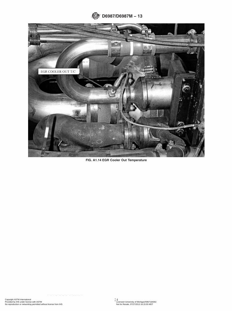
FIG. A1.14 EGR Cooler Out Temperature
D6987/D6987M − 13
24Copyright ASTM International Provided by IHS under license with ASTM Licensee=University of Michigan/5967164002
Not for Resale, 07/27/2013 16:15:55 MDTNo reproduction or networking permitted without license from IHS
--``,`,``,``,,```,,``,,,``,,```,-`-`,,`,,`,`,,`---

FIG. A1.15 EGR Pre-Venturi Temperature and Pressure
D6987/D6987M − 13
25Copyright ASTM International Provided by IHS under license with ASTM Licensee=University of Michigan/5967164002
Not for Resale, 07/27/2013 16:15:55 MDTNo reproduction or networking permitted without license from IHS
--``,`,``,``,,```,,``,,,``,,```,-`-`,,`,,`,`,,`---

FIG. A1.16 Before Oil Filter Pressure
D6987/D6987M − 13
26Copyright ASTM International Provided by IHS under license with ASTM Licensee=University of Michigan/5967164002
Not for Resale, 07/27/2013 16:15:55 MDTNo reproduction or networking permitted without license from IHS
--``,`,``,``,,```,,``,,,``,,```,-`-`,,`,,`,`,,`---

A2. PROCUREMENT OF TEST MATERIALS
A2.1 Throughout the text, references are made to necessaryhardware, reagents, materials, and apparatus. In many cases,for the sake of uniformity and ease of acquisition, certainsuppliers are named. If substitutions are deemed appropriatefor the specified suppliers, obtain permission to substitute inwriting from the TMC before such substitutions will beconsidered to be equivalent. The following entries represent aconsolidated listing of the ordering information necessary tocomplete the references found in the text.
A2.2 The test engine (P/N 11GBA81025) is available fromMack Trucks, Inc., 13302 Pennsylvania Ave., Hagerstown, MD21742. The oil pump and the parts shown in Table A2.1 areavailable from Test Engineering, Inc., 12718 Cimarron Path,San Antonio, TX 78249-3423.
A2.3 Air Filtration—Mack air filter element (p/n 57MD33)and Mack air filter housing (p/n 2MD3183) are available fromMack Trucks, Inc.
A2.4 Intercooler —When ordering the Modine cooler fromMack Trucks Inc., instruct the dealers to use P/N 5424 03 928031. Because it is a non-stocked part in the Mack partsdistribution system, it will appear as an invalid P/N. Explainthat the P/N is valid and that you want to have it expedited ona Ship Direct purchase order. It will then be shipped fromModine to you, bypassing the normal parts distribution system.
A2.5 Cleaning solvent that meets the requirements of 7.4 isavailable from local petroleum product suppliers.
A2.6 PC-9-HS reference diesel fuel is available from Chev-ron Phillips, Phillips 66 Co. Marketing Services Ctr., P.O. Box968, Borger, TX 79008-0968.
A2.7 Oil cooler adapter blocks are available from South-west Research Institute, 6220 Culebra Road, P.O. Drawer28510, San Antonio, TX 78228-0510.
FIG. A1.17 Intake Manifold Pressure
D6987/D6987M − 13
27Copyright ASTM International Provided by IHS under license with ASTM Licensee=University of Michigan/5967164002
Not for Resale, 07/27/2013 16:15:55 MDTNo reproduction or networking permitted without license from IHS
--``,`,``,``,,```,,``,,,``,,```,-`-`,,`,,`,`,,`---

A2.8 Pencool 3000 is available from The PenrayCompanies, Inc., 100 Crescent Center Pkwy., Suite 104,Tucker, GA 30084.
A2.9 Keil Probes are available from United Sensor Corp., 3Northern Blvd., Amherst, NH 03031.
A2.10 Bulldog Premium EO-M+ oil is available from localMack truck dealers.
A3. DETERMINATION OF OPERATIONAL VALIDITY
A3.1 Quality Index Calculation:
A3.1.1 Calculate quality index (QI) for all control param-eters according to the DACA II Report. In addition, account formissing or bad quality data according to the DACA II Report.
A3.1.2 Use the U, L, Over Range, and Under Range valuesshown in Table A3.1 for the QI calculations.
A3.1.3 Do not use the data from the first 6 min of Phase II.This is considered transition time and the data is not to be usedto calculate QI.
A3.1.4 Round the calculated QI values to the nearest 0.001.
A3.1.5 Report the QI values on Form 5.
A3.2 Averages :
A3.2.1 Calculate averages for all control, ranged, and non-control parameters and report the values on Form 5.
A3.2.2 The averages for control and non-control parametersare not directly used to determine operational validity but theymay be helpful when an engineering review is required (seeA3.4).
A3.3 Determining Operational Validity:
A3.3.1 QI threshold values for operational validity areshown in Table A3.1. Specifications for all ranged parametersare shown in Table A3.1.
A3.3.1.1 A test with EOT QI values for all control param-eters equal to or above the threshold values and with averagesfor all ranged parameters within specifications is operationallyvalid, provided that no other operational deviations exist thatmay cause the test to be declared invalid.
A3.3.1.2 A test with any control parameter QI value lessthan the threshold value requires an engineering review todetermine operational validity (see A3.4).
A3.3.1.3 With the exception of crankcase pressure, a testwith a ranged parameter average value outside the specificationis invalid. A test with crankcase pressure outside the specifi-cation requires an engineering review to determine operationalvalidity.
A3.4 Engineering Review:
A3.4.1 Conduct an engineering review when a controlparameter QI value is below the threshold value. A typicalengineering review involves investigation of the test data todetermine the cause of the below threshold QI. Other affectedparameters may also be included in the engineering review.This can be helpful in determining if a real control problemexisted and the possible extent to which it may have impactedthe test. For example, a test runs with a low QI for fuel flow.An examination of the fuel flow data may show that it containsseveral over range values. At this point, an examination of
TABLE A2.1 New Parts for Each Rebuild
Part Name Mack Part Number Quantity
1. Cylinder liners 509GC471 62. Piston Assembly 240GC2256M
Piston Crown 240GC5114M 6Piston Skirt 240GC5119M 6
3. Piston Ring Set 353GC2141 6No. 1 Compression ring 349GC3107 6No. 2 Compression ring 349GC3108 6
Oil ring 350GC343 64. Overhaul gasket sets 57GC2176 2
57GC2178A 157GC2179 1
5. Spin-on filters 485GB3191C 2Centrifugal filter cartridge 239GB244B 1
6. Engine coolant conditioner 25MF435B 17. Primary fuel filter 483GB470AM 18. Secondary fuel filter 483GB471M 19. Valve guides 714GB3103 2410. Valve stem seals 446GC32811. Connecting rod bearings 6
Upper 62GB327 6Lower 62GB328 6
12. Main Bearings 57GC387 713. Thrust Washers 714GC45 2
714GC46 2
NOTE 1—A P/N 57GC3116 cylinder rebuild kit contains items 1, 2, and3. Six kits are required per engine rebuild. A P/N 57GC2177B filter kitcontains items 5, 6, 7, and 8. A P/N 62GB2396A Service Bearing Paircontains one each of the upper and lower connecting rod bearings (item11).
D6987/D6987M − 13
28Copyright ASTM International Provided by IHS under license with ASTM Licensee=University of Michigan/5967164002
Not for Resale, 07/27/2013 16:15:55 MDTNo reproduction or networking permitted without license from IHS
--``,`,``,``,,```,,``,,,``,,```,-`-`,,`,,`,`,,`---

exhaust temperatures may help determine whether the instru-mentation problem affected real fuel flow versus affecting onlythe data acquisition.
A3.4.2 For reference oil tests, conduct the engineeringreview jointly with the TMC. For non-reference oil tests,optional input is available from the TMC for the engineeringreview.
A3.4.3 Determine operational validity based upon the engi-neering review and summarize the decision in the commentsection on Form 11. It may be helpful to include any supportingdocumentation at the end of the test report. The final decisionregarding operational validity rests with the laboratory.
A4. O2 SENSOR CALIBRATION
A4.1 Order:
A4.1.1 Run the calibration procedure in the order pre-scribed. Running in the wrong order will affect the finalcalibration.
A4.2 Equipment :
A4.2.1 The following equipment shall be available for thecalibration procedure:
A4.2.1.1 The O2 sensor and the readout instrumentation tobe used on the engine installation.
A4.2.1.2 The O2 calibration chamber is shown in Fig. A4.1.This chamber is a steel cylinder in which the sensor is mountedperpendicular to the gas flow. The chamber has a calibrationgas supply line and a small vent hole that allows continuousflow of calibration gas across the sensor. To regulate the gasflow, the gas supply line shall include a ball and tube flowmeter and a valve. The layout of the O2 calibration system isshown in Fig. A4.2.
A4.2.1.3 The various tubing and quick-connects needed todirect gas flow through the calibration chamber.
A4.3 Calibration Gases:
A4.3.1 The following pressure regulated calibration gasesshall be available:
A4.3.1.1 Nitrogen, 100 (100.0/99.8 %).
A4.3.1.2 Oxygen, 5.0 % 6 0.2 %.A4.3.1.3 Oxygen, 9.0 % 6 0.2 %.
A4.4 Calibration Procedure:
A4.4.1 Sensor Installation:A4.4.1.1 Screw the O2 sensor into the calibration chamber
and secure to minimize leaks. Do not over tighten. Plug thesensor into the readout and then power up the readout. Allowthe sensor element to reach operating temperature; thiswarm-up takes a minimum of 15 min.
NOTE A4.1—The sensing element and body are both very hot whenplugged in. Take all precautions necessary to avoid burns. Avoid splashingliquids or directing air from an air hose across the sensor. These conditionscan cause sudden cooling of the sensor, which will cause instant failure ofthe crystal element.
A4.4.2 Pre-Calibration Measurements:A4.4.2.1 Record the actual calibration gas concentration
that is certified on each gas bottle.A4.4.2.2 Attach the nitrogen bottle to the calibration cham-
ber and adjust the gas flow across the chamber to 3 L/min.Regulate flow using the pressure regulator valve on the gasbottle, not the control valve on the flow meter. Wait 5 min andrecord the percent oxygen. Do not adjust the O2 meter.
A4.4.2.3 Attach the 5 % O2 bottle to the calibration cham-ber and adjust the gas flow across the chamber to 3 L/min.Regulate flow using the pressure regulator valve on the gas
TABLE A3.1 Quality Index and Average Calculation Values
Control Parameter UnitsQuality Index
ThresholdQuality Index U and L Values Over and Under Range Values
U L Low High
SpeedA r/min 0.000 1802.5 1202.5 1797.5 1197.5 1063 1937Fuel flowA kg/h 0.000 60.20 64.50 58.20 62.50 4.4 118.3Inlet manifold temperature °C 0.000 70.8 66.8 69.2 65.2 22.2 113.8Coolant out temperature °C 0.000 66.9 85.9 65.1 84.1 16.7 134.3Fuel in temperature °C 0.000 40.5 39.5 12.6 67.4Oil gallery temperature °C 0.000 88.6 113.6 87.4 112.4 55.1 145.9Intake air temperature °C 0.000 26.0 24.0 –29.8 79.8
Ranged parameter Units RangeOver and Under Range Values
Low HighInlet air restriction kPa 3.5-4.0 0 14Inlet manifold pressure kPa min 160 min 210 0 400Exhaust back pressure kPa 2.7-3.5 0 16Crankcase pressure kPa 0.25-0.75 0 3Intake CO2 % 1.5 ± 0.05 0.2 ± 0.05 0 5A U and L values for speed, fuel flow, coolant out temperature, and oil gallery temperature are split by test phase.
D6987/D6987M − 13
29Copyright ASTM International Provided by IHS under license with ASTM Licensee=University of Michigan/5967164002
Not for Resale, 07/27/2013 16:15:55 MDTNo reproduction or networking permitted without license from IHS
--``,`,``,``,,```,,``,,,``,,```,-`-`,,`,,`,`,,`---

bottle, not the control valve on the flow meter. Wait 5 min andrecord the percent oxygen. Do not adjust the O2 meter.
A4.4.2.4 Attach the 9 % O2 bottle to the calibration cham-ber and adjust the gas flow across the chamber to 3 L/min.Regulate flow using the pressure regulator valve on the gasbottle, not the control valve on the flow meter. Wait 5 min andrecord the percent oxygen. Do not adjust the O2 meter.
A4.4.3 Calibration Measurements:A4.4.3.1 Reattach the nitrogen bottle and adjust flow to
3 L/min. Wait 5 min for stabilization and adjust the readout toachieve the correct O2 gas concentration. Record the correctedreading.
A4.4.3.2 Reattach the 5 % oxygen bottle and adjust flow to3 L/min. Wait 5 min for stabilization and adjust the readout toachieve the correct O2 gas concentration. Record the correctedreading.
A4.4.3.3 Reattach the 9 % oxygen bottle and adjust flow to3 L/min. Wait 5 min for stabilization and adjust the readout toachieve the correct O2 gas concentration. Record the correctedreading.
A4.4.3.4 Recheck the 5 % O2 reading. If it has not changed,reconnect the 9 % O2 bottle and confirm the reading is stillcorrect.
A4.4.3.5 Once the 5 % and 9 % readings are stable, measurethe 0 % O2 and record. Do not readjust the readout. Thisreading is only done to confirm the fitness of the sensor and toprovide a level of confidence in precision in the O2 measuringsystem.
A4.5 Records :
A4.5.1 File all measurements with the permanent laboratorycalibration records. A sample O2 calibration sheet is shown inTable A4.1.
A4.5.2 When re-installing the O2 sensor in the engineexhaust tube, use an anti-seize compound specifically approvedfor O2 sensors (contains no lead).
FIG. A4.1 Oxygen Sensor Calibration Chamber
D6987/D6987M − 13
30Copyright ASTM International Provided by IHS under license with ASTM Licensee=University of Michigan/5967164002
Not for Resale, 07/27/2013 16:15:55 MDTNo reproduction or networking permitted without license from IHS
--``,`,``,``,,```,,``,,,``,,```,-`-`,,`,,`,`,,`---

FIG. A4.2 Oxygen Sensor Calibration System
TABLE A4.1 Sample Oxygen Sensor Calibration Sheet
T-10 Oxygen Sensor Calibration Sheet
Laboratory:Date:Test Stand:Stand Run Number:Engine Serial Number:Engine Hours:
Calibration Gas Information and Calibration Results
Calibration Gas IdentificationRequired Calibration Gas
ConcentrationCertified
Concentration %Pre-Calibration
Oxygen %Post Calibration
Oxygen %0 % Oxygen (nitrogen 100 %) 100.0 ± 0.2 % Nitrogen5 % Oxygen 5.0 ± 0.2 % Oxygen9 % Oxygen 9.0 ± 0.2 % Oxygen
D6987/D6987M − 13
31Copyright ASTM International Provided by IHS under license with ASTM Licensee=University of Michigan/5967164002
Not for Resale, 07/27/2013 16:15:55 MDTNo reproduction or networking permitted without license from IHS
--``,`,``,``,,```,,``,,,``,,```,-`-`,,`,,`,`,,`---

A5. TEMPERATURE TO INJECTION TIMING CORRELATION
A5.1 See Table A5.1.
A6. BREAK-IN, START-UP, SHUTDOWN, AND TRANSITION PROCEDURES
A6.1 The break-in sequence is shown is Table A6.1.
A6.2 The Phase I start-up sequence is shown in Table A6.2.
A6.3 The Phase II start-up sequence is shown in Table A6.3.
A6.4 The shutdown sequence for Phases I and II is shown inTable A6.4.
A6.5 The transition sequence from Phase I to Phase II isshown in Table A6.5.
A6.6 Emergency (or hard) shutdowns are considered alaboratory safety procedure and are not specified by this testmethod.
A6.7 The torque values in Tables A6.1-A6.5 are nominalvalues. Run the appropriate fuel rates to achieve the nominaltorque values.
TABLE A5.1
Intake ManifoldTemperature
Injection Timing(°BTDC)
30 2140 1850 1560 1270 980 690 3
TABLE A6.1 Break-In Sequence
StepTime
(h:mm:ss)Speed(r/min)
Torque(N·m)
Comments
Prior to start set injection timing to 18° BTDC and full EGR bypass1 0:00:00 idle 0 engine idle, waiting for oil pressure
0:00:10 idle 0 proceed if oil pressure >138 kPa2 0:00:11 idle 245 engine idle; set torque to 245; hold conditions for 4 min 50 s3 0:05:00 1200 245 set speed to 1200; linearly ramp torque to 815 in 4 min
0:09:00 1200 815 end of torque ramp; hold conditions for 2 min 30 s4 0:11:30 1200 815 linearly ramp torque to 1085 in 2 min
0:13:30 1200 1085 end of torque ramp; hold conditions for 2 min 30 s5 0:16:00 1200 1085 linearly ramp torque to 2440 in 10 min
0:26:00 1200 2440 end of torque ramp, hold conditions for 2 min 30 s0:28:30 1200 2440 set EGR, hold conditions for 30 min
6 0:58:30 1200 2440 linearly ramp torque to 1300 in 2 min0:59:00 1200 ramping linearly ramp speed to 1800 in 2 min1:00:30 ramping 1300 end of torque ramp1:01:00 1800 1300 end of speed ramp; hold conditions for 2 min 30 s1:03:30 1800 1300 set injection timing and EGR, hold conditions for 30 min
7 1:33:30 1800 1300 proceed to shutdown sequence
D6987/D6987M − 13
32Copyright ASTM International Provided by IHS under license with ASTM Licensee=University of Michigan/5967164002
Not for Resale, 07/27/2013 16:15:55 MDTNo reproduction or networking permitted without license from IHS
--``,`,``,``,,```,,``,,,``,,```,-`-`,,`,,`,`,,`---

TABLE A6.2 Phase I Start-Up Sequence
StepTime
(h:mm:ss)Speed(r/min)
Torque(N·m)
Comments
Prior to start set injection timing to 18° BTDC and full EGR bypass1 0:00:00 idle 0 engine idle, waiting for oil pressure
0:00:10 idle 0 proceed if oil pressure >138 kPa2 0:00:11 idle 245 engine idle; set torque to 245, hold conditions for 4 min 50 s3 0:05:00 1200 245 set speed to 1200; linearly ramp torque to 815 in 4 min
0:09:00 1200 815 end of torque ramp; hold conditions for 2 min 30 s4 0:11:30 1800 815 set speed to 1800; linearly ramp torque to 1085 in 2 min
0:13:30 1800 1085 end of torque ramp, hold conditions for 2 min 30 s5 0:16:00 1800 1085 linearly ramp torque to 1300 in 2 min
0:18:00 1800 1300 end of torque ramp; hold conditions for 2 min 30 s0:20:30 1800 1300 set injection timing and EGR; proceed to Phase I, set fuel rate
TABLE A6.3 Phase II Start-Up Sequence
StepTime
(h:mm:ss)Speed(r/min)
Torque(N·m)
Comments
Prior to start set injection timing to 18° BTDC and full EGR bypass1 0:00:00 idle 0 engine idle, waiting for oil pressure
0:00:10 idle 0 proceed if oil pressure >138 kPa2 0:00:11 idle 245 engine idle; set torque to 245; hold conditions for 4 min 50 s3 0:05:00 1200 245 set speed to 1200; linearly ramp torque to 815 in 4 min
0:09:00 1200 815 end of torque ramp; hold conditions for 2 min 30 s4 0:11:30 1200 815 linearly ramp torque to 2440 in 10 min
0:21:30 1200 2440 end of torque ramp; hold conditions for 2 min 30 s5 0:24:00 1200 2440 set EGR; proceed to Phase II; set fuel rate
TABLE A6.4 Shutdown Sequence, Phases I and II
StepTime
(h:mm:ss)Speed(r/min)
Torque(N·m)
Comments
Prior to start of shutdown sequence engine running at test conditions, either Phase I or II1 0:00:00 1800/
12001300/2440 set EGR to full bypass; linearly ramp torque to 815 in 1 min
0:01:00 1800/1200
815 end of torque ramp; hold conditions for 1 min
2 0:02:00 1800/1200
815 linearly ramp torque to 270 in 1 min 30 s
0:03:30 1800/1200
270 end of torque ramp; hold conditions for 3 min 30 s
3 0:07:00 1800/1200
270 linearly ramp torque to 0 in 1 min; linearly ramp speed to idle in 2 min
0:08:00 ramping 0 end of torque ramp0:09:00 idle 0 end of speed ramp; hold conditions for 1 min
4 0:10:00 idle 0 stop engine in 1 s0:10:01 0 0 end of shutdown
TABLE A6.5 Transition Sequence from Phase I to Phase II
StepTime
(h:mm:ss)Speed(r/min)
Torque(N·m)
Comments
Prior to start of sequence phase I has completed; set injection timing to 18° BTDC1 0:00:00 1800 1300 linearly ramp speed to 1200 in 2 min 30 s
0:02:00 ramping 1300 linearly ramp torque to 2440 in 2 min 30 s0:02:30 1200 ramping end of speed ramp0:04:30 1200 2440 end of torque ramp; hold conditions for 2 min 30 s
2 0:07:00 1200 2440 set EGR and fuel rate; proceed to Phase II
D6987/D6987M − 13
33Copyright ASTM International Provided by IHS under license with ASTM Licensee=University of Michigan/5967164002
Not for Resale, 07/27/2013 16:15:55 MDTNo reproduction or networking permitted without license from IHS
--``,`,``,``,,```,,``,,,``,,```,-`-`,,`,,`,`,,`---

A7. SAFETY HAZARDS
A7.1 General :
A7.1.1 Operating engine tests can expose personnel andfacilities to a number of safety hazards. It is recommended thatonly personnel who are thoroughly trained and experienced inengine testing should undertake the design, installation, andoperation of engine test stands.
A7.1.2 Each laboratory conducting engine tests should havetheir test installation inspected and approved by their SafetyDepartment. Personnel working on the engines should beprovided with proper tools, be alert to common sense safetypractices, and avoid contact with moving or hot engine parts, orboth. Guards should be installed around all external moving orhot parts. When engines are operating at high speeds, heavy-duty guards are required and personnel should be cautionedagainst working alongside the engine and coupling shaft.Barrier protection should be provided for personnel. All fuellines, oil lines, and electrical wiring should be properly routed,guarded, and kept in good order. Scraped knuckles, minorburns, and cuts are common if proper safety precautions are nottaken. Safety masks or glasses should always be worn bypersonnel working on the engines and no loose or flowingclothing, including long hair or other accessory to dress whichcould become entangled, should be worn near running engines.
A7.1.3 The external parts of the engines and the floor areaaround the engines should be kept clean and free of oil and fuelspills. In addition, all working areas should be free of trippinghazards. Personnel should be alert for leaking fuel or exhaustgas. Leaking fuel represents a fire hazard and exhaust gasfumes are noxious. Containers of oil or fuel cannot bepermitted to accumulate in the testing area.
A7.1.4 The test installation should be equipped with a fuelshut-off valve, which is designed to automatically cutoff thefuel supply to an engine when the engine is not running. Aremote station for cutting off fuel from the test stand isrecommended. Suitable interlocks should be provided so thatthe engine is automatically shutdown when any of the follow-ing events occur: (1) engine or dynamometer water tempera-ture becomes excessive; (2) engine loses oil pressure; (3)dynamometer loses field current; (4) engine over-speeds; (5)exhaust system fails; (6) room ventilation fails; or (7) the fireprotection system is activated.
A7.1.5 Consider an excessive vibration pickup interlock, ifequipment operates unattended. Fixed fire protection equip-ment should be provided.
A7.1.6 Normal precautions should be observed when usingflammable solvents for cleaning purposes. Ensure adequate firefighting equipment is immediately accessible.
A8. T-10A ABBREVIATED LENGTH TEST REQUIREMENTS
A8.1 Overview —The purpose of the T-10A is to providethe low temperature viscosity result for used oil. The lowtemperature result in question is the MRV viscosity after 75 hat Stage I T-10 conditions. This result may be obtained twodifferent ways. First, it may be obtained from an operationallyvalid standard T-10 test. Second, it may be obtained from a teststand setup that runs only the first 75 h of T-10 conditions.Unlike the standard T-10 test, this form of the T-10A does notrequire a new engine build with each test. Instead, it is aflush-and-run setup. With the exception of A8.4, A8.5.2,A8.5.3, and A8.6, no special instructions are necessary toobtain a T-10A result from a standard T-10. The specialinstructions necessary to obtain a T-10A result from a flush-and-run setup are contained in the remainder of this annex.
A8.2 Preparation of Apparatus at Rebuild (refer to Section8)—The timing and frequency of engine rebuild is left
to the discretion of the laboratory.
A8.2.1 Injectors (refer to 8.4.1)—Check the injector open-ing pressure at rebuild. Reset the injector opening pressure if itis outside the specification of 36 900 kPa to 37 900 kPa [5350to 5500 psi].
A8.3 Procedure (refer to Section 9):
A8.3.1 Pretest Oil Flush—The pre-test flush is not per-formed on a new engine build. For new engine builds, run thebreak-in sequence according to A8.3.2. For existing enginebuilds, flush the engine and auxiliary oil system with test oil for15 min. Drain the oil. Repeat the flush and drain sequence twomore times. Use the same set of oil filters for all three flushes.At the completion of the third flush, drain the oil, change the oilfilters, and charge the engine and auxiliary oil system with testoil. Proceed with the test according to A8.3.3.
A8.3.2 Pretest Break-In (see 9.1.2)—The pre-test break-in isnot necessary for every test; it is only necessary for a newengine build. For a new engine build, run a 30 min break-in atPhase I conditions. To do this, follow the Phase I start-upsequence shown in Table A6.2, and once the start-up sequenceis complete, hold the conditions for 30 min. Change all oilfilters at the completion of the break-in.
A8.3.3 Test Cycle (see 9.4)—Conduct the test by operatingfor 75 h at Phase I conditions, which are shown in Table 2.
A8.3.4 Post-Test Oil Flush—At the completion of the test,drain the oil and change the oil filters. Hot flush the engine andauxiliary oil system with Bulldog Premium Oil for 15 min.Drain the oil. Repeat the flush and drain sequence two moretimes. Use the same set of oil filters for all three flushes.
D6987/D6987M − 13
34Copyright ASTM International Provided by IHS under license with ASTM Licensee=University of Michigan/5967164002
Not for Resale, 07/27/2013 16:15:55 MDTNo reproduction or networking permitted without license from IHS
--``,`,``,``,,```,,``,,,``,,```,-`-`,,`,,`,`,,`---

A8.4 Oil Inspection (see 10.3)—Analyze the 75 h oilsample for MRV viscosity according to a research report11 onmini-rotary viscosity and yield stress of highly sooted dieselengine oils. As part of the MRV measurement procedure, besure to prepare the sample in accordance with A4.3 (Annex A4)of Test Method D5967.
A8.5 Laboratory and Engine Test Stand Calibration/Non-Reference Oil Requirements (Section 11):
A8.5.1 Test Stand/Engine Calibration (refer to 11.5)—Thecalibration period for a flush-and-run T-10A is five operation-ally valid non-reference oil tests.
A8.5.1.1 A T-10A flush-and-run stand may be installed in astand that originally calibrated as a standard T-10 withoutimpacting the standard T-10 calibration status. However, theflush-and-run setup will only be calibrated for the first non-reference oil test. To re-establish calibration, a reference oil testshall be run following the first test on the flush-and-run engine.
A8.5.1.2 A newly rebuilt engine requires a reference oil testto establish test stand calibration. Additionally, a T-10A cannotbe run on an engine build that has seen Phase II test conditions(break-in conditions are excluded for a T-10A obtained as partof a standard T-10).
A8.5.2 Test Result (see 11.6)—The specified test result isMRV viscosity at 75 h. Report the result on Forms 4 and 8.
A8.5.3 Non-Reference Oil Test Result Severity Adjustments(see 11.8)—This test method incorporates the use of an SA fornon-reference oil test results. A control chart technique, de-scribed in the LTMS, has been selected for identifying when abias becomes significant for MRV viscosity at 75 h. Whencalibration test results identify a significant bias, an SA isdetermined according to LTMS. Report the SA on Form 4 inthe space for SA. Add this SA value to non-reference oil testresults, and enter the SA adjusted result in the appropriatespace. The SA remains in effect until a new SA is determinedfrom subsequent calibration test results, or the test resultsindicate the bias is no longer significant. Calculate and applySA on a laboratory basis. Be aware that the SA applied tonon-reference results is the laboratory SA that is in place at thecompletion of the 75th hour of the test (that is, for T-10Aresults that are obtained through a standard length T-10, do notuse the SA at EOT of the T-10, instead use the SA that is inplace at 75 h).
A8.6 Precision and Bias (refer to Section 13):
A8.6.1 Precision—The test precision for MRV Viscosity at75 h, as of December 23, 2003, is shown in Table A8.1.
A8.6.2 Bias—Bias is determined by applying the LTMScontrol chart technique (see A8.5.3) and when a significant biasis determined, a severity adjustment is permitted for non-reference oil test results.
A9. T-10 RING AND LINER OUTLIER SCREENING CRITERIA
A9.1 Average Top Ring Weight Loss:
A9.1.1 Calculate the average top ring weight loss using allrings and report the data on the appropriate forms.
A9.1.2 For each cylinder, calculate the top ring weight lossrelative offset as:Table A9.1
TRWLOffsetcylinder5 (A9.1)
~TRWLcylinder 2 ATRWL 2 RRPTRWLcylinder!/RSDTRWL
where:TRWLcylinder = top ring weight loss for the cylinder, mg,ATRWL = average top ring weight loss from A9.1.1,
mg,RRPTRWL = reference relative top ring weight loss profile
from Table A9.1,RSDTRWL = reference top ring weight loss standard de-
viation from Table A9.1, andCylinder = 1,2,3,4,5,6.
11 Supporting data have been filed at ASTM International Headquarters and maybe obtained by requesting Research Report RR:D02-1517.
TABLE A8.1 Test Precision
Test ResultIntermediate Precision
(i.p.)Reproducibility (R)
MRV viscosity at 75 h(cP)
2108 2139
D6987/D6987M − 13
35Copyright ASTM International Provided by IHS under license with ASTM Licensee=University of Michigan/5967164002
Not for Resale, 07/27/2013 16:15:55 MDTNo reproduction or networking permitted without license from IHS
--``,`,``,``,,```,,``,,,``,,```,-`-`,,`,,`,`,,`---

A9.1.2.1 If maximum |TRWLOffsetcylinder| > 2.20, theoutlier screened average top ring weight loss is the average ofthe top ring weight losses for the five cylinders for which|TRWLOffsetcylinder| is not maximized plusRRPTRWLcylinder/6 for the cylinder where it is maximized.
A9.1.2.2 If max |TRWLOffsetcylinder| ≤ 2.20, the outlierscreened average top ring weight loss is identical to the averagetop ring weight loss.
A9.2 Average Cylinder Liner Wear:
A9.2.1 Calculate the average cylinder liner wear step usingall cylinder liners. Report the data on Forms 4 and 10.
A9.2.2 For each cylinder, calculate the cylinder liner wearstep relative offset as:
CLWOffsetcylinder 5 ~CLWcylinder 2 ACLW 2 RRPCLWcylinder!/RSDCLW
(A9.2)
where:CLWcylinder = cylinder liner wear step for the cylinder,
µm,ACLW = average cylinder liner wear step from
A9.2.1, µm,RRPCLWcylinder = reference relative cylinder liner wear step
profile from Table A9.1,RSDCLW = reference cylinder liner wear step stan-
dard deviation from Table A9.1, andCylinder = 1,2,3,4,5,6.
A9.2.2.1 If maximum |CLWOffsetcylinder| > 2.20, the outlierscreened average cylinder liner wear step is the average of thecylinder liner wear steps for the five cylinders for which|CLWOffsetcylinder| is not maximized plus RRPCLWcylinder/6for the cylinder where it is maximized.
A9.2.2.2 If maximum |CLWOffsetcylinder| ≤ 2.20, the outlierscreened average cylinder liner wear step is identical to theaverage cylinder liner wear step.
A10. T-10 MACK MERIT CALCULATION METHODOLOGY
A10.1 Merit System Components:
A10.1.1 Targets—Target performance level based on onetest.
A10.1.2 Maximums—Limit of acceptable performance.
A10.1.3 Minimums—Best achievable result.
A10.1.4 Weights—Relative contribution to total merit.
A10.1.5 Multipliers—Using Table A10.1, determine themultiplier for each parameter as follows:
A10.1.5.1 If a result is at the target, multiplier is one (forexample, liner wear = 30 yields multiplier = 1).
A10.1.5.2 If a result is at or below the minimum, multiplieris two (for example, liner wear = 10 yields multiplier = 2).
A10.1.5.3 If a result is at the maximum, multiplier is zero(for example, liner wear = 32.0 yields multiplier = 0).
A10.1.5.4 If a result is between minimum and target,linearly interpolate multiplier between 2 and 1 (for example,liner wear = 24 yields multiplier = 1 + (24 − 30)/(12 − 30) =1.33).
A10.1.5.5 If a result is between target and maximum,linearly interpolate multiplier between 1 and 0 (for example,liner wear = 31.0 yields multiplier = 1 − (31.0 − 30)/(32.0 − 30)= 0.5).
A10.1.5.6 If a result is above the maximum, linearly ex-trapolate multiplier on the same line as between 1 and 0 (forexample, liner wear = 33.0 yields multiplier = 1 − (33.0 −30)/(32.0 − 30) = -0.5).
A10.2 Calculated Merit Result—Sum the products ofweights and multipliers across the five results. This is thecalculated merit result. In equation form:
calculated Merit 5 (i51
5
weighti (A10.1)
x H δ~resulti.targeti! 3 ~maxi 2 resulti!/~maxi 2 targeti!
1δ~mini,resulti # targeti! 3 @11~targeti 2 resulti!/~targeti 2 mini!#
1δ~resulti # mini! 3 2J
where:δ(x) = 1 if x is true; 0 if x is false.
A10.2.1 Report the results of the merit calculations on Form4.
TABLE A9.1 Relative ProfilesA
CylinderCylinder Liner Wear
RRPCLWMiddle Ring Weight Loss
RRPTRWL
1 4.5 392 -0.6 -13 -0.6 84 -1.2 -175 -1.6 -26 -0.6 -27
RSDCLW RRPTRWLStandard Deviation. 5.9 45
A Contact the TMC to obtain a history of cylinder liner wear and top ring weight lossrelative profiles.
TABLE A10.1
Criterion0-300 Hour
Delta Pb
250-300Hour
Delta Pb
CylinderLinerWear
Top RingWeightLoss
OilConsumption
Weight 225 225 250 150 150Maximum 35 14 32.0 158 65.0
Target 30 10 30 140 57Minimum 5 0 12 50 25
D6987/D6987M − 13
36Copyright ASTM International Provided by IHS under license with ASTM Licensee=University of Michigan/5967164002
Not for Resale, 07/27/2013 16:15:55 MDTNo reproduction or networking permitted without license from IHS
--``,`,``,``,,```,,``,,,``,,```,-`-`,,`,,`,`,,`---

APPENDIX
(Nonmandatory Information)
X1. T-10 WITH ULTRA-LOW SULFUR DIESEL FUEL (ULSD)
X1.1 The European Automobile Manufacturers Association(ACEA) uses results from T-10 tests run on ultra-low sulfurdiesel fuel, designated by ACEA as the T-10 ULSD. Ranges for
such a fuel are provided in Table X1.1. This test method makesno attempt to quantify precision or discrimination betweenresults for T-10 tests run with this or any other alternate fuel.
SUMMARY OF CHANGES
Subcommittee D02.B0 has identified the location of selected changes to this standard since the last issue(D6987 – 11) that may impact the use of this standard.
(1) Subsection A2.6 has a revised fuel designation.(2) Editorial changes were made, applying Form and Style(including SI 10) guidelines.
ASTM International takes no position respecting the validity of any patent rights asserted in connection with any item mentionedin this standard. Users of this standard are expressly advised that determination of the validity of any such patent rights, and the riskof infringement of such rights, are entirely their own responsibility.
This standard is subject to revision at any time by the responsible technical committee and must be reviewed every five years andif not revised, either reapproved or withdrawn. Your comments are invited either for revision of this standard or for additional standardsand should be addressed to ASTM International Headquarters. Your comments will receive careful consideration at a meeting of theresponsible technical committee, which you may attend. If you feel that your comments have not received a fair hearing you shouldmake your views known to the ASTM Committee on Standards, at the address shown below.
This standard is copyrighted by ASTM International, 100 Barr Harbor Drive, PO Box C700, West Conshohocken, PA 19428-2959,United States. Individual reprints (single or multiple copies) of this standard may be obtained by contacting ASTM at the aboveaddress or at 610-832-9585 (phone), 610-832-9555 (fax), or [email protected] (e-mail); or through the ASTM website(www.astm.org). Permission rights to photocopy the standard may also be secured from the ASTM website (www.astm.org/COPYRIGHT/).
TABLE X1.1 ULSD Fuel Specification
Property Specification ASTM Test MethodAdditives Lubricity additive only . . .Distillation Range, °C 90 % 293 – 332 D86Specific Gravity 0.840 – 0.855 D4052API Gravity 34 – 37 D4052Corrosion, 3 h at 50 °C 1 max D130Sulfur, mass, mg/kg 7 – 15 D5844Flash Point, °C 54 min D93Pour Point, °C -18 max D97Cloud Point, °C Report D2500Viscosity at 40 °C, cSt 2.0 – 2.6 D445Ash, weight % 0.005 max D482Carbon Residue on 10 % Bottoms 0.35 max D524Net Heat of Combustion Report D3338Water and Sediment, volume % 0.05 max D2709Total Acid Number 0.05 max D664Strong Acid Number 0 max D664Cetane Index Report D976Cetane Number 43 – 47 D613Accelerated Stability, mg/100 mL 1.5 max D2274Composition:
Aromatics, wt % 26 – 31.5 D5186Olefins, vol % Report D1319Saturates, vol % Report D1319
SLBOCLE, g 3100 minA D6078A
A May be altered to be consistent with CARB or ASTM diesel fuel specifications.
D6987/D6987M − 13
37Copyright ASTM International Provided by IHS under license with ASTM Licensee=University of Michigan/5967164002
Not for Resale, 07/27/2013 16:15:55 MDTNo reproduction or networking permitted without license from IHS
--``,`,``,``,,```,,``,,,``,,```,-`-`,,`,,`,`,,`---