Aftertreatment Diesel Exhaust Fluid Tank (DEF) Level Sensor ...
15
Aftertreatment Diesel Exhaust Fluid Tank (DEF) Level Sensor, Replacement VAH, VHD, VN Aftertreatment Diesel Exhaust Fluid Tank (DEF) Level Sensor, Replacement W2055830 This information covers the procedure for replacing the fluid level sensor in the aftertreatment diesel exhaust fluid (DEF) tank on VOLVO VAH, VHD and VN vehicles. Contents • “Special Tools”, page 2 . • “AftertreatmentDiesel Exhaust Fluid (DEF) Tank, Level Sensor, Replacement”, page 3 . Note: Information is subject to change without notice. Illustrations are used for reference only and can differ slightly from the actual vehicle being serviced. However, key components addressed in this information are represented as accurately as possible. SSeerrvviicceBBulllleettiinn Volvo Trucks North America TTrruucckss Greensboro, NC USA Date Group No. Release Page This service bulletin replaces bulletin 258-78 dated 3.2010. 10.2012 258 78 02 1(15) PV776-89076851 USA55941 English
-
Upload
khangminh22 -
Category
Documents
-
view
4 -
download
0
Transcript of Aftertreatment Diesel Exhaust Fluid Tank (DEF) Level Sensor ...

AftertreatmentDiesel Exhaust Fluid Tank(DEF) Level Sensor, Replacement
VAH, VHD, VN
AAfftteerrttrreeaattmmeenntt DDiieesseell EExxhhaauusstt FFlluuiidd TTaannkk ((DDEEFF))LLeevveell SSeennssoorr,, RReeppllaacceemmeenntt
W2055830
This information covers the procedure for replacing the fluid level sensor in the aftertreatmentdiesel exhaust fluid (DEF) tank on VOLVO VAH, VHD and VN vehicles.
CCoonntteennttss• “Special Tools”, page 2 .
• “AftertreatmentDiesel Exhaust Fluid (DEF) Tank, Level Sensor, Replacement”, page 3 .
NNoottee:: Information is subject to change without notice.Illustrations are used for reference only and can differ slightly from the actual vehicle beingserviced. However, key components addressed in this information are represented asaccurately as possible.
SSeerrvviiccee BBuulllleettiinnVVoollvvoo TTrruucckkss NNoorrtthhAAmmeerriiccaa TTrruucckkssGreensboro, NC USA
Date Group No. Release PageThis service bulletin replaces bulletin 258-78 dated 3.2010. 10.2012 225588 7788 0022 1(15)
PPVV777766--8899007766885511USA55941 English
VVoollvvoo TTrruucckkss NNoorrtthh AAmmeerriiccaa Date Group No. Release PageSSeerrvviiccee BBuulllleettiinn 10.2012 225588 7788 0022 2(15)
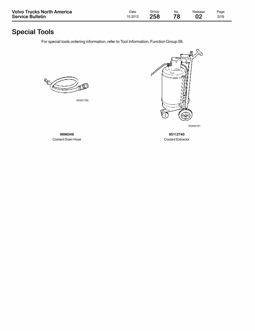
SSppeecciiaall TToooollssFor special tools ordering information, refer to Tool Information, Function Group 08.
W0001795
W2004191
99999966004499Coolant Drain Hose
8855111122774400Coolant Extractor
VVoollvvoo TTrruucckkss NNoorrtthh AAmmeerriiccaa Date Group No. Release PageSSeerrvviiccee BBuulllleettiinn 10.2012 225588 7788 0022 3(15)
22558899--0033--0022--0055AAfftteerrttrreeaattmmeenntt DDiieesseell EExxhhaauusstt FFlluuiidd ((DDEEFF)) TTaannkk,, LLeevveell SSeennssoorr,,
RReeppllaacceemmeennttYou must read and understand the precautions and guide-lines in Service Information, Function Group 20, "EngineSafety Practices" before performing this procedure. If youare not properly trained and certified in this procedure, askyour supervisor for training before you perform it.
WWAARRNNIINNGG
AftertreatmentDEF is an irritant. Contact with DEF can irri-tate the skin and eyes. Inhaling DEF mist can cause lungirritation. Avoid DEF contact with skin and eyes. Avoidbreathing mist created by DEF spray.
WWAARRNNIINNGG
When disconnecting hoses and components, do not spillDEF onto separated connectors. If this occurs, replace theconnectors immediately. Cleaning with water or com-pressed air will not help as the DEF quickly oxidizes metaland, due to capillary action, “creeps” along cabling at aspeed of about 0.6 meters/hour.
NNoottee:: If the DEF lines will remain open for an extended peri-od of time, seal the opening to prevent crystallization of fluidin the line.
NNoottee:: Before removing appropriate coolant and DEF lines,please mark them to ensure proper reinstallation to the cor-rect location
Special tools: 85112740, 9996040
Removal11Secure the vehicle for service by parking it on a flat level sur-face, applying the parking brake, chocking the rear wheels,and placing the transmission in neutral or park.
22If equipped, remove the left-side fairing under the cab door togain access to the diesel exhaust fluid (DEF) tank and sur-rounding components.
33Disconnect all cables from the negative (ground) battery ter-minals to prevent personal injury from electrical shock andprevent damage to electrical components.

VVoollvvoo TTrruucckkss NNoorrtthh AAmmeerriiccaa Date Group No. Release PageSSeerrvviiccee BBuulllleettiinn 10.2012 225588 7788 0022 4(15)
W2004191
44Connect the coolant extractor to the drain fitting at the bottomof the radiator and drain the coolant.
NNoottee:: An alternate method is to connect a coolant drain hoseto the radiator drain fitting and drain the coolant into a suit-able container.
DDAANNGGEERR
Coolant is toxic and can pose a risk of poisoning. Do notdrink coolant. Use proper hand protection when handling.Keep coolant out of reach of children and animals. Failureto follow these precautions can cause serious illness ordeath.
85112740
W2055831
1 DEF Tank Drain Plug
55Remove the drain plug from the DEF tank and, using a suit-able container, catch any drained fluid remaining in the tank.When all the fluid has drained, replace the drain plug andtighten.

VVoollvvoo TTrruucckkss NNoorrtthh AAmmeerriiccaa Date Group No. Release PageSSeerrvviiccee BBuulllleettiinn 10.2012 225588 7788 0022 5(15)
W2055832
1 ACM Electrical Connector
66Disconnect the electrical harness from the aftertreatmentcontrol module (ACM) electrical connector.
W2055838
1 Level Sensor Electrical Connector
77If equipped, disconnect the electrical harness from the levelsensor electrical connector.

VVoollvvoo TTrruucckkss NNoorrtthh AAmmeerriiccaa Date Group No. Release PageSSeerrvviiccee BBuulllleettiinn 10.2012 225588 7788 0022 6(15)
W2077567
1 DEF Quality Sensor Module Electrical Connector
W2077951
1 DEF Quality Sensor Module Electrical Connector 25LTank

VVoollvvoo TTrruucckkss NNoorrtthh AAmmeerriiccaa Date Group No. Release PageSSeerrvviiccee BBuulllleettiinn 10.2012 225588 7788 0022 7(15)
W2077950
1 DEF Quality Sensor Module Electrical Connector 33LTank
88 If equipped, disconnect the electrical harness from the DEFquality sensor module electrical connector. Remove the fas-teners from the module.
99Disconnect the electrical harness from the DEF pump electri-cal connector.
1100Disconnect the DEF pump-to-doser valve fluid hose and theelectrical connector.
1111Disconnect the coolant lines from the DEF tank.
1122Position a floor jack under the DEF tank and use the jack tosupport the weight of the DEF tank.
VVoollvvoo TTrruucckkss NNoorrtthh AAmmeerriiccaa Date Group No. Release PageSSeerrvviiccee BBuulllleettiinn 10.2012 225588 7788 0022 8(15)
W2055835
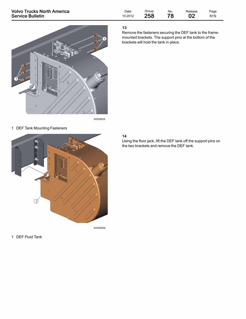
1 DEF Tank Mounting Fasteners
1133Remove the fasteners securing the DEF tank to the frame-mounted brackets. The support pins at the bottom of thebrackets will hold the tank in place.
W2055836
1 DEF Fluid Tank
1144Using the floor jack, lift the DEF tank off the support pins onthe two brackets and remove the DEF tank.

VVoollvvoo TTrruucckkss NNoorrtthh AAmmeerriiccaa Date Group No. Release PageSSeerrvviiccee BBuulllleettiinn 10.2012 225588 7788 0022 9(15)
W2055837
1 DEF Fluid Hose (Large & Small)2 DEF Coolant Line (2)
1155Remove the DEF fluid hoses attached to the level sensor onthe DEF tank.
NNoottee:: Before detaching the DEF fluid hoses, note their posi-tion since the hoses differ in size.
1166Remove the two coolant lines attached to the level sensor onthe DEF tank.
W2055839
1 Level Sensor2 Clamp
1177Loosen the clamp securing the level sensor to the DEF tankand remove the level sensor and quality sensor module, ifequipped. Use care when handling the sensor to avoid dam-aging the sensor.

VVoollvvoo TTrruucckkss NNoorrtthh AAmmeerriiccaa Date Group No. Release PageSSeerrvviiccee BBuulllleettiinn 10.2012 225588 7788 0022 10(15)
Installation
W2055839
1 Level Sensor2 Clamp
11Position the level sensor onto the DEF tank and tighten theclamp to secure it in place. Use care when handling the sen-sor to avoid damaging the sensor.
W2055837
1 DEF Fluid Hose (2)2 DEF Coolant Line (2)
22Attach the two coolant lines to the fittings on the level sensor.
33Attach the two DEF fluid hoses to the fittings on the level sen-sor. Since the hoses are different sizes, be sure to attachthem to the correct fittings.
VVoollvvoo TTrruucckkss NNoorrtthh AAmmeerriiccaa Date Group No. Release PageSSeerrvviiccee BBuulllleettiinn 10.2012 225588 7788 0022 11(15)
W2055836
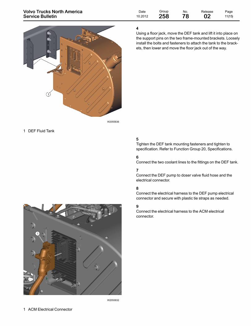
1 DEF Fluid Tank
44Using a floor jack, move the DEF tank and lift it into place onthe support pins on the two frame-mounted brackets. Looselyinstall the bolts and fasteners to attach the tank to the brack-ets, then lower and move the floor jack out of the way.
55Tighten the DEF tank mounting fasteners and tighten tospecification. Refer to Function Group 20, Specifications.
66Connect the two coolant lines to the fittings on the DEF tank.
77Connect the DEF pump to doser valve fluid hose and theelectrical connector.
88Connect the electrical harness to the DEF pump electricalconnector and secure with plastic tie straps as needed.
W2055832
1 ACM Electrical Connector
99Connect the electrical harness to the ACM electricalconnector.

VVoollvvoo TTrruucckkss NNoorrtthh AAmmeerriiccaa Date Group No. Release PageSSeerrvviiccee BBuulllleettiinn 10.2012 225588 7788 0022 12(15)
W2055838
1 Level Sensor Electrical Connector
1100 If equipped, connect the electrical harness to the levelsensor electrical connector.
VVoollvvoo TTrruucckkss NNoorrtthh AAmmeerriiccaa Date Group No. Release PageSSeerrvviiccee BBuulllleettiinn 10.2012 225588 7788 0022 13(15)
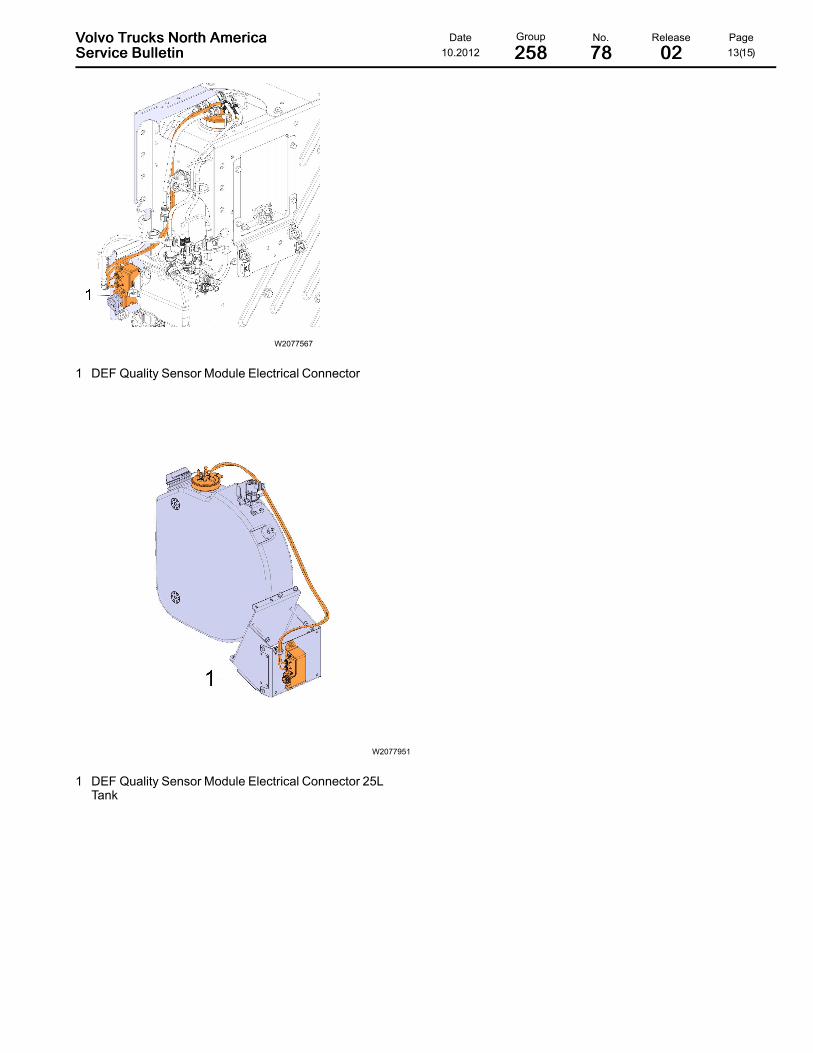
W2077567
1 DEF Quality Sensor Module Electrical Connector
W2077951
1 DEF Quality Sensor Module Electrical Connector 25LTank
VVoollvvoo TTrruucckkss NNoorrtthh AAmmeerriiccaa Date Group No. Release PageSSeerrvviiccee BBuulllleettiinn 10.2012 225588 7788 0022 14(15)
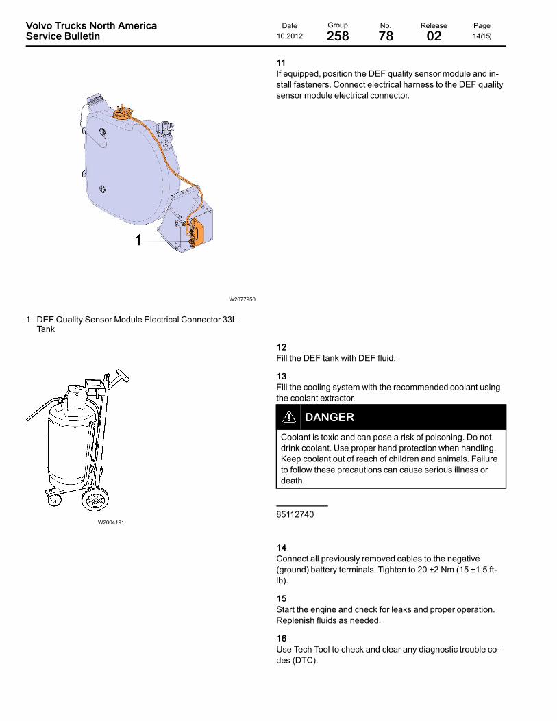
W2077950
1 DEF Quality Sensor Module Electrical Connector 33LTank
1111If equipped, position the DEF quality sensor module and in-stall fasteners. Connect electrical harness to the DEF qualitysensor module electrical connector.
1122Fill the DEF tank with DEF fluid.
W2004191
1133Fill the cooling system with the recommended coolant usingthe coolant extractor.
DDAANNGGEERR
Coolant is toxic and can pose a risk of poisoning. Do notdrink coolant. Use proper hand protection when handling.Keep coolant out of reach of children and animals. Failureto follow these precautions can cause serious illness ordeath.
85112740
1144Connect all previously removed cables to the negative(ground) battery terminals. Tighten to 20 ±2 Nm (15 ±1.5 ft-lb).
1155Start the engine and check for leaks and proper operation.Replenish fluids as needed.
1166Use Tech Tool to check and clear any diagnostic trouble co-des (DTC).
VVoollvvoo TTrruucckkss NNoorrtthh AAmmeerriiccaa Date Group No. Release PageSSeerrvviiccee BBuulllleettiinn 10.2012 225588 7788 0022 15(15)
1177If equipped, re-install the left-side fairing under the cab door.