DEF STAN 00-970 NOTICE OF PROPOSED AMENDMENT ...
44
1 of 44 DEF STAN 00-970 NOTICE OF PROPOSED AMENDMENT (Def Stan 00-970-NPA) TITLE OF PROPOSAL: Change of references in Part 1 Section 6 Clauses 6.2 and 6.6 Stage of Amendment: Issue 3 Def Stan 00-970 NPA Serial No: 2012-004 Unsatisfactory Report Serial No: MAA Originator: C2/Grade R A Bennett-Jones MAA-Cert-ADS1a Proposed Issue Date Dec 2012 Affected Part: (including paragraphs) Part 1 Section 6 Clauses 6.2.36, 6.2.37, 6.6, 6.6.11, 6.6.20 and 6.6.100 along with Table 4 and Leaflet 35 Cross-reference to other relevant amendment proposals or documents: Weblink of where this document can be accessed ADS Point of Contact details Rank/Grade and Name: As above Telephone Number mil/civ; 9679 35109 / 35366 030 679 35109 / 35366 Civilian Email address: MAA-Cert-ADS [email protected] Part 1 (for issue to Regulated Community) INTRODUCTION (Not more than 250 words) The new text will be clearly identifiable within Annex A. Replacement of reference. 1. At a previous issue of the Def Stan it was noted that BS 3g 100 was to be withdrawn for new design, as such a leaflet 35 was to be written to maintain details of the requirement. 2. When reviewing the current issue it was noted that the leaflet 35 referred to in several clauses had not been added to the standard. 3. Research could not find any evidence of the previous work within the archive, JAC papers or JAC minutes as to when this amendment should have been effected; hence no copy of Leaflet 35 is available.
-
Upload
khangminh22 -
Category
Documents
-
view
4 -
download
0
Transcript of DEF STAN 00-970 NOTICE OF PROPOSED AMENDMENT ...

1 of 44
DEF STAN 00-970 NOTICE OF PROPOSED AMENDMENT (Def Stan 00-970-NPA) TITLE OF PROPOSAL: Change of references in Part 1 Section 6 Clauses 6.2 and 6.6 Stage of Amendment: Issue 3
Def Stan 00-970 NPA Serial No: 2012-004
Unsatisfactory Report Serial No:
MAA Originator: C2/Grade R A Bennett-Jones MAA-Cert-ADS1a
Proposed Issue Date Dec 2012
Affected Part: (including paragraphs)
Part 1 Section 6 Clauses 6.2.36, 6.2.37, 6.6, 6.6.11, 6.6.20 and 6.6.100 along with Table 4 and Leaflet 35
Cross-reference to other relevant amendment proposals or documents:
Weblink of where this document can be accessed ADS Point of Contact details
Rank/Grade and Name: As above
Telephone Number mil/civ; 9679 35109 / 35366 030 679 35109 / 35366
Civilian Email address: MAA-Cert-ADS [email protected] Part 1 (for issue to Regulated Community) INTRODUCTION (Not more than 250 words) The new text will be clearly identifiable within Annex A. Replacement of reference. 1. At a previous issue of the Def Stan it was noted that BS 3g 100 was to be withdrawn for new design, as such a leaflet 35 was to be written to maintain details of the requirement. 2. When reviewing the current issue it was noted that the leaflet 35 referred to in several clauses had not been added to the standard. 3. Research could not find any evidence of the previous work within the archive, JAC papers or JAC minutes as to when this amendment should have been effected; hence no copy of Leaflet 35 is available.

2 of 44
4. The proposed new reference document is STANAG 3456 which also refers to BS ISO 1540 and Mil-STD-704.
5. To correct information held in Table 4 and the respective notes.
SUMMARY OF PROPOSED AMENDMENT Change: See Annex A
Impact Assessment:
Objective: Clarification of the requirement
Risk Assessment: The impact of not incorporating the recommended changes is the possibility of misinterpretation of the requirement
Courses of Action. 1. Do nothing. The option to do nothing is not desirable for the following reason. Not incorporating the changes will result in continuing misunderstanding of the requirement, leading to possible ambiguity of the requirement and lack of full compliance. 2. Partial Amendment – Due to the nature of the change partial amendment is not considered. 3. Full Amendment. There is no reason that full implementation of all the changes should not be completely feasible. The changes will remove possible ambiguity within 00-970.It is highly likely that the additional detail will be complied with in full. Retrospective mandation would not be considered necessary. Preferred Course of Action. Amendment
Benefits and Costs: 1. Do nothing. There is little benefit of this option and could result in increased
confusion and non compliance with Def Stan 00-970. 2. Partial Amendment – No benefit. 3. Full Amendment. Full amendment will clarify the Def Stan 00-970 Part 1
reference, possibly resulting in improved overall compliance with the document. The changes proposed here represent current practice and would have no or little economic impact.
Post Implementation Review: Timing of post-implementation review. The author will establish the impact of the implementation of the change and consider lessons learned from this implementation. Consultation period ends: 21 December 2012 The consultation period for this proposed amendment ends on the stated date. Please send your feedback via email to MAA-Tech-Cert-ADS groupmailbox @mod.uk.

3 of 44
Part 2 (for MAA internal use) Log of Comments (to be completed once the consultation period has ended). Comment reference
Date From (name)
Post Précis or Topic of Comment
MAA Response
e-mail from R Pitts
29 Oct 2012
Robert Pitts DE&S - DAT
Clarification of STANAG ref to sub documents and availability. Correction to table numbering. Notification of a contradiction with AC frequency within the table.
All sub documents are available, reference to the STANAG is preferred. Table number corrected. Miss-print from original issue corrected.
e-mail from G Warren
31 Oct 2012
Graham Warren
MAA-Cert-
ES1a2
Clarification of R Pitts e-mail and solution.
As all 3 sub documents can be considered reference to the STANAG is acceptable. Agreed with other changes noted above.
Recap of Proposal: A short summary of the proposal amendment including what changes were incorporated following the consultation period. Recommendation. This section will be completed once all the comments have been received. The recommendation is for the relevant Head of Division to approve the proposal. Approval. This section will detail exactly what has been approved and by whom, and confirm the date for the amendment to be incorporated as well as the date the NPA should be reviewed to determine what the effects of the amendment were in terms of meeting the objective of the change, if there were any unintended consequences and establishing whether the estimated costs were correct. Accepted changes will be authorised at the following levels:
Changes requiring retrospective mandation: 2 * Changes not requiring retrospective mandation but having an engineering impact:
1* Changes deemed as administrational only: C1 or Equivalent.
Approved by:

4 of 44
Signature
Name
Rank/Grade
Post
Date signed
Date for amendment to be incorporated
Date for NPA review to take place

5 of 44
Part 3 - NOTIFICATION OF AUTHORIZED AMENDMENT (Def Stan 00-970 NAA)
Document Part: Sub-Part
Unsatisfactory Report Reference
NPA Reference
Originator Date
Amendment to be Incorporated on XX/XXX/XX
INTRODUCTION AUTHORIZED AMENDMENT FURTHER ACTION APPROVAL This Def Stan 00-970 NPA has been approved by the xxxx on behalf of DG MAA INCORPORATION The amendment will be incorporated in….
Signed (IAW with part 2).
for DG MAA

6 of 44
Annex A.
Proposed change.
Existing Text POWER SUPPLIES 6.2.36. Where a particular equipment adversely affects the characteristics of the power supplies to other equipment, the effects shall not exceed the limits defined in Leaflet 35.
Primary power supplies are listed in Table 4. The characteristics of electrical power supplied to the terminals of airborne equipment are specified in Leaflet 35.
6.2.37. Utilisation equipment/systems shall be capable of withstanding without damage the interruption and transients specified in Leaflet 35.
6.6. ELECTRICAL SYSTEMS This content is similar to JAR 25.1353 - 25.1363.
The requirements apply to all electrical systems in aeroplanes. An electrical system comprises those electrical units and components which generate, distribute and control the supply of AC and/or DC electrical power for other systems. Characteristics of electrical generating and distributing and consumer units are given in Leaflet 35. Leaflet 14 makes general recommendations concerning the design of electrical installations, and Leaflet 15 gives further information on the
7 of 44
standard power supplies and their application to the installations. Leaflet 16 lists British Standards and Defence Standards, which contain advice on accessories and components.
POWER SUPPLIES GENERAL 6.6.11. The power supplies shall be selected from those listed in Table 4 and shall be compatible with the characteristics of aircraft electrical systems defined in Leaflet 35.
The nominal voltage and nominal frequency at the bus bars shall be as specified in Table 3. All consumer equipment shall be suitable for operating on a power supply conforming to the characteristics defined in Leaflet 35.
NOTE: Where there is a requirement for a different power supply to those listed in Table 4 and Table 5 - approval must be obtained from the Aircraft Design Authority and agreed with the MOD Project Team Leader (PTL).
GENERATOR SYSTEMS GENERAL 6.6.20. Each generator system shall provide an output conforming to the supply characteristics required by Leaflet 35 (see Table 4) and shall be capable of withstanding the transient condition specified in Leaflet 35.
6.6.100. The electrical system of the aeroplane under test is to be fully representative of the production standard aeroplane and working.
(a) Ground and flight conditions are to be representative of the Service role of the aeroplane and the range of climatic conditions for which clearance is required. (b) For new electrical systems it is essential that comprehensive rig testing of a fully configured system has been completed and satisfactory operating characteristics established, prior to the
The object of the tests is to demonstrate that the electrical system fitted to the aeroplane is suitable for Service use and provides for: (a) External electrical supplies (AC and/or DC as applicable to be satisfactorily utilised to supply electrical power to operate services of the aeroplane on the ground, and

8 of 44
commencement of tests which are the subject of this Chapter. (c) For 'mid-term updates' and modifications generally to electrical systems where the original test rig installation is no longer available and provision of a new system rig is deemed to be uneconomic, aeroplane ground tests assume additional importance and particular care must be given to the planning and execution of them to establish the level of confidence in the system required for initial flight tests.
(b) Primary, auxiliary and emergency electrical generators of the aeroplane to be satisfactorily started up, controlled and brought on line and together with stored energy sources, to supply power to operate services of the aeroplane on the ground and in flight as applicable. The tests are applicable to all new electrical systems in aeroplanes, and all systems where modifications have been made likely to affect the results of the tests unless otherwise stated. The need for further testing must also be assessed where modifications are made to other systems of the aeroplane, which change the loading and/or operating characteristics of the electrical system.

9 of 44
TABLE 4
PRIMARY POWER SUPPLIES
(Characteristics shall be in accordance with BS 3G100 Part 3)
NOMINAL
VOLTAGE AT BUS BAR
NOMINAL
FREQUENCY (Hz)
TRANSMISSIO
N SYSTEM
SWITCHING
DISTRIBUTION CIRCUITS
PROTECTION OF DISTRIBUTION
CIRCUITS
28V DC
SINGLE LINE
AND NEGATIVE GROUND
IN POSITIVE
LINE (SEE ALSO NOTE 3)
IN POSITIVE
LINE
115/200V 3 PHASE AC
500
(CONSTANT)
115/200V 3 PHASE AC
400
(VARIABLE)
THREE LINES –
NEUTRAL POINTS
GROUNDED AT GENERATORS
IN ALL THREE
LINES
IN ALL THREE
LINES
NOTES: 1 The only ground supplies available will be 28 V DC and 115/200 V AC 400 Hz. 2 In certain circuits it may be desirable to use negative switching e.g., use of solid state switches. A fail-safe circuit shall be achieved. 3 The 115-volt supply is angle phase derived from the primary 3 phase supply and connected between line and neutral; switching and protection to be in the line. 4 For turbo-propeller aeroplanes with electrical propeller anti-icing, the neutral for this circuit should be grounded through a high impedance. 5 When it is essential to use existing equipment requiring alternating current of different voltages and frequencies from those given in Table 3, the approval of the Project Team Leader (PTL) is required. 6 Power conversion devices having an input supply as specified in Table 3 may be used to provide the supplies specified in Table 4 and shall be approved by the Project Team Leader (PTL).

10 of 44
Proposed new Text POWER SUPPLIES 6.2.36. Where a particular equipment adversely affects the characteristics of the power supplies to other equipment, the effects shall not exceed the limits defined in Leaflet 35.
Primary power supplies are listed in Table 4. The characteristics of electrical power supplied to the terminals of airborne equipment are specified in Leaflet 35.
6.2.37. Utilisation equipment/systems shall be capable of withstanding without damage the interruption and transients specified in Leaflet 35.
6.6. ELECTRICAL SYSTEMS This content is similar to JAR 25.1353 - 25.1363.
The requirements apply to all electrical systems in aeroplanes. An electrical system comprises those electrical units and components which generate, distribute and control the supply of AC and/or DC electrical power for other systems. Characteristics of electrical generating and distributing and consumer units are given in Leaflet 35. (See also STANAG 3456). Leaflet 14 makes general recommendations concerning the design of electrical installations, and Leaflet 15 gives further information on the standard power supplies and their application to the installations. Leaflet 16 lists British Standards and Defence Standards, which contain advice on accessories and components.
POWER SUPPLIES GENERAL 6.6.11. The power supplies shall be selected The nominal voltage and nominal frequency at the NOTE: Where there is a requirement for a

11 of 44
from those listed in Table 4 be compatible with the characteristics of aircraft electrical systems defined in Leaflet 35.
bus bars shall be as specified in Table 4. All consumer equipment shall be suitable for operating on a power supply conforming to the characteristics defined in Leaflet 35.
different power supply to those listed in Table 4 and Table 5 - approval must be obtained from the Aircraft Design Organisation Authority and agreed with the MOD Project Team Leader (PTL).
GENERATOR SYSTEMS GENERAL 6.6.20. Each generator system shall provide an output conforming to the supply characteristics required by Leaflet 35 (see Table 4) and shall be capable of withstanding the transient condition specified in Leaflet 35.
6.6.100. The electrical system of the aeroplane under test is to be fully representative of the production standard aeroplane and working.
(a) Ground and flight conditions are to be representative of the Service role of the aeroplane and the range of climatic conditions for which clearance is required. (b) For new electrical systems it is essential that comprehensive rig testing of a fully configured system has been completed and satisfactory operating characteristics established, prior to the commencement of tests which are the subject of this Clause (c) For 'mid-term updates' and modifications generally to electrical systems where the original test rig installation is no longer available and provision of a new system rig is deemed to be uneconomic, aeroplane ground tests assume additional importance and particular care must be given to the planning and execution of them to establish the level of confidence in the system
The object of the tests is to demonstrate that the electrical system fitted to the aeroplane is suitable for Service use and provides for:
(a) External electrical supplies (AC and/or DC as applicable to be satisfactorily utilised to supply electrical power to operate services of the aeroplane on the ground, and (b) Primary, auxiliary and emergency electrical generators of the aeroplane to be satisfactorily started up, controlled and brought on line and together with stored energy sources, to supply power to operate services of the aeroplane on the ground and in flight as applicable.
The tests are applicable to all new electrical systems in aeroplanes, and all systems where

12 of 44
required for initial flight tests. modifications have been made likely to affect the results of the tests unless otherwise stated. The need for further testing must also be assessed where modifications are made to other systems of the aeroplane, which change the loading and/or operating characteristics of the electrical system. See BS EN 2283 for wiring installation testing.

13 of 44
TABLE 4
PRIMARY POWER SUPPLIES
(Characteristics shall be in accordance with Leaflet 35 BS 3G100 Part 3)
NOMINAL
VOLTAGE AT BUS BAR
NOMINAL
FREQUENCY (Hz)
TRANSMISSION
SYSTEM
SWITCHING
DISTRIBUTION CIRCUITS
PROTECTION OF DISTRIBUTION
CIRCUITS
28V DC
SINGLE LINE
AND NEGATIVE GROUND
IN POSITIVE LINE
(SEE ALSO NOTE 3)
IN POSITIVE LINE
115/200V 3 PHASE
AC
400
(CONSTANT)
THREE LINES –
NEUTRAL POINTS
IN ALL THREE
LINES
IN ALL THREE
LINES
115/200V 3 PHASE
AC
BASED AROUND
400 (VARIABLE)
GROUNDED AT GENERATORS
NOTES: 1 The only ground supplies available will be 28 V DC and 115/200 V AC 400 Hz. 2 In certain circuits it may be desirable to use negative switching e.g., use of solid state switches. A fail-safe circuit shall be achieved. 3 The 115-volt supply is angle phase derived from the primary 3 phase supply and connected between line and neutral; switching and protection to be in the line. 4 For turbo-propeller aeroplanes with electrical propeller anti-icing, the neutral for this circuit should be grounded through a high impedance. 5 When it is essential to use existing equipment requiring alternating current of different voltages and frequencies from those given in Table 4, the approval of the Project Team Leader (PTL) is required. 6 Power conversion devices having an input supply as specified in Table 4 may be used to provide the supplies specified in Table 5 and shall be approved by the Project Team Leader (PTL).

14 of 44
LEAFLET 35 CHARACTERISTICS OF AIRCRAFT
ELECTRICAL SYSTEMS
Note: This leaflet contains information extracted from BS 3G 100 Part 3 dated June 1972. It has been generated to retain previous reference material following some parts of BS 3G 100 being declared obsolescent.
1. SCOPE 1.1 This leaflet specifies the characteristics of electrical power supplied to the terminals of airborne equipment and defines limits for those aspects of utilisation equipment that may adversely affect the characteristics of electrical power supplied to other equipment.
The characteristics specified in this leaflet are based on the following assumptions:
(a) the system capacity is not less than 1.5 kW;
(b) the normal loading on the system is between 5% and 85% of the power supply system capacity;
(c) the load balance in A.C. systems is such that under steady state conditions the maximum difference in line current on any power source does not exceed 15% of the rated current of that power source; and
(d) the power factor in A.C. systems is between 0.8 lag and 1.0 at loads between 30% and 85% of rated load, and between 0.5 lag and 1.0 at loads between 5 % and 30% of rated load.
2. DEFINITIONS AND TERMS 2.1 For the purposes of this leaflet the following definitions and terms apply:
(a) Electrical system. A combination of power sources and utilisation equipment connected to a main distribution point.
NOTE. There may be more than one power source on each system and more than one system in an aircraft electrical installation.
(b) System capacity. The total nominal capacity of the power sources on a system under the prescribed operating and environmental conditions in the aircraft, due allowance being made for any reduction in available power in parallel operation.
(c) Main power source. A generator, usually driven by one of the aircraft propulsion engines, or a power conversion device (not forming part of utilisation equipment) installed to provide electrical power during normal operation of the aircraft.
(d) Emergency power source. A generator, a power conversion device (not forming part of a utilisation equipment) or a battery, installed to provide electrical power during conditions of electrical emergency in flight.
(e) Normal system operation. The conditions, which occur when making the necessary operations to ensure that the electrical system performs all the intended functions, required during the aircraft operational period and when no fault occurs. These operations occur at any instant and any number of times during the period. Examples of such operations are switching

15 of 44
of utilisation equipments, engine speed changes, busbar switching and paralleling of power sources.
(f) Abnormal system operation. The conditions that arise owing to deterioration or loss of control of voltage and/or frequency, the magnitude and duration of the disturbance being limited by the protection circuits. This condition only occurs rarely and at random.
NOTE. In the event of a limited fault occurring, the system steady state voltage could be anywhere within the abnormal steady state limits (ASSL) since these define the limits for operation of the protective system. Such a fault is extremely rare and would only be revealed by a check of the system voltage; possibly requiring instruments of higher accuracy than those normally installed in the aircraft.
(g) Emergency system operation. The conditions that arise in flight when the main power sources are unable to provide sufficient or proper power, thus requiring use of the limited emergency power source(s).
(h) Steady state conditions. Conditions that prevail at any fixed load when only inherent or natural changes occur, i.e.: no fault occurs and no deliberate change is made to any part of the system.
(i) Utilisation equipment. Any individual unit or any functional group of units to which, as a whole, electrical power is applied. Utilisation equipment falls into three categories as listed below according to the voltage range over which the equipment is required to operate.
Category A covers equipment required to operate over a narrow voltage range only. It is of limited application for special use only if permitted by the individual aircraft specification.
Category B covers the majority of aircraft electrical equipment and is the preferred category. When an individual equipment specification does not designate a category, Category B shall be assumed.
Category C covers equipment required to operate over, or capable of operating over, a wider voltage range than Category B.
(j) Earth (ground). The primary aircraft structure which is normally the referenced earth for the neutral of the A.C. and the negative of the D.C. in the power generation and power utilisation systems.
(k) A.C. phase voltage. The A.C. voltages stated herein shall be for any phase of those supplied to utilisation equipment, a phase being considered the line-to-neutral (earth) circuit at the equipment terminals.
(l) Average rms values. The arithmetical sum of the individual phase voltage divided by the number of phases.
(m) Transient. The short term changing condition of a characteristic that goes beyond the steady state limits and returns to the steady state limits within a specified time period. For the purposes of this document, transients are divided into surges and spikes.
(n) Surge. A variation from the controlled steady state level of a characteristic resulting from the inherent regulation of the electrical power supply system and remedial action by the regulator.

16 of 44
(o) Spike. A variation from the surge level or from the controlled steady state level of a characteristic resulting from the very high frequency currents of complex waveform produced when inductive loads are switched. Such action usually generates a train of spikes, each of which attains high amplitude in an extremely short time.
(p) Total harmonic content. The total rms voltage or current remaining when the fundamental component of a complex wave is removed.
(q) Frequency modulation. The cyclic and/or random variation of frequency about a mean frequency during steady state electrical system operation. It is normally within a narrow band of frequency and occurs as a result of speed variations in a generator rotor owing to drive speed regulation or oscillations in the rotor coupling. It is often non-sinusoidal.
(r) Frequency modulation repetition rate. The reciprocal of the period of the frequency modulation waveform.
(s) Frequency drift. The slow and random variation of the controlled frequency level within the steady state limits caused, for example, by environmental effects or wear on the electrical power system drive.
(t) Voltage modulation. The cyclic and/or random variation of the peak value of A.C. voltage about a mean value during steady state electrical system operation caused, for example, by voltage, regulation or speed variations. The voltage modulation envelope is formed by the continuous curve joining successive peaks of the basic voltage wave.
(u) Voltage modulation frequency components. The components at individual frequencies that together make up the voltage modulation envelope.
(v) Voltage ripple. The cyclic or random variation, or both, of the D.C. voltage about a mean level during steady state electrical system operation.
(w) Equivalent step function. A mathematical function that is used in this standard to provide a definitive basis for comparison of actual surges recorded on the electrical system with the requirements stated herein.
3. GENERAL REQUIREMENTS 3.1 Electrical systems. Every system shall be designed so that normal service maintenance will ensure the retention of the specified characteristics throughout the full range of operational and environmental conditions likely to be encountered in the aircraft in which it is installed. The electrical power sources shall be so designed and controlled as to ensure that the characteristics of electrical power at the utilisation equipment terminals are in accordance with the requirements of this leaflet and shall be so installed and protected that the failure of any power source and its disconnection from the system does not result in subsequent impaired performance of the remaining power sources.
3.1.1 A.C. power. The A.C. power system shall be three phase, four wire, star connected having a nominal voltage of 115/200 V, a nominal frequency of 400 Hz and a phase sequence A-B-C (see Figure 1). The neutral point of each source of power shall normally be connected to earth (see 2. (j)), which shall then be considered the fourth wire. Where an auxiliary single-phase supply is provided, it shall meet the line-to-neutral requirements stated herein.

17 of 44
3.1.2 D.C. power. The D.C. power system shall be a two-wire system having a nominal voltage of 28 V. The negative of each power source shall normally be connected to earth, which shall then be considered the second wire.
3.2 Utilisation equipment. Utilisation equipment shall maintain the specified performance when supplied with appropriate power having the range of characteristics detailed herein and shall not degrade the power characteristics beyond their limits. When use is required of power having other characteristics or closer tolerances than are specified herein, the conversion to other characteristics, or closer tolerances shall be accomplished as a part of the utilisation equipment.
The individual specification for the utilisation equipment shall state the degrees of degradation of performance permitted in specific regions of normal, abnormal and emergency system operations.
4. CONSTANT FREQUENCY A.C. POWER SYSTEM CHARACTERISTICS NOTE: The characteristics below apply to the power at the utilisation equipment terminals unless otherwise stated.
The voltage characteristics apply to line-to-neutral quantities; line-to-line characteristics should be as a result of the line-to-neutral values being as shown.
All A.C. voltage values are rms values unless otherwise stated. Transient surge rms voltages are derived from the recorded peak.
4.1 Steady state characteristics
4.1.1 Voltage. The individual phase voltages and average of the three phase voltages shall be within the limits specified in Table 1.
4.1.2 Phase displacement. The displacement between the corresponding zero points on the waveform shall be within the limits 118 and 122.
4.1.3 Voltage unbalance. The maximum difference between individual phase voltages at the aircraft busbars shall not exceed 3 V.
The maximum difference between individual phase voltages at the terminals of utilisation equipment (see 2. (i)) will depend on the individual load currents and the resultant cable volt drop, but should not exceed the values shown in Figure 2 (see also 7.5.3).
4.1.4 Voltage waveform (see also Appendix A). The voltage waveform shall be such that:
(a) the crest factor lies between 1.31 and 1.51;
(b) the rms value of the total harmonic content does not exceed 5% of the fundamental rms voltage;
(c) no individual harmonic exceeds 4%. of the fundamental voltage;

18 of 44
(d) the divergence of corresponding ordinates from those of the equivalent sine wave does not exceed (15.5 + 5.5 cos 2)% of the measured rms. voltage where Vp sin is the equation of the equivalent sine wave.
4.1.5 Voltage modulation. The modulation of phase voltage (including the effects of frequency modulation) shall not exceed 3.5 V when measured as the peak-to-valley difference between the maximum and minimum peak voltages reached on the modulation envelope over a period of at least one second. Frequency components of the modulation envelope waveform shall be within the limits shown in Figure 3.
4.1.6 Frequency. The frequency of main power supplies shall be maintained within the limits 380 Hz and 420 Hz and that of emergency power supplies within the limits 360 Hz and 440 Hz.
NOTE 1. The limits of 380 Hz to 420 Hz are quoted to conform to International Standards for all aircraft. It is acknowledged that many systems have steady state frequency limits held to much closer tolerances. When these apply they should be quoted in the relevant specifications.
NOTE 2. Where use of the emergency system is required at frequencies below 360 Hz, the voltage shall be so controlled that it does not exceed the value given by f/3 where f is the frequency (Hz), e.g.: at 300 Hz, the voltage shall not exceed 100 V.
4.1.7 Frequency drift. Variation of the controlled frequency level owing to drift shall not exceed 10 Hz and the rate of frequency drift shall not exceed 15 Hz/min.
4.1.8 Frequency modulation. Frequency variations owing to modulation shall be such that, during any one-minute period, the departure from the average frequency lies within the band defined in Figure 4.
4.2 Transient characteristics (see also Appendix. B).
4.2.1 Voltage. Transient surge voltages, when converted to their equivalent step functions (see 8.1), shall be within the limits of Figures. 5, 6 or 7 for all operations of the aircraft system. The most severe phase transient shall be used in determining conformity with this requirement.
Transient spikes on the supply system will not exceed the open-circuit values shown in Figure 8, and can be assumed to have a source impedance of 50. Their effect at the terminals of utilisation equipment will, therefore, depend upon the input impedance (at 0.1 MHz) of the equipment.
4.2.1.1 Normal system operation. Limits 5 and 6 of Figures. 5, 6 and 7 apply when switching loads from 5% up to 85% and down to 5% of system capacity; Limits 3 and 4 apply when switching loads from 10% up to 170% and down to 10%, this condition representing switching loads that include motor loads.
Under conditions of busbar switching, transfer or synchronisation, an interruption of the A.C. supply is likely to occur. The exact duration of the interruption will be defined in the individual system specification, but may be between 30 ms and 200 ms, during which the voltage may be any value between zero and the applicable

19 of 44
steady state limits. Upon completion of the interruption, the equivalent step function of the voltage transient shall be within Limits 3 and 4 of Figs. 5, 6 or 7 as appropriate.
4.2.1.2 Abnormal system operation. Limits 1 and 2 of Figures. 5, 6 and 7 apply.
4.2.2 Frequency. Frequency transients shall be within the limits of Figure 9 for all operations of the aircraft system.
4.2.2.1 Normal system operation. Limits 5 and 6 of Figure 9 apply when switching loads from 5% up to 85% and down to 5% of system capacity; Limits 3 and 4 apply when switching loads from 10% up to 170% and down to 10%, this condition representing switching loads that include motor loads.
4.2.2.2 Abnormal system operation. Limits 1 and 2 of Figure 9 apply.
5. VARIABLE FREQUENCY A.C. POWER SYSTEM CHARACTERISTICS (INCLUDING ROTORCRAFT APPLICATIONS)
NOTE. The characteristics below apply to the power at the utilisation equipment terminals unless otherwise stated. The voltage characteristics apply to line-to-neutral quantities; line-to-line characteristics should be as a result of the line-to-line neutral values being as shown. All A.C. voltages are rms values unless otherwise stated. Transient surge rms voltages are derived from the recorded peak values.
5.1 Steady state characteristics
5.1.1 Voltage. As in 4.1.1.
5.1.2 Phase displacement. As in 4.1.2.
5.1.3 Voltage unbalance. As in 4.1.3.
5.1.4 Voltage waveform. As in 4.1.4.
5.1.5 Voltage modulation. As in 4.1.5.
5.1.6 Frequency. The frequency of the Power supplies shall be maintained within the limits 320 Hz and 480 Hz.
5.2. Transient characteristics. (see also Appendix B).
5.2.1 Voltage. Transient surge voltages, when converted to their equivalent step functions (see 8.1) shall be within the limits of Figures 10, 11 or 12 for all operations of the aircraft system. The most severe phase transient shall be used in determining conformity with this requirement.
Transient spikes on the supply system will not exceed the open-circuit values shown in Figure 8, and can be assumed to have a source impedance of 50. Their effect at the

20 of 44
terminals of utilisation equipment will, therefore, depend upon the input impedance (at 0.1 MHz) of the equipment.
5.2.1.1 Normal system operation. Limits 5 and 6 of Figs. 10, 11 and 12 apply when switching loads from 5% up to 85% and down to 5% of system capacity; Limits 3 and 4 apply when switching loads from 10% up to 170% and down to 10%, this condition representing switching loads that include motor loads.
Under conditions of busbar switching, transfer or synchronisation, an interruption of the A.C. supply is likely to occur. The exact duration of the interruption will be defined in the individual system specification, but may be between 30 ms and 200 ms during which the voltage may be any value between zero and the applicable steady state limits. Upon completion of the interruption, the equivalent step function of the voltage transient shall be within Limits 3 and 4 of Figures 10, 11 or 12, as appropriate.
5.2.1.2 Abnormal system operation. Limits 1 and 2 of Figures. 10, 11 and 12 apply.
5.2.2 Frequency. Changes in frequency shall be such that the rate of change of frequency does not exceed 65 Hz/s.
6. D.C. POWER SYSTEM CHARACTERISTICS NOTE. The characteristics below apply to the power at the utilisation equipment terminals.
6.1 Steady state characteristics
6.1.1 Voltage. The voltage shall be within the limits shown in Table 2.
NOTE. Aircraft employing D.C. electric engine starters normally experience low D.C. system voltages during the starting cycle; equipment that is required to operate or be left switched on during this cycle should be so identified in the individual specification which should also define the appropriate voltage levels.
6.1.2 Voltage ripple. With no battery connected, ripple on the D.C. supply shall be such that the maximum departure from the average D.C. level is less than 2 V.
The rms values of individual cyclic components of the ripple shall not exceed the values shown in Figure 13.
6.2 Transient characteristics
6.2.1 Voltage. Transient surge voltages, when converted to their equivalent step functions, shall be within the limits of Figures 14, 15 or 16 for all operations of the aircraft system. The most severe transient shall be used in determining conformity with this requirement.
Transient spikes on the supply system will not exceed the open-circuit values shown in Figure 17, and can be assumed to have a source impedance of 50. Their effect at the

21 of 44
terminals of utilisation equipment will, therefore, depend upon the input impedance (at 0.1 MHz) of the equipment.
2.1.1 Normal system operation. Limits 5 and 6 of Figures 14, 15 or 16 apply when switching loads from 5% up to 85% and down to 5% of system capacity; Limits 3 and 4 apply when switching loads from 10% up to 170% and down to 10%, these conditions representing switching loads that include motor loads.
Under conditions of busbar switching or transfer, an interruption of the D.C. supply is likely to occur. The exact duration of the interruption will be defined in the individual system specification, but may be between 30 ms and 200 ms during which the voltage may be any value between zero and the applicable steady state limits. Upon completion of the interruption, the equivalent step function of the voltage transient shall be within Limits 3 and 4 of Figures 14, 15 or 16 as appropriate.
6.2.1.2 Abnormal system operation. Limits 1 and 2 of Figures. 14, 15 and 16 apply.
NOTE. Figures 14, 15 and 16 represent transient surges on D.C. systems powered by wide speed range D.C. generators or by TRUs supplied from a variable frequency A.C. system. Where the power source is a TRU supplied from a constant frequency A.C. system, reduced transient surges will result, as indicated in Figure 18.
7. UTILISATION EQUIPMENT NOTE. This section details limits for those aspects of utilisation equipment that may adversely affect the characteristics of electrical power supplied to other equipments.
7.1 Power requirements. The specification for the utilisation equipment shall state which of the types of power listed herein is required. The equipment shall preferably require only one type of power, but where an A.C. equipment requires more than 5 A of D.C. power, both types of input may be used. Equipment using both A.C. and D.C. input power shall give specified performance when subjected to simultaneous variations of A.C. and D.C. power within the limits shown in Sections 4 or 5, and 6 of this leaflet.
7.2 Conversion. Equipment that requires power with characteristics differing from those of the main supply shall accept the power as defined herein and convert it by means of devices integral with or ancillary to the utilisation equipment or system.
7.3 Performance. Subject to the relevant requirements of this section, the equipment shall give its specified performance when supplied with the appropriate power having the ranges of characteristics specified in Sections 3, 4, 5 and 6. The individual equipment specification shall state the degrees of degradation permitted in specific regions of system operation.
The equipment shall be capable of withstanding the abnormal steady state limits of voltage (see Tables 1 and 2) without damage.
7.4 Influence on electrical systems. In order to limit influence by utilisation equipment that would tend to cause the characteristics of power at the input terminals to go beyond the limits specified in Sections 4, 5 and 6:

22 of 44
(a) the line current in A.C. equipment shall be such that the rms value of the total harmonic content does not exceed 10%. of the fundamental rms current;
(b) for equipment in which the load is pulsed, the rate and magnitude of current variation shall be minimised and shall be agreed with the aircraft system designer;
(c) equipment shall preferably be so designed that it does not feed back direct current to the supply system (e.g.: half-wave rectification of a phase supply). Departures from this requirement shall be agreed with the aircraft system designer;
(d) transient voltage spikes generated within an equipment shall not exceed the voltage levels shown in Figures 8 and 17.
7.5 A.C. power
7.5.1 Three phase. For loads rated at 500 VA or more, three phase power shall be used where practicable.
7.5.2 Single phase. For loads rated at less than 500 VA, single phase power shall normally be used. Equipment consuming more than 500 VA, which is inherently single phase in power requirement shall present, if practicable, a three phase demand by being internally segregated into three single phase loads. Single-phase power shall normally be connected on a line-to-neutral basis.
7.5.3 Phase load balance. Three phase equipment shall require equal phase volt-amperes as far as is practicable; in no case shall the phase volt-ampere difference between the phases with the lowest and highest loadings, assuming balanced voltages, exceed the limits shown in Figure 19 unless otherwise agreed with the aircraft system designer.
7.5.4 Power factor. Under steady state conditions, the power factor of A.C. equipment shall be as near unity as is practicable; the full load power factor on the worst phase shall not be less than that shown in Figure 20.
7.6 Standby power. For those modes of equipment operation in which performance is not required but power is needed to maintain the equipment at standby readiness, the standby power requirements should be kept to a minimum.
8 EXPLANATORY NOTES 8.1 Voltage transients. The several voltage transient curves given in this leaflet are not intended to represent actual surges and spikes; they are the envelopes of the step functions for all likely surges and spikes from which voltage levels for purposes of design and/or test can be taken.
The voltages shown are open circuit values and shall be assumed to come from a source whose impedance is 50 for spikes, 1 for A.C. surges and 0.5 for D.C. surges.
Tests to which equipment shall be submitted to determine compliance with the requirements of this leaflet as regards transients are given in Appendix B.
8.2 Voltage ripple. The voltage ripple shall be measured with a peak reading voltmeter in series with a 4.0 F capacitor. The higher of the two values measured when the voltmeter is connected successively for each of two polarities shall be considered the ripple voltage.

23 of 44
8.3 Equivalent step functions of transient surges. An equivalent step function is a reasonable rms equivalent of a transient voltage surge. The curves indicate the time duration for which the peak voltage of an actual surge should be applied to give the same effect as the whole surge. A typical example of conversion of a transient surge to its equivalent step function is shown in Figure 21.
8.4 Crest factor. The crest factor limits given herein assume that the limits at the terminals of the power sources do not exceed 1.36 to 1.46 and are degraded to 1.31 to 1.51 at the equipment terminals by the character of the loads.
8.5 Steady state voltage limits. Tables 1 and 2 define the normal, abnormal and emergency values of voltage to which utilisation equipment will be exposed during steady state operation.
These voltage limits take into account the following factors:
(a) the control limits of busbar voltage under balanced load conditions;
(b) the effect on busbar voltage of an unbalanced system load; and
(c) an allowance for the voltage drop in the utilisation equipment supply cables.
NOTE. For three-phase equipment with unbalanced loads see also 4.1.3 and 7.5.3.
The abnormal steady state limits take into account the extreme limits of under and over voltage protection devices (see also 2.6, Note).
24 of 44
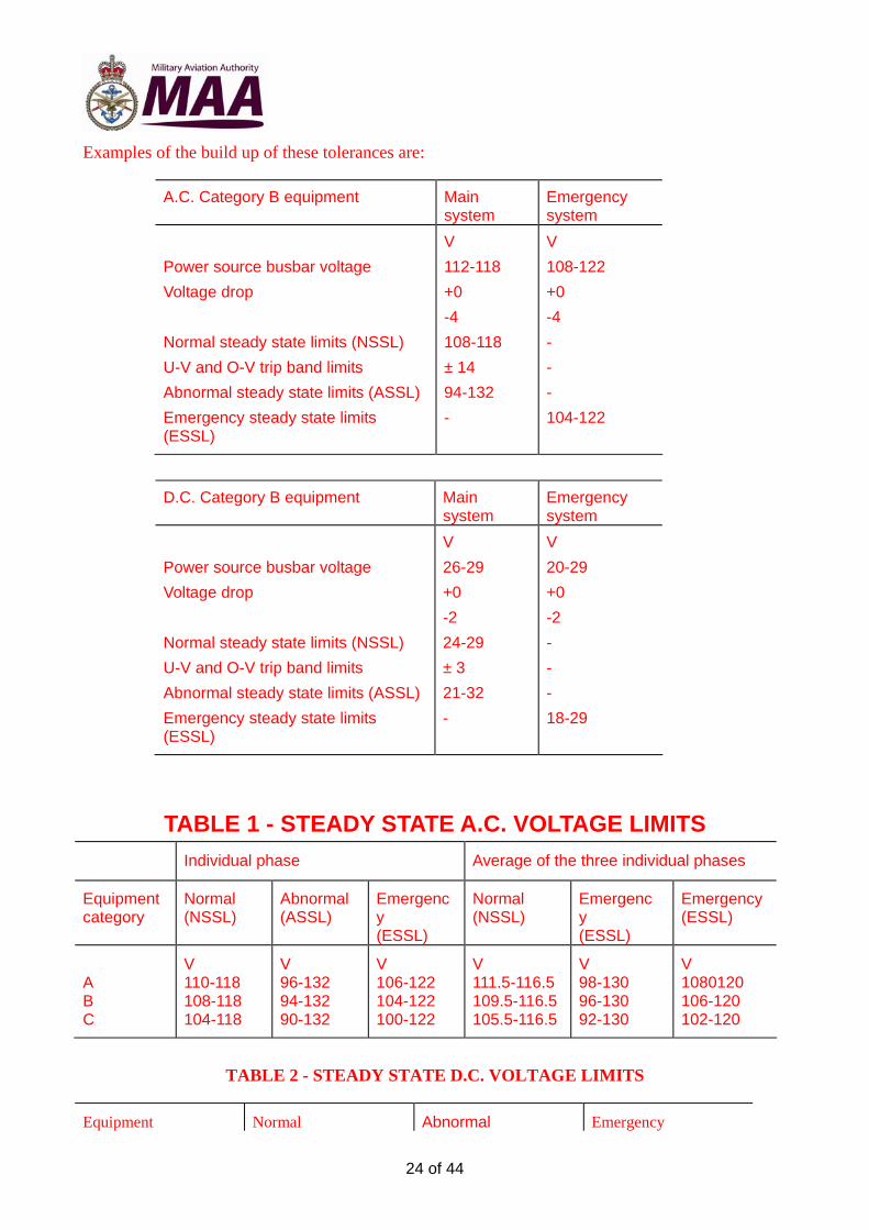
Examples of the build up of these tolerances are:
A.C. Category B equipment Main system
Emergency system
Power source busbar voltage
Voltage drop
Normal steady state limits (NSSL)
U-V and O-V trip band limits
Abnormal steady state limits (ASSL)
Emergency steady state limits (ESSL)
V
112-118
+0
-4
108-118
± 14
94-132
-
V
108-122
+0
-4
-
-
-
104-122
D.C. Category B equipment Main system
Emergency system
Power source busbar voltage
Voltage drop
Normal steady state limits (NSSL)
U-V and O-V trip band limits
Abnormal steady state limits (ASSL)
Emergency steady state limits (ESSL)
V
26-29
+0
-2
24-29
± 3
21-32
-
V
20-29
+0
-2
-
-
-
18-29
TABLE 1 - STEADY STATE A.C. VOLTAGE LIMITS Individual phase Average of the three individual phases
Equipment category
Normal (NSSL)
Abnormal (ASSL)
Emergency (ESSL)
Normal (NSSL)
Emergency (ESSL)
Emergency (ESSL)
A B C
V 110-118 108-118 104-118
V 96-132 94-132 90-132
V 106-122 104-122 100-122
V 111.5-116.5 109.5-116.5 105.5-116.5
V 98-130 96-130 92-130
V 1080120 106-120 102-120
TABLE 2 - STEADY STATE D.C. VOLTAGE LIMITS
Equipment Normal Abnormal Emergency

25 of 44
category (NSSL) (ASSL) (ESSL) A B C
V 25-29 24-29 22-29
V 22-32 21-32 19-32
V 19-29 18-29 16-29
Figure 1 - Phase sequence and line designations
Figure 2 - Voltage spread at terminals of three-phase utilisation equipment (Assuming load balance as in Figure 19)

26 of 44
Figure 3 - RMS voltage of components of voltage modulation envelope

27 of 44
Figure 4 - Characteristics of A.C. frequency modulation

28 of 44

29 of 44
Figure 5 - Envelopes for step functions for A.C. surges (Cat. A equipment - constant frequency systems)
Figure 6 - Envelopes for step functions for A.C. surges (Cat. B equipment - constant frequency systems)

30 of 44
Figure 7 - Envelopes for step functions for A.C. surges (Cat. C equipment - constant frequency systems)
Figure 8 - Envelope of transient spike voltages for A.C. equipment

31 of 44
Time (s)
NOTE: Frequency transients occurring in the region below 10-3 s are insignificant and therefore are not defined. During busbar transfer the power supply may be interrupted (see 4.2.1.1. for details).
Figure 9 - Envelopes of frequency transients on A.C. supplies
Time (s)
Figure 10 - Envelopes for step functions for A.C. surges (Cat. A equipment - variable frequency systems)

32 of 44
Figure 11 - Envelopes for step functions for A.C. surges (Cat. B equipment - variable frequency systems)
Figure 12 - Envelopes for step functions for A.C. surges (Cat. C equipment - variable frequency systems)

33 of 44
Figure 13 - Frequency characteristics of ripple in D.C. systems

34 of 44
Figure 14 - Envelopes for step functions for D.C. surges (Cat. A equipment)
Figure 15 - Envelopes for step functions for D.C. surges (Cat. B equipment)

35 of 44
Figure 16 - Envelopes for step functions for D.C. surges (Cat. C equipment)
Figure 17 - Envelopes of transient spike voltages for D.C. equipment

36 of 44
Figure 18 - Envelopes for step functions for D.C. surges (Cat. B equipment) where D.C. power source is a TRU fed from a constant frequency A.C. supply
Figure 19 - Unbalance limits for three-phase utilisation equipment

37 of 44
Figure 20 - Power factor limits for A.C. equipment

38 of 44
Trace of transient: For D.C. surges, this is the actual voltage trace; for A.C. surges, it is the envelope formed by joining successive peaks on the voltage trace.
Voltage scale: For D.C. transients this is the actual voltage; for A.C. transients it is the actual peak value divided by 1.414.
Conversion: This is based on excess volt-seconds over the normal volt-second input for overvoltage surges, and on the volt-seconds in defect of the normal volt-second input for undervoltage surges.
V = The maximum departure in volts from the normal steady state limits (NSSL).
T = The period of time during which the voltage is outside the NSSL.
A = The area in volt-seconds of that part of the trace which lies outside the NSSL.
Ts = The duration of the step function at the maximum voltage V, = A/V.
Figure 21 - Conversion of a transient voltage surge to its equivalent step function

39 of 44
Figure 22 - Envelopes for step functions for A.C. surges at the point of regulation
Figure 23 - Envelopes for step functions for A.C. surges at the point of regulation

40 of 44
APPENDIX A VOLTAGE WAVEFORM MEASUREMENTS
A.1 As guidance for design and test purposes, the following load is suggested as being to a large extent representative of the mixed loading in aircraft.
Where C is the system capacity (kW), the system shall supply power to loads (1), (2), and (3) together.
(a) A balanced three phase 0.8 lagging power factor load of 0.6 c kW.
(b) A three phase full wave bridge rectifier connected through a delta-star transformer and feeding a resistive load consuming 0.1 c kW with a smoothing choke in series having an
inductance of 300 x P
C mH .
(c) A three phase full wave bridge rectifier connected through a delta-star transformer and feeding a resistance load consuming 0.05C kW with a smoothing capacitor in parallel having a
capacitance of 1.3 x CP
F .
NOTE 1: P = (rectifier output voltage)2/73 000 (= 1, when line voltage ratio of delta-star transformer is 1:1).
NOTE 2: Inductances used as part of the test loads must be designed so that the flux density is below the saturation level.
A.2 The circuit shown in Figure 24 will give a direct presentation on an oscilloscope of very small divergences of corresponding ordinates from those of a sine wave. The basic principle is to take a sample of the supply waveform and compare it with a pure sine wave, which is equal to its fundamental, the two being held synchronous and in phase.
The sine save is obtained through a low pass filter from the supply under test. A phase-adjuster (a synchro can be used) precedes the filter and provides infinite adjustment of phase angle between its output voltage and the supply voltages. One line of the sample voltage is made common with one line of the sinusoidal voltage and the two free lines are connected to an oscilloscope, and to an harmonic analyser that is tuned to the power supply frequency. The differences in phase angle and amplitude between the two fundamentals are tuned out to register a zero reading on the analyser. The voltages that then appear on the oscilloscope show the divergence of the supply waveform from sinusoidal value at all ordinates. By means of a switch, a given percentage of the peak value of the sine wave can be displayed and this provides a reference for measuring the amplitude of the divergence.

41 of 44
To oscilloscope
Figure 24 - Input circuit to oscilloscope

42 of 44
APPENDIX B TRANSIENT VOLTAGE CHECK TESTS B.1 The following are suggested as type tests to check whether the transient voltage requirements have been met. Owing to the impracticability of testing equipment by applying a large number of different voltage levels at varying durations, tests at one surge value and one spike value with corresponding durations taken from the step function curves shall be made as indicated below. Where, however, it is known from design criteria that other voltages at their proper durations are potentially damaging, additional tests shall be made at these values. Tests B.2 and B.3 shall be applied to all electrical or electronic equipment and Test B.4 shall be applied, in addition, to any equipment containing a semiconductor or other voltage sensitive device.
B.2 Tests for effects of imported voltage surges
B.2.1 Overvoltage surges
B.2.1.1 The tests shall be applied while the equipment is operating at nominal input conditions after being operated under such conditions as will produce maximum working temperature.
B.2.1.2 The tests shall comprise five successive cycles, each cycle being as follows:
(a) a period of 2½ minutes at nominal voltage, followed by
(b) a period of 50 ms at voltage V (see Note 2), followed by
(c) a period of 2½ minutes at nominal voltage.
NOTE 1: The D.C. voltage change shall be such that 90% of the change is achieved at a rate of between 104 V/s and 106 V/s (the time for the voltage change is not included in the 50 ms).
NOTE 2: Values for V are as follows:
A.C. equipment 255 V peak = (180 V rms.) D.C. equipment (general) 80 V D.C. equipment (fed from TRU from a constant frequency supply) 45 V
B.2.1.3 At the conclusion of the tests the equipment shall be examined to determine that no damage has resulted.
B2.2 Undervoltage surges
B.2.2.1 The equipment shall not malfunction when the voltage is reduced for 50 ms from nominal to the lowest value of Limit 4 on the appropriate step function curve for the equipment.
B.2.2.2 Any malfunction that results from the interruption of the input power for a period of 0.2 s shall be declared.

43 of 44
B.3 Tests for exported voltage spikes
B.3.1 The supply circuit shall be adjusted to provide nominal value of voltage. A switch of the type normally intended to control the supply to the equipment shall be connected to the equipment by cables of the type and size that will be used in the aircraft installation, and of length such as to give the appropriate voltage drop.
An oscilloscope, or other approved device, having an input impedance equivalent to a resistance of not less than 0.1 M shunted by a capacitance not exceeding 50 pF, a band width of not less than 30 MHz and being capable of measuring up to this frequency shall be connected across the input terminal of the equipment.
B.3.2 The equipment shall be operated using its normal internal switching sequence if any, and over its full range of functions, so as to obtain the maximum value of transient voltage.
B.3.3 The equipment shall be switched off and on at least 50 times (100 switching operations) to increase the probability that the worst spike is recorded.
B.3.4 The spikes measured during tests B.3.2 and B.3.3 shall be within the limits shown in Figure 8 (A.C. equipment) or Figure 17 (D.C. equipment).
B.4 Tests with imported voltage spikes
B.4.1 For these tests, simulated voltage spikes shall be applied 50 times at one-second intervals to the equipment while it is operating at nominal voltage. In addition to checking for malfunctioning, measurements shall be made within the equipment to ensure compliance with B.4.3. Measuring equipment having impedance characteristics as specified in B.3.1 shall be used.
B.4.2 The simulated spikes shall comprise a half cycle of a sine wave rising to peak amplitude in 10 s; the source impedance shall be 50 and the voltage such that when superimposed on the supply, the resultant open circuit voltage is 1000 V (peak value) for A.C. equipment and 600 V for D.C. equipment.
B.4.3 The voltage spikes so imposed shall not cause any malfunctioning of the equipment, and shall not result in unsafe voltages being applied to any component within the equipment.
B.5 The test conditions are summarised in the table overleaf.

44 of 44
Supply Open circuit voltage
Source impedance
Pulse width
Characteristics
A.C.
V 1000 (peak value)
50
20 s Waveshape. ½ cycle sine wave. Rise time. To peak amplitude in 10 s. Application. Equipment energised, pulse superimposed on supply 50 times at 1-second intervals.
255 (peak value)
1 50 ms Waveshape. 400 Hz of total amplitude for 50 ms. Rise time. At 400 Hz sine wave. Application. Equipment energised, supply voltage stepped 5 times at 5-minute intervals.
D.C.
600 50 20 s Waveshape. ½ cycle sine wave. Rise time. To peak amplitude in 10 s. Application. Equipment energised, pulse superimposed on supply 50 times at 1-second intervals.
80 or 45 (see B.2.1.2)
0.5 50 ms Waveshape. Nominal square wave. Rise time. See B.2.1.2, Note 1. Application. Equipment energised, supply voltage stepped 5 times at 5-minute intervals.
NOTE: Tolerances on open circuit voltages: 0 and -10% Tolerances on source impedance: 20% Tolerances on pulse width: 10%