technical service bulletin - coe heated def line dtc's p20bd ...
16
TECHNICAL SERVICE BULLETIN COE HEATED DEF LINE DTC’S P20BD, P20B9, OR P20C1 BULLETIN NO: SB-18-013 DATE: 5-22-2018 REFERENCE: HMM-180521-J1
-
Upload
khangminh22 -
Category
Documents
-
view
1 -
download
0
Transcript of technical service bulletin - coe heated def line dtc's p20bd ...

TECHNICAL SERVICE BULLETIN
COE HEATED DEF LINE DTC’S P20BD, P20B9, OR P20C1
BULLETIN NO: SB-18-013DATE: 5-22-2018REFERENCE: HMM-180521-J1

SUBJECT VEHICLES: Certain 15MY-18MY COE Trucks equipped with a J05 engine
OVERVIEW:
If the following DTC’s (Diagnostic Trouble Codes) are present, refer to the Diagnostic Procedure below.
DTC: P20BD DEF heater 1 failure (Open load / low)
DTC: P20B9 DEF heater 2 failure (Open load / low)
DTC: P20C1 DEF heater 3 failure (Open load / low)
If the resistance is found to be outside of the specified range, replace the heated DEF line harness following the repair procedure, below.
BEFORE YOU BEGIN:
• Read and understand all instructions and procedures before you begin the work.
• Read and follow all WARNINGS and NOTICES set forth in this publication. These alerts help to avoid damage to components, serious personal injury, or both.
• Park the vehicle on a flat, level and solid surface.• Place the gear shift lever in "Neutral" or "Park".• Apply the parking brake firmly and confirm parking brake
activation.• Turn off the engine and remove the key from the ignition switch.• Always wear safety glasses or goggles to protect your eyes.• Place wheel chocks in front of and behind all the wheels to
prevent the vehicle from moving.
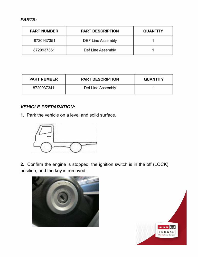
PARTS:
VEHICLE PREPARATION:
1. Park the vehicle on a level and solid surface.
2. Confirm the engine is stopped, the ignition switch is in the off (LOCK)position, and the key is removed.
PART NUMBER PART DESCRIPTION QUANTITY
8720937351 DEF Line Assembly 1
8720937361 Def Line Assembly 1
PART NUMBER PART DESCRIPTION QUANTITY
8720937341 Def Line Assembly 1

3. Apply the parking brake.
4. Chock all the wheels.
Diagnostic Procedure:
1. If one of the following DTC’s is present, P20BD, P20B9, or P20C1, access and disconnect connector 6P near the driver’s side frame rail on the heated DEF line harness.

2. Measure the resistance of each of the 3 DEF heater circuits on the DEF line side of connector 6P. The resistance should meet the standard value. If the resistance does not meet the standard value, proceed to the repair procedure, below.
Standard Value: 5.5 ohms (+/- 1 ohm) @ 69°F (20°C)
Repair Procedure:
WARNING: NEVER remove coolant lines until the engine has cooled off completely. Failure to allow the engine to cool off may result in serious coolant burn injuries.
1. Locate the SCR coolant lines near the passenger side frame rail. Place a drain bucket under the coolant lines. Remove the coolant supply line from the coolant cut valve hose. Remove the coolant return line from the LLC Pipe hose. Discard the coolant from the drain bucket.

2. Disconnect the DEF line connection from the DEF injector. Remove the harness clip from the bracket.
3. On the driver’s side, disconnect the DEF harness 6P wire connector to the DCU harness.
4. Remove the 5 DEF line assembly retainer clips along the frame rail to free the line.

Single Cab Models
5A. Remove the 2 retainer clips holding the DEF line assembly to the frame bracket. Remove the one DCU (dosing control unit) harness clip from the frame bracket.
Crew Cab Models
5B. Remove the 4 retainer clips holding the DEF line assembly to the DCU (dosing control unit) bracket and the frame bracket. Remove the one DCU harness clip retaining the harness to the frame bracket. Remove the 2 bolts retaining the DEF Line assembly brackets to the DCU bracket and retain for reinstallation.

6. Remove the 3 bolts securing the DEF sending unit cover and retain for reinstallation.
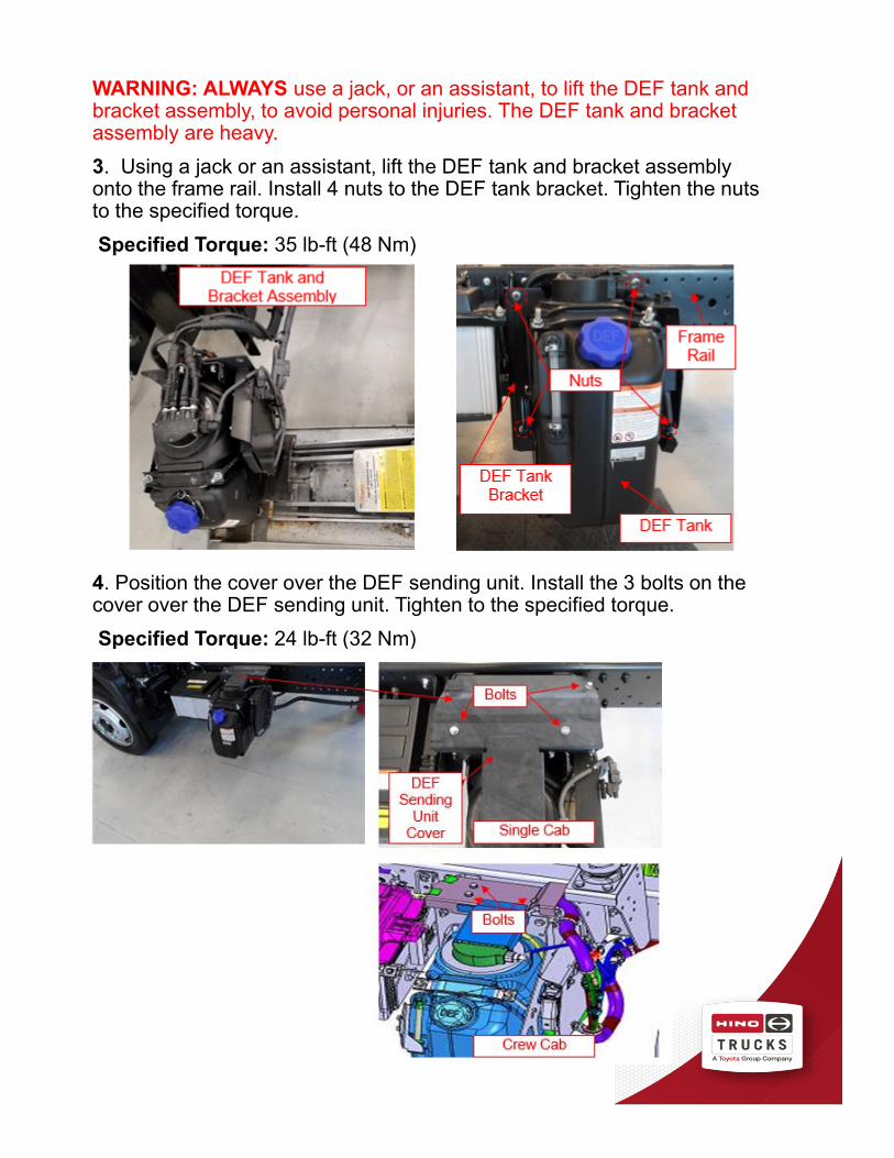
WARNING: ALWAYS use a jack, or an assistant, to lift the DEF tank and bracket assembly, to avoid personal injuries. The DEF tank and bracket assembly are heavy.
7. Remove the 4 nuts retaining the DEF tank bracket to the frame rail and retain for reinstallation. Using a jack or assistant, lift the DEF tank and bracket assembly off of the frame rail and set the tank and assembly on the floor.

8. Remove the DEF lines and coolant lines from the DEF tank sender.
9. Remove the 3 DEF line connections and 2 coolant line connections from the top of the DEF pump. Remove and discard the DEF line assembly. For crew cab models, discard both halves of the DEF line assembly.

Assembly Instruction
1. Using the new DEF line assembly, connect the DEF lines and coolant lines to the DEF pump.
2. Connect the coolant hoses from the DEF line assembly to the DEF tank sender. Connect the DEF line quick disconnect fittings to the DEF tank sender.
WARNING: ALWAYS use a jack, or an assistant, to lift the DEF tank and bracket assembly, to avoid personal injuries. The DEF tank and bracket assembly are heavy.
3. Using a jack or an assistant, lift the DEF tank and bracket assembly onto the frame rail. Install 4 nuts to the DEF tank bracket. Tighten the nuts to the specified torque.
Specified Torque: 35 lb-ft (48 Nm)
4. Position the cover over the DEF sending unit. Install the 3 bolts on the cover over the DEF sending unit. Tighten to the specified torque.
Specified Torque: 24 lb-ft (32 Nm)
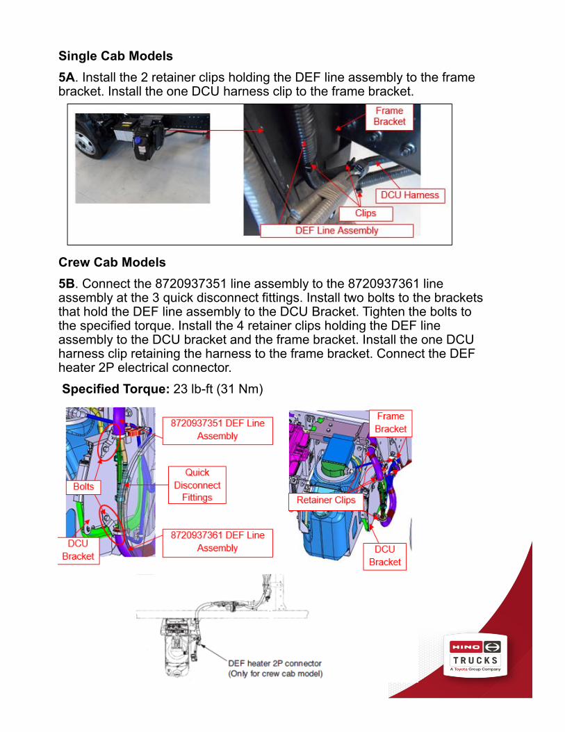
Single Cab Models
5A. Install the 2 retainer clips holding the DEF line assembly to the frame bracket. Install the one DCU harness clip to the frame bracket.
Crew Cab Models
5B. Connect the 8720937351 line assembly to the 8720937361 line assembly at the 3 quick disconnect fittings. Install two bolts to the brackets that hold the DEF line assembly to the DCU Bracket. Tighten the bolts to the specified torque. Install the 4 retainer clips holding the DEF line assembly to the DCU bracket and the frame bracket. Install the one DCU harness clip retaining the harness to the frame bracket. Connect the DEF heater 2P electrical connector.
Specified Torque: 23 lb-ft (31 Nm)

6. Install the 5 DEF line assembly retainer clips along the frame rail.
7. Connect the 6P DEF harness wire connector to the DCU wire harness.
8. Connect the DEF line to the DEF injector and secure the harness clip to the bracket.

9. Install the coolant supply line to the coolant cut valve hose. Install the coolant return line to the LLC Pipe hose. Ensure the hose clamps are properly positioned.
Single Cab Models
10A. Release the cab lock and raise the cab.
Crew Cab Models
10B. Pull up the rubber floor cover under the passenger seat. Unfasten the latches that retain the passenger seat to the floor. Fold the passenger seat back forward, and fold the center console forward. Fold up the passenger seat to access the engine from the right side.
11. Fill and bleed the vehicles cooling system with approved Hino Genuine Coolant.
12. Inspect all coolant hose connections on the SCR system for leaks.
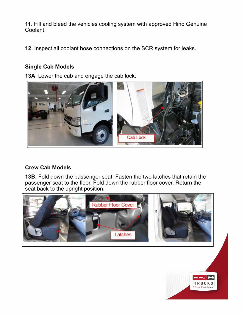
Single Cab Models
13A. Lower the cab and engage the cab lock.
Crew Cab Models
13B. Fold down the passenger seat. Fasten the two latches that retain the passenger seat to the floor. Fold down the rubber floor cover. Return the seat back to the upright position.

FINAL INSPECTION
1. To complete this procedure, review the steps of the repair
procedure and confirm the following:
• Confirm that all the nuts are tightened to their specified torque.
• Confirm that all hoses, clamps, and clips are properly installed.
• There are no leaks present and the cooling system is full.
• DTC’s were cleared and the MIL light is not on.
Note: This technical service bulletin is provided as technical
information and is not authorization for a warrantable repair.
CLAIM APPLICATION
Reimbursable in accordance within the terms and policies of the Hino limited warranties.
DEF Line Assembly Replacement:
Labor charge: 1.2 hours
Warranty code: 86668
Trouble code: 44
Operation code: 86650AOT
Original failed part: 8720937341