
M-LINE Marine Diesel Engines - Operation manual - VETUS
148
Operation manual M-LINE Marine Diesel Engines 345102.01
-
Upload
khangminh22 -
Category
Documents
-
view
0 -
download
0
Transcript of M-LINE Marine Diesel Engines - Operation manual - VETUS

Operation manualM-LINE Marine Diesel Engines
345102.01

ii
1
Operation manual
Please enter the serial numbers here.These numbers should be quoted when inquiring about Customer Ser-vice, Repairs or Spare Parts (see page 6).
We reserve the right to make any changes without previous notice.
Copyright © 2019 Vetus B.V. Schiedam Holland
Serial numbers
Engine serial number Vetus:
Engine serial number Mitsubishi:
Gearbox serial number:
M2.13M2.18M3.29 M3.28 SOLASM4.35 M4.15 SOLASM4.45 M4.17 SOLASM4.56 M4.55 SOLAS
3451
02.0
1

2
Please read and observe the information giv-en in this operation manual. This will enable you to avoid accidents, preserve the manu-facturer’s warranty and maintain the engine in peak operating condition.
Make sure that the manual will remain intact and damage is prevented. Keep the manual away from humidity and heat.Do not alter the content of the manual.
The manual is an integral part of the engine. Hand over the manual tot the new owner if boat or engine is being sold.
For the Guarantee Conditions, see the Ve-tus Diesel ‘Service and Warranty Manual’ (320199.06).
This engine has been built exclusively for the application specified in the scope of sup-ply and is to be used only for the intended purpose. Any use exceeding that scope is considered to be contrary to the intended purpose. The manufacturer will not not as-sume responsibility for any damage resulting therefrom. The risks involved are to be borne by the user.
Use in accordance with the intended pur-pose also implies compliance with the con-ditions laid down by the manufacturer for operation, maintenance and servicing. The engine should only be operated, maintained and serviced by persons which are familiar with the former and the hazards involved.
The relevant accident prevention guidelines and other generally accepted safety and industrial hygiene regulations must be ob-served.
Unauthorized engine modifications will in-validate any liability claims against the man-ufacturer for resultant damage.
Manipulations of the injection and regulating system may also influence the performance of the engine, and its emissions. Adherence to legislation on pollution cannot be guaran-teed under such conditions.

3
Contents
1 Safety measures 4Warning indications 4Preventing fire and explosion 5Prevention of injury 6When problems occur 8
2 Introduction 9Data tag 10Cylinder numbering and direction of rotation 11Fuel pump seal 11Identification of engine parts M2, M3 12Identification of engine parts M4 14Control panels 16Control lever 19
3 First commissioning 20
4 Running-in 31
5 Use 32General guidelines 32Starting 34Starting using the spring starter 38Cruising 40Stopping 43
6 Maintenance 44Introduction 44Maintenance schedule 46Checking engine oil level 48Checking coolant level 50Checking and cleaning the raw water strainer 52Draining of water from the water separator/fuel filter 53Engine oil change 56Battery, cables and connections 60Gearbox oil level check 64Fuel filter replacement 65Cleaning filter fuel lift pump 66Bleeding, after fuel filter replacement 67Changing the gearbox oil 68Flexible engine mounts, hose connections and fasteners 69Checking valve clearance 70Checking the V-belt 74Checking valve oil sump ventilation 76Raw water pump inspection 77Coolant replacement 80Air filter replacement 84Checking the starter motor and alternator 85
Checking engine speed 86Cleaning the heat exchanger 88
7 Lay-up / Winter storage procedure 92
8 Recommissioning after lay-up or winter storage 100
9 Troubleshooting 106
10 Technical data 116Engine specifications 116Gearbox specifications 121Torque wrench settings 122
11 Operating media 124Fuel 124Lubricating oil 126Coolant 129
12 Wiring diagrams 130
13 Overall dimensions 136
14 Parts for maintenance 140
15 Index 141

4
1 Safety measures
Danger
Indicates that great potential danger exists that can lead to serious injury or death.
Warning
Indicates that a potential danger that can lead to injury exists.
Caution
Indicates that the usage procedures, actions etc. concerned can result in serious damage to or destruction of the engine. Some CAU-TION indications also advise that a potential danger exists that can lead to serious injury or death.
note
Emphasises important procedures, circum-stances etc.
Symbols
Indicates that the relevant procedure must be carried out.
Indicates that a particular action is for-bidden.
Pass the safety precautions on to other peo-ple who will use the engine.
General rules and laws concerning safety and accident prevention must always be ob-served.
Warning indicationsThe following warning indications are used in this manual in the context of safety:
Warning indications

5
1 Safety measures
• Do not smoke if refuelling.
• Avoid spilling fuel on hot surfaces. Spilled fuel must be cleaned up immediately.
• Do not use petrol or diesel to clean compo-nents but make use of good quality, non-inflammable, non-poisonous solvents that are available from dealers.
• Always be alert to possible fuel or oil leak-age!If you discover a leak, take counter-meas-ures immediately. If fuel or oil is spilled on a hot engine, fire can break out. This can cause physical injury or damage to the equipment.
• Do not fill the fuel tank while the engine is running!Only refuel with the engine stopped.
• Never put flammable materials in the vicin-ity of the engine!
• Keep the engine and engine compartment clean!Remove all inflammable materials such as fuel, oil and other litter before it builds up in the vicinity of the engine.
• Connecting (emergency) extra starting bat-teryProceed as follows when an extra starting battery is used to jump start the engine:
- First connect the positive lead
- Lastly connect the earth cable (negative pole) to the engine block
If this cable is connected in error to the negative pole of the engine battery, a spark can occur. The result of this could be that explosive gas produced by the battery explodes.
- Once the engine is started, first remove the earth cable.
Preventing fire and explosion
Fire risk!

6
1 Safety measures Prevention of injury
• The moving parts of the engine are danger-ous. Never touch moving parts of the en-gine while it is running, to prevent cuts and other injuries.
• Stop the engine before carrying out main-tenance!
• Always stop the engine before topping up or replacing fuel, oil or coolant.
• Before carrying out inspection or mainte-nance, the ignition key must be removed and the main battery switch turned off.
• Satisfy yourself that everything is in order before the engine is started again!Make sure that no-one is working on or close to the engine before you start it. Re-move all foreign objects from around the engine, such as litter, oil, tools and other components that are not part of the engine.
• Install all protective covers!To prevent injury, make sure that all protec-tive covers and cover plates are replaced over moving parts.
• Remove any tool used to turn the engine over. If you leave this in position, serious injury or damage to the equipment can re-sult.
• NEVER open the cap of the expansion tank when the engine is at working temperature.
• Only check the coolant level after the en-gine has been stopped and the filler cap on the heat exchanger is cool enough to be removed with bare hands.
• Never attempt to adjust the fan belt on a running engine.

7
1 Safety measures Prevention of injury
• Be careful with battery acid!If battery acid comes in contact with the eyes or skin, rinse the affected part imme-diately with copious amounts of water. If battery acid comes in contact with the eyes, rinse them out immediately with plenty of water and consult a doctor.
• Be careful with antifreeze!If you accidentally swallow antifreeze, make yourself vomit and consult a doctor imme-diately. If antifreeze comes in contact with your eyes, wash them out immediately with plenty of water and consult a doctor.
• Make sure that you are wearing suitable clothing before starting work!For your own safety you will most likely need special equipment – safety helmet, eye protection, safety boots, safety gog-gles, heavy gloves, ear protectors etc. Use them when necessary.
• Carry out maintenance procedures safely by only using suitable tools.
• Exhaust gasesDo not start the engine if the exhaust sys-tem is not connected.

8
When the engine stops suddenly:If the engine stops suddenly, do not start it again immediately. Track down the cause and carry out the necessary repairs before you start the engine again. If you do not do this, serious engine problems can develop.
If the oil pressure is too low:Stop the engine immediately and check the lubrication system. Running an engine with low oil pressure can cause bearing and other parts to seize.
lf the engine overheats:If the engine should overheat, do not switch it off immediately. If an overheated engine is stopped suddenly, this can cause the coolant temperature to rise rapidly and moving parts to seize. First let the engine run in neutral to al-low the hot parts of the engine to cool down, stop the engine and allow it to cool, and then gradually top up the coolant. Remember: adding coolant to an overheated engine can cause damage to the cylinder head.
If the fan belt is broken:Immediately stop the engine. If an engine is used with a broken fan belt, this can lead to the engine overheating, which in turn can cause coolant to spray out of the expansion tank.
If the engine behaves strangely: Stop the engine or reduce the speed as far as possible. Do not use the engine again until the cause of the defect has been solved.
1 Safety measures When problems occur

9
Vetus diesel engines are designed both for pleasure craft and commercial craft. Conse-quently, a wide range of variants are offered to meet the requirements of specific cases.
Your engine is appropriately equipped for your vessel, which means that not necessarily all components described in this manual are mounted to your engine.
We have endeavoured to highlight any differ-ences so that you will able to locate the oper-ating and maintenance instructions relevant to your engine quickly and easily.
Please read this manual before starting your engine and always observe the operating and maintenance instructions.
We are available to help with any additional inquiries.
Sincerely,Vetus b.v.
2 Introduction
Dear customer,

MARINE DIESEL ENGINESCHIEDAM HOLLAND
1580Meets exhaust emission regulationsacc. 94/25/EC, 2003/44/ECLight Diesel Fuel Only (B7Allowed)
123456 654321
Type:
Engine Nr.:
kW HP
Weight, approx.:
Power
BSO cert.:
kg
RPM
Mfg Date:
XXXXXX XX
XX/XXXX
MXXX---A XXXXXXXXXXXX
XXX
XXXXXXXX
10
2 Introduction Data tagSerial number
1 Engine data tag
The Vetus engine serial number and perfor-mance data are printed on the engine data tag.
Model and engine serial number must be giv-en when ordering spare parts.
2 Engine data tag location
The type plate is positioned as shown.
3 Engine serial number
The Mitsubishi engine serial number is stamped on the fuel injection pump.
VD00
973
VD00
957
VD00
974

M2M3
Lead seal
Maximum speedadjustment screw
M4
Lead seal
Maximum speedadjustment screw
11
2 Introduction Cylinder numbering and direction of rotation Fuel pump seal
4 Cylinder numbering and direction of rotation
Cylinder numberingCylinders are numbered consecutively, begin-ning at the front end.
Direction of rotationThe direction of rotation is viewed towards the flywheel counter clockwise.
5 Fuel pump seal
Caution
Breaking the seals on the regulator to alter the settings of maximum rpm and maximum injector volume may only be carried out by authorised Vetus Service personnel.
Breaking the seals and altering the settings can lead to:
- Accelerated wear of engine components.
- Increased fuel and oil consumption.
- Incorrectly adjusted injector volume and poor engine performance.
- Breaking emission regulations.
VD00
930
VD00
950
VD00
145

1 2 3 4 5 6 7 8
9 10 11 12
12
2 Introduction Identification of engine parts M2, M3
VD02
022
1 Calorifier connection, engine ‘IN’2 Calorifier connection, engine ‘OUT’3 Cooling system air bleed nipple / Con-
nection for extra expansion tank (Keel cooling model only)
4 Oil filler cap5 Filler cap for cooling system6 Expansion tank7 Heat exchanger8 Cooling system drain plug9 V-belt
10 Alternator11 Starter motor12 Exhaust injection bend ø 40 mm

13 14 15 16 17 18 19 20 21 22
23 24 25 26 27 28 29 30 31
13
2 Introduction Identification of engine parts M2, M3
VD02
023
13 Airvent connection14 Water separator/Fuel filter15 Water separator/fuel filter air bleed
nipple16 Fuse17 Fuel lift pump18 Connection electrical system19 Fuel supply pipe connection ø 8 mm20 Air inlet silencer / Air filter21 Oil dipstick22 Connection for throttle push-pull cable23 Gearbox filler cap24 Water separator/fuel filter drain plug25 Gearbox26 Fuel return pipe connection ø 8 mm27 Oil filter28 Manual operation of electric stop29 Raw water inlet ø 20 mm30 Raw water pump31 Fuel pump air bleed nipple

1 2 3 4 5 6 7 8
9 10 11 12 13 14 15 16
14
2 Introduction Identification of engine parts M4
VD00
971
1 Calorifier connection, engine ‘OUT’2 Cooling system air bleed nipple / Con-
nection for extra expansion tank (Keel cooling model only)
3 Oil filler cap4 Filler cap for cooling system5 Expansion tank6 Heat exchanger7 Cooling system drain plug8 Airvent connection9 Calorifier connection, engine ‘IN’
10 V-belt11 Raw water inlet ø 20 mm12 Raw water pump13 Alternator14 Starter motor15 Connection for gearbox push-pull cable16 Gearbox drain plug

17 18 19 20 21 22 23 24 25 26
27 28 29 30 31 32 33 34 35
15
2 Introduction Identification of engine parts M4
VD00
972
17 Exhaust injection bend ø 50 mm18 Water separator/Fuel filter19 Water separator/fuel filter air bleed
nipple20 Fuse21 Fuel lift pump22 Connection electrical system23 Fuel supply pipe connection ø 8 mm24 Air inlet silencer / Air filter25 Oil dipstick26 Fuel pump air bleed nipple27 Gearbox28 Gearbox filler cap29 Water separator/fuel filter drain plug30 Gearbox oil dipstick31 Fuel return pipe connection ø 8 mm32 Cooling system drain plug33 Oil filter34 Manual operation of electric stop35 Connection for throttle push-pull cable

5 37 864 9
1 2
5 37864
16
8 Indicator light pre-heating 9 Warning light gearbox low oil pressure [1]
1 Tachometer/Operating hours counter 2 Voltmeter 3 Starter pre-heat switch/lock 4 Warning light high raw water temperature 5 Warning light low oil pressure 6 Warning light high coolant temperature 7 Warning light battery charging
2 Introduction Control panels
Panel, model MP22Panel, excl. voltmeter, model MP21
Panel, model MP10
[1] This is an option, not fitted as standard.
VD00
576
VD00
575

5 37 864 9
1 210
11 1212
17
8 Indicator light pre-heating 9 Warning light gearbox low oil pressure [1]
10 Temperature gauge, coolant 11 Oil pressure gauge 12 Starter pre-heat switch
1 Tachometer/Operating hours counter 2 Voltmeter 3 Starter pre-heat switch/lock 4 Warning light high raw water temperature 5 Warning light low oil pressure 6 Warning light high coolant temperature 7 Warning light battery charging
2 Introduction Control panels,option
Panel, model MP34 Panels, model MP10, MP22, MP34for SOLAS engines only
[1] This is an option, not fitted as standard.
VD00
631
VD02
043

5 37 8613 9
1 2
5 37 864 14
1 2
18
8 Indicator light pre-heating 9 Warning light gearbox low oil pressure [1]
13 Warning light second alternator 14 Warning light general
1 Tachometer/Operating hours counter 2 Voltmeter 3 Starter pre-heat switch/lock 4 Warning light high raw water temperature 5 Warning light low oil pressure 6 Warning light high coolant temperature 7 Warning light battery charging
2 Introduction Control panels,option
Panel, model MP22for keel cooled engines with second alternator only
Panel, model MPA22
[1] This is an option, not fitted as standard.
VD00
630
VD00
952
Single lever controlhandle for two engines
Single lever controlhandle for 1 engine
neutralgearbox reverse gearbox forward
forward throttlereverse throttle
19
2 Introduction Control lever
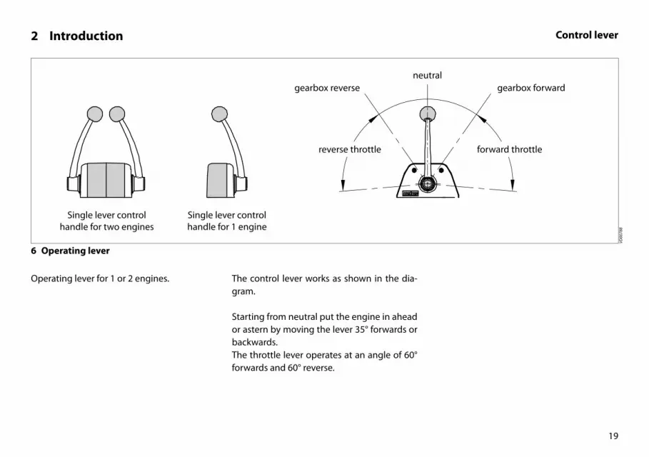
6 Operating lever
Operating lever for 1 or 2 engines. The control lever works as shown in the dia-gram.
Starting from neutral put the engine in ahead or astern by moving the lever 35° forwards or backwards.The throttle lever operates at an angle of 60° forwards and 60° reverse.
VD00
788

OIL OIL
20
3 First commissioning
1 Commissioning the engine
Before starting the engine for the first time, the following procedures must be carried out:
2 Filling with engine oil
As a rule engines are delivered empty of oil.
• Fill the engine with oil through the filler neck on top of the valve cover.
For quantity and oil specification see page 118 and 126.
• Check the oil level with the dipstick, see page 48.
A second oil filling cap is located at the distri-bution cover.
Engine Oil 15W40API: CF4, CG4, CH4, CI4ACEA: A3/B3, A3/B4, E7
For example: - Vetus Marine Diesel Engine Oil 15W40 - Shell Rimula R4 L 15W40
litres Imp. pt US pt
M2 : 2.3 4.0 4.9
M3 : 3.4 6.0 7.2
M4 : 5.5 9.7 11.6
VD00
976
VD00
977

27 17
OIL OIL
21
3 First commissioning
3 Filling gearbox with oil
• Fill the gearbox with oil. Technodrive:
For quantity and oil specification see page 128.
• Check the oil level with the dipstick, see page 64.
ZF Hurth:
For quantity and oil specification see page 128.
• Check the oil level with the dipstick, see page 64.
Vetus engines are normally equipped with Technodrive or ZF-Hurth gearboxes.
In case your engine is equipped with another brand of gearbox follow the in-structions given in the supplied owners manual.
VD00
975
VD00
975
12
17
COOLANT
22
3 First commissioning
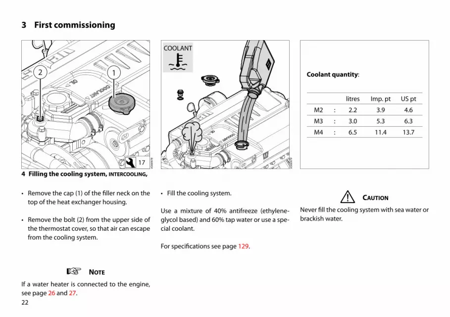
4 Filling the cooling system, interCooling,
• Remove the cap (1) of the filler neck on the top of the heat exchanger housing.
• Remove the bolt (2) from the upper side of the thermostat cover, so that air can escape from the cooling system.
• Fill the cooling system.
Use a mixture of 40% antifreeze (ethylene-glycol based) and 60% tap water or use a spe-cial coolant.
For specifications see page 129.
Caution
Never fill the cooling system with sea water or brackish water.
note
If a water heater is connected to the engine, see page 26 and 27.
Coolant quantity:
litres Imp. pt US pt
M2 : 2.2 3.9 4.6
M3 : 3.0 5.3 6.3
M4 : 6.5 11.4 13.7
VD00
979
VD00
978

1 cm(3/8”)
COOLANT
17
23
3 First commissioning
The level of the coolant must be approx. 1 cm (3/8”) below the lower edge of the filler neck.
Bleeding will take place automatically during filling!
• Replace the filler cap. • Reinstall the bolt in the thermostat cover..
VD00
158
VD00
980
VD00
981

2
1DO NOT OPEN
1.0 bar 2
1
DO NOT OPEN
1.0 bar
24
3 First commissioning
5 Filling the cooling system, keel Cooling
• Remove the cap ‘do not open’ (1) of the filler neck on the top of the heat exchanger housing.
• Fill the cooling system.
• Reinstall the filler cap ‘do not open’.
• • Remove the pressure cap (2) of the extra expansion tank.
Use a mixture of 40% antifreeze (ethylene-glycol based) and 60% tap water or use a spe-cial coolant.
For specifications see page 129.
VD00
925
VD00
932
Coolant quantity (engine only):
litres Imp. pt US pt
M2 : 3.0 5.3 6.3
M3 : 4.0 7.0 8.4
M4 : 7.2 12.7 15.2
Caution
Never fill the cooling system with sea wa-ter or brackish water.
note
If a water heater is connected to the engine, see page 26 and 27.

25
3 First commissioning
• Top up the extra expansion tank to the min-imum level.
• Reinstall the pressure cap (2).
VD00
929
VD00
953

2
1DO NOT OPEN
1.0 bar
26
3 First commissioning
6 Filling coolant system, if a water heater is connected -1-
The highest point of the water heater is situ-ated at a loWer level than the expansion tank for the ship’s engine.The water heater will be filled and bled auto-matically during filling of the cooling system.
• Remove the ‘do not open’ cap (1) and fill the cooling system via the filler neck.
• Add coolant into the expansion tank (2) un-til minimal level has been reached.
Use a mixture of 40% antifreeze (ethylene-glycol based) and 60% tap water or use a spe-cial coolant.
For specifications see page 129.
VD00
895
VD00
925
Caution
Never fill the cooling system with sea water or brackish water.

2
3
1DO NOT OPEN
1.0 bar
27
3 First commissioning
7 Filling coolant system, if a water heater is connected -2-
The highest point of the water heater is situ-ated at a higher level than the expansion tank for the ship’s engine.The water heater will not be filled and bled automatically during filling of the cooling system.
• Fill the cooling system via the expansion tank (2).
• Open valve (3) during filling and bleeding the system.
Use a mixture of 40% antifreeze (ethylene-glycol based) and 60% tap water or use a spe-cial coolant.
For specifications see page 129.
VD00
896
VD00
925
note
• Remember to close valve (3) after filling the system.
Caution
Never fill the cooling system with sea water or brackish water.

Neutral
(No throttle, gearboxnot engaged)
FUEL
28
3 First commissioning
8 Fuel
• Ensure that the fuel tank is filled with diesel fuel.
Use only clean, water-free, commercial ap-proved diesel fuel.
For fuel grade see page 124.
• Bleed the fuel system, see page 54.
9 Other preparations
• Check that the battery is charged and check the battery cable connections.
• Set the main switch to position ‘on’.
• Open the sea cock.
• Check that the gearbox control lever is set to ‘neutral’.
Warning
Never fill the fuel tank while the engine is running. Do not spill fuel. Prevent unnec-essary pollution.
VD00
002
VD00
789

OIL
29
3 First commissioning
10 Test run
• Start the engine.
How to start the engine and what to check before, during and immediately after start-ing is described on page 34 and further.
• Allow the engine to test run for about 2 minutes at idling speed .
• Stop the engine
• Check the oil level. If necessary top up to the indicated level.
• Start the engine.
• Allow the engine to test run for about 10 minutes at idling speed.
• Stop the engine.
• Check that the engine and all connections (fuel, coolant and exhaust) for leaks.
Caution
Stop the engine immediately if it makes any strange noises, vibrates excessively or if black smoke comes out of the exhaust!
VD00
982
VD00
983

30
3 First commissioning
11 Bleeding
The cooling system must be bled as soon as the engine has reached normal working tem-perature.
• Open the cap on the filler neck.
• Vary the revolutions between idling and 2000 rev/min.
• Add coolant if necessary.
• Replace the cap on the filler neck.
• Check the coolant temperature.
12 Sea trial
• Check the operation of the remote control.
• Carry out a sea trial
VD00
663
VD00
984
VD00
791

31
4 Running-in
In order to ensure a long life for your en-gine, please observe the following for the first 50 operating hours:
• Allow the engine to reach operating tem-perature before applying a load.
• Avoid fast acceleration.
• Do not allow the engine to run faster than 3/4 of maximum RPM.
After the first 50 operation hours carry out the following maintenance:
• Drain water from fuel filter, see page 53.
• Engine oil change, see page 56.
• Replace oil filter, see page 58.
• Replace fuel filter, see page 65.
• Change gearbox oil, see page 68.
• Check V-belt, see page 74.
• Check flexible engine mounts, see page 69.
• Check engine for leaks, see page 69.
• Check tightness of all fasteners, bolts and nuts, see page 69.

32
5 Use General guidelines
General guidelines for use
Implementing the following recommenda-tions will result in longer life and better per-formance and more economical operation of your engine.
• Carry out the maintenance described regu-larly, including the ‘Daily procedures before starting’.
• Use anti-freeze in the engine coolant all year long, this helps prevent corrosion as well as protecting against frost damage. For specifications see page 129.
• Never run the engine without a thermostat.
• Use a good quality lubricating oil. For speci-fications see page 126.
• Use a good quality diesel fuel that is free of water and other pollutants.
• Always stop the engine immediately if one of the warning lamps for oil pressure, high coolant temperature, high raw water tem-perature [1] or battery charging lights up.
• Always follow the safety advice, see page 4.
[1] Only engines with intercooling.

33
5 Use General guidelines
note
First commissioningFollow the instructions given for ‘First com-missioning’ on page 20 and further if the en-gine is being commissioned for the first time.
After repair work:
Check that all guards have been replaced and that all tools have been removed from the en-gine.When starting with pre-heating, do not use any other substance (e.g. injection with ‘Easy Start’). Doing so could result in an accident.

half throttle,gearbox not engaged
34
5 Use Starting
Before starting, always check the following points:
• Engine oil level.
• Coolant level.
• Sea cock open.
• Main switch ‘on’.
• Gearbox in ‘neutral’ position.
1 Control lever
Set the control lever to ‘half throttle’ without engaging the gearbox.
2 Control panel
The starter switch on the control panel is key operated or knob operated (for SOLAS en-gines only).
The knob has exactly the same functions as the starter key.
Warning
Never start the engine with the fuel injec-tion pump removed. Disconnect battery.
VD00
923
VD02
055

35
5 Use Starting
4 Pre-heating
The ideal pre-heating time depends on am-bient temperature; the lower the ambient temperature, the longer the pre-heating time required. See table.
• Turn the key further clockwise to the ‘ ’ position.
While pre-heating takes place the preheating indicator light will be on and the alarm buzzer off.
• Hold the key in this position for about 6 sec-onds.
Ambient Tem-perature
Pre-heating time
Above + 5°C (41°F)
about 6 seconds
+5°C to -5°C (+41°F to +23°F)
about 12 seconds
Below -5°C (23°F) about 18 seconds
Maximum pre-heating time
1 minute
Caution
To prevent the glow plugs from burning out, never exceed the stated maximum pre-heat-ing time.
3 Switching on
• Turn the start key on the instrument panel clock-wise; the warning lights for oil pres-sure and alternator will now light up and the alarm buzzer will sound.
VD02
056
VD02
054
36
5 Use Starting
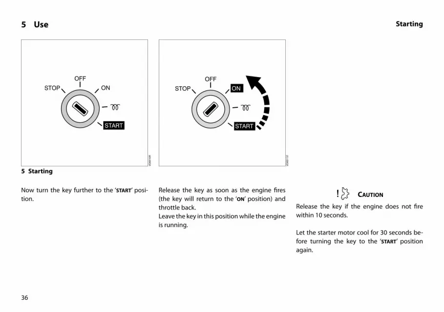
5 Starting
Now turn the key further to the ‘start’ posi-tion.
Release the key as soon as the engine fires (the key will return to the ‘on’ position) and throttle back.Leave the key in this position while the engine is running.
Caution
Release the key if the engine does not fire within 10 seconds.
Let the starter motor cool for 30 seconds be-fore turning the key to the ‘start’ position again.
VD00
109
VD00
110

37
5 Use Starting
Check that the indicator lights for oil pressure and alternator are off.
Cooling water should now flow out of the ex-haust; if this is not the case, stop the engine immediately [1].
Let the engine run for 5 to 10 minutes in neu-tral. A good warm up is essential to ensure maximum lifetime and good performance.
Never turn the main switch off while the en-gine is running.
Caution
Never turn the key to the ‘start’ position while the engine is running.Doing so will damage the starter motor.
[1] Only engines with intercooling.
VD00
629
VD02
057

half throttle,gearbox not engaged
1 2
38
5 Use Starting using the spring starter(option)
6 Preparation
• Convince yourself that it is safe to start the engine.
• Set the control lever to ‘half throttle’ with-out engaging the gearbox.
• Turn the start key on the instrument panel clock-wise to the ‘ON’ position.
• Re-set the trip mechanism by lifting the plunger (1) allowing the trip lever (2) to move upwards.
• Place the handle (3) on the spring starter.
VD00
951
VD02
005
7 Re-set trip mechanism
Caution
Never leave the spring starter part-wound.
note
It is possible to unwind the starter, should the need occur, by turning the handle anti-clockwise. Additional force will be required to overcome the initial friction.
Caution
Never turn the key to the‘start’ position while operating
the spring starter.

3 4 3 21
39
8 Winding the springs
• Using the handle (3) clockwise to wind the springs.
For a warm engine wind until the white springs are visible through the inspection window (4).For a cold engine wind further until the red springs are visible through the inspection window.Overwinding will reduce the life of the starter.
5 Use Starting using the spring starter(option)
9 Starting
• Remove the handle (3) from the starter.
note
The starter must NEVER be tripped with the winding handle in place.
• Now start the engine by lifting the plunger (1) and moving the trip lever (2) through 90 degrees until it holds out. Throttle back as soon as the engine runs.
Leave the key in the ‘ON’ position while the engine is running.
VD02
006
VD02
008
VD02
007
note
If the engine does not start first time, allow it to come to a complete rest before retrying.

40
5 Use Cruising
The instrument panel is provided with the fol-lowing instruments (Depending of the type of panel, see page 16).
10 Tachometer
Indicating the number of revolutions per minute of the engine.
Also the number of running hours is indicat-ed.
Warning
Avoid idling for more than 10 minutes.
This can lead to carbon deposits in the com-bustion chambers and incomplete combus-tion of fuel.
VD00
577
Idling speed:
M2.13,M2.18
: 850 rpm
M3.29M3.28 SOLAS
: 900 rpm
M4.35M4.45M4.15 SOLASM4.17 SOLAS
: 840 rpm
M4.56M4.55 SOLAS
: 900 rpm
41
5 Use Cruising
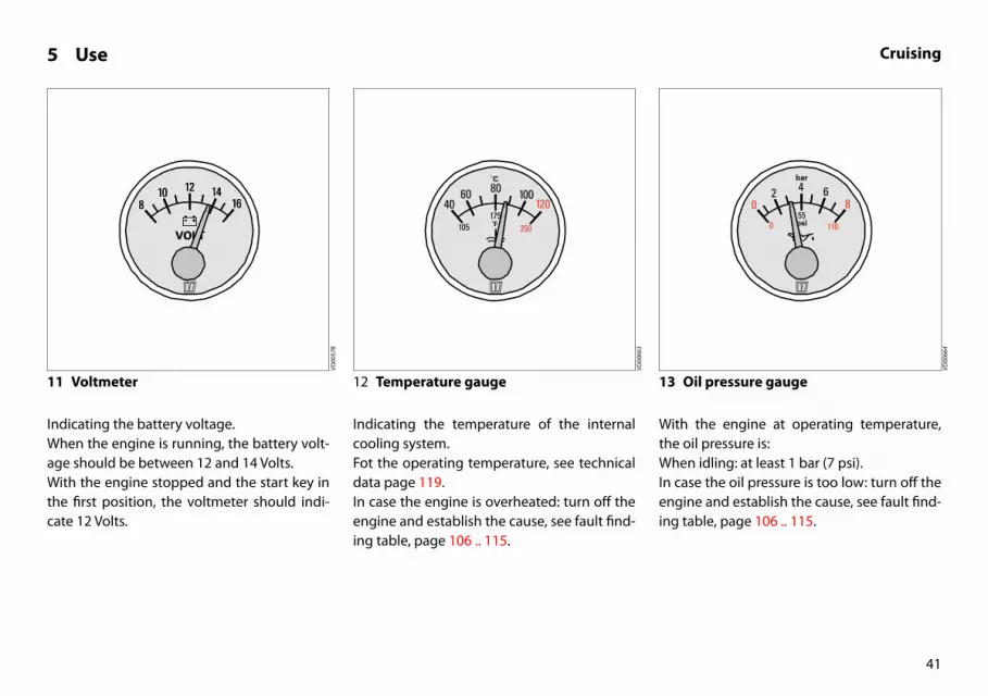
11 Voltmeter
Indicating the battery voltage.When the engine is running, the battery volt-age should be between 12 and 14 Volts.With the engine stopped and the start key in the first position, the voltmeter should indi-cate 12 Volts.
12 Temperature gauge
Indicating the temperature of the internal cooling system.Fot the operating temperature, see technical data page 119.In case the engine is overheated: turn off the engine and establish the cause, see fault find-ing table, page 106 .. 115.
13 Oil pressure gauge
With the engine at operating temperature, the oil pressure is:When idling: at least 1 bar (7 psi).In case the oil pressure is too low: turn off the engine and establish the cause, see fault find-ing table, page 106 .. 115.
VD00
578
VD00
663
VD00
664

42
5 Use Cruising
14 Warning lights
None of the five warning lights should light up while the engine is running.
15 Alarm buzzer
Oil pressure, battery charging and tempera-ture indicator lights are all connected to an alarm buzzer. If this alarm buzzer sounds while running, Stop the engine immediately!
VD00
2058
VD02
059

Neutraal
43
5 Use Stopping
17 Stopping on the engine itself
On the engine itself stopping is possible bypressing the black button on the fuel injectionpump.If the fuel supply is not shut off by the electri-callyoperated fuel solenoid stopping of theengine can be done this way.
VD00
986
VD02
045
VD00
106
16 Stopping
• Reduce engine speed to idle and shift the gearbox to ‘Neutral’.
• Turn the key entirely to the left, through the ‘oFF’ position.
• When the engine has stopped, turn the key to the ‘oFF’ position.
note
Never stop the engine immediately after it has been in operation for a long time. Allow the engine to idle for a few minutes before stop-ping.
note
If the engine is not to be used for some time, it is recommended that the sea cock is closed and the battery main switch turned off.
44
6 Maintenance Introduction
Introduction
The following guidelines should be observed for daily and periodic maintenance. Perform each function at the indicated time interval.
The intervals stated are for normal operation-al conditions. Service the unit more frequent-ly under severe conditions.
Failure to carry out maintenance can result in faults and permanent damage to the engine.
No claim can be made on the Guarantee if maintenance has been neglected.

45
6 Maintenance Introduction
Keep record of the following information in the logbook and/or the ‘Service and War-ranty Manual’:
- Total engine hours (reading engine hour counter).
- Amounts of oil, fuel and coolant needed for topping up.
- The dates and intervals at which the oil and coolant are changed.
- Oil pressure and coolant temperature.
- Parts on which maintenance is conducted and type of maintenance (adjustment, repair or replacement), and the results of each procedure.
- Changes in operating conditions, such as ‘Exhaust gas became black’, etc.

46
6 Maintenance Maintenance schedule
Danger
Stop the engine before carrying out any maintenance work
Every 10 hours or daily, before starting page
Check engine oil level 48
Check engine oil level, at free-fall lifeboats (SOLAS) 49
Check coolant level 50
Check water strainer 52
After the first 50 hours page
Drain water from fuel filter 53
Engine oil change 56
Replace oil filter 58
Check gearbox oil level 64
Replace fuel filter 65
Check flexible engine mounts 69
Check engine for leaks 69
Check tightness of all fasteners, bolts and nuts 69
Check V-belt 74
Every 100 hours, at least once every year page
Drain water from fuel filter 53
Battery, cables and cable connections 60
Check gearbox oil level 64
Every 250 hours, at least once every year page
Engine oil change 56
Replace oil filter 58
Every 500 hours, at least once every year page
Replace fuel filter 65
Cleaning fuel lift pump 66
Change gearbox oil 68
Check flexible engine mounts 69
Check engine for leaks 69
Check tightness of all fasteners, bolts and nuts 69
Check valve clearance 70
Check V-belt 74
Check valve oil sump ventilation (SOLAS) 76

47
[1] Consult the service manual, work to be carried out by a Vetus Mit-subishi dealer.
[1] Only engines with intercooling.
6 Maintenance Maintenance schedule
Danger
Stop the engine before carrying out any maintenance work
Every 500 hours page
Check glow plugs [1]
Check and adjust injector pressure [1]
Every 1000 hours, at least once every 2 years page.
Raw water pump inspection 77
Replace coolant 80
Replace air filter 84
Every 1000 hours page.
Check starter motor 85
Check alternator 85
Check turbocharger [1]
When required page
Bleeding fuel system 54
Check idle rpm 86
Cleaning heat exchanger [2] 88

OIL OIL
48
6 Maintenance Checking engine oil levelDaily, before starting.
1 Check oil level
• Turn the engine off.
The dipstick is located on the starboard side of the engine.
2 Oil level
The oil level must be at or near the upper
mark on the dipstick [1].
• If necessary top up with the same brand and type of oil.
3 Topping up oil
The oil filling cap is on top of the the valve cover,.
A second oil filling cap is located at the distru-bution cover, see page 20.
[1] The difference between the two oil level marks is:
VD00
155
VD00
982
VD00
976
litres Imp. pt US pt
M2 : 1.25 2.2 2.6
M3 : 1.3 2.3 2.7
M4 : 1.8 3.2 3.8

M4: 14 mm (9/16”) M4: 16 mm (5/8”) M4: 18 mm (11/16”)
M3: 15 mm (5/8”) M3: 23 mm (7/8”) M3: 30 mm (1 3/16”)
α = 0° α = 25° α = 30° α = 35°
α
49
VD00
968
VD02
061
6 Maintenance Checking engine oil levelFor free-fall life boats.
4 Position of the boat
• Determine the angle on which the boat is positioned.
.
5 Oil level
The oil level must be at or near the with ‘H’ in-
dicated level on the dipstick [1].
• If necessary top up with the same brand and type of oil.

1 cm(3/8”)
COOLANT COOLANT
50
6 Maintenance Checking coolant levelDaily, before starting.
6 Checking coolant level
• Check the coolant level in the header tank. This has to be checked when the engine is cold.
• Remove the cap of the filler neck on the heat exchanger.
7 Coolant level
The level of the coolant must be approx. 1 cm (3/8”) below the lower edge of the filler neck.
8 Topping up coolant
• If necessary, top up.The internal cooling system can be filled with a mixture of anti-freeze (40 %) and tap water (60 %) or with a special coolant. For specifica-tion, see page 129.
Warning
Never open the cap on the header tank when the engine is at operating temperature.
note
For a keel-cooled version, see page 24.If a water heater is connected, see page 26 and 27
Caution
Never fill the cooling system with sea water or brackish water.
VD00
158
VD00
987
VD00
984

51
6 Maintenance Checking coolant levelDaily, before starting.
• When topping up coolant, remove the bolt from the upper side of the thermo-stat cover, so that air can escape from the cooling system.
VD00
988

52
6 Maintenance Checking and cleaning the raw water strainerDaily, before starting.
9 Checking the raw water strainer
• Check daily whether there is any dirt in the raw water strainer.
10 Cleaning the strainer
• Close the seacock before removing the lid of the water strainer.
• Clean the raw water strainer as often as is necessary, depending on the pollution of the waterways, but at least once every 6 months. A clogged raw water strainer will result in excessive temperatures or over-heating of the engine coolant.
• Check the sealing between the lid and housing after cleaning and re-assembling the strainer. An improperly sealed lid will re-sult in air sucked in by the sea water pump which again will result in overheating of the engine.
VD00
802
VD00
801
note
Only engines with intercooling!

53
6 Maintenance Draining of water from the water separator/fuel filterEvery 100 operating hours.
Danger
Do not smoke when draining off water and sediment. Keep flame and sources of ignition out of the area. Remove spilled fuel and litter before you start the engine.
11 Empty fuel filter
• Open the drain plug at the lower side of the filter.
• Drain the water and close the drain plug.
12 Empty water separator
Empty the separately installed water separa-tor/fuel filter:
• Open the drain plug at the lower side of the filter.
• Drain the water and close the drain plug.
Note : The water separator is not within the scope of supply but installation is required!
VD00
803
VD02
038
54
6 Maintenance Draining of water from the water separator/fuel filterEvery 100 operating hours.
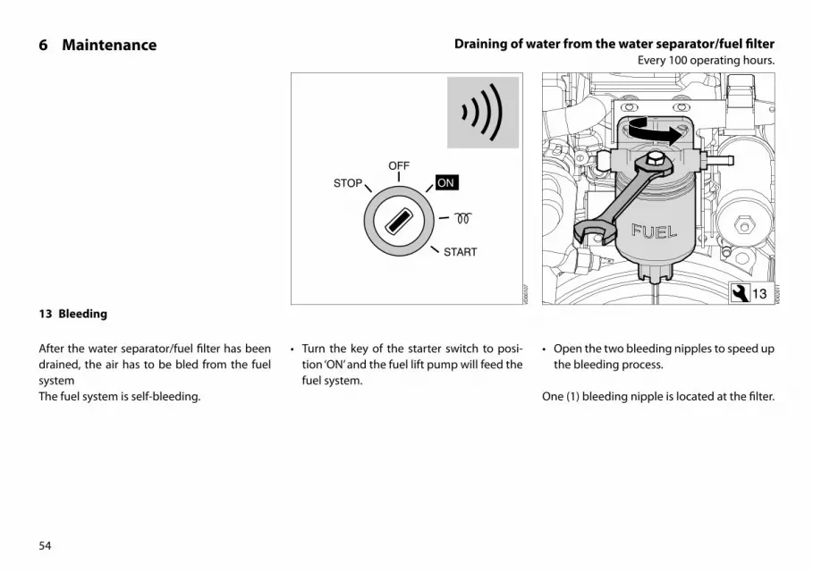
13 Bleeding
After the water separator/fuel filter has been drained, the air has to be bled from the fuel systemThe fuel system is self-bleeding.
• Turn the key of the starter switch to posi-tion ‘ON’ and the fuel lift pump will feed the fuel system.
• Open the two bleeding nipples to speed up the bleeding process.
One (1) bleeding nipple is located at the filter.
13
VD02
011
VD00
107

M2M3
M4
55
6 Maintenance Draining of water from the water separator/fuel filterEvery 100 operating hours.
A second bleeding nipple is located at the fuel injection pump.
• Close the bleeding nipples when all air has escaped.
• Operate the starter switch until the engine fires; release the starter switch if the engine does not fire within 20 seconds.
• Wait until the starter motor has stopped before making a new attempt to start the engine.
• Repeat the above if the engine cuts out af-ter a short time.
VD02
029
VD02
028
VD00
109
1410 211214 Start the engine

56
6 Maintenance Engine oil changeEvery 250 operating hours.
15 Engine oil change
Change the engine oil every 250 hours of operation (together with engine oil filter re-placement).
If the engine runs less than 250 hours during the year the oil should be changed at least once a year.
Run the engine for a few minutes before changing the oil; warm oil can be pumped out more easily.
Change the oil with a switched off engine at operation temperature. (Lube oil temperature approx. 80°C (176°F).)
Danger
Be aware of the risk of skin burning during draining the hot oil! Used oil must be collect-ed in a container for proper disposal accord-ing to laws and regulations.
Warning
Never use additives.
This could cause damage to the engine which is not covered by the guarantee.

57
Danger
Beware of burns from hot oil.
6 Maintenance Engine oil changeEvery 250 operating hours.
16 Draining the oil
• Remove the dipstick; insert the suction hose of the supplied sump pump in the dipstick tube.
• Push down the pump handle quickly and pull it up slowly.
• Pump the sump empty.
• After draining remove the suction hose of the sump pump out of the dipstick tube. Warning
The engine oil must be disposed in accord-ance with the applicable environmental regu-lations.
VD00
997

58
6 Maintenance Engine oil changeEvery 250 operating hours.
17 Removing the oil filter
• Unscrew the oil filter, with a commercially available tool.Catch any dripping oil.
• Clean the contact surface of the gasket.
• Lubricate the oil seal of the new filter ele-ment with clean engine oil.
For oil filter art. code see page 140.
19 Oil filter installation
• Install the filter in accordance with the in-structions printed on the filter element housing.
Tightening torque 11 - 13 Nm (8-10 ft.lbf )
Danger
Beware of burns from hot oil.
18 Oiling the oil seal
VD00
999
VD00
124
VD00
998

59
6 Maintenance Engine oil changeEvery 250 operating hours.
20 Refilling with oil
• Refill the engine with new oil (for specifica-tion see page 126) through the filler open-ing in the valve cover.
• Operate the engine at idling speed for a short period of time. Check for oil leaks whilst the engine is running. Stop the en-gine. Allow 5 minutes for the oil to return to the sump. Check the oil level with the dipstick.
amount oF oil (oil Filter inCl.):
litres Imp. pt US pt
M2 : 2.5 4.4 5.3
M3 : 3.6 6.3 7.6
M4 : 5.7 10 12
VD00
976

60
6 Maintenance Battery, cables and connectionsEvery 100 operating hours.
Warning notes and safety regulations for working with batteries
Wear eye protection.
Keep children away from acid and bat-teries.
Explosion hazard:A highly-explosive oxyhydrogen gas mixture occurs when charging batter-ies, therefore:
Fires, sparks, naked flames and smok-ing are prohibited:
• Avoid causing sparks when dealing with cables and electrical equip-ment, and beware of electrostatic discharges.
• Avoid short-circuits.
Pb
Corrosive hazard:
Battery acid is highly corrosive, there-fore:
• Wear protective gloves and eye pro-tection.
• Do not tilt battery, acid can escape from the degassing openings or vents.
First aid:
• Rinse off acid splashed in the eyes immediately for several minutes with fresh water. Then consult a doctor immediately.
• Neutralize acid splash on skin or clothes immediately with acid neu-tralizer (soda) or soap suds and rinse with plenty of water.
• If acid is consumed, consult a doc-tor immediately.
Warning note:
• Do not place batteries in direct day-light without protection.
• Discharged batteries can freeze up, therefore store in an area free from frost.
Disposal:Hand in old batteries at a collection point. Keep the batteries upright and do not tip during transport and storage to prevent acid leaking out.Never dispose of old batteries as do-mestic waste.
Careful! Metal parts of the battery will are always live so never lay objects or tools on the battery.

61
6 Maintenance Battery, cables and connectionsEvery 100 operating hours.
21 Battery, battery connections
Keep battery clean and dry.
• Remove battery cables (negative first).
• Clean battery posts (+ and −) and clamps and grease with acid-free and acid-resistant grease.
Ensure that clamps make good contact after reassembling.
• Hand tighten the bolts only.
VD00
117

1
Vetus maintenance-free batteries GREEN DOT ALL DARK CLEAR
62
6 Maintenance Battery, cables and connectionsEvery 100 operating hours.
22 Checking specific gravity
Every Vetus Maintenance-free battery has a hydrometer (1) built into the cover.
Visual inspection of the hydrometer will show one of three conditions:
23 Hydrometer operation
Green dot visible:State of charge 65 % or more.
Dark:State of charge less than 65 %. Recharge im-mediately.
Clear or light yellow:Electrolyte level low.
In case of low level, caused by overcharging the battery for a long period of time with a voltage too high, replace battery. Check alter-nator and/or voltage regulator.
VD00
121,
VD
0012
2, V
D00
123
VD00
118
Conventional batteries Conventional batteries
63
6 Maintenance Battery, cables and connectionsEvery 100 operating hours.
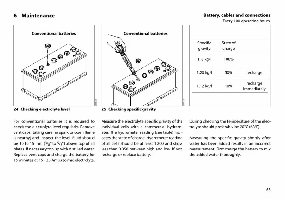
24 Checking electrolyte level
For conventional batteries it is required to check the electrolyte level regularly. Remove vent caps (taking care no spark or open flame is nearby) and inspect the level. Fluid should be 10 to 15 mm (3/8” to 5/8”) above top of all plates. If necessary top up with distilled water. Replace vent caps and charge the battery for 15 minutes at 15 - 25 Amps to mix electrolyte.
25 Checking specific gravity
Measure the electrolyte specific gravity of the individual cells with a commercial hydrom-eter. The hydrometer reading (see table) indi-cates the state of charge. Hydrometer reading of all cells should be at least 1.200 and show less than 0.050 between high and low. If not, recharge or replace battery.
Specific gravity
State of charge
1,.8 kg/l 100%
1.20 kg/l 50% recharge
1.12 kg/l 10%recharge
immediately
During checking the temperature of the elec-trolyte should preferably be 20°C (68°F).
Measuring the specific gravity shortly after water has been added results in an incorrect measurement. First charge the battery to mix the added water thoroughly.
VD00
120
VD00
119
64
6 Maintenance Gearbox oil level checkEvery 100 operating hours.
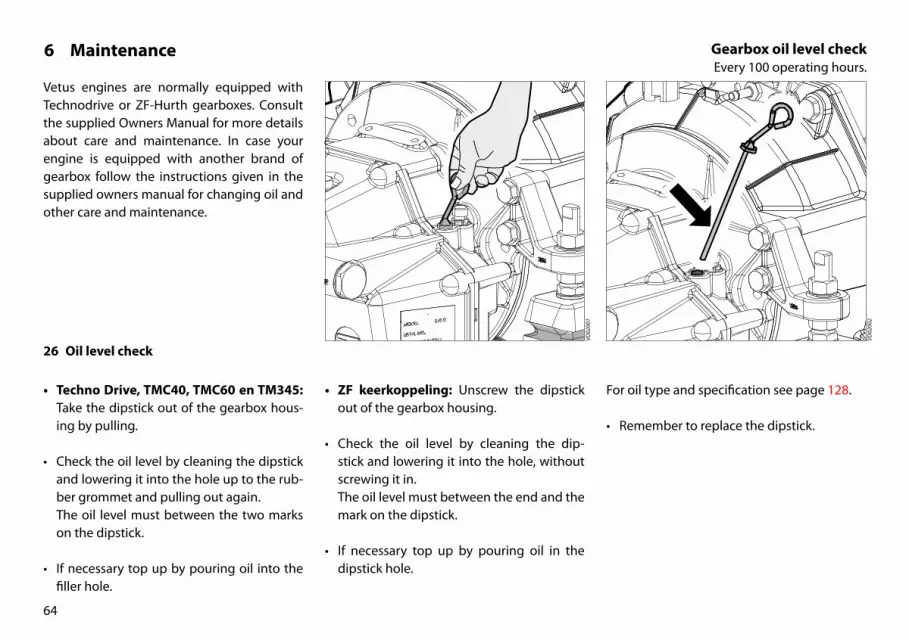
Vetus engines are normally equipped with Technodrive or ZF-Hurth gearboxes. Consult the supplied Owners Manual for more details about care and maintenance. In case your engine is equipped with another brand of gearbox follow the instructions given in the supplied owners manual for changing oil and other care and maintenance.
26 Oil level check
• Techno Drive, TMC40, TMC60 en TM345: Take the dipstick out of the gearbox hous-ing by pulling.
• Check the oil level by cleaning the dipstick and lowering it into the hole up to the rub-ber grommet and pulling out again.The oil level must between the two marks on the dipstick.
• If necessary top up by pouring oil into the filler hole.
• ZF keerkoppeling: Unscrew the dipstick out of the gearbox housing.
• Check the oil level by cleaning the dip-stick and lowering it into the hole, without screwing it in.The oil level must between the end and the mark on the dipstick.
• If necessary top up by pouring oil in the dipstick hole.
VD02
002
VD02
001
For oil type and specification see page 128.
• Remember to replace the dipstick.

1 2
65
6 Maintenance Fuel filter replacementEvery 500 operating hours.
27 Fuel filter removal
The fuel filter is to be replaced as a unit.
• Close the fuel stopcock.
• Remove the fuel filter, use a filter wrench. Catch any fuel.
• Clean any debris from the filter carrier rim.
• Lubricate the rubber gasket sparingly with clean engine oil.
• Fill the new filter with clean diesel fuel.
For fuel filter art. code see page 140.
VD01
012
VD00
133
VD00
154
Danger
Keep naked flames away when working on the fuel system. Do not smoke!
28 Fuel filter installation
• Install the filter. When the rubber gasket touches the housing, apply another tight-ening of a half to three quarters of a turn by hand.
• Open fuel stopcock.
• Check for leaks.
Fuel �lter
66
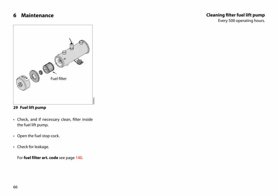
6 Maintenance Cleaning filter fuel lift pumpEvery 500 operating hours.
29 Fuel lift pump
• Check, and if necessary clean, filter inside the fuel lift pump.
• Open the fuel stop cock.
• Check for leakage.
For fuel filter art. code see page 140.
VD00
954

67
6 Maintenance Bleeding, after fuel filter replacementEvery 500 operating hours.
30 Bleeding
• After replacing the fuel filter the air has to be bled from the fuel system.
• For bleeding see page 45.
31 Start the engine
• Operate the starter switch until the engine fires; release the starter switch if the engine does not fire within 20 seconds.Wait until the starter motor has stopped before making a new attempt to start the engine.
• Repeat the above if the engine cuts out af-ter a short time.
• Check for leaks once more.
VD00
109

OIL
68
6 Maintenance Changing the gearbox oilEvery 500 operating hours.
32 Draining the oil
Drain the oil with the aid of a separate sump pump.
• Remove the dipstick.
• Insert the suction hose of the sump pump in the dipstick hole. Push down the pump handle quickly and pull it up slowly.
• Remove the sump pump when all the old oil has been pumped out.
Or, if sufficient space below the gearbox is available, oil can be drained by removing the drain plug.
• Remove the fillercap to vent the gearbox and check if all oil has been drained
• Collect the oil in a dripping pan.
33 Filling with new oil
• Refill the gearbox to the correct level via the dipstick opening.
For oil specification see page 128.
In case your engine is equipped with another brand of gearbox follow the instructions giv-en in the supplied owners manual for chang-ing oil and other care and maintenance.
14 / 17
VD02
004
VD02
003
VD00
975

69
VD00
983
VD00
806
6 Maintenance Flexible engine mounts, hose connections and fastenersEvery 500 operating hours.
34 Check flexible engine mounts
• Check the bolts which secure the damper element, the mounting bolts to engine bed and the nuts at the adjustment spindle for tightness.
• Inspect the rubber element of the engine support for cracks. Also check the deflec-tion of the damper element, the deflection influences the alignment of engine and propshaft! Re-align engine in case of doubt.
• Inspect all hose connections of the cooling-system. (Cracked hoses, loose hose clamps)
36 Check fasteners
• Check tightness of all fasteners, bolts and nuts.
35 Inspection hose connections

1 2
70
6 Maintenance Checking valve clearanceEvery 500 operating hours.
37 Checking / adjusting valve clearance
Checking the valve clearance must be done with a cold engine, that is an engine which did not run for at least 6 hours.
38 Remove upper cover
• Close the sea cock.
• Disconnect the hoses (1) and (2).
• Remove the 4 bolts and remove the upper cover.
39 Remove the V-belt protection cover
• Loosen the the screws -the screws can be loosened without tools and they have anti-loss rings- and remove the V-belt protec-tion.
note
After checking / adjusting the valve clearance re-install the V-belt protection and the upper cover and re-connect the hoses.
13
VD02
030
VD02
036
6

M2
2
M2Mark ongearcase
TDC mark
M2Valve clearance:Inlet 0.25 mm (0.010”)Exhaust 0.25 mm (0.010”)
71
10
VD02
040
24
VD01
049
VD00
989
10 1.0 x 5.5
6 Maintenance Checking valve clearanceEvery 500 operating hours.
40 Remove rocker cover
• Remove the 2 nuts of the rocker cover.
• Complete the following steps:
41 Locating TDC
• Locate the Top Dead Center (TDC), at the end of the compression stroke, for cylinder 1 by barring the engine slowly until the TDC marks of the engine block and the crank pulley match.
Note: There are two TDC’s e.g. compression and suction. At the TDC at the end of the com-pression stroke the rocker arm does not move when the crank pulley is rotated a little.
42 Adjusting valve clearance
Cylinders are numbered consecutively, begin-ning at the front end.
• Check valve clearance at cylinder 1 and ad-just if necessary.
• Rotate the crankshaft 180° clockwise and check valve clearance at cylinder 2.

M3Valve clearance:Inlet 0.25 mm (0.010”)Exhaust 0.25 mm (0.010”)
3
M3Mark ongearcase
TDC mark
M3
72
6 Maintenance Checking valve clearanceEvery 500 operating hours.
43 Remove rocker cover
• Remove the 2 nuts of the rocker cover.
• Complete the following steps:
44 Locating TDC
• Locate the Top Dead Center (TDC), at the end of the compression stroke, for cylinder 1 by barring the engine slowly until the TDC marks of the engine block and the crank pulley match.
Note: There are two TDC’s e.g. compression and suction. At the TDC at the end of the com-pression stroke the rocker arm does not move when the crank pulley is rotated a little.
45 Adjusting valve clearance
Cylinders are numbered consecutively, begin-ning at the front end.
• Check valve clearance at cylinder 1 and ad-just if necessary.
• Rotate the crankshaft 240° clockwise and check valve clearance at cylinder 3.
• Again rotate the crankshaft 240° and check valve clearance at cylinder 2.
24
VD01
049
10
VD02
039
VD00
989
10 1.0 x 5.5

M4Mark ongearcase
TDC mark for no. 1and no. 4 pistons
TDC mark for no. 2and no. 3 pistons
Injection timing mark
M4 M4Valve clearance:Inlet 0.25 mm (0.010”)Exhaust 0.25 mm (0.010”)
73
6 Maintenance Checking valve clearanceEvery 500 operating hours.
46 Remove rocker cover
• Remove the 2 nuts of the rocker cover.
• Complete the following steps:
• Locate the Top Dead Center (TDC), at the end of the compression stroke, for cylinder 1 by barring the engine slowly until the TDC marks of the engine block and the crank pulley match.
27
VD00
130
VD00
990
12
VD02
037
12 1.2 x 6.547 Locating TDC 48 Adjusting valve clearance
• Check valve clearance at cylinder 1 and ad-just if necessary.
• Rotate the crankshaft 180° clockwise and check valve clearance at cylinder 3.
• Again rotate the crankshaft 180° and check valve clearance at cylinder 4.
• Finally again rotate the crankshaft 180° and check valve clearance at cylinder 2.
Note 1: There are two TDC’s e.g. compres-sion and suction. At the TDC at the end of the compression stroke the rocker arm does not move when the crank pulley is rotated a little.
Note 2: Cylinders are numbered consecu-tively, beginning at the front end.

74
6 Maintenance Checking the V-beltEvery 500 operating hours.
49 Remove the V-belt protection cover
• Loosen the the screws -the screws can be loosened without tools and they have anti-loss rings- and remove the V-belt protec-tion.
50 Inspection V-belt
• Inspect the belt for wear and tear (fraying and cracking). Belts which are in poor con-dition should be replaced.
For V-belt art. code see page 140.
•
Danger
Check, tension and change belts only with the engine off. Refit belt guard, if provided.
VD00
034
VD02
041

75
6 Maintenance Checking the V-beltEvery 500 operating hours.
51 Checking tension
• Check tension of the V-belt by applying moderate finger and thumb pressure. If the deflection of the belt is more than 12 mm (1/2”), using about 10 kg (20 lbs) thumb pressure, it should be tensioned.
52 Tensioning V-belt
• Loosen the bolt of the adjustment bracket and both the alternator mounting bolts. Now push the alternator outwards until the belt tension is correct.
• Now first re-tighten the upper mounting bolt of the alternator.
• Then re-tighten the bolt of the adjustment bracket and the lower mounting bolt.
53 Reinstall the protection cover
• Always reinstall the V-belt guard onto the engine.
1412
VD00
128
VD00
129
VD02
047

1 32
76
6 Maintenance Checking valve oil sump ventilationOnce every year.
54 Checking valve
• Loosen bolt (1) and lift the valve from the engine.
• Remove the plug (2).
• Check if the ball (3) can move freely in the valve housing.
• Also inspect the ball for corrosion. A cor-roded ball needs to be replaced.
• Re-assemble the valve in reverse order.
VD02
021
VD02
020
note
Only at engines (SOLAS) for lifeboats!

77
6 Maintenance Raw water pump inspectionEvery 1000 operating hours.
55 Raw water pump inspection
The rubber impeller of the outboard water pump is not proof against running dry.
Note The impeller used on SOLAS engines is indeed proof against running dry.
If the water supply has been blocked, it may be necessary to replace the impeller. Always carry a spare impeller on board.
56 Pump cover removal
Inspection where appropriate changing is as follows:
• Close the sea cock.
• Remove the cover of the pump by unscrew-ing the screws out of the housing.
The position of the hose connections on the pump may be different as in the drawing
57 Impeller removal
• Slide the impeller off of the shaft using a waterpump plier.
• Mark the impeller to ensure correct re-in-stallation if it is to be re-used. The impeller must be installed in the same position as removed.
note
Only engines with intercooling!
VD02
013
VD02
014
101.6 x 6.3

1
78
6 Maintenance Raw water pump inspectionEvery 1000 operating hours.
58 Impeller inspection
• Inspect the impeller for damage.
• Replace the impeller if necessary.
For impeller art. code see page 140.
59 Pump housing inspection
• Check the inside of the pump housing for damage. Pay special attention to wear of the cam (1).
• Replace the cam and/or the pump housing in case of excessive wear.
VD02
045
VD00
127
VD02
019

79
6 Maintenance Raw water pump inspectionEvery 1000 operating hours.
60 Re-install the impeller
• The impeller should be lubricated with glycerin or a non-petroleum based lubri-cant such as a silicone spray before fitting it into the impeller housing.
• Fit the impeller to the pump shaft. (if an existing impeller is re-used, install it in the same position as removed).
61 Reinstall the pump cover
• Reinstall the cover with a new O-ring.
• Check the water filter and open the sea cock.
For O-ring art. code see page 140.
VD00
004
VD00
961

21
80
6 Maintenance Coolant replacementEvery 1000 operating hours.
62 Coolant replacement
The coolant has to be replaced every 1000 op-erating hours or at least once every two years.
N.B. Replacing the coolant may also be neces-sary as part of the winter storage procedure; in case that the coolant present in the cooling system offers insufficient protection for the winter.
Danger
Be aware of the risk of skin burning during draining the hot coolant! Used coolant must be collected in a container for proper disposal according to laws and regulations.
Warning
Cooling system protective liquids must be disposed of in accordance with environmen-tal regulations.
note
Keel coolerHow the cooling system in engines with keel cooling should be drained depends on the installation of the keel cooler.Refer to the keel cooler manufacturer’s in-structions for this.
Check using a coolant hydrometer wheth-er the coolant is providing sufficient pro-tection against freezing if total draining off is not possible.
VD00
995
63 Preparation
• Remove the plug (1) and the filler cap (2) to vent the cooling system.

1 32
81
6 Maintenance Coolant replacementEvery 1000 operating hours.
64 Draining of coolant
• Remove the drain plugs from the engine block (1) and heat exchanger housing (2).
• After draining replace the drain plugs.
14
VD02
025
PH2
VD02
026
13
VD02
024
• For M4.56 and M4.55 SOLAS only
• Detach the hose to the oil coiler (3) and remove the drain plug from the heat ex-changer housing (2).
• After draining re-install the hose and the drain plug.
82
6 Maintenance Coolant replacementEvery 1000 operating hours.
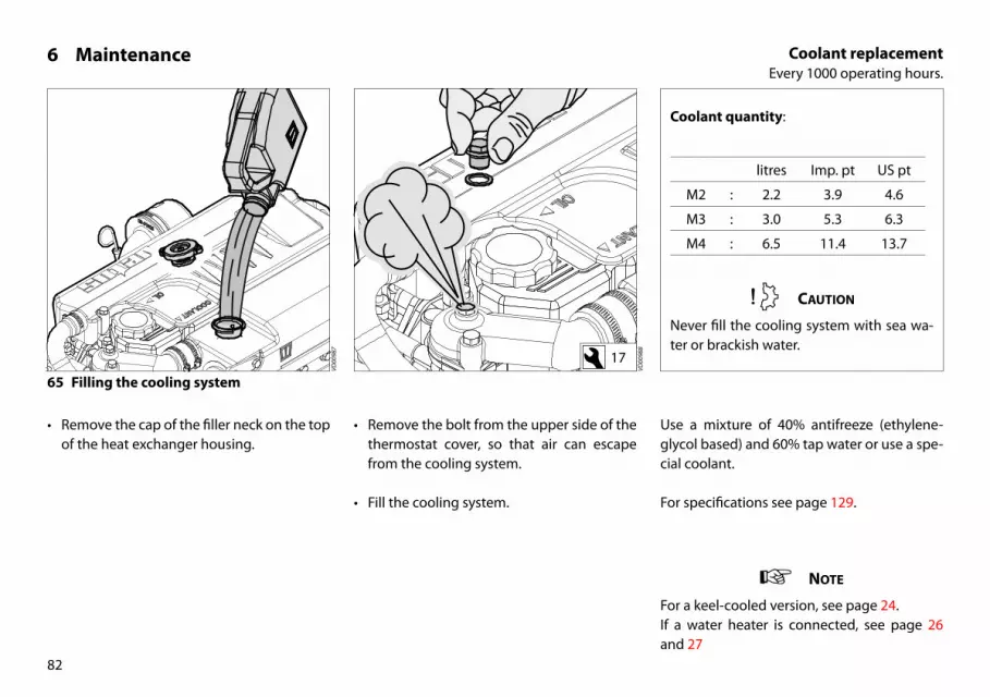
65 Filling the cooling system
• Remove the cap of the filler neck on the top of the heat exchanger housing.
• Remove the bolt from the upper side of the thermostat cover, so that air can escape from the cooling system.
• Fill the cooling system.
Use a mixture of 40% antifreeze (ethylene-glycol based) and 60% tap water or use a spe-cial coolant.
For specifications see page 129.
Coolant quantity:
litres Imp. pt US pt
M2 : 2.2 3.9 4.6
M3 : 3.0 5.3 6.3
M4 : 6.5 11.4 13.7
Caution
Never fill the cooling system with sea wa-ter or brackish water.
note
For a keel-cooled version, see page 24.If a water heater is connected, see page 26 and 27
17
VD00
988
VD00
987

1 cm(3/8”)
COOLANT
83
6 Maintenance Coolant replacementEvery 1000 operating hours.
The level of the coolant must be approx. 1 cm (3/8”) below the lower edge of the filler neck.
Bleeding will take place automatically during filling!
• After filling replace the filler cap and re-install the plug.
• After the engine has run for the first time and has reached operating temperature and has cooled down again to ambient temperature, check the coolant level in the heat exchanger housing.
• If necessary, add coolant.
Caution
Never fill the cooling system with sea water or brackish water.
Water heater
If a water heater is connected to the en-gine and this heater is positioned above the upper side of the engine than bleeding of the heater will not take place automati-cally! Fill the heater separately to bleed the cooling system completely.
VD00
158

2 1 3
84
6 Maintenance Air filter replacementEvery 1000 operating hours.
66 Air filter replacement
• Loosen the hose clamp (1).
• Remove the filter housing (2).
• Remove the old filter and fit a new filter (3).
• Replace the unit in reverse order and tight-en the hose clamp again.
For air filter art. code see page 140.
Warning
Never clean the element with petrol or hot liquids.
Never apply any oil to the air filter.
Never start the engine without the air filter in place.
VD02
009
VD02
010
note
Engines for lifeboats (SOLAS) are sup-plied without an air filter.
never install an air filter into the filter housing at these engines.

85
6 Maintenance Checking the starter motor and alternatorEvery 1000 operating hours.
67 Checking the starter motor
• Check for visible defects.
• Check whether the Bendix engages with the starter ring when the starter motor is activated. If the Bendix does not engage properly, contact your Vetus dealer.
68 Checking the alternator
• Check for visible defects.
• Remove the alternator belt. Turn the pulley by hand to check whether the alternator can be turned easily. If this is not the case, contact your Vetus dealer.
VD00
992
VD00
991
VD02
048
• If a spring starter is installed then check functioning by starting the engine as de-scribed on pages 38 and 39.
86
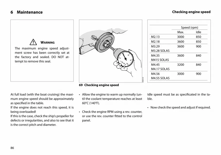
6 Maintenance Checking engine speed
At full load (with the boat cruising) the maxi-mum engine speed should be approximately as specified in the table.If the engine does not reach this speed, it is being overloaded!If this is the case, check the ship’s propeller for defects or irregularities, and also to see that it is the correct pitch and diameter.
Idle speed must be as specificated in the ta-ble.
• Now check the speed and adjust if required.
69 Checking engine speed
• Allow the engine to warm up normally (un-til the coolant temperature reaches at least 60°C (140°F).
• Check the engine RPM using a rev. counter, or use the rev. counter fitted to the control panel.
Warning
The maximum engine speed adjust-ment screw has been correctly set at the factory and sealed. DO NOT at-tempt to remove this seal.
VD00
134
Speed (rpm)Max. Idle
M2.13 3000 850M2.18 3600 850M3.29M3.28 SOLAS
3600 900
M4.35M415 SOLAS
3600 840
M4.45M4.17 SOLAS
3200 840
M4.56M4.55 SOLAS
3000 900

Lead seal
Maximum speedadjustment screw
Minimum speedadjustment screw
M2M3
M4
Lead seal
Maximumspeed
adjustmentscrew
Minimumspeed
adjustmentscrew
Increasing RPM
87
6 Maintenance Checking engine speed
If the engine speed differs from that stated above, it must be adjusted.The engine idling speed can be reset using the adjustment screw on the fuel pump.
10
VD00
994
10
VD00
993
70 Adjusting engine idling speed

88
6 Maintenance Cleaning the heat exchanger
note
Cleaning of the heat exchanger is not a routine maintenance job.
Only clean the heat exchanger if this is (badly) fouled.
Under normal conditions of use cleaning the heat exchanger is not necessary!
The engine temperature will be higher than normal if the heat exchanger is fouled.
Possible causes of fouling are: - Small rubber particles from a damaged sea
water pump impeller. - Growth of algae or seaweed.
note
Only engines with intercooling!

2
89
6 Maintenance Cleaning the heat exchanger
71 Remove the drain plug
• Close the seacock and detach the water in-let hose from the sea water pump.
• Drain the coolant: To do this, remove the drain plug from the heat exchanger hous-ing.
• Remove the filler cap from the top of the heat exchanger housing to allow air into the system and check that all coolant has drained off.
72 Removal of bolts out of the end covers
• Take out both central bolts from the end covers and take the end covers with the O-rings out of the housing.
Turn the alternator outwards, by loosening the bolts and removing the V-belt, if more space is required for the Allen key.
note
Only engines with intercooling!
13 5VD02
024
VD02
027
VD00
984

90
6 Maintenance Cleaning the heat exchanger
73 Remove heat exchanger
• Slide the heat exchanger out of the hous-ing.
• At the M4.56 and M4.55 SOLAS the heat ex-changer must be slide out of the housing to the front, instead of to the rear.Therefore loosen the bolts of the alternator, remove the V-belt and turn the alternator outwards.
74 Cleaning the heat exchanger
• Clean the heat exchanger: Use a pipe clean-er to remove fouling in the pipes.
• Then rinse the heat exchanger pipes with clean water.
• Ensure that both heat exchanger end chambers are free from dirt.
note
Only engines with intercooling!
6 VD02
033
VD02
031
VD02
032

91
6 Maintenance Cleaning the heat exchanger
75 Replacing heat exchanger
• Replace the heat exchanger in the original position in the heat exchanger housing.
• Use new O-rings (61 x 2.5 mm) which have been greased.
For O-ring art. code see page 140.
• Refit the drain plug.
• Reconnect all hoses previously removed.
• Refill the cooling system, see page 82.
note
Only engines with intercooling!
76 Replacing the end covers
• Fit the end covers in the housing.
• Tighten up the bolts when both covers are in the correct position.
VD02
042
VD00
157
92
7 Lay-up / Winter storage procedure
In case of lay-up for a long period the stor-age procedures as described in this chapter should be carried out.
A long period means a period longer than 3 months, for example, during the winter pe-riod.
Make sure that the engine compartment is well ventilated during the winter period.
Good ventilation prevents damp in the en-gine compartment, thus preventing corrosion of the engine from occurring.
The engine should be inspected at the start of the storage period and any necessary repairs should be carried out.
Consult a Vetus Dealer if help is required with this.
Inspections and maintenance work to be car-ried out are:

93
7 Lay-up / Winter storage procedure
Inspections and maintenance work to be carried out: page
1 Clean the engine, remove any salt. Paint any rust spots and spray the whole engine with a protective medium, for example CRC protective 6-66.
94
2 Drain off the water from the fuel system and fill the fuel tank. 94
3 Make sure that the engine fuel system is filled with a fuel mixture with protective properties. 95
4 Flush out the raw water circuit with fresh water and if necessary fill with antifreeze. Clean the heat exchanger if necessary.
96
5 Make sure that the cooling system is filled with a suitable anti-freeze. 97
6 Change the oil filter and the engine oil. 98
7 Change the oil in the gearbox. 98
8 Disconnect the battery cables, charge the batteries if necessary and grease the battery terminals. 99
1 2
94
7 Lay-up / Winter storage procedure
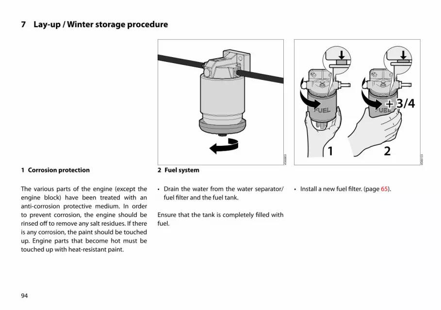
1 Corrosion protection
The various parts of the engine (except the engine block) have been treated with an anti-corrosion protective medium. In order to prevent corrosion, the engine should be rinsed off to remove any salt residues. If there is any corrosion, the paint should be touched up. Engine parts that become hot must be touched up with heat-resistant paint.
2 Fuel system
• Drain the water from the water separator/fuel filter and the fuel tank.
Ensure that the tank is completely filled with fuel.
• Install a new fuel filter. (page 65).
VD00
803
VD00
133
95
7 Lay-up / Winter storage procedure
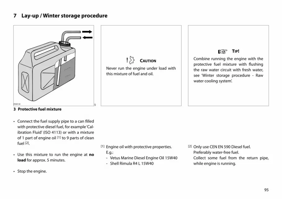
3 Protective fuel mixture
• Connect the fuel supply pipe to a can filled with protective diesel fuel, for example ‘Cal-ibration Fluid’ (ISO 4113) or with a mixture of 1 part of engine oil [1] to 9 parts of clean fuel [2].
• Use this mixture to run the engine at no load for approx. 5 minutes.
• Stop the engine.
[2] Only use CEN EN 590 Diesel fuel. Preferably water-free fuel. Collect some fuel from the return pipe,
while engine is running.
VD00136
tip!
Combine running the engine with the protective fuel mixture with flushing the raw water circuit with fresh water, see ‘Winter storage procedure - Raw water cooling system’.
Caution
Never run the engine under load with this mixture of fuel and oil.
VD
[1] Engine oil with protective properties. E.g.:
- Vetus Marine Diesel Engine Oil 15W40 - Shell Rimula R4 L 15W40

96
7 Lay-up / Winter storage procedure
4 Raw water cooling system
• Close the sea cock.
• Remove the lid of the water strainer.
• If necessary, clean the raw water strainer.
• Connect the raw water intake to a fresh wa-ter (tap water) supply or a tank containing fresh water. Open the tap and allow the en-gine to idle for at least 5 minutes to remove any salt and contamination from the raw water cooling system. Make sure that there is a sufficient supply of water to prevent the engine from over-heating.
• Stop the engine and close the sea cock.
• The raw water system must be protected in areas where the temperature drops to be-low zero during the winter. Pour 1 litre (1/4 gallon) of anti-freeze (prefer-ably a non-toxic biodegradable anti-freeze) into the water strainer and run the engine until the anti-freeze has disappeared into the cooling system.
tip!
Combine flushing the raw water circuit with fresh water with running the en-gine with the protective fuel mixture, see ‘Winter storage procedure - Protec-tive fuel mixture’
Heat exchanger Only clean the heat exchanger if this is absolutely necessary, see page 88.
Raw water pump Check the impeller of the raw water pump at least once every two years, see page 77.
VD00125
note
Only engines with intercooling!
VD00
801

97
7 Lay-up / Winter storage procedure
Anti-freeze can be toxic. Take care that no anti-freeze is spilled into the waterway
• Check the seal between the lid and hous-ing after cleaning and re-assembling the strainer.
An improperly sealed lid will result in air sucked in by the raw water pump which again will result in overheating of the engine
5 Fresh water cooling system
To avoid corrosion during winter storage the cooling system must be filled with an anti-freeze/water mixture (or a coolant).
For specifications see page 129.
N.B. Replacing the coolant is only necessary if the coolant present in the cooling system of-fers insufficient protection against tempera-tures below 0˚C (32˚F).
For coolant replacement see page 80.
tip!
Protect the sea cock as follows:With the motor stopped.
• Place the sea cock in a position that it is just opening.
• Pour a small amount of non-toxic bi-odegradable anti-freeze into the raw water strainer.
• Close the sea cock as soon as it is filled with anti-freeze.
VD00
984

98
7 Lay-up / Winter storage procedure
6 Lubrication system
With the engine still at operating tempera-ture: (If not, run the engine until warm, then turn off.)
• Replace the oil filter and change the engine oil; use oil with protective properties. See page 56.
For quantity and oil specification see page 118 and 126.
7 Changing the gearbox oil
• Stop the engine and change the oil of the gearbox. (page 68)
VD00
998
VD00
997
VD00
975

99
7 Lay-up / Winter storage procedure
8 Electrical system
• Disconnect the battery cables. • Charge batteries during winter lay-up regu-larly if required!
• Follow the recommendations given on pages 60 to 63 or consult the recommen-dations given by the battery supplier for in-spection and maintenance of the batteries.
CT40
063
VD00
139

100
8 Recommissioning after lay-up or winter storage
The engine must be inspected and any main-tenance work carried out when re-commis-sioning for example at the beginning of the sailing season.
Consult a Vetus Dealer if help is required with this.
Inspections and maintenance work to be car-ried out are:
Inspections and maintenance work to be carried out are: page
1 Drain the water from the fuel system. 101
2 Check the raw water system. 102
3 Check the coolant level in the internal cooling system. 103
4 Check the oil level. 103
5 Check the batteries and reconnect these. 104
6 Check the operation of the engine. 104
7 Check all hose connections for leaks. 105
8 Check the operation of the instruments and the engine controls. 105

101
8 Recommissioning after lay-up or winter storage
1 Fuel system
• Drain the water from the water separator/fuel filter. (page 53)
• Drain the water from the fuel tank. • Open the fuel valve.
VD00
141
VD00
803
VD00
137
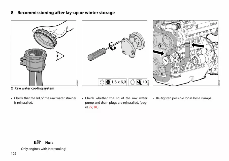
102
8 Recommissioning after lay-up or winter storage
2 Raw water cooling system
• Check that the lid of the raw water strainer is reinstalled.
• Check whether the lid of the raw water pump and drain plugs are reinstalled. (pag-es 77, 81)
• Re-tighten possible loose hose clamps.
note
Only engines with intercooling!
VD00
801
VD00
983
VD02
013
101,6 x 6,3

OILCOOLANT
103
8 Recommissioning after lay-up or winter storage
• Open the sea cock.
3 Fresh water cooling system
• Check the coolant level. (page 50)
4 Lubrication system
• Check the engine oil level. (page 48)
VD00
138
VD00
982
VD00
984

104
8 Recommissioning after lay-up or winter storage
5 Electrical system
• Make sure that the batteries are fully charged. (page 60, 99)
• Connect the batteries.
6 Switching on
• Turn the start key on the instrument panel clock-wise; the warning lights for oil pres-sure and alternator will now light up and the alarm buzzer will sound.
VD00
140
CT40
063
VD02
054
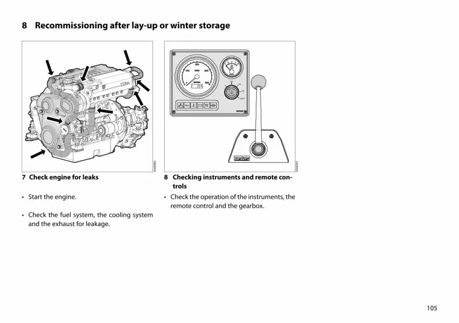
105
8 Recommissioning after lay-up or winter storage
7 Check engine for leaks
• Start the engine.
• Check the fuel system, the cooling system and the exhaust for leakage.
8 Checking instruments and remote con-trols
• Check the operation of the instruments, the remote control and the gearbox.
VD00
581
VD00
983

106
9 Troubleshooting General
Engine faults are in most cases caused by im-proper operation or insufficient maintenance.
Note Not all possible faults mentioned will be applicable to your engine.
In case of a fault, always check first that the operation and maintenance instructions have been followed.
In the following tables information is given about the possible causes of faults and sug-gested remedies. Please note that these ta-bles can never be complete.
If you are unable to identify the cause of the fault or to rectify it yourself, then contact the nearest service representative.
Danger Before starting, make sure that nobody is in the immediate vincinity of the engine.When carrying out repair, never start the en-gine with the fuel injection pump removed removed.Disconnect battery!

107
9 Troubleshooting Fault finding table
Fault page
1 Engine will not crank 108
2 Engine cranks but will not start, no smoke from exhaust 108
3 Engine cranks but will not start, smoke from exhaust 109
4 Engine starts but runs unevenly (rough idling) or stalls 109
5 Engine does not reach maximum rpm under load 110
6 Engine overheats 111
7 Engine not firing on all cylinders 111
8 Engine has little or no oil pressure 112
9 Engine oil consumption excessive 112
10 Fuel consumption excessive 113
11 Black exhaust smoke (idling) 113
12 Blue exhaust smoke (idling) 113
13 Black exhaust smoke (at load) 114
14 White exhaust smoke (at full load) 114
15 Burnt oil trace in exhaust line . 115
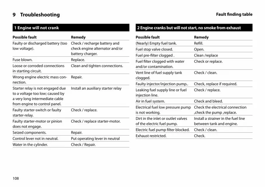
108
1 Engine will not crank
Possible fault RemedyFaulty or discharged battery (too low voltage).
Check / recharge battery and check engine alternator and/or battery charger.
Fuse blown. Replace.
Loose or corroded connections in starting circuit.
Clean and tighten connections.
Wrong engine electric mass con-nection.
Repair.
Starter relay is not engaged due to a voltage too low; caused by a very long intermediate cable from engine to control panel.
Install an auxiliary starter relay
Faulty starter-switch or faulty starter-relay.
Check / replace.
Faulty starter-motor or pinion does not engage.
Check / replace starter-motor.
Seized components. Repair.
Control lever not in neutral. Put operating lever in neutral
Water in the cylinder. Check / Repair.
2 Engine cranks but will not start, no smoke from exhaust
Possible fault Remedy(Nearly) Empty fuel tank. Refill.
Fuel stop valve closed. Open.
Fuel pre-filter clogged . Clean /replace
Fuel filter clogged with water and/or contamination.
Check or replace.
Vent line of fuel supply tank clogged.
Check / clean.
Faulty injector/injection pump.. Check, replace if required.
Leaking fuel supply line or fuel injection line.
Check / replace.
Air in fuel system. Check and bleed.
Electrical fuel low pressure pump is not working.
Check the electrical connection ,check the pump ,replace.
Dirt in the inlet or outlet valves of the electric fuel pump.
Install a strainer in the fuel line between tank and engine.
Electric fuel pump filter blocked. Check / clean.
Exhaust restricted. Check.
9 Troubleshooting Fault finding table

109
9 Troubleshooting Fault finding table
3 Engine cranks but will not start, smoke from exhaust
Possible fault RemedyFaulty injector/injection pump. Check, replace if required.
Air in fuel system. Check and bleed.
Wrong fuel quality or contami-nated fuel.
Check fuel. Drain and flush fuel tank. Replace with new fuel.
Incorrect injection timing. Check / adjust.
Setting of stop valve incorrect. Check / adjust.
Incorrect lube oil SAE class or quality for ambient temperature.
Replace.
Faulty glow plugs. Check / replace.
Insufficient intake air. Check.
Intake air filter clogged . Clean/replace
Incorrect valve clearance. Adjust.
4 Engine starts but runs unevenly (rough idling) or stalls
Possible fault Remedy(Nearly) Empty fuel tank. Refill.
Fuel supply line restricted. Check / clean.
Fuel filter clogged with water and/or contamination.
Check or replace.
Vent line of fuel supply tank clogged.
Check / clean.
Faulty injector/injection pump. Check, replace if required.
Leaking fuel supply line or fuel injection line.
Check / replace.
Air in fuel system. Check and bleed.
Wrong fuel quality or contami-nated fuel.
Check fuel. Drain and flush fuel tank. Replace with new fuel.
Exhaust restricted. Check.
Incorrect valve clearance. Adjust.
Idle setting too low. Check/ adjust.
Clogged filter of electric fuel lift pump.
Check / clean.

110
9 Troubleshooting Fault finding table
5 Engine does not reach maximum rpm under load
Possible fault RemedyFuel pre-filter clogged . Clean /replace
Fuel filter clogged with water and/or contamination.
Check or replace.
Clogged injectors Check, replace if required.
Faulty injector/injection pump. Check, replace if required.
Leaking fuel supply line or fuel injection line.
Check / replace.
Air in fuel system. Check and bleed.
Wrong fuel quality or contami-nated fuel.
Check fuel. Drain and flush fuel tank. Replace with new fuel.
Incorrect injection timing. Check / adjust.
Setting of stop valve incorrect. Check / adjust.
Oil level too high. Lower level.
Lubricating oil incorrect SAE spec or quality for ambient temperature.
Replace.
Insufficient intake air. Check.
Leak in inlet manifold. Check / replace.
Exhaust restricted. Check / clean.
Incorrect valve clearance. Adjust.
Transmission defect. Check
Turbocharger damaged . Replace
5 Engine does not reach maximum rpm under load
Possible fault RemedyEngine overloaded. Check size of propeller.
Boat load inadequate . -
Hull/propeller dirty . Clean

111
9 Troubleshooting Fault finding table
6 Engine overheats
Possible fault RemedyFaulty injector/injection pump. Check, replace if required.
Sea cock closed. Open.
Raw water strainer clogged. Check / clean.
Faulty raw water pump impeller. Check / replace.
Leak in raw water feed system. Check / replace.
Coolant level too low. Check / top up.
Faulty coolant pump. Check / replace.
Faulty thermostat. Check / replace.
Leak in coolant circuit . Check.
Heat exchanger dirty or clogged as a result of rubber particles from a worn impeller.
Check / clean.
Oil level too low. Increase level.
Oil level too high. Lower level.
Faulty oil filter. Replace.
Insufficient intake air. Check / replace air intake filter.
Leak in inlet manifold. Check / replace.
Faulty turbo compressor. Check / replace.
Motor becomes apparently overheated as a result of faulty temperature switch, sensor or meter.
Check / replace.
7 Engine not firing on all cylinders
Possible fault RemedyFuel supply line restricted. Check / clean.
Fuel filter clogged with water and/or contamination.
Check or replace.
Faulty electric fuel pump. Check / replace.
Faulty injector/injection pump. Check, replace if required.
Leaking fuel supply line or fuel injection line.
Check / replace.
Air in fuel system. Check and bleed.
Faulty glow plugs. Check / replace.
Incorrect valve clearance. Adjust.

112
9 Troubleshooting Fault finding table
8 Engine has little or no oil pressure
Possible fault RemedyOil level too low. Increase level.
Incorrect lube oil SAE class or quality for ambient temperature.
Replace.
Blocked oil filter. Replace.
Faulty oil pump. Repair / replace.
Oil leaks . Check.
Excessive inclination of engine. Check / Adjust.
Oil pressure apparently too low due to faulty oil pressure switch, sensor or meter.
Check / replace.
9 Engine oil consumption excessive
Possible fault RemedyOil level too high. Lower level.
Incorrect lube oil SAE class or quality for ambient temperature.
Replace.
Leak in lubricating oil system. Repair / replace.
Insufficient intake air. Check.
Excessive wear of cylinder/pis-ton.
Check compression; overhaul engine.
Turbocharger leaks oil. Repair / replace.
Engine overloaded. Check size of propeller. Clean the propeller.
Excessive inclination of engine. Check / Adjust.

113
9 Troubleshooting Fault finding table
10 Fuel consumption excessive
Possible fault RemedyFaulty injector/injector pump. Check, replace if necessary.
Incorrect fuel quality or dirty fuel.
Check fuel. Drain and rinse fuel tank. Replace with new fuel.
Fuel leaks . Check and repair.
Incorrect injection timing. Check / adjust.
Insufficient air intake. Check.
Excessive wear of cylinder / piston.
Check compression; refurbish engine.
11 Black exhaust smoke (idling)
Possible fault RemedyInjector fault Check /replace.
Oil level too high. Lower level.
Excessive inclination of engine. Check / Adjust.
12 Blue exhaust smoke (idling)
Possible fault RemedyOil level too high. Lower level.
Leaking from turbo compressor oil seal.
Check / replace oil seal.
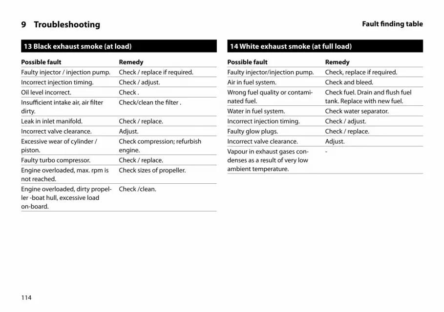
114
9 Troubleshooting Fault finding table
13 Black exhaust smoke (at load)
Possible fault RemedyFaulty injector / injection pump. Check / replace if required.
Incorrect injection timing. Check / adjust.
Oil level incorrect. Check .
Insufficient intake air, air filter dirty.
Check/clean the filter .
Leak in inlet manifold. Check / replace.
Incorrect valve clearance. Adjust.
Excessive wear of cylinder / piston.
Check compression; refurbish engine.
Faulty turbo compressor. Check / replace.
Engine overloaded, max. rpm is not reached.
Check sizes of propeller.
Engine overloaded, dirty propel-ler -boat hull, excessive load on-board.
Check /clean.
14 White exhaust smoke (at full load)
Possible fault RemedyFaulty injector/injection pump. Check, replace if required.
Air in fuel system. Check and bleed.
Wrong fuel quality or contami-nated fuel.
Check fuel. Drain and flush fuel tank. Replace with new fuel.
Water in fuel system. Check water separator.
Incorrect injection timing. Check / adjust.
Faulty glow plugs. Check / replace.
Incorrect valve clearance. Adjust.
Vapour in exhaust gases con-denses as a result of very low ambient temperature.
-

115
9 Troubleshooting Fault finding table
15 Burnt oil trace in exhaust line .
Possible fault RemedyOil level too high . Lower level.
Excessive wear of cylinder / piston, piston rings.
Check compression; refurbish engine.
Faulty turbocharger . Check, Repair / Replace .

116
10 Technical data Engine specifications
Model : M2.13 M2.18 M3.29M3.28 SOLAS
M4.35M4.15 SOLAS
M4.45M4.17 SOLAS
M4.56M4.55 SOLAS
General Make : Vetus Mitsubishi
Number of cylinders : 2 2 3 4 4 4
Based on : L2E-65DMA L2E-65DM L3E-6ADM S4L2-66DM S4L2-65DM S4L2-T
Type : 4-stroke diesel, in-line
Injection : Indirect
Aspiration : Natural Turbo-charged
Bore : 76 mm 76 mm 76 mm 78 mm 78 mm 78 mm
Stroke : 70 mm 70 mm 70 mm 92 mm 92 mm 92 mm
Total displacement :635 cm3
(39 cu.in.)635 cm3
(39 cu.in.)952 cm3
(58 cu.in.)1758 cm3
(104 cu.in.)1758 cm3
(104 cu.in.)1758 cm3
(104 cu.in.)
Compression ratio : 23:1 23:1 22:1 22:1 22:1 22:1
Idling speed : 850 rpm 850 rpm 900 rpm 840 rpm 840 rpm 900 rpm
Max. no. of revolutions at no load
: 3000 rpm 3600 rpm 3600 rpm 3200 rpm 3200 rpm 3250 rpm
Direction of rotation : Counter clockwise, viewed towards the flywheel
Valve Clearances (cold) : Inlet 0.25 mm (0.010”)
Exhaust 0.25 mm (0.010”)
Weight (with standard gearbox) :107 kgs(236 lbs)
107 kgs(236 lbs)
134 kgs(295 lbs)
199 kgs(439 lbs)
199 kgs(439 lbs)
206 kgs(454 lbs)

117
10 Technical data Engine specifications
Model : M2.13 M2.18 M3.29M3.28 SOLAS
M4.35M4.15 SOLAS
M4.45M4.17 SOLAS
M4.56M4.55 SOLAS
Engine installationMax. installation angle : 15 degrees backwards
Max. athwartships angle : 25 degrees continuously, 30 degrees intermittent
Maximum Output
at the flywheel (ISO 8665) :8.8 kW(12 hp)
11.8 kW(16 hp)
20 kW(27.2 hp)
24.3 kW(33 hp)
30.9 kW(42 hp)
36.8 kW(50 hp)
at the prop shaft (ISO 8665) :8.7 kW
(11.8 hp)11.6 kW(15.8 hp)
19.3 kW(26.2 hp)
23.6 kW(32.1 hp)
30 kW(40.8 hp)
35.6 kW(49 hp)
at no. of revolutions of : 3000 rpm 3600 rpm 3600 rpm 3000 rpm 3000 rpm 3000 rpm
Torque. :32.7 Nm(3.3 kgm)(24.1 ft.lb)
35.1 Nm(3.6 kgm)(25.9 ft.lb)
60.2 Nm(6.1 kgm)(37.8 ft.lb)
83.8 Nm(8.5 kgm)(57.1 ft.lb)
106.4 Nm(10.8 kgm)(72.3 ft.lb)
127 Nm(13 kgm)
(93.7 ft.lb)
at no. of revolutions : 1600 rpm 2000 rpm 2500 rpm 1700 rpm 1750 rpm 2000 rpm
Fuel consumption :268 g/kW.h(196 g/hp.h)(6.9 oz/hp.h)
268 g/kW.h(196 g/hp.h)(6.9 oz/hp.h)
270 g/kW.h(199 g/hp.h)(7.0 oz/hp.h)
252 g/kW.h(185 g/hp.h)(6.5 oz/hp.h)
252 g/kW.h(185 g/hp.h
(6.5 oz/hp.h))
244 g/kW.h(179 g/hp.h)(6.3 oz/hp.h)
at no. of revolutions : 2500 rpm 2500 rpm 2600 rpm 1800 rpm 1800 rpm 1800 rpm

118
10 Technical data Engine specifications
Model : M2.13 M2.18 M3.29M3.28 SOLAS
M4.35M4.15 SOLAS
M4.45M4.17 SOLAS
M4.56M4.55 SOLAS
Fuel System (Self-bleeding)Injection pump : Bosch type NC Bosch type NC Bosch type NC Bosch type M Bosch type M Bosch type M
Injectors : Plug injector
Opening pressure : 140 bar (kgf/cm2) (2030 psi)
Firing order : 1 - 2 1 - 2 1 - 3 - 2 1 - 3 - 4 - 2 1 - 3 - 4 - 2 1 - 3 - 4 - 2
Injection timing : 17° BTDC 17° BTDC 17° BTDC 21° BTDC 17° BTDC 14° BTDC
Fuel lift pump : Suction height max. max. 1,5 m (5 ft)
Fuel supply connection : for hose 8 mm (5/16”) I.D.
Fuel return connection : for hose 8 mm (5/16”) I.D.
Oil lubrication systemOil capacity, max.
without oil filter :2.3 litres
(4.0 Imp. pt)(4.9 US pt)
2.3 litres(4.0 Imp. pt)(4.9 US pt)
3.4 litres(6.0 Imp. pt)(7.2 US pt)
5.5 litres(9.7 Imp. pt)(11.6 US pt)
5.5 litres(9.7 Imp. pt)(11.6 US pt)
5.5 litres(9.7 Imp. pt)(11.6 US pt)
with oil filter :2.5 litres
(4.4 Imp. pt)(5.3 US pt)
2.5 litres(4.4 Imp. pt)(5.3 US pt)
3.6 litres(6.3 Imp. pt)(7.6 US pt)
5.7 litres(10 Imp. pt)(12 US pt)
5.7 litres(10 Imp. pt)(12 US pt)
5.7 litres(10 Imp. pt)(12 US pt)
Oil temperature in sump : max. 130°C (266°F)

119
10 Technical data Engine specifications
Model : M2.13 M2.18 M3.29M3.28 SOLAS
M4.35M4.15 SOLAS
M4.45M4.17 SOLAS
M4.56M4.55 SOLAS
Cooling systemCapacity,
Intercooler version :2.2 litres
(3.9 Imp. pt)(4.6 US pt)
2.2 litres(3.9 Imp. pt)(4.6 US pt)
3 litres(5.3 Imp. pt)(6.3 US pt)
6.5 litres(11.4 Imp. pt)(13.7 US pt)
6.5 litres(11.4 Imp. pt)(13.7 US pt)
6.5 litres(11.4 Imp. pt)(13.7 US pt)t)
Keel cooler version, engine only
:3 litres
(5.3 Imp. pt)(6.3 US pt)
3 litres(5.3 Imp. pt)(6.3 US pt)
4 litres(7.0 Imp. pt)(8.4 US pt)
7.2 litres(12.7 Imp. pt)(15.2 US pt)
7.2 litres(12.7 Imp. pt)(15.2 US pt)
7.2 litres(12.7 Imp. pt)(15.2 US pt)
Thermostat
Opening at :71±1.5°C (160°F)
71±1.5°C (160°F)
71±1.5°C (160°F)
76±1.5°C(168°F)
76±1.5°C(168°F)
76±1.5°C(168°F)
Fully opened at : 84°C (183°F) 84°C (183°F) 84°C (183°F) 90°C (194°F) 90°C (194°F) 90°C (194°F)
Coolant pump,
Flow at max. engine rpm : 50 l/min (11 Imp. Gal/min, 13.2 US Gal/min)
Total head keelcooler at max. flow
: 2 m Water (6’ 7”)
Inlet connection for hose keel-cooler
:28 mm
(1 1/8”) I.D28 mm
(1 1/8”) I.D28 mm
(1 1/8”) I.D32 mm inw.(1 1/4”) I.D
32 mm inw.(1 1/4”) I.D
32 mm inw.(1 1/4”) I.D

120
10 Technical data Engine specifications
Model : M2.13 M2.18 M3.29M3.28 SOLAS
M4.35M4.15 SOLAS
M4.45M4.17 SOLAS
M4.56M4.55 SOLAS
Raw water pump,
Flow at max. engine rpm :20 l/min
(4.4 Imp. Gal/min)(5.3 US Gal/min)
20 l/min(4.4 Imp. Gal/min)(5.3 US Gal/min)
20 l/min(4.4 Imp. Gal/min)(5.3 US Gal/min)
30 l/min(6.6 Imp. Gal/min)(7.9 US Gal/min)
30 l/min(6.6 Imp. Gal/min)(7.9 US Gal/min)
78 l/min(17.2 Imp. Gal/min)(20.6 US Gal/min)
Total head at max. flow : 2 m Water (6’ 7”)
Inlet connection for hose : 20 mm (3/4”) I.D.
Heater supply connection : 10 mm (3/8”) 10 mm (3/8”) 10 mm (3/8”) 16 mm (5/8”) 16 mm (5/8”) 16 mm (5/8”)
Heater return connection : 10 mm (3/8”) 10 mm (3/8”) 10 mm (3/8”) 16 mm (5/8”) 16 mm (5/8”) 16 mm (5/8”)
Electrical SystemVoltage : 12 Volt
Alternator : 14 Volt, 75 A 14 Volt, 75 A 14 Volt, 75 A 14 Volt, 110 A 14 Volt, 110 A 14 Volt, 110 A
2nd Alternator
Intercooled version, option — — — 14 Volt, 75 A 14 Volt, 75 A 14 Volt, 95 A
Keelcooled version, standard — — — 14 Volt, 110 A 14 Volt, 110 A 14 Volt, 110 A
Starter motor : 14 Volt, 1.2 kW 14 Volt, 1.2 kW 14 Volt, 1.2 kW 14 Volt, 1.7 kW 14 Volt, 1.7 kW 14 Volt, 1.7 kW
Battery capacity, starter battery : min. 55 Ah, max. 108 Ah
Protection : Blade fuse ‘ATO’ 20 A

121
10 Technical data Engine specificationsGearbox specifications
Model : M2.13 M2.18 M3.29M3.28 SOLAS
M4.35M4.15 SOLAS
M4.45M4.17 SOLAS
M4.56M4.55 SOLAS
Exhaust systemExhaust diameter : 40 mm 40 mm 40 mm 50 mm 50 mm 60 mm
Exhaust back pressure : at specified output max. 150 mbar (2.2 psi)
Gearbox Gear ratio
Technodrive: model TMC40P : 2.00 / 2.60 : 1 2.00 / 2.60 : 1 2.00 / 2.60 : 1 — — —
model TMC60A : 2.00 / 2.45 :1 2.00 / 2.45 :1 2.00 / 2.45 :1 2.00 / 2.45 :1 2.00 / 2.45 :1 —
model TMC60P : — — —2.00 / 2.45 /
2.83 : 12.00 / 2.45 /
2.83 : 12.00 / 2.45 : 1
model TM345 : — — — — — 2.00 / 2.47 : 1
model TM345A : — — — — — 2.00 / 2.47 : 1
ZF Hurth: model ZF12M : 2.14 / 2.63 : 1 2.14 / 2.63 : 1 2.14 / 2.63 : 1 2.14 / 2.63 : 1 2.14 / 2.63 : 1 2.14 : 1
model ZF15MIV : 2.13 / 2.99 : 1 2.13 / 2.99 : 1 2.13 / 2.99 : 1 2.13 / 2.99 : 1 2.13 / 2.99 : 1 2.13 / 2.99 : 1

122
10 Technical data Torque wrench settingsM2.13 M2.18 M3.29 M3.28 SOLAS
Screw connection Thread Wrench Size Torque
Nm (kgm) (ft.lbf )
Cylinder head bolt M10 14 78 ±5 (8 ±0.5) (58 ±3.5)
Cilinder head bolt M8 12 25 ±5 (2.5 ±0.5) (18 ±3.5)
Connecting rod nut M8 14 33 ±1.5 (3.35 ±0.15) (24 ±1)
Fly wheel bolt M10 17 88 ±5 (9 ±0.5) (65 ±3.5)
Crank shaft pulley nut M16 24 108 ±10 (11 ±1.0) (80 ±7)
Main bearing cap bolt M10 17 52 ±2.5 (5.25 ±0.25) (38 ±2)
Rocker stay bolt M8 12 18 ±3.5 (1.85 ±0.35) (13 ±2.5)
Valve cover nut M6 10 6 ±1 (0.6 ±0.1) (4.5 ±0.8)
Nozzle holder M20 21 54 ±5 (5.5 ±0.5) (40 ±3.5)
Fuel leak oil pipe nut M12 17 25 ±5 (2.5 ±0.5) (18 ±3.5)
Nozzle retaining nut M16 21 37 ±2.5 (3.75 ±0.25) (27 ±2)
Fuel injection pipe nut M12 17 29 ±5 (3.0 ±0.5) (21 ±3.5)
Delivery valve holder M16 17 36 ±2 (3.7 ±0.2) (26 ±1.5)
Injection pump hollow screw M10 14 12 ±2.5 (1.25 ±0.25) (9 ±2)
Injection pump air vent screw M6 10 6 ±1 (0.6 ±0.1) (4.5 ±0.8)
Solenoid lock nut M30 36 44 ±5 (4.5 ±0.5) (32 ±3.5)
Temperature switch M16 19 22.5 ±4 (2.3 ±0.4) (16.5 ±3)
Oil filter M20 — 12 ±1 (1.2 ±0.1) (9 ±0.8)
Oil pressure switch PT1/8 26 10 ±2 (1 ±0.2) (7 ±1.5)
Pressure relief valve M18 22 44 ±5 (4.5 ±0.5) (32 ±3.5)
Oil drain plug M18 19 54 ±5 (5.5 ±0.5) (40 ±3.5)
Glow plug M10 12 17.5 ±2.5 (1.75 ±0.25) (13 ±2)

123
10 Technical data Torque wrench settingsM4.35 M4.45 M4.56 M4.15 SOLAS M4.17 SOLAS M4.55 SOLAS
Screw connection Thread Wrench Size TorqueNm (kgm) (ft.lbf )
Cylinder head bolt M10 x 1,25 14 88 ±5 (9 ±0.5) (65 ±3.5)
Connecting rod nut M9 x 1 14 34.8 ±2.5 (3.55 ±0.25) (26 ±2)
Fly-wheel bolt M12 x 1,25 19 132 ±5 (13.5 ±0.5) (98 ±3.5)
Crank shaft pulley nut M18 x 1,5 27 172 ±25 (17.5 ±2.5) (127 ±19)
Main bearing cap bolt M10 x 1,25 17 51.5 ±2.5 (5.25 ±0.25) (38 ±2)
Rocker stay bolt M8 x 1,25 12 14.7 ±5 (1.5 ±0.5) (10 ±3.5)
Valve cover bolt M8 x 1,25 12 11.3 ±1.5 (1.15 ±0.15) (8 ±1)
Nozzle holder M20 x 1,5 21 54 ±5 (5.5 ±0.5) (40 ±3.5)
Fuel leak oil pipe nut M12 x 1,5 18 27 ±2.5 (2.75 ±0.25) (20 ±2)
Nozzle retaining nut M16 x 0,75 19 37 ±2.5 (3.75 ±0.25) (27 ±2)
Fuel injection pipe nut M12 x 1,5 — 29 ±5 (3 ±0.5) (22 ±3.5)
Delivery valve holder – 19 44 ±5 (4.5 ±0.5) (32 ±3.5)
Solenoid lock nut M30 x 1,5 36 44 ±5 (4.5 ±0.5) (32 ±3.5)
Temperature switch M16 x 1,5 17 22.6 ±4 (2.3 ±0.4) (16 ±3)
Oil filter M20 x 1,5 — 12 ±1 (1.2 ±0.1) (9 ±0.8)
Oil pressure switch PT1/8 26 10 ±2 (1 ±0.2) (7 ±1.5)
Pressure relief valve M22 x 1,5 22 49 ±5 (5 ±0.5) (36 ±3.5)
Oil drain plug M14 x 1,5 22 39 ±5 (4 ±0.5) (29 ±3.5)
Glow plug M10 x 1,25 12 17.2 ±2.5 (1.75 ±0.25) (13 ±2)
Fly-wheel housing bolt M12 x 1,25 17 64 ±10 (6.5 ±1) (47 ±7)

124
Fuel Quality Grade
Use only diesel fuel or diesel blends with up to 7% FAME (B7), with less than 0.5% sulphur content of which the quality is fully controlled and conform the standards below.
The following fuel specifications / standards are approved: - CEN EN 590:2009 - ASTM D975-09
Don’t use fuel with more than 1% sulfur!
The cetane number must be at least 49.
The exhaust emission levels determined during certification by the su-pervising authority are always based on the reference fuel described by law. These fuels match the diesel fuels which are in accordance with CEN EN 590 and ASTM D 975. Emission levels cannot be guaranteed with other fuels.
11 Operating media Fuel
Winter-grade fuel
Waxing may occur at low temperatures, clogging the fuel system and reducing engine efficiency.If the ambient temperature is less than 0°C (+32°F), winter-grade fuel -suitable down to -15°C (+5°F) - should be used. This fuel is usually available from filling stations well in advance of the cold months. Die-sel fuel containing additives (Super Diesel) is often on sale as well, for use down to -20°C (-4°F).

125
Biodiesel
Caution
Use only the prescribed diesel fuel or diesel blends. Do not use 100% biodiesel (B100)!
Although the use of biodiesel is allowed in diesel blends with up to 7% FAME (Fatty Acid Methyl Esters) (B7) fast degradation of the biodiesel should be taken in account.Problems caused by using FAME of poor quality or degraded fuel are not covered by warranty.
11 Operating media Fuel

126
Engine oil
Lubricating oils are specified by performance and quality classes. It is usual for the specifications to be indicated according to the API (Ameri-can Petroleum Institute) and ACEA (European Automobile Manufactur-ers Association).
Acceptable API oils : CF4, CG4, CH4, CI4Acceptable ACEA oils: A3/B3, A3/B4, E7
Only use oil of a recognised brand to lubricate the engine. The choice of a correct oil guarantees that the engine starts easily, because an oil film remains on the cylinder walls and bearing surfaces. The friction is low and so the starting rpm necessary for a dependable start can be achieved with a lower starting torque. An incorrect choice of oil can lead to a thickened oil layer on the cylinder walls and bearing surfaces. This can in turn lead to higher frictional resistance and more effort, which forms a hindrance to reaching the starting rpm required for a dependable start, and this results in a reduced lifespan.
Recommended lubricating oil viscosity
There are two important considerations when it comes to ambient temperature in order to achieve satisfactory engine performance. - the possibility to turn the engine over quickly enough to make an
easy start possible and - adequate lubrication of internal wear surfaces during starting and
warming up.By making the right choice of lubricating oil these requirements can be met.
Because the viscosity (runniness) of lubricating oil varies with tempera-ture, the ambient temperature in which the engine is started deter-mines the choice of viscosity class (SAE class).To avoid having to change the oil for different seasons we recommend SAE 15W-40 all-season motor oil.
For example:Vetus Marine Diesel Engine Oil 15 W40Shell Rimula R4 15W40
For oil capacity see p. 118.
11 Operating media Lubricating oil

127
Caution
Do not mix oil of different brands together. Oils of different brands are mostly not com-patible with each other. If they are mixed, the mixtures can cause components such as pis-ton rings, cylinders etc. to seize up and cause wear to moving parts. The best thing is to keep to one brand and one type of lubricat-ing oil for each subsequent service.
Limits concerning motor oilIf an analysis of the used lubricating oil is con-ducted to determine its condition, consult the overview below. Change the oil if one or more of the conditions is not met.
note
- How often the oil has to be changed de-pends on the characteristics of the fuel. Only use the recommended fuels.
- The limit for the total base number is half of that of new oil in the case of an analysis method based on perchloric acid.
11 Operating media Lubricating oil
Limits concerning motor oil
Characteristic Unit Test method Limit
Viscosity cSt @ 100°C JIS: K 2283+30% / -15% max.
for new oil
Total base numberl (HCl) mgKOH/g JIS: K 2501
2.0 min.
Total acid number mgKOH/g +3.0 max. for new oil
Water content % volume JIS: K 2275 0.2 max.
Flash point °C JIS: K 2265 180 min.
Pentane insolubles % weigthASTM: D 893
0.5 max.
Coagulated pentane insolubles % weight 3.0 max.
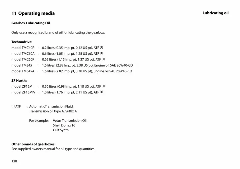
128
Gearbox Lubricating Oil
Only use a recognised brand of oil for lubricating the gearbox.
Technodrive:
model TMC40P : 0.2 litres (0.35 Imp. pt, 0.42 US pt), ATF [1]
model TMC60A : 0.6 litres (1.05 Imp. pt, 1.25 US pt), ATF [1]
model TMC60P : 0.65 litres (1.15 Imp. pt, 1.37 US pt), ATF [1]
model TM345 : 1.6 litres, (2.82 Imp. pt, 3.38 US pt), Engine oil SAE 20W40-CD
model TM345A : 1.6 litres (2.82 Imp. pt, 3.38 US pt), Engine oil SAE 20W40-CD
ZF Hurth:
model ZF12M : 0,56 litres (0.98 Imp. pt, 1.18 US pt), ATF [1]
model ZF15MIV : 1,0 litres (1.76 Imp. pt, 2.11 US pt), ATF [1]
[1] ATF : AutomaticTransmission Fluid; Transmission oil type A, Suffix A.
For example: Vetus Transmission Oil Shell Donax T6 Gulf Synth
Other brands of gearboxes:See supplied owners manual for oil type and quantities.
11 Operating media Lubricating oil
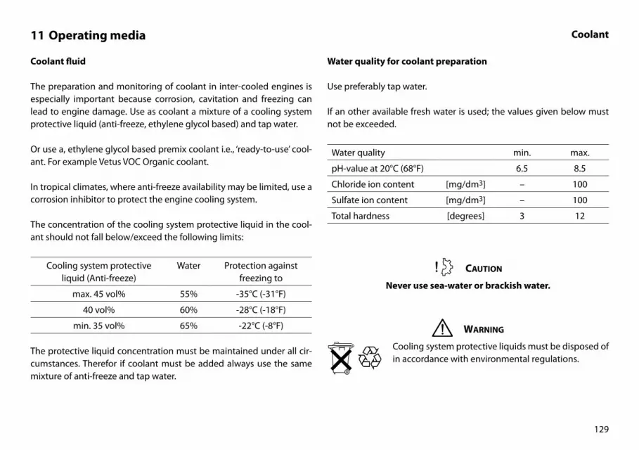
129
Coolant fluid
The preparation and monitoring of coolant in inter-cooled engines is especially important because corrosion, cavitation and freezing can lead to engine damage. Use as coolant a mixture of a cooling system protective liquid (anti-freeze, ethylene glycol based) and tap water.
Or use a, ethylene glycol based premix coolant i.e., ‘ready-to-use’ cool-ant. For example Vetus VOC Organic coolant.
In tropical climates, where anti-freeze availability may be limited, use a corrosion inhibitor to protect the engine cooling system.
The concentration of the cooling system protective liquid in the cool-ant should not fall below/exceed the following limits:
Cooling system protective liquid (Anti-freeze)
Water Protection against freezing to
max. 45 vol% 55% -35°C (-31°F)
40 vol% 60% -28°C (-18°F)
min. 35 vol% 65% -22°C (-8°F)
The protective liquid concentration must be maintained under all cir-cumstances. Therefor if coolant must be added always use the same mixture of anti-freeze and tap water.
11 Operating media Coolant
Water quality for coolant preparation
Use preferably tap water.
If an other available fresh water is used; the values given below must not be exceeded.
Water quality min. max.
pH-value at 20°C (68°F) 6.5 8.5
Chloride ion content [mg/dm3] – 100
Sulfate ion content [mg/dm3] – 100
Total hardness [degrees] 3 12
Caution
Never use sea-water or brackish water.
Warning
Cooling system protective liquids must be disposed of in accordance with environmental regulations.

n/hV
G3Y
p ϑϑ
A1 A3 A4 A2 A5 A6
D+
W
B+
30
8587
86
A1 A3 A4 A2 A5 A6
p
'21' '22'
Model 21 22Voltmeter - 1Tachometer 1 1
-4 -1 -2 -5 -3 61 91 92 93 W
- + (31) (15)
-1 -2
L1 L2 L3 L4 L5
-619/94X2M
95W155817/1931
-1 -2 -3 -4
G1 G2 NC NC
X1
-8 -7 -5 -4 -3 -6-1 -2
X3M X4M
L6
BZ
B4 B1 B2 B5 B3B6
B4 B1 B2 B5 B3B6
R
M M
Fuel lift pump (ETR)
Pre-heating(GLow plugs)
Startermotor
Battery
Batterymain
switch
Plug 'A'
Socket 'A'
Coolanttemp.
Exhausttemp.
AlternatorStopsolenoid (ETS)
Oilpress.
Gearboxoil press.
Battery charging
Warning lights
Pre-heating
Gearboxoil press.
Transparent Yellow/Green Green Brown Blue Gray Yellow/
Green
Key switch Voltmeter Tachometer/hour counter
Printedcircuit board
Engine panel model
PANEL
ENGINE
Fuse
Pre-heating
relay
Plug 'B'
Socket 'B'
Red Yellow Orange Violet White Black
L4 L2 L1L5L3 L6
130
12 Wiring diagrams Engine with panel model ‘21’, ‘22’M2 and M3, intercooled version
VD00
962

n/hV
G3Y
p ϑϑ
A1 A3 A4 A2 A5 A6
D+
W
B+
30
8587
8630
8587
86
A1 A3 A4 A2 A5 A6
p
'21' '22'
Model 21 22Voltmeter - 1Tachometer 1 1
-4 -1 -2 -5 -3 61 91 92 93 W
- + (31) (15)
-1 -2
L1 L2 L3 L4 L5
-619/94X2M
95W155817/1931
-1 -2 -3 -4
G1 G2 NC NC
X1
-8 -7 -5 -4 -3 -6-1 -2
X3M X4M
L6
BZ
B4 B1 B2 B5 B3B6
B4 B1 B2 B5 B3B6
R
M M
L4 L2 L1L5L3 L6
Fuel lift pump (ETR)
Pre-heating(GLow plugs)
Startermotor
Battery
Batterymain
switch
Plug 'A'
Socket 'A'
Coolanttemp.
Exhausttemp.
AlternatorStopsolenoid (ETS)
Oilpress.
Gearboxoil press.
Battery charging
Warning lights
Pre-heating
Gearboxoil press.
Transparent Yellow/Green Green Brown Blue Gray Yellow/
Green
Key switch Voltmeter Tachometer/hour counter
Printedcircuit board
Engine panel model
PANEL
ENGINE
Fuse
Pre-heating
relay
Auxiliarystart relay
Plug 'B'
Socket 'B'
Battery charging2nd alternator
Connection for 2nd alternator
Black
Yellow/Green
Violet
Green
Red Yellow Orange Violet White Black
131
12 Wiring diagrams Engine with panel model ‘21’, ‘22’M4, intercooled version
VD00
963
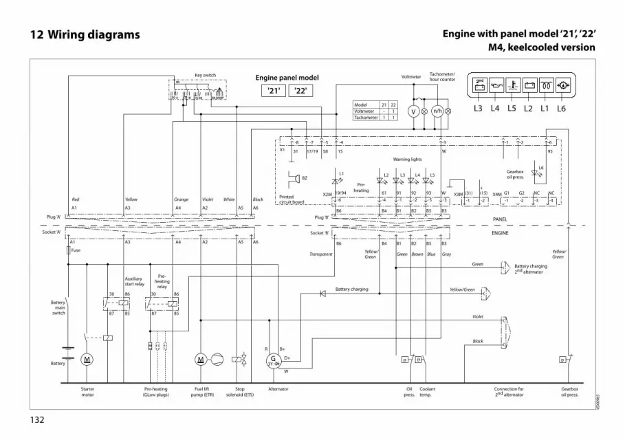
n/hV
p ϑD+
W
B+
p
'21' '22'
Model 21 22Voltmeter - 1Tachometer 1 1
-4 -1 -2 -5 -3 61 91 92 93 W
- + (31) (15)
-1 -2
L1 L2 L3 L4 L5
-619/94X2M
95W155817/1931
-1 -2 -3 -4
G1 G2 NC NC
X1
-8 -7 -5 -4 -3 -6-1 -2
X3M X4M
L6
BZ
B4 B1 B2 B5 B3B6
B4 B1 B2 B5 B3B6
G3Y
A1 A3 A4 A2 A5 A6
30
8587
8630
8587
86
A1 A3 A4 A2 A5 A6
R
M M
L4 L2 L1L5L3 L6
Coolanttemp.
Oilpress.
Gearboxoil press.
Warning lights
Pre-heating
Gearboxoil press.
Transparent Yellow/Green Green Brown Blue Gray Yellow/
Green
Key switch Voltmeter Tachometer/hour counter
Printedcircuit board
Engine panel model
PANEL
ENGINE
Plug 'B'
Socket 'B'
Connection for 2nd alternator
Black
Violet
Battery charging
Battery charging2nd alternator
Yellow/Green
Green
Fuel lift pump (ETR)
Pre-heating(GLow plugs)
Startermotor
Battery
Batterymain
switch
Plug 'A'
Socket 'A'
AlternatorStopsolenoid (ETS)
Fuse
Pre-heating
relay
Auxiliarystart relay
Red Yellow Orange Violet White Black
132
12 Wiring diagrams Engine with panel model ‘21’, ‘22’M4, keelcooled version
VD00
965

G3Y
D+
W
B+
30
85 87
86
87a
30
8587
86
87a
1N4002
30
8587
86
87a
Battery charging2nd alternator
Black
Yellow/ Green
Violet
2nd Alternator
Battery
Batterymain switch
Fuse 5A Consumers
White
Red
Yellow
Red
2nd Alternator
A2 A5
M
Fuel lift pump (ETR)
Stopsolenoid (ETS)
Tilt Switch
Violet White
133
12 Wiring diagrams Option, 2nd alternator M4Option, Tilt switch SOLAS engines
VD00
996
VD00
964

L2L1L5L3
L4 & L6
G3Y
p ϑϑ
A1 A3 A4 A2 A5 A6
D+
W
B+
30
8587
86
A1 A3 A4 A2 A5 A6
'10'
61 91 92 93
L1 L2 L3 L4 L5
19/94
155817/1931
BZ
B4 B1 B2 B5 B3B6
B4 B1 B2 B5 B3B6
R
M M
W
L6
Fuel lift pump (ETR)
Pre-heating(GLow plugs)
Startermotor
Battery
Batterymain
switch
Plug 'A'
Socket 'A'
Coolanttemp.
Exhausttemp.
AlternatorStopsolenoid (ETS)
Oilpress.
Battery charging
Warning lights
Pre-heating
Transparent Yellow/Green Green Brown Blue Gray
Key switch
Printedcircuit board
Red Yellow Orange Violet White Black
Engine panel model
PANEL
ENGINE
Fuse
Pre-heating
relay
Plug 'B'
Socket 'B'
134
12 Wiring diagrams Option, panel model ‘10’
VD00
966

-4 -1 -2 -5 -3 61 91 92 93 W
- + (31) (15)
-1 -2
L1 L2 L3 L4 L5
-619/94X2M
95W155817/1931
-1 -2 -3 -4
G1 G2 NC NC
X1
-8 -7 -5 -4 -3 -6-1 -2
X3M X4M
L6
BZ
n/hV p ϑ
G3Y
B4 B1 B2 B5 B3B6
p ϑϑD+
W
B+
30
8587
86
A4 A2 A5 A6
B4 B1 B2 B5 B3B6
p
+
-1 -2 -1 -2 -3 -4-3
B4 B1 B2 B5 B3B6
InterfaceSTM6911
R
'34'
M
A1 A3 A4 A2 A5 A6
30
8587
86
A1 A3
M
L4 L2 L1L5L3 L6
Fuel lift pump (ETR)
Pre-heating(GLow plugs)
Socket 'A'
Coolanttemp.
Exhausttemp.
AlternatorStopsolenoid (ETS)
Oilpress.
Gearboxoil press.
Battery charging
Transparent Yellow/Green
Green Brown Blue Gray
Yellow/Green
Key switchVoltmeter
Tachometer/hour counter
Engine panel model
Pre-heating
relay
Plug 'B'
Socket 'B'
Connection for 2nd alternator
Warning lights
Pre-heating
Gearboxoil press.
Printedcircuit board
Battery charging2nd alternator
Black
Yellow/Green
Violet
Green
Oil pressuregauge
Temperaturegauge
Socket 'B' To 2nd panel
Interface cable MPVB2
Startermotor
Battery
Batterymain
switch
Plug 'A'
Fuse
Auxiliarystart relay
Red Yellow Orange Violet White Black
135
12 Wiring diagrams Option, panel model ‘34’
VD00
967

430 (16 15/16”)
490 (19 1/2”)631 (24 13/16”)
360 (14 3/16”) 109 (4 5/16”)
1 2 3 4
178
(7”)
350
(13
3 /4”
)
528
(20
13/ 1
6”)
MIN
. 70
(2 5
/ 8”)
MAX
. 90
(3 1
/ 8”)
68 (2
11 /
16”)
136
13 Overall dimensions
1 Exhaust ø 40 mm2 Fuel supply ø 8 mm3 Fuel return ø 8 mm4 Sea water intake ø 20 mm 1 : 10M2.13 / M2.18
VD00
985

430 (16 15/16”)
516 (20 5/16”)771 (30 3/8”)
443 (17 7/16”) 109 (4 5/16”)
MIN
. 71
(2 1
3 /16
”)
MAX
. 90.
5 (3
9/ 1
6”)
178
(7”)
350
(13
3 /4”
)
528
(20
3 /4”
)
91 (3
9/ 1
6”)
1 2 3 4
137
13 Overall dimensions
1 Exhaust ø 40 mm2 Fuel supply ø 8 mm3 Fuel return ø 8 mm4 Sea water intake ø 20 mm 1 : 10M3.29
M3.28 SOLAS
VD02
035

204 (8 1/16”)
899 (35 3/8”)
585 (23 1/16”) 73 (2 7/8”) 430 (16 15/16”)
490 (19 5/16”)
1 2 3 4
193
(7 5
/ 8”)
111
(4
3/ 8
”)
195
(7 1
1 /16
”)39
9 (1
5 11
/ 16”
)
594
(23
3 /8”
)
MIN
. 66
(2 5
/ 8”)
MAX
. 80
(3 1
/ 8”)
138
13 Overall dimensions
1 Exhaust ø 50 mm2 Fuel supply ø 8 mm3 Fuel return ø 8 mm4 Sea water intake ø 20 mm 1 : 10M4.35 / M4.45
M4.15 SOLAS / M4.17 SOLAS
VD00
970

430 (16 15/16”)
490 (19 1/2”)896 (35 9/32”)
585 (23 1/16”) 74 (2 15/16”)
1 32 4
MIN
. 60
(2 3
/ 8”)
MAX
. 87.
5 (3
7/ 1
6”)
195
(7 1
/ 16”
)39
9 (1
5 11
/ 16”
)
594
(23
3 /8”
)
97 (3
13 /
16”)
139
13 Overall dimensions
1 Exhaust ø 60 mm2 Fuel return ø 8 mm3 Fuel supply ø 8 mm4 Sea water intake ø 20 mm 1 : 10M4.56
M4.55 SOLAS
VD02
034

140
14 Parts for maintenance
Engine model Oil filter Fuel filterFilter fuel lift pump
V-Belt
Raw water pump
Air filterO-ring heat exchanger
coverImpeller +
O-ringImpeller O-ring
M2.13 STM0051 STM3690 STM4050 STM7439 STM8076 STM6161 STM7696 08-01308 2 x STM6113
M2.18 STM0051 STM3690 STM4050 STM7439 STM8076 STM6161 STM7696 08-01308 2 x STM6113
M3.29 STM0051 STM3690 STM4050 STM7439 STM8076 STM6161 STM7696 08-01308 2 x STM6113
M4.35 STM0051 STM3690 STM4050 STM7643 STM8061 STM7696 08-01308 2 x STM6113
M4.45 STM0051 STM3690 STM4050 STM7643 STM8061 STM7696 08-01308 2 x STM6113
M4.56 STM0051 STM3690 STM4050 STM7643 STM8074 08-01019 08-01022 STM7467 2 x STM6113
M3.28 SOLAS STM0051 STM3690 STM4050 STM7439 08-01352 STM7696 08-01308 2 x STM6113
M4.15 SOLAS STM0051 STM3690 STM4050 STM7643 08-01352 STM7696 08-01308 2 x STM6113
M4.17 SOLAS STM0051 STM3690 STM4050 STM7643 08-01352 STM7696 08-01308 2 x STM6113
M4.55 SOLAS STM0051 STM3690 STM4050 STM7643 08-01353 08-01022 STM7467 2 x STM6113
Check / replace every ... hour:
100 500 500 500 1000 1000 1000 1000 -
See page: 58 65 66 74 78 78 78 84 91
V-belt 2nd alternator: M4.35 / M4.45 75 A (Intercooled engine) : STM9857
M4.56 95 A (Intercooled engine) : STM9857
M4.35 / M4.45 / M4.56 110 A (Keelcooled engine) : STM9858

141
15 Index
A
Air filter 13, 15Airvent connection 13, 14Alarm buzzer 42Alternator 12, 14
B
Battery 60Battery cables 61Battery charging, Warning light 16–18Battery connections 61Biodiesel 125Bleeding 30, 54
C
Calorifier connection 12, 14Changing the gearbox oil 98Check engine for leaks 105Checking coolant level 50Checking engine oil level 48, 49Checking engine speed 86Checking the alternator 85Checking the starter motor 85Check oil level 48, 49Cleaning the heat exchanger 88Cleaning the strainer 52Control lever 19, 34Control panels 16–18
Coolant 129Quantity 24
Coolant level 50Coolant replacement 80Coolant temperature, Warning light 16–18Cooling system air bleed nipple 12, 14Cooling system drain plug 12, 14, 15Cooling system, Filler cap for 12Corrosion protection 94Cruising 40Cylinder numbering 11–17
D
Direction of rotation 11Draining of coolant 81
E
Electrical system 99, 104Electrical system, Connection 13, 15Electrolyte level 63Empty fuel filter 53Empty water separator 53Engine data tag 10Engine oil 59, 126Engine oil change 56Engine serial number 1, 10Engine specifications 116–121Exhaust injection bend 12, 15Expansion tank 12, 14
Expansion tank, Connection for extra 12, 14
F
Fasteners 69Fault finding table 107–115Filler cap for cooling system 14Filling gearbox with oil 21Filling the cooling system 22, 82Filling with engine oil 20First commissioning 20–28Flexible engine mounts 69Fresh water cooling system 97, 103Fuel 28Fuel filter replacement 65Fuel lift pump 13, 15Fuel lift pump, Cleaning filter 66Fuel pump air bleed nipple 13, 15Fuel pump seal 11Fuel Quality Grade 124Fuel return pipe 13, 15Fuel supply pipe 13, 15Fuel system 94, 101Fuse 13, 15
G
Gearbox 13, 15Gearbox drain plug 14Gearbox filler cap 13, 15Gearbox low oil pressure,
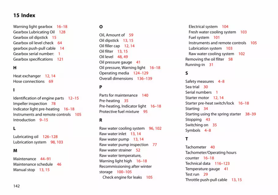
142
15 Index
Warning light gearbox 16–18Gearbox Lubricating Oil 128Gearbox oil dipstick 15Gearbox oil level check 64gearbox push-pull cable 14Gearbox serial number: 1Gearbox specifications 121
H
Heat exchanger 12, 14Hose connections 69
I
Identification of engine parts 12–15Impeller inspection 78Indicator light pre-heating 16–18Instruments and remote controls 105Introduction 9–15
L
Lubricating oil 126–128Lubrication system 98, 103
M
Maintenance 44–91Maintenance schedule 46Manual stop 13, 15
O
Oil, Amount of 59Oil dipstick 13, 15Oil filler cap 12, 14Oil filter 13, 15Oil level 48, 49Oil pressure gauge 41Oil pressure, Warning light 16–18Operating media 124–129Overall dimensions 136–139
P
Parts for maintenance 140Pre-heating 35Pre-heating, Indicator light 16–18Protective fuel mixture 95
R
Raw water cooling system 96, 102Raw water inlet 13, 14Raw water pump 13, 14Raw water pump inspection 77Raw water strainer 52Raw water temperature, Warning light high 16–18Recommissioning after winter storage 100–105
Check engine for leaks 105
Electrical system 104Fresh water cooling system 103Fuel system 101Instruments and remote controls 105Lubrication system 103Raw water cooling system 102
Removing the oil filter 58Running-in 31
S
Safety measures 4–8Sea trial 30Serial numbers 1Starter motor 12, 14Starter pre-heat switch/lock 16–18Starting 34Starting using the spring starter 38–39Stopping 43Switching on 35Symbols 4–8
T
Tachometer 40Tachometer/Operating hours counter 16–18Technical data 116–123Temperature gauge 41Test run 29Throttle push-pull cable 13, 15

143
15 Index
Topping up coolant 50Topping up oil 48Torque wrench settings 122, 123Troubleshooting 106–115
U
Use 32–41
V
Valve clearance, Checking / adjusting 70Valve oil sump ventilation, Checking 76V-belt 14V-belt, Checking the 74–75V-belt, Tensioning 75Voltmeter 16–18, 41
W
Warning indications 4–8Warning light
Battery charging 16–18Gearbox low oil pressure 16–18High coolant temperature 16–18Low oil pressure 16–18Raw water temperature 16–18
Warning lights 42Water separator 13, 15water separator/fuel filter 53Water separator/Fuel filter 13Water separator/fuel filter drain plug 13, 15
Winter-grade fuel 124Winter storage procedure 92–99
Changing the gearbox oil 98Corrosion protection 94Electrical system 99Fresh water cooling system 97Fuel system 94Lubrication system 98Protective fuel mixture 95Raw water cooling system 96
Wiring diagram 130–135

144

145
Manuals
Art. code Description
345101.01 Bedieningshandleiding M-LINE M2, M3, M4 (Nederlands)345102.01 Operation manual M-LINE M2, M3, M4 (English)345103.01 Bedienungsanleitung M-LINE M2, M3, M4 (Deutsch)345104.01 Manuel d’utilisation M-LINE M2, M3, M4 (Français)345105.01 Manual de operacion M-LINE M2, M3, M4 (Español)345106.01 Istruzioni per l’uso M-LINE M2, M3, M4 (Italiano)345107.01 Brugsanvisning M-LINE M2, M3, M4 (Dansk)345108.01 Användarmanual M-LINE M2, M3, M4 (Svenska)345109.01 Bruksanvisning M-LINE M2, M3, M4 (Norsk)345110.01 Käyttöopas M-LINE M2, M3, M4 (Suomeksi)345119.01 Instrukcja obsługi M-LINE M2, M3, M4 (Polski)
320331.01 (STM0032) Installatiehandleiding / Installation manual (Nederlands / English)
320199.06 (STM0016) Service- en Garantieboek / Service and Warranty Manual / (Nederlands / English / Service- und Garantieheft / Livret Garantie et Service / Deutsch / Français / Manual de servicio y garantía / Libretto di assistenza e garanzia Español / Italiano / Service- og garantibog / Service- och garantihäfte Dansk / Svenska / Service- og garantibok / Huolto- ja takuukirja Norsk / Suomeksi)
341131.06 Onderdelenboek / Parts manual M2 (Nederlands / English)341731.06 Onderdelenboek / Parts manual M3 (Nederlands / English)341331.06 Onderdelenboek / Parts manual M4 (Nederlands / English)
342102.02 Service manual M2, M3 (English)342402.02 Servive manual M4 (English)

Vet
us D
iese
l
VF4
V
F5
N
eder
land
s
345102.01 2019-09 Printed in the Netherlands
F O K K E R S T R A AT 5 7 1 - 3 1 2 5 B D S C H I E DAM - H O L L A N DT E L . : + 3 1 0 ( 0 ) 8 8 4 8 8 4 7 0 0 - s a l e s @ ve t u s . n l - w w w. ve t u s . co m
Vetus D
iesel M-LIN
E M2 M
3 M
4
Englishvetus b. v.