Development of emulsions from biomass pyrolysis liquid and diesel and their use in engines—Part 2:...
15
Available online at www.sciencedirect.com Biomass and Bioenergy 25 (2003) 85 – 99 Development of emulsions from biomass pyrolysis liquid and diesel and their use in engines—Part 1: emulsion production D. Chiaramonti a ; ∗ , M. Bonini a , E. Fratini a , G. Tondi b , K. Gartner c , A.V. Bridgwater d , H.P. Grimm e , I. Soldaini f , A. Webster g , P. Baglioni a;∗ a Department of Chemistry and CSGI (Consorzio Sistemi a Grande Interfase), University of Florence, via della Lastruccia 3, I-50019 Florence, Italy b Energetics Department “S. Stecco”, Faculty of Mechanical Engineering, University of Florence, Via S. Marta 3, I-50139 Florence, Italy c Institute f ur Elektrische Energietechnik (IEE), Universit at Gh-Kassel, Energietechnik, Fb 16, Rationelle Energiewandlung, D-34109 Kassel, Germany d Aston University, Bio-Energy Research Group, Aston Triangle, Birmingham B4 7ET, UK e WIP, Sylvensteinstr. 2, D81369 M unchen, Germany f Pasquali Macchine Agricole, Via Nuova 30, I-50041 Calenzano, Italy g ORMROD Diesels, Unit 4, Peel Industrial Estate, West Pimbo, Skelmersdale, Lancashire WN8 9PT, UK Received 18 March 2002; received in revised form 28 October 2002; accepted 28 October 2002 Abstract The current method of utilising biomass derived fast liquid (bio-crude oil or bio-oil) in a diesel engine requires three fuels and a complex start-up and shut down procedure. For more rapid and successful commercialisation of this renewable liquid fuel, a more convenient and cheaper method of utilisation is needed that provides a single fuel that is stable and readily ignites in a compression engine. This paper describes the production of emulsions from biomass fast pyrolysis liquid and diesel fuel for utilisation in diesel engines. The objective is to allow unmodied diesel engines to run on fast pyrolysis liquid derived from biomass without the cost and complexity of a dual fuel system. The immediate application is in stationary engines for power generation, but there are longer term opportunities for use as a transport fuel. This paper describes the production of the emulsions that have been tested in dierent diesel engines (tests in engines is reported in a separate paper). ? 2002 Elsevier Science Ltd. All rights reserved. Keywords: Biomass pyrolysis; Biomass power production; Emulsion; Diesel engine; Bio-crude oil 1. Introduction Pyrolysis is the thermochemical process that converts biomass into liquid, charcoal and non- ∗ Corresponding authors. Tel.: +39-055-457-3033; fax: +39- 055-457-3032. E-mail addresses: [email protected] (D. Chiaramonti), [email protected] (P. Baglioni). condensable gases, acetic acid, acetone and methanol by heating the biomass to about 750 K in absence of air. The process can be adjusted to favor charcoal, pyrolytic oil, gas or methanol production with a fuel to feed eciency up to 95%. Pyrolysis can be used for the production of bio-oil by various processes (e.g. ash pyrolysis) [1–5]. Bio-crude oil (BCO) (pyrolysis oil) use for power and heat production represents a main goal in the 0961-9534/03/$ - see front matter ? 2002 Elsevier Science Ltd. All rights reserved. PII:S0961-9534(02)00183-6
Transcript of Development of emulsions from biomass pyrolysis liquid and diesel and their use in engines—Part 2:...

Available online at www.sciencedirect.com
Biomass and Bioenergy 25 (2003) 85–99
Development of emulsions from biomass pyrolysis liquid anddiesel and their use in engines—Part 1: emulsion production
D. Chiaramontia ;∗, M. Boninia, E. Fratinia, G. Tondib, K. Gartnerc, A.V. Bridgwaterd,H.P. Grimme, I. Soldainif , A. Websterg, P. Baglionia;∗
aDepartment of Chemistry and CSGI (Consorzio Sistemi a Grande Interfase), University of Florence,via della Lastruccia 3, I-50019 Florence, Italy
bEnergetics Department “S. Stecco”, Faculty of Mechanical Engineering, University of Florence,Via S. Marta 3, I-50139 Florence, Italy
cInstitute f,ur Elektrische Energietechnik (IEE), Universit,at Gh-Kassel, Energietechnik, Fb 16,Rationelle Energiewandlung, D-34109 Kassel, Germany
dAston University, Bio-Energy Research Group, Aston Triangle, Birmingham B4 7ET, UKeWIP, Sylvensteinstr. 2, D81369 M,unchen, Germany
fPasquali Macchine Agricole, Via Nuova 30, I-50041 Calenzano, ItalygORMROD Diesels, Unit 4, Peel Industrial Estate, West Pimbo, Skelmersdale, Lancashire WN8 9PT, UK
Received 18 March 2002; received in revised form 28 October 2002; accepted 28 October 2002
Abstract
The current method of utilising biomass derived fast liquid (bio-crude oil or bio-oil) in a diesel engine requires three fuelsand a complex start-up and shut down procedure. For more rapid and successful commercialisation of this renewable liquidfuel, a more convenient and cheaper method of utilisation is needed that provides a single fuel that is stable and readilyignites in a compression engine. This paper describes the production of emulsions from biomass fast pyrolysis liquid anddiesel fuel for utilisation in diesel engines. The objective is to allow unmodi;ed diesel engines to run on fast pyrolysis liquidderived from biomass without the cost and complexity of a dual fuel system. The immediate application is in stationaryengines for power generation, but there are longer term opportunities for use as a transport fuel. This paper describes theproduction of the emulsions that have been tested in di<erent diesel engines (tests in engines is reported in a separate paper).? 2002 Elsevier Science Ltd. All rights reserved.
Keywords: Biomass pyrolysis; Biomass power production; Emulsion; Diesel engine; Bio-crude oil
1. Introduction
Pyrolysis is the thermochemical process thatconverts biomass into liquid, charcoal and non-
∗ Corresponding authors. Tel.: +39-055-457-3033; fax: +39-055-457-3032.
E-mail addresses: [email protected];.it(D. Chiaramonti), piero.baglioni@uni;.it (P. Baglioni).
condensable gases, acetic acid, acetone and methanolby heating the biomass to about 750 K in absence ofair. The process can be adjusted to favor charcoal,pyrolytic oil, gas or methanol production with a fuelto feed eBciency up to 95%. Pyrolysis can be usedfor the production of bio-oil by various processes (e.g.Dash pyrolysis) [1–5].Bio-crude oil (BCO) (pyrolysis oil) use for powerand heat production represents a main goal in the
0961-9534/03/$ - see front matter ? 2002 Elsevier Science Ltd. All rights reserved.PII: S0961 -9534(02)00183 -6

86 D. Chiaramonti et al. / Biomass and Bioenergy 25 (2003) 85–99
biomass sector. The concept of using biomass-basedfuels, speci;cally vegetable oils as diesel fuelalternatives, is particularly interesting and it is notnew. Rudolf Diesel himself demonstrated that hisengine could run on vegetable oil fuels. Since then anumber of vegetable oils have been tested as dieselfuel alternatives [6–10]. These fuels are non-toxic,renewable sources of energy, which do not contributeto the net global CO2 buildup.A large number of studies on biomass derived oilsas biofuels have been performed [10–13]. However,direct use of pyrolysis oils (BCOs) requires signi;cantadaptations of technology to fuel characteristics, andit has not yet been fully proven at demonstration scale[8,10,14].BCOs have already been used in modi;ed dieselengines, in which a dedicated fuel feeding system hasbeen designed, constructed and installed in parallel tothe diesel feeding line: in addition, the operation ofthe engine becomes more sophisticated (use of clean-ing fuels, as methanol, in a particular sequence dur-ing start-up and shut-down), and a pilot diesel fuelinjection is necessary. This approach requires a sig-ni;cant adaptation of the engine and, consequently,capital and O&M costs per kW installed are higherthan standard diesel engines [15,16]. This fact repre-sents a considerable barrier to the use of BCO in dieselengines.Measurements of the combustion performance ofbiofuel oils, blends with diesel fuels and emulsionswith water have been reported [12].The development and use of BCO/diesel oil emul-sions represent a relatively short-term approach tothe exploitation of the signi;cant biomass resourcespotentially available by pyrolysis. The upgrading ofthe fuel itself by means of the production of stableemulsions allows the use of low-cost large-scale massproduction diesel engines with only minor modi;ca-tions, thus reducing signi;cantly the investment costin comparison to dual fuel engines. The fuel pro-duction process aims therefore at producing low-costand stable emulsions, compatible with the existingdiesel technology (only minor modi;cations to theengine) [17].This approach to fuel upgrading is investigated byvarious research groups. In particular, CANMET hasdeveloped a method for microemulsion productionfrom pyrolysis oil and diesel oil: stable emulsions
have been produced in the range of 5–40% have beenproduced and tested.In the present work, background knowledge onemulsi;cation processes has been used to understandthe forces that play a fundamental role in the pro-duction of pyrolysis oil/diesel oil emulsions and toformulate stable systems [18]. Initially, a large num-ber of tests at laboratory level have been realized toselect the most appropriate combination of additives.Once de;ned the surfactants mixture to be used,the emulsi;cation process has been adjusted and re-alized at demonstration level in a semi-automaticplant [17].
2. Theory
2.1. Introduction to the production of emulsions
Though emulsions are ubiquitous in everyday life,the study of these systems has been often carried onin empirical ways [19]. Dispersions of two or morenot miscible Duids are produced for many applica-tions. Examples are abundant either between natu-ral products (such as milk) and industrial products[20,21]. Systems obtained from homogenization oftwo or more not miscible Duids are indicated as emul-sions, miniemulsions or microemulsions (or swollenmicelles) depending on the size of the particlesdispersed in the continuous phase [22,23]. Thesesystems are produced using one or several additives(surfactants and co-surfactants) that are able to lowerthe surface energy of the interface of the produceddroplets [24].Emulsions are obtained from a dispersion of twonon-miscible Duids. The dispersion produces a con-tinuous phase and a ;nely dispersed droplets phase.Most of the properties of the emulsion systems (sta-bility, viscosity, etc.) depend on the droplets sizeand size distribution that usually cover a rather wideinterval, i.e. from 300 to 400 nm to about 10 �m.A commonly used classi;cation of emulsions isbased on the polarity of the dispersant phase comparedto that of the dispersed one. In almost all the appli-cations, water is one of the Duids, while the other ischaracterized by a lower dielectric constant. In generalthis second Duid is indicated as oil. Therefore emul-sions are generally indicated as dispersions of water

D. Chiaramonti et al. / Biomass and Bioenergy 25 (2003) 85–99 87
Fig. 1. Most important mechanisms of emulsion breaking: (a) stable emulsion; (b) creaming; (c) Ostwald ripening; (d) Docculation;(e) coalescence; (f) breaking.
droplets in oil (water-in-oil emulsions, W/O) or oildroplets in water (oil-in-water emulsions, O/W).
2.2. Stability of emulsions
The formation and stability of droplets depends ontwo competitive factors:
(i) the migration of the surfactant at the dropletsinterface (stabilizing process),
(ii) the droplets coalescence (destabilizationprocess).
The phase characterized by the highest coalescencerate will become the continuous phase.Emulsions formation and stability are also a<ectedby the sequence and the methodology used to mixtogether the emulsion components. For example, wecan either dissolve the emulsi;er in the oil and in thewater phase or dissolve the emulsi;er in one Duid andadd it to the other one, etc. Moreover, the mean dropletdiameter depends on the intensity and on the amountof the introduced energy for the particular preparationtechnique.
Stability of emulsions can be described by theDerajaguin, Landau, Vervey and Overbeek (DLVO)theory and its implementations that take into accountdi<erent kind of interactions, as Van der Waals in-teractions, electrostatic interactions, steric, hydration,etc. [18,25–28].The main mechanisms of emulsion breaking areshown in Fig. 1.The destabilization of an emulsion goes throughseveral consecutive and parallel steps before the ;nalstage of separated layers is reached. At ;rsts, dropletsmove due to di<usion (or stirring), and if the repul-sion potential is too weak, they become aggregated toeach other: in practice, Docculation has taken place.The single droplets are now replaced by twins (ormultiples) separated by a thin ;lm. The thickness ofthe thin ;lm is reduced due to the Van der Waals at-traction, and when a critical value of its dimension isreached the ;lm bursts and the two droplets unite toa single droplet. Coalescence has occurred. In parallelwith these phenomena, the droplets rise through themedium (creaming) or sink to the bottom (sedimen-tation) due to di<erences in density of the dispersedand continuous phase. The ;nal result is a highly

88 D. Chiaramonti et al. / Biomass and Bioenergy 25 (2003) 85–99
concentrated emulsion at the top or bottom of the con-tainer, and the increased number of droplets per vol-ume increases the Docculation rate in a most decisivemanner. The Docculation and coalescence process leadto larger and larger droplets until, ;nally, a phase sep-aration has occurred.Since emulsions are not thermodynamically stable,it is obvious that the control of the stability of theemulsions is limited to the kinetic control of the sepa-ration of the constituents (oil and water). After sometime, emulsions destabilize as a result of the aginge<ect, and the total area of the system decreases. Themost common method to verify the stability of emul-sions is simply by testing the formation of separatephases at room temperature, by heating the samplesor by centrifuging. More re;ned methods consist inthe analysis of the particle size or of the viscosity asa function of time [18].Coalescence is by de;nition slow in stable emul-sions and measurement of the ageing rate is accel-erated by use of centrifugation at between 1000 and25; 000 g.In addition, in the case of pyrolysis oils, one of thesigni;cant problems in their utilization is their claimedinstability, which manifests as changes in viscosity. Ameasure of stability or instability is a valuable indi-cator of one of the key properties of pyrolysis liquidsand a viscosity index is proposed to provide such ameasure. The viscosity index is de;ned in the equa-tion below and provides a measure of viscosity changeover a given time period:
VI =(�t2 − �t1)
�t1;
where VI is the viscosity index, �t1 the viscosity attime t1 (i.e. before storage) and �t2 the viscosity attime t2(i.e. after 24 h storage at 80◦C).The lower the number, the more stable the liquid.A perfectly stable liquid has a viscosity index of 0.00.This approach has also been applied to evaluate thestability properties of the emulsions.
2.3. BCO=diesel emulsions
As reported above, the process for obtaining a stableemulsion may be very diBcult and time consuming:in the case of BCO and diesel (Fig. 2), approximately
Fig. 2. BCO/diesel oil mixture (left) and emulsion (right).
one hundred di<erent surfactants, and a consistentnumber of mixtures of them, have been tested. Thereason for that mainly relies on the composition of theBCO itself. In fact, BCO is made of a mixture of sev-eral organic products: from short chain products, asaldehyde or carboxylic acid, to polymers.The interactions that are responsible for the stabilityof an emulsion are Van der Waals, electrostatic andsteric interactions. Clearly, if the phases are singleproducts it is rather simple to evaluate the kind ofmolecular interaction and to understand the class ofsurfactants that should be used to obtain the emulsion.If instead the molecular composition of one phase iscomplex, it becomes very diBcult to ;gure out theadditive to be used for the emulsi;cation process. Thisis exactly the case of the BCO/diesel oil system.The methodology to be used is the following: (1) ane<ective solvent for the BCO has to be identi;ed. Thisallows a surfactant to be used even if it is not solublein the BCO: it is suBcient that the surfactant is solublein the same solvent, (ii) the additive for the emulsionformation is tested. As the additive class showing thebetter results in terms of stability is determined, asmany surfactants as possible belonging to the additiveclass must be tested, (iii) a small number of surfactantscan therefore be chosen, and the emulsion propertiesoptimized. A mixture of di<erent additives can alsobe adopted.As the surfactants to be used for emulsion prepara-tion are ;nally de;ned, the process for the productionof the ;nal emulsion has to be optimized.

D. Chiaramonti et al. / Biomass and Bioenergy 25 (2003) 85–99 89
Three kinds of emulsions can be prepared in respectto the BCO/diesel oil ratio:
• water-in-oil emulsions (W/O) are obtained if up to∼ 45% w/w BCO is added to the diesel oil phase,
• oil-in-water emulsions (O/W) are obtained if up to∼ 45% w/w of diesel oil is added in BCO,
• bicontinuous emulsions are obtained when the per-centage by weight of the two phases is close to 50%.
In the ;rst case, BCO’s droplets dispersed in dieseloil (continuous medium) form the emulsion. In thesecond case Diesel oil’s droplets dispersed in BCO(continuous medium) form the emulsion. Descriptionof the third case is more complex: in fact, from a the-oretical point of view, both oil and water phase arecontinuous (no droplets) and form a so-called bicon-tinuous emulsion.The choice of the emulsifying agent, which changesthe interfacial properties (namely interaction potentialbetween droplets) of the system avoiding (or delay-ing) the emulsion’s breaking, is a procedure driven byseveral empirical rules. These rules are built on theprimary condition for an emulsi;er to be eBcient in atwo phase, two-liquid emulsion. It has to be localizedat the oil/water interface to a maximal extent. Thiscriterion is exempli;ed in the hydrophilic lipophilicbalance (HLB) number.It is important to emphasize that the HLB numberfor a certain molecule denotes the balance between itshydrophilic/lipophilic properties only; the number perse does not give any information about the stabilizingeBcacy of the emulsi;er. The HLB number meansthat the emulsi;er is optimal in a water-oil system inwhich the properties of the oil match the surfactant.Hence, each water-oil combination is characterizedby an HLB number. The de;nition of this number israther complicated and depends on the family of thesurfactant. A more detailed treatment of this subjectis given in Ref. [18].More practically, emulsi;ers characterized by HLBnumber:
• from 4 to ∼ 8, stabilize W/O emulsions,• from 8 to ∼ 10, stabilize bicontinuous emulsions,• from 10 to ∼ 18, stabilize O/W emulsions.The phase inversion temperature (PIT) or HLB tem-perature concept relates the emulsi;er selection to
the temperature at which an emulsion stabilized by anon-ionic emulsi;er of the polyethylene glycol typechanged from oil-in-water to water-in-oil with risingtemperature.A large number (approximately one hundred) ofsurfactants were tested, including both of commer-cial blends and chemically pure composition. Amongthem, cationic, anionic, zwitterionic and non-ionic sta-bilizers. Moreover, for each of these classes of addi-tives, polymeric and non-polymeric surfactants werealso tested. Additives with sulfur or nitrogen in theircomposition have been neglected, in order to avoid anincrease in the NOx and SOx gaseous emissions dur-ing the emulsion combustion. A list of the most sig-ni;cant tested surfactants is given in Table 1.The water-in-oil emulsions have been preparedby adding the surfactant to diesel oil and thereafteradding the bio-oil to the resulting mixture. Bicon-tinuous emulsions have been formulated by addingthe surfactant to diesel oil, and to BCO then mixingtogether the resulting mixtures. Oil-in-water emul-sions have been formulated by adding to the bio-oilthe surfactant and thereafter adding to the resultingmixture the diesel oil during emulsi;cation.The emulsi;cation process has been carried out byusing a homogenization unit. The temperature dur-ing mixing has been preferably maintained between60–65◦C and the emulsi;cation process has been con-tinued until a homogeneous single phase has been ob-tained. During the emulsi;er choice phase, emulsionshave been prepared by using a discontinuous processon a little amount of mixture (from 20 to 500 g). Onceidenti;ed the emulsi;er, a continuous process has beenemployed to produce a greater amount of material (upto 10 kg). In this con;guration the tank was a heatingcase to have the desired temperature in the continuoushomogenization unit.It is important to underline that emulsions can beprepared also at room temperature: however, in thiscase the emulsions stability decreases (∼ 20 days).Nevertheless, the destabilization of the emulsions,prepared at both high and room temperature, is anon-irreversible process: mixing (by a stirrer) issuBcient to obtain again a homogenous system.The phase diagram of the system BCO\diesel oil\
emulsi;er has been investigated in order to identifythe best w/w ratio in terms of homogeneity, stability,engine performance, and operational costs.
90 D. Chiaramonti et al. / Biomass and Bioenergy 25 (2003) 85–99
Table 1List of the most signi;cant tested surfactants. Emulsions’ stability (Stab) is given in terms of days before observing a complete phaseseparation. These preliminary tests were performed at room temperature and without using the homogenization unit (stirring was performedwith a magnetic stirrer)
Surfactant Producer Stab Surfactant Producer Stab
Ampholak 7TX Akzo-Nobel 0 Hypermer B261(E) Uniqema 5Ampholak 7TY Akzo-Nobel 0 Hypermer E-476 Uniqema 5Amphoteen BTH-35 Berol-Nobel 1 Igepal CO-630 Aldrich 1Armotan ML Akzo-Nobel 1 Igepal CO-720 Aldrich 1Armotan MO Akzo-Nobel 1 Igepal CO-850 Aldrich 1Armotan MRD Akzo-Nobel 1 Igepal CO-880 Aldrich 1Armotan MS Akzo-Nobel 1 Igepal CO-890 Aldrich 1Armoteric LB Akzo-Nobel 0 Igepal CO-990 Aldrich 1Atlas G5000 Uniqema 7 Igepal CO-520 Aldrich 1Atlox 4912 Uniqema 7 Kelzan Kelco 0Atlox 4913 Uniqema 7 Kelzan D Kelco 0Atlox 4914 Uniqema 7 Kelzan M Kelco 0Atsurf 3969 Uniqema 3 Kelzan S Kelco 0Bevaloid 6903 Rhodia 2 Marasperse N-22 Reed Lignin Inc. 0Bretax AM CTP 0 Morwet D-425 PC Petrochemicals Comp. 1Bretax S CTP 0 Morwet EFW PC Petrochemicals Comp. 1BrijJ 58 Aldrich 1 OMA-4 Akzo-Nobel 0BrijJ76 Aldrich 1 PEMULEN BF Goodrich 0BrijJ92V Aldrich 1 Q-Broxin Boroid International 0BrijJ96V Aldrich 1 Reax 888 Westvaco 0Carbopol Ultrez 10 BF Goodrich 0 Reodal NA Dalton 1Carbopol BF Goodrich 0 Reodal NA 40 Dalton 1Carbowax 400 Carlo Erba 0 Reodal TF Dalton 1Chimipal PE/403 Cesalpina 0 Rhodoline DP226/35 Rhodia 0CTAB Fluka 0 Rolfor EP/526 Cesalpina 0Dapral GE202 Akzo-Nobel 2 Rolfor HT/11 Cesalpina 0Darvan n.1 R.T. Vanderbilt Co. 0 SCS 4682 Uniqema 2Darvan n.2 R.T. Vanderbilt Co. 0 SCS 4683 Uniqema 2Daxad 19 Grace 0 SCS 4684 Uniqema 2Daxad 23 Grace 0 SCS 4712 Uniqema 2Daxad Duoride Grace 0 Span 30 Fluka 1SDS Fluka 0 Span 40 Fluka 1Dowfax 2A1 Dow 1 Span 60 Fluka 1Dowfax 3B2 Dow 1 Span 65 Fluka 1Duomeen TDO Akzo-Nobel 1 Span 80 Fluka 1Ethomeen C/12 Akzo-Nobel 1 Span 85V Fluka 1Ethomeen C/25 Akzo-Nobel 1 Syn-Fac 8337 MilliKen Chemicals 0Hypermer 1070 Uniqema 5 Synperonic PE/F127 Uniqema 2Hypermer A-60 Uniqema 4
Fig. 3 shows the phase diagram of the analyzedsystem. The most interesting region is the one left tothe dashed line (any concentration of BCO and dieseloil, emulsi;er ¡ 5% by weight). The circles corre-spond to the 25% (W/O), 50% (bicontinuous) and75% (O/W) of BCO by weight. These three regionshave been studied more intensively.
2.4. The emulsiBcation system
Further than the use of an emulsifying agent, thesystem used to emulsify BCO and diesel is basedon repeated cut of the Duid columns Dowing inpre-de;ned channels, at the end of which some bladescut the Duid threads, thus producing the emulsion. The

D. Chiaramonti et al. / Biomass and Bioenergy 25 (2003) 85–99 91
BCO Emulsifier
Diesel oil
O/W Emulsions Bicontinuous Emulsions
W/O Emulsions
Fig. 3. Phase diagram for the BCO \ diesel oil \ emulsi;er ternary system.
Fig. 4. Front view of the stator head (left) and front view of rotor head.
emulsi;er head works like a centrifugal pump, theDuid is sucked from the center, cut and expelledto the side. The system is constituted by a rotatinghead with a series of radial channels in which, dueto the centrifugal force, the liquid is Dowing througha central hole (Fig. 4). On the outer side, a ;xedgrooved skirt wrapping up the rotating head is present.The liquid streams are therefore subject to a seriesof cuts.Initially the BCO/diesel oil emulsion was producedusing a laboratory scale emulsi;cation system. Thissetup is perfectly similar to the 50 l h−1 emulsi;erplant described later with exception for the production
capacity (5 l h−1) and for pipes, valves and pumps.Emulsions produced with this system have been usedto perform the surfactants’ screening and to obtain the;nal emulsion formulation.In order to produce a suBcient amount of emulsionfor tests (approximately 1:5 t) a 50 l h−1 emulsi-;er plant was designed and constructed. This plant,therefore, di<erently from the laboratory scale emul-si;cation system, includes other components, aspipes, valves, pumps and tanks that are not strictlynecessary for the production of small quantities ofemulsion. However, the large scale emulsi;cationsystem has been assembled in order to obtain the same
92 D. Chiaramonti et al. / Biomass and Bioenergy 25 (2003) 85–99
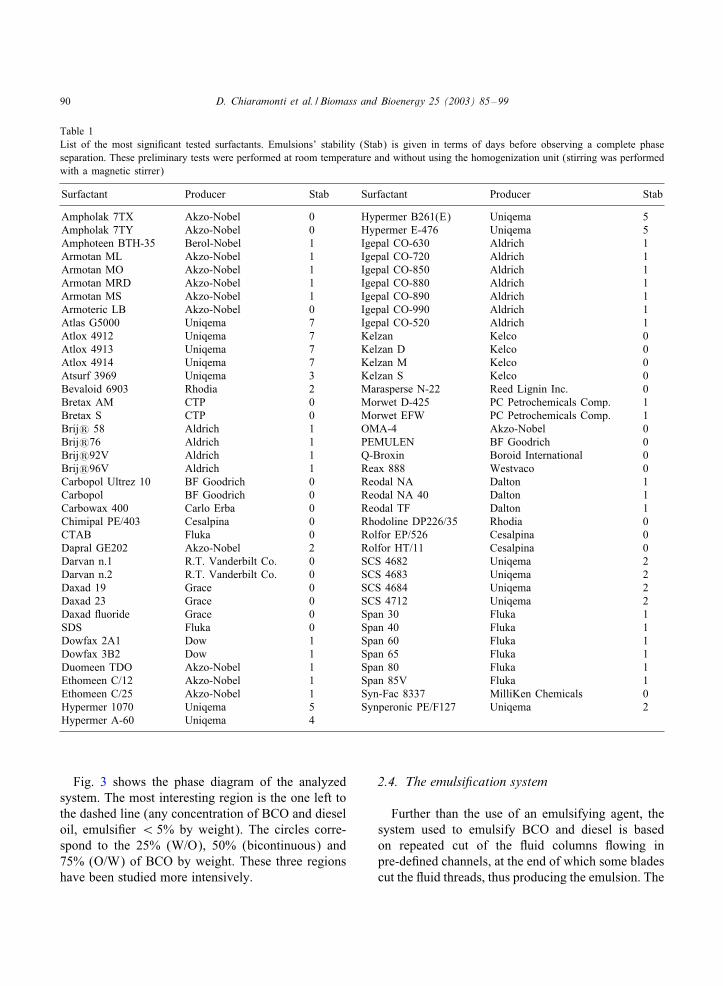
Fig. 5. Layout of the emulsi;cation system by PMA.
operating conditions used in the laboratory. It iscomposed by the following main elements:
• 1 emulsi;cation tool driven by a 1100 W variablespeed electrical motor,
• 3 pumps for BCO, diesel oil and emulsion,• 1 water heated tank (1000 ml) for additive (inwhich the additive is melted),
• 1 water heated, process tank (46 l) containing theemulsion during the process,
• 2 water heated tanks (25 l) in which diesel oil andBCO are heated to the process temperature,
• 2 cooling tanks (30 l) for the produced emulsion,that are also used as pre-heating tanks,
• 2 storage tanks (200 l) containing diesel oil andBCO,
• 1 storage tank (200 l) to store the produced emul-sion,
• 1 electrical control board.Proper materials for storage, ;tting, sealing etc. havebeen chosen to resist the corrosive characteristics ofBCO.The main data of the 50 l h−1 emulsi;cation systemare the following:
• max power: 7:5 kW,• max capacity: 35 l per batch,• 50 l h−1 for 30 min batch,• max operating temperature: 80◦C,• max Dow: 24 l min−1.A layout of the emulsi;cation system is reported inFig. 5.

D. Chiaramonti et al. / Biomass and Bioenergy 25 (2003) 85–99 93
3. Experimental: making emulsions
3.1. Characterization of BCO
Four di<erent types of BCO from various feedstockand reactor technologies have been selected and or-dered: (1) ENEL1: pyrolytic oil produced from Cana-dian oak, produced by ENEL in the transported bed re-actor by Ensyn in Bastardo (Italy), (2) ENEL2: BCOfrom beech wood, produced by ENEL in the sameplant as ENEL1, (3) Dyna1001: BCO from Californiapine produced by Dynamotive in the bubbling Duidbed reactor (Vancouver, Canada); (4) BTG: BCOfrom pine wood, produced by BTG (Twente, NL)in the rotating cone reactor, Netherland. Details onpyrolysis technologies are given in literature [4].Table 2 shows the characteristics of the four BCOsas measured during the research work. BTG oil hasbeen analyzed only in part due to time constraints.A brief description of the methods used for thephysico-chemical parameter determination is reportedbelow.
Density. The density of the samples has beendetermined by pycnometers and/or volumetric Dasks(Klasse A) (di<erent accuracy is due to the viscousnature of the Canadian oak derived BCO that did notallow an accurate volume measurement).
Elemental analysis. Elemental analysis has beenperformed with the aid of a CHN Analyzer (CarloErba Elemental Analyzer, mod. 1106) according tothe instrument standard procedures.
Viscosity. The viscosity has been determinedby a rotational viscometer Physica USD 200 PaarPhysica on thermostated samples (25◦C; 35◦C,and 45◦C). In the case of the Canadian oak BCOit has been used a plate-cone measuring system(plate=TEK 150P; cone=MK21=89), while on beechand pine derived BCO it has been used a double gapmeasuring system (stator =TEZ180; rotor =Z1DIN).The plate-cone measuring system needed only 0.5–1:5 cm3 of sample, whereas double gap measuringsystem needed 22:5 cm3.
Alkali contents. The determination of Na, K, Cacontent has been carried out by atomic absorptionspectroscopy on a solution from ash residues. Thesolution has been obtained by nitric-perchloric aciddigestion (about 80◦C) on residual ash matter. Dis-tilled water has been added to reach a ;nal volume of
25 cm3 in a volumetric Dask. A nitric-perchloric acidsolution (without ash) has been used as reference. Theinstrument was a Perkin Elmer Analyst 100 assembledwith air-acetylene Dame.
Ash weight. The ash content has been measuredby weight di<erence with the starting sample afterkeeping the sample at 600◦C for 2 h. Final temper-ature has been reached in ;ve steps with stops at100◦C; 200◦C; 300◦C, and 400◦C to avoid leak ofsample. For this measure, about 2 g of BCO have beenused and the weight of an empty porcelain capsule hasbeen the tare.
Water weight. The water content has been per-formed following two di<erent methods, whichprovided similar results. The ;rst method employedis the Karl–Fischer determination. The coulometeremployed has been an Accoumet titration system(model E-94000) assembled with standard Karl–Fischer platinum electrodes. The samples of BCOhas been diluted 1:10 by volume with Karl–Fischersolvent methanol. The titration has been performedwith Karl–Fischer reagent. Solvent and reagent havebeen purchased by Fluka.The second method employed is the drying ofknown amount of BCO (about 1 g). The determina-tion of water content has been performed by weightdi<erence with respect to the starting sample afterleaving the amount of BCO in a drier containing adehydration substance (in reported case it has beenused phosphoric anhydride, P2O5). The BCO con-tainer was a Petri dish in order to have surface area aswide as possible and therefore the maximum dryingspeed rate. The measure has been stopped when theequilibrium weight of the sample was reached (in ourcase less than a week). An important considerationis that by this second method it has been possible tocheck the surface cross-linking process induced bydrying.
Higher heat value (HHV). The HHV of the BCOsamples has been determined according to DIN51900(see also ISO 1928-1976 for solid fuels).The HHV allows comparing the energy output fromburning any kind of fuel. This value is measured ex-perimentally in a calorimeter. There are two kinds ofcalorimetric systems based on an isotherm or an adi-abatic process. In this case an adiabatic system wasused. This means that there is no exchange betweencalorimetric bomb and environment.

94 D. Chiaramonti et al. / Biomass and Bioenergy 25 (2003) 85–99
Table 2Measured physico-chemical properties of BCO
Physico-chemical properties ENEL1 ENEL2 Dyna1001 BTGCanadian oak Beech wood California pine Pine wood
Viscosity (cPoise) at 25◦C 701 9.8 46.2 21.3Viscosity (cPoise) at 35◦C 361 6.7 27.1 14.7Viscosity (cPoise) at 45◦C 150 4.1 14.1 9.2
Elemental analysis (% w/w)H 5.79 5.94 6.31 6.18C 44.06 34.96 43.52 44.08O 48.68 58.70 50.07 49.64N 0.08 0.11 0.07 0.09S ¡ 0:01 ¡ 0:01 ¡ 0:01 ¡ 0:01
Alkali/BCO (ppm)Na 103 179 6 168K 339 694 8 725Ca 1096 1561 123 1498Ash weight (% w/w) 1.38 0.28 0.03 0.29
Alkali/ash (mg g−1):Na 7.5 64 20.5 163.7K 24.6 248 26.9 29.8Ca 79.4 558 410 624.3
Water weight (% w/w) 22.1[23.1]a 43.6[45.1] 30.5[31.1] 34.4Density at 20◦C (g cm−3): 1.230 1.165 1.175 1.189pH 3.2 3.0 2.6 2.9LHV (kJ kg−1) 16942 14577 16779 16090HHV (kJ kg−1) 18205 15873 18155 17460
aNumbers in square brackets indicate water content values measured adopting the Karl–Fisher method
The measure gives the temperature inside of thecalorimetric bomb before, during and at the end of thefuel burning. On the basis of this information (weightof the BCO sample, temperature di<erences and chem-ical reactions during the burning) it is possible to cal-culate the higher heat value. This process has to berepeated at least two times to obtain one value, untiltwo measures di<er no more than 146:4 kJ kg−1.
Lower heating value (LHV). The lower heatingvalue is calculated with elemental analysis data bysubtracting the contribution of the water content fromthe HHV:
LHV = HHV − (5:84× F);where F = water content (%), LHV and HHV inkcal kg−1.
3.2. Main diDerences between oak, beech and pinederived BCO
The beech and pine derived BCO show low viscos-ity, correlated the larger amount of water, whereas oakderived BCO shows very high viscosity, in agreementwith high solid noxious fraction relieved in the Duid.The values obtained for the density are similar and inall cases higher than water.Elemental analysis data show that pine and oakderived BCO are similar, whereas some di<erences,especially for the carbon and oxygen content, can benoted with respect to the beech derived BCO.The alkali content values indicated that a larger con-centration for these elements corresponds to a greaterpresence of water: in fact the BCOwith a great amount
D. Chiaramonti et al. / Biomass and Bioenergy 25 (2003) 85–99 95
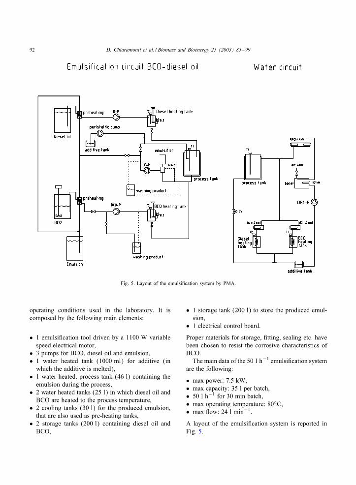
of water and a low amount of ash has greater valuesof Na, K, Ca in comparison with the BCO with a lowamount of water and a greater amount of ash. An ex-ception is represented by the California pine derivedBCO, probably due to the di<erent technology used,type of biomass and its pre-treatment. It can be noticedthat in all cases a considerable amount of calcium wasmeasured.Furthermore, the higher value of ash in the oakderived BCO is due to inert and/or ;reproof materi-als content in the bio-oil. The California pine derivedBCO presents a very low ash content in comparisonwith the other two BCOs.Regarding the heating values, the oak and pine de-rived BCOs are characterized by a greater value incomparison with the BCO utilizing beech wood asfeedstock, due to the higher content of carbon and hy-drogen; anyway the measured values are conform withthose ones reported in literature.
Table 3Physico-chemical properties of ENEL2\diesel oil emulsions
Physico-chemical properties 25% ENEL2 50% ENEL2 75% ENEL2Beech wood Beech wood Beech wood
Viscosity (cStoke) at 25◦C 9.43 28.3 n.a.Density at 20◦C (g cm−3): 0.921 1.003 1.084
Elemental analysis (% w/w)H 12.11 10.09 8.83C 71.59 56.64 44.98O 16.13 33.05 45.88N 0.04 0.07 0.09S ¡ 0:01 ¡ 0:01 ¡ 0:01
Alkali/emulsion (ppm)Na 45 91 134K 174 347 520Ca 390 781 1171Ash weight (% w/w) 0.07 0.14 0.21
Alkali/ash (mg g−1)Na 64.3 65.0 63.8K 248.6 247.9 247.6Ca 557.1 557.9 557.6
Water weight (% w/w) 10.7 [11.1] 21.6 [22.0] 32.4 [32.9]pH 3.2 3.1 3.0LHV (kJ kg−1) 35.716 27.142 19.260HHV (kJ kg−1) 38.357 29.342 21.186
Finally, it is important to remark that the BCO is anunstable product; it tends to separate in a two phasesDuid, where the upper phase has higher water contentthan lower phase. This phenomenon is time dependentand it can imply a low replicability of the tests.
4. Results of emulsion production
4.1. Characterization of emulsions
Three di<erent emulsions were prepared:
(1) 25% BCO, 74% diesel oil, 1% additive (w/w),(2) 50% BCO, 49% diesel oil, 1% additive (w/w),(3) 75% BCO, 24% diesel oil, 1% additive (w/w).
As additive, we used a mixture of polymeric sur-factants and short chain additives. More information

96 D. Chiaramonti et al. / Biomass and Bioenergy 25 (2003) 85–99
Table 4Physico-chemical properties of Dyna1001\diesel oil emulsions
Physico-chemical properties 25% Dyna1001 50% Dyna1001 75% Dyan1001California Pine California Pine California Pine
Viscosity (cStoke) at 25◦C 9.79 25.41 n.a.Density at 20◦C (g cm−3) 0.923 1.008 1.094
Elemental analysis (% w/w)H 12.27 10.50 8.98C 74.63 61.82 51.03O 13.04 27.6 39.88N 0.03 0.05 0.07S ¡ 0:01 ¡ 0:01 ¡ 0:01
Alkali/emulsion (ppm)Na 2 4 6K 3 5 8Ca 41.1 83.2 125.1Ash weight (% w/w) 0.01 0.02 0.03
Alkali/ash (mg/g)Na 20.1 20.3 20.4K 26.0 26.4 26.7Ca 411 415 417
Water weight (% w/w) 7.3 [ 7.7] 14.9 [15.3] 22.5 [23.1]PH 3.0 2.9 2.8LHV (kJ/kg) 35.815 28.354 21.560HHV (kJ/kg) 38.491 30.645 23.518
about the used additives is given in [29]. Thephysico-chemical properties of the emulsions arestrictly related to the properties of the fuels (dieseloil and BCO). Emulsions prepared from Califor-nia pine seems the most interesting. Tables 3 and 4report these properties as measured by CSGI. More-over, CSGI provided Aston University with somesamples of emulsion for a more detailed analysis ofthe viscosity index. The following six samples wereprovided:
(1) 25% ENEL2: 25% bio-oil, 75% diesel, ¡ 1%emulsifying agent,
(2) 50% ENEL2: 50% bio-oil, 50% diesel, ¡ 1%emulsifying agent,
(3) 75% ENEL2: 75% bio-oil, 25% diesel, ¡ 1%emulsifying agent,
(4) 25% Dyna1001: 25% bio-oil, 75% diesel,¡ 1%emulsifying agent,
(5) 50% Dyna1001: 50% bio-oil, 50% diesel,¡ 1%emulsifying agent,
(6) 75% Dyna1001: 75% bio-oil, 25% diesel,¡ 1%emulsifying agent.
A Metrohm 758 KFD Titrino, was used for quanti-tative determination of water in pyrolysis liquids. Asmall sample of raw pyrolysis liquid was weighted:the liquid was then injected through a septum into themeter. The Titrino determines water content by volu-metric titration (Tables 3 and 4).With respect to the viscosity index, it has alreadybeen said that the lower is the number, the more sta-ble is the liquid. A perfectly stable liquid has a vis-cosity index of 0.00. The samples analyzed by AstonUniversity were stable and opaque with no evidenceof phase separation. The stability measurements sug-gested a higher level of stability than conventionalbio-oils, which is promising. It was observed that the

D. Chiaramonti et al. / Biomass and Bioenergy 25 (2003) 85–99 97
Table 5Viscosity measurements: results summary
Sample Water Initial Final Viscosity indexcontent (wt%) viscosity (cS) viscosity (cS) at 80◦C
Bio-emulsions25% ENEL2 10.2 9.43 11.59 0.2350% ENEL2 20.3 28.30 29.20 0.0375% ENEL2 30.4 3172 ¿ 4000 n.a.25% BCO1001 7.9 9.79 10.62 0.0950% BCO1001 15.8 25.41 31.63 0.2475% BCO1001 23.7 1807.8 ¿ 4000 n.a.
Bio-oilsAston Duid bed 22.6 1.56Aston ablative 16.4 0.44NREL hot vapor 17.2 0.97;lteredEnsyn liquid 15.6 0.94
Average of triplicates, Average of duplicates. Average of duplicates. There was no appreciable¡ 0:2 standard deviation. change in weight (i.e. no
loss of volatiles) duringthe test.
75% bio-oil content emulsions had very high viscos-ity, which make them diBcult to use in most applica-tions. A summary of these measurements is shown inTable 5.
5. Conclusions
The research work on emulsions demonstratedthat:
• The emulsions are more stable than the pure BCO:further than from experimental evidence, this factwas also con;rmed by the measurement of theviscosity index.
• Higher the emulsi;er content, higher theviscosity and stability of emulsions. The optimalrange to have an acceptable viscosity is between0.5% and 2%. Emulsi;er up to 4% has beenadded, in this case an additive (like n-octanol)must be employed to reduce the viscosity of theemulsion.
• Higher the BCO content, higher the viscosity of theemulsion.
• The stability versus time at high temperature (ap-proximately 70◦C) of the produced emulsions wasabout 3 days.
• The use of fresh bio-oil, i.e. pyrolysis oil immedi-ately after its production, is recommended, since theuse of aged oils makes the emulsi;cation processmore diBcult and reduces the quality of the emul-sions in terms of droplet size and stability. In fact,chemical reactions occurring in BCO (in particular,polymerization) lead to the formation of solid prod-ucts. Therefore, in order to obtain a stable emulsion,it is necessary to micronize these products, makingthe necessary emulsi;cation time longer than in thecase of fresh bio-oil.
The possibility of producing stable emulsions in avery wide range (5/95 to 75/25 o/w emulsions) hasbeen demonstrated. It is therefore possible to considerpyrolysis oil emulsi;cation as a possible and rela-tively short-term approach to the wide use of these oilsreducing the investment in technologies. Nevertheless,since the quality of the BCO has a great impact on theselection of the emulsifying agent as well as on theemulsi;cation process, a general purpose approach is
98 D. Chiaramonti et al. / Biomass and Bioenergy 25 (2003) 85–99
not possible. The feedstock and the pyrolysis processmust be precisely de;ned in order to allow the exactidenti;cation of the most appropriate emulsi;cationtechnique.
Acknowledgements
Authors wish to acknowledge the persons whocollaborated to this research project: Riccardo Ricceri,Giuseppe Sarti and Paolo Favuzza (CSGI, Univer-sity of Florence), Pier Francesco Niccolini, GrazianoCrocetti and Lino Pasquali (Pasquali Macchine Agri-cole), JVurgen Schmid, Rainer Grischke and Catarinavon Schwerin (IEE, Kassel University), John Leech,Liz Peacock and Dereck Ormrod (Ormrod Diesels),Francesco Martelli (Energetics Department “SergioStecco”, University of Florence), and ETA for thesupport provided during the experimental campaign.The authors would also like to acknowledgeGiuliano Grassi (General Secretary of the EuropeanBiomass Industry Association, EUBIA) for his pre-cious recommendations and advices.Particular thanks to Dynamotive Technologies Ltd.(Canada), ENEL (Italy) and BTG (Netherland) forthe provision of oil during the research project.The research was funded in part by the EuropeanCommission in the framework of the Non NuclearEnergy Programme JOULE III. A special acknowl-edgement to the EC oBcers Mario Frias and MichailPapadoyannakis, for their useful support and collabo-ration during the project implementation.
References
[1] Bridgwater AV, Meier D, Radlein D. An overviewof fast pyrolysis of biomass. Organic Geochemistry1999;30(12):1479–93.
[2] EUREC-Agency. The future for renewable energy, prospectsand directions. London: James and James Science Publisher,1996.
[3] Bridgwater AV. Principles and practice of biomass fastpyrolysis processes for liquids. Journal of Analytical andApplied Pyrolysis 1999;51(1–2):3–22.
[4] Bridgwater AV, Peacocke GVC. Fast pyrolysis processesfor biomass. Renewable and Sustainable Energy Reviews2000;4(1):1–73.
[5] Meier D, Faix O. State of the art of applied fast pyrolysis oflignocellulosic materials—a review. Bioresource Technology1999;68(1):71–7.
[6] Peterson CL. Winter rape oil fuel for diesel engines. Journalof the American Oil Chemists Society 1983;60(8):1579–87.
[7] Masjuki H. Rapid test to measure performance, emissions andwear of a diesel engine fueled with palm oil diesel. Journalof the American Oil Chemists Society 1993;70(10):1021–5.
[8] Ryan TW. E<ects of vegetable oil properties on injectionand combustion in two di<erent diesel engines. Journal ofthe American Oil Chemists Society 1984;61(10):1610–9.
[9] Machacon HT, Matsumoto Y, Ohkawara C, Shiga S,Karasawa T, Nakamura H. The e<ect of coconut oil anddiesel fuel blends on diesel engine performance and exhaustemissions. JSAE Review 2001;22(3):349–55.
[10] Lopez-Juste G, SalvYa-Monfort JJ. Preliminary test oncombustion of wood derived fast pyrolysis oils in a gas turbinecombustor. Biomass and Bioenergy 2000;19(2):119–28.
[11] Sridhar G, Paul PJ, Mukunda HS. Biomass derived producergas as a reciprocating engine fuel—an experimental analysis.Biomass and Bioenergy 2001;21(1):61–72.
[12] Crookes RJ, Kiannejad F, Nazha MAA. Systematicassessment of combustion characteristics of biofuels andemulsions with water for use as diesel engine fuels. EnergyConversion and Management 1997;38(6):1785–95.
[13] Demirbas A. Conversion of biomass using glycerin to liquidfuel for blending gasoline as alternative engine fuel. EnergyConversion and Management 2000;41(16):1741–8.
[14] Shihadeh A, Hochgreb S. Diesel engine combustion ofbiomass pyrolysis oils. Energy and Fuels 2000;14(2):260–74.
[15] Leech J. Running a dual fuel engine on pyrolysis oil. In:Kaltschmitt M, Bridgwater AV, editors. Running a dual fuelengine on pyrolysis oil. CPL Press, Newbury, UK. 1996.p. 175–85.
[16] Leech J, Bridgwater AV, Cuevas A, Maggi R. Developmentof an internal combustion engine for use with crude bio-oiland evaluation of associated processes. Zervos A, Sala M,editors. Renewable Energy Development. Venice, Italy, 1995.p. 340–5.
[17] Baglioni P, Chiaramonti D. Final Report EC ContractJOR3-CT98-0307—Development of a Bio Crude Oil/DieselEmulsion. Florence: CSGI - University of Florence, 2001.
[18] Baglioni P, Berti D, Bonini M. Preparation and stability ofemulsions. La Chimica e L’Industria 2000;82:743.
[19] Sjoblom J. Emulsions—A fundamental and practicalapproach. Dordrecht: Kluwer Academic Publishers, 1992.
[20] Friberg S. Food emulsions. New York: Marcel Dekker, 1976.[21] Evans DF, Wennerstrom H. The colloidal domain: where
physics, chemistry, biology, and technology meet. New York:VCH Publishers, 1999.
[22] Mitchell DJ, Ninham BW. Micelles, Vesicles andMicroemulsions. Journal of the Chemical Society FaradayTransactions 1981;77:601–29.
[23] Becher P. Encyclopedia of emulsion technology. New York:Marcel Dekker, 1985.
[24] Tadros TF. Surfactants in agrochemicals. New York: MarcelDekker, 1995.
[25] Ninham BW. On progress in forces since the DLVO theory.Advances in Colloid and Interface Science 1999;83(1–3):1–17.

D. Chiaramonti et al. / Biomass and Bioenergy 25 (2003) 85–99 99
[26] Ninham BW, Deryaguin BV. Selected works of B.V.Deryaguin. Progress in Surface Science 1994;47(4):5–8.
[27] Ninham BW, Deryaguin BV. Selected works of B.V.Deryaguin. Progress in Surface Science 1992;40:15–20.
[28] Verwey EJW, Overbeek JTG, Van Ness K. Theory ofthe stability of lyophobic colloids—the interaction of soil
particles having an electrical double layer. Amsterdam:Elsevier, 1948.
[29] Baglioni P, Fratini E, Ricceri R., Sarti G, Chiaramonti D.Engine fuels consisting of an emulsion comprising mineraland/or natural oils; their preparation and use in internalcombustion engine, PCT/EP99/04607, 1999.