
marine diesel engines - SERVICE MANUAL
138
SERVICE MANUAL 80N4 and 110T4 120N6 and 17016 MARINE DIESEL ENGINES 45KW • 60Hz 35KW • 50Hz BED 55KW • 60Hz 45KW • 50Hz BED 65KW • 60Hz 55KW • 50Hz BED 95KW • 60Hz BOKW • 50Hz BED MARINE DIESEL GENERATORS PUBLICATION N0.47069 FIRST EDITION JANUARY 2002 'WESTERBEKE J WESTERBEKE CORPORATION • MYLES STANDISH INDUSTRIAL PARK I I 50 JOHN HANCOCK ROAD • TAUNTON MA 02780-7319 • TEL. (508)823-7677 FAX {508)884-9688 • WEBSITE: WWW. WESTERBEKE.COM - Member National MariM Manufacturers Association
-
Upload
khangminh22 -
Category
Documents
-
view
0 -
download
0
Transcript of marine diesel engines - SERVICE MANUAL

SERVICE MANUAL 80N4 and 110T4 120N6 and 17016
MARINE DIESEL ENGINES
45KW • 60Hz 35KW • 50Hz BED 55KW • 60Hz 45KW • 50Hz BED 65KW • 60Hz 55KW • 50Hz BED 95KW • 60Hz BOKW • 50Hz BED
MARINE DIESEL GENERATORS PUBLICATION N0.47069
FIRST EDITION JANUARY 2002
l~ 'WESTERBEKE J WESTERBEKE CORPORATION • MYLES STANDISH INDUSTRIAL PARK I I 50 JOHN HANCOCK ROAD • TAUNTON MA 02780-7319 • TEL. (508)823-7677
FAX {508)884-9688 • WEBSITE: WWW. WESTERBEKE.COM
-~ Member National MariM Manufacturers Association

CALIFORNIA PROPOSITION 65 WARNING
Exhaust gas from diesel and gasoline engines (and some of its constituents} are known to the State of California to cause cancer, birth defects, and other reproductive harm.
A WARNING: Exhaust gasses contain Carbon Monoxide, an odorless and colorless gas. Carbon Monoxide is poisonous and can cause unconsciousness and death. Symptoms of Carbon Monoxide exposure can include: •Dizziness •Nausea •Headache • Weakness and Sleepiness
• Throbbing in Temples • Muscular Twitching • Vomiting •Inability to Think Coherently
IF YOU OR ANYONE ELSE EXPERIENCE ANY OF THESE SYMPTOMS, GET OUT INTO THE FRESH AIR IMMEDIATELY. If symptoms persist, seek medical attention. Shut down the unit and do not restart until it has been inspected and repaired.
A WARNING DECAL is provided by WESTERBEKE and should be fixed to a bulkhead near your engine or generator. WESTERBEKE also recommends installing CARBON MONOXIDE DETECTORS in the living/sleeping quarters of your vessel. They are inexpensive and easily obtainable at your local marine store.

TABLE OF CONTENTS
lntroduction ............................................................. 2 Testing for Overhaul ........................................... .3
Engine Troubleshooting ...................................... .4 Angular Tightening Methods ............................... 8 Standard Torque Specifications .......................... 9
Engine Disassembly ........................................... 10
Important Measurements .................................. 11
Disassembly Steps ............................................. 12
Inspection/Repair .............................................. 15
Cylinder Head Disassembly ............................... 16 Inspection/Repair ....................................... 17 - 34
Refer to the index for specific items in this section such as: pistons, flywheel, crankshaft, valves, push rods, camshaft, etc.
Assembly .................................................... 35 - 46 Refer to the index for specific items in this section such as: rocker arms, oil cooler, engine timing, etc.
Lubricating System ........................................... .47 Cooling System ................................................. .49 Raw Water Pump ............................................... 52 Turbocharger ..................................................... 53 Engine Adjustments ........................................... 55 Fuel System ....................................................... 56 Tachometer ........................................................ 62 Alternator ................................................... 63 - 69
Complete testing and breakdown of the Manda 51A alternator.
Starter Motor ............................................. 70 - 83 Complete testing and breakdown of the starter motor.
Wiring Diagram (#44780) .................................. 84
Remote Instrument Panel Wiring(#44392) ....... 86
Wiring Diagram (#44781) .................................. 87 Engine Troubleshooting ..... .-..................... 89- 108
An extensive troubleshooting chart.
Torque Data ............................................ 109 - 111 BE Generator ................................................... 112 Voltage Regulator ,. .......................................... 113 Generator Information ..................................... 114 AC Voltage Connections ................................. 115 Internal Wiring diagram .................................. 116 Electronic Governor Adjustments ................... 117 Troubleshooting the Electronic Governor ...... 118 BE Troubleshooting ......................................... 119 Generator Maintenance .................................. 120
45 BED Generator Specifications .................... 121
55 BED Generator Specifications .................... 122
65 BED Generator Specifications .................... 123
95 BED Generator Specifications .................... 124
BON4 Engine Specifications ........................... 125
110T4 Engine Specifications ......................... 126
12DN6 Engine Specifications ......................... 127
170T6 Engine Specifications ......................... 128
Lay-up and Recommissioning .......................... .46 Metric Conversions Data ................................. 129
Special Tools ....... : ........................................... 131
Index ............................................................. 132
Engines & Generators
1

INTRODUCTION PRODUCT SOFTWARE Product software, (technical data, parts lists, manuals, brochures and catalogs), provided from sources other than WESTERBEKE are not within WESTERBEKE'S control.
WESTERBEKE CANNOT BE RESPONSIBLE FOR THE CONTENT OF SUCH SOFTWARE, MAKES NO WARRANTIES OR REPRESENTATIONS WITH RESPECT THERETO, INCLUDING ACCURACY, TIMEliNESS OR COMPLETENESS THEREOF AND WILL IN NO EVENT BE UABLE FOR ANY TYPE OF DAMAGE OR INJURY INCURRED IN CONNECTION WITH OR ARISING OUT OF THE FURNISHING OR USE OF SUCH SOFTWARE.
WESTERBEKE customers should keep in mind the time span between printings of WESTERBEKE product software and the unavoidable existence of earlier WESTERBEKE product software. The product software provided with WESTERBEKE products, whether from WESTERBEKE or other suppliers, must not and cannot be relied upon exclusively as the definitive authority on the respective product. It not only makes good sense but is imperative that appropriate representatives of WESTERBEKE or the supplier in question be consulted to determine the accuracy and currentness of the product software being consulted by the customer.
NOTES, CAUTIONS AND WARNINGS As this manual takes you through the operating procedures, maintenance schedules, and troubleshooting of your marine engine, critical information will be highlighted by NOTES, CAUTIONS, and WARNINGS. An explanation follows:
NOTE: An operating procedure essential to note.
A CAUTION: Procedures which, if not strictly observed, can result in the damage or destruction of your engine.
A WARNING: Procedures which, if not properly followed, can result in personal injury or loss of life.
ORDERING PARTS Whenever replacement parts are needed, always provide the engine model number and serial number as they appear on the silver and black nameplate located on the manifold. You must provide us with this information so we may properly identify your engine. In addition, include a complete part description and part number for each part needed (see the separately furnished Parts List). Insist upon WESTERBEKE packaged parts because will fit or generic parts are frequently not made to the same specifications as original equipment.
Customer Identification Card
I""IWESTERBEKE J Engines & Generators
Customer Identification
MR. GENERATOR OWNER
MAIN STREET
HOMETOWN, USA
Model 55 BED
Expires 11/2001
Ser. #UOOOO-E102
The WESTERBEKE serial number is an alphanumeric number that can assist in determining the date of manufacture of your WESTERBEKE engine/generator. The manufacturer's date code is placed at the end of the engine serial number and consists of a character followed by three numbers. The character indicates the decade (A=1960s, B=1970s, C=1980s, D=1990s E=2000s), the first number represents the year in the decade, and the second and third numbers represent the month of manufacture.
SERIAL NUMBER LOCATION The engine's serial number can be found stamped into the engine block just out board of the injection pump. An identification plate on the engine manifold also displays the engine model and serial number.
The generator serial number is stamped on the left side of the generator housing and on the fiat surface above the rotary carrier bearings.
ENGINE OVERHAUL The following sections contain detailed information relating to the proper operation characteristic of the major components and systems of the engine. Included are disassembly, inspection and reassembly instructions for the guidance of suitable equipped and staffed marine engine service and rebuilding facilities. The necessary procedures should be taken only by such facilities.
Additional detailed information and specifications are provided in other sections of this manual, covering the generator, alternator, starter motor, engine adjustments, cooling pumps, etc.
Engines & Generators
2

TESTING FOR OVERHAUL HOW TO DETERMINE ENGINE OVERHAUL PERIOD Cause of Low Compression Generally, the time at which an engine should be overhauled is determined by various conditions such as lowered engine power output, decreased compression pressure, and increased fuel and oil consumption. The lowered engine power output is not necessarily due to trouble with the engine itself, but is sometimes caused by injector nozzle wear or injection pump wear. The decrease in compression pressure is caused by many factors. It is, therefore, necessary to determine a cause or causes on the basis of data produced by periodic inspection and maintenance. Oil analysis on a seasonal basis is a good means of monitoring engine internal wear. When caused by worn cylinders or piston rings, the following symptoms will occur:
1 Low engine power output 2 Increased fuel consumption 3 Increased oil consumption 4 Hard engine starting 5 Noisy engine operation
These symptoms often appear together. Symptoms 2 and 4 can result also from excessive fuel injection, improper injection timing, and wear of the injectors. They are caused also by defective electrical devices such as the battery, alternator, starter and glow plugs. Therefore it is desirable to judge the optimum engine overhaul time by the lowered compression pressure caused by worn cylinders and pistons plus increased oil consumption. Satisfactory combustion is obtained only under sufficient compression pressure. If an engine lacks compression pressure, incomplete combustion of fuel will take place even if other parts of the engine are operating properly. To determine the period of engine overhaul, it is important to measure the engine compression pressure regularly. At the same time, the engine speed at which the measurement of compression pressure is made should be checked because the compression pressure varies with engine rpm. The engine rpm can be measured at the front end of the crankshaft.
NOTE: To test engine compression see the ENGINE ADJUSTMENT section of this manual.
ASSEMBLY 1. Wash all parts, except for oil seals, 0-rings, rubber sheets,
etc., with cleaning solvent and dry them with pressure air.
2. Always use tools that are in good condition and be sure you understand how to use them before performing any job.
3. Use only good quality lubricants. Be sure to apply a coat of oil, grease or sealant to parts as specified ..
4. Be sure to use a torque wrench to tighten parts for which torques are specified.
5. Ant time the engine is assembled, new gaskets and 0-rings must be installed.
3
OVERHAUL CONDITIONS Compression pressure tends to increase a little in a new engine until piston rings and valve seats have been broken in. Thereafter, it decreases gradually with the progress of wear of these parts.
When decrease of compression pressure reaches the repair limit, the engine must be overhauled.
The engine requires overhaul when oil consumption is high, blowby evident, and compression values are at minimum or below. Engine compression should be 3I kg/cm2, 44I psi at 200 rpm. The maximum difference between cylinders must not exceed I Oo/o.
DISASSEMBLY 1. Before disassembly and cleaning, carefully check for
defects which cannot be found after disassembly and cleaning.
2. Drain water, fuel and oil before disassembly.
3. Clean or wash the engine exterior.
4. Do not remove or disassemble the parts that require no disassembly.
5. Perform disassembly in a proper order using proper tools. Keep disassembled parts in order. Apply oil when necessary. Take special care to keep the fuel system parts from intrusion of dust and dirt.
6. Parts must be restored to their respective components from which they were removed at disassembly. This means that all parts must be set aside separately in groups, each marked for its component, so that the same combination or set can be reproduced at assembly.
7. Pay attention to marks on assemblies, components and parts for their positions or directions. Put on marks, if necessary, to aid assembly ..
8. Carefully check each part or component fore any sign of faulty condition during removal or cleaning. The part will tell you how it acted or what was abnormal about it more accurately during removal or cleaning.
ALTERNATOR INSPECTION When rebuilding the engine, the alternator should be cleaned and inspected. The housing can be wiped off with a solvent and the alternator terminal studs should be cleaned with a wire brush. Make certain the studs are tight and clean the wiring connections that connect to the wiring harness.
Tum the rotor pulley by hand. It should tum smoothly.
Depending on when the alternator was last serviced, the brushes may need replacing. If the alternator is at all suspect, send it to a service shop for testing and overhaul.
For additional information on alternators refer to the ALTERNATOR TROUBLESHOOTING and MANDO SERVICE in this manual.

ENGINE TROUBLESHOOTING The following troubleshooting chart describes certain problems relating to engine service, the probable causes of these problems, and the recommendations to overcome these problems. This chart may be of assistance in determining the need for an engine overhaul.
PROBLEM PROBABLE CAUSE
HARD STARTING LOW CRANKING SPEED 1. Engine oil viscosity too high. 2. Run-down battery. 3. Worn battery. 4. Battery terminals loosely connected. 5. Defective starter.
DEFECTIVE INJECTION SYSTEM 1. Air trapped in fuel passage. 2. Clogged fuel filter. 3. Low injection pressure. 4. Inadequate spray. 5. Injection pump delivering insufficient fuel. 6. Injection too early.
MAIN ENGINE TROUBLES 1. Low compression.
a. Incorrect valve clearance. b. Inadequate contact of valve seat. c. Valve stem seized. d. Broken valve spring.
Refer also to the more detailed Troubleshooting section in the back of this manual. NOTE: The engine's electrical system is protected by a 20-ampere manual reset circuit breaker. The preheat solenoid is mounted on the same bracket.
VERIFICATION/REMEDY
1. Replace engine oil with less viscous oil. 2. Recharge battery. 3. Replace battery. 4. Clean terminals and correct cables. 5. Repair or replace starter.
1. Bleed air from fuel system. 2. Clean or replace filter. 3. Adjust injection pressure. 4. Clean or replace nozzle. 5. Repair or replace injection pump. 6. Adjust injection timing.
a. Adjust valve clearance. b. Lap valve. c. Replace valve and valve guide. d. Replace valve spring.
e. Compression leaks through cylinder head gasket. e. Replace gasket. f. Piston ring seized. f. Replace piston and piston ring. g. Worn piston ring and cylinder. g. Overhaul engine.
2. Burnt glow plug. 2. Replace glow plug. 3. Faulty glow plug operation. 3. Correct lead wire connection. 4. Incorrect governor lever position. 4. Set lever to starting position.
LOW OUTPUT LOW COMPRESSION See HARD STARTING
INJECTION SYSTEM OUT OF ADJUSTMENT 1. Incorrect injection timing. 1. Adjust injection timing. 2. Insufficient injection. 2. Repair or replace injection pump. 3. Low injection pressure. 3. Check injection nozzle and adjust pressure.
INSUFFICIENT FUEL 1. Air trapped in fuel system. 1. Check and retighten connector. 2. Clogged filter. 2. Clean or replace filter. 3. Contaminated fuel tank. 3. Clean tank.
INSUFFICIENT INTAKE AIR 1. Clogged air cleaner. 1. Clean or replace air cleaner.
(continued)
4

ENGINE TROUBLESHOOTING PROBLEM PROBABLE CAUSE VERIFICATION/REMEDY
LOW OUTPUT (cont.) OVERHEATING 1. Low coolant level. 1. Add coolant. 2. Loose V-belt. 2. Adjust or replace V-belt. 3. Incorrect injection timing. 3. Adjust injection timing. 4. Low engine oil level. 6. Add engine oil.
EXCESSIVE OIL OIL LEAKAGE CONSUMPTION 1. Defective oil seals. 1. Replace oil seals.
2. Broken gear case gasket. 2. Replace gasket. 3. Loose gear case attaching bolts. 3. Retighten bolts. 4. Loose drain hose. 4. Retighten hose. 5. Loose oil pipe connector. 5. Retighten oil connections. 6. Broken rocker cover gasket. 6. Replace gasket. 7. Loose rocker cover attaching bolts. 7. Retighten attaching bolts.
OIL LEVEL RISING 1. Incorrectly positioned piston ring gaps. 1. Correct ring gap positions. 2. Displaced or twisted connecting rod. 2. Replace connecting rod. 3. Worn piston ring. 3. Replace ring. 4. Worn piston or cylinder. 4. Replace piston and rebore cylinder.
OIL LEVEL FALLING 1. Defective stem seal. 1. Replace stem seal. 2. Worn valve and valve guide. 4. Replace a valve and valve guide.
EXCESSIVE FUEL ENGINE BODY TROUBLES CONSUMPTION 1. Noisy knocking. 1. See KNOCKING.
2. Smoky exhaust. 2. See SMOKY EXHAUST. 3. Moving parts nearly seized or excessively worn. 3. Repair or replace. 4. Poor compression. 4. See LOW COMPRESSION; HARD STARTING. 5. Improper valve timing. 5. Adjust. 6. Improper valve clearance. 6. Adjust.
INSUFFICIENT INTAKE AIR 1. Air intake obstructed. 1. Remove obstruction.
NOZZLE TROUBLES 1. Seized nozzle. 1. Replace. 2. Worn nozzle. 2. Replace.
IMPROPER FUEL Replace with proper fuel.
FUEL LEAKS Find fuel leaks.
SMOKY EXHAUST WHITISH OR PURPLISH 1. Excessive engine oil. 1. Correct oil level. 2. Excessive rise of oil into combustion chamber.
a. Poor piston contact. a. Check. b. Seized piston ring. b. Replace or clean. c. Excessive piston-to-cylinder clearance. c. Replace or correct.
(continued)
5
ENGINE TROUBLESHOOTING PROBLEM PROBABLE CAUSE VERIFICATION/REMEDY
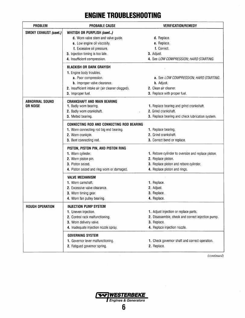
SMOKY EXHAUST (cont.) WHITISH OR PURPLISH (cont .. ) d. Worn valve stem and valve guide. d. Replace. e. Low engine oil viscosity. e. Replace. f. Excessive oil pressure. f. Correct.
3. Injection timing is too late. 3. Adjust. 4. Insufficient compression. 4. See LOW COMPRESSION; HARD STARTING.
BLACKISH OR DARK GRAYISH 1. Engine body troubles.
a. Poor compression. a. See LOW COMPRESSION; HARD STARTING. b. Improper valve clearance. b. Adjust.
2. Insufficient intake air (air cleaner clogged). 2. Clean air cleaner. 3. Improper fuel. 3. Replace with proper fuel.
ABNORMAL SOUND CRANKSHAFT AND MAIN BEARING OR NOISE 1. Badly worn bearing. 1. Replace bearing and grind crankshaft.
2. Badly worn crankshaft. 2. Grind crankshaft. 3. Melted bearing. 3. Replace bearing and check lubrication system.
CONNECTING ROD AND CONNECTING ROD BEARING 1. Worn connecting rod big end bearing. 1. Replace bearing. 2. Worn crankpin. 2. Grind crankshaft. 3. Bent connecting rod. 3. Correct bend or replace.
PISTON, PISTON PIN, AND PISTON RING 1. Worn cylinder. 1. Rebore cylinder to oversize and replace piston. 2. Worn piston pin. 2. Replace piston. 3. Piston seized. 3. Replace piston and rebore cylinder. 4. Piston seized and ring worn or damaged. 4. Replace piston and rings.
VALVE MECHANISM 1. Worn camshaft. 1. Replace. 2. Excessive valve clearance. 2. Adjust. 3. Worn timing gear. 3. Replace. 4. Worn fan pulley bearing. 4. Replace.
ROUGH OPERATION INJECTION PUMP SYSTEM 1. Uneven injection. 1. Adjust injection or replace parts. 2. Control rack malfunctioning. 2. Disassemble, check and correct injection pump. 3. Worn delivery valve. 3. Replace. 4. Inadequate injection nozzle spray. 4. Replace injection nozzle.
GOVERNING SYSTEM 1. Governor lever malfunctioning. 1. Check governor shaft and correct operation. 2. Fatigued governor spring. 2. Replace.
(continued)
6

ENGINE TROUBLESHOOTING PROBLEM PROBABLE CAUSE VERIFICATIONJREMEOY
KNOCKING ENGINE KNOCKS WITHOUT MUCH SMOKE 1. Main engine troubles. a. Overheated cylinder. a. See OVERHEATING; LOW OUTPUT. b. Carbon deposits in cylinder. b. Clean. 2. Too early injection timing. 2. Correct. 3. Too high injection pressure. 3. Correct. 4. Improper fuel. 4. Replace with proper fuel.
KNOCKING WITH DARK SMOKE 1. Poor compression. 1. See LOW COMPRESSION; HARD STARTING. 2. Injection pump malfunctioning. 2. Adjust/Repair 3. Improper nozzle.
a. Poor spray. a. Clean or replace nozzle. b. Poor chattering. b. Repair or replace nozzle. c. After-injection drip. c. Repair or replace nozzle. d. Nozzle needle valve seized. d. Replace.
INTERMITTENT 1. Fuel filter clogged. 1. Clean or replace. EXHAUST SOUND 2. Water mixed in fuel 2. Replace fuel.
OVERHEATING 1. V-belt slackening or slippery with oil. 1. Adjust, replace or clean. 2. Damaged water pump. 2. Replace. 3. Lack of coolant. 3. Add. 4. Low oil level or poor oil quality. 4. Add or change. 5. Knocking. 5. See KNOCKING. 6. Moving parts seized or damaged. 6. Replace. 7. Defective thermostat. 7. Replace.
LOW OIL PRESSURE 1. Worn Bearings. 1. Engine overhaul replace bearings. 2. Relief valve malfunction. 2. Overhaul oil pump. 3. Clogged oil cooler. 3. Repair. 4. Diesel dilution of the oil. 4. Injection pump repair.
7

ANGULAR NUT AND BOLT TIGHTENING METHOD 1. Carefully wash the nuts and bolts to remove all oil and
grease.
2. Apply a coat of molybdenum disulfide grease to the threads and setting faces of the nuts and bolts.
3. Tighten the nuts and bolts to the specified torque (snug torque) with a torque wrench.
CENTER LINE
4. Draw a line (A-B) across the center of each bolt.
5. Draw another line (C-D) on the face of each of the parts to be clamped. This line should be an extension of the line (A-B).
COINCIDING LINE G
8
6. Draw another line (F-G) on the face of each of the parts to be clamped. This line will be in the direction of the specified angle (Q) across the center (E) of the nut or bolt.
7. Use a socket wrench to tighten each nut or bolt to the point where the line (A-B) is aligned with the line (F-G).
Example: Specified Angle and Tightening Rotation
A 30° 1112 of a tum
B 60° 116 of a tum
c 90° 114 of a tum
D 180° 1/2 of a tum
E 360° One full tum

STANDARD BOLTS I TIGHTENING TORQUE SPECIFICATIONS NOTE: The torque values given in the following table should be applied where a particular torque is not specified.
kg-m
~ ~ ~ ~ ~ ~ M 6 X 1.0 0.6 ±0.2 0.7
+0.2 0.8 +0.2 0.9 +0.2 -0.3 -0.3 -0.3
---
M 8 X 1.25 1.3 ±0.5 1.6 +0.4 1.8
+0.5 2.1 +0.5
2.4 ±0.7 -0.6 -0.6 -0.7 '
M10 X 1.25 2.8 ±0.7 3.3 +0.8 3.8 +0.9 4.3 ±0.9 5.1 ±1.3 -0.9 -1.0
"M10 X 1.5 2.7 ±0.7 3.2 ±0.8 3.7 ±0.9 4.2 ±1.0 4.9 ±1.2
M12 X 1.25 6.2 +1.3
6.7 +1.4
7.7 +1.6 8.8 +1.8
9.7 +1.9
-1.2 -1.3 -1.5 -1.7 -2.0
*M12 X 1.75 5.8 ±1.2 6.3 ±1.2 7.2 ±1.4 8.2 ±1.6 9.1 ±1.8
M14 X 1.5 9.7 +2 10.4 +2 11.9
+2.3 13.6
+2.6 14.5 ±2.9 -1.9 -2.1 -2.4 -2.8
*M14 X 2.0 9.1 ±1.8 9.8 ±1.9 11.2 ±2.2 12.8 ±2.5 13.6 ±2.7
M16 X 1.5 13.3 +2.7 15.1 ±3.1 17.3 ±3.5 19.7 ±4.0 20.4 ±4.1
*M16 X 2.0 12.7 ±2.5 14.4 ±2.9 16.5 ±3.3 18.8 ±3.8 19.5 ±3.9
M18 X 1.5 19.2 ±3.8 21.7 +4.4 24.9 ±5.0 28.4 ±5.7 29.3 ±5.9 -4.3
*M18 X 2.5 19.2 ±3.8 21.8 +4.4
25.0 ±5.0 28.5 ±5.7 29.4 +5.9 -4.3 -5.8
M20 X 1.5 26.3 ±5.3 30.0 +6.1 34.4 ±6.9 I 39.2
+7.9 40.4 ±8.1 -6 -7.8
*M20 X 2.5 24.3 ±4.9 27.8 +5.5
31.8 ±6.4 I 36.3 +7.2 I 37.4 ±7.5 -5.6 -7.3
.. _ I
M22 X 1.5 32 0 +10.2 40.4 ±8.1 46.3 +9.2 i 528+10.5 ! 54.1 ±10.8 . - 6.4 -9.3 ; . -10.6 i
*M22 X 2.5 27.8 ±5.6 37.6 ±7.5 43.1 i
±8.6 49.1 ±9.8 I 50.3 ±10.1
47 9 +15.4 549+17.6 I 62 6+20.1 ! M24 X 2.0 45.8 ±9.2 i 70.6 ±14.1
! . - 9.6 . -11.0 . -12.6 i
*M24 X 3.0 43.1 ±8.6 I
45.1 ±9.0 51.7±10.3 589+11.8 I 66.4 ±13.3 ! . -11.7 !
NOTE: Bolts marked with an asterisk are used for female threaded parts made of soft materials such as castings.
9

ENGINE DISASSEMBLY GENERATOR Disconnect the AC wiring and unplug the engine's DC wiring harness at the generator control panel. Remove the battery cables from the engine and tape over the terminals.
NOTE: Label any lines, hoses or cables as you separate them.
Separate the exhaust hose at the water injected elbow and disconnect the fuel supply and return lines.
Drain the engine oil and the coolant from the engine.
Carefully support and then unbolt the generator backend from the engine. See SPECIAL TOOLS in this manual.
Additional generator information will be found in the GENERATOR section of this manual.
PROPULSION ENGINE Switch off the batteries and disconnect the battery cables from the engine and tape over the terminals.
Drain or pump out all the engine oil and drain the coolant from the engine and engine hoses.
Unplug the instrument panel wiring harness. Drain the transmission fluid and the transmission oil cooler hoses, Detach the oil cooler hoses and unbolt the transmission from the engine.
DRAIN PLUG
ENGINE DISASSEMBLY Take the following precautions:
• Clean the exterior of the engine of any deposits of dirt and oil. ,
• Be careful not to damage the disassembled parts.
• Arrange parts in the order of disassembly. Mark or label parts as needed to insure proper mating and reassembly. Keep parts clean.
• Mount the engine on a suitable engine stand for disassembly.
With the transmission/generator separated from the engine, begin the following step by step procedure to disassemble the engine.
l.Remove the transmission damper plate from the engine flywheel.
2. Remove the engine oil cooler and oil hoses. Note oil hose connections from the oil cooler to the engine.
3. Remove the engine heat exchanger. If possible, leave one end of each hose connected to the part being removed.
4. Remove the bell housing and the circuit breaker/ preheat solenoid mounting bracket.
5. Remove the engine back plate.
6. Remove the start motor, drive belt and the alternator. Label the wires and cables.
7. Remove the engine mounted raw water pump,
DRAIN PETCDCK ~ 4t... .. r I/·· WATER PUMP for parts breakdown.
""'4< c It complete with its adapter mounting plate. See RAW
~ ~ iJ_ 8. With the hoses disconnected, remove the thermostat DRAIN ~·~ housing and housing gasket, leaving the temperature
~ sender in place.
TRANSMISSION If the transmission is not being rebuilt it should be visually inspected. Flush out and pressure test the oil cooler and replace the coolant hoses. Inspect and lubricate the gear shift linkage and the propeller shaft coupling. Clean and repaint the transmission and change the transmission fluid.
For transmission service and maintenance refer to your transmission manual. To rebuild a transmission contact your WESTI}RBEKE dealer or an authorized transmission service center.
DAMPER PLATE
DAMPER PLATE BOLTS
9. Remove the coolant circulating pump. Refer to COOlANT PUMP ASSEMBLY.
lO.Remove the air intake silencer and the intake manifold.
ll.Remove the oil filter and the mounting bracket from the engine block.
12.Unbolt the elbows and remove the exhaust manifold in its entirety.
13.Remove the fuel injection pump. Disconnect the fuel injection pipes and fuel leak-off pipe from the fuel injection pump and nozzles.
NOTE: Put plugs or caps on the openings of the injection pump and nozzle connectors. Golf tees work well as plugs.
14.Remove the fuel injection nozzle .• Loosen the fuel injection nozzles with a wrench. Remove the nozzles and gaskets from the cylinder head.
lS.Pepare to disassemble the engine block.
Engines & Generators
10

MEASUREMENTS
PRIOR TO MAIN ENGINE DISASSEMBLY 1. Idler Gear
Measure the following points before disassembly.
mm(in)
Standard Limit
Idler Gear End 0.058 __: 0.115 0.2 Play (0.002 - 0.005) (0.008)
mm(in)
Standard Limit
Timing Gears 0.10- 0.17 0.3 Backlash (0.004 - 0.007) (0.012)
Includes the crankshaft gear, the camshaft gear, and the idler gear.
2. Cam Shaft
Measure the following points before disassembly.
mm(in)
Standard Limit
Cam Gear End 0.050-0.114 0.2 Play (0.002 - 0.005) (0.008)
3. Crankshaft Bearing Cap
Measure the crankshaft end play at the thrust bearing (center main bearing) before disassembly.
mm(in)
Standard Limit
Crankshaft End 0.15-0.33 0.4 Play (0.006- 0.014) (0.016)
FEELER GAUGE
MEASURE IDLER GEAR END PLAY
MEASURE TIMING GEARS BACKLASH
CAMSHAFT GEAR
FEELER GAUGE
MEASURE CAM SHAFT GEAR END PLAY
Cl MEASURE CRANKSHAFT BEARING CAP END PLAY
11

10
11
Disassembly Steps 1. Dipstick and guide tube e tube 2. Air breather
3. Turbo adapter
4. Oil feed pipe 5. Oil drain pipe
6. Turbocharger
7. Gasket 8. Starter 9. Drive belts
10. Alternator 11. Waterpump pulley
12. Cylinder head cover
11/
9
I 4
5
9
DISASSEMBLY
3
1 6
4
5
Turbocharger
Plug oil ports in turbocharger body immediately after removal of the turbocharger.
6 7 12
2
Engines & Generators
12

DISASSEMBLY Disassembly Steps
1. Rubber hose. ; water by-pass 9. Oil pump driving pinion 2. Rocker arm shaft assembly 10. Starting handle nut 3. Push rod 11. Taper bushing 4. C,ylinder head bolt 12. Crankshaft pulley and dust thrower 5. Cylinder head assmbly 13. Timing gear cover 6. Cylinder head gasket 14. Oil thrower 7. Water pump assembly • 15. Flywheel 8. Tappet chamber cover
3
~9
15
13
8
13

DISASSEMBLY NUMBERS INDICATE SUGGESTED ORDER OF DISASSEMBLY
SIX CYLINDER MODEL (SHOWN)
11 CRANKSHAFT ~ BEARING (LOWER) AND BEARING CAP~(\
14 CRANKSHAFT
2 OIL PAN 3 THRUST ~~:.c..,-....;;;~~~.",, BEARING-----~ (NOT SHOWN)
Disassembl.y Steps
1. Oil cooler 2. Oil pan 3. Oil pump and coupling 4. Flywheel housing 5. Piston and connecting rod 6. Idler gear 7. Camshaft 8. Tappet 9. Timing gear case
10. Idler gear shaft 11. Crankshaft bearing cap 12. Crankshaft bearing (lower half) 13. Thrust bearing 14. Crankshaft 15. Crankshaft bearing (u'pper half) 16. Oil-Jet (6 cyl., turbo only)
61DLER GEAR
OIL COOLER INSPECT OIL COOLER ASSEMBLY.· REPLACE ANY PARTS THAT SHOW EXCESSIVE WEAR OR DAMAGE.
OIL COOLER ELEMENT
BY·PASS VALVE, O·RING, SPRING AND PLUG
14
30IL PUMP AND COUPLING
4FLYWHEEL HOUSING
1 OIL COOLER INSPECT OIL COOLER ASSEMBLY. REPLACE ANY PARTS THAT SHOW EXCESSIVE WEAR OR DAMAGE.

INSPECTION/REPAIR
5
• TOPRING
-2ND RING
3
~ COMBUSTION CHAMBER
NUMBERS INDICATE ORDER OF DISASSEMBLY
Important Operation
Note:
1. PISTON RINGS
2. SNAP RINGS
3. PISTON PIN AND CONNECTING ROD
4. CONNECTING ROD BEARINGS
5. PISTON
Remove any carbon deposits from the upper part of the cylinder bore.
This will prevent damage to the piston and the piston rings when they are removed from the cylinder bore.
1. Piston Rings
Use a piston ring remover to remove the piston rings.
Do not attempt to use some other tool. Piston ring stretching will result in reduced piston ring tension.
2, 3. SNAP RINGS and Piston Pin
(1) Use a pair of snap ring pliers to remove the snap ring.
(2) Tap the piston pin out with a hammer and brass bar.
15
CARBON DEPOSITS
QJk====F=~
REMOVE CARBON DEPOSITS
REMOVING THE PISTON RINGS
SNAP RING PLIERS
---
REMOVING THE SNAP RINGS
REMOVING THE PISTON PINS BRASS BAR

CYLINDER HEAD DISASSEMBLY NUMBERS INDICATE THE SUGGESTED ORDER OF DISASSEMBLY
P. ~ SPLIT COLLAR .__7 SPRING SEAT (UPPER)
9 VALVE SEAT (LOWER)
5 THERMOSTAT· HOUSING/GASKET
10 VALVE
WHEN REMOVING THE SPLIT COLLAR USE VALVE SPRING COMPRESSOR
1 EXHAUST MANIFOLD/GASKET
16
INTAKE MANIFOLD/GASKET (SIX CYLINDER SERIES SHOWN)
'------..-11 VALVE STEM OIL SEAL
LaAj ~RCYLINDER
SERIES
INSPECTION AND REPAIR
Make all necessary adjustments, repairs and part replacements if excessive wear or damage is discovered during inspection.

INSPECTION/REPAIR CYLINDER HEAD
Cylinder Head Lower Face Warpage
1. Use a straight edge and a feeler gauge to measure the four sides and the two diagonals of the cylinder head lower face.
2. Regrind the cylinder head lower face if the measured values are greater than the specified limit but less than the maximum grinding allowance.
If the measured values exceed the maximum grinding allowance, the cylinder head must be replaced.
Cylinder Head Lower Face Warpage mm(in)
Standard
0.05 (0.002) or less
INSPECT THE CYLINDER HEAD FACE
Limit
0.2 (0.008)
Cylinder Head Height (Reference)
Standard
89.95 (3.544) - 90.05 (3.548)
Note:
Maximum Grinding Allowance
0.3 (0.012)
mm(in)
Limit
89.65 (3.530)
If the cylinder head lower face is reground, valve depression must be checked.
17
Water Jacket Water Pressure Test
Use the hydraulic gauge to check the water jacket water pressure.
Apply water pressure to the water jacket at 5 kg/cm2
(71.1 psi) for three minutes.
Check the entire cylinder head for water leakage.
TESTING THE WATER JACKET PRESSURE
VALVE GUIDE
Valve Stem and Valve Guide Clearance
Measuring Method - I
1. With the valve stem inserted in the valve guide, set the dial indicator needle to "0".
2. Move the valve head from side to side. Note the total dial indicator reading (TIR).
This value is the clearance between the valve stem and the valve guide.
If the measured values exceed the specified limit, the valve and the valve guide must be replaced as a set.
Valve Stem Clearance mm(in)
S.iandard Limit
Intake Side TIR 0.039 - 0.068 0.20 (0.0015 - 0.0027) (0.008)
Exhaust Side TIR 0.064 - 0.093 0.25
(0.0025 - 0.0038) (0.0098)
MEASURE THE VALVE STEM AND GUIDE CLEARANCE

INSPECTION/REPAIR Measuring Method - II
1. Measure the valve stem outside diameter.
2. Use a caliper calibrator or a telescoping gauge to measure the valve guide inside diameter.
The difference between the valve stem outside diameter and the valve guide inside diameter is equal to the valve stem clearance.
MEASURING THE VALVE GUIDE 1.0.
Valve Guide Replacement
Valve Guide Removal
Use a hammer and the valve guide remover to drive out the valve guide from the cylinder head lower face.
The height of the valve guide top edge from the . cylinder head upper face should be 14.1 mm (0.55 m).
18
Valve Depression
1. Install the valve CD to the cylinder head CZ) . 2. Use a depth gauge or a straight edge with steel rule
to measure the valve depression from the cylinder head lower surface.
If the measured value exceeds the specified limit, the valve seat insert and/or valve must be replaced.
If the valve is replaced, the valve guide must be also replaced.
Intake and Exhaust Valve Depression
Valve Contact Width
Standard
1.0 (0.039)
mm(in)
Limit
2.5 (0.098)
1. Inspect the valve contact faces for roughness and unevenness.
Make smooth the valve contact surfaces.
2. Measure the valve contact width.
If the measured value exceeds the specified limit, the valve seat insert must be replaced.
mm(in)
Standard Limit
Valve Contact Width 1.5 (0.059) 2.0 (0.078)
WIDTH

INSPECTION/REPAIR Valve Seat Insert Replacement
Valve Seat Insert Removal
1. Arc weld the entire inside circumference CD of the valve seat insert ~ .
2. Allow the valve seat insert to cool for a few minutes.
This will invite contraction and make removal of the valve seat insert easier.
Valve Seat Insert Correction
3. Use a screwdriver @ to pry the valve seat insert free.
Take care not to damage the cylinder head @ . 4. Carefully remove carbon and other foreign material
from the cylinder head insert bore.
Valve Seat Installation
1. Carefully place the attachment CD (having the smaller outside diameter than the valve seat insert) on the valve seat insert ~ .
Note:
The smooth side of the attachment must contact the valve seat insert.
2. Use a bench press @ to slowly apply pressure to the attachment and press the valve seat insert into place. (Amount of pressure needed is more than 2,500 kg)
Note:
Do not apply an excessive amount of pressure with the bench press. Damage to the valve seat insert will result.
. 19
1 . Remove the carbon deposits from the valve seat insert surface.
2. Use valve cutters (15°, 30°, or 75° blades) to remove scratches and other rough areas.
This will bring the contact width back to the standard value of 90° ® . Remove only the scratches and rough areas. Do not cut away too much. Take care not to cut away unblemished areas of the valve seat surfaces.
Angle Location
Intake Valve Seat Angle ® Exhaust Valve Seat Angle @
Note:
Use an adjustable valve cutter pilot.
v~ ,-;;-
Standard
45°
45°
Do not allow the cutter pilot to wobble inside the valve guide. ' 3. Apply abrasive compound to the valve seat insert
surface.
4. Insert the valve into the valve guide.
5. Hand lap the valve and the valve seat with a lapping cup.
This will provide optimum valve and valve seat contact for effective gas sealing.
6. Check that the valve contact width is correct.
7. Check that the valve seat insert surface is in contact with the entire circumference of the valve.
I

INSPECTION/REPAIR VALVE SPRING
Valve Spring Free Length
Use a vernier caliper to measure the valve spring free length.
If the measured value is less than the specified limit, the valve spring must be replaced.
mm(in)
Standard Limit
Exhaust and Intake Valve Spring Free 49.0 (1.929) 47.0 (1.850) Length -~
Valve Spring Inclination
Use a surface plate and a square to measure the valve spring inclination.
If the measured value exceeds the specified limit, the valve spring must be replaced.
Valve Spring Inclination
mm(in)
Standard Limit
less than 2.7 (0.106)
1.3 (0.051)
"~LINATION
SQUARIJ
VALVE SPRING TESTER
20
Valve Spring Tension
Use a spring tester to measure the valve spring tension.
If the measured value is less than the specified limit, the valve spring must be replaced.
kg(lb)
Standard Limit
Valve Spring Tension at 40 mm 14.5 (30.86) 1 1 .5 (24.36) Set Length
TAPPET (Cam Follower or Valve Lifter)
Inspect the tappets for excessive wear, damage and any abnormalities.
PITIED CRACKED NORMAL
Use a micrometer to measure the tappet diameter.
mm(in)
Standard Limit
Tappet Diameter 27.97 - 27.98 27.92
(1.1020- 1.1024) (1.1000)
Use a dial indicator to measure the clearance between the tappet and cylinder body tappet travelling bore.
mm(in)
I Standard Limit
Tappet and Tappet I 0.020 - 0.054 0.1 Travelling Bore I (0.001 - 0.002) t~0.004) Clearance I

INSPECTION/REPAIR PUSH ROD
Use a filler gauge to measure the valve push rod runout.
Roll the push rod along a smooth flat surfase (illustration).
mm(in)
Limit
Push Rod Run-Out 0.3 (0.012)
Rocker Arm Correction
Inspect the rocker arm valve stem contact surfaces for ridges(!) and scoring@
If the surfaces have light ridge or scoring, they may be honed with an oil stone.
~SCORING@
ROCKER ARM SHAFT AND ROCKER ARM
Inspect all disassembled parts for wear, damage and any abnormalities.
ROCKER ARM ASSEMBLY
21
Rocker Arm Shaft Outside Diameter
Use a micrometer to measure the rocker arm outside diameter.
If the measured value is less than the specified limit, the shaft must be replaced.
mm(in)
Standard Limit
Rocker Arm Shaft 18.98 - 19.00 18.85 Diameter (0.747- 0.749) (0.743)
ROCKER ARM
Rocker Arm Shaft and Rocker Arm Clearance
1. Use a vernier caliper to measure the rocker arm bushing inside diameter.
mm(in)
Standard Limit
Rocker Arm Bushing 19.01 - 19.03 19.05 Inside Diameter (0.749- 0.750) (0.751)
2. Measure the rocker arm shaft outside diameter.
Replace either the rocker arm or the rocker arm shaft if the clearance exceeds the specified limit.
ROCKER ARM SHAFT mm(in)
Standard I Limit
Rocker Arm Bushing 0.01-0.05 I 0.2
and Rocker Arm (0.0004 - 0.0020) 1 (0.0079)
Shaft Clearance
3. Check that the rocker arm oil port is free of obstructions.
If necessary, use compressed air to clear. the rocker arm oil port.

INSPECTION/REPAIR IDLER GEAR AND IDLER GEAR SHAFT
1. Use a micrometer to measure the idler gear shaft outside diameter.
If measured diameter exceeds specified limit, replace the idler gear shaft.
Idler Gear Shaft Outside Diameter
MEASURING IDLER GEAR SHAFT
mm(in)
Standard Limit
44.945 - 44.975 (1 .769 - 1.771)
44.9 (1.768)
2. Use a dial indicator to measure the idler gear inside diameter.
Idler Gear and Idler Gear Shafft Clearance
MEASURING IDLER GEAR I.D.
CAMSHAFT
0.2 (0.008)
1. Use the camshaft bearing remover and installer to remove camshaft bearing from the cylinder body.
Camshaft Bearing Remover and Installer.
2. Measure the clearance between the cam journal and the camshaft bearing.
3. Align the camkshaft bearing oil holes witn the mating oil ports (machined on the cylinder body camshaft bearing fitting bore).
4. Use a micrometer to measure the cam lobe height.
If the cam lobe height is less than the specified limit, the camshaft must be replaced.
mm(in)
Standard Limit
Cam Lobe Height (C-D) 7.71 (0.304) 7.21 (0.284)
Cam Journal 56.0 (2.205) 55.6 (2. 1 89) Diameter A.r B
mm(in) \
Standard Limit
Cam Journal and Cam 0.03-0.09 0.15 Bearing Clearance (0.001 - 0.004) (0.006)
I
4? +
REMOVER ANO INSTALLER
MEASURING THE CAMSHAFT
Engines & Generators
22

INSPECTION/REPAIR 5. Place the camshaft on a measuring stand.
Use a dial indicator to measure the camshaft runout.
Note the total indicator reading (TIR).
If the measured run-out exceeds the specified limit, the camshaft must be replaced.
mm(in)
I Camshaft Run-Out TIR
Limit
0.12 (0.005)
I CYLINDER BODY AND LINER .. Cylinder liner Bore Measurement
Use a cylinder indicator to measure the cylinder liner bore at measuring position CD in line with the crankshaft 0 and across the crankshaft @ . Measuring Point CD mm (in): 20.0 (0.79) (Maximum Wear Portion)
If the measured value exceeds the specified limit, the cylinder liner must be replaced.
mm(in)
I Standard Limit
Cylinder 4 Cyl. 11 02.021 - 1 02.060 102.20 I (4.017 - 4.018) (4.024) Liner Bore I
Total Indica-6 Cyl. 1105.021 - 105.060 105.20
tor Reading (4.135- 4.136) (4.142)
Note: The inside of the dry type cylinder liner is chrome plated. It cannot be rebored or honed. If the inside of the cylinder liner is scored or scorched, the cylinder liner must be replaced.
23
Cylinder. Liner Projection Inspection
1. Hold a straight edge CD along the top edge of the cylinder liner to be measured.
2. Use a feeler gauge 0 to measure each cylinder liner projection.
mm(in)
Limit
·cylinder Liner Projection 0.03 - 0.1 0 (0.001 - 0.004)
The difference in the cylinder liner projection height between any two adjacent cylinders must not exceed 0.03 mm (0.001 in) .
Cylinder Liner Replacement
Cylinder Liner Removal
0 STRAIGHT EDGE
1. Set the cylinder liner remover to the cylinder liner.
2. Check that the remover shaft ankle is firmly gripping the cylinder liner bottom edge.
3. Slowly tur:n the remover shaft handle counterclockwise to pull the cylinder liner free.
Cylinder Liner Remover: 9-8523-1169-0
Cylinder Liner Remover Ankle: For all models except 6BG1; 9-8523-2557-0 For 6BG 1 ; 5-8523-1 004-0
NOTE: Take care not to damage the cylinder body upper face during the cylinder liner removal procedure.
REMOVER TOOL

INSPECTION/REPAIR Cylinder Bore Measurement
Cylinder Liner Grade Selection
The term "grade" refers to the cylinder body inside diameter and the cylinder liner outside diameter combination.
Measure the cylinder body inside diameter and select the appropriate cylinder liner grade.
Loose fitting cylinder liners (the liner is too small for the cylinder bore) will adversely affect engine cooling efficiency and may lead to serious engine damage.
Cylinder liners which are too large for the cylinder bore will be difficult to install.
MEASURING THE CYLINDER BODY I.D.
1r1r Cylinder Body Inside Diameter Measurement
1. Take measurements at measuring point G) across the positions W-W, X-X, Y-Y, and Z-Z.
Measuring Point G) : 115 mm (4.531 in)
2. Calculate the average value of the four measurements to determine the correct cylinder liner grade.
MEASURING ·cYLINDER LINERS p
-
! I I
i I
f
o--
T MEASURING POINT 1
j_
24
Cylinder Liner Outside Diameter Measurement
1. Take measurements at measuring points CD, ®, and@.
Measuring Points mm(in):
<D 20.0 (0.788) (2) 1 05.0 (4.137) <3) 195.0 (7.683)
2. Calculate the average value of the 6 measurements to determine the correct cylinder liner grade.
MM (IN)
CYLINDER LINER FITTING CLEARANCE STANDARD
0.001 - 0.019 (0.00004 - 0.0007)
MEASURING POINTS
y/ Y----~
----X----
Cylinder Bore and Cylinder Liner Outside Diameter Combinations
(Reference) 80N4/11 OT4
Grade
1
2
3
Cylinder Bore
1 05.001 - 1 05.01 0 (4.1339 - 4.1343)
1 05.011 - 1 05.020 (4.1343 - 4.1346)
105.021 - 105.030 (4.1347 - 4.1350)
120N6/170T6
Grade I Cylinder Bore
I 107.001 - 107.010 1 I
I (4.2126 - 4.2130)
2 I 107.011- 107.020
I (4.2130- 4.2134)
I 107.021 - 107.030 3
I (4.2134 - 4.2138)
mm(in)
Cylinder Liner Outside Diameter
1 05.011 - 1 05.020 (4.1343 - 4.1346)
105.021 - 1 05.030 (4.1347 - 4.1350)
1 05.031 - 1 05.040 (4.1350 - 4.1354)
mm(in)
Cylinder Liner Outside Diameter
107.011 - 107.020 (4.2130 - 4.2134)
I 107.021 - 107.030 (4.2134 - 4.2138)
I 107.031 - 107.040 I (4.2138 - 4.2142)

INSPECTION/REPAIR Cylinder Liner Installation
1. Carefully wipe away any foreign material from the cylinder liner inside and outside surfaces and the cylinder bore.
2. Use new kerosene or diesel oil to thoroughly clean the cylinder liner and bore surfaces.
3. Use a clean rag to remove all traces of kerosene or diesel oil from the cylinder liner and bore surfaces.
(!)CYLINDER LINER
, 4. Insert the cylinder liner G) into the cylinder body
@ from the top of the cylinder body.
5. Set the cylinder liner installer @ to the top of the cylinder liner.
Cylinder Liner Installer: For 4 Cyl. · For 6 CYL.
9-8523-2554-0 5-8522-1 018-0
6. Position the cylinder body so that the installer center @ is directly beneath the bench press shaft center @.
7. Check that the cylinder liner is set perpendicular to the cylinder.
Check that the cylinder liner does not wobble.
8. Use the bench press to apply an initial seating force of 500 kg (1, 102.5 I g) to the cylinder liner.
9. Use the bench press to apply a final seating force of 2,500 kg (5,512.5 lb) to fully seat the cylinder liner.
10. After installing the cylinder liner, measure the cylinder liner projection.
Refer to "Cylinder Liner Projection Inspection".
25
Piston Grade Selection
The term "piston grade" refers to the piston diameter and cylinder liner bore combination.
Selection of the proper piston grade will ensure efficient engine operation, free from cylinder liner and piston problems.
Measure the cylinder liner bore after installing the cylinder liner. Then select the appropriate piston grade for the installed cylinder liner.
'\
.
I
,
0.~ CYLINDER
LINER I I BORE
~ ~-~
Cylinder Liner Bore Measurement
1. Locate the two measuring points.
Cylinder Liner Measuring Point CD : 20 mm (0.788 in) Cylinder Liner Measuring Point (2) : 105 mm (4.r173 in)
2. Measure the cylinder liner bore at measuring point G) and @ in four different directions (W-W, X-X, Y-Y, and Z-Z).
3. Calculate the average value of the eight measure-ments.
mm(in)
Cylinder Liner Bore Total Indicator Reading
4 Cyl. l 6 Cyl.
1 02.021 - 1 02.060 i 1 05.021 - 1 05.060 (4.0166 - 4,0181) I (4.1347 - 4.1362)
Note:It is most important that the correct piston grade be used. Failure to select the correct piston grade will result in piston seizure. Always measure the cylinder bore and select the appropriate piston grade.

INSPECTION/REPAIR Piston Outside Diameter
1. Piston outside diameter vary depending on the piston type to be used.
2. Measure the piston outside diameter at the measuring piston ® shown in the illustration.
3. Piston Grade.
~ Steel Strut Built-in Type (Autothermatic Type)
You can fin"d steel strut on the inner surface of piston as shown in the illustration.
mm(in)
Grade I 4 Cyl. I 6 CYL l
I 101.955 - 101.974
!
104.955 - 104.974 A I
I I (4.0140- 4.0147) (4.1321 - 4.1328)
c I 1 01 .975 - 1 01.994 i 1 04.975 - 1 04.994 i (4.0148 - 4.0155) I (4.1329 - 4.1336) I
/STEEL STRUT
82 MM (3.228 IN)
Cylinder Liner Bore and Piston Clearance
1) Steel strut Built-in Type (Autothermatic Type) For all 4B, 6B series 0.055 - 0.085 mm (0.0021 - 0.0033 in)
PISTON AND PISTON RING
Piston Ring and Piston Ring Groove Clearance
'use a feeler gauge to measure the clearance between the piston ring and the piston ring groove.
Do this at several points around the piston.
If the clearance between the piston ring and the piston ring groove exceeds the specified limit, the piston ring must be replaced.
mm(in)
Standard Limit
1st compression ring 0.085 _, 0.110 0.20
(0.0033 - 0.0043) (0.0079)
2nd compression ring 0.030 - 0.055 0.15
(0.0012 - 0.0022) (0.0059)
Oil ring 0.030 - 0.070 0.15
(0.0012 - 0.0028) (0.0059)
26
MEASURING PISTON O.D.
1. Insert the piston ring horizontally (in the position it would assume if it were installed to the piston) into the cylinder liner.
2. Use an inverted piston to push the piston ring into the cylinder liner until it reaches either measuring point CD or measuring point ~ . Cylinder liner diameter is the smallest at these two points.
Do not allow the piston ring to slant to one side or the other. It must be perfectly horizontal.
Cylinder Liner Measuring Point CD : 10 mm (0.39 in) Cylinder Liner Measuring Point ~ : 130 mm (5.12 in)
PISTON
PISTON RING
=-1 3. Use a feeler gauge to measure the piston ring gap.
If the measured value exceeds the specified limit, the piston ring must be replaced.
mm(in)
Standard Limit
1st Compression 0.25-0.45 I 1.50 Ring Gap (0.0098 - 0.0177) ! (0.0591)
2nd Compression 0.20- 0.40 1.50 Ring Gap I (0.0079 - 0.0157) (0.0591)
Oil ring Gap 0.20- 0.40 1.50 (0.0079 - 0.0157) i (0.0591)
MEASURING PISTON RING GAP

INSPECTION/REPAIR PISTON PIN
Piston Pin Outside Diameter
Use a micrometer to measure the piston pin outside diameter at several points.
If the measured piston pin outside diameter exceeds the specified limit, the piston pin must be replace.
mm(in)
Standard I Limit
Piston Pin Outside I
35.000 - 35.005 I 34.95 (1.378o - 1.3781) I Diameter (1.3760)
Piston Pin and Piston Clearance
Use an inside dial indicator to measure the piston pin hole.
Piston Pin Hole Diameter
4 CYL.
6 CYL.
MEASURING PISTON PIN HOLE 1.0.
mm(in)
Standard
35.000 - 35.008 (1.3780 - 1.3783)
35.01 0 - 35.018 (1.3783 - 1.3787)
Piston Pin and Piston Pin Hole Clearance
Determine the clearance between the piston pin and the piston pin hole by calculating the difference between the piston pin hole diameter and the piston pin outside diameter.
I Piston Pin and Piston Pin j
Hole Clearance
mm(in)
Limit
0.050 (0.002)
PIN HOLE DIAMETER
If an inside dial indicator is not available, use the following procedure to check the piston pin fit.
27
1. Use a piston heater to heat the piston to approximately 6o·c (140.F).
2. Push strongly against the piston pin with your thumbs.
The piston pin fitting should feel tight.
PISTON PIN SHOULD FIT TIGHTLY
USING A HOT PLATE TO HEAT THE PISTON

INSPECTION/REPAIR CONNECTING ROD
Connecting Rod Alignment
Use a connecting rod aligner to measure the parallelism between the connecting rod big end hole and the connecting rod small end hole.
If either the measured parallelism exceeds the specified limit, the connecting rod must be replaced.
Connecting Rod Alignment (Per Length of 100 mm (3.94 in))
Parallelism
CONNECTING ROD ALIGNER
Standard
0.05 (0.0020) or less
FEELER GAUGE
CONNECTING ROD
mm(in)
Limit
0.20 (0.0079)
Piston Pin and Connecting Rod Small End Bushing Clearance
Use a caliper calibrator and a micrometer to measure the piston pin and connecting rod small end bushing clearance.
If the clearance between the piston pin and the connecting rod small end bushing exceeds the specified limit, replace either the piston pin or the connecting rod bushing.
Piston Pin and Connecting Rod Small End Bushing Clearance
mm(in)
Standard Limit
0.010- 0.030 (0.0004 - 0.0012)
0.05 (0.0020)
Connecting Rod Bushing Removal
1. Clamp the connecting rod in a vise.
2. Use a brass bar and a bench press or hammer to remove the connecting rod bushing.
OLD BUSHI
CONNECTING ROD END
Connecting Rod Bushing Installation
Use the connecting rod bushing installer to install the connecting rod bushing.
Connecting Rod Bushing Installer: 9-8523-1369-0 (J-29765)
NOTE: The connecting rod bushing oil port must be aligned with the connecting rod oil port.
3. Use a piston pin hole grinder CD fitted with a reamer ® or an adjustable pilot reamer to ream the piston pin hole.
Connecting Rod .Bushing Inside Diameter
REAMING THE PISTON HOLES
mm(in)
35.017 - 35.025 (1.3786 - 1.3789)
I'
·~ MEASURING SMALL END BUSHING CLEARANCE
PISTON PIN CONNECTING ROD
TAKING MEASUREMENTS
28

INSPECTION/REPAIR Connecting Rod Bearing Inspection
1. Fit the connecting rod bearing lower half into the connecting rod bearing cap.
2. Check the connecting rod bearing lower half tension.
If the tension is insufficient, the bearing must be replaced.
3. Tighten the connecting rod and the bearing cap to the specified torque.
kg.m(lb ft)
1st step 2nd step
Connecting Rod and Bearing 4 6Qo+3~: Cap Bolt Tightening Torque (28.9)
FITTING THE LOWER BEARING
4. Use an inside dial indicator to measure the connecting rod inside diameter.
Connecting Rod Bearing Nominal Diameter
64 (2.520)
mm(in)
29
CRANKSHAFT
Crankshaft and Bearing Inspection
1. Inspect the crankshaft journal surfaces and the crank pin surfaces for excessive wear and damage.
2. Inspect the oil seal fitting surfaces of the crankshaft front and rear ends for excessive wear and damage.
3. Replace or repair the crankshaft if any excessive wear or damage is discovered.
4. Inspect the crankshaft oil ports for obstructions.
5. Use high pressure air to clean the oil ports if necessary.
Crankshaft Journal and Crankpin Outside Diameter
1. Use a micrometer to measure the crankshaft journal outside diameter across points G) - G) and ~ -~.
2. Use the micrometer to measure the crankshaft journal outside diameter at the two points ( @ and @).
3. Repeat steps 1 and 2 to measure the crankshaft outside diameter.
If the measured crankshaft journal diameter and/or the crankpin outside diameter are less than the standard value, the crankshaft must be reground.
(6 Cyl.) Position at
Center Crankshaft Journal Bearing Only Diameter Other
Bearings
(4 Cyl.) I Position at i
Crankshaft Journal ~· All B . T Diameter earmgs i
mm(in)
Standard
79.905 - 79.925 (3.1459 - 3.1467)
79.919 - 79.939 (3.1464 - 3.1472)
mm(in)
Stondard
79.905 - 79.925 (3.1459- 3.1467)

INSPECTION/REPAIR mm(in)
Standard
Crankshaft Pin Diameter 63.924 - 63.944 (2.5167- 2.5175)
4. Measure the crankshaft journal outside diameter (and/or the crankpin outside diameter) ano the bearing inside diameters to determine the bearing clearance.
Crankshaft Journal and Bearing Clearances
If the bearing clearance exceeds the specified limit, the crankshaft must be reground (except for the 120N6 and 170T6) or the bearing must be replaced.
mm(in)
6CYL. Position at Standard Limit
Center 0.039-0.098 Crankshaft Journal Bearing (0.0015-0.0039) 0.11 and Main Bearing Only
(0.0043) Clearance Other 0.025-0.084
Bearings (0.001 0-0.0033)
mm(in)
4 Cyl. Position at Standard J Limit
Crankshaft Journal All I and Main Bearing
0.039-0.098 I 0.11
Clearance Bearings (0.0015-o.oo39) 1 ("0.0043)
mm(in)
Standard Limit
Crankpin and 0.03-0.07 0.10 Connecting Rod (0.0012-0.0028) (0.0039) Bearing Clearance
Crankshaft Journal Bearing Inside Diameter
1. Install the main bearing cap with bearings to the cylinder body with the specified torque and facing the arrow mark on the bearing cap toward front. Place them in order of punched cylinder numbers.
2. Use an inside dial indicator to measure the main bearing diameters.
Main Bearing Cap Torque
Main Bearing Nominal Diameter
kg-m(lb.ft)
24.1 ± 1 (173.5 ± 7.2)
80 (3.150)
30
Connecting Rod Bearing Inside Diameter
Tighten the connecting rod and the bearing cap with specified torque, and use inside dial indicator to measure the connecting rod bearing inside diameter.
Connecting Rod and Bearing Cap Bolt Tightening Torque
Connecting Rod Bearing Nominal Diameter
MEASURING EB CONNECTING ROD BEARING I.D.
Crankshaft Run-Out
1st step
4 (28.9)
1. Mount the crankshaft on a set of V-blocks.
kg-m(lb.ft)
2nd step
60o-.-3g:
mm(in)
2. Set a dial indicator to the center of the crankshaft journal.
3. Gently turn the crankshaft in the normal direction of engine rotation.
Read the dial indicator (TIR) as you turn the crankshaft.
If the measured value exceeds the specified limit. the crankshaft must be replaced.
INSPECTION/REPAIR mm(in)
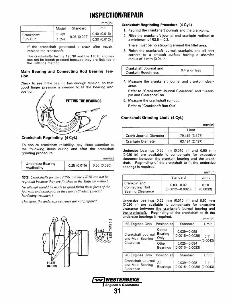
Model Standard Limit
Crankshaft 6 Cyl. I 0.05 (0.002)
0.40 (0.016)
Run-Out 4 Cyl. 0.30 (0.012)
If the crankshaft generated a· crack after repair, replace the crankshaft.
The crankshafts for the 120N6 and the 170T6·engines can not be bench pressed because they are finished in the Tufftride method.
Main Bearing and Connecting Rod Bearing Tension
Check to see if the bearing has enough tension, so that good finger pressure is needed to fit the bearing into position.
FITTING THE BEARINGS
Crankshaft Regrinding (4 Cyl.)
To ensure crankshaft reliability, pay close attention to the following items during and after the crankshaft grinding procedure.
mm(in)
Undersize Bearing Availability
0.25 (0.01 0) 0.50 (0.020)
Note: Crankshafts for the 120N6 and the 170T6 can not be reground because they are finished in the Tufftride method.
No attempt should be made to grind finish these faces of the journals and crankpins as they are Tufftrided. (special hardening treatment).
Therefore, the undersize bearings are not prepared.
31
Crankshaft Regrinding Procedure (4 Cyl.) 1. Regrind the crankshaft journals and the crankpins.
2. Fillet the crankshaft journal and crankpin radious to a minimum of R3.5 ± 0.2.
There must be no stepping around the fillet area.
3. Finish the crankshaft journal, crankpin, and oil port corners to a smooth surface having a chamfer radius of 1 mm (0.04 in).
Crankshaft Journal and Crankpin Roughness
0.4 fl. or less
4. Measure the crankshaft journal and crankpin clearance.
Refer to "Crankshaft Journal Clearance" and "Crankpin and Clearance': on
5. Measure the crankshaft run-out.
Refer to "Crankshaft Run-Out':
Crankshaft Grinding Limit (4 Cyl.)
mm(in)
Limit
Crank Journal Diameter 79.419 (3.127)
Crankpin Diameter 63.424 (2.497)
Undersize bearings 0.25 mm (0.01 0 in) and 0.50 mm (0.020 in) are available to compensate for excessive clearance between the crankpin bearing and the crankshaft. Regrinding of the crankshaft to fit the undersize bearings is required.
mm(in)
Standard Limit
Crankpin and 0.03-0.07 0.10 Connecting Rod (0.0012-0.0028) (0.0039) Bearing Clearance
Undersize bearings 0.25 mm (0.01 0 in) and 0.50 mm (0.020 in) are available to compensate for excessive clearance between the crankshaft journal bearing and the crankshaft. Regrinding of the crankshaft to fit the undersize bearings is required. (" ) mm 1n
6B Engines Only Position at Standard Limit
Center 0.039-0.098
Crankshaft Journal Bearing (0.0015-0.0039) 0.11 and Main Bearing Only Clearance Other 0.025-0.084
(0.0043)
Bearings (0.001 0-0.0033)
4B Engines Only I Position at Standard Limit
Cranks~aft Jou_rnall All T 0.039-0.098 0.11 ~~d Mam Beanng I Bearings I (0.0015-0.0039) I (0.0043)
earance

INSPECTION/REPAIR Plastigage Clearance Measurements
This is another method to measure the crankjournal bearing clearance.
Crankshaft Journal Bearing Clearance
1. Clean the cylinder body, the journal bearing fitting portions, the bearing cap, and the inside and outside surfaces of the bearing.
2. Install the new journal bearing to the cylinder body.
3. Carefully place the crankshaft on the bearing.
4. Rotate the crankshaft approximately 30° to seat the bearing.
5. Place the Plastigage (arrow) over the crankshaft journal across the full width of the bearing.
Apply engine oil to the Plastigage to keep it from falling.
/PLASTIGAGE
0 0 0 0
6. Install the bearing cap with the bearing.
7. Tighten the bearing cap to the specified torque.
Do not allow the crankshaft to turn during bearing cap installation and tightening.
PLASTIGAGE SCALE
Crankshaft Pin Bearing Clearance
1. Clean the crankshaft, the connecting rod, the bearing cap, and the bearings.
2. Install the bearing to the connecting rod.
Do not allow the crankshaft to move when installing the bearing cap.
3. Hold the connecting rod (with the bearing installed) against the crankshaft pin.
4. Attach the plastigage to the crankshaft pin.
Apply engine oil to the plastigage to keep it from falling.
5. Install the connecting rod bearing cap and tighten it to the specified torque.
Do not allow the connecting rod to move when installing and tightening the bearing cap.
6. Remove the bearing cap.
7. Compare the width of the plastigage attached to either the crankshaft or the bearing against the scale printed on the plastigage container.
If the measured value exceeds the limit, perform the following additional steps.
TIGHTEN THE BEARING CAP 1) Use a micrometer to measure the crankshaft outside diameter.
8. Remove the bearing cap.
9. Compare the width of the plastigage attached to either the crankshaft or the bearing against the scale printed on the plastigage container.
If the measured value exceeds the limit, perform the following additional steps.
1) Use a micrometer to measure the crankshaft outside diameter.
2) Use an inside dial indicator to measure the bearing inside diameter.
3) Replace the crankshaft and/or the bearing if the r11Pnsurerl vnlue(s) exceerl the limit
32
2) Use an inside dial indicator to measure the bearing inside diameter.
3) Replace the crankshaft and/or the bearing if the measured value(s) exceed the limit.

INSPECTION/REPAIR Crankshaft Tufftriding Inspection (6 Cyl.)
Inspection Model 120N_6 and 170T6
1. Use an organic cleaner to thoroughly clean the crankshaft. There must be no traces of oil on the surfaces to be inspected.
2. Prepare a 10% solution of ammonium cuprous chloride (dissolved in distilled water).
3. Use a spot glass rod to apply the solution to the surface to be inspected.
Hold the surface to be inspected perfectly horizontal to prevent the solution from running.
Note: Do not allow the solution to come in contact with the oil ports and their surrounding area.
AMMONIUM CUPROUS CHLORIDE
FACE IN CONTACT WITH CRANKPIN OR JOURNAL
Judgement
1. Wait for thirty to forty seconds.
TEST LIQUID SHOULD NOT BE APPLIED NEAR THE OIL PORT
I
If there is no discoloration after thirty or forty seconds, the crankshaft is useable.
If discoloration appears (the surface being tested will become the color of copper), the crankshaft must be replaced.
2. Clean the surface being tested with clean water of steam immediately after completing the test.
Note: The ammonium cuprous chloride solution is highly corrosive. Because of this, it is imperative that the suifaces being tested be cleaned immediately after completing the test.
33
Oil Seal Wear Ring Replacement (6 cyl.)
Removal
Use the oil seal wear ring remover to remove the oil seal wear ring from the crankshaft front end.
Oil Seal Wear Ring Remover:
OIL SEAL WEAR RING REMOVER
Installation
Use a brass bar and a hammer to drive the oil seal wear ring into place.
0 ('7o _ o{ol,..J\_ o ____) ~~"1
Crankshaft Gear Inspection
Visually inspect the crankshaft gear.
Replace the crankshaft gear if excessive wear or damage is discovered. I
Removal
Use the crankshaft gear remover to remove the crankshaft gear.
Crankshaft Gear Remover: 9-8521-0141-0

INSPECTION/REPAIR
Installation
Use the crankshaft gear installer to install the crankshaft gear.
FL VWHEEL AND FL VWHEEL HOUSING (REAR OIL SEAL)
Ring Gear Inspection
Inspect the ring gear.
If the ring gear teeth are broken or excessively worn, the ring gear must be replaced.
REMOVING THE RING GEAR
Ring Gear Removal
Strike around the edges of the ring gear with a hammer and chisel to remove it.
Ring Gear Installation
1. Heat the ring gear evenly with a gas burner to invite thermal expansion.
Do not allow the temperature of the ring gear to exceed 200"C (390"F).
2. Use a hammer to install the ring gear when it is sufficiently heated.
34
Flywheel Housing 9il Seal Replacement
Removal
Use a pry bar to remove the flywheel housing oil seal.
Installation
Use the oil seal installer to install the flywheel housing oil seal.
INSTALLING THE OIL SEALER
TIMING GEAR CASE COVER
Crankshaft Front Oil Seal Replacement
Removal
Use an adapter and a hammer to remove the crank front end oil seal.
Installation
Use the crankshaft front oil seal installer to instal crankshaft front oil seal.
INSTALLING FRONT OIL SEAL

ASSEMBLY
PISTON/CONNECTING ROD ASSEMBLY
2 CONNECTING ROD
5 CONNECTING
ROO BEARING~ ~ :
~~ ~
1 PISTON
NUMBERS INDICATE THE SUGGESTED ORDER OF
ASSEMBLY
PISTON AND CONNECTING ROD
Important Operations
1. Piston
Use a piston heater to heat the pistons to approximately so·c (140.F).
2. Connecting Rod
1) Install the connecting rod to the piston with setting the marks as·illustrated.
2) Install the piston pin into the piston and the connecting rod bushing.
3. Piston Pin Snap Ring
PISTON HEAD
FRONT MARK@
USING A PISTON HEATER
1) Use a pair of snap r!ng pliers to install the piston pin snap ring.
2) Check that the piston moves smoothly on the piston pin.
35
SNAP RING PLIERS
4. Piston Ring
1) Use a piston ring installer to install the three piston rings.
Install the piston rings in the following order.
(1) Oil ring (2) 2nd compression ring (3) 1st compression ring
The marked side of the two compression rings must be facing up.
The undercut side of the second compression ring will be facing down.
As the oil ring has no any facing mark, it may face in either direction.
2) Lubricate the piston ring surfaces with engine oil.
3) Check that the piston rings rotate smoothly in the piston ring grooves.
PISTON
PISTON RINGS
5. Connecting Rod Bearing
1) Install the connecting rod bearings to .the connecting rod large-end and the connecting rod cap.
2) Install the bearing cap to the connecting rod with semi-tightening the cap bolts.
3) Lubricate the bearing with engine oil.

6 SPRING SEAT ~ (SPLIT COLLAR) /T
5 SPRING SEAT
ASSEMBLY UPPER
41NTAKE/EXHAUST ----c~~ 1 Q INTAKE MANIFOLD 1 VALVE STEM
?THERMOSTAT_ HOUSING & GASKET
8 THERMOSTAT
SPRINGS
3 SPRING SEAT (LOWER)
~OIL SEAL
~ 01/>'!---~ · 'J INTAKE AND 6 EXHAUST VALVES Important Operations
1. Valve Stem Oil Seal
1) Lubricate the oil seals and valve stem sealing area with engine oil.
2) Use a valve stem oil seal installer to install the oil seal.
CYLINDER HEAD ASSEMBLY
EXHAUST MANIFOLD AND GASKET
4 Cyl.
3. Intake and Exhaust Valve Springs
2. Intake and Exhaust Valves 1) Place the cylinder head on a flat wooden sur
face.
2) Lubricate valve stems with engine oil.
3) Install the valves to the intake or exhaust guides.
Install the valves to their original lapped valve seats
36
Install the valve springs with their painted end (the close pitched end) facing down.
PAINTED PORTION

ASSEMBLY
SPRING COMPRESSOR
Use a spring compressor to push the valve spring into position.
2) Install the spring seat split collar.
3) $et the spring seat split collar by tapping lightly around the head of the collar with a rubber hammer.
SETTING THE SPRING SEAT SPLIT COLLAR
5. Intake Manifold and Gasket
1) Install the intake manifold gasket.
The intake manifold gasket must be installed with its unchamfered corner facing up and to the front of the engine.
¢::JREAR UNCHAMFERED CORNER
2) Install the intake manifold.
3) Tighten the intake manifold bolts to the specified torque a little at a time in the numerical order shown in the illustration.
Intake Manifold Bolt Torque
kg.m(lb.ft)
2.6 ± 0.5 (1 8.8 ± 3.6)
TORQUE ORDER
6. Exhaust Manifold and Gasket 1) Install the exhaust manifold gasket.
The 'TOP" mark must be facing up.
4 CYL. AND 6 CYL. USE DIFFERENT MANIFOLD GASKETS. 6CYL. SHOWN
2) Install the exhaust manifold.
3) Tighten· the exhaust manifold bolts to the specified torque a little at a time in the numerical order shown in the illustration.
Exhaust Manifold Bolt Torque
SIX CYL.
kg.m(lb.ft)
2.9 ± 0.5 (21 .0 ± 3.6)
G~- --l 111
1
I 19 \....____
37
I 12 1
----"

ASSEMBLY
5 CRANKSHAFT ~ THE ROCKER ARM MUST BE INSTALLED WITH THE OIL PARTS FACING UP.
BEARING (LOWER) AND BEARING CAP~~
NUMBERS INDICATE SUGGESTED ASSEMBLY SEQUENCE ~ ~ ~;,o..._.....~ ....... ~ .....,,_.,__
2 OIL PUMP AND COUPLING
14 OIL PAN (NOT SHOWN)
8CAMSHAFT
1 OIL COOLER
1 OIL JET
' ~
MAJOR COMPONENT REASSEMBLY STEPS
Important Operations
1. Oil Jet (6 Cyl. Turbo)
Install the oil jets taking care not to damage the oil jet nozzles.
kg-m(lb.ft)
Oil Jet Torque 2.1 ± o.5 (15.2 ± 3.6) 1
2. Crankshaft Bearing (Upper Half)
3. Crankshaft Bearing (lower Half) and Crankshaft Bearing Cap
The Crankshaft Bearing Configulation
With Oil Groove Without Oil Groove
Bearing Upper 4 All Upper Halves -Half 6 All Upper Halves -
All Lower Halves Center Bearing Bearing Lower 4 Except Center Only Half Bearing
-
6 - All Lower Halves --- --- -·-. -·-·---·
Take care not to misinstall the bearing halves.
38
WITH OIL HOLE
~DJJ)
~NQ OIL GROOVE AND HOLE (LOWER)
4. Crankshaft
Crankshaft counterweight size will vary from engine to engine. Check your Parts Catalog Part Number listing to determine crankshaft counterweight size for your engine.
5. Thrust Bearing
Install the thrust bearings with the oil groove side facing the crankshaft sliding face.

ASSEMBLY
6. Crankshaft Bearing Cap
1) Lubricate the bearing cap bolts with engine oil.
2) Install the bearing caps to the crankshaft.
The arrow mark must be pointing to the front of the engine.
3) Tighten the bearing cap bolts to the specified torque a little at a time in the numerical order shown in the illustration.
Crankshaft Bearing Cap Bolt Torque
kg-m(lb.ft)
24.0 ± 1 (173.5 ± 7.2)
4) Check that the crankshaft turns smoothly by manually rotating it.
7. Timing Gear Case
1) Apply liquid gasket to the timing gear case surfaces contacting the cylinder body.
2) Tighten the timing gear case bolts to the specified torque.
kg-m(lb.ft)
8. Camshaft
Tighten the thrust plate bolts through the camshaft gear hole.
Thrust Plate Bolt Torque
Camshaft Gear Bolt Torque
kg.m(lb.ft)
2.6 ± o.5 (18.8 ± 3.6) 1
kg-m(lb.ft)
9. Idler Gear Shaft
Use the thrust collar fixing bolt as a guide to install the idler gear shaft.
The oil port must be facing the camshaft.
1 0. Idler Gear
1) Install the idler gear.
Set the timing marks [A] and [B] as shown in the illustration.
2) Tighten the idler gear bolts seating the thrust collar to the specified torque.
The thrust collar must be installed with the chamfered side facing the front of the engine.
kg-m(lb.ft)
Idler Gear Bolt Torque 5.5 ± 1 (39.8 ± 7.2) I IDLER GEAR B-MARK
INJECTION PUMP GEAR
C-MARK
39
CAMSHAFT GEAR

ASSEMBLY 11. Piston and Connecting Rod
Position the piston ring gaps as shown in the illustration.
1) Set the piston ring gaps as shown in the illustration.
2) Lubricate the piston, the piston rings, and the connecting rod bearings with engine oil.
3) Position the piston front mark towards the front of the engine.
PISTON RING ALIGNMENT
4) Use the piston ring compressor to compress the piston rings.
FRONT MARK
5) Use a hammer grip to push the piston in until it makes contact with the crankpin.
At the same time, rotate the crankshaft until the crankpin reaches its highest point.
· 6) Set the bearing cap cylinder number marks and the connecting rod cylinder number marks.
The marks must be facing the exhaust manifold.
CYLINDER NUMBERS
REFER TO THE "ANGULAR TIGHTENING METHOD."
40
7) Lubricate the connecting rod cap bolt threads and setting faces with Mos. grease.
8) Use the angular tightening method to tighten the connecting rod cap bolts to the specified torque.
kg-m(lb ft)
1st step 2nd step
Connecting Rod Bolt Torque 4 6Qo+3g: and Angle (28.9)
12. Oil Pump and Coupling
1) Lubricate the oil pump with the specified grade of engine oil.
2) Install the oil pump with the coupling.
3) Tighten the oil pump bolts to the specified torque.
kg-m(lb.ft)
Oil Pump Bolt Torque 5.3 ± 1.0 (38.3 ± 7.2) 1
13. Flywheel Housing
1) Apply a liquid gasket to the shaded area of the illustration.
2) Install the flywheel housing.
Tighten the flywheel housing bolts to the speicfied torque.
kg-m(lb ft)
Flywheel Housing Outer Bolt 16.1 ± 1 (115.7 ± 7.2) Bolt Torque Inner Bolt 2.6 ± 0.5 (18.8 ± 3.6)
FLYWHEEL HOUSING

ASSEMBLY 14. Oil Pan
1) Apply liquid gasket to the areas indicated by the arrows in the illustration.
2) Install the oil pan gasket.
3) Install the oil pan.
Tighten the oil pan bolts to the specified torque.
kg-m(lb.ft)
Oil Pan Bolt Torque 2.6 ± 0.5 (18.5 ± 3.6) I
APPLY LIQUID GASKET
~~~~~~~
MAJOR COMPONENT REASSEMBL V
Important Operations
1. Flywheel
1) Lublicate the flywheel bolt threads.
2) Install the flywheel.
The crankshaft rear end dowel pin and the flywheel dowel hole must be aligned.
3) Tighten the flywheel bolts to the specified torque in the numerical order shown in the illustration.
Flywheel Bolt Torque
kg-m(lb.ft)
16 ± 1.5 (115.7 ± 10.8)
22.3 ± 2.2 (1 61 .2 ± 1 5.9)
LUBRICATE WITH ENGINE OIL
15. Oil Cooler
1) Apply liquid gasket to the oil cooler gasket.
2) Install the oil cooler gasket to the oil cooler body case.
3) Install the oil cooler.
Tighten the oil cooler bolts to the specified torque.
Start from the middle and work out to either side.
Oil Cooler Torque
OIL COOLER ASSEMBLY
0 s._
~1 BY-PASS VALVE, 0-RING, SPRING AND PLUG
OIL COOLER BOLT TORQUE SEQUENCE
41
2. Injection Pump and Injection Pump Gear Assembly
1) Install the injection pump bracket with the injection pump to the timing gear case.
Dowel the injection pump bracket with the timing gear case.
2) Tighten the injection pump bolts to the specified torque.
kg·m(lb.ft) jlnjection Pump Bolt Torque I 2.6 ± 0.5 (18.8 ± 3.6) I
3) Align the injection pump gear "C" timing mark with the idler gear "C" timing mark.
INJECTION~ PUMP

ASSEMBLY
3. Crankshaft Pulley Nut a) Apply MoS2 to the crankshaft pulley nut threads
and fitting face. b) Use the appropriate wrench to tighten the
crankshaft pulley nut to the specified torque.
CRANKSHAFT PULLEY NUT TORQUE (4B SERIES) (6B SERIES)
4. Tappet Chamber Cover
Kg-m (lb·ft) 44.0 ± 5.0 (318.1 ± 36.2)
44.0 ± 5.0 (318.1 ± 36.2)
SOCKET WRENCH
a) Apply liquid gasket to the tappet chamber cover gasket.
b) Install the tappet chamber cover and tighten the bolts to the specified torque.
Kg-m {lb·H) TAPPET CHAMBER COVER 2.6 ± 0.5 (18.8 ± 3.6) BOLT TORQUE
5. Water Pump
TAPPET CHAMBER COVER
NOTE: Refer to the Coolant Pump section in this manual for details of the water pump.
6. Cylinder Head, Gasket, and Bolts
a) Carefully place the cylinder head gasket on the cylinder body upper surface. The gasket "TOP" mark must be facing up.
b) Align the cylinder body dowels and the cylinder head dowel holes.
TOP MARK
¢:::J FRONT
c) Carefully place the cylinder head on the cylinder body.
d) Tighten the cylinder head bolt as follows:
... FRONT
1. As cylinder head bolts l:lave two kinds of length, install them at the proper location. (The shorter ones 4 cyl. series: 4 bolts, 6 cyl. series; 6 bolts) must be used at the injection pump side.
2. Follow the numerical sequence shown in the illustrations.
TORQUE SEQUENCE
3. The cylinder head bolt tightening method vary depending on the gasket type to be used.
Engines & Generators
42

INJECTION PUMP v DRIVING
± ±
For laminated steel type gasket.
ASSEMBLY
• 14 ROCKER ARM
13PUSH RODS
Apply molybdenum disulfide grease to the cylinder head bolt threads and setting faces.
Use the Angular Tightening Method.
ASSEMBLY I
kg.m(lb.ft)
1st step 2nd step 3rd step
Bolt Torque 7.0 (50.6) 9.0±0ꞏ5 (65.1±3•6) 90.+3g:
For steel-sandwich gasket.
Apply engine oil to the cylinder head bolt threads and setting faces.
kg.m(lb.ft)
.
@ 7DIL PUMP
WITH GEAR u PINION
7. Rocker Arm and Rocker Arm Shaft
1) Check that the rocker arm shaft bracket lower surface oil port is free from obstruction.
2) Install the rocker arm shaft with the bracket to the ꞏcylinder head.
3) Tighten the rocker arm bracket bolts to the specified torque a little at a time in the numeri- cal order shown in the illustration.
4) Lubricate the rocker arm and the rocker arm shaft with engine oil.
kg.m(lb.ft) Rocker Arm Shaft Bracket
Bolt Torque 3.1 0.5 (22.4 3.6)
13
8TAPPET CHAMBER COVER
@(i'
@
2 3
ROCKER ARM . ASSEMBLY
4 NUMBERS INDICATE SUGGESTED ASSEMBLY SEQUENCE
2 3 5) Adjust the valve clearance. Refer to MAINTENANCE for the valve clearance
ROCKER ARM SHAFT
THE ROCKER ARM MUST BE INSTALLED WITH THE OIL PARTS FACING UP. 3 ROCKER ARMS
adjustment procedure.
NUMBERS INDICATE SUGGESTED ASSEMBLY SEQUENCE Engines & Generators
43
=/
1st step 2nd step
Bolt Torque
7.0 (50.6)
New bolt
9.5±0.5 (68.6±3.6)
Reused bolt 11.5±0ꞏ5 (83.1±3•6)

ASSEMBLY 1. Cylinder Head Cover
1) Check that the rocker arms, the rocker arm shafts, and the valve springs are thoroughly lubricated with engine oil.
If required, relubricate these parts.
2) Place the cylinder head cover gasket on the cylinder head cover.
Check the head cover gasket for looseness.
3) Tighten the cylinder head cover bolts to the specified torque a little at a time in the sequence shown in the illustration.
6 CYL.
Cylinder Head Cover Bolt Torque
4 CYL.
Cylinder Head Cover Bolt Torque
e e 1==1 1 2
6 CYLINDER
CYLINDER HEAD COVERS
2. Starter
kg-m(lb.ft)
2.1 ± 0.5 (15.2 ± 3.6)
kg-m(lb.ft)
1.1 ± 0.5 (7.9 ± 3.6)
4 CYLINDER
Install the starter to the flywheel housing and tighten the bolts to the specified torque.
Starter Fixing Bolts Torque
DRIVE BELT Adjust the drive belt tension.
kg.m(lb.ft)
8.4 (60.7)
Refer to MAINTENANCE for the drive belt tension adjustment.
44
3. Oil Filter Assembly 1) Before the installation, set the special gaskets
which are included within the repair kit with the two oil filter mounting bolts.
2) Apply a coat of LOCTITE 271 on the bolt threads to seal the bolts from the crankcase as illustrated.
3) Install the oil filter assembly and tighten the bolts securely.
Oil Filter Assembly Mounting Bolt Torque
4. Injection Nozzle
kg-m(lb.ft)
Install the injection nozzles with the injection nozzle gaskets.
Be careful! not to damage the nozzle tips.
kg-m(lb.ft)
5. Fuel Injection Pipe and Fuel Leak Off Pipe
1) Install the fuel injection pipes ® and tighten the bolts to the specified torque.
kg-m(lb.ft)
Injection Pipe Torque 3.1 ± o.2 (22.4 ± 1.5) 1
2) Carefully position and set the clips (D It is very important that each clip be positioned correctly.
An improperly positioned clip will result in objectionable fuel pulsing noise and injection pipe breakage.
3) Install the fuel leak off pipes@

ASSEMBLY
6. Fuel Pipe (Feed Pump to Fuel Filter). 7. Fuel Pipe (Fuel Filter to Injection Pump). 8. Fuel Return Pipe.
Install the fuel pipes and tighten the fuel pipe joint bolts to the specified torque. Take care not to interchange the check valves and joint bolts.
Kg-m (lb-ft)
I FUEL PIPE JOINT BOLT TORQUE 1.7 ± 0.1 (12.3 ± 0.7)
9. Intake Pipe. Install the intake pipe and tighten the intake pipe flange bolts to the specified torque.
Kg-m (lb-H)
INTAKE PIPE FLANGE BOLT TORQUE 1.7±0.1 (12.3±0.7)
1 O.lnstall the Thermostat and Thermostat Housing. a. Inspect the thermostat housing and the housing
gasket. Apply some sealant to the gasket when reassembling.
b. Install the temperature switch and sender and reconnect their wires.
11.1nstall the Oil and Water Sender and Switch. 12.1nstall the Starter Motor. 13.1nstall the Breaker Panel and the Preheat
Solenoid. 14. Reinstall the Engine Electrical harness. 15. Mount the complete Exhaust Manifold and the
Expansion Tank to the Cylinder Head.
EXHAUST MANIFOLD/HEAT EXCHANGER The exhaust manifold, which was disassembled from the cylinder head, should be inspected before reassembly. a. Remove the exhaust elbows from the lower surface
of the manifold. Clean and inspect for cracks and defects. Replace as needed.
b. Remove the exhaust nipples, elbows and plugs from the manifold and heat exchanger.
c. Remove water connectors from the ends of the manifold. Be sure to note the proper location and arrangement of each for proper alignment.
d. Examine all parts for defects, corrosion and wear and replace as needed.
e. Flush out the manifolds interior with a liquid cleaner and rinse thoroughly with fresh water.
f.Use a pipe cleaner to clear the passage that connects the coolant recovery tank tubing.
g. Flush out the coolant recovery tank and its connecting tube.
h. Replace the heat exchanger zinc. i.lnstall new hose connections and clamps for the cool
ing system.
16.Aiternator installation. a. Put the alternator in position. Install the adjusting bolt in position to hold the alternator in position. b. Put the belt in position on the pulley. Move the alternator away from the engine to make an adjustment to the belt. c. Tighten the bolts. d. Make sure the tension of the belt is correct, about 1/2" deflection at the center with pressure.
MARINE TRANSMISSION 1. Assemble the damper plate to the flywheel.
2. Reinstall the marine transmission and fill with ATF Dextron Ill.
NOTE: Some transmissions, such as the Borg Warner Velvet Drive require oil coolers. Oil coolers should be cleaned, pressure tested and repainted at engine overhaul. The transmission oil cooler hoses should also be inspected. Refer to the text on Heat Exchangers.
3. Fill the engine cooling system with antifreeze mixture and the engine oil sump with lube oil (A.P.I. spec. CF or CG-4). The engine should, be test run under load prior to reinstalling. At this time readjust the valve clearances on the hot engine.
Allow the engine to cool to room temperature and retorque the cylinder head bolts and re-check the valve clearances. See ENGINE ADJUSTMENTS.
GENERATOR 1. Mount the generator back end assembly with its
control panel. Reconnect all DC wiring and reconnect all AC connections.
A CAUTION: Check all AC and DC wiring connections to WESTERBEKE wiring schematics and diagrams.
2. Fill the engine cooling system with antifreeze mixture and the engine oil sump with lube oil (A.P.I. spec. CF or CG-4). The engine should be test run under load prior to reinstalling. At this time readjust the valve clearances on the hot engine.
Allow the engine to cool to room temperature and retorque the cylinder head bolts and re-check the valve clearances.See ENGINE ADJUSTMENTS.
Engines & Generators
45

ASSEMBLY
ENGINE TUNING OPERATION After reassembly, the engine must be tuned. This will ensure that the engine operates at its maximum efficiency. 1. Mount the engine on a test bench. 2. Connect the electrical wiring. Refer to the WIRING
DIAGRAM. 3. Connect the air intake line to the air cleaner. 4. Connect the exhaust pipe. 5. Manually operate the fuel feed pump to feed fuel
to the engine. 6. Bleed the fuel lines of air. 7. Crank the engine with the starter (non-ignition
operation) for about twenty seconds. This will pre-lubricate the engine internal components.
8. Start the engine and allow it to run at 750 to 800 rpm for five minutes.
9. Remove the cylinder head cover while the engine is running.
10.Check that the engine oil is continuously circulating from the oil pump to the valve rockers through the cylinder head. If there is no oil circulation or if the oil circulation is sluggish, stop the engine and make the appropriate repairs or adjustments. Reinstall the cylinder head cover.
11.1ncrease the engine speed to 1500 rpm to do the engine warming-up operation.
12. Check the engine for oil, fuel, coolant, and air intake leakage.
13. Check for abnormal noise and odor. 14.Check for abnormal electrical charging. 15. Check the engine fastening parts for looseness. 16 When the engine coolant temperature reaches
75°C (167°F) or more, increase the engine speed to 2000 rpm and allow it to run for twenty seconds. This will give the engine the essential run-in operating time.
17.Adjust the engine operation speed to the specified value. .
18.Stop the engine to complete the tuning procedure.
Refer to the following pages for details of sub-assemblies. These sections also !nclude: Wiring D!agrams •. Engine/Generator Specifications, Torque Diagrams, Generator Data, and a detailed Troubleshootmg Sectton.
Engines & Generators
46

LUBRICATING SYSTEM OIL SYSTEM FLOW DIAGRAM
Full flow filter
_____________ _)
OIL PUMP THIS GEAR TYPE OIL PUMP IS DRIVEN BY THE CAMSHAFT OIL PUMP DRIVE
NUMBERS INDICATE SUGGESTED ORDER OF DISASSEMBLY
4DRIVEN GEAR
6 DRIVEN GEAR SHAFT-----~~~
2 SUCTION PIPE .
Valve opening pressure 2kg/cm 2
6BD1·T only r-- --, I I 1 Partial 1
filter I Valve opening I pressure 4.5kg/cm 2
LL_-_-,-_-_-'_ J
Oil pan
DRIVE SHAFT & GEAR
Oil pressure and oil filter
warning light Battery
~111----1~ TURBOONLY
Oil pressure switch __ _::=-___ j_ _____ _ ~--~----------------r-------~1
I ~----.----.----.----,-;--~---.--~,
L----------
Visually inspect the disassembled parts for excessive wear and damage.
Oil Pump Drive Gear
Use a feeler gauge to measure the clearance between the oil pump cover (oil pump case) inside surface and the drive gear.
If the clearance exceeds the specified limit, the. drive gear and/or the oil pump cover must be replaced.
Oil Pump Cover and Oil Pump Drive Gear Clearance
OIL PUMP COVER
mm(in)
Limit
0.18 (0.0071)
Make the necessary adjustments, repairs, and parts replacements if excessive wear or damage is indicated.
47

LUBRICATING SYSTEM
OIL PUMP BODY
STRAIGHTEDGE
Oil Pump Driven Gear
Use a feeler gauge to measure the clearance between the oil pump case cover inside surface and the driven gear.
If the clearance exceeds the specified limit, the driven gear or the oil pump cover must be replaced.
mm(in)
Limit
Oil Pump Body and Driven Gear Clearance ------
SPIN ON OIL FILTER~
0-RING
DRAIN
Cartridge (Spin-On) Type
Removal
Remover and Installer: Filter Wrench
1. Loosen the used oil filter by turning it counterclockwise with the filter wrench.
2. Discard the used oil filter.
Installation
1. Wipe the oil filter mounting face with a clean rag.
This will allow the new oil filter to seat properly.
2. Lightly oil the 0-ring.
3. Turn in the new oil filter until the sealing face is fitted against the 0-ring.
4. Use the filter wrench to turn in the oil filter an additional 3/4 of a turn or one turn.
5. Check the engine oil level and replenish to the specified level if required.
6. Start the engine and check for oil leakage from the oil filter.
1 ELEMENT
OIL COOLER NUMBERS INDICATE THE ORDER OF ASSEMBLY
INSPECT AND MAKE ALL NECESSARY REPAIRS AND . REPLACEMENTS
Install the oil cooler element to the oil cooler and tighten the cooler element fixing nuts to the ~pecified torque.
Oil Cooler Element Fixing Nut Torque
kg.m(lb.tt)
2.6 ± 0.5 (1 8.8 ± 3.6)
CHANGING THE OIL
48

COOLING SYSTEM
1 COOLANT PUMP PULLEY
COOLANT PUMP DISASSEMBLY
1. Impeller
Use the remover to remove the impeller.
2.
NUMBERS INDICATE ORDER OF DISASSEMBLY
PUMP BODY
2 COVER AND GASKET
f\
31MPELLER
3. Snap Ring
Use a p.,ir of snap· _ring pliers to remove the snap ring.
4. Spindle, Bearing, and Spacer
Use a bench press and a suitable remover to remove the spindle, bearing, and spacer.
Use a bench press and a ·suitable rod to remove the pulley center.
PULLEY CENTER
v I I I v
49
5. Seal Unit, Washer and Seal
Use a suitable remover to remove the seal unit, the washer, and the seal.

COOLING SYSTEM INSPECTION AND REPAIR
Make the necessary adjustments, repairs, and parts replacements if excessive wear or damage is discovered during inspection.
6. Bearing Replacement
Removal:
REMOVING THE BEARINGS AND SPACER
Use a bench press to remove two bearings and the spacer.
Installation:
Use a bench press to install two bearings and the spacer.
Use a micrometer to check the fitness at the three points shown in the illustrations.
ASSEMBLY
7. Spindle, Bearing, and Spacer
Lubricate the bearing with multipurpose grease.
Use a bench press to install the spindle, the bearing and the spacer.
SEALED SIDE OUTWARD.
LARGE BEARING
8. Snap Ring
Use a pair of snap ring pliers to install the snap ring.
9. Pulley Center
Use a bench press and a bar to install the pulley center.
PRESS & BAR
mm(in)
Shaft to Pulley Center 0.02- 0.06 Fitness (0.0008 - 0.0024)
Fitness Shaft to Impeller 0.07- 0.11 Fitness (0.0028 - 0.0043)
Pulley Center to Pulley 0.14 (0.0055) Fitness or less
SHAFT
({~) IMPELLER
@ PULLEY CENTER PULLEY
@ @ TAKING MEASUREMENTS
10. Seal Unit. Washer and Seal
50
1) Apply a thin coat of liquid gasket to the seal unit outer periphery before installation.
2) Use a bench press and a bar to install the seal unit into the pump body.

COOLING SYSTEM 11. Impeller
1) Use a bench press to install the impeller to the spindle.
2) Use a feeler gauge to measure the clearance between the impeller and the pump body.
Clearance between Impeller and Pump Body
mm(in)
0.3-0.8 (0.0118-0.0315)
\( 12. Pulley 11
Install the pulley and tighten the pulley bolts to the specified torque.
Pulley Fixing Bolts Torque
INSTALLING THE PULLEY
THERMOSTAT
HEAT EXCHANGER The heat exchanger should be inspected and serviced during an engine overhaul.
1. Disconnect the hoses and remove the hoses fittings, drain plug and zinc anode. Also, remove the end fittings and gaskets.
2. Inspect the tube (casing) for wear and dents, if at all suspect replace the heat exchanger.
3. Clean out any zinc debris and pressure test the coolant and raw water passages.
4. When reassembling, install new gaskets and 0-rings. Apply some lubricant to the new gaskets and to the fittings as you install them.
5. Install a new zinc anode.
Note: All of the above can be accomplished by sending the heat exchanger to a heat exchanger service shop. They will also service transmission and engine oil coolers.
6. Repaint the assembled heat exchanger with WESTERBEKE heat resistant spray enamel.
Disassemble and inspect both halves of the thermostat housing looking for cracks and deterioration, replace if necessary. Install a new thermostat and gasket.
ZINC ANODE
INSPECT THE THERMOSTAT HOUSINGS FOR CRACKS OR DAMAGE. INSTALL A NEW THERMOSTAT AND GASKET.
REPLACE GASKET
THE GASKET IS GROOVED AND FITS AROUND THE OUTER EDGE OF THE THERMOSTAT
ALSO SERVES AS A DRAIN FOR RAW WATER
51
DRIVE BELT
Adjustment
TO REMOVE HEAT EXCHANGER
1. Inspect the cooling fan drive belt for cracking and other damage. Replace if suspect.
2. Check the drive belt tension by exerting a force of 1 Okg (22 I b) midway between the pulley and the alternator pulley.
3. Adjust the belt tension by loosing the alternator mounting bolt and adjusting bolt and pivoting the alternator.
Be sure to retighten the bolts after adjusting the belt tension.

~~ te. iii
::.n~(l) ~:;~
~~ iill'll 0~ Ulh'j
WESTERBEKE RAW WATER PUMP #43514 COMPLETE OVERHAUL/PUMP REMOVED FROM ENGINE
DISASSEMBLY/REASSEMBLY and INSPECTION 1. Remove the cover and the sealing 0-ring. Inspect the 0-ring for re-use.
Inspect the cover shaft bushing for wear. Remove the impeller and inspect the impeller blades.
2. Remove the locknut, shaft key and drive gear (insert a metal rod 0.19" dia. thm the hole in the shaft to prevent the shaft from turning), using snap pliers, remove the snap ring.
3. Press out the shaft and bearing assembly from the housing, using an arbor press,. support the bearings inner race and drive the shaft out of the bearings. Remove and inspect the 0-rings.
4. Remove the shaft seal from the housing noting the facing position for reassembly.
5. Remove the cam screw and sealing washing and remove the cam.
NOTE: Inspect all parts for wear and corrosion and replace any parts that are suspect. 0-rings and seals should be replaced.
NOTE: The part number for the complete assembled pump
is 43514. The gear is not included.
The glycerine pack is
part number 48250.
0-RING 43568
\
KEY
~COVER 43509
-------LOCK WASHER 31780 SCREW 43672
CAP SCREW 43672
ASSEMBLY 1. Install the seal, cam, washer and screw into the housing. Apply blue Loctite
MM115 to the sealing washer and screw.
2. Install the three 0-rings and two woodruff keys on the shaft. Then slide the two bearings onto the shaft and install the shaft into the housing.
3. Install the snap ring, the gear, and locknut (do not tighten)
4. Apply glycerine to the seal and install it on the shaft - seating it into the housing.
5. Install the wear plate over the shaft aligned with the retaining pin.
6. Coat the blades of the impeller with glycerine and assemble it to the shaft aligning the key.
7. Assemble the 0-ring and cover coating each with glycerine and tighten the six cover screws.
8. Install the 0-ring on the gear end and tighten the locknut.
9. Pressure test the assembled pump at 15 psi.
BEARING 35972
APPLY BLUE LOCTITE TO SCREW AND WASHER
= ~ ~ .... m = ., = 3: .,
INSERT ROD TO HOLD SHAFT FROM
RNING
COVER-COAT~__¢-'~ BLADES WITH . SHAFT NU GLYCERINE ~ JniCTAJJ 1

TURBOCHARGER
TURBO CHARGER TO OIL SUMP --+ ...
Rotor Shaft Axial Play Measurement
1) Install a dial indicator on the turbine housing as illutrated.
2) Use the dial indicator to measure the rotor shaft axial play with moving the shaft push and pull. Read the total indicator reading (TIR).
mm(in)
Limit
Rotor Shaft Axial Play TIR 0.11 (0.0043)
3) If the measured value exceeds the specified limit the shaft must be replaced.
-----t~~~-PUSHAND PULL
t---
Rotor Shaft Radial Play Measurement
1) Turn over the turbocharger with the turbine exhaust inlet flange facing up.
2) Install a dial indicator to measure the rotor shaft radial play.
3) Use the dial indicator to measure play. Read the TIR.
mm(in)
(4 Cyl.) Limit
Rotor Shaft Radial Play TIR 0.19 (0.0075)
mm(in)
(6 Cyl.) Limit
Rotor Shaft Radial Play TIR 0.215 (0.0085)
4) If the measured value exceeds the specified limit, replace the shaft.
DIAL INDICATOR
MAGNET BASE
Turbocharger Mounting Flange Gasket
Carefully position the gasket with the edged side facing up.
Turbocharger
Semitighten the turbocharger mounting nuts.
The nuts will be fully tightened after installation of the oil pipes.
kg·m(lb.ft) Turbocharger Mounting Nut Torque
Oil Drain Pipe
1) Remove the exhaust manifold distance tube immediately beneath the turbocharger.
This will make it easier to install the oil drain pipe.
2) Install the oil drain pipe and tighten the oil drain pipe flange nuts to the specified torque.
kg.m(lb.ft)
Oil Drain Pipe Torque 3.8 ± 0.7 (27.5 ± 5.1) I 3) Reinstall the exhaust manifold distance tube_
Engines & Generators
53

TURBOCHARGER
Oil Feed Pipe 1) Pre-lubricate the turbocharger with engine oil
through the oil port shown in the illustration.
2) Install the oil feed pipe and tighten the pipe flange bolts to the specified torque.
Oil Feed Pipe Flange Bolt Torque
Turbo Adapter (6 cyl.)
kg.m(lb.ft)
2.6 ± 0.5 (18.8 ± 3.6)
1) Use a screw driver to insert the gas sealing ring to the turbocharger exhaust outlet port.
2) Tighten the turbo adaptor fixing bolts to the specified torque.
GAS SEALING RING
-
FIXING BOLTS
kg·m(lb.ft)
Turbo Adaptor Fixing Bolt Torque
5.3 ± 1.0 (38.3 ± 7.2)
CHECKING
1. Check the air intake duct connections for air leakage.
2. Check the intake manifold connections for air leakage.
3. Check the exhaust duct connections for smoke leakage.
4. Check the turbocharger mounting nuts for looseness.
5. Check the oil feed pipe for oil leakage.
6. Check the oil return pipe joints for oil leakage.
Kg-m (lb-11)
I OIL RETURN PIPE BOLTS TORQUE 2.1 ± 0.5 (15.2 ± 3.6)
54

ENGINE ADJUSTMENTS INJECTION TIMING ADJUSTMENT Bring No. 1 piston to the top dead center on the compression stroke. Turn the crankshaft pulley clockwise (viewed at engine front) and align the mark on the crankshaft pulley with the TDC mark.
Remove the access cover at the front of the injection pump and check the alignment between the pointer A on the injection pump gear lock plate and the projected pointer B on the timing gear case. If A and B are in alignment, the timing is set correctly.
If they are in alignment, No. 1 cylinder is at the TDC on the compression stroke. If it is in misalignment, recheck by turning the crankshaft pulley one more tum to repeat the procedure to make sure that it is in alignment.
Check the crankshaft position for the start of fuel injection.
1. Tum the crankshaft pulley counterclockwise viewed from the engine front about 30°.
2. Remove No. 1 high pressure injection line.
~!itr."""'f-- DELIVERY VALVE
3. Remove the injection pump No. 1 delivery valve holder, delivery valve and spring and reinstall the delivery valve holder back into the pump. DELIVERY VALVE HOLDER TIGHTENING TORQUE: 39- 44 Nm (4- 4.5 Kg-m/28.9- 32.5 tt-lb)
4. Hold the fuel control lever at the fully open position.
55
5. Slowly tum the crankshaft pulley clockwise and at the same time, feed fuel to the injection pump by slowly pumping the feed pump. When the fuel stops to flow out from No. 1 delivery valve holder, stop turning the crankshaft pulley and pumping. This is the beginning of fuel injection. ·
4 CYL. SHOWN
THE 6 CYL. HAS EIGHT TIMING NOTCH LINES PUNCHED ON THE GEAR CASE AND THE TDC MARK ON THE CRANK PULLEY
PULLEY MARK
6. Notice which injection timing mark is aligned with the pulley mark. The timing mark in alignment with the pulley mark indicates the degrees before (TDC), the start of fuel injection
7. Blow out the remaining fuel from"the delivery valve holder. Check that there is no fuel being delivered from the priming pump.
INJECTION TIMING BCTC (4 CYL.) 14 (4 CYL. TURBO) 12
INJECTION TIMING BTDC (6 CYL.) 12 (6 CYL. TURBO) 12

ENGINE ADJUSTMENTS ADJUSTMENT PROCEDURES 1. Align the pulley mark and the specified timing mark.
(Refer to the injection timing specifications.)
2. Loosen the four injection pump attachment nuts.
3. To advance the timing, pivot the injection pump at the pump drive shaft away from the engine.
To retard the timing, pivot the injection pump at the pump drive shaft toward the engine.
NOTE: A 1 mm misalignment between the timing marks on the crankshaft pulley will correspond to about 2° in crank angle.
4. Recheck the timing, following procedures 1 through 5.
5. Tighten the four injection pump attachment nuts.
6. Again remove No. 1 delivery valve holder, and reinstall the delivery valve, spring and the valve holder.
DELIVERY VALVE HOLDER TIGHTENING TORQUE: 39- 44 Nm (4- 4.5 Kg-m/28.9- 32.5 H-I b)
7. Reinstall the No. 1 high pressure injection line.
56
LOOSEN FOUR NUTS (BOTH SIDES)
TIMING GEAR CASE

ENGINE ADJUSTMENTS
TESTING ENGINE COMPRESSION Make certain the oil level (dipstick) is at the correct level and the air intake filter is clean. The battery and starter motor must also be in good condition.
1. Warm the engine to normal operating temperature.
2. Move the control lever to a position for shutting off the fuel. (Disconnect the wires if a fuel shutdown solenoid is used).
3. Remove all the glow plugs from the engine and install the compression gauge/adapter combination to the cylinder on which the compression is to be measured.
TESTING ENGINE COMPRESSION
4. Close the raw water seacock (thru-hull).
5. Crank the engine and allow the gauge to reach a maximum reading, then record that reading.
6. Repeat this process for each cylinder.
COMPRESSION PRESSURE 441 psi (31.0 Kg/em') at 200 rpm. ALLOWABLE LIMIT 370PSI (26.0 Kg/em').
MAXIMUM PERMISSIBLE DIFFERENCE BETWEEN CYLINDERS 28.44 psi (2.0 Kg/em')
NOTE: If the readings are below the limit, the en-gine needs an overhaul.
7. Re-install the glow plugs and reset the fuel shut-off to the run position.
8. Open the raw water seacock (thru-hull).
Low Compression When low compression is found, determine the cause by applying a small amount of oil in the cylinder thru the glow plug hole. Allow the oil to settle.
Install the pressure gauge and repeat the above test. If the compression reading rises dramatically, the fault is with the rings. If the compression valve does not rise, the problem is with the valves.
A slight rise in compression would indicate a problem with both the rings and the valves.
57
OIL PRESSURE The engine's oil pressure, during operation, is indicated by the oil pressure gauge on the instrument panel. During normal operation, the oil pressure will range between 40 and 60 psi (2.8 and 4.2 kg/cm2).
NOTE: A newly started, cold engine can have an oil pressure reading up to 60 psi (4.2 kglcm2). A warmed engine can have an oil pressure reading as low as 35 psi (2.5 kg/cm2). These readings will vary depending upon the temperature of the engine and the rpms.
Low Oil Pressure The specified safe minimum oil pressure is 5 - 10 psi. A gradual loss of oil pressure usually indicates a worn bearings. For additional information on low oil pressure readings, see the ENGINE TROUBLESHOOTING chart.
Testing Oil Pressure To test the oil pressure, remove the oil pressure sender, then install a mechanical oil pressure gauge in it's place. After warming up the engine, set the engine speed at idle and read the oil pressure gauge.
OIL PRESSURE 50 psi at 1800 rpm. SENDER AND SWITCH TORQUE 9 • 13 H·lb (1.2 • 1.8 m - kg).
Oil pressure at 1800 (or 1500) rpm should maintain a reading of 50 psi.
PREHEAT SOLENOID
I OIL PRESSURE SWITCH
2DA BREAKER

ENGINE ADJUSTMENTS VALVE CLEARANCE ADJUSTMENT NOTE: The cylinder head bolts have been tightened with the "Angular Tightening Method" shown in this manual. Therefore, it is not necessary to retighten the cylinder head bolts before adjust~ng the valve clearances. Chart shows six cylinder model
Cylinder No. 1 2 3 4 5 6
Valve arrangement I E I E I E I E I E I E
When No. 1 cylinder is at TDC in the 00 0 0 0 0 compression stroke
When No. 6 cylinder is at TDC in the 0 0 0 0 00 compression stroke
1. In order to bring No.1 or No.6 (six cyl.), No.4 piston (four cyl.) to the top dead center in the compression stroke, align the TDC mark and the crankshaft pulley mark.
Chart shows tour cylinder model
Cylinder No. 1 2 3 4
Valve arrangement I E I E I E I E
When No. 1 cylinder is at TDC in the 0 0 0 0 compression stroke
When No. 6 cylinder is at TDC in the 0 0 0 0 compression stroke
2. Do the adjustment on the circle marked valves in the above table where No.1 piston is in the TDC in the compression stroke. After these steps, do the adjustments on the double circle ,marked valves where the No.6 piston (six cyl.) No.4 piston (four cyl.) is on TDC in the compression stroke.
3. After adjusting the valves with piston No.1 at TDC, rotate the crankshaft 360° again aligning the TDC mark and the pulley mark. This brings piston No.6 or No.4 to TDC, then adjust the remaining valves.
58
SCREW
VALVE CLEARANCE 0.076 IN (0.40MM)
4. Loosen each valve clearance adjusting screw as shown in the illustration.
5. Insert a 0.40mrn (0.016 in) feeler gauge between the rocker arm and valve stem end.
6. Tum the valve clearance adjusting screw until a slight drag can be felt on the feeler gauge.
7. Tighten the locknut
LOCKNUT TORQUE 18.8 ± 3.6 ft-lb (2.6 ± 0.5 kg-m)
8. Rotate the crankshaft 360°.
9. Realign the crankshaft pulley TDC notched line with the timing pointer.
10. Adjust the clearances for the remaining valves as shown in the illustrations.
N0.1 CYLINDER IS AT TDC IN COMPRESSION STROKE
FRONT
N0.1 CYLINDER IS AT TDC IN COMPRESSION STROKE L...ojt-t-===Uf=-"""-'"""'-+=""""'~=-'
N0.4 CYLINDER IS AT TDC IN COMPRESSION STROKE

FUEL SYSTEM
FUEL INJECTION PUMP The fuel injection pump is a very important component of the diesel engine, requiring the utmost care in handling. If the fuel injection pump requires servicing, remove it and take it to an authorized fuel injection pump service facility. Do not attempt to disassemble and repair it.
] o I ® I o
3RG • • • • • • • • • • • • • • • • Pump No. 101· .......... .
NP·PE 6A95··· •· ·•· •• · · · ·• · •• · (LICENCE BOSCH >
®···Identification number
IDENTIFICATION PLATE AND PRODUCT SERIAL NUMBER
1. Injection pump adjustment and repair should be made by the nearest DKKC (Diesel Kiki Co., Ltd.) or ROBERT BOSCH Authorized Service Outlet.
2. When you ask such authoriged service outlet the adjustment or repair, the Identification Plate and Product Serial Number will give them a necessary clue to get technical data distributed by the manufacturers previously.
Without this data, the Service Outlet will be unable to effectively service your injection pump.
If you are unable to locate the data applicable to your injection pump, please contact your WESTERBEKE dealer.
I INJECTION PUMP
--~~~~~~~~~~~ STRAINER FUEL FEED PUMP CLEAN WITH DIESEL FUEL-..
Fuel Feed Pump The fuel feed pump is an integral part of the injection pump. The fuel strainer in the pump should be serviced. Refer to the illustration.
Changing the Fuel Filter 1. Shut the fuel supply off. 2. Slip a plastic bag over the fuel filter to prevent
fuel spillage then loosen the fuel filter, turning counterclockwise with a filter wrench.
3. Using a rag, wipe clean the sealing face on the housing bracket so the new filter can be seated properly.
4. Lightly oil the sealing 0-ring on the new filter. To reinstall, turn the filter assembly counterclockwise carefully until the 0-ring contacts the sealing surface of the housing bracket. Turn 2/3 further with the filter wrench.
NOTE: The cartridge contains fuel. Take care not to spill it during disassembly. 5. Open the fuel supply. The filter will fill with fuel.
Check for leaks. 6. Run the engine to make certain there are no leaks.
TO LIFT PUMP AND 1/VI.,IJIVI/IVI>_
FUEL
PRE-FILL . WITH FRESH FUEL
FUEL INJECTORS Poor fuel quality, contaminants and loss of positive fuel pressure to the injection pump can result in injector faults. Fuel injectors must be serviced in a clean ~com environment. Before removing the old injector, clean the area around the base of the injector to help prevent any rust or debris from falling down into the injector hole. If the injector will not lift out easily and is held in by carbo.n build-up or the like, work the injector side-to-side with the aid of the socket wrench to free it, and then lift it out. The injector seats in the cylinder head on a copper sealing washer. This washer should be removed with the injector and replaced with a new washer when the new injector is installed. The fuel injectors should be pressure tested after 750 operating hours.
59
INJECTION STARTING PRESSURE
HOLD DOWN NUTS TORQUE
18.1 Mpa (2630 psi)
1.9 ± 0.2 kg-m (13.5 ± 1.5 ft·lb)

FUEL SECTION 5NOZZLE
HOLDER PUSH
NUMBERS INDICATE THEDRDEROF DISASSEMBLY.
6 RETAINING NUT
Nozzle
~INJEcnON NOZZLE
,NOZZLE HOLDER CAP NUT
CAP NUT GASKET
NOZZLE ADJUSTING SCREW
PUSH ROO SPRING
Remove the nozzle assembly from the nozzle body.
Keep the parts separately to maintain the proper needle valve to body combination.
Push Rod Spring
Check the push rod spring for wear, weakness, and corrosion.
Nozzle Holder Push Rod
1. Check the nozzle holder push rod curvature.
2. Check the nozzle holder push rod and needle valve contact surfaces for excessive wear and poor contact.
Injection Nozzle
1. Check the injection nozzle needle valve, the valve seat, and the injection nozzle hole for carbon deposits.
If carbon deposits are present, the injection nozzle and the needle valve. must be replaced.
2. Hold the nozzle body vertically.
Pull the needle valve about one-third of the way out of the nozzle body.
Release the needle valve.
Check that the needle valve falls back into the nozzle body as far as the valve seat.
If the needle valve does not fall back into the nozzle body as far as the valve seat, the injection nozzle and the needle valve must be replaced.
3. Injection Pipe Connector
kg.m(lb.ft)
Nozzle Connector Torque 5.5 ± 0 5 (38.8 ± 3.6)
4. Injection-Nozzle
There must be no oil on the contact surfaces of the injection nozzle and the injection nozzle holder.
Clean these contact surfaces with diesel fuel before installation.
The nozzle dowel pin must be aligned with the dowel hole in the nozzle holder body.
5. Retaining Nut
Nozzle Retining Nut Torque
INJECTION TESTING
ALIGN THE DOWEL WITH THE HOLE.
kg.m(lb.ft)
1. Using the nozzle tester, check the spray pattern and injection starting pressure of nozzle and, if it exceeds the limit, adjust or reRiace the nozzle. When using nozzle tester, take the following precautions:
A CAUTION: The spray injected from the nozzle is of such velocity that it may penetrate deeply into
the skin of fingers and hands, destroying tissue. If it enters the bloodstream, it may cause blood poisoning.
INJECTION NOZZLE
a. If the diesel fuel of the nozzle tester is discolored, replace it. At the same time, clean or replace the fuel filter.
b.Set the nozzle tester in a clean place where there is no dust or dirt.
c. Mount the nozzle holder on the nozzle tester. d.Use the fuel at the approximate temperature of
68"F (20"C).
60

FUEL SECTION
e. Operate the hand lever of nozzle tester several times to bleed the air in the nozzle line, then move the hand lever at intervals of one stroke per second while reading the injection starting pressure.
Injection Starting Pressure Adjustment.
The Injection nozzle injection starting pressure can be adjusted after the screw is installed.
INJECTION STARTING PRESSURE 2630 psi (18.1 MPa) (185 Kg/em')
~~. w GOOD BAD :BAD '-,
Spray Condition Check (During Injection Nozzle Testing Operation)
1. Tighten the cap nut. 2. Check the injection nozzle starting pressure. 3. Check the injection nozzle spray condition.
Nozzle Holder Cap Nut kg-m(lb.ft)
Cap Nut Torque 4.5 ± o.5 (32.5 ± 3.6) 1
Kg-m (lb-11) I INJECTION HOLDDOWN NUTS TORQUE 1.9±0.2 (13.7±1.5)
GLOW PLUGS The glow plugs are wired through the preheat solenoid. When PREHEAT is pressed at the control panel this solenoid should "click" on and the glow plug should begin to get hot.
Inspection To inspect the plug, remove the electrical terminal connections, then unscrew or unclamp each plug from the cylinder head. Thoroughly clean each plug's tip and threads with a soft brush and cleaning solution to remove all the carbon and oil deposits. While cleaning, examine the tip for wear and burn erosion; if it has eroded too much, replace the plug.
Testing An accurate way to test glow plugs is with an ohmmeter. Touch one prod to the glow plug's wire connection, and the other to the body of the glow plug, as shown. A good glow plug will have a 0.4 - 0.6 ohm resistance. This method can be used with the plug in or out of the engine. You can also use an ammeter to test the power drain (5 - 6 amps per plug).
A WARNING: These glow plugs will become very hot to the touch. Be careful not to burn your fingers when testing the plugs.
TESTING A GLOW PLUG WITH AN OHMMETER
KEYIPREHEAT·IJ!J.
GLOW PLUGS
+ TESTING A GLOW PLUG USING A TEST LIGHT
FROM PREHEAT TERMINAL
61
Re-install the plugs in the engine and test them again. The plugs should get very hot (at the terminal end) within 20 to 25 seconds. If the plugs don't heat up quickly, check for a short circuit. When reinstalling the glow plugs, use anti-seize compound on the threads.
A WARNING: Do not keep a glow plug on for more than 30 seconds.
Kg-m (lb-H) I GLOW PLUG TIGHTENING TORQUE TORQUE 2.7 (19.5)

TACHOMETER TACHOMETER/HOUR METER The tachometer/hour meter used in propulsion engine instrument panels contains two separate electrical circuits with a common ground. One circuit operates the hour meter and the other the tachometer. The hour meter circuit operates on 12 volts alternator charging voltage supplied to the ( +) terminal on the back of the instrument.
The tachometer circuit operates on AC voltage 6-8 volts, fed from one of the diodes in the alternator and supplied to the tachometer input te1minal while the engine is running, and the alternator producing battery charging voltage 13.0-14.8 volts DC.
The following are procedures to follow when troubleshooting a fault in either of the two circuits in a tachometer/hour meter.
Hour meter Inoperative Check for the proper DC voltage between ( +) and (-) te1minals.
1. Voltage present - meter is defective - repair or replace.
2. Voltage not present - trace ( +) and (-) elecuical connections for fault. (Jump 12 volts DC to meter(+) te1minal to verify the operation.)
Tachometer Inoperative Check for the proper AC voltage between tachometer input tenninal and (-) tenllinal with the engine running.
1. Voltage present - attempt adjusting meter through calibration access hole. No results, repair or replace meter.
2. AC voltage not present - check for proper alternator DC output voltage.
3. Check for AC voltage at tach tenllinal on alternator to ground.
4. Check elecuical connections from tachometer input terminal to alternator connection.
Tachometer Sticking 1. Check for proper AC voltage between "tach inp."
te1minal and (-) terminal.
2. Check for good ground connection between meter(-) tenllinal and alternator.
3. Check that alternator is well grounded to engine block at alternator pivot bolt.
Tachometer Inaccurate a. With a hand-held tach on the front of the crankshaft
pulley retaining nut or with a su·obe-type tach, read the front crankshaft pulley rpm at idle.
b. Adjust the ·tachometer with a small Phillips type screwdriver through the calibration access hole in the rear of the tachometer. Zero the tach and bring it to the rpm indicated by the strobe or hand tach. (Ve1ify the rpm at idle and at high speed and adjust the tach as needed).
NOTE: Current model tachometers use a coarse adjustment dial to set the tachometer to the crankshaft pulley rpms. The calibrating screw is then used for fine tuning.
COARSE ADJUSTMENT
CALIBRATION
JUMPER WIRE
) TERMINAL
TACH INP AC VOLTAGE
TACHOMETER CHECK (New Installation) NOTE: In a new installation having new instrument panels, the tachometer may not always be correctly calibrated to the engine's rpm. This calibration should be checked in all new installations.
1. Warm up the engine to normal operating temperature. Remove any specks on the crankshaft pulley with a clean cloth and place a piece of suitable reflecting tape on the pulley to facilitate use of a photoelectric type tachometer.
2. Start and idle the engine.
3. Aim the light of the tachometer onto the reflecting tape to confirm the engine speed. Check the instrument panel tachometer reading. Adjust the tachometer in the panel by using the instrument coarse adjustment to calibrate the insu·ument reading to the closest R.P.M. that the photo tach is showing. Then use the fine calibration adjustment to bring the instrument to the exact reading as the photo tach.
62.

WESTERBEKE 51 A MANDO ALTERNATOR DISASSEMBLY AND TESTING
FAN
EXCITER TERMINAL R
SENSING TERMINALS
GROUND TERMINAL E
JUMPER B
TESTING THE OUTPUT CIRCUIT
REAR HOUSING
CAPACITOR
1. Connect the positive voltmeter lead to the output terminal B and connect the negative lead to the ground terminal E on the alternator.
2. Wiggle the engine wiring harness while observing the voltmeter. The meter should indicate the approximate battery voltage, and should not vary. If no reading is obtained, or if the reading varies, check the alternator output circuit for loose or dirty connections Dr
damaged wiring.
NOTE: Prior to any alternator testing, inspect the entire alternator system wiring for defects. Check all connections for tightness and cleanliness, particularly battery cable clamps and battery terminals. Inspect the alternator drive belt for excessive wear and replace if necessary. Also adjust for proper belt tension.
A WARNING: A failed alternator can become very hot. Do not touch until the alternator has cooled down.
A WARNING Before starting the engine, make certain that everyone is clear of moving parts! Keep away from sheaves and belts during test procedures.
A WARNING Multimeters and DC Circuits DC and AC circuits are otter mixed together in marine applications. Always disconnect shore power cords, isolate DC and AC converters and shut down generators before performing DC testing. No AC tests should be made without proper knowledge of AC circuits.
REFER TO THE WIRING DIAGRAMS FOR THE ABOVE WIRING HARNESS CONNECTIONS
TESTING THE EXCITATION CIRCUIT 1. Connect the positive ( +) voltmeter lead to the excitation
terminal Ron the alternator and the negative(-) lead to the ground terminal E on the alternator.
2. Turn the ignition switch to the on position and note the voltmeter reading. The reading should be 1.3 to 2.5 volts (see illustration).
3. Ifthe reading is between .75 and 1.1 volts, the rotor field circuit probably is shorted or grounded. Disassemble the alternator and test the rotor as described under CLEAN AND TEST ALTERNATOR COMPONENTS in this section.
4. If the reading is between 6.0 and 7.0 volts, the rotor field circuit probably is open. Remove the regulator and inspect it for worn brushes or dirty slip rings. Replace the brushes if they are less than l/4in. (6 mm) long. If the brushes and slip rings are in good condition, disassemble the alternator anJ test the ; otur, a" outlined under CLEAN AND TEST ALTERNATOR COMPONENTS in this section.
WESTERS EKE Engines & Generators
63

MANDO ALTERNATOR SERVICE
TESTING THE EXCITER LEAD
5. If no reading is obtained, an open exists in the alternator-excitation lead or in the excitation circuit of the regulator. Disconnect the lead from exc terminal R. Connect the positive voltmeter lead to the excitation lead and the negative voltmeter lead to ground terminal E. If the voltmeter now indicates an approximate. battery voltage, the voltage regulator is defective and must be replaced. If no voltage is indicated, check the excitation circuit for loose or dirty connections or damaged wiring.
TEST VOLTAGE REGULATOR Perform this test to determine if the voltage regulator is operating correctly, using a 0 - 20 volt DC voltmeter.
NOTE: The battery must be fully charged to obtain a proper voltage reading in this test. If necessary, charge the battery with a battery chargeror allow the engine to run a sufficient length of time to fully charge the battery before taking a reading.
1. Connect the positive ( +) voltmeter lead to the positive battery terminal and the negative(-) voltmeter lead to the negative terminal.
2. Start the engine and run it at fast idle until the engine reaches its normal operating temperature. Adjust the engine speed to 1500 - 2000 rpm and observe the voltmeter for the highest reading. The reading should be between 13.7 and 14.7 volts.
3. If the reading is high, check for a loose or dirty alternator ground lead connection. If the connection is good, the voltage regulator is faulty and must be replaced. Be sure to disconnect the battery cables before attempting to remove the alternator.
4. If the reading is low: a. Stop the engine and remove the alternator wiring
connections. b. Remove the Phillips cover screw from the regulator
cover (see illustration).
c. Remove the nut from the output terminal and the nut from the sensing terminal, and remove Jumper (A).
u. Remove anOLher nut irom the sensing terminai, anu the nut from the excitation terminal.
e. Remove the regulator cover.
f. Temporarily re-install Jumper (A) and all associated nuts. Leave Jumper (B) installed.
g. Remove the plastic plug from the side of the regulator.
h. Connect a jumper between the top brush lead and the ground.
REGULATOR _ __._._ L
COVER
SENSING TERMINAL
GROUND/
CONNECT \ JUMPER WIRE \
\ \
i. Repeat steps 1 and 2.
:JUMPER B
OUTPUT TERMINAL
BRUSHES
I
TOP LEAD FROM BRUSH
NOTE: Do not let the voltage exceed 16 volts.
j. If a voltmeter reading of 14.5 volts or above is now obtained, the voltage regulator is faulty and must be replaced. If the voltmeter reading is below 14.5 volts, inspect the brushes and slip rings for wear, dirt or damage. If the brushes and slip rings are good, the alternator is fault internally. Disassemble the alternator and test the components, as outlined in this section.
WESTERS EKE Engines & Generators
64

MANDO ALTERNATOR SERVICE REMOVE ALTERNATOR 1. Disconnect the negative (-) battery ground cable.
2. Disconnect the wiring leads.
3. Loosen the screws. Holding the alternator, rotate it toward the engine and lift the belt off the pulley.
4. Remove the screws and washers and remove the alternator.
REGULATOR
DISASSEMBLE ALTERNATOR
TERMINAL NUTS
CAPACITOR
1. Remove the terminal nuts to remove the jumper (see illustration).
2. Remove the remaining terminal nuts.
3. Remove the capacitor.
4. Remove the Phillips screw from the regulator cover.
S. Remove the brush/regulator-assembly cover.
6. Remove the nut from the terminal.
7. Remove the jumper.
8. Remove the terminal insulators.
9. Remove the two Phillips screws and remove the brush/regulator assembly.
~\ PULLEY\\ REMOVAL
10. Place an oversized V-belt around the pulley and fasten the pulley in a vise.
11. Use a 7/8 in. box wrench to loosen and remove the pulley nut.
12. Remove the pulley nut, lockwasher, pulley, fan, and spacer.
PULLEY AND FAN COMPONENTS
A CAUTION: DO NOT insert screwdriver blades more than 1/16 in. (1.6 mm). Damage to the stator winding could result from deeper penetration.
NOTE: Score the stator, and the front and rear housings so the unit may be reassembled correctly.
13. Remove the four through-bolts and carefully pry the front housing away from the rear housing using two screwdrivers.
REAR HOUSING
SCREW DRIVER
14. Carefully push the rotor assembly out of the front housing and rear housing.
NOTE: If the bearing is removed from the housing, a new bearing must be installed.
1 ~ .. ~fter removjng the three beJ.ring locking ~c;-C:'.\·:;, :Ctr.: fully press the front bearing out of the housing. Press against the inner race of the bearing.
WESTERS EKE Engines & Generators
65

MANDO ALTERNATOR SERVICE
BEARING LOCKING SCREWS
BEARING DRIVER
FRONT BEARING FRONT HOUSING
16. Remove the rectifier assembly by removing the Phillips screw and lifting out the assembly.
RECTIFIER REMOVAL
CLEAN AND TEST ALTERNATOR COMPONENTS 1. Inspect and test the brush/regulator assembly. The
brush set may be reused if the brushes are 114 in. (6 mm) or longer. The brushes must not be oil soaked, cracked or grooved.
Test for continuity between 1 and 2, and 3 and 4 using a test lamp or an ohmmeter. These checks will indicate a good brush/regulator assembly; replace the complete assembly, if necessary.
TESTING BRUSH ASSEMBLY
66
2. Inspect and test the diode-trio assembly:
a. Using a commercial diode tester, a 12-volt DC test lamp or an ohmmeter, check the resistance between each of the three diode terminals and the indicator light stud.
light stud
DIODE TRIO ASSEMBLY
b. Reverse the tester leads and repeat the resistance checks.
c. A very low resistance should be indicated in one direction and a very high resistance should be indicated in the other direction if the diodes are normal.
d. If any diode appears to be defective, replace the complete assembly. Do not attempt to replace an individual diode.
3. Test the diode-rectifier bridge as follows: a. Using a commercial diode tester, check for
continuity from each of three terminals to the ouput terminal.
GROUNDTERMINAL
RECTIFIER DIODES
b. Reverse the tester leads and repeat Step a. c. Continuity should exist in only one direction and
all diodes should check alike.
d. Perform the same continuity checks between the three terminals and strap ground terminal. This should show continuity in only one direction
through the diodes and all diodes should check alike.
e. If any diode appears to be defective, replace the rectifier assembly.

MANDO ALTERNATOR SERVICE 4, Clean and inspect the front and rear housings:
a. Inspect the rear housing for cracks or breaks in the casting, stripped threads or a damaged bearing bore. Replace the housing if any of these conditions exist.
b. Inspect the front housing for cracks, stripped or damaged threads in the adjusting ear, or an out-ofround bore in the mounting foot. If possible, correct slightly damaged threads using a tap. Replace the housing, if necessary.
c. If the housings are to be reused, clean them in solvent and dry with compressed air.
5. Clean and inspect the rotor shaft bearings:
NOTE: Do not use a solvent on the rear rotor bearing since it is serviced as a unit with the rotor:
a. The bearings should be wiped clean with a lint-free cloth containing a moderate amount of commerc:,J solvent. Do not immerse a bearing in solvent, or use pressurized solvent or air.
b. Check the bearings for obvious damage, looseness or rough rotation. Replace a bearing if any doubt exists as to its condition.
NOTE: If the rear rotor bearing needs replacement, replace the entire rotor:
6. Inspect the belt pulley for rough or badly worn belt grooves or keyway, and for cracks or breaks. Remove minor burrs and correct minor surface damage; replace a badly worn or damaged pulley.
FRONT HOUSING ---4 ...
EAR HOUSING
7. Test the stator windings as follows: a. Using an ohmmeter or test lamp, check for
continuity between all three leads (1, 2, and 3). A low ohm reading or lit test lamp should be observed.
67
LAMINATIONS
b. Check the resistance from each lead (1, 2, and 3) to the laminations (4). There should be no continuity if the insulation is good.
c. Inspect the stator windings for signs of discoloration. A discolored winding should be replaced.
d. If a winding shows a high resistance or an open circuit between any two of the three winding terminals or indicates poor insulation between the windings and the laminations, the stator must be replaced.
8. Check the rotor assembly as follows:
NOTE: If slip rings need to be replaced, you must replace the entire rotor:
a. Visually inspect for physical defects such as darnaged shaft threads, worn or damaged bearing areas, burned or pitted slip rings or scuffed pole fingers.
b. Measure the winding resistance across the slip rings (A). Place the ohmmeter leads on the edges of the slip rings, not on the brush contact surfaces. The correct winding resistance at 70- 80° F (21 -27° C) is 4.1 to 4.7 ohms.
c. Minor burning or pitting of the slip ring surfaces can be removed using a crocus cloth. Thoroughly wipe the slip rings clean after polishing, removing all grit and dust. ·
d. Check for a grounded slip ring or rotor winding by measuring the resistance from each slip ring to the rotor body or pole finger (B). An open circuit should be indicated in both cases for a good rotor.
e. If the windings are defective or physical damage cannot be corrected, replace the rotor assembly.
9. Use a commercial capacitor checker to test the capacitor for capacity, shorts, leakage, and series resistance.
r-----------------------~P .------.----oB
r-+W~~--+;:o:::::::l.o L2
'<H::l---k> EXC
o--+:r-+o s
INTERNAL CIRCUIT WIRING
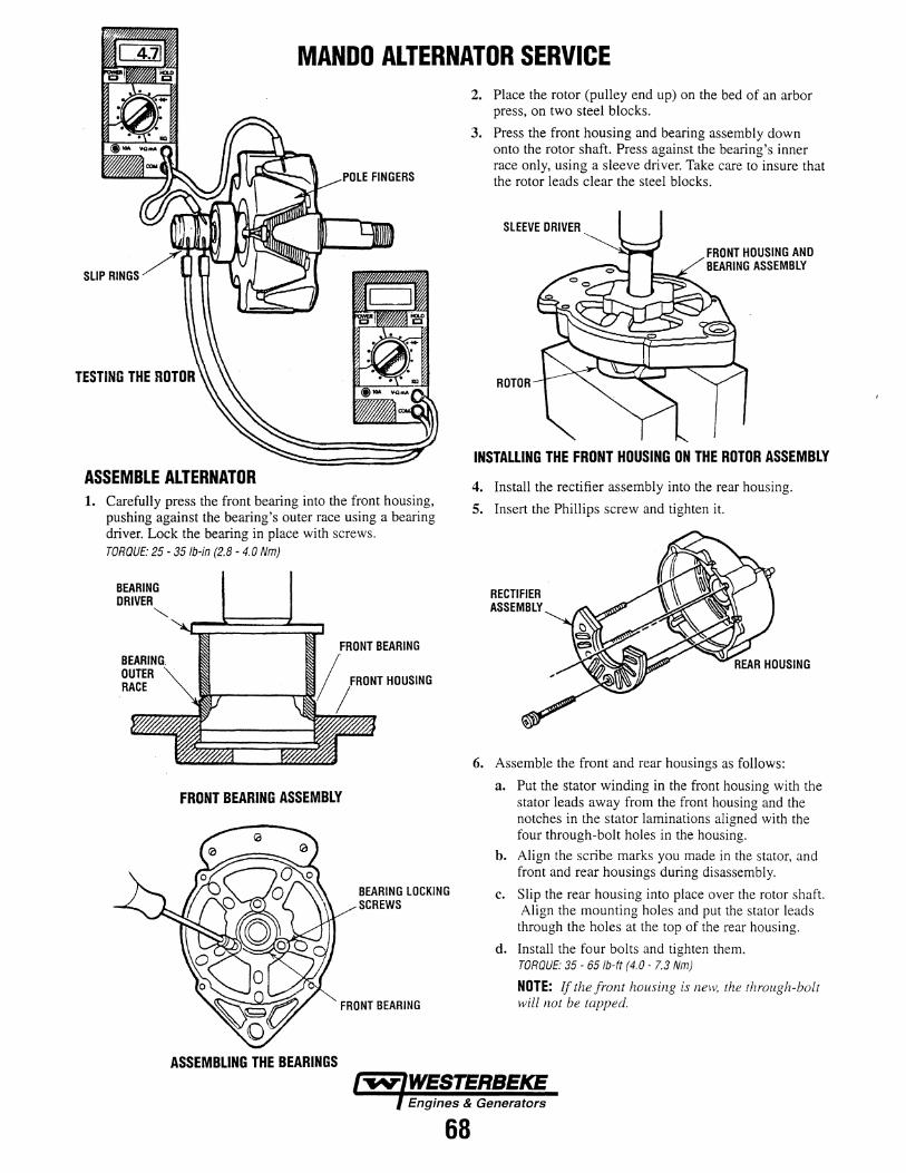
MANDO ALTERNATOR SERVICE
SLIP RINGS
ASSEMBLE ALTERNATOR 1. Carefully press the front bearing into the front housing,
pushing against the bearing's outer race using a bearing driver. Lock the bearing in place with screws. TORQUE: 25- 35 /b-in (2.8- 4.0 Nm)
BEARING DRIVER
'-.....,
OUTER RACE
FRONT BEARING
HOUSING
FRONT BEARING ASSEMBLY
ASSEMBLING THE BEARINGS
BEARING LOCKING SCREWS
FRONT BEARING
2. Place the rotor (pulley end up) on the bed of an arbor press, on two steel blocks.
3. Press the front housing and bearing assembly down onto the rotor shaft. Press against the bearing's inner race only, using a sleeve driver. Take care to insure that the rotor leads clear the steel blocks.
SLEEVE DRIVER
ROTOR
FRONT HOUSING AND BEARING ASSEMBLY
INSTALLING THE FRONT HOUSING ON THE ROTOR ASSEMBLY
4. Install the rectifier assembly into the rear housing.
5. Insert the Phillips screw and tighten it.
RECTIFIER ASSEMBLY
6. Assemble the front and rear housings as follows:
a. Put the stator winding in the front housing with the stator leads away from the front housing and the notches in the stator laminations aligned with the four through-bolt holes in the housing.
b. Align the scribe marks you made in the stator, and front and rear housings during disassembly.
c. Slip the rear housing into place over the rotor shaft. Align the mounting holes and put the stator leads through the holes at the top of the rear housing.
d. Install the four bolts and tighten them. TORQUE: 35- 65/b-ft (4.0- 7.3 Nm)
NOTE: If the front housing is new, the through-bolt will not be tapped.
WESTERS EKE Engines & Generators
68

MANDO ALTERNATOR SERVICE 7. Install the spacer and the fan. Then push the pulley,
lockwasher and nut onto the shaft. Tum the nut a few turns.
8. Place an oversized V-belt around the pulley and fasten the pulley in a vise.
INSTALLING THE PULLEY AND THE FAN NUT
9. Use a torque wrench to the tighten the nut. TORQUE: 35- 50 lb-tt (47- 68 Nm)
10. Carefully install the brush/regulator assembly on the rear housing with the two mounting screws.
11. Install the small terminal insulators.
12. Install the large terminal insulator.
13. Install the jumper.
14. Install the nut on the terminal.
15. Install the brush/regulator assembly cover.
16. Install the Phillips screw for the brush/regulator assembly cover. TORQUE: 25 - 35 lb-tt (2.8 - 5.1 Nm)
17. Install the capacitor.
18. Install the terminal nuts.
19. Install the jumper.
20. Install the last terminal nut.
69
INSTALL ALTERNATOR 1. Install the alternator, screws and washers.
2. Connect the wiring leads.
3. Put the belt on the alternator, crankshaft and coolant pump pulleys.
4. Adjust the alternator belt's tension (see DRIVE BELT ADJUSTMENT under ENGINE ADJUSTMENTS).
MANDO ALTERNATOR SPECIFICATIONS Battery Voltage 12 Volt
Maximum Speed 13500 RPM
Cut in Speed Max. 2000 RPM (at exc.) Max. 1500 RPM (at L2)
Reg. Set Voltage 14.7 Volts
Ambient Temp. -20°C- 1 oooc Ground Negative

STARTER MOTOR
BATTERY
--
-
START SWITCH
CONlROL SWITCH
FIGURE 1. STARTER WIRING CIRCUIT
TROUBLESHOOTING To independently test the starter it is necessary to remove it from the engine. However, before doing this, checks should be made to ensure that the problem is with the starter and not with the engine, battery, wiring or switches. When the other possible problem sources have been eliminated, then remove and test the starter. Comparison of test results with the Troubleshooting chart will aid in isolating the problem within the starter to specific components. This will determine the repair or repairs needed to restore the starter to serviceability.
Battery Test Realistic testing, as well as successful operation, requires a fully charged battery capable of supplying the current needs of the starting system. Step one in troubleshooting the starting system is to test the battery. Follow the battery manufacturer's instructions.
Wiring and Switches VIsual Inspection
Visually inspect all wiring and switches in the starting circuit for damage and loose or corroded connections. This includes all ground connections. Clean and tighten the connections as required. Replace damaged wiring or components.
70
Continuity Check
Disconnect the field lead on the starter from the solenoid M terminal and insulate it carefully to prevent accidental contact. Set the transmission in neutral. Use a voltmeter to check for voltage at the solenoid S terminal while the start switch is held in the START position. If voltage is not present at the S terminal, use the voltmeter and the wiring diagram to trace the control circuit and locate the point of voltage loss and correct it as necessary.
Starter Removal If the battery, wiring and switches are in satisfactory condition and the engine is known to be functioning properly, remove the starter for further testing.
Starter No-Load Test With the starter removed from the engine, the no-load test can reveal damage that can be corrected by repair or it may indicate the need for component testing after the starter is disassembled. Repair and component test procedures are described in the UNIT REPAIR section. The no-load test is also used to test units for normal operation after repair or overhaul. Comparison of test results with the Troubleshooting chart will indicate what corrective action, if any, is required.

STARTER MOTOR
Test Hook-Up (Figure 2)
Connect the starter for the no-load test as shown in the illustration using suitable instruments, battery cables and connecting wiring. Do the following:
1. Secure the starter in a suitable test stand to check its operation.
2. Use a momentary contact, pushbutton switch in the test circuit for a quick release if very high current surges are encountered.
3. Make all connections or disconnections with the switch open and the carbon pile load turned off.
4. If sparking or current flow in the battery circuit is noted when making the connections, the starter solenoid switch contacts may be frozen shut (refer to TROUBLESHOOTING).
5. As the last step in making the test connection, ground the negative battery cable securely to a clean metal ground on the starter frame.
6. The carbon pile load is used to adjust the operating voltage for comparison with specifications. It may not be necessary in all cases but should be used to eliminate the need for interpolation of test data.
Test Procedure
A CAUTION: Keep fingers and tools away from the opening in the D.E. (drive end} housing while testing. The strong shifting action of the solenoid could cause personal injury or damage as the drive pinion moves into the cranking position and spins.
BATIERY
CARBON PILE
+
NOTE: During the no-load test, close the switch and operate the starter for cycles of 30 seconds maximum. Between cycles, allow the starter to cool for at least two minutes, otherwise overheating and damage to the starter may result.
1. Momentarily close the switch.
a. If there is a high current flow and the starter fails to operate (zero rpm), release the switch immediately. Internal mechanical damage is indicated. Discontinue the test and refer to TROUBLESHOOTING.
b. If there is no current flow and the starter fails to operate (zero rpm), release the switch immediately. An open circuit is indicated. Discontinue the test and refer to TROUBLESHOOTING.
c. If there is a current flow and the starter operates, release the switch and proceed with the next step of the no-load test.
2. Close the switch and observe the voltmeter. Adjust the carbon pile load to obtain a 10 volt reading (20 volts on a 24-volt starter). Observe and record the ammeter and rpm readings. Release the switch.
3. Compare the ammeter and rpm readings to those listed under SPECIFICATIONS at the end of this section. If the readings are outside the limits shown, refer to TROUBLESHOOTING to determine the most likely causes. If the readings are within the limits, the starter is operating normally.
CLAMP ON AMMETER
VOLTMETER
BAT. 5 M
FIGURE 2. STARTER NO-LOAD TEST HOOK-UP
71

STARTER MOTOR
Troubleshooting If.the results of the no-load test are outside the limits, refer to the following TROUBLESHOOTING chart for the proba-
. ble cause and its remedy. The problems listed in the chart apply specifically to the no-load test and do not necessarily apply to operation under other circumstances.
PROBLEM PROBABLE CAUSE VERIFICATION/REMEDY*
Normal current and speed. a. Starter OK. a. Recheck battery, switches and wiring, including battery cable loss. Check if starter operation on engine is slow or sluggish.
Current flow with test circuit switch open. a. Solenoid switch contacts stuck closed. a. Test and, if necessary, replace solenoid assembly.
Failure to operate with very low or no a. Open solenoid wiring. a. Inspect and test solenoid assembly. current. b. Open field circuit. b. Inspect and test frame and field assembly.
c. Open armature coil(s) or high insulation between commutator bars.
c. Inspect armature.
d. Broken brush spring(s) or worn brushes. d. Inspect brushes and brush springs. Failure to operate with high current. a. Frozen bearing or other damage to drive a. Inspect bearings, armature, drive shaft
train. and related drive parts.
b. Dire·ct ground in terminals or fields. b. Inspect and test frame and field assem-bly, solenoid assembly, armature and brush installations for shorts.
Low speed with high current. a. Excessive friction in bearing(s) or gear a. Inspect bearing, armature, drive shaft, reduction unit, bent armature shaft or and gear reduction gears. loose pole shoe, bent drive shaft.
b. Shorted armature. b. Inspect and test armature.
c. Grounded armature or fields. c. Inspect and test frame and field coil assembly and armature.
Low speed with normal (or low) current. a. High internal electrical resistance caused by poor connections, defective leads or
a. Inspect internal wiring, electrical connec-1ions and armature commutator.
dirty commutator.
b. Causes listed under Failure to operate b. Remedies listed under Failure to operate with very law or no current. with very law or no current.
High speed with high current. a. Shorted fields. a. Inspect and test field and frame assembly.
* Refer to the UNIT REPAIR section for required disassembly, inspection, test, and if necessary, repair or replacement instructions.
STARTER REPAIR NOTE: Always install fasteners at their original locations. If it is necessary to replace fasteners, use only the correct part numbers or equivalent. If the correct part number is not available, use only a fastener of equal size and strength. Use a torque wrench to tighten fasteners when a torque value is specified. Torques specified are for dry, unlubricated fasteners unless otherwise specified.
Introduction (Figure 3) Figure 3 shows the starter broken down into its component parts and assemblies. Do not attempt to disassemble the following components which are serviced as assemblies:
Solenoid assembly (1)
Clutch Drive assembly (2)
Brush Holder assembly (3)
Armature assembly (13)
Frame and Field assembly (19)
72
This section provides instructions for complete disassembly of the starter as would be the case for overhaul. If the starter is not due for an overhaul, and repair affecting specific parts only is required, the starter may be disassembled only to the extent necessary to gain access to these parts. Parts removed from the starter as subassemblies or groups need not be disassembled for such limited repair unless they contain the affected parts. Total disassembly is recommended however, to ensure that all parts can be thoroughly cleaned and inspected.
In this section the starter is broken down by main groups. These groups are then disassembled into individual parts and assemblies. Illustrations accompany the text to show specific operations. To see the parts relationship of the complete starter, refer back to Figure 3.
To begin, make a mark completely down one side of the starter to ensure proper alignment of all its components at assembly. Use a colored pencil or marker that will show on all parts.

STARTER MOTOR
30 31 32 15 11 @ 12 b
1. SOLENOID ASSEMBLY 10 y~YA_ -........:__.....'"'7-~• 2. CLUTCH DRIVE 35 --:;:::::.-~
ASSEMBLY 6~ 3. BRUSH HOLDER 2 "/
ASSEMBLY 4. BRUSH (GROUNDED) 5. BRUSH (INSULATED) 6. D.E. HOUSING
BUSHING 7. BRUSH SPRING 8. D.E. ARMATURE
BEARING 9. C.E. ARMATURE
BEARING 10. CENTER SUPPORT
BEARING 11. SHIFT LEVER 12. PINION STOP 13. ARMATURE 14. C.E. FRAME 15. DRIVE SHAFT 16. ARMATURE SUPPORT
BRACKET 17. DRIVE SHAFT
SUPPORT 18. DRIVE HOUSING 19. FRAME & FIELD
ASSEMBLY 20. C.E. FRAME 0-RING
21
21. SHIFT LEVER SCREW 22. SHIFT LEVER WASHER 23. SHIFT LEVER NUT 25. SOLENOID SCREW 26. PLATE (IF USED) 27. DRIVE HOUSING PLUG 28. DOWEL PIN 29. INSULA TED BRUSH SCREW 30. WASHER (FIBER) 31. WASHER (THIN; ONE OR
TWO MAY BE USED) 32. WASHER (THICK) 33. FRAME SEAL 34. BUSHING PLUG (IF USED) 35. STOP RING 36. DRIVE HOUSING BOLT (LONG) 37. DRIVE HOUSING BOLT
(SHORTER ON SOME MODELS) 39. GROUNDED BRUSH SCREW 41. THRU BOLT 42. BRUSH PLATE SCREW
FIGURE 3. STARTER ASSEMBLY
73
18
22 23
34

STARTER MOTOR
General Disassembly (Figure 4) Remove or Disconnect:
1. The motor lead on the frame, field and brush holder group (A) from the solenoid assembly (1). Reinstall the nut on the solenoid terminal.
a. Remove the nut on the solenoid, slip off the motor lead and reinstall the nut.
2. Thru bolts (41).
3. Brush plate screws (42).
4. C.E. frame (14) and 0-ring (20).
Important:
a. In the following step, use care not to lose the small dowel pin (28) installed between the frame, field and brush holder group (A) and the gear reduction and drive group (B). This dowel pin is required for assembly and must be saved. If the dowel pin should be lost, it must be replaced with a 2 mm (0.079 in.) dia. x 10 mm (0.394 in.) long pin procured or manufactured locally.
41
1. SOLENOID ASSEMBLY 8. D.E. ARMATURE BEARING 9. C.E. ARMATURE BEARING
13. ARMATURE ASSEMBLY 14. C.E. FRAME. 20. C.E. FRAME 0-RING 25. SOLENOID SCREW 28. DOWEL PIN 33. FRAME SEAL 41. THRU BOLT 42. BRUSH, PLATE SCREW A. FRAME, FIELD & BRUSH HOLDER GROUP B. GEAR REDUCTION & DRIVE GROUP
5. Frame, field and brush holder group (A), dowel pin (28) and frame seal (33).
a. The armature assembly (13) may come off with the frame, field and brush holder group (A) or may be retained by the gear reduction and drive group (B).
6. Armature assembly (13) with bearings (8 and 9).
a. Do not remove the bearings from the armature assembly unless replacement is required (refer to CLEANING, INSPECTION AND REPAIR).
7. Solenoid screws (25).
8. Solenoid assembly (1).
9
a. Pivot the inside end of the solenoid assembly (1) out of engagement with the shift lever in the gear reduction and drive group (B) and withdraw the solenoid assembly.
25
1
8
FIGURE 4. ELECTRICAL GROUP
74

STARTER MOTOR
Disassembly of Frame, Field and Brush Holder Group (Figure 5) Remove or disconnect:
1. Insulated brush screws (29).
a. Move the brush holder assembly (3) [with the brushes (4 and 5)] away from the frame and field assembly (19) slightly to reach across with a screwdriver and remove the screws (29).
2. Frame and field assembly (19).
3. Grounded brush screws (39).
4. Brushes ( 4 and 5), if replacement is required.
a. Grasp the brush end of each brush spring (7) with needle nose pliers, twist the spring end away from the brush ( 4 or 5) and withdraw the brush.
5. Brush springs (7), if replacement is required.
3. BRUSH HOLDER ASSEMBLY
4. BRUSH (GROUNDED) 5. BRUSH (INSULATED) 7. BRUSH SPRING
19. FRAME & FIELD ASSEMBLY
29. INSULATED BRUSH SCREW
39. GROUNDED BRUSH. SCREW
a. Grasp the brush end of each brush spring (7) with needle nose pliers, twist the spring end away from
FIGURE 5. FRAME, FIELD AND BRUSH HOLDER GROUP
the brush socket on the brush holder assembly (3) and remove the spring.
NOTE: At this stage of disassembly, all electrical components can be inspected, and if required, independently tested as specified in CLEANING, INSPECTION AND REPAIR.
Disassembly of Gear Reduction and Drive Group (Figure 6) Remove or disconnect:
1. Housing bolts (36 and 37).
37
2. Armature support bracket (16). G;.._rrv Important: ~ ·30 a. The washers (30 through 32) may stick to the arma- ·
ture support bracket or to the drive shaft and clutch group (C) as the armature support bracket is 31 removed. In either case, note the position and num- 32
ber of each of these washers.
3. Washers (30 through 32).
a. Save the washers; they are to be installed in the same position and number at assembly.
4. Drive housing plug (27) and plate (26).
a. Pry out the drive housing plug using a large screwdriver.
5. Shift lever nut (23), washer (22) and screw (21).
6. Remove the shift lever (11) and the drive shaft and clutch group (C) from the drive housing (18) together, then separate them.
21
6. D.E. HOUSING BUSHING 11. SHIFT LEVER 16. ARMATURE SUPPORT
BRACKET 18. DRIVE HOUSING 21. SHIFT LEVER SCREW 22. SHIFT LEVER WASHER 23. SHIFT LEVER NUT 26. PLATE (IF USED) 27. DRIVE HOUSING PLUG 30. WASHER (FIBER)
11
6
32. WASHER (THICK) 34. BUSHING PLUG (IF
USED) 36. DRIVE HOUSING BOLT
(LONG)
a. Do not remove the bushing plug (34) or the bushing (6) from the drive housing (18) unless replacement is required (refer to CLEANING, INSPECTION AND REPAIR).
37. DRIVE HOUSING BOLT (SHORTER ON SOME MODELS) DRIVE SHAFT & CLUTCH GROUP
31. WASHER (THIN; ONE OR C. TWO MAY BE USED)
FIGURE 6. GEAR REDUCTION AND DRIVE GROUP
75

STARTER MOTOR
Disassembly of Drive Shaft and Clutch Group (Figures 7 and B) Disassembly of the drive shaft and clutch group is not required unless it is necessary to clean, inspect or replace one or more parts of the group separately. Then proceed as follows:
Remove or disconnect:
1. Stop rings (35) and pinion stop (12).
a. Position the drive shaft and clutch group on the work bench with the internal gear end down.
b. Using an open tube slightly larger than the shaft (see Figure 8), drive the pinion stop (12) toward the clutch drive assembly (2) until it clears the stop rings (35).
c. Using care not to scratch the drive shaft (15), pry the stop rings out of the shaft groove and slide them off the end of the shaft.
d. Inspect the edges of the shaft groove for burrs that may have been formed through repeated cranking cycles. Such burrs may make removal of the pinion stop and clutch drive assembly (2) difficult. If burrs are found, use a suitable file to carefully remove the burrs only - not the base metal. Thoroughly clean away metal filings.
e. Slide the pinion stop (12) off the drive shaft (15). Discard the old pinion stop (12) and stop rings (35). New parts must be used at assembly.
2. Clutch drive assembly (2) from drive shaft (15).
3. Drive shaft support (17) from drive shaft (15).
a. Do not remove the bearing (10) from the drive shaft (15) unless replacement is required. (refer to CLEANING, INSPECTION AND REPAIR).
76
2. CLUTCH DRIVE ASSEMBLY
10. CENTER SUPPORT BEARING
12. PINION STOP
10 15. DRIVE SHAFT 17. DRIVE SHAFT
SUPPORT 35. STOP RINGS (2 PCS)
FIGURE 7. DRIVE SHAFT AND CLUTCH GROUP
-B 22MM 14.2 MM (0.87 IN.) CIA (0.56 IN.) CIA
-
1- OPEN TUBE
FIGURE 8. REMOVING PINION STOP

STARTER MOTOR
CLEANING, INSPECTION, TESTING AND REPAIR Cleaning NOTE: Do not clean or immerse starter parts in grease dissolving solvents. Solvents will dissolve grease packed in the drive assembly and may damage the armature or field coil insulation.
Clean:
1. All starter parts with a soft cloth prior to testing.
Inspection (Figure 3) Inspection in the following steps refers to visual inspection of the starter parts and assemblies to determine their serviceability. Electrical tests for certain assemblies are described in COMPONENT ELECTRICAL TESTING.
Inspect:
1. All parts for cracks, distortion other structural damage. Replace parts or assemblies which are cracked, bent or otherwise damaged.
2. Threaded parts for stripped, crossed or otherwise damaged threads. Replace parts with thread damage that cannot be cleaned up using a suitable tap or die. Replace any hardware items that have damaged threads.
3. The solenoid assembly (1) for a cut or tom boot. If the boot is damaged, replace the solenoid assembly.
4. The clutch drive assembly (2) for the following. Replace the clutch drive assembly if damaged:
a. Pinion gear turns roughly or turns in both directions.
b. Pinion gear teeth broken or showing evidence of step wear.
c. Deep scoring or other damage to the shift lever collar.
5. The brush holder assembly (3) for the following. Replace the brush holder if damaged:
a. Loose riveted joints.
b. Cracked or broken insulation.
6. Brushes (4 and 5) for excessive wear.
a. The minimum allowable brush length is 12 mm (0.472 in.). Replace excessively worn brushes in sets.
7. The D.E. housing bushing (6) for scoring or other damage. Replace a damaged bushing (refer to REPAIR PROCEDURES).
8. Ball bearings (8, 9 and 10) as follows:
a. Hold the armature (13) or drive shaft (15) and slowly rotate the outer bearing race by hand.
b. Check that the bearing turns freely without binding or the feel of flat spots.
c. Replace damaged bearings (refer to REPAIR PROCEDURES).
9. Armature assembly (13) for the following:
77
a. Gear teeth that are broken, or that show evidence of step wear or root interference.
b. Rough commutator surface. Polish with a No. 400 grit polishing cloth if necessary. Thoroughly clean metal dust from between the commutator bars. If the commutator surface cannot be repaired in this manner, replace the armature assembly. Do not tum the commutator in a lathe.
c. Worn commutator. Replace the armature assembly if the commutator OD is less than 35 mm (1.378 in.) or if the undercut depth at any point is less than 0.2 mm (0.008 in.). Do not undercut the insulation.
10. Drive shaft (15) for the following. Replace the drive shaft if damaged:
a. Scored. or damaged shaft where it turns in the bushing (6).
b. Internal gear with teeth broken or showing evidence of step wear.
c. Damaged spline. The clutch drive assembly must slide smoothly and easily over the full length of the spline.

STARTER MOTOR
Component Electrical Testing (Figures 9 and 1 0) Perform the following electrical tests on the solenoid assembly (1), armature assembly (13) and frame and field assembly (19) to determine their serviceability.
1. Using a suitable ohmmeter, check the windings of the solenoid assembly (1) for continuity as follows:
a. Check the resistance of the solenoid pull-in and hold-in windings in series by measuring the resistance between the motor terminal (see Figure 9) and the solenoid case. The resistance should be approximately 0.95 ohms for 12-volt starters and approximatelyl.75 ohms for 24-volt starters.
b. An extremely high resistance reading indicates a break or fault in the winding continuity. A very low resistance reading indicates a short or ground in the winding circuit. Either condition is cause for replacement of the solenoid assembly.
2. Check the armature (13) as follows for shorts, opens or grounds using suitable test equipment and instruments (test lamp must be 110 volts or less).
a. Rotate the armature in a growler holding a steel strip such as a hacksaw blade against the armature. If a short circuit is present, the steel strip will vibrate in that area.
b. Check the armature for grounds using a test lamp or ohmmeter. There shall be no continuity between the armature shaft and any point on the commutator.
c. Check for opens by visually inspecting the points where the armature conductors join the commutator. A poor connection often will be indicated by signs of arcing or burning of the commutator.
d. Replace armatures which are shorted, grounded or show evidence of opens.
3. Check frame and field assembly (19) for grounds or opens using a test lamp (110 volts max.) or ohmmeter, as follows:
a. Check that there is continuity (no opens) between the field terminal that connects to the solenoid, and the connection points for the insulated brushes on the field coil straps.
b. Check that there is no continuity (no grounds) between the frame and the field terminal that connects to the solenoid.
c. Replace frame and field assemblies that have grounds or opens.
78
SWITCH TERMINAL
BATTERY TERMINAL
MOTOR TERMINAL
FIGURE 9. SOLENOID TERMINALS
FIGURE 10. FRAME AND FIELD ASSEMBLY
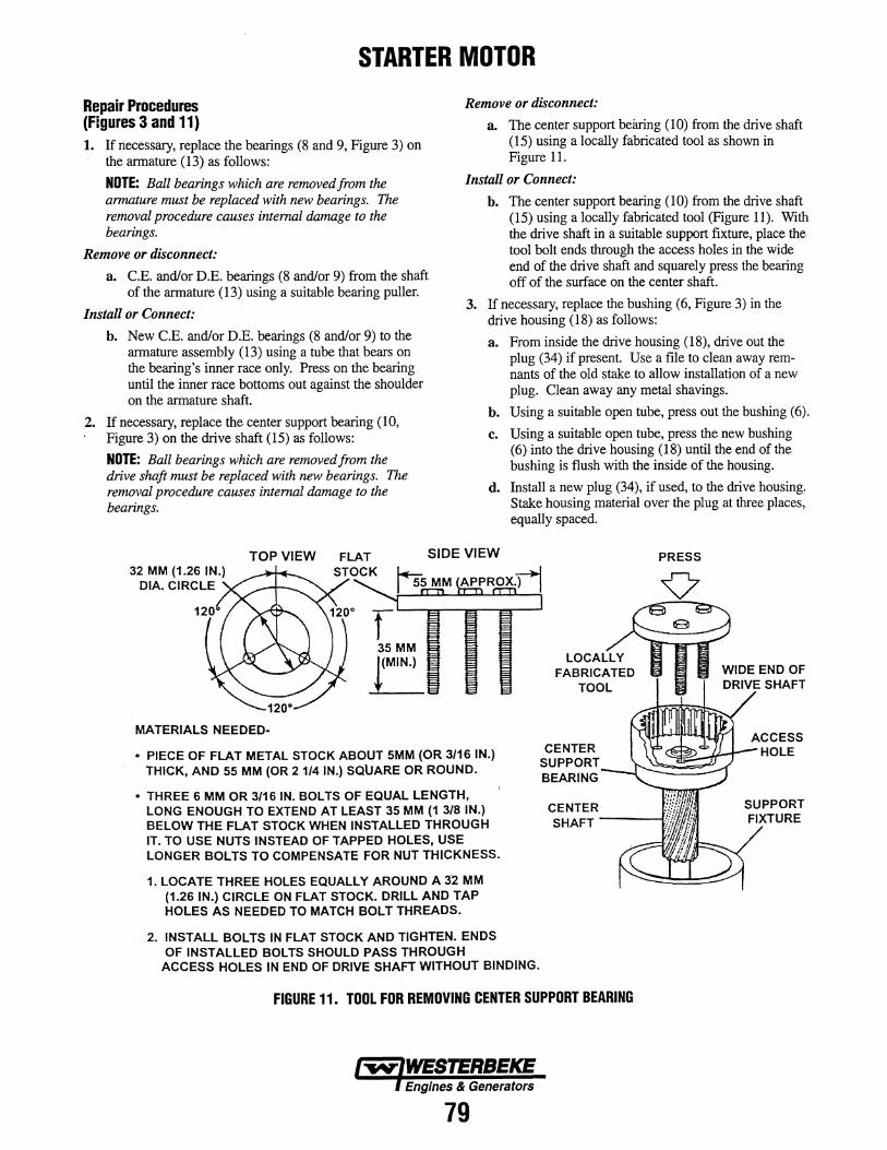
STARTER MOTOR
Repair Procedures (Figures 3 and 11) 1. If necessary, replace the bearings (8 and 9, Figure 3) on
the armature (13) as follows:
NOTE: Ball bearings which are removed from the armature must be replaced with new bearings. The removal procedure causes internal damage to the bearings.
Remove or disconnect:
a. C.E. and/or D.E. bearings (8 and/or 9) from the shaft of the armature (13) using a suitable bearing puller.
Install or Connect:
b. New C.E. and/or D.E. bearings (8 and/or 9) to the armature assembly (13) using a tube that bears on the bearing's inner race only. Press on the bearing until the inner race bottoms out against the shoulder on the armature shaft.
2. If necessary, replace the center support bearing (10, Figure 3) on the drive shaft (15) as follows:
NOTE: Ball bearings which are removed from the drive shaft must be replaced with new bearings. The removal procedure causes internal damage to the bearings.
Remove or disconnect:
a. The center support beluing (10) from the drive shaft (15) using a locally fabricated tool as shown in Figure 11.
Install or Connect:
b. The center support bearing (10) from the drive shaft (15) using a locally fabricated tool (Figure 11). With the drive shaft in a suitable support fixture, place the tool bolt ends through the access holes in the wide end of the drive shaft and squarely press the bearing off of the surface on the center shaft.
3. If necessary, replace the bushing (6, Figure 3) in the drive housing (18) as follows:
a. From inside the drive housing (18), drive out the plug (34) if present. Use a file to clean away remnants of the old stake to allow installation of a new plug. Clean away any metal shavings.
b. Using a suitable open tube, press out the bushing (6).
c. Using a suitable open tube, press the new bushing (6) into the drive housing (18) until the end of the bushing is flush with the inside of the housing.
d. Install a new plug (34), if used, to the drive housing. Stake housing material over the plug at three places, equally spaced.
TOP VIEW SIDE VIEW PRESS
MATERIALS NEEDED-
• PIECE OF FLAT METAL STOCK ABOUT 5MM (OR 3/16 IN.) THICK, AND 55 MM (OR 2 1/4 IN.) SQUARE OR ROUND.
• THREE 6 MM OR 3/16 IN. BOLTS OF EQUAL LENGTH, LONG ENOUGH TO EXTEND AT LEAST 35 MM (1 3/8 IN.) BELOW THE FLAT STOCK WHEN INSTALLED THROUGH IT. TO USE NUTS INSTEAD OF TAPPED HOLES, USE LONGER BOLTS TO COMPENSATE FOR NUT THICKNESS.
1. LOCATE THREE HOLES EQUALLY AROUND A 3'2 MM (1.26 IN.) CIRCLE ON FLAT STOCK. DRILL AND TAP HOLES AS NEEDED TO MATCH BOLT THREADS.
2. INSTALL BOLTS IN FLAT STOCK AND TIGHTEN. ENDS OF INSTALLED BOLTS SHOULD PASS THROUGH
ACCESS HOLES IN END OF DRIVE SHAFT WITHOUT BINDING.
CENTER SUPPORT BEARING
FIGURE 11. TOOL FOR REMOVING CENTER SUPPORT BEARING
l"'ffV"IWESTERBEKE l Engines & Generators
79

STARTER MOTOR
ASSEMBLY Lubrication During Assembly 1. The armature bearings (8 and 9, Figure 3) and drive shaft
support bearing (10) are permanently lubricated. Do not add lubricant to these bearings. Lubricate the following just before or during assembly (avoid excessive grease):
a. D.E. housing bushing (6) (in drive housing).
b. The pivot hole and working surface on the ends of the shift lever (11).
c. The internal gear, shaft and spline on the drive shaft (15).
Drive Shaft and Clutch Group (Figures 7 and 12) 1. If disassembled, position the drive shaft on the work sur
face with the internal gear end down and assemble the drive shaft and clutch group as follows:
Important:
a. If the center support bearing (10) is being replaced, install it on the drive shaft (15) as specified in REPAIR PROCEDURES, step 2, before proceeding with assembly.
Install or Connect:
1. The drive shaft support (17) to the drive shaft (15), seating the bearing (10) in the support.
2. The clutch drive assembly (2) to the drive shaft (15).
3. A new pinion stop (12) onto the drive shaft (15), the end with the recess for the stop rings (35) up.
a. Install the stop rings (35) in the groove in the drive shaft (15).
b. Pick up and support the assembly under the pinion stop (12). A metal block, with a U-shaped cutout that will slide over the shaft between the pinion gear and the stop, can be clamped in a vise to provide support (see Figure 12).
c. Make sure the stop rings (35) (in the drive shaft groove) are fully seated in the pinion stop recess and stake the upper edge of the pinion stop (12) over the stop ring (35) at four places, equally spaced. Do not allow staked metal to contact the drive shaft (15).
Assembly of Gear Reduction and Drive Group (Figure 6)
Important:
If the D.E. bushing (6) ~d plug (34) are being replaced, install them in the drive housing (18) as specified in REPAIR PROCEDURES, step 3, before proceeding with assembly.
1. Lubricate the D.E. housing bushing, shift lever, and drive shaft as described under LUBRICATION DURING ASSEMBLY.
Install or Connect:
2. The arms on the shift lever (11) with the shift collar on the drive shaft and clutch group (C).
3. The assembled shift lever (11) and the drive shaft and clutch group (C) into the drive housing (18), aligning the holes in the drive shaft support ( 17, Figure 7) with those in the drive housing.
a. Make sure that the drive shaft support is fully seated in the drive housing and that the drive shaft bearing (10, Figure 7) remains fully seated in the drive shaft support.
4. Shift lever screw (21), washer (22) and nut (23).
Tighten:
a. Nut to 4.5 Nm (40 lb-in.).
5. The plate (26), if used, and the drive housing plug (27) to the drive housing (18).
6. Washers (30 through 32) in the same number and positions as noted at disassembly.
7. The armature support bracket (16) to the drive housing (18), aligning the mark made prior to disassembly with that on the drive housing.
8. Drive housing bolts (36 and 37).
APPROX.
METAL BLOCK APPROX. 9 MM (3/16 IN.)
38 MM (1 1/2 IN.)
FIGURE 12. PINION STOP SUPPORT BLOCK
Engines & Generators
80

STARTER MOTOR
Assembly of Frame, Field and Brush Holder Group (Figures 5, 13 and 14)
SPRING POST
BRUSH HOLDER ASSEMBLY
BRUSH SOCKET
FIGURE 13. BRUSH SPRING ON POST
Install or Connect:
1. Brush springs (7), if removed.
a. Start each brush spring onto the post on the brush holder assembly (3) as shown in Figure 13, just enough to hold the inside end of the spring from turning.
b. Grasp the free end of the spring with needle nose pliers and twist clockwise over the top of the brush socket.
c. Push the spring fully onto the post and release the free end to engage the notch in the brush socket.
NOTE: The brush leads may be damaged by excessive handling. Do not over-flex tl}e leads near the clip welds or the clips may break off.
2. Brushes ( 4 and 5), if removed.
a. See Figure 14 for the proper installed position of all brushes. Make sure the insulated brushes (5) go into the brush sockets of the brush holder assembly (3) that are mounted on the insulation.
b. To install each brush, grasp the free end of the brush spring with needle nose pliers, twist clockwise to clear the brush socket and insert the brush partly into the brush socket.
c. Gradually release the spring so that its end contacts the side (not end) of the brush (see Figure 13). This will hold the brushes retracted until after the brush holder is installed over the armature commutator.
3. Grounded brush screws (39).
a. Position the terminals of the grounded brush leads behind the terminal tabs on the brush holder (3) (see Figure 13).
b. Insert the brush screws (39) through the terminal tabs on the brush holder and thread them into the brush lead terminals.
Tighten:
c. Grounded brush screws to 1.5 Nm (13 lb-in.).
INSULATED BRUSH
GROUNDED BRUSH
FIGURE 14. SPRINGS AND BRUSHES ON BRUSH HOLDER
81
SPRING POST

STARTER MOTOR
4. The frame and field assembly (19) to the brush holder assembly.
a. Position the brush holder assembly (3) (with installed brushes) over the terminal end of the frame and field assembly (19).
b. Attach the terminals of the insulated brush leads to the conductors in the frame and field assembly with the insulated brush screws (29).
Tighten:
c. The insulated brush screws to 1.5 Nm (13lb-in.). ·
Starter Assembly (Figures 4 and 15) Support the gear reduction and drive group (B) with the pinion gear end down and proceed as follows:
Important:
If the armature bearings (8 and 9) are being replaced, install them on the armature (13) as specified in REPAIR PROCEDURES, step 1 before proceeding with assembly.
Install or Connect:
1. Solenoid assembly (1).
a. Pivot the plunger of the solenoid assembly into engagement with the shift lever in the gear reduction and drive group (B).
b. Position the solenoid assembly mounting flange and install the solenoid mounting screws (25).
Tighten:
c. Solenoid screws to 2.8 Nm (25lb-in.).
2. Frame seal (33).
3. The armature assembly (13) with bearings (8 and 9) into the gear reduction and drive group (B).
a. Make sure the gear teeth are aligned, then seat the bearing (8) on the armature shaft fully into the housing recess.
4. Frame, field and brush holder group (A).
a. Place the dowel pin (28) in the hole in the armature support bracket of the gear reduction and drive group (B).
b. Position the frame, field and brush holder group over the armature assembly (13), align the hole for the dowel pin (28) and the marks made prior to disassembly, and seat in the gear reduction and drive group (B).
c. Twist the brush springs (7, Figure 5) away from the brushes (4 and 5, Figure 5), slide the brushes in to contact the commutator on the armature (13), and release the brush springs to contact the ends of the brushes.
5. 0-ring (20).
82
Important:
a. The 0-ring can easily be damaged during installation of the C.E. frame (14). To prevent such damage, install the 0-ring as described in the following steps.
b. Install the 0-ring on the frame, field and brush holder group (A) so that it is against the shoulder on the field frame that will abut the C.E. frame when installed. This is the normal installed position for the 0-ring.
c. Carefully roll the 0-ring out of its normal installed position up onto the major O.D. of the field frame. Allow the 0-ring to remain in this position until the C.E. frame is partially installed.
6. C.E. frame (14)
a. Align the marks on the C.E. frame and frame and field assembly (19, Figure 5) made prior to disassembly.
b. Start the C.E. frame onto the frame and field assembly, leaving a gap just slightly larger than the thickness of the 0-ring (20).
7. Brush plate screw (42).
a. Use a scribe or similar tool to align the tapped holes in the brush holder assembly (3, Figure 5) with the screw holes in the C.E. frame (14).
Tighten:
b. Brush plate screws to 2.8 Nm (25 lb-in.).
8. Thru bolts (41).
a. Install the thru bolts and tighten them by hand but do not close the gap between the C.E. frame and the frame and field assembly where the 0-ring (20) goes.
b. Roll the 0-ring (20) back down into its installed position between the C.E. frame and the frame and field assembly.
c. Align the timing ribs on the edge of the C.E. frame (14) with the timing spots on the frame and field assembly (A) to assure proper brush alignment. Refer to Figure 15. Marks are located in 2 places on the motor but will only match one way.
Tighten:
d. Thru bolts (41) to 8.5 Nm (75 lb-in.).
9. The motor lead on the frame and field assembly (19, Figure 5).
a. Remove the nut from the terminal on the solenoid, install the motor lead terminal and reinstall the nut.
Tighten:
b. The nut on the terminal of the solenoid assembly to 11 Nm (100 lb-in.).

STARTER INSTALLATION Testing After Repair or Overhaul
STARTER MOTOR
After repair or overhaul, the starter can be tested as specified in the Starter No-Load Test found in the TROUBLESHOOTING section.
After repair, overhaul, testing or replacement of the starter, reinstall it using the following torques when making the electrical connections to the starter.
A CAUTION: Make sure the negative battery cable is disconnected at the battery when making the electrical connections to the starter. Otherwise, injury may result. If a tool is shorted at the solenoid battery terminal, the tool will heat enough to cause a skin burn.
Tighten:
a. Solenoid battery (B) terminal nut to 18 Nm (13 lb-ft.):
C.E. FRAME
TIMING MARKS
b. Solenoid switch (S) terminal nut to 1.8 Nm (16 lb-in.). FIGURE 15. ALIGNING TIMING MARKS
STARTER SPECIFICATIONS All12 Volt models have these No-Load Test Specifications:
AMPS RPM VOLTS
Minimum Maximum Minimum Maximum
10 125 190 3000 5600
All 24 Volt models have these No-Load Test Specifications:
AMPS RPM VOLTS
Minimum Maximum Minimum Maximum 20 75 90 3600 5400
Starter Solenoid current consumption:
PULL IN WINDING HOLD IN WINDING RATED VOLTAGE
AMPS VOLTS OHMS AMPS VOLTS OHMS 12 52-59 10 0.17-0.19 12-14 10 0.76-0.81
24 100-125 20 0.16-0.20 12-14 20 1.15-1.65
83

I
Al HRNA!OR 21ypc 12A
111011 Jill!!_r' ~ \:!.l.~ .. J4
tl4 ••o \ ,hr~.-..~ J./
Ill OIIG
110 liED
112 RED
BATTERY SWITCH \I r ¥-<>!----- --1::1.--~ "'"""' I 12-2• voc
L~ o
~ STARU:R MOTOR
I
WIRING DIAGRAM #44780
WATER ilNBATURf
= = a ;;
~
·7~ K"'""' ~
;;
IIIILIIIIIT
ti4UL
114 IED/wtll
lUJAN
114 ILU ...... IU YIO
~!~ i ~ = ~
1 re I[[.T(I,~ L-~~ ~ ~
L~====~~~=1~{-+-+-''!..!.'!-' _!.••!.!!•-, 114 .. , I f---
0
114 II[OIVIO
ALURNATOR 12y .S!A
114 VIO
110 OIIG
1148RN
L------fo~ e ili RED 183 L--------11~ a •·oOf::::::...-•uuw""'"''--lill~;~:f-~~~~~~~~~~--lr"'-' ""'-' ----1 ~ ~~-r\--..~-""'-~,~~·=u=•=E=D=::j•~uC"MEio========~===~i=i::i=====~---J I• ~ au ~~ 111Bu
BUIIKT 7st-'7.-"1.._o;------, L----"'!!!!..j' ~-;- ( )
._ ____ _,_v,_,oo4-9 , ,,. voo
YIO -~ llo YIO~ l JSHIELDED
A---t:--_,_ ~ JM&u ,---
I. R[MOV£ JUMPER IH£1 C~IECTIIG A SECOND REMOTE PAIEL.
2. GIOUID "I" T[RfiiiAl Of PREHEAT SOLENOID 01 21¥ SYSTEM ONLY.
r---+--'!!..!"---0 T82-2
r-J--.!!L!lli!!OL--0 TBI-5 r---"L!O.L!.W'-~~ TBI·l
HOUR
I_. METER
Ill lED/WilT
Ill (IIIII . "' Ill liED
Ill DIG
Ill WMT
Ill 111M
84
PAEIEAT SWITCH
START SWITCH
STOP SWITCH
___ __j
1141t:l
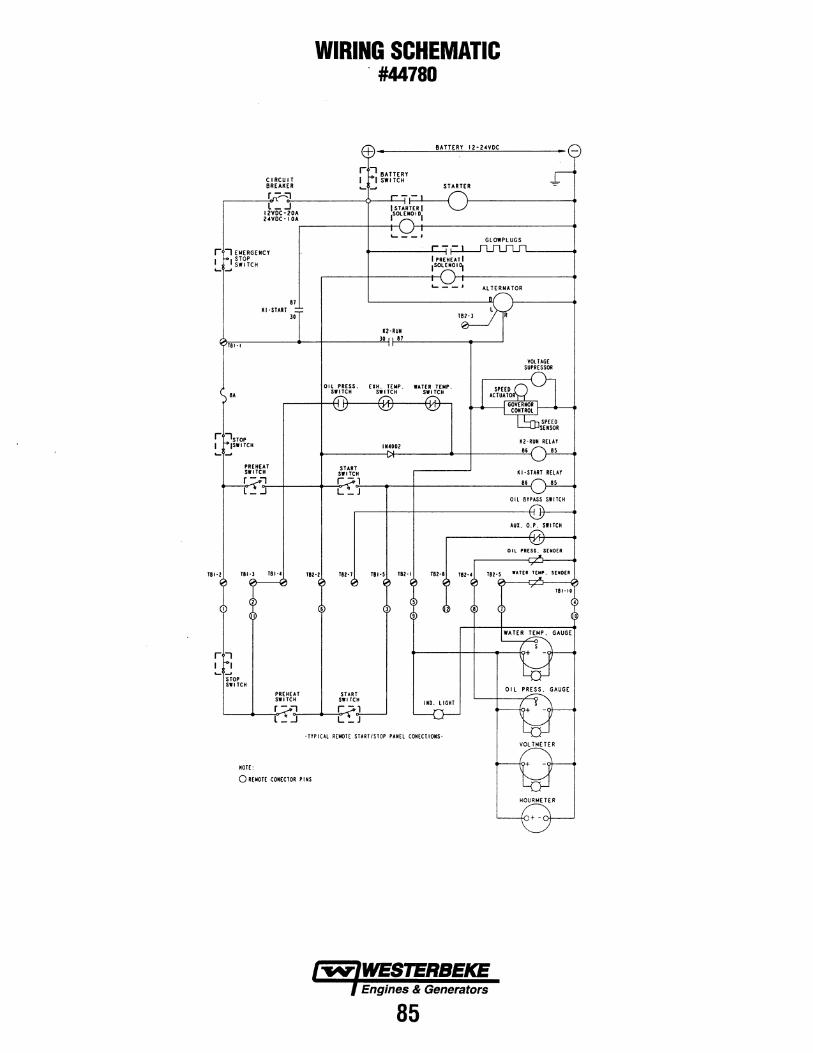
CIRCUIT BREAKER
WIRING SCHEMATIC . #44780
BATTERY 12·24VDC
STARTER
.-----~r~~~----------~~--~~~--~ l_ .J 12VDC·20A 24YDC-IOA
r I EMERGENCY STOP
~_!SWITCH
81 IU ·START
30
'----1
K2·RUN
I PREHEAT I ISOlENOI~
'- --'
GlOWPLUGS
AlTERNATOR
~,.~.~-.----------._--~ ________ _23~0 ~·~'------------.---__J
•• OIL PRESS. EIH. TEMP. WATER TEMP.
SWITCH SWITCH SWITCH
START SWITCH r -,
114002
Oil PRESS. SENDER
TBI·Z Tll·l TBHI
r1 I I ... ~
STOP SWITCH
NOTE:
PREHEAT SWITCH
YIZ·Z TIZ·T
START SWITCH
Tll-5 TBZ·I
IND. LIGHT
·TYPICAL REMOTE START/STOP PANEl CONECtiOIS·
0 REIIOTE CONECTOR PINS
85
TBI-IO

REMOTE INSTRUMENT PANEL #44329 STOP SWITCH
0 PREHEAT PREHEAT SWITCH
REMOTE CONTROL PANEL CREAR VIEW> ,---··-··-··-··-··-··-··-··-··-··-··-··-··-··-··-··-: : I I :
I :
.I 0
STOP SWITCH
START SWITCH
114 RED
110 RED
P.N. 44336
PREHEAT SWITCH
114 RED
86
START SWITCH
'.tl6 RED/VL
116 BLK
116 RED/WHT
116 WHT
116 WHT/RED
116 VEL/RED
2
5
000 ®®® @~@
MALE CABLE CONNECTOR REAR VIEW

WIRING DIAGRAM MARINE ENGINES #44781
+~ .!l..E.U..I.RAJ SAlill "SWITCH ~""'="" CUSEO 6N!milMODELSI
NOTES:
llAllE..B.l 12-24 vpc
\
I. THIS PRODUCT 1$ PROTECTtD BY A MANUAL RESET CIRCUIT 8REAII£R LOCATED NEAR THE STARTER. EXCESSIVE CURRENT WILL CAUSE THE BREAKER TO TRIP AND TN[ EMGIIt[ WILL SHUT DOWN. THE ISUILDU/OWM(R MUST 8£ SURE THAT THE INSTRUMENT PANEL. WIRING. AND ENGINE ARE INSTALLED TO PII[V(IIT CONTACT B£TWEEN ELECTRICAL DEVICES AND SEAWATER.
2'. AN ON·Of'F SWITCH SHOULD BE INSTALLED BETWEEN THE UTT£RY AND STARTER TO DISCONNECT THE U.TTERY IN AN EMERGENCY AltO WHEN LEAVING THE BOAT. A SWITCH WITH A CONTINUOUS RATING OF 175 AMPS AT 12 VDC WILL SERVE THIS FUifCTION. THIS SWITCH SltOULD MOT liE US[O TO MAKE 01 BREAK THE CIRCUIT.
l. TN[ PINII WIRE AT PLUG 2 IS UNU:sED AND SHOULD BE INSULATED. CAPTAIN PANEL ONLJ.
4, THE GRAY WIRE AT PLUG Z IS UNUSED AND SHOULD BE INSULATED. ADMIRAl PANEL ONlY,
S. CONNECT THE CIRCUIT BREAKER AIIO RESISTOR WIRE TO THE "I" TERMINAl FOR 12 VOlT STSTEMS ONlY. FOI 24 VOlT SYSTEMS REMOVE THE CIRCUIT BREAKER AIIO COJIIIECT THE RESISTOR WIRE TO THE 114 lT. BlU WIRES AND THEil GROUND THE "I" TERMINAl.
Sl
PI
S2
P2
87
-,
:::0 -' "' ... -'
;
ADMIRAL PANEL
Rev.l-2001.

+
.. .. ... ... ~
~\ .... .., "' ... ;;: z
'
START SOL.
WIRING SCHEMATIC MARINE ENGINES #44781
BATTERY 12·24 VDC
STARTER
SI·Z Sl•l SI·S SH SZ·I SHISZ·II SH Sl-l 11·3 SZ·IZ Sl·l -,"':j - Pi-IPI:S ;T.,'Tz.l -PHI fi .• -;,:j" PH Pz:1z- - - - - -"":j
ADMIRAL PANEL
KEY sw.
TACHOMETER
L-~-+----~s _;~~--•
OPTIONAL ALTERNATORS
PRESTOLITE 72 AMP ALT
PRESTOLITE\LEECE-NEVILLE 90 AMP ALT.
PREHEAT SWITCH
88
DISCONNECT JUMPER fOR USE WITH TWO BATTERIES.
Ue\'.1·2001

ENGINE TROUBLESHOOTING
Hard Starting ................................................................................................... 90 Starter Inoperative ................................................................................ 90 Starter Operates but engine does not tum over .................................... 91 Engine turns over but does not start though fuel is being delivered to the injection pump .............................................. 92 Engine turns over but does not start .................................................... 93
Unstable Low Idling ................................................................................... 94
Insufficient Power ..................................................................................... 96 Excessive Fuel Consumption ..................................................................... 99 Excessive Oi I Consumption ...................................................................... 1 o 1 Overheating .............................................................................................. 1 02 White Exhaust Smoke .............................................................................. 1 03 Dark Exhaust Smoke ................................................................................ 1 04 Oil Pressure Does Not Rise ...................................................................... 105 Abnormal Engine Noise ............................................................................ 106
NOTE: Use this section to quickly diagnose and repair engine failures. Each troubleshooting chart has three headings arranged from left to right. # 1 Check Point, #2 Trouble Cause, #3 Remedy
Engines & Generators
89

ENGINE TROUBLESHOOTING
HARD STARTING
1) STARTER INOPERATIVE
Checkpoint Trouble Cause Remedy
Transmission neutral switch: NG
Defective neutral switch NG
Replace the neutral switch - r--(if so equipped)
J
I ~ Loose battery cable terminals ~ Clean and/or retighten the bat-
Battery Poor connections due to rusting tery cable terminals
NG Battery discharged or weak ~ Recharge or replace the battery
NG ~ Drive belt loose or broken Adjust or replace the drive belt
OK
I Starter switch NG Defective starter switch or NG Replace the starter switch or -
starter relay t-- the starter relay
OK
Starter motor ~ Defective magnetic switch or NG Repair or replace the magnetic starter relay
1---switch
OK
Starter motor NG Defective starter motor ~ Repair or replace the starter motor -
90
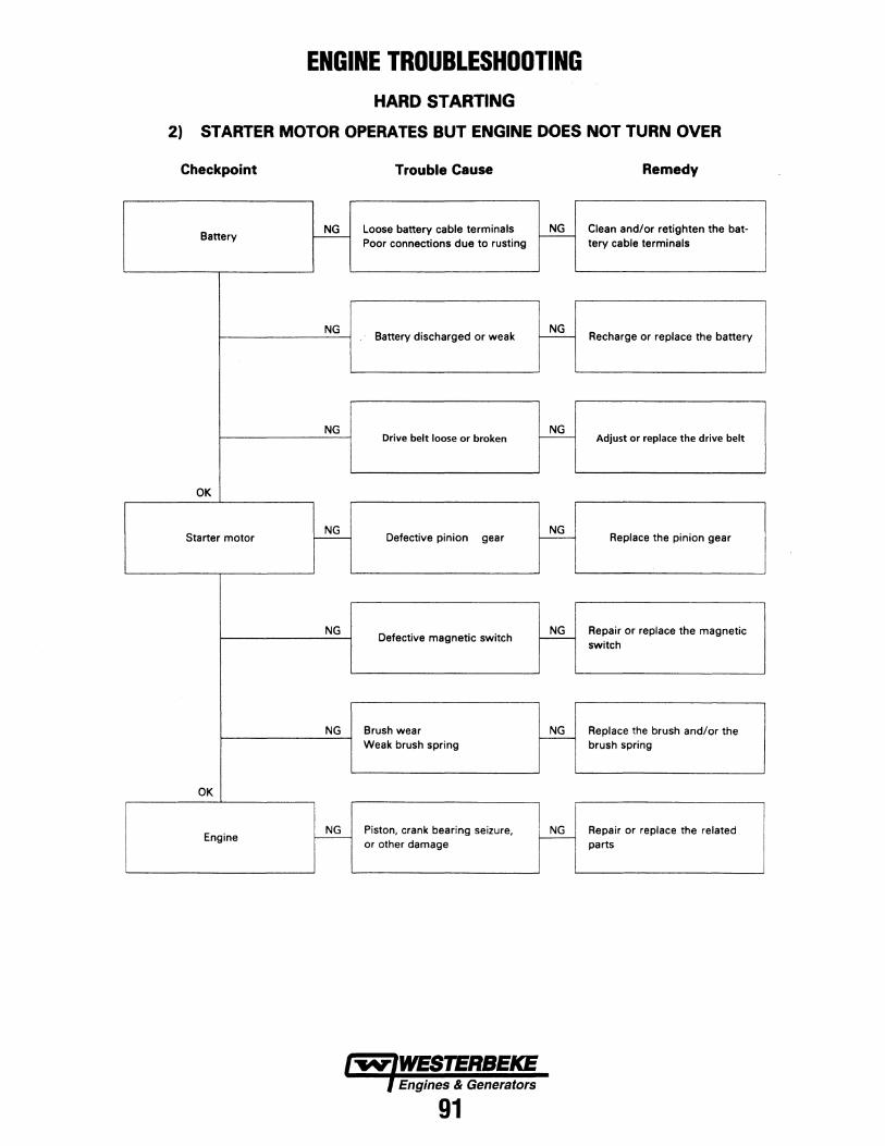
ENGINE TROUBLESHOOTING HARD STARTING
2) STARTER MOTOR OPERATES BUT ENGINE DOES NOT TURN OVER
Checkpoint Trouble Cause Remedy
Battery ~ Loose battery cable terminals NG Clean and/or retighten the bat-Poor connections due to rusting
-tery cable terminals
NG Battery discharged or weak
NG Recharge or replace the battery -
NG Drive belt loose or broken ~ Adjust or replace the drive belt
OK
Starter motor NG
Defective pinion NG
Replace the pinion gear r-- gear -
NG Defective magnetic switch
NG Repair or replace the magnetic -switch
NG Brush wear NG Replace the brush and/or the -
Weak brush spring brush spring
OK
Engine ~ Piston, crank bearing seizure, ~ Repair or replace the related or other damage parts
Engines & Generators
91
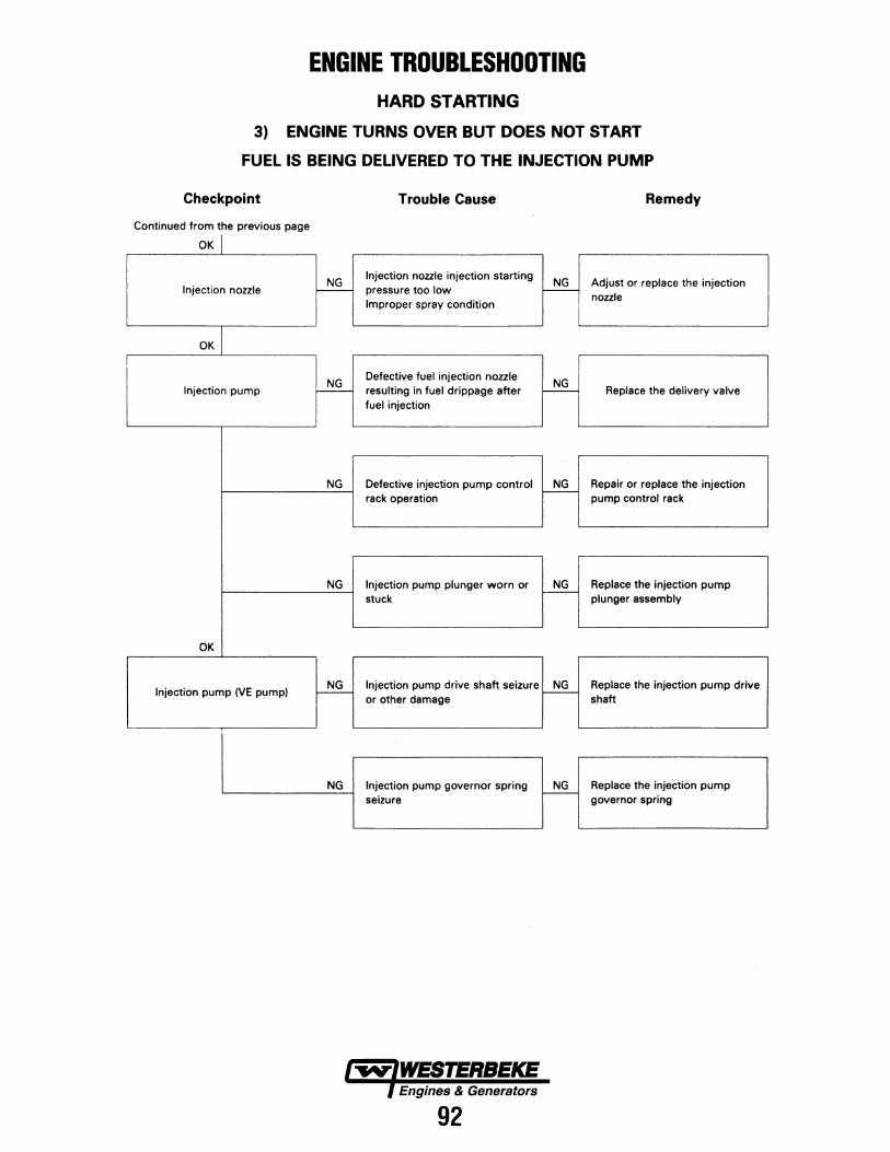
ENGINE TROUBLESHOOTING HARD STARTING
3) ENGINE TURNS OVER BUT DOES NOT START
FUEL IS BEING DELIVERED TO THE INJECTION PUMP
Checkpoint Trouble Cause Remedy
Continued from the previous page
OK I
~ Injection nozzle injection starting
~ Adjust or replace the injection Injection nozzle pressure too low
nozzle Improper spray condition
OK
NG Defective fuel injection nozzle ~ Injection pump r--- resulting in fuel drippage after Replace the delivery valve
fuel injection
NG Defective injection pump control ~ Repair or replace the injection rack operation pump control rack
NG Injection pump plunger worn or ~ Replace the injection pump stuck plunger assembly
OK
Injection pump (VE pump) ~ Injection pump drive shaft seizure ~ Replace the injection pump drive or other damage shaft
NG Injection pump governor spring ~ Replace the injection pump seizure governor spring
92

ENGINE TROUBLESHOOTING HARD STARTING
4) ENGINE TURNS OVER BUT DOES NOT START
Checkpoint Trouble Cause Remedy
~ Defective engine stop mechanism. NG Replace the engine stop
Engine stop mechanism r--- mechanism.
NG Defective fuel cut solenoid valve NG Replace the fuel cut solenoid (VEpump) r--- valve
FUEL IS NOT BEING DELIVERED TO THE INJECTION PUMP
Fuel NG
Fuel tank is empty ~ Fill the fuel tank r----
OK
~ Clogged or damaged fuel lines ~ Repair or replace the fuel lines
Fuel piping Retighten the fuel line Loose fuel line connections
connections
OK
Fuel filter ~ Fuel filter overflow valve does ~ Repair or replace the fuel filter not close overflow valve
NG Clogged fuel filter element ~ Replace the fuel filter element or
the fuel filter cartridge
OK
Fuel system NG
Air in the fuel system NG
Bleed the air from the fuel system !------- r---
I Continued on the next page
93

ENGINE TROUBLESHOOTING UNSTABLE LOW IDLING (PROPULSION)
Checkpoint Trouble Cause Remedy
Low idling NG
Low idling improperly adjusted NG
Adjust the low idling f-- r----
OK
Throttle control system NG Throttle control system NG Adjust the throttle control -
improperly adjusted '---
system
OK
Fuel system NG
Fuel system leakage or blockage NG
Repair or replace the fuel system - -
NG Air in the fuel system
NG Bleed the air from the fuel system r---
NG Water particles in the fuel system ~ Change the fuel
OK
Fuel filter ~ Clogged fuel filter element ~ Replace the fuel filter element or the fuel filter cartridge
I Continued on the next page
94

ENGINE TROUBLESHOOTING UNSTABLE LOW IDLING (PROPULSION)
Checkpoint Trouble Cause Remedy
Continued from the previous page
OK I NG
Defective governor lever operation NG Repair or replace the governor
Injection pump I-- 1----lever
NG Regulator valve improperly NG Adjust or replace the regulator -adjusted (VE pump only) valve
NG Broken plunger spring
NG Replace the plunger spring -
NG Worn plunger
NG Replace the plunger assembly -
NG NG I Worn camshaft (In-line pump only) ,.---- Replace the camshaft
NG Worn roller tappet (In-line pump NG Replace the roller tappet
only) 1--
NG Worn cam disc (VE pump only) ~ Replace the cam disc
Valve clearance NG Valve clearance improperly ~ Adjust the valve clearance 1--adjusted
95

ENGINE TROUBLESHOOTING INSUFFICIENT POWER
Checkpoint Trouble Cause Remedy
Air cleaner NG
Clogged air cleaner element NG Clean or replace the air cleaner
1--- r-- element
OK
Fuel ~ Water particles in the fuel NG
Replace the fuel r--
OK
Fuel filter NG - Clogged inlet filter screen ~ Clean filter screen
OK
Fuel feed pump _!:!§____ Defective fuel feed pump ~ Repair or replace the fuel feed pump
OK
Injection nozzle ~ Injection nozzle sticking _!:!§____ Replace the injection nozzle
NG Injection nozzle injection starting _!:!§____ Adjust or replace the injection
pressure too low nozzle
Improper spray condition
OK
Fuel injection pipes NG Fuel injection pipes damaged or _!:!§____ Replace the fuel injection pipes r-- obstructed
I Continued on the next page
Engines & Generators
96

ENGINE TROUBLESHOOTING INSUFFICIENT POWER
Checkpoint Trouble Cause Remedy
Continued from the previous page
OK I
Injection pump ~ Defective delivery valve ~ Replace the delivery valve
NG Defective timer ~ Repair or replace the timer
NG Improper control lever operation ~ Adjust or replace the control
lever
NG ~ Adjust the injection timing
Defective injection timing Repair or replace the injection pump timer
NG Weak governor spring ~ Replace the governor spring
NG Worn plunger ~ Replace the plunger assembly
NG Worn camshaft (In-line pump only) ~ Replace the camshaft
Continued on the next page
97

ENGINE TROUBLESHOOTING INSUFFICIENT POWER
Checkpoint Trouble Cause Remedy
Continued from the previous page
OK I
Injection pump NG
Worn roller tappet NG
Replace the roller tappet - !---
OK
~ Exhaust gas leakage from the
~ Repair or replace the related Turbocharger exhaust system
Air leakage from the intake system parts
NG Defective turbocharger assembly ~ Replace the turbocharger assembly
OK Blown out cylinder head gasket
NG Worn cylinder liner NG Compression pressure f--- Piston ring sticking or broken - Replace the related parts
Improper seating between the valve and the valve seat
OK
Valve clearance NG Valve clearance improperly NG
Adjust the valve clearance f---adjusted -
!
OK
Valve spring NG
Valve spring weak or broken NG
Replace the valve spring f--- -
OK
Exhaust system ~ Exhaust pipe clogged NG
Clean the exhaust pipe -
OK
Full load adjusting screw seal _!!§_ Open and improperly set NG Adjust and reseal the adjusting adjusting screw seal -
screw
Engines & Generators
98

ENGINE TROUBLESHOOTING
EXCESSIVE FUEL CONSUMPTION
Checkpoint Trouble Cause Remedy
Fuel system NG
Fuel leakage NG Repair or replace the fuel system r---- -
related parts I
I
OK I I
Air cleaner NG
Clogged air cleaner element NG Clean or replace the air cleaner
,...-- -element
OK I i
Low idling speed NG
Poorly adjusted low idle speed NG
Adjust the low idle speed - r----
OK I
I NG Injection nozzle injection starting NG Adjust or replace the injection
Injection nozzle - pressure too low r--- nozzle
I Improper spray condition
OK I
Fuel injection timing NG Fuel injection timing improperly NG
Adjust the fuel injection timing - adjusted r---
OK I
NG Defective delivery valve result- NG Injection pump - ing fuel drippage after fuel - Replace the delivery valve
injection
OK I
Turbocharger ~ Air leakage from the turbocharger ~ Repair the turbocharger intake intake side side
I Continued on the next page
99

ENGINE TROUBLESHOOTING EXCESSIVE FUEL CONSUMPTION
Checkpoint Trouble Cause Remedy
Continued from the previous page
OK I
Turbocharger NG
Defective turbocharger assembly ~ Replace the turbocharger assembly -
OK I
Valve clearance NG Valve clearance improperly NG
Adjust the valve clearance r---adjusted
r---
OK I Blown out cylinder head gasket
NG Worn cylinder liner NG Compression pressure r--- Piston ring sticking or broken - Replace the related parts
Improper seating between the valve and the valve seat
OKJ
Valve spring ~ Valve spring weak or broken NG
Replace the valve spring -
100

ENGINE TROUBLESHOOTING
EXCESSIVE OIL CONSUMPTION
Checkpoint Trouble Cause Remedy
I Engine oil
NG Engine oil unsuitable NG Replace the engine oil - Too much engine oil r----
Correct the engine oil volume
OK I
Oil seal and gasket NG Oil leakage from the oil seal ~ Replace the oil seal and/or the -
and/or the gasket gasket
OK I
Air breather NG
Clogged air breather NG
. Clean the air breather - r----
OK I
Inlet and exhaust valves NG Defective valve seals NG Replace the valve seals, the Valve seals t--- Worn valve stems and valve -
valves, and the valve guides guides
OKI
Piston rings NG Piston rings worn, broken or NG Replace the piston rings or - improperly installed - properly install
OK I
Cylinder liners NG Cylinder lines scored or ~ Replace the cylinder liners - worn
101

ENGINE TROUBLESHOOTING OVERHEATING
Checkpoint Trouble Cause Remedy
Cooling water NG Insufficient antifreeze NG Replenish the antifreeze r--- -
Insufficient raw water Correct raw water flow
OK I
Drive belt NG Drive belt loose or cracked NG Replace the drive belt - causing slippage -
OK I
Raw water pump NG Impeller or bearings ~ Repair/replace raw water pump -
OK I
Water pump NG
Defective water pump ~ Repair or replace the water pump -
OK I Cylinder head and cylinder body NG Defective sealing cap resulting in NG
Replace the sealing cap sealing cap
1---water leakage
1---
OK I
Thermostat ~ Defective thermostat ~ Replace the thermostat
OK I
Cooling system NG Cooling system clogged by NG Clean the foreign material from r---
foreign material r--- the cooling system
OK I
Fuel injection timing NG Fuel injection timing improperly NG
Adjust the fuel injection timing r--- adjusted 1---
Engines & Generators
102

ENGINE TROUBLESHOOTING
WHITE EXHAUST SMOKE
Checkpoint Trouble Cause Remedy
Fuel ~ Water particles in the fuel NG
Replace the fuel -
OK I
Fuel injection timing NG Retarded fuel injection timing
NG Adjust the fuel injection timing - r---
OK I Blown out cylinder head gasket
NG Worn cylinder liner ~ Compression pressure - Piston ring sticking or broken Replace the related parts
Improper seating between the valve and the valve seat
OK I
Turbocharger NG
Defective turbocharger NG
Replace the turbocharger r--- r---
OK I
Inlet and exhaust valves NG Defective valve seals NG Replace the valve seals, the Valve seals r--- Worn valves stems and valve -
valves, and the valve guides guides
OK I
Piston rings NG Piston rings worn, broken or NG Replace the piston rings or -
improperly installed r---
properly install
OK I
Cylinder liners NG Cylinder lines scored or ~ Replace the cylinder liners - worn
103

ENGINE TROUBLESHOOTING
DARK EXHAUST SMOKE
Checkpoint Trouble Cause Remedy
Air cleaner NG
Clogged air cleaner element NG Clean or replace the air cleaner - - element
OK
NG Injection nozzle injection starting NG Adjust or replace the injection Injection nozzle r---- pressure too low -
nozzle Improper spray condition
OK
Fuel injection timing NG Fuel injection timing improperly NG
Adjust the fuel injection timing r--- adjusted r------:-
OK
~ Defective delivery valve resulting
~ Injection pump in fuel drippage after Replace the delivery valve fuel injection
NG Excessive injection volume ~ Adjust the injection volume
104

ENGINE TROUBLESHOOTING OIL PRESSURE DOES NOT RISE
Checkpoint Trouble Cause Remedy
Engine oil NG Improper viscosity engine oil NG Replace the engine oil
I-- Too much engine oil -
Correct the engine oil volume
OK
Oil pressure gauge or sendor NG Defective oil pressure gauge ~ Repair or replace the oil
Oil pressure indicator light t--- or sendor pressure gauge or sendor
OK
Oil filter NG
Clogged oil filter element ~ Replace the oil filter element or t---
the oil filter cartridge
OK
Relief valve and by-pass valve NG Relief valve sticking and/or weak NG Replace the relief valve and/or - by-pass valve spring
t---the by-pass valve spring
OK
Oil pump NG
Clogged oil pump strainer NG
Clean the oil pump strainer - I--
NG Worn oil pump related parts
NG Replace the oil pump related t---
parts
OK
Rocker arm shaft NG
Worn rocker arm bushing ~ Replace the rocker arm bushing t---
OK
Camshaft ~ Worn camshaft and camshaft NG Replace the camshaft and the bearing
-camshaft bearings
' OK
i Crankshaft and bearings rl Worn crankshaft and bearings , Replace the crankshaft and/or
I the bearings
Engines & Generators
105

ENGINE TROUBLESHOOTING ABNORMAL ENGINE NOISE
1. Engine Knocking
Checkpoint Trouble Cause Remedy
Check to see that the engine has been thoroughly warmed up before beginning the troubleshooting procedure.
Fuel NG
Fuel unsuitable ~ Replace the fuel 1---
'----
OK I
Fuel injection timing NG Fuel injection timing improperly NG
Adjust the fuel injection timing -adjusted
r---
OK I
Injection nozzle NG Improper injection nozzle starting NG Adjust or replace the injection - pressure and spray condition r-- nozzle
OK I
Compression pressure NG Blown out head gasket ~ Replace the head gasket or the -
Broken piston ring piston ring
2. Exhaust Leakage Noise
NG Loosely connected exhaust or ~ Tighten the exhaust hose
Exhaust System - connections broken exhaust hose
Replace the exhaust hose
OK I
Injection nozzles and/or glow ~ Loose injection nozzles and/or NG Replace the washers
plugs glow plugs r-- Tighten the injection nozzles and/or the glow plugs
I Continued on the next page
106

ENGINE TROUBLESHOOTING
ABNORMAL ENGINE NOISE
2. Exhaust Leakage Noise
Checkpoint Trouble Cause Remedy
Continued from the previous page
OK I
Exhaust manifold NG Loosely connected exhaust mani- NG Tighten the exhaust manifold - fold and/or glow plugs
-connections
OK I
Cylinder head gasket NG
Damaged cylinder head gasket NG
Replace the cylinder head gasket - r---
3. Continuous Noise
NG NG Readjust the drive belt tension Drive belt r--- Loosen drive belt r---
I OK I
NG NG Repair/replace raw water pump Raw water pump r--- Impeller or bearings r----
OK I
Water pump bearing NG Worn or damaged water pump NG
Replace the water pump bearing -bearing
r---
OK I
Alternator -~ Defective alternator NG Repair or replace the alternator , r---
OK I
Valve clearance NG Valve clearance improperly NG
Adjust the valve clearance -adjusted I---
107

ENGINE TROUBLESHOOTING ABNORMAL ENGINE NOISE
4. Slapping Noise
Checkpoint Trouble Cause Remedy
Valve clearance NG Valve clearance improperly ~ Adjust the valve clearance 1---
adjusted
OK I
Rocker arm NG
Damaged rocker arm NG
Replace the rocker arm - -
OK I
Flywheel NG
Loose flywheel bolts NG
Retighten the flywheel bolts - -
OK _l
Crankshaft and thrust bearings NG Worn or damaged crankshaft NG Replace the crankshaft and/or
1--- and/or thrust bearings - the thrust bearings
OKI
Crankshaft and connecting rod NG Worn or damaged crankshaft NG Replace the crankshaft and/or bearings
1---and/or connecting rod bearings - the connecting rod bearings
OK I
Connecting rod bushing and NG Worn or damaged connecting rod NG Replace the connecting rod piston pin
1---bushing and piston pin - bushing and/or the piston pin
OK\
~ Worn or damaged piston and NG Replace the piston and the cylin-Piston and cylinder liner cylinder liner 1---
der liner Foreign material in the cylinder
108

TIMING GEAR CASE
FLYWHEEL • HOUSING
INTAKE/EXHAUST MANIFOLDS
16.0±1.0
TORQUE DATA Kg-m (lb-ft)
FUEL SYSTEM
For lam;nated steel sheet gasket
7.0->9.0±0.5 -+900+3.·: (50.6)->(65.1 ±3.6)
Apply MoS2 grease
109
4.2±0.8 (30.4±5.8)
~ 2.6±0.5
~ (18.8±f)
~ ~-~ (Pt& "0 'Y!fd'll
0.6±0.2 (4.3±1.5)
2.1±0.5~ (15.2±3.6) ~
I
CYLINDER HEAD

5.3±1.0 /(38.3±7.2)
@,,~
FUEL FILTER
COOlANT PUMP~ 5.3±1
(38.3±7.2)
CYLINDER BODY (6 CYL. SHOWN)
TORQUE DATA Kg-m (lb-lt)
2.6±0.5 (J8.8±3.6)
110
4-+60° ., g: (28.9)
2.1±0.5 (15.2±3.6)
PISTON
FLYWHEEL
3.8±0.7 (27.5±5.1)
TURBOCHARGER
6 CYL.
22.3±2.2 (161.2±15.9)

. 5.3±1~ (38.3±7.2)
~~
/
//
TORQUE DATA Kg-m (lb-H)
ROCKER ARM
CAMSHAFT
-.v- WESTERBEKE Engines & Generators
111

THE BE GENERATOR SINGLE AND THREE. PHASE EMERGENCY
STOP
DESCRIPTION This generator is a four-pole, brushless, self-excited g~_nerator which requires only the driving force of the engine to produce AC output. The copper and laminated iron in the exciter stator are responsible for the self-exciting feature of this generator. The magnetic field produced causes an AC voltage to be induced into the related excitor rotor windings during rotation. Diodes located in the exciter rotor rectify this voltage to DC and supply it to the windings of the rotating field; This creates an electromagnetic field which rotates through the windings of the main stator, inducing an AC voltage which is supplied to a load. An AC voltage is produced in the auxiliary windings <;>f the main stator and is, in tum, supplied to a voltage regulator. The regulator produces a DC voltage to further excite the exciter stator windings, enabling the generator to produce a rated AC output. The voltage regulator senses AC voltage output and adjusts DC excitation to the exciter stator winding according to amperage load the generator is furnishing To maintain a constant voltage output.
PARALLEL OPERATION Two or more of these generators may be run in parallel by simply adding a parallel device. The parallel device is added to the electrical terminal box to ensure equal output of generator voltage. Contact your WESTERBEKE dealer or the WESTERBEKE factory for information on parallel operation.
112
MAINTENANCE
A CAUTION: Prior to performing any maintenance, make certain that the generator is shut down, switches are off and the unit is at room temperature.
Use compressed air to clean the generators exte1ior. Do not use liquids or water. Do not use compressed air on any interior components. as this could result in short circuits.
~ "AUTOMATIC
VOLTAGE
R

VOLTAGE REGULATOR ADJUSTMENTS Description The voltage regulator is an advanced design which ensures optimum AC alternator performance. It is equipped with complete protection circuitry to guard. against operating conditions that could be detrimental to the AC alternator.
This potentiometer is used to adjust output voltage. At proper engine operating speed the output voltage should be held at ±1% from a no-load condition to a full rated generator output and from power factor 1.0 - 0.8 with engine drive speed variations up to -6%.
Prior to starting the engine, tum the VOLT and STAB trimmers (using a mini phillips screwdriver) fully in a counter clockwise (Minimum) direction until you feel them hit their stops.
Tum the AMP and HERTZ trimmers completely clockwise (Maximum) in the same manner.
With the alternator running at no-load, at normal speed, and with VOLT adjust at minimum, it is possible that output voltage will oscillate. Slowly rotate the VOLT adjust clockwise. The voltage output of the alternator will increase and stabilize. Increase the voltage to the desired value. In this situation, only the green LED will stay lit.
Stability This potentiometer permits variation of the regulator's response to generator load changes so as to limit overcompensation and obtain a minimum recovery time to the normal voltage output.
In order to adjust the regulator stability the alternator must be running at no-load and the output must be monitored.
Turn the STAB adjust slowly clockwise until the voltage starts to fluctuate. At this point rotate the STAB adjust counterclockwise until the voltage is stable within 1 or 2 tenths of a volt.
"' Q w .....
green L
yellow L..
---Hertz Amp Stab Volt
VOLTAGE REGULATOR DIAGRAM
Amp-Hertz These two adjustments are used in conjunction with the two protection circuits in the voltage regulator that are indicated by the illumination of a colored LED lights.
1. Delayed overload protection (yellow LED).
2. Low speed protection (red LED).
Both systems have an intervention threshold which can be adjusted using the respective potentiometer. Each of the two circuits are able to cause an adequate reduction in excitor voltage to safeguard the excitor windings and prevent their overheating.
The overload protection system has a delay which permits temporary overloading of the generator during times such as motor start-up or other similar load surge demands. The regulator also has a third LED (green), that glows during generator operation to indicate correct operation of the regulator with the generator.
113

GENERATOR INFORMATION USE OF ELECTRIC MOTORS The power required to start an electric motor is considerably more than is required to keep it running after it is started. Some motors require much more current to start them than others. Split-phase (AC) motors require more current to start, under similar circumstances, than other types. They are commonly used on easy-starting loads, such as washing machines, or where loads are applied after the motor is started, such as small power tools. Because they require 5 to 7 times as much current to start as to run, their use should be avoided, whenever possible, if the electric motor is to be driven by a small generator. Capacitor and repulsioninduction motors require from 2 to 4 times as much current to start as to run. The current required to start any motor varies with the load connected to it. An electric motor connected to an air compressor, for example, will require more current than a motor to which no load is connected.
In general, the current required to start 115-Volt motors connected to medium starting loads will be approximately as follows:
MOTOR SIZE AMPS FOR AMPS FOR (HP) RUNNING STARTING
(AMPERES) (AMPERES) 1/6 3.2 6.4 to 22.4* 1/4 4.6 9.2 to 32.2* 1/3 5.2 10.4 to 72.8* 1/2 7.2 14.4 to 29.2* 3/4 10.2 20.4 to 40.8* 1 13 26 to 52
NOTE: In the above table the maximum Amps for Starting is more for some ·small motors than for larger ones. The reason for this is that the hardest starting types (split-phase) are not made in larger sizes.
Because the heavy surge of current needed for starting motors is required for only an instant, the generator will not be damaged if it can bring the motor up to speed in a few seconds. If difficulty is experienced in starting motors, tum off all other electrical loads and, if possible, reduce the load on the electric motor ..
Required Operating Speed Run the generator first with no load applied, then at half the generator's capacity, and finally loaded to its full capacity as indicted on the generator's data plate. The output voltage should be checked periodically to ensure proper operation of the generating plant and the appliances it supplies. If an AC voltmeter or ampere meter is not installed to monitor voltage and load, check it with a portable meter and amp probe.
NOTE: When the vessel in which the generator is installed contains AC equipment of 120 volts only, it is recommended that the generator's AC terminal block be configured to provide one 120 volt AC hot leg for the vessel's distribution panel. This will ensure good motor starting response from the generator.
-
114
Generator Frequency Adjustment Frequency is a direct result of engine/generator speed, as indicated by the following:
D When the generator is run at 1800 RPM, the AC voltage output frequency is 60 Hertz.
D When the generator is run at 1500 RPM, the AC voltage output frequency is 50 Hertz.
Therefore, to change the generator's frequency, the generator's drive engine's speed must be changed. Along with a reconfiguring of the AC output connections at the generator, a regulator board voltage output adjustment must also be made. See ELECTRONIC GOVERNOR in the manual.
A CAUTION: Prior to any cleaning or maintenance, make certain all switches are off and the generator is at room temperature.
Generator Maintenance 0 Maintaining reasonable cleanliness is important.
Connections of terminal boards and rectifiers may become corroded, and insulation surfaces may start conducting if salts, dust, engine exhaust, carbon, etc. are allowed to build up. Clogged ventilation openings may cause excessive heating and reduced life of windings.
0 For unusually severe conditions, thin rust-inhibiting petroleum-base coatings, should be sprayed or brushed over all surfaces to reduce rusting and corrosion. Typical materials suggested are Daubert Chemical Co. "NonRustAC-410" and Ashland "Tectyle 506" or equivalent.
0 In addition to periodic cleaning, the generator should be inspected for (a) tightness of all connections, (b) evidence of overheated terminals and (c) loose or damaged wires.
0 The drive discs on single bearing generators should be checked periodically if possible for tightness of screws and for any evidence of incipient cracking failure. Discs should not be allowed to become rusty because rust may accelerate cracking. The bolts which fasten the drive disc to the generator shaft must be hardened steel SAE grade 8, identified by 6 radial marks, one at each of the 6 corners of the head.
0 The rear armature bearing is lubricated and sealed; no maintenance is required. However, if the bearing becomes noisy or rough-sounding, have it replaced.
0 Examine bearing at periodic intervals. No side movement of shaft should be detected when force is applied. if side motion is detectable, bearings are wearing or wear on shaft of bearing socket outside bearing has occurred. Repair must be made quickly or major components will rub and cause major damage to generator.
0 Compressed air can be used to clean the generator exterior. Do not use compressed air on internal components.

GENERATOR AC VOLTAGE CONNECTIONS AC VOLTAGE CONNECTIONS The frame ground wire (white/green) must be properly positioned when changing the AC output configuration L1 of the AC terminal block. For making connections to the AC terminal block, use terminal ends for 1/4 inch studs that will accept multi strand copper wire sized for the amperage rating from the hot lead connection. The frame ground wire is white L2 or white with a green strip. It connects between the neutral stud and the generator frame.
Generator Frequency 1. Frequency is a direct result of engine/generator speed:
1800 rpm= 60 hertz; 1500 rpm= 50 hertz.
2. To change generator frequency
Configure the AC terminal block for the desired voltage frequency as shown. Ensure that the case ground wire is connected to the correct terminal block neutral ground stud.
NOTE: The white/green ground wire may be removed in those installations where the AC circuit has a separate neutral and ground circuit. This will prevent the unit from being a ground source in the vessel.
IMPORTANT When changing from 50Hz to 60Hz the generator power and nominal vottage will increase by 20% but the current does not change from the 50Hz value. Should voltage stay at 50Hz, then the output power may be i·ncreased by 5% due to improved ventilation. This is accomlished by resetting the AVR potentiometer. Changing froom 60Hz.to 50Hz, the voltage and power values must decrease by 20% o( the 60Hz value.
L3
L1
L2
L3
115
0 L1 2+3
0 6+7
0 N L3 9 I 0 +I I 9+ I I
~r· 12
SERIES Y PARALLEL Y 480V/60Hz 208V/60 Hz 380V/50 Hz 190V/50 Hz
0 L1 2+3
0 L2 6+7
0 L3 8+9 I 0 +I I
~ SERIES DELTA PARALLEL DELTA 240V/60 Hz 120V/60 Hz 220V/50 Hz 1100V/50 Hz
NOTE: IF WIRING FOR 50 Hz, THE 60Hz JUMPER MUST BE REMOVED FROM THE REGULATOR. .
SINGLE PHASE
0 0 6.,. 9 8+ I I
DOUBLE DELTA 120.:240V/60 Hz 110-220V/50 Hz
~

BLUE _________ .J
INTERNAL WIRING DIAGRAM 12 WIRE • 3 PHASE • RECONNECTABLE
FUSE
YELLOW
I 7
I ' I \ L_ _______ ,
RED
RED
2-3FOR SENSING 100-140V 1-2 FOR SENSING 200-280V
12 WIRE 3 PHASE SHOWING PARALLEL Y
116
THE (PD) PARALLEL DEVICE IS OPTIONAL UP TO 320 KVA. THE LINK P ACTIVATES OR DE-ACTIVATES THE PARALLELING DEVICE IF IT IS PRESENT.

ELECTRONIC GOVERNOR ADJUSTMENTS
DESCRIPTION The system is composed of three basic components: 1. Controller. Mounted in the instrument panel. 2. Sensor. Installed on the bellhousing over the
flywheel ring gear. 3. Actuator. Mounted at the front of the engine and
attached with linkage to the throttle arm of the injection pump.
-SENSOR PNN039172
CONTROLLER ADJUSTMENT
LINEAR ACTUATOR PN#30300712V. PN#39746 24V
CONTROLLER PNN303008 12V PN#39747 24V
1. Speed. This adjustment is used to raise or lower the engine's speed to the desired hertz.
2. Gain. This adjustment affects the reaction time of the actuator to the generator/engine load changes.
NOTE: A high gain adjustment can induce an oscillating of the actuator producing a hunting mode. In such cases, lessen the gain adjustment.
Calibration 1. With no power to the governor, adjust the GAIN to
9:00 o'clock. 2. Start the engine and adjust the speed by turning the
speed pot clockwise to desired speed.
NOTE: Controllers are factory adjusted to minimum rpm. However: for safety, one should be capable of disabling the engine if an overspeed should exist.
3. At no-load, turn the GAIN potentiometer clockwise until the engine begins to hunt. if the engine does not hunt, physically upset the governor linkage.
4. Turn the GAIN potentiometer counterclockwise until stable.
NOTE: The controller operates on I 2VDC. The voltage range is ± 20% (9.6VDC I2VDC I4.4VDC).lfvoltage varies above or below these ranges, the controller will not operate and the engine will run in an idle mode until proper voltage is supplied to the controller:
TO B.Et:TRONIC CONTROLWI
IUTBIMIN IIOARDI1
Al
~
IDC•~I4RED""'=:
f14B!.ACK
""""'11'?A RED ~
""2,....,. BlACK
~·'-"
,....,.3,.... BLAC. J Tb SENSO R :O"'f"' l j ~ -
,..,.4~ Wlllli
VIOLET
(TOUIIEARACT UATOR ~OLET
~ ~
.-.S.c-. VIOLET ~...,.
,....,srr , VIOLET '-" ~
TERMINAL BOARD #3 REFER TO WIRING DIAGRAMS
INSPECTION AND ADJUSTMENT
T8GDVE8NOR
r The controller has two adjustment pods. You need a mini screw driver to adjust these. One is speed and the gain. These are noted on the drawing of the controller. When you press the preheat switch, the actuator linkage attached to the throttle arm of the injection pump should move outward towards the injection pump and return back into the actuator in a quick motion. Start the engine. The speed should be in the low idle range 600-700 rpm. If the engine speed is higher than this idle range, shut the engine down. Check the linkage between the actuator and throttle arm. The throttle arm stop should be about touching the open idle stop screw boss. Adjust the linkage to position the throttle lever. The controller has an adjustment screw for speed adjustment. Turn this screw outward (counter clockwise) a few turns. Restart the engine.
NOTE: If there is any oscillating of the actuator linkage producing hunting, adjust the gain towards zero "0" until this hunting is removed.
Increase the engine speed slowly with the speed adjusting screw turning it inward (clockwise). In some instances this screw may need to be turned 6-10 turns before an increase in engine speed is noted. Bring the engine speed to 1800 rpm (60 Hz), 1500 rpm (50 Hz). Momentarily push the actuator linkage towards the actuator and release. The actuator should quickly regain proper speed. If there is any hunting adjust the gain towards zero "0" until this hunting is removed. When the gain is adjusted you may need to readjust the speed at no load, shut the generator down. Push the DC exciter circuit breaker in. Start the generator. Check speed (Hertz) set at 60 Hz. Load the generator. If the governor is slow to react and maintain 60 Hertz adjust the gain clockwise. Again you may need to adjust the speed at no load. You will find the governor will maintain 60 ± 0.5 Hertz right up to the full rated amperage output for the generator.
117

TROUBLESHOOTING THE ELECTRONIC GOVERNOR Problem Probable Cause Verification/Remedy
System appears dead 1. (Engine runs at idle.)
Low battery voltage at controller. 1. Check wiring for cause. Check battery state of charge.
2. Stuck linkage. 2. Lubricate, free up linkage between controller and throttle arm. I
3. No signal or weak signal from sensor. 3. Check for improperly installed or damaged sensor in flywheel (Measure AC voltage from sensor while housing. Replace or adjust. engine is running at idle. Voltage should be 1.5 volts o,r greater.
4. Check Actuator- depress PREHEAT and check for battery voltage between negative black lead at terminal block. a. Purple lead to black. 4. Replace controller if battery voltage is not present at both
leads. b. Second purple to black.
5. Perform the following check between terminals at the actuator and the negative DC lead at the controller terminal block. (Preheat depressed).
a. Low voltage (1.20-2.0 VDC) at either a. Broken actuator lead. actuator connection.
b. Battery voltage at both actuator b. Broken actuator lead. connections.
c. Battery voltage at one actuator lead c. Replace the actuator. but not the other.
Actuator fully extends when PREHEAT 1. Check controller. Lift one of the purple is depressed and stays extended. actuator leads from the terminal block.
Depress PREHEAT. a. Actuator fully extends. a. Short in lead to actuator.
b. Actuator does not fully extend and b. Replace controller. connections.
NOTE: Release PREHEAT and reconnect the purple lead.
Actuator hunts (oscillates) and 1. Linkage between actuator and throttle 1. Lubricate/free-up. engine running. · binding.
2. Improper adjustment of GAIN on 2. Lessen GAIN adjustment (Recalibrate the Controller). controller.
3. Inadequate DC power supply to controller, complete the following tests:
Connect a DC voltmeter across the plus and negative leads at the controller terminal block.
Lift both purple leads from the terminal block.
Connect one purple lead to the C plus terminal and the other to the DC negative.
Momentarily depress PREHEAT. The actuator should fully extend. 3. If actuator does not fully extend, check the actuator leads.
If the voltage is less than specified, check for loose or poor connections, low battery voltage, voltage drop in DC circuit due to remote panel installation and small wire sizes making connections.
DC voltage registering on the meter should be: 12 VDC System - 9.6 VDC or higher 24 VDC System -19.2 VDC or higher
NOTE: Reconnect actuator leads properly after making this test.
3a. Sensor positioned marginally too far 3a. Check the position of the sensor. away from flywheel teeth giving erratic signal voltage to controller.
I I
118

BE TROUBLESHOOTING NOTE: AC GENERATOR TROUBLESHOOTING MUST
BE PERFORMED WITH THE ENGINE OPERATIN AT 60HZ.
FAULT PROBABLE CAUSE
NO AC VOLTAGE OUTPUT AT NO LOAD. 1. Short or open in the 4. Open in exciter main stator winding. stator winding.
2. Shorted pozi-resistor 5. Open in rotating on exciter rotor. field winding.
3. Four or more shorted or open diodes on exciter rotor.
RESIDUAL VOLTAGE PRODUCED AT 1. Blown 6 AMP fuse 3. Shorted or open main NO LOAD 15- 20 VOLTS AC. auxiliary circuit feed to AVR. stator auxiliary winding.
2. Faulty voltage regulator 4. AC circuit breaker tripped.
LOW AC VOLTAGE OUTPUT AT 1. Reset voltage potentiometer. 3. Open or shorted exciter NO LOAD 60 -100 VAC. rotor winding.
2. Open or shorted diodes in. exciter rotor 1 to 3 diodes. 4. Faulty voltage regulator.
HIGH AC OUTPUT VOLTAGE 1. Reset voltage potentiometer. 150 VAC OR HIGHER.
2. Faulty voltage regulator.
UNSTABLE VOLTAGE OUTPUT. 1. STB pod on regulator 2. Faulty voltage regulator. (ENGINE SPEED STEADY) needs adjustment.
AC VOLTAGE DROP UNDER LOAD 1. Diode(s) on exciter rotor 60- 100 VOLTS AC. breaking down when load is
applied (inductive) 1-3 diodes.
119

GENERATOR MAINTENANCE
REAR CASE
SEAL
A CAUTION: Prior to performing any maintenance, make certain that the generatoe is shutdown, switches are off and the unit is at room temperature.
CLEANING Use compressed air to clean the exterior of the generator. Do not use liquids or water. Do not use compressed air on interior components as this could cause short circuits.
~COVER
~ ~ ________ FRONT PANEL
~ ~. FRONTCOVER REAR~ PANEL "\J
~~:siDE PANELS
TERMINAL BOARD--~~~COMPONENT ~~ COVER ,...--
COUPLING HUB
ROTOR AND FAN
DISASSEMBLY If it becomes necessary to disassemble the stator/rotor assembly, use the following text as a guide.
1. Insert a suitable puller (which can be easily made) and remove the exciter.
2. Extract the rotor using a hoist with soft ropes of sufficient strength. Carefully remove the rotor and place it on the prepared work area. It may be necessary to remove the front cover to extract the rotor due to the diameter of the fan.
SNAP RING PLIERS
HU I UH/tAN ASSEMBLY
3. Remove the seager rings with snap ring pliers.
4. Remove the bearings with a proper b'earing puller.
Rotation Diode Bridge 1. Disconnect the five wires of the
rotating diode bridge.
2. Remove the blocking bolt and pulling gently, remove the diode bridge.
DIODE BRIDGE
REASSEMBLY
DIODE BRIDGE
1. Heat the bearing with a special magnetic device and using insulated gloves, assemble the bearings to the shaft.
2. Put the seager rings back into place. Thoroughly clean the shaft and .spread a thin layer of "Permabond" pr similar product over the shaft seat.
3. Reassemble the exciter carefully, making sure the diode connecting cables are turned toward the outside.
4. Install the rotor and completely reassemble the generator with ail the covers back in place.
120

45 BED GENERATOR SPECIFICATIONS
Engine Type
Aspiration
Governor
Bore & Stroke
Piston Displacement
Firing Order
Cylinder Liner Type
Direction of Rotation
Engine Torque
Compression Ratio
Dimensions- inches (mm) w/out transmission
Weight (dry)
GENERAL Diesel, four cylinder, four-cycle, marine engine. Vertical in-line overhead valve, water cooled direct injection, 70 hp@ 1800 rpm and 60 hp @1500 rmp.
Naturally aspirated.
Integral with injection pump.
4.02 x 4.65 inches (1 02.0 x 118.0 mm).
262 cubic inches (4.3 liter).
1 -3-4-2.
Dry
Clockwise, when viewed from the front.
210 ft-lb@ 1500 rpm.
17:1
Height: 33.6 inches Width: 30.6 inches Length: 62.5 inches
1585 lbs (719 kgs).
(855 mm) (778 mm) (1588 mm)
TUNE-UP SPECIFICATIONS Compression Pressure (Limit of difference
Injector Pressure
Valve Seat Angle
Valve Clearance (engine cold)
Engine Speed
441 psi (31 kg/em') at 200 rpm Not to exceed 28.44 psi (20.0 kg/em').
2133 psi (150 kf/cm').
Intake 45° .. Exhaust 45°.
Intake and exhaust. 0.016 inches (0.40 mm).
50 Hz@ 1500 rpm 60Hz@ 1800 rpm
GENERATOR DATA Generator Power@ 1800 (1500) rpm 45KW(35KW)
Design Brushless, four pole, revolving field, power take-off
Frequency All units adjustable to 50 or 60 Hertz ..
Phase Three phase. Single phase units available.
Power Factor 0.8
Wire 12 lead reconnectable
Voltage Regulation standard ± 1% no load to full load.
Insulation Class "H", as defined by NEMA MGI-!.65
Cooling Direct drive centrifugal blower.
Temperature Rise Within NEMA MGI-22.40 definition -full load
Interference Level Meets "CE" requirements
Voltage Output 60 Hertz 50 Hertz Configuration L-L L-N L-L L-N Series Star 480 277 400 230 Parallel Star 208 120 230 127 Series Delta 240 120 230 115 Parallel Delta 130 110 Zig Zag 400 230 330 190
Voltage regulator is adjustable ± 5%
3 Phase amperage calculation: Amps=Watts/[Voltage x 1.732 x P.F.]
121
General
Fuel
Fuel Injection Pump
Fuel Injection Timing
Nozzle
Fuel Filter (on engine)
Air cleaner
AirFlow (engine combustion)
Fuel Consumption
FUEL SYSTEM
Closed system with bleed points.
No.2 diesel oil (cetane rating of 45 or higher).
BOSCH Model A type (In-line).
WBTDC
Multi-hole
Full flow replaceable.
Replaceable paper element.
123 elm.
3.5 U.S. gph (13.2 lph).
ELECTRICAL SYSTEM Starting Battery
Battery Capacity
DC Charging Alternator
Starting Aid
Starter
DC Cranking Current
12 Volt, (-) negative ground.
750- 900 Cold Cranking Amps (CCA).
51 Amp rated, belt-driven.
Glow plugs.
12 Volt, 32.9 KW.
400 CCA.
LUBRICATION SYSTEM General
Oil Filter
Sump Capacity (not including filter)
Operating Oil Pressure (engine hot)
Oil Grade
Exhaust Elbow
Exhaust Hose Size
Gear type/pressure circulation.
Full flow, paper element, spin-on type.
14.5 U.S. qts (13.8 liters).
25-85 psi.
API Specification CG-4, SAE 30, 1 OW-30, 15W-40.
EXHAUST SYSTEM 45° elbow
4" I.D. (101.6 mm) hose
ENGINE AIR REQUIREMENTS Combustion Air 1230 elm
Note: The pressure differential between the outside of the engine compartment versus the inside of the engine compartment should not exceed 2 inches of water (51 mm) at full open throttle (measure with a manometer).
General
Operating Temperature
Fresh Water Pump
Raw Water Pump
Coolant (Fresh Water) System Capacity
COOLING SYSTEM Fresh water-cooled block, thermostaticallycontrolled with heat exchanger.
170-190° F (77- 88° C).
Centrifugal type, metal impeller, belt-driven.
Positive displacement, rubber impeller, engine-driven.
17 US qts (16.1 liters).

55 BED GENERATOR SECTION
Engine Type
Aspiration
Governor
Bore & Stroke
Piston Displacement
Firing Order
Direction of Rotation
Engine Torque (rnax.)
Compression Ratio
Dimensions - inches (mrn) w/out soung guard
Weight (dry)
GENERAL Diesel, four cylinder, four-cycle, turbocharged marine engine. Vertical in-line overhead valve, water cooled direct injection, 90 hp @ 1800 rpm and 80 hp @ 1500 rpm.
Turbo charged.
Integral with injection purnp.
4.02 x 4.65 inches (1 02.0 x 118.0 mm).
202 cubic inches (4.3 liter).
1 -3-4-2.
Clockwise, when viewed from the front.
280 ft-lb@ 1500 rpm.
17:1.
Height: 33.6 inches Width: 30.6 inches Length: 62.5 inches
1647 lbs (746 kgs).
(855 mm) (778 mm) (1588 mm)
TUNE-UP SPECIFICATIONS Compression Pressure (Limit of difference
Injector Pressure
Valve· Seat Angle
Valve Clearance (engine cold)
Engine Speed
441 psi (31 kg/em') at 200 rpm Not to exceed 28.44 psi (20.0 kg/em').
2630 psi (185 kf/cm').
Intake 45° Exhaust 45°
Intake and exhaust 0.016 inches (0.40 mm).
50 Hz@ 1800 rpm 60hz@ 1800 rpm
GENERATOR DATA Generator Power@ 1800 (1500) rpm 55KW(45KW)
Design Brushless, four pole, revolving field, power take-off
Frequency All units adjustable to 50 or 60 Hertz ..
Phase Three phase. Single phase units available.
Power Factor 0.8
Wire 12 lead reconnectable
Voltage Regulation Standard ± 1% no load to full load.
Insulation Class "H", as defined by NEMA MGI-!.65
Cooling Direct drive centrifugal blower.
Temperature Rise Within NEMA MGI-22.40 defination -full load
Interference Level Meets "CE" requirements
Voltage Output 60 Hertz 50 Hertz Configuration L-L L-N L-L L-N Series Star 480 277 400 230 Parallel Star 208 120 230 127 Series Delta 240 120 230 115 Parallel Delta 130 110 Zig Zag 400 230 330 190
Voltage regulator is adjustable ± 5%
3 Phase amperage calculation: Amps=Watts/[Voltage x 1.732 x P.F.]
122
General
Fuel
Fuel Injection Pump
Fuel Injection Timing
Nozzle
Fuel Filter (on engine)
Air cleaner
Air Flow (engine combustion)
Fuel Consumption
FUEL SYSTEM Closed system with bleed points.
No.2 diesel oil (cetane rating of 45 or higher).
BOSCH Model A type (In-line).
12° BTDC
Multi-hole
Full flow replaceable.
Replaceable paper element.
190 cfm.(6.2 cmm).
4.8 u.s. gph (18.2 lph).
ELECTRICAL SYSTEM Starting Battery
Battery Capacity
DC Charging Alternator
Starting Aid
Starter
DC No-load Current
DC Cranking Current
12 Volt, (-) negative ground
750- 900 Cold Cranking Amps (CCA)
51 Amp rated, belt-driven
Glow plugs
12 Volt, 2.9 KW
± 2% of rated amps
450 amps (engine cold).
LUBRICATION SYSTEM General
Oil Filter
Sump Capacity (not including filter)
Operating Oil Pressure (engine hot)
Oil Grade
General
Operating Temperature
Fresh Water Pump
Raw Water Pump
Coolant (Fresh Water) System Capacity
Exhaust Elbow
Exhaust Hose Size
Gear type/pressure circulation
Full flow, paper element, spin-on type.
14.5 U.S. qts (13.8 liters)
250-85 psi
API Specification CG-4, SAE 30, 1 OW-30, 15W-40
COOLING SYSTEM Fresh water-cooled block, thermostaticallycontrolled with heat exchanger.
170-190° F (77- 88° C)
Centrifugal type, metal impeller, belt-driven.
Positive displacement, rubber impeller, engine-driven.
17 US qts (16.11iters)
EXHAUST SYSTEM 45° elbow
4" I.D. (101.6 mm) hose
ENGINE AIR REQUIREMENTS Combustion Air 160 cfm
Note: The pressure differential between the outside of the engine compartment versus the inside of the engine compartment should not exceed 2 inches of water (51 mm) at full open throttle (measure with a manometer).

65 BED GENERATOR SPECIFICATIONS
Engine Type
Aspiration
Governor
Bore & Stroke
Piston Displacement
Firing Order
Cylinder Liner Type
Direction of Rotation
Engine Torque
GENERAL Diesel, six cylinder, four-cycle, Vertical in-line, overhead valve, fresh water cooled direct injection, marine engine. 1 00 hp @ 1800 rpm and 85 hp @ 1500 rpm.
Naturally aspirated.
Integral with injection pump.
4.13 x 4.92 inches (105.0 x 125.0 mm)
396 cubic inches (6.5 liter)
1-5-3-6-2-4
Dry
Clockwise, when viewed from the front.
313 ft-lb @ 1500 rpm.
Compression Ratio 17:1
Dimensions - inches (mm) Height: 34.2 inches w/out transmission Width: 30.6 inches
Length: 7 4.9 inches
(868 mm) (778 mm) (1903 mm)
Weight (dry) 19371bs (878 kgs).
TUNE-UP SPECIFICATIONS Compression Pressure (Limit of difference
Injector Pressure
Valve Seat Angle
Valve Clearance (engine cold)
Engine Speed
441 psi (31 kg/em') at 200 rpm Not to exceed 28.44 psi (20.0 kg/em').
2631 psi (185 kf/cm').
Intake 45° Exhaust 45°
Intake and exhaust 0.016 inches (0.40 mm)
50 Hz@ 1500 rpm 60Hz@ 1800 rpm
GENERATOR DATA Generator Power @ 1800 (1500) rpm 65KW(55KW)
Design Brushless, four pole, revolving field, power take-off
Frequency All units adjustable to 50 or 60 Hertz ..
Phase Three phase. Single phase units available.
Power Factor 0.8
Wire 12 lead reconnectable
Voltage Regulation Standard ± 1% no load to full load.
Insulation Class "H", as defined by NEMA MGI-!.65
Cooling Direct drive centrifugal blower.
Temperature Rise Within NEMA MGI-22.40 defination -full load
Interference Level Meets "CE" requirements
Voltage Output 60 Hertz 50 Hertz Configuration L-L L-N L-L L-N Series Star 480 277 400 230 Parallel Star 208 120 230 127 Series Delta 240 120 230 115 Parallel Delta 130 110 Zig Zag 400 230 330 190
Voltage reguialor is adjustable ± 5%
3 Phase amperage calculation: Amps=Watts/[Voltage x 1.732 x P.F.]
123
General
Fuel
Fuel Injection Pump
Fuel Injection Timing
Nozzle
Fuel Filter (on engine)
Air cleaner
AirFlow (engine combustion)
Fuel Consumption
FUEL SYSTEM Closed system with bleed points.
No.2 diesel oil (cetane rating of 45 or higher).
BOSCH Model A type (In-line).
WBTDC
Multi-hole
Full flow replaceable.
Replaceable paper element.
170 cfm.(6.2 cmm).
4.9 U.S. gph (18.5 lph).
ELECTRICAL SYSTEM Starting Battery
Battery Capacity
DC Charging Alternator
Starting Aid
Starter
DC No-load Current
DC Cranking Current
12 Volt, (-) negative ground
750- 900 Cold Cranking Amps (CCA)
51 Amp rated, belt-driven
Glow plugs
12 Volt, 2.9 KW actuated shift.
± 2% of rated amps
450 CCA
LUBRICATION SYSTEM General
Oil Filter
Sump Capacity (not including filter)
Operating Oil Pressure (engine hot)
Oil Grade
General
Operating Temperature
Fresh Water Pump
Raw Water Pump
Coolant (Fresh Water) System Capacity
Exhaust Elbow
Exhaust Hose Size
Gear type/pressure circulation
Full flow, paper element, spin-on type.
14.5 U.S. qts (13.8 liters)
28-85 psi
API Specification CG-4, SAE 30, 1 OW-30, 15W-40
COOLING SYSTEM Fresh water-cooled block, thermostaticallycontrolled with heat exchanger.
170-190° F (77- 88° C)
Centrifugal type, metal impeller, belt-driven.
Positive displacement, rubber impeller, engine-driven.
25 US qts (23.7 liters)
EXHAUST SYSTEM 45° elbow
4" I.D. (101.6 mm) hose
ENGINE AIR REQUIREMENTS Combustion Air 170 elm
Note: The pressure differential between the outside of the engine compartment versus the inside of the engine compartment should not exceed 2 inches of water (51 mm) at full open throttle (measure with a manometer)

95 BED GENERATOR SPECIFICATIONS
Engine Type
Aspiration
Governor
Bore & Stroke
Piston Displacement
Cylinder Liner Type
Firing Order
Direction of Rotation
Engine Torque (max.)
Compression Ratio
GENERAL Diesel, six cylinder, four-cycle, turbocharged marine engine. Vertical in-line overhead valve, fresh water cooled direct injection, 145 hp @.1800 and 125 hp@ 1500 rpm.
Turbocharged.
Integral with injection pump.
4.13 x 4.92 inches (105.0 x 125.0 mm)
396 cubic inches (6.5 liter)
Dry
1-5-3-6-2-4
Clockwise, when viewed from the front.
423 ft-lb@ 1800 rpm.
17:1
Dimensions - inches (mm) Height: 34.2 inches (867 mm) (778 mm) (1903 mm)
w/out transmission Width: 30.6 inches Length: 75.0 inches
Weight (dry) 2100 lbs (952 kgs).
TUNE-UP SPECIFICATIONS Compression Pressure (Limit of difference
Injector Pressure
Valve Seat Angle
Valve Clearance (engine cold)
Engine Speed
441 psi (31 kg/em') at 200 rpm Not to exceed 28.44 psi (20.0 kg/em')
2631 psi (185 kf/cm').
Intake 45• Exhaust 45•
Intake and exhaust 0.016 inches (0.40 mm)
50 Hz@ 1500 rpm 60Hz@ 1800 rpm
GENERATOR DATA Generator Power@ 1800 (1500) rpm 95KW(80KW)
Design Brushless, four pole, revolving field, power take-off
Frequency All units adjustable to 50 or 60 Hertz ..
Phase Three phase. Single phase units available.
Power Factor 0.8
Wire 12 lead reconnectable
Voltage Regulation Standard ± 1% no load to full load.
Insulation Class "H", as defined by NEMA MGI-!.65
Cooling Direct drive centrifugal blower.
Temperature Rise Within NEMA MGI-22.40 defination -full load
Interference Level Meets "CE" requirements
Voltage Output 60 Hertz 50 Hertz Configuration L-L L-N L-L L-N Series Star 480 277 400 230 Parallel Star 208 120 230 127 Series Delta 240 120 230 115 Parallel Delta 130 110 Zig Zag 400 230 330 190
Voltage regulator 1s adJustable ± o% 3 Phase amperage calculation: Amps=Watts/[Voltage x 1.732 x P.F.]
General
Fuel
Fuel Injection Pump
Fuel Injection Timing
Nozzle
Fuel Filter (on engine)
Air cleaner
Air Flow (engine combustion)
Fuel Consumption
FUEL SYSTEM Closed system with bleed points.
No. 2 diesel oil (cetane rating of 45 or higher).
BOSCH Model A type (In-line).
12• BTDC
Multi-hole
Full flow replaceable.
Replaceable paper element.
240 cfm (6.2 cmm)
7.2 u.s. gph (27.3 lph).
ELECTRICAL SYSTEM Starting Battery
Battery Capacity
DC Charging Alternator
Starting Aid
Starter
DC No-load Current
DC Cranking Current
General
Operating Temperature
Fresh Water Pump
Raw Water Pump
Coolant (Fresh Water) System Capacity
Exhaust Elbow
Exhaust Hose Size
12 Volt, (-) negative ground
750- 900 Cold Cranking Amps (CCA)
51 Amp rated, belt-driven
Glow plugs
12 Volt, 2.9 KW actuated shift.
± 2% of rated amps
450 CCA
COOLING SYSTEM Fresh water-cooled block, thermostaticallycontrolled with heat exchanger.
110 -19o• F (77- sa· C)
Centrifugal type, metal impeller, belt-driven.
Positive displacement, rubber impeller, engine-driven.
25 US qts (23,71 liters)
EXHAUST SYSTEM 45• elbow
4" I. D. (1 01.6 mm) hose
LUBRICATION SYSTEM General
Oil Filter
Sump Capacity (not including filter)
Operating Oil Pressure (engine hot)
Oil Grade
Gear type/pressure circulation
Full flow, paper element, spin-on type.
22.0 U.S. qts (20.81iters)
25- 85 psi (3.5 - 4.2 kg/em')
API Specificationr CG-4, SAE 30, 1 OW-30, 15W-40
ENGINE AIR REQUIREMENTS Combustion Air
Engine Cooling
190 cfm
200 cfm
Note: The pressure differential between the outside of the engine compartment versus the inside of the engine compartment should not exceed 2 inches of water (51 mm) at full open throttle (measure with a manometer).
WESTERS EKE Engines & Generators
124

80N4 SPECIFICATIONS
Engine Type
Aspiration
Governor
Bore & Stroke
Piston Displacement
Firing Order
Direction of Rotation
Engine Torque
Compression Ratio
Dimensions - inches (mm) w/out transmission
Weight (dry)
GENERAL Diesel, four cylinder, four-cycle, marine engine. Vertical in-line overhead valve, water cooled direct injection, 80 hp@ 2500 rpm.
Naturally aspirated.
Integral with injection pump.
4.02 x 4.65 inches (1 02.0 x 118.0 mm).
262 cubic inches (4.31iter).
1-3-4-2.
Clockwise, when viewed from the front.
210 ft-lb @ 1500 rpm.
17:1
Height: 32.0 inches Width: 25.2 inches Length: 47.2 inches
971 lbs (440.8 kgs).
(813 mm) (645mm) (1168 mm)
TUNE-UP SPECIFICATIONS Compression Pressure (Limit of difference
Injector Pressure
Valve Seat Angle
Valve Clearance (engine cold)
Engine Speed
General
Operating Temperature
Fresh Water Pump
Raw Water Pump
Coolant (Fresh Water) System Capacity
Exhaust Elbow
Exhaust Hose Size
441 psi (31 kg/em') at 200 rpm Not to exceed 28.44 psi (20.0 kg/em').
2133 psi (150 kf/cm').
Intake 45° .. Exhaust 45°.
Intake and exhaust. 0.016 inches (0.40 mm).
Idle: 600 - 900 rpm. Cruise: 1800 - 2200 rpm. Max: 2400 -2500 rpm.
COOLING SYSTEM Fresh water-cooled block, thermostaticallycontrolled with heat exchanger.
110 -190° F (77 - 88° c).
Centrifugal type, metal impeller, belt-driven.
Positive displacement, rubber impeller, engine-driven.
17 US qts (16.11iters).
EXHAUST SYSTEM 45° elbow
4" I. D. (101.6 mm) hose
ENGINE AIR REQUIREMENTS Combustion Air 150 cfm
Note: The pressure differential between the outside of the engine compartment versus the inside of the engine compartment should not exceed 2 inches of water (51 mm) at full open throttle (measure with a manometer).
125
General
Fuel
Fuel Injection Pump
Fuel Injection Timing
Nozzle
Fuel Filter (on engine)
Air cleaner
AirFlow (engine combustion)
Fuel Consumption
FUEL SYSTEM Closed system with bleed points.
No.2 diesel oil (cetane rating of 45 or higher).
BOSCH Model A type (In-line).
WBTDC
Multi-hole
Full flow replaceable.
Replaceable paper element.
150 cfm.
4.7 u.s. gph (17.81ph).
ELECTRICAL SYSTEM Starting Battery
Battery Capacity
DC Charging Alternator
Starting Aid
Starter
DC No-load Current
DC Cranking Current
12 Volt, (-) negative ground.
750- 900 Cold Cranking Amps (CCA).
51 Amp rated, belt-driven.
Glow plugs.
12 Volt, 3 KW.
± 2% of rated amps.
400 CCA.
LUBRICATION SYSTEM General
Oil Filter
Sump Capacity (not including filter)
Operating Oil Pressure (engine hot)
Oil Grade
General
Gear Ratio (Standard)
Gear type/pressure circulation.
Full flow, paper element, spin-on type.
14.5 U.S. qts (13.8 liters).
25-85 psi.
API Specification CF or CG-4, SAE 30, 10W-30, 15W-40.
TRANSMISSION (HURTH Standard Transmission) Case-hardened helical gears, hydraulically operated multiple disc clutch.
2:00:1 (Hurth 45A) or (Hurth 63A)
Propeller Shaft Right handed-standard transmission.
Propeller Recommendations 22x16 P-2 blade or 22x14 P-3 blade (using standard propeller should allow the engine to reach its full transmission) rated rpm (2500 + 000 -1 00) at full open throttle
while underway in forward gear.
Lubricating Fluid Dextran Ill
Transmission Sump Capacity Hurth 45 2.13 US qts (2.0 liters) approximate.

11 OT 4 SPECIFICATIONS
Engine Type
Aspiration
Governor
Bore & Stroke
Piston Displacement
Firing Order
Direction of Rotation
Engine Torque (max.)
Compression Ratio
GENERAL Diesel, four cylinder, four-cycle, turbocharged marine engine. Vertical in-line overhead valve, water cooled direct injection, 110 hp @ 2400 rpm.
Turbo charged.
Integral with injection pump.
4.02 x4.65 inches (102.0 x 118.0 mm).
202 cubic inches (4.3 liter).
1 - 3 - 4 - 2.
Clockwise, when viewed from the front.
280 tt-lb @ 1500 rpm.
17:1.
Dimensions- inches (mm) Height: 32.0 inches (813 mm) (719 mm) (1168mm)
w/out transmission Width: 28.3 inches Length: 47.2 inches
Weight (dry) 987 lbs (448.0 kgs).
TUNE-UP SPECIFICATIONS Compression Pressure (Limit of difference
Injector Pressure
Valve Seat Angle
Valve Clearance (engine cold)
Engine Speed
General
Operating Temperature
Fresh Water Pump
Raw Water Pump
Coolant (Fresh Water) System Capacity
Exhaust Elbow
Exhaust Hose Size
Combustion Air
441 psi (31 kg/em') at 200 rpm Not to exceed 28.44 psi (20.0 kg/em').
2133 psi (150 kf/cm').
Intake 45° Exhaust 45°
Intake and exhaust 0.016 inches (0.40 mm).
Idle: 600 - 900 rpm. Cruise: 1800 - 2200 rpm. Max: 2300 -2400 rpm.
COOLING SYSTEM Fresh water-cooled block, thermostaticallycontrolled with heat exchanger.
180 - 190° F (77 - 88° C)
Centrifugal type, metal impeller, belt-driven.
Positive displacement, rubber impeller, engine-driven.
17 US qts (16.11iters)
EXHAUST SYSTEM 45° elbow
4" I.D. (101.6 mm) hose
230 cfm
Note: The pressure differential between the outside of the engine compartment versus the inside of the engine compartment should not exceed 2 inches of water (51 mm) at full open throttle (measure with a manometer).
126
General
Fuel
Fuel Injection Pump
Fuel Injection Timing
Nozzle
Fuel Filter (on engine)
Air cleaner
AirFlow (engine combustion)
Fuel Consumption
FUEL SYSTEM Closed system with bleed points.
No.2 diesel oil (cetane rating of 45 or higher).
BOSCH Model A type (In-line).
12° BTDC.
Multi-hole.
Full flow replaceable.
Replaceable paper element.
230 cfm.
6.1 U.S. gph (23.11ph).
ELECTRICAL SYSTEM Starting Battery
Battery Capacity
DC Charging Alternator
Starting Aid
Starter
DC No-load Current
DC Cranking Current
12 Volt, (-) negative ground
750- 900 Cold Cranking Amps (CCA)
51 Amp rated, belt-driven
Glow plugs
12 Volt, 3 I<!N
±2% of rated amps
400 CCA.
LUBRICATION SYSTEM General
Oil Filter
Sump Capacity (not including filter)
Operating Oil Pressure (engine hot)
Oil Grade
General
Gear Ratio (Standard)
Gear type/pressure circulation
Full flow, paper element, spin-on type.
14.5 U.S. qts (13.8 liters)
25-85 psi
API Specification CF or CG-4, SAE 30, 10W-30, 15W-40
TRANSMISSION (HURTH Standard Transmission) Case-hardened helical gears, hydraulically operated multiple disc clutch.
2:00:1 (Hurth 45A) or (Hurth 63A)
Propeller Shaft Right handed-standard transmission.
Propeller Recommendations 24x18 P-2 blade or 24x16 P-3 blade (using standard propeller should allow the engine to reach its full transmission) rated rpm (2400 + 000 -1 00) at full open throttle
while underway in forward gear.
Lubricating Fluid Dextran Ill
Transmission Sump Capacity Hurth 45A 2.13 US qts (2.0 liters) approximate.

120N6 SPECIFICATIONS
Engine Type
Aspiration
Governor
Bore & Stroke
Piston Displacement
Firing Order
Direction of Rotation
Engine Torque
Compression Ratio
Dimensions- inches (rnrn) w/out transmission
Weight (dry)
GENERAL Diesel, six cylinder, four-cycle, Vertical in-line, overhead valve, fresh water cooled direct injection, marine engine. 120 hp@ 2500 rpm.
Naturally aspirated.
Integral with injection pump.
4.13 x 4.92 inches (105.0 x 125.0 rnrn)
296 cubic inches (6.5 liter)
1-5-3-6-2-4
Clockwise, when viewed from the front.
298 ft-lb @ 1500 rpm.
17:1
Height 32.5 inches Width: 25.2 inches Length: 56.4 inches
11751bs (534.1 kgs).
(823 rnrn) (645 rnrn) (1410 rnrn)
TUNE-UP SPECIFICATIONS Compression Pressure (Limit of difference
Injector Pressure
Valve Seat Angle
Valve Clearance (engine cold)
Engine Speed
General
Operating Temperature
Fresh Water Pump
Raw Water Pump
Coolant (Fresh Water) System Capacity
Exhaust Elbow
Exhaust Hose Size
441 psi (31 kg/ern') at 200 rpm Not to exceed 28.44 psi (20.0 kg/em').
2631 psi (180 kf/cm').
Intake 45° Exhaust 45°
Intake and exhaust 0.016 inches (0.40 mm)
Idle: 600 - 900 rpm Cruise: 1800 - 2200 rpm Max: 2400-2500 rpm
COOLING SYSTEM Fresh water-cooled block, thermostaticallycontrolled with heat exchanger.
180 -190° F (77- 88° C)
Centrifugal type, metal impeller, belt-driven.
Positive displacement, rubber impeller, engine-driven.
25 US qts (23.71iters)
EXHAUST SYSTEM 45° elbow
4" I. D. (1 01.6 mm) hose
ENGINE AIR REQUIREMENTS Combustion Air 240 elm
Note: The pressure differential between the outside of the engine compartment versus the inside of the engine compartment should not exceed 2 inches of water (51 mm) at full open throttle (measure with a manometer).
127
General
Fuel
Fuel Injection Pump
Fuel Injection Timing
Nozzle
Fuel Filter (on engine)
Air cleaner
AirFlow (engine combustion)
Fuel Consumption
FUEL SYSTEM Closed system with bleed points.
No. 2 diesel oil (cetane rating of 45 or higher).
BOSCH Model A type (In-line).
WBTDC
Multi-hole
Full flow replaceable.
Replaceable paper element.
240 elm
6.5 U.S. gph (24.61ph).
ELECTRICAL SYSTEM Starting Battery
Battery Capacity
DC Charging Alternator
Starting Aid
Starter
DC No-load Current
DC Cranking Current
12 Volt, (-) negative ground
750- 900 Cold Cranking Amps (CCA)
51 Amp rated, belt-driven
Glow plugs
12 Volt, 3 'rWV actuated shift.
± 2% of rated amps
400 CCA
LUBRICATION SYSTEM General
Oil Filter
Sump Capacity (not including filter)
Operating Oil Pressure (engine hot)
Oil Grade
General
Gear Ratio (Standard)
Gear type/pressure circulation
Full flow, paper element, spin-on type.
22 U.S. qts (20.8 liters)
25- 85 psi (3.5 - 4.2 kg/em')
API Specification CF or CG-4, SAE 30, 10W-30, 15W-40
TRANSMISSION (HURTH Standard Transmission) Case-hardened helical gears, hydraulically operated multiple disc clutch.
2:00:1 (Hurth 45A) or (Hurth 63A)
Propeller Shaft Right handed-standard transmission.
Propeller Recommendations 22x16 P-2 blade or 22x14 P-3 blade (using standard propeller should allow the engine to reach its transmission) full rated rpm (2500 + 000 -100) at full open
throttle while underway in forward gear.
Lubricating Fluid Dextran Iff
Transmission Sump Capacity Hurth 45
Hurth 63 2.13 US qts (2.0 liters) approximate. 4.2 US qts (4.0 liters) approximate.

170T6 SPECIFICATIONS
Engine Type
Aspiration
Governor
Bore & Stroke
Piston Displacement
Firing Order
Direction of Rotation
Engine Torque (max.)
Compression Ratio
Dimensions- inches (rnrn) w/out transmission
Weight (dry)
GENERAL Diesel, six cylinder, four-cycle, turbocharged marine engine. Vertical in-line overhead valve, fresh water cooled direct injection, 170 hp@ 2500 rpm.
Turbocharged.
Integral with injection pump.
4.13 x4.92 inches (105.0 x 125.0 rnrn)
423 cubic inches (6.5 liter)
1-5-3-6-2-4
Clockwise, when viewed from the front.
423 ft-lb@ 1800 rpm.
17:1
Height: 33.5 inches Width: 28.0 inches Length: 57.:5 inches
1245 lbs (565.23 kgs).
(823 rnrn) (711 rnrn) (1410 rnrn)
TUNE-UP SPECIFICATIONS Compression Pressure (Limit of difference
Injector Pressure
Valve Seat Angle
Valve Clearance (engine cold)
Engine Speed
General
Operating Temperature
Fresh Water Pump
Raw Water Pump
Coolant (Fresh Water) System Capacity
Exhaust Elbow
Exhaust Hose Size
Combustion Air
441 psi (31 kg/ern') at 200 rpm Not to exceed 28.44 psi (20.0 kg/em')
2631 psi (185 kf/cm').
Intake 45° Exhaust 45°
Intake and exhaust 0.016 inches (0.40 mm)
Idle: 600 - 900 rpm Cruise: 1800 - 2200 rpm Max: 2400-2500 rpm
COOLING SYSTEM Fresh water-cooled block, thermostaticallycontrolled with heat exchanger.
180-190° F (77- 88° C)
Centrifugal type, metal impeller, belt-driven.
Positive displacement, rubber impeller, engine-driven.
25 US qts (23.7 liters)
EXHAUST SYSTEM 45° elbow
4" !.D. (1 01.6 mm) hose
365 cfm
Note: The pressure differential between the outside of the engine compartment versus the inside of the engine compartment should not exceed 2 inches of water (51 mm) at full open throttle (measure with a manometer).
128
General
Fuel
Fuel Injection Pump
Fuel Injection Timing
Nozzle
Fuel Filter (on engine)
Air cleaner
Air Flow (engine combustion)
Fuel Consumption
FUEL SYSTEM Closed system with bleed points.
No. 2 diesel oil (cetane rating of 45 or higher).
BOSCH Model A type (In-line).
12° BTDC
Multi-hole
Full flow replaceable.
Replaceable paper element.
365 cfm.
9.3 u.s. gph (35.2 lph).
ELECTRICAL SYSTEM Starting Battery
Battery Capacity
DC Charging Alternator
Starting Aid
Starter
DC No-load Current
DC Cranking Current
12 Volt, (-) negative ground
750- 900 Cold Cranking Amps (CCA)
51 Amp rated, belt-driven
Glow plugs
12 Volt, 3 IWV
± 2% of rated amps
400 CCA
LUBRICATION SYSTEM General
Oil Filter
Sump Capacity (not including filter)
Operating Oil Pressure (engine hot)
Oil Grade
General ened
Gear Ratio (Standard)
Propeller Shaft
Gear type/pressure circulation
Full flow, paper element, spin-on type.
22 U.S. qts (20.8 liters)
25-85 psi
API Specification CF or CG-4, SAE 30, 10W-30, 15W-40
TRANSMISSION (HURTH Standard Transmission) Case-hardhelical gears, hydraulically operated multiple disc clutch.
2:00:1 (Hurth 45A) or (Hurth 63A)
Right handed-standard transmission.
Propeller Recommendations 24x18 P-2 blade or 24x16 P-3 blade (using standard propeller should allow the engine to reach its transmission) full rated rpm (2500 + 000 -100) at full open
throttle while underway in forward gear.
Lubricating Fluid Dextran Ill
Transmission Sump Capacity Hurth 63 4.2 US qts (4.0 liters) approximate.

STANDARD AND METRIC CONVERSION DATA
LENGTH-DISTANCE Inches (in) x 25.4 = Millimeters (mm) x .0394 = Inches Feet (ft) x .305 = Meters (m) x 3.281 = Feet Miles x 1.609 = Kilometers (km) x .0621 = Miles
DISTANCE EQUIVALENTS 1 Degree of Latitude = 60 Nm = 111.120 km 1 Minute of Latitude = 1 Nm = 1.852 km
VOLUME Cubic Inches (in3) x 16.387 =Cubic Centimeters x .061 =in3
Imperial Pints (IMP pt) x .568 = Liters (L) x 1.76 = IMP pt Imperial Quarts (IMP qt) x 1.137 =Liters (L) x.88 =IMP qt Imperial Gallons (IMP gal) x 4.546 = Liters (L) x .22 = IMP gal Imperial Quarts (IMP qt) x 1.201 = US Quarts (US qt) x .833 = IMP qt Imperial Gallons (IMP gal) x 1.201 = US Gallons (US gal) x .833 = IMP gal Fluid Ounces x 29.573 = Milliliters x .034 = Ounces US Pints (US pt) x .473 = Liters(L) x 2.113 = Pints US Quarts (US qt) x .946 = Liters (L) x 1.057 = Quarts US Gallons (US gal) x 3.785 = Liters (L) x .264 =Gallons
MASS-WEIGHT Ounces (oz) x 28.35 =Grams (g) x .035 =Ounces Pounds (lb) x .454 = Kilograms (kg) x 2.205 = Pounds
PRESSURE Pounds Per Sq In (psi) x 6.895 = Kilopascals (kPa) x .145 =psi Inches of Mercury (Hg) x .4912 = psi x 2.036 = Hg Inches of Mercury (Hg) x 3.377 = Kilopascals (kPa) x .2961 = Hg Inches of Water (H20) x .07355 = Inches of Mercury x 13.783 = H20 Inches of Water (H20) x .03613 = psi x 27.684 = H20 Inches of Water (H20) x .248 = Kilopascals (kPa) x 4.026 = H20
TORQUE Pounds-Force Inches (in-lb) x .113 =Newton Meters (Nm) x 8.85 =in-lb Pounds-Force Feet (ft-lb) x 1.356 = Newton Meters (Nm) x .738 = ft-lb
VELOCITY Miles Per Hour (MPH) x 1.609 = Kilometers Per Hour (KPH) x .621 = MPH
POWER Horsepower (Hp) x .745 = Kilowatts (Kw) x 1.34 = MPH
FUEL CONSUMPTION Miles Per Hour IMP (MPG) x .354 = Kilometers Per Liter (Km/L) Kilometers Per Liter (Km/L) x 2.352 = IMP MPG Miles Per Gallons US (MPG) x .425 = Kilometers Per Liter (Km/L) Kilometers Per Liter (Km/L) x 2.352 = US MPG
TEMPERATURE Degree Fahrenheit (°F) = (°C X 1.8) + 32 Degree Celsius (°C) = (°F - 32) x .56
LIQUID WEIGHTS Diesel Oil = 1 US gallon = 7.13 lbs Fresh Water = 1 US gallon = 8.33 lbs Gasoline = 1 US gallon = 6.1 lbs Salt Water = 1 US gallon = 8.56 lbs
129

METRIC CONVERSIONS INCHES TO MILLIMETERS MILLIMETERS TO INCHES
Inches mm Inches mm mm Inches mm Inches
1 25.40 15 381.00 1 0.0394 15 0.5906 2 50.80 20 508.00 2 0.0787 20 0.7874 3 76.20 25 635.00 3 0.1181 25 0.9843 4 101.60 30 762.00 4 0.1575 30 1.1811 5 127.00 35 889.00 5 0.1969 35 1.3780
10 254.00 40 1016.00 10 0.3937 40 1.5748
10 MILLIMETERS= 1 CENTIMETER, 100 CENTIMETERS= 1 METER= 39.371NCHES (3.3 FEET)
INCHES TO METERS METERS TO INCHES Inches Meters Inches Meters Meters Inches Meters Inches
1 0.0254 7 0.1778 0.1 3.937 0.7 27.559 2 0.0508 8 0.2032 0.2 7.874 0.8 31.496 3 0.0762 9 0.2286 0.3 11.811 0.9 35.433 4 0.1016 10 0.2540 0.4 15.748 1.0 39.370 5 0.1270 11 0.2794 0.5 19.685 1.1 43.307 6 0.1524 12 0.3048 0.6 23.622 1.2 47.244
TO CONVERT METERS TO CENTIMETERS, MOVE DECIMAL POINT TWO PLACES TO THE RIGHT
YARDS TO METERS METERS TO YARDS Yards Meters Yards Meters Meters Yards Meters Yards
1 0.91440 6 5.48640 1 1.09361 6 6.56168 2 1.82880 7 6.40080 2 2.18723 7 7.65529 3 2.74320 8 7.31520 3 3.28084 8 8.74891 4 3.65760 9 8.22960 4 4.37445 9 9.84252 5 4.57200 10 9.14400 5 5.46807 10 10.93614
MOVE DECIMAL POINT FOR HIGHER VALUES- e.g. 6,000 METERS= 6,561.68 YARDS
POUNDS TO KILOGRAMS KILOGRAMS TO POUNDS lb kg lb kg kg lb kg lb
1 0.454 6 2.722 1 2.205 6 13.228 2 0.907 7 3.175 2 4.409 7 15.432 3 1.361 8 3.629 3 6.614 8 17.637 4 1.814 9 4.082 4 8.818 9 19.842 5 2.268 10 4.536 5 11.023 10 22.046
GALLONS TO LITERS LITERS TO GALLONS Gallons Liters Gallons Liters Liters Gallons Liters Gallons
1 3.79 10 37.86 1 0.26 60 15.66 2 7.57 20 75.71 2 0.53 90 23.77 3 11.36 30 113.57 5 1.32 120 31.32 4 15.14 40 151.42 10 2.64 150 39.62 5 18.93 50 189.28 20 5.28 180 47.54
PINTS TO LITERS LITERS TO PINTS Pints Liters Pints Liters Liters Pints Liters Pints
1 0.47 6 2.84 1 2.11 6 12.68 2 0.95 7 3.31 2 4.23 7 14.79 3 1.42 8 3.79 3 6.34 8 16.91 4 1.89 9 4.26 4 8.45 9 19.02 5 2.37 10 4.73 5 10.57 10 21.13
TEMPERATURE 32 40 50 60 70 75 85 95 105 140 175 212 OF I I I I I I I I I I I I I I I I I I I I I I I I 0 5 10 15 20 25 30 35 40 60 80 100 oc
130

SPECIAL TOOLS
~ \()
~ 6)
CONNECTING ROD BUSHING INSTALLER #47020
,.
CRANKSHAFT REAR OIL SEAL INSTALLER #47019
CYLINDER LINER INSTALLER #47015
VALVE STEM OIL SEAL INSTALLER #47014
CRANKSHAFT TAPER BUSHING REMOVER #47017
CRANKSHAFT BEARING REMOVER AND INSTALLER #47021
/ VALVE SPRING COMPRESSOR
~
PISTON RING COMPRESSOR
~ CRANKSHAFT GEAR REMOVER #470
131
~
~
CRANKSHAFT PULLEY SOCKET 6CYL. 54MM 4 CYL. 42MM
COMPRESSION GAUGE ADAPTER #47019
COMPRESSION GAUGE
CYLINDER LINER REMOVER ANGLE #47022
CYLINDER LINER REMOVER
NOTE: Numbers in italic are WESTERBEKE part numbers. Contact your WESTERBEKE dealer for additional tools.
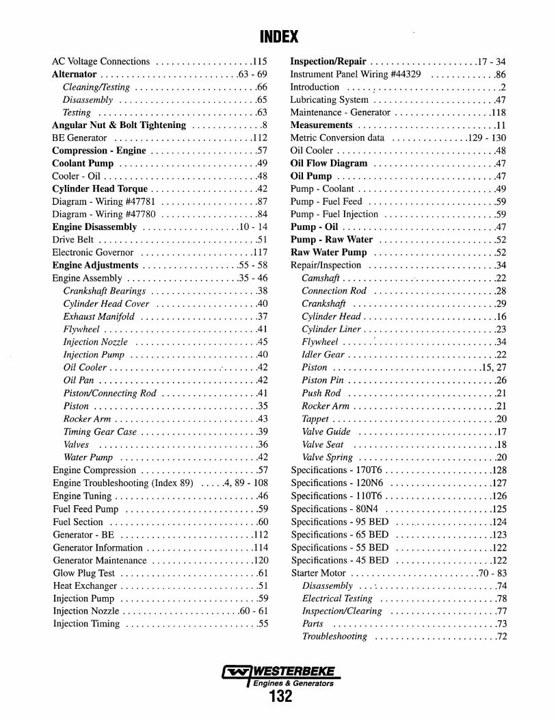
INDEX AC Voltage Connections ................... 115 Inspection/Repair ..................... 17 - 34 Alternator ........................... 63- 69 Instrument Panel Wiring #44329 ............. 86
Cleaningffesting ........................ 66 Introduction ..... : ........................ 2 Disassembly ........................... 65 Lubricating System ....................... .47 Testing ............................... 63 Maintenance - Generator ................... 118
Angular Nut & Bolt Tightening .............. 8 Measurements ........................... 11 BE Generator ........................... 112 Metric Conversion data ............... 129- 130 Compression - Engine ..................... 57 Oil Cooler .............................. .48 Coolant Pump .......................... .49 Oil Flow Diagram ....................... .47 Cooler - Oil . . . . . . . . . . . . . . . . . . . . . . . . . . . . . .48 Oil Pump ............................... 47 Cylinder Head Torque .................... .42 Pump - Coolant .......................... .49 Diagram- Wiring #47781 ................... 87 Pump - Fuel Feed ......................... 59 Diagram- Wiring #47780 ................... 84 Pump - Fuel Injection ...................... 59 Engine Disassembly ................... 10 - 14 Pump - Oil ............................. .47 Drive Belt ............................... 51 Pump - Raw Water ....................... 52 Electronic Governor ...................... 117 Raw Water Pump ........................ 52 Engine Adjustments ................... 55 - 58 Repair/Inspection ......................... 34 Engine Assembly ...................... 35 - 46 Camshaft .............. · ................ 22
Crankshaft Bearings ..................... 38 Connection Rod ........................ 28 Cylinder Head Cover ................... .40 Crankshaft ............................ 29 Exhaust Manifold ....................... 37 Cylinder Head . ......................... 16 Flywheel ............................. .41 Cylinder Liner . ......................... 23 Injection Nozzle ....................... .45 Flywheel ...... : ....................... 34 Injection Pump ........................ .40 Idler Gear ............................ .22 Oil Cooler ..................... : . ..... .42 Piston ............................. 15, 27 Oil Pan ............................... 42 Piston Pin ............................. 26
Piston/Connecting Rod .................. .41 Push Rod ............................. 21 Piston ................................ 35 Rocker Arm ............................ 21 Rocker Arm ............................ 43 Tappet ............................... . 20 Timing Gear Case ...................... .39 Valve Guide ........................... 17 Valves ............................... 36 Valve Seat ............................ 18 Water Pump ........................... 42 Valve Spring ........................... 20
Engine Compression ....................... 57 Specifications - 170T6 ..................... 128 Engine Troubleshooting (Index 89) .... .4, 89- 108 Specifications- 120N6 .................... 127 Engine Tuning ........................... .46 Specifications- 110T6 ..................... 126
Fuel Feed Pump .......................... 59 Specifications- 80N4 ..................... 125 Fuel Section ............................. 60 Specifications- 95 BED .................... 124 Generator- BE .......................... 112 Specifications- 65 BED ................... 123
Generator Information ..................... 114 Specifications- 55 BED ................... 122 Generator Maintenance .................... 120 Specifications - 45 BED ................... 122 Glow Plug Test ........................... 61 Starter Motor ......................... 70- 83 Heat Exchanger ........................... 51 Disassembly ... : ....................... 74 Injection Pump ........................... 59 Electrical Testing ....................... 78 Injection Nozzle ....................... 60- 61 Inspection/Clearing ..................... 77 Injection Timing .......................... 55 Parts ................................ 73
Troubleshooting ........................ 72
Engines & Generators
132

INDEX Tachometer .............................. 62 Turbocharger ............................. 53 Testing for Overhaul ........................ 3 Valve Clearance Adjustment ............... .49 Thermostat .............................. 51 Voltage Regulator Adjustments .............. 113 Timing - Injection ......................... 55 Wiring - Instrument Panel #44329 ............. 86 Torque Data ........................ 109- 111 Wiring Diagram #44780 .................... 84 Torque Specifications ....................... 9 Wiring Diagram #44781 .................... 87 Torque - Cylinder Head .................. .42 Wiring Diagram Internal ................... 116 Troubleshooting BE Generator .............. 119 Wiring Schematic #44780 ................... 85 Troubleshooting Electronic Governor ......... 118 Wiring Schematic #44781 ................... 88 Troubleshooting Engine (Index 89) .... .4, 89- 108
Engines & Generators
133


Engines & Generators
1049WMDW2;02